
SECTION 8B - EXHAUST SYSTEM
IMPORTANT
Before performing any Service Operation or other procedure described in this Section, refer to Section
00 CAUTIONS AND NOTES for correct workshop practices with regard to safety and/or property
damage.
1. GENERAL DESCRIPTION
All V2 Series Models feature a low back pressure exhaust system, similair to the system fitted to VT Series II
Models. V2 Series Models retain a dual exhaust s ystem back to the rear of the twin intermediate m ufflers. At this
point, the exhaust converges into a single pipe and rear muffler/tailpipe arrangement. The exhaust outlet for V2
Series Models are fitted with the large, chrome, oval fitting, regardless of engine type or model varient.
The engine exhaust manifolds connect to two equal length, symmetrical stainless steel front pipes. The front
exhaust pipes are of a dual wall air gap construction on vehicles fitted with the GEN III V8 engine.
The system layout for both V6 Supercharged and GEN III V8 engines is similar, in that a catalytic converter is
welded to each engine pipe, with a flanged, gasketed joint connecting each converter to the twin, intermediate
exhaust pipes. A service catalytic converter is available for replacement purposes.
On vehicles fitte d with the GEN III V8 eng in e, the t wo intermediat e exh aust pi pes are stif f ened by a welded br idgin g
piece and balance pipe, at points before the twin intermediate mufflers.
The catalytic converters as fitted to V2 Series Models equipped with the GEN III V8 engine, are supported by a
bracket bolted to each converter and secured to the transmission extension housing. The automatic transmission
converter design is different to that fitted to the manual transmission.
The exhaust system is supported by two rubber bumper supports attached to the rear suspension crossmember,
supporting the rear of the intermediate muffler. Additional support is provided by two rubber bumpers, which are
fitted to brackets attached to the rear tail pipe, rearward of the rear muffler.
All rubber bumpers are identical and are secured by:
a. Clips at the intermediate muffler brackets, welded to the rear suspension crossmember and clips at the rear
body hanger bracket.
b. Flanged pegs at all other loc ations.

2. SERVICE OPERATIONS
2.1 SERVICE NOTES
When installing any exhaust system component, care must be taken to install each component in the correct
relationship to one another .
Incorrect assembly of exhaust system components can frequently be the cause of rattles and ‘booms' due to
incorrect alignment or clearance from body or suspension parts.
When installing the exhaust system, ensure that the correct assembly, installation, tightening sequence and
clearance for the system involved are observed.
When exhaust system service work is required, refer to the various illustrations and instructions provided in this
Section. T his i nform ation provides the c orrect arra ngem ent, alig nm ent and c learanc es f or both eng ines a vail able i n
the V2 Series range of vehicles.
Step by step pr ocedures f or the replacem ent of individual ex haust system components are not included as s pecial
instructions are not required; only normal workshop practices are necessary. Exhaust system clearances and
torque specifications for fasteners are detailed in the illustrations included in this Section.
NOTE 1: A service replacement catalytic converter is available. This allows the exhaust pipe to be welded to the
component if removing or replac ing the con verter and eng ine ex haust pi pe.
NOTE 2: If removing or r ep lac in g the cata l ytic c onv er ter, al wa ys ensur e that n e w seali ng r ings /gas kets ar e inst alled
on reassembly.
2.3 EXHAUST FITMENT AND TIGHTENING SEQUENCE
V6 SUPERCHARGED
Figure 8B-3
Installation
Loosely install the exhaust system as follows;
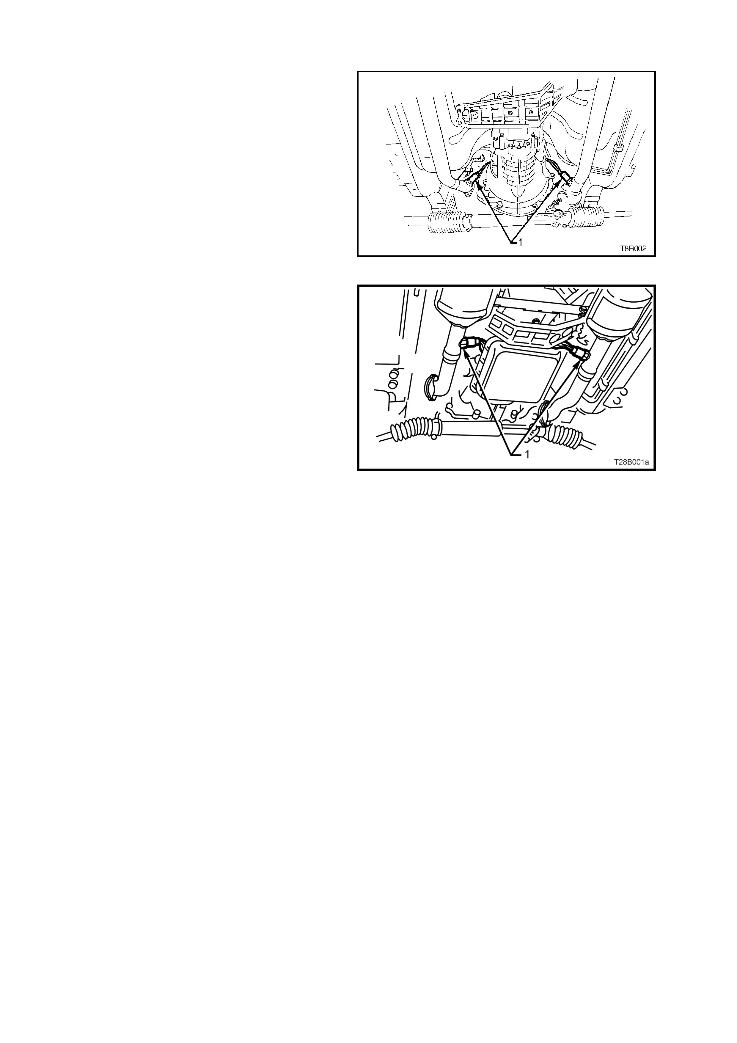
1. Attach front pipe and catalytic converter assemblies, loosely to the exhaust manifolds (1).
2. Hook intermediate assembly to suspension brackets with four bumper rubbers (two per intermediate muffler).
Fit four retaining clips to the suspension bracket ends (2).
3. Install bolts to the int ermediate muffler assembly to catalytic converter f langes, af ter installing a new gask et to
each flange (3).
4. Install a new gasket to the tailpipe assembly.
5. Install the intermediate muffler assembly to the rear muffler assembly and hand tighten the two bolts to the
flange (4).
6. Attach the rear muffler assembly to the body mount hangers with two bumper rubbers (5) and retaining clips.
Tightening Sequence
1. Tighten the flange bolts at the rear of the catalytic converter (3).
2. Evenly tighten the two bolts securing the flange (4) between the tailpipe and intermediate muffler to the
specified torque wrench setting.
3. Tighten each of the flange nuts evenly, so that a similar amount of thread is showing on each (1).
4. Ensure that all bumper rubbers are under load (2 and 5). If this is not achieved, loosen exhaust joints in the
reverse order to the above. Load the hangers and re-tighten in the sequence described, from steps 1 to 3.
NOTE 1: The exhaust system should be self-aligning and not require further adjustment, provided step 4 is
achieved.
NOTE 2: When tightening all fasteners related to the exhaust system, refer to 5 TORQUE WRENCH
SPECIFICATIONS in this S ect ion , for the correc t va lue s .
GEN III V8
Figure 8B-4
Installation
Loosely install the exhaust system as follows;
1. Attach front pipe and catalytic converter assemblies, loosely to the exhaust manifolds (1).
2. Hook intermediate assembly to suspension brackets with four bumper rubbers (two per intermediate muffler).
Fit four retaining clips to the suspension bracket ends (2).
3. Hand star t bolts to the in term ediate exhaust pipe to ca talytic convert er flanges, af ter installin g a new gasket to
each flange (3).
4. Hand start the two bolts securing the catalytic converter bracket to the converters (6).
5. Install a new gasket to the tailpipe assembly.
6. Install the intermediate muffler assembly to the rear muffler assembly and hand tighten the two bolts to the
flange (4).
7. Attach the rear muffler assembly to the body mount hangers with two bumper rubbers (5) and retaining clips.
Tightening Sequence
1. Tighten the flange bolts at the rear of the catalytic converter (3).
2. Evenly tighten the two bolts securing the flange (4) between the tailpipe and intermediate muffler to the
specified torque wrench setting.
3. Tighten each of the flange nuts evenly, so that a similar amount of thread is showing on each (1).
4. Ensure that all bumper rubbers are under load (2 and 5). If this is not achieved, loosen exhaust joints in the
reverse order to the above. Load the hangers and re-tighten in the sequence described, from steps 1 to 3.
5. After all other operations have been completed, tighten the catalytic converter bracket bolts.
NOTE 1: The exhaust system should be self-aligning and not require further adjustment, provided step 4 is
achieved.
NOTE 2: When tightening all fasteners related to the exhaust system, refer to 5 TORQUE WRENCH
SPECIFICATIONS in this Section, for the correct values.
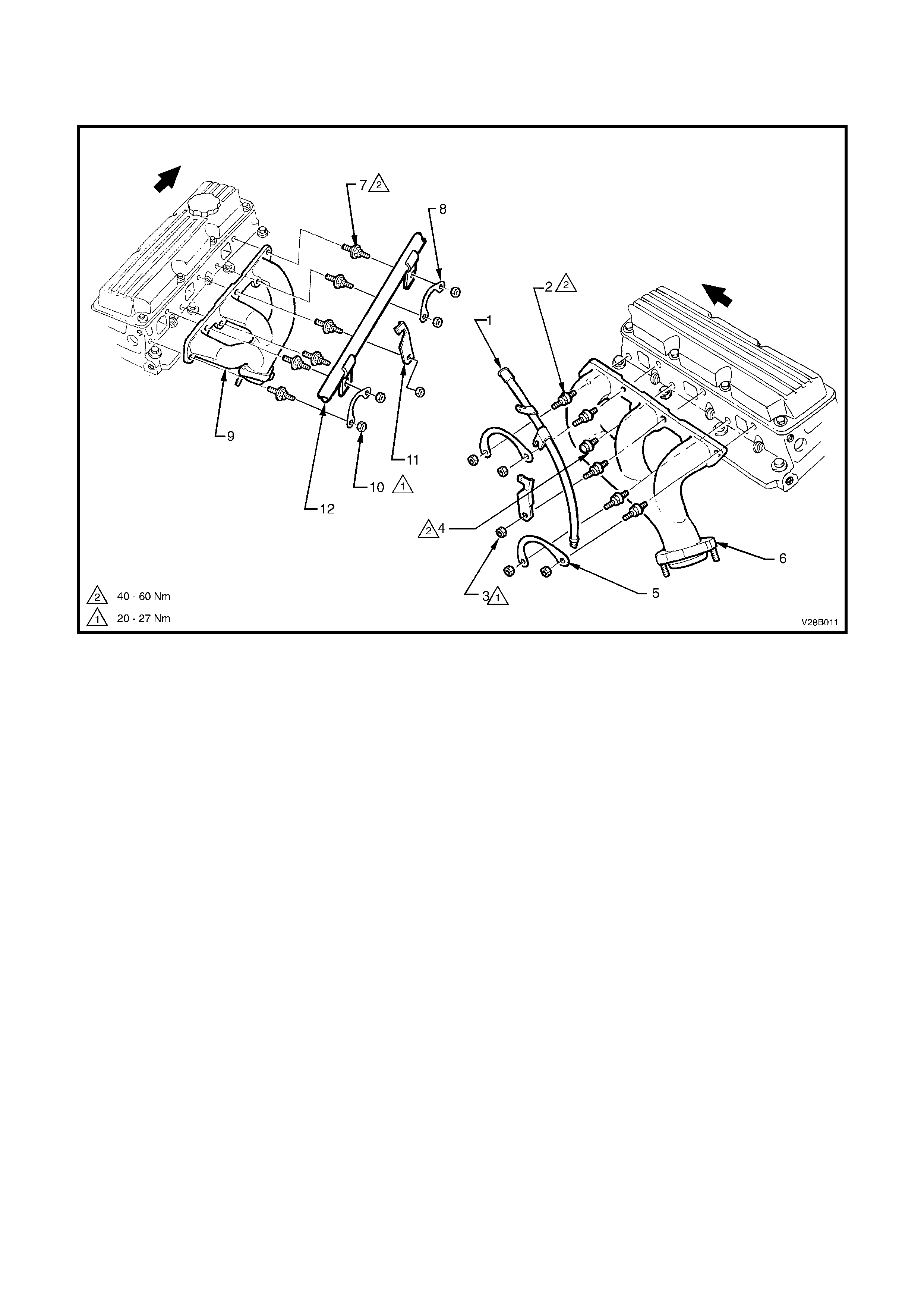
2.4 EXHAUST MANIFOLD INSTALLATIONS
V6 SUPERCHARGED
Figure 8B-5
Legend
1. Dipstick tube 5. Bolt lock plate (2 places) 9. Exhaust manifold - RH side
2. Stud (5 places) 6. Exhaust manifold, LH 10. Nut (5 places)
3. Nut (4 places) 7. Stud (6 places) 11. Spark plug lead support
4. Bolt (2 places) 8. Bolt lock plate (2 places) 12. Radiator inlet pipe
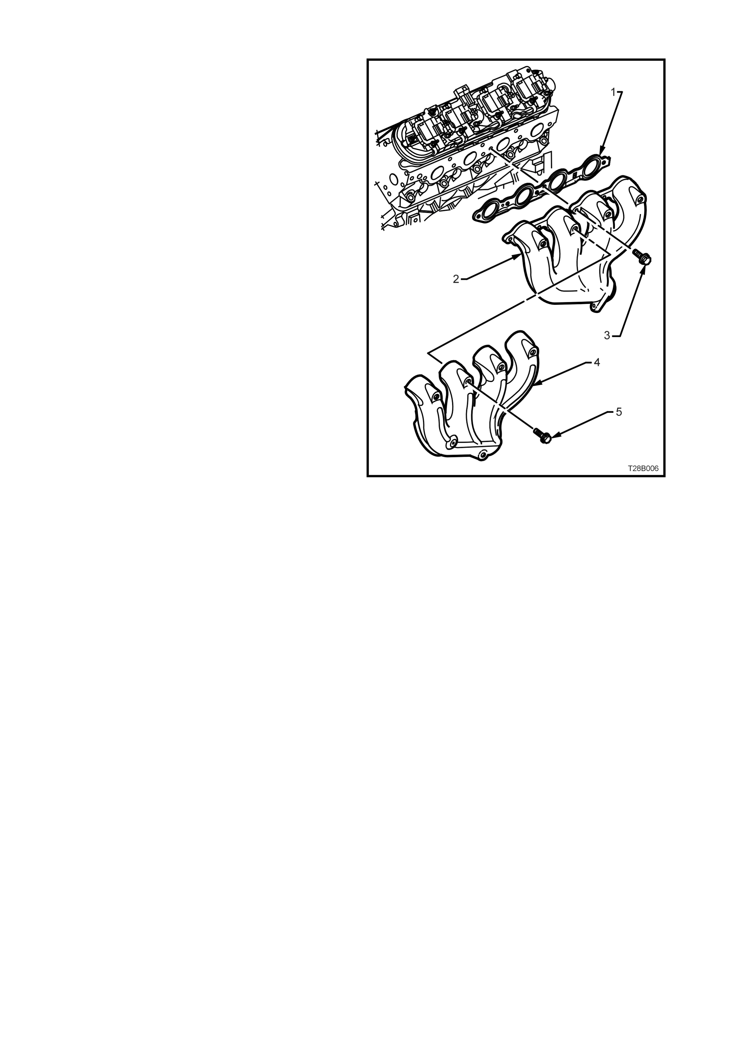
GEN III V8 ENGINE
The exhaust manifolds fitted to the GEN III V8
engine, are of a one piece, high temperature
silicone molybdenum cast iron and direct exhaust
gases from the combustion chambers to the
exhaust system.
Each manifold also has an externally mounted,
heat shield attached, that is made from
aluminiumised steel. Each heat shield is attached
to the manifold by 5 screws.
NOTE: While the left hand exhaust manifold is
shown, the right hand arrangement is similar.
Legend:
1. Gasket, exhaust manifold
2. Manifold, exhaust
3. Bolt, exhaust manifold to cylinder head
4. Shield, exahust manifold heat
5. Screw, heat shield to exahust manifold (5
places)
Figure 8B-6
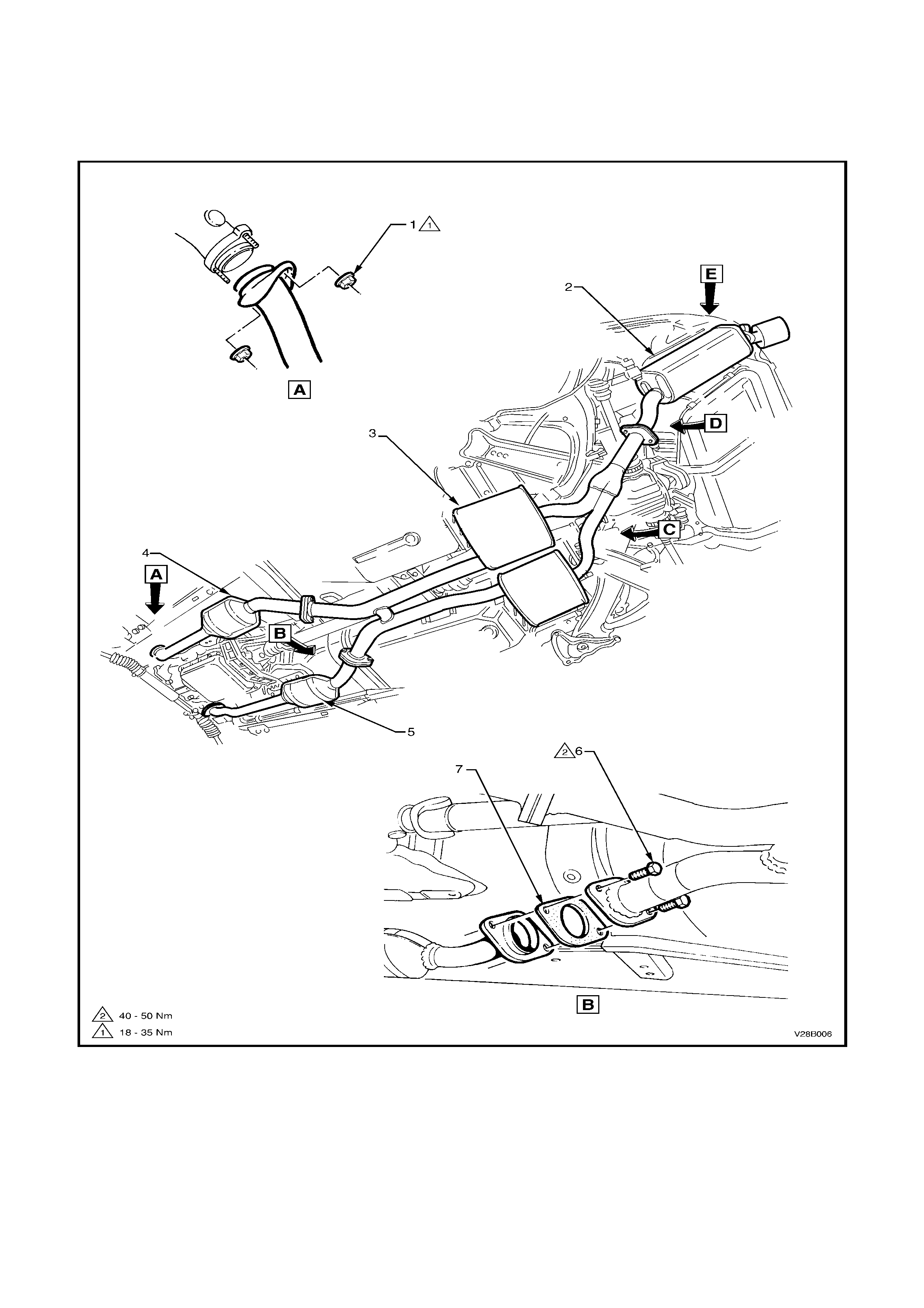
2.5 EXHAUST SYSTEM LAYOUTS
The following layout diagrams relate to the exhaust systems used for V2 Series Models, fitted with either the V6
Supercharged or GEN III V8 engines.
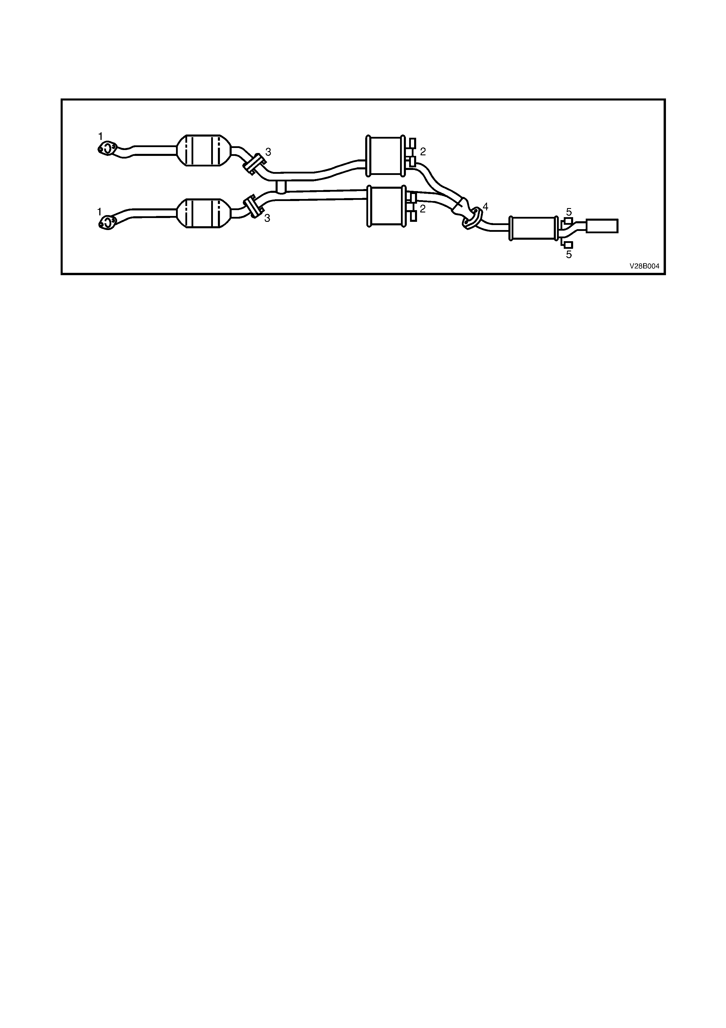
V6 SUPERCHARGED
Figure 8B-7
Legend
1. Nut (2 places) 4. Catalytic converter LH 6. Bolt (4 places)
2. Rear muffler 5. Catalytic converter RH 7. Gasket (2 places)
3. Intermediate muffler (1 per side)
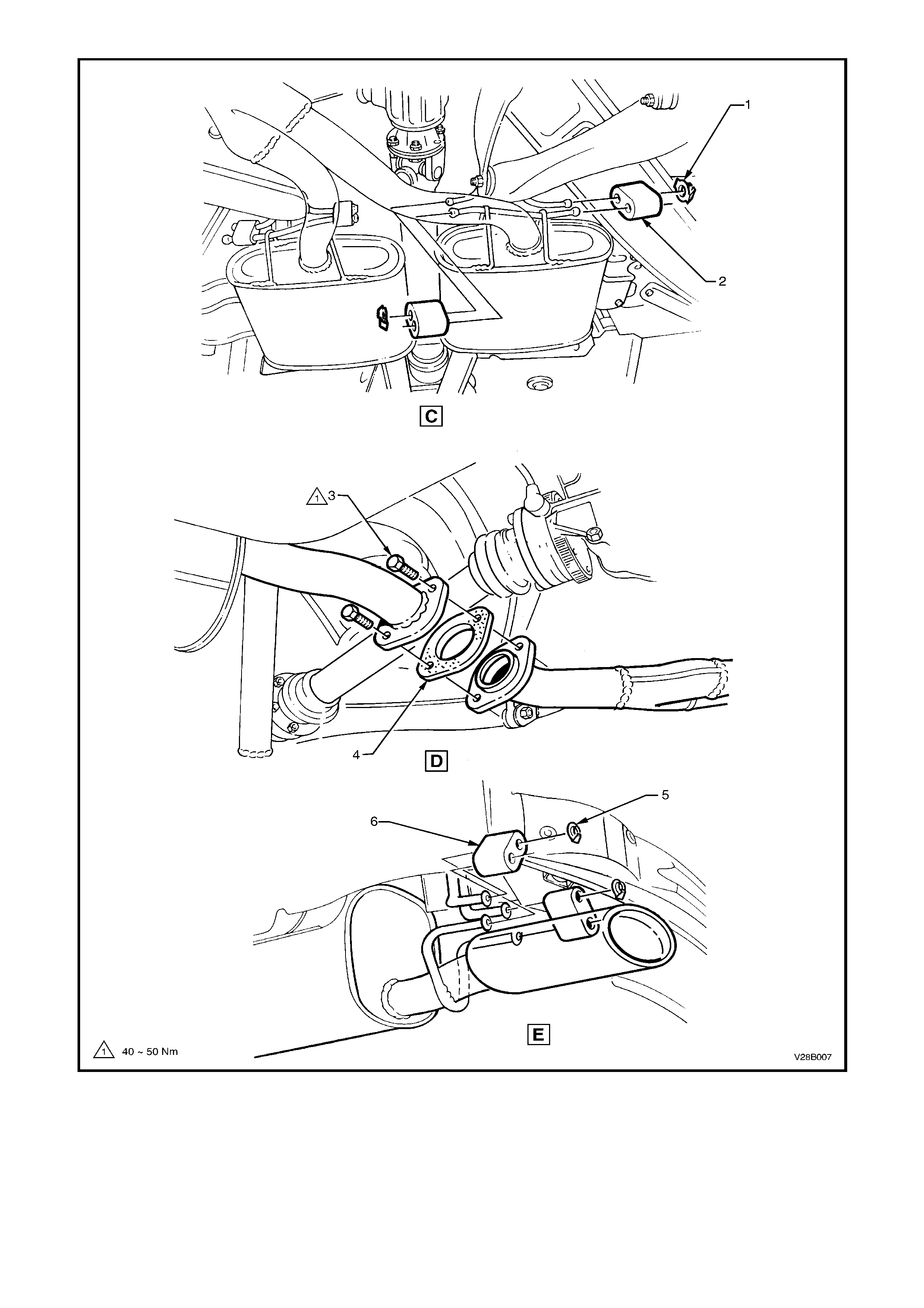
Figure 8B-8
Legend
1. Front muffler bumper retainer 3. Rear muffler attaching bolt (2 places) 5. Rear muffler bumper retainer
2. Front muffler bumper rubber 4. Rear muffler flange gasket 6. Rear muffler bumper rubber
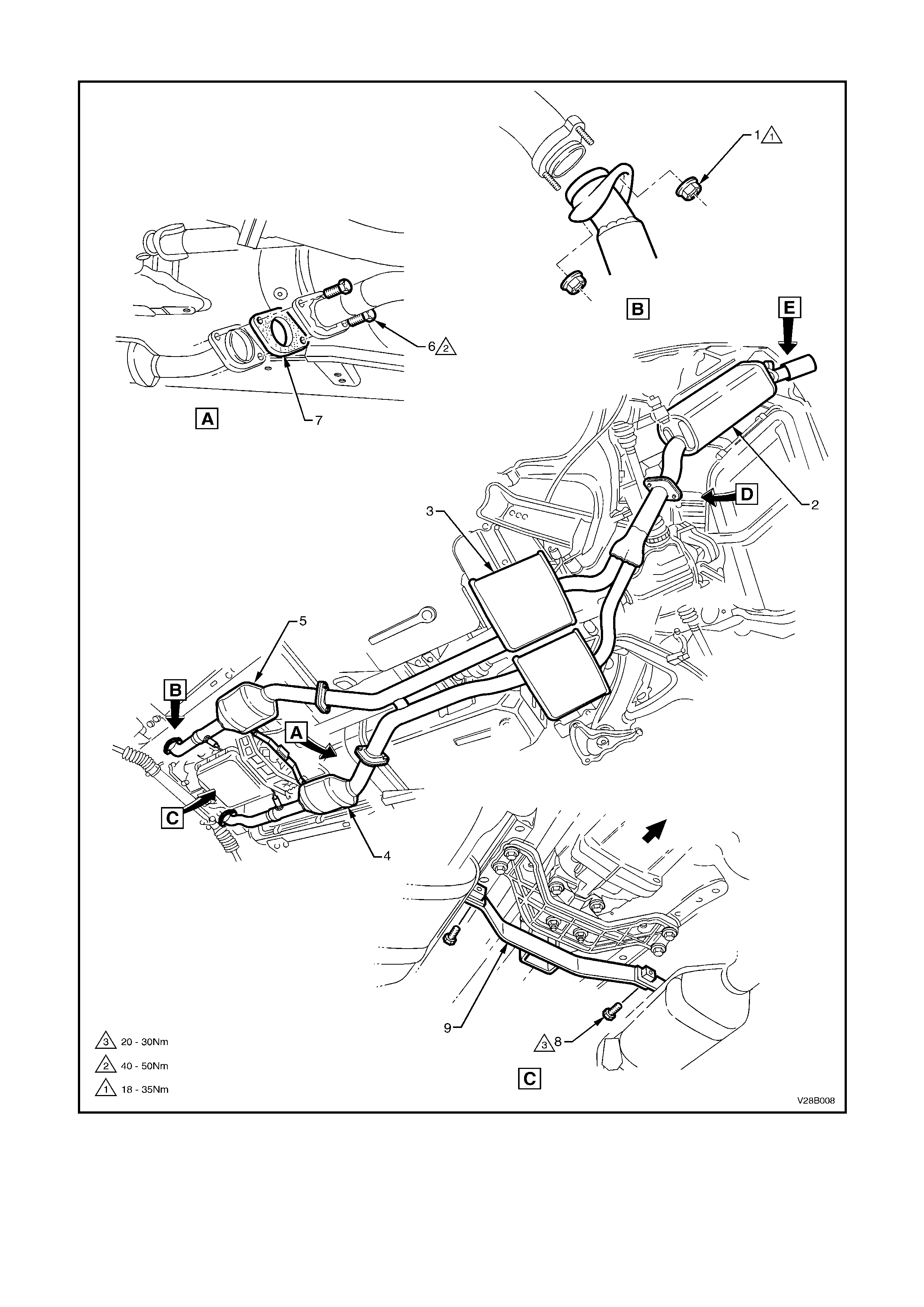
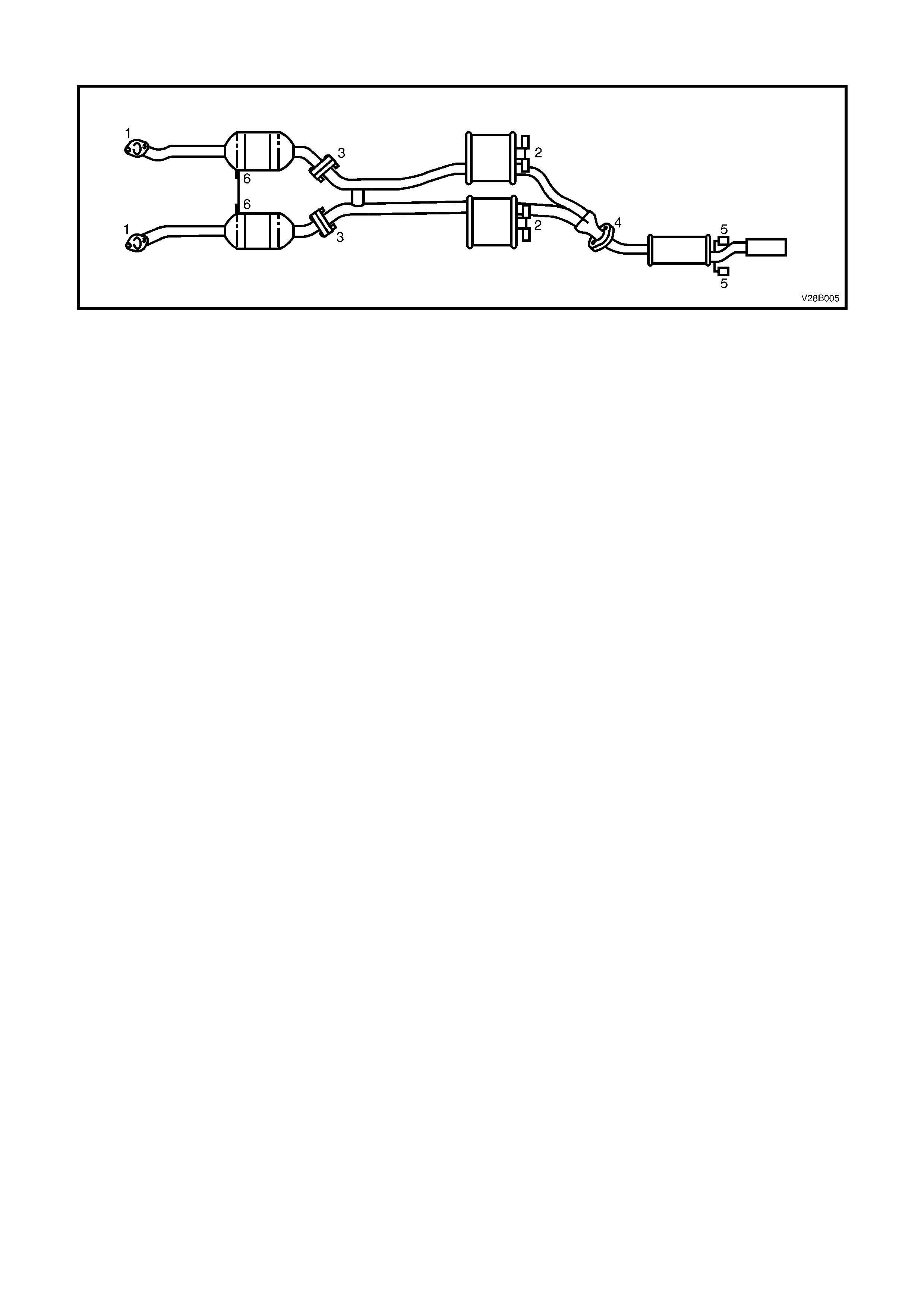
GEN III V8 ENGINE
Figure 8B-9
Legend
1. Nut (2 places) 4. Catalytic converter, RH 7. Gasket (2 places)
2. Rear muffler 5. Catalytic converter, LH 8. Bolt (2 places)
3. Intermediate mufflers (1 per side) 6. Bolt (4 places) 9. Catalytic converter bracket

Figure 8B-10
Legend
1. Front muffler bumper retainer 3. Rear muffler attaching bolt (2 places) 5. Rear muffler bumper retainer
2. Front muffler bumper rubber 4. Rear muffler flange gasket 6. Rear muffler bumper rubber
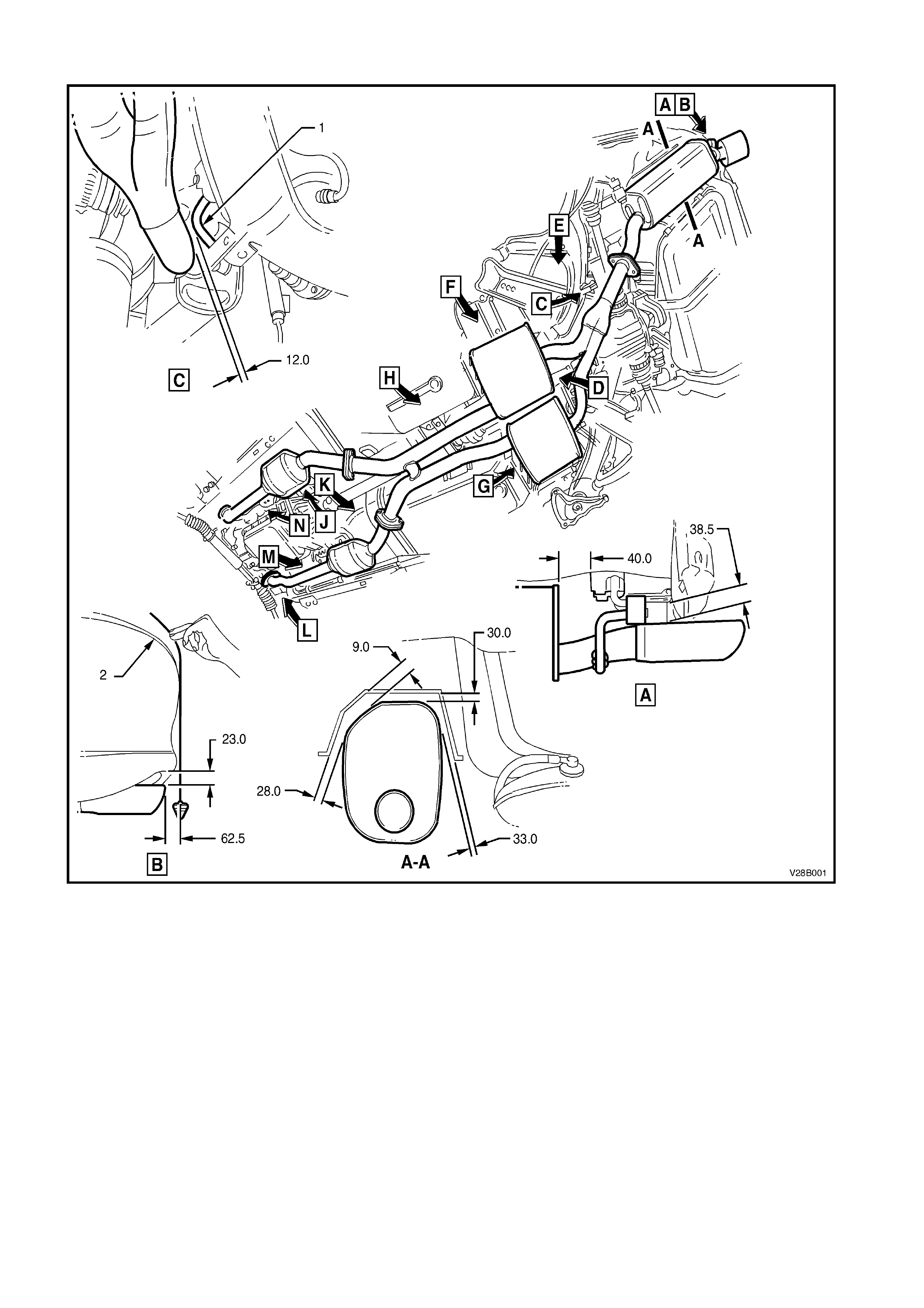
2.6 EXHAUST SYSTEM CLEARANCES
Figure - 8B-11
Legend
1. Stabiliser bar shackle For view D, E, F, G and H, refer to Figure 8B-12.
2. Rear bumper facia For view J, K, L, M, N and P, refer to Figure 8B-13.
NOTE: All dimensions are in mm.
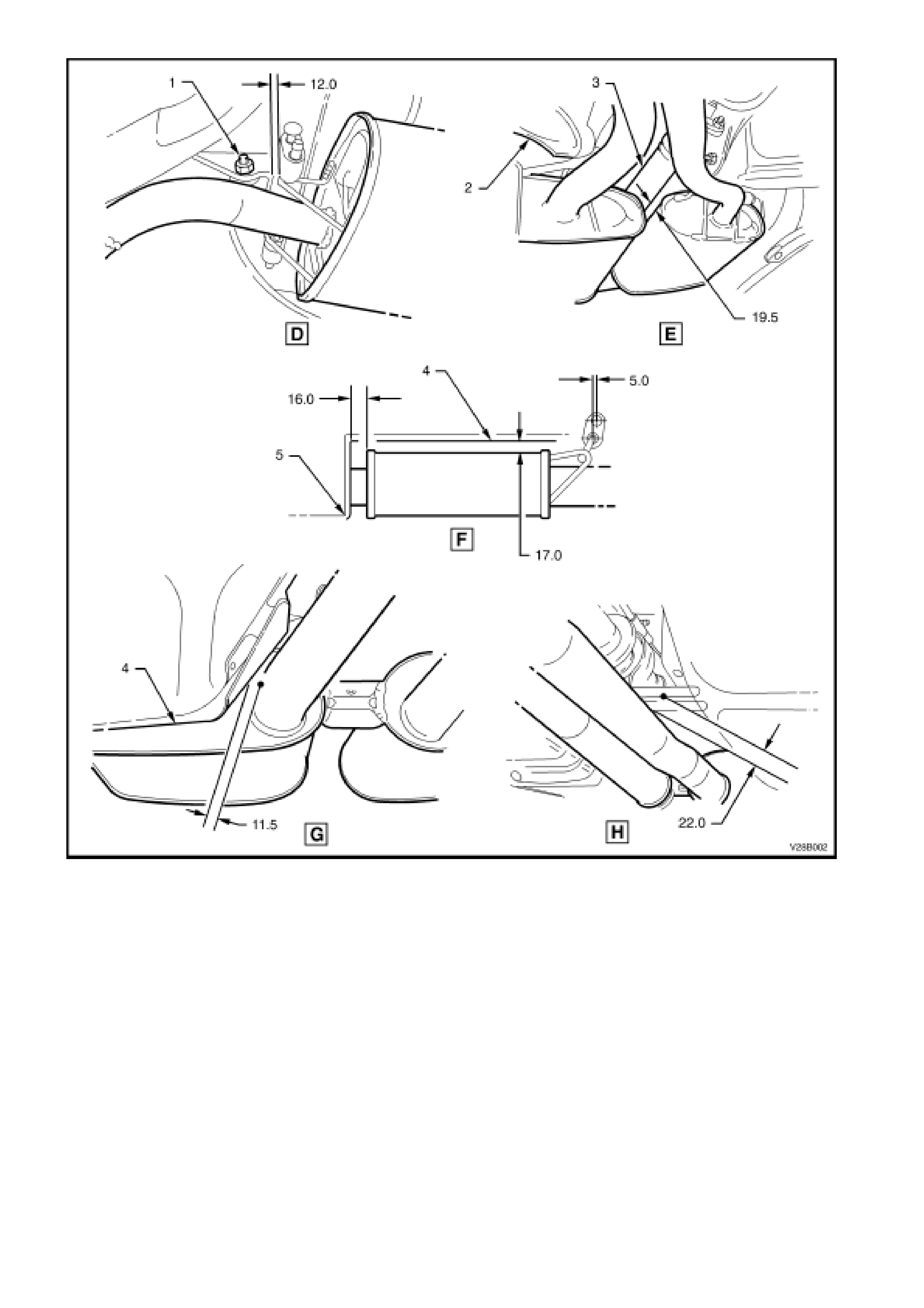
Figure 8B-12
Legend
1. Rear suspension con trol arm moun t 4. Intermediate heat shield
2. Rear suspension con trol arm a sse mbly 5. Footwell
3. Propeller shaft assembly NOTE: All dimensions are in mm.
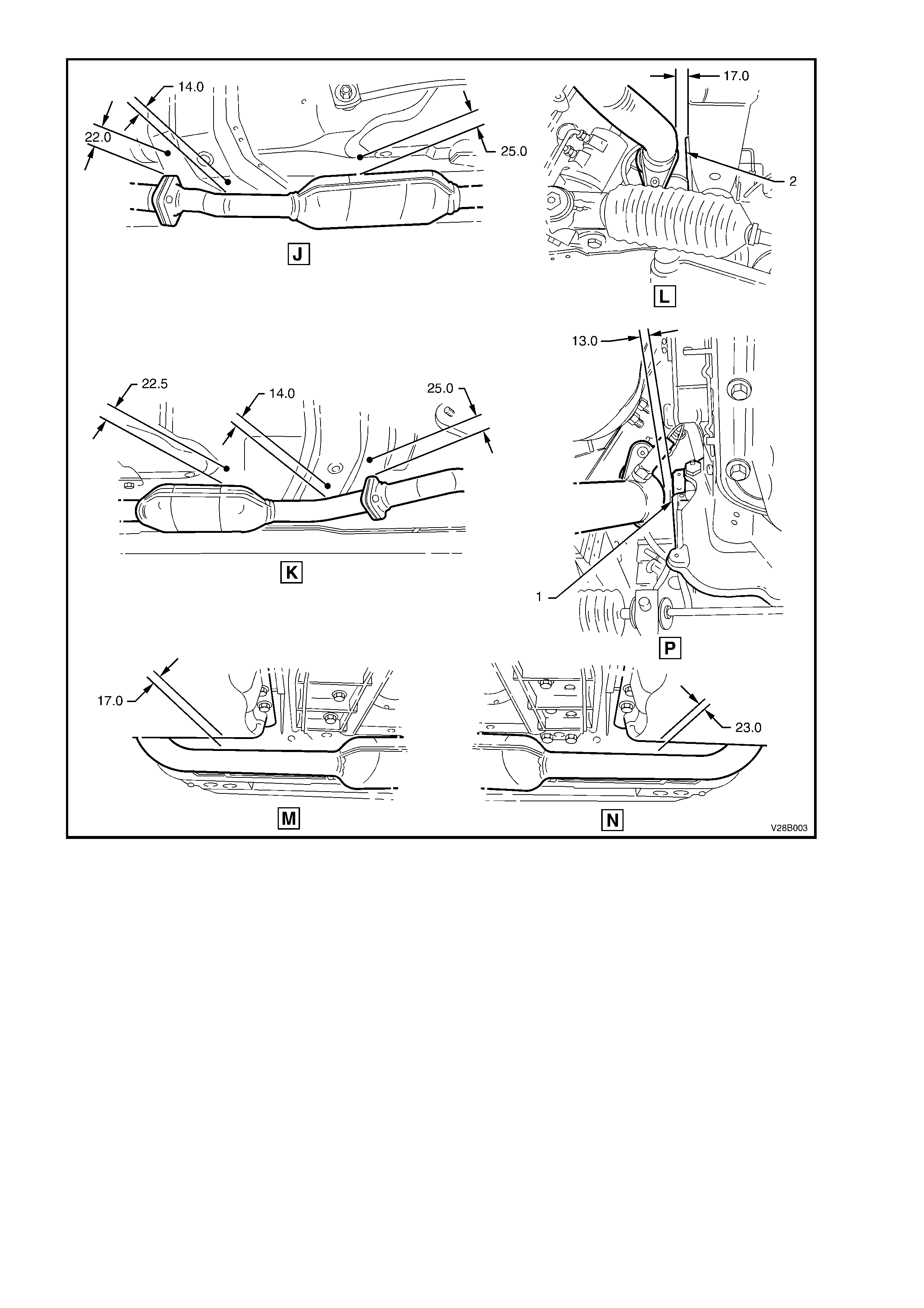
Figure 8B-13
Legend
1. Engine block 2. Front longitudinal assembly NOTE: All dimensions are in mm.
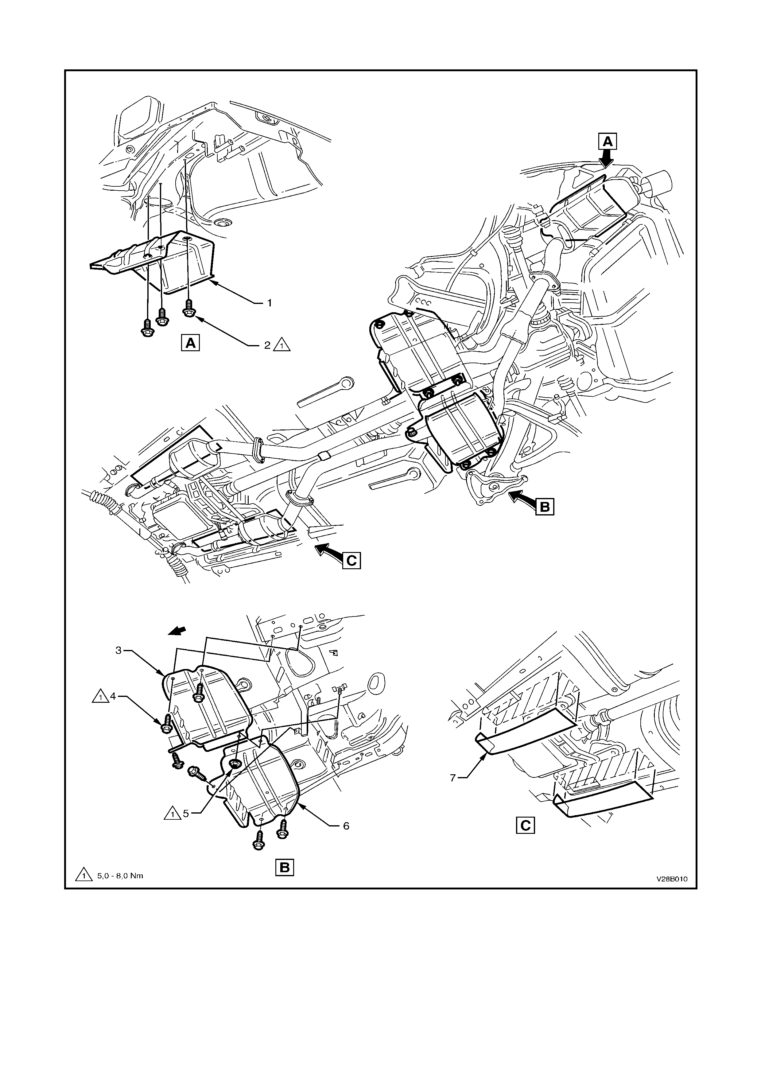
2.7 EXHAUST SYSTEM HEAT SHIELDS
Figure 8B-14
Legend
1. Heat shield (Rear Muffler) 4. Screw (6 places) 6. Heat shield (RH Intermediate)
2. Screw (3 places) 5. Nut (1 place) 7. Self-adhesive insulators
3. Heat shield (LH Intermediate)

3. EXHAUST SYSTEM DIAGNOSIS
CONDITION PROBABLE CAUSE CORRECTION
Leaks at pipe joints. Tighten joint bolts to the correct
torque specifications.
Damaged or improperly installed
catalytic converter sealing
ring/gaskets.
Replace gasket as necessary.
Leaking exhaust gases
Burned or rusted out exhaust pipe
or muffler/s. Replace component as necessary.
Leaks at manifold or pipe
connections. Tighten bolts at leaking
connections to the correct torque
specif ications . Replace gas kets as
required.
Burned or blown out pipe or
muffler/s. Replace pipe/muffler assembly as
necessary.
Exhaust manifold/s cracked or
broken. Replace manifold.
Exhaust noises
Leak between manifold/s and
cylinder hea d/s . Tighten manifold to cylinder head
studs to the correct torque
specification.
Clogged catalytic converter (may
result from serious engine
malfunction).
Replace catalytic converter.
Loss of engine power, hesitation,
surging, poor fuel economy,
stalling or
hard starting Cr us hed pip e work . Replace pipewor k.
Dislodged tubes and/or baffles in
muffler. Replace muffler. Internal rattling in muffler
Catalytic converter monolith has
crumbled and pieces blown into
muffler.
Replace catalytic converter
assem bly and aff ec ted muffler .

4. SPECIFICATIONS
TYPE: ................................................................................... Single system
MATERIAL:
Engine Pipes......................................................................... 409 stainless steel
Intermediate Muffler.............................................................. 409 stainless steel
Rear Muffler.......................................................................... 409 stainless steel
CATALYTIC CONVERTER:
Make..................................................................................... AC Australia
Type...................................................................................... Three way monolith
Outer Steel Shell
Material....................................................................... Stainless
Inlet Diameter............................................................. 50 mm
Outlet Diameter .......................................................... 50 mm
Monolith
Material....................................................................... Extruded Cordierite
Volume ....................................................................... 1.4 litres each
Cells/in2....................................................................... 400

5. TORQUE WRENCH SPECIFIC ATIONS
V6 Supercharged Nm
Engine front pipe flange to exhaust manifold flange
attaching nuts........................................................................ 18 - 35
Front exhaust pipe and intermediate flanges to
catalytic converter assembly................................................. 40 - 50
Exhaust manifold to cylinder head studs.............................. 40 - 60
Exhaust manifold lock plate and support nuts...................... 20 - 27
Heat shield screws/nuts to underbody.................................. 5 - 8
GEN III V8 Nm
Extension housing to exhaust pipe support bracket
attaching bolt (A/T only)........................................................ 18 - 35
Catalytic converter bracket bolt to converter........................ 40 - 50
Engine front pipe flange to exhaust manifold flange nut ...... 18 - 35
Front exhaust pipe to intermediate pipe flange bolts............ 40 - 50
Exhaust manifold to cylinder head bolts: Stage 1............... 15
Stage 2............... 25
Exhaust manifold heat shield screw ..................................... 8 - 10
Heat shield screws/nuts to underbody.................................. 5 - 8