SECTION 12A BATTERY & CABLES
CAUTION:
This v ehicle will be equipped with a Supplemental Restraint System (SRS). A SRS
will consist of either seat belt pre-tensioners and a driver’s side air bag, or seat
belt pre-tensioners and a driver’s and front passenger’s side air bags. Refer to
CAUTIONS, Section 12M, before performing any service operation on or around
SRS components, the steering mechanism or wiring. Failure to follow the
CAUTIONS could result in SRS deployment, resulting in possible personal injury
or unnecessary SRS system repairs.
CAUTION:
This vehicle may be equipped with LPG (Liquefied Petroleum Gas). In the interests
of safety, the LPG fuel system should be isolated by turning 'OFF' the manual
service valve and then draining the LPG service lines, before any service work is
carried out on the vehicle. Refer to the LPG leaflet included with the Owner's
Handbook for details or LPG Section 2 for more specific servicing information.
1. GENERAL DESCRIPTI ON
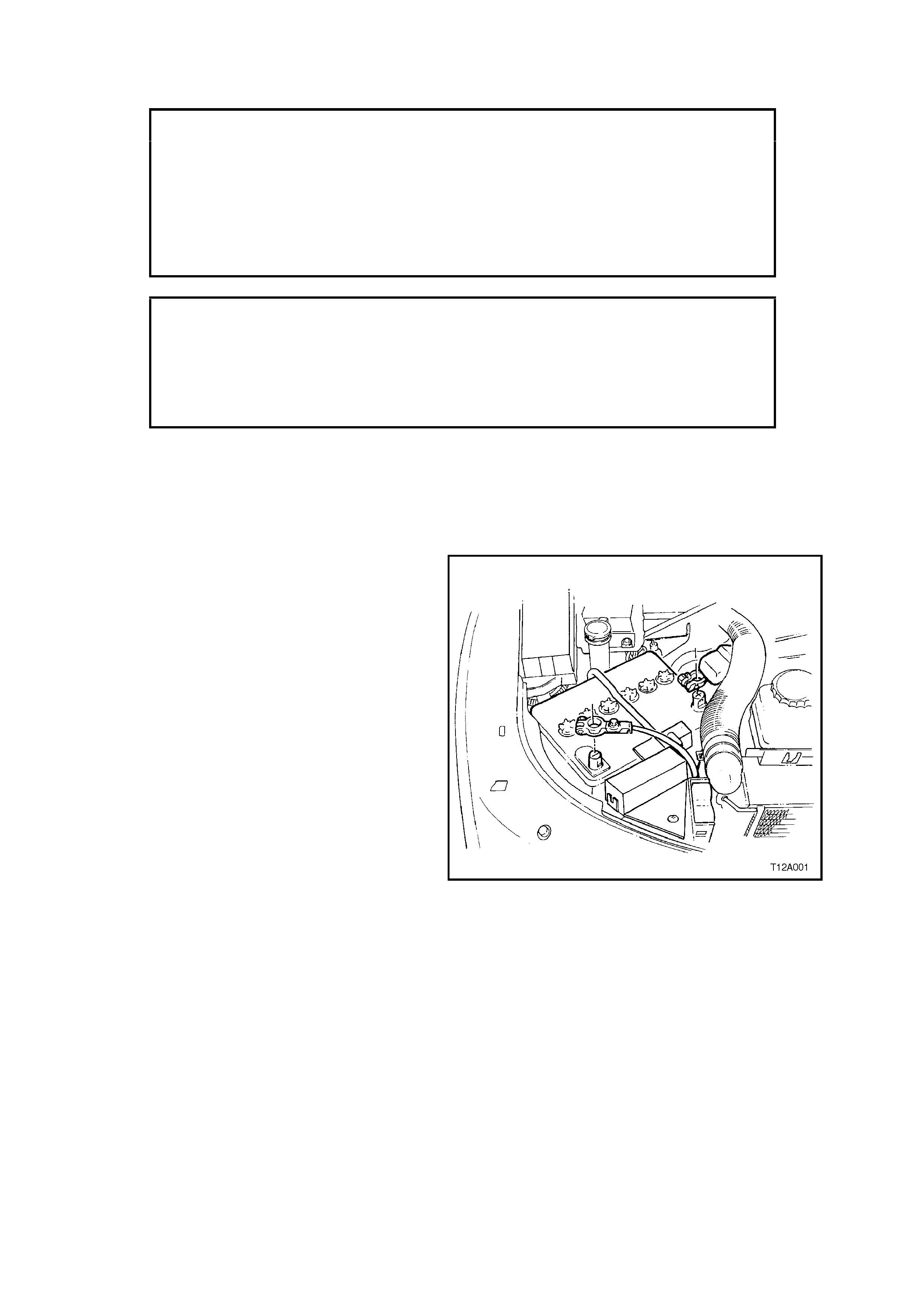
In all VT Series Models, the 12 volt battery is
located in the engine compartment behind the
driver’s side headlamp, refer to Fig. 12A-1. The
battery cables are attached to the battery terminals
by nut tightened clamps. The negative terminal is
earthed to the vehicle body at the fender inner
panel stud, and to the engine (at right-hand engine
mounting bracket for V6 engine and at the power
steering pump bracket to cylinder head attaching
stud for V8 engine).
The battery has four major functions in the vehicle
electrical system:
1. Provide a source of energy for cranking the
engine.
2. Acts as a voltage stabiliser for the electrical
system.
3. It can, for a limited time, provide energy when
the electrical load used exceeds the output of
the generator.
4. Provides power for accessories when the
engine is not running.
Figure 12A-1
1.1 BATTERY RATINGS
There are two battery ratings which must be
considered when replacing a battery, Rated
Reserve Capacity and Rated Cold Cranking
Current. When replacing a battery, ensure that the
replacem ent battery meets or exceeds these rating
specifications.
The Rated Reserve Capacity (RRC) of the battery
is the maximum length of time (in minutes) it is
possible to travel at night with minimum electrical
load and no generator output.
This time is for a fully charged battery, being
discharged at a constant current of 25 amperes at
25°C, to reach 10.5 volts. The value of 25 am peres
represents the nominal battery current draw that
could be expected on a rainy night.
The Rated Cold Cranking Current (RCC) or Rapid
Discharge Current, is a measure of the battery’s
ability under severe cold starting conditions to
maintain a sufficiently high voltage for ignition
requirements, while supplying the high engine
cranking current, and if it can do this for a
sufficiently long enough period to ensure that the
engine will start.
The c urrent rating is the m inimum amperage rating
which must be maintained by the battery for 30
seconds at -18ºC, while meeting a minimum
requirement of 7.2 volts.
On the top surface of the battery case, there is a
specification label which contains important
information with regards to servicing of the battery.
This information includes battery ratings and
original equipment battery part number.
VT Executive Sedan and Station Wagon Models
with V6 engine are fitted with a 12 volt, low
maintenance 75 minutes RRC/350 RCC amp
capacity battery.
All other VT Ser ies Models are fitted with a 12 volt,
low maintenance 95 minutes RRC/400 RCC amp
capacity battery.
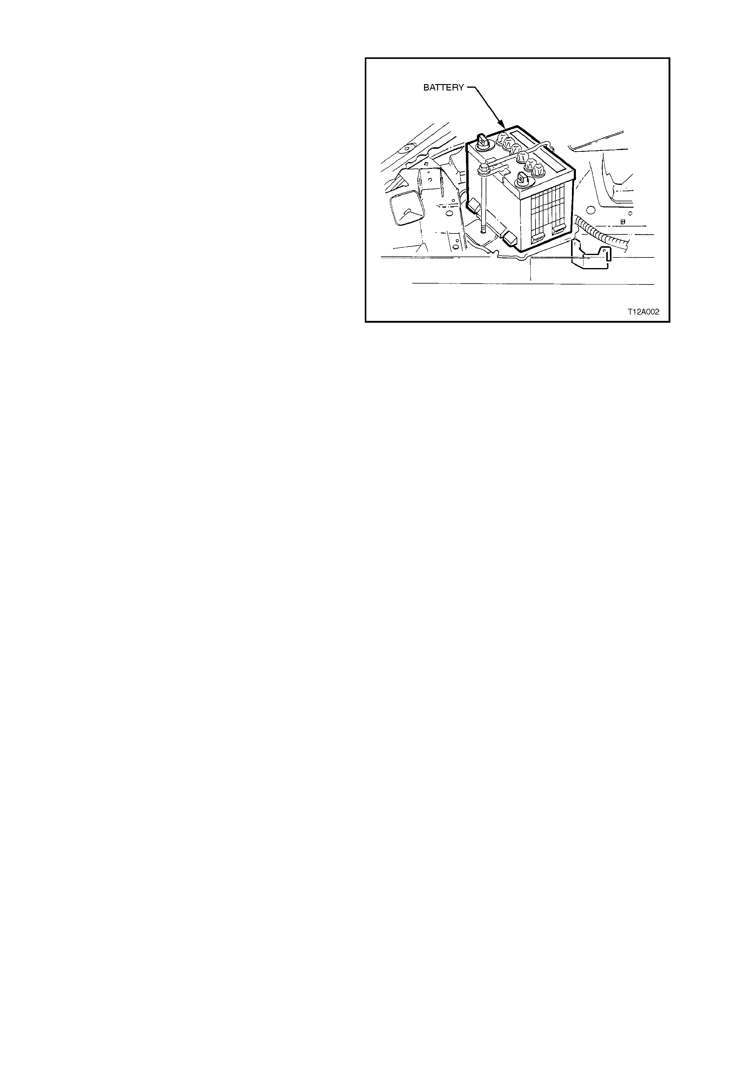
Figure 12A-2

2. SERVICE OPERATIONS
CAUTION:
Do not allow liquid from battery to contact eyes,
skin, clothing or painted surfaces. Battery fluid
contains sulfuric acid which causes injury and
damage in the event of contact. In the event of
an accident, flush area immediately with large
amounts of water. Also, in the case of eye
contact, see a physician immediately.
Lead acid batteries produce ex plosive gases. Keep
sparks, flames and lighted cigarettes away from
battery when charging or working around battery
area in an enclosed area. Failure to follow this
warning could cause the battery to explode.
Take care with all metal objects including items of
jewellery (rings and metal watch bands) and tools
when working near battery term inals. Metal objects
that touch a battery term inal can cause spark s and
serious heat burns to the user or wearer.
Ensure that the ignition is switched off when
connecting or disconnecting battery cables, battery
chargers or jumper cables. Failing to do so may
damage vehicle electronic components.
It is advisable to always disconnect the battery
negative cable from the battery first, and connect it
to the battery last, to avoid the possibility of shorting
to earth with the spanner while working on the
connections of the positive cable. Spanners
shorting to earth from either end of the positive
cable would carry high amperage and heat quick ly,
causing serious burns to the hand.
2.1 BATTERY INSPECTION
1. Check battery terminals and around battery
area for corrosion deposits. Remove any
deposits by scrubbing with a stiff brush, then
treat with a solution of warm water and bak ing
soda or ammonia. Rinse off with clean water.
Smear battery posts and terminals with
petroleum jelly to resist corrosion.
If battery posts are severely damaged (i.e.
loose, burned or broken), replacement of the
battery is recommended.
2. Check battery case and replace batter y if cas e
is cracked.
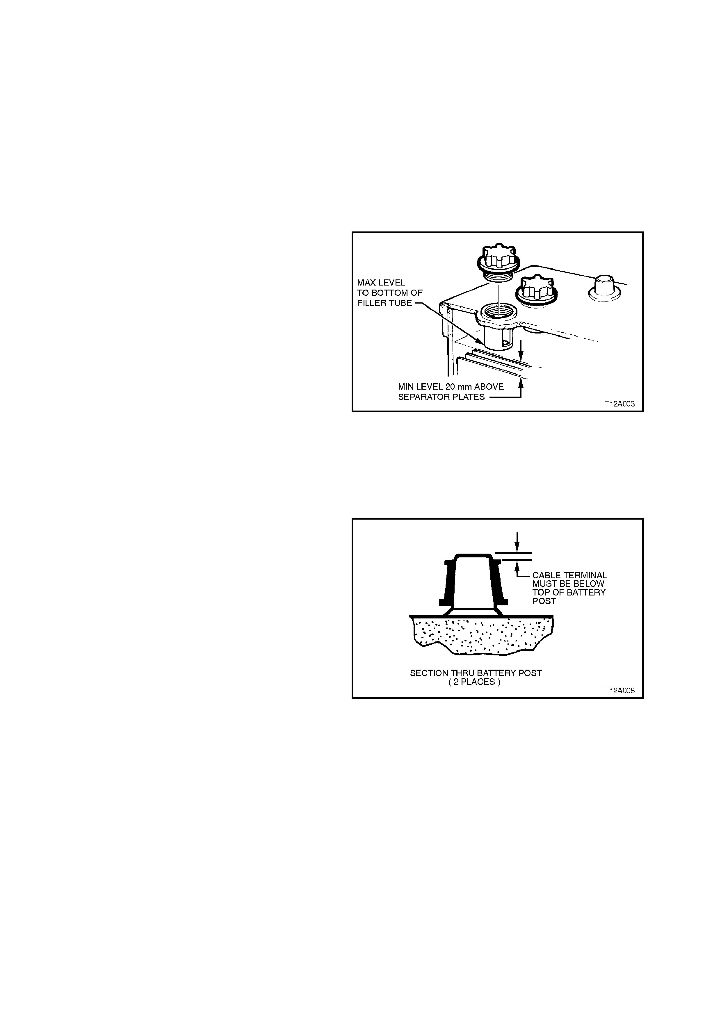
3. Check electrolyte level and carefully top up
with distilled water as necessary so it is level
with the bottom of each filler neck tube. DO
NOT OVERFILL.
The battery level should be maintained
between the bottom of each filler neck tube
and 20 mm above the separator plates.
NOTE:
Normal battery water usage is less than 30 ml per
10 000 km, but may be more for long continuous
running or high temperatures.
If battery water usage is consider ed exc es sive and
inspection reveals that the battery case is OK, the
generator may be overcharging. Check generator
output as described in Section 6D1-1 CHARGING
SYSTEM - V6 ENGINE or Section 6D2-1
CHARGING SYSTEM - V8 ENGINE.
4. Check that battery is firmly secured by its
clamping bracket.
Figure 12A-3
5. Check that battery cable terminal clamps are
securely attached to battery posts and that
cable insulation is not damaged or worn
anywhere along cable. Check that cables do
not have broken or frayed strands and that
they are secure in their terminals.
Replace any damaged component found,
including the battery itself.
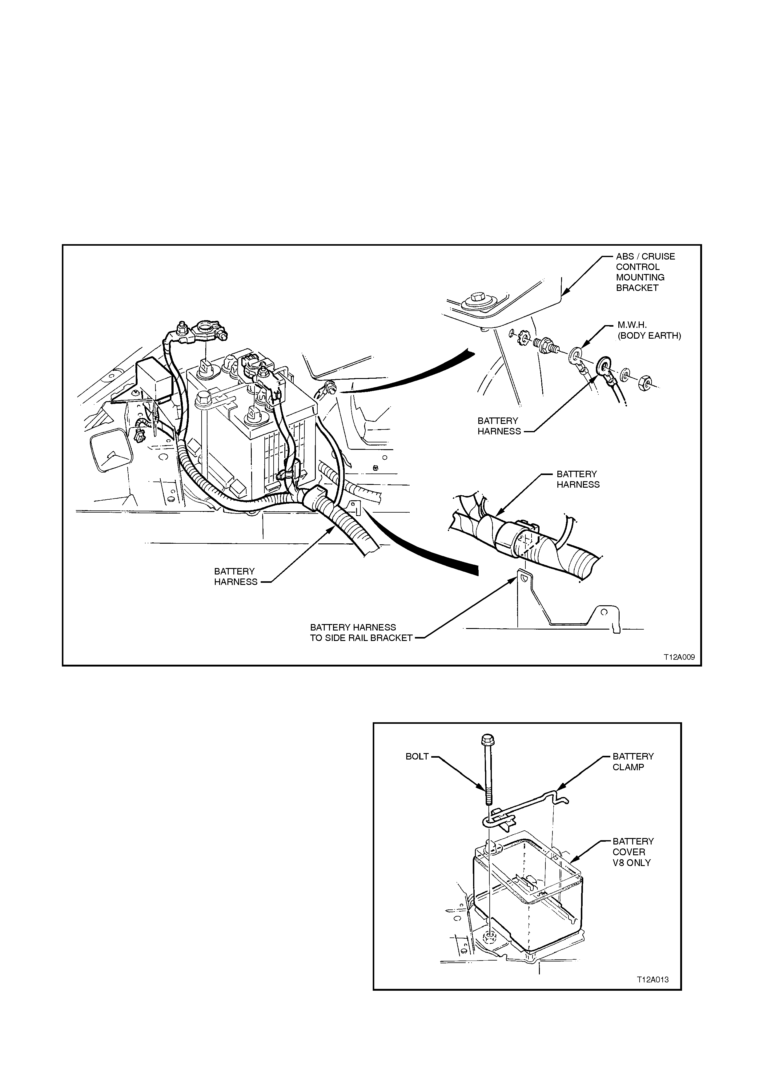
The following figures illustrate the V6 and V8
battery harness installation details f or all VT Series
Models.
Figure 12A-4
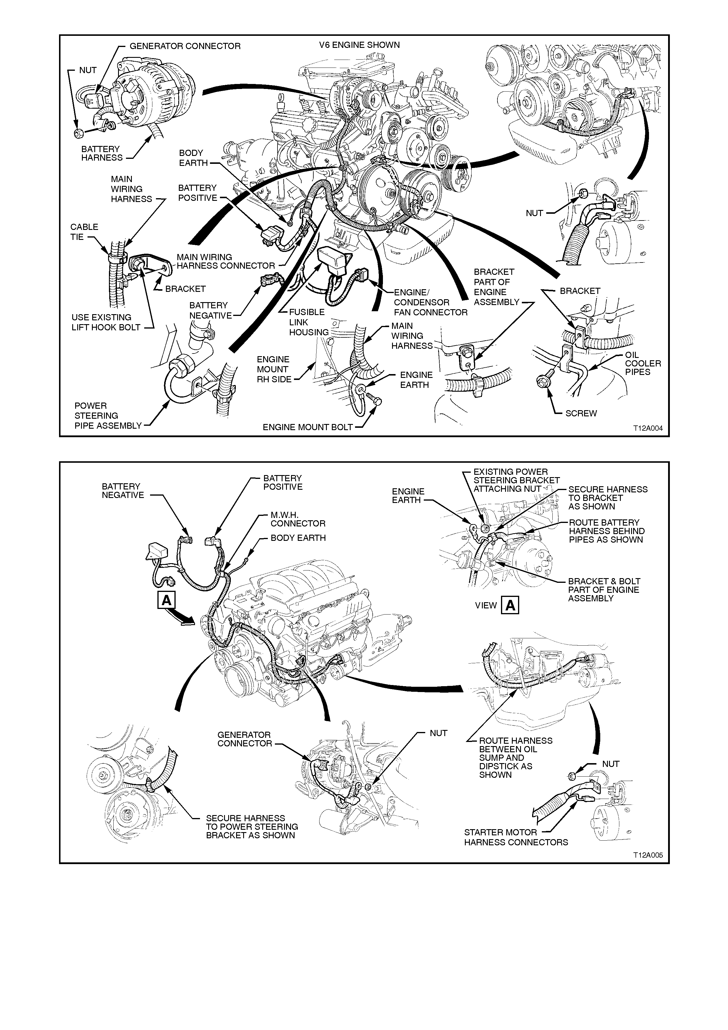
Figure 12A-5
Figure 12A-6

2.2 HYDROMETER TEST
As a lead acid battery is discharged, the sulfuric
acid in the electrolyte combines with the material
mak ing up the plates . This rem oves the acid so the
electrolyte nearly becomes pur e water. T his means
there is a relation between state of charge and the
specific gravity reading. The lower the specific
gravity reading, the lower the battery state of
charge.
A hydrometer can be used to measure the
concentration of sulfuric acid in the battery
electrolyte in terms of specific gravity.
As a battery drops from a charged to a discharged
condition, the acid leaves the solution and enters
the plates, causing a decrease in electrolyte
specif ic gr avity. By meas ur ing the s pecific gr avity of
the electrolyte with a hydrometer, an indication of
the approximate state of charge of the battery can
be determined.
NOTE:
If distilled water has been added to battery, do not
use hydrometer until elec trolyte has been mixed by
charging for at least 30 minutes.
1. Unscrew battery vent caps.
2. Hold hydrometer vertically and draw in
sufficient liquid from battery cell to allow float
to float freely with bulb fully released.
3. Compensate reading for temperature by
adding 0.004 for every 5°C that the electrolyte
temperature exceeds 27°C, or subtracting
0.004 for every 5°C less than 27°C.
4. Determine state of charge of battery using
temperature com pensated specific gravity and
following table.
Figure 12A-7
BATTERY CONDITION TEMPERATURE
COMPENSATED
SPECIFIC GRAVITY
Fully Charged 1.240 to 1.260
Recharge When Below 1.190
Fully Discharged 1.110 to 1.130
NOTE:
The s pecific gr avity of a char ged battery should not
vary more than 0.025 between cells. Larger
variations indicate defective cells.
5. Refit battery vent caps.

2.3 LOAD TEST
Load testing the battery with a High Rate Discharge (HRD) tester will impose a simulated starter motor current
draw on the battery and test it to see if it is in good enough condition to be put back into service. The battery
must be at least 65% charged (as indicated by a hydrometer test) in order to perform a valid test.
HRD testers are available as either FIX ED or VARIABLE load testers and operating instruc tions and procedures
may vary from brand to brand.
Follow these steps to load test a battery:
NOTE:
If available, the tester’s manufacturer’s instructions must be followed.
1. After check ing battery state of charge, and found to be OK, disc onnect battery leads and connect a carbon
pile to the battery terminals.
2. For a fixed load tester: Set selector switches on load tester to appropriate battery size and apply load for
approximately 10 seconds to remove any surface charge. Wait another 15 seconds for battery to recover
before conducting next step.
For a variable load test er: Apply a 300-ampere capacity load for approxim ately 15 seconds with the carbon
pile to remove any surface charge. Wait another 15 seconds for the battery to recover before conducting
next step.
3. For a variable load tester: Set selector on load tester to 50% of rapid discharge current or 3 times the
20 hour discharge rate.
4. Apply load test for 10 seconds (for fixed load tester, use setting as per step 2) and read load tester.
5. For a fixed load tester: If the voltage is at or above the minimum voltage specified by the tester
manufacturer, then the battery is not faulty, and should be recharged.
If the voltage on load is below the m inimum voltage s pecif ied by the tester manuf acturer the battery is faulty
and should be replaced. If one cell is faulty it w ill show up in this test by excessive gassing or overheating.
For a variable load tester: If the voltage is at or above 9.6 volts , then the battery is not f aulty, and should be
recharged.
If the voltage on load is 9.5 volts or below, the battery is faulty and should be replaced. If one cell is faulty it
will show up in this test by excessive gassing or overheating.
If a High Rate Discharge tester is not available, an alternative method of load testing the battery can be
conducted as follows:
1. Check battery state of charge, refer to 2.2 HYDROMETER TEST in this Section. If under half charge,
recharge before conducting this test.
2. Connect a voltmeter across battery terminals.
3. Start engine whilst reading voltmeter.
4. During starting at norm al temper atures, indicated voltage of a f ully charged battery should not fall below 10
V. If voltage falls away quickly, battery is faulty. If battery and engine temperatures are below 5ºC, voltage
may be 0.5 to 1.0 V lower. If one cell is faulty it will show up in this test by excessive gassing or overheating.
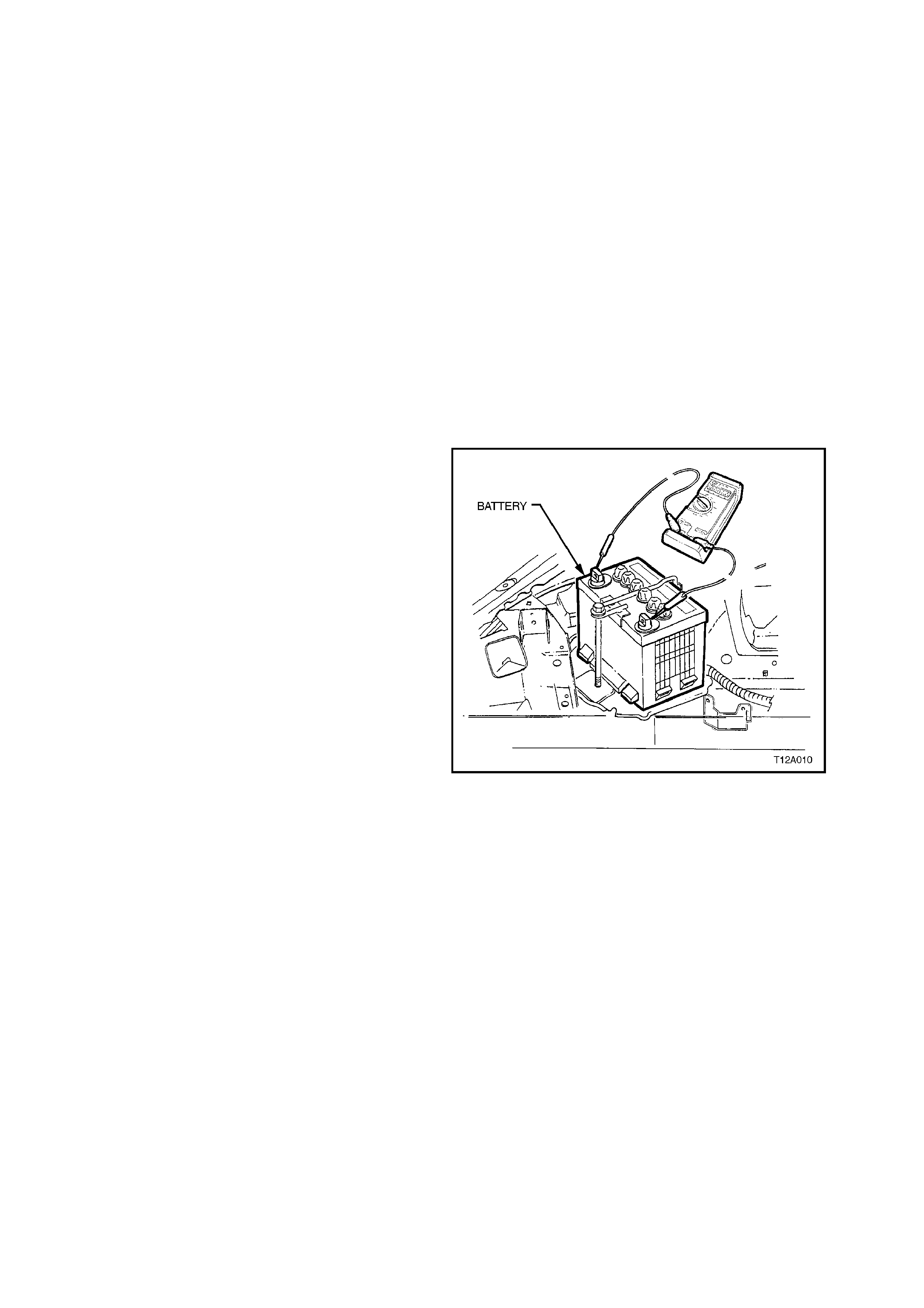
2.4 BATTERY CURRENT DRAW TEST
With all the vehicle’s electrical components turned
off there will be some small current draw from the
battery (sometimes called standing current).
The standing current is that which the vehicle
consumes when left sitting with the ignition and all
electrical consumers such as radios, etc. turned off.
If a vehicle exhibits a flat battery after an overnight
stop, or goes down after a period of two or three
days of not being used, the vehicle’s electrical
system should be checked for excessive current
draw or standing current from the battery as
follows:
1. If battery is flat, remove and temporarily install
a known good battery. Ensure vehicle starts
and its acces sories and thef t deterrent system
operate normally.
2. Ensure ignition is switched off and interior
illumination is off. Close all doors and activate
theft deterrent system to lock all doors (if
fitted).
3. Connect positive lead of an ammeter (set on
highest scale) to base of positive battery post
and its negative lead is attached to the top of
the battery positive cable terminal clamp.
NOTE:
Ensure that am m eter is capable of carrying at least
20 amps.
4. Loosen positive cable terminal clamp nut and
carefully lift positive cable from battery post
while keeping the ammeter leads connected
as per Step 4.
5. Slowly decrease ammeter scale setting and
read measurement.
6. The ammeter should read approximately
35 mA, depending on vehicle equipm ent level,
ie vehicles with ABS, SRS etc.
7. If ammeter reading is higher than specified, a
visual inspection of the vehicle should be
conducted. Check to see if there are any
unwanted lamps on (including rear
compartment lamp), motors running or
switches (relays activating).
On sedans, chec k if rear com partm ent lamp is
on by lowering rear seat back fold down tray
and inspecting inside rear compartment area.
Figure 12A-9

If no cause for the excessive standing current
draw is immediately apparent, it may be
possible to isolate the s our c e by systematic ally
removing one fuse or circuit breaker at a time
to determine which particular fuse protection
circuits are drawing current. Having
determined which circuits are drawing current,
reinstall fus e/circ uit break er and rem ove wiring
harness c onnectors from consum ers, one at a
time, on the circuits protec ted by the particular
fuse/circuit breaker and note ammeter
reading. W hen ammeter reading decreases to
35 mA or less af ter rem oving a wiring harness
connector, that particular consumer is the
cause of the current draw from the battery.
Remove the consumer and investigate cause
of why it is drawing excessive standing
current.
Refer to Section 12N FUSES AND WIRING
HARNESSES for location of all fuses.

2.5 BATTERY CHARGE
Flat batteries can safely be boost charged, but avoid excessive current if the battery is initially more than half
charged, and particularly if it is almost fully charged. Slow charging is advisable if time permits.
CAUTION:
During chargi ng, an explo siv e hydrogen and oxygen g as mixture is released by the b att ery. Ensu re th ere
are no naked flames or electrical spark discharges in the vicinity of the battery during charging.
NOTE:
a. Fast charging can substantially ‘boost’ a battery, but the fully charged condition can only be achieved by
slow charging. DO NOT USE A FAST CHARGER FOR STARTING THE VEHICLE.
b. Fast charging must not be used if:
i. Specific gravity readings are not uniform between battery cells, or are above 1.200 at the start.
ii. Electrolyte is discoloured with brown sediment.
iii. Either of the above two conditions develops after commencing fast charge.
c. The following table assumes ‘constant current’ type chargers. If a ‘constant voltage’ charger is used,
charge at 14.5 V to 15.0 V, the battery will automatically regulate the current to a safe level.
Refer to battery charger manufacturer’s specifications to check what type of charger is used and follow
manufacturer’s recommendations for battery charging.
1. Remove battery from vehicle and remove vent caps and check electrolyte level in each cell, add distilled
water if necessary to bring to the correct level.
Rest caps loosely in openings to prevent acid mist escaping.
NOTE:
Ensure that the ignition is s witched of f when connec ting or disc onnec ting battery cable terminals . F ailing to do s o
may damage vehicle electronic components.
2. Connect battery, with correct polarity, to charging apparatus and set charging current according to the
following table.
Initial Charging Current Time For Fully Discharged Battery Time For Partly Discharged Battery
Slow 4A Charge approx 24 hrs. max. Proportional to the charge at the start.
Fast 35A Charge approx 2 hrs. max.
3. After a few minutes, check electrolyte specific gravity (refer to 2.2 HYDROMETER TEST in this Section)
and colour (see previous NOTE: b. iii).
4. Monitor electrolyte temperatur e during charging pr oc edure. If temper ature r eaches 55°C, s witch of f c harging
current and allow battery to cool. Reduce charging current to prevent subsequent overheating.
For best results, batteries should be charged while the electrolyte and plates are at room temperature. A
battery that is extremely cold may not appear to accept current for several hours after starting to charge.
NOTE:
A fast c harged battery can be brought to the fully charged condition by slow charging for a few hours . Dur ing the
last few hours on charge, the current should be 1.0 amp or less.
5. Check voltage and electrolyte specific gravity once per hour. Slow charging is completed when there is no
change in voltage or electroly te specific gravity over a three hour period.
CAUTION:
Charging at more than the recommended times or currents can significantly reduce battery life.

2.6 VEHICLE WIRING - PERIODICAL CHECKS
To ens ure effic ient operation of electric al system and to saf eguard against dam age, the f ollowing check s should
be carried out periodically:
1. Check that all harness and wires are held securely by their respective retainer clips.
2. Check harness and wires for chaffing or damaged insulation and repair or replace as necessary.
3. Check that harness and wire terminals are secure.
4. Ensure battery tray, battery clamp and battery cable terminals are clean and free from corrosion.
Should battery cable terminal clamps be seriously corroded, with metal partly eaten away, replace battery
harness and investigate cause of electrolyte leakage.

2.7 DRY CHARGED BATTERY STORAGE AND ACTIVATION
Dry charged batteries are fully charged when manuf actured and contain no elec trolyte until activated f or ser vice.
The dry charged battery is completely sealed and can be stored indefinitely with no servicing until activated. To
activate a dry charged battery:
1. Remove vent caps and add electrolyte of 1.265 specific gravity to each cell until correct level is reached.
2. Several minutes after activating battery, check electrolyte level and add more electrolyte (not water) as
necessary.
NOTE:
a. After a dry charge battery is activated, it becom es a ‘wet’ battery and only distilled water should be added in
subsequent servicing.
b. Although a dry charged battery can be put into service immediately after activation, the following tests are
recommended.
i. After adding electrolyte, check open circuit terminal voltage of battery. If less than 10V, replace battery.
ii. Check specific gravity of electrolyte in each cell. If any temperature corrected reading shows more than
a 0.030 drop from initial specific gravity of electrolyte (refer to 2.2 HYDROMETER TEST in this
Section), slow charge battery before use, refer to 2.5 BATTERY, CHARGE in this Section.
iii. Check cells for violent gassing and if detected, slow charge battery before use.
2.8 BATTERY
REMOVE
NOTE:
Ensure ignition is switched off before disconnecting
or reconnecting battery cables. Failure to do so m ay
damage electronic components within the vehicle.
1. Disconnect battery cables from battery.
2. Unscrew clamp bolt and remove battery clamp.
3. Lift and manoeuvre battery from engine
compartment.
Figure 12A-10
REINSTALL
Installation is the reverse of removal procedures,
noting the following points:
1. Ensure battery tray, battery clamp and battery
cable terminals are clean and free from
corrosion before installing battery.
Should battery cable terminal clamps be
seriously corroded, with metal partly eaten
away, replace battery harness.
If necessary, remove any deposits by
scrubbing with a stiff brush and treating with a
solution of warm water and baking soda or
ammonia. Rinse off with clean water. Smear
battery posts and cable terminals with
petroleum jelly to resist corrosion.
2. Install battery and check that it rests level in
the tray. Make certain no foreign objects such
as loose nuts or stones are lying in the bottom
of the tray. Install battery cable terminal
clamps over battery posts. Figure 12A-11
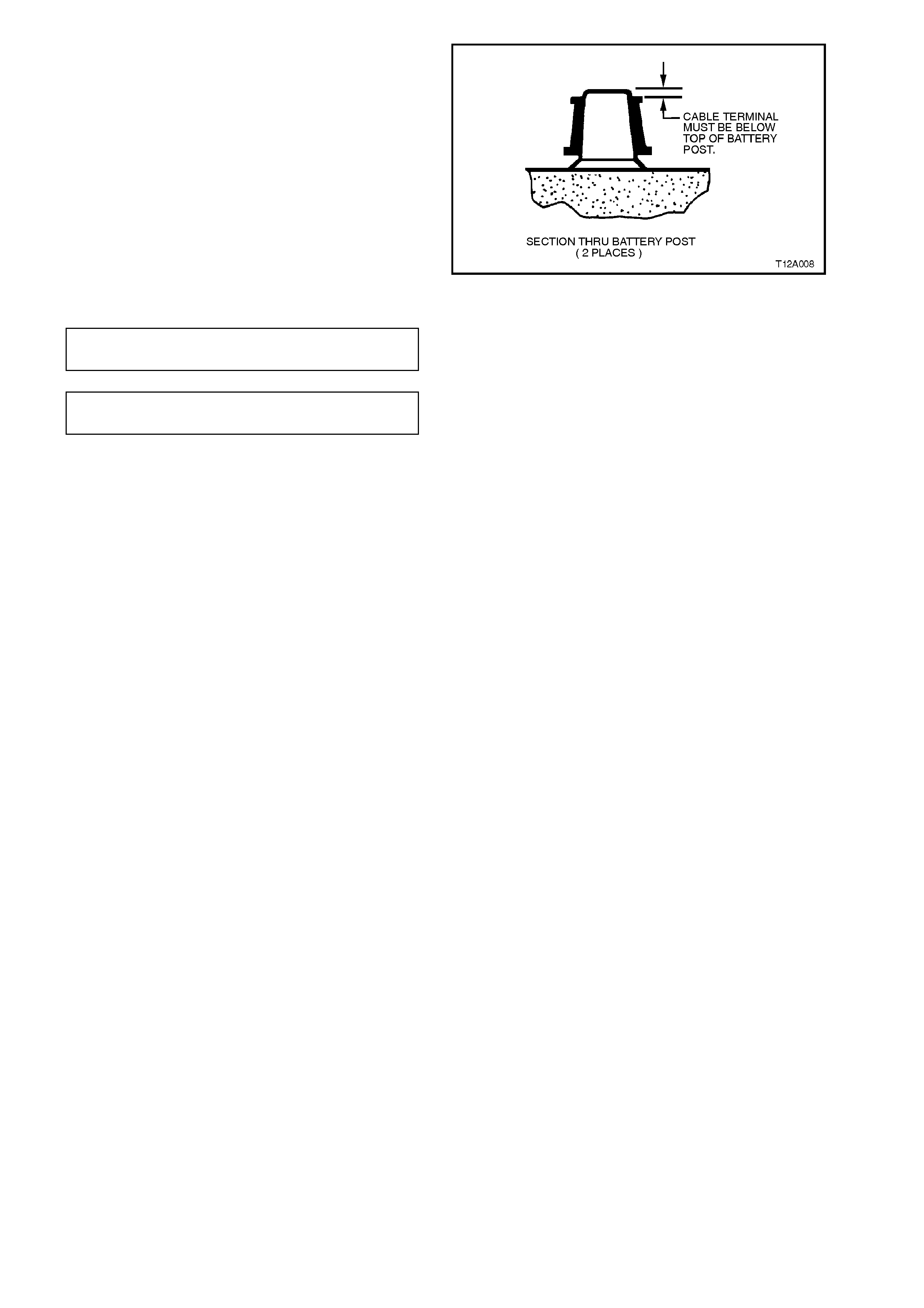
NOTE:
Ensure that cable term inals are fitted below battery
posts as shown.
Tighten battery to support tray clamp bolt and c able
terminal nuts to specified torques.
Figure 12A-12
BATTERY CLAMP BOLT
TORQUE SPECIFICATION 2.0 – 3.0Nm
BATTERY CABLE TERMINAL NUT
TORQUE SPECIFICATION 2.0 – 5.0 Nm
3. Coat battery terminals and clamps with
petroleum jelly.
2.9 EMERGENCY JUMP STARTING PROCEDURE
NOTE:
DO NOT attempt to pus h or tow the vehicle to start
it. Damage to the catalytic converter could result if
unburnt fuel were to reach the converter and
ignited.
Do not use a fast charger f or attem pting to s tart the
vehicle.
Both booster (auxiliary) and discharged battery
should be treated carefully when using jumper
cables.
W hen using the f ollowing procedur e, be careful not
to cause any sparks.
CAUTION:
Departure from these conditions or the
following procedure could r esult in:
1. Serious personal injury (particularly to
eyes) or property damage from such
causes as battery explosion, battery acid
or electr ical burns, and/or
2. Damage to electronic components of either
vehicle.
Never expose the battery to open flame or
electric spark as batteries generate hydrogen
gas which is explosive.
Remove rings, watches or other jew ellery. Wear
approved eye protection.
Do not allow battery fluid to contact eyes, skin,
fabrics, or painted surfaces as the fluid is a
corrosive acid. Flush any contacted area with
water immediately and thoroughly, and get
medical attention.
Take care so as to ensure metal too ls or jumper
cables do not contact the positive battery
terminal (or metal in contact with it) and any
other metal on the vehicle, because a short
circuit could occur.
1. Position the two vehicles so that they are NOT
touching and apply the park brak es. Autom atic
transmission are to be placed in PARK and
manual transmissions placed in NEUTRAL.
Turn off the ignition, lights and all other
electrical loads.
NOTE:
Ensure that booster vehicle’s battery has a 12 volt
rating and has negative earth connection, otherwise
serious injury or damage to electrical equipment
may result .
2. On both batteries, check that vent caps are
tight. Place a wet cloth (if available) over vents
caps of each battery.
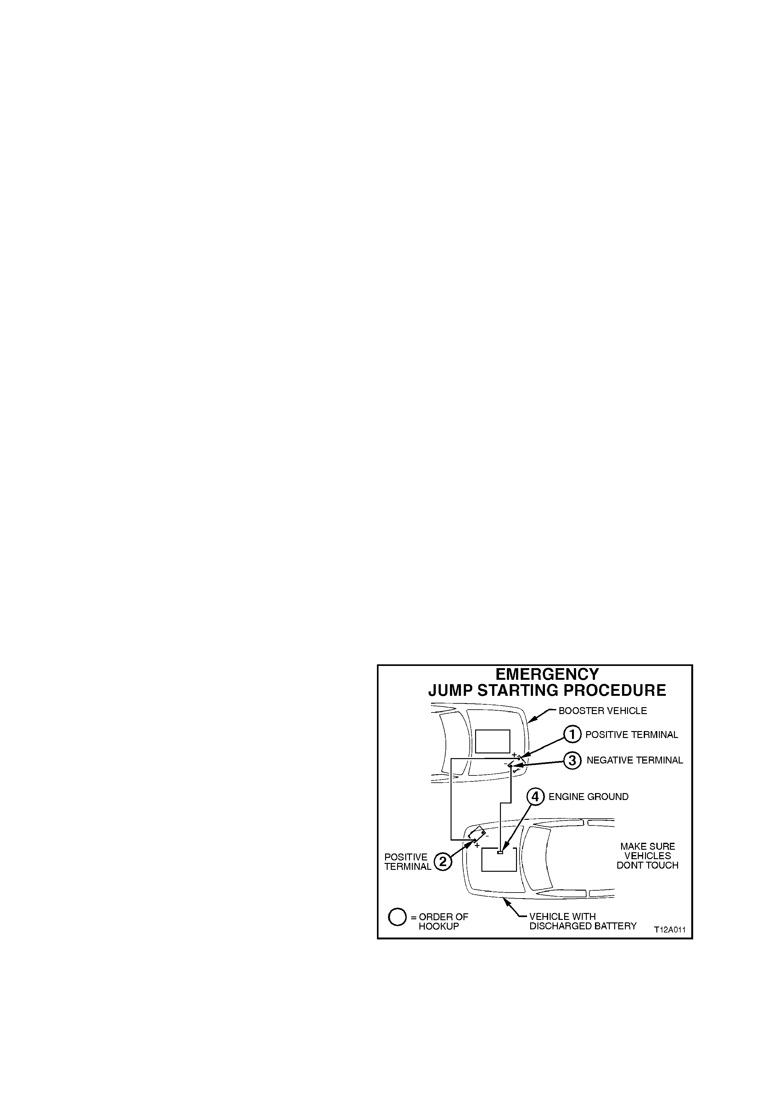
3. Attach one end of one jumper cable (red) to
the positive terminal of the booster battery and
the other end of the s am e cable to the positive
terminal of the discharged battery.
4. Attach one end of the second jumper cable
(black) to the negative terminal of the booster
battery and the other end to a solid stationary,
me tallic point on the engine of the vehicle with
the discharged battery. DO NOT CONNECT
DIRECTLY TO NEGATIVE POST OF
DISCHARGED BATTERY.
Figure 12A-13

5. After making all connections, ensure that
jum per c ables are not on or near drive pulleys,
cooling fans or other points that will move
when the engine is started.
6. Start the engine in the vehicle with the booster
battery and run the engine at a moderate
speed for a few minutes.
7. Start the engine in the vehicle with the
discharged battery. Once engine starts, allow
both engines to idle for approximately five to
ten minutes (this allows both vehicles electrical
systems to balance) and then leave running
and remove the jumper cables by reversing
the installation sequence. When removing
each clamp, take care that it does not touch
any other metal while the other end remains
attached.
NOTE:
If engine in the vehicle with discharged battery does
not start within 30 seconds, stop cranking the
engine and check for cause of engine not starting.
8. Finally, discard the wet cloths covering vent
caps of both batteries.

3. DIAGNOSIS
STEP ACTION VALUE YES NO
1. •Check battery is correct size
recommended for vehicle.
•Refer to the specifications at end of
this Section for recommended
sizes.
•Battery correct size?
Go to Step 2 Fit correct size
2. •Check for obvious damage such as
cracked or broken case, terminal
damage, etc.
•Battery OK?
Go to Step 3 Fit new battery
3. •Check electrolyte level
•Level OK? Go to Step 4 Go to Step 5
4. •Battery may have failed due to over
charge.
•Check open circuit voltage.
•Above 12.4 V
Go to Step 6 Go to Step 7
5. •Check generator voltage output Is output
voltage
14.5 ± 0.2
@ 20ºC
Go to Step 4 Fit new battery
6. •Load test battery, noting the
following points:
•For fixed type load tester set to
battery range or for variable load
tester set to current as per
specifications.
•Apply load for 10 seconds. Read
tester just before releasing load.
Voltage
reading
more than
9.6 V
Battery serviceable
check for other
faults.
Battery not
serviceable. Replace
with correct battery
7. •Recharge battery, refer to 2.5
BATTERY CHARGE in this Section
for charging current and time
specifications.
•Did battery fail to accept charge or
is open circuit voltage below 12.4 V
after charging?
Battery not
serviceable.
Replace with new
correct battery.
Go to Step 8
Go to Step 6
8. •Start engine.
•Does engine start? Go to Step 9 Recheck vehicle and
retest battery
9. •Test voltage regulator with engine
running at half throttle. Read
terminal voltage. Wait until voltage
is stable.
Is reading
between
14.1 &
14.4
volts?
Reading at
optimum level for
long battery life
Voltage regulator
fault, rectify.
Improper charging
cause of battery
failure.
After the battery has been charged or tes ted and has proven to be in good condition, the caus e of a no-start or
slow cranking condition must be determined in order to avoid further customer complaint. If no obvious cause is
evident, the vehicle’s electrical system should be diagnosed using the following steps.
Step 1: Check Starting System
If the battery tested OK on a load test (refer to 2.3 LO AD TEST in this Sec tion) and the engine s till will not turn
over or is difficult to start, the starting system should be checked. If there are no problems with the engine
turning over on the starter motor, proceed to STEP 2.
To check the starting system to verify proper operation, a simple cranking test can be done as follows:
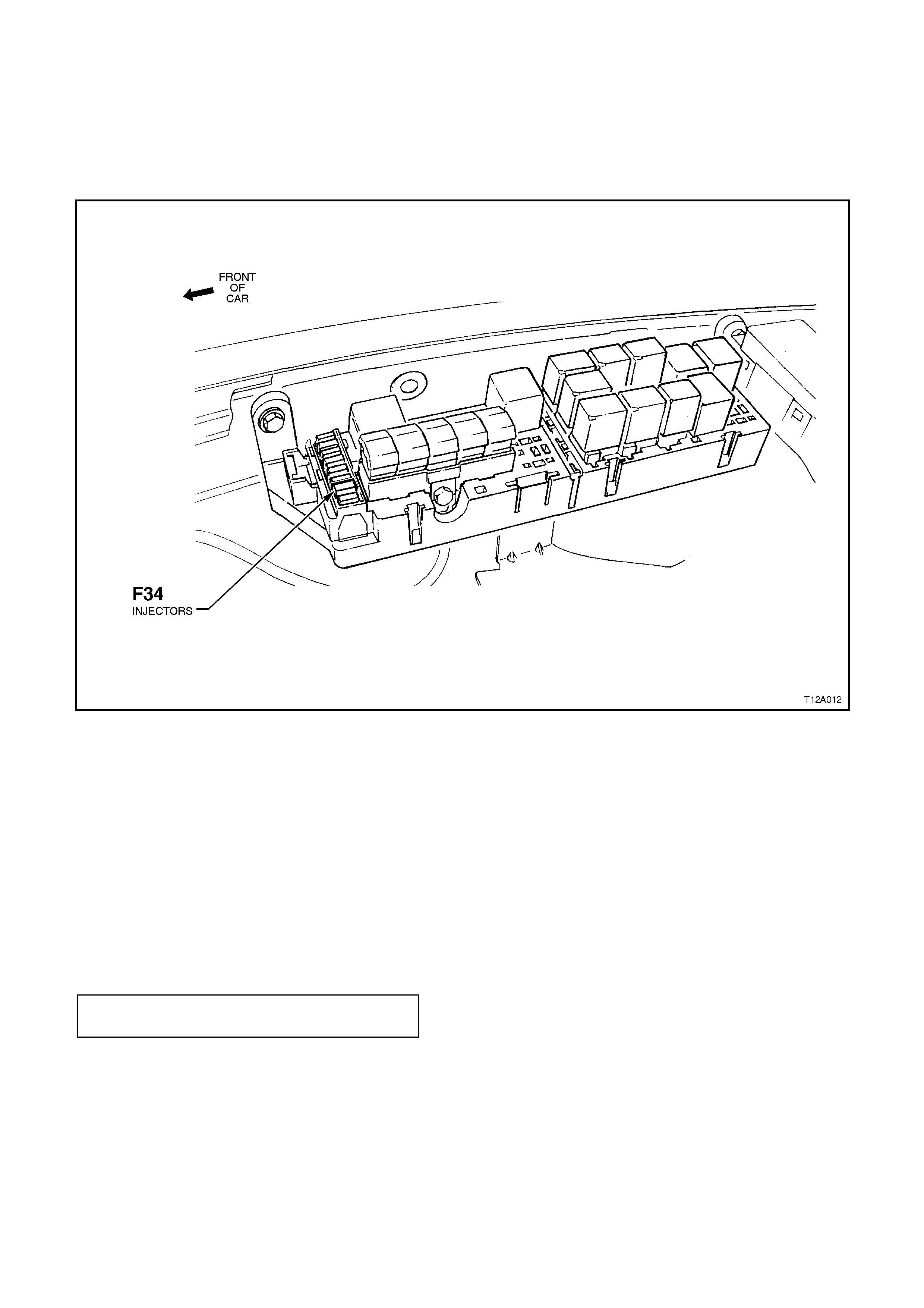
1. To prevent vehicle ignition and fuel injection while cranking the engine, remove fuse F14 from the
passenger compartment fuse and relay housing.
2. Connect a voltmeter from positive (BAT) terminal of starter motor to a good earth connection.
3. Turn ignition key to ‘START ’ position and read voltmeter while cr anking, using c are not to r un s tarter motor
continuously for more than 30 seconds. If starter motor is run for more than 30 seconds, it must be
allowed to cool for at least three minutes before recranking, to avoid damage to the starter motor.
4. If voltage noted in operation 3 is less than 9.6 volts @ 21ºC during cranking and the battery has already
check ed OK, an exces sive current draw from the starter m otor or an ex cessive voltage drop in the batter y
cables could be the cause of the low cranking voltage: proceed to operation 5.
If voltage measured while cranking is greater than 9.6 volts (i.e. Starting system OK), proceed to Operation
6.
Figure 12A-14
5. Check starter motor operation, refer to
Section 6D1-2 ENGINE ELECTRICAL -
STARTING SYSTEM - V6 ENGINE or
Section 6D2-2 ENGINE ELECTRICAL -
STARTING SYSTEM - V8 ENGINE.
Check routing of battery cables (refer to
Figures 12A-4 and 12A-5 in this Section) in
order to check for excessive cable resistance
or poor connections.
Ensure that battery terminal mating surfaces
are clean and cable terminal clamp nuts are
tightened to the correct torque specification.
BATTERY CABLE TERMINAL NUT
TORQUE SPECIFICATION 2 - 5 Nm
6. Reinstall fuse F34 to engine compartment relay
housing.

7. If starting system tests reveal no abnormal conditions, but excessive cranking is required to start the vehicle,
the cause should be diagnosed and corrected to reduce battery demands. Two possible causes for
excessive long cranking time are problems with the engine fuel system or ignition system. Refer to
Section 6C1 POWERTRAIN MANAGEMENT - V6 ENGINE, or Section 6C2 POWERTRAIN
MANAGEMENT - V8 ENGINE for diagnostic procedures.
Step 2: Check Battery Current Draw
Carry out battery current draw test, refer to 2.4 BATTERY CURRENT DRAW TEST in this Section.
Step 3: Check Charging System
A charging system problem may keep the battery sufficiently charged during norm al operation, but may not be
able to sustain the elec tric al s ystem dur ing prolonged per iods of dr iving a number of ac c ess or ies, air conditioner ,
heated rear window, etc. It is for this reason the charging system should be checked, refer to
Section 6D1-1 ENGINE ELECTRICAL - CHARGING SYSTEM - V6 ENGINE or Section 6D2-1 ENGINE
ELECTRICAL - CHARGING SYSTEM - V8 ENGINE.
Step 4: Driver Related Condition
If no cause is found for a discharged battery and the battery tests OK, a lamp may have been left on, or the
driving habits of the vehicle owner may be such that, especially with many short trips and repeated starts, the
generator does not get a chance to recharge the battery between starts.
If this situation is suspected, the vehicle owner should be instructed in ways to reduce battery drain.
With the increased use of electronic sensors and computer control, the battery is much more than just a
component used to start a car. Low battery voltage can affect the operation of a vehicle’s PCM and cause
annoying driveability problems. Low battery voltage can cause the PCM to set a diagnostic trouble code. If a
PCM senses low battery voltage, the PCM can also adjust fuel injector timing for increased engine rpm in order
to produce greater charging current from the generator.
A battery with a low state of charge can, therefore, cause a number of poor driveability symptoms. This should be
taken into consideration any time a customer complains of a driveability-related problem. Always check the
condition of the battery before beginning a full driveability diagnosis procedure.

4. SPECIFICATIONS
VT EXECUTIVE MODELS WITH V6 ENGINE
Rated Voltage 12 Volts
Charge Acceptance 10 Amps minimum
Rapid Discharge Current (RCC) 350 Amps minimum
Reserve Capacity (RRC) 75 minutes minimum
20 Hour Discharge 50 Amp Hour minimum
5 Second Voltage @ 25o C 150 Amp 10.4 +/- 0.2 volts
400 Amp 8.4 +/- 0.2 volts
Number of Plates (per cell) 9
NOTE:
Specified ratings when tested in accordance with Australian Standard AS 2149-1990
VT MODELS WITH V8 ENGINE AND BERLINA, CALAIS WITH V6 ENGINE
Rated Voltage 12 Volts
Charge Acceptance 10 Amps minimum
Rapid Discharge Current (RCC) 400 Amps minimum
Reserve Capacity (RRC) 95 minutes minimum
20 Hour Discharge 55 Amp Hour minimum
5 Second Voltage @ 25o C 150 Amp 10.6 +/- 0.2 volts
400 Amp 8.4 +/- 0.2 volts
Number of Plates (per cell) 11
NOTE:
Specified ratings when tested in accordance with Australian Standard AS 2149-1990

5. TORQUE WRENCH SPECIFI CATIONS
Nm
Battery to Support Tray Clamp Bolt 2 - 3
Battery Cable Terminal Nut 2 - 5