
SECTION 12B - LIGHTING SYSTEM
CAUTION:
This v ehicle will be equipped with a Supplemental Restraint System (SRS). A SRS
will consist of either seat belt pre-tensioners and a driver’s side air bag, or seat
belt pre-tensioners and a driver’s and front passenger’s side air bags. Refer to
CAUTIONS, Section 12M, before performing any service operation on or around
SRS components, the steering mechanism or wiring. Failure to follow the
CAUTIONS could result in SRS deployment, resulting in possible personal injury
or unnecessary SRS system repairs.
CAUTION:
This vehicle may be equipped with LPG (Liquefied Petroleum Gas). In the interests
of safety, the LPG fuel system should be isolated by turning 'OFF' the manual
service valve and then draining the LPG service lines, before any service work is
carried out on the vehicle. Refer to the LPG leaflet included with the Owner's
Handbook for details or LPG Section 2 for more specific servicing information.
1. GENERAL DESCRIPTI ON
The front lamp assemblies on VT Series Models comprise a sem i-sealed headlamp and a turn signal lamp and a
parking lamp.
For all VT models, the parking lamp is in the headlamp assembly with the turn signal next to it.
The headlamp features a dual pocket reflector, quartz halogen bulbs and a parking lamp bulb. The reflector is of
homofocal design, with both inner and outer pockets used for high beam.
The turn signal lamp has a c lear appear anc e lens. The illumination bulb has a orange c olour ed glass and has of f s et
locating pins on its base.
Fitted into each front fender, is a turn signal side repeater lamp assembly.
The rear lamp ass emblies f or the station wagon compr ise a turn signal lamp, s top and tail lam p and back -up lamp
in one unit. All sedan vehicles have a rear quarter lamp housing with stop/tail and turn signal bulbs. For Calais the
turn signal bulb glass is coloured orange and has off set locating pins. T he orange c oloured bulb glas s provides the
amber light behind the clear lamp lens. The bulb used for Commodore Executive, Berlina, S and SS models has
clear glass and standard parallel locating pins, which illuminates an amber lens.
Also, different rear quarter lamp harnesses with specific bulb sockets are used for each type of bulb locating pin
style.
All sedan models have separate decklid lam ps with back-up lam p bulb and an additional tail lamp bulb is provided
for Berlina and Calais. The rear licence plate lamps are specific for sedan and station wagon models.
On sedan models, the licence plate lamps are located in the rear compartment lid decor panel, above the licence
plate. Station Wagon has two lamps attached to the tailgate lock trim assembly.
Specific style fog lamps are fitted to the front bumper bar assembly for Calais and SS Models as standard
equipment.
The fog lamps are controlled by a switch assembly located in the instrument facia, below the headlamp switch.
The fog lamps operate when the headlamps are switched on and the fog lamp switch button depressed. If the
headlamps are operating on high beam, switching on the fog lamps turns the headlamp low beam off. If the
headlamps are on low beam, they remain on when the fog lamps are switched on.
All vehicles are fitted with hazard warning flashers, which are operated by a switch in the instrument facia, located
below the air outlets.
All vehicles are fitted with courtesy lamps in the passenger compartment (dome lamp), ignition lock and glove
compartment. Additional interior lighting, depending on vehicle type, is provided by courtesy lamps in door trims,
front and rear footwells, rear compartment, front reading lamp assemblies, rear reading lamps and console bin
lamp.
Operation of the parking/tail and headlamps is controlled by a headlamp switch located in the instrument facia, to
the right of the steering wheel. Headlamp high beam or headlamp flash control is by the headlamp and turn signal
control switch stalk to the right of the steering column.
In conjunction with the headlamp, fog lam p and headlamp and turn signal control switches, various relays, located
in the engine compartment relay housing and passenger com partment fuse panel, are used for headlamp, hazard
warning, turn signals and fog lamp control.
Techline

Turn signal control is by the headlamp and turn signal control switch stalk to the right of the steering column.
Stop lamps operation is controlled by a stop lamp switch fitted into a tubular clip in the brake pedal support.
Back-up lamp operation is controlled by the switch screwed into left hand the side of the transmission case for
manual transmission, or by the neutral start/back-up lamp switch (vehicles with automatic transmission) which is
attached to the side of the gearshift assembly, beneath the console cap.
There are two series of Body Control Module (BCM) installed in VT Series Com m odor e, and selection is dependent
on model s tyle. Comm odore Exec utive is f itted with the Low Series BCM while Berlina and Calais ar e f itted with the
High Series BCM. The BCM provides additional lighting system enhancements. These features are:
1. Automatic Lights Off.
This system deactivates the head and park/tail lamps when the ignition has been switched from on to off and the
drivers door is opened. The lamps switch back on when the ignition is switched on, if the headlam ps switch is still
turned on. On Berlina, Calais, an adjustable time delay can be applied before the headlamps are automatically
switched off.
2. Dome Lamp Delay.
Additional control of the dom e lam p operation by the BCM allows for 30 second delay period to turn the dom e lam p
off after all doors are closed. On vehicles with High Series BCM, should the dome lamp be left on by the dome lamp
switch, and with ignition off, the BCM will turn off the dome lamp after a maximum period of two hours to prevent
battery drain.
On vehicles with High Series BCM, additional features include:
3. Instrument Dimming Control.
Incorporated in the headlamp switch assembly is a control for variable instrument cluster illumination intensity.
4. Rear Lamp Failure Warning System (High Series BCM only).
This system checks for bulb or fuse failure associated with the stop or tail lamps including the high level stop lamp.
For additional information on these systems, including diagnostics, refer Section 12J-1, LOW SERIES BODY
CONTROL MODULE or Section 12J-2, HIGH SERIES BODY CONTROL MODULE.
2. SERVICE OPERATIONS
2.1 AIMING OF HEADLAMPS AND FOG LAMPS
The headlamps and fog lamps (if fitted) must be
correctly aimed in order to obtain the maximum
road illum ination and safety that has been built into
the vehicle lighting system . The headlam ps and f og
lamp s m us t be chec ked for c orr ec t aim whenever a
bulb or headlamp/fog lamp assembly is replaced,
and after any adjustments or repairs to the front
end sheet metal.
Headlamp aiming machines are in general use.
When using one of these machines, ensure that it
is in good condition and carefully follow the
instructions of the manufacturer.
Regardless of the method used for checking
headlamp and fog lam p aim, the vehic le must be at
kerb weight, that is, with fuel, oil, water and spare
tyre but no passengers. The tyres must be
uniformly inflated to their specified pressure.
NOTE:
If the vehicle will regularly carry an unusual load in
the rear compartment or tow a trailer, these loads
should be on the vehicle when the headlamps/fog
lamps are checked.
HEADLAMP AIM
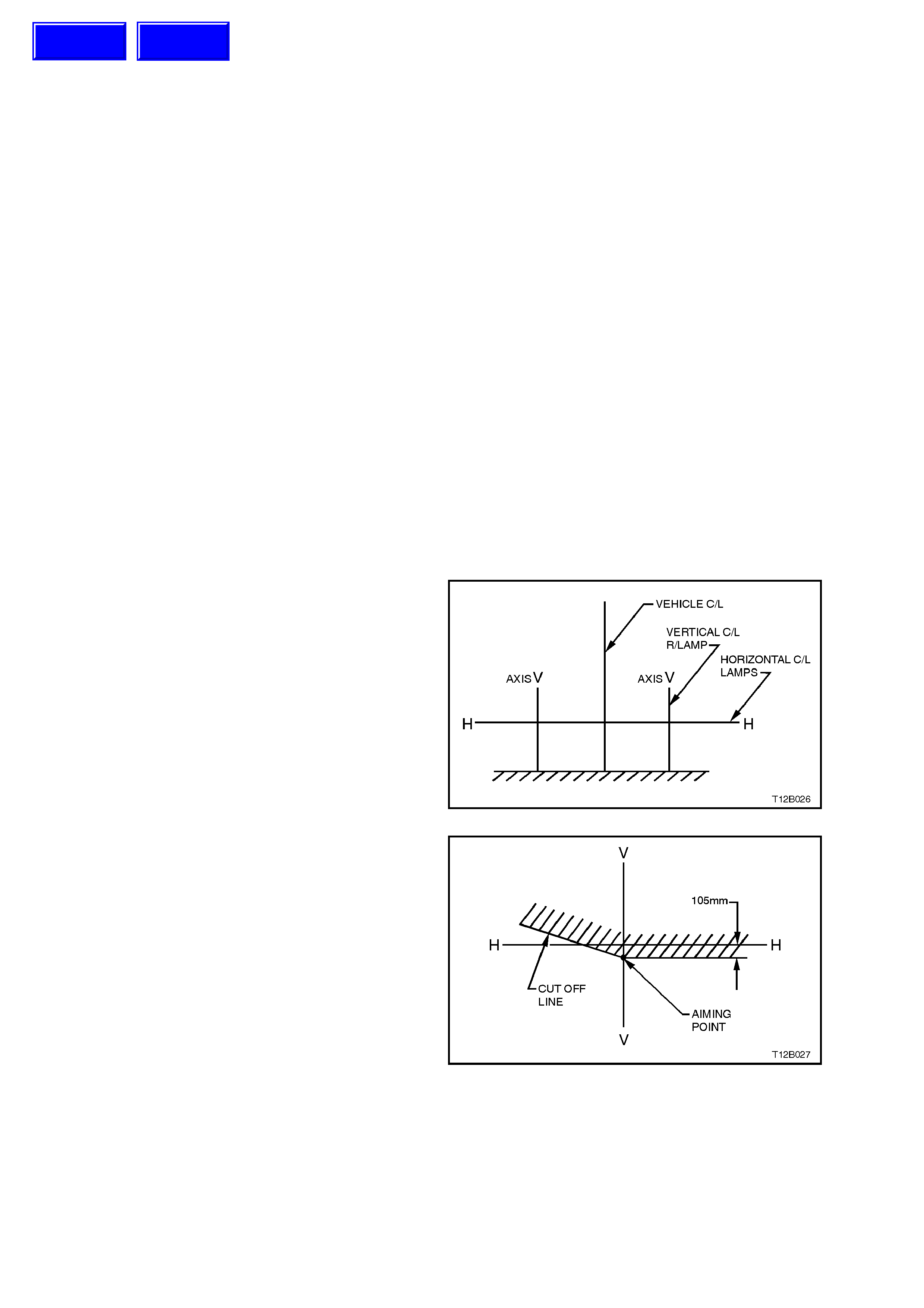
1. If suitable test equipment is not available, set
up a screen or use vertic al wall, in conjunction
with a flat horizontal floor. Park vehicle
immediately in front of screen and mark
horizontal and vertical centre lines of left and
right headlam ps, and vehic le c entre line on the
screen or wall.
2. Park vehicle 7.6 metres in front of screen or
wall ensuring the vehicle is aligned with
vehicle centre line mark on screen.
Figure 12B-1
3. Individually aim each headlamp to a point on
its vertical centre line, 105 mm below the
headlamp horizontal centre line.
Figure 12B-2
a. Adjust inboard adjuster to achieve correct
vertical beam height.
b. Adjust outboard adjuster to centralise beam.
Aiming directions for each adjuster are visible on
the headlamp assembly.
Techline
Techline
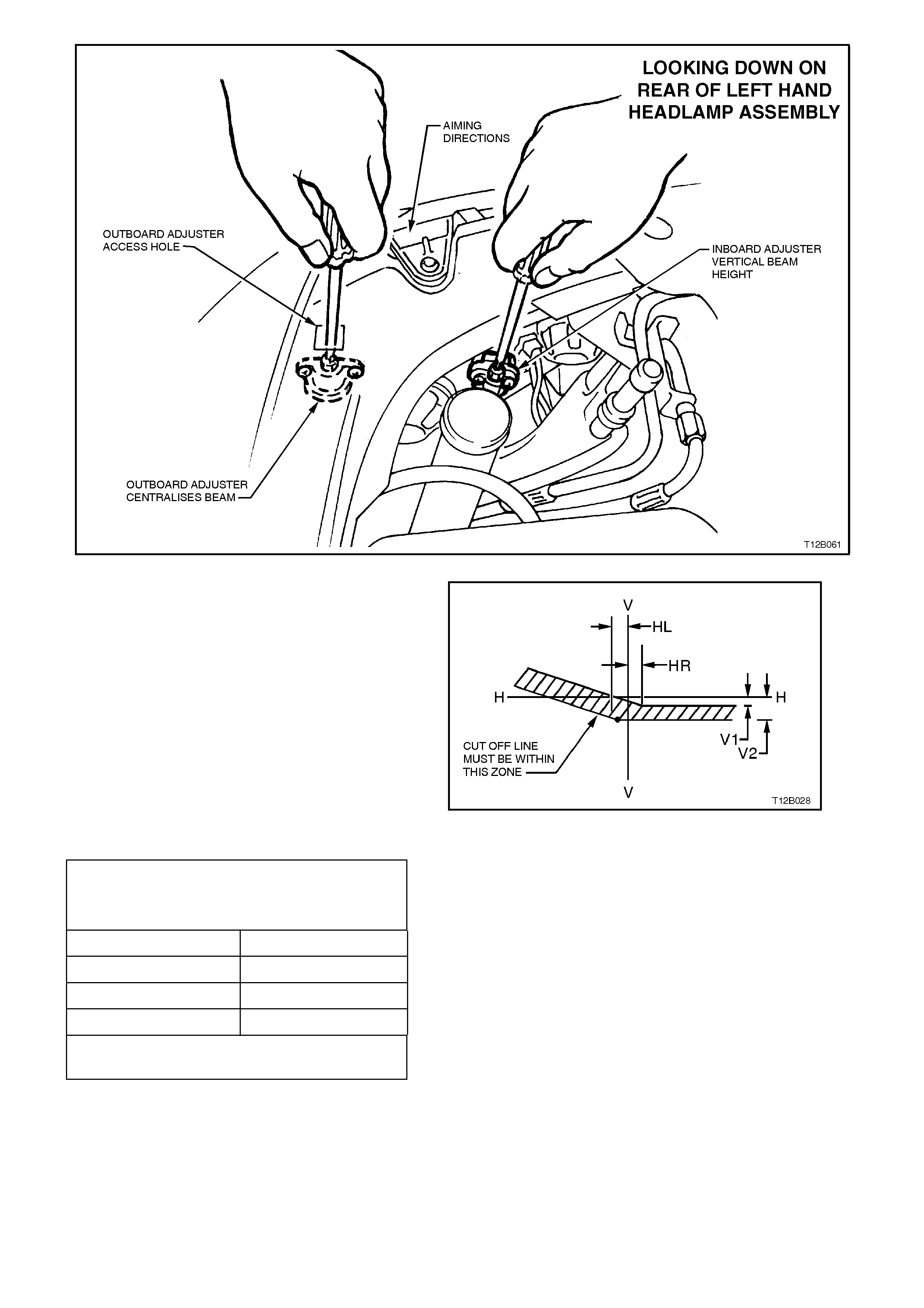
Figure 12B-3
4. The allowable variations on headlamp aiming
point settings shown in Fig. 12B-1 are
specified as follows:
Figure 12B-4
HE ADLAMPS AIMING.
ACCEPTABLE VARIATIONS IN HEADLAMP
AIMING POINTS
HL 100 mm
HR 0 mm
V1 95 mm
V2 115 mm
Maximum Allowable Vertical Variation Between
Any Pair Of Headlamps Is Not To Exceed 20 mm
FOG LAMP AIM
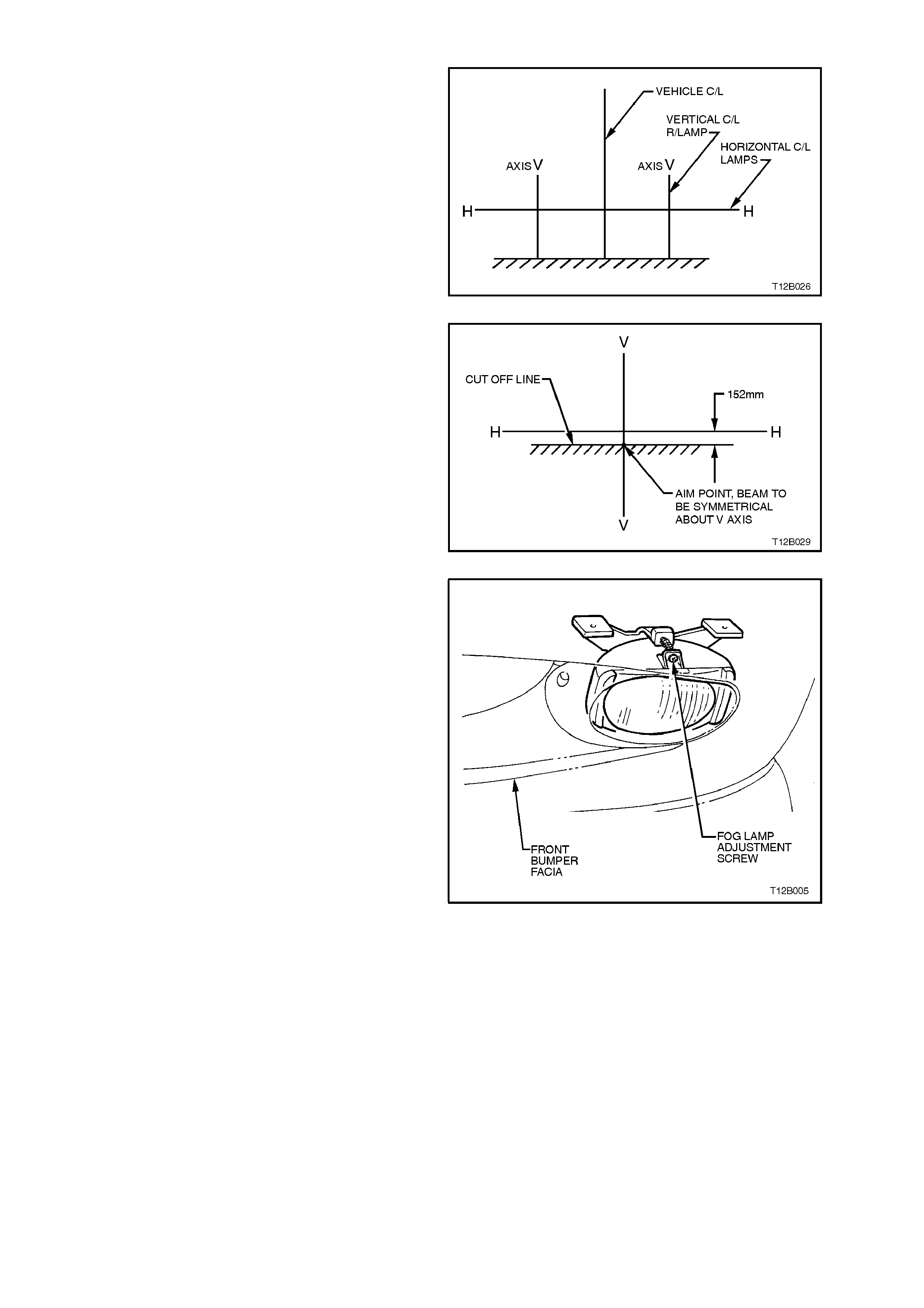
1. If suitable headlamp aiming check equipment
is not available, set up a screen or use a
vertical wall, in conjunction with a flat
horizontal floor. Park vehicle immediately in
front of screen and mark horizontal and
vertical centre lines of left and right
headlamps, and vehicle centre line on the
screen.
2. Park vehicle 7.6 metres in front of screen,
ensuring the vehicle is aligned with centre line
mark on screen.
Figure 12B-5
3. Check headlamp aim and adjust as required,
refer previous instructions.
4. W ith headlamps turned on low beam, turn fog
lamps on. Individually aim each fog lamp to a
point symmetrical about ‘V’ axis and 152 mm
below headlamp horizontal centre line.
Figure 12B-6
NOTE:
There is no pr ovis ion f or hor izontal adjustment. Fo g
lamps are fixed to vertical centreline.
Fog lamp aim adjustment is by rotating the
adjuster at the front of the lamp housing.
Turning the adjuster anti-clockwise lowers the
beam, turning clock wise raises the beam . The
adjustment is made using a No. 2 ‘Philips
Head’ screw driver.
Figure 12B-7
2.2 HEADLAMP BULB
REPLACE
1. Open engine compartment.
Driver’s side headlamp only
V6 engine models:
Disconnect battery terminals, remove battery
retaining clam p and m anoeuvre batter y to gain
access to headlamp dust cap.
V8 engine models:
Disconnect battery terminals, remove battery
retaining clamp and remove battery from
engine compartment.
Driver’s and passenger side
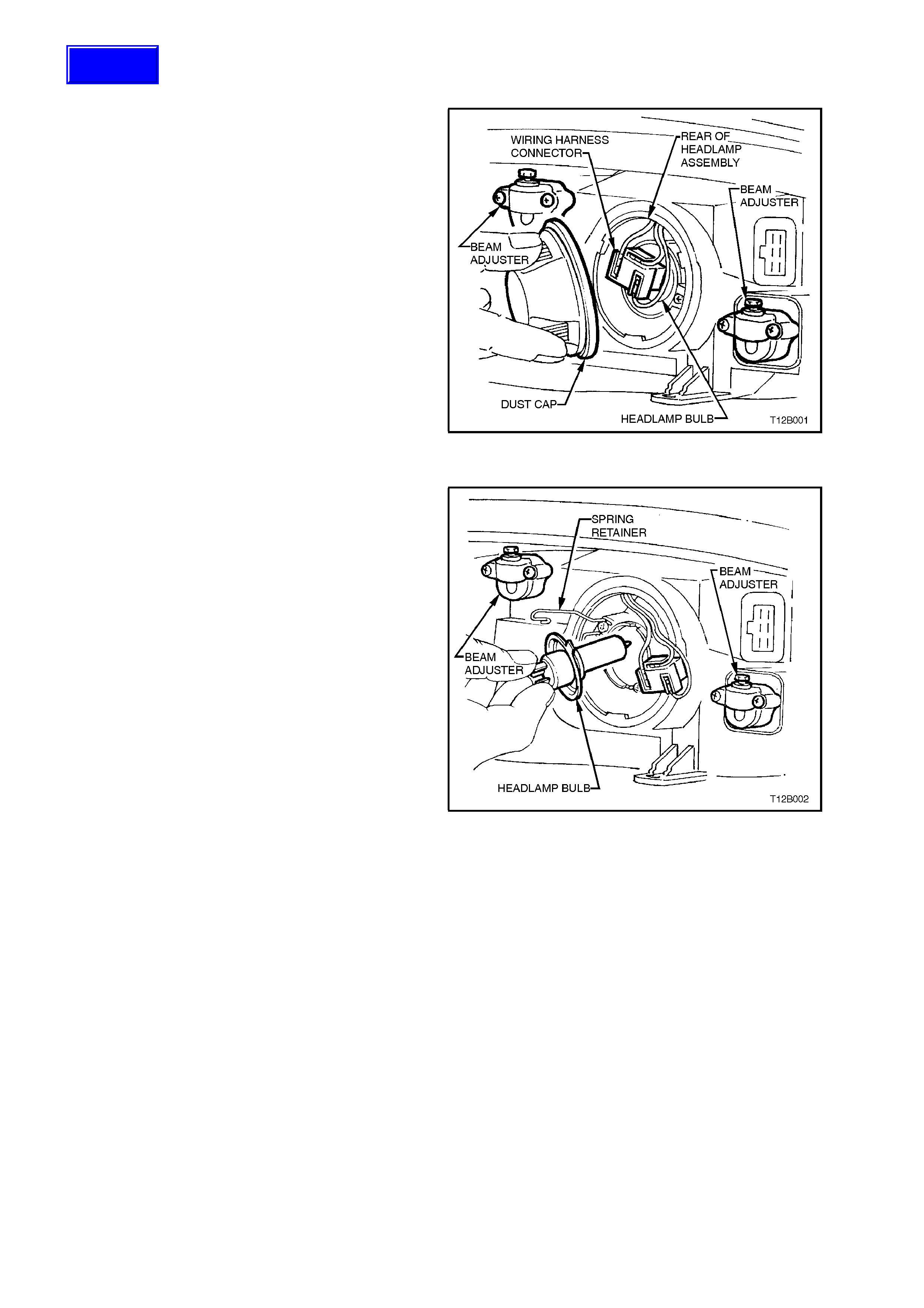
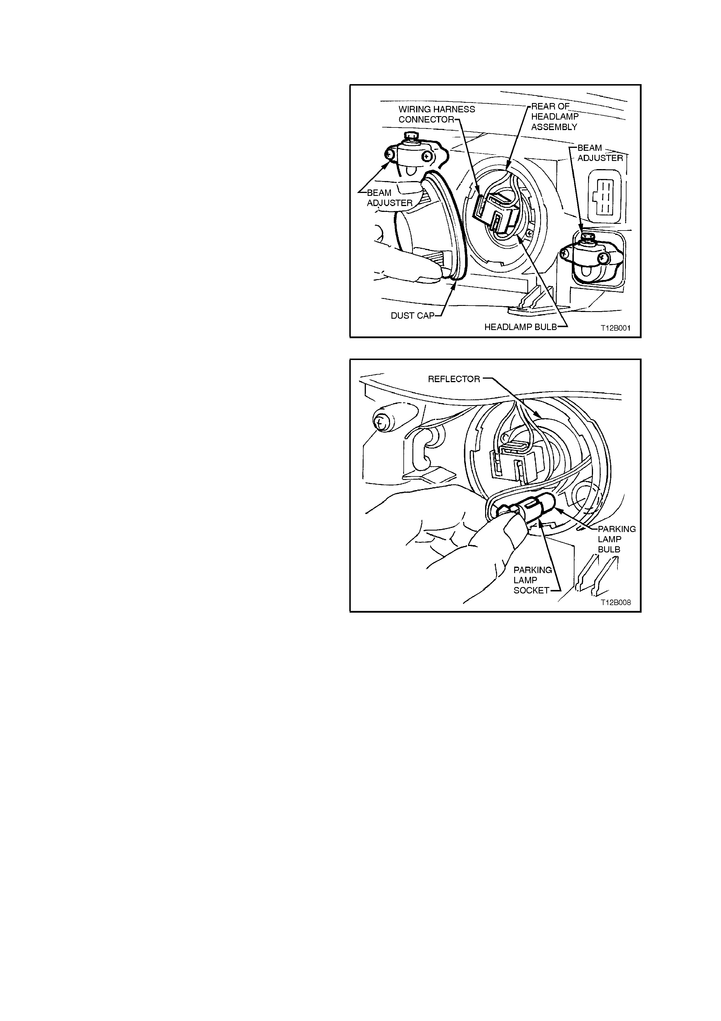
2. From inside engine compartment, remove
dust cap from rear of headlamp housing
assembly by turning dust cap anti-clockwise,
and pull away from housing. If dust cap seal
stays on headlamp housing, remove seal and
install onto cap.
3. Carefully pull wiring harness connector from
rear of bulb.
Figure 12B-8
4. Depress and unclip bulb spring retainer and
pivot clear of bulb. Remove bulb from
reflector.
NOTE:
Do not handle quartz envelope of headlam p bulb. If
touched accidentally, wipe immediately with
methylated spirits or bulb performance will
deteriorate.
5. Refit new bulb into reflector, ensuring correct
mating of bulb base locating tangs with
reflector cut-outs. Refit spring retainer and
wiring harness connector.
NOTE:
The different sized locating tangs on the bulb base
and mating cut-outs in the reflector will allow the
bulb to seat correctly into the reflector in one
location only. This ensures correct relationship of
the bulb to the reflector.
6. Inspect rubber seal in dust cap to ensure that
it is not dam aged and that it is s eated c orr ec tly
in cap. Replace seal if damaged.
7. Install cap to rear of headlamp housing with
cap tang located facing down. Lock cap into
place by turning clockwise.
Driver’s side only
Reinstall battery if removed, secure battery
retaining clamp and reconnect battery
terminals.
Driver’s and passenger sides
8. Check headlamp operation and re-aim
headlamps (headlam p aim varies from bulb to
bulb), refer to 2.1 AIMING OF HEADLAMPS
AND FOG LAMPS in this Section.
Figure 12B-9
Techline
2.3 PARKING LAMP BULB
REPLACE
1. Open engine compartment hood.
Driver’s side headlamp only
V6 engine models:
Disconnect battery terminals, remove battery
retaining clam p and m anoeuvre batter y to gain
access to headlamp dust cap.
V8 engine models:
Disconnect battery terminals, remove battery
retaining clamp and remove battery from
engine compartment.
Driver’s and passenger side
2. From inside engine compartment, remove
dust cap from rear of headlamp housing
assembly by turning dust cap anti-clockwise,
and pull away from housing. If dust cap seal
stays on headlamp housing, remove seal and
install onto cap. Figure 12B-10
3. Remove parking lamp socket from reflector.
Alternatively, use pointed nose pliers to pull
out parking lamp socket if access is difficult.
Pull bulb from socket.
4. Insert new bulb into soc k et and r eins tall s ocket
into reflector.
5. Inspect rubber seal in dust cap to ensure that
it is not dam aged and that it is s eated c orr ec tly
in cap.
Install cap to rear of headlamp housing and
lock cap into place by turning clockwise.
Driver’s side only
Reinstall battery if removed, secure battery
retaining clamp and reconnect battery
terminals.
Driver’s and passenger sides
6. Check parking lamp operation. Figure 12B-11

2.4 INBOARD HIGH BEAM BULB
REPLACE
1. Open engine compartment.
Driver’s side headlamp only
V6 engine models:
Disconnect battery terminals, remove battery
retaining clam p and m anoeuvre batter y to gain
access to headlamp dust cap.
V8 engine models:
Disconnect battery terminals, remove battery
retaining clamp and remove battery from
engine compartment.
Driver’s and passenger side
2. From inside engine compartment, remove
inboard high beam dust cap from rear of
headlamp housing assembly by turning dust
cap anti-clockwise, and pull away from
housing. If dust cap seal stays on headlamp
housing, remove seal and install onto cap.
3. Disconnect harness connector from bulb.
Depress and unclip bulb retaining clip to
release, and allow to fall c lear of bulb. Pull out
bulb.
Figure 12B-12
4. Install new bulb into reflector, ensuring that
locating lug on bulb housing aligns with squar e
edge on bulb and locating lugs on bulb mate
with holes on bulb housing. Reconnect bulb
retaining clip. Connect bulb harness
connector.
NOTE:
Do not handle quartz envelope of inboard high
beam bulb. If touched accidentally, wipe
immediately with methylated spirits or bulb
performance will deteriorate.
5. Inspect rubber seal in dust cap to ensure that
it is not damaged and that it is seated
correctly. Reinstall dust cap onto rear of
headlamp housing and lock into place by
turning clockwise.
Driver’s side only
Reinstall battery if removed, secure battery
retaining clamp and reconnect battery
terminals.
Driver’s and passenger sides
6. Test operation of inboard high beam lamp
bulb.
Figure 12B-13
2.5 FRONT TURN SIGNAL LAMP BULB
REPLACE
NOTE:
If replacing a front turn signal lamp bulb, ensure
the correct type is fitted. For all models, the bulb
glass is coloured orange and has offset locating
pins.
1. Open engine compartment.
Driver’s side headlamp only
V6 engine models:
Disconnect battery terminals, remove battery
retaining clam p and m anoeuvre batter y to gain
access to headlamp dust cap.
V8 engine models:
Disconnect battery terminals, remove battery
retaining clamp and remove battery from
engine compartment.
Driver’s and passenger side
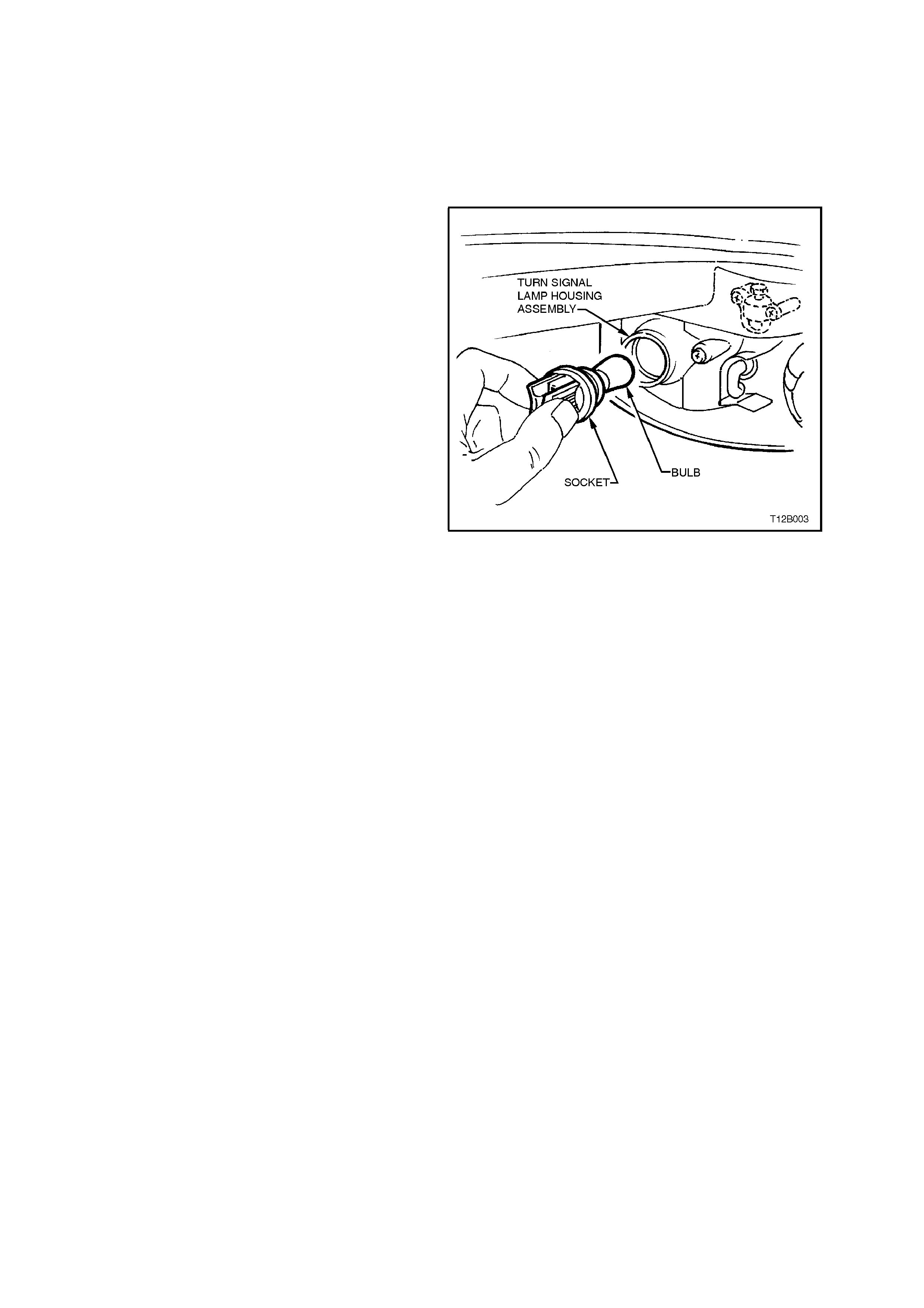
2. From inside engine compartment, twist to
release bulb socket from behind headlamp
assembly.
3. Depress bulb into socket and rotate to
remove.
4. Inspect O-ring on bulb socket for dam age and
correct seating. Replace O-ring if necessary.
5. Install new bulb into socket, install socket into
housing and twist to lock into position.
Driver’s side only
Reinstall battery if removed, secure battery
retaining clamp and reconnect battery
terminals.
Driver’s and passenger sides
6. Check turn signal lamp operation.
Figure 12B-14
2.6 HEADLAMP AND TURN SIGNAL/PARKING LAMP ASSEMBLY
REMOVE
1. Open engine compartment.
Driver’s side headlamp only
V6 engine models:
Disconnect battery terminals, remove battery retaining clamp and manoeuvre battery.
V8 engine models:
Disconnect battery terminals, remove battery retaining clamp and remove battery from engine compartment.
Driver’s and passenger side
2. From inside engine compartm ent, disconnect wiring harness connector from headlamp assem bly. Remove
turn signal lamp bulb socket from headlamp assembly.
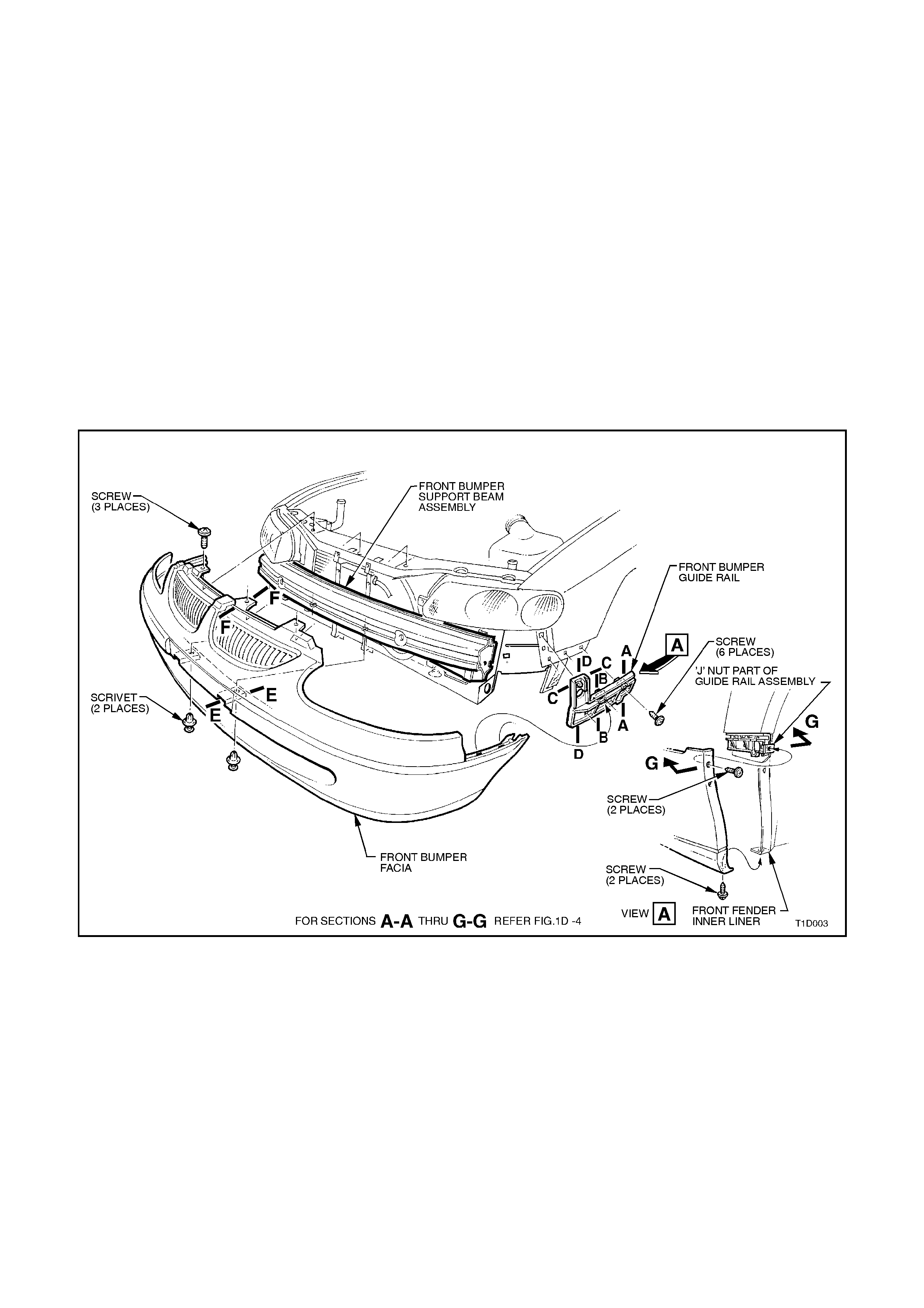
3. Remove bumper facia retaining scrivets (two) from behind number plate.
4 .Rem ove sc r ews sec uring bumper facia sides to f ront fender wheel arch opening and r adiator s uppor t upper
panel.
5. With the facia suppor ted, pull the fac ia side m em bers out, dis connect the f acia side s upports, then s lide the
facia forward removing the facia assembly, refer Fig. 12B-15.
Figure 12B-15
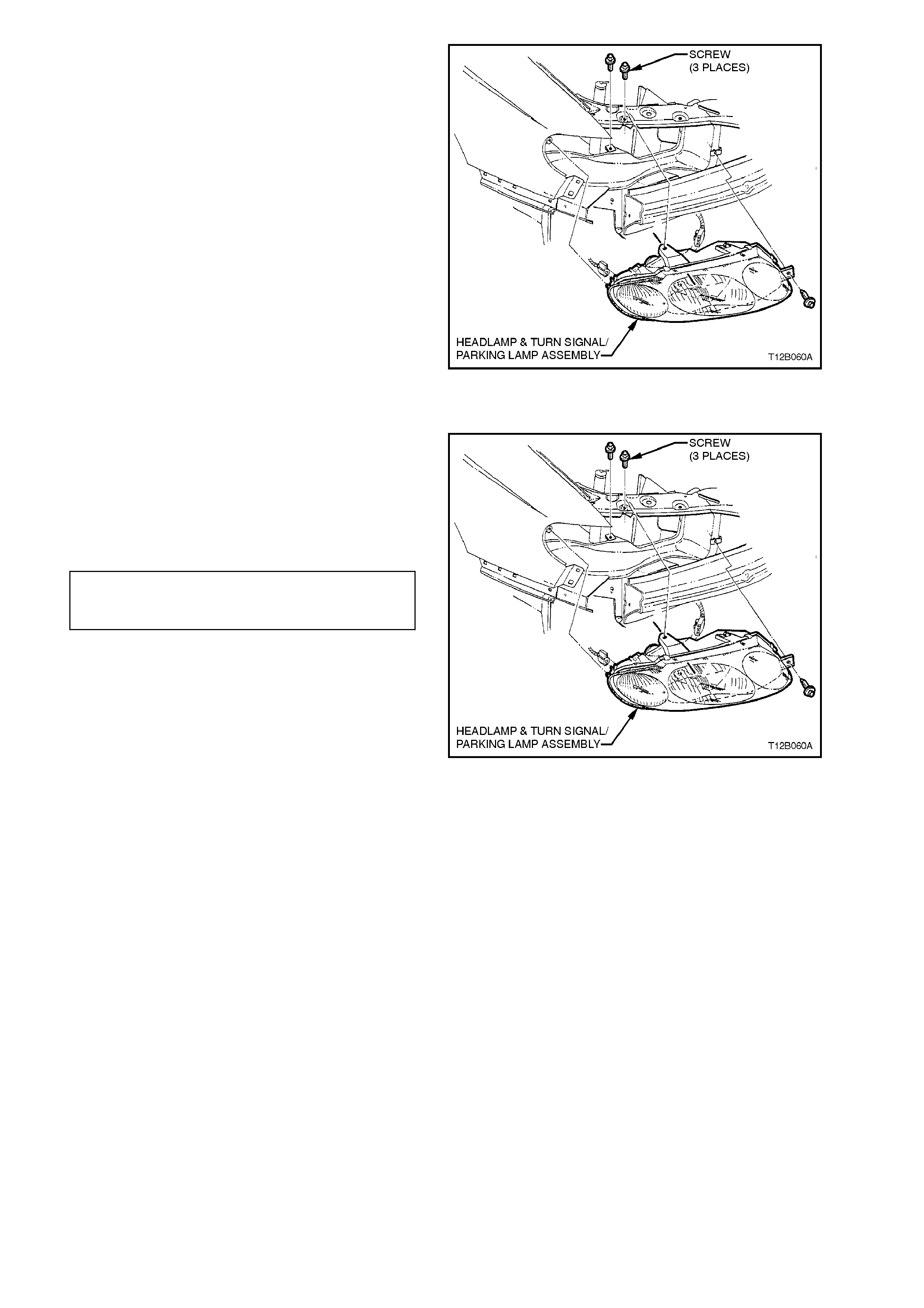
6. Remove headlamp r etaining scr ews (3 places )
and remove headlamp & turn signal/ parking
lamp assembly..
Figure 12B-16
REINSTALL
Reinstallation of the headlamp & turn signal/
parking lamp assembly is the reverse of removal
procedures noting the following points:
1. Install headlamp & turn signal/ parking lamp
assembly and tighten retaining screws to the
correct torque specification.
HEADLAMP & TURN SIGNAL/
PARKING LAMP ASM. RETAINING 2 - 5 Nm
SCREW TORQUE SPECIFICATION
2. Reintall front bumper facia assembly by
snapping the facia onto the retainers at guide
rails, one side at a time.
3. Ensure correct fender, hood and headlamp
clearance, adjust facia if necessary, refer
Section 1D BUMPER BARS.
4. Reconnect all wiring harness connectors and
check operation of headlamp and turn signal/
parking lamps and if fitted, fog lamps.
5. Check headlamp (and fog lamp if fitted) aim,
refer to 2.1 AIMING OF HEADLAMP AND
FOG LAMPS in this section.
Figure 12B-17
6. Install front facia grille.
Driver’s side only
Reinstall battery if removed, secure battery
retaining clamp and reconnect battery
terminals.
NOTE:
When installing headlamp assembly, use care to
ensure that the turn s ignal/parking lam p lens is not
scratched by fender extension peak, and no
damage is made to the front bumper bar facia.
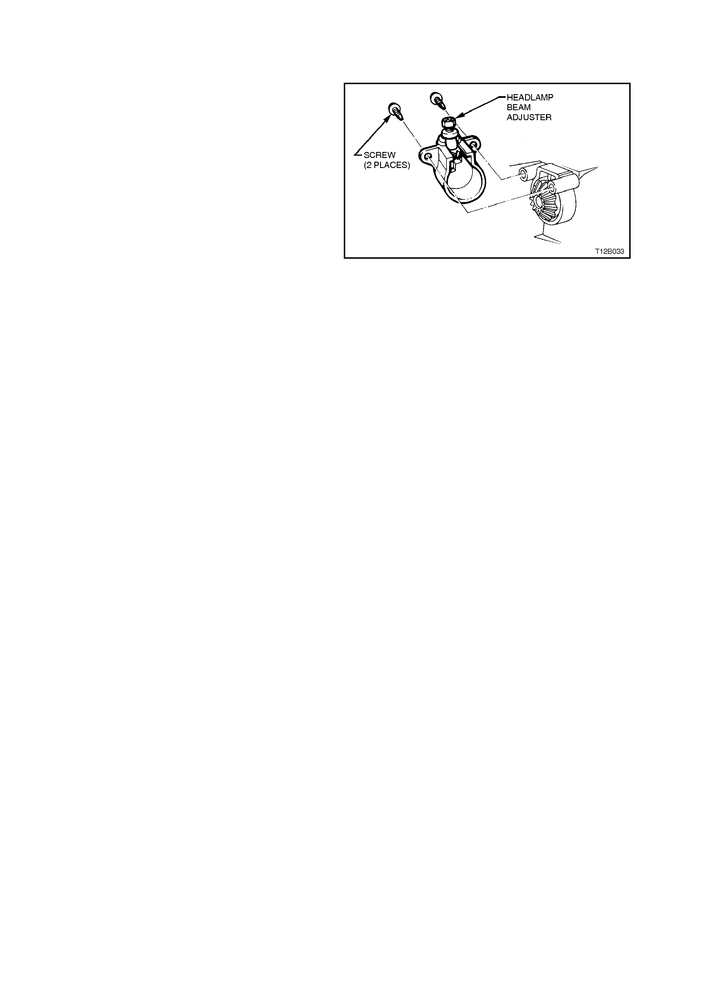
2.7 HEADLAMP ADJUSTER
REMOVE
1. Remove headlamp assembly refer to
2.6 HEADLAMP AND TURN
SIGNAL/PARKING LAMP ASSEMBLY in this
Section.
2. Remove two screws securing headlamp
adjuster to headlamp assembly and remove
adjuster.
3. Inspect adjuster and replace if worn or
damaged.
REINSTALL
Installation of the headlam p adjuster is the reverse
of removal procedures noting the following point:
1. Align bevel gear to avoid tooth abutment with
mating gear prior to tightening securing
screws.
Figure 12B-18
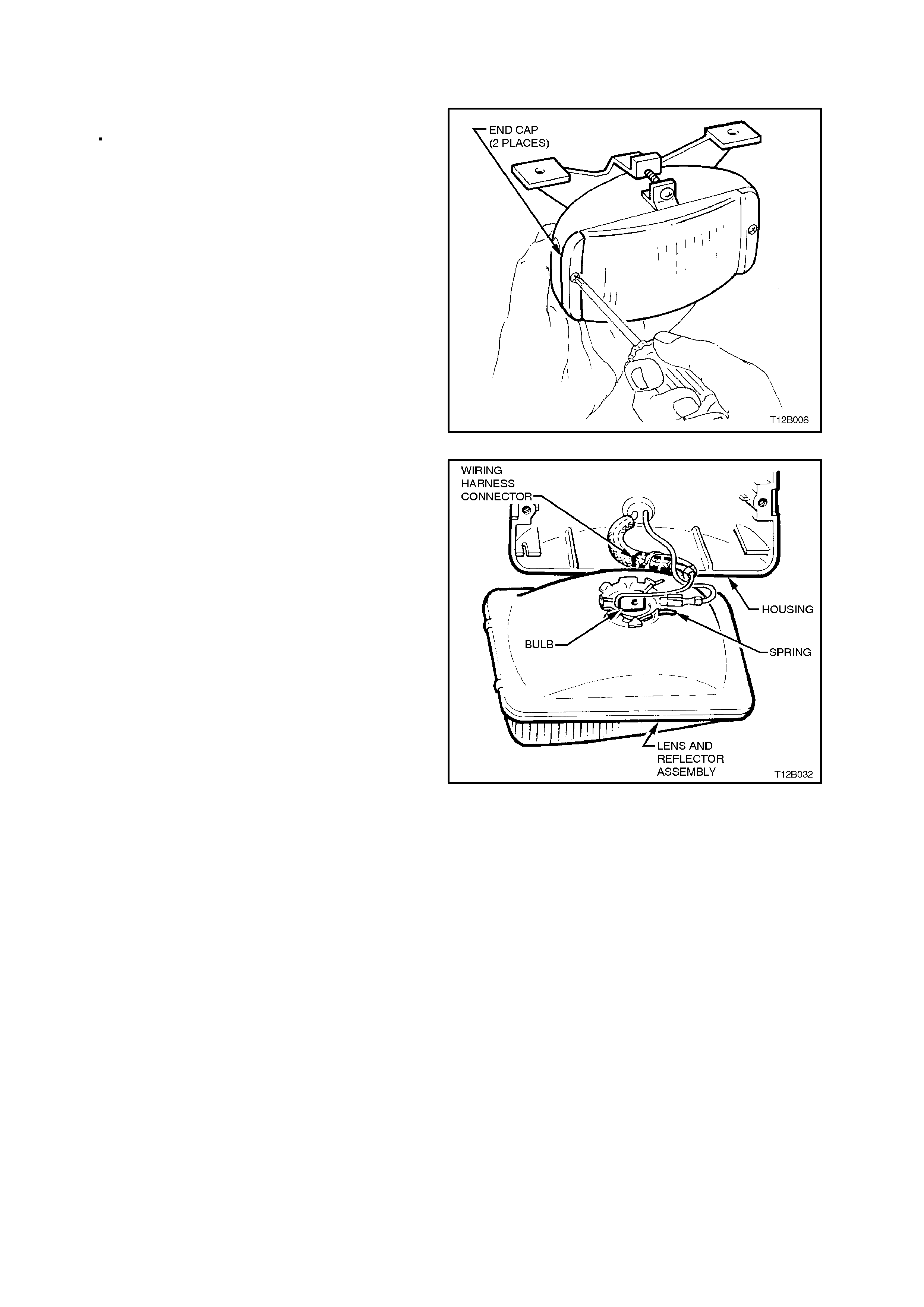
2.8 FOG LAMP BULB CALAIS AND SS MODELS
REPLACE
1. Remove fog lamp assembly, refer to
2.9 FOG LAMP ASSEMBLY - CALAIS AND
SS MODEL in this Section.
2. Remove lens and reflector assembly to
housing end cap retainer screws, remove end
caps.
Figure 12B-19
3. Pull lens and reflector assembly out from
housing.
4. Disconnect bulb lead from wiring harness
connector.
5. Squeeze halves of spring retainer together
and pivot spring backward clear of bulb. Lift
out bulb and remove.
6. Connect new bulb lead to wiring harness
connector, install bulb into correct locating
notches in reflector and reconnect spring
retainer.
NOTE:
Do not handle quartz envelope of bulb. If touched,
wipe immediately with methylated spirits or bulb
performance will deteriorate.
7. Reinstall lens and reflector assembly into
housing. Install end caps and screws, tighten
screws.
8. Reinstall fog lamp assembly, refer to
2.9 FOG LAMP ASSEMBLY - CALAIS AND
SS MODELS in this Section.
9. Check fog lamp operation and aim, refer to
2.1 AIMING OF HEADLAMPS AND FOG
LAMPS in this Section.
Figure 12B-20
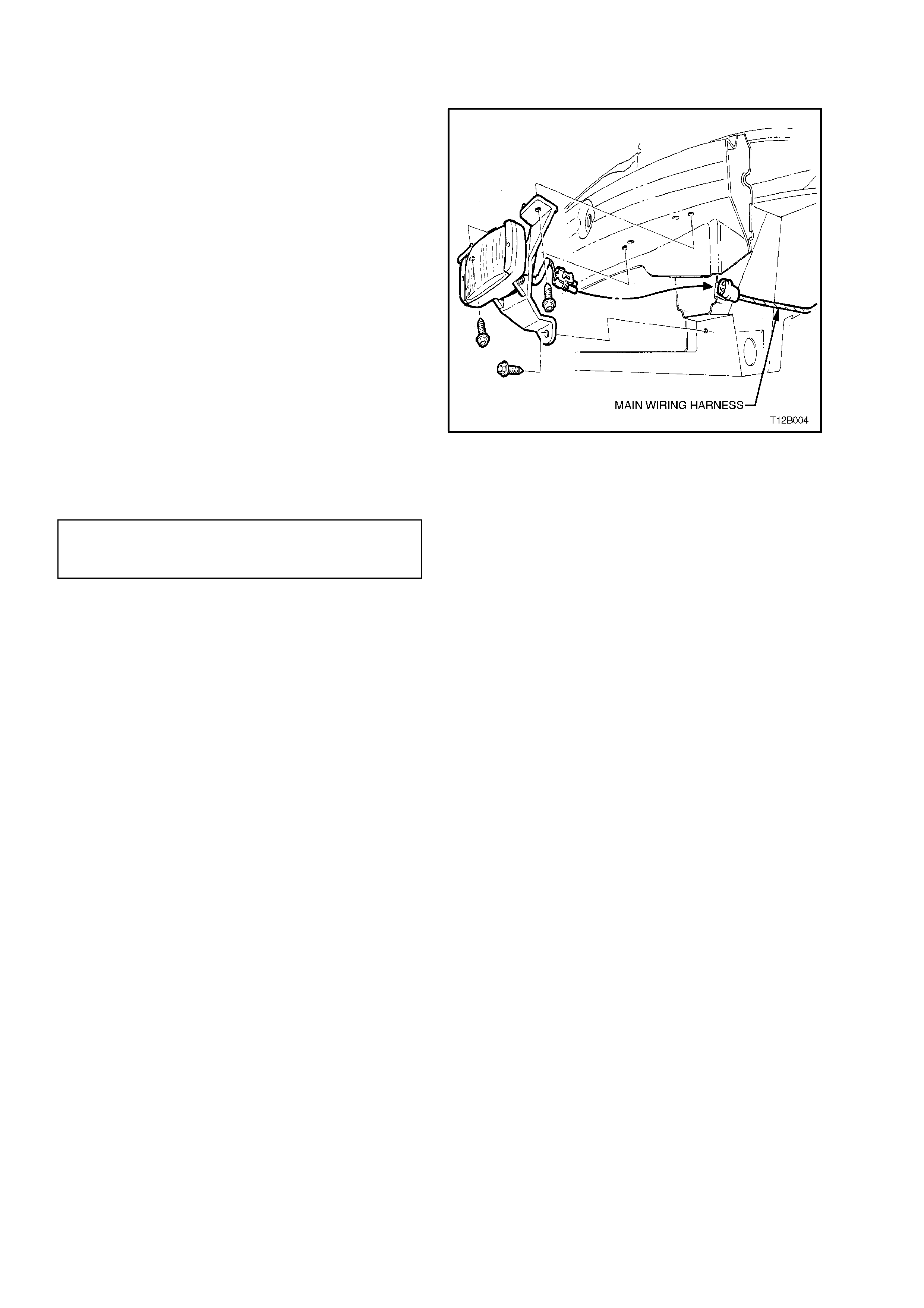
2.9 FOG LAMP ASSEMBLY - CALAIS AND SS MODELS
REMOVE
1. From inside wheelhouse, disconnect main
wiring harness from fog lamp harness
connector.
2. From behind bumper bar, remove three
mounting frame to bumper bar beam screws,
remove fog lamp assembly.
REINSTALL
Reinstallation of the fog lamp assembly is the
reverse of rem oval procedur es, noting the following
points:
1. Install fog lamp assembly to bumper bar
beam, ensuring that locating screw in lamp
mounting frame is located in the mating hole in
the bumper bar beam.
2. Tighten lamp mounting frame to bumper bar
beam and facia screws to the correct torque
specification. Figure 12B-21
FOG LAMP MOUNTING FRAME TO
BUMPER BAR BEAM AND FACIA
SCREW TORQUE SPECIFICATION 2 - 5 Nm
3. Check fog lamp operation. Recheck fog lamp
aim, refer to 2.1 AIMING OF HEADLAMPS
AND FOG LAMPS in this Section.
2.10 FOG LAMP SWITCH
REMOVE
1. Disconnect battery earth lead.
CAUTION:
Disable the SRS (Air Bag). Refer to DISABLING
THE SRS, Section 12M SUPPLEMENTAL
RESTRAINT SYSTEM.
2. Release steering column height adjusting
lever and completely lower steering column,
lock lever in this position.
Place a clean shop rag over and around
steering column upper cover. This step is
important so as to prevent any possibility of
damage to cover when removing the
instrument facia.
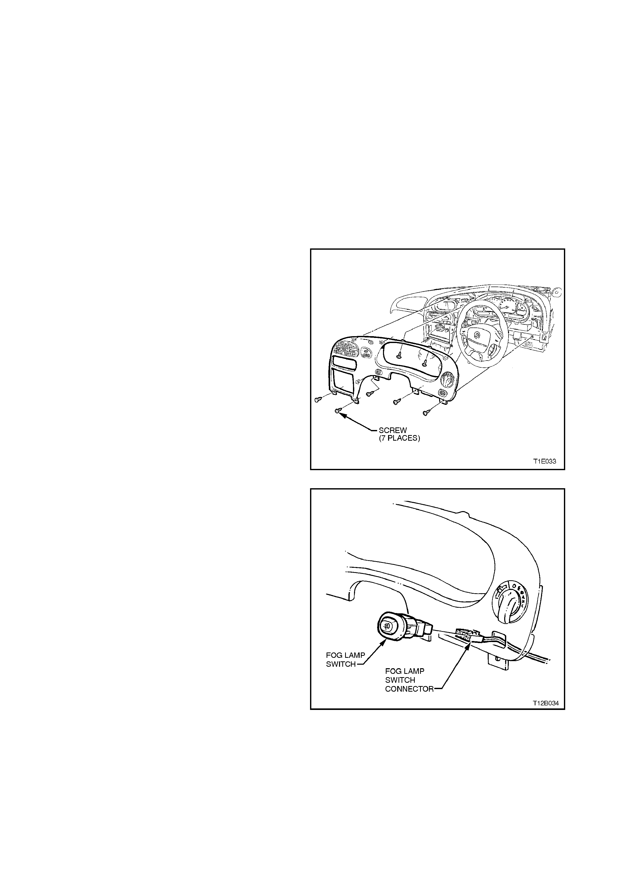
3. Remove instrument facia panel in order to gain
access to rear of fog lamp switch. For further
information refer to Section 1A3 INSTRUMENT
PANEL AND CONSOLE.
Figure 12B-22
4. Depress retaining tang on instr ument harness to
fog lamp switch connector, pull connector from
switch.
5. Squeeze together retaining tangs at side of
switch and push switch out from facia.
Figure 12B-23
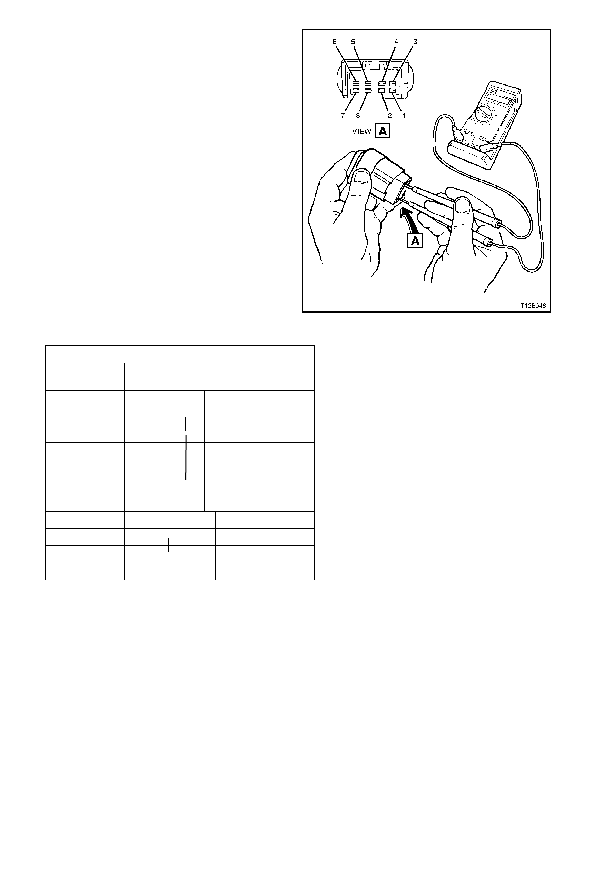
TEST
W ith the aid of an ohmmeter, check continuity of fog
lamp switch contacts using the following chart.
If continuity is not as specified at any switch position,
replace switch assembly.
Figure 12B-24
FOG LAMP SWITCH CONTACTS
TERMINAL
NO. SWITCH
STATUS
OFF ON
1 O PARK LAMPS
2 O FOG LAMPS
3
4
5O
6
7 O Illumination +
●
8 O Illumination –
REINSTALL
Installation of the fog lamp switch is the reverse of
removal procedures, noting the following points:
1. If, when instrument facia was pulled away
from instrument panel pad, the pad retaining
clips came away with the facia lugs, pull clips
from lugs and reinstall into pad holes.
If fitted, ensure that steering column to
instrument facia screen lip is fitted correctly to
edge on instrument panel pad. Refit
instrument facia and ensure that it is held to
the instrument panel pad securely.
2. Check fog lamp operation and ensure that
switch illumination bulb illuminates when the
headlamps are turned on.
IMPORTANT:
Enable the SRS (Air Bag). Refer to ENABLING
THE SRS, Section 12M SUPPLEMENTAL
RESTRAINT SYSTEM.
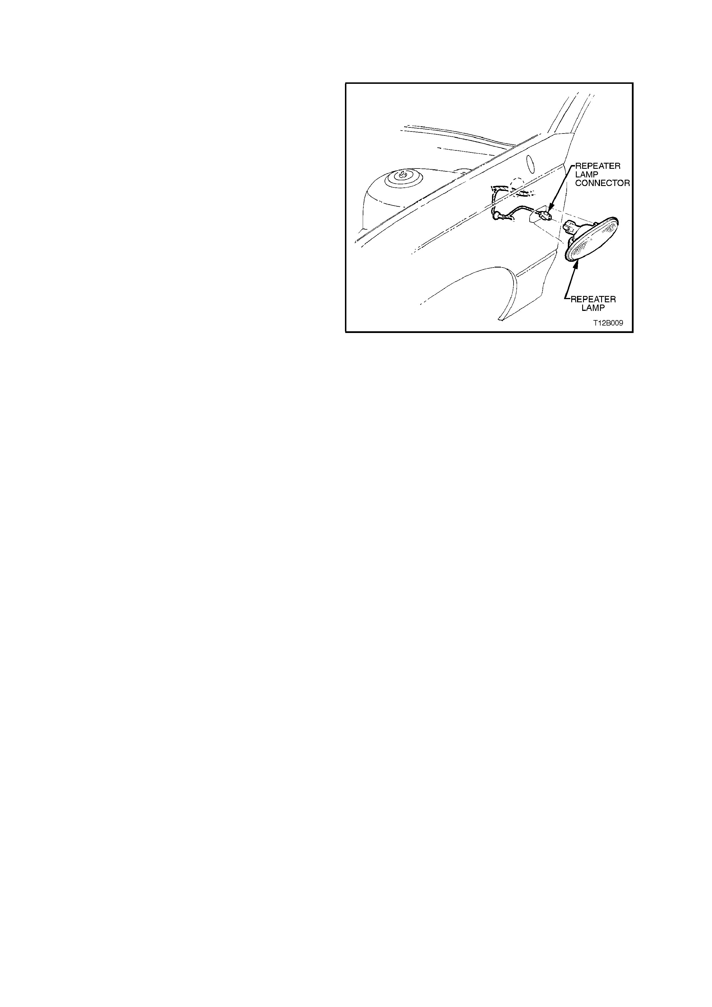
2.11 SIDE REPEATER LAMP
REMOVE
1. Grip rear edge of lamp hous ing with finger tips
and pull housing forward and outwards from
fender panel. Once hous ing has releas ed fr om
fender panel, remove housing and twist bulb
socket to release from housing.
2. If required, pull bulb from socket to replace.
3. Inspect lamp housing and bulb socket seals
for damage, replace if necessary.
REINSTALL
1. If necessary, install new bulb to socket.
2. Assemble repeater lamp housing to socket
and twist socket to lock into housing.
3. Install lamp housing into fender opening with
housing locking nib facing forward and
engaging into opening.
4. Push rear of lamp housing into fender
opening, ensuring lamp housing is securely
locked to fender.
5. Check repeater lamp operation.
Figure 12B-25
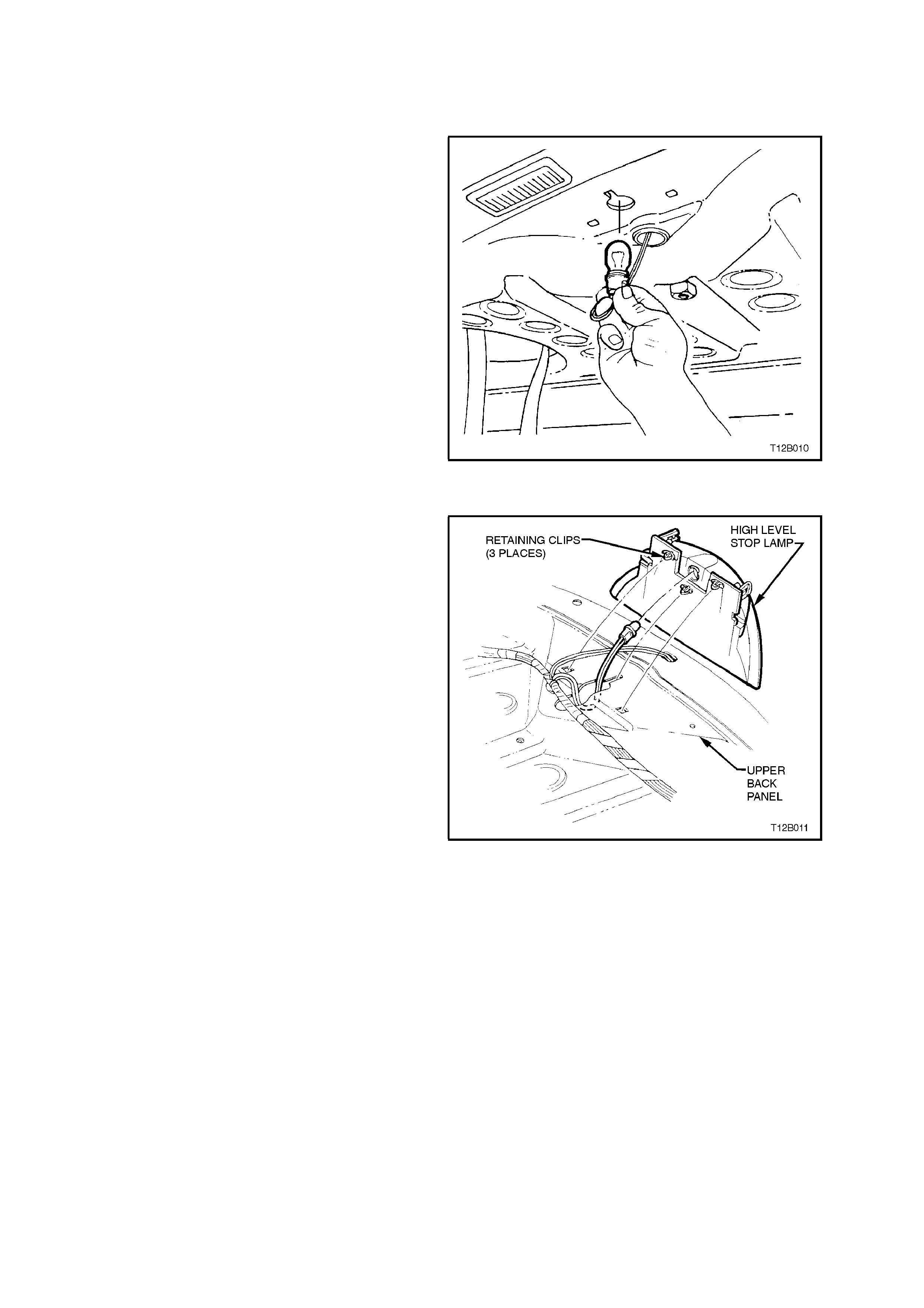
2.12 HIGH LEVEL STOP LAMP
SEDAN MODELS WITHOUT REAR COMPARTMENT LID SPOILER
BULB REPLACEMENT
Access to the bulb is through the rear c ompartment
and up through the upper rear panel opening
beneath the stop lamp mounting.
1. Twist bulb socket to release from lamp. Pull
socket down into rear compartment and pull
bulb from socket.
NOTE:
It may be necessary to use a pair of pointed nose
pliers to hold and release bulb socket.
2. Install new bulb into socket and install bulb
socket into housing.
Figure 12B-26
LAMP REPLACEMENT
Fig. 12B-27 illustrates the installation of the high
level stop lamp for sedan models without rear
compartment lid air spoiler.
To remove lamp assembly, remove rear parcel
shelf, refer to Section 1A8 HEADLINING AND
REAR END TRIM. Remove bulb and socket as
described previously. Disengage retaining clips
securing high level stop lamp to upper back panel
and remove lamp assembly.
On reinstallation of high mount stop lamp, ensure
that stop lamp housing is pushed fully rearward
before engaging retaining clips.
Figure 12B-27
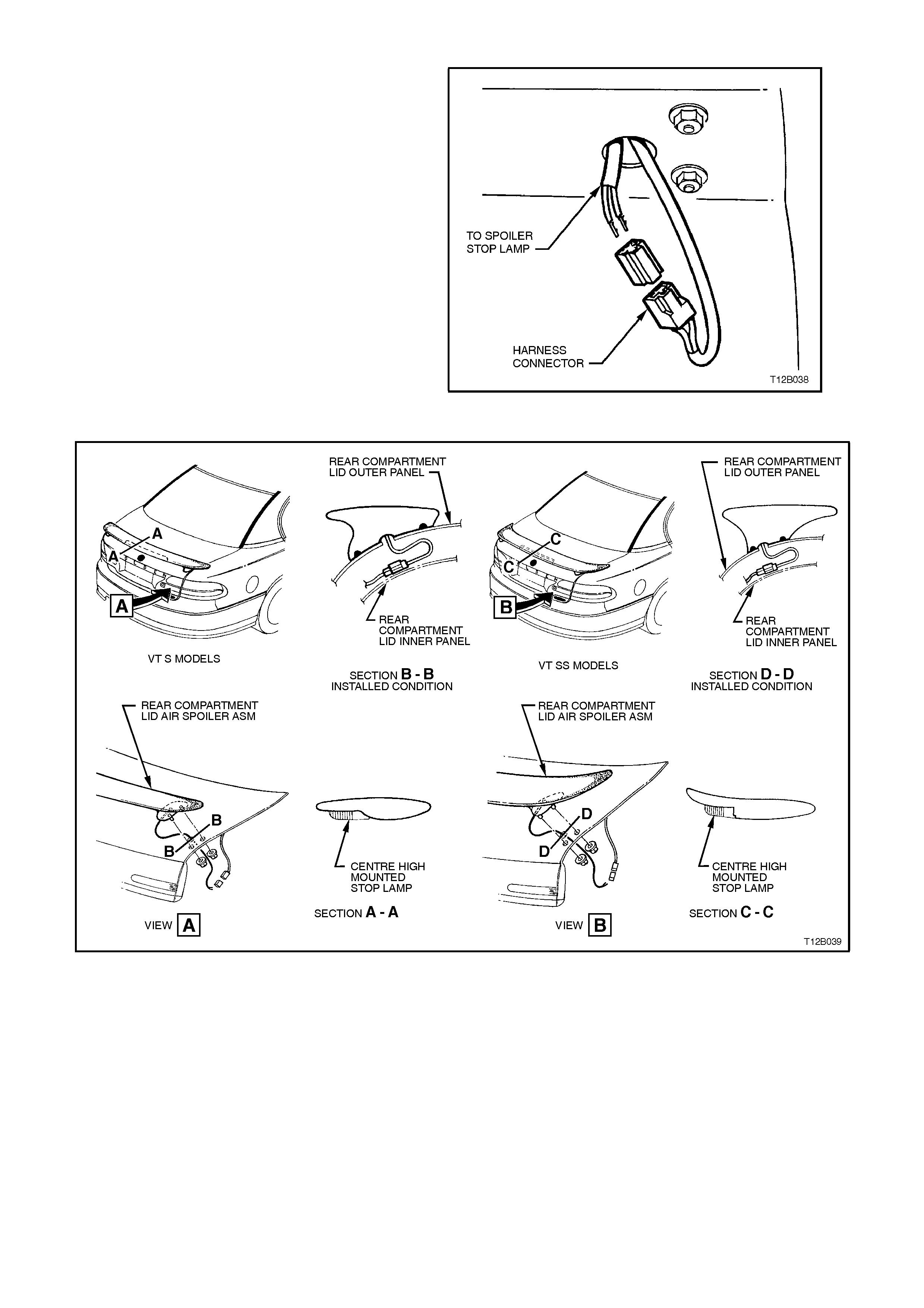
S AND SS MODELS
Fig. 12B-28 illustrates the installation of the high
level stop lamp for S and SS sedan models with
rear compartment lid air spoiler.
REMOVE
To remo ve lamp assembly:
1. Open rear compartment lid and locate high
mounted stop lamp to wiring harness
connectors.
2. Disconnect high mounted stop lamp to wiring
harness connectors and remove connector
from stop lam p harness. T his will allow s poiler
to be removed.
3. Remove rear compartment lid air spoiler (4
bolts), ensuring no damage is made to rear
compartment lid paintwork, and remove
spoiler. Note that sealant may be present.
Figure 12B-28
Figure 12B-29
4. Using fine bladed screwdriver, gently prise
high level stop lamp assembly screw cover
plate from spoiler. Cover plate is attached with
3 pieces of double sided tape.
5. Remove high level stop lamp assembly to
spoiler attaching screws.
6. Remove high level stop lamp from spoiler,
disengaging harness rubber grommet from
hole in spoiler and feed out harness through
spoiler, remove lamp assembly.
HIGH MOUNT STOP LAMP TO
SPOILER ATTACHING SCREW
TORQUE SPECIFICATION
1 - 3 Nm
REINSTALL
To reinstall lamp assembly:
1. Feed harness through hole in spoiler and into
rear compartment.
2. Assem ble lamp ass embly to spoiler and install
high mount stop lamp assembly to spoiler
attaching screws. Tighten screws to the
correct torque specification. Replace screw
cover plate using 3 pieces of double sided
tape.
3. If installing new lam p assem bly, push harness
sleeve toward lamp assembly and secure
sleeve position with some electrical tape.
4. Attach lamp wiring connector to lamp
assembly. Reconnect lamp assembly wiring
harness connectors and check lamp
operation.
5. To install rear compartment lid air spoiler, refer
to Section 1A9 EXTERIOR
ORNAMENTATION.
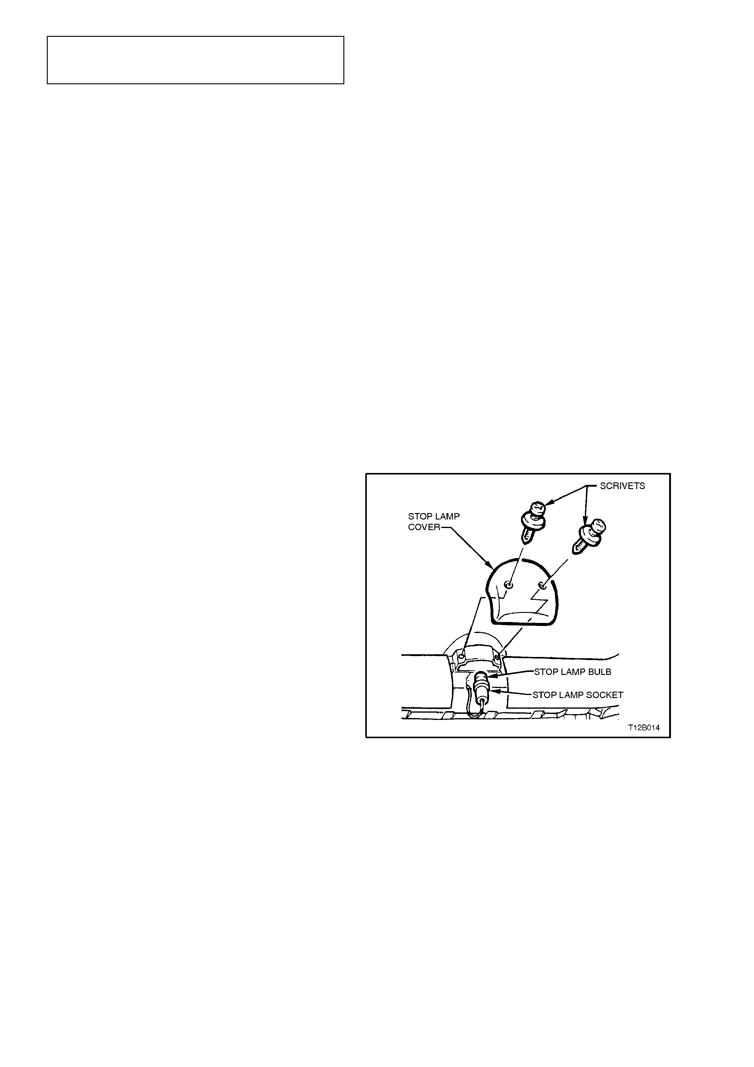
STATION WAGON
BULB REPLACEMENT
1. Open tailgate and remove tailgate trim cover
at rear of high level stop lamp (2 scrivets).
2. From inside cavity of tailgate trim, twist and
unlock bulb socket from lamp assembly and
pull socket out from cavity.
3. Twist and remove bulb from socket.
4. Install new bulb to socket, refit holder to lamp
assembly. Reinstall tailgate trim cover and
check stop lamp operation.
Figure 12B-30
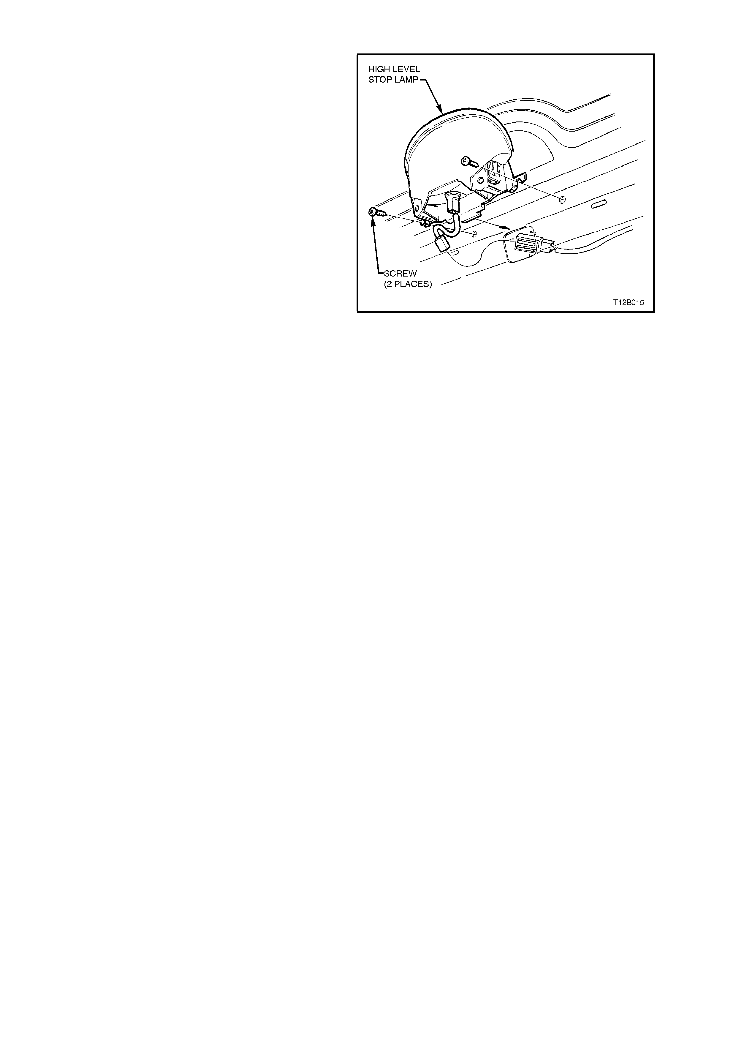
HIGH LEVEL STOP LAMP REPLACEMENT
1. Remove tailgate trim, refer to
Section 1A4 REAR COMPARTMENT LID
AND TAILGATE.
2. Remove high level stop lamp cover at rear of
high level stop lamp (2 scrivets).
3. Twist and unlock bulb socket from lamp
assembly.
4. Remove lamp assembly to tailgate attaching
screws (2) and remove lamp assembly.
5. Reinstall lamp assembly in reverse order of
removal.
6. Check stop lamp operation.
Figure 12B-31
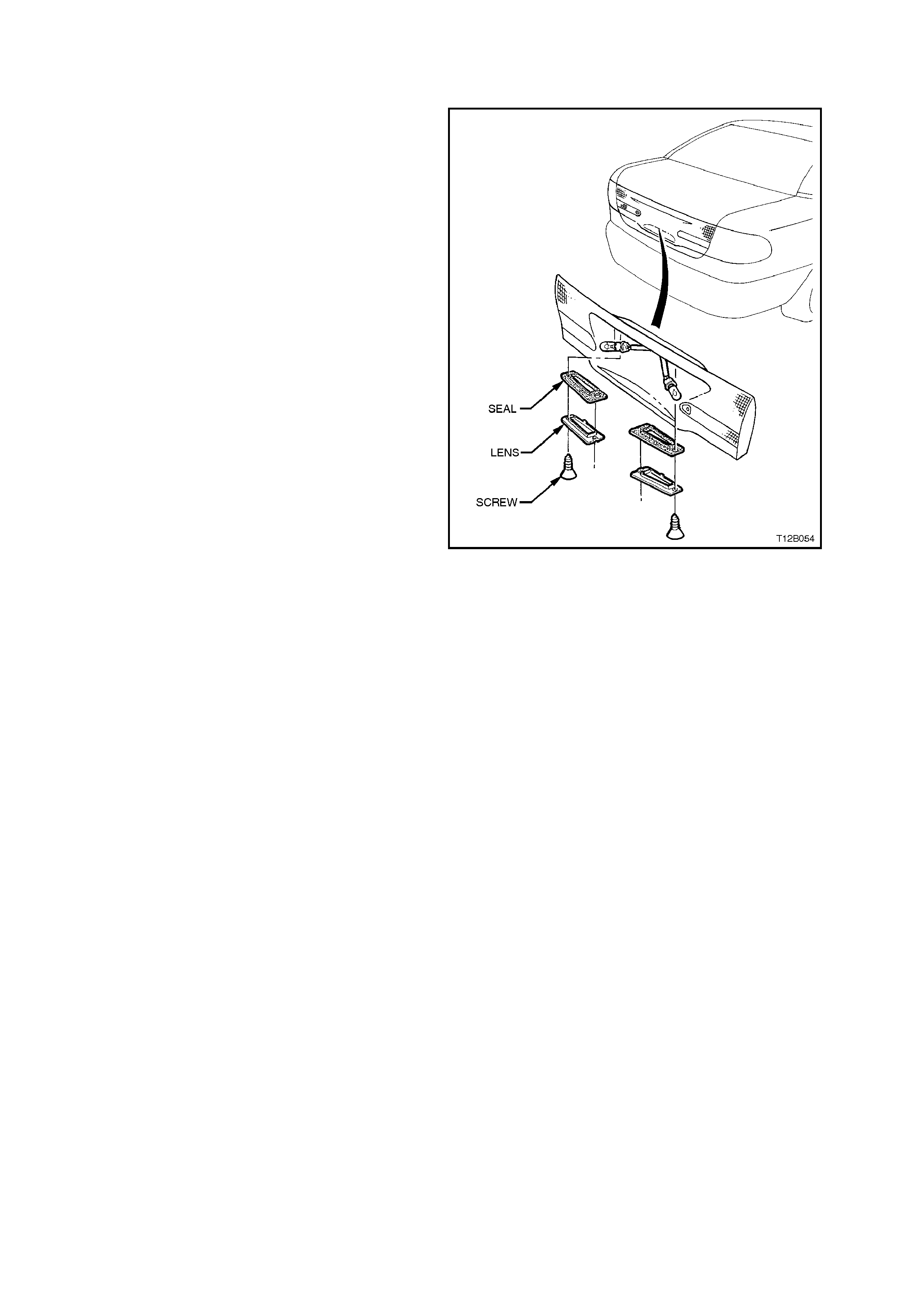
2.13 LICENCE PLATE LAMP/BULB - SEDAN
REMOVE
1. Remove screws securing lamp lens to decklid
lamp assembly and remove lamp lens.
2. Pull bulb from socket.
3. Inspect bulb socket sealing ring for damage,
replace if required.
REINSTALL
1. Push new bulb into bulb socket.
2. Check lamp operation.
Figure 12B-32
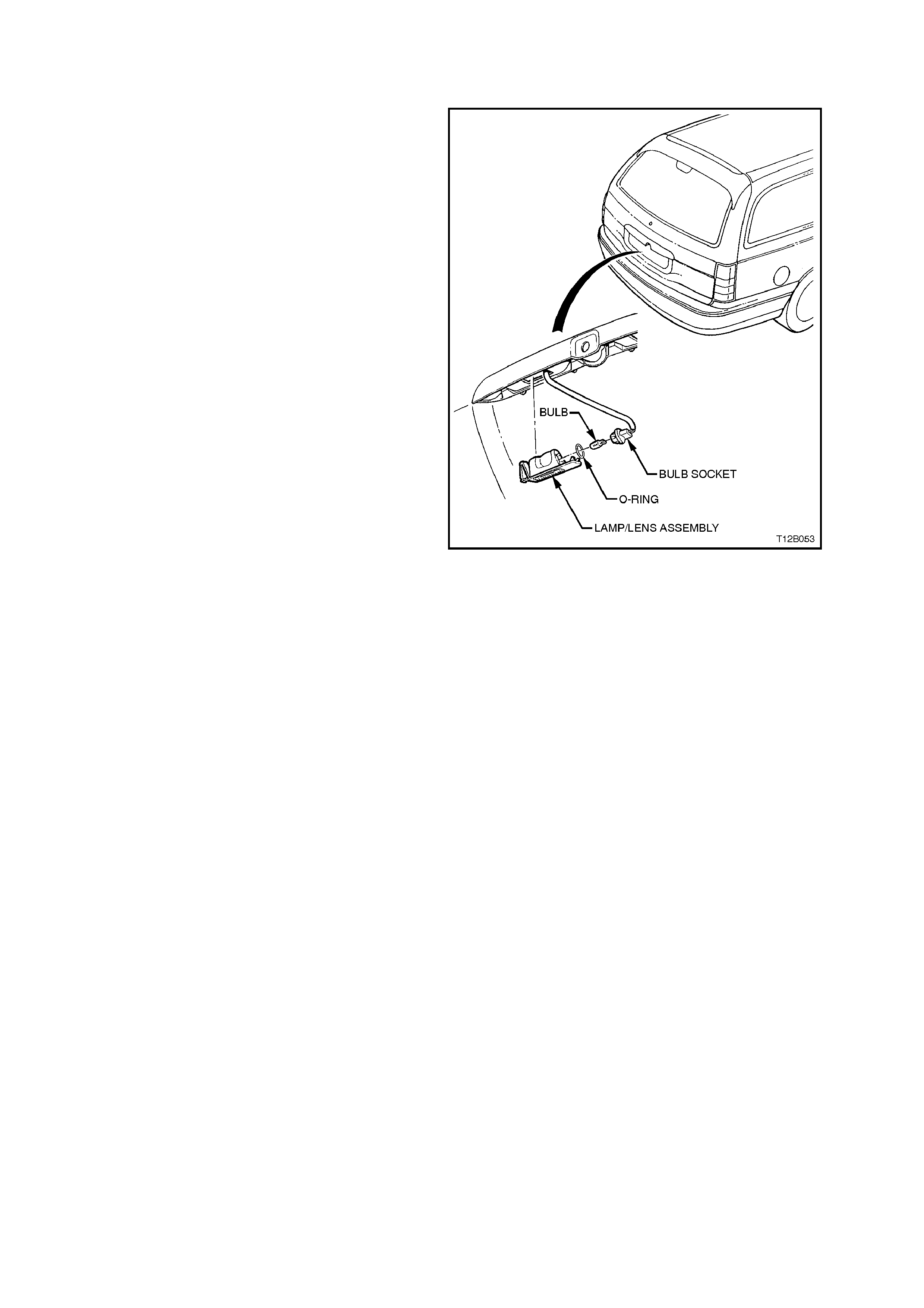
2.14 LICENCE PLATE LAMP - STATION WAGON
BULB REPLACEMENT
1. Slide tab on licence plate lamp lens to
disengage lamp assembly from tailgate lock
trim and remove lens complete with bulb.
2. Replace bulb and install lens.
NOTE:
There is a locating tag on one end of lens at the
bulb contact. This is to ensure that lens will only
assemble to tailgate lock trim in one direction only.
Figure 12B-33
REMOVE
1. Remove tailgate trim, refer to Section 1A4
REAR COMPARTMENT LID AND
TAILGATE.
2. From inside tailgate, disconnect wiring
connectors from licence plate lamp assembly.
3. Slide tab on licence plate lamp lens to
disengage lamp assembly from tailgate lock
trim and remove lens complete with bulb.
REINSTALL
1. Installation is the reverse of removal
procedures.
2. Check lamp operation.
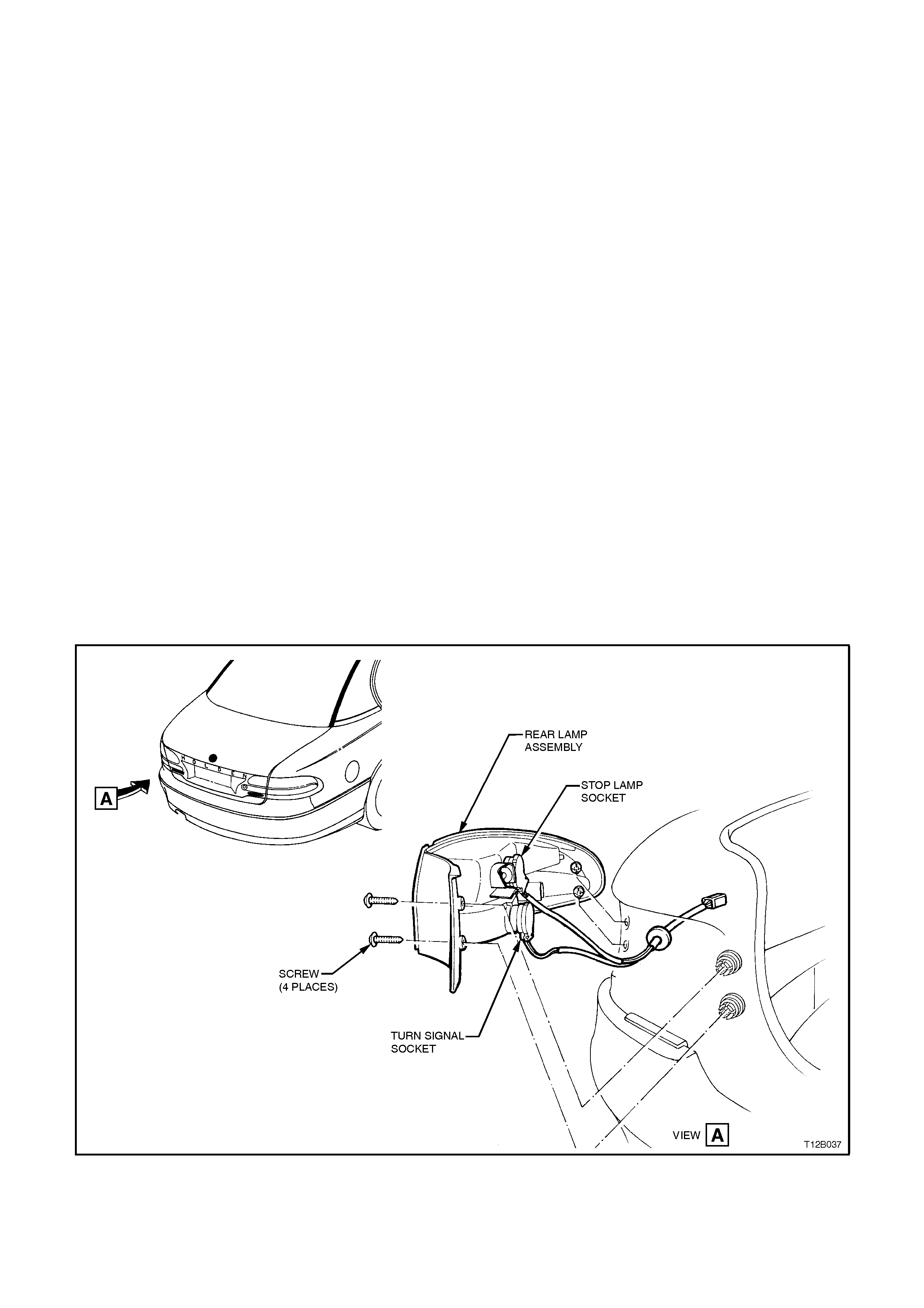
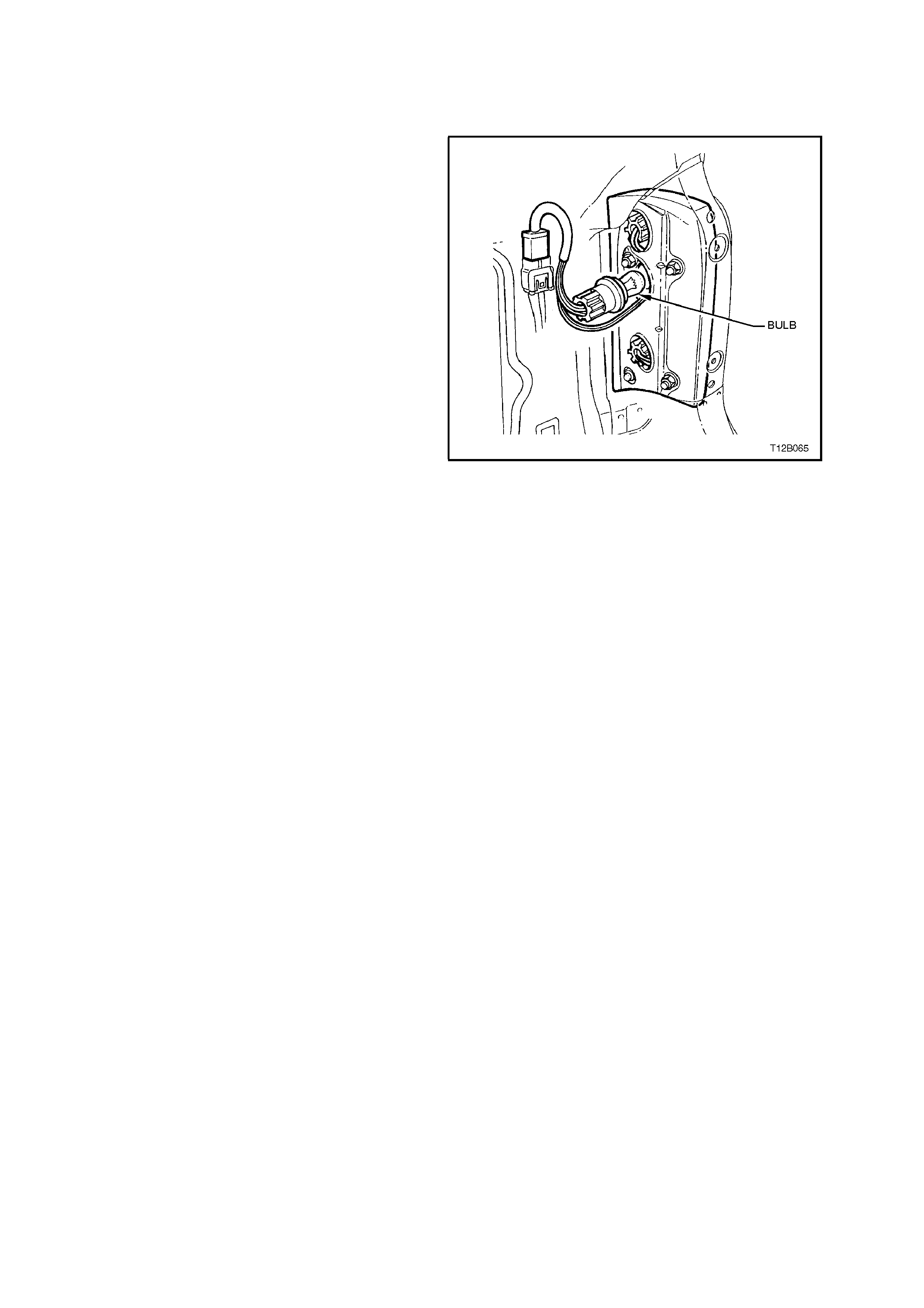
2.15 S EDAN REAR LAMP BULBS
STOP/TAIL AND TURN SIGNAL LAMP BULBS
REPLACE
1. Open rear compartment.
2. Remove rear lamp assembly refer to
2.17 REAR LAMP ASSEM BLY- SEDAN in this
Section.
3. Remove appropriate bulb socket by turning
and removing socket.
4. Remove bulb from socket by depressing bulb
into its socket and then rotate to remove.
Inspect bulb socket to lamp housing seals for
damage, replace if necessary.
5. Insert new bulb into socket and refit socket
into lamp housing, ensuring socket locks
securely into place. Note that there are
different socket types for stop/tail lamps and
turn signal lamps. These are colour coded.
NOTE:
If replacing a rear quarter turn signal lamp bulb,
ensure the cor rect type is fitted. For Calais models ,
the turn signal bulb glass is coloured orange and
has offset locating pins, whereas the bulb used for
Executive, SS, and Berlina has clear glass and
standard parallel locating pins.
Also, different rear quarter lamp harnesses with
specif ic bulb sock ets are used for eac h type of bulb
locating pin style.
6. Check rear lamp operation.
Figure 12B-34
2.16 STATION WAGON REAR LAMP BULBS
STOP/TAIL AND TURN SIGNAL LAMP BULBS
REPLACE
1. Open rear tailgate.
2. Remove rear lamp cover trim, taking care not
to damage cover trim surround.
3. Remove appropriate bulb socket by turning
and removing socket.
4. Remove bulb from socket by depressing bulb
into its socket and then rotate to remove.
Inspect bulb socket to lamp housing seals for
damage, replace if necessary.
5. Insert new bulb into socket and refit socket
into lamp housing, ensuring socket locks
securely into place. Note that there are
different socket types for stop/tail lamps and
turn signal lamps. These are colour coded
and will only install to cor rect m ating apertures
in housing.
6. Check rear lamp operation. Figure 12B-35
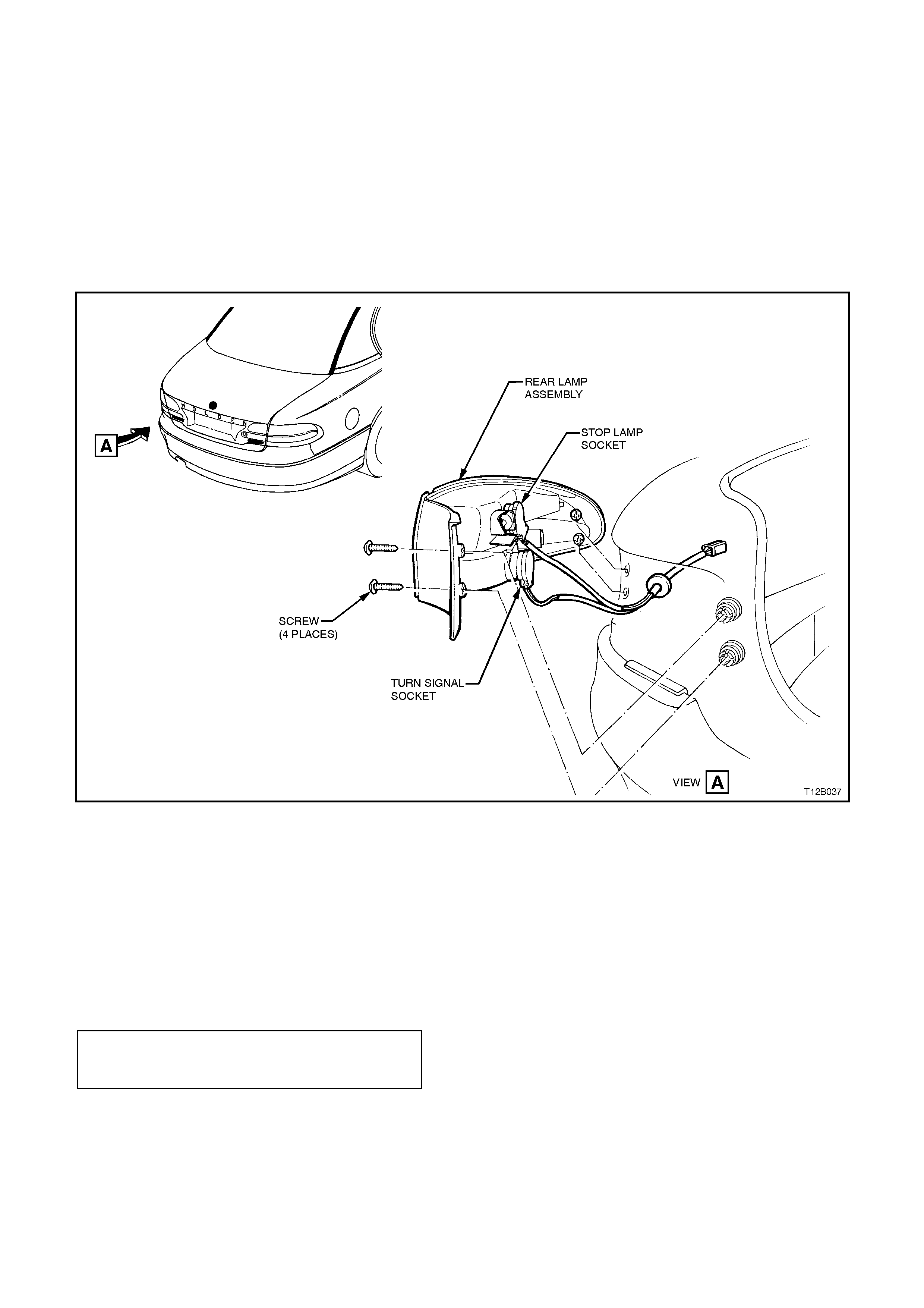
2.17 REAR LAMP ASSEMBLY - SEDAN
REAR QUARTER LAMP ASSEMBLY
REMOVE
1. Open rear compartment.
Remove rear quarter lamp assembly to body
attaching screws (two screws).
2. Pull rear quarter lamp housing sideways out
from panel so locating pegs on side of lamp
assembly snap free from retainers. While
supporting lamp housing, r emove bulb soc kets
by turning and removing socket.
Figure 12B-36
REINSTALL
1. Insert bulb sockets into rear quarter lamp
housing, ensuring sockets lock securely into
place.
2. Ensure that rear quarter lamp harness
grommet is seated correctly. Assemble lamp
housing to body, ensuring locating pegs snap
into retainers and install and tighten attaching
nuts to the correct torque specification.
REAR QUARTER LAMP HOUSING
TO BODY ATTACHING NUT
TORQUE SPECIFICATION 3 - 4 Nm
3. Check rear lamp operation.
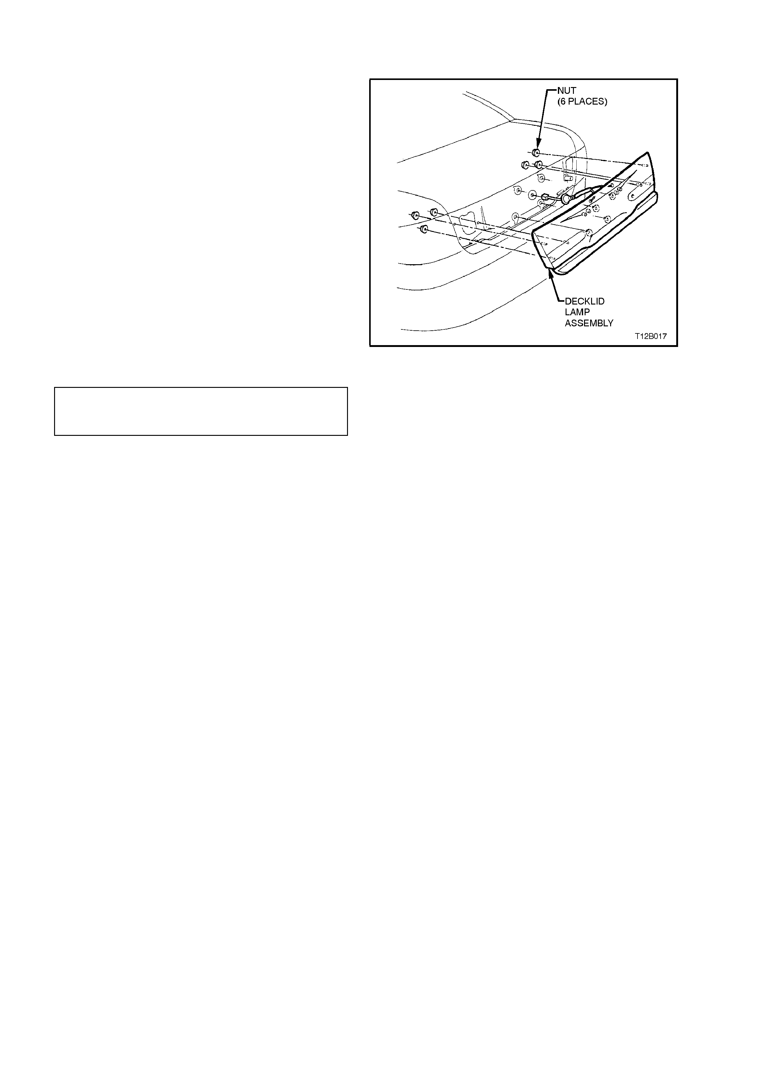
DECKLID LAMP ASSEMBLY
REMOVE
1. Open decklid.
2. From inside deck lid, dis c onnect wiring harnes s
from decklid lamp assembly.
3. Remove lamp assembly to decklid attaching
nuts. Pull lamp assembly outer edge from
decklid and slide outward, disengaging lamp
housing tongue from decklid extension
moulding.
REINSTALL
1. Check condition of lamp housing to decklid
rubber sealing gasket and replace if damaged.
2. Assemble lamp housing to decklid, engaging
lamp assembly tongue in and around moulding
mounting boss grommet. Install and tighten
attaching nuts to the correct torque
specification. Figure 12B-37
DECKLID LAMP HOUSING TO
DECKLID ATTACHING NUT
TORQUE SPECIFICATION 3 - 4 Nm
3. Reconnect wiring harness connector.
4. Check rear lamp operation.
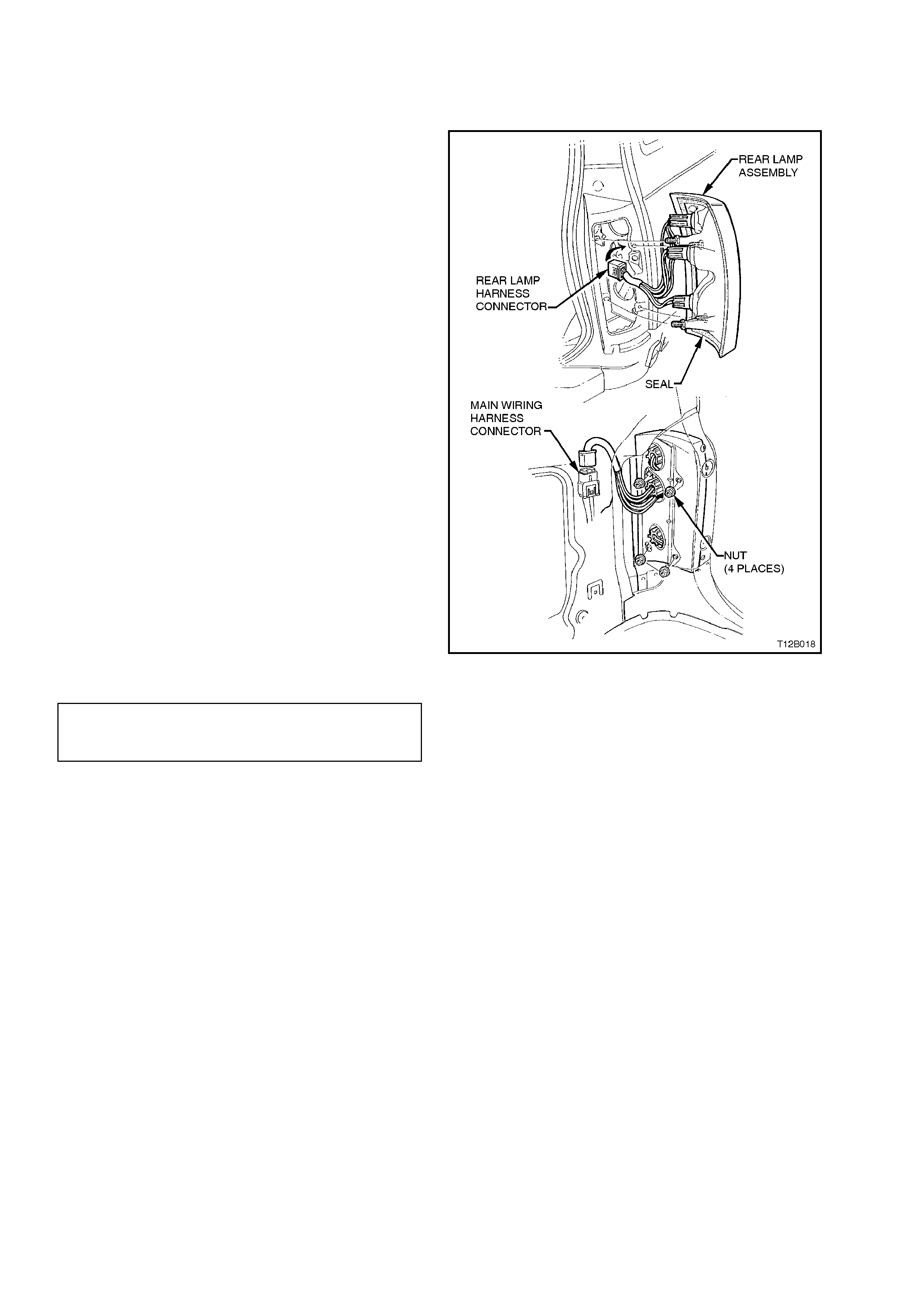
2.18 REAR LAMP ASSEMBLY - STATION WAGON
REMOVE
1. Open vehicle tailgate.
2. Remove rear lamp cover trim, taking care not
to damage cover trim surround.
Remove four nuts retaining lamp housing to
rear end panel.
3. Remove wiring harness connector, remove
housing.
REINSTALL
Installation is the reverse of removal procedures,
noting the following points:
1. If necessary, install bulbs to sockets and refit
sockets to lamp assembly.
2. Tighten lamp retaining screws to the correct
torque specification.
3. Check rear lamp operation.
Figure 12B-39
REAR LAMP HOUSING
RETAINING SCREW
TORQUE SPECIFICATION 1 - 3 Nm
2.19 INTERIOR LAMPS
NOTE:
The interior lighting configuration is dependant on
the vehicle model and trim level.
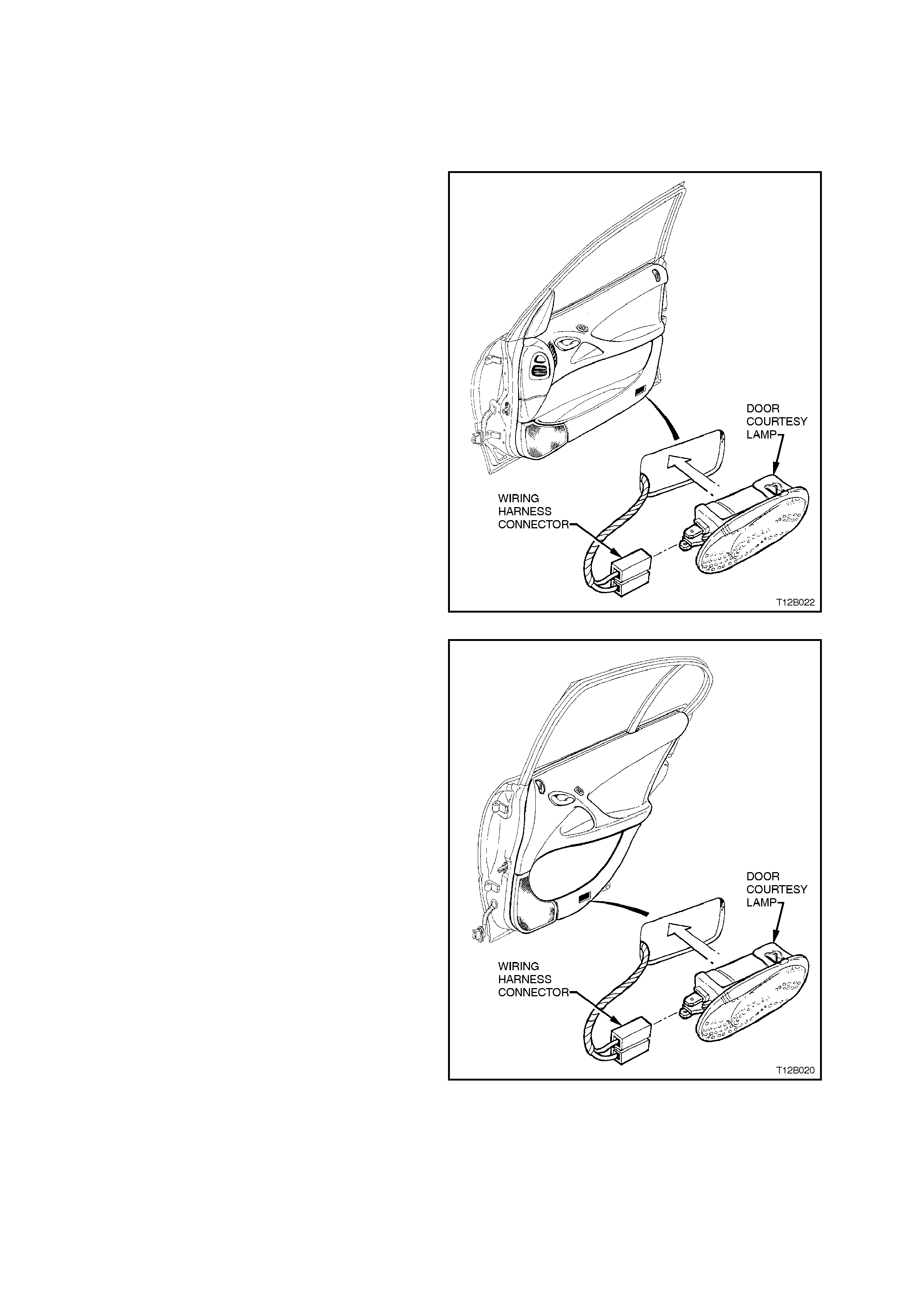
DOOR COURTESY LAMPS
Figs. 12B-40 and 12B-41 illustrate the installation of
the front and rear door courtesy lamps. To gain
access to bulb, use a fine bladed screwdriver
inserted between notch in lens surround and edge
of lens, lever lens from surround.
To rem ove bulb from lens, bend back lever contact
retaining the bulb and remove bulb.
Figure 12B-40
Figure 12B-41
GLOVE COMPARTMENT LAMP
Fig. 12B-42 illustrates the installation of the glove
compartment lamp. To gain access to bulb, use a
fine bladed screwdriver to carefully lever out lens
from instrument panel.
To rem ove bulb from lens, bend back lever contact
retaining the bulb and remove bulb.
Figure 12B-42
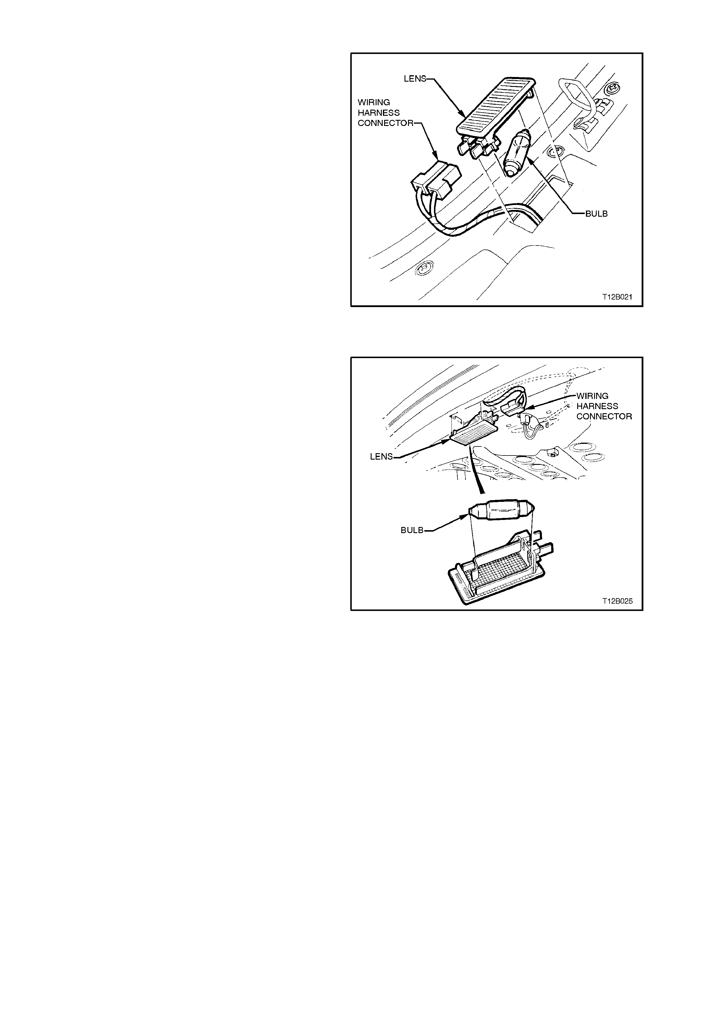
REAR COMPARTMENT LAMP - SEDAN
Fig. 12B-43 illustrates the installation of the rear
compartment lamp and switch. To gain access to
bulb, use a fine bladed screwdriver to carefully
lever out lens.
To rem ove bulb from lens, bend back lever contact
retaining the bulb and remove bulb.
Figure 12B-43
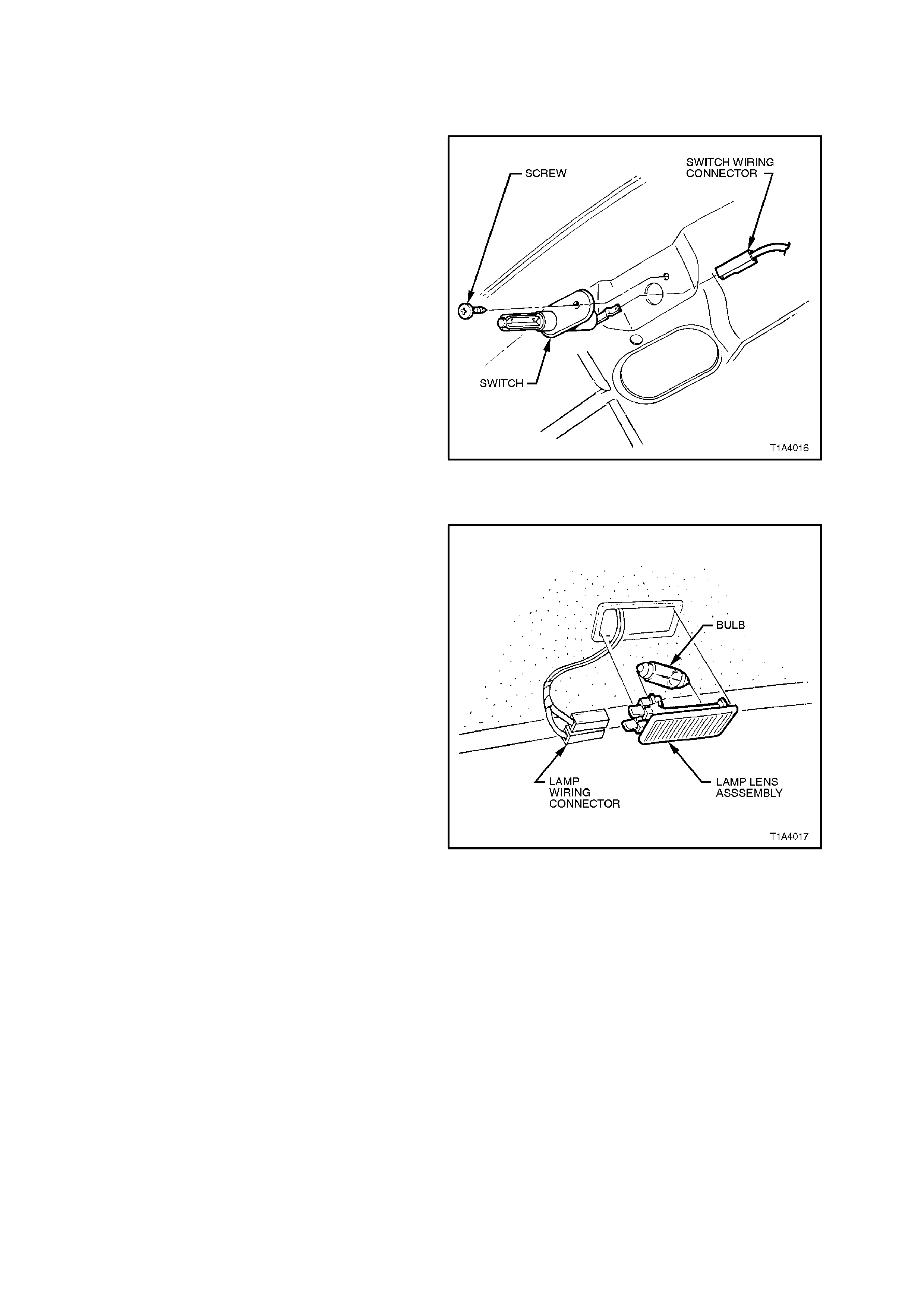
REAR COMPARTMENT LAMP SWITCH
The rear compartment lamp is operated by a
switch attached to the decklid.
REMOVE
1. Remove attaching screw and pull switch out
far enough to gain access to wiring harness
connectors.
2. Disconnect wiring harness connectors and
remove switch.
REINSTALL
Reverse removal operations.
Figure 12B-44
REAR COMPARTMENT LAMP - STATION WAGON
Fig. 12B-45 illustrates the installation of the rear
compartment lamp for station wagon. To gain
access to bulb, use a fine bladed screwdriver to
carefully lever out lens from surround.
To rem ove bulb from lens, bend back lever contact
retaining the bulb and remove bulb.
Figure 12B-45

REAR COMPARTMENT LAMP SWITCH
The rear compartment lamp is operated by a
switch attached to the tailgate.
REMOVE
1. Remove attaching screw and pull switch out
far enough to gain access to wiring harness
connectors.
2. Disconnect wiring harness connectors and
remove switch.
REINSTALL
Reverse removal operations.
Figure 12B-46
DOME AND FRONT READING LAMPS
Fig. 12B-47 illustrates the installation of the dome
lamp assembly for models without reading lamps.
To gain access to bulb, use a fine bladed
screwdriver inserted between notch in lens
surround and edge of lens. Carefully lever out lens
from housing, gently prising from all four notches,
ensuring no damage is made to housing surround
or headlining.
Figure 12B-47
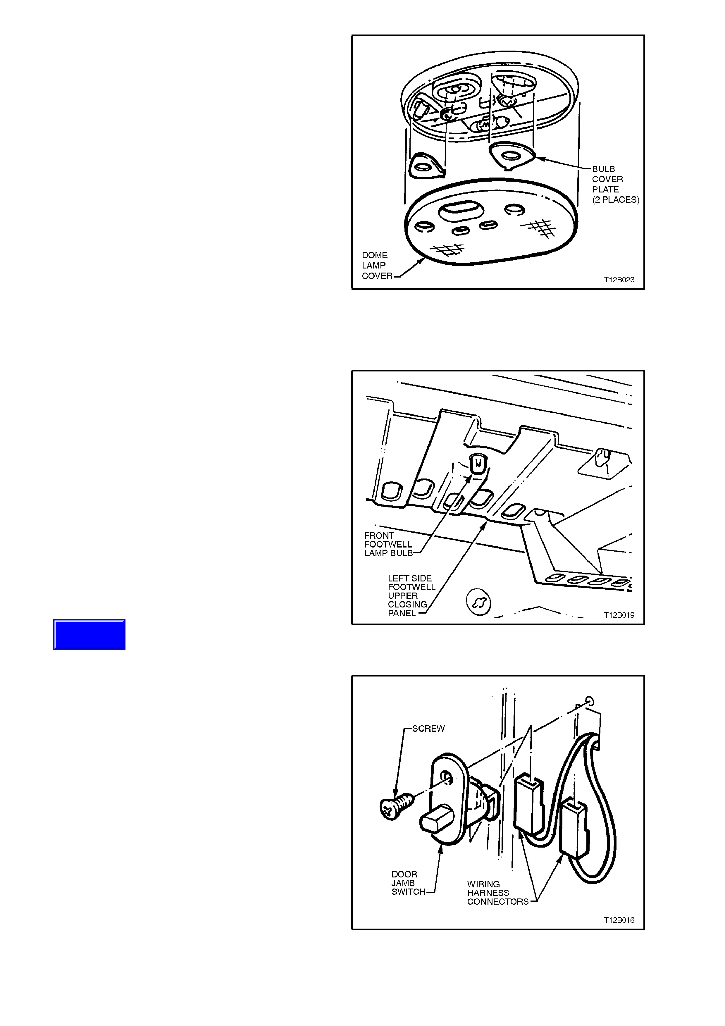
Fig. 12B-48 illustrates the installation of the dome
and front reading lamp ass embly for Calais Models .
To gain access to bulb, use a fine bladed
screwdriver inserted between notch in lens
surround and edge of lens. Carefully lever out lens
from housing, gently prising from all four notches,
ensuring no damage is made to housing surround
or headlining.
The dome lamp bulb is a festoon bulb and can be
removed by bending contacts out from bulb. Once
installed, ensure that they are lock ed fir m ly in place
in their socket s.
To gain access to the reading lamp bulbs, remove
bulb cover plates by gently levering thin tab away
from housing using a fine bladed screwdriver.
Reading lamp bulbs are festoon bulbs and can be
removed by bending contacts out from bulb. Once
installed, ensure that they are lock ed fir m ly in place
in their sockets. Reinstall bulb cover plates and
click firmly into place.
Reinstall lens.
Figure 12B-48
FOOTWELL LAMPS
Front footwell lamp bulbs are located in sockets
which are a twist fit into right and left hand
instrument panel side trims.
Bulbs are a push fit into socket. Bulbs are fitted
with a green cover. When installing new bulb,
ensure that new cover is installed onto bulb.
The sockets are part of the main wiring harness.
Figure 12B-49
DOOR JAMB SWITCHES
The door j amb s witches are installed in eac h of the
door hinge pillars. When the door of the vehicle is
closed, a plunger in the switch is depressed,
creating an open circuit in the earth circuit. When
the door is opened, the plunger is released and
completes the circuit to earth.
On vehicles with High Series BCM (refer to
Section 12J-2 HIGH SERIES BODY CONTROL
MODULE), the door jamb switches have dual
contacts. On vehicles with Low Series BCM, the
door jamb switches are a single contact type.
Figure 12B-50
Techline
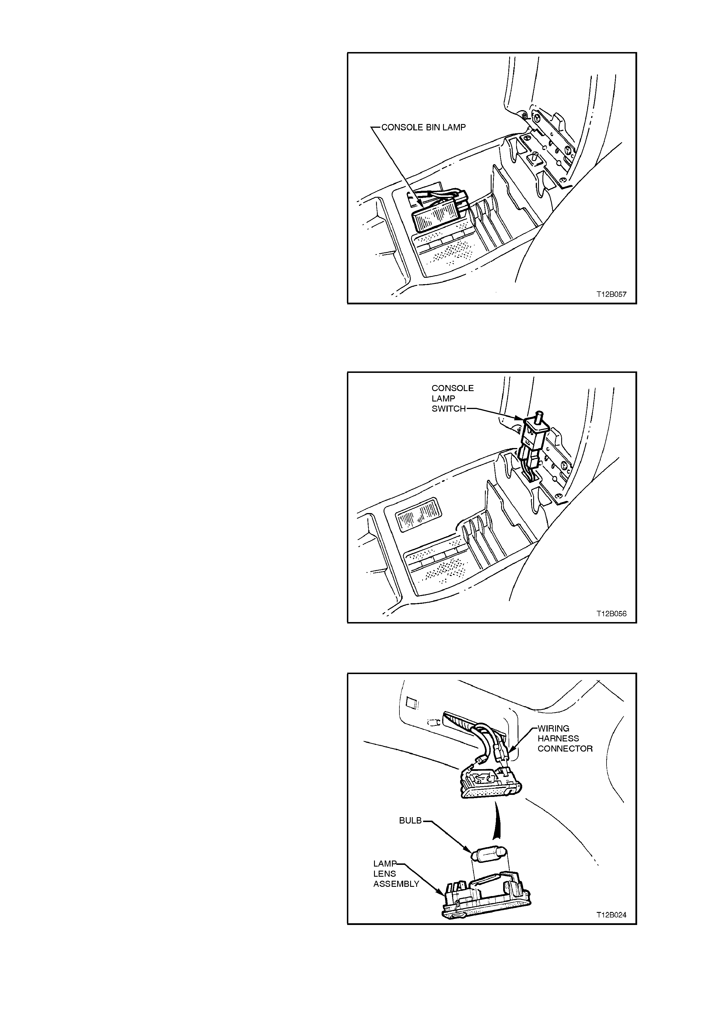
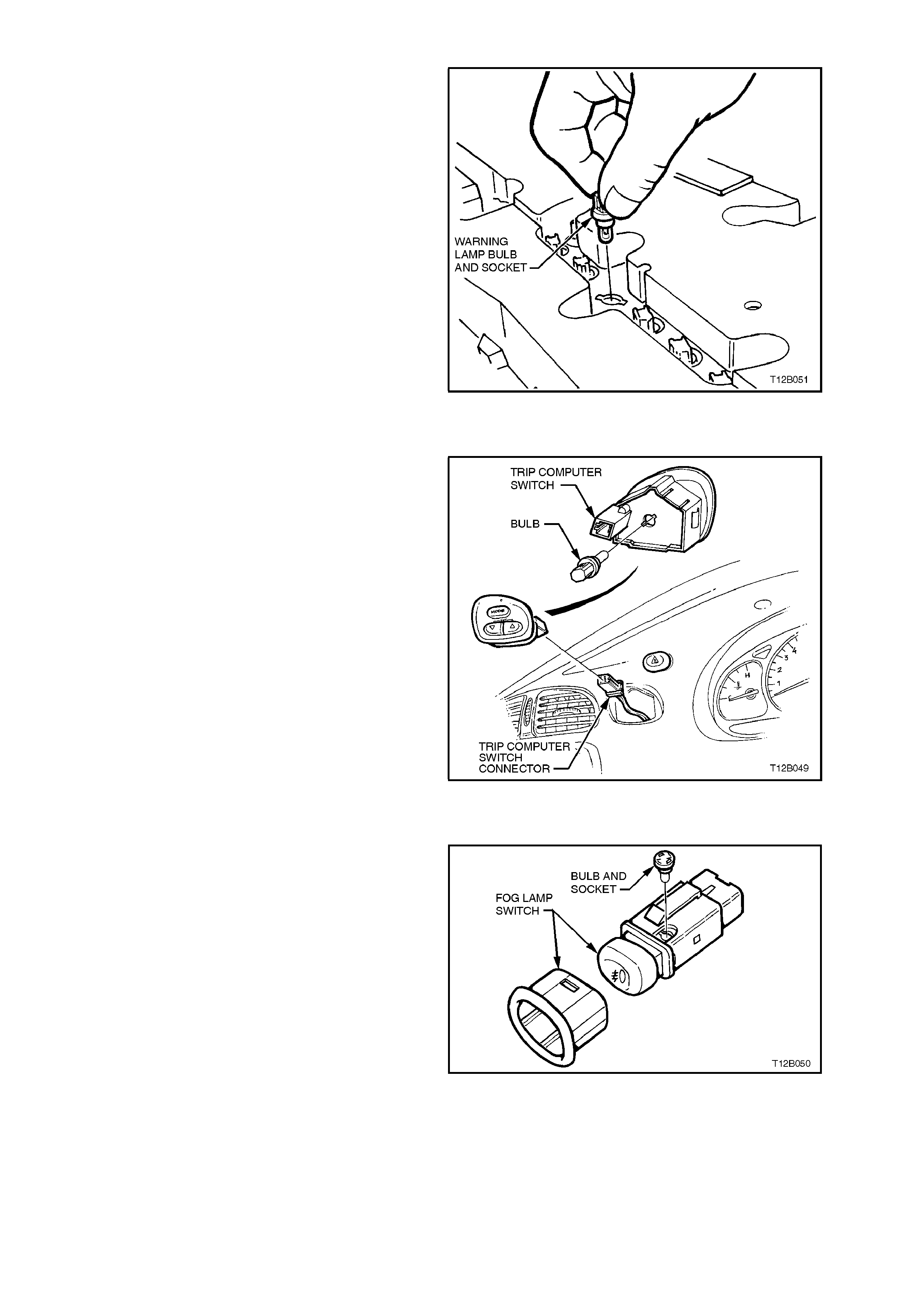
CONSOLE BIN LAMP
From inside of console, use a fine bladed
screwdriver to carefully lever lens fr om console. To
remove lens, pull wiring harness connectors from
lens and remove lens.
Bulb can be replaced by bending back the contact
retaining the bulb and removing the bulb.
Figure 12B-51
CONSOLE BIN LAMP SWITCH
REMOVE
1. Open console bin and pull s witch from c ons ole
bin assembly.
2. Disconnect wiring connector from switch and
remove switch from console bin.
Figure 12B-52
REAR READING LAMP
Fig. 12B-53 illustrates the installation of the rear
reading lamp assembly for Calais sedan models.
To gain ac ces s to bulb, us e f ine bladed sc r ewdriver
and gently lever lens from lens surround, ensuring
no damage is made to lens surround or headlining.
Pull bulb from contacts to remove.
Figure 12B-53
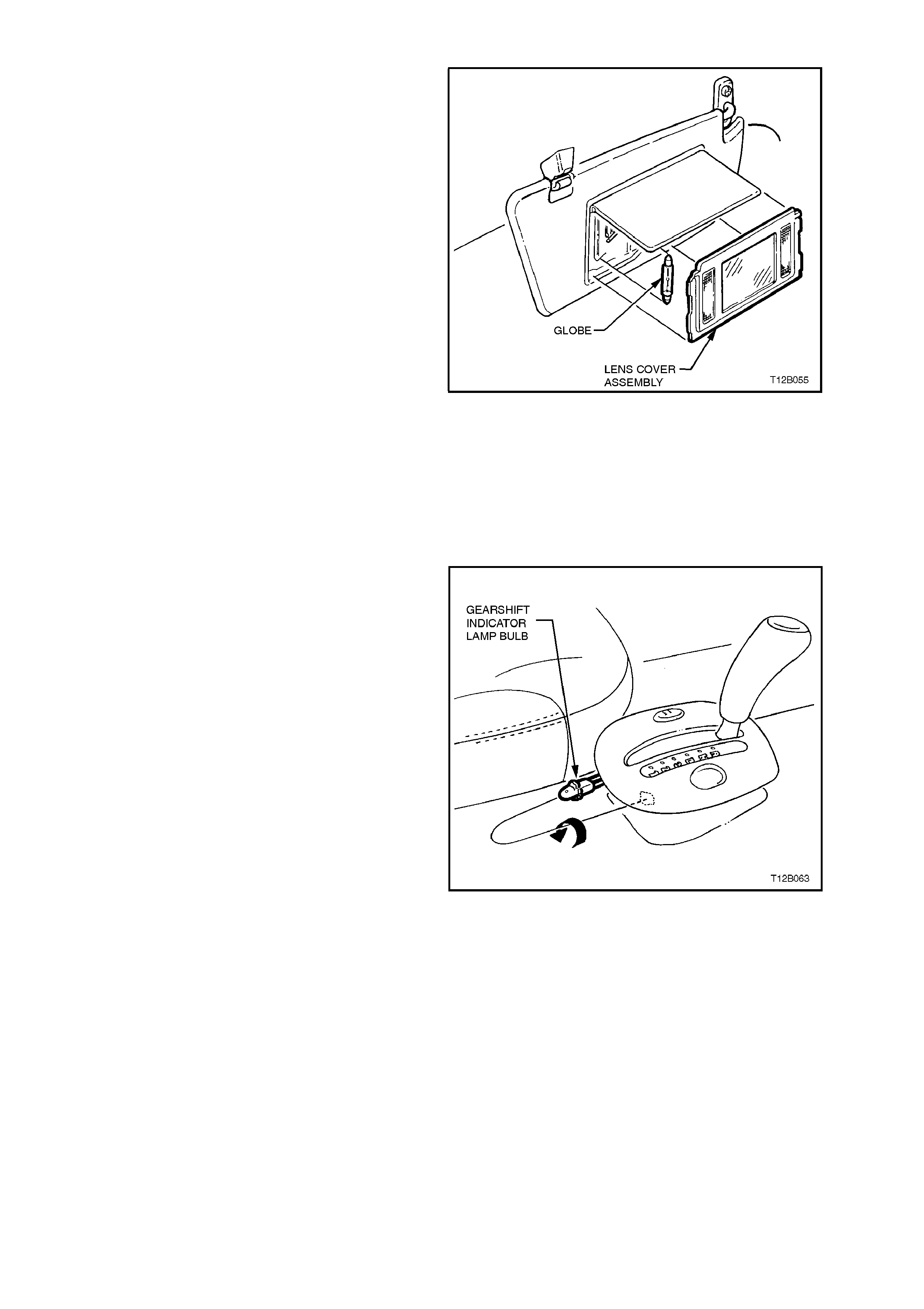
FRONT VANITY MIRROR LAMP - CALAIS ONLY
Fig. 12B-54 illustrates the installation of the front
vanity mirror lamp. Lower visor and lift flap to
expose vanity mirror and lamp assembly. To gain
access to bulb, use fine bladed screwdriver and
gently lever fr ont vanity mirror lamp c over as s embly
from visor and pivot assembly.
NOTE:
Damage to vanity mir ror lamp s urround will occur if
care is not taken when levering lens cover
assembly.
Bulbs (2) are festoon bulbs and can be replac ed by
pulling from contacts.
If replacing lamp housing, pull wiring harness
connectors from lamp housing terminals.
Figure 12B-54
GEARSHIFT INDICATOR LAMP BULB
REPLACE
1. Disconnect battery earth lead.
2. Remove transmission console as described in
Section 1A3 INSTRUMENT PANEL &
CONSOLE.
3. From beneath console cap, disconnect
console wiring harness to illumination
connectors.
4. Disconnect illumination bulb socket and pull
bulb from socket.
5. Install new bulb into socket. Install socket into
holder and twist clockwise to retain.
6. Reinstall transmission console cap assembly,
reverse to removal procedures, ensuring all
connectors are reconnected.
7. Turn headlamps on and ensure bulb
illuminates.
Figure 12B-55
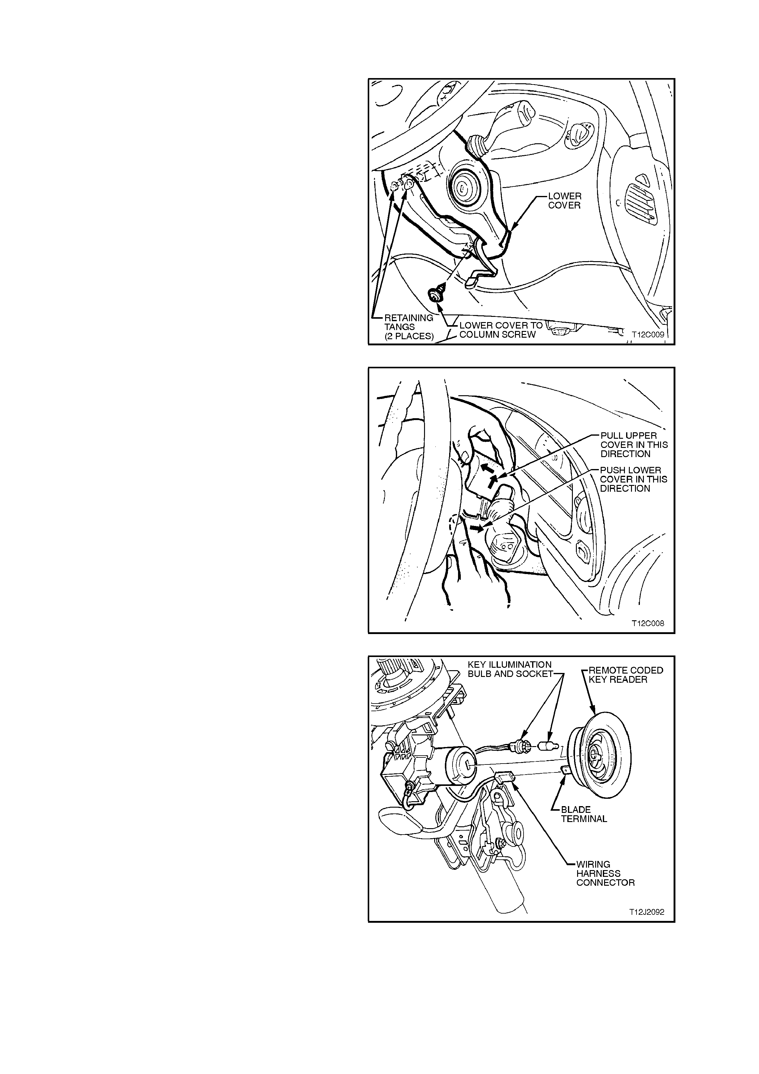
IGNITION LOCK LAMP
CAUTION:
Disable the SRS (Air Bag). Refer to DISABLING
THE SRS Section 12M SUPPLEMENTAL
RESTRAINT SYSTEM.
1. Release steering column height adjusting lever
and allow steering column to move upward.
Leave lever in the released position.
Remove ignition keys from ignition switch.
2. Remove steering column lower cover to
column and upper cover attaching screws.
Figure 12B-56
3. Pull steering column upper cover up and
toward steering wheel at the sam e tim e pulling
lower cover down and away from steering
wheel. This will release the steering column
lower cover end retainers from mating slots in
upper cover.
4. Remove steering column covers.
Figure 12B-57
5. Pull ignition lock lamp socket from lamp
housing on key reader assembly.
6. Pull bulb from socket.
7. Replace bulb and reinst all lamp housing to key
reader assembly.
8. Reinstall steering column covers and screw.
IMPORTANT:
Enable the SRS (Air Bag). Refer to ENABLING
THE SRS, Section 12M SUPPLEMENTAL
RESTRAINT SYSTEM.
Figure 12B-58
INSTRUMENT CLUSTER ASSEMBLY LAMP BULBS
The instrument assembly and warning lamp
illumination bulbs ar e a push f it into a s oc ket, which
in turn are a twist fit into the rear of the instrument
case and flexible printed circuit board.
To remove the lamp socket, remove the
instrument cluster, refer to Section 12C
INSTRUMENTS, WIPERS/ WASHERS AND
HORN. Remove the lamp socket from the printed
circuit board and pull bulb from its socket.
Installation is the reverse of removal procedure.
Figure 12B-59
TRIP COMPUTER SWITCH ASSEMBLY ILLUMINATION BULB
The trip computer assembly illumination bulb is a
push fit into a socket, which in turn is a twist f it into
the rear of the trip computer flexible printed circuit
board.
To remove the lamp socket, remove the trip
computer switch assembly, refer to Section 12C
INSTRUMENTS, WIPERS/WASHERS AND
HORN. Remove the lamp socket from the printed
circuit board and pull bulb from its socket.
NOTE:
Procedures for replacing the trip computer
assembly illumination lamps are covered in
Section 12C INSTRUMENTS,
WIPERS/WASHERS AND HORN .
Figure 12B-60
INSTRUMENT FACIA AND CENTRE FACIA ESCUTCHEON SWITCH ILLUMINATION BULBS
The instrument facia and centre facia escutcheon
switch assemblies are illuminated by a bulb and
socket assembly which is a twist fit into the
underside of the switch assembly.
To remove switch assemblies, refer to Section
12C INSTRUMENTS, WIPERS/WASHERS AND
HORN. Then, using a fine bladed screwdriver,
inserted into cross on bulb socket, twist socket anti-
clockwise, remove bulb and socket assembly.
Installation of the bulb and socket assembly is the
reverse of removal procedure.
Figure 12B-61
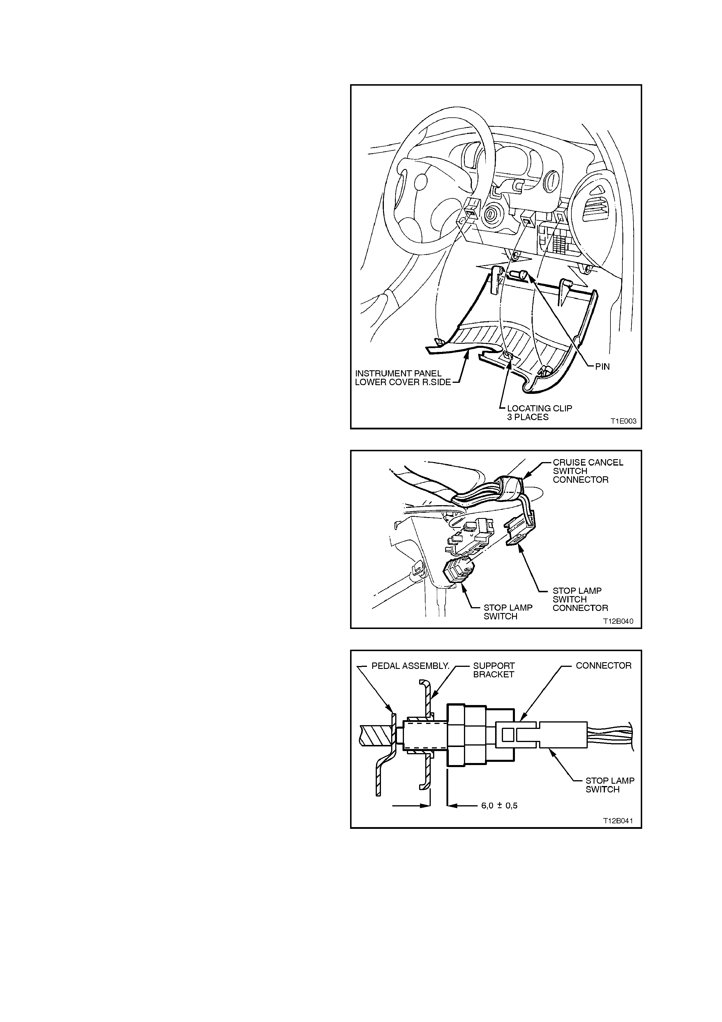
2.20 STOP LAMP SWITCH
REPLACE
1. Lower instrument panel right hand cover
assembly by pulling firmly to release retaining
clips and allowing cover to swing down.
Figure 12B-62
2. Remove wiring harness connectors from
switch.
3. Pull switch assembly out from pedal support
tubular clip to remove.
4. Push new switch assembly through pedal
support tubular clip.
Figure 12B-63
5. Hold brake pedal at its ‘REST’ position.
6. Adjust switch position to achieve gap of 5.5 -
6.5 mm.
7. Refit wiring harness connectors to switch and
check stop lamp operation.
8. Reinstall instrument panel lower trim and
cover assemblie s.
Figure 12B-64
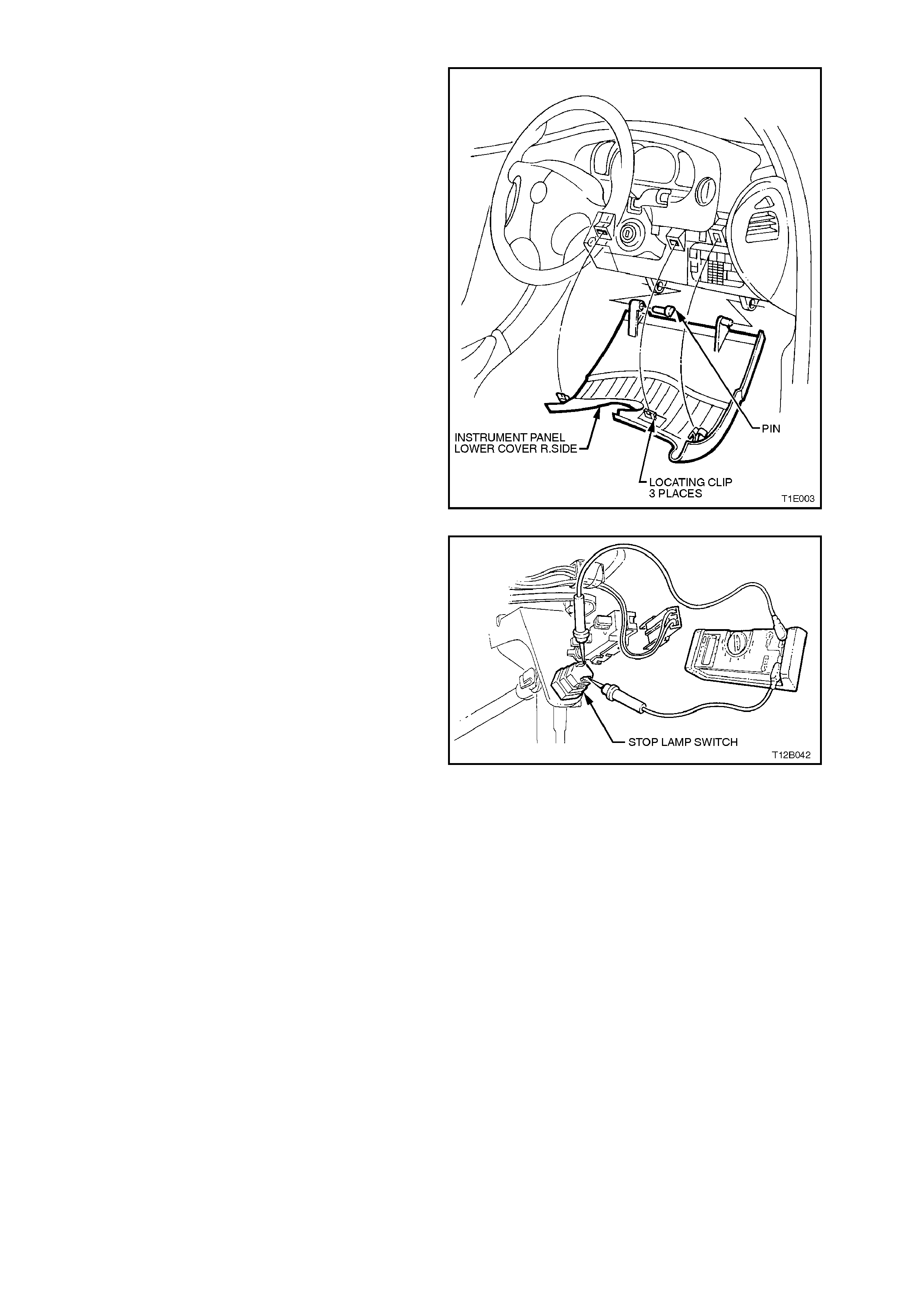
TEST
1. Lower instrument panel right hand cover
assembly by pulling firmly to release retaining
clips and allowing cover to swing down.
Figure 12B-65
2. Remove wiring harness connectors from
switch terminals.
3. Connect an ohmm eter across switch term inals
and ohmmeter should indicate open circuit
with brake pedal at rest.
Depress brake pedal and ohmmeter should
indicate continuity.
4. If ohmmeter does not indicate readings as
above, check switch adjustment as described
in 2.20 STOP LAMP SWITCH in this Section.
Retest switch after adjustment.
If switch adjustment is OK, replace switch as
previously described. Figure 12B-66
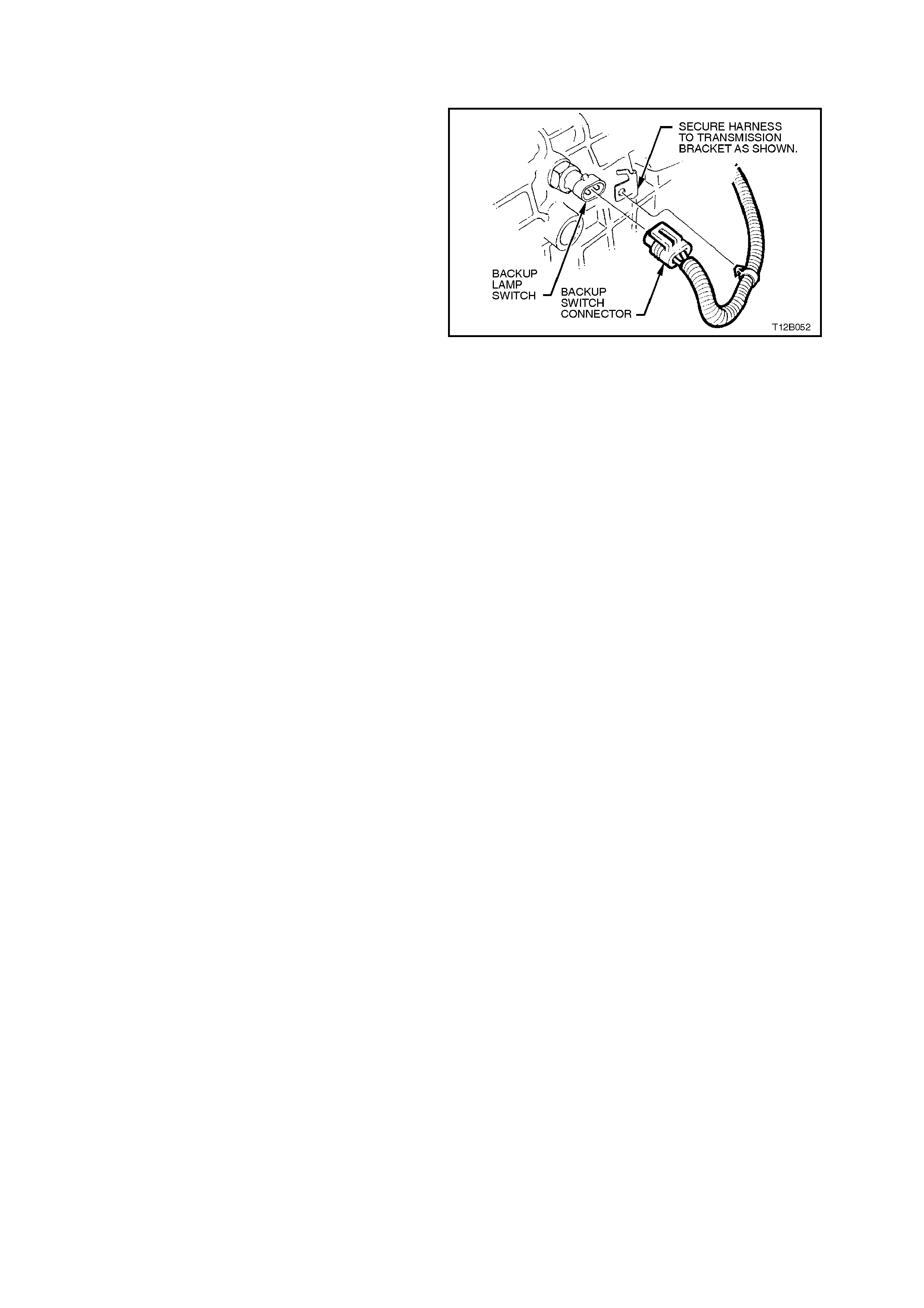
2.21 BACK-UP LAMP S WITCH
MANUAL TRANSMISSION
The back-up lamp switch for vehicles equipped with
manual transmission is non-adjustable. The switch
is screwed into the left hand side of the
transmission case.
For switch testing, removal and installation
procedures refer to Section 7B1 MANUAL
TRANSMISSION V6 ENGINE or Section 7B2
MANUAL TRANSMISSION - V8 ENGINE.
Figure 12B-67
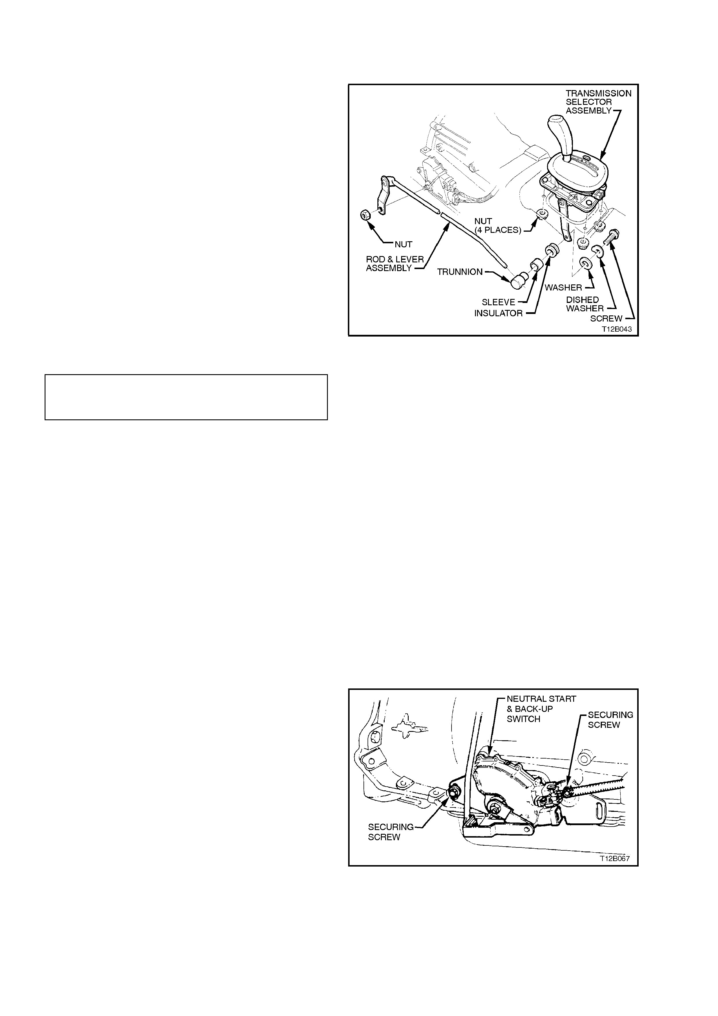
2.22 NE UTRAL START/BACK-UP LAMP SWITCH
ADJUST
Switch operation is controlled by the gearshift
linkage and has no separate adjustment. The
adjustment of the gearshif t linkage theref ore affec ts
the operation of the switch.
Adjustment of the gearshift linkage is as follows:
1. Raise front of vehicle and support on safety
stands. Refer to Section 0A GENERAL
INFORMATION for location of jacking points.
2. Loosen locking bolt at transmission selector
lever.
3. Position transmission selector lever in ‘PARK’.
4. Tighten locking bolt at transmission selector
lever to the correct torque specification.
Figure 12B-68
TRANSMISSION SELECTOR
LEVER LOCKING BOLT
TORQUE SPECIFICATION 20 - 30 Nm
5. Lower vehicle, check linkage and neutral
start/back-up switch operation by turning
ignition switch to the start position. T he starter
motor should operate in Park and Neutral
positions only.
Also check that the position indicator aligns
with the correct range indicator on the
transmission indicator support assembly.
If the indicator requires adjustment, remove
transmission console, refer to Section 1A3
INSTRUMENT PANEL & CONSOLE.
Place transmission selector lever in neutral
position. Lift up and reposition transmission
indicator support scale so that indicator is
positioned centrally with letter ‘N’ on scale.
TEST
Before conducting the following test, ensure that
the gearshift linkage is correctly adjusted, refer to
previous instructions on gearshift adjustment.
1. Disconnect battery earth lead.
2. Remove console cap and transmission
indicator support assembly, refer to Section
1A3 INSTRUMENT PANEL AND CONSOLE.
3. Pull back harness connector retainer and
disconnect main wiring harness connector
from neutral start/back-up switch wiring
harness connector.
Figure 12B-69
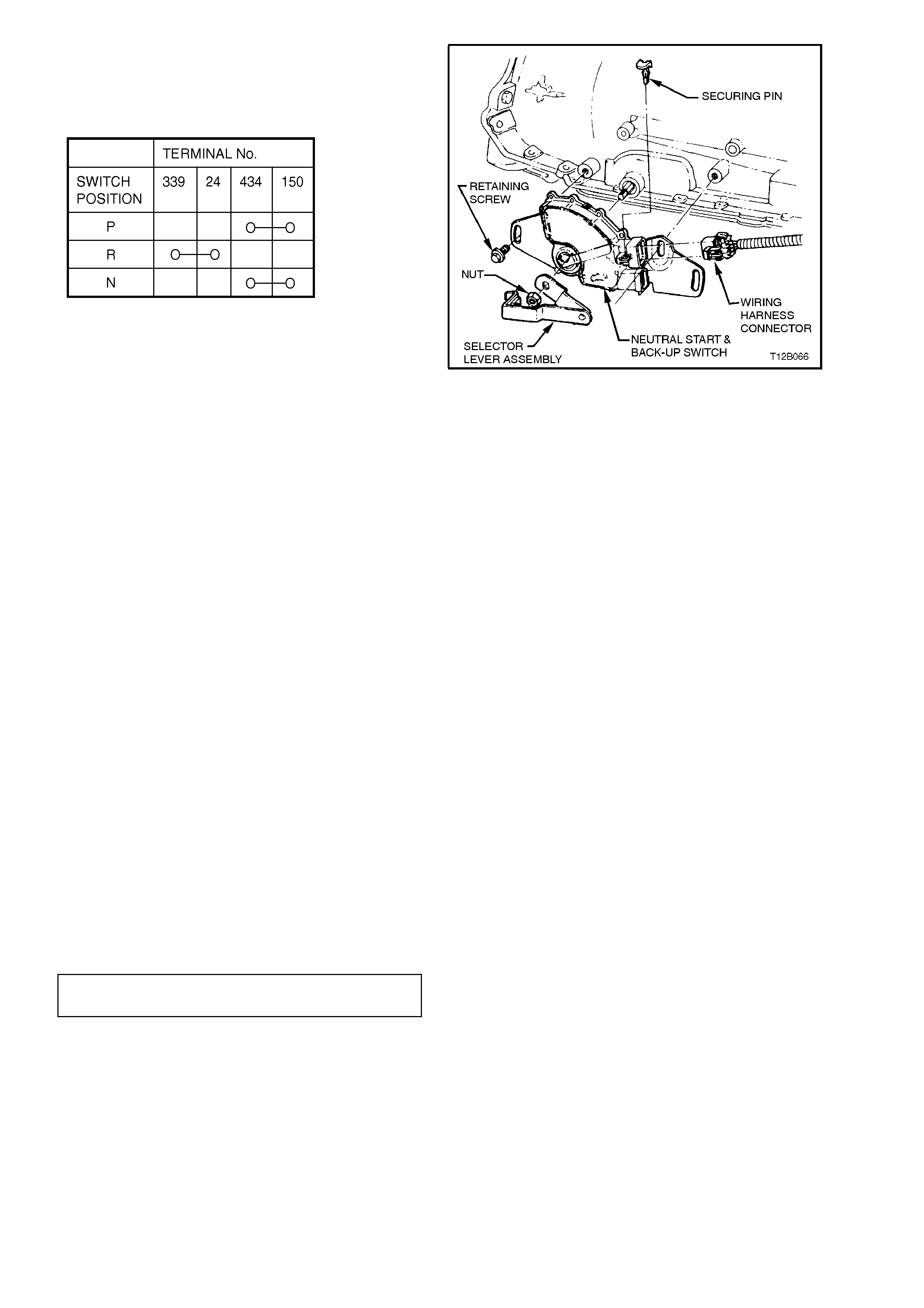
4. Using an ohmm eter connec ted to s witch wiring
harness c onnector term inals, select each gear
and check for continuity between switch
terminals as per the following chart and Fig.
12B-70.
If continuity between terminals is not as
specified, replace switch as per following
removal and installation instructions.
Figure 12B-70
REMOVE
1. Raise front of vehicle and place on safety
stands, refer to Section 0A GENERAL
INFORMATION for location of jacking points.
2. While holding the lower selector lever
assembly remove the retaining nut, then
carefully remove the lever assembly from the
transmission selector shaft.
3. Prise the wiring harness connector securing
pin from the neutral start and backup lamp
switch assembly, taking care not to break the
pin. Disconnect the wiring harness connector
from the switch assembly.
4. Remove the two retaining s c rews and s lide the
switch assembly over the transmission
selector shaft and remove from the vehicle.
REINSTALL
Installation is the reverse of removal procedures,
noting the following points:
1. When installing the two switch retaining
screws, have them finger-tight until the
adjustment process is completed.
2. When installing the wiring harness connector
securing pin, tak e care not to break the lug on
the switch body during the process.
3. After installing the selector lever retaining nut,
tighten to the specified torque.
SELECTOR LEVER RETAINING
NUT TORQUE SPECIFICATION 15 - 35 Nm
4. After adjusting the neutral start and back-up
lamp switch, check that the engine can only be
started when the transm iss ion selector lever is
in either the ‘P’ (Park) or ‘N’ (Neutral) position.
2.23 HEADLAMP AND TURN SIGNAL CONTROL SWITCH ASSEMBLY
REMOVE
1. Disconnect battery earth lead.
CAUTION:
Disable the SRS (Air Bag). Refer to DISABLING
THE SRS, Section 12M SUPPLEMENTAL
RESTRAINT SYSTEM.
2. Release steering column height adjusting lever
and completely lower steering column.
Remove ignition keys from ignition switch.
3. Place a clean shop rag over and around
steering column upper cover. This step is
important so as to prevent any possibility of
damage to cover should there be any contact
with lower edge of instrument facia while
removing the cover.
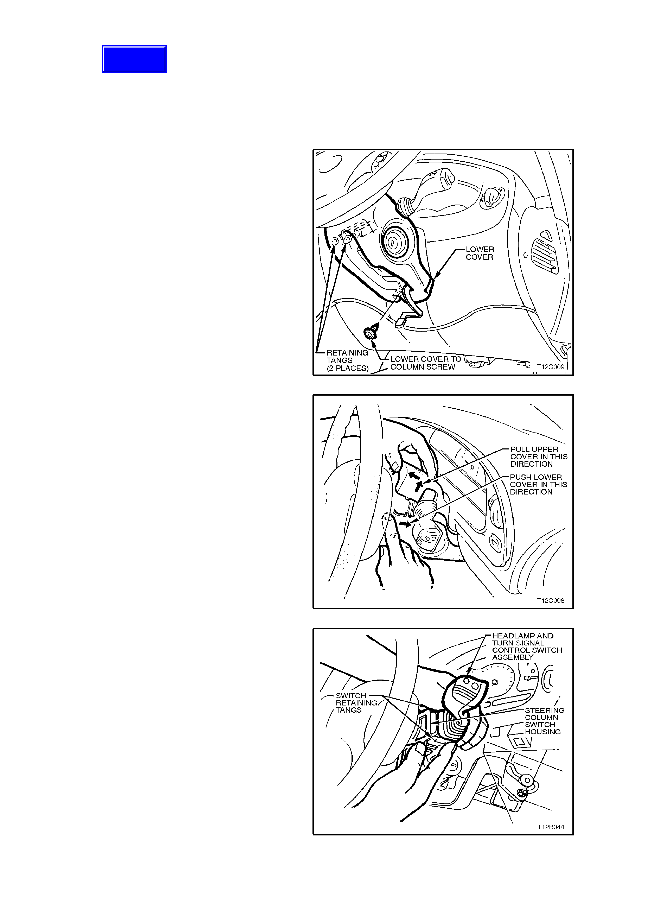
4. Remove steering column lower cover to
column and upper cover attaching screw.
Figure 12B-71
5. Pull steering column upper cover up and
toward steering wheel at the sam e tim e pulling
lower cover down and away from steering
wheel. This will release the steering column
lower cover end retainers from mating slots in
upper cover
Remove steering column covers.
Figure 12B-72
6. On headlamp and turn signal control switch
with integrated cruise control switch contacts,
disconnect wiring harness connector to switch
cruise control switch harness connector.
7. Depress retaining tangs on switch assembly
and withdraw switch from switch housing on
steering column.
8. Depress wiring harness connector retaining
tangs and pull connectors from rear of switch.
Figure 12B-73
Techline
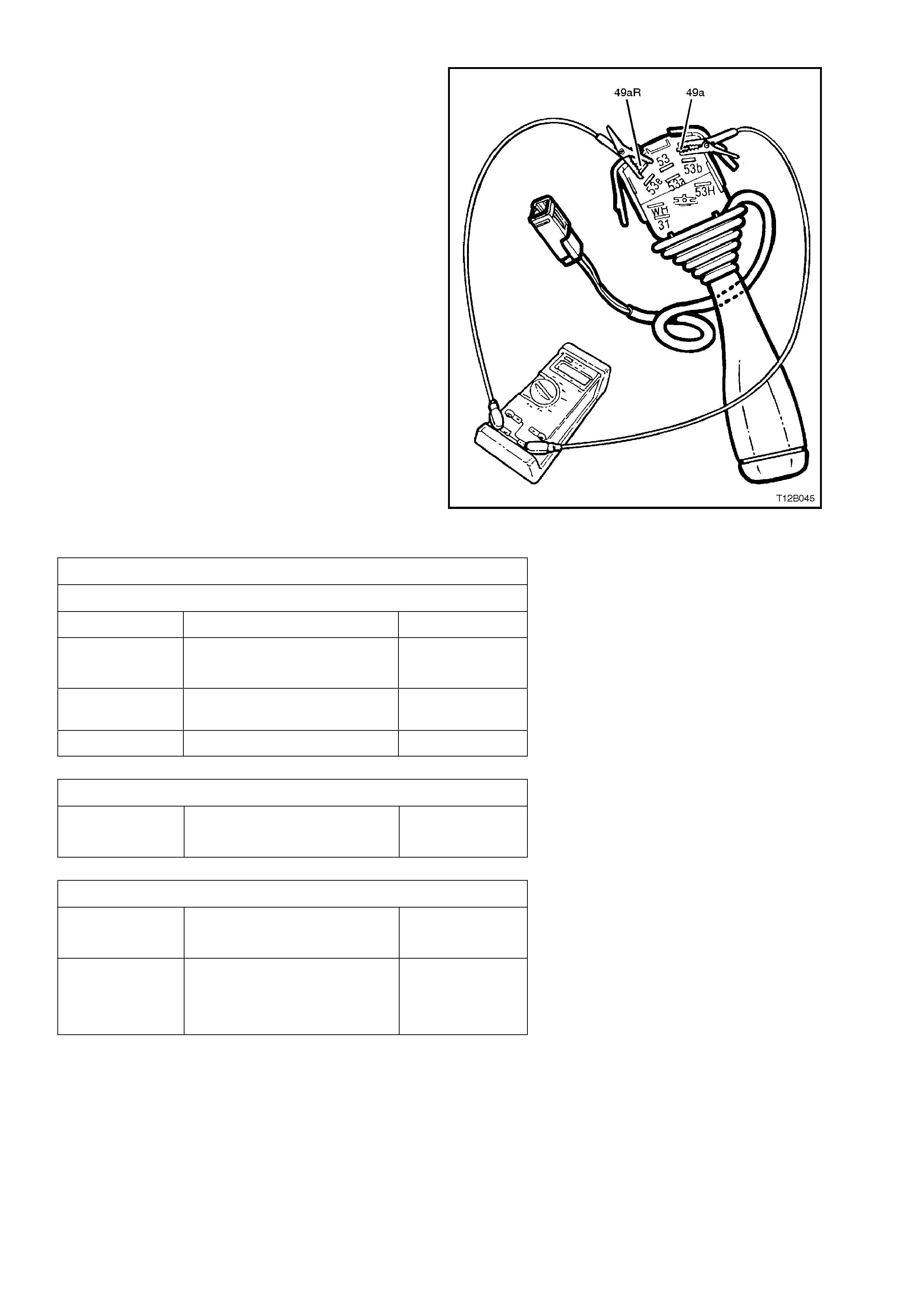
TESTING SWITCH
Using an ohmmeter, check switch contacts for
continuity at each switch position as indicated in the
following chart.
If continuity between switch terminals is not as
specified, replace switch assembly.
NOTE:
Switch terminal numbering is indicated on the
switch body, adjacent to each terminal.
Figure 12B-74
HEADLAMP AND TURN SIGNAL CONTROL SWITCH ASSEMBLY
TURN SIGNAL SWITCH CONTACTS
Switch Terminals Switch Position Indication If OK
49a and 49aR
49a and 49aL
Switch in central position Open circuit
49a and 49aR Switch in right hand turn
position Continuity
49a and 49aL Switch in left hand turn position Continuity
HEADLAMP FLASH CONTACTS
30 and 56a Flash position
High beam or central position
Continuity
Open circuit
HEADLAMP HIGH BEAM CONTACTS
56 and 56a Flash or central position
High beam position
Open circuit
Continuity
56 and 56b Central position
High beam position
Flash position
Continuity
Open circuit
Continuity
REINSTALL
Reinstallation of the s witch ass em bly is the rever se
of the removal procedure, noting the following
points:
1. Check switch operation once it is installed.
IMPORTANT:
Enable the SRS (Air Bag). Refer to ENABLING
THE SRS, Section 12M SUPPLEMENTAL
RESTRAINT SYSTEM.
2.24 HEADLAMP SWITCH
There are two specific headlamp switch
assem blies used on VT Series Models, with usage
dependant on what category of BCM is installed in
the vehicle.
Switch identification is by the colour of the switch
body. Switch bodies coloured black (two step
dimmer) are used on vehicles with Low Series
BCM. Switches with grey coloured bodies ar e used
for vehicles with High Series BCM. This switch has
spring loaded variable dimmer control knob.
If replacing a headlamp switch, ensure the correct
type is fitted.
REMOVE
1. Disconnect battery earth lead.
CAUTION:
Disable the SRS (Air Bag). Refer to DISABLING
THE SRS, Section 12M SUPPLEMENTAL
RESTRAINT SYSTEM.
2. Release steering column height adjusting lever
and completely lower steering column. Lock
lever in this position.
3. Place a clean shop rag over and around
steering column upper cover. This step is
important so as to prevent any possibility of
damage to cover when removing the
instrument facia.
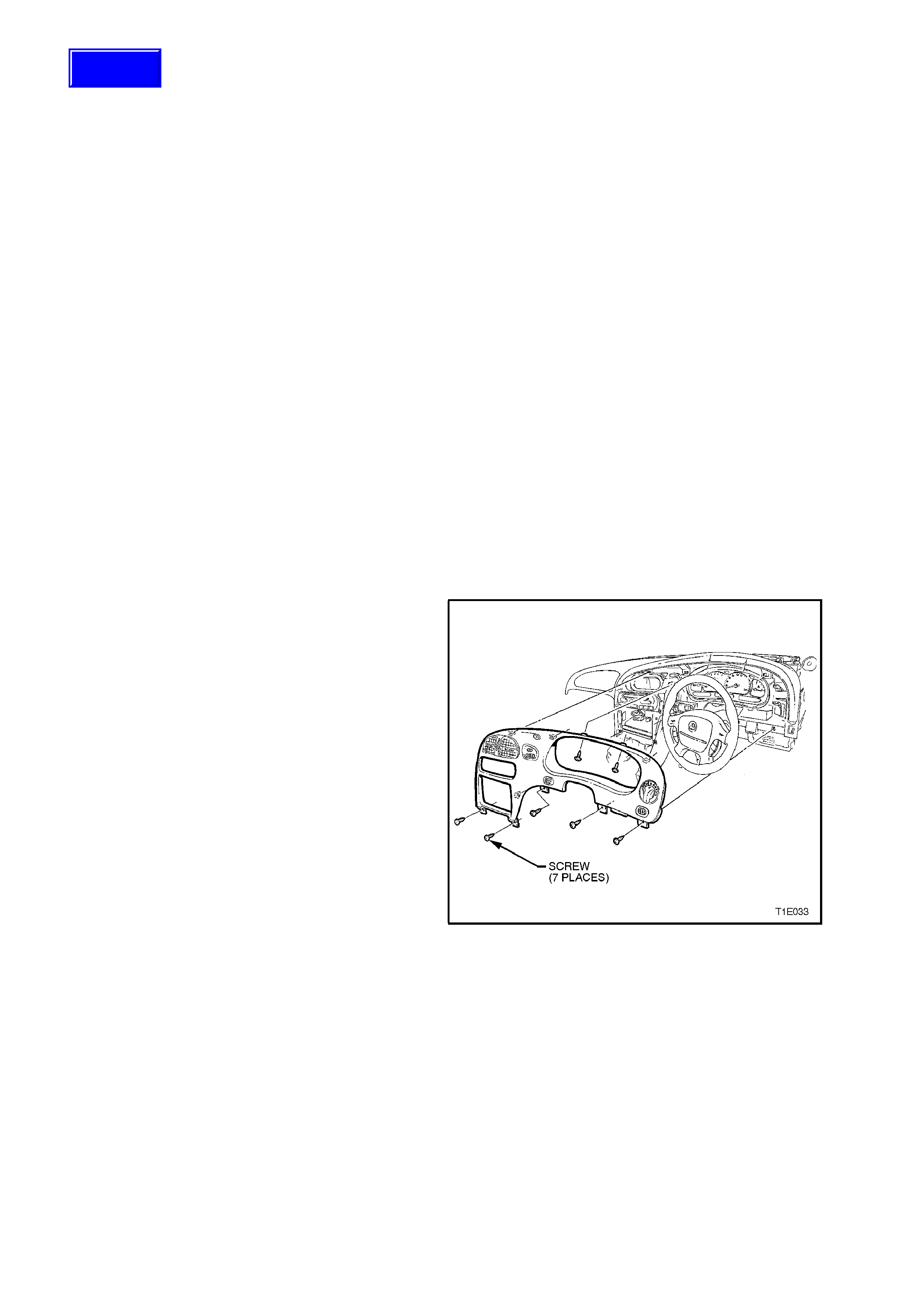
4. Remove instrument facia, refer to
Section 1A3 INSTRUMENT PANEL &
CONSOLE
Figure 12B-75
Techline
5. Pull instrument facia out only far enough to
gain access to rear of headlamp switch.
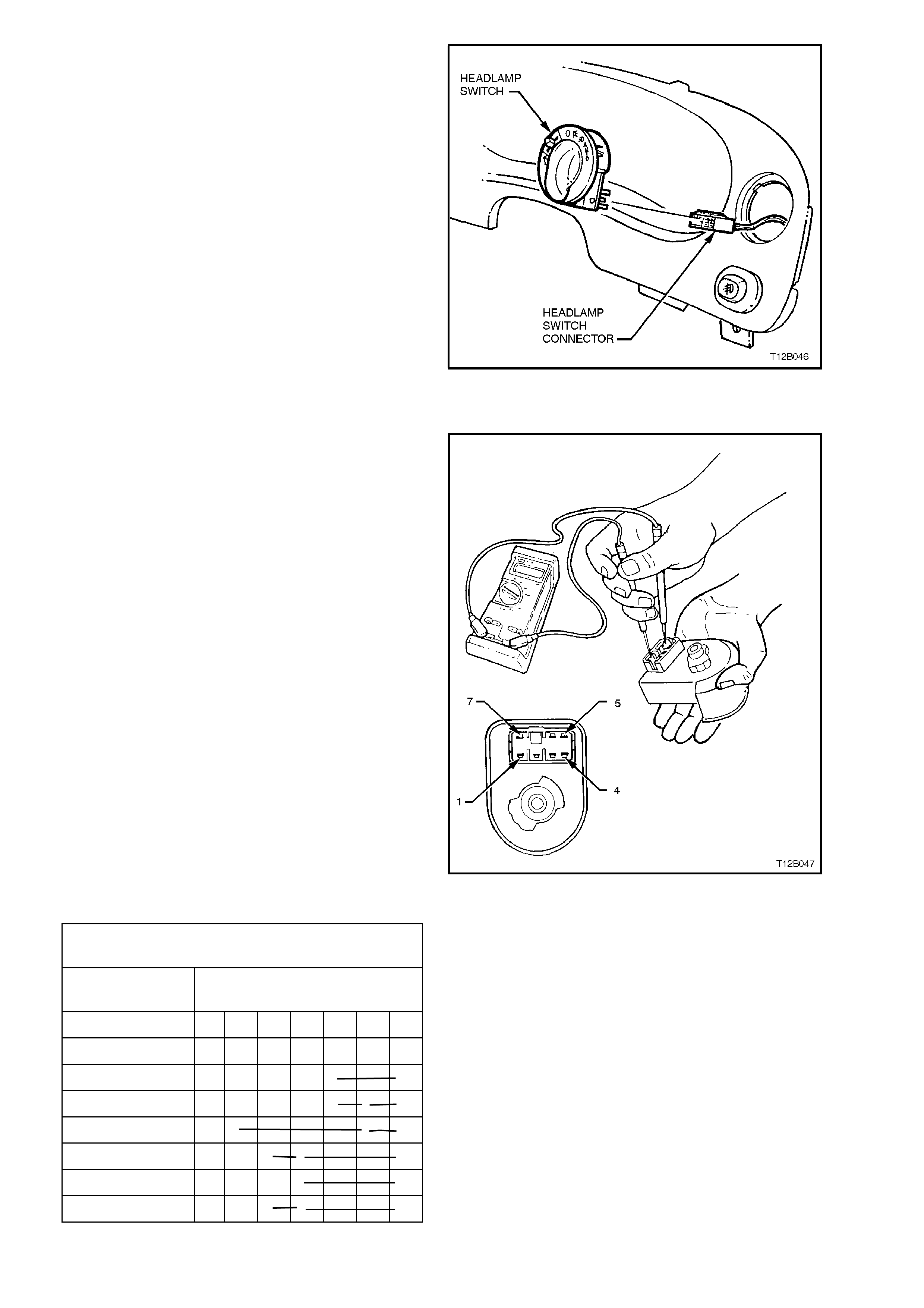
6. Pull connector from headlamp switch
7. Depress retaining tang on instrument harness
headlamp switch connector and remove
switch from facia.
Figure 12B-76
TESTING SWITCH
With the aid of an ohmmeter, check continuity of
headlamp switch contacts, using the following
chart.
If continuity is not as specified at any switch
position, replace switch cluster assembly.
Figure 12B-77
HEADLAMP SWITCH FOR VEHICLES WITH HIGH
SERIES BCM
SWITCH
POSITION TERMINAL NO.
1234567
OFF
PARKLAMPS O O
HEADLAMPS O O O
AUTO (CALAIS) O O O
DIM O O O
NEUTRAL O O
BRIGHT O O O

HEADLAMP SWITCH FOR VEHICLES WITH LOW
SERIES BCM
SWITCH
POSITION TERMINAL NO.
1234567
OFF
PARKLAMPS O O
HEADLAMPS O O O
DIM O O
BRIGHT O O
At low intensity setting, reading should be approx.
2.65 kW and at high intensity setting, approx. 5.3
kW.
REINSTALL
Installation of the headlamp s witch is the r ever se of
the removal procedure, noting the following points:
1. If, when instrument facia was pulled away
from instrument panel pad, the pad retaining
clips came away with the facia lugs, pull clips
from lugs and reinstall into pad holes. Fit
instrument facia and ensure that it is held to
the instrument panel pad securely.
2. Check for correc t operation of headlamps and
switch.
IMPORTANT:
Enable the SRS (Air Bag). Refer to ENABLING
THE SRS Section 12M SUPPLEMENTAL
RESTRAINT SYSTEM.
2.25 HAZARD WARNING FLASHER SWITCH
REMOVE
1. Disconnect battery earth lead.
CAUTION:
Disable the SRS (Air Bag). Refer to DISABLING
THE SRS, Section 12M SUPPLEMENTAL
RESTRAINT SYSTEM.
2. Release steering column height adjusting lever
and completely lower steering column, lock
lever in this position.
3. Place a clean shop rag over and around
steering column upper cover. This step is
important so as to prevent any possibility of
damage to cover when removing the
instrument facia.
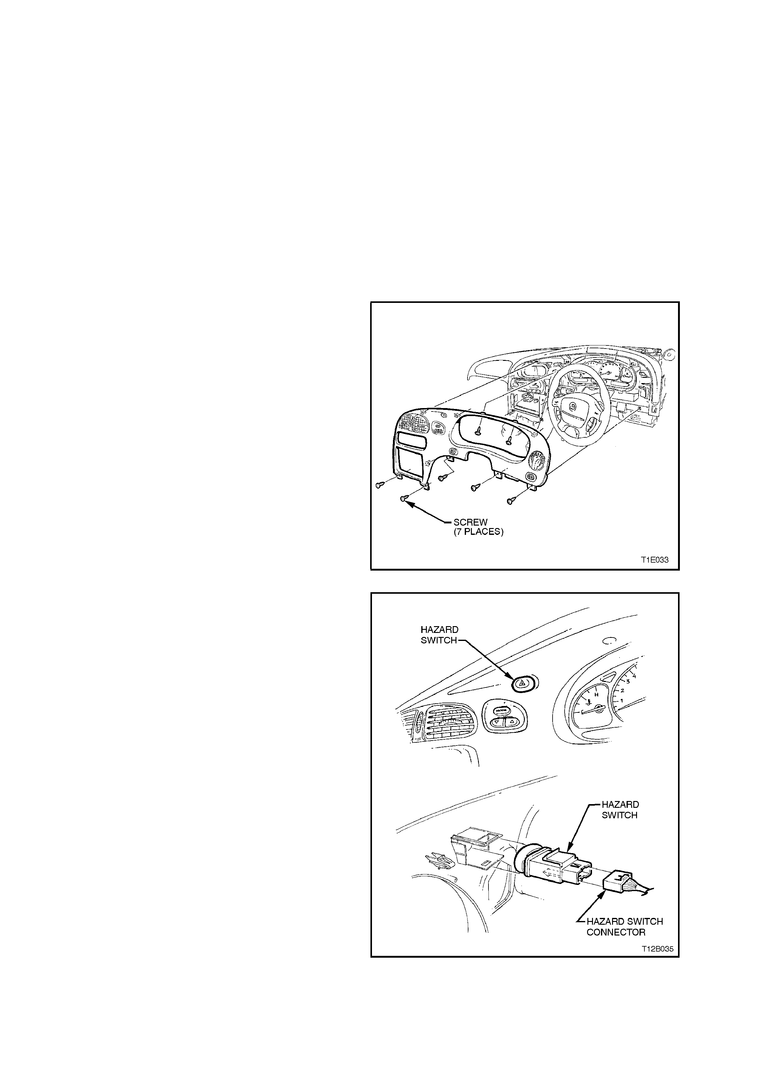
4. Remove instrument facia, refer to
Section 1A3 INSTRUMENT PANEL &
CONSOLE.
Pull instrument facia out only far enough to
gain access to rear of all instrument facia
switches.
Figure 12B-78
5. Depress retaining tangs on instrument
harness to facia switch connectors and pull
connectors from switches.
6. Remove instrument facia.
7. Squeeze together retaining tangs at side of
switch and push switch out from facia.
Figure 12B-79
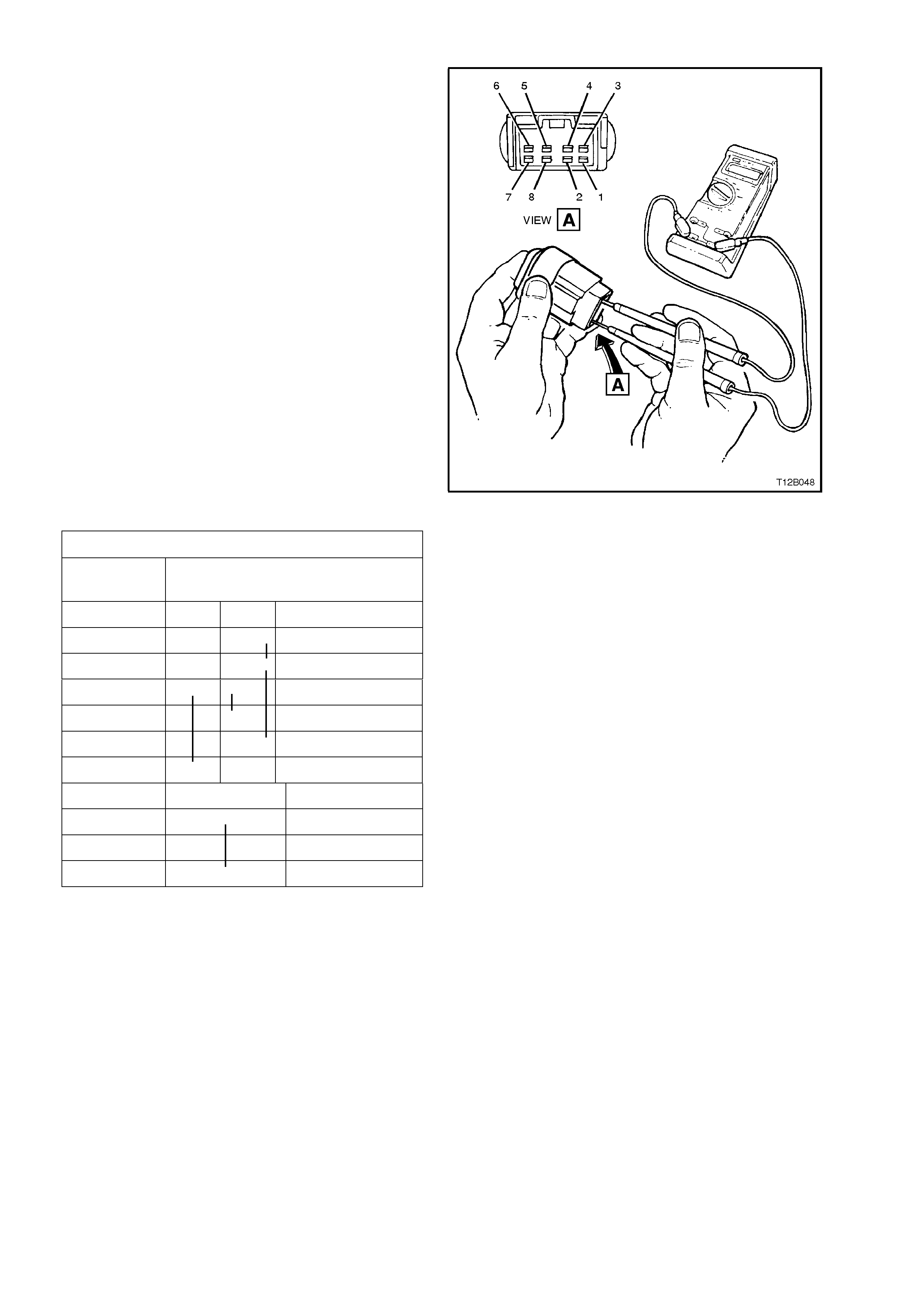
TEST
With the aid of an ohmmeter, check continuity of
hazard warning flasher switch contacts, using the
following chart.
If continuity is not as specified at any switch
position, replace switch assembly.
Figure 12B-80
HAZARD WARNING FLASHER SWITCH CONTACTS
TERMINAL
NO. SWITCH
STATUS
OFF ON
1 O TURN SIGNAL
2 O SIDE TURN
3 O O FLASHER RELAY
4 O BATTERY +
5 O SIDE TURN
6 O IGN. SWITCH
7 O ILLUMINATION +
●
8 O ILLUMINATION –
REINSTALL
Installation of the hazard warning flasher switch is
the reverse of removal procedures, noting the
following points:
1. If, when instrument facia was pulled away
from instrument panel pad, the pad retaining
clips came away with the facia lugs, pull clips
from lugs and reinstall into pad holes. Refit
instrument facia and ensure that it is held to
the instrument panel pad securely.
2. Check hazard warning flasher operation and
ensure that switch illum ination bulb illuminates
when the headlamps are turned on.
IMPORTANT:
Enable the SRS (Air Bag). Refer to ENABLING
THE SRS, Section 12M SUPPLEMENTAL
RESTRAINT SYSTEM.
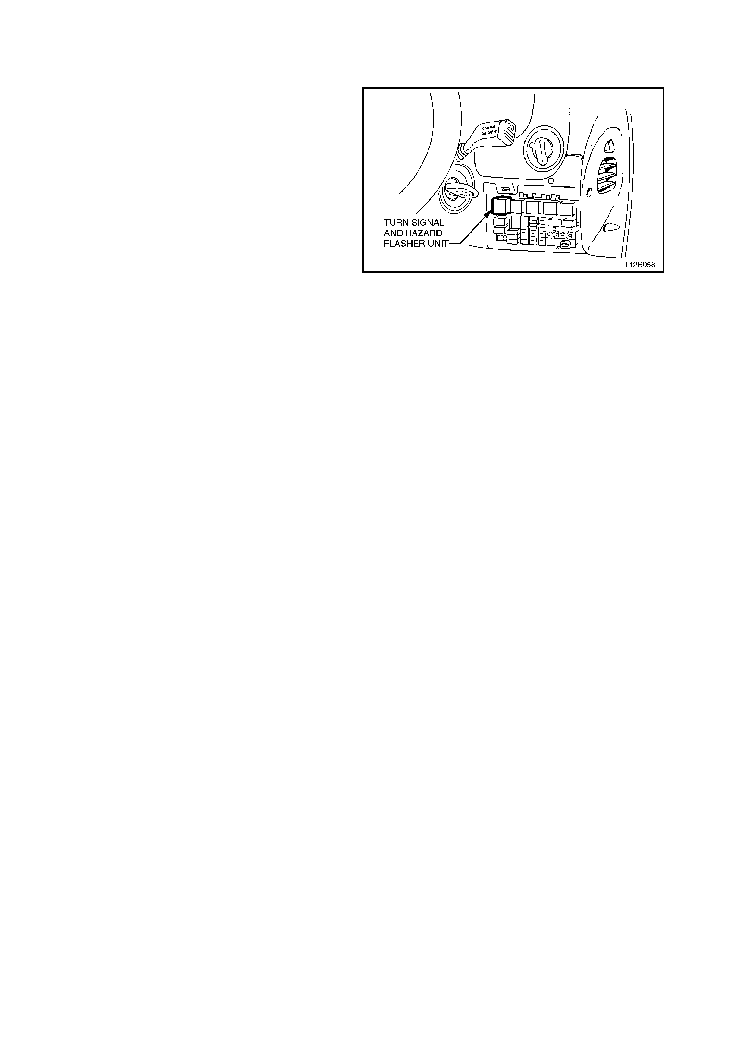
2.26 TURN S IGNAL AND HAZARD FLASHER UNIT
REPLACE
Fig. 12B-81 illustrates the location on the interior
fuse panel and installation of the turn signal and
hazard flasher unit (located inside the vehicle,
attached to the fuse panel).
Access to the turn signal and hazard flasher unit is
by gripping the upper portion of the instrument
panel right hand cover assembly and pulling down,
disengaging the retaining clips.
Figure 12B-81
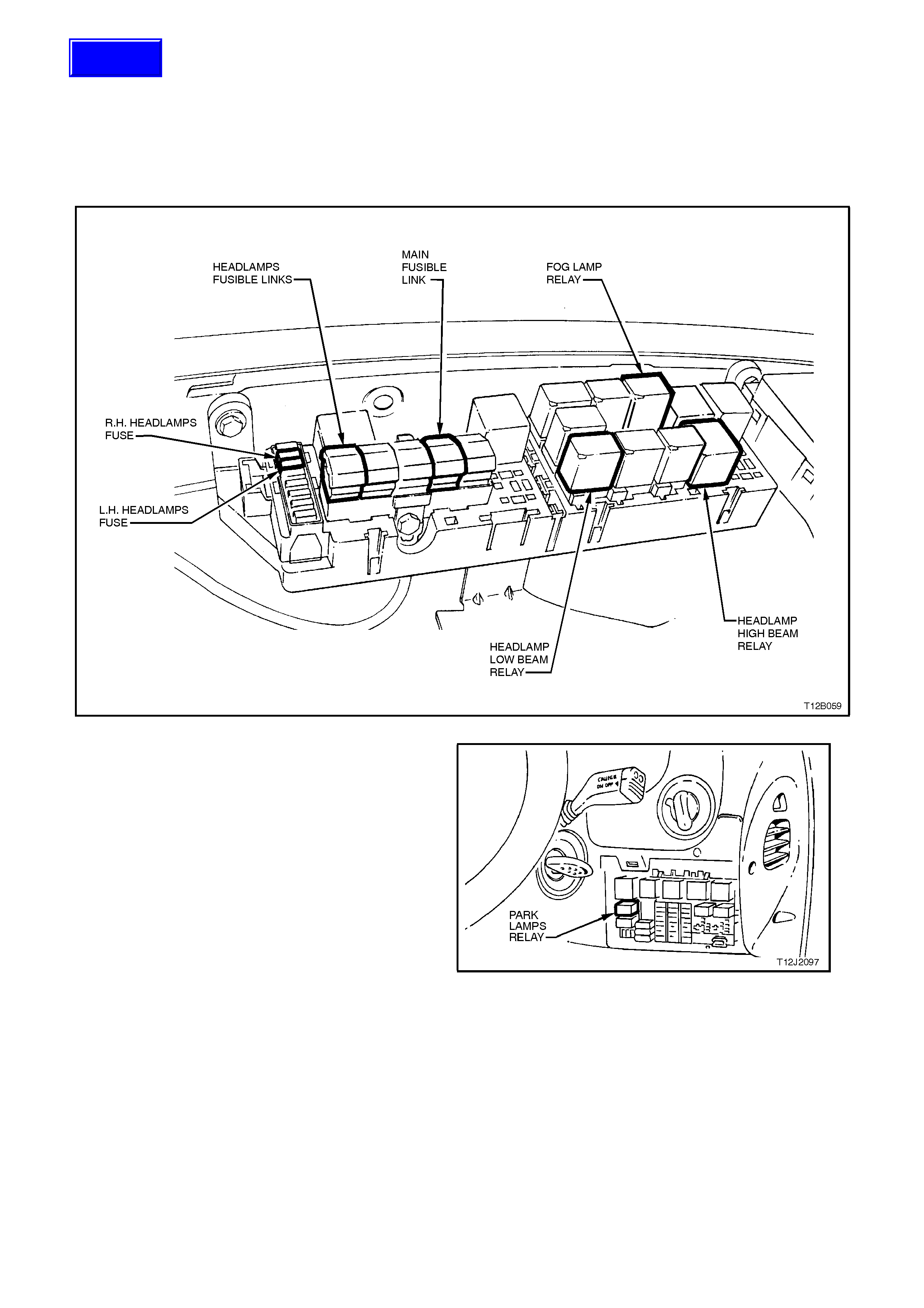
2.27 HEADLAMPS AND PARKING LAMPS RELAYS
REPLACE
Fig. 12B-83 illustrates the location in the engine
compartment relay housing of the relays used for
the headlamp oper ation ( all models) , f og lamp relay
(vehicles with fog lamps) and the fusible link FJ.
Figure 12B-82
The parking lamps relay is located inside the
vehicle, attached to the fuse panel. Access to the
parking lamps relay is by opening the instrument
panel right hand cover.
Figure 12B-83
Techline

3. SPECIFICATIONS
BULB POWER RA TING -
WATTS BASE TYPE
HEADLAMPS
Hi/Lo Beam (Outboard)
Inboard High Beam
60/55
55
H4
H3
FOG LAMPS 55 H3
PARKING LAMPS (Front) 5 Wedge
TURN SIGNAL LAMPS (Front) 21 Offset Pin (Orange glass)
SIDE REPEATER LAMP 5 Wedge
TURN SIGNAL (Sedan - Rear)
Executive, Berlina, S and SS
Calais
21
21
Std. Parallel Pin
Offset Pin (Orange glass)
TURN SIGNAL (Wagon - Rear)
All models 21 Offset Pin (Orange glass)
BACK-UP LAMP 21 Std. Parallel Pin
STOP AND TAIL LAMP 21/5 Std. Parallel Pin
LICENCE PLATE LAMP 5 Wedge
INSTRUMENT CLUSTER
ILLUMINATION LAMP
Executive
Berlina, Calais
3.6
5
Wedge
Wedge
INSTRUMENT CLUSTER
WARNING CLUSTER LAMP 1.2 Wedge
TRIP COMPUTER ILLUMINATION
LAMP 1.2 Wedge
REAR COMPARTMENT 10 Festoon
DOME (Courtesy) LAMP 10 Festoon
FRONT SEAT READING LAMP 5 Std. Parallel Pin
REAR SEAT READING LAMP 5 Wedge
GLOVE COMPARTMENT LAMP
Executive, Berlina, S and SS
Calais
5
10
Festoon
Festoon
FRONT FOOTWELL LAMPS 2.7 Wedge
FRONT VANITY MIRROR LAMP 1.4 Wedge
DOOR COURTESY LAMP 5 Festoon
CONSOLE BIN LAMP 5 Festoon
HIGH MOUNTED STOP LAMP 18 Wedge
HIGH MOUNTED STOP LAMP - S,
SS MODEL 5 LED assembly
FRONT AND REAR CIGAR
LIGHTER LAMP 1.2 Wedge
IGNITION LOCK LAMP 1.2 Wedge

4. TORQUE WRENCH SPECIFI CATIONS
Nm
Headlamp and turn signal/parking lamp assembly
securi ng screws 2 - 5
Calais and SS Fog lamp mounting frame to bumper
bar beam screws 2 - 5
S and SS high level stop lamp to rear spoiler
attaching screws 1 - 3
Station wagon high mounted stop lamp attaching
screws 1 - 3
Dome lamp attaching screws 3 - 5
Door jamb switch attaching screws 3 - 5
Headlamp adjuster attaching screws 3 - 5
Decklid lamp assembly attaching nuts 2 - 5
Decklid lamp housing attaching nuts 3 - 4
Rear compartment lamp switch attaching screw 1 - 3
Rear lamp housing retaining screw 1 - 3
Tailgate lamp switch attaching screw 1 - 3
Transmission selector lever locking bolt 20 - 30
Rear quarter lamp housing attaching nuts 3 - 4
Station wagon rear lamp housing retaining nuts 1 - 3
Selector lever retaining nut 15 - 35