
SECTION 12C - INSTRUMENTS, WIPERS/WASHERS
& HORN
CAUTION:
This v ehicle will be equipped with a Supplemental Restraint System (SRS). A SRS
will consist of either seat belt pre-tensioners and a driver's side air bag, or seat
belt pre-tensioners and a driver's and front passenger's side air bags. Refer to
CAUTIONS, Section 12M, before performing any service operation on, or around
any SRS components, the steering mechanism or wiring. Failure to follow the
CAUTIONS could result in SRS deployment, resulting in possible personal injury
or unnecessary SRS system repairs.
CAUTION:
This vehicle may be equipped with LPG (Liquefied Petroleum Gas). In the interests
of safety, the LPG fuel system should be isolated by turning 'OFF' the manual
service valve and then draining the LPG service lines, before any service work is
carried out on the vehicle. Refer to the LPG leaflet included with the Owner's
Handbook for details or LPG Section 2 for more specific servicing information.
1. GENERAL DESCRIPTI ON
Two versions of instrument cluster assemblies are used on VT Series Models, one with a single window trip
computer display and the other with a triple window display.
A trip computer is standard equipment on all VT Series Models.
The instrum ent cluster assem bly on VT Series Models consists of specific style analogue type instrument gauges.
An electronic s peedometer is s ituated to the right of c entre, with the odom eter and trip - odometer readings stored
on the trip com puter. A tachometer is located to the left of centre, an elec tronic tem perature gauge to the left of the
tachometer and a bi-metal fuel gauge to the right of the speedometer. W arning lights are located at the bottom of
the instruments above the odometer.
Instrument cluster illumination is by bulbs located in sockets, which are a twist fit into the rear of the instrument
case.
Located in the centre lower section of the instrument cluster on Executive, S, SS and Acclaim is a single window
Liquid Crystal Display (LCD) trip computer. A triple window trip computer is standard on VT Series Berlina and
Calais Models. Refer to 1.4 TRIP COMPUTER - SINGLE WINDOW TYPE or 1.5 TRIP COMPUTER - TRIPLE
WINDOW TYPE in this Section for an explanation of trip computer functions.
The trip c omputer on both instrum ent cluster ass emblies is operated by means of a switch ass embly located to the
left of the instrument cluster in the instrument facia.
NOTE:
If installing a new trip computer, the original odometer reading must be transferred into the replacement trip
computer. This can be done by authorised Holden dealers using TECH 2.
Techline
Techline
Techline
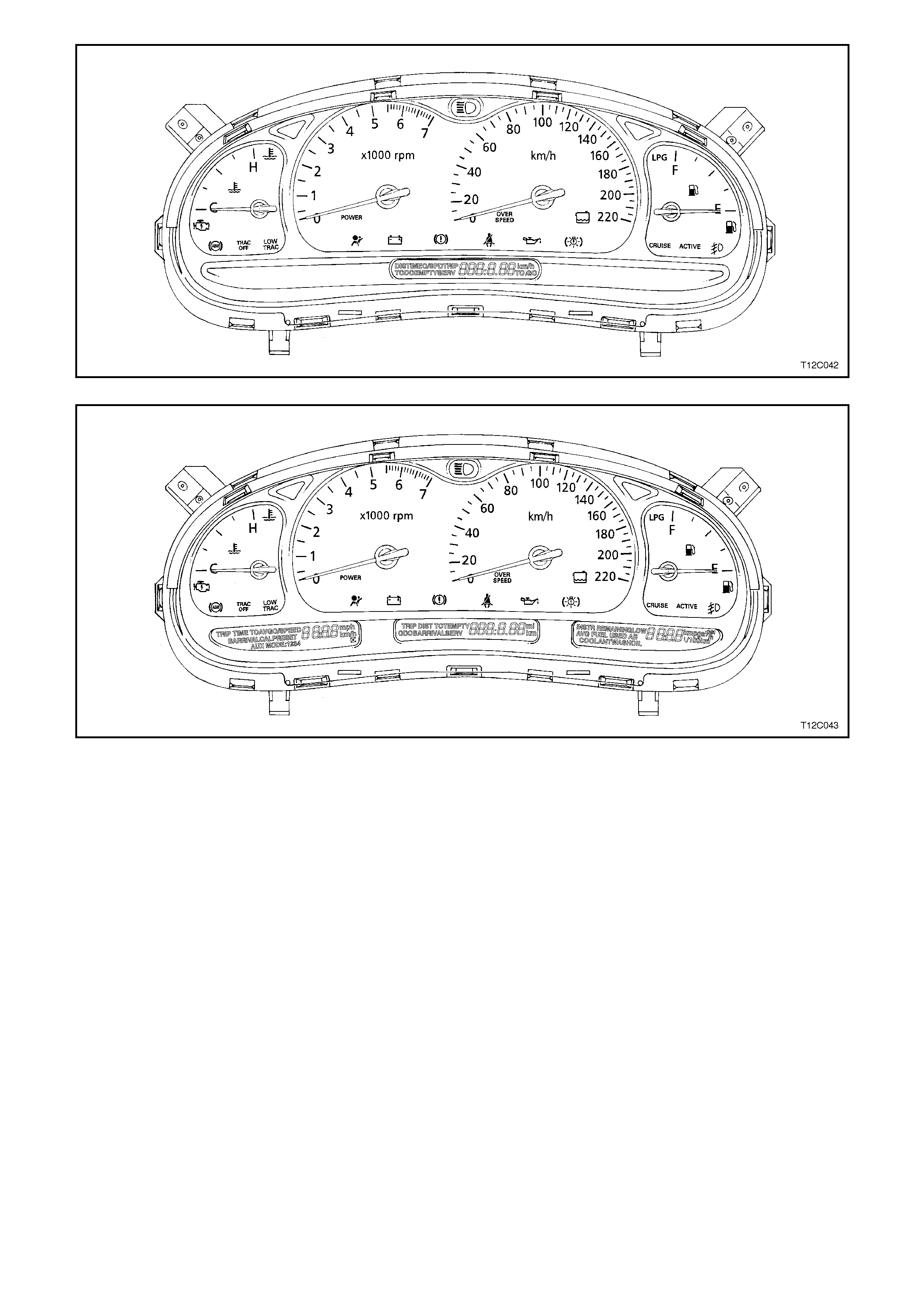
Figure 12C-1
Figure 12C-2
Incorporated inside the instrument cluster is an audible warning chime which will sound when one or more of the
following warning lamps illuminate in the warning lamp cluster.
The addition of the audible warning chime f eature is used to em phasise the following conditions, with the tone and
frequency of the chime varied to allow different warnings to be identified by sound.
Over speed - triggered when over speed warning lamp is turned on.
Low fuel level - triggered when low fuel warning lamp is turned on.
High Temp - when high temperature warning lamp is turned on.
Park Brake ON - triggered when park brake warning lamp is turned on and vehicle speed is greater than
approximately 8 km/h.
Low Oil - triggered when low oil lamp is turned on.
SRS Warning - triggered when SRS warning lamp is turned on.
The following chart sets out the chime tones for each warning.

DESCRIPTION TRIGGER FOR AUDIBLE WARNING SEQUENCE OF TONES
OVERSPEED Whenever first time over speed warning light is
turned on except for lamp check. C, F
UNDERSPEED Whenever over speed warning light is turned
off if it is in customise mode. F, C
LOW FUEL Whenever fuel light is turned ‘ON’ or whenever
fuel light starts flashing. G, GO
Repeated four times.
PARK BRAKE Whenever Park Brake warning light is turned
on and vehicle speed is greater than 8 km/h.,
except for lamp check.
C, D, E
Repeated four times.
HIGH TEMP. Whenever High temperature warning light is
first turned on except for lamp check. C, D, E
Repeated four times.
LOW OIL Whenever Low Oil Pressure warning light is
first turned on except for lamp check and
engine is running.
C, D, E
Repeated four times.
SRS WARNING Whenever SRS warning light is first turned on
except for lamp check. D, E, F
Repeated three times.
SET Whenever Set function is used. CI, FI
AUXILIARY Whenever Auxiliary Mode is used. CI, FI
ON/OFF Whenever ON/OFF function is used. CI, FI
MODE CHANGE Whenever displayed mode changes. CI
BUTTON PRESS Whenever button is pressed. FI
The corresponding frequencies of the tones are listed in the following table.
TONE GO C C
SHARP DEFGBICIFI
FREQUENCY
(Hz) 392 523 554 587 659 698 784 988 1046 1397
NOTE:
Should it be necessary to electric weld on any vehicle at any time, removal of the instrument cluster is mandatory.
Failure to do so will result in damage to the instrument gauge circuitry.
On all VT Series Models the clock is incorporated in the radio/cassette player LCD window.
1.1 INSTRUME NT FACIA SWITCHES
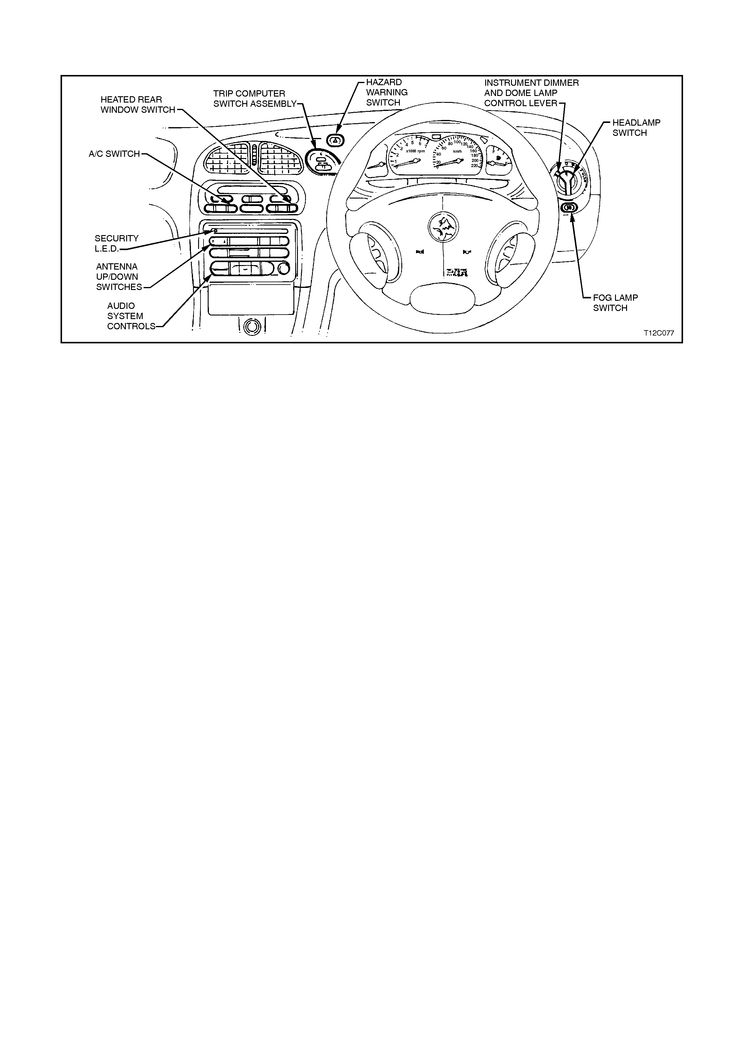
Fig. 12C-3 illustrates the various switch locations in the instrument facia for all models.
Figure 12C-3
Two different types of headlamp switches are used, one each for the different type of BCM used in VT Series
Models. Refer to Section 12J-1 BODY CONTROL MODULE for Low Series BCM identification details or
Section 12J-2 BODY CONTROL MODULE for High Series BCM identification details.
The headlamp switch used for the Low Series BCM incorporates a switch for two levels of instrument cluster
illumination (high and low level intensity) and a three-position switch for off, parking and headlamps on.
With High Series BCM, the headlam p s witch incorpor ates a variable intens ity instr um ent cluster illum ination control,
a four-position switch for off, parking and headlamps on and an auto headlamps on switch mode.
For testing of the instrument facia switches, refer to Section 12B, LIGHTING SYSTEM.
Switches for the power antenna up and down control on Calais models are located in the radio control panel.
1.2 WIPERS AND WASHERS
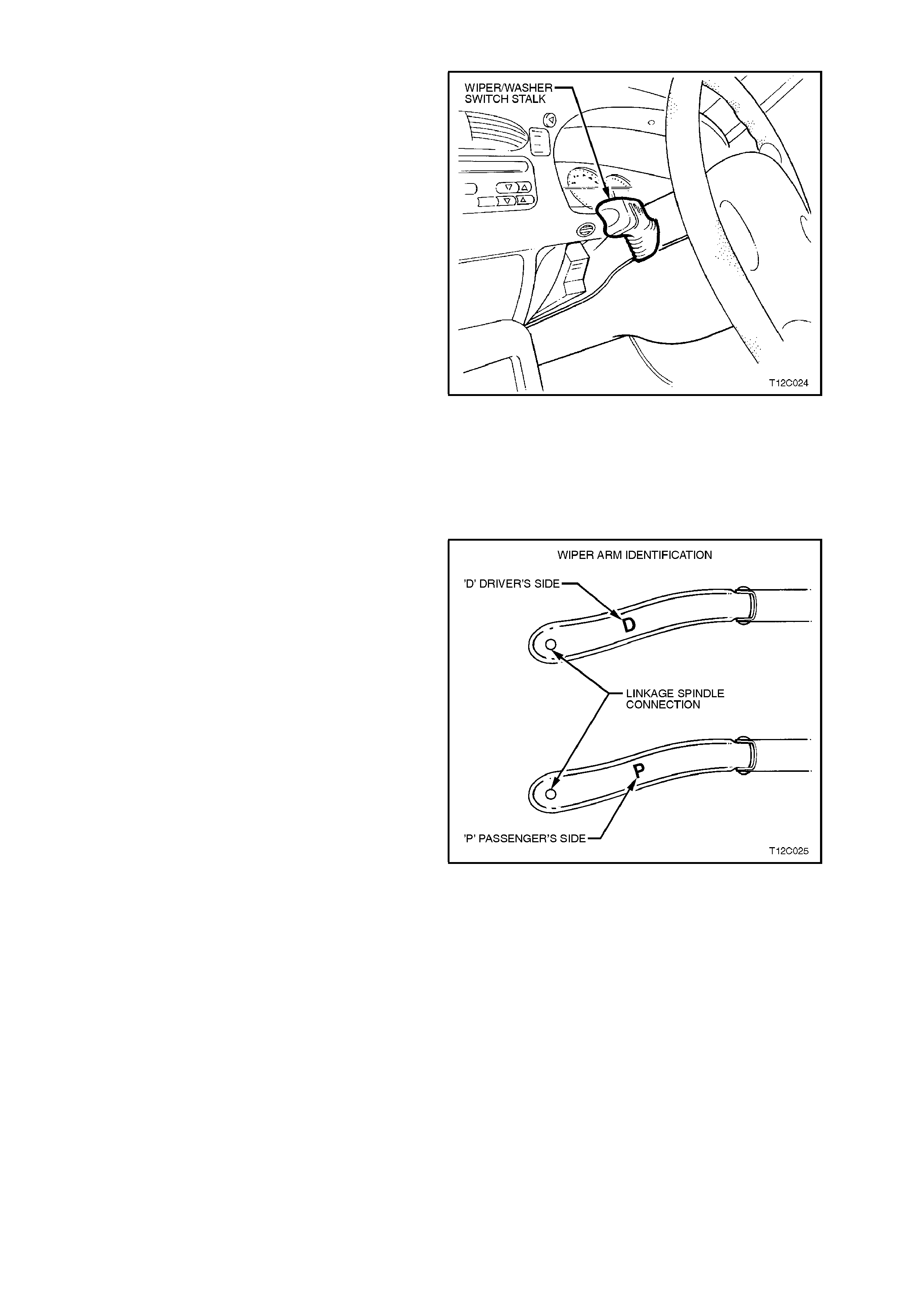
All VT Series Models are fitted with windshield
washers and four speed (m ist, interm ittent, low and
high speed) windshield wipers. Wagons are
equipped with a tailgate washer and single speed
wiper. All washers and wipers are controlled from
the left-hand steering column stalk switch. There
are specific switch assemblies for sedan and
wagon model applications and these are also
dependant on which series of BCM is fitted.
The rear wiper on wagons will usually have an
intermittent sweep. However, on wagons built with
an automatic transmission, the rear wiper will
change to a continuous sweep when reverse gear
is selected.
On vehicles with low series BCM, the wiper
intermittent dwell control circuitry is integrated
inside the BCM.
On vehicles fitted with high series BCM, the module
controls the intermittent dwell time based upon the
vehicle road speed and the s etting of an adjustable
control on the left-hand control stalk.
For details on BCM control of the windshield
wipers and washers, depending on model variant,
refer to either Section 12J-1 LOW SERIES BCM
or Section 12J-2 HIGH SERIES BCM.
Figure 12C-4
The windshield wiper blade arms are the fold back
type assemblies, with a specific arm and blade for
each side of the vehicle. T he arm s are identif ied by
a letter ‘D’ for the drivers side and the letter ‘P’ for
the passengers side on the under side of the arm,
refer F ig. 12C-5. The wiper blades can be identified
by their length; the drivers side wiper arm is 550
mm long and the pass engers side wiper arm is 500
mm long.
A windshield reservoir (sedan) or a common
windshield/tailgate reservoir (wagon) is located in
the right-hand front wheel house. A filler cap is
provided in the engine compartment, adjacent to
the battery to allow filling of the reservoir.
Specific washer pumps are used for sedan and
wagon models. The pump used for wagon models
has dual outlets for the windshield and tailgate.
For the identification of the washer pumps and
reservoir location, refer to Fig. 12C-65 and Fig.
12C-75 in this Section. Figure 12C-5
1.3 HORN
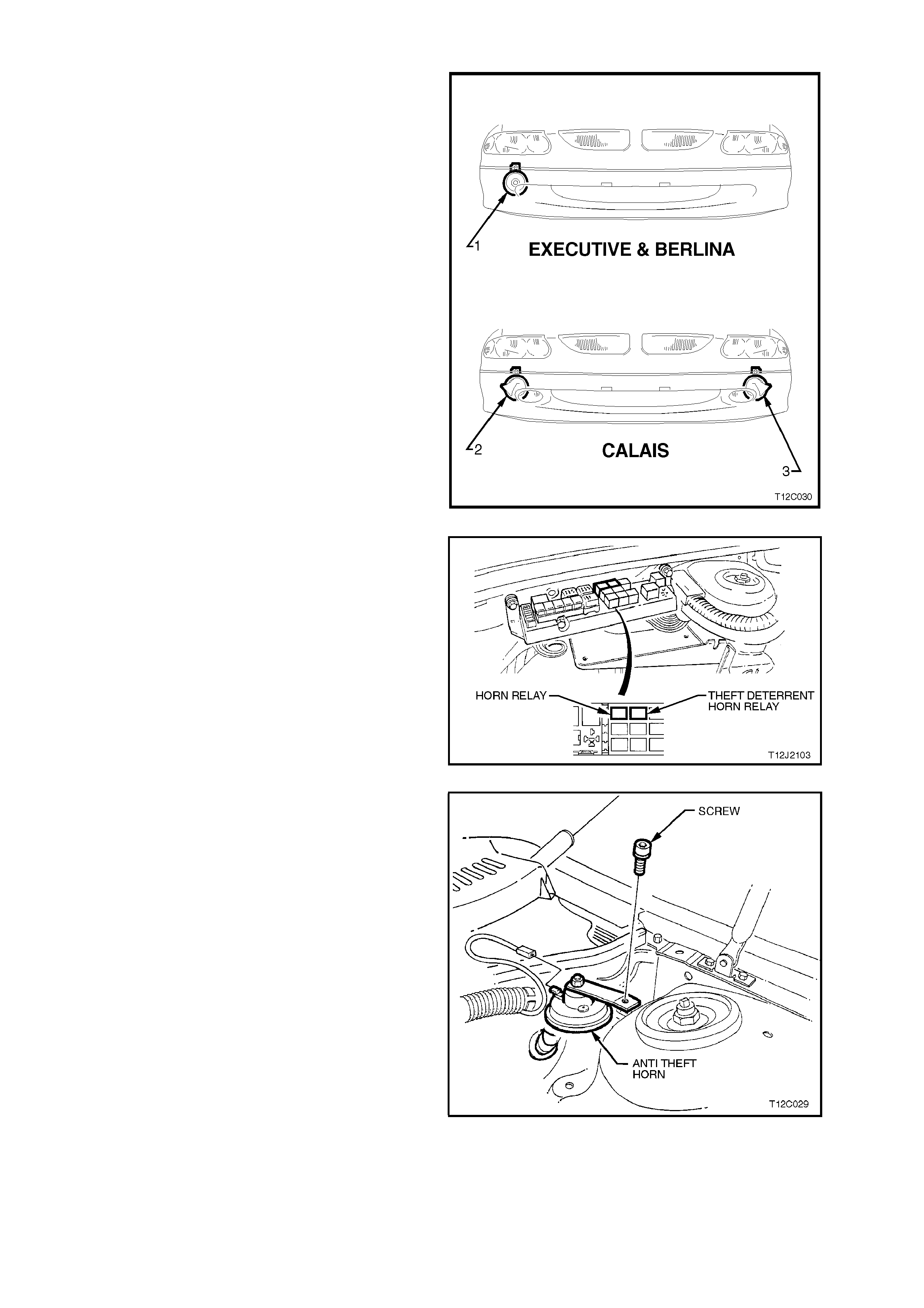
VT Series Executive and Berlina Models have a
single, disc type low note (400 Hz) horn (1)
mounted on the right-hand wheel house panel
behind the bumper facia.
VT Series Calais Models are fitted with trumpet
type high (500 Hz) and low note (400 Hz) horns, the
high note horn (2) is mounted on the right-hand
wheel house panel and the low note horn (3) on the
left-hand front wheel house panel behind the
bumper facia.
Figure 12C-6
The horn/s ar e operated by depressing the steering
wheel horn bar which earths a spring loaded
contact in the steering column switch housing
assembly. This energises a horn relay (located in
the engine compartment relay housing) and the
horn/s sound. The horn assem blies use a solenoid
operated diaphragm to generate sound.
Figure 12C-7
On vehicles with High Series BCM, a thef t deter rent
system horn is fitted inside the engine
compartment, behind the left hand strut tower.
Also located in the engine compartment relay
housing is a theft deterrent s ystem horn relay, refer
Fig. 12C-7.
Figure 12C-8
1.4 TRIP COMPUTER - SINGLE WINDOW TYPE
OPERATION
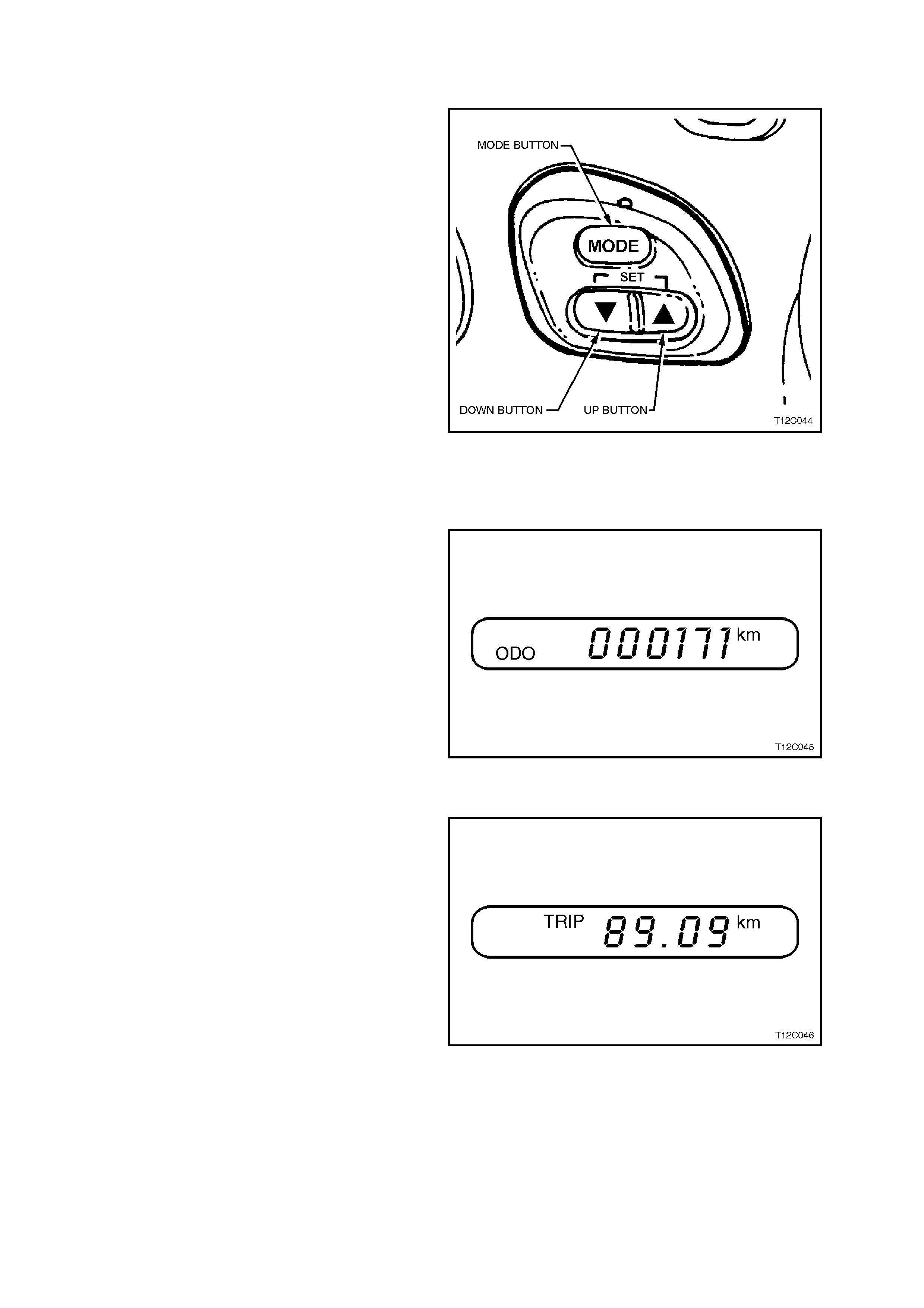
The buttons for the trip com puter are loc ated to the
left of the gauges. The window for the trip computer
is located directly beneath the gauges.
When the ignition is turned on, the trip computer
will display the same group of functions as when
the ignition was last turned ‘OFF’.
To reset the computer, hold down the Up Button (⇑
⇑⇑
⇑)
and the Down Button (⇓
⇓⇓
⇓) simultaneously. This will
reset all f unctions , with the exception of DIST ANCE
TO EMPTY, OVERSPEED WARNING,
ODOMETER, TIME TO ARRIVAL, DISTANCE TO
ARRIVAL and REMAINING FUEL .
To scroll between the four basic, more commonly
used functions press the MODE button.
NOTE:
If the wrong buttons have been accidentally
pressed, c aus ing the display to show other than the
normal readings, turn the ignition off, then on again. Figure 12C-9
BASIC FUNCTIONS
ODOMETER
The odometer records kilometres travelled since
the vehicle was built.
Figure 12C-10
TRIP
Shows the kilometres travelled from the start of a
particular trip. Reset the reading to zero by
pressing the ⇑
⇑⇑
⇑ and ⇓
⇓⇓
⇓ buttons together when this
window is shown.
Figure 12C-11
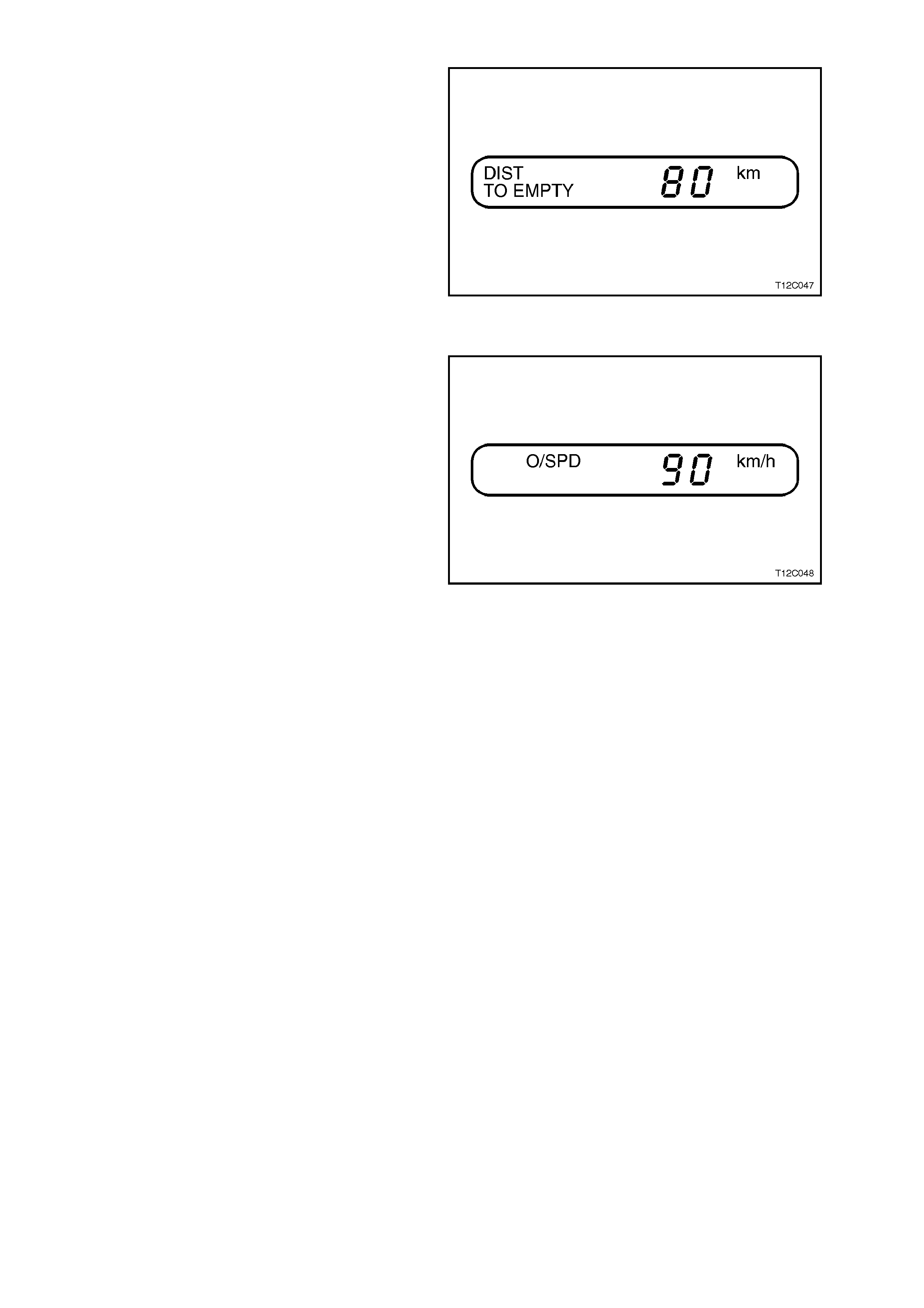
DISTANCE TO EMPTY
DISTANCE TO EMPTY is an estimate of how far
current fuel will last. It is based on previous fuel
usage and is frequently updated. Therefore, as
conditions become suited to more economical
driving the DISTANCE TO EMPTY may actually
increase, for example from city to highway driving.
Figure 12C-12
OVERSPEED
Set the speed not to be exceed. For example, if
driving in a 90 km/h zone, set OVERSPEED to 90
by tapping the ⇑
⇑⇑
⇑ or ⇓
⇓⇓
⇓ buttons. W hen vehicle speed
exceeds 90 km /h the O VERSPEED warning light in
the instrument panel and an audible chime will
warn that set speed has been exceeded. At that
time the trip computer will automatically show
overspeed display, allowing adjustments as
required.
OVERSPEED is adjustable in 5 km/h units and
works at speeds between 20 km/h and 200 km/h.
Tap the ⇑
⇑⇑
⇑ or ⇓
⇓⇓
⇓ buttons as requir ed or hold a button
to scroll quickly to a speed. Brief ly press the ⇑
⇑⇑
⇑ and
⇓
⇓⇓
⇓ buttons together to set the OVERSPEED to the
speed at which the vehicle is currently travelling.
Press and hold both the ⇑
⇑⇑
⇑ and ⇓
⇓⇓
⇓ buttons for at least
2 seconds (when this display is showing) to turn the
OVERSPEED warning on or off.
OVERSPEED presets can also be chosen, refer
OVERSPEED ADJUSTING in this Section.
Figure 12C-13
ADDITIONAL FUNCTIONS
The following details the additional functions that have been provided in the trip computer.
CUSTOMISE MODE
The trip computer features can by customised. W hen the vehicle is stationary, hold down the MODE button while
turning the ignition from OFF to ON. The trip computer then steps you through a series of choices:
CHOICE 1: ODO (odom eter) window shown or skipped. Use the ⇑
⇑⇑
⇑ or ⇓
⇓⇓
⇓ button to select YES or NO as to whether
the odometer will be displayed when the ignition is ON. Note that the odometer will still count in the background
(and will appear when the ignition is OFF), even if the display is set to NO. When the display is flashing on your
selection, press the MODE button to go the next choice.
CHOICE 2: TRIP distance - feature available or sk ipped. Use the ⇑
⇑⇑
⇑ or ⇓
⇓⇓
⇓ button until your choice is flashing. Press
the MODE button to go to choice 3.
CHOICE 3: DISTANCE T O GO - f eature available or s kipped. T his choice will activate an additional s et of displays:
DISTANCE T O GO and T IME TO GO. Use the ⇑
⇑⇑
⇑ or ⇓
⇓⇓
⇓ button until choice is f lashing. Press the MO DE button to go
to choice 4.
CHOICE 4: Adjust DISTANCE T O G O def ault s etting. T he DISTANCE T O GO c an be re set ( when not in c us tomise
mode) by pressing the ⇑
⇑⇑
⇑ and ⇓
⇓⇓
⇓ buttons together. T he distance res ets to 500 km , which is the def ault setting. W hen
in customise mode, choice 4 enables the default setting to be altered up or down with the ⇑
⇑⇑
⇑ or ⇓
⇓⇓
⇓ buttons. When
correct, press the MODE button to go to choice 5.
CHOICE 5: UNDERSPEED chime. OVERSPEED provides a chime when your travelling speed exceeds
OVERSPEED chosen s peed. An additional chime c an be activated to indicated when travelling speed drops below
OVERSPEED. Choice 5 in cus tom ise m ode is to turn the sec ond chim e, the "unders peed" c him e of f or on. Us e the
⇑
⇑⇑
⇑ or ⇓
⇓⇓
⇓ button until your choice is flashing. Press the MODE button to end customise mode.
To activate customise mode again, turn the ignition OFF, then turn ON while holding down the MODE button.
Customise mode will end automatically if vehicle speed exceeds 10 km/h or if the ignition is turned off and on.
ADDITIONAL DISPLAYS
Two additional displays can be activated using
customise mode. DISTANCE TO GO and TIME TO
GO are turned on and off as a set, they cannot be
individually activated.
When activated, press the MODE button to scroll
through the Tr ip Computer displays. T here will now
be six displays instead of four. The new displays
will be slotted in between the TRIP display and the
DISTANCE TO EMPTY display. Customise mode
can be used to deactivate the displays, if required.
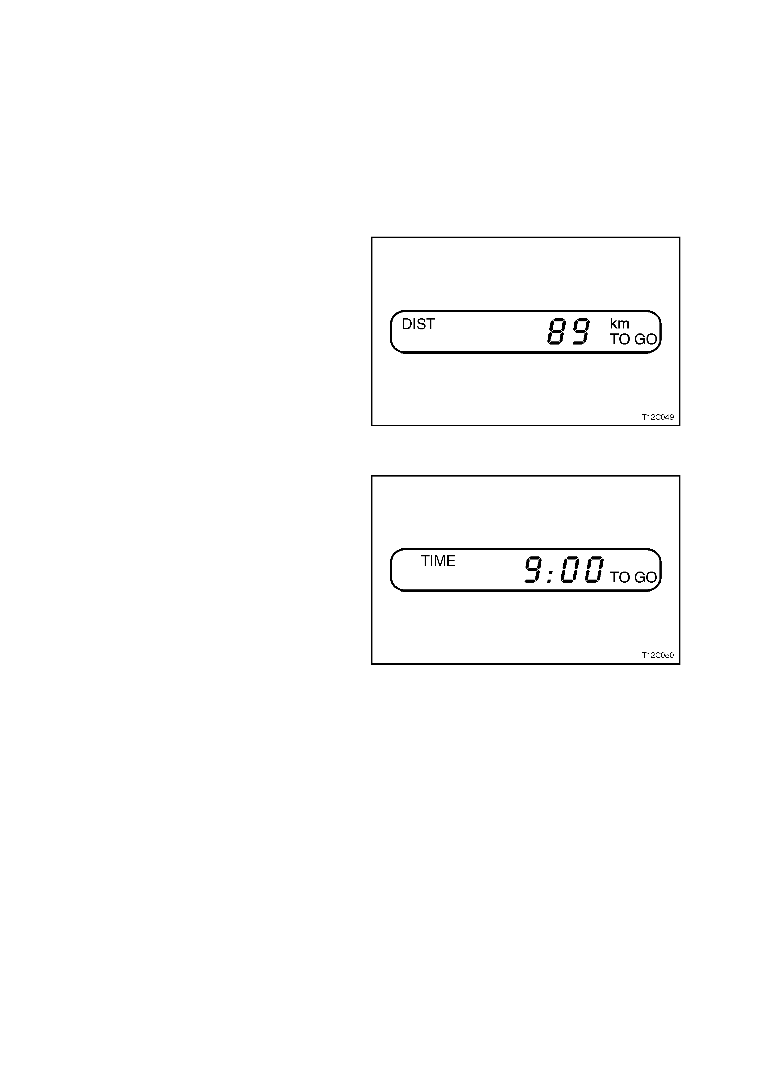
DISTANCE TO GO
At the start of a trip an estimate of distance to
arrival (from maps, road signs etc.) should be
made. Tap the ⇑
⇑⇑
⇑ or ⇓
⇓⇓
⇓ buttons until the display
shows estimated trip distance. W hen the vehicle is
driven the trip com puter will constantly update tim e
to arrival, based on changing driving speeds . The ⇑
⇑⇑
⇑
or ⇓
⇓⇓
⇓ buttons can be used to adjust the kilometres
any time this display is shown.
Figure 12C-14
TIME TO GO
Shows time to arrival in hours and minutes.
TIME TO GO is only shown if the DISTANCE TO
GO is more than zero.
Figure 12C-15
Even if DISTANCE TO GO is turned off using
customise mode, it can still be temporarily turned
on by the following quick method:
Press MODE button until the TRIP display is
shown, press the ⇑
⇑⇑
⇑ and ⇓
⇓⇓
⇓ buttons together to zero
the trip display, then increase the distance up by
pressing the ⇑
⇑⇑
⇑ button.
However, when the trip distance reaches zero the
function will turn off again. Use the customise
mode to permanently turn the above displays on.
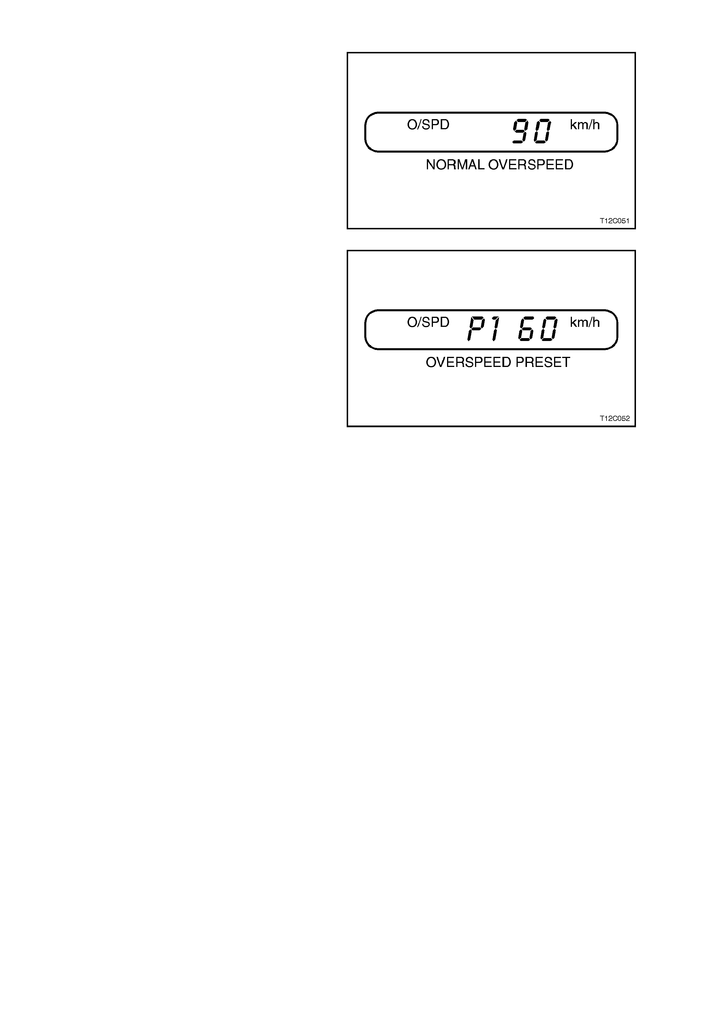
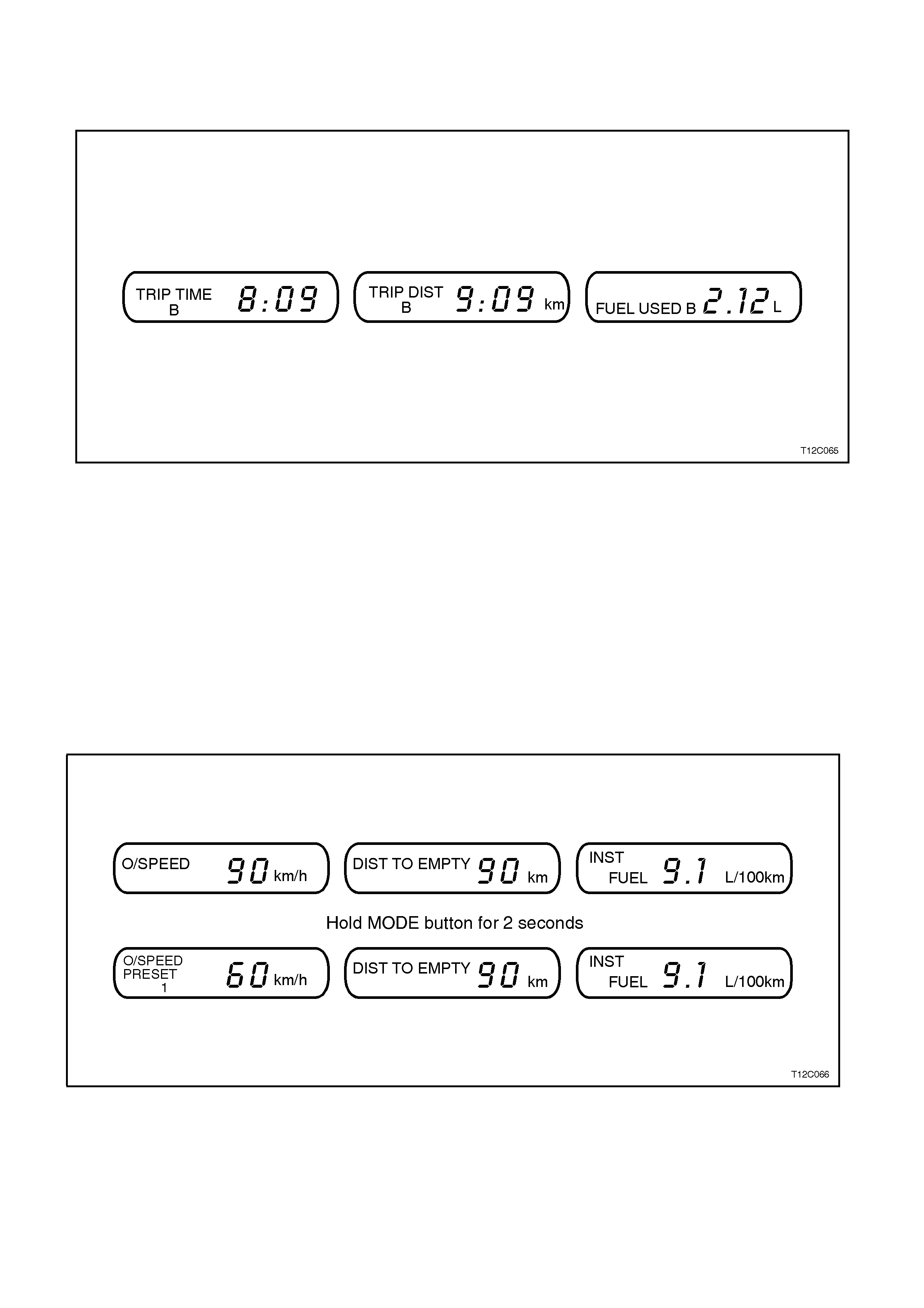
OVERSPEED A DJUSTING
Instead of adjusting OVERSPEED up and down in
5 km increments, you can set four commonly used
speeds, e.g. 60, 80, 100 and 110.
Hold down the MODE button for 2 seconds when
the OVERSPEED display is shown. T he dis play will
change from normal OVERSPEED to
OVERSPEED PRESET.
Figure 12C-16
P1 is the first preset number, with a default setting
of 60 km/h.
Tap the ⇑
⇑⇑
⇑ button to see the second preset, P2,
which has a default setting of 80 km/h, P3 has a
default setting of 100 km/h and P4 of 110 km/h.
Tap the ⇑
⇑⇑
⇑ or ⇓
⇓⇓
⇓ buttons to m ove between the preset
numbers.
The OVERSPEED PRESET display has now
replaced the normal OVERSPEED display in the
set of displays. Tap the MODE button to scroll
through the other displays.
To change the display back to normal
OVERSPEED, again hold down the MODE button
for 2 seconds while the OVERSPEED PRESET
display is shown.
Figure 12C-17
ALTERING OVERSPEED PRESETS
The default settings of 60, 80, 100 and 110 km/h can be changed for your individual preference.
The vehicle must be standing still when changing OVERSPEED PRESETS. T o alter, ensure the required preset is
showing, e.g. P2 80 km/h. T hen, br ief ly press the ⇑
⇑⇑
⇑ and ⇓
⇓⇓
⇓ buttons together. T he display starts to flash. Us e the ⇑
⇑⇑
⇑ or
⇓
⇓⇓
⇓ button to adjust the setting. When correct, briefly press the ⇑
⇑⇑
⇑ and ⇓
⇓⇓
⇓ buttons together. Each preset can be changed
in this way.
The presets are automatically arranged in ascending order.
One or more presets can be assigned to OFF, by reducing the pr eset down to 0 (OFF). W hen dr iving three or less
presets will be available to choos e from . To turn back on, select the OFF preset (when the vehicle is standing still)
and use the ⇑
⇑⇑
⇑ button to increase the number.
OVERSPEED PRESETS must be altered when the vehicle is standing still. If the ⇑
⇑⇑
⇑ and ⇓
⇓⇓
⇓ buttons are briefly
pressed while driving, the OVERSPEED setting will be changed to the speed at which you are travelling (in multiples
of 5 km/h).
If the ⇑
⇑⇑
⇑ and ⇓
⇓⇓
⇓ buttons are pressed for 2 seconds, either while driving or standing still, OVERSPEED will be turned
completely OFF or ON.
SERVICE DUE
A service reminder message is built into the trip computer.
The reminder message will first appear 1,000 km before the service is actually due, giving time to arrange for the
service to be c arried out. The m essage will be shown on the T rip com puter fo r 10 sec onds whenever the vehic le's
ignition is switched ON or OFF, until the tr ip com puter is reset. When the s ervice is over due the mess age will f lash
for 10 seconds when the ignition is turned ON or OFF.
•SERV 1500 km will show when the vehicle has travelled 1,000 km since it was built.
•SERV 10000 km will show when the vehicle has travelled 9,000 km since it was built
•SERV 20000 km will show when the vehicle has travelled 19,000 km since it was built.
•SERV 30000 km will show when the vehicle has travelled 29,000 km since is was built etc.
When a service is performed on the vehicle, this
reminder should be reset so that it does not prompt
until the next service is nearly due. Otherwise, it will
keep on reminding of a service that is already
complete:

To reset the service reminder message:
1. Turn the ignition OFF.
2. Hold down the ⇑
⇑⇑
⇑ and ⇓
⇓⇓
⇓ mode buttons on the trip computer together.
3. Turn the ignition ON (mode buttons still depressed).
4. Release mode buttons after approximately 3 seconds.
5. Use the mode button to step through trip computer screens until the service due reminder screen appears on
the LCD (usually only one press).
6. Press and hold both the ⇑
⇑⇑
⇑ and ⇓
⇓⇓
⇓ mode buttons until an audible beep is heard (approximately 3 seconds).
7. Turn the ignition OFF.
NOTE1:
The service due indicator message has now been reset, therefore, the next service due reminder message will not
be displayed until 1000 km before the next service is due.
NOTE2:
The Service Due message is calculated only by distance. Remember that if driving infrequently special servicing
may be required.
ADDITIONAL TRIP COMPUTER NOTES
Two warning lights are linked to the trip computer displays.
1. When the fuel tank level first dr ops below 8 litres ( approx .) , the DIST ANCE TO EMPTY display is autom atic ally
shown for 10 seconds, after which the trip computer returns to its previous display.
2. When the OVERSPEED warning symbol is first shown, the OVERSPEED trip computer display is automatically
shown for 10 s econds. This is to show what the pre-selected speed is and allow adjustm ent if required. After
10 seconds, the trip computer returns to its previous display.
Some of the displays will change the units of measurem ent over tim e. For exam ple, the TIME TO GO will show 10
minute units above 2 hours to arrival, will show 5 m inute units below 2 hours to arr ival and will show 1 minute units
below 10 minutes to arrival.
If the HOT warning is displayed when driving it indicates that the engine water tem perature is dangerously hot. An
audible warning chime is designed to bring this to the attention of the operator. The vehicle should be stopped as
soon as it is safe to do so.
NOTE:
The message will only be displayed for 10 seconds.
If the SERV ERROR warning is displayed on the trip computer a fault in the trip computer system is indicated and
the vehicle should be taken to a Holden Dealer.
1.5 TRIP COMPUTER - TRIPLE WINDOW TYPE
OPERATION
The buttons f or the tr ip com puter are loc ated to the
left of the gauges. As in the s ingle window type, the
triple windows for the trip computer are located
directly beneath the gauges.
The basic, more commonly used functions of the
trip computer f ollow. T ap the MODE button to s c roll
between these three sets of displays.
The speed related displays are in the left window,
distance related displays in the centre and fuel
related displays on the right.
The trip c omputer c an be reset when AVG SPEED
or TRIP TIME are shown on the left window.
Resetting does not affect the ODOMETER,
OVERSPEED, DISTANCE TO EMPTY or INST
FUEL.
For customising details of the trip computer, and
additional operating notes, refer to
CUSTOMISE MODE in this Section.
BASIC FUNCTIONS
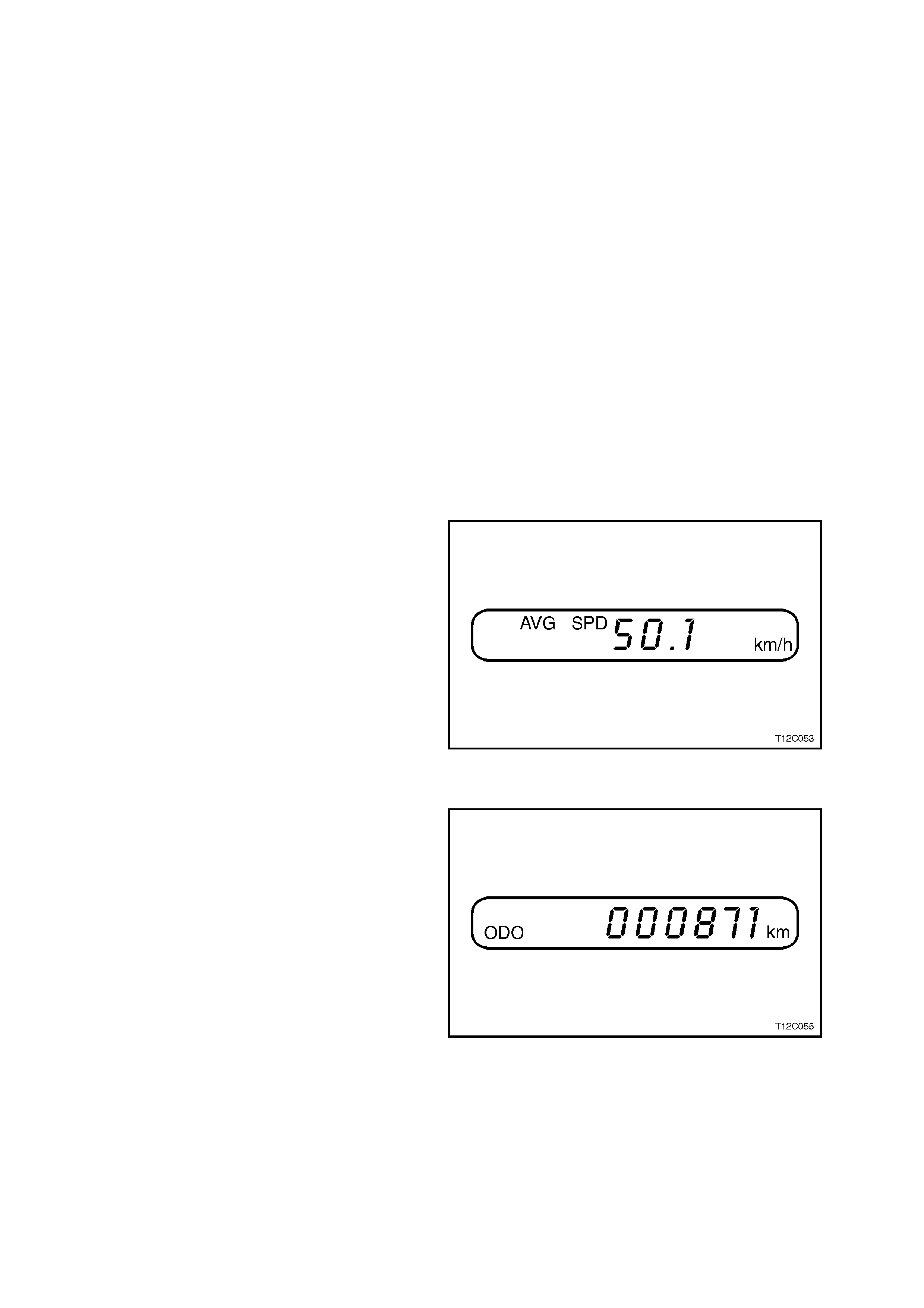
AVERAGE SPEED
Shows the average speed (while the engine is
running) since the trip computer was reset.
Figure 12C-18
ODOMETER
The odometer records kilometres travelled since
the vehicle was built.
Figure 12C-19
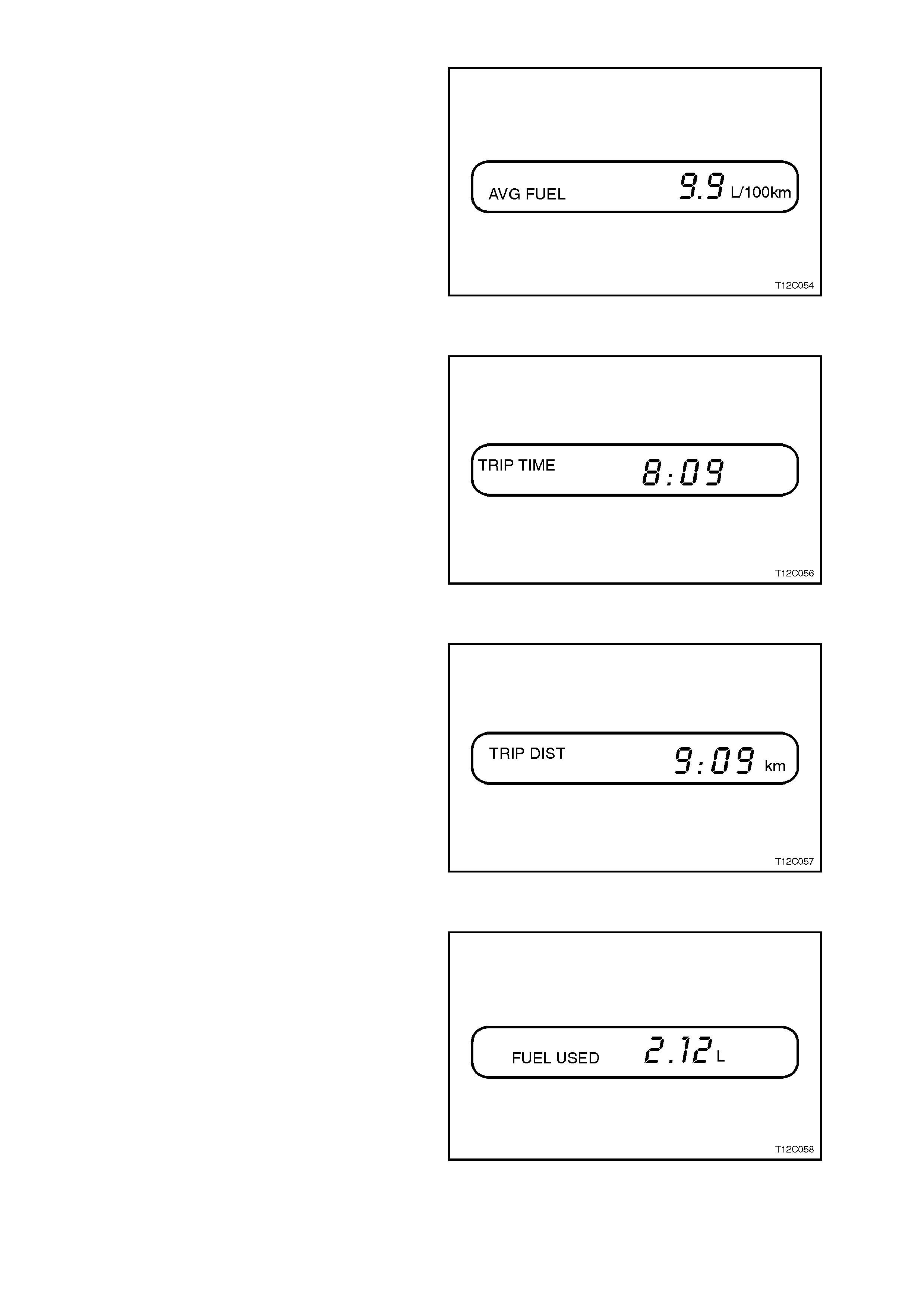
AVERAGE FUEL
Shows average fuel used since the trip computer
was reset. After resetting, some large numbers
may initially be shown, due to the short distance
travelled and the high fuel used when accelerating.
Figure 12C-20
TRIP TIME
Shows the engine running time since the trip
computer was reset.
Figure 12C-21
TRIP DISTANCE
Shows the kilometres travelled from the start of a
particular trip. Reset the reading to zero by
pressing the ⇑
⇑⇑
⇑ and ⇓
⇓⇓
⇓ buttons together when this
window is shown.
Figure 12C-22
FUEL USED
Shows the total litres of fuel used since the trip
computer was reset.
Figure 12C-23
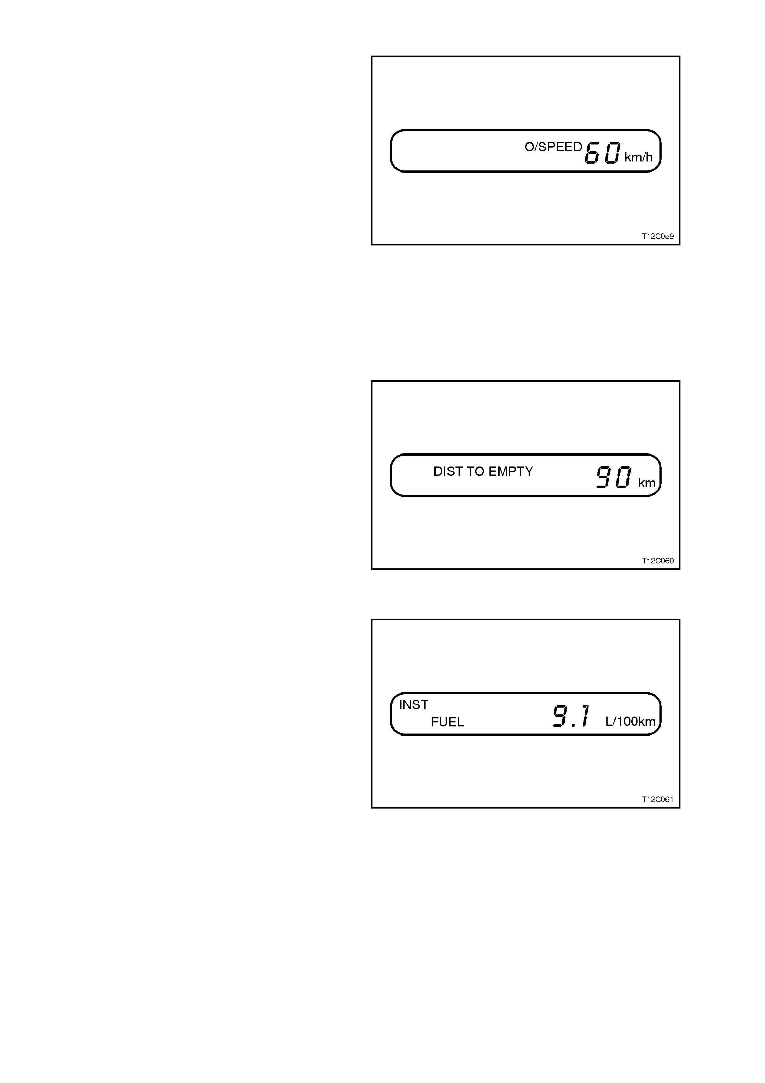
OVERSPEED
Set the speed not to be exceeded. For example if
driving in a 90 km/h zone, set OVERSPEED to 90
by tapping the ⇑
⇑⇑
⇑ or ⇓
⇓⇓
⇓ buttons. W hen vehicle speed
exceeds 90 km /h the O VERSPEED warning light in
the instrument panel and a chime will warn that
speed has been exceeded. At that time the trip
computer will automatically show overspeed
display, allowing adjustments as required.
OVERSPEED is adjustable in 5 km/h units and
works at speeds between 20 km/h and 200 km/h.
Tap the ⇑
⇑⇑
⇑ or ⇓
⇓⇓
⇓ buttons or hold a button to scroll
quickly to a speed. Briefly press the ⇑
⇑⇑
⇑ and ⇓
⇓⇓
⇓
buttons together to set OVERSPEED to the speed
at which the vehicle is currently travelling.
Press and hold both the ⇑
⇑⇑
⇑ and ⇓
⇓⇓
⇓ buttons for at least
2 secs (when this window is shown) to turn
OVERSPEED ON or OFF.
OVERSPEED presets can also be chosen, refer
OVERSPEED ADJUSTING in this Section.
Figure 12C-24
DISTANCE TO EMPTY
DISTANCE TO EMPTY is an estimate of how far
current fuel will last. It is based on previous fuel
usage and is frequently updated. Therefore, as
conditions become suited to more economical
driving the DISTANCE TO EMPTY may actually
increase, for example from city to highway driving.
Figure 12C-25
INSTANTANEOUS FUEL
Shows instantaneous fuel usage in litres per 100
km when driving. When speed drops below 10
km/h the usage is shown in litres per hour.
Figure 12C-26
ADDITIONAL DISPLAYS
Additional displays can be activated using
customise m ode. Ref er CUSTOMISE MO DE in this
Section. DISTANCE TO ARRIVAL, TIME TO
ARRIVAL and REMAINING FUEL are turned on
and off as a set, they cannot be individually
activated.
When the displays are activated, press the MODE
button to scroll through all the Trip Computer
displays. There will now be four sets of displays,
instead of thr ee. The new displays will be slotted in
between the TRIP display and the DISTANCE TO
EMPTY display. Customise mode can be used to
deactivate the following displays, if required.
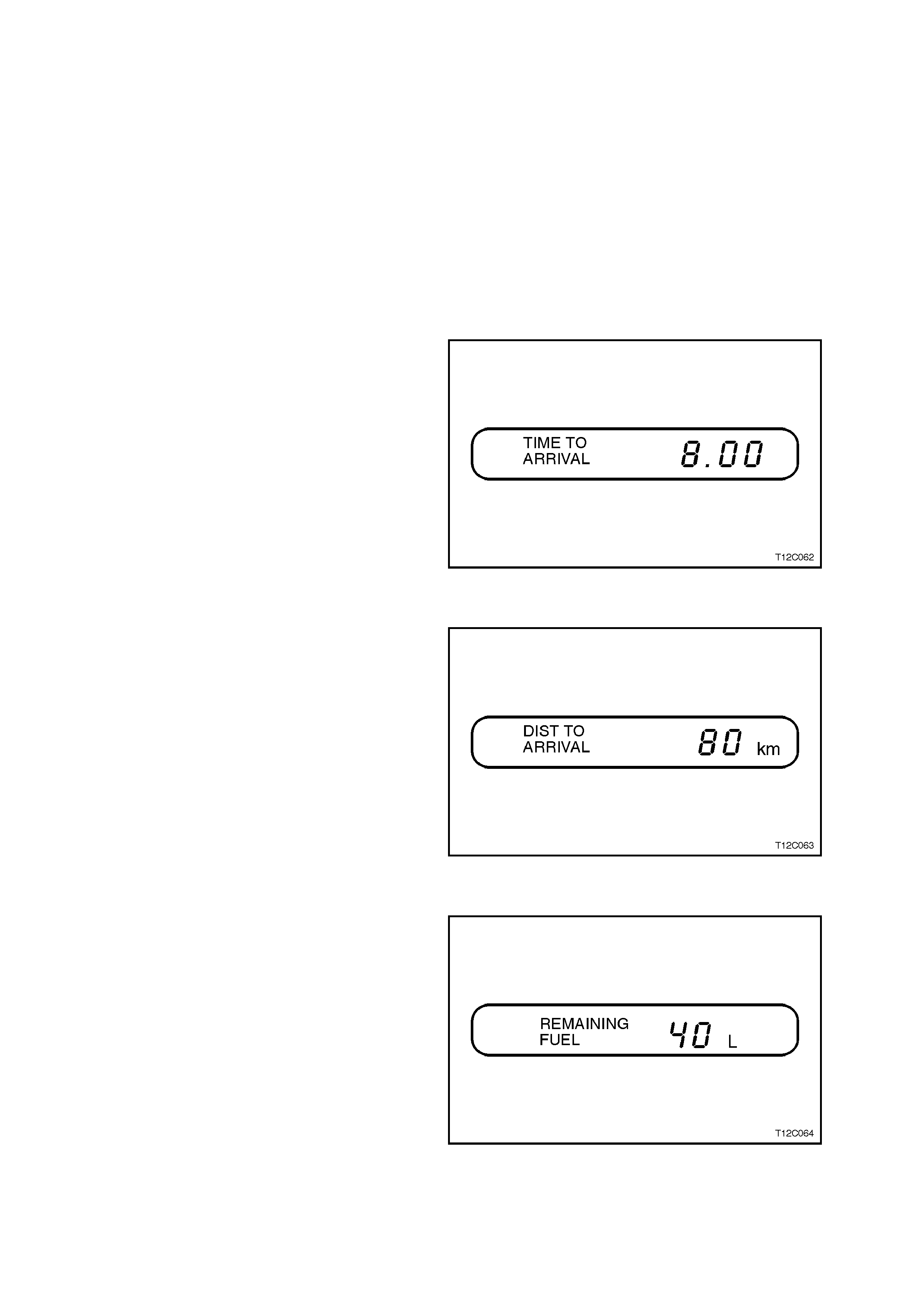
TIME TO ARRIVAL
Shows trip time to arrival in hours and minutes,
based on DISTANCE TO ARRIVAL.
Figure 12C-27
DISTANCE TO ARRIVAL
At the start of a trip estimate distance to arrival
(from maps, road signs etc.). Tap the ⇑
⇑⇑
⇑ or ⇓
⇓⇓
⇓
buttons until the display shows estimated trip
distance. When the vehicle is driven the computer
will constantly update time to arrival, based on
changing driving speeds. The ⇑
⇑⇑
⇑ or ⇓
⇓⇓
⇓ buttons can be
used to adjust the kilometres any time this display
is shown.
Figure 12C-28
REMAINING FUEL
Shows the litres of fuel left in the fuel tank , r ounded
to the nearest 5 litres.
When fuel level is low, LO will be displayed.
Figure 12C-29
TRIP B
W hen the Trip B set of windows has been turned on (using the custom ise mode) and are showing on the display,
hold the MODE button down for 2 seconds. The trip computer will show Trip B details.
Figure 12C-30
Press the MODE button to view displays. Two diff erent sets of trip displays are now counting, the original set of trip
displays (labelled A while B is turned on) and a new set of tr ip displays, labelled B. T his is useful on a long trip, as
Trip B can be reset at the beginning of the journey and then locked away (by pressing the MODE button for 2
seconds when Trip B is shown). TIME TO ARRIVAL, DISTANCE TO ARRIVAL and REMAINING FUEL will again
be shown on the display, but Trip B will still be c ounting away in the bac kground and the or iginal trip display can be
used for short distances during the journey. Trip B can be viewed at any time by pressing the MODE button for 2
seconds when DISTANCE TO ARRIVAL is shown.
OVERSPEED A DJUSTING
Instead of adjusting O/SPEED up and down in 5 km increments (refer OVERSPEED in this Section), you can
instead set four commonly used speeds, e.g. 60, 80, 100 and 110.
Hold down the MODE button for 2 seconds when the O/SPEED is shown. The display will change from normal
O/SPEED to O/SPEED PRESET.
Figure 12C-31
PRESET 1 is the first preset number, with a default setting of 60 km/h.
Tap the ⇑
⇑⇑
⇑ button to see the second PRESET, which has a default setting of 80 km/h, PRESET 3 has a default
setting of 100 km/h and PRESET 4 of 110 km/h. Tap the ⇑
⇑⇑
⇑ or ⇓
⇓⇓
⇓ buttons to move between the PRESET numbers.
The O/SPEED PRESET display has now replaced the normal O/SPEED display. Tap the MODE button to scroll
through the other displays.
To change the display back to normal O/SPEED, again hold down the MODE button for 2 seconds while the
O/SPEED PRESET display is shown.
ALTERING OVERSPEED PRESETS
The default settings of 60, 80, 100 and 110 km/h can be changed to suit individual preferences.
The vehicle must be stationary when changing an O/SPEED PRESET. To alter, ensure the preset to change is
showing, e.g. PRESET 2 80 k m /h. T hen, brief ly pres s the ⇑
⇑⇑
⇑ and ⇓
⇓⇓
⇓ buttons together. The display starts to flash. Us e
the ⇑
⇑⇑
⇑ or ⇓
⇓⇓
⇓ button to adjust the setting. When c orrec t, briefly press the ⇑
⇑⇑
⇑ and ⇓
⇓⇓
⇓ buttons together. Each PRESET can
be changed in this way.
The PRESETs are automatically arranged in ascending order.
One or more PRESET can be assigned to OF F, by reducing the preset down to 0 (O FF ). When dr iving only three or
less PRESETs will be available to choose from. To turn back on, select the OFF PRESET (when the vehicle is
stationary) and use the ⇑
⇑⇑
⇑ button to increase the number.
An O/SPEED PRESET must be altered when the vehicle is stationary. If the ⇑
⇑⇑
⇑ and ⇓
⇓⇓
⇓ buttons are briefly pressed
while driving, the OVERSPEED setting will be changed to the speed at which you are travelling.
If the ⇑
⇑⇑
⇑ and ⇓
⇓⇓
⇓ buttons are pressed together for more than 2 seconds, either while driving or stationary, O/SPEED will
be turned completely OFF or ON.
ADDITIONAL FUNCTIONS
The following details the additional functions that have been provided in the trip computer.
CUSTOMISE MODE
The trip computer uses in its calculations different calibration num bers. These figures are pre-set for the standard
vehicle and do not have to be adjusted. However, each vehicle does vary due to tyre size, tolerances etc., and
therefore the facility is provided to adjust each figure for greater accuracy. Also provided in customise mode are
different choices about displays.
To enter customise mode, press and hold the MODE button while the ignition is turned from OFF to ON. After
entering customise mode, tap the MODE button to view each calibration/choice or alter the settings as described
below.
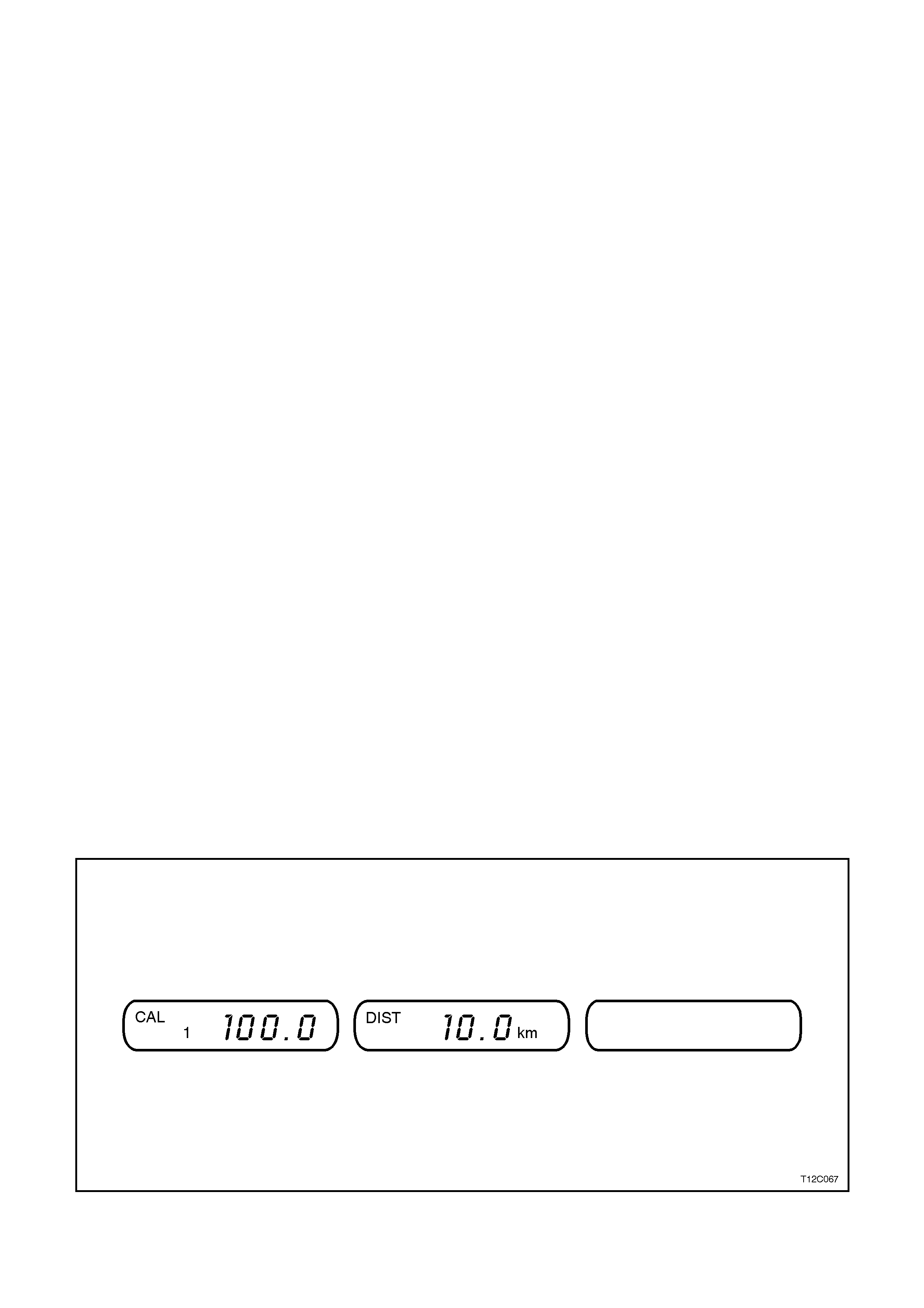
CALIBRATION 1: DISTANCE CALIBRATION
If necessary to check/adjust distance calibration, line the vehicle front wheels against a highway kilometre shield
post before entering customise mode. Press both the ⇑
⇑⇑
⇑ and ⇓
⇓⇓
⇓ buttons together when TRIP DIST is showing in
the centre window (to zero the TRIP DIST ). Dr ive to another s hield pos t (between 10 k m and 500 km) and st op with
the front wheels lined up again. Note the real distance between the shield pos ts and the distanc e on the TR IP DIST
display. If different, enter customise mode. The TRIP DIST will be shown in the centre window. Press the ⇑
⇑⇑
⇑ or ⇓
⇓⇓
⇓
buttons to adjust the centre display to show the real distance indicated by the shield posts.
NOTE:
1 The left display (the distance calibration %) will automatically adjust with the centre display. The default distance
calibration is 100.0%. The maximum it can be adjusted to is 120.0%, the minimum is 80%.
NOTE:
2 Altering the distance calibration does not affect the odometer.
Press the MODE button to go to the next calibration number.
Figure 12C-32
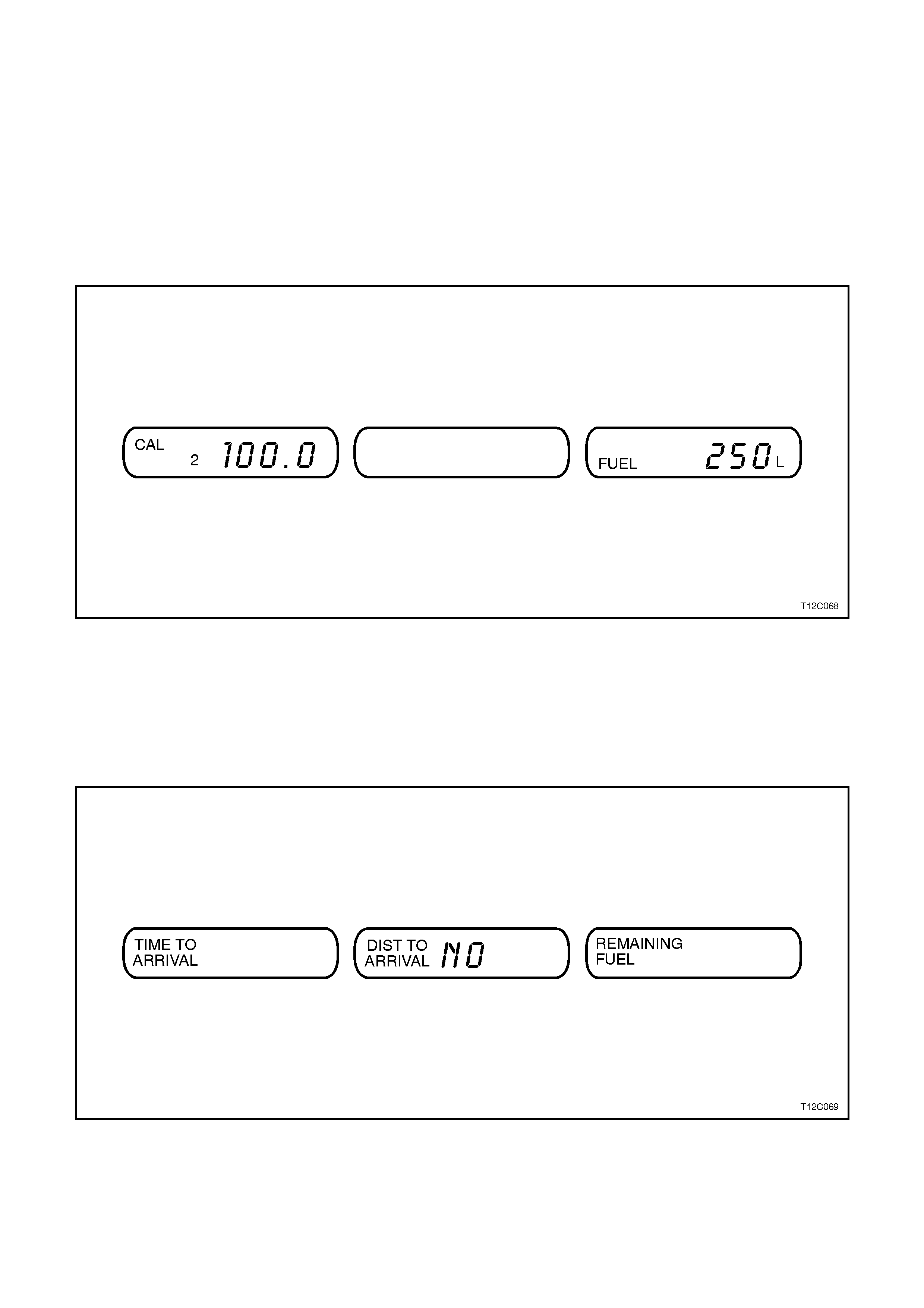
CALIBRATION 2: FUEL FLOW CALIBRATION NUMBER
If necessary to check/adjust fuel flow calibration number, calculate the following before entering customise mode.
Press both the ⇑
⇑⇑
⇑ and ⇓
⇓⇓
⇓ buttons together when FUEL USED is s howing in the r ight - hand window (to zero the FUEL
USED). Then, for at least five consecutive fuel fills, record the total litres added (but no more than 500 litres),
according to the service station fuel bowser. If this is different to the FUEL USED reading, enter customise mode
and tap the MODE button once, to show CAL 2. The FUEL USED will be shown on the right - hand display. Press
the ⇑
⇑⇑
⇑ or ⇓
⇓⇓
⇓ buttons to adjust the right - hand display to show the actual total fuel us ed ac cor ding to the s ervic e s tation
fuel bowser.
NOTE:
The left display (the fuel flow calibration %) will automatically adjust with the right display. The default fuel calibration
is 100.0%. The maximum it can be adjusted to is 120.0%, the minimum is 80%.
Figure 12C-33
Press the MODE button to go to the next choice.
CHOICE: SKIP DISTANCE TO ARRIVAL
To activate an additional set of displays: TIME TO ARRIVAL, DISTANCE TO ARRIVAL and REMAINING FUEL,
press ⇑
⇑⇑
⇑ or ⇓
⇓⇓
⇓ button to select YES or NO.
For an explanation of these displays refer ADDITIONAL DISPLAYS in this Section.
Figure 12C-34
Press the MODE button to go to the next calibration number.
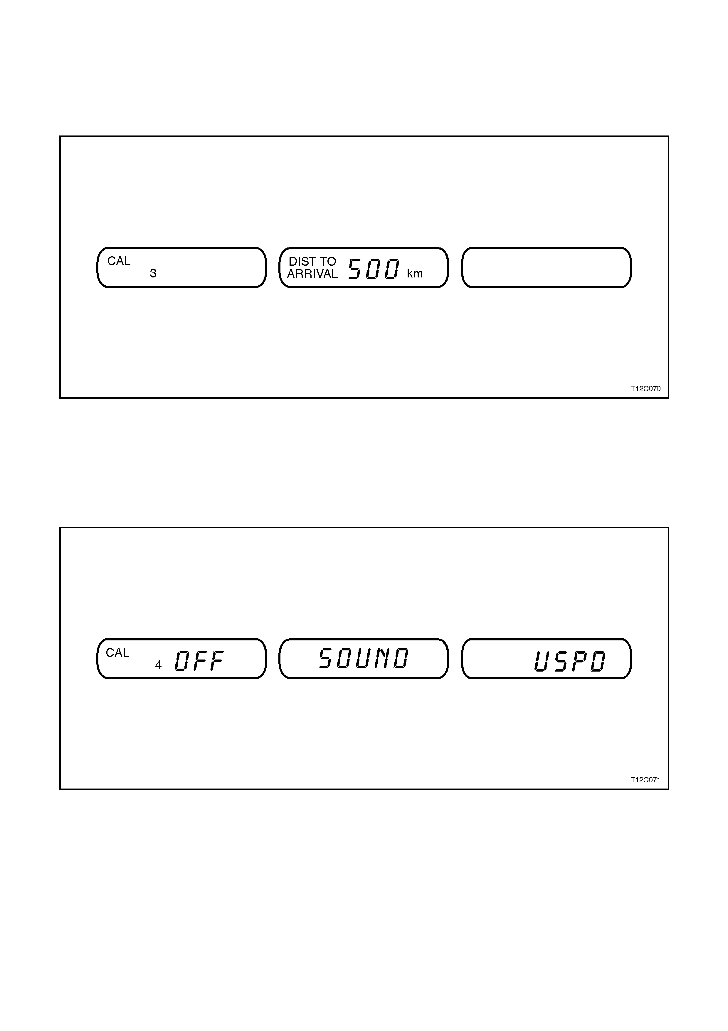
CALIBRATION 3: ADJUST DISTANCE TO ARRIVAL DEFAULT SETTING
DISTANCE TO ARRIVAL can be reset (when not in customise mode) by pressing the ⇑
⇑⇑
⇑ and ⇓
⇓⇓
⇓ buttons together. The
distance resets to 500 k m, which is the def ault setting. When in cus tomis e mode, the def ault setting can be altered
up or down by pressing ⇑
⇑⇑
⇑ or ⇓
⇓⇓
⇓ buttons.
This can be used to quickly recall details of a regularly travelled trip.
Figure 12C-35
Press the MODE button to go to the next choice.
CHOICE: UNDERSPEED CHIME
OVERSPEED provides a chime when travelling speed exceeds OVERSPEED setting, and another chime when
travelling speed drops below UNDERSPEED setting. Customise mode provides a choice for turning the second
chime, the "underspeed" chime OFF or ON. Press ⇑
⇑⇑
⇑ or ⇓
⇓⇓
⇓ button to turn underspeed chime OFF or ON.
Figure 12C-36
Then press MODE button to end Customise mode.
NOTE:
Customise mode will end automatically if vehicle speed exceeds 10 km/h or if the ignition is turned off and on.

SERVICE DUE
A service reminder message is built into the trip computer.
The reminder message will first appear 1,000 km before the service is actually due, giving time to arrange for the
service to be perform ed. The message will be shown on the Trip com puter for 10 seconds whenever the vehicle's
ignition is switched ON or OFF, until the tr ip com puter is reset. When the s ervice is over due the mess age will f lash
for 10 seconds when the ignition is turned ON or OFF.
•SERV 1500 km will show when the vehicle has travelled 1,000 km since it was built.
•SERV 10000 km will show when the vehicle has travelled 9,000 km since it was built.
•SERV 20000 km will show when the vehicle has travelled 19,000 km since it was built.
•SERV 30000 km will show when the vehicle has travelled 29,000 km since is was built etc.
When a service is performed on the v ehicle, this reminder should be reset so that it does not prompt until
the next service is nearly due. Otherwise, it will keep on reminding of a service that is already complete:
W hen a ser vice is perform ed on the vehicle, this rem inder should be reset s o that it does not prom pt until the nex t
service is nearly due. Otherwise, it will keep on reminding of a service that is already complete:
To reset the service reminder message:
1. Turn the ignition OFF.
2. Hold down the ⇑
⇑⇑
⇑ and ⇓
⇓⇓
⇓ mode buttons on the trip computer together.
3. Turn the ignition ON (mode buttons still depressed).
4. Release mode buttons after approximately 3 seconds.
5. Use the mode button to step through trip computer screens until the service due reminder screen appears on
the LCD (usually only one press).
6. Press and hold both the ⇑
⇑⇑
⇑ and ⇓
⇓⇓
⇓ mode buttons until an audible beep is heard (approximately 3 seconds).
7. Turn the ignition OFF.
NOTE1:
The servic e due indicator mes sage has now been res et, therefore, the next ser vice due reminder m essage will not
be displayed until 1000 km before the next service is due.
NOTE2:
The Service Due message is calculated only by distance. Remember that if driving infrequently special servicing
may be required.
ADDITIONAL TRIP COMPUTER NOTES:
If the wrong buttons have been accidentally pressed, causing the window to show other than normal, turn the
ignition OFF then ON again when the vehicle is standing still.
Two warning lights are linked to the trip computer displays:
1. When the fuel tank level first dr ops below 8 litres ( approx .) , the DIST ANCE TO EMPTY display is autom atic ally
shown for 10 seconds, after which the trip computer returns to its previous display.
2. When the OVERSPEED warning symbol is first shown, the OVERSPEED trip computer display is automatically
shown for 10 seconds. This is to show what your pre-selected speed is and allow you to adjust it if required.
After 10 seconds, the trip computer returns to its previous display.
Some displays will change the units of meas urement over tim e. For ex ample, the TIME T O ARRIVAL will s how 10
minute units above 2 hour s to ar r ival, will show 5 m inute units below 2 hours to arr ival and will show 1 m inute units
below 10 minutes to arrival.
Calais Model vehicles have a priority key system which identifies settings used by two individual keys (priority 1 or
priority 2). If the vehicle is fitted with this system the trip computer will remember the last selected settings. W hen
the ignition is turned on with a particular key the last set of displays and overspeed settings for that key owner will
be used.
NOTE:
An X symbol, shown in the left trip computer window, indicates a fault in the trip computer.
2. INSTRUMENT SERVICE OPERATIONS
2.1 INSTRUME NT CLUSTER
REMOVE
1. Disconnect the battery earth lead.
CAUTION:
If vehicle is equipped with SRS (AIRBAG),
disable the system. Refer to ‘SUPPLEMENTAL
RESTRAINT SYSTEM, Section 12M (Version
6.2) or Section 12M (Versiom 8.0/8.1).
2. Remove the Instrument panel facia, refer
Section 1A3 INSTRUMENT PANEL &
CONSOLE.
3. Remove the two (2) screws securing the
instrument cluster to the instrument panel.
4. Pull instrument cluster out, disconnecting rear
of cluster from instrument connector, feed
cluster out between instrument panel pad and
steering wheel.
Figure 12C-37
REINSTALL
Installation of the instrument cluster is the reverse
of removal procedure.
IMPORTANT:
If vehicle is equipped with SRS AIRBAG),
enable the system. Refer to ‘SUPPLEMENTAL
RESTRAINT SYSTEM, Section 12M - (Version
6.2) or Section 12M - (Version 8.0/8.1).
1. On completion of installation, check that all
instrum ent cluster, instr um ent fac ia switch and
clock functions are operating correctly.
NOTE 1:
If installing a new instrument cluster or trip
computer, the original odometer and trip odometer
readings must be transferred into the replacement
instrum ent cluster. This can be done by authorised
Holden dealers using TECH 2.
NOTE 2:
Before replacing any instrument cluster assembly
that is suspected of being faulty, first carry out
instrument cluster input checks, refer
2.2 INSTRUMENT CLUSTER INPUTS in this
Section.
Techline

If these tests prove that the inputs to the instrument
cluster are OK, carry out checks of the gauge
assembly, refer 5.3 INSTRUMENT CLUSTER
DIAGNOSTICS in this Section.
Following these steps will ensure correct diagnosis
of a system fault and needless replacement of
components which are not faulty.
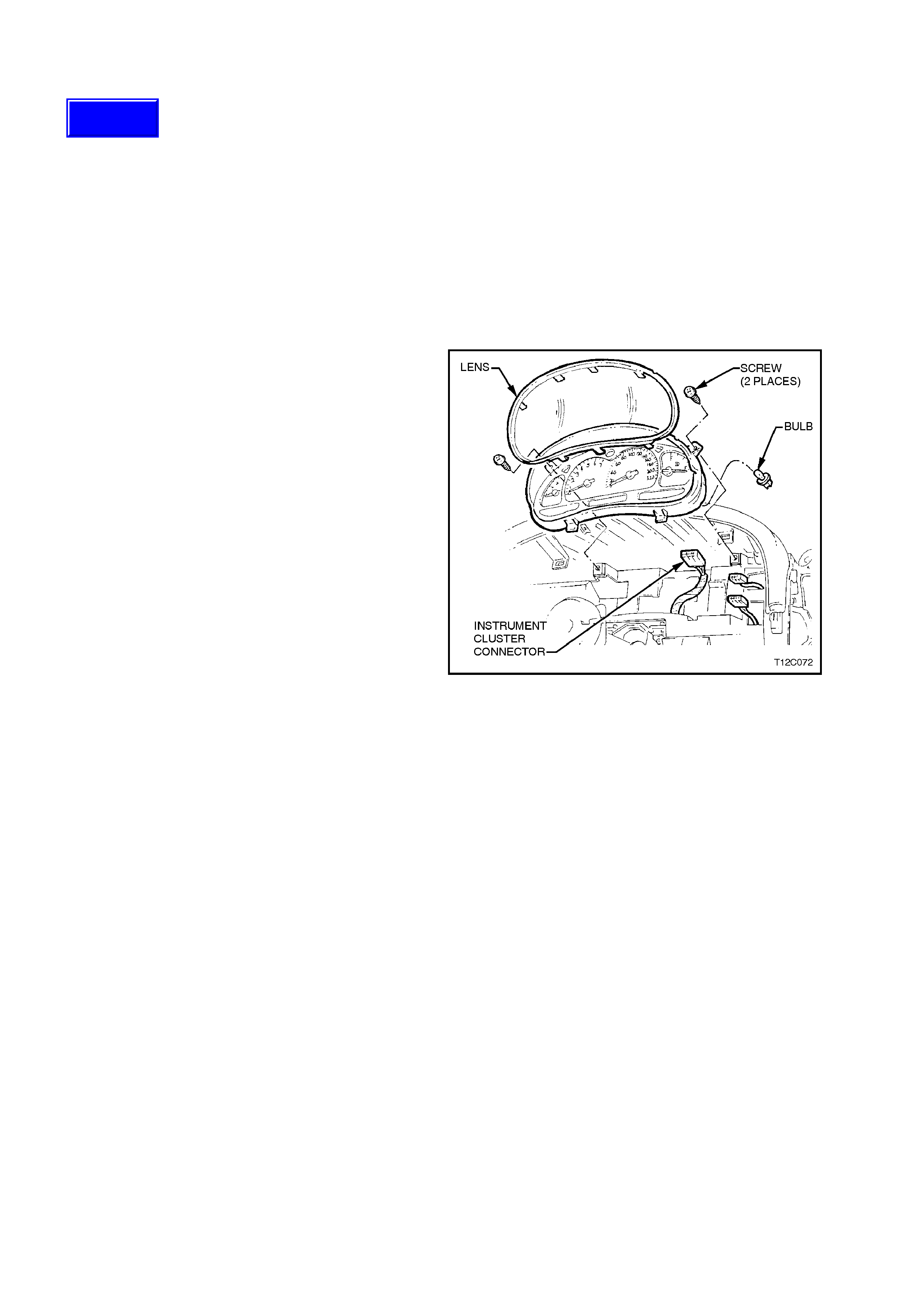
DISASSEMBLE
Disassembly of the instrument cluster assembly is
limited to lens and bulb replacement, refer to Fig.
12C-37
CAUTION:
During the following service operation, when
removing or reinstalling the instrument gauge lens,
grip around the edges. Finger marks on the lens and
instrument gauge assembly faces are difficult to
remove.
1. Carefully remove the instrument cluster lens by
releasing the tabs securing the lens to the
instrument cluster housing refer Fig.12C-37.
2. Remove all warning lamp and instrument cluster
assembly illumination bulbs and sockets by
twisting sockets to release them from case.
REASSEMBLE
Reassembly is the reverse of disassembly
procedure.
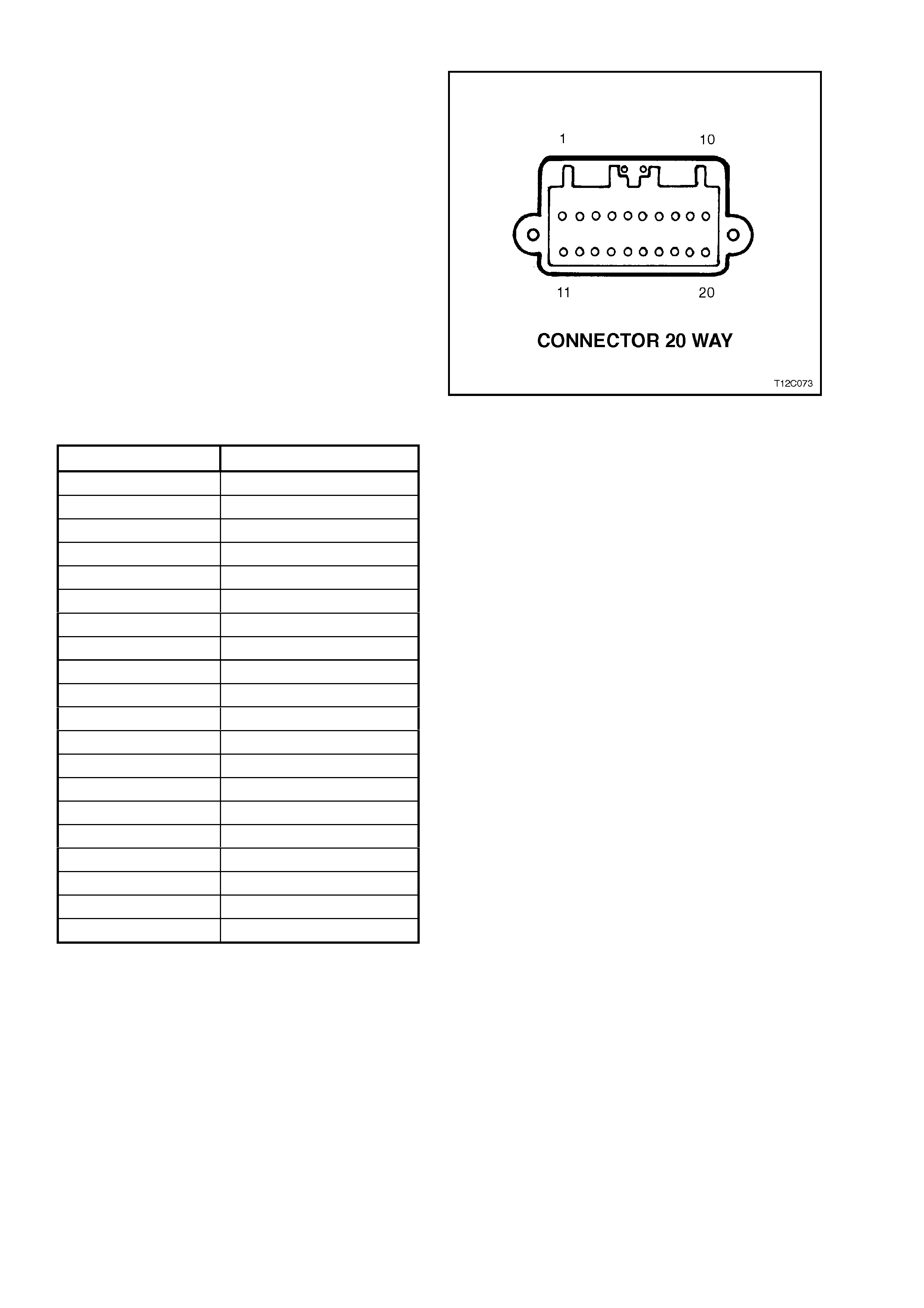
2.2 INSTRUME NT CLUS TER INPUTS
The following chart details the instrument cluster
connector terminal identification.
Figure 12C-38
PIN NUMBER FUNCTION
1 Right Turn
2 Cruise Engaged
3 Fog Lamps ON
4 Park Lights
5 Illum. - Switch Negative
6 Ground
7 High Beam
8 Left Turn
9 ABS Off
10 LPG Fuel Sender
11 Low Traction
12 Serial Data
13 Trip Comp. Switch input
14 Generator
15 Brake (P&F)
16 Fuel Sender
17 Speed In
18 Tacho In
19 Ignition
20 Battery
CHECK
To check the input voltage or wiring continuity
between the various sensors/senders to the
instrument cluster connector refer to
5. DIAGNOSTICS in this Section.

2.3 SE NDER UNITS
VEHICLE SPEED SENDER
MANUAL TRANSMISSION
For all details of the m anual trans m ission vehic le speed sensor rem oval, testing, reinstallation instr uctions, ref er to
Section 6C1 POWERTRAIN MANAGEMENT V6 ENGINE or Section 6C2 POWERTRAIN MANAGEMENT V8
ENGINE.
AUTOMATIC TRANSMISSION
For all details of the automatic transmission vehicle speed sensor removal, testing, reinstallation instructions, refer
to Section 6C1 POWERTRAIN MANAGEM ENT V6 ENGINE or Section 6C2 POWERTRAIN MANAGEM ENT V8
ENGINE.
FUEL GAUGE SENDER UNIT
TEST - SENDER UNIT OPERATION
With sender unit removed from fuel tank, use an ohmmeter to measure resistance between sender unit terminals,
at the specified float positions.
FLOAT LEVEL DECK
HIGHT RESISTANCE
SETTING OHMS FLOAT POSITION
3 - 10 mm 37.5 - 42.5
246.7 - 253.3
Empty
Full
NOTE:
When the float is positioned half way, a resistance of 110 Ohms - 115 Ohms can be expected.
If resistance is not as specified at a particular float position, replace sender unit.
Techline
Techline
Techline
2.4 TRIP COMPUTER SWITCH ASSEMBLY
REMOVE
1. Disconnect the battery earth lead.
CAUTION:
If vehicle is equipped with SRS (AIRBAG),
disable the system. Refer to ‘SUPPLEMENTAL
RESTRAINT SYSTEM, Section 12M - (Version
6.2) or Section 12M - (Version 8.0/8.1).
2. Remove the Instr um ent panel fac ia far enough
to gain access to trip computer switch
connector, refer Section 1A3 INSTRUMENT
PANEL & CONSOLE
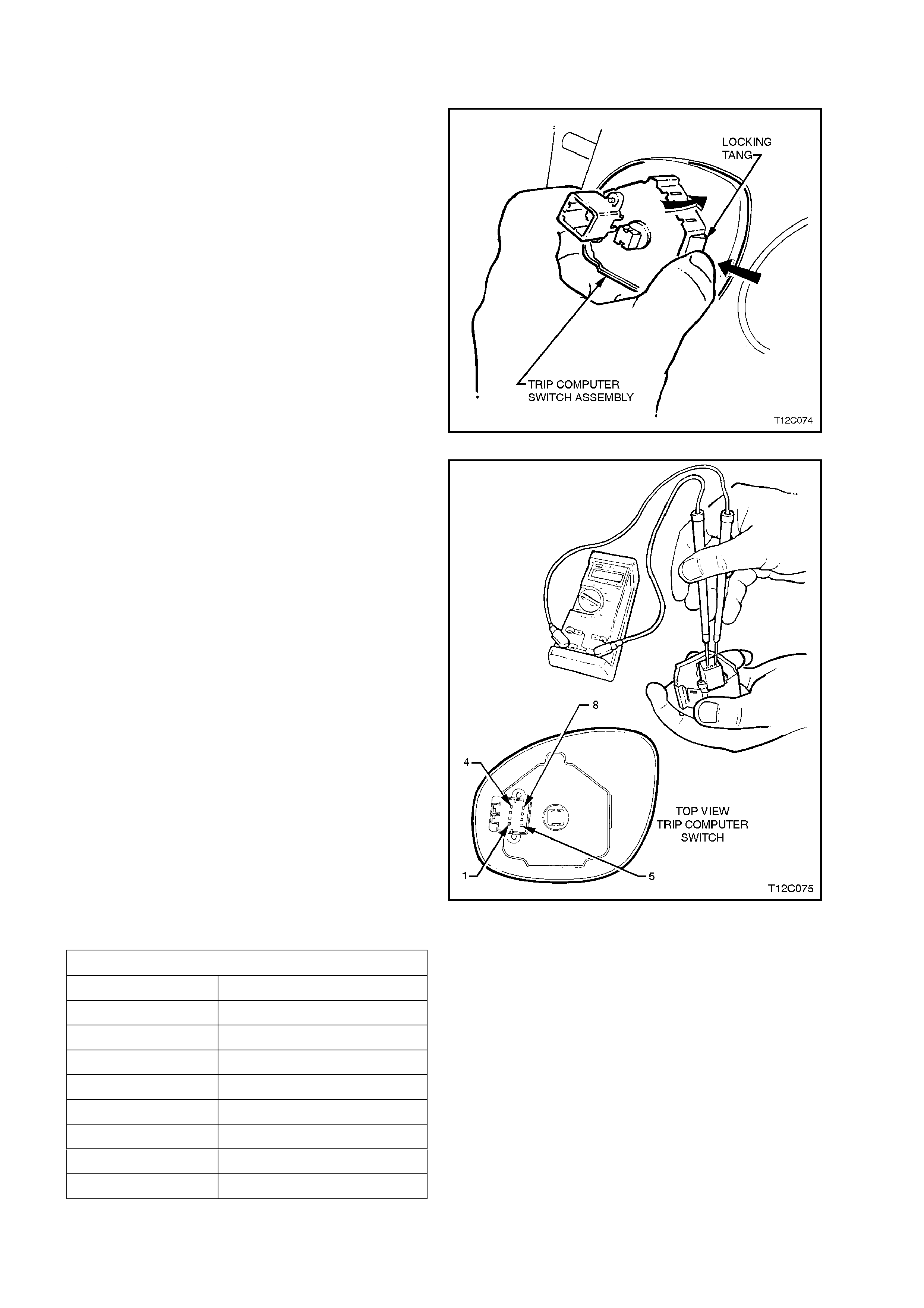
3. Depress locking tang on trip computer switch
instrument harness connector and pull
connector from switch.
4. From behind instrument facia, squeeze
together switch to instrument facia retainers
and push switch out from facia.
Figure 12C-39
TESTING SWITCH
With the aid of an ohmmeter, check resistance of
trip computer switch contacts using the following
chart.
If resistance is not as specified at switch position,
replace the switch assembly.
Figure 12C-40
CONNECTOR DETAILS
PIN FUNCTION
1 NOT CONNECTED
2 NOT CONNECTED
3 SECURITY LED
4 NOT CONNECTED
5 ENCODED SWITCH
6 ILLUMINATION GROUND
7 ILLUMINATION POSITIVE
8 GROUND
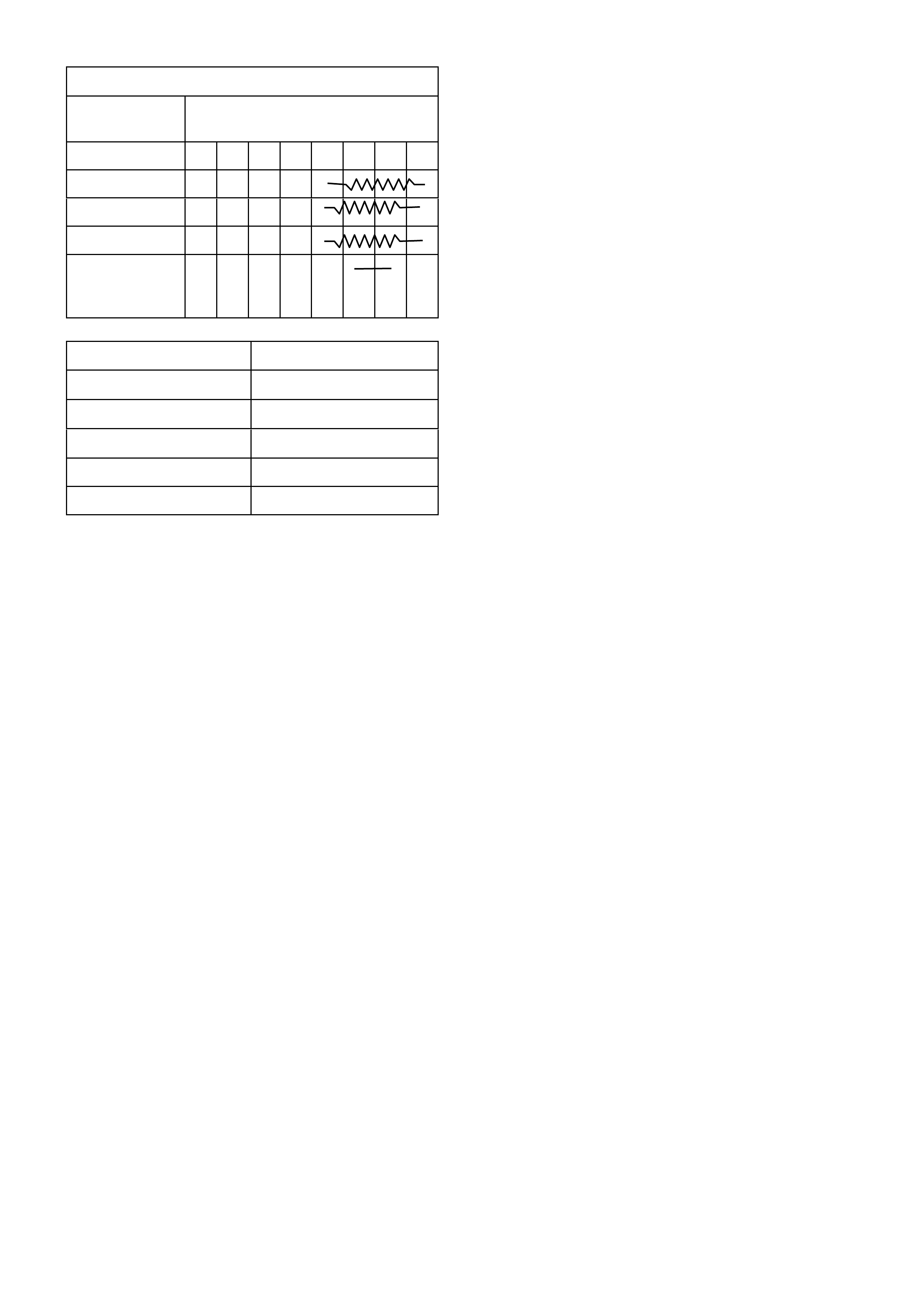
TRIP COMPUTER SWITCH CONTACTS
BUTTON
DEPRESSED Terminal No.
12345678
MODE X X
UP X X
DOWN X X
Illumination
Bulb and
Circuit
XX
FUNCTION RESISTANCE
MODE 20 KΩ
UP 10 KΩ
DOWN 4.99 KΩ
SECURITY LED --
ILLUMINATION --
REINSTALL
Reinstallation is the reverse of removal
procedures.
IMPORTANT:
If vehicle is equipped with SRS AIRBAG),
enable the system. Refer to ‘SUPPLEMENTAL
RESTRAINT SYSTEM, Section 12M - (Version
6.2) or Section 12M - (Version 8.0/8.1).
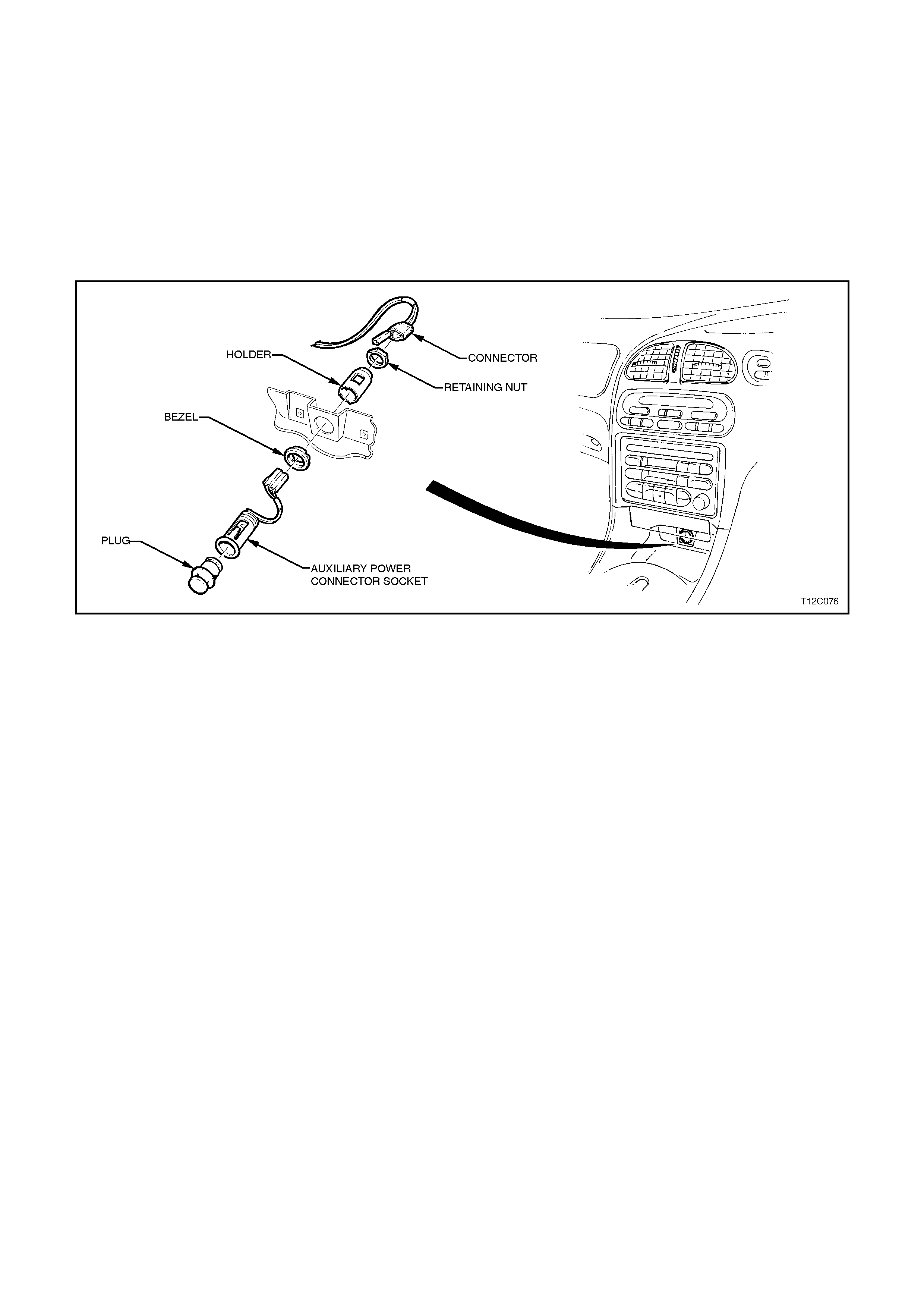
2.5 INSTRUME NT PANEL AUXILIARY POWER CONNECTOR
REMOVE
1. Disconnect the battery earth lead.
CAUTION:
If vehicle is equipped with SRS (AIRBAG), disable the system. Refer to ‘SUPPLEMENTAL RESTRAINT
SYSTEM, Section 12M (Version 6.2) or Section 12M - (Version 8.0/8.1).
2. Remove the instrument panel centre facia assembly refer Section 1A3 INSTRUMENT PANEL & CONSOLE.
3. Rem ove the auxiliary power connec tor retainer nut f rom the rear of the ins trum ent panel centr e facia as sem bly
removing the connector assembly.
Figure 12C-41
REINSTALL
Installation is the reverse of removal procedure.
IMPORTANT:
If vehicle is equipped with SRS AIRBAG), enable the system. Refer to ‘SUPPLEMENTAL RESTRAINT
SYSTEM, Section 12M (Version 6.2) or Section 12M - (Version 8.0/8.1).
3. WIPERS AND WASHERS SERVICE OPERATIONS
3.1 FRONT WIPER ARM
REMOVE
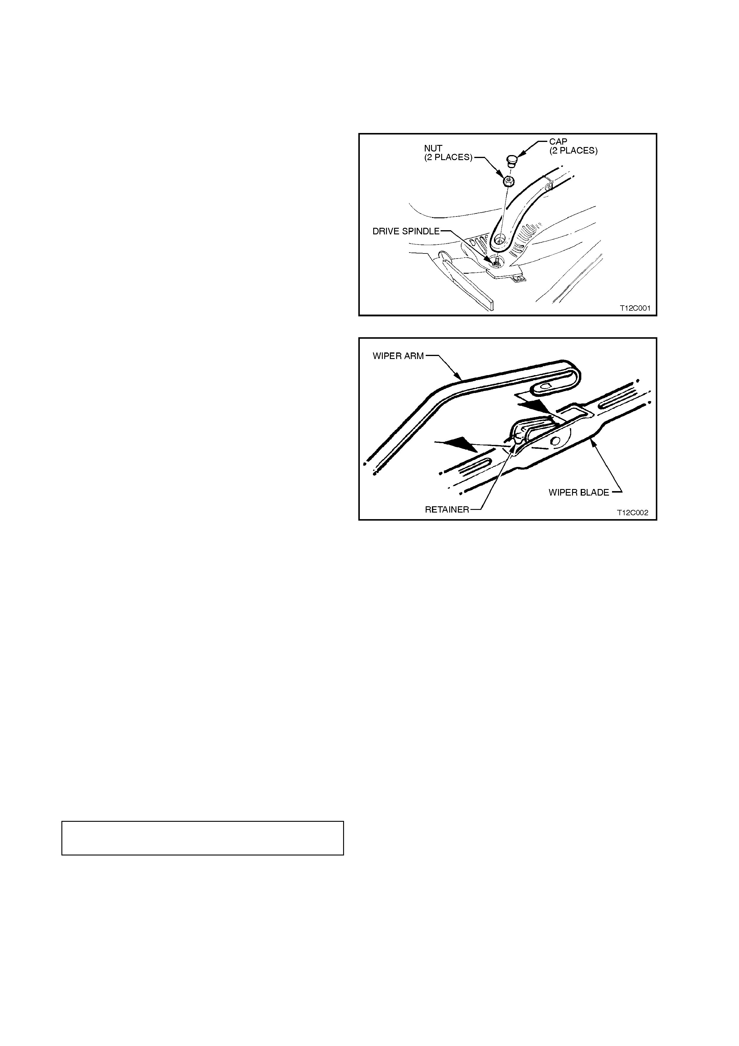
1. Open engine hood.
2. Using a small sc r ew driver or s cr ibe, gently pry
the cap from the front wiper arm.
3. Remove the nut securing the front wiper arm
to the drive spindle.
4. Remove wiper arm from drive spindle, taking
care not to allow wiper arm to contact rear
edge of engine hood.
Figure 12C-42
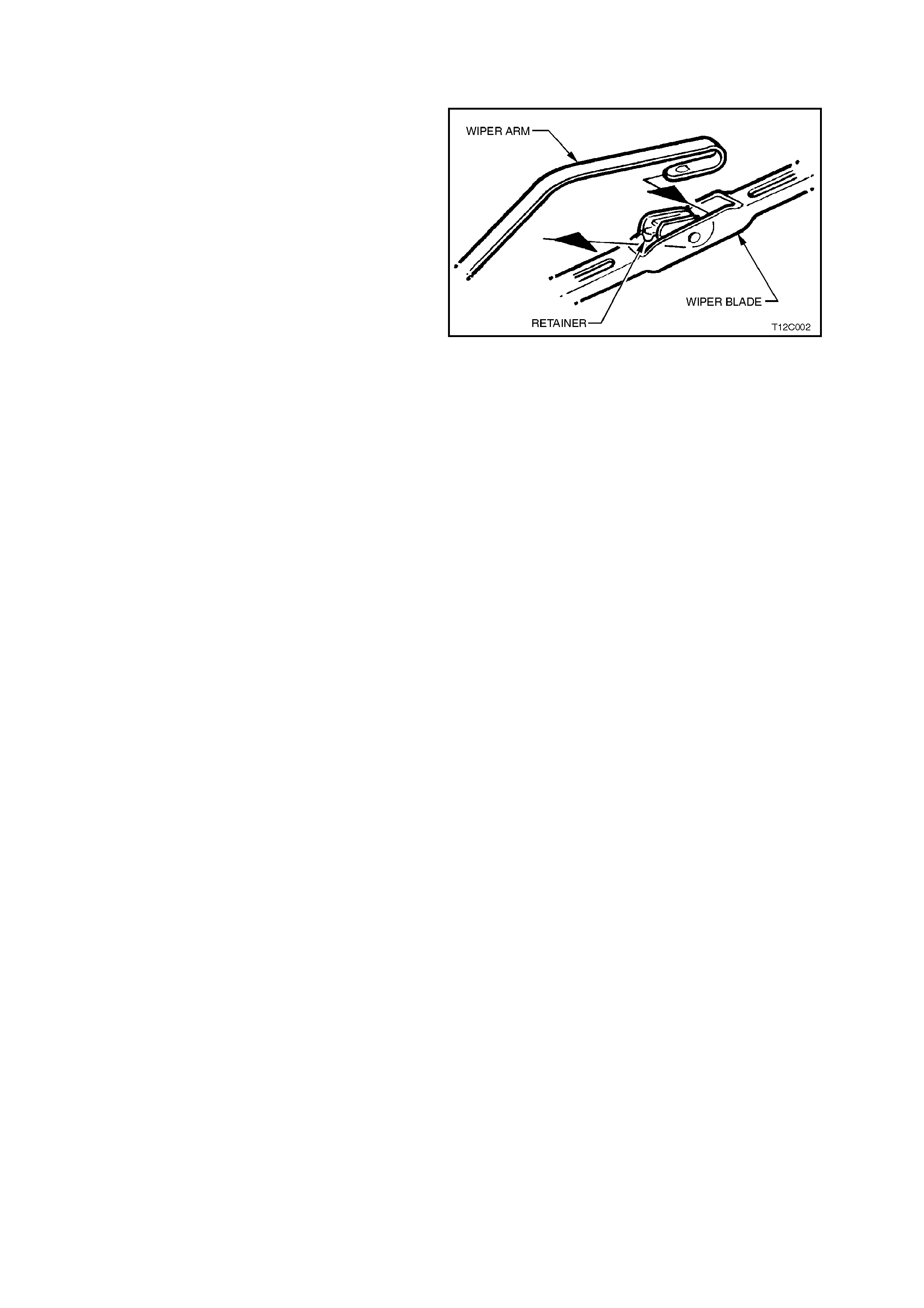
5. If required, remove wiper blade from arm by
lifting up the retainer on the wiper blade and
pulling blade from arm.
Figure 12C-43
REINSTALL
1. If removed, slide wiper blade into wiper arm
until the wiper blade retainer locks into
position.
2. Ensure that the wiper motor linkages are in
the PARKED position.
3. Reinstall wiper arm assembly onto drive
spindle so that the blade is positioned with the
tip 35 mm ± 5 mm above the edge of the
plenum cover, refer Fig. 12C-44.
NOTE: Ensure the correct wiper arm and blades
are fitted to each side of the vehicle, ref er Fig 12C-
44.
4. Reinstall the nut securing the front wiper arm
to the drive spindle and tighten to the correct
torque specification.
WI PER ARM NUT
TORQUE SPECIFICATION 20 - 25 Nm
5. Reinstall wiper arm cap.
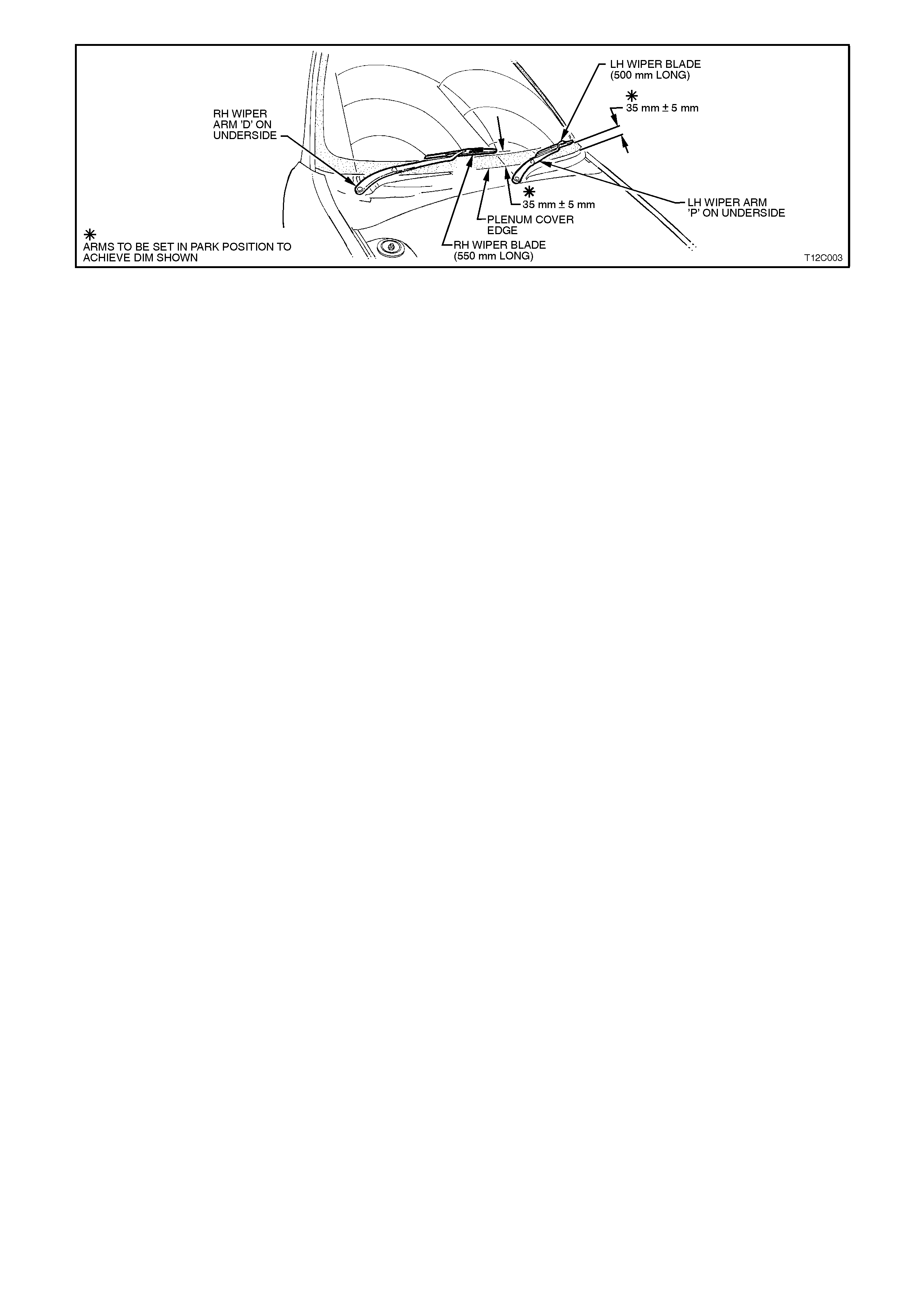
Figure 12C-44
3.2 REAR WIPER ARM
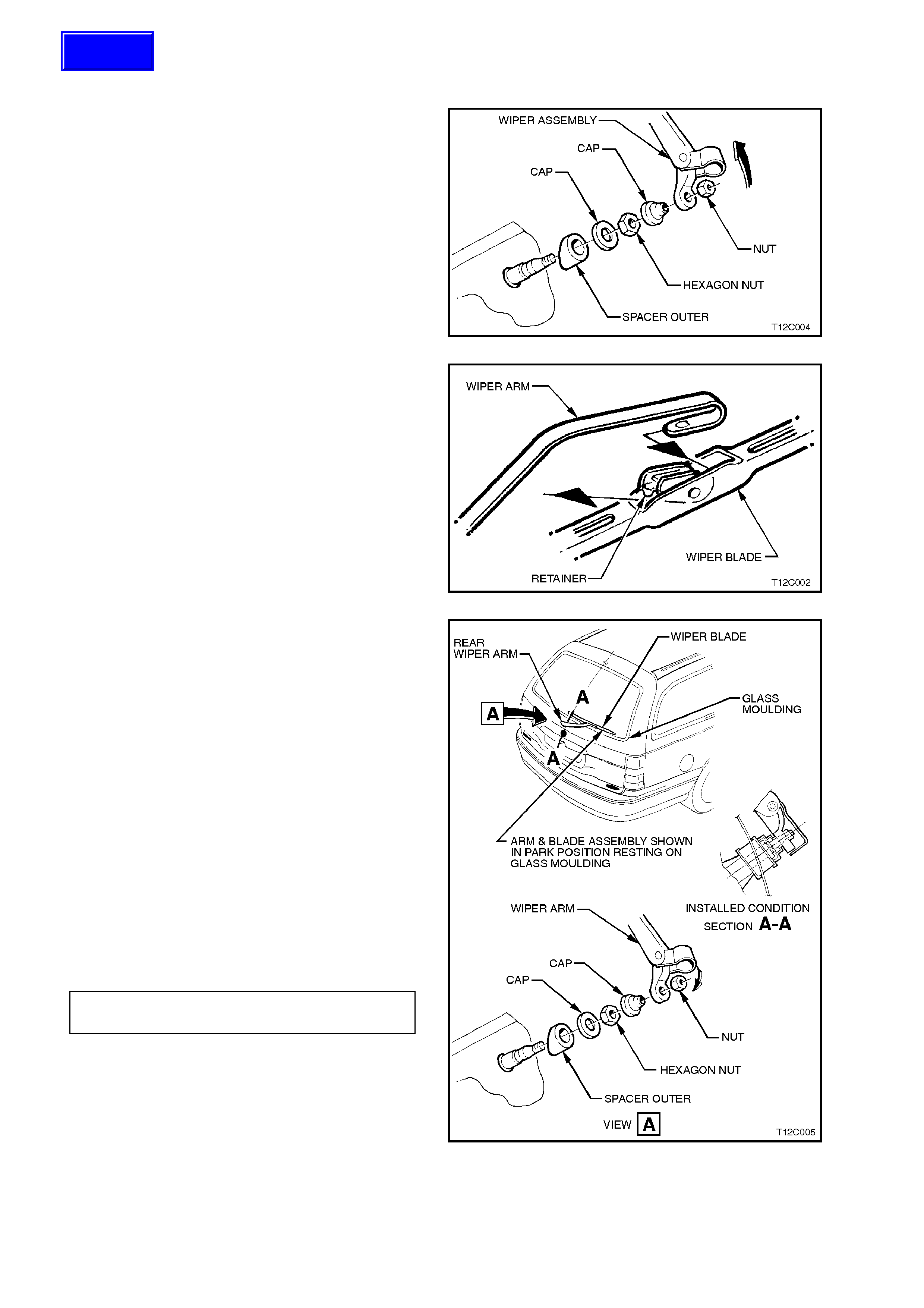
REMOVE
1. Lift up trim cap from wiper m otor drive spindle
end of wiper arm.
2. Remove wiper arm to drive spindle securing
nut and remove wiper arm.
Figure 12C-45
3. If required, remove wiper blade from arm by
lifting up the retainer on the wiper blade and
pulling blade from arm.
Figure 12C-46
REINSTALL
1. If removed, slide wiper blade into wiper arm
until the wiper blade retainer locks into
position.
2. Ensure the wiper motor is in the PARKED
position.
3. Reinstall wiper arm assembly onto drive
spindle so that the wiper blade rests on the
glass moulding, refer Fig. 12C-47.
NOTE:
To ensure arm will not wipe over moulding in the
park position, push arm onto wiper spindle with the
arm in the vertical position and then rotate wiper
arm clockwise until blade rests on glass moulding.
4. Reinstall the nut sec uring the wiper arm to the
drive spindle and tighten to the correct torque
specification.
WI PER ARM NUT 6 - 14
TORQUE SPECIFICATION Nm
5. Push trim cap onto wiper arm.
Figure 12C-47
Techline
3.3 FRONT AND REAR WIPE R BLADES
REMOVE
1. W ith engine hood lowered, lift wiper arm from
glass.
2. Remo ve wiper blade from arm by lifting up the
retainer on the wiper blade and pulling blade
from arm.
Figure 12C-48
REINSTALL
1. Slide wiper blade into wiper arm until the wiper
blade retainer locks into position.
2. Lower wiper arm onto glass.
3.4 FRONT AND REAR WIPER BLADE INSERT
REPLACE
1. Remove wiper blade from arm, refer
3.3 FRONT AND REAR WIPER BLADES in
this Section.
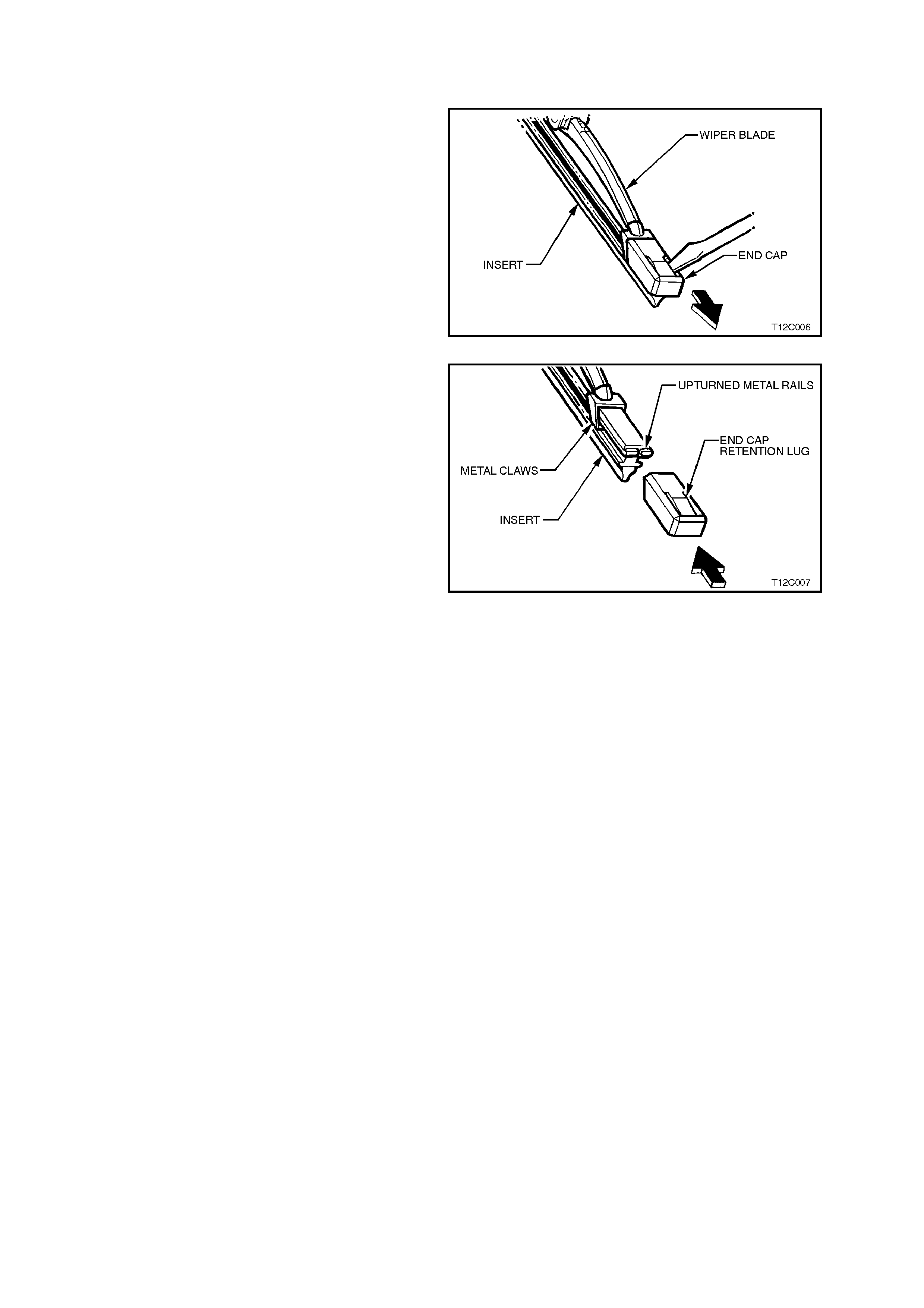
2. Using a sm all screwdriver, lif t the retention lug
and slide the end cap off the wiper insert.
NOTE:
Do not re-use end cap.
3. Slide insert out of wiper blade and discard.
Figure 12C-49
NOTE:
The replacement insert will be supplied with one
end cap and a small retaining clip fitted.
4. Rem ove the small retaining clip f rom the ins ert
and slide the end without the end cap into the
wiper blade ensuring that the insert passes
through each metal claw.
5. Assemble the new end cap onto the end of the
insert, ensuring the retention lug on the end
cap is located securely behind the two
upturned ends of the metal rails, refer Fig
12C-50.
6. Reinstall wiper blade onto arm, refer
3.3 FRONT AND REAR WIPER BLADE in
this Section.
Figure 12C-50
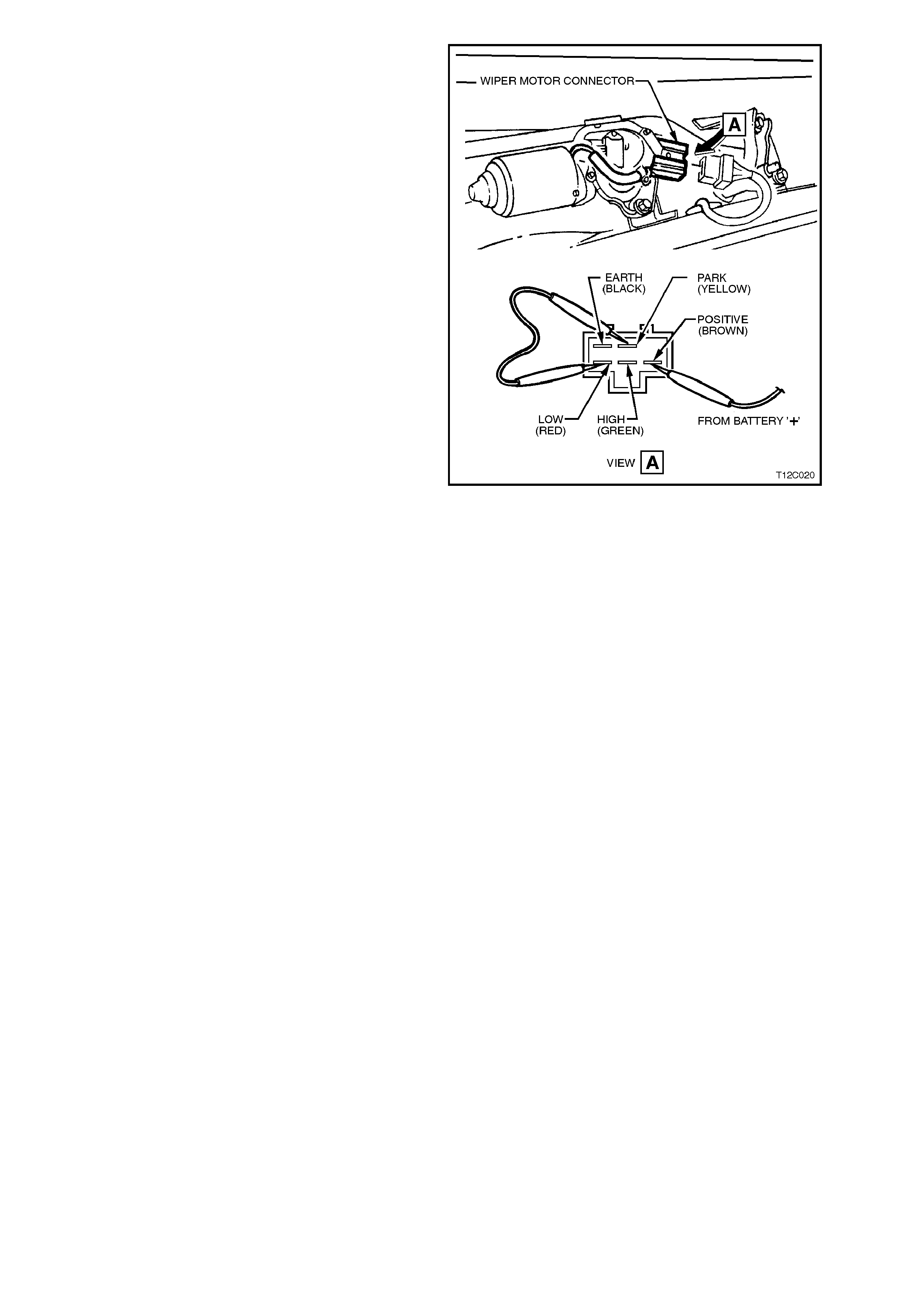
3.5 FRONT WIPER MOTOR AND LINKAGE
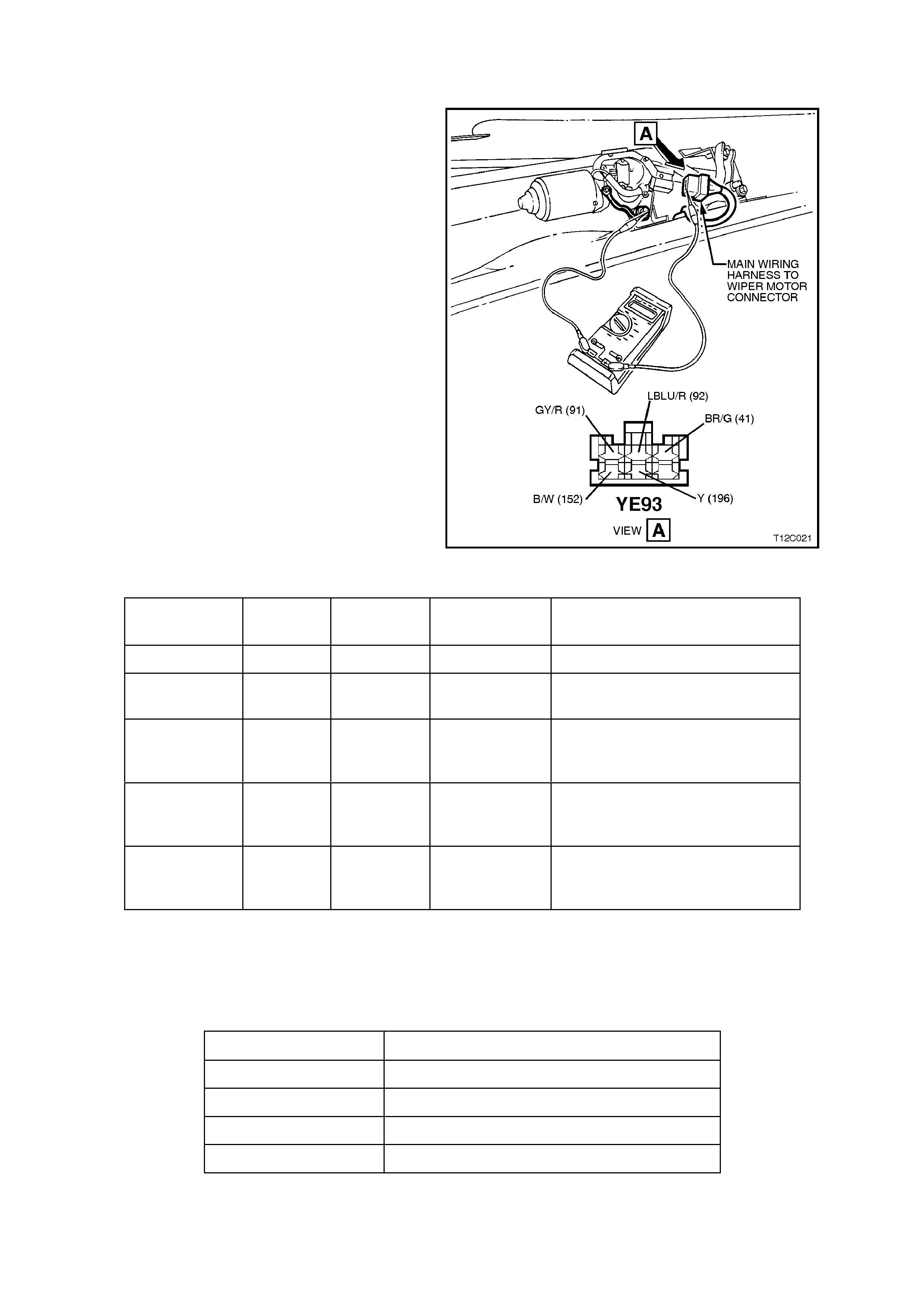
CHECKING WIPER MOTOR WIRING
The following operation checks the wiper motor
wiring at the wiper motor connector (YE93) as an
aid to diagnosing a fault in the wiper motor system.
NOTE:
On vehicles with high series BCM, operation of
the interm ediate dwell control can be c heck ed with
TECH 2, refer Section 12J-2 HIGH SERIES BCM.
1. Remove wiper arms, plenum covers, water
deflector and disconnect wiring harness
connector YE93, refer to Steps 1 - 6 in the
following wiper motor removal procedure.
2. Using a multimeter connected with the
negative lead to the black wire term inal of the
wiring harness connector and the positive
lead to the main wiring harness connector
wire terminal nom inated in the f ollowing chart,
check wiper motor wiring as follows:
Figure 12C-51
WIRE
COLOUR CIRCUIT
NO. CIRCUIT MULTIMETER
SETTING RESULT IF WIPER MOTOR
WIRING IS OK
Black/White 152 Earth Resistance 0 ohms (approximately).
Brown/Green 41 Power
source Voltage B+ with ignition in ACC or ON
position.
Grey/Red 91 Low speed Voltage B+ with ignition in ACC or ON
position and wiper switch in low
speed position.
LBlue/Red 92 High speed Voltage B+ with ignition in ACC or ON
position and wiper switch in high
speed position.
Grey/Red 91 INT
Position Voltage B+ cycling with ignition in ACC or
ON position and wiper switch in
INT position.
3. With wiring harness connector YE93
disconnected, check for continuity between
the Yellow wire, circuit 196 and the Grey/Red
wire, circuit 91, as per the following table:
SWITCH POSITION RESULT IF WIPER MOTOR WIRING IS OK
OFF Continuity
INTERMITTENT Continuity
LOW Continuity (low resistance)
HIGH Open circuit
NOTE:
If any of the readings are not as specified, check
and repair faulty circuit as necessary.
CHECKING WIPER MOTOR OPERATION
The following operation checks the various
functions of the wiper motor. If there is a f ault in the
wiper system, and the following operation proves
that the wiper motor is OK, check the wiper/washer
switch or wiring as described in this Section, or
check the BCM control, depending on model
variant, refer to either Sect ion 12J-1 L O W SERIES
BCM or Section 12J-2 HIGH SERIES BCM.
If the following operation proves that the wiper
motor is faulty, replace the wiper motor assembly.
1. Remove wiper arms, plenum covers, water
deflector and disconnect wiring harness
connector, refer to Steps 1 - 6 in the following
wiper motor removal procedure.
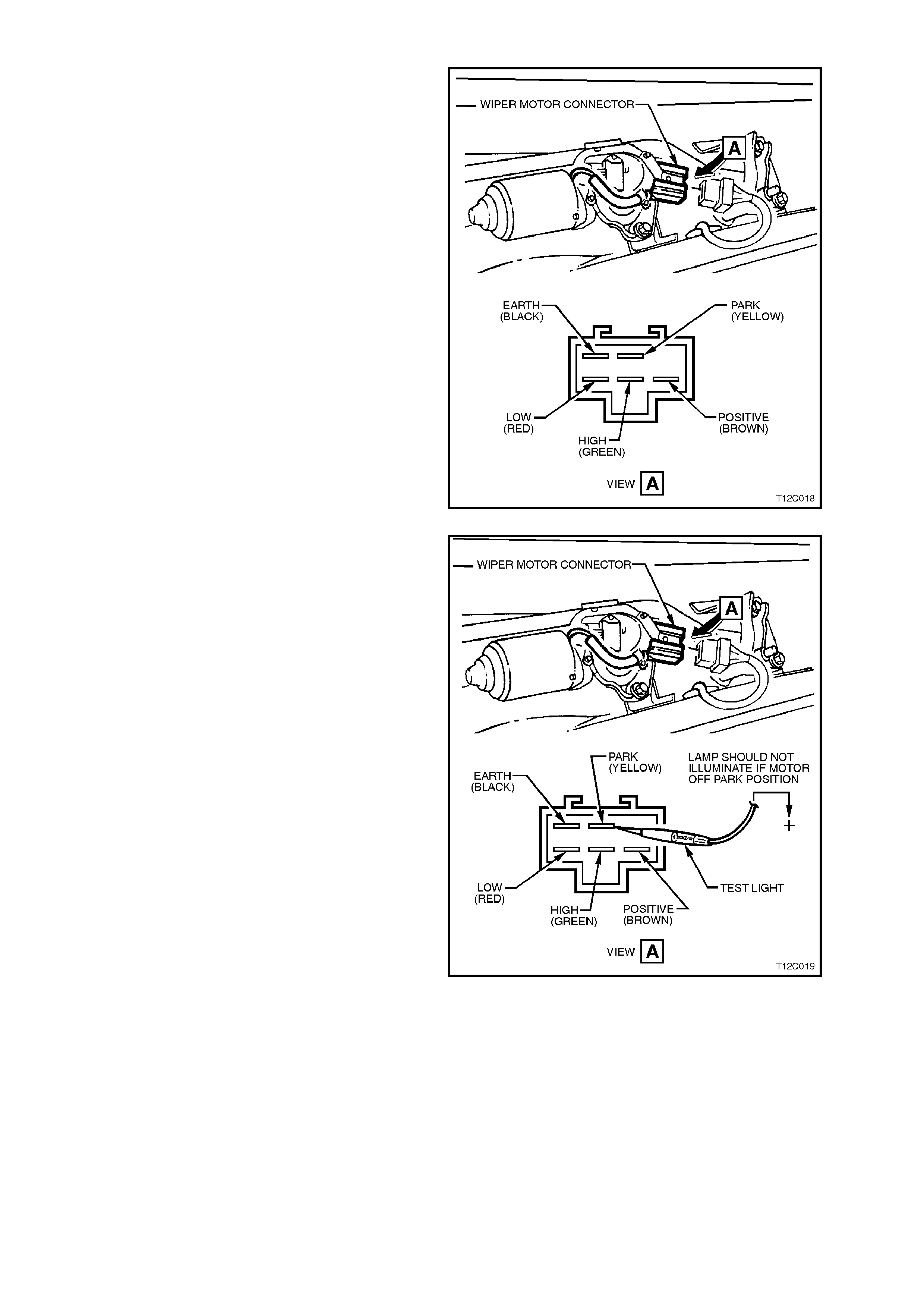
2. Connect a lead from vehicle battery positive
terminal to the Red wire of the wiper motor
connector. T he wiper motor should operate on
low speed.
3. Connect a lead from vehicle battery positive
terminal to the Green wire of the wiper motor
connector. T he wiper motor should operate on
high speed.
Figure 12C-52
4. To check wiper motor PARK operation,
connect a jum per lead from vehicle positive to
Red wire of motor connector and allow motor
to turn linkages approximately 1/4 of a turn
past the PARK position.
To check if the wiper motor is off the parked
position, connect a test lamp between battery
positive and the Yellow wire of the wiper m otor
connector. The lamp should NOT illum inate. If
the lamp does illuminate, contacts within the
wiper motor ar e faulty or check f or Yellow wire
shorted to earth.
Figure 12C-53
Using a second jumper wire, connect the Red
and Yellow wires of the wiper motor connector
together.
Using jumper leads from battery positive,
connect to Brown wire of wiper motor
connector and the wiper m otor should turn the
wiper linkages to the PARK position and stop.
If the wiper motor does not tur n the link ages or
the linkages do not stop at the PARK position,
the contacts within the wiper motor are faulty
and therefore, the wiper motor must be
replaced.
5. Reconnect wiring harness connector to wiper
motor.
6. Reinstall water deflector, plenum chamber
covers and wiper arm assemblies, refer to the
following removal and reinstallation procedure
of the wiper motor in this Section.
Figure 12C-54
CIRCUIT DIAGRAMS
Fig. 12C-55 shows the circuit for the front
wiper/washer system for vehicles with Low Series
BCM and Fig. 12C-56 the circuit for the front
wiper/washer system for vehicles with High Series
BCM.
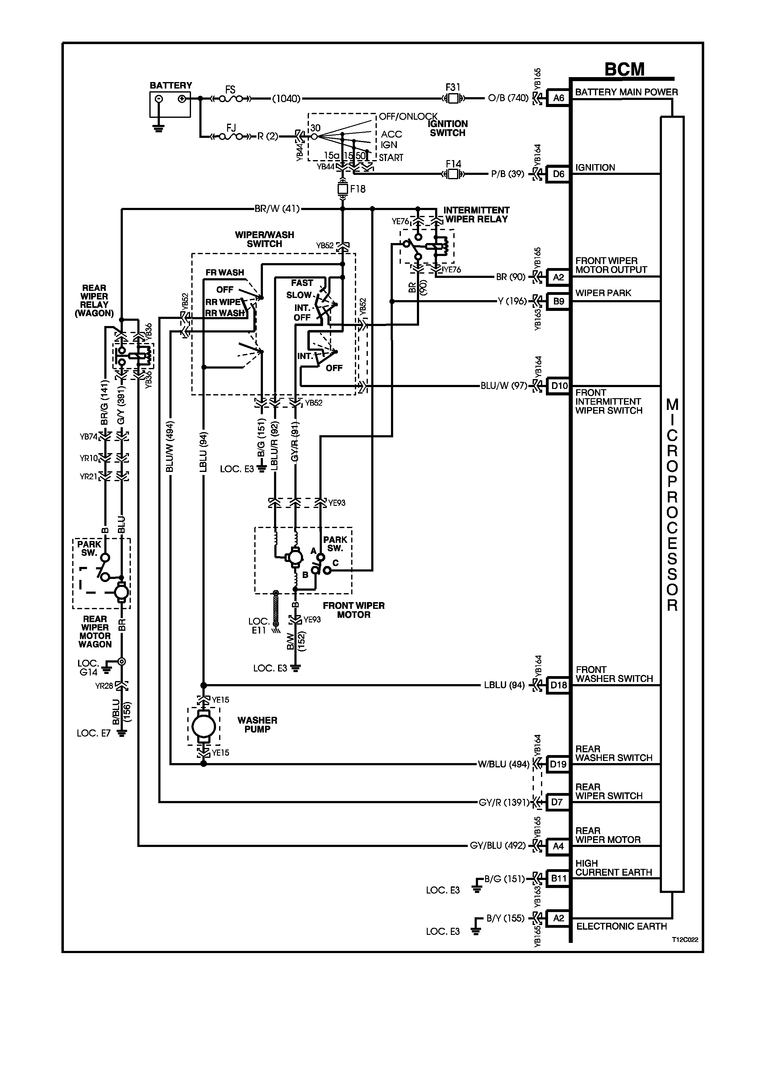
Figure 12C-55
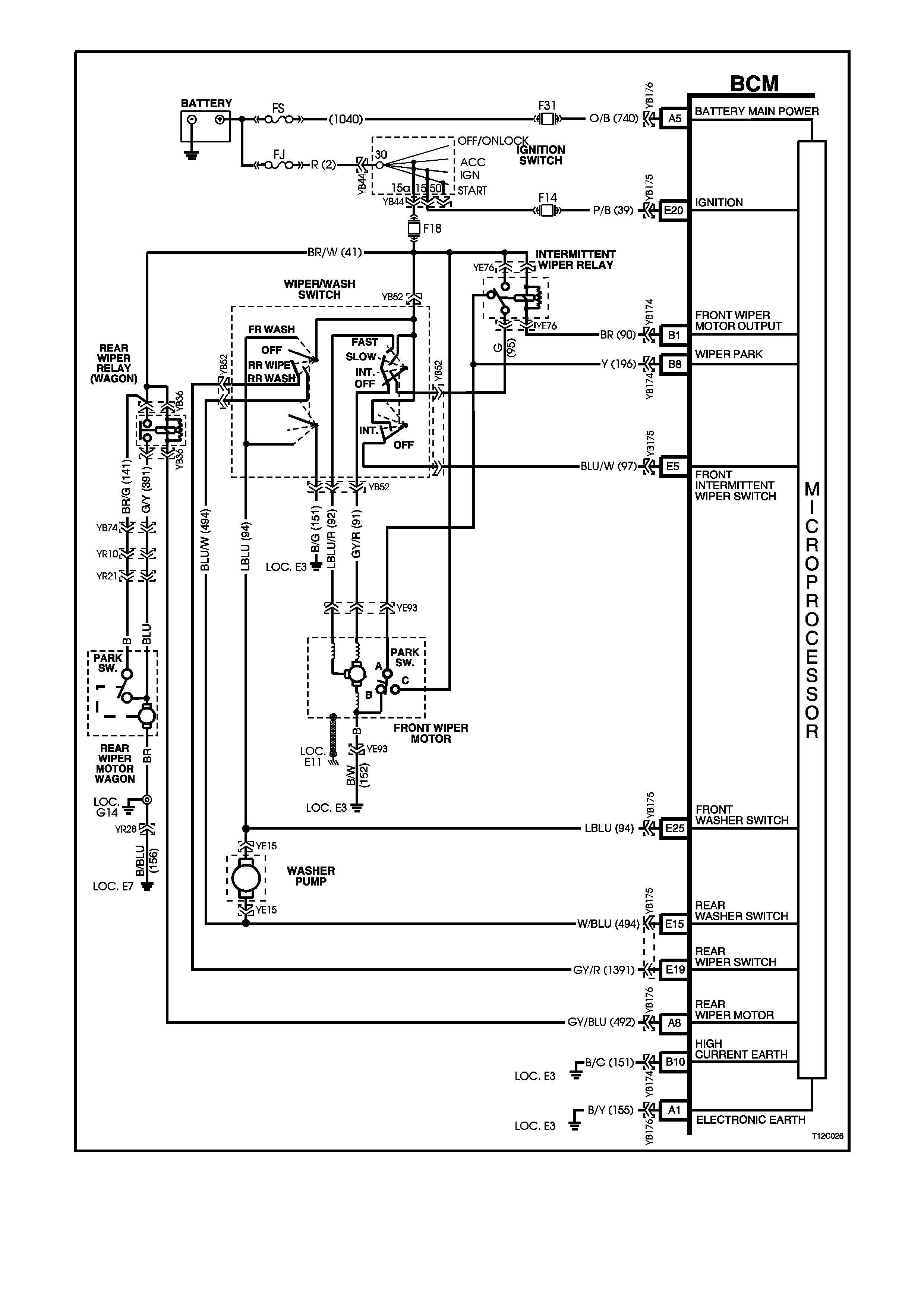
Figure 12C-56
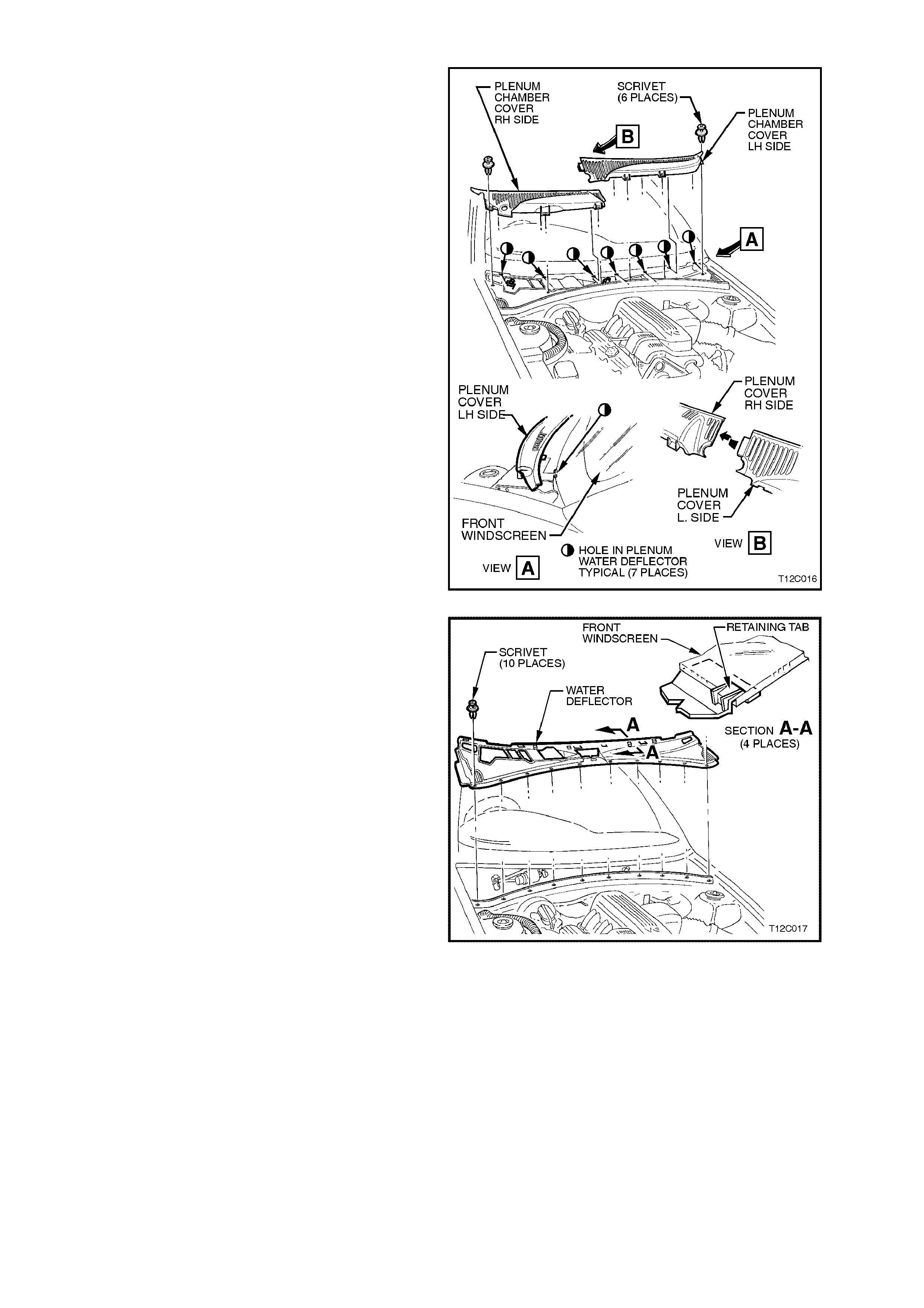
REMOVE
1. Rem ove wiper arm s, ref er 3.1 FRONT WIPER
ARM in this Section.
2. Remove the six f asteners s ecuring the plenum
chamber covers to the plenum chamber.
3. Pull the plenum chamber covers forward to
release them from the retainer securing them
to the windscreen, lift covers upwards while
manoeuvring the cover away from the engine
hood hinge and remove covers.
NOTE:
Remove the right - hand plenum cover first.
Figure 12C-57
4. Remove the 10 fasteners securing the water
deflector to the plenum chamber.
5. Pull the water deflector forward to release it
from the retainers securing it to the
windscreen, remove water deflector.
Figure 12C-58
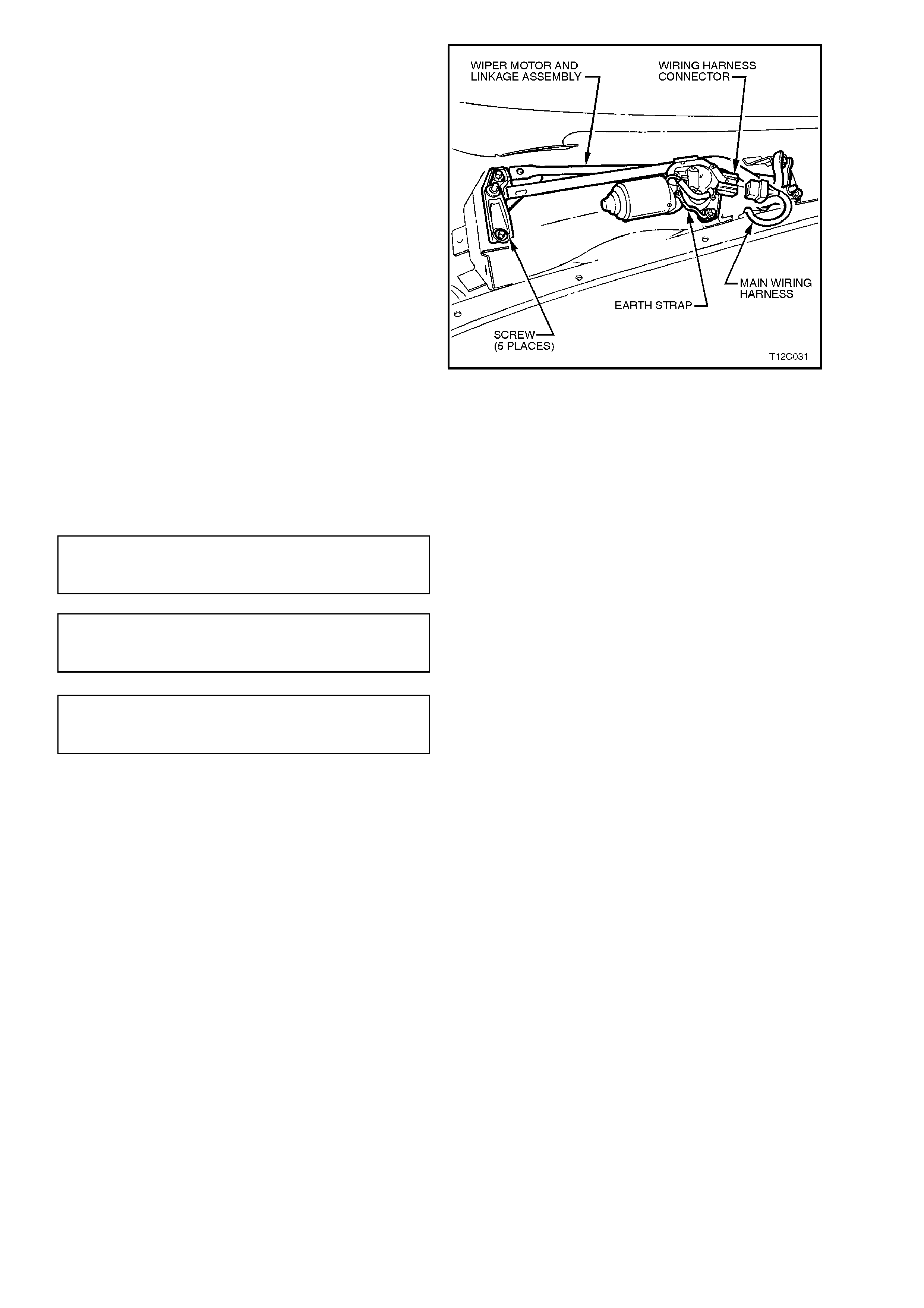
6. Squeeze the tang at the main wiring harness
to wiper motor harness connector and
disconnect wiring harness.
7. Remove the five screws securing the wiper
motor and linkage assembly to the plenum
chamber and remove wiper motor and linkage
assembly.
8. If necessary, remove the nut securing the
wiper linkages to the wiper arm pivot and the
two screws securing the wiper motor to the
wiper linkages and separate the wiper motor
from the wiper linkages.
Figure 12C-59
REINSTALL
Installation of the wiper motor is the reverse of the
removal procedure, noting the following:
1. Ensure all fasteners are tightened to the
correct torque specification.
WI PER MOTOR TO LINKAGE
SECURING SCREWS TORQUE
SPECIFICATION 7 - 9 Nm
WI PER MOTOR CRANK ARM PIVOT
TO WIPER LINKAGE SECURING NUT
TORQUE SPECIFICATION 16 - 20 Nm
WI PER MOTOR AND LINKAGE
ASSEMBLY SECURING SCREW S
TORQUE SPECIFICATION 4 - 6 Nm
NOTE:
Ensure that the wires from the connector do not get
caught or foul the wiper motor linkages.
2. Operate wiper motor before installing the
wiper arm s to ensure it is in the correct PARK
position.
3. When installing the water deflector and
plenum covers, ensure that the retaining tabs
engage under the windscreen.
3.6 WI P ER/WASHER SWITCH
REMOVE
1. Disconnect battery earth lead.
2. Remove ignition keys from ignition switch.
CAUTION:
If vehicle is equipped with SRS (AIRBAG),
disable the system. Refer to ‘SUPPLEMENTAL
RESTRAINT SYSTEM, Section 12M (Version 6.2)
or Section 12M - (Version 8.0/8.1).
3. Lower fuse panel cover.
4. Release steering column height adjuster,
completely lower steering column and leave
lever in the release position.
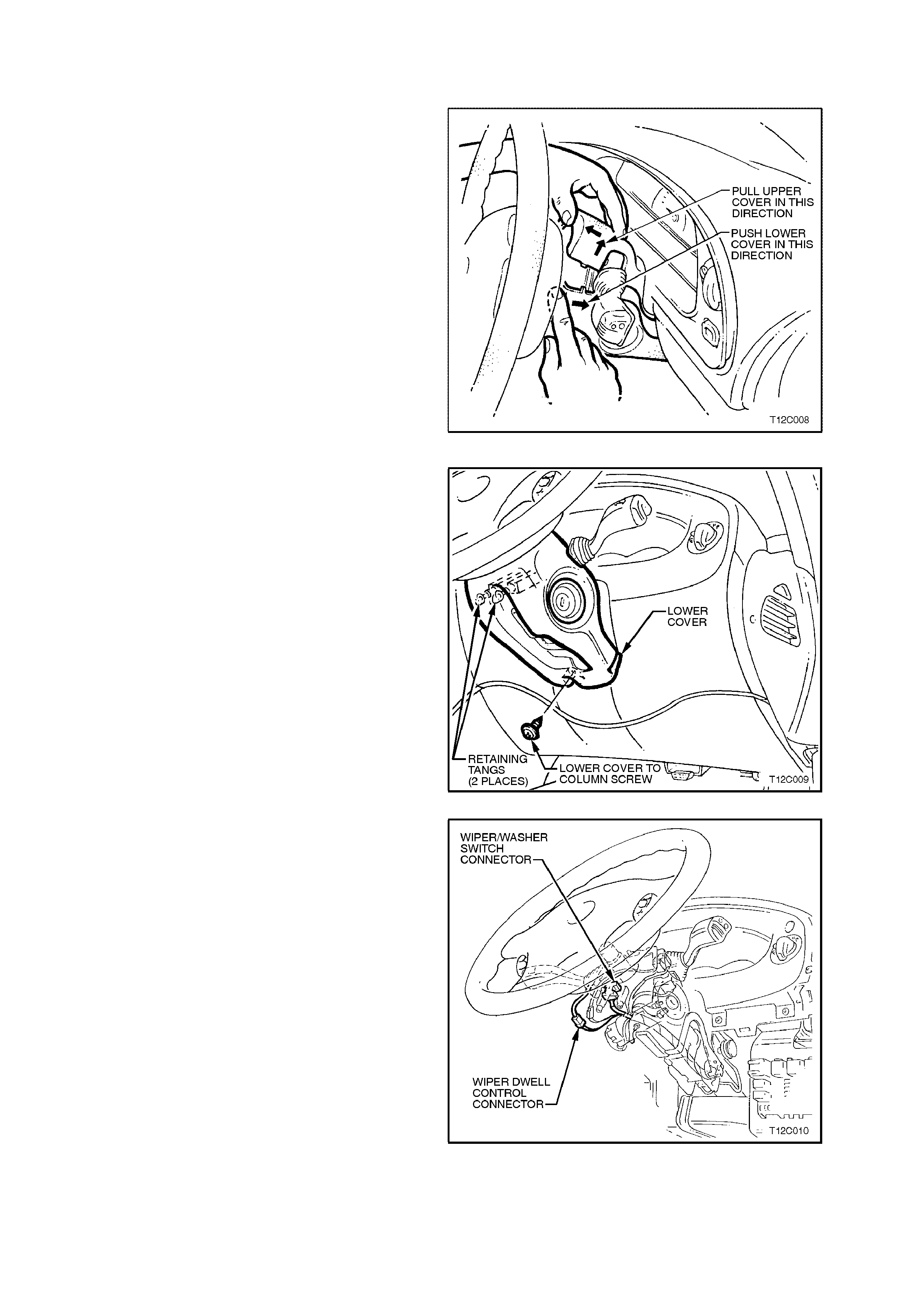
5. Insert finger between the steering wheel and
the lower cover as shown in Fig. 12C-60 and
apply a small amount of pressure (pushing
towards instrument cluster) while lifting the
upper cover up.
6. Remove upper cover by lifting upwards and
rearwards. Figure 12C-60
7. Remove sc rew securing the lower cover to the
steering column.
8. Slide lower cover toward the steering wheel to
release cover from the retaining tangs on the
steering column.
9. While feeding the key reader outer surround
from lower cover, remove cover.
Figure 12C-61
10. On vehicles with high series BCM, disconnect
the wiring harness connector to the wiper dwell
control switch harness connector by
depressing harness retaining tang and pulling
connectors apart.
Figure 12C-62
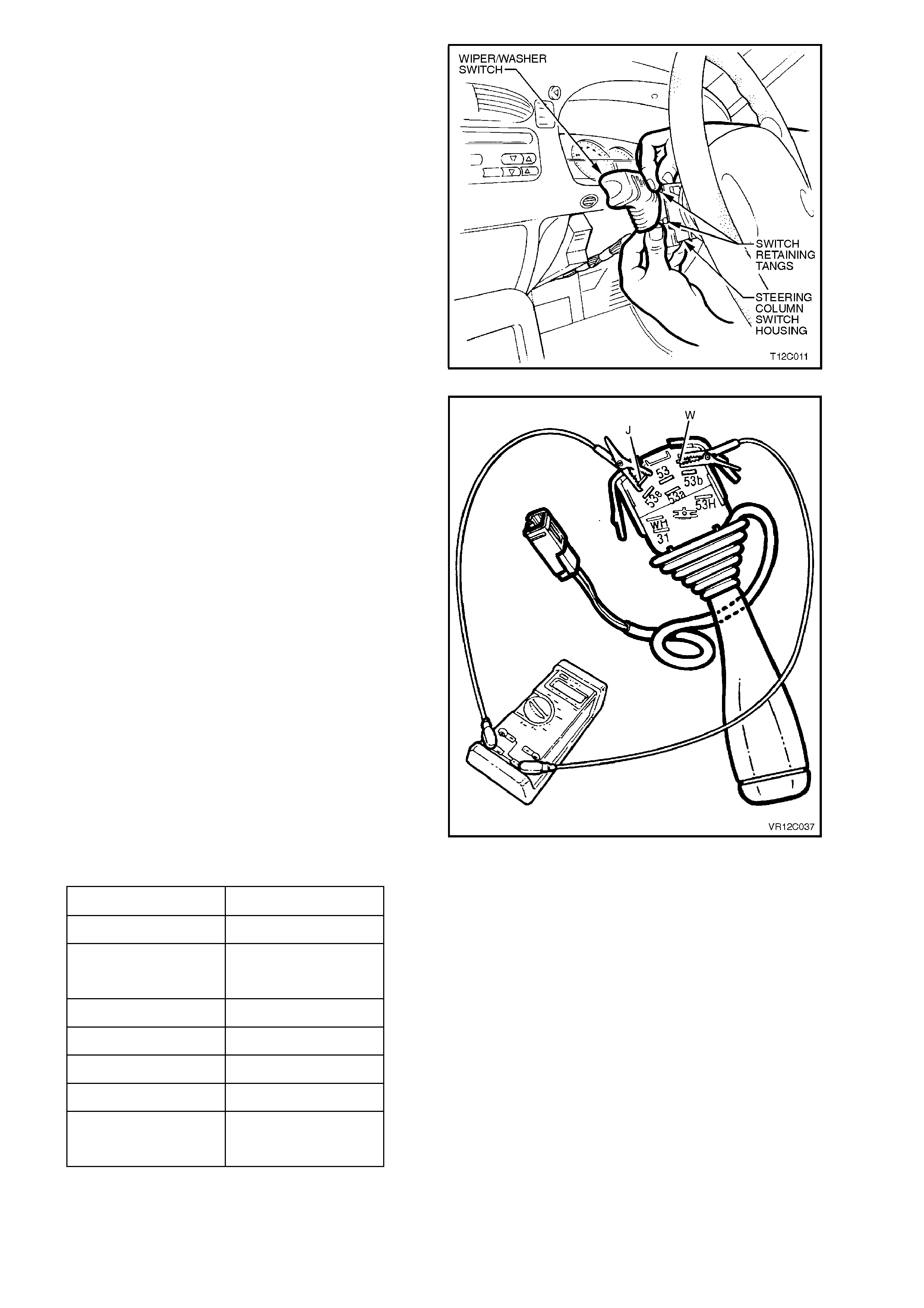
11. Depress retaining tangs on switch assembly
and withdraw switch from switch housing on
steering column.
12. Lift up wiring harness connector retaining
tangs on either side of switch body and pull
connector from switch and remove switch.
Figure 12C-63
TESTING SWITCH
Using an ohmmeter connected to the various
switch terminals (refer Fig. 12C-64), check the
operation of the wiper/washer switch as per the
following chart.
If continuity is not as specified at any switch
position, replace switch assembly.
NOTE:
With dwell control adjusted fully up, multimeter
should register approximately 5.3 kohms, and with
control adjusted fully down, approximately 680
ohms.
Figure 12C-64
SWITCH POSITION TERMINALS
OFF 53 to 53e
INT 53 to 53e
J to 53a
1 53 to 53a
2 53a to 53b
FRONT. WASH W to 53a
REAR WIPE 53a to 53H
REAR WASH 53a to WH
53a to 53H

REINSTALL
Installation of the wiper/washer switch is the
reverse of the removal procedure, noting the
following:
Check operation of all wiper/washer switch
functions.
IMPORTANT:
If vehicle is equipped with SRS AIRBAG), enable
the system. Refer to ‘SUPPLEMENTAL
RESTRAINT SYSTEM, Section 12M (Version 6.2)
or Section 12M - (Version 8.0/8.1).

3.7 W INDSHIELD WASHERS
REMOVE AND REINSTALL
Fig. 12C-65, 12C-66 and 12C-67 illustrate the installation of the windshield washer system components.
The spray direction of the washer nozzle can be adjusted by inserting the point of a pin into the ball of the nozzle
and swivelling it to the position nominated in Fig. Fig.12C-67.
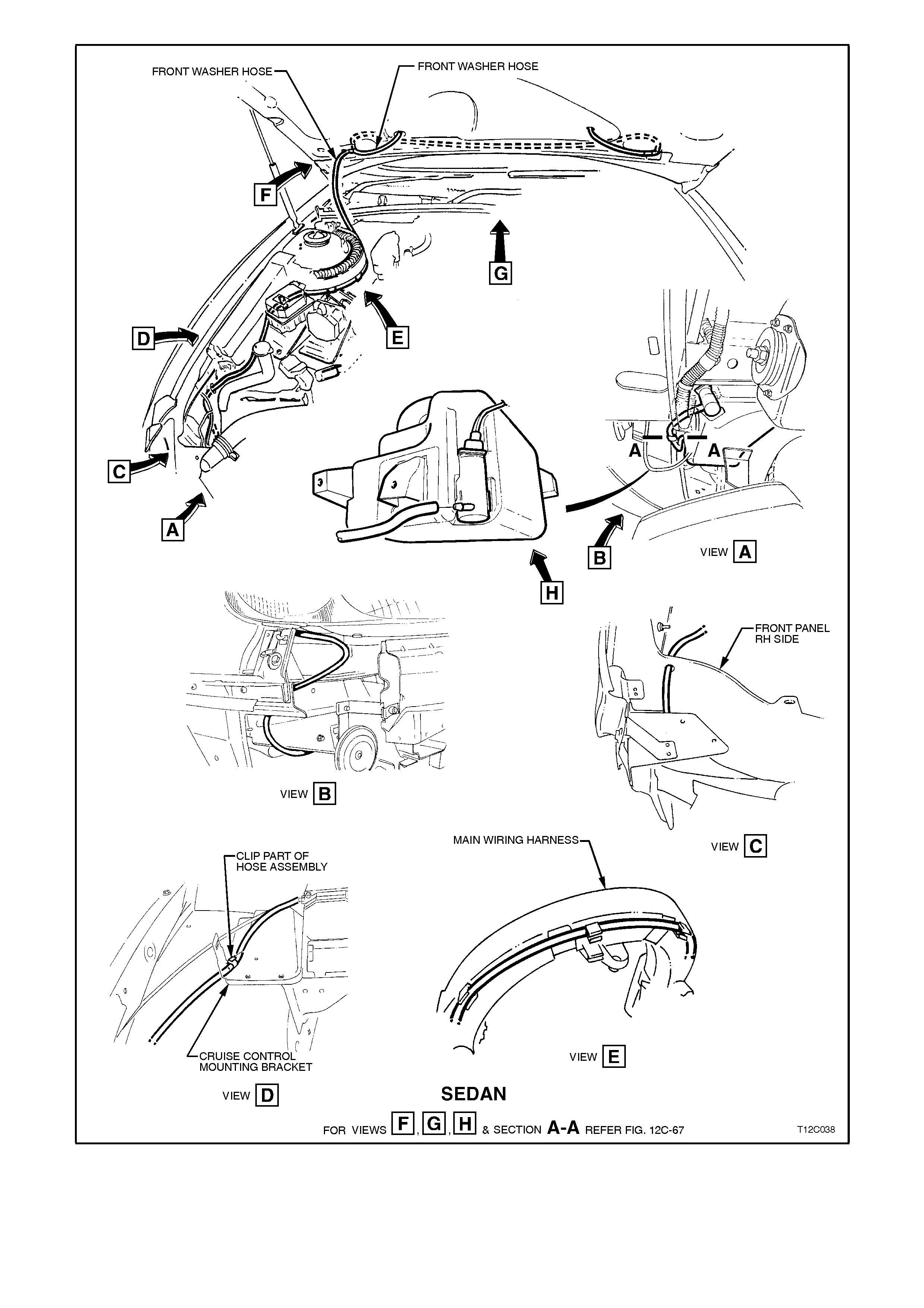
Figure 12C-65
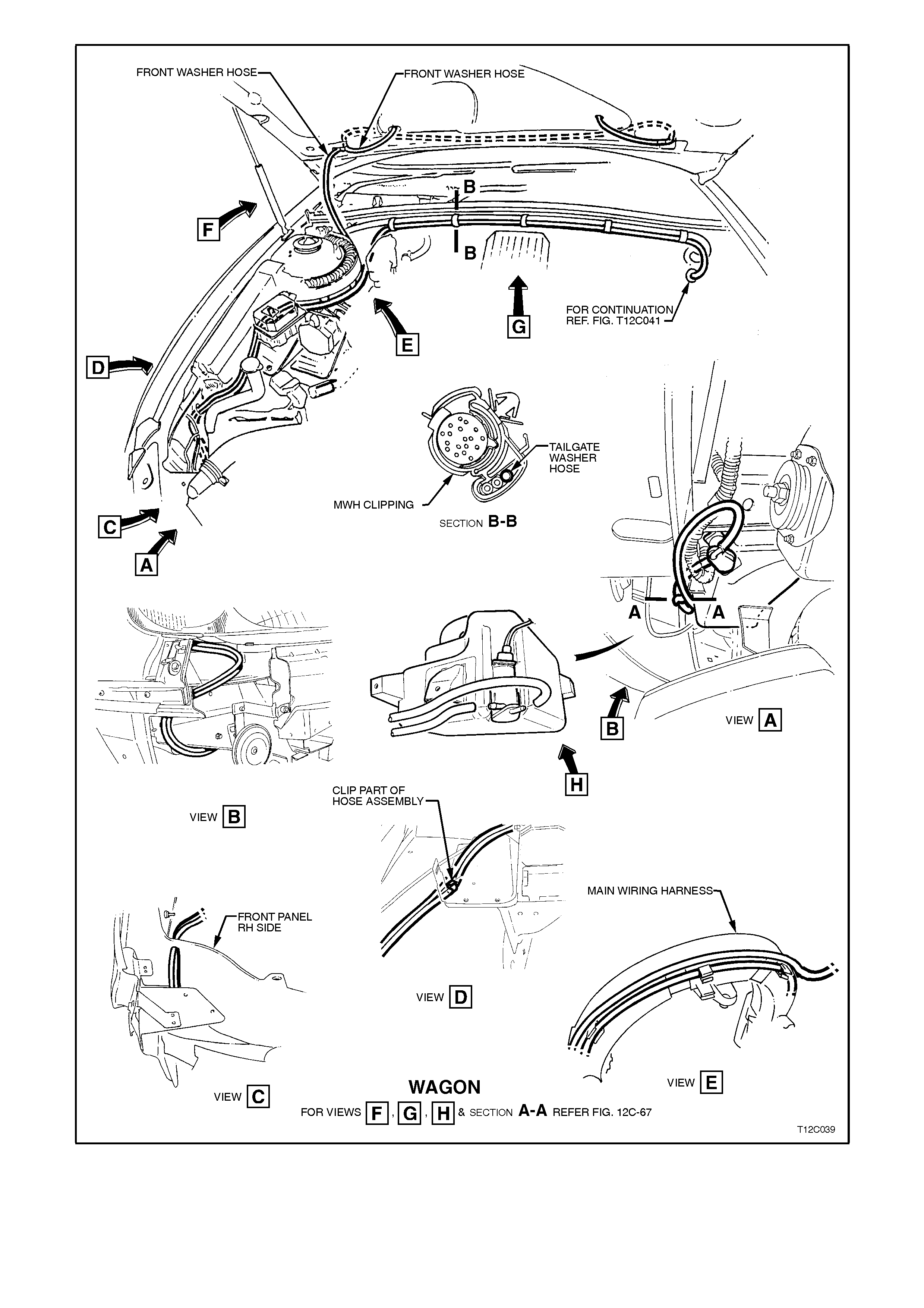
Figure 12C-66
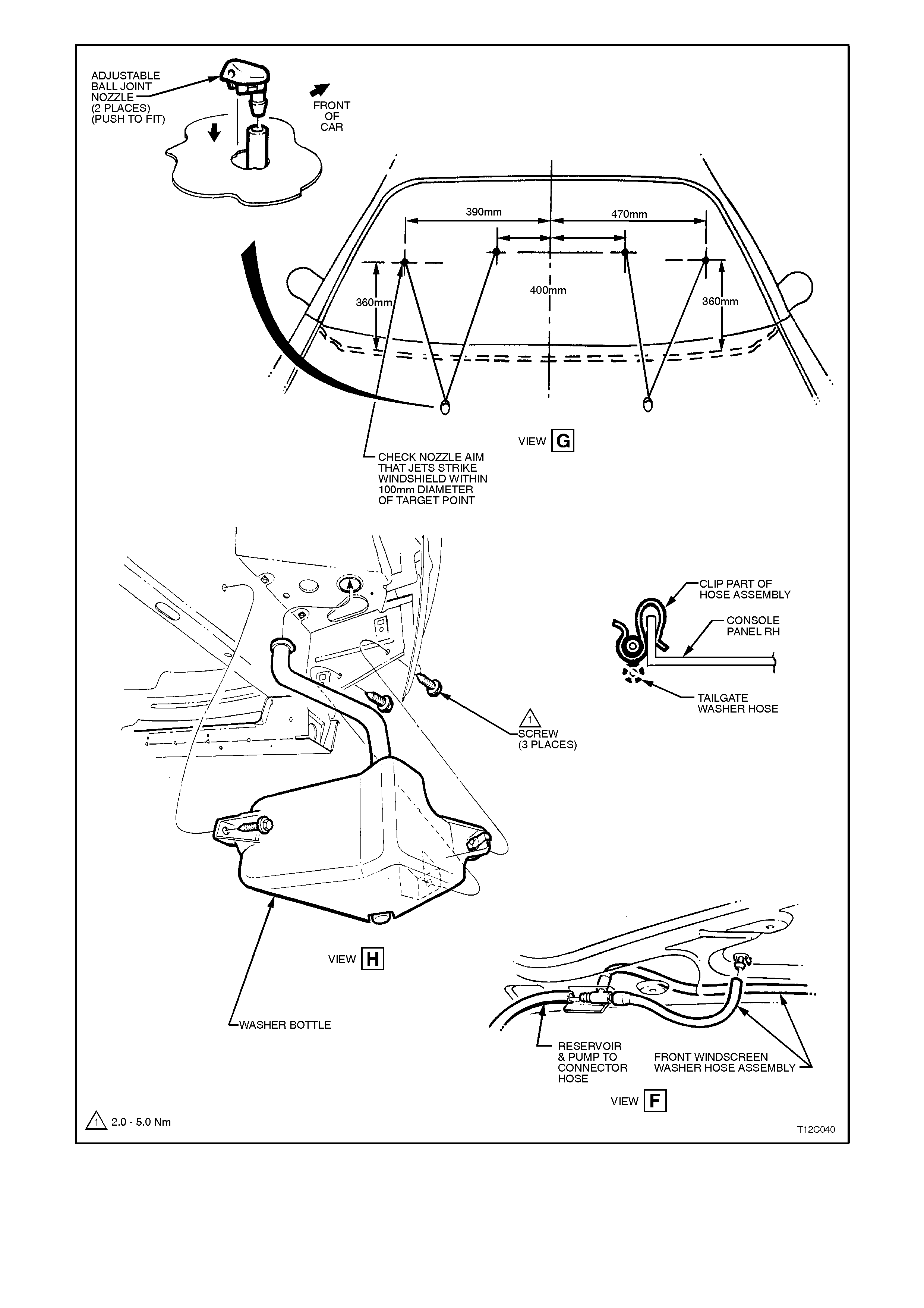
Figure 12C-67

CHECKING WASHER PUMP AND WIRING
The f ollowing operation chec ks the power sourc e and earth circuits f or the washer pump. If the following operation
proves that the washer pum p wiring is OK, and the washers are not work ing, there is a f ault in the pump or ther e is
a blockage in either the washer hoses or nozzles. If the wiring check indicates a fault, c heck wiring continuity. Also,
if necessary, check wiper/washer switch, refer 3.6 WIPER/WASHER SWITCH, in this Section.
1. Remove wiring harness connector from washer pump.
2. Connect a multimeter across washer pump wiring harness connector and check pump wiring as follows:
FRONT WASHERS
WIRE
COLOUR CIRCUIT
No. CIRCUIT MULTIMETER
SETTING RESULT IF WIPER
MOTOR IS OK
LBlue 94 Power
source Voltage Multimeter + lead
connected to LBlue wire
and - lead connected to
White/Blue wire
connector.
B+ with ignition in ACC or
ON position and
wiper/washer lever pulled
back.
White/Blue 494 Earth Resistance Multimeter leads
connected to White/Blue
wire and earth.
Approximately 0 ohms
with wiper/washer lever
pulled back.
REAR WASHERS
LBlue 94 Earth Resistance Multimeter leads
connected to White/Blue
wire and earth.
Approximately 0 ohms
with wiper/washer lever
pushed forward.
White/Blue 494 Power
source Voltage Multimeter + lead
connected to White/Blue
wire and - lead connected
to LBlue wire of
connector.
B+ with ignition in ACC or
ON position and
wiper/washer lever
pushed forward.
If wiring check s OK, apply 12 volts across the pump term inals and the pum p should operate. If pump oper ates, but
water does not spray from nozzles, revers e connections and check to see if water now sprays from nozzles. If water
still does not spray from nozzles, check for a blockage in the washer hoses, nozzles or pump.
3.8 REAR WIPER MOTOR
REMOVE
1. Remove rear wiper arm, refer
3.2 REAR WIPER ARM, in this Section.
2. Remove tailgate interior trim panel, refer
Section 1A4 REAR COMPARTMENT LID &
TAILGATE.
3. Depress retaining tang on rear compartment
harness connector and disconnect from rear
wiper motor connector.
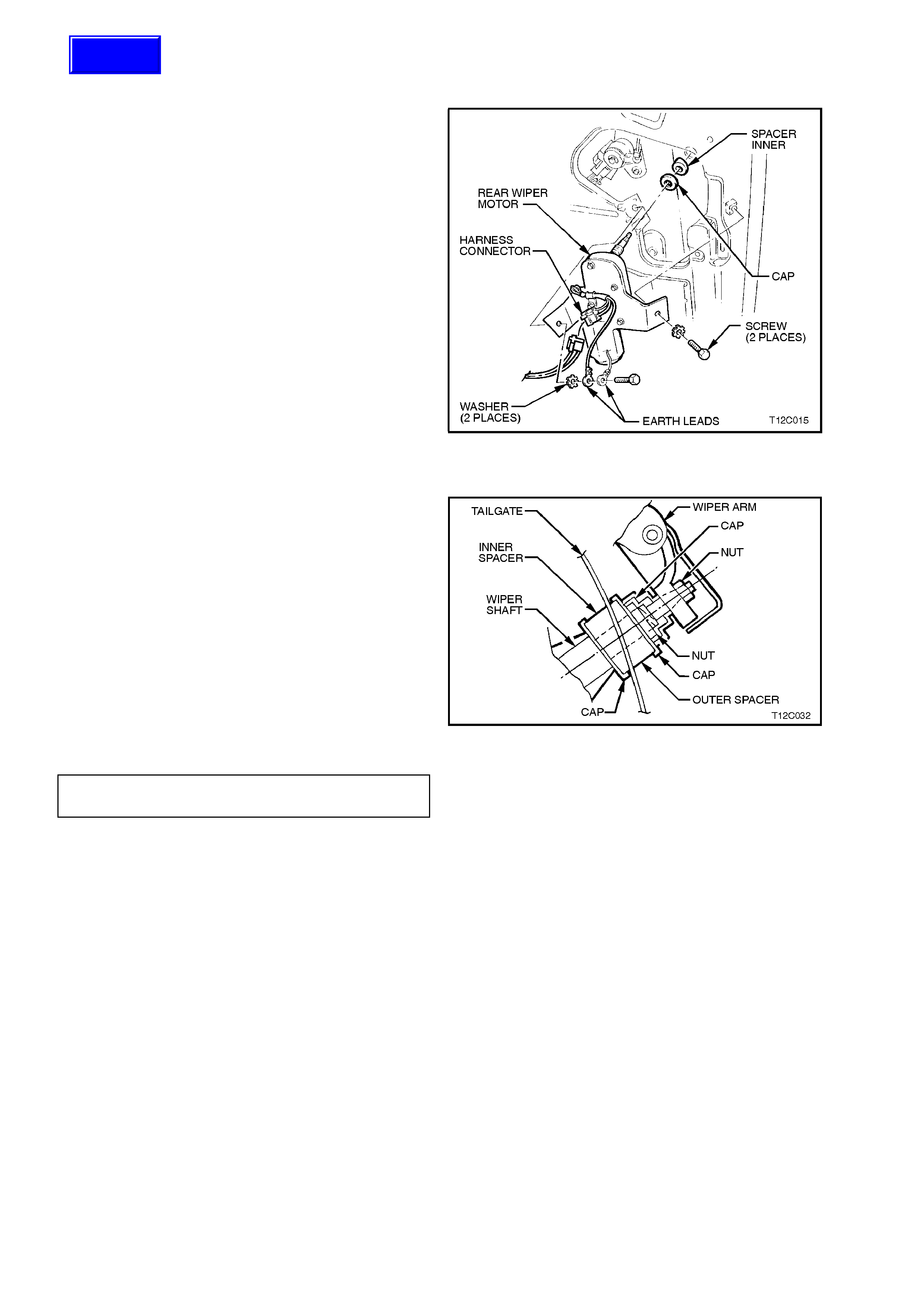
4. Remove the two screws securing the rear
wiper motor to the tailgate, remove wiper
motor and bracket assembly.
5. Remove inner spacer and cap from wiper
motor shaft.
Figure 12C-68
REINSTALL
Installation of the r ear wiper motor is the rever se of
the removal procedure, noting the following points
1. Ensure the inner and outer spacers are fitted
onto the wiper shaft correctly, refer Fig. 12C-
69.
2. To ensure the earth connection, the wiper
motor earth lead must be installed before the
tailgate harness earth lead.
3. Tighten wiper motor securing screws to the
correct torque specification.
Figure 12C-69
WI PER MOTOR SECURING SCREW
TORQUE SPECIFICATION 6 - 14 Nm
Techline
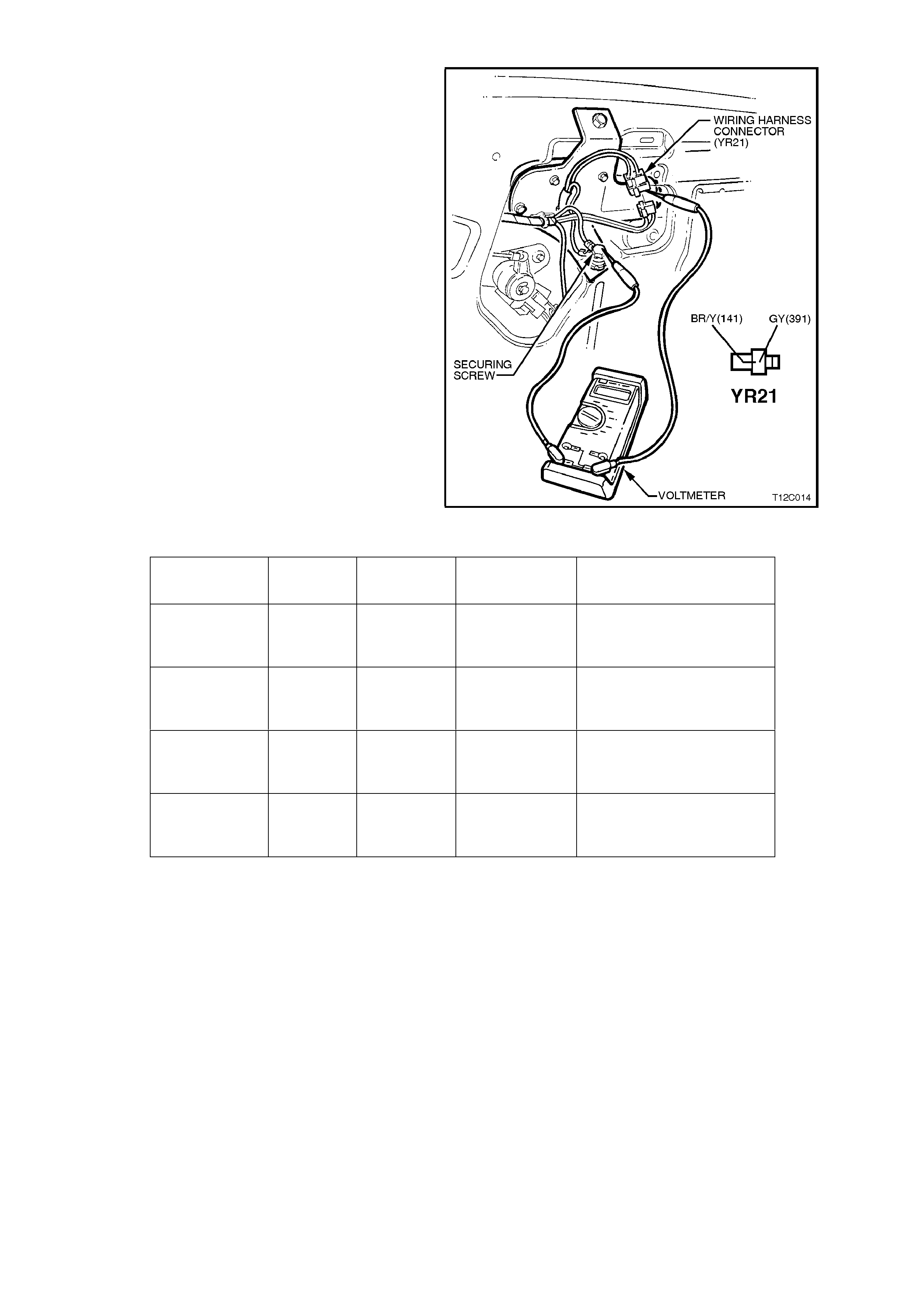
CHECKING WIPER MOTOR WIRING
1. Remove tailgate interior trim panel, refer
Section 1A4 REAR COMPARTMENT LID &
TAILGATE.
2. Depress retaining tang on rear compartment
harness connector and disconnect from rear
wiper motor connector.
3. Using a multimeter connected between one
of the wiper motor securing screws and the
rear compartment harness connector, check
wiper motor wiring as per the following chart.
Figure 12C-70
WIRE
COLOUR CIRCUIT
No. CIRCUIT MULTIMETER
SETTING RESULT IF WIPER
MOTOR IS OK
Brown/White 41 Power
source Voltage B+ with ignition in ACC or
ON position and
wiper/washer switch OFF
Grey 391 Motor drive Voltage 0 volt with ignition in ACC
or ON position and
wiper/washer switch OFF
Brown/White 41 Power
source Voltage B+ with ignition in ACC or
ON position and
wiper/washer switch ON
Grey 391 Motor drive Voltage 0 volt with ignition in ACC
or ON position and
wiper/washer switch ON
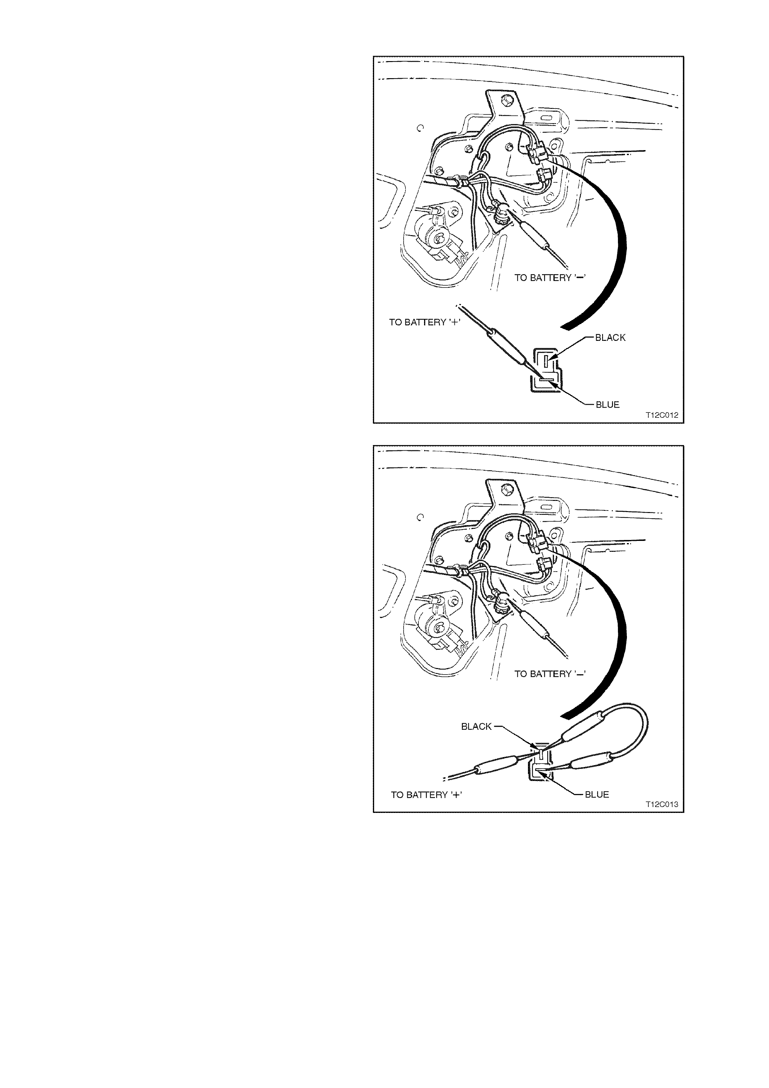
CHECKING WIPER MOTOR OPERATION
1. Remove rear wiper arm, refer
3.2 REAR WIPER ARM in this Section.
2. Remove tailgate interior trim panel, refer
Section 1A4 REAR COMPARTMENT LID &
TAILGATE.
3. Use a jum per lead connected between battery
earth and the wiper mounting bracket and
earth lead (Brown wire).
4. Using a second jumper lead connected to
battery positive, touch jumper lead terminal to
Blue wire terminal of wiper motor connector.
Drive spindle of motor should rotate. If drive
spindle does not rotate, motor is faulty and
must be replaced.
Figure 12C-71
5. To check wiper motor PARKED operation,
connect a bridging wire between the Black and
Blue wires of the wiper motor connector.
Connect a jum per wire from battery positive to
Black wire to wiper motor connector, and wiper
motor spindle should rotate.
Disconnect bridging wire from Blue wire and
wiper motor should continue to rotate until it
reaches the PARK position.
If m otor does not park, the contacts within the
motor are faulty and therefore, the motor m ust
be replaced.
Figure 12C-72
CIRCUIT DIAGRAMS
Fig. 12C-73 shows the circuit for the rear
wiper/washer system for vehicles with Low Series
BCM and Fig. 12C-74 the circuit for the rear
wiper/washer system for vehicles with High Series
BCM.
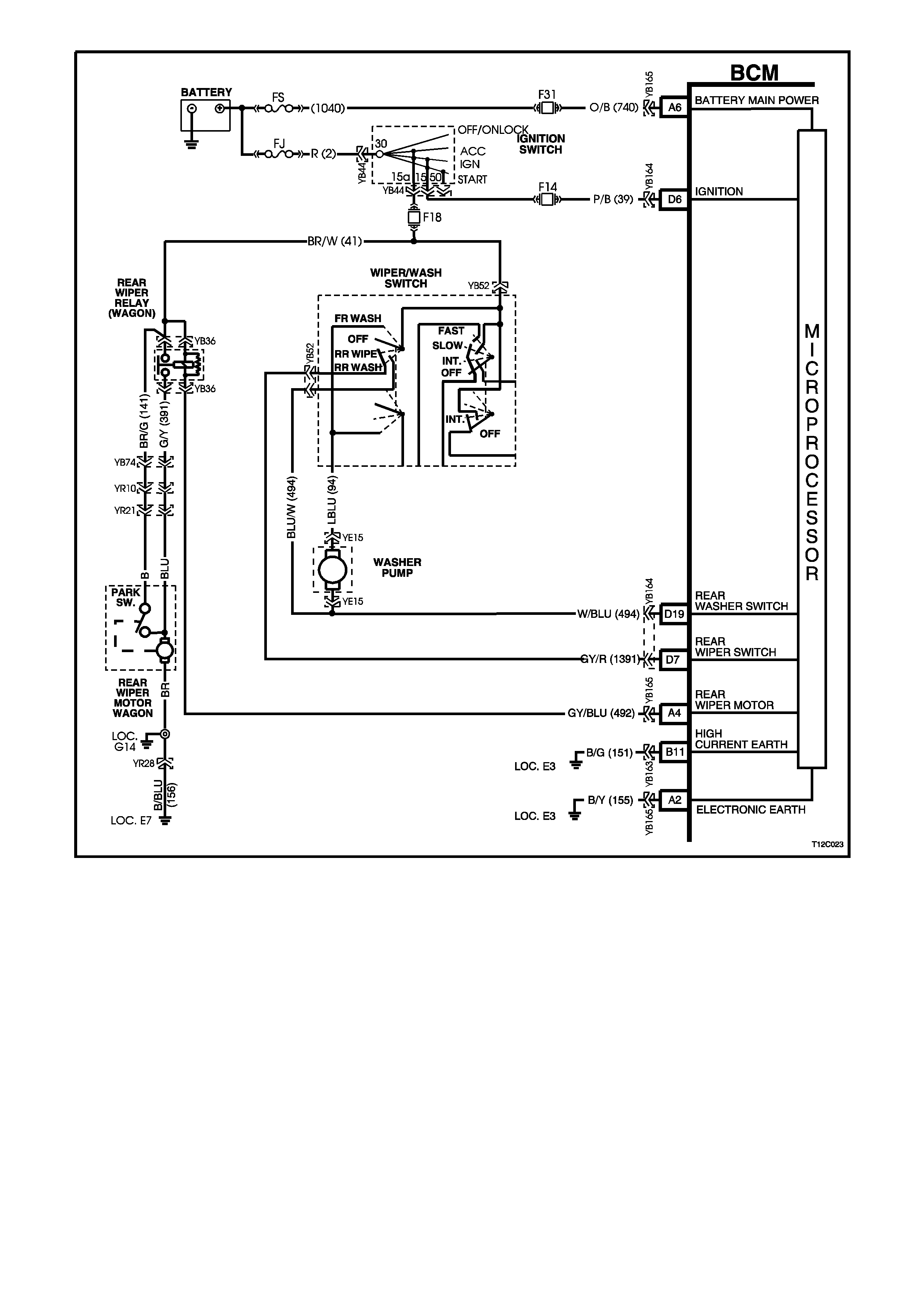
Figure 12C-73

Figure 12C-74

3.9 TAILGATE WASHERS
REMOVE AND REINSTALL
Fig. 12C-75 illustrates the installation of the tailgate washer system.
The spray direction of the washer nozzle can be adjusted by inserting the point of a pin into the ball of the nozzle
and swivelling it to the position nominated in Fig. 12C-75.
CHECKING WASHER PUMP AND WIRING
As a common washer pump with dual outlets is used for the tailgate and windscreen washers, refer
3.7 WINDSHIELD WASHERS - CHECKING WASHER PUMP AND WIRING in this Section, for the procedure on
how to check the operation of the washer pump.
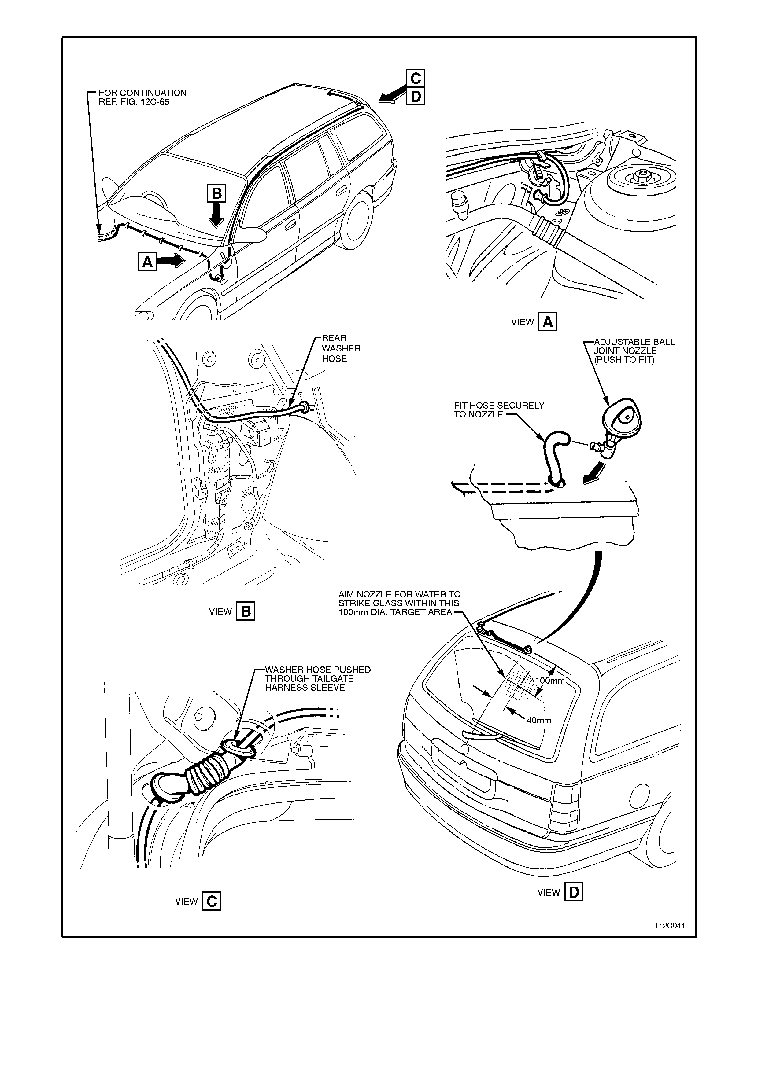
Figure 12C-75
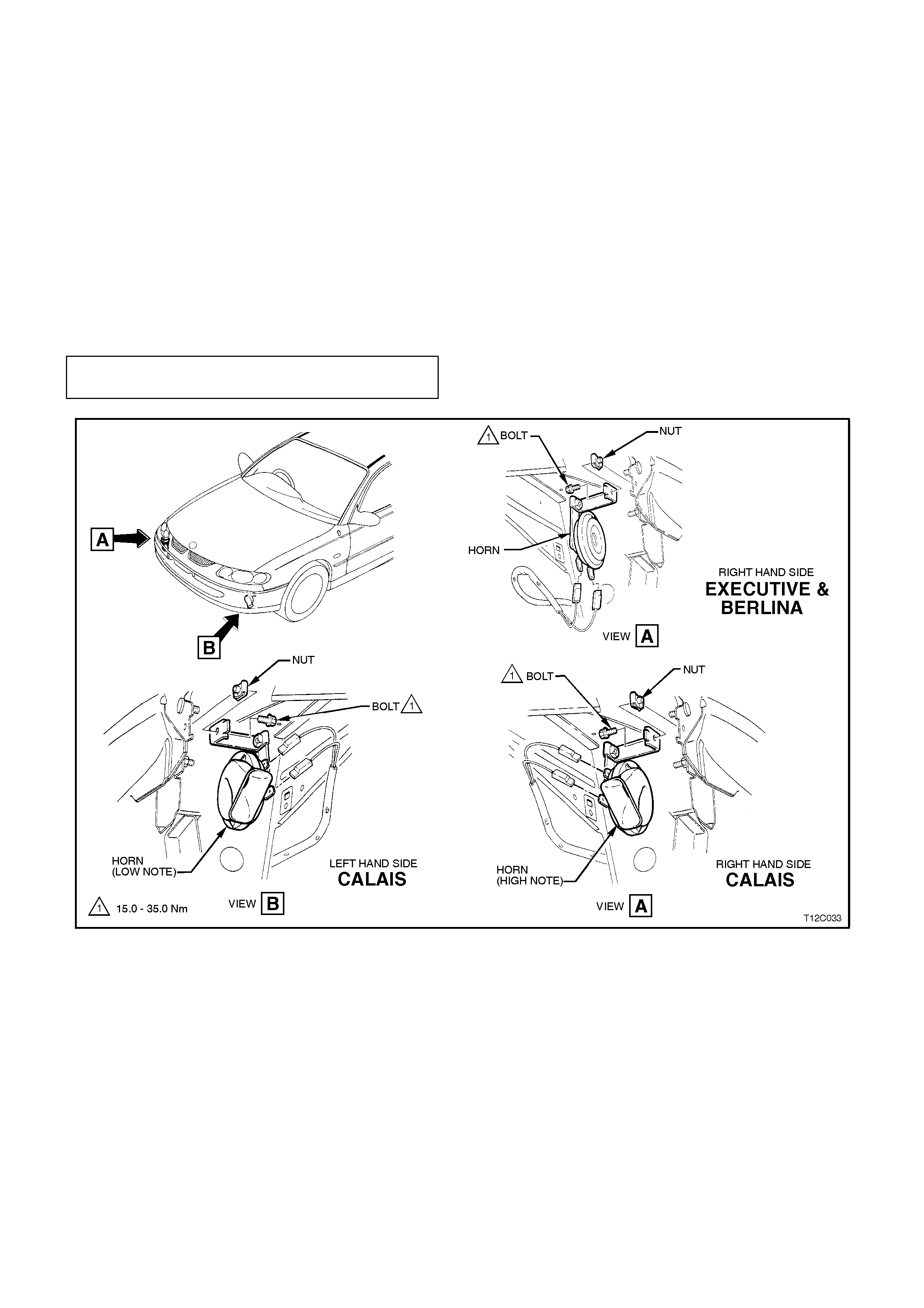
4. HORN SERVICE OPERATIONS
4.1 HORN ASSEMBLY
REMOVE
1. From beneath vehicle, depending on which horn is to be removed, reach up between either the left - hand or
right - hand front wheelhouse panel and disconnect wiring harness connector/s from horn/s.
2. Unscrew horn/s attaching bolt and remove horn/s.
REINSTALL
Installation of the horn is the reverse of the removal procedure, noting the following:
1. Ensure connectors are installed correctly.
2. Ensure horn/s securing bolt/s are tightened to the correct torque specification.
HORN SECURING BOLT
TORQUE SPECIFICATION 15 - 35 Nm
Figure 12C-76
TEST
1. From beneath vehicle, reach up between bumper bar and front panel side support. Connect a voltmeter
between horn positive lead (Green wire) and vehicle body earth.
2. Activate horn and note reading:
No voltage indicates a fault in the horn actuator, wiring harness, relay or connections.
Less than 9 volts indicates resistance in circuit wiring or a short circuit in horn.
9 - 11 volts is normal.
Above 11 volts indicates an open circuit in horn.
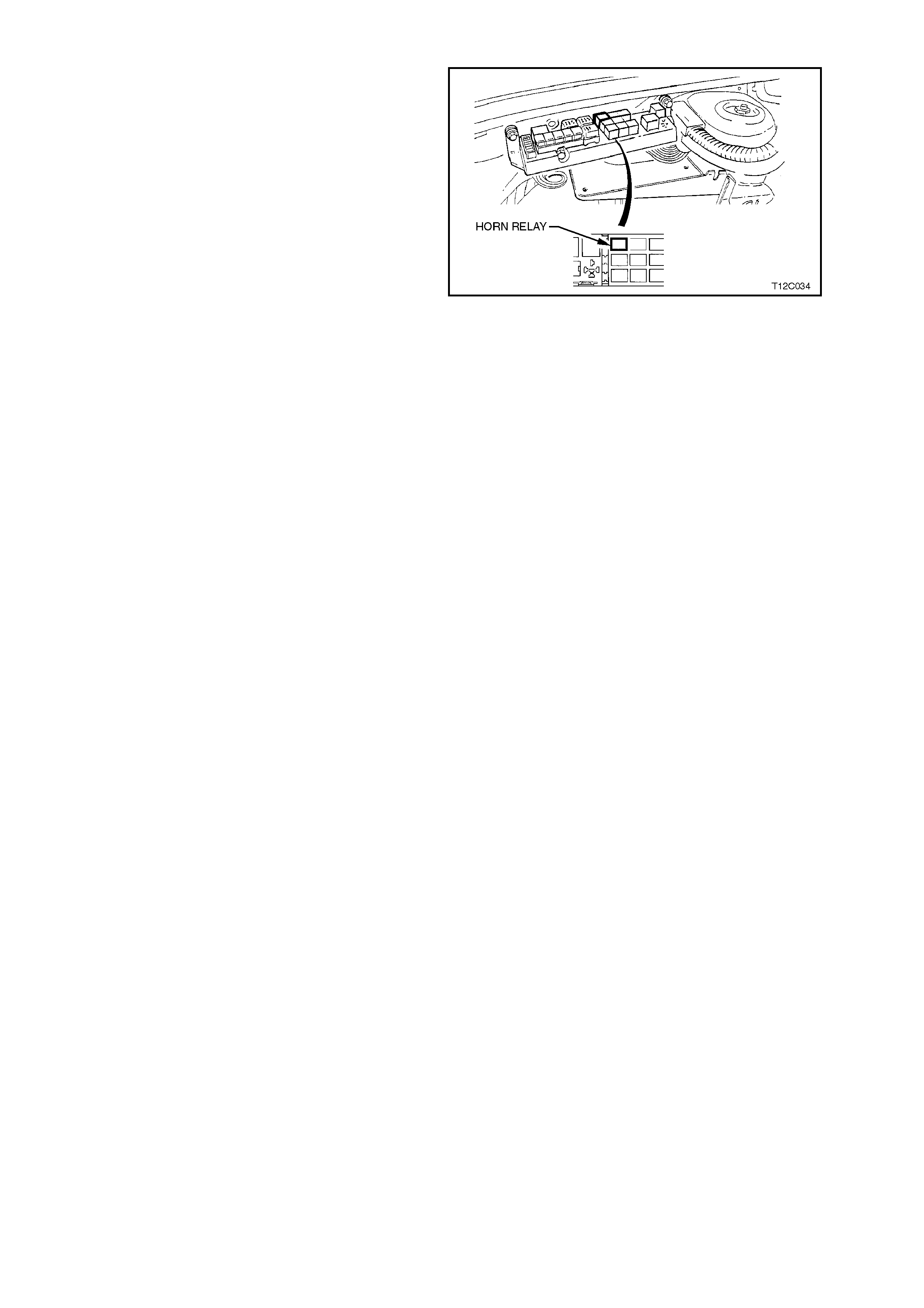
HORN RELAY
The horn relay is located in the engine
compartment relay housing, refer Fig. 12C-77.
Figure 12C-77
HORN ACTUATOR
The horn pad is incorporated into the Supplem ental Restraint System (SRS) airbag inf lator module in the centre of
the steering wheel and therefore, is not serviced separately. For all SRS service operations, refer to
Section 12M (Version 6.2), SUPPLEMENTAL RESTRAINT SYSTEM or Section 12M (Version 8.0/8.1),
SUPPLEMENTAL RESTRAINT SYSTEM.
CAUTION:
If vehicle is equipped with SRS (AIRBAG), disable the system. Refer to ‘SUPPLEMENTAL RESTRAINT
SYSTEM, Section 12M - (Version 6.2) or Section 12M - (Version 8.0/8.1).
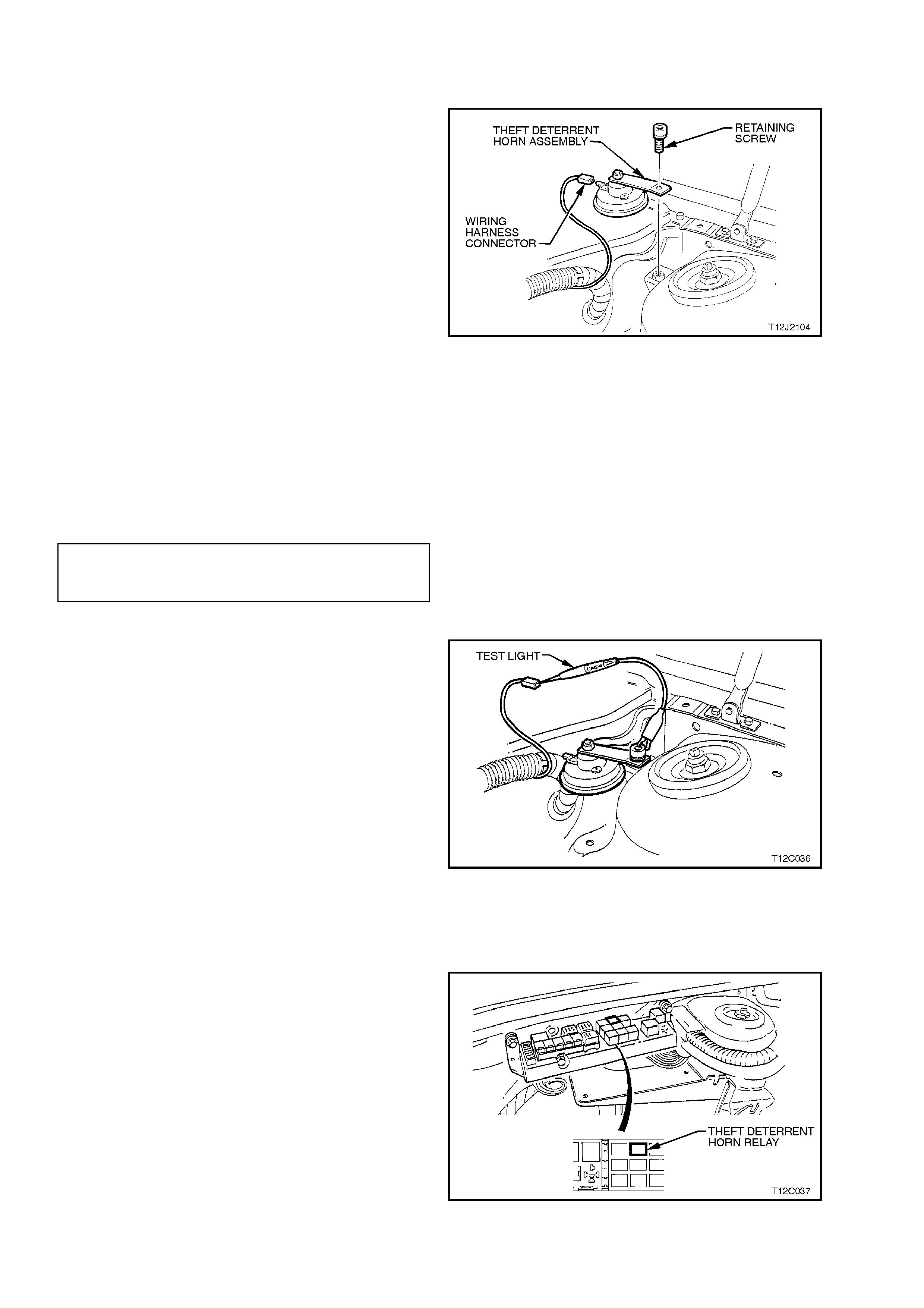
4.2 THEFT DE TE RRENT HORN
REMOVE
1. Disconnect wiring harness connector from
theft deterrent horn.
2. Unscrew horn attaching bolt and remove horn.
Figure 12C-78
REINSTALL
Reinstallation of the theft deterrent horn is the
reverse of the removal procedure, noting the
following:
1. Ensure connector is installed correctly.
2. Ensure theft deterrent horn securing bolt is
tightened to the correct torque specification.
THEFT DETERRENT HORN
SECURRING BOLT TORQUE
SPECIFICATION 20 - 27 Nm
TEST
1. Disconnect wiring harness connector from
theft deterrent horn. Connect a test light
between theft deterrent horn wiring harness
connector and vehicle body earth.
2. Remove theft deterrent horn relay and bridge
terminals 3, circuit 1340 to terminal 5, circuit
129. Test light should illuminate.
- OR -
Activate alarm system. Test light should flash.
If test light illuminates or flashes, it indicates a
faulty theft deterrent horn.
If test light does not illuminate or f lash, it indicates
a fault in BCM, wiring harness, relay or
connections, r efer to Section 12J-2 HIGH SERIES
BCM.
Figure 12C-79
THEFT DETERRENT HORN RELAY
The theft deterrent horn relay is located in the
engine compartment relay housing, refer Fig. 12C-
80.
Figure 12C-80

5. INSTRUMENT ASSEMBLY DIAGNOSTICS
5.1 BASIC KNOWLEDGE REQUIRED
Before attem pting to diagnose the com bined inst rument as sembly you m ust have a good unders tanding of elec tr ical
system basics and the use of circuit testing tools. Without this basic knowledge it will be difficult to use the
diagnostic procedures detailed in this Section.
Some electr ical basics, as well as basic troubles hooting procedures and hints as the use of circuit tes ting tools are
covered in Section 12P WIRING DIAGRAMS.
Basic Electrical Circuits - You should understand the basic theory of electricity, series and parallel circuits, and
voltage drops across series resistors. You should know the meaning of voltage (volts), current (amps), and
resistanc e (ohms). You should understand what happens in a circuit with an open or shorted wire (s horted either to
voltage or earth). You should also be able to read and understand a wiring diagram.
Additionally, a knowledge of AC theory including; inductance, capacitance and impedance would be useful.
Use of Circuit Testing Tools - You should know how to use a jumper lead to test c irc uits . You should be familiar with
the use of a high input im pedanc e (10 Mohm ) digital type multim eter such as Tool No. J 39200 or equivalent and be
able to measure voltage, current, and resistance. You should be familiar with the proper use of the TECH 2
Diagnostic Scan Tool.
NOTE:
All earth resistance checks done with a high impedance multimeter must be done with the vehicle’s battery
removed.
Techline
Techline

5.2 PRELIMINARY SYSTEM DIAGNOSIS
When investigating any complaint of a combined instrument assembly problem or malfunction, always begin
diagnosis with a circuit check, refer to 5.8 INSTRUMENT DIAGNOSTICS PROCEDURES, DIAGNOSTIC CIRCUIT
CHECK in this Section.
The diagnos tic circuit c heck is a preliminar y procedur e that check s to ensure the com bined ins trum ent assem bly is
communicating on the serial data line as well as helping to identify the problem.

5.3 INSTRUME NT CLUS TER DIAGNOSTICS
The instrument is equipped with a self-diagnostic capability that can detect and isolate instrument problems or
failures. W hen a fault is detected, the instrum ent cluster sets a diagnsotic trouble code (DTC) that represents that
particular problem or failur e. W hen DTC 24, 25 or 26 is set, an icon X is shown in the left-hand ins trument window
on high series vehicles, or SERV ERROR on low series..
Errors can be identified by using TECH 2 to test instruments and force values and conditions into the instrument
cluster. The results of these tests can be used to diagnose problems in the instrument assembly such as
inoperative bulbs and faulty gauges and switches.
Faults within other components can be identified after using TECH 2 to confirm correct operation of the
instruments. For example, if there was a reported fault with the speedometer gauge and TECH 2 diagnosed the
gauge as working correctly, then the fault would lie in the Powertrain Control Module or in the harness from the
speed sensor to the PCM, both of which would then require further testing.
It is important to note that an open circuit fuel (petrol) gauge sender unit is recognised by the instrument cluster self-
diagnosis as ‘t 00 – C’, whereas the TECH 2 Diagnosis Tool will recognise the same fault as DTC 3.
In some instanc es, a DTC may be permanently set. For example, a vehicle which is not f itted with ABS or ABS/ET C
will have DTC 8 permanently set. Similarly, a vehicle which is not fitted with LPG will have DTC 4 permanently set.
Some wiring changes have been made during production of the VT Series. Where these changes apply to the
instrument cluster diagnostics, they are shown as VT 1.5 Only on the diagrams included with the diagnostic charts.
TECH 2 DIAGNOSTIC TOOL USE WITH INTERMITTENCE
The TECH 2 Diagnostic T ool allows manipulation of wiring harnesses, while obser ving the TECH 2 Diagnostic Tool
readout. If the pr oblem seem s to be related to certain param eters that can be c hecked on the T ECH 2 Diagnostic
Tool, they should be checked while driving the vehicle. If there does not seem to be any connection between the
problem and any specif ic circuit, the T ECH 2 Diagnostic T ool can be used to m onitor each par ameter, watching f or
a period of time to see if there is any change in the readings that indicates intermittent operation.
The T ECH 2 Diagnostic Tool s aves tim e in diagnosis and helps to prevent the r eplacem ent of good parts . T he k ey
to using the TECH 2 Diagnostic Tool successfully is the technicians ability to understand the system being
diagnosed, as well as unders tanding the TECH 2 Diagnostic T ool operation and limitations . The technician s hould
read the TECH 2 operators manual to become familiar with the TECH 2 Diagnostic Tool operation.
With an understanding of the data which the tool displays, and knowledge of the circuits involved, the tool can be
very useful in obtaining information which would be more difficult or impossible to obtain with other equipment.
The TECH 2 Diagnostic Tool does not make the use of diagnostic charts unnecessary, nor can it indicate exactly
where a problem is in a particular circuit. Diagnostic Charts incorporate diagnosis procedures that require the use
of a TECH 2 Diagnostic Tool.
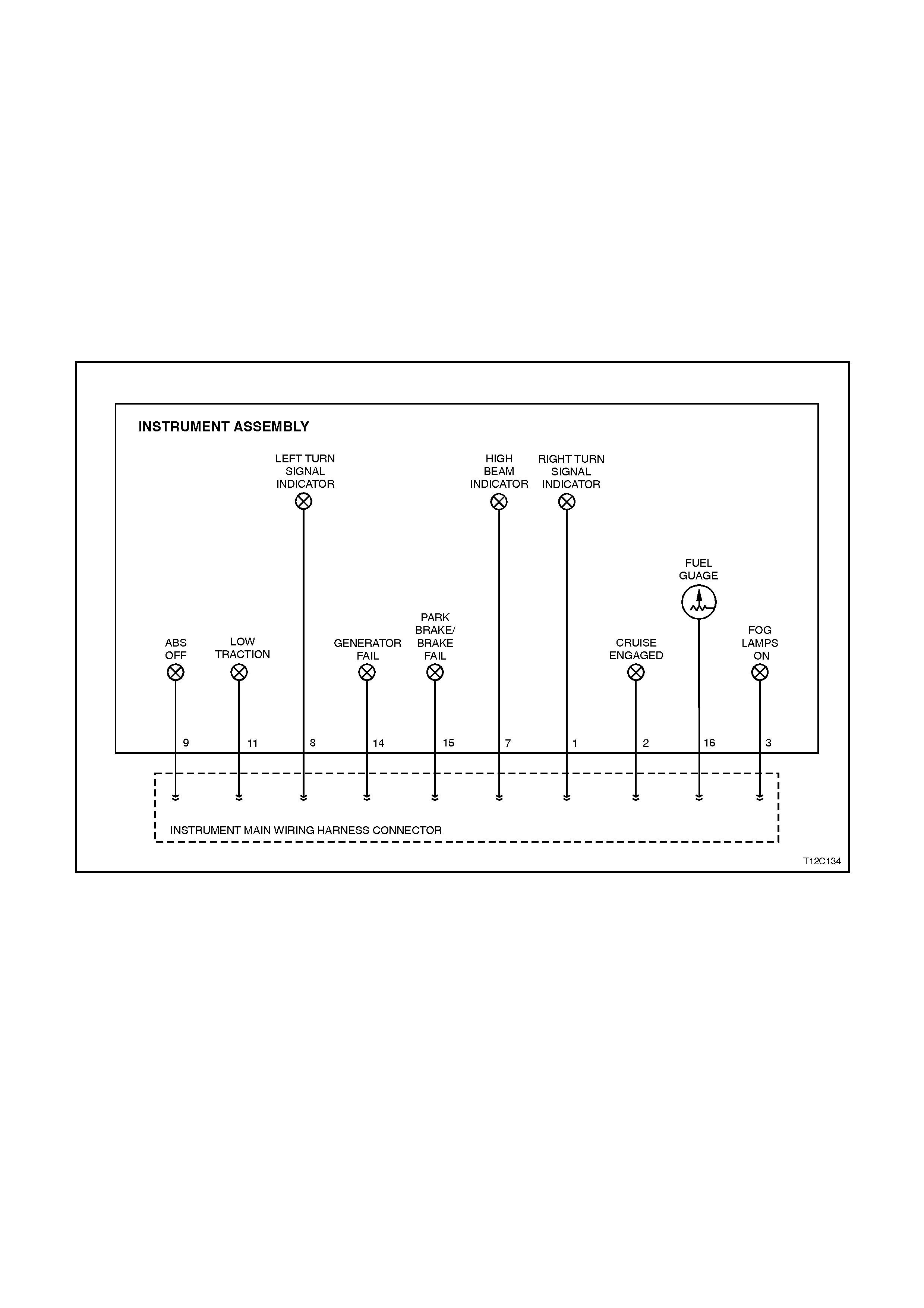
5.4 DIAGNOSING FAULTS NOT COVERED BY TECH 2 DIAG NOSTIC TOOL
Some components of the instrument assembly cannot be diagnosed by the TECH 2, although their operation can
be tested using the F4; Miscellanious Tests function of the TECH 2. These components must be dealt with
separately and include the following instrument tell-tale lamps:
•Fog lamps on lamp
•Cruise engaged lamp
•Low traction lamp
•ABS off lamp
•Park brake/brake fail warning lamp
•Generator lamp
•Turn signal indicator lamps
•High beam lamp
Fig 12C-81 illustrates the components of the instrument assembly which are exclusively not on the serial data line.
Figure 12C-81

WARNING LAMP APPLICATION CHART
The following table indicates the wiring configuration for the instrument cluster warning lamps.
NOTE:
Some lamps may not be installed in all models
LAMP CONFIGURATION SINGLE WINDOW
DISPLAY TRIPLE WINDOW
DISPLAY
High Beam HW X X
Left Turn HW X X
Right Turn HW X X
Shift Pattern SD X X
Overspeed INT X X
LPG SD – –
Air Bag SD X X
Gen Fail HW X X
Brake/Park Fail HW X X
Seat Belt INT X X
Oil Pressure SD X X
Rear Lamp Fail SD – X
High Temperature SD – X
Check Powertrain SD X X
ABS Off HW X X
Traction Off SD X
Low Traction HW X
Cruise SD X X
Cruise Active HW X X
Fog Lamps HW X X
Low Fuel INT X X
INT = Internal HW = Hard Wired SD = Serial Data
FUEL GAUGE SENDER
When investigating complaints regarding the operation of the fuel gauge, use the TECH 2 diagnostic tool to
ascertain whether the problem lies in the fuel sender or in the fuel gauge.
If the fuel gauge does not respond to any of the control tests, ie the gauge remains stationary below the empty
mark, then there may be a faulty connection between the fuel sender and the instrument assembly. Verify that these
connections are reliable before commencing any further diagnostic work.
To check the fuel sender, connect TECH 2 to the data link connector as detailed in 5.6 CONNECTING TECH 2
FOR SYSTEM DIAGNOSIS in this Section.
Refer to 5.9 USING TECH 2 TO DIAGNOSE THE INSTRUMENT ASSEMBLY in this Section to initiate the
diagnosis procedures. Select F1: Diagnostic Trouble Codes and then F0: Read DTC Information. If any trouble
codes have been logged by the fuel sender, these will appear as DTC 1, 2 or 3 for petrol, or as DTC 4, 5 or 6 for
LPG.

IMPORTANT:
An open circuit fuel gauge sender unit is shown as DTC 3 on TECH 2, whereas the instrument cluster diagnostic
mode display shows the same fault as t 00 – C.
If no diagnostic trouble codes relating to the fuel sender have been logged, the operation of the fuel gauge can be
checked by performing control tests, refer to 5.9 USING T ECH 2 T O DIAGNOSE THE INSTRUM ENT ASSEMBLY
in this Section to initiate the diagnosis pr ocedures. Select F4: Miscellaneous T ests and then F 7 Control Tes ts. Fuel
Gauge can be selected and it is possible to verify that the gauge operates accurately within the specified ranges.
If, when performing the control test, the fuel level indicated by the fuel gauge varies more than 3° than the
com manded fuel level (at em pty, half and full m arks) then the instrument as sembly will need to be replaced, and a
new one installed and programmed.
FOG LAMPS ON INDICATOR LAMP
A failure of the fog lamps on indicator lamp can be caused by any of the following:
•Faulty connection from fog lamp switch connector (Violet/Red).
•Faulty connection on pin 3 on the instrument assembly harness connector.
•A non-functioning fog lamps on indicator lamp bulb.
CRUISE ENGAGED LAMP
A failure of the cruise engaged warning lamp can be caused by any of the following:
•Faulty connection from the cruise c ontrol actuator harnes s connec tor (White) to instr ument harness connector
terminal 2, resulting in cruise engaged lamp failing to operate at all.
•A non-functioning cruise engaged lamp.
LOW TRACTION WARNING LAMP
•A failure of the low traction warning lamp can be caused by any of the following:
•Faulty connection f r om the ABS/ET C module harnes s c onnec tor ( Yellow/Red) to instrument harnes s c onnec tor
terminal 11, resulting in low traction lamp failing to operate at all.
•A non-functioning low traction warning lamp.
ABS OFF WARNING LAMP
The ABS off warning lamp is illuminated when the ABS or ABS/ETC module is disabled due to a fault with the
module. A failure of the ABS off warning lamp can be caused by any of the following:
•Faulty connection f r om the ABS/ET C module harnes s c onnec tor ( Yellow/Red) to instrument harnes s c onnec tor
terminal 9, resulting in low traction lamp failing to operate at all.
•A non-functioning ABS off warning lamp.
PARK BRAKE/BRAKE FAIL WA RNING LAMP
A failure of the park brake/brake warning lamp can be caused by any of the following:
•Faulty connection from the brake fail warning switch connector (Brown/Orange) to instrument harness
connector terminal 15, resulting in park brake/brake fail warning lamp activated only by the park brake switch.
•Faulty connection from the park brake switch connector (Brown/Orange) to instrument harness connector
terminal 15, resulting in park brake/brake fail warning lamp activated only by the brake fail warning switch.
•A non-functioning brake fail warning switch.
GENERATOR WARNING LAMP
A failure of the generator warning lamp can be caused by any of the following:
•Faulty connection from the generator harness c onnector ( Brown) to instrum ent harnes s c onnector term inal 14,
resulting in generator lamp failure to operate at all.
•Short circuit of Brown wire to earth between instrument harness connector and generator harness connector,
resulting in generator warning lamp continually on.
•A non-functioning generator warning lamp bulb.

TURN SIGNAL INDICATOR LAMPS
A failure in one or both of the turn signal indicator lamps can be caused by any of the following:
•Faulty connection from terminal 49aL (Light Blue) from the turn signal switch (characterised by left-hand turn
signals inoperative).
•Faulty connection from terminal 49aR (Blue) from the turn signal switch (characterised by right-hand turn
signals inoperative).
•Faulty connection on pins 8 (left-hand indicator bulb) or 1 (right-hand indicator bulb) on the instrument
assembly harness connector.
•A non-functioning turn signal lamp bulb.
HIGH BEAM INDICATOR LAMP
A failure of the high beam indicator lamp can be caused by any of the following:
•Faulty connection from terminal turn signal switch 1 connector (Blue/Yellow) from flash/dip switch.
•Faulty connection on pin 7 on the instrument assembly harness connector.
•A non-functioning high beam indicator lamp bulb.
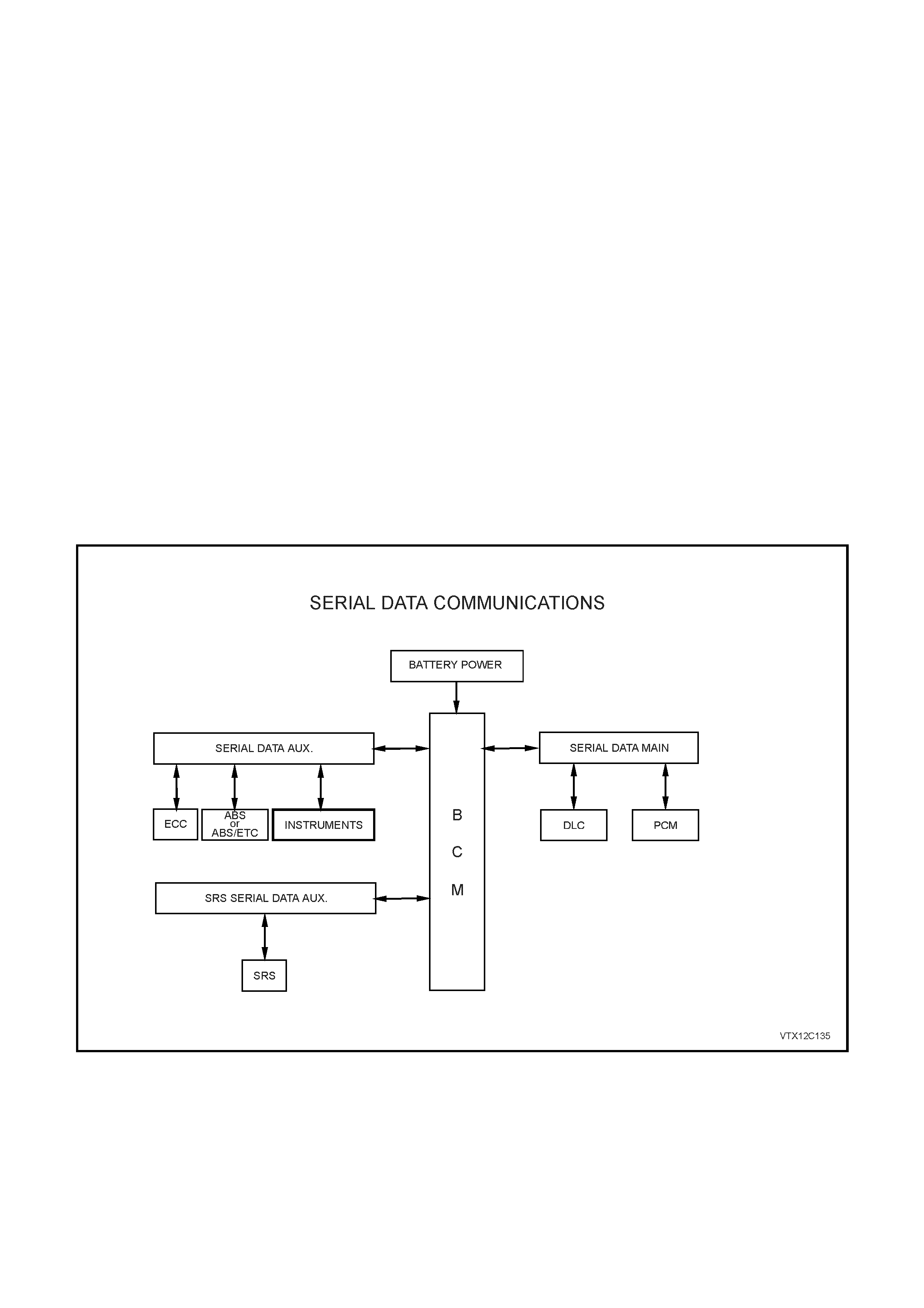
5.5 SERIAL DATA COMMUNICATION
GENERAL INFORMATION
The VT Series Model uses a BUS MASTER communication system, where the BCM is the bus master.
The BCM periodically polls (surveys) each device on the bus and requests status data.
The devices connected are:
•Body Control Module (BCM)
•Powertrain Control Module (PCM)
•Electronic Climate Control (ECC)
•Instrument Cluster (INS)
•Anti-lock Brake (ABS) or Anti-lock Brake / Electronic Traction Control (ABS/ETC)
•Supplementary Restraint System (SRS)
•External diagnostic tool (TECH 2)
The data provided by each device may be utilised by any device connected to the bus.
Each device has a unique response Message Identifier Word (MIW) for ease of identification.
The bus m aster ( BCM) polls each device with a ser ial data mes sage which includes that device’s MIW . T he device
responds by putting a serial data message onto the bus which includes its MIW and data, which is retrieved and
utilised by any device requiring it.
The BCM polls each device for a status update, once ever y 300 m illiseconds . The exception to this being the PCM
which is polled twice every 300 milliseconds.
The TECH 2 diagnostic tool can be used to read serial data on the data bus and analyse faults in the instrument
assembly and its related components.
Figure 12C-82
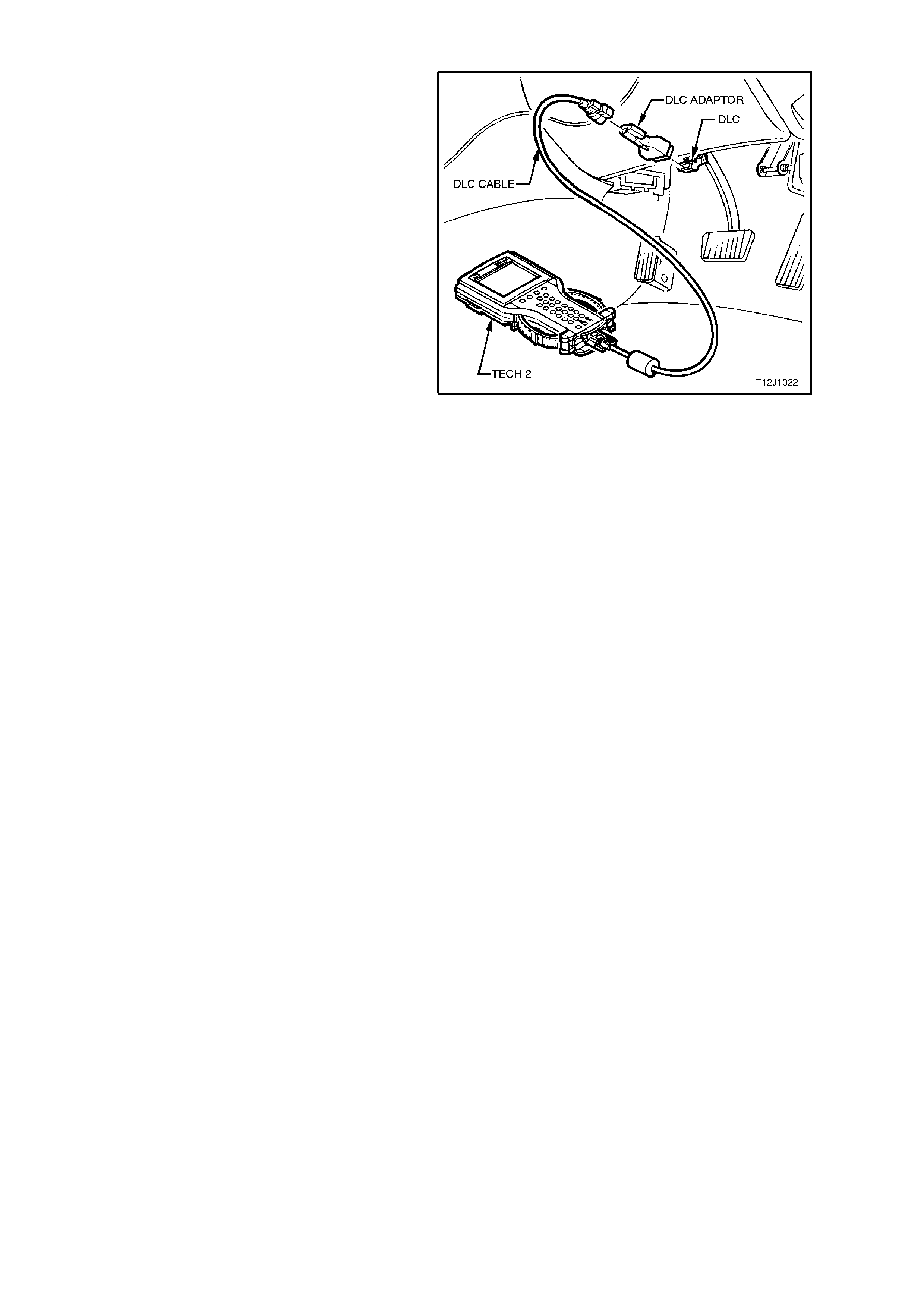
5.6 CONNECTING TECH 2 FOR SYSTEM DIAGNOSIS
TECH 2, with the appropriate sof tware, c ables and
adaptors, when connected to the Data Link
Connector (DLC) is capable of reading the
combined instrument cluster serial data. The DLC
is connected to the instrument panel lower right
hand-trim, to the right of the steering column.
For additional general information on connecting
and operating TECH 2, refer to
Section 0C TECH 2.
Figure 12C-83
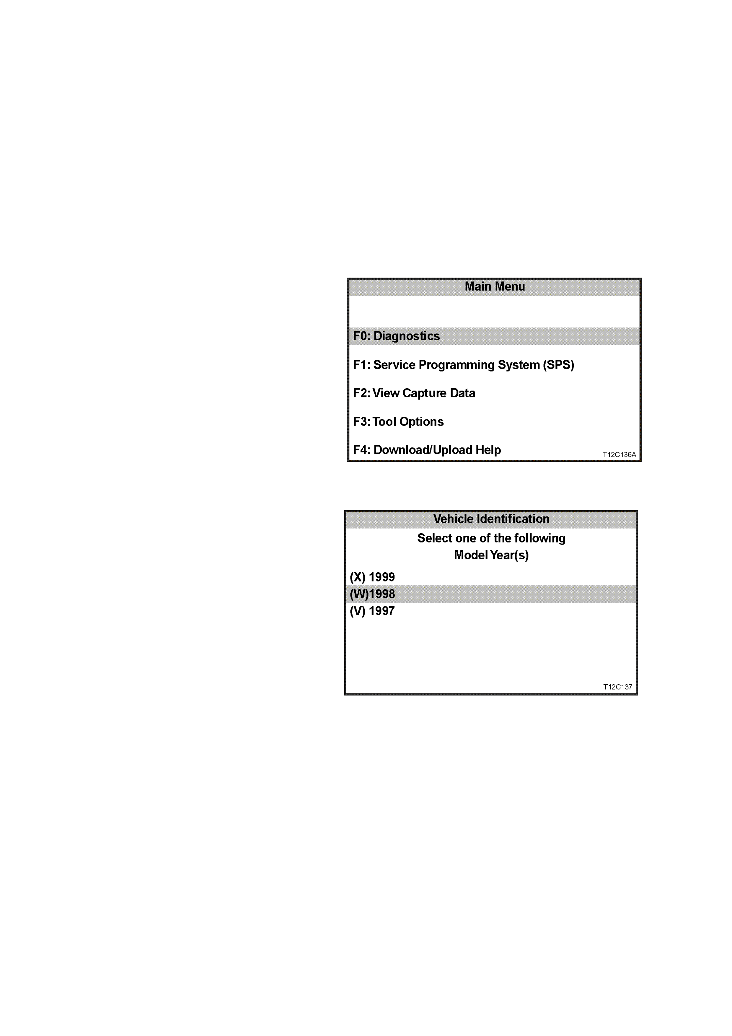
5.7 TECH 2 TEST MODES AND DISPLAYS FOR INSTRUMENT DIAGNOSIS
A prerequisite of this diagnostic section is for the
user to be familiar with the proper use of TECH 2.
The following illustrate only the major TECH 2
screen displays and provide a brief explanation of
their function for diagnosing the Instruments. If
additional information is required on the operation
of TECH 2, reference should be made to either
Section 0C TECH 2 or the TECH 2 USER’S
GUIDE.
W ith the ignition turned of f, connect the TECH 2 to
the Data Link Connector (DLC) using the DLC
Adaptor, refer to 5.6 CONNECTING T ECH 2 FOR
SYSTEM DIAGNOSIS in this Section.
MAIN MENU
Turn the ignition on and press the power button
(PWR) on the TECH 2.
The TECH 2 will perform a series of self-
diagnosing power on self tests (POST ). Once this
has been completed successfully, the TECH 2
startup screen will be displayed. Press the Enter
key to continue.
The Main Menu screen should look as follows.
Press the F0 function button or Select F0:
Diagnostics by using the arrow keys until F0:
Diagnostics is highlighted and press the Enter
key.
Figure 12C-84
MODEL YEAR
Select the appropriate Model Year and press
Enter.
Figure 12C-85
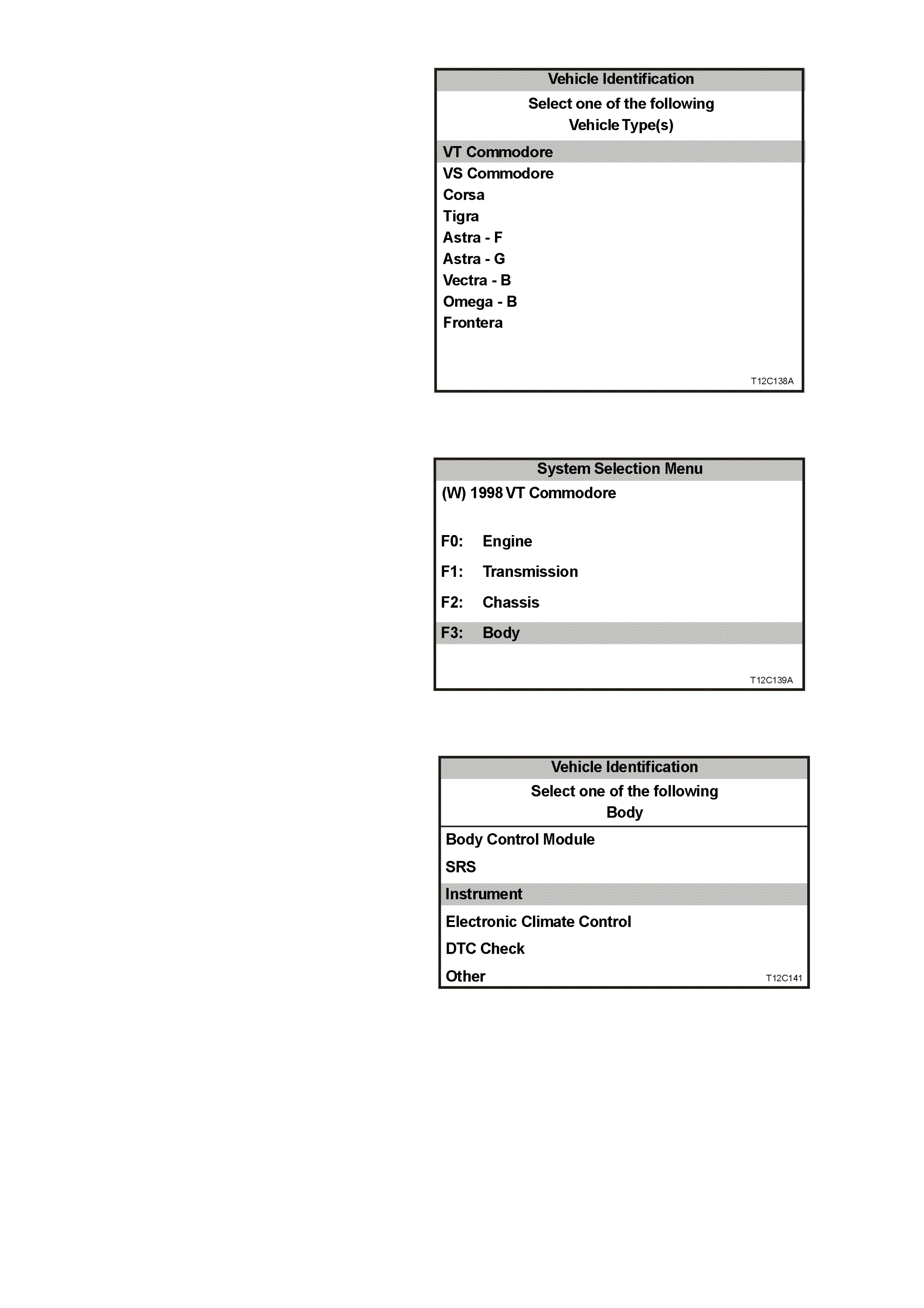
VEHICLE IDENTIFICATION MENU
Select the VT Commodore Vehicle Type and
press Enter.
Figure 12C-86
SYSTEM SELECTION MENU
Select F3: Body from the System Selection
Menu and press Enter.
Figure 12C-87
VEHICLE IDENTIFICATION MENU
Once F3: Body has been selected from the
selection menu, Instrument can be selected.
Select Instrument.
Figure 12C-88
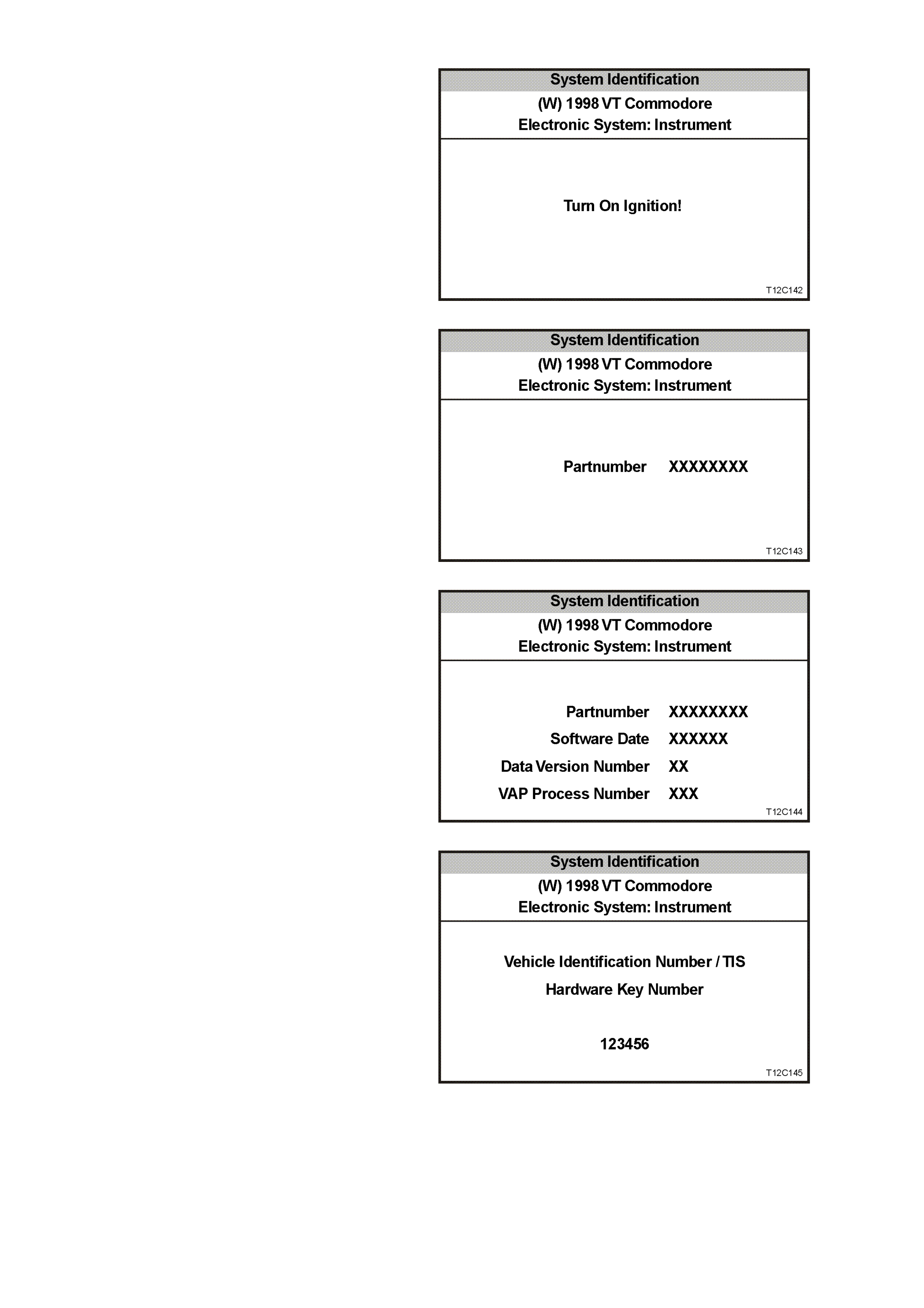
SYSTEM IDENTIFICATION MENU
Turn the ignition on (as requested) and press
CONFIRM soft key to continue.
Figure 12C-89
The part number of the instrument cluster will be
displayed. Press the MORE soft key to display
more detailed information about the part.
Figure 12C-90
Press the CONFIRM soft key to confirm these
details.
Figure 12C-91
The vehicle Identification Number/TIS Hardware
Key Num ber will now be displayed. Press Conf irm
soft key to continue
Figure 12C-92
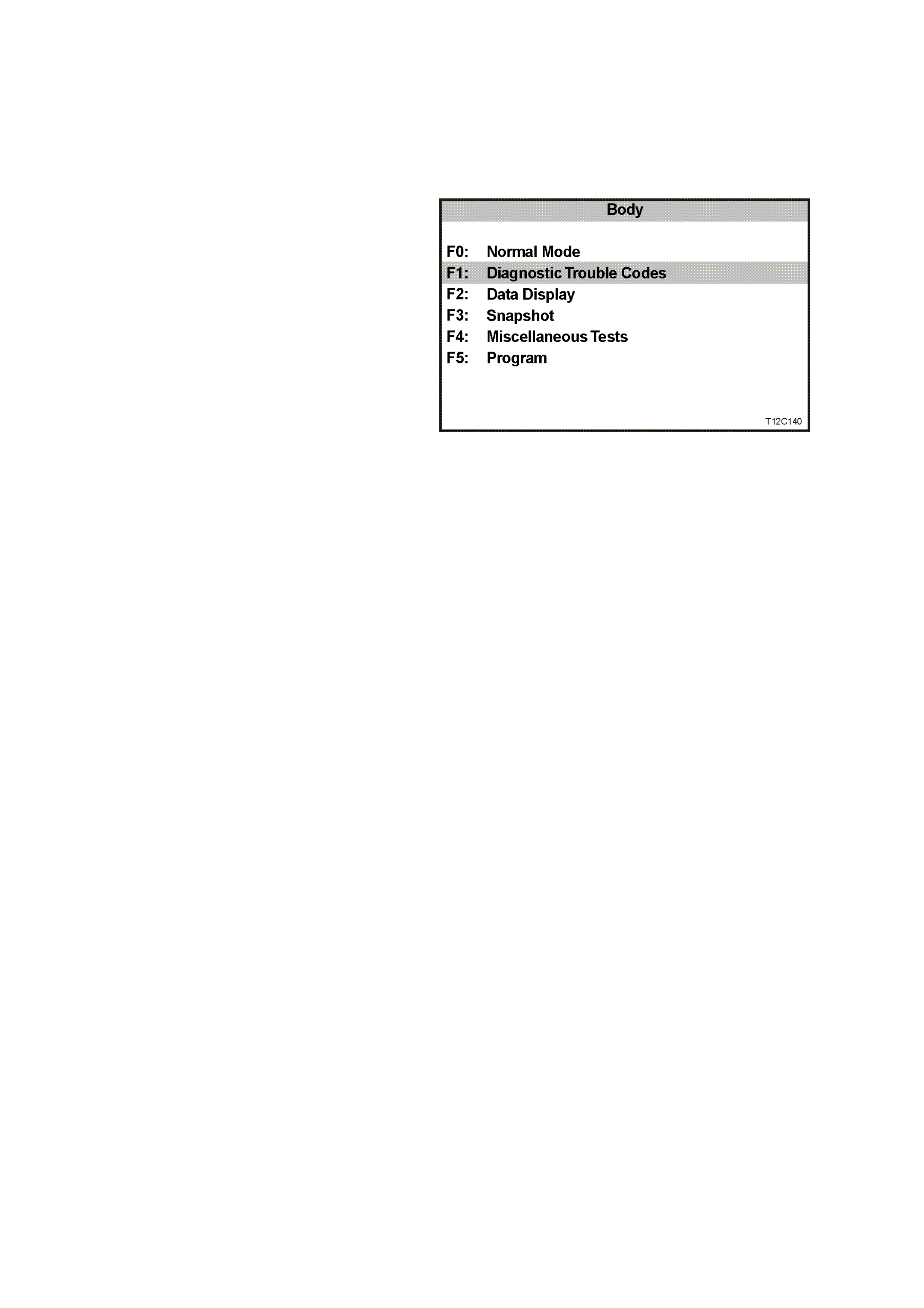
BODY MENU
This menu provides the TECH 2 user with acces s
to the various functions used to diagnose f aults in
the instrument assembly and its related
components. The six functions F0 to F5 are
explained in m or e detail in 5.9 USING TECH 2 T O
DIAGNOSE THE INSTRUMENT ASSEMBLY in
this Section.
F0: NORMAL MODE
The instrument normal mode data list is used to
view serial data being sent from the instrument
assembly
F1: DIAGNOSTIC TROUBLE CODES
In this mode Diagnostic Trouble Codes can be
read and cleared.
F2: DATA DISPLAY
In this test mode, TECH 2 displays the status of
inputs and outputs of the combined instrument
assembly.
F3: SNAPSHOT
In this test mode, the TECH 2 captures data
before and af ter a for ced m anual error. T his is not
applicable to instrument diagnostics.
F4: MISCELLANEOUS TESTS
In this test mode, the TECH 2 can test and
diagnose faults in the instrument assembly.
Telltale lamps and instrument gauges can be
tested in this mode.
F5: PROGRAM
Instruments and options can be programmed
when this mode is selected.
Figure 12C-93
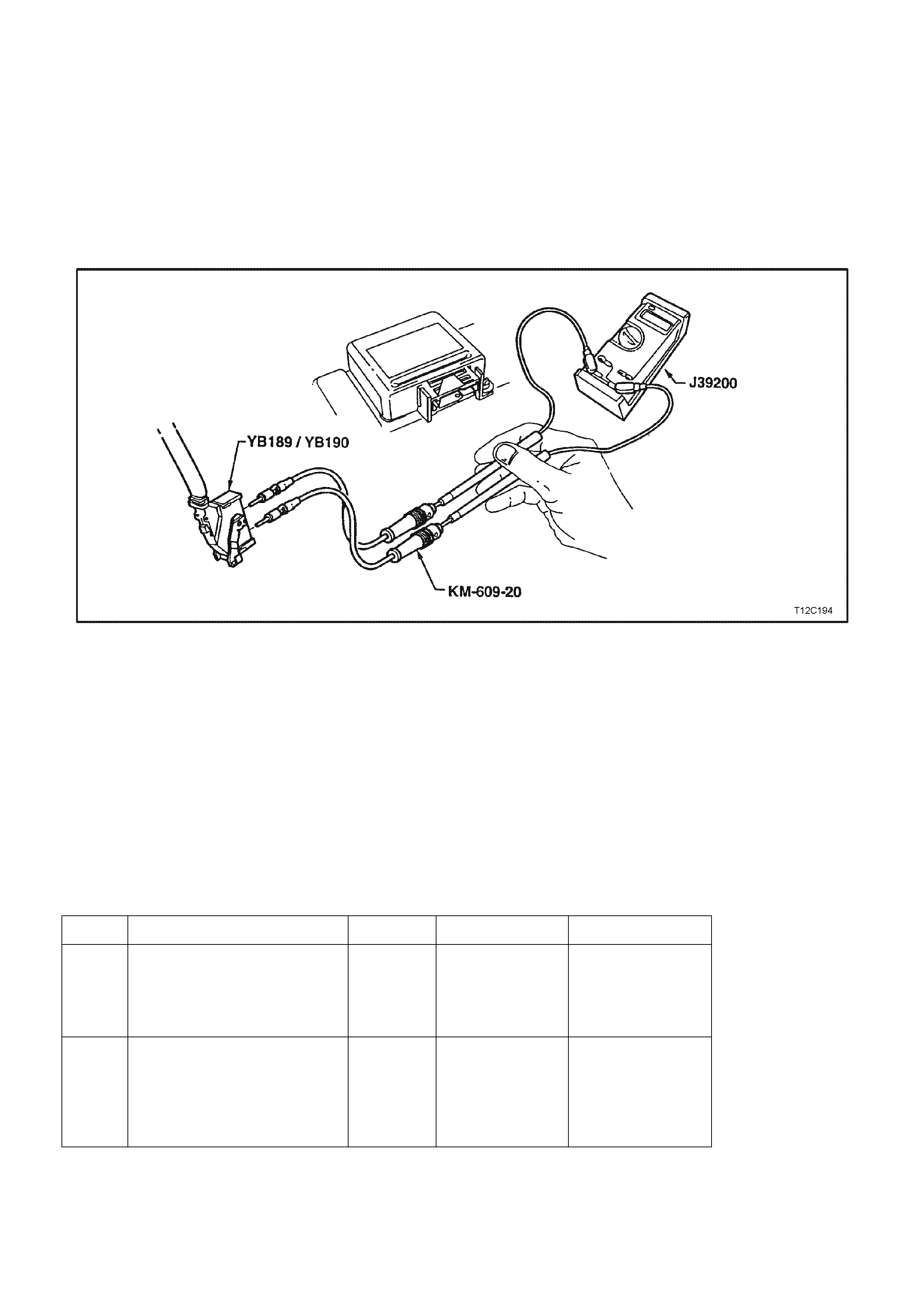
5.8 INSTRUMENT DIAGNOSTICS
INTRODUCTION
The following charts are designed to provide fast and efficient fault location of the instruments. Each diagnostic
chart consists of: a ‘diagnostic chart’ and pertinent information including Diagnostic Trouble Code (DTC) setting
parameters and, in most charts, circuit diagrams.
W hen carrying out wiring checks as directed by the diagnostic charts, rather than probe terminals and connectors
with incorrect s ized m ultimeter connections, use the adaptors contained in connector tes t adaptor k it KM-609. T his
is will prevent any possibility of spreading or damaging wiring harness terminals which may later cause a system
intermittent failure. The following illustration shows the test lead set (KM-609-20) being used to check the SRS
wiring harness.
Figure 12C-94
DIAGNOSTIC CIRCUIT CHECK
CIRCUIT DESCRIPTION:
When investigating any complaint of a combined instrument assembly problem or malfunction, always begin
diagnosis with the following diagnostic circuit check. This check is a preliminary procedure that checks to ensure the
com bined instrument assem bly is communicating on the serial data line as well as helping to identify a problem or
malfunction and directing the reader to the appropriate diagnostic chart in this Section.
With TECH 2 connected to the DLC and the ignition switched on, TECH 2 should display serial data
communication. If TECH 2 does not display serial data, the serial data circuit maybe open or shorted.
There are several other control modules that are connected to the serial data line (PCM, BCM, ABS or ABS/ETC,
ECC and SRS). ANY one of these contr ol m odules could c ause a f ault on the serial data line. T his f ault could r esult
in TECH 2 not being able to display serial data.
STEP ACTION VALUE YES NO
1. •Turn the ignition on.
•Do any instrument
assembly warning lamps
illuminate?
Go to Step 5. Go to Step 2.
2. •Check instrument cluster
fuses F11, F13 and F21 in
instrument panel
compartment.
•Are any fuses blown?
Replace blown
fuses.
Recheck and
verify repair.
Go to Step 3.

STEP ACTION VALUE YES NO
3. •Check continuity of circuit
155 (Black/Yellow wire)
between instrument
assembly connector YB66
and a known good earth.
•Is there continuity?
Go to Step 4. Check and repair
open in
circuit 155.
4. •With ignition ON, check for
voltage at instrument
cluster connector YB66,
terminals 19 and 20.
•Is voltage as specified?
B+ Replace
instrument
cluster,
refer to 2.1
INSTRUMENT
CLUSTER in this
Section.
Check and repair
circuits 44 and/or
1340 as necessary.
5. •Turn the ignition off
•Connect TECH 2 to DLC.
•Turn the ignition on.
•Push power button on
TECH 2.
•Does TECH 2 power up?
Go to Step 6. Refer to Section
0C - TECH 2.
6. •At the TECH 2 title screen
press the Enter key.
•Select Diagnostics \ 1998 \
VT Commodore \ Body \
Instrument.
•Does TECH 2 display
Instrument System
Identification (ie. Part
Number)?
Go to Step 7. Go to DTC-14
No Serial
Communication. in
this Section.
7. •With TECH 2 still
connected and instruments
selected, select Diagnostic
Trouble Codes.
•Does TECH 2 display any
DTC’s?
Refer to
corresponding
diagnostic chart.
Refer to 5.4
DIAGNOSING
FAULTS NOT
COVERED BY
TECH2
DIAGNOSING
TOOL in this
Section
WHEN A LL DIAGNOSIS AND REPAIRS ARE COMPLETED, CLEAR ALL DTC AND
VERIFY CORRECT OPERATION

NO SERIAL DATA COMMUNICATION
CIRCUIT DESCRIPTION:
When investigating any complaint of an Instrument problem or malfunction, always begin diagnosis with the
diagnostic circuit check. This check is a preliminary procedure that checks to ensure the Instruments are
communicating on the serial data line as well as helping to identify a problem or malfunction and directing the
reader to the appropriate diagnostic chart in this section.
With TECH 2 connected to the DLC and ignition switched on, TECH 2 should display serial data communication.
If TECH 2 does not display serial data, the serial data circuit maybe open or shorted.
There are several other control modules that are connected to the serial data line (PCM, BCM, ABS/ASR,
instruments and SDM). Any of these control modules could cause a fault on the serial data line. This fault could
result in TECH 2 not being able to display serial data.
TEST DESCRIPTION:
Number(s) below refer to step number(s) in the following diagnostic chart.
1. Ensures the Diagnostic Circuit Check has been performed.
2. Determines if there is a fault in the serial data circuit (1221) between the BCM and PCM.
3. Checks if fault is common with other control modules connected to the serial data circuit.
4. Checks internal switch in BCM for open circuit.
5. Checks circuit 1220 and determines if fault is in wiring or a control module.
6. Checks circuit 1220 for open circuit.
7. Checks integrity of earth circuits for the instruments.
DIAGNOSTIC AIDS:
A fault with the serial data circuit could be caused by one or m ore of the several contr ol modules connec ted to this
serial data circuit. Isolate the fault by disconnecting each control module, one at a time, until serial data
communication is restored.
STEP ACTION VALUE YES NO
1•Was the Diagnostic Circuit
Check performed? Go to Step 2. Go to
DIAGNOSTIC
CIRCUIT CHECK
in this Section.
2•Connect TECH 2 to the
DLC.
•Select Body / DTC Check /
DTC Check.
•Can TECH 2
communicate with the
BCM and PCM?
NOTE:
If “No Data” is displayed next
to the BCM or PCM, then
there is no communication
between TECH and these
control modules.
Go to Step 3. Go to BCM Serial
Data
Communication
diagnostics in
Section 12J-2
HIGH SERIES
BCM.
3•In Step 2, was TECH 2
able to communicate with
all the other control
modules, except the
Instruments, fitted to the
vehicle (ABS, ECC, SRS)?
NOTE:
If “No Data” is displayed next
to a control module, then
there is no communication
between TECH 2 and that
control module.
Go to Step 6. Go to Step 4.

STEP ACTION VALUE YES NO
4•Using an ohmmeter,
check continuity of circuits
1220 (Green/White wire)
and 1221 (Red/Black wire)
between BCM connector
YB164, terminals 2 and 3
(Low Series BCM) or
YB175, terminals 2 and 9
(High Series BCM).
•Does continuity exist?
Go to Step 5. Replace BCM,
refer to
Section 12J-2
LOW SERIES
BCM or
Section 12J-2
HIGH SERIES
BCM.
5•Check circuit 1220 for
open, short to earth or
short to voltage between
BCM and individual control
modules
•Is circuit 1220 okay?
NOTE:
Disconnect each control
module in circuit 1220 one at a
time to isolate the fault in the
circuit or to identify the control
module causing the fault.
Replace faulty
control module as
necessary, refer
to relevant
Section. Recheck
and verify repair.
Repair circuit 1220
as necessary.
Recheck and verify
repair.
6•Using an ohmmeter,
check for continuity
between BCM connector
YB164, terminal 3 (Low
Series BCM) or YB175,
terminal 9 (High Series
BCM) and instruments
connector YB66, terminal
12 (Green/White wire).
•Does continuity exist?
Go to Step 7. Repair open in
circuit 1220.
Recheck and verify
repair.
7•Check the integrity of the
Instruments earth circuit
by performing a voltage
drop on circuit 155
between instrument
connector YB66, terminal
6 and earth point E3.
•With ignition on, is voltage
less than the specified
value?
0.15 Volts Replace
instrument cluster
assembly, refer to
2.1
INSTRUMENT
CLUSTER in this
Section.
Repair earth circuit
as necessary.
Recheck and verify
repair
WHEN A LL DIAGNOSIS AND REPAIRS ARE COMPLETED, CLEAR ALL DTC AND
VERIFY CORRECT OPERATION

DTC 1 FUEL GAUGE SENDER UNIT- SHORT CIRCUIT:
CIRCUIT DESCRIPTION
IMPORTANT:
Instrument diagnostics for the fuel gauge sender unit were disabled in vehicle production commencing 18th April
1998. Revised software will be available in october 1998.
The instrument assembly supplies a 12 volt reference voltage and an earth circuit to the fuel gauge sender unit. The
fuel sender provides a resistance value to the instrument assembly based on its position relative to the fuel level.
The fuel sender resistance will vary between 37.5 ohms and 253.3 ohms from no fuel in the tank to full tank.
DTC 1 WILL SET IF:
•The fuel sender resistance is less than 7.4 ohms for a period of 20 seconds. The DTC will reset when the fuel
sender resistance returns to its normal operating range for a period of 60 seconds.
When a DTC 1 is set the fuel gauge will display the fuel tank level as empty irrespective of actual fuel level.
TEST DESCRIPTION:
Number(s) below refer to step number(s) in the following diagnostic chart.
2-4. Use of T ECH 2 to view data being sent f rom f uel s ender. If voltage is not within corr ect operating s pec if ic ations
then there is either an open circ uit, short circ uit or a faulty fuel sender. If open- or short-circ uit then check s will
be made to locate the circuit interruption.
5. Use of TECH 2 to drive the gauge on the instrument assembly to verify that gauge is functioning correctly.
6. W ith the fuel sender disconnected, the fuel sender signal resistance value should be between 37.5 and 253.3
ohms, which is dependant on fuel level.
7. Continuity check of harness between voltage circuit 30 and earth circuit 155 at harness connector YB74 will
indicate a short circuit in harness between YB74 and instrument assembly.
8. Continuity check of harness between voltage circuit 30 and earth circuit 155 at harness connector YR32 will
indicate a short circuit in harness between YB74 and YR32.
9. Removal of fuel tank allows acces s to fuel sender . Continuity c heck of harness between voltage circuit 30 and
earth circuit 155 at harness connector YR44 will indicate a short circuit in harness between YR32 and YR44,
otherwise there is a fault in the fuel sender.

DIAGNOSTIC AIDS:
The T ECH 2 diagnostic tool reads fuel sender pos ition as a voltage between 0 and 12 volts. The f uel sender signal
resistance should be between 37.5 to 253.3 ohms when the fuel sender is functioning correctly. The fuel sender
voltage should increase at a steady rate as the fuel level increases.
The multimeter allows continuity of the wiring harness to be checked. Harness voltage can also be confirmed at
connector locations.
Check for any damage to the harness which could cause an intermittent open or short to earth or backed-out
terminals at the instrument assembly connectors, broken connector locks, improperly formed or damaged terminals.
STEP ACTION VALUE YES NO
1. •Has diagnostic circuit test
been carried out? Go to Step 2. Go to Diagnostic
Circuit Check in
this Section.
2. •Connect TECH 2 to DLC.
•Select 1998 \ VT
Commodore \ Diagnostics
\ Body \ Instrument \ Data
Display \ Instrument.
•Check the petrol sender
signal
•Is Petrol sender signal
voltage 0V?
Short circuit from
fuel sender to
instrument
cluster,
go to Step 5.
Go to Step 3.
3. •Is Petrol Sender signal
voltage 5V? Open circuit from
fuel sender to
instrument
cluster,
go to Step 5
Go to Step 4.
4. •Is Petrol Sender Input
voltage between 0V and
5V?
Go to Step 5. Replace fault fuel
sender faulty.
Refer to Section 8A
FUEL TANK.
5. •Using TECH 2, run Control
Tests, refer to 5.14 F4:
MISCELLANEOUS TEST
in this Section.
•Does the fuel gauge
operate correctly?
Go to Step 6. Replace instrument
cluster, refer to 2.1
INSTRUMENT
CLUSTER in this
section
6. •Disconnect battery.
•Disconnect fuel tank
harness from body
harness connector YR32
located under the rear of
vehicle.
•Using multimeter, check
resistance across fuel tank
sender circuits 30 (BR)
and 155 (Black/Yellow) on
fuel tank harness.
•Is resistance within
specified range?
Between
37.5
ohms and
253.3
ohms
Go to Step 7. Replace faulty fuel
sender, refer to
Section 8A
FUEL TANK..

STEP ACTION VALUE YES NO
7. •Using multimeter check
continuity between main
wiring harness circuit 155
(Black/Yellow) and circuit
30 (Tan wire) at connector
YB74 in the passenger
compartment.
•Is there continuity?
Short circuit in
main wiring
harness between
YB74 and YB66,
repair harness.
Go to Step 8.
8. •Using multimeter check
continuity between body
harness circuit 155
(Black/Yellow) and circuit
30 (Brown wire) at
connector YR32 under the
vehicle.
•Is there continuity?
Short circuit in
body harness
between YR32
and YB74, repair
harness.
Go to Step 9.
9. •Drain and remove fuel tank,
refer Section 8A FUEL
TANK.
•Using multimeter check
continuity between body
harness circuit 155
(Black/Yellow) and circuit
30 (Brown wire) at
connector YR44 under the
vehicle.
•Is there continuity?
Short circuit in
body harness
between YR44
and YR32, repair
harness.
Replace faulty fuel
sender, refer to
Section 8A FUEL
TANK.
10. •Use TECH 2 to clear DTC.
•Has DTC cleared?
End of diagnostic
checking. Refer to
corresponding
diagnostic chart.
WHEN A LL DIAGNOSIS AND REPAIRS ARE COMPLETED, CLEAR ALL DTC AND
VERIFY CORRECT OPERATION
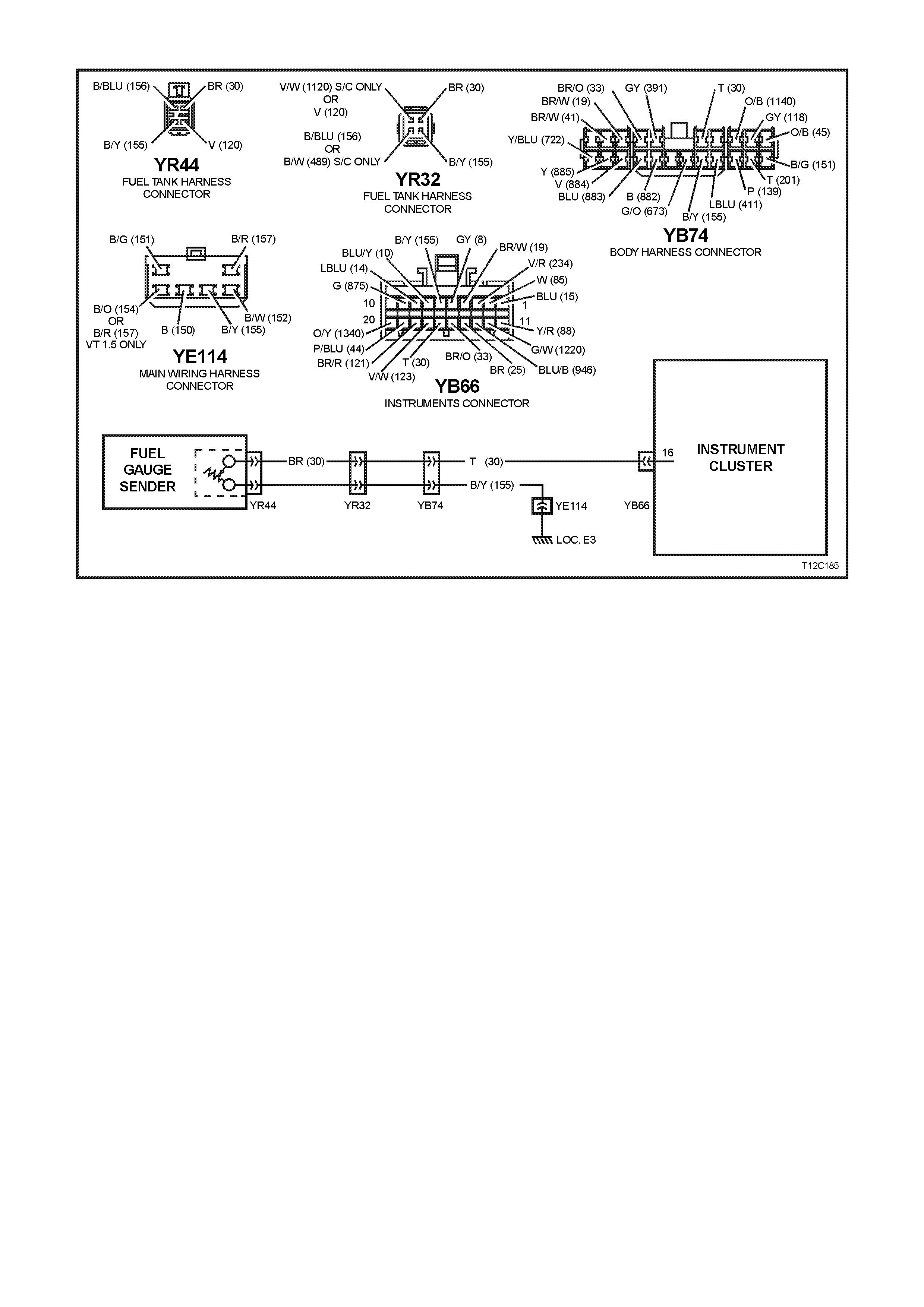
DTC 2 FUEL GAUGE SENDER UNIT - INTERMITTENT
CIRCUIT DESCRIPTION:
IMPORTANT:
Instrument diagnostics for the fuel gauge sender unit were disabled in vehicle production commencing 18th April
1998. Revised software will be available in october 1998.
The instrument assembly supplies a 12 volt reference voltage and an earth circuit to the fuel sender. The fuel
sender provides a resistance value to the instrument assembly based on its position relative to the fuel level. The
fuel sender resistance will vary between 37.5 ohms and 253.3 ohms from no fuel in the tank to full tank.
DTC 2 WILL SET IF:
•There is an intermittent fault in the connection between the fuel sender and the instrument cluster. The DTC is
set when the fuel sender resistance is greater than 260 ohm s for 2 seconds or if the fuel sender resistance is
less than 37.5 ohm s f or 2 seconds. T he DTC is reset when the fuel sender is detec ted as being open cir cuit or
short circuit or the sender is within its normal operating range for a period of 60 seconds.
TEST DESCRIPTION:
Number(s) below refer to step number(s) in the following diagnostic chart.
2-4. Use of T ECH 2 to view data being sent f rom f uel s ender. If voltage is not within corr ect operating s pec if ic ations
then there is either an open circ uit, short circ uit or a faulty fuel sender. If open- or short-circ uit then check s will
be made to locate the circuit interruption.
5. Use of TECH 2 to drive the gauge on the instrument assembly to verify that gauge is functioning correctly.
6-9. Tes t driving the car and m anipulating the harness es while viewing the serial data sent fr om the fuel sender will
indicate the presenc e of a c irc uit inter ruption as the voltage will fluc tuate in the event of an open c irc uit or s hort
circuit.
Additionally, viewing the DTC will indicate the presence of the intermittent fault if triggered by manipulating the
relevant harness.

DIAGNOSTIC AIDS:
By manipulating the harnesses at the various connectors it is possible to isolate the cause of the circuit interruption.
By working through the chart in the specified order it is possible to work out which harness contains the fault. This
harness can then be removed and repaired.
The TECH 2 diagnostic tool reads fuel sender position as a voltage between 0 and 12 volts. The fuel sender signal
resistance should be between 37.5 to 253.3 ohms when the fuel sender is functioning correctly. The fuel sender
voltage should increase at a steady rate as the fuel level increases.
The multimeter allows continuity of the wiring harness to be checked. Harness voltage can also be confirmed at
connector locations.
Check for any damage to the harness which could cause an intermittent open or short to earth or backed out
terminals at the instrument assembly connectors, broken connector locks, improperly formed or damaged terminals.
STEP ACTION VALUE YES NO
1.
• Was the Diagnostic Circuit
Check performed? Go to Step 2. Go to Diagnostic
Circuit Check in
this Section.
2. •Connect TECH 2 to DLC.
•Select 1998 \ VT
Commodore \ Diagnostics
\ Body \ Instrument \ Data
Display \ Instrument.
•Check the petrol sender
signal.
•Is petrol sender Input
voltage 0V?
Short circuit from
fuel sender to
instrument
cluster,
go to Step 5.
Go to Step 3.
3. •Is petrol sender signal
voltage 5V? Open circuit from
fuel sender to
instrument
cluster,
go to Step 5.
Go to Step 4.
4. •Is petrol sender signal
voltage between 0V and
5V?
Go to Step 5. Replace faulty fuel
sender, refer to
Section 8A FUEL
TANK. .
5. •Using TECH 2, run Control
Tests,
refer to 5.14 F4:
MISCELLANEOUS TEST
in this Section.
•Does the fuel gauge
operate correctly?
Go to Step 6. Replace instrument
cluster. Refer to
2.1 INSTRUMENT
CLUSTER in this
section.

STEP ACTION VALUE YES NO
6. •Clear DTC 2 by selecting
Diagnostics \ 1998 \ VT
Commodore \ Body \
Instrument \ Diagnostic
Trouble Codes \ Clear
DTC Information.
•Turn ignition off then on.
•Select Diagnostics \ 1998 \
VT Commodore \ Body \
Instrument \ Data Display \
Instrument and view petrol
sender signal data.
•Take vehicle for a test
drive and monitor the
petrol sender signal.
•Did the voltage of the
petrol sender signal vary
during the manipulations,
or
•Did DTC 2 set again?
Repair faulty
main wiring
harness.
Go to Step 7.
7. •Clear DTC 2 by selecting
Diagnostics \ 1998 \ VT
Commodore \ Body \
Instrument \ Diagnostic
Trouble Codes \ Clear
DTC Information.
•Turn ignition off then on.
•Select Diagnostics \ 1998 \
VT Commodore \ Body \
Instrument \ Data Display \
Instrument and view petrol
sender signal data.
•Have assistant manipulate
harness at connector YB74
in the passenger
compartment to induce an
intermittent fault.
•Did the voltage of the
petrol sender signal vary
during the manipulations,
or
•Did DTC 2 set again?
Repair faulty
body harness or
faulty main wiring
harness.
Go to Step 8.
8. •Have assistant manipulate
harness at connector
YR32 under the vehicle to
induce an intermittent fault.
•Did the voltage of the
petrol sender signal vary
during the manipulations,
or
•Did DTC 2 set again?
Repair faulty
body harness or
faulty fuel tank
harness.
Go to Step 9.

STEP ACTION VALUE YES NO
9. •Drain and remove fuel
tank, refer to Section 8A
FUEL TANK.
•Have assistant manipulate
harness at connector
YR44 under the vehicle to
induce an intermittent fault.
•Did the voltage of the
petrol sender signal vary
during the manipulations,
or
•Did DTC 2 set again?
Repair faulty fuel
tank harness. Repair faulty fuel
sender. Refer to
Section 8A FUEL
TANK.
10. •Use TECH 2 to clear DTC.
•Has DTC cleared.
End of diagnostic
checking. Refer to
corresponding
diagnostic chart.
WHEN A LL DIAGNOSIS AND REPAIRS ARE COMPLETED, CLEAR ALL DTC AND
VERIFY CORRECT OPERATION

DTC 3 FUEL SENDER - OPEN CIRCUIT
CIRCUIT DESCRIPTION:
IMPORTANT:
Instrument diagnostics for the fuel gauge sender unit were disabled in vehicle production commencing 18th April
1998. Revised software will be available in october 1998.
The instrument assembly supplies a 12 volt reference voltage and an earth circuit to the fuel sender. The fuel
sender provides a resistance value to the instrument assembly based on its position relative to the fuel level. The
fuel sender resistance will vary between 37.5 ohms and 256.3 ohms from no fuel level in the tank to full tank level.
IMPORTANT:
An open circuit f uel gauge s ender unit is s hown as DT C 3 on the TECH 2, whereas the instr ument clus ter diagnos is
mode display shows the same fault as ‘t 00 – C’.
DTC 3 WILL SET IF:
•The f uel sender c ircuit provides a resis tance above 260 ohms f or a dur ation longer than 20 sec onds. T he DT C
will reset when the fuel sender resistances return to its normal operating range for a period of 60 seconds.
When a DTC 3 is set the fuel gauge will display the fuel tank level as empty irrespective of actual fuel level.
TEST DESCRIPTION:
Number(s) below refer to step number(s) in the following diagnostic chart.
2-4. Use of T ECH 2 to view data being sent f rom f uel s ender. If voltage is not within corr ect operating s pec if ic ations
then there is either an open circ uit, short circ uit or a faulty fuel sender. If open- or short-circ uit then check s will
be made to locate the circuit interruption.
5. Use of TECH 2 to drive the gauge on the instrument assembly to verify that gauge is functioning correctly.
6. W ith the f uel sender disc onnected, the fuel sender signal resistanc e value should be between 37.5 and 253.3
ohms, which is dependant on fuel level.
7. Probing circuit 155 with a m ultim eter c onnected to body earth check s the f uel sender earth circ uit at connector
YR32.
8. Probing circuit 155 with a m ultim eter c onnected to body earth check s the f uel sender earth circ uit at connector
YB74.
9. Probing circuit 30 with a multimeter connected to B+ checks the fuel sender voltage circuit at connector YR32.
10. Probing circuit 30 with a multimeter connected to B+ checks the fuel sender voltage circuit at connector YB74.
11. Removing fuel tank to gain access to fuel sender enables fuel tank harness, which can then be checked for
continuity at each end (ie, no circuit breaks).

DIAGNOSTIC AIDS:
The TECH 2 diagnostic tool reads fuel sender position as a voltage between 0 and 12 volts. The fuel sender signal
resistance should be between 37.5 to 253.3 ohms when the fuel sender is functioning correctly. The fuel sender
voltage should increase at a steady rate as the fuel level increases.
The multimeter allows continuity of the wiring harness to be checked. Harness voltage can also be confirmed at
connector locations.
Check for any damage to the harness which could cause an intermittent open or short to earth or backed-out
terminals at the instrument assembly connectors, broken connector locks, improperly formed or damaged terminals.
STEP ACTION VALUE YES NO
1.
• Was the Diagnostic Circuit
Check performed? Go to step 2. Go to Diagnostic
Circuit Check in
this Section.
2. •Connect TECH 2 to DLC.
•Select 1998 \ VT
Commodore \ Diagnostics
\ Body \ Instrument \ Data
Display \ Instrument.
•Check the petrol sender
signal.
•Is petrol sender signal
voltage 0V?
Short circuit from
fuel sender to
instrument
cluster,
go to Step 5.
Go to Step 3.
3. •Is petrol sender signal
voltage 5V? Open circuit from
fuel sender to
instrument
cluster,
go to Step 5.
Go to Step 4.
4. •Is petrol sender signal
voltage between 0V
and 5V?
Go to Step 5. Replace faulty fuel
sender, refer to
Section 8A FUEL
TANK.
5. •Using TECH 2, run Control
Tests,
refer to 5.14 F4:
MISCELLANEOUS TEST
in this Section.
•Does the fuel gauge
operate correctly?
Go to Step 6. Replace instrument
cluster. Refer to
2.1 INSTRUMENT
CLUSTER.
6. •Disconnect battery.
•Disconnect fuel tank
harness from body
harness connector YR32
located under the rear of
the vehicle.
•Using an ohmmeter, check
resistance across fuel tank
sender circuits 30 (Brown
wire) and 155
(Black/Yellow w ire) on fuel
tank harness.
•Is resistance within
specified range?
Between
37.5 ohms
and 253.3
ohms
Go to Step 7. Replace faulty fuel
sender, refer to
Section 8A FUEL
TANK.

STEP ACTION VALUE YES NO
7. •Using an ohmmeter check
continuity of body harness
circuit 155 (Black/Yellow
wire) connector YR32 to
body earth using suitable
body earth location.
•Is there continuity?
Go to Step 9. Go to Step 8.
8. •Using an ohmmeter check
continuity of body harness
circuit 155 (Black/Yellow
wire) connector YB74 to
body earth using suitable
body earth location.
Is there continuity?
Repair open
circuit between
connectors YR32
and YB74.
Repair open circuit
between YB74 and
YE114.
9. •Using a multimeter check
voltage across circuit 30
(Brown wire) at connector
YR32 to suitable body
earth location.
•Is voltage as specified?
+12V Go to Step 11. Go to Step 10.
10. •Using a multimeter check
voltage of body harness
circuit 30 (Tan wire) at
connector YB74 to suitable
body earth location.
•Is voltage as specified?
+12V Repair open
circuit between
connectors YR32
and YB74.
Repair open circuit
between
connectors
YB74 and YB66.
11. •Drain and remove fuel
tank, refer to Section 8A
FUEL TANK.
•Using an ohmmeter, check
for continuity of fuel tank
harness at YR44 between
circuits 155 (Black/Yellow
wire) and 30 (Brown wire).
•Is there continuity?
Go to Step 13. Go to Step 12.
12. •Disconnect fuel sender
harness from fuel sender.
•Using an ohmmeter, check
continuity across fuel
sender.
•Is there continuity?
Repair open
circuit in fuel tank
harness.
Replace faulty fuel
sender. Refer to
Section 8A FUEL
TANK.
13. •Use TECH 2 to clear DTC.
•Has DTC cleared?
End of diagnostic
checking. Refer to
corresponding
diagnostic chart.
WHEN A LL DIAGNOSIS AND REPAIRS ARE COMPLETED, CLEAR ALL DTC AND
VERIFY CORRECT OPERATION

DTC 4 LPG GAUGE SENDER UNIT - OPEN CIRCUIT
CIRCUIT DESCRIPTION:
The instrument assembly supplies a 12 volt reference voltage and an earth circuit to the LPG gauge sender unit.
The LPG sender provides a resistance value to the instrument assembly based on its position relative to the LPG
level. The LPG sender resistance will vary betw een 37.5 ohms and 256.3 ohms from no LPG in the tank to full tank.
NOTE:
If a vehicle is not fitted with LPG, DTC 4 will always be set.
DTC 4 WILL SET IF:
• The LPG sender circuit provides a resistance above 260 ohms for a duration longer than 20 seconds. The
DTC is reset when the LPG sender resistance returns to its normal operating range for a period of 60 seconds.
When a DTC 4 is set the LPG gauge will display the LPG tank level as empty when LPG mode is selected
irrespective of actual fuel level.
TEST DESCRIPTION:
Number(s) below refer to step number(s) in the following diagnostic chart.
2-4. Use of TECH 2 to view data being sent from LPG sender. If voltage is not within correct operating
specifications then there is either an open circuit, short circuit or a faulty LPG sender. If open- or short-circuit
then checks will be made to locate the circuit interruption.
5. Use of TECH 2 to drive the gauge on the instrument assembly to verify that gauge is functioning correctly.
6. With the LPG sender disconnec ted, the LPG sender signal r esis tanc e value should be between 37.5 and 253.3
ohms, which is dependant on LPG level.
7. Probing circuit 155 with a multimeter connected to body earth checks the LPG sender earth circuit at
connector YB51.
8. Probing circuit 155 with a multimeter connected to body earth checks the LPG sender earth circuit at
connector YE110.
9. Probing circuit 1030 with a multimeter connected to B+ checks the LPG sender voltage circuit at
connector YB51.
10. Probing circuit 1030 with a multimeter connected to B+ checks the LPG sender voltage circuit at
connector YE112.
11. Enables the LPG tank harness to be checked for continuity at both ends.

DIAGNOSTIC AIDS:
The TECH 2 diagnostic tool reads LPG sender position as a voltage between 0 and 12 volts. The LPG sender
signal resistance should be between 37.5 to 253.3 ohms when the LPG sender is functioning correctly. The LPG
sender voltage should increase at a steady rate as the LPG level increases.
The multimeter allows continuity of the wiring harness to be checked. Harness voltage can also be confirmed at
connector locations.
Check for any damage to the harness which could cause an intermittent open or short to earth or backed out
terminals at the instrument assembly connectors, broken connector locks, improperly formed or damaged terminals.
STEP ACTION VALUE YES NO
1.
• Was the Diagnostic Circuit
Check performed? Go to step 2. Go to Diagnostic
Circuit Check in
this Section.
2. •Connect TECH 2 to DLC.
•Select 1998 \ VT
Commodore \ Diagnostics
\ Body \ Instrument \ Data
Display \ Instrument.
•Check the LPG Sender
Input.
•Is LPG Sender Input
voltage 0V?
Short circuit from
LPG sender to
instrument
cluster,
go to Step 5.
Go to Step 3.
3. •Is LPG Sender Input
voltage 5V? Open circuit from
LPG sender to
instrument
cluster,
go to Step 5.
Go to Step 4.
4. •Is LPG Sender signal
voltage between 0V and
5V?
Go to Step 5. Replace faulty LPG
sender, refer to
Section 2 - VT
Sedan with
production LPG or
Section 2A - VT
Sedan with
accessory LPG &
VT Wagon with
production LPG.
5. •Using TECH 2, run Control
Tests, refer to 5.14 F4:
MISCELLANEOUS TEST
in this Section.
•Does the fuel gauge
operate correctly?
Go to Step 6. Replace instrument
cluster. Refer to
2.1 INSTRUMENT
CLUSTER in
this section.
6. •Disconnect battery.
•Disconnect LPG tank
harness from body
harness YB51 located in
the left-hand footwell.
•Using an ohmmeter, check
resistance across LPG
sender circuits 1030
(Yellow wire) and 155
(Black/Yellow wire) on LPG
tank harness.
•Is resistance within
specified range?
Between
37.5 ohms
and 253.3
ohms
Go to Step 7. Replace faulty LPG
sender, refer to
Section 2 - VT
Sedan With
Production LPG or
Section 2A - VT
Sedan With
Accessory LPG &
VT Wagon With
Production LPG.

STEP ACTION VALUE YES NO
7. •Using an ohmmeter, check
continuity of body harness
circuit 155 (Black/Yellow
wire) connector YB51 to
body earth using suitable
body earth location.
•Is there continuity?
Go to Step 9. Go to Step 8.
8. •Using an ohmmeter, check
continuity of body harness
circuit 155 (Black/Yellow
wire) at connector YE110
to suitable body earth
location.
•Is there continuity?
Repair open
circuit between
connectors YB51
and YE110.
Repair open circuit
between YE110
and YE114.
9. •Using a multimeter check
voltage across circuit 1030
(Yellow wire) at connector
YB51 to suitable body
earth location..
•Is voltage specified?
+12V Go to Step 11. Go to Step 10.
10. •Using a multimeter check
voltage of body harness
circuit 1030 (Yellow wire)
at connector YE112 to
suitable body earth
location.
•Is voltage specified?
+12V Repair open
circuit between
connectors YB51
and YE112.
Repair open circuit
between YE112
and YB66.
11. •Using an ohmmeter, check
for continuity of LPG tank
harness at YR50 between
circuits 155 (Black/Yellow
wire and 1030 (Yellow
wire).
•Is there continuity?
Go to Step 13. Go to Step 12.
12 •Disconnect LPG sender
harness from LPG sender.
•Using an ohmmeter, check
continuity across LPG
sender.
•Is their continuity?
Repair open
circuit in LPG
tank harness.
Replace faulty LPG
sender, refer to
Section 2 - VT
Sedan With
Production LPG or
Section 2A - VT
Sedan With
Accessory LPG &
VT Wagon With
Production LPG.
13. •Use TECH 2 to clear DTC.
•Has DTC cleared?
End of diagnostic
checking. Refer to
corresponding
diagnostic chart.
WHEN A LL DIAGNOSIS AND REPAIRS ARE COMPLETED, CLEAR ALL DTC AND
VERIFY CORRECT OPERATION

DTC 5 LPG GAUGE SENDER UNIT - SHORT CIRCUIT
CIRCUIT DESCRIPTION:
The instrument assembly supplies a 12 volt reference voltage and an earth circuit to the LPG gauge sender unit.
The LPG sender provides a resistance value to the instrument assembly based on its position relative to the LPG
level. The LPG sender resistance will vary betw een 37.5 ohms and 253.3 ohms from no LPG in the tank to full tank.
DTC 5 WILL SET IF:
•The LPG sender resistance is less than 7.4 ohms for a period of 20 seconds. The DTC is reset when the LPG
sender resistance returns to its normal operating range for a period of 60 seconds. After this tim e the DTC will
be logged as a History DTC.
When a DTC 4 is set the LPG gauge will display the LPG tank level as empty when LPG mode is selected
irrespective of actual fuel level.
TEST DESCRIPTION:
Number(s) below refer to step number(s) in the following diagnostic chart.
2-4. Use of TECH 2 to view data being sent from LPG sender. If voltage is not within correct operating
specifications then there is either an open circuit, short circuit or a faulty LPG sender. If open- or short-circuit
then checks will be made to locate the circuit interruption.
5. Use of TECH 2 to drive the gauge on the instrument assembly to verify that gauge is functioning correctly.
6. With the LPG sender disconnec ted, the LPG sender signal r esis tanc e value should be between 37.5 and 253.3
ohms, which is dependant on LPG level.
7. Continuity check of harness between voltage circuit 1030 and earth circuit 155 at harness connectors
YB110/YB112 will indicate a short circuit in harness between YE112 and instrument cluster.
8. Continuity check of har ness between voltage circuit 1030 and ear th circuit 155 at harness connector YB51 will
indicate a short circuit in harness between YB51 and YE112.
9. Continuity check of har ness between voltage circuit 1030 and ear th circuit 155 at harnes s connector YR50 will
indicate a short circuit in harness between YR50 and YB51, otherwise there is a fault in the LPG sender.

DIAGNOSTIC AIDS:
The TECH 2 diagnostic tool reads LPG sender position as a voltage between 0 and 12 volts. The LPG sender
signal resistance should be between 37.5 to 253.3 ohms when the LPG sender is functioning correctly. The LPG
sender voltage should increase at a steady rate as the LPG level increases.
The multimeter allows continuity of the wiring harness to be checked. Harness voltage can also be confirmed at
connector locations.
Check for any damage to the harness which could cause an intermittent open or short to earth or backed out
terminals at the instrument assembly connectors, broken connector locks, improperly formed or damaged terminals.
STEP ACTION VALUE YES NO
1.
• Was the Diagnostic Circuit
Check performed? Go to Step 2. Go to Diagnostic
Circuit Check in
this Section.
2. •Connect TECH 2 to DLC.
•Select 1998 \ VT
Commodore \ Diagnostics
\ Body \ Instrument \ Data
Display \ Instrument.
•Check the LPG Sender
signal.
•Is LPG Sender signal
voltage 0V?
Short circuit from
LPG sender to
instrument
cluster,
go to Step 5.
Go to Step 3.
3. •Is LPG Sender signal
voltage 5V? Open circuit from
LPG sender to
instrument
cluster,
go to Step 5.
Go to Step 4.
4. •Is LPG Sender signal
voltage between 0V and
5V?
Go to Step 5. Replace faulty LPG
sender, refer to
Section 2 - VT
Sedan With
Production LPG or
Section 2A - VT
Sedan With
Accessory LPG &
VT Wagon With
Production LPG.
5. •Using TECH 2, run Control
Tests, refer to 5.14 F4:
MISCELLANEOUS TEST
in this Section.
•Does the fuel gauge
operate correctly?
Go to Step 6. Replace instrument
cluster. Refer to
2.1 INSTRUMENT
CLUSTER in this
Section.
6. •Disconnect battery.
•Disconnect LPG tank
harness from body
harness connector YB51
located in the left-hand
footwell.
•Using an ohmmeter, check
resistance across LPG
sender circuits 1030
(Yellow wire) and 155
(Black/Yellow wire) on LPG
tank harness.
•Is resistance within
specified range?
Between
37.5
ohms and
253.3
ohms
Go to Step 7. Replace faulty LPG
sender, refer to
Section 2 - VT
Sedan With
Production LPG or
Section 2A - VT
Sedan With
Accessory LPG &
VT Wagon With
Production LPG.

STEP ACTION VALUE YES NO
7. •Using an ohmmeter check
continuity between body
harness circuit 155
(Black/Yellow wire) at
connector YE112 and
circuit 1030 (Yellow wire)
at connector YE110 in the
engine compartment.
•Is there continuity?
Short circuit in
body harness
between YE112
and YB66.
Go to Step 8.
8. •Using an ohmmeter check
continuity between body
harness circuit 155
(Black/Yellow wire) and
circuit 1030 (Yellow wire)
at connector YB51.
•Is there continuity?
Short circuit in
body harness
between YB51
and YE112,
repair harness.
Go to Step 9.
9•Using an ohmmeter check
continuity between body
harness circuit 155
(Black/Yellow wire) and
circuit 1030 (Yellow wire)
at connector YR50 located
at the LPG tank..
•Is there continuity?
Short circuit in
body harness
between YR50
and YB51, repair
harness.
Replace faulty LPG
sender, refer to
Section 2 - VT
Sedan With
Production LPG or
Section 2A - VT
Sedan With
Accessory LPG &
VT Wagon With
Production LPG.
10. •Use TECH 2 to clear DTC.
•Has DTC cleared?
End of diagnostic
checking. Refer to
corresponding
diagnostic chart.
WHEN A LL DIAGNOSIS AND REPAIRS ARE COMPLETED, CLEAR ALL DTC AND
VERIFY CORRECT OPERATION
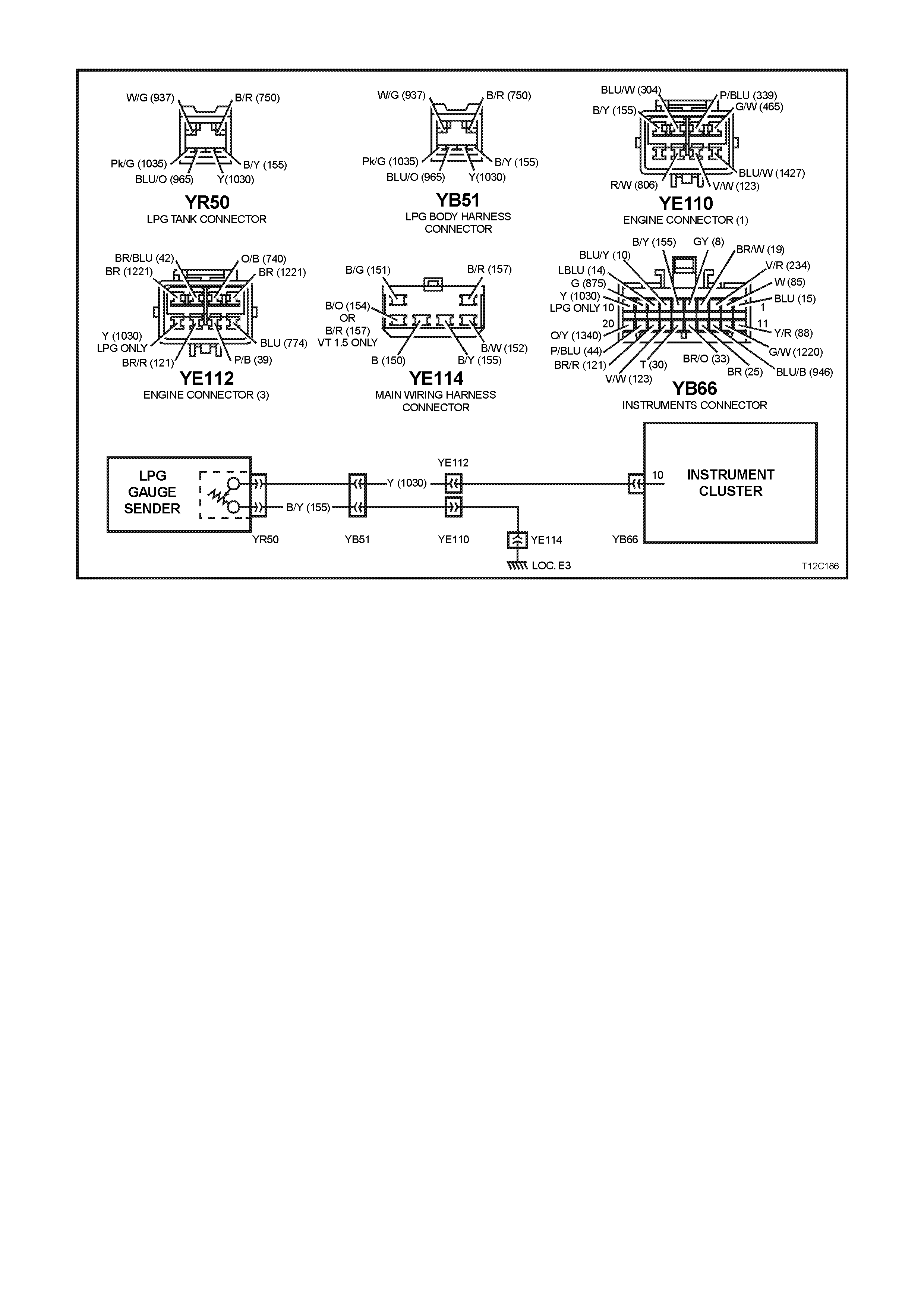
DTC 6 LPG GAUGE SENDER UNIT - INTERMITTENT
CIRCUIT DESCRIPTION:
The instrument assembly supplies a 5 volt reference voltage and an earth circuit to the LPG sender. The LPG
gauge sender unit provides a resistanc e value to the instrum ent assem bly based on its position relative to the LPG
level. The LPG sender resistance will vary betw een 37.5 ohms and 253.3 ohms from no LPG in the tank to full tank.
DTC 6 WILL SET IF:
•There is an interm ittent fault in the connection between the LPG s ender and the instrum ent cluster. The DT C is
set when the LPG sender res istance is greater than 260 ohms f or 2 seconds or if the LPG sender resist ance is
less than 37.5 ohms for 2 seconds . T he DTC is reset when the LPG sender is detected as being open circ uit or
short circuit or the sender is within its normal operating range for a period of 60 seconds.
TEST DESCRIPTION:
Number(s) below refer to step number(s) in the following diagnostic chart.
2-4. Use of TECH 2 to view data being sent from LPG sender. If voltage is not within correct operating
specifications then there is either an open circuit, short circuit or a faulty LPG sender. If open- or short-circuit
then checks will be made to locate the circuit interruption.
5. Use of TECH 2 to drive the gauge on the instrument assembly to verify that gauge is functioning correctly.
6-9. Test driving the car and manipulating the harnesses while viewing the serial data sent from the LPG sender will
indicate the presenc e of a c irc uit inter ruption as the voltage will fluc tuate in the event of an open c irc uit or s hort
circuit.
Additionally, viewing the DTC will indicate the presence of the intermittent fault if triggered by manipulating the
relevant harness.
DIAGNOSTIC AIDS:
By manipulating the harnesses at the various connector s it is pos sible to isolate the c ause of the circuit inter ruption.
By working through the chart in the specified order it is possible to work out which harness contains the fault. This
harness can then be removed and repaired.
The T ECH 2 diagnostic tool reads fuel sender pos ition as a voltage between 0 and 12 volts. The f uel sender signal
resistance should be between 37.5 to 253.3 ohms when the fuel sender is functioning correctly. The fuel sender
voltage should increase at a steady rate as the fuel level increases.
The multimeter allows continuity of the wiring harness to be checked. Harness voltage can also be confirmed at
connector locations.
Check for any damage to the harness which could cause an intermittent open or short to earth or backed out
terminals at the instrument assembly connectors, broken connector locks, improperly formed or damaged terminals.

STEP ACTION VALUE YES NO
1.
• Was the Diagnostic Circuit
Check performed? Go to Step 2. Go to Diagnostic
Circuit Check in
this Section.
2. •Connect TECH 2 to DLC.
•Select 1998 \ VT
Commodore \ Diagnostics
\ Body \ Instrument \ Data
Display \ Instrument.
•Check the LPG sender
signal.
•Is LPG sender signal
voltage 0V?
Short circuit from
LPG sender to
instrument
cluster,
go to Step 5.
Go to Step 3.
3. •Is LPG sender signal
voltage 5V? Open circuit from
LPG sender to
instrument
cluster,
go to Step 5.
Go to Step 4.
4. •Is LPG sender signal
voltage between 0V and
5V?
Go to Step 5. Replace faulty LPG
sender, refer to
Section 2 - VT
Sedan With
Production LPG or
Section 2A - VT
Sedan With
Accessory LPG &
VT Wagon With
Production LPG.
5. •Using TECH 2, run Control
Tests,
refer to 5.14 F4:
MISCELLANEOUS TEST
in this Section.
•Does the fuel gauge
operate correctly?
Go to Step 6. Replace instrument
cluster. Refer to
2.1 INSTRUMENT
CLUSTER in this
Section.
6. •Clear DTC 6 by selecting
Diagnostics \ 1998 \ VT
Commodore \ Body \
Instrument \ Diagnostic
Trouble Codes \ Clear
DTC Information.
•Turn ignition off then on.
•Select Diagnostics \ 1998 \
VT Commodore \ Body \
Instrument \ Data Display \
Instrument and view LPG
sender signal data.
•Take vehicle for a test
drive and monitor the LPG
sender signal.
•Did the voltage of the LPG
sender signal vary during
the manipulations, or
•Did DTC 6 set again?
Repair faulty
wiring harness. Go to Step 7.

STEP ACTION VALUE YES NO
7. •Clear DTC 6 by selecting
Diagnostics \ 1998 \ VT
Commodore \ Body \
Instrument \ Diagnostic
Trouble Codes \ Clear
DTC Information.
•Turn ignition off then on.
•Select Diagnostics \ 1997 \
VT Commodore \ Body \
Instrument \ Data Display \
Instrument and view LPG
Sender Signal data.
•Have assistant manipulate
harness at connector
YE112 and YE110 in the
engine compartment to
induce an intermittent fault.
•Did the voltage of the LPG
sender signal vary during
the manipulations, or
•Did DTC 6 set again?
Repair faulty
wiring harness. Go to Step 8.
8. •Have assistant manipulate
harness at connector YB51
in the left-hand footwell to
induce an intermittent fault.
•Did the voltage of the LPG
sender signal vary during
the manipulations, or
•Did DTC 6 set again?
Repair faulty
wiring harness. Go to Step 9.
9. •Have assistant manipulate
harness at connector
YR50 located at the LPG
tank to induce an
intermittent fault.
•Did the voltage of the LPG
sender signal vary during
the manipulations, or
•Did DTC 6 set again?
Repair faulty
wiring harness. Replace faulty LPG
sender, refer to
Section 2 - VT
Sedan With
Production LPG or
Section 2A - VT
Sedan With
Accessory LPG &
VT Wagon With
Production LPG.
10. •Use TECH 2 to clear DTC.
•Has DTC cleared?
End of diagnostic
checking. Refer to
corresponding
diagnostic chart.
WHEN A LL DIAGNOSIS AND REPAIRS ARE COMPLETED, CLEAR ALL DTC AND
VERIFY CORRECT OPERATION
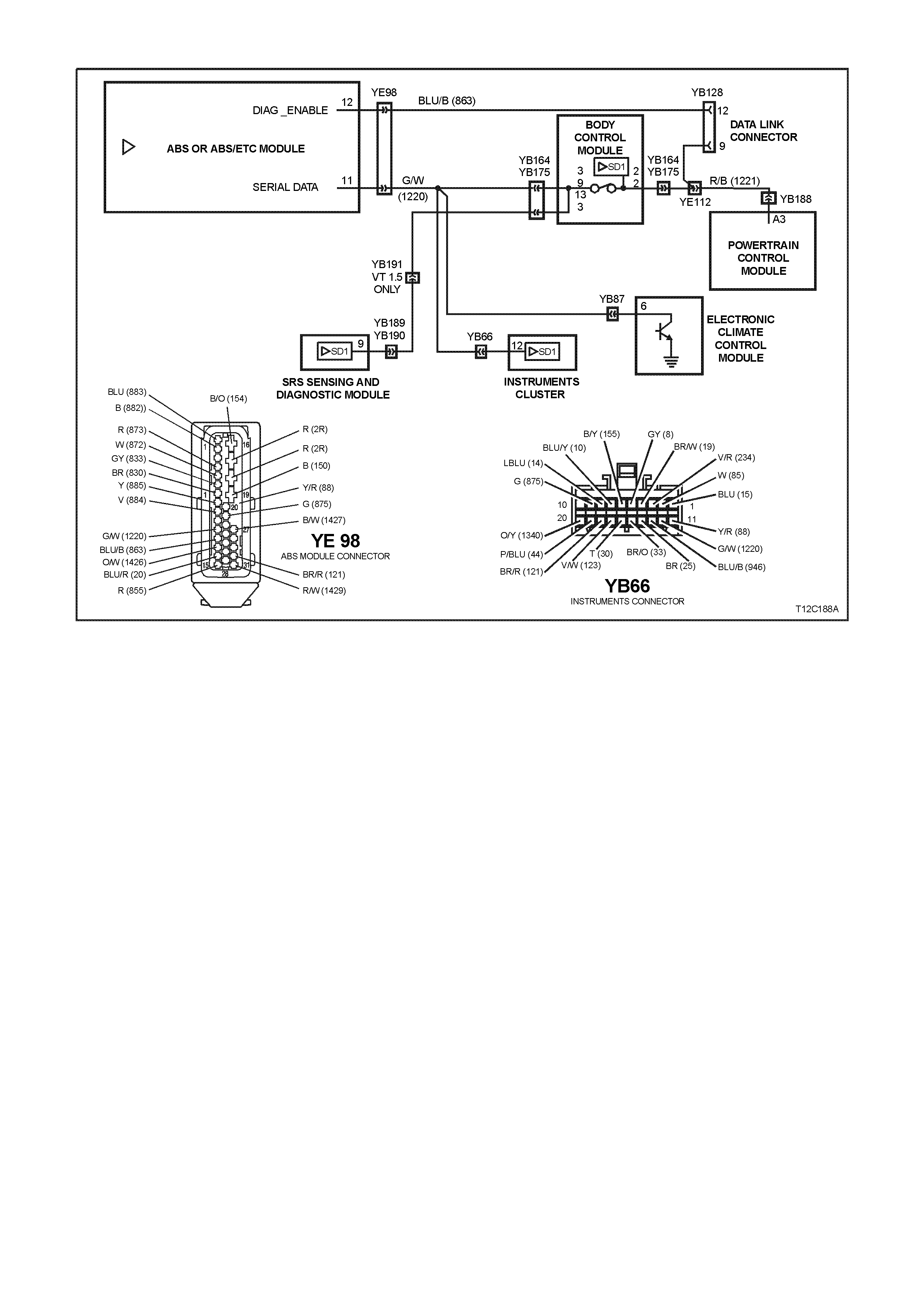
DTC - 8 NO SERIAL DATA FROM ABS
CIRCUIT DESCRIPTION:
The ABS/ETC module sends serial data along the serial data line, circuit 1220. This is read by the instrument
assembly to indicate the status of the trac tion c ontrol. If tr ac tion contr ol has been dis abled by the ABS/ET C module,
the Traction Control Off lamp will illuminate.
NOTE:
If a vehicle is not fitted with ABS or ABS/ETC, DTC 8 will always be set.
DTC 8 WILL SET IF:
•There is no ABS data message on the SDI bus for more than 10 seconds. In practice the trouble code is set
somewhere between 10 and 20 seconds after the last ABS data message is received by the instrument. The
DTC is reset within 10 seconds of the arrival of an ABS data message on the SDI bus.
TEST DESCRIPTION:
Number(s) below refer to step number(s) in the following diagnostic chart.
1. Ensures that the Diagnostic Circuit Check has been performed.
2. Determines if the TECH 2 is powered up and operating correctly.
3. Checks for the presence of serial data from the ABS module. If this data can be read this indicates that the
problem is intermittent.
4. Checks the continuity of the serial data line (circuit 1220) between the ABS module and the instrument cluster.
5. If the DTC can be cleared, the fault is intermittent. If the DTC cannot be cleared, the instrument cluster is
faulty.
DIAGNOSTIC AIDS:
By manipulating the harnesses at the various connectors it is often possible to isolate the cause of the circuit
interruption. This harness can then be removed and repaired.
Check for any damage to the harness which could cause an intermittent open or short to earth or backed out
terminals at the instrument assembly connectors, broken connector locks, improperly formed or damaged terminals.
The multimeter allows continuity of the wiring harness circuit 1220 to be checked.
If the f ault cannot be found in the harness then the f ault may lie in the ABS module or the BCM, both of which can
be diagnosed in their relevant Sections.

STEP ACTION VALUE YES NO
1.
• Was the Diagnostic Circuit
Check performed? Go to Step 2. Go to Diagnostic
Circuit Check in
this Section.
2. •Connect TECH 2 to DLC.
•Turn ignition on.
•Push power button on
TECH 2.
•Does TECH 2 power up ?
(Screen should illuminate
and display TECH 2).
Go to Step 3. Go to TECH 2
diagnostics, refer to
Section 0C TECH
2.
3. •At the TECH 2 title screen
press the Enter key.
•Select Diagnostics \ 1998 \
VT Commodore \ Chassis \
ABS/ETC.
•Turn on the ignition and
press the Confirm soft key.
•Does TECH 2 display the
Electronic System:
ABS/ETC information (ie.
Part Number \ System ID \
System)?
Go to Step 4. Go to Section 5B
ABS & ABS/ETC.
4. •Using an ohmmeter, check
for continuity of circuit 1220
(Green/White wire)
between ABS/ETC module
connector YE98 and
instrument cluster
connector YB66.
•Is there continuity?
Go to Step 5. Find source of
open circuit and
repair faulty main
wiring harness.
5. •Use TECH 2 to clear DTC.
•Has DTC cleared?
DTC 8 is
intermittent.
Check circuit 1220
(Green/White
wire) between
ABS/ETC module
and instrument
cluster for an
intermittent fault.
Check the
instrument cluster
and ABS/ETC
module connectors
for terminal
retention. If OK,
replace instrument
cluster, refer to 2.1
INSTRUMENT
CLUSTER in this
Section.
WHEN A LL DIAGNOSIS AND REPAIRS ARE COMPLETED, CLEAR ALL DTC AND
VERIFY CORRECT OPERATION
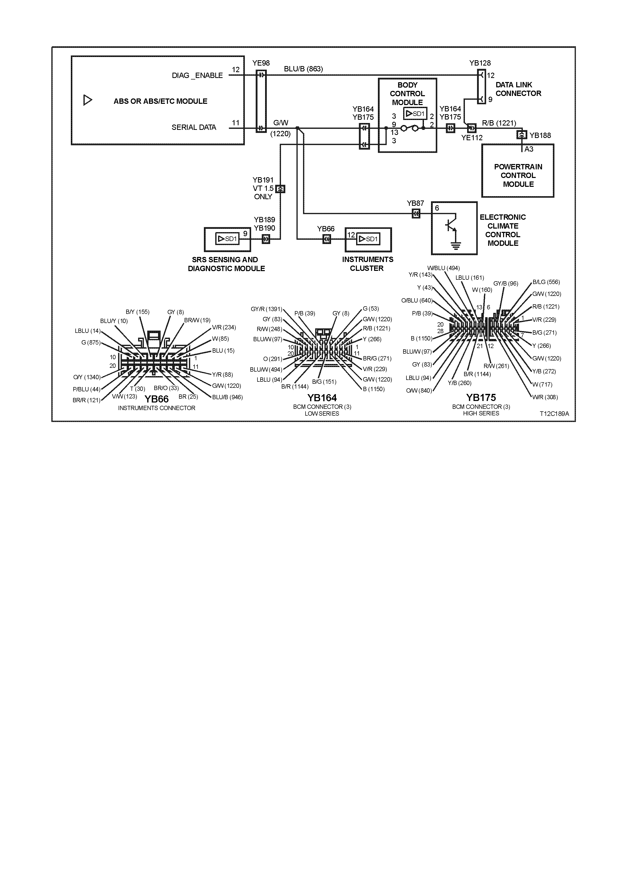
DTC - 9 NO SERIAL DATA FROM BCM
CIRCUIT DESCRIPTION:
The BCM s ends serial data along the ser ial data line, circuit 1220. T his is read by the instrum ent cluster to indic ate
the status of the various components on the serial data line.
DTC 9 WILL SET IF:
• •There is no BCM data message on the SDI bus for m ore than 10 s econds. In practice the trouble code is
set somewhere between 10 and 20 seconds after the last BCM data message is received by the instrument.
The trouble code is reset within 10 seconds of the arrival of a BCM data message on the SDI bus.
TEST DESCRIPTION:
Number(s) below refer to step number(s) in the following diagnostic chart.
1. Ensures that the Diagnostic Circuit Check has been performed.
2. Determines if the TECH 2 is powered up and operating correctly.
3. Check s for the presenc e of s erial data fr om the BCM. If this data c an be read this indic ates that the problem is
intermittent.
4. Checks the continuity of the serial data line (circuit 1220) between the BCM and the instrument cluster.
5. If the DTC can be cleared, the fault is intermittent. If the DTC cannot be cleared, the instrument cluster is
faulty.
DIAGNOSTIC AIDS:
By manipulating the harnesses at the various connectors it is often possible to isolate the cause of the circuit
interruption. This harness can then be removed and repaired.
Check for any dam age to the harness which c ould cause an interm ittent open circuit or backed out ter minals at the
instrument assembly connectors, broken connector locks, improperly formed or damaged terminals.
The multimeter allows continuity of the wiring harness circuit 1220 to be checked.
If the f ault cannot be f ound in the har nes s then the fault m ay lie in the BCM. Ref er to Section 12J-1 L OW SERIES
BCM or SECTION 12J-2 HIGH SERIES BCM for diagnosis procedures.

STEP ACTION VALUE YES NO
1.
• Was the Diagnostic Circuit
Check performed? Go to Step 2. Go to Diagnostic
Circuit Check in
this Section.
2. •Connect TECH 2 to DLC.
•Turn ignition on.
•Push power button on
TECH 2.
•Does TECH 2 power up ?
(Screen should illuminate
and display TECH 2)
Go to Step 3. Go to TECH 2
diagnosis, refer to
Section 0C -
TECH 2.
3. •At the TECH 2 title screen
press the Enter key.
•Select Diagnostics \ 1998 \
VT Commodore \ Body \
Body Control Module.
•Turn on the ignition and
press the Confirm soft key.
•Does TECH 2 display the
Electronic System: BCM
information (ie. BCM Level
/ BCM Type)?
Go to Step 4. Go to BCM Serial
Data
Communication
Diagnosis in
Section 12J-1 LOW
SERIES BCM
or
Section 12J-2
HIGH SERIES
BCM.
4. •Using an ohmmeter, check
for continuity of circuit 1220
(Green/White wire)
between BCM connector
YB164 and instrument
cluster connector YB66
(Low Series BCM) or
YB175 and YB66 (High
Series BCM).
•Is there continuity?
Go to Step 5. Find source of
open circuit and
repair faulty main
wiring harness.
5. •Use TECH 2 to clear DTC.
•Has DTC cleared?
DTC 9 is
intermittent.
Check circuit 1220
(Green/White
wire) between
BCM module and
instrument cluster
for an intermittent
fault.
Check the
instrument cluster
and BCM
connectors for
terminal retention.
If OK, replace
instrument cluster,
refer to 2.1
INSTRUMENT
CLUSTER in this
Section.
WHEN A LL DIAGNOSIS AND REPAIRS ARE COMPLETED, CLEAR ALL DTC AND
VERIFY CORRECT OPERATION
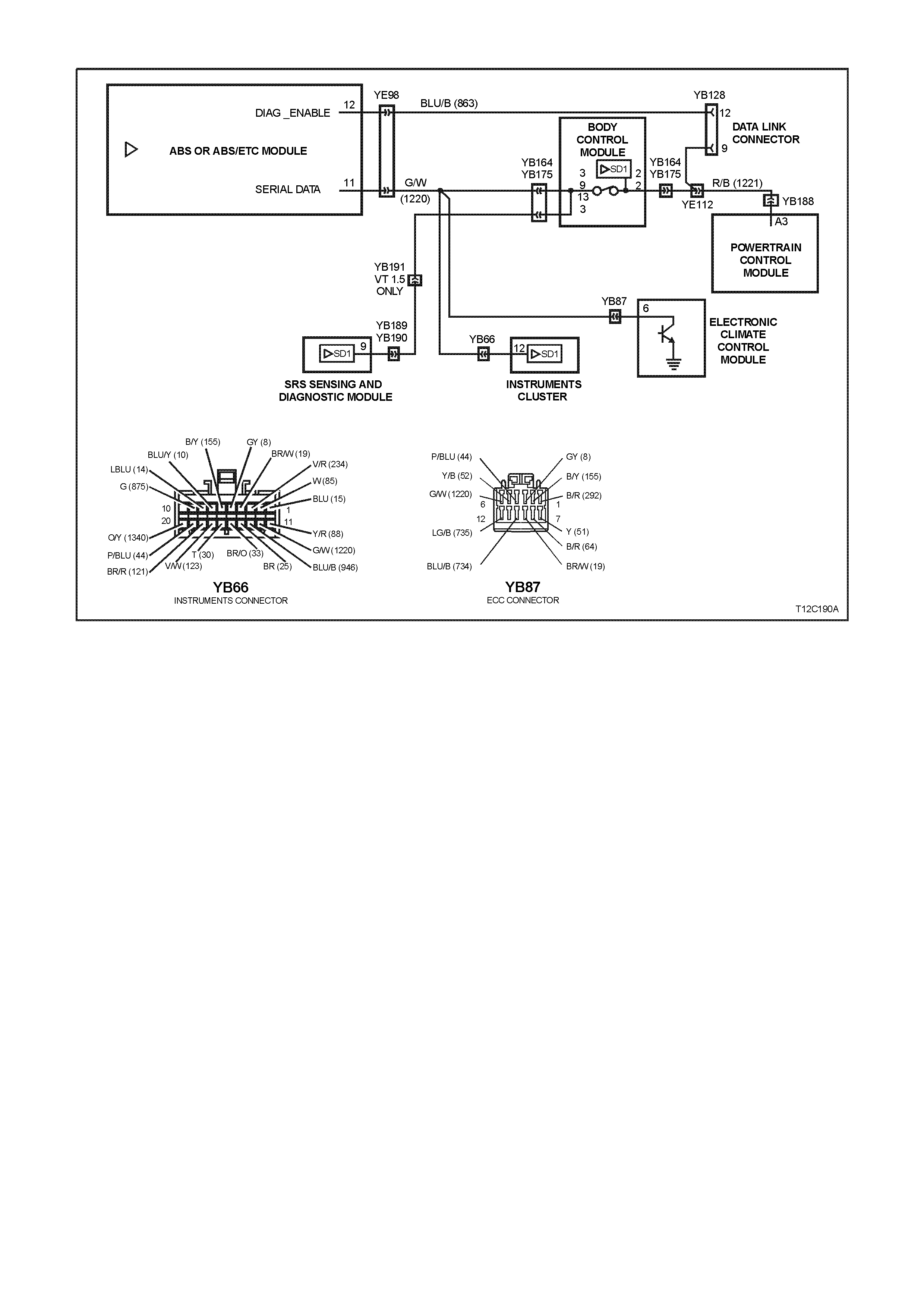
DTC - 10 NO SERIAL DATA FROM ECC
CIRCUIT DESCRIPTION:
The ECC module sends serial data to the instrument assembly along the serial data line, circuit 1220.
DTC 10 WILL SET IF:
•There is no ECC data message on the SDI bus for more than 10 seconds. In practice the trouble code is set
somewhere between 10 and 20 seconds after the last ECC data message is received by the instrument. The
DTC is reset within 10 seconds of the arrival of a ECC data message on the SDI bus.
TEST DESCRIPTION:
Number(s) below refer to step number(s) in the following diagnostic chart.
1. Ensures that the Diagnostic Circuit Check has been performed.
2. Determines if the TECH 2 is powered up and operating correctly.
3. Checks for the presence of serial data from the ECC module. If this data can be read this indicates that the
problem is intermittent.
4. Checks the continuity of the serial data line (circuit 1220) between the ECC module and the instrument cluster.
5. If the DTC can be cleared, the fault is intermittent. If the DTC cannot be cleared, the instrument cluster is
faulty.
DIAGNOSTIC AIDS:
By manipulating the harnesses at the various connectors it is often possible to isolate the cause of the circuit
interruption. This harness can then be removed and repaired.
Check for any damage to the harness which could cause an intermittent open or short to earth or backed out
terminals at the instrument assembly connectors, broken connector locks, improperly formed or damaged terminals.
The multimeter allows continuity of the wiring harness circuit 1220 to be checked.
If the fault cannot be found in the harness then the fault m ay lie in the ECC m odule or the BCM, both of which can
be diagnosed in their relevant Sections.

STEP ACTION VALUE YES NO
1.
• Was the Diagnostic Circuit
Check performed? Go to Step 2. Go to Diagnostic
Circuit Check in
this Section.
2. •Connect TECH 2 to DLC.
•Turn ignition on.
•Push power button on
TECH 2.
•Does TECH 2 power up ?
(Screen should illuminate
and display TECH 2)
Go to Step 3. Go to TECH 2
diagnosis, refer to
Section 0C -
TECH 2.
3. •At the TECH 2 title screen
press the Enter key.
•Select Diagnostics \ 1998 \
VT Commodore \ Body \
Electronic Climate Control.
•Turn on the ignition and
press the Confirm soft key.
•Does TECH 2 display the
Electronic System: ECC
information?
Go to Step 4. Refer to
Section 2F AIR
CONDITIONING -
ECC
DIAGNOSTICS..
4. •Using an ohmmeter, check
for continuity of circuit
1220 (Green/White wire)
between ECC module
connector YB87 and
instrument cluster
connector YB66.
•Is there continuity?
Go to Step 5. Repair faulty main
wiring harness.
5. •Use TECH 2 to clear DTC.
•Has DTC cleared?
DTC 10 is
intermittent.
Check circuit
1220
(Green/White
wire) between
ECC module and
instrument cluster
for an intermittent
fault.
Check the
instrument cluster
and ECC module
connectors for
terminal retention.
If OK, replace
instrument cluster,
refer to 2.1
INSTRUMENT
CLUSTER in this
Section.
WHEN A LL DIAGNOSIS AND REPAIRS ARE COMPLETED, CLEAR ALL DTC AND
VERIFY CORRECT OPERATION

DTC - 11 NO SERIAL DATA FROM PCM
CIRCUIT DESCRIPTION:
The PCM sends serial data to the BCM along the m ain serial data line, circuit 1221. Serial data is then sent to the
instrum ent cluster along the auxiliar y s erial data line, circuit 1220. T his is read by the instrum ent cluster to indicate
the status of the check power train lamp and the oil pressure warning lamp.
DTC 11 WILL SET IF:
•There is no PCM data message on the SDI bus for more than 10 seconds. In practice the trouble code is set
somewhere between 10 and 20 seconds after the last PCM data message is received by the instrument. The
trouble code is reset within 10 seconds of the arrival of a ECC data message on the SDI bus.
TEST DESCRIPTION:
Number(s) below refer to step number(s) in the following diagnostic chart.
1. Ensures that the Diagnostic Circuit Check has been performed.
2. Determines if the TECH 2 is powered up and operating correctly.
3. Check s for the presenc e of s erial data fr om the PCM. If this data can be read this indicates that the pr oblem is
intermittent.
4. Checks the continuity of the serial data line (circuit 1221) between the PCM and the BCM.
5. Checks the continuity of the serial data line (circuit 1220) between the BCM and the instrument cluster.
6. If the DTC can be cleared, the fault is intermittent. If the DTC cannot be cleared, the instrument cluster is
faulty.
DIAGNOSTIC AIDS:
By manipulating the harnesses at the various connectors it is often possible to isolate the cause of the circuit
interruption. This harness can then be removed and repaired.
Check for any damage to the harness which could cause an intermittent open or short to earth or backed out
terminals at the instrument assembly connectors, broken connector locks, improperly formed or damaged terminals.
The multimeter allows continuity of the wiring harness circuits 1221 and 1220 to be checked.
If the fault cannot be found in the harness then the fault may lie in the PCM or the BCM, both of which can be
diagnosed in their relevant Sections.

STEP ACTION VALUE YES NO
1.
• Was the Diagnostic
Circuit Check performed? Go to Step 2. Go to Diagnostic
Circuit Check in
this Section.
2. •Connect TECH 2 to DLC.
•Turn ignition on.
•Push power button on
TECH 2.
•Does TECH 2 power up ?
(Screen should illuminate
and display TECH 2)
Go to Step 3. Go to TECH 2
diagnosis, refer to
Section 0C -
TECH 2.
3. •At the TECH 2 title screen
press the Enter key.
•Select Diagnostics \ 1998
\ VT Commodore \ Engine
\ Select appropriate
engine.
•Turn on the ignition and
press the Confirm soft
key.
•Does TECH 2 display the
Engine System:
Identification information
(ie. PROM Identification)?
Go to Step 4. Refer to
Section 6C1
POWERTRAIN
MANAGEMENT -
V6 ENGINE
or
Section 6C2
POWERTRAIN
MANAGEMENT -
V8 ENGINE.
4. •Using an ohmmeter,
check for continuity of
circuit 1221 (Red/Black
wire) between BCM
connector YB164 (Low
Series BCM), or YB175
(High Series BCM) and
PCM connector YB66..
•Is there continuity?
Harness from
PCM to
BCM OK.
Go to Step 5.
Repair faulty
wiring harness
from PCM to
BCM.
5. •Using an ohmmeter,
check for continuity of
circuit 1220 (Green/White
wire) between BCM
connector YB164 (Low
Series BCM) or YB175
(High Series BCM) and
instrument cluster
connector YB66.
•Is there continuity?
Harness from
BCM to
instrument
cluster OK.
Go to Step 6.
Repair faulty
wiring harness
from BCM to
instrument.
6. •Use TECH 2 to clear
DTC.
•Has DTC cleared?
DTC 11 is
intermittent.
Check circuit
1221 (Red/Black
wire) between
BCM and PCM,
and circuit 1220
(Green/White
wire) between
BCM and
instrument
cluster for an
intermittent fault.
Check the
instrument cluster,
PCM and BCM
connectors for
terminal retention.
If OK, replace
instrument cluster,
refer to 2.1
INSTRUMENT
CLUSTER in this
Section.
WHEN A LL DIAGNOSIS AND REPAIRS ARE COMPLETED, CLEAR ALL DTC AND
VERIFY CORRECT OPERATION
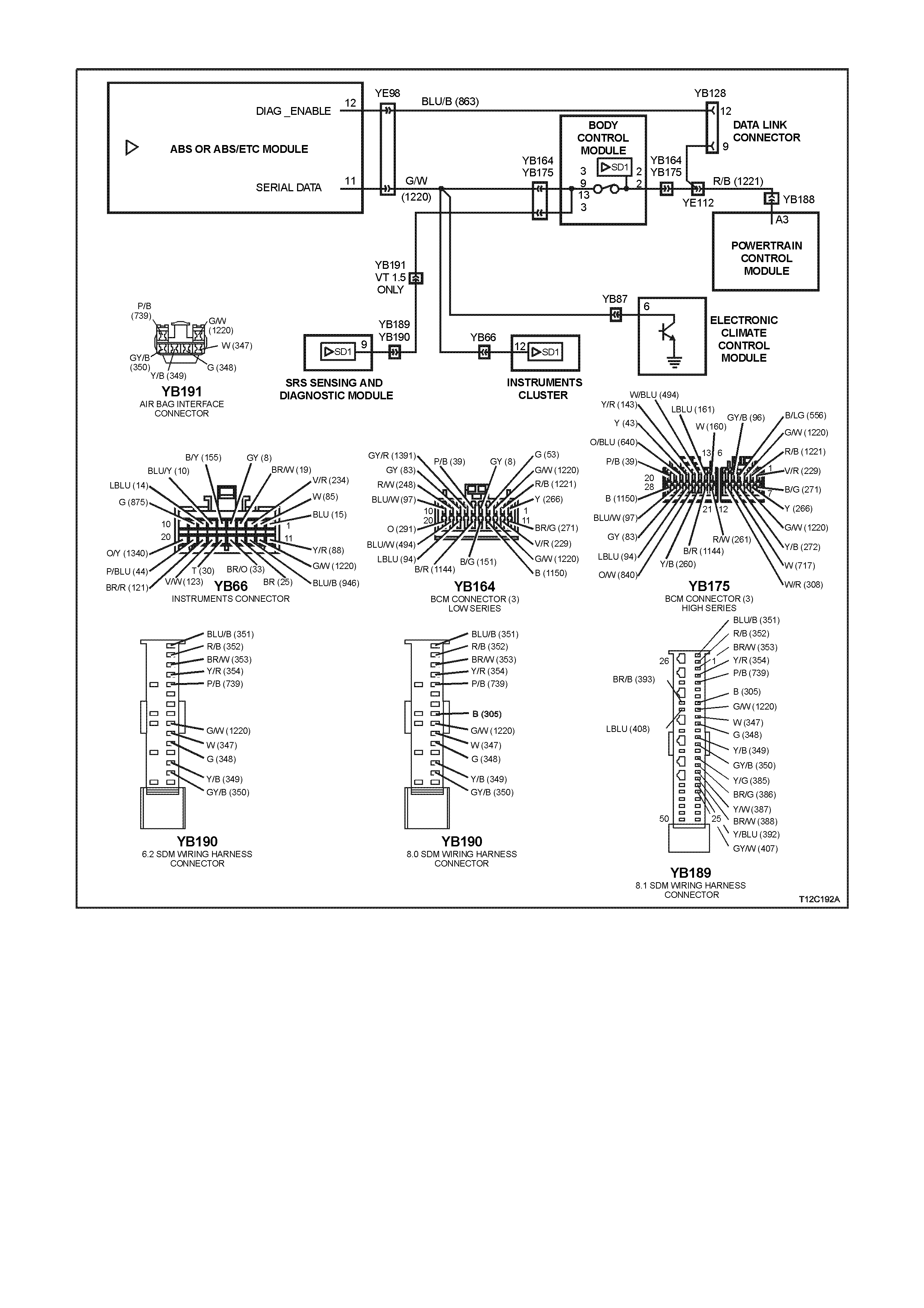
DTC - 12 NO SERIAL DATA FROM SDM
CIRCUIT DESCRIPTION:
The SRS Sensing and Diagnostic Module (SDM) sends serial data along the serial data line, via the BCM. This is
read by the instrument cluster to indicate the status of the SDM.
NOTE:
There ar e three versions of SDM used by the SRS. Version 6.2 and vers ion 8.0 ar e used on vehicles with either 2-
loop (left-hand drive only), 3-loop or 4-loop system s, while version 8.1 is used on vehicles with a 6-loop system. For
more information, refer to Section 12M SUPPLEMENTAL RESTRAINT SYSTEM (Version 6.2) or
Section 12M SUPPLEMENTAL RESTRAINT SYSTEM (Version 8.0/8.1).
DTC 12 WILL SET IF:
•There is no serial data being received from the SDM.

TEST DESCRIPTION:
Number(s) below refer to step number(s) in the following diagnostic chart.
1. Ensures that the Diagnostic Circuit Check has been performed.
2. Determines if the TECH 2 is powered up and operating correctly.
3. Checks for the presence of serial data from the SDM. If this data can be read this indicates that the problem is
intermittent.
4. Checks the continuity of the serial data line (circuit 1220) between the SDM and the BCM.
5. Checks the continuity of the serial data line (circuit 1220) between the BCM and the instrument cluster.
6. If the DTC can be cleared, the fault is intermittent. If the DTC cannot be cleared, the instrument cluster is
faulty.
DIAGNOSTIC AIDS:
By manipulating the harnesses at the various connectors it is often possible to isolate the cause of the circuit
interruption. This harness can then be removed and repaired.
Check for any damage to the harness which could cause an intermittent open or short to earth or backed out
terminals at the instrument assembly connectors, broken connector locks, improperly formed or damaged terminals.
The multimeter allows continuity of the wiring harness circuit 1220 to be checked.
If the fault cannot be found in the harness then the fault may lie in the SDM or the BCM, both of which can be
diagnosed in their relevant Sections.
STEP ACTION VALUE YES NO
1.
• Was the Diagnostic
Circuit Check performed? Go to Step 2. Go to Diagnostic
Circuit Check in
this Section.
2. •Connect TECH 2 to DLC.
•Turn ignition on.
•Push power button on
TECH 2.
•Does TECH 2 power up ?
(Screen should illuminate
and display TECH 2)
Go to Step 3. Go to TECH 2
diagnosis, refer to
Section 0C -
TECH 2.
3. •At the TECH 2 title screen
press the Enter key.
•Select Diagnostics \ 1998
\ VT Commodore \ Body \
SRS.
•Turn on the ignition and
press the Confirm soft
key.
•Does TECH 2 display the
Electronic System:
Identification information
(ie. Part Number /
Production Date)?
Go to Step 4. Refer to
Section 12M
SUPPLEMENTAL
RESTRAINT
SYSTEM
(Version 6.2)
or
Section 12M
SUPPLEMENTAL
RESTRAINT
SYSTEM
(Version 8.0/8.1).

STEP ACTION VALUE YES NO
4. •Disable the SRS, refer to
Section 12M
SUPPLEMENTAL
RESTRAINT SYSTEM
(Version 6.2) or
Section 12M
SUPPLEMENTAL
RESTRAINT SYSTEM
(Version 8.0/8.1).
•Using an ohmmeter and
Tool KM-609-20, check
harness for continuity of
circuit 1220 (Green/White
wire) between SDM
connector YB189/YB190
and BCM connector
YB164 (Low Series BCM),
or YB189/YB190 and YB
175 (High Series BCM)
•Is there continuity?
Harness from
SDM to BCM
OK.
Go to Step 6.
Repair faulty
wiring harness
from
SDM to BCM.
5. •Using an ohmmeter,
check for continuity of
circuit 1220 (Green/White
wire) between BCM
connector YB164 (Low
Series BCM), or YB175
(High Series BCM) and
instrument cluster
connector YB66.
•Is there continuity?
Harness from
BCM to
instrument
cluster OK.
Go to Step 6.
Faulty wiring
harness from BCM
to instrument
cluster.
8. •Enable the SRS, refer to
Section 12M
SUPPLEMENTAL
RESTRAINT SYSTEM
(Version 6.2) or
Section 12M
SUPPLEMENTAL
RESTRAINT SYSTEM
(Version 8.0/8.1).
•Use TECH 2 to clear
DTC.
•Has DTC cleared?
DTC 12 is
intermittent.
Check circuit
1220 (Green/
White wire)
between SDM
and BCM, and
between BCM
and instrument
cluster for an
intermittent fault.
Check the
instrument cluster,
SDM and BCM
connectors for
terminal retention.
If OK, replace
instrument cluster,
refer to 2.1
INSTRUMENT
CLUSTER in this
Section.
WHEN A LL DIAGNOSIS AND REPAIRS ARE COMPLETED, CLEAR ALL DTC AND
VERIFY CORRECT OPERATION

DTC - 13 NO INSTRUMENT POLL FROM BCM
CIRCUIT DESCRIPTION:
The BCM uses the serial data line (circuit 1220) to poll the instrument cluster for information.
DTC 13 WILL SET IF:
• There is no instrument poll from the BCM for more than 10 seconds. In practice the trouble code is set
som ewhere between 10 and 20 sec onds after the las t instrum ent poll is r eceived by the instr ument. The DT C is
reset within 10 seconds of the arrival of an instrument poll from the BCM.
TEST DESCRIPTION:
Number(s) below refer to step number(s) in the following diagnostic chart.
1. Ensures the Diagnostic Circuit Check has been performed.
2. Determines if the BCM can communicate with the TECH 2.
3. Checks if fault is common with other control modules connected to the serial data circuit.
4. Checks internal switch in BCM for open circuit.
5. Checks circuit 1220 and determines if fault is in wiring or a control module.
6. Checks circuit 1220 for open circuit.
7. Checks integrity of earth circuits for the instruments.
8. If the DTC can be cleared, the fault is intermittent. If the DTC cannot be cleared, the instrument cluster is
faulty.
DIAGNOSTIC AIDS:
By manipulating the harnesses at the various connectors it is often possible to isolate the cause of the circuit
interruption. This harness can then be removed and repaired.
Check for any damage to the harness which could cause an intermittent open or short to earth or backed out
terminals at the instrument cluster connectors, broken connector locks, improperly formed or damaged terminals.
The multimeter allows continuity of the wiring harness circuit 1220 to be checked.
If the f ault cannot be found in the harness then the f ault may lie in the BCM, which c an be diagnosed in the r elevant
Section.

STEP ACTION VALUE YES NO
1
• Was the Diagnostic
Circuit Check
performed?
Go to Step 2. Go to Diagnostic
Circuit Check in
this Section.
2•Connect TECH 2 to the
DLC.
•Select Body / DTC
Check / F0: DTC
Check.
•Can TECH 2
communicate with the
BCM?
NOTE:
If ‘No Data’ is displayed
next to the BCM, then
there is no communication
between TECH 2 and the
BCM. If 'No DT C' or 'DTCs
Set' is displayed then there
is communication between
the TECH 2 and the BCM.
Go to Step 3. Go to BCM
Serial Data
Communication
diagnostics in
Section 12J-1
LOW SERIES
BCM, or
Section 12J-2
HIGH SERIES
BCM.
3•In Step 2, was TECH 2
able to communicate
with all the other
control modules,
except the
Instruments, fitted to
the vehicle (ABS or
ABS/ETC, ECC,
SRS)?
NOTE:
If ‘No Data’ is displayed
next to a control module,
then there is no
communication between
TECH 2 and that control
module.
Go to Step 6. Go to Step 4.
4•Using an ohmmeter,
check continuity of
circuits 1220
(Green/White wire) and
1221 (Red/Black wire)
between BCM
connector YB164,
terminals 2 and 3 (Low
Series BCM) or YB175,
terminals 2 and 9 (High
Series BCM).
•Does continuity exist?
Go to Step 5. Replace BCM,
refer to
Section 12J-1
LOW SERIES
BCM, or
Section 12J-2
HIGH SERIES
BCM.

STEP ACTION VALUE YES NO
5•Check circuit 1220 for
open, short to earth or
short to voltage
between BCM and
individual control
modules.
•Is circuit 1220 okay?
NOTE:
Disconnect each control
module in circuit 1220 one
at a time to isolate the fault
in the circuit or to identify
the control module causing
the fault.
Refer to the
appropriate
diagnostic
procedure for the
faulty control
module.
Repair circuit 1220
as necessary.
6•Using an ohmmeter,
check for continuity
between BCM
connector YB164,
terminal 3 (Low Series
BCM) or YB175,
terminal 9 (High Series
BCM) and instruments
connector YB66,
terminal 12
(Green/White wire).
•Does continuity exist?
Go to Step 7. Repair open in
circuit 1220.
7•Check the integrity of
the Instruments earth
circuit by performing a
voltage drop on circuit
155 between
instrument connector
YB66, terminal 6 and
earth point E3.
•With ignition on, is
voltage less than the
specified value?
0.15 volt Go to Step 8. Repair earth circuit
as necessary.
8•Use TECH 2 to clear
DTC.
•Has DTC cleared?
DTC 13 is
intermittent. Check
circuit 1220
(Green/White
wire) between
BCM and
instrument cluster
for an intermittent
fault.
Check the
instrument cluster
and BCM
connectors for
terminal retention.
If OK replace
instrument cluster,
refer to 2.1
INSTRUMENT
CLUSTER in this
Section.
WHEN A LL DIAGNOSIS AND REPAIRS ARE COMPLETED, CLEAR ALL DTC AND
VERIFY CORRECT OPERATION
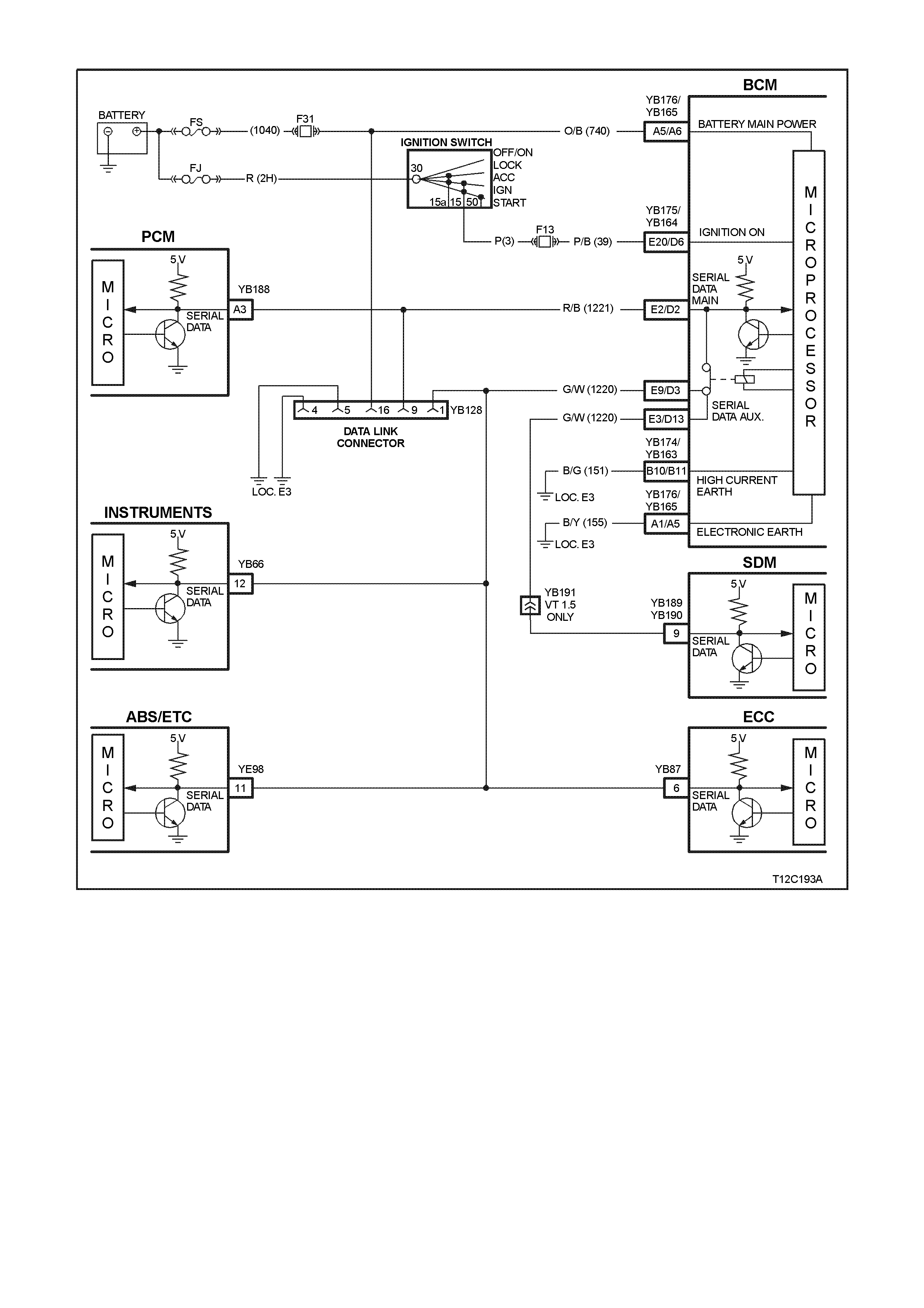
DTC - 14 NO SERIAL COMMUNICATION
CIRCUIT DESCRIPTION:
When investigating any complaint of an Instrument problem or malfunction, always begin diagnosis with the
diagnostic cir cuit check . This check is a prelim inary procedure that check s that the Instr uments are com m unicating
on the serial data line as well as helping to identify a problem or malfunction and directing the reader to the
appropriate diagnostic chart in this section.
With TECH 2 connected to the DLC and ignition switched on, TECH 2 should display serial data communication.
If TECH 2 does not display serial data, the serial data circuit maybe open or shorted.
There are several other control modules that are connected to the serial data line (PCM, BCM, ABS or ABS/ETC,
instruments and SDM). Any of these control modules could cause a fault on the serial data line. This fault could
result in TECH 2 not being able to display serial data.

TEST DESCRIPTION:
Number(s) below refer to step number(s) in the following diagnostic chart.
1. Ensures the Diagnostic Circuit Check has been performed.
2. Determines if the BCM can communicate with the TECH 2.
3. Checks if fault is common with other control modules connected to the serial data circuit.
4. Checks internal switch in BCM for open circuit.
5. Checks circuit 1220 and determines if fault is in wiring or a control module.
6. Checks circuit 1220 for open circuit.
7. Checks integrity of earth circuits for the instruments.
8. If the DTC can be cleared, the fault is intermittent. If the DTC cannot be cleared, the instrument cluster is
faulty.
DIAGNOSTIC AIDS:
A fault with the serial data circuit could be caused by one or more of the several control modules connected to this
serial data circuit. Isolate the fault by disconnecting each control module, one at a time, until serial data
communication is restored.
STEP ACTION VALUE YES NO
1
• Was the Diagnostic
Circuit Check
performed?
Go to Step 2. Go to Diagnostic
Circuit Check in
this Section.
2•Connect TECH 2 to the
DLC.
•Select Body / DTC
Check / F0: DTC
Check.
•Can TECH 2
communicate with the
BCM?
NOTE:
If ‘No Data’ is displayed
next to the BCM, then
there is no communication
between TECH 2 and the
BCM. If 'No DTC' or
'DTCs Set' is displayed
then there is
communication between
the TECH 2 and the BCM.
Go to Step 3. Go to BCM
Serial Data
Communication
diagnostics in
Section 12J-1
LOW SERIES
BCM, or
Section 12J-2
HIGH SERIES
BCM.
3•In Step 2, was TECH 2
able to communicate
with all the other
control modules,
except the
Instruments, fitted to
the vehicle (ABS or
ABS/ETC, ECC,
SRS)?
NOTE:
If ‘No Data’ is displayed
next to a control module,
then there is no
communication between
TECH 2 and that control
module.
Go to Step 6. Go to Step 4.

STEP ACTION VALUE YES NO
4•Using an ohmmeter,
check continuity of
circuits 1220
(Green/White wire) and
1221 (Red/Black wire)
between BCM
connector YB164,
terminals 2 and 3 (Low
Series BCM) or YB175,
terminals 2 and 9 (High
Series BCM).
•Does continuity exist?
Go to Step 5. Replace BCM,
refer to
Section 12J-1
LOW SERIES
BCM, or
Section 12J-2
HIGH SERIES
BCM.
5•Check circuit 1220 for
open, short to earth or
short to voltage
between BCM and
individual control
modules.
•Is circuit 1220 okay?
NOTE:
Disconnect each control
module in circuit 1220 one
at a time to isolate the
fault in the circuit or to
identify the control module
causing the fault.
Refer to the
appropriate
diagnostic
procedure for the
faulty control
module.
Repair circuit 1220
as necessary.
6•Using an ohmmeter,
check for continuity
between BCM
connector YB164,
terminal 3 (Low Series
BCM) or YB175,
terminal 9 (High Series
BCM) and instruments
connector YB66,
terminal 12
(Green/White wire).
•Does continuity exist?
Go to Step 7. Repair open in
circuit 1220.
7•Check the integrity of
the Instruments earth
circuit by performing a
voltage drop on circuit
155 between
instrument connector
YB66, terminal 6 and
earth point E3.
•With ignition on, is
voltage less than the
specified value?
0.15 volt Go to Step 8. Repair earth circuit
as necessary.
8•Use TECH 2 to clear
DTC.
•Has DTC cleared?
DTC 14 is
intermittent. Check
circuit 1220
(Green/White
wire) between
BCM and
instrument cluster
for an intermittent
fault.
Check the
instrument cluster
and BCM
connectors for
terminal retention.
If OK replace
instrument cluster,
refer to 2.1
INSTRUMENT
CLUSTER in this
Section.
WHEN A LL DIAGNOSIS AND REPAIRS ARE COMPLETED, CLEAR ALL DTC AND
VERIFY CORRECT OPERATION

DTC - 16 ABS OR ABS/ETC FAULT LOGGED
CIRCUIT DESCRIPTION:
The ABS or ABS/ETC module informs the instrument via the serial data bus whenever an ABS or ABS/ETC DTC
has been set. Refer to Section 5B ABS & ABS/ETC for fault diagnosis procedures.
DTC - 17 BCM FAULT LOGGED
CIRCUIT DESCRIPTION:
The BCM informs the instrument via the serial data bus whenever a BCM DTC has been set. Refer to
Section 12J-1 LOW SERIES BCM, or Section 12J-2 HIGH SERIES BCM for fault diagnosis procedures.
DTC - 18 ECC FAULT LOGGED
CIRCUIT DESCRIPTION:
The ECC module informs the instrument via the serial data bus whenever an ECC DTC has been set. Refer to
Section 2F AIR CONDITIONING - ECC for fault diagnosis procedures.
DTC - 19 PCM FAULT LOGGED
CIRCUIT DESCRIPTION:
The PCM informs the instrument via the serial data bus whenever a PCM DTC has been set. Refer to
Section 6C1 POWERTRAIN MANAGEM ENT - V6 ENGINE, or Section 6C2 POWERTRAIN M ANAGEMENT - V8
ENGINE for fault diagnosis procedures.
DTC - 20 SDM FAULT LOGGED
CIRCUIT DESCRIPTION:
The SDM informs the instrument via the serial data bus whenever an SDM DTC has been set. Refer to
Section 12M SUPPLEMENTAL RESTRAINT SYSTEM (Version 6.2) for fault diagnosis procedures on vehicles
fitted with a version 6.2 SDM, or to Section 12M SUPPLEMENTAL RESTRAINT SYSTEM (Version 8.0/8.1) for
fault diagnosis procedures on vehicles fitted with a version 8.0 or 8.1 SDM.
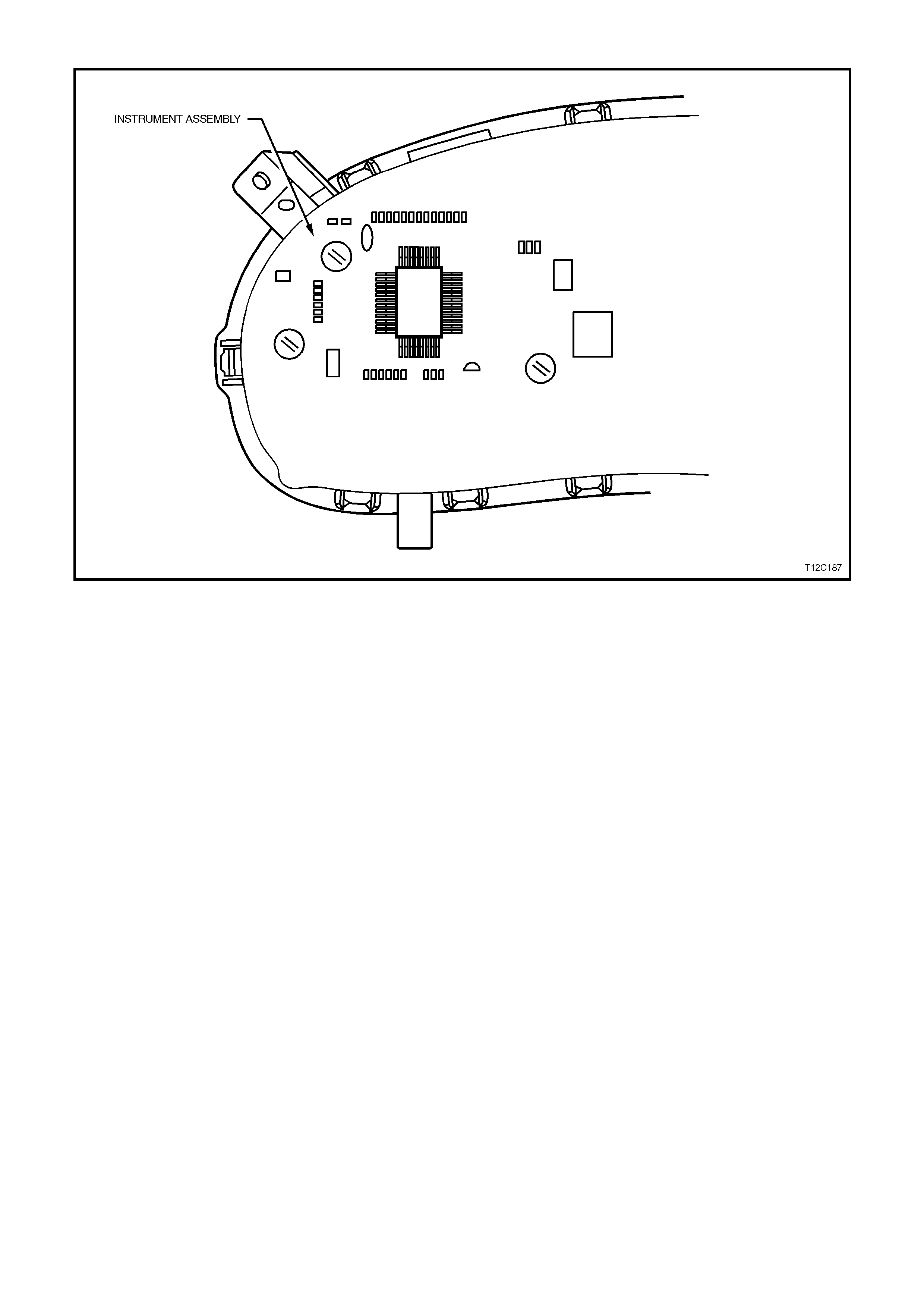
DTC - 24 EE CHECKSUM = FAILURE
CIRCUIT DESCRIPTION:
The EEPROM (Electrically Erasable Programmable Read Only Memory) is part of the printed circuit board housed
within the instrument assembly. It stores variables required in the operation of the instrument cluster and in the
interpretation of the incom ing data and can be progr am m ed for dif f erent instrum ent levels . If a DT C 24 is detec ted,
an icon ! appears in the left-hand instrument window on a triple window display, or SERV ERROR on a single
window display. If a DTC 24 was set as a result of interrupted instrument programming then the following diagnostic
table will need to be followed.
DTC 24 WILL SET IF:
•The EEPROM checksum is incorrect. The testing of the EEPROM checksum occurs every time the ignition is
turned on. The DTC will be reset when the EEPROM checksum is tested as being correct.
DIAGNOSTIC AIDS:
If the programmed instrum ent c luster values are corr upted, reprogr am m ing can be carr ied out via TECH 2 to rec tify
the fault, refer to Section 5.15 F5: PROGRAM in this Section.

STEP ACTION VALUE YES NO
1
• Was the Diagnostic Circuit
Check performed? Go to Step 2. Go to Diagnostic
Circuit Check in
this Section.
2. •Go to Section 5.15
F5: PROGRAM in this
Section.
•Is programming completed
successfully?
Go to Step 3. Replace the
instrument cluster,
refer 2.1
INSTRUMENT
CLUSTER in this
Section.
3. •Use TECH 2 to clear DTC.
•Has DTC cleared?
Instrument
cluster OK.
End of
diagnostic
testing.
EEPROM failed.
Replace the
instrument cluster,
refer 2.1
INSTRUMENT
CLUSTER in this
Section.
WHEN A LL DIAGNOSIS AND REPAIRS ARE COMPLETED, CLEAR ALL DTC AND
VERIFY CORRECT OPERATION

DTC - 25 ROM CHECKSUM = FAILURE
CIRCUIT DESCRIPTION:
The ROM (Read Only Memory) is part of the printed circuit board housed within the instrument cluster. It stores
variables required to initialise the instrument cluster. If a DTC 25 is detected, an icon ! appears in the left-hand
instrument window on a triple window display, or SERV ERROR on a single window display. If a DTC 25 has been
set, then the instrument assembly will need to be replaced.
DTC 25 WILL SET IF:
• The ROM checksum is incorrect. The testing of the ROM checksum occurs when the instrument cluster is reset
(due to battery removal or low power cranking). The DTC will be reset when the ROM checksum is tested as
being correct.
DIAGNOSTIC AIDS:
If the ROM checksum is incorrect, the instrument cluster may need to be replaced and reprogrammed.
STEP ACTION VALUE YES NO
1
• Was a Diagnostic Circuit
Check performed? Go to Step 2. Go to Diagnostic
Circuit Check in
this Section.
2•Use TECH 2 to clear DTC.
•Has DTC cleared?
Instrument
cluster OK.
End of diagnostic
testing..
ROM checksum
error.
Replace instrument
cluster, refer to 2.1
INSTRUMENT
CLUSTER in this
Section.
WHEN A LL DIAGNOSIS AND REPAIRS ARE COMPLETED, CLEAR ALL DTC AND
VERIFY CORRECT OPERATION

DTC - 26 INTERNAL FAULT
CIRCUIT DESCRIPTION:
The instrument cluster is equipped with self-diagnostic capability that can detect an internal fault within the
instrument cluster. If an internal fault is detected, an icon ! appears in the left-hand instrument window on a triple
window display, or SERV ERROR on a single window display. If a DTC 26 has been set, then the instrument cluster
will need to be replaced.
DTC 26 WILL SET IF:
• The instrument has detected an internal fault.
STEP ACTION VALUE YES NO
1
• Has diagnostic circuit
test been carried out ? Go to Step 2. Go to Diagnostic
Circuit Check in
this Section.
2•Use TECH 2 to clear
DTC.
•Has DTC cleared?
Instrument
cluster OK.
End of diagnostic
testing.
Internal fault.
Replace instrument
cluster, refer to 2.1
INSTRUMENT
CLUSTER in this
Section.
WHEN A LL DIAGNOSIS AND REPAIRS ARE COMPLETED, CLEAR ALL DTC AND
VERIFY CORRECT OPERATION

LOW SERIES TRIP COMPUTER DIAGNOSTIC FUNCTIONS - SINGLE WINDOW DISPLAY
DESCRIPTION
On low series BCM equipped vehicles the combined instrument assembly is fitted with a single window trip
computer. The purpose of this diagnostic chart is to determine if there is a fault with any of the display functions.
Because there are no serviceable items within the combined instrument assembly, if a fault is detected the
combined instrument assembly is to be replaced, refer to 2.1 INSTRUMENT CLUSTER in this Section.
To enter DIAGNOSTIC MODE :
Press the MODE button down together with ⇑
⇑⇑
⇑ button while turning ignition from off to on.
Action Window Displays
Initial display (Ignition voltage)
V 14.5
Press MODE button (Fuel level)
00.00 L
Press MODE button (Instantaneous fuel)
00.00 l/h
Press MODE button (Temp. from PCM)
T 34ºC
Press MODE button (Speedometer reading)
SPD 000 km/h
Press MODE button (Button voltage)
vb 0.0
Press MODE button (Diagnostic Mode Display – refer to Note)
t 00 – –
Press MODE button (All segments on)
To exit DIAGNOSTIC MODE :
Press the ⇑
⇑⇑
⇑ button together with ⇓
⇓⇓
⇓ button
Press ⇑
⇑⇑
⇑ & ⇓
⇓⇓
⇓ button to exit (Odometer reading)
000000.0
NOTE:
The diagnostic mode display uses the format t NN XY, where:
t = diagnostic trouble code (DTC)
NN = the actual DTC number,
X = the history status (H for active and – for inactive), and
Y = the current DTC status (C for active and – for inactive).
IMPORTANT:
An open circuit fuel gauge sender unit is shown the instrument cluster diagnostic mode display as ‘t 00 – C’
whereas the TECH 2 shows the same fault as DTC 3.

HIGH SERIES TRIP COMPUTER DIAGNOSTIC FUNCTIONS - THREE WINDOW DISPLAY
DESCRIPTION
On high series BCM equipped vehicles the combined instrument assembly is fitted with a triple window trip
computer. The purpose of this diagnostic chart is to determine if there is a fault with any of the display functions.
Because there are no serviceable items within the combined instrument assembly, if a fault is detected the
combined instrument assembly is to be replaced, refer to 2.1 INSTRUMENT CLUSTER in this Section.
To enter DIAGNOSTIC MODE :
Press the MODE button down together with ⇑
⇑⇑
⇑ button while turning ignition from off to on.
Action Window 1 Displays Window 2 Displays Window 3 Displays
Initial display (Odometer reading)
00000.0
First display (Speed)
SPEED 000 km/h
(Ignition voltage)
V 14.5 (Remaining fuel)
REMAINING
FUEL 00.0 L
Press MODE button (Button Voltage)
B V 5.0 (Temp from PCM)
TEMP 34ºC (Instantaneous fuel)
INST
FUEL 00.00 L/H
Press MODE button (Diagnostic Mode
Display –
refer to Note)
t 00 – –
Press MODE button All segments on All segments on All segments on
To exit DIAGNOSTIC MODE :
Press the ⇑
⇑⇑
⇑ button together with ⇓
⇓⇓
⇓ button
Press ⇑
⇑⇑
⇑ & ⇓
⇓⇓
⇓ button to
exit (Odometer reading)
00000.0
NOTE:
The diagnostic mode display uses the format t NN XY, where:
t = diagnostic trouble code (DTC)
NN = the actual DTC number,
X = the history status (H for active and – for inactive), and
Y = the current DTC status (C for active and – for inactive).
IMPORTANT:
An open circuit fuel gauge sender unit is shown the instrument cluster diagnostic mode display as ‘t 00 – C’
whereas the TECH 2 shows the same fault as DTC 3.
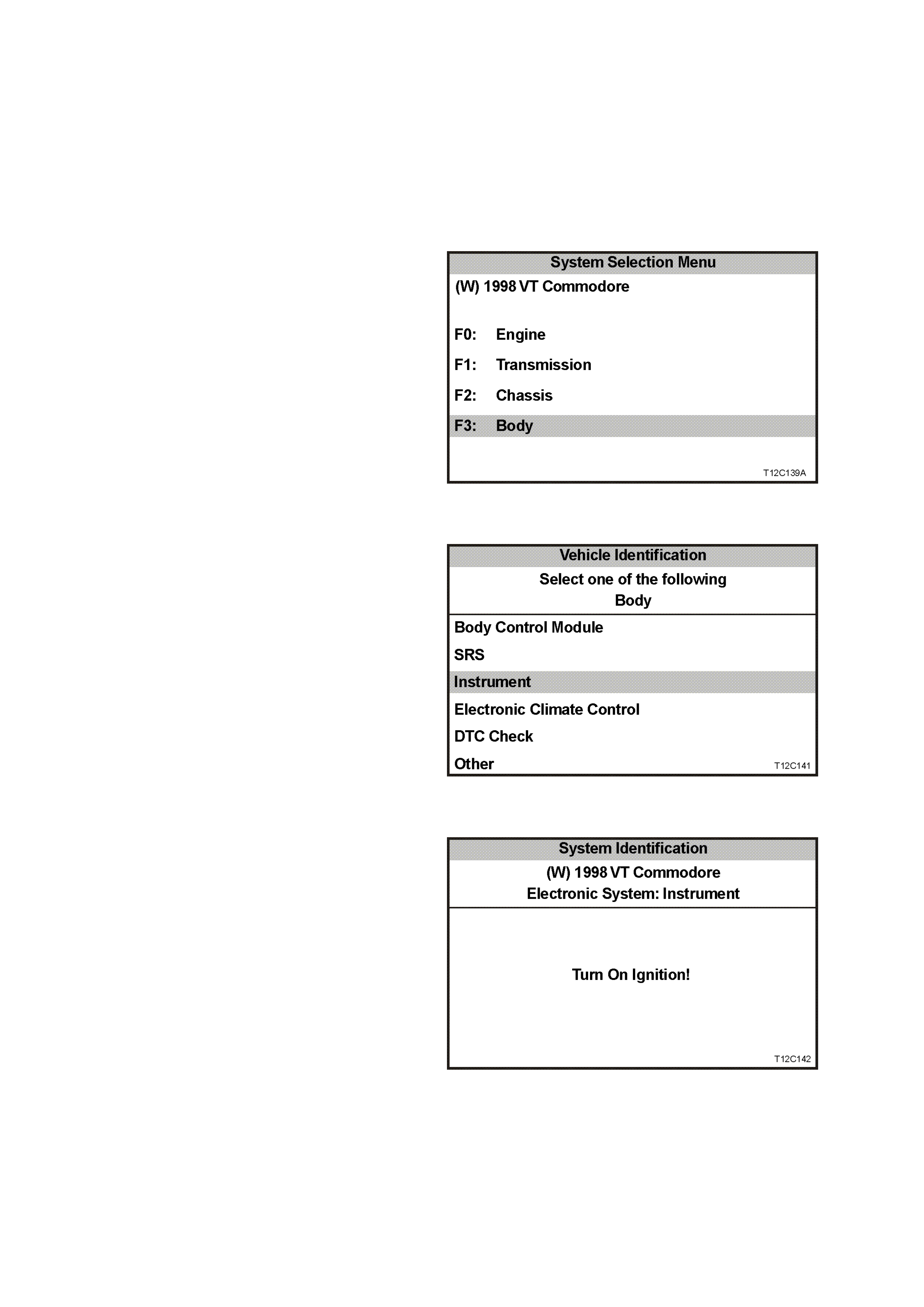
5.9 USING TECH 2 TO DIAGNOSE THE INSTRUMENT ASSEMBLY
A prerequisite to this diagnostic sect ion is that the
user is f am iliar with the proper us e of T ECH 2. T he
following illustrate only the major TECH 2 screen
displays and provide a brief explanation of their
function for diagnosing the Instruments. If
additional information is required on the operation
of TECH 2, reference should be made to either
Section 0C TECH 2 or the TECH 2 User’s Guide.
SYSTEM SELECTION MENU
With TECH 2 connected to the DLC and the F0:
Diagnostics selected from the Main Menu, the
correct V.I.N. number must be entered for access
to the System Selection Menu.
Select F3: Body.
This m ode contains all f unctions to test, diagnos e,
monitor and program the vehicles body systems
including the Instruments as well as providing the
opportunity to check all DTC that may be set in
the vehicle.
Figure 12C-95
VEHICLE IDENTIFICATION MENU
Once F3: Body has been selected from the
System Selection Menu, Instrument can be
selected.
Select Instrument.
NOTE:
If information regarding DTC set for the vehicle is
required, select DTC Check and press enter to
continue. To r eturn to the Instrum ent mode option
from the DTC Check mode option screen display,
simply press the Exit key on TECH 2.
Once Instrument has been selected, the following
two System Identification screens will appear
which require action. Figure 12C-96
SYSTEM IDENTIFICATION
Turn the ignition ON (as requested) and press
Confirm soft key to continue.
Figure 12C-97
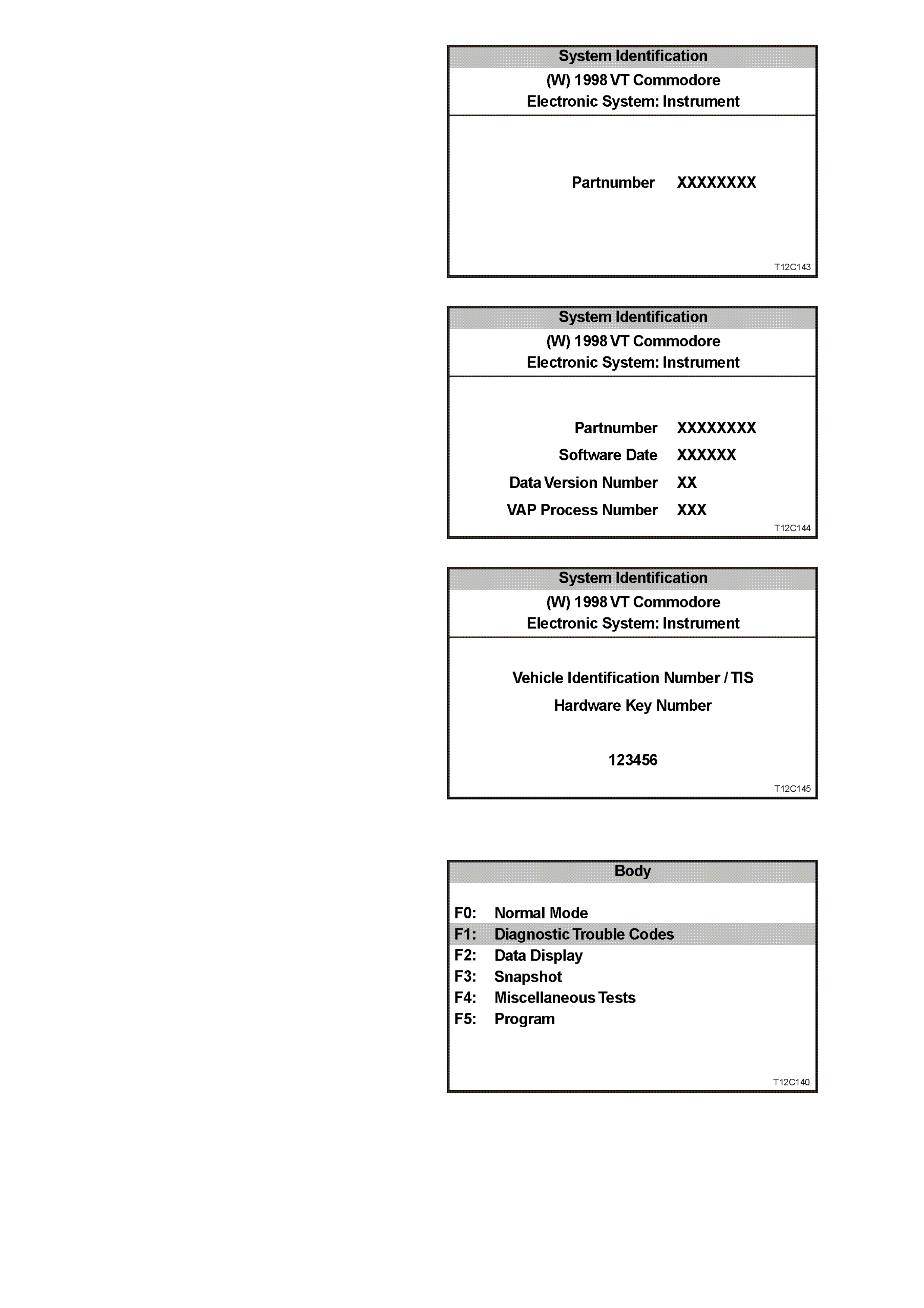
The part number of the instrument cluster will be
displayed. Press the More soft key to display more
detailed information about the part.
Figure 12C-98
Press the Confirm soft key to confirm these
details.
Figure 12C-99
The Vehic le Identification Number / TIS Hardware
Key Number will be displayed.
Figure 12C-100
BODY MENU
The Body Menu will be displayed.
Figure 12C-101
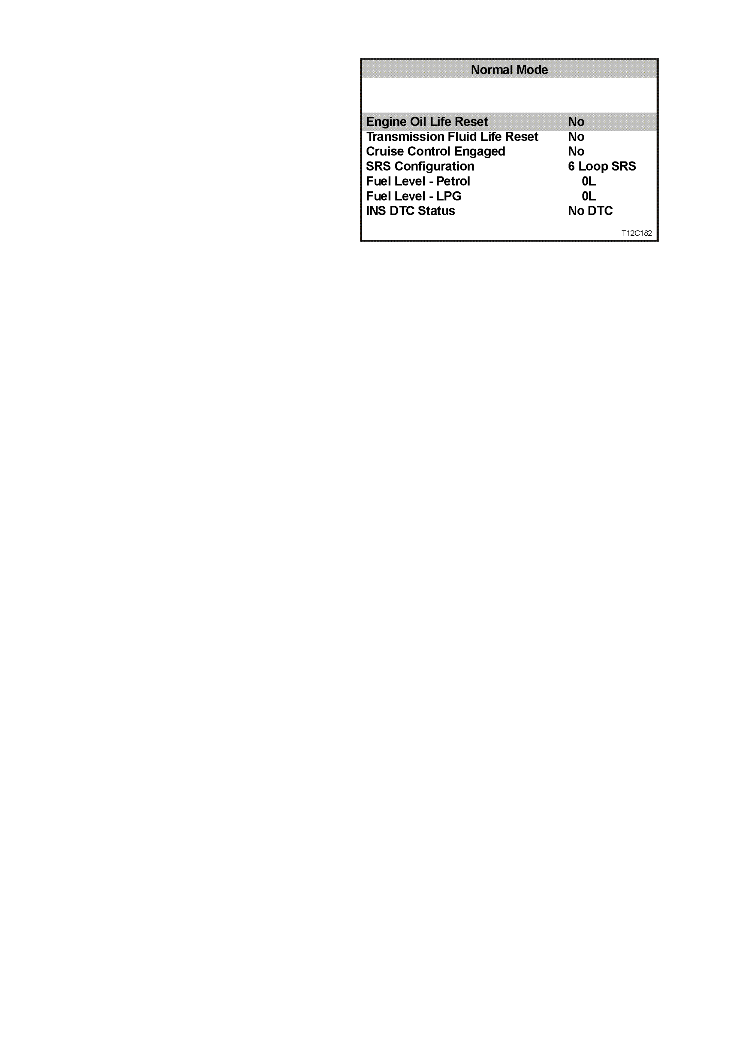
5.10 F0 : NORMAL MODE
The instrument normal mode data list is used to
view serial data being sent to the instrument
cluster.
Figure 12C-102
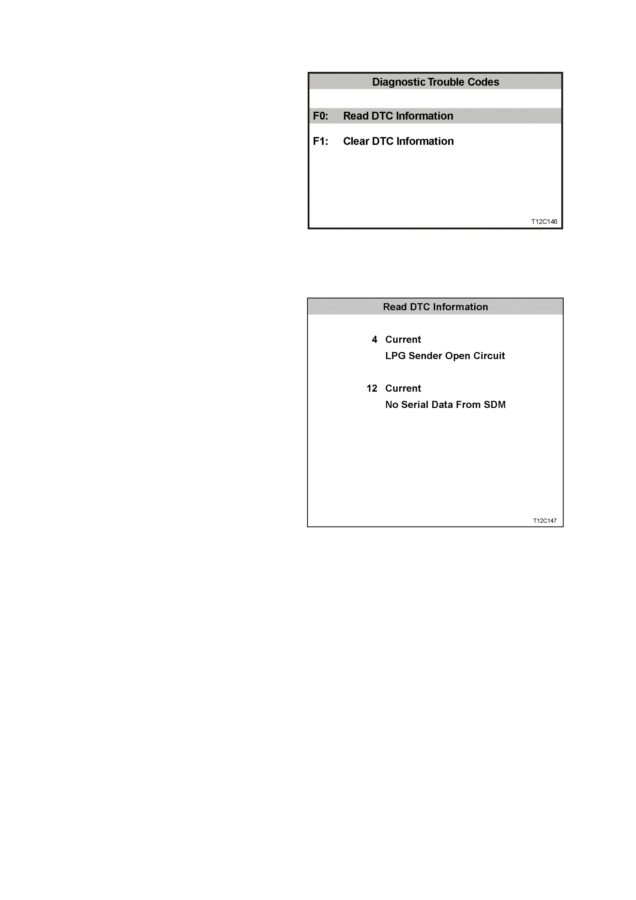
5.11 F1: DIAGNOSTIC TROUBLE CODES
DIAGNOSTIC TROUBLE CODES MENU
F0: Read DTC Information - If this mode is
selected, a listing of all (if any) DTC that have
been set by the combined instrument assembly
will be displayed.
NOTE:
If any DTC are set, reference should be made to
the relevant diagnostic charts in this Section.
F1: Clear DTC Information - DT C c an be c leared
in this mode by simply selecting F1: Clear DTC
Inform ation, pressing the Enter button on T ECH 2
and confirming the action as instructed by TECH
2.
NOTE:
TECH 2 will display Clear DTC Information Failed
if any DTC are still current.
Figure 12C-103
READ DTC INFORMATION
Select F0: Read DTC Information.
Use the following table to ass ist in diagnosing and
rectifying DTC.
NOTE:
Screen shot shows an example of 2 DTC only.
Figure 12C-104
The following chart sets out all the possible
diagnostic trouble codes as indicated by TECH 2.
Numbers not listed are reserved for future use.

DTC CODE DESCRIPTION
1 Fuel gauge sender unit – short circuit
2 Fuel gauge sender unit – intermittent
3 Fuel gauge sender unit – open circuit
4 LPG gauge sender unit – open circuit
5 LPG gauge sender unit – short circuit
6 LPG gauge sender unit – intermittent
8 No serial data from ABS
9 No serial data from BCM
10 No serial data from ECC
11 No serial data from PCM
12 No serial data from SDM
13 No instrument poll from BCM
14 No serial communication
16 ABS or ABS/ETC fault logged
17 BCM fault logged
18 ECC fault logged
19 PCM fault logged
20 SDM fault logged
24 EE checksum error
25 ROM checksum error
26 Internal fault
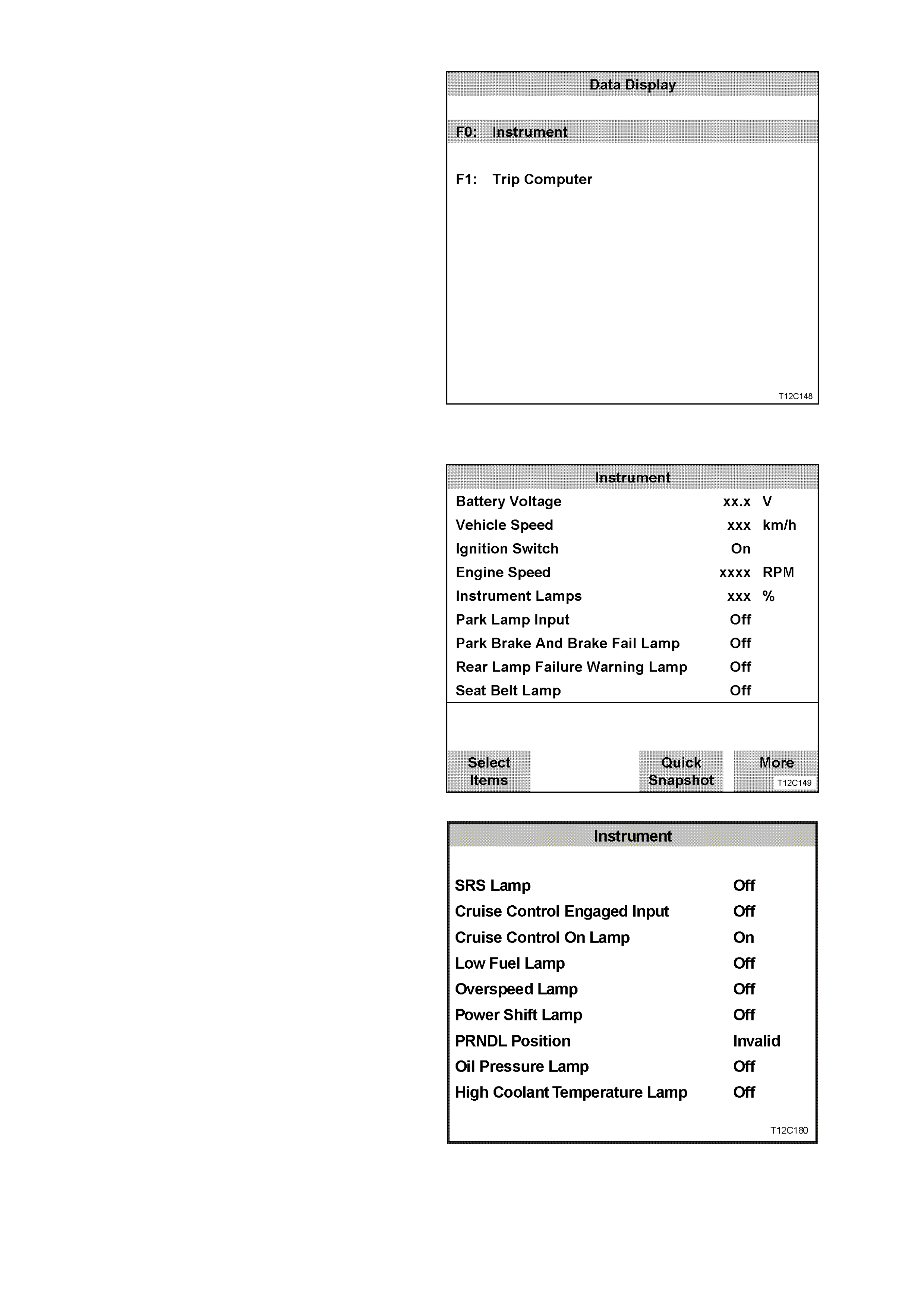
5.12 F2: DATA DISPLAY
Inthis test mode, the status of the instrument
cluster inputs and outputs can be monitored.
Select either F0: Instrument or F1: Trip Com puter
from the data display screen.
Figure 12C-105
F0: INSTRUMENT
The serial data from the instruments can be
checked and tested by selecting the instrument
and pressing the Select Items soft key. The list
can be scrolled by using the Up and Down arrow
keys.
Figure 12C-106
Use the Up and Down arrow keys to navigate
through the items.
Figure 12C-107
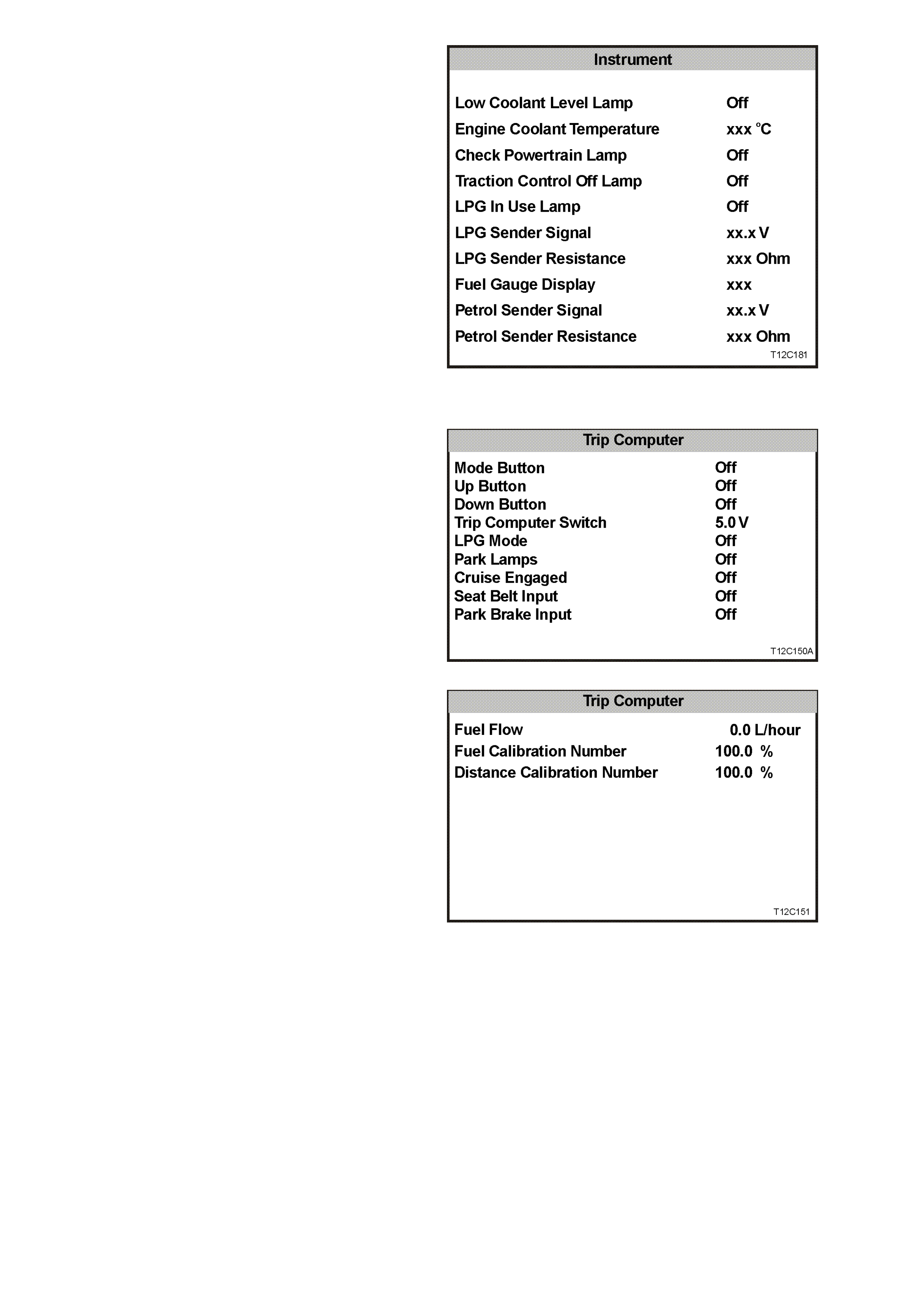
NOTE:
Traction control data list parameters are only
applicable if ABS/ETC is fitted.
Figure 12C-108
F1: TRIP COMPUTER
Figure 12C-109
Figure 12C-110
The following table lists each item contained in the
data stream together with a brief description of its
meaning.

DATA STREAM / SCREEN
DISPLAY DESCRIPTION UNIT
Battery Voltage Displays current battery voltage (approximately 12 volts). Volts
Vehicle Speed Displays current vehicle speed km/h
Ignition Switch Displays the current status of the ignition switch On/Off
Engine Speed Displays current engine speed RPM
Instrument Lamps Displays the current level of instrument lamps illumination
(0-100%) %
Park Lamp Input Displays status of the park lamps switch On/Off
Brake Lamp Used to check operation of brake lamp On/Off
Bulb Failed Warning Lamp Used to check operation of bulb failed warning lamp On/Off
Seat Belt Lamp Used to check operation of seat belt lamp On/Off
SRS Lamp Used to check operation of SRS lamp On/Off
Cruise Control Input Displays status of cruise control input On/Off
Cruise Control Lamp Used to check operation cruise control lamp On/Off
Low Fuel Lamp Used to check operation of low fuel lamp On/Off
Overspeed Lamp Used to check operation of overspeed lamp On/Off
Power Shift Lamp Displays status of power shift button On/Off
PRNDL Position Displays position of transmission selector lever INVALID
Oil Pressure Lamp Used to check operation of oil pressure lamp On/Off
High Coolant Temperature Lamp Used to check operation of high coolant temperature lamp On/Off
Low Coolant Level Lamp Used to check operation of low coolant level lamp On/Off
Engine Coolant Temperature Displays signal from engine temperature On/Off
Check Powertrain Lamp Used to check operation of check power train lamp On/Off
Traction Control Off Lamp Used to check operation of traction control disabled lamp On/Off
LPG In Use Lamp Used to check operation LPG in use lamp On/Off
LPG Sender Signal Displays signal from LPG sender 5 volts
LPG Sender Resistance Displays LPG gauge sender unit resistance 35.2 - 253.3
ohms
variable
Fuel Gauge Display Used to check operation of fuel gauge display 18%
Fuel Gauge Sender Signal Displays signal from fuel tank sender 0 - 5 volts
variable
Petrol Sender Resistance Displays petrol gauge sender unit resistance 35.2 - 253.3
ohms
variable

5.13 F3: SNAPSHOT
In this test mode, the TECH 2 captures data list
informationm before and/or after a forced manual
trigger.
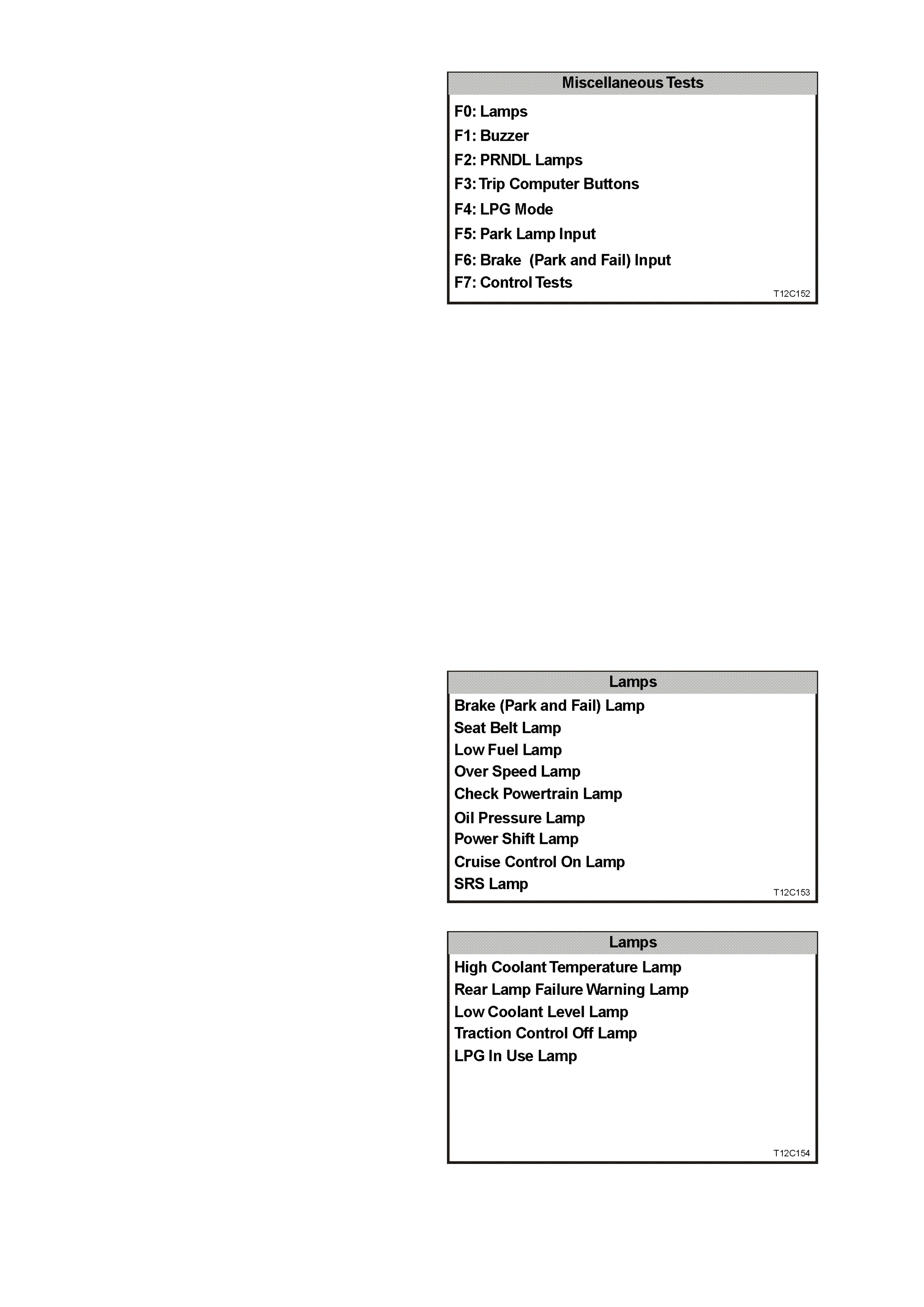
5.14 F4: MISCELLANEOUS TESTS
Miscellaneous Tests allows for the testing of
various components of the instrument cluster,
such as instrument and warning lamps, switches
and instrument gauges.
F0: Lamps - once this m ode is selected, lam ps in
the instrument assembly may be tested.
F1: Buzzer - operation of the buzzer can be
tested with this function.
F2: PRNDL Lamps - once this mode is selected,
the PRNDL lamps in the instrument assembly
may be tested by moving the transmission
selector lever through its various positions.
F3: Trip Computer Buttons - once this mode is
selected, the buttons on the trip c omputer m ay be
tested.
F4: LPG Mode - once this mode is selected, the
LPG mode may be tested.
F5: Park Lamp Input - once this mode is
selected, the park lamp input may be tested.
F6: Cruise Engaged Input - once this mode is
selected, DTC stored in the control module
memory may be cleared.
F7: Brake (Park And Fail) Input - onc e this mode
is selected, the park brake and brake fail input
may be tested.
F8: Control Tests - this function is used to test
the operation of the speedometer, tachometer,
engine coolant temperature, fuel gauge and sets
the function lamps illumination.
Figure 12C-111
F0: LAMPS
F0: Lamps function provides a means of testing
the correct operation of various warning/status
lamps in the instrument assembly.
Use the Up and Down arrow keys to scroll thr ough
the list and highlight a lamp.
Press the Enter button to test the selected lamp.
Figure 12C-112
The adjacent figure shows the remainder of the
F0: Lamps menu.
Figure 12C-113
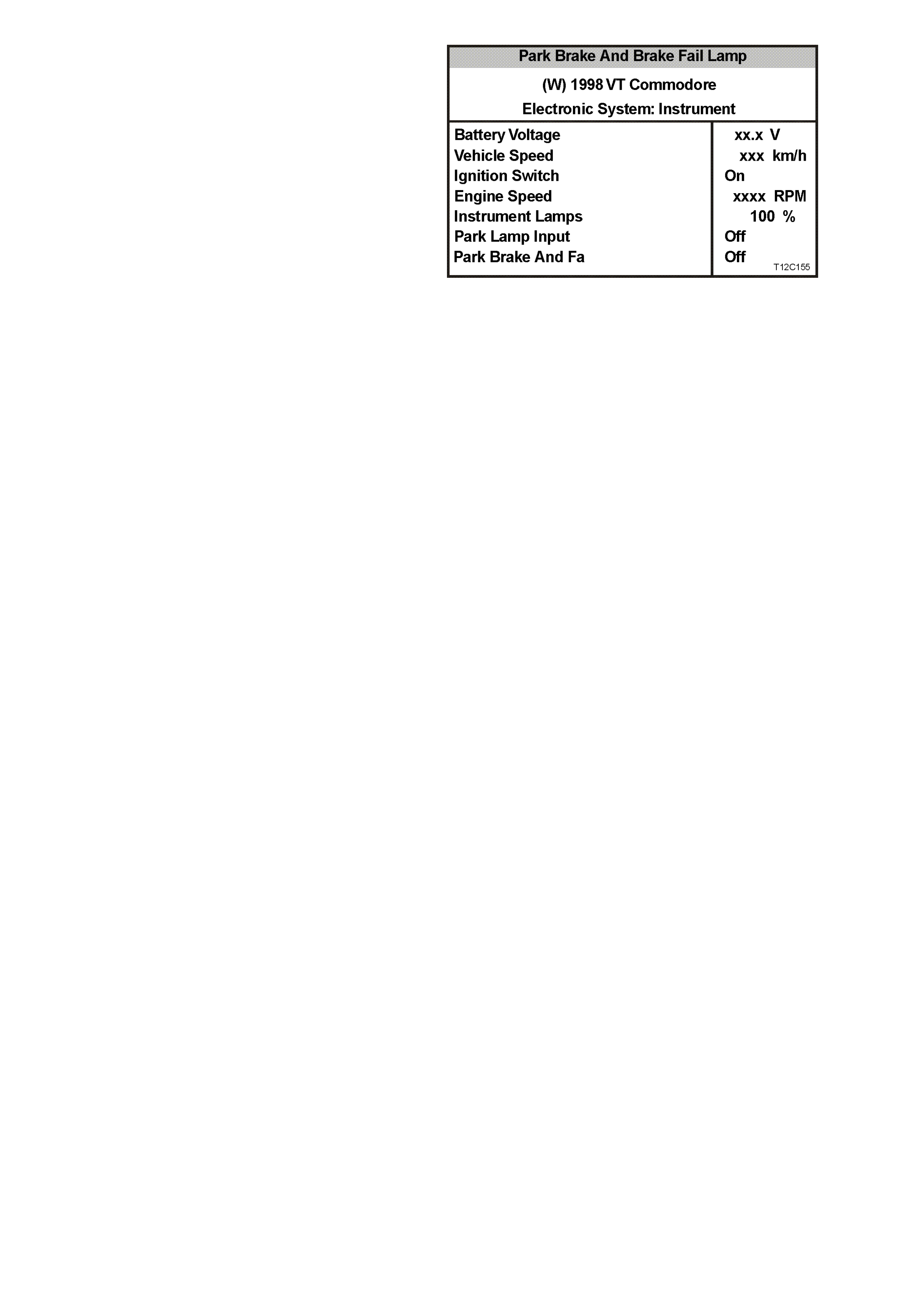
Once a lamp has been highlighted and selected,
the TECH 2 will show the following screen.
Current serial data will be shown at the top of the
screen and the selected lamp and its current
status will be displayed at the bottom.
Press the O n s of t key to turn the selected lam p on
and note its status on the instrument assembly.
If the lamp does not come on and the TECH 2
display indicates that it is, there is a fault in the
lamp and the bulb will need to be replaced.
Press the Off soft key to turn the lamp off.
Press the Quit soft key to continue and return to
the previous screen. Figure 12C-114
F1: BUZZER
The operation of the buzzer can be tested, and a
1 kHz tone will be emitted from the instrument
buzzer.
Soft keys: Quit, On and Off
F2: PRNDL LAMPS
Not used.
F3: TRIP COMPUTER BUTTONS
F0: Mode Button
With this test a mode button press can be
simulated. This is to test if the button is stuck or
the instrument is not working properly.
F1: Up Button
With this test an up button press can be
simulated. This is to test if the button is stuck or
the instrument is not working properly.
F2: Down Button
With this test a down button press can be
simulated. This is to test if the button is stuck or
the instrument is not working properly.
F4: LPG MODE
This function allows the TECH 2 user to enable or
disable the instrument LPG mode for testing
purposes. The LPG lamp will illuminate and the
fuel gauge will indicate the level of the LPG tank.
F5: PARK LAMP INPUT
This test allows the T ECH 2 user to turn enable or
disable the park lamps input. This will dim the
Power, Cruise and LPG lam ps only. It will have no
effect on the other warning lamps or instrument
assembly illumination.
F6: BRAKE (PARK AND FAIL) INPUT
This function allows the TECH 2 user to enable or
disable the brake (park and fail) input.

F7: CONTROL TESTS
Control Tests allow the TECH 2 user to force
known values into the speedometer, tachometer,
engine coolant tem perature gauge and fuel gauge
to verify their correct operation.
Figure 12C-115
Vehicle Speed
This function controls the speedometer.
Comm anded vehicle speed can be adjusted up or
down in 20 km /h steps f rom 0 k m /h to a m axim um
value of 220 km/h. Ensure that the speedometer is
accurate according to the following table.
Commanded
Vehicle
Speed
Speedo
Error Acceptable
Readings on
Speedometer
60 km/h –1/+3 km/h 59 – 63 km/h
100 km/h –1/+3 km/h 99 – 103 km/h
160 km/h –1/+5 km/h 159 – 165 km/h
Engine Speed
This functions controls the tachometer.
Comm anded engine speed c an be adjusted up and
down in 1000 rpm steps with a maximum value of
6000 rpm. Ensure that the tachometer is accurate
according to the following table.
Commanded
Engine Speed Acceptable Readings on
Tachometer
1000 RPM 860 – 1140 RPM
3000 RPM 2860 – 3140 RPM
5000 RPM 4860 – 5140 RPM
Engine Coolant Temperature
This function controls the temperature gauge.
There are three steps when testing the tem perature
gauge; cold, mid and hot. The test is conducted
using the Up and Down soft keys.
Fuel Gauge
This function controls the fuel gauge. There are
three steps when testing the fuel gauge; empty, half
and full. The test is conducted using the Up and
Down soft keys.
Function Lamps Illumination
This function controls the function lam ps. Note that
this test applies only to the Power, Cruis e and LPG
lamp illumination level. The illumination can be
adjusted in increments of 20% from 0% to 100%.
The function lamps are turned on automatically
when the test is being performed.

5.15 F5: PROGRAM
Turn ignition off.
Connect TECH 2 to the vehicle, refer to
5.6 CONNECTING THE TECH 2.
Navigate through the TECH 2 m enus to display the
ECC Applicatiom Menu.
Select F5: Program.
Body
F0: N orm al M ode
F2: Data Display
F1: Diagnostic Trouble Codes
F3: Snaps hot
F4: M iscellaneous T ests
F5: Program
T12C157
Figure 12C-113
F0: INSTRUMENT CONFIGURATION
Select F0: Instrument Configuration.
Program
F0: Instrument Configuration
F2: Odometer V alue
F1: Options
F3: Fuel Gauge Calibration
F4: Reset Service Interval
F5: Reset User Calibration
T212C159
Figure 12C-114
Using the Next soft key, step through each
parameter and modify as necessary.
Press the Confirm soft key to continue.
Instrum en t Configuration
(X) 1999 V T Comm odore
Step Through Each Parameter And Modify
If Nece ssary.
C onfirm Program m ing At The End.
E lec tro nic S ystem: Ins trume nt
T212C158
Figure 12C-115
Techline
Techline
Techline
Techline
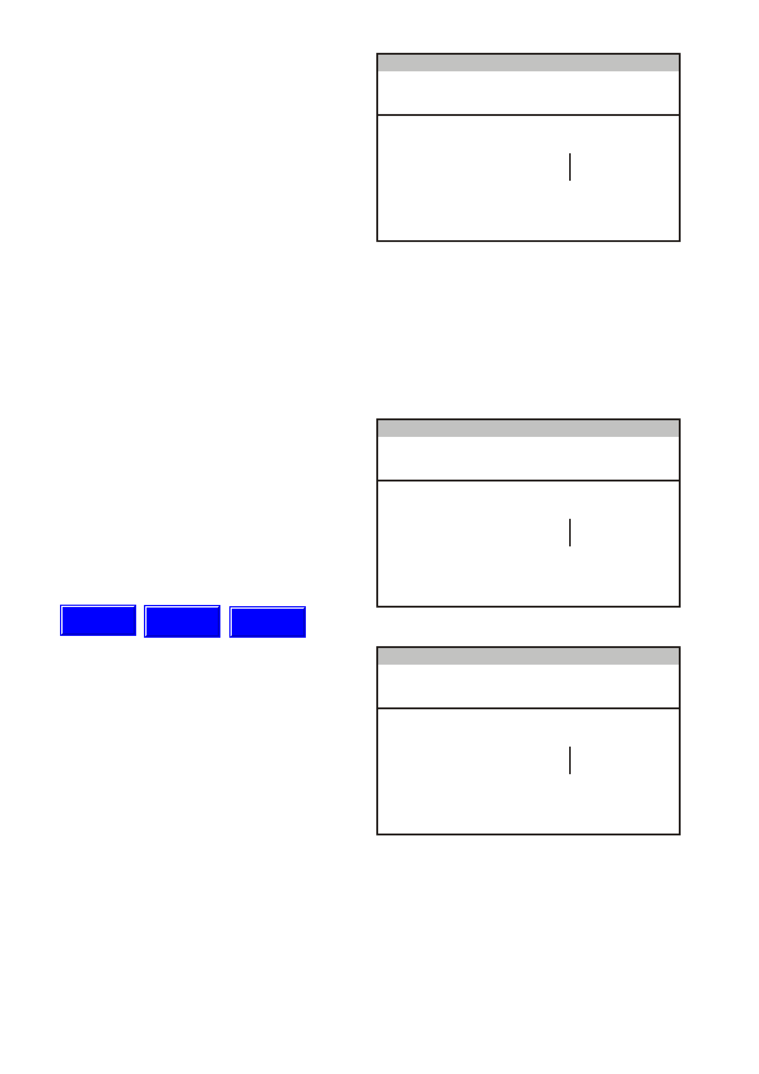
1. SRS Configuration
Press Modify soft key to set to one of the
following options:
• No SRS
• 2 Loop SRS
• 3 Loop SRS
• 4 Loop SRS
• 6 Loop SRS
NOTE: Configuration of the various SRS
systems is as follows:
• a 2-loop system is for left-hand drive
vehicles with pre-tensioners only.
• a 3-loop system is for vehicles with pre-
tensioners and driver’s air bag only.
• a 4-loop system is for vehicles with pre-
tensioners, driver’s air bag and front
passenger’s air bag only.
• a 6-loop system is for vehicles with pre-
tensioners, driver’s air bag, front
passenger’s air bag and side air bags.
Instrum en t Configuration
(X) 1999 V T Comm odore
SRS C onfiguration 6 Loop SRS
E lec tro nic S ystem: Ins trume nt
T212C160
Figure 12C-116
2. SRS Lamp
Press Modify soft key to set to -
Enabled/Disabled.
• For all models, set to Enabled.
Instrum en t Configuration
(X) 1999 V T Comm odore
SRS Lam p Enabled
E lec tro nic S ystem: Ins trume nt
T212C161
Figure 12C-117
3. Speedometer Pulses
Press Modify soft key to set the speedometer
pulses per kilometre for the correct tyre size.
Nominal value is 6250 pulses per km.
• Tyre size 205 65 R15, select 6272 pulses.
• Tyre size 215 60 R15, select 6285 pulses.
• Tyre size 215 60 R16, select 6077 pulses.
• Tyre size 225 50 R16, select 6391 pulses.
• Tyre size 225 55 R16, select 6087 pulses.
• Tyre size 225 60 R15, select 6238 pulses.
• Tyre size 235 45 R17, select 6301 pulses.
Instrum en t Configuration
(X) 1999 V T Comm odore
Speedom eter Pulses 6250
E lec tro nic S ystem: Ins trume nt
T212C162
Figure 12C-118
Techline
Techline
Techline
4. Speedometer Calibration
If the Police Mode has been enabled at
F5: Program / F1: Options, the speedometer
calibration screen appears next. This allows
the speedometer to be calibrated.
Press the Modify soft key to adjust the
speedom eter calibration, or the Next s oft k ey to
continue.
Instru ment Conf igur a t ion
(X) 1999 VT Commodore
Speedometer Calibratio n 100%
Electronic System: Instrument
T212C198
Figure 12C-119
5. Tachometer Ratio
Press Modify soft key to set to - V6 or V8
Gen 3.
• Only V6 and V8 Gen 3 are applicable to the
VT Series II.
Instru ment Conf igur a t ion
(X) 1999 VT Commodore
Tachometer Ratio V6
Electronic System: Instrument
T212C163
Figure 12C-120
6. High Voltage Tachometer
Press Modify soft key to set to - Disabled.
• For V6 engine, set to Disabled.
• For GEN III V8 engine, set to Disabled.
Instrum en t Configuration
(X) 1999 V T Comm odore
High V oltage Tachometer Disabled
E lec tro nic S ystem: Ins trume nt
T212C164
Figure 12C-121
7. ECC Equipped
Press Modify soft key to set to -
Enabled/Disabled.
• For vehicles equipped with a tripple window
display set to – Enabled.
• For vehicles equipped with single window
instruments set to – Disabled.
Inst ru me nt Conf igur a tion
(X) 1999 VT Co mm o dor e
Electronic System: Instrument
ECC Option Enabled
T212C164A
Figure 12C-48A

8. Program Instrument Confirm
Press Abort soft key to abandon process, or
press Program soft key to confirm parameters.
Press Confirm soft key when programming is
completed.
Inst ru me nt Conf igur a tion
(X) 1999 VT Co mm o dor e
Electronic System: Instrument
SRS Configuration
SRS Lamp
Speedometer Pulses
Speedometer Calibration
Ta cho m eter Ratio
H igh Volta ge Tachometer
ECC Option
6 Loo p SR S
Enabled
625 0
100 %
V6
Disabled
Enabled
T212C165A
Figure 12C-122
F1: OPTIONS
Options such as instrument lamp illumination
enable/disable and Police Mode can be set by
selecting F1: Options from the Program Menu.
Program
F0: Instrument Configuration
F2: Odometer V alue
F1: Options
F3: Fuel Gauge Calibration
F4: Reset Service Interval
F5: Reset User Calibration
T212C159
Figure 12C-123
Using the Next soft key, step through each
parameter and modify as necessary.
Press Confirm soft key to continue.
Options
(X) 1999 V T Comm odore
Step Through Each Parameter And Modify
If Nece ssary.
C onfirm Program m ing At The End.
E lec tro nic S ystem: Ins trume nt
T212C183
Figure 12C-124
1. Rear Lamp Failure Lamp
Press Modify soft key to set to -
Enabled/Disabled.
• For Calais, set to Enabled.
• For all other models, set to Disabled.
Options
(X) 1999 V T Comm odore
Rear Lamp Failure Lamp Enabled
E lec tro nic S ystem: Ins trume nt
T212C167
Figure 12C-125
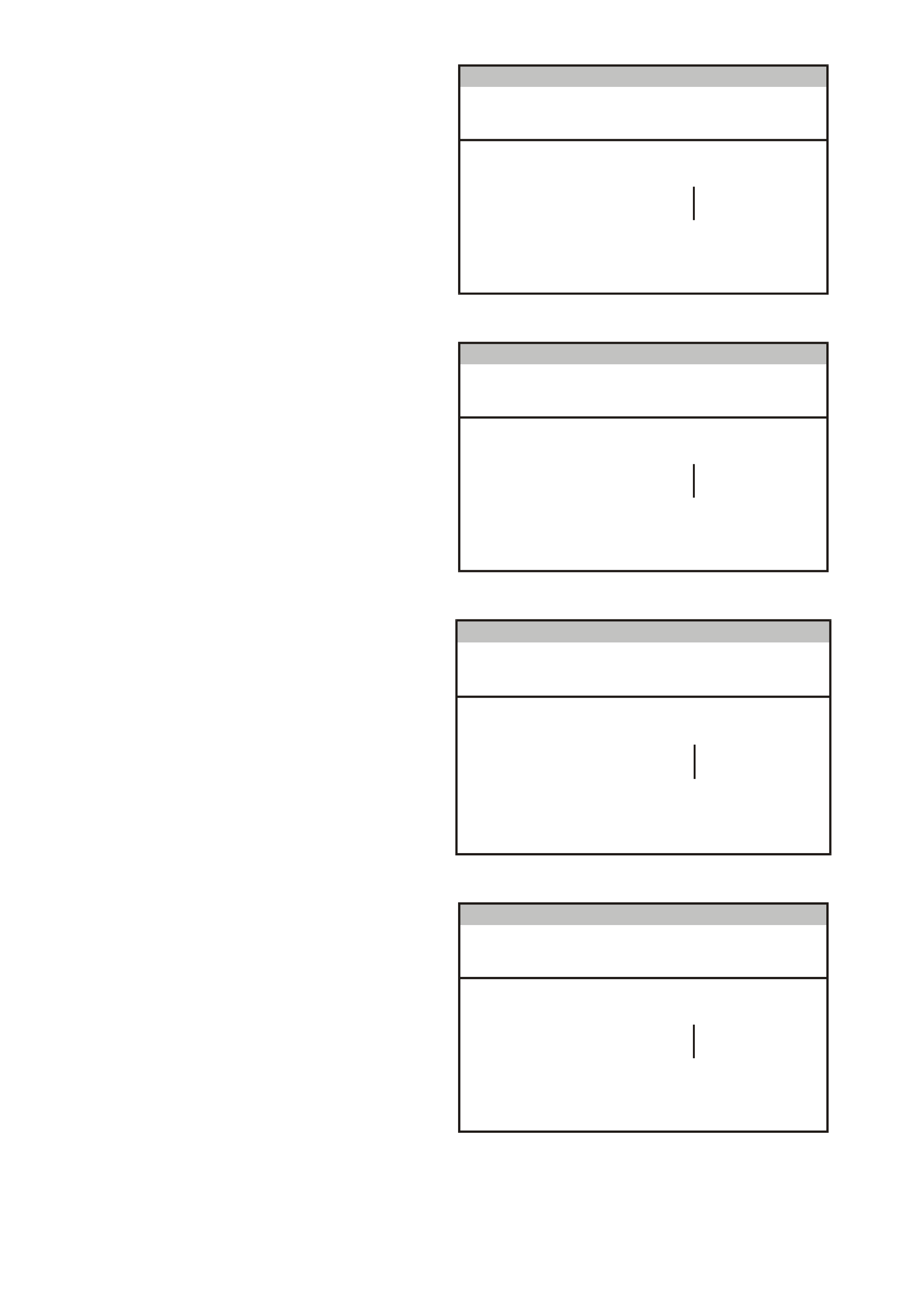
2. Trac tion Control Off Lamp
Press Modify soft key to set to -
Enabled/Disabled.
• For Calais, set to Enabled.
• For other models, check if the option is
fitted. If not fitted, set to Disabled.
Options
(X) 1999 V T Comm odore
Traction C ontrol Off Lam p Enabled
E lec tro nic S ystem: Ins trume nt
T212C168
Figure 12C-126
3. LPG Lamp
Press Modify soft key to set to -
Enabled/Disabled.
• For V6 engine, check if the option is fitted. If
not fitted, set to Disabled.
• For GEN III V8 engine, set to Disabled.
Options
(X) 1999 V T Comm odore
LPG Lam p Disabled
E lec tro nic S ystem: Ins trume nt
T212C169
Figure 12C-127
4. Cruise On Lamp
Press Modify soft key to set to -
Enabled/Disabled.
• For Berlina and Calais, set to Enabled.
• For other models, check if the option is
fitted. If not fitted, set to Disabled.
Options
(X) 1999 VT C omm od ore
C ruise O n Lam p Enabled
E lectro nic S ystem : In strum e nt
T212C170
Figure 12C-128
5. Police Mode
Press Modify soft key to set to -
Enabled/Disabled.
• For Police vehicles only, set to Enabled.
• For all other vehicles, set to Disabled.
Options
(X) 1999 V T Comm odore
Polic e Mo de Disabled
E lec tro nic S ystem: Ins trume nt
T212C171
Figure 12C-129
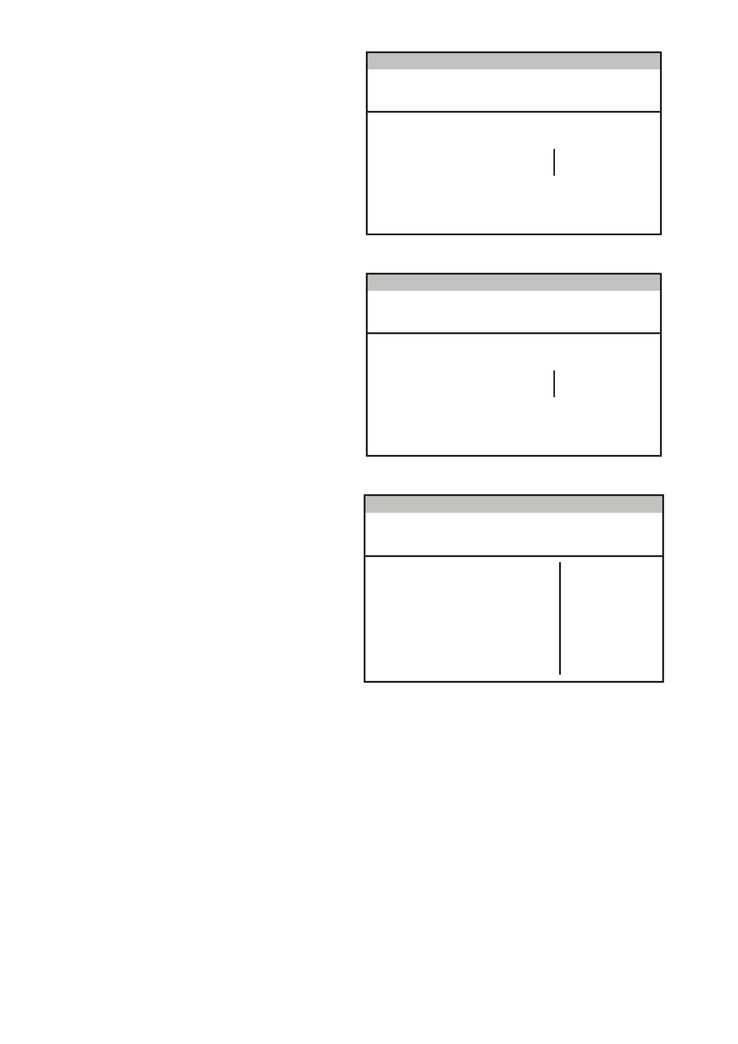
6. Low Coolant Lamp
Press Modify soft key to set to -
Enabled/Disabled.
• For V6 engine, set to Disabled.
• For GEN III V8 engine, set to Enabled.
Options
(X) 1999 V T Comm odore
Low Coolant Lam p Disabled
E lec tro nic S ystem: Ins trume nt
T212C172
Figure 12C-130
7. High Temperature Lamp
Press Modify soft key to set to - Enabled.
Options
(X) 1999 V T Comm odore
High Temperature Lamp Enabled
E lec tro nic S ystem: Ins trume nt
T212C184
Figure 12C-131
8. Program Options Confirm
Press Abort soft key to abandon process, or
press Program soft key to confirm parameters.
Press Confirm soft key when programming is
completed.
Options
(X) 1999 VT C omm od ore
Trac t io n C o n t ro l L a mp Enabled
R ear Lam p F ailure Lam p Ena bled
C ruise O n Lam p Enabled
Low Co olant Lam p Disabled
High Temperature Lamp Enabled
E lectro nic S ystem : In strum e nt
LPG Lam p Disabled
Po lic e Mo d e Disabled
T212C173
Figure 12C-132

9. Speedometer Calibration
NOTE: This is only available in TECH 2 when
instrument has been configured to Police
mode.
Turn the ignition off.
Hold down the MODE button as well as the ▲
and ▼ buttons on the trip computer.
Turn the ignition on while holding down the
three buttons.
Release the MODE button after 3 seconds,
then release the other two buttons. The
calibration value will now be flashing and C will
be displayed.
The calibration value (in percentage) can now
be adjusted with the ▲ and ▼ buttons. Set to
80% - 120% as necessary.
W hen the calibration has been achieved, press
the MODE button to lock in the c alibration data
and return to the normal display.
F2: ODOMETER VALUE
NOTE: It is only possible to program the odometer
reading on an instrument once the TIS approval
code has been obtained and on an instrument
which presently reads no more than 100 km.
F3: FUEL GAUGE CALIBRATION
Select F3: Fuel Gauge Calibration.
Program
F0: Instrument Configuration
F2: Odometer V alue
F1: Options
F3: Fuel Gauge Calibration
F4: Reset Service Interval
F5: Reset User Calibration
T212C159
Figure 12C-133
The next screen displays the instrument Code
Index and Code Version. If these need to be
updated, press the Modify soft key, otherwise
press the Okay soft key.
Fuel Gauge Ca libration
(X) 1999 V T Comm odore
C ode Index
Code Version 1
0
E lec tro nic S ystem: Ins trume nt
T212C196
Figure 12C-134

Select the vehicle type, press Enter and wait for
the programming to be completed.
Press the Confirm soft key when programming is
completed.
F u e l Ga u g e C a lib r at io n
(X ) 199 9 V T C o m mod o re
E lectro n ic System: In strumen t
T212C197
Se dan Calibration
Wagon C alibration
Figure 12C-135
F4: RESET SERVICE INTERVAL
Select F4: Reset Service Calibration.
Press the Abort soft key to abandon the process,
or press the Reset soft key to reset the service
interval.
Press the Confirm soft key when programming is
completed.
Reset Service Interval
(X) 1999 VT Commodore
Reset Service Interval ?
Electronic System: Instrument
T212C199
Figure 12C-136
F5: RESET USER CALIBRATION
Select F5: Reset Service Calibration.
Press the Abort soft key to abandon the process,
or press the Reset soft key to reset the following
parameters:
• Trip Distance Calibration
• Fuel Used Calibration
• Speedometer Calibration
Press the Confirm soft key when programming is
completed.
Reset User Calibration
(X) 1999 VT Commodore
Reset User Calibration ?
Electronic System: Instrument
T212C200
Figure 12C-137

6. TORQUE WRENCH SPECIFI CATIONS
Nm
Instrument Assembly Attaching Screws 1 - 3
Front Wiper Arm Attaching Nut 20 - 25
Front Wiper Motor to Linkage Screws 7 - 9
Front Wiper Motor Crank Arm Pivot to
Linkage Nut 16 - 20
Front Wiper Motor and Linkage Assembly
Securing Screws 4 - 6
Rear Wiper Arm Attaching Nut 6 - 14
Rear Wiper Motor Attaching Screw 6 - 14
Horn Securing Bolt 15 - 35
Theft Deterrent Horn Bolt 20 - 27
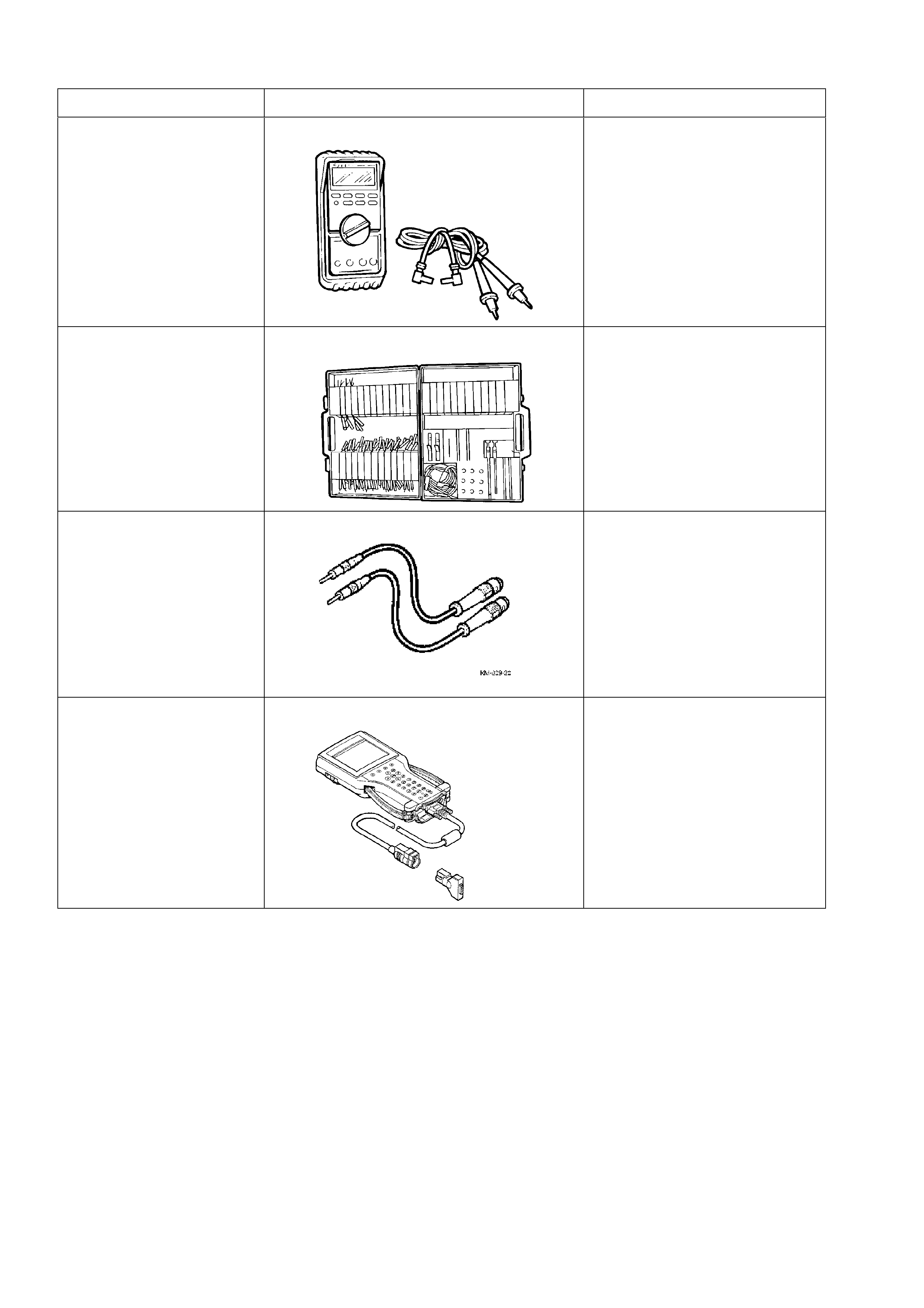
7. SPECIAL TOOLS
TOOL NO. REF IN TEXT TOOL DESCRIPTION COMMENTS
J39200 DIGITAL MULTIMETER TOOL NO. J39200
PREVIOUSLY RELEASED, OR
USE COMMERCIALLY
AVAILABLE EQUIVALENT.
MUST HAVE 10 MEG OHM
INPUT IMPEDANCE
KM-609 CONNECTOR TEST ADAPTOR KIT PREVIOUSLY RELEASED FOR
V CAR. USED IN
CONJUNCTION WITH A
MULTIMETER FOR
MEASURING VOLTAGES AND
RESISTANCES WITHOUT
DAMAGING WIRING
HARNESS CONNECTORS
KM-609-20 SRS TEST LEAD SET PREVIOUSLY RELEASED
70000861 TECH 2 DIAGNOSTIC SCAN TOOL MANDATORY TOOL USED
FOR DIAGNOSIS OF VEHICLE
ELECTRICAL SYSTEMS