
SECTION 12D - AUDIO SYSTEMS
CAUTION:
This v ehicle will be equipped with a Supplemental Restraint System (SRS). A SRS
will consist of either seat belt pre-tensioners and a driver’s side air bag, or seat
belt pre-tensioners and a driver’s and front passenger’s side air bags. Refer to
CAUTIONS, Section 12M, before performing any service operation on or around
SRS components, the steering mechanism or wiring. Failure to follow the
CAUTIONS could result in SRS deployment, resulting in possible personal injury
or unnecessary SRS system repairs.
CAUTION:
This vehicle may be equipped with LPG (Liquefied Petroleum Gas). In the interests
of safety, the LPG fuel system should be isolated by turning 'OFF' the manual
service valve and then draining the LPG service lines, before any service work is
carried out on the vehicle. Refer to the LPG leaflet included with the Owner's
Handbook for details or LPG Section 2 for more specific servicing information.
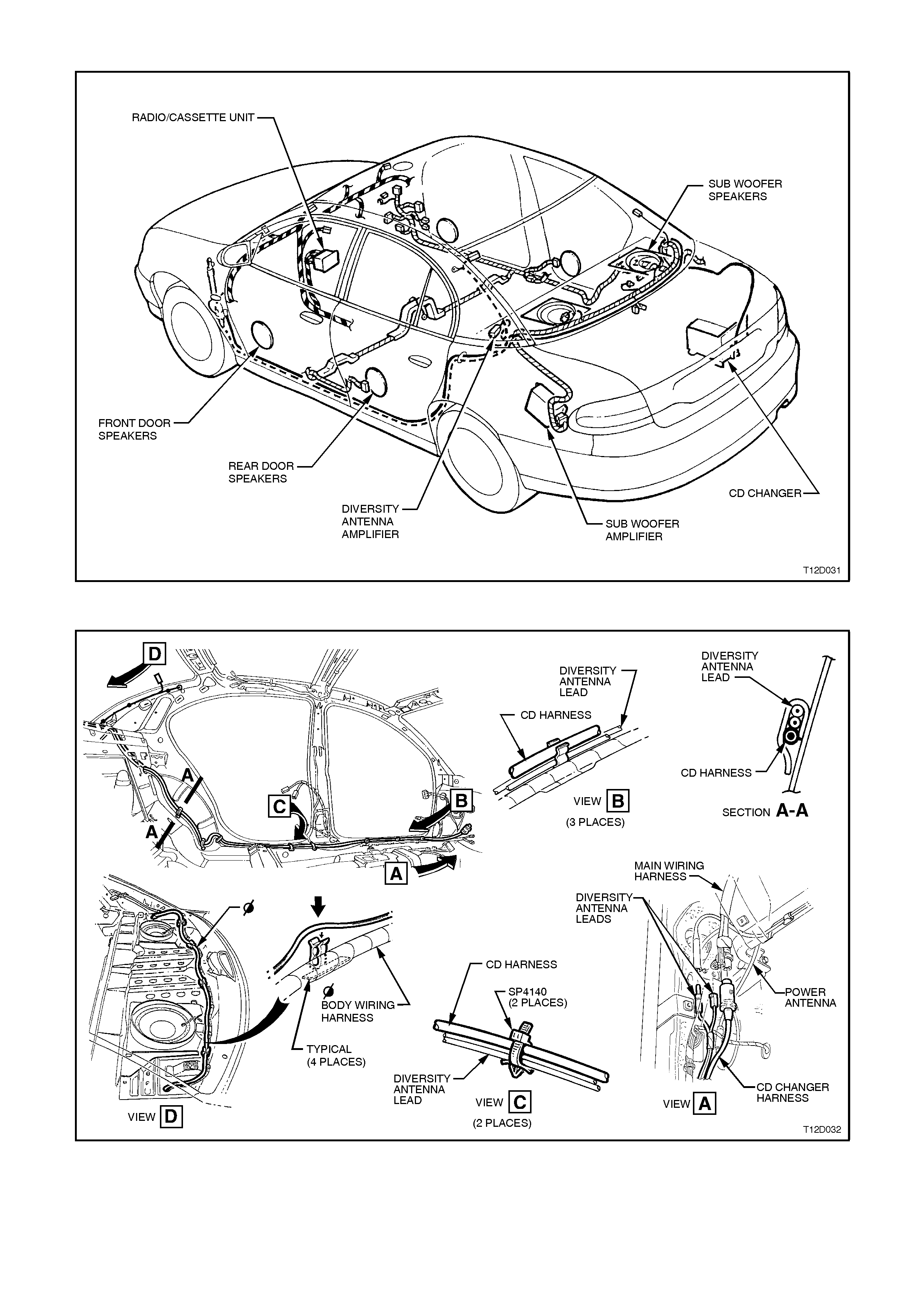
1. GENERAL INFORMATION
All VT models ar e f itted with a high perf ormanc e ‘double DIN’ size AM/FM ster eo radio/c as s ette player combination.
Berlina models are fitted as standard with radio/cassette/single Compact Disc (CD) player with power antenna
control. T he audio system fitted to Calais com prises a radio/cas sette player with a 10 disc CD player/changer f itted
to the vehicle (refer to
2.11 COMPACT DISC PLAYER/CHANGER INSTALLATION in this Section).
All radio/cassette player assemblies incorporate Personal Identification Number (PIN) security code theft deterrent
and flashing LED features.
All vehicles have speakers mounted in each upper corner of the instrument dash panel.
All VT models except Calais have 150 mm diameter ‘twin cone’ speakers mounted in the front and rear door trim
side pockets.
Calais vehicles are fitted with unique 150 mm diameter ‘twin cone’ speakers mounted in the front door trim side
pockets and 150 mm coaxial speakers mounted in the rear door trim side pockets.
The audio system on the Calais features personal identity memories which individually memorises the following
settings for different ignition keys:
Last used volume level Last used mode
FM1- radio memory presets FM2- radio memory presets
AM- radio memory presets Bass control settings
Treble control settings Speaker balance setting
Speaker fader setting Time/Frequency priority settings
Local On/Off setting
Techline
The audio s ystem fitted to the Calais also f eatures a pair of ‘subwoofer’ speaker and brac ket assem blies, m ounted
on top of the rear parcel shelf. These rear parcel shelf mounted speakers are powered by an additional amplifier
located in the lefthand side of the rear compartment, refer to 2.12 SUBWOOFER AMPLIFIER in this Section.
The Calais includes steer ing wheel mounted s tereo contr ols. Control of the radio, tape and CD player func tions c an
be accomplished without the need for the driver’s hands being removed from the steering wheel.
The radio reads the switch resistance from the steering wheel stereo controls via the clock spring coil harness.
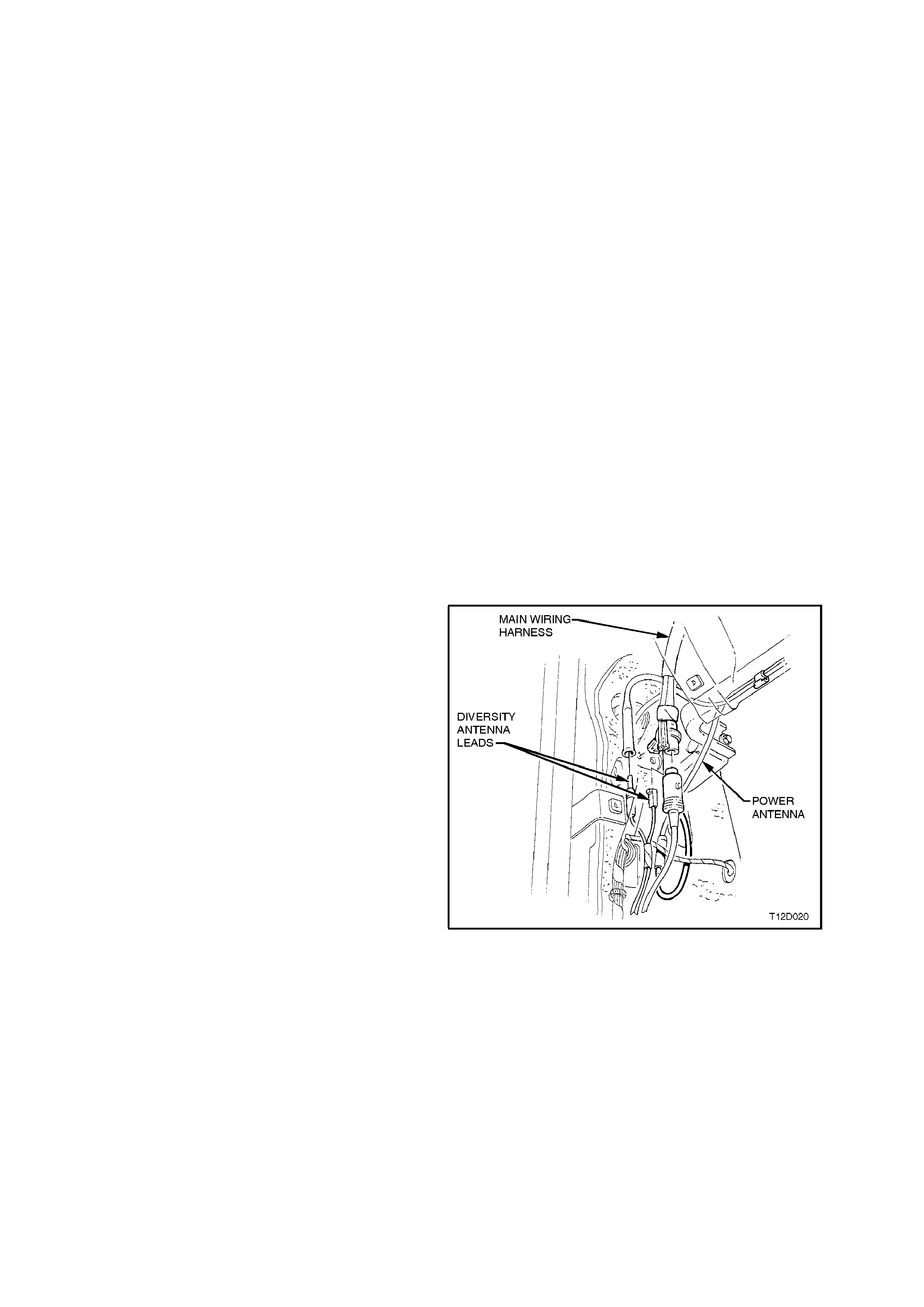
A manual pull up, pus h down mast type antenna is fitted as s tandard equipm ent on VT Ex ecutive m odels. A power
antenna, controlled via the radio, is available as an option on base models . Ref er to 2.8 POWER ANTENNA in this
Section.
Berlina and Calais have a height adjustable power antenna fitted as standard equipment. The power antenna
operation on these models is controlled via a switch located on the radio facia and in conjunction with the body
control module (BCM), refer to Section 12J-1 BODY CONTROL MODULE.
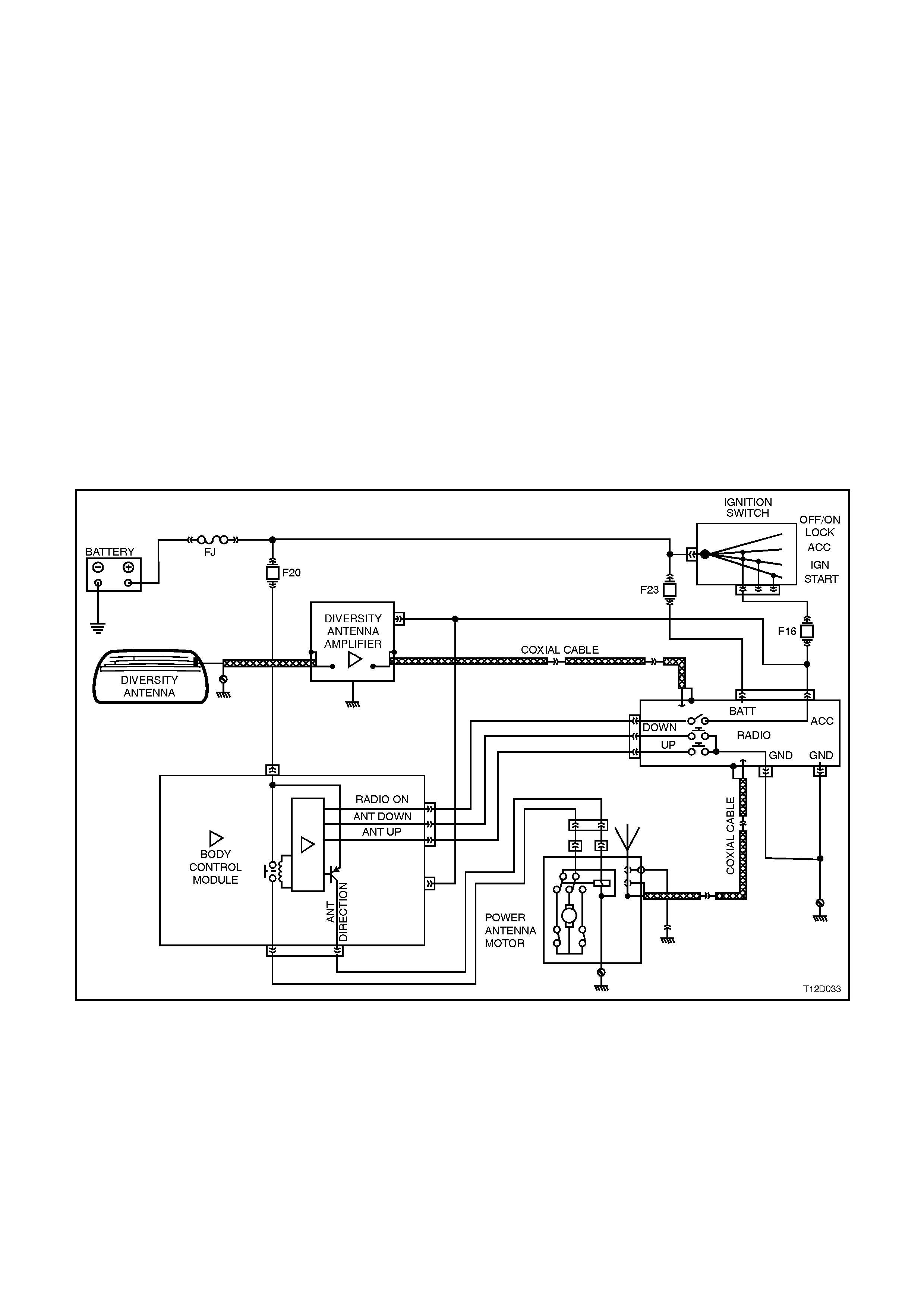
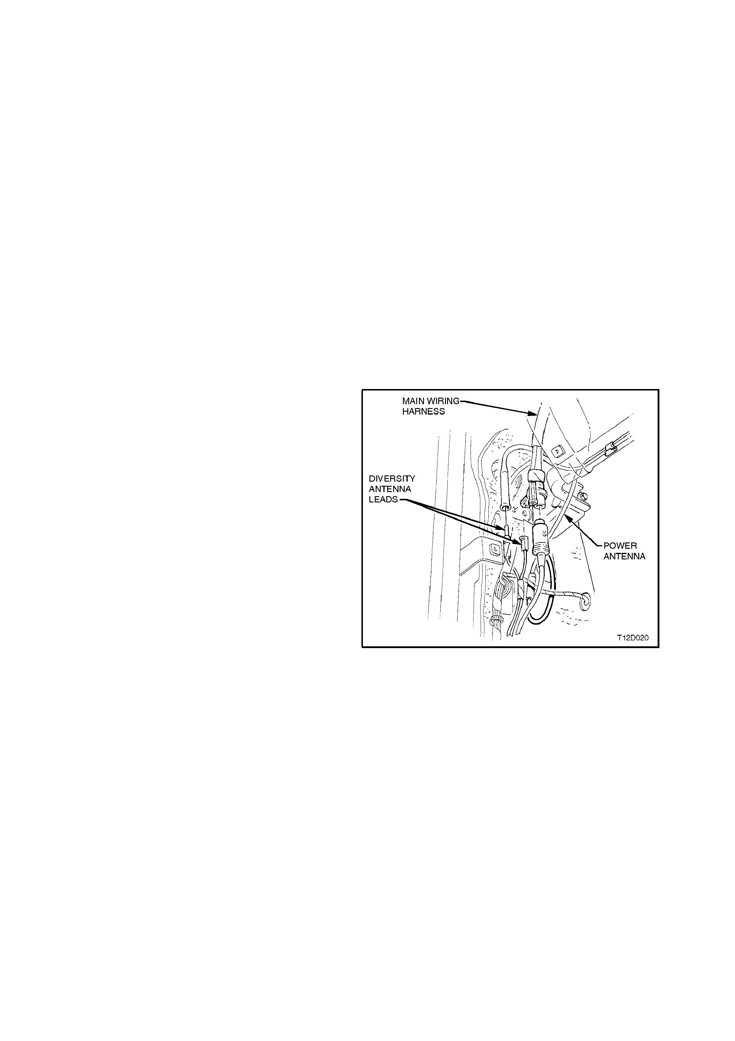
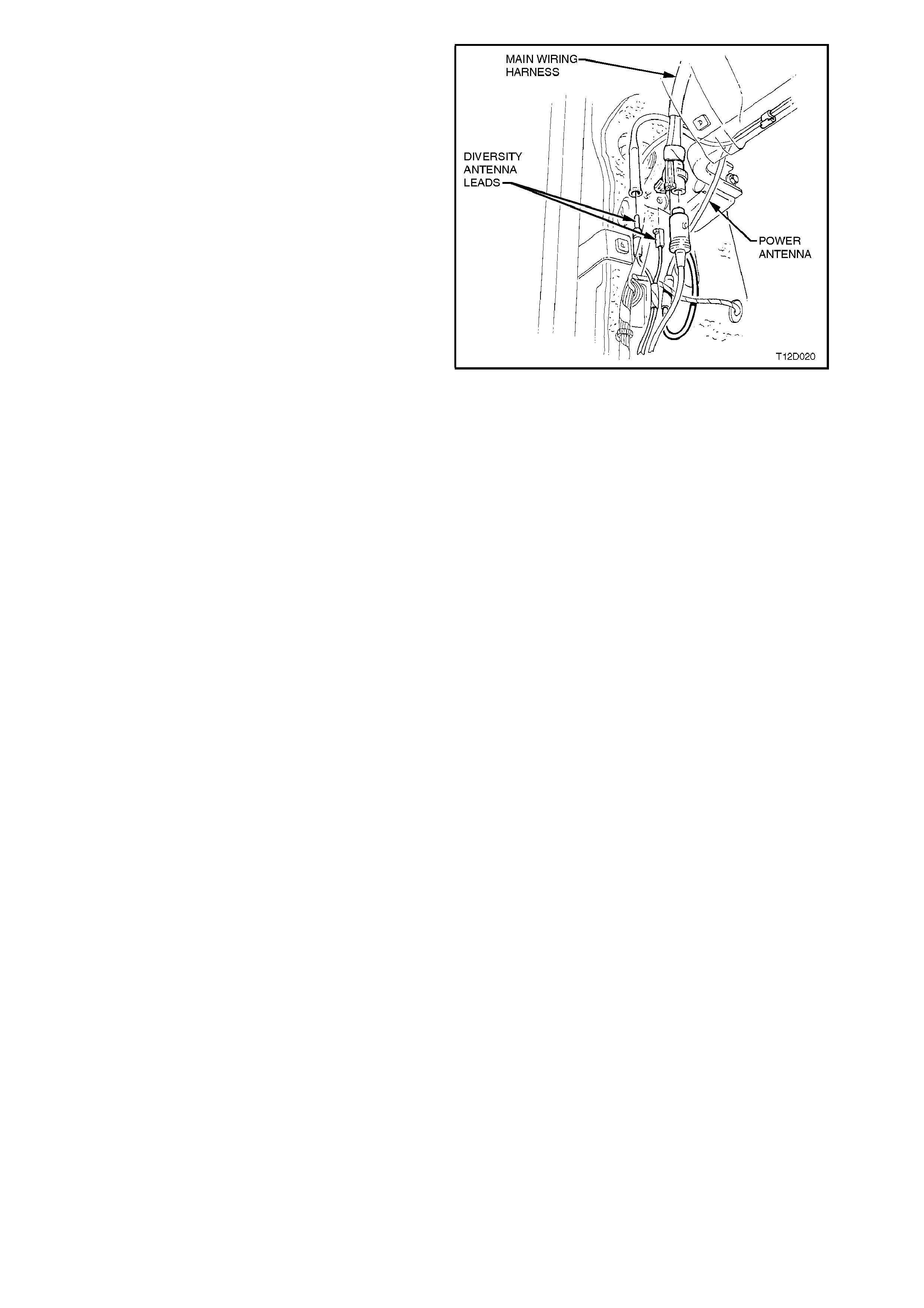
To aid in the reception of FM radio signals a diversity antenna system is fitted to Calais.
The diversity antenna system consis ts of a diversity antenna, which is an integral par t of the rear window glass, and
a diversity antenna module. The diversity antenna module is located under the rear parcel shelf trim on the
passenger side and amplifies the signal received by the diversity antenna. The am plified signal is sent to the radio
via a coaxial cable.
The radio receives signals from both the diversity and the fender mounted mast antenna and uses the stronger
signal for radio reception. This use of two antennae located in different positions on the vehicle makes the radio
reception less likely to be affected by signal nulls (multipathing) experienced in moving vehicles.
Operating instructions for the audio system accompany the VT Owner’s Handbook in the vehicle’s glove
compartment.
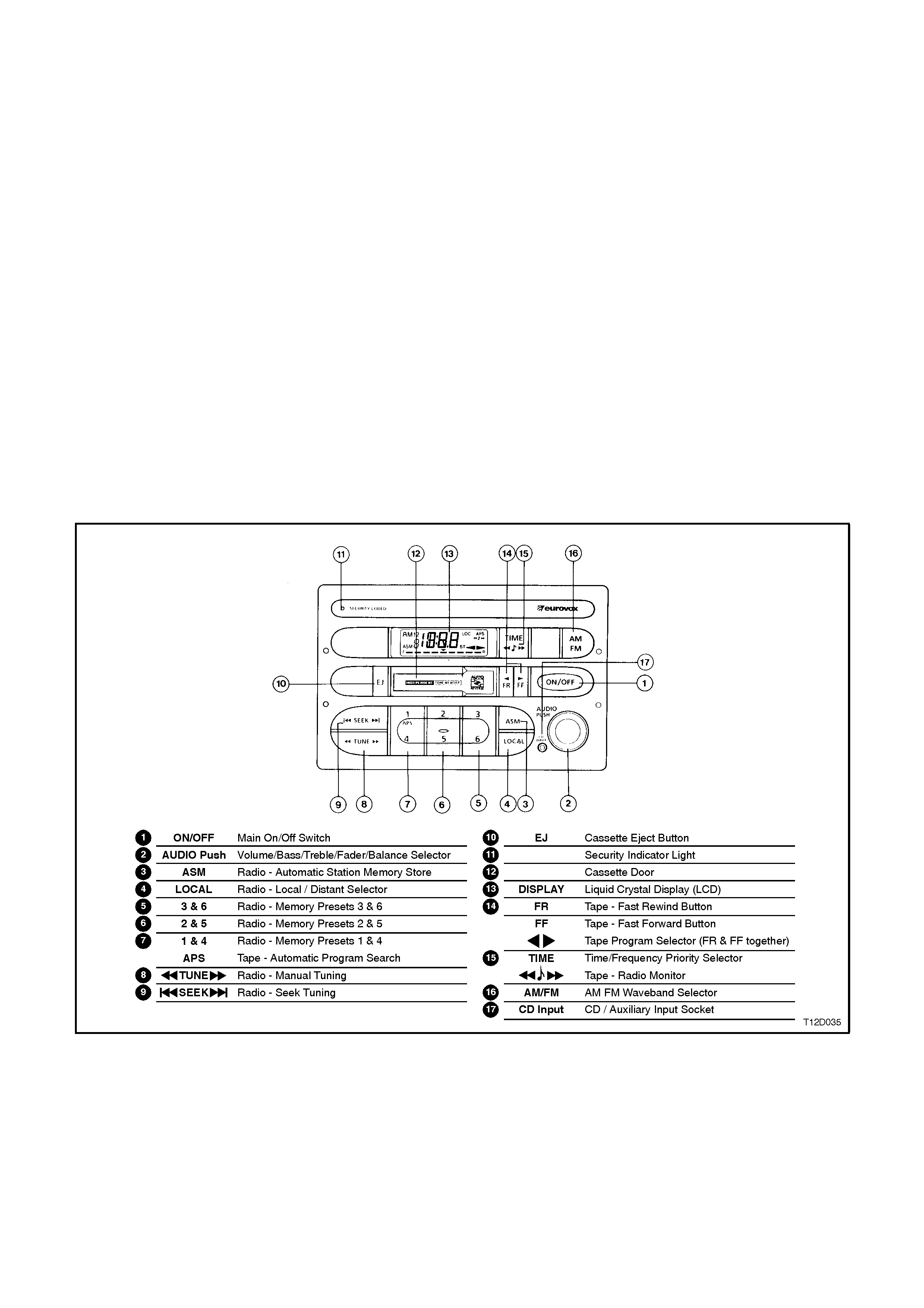
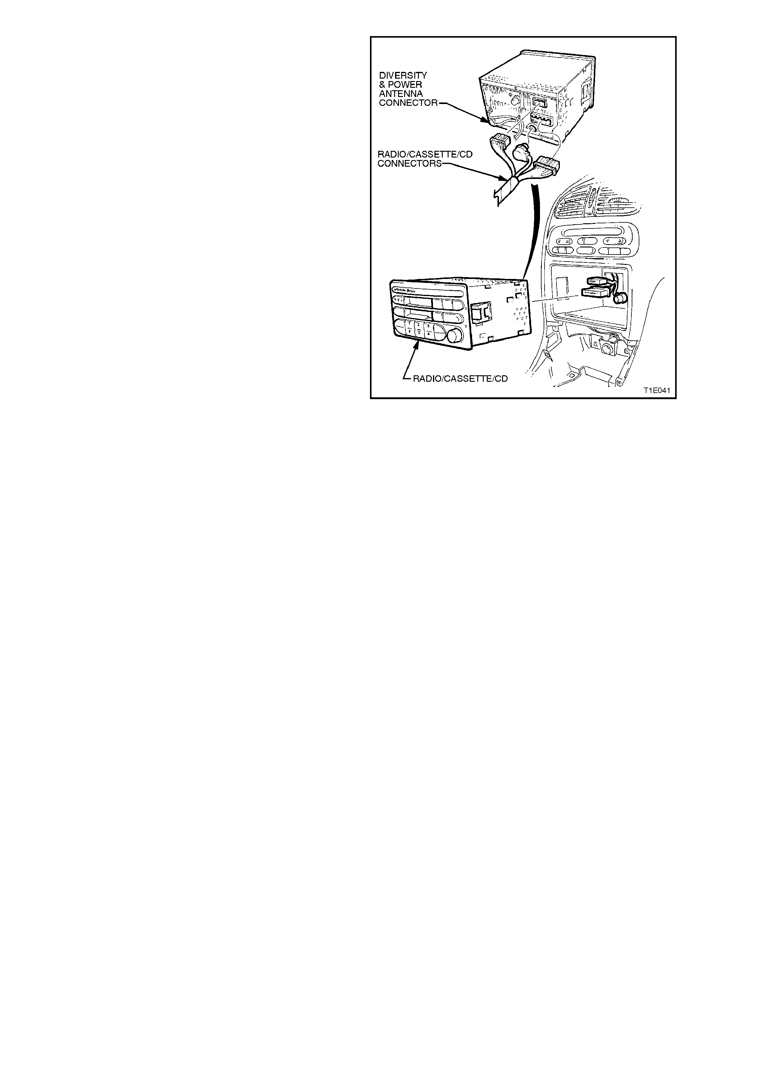
Fig. 12D-1 shows the radio/cassette player fitted to base models.
Figure 12D-1
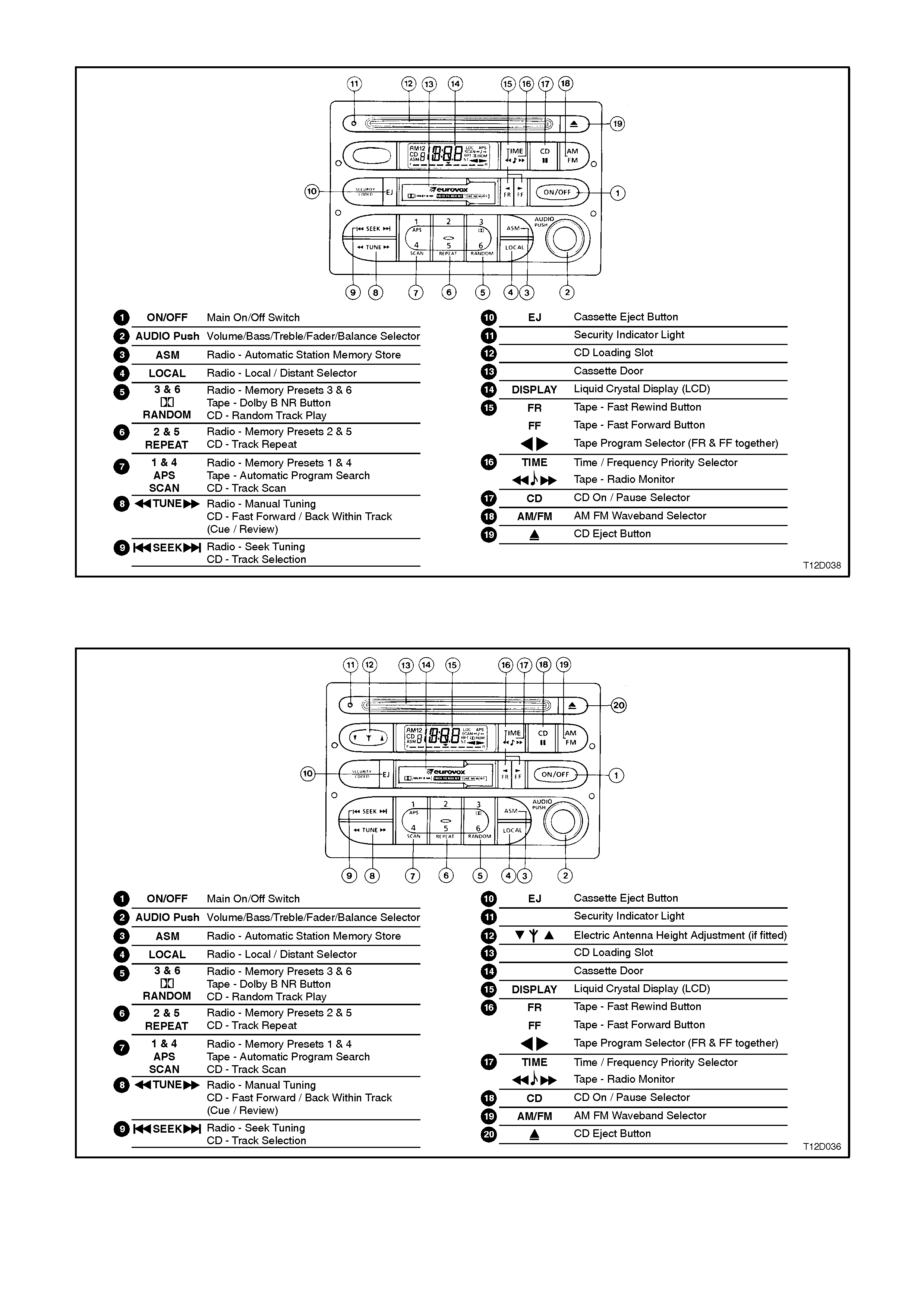
Fig. 12D-2 shows the radio/cassette/CD player available on base models with automatic power antenna.
Figure 12D-2
Fig. 12D-3 shows the radio/cassette/CD player fitted to VT Berlina models with power antenna.
Figure 12D-3
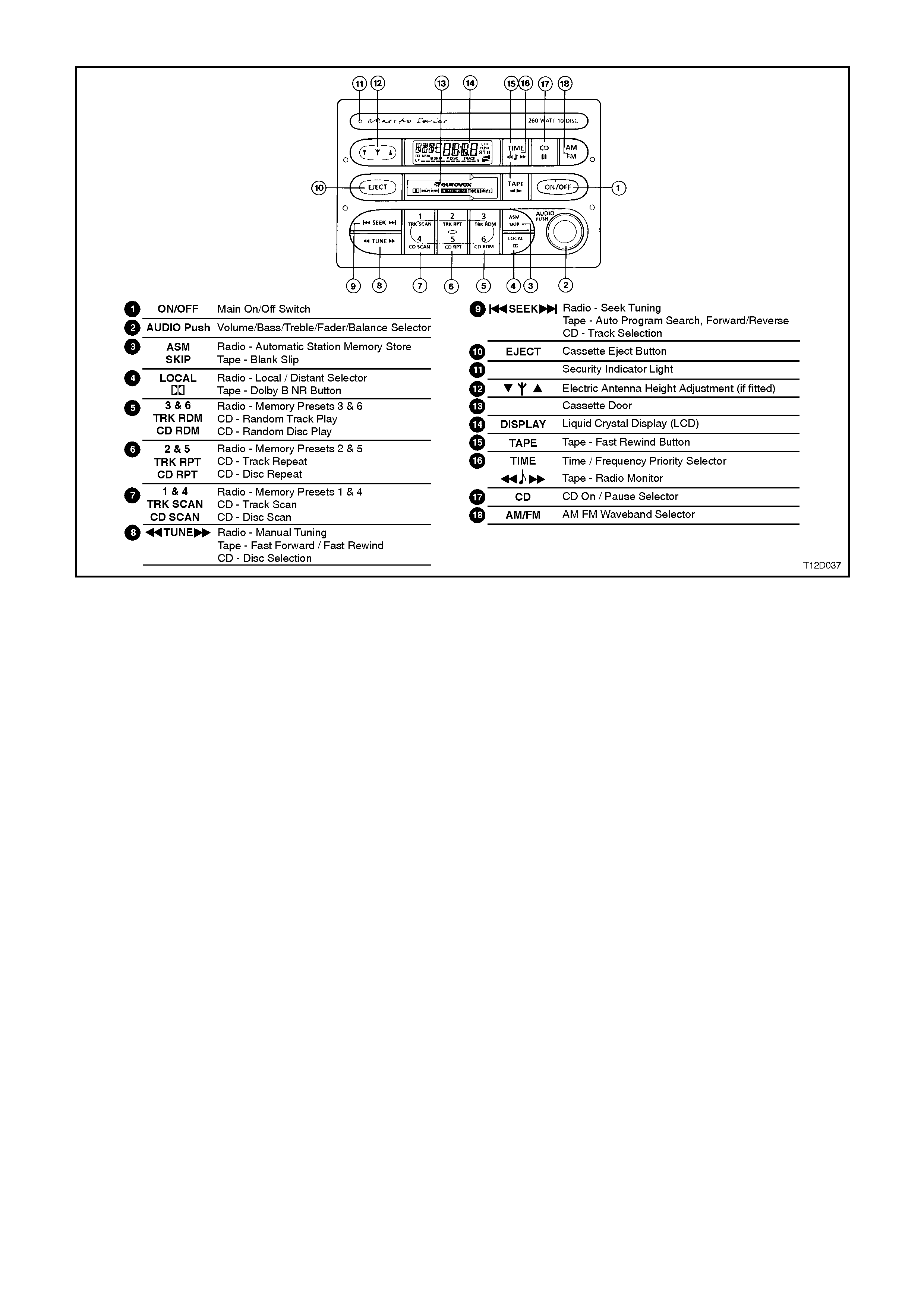
Fig. 12D-4 shows the radio/cassette/CD changer fitted to VT Calais models with CD changer and power antenna.
Figure 12D-4
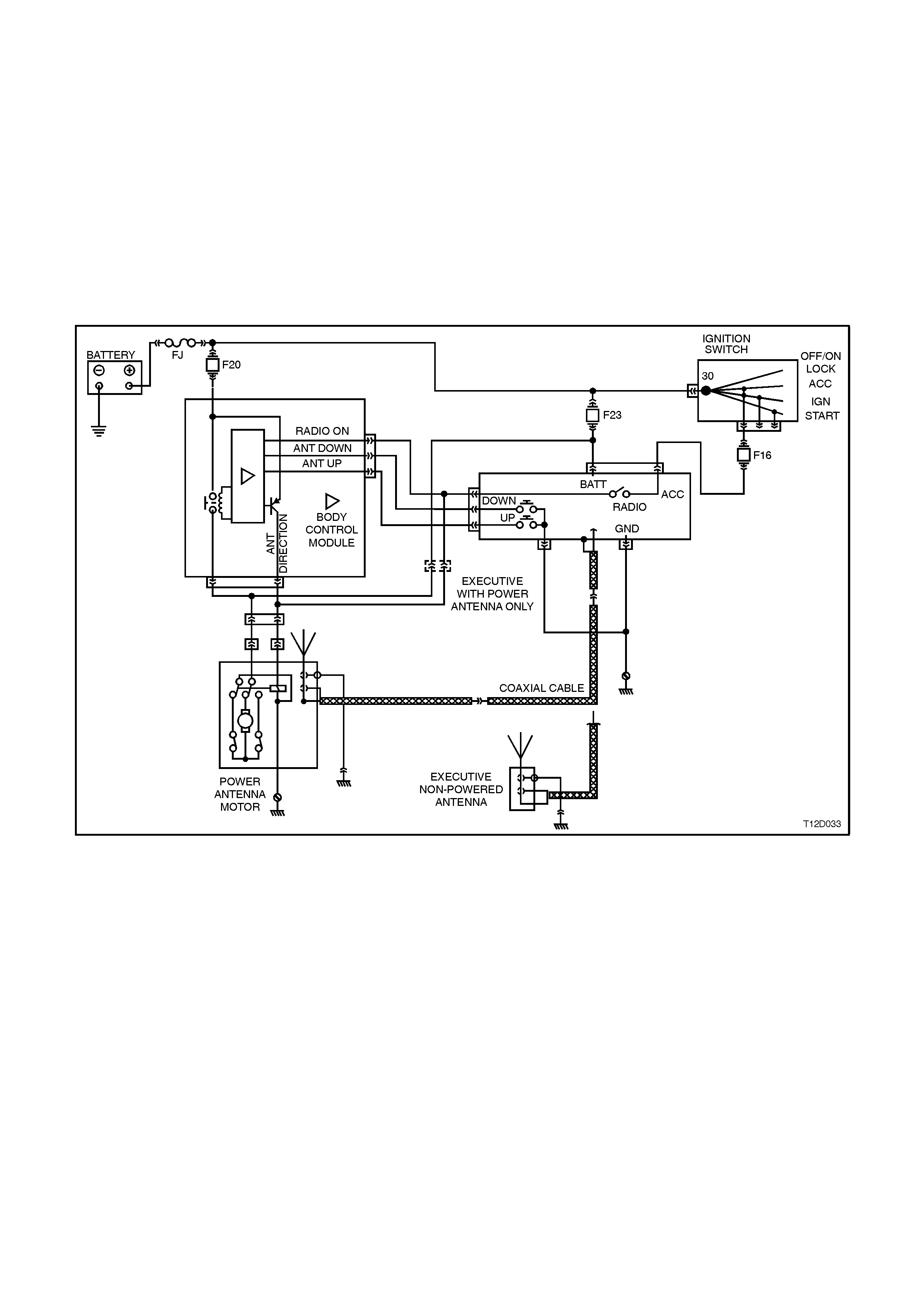
1.1 POW E R ANTENNA OPERATION
For Berlina and Calais, the operation of the power antenna is controlled by the body control m odule and a height
adjustm ent switch located on the radio/cass ette/CD player control panel adjacent to the liquid cr ystal display. For
service information re fer to Sections 12J-1 LOW SERIES BCM and Section 12J-2 HIGH SERIES BCM.
For VT Commodores with the power antenna option, the operation of the antenna is controlled by the
radio/cassette/CD player. When the radio is switched on, the antenna mast is raised to its full height, and
retracts when the radio is switched off, or a tape or CD is played.
For vehicles with a high series BCM, when the radio is turned ON and with the ignition key in the ACC position,
control circuitry within the radio supplies voltage to the antenna assembly lead for 8 seconds after a delay of
approximately 3 seconds after the radio is turned ON. This allows the motor to raise the antenna mast to full
height for optimum radio reception.
Approximately 15 seconds after switching the ignition and/or radio OFF, the module terminal 3 supplies voltage
to the antenna red lead and the mast is retracted fully.
Figure 12D-5
1.2 DIVERSITY ANTENNA OPERATION
To aid in the consistent reception of FM radio signals, the Calais model is equipped with a diversity antenna
system.
The diversity antenna system consists of a diversity antenna, diversity antenna module and coaxial leads.
The diversity antenna is an integral part of the rear window glass. The thin conductors that form the diversity
antenna are laid on the inside of the glass in the s ame manner as the r ear window demis ter elements . A terminal
is located on the passenger side of the rear window allowing connection of the diversity antenna to the diversity
antenna module lead.
The diversity antenna module amplifies the signal received from the diversity antenna. It then transmits the
amplified signal to the radio’s diversity antenna input.
The diversity antenna module is located beneath the trim on the passenger side of the rear parcel shelf. The
module is connected to the diversity antenna via one of two coaxial leads, the other lead, located under the
passenger side rocker panel cover, connects the module to the radio’s diversity antenna input extension lead.
Another single wire lead is used to supply the diversity antenna module with 12 V for its operation and the
module is earthed through its case to the vehicle body.
To prevent interference, it is very important that the module and coaxial leads are earthed securely.
The radio receives signals from both the diversity antenna system and the conventional fender mounted mast
type antenna. Internal circuitry w ithin the radio decides which antenna is located in the cleaner signal area. It then
uses that antenna for its radio reception.
When the vehicle is in motion the radio constantly monitors both antenna inputs and swaps between them in
order to maintain the best possible radio reception.
Figure 12D-6
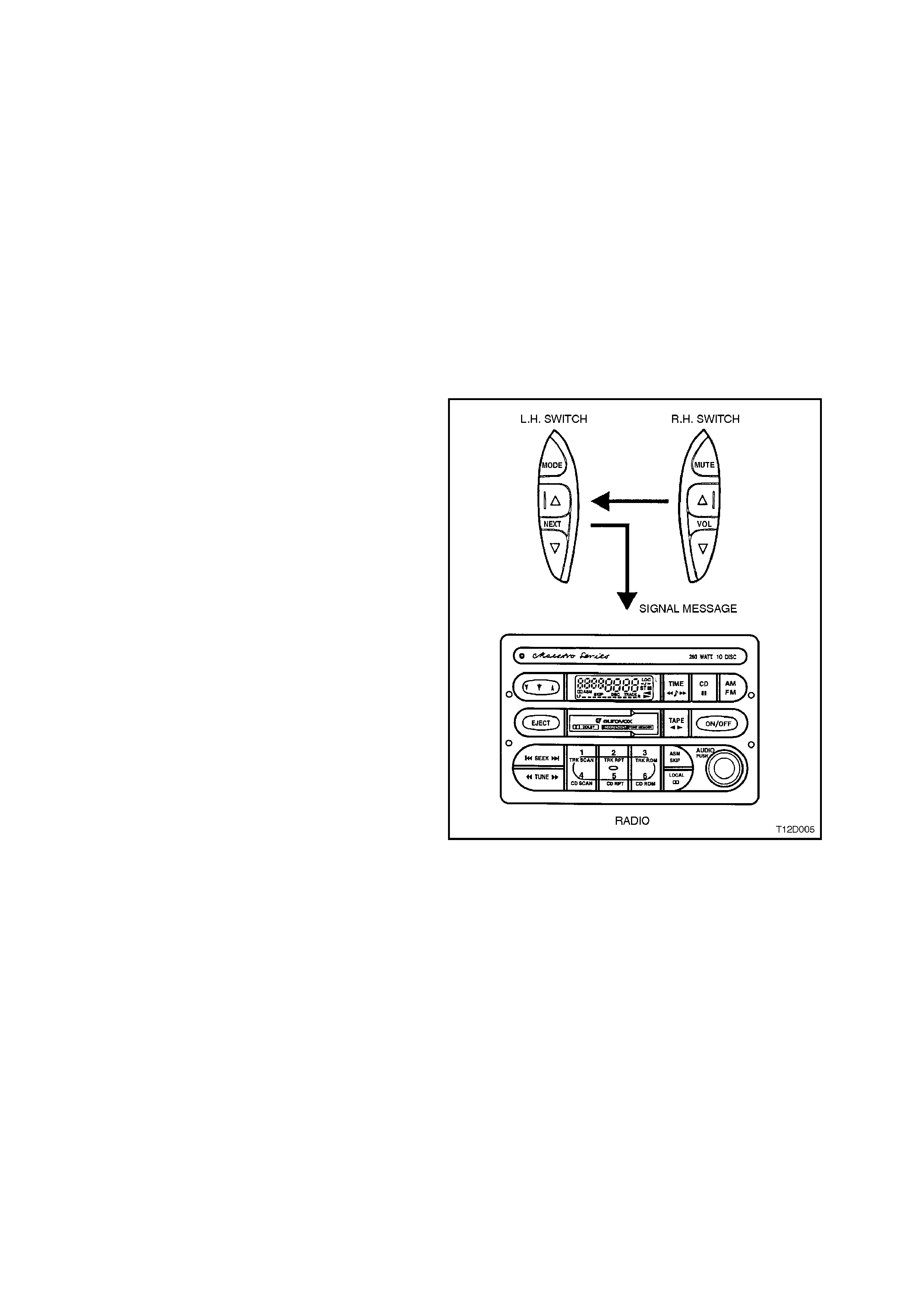
1.3 HORN BAR STEREO CONTROL OPERATION
There are two major components of the horn bar
stereo control system. These components are as
follows:
1. Right hand switch assembly -
Located to the right hand side of the horn bar,
the right hand switch assembly has three
momentary contact switches that are used to
control VOLUME UP, VOLUME DOWN and
MUTE functions of the stereo.
2. Left hand switch assembly -
Located to the left hand side of the horn bar,
the left hand switch assembly has three
momentary contact switches that are used to
control NEXT UP, NEXT DOWN and MODE
SELECTION.
OPERATION
When a button is pressed on the horn bar control,
the radio decides the function required by
measuring the resistance of the contact pressed.
Each contro l switch has a unique resis tance value,
and this is used by the radio to determine which
command has been issued.
Figure 12D-7
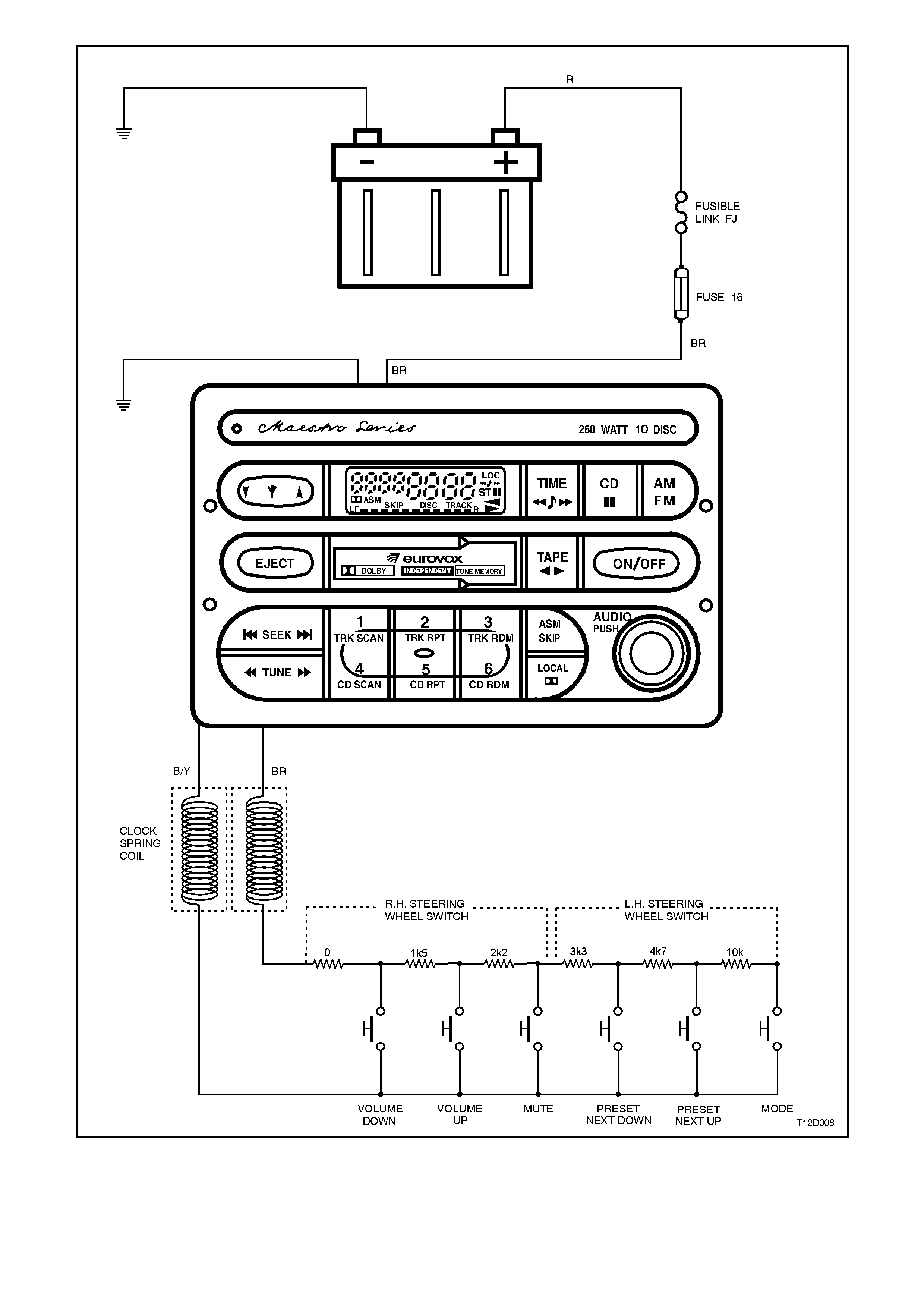
Figure 12D-8
2. SERVICE OPERATIONS
2.1 RADIO/CASSETTE PLAYER
REMOVE
1. Disconnect battery earth cable.
2. Lower instrument panel lower cover - left side.
3. Open instrument panel compartment and
remove left hand side lower trim assembly,
refer to Section 1A3 INSTRUMENT PANEL
AND CONSOLE.
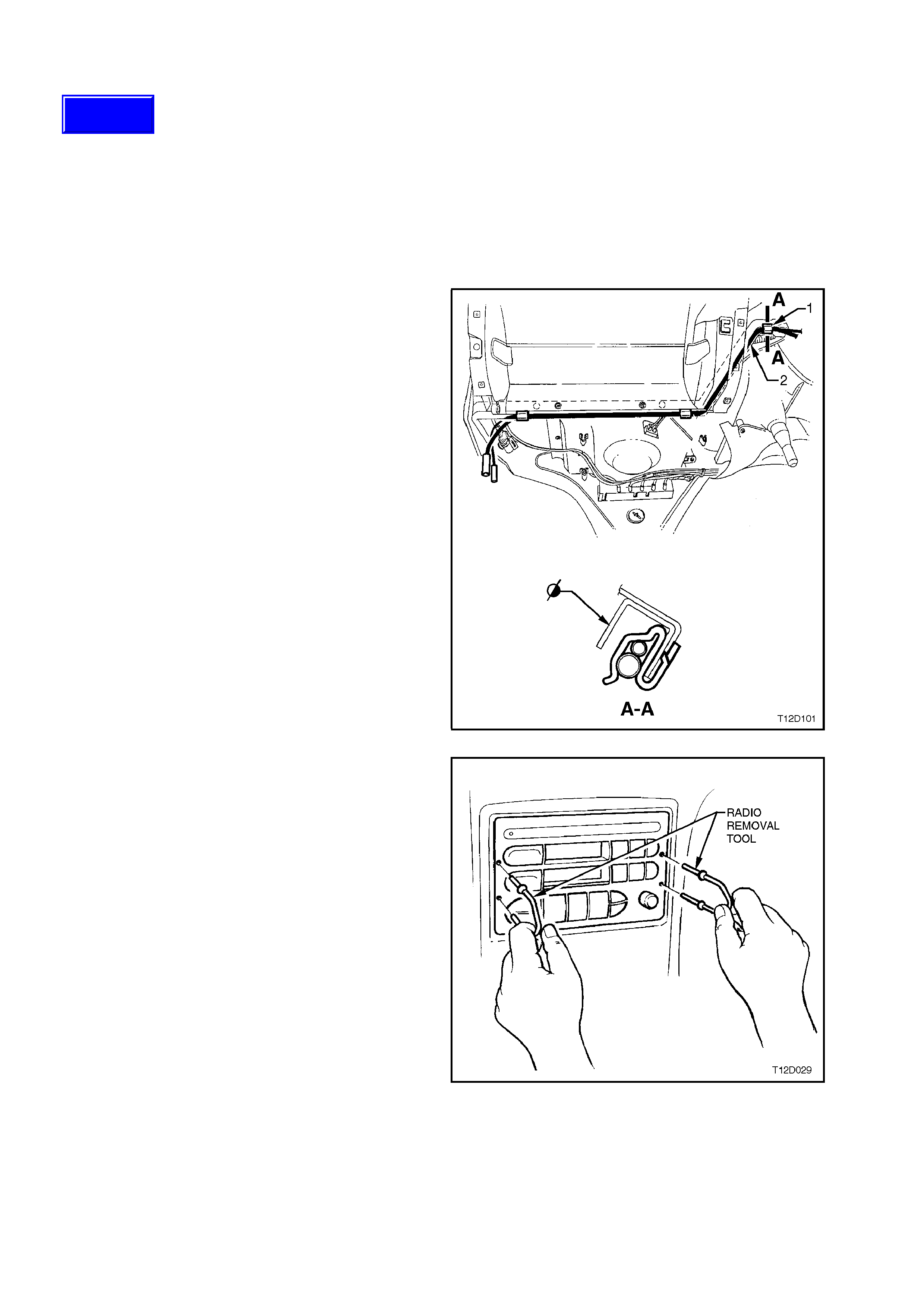
4. Unhook excess antenna lead (2) coiled
through clip (1) on right hand side of
instrument carrier rail.
Figure 12D-9
5. Using special service tool 179 1308 0000,
insert into access holes on either side of
radio/cassette player and push service tool to
release retaining spring clips.
6. Pull radio/cassette player out sufficiently to
access wiring harness and antenna
connectors at rear of unit.
Figure 12D-10
Techline
7. Disconnect radio/cassette wiring harness and
if present CD connectors.
8. Release antenna leads from flexible tab on
rear of radio.
9. Disconnect mast antenna and if fitted diversity
antenna connections from rear of
radio/cassette play er.
10. Remove radio/cassette player.
Figure 12D-11
REINSTALL
Installation is the revers e of the rem oval procedure
noting the following points:
1. Ensure antenna leads are secured by flexible
tab on rear of radio.
2. Locate wiring and antenna leads from behind
radio carrier and gently pull all leads from
behind, whilst sliding radio into position.
NOTE:
This is necessary to ensure that none of the leads
are jammed or damaged behind the radio.
If care is not taken antenna lead may be
crushed between radio and radio carrier,
causing intermittent reception problems.
3. Check for correct operation.
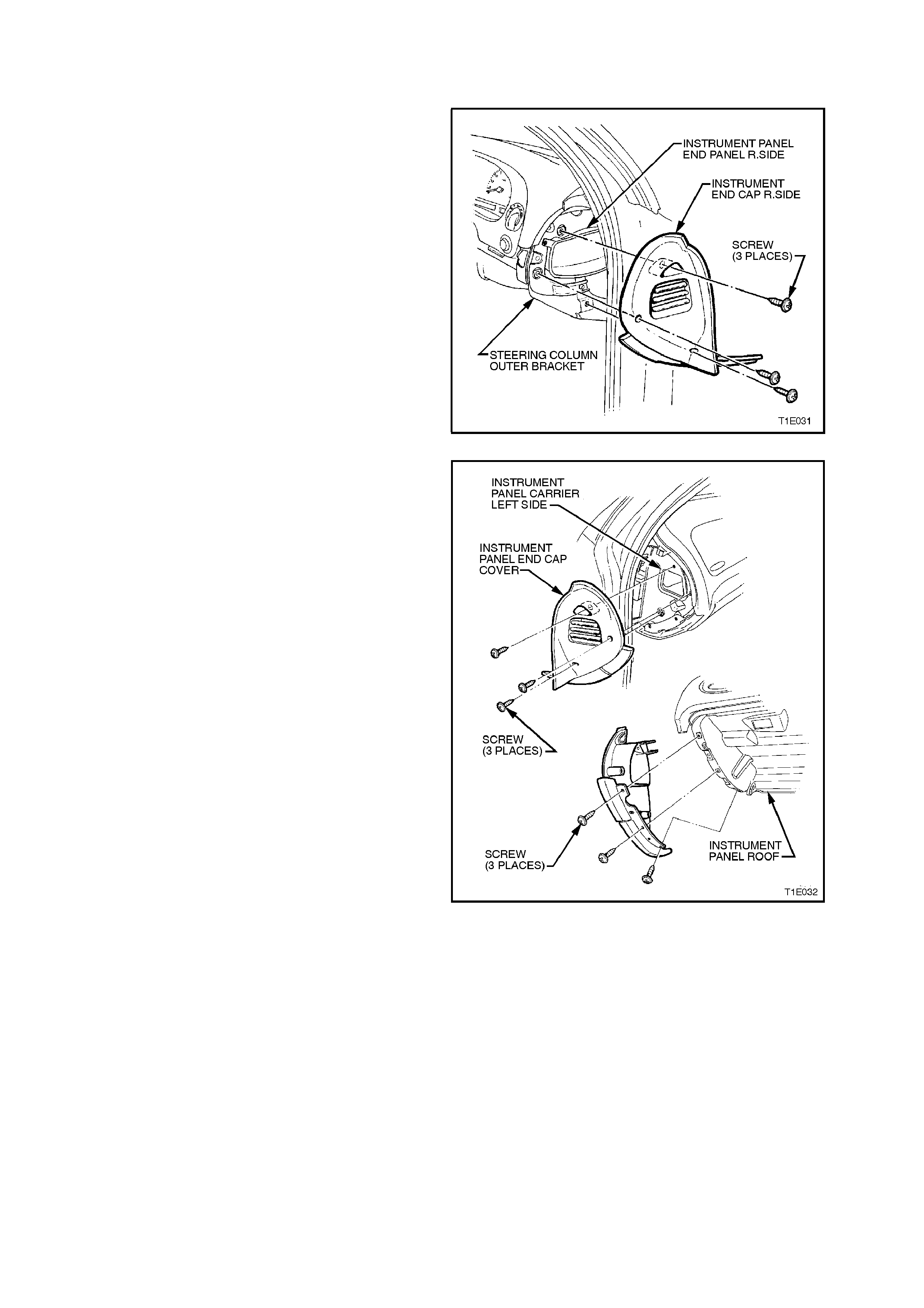
2.2 FRONT INSTRUMENT PANEL SPEAKERS - ALL MODELS
REMOVE
1. Disconnect battery earth cable.
2. Remove the three screws and remove
instrument panel end cap cover right hand
side.
Figure 12D-12
3. Remove the six retaining screws for
instrument panel end cap cover left hand side.
Figure 12D-13
4. Remove retaining screw from the demist
nozzle right hand and remove.
5. Remove retaining screw from the demist
nozzle left hand and remove.
NOTE:
On all vehicles, care must be taken to avoid
damage to the solar sensor (if fitted).
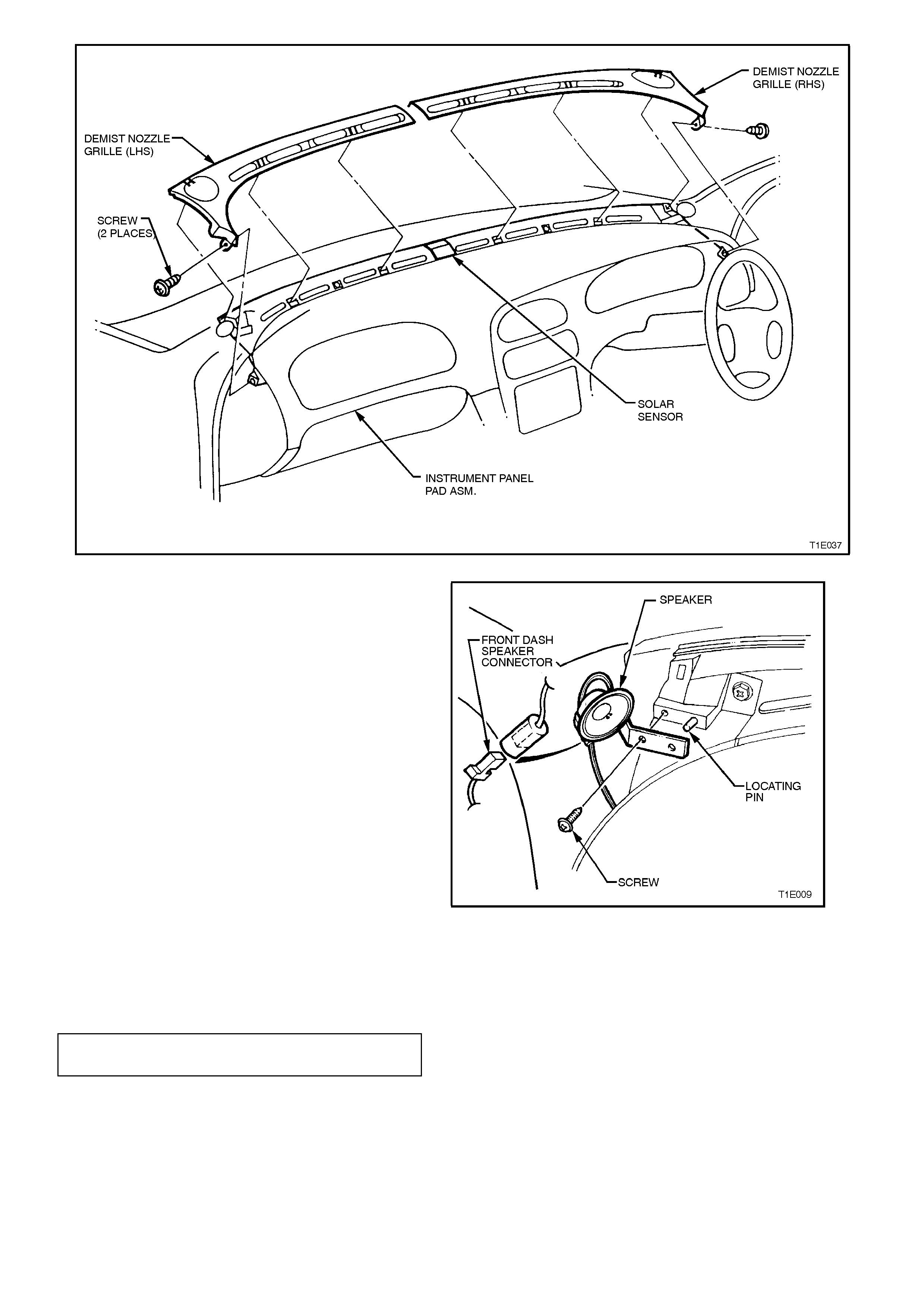
Figure 12D-14
6. Disconnect left and right front dash speaker
harness connectors. Using a Phillips head
screw driver, remove screw attaching front
dash speakers and remove both speakers.
NOTE:
The c onnector loc k ing tab may be hidden under the
anti-rattle foam wrap.
Figure 12D-15
REINSTALL
Installation is the reverse of the r emoval proc edure.
Tighten speaker screws to the specified torque.
FRONT INSTRUMENT PANEL
SPEAKERS 1 - 3 Nm
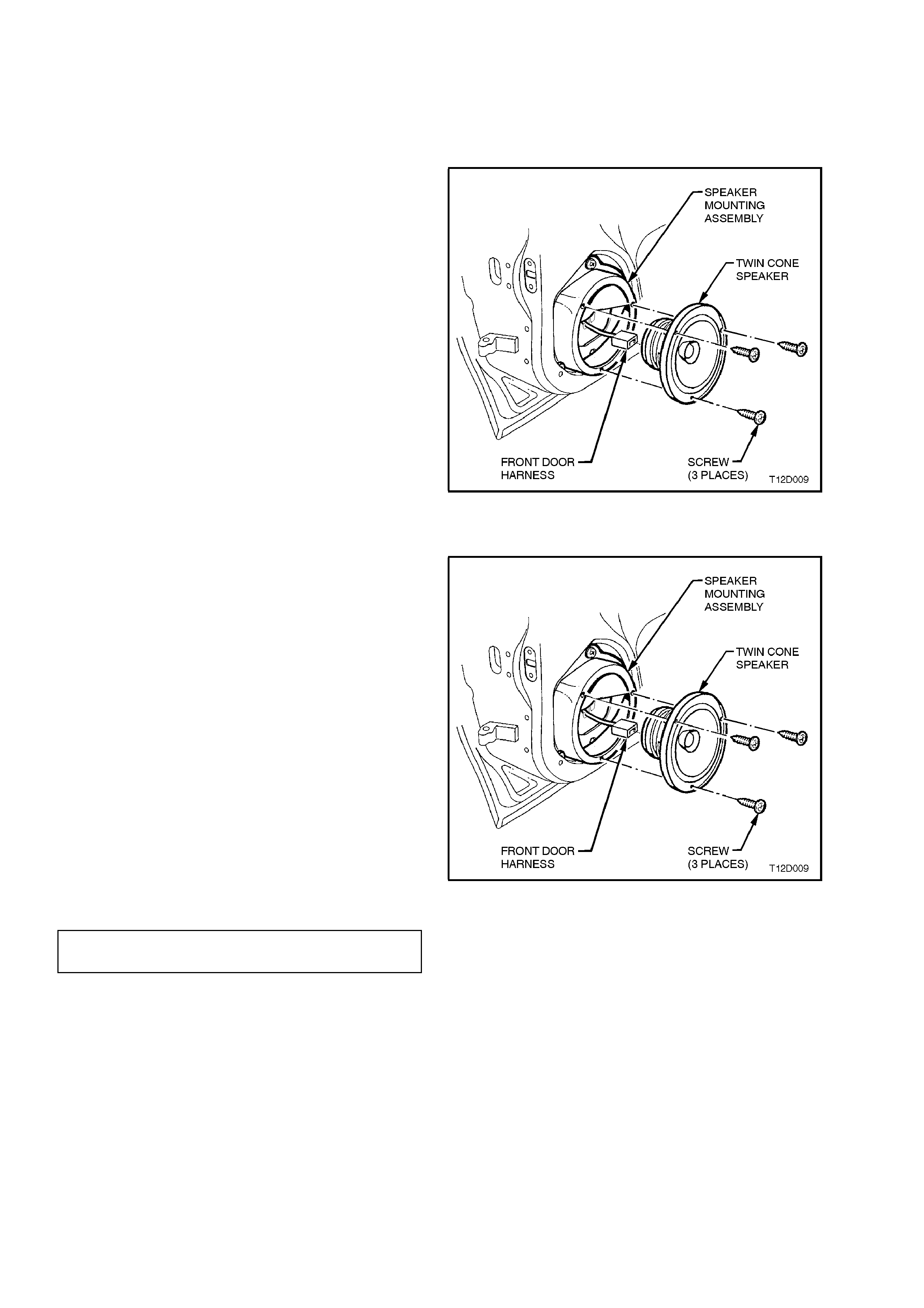
2.3 FRONT DOOR SPEAKERS - ALL MODELS
REMOVE
1. Remove door trim from front door. Refer to
Section 1A5 FRONT AND REAR DOOR
ASSEMBLIES.
2. Remove speaker assembly to speaker box
attaching screws.
3. Remove speaker from speaker box.
Release wiring harness from tab on rear of
speaker box.
Disconnect wiring harness from speaker
connector and remove speaker.
Figure 12D-16
REINSTALL
Installation is the reverse of the rem oval procedure
noting the following:
1. Ensure electrical connector is properly
attached to speaker.
2. Before installing speaker, visually inspect
speaker mounting box cavity for protrusions
that will touch the underside of the speaker
cone on installation, i.e. cable ties etc.
Resecure wiring harness to tab on rear of
speaker box.
3. Carefully reinstall speaker attaching screws
ensuring that speaker frame is not distorted
when screws are tightened.
NOTE:
Angled insertion of speaker attaching screws can
lead to speaker distortion. Make sure screws are
installed square to speaker frame. Figure 12D-17
FRONT DOOR SPEAKER
ATTACHING SCREWS 1 - 3 Nm

NOTE:
There are specific front speaker assemblies for
base model and Calais application. Refer to Fig.
12D-18 for identification details . Check that the part
numbers and resistance values are correct, as
incorrect speaker fitment can affect system
operation, resulting in unnecessary complaints.
Check speaker operation once installation has
been completed.
Figure 12D-18
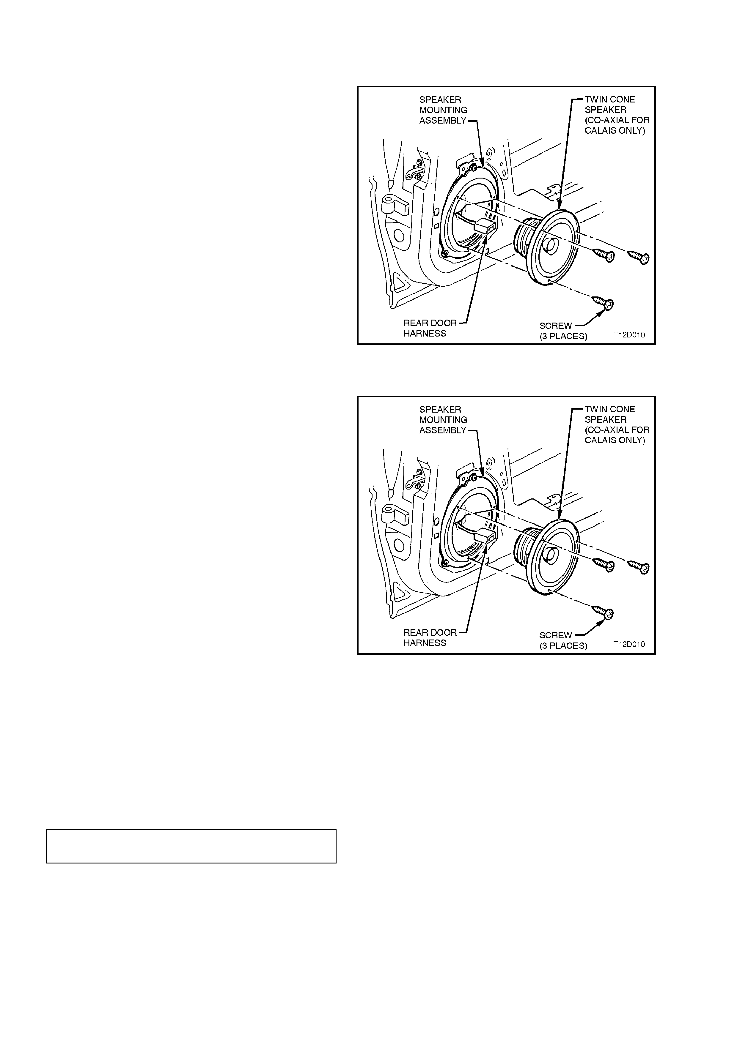
2.4 REAR DOOR SPEAKERS
REMOVE
1. Remove door trim from rear door. Refer to
Section 1A6 FRONT AND REAR DOOR
ASSEMBLIES.
2. Remove speaker assembly to speaker box
attaching screws.
3. Remove speaker from speaker box.
Release wiring harness from tab on rear of
speaker box.
Disconnect wiring harness from speaker
connector and remove speaker.
Figure 12D-19
REINSTALL
Installation is the reverse of the rem oval procedure
noting the following points:
NOTE:
There are specific rear speaker assemblies for
base model and Calais application. Refer to Fig.
12D-18 for identific ation details. Check that the part
numbers and resistance values are correct, as
incorrect speaker fitment can affect system
operation, resulting in unnecessary complaints.
1. Ensure electrical connector is properly
attached to speaker.
2. Before installing speaker, visually inspect
speaker mounting box cavity for protrusions
that will touch the underside of the speaker
cone on installation, ie. cable ties etc.
Resecure wiring harness to tab on rear of
speaker box.
3. Carefully reinstall speaker attaching screws
ensuring that speaker frame is not distorted
when screws are tightened.
NOTE:
Angled insertion of speaker attaching screws can
lead to speaker distortion. Make sure screws are
installed square to speaker frame and are tightened
to the correct torque specification.
Figure 12D-20
Check speaker operation once installation has been
completed.
REAR DOOR SPEAKER
ATTACHING SCREWS 1 - 3 Nm
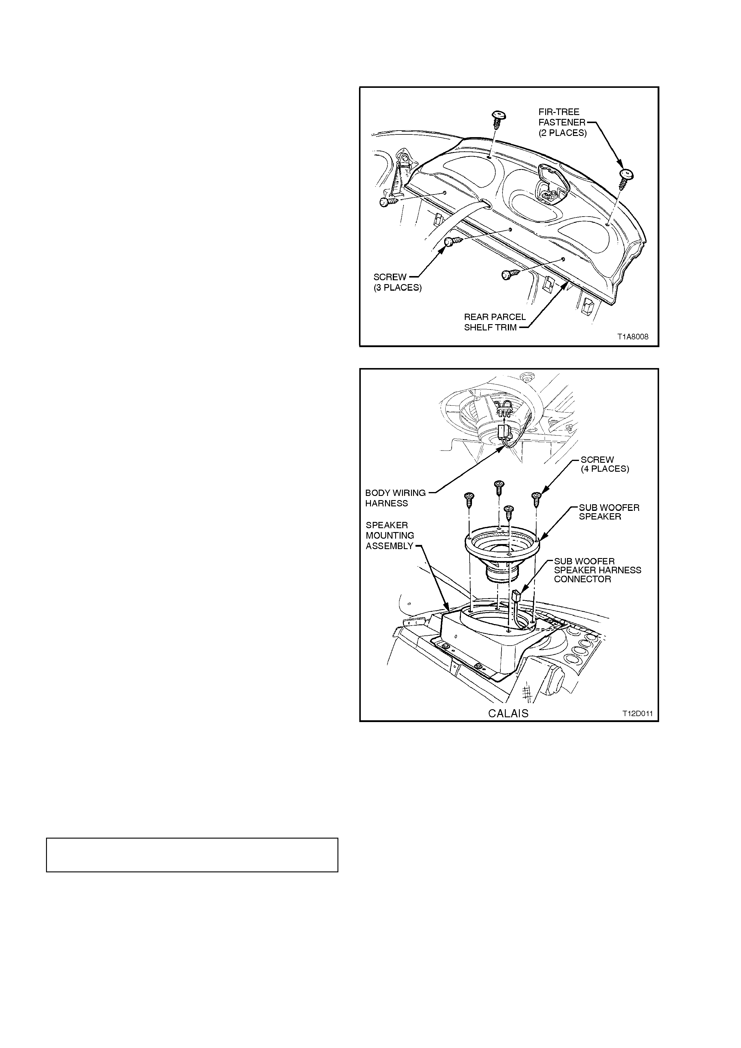
2.5 SUBWOOFER SPEAKERS - CALAIS
REMOVE
1. Disconnect battery earth cable.
2. Remove rear seat cushion and back
assemblies (refer to Section 1A7 SEATS
AND SEAT BELT ASSEMBLIES).
3. Remove the centre seat belt lower attachment
(refer to Section 1A7 SEATS AND SEAT
BELT ASSEMBLIES).
4. Open flap to child restraint fitting and unbolt
child restraint fitting.
5. From the rear compartment, carefully tap out
the fasteners securing the trim to the rear
parcel shelf.
6. Disassemble webbing guide (unclip from
parcel shelf).
7. Pull flap in parcel shelf forward, feed seatbelt
tongue and anchor through hole and remove
parcel shelf trim. Figure 12D-21
8. From the rear compartment, carefully remove
wiring harness connections to lefthand side
and righthand side sub-woofers.
9. From within passenger compartment, remove
four screws securing each sub-woofer and
carefully lift from mounting bracket.
REINSTALL
Installation is the reverse of the rem oval procedure
noting the following:
1. Ensure electrical connector is properly
attached to speaker.
2. Before installing speaker, visually inspect
speaker mounting box cavity for protrusions
that will touch the underside of the speaker
cone on installation i.e. cable ties etc.
3. Carefully reinstall speaker attaching screws
ensuring that speaker frame is not distorted
when screws are tightened.
When refitting parcel shelf trim, check to ensure
that foam sealing ring has not f olded back on itself .
Take care when refitting to ensure foam sealing
ring is not dislodged or folded back during this
process.
NOTE:
Angled insertion of speaker attaching screws can
lead to speaker distortion. Make sure screws are
installed square to speaker frame.
Figure 12D-22
SUBWOOFER SPEAKER
ATTACHING SCREWS 1 - 3 Nm
2.6 CALAIS AUDIO SYSTEM
Figure 12D-23
Figure 12D-24
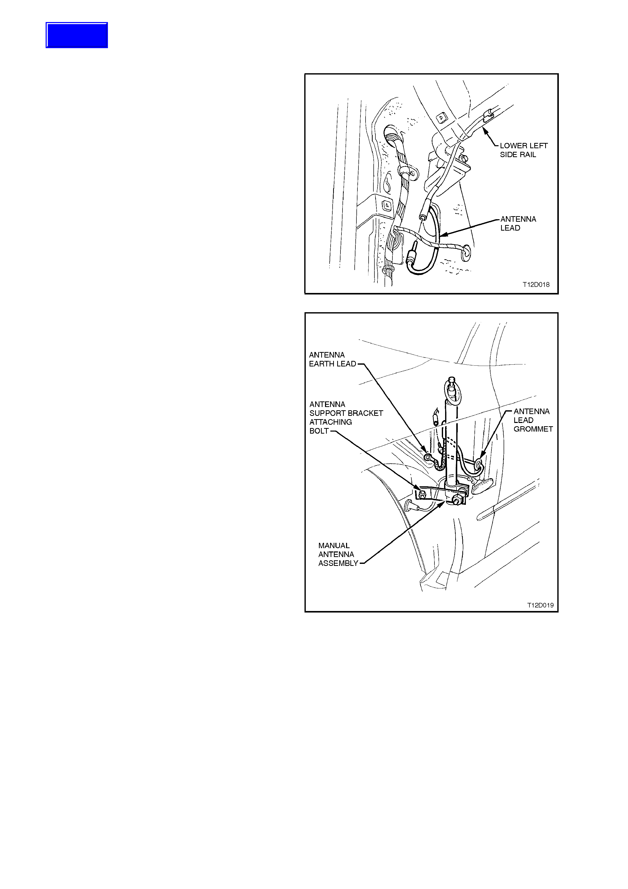
2.7 MANUAL ANTENNA
REMOVE
1. From inside vehicle, remove glove
compartment and instrument panel lower trim,
refer to Section 1A3 INSTRUMENT PANEL &
CONSOLE.
2. Release the forward section of rocker panel
cover.
3. Remove the upper retainer screw and the
screw beneath the rocker panel cover securing
the shroud lower trim assembly to the rocker
panel.
4. Pull the shroud lower trim assembly rearward
from the retainer removing the assembly.
5. Disconnect antenna lead from main wiring
harness connecting socket near powertrain
control module at left hand cowl panel.
6. Remove nut, retainers and screws securing
left hand fender inner liner and remove inner
liner. Figure 12D-25
7. Push antenna mast down to fully retracted
position.
8. Remove screw connecting earth braid to inner
fender earth terminal.
9. While supporting antenna, remove M8 bolt
attaching antenna bracket to inner fender
panel.
10. Remove antenna lead grommet from inner
fender panel and pull lead out f rom pas senger
compartment.
11. Withdraw antenna down from bezel and
remove, complete with lead and grommet.
12. If necessary, loosen antenna bracket screw
and remove bracket from antenna.
Figure 12D-26
Techline

REINSTALL
Manual antenna installation is the reverse of
removal procedures, noting the following points:
1. If removed, leave antenna bracket screw
loose.
2. Ensure that antenna and earth leads are
routed correctly and securely connected.
3. With antenna pushed up agains t stop in bezel,
tighten antenna bracket to inner fender panel
attaching bolt to the correct torque
specification.
ANTENNA BRACKET TO INNER
FENDER PANEL ATTACHING
BOLT TORQUE SPECIFICATION 3.0 - 6.0 Nm
Tighten bracket screw to the correct torque
specification.
ANTENNA BRACKET SCREW
TORQUE SPECIFICATION 2.0 - 5.0 Nm
Check radio operation and reception.
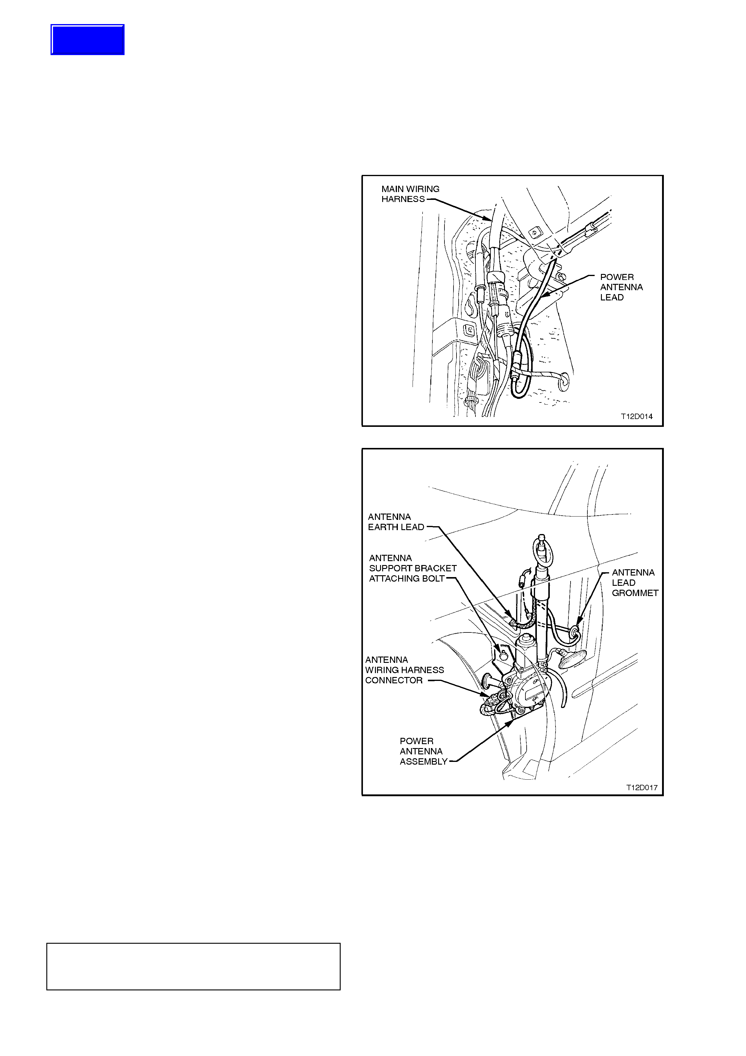
2.8 P O WER ANTENNA
POWER ANTENNA SWITCHES
The power antenna direc tional control s witches are
integrated with the radio and as such cannot be
serviced separately.
POWER ANTENNA ASSEMBLY
REMOVE
1. From inside vehicle, remove footwell upper
closing panel left side, instrument panel
compartment and instrument panel
compartment roof, refer to Section 1A3
INSTRUMENT PANEL AND CONSOLE.
2. Disconnect antenna lead from main wiring
harness connecting socket above powertrain
control module at left hand cowl panel.
Figure 12D-27
3. Set antenna mast to fully retracted position.
4. Remove nut, retainers and screws securing
right hand fender inner liner and remove inner
liner.
5. Remove screw connecting earth braid to inner
fender earth terminal.
6. Disconnect antenna wiring harness connector
from main wiring harness connector in wheel
well.
7. While supporting antenna assembly, remove
antenna support bracket attaching bolt.
8. Remove antenna lead grommet from inner
fender panel and pull lead out f rom pas senger
compartment.
9. Withdraw antenna down through bezel and
remove, complete with leads, grommet and
bracket.
Figure 12D-28
REINSTALL
Reinstallation is the reverse of the removal procedure taking note of the following:
1. Ensure cable and harness are routed correctly .
2. Ensure that antenna and earth leads are routed correctly and securely connected.
3. W ith antenna pushed up against stop in bezel, tighten antenna bracket to inner fender panel attaching bolt to
the correct torque specification.
ANTENNA BRACKET TO INNER
FENDER BOLT
TORQUE SPECIFICATION 5.0 - 12.0 Nm
4. Check antenna operation and radio reception.
Techline

MAST REPLACEMENT
The following procedure is for replacing a damaged or faulty antenna mast and drive cable assembly.
1. Remove power antenna assembly as previously described in this Section.
2. Remove chrome plated nut from top end of mast tube.
3. Extend damaged antenna mast as far as possible by attaching battery negative via a jumper lead to antenna
mounting bracket and battery positive to both the antenna red and white wire terminals.
At end of mast travel, pull out mast and drive cable from antenna housing.
NOTE:
If m ast is too badly damaged to extend, grip tip of m ast with a pair of pliers and pull m ast and drive c able as sem bly
up and out from antenna housing.
4. If necess ary, rem ove contact spring ( metal s leeve) from old m ast and drive cable and ins tall onto replacem ent
mast and drive cable.
5. Feed end of drive cable down mast tube of antenna hous ing with serrated s ide of drive c able fac ing toward the
centre of the housing. Continue to feed drive cable down until it engages with the drive mechanism.
NOTE:
It may be necessary to twist the drive cable clockwise and anti-clockwise slightly to enable end of cable to feed
through opening at base of mast tube before it engages the drive mechanism.
6. W ith the aid of an assistant to hold the antenna and m ast assembly, connect antenna mounting bracket via a
jumper lead to battery negative.
7. Mom entarily connect battery positive to the antenna red wire and drive m echanism should start to r etract drive
cable into antenna housing.
8. With the drive cable engaged to drive mechanism, reconnect battery positive to antenna red wire and allow
drive mechanism to wind in drive cable and mast into mast tube and housing.
9. At this stage the mast might be fully retracted into the mast tube and housing. Reconnect both the red and
white wires to battery positive and allow the mast to extend fully until the motor stops.
Disconnect white wire from battery positive and allow mast to fully retract.
10. Reinstall chrome plated nut to top end of mast tube and tighten securely.
11. Reinstall power antenna assembly as previously described in this Section. Check antenna mast operation.
CHECKING ANTENNA MOTOR OPERATION
NOTE:
The following ‘Checking Antenna Motor Operation’ tests are made at the main wiring harness to antenna motor
connector located at the right hand cowl panel, above the engine management powertrain control module.
The voltages shown are measured to a good earth point on the vehicle body.
VOLTAGE ON ANTENNA HA RNESS WIRES
Red White Action
12V 12V Antenna extends
12V 0V Antenna retracts
0V 12V Antenna does not move
0V 0V Antenna does not move
If the antenna motor does not correctly respond to the inputs as specified, ensure that a good earth connection is
being made through the mounting bracket by measuring the resistance from the bracket to a good earth point. If
more than 1W replace power antenna assembly. Check that the forked earth connector is securely attached to the
antenna mounting.
NOTE:
If there is significant noise on the AM band (with radio tuned to weak station outdoors), then check antenna earth
quality. The antenna earth terminal has a large effect on the screen.
2.9 DIVERSITY ANTENNA
The diversity antenna is an integral part of the rear window assembly. The thin conductors that form the diversity
antenna are laid on the inside of the rear window glass in the same manner as the heated rear window elements.
A single terminal is located on the inside of the r ear window glass, on the pas senger s ide, to allow connection of the
diversity antenna to the diversity antenna module, located under the rear parcel shelf trim.
The diversity antenna module amplifies the radio signal received by the diversity antenna and transmits it to the
radio/cassette player via coaxial cable.
NOTE:
Due to the internal circuitry of the radio receiver, if the fender mounted mast antenna is retracted, faulty or
disconnected, the radio may not use the diversity antenna system for radio reception if the FM signal is weak.
DIVERSITY ANTENNA - TEST
1. Disconnect diversity antenna module connector from diversity antenna terminal.
2. Using an ohmmeter measure the resistance from the diversity antenna terminal to the diversity antenna
conductors on the inside of the rear window glass.
Resistance should be less than 20 W from diversity antenna connector to any point on the diversity antenna
conductors.
NOTE:
Care should be taken when measuring resistance that the diversity antenna conductors are not damaged by the use
of excessive force on the ohmmeter probe.
DIVERSITY ANTENNA MODULE
REMOVE
1. Remove rear seat cushion and back assemblies, refer to Section 1A7 SEATS AND SEAT BELTS.
2. Remove rear parcel shelf trim and side quarter window trim, refer to Section 1A8 HEADLINING & REAR
END TRIM.
3. Remove passenger side lower shroud trim and rocker panel cover, refer to Section 1A1 BODY.
4. Disconnect diversity antenna module harness
to main wiring harnes s connector located near
the PCM.
5. Disconnect diversity antenna module coaxial
cable from radio diversity antenna extension
cable connector located near PCM.
Figure 12D-29
6. Remove diversity antenna module leads from
retaining clips and remove leads from rocker
panel.
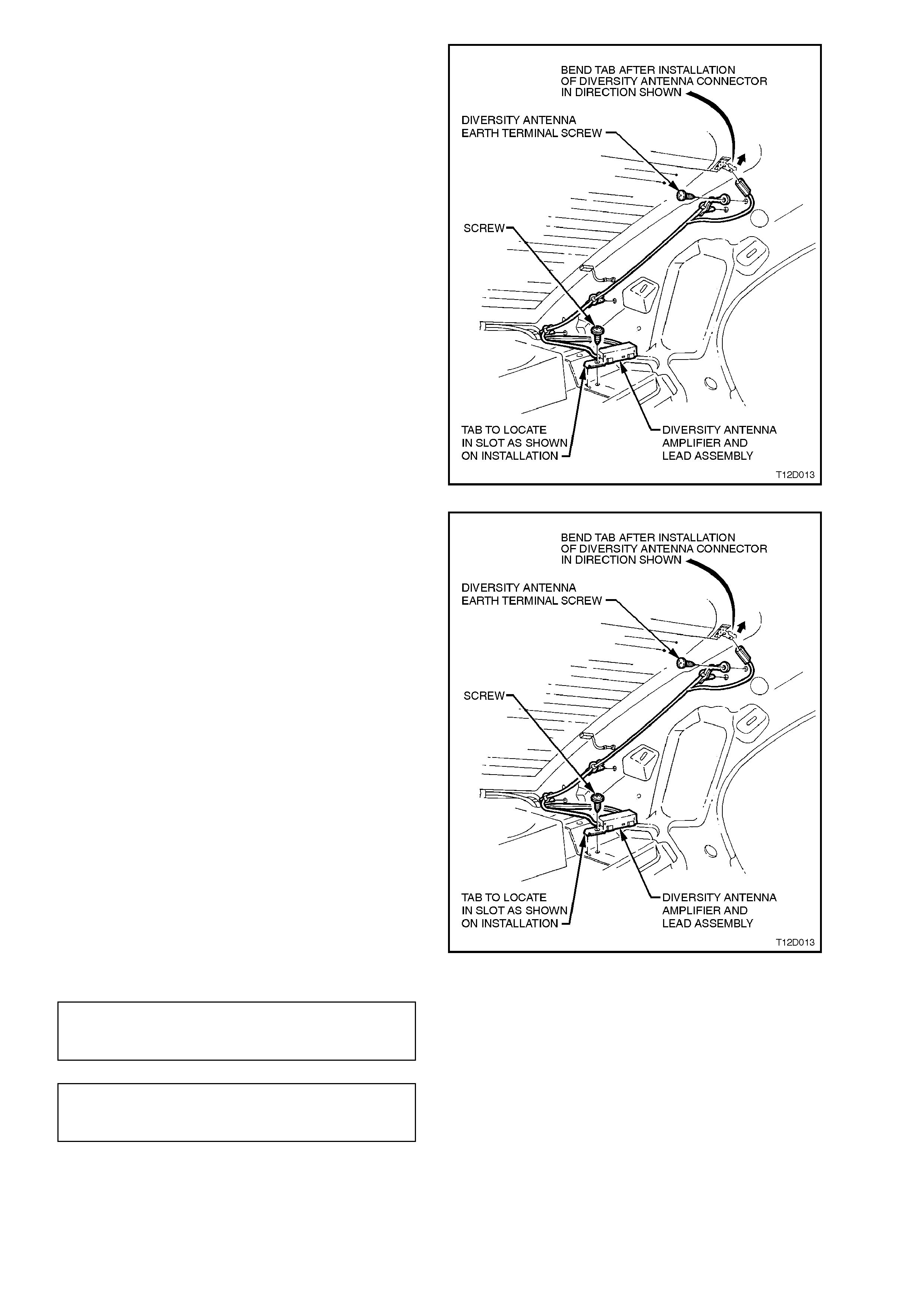
7. Remove diversity antenna module connector
from diversity antenna term inal located on rear
window.
8. Remove screw securing diversity antenna
earth terminal to vehicle body.
9. Remove screw securing diversity antenna
am plifier to r ear parc el s helf. Rem ove diversity
antenna module and leads.
Figure 12D-30
REINSTALL
Reinstallation is the reverse of the removal
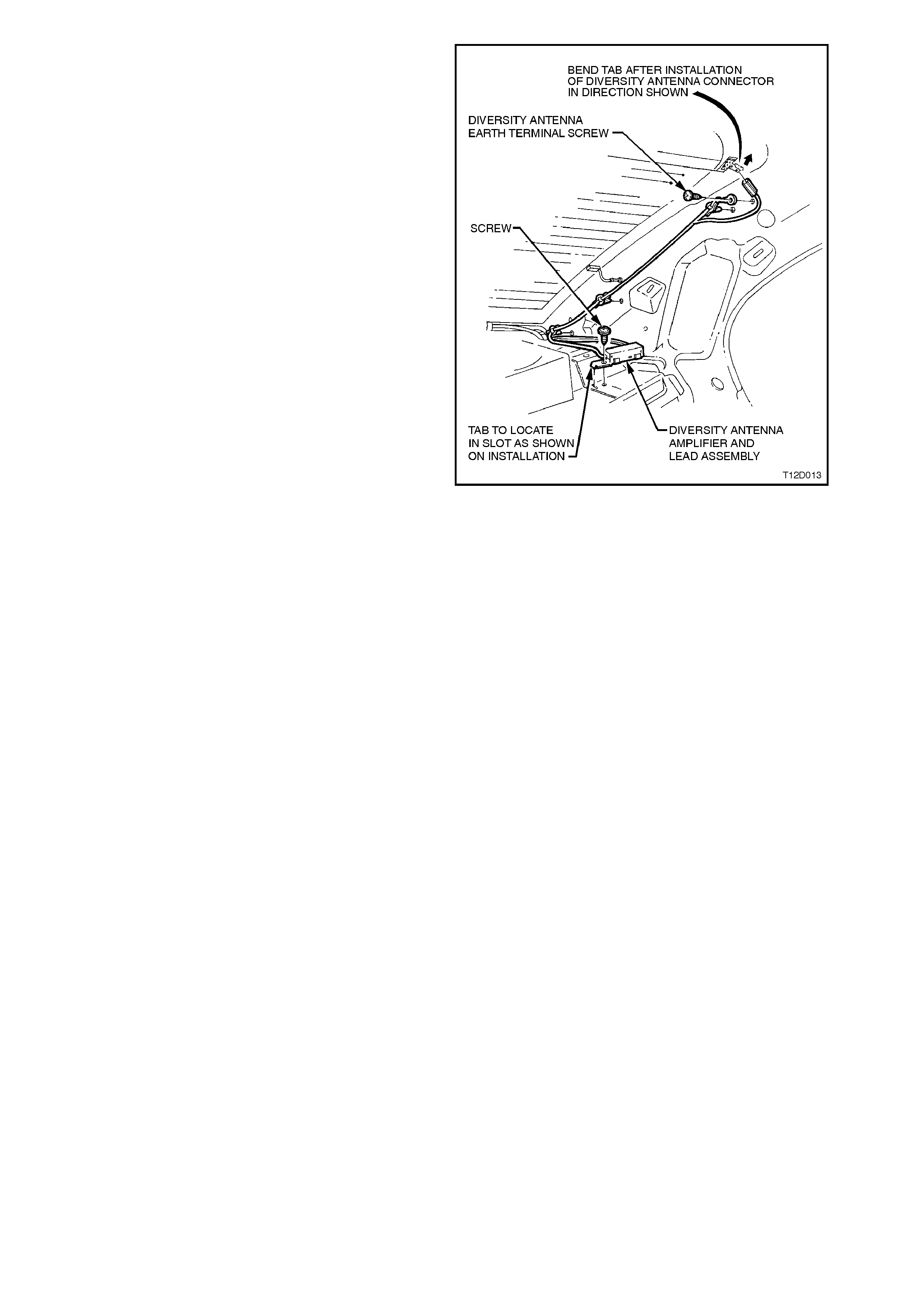
procedure noting the following:
1. Ensure that locating tag on diversity antenna
module is correctly engaged into the m ounting
slot on the rear parcel shelf.
Tighten diversity antenna module mounting
screw to the correct torque specification.
Figure 12D-31
DIVERSITY ANTENNA MODULE
EARTHING SCREW TORQUE
SPECIFICATION 1 - 3 Nm
DIVERSITY ANTENNA MODULE
MOUNTING SCREW TORQUE
SPECIFICATION 1 - 3 Nm
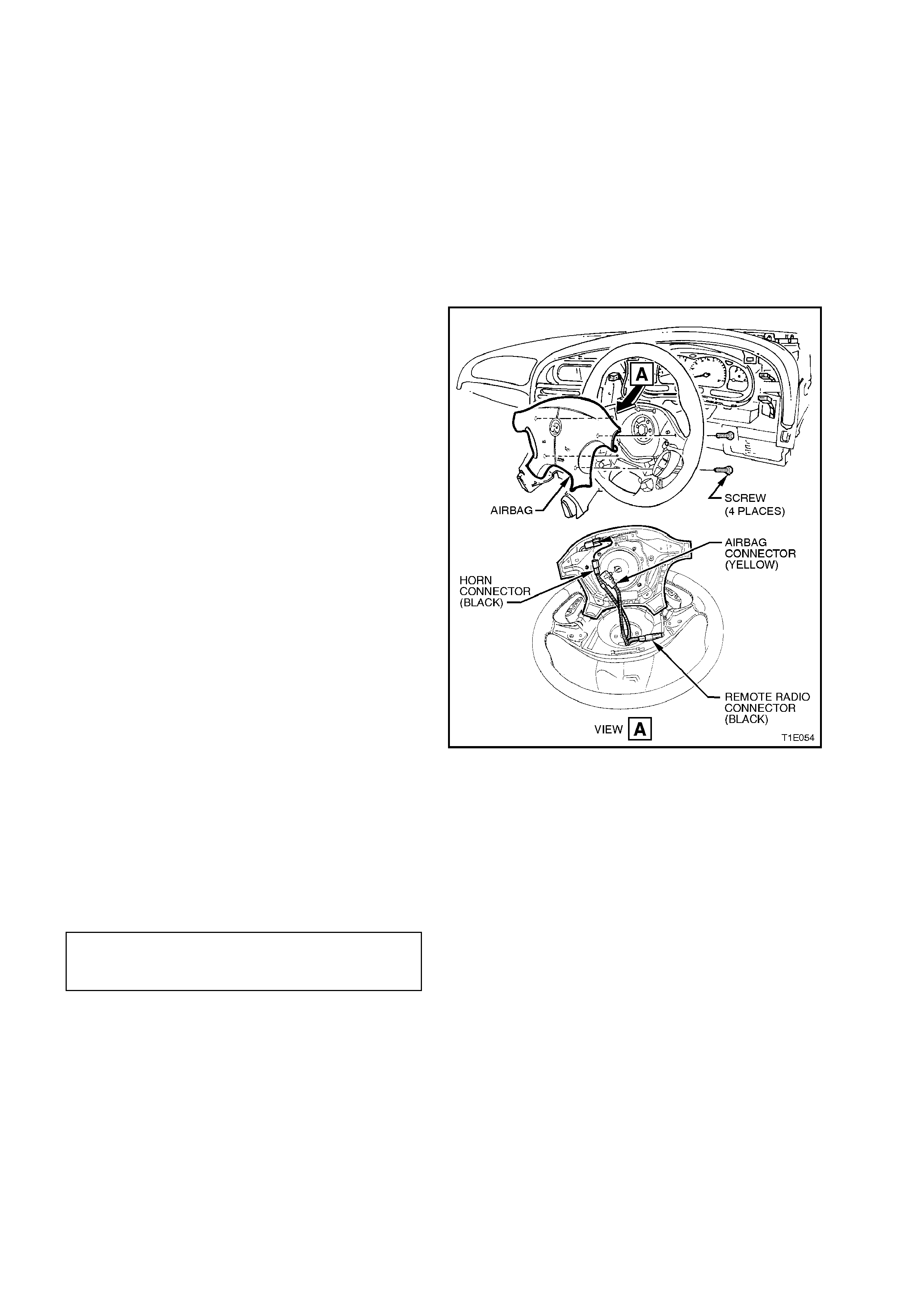
2.10 HORN BAR STEREO CONTROLS
The horn bar stereo control system c onsists of two
control switch assemblies which are located on
each side of the driver’s side air bag and a radio
connection.
The horn bar s ter eo contr ols utilise the c loc k s pr ing
coil harness as a data link to the radio.
REMOVE
CAUTION:
Disable the SRS (Air Bag). Refer to DISABLING
THE SRS, Section 12M SUPPLEMENTAL
RESTRAINT SYSTEM.
1. Remove air bag assembly from steering
wheel, refer to Section 9A STEERING.
2. Disconnect horn bar stereo control harness
from steering column harness connector.
3. Remove horn bar stereo switch assembly to
steering wheel attaching screws and remove
horn bar stereo switch assembly.
NOTE:
The horn bar stereo switch assembly consists of
two switch blocks connected together by a wiring
harness.
Figure 12D-32
REINSTALL
Installation is the revers e of the rem oval procedure
noting the following.
1. Tighten horn bar stereo switch assembly to
steering wheel attaching screws to the correct
torque specification.
STEREO SWITCH TO STEERING
WHEEL ATTACHING SCREW
TORQUE SPECIFICATION 1 - 3 Nm
IMPORTANT:
Enable the SRS (Air Bag). Refer to ENABLING
THE SRS, Section 12M SUPPLEMENTAL
RESTRAINT SYSTEM.
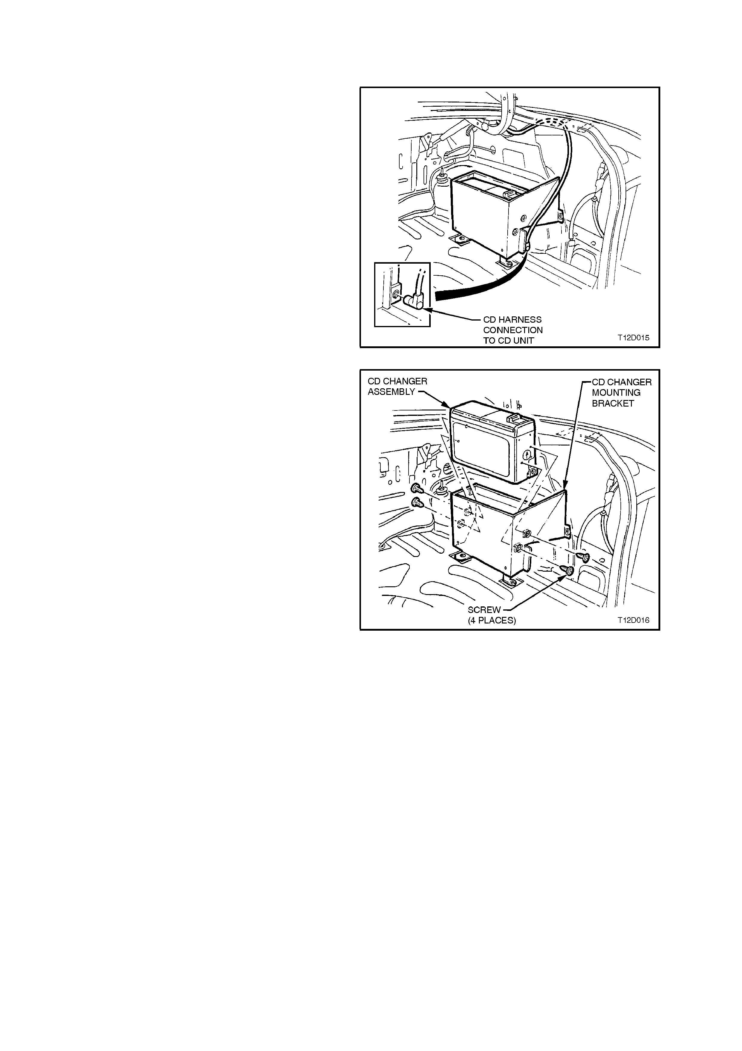
2.11 COMPACT DISC PLAYER/ CHANGER INSTALLATION - CALAIS
REMOVE
1. Open decklid and remove carpet, refer to
Section 1A1 BODY.
2. Rem ove two trim retainer s from right side rear
compartment wheelhouse carpet trim (on CD
changer assem bly) and remove right side rear
compartment wheelhouse trim. Refer to
Section 1A1 BODY.
3. Disconnect CD changer harness connector.
Figure 12D-33
4. Remove CD changer to mounting bracket
retaining screws (four screws) and withdraw
CD changer from mounting bracket.
Figure 12D-34
REINSTALL
1. Reinstallation is the reverse of the removal
operations.
2. Check CD changer operation.
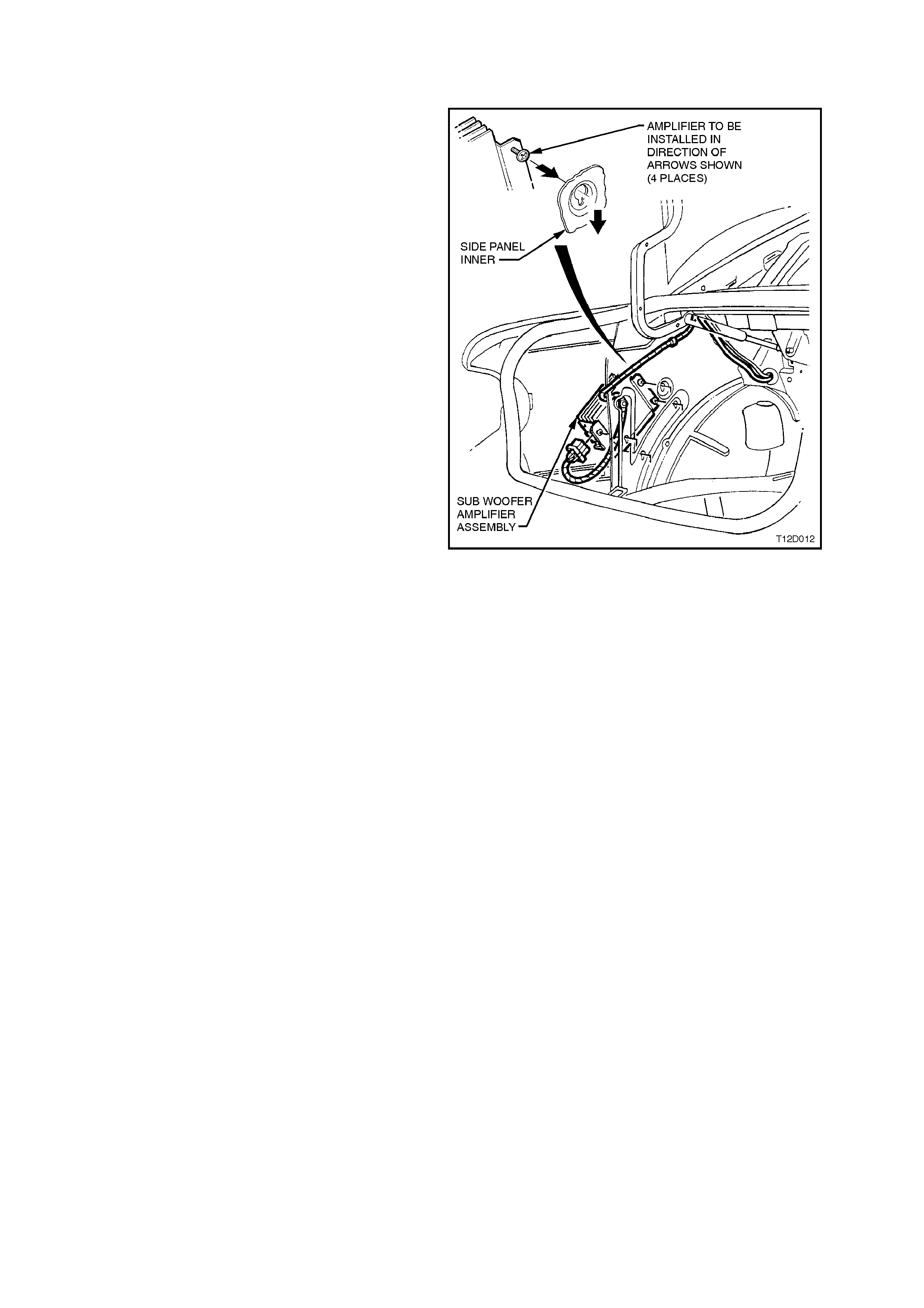
2.12 SUBWOOFER AMPLIFIER
REMOVE
1. Open decklid and remove carpet, refer to
Section 1A1 BODY.
2. Remove trim retainer from left side rear
compartment wheelhouse carpet trim and
remove left side rear compartment
wheelhouse trim, refer to Section 1A1 BODY.
3. Loosen subwoofer amplifier retaining screws
(four screws) and slide amplifier upwards to
release screw heads from slots in side inner
panel.
4. Withdraw subwoofer amplifier assembly from
rear compartment.
5. Disconnect subwoofer amplifier assembly
harness connector.
Figure 12D-35
REINSTALL
1. Reverse removal operations.
2. Check subwoofer amplifier operation.
3. DIAGNOSIS
This radio problem diagnosis is split into several parts.
1. The first part is a short description of the principles of radio operation. It is by no means exhaustive, and is to
serve only to give an understanding of how radios work in order to better understand how to solve problems
when they occur.
2. Many radio problem s are caused by basic earthing and short-circuiting problems, which can be quickly found
using the checks included in the ‘Basic Checks’ in this Diagnosis Section.
3. The m ost com mon fault is that of ‘s tatic’ and so an explanation of what it is, what causes it, and how to fix it is
also included.
4. Diagnostic flow charts are included to help diagnose common complaints.
PRINCIPLES OF OPERATION
RADIO RECEPTION
High quality radio rec eption is obvious ly more dif ficult to ac hieve in a moving vehicle than from a st ationary location.
Radio systems fitted to vehicles incorporate sophisticated electronics to enhance radio reception by extending the
useable listening range whilst eliminating extraneous noises, such as static.
Many owners complain of ‘reception problems’ which are normal radio operating characteristics, particularly with
FM. Such complaints arise as a result of owner misconception as to what constitutes normal radio reception.
Naturally, radio replacement under these circumstances will not affect the radio operating characteristics and has
the potential to create additional owner dissatisfaction. T hus a careful, well informed explanation of radio reception
expectations is more lik ely to enhance the owner’s understanding and satis faction, as well as avoiding unneces sary
repair costs and inconvenience to the owner of the vehicle.
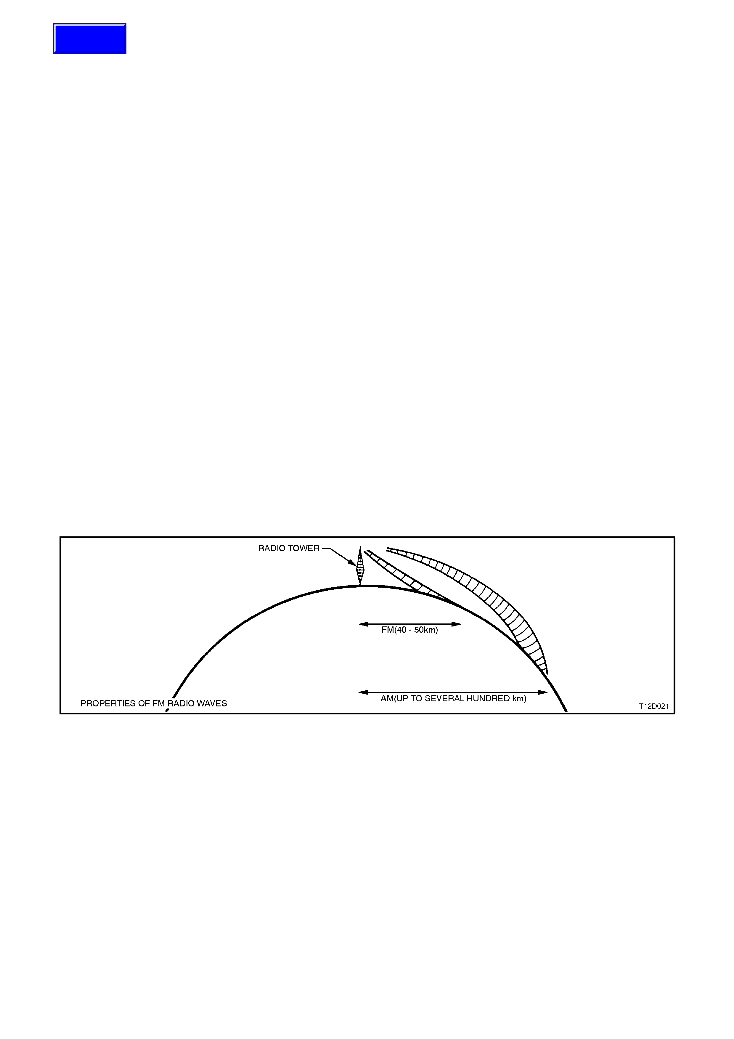
FM RECEPTION IN VEHICLES
FM stereo’s maximum range is normally limited to 40 to 50 km. The strength of the FM signal is related to the
distance between the receiver and the transmitter. FM signals follow the line of sight, exhibiting many similar
character istics to those of light. That is , similarly to sunlight, FM radio waves are cut of f by the horizon. Since m ost
FM transmitter towers are nominally 100 metres from the ground, useable reception cannot extend much beyond
the horizon. FM signals will not bend around corners, but as with light, may be reflected (or blocked) by large
objects such as hills and buildings.
Figure 12D-36
Although FM signals will not bend around corners, they can be reflected by large structures, hills, or buildings, for
example. Because of these characteristics, a reflected signal and a direct signal can reach the radio’s antenna at
the sam e time, r esulting in the signals inter fering with each other or c ancelling each other out. This obviously leads
to a distortion of the received signal or a loss of sound, and is known as multi-path interference.
Multi-path interference occurs only with FM reception and can be characterised by changes in distortion (static)
levels occurring as the vehicle is moving. This is due to the vehicles antenna entering and leaving FM signal
interference areas.
FM signal waves have short wavelength, which also means that the interference area is small - in the region of
several centim etres across . Because of the s mall s ize of interferenc e areas, a vehicle m ay pass through many in a
short tim e. When the vehicle is s tationary in an interf erence area, m oving it half a m etre will place the antenna in a
region of clear signal.
A vehicle fitted with a two antenna FM divers ity sys tem helps reduc e m ultipath interf erence by ensuring that at least
one antenna is outside the cancelled signal region.
Flutter or fading is caused when a vehicle passes into an area where the direct signal can be overshadowed by a
building, large structure or hill.
Techline
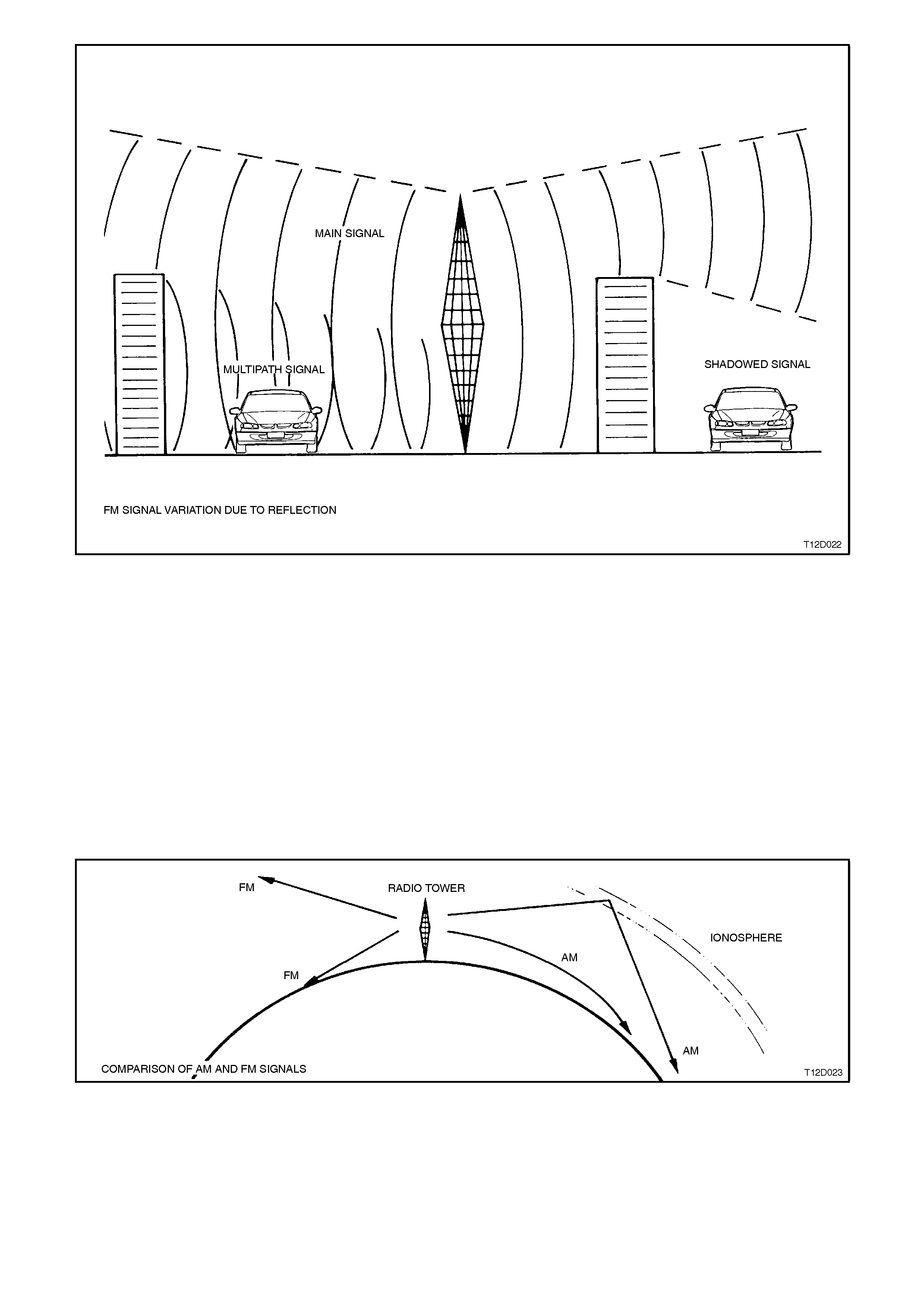
Figure 12D-37
Atmospheric conditions can also affect FM reception. Unexplained loss of sensitivity can be caused by high
humidity. Cloudy days are also better for reception than clear days. With electronic tuning radios, users can
sometimes be confused by abbreviated radio station call signs. People who tune their radio to these abbreviated
call signal frequencies may be slightly off the correct frequency.
NOTE:
FM station call signs are spaced 100 kHz apart in Australia, ie. 93.9, 94.0, 94.1, etc.
AM station call signs are spaced 9 kHz apart, i.e. 999, 1008, 1017, etc.
AM RECEPTION IN VEHICLES
In contrast to FM s ignals, AM signals will bend around co rner s and s kip along the ground. This is due to AM s ignals
having longer wavelength and lower frequency. The signal can be reflected by the layer of atmosphere known as
the ionosphere. This phenomenon gives AM a longer reception range than FM.
Figure 12D-38
AM reception is affected by static induced by electrical power lines, traffic lights, electronic signs and thunderstorms.
Fade of AM signals can also be expected when driving through tunnels, underpasses, and in city centres.
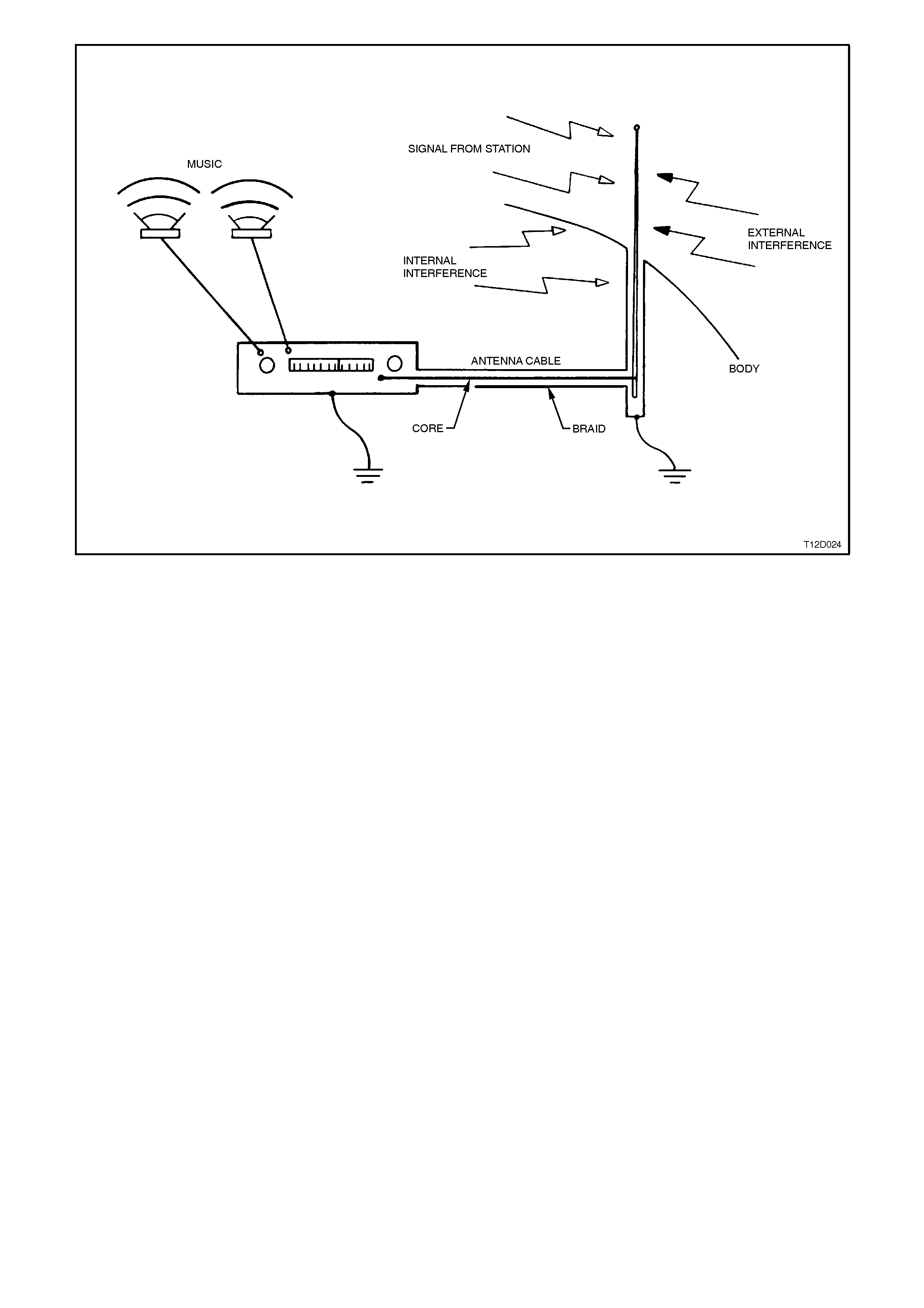
Figure 12D-39
As shown, signals from radio stations are picked up by the antenna and fed to the radio while being shielded from
interference sources by the braid. This is a complete electrical circuit, any breaks in the circuit, such as poor
connections, will result in poor reception.
Interference is due to the antenna system picking up signals other than those from the desired station. These
undesirable signals may be produced by electric al equipment in the vehicle itself , such as ignition, which is termed
‘internal interference’. Conversely, interference from sources outside the vehicle, such as from power lines, is
known as ‘external interference’.
Internal interference is minimised by the shielding around the antenna wire, which prevents internal noise being
picked up and fed to the radio. The shielding around the core takes the form of a ‘braid’, which completes the
electrical circuit along which signals travel to the radio. Faults in this shielding system allow interference to reach the
radio and hence be reproduced at the speakers as noise.
It is therefore important that the shield of the antenna cable is effectively earthed at both the radio (to the radio
case) and at the antenna end (to the vehicle body), to ensure that:
1. Minimal interference is received by the radio.
2. The optimum radio sensitivity is achieved.
BASIC CHECKS
Proper performance of the radio system depends greatly on earthing of the antenna and radio case to the vehicle
body, as it eliminates stray currents in the antenna circuit. Stray currents may be induced by wires running parallel
to the path of the radio or antenna wiring, or may be due to ‘noisy’ in-vehicle electrical items.
With an ohmmeter, the resistances or connection quality can be checked for the major parts of the radio.
When using an ohmmeter to measure very low resistances, the lead resistance becomes considerable, and must
be subtracted from all subsequent readings. That is, touch the leads together, note the reading, and subtract this
from all subsequent readings.
NOTE:
A very good contact point is required to m eas ure earth res istance. T his point mus t not have curr ent f lowing through
it during m easurement, ther efore ensuring that the ignition is tur ned OFF. Avoid measuring using the sc rew on the
door jam b switch. The best place to meas ure earth resis tance is to use one of the self tapping s crews retaining the
A-pillar drip rail. Since these screws are sometimes not properly earthed, one of the screws may be removed to
take measurements directly to the body sheet metal.
1. Remove battery earth lead.
NOTE:
Failure to disc onnect battery earth lead may lead to
incorrect resistance measurements due to stray
currents.
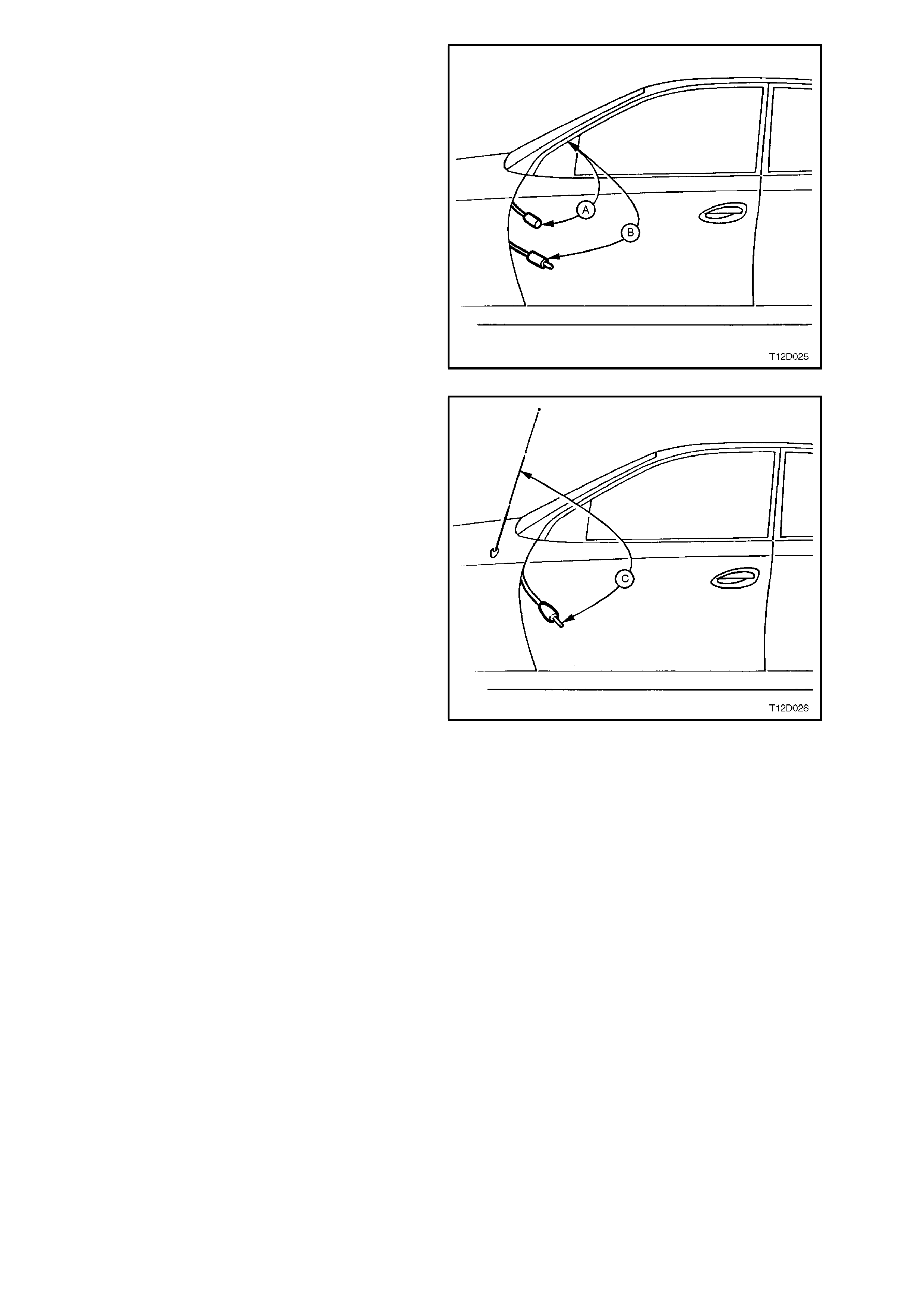
2. Disconnect antenna extension lead from
behind passenger side kick trim.
3. Measure resistance from the outer of the
antenna lead to vehicle body (A).
Resistance reading 0.3 ohm max.
4. Measure resistance from outer of the antenna
extension lead to vehicle body (B).
Resistance reading 0.6 ohm max.
Figure 12D-40
5. Check continuity of path from antenna cable
core to antenna m ast by measuring r esistance
(C).
Resistance reading 0.4 ohm max.
NOTE:
This test can in fact only be performed on power
antennas, since manually operated antennas are
fitted with in-line capacitors with the antenna body,
which misleadingly indicates an open circuit when
resistance is measured.
On vehicles with manually operated antennas,
disconnect antenna lead from antenna lead
extension and measure resistance of extension
lead cable core from radio to antenna lead
connection ends.
Resistance values significantly higher than those
specif ied indicates poor c onnections which m u st be
rectified before proper radio performance will be
obtained.
6. Check for shorts between antenna core and
braid by disconnecting from radio and
measuring the resistance between the two.
The measured value should indicate an open
circuit (very high or infinite resistance).
7. Disconnect antenna extension lead at both
ends and test core for continuity.
Figure 12D-41
COMMON RADIO PROBLEMS
STATIC
Static is a buzzing or crack ling noise caused by the radio pick ing up unwanted radio waves and converting them to
noise output by the speakers.
The unwanted radio waves (interference) come from several sources, which can be put into two groups; internal
and external. As the names sugges t, ex ternal inter f er enc e comes f r om outside the vehicle, and is dif f ic ult to c ontrol,
while internal interference is generated by the vehicle.
It must be emphasised that a radio system in good condition will protect itself from much static. Before trying to
locate and rem ove a sour ce of interf erence it m us t firs t be determ ined that the shielding and ear thing of the radio is
in good working order. This can easily be done by performing the tests detailed in the ‘Basic Checks’.
It should be noted that static may occur on weak stations, or when driving under bridges because signals from
ignition and the like become relatively stronger than the radio station signal, causing the ignition interference to
become quite strong. This could be due to stronger than normal ignition interference or a poorly-functioning
antenna.
If the cause cannot be isolated after performing the tests and trying to isolate a source of interference, using the
following procedures, it may be that the radio has an internal fault and requires repair.
EXTERNAL INTERFERENCE
Static which occurs only while travelling in certain localities, such as near electrical transformers, is undoubtedly
external interference.
If there is any doubt whether the suspected source is caus ing inter f er ence, a s imple chec k is to s top the vehicle and
turn off everything but the radio. If the source is external, the interference will continue and little can be done to
eliminate it.
NOTE:
The perceived interference level can be significantly reduced, in noisy environments, by slightly reducing the treble
on the radio tone controls.
INTERNA L INTERFERENCE
Internal interference is that caused by some component of the vehicle’s electrical system, and may take many
forms.
Many of the electrical item s fitted to motor vehicles produce som e sort of radio waves, but these radio waves only
become a problem if they are in the range of frequencies at which the radio receiver picks up and reproduces
signals as sound. For the radio, the vehicle’s electrical system must be designed not to emit radio signals at the
frequencies of the AM and FM bands.
Components are sometim es fitted with suppres sing devic es as par t of their design, and failure of thes e suppr es sor s
may allow the item to start interfering with radio operation.
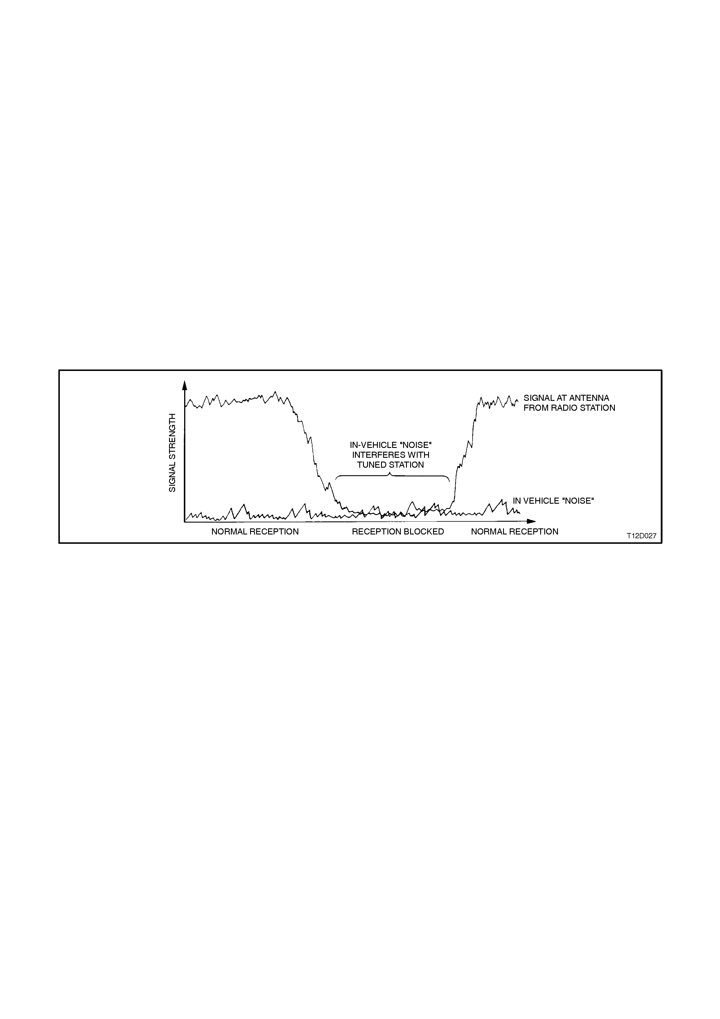
Interference will be worse on weak stations, since a strong signal normally overpowers the interfering signal.
Interference can occur when the signal strength drops below a certain threshold, such as driving under a bridge,
inside a workshop, or in the shadow of a building. This situation is shown in the following figure.
Figure 12D-42
Static may be caused by many internal sources. If static is at ignition frequency, varying with engine speed, the
ignition is the culprit. However, many electrical faults will cause static which otherwise would not be heard.
Examples of ignition interference sources are:
1. Plug leads breaking down.
2. Carbon tracking (arcing) to earth.
3. Faulty spark plugs.
4. Inoperative interference shields.
The actual cause of the interference can be isolated through carefully noting the circumstances under which the
problem occur s . For example, if it oc c ur s only at speeds above approx imately 80 km /h in an automatic tr ans miss ion
equipped vehicle, quite possibly it is the electrical signal being sent to the torque converter clutch.
Other sources of static can be:
1. Electric cooling fan.
2. Electric fuel pump.
3. Normal computer ‘noise’ at certain frequencies.
4. Windshield wipers or washers.
DIAGNOSING INTERNAL INTERFERENCE
If a vehicle has an interference problem that only occurs when the engine is turned ON, or some other repeatable
circumstance, carry out the following procedure:
1. Park vehicle in an open area, as far away from buildings as possible. Turn the radio onto the band (AM\FM)
and frequency where the complaint occurs, with the ignition on ACC.
2. Reproduce the interference, eg. turn ignition ON.
3. If interference is due to a fan blower motor, etc. and is judged to be objectionable, the component should be
substituted to determine whether it is faulty.

NOTE:
Internal interference is often a symptom of a defective radio system, such as poor antenna earthing, etc. If
substituting a new component does not f ix the c ondition, the pr oblem is ver y likely to be in the radio system, and the
resistance checks in this Section should be performed.
4. Whistles/s queals that occ ur only when the ignition is ON, are probably due to electronic m odules in the vehicle
creating interference when active (power applied). These m odules may be isolated as a cause of interference
by removing power to them and rechecking. This is best done by turning the ignition OFF, rem oving the fuse
that supplies that particular item with power, turning the ignition back on and rechecking. By process of
elimination, the ‘noisy’ module should be able to be found. Once found, substitute the module to find out
whether the interference is normal.
SPEAKERS
Before removing speakers suspected of being noisy or faulty, ensure that any distortion which may be present is not
due to any of the following:
1. Foreign matter such as sand lying on the speaker cone.
2. Cable ties or other such material resting on the back of the speaker cone.
3. Incorrectly fitted speaker mesh or loose trim around speaker assembly.
4. Distortion of speaker assembly caused by the angled insertion of the speaker retaining screws. Speaker
problem s due to this m ay be rec tified by loosening the screws and r etightening, being ca reful not to distor t the
speaker cone again.
CASSETTE PLAYER CARE
To ens ure proper and r eliable operation, the oxides used in tape m anuf acture m us t be cleaned fr om the heads and
capstan drive of the unit, at intervals of no more than 100 hours of operation. Sticky oxide build up on the capstan
can result in tape speed variation, and ultimately in tape damage. Hence it is impor tant that user s are advis ed of the
importance of keeping cassette units clean.
Cassette players may be cleaned using a wet head cleaning tape.

3.1 DIAGNOSTIC PROCEDURES
When using the following diagnostic charts, continually refer to the following circuit diagrams.
RADIO/CASSETTE PLAYER FAULT DIAGNOSIS
The f ollowing chart sets out com m on user com plaints and s ymptom s with refer ence given to which diagnostic c hart
to follow for problem rectification.
COMPLAINT SYMPTOM TABLE NO.
Power No power/illumination 1
Sound No sound/Low sound 1,2
One speaker low/not working 1,2
Distortion/Poor sound 1,2,3
Noise 1,2,3
Radio No or weak reception 3
Vehicle Interference 3
External Interference 3
Search tune skipping stations 3
Tape Tape speed too fast/slow 4
Noise 1,2,4
Jammed cassette mechanism 4
Will not eject tape 4
Can’t insert tapes 4
CD Player CD Changer error messages 5
Cannot select CD mode 5
CD player skips 5
CD player repeats same passage of sound 5
Horn Bar Stereo Controls
(Calais) No/unexpected operation 6
Power Antenna Fails to extend 7
Fails to retract 7

TABLE NO. 1 POWER AND SOUND DIAGNOSIS
STEP ACTION RESULT YES NO
1• Turn ignition switch to
ACC position
• Turn radio on
• Does the display
illuminate correctly?
Go to Step 5 Go to Step 2
2• Partially remove radio,
refer to 2.1
RADIO/CASSETTE
PLAYER in this
Section
• Is connector firmly
pushed into rear of
radio?
Go to Step 3 Push connector
firmly into back of
radio and verify
correct operation.
3• Using multimeter,
check voltage of circuit
4 on radio connector
YB72 (BR).
• Is there at least 11
volts on the
ignition/accessory
main radio connector?
Go to Step 4 Go to Step 16
4• Using multimeter,
check continuity of
earth circuit 1151 at
connector YB72 (B/W)
using suitable body
earth location.
• Is there continuity?
Remove and
return for repair. Rectify the earth
connection
problem and
verify repair.
5• Is there sound from all
speakers? Go to Step 6 Go to Step 2 of
Table 2
6• Check the terminals at
the rear of the affected
speakers. For door
speakers, check that
they are in good
condition and do not
contact the body work.
Look for signs that
contact with the body
work may have
occurred previously.
• Tap door panels to
verify that terminals will
not make contact with
body work, and
insulate terminals if
necessary.
• Are there indications
that the speaker
terminals have made
contact with the body
work?
Insulate terminals
and recheck
speaker
operation.
Go to Step 14
Go to Step 7
7• Is the sound distorted
in all modes (radio,
cassette, CD)?
Go to Step 8 See relevant
diagnostic chart
in this section.

STEP ACTION RESULT YES NO
8• Using multimeter,
check voltage of circuit
4 on radio connector
YB72 (BR).
• Is there at least 11
volts on the
ignition/accessory
main radio connector?
Go to Step 9 Rectify the
voltage
connections and
verify repair.
9• Is connector firmly
pushed into rear of
radio?
Go to Step 10 Push connector
firmly into back of
radio and verify
correct operation.
10 • Use fader and balance
controls to decide
whether distortion is
from one or more
speakers.
• Is distortion from one
speaker only?
Go to Step 11 Return radio for
repair.
11 • Is there foreign matter
such as dirt in the
speaker cone?
Clear the speaker
of foreign matter
and verify repair.
Go to Step 12
12 • Ensure speaker
terminals do not touch
body work.
• Is the connector firmly
on the speaker?
Go to Step 13 Push connector
firmly onto
speaker and
verify repair.
13 • Check that the correct
speaker has been
fitted to the vehicle.
Note that low series
models and Calais
have different speaker
designations with
different impedance
values. The
appropriate type must
be fitted for correct
operation, refer to 2.3
FRONT DOOR
SPEAKERS - ALL
MODELS and
2.4 REAR DOOR
SPEAKERS in this
Section.
• Is the correct speaker
installed?
Go to Step 14 Fit correct
speaker and
verify repair.
14 • Connect a working
substitute speaker.
• Does the speaker work
clearly?
Install new
speaker,
ensuring correct
impedance and
verify repair.
Go to Step 15
15 • Is the wiring to the
speaker damaged? Repair fault in
harness Remove and
return for repair.

STEP ACTION RESULT YES NO
16 • Check fuse F16.
• Is fuse OK?
Go to Step 17 Replace fuse and
investigate cause
of blown fuse.
17 • Check continuity of
wiring harness from
ignition switch
connector YB44 (BR)
to radio harness YB72
(BR).
• Is there continuity?
Investigate
source of voltage
interruption from
ignition switch
and battery.
Repair wiring
harness and
verify repair.

TABLE NO. 2 INTERMITTENT FAULT DIAGNOSIS
STEP ACTION RESULT YES NO
1• Does customer
complain of sound
dropping out during all
modes intermittently?
Go to Step 2 See relevant
diagnostic table
in this Section.
2• Does the drop-out
occur only in one or
two speakers?
Go to Step 3 Go to Step 4
3• Check connections at
the relevant speaker
and harness
connectors between
speaker assembly and
radio. Inspect
terminals for damage
or poor fit.
• Check the terminals at
the rear of the affected
speakers. For door
speakers, check that
they are in good
condition and do not
contact the body work.
Look for signs that
contact with the body
work may have
occurred previously.
• Tap door panels to
verify that terminals will
not make contact with
body work, and
insulate terminals if
necessary.
• Do the connections
appear OK, even when
pulled and
manipulated?
Go to Step 10 in
TABLE 1
POWER AND
SOUND
RELATED
PROBLEMS in
this Section
Repair harness
or replace
speaker if
terminals are
damaged, and
verify correct
operation.
4• Check connections at
rear of radio, inspect
terminals for damage
or poor fit.
• Do the connections
appear OK, even when
pulled and
manipulated?
Go to Step 5 Repair harness
and verify correct
operation.
5• Using multimeter,
check for continuity of
cellular telephone
mute circuit 656
(Yellow/Black) on radio
connector YB72 to
body earth.
• Does this circuit
indicate continuity to
earth?
Cellular
telephone mute
line has shorted
to earth, locate
short circuit
and/or damage to
harness and
verify repair.
Remove radio
and return for
repair
OR
Calais only -
Go to Step 6

STEP ACTION RESULT YES NO
6• Does customer
complain of settings
(ie, volume, mode,
radio station,
bass/treble etc)
changing when ignition
is turned from ACC to
ON when starting the
car?
Refer to Note 1 at
the end of this
Table.
Go to Step 7
7• Does customer
complain of settings
(ie, volume, mode,
radio station,
bass/treble, antenna
height etc) changing,
or intermittent erratic
audio system operation
when driving the car.
Refer to Note 2 at
the end of this
Table.
Remove radio
and return for
repair.
NOTE 1
Inform customer that the priority key settings are restored from the BCM when the vehicle is unlocked with the
rem ote using its priority k ey signal. These s ettings will be restored when the ignition is turned to ACC position. T he
BCM will request the priority key settings of the key in the ignition when the ignition is cycled. If a different key is
then used to start the car, or the car was not locked and a different key used to start the car the BCM will use the
priority key settings for the current key. This may result in the settings changing when the ignition is cycled, and is
part of normal operation.
Suggest to customer that the key used to start the car should be the same key used to unlock the car.
NOTE 2
If there is an intermittent open circ uit or short circuit to body earth in the priority key circuit (Grey) f rom the BCM to
the radio then the priority key settings may alternate. As the priority key changes, the radio settings will change to
reflect the values stored in each key. This will result in volume, mode, radio station, bass/treble settings to change
for apparently no reason.
This can additionally cause the radio to switch on and off erratically if one priority key sets the radio on and the other
turns it off.
The priority line circuit will need to be investigated for a short- or open circuit, refer to
Section 12P WIRING DIAGRAMS.

TABLE NO. 3 RADIO/RECEPTION DIAGNOSIS
STEP ACTION RESULT YES NO
1• When radio mode is
selected, is there no
reception or weak
reception?
Go to Step 2 Go to Step 9
2• Fully extend antenna
and move vehicle to
known high quality
reception area.
• Is reception still weak?
Go to Step 3 Reconfirm
problem with
customer.
3• Is the antenna plugged
into the rear of the
unit and behind the
passenger’s side kick
trim?
Go to Step 4 Plug the antenna
into the unit and
behind
passenger’s side
kick trim.
Go to Step 1
4• Is the reported
problem on a Calais
and only with FM
reception?
Go to Step 5 Go to Step 7
5• Drive vehicle to known
good reception area.
• Extend antenna fully
• With the radio turned
on, press and hold the
LOC button and press
the TIME button.
Release both buttons
and watch the radio
display. This performs
an antenna check
diagnostic.
• If diversity antenna and
main antenna are OK
the radio will display
GOOD. Go to Step 6.
• If there is a fault with
the diversity antenna
system, B-S (bad sub-
antenna) will be
displayed. Go to Step
6.
• If there is a fault with
the main antenna, B-M
will be displayed.
• Was GOOD displa yed
during the diagnostics?
Go to Step 7 Go to Step 6

STEP ACTION RESULT YES NO
6• If fitted, check
connections diversity
antenna connections:
• Check diversity
antenna
connections near
rear parcel shelf
and behind
passenger’s side
kick trim.
• Check diversity
antenna connection
on rear window,
• Diversity antenna
earth screw in ‘C’
pillar,
• Diversity antenna
amplifier power
circuit at connector
YB144 (BR).
• Diversity antenna
amplifier earth
circuit
• See also notes
regarding diversity
antenna fault diagnosis
after Table 8 in this
Section
• Are all these
connections OK?
Go to Step 7 Repair necessary
connections and
verify repair.
Go to Step 1
7• Compare the weak
signal in this vehicle
with that coming from
a vehicle which does
not experience this
problem.
• Does the weak signal
sound more evident in
this vehicle than the
comparison car?
Go to Step 8 Explain to the
customer that the
weak signal or
distortion
appears to be
one affected by
the location of the
car. Refer to
Principles of
Operation in 3
DIAGNOSIS in
this Section.
8• Has a new antenna
been attached to the
back of the radio?
Remove and
return unit for
repair.
Go to Step 9
9• Attach a new lead and
retest.
• Is reception still weak?
Remove and
return unit for
repair.
Fit new antenna
and verify repair.
10 • Is there vehicle related
interference, that is, it
disappears when
vehicle’s electrics and
engine are off?
Go to Step 11 Go to Step 13
11 • Can the cause be
located by turning off
various vehicle
components?
Go to Step 12 Remove and
return for repair.

STEP ACTION RESULT YES NO
12 • Is the noise a whine,
such as from the
vehicle’s alternator or
with increase in engine
speed ?
Undertake the
necessary steps
to ensure that the
generator/coil
suppressor and
earth to radio
function are all
fully operational.
Go to Step 10
Go to Step 13
13 • Has a new antenna
extension lead been
installed?
Go to Step 14 Attach a new
antenna
extension lead,
routed away from
the other wiring.
Go to Step 10
14 • Using a multimeter,
check the resistance
from the radio case to
the body earth at
instrument carrier
(refer to Section 12P
WIRING DIAGRAMS.
• Is the resistance
greater than 0.5 ohms
Remove and
return for repair. Remove and
return for repair.
15 • Is there external
interference, that
appears only in certain
locations?
Advise the
customer that
external
interference
cannot be
eliminated unless
the source is
eliminated. To
reduce this
interference,
extend antenna
fully and if the
interference is a
high frequency
noise, use the
treble control to
reduce treble
response.
Go to Step 16
16 • Does the search tune
skip stations? Go to Step 17 Reconfirm
problem with
customer.
17 • Fully extend the
antenna
• Switch off ‘LOC’
feature
• Does the search tune
still skip stations?
Go to Step 18 Reconfirm
problem with
customer.
18 • Test the antenna or
extension lead for fault
• Is antenna or lead
faulty?
•Repair or replace
the faulty
component.
Go to Step 16.
Remove and
return for repair.

TABLE NO. 4 CASSETTE PLAYER DIAGNOSIS
STEP ACTION RESULT YES NO
1• Can cassettes be
inserted? Go to Step 8 Go to Step 2
2• Is the cassette
mechanism empty? Go to Step 6 Go to Step 3
3• Attempt to eject the
cassette by pressing
the eject button.
• Did the cassette eject
easily?
Go to Step 1 Go to Step 4
4• If the cassette ejected
slightly, push it back
into the unit, then exert
normal pressure (not
force) on eject button
whilst guiding the
cassette upwards.
• Did the cassette eject?
Go to Step 5 Remove and
return radio for
repair.
5• Is the cassette door
bent or damaged so
that door is blocking
cassette entrance?
Remove and
return radio for
repair.
Go to Step 1
6• Does there appear to
be a foreign object
within the mechanism?
Go to Step 7 Remove and
return radio for
repair.
7• Is it possible to remove
the foreign object
without damaging the
unit?
Remove foreign
object and
go to Step 1
Remove and
return radio for
repair.
8• Does the tape play as
though it is in fast-
forward mode?
Remove and
return radio for
repair.
Go to Step 9
9• Does the unit operate
properly in all functions
other than cassette
mode?
Go to Step 12 Go to Step 10
10 • Is the tonal quality poor
which makes the
output sound muffled?
Clean the tape
path using only a
wet cleaning
system,
go to Step 12
Go to Step 11
11 • Does the cassette run
slowly or switch to
auto-reverse before
the end of the tape has
been reached?
Run the offending
cassette on fast-
forward and fast-
rewind for full
length and re-
check tape
function.
Go to Step 12
Reconfirm
problem with
customer.
12 • Insert a tape which you
know works without a
problem.
• Does the unit work
without a problem?
End of diagnostic
procedure. Remove and
return radio for
repair.

TABLE NO. 5 CD PLAYER DIAGNOSIS
STEP ACTION RESULT YES NO
1• When attempting to
use CD changer, does
an error message
appear?
Go to Step 2 Go to Step 8
2• Is it the error “E01” (No
magazine is disc
changer)?
Insert a loaded
disc magazine
into the changer.
Go to Step 3
3• Is it the error “E02” (No
disc in the magazine)? Insert a disc into
the magazine. Go to Step 4
4• Is it the e rror “E04”
(Disc is dirty or upside
down)?
Go to Step 5 Go to Step 6
5• Check that the disc is
clean and free from
scratches and inserted
the correct way up.
• Is CD clean and
inserted properly?
Remove and
return for repair. Rectify problem
and verify repair.
6• Is the error “E 08” (CD
changer is too hot)?
• As with all compact
disc players, the unit
will not operate if the
ambient temperature is
above 55°C, otherwise
permanent laser
damage can occur.
Remove and
return for repair. Go to Step 7
7• Is the error “E99”
(Micro computer is
locked)?
Hold On/Off
button on radio
for more than
6 seconds, then
reload discs.
Remove and
return for repair.
8• Can the CD mode be
selected and activated
on the head unit?
Go to Step 10 Go to Step 9
9• Check the CD
connector on the CD
changer and in the
passenger
compartment.
• Is the CD connector
secure and the
harness undamaged?
Remove and
return for repair. Reconnect or
repair harness
and verify correct
operation.
Go to Step 8
10 • Does the CD changer
skip on rough roads? Go to Step 11 Go to Step 13
11 • Are the spring adjuster
caps on each end of
the CD changer
adjusted with the slot
facing up-down?
Go to Step 12 Adjust the spring
adjuster
appropriately and
verify repair.

STEP ACTION RESULT YES NO
12 • Road test the vehicle.
• Does skipping only
occur under severe
conditions?
Explain to the
customer that CD
skipping is
usually due to
dirty or scratched
CDs. The CD
player does at
times skip on
very rough roads
or if a large
pothole is
encountered.
Go to Step 14
13 • Does the CD skip or
repeat the same
passage of output?
Go to Step 14 Reconfirm
problem with
customer.
14 • Insert and attempt to
play a known clean
and properly playing
CD.
• Does the CD player
continue to skip under
normal driving
conditions?
Remove and
return for repair. Explain to the
customer that CD
skipping is
usually due to
dirty or scratched
CDs. The CD
player does at
times skip on
very rough roads
or if a large
pothole is
encountered.

TABLE NO. 6 HORN BAR STEREO CONTROL FAULT DIAGNOSIS - CALAIS
STEP ACTION RESULT YES NO
1• Switch radio ON with
key in ACC position.
• Do all switches operate
correctly?
Reconfirm
problem with
customer.
Go to Step 2.
2• Using multimeter,
check resistance
across radio connector
YB73 terminals BR
and B/Y.
• Does resistance
indicate open circuit
with no horn bar
buttons pressed?
Go to Step 3. Replace switch
assemblies and
verify repair.
3• Using multimeter,
check continuity of
harness between horn
bar radio controls and
radio YB148 and YB73
(BR to BR and B/Y to
B/Y).
• Is there continuity of
each of the circuits?
Go to Step 4. Repair harness
and verify repair.
4• Using multimeter,
check the resistance of
the circuit when each
of the buttons are
pressed.
• Press MODE switch on
left hand-side of
steering wheel.
Is
resistance
between
20k6 and
22k8?
Go to Step 5. Replace switch
assemblies and
verify repair.
5• Press NEXT ↑ switch
on the left-hand side of
steering wheel.
Is
resistance
between
11k1 and
12k3?
Go to Step 6. Replace switch
assemblies and
verify repair.
6• Press NEXT ↓ switch
on the left-hand side of
steering wheel.
Is
resistance
between
6k7 and
7k4.
Go to Step 7. Replace switch
assemblies and
verify repair.
7• Press MUTE switch on
the right-hand side of
steering wheel.
Is
resistance
between
3k5 and
3k9?
Go to Step 8. Replace switch
assemblies and
verify repair.
8• Press VOL ↑ switch on
the right-hand side of
steering wheel.
Is
resistance
between
1k4 and
1k6?
Go to Step 9. Replace switch
assemblies and
verify repair.
9• Press VOL ↓ switch on
the right-hand side of
steering wheel.
Does
multimeter
indicate
continuity?
Remove and
return for repair. Replace switch
assemblies and
verify repair.

TABLE NO. 7 POWER ANTENNA FAULT DIAGNOSIS - HIGH SERIES BCM
This diagnostic chart is only applicable to vehicles fitted with a power antenna.
For vehicles fitted with a high series BCM, f or diagnosis refer to Section 12J-2 HIGH SERIES BODY CONT ROL
MODULE.
STEP ACTION RESULT YES NO
1• Does power antenna
fail to operate
correctly?
Go to Step 2 Reconfirm
problem with
customer.
2• Using multimeter
check continuity of
circuits 143
(Yellow/Red), 160
(White) and 161 (Light
Blue) between
connectors YB72 and
YB175.
• Is there continuity?
Go to Step 3 Faulty connection
from
radio/cassette to
body control
module. Repair
harness and
verify repair.
3• Using multimeter
check continuity of
circuits 145 (Green),
954 (Grey) between
connectors YB175 and
YB15.
Go to Step 4 Faulty connection
from body control
module to
antenna module.
Repair harness
and verify repair.
4• Using multimeter
check continuity of
circuits 145 (Red), 954
(White) between
connectors YB15 and
power antenna
module.
Go to Step 5 Faulty connection
from power
antenna harness
connector to
power antenna
module. Repair
harness and
verify repair.
5• Is forked earth lead
connector is securely
attached to power
antenna module.
Go to Step 6 Attach forked
earth lead
connector to
power antenna
module and verify
repair.
6• Replace power
antenna module with a
known working one.
Does antenna work
correctly?
End of diagnostic
procedure. Remove and
return for repair.

TABLE NO. 8 POWER ANTENNA FAULT DIAGNOSIS - LOW SERIES BCM
STEP ACTION RESULT YES NO
1• Does power antenna
fail to operate
correctly?
Go to Step 2 Reconfirm
problem with
customer.
2• Using multimeter
check voltage of circuit
45 (Orange/Blue) at
connector YB72 and
YB175.
• Is voltage approx 12
volts?
Go to Step 3 Faulty connection
from voltage to
YB74. Repair
harness and
verify repair.
3• Using multimeter
check continuity of
circuits 145 (Green),
954 (Grey) between
connectors YB74 and
YB15.
Go to Step 4 Faulty connection
from YB74 to
YB15. Repair
harness and
verify repair.
4• Using multimeter
check continuity of
circuits 145 (Red), 954
(White) between
connectors YB15 and
power antenna
module.
Go to Step 5 Faulty connection
from power
antenna harness
connector to
power antenna
module. Repair
harness and
verify repair.
5• Is forked earth lead
connector is securely
attached to power
antenna module.
Go to Step 6 Attach forked
earth lead
connector to
power antenna
module and verify
repair.
6• Replace power
antenna module with a
known working one.
Does antenna work
correctly?
End of diagnostic
procedure. Remove and
return for repair.
DIVERSITY ANTENNA FAULT DIAGNOSIS
Before commencing the diagnostic procedure for the diversity antenna system the following should be checked:
1. Determine whether the reception problem is apparent with FM, AM or both.
Faults aff ecting both FM and AM reception ar e not caused by the diversity antenna system due to the f act that
the diversity antenna system only affects FM reception.
Such faults are more likely to be caused by the conventional fender mounted mast type antenna system.
2. Ensure that the customer complaint is not due to normal operation or the limitations of FM transmissions.
The diversity antenna system is designed to m inimis e distortion in the s ound quality of FM reception and not to
give large increases in FM reception range.
Compare reception quality with that of another vehicle equipped with a diversity antenna system in the same
location and under the same conditions.
DIVERSITY ANTENNA SYSTEM TEST PROCEDURE
NOTE:
When the vehicles conventional antenna is
lowered, disconnected or faulty, the radio will not
use the diversity antenna system to receive FM
radio signals. If no FM stations can be received
then the fault is not due to the diversity antenna
system.
1. Remove passenger side cowl panel cover.
Refer to Section 1A2 BODY DIMENTIONS.
Locate the two antenna connectors near the
PCM. The thinner of the two connectors is the
diversity antenna system connector. The one
larger in diam eter is f or the conventional fender
mounted mast type antenna.
Figure 12D-43
2. Raise mast antenna to full height.
3. Switch the ignition key to the ACC position.
Switch the radio to the FM band and tune to a
‘weak’ station.
NOTE:
A ‘weak’ station can be selected by tuning to
different stations and picking one that is of a lower
intensity or contains more ‘noise’ than the others.
4. Lower mast type antenna. Radio reception of
the ‘weak’ station should now be sm all enough
so that music can no longer be heard or is
extremely faint.
5. If m usic can still be heard s trongly then repeat
steps 3 and 4 with ‘weaker’ stations until
music is virtually non-existent with the mast
antenna lowered.
6. Unplug diversity antenna system connector
(thinner connector) from extension to radio.
Unplug mast type antenna (thicker connector)
from extension to radio.
Figure 12D-44
7. Plug male diversity antenna lead into female
front antenna extension to radio, making sure
that the pin of the male connector is inserted
fully into the cavity in the fem ale connector and
that the outer conductor of the diversity lead
connector is in contact with shielding of the
radio extension connector.
The diversity antenna system is now connec ted
to the radio’s conventional antenna input.
8. The radio should now receive the station with
only a little less s trength than the m ast antenna
did originally.
If the station cannot be heard, the diversity
antenna may be located in a FM signal
interference area.
To determine if this is the case move the
vehicle a few m e ters to s ee if s tations rec eption
improves.
9. If station can be heard clearly then diversity
antenna system is operating correctly.
If the station s till c an not be hear d then the f ault
may be in diversity antenna system. Continue
with next step.
10. Test voltage at diversity antenna module to
main wiring harness connector with k ey in ACC
position. If 12V then continue with next step.
If 0V then trace wire back to fault and repair.
11. Remove passenger side quarter window trim
and parcel shelf. Refer to Section 1A9
HEADLINING AND REAR TRIM.
12. Check connection from diversity antenna
module to rear window connector. Check earth
terminal for a good electrical earth.
Figure 12D-45
13. Disconnect battery earth terminal. Measure the
resistance from the case of the diversity
antenna module to a good earth point. If greater
than 1 W tighten module to parcel shelf
retaining screw and recheck resistance.
14. Check diversity antenna for continuity. Refer
to DIVERSITY ANTENNA in this Section. If
antenna continuity is acceptable then a new
diversity antenna module should be tried.

4. SPECIFICATIONS
LOW SERIES
Radio/Cassette Player AM/FM Stereo/Casset Player
Power Output 4 X 7.5 watt
Speakers
Type
- Instrument Panel mounted 2 speakers - instrument facia mounted tweeters.
- Front Door 2 speakers - front door trim mounted 150 mm full range dual cone
- Rear Door 2 speakers - rear door trim mounted 150 mm full range dual cone
Impedance Instrument panel speakers - 2 ohm
Front and rear door speakers - 4 ohm
BERLINA
Radio/Cassette/CD Player AM/FM Stereo/Cassette/Single CD Player
Power Output 4 X 15 watt
Speakers
Type
- Instrument Panel 2 speakers - instrument facia mounted tweeters.
- Front Door 2 speakers - front door trim mounted 150 mm full range dual cone
- Rear Door 2 speakers - rear door trim mounted 150 mm full range dual cone
Impedance Instrument panel speakers - 2 ohm
Front and rear door speakers - 4 ohm
CALAIS
Radio/Cassette Player AM/FM Stereo/Cassette/CD Changer
Power Output Head unit - 4 X 30 wattSubwoofer amplifier 2 X 70 watt max.
Speakers
Type
- Instrument Panel 2 speakers - instrument facia mounted tweeters.
- Front Door 2 speakers - front door trim mounted 150 mm full range dual cone.
- Rear Door 2 speakers - rear door trim mounted 150 mm full range coaxial.
- Rear Parcel Shelf 2 speakers - rear parcel shelf mounted 200mm sub woofer.
Impedance All speakers - 2 ohm

5. TORQUE WRENCH SPECIFI CATIONS
Nm
Power Antenna Module Attaching Screws 1 - 3
Centre Facia Attaching Screws 1 - 3
Front Speaker Attaching Screws (all models) 1 - 3
Front Door Speaker Attaching Screws (all models) 1 - 3
Rear Door Speaker Attaching Screws (all models) 1 - 3
Demist Grille To Instrument Panel Attaching Screw 1 - 3
Antenna Bracket To Inner Fender Panel Attaching Bolt 3 - 6
Manual Antenna Bracket Screw 2 - 5
Diversity Antenna Module to Parcel Shelf Attaching
Screw 1 - 3
Sub Woofer Amplifier Attaching Screws 0.5 - 1.5
CD Changer Attaching Screws 1 - 3
Stereo Switch to Steering Wheel Attaching Screw 1 - 3
6. SPECIAL TOOLS
TOOL NO. REF IN TEXT TOOL DESCRIPTION COMMENTS
179 1308 0000 RADIO REMOVAL TOOLS
J39200 DIGITAL MULTIMETER TOOL NO. J39200
PREVIOUSLY RELEASED, OR
USE COMMERCIALLY
AVAILABLE EQUIVALENT.
MUST HAVE 10 MEGAOHM
OHM INPUT IMPEDANCE