
SECTION 12E - CRUISE CONTROL
CAUTION:
This vehicle will be equipped with a Supplemental Restraint System (SRS). A SRS will
consist of either seat belt pre-tensioners and a driver's side air bag, or seat belt pre-
tensioners and a driver's and front passenger's side air bags. Refer to CAUTIONS,
Section 12M, before performing any service operation on, or around any SRS
components, the steering mechanism or wiring. Failure to follow the CAUTIONS
could result in SRS deployment, resu lting in possible perso nal in jury or u nnecessary
SRS system repairs.
CAUTION:
This vehicle may be equipped with LPG (Liquefied Petroleum Gas). In the interests of
safety, the LPG fuel system should be isolated by turning 'OFF' the manual service
valve and then draining the L PG service lines, before any service w ork is carried out
on the vehicle. Refer to the LPG leaflet included with the Owner's Handbook for
details or LPG Section 2 for more specific servicing information.
1. GENERAL INFORMATION
Cruise control is a vehicle speed control system which m aintains a desired vehicle speed without the driver having
to continually apply foot pressure to the accelerator pedal.
The c ruise control system used on VT Series Models is an Electro-m otor system that is vacuum independent. T he
Electro-motor cruise control system uses a stepper motor to control vehicle speed.
Depending on the model variant, cruise control is available as either standard or optional equipment on all VT
Series Models with automatic transmission. Cruise control is not available on vehicles with manual transmission.
1.1 SYSTEM OPERATION
The main components of the Electro-motor cruise control system are the cruise control module, cruise control
switch, brak e pedal elec tr ical r eleas e switch, c r uise c ontr ol cable and elec tr ic wiring (inc orpor ated in the main wiring
harness).
The cruis e control m odule also uses an output from the Powertrain Contr ol Module (PCM) f or vehic le speed, and an
input to the Body Control Module (BCM) to send a serial data message to the instruments (cruise control interface).
When the cruise control module is powered up via the cruise control ON/OFF switch, the cruise control module
activates an input to the BCM. The BCM sees this line as active and sends a serial data m es sage to the instr um ent
cluster to turn its ‘CRUISE’ lamp on. W hen the SET switch is depressed (provided the vehicle speed is above 40
km /h and the brak e pedal is not depressed) the cr uise control m odule lights up the ACTIVE lam p in the instrum ent
cluster and in turn, inform s the PCM to use a s pecific tr ansmis sion s hif t patter n. T his is designed pr imar ily for cruis e
mode, having fewer transmission down shifts and reduced transmission gear change activity. For further
information about the BCM cruise control interface, refer to either Section 12J-1 LOW SERIES BCM or
Section 12J-2 HIGH SERIES BCM.
Figure 12E-1 illustrates the component relationship for the cruise control system.
Techline
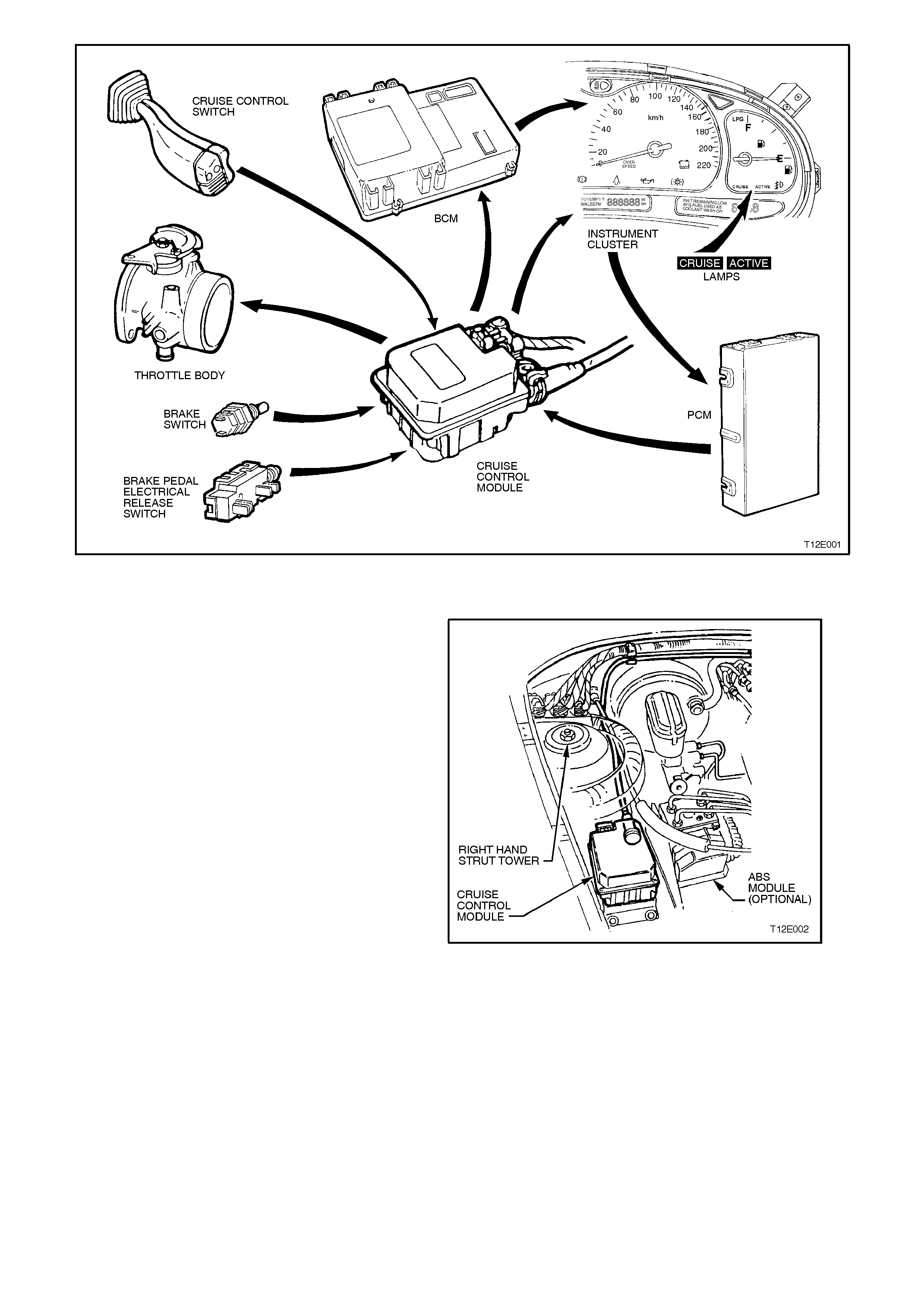
Figure 12E-1
COMPONENTS
The cruise control module is mounted forward of
the right hand strut tower, regardless of the engine
variant.
Figure 12E-2
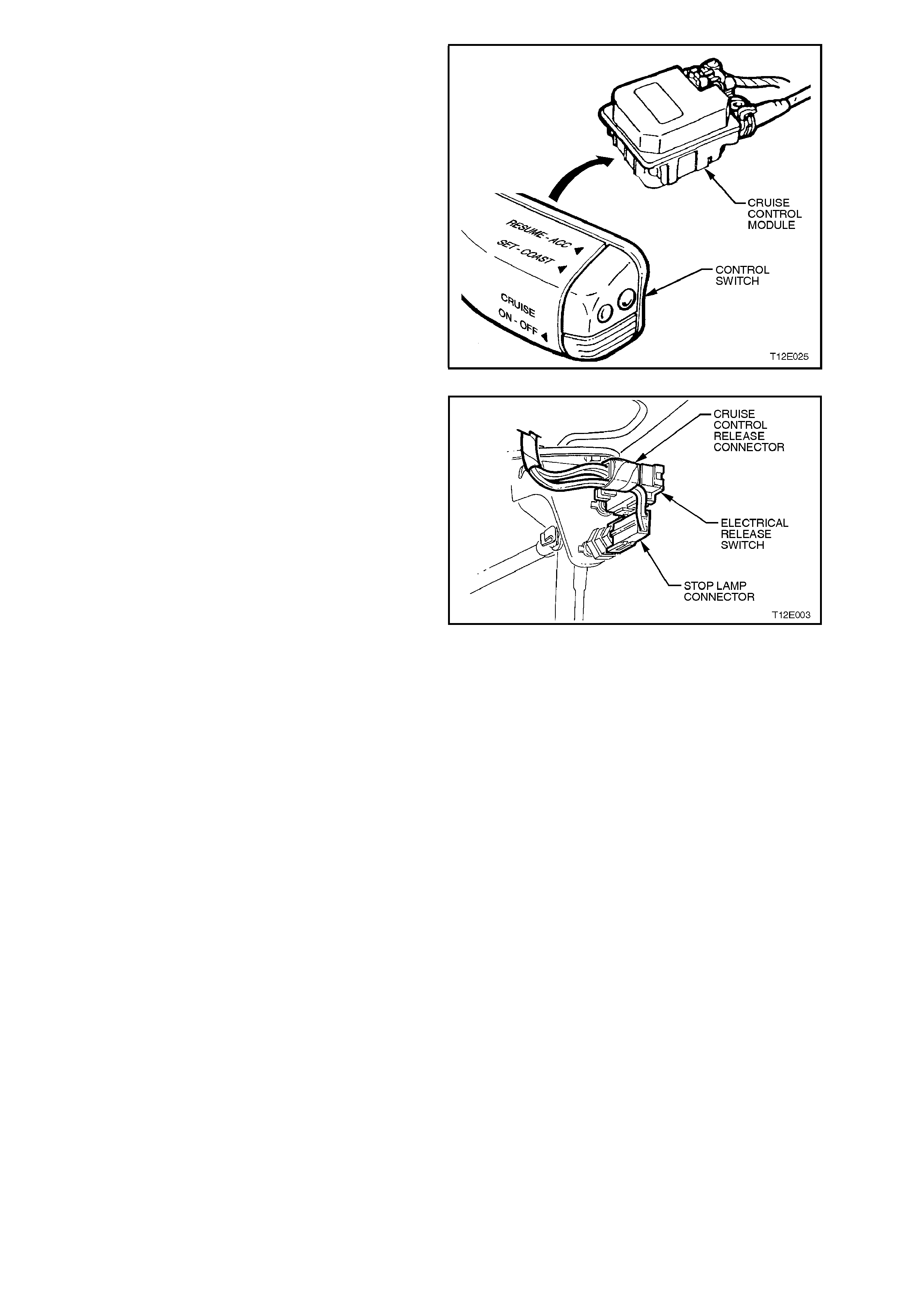
The cruise control module functionally integrates an
electronic controller with an electric stepper motor.
The electronic controller monitors vehicle speed
from a signal generated from the PCM which in
turn, operates the electric stepper motor.
The stepper motor, in response to the electronic
controller, adjusts the throttle position to maintain
the desired vehicle set speed. The electronic
controller is operated by the cruise control system
control switches located at the tip of the headlamp
and turn signal stalk control switch assembly.
Figure 12E-3
Two switches, mounted on the brake pedal
support, disengage the cruise control system
electronically when the brake pedal is depressed.
The upper switch is the cruise control electrical
release switch. Only the two rear terminals are
used.
NOTE:
Using the front set of terminals will result in the
cruise control not functioning.
The lower switch is used to illuminate the stop
lamps and signal the cruise control module to
disengage.
With the brake pedal at rest, the stop lamp contacts
in the lower switch are open, and close when the
brake pedal is depressed.
With the brake pedal at rest, the electrical release
contacts in the upper switch are closed, and open
when the brake pedal is depressed.
Both switches are used to signal the cruise control
module so that if one s hould fail, the sec ond switch
will still generate a signal to the cruise control
module to disengage the cruise control function.
Figure 12E-4
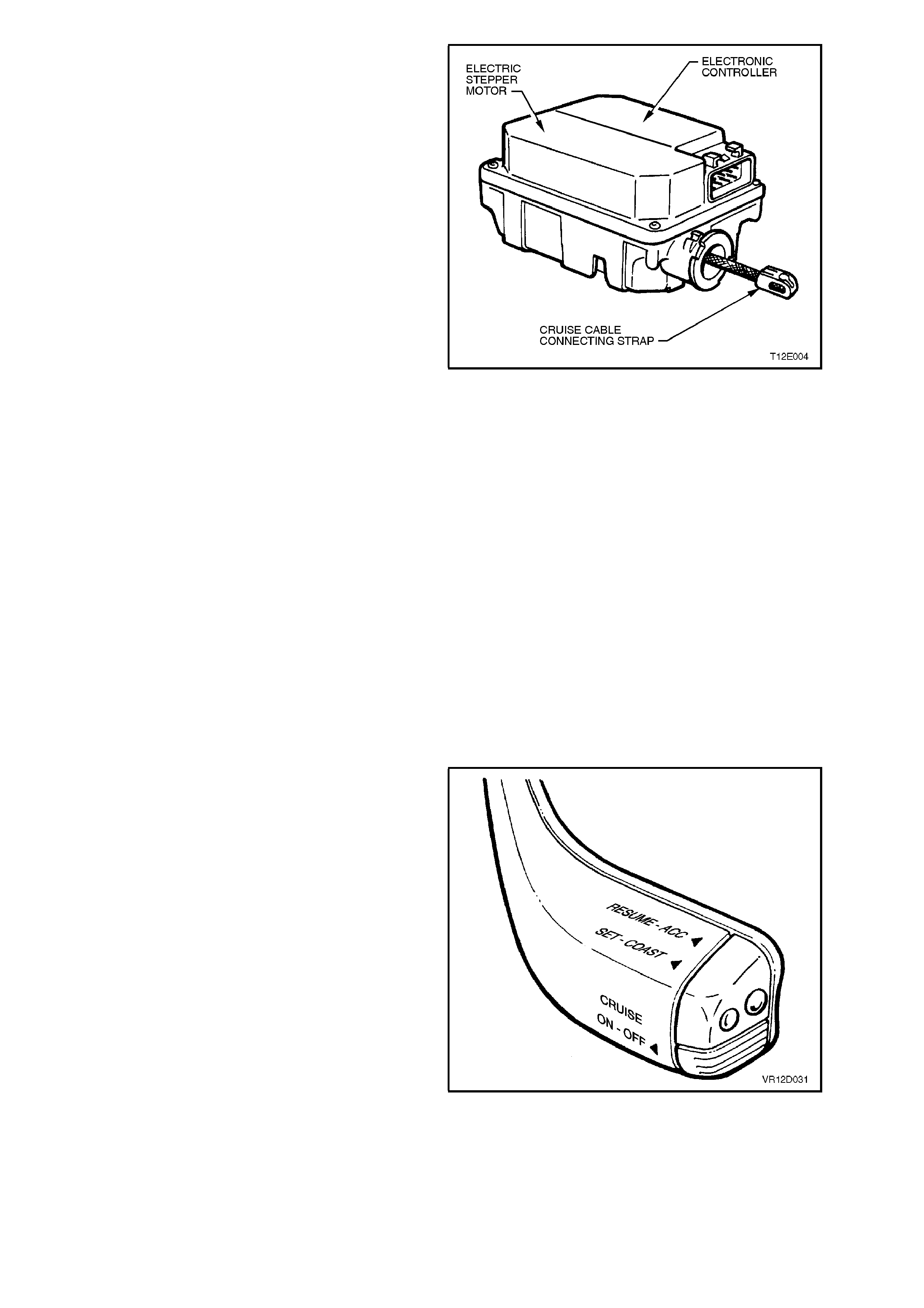
The cruise control module comprises an electronic
controller and electric stepper motor, solenoid
operated clutch and gear train assemblies.
The electronic controller receives signals from the
cruise control electrical release switch, stop lamp
switch and vehicle speed output, and generates
signals to control the stepper motor and solenoid
operated clutch.
The electric stepper motor is a brushless type
motor with a four pole permanent m agnet arm ature
and three phase stator. The motor provides torque
through a mechanical gear train to a control cable,
which actuates the throttle linkage.
When the brake pedal electrical release switch is
activated (brake pedal depressed) the stepper
motor begins to spin the motor back to the zero
motor position. If the signal at pin G of the cruise
control module is pulled high, it will cause the
stepper motor clutch to de-energised in about 0.75
seconds. In most cases, the stepper motor will be
in the zero position when the clutch is disengaged.
This time delay period is introduced to prevent the
accelerator pedal from ‘slapping’ while the throttle
is still held open. The stepper motor relies on the
throttle return spring to return the stepper motor to
the zero position as the spring on the drum gear is
not strong enough to return the throttle/cruise to
zero.
The internal components of the control module are
not serviceable.
WARNING:
DO NOT ATTEMPT TO REPAIR THE CONTROL
MODULE ASSEMBLY IF FAULTY.
UNAUTHORISED REPAIR OF THE CONTROL
MODULE WILL AFFECT VEHICLE SAFETY.
Figure 12E-5
CRUISE CONTROL SWITCH OPERATION
ENGAGING THE CRUISE CONTROL
With the ignition switched on, press the cruise
ON/OFF button. This will cause the ‘CRUISE’ lamp
in the instrument cluster to illuminate, refer to Fig.
12E-7, indicating power is on.
Accelerate the vehicle to the desired cruise speed
(above 40 k m/h) and depress and release the SET
button, then release the accelerator pedal.
Figure 12E-6
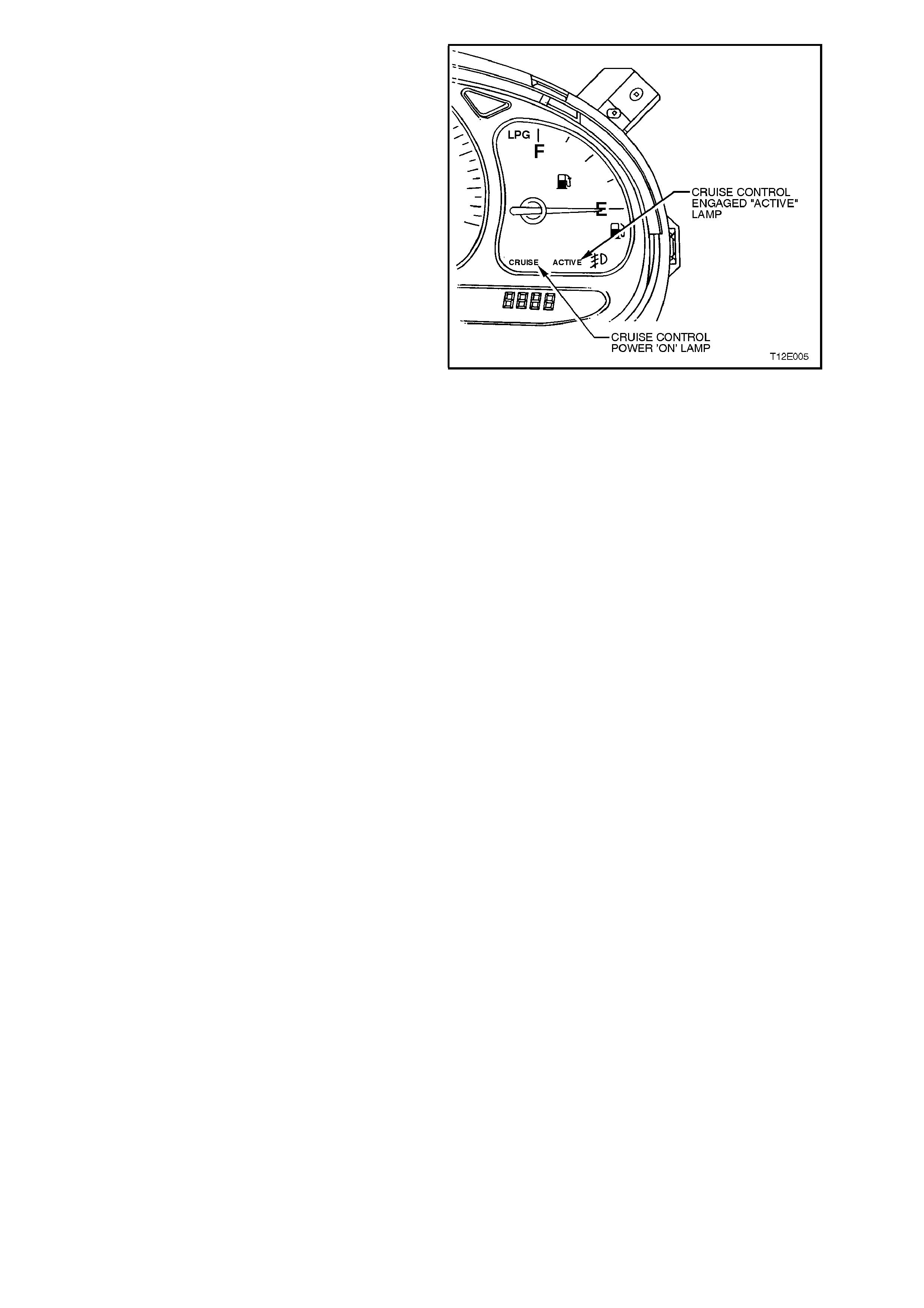
The ‘ACTIVE’ lamp in the instrument cluster will
illuminate when the cruise control system is
engaged. The cruise speed will be automatically
ma intained, provided the vehicle speed is above 40
km/h.
Figure 12E-7
TO CHANGE CRUISE SPEED
To reset the cruise control to a higher speed, accelerate the vehicle to the desired speed, depress the SET button
and release it.
Depressing the RESUME button will cause an increase in cruise speed and the vehicle will accelerate at a
controlled rate until the RESUME button is released. The vehicle will now cruise at this higher set speed.
To decrease the cruise speed, press the SET button. The vehicle will decelerate, coasting to a slower speed at a
controlled rate until the SET button is released. The vehicle will now continue to cruise at the reduced set speed.
NOTE:
While holding the SET button, the ‘Active’ lamp in the instrument cluster will turn OFF. The ‘Active’ lamp will
illuminate when the SET switch is released.
The c ruise c ontrol switches also provide the f acility for T AP UP and T AP DOWN f or sm aller increment adjus tm ents
in vehicle cruise .
TAP UP is achieved by quickly depressing the RESUME button and the cruise speed will increase by 2.0 km /h for
every TAP UP. Quick ly depressing the SET button ( T AP DO WN) will decreas e the c ruis e c ontr ol speed by 2.0 km/h
for every TAP DOWN. TAP DOWNS are limited to the minimum cruising speed of 40 km/h.
TO OVERRIDE THE CRUISE CONTROL SYSTEM
The accelerator pedal may be depressed at any time to override the cruise control system. Release of the
accelerator pedal will return the vehicle to the previous set cruise speed.
TO DISENGAGE THE CRUISE CONTROL SYSTEM
The system is disengaged when:-
1. The brake pedal is depressed.
2. The ON/OFF button is depressed switching the cruise control system to the STANDBY mode.
When the cruise control system is disengaged, the ACTIVE lamp goes out but the CRUISE lamp remains on.
To resume the previous set cruise control memory speed after braking, stopping, or pressing the ON/OFF switch
once, first accelerate, if required, until the vehicle speed is greater than 40 km/h, then press the RESUME button
(for less than one second). The vehicle will then automatically accelerate to the previous cruise speed setting.
The cruise control module will retain the previous set speed in memory for as long as the CRUISE lamp is
illuminated. Depr essing the brak e pedal or press ing the ON/OFF s witch once while the ACTI VE lam p is on, will not
erase the vehicle set speed from the control module memory.
Pressing the O N/OFF switch while only the CRUISE lamp is on or by turning the ignition off will erase the previous
cruise set speed from the control module memory.
NOTE:
Each time the ignition is cycled, the CRUISE and ACTIVE lamps will go out. To reactivate the cruise control, the
cruise control ON/OFF switch will have to be pressed.
2. SERVICE OPERATIONS
2.1 CRUISE CONTROL CABLE
REMOVE
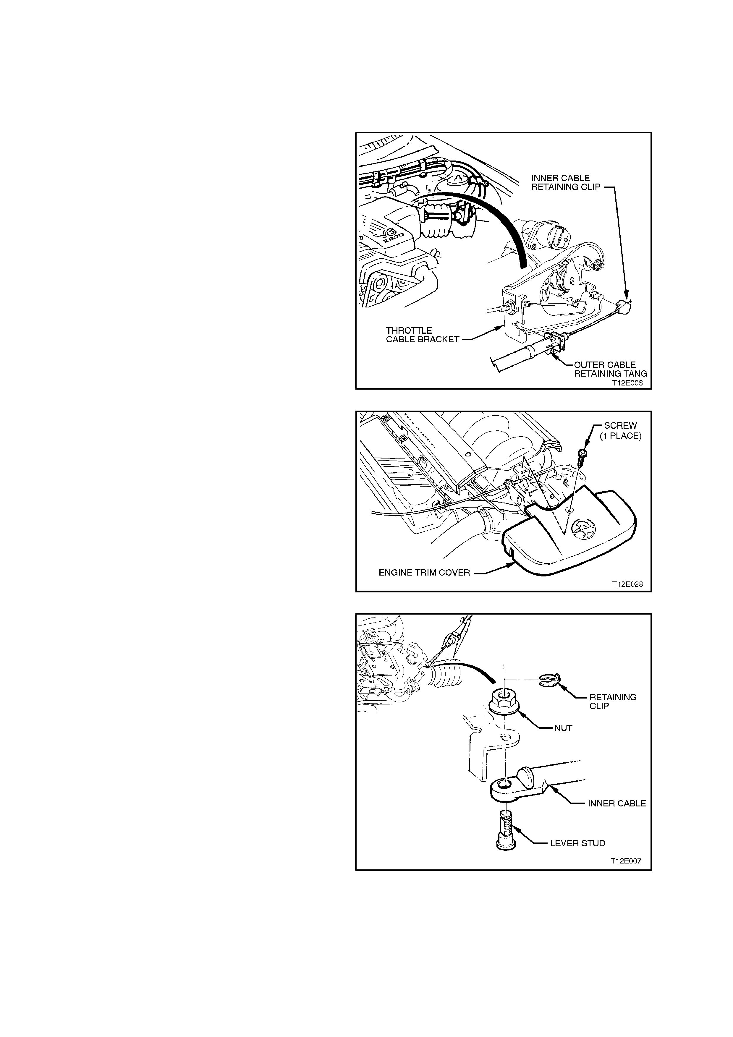
1. On vehicles with V6 engine, push the outer
cable retaining tang at the throttle cable
bracket away from the throttle body and pull
outer cable out of throttle cable bracket.
2. On vehicles with V6 engine, remove the inner
cable retaining clip from the throttle body
linkage lever stud by pushing the retaining clip
off the stud with a the aid of a screwdriver.
Figure 12E-8
3. On vehicles with V8 engine, loosen the four
engine trim cover retaining screws and
remove the screw securing the front engine
trim cover to the throttle cable attaching
bracket, then remove the front trim cover.
Figure 12E-9
4. On vehicles with V8 engine, remove the inner
cable retaining clip and nut from the throttle
body linkage lever stud. Remove inner cable
and lever stud from throttle linkage, separate
stud from cable.
Figure 12E-10
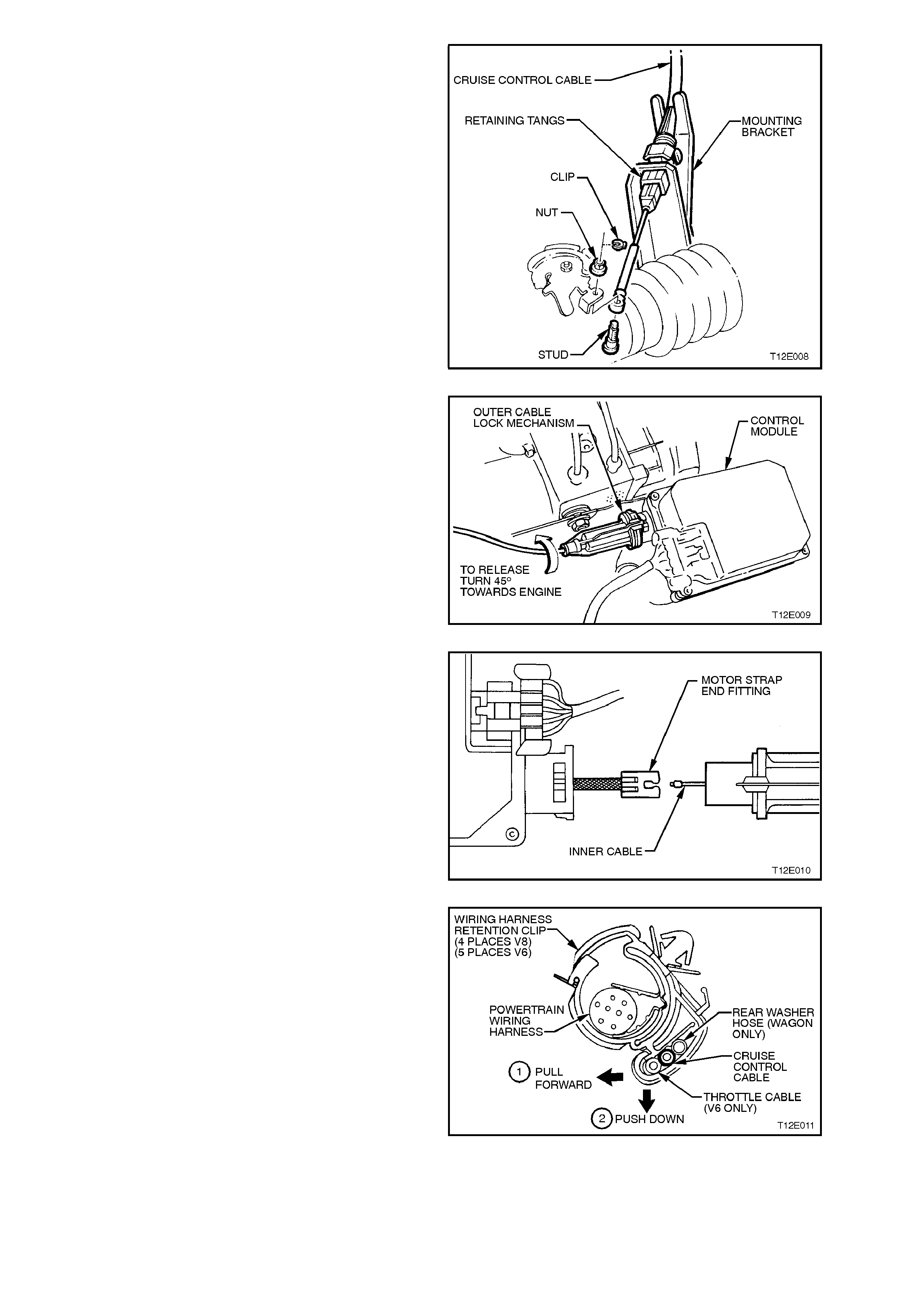
5. On vehicles with V8 engines, depress outer
cable retaining tangs at cable mounting
bracket and pull cable from bracket.
Figure 12E-11
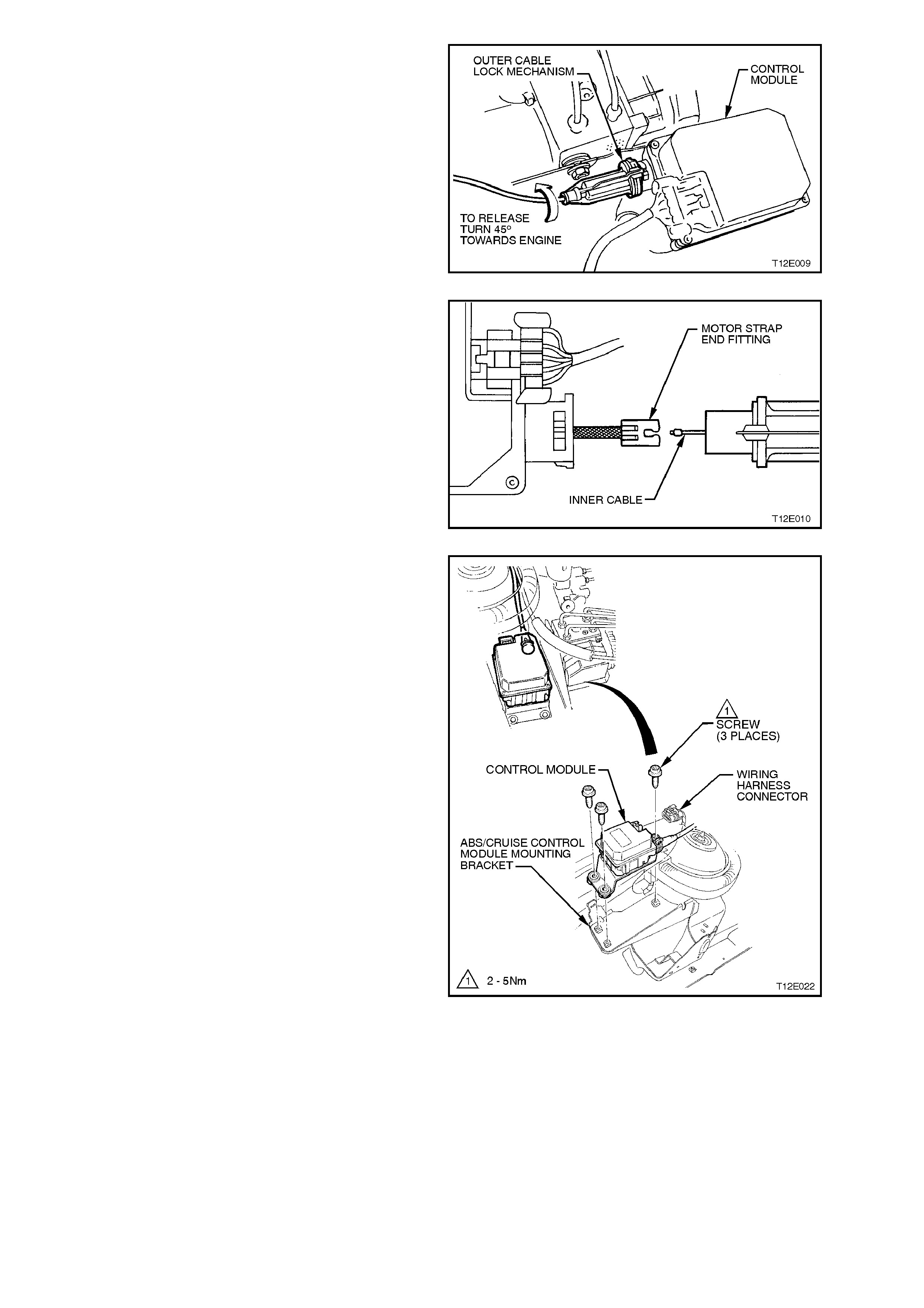
6. At the control module, turn the outer control
cable toward the engine (approx. 45°) to
release cable lock mechanism from control
module.
Figure 12E-12
7. Pull cable fr om c ontrol m odule and disconnect
inner cable from electric stepper motor strap
end fitting by lifting cable upward,
approximately 45°, allowing cable to be
released from end fitting.
Figure 12E-13
8. Release cruise control cable from main wiring
harness clips (5 places V6, 4 places V8) by
pulling the retention clip forward (1) and then
pushing the retention clip down to open and
release cable.
9. On vehicles with V6 engines, remove cruise
control to throttle cable r etaining clip at the left
hand engine hood strut.
10. Remove control cable.
11. If necessary, on vehicles with V8 engine,
remove the two bolts securing the cable
mounting bracket to the alternator mounting
bracket and remove cable mounting bracket . Figure 12E-14
REINSTALL
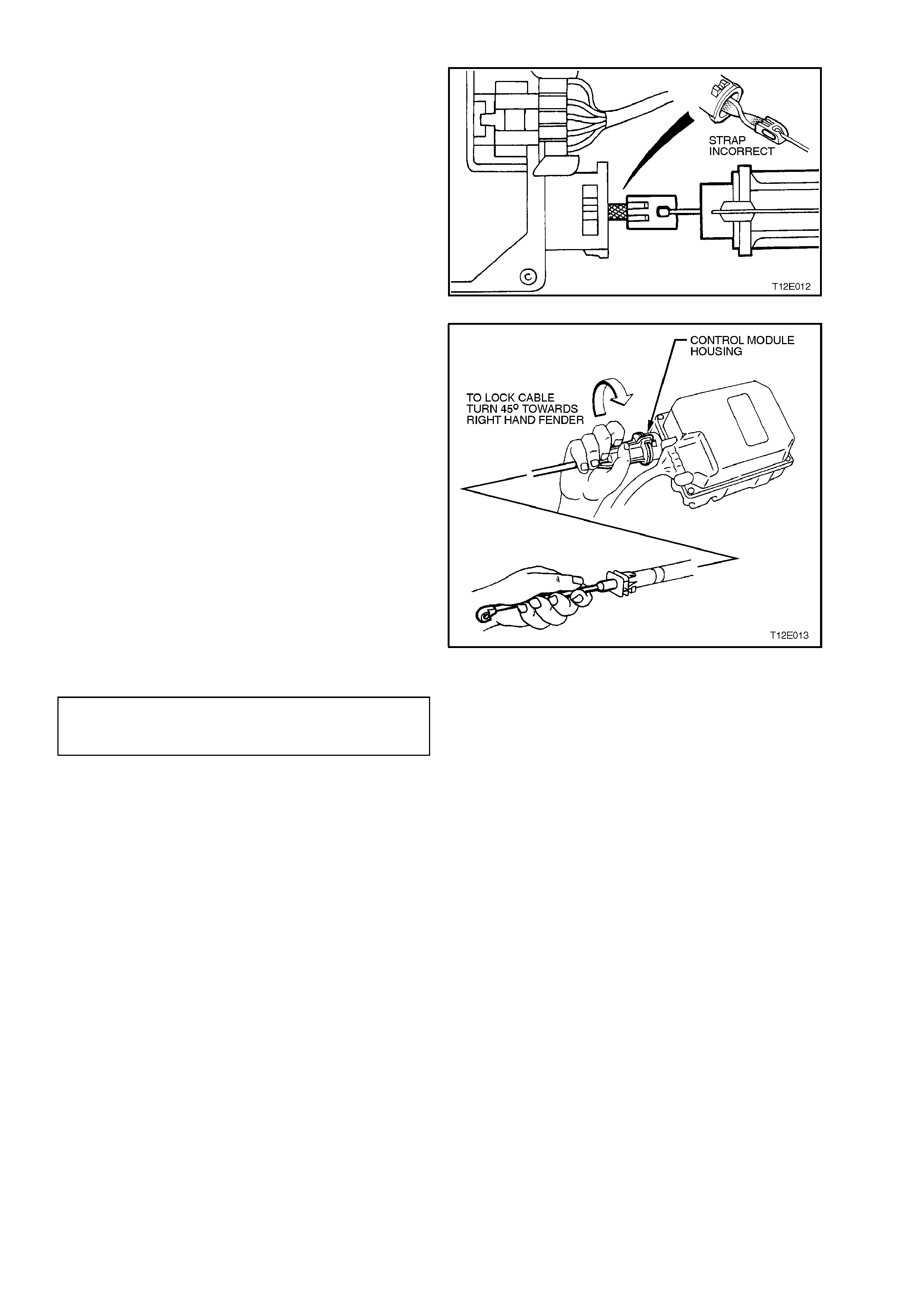
1. Ensuring that the motor strap is not twisted,
attach inner cable end to the motor strap end
fitting at the control module.
Figure 12E-15
2. While holding the inner cable at the throttle
body linkage lever stud connection end, slide
outer cable over the m otor strap until the outer
cable sits flush with the control module
housing.
3. Turn outer cable towards the right hand f ender
(approx. 45º) to lock the outer cable locking
mechanism to the control module, refer Fig.
12E-16.
4. If removed, on vehicles with V8 engine, install
the cable mounting bracket to the alternator
mounting brac ket and tighten securing bolts to
the correct torque specification.
Figure 12E-16
CABLE MOUNTING BRACKET
SECURING BOLT
TORQUE SPECIFICATION 6.0 - 14 Nm
5. Install cable into throttle body bracket (V6) or
mounting bracket (V8) ensuring that the
retaining tangs lock into place.
6. Ensuring the cable is routed correctly, lock
cable into main wiring harness retention clips
and cruise control to throttle cable retaining
clip, refer to Fig. 12E-17 (V6) or 12E-18 (V8).
NOTE:
Figure. 12E-17 shows the cruise control routing for
a standard V6 engine, the routing of the cruise
control cable for V6 supercharged engines is the
same.
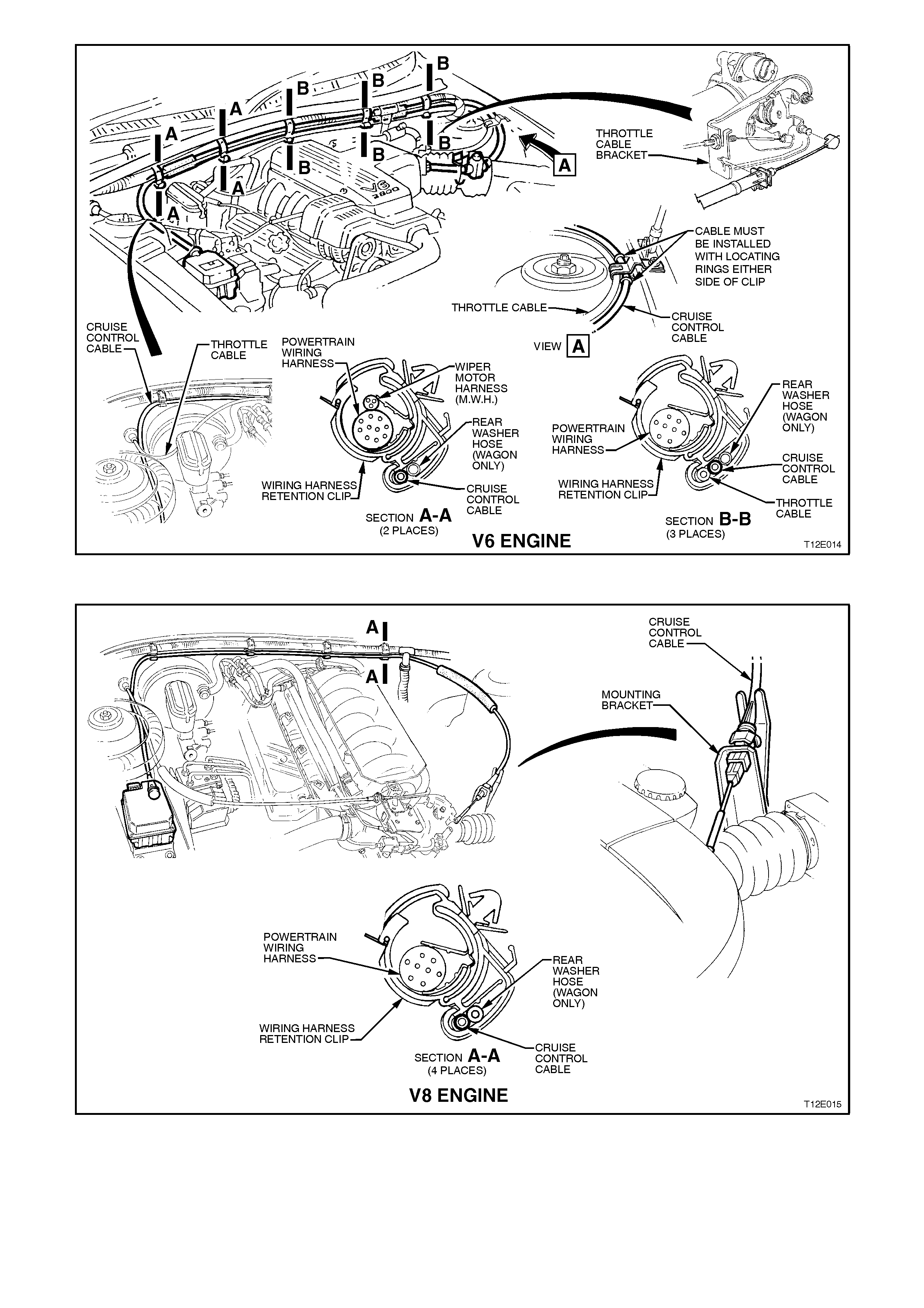
Figure 12E-17
Figure 12E-18
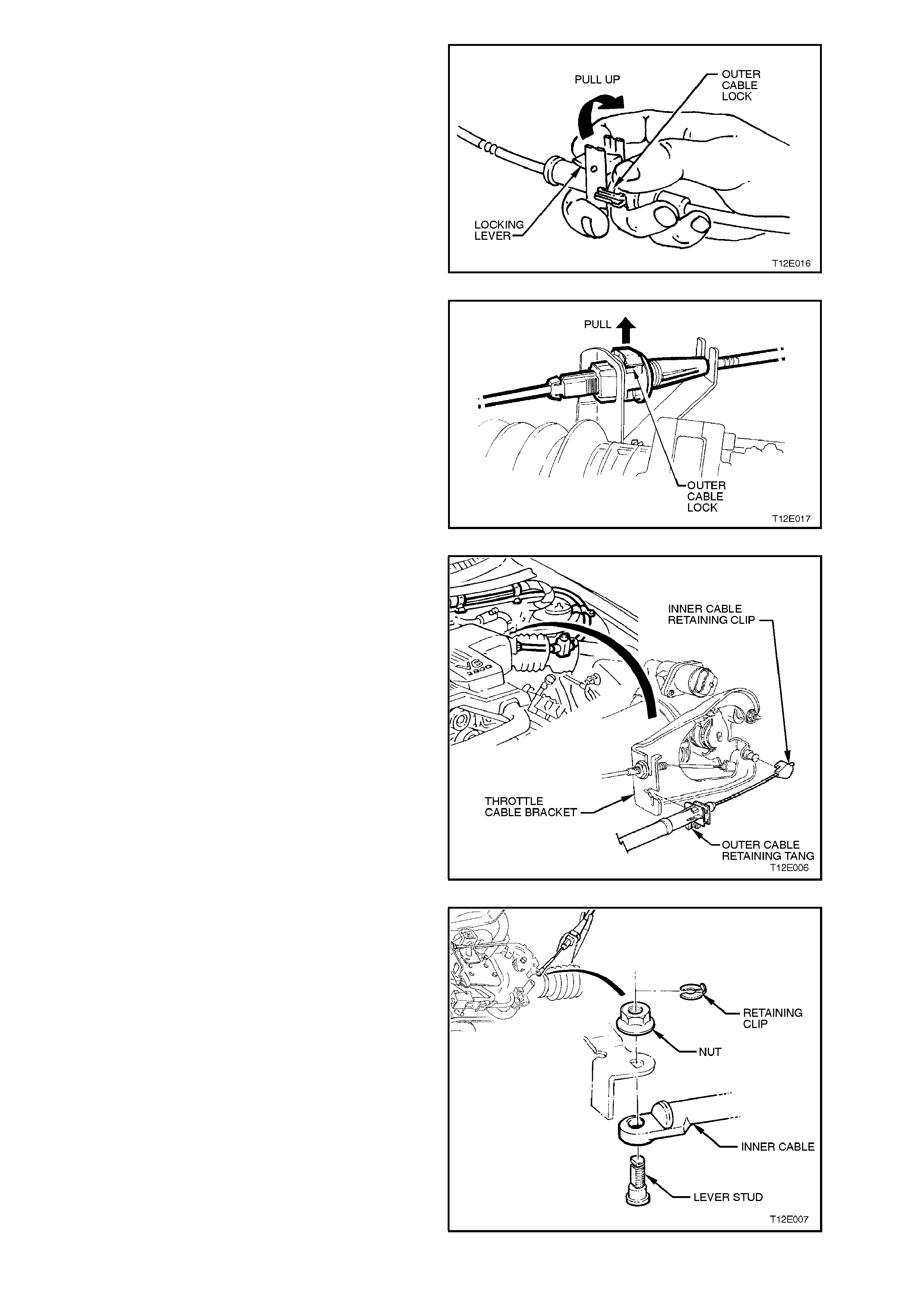
7. Unlock the control cable by pulling up the
cable lock, ref er to Fig. 12E-19 (V6) or 12E-20
(V8).
Figure 12E-19
Figure 12E-20
8. On vehicles with V6 engine, push the outer
cable retainer into the throttle cable bracket.
9. On vehicles with V6 engine, push the inner
cable retaining clip onto the throttle body
linkage lever stud.
Figure 12E-21
10. On vehicles with V8 engine, install the inner
cable lever stud, retaining nut. Tighten lever
stud nut to the cor rect torque spec ification and
install clip to the throttle body linkage.
Figure 12E-22
LEVER STUD NUT
TORQUE SPECIFICATION 1.0 - 3.0 Nm
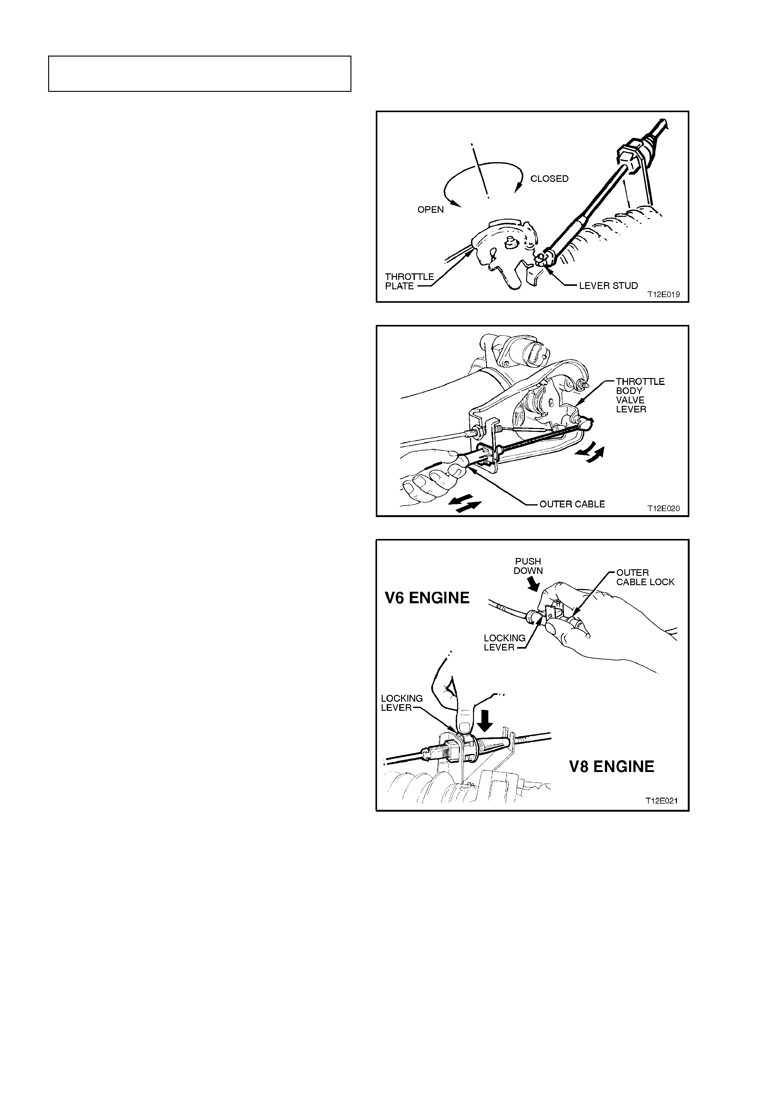
11. On vehicles with V8 engine, ensure that the
throttle plate is in the closed position, refer to
Fig. 12E-22.
Figure 12E-23
12. On vehicles with V6 engine, adjust the cruise
control cable to achieve a minimum slack
while ensuring that the throttle valve is closed,
refer to Fig. 12E-24.
Figure 12E-24
13. Lock the control cable by pushing the cable
lock down, refer to Fig. 12E-25.
14. On vehicles with V8 engine, reinstall the
engine front cover.
Figure 12E-25
2.2 CRUISE CONTROL MODULE
REMOVE
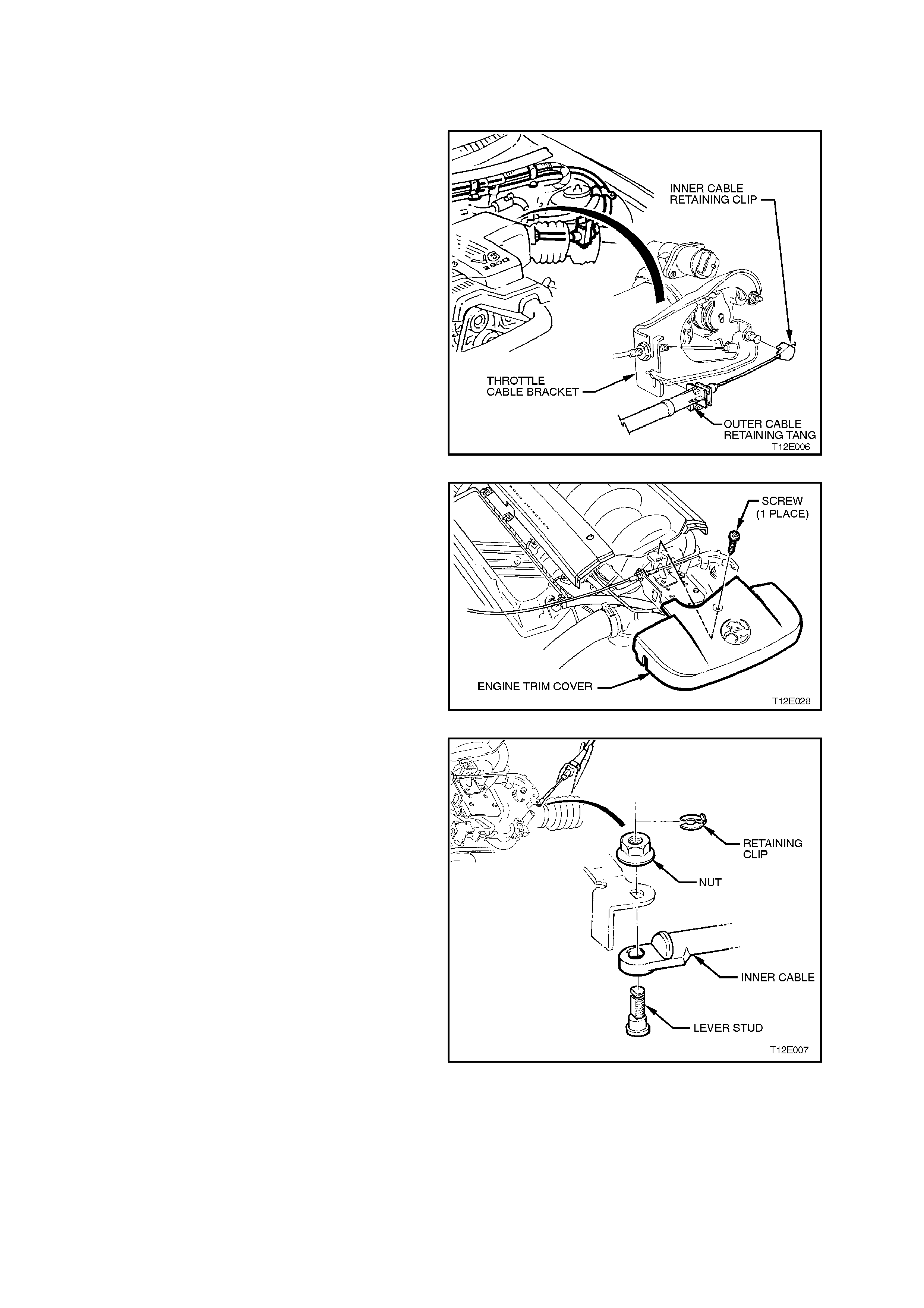
1. On vehicles with V6 engine, push the outer
cable retaining tang at the throttle cable
bracket away from the throttle body and pull
outer cable out of throttle cable bracket.
2. On vehicles with V6 engine, remove the inner
cable retaining clip from the throttle body
linkage lever stud by pushing the retaining clip
off the stud with a the aid of a screwdriver.
Figure 12E-26
3. On vehicles with V8 engine, loosen the four
engine trim cover securing screws and remove
the screw securing the front engine trim cover
to the throttle cable attaching bracket, then
remove the front trim cover.
Figure 12E-27
4. On vehicles with V8 engine, remove the inner
cable retaining clip and nut from the throttle
body linkage lever stud. Remove inner cable
and lever stud from throttle linkage, separate
stud from cable.
Figure 12E-28
5. At the control module, turn the outer control
cable toward the engine (approx. 45°) to
release cable lock mechanism from control
module.
Figure 12E-29
6. Pull cable fr om c ontrol m odule and disconnect
inner cable from electric stepper motor strap
end fitting by lifting cable upward,
approximately 45°, allowing cable to be
released from end fitting.
Figure 12E-30
7. Pull up tang on wiring harness connector, and
pull connector from control module.
8. Remove the three screws securing the control
module to the ABS/cruise control module
mounting bracket and remove control module.
Figure 12E-31

REINSTALL
Installation of the cruise control module is the
reverse of the removal operation, noting the
following:
1. To reinstall the cruise control cable, refer to
steps 1 to 3 and 7 to 13 of
2.1 CRUISE CONTROL CABLE -
REINSTALL in this Section.
2. Tighten all fasteners to the correct torque
specification.
CONTROL MODULE SECURING
SCREW TORQUE SPECIFICATION 2 - 5
Nm
LEVER STUD NUT
TORQUE SPECIFICATION 1.0 - 3.0
Nm
2.3 CRUISE CONTROL SWITCH ASSEMBLY
REMOVE AND REINSTALL
The cruise control switches are integrated with the
headlamp and turn signal control switch stalk
located to the right of the steering column.
Removal and installation instructions for the right
hand switch stalk are described in
Section 12B LIGHTING SYSTEM.
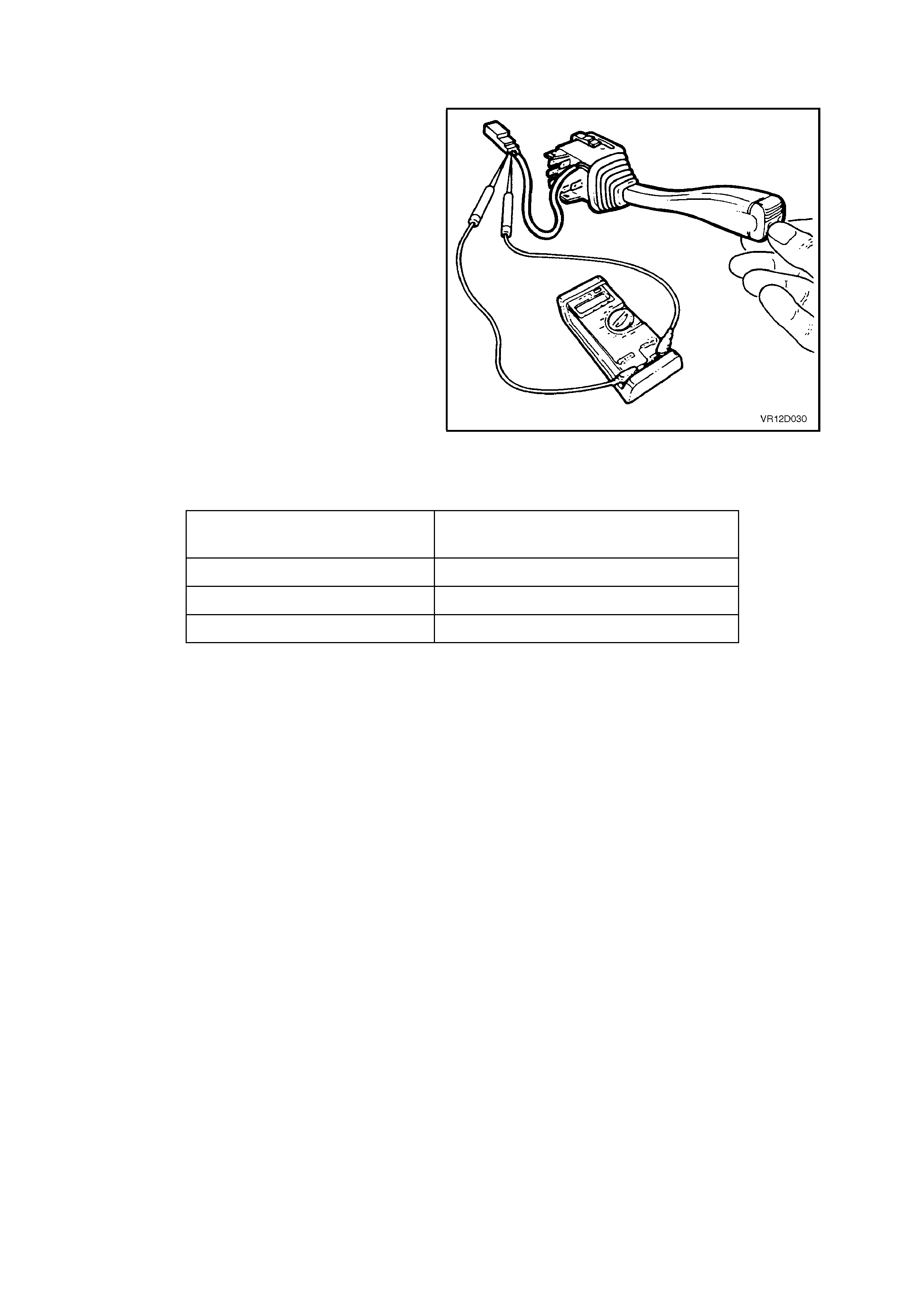
CHECKING SWITCH CONTACTS
With the cruise control system control switch lead
disconnected f rom the main wiring harness, check
the cruise control switch contacts as follows:
Attach an Ohmmeter to the appropriate terminals
nominated in the following chart and depress and
hold button as directed. The Ohmmeter will read
approximately 470 W resistance when the button is
depressed and show an open circuit when
released.
If the nom inated value is not achieved, replace the
cruise control switch assembly. Figure 12E-32
SWITCH POSITION SWITCH CONNECTOR
WIRE COLOUR
ON/OFF Button Depressed Red & Grey wire
SET - Button Depressed Blue & Red wire
RES + Button Depressed Red & Green wire

2.4 ELE CTRICAL RELEASE SWITCH (BRAKE LAMP SWITCH B)
TESTING SWITCH CONTACTS
1. Remove the instrument panel right hand
foot well upper cover, refer to
Section 1A3 INSTRUMENT PANEL AND
CONSOLE.
2. Check adjustment of switch, refer to the
following switch installation and adjustment
procedure and adjust the switches as
required.
Ensure that the brake lights are operating
when the brake pedal is depressed.
If brake lights are not operating,
repair as necessary, refer to
Section 12B LIGHTING SYSTEM.
3. Remove wiring harness connector from rear
most terminals of swi tch.
4. Connect an Ohmmeter across the switch
terminals and the ohmmeter should indicate
continuity with the brake pedal at rest.
Depress the brake pedal and the Ohmmeter
should indicate an open circuit.
5. Replace the switch as per the following
rem oval procedur e if the tests prove the s witch
to be faulty.
6. If the test pr oves the switch to be OK, ref it the
wiring harness connector to the switch and
refit the right hand foot well upper cover to the
instrument panel, refer to Section 1A3
INSTRUMENT PANEL AND CONSOLE.
Figure 12E-33
REMOVE
1. Remove the instrument panel right hand foot
well upper cover, refer to Section 1A3
INSTRUMENT PANEL AND CONSOLE.
2. Disconnect wiring harness connectors from
electrical release switch.
3. Pull switch from tubular clip.
4. If necessary, remove clip from brake pedal
support.
Figure 12E-34
REINSTALL AND ADJUST
1. If removed, install the tubular clip into the mounting hole of the brake pedal support.
2. Holding the brake pedal in it’s depressed position, install switch into tubular clip. Push switch forward until the
switch body locates in the clip.
NOTE:
Audible ‘clicks’ will be heard as the threaded portion of switch assembly is pushed into the tubular clip toward the
brake pedal.
Pull brake pedal fully against pedal stop until audible ‘click’ sounds can no longer be heard. (Switch assembly is
pushed back out from the clip to provide correct switch position adjustment).
Depress the brake pedal again and repeat above procedure to ensure that the switch adjustment is correct (no
‘click’ sounds).
3. Reconnect wiring harness connector to switch.
4. Refit the right hand foot well upper cover to the instrument panel, refer to Section 1A3, INSTRUMENT
PANEL.

3. DIAGNOSIS
3.1 PRELIMINARY DIAGNOSIS AND INSPECTION
NOTE:
If a vehicle is fitted with traction control, the cruise control system will disengage or fail to engage whenever the
LOW TRAC lamp is illuminated in the instrument cluster, and will not engage or re-engage until the LOW TRAC
lamp turns off.
When a vehicle is suspected of having a cruis e control s ystem operation m alf unction, it is im portant to car ry out the
following preliminary diagnosis. This diagnosis should be used to determine whether the cruise control system
problem is the result of an actual system defect, or the result of a problem with some other vehicle component.
Also, som e c ruise c ontrol system c om plaints m ay be a misunder standing by the driver about how the cruis e contr ol
system f unctions . In that c ase, the oper ation of the s ystem s hould be ex plained in a manner the dr iver under st ands.
A practical demonstration is very useful to explain system operation.
If it is decided the cruise control system is at fault, perform a visual inspection of all components in the system.
Cruise control system malfunctions can be caused by mechanical, electrical, or a combination of both problems.
Things to check are:
1. Switch inputs to cruise control module.
2. Dirty, corroded, or loose electrical connections.
3. Damaged or incorrectly adjusted electrical release switch or stop lamp switch (refer
2.4 ELECTRICAL RELEASE SWITCH in this Section for electrical release switch adjustment).
4. Binding or sticking throttle linkage.
5. Broken components (i.e. cruise control cable).
6. Bare, broken or disconnected wires.
7. Adjustment of control cable, refer 2.1 CRUISE CONTROL CABLE , in this Section.
If preliminary inspection reveals no problem, and the system is malfunctioning, refer to
3.3 SELF DIAGNOSTIC PROCEDURE, in this Section.
NOTE:
Verify the problem exists before attempting any repairs. Sometimes normal operating characteristics may be
misunderstood as a problem.
Techline

3.2 CRUISE CONTROL SYSTEM FUNCTIONAL CHECK
The f ollowing procedure s hould be used to chec k the oper ating m odes of the cruis e control s ystem. T his proc edure
should always be used after repair work has been completed on the cruise control system.
ROAD TEST PROCEDURE
1. Check ON/OFF activation: Ignition ON, depress the cruise control ON/OFF button to turn the system ON;
system CRUISE lamp should illuminate.
2. Check the low speed inhibit: Dr ive vehicle at 30 k m /h. Depress SET button and r elease. Cruis e control m ust
not engage and only the CRUISE lamp should be illuminated.
3. Check set speed: Drive vehicle at a steady speed of 60 km/h. Depress SET button and release. Cruise control
should engage at approximately 60 km/h and both the CRUISE and ACTIVE lamps must illuminate.
4. Check brake release: With cruise control system engaged, depress brake pedal. The cruise control must
release the throttle, allowing vehicle speed to drop. The system must not re-engage when the brake pedal is
released. The ACTIVE lamp must go out but the CRUISE lamp will remain on.
5. Check resume feature: With vehicle speed at approximately 50 km/h, depress the RESUME button and
release. The vehicle should accelerate to approximately 60 km/h and the CRUISE and ACTIVE lamp should
illuminate again.
6. Check coast feature: Depress the SET button and hold. Only the ACTIVE lamp must go out. Allow the vehicle
speed to drop to 50 km/h and release SET button. The cruise control should hold the vehicle speed at
approximately 50 km/h and both the ACTIVE and CRUISE lamps should be illuminated.
7. Check accelerator feature: Depress the Resume button and hold. The vehicle speed should begin to
increase. Allow the speed to increase to 60 km/h and releas e s witch. T he c r uise c ontr ol s hould hold the vehicle
speed at approximately 60 km/h. Both the ACTIVE and CRUISE lamps should be illuminated.
8. Check coast down mode:
a) Press and release the ON/OFF button. The vehicle should begin to slow down (this has the s ame eff ect as
holding the SET button). In this mode, the cruise is deactivated and allows the vehicle to slow down but the
CRUISE lamp remains illum inated. Allow the vehicle to slow to approxim ately 50 k m/h and press and release
the RESUME button. The vehicle must return to approximately 60 km/h and both the CRUISE and ACTIVE
lamps should be illuminated.
b) Press and release the ON/OFF button and allow vehicle to slow to approxim ately 50 k m/h again and press
the SET button. The vehic le speed must hold at 50 k m/h and both the CRUISE and ACT IVE lamps s hould be
illuminated.
c) Press the ON/OFF button again and allow the vehicle to coast down. Only the CRUISE lamp should be
illuminated.
d) Press the ON/OFF button again while in coast down mode (Step C) to fully turn the cruise control system off.
Both the CRUISE and ACTIVE lamps must go out.

3.3 SELF DIAGNOSTIC PROCEDURE
To provide a means of checking brake switch, cruise release switch, speed sensor inputs and electro-motor
operation, the cruise control system incorporates self diagnostic checks.
Following the Self Diagnostic Procedure is a detailed diagnostic chart to pin point the cause of a cruise control
system malfunction.
Carry out Self Diagnostic Procedure as outlined.
Jack up vehicle and support on saf ety s tands. Refer to Section 0A GENERAL INFORMATION for the location of
jacking points. Ensure drive shafts are horizontal.
Follow steps 1 - 23 in the SWIT CH DIAG NOSTIC T EST CHART f ollowing and perf or m the f unc tion as r eques ted. If
at any stage during this procedure the system doesn’t function as nominated (lamp illumination), repair fault as
necessary.
STEP FUNCTION LAMPS COMMENTS
CRUISE ACTIVE
1. Ignition OFF OFF OFF Clears memory of any pre-set speed
2. Press & Hold
ON/OFF button OFF OFF Triggers diagnostic test. ON/OFF
button must be held until step 13
3. Start engine ON OFF
4. Wait 5 seconds ON OFF Waits for LOW TRAC warning lamp to
distinguish (if fitted)
5. Press & hold SET/
COAST button ON ON Tests SET/COAST function of cruise
control switch asse mbly
6. Release SET/
COAST button ON OFF
7. Press & hold
RESUME/ACC
button
ON ON Checks RESUME/ACC function of
cruise control switch assembly
8. Release
RESUME/ ACC
button
ON OFF
9. Press & hold
brake pedal ON ON Checks cruise control release switch
(stop lamp switch B)
10. Release brake
pedal ON OFF
11. Press & hold
brake pedal ON ON This step is included for addition
features (i.e. cruise control for
vehicles with manual transmission).
Although this Step is not applicable to
VT Series Models, it still must be
conducted in order to complete switch
diagnostic test.
12. Release brake
pedal ON OFF
13. Release ON/OFF
button ON ON Enters the second stage of the
diagnostic mode to check the
ON/OFF switch and cruise control
warning lamps.
14. Press & hold
ON/OFF button OFF OFF
15. Press & hold
brake pedal OFF ON Checks stop lamp switch (stop lamp
switch A) and cruise control switch
inputs to cruise control module. If not
functioning, repair as necessary.

STEP FUNCTION LAMPS COMMENTS
CRUISE ACTIVE
16. Release brake
pedal OFF OFF
17. Press & hold
brake pedal OFF ON
18. Release brake
pedal OFF OFF
19. Release ON/OFF
button OFF ON Enters final stage of diagnostic mode,
allowing vehicle to be road tested
without having to hold cruise control
function buttons.
20. Press & hold
brake pedal
After motor
stroking
OFF
OFF
OFF
ON
Checks stepper motor and cable
operation.
Stepper motor will stroke and return to
rest (closed throttle) state. If not
functioning, repair as necessary.
21 Start engine and
select drive OFF X ACTIVE lamp can be either on or off
22. Drive vehicle and
monitor ACTIVE
lamp
OFF X ACTIVE lamp will flash with vehicle
speed signal.
Checks speed sender input to cruise
control module. If not functioning as
specified, replace cruise control
module.
23. Select park &
switch engine
OFF
OFF OFF Ends diagnostic mode. Returns cruise
control to normal operating conditions.
NOTE:
If at any time during Steps 1 - 23 of the diagnostic test the ignition is s witched of f , the cruis e c ontrol s ystem will exit
diagnostic mode and return to normal operating conditions.
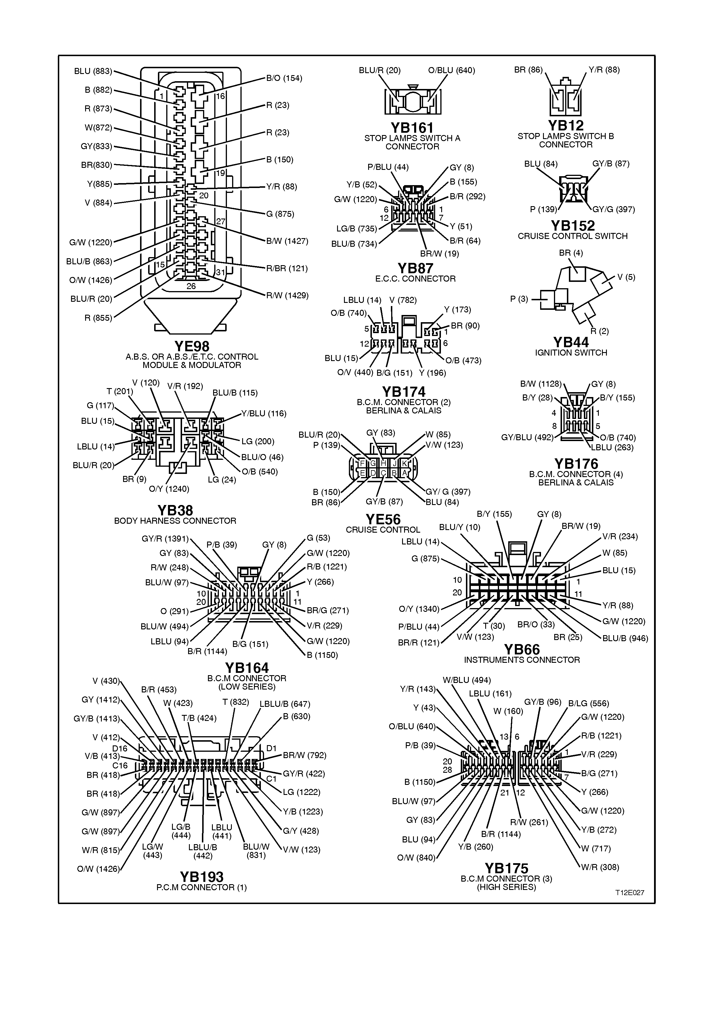
3.4 CRUISE CONTROL SYSTEM CIRCUIT DIAGRAM & CONNECTORS
Figure 12E-35
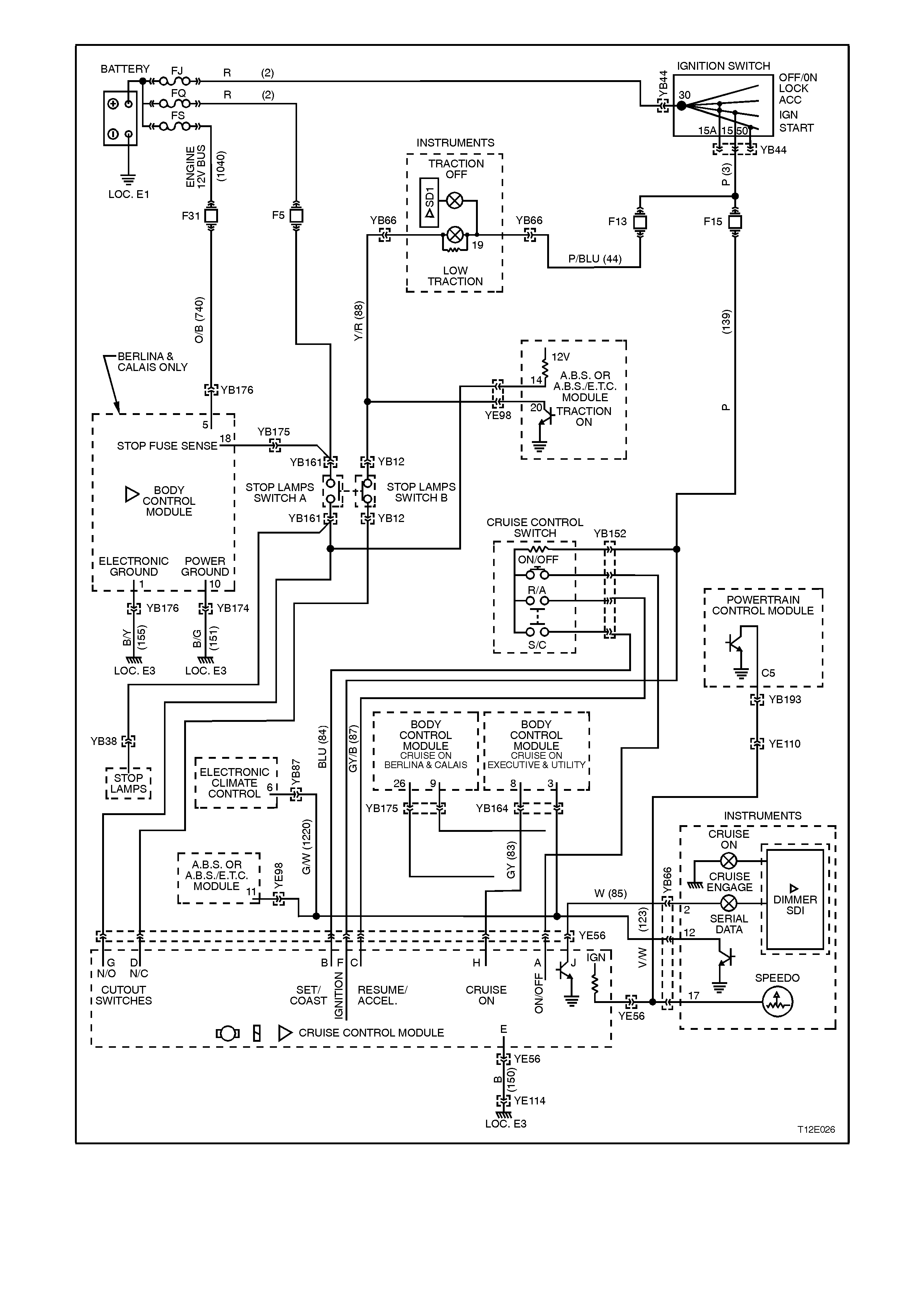
Figure 12E-36

3.5 CRUISE CONTROL S YSTEM DIAGNOSTIC CHART
When using the following diagnostic chart, c ontinually refer to the cruis e control s ystem circ uit diagram at the top of
the chart.
TEST DESCRIPTION:
The numbers below refer to Step numbers in the diagnostic chart for the cruise control system.
1. Checks ignition supply to control module.
2. Checks for earth supply to control module.
3. Checks circuits 84 and 87.
4. Checks if fault is in circuits 84 and 87, or with control module.
4. Checks RESUME/ACC function on cruise control switch assembly.
5. Checks SET/COAST function on cruise control switch assembly.
6. Checks for ignition supply to cruise control switch.
7. Checks RESUME/ACC function of cruise control switch.
8. Checks power supply to cruise control module at RESUME/ACC input.
9. Checks SET/COAST function of cruise control switch.
10. Determines if fault is with serial data communication (including BCM) or with stop lamp switch inputs.
11. Checks cruise control interface (serial data).
12. Checks circuit 83 for open circuit.
13. Checks for faulty stop lamp switch A.
14. Checks for faulty stop lamp switch B (release switch).
15. Checks operation of ACTIVE lamp.
16. Determines if fault is in circuit 85 or in instrument cluster.
17. Checks for fault in circuit 123 and/or PCM.
18. Checks operation of cruise control system during road test.
19. Visual checks of cruise control cable for damage and adjustment.
20. Further diagnostic test that can be performed to help isolate any malfunctions within the system.
STEP ACTION VALUE YES NO
1. • Ignition OFF.
• Disconnect connector
YE56 from cruise
control module.
• Ignition ON.
• Measure voltage
between terminal F,
circuit 139 (Pink wire)
and a good earth.
• Is voltage as specified
?
Battery
+Go to Step 2. Check and repair
open in circuit 139
between (and
including) fuse
F15 and
connector YE56,
recheck and verify
repair.
2. • Ignition OFF.
• With connector YE56
still disconnected from
control module, check
for continuity between
control module
connector YE56,
terminal E, circuit 150
(Black wire) and earth
location E3.
• Does continuity exist ?
Go to Step 3. Check and repair
open in circuit
150, recheck and
verify repair.

STEP ACTION VALUE YES NO
3. • Ignition ON.
• Measure voltage at
connector YE56,
terminal B, circuit 84
(Blue wire ) and
terminal C, circuit 87
(Grey/Black wire) to
earth.
• Is voltage as specified
at either terminal ?
Less
than 1
Volt
Go to Step 5. Go to Step 4.
4. • Ignition ON.
• Disconnect cruise
control switch
assembly connector
YB152 and measure
voltage at terminals B
and C to earth on
connector YE56 again.
• Is voltage as specified
at either terminal ?
Less
than 1
Volt
Replace cruise
control switch
assembly, refer to
2.3 CRUISE
CONTROL
SWITCH
ASSEMBLY in
this Section.
Check and repair
short to voltage in
circuit 84 and/or
87 recheck and
verify repair.
5. • Ignition ON.
• Press and hold
RESUME/ACC button
on cruise control
switch assembl y.
• Measure voltage
between connector
YE56, terminal C,
circuit 87 (Grey/Black
wire) and earth.
• Is voltage as specified
?
Greater
than 9
Volts
Go to Step 8. Go to Step 6.
6. • Ignition OFF.
• Disconnect cruise
control switch
assembly connector
YB152.
• Ignition ON.
• Measure voltage
between connector
YB152, circuit 139
(Pink wire) and earth.
• Does voltage exist ?
Battery
+Go to Step 7. Check and repair
open in circuit 139
between (and
including) fuse
F15 and
connector YB152,
recheck and verify
repair.

STEP ACTION VALUE YES NO
7. • Ignition OFF.
• Disconnect cruise
control switch
assembly connector
YB152.
• Press and hold the
RESUME/ACC button
and check for
continuity between
Red and Green
terminals on cruise
control switch
assembly.
• Is resistance as
specified ?
Approx.
470
Ohms
Check and repair
open in circuit 87,
recheck and verify
repair.
Replace cruise
control switch
assembly, refer
2.3 CRUISE
CONTROL
SWITCH
ASSEMBLY in
this Section.
8. • Ignition ON.
• Press and hold
SET/COAST button on
cruise control switch
assembly.
• Measure voltage
between connector
YE56, terminal B,
circuit 84 (Blue wire)
and a good earth.
• Is voltage as specified
?
Greater
than 9
Volts
Go to Step 10. Go to Step 9.
9. • Ignition OFF.
• Disconnect cruise
control switch
assembly connector
YB152.
• Press and hold the
SET/COAST button
and check for
continuity between
Red and Blue
terminals on cruise
control switch
assembly.
• Is resistance as
specified ?
Approx.
470
Ohms
Check and repair
open in circuit 84,
recheck and verify
repair.
Replace cruise
control switch
assembly, refer
2.3 CRUISE
CONTROL
SWITCH
ASSEMBLY in
this Section.

STEP ACTION VALUE YES NO
10. • Ignition OFF.
• Reconnect cruise
control switch
connector YB152 and
cruise control module
connector YE56.
• Ignition ON.
• Repeatedly press the
cruise ON/OFF button.
• Does the CRUISE
lamp in the instrument
cluster toggle between
on and off with switch
operating ?
Go to Step 13. Go to Step 11.
11. • Ignition ON.
• Back probe BCM
connector YB175 (high
series BCM), terminal
26 or YB164 (low
series BCM), terminal
8, circuit 83 (Grey wire)
with a voltmeter to
earth.
• Repeatedly press the
cruise ON/OFF button
again.
• Does the voltage vary
?
Switch
pressed
12 Volts
Switch
released
0 Volts
Go to CRUISE
CONTROL
INTERFACE
DIAGNOSIS in
Section 12J-1
LOW SERIES
BCM or 12J-2
HIGH SERIES
BCM.
Go to Step 12.
12. • Ignition OFF.
• Disconnect connector
YE56 from cruise
control module and
connector YB175 (high
series BCM) or YB164
(low series BCM) from
BCM.
• Check for continuity
between connector
YE56, terminal H and
connector YB175,
terminal 26 or YB164,
terminal 8, circuit 83
(Grey wire).
• Does continuity exist ?
Replace cruise
control module
assembly, refer to
2.2 CRUISE
CONTROL
MODULE in this
Section.
Repair open in
circuit 83, recheck
and verify repair.
13. • Remove connector
YE56 from cruise
control module.
• Ignition ON.
• Measure voltage at
connector YE56,
terminal G, circuit 20
(Blue/Red wire) to
earth.
• Is voltage as specified
?
Less
than 1
Volt
Go to Step 14. Check operation
of brake light
switch (switch A)
(in particular, look
for mis-adjusted
brake light
switch). Repair as
necessary,
recheck and verify
repair.

STEP ACTION VALUE YES NO
14. • With connector YE56
still disconnected from
cruise control module
and Ignition ON,
measure voltage at
connector YE56,
terminal D, circuit 86
(Brown wire) to earth.
• Is voltage as specified
?
12 Volts Go to Step 15. Check operation
of release switch
(switch B) (in
particular, look for
mis-adjusted
release switch or
check for open in
circuit 86. Repair
as necessary,
recheck and verify
repair.
15. • With connector YE56
still disconnected from
cruise control module
and ignition ON (using
an appropriate jumper
lead from KM 609)
place a short between
cruise control
connector YE56,
terminal J and earth.
• Does the cruise control
ACTIVE lamp
illuminate in the
instrument cluster ?
Go to Step 17. Go to Step 16.
16 • Ignition OFF.
• Disconnect connector
YB66 from instrument
cluster.
• Check for continuity
between connector
YE56, terminal J and
connector YB66,
terminal 2, circuit 85
(White wire).
• Does continuity exist ?
Check ACTIVE
lamp bulb, if OK,
replace
instrument panel
cluster, refer 12C
INSTRUMENTS,
WIPERS /
WASHERS &
HORN.
Repair open in
circuit 85, recheck
and verify repair.
17. • Jack up rear of vehicle
and support on safety
stands.
• Back probe cruise
control connector
YE56, terminal K,
circuit 123
(Violet/White) with a
Voltmeter to earth.
• Ignition ON.
• Spin rear wheels by
hand.
• Does voltage vary from
less than 1 Volt to
greater than 10 Volts ?
Go to Step 18. Check for open or
short to earth in
circuit 123
(Violet/White wire)
between PCM
and cruise control
module connector
YE56, recheck
and verify repair
NOTE:
If circuit 123 is
OK, refer to PCM
diagnosis.

STEP ACTION VALUE YES NO
18. • Reconnect all electrical
connectors.
• Drive vehicle at
approximately 50 km/h
and press the
SET/COAST button to
set vehicle speed.
• Does the cruise fail to
hold speed ?
Go to Step 19. System OK.
19. • Check condition and
adjustment of cruise
control cable, refer 2.1
CRUISE CONTROL
CABLE, in this Section.
• Is cable OK?
Go to Step 20. Adjust or replace
as necessary the
cruise control
cable, refer to 2.1
CRUISE
CONTROL
CABLE in this
Section.
20. • Perform switch
diagnostic test, refer
3.3 SELF
DIAGNOSTIC
PROCEDURE,
SWITCH
DIAGNOSTIC TEST
CHART in this Section.
• Does test highlight a
fault with the system ?
Repair fault as
necessary,
recheck and verify
repair.
Replace cruise
control module
assembly, refer to
2.2 CRUISE
CONTROL
MODULE in this
Section.

4. TORQUE WRENCH SPECIFI CATIONS
Nm
Cable Mounting Bracket Securing Bolt 6 - 14
Control Module Securing Screw 2 - 5
Lever Stud Nut 1.0 - 3.0
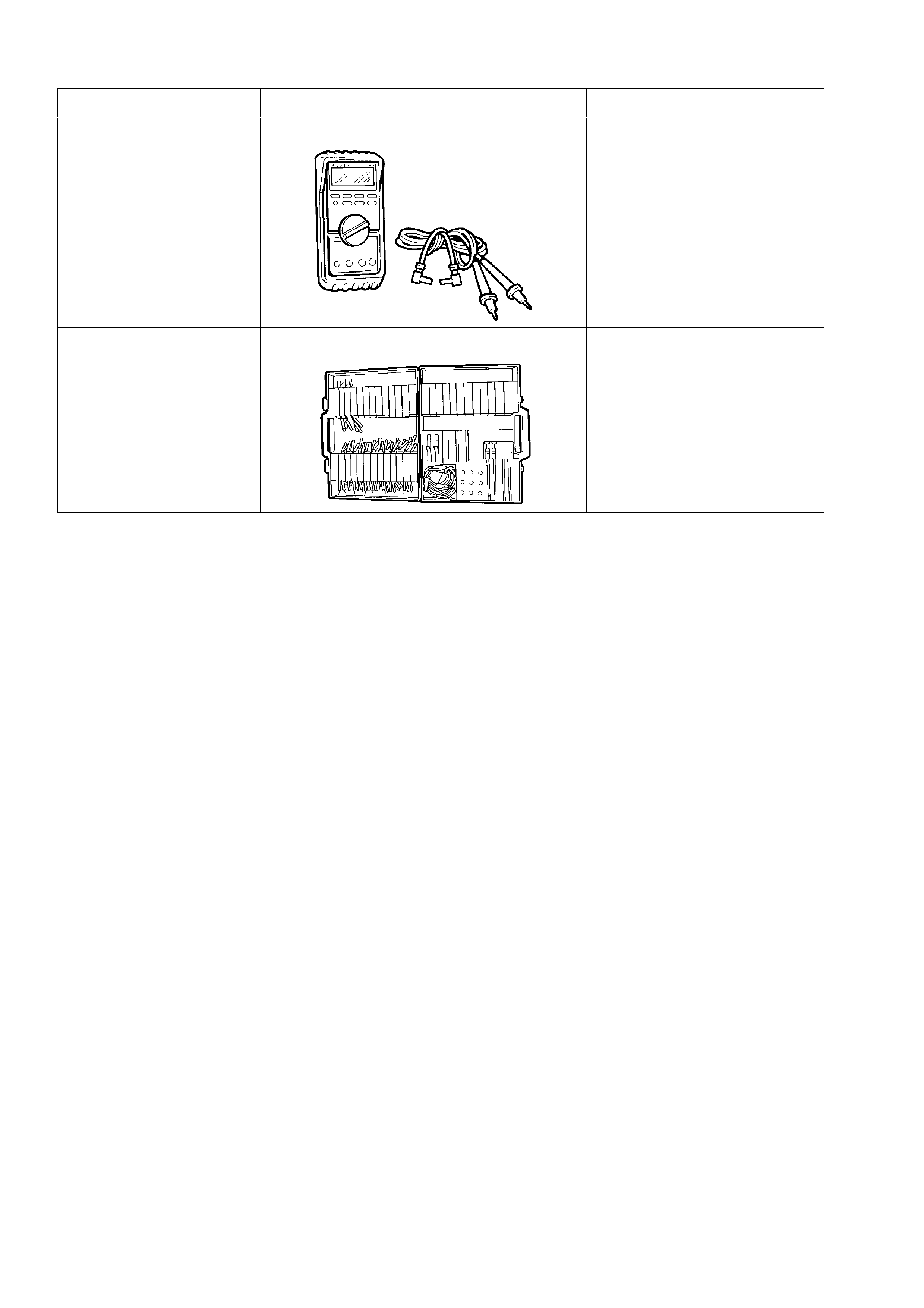
5. SPECIAL TOOLS
TOOL NO. REF IN TEXT TOOL DESCRIPTION COMMENTS
J39200 DIGITAL MULTIMETER TOOL NO. J39200
PREVIOUSLY RELEASED, OR
USE COMMERCIALLY
AVAILABLE EQUIVALENT.
MUST HAVE 10 MEG OHM
INPUT IMPEDANCE
KM-609 ELECTRONIC KIT USED IN CONJUNCTION
WITH A MULTIMETER FOR
MEASURING VOLTAGES AND
RESISTANCE’S WITHOUT
DAMAGING WIRING
HARNESS CONNECTORS