SECTION 12H - ELECTRICALLY ADJUSTABLE
REAR VISION MIRRORS
CAUTION:
This vehicle will be equipped with a Supplemental Restraint System (SRS). A SRS will
consist of either seat belt pre-tensioners and a driver's side air bag, or seat belt pre-
tensioners and a driver's and front passenger's side air bags. Refer to CAUTIONS,
Section 12M, before performing any service operation on, or around any SRS
components, the steering mechanism or wiring. Failure to follow the CAUTIONS
could result in SRS deplo yment, resulting in possible p ersonal injury or unnecessary
SRS system repairs.
CAUTION:
This vehicle may be equipped with LPG (Liquefied Petroleum Gas). In the interests of
safety, the LPG fuel system should be isolated by turning 'OFF' the manual service
valve and then draining the LPG serv ice lines, before any service w ork is carried out
on the vehicle. Refer to the LPG leaflet included with the Owner's Handbook for
details or LPG Section 2 for more specific servicing information.
1. GENERAL INFORMATION
Electrically adjustable rear vision mirrors are fitted as standard equipment on all VT Series Models.
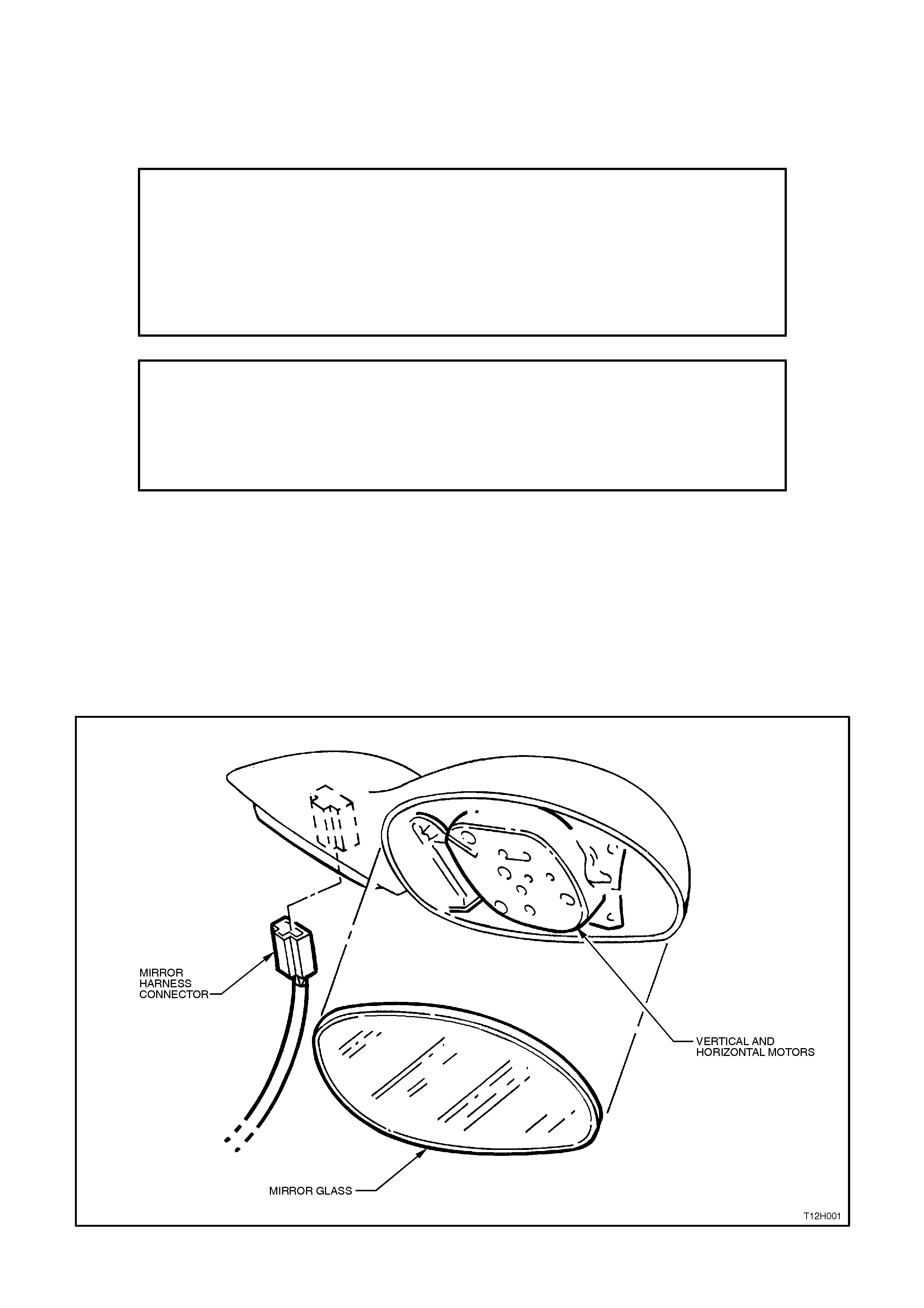
Each exterior mirror assembly has two internal reversible motors: one to adjust the mirror face up and down
(vertical position), the other to adjust the mirror face right and left (horizontal position).
The rear vision mirrors are adjusted from the interior of the vehicle by a mirror control switch mounted in the driver's
side front door pull handle.
The control switch has two controls. A slide select switch that has two positions: Left mirror and Right mirror, and a
toggle type direction switch, which is used to control the direction of movement of the mirror face.
Figure 12H-1
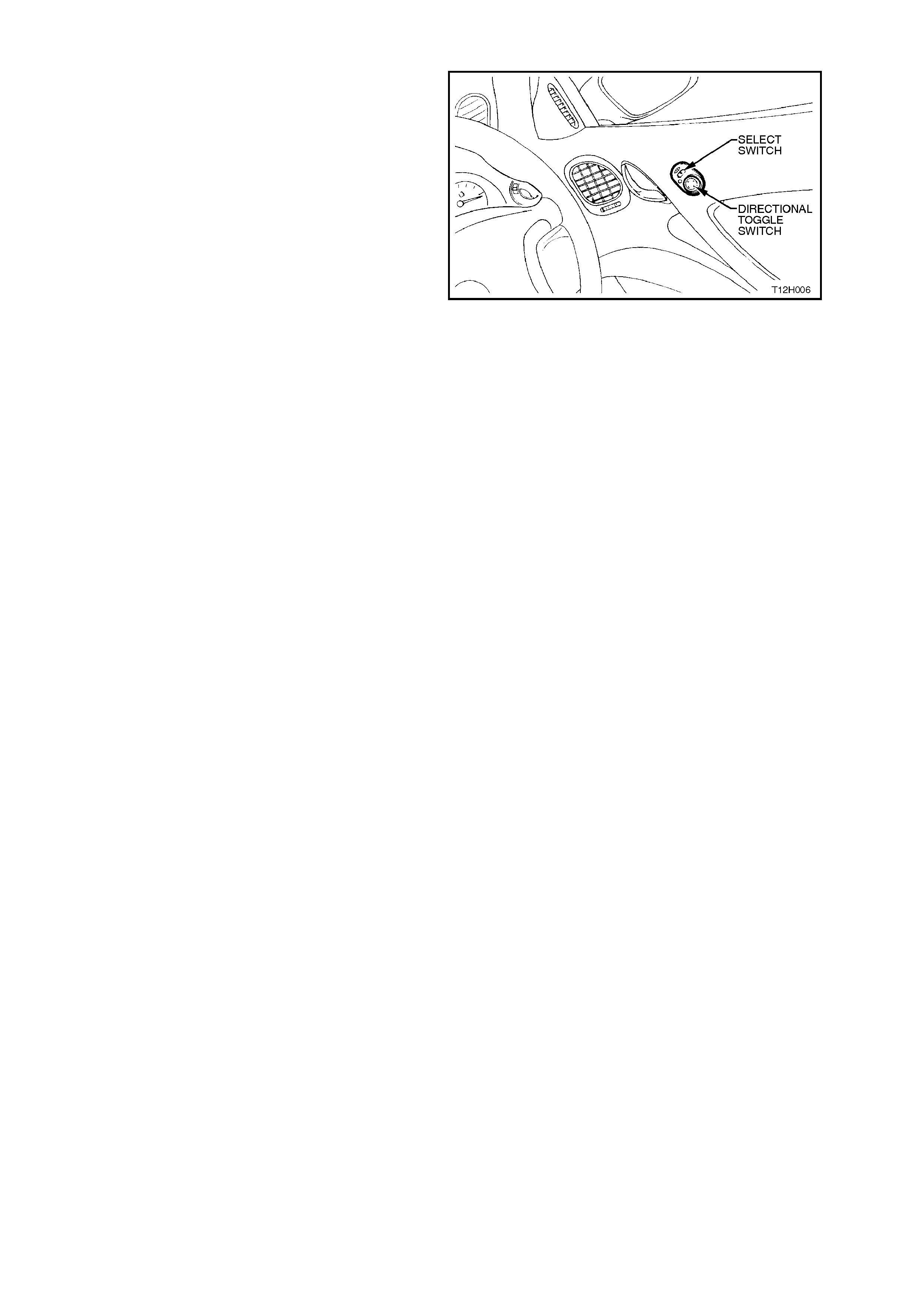
1.1 CONTROL SWITCH OP ERATION
The mirror control switch is two switches in one; a
select switch which is used to select either the left
or right hand m irror, and a directional toggle s witch
which is used to move the mirror face in the
required direction.
The dire ctional toggle switch is designed to operate
in only one direction at a time and is activated by
depressing the edge of the toggle, causing the
toggle to ‘cock’ in the required direction.
Figure 12H-2
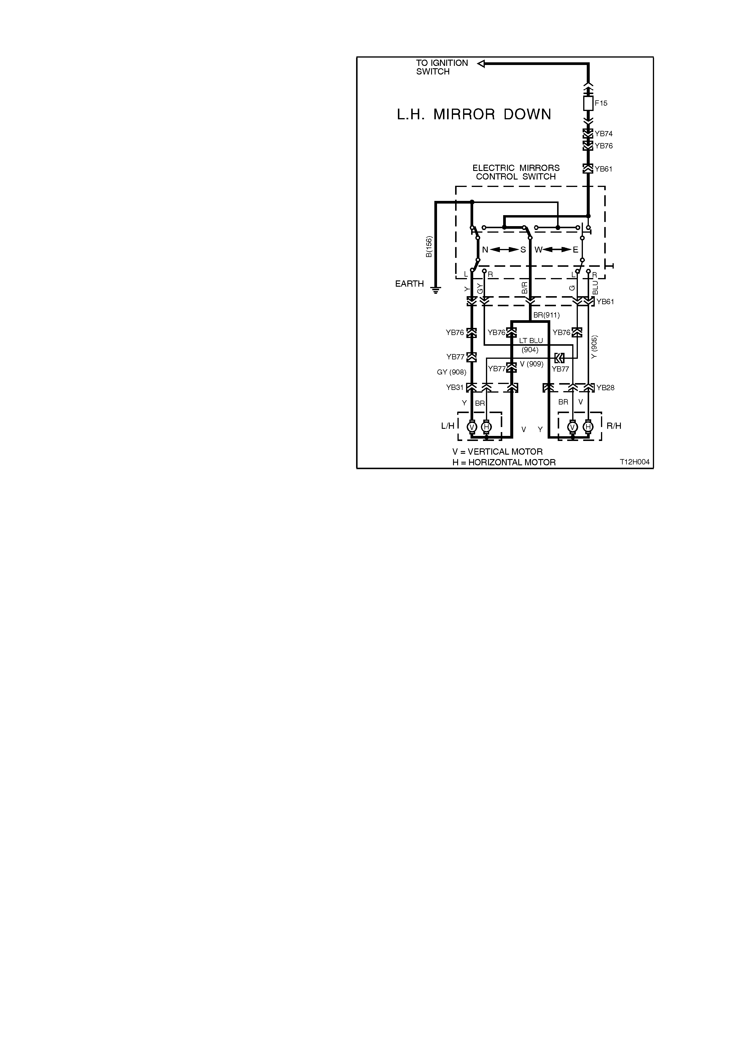
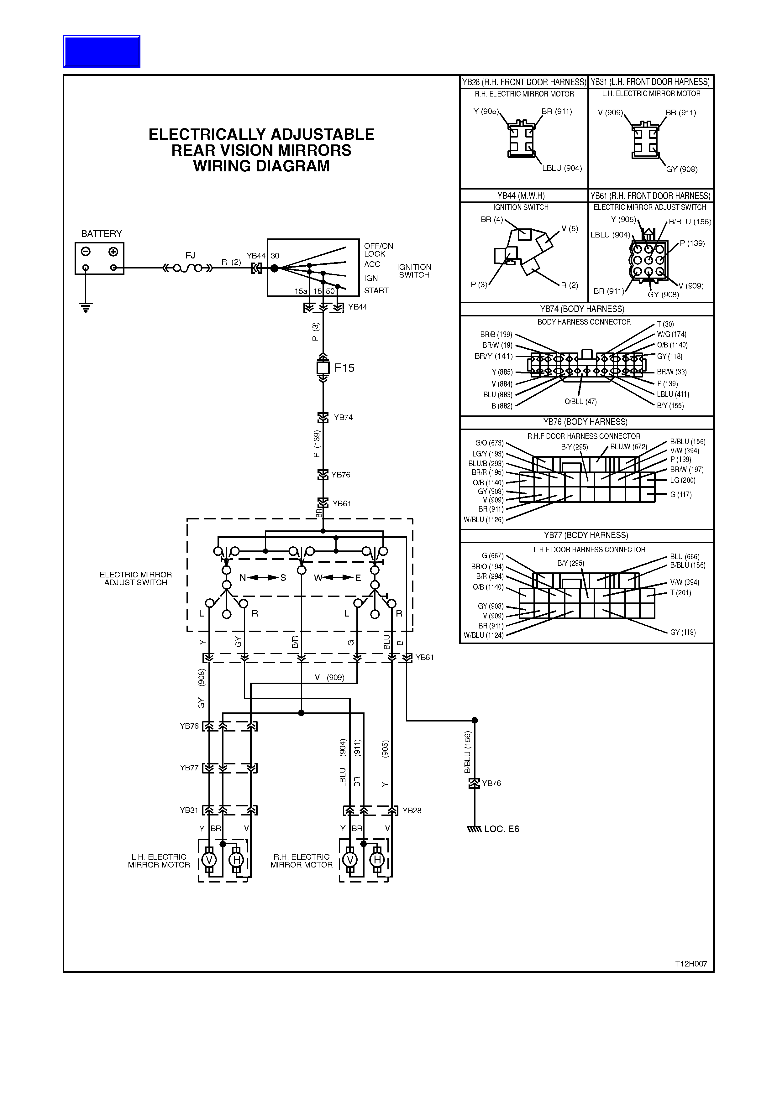
1.2 CIRCUIT OPERATION
With the switches in the positions shown in Fig.
12H-3, the LH exterior rear view mirror is moved
DOWNWARDS. Battery voltage from fuse F15 is
applied through the directional contacts of the
mir ror switch to circ uit 911 (Brown wire) to one side
of all mirror asse mbly motors.
The LH mirror vertical motor has a path to earth
through circuit 908 (Gr ey wire), through the LH s ide
select switch contacts, through the directional
contacts and circuit 156 (Black wire).
This allows the LH side vertical motor to operate
and turns the mirror DOWNWARDS until the
directional toggle switch is released.
W hen the directional toggle switch is depressed to
move the mirror UPW ARDS, the LH mirror vertical
motor receives voltage, however, the voltage is
reversed. Power is supplied through fuse F15,
through the directional toggle and LH side select
switch contacts , through circ uit 908 (Gr ey wire) and
through the motor. The motor is earthed through
circuit 911 (Brown wire), through the directional
switch contacts and circuit 156 (Black wire).
Figure 12H-3

The LH mirror INWARD and DOWNARD operation,
operates similarly. When the directional switch is
moved to the OUTWARD position, battery voltage
from fuse F15 is applied through the directional
centre contacts of the mirror control switch to circuit
911 (Brown wire) to one side of all mirr or ass embly
motors.
The LH mirror horizontal motor has a path to earth
through circuit 909 (Violet wire), through the LH
side select switch contacts, through the directional
contacts and through circuit 156 (Black wire).
This allows the LH side hor izontal motor to operate
and turns the mirror OUTWARDS until the
directional toggle switch is released.
W hen the directional toggle switch is depressed to
move the mirror INWARDS, the LH mirror
horizontal motor receives voltage, however the
voltage is reversed. Power to the motor is supplied
through fuse F15, through the directional and LH
side select switch contacts, through circuit 909
(Violet wire) and through the motor. The motor is
earthed through circuit 911 (Brown wire), through
the directional switch contacts and circuit 156
(Black w ire).
The RH mirror assembly operates in a similar
manner as the LH mirr or assem bly when the select
and directional switches contacts are selected,
except:
To m ove the RH mirr or down, power is supplied via
circuit 911 (Brown wire) and earthed through
circuits 904 (Light Blue wire) and 156 (Black wire).
To move the RH mirror up, power is supplied
through circuit 904 and earthed through circuits 911
and 156. To move the RH mirror out, power is
supplied via circ uit 911 and earthed thr ough c irc uits
905 and 156. To move the RH mirror in, power is
supplied through circuit 905 and earthed through
circuits 911 and 156.
Figure 12H-4
2. SERVICE OPERATIONS
2.1 MIRROR ASSEMBLY
REMOVE
1. Disconnect battery earth lead.
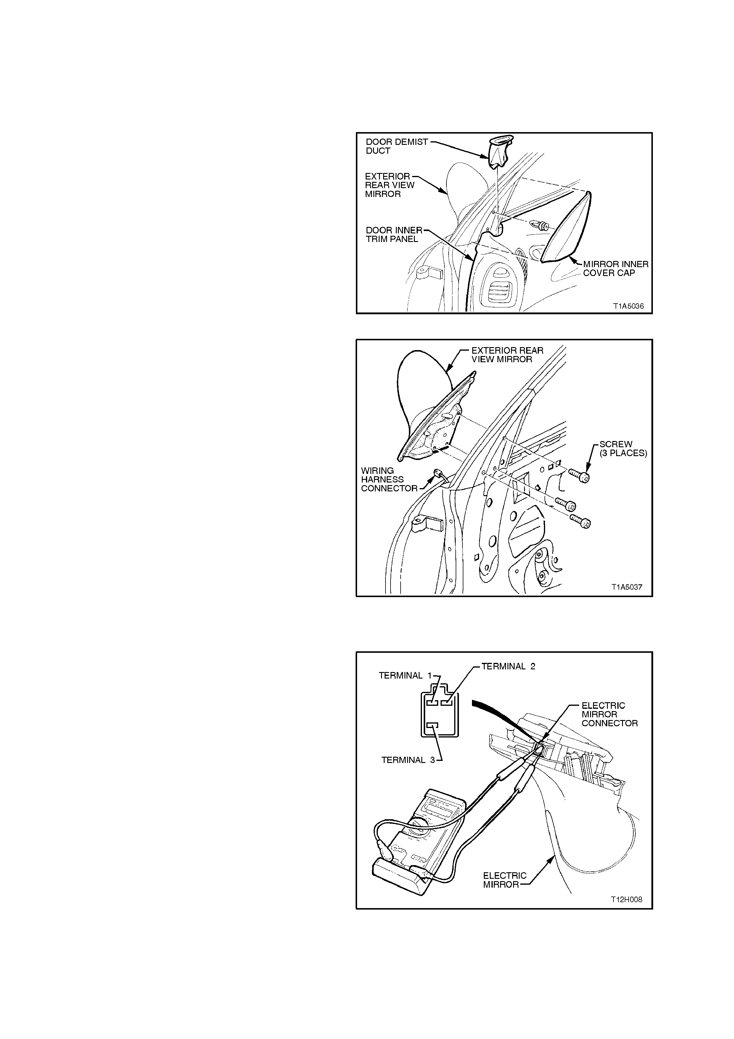
2. Remove the mirror inner cover cap by gently
pryi ng cap away from door.
3. Remove door demist duct to allow access to
the exterior rear view mirror retaining screws
by pulling duct up and out of door trim.
Figure 12H-5
4. Using a right angled screwdriver, remove the
three screws securing the mirror to the door
and while supporting the mirror, disconnect the
mirror wiring harness connector.
5. Remove mirror assembly.
NOTE:
Fig. 12H-6 shows the door with the inner trim panel
removed. To remove the three exterior rear vision
mirror retaining screws, the inner door trim does
not have to be removed.
Figure 12H-6
TEST
The following operations, per formed with the m irror
assembly removed from the vehicle, check the
mirror assembly horizontal and vertical motors. If
the following operations prove that a mirror
assembly is faulty, replace the mirror assembly.
Using an ohmmeter c onnec ted to the electr ic mirror
connector, refer Fig. 12H-7, check continuity of
mirror wiring between the following terminals:
• Ter. 1 and Ter. 2
• Ter. 1 and Ter. 3
• Ter. 2 and Ter. 3
If the ohmmeter indicates an open circuit or a very
high resistance (more than 200 ohms) replace the
mirror assembly. If the mirror motor resistance is
acceptable, proceed to Step 2.
Figure 12H-7
2. Referring to Fig. 12H-8, connect leads from a
12 volt battery to the mirror harnes s connector
term inals nominated in the f ollowing c hart and
observe mirror movement.
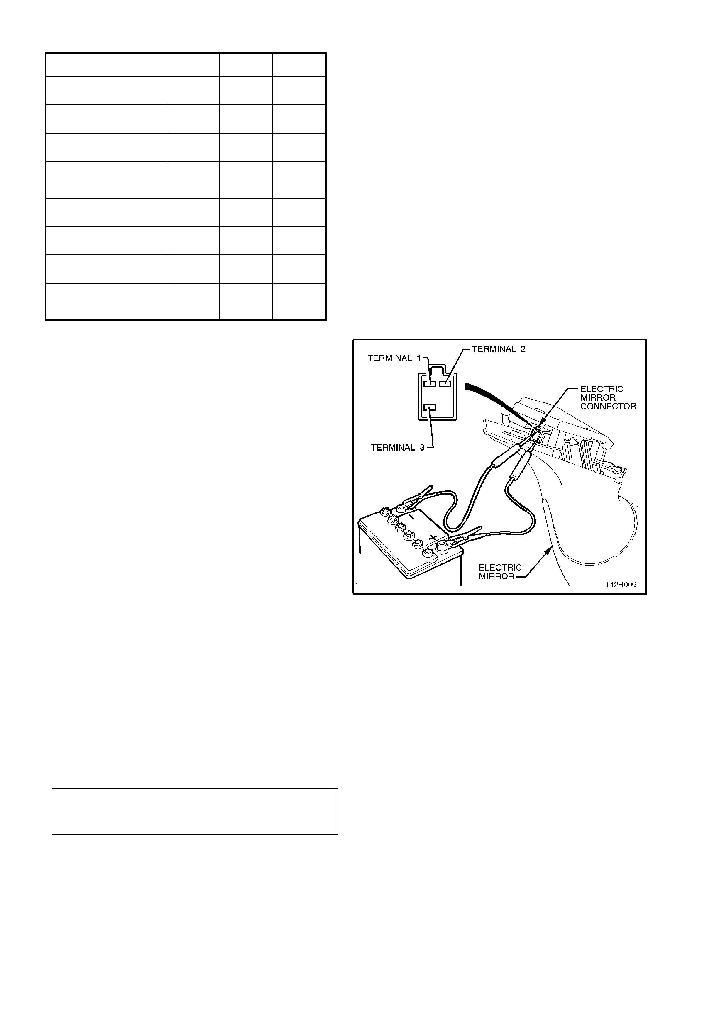
FUNCTION TER. 1 TER. 2 TER. 3
LH MIRROR -IN -+
LH MIRROR - OUT +-
LH MIRROR - UP +-
LH MIRROR -
DOWN -+
RH MIRROR - IN +-
RH MIRROR - OUT -+
RH MIRROR - UP +-
RH MIRROR -
DOWN -+
+ = battery positive (12 volts)
- = battery negative
If the movement of the mirror is not as per the
above chart, replace mirror assembly.
Figure 12H-8
REINSTALL
Installation of the exterior rear vision mirror is the
reverse of the removal procedure, noting the
following:
1. Ensure wiring harness and connector for the
mirror are correctly routed.
2. Ensure the three mirror to door securing
screws are tightened to the correct torque
specification.
MIRROR TO DOOR
SECURING SCREW
TORQUE SPECIFICATION 2.5 - 3.0 Nm
3. Ensure that when installing the door demist
duct, that it clips into position.
4. Check mirror operation.
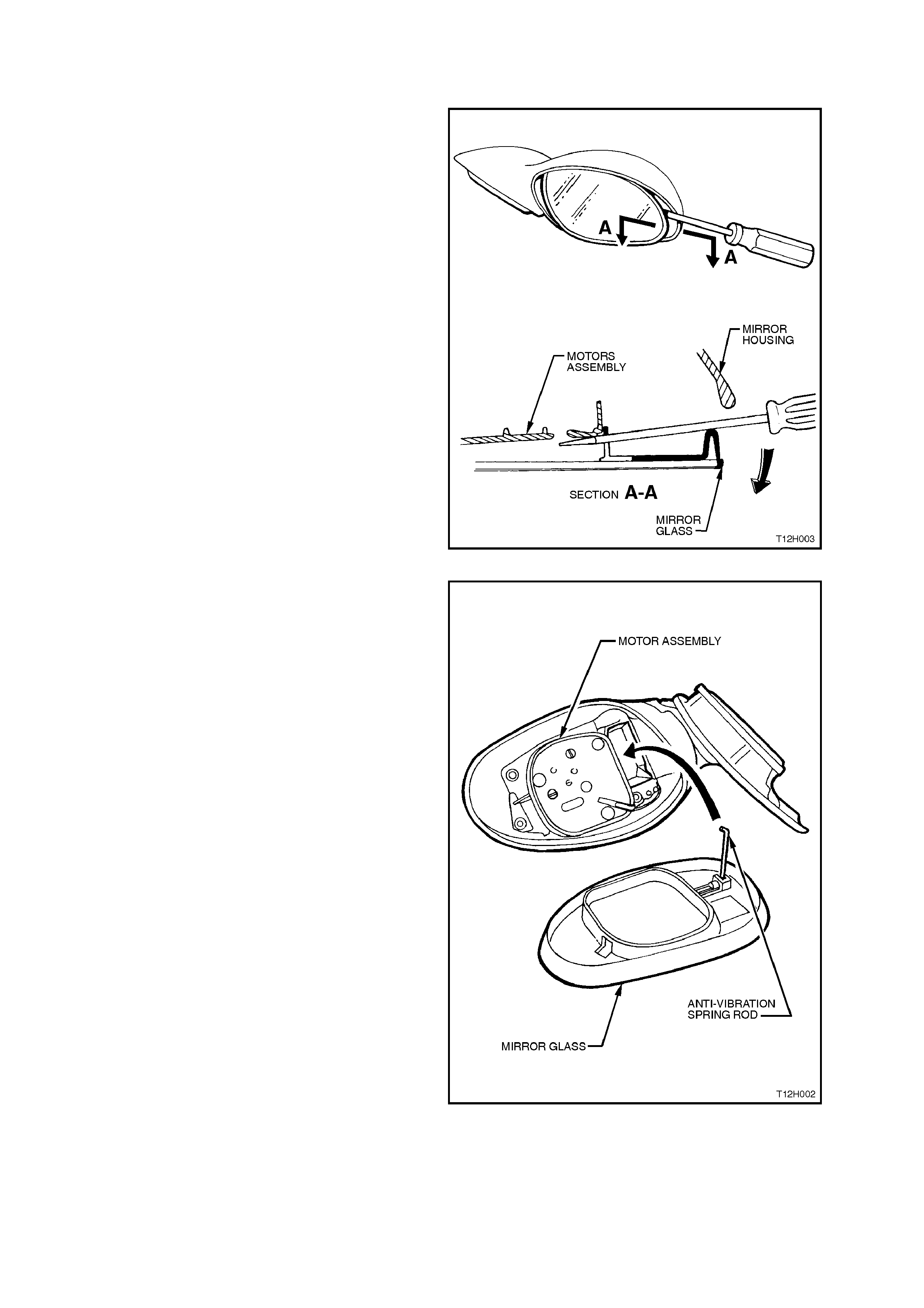
2.2 MIRROR GLASS
REPLACE
Adjust m irror glass so that it is in the fully “UP” and
fully “IN” position.
Insert a screwdriver into the slot on the inside of the
mirror glass and lever mirror glass away from the
motor assembly, refer to Fig. 12H-9.
Remove mirror glass from motor assembly.
Figure 12H-9
Install new mirror glass onto motor assembly,
ensuring that the anti-vibration spring rod is at a
right angle to the mirror glas s and that it aligns with
the corresponding aperture in the mirror housing,
refer to Fig. 12H-10
While supporting the mirror housing, push mirror
glass s quarely onto the m irror m otor ass embly until
it is firmly seated.
Figure 12H-10
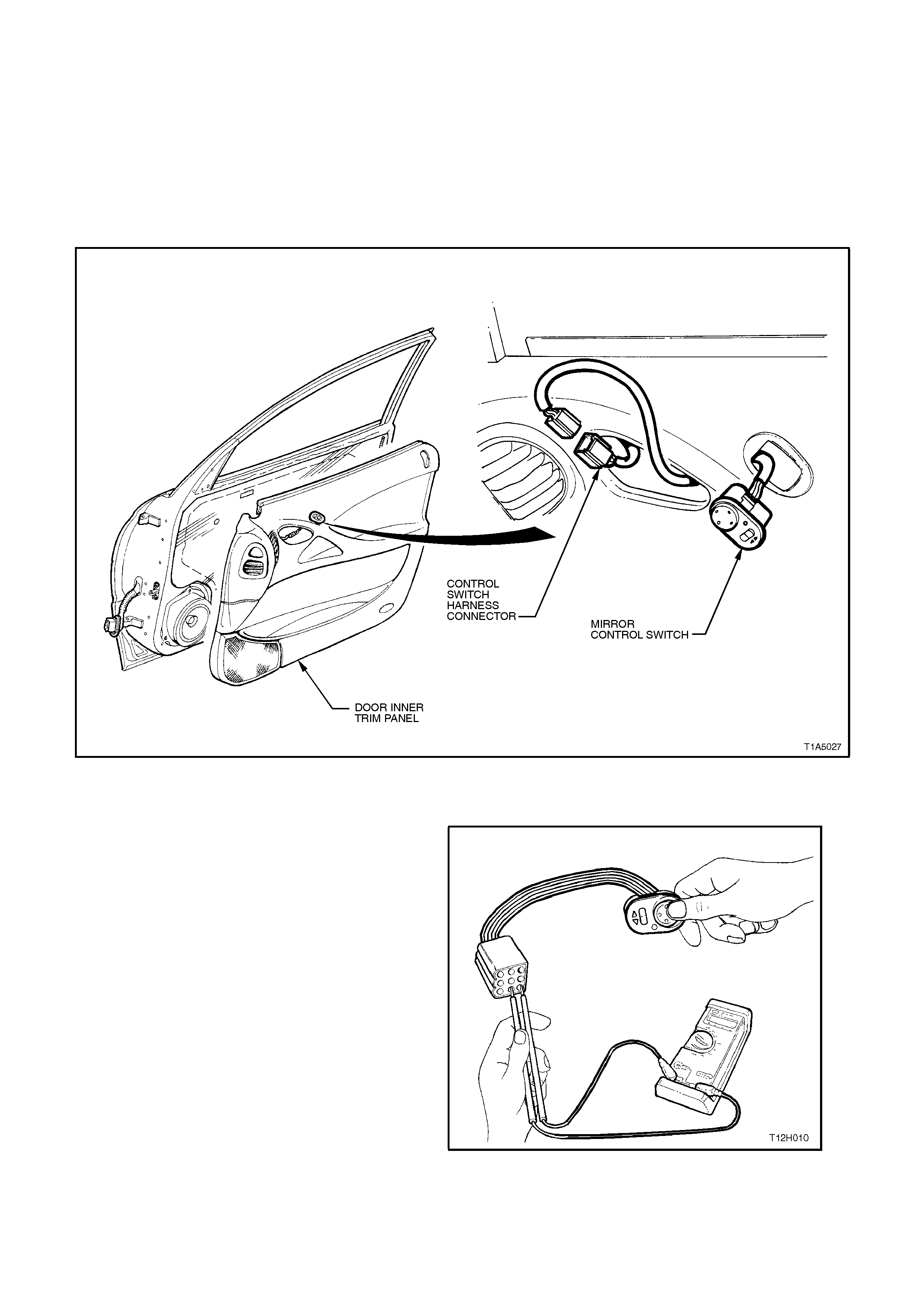
2.3 MIRROR CONTROL SWITCH
REMOVE
1. Remove door inner trim panel, refer to
Section 1A5 FRONT & REAR DOOR
ASSEMBLIES.
2. Disconnect the door electrical harness from
the control switch harness assembly.
3. From inside of door trim assembly, push the
control switch free and remove the switch.
Figure 12H-11
TESTING SWITCH CONTACTS
With reference to the Figs . 12H-12 and 12H- 13 and
the following three charts, the mirror control switch
contacts c an be check ed f or continuity between the
various terminals with the aid of an ohmmeter.
Attach an ohmmeter to the appropriate terminals
nominated in the following two charts.
Select the appropriate mirror on the select switch,
i.e. LH or RH and depress the directional toggle
switch in the direction indicated in the chart. The
ohmm eter should indicate continuity if the switch is
OK.
Figure 12H-12
LEFT HAND MIRROR
FUNCTION SWITCH WIRE
COLOURS VALUE
Out Light Green and Black Continuity
In Light Green and Brown Continuity
Up Yellow and Black Continuity
Down Yellow and Brown Continuity
RIGHT HAND MIRROR
FUNCTION SWITCH WIRE
COLOURS VALUE
Out Blue and Brown Continuity
In Blue and Black Continuity
Up Grey and Black Continuity
Down Grey and Brown Continuity
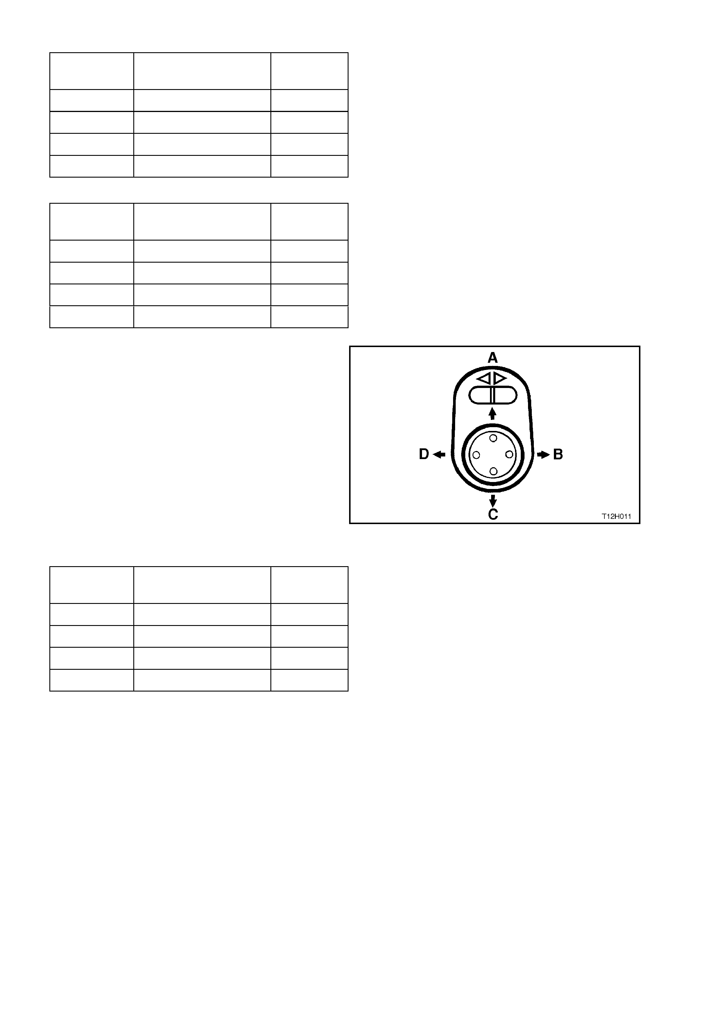
For the following test of switch contacts, attach an
ohmmeter to the appropriate terminals nominated
in the following chart and then depress and hold the
directional toggle s witch in the dire ction indic ated in
the chart and Fig. 12H-13. The ohmmeter should
indicate continuity if the switch is OK.
Figure 12H-13
TOGGLE
DIRECTION SWITCH WIRE
COLOURS VALUE
A Black/Red and Brown Continuity
B Black/Red and Black Continuity
C Black/Red and Black Continuity
D Black/Red and Brown Continuity
REINSTALL
Reinstallation of the exterior rear vision mirror control
switch is the reverse of the removal procedure.

3.1 ELECTRIC MIRROR/S INOPERATIVE
STEP ACTION VALUE YES NO
1. • Are both electric rear view
mirrors inoperative? Go to Step 2. Go to Step 3.
2. • Is fuse F15 OK (located in
fuse panel)? Go to step 3. Replace blown
fuse, check wiring
for cause of fuse
blowing.
Re-check system.
3. • Remove RH front door inner
trim panel, refer to Section
1A5 FRONT AND REAR
DOOR.ASSEMBLIES.
• Reconnect mirror control
switch.
• Turn ignition ON.
• Using a test light at the
switch side of connector
YB61, check for power at
brown.
• Does test light illuminate ?
Go to Step 4. Check and repair
open circuit in
circuit 139 (Pink
wire) from fuse
F15 to control
switch.
Re-check system.
4. • Using an ohmmeter, check
circuit 156 for continuity
between connector YB61
(Black wire) and earth
connection (location E6).
• Is wiring OK ?
Go to Step 5. Check and repair
open circuit in
earth circuit 156
(Black w ire).
Re-check system
5. • At connector YB61, check for
continuity in the following
circuits:
Circuit 911 (Brown wire) to
circuit 909 (Violet wire)
(LH mirror horizontal
motor).
Circuit 911 (Brown wire) to
circuit 908 (Grey w ire).
(LH mirror vertical motor).
Circuit 911 (Brown wire) to
circuit 905 (Yellow wire)
(RH mirror horizontal
motor).
Circuit 911 (Brown wire) to
circuit 904 (L/Blue wire)
(RH mirror vertical motor).
• Is wiring OK ?
Go to Step 6. Check and repair
open circuit.
Re-check system.
6. • Check mirror control switch,
refer to 2.3 MIRROR
CONTROL SWITCH, in this
Section.
• Is mirror control switch OK ?
System OK. Replace mirror
control switch.
Re-check system.

3.2 EITHER MIRROR NOT WORKING IN ONE OR MORE DIRECTIONS
STEP ACTION VALUE YES NO
1. • Remove mirror control switch
and test switch contacts,
refer to 2.3 MIRROR
CONTROL SWITCH in this
Section.
• Are mirror switch contacts
OK ?
Go to Step 2. Replace mirror
control switch.
Re-check system.
2. • With connector YB61, check
for continuity in the following
the particular circuit that the
mirror is operating:
LH mirror horizontal: circuit
911 (Brown wire) to circuit
909 (Violet wire).
LH mirror vertical: circuit
911 (Brown wire) to circuit
908 (Grey wire).
RH mirror horizontal: circuit
911 (Brown wire) to circuit
905 (Yellow wire).
RH mirror vertical: circuit
911 (Brown wire) to circuit
904 (L/Blue wire).
• Is wiring OK ?
Go to Step 3. Check and repair
open circuit.
Re-check system.
3. • Check faulty mirror
assembly, refer to 2.1
MIRROR ASSEMBLY, in this
Section.
• Is mirror OK ?
System OK. Replace mirror
assembly.
Re-check system.

4. TORQUE WRENCH SPECIFI CATIONS
Nm
Mirror to Door Securing Screws 2.5 - 3.0
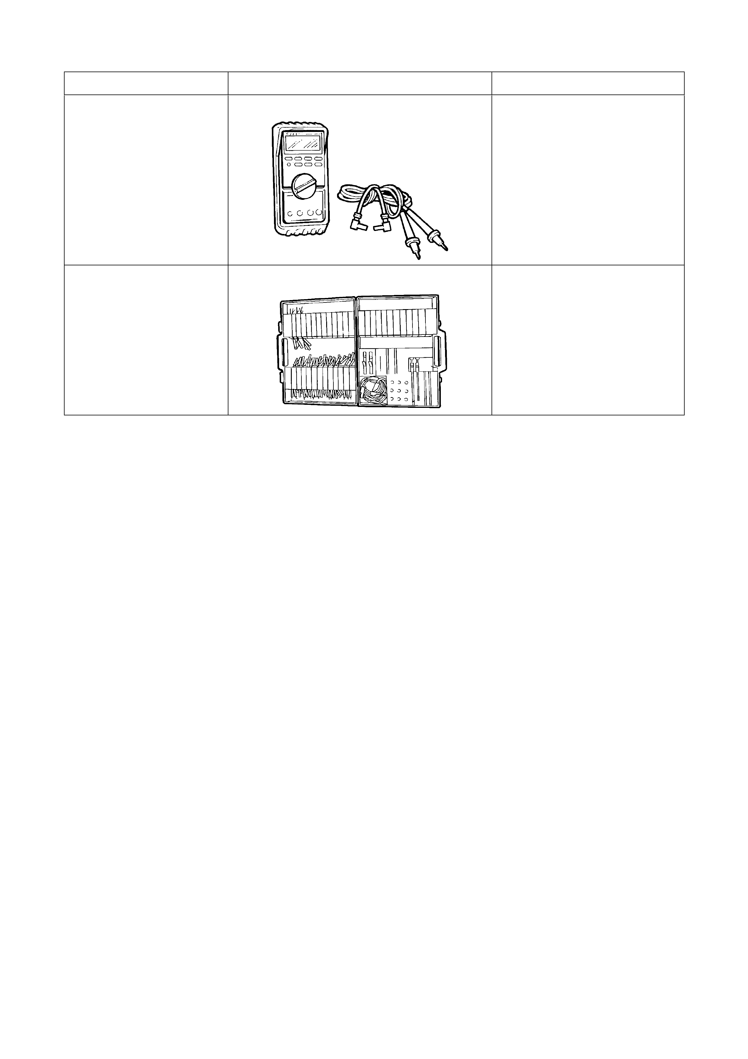
5. SPECIAL TOOLS
TOOL NO. REF IN TEXT TOOL DESCRIPTION COMMENTS
J39200 DIGITAL MULTIMETER TOOL NO. J39200
PREVIOUSLY RELEASED, OR
USE COMMERCIALLY
AVAILABLE EQUIVALENT.
MUST HAVE 10 MEG OHM
INPUT IMPEDANCE
KM-609 ELECTRONIC KIT USED IN CONJUNCTION
WITH A MULTIMETER FOR
MEASURING VOLTAGES AND
RESISTANCE’S WITHOUT
DAMAGING WIRING
HARNESS CONNECTORS