
SECTION 12J-1 LOW SERIES BODY
CONTROL MODULE
CAUTION:
This vehicle will be equipped with a Supplemental Restraint System (SRS). A SRS will
consist of either seat belt pre-tensioners and a driver's side air bag , or seat belt pre-
tensioners and a driver's and front passenger's side air bags. Refer to CAUTIONS,
Section 12M, before performing any service operation on, or around any SRS
components, the steering mechanism or wiring. Failure to follow the CAUTIONS
could result in SRS d eployment, resultin g in po ssible personal in jury or unnecessary
SRS system repairs.
CAUTION:
This vehicle may be equipped with LPG (Liquefied Petroleum Gas). In the interests of
safety, the LPG fuel system should be isolated by turning 'OFF' the manual service
valve an d then draining t he LPG service lines, befo re any service w ork is carried out
on the vehicle. Refer to the LPG leaflet included with the Owner's Handbook for
details or LPG Section 2 for more specific servicing information.
1. GENERAL DESCRIPTI ON
A Body Control Module (BCM) combines into one central module, the control or assist of various vehicle electrical
systems or features, rather than having individual modules for each system or feature.
Low Series BCMs are fitted as standard equipment on all VT Series Executive, Acclaim, S and SS Models.
NOTE:
Two levels of Low Series BCM have been released; a LOW level for vehic les without power operated windows and
a MID level for vehic les with power operated windows. If a service operation or diagnostic procedure requires that a
Low Series BCM be replaced, ensure that the correct BCM level is reinstalled for the particular level of vehicle.
Fig. 12J-1-1 illustrates the identification details for the Low Series BCM. External identification can be made by
referring to the last three digits of the BCM part number.
Specific software has been developed for use with the TECH 2 diagnostic scan tool to assist with various vehicle
electrical system fault finding, including the various BCM functions and controls.
The TECH 2 connection for the Low Series Australian Arrow BCM serial data communication is via the Data Link
Connector (DLC) , attached to the instrum ent panel lower right hand trim , to the left of the steering column, refer to
Fig 12J-1-2.
The Low Ser ies BCM is loc ated beneath the instr ument clus ter, to the r ight of the steer ing c olumn, ref er to F ig. 12J-
1-2.
Techline
Techline
Techline
Techline
Techline
Techline
Techline
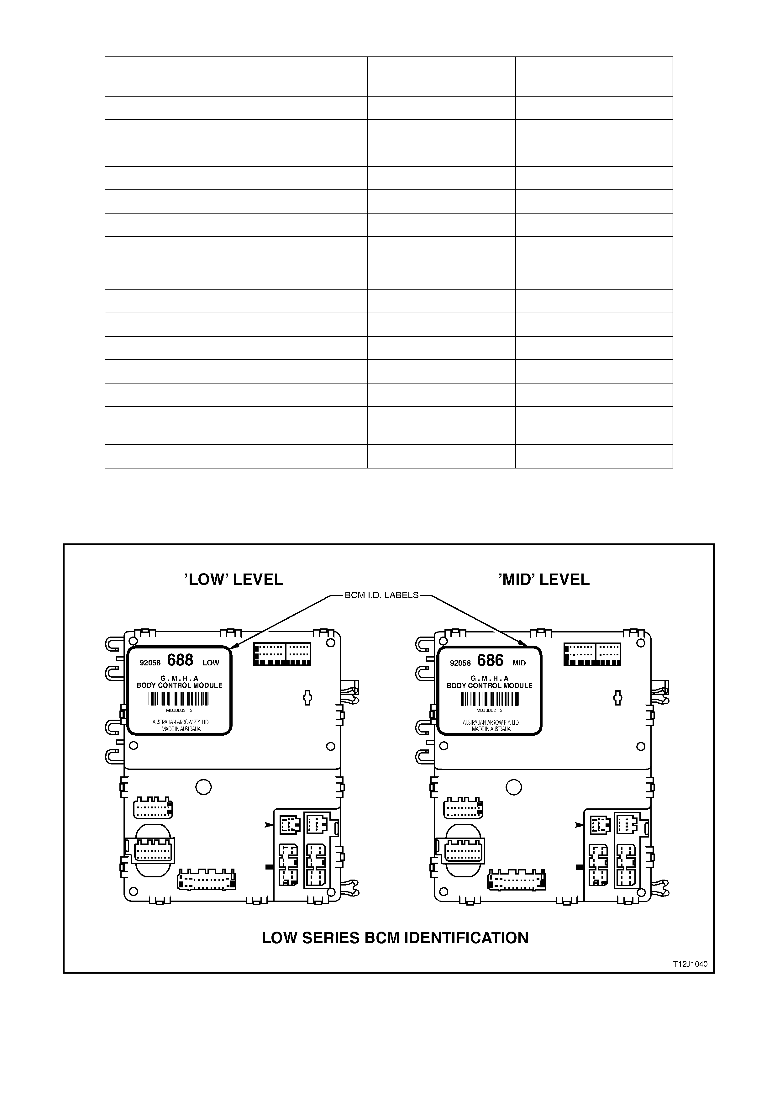
BODY CONTROL MODULE FEATURES
BCM FEATURE LEVEL 1
LOW - 688 LEVEL 1 (OPTIONAL)
MID - 686
Serial Data Interface (SDI) (Bus master) A A
Central door locking A A
Boot release with speed interlock A A
Power window system N/A A
Dome lamp delay control A A
Heated rear window control A A
Intermittent and synchronised to front rear
wiper control with full wipe in reverse gear
(wagon only)
N/A A
Fixed dwell wiper control A A
Auto lights OFF (fixed) A A
Engine disable A A
Engine cooling low speed fan control A A
Cruise control interface A A
SRS (air bag) deployment vehicle
shutdown AA
Air conditioning interface A A
N/A = NOT AVAILABLE
A = AVAILABLE
Figure 12J-1-1
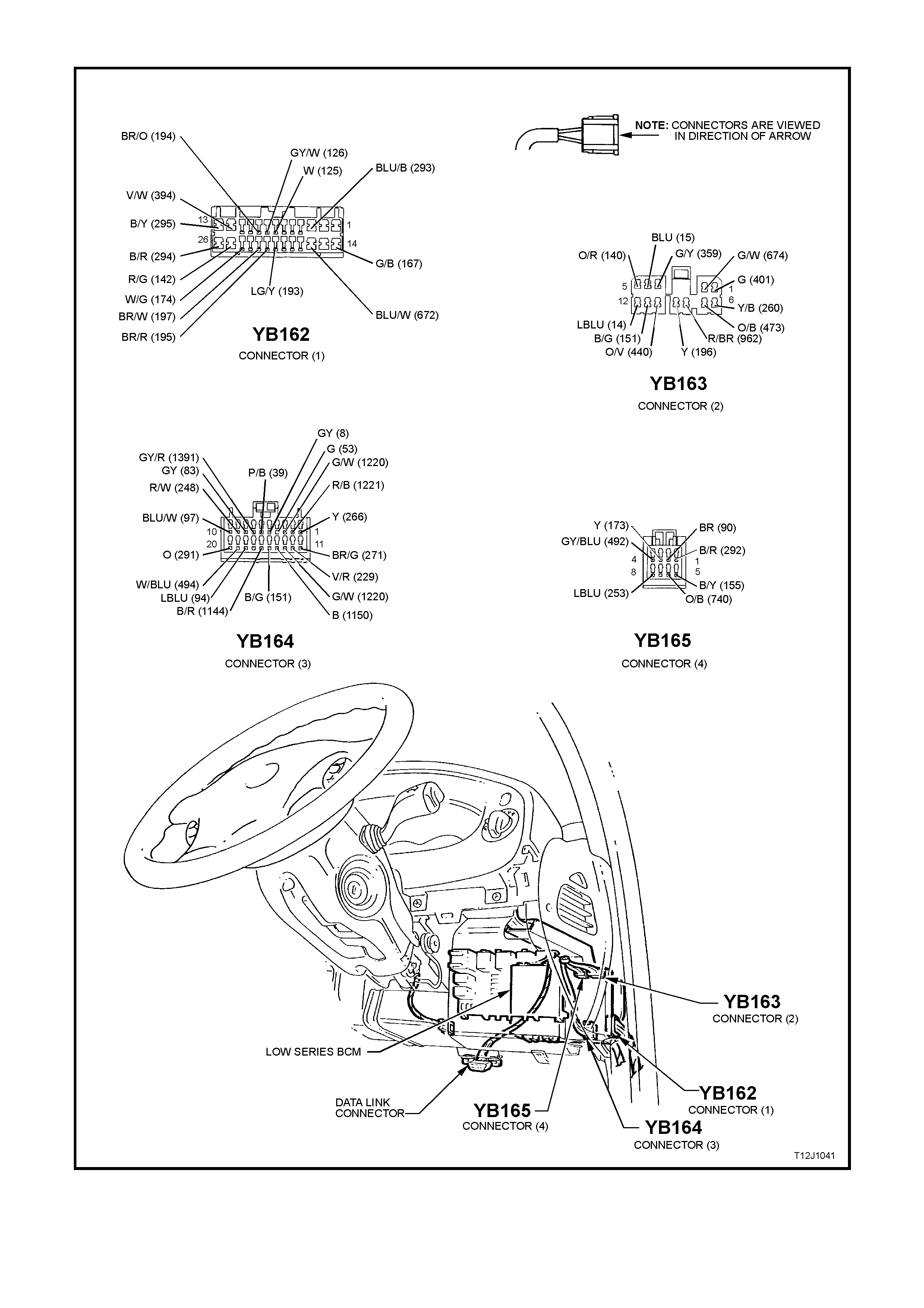
LOW SERIES BCM TERMINAL IDENTIFICATION
Figure 12J-1-2

YB165 CONNECTOR 4
PIN NO. DESCRIPTION CIRCUIT WIRE
COLOUR CIRCUIT TYPE
A1 DEMSIST OUTPUT 29 2 B/R O
A2 WIPER OUTPUT 90 BR O
A3 WINDOW POWER
OUTPUT 173 Y O
A4 REAR WIPER
OUTPUT 492 GY/BLU O
A5 EARTH 155 B/Y E
A6 BATTERY POSITIVE 740 O/B P
A7 NC
A8 THEFT DETERRENT
LED OUTPUT 263 LBLU O
YB163 CONNECTOR 2
PIN NO. DESCRIPTION CIRCUIT WIRE
COLOUR CIRCUIT TYPE
B1 BLOWER INHIBIT
OUTPUT 401 G O
B2 POWER WINDOW
DOWN OUTPUT 674 G/W O
B3 A/C BLOWER INPUT 359 DKG/Y PPU
B4 RIGHT INDICATOR
OUTPUT 15 BLU O
B5 INDICATOR POWER 140 O/R P
B6 ALARM STATUS
OUTPUT 260 Y/B O
B7 LOW FAN SPEED
OUTPUT 473 O/B O
B8 A/C LED OUTPUT 962 R/BR O
B9 WIPER PARK INPUT 196 Y PPU
B10 DOOR LOCK POWER 440 O/V P
B11 POWER EARTH 151 B/G E
B12 LEFT INDICATOR
OUTPUT 14 LBLU O

YB162 CONNECTOR 1
PIN NO. DESCRIPTION CIRCUIT WIRE
COLOUR CIRCUIT TYPE
C1 NC
C2 NC
C3 DRIVER’S DOOR
UNLOCK OUTPUT 293 BLU/B O
C4 NC
C5 NC
C6 NC
C7 PASSENGER’S DOOR
AJAR INPUT 125 W PPU
C8 DRIVER’S DOOR
AJAR INPUT 126 GY/W PPU
C9 PASSENGER’S DOOR
INLOCK INPUT 194 BR/O PPU
C10 NC
C11 NC
C12 DEADLOCKS 394 V/W O
C13 ALL DOORS LOCK
OUTPUT 295 B/Y O
C14 WINDOW DOWN
INPUT 167 G/B PD
C15 NC
C16 WINDOW UP INPUT 672 BLU/W PD
C17 NC
C18 NC
C19 NC
C20 UNLOCK INPUT 193 LG/Y PPU
C21 LOCK INPUT 195 BR/R PPU
C22 DEADLOCK REQUEST
INPUT 197 BR/W PPU
C23 NC
C24 DOME LAMP OUTPUT 174 W/G O
C25 BOOT OUTPUT 142 R/G O
C26 PASSENGER’S DOOR
UNLOCK OUTPUT 294 B/R O

YB164 CONNECTOR 3
PIN NO. DESCRIPTION CIRCUIT WIRE
COLOUR CIRCUIT TYPE
D1 REMOTE RECEIVER
(DATA) 266 Y I
D2 SERIAL DATA MAIN
BUS 1221 R/B I/O
D3 SERIAL DATA
AUXILIARY BUS 1220 G/W I/O
D4 AIR CONDITIONING
THERMOSTAT 53 G PD
D5 ILLUMINATION LINK 8 G/Y LINK
D6 IGNITION INPUT 39 P/B PD, P
D7 REAR WIPE INPUT 1391 GY/R PD
D8 CRUISE ON INPUT 83 GY PD
D9 A/C SWITCH INPUT 2 48 R/W PD
D10 INTERMITTENT
WIPER INPUT 97 BLU/W PD
D11 REMOTE RECEIVER
(EARTH) 271 BR/G E
D12 SLIP RING 229 V/R I/O
D13 SDM SERIAL DATA
BUS 1220 G/W I/O
D14 LIGHTS OFF EARTH
OUTPUT 1150 B PD, O
D15 ILLUMINATION LINK 151 B/G LINK
D16 BOOT RELEASE
INPUT 1144 B/R PPU
D17 NC
D18 FRONT SCREEN
WIPE / WASH INPUT 94 LBLU PD
D19 REAR SCREEN WASH
INPUT 494 W/BLU PD
D20 DEMIST INPUT 291 O PD
GLOSSARY
E - Earth O - Output P - Power PU - Pull up
PPU - Pulsed pull up PD - Pull down I - Input I/O - Input / Output
NC - No circuit
B - Black W - White R - Red P - Pink
O - Orange Y - Yellow V - Violet BLU - Blue
G - Green LG - Light green BR - Brown GY - Grey
T - Tan LBLU - Light blue DKBLU - Dark blue
1.1 SE RIAL DATA COMMUNICATION (BUS MASTER)
GENERAL INFORMATION
The VT Series Model uses a BUS MASTER communication system, where the BCM is the bus master.
The BCM periodically polls (surveys) each device on the bus and requests status data.
The devices connected to the bus are:
• Body Control Module (BCM)
• Powertrain Control Module (PCM)
• Instrument cluster (INS)
• Anti-lock Brake/Electronic Traction Control System (ABS/TCS)
• Supplemental Restraint System (SRS)
• External diagnostic tool (TECH 2)
The data provided by each device may be utilised by any device connected to the bus.
Each device has a unique response Message Identifier Word (MIW) for ease of identification.
The bus master (BCM) polls each device with a serial data message which includes that devices MIW. The device
responds by putting a serial data message onto the bus which includes its MIW and data, of which is retrieved and
utilised by any device requiring it.
The BCM polls each device for a status update, once every 300 milliseconds. The exception to this being the PCM
which is polled twice every 300 milliseconds.
When the ignition switch is turned from the OFF position to the ON position, the BCM will communicate with the
PCM for anti theft purposes. If the BCM does not receive an OK TO START message from the PCM within 0.5
seconds of ignition on, the auxiliary data bus is isolated via switching from the BCM.
The isolation of the auxiliary data bus during this period eliminates the possibility of a device failure other than the
BCM or PCM, causing a problem on the bus and inhibiting antitheft communications.
This period (short loop time) continues until the PCM responds with an acknowledgment or a maximum of five
seconds after which the BCM will switch to the standard polling sequence.
Following successful antitheft communications, the BCM begins sequential polling of devices on the bus and normal
system operation is established.
When the ignition switch is in the OFF position, the BCM continues to poll, allowing for TECH 2 communications
and external control of the bus prior to the ignition being switched on.
NOTE:
The circuit diagrams shown in this General Description Section are to aid in interpreting the operation of the circuit
and therefore, only the main connectors and wiring colours are shown. For complete circuits details, refer to either
the relevant diagnostic section or Section 12P Wiring Diagrams.
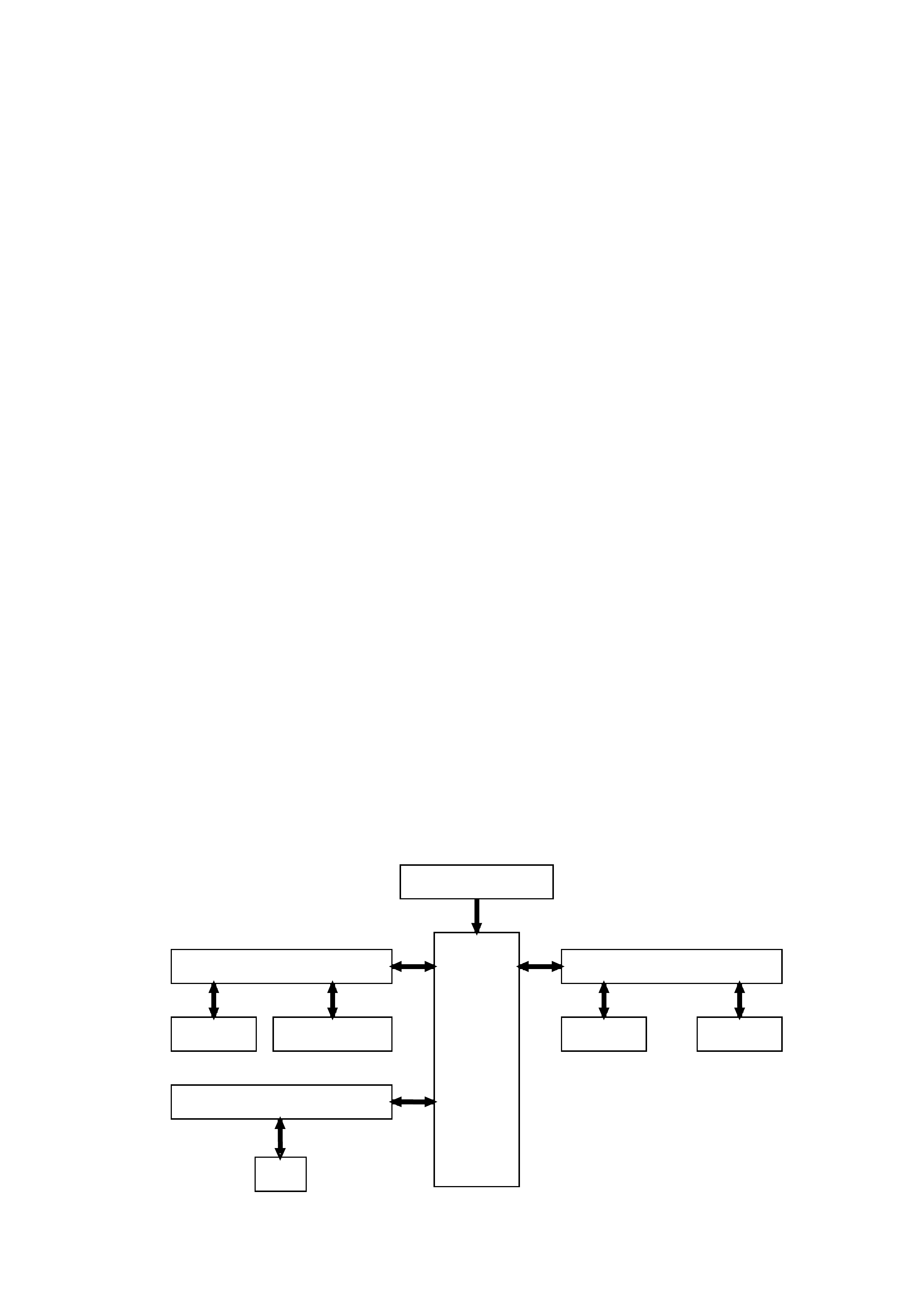
SYSTEM OVERVIEW
SRS SERIAL DATA AUX. D13
SRS
INSTRUMENTSABS/ETC
SERIAL DATA AUX. D3
B
C
M
BATTERY POWER A5
PCMDLC
SERIAL COMMUNICATIONS
D2 SERIAL DATA MAIN
INPUTS / OUTPUTS
Figure 12J-1-3
Figure 12J-1-4
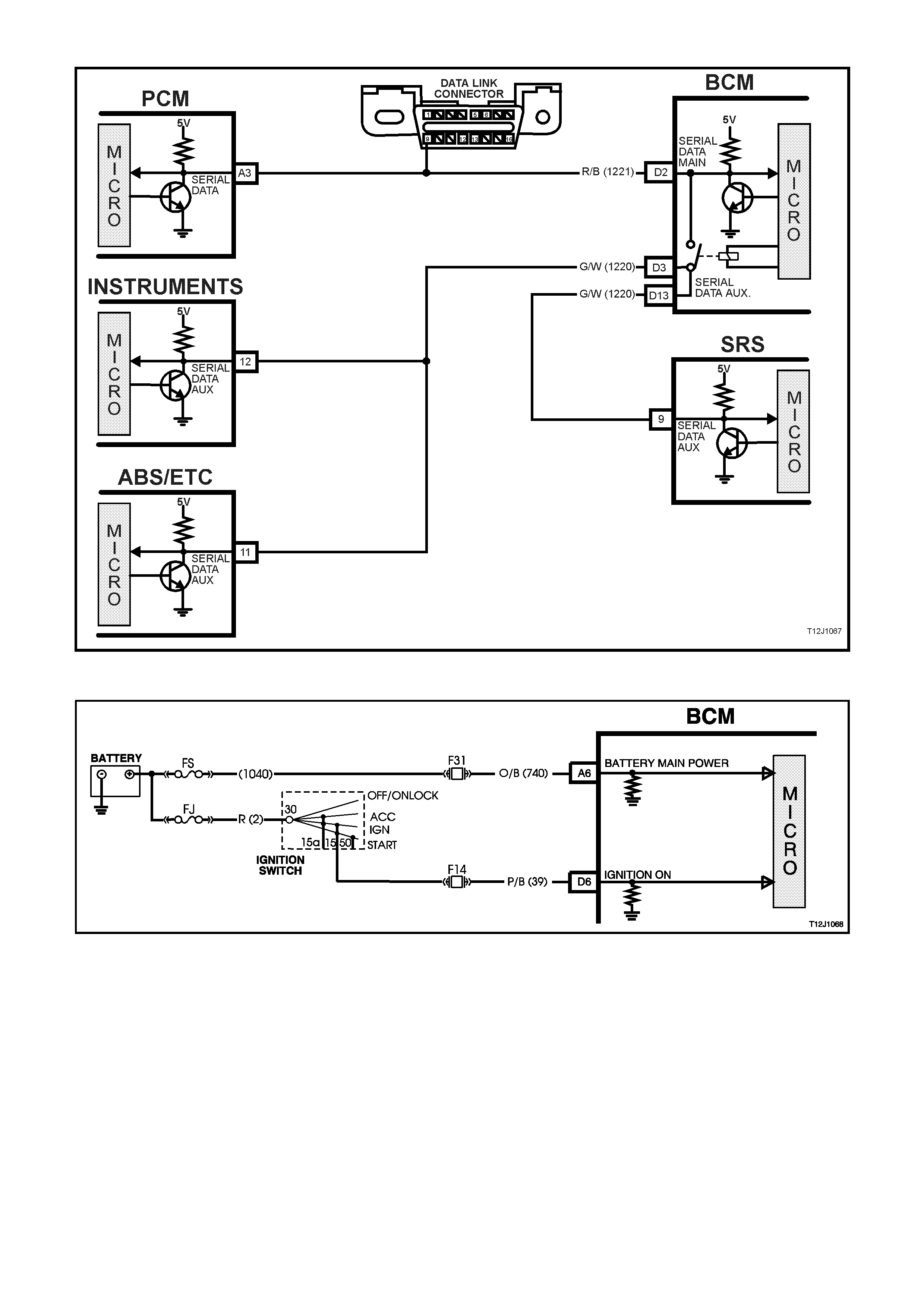
SERIAL DATA SIGNAL - MAIN
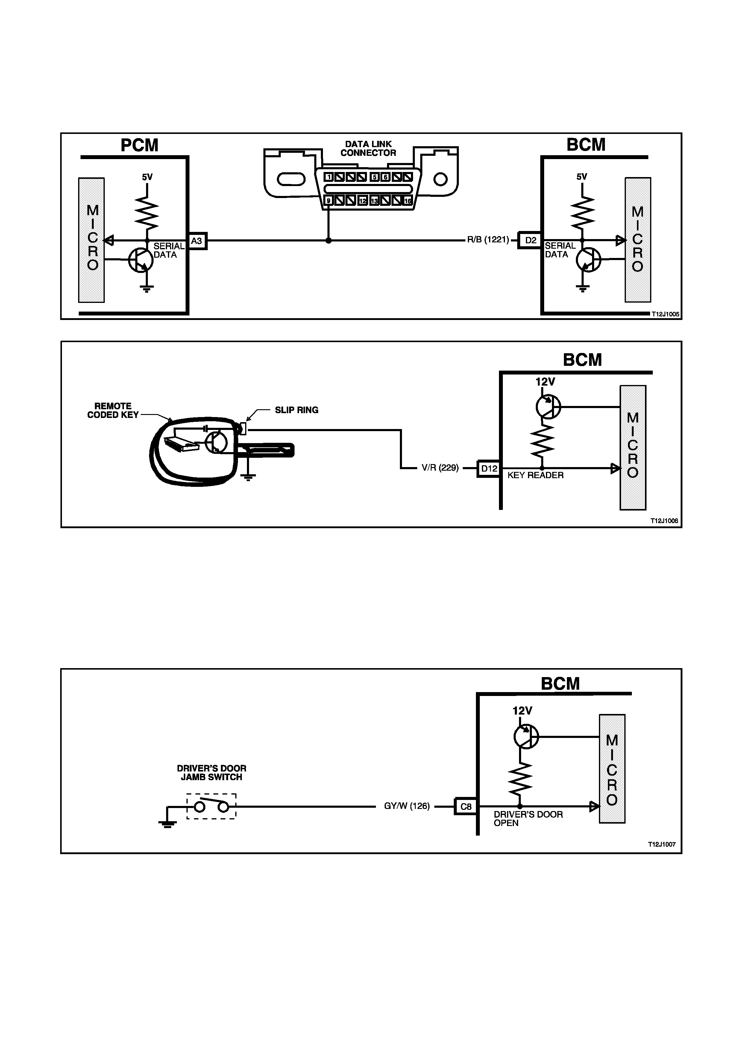
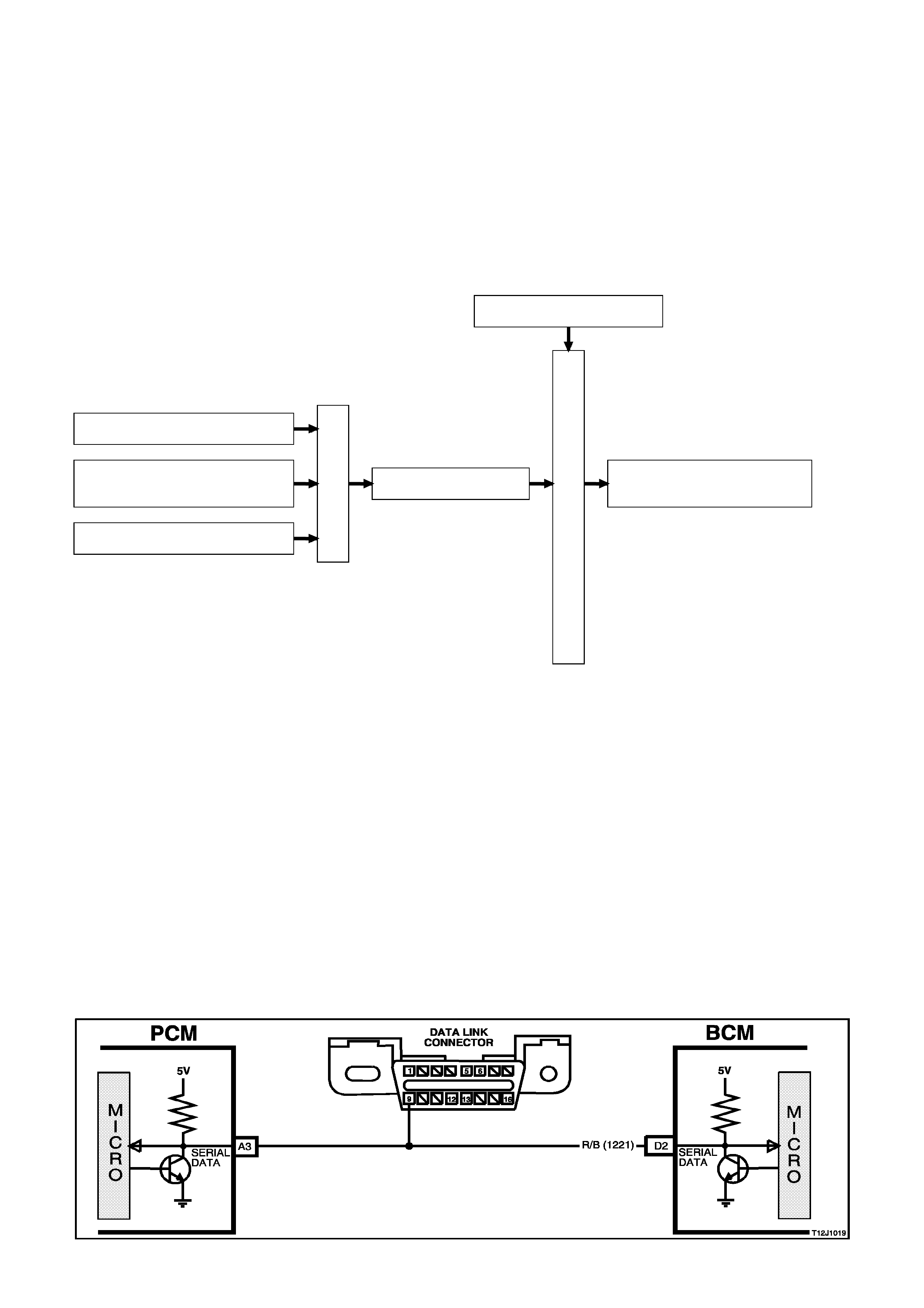
BCM terminal D2, serial data signal - main, refer to Fig. 12J-1-3, is connected to the PCM and DLC via circuit 1221
(Red/Black wire). It is via this line that the BCM c om m unicates with the PCM and external devices c onnected to the
DLC, at all times.
SERIAL DATA SIGNAL - AUXILIARY
BCM terminal D3, serial data signal - auxiliary, refer to Fig 12J-1-3, is connected to the INS, ABS/ETC and SRS
modules via circuit 1220 (G reen/White wire). It is via this line that the BCM com municates with these devices, after
successful anti thef t communications between the PCM and BCM (via the serial data - main line when the ignition
switch is turned from the OFF to ON position).
During anti theft communications, the serial data - auxiliary line is isolated from the serial data - main line via
switching within the BCM If the BCM does not receive an OK TO START message from the PCM within 0.5
seconds of ignition on (this will continue f or a five second period if there is still no acknowledgm ent fr om the PCM,
before it starts polling)

INPUTS
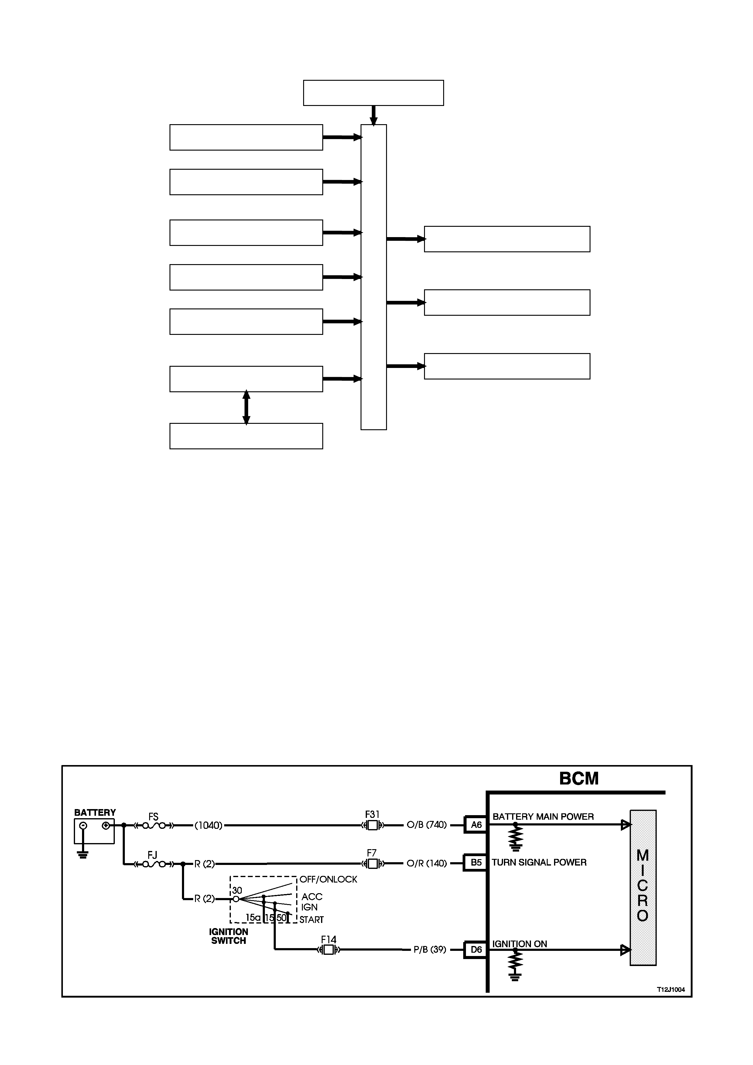
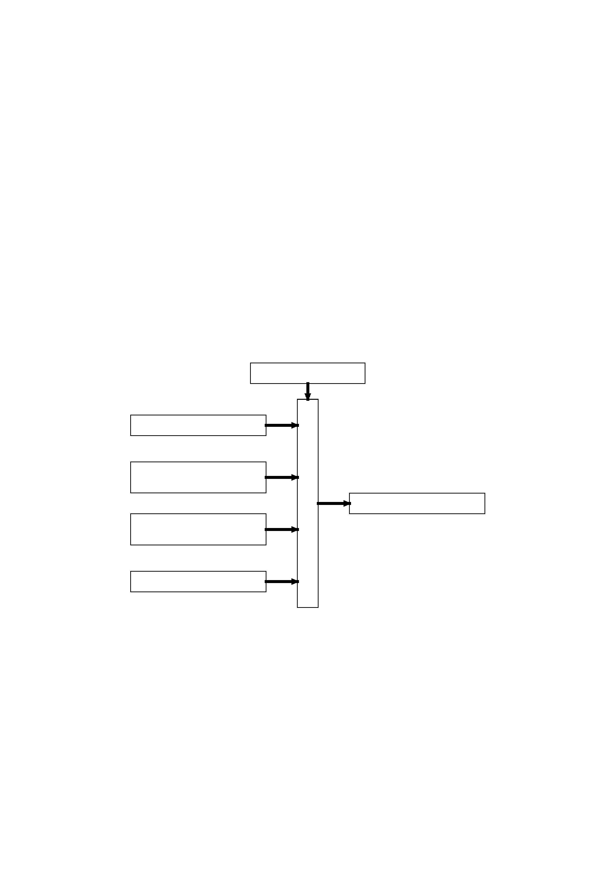
IGNITION SWITCH ON INPUT SIGNAL
The BCM uses this input signal to determine when the ignition switch is in the IGN or START position. W hen the
ignition switch is in the IGN or START position, battery voltage is applied to the BCM term inal D6 from the ignition
switch and fuse F14 via circuit 39 (Pink/Black wire), refer to Fig. 12J-1-4.

1.2 CENTRAL DOOR LOCKING SYSTEM
GENERAL INFORMATION
NOTE:
The c ircuit diagrams shown in this General Descr iption Section are to aid in interpreting the operation of the circ uit
and therefore, only the main connectors and wiring colours are shown. For complete circuit details, refer to either
the relevant diagnostic section or Section 12P WIRING DIAGRAMS.
The central door lock ing system provides for locking and unloc king of all doors and tailgate (station wagon m odels)
as well as enhanced locking or 'deadlock' (doors only).
The system incorporates the following functions:
1. Door and tailgate locking activated via:
Driver's door lock actuator (mechanically linked to door interior snib and door latch).
Left hand front passenger’s door lock actuator (mechanically linked to interior snib button).
Driver’s door key lock cylinder micro switches, which are also mechanically linked to the door latch, and
therefore linked to the actuators. VT Series Models require micro switch activation to force lock (and unlock)
without moving the actuator.
Pressing the lock button on remote coded key (provided all doors are closed
2. Door and tailgate unlocking via:
All door lock actuators (mechanically linked to door interior snib).
Pressing the unlock button on remote coded key.
The driver’s door key lock cylinder can also be m oved independently of the actuator, allowing unlocking of the
driver’s door latch in the case where the actuator is struck down, ie. deadlock when the battery is discharged.
3. Single and Two Stage Unlocking
The BCM is capable of operating in either of two unlock modes, either two or single stage unlock. The BCM, as
fitted to the vehicle is programmed to operate the central door locking system in the two stage unlock mode.
Two Stage Unlock
In two stage unlock mode, when the rem ote coded key unlock button is depressed for 0.25 seconds, the BCM, on
receiving the unlock request f rom the rem ote coded k ey, via the rem ote r ece iver, will unlock the driver ’s door only. If
the remote coded key unlock button is depressed again f or 0.25 seconds the BCM, on r eceiving the second unloc k
request from the remote coded key, will unlock all passenger doors.
Or alternatively, if the remote coded key is depressed continuously for 0.5 seconds, the BCM, on receiving the
unlock request from the remote coded key, will unlock all doors, first the driver’s door, then all passenger doors.
Single Stage Unlock
In single stage unlock mode, when the remote coded key unlock button is depressed for 0.25 seconds or longer,
the BCM on receiving the unlock request from the remote coded key, will unlock all doors simultaneously.
With TECH 2, the BCM can be pr ogrammed to operate in either two stage or s ingle stage unloc k (depending on the
vehicle’s owner or operator requirements).
If a short circuit exists on either the lock or unlock signal inputs, the opposing input is still able to perform its
function. This enables the doors to be unlocked when a short circuit exists on the lock input or vice-versa.
To protect the motors used in the door and tailgate lock actuators, in the event of multiple activation's within a
defined time period, the system will 'time-out' and protect the motors from damage. After a fixed time delay, the
system will re-activate as normal.
The deadlock feature provides for mechanical jamming of the door lock actuators. This is achieved electrically via
the driver's door key lock cylinder micro-switch.
NOTE:
Deadlock is inhibited whilst the ignition is on.
Operation of the Central Door Locking System is also affected by the Theft Deterrent System, refer to
1.4 THEFT DETERRENT SYSTEM in this Section.
SYSTEM CHECK
The operation of the Central Door Locking System is independent of the ignition being switched ON or OFF.
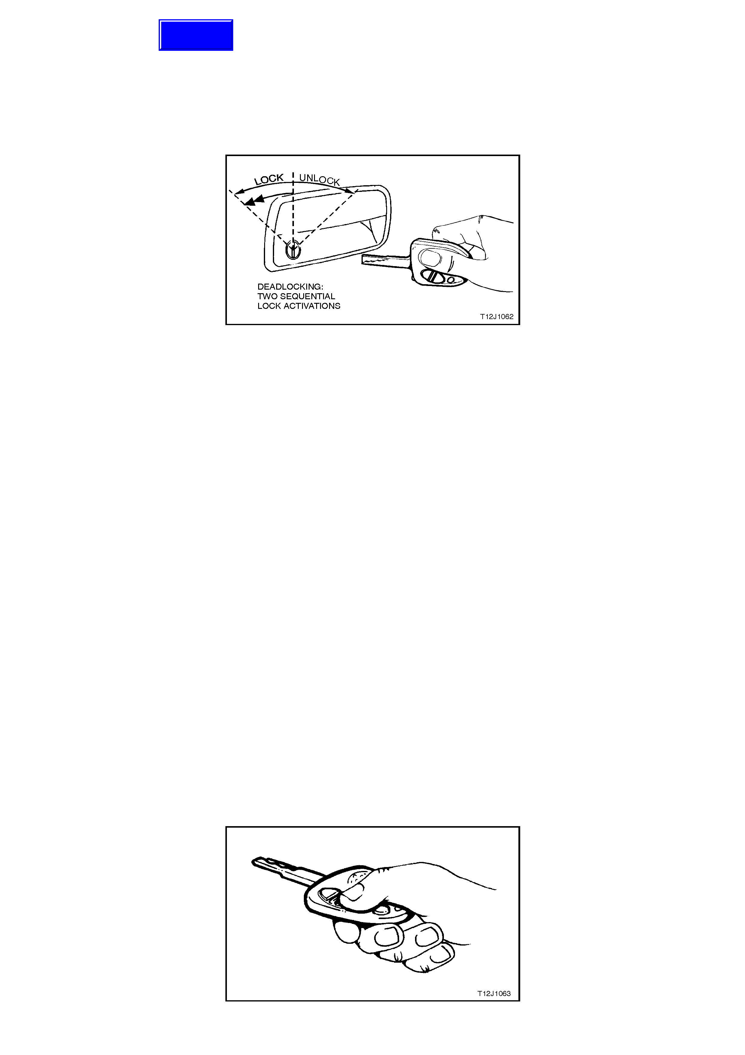
The Figure below shows the key positions on the driver’s door for the various key locking functions.
Deadlock refers to the electrical means that can be activated to ensure vehicle security by inhibiting door lock
operation.
Even though the electronic theft deterrent system, via the remote coded key, can activate the doors locks, it does
not engage the electrical 'blocking' of the doors (deadlocking).
Figure 12J-1-5
CENTRAL LOCKING AND UNLOCKING
Operation of this system can be effected as follows;
1. Driver’s door, outside key and inside locking (snib) button (locking and unlocking).
2. Left hand front passenger door inside locking (snib) button (locking and unlocking)
3. Rear passenger doors inside locking (snib) button (only unlocking is possible).
DEADLOCK
The deadlocking feature applies to all four doors, but not to the luggage compartment lid or tailgate.
After the deadlocking feature device has been engaged, unlocking is possible at the driver’s door from outside, by
inserting the key into the driver’s door lock cylinder and turning the key to the unlock position or activating the unlock
button on the rem ote key unlocks the deadloc k s on all door s, but only unlocks the dr iver ’s door ( providing two stage
unlocking is enabled).
To ensure access to the vehicle if the electrical system should fail (discharged battery), after the system has been
engaged, the driver’s door lock cylinder can be moved independently of the actuator and therefore allowing
unlocking of the driver’s door latch.
The rear com partment lid or tailgate can be lock ed/unlocked when the m echanical deadloc king featur e is actuated,
while leaving the doors secured.
NOTE:
Deadlocking is not possible with the ignition in the ON position.
REMOTE CODED KEY CHECK
Check that the remote coded key locks all doors when the rem ote coded key lock button is pressed, at a distance
within 4 metres from the driver’s side B pillar.
When the rem ote coded k ey unlock button is pr essed the dr iver's side s hould unloc k (vehicles progr am m ed f or two
stage unlock). Pressing the unlock button again and all passenger doors (and tailgate on station wagon models)
should unlock.
On vehicles programmed for single stage unlock, the single press of the unlock button will unlock all doors and
tailgate on station wagon models.
If this test does not prove satisfactory, refer to 2.3 REMOTE CODED KEY in this Section for a more detailed
diagnosis before continuing with the central locking system check.
Figure 12J-1-6
Techline
CHECKING THE DEADLOCK FEATURE
Open all windows.
Close all doors.
Actuate the deadlock feature from the driver’s door with the key.
Check that all door lock buttons cannot be pulled up. They are electrically blocked.
NOTE:
The door lock (snib) buttons can be pulled up slightly, but they will be under tension.
OVERHEATING PREVENTION
In the event of multiple activations within a defined time period, the central door locking system will be deactivated
and remain inoperative for a defined time period to prevent the door actuators from overheating. After a fixed time
delay, the system will re-activate and operate as normal.
SYSTEM OVERVIEW
B
O
D
Y
C
O
N
T
R
O
L
M
O
D
U
L
E
B
O
D
Y
C
O
N
T
R
O
L
M
O
D
U
L
E
CENTRAL DO OR LOCKING SYSTEM
C26 DOOR UNLOCK DRIVE
C13 DOOR LOCK DRIVE
C3 DRIVER'S DOOR
UNLOCK DRIVE
C12 DEADLOCK DRIVE
BATTERY POWER A6
DOOR LOCK POWER B10
DRIVER'S DOOR
UNLOCK C20
LOCK REQUEST C21
LOCK/DEADLOCK
REQUEST C22
UNLOCK REQUEST C9
REMOTE RECEIVER
CIRCUIT OPERATION
The door and tailgate locks are operated by reversible motors that receive voltage from relays within the BCM.
These relays operate the motors by applying battery voltage to one side of each motor and earth to the other side.
The central door locking system has four operational phases as follows:
1. Lock to Unlock 2. Unlock to Lock
3. Lock to Deadlock 4. Deadlock to Unlock
The circuit operation of each of these four phases is described as follows:
LOCK TO UNLOCK OPERATION
(Refer to Fig. 12J-1-10)
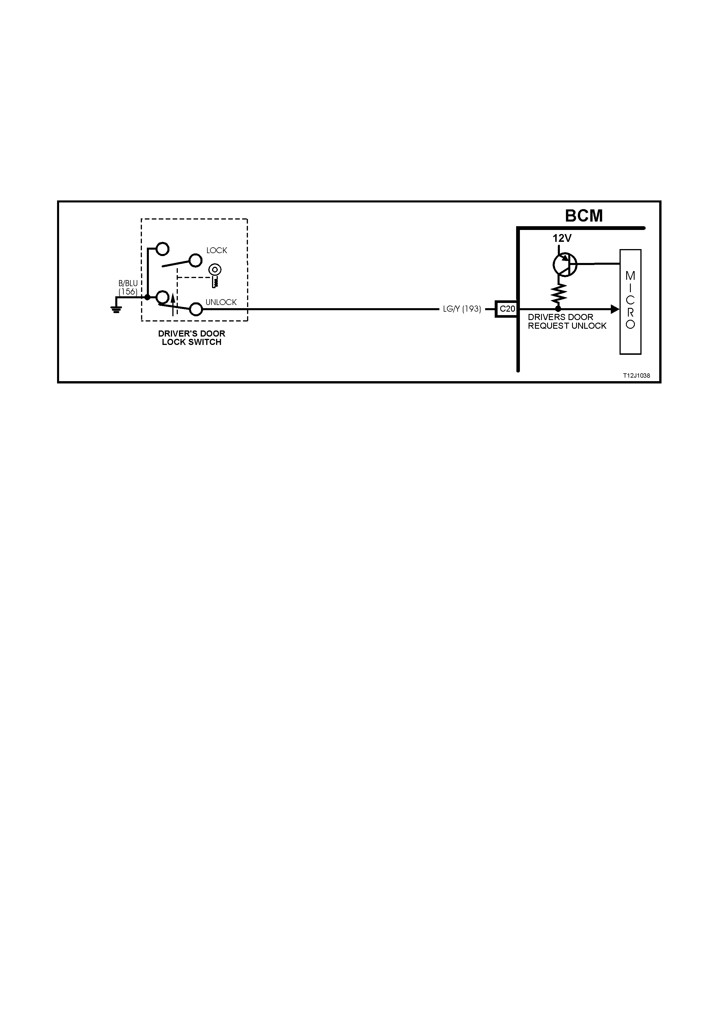
DRIVER’S DOOR REQUEST UNLOCK INPUT SIGNAL
(Refer to Fig. 12J-1-7)
When unlock ing the doors and tailgate via the r ight hand front door lock cylinder m icros witch or interior snib button,
BCM terminal C20 (driver's door request unlock signal), is connected to earth by the driver’s door lock actuator
switch contacts changing position from term inals 4-5 to 3-5 or in the cas e of the driver’s door cylinder micr o switch,
C20 is connected to earth via the microswitch contacts, unlock position circuit 156 (Black/Blue wire). This action
causes the voltage on terminal C20, circuit 193 (Light Green/Yellow wire), to be pulled low, less than 0.2 volts
(driver’s door unlocked). This low voltage at terminal C20 is seen by the BCM as a driver’s door request unlock
signal.
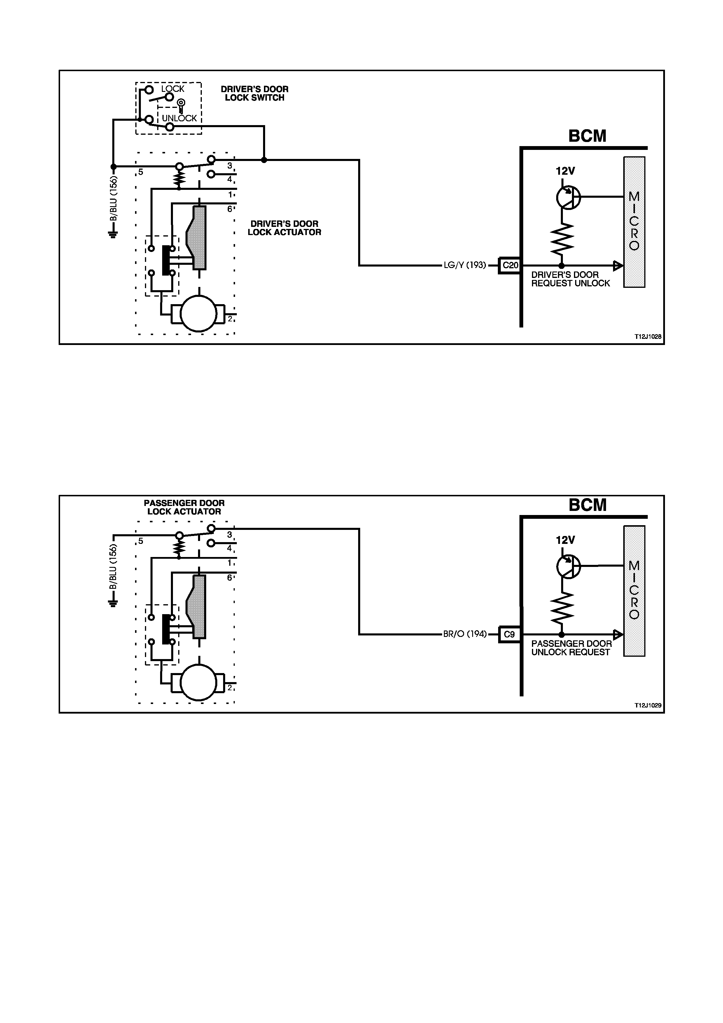
NOTE:
Manually activating any unlock request line will cause all doors to be unlocked.
Figure 12J-1-7
PASSENGER DOOR UNLOCK REQUEST INPUT SIGNAL
(Refer to Fig. 12J-1-8)
When unlocking the doors via any passenger door interior snib button, BCM terminal C9 (passenger door unlock
request signal) is connected to earth by the activated passenger door lock actuator switch contacts, terminals 3,
circuit 194 ( Brown/Orange wire) and 5, cir cuit 156 (Black /Blue wire). T his action caus es the voltage on term inal C9,
circuit 194 to be pulled low, less than 0.2 volts (doors unlocked). This low voltage at terminal C9 is seen by the BCM
as a passenger door unlock request signal.
Figure 12J-1-8
A low voltage at term inal C20 or C9 is seen by the BCM as a system unloc k r equest. T his then enables the BCM to
energise the internal unlock relay for approximately 0.75 seconds. This causes the unlock relay contacts to close
and battery voltage is applied, via fuse F20, circuit 440 (Orange/Violet wire) and BCM terminals B10 and
C26, to terminal 2 of each of the passenger door lock actuators and to the tailgate lock actuator (station wagon
models), circuit 294 (Black/Red wire). Battery voltage is also applied, via fuse F20, circuit 440 (Orange/Violet wire)
and BCM terminals B10 and C3, to terminal 2 of the driver’s door lock actuator, via circuit 293 (Blue/Black wire).
The opposite terminal of the door lock actuators (terminal 1) is connected to earth via BCM terminal C12, circuit 394
(Violet/White wire) through the BCM’s internal deadlock relay contacts and BCM terminal B11, circuit 151
(Black/Green wire). This causes the door lock actuator motor armatures to rotate from the lock to the unlock
position, and the door lock actuator switch contacts to change from terminal 1 to 6. The rotation of the passenger
door lock ac tuator motor armatures als o caus es the door loc k switch c ontacts to c hange f r om the loc k to the unloc k
position. The tailgate lock actuator motors are earthed via the BCM terminal C13, circuit 295 (Black/Yellow wire),
through the BCM’s internal lock relay contacts and BCM terminal B11 and circuit 151 (Black/Green wire).
REMOTE CODED KEY OPERATION
(Refer to Fig 12J-1-9 for remote receiver, Fig. 12J-1-11 for first stage of two stage unlock and Fig. 12J-1-12 for
second stage of two stage unlock)
TWO STAGE UNLOCK
If the BCM is operating in the two stage unlock mode and the remote coded key unlock button is depres s ed f or 0.25
seconds, the BCM, on receiving the unlock request from the remote coded key, via the remote receiver, activates
the microprocessor within the BCM, causing the driver’s door unlock relay to toggle to the unlock state, unlocking
the driver’s door only as described previously.
If the rem ote c oded key unlock button is depress ed again for 0.25 seconds , the m icroproc essor within the BCM, on
receiving the sec ond unlock reques t from the r emote coded k ey, will toggle the unlock r elay contacts to the unlock
state and the passenger doors (and tailgate) will unlock as described previously.
If the remote coded key is depressed continuously for 0.5 seconds, the microprocessor within the BCM, on
receiving the unlock request from the remote coded key, will unlock all doors, first the driver’s door, then all
passenger doors (and tailgate), as described previously.
SINGLE STAGE
If the BCM is operating in the single stage unlock mode and the rem ote coded k ey unlock button is depressed for
0.25 seconds, the micropr ocessor within the BCM, on receiving the RF unloc k request f rom the rem ote coded key,
causes the unlock relay contacts to toggle to the unloc k state, all doors (and tailgate) will then unlock as des cribed
previously.
Figure 12J-1-9
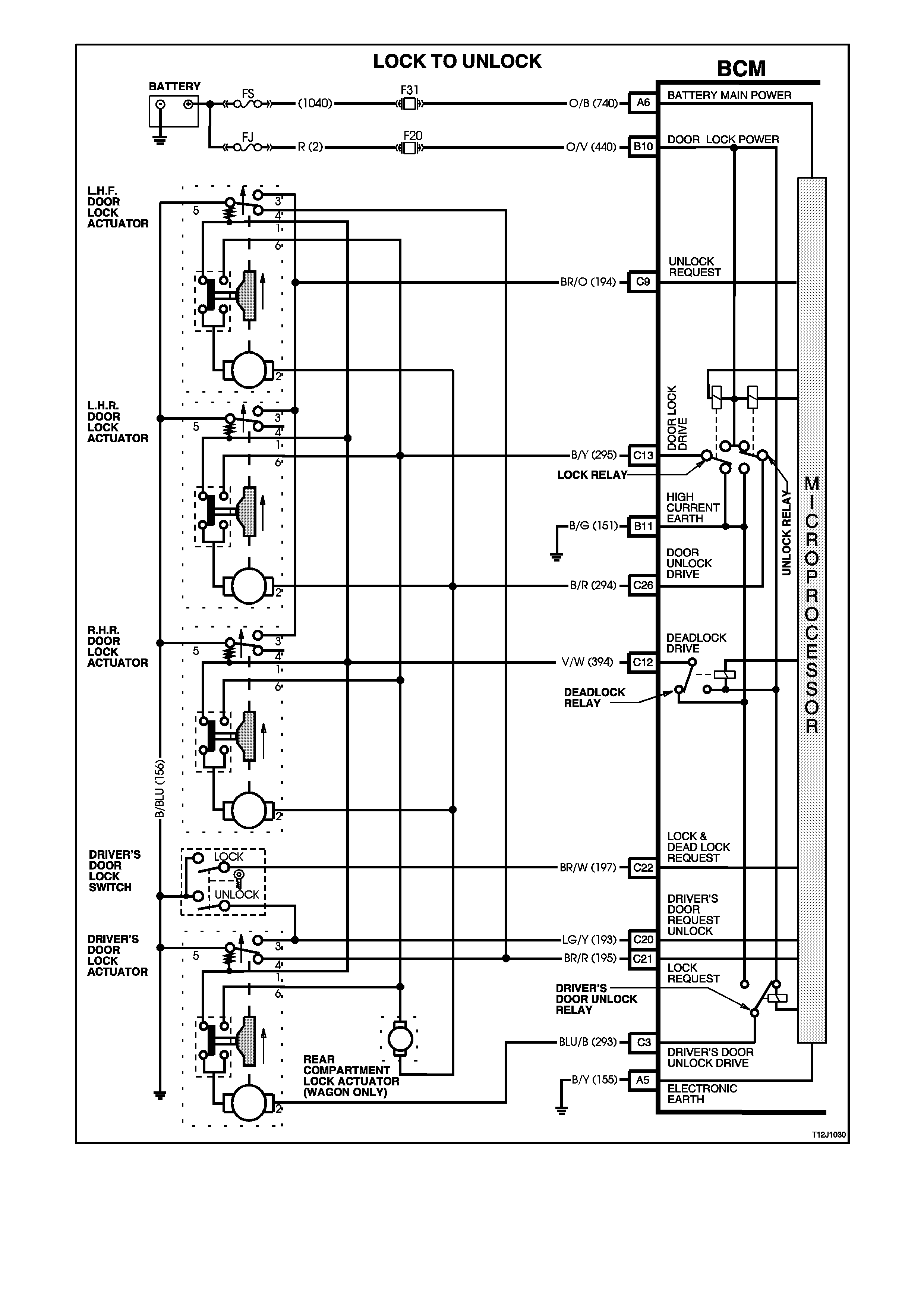
Figure 12J-1-10
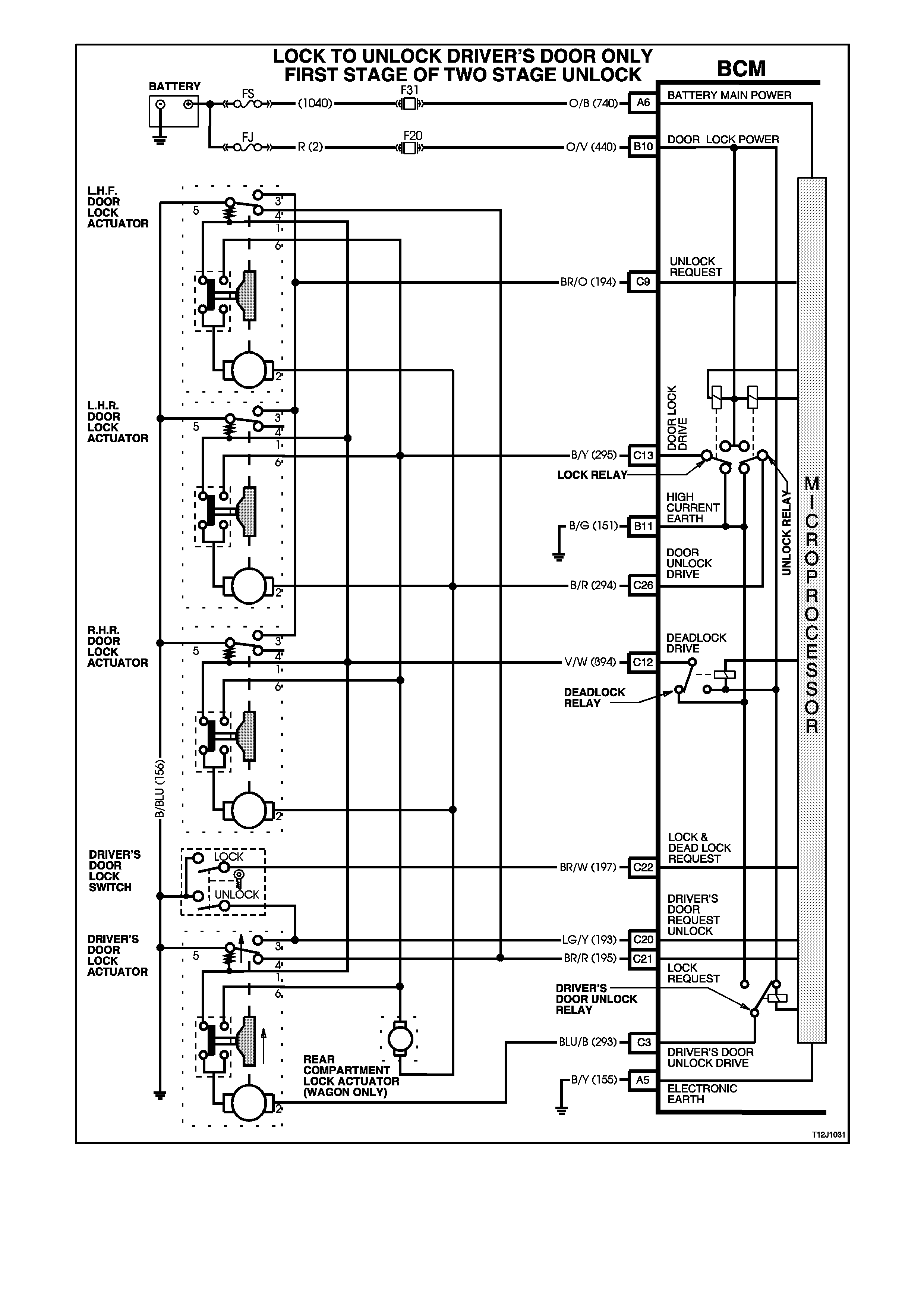
Figure 12J-1-11
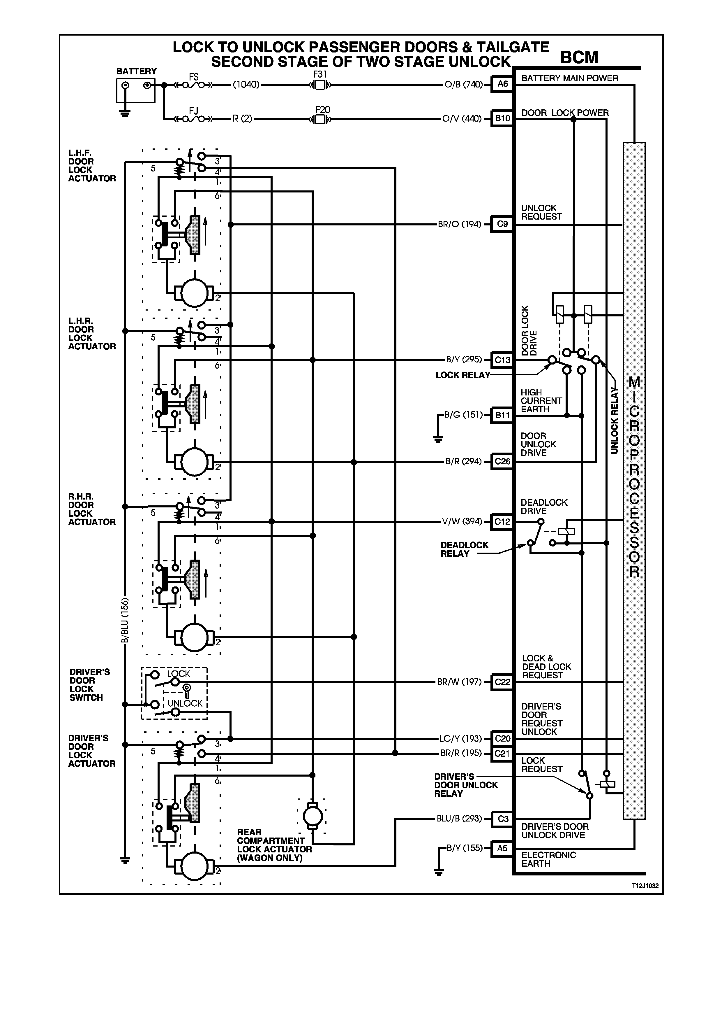
Figure 12J-1-12
UNLOCK TO LOCK OPERATION
(Refer to Fig. 12J-1-15)
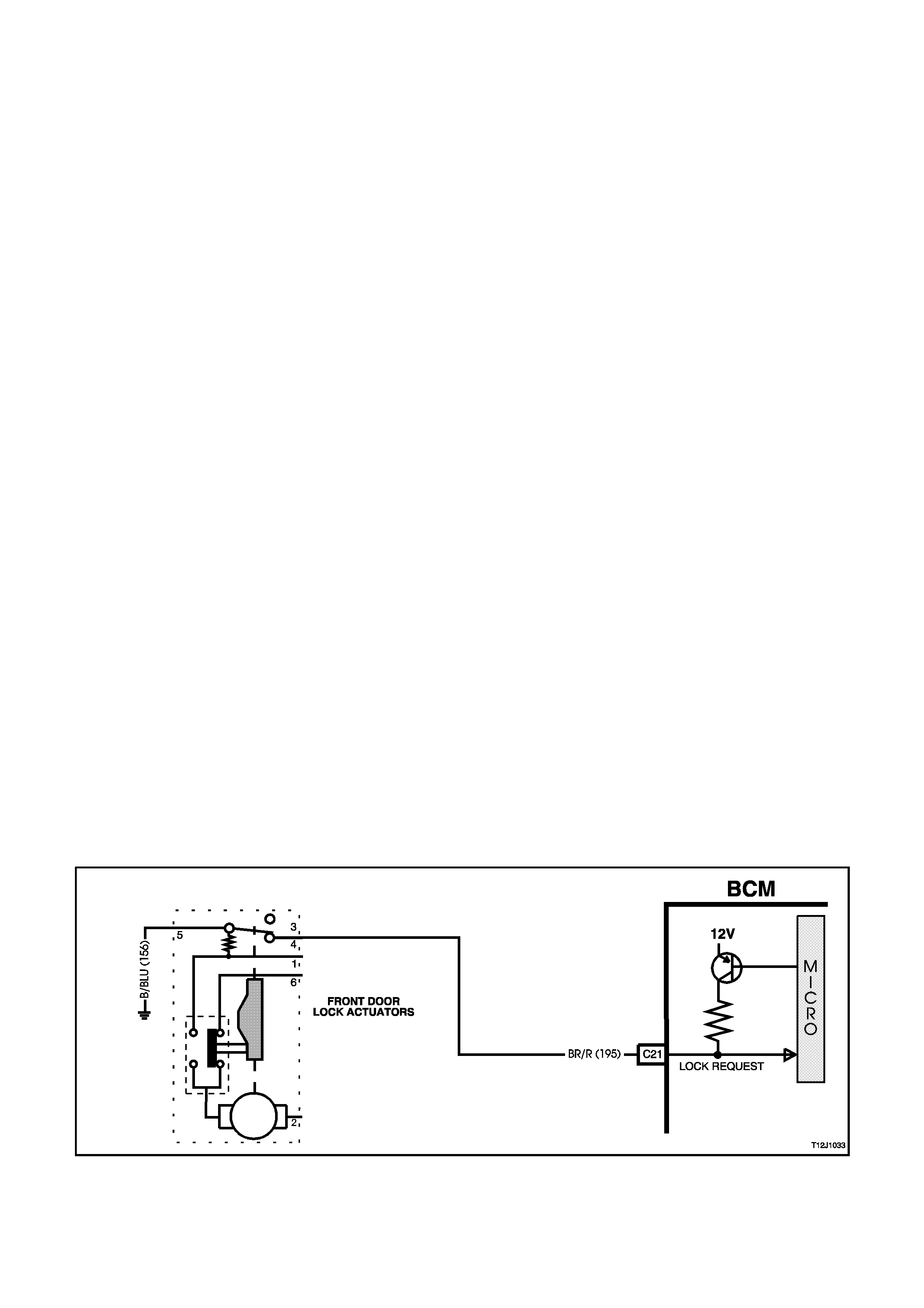
LOCK REQUEST
(Refer to Fig. 12J-1-13)
When locking the doors and tailgate via the driver’s door interior snib button, the BCM terminal C21, circuit 195
(Brown/Red wire), is connected to earth, circuit 156 (Black/Blue wire) by the driver’s door lock actuator key switch
contacts changing over from terminals 3-5 to 4-5.
This action causes the voltage on terminal C21, circuit 195 (Brown/Red wire), to be pulled low, less than 0.2 volts
(doors locked).
This low voltage at terminal C21 is seen by the BCM as the system lock request.
LOCK AND DEADLOCK REQUEST
(Refer to Fig. 12J-1-14)
When locking the doors and tailgate via the driver’s door lock cylinder microswitch, BCM terminal C22
(lock/deadlock request signal) is connected to earth via the microswitch contacts, lock position, circuit 156
(Black/Blue wire). This action causes the voltage on terminal C22, circuit 197 (Brown/White wire) to be pulled low,
less than 0.2 volts (door locked). This low voltage at terminal C22 is seen by the BCM as the system lock request
(only if the driver’s door is closed).
Either of these two lock requests (via snib or driver’s door microswitch) then enable the BCM to energise the
internal lock relay for approximately 0.75 seconds, the lock relay contacts close and battery voltage is applied, via
fuse F20, circuit 440 (Orange/Violet wire) and BCM terminals B10 and C13, to terminal 6 of each door lock actuator
and to the tailgate actuator, circuit 295 (Black/Yellow wire).
The opposite terminal (terminal 2) of the passenger doors and tailgate door lock actuator motors is connected to
earth through BCM terminal C26, circuit 294 (Black/Red wire), the internal unlock relay contacts and through BCM
terminal B11 to earth, circuit 151(Black/Green wire). The opposite terminal (terminal 2) of the driver’s door lock
actuator motor is connected to earth through BCM terminal C3, circuit 293 (Blue/Black wire), the internal driver’s
door unlock relay contacts and through BCM terminal B11 to earth, circuit 151 (Black/Green wire).
This allows the door lock actuator motor armatures to rotate to the lock position and causes the door lock actuator
switch contacts to change from terminals 6 to 1. This action disconnects the voltage supply to the door lock actuator
motor armatures, the armatures now have earth connection on both sides, with actuator terminals 6 earthed
through the deadlock relay terminals and through BCM terminal B11 to earth circuit 151 (Black/Green wire). This
causes an instantaneous halt to door lock actuator motor armature rotation.
This rotation of the passenger door lock actuator motor armatures also causes the passenger door lock switch
contacts to change to the lock position.
After approximately 0.75 seconds, the power to all the actuators via BCM terminal C13 circuit 295 (Black/Yellow
wire) is disconnected by the opening of the internal lock relay contacts.
REMOTE CODED KEY OPERATION
When locking the doors via the remote coded key, the RF output signal from the key, via the remote receiver,
activates the microprocessor within the BCM, causing the door lock relay to be energised locking all doors (and
tailgate) as described previously. If any door does not lock either BCM terminal C20 (driver’s door request unlock)
or C9 (Unlock request) will remain low, this low voltage is seen by the BCM as an unsuccessful attempt to lock all
doors and the BCM will suppress the indicators flash (driver’s door must be closed).
Figure 12J-1-13
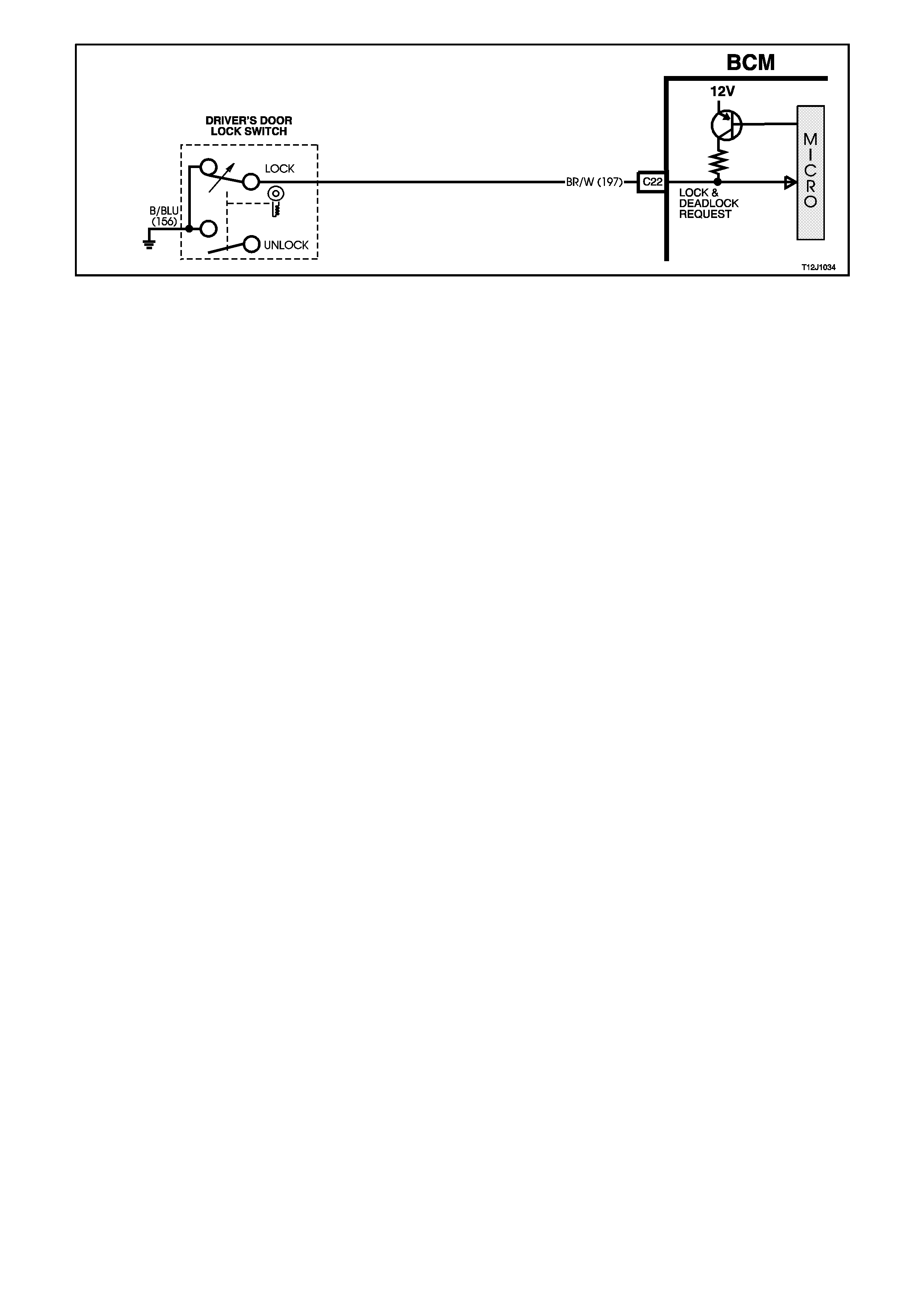
Figure 12J-1-14

Figure 12J-1-15
UNLOCK TO DEADLOCK OPERATION
(Refer to Fig. 12J-1-17)
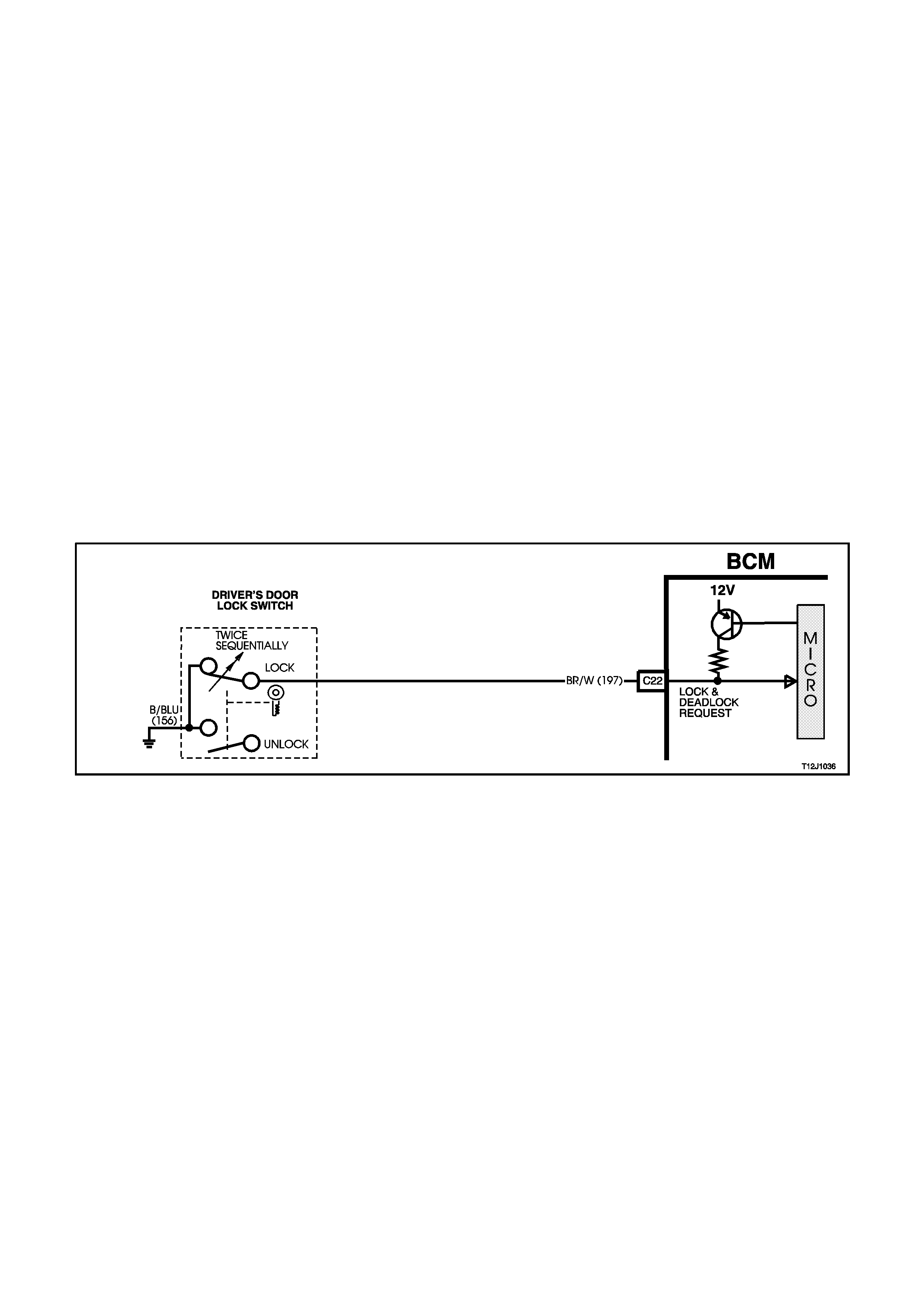
LOCK / DEADLOCK REQUEST INPUT SIGNAL
(Refer to Fig. 12J-1-16)
NOTE:
This operation will only work if the driver’s door is closed and the ignition is off. If the driver’s door is opened, the
door will not lock and if the ignition is on, the doors will not deadlock.
Deadlocking is activated after two sequential lock activation’s of the driver’s door lock switch. This action causes the
micro-switch contacts to change to the lock position. This connects BCM terminal C22 circuit 197 (Brown/White
wire) to earth via circuit 156 (Black/Blue wire), causing the voltage on terminal C22 to be pulled low, less than 0.2
volts.
This low voltage at terminal C22 is seen by the BCM as the system deadlock request. This enables the BCM to
energise the internal lock and deadlock relays for approximately 0.75 seconds, the lock and deadlock relays
contacts clos e and battery voltage is applied, via fuse F20, circ uit 440 (Or ange/Violet wire) and BCM term inals B10,
C13 and C12, circuit 295 ( Black/Yellow wire) and 394 (Violet/White wire) to term inals 6 and 1 of each electr ic door
lock motor.
The opposite terminal (terminal 2) of all the passenger lock actuator motors is connected to earth through BCM
terminal C26, the internal unlock relay contacts and through BCM terminal B11 to earth, circuit 151 (Black/Green
wire). Terminal 2 of the driver’s door lock actuator motors is connected to earth through BCM terminal C3, the
internal driver’s door unlock relay contacts and through BCM term inal B11 to earth, circuit 151 (Black/Green wire).
This causes the door lock actuator m otor armatur es to rotate in the loc king (downward) direction into the deadlock
position. This rotation of the door lock actuator m otor arm atures als o causes the door lock ac tuator switch contacts
to change from terminals 6 to 1 to 6.
NOTE:
The tailgate actuator is not designed to go to deadlock.
Figure 12J-1-16

Figure 12J-1-17
DEADLOCK TO UNLOCK OPERATION
(Refer to Figs. 12J-1-18 and 12J-1-19)
When unlocking the doors from the deadlock position by the driver’s door lock cylinder, by turning to the unlock
position, the micros witch contacts change to the unlock pos ition. T his connec ts BCM term inal C20 c ircuit 193 (Light
Green/Yellow wire), to earth via circuit 156 (Black/Blue wire), causing the voltage at term inal C20 to be pulled low,
less than 0.2 volts.
This low voltage at terminal C20 is seen by the BCM as the driver’s door unlock request signal. T his then enables
the BCM to energise the internal unlock relays for approximately 0.75 seconds. This causes the relay contacts to
toggle and battery voltage is applied, via fuse F20, circuit 440 (Orange/Violet wire) and BCM terminals B10, C26
(passenger doors unlock, drive, circuit 294 (Black/Red wire)) and C3 (drivers door unlock, drive, circuit 293
(Blue/Black wire)) to terminals 2 of each of the door lock actuators and to the tailgate lock actuator.
Figure 12J-1-18
Initially, actuator term inal 6 is connected to earth via circuit 295 (Black /Yellow wire) through the BCM ter minal C13,
through the internal lock relay contacts to terminal B11 to circuit 151 (Black/Green wire). This then allows the
passenger door lock actuator m otor armatures to rotate from the deadlock toward the unlock position, causing the
passenger door lock actuator switch contacts to c hange f r om terminal 6 to 1. As terminal 1 is connec ted to ear th via
circuit 394 (Violet/White wire) through terminal C12 of the BCM, the deadlock relay contacts to terminal B11 to
circuit 151 (Black/Green wire), the door lock actuator motor armatures will continue to rotate further to the unlock
position.
This rotation of the passenger door lock ac tuator motor armatur es causes the door lock ac tuator switch contac ts to
change back to terminal 6. This rotation of the passenger door actuator lock motor armatures also causes the
passenger door lock switch contacts to change to the unlock position.
NOTE:
If the ignition is off, the doors may be unlocked from the deadlock position by activating the unlock button on the
remote key. If set for two stage unlock, the driver’s door will fully unlock (deadlock to unlock) and the remaining
passenger doors will go from the deadlock position to the lock position. If set for single stage unlock, all doors will
go from the deadlock position to the unlock position.
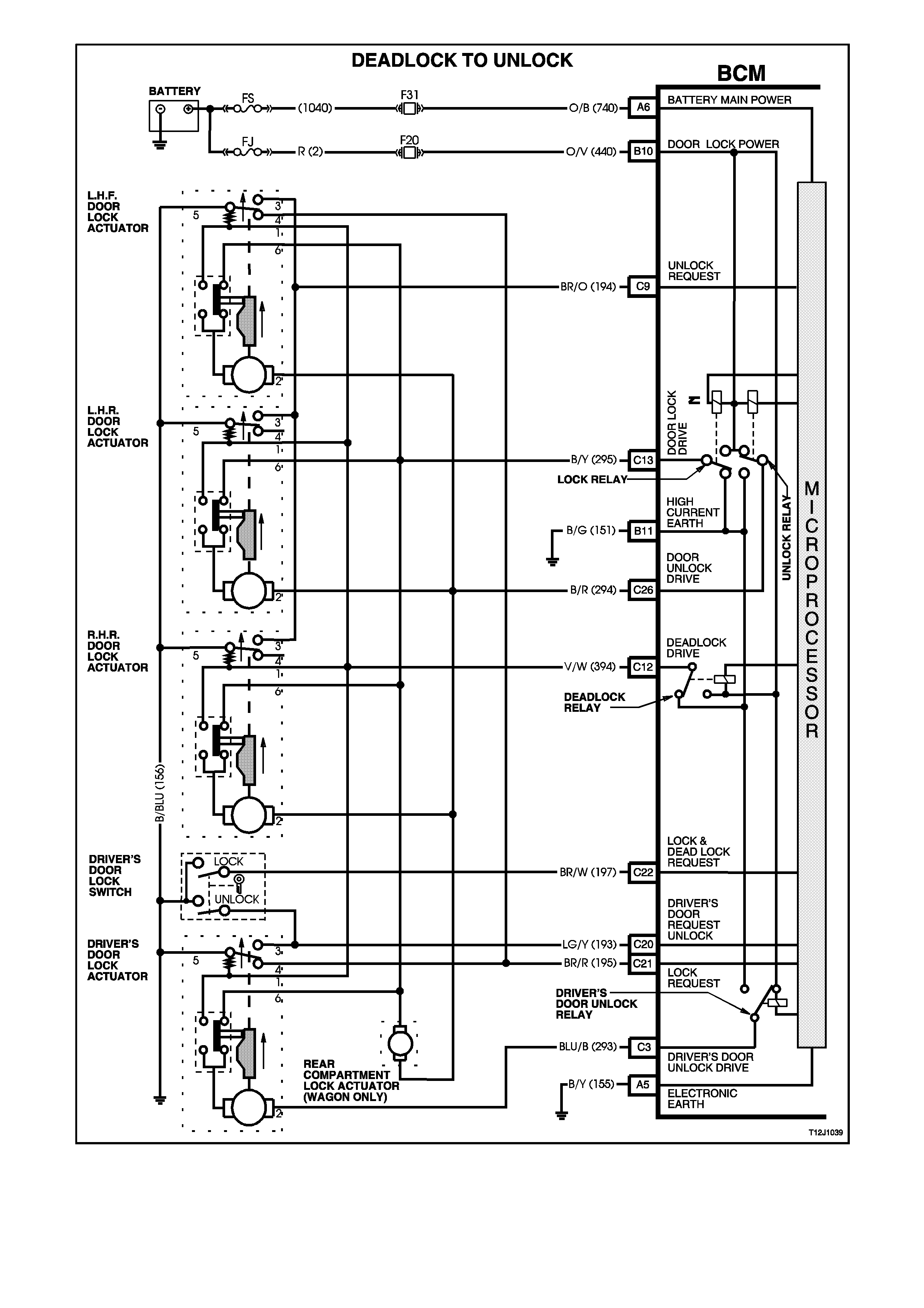
Figure 12J-1-19
1.3 BOOT RELEASE
GENERAL INFORMATION
The rear com partment lock actuator is controlled by pressing the rear compartment lock switch which is located in
the glove com partm ent, or pr essing the boot releas e button on the rem ote c oded k ey which in tur n trans m its an RF
output signal. The RF signal is received by the BCM’s remote r eceiver and activates the m icroprocess or within the
BCM.
The BCM will monitor the rear compartment lock switch and remote boot signal and inhibit boot release if the
vehicle speed is above 15 km/h.
NOTE:
The c ircuit diagrams shown in this General Descr iption Section are to aid in interpreting the operation of the circ uit
and therefore, only the main connectors and wiring colours are shown. For complete circuit details, refer to either
the relevant diagnostic section or Section 12P WIRING DIAGRAMS.
SYSTEM OVERVIEW
B
O
D
Y
C
O
N
T
R
O
L
M
O
D
U
L
E
BATTERY POWER A6
BOOT RELEASE
SE RIAL DAT A MAIN D 2
REMOTE RECEIVER D1
PCM
BOOT RELEASE D16
VEHICLE SPEED SENSOR C25 BOOT SOLENOID DRIVE
CIRCUIT OPERATION
BATTERY POWER
Battery voltage is applied to the BCM microprocessor from terminal A6 at all times from fusible link FS and fuse F31
via circuit 740 (Orange/Black wire).
INPUTS
Serial Data Signal
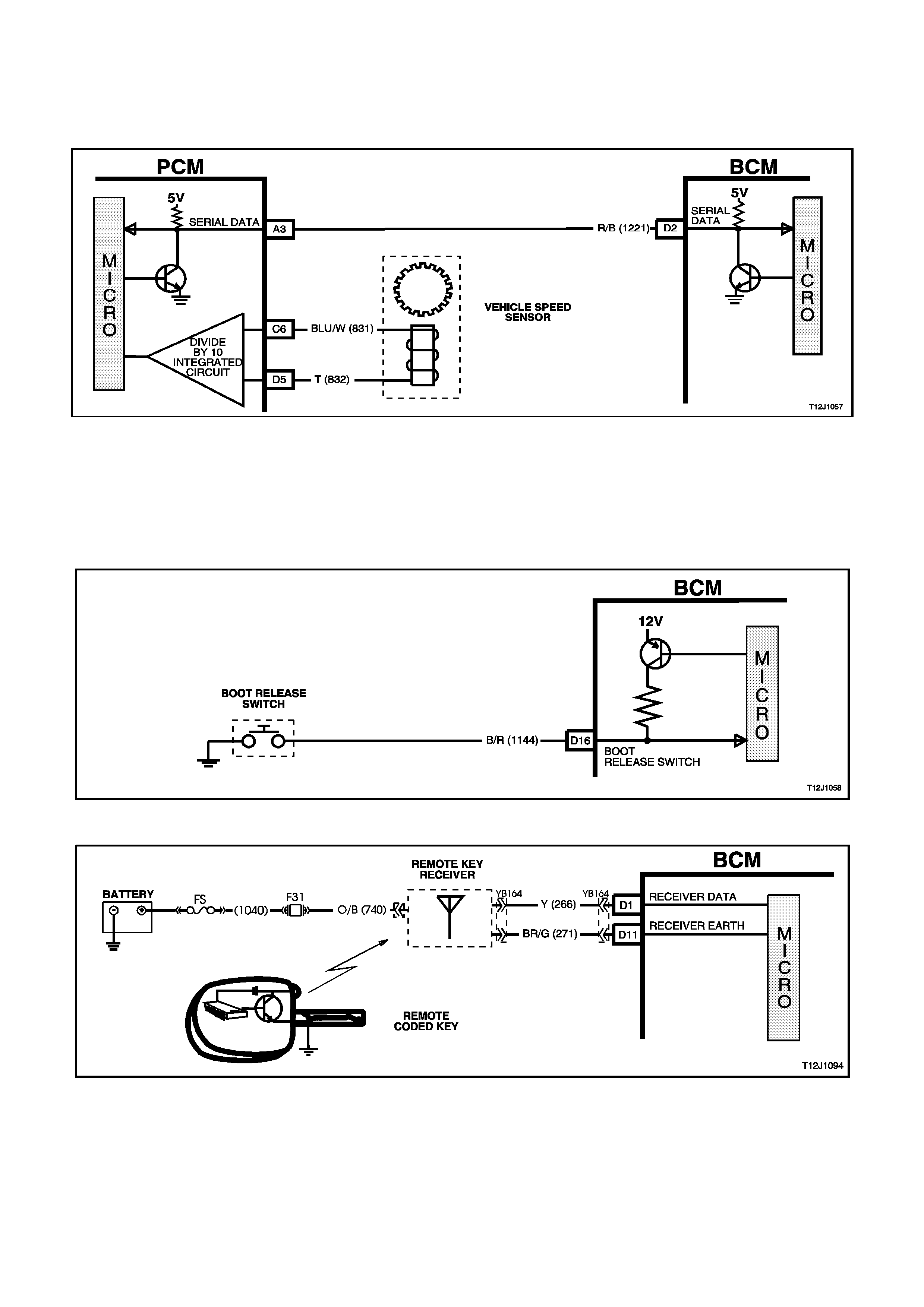
(Refer to Fig. 12J-1-20)
BCM terminal D2, serial data bus, is connected to the PCM terminal A3, via circuit 1221 (Black/Red wire). It is via
the serial data bus line that the BCM receives serial data relating to the speed of the vehicle.
Figure 12J-1-20
BOOT RELEASE INPUT
(Refer to Fig. 12J-1-21 and to Fig. 12J-1-22)
Pressing the r ear com partm ent loc k switch caus es the contac ts to clos e, connecting BCM ter m inal D16 to earth via
circuit 1144 (Black/Red wire). This action causes the voltage at terminal D16 to be pulled low, less than 0.2 volts.
This low voltage at terminal D16 is seen by the BCM as a boot release switch input signal. The BCM will not activate
the rear compartment lock actuator if the vehicle speed is greater than 15 km/h.
Figure 12J-1-21
Figure 12J-1-22
OUTPUTS
(Refer to Fig. 12J-1-23)
The BCM can activate the rear compartment lock actuator by energising it’s internal boot release relay. This will
apply battery voltage from terminal B5, through the boot release relay contacts and terminal C25 to the rear
com partment releas e actuator, circuit 142 (Red/G reen wire). The earth circuit for the rear compartm ent solenoid is
via the body and main wiring harness.
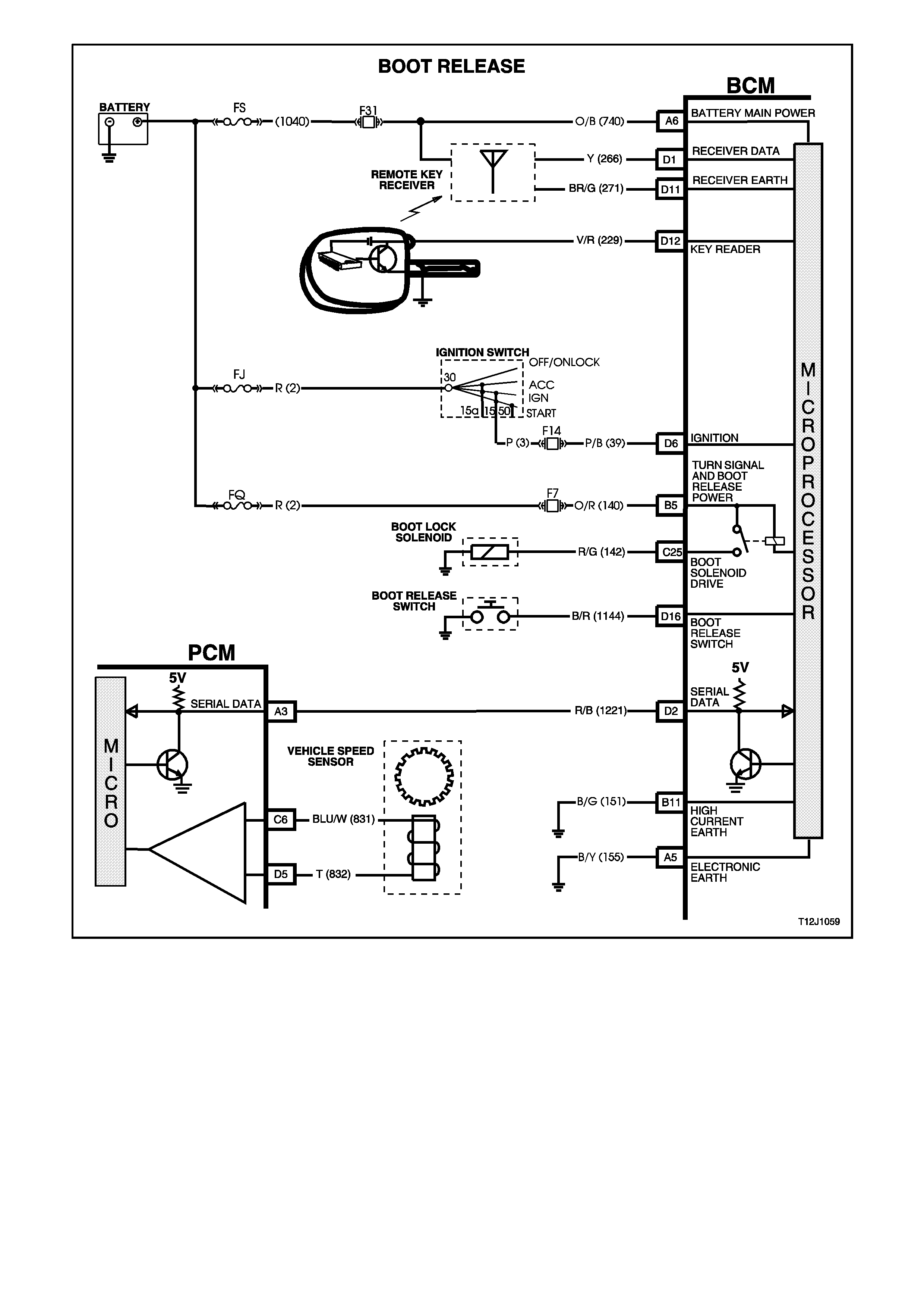
Figure 12J-1-23

1.4 THEFT DETERRENT SYSTEM
GENERAL INFORMATION
The theft deterrent system on VT Series Models uses a remote c oded k ey to arm and disar m the system, as well as
electrically lock or unlock all doors and tailgate (station wagon), or operate the boot unlock mechanism (sedan).
NOTE:
The c ircuit diagrams shown in this General Descr iption Section are to aid in interpreting the operation of the circ uit
and therefore, only the main connectors and wiring colours are shown. For complete circuit details, refer to either
the relevant diagnostic section or Section 12P WIRING DIAGRAMS.
SYSTEM OPERATION
There are two modes of theft deterrent operation, armed and disarmed.
ARMED
The theft deterrent system can be manually armed in one of two ways:
Actively, by pressing the lock button on the remote coded key or,
Passively, as the BCM will automatically arm 30 seconds after the ignition is turned off.
When the system is armed, the start relay (located in the engine compartment relay housing) and the engine
management system control module (PCM) are disabled, preventing the engine from being started.
DISARMED
With the system disar med and the PCM enabled, the engine will be allowed to be started when the ignition switch is
turned to the run position.
The theft deterrent system can be disarmed in three ways:
1. Pressing the unlock button on the rem ote coded key. This unlock s the doors, turns the interior dom e lamp on
and disarms the system for 30 seconds.
2. By inserting the remote coded key into the ignition switch cylinder and turning the ignition to the ON or run
position. This causes the BCM to read a security code serial data output from the remote coded key contact pin
via the remote coded key reader assembly.
3. The system can also be disarm ed by turning the ignition switch to the O N position for approxim ately two hours
(timed override function).
NOTE:
Should the engine crank brief ly when the ignition switch is tur ned to the START position ( ie. due to m is-aligned or a
faulty remote coded k ey reader) then pressing the unlock button on the rem ote coded k ey will also disar m the theft
deterrent system.
The theft deterrent system has a timed override function. The theft deterrent system can be overridden (disabled),
as for example in the event of a remote coded key failure, by turning the ignition switch to the ON position for two
hours. The theft deterrent aler t indicator LED will go out once the system has been disabled and norm al starting of
the vehicle can take place.
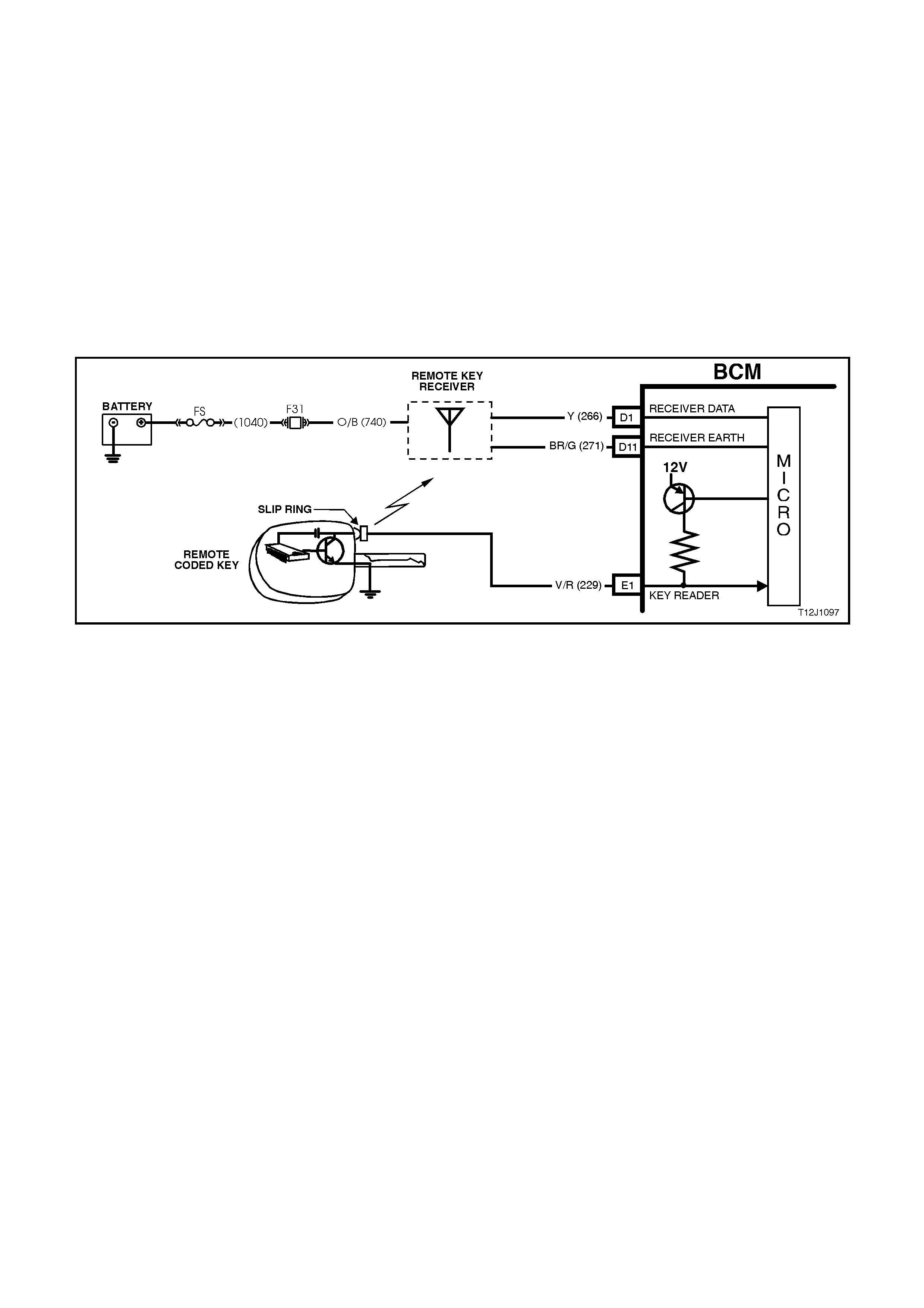
REMOTE CODED KEY
(Refer to Fig. 12J-1-24)
The theft deterrent system uses a remote coded key to arm and disarm the system, and electrically lock or unlock
all doors and tailgate (station wagon), or operate the boot unlock mechanism (sedan models).
The rem ote coded key is powered by its own internal battery. If its internal battery fails, the remote coded k ey can
be powered by the rem ote coded key reader once the k ey is inserted into the ignition switch cylinder and tur ned to
the IGN or START position.
When the theft deterrent system is armed by pressing the remote coded key lock button, the indicators will flash
once and the theft deterrent alert indicator LED will begin to flash. Disarming the system by pressing the unlock
button will cause the indicators to flash twice and the theft deterrent alert indicator LED will stop flashing.
The Radio Frequency (RF) transmitted by the remote coded key is received by the BCM’s remote receiver located
in the dash panel.
NOTE:
Passive arming of the system does not automatically operate the door locks or flash the indicators.
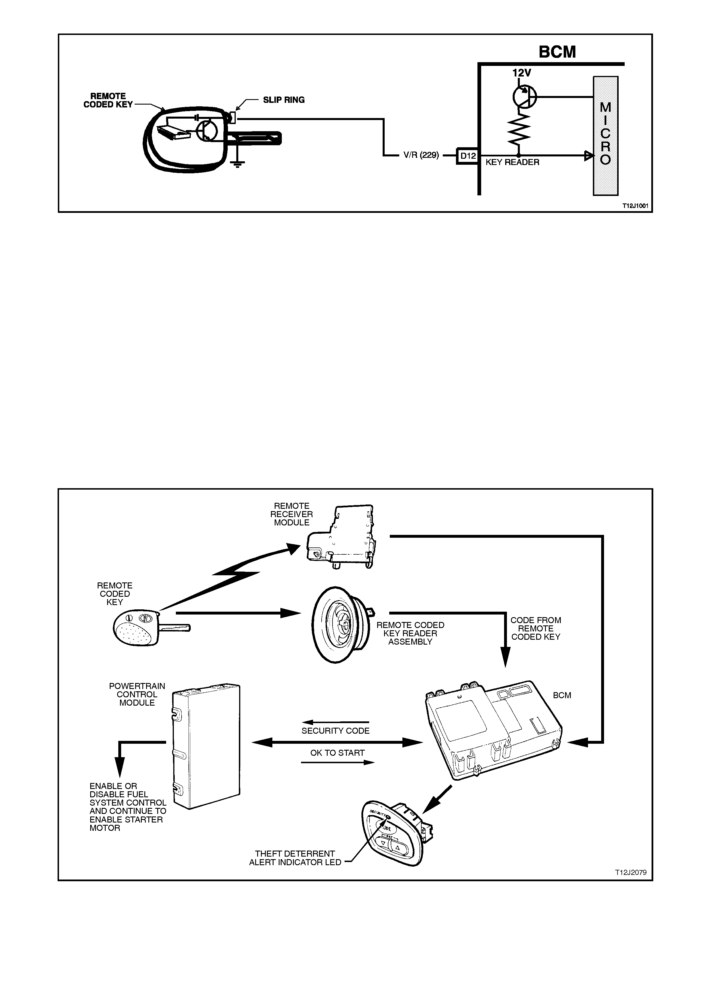
Figure 12J-1-24
THEFT DETERRENT ALERT INDICATOR LED
The theft deterrent aler t indicator LED is used to indicate the st ate of the system . A flashing LED indicates that the
system is arm ed and consequently the vehicle cannot be started. When the LED is turned of f, the BCM is disarm ed
and the engine can be started.
The theft deterrent LED is incorporated into the trip computer module in the instrument panel facia.
OPERATION
(Refer to Fig. 12J-1-25)
When the ignition switch is turned to the ON position, the BCM polls the PCM and sends an encrypted BCM/Key
security code (The security code is received via the BCM slip ring or remote receiver in the event of no slip ring
communication). The PCM compares the received security code with it’s stored security code and if the codes
match, the PCM will enable injector fuelling and continue engine cranking. The PCM will return an OK TO START
message, which tells the BCM to jump from SHORT LOOP mode to the LONG LOOP mode.
NOTE:
It is very important that the remote coded key reader is aligned correctly with the ignition lock assembly, or
misalignment with the remote coded key contact may occur resulting in intermittent or no engine cranking or
starting.
Figure 12J-1-25
SYSTEM OVERVIEW
THEFT DETERRENT SYSTEM
BATTERY POWER A6
TURN SIGNAL POWER B5
KEY READER D12
IGNITION SWITCH ON D6
DRIVER'S DOOR OPEN C8
B4 RH TURN SIGNAL
A8 THEFT DETERRENT
B12 LH TURN SIGNAL
REMOTE RECEIVER
SERIAL DATA D2
PCM
B
O
D
Y
C
O
N
T
R
O
L
M
O
D
U
L
E
CIRCUIT OPERATION
(Refer to Fig. 12J-1-30)
BATTERY POWER
(Refer to Fig. 12J-1-26)
Battery voltage is applied to the BCM microprocessor from terminal A6 at all times from fusible link FS and fuse F31
via circuit 740 (Orange/Black wire).
INDICATORS POWER
(Refer to Fig. 12J-1-26)
Battery voltage is applied to BCM terminal B5 at all times from fusible link FJ and fuse F7 via circuit 140
(Orange/Red wire).
INPUTS
IGNITION SWITCH ON INPUT SIGNAL
(Refer to Fig. 12J-1-26)
The BCM uses this input signal to determine when the ignition switch is in the IGN or START position. When the
ignition switch is in the IGN or START position, battery voltage is applied to the BCM term inal D6 from the ignition
switch and fuse F14 via circuit 39 (Pink/Black wire).
Figure 12J-1-26
BCM AND ENGINE CONTROL MODULE COMMUNICA TION (SERIAL DATA)
(Refer to Figs. 12J-1-27 and 12J-1-28)
When the ignition switch is turned to the O N position, the BCM polls the PCM and sends a s ecurity code. The PCM
compares this code with it’s stored code and if they match, the PCM will enable fuel system control and continue
engine cranking.
The serial data from the remote coded key is applied to BCM terminal D12, circuit 229 (Violet/Red wire).
Figure 12J-1-27
Figure 12J-1-28
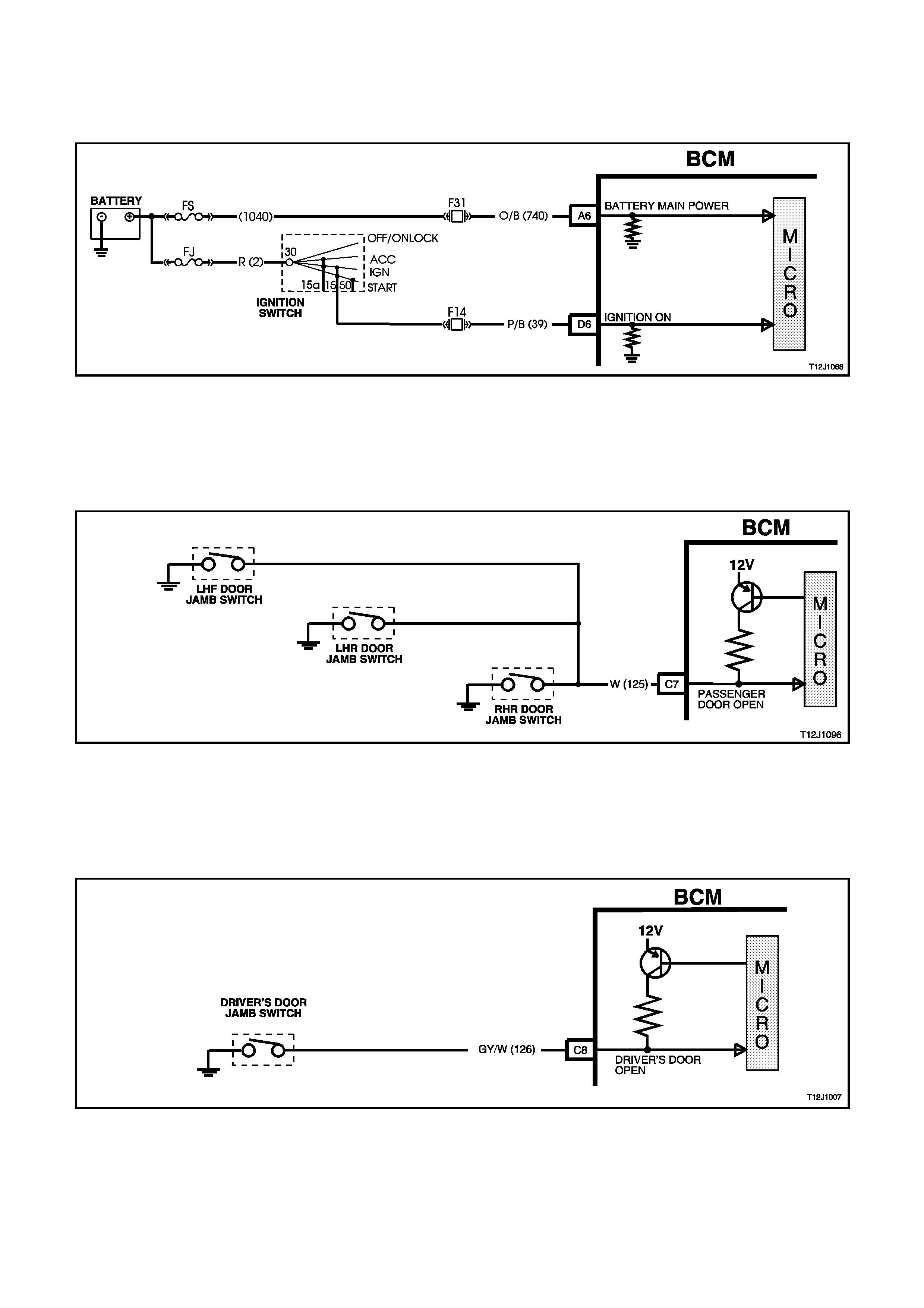
DRIVER'S DOOR JAMB SWITCH
(Refer to Fig. 12J-1-29)
The BCM uses this input signal to determine if the driver's front door is opened or closed. The BCM must sense that
the driver's door is closed before the theft deterrent system can be actively armed.
When the door is opened, the jamb switch earth’s terminal C8 via circuit 126 (Grey/White wire). This causes the
voltage at terminal C8 to be pulled low, less than 0.2 volts (driver's door open). This low voltage at terminal C8 is
seen by the BCM as the driver's door open input signal.
Figure 12J-1-29
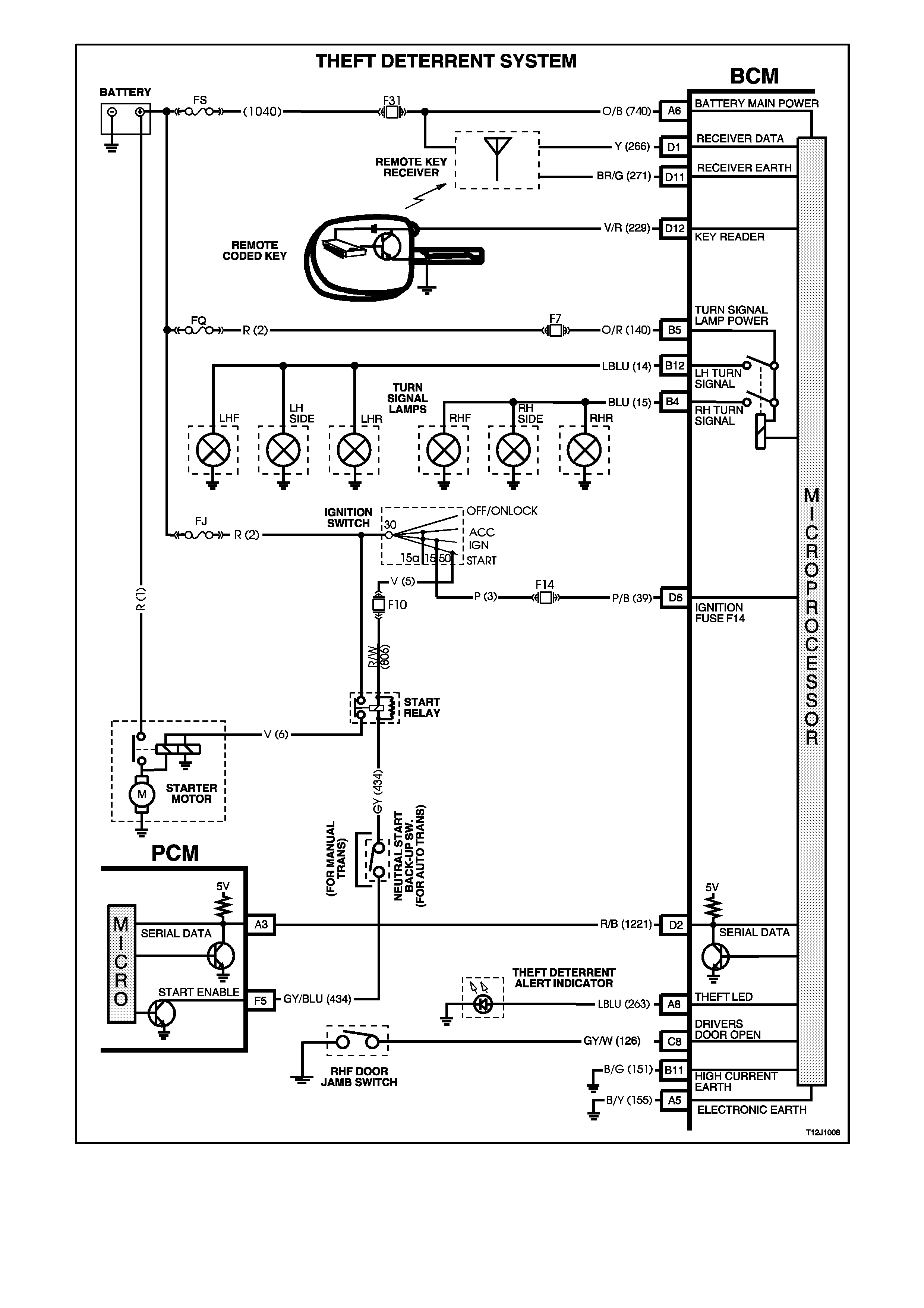
Figure 12J-1-30

OUTPUTS
LEFT HAND INDICATORS
The BCM controls the operation of the left hand indicators by pulsing its internal indicator relay. This causes the
indicator relay contacts to close and open a number of times. This allows battery voltage from terminal B5 to be
applied internally to terminal B12, to the left hand indicator lamps via circuit 14 (Light Blue wire).
RIGHT HAND INDICATORS
The BCM c ontrols the operation of the right hand indic ators in the s am e m anner as the lef t hand indicator s. Pulsing
of its internal indicator relay causes the indicator relay contacts to close and open a number of times. This allows
battery voltage from terminal B5 to be applied internally to terminal B4, to the right hand indicator lamps via circuit
15 (Blue wire).
THEFT DETERRENT ALERT INDICATOR LED
The theft deterrent alert indicator LED will continuously flash on and off whenever the system is armed. The BCM
controls the oper ation of the thef t deter rent aler t indic ator LED by pulsing an internal switch on and of f , which in tur n
switches the voltage applied to the theft deterrent alert indicator LED via terminal A8, circuit 263 (Light Blue wire).
1.5 HEATED REAR WINDOW CONTROL
GENERAL INFORMATION
This system imposes a time limit on the demisting of the rear window in order to maintain a higher state of charge of
the vehicle battery. Driver control of the demister is from the heated rear window switch located in the instrument
facia. Pressing of this momentary contact switch will toggle the heating element in the rear window on and off. The
heating is allowed to continue for 15 minutes and each new activation of the heated rear window switch resets the
delay timer.
The demisting of the rear window is only allowed when the ignition is ON, and defaults to the OFF state when the
ignition is switched from OFF to ON.
Control of the demister is via the heated rear window relay (located inside the vehicle, attached to the fuse panel)
which is in parallel with the heated rear window indicator warning lamp in the instrument cluster.
NOTE:
The circuit diagrams shown in this General Description Section are to aid in interpreting the operation of the circuit
and therefore, only the main connectors and wiring colours are shown. For complete circuits details, refer to either
the relevant diagnostic section or Section 12P WIRING DIAGRAMS.
SYSTEM OVERVIEW
B
O
D
Y
C
O
N
T
R
O
L
M
O
D
U
L
E
HEATED REAR W INDOW CONTROL
IGNITION SWITCH 'ON' D6
HEATED REAR W INDOW
SWITCH D20
A1 HEATED REAR
WINDOW RELAY & INDICATOR
BATTERY POWER A6
CIRCUIT OPERATION
(Refer to Fig. 12J-1-32)
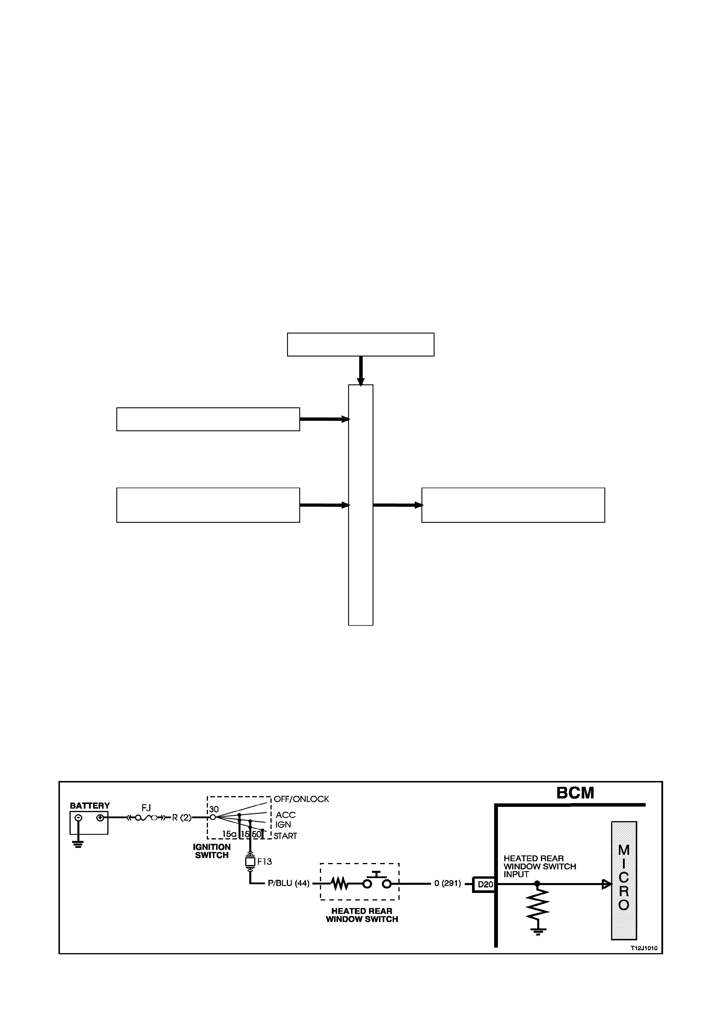
HEATED REAR WINDOW SWITCH INPUT SIGNAL
(Refer to Fig. 12J-1-31)
Pressing the heated rear window switch causes the contacts in the switch to close, connecting BCM terminal D20
through circuit 291 (Blue/Orange wire) to ignition, circuit 44 (Pink/Blue wire). This action causes the voltage at
term inal D20 to be pulled high, greater than 3.5 volts. T his high voltage at term inal D20 is seen by the BCM as the
heated rear window switch input signal.
Figure 12J-1-31
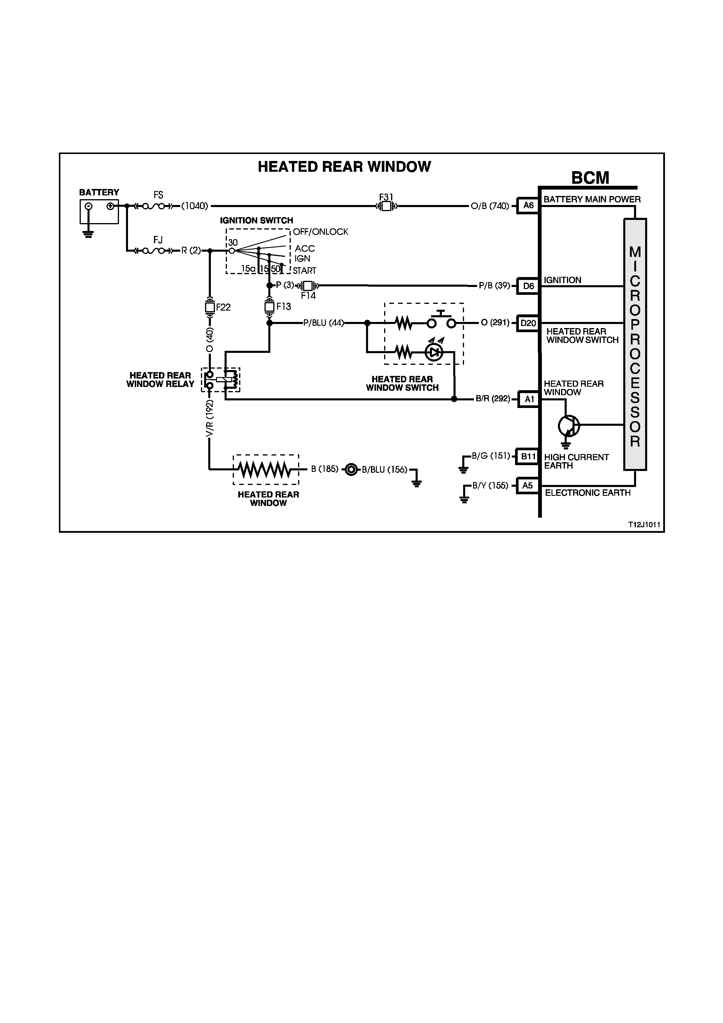
The BCM controls the operation of the heated rear window by the timer circuit turning on a transistor which then
earth’s the heated rear window relay pull-in coil circuit through BCM term inal A1, circuit 292 (Black/Red wire). This
causes the heated r ear window relay contacts to close and battery voltage from fus e F22 circ uit 40 (O range wire) to
be applied to the heated rear window circuit 192 (Violet/Red wire). The earth circuit for the heated rear window is
through circuit 185 (Black wire).
Power is supplied to the rear window relay coil by the IGN output of the ignition switch, circ uit 44 ( Pink /Blue wire) via
fuse F13. The demisting of the rear window is only allowed when the ignition is ON and defaults to OFF when the
ignition is switched from OFF to ON.
Figure 12J-1-32
1.6 POWER WINDOW SYSTEM
GENERAL INFORMATION
The BCM controls the following functions of the power window system:
1. Control of positive supply to all door window motors.
2. Automatic down of driver's door window (activated when the driver's power window switch DOWN button is
depressed for more than 0.4 seconds).
Once activated, the automatic down feature is cancelled within 100 ms (0.01 second) after:
a. The driver's power window switch UP button is depressed following which the window will move upward (if up
button is held) or:
b. The driver's power window switch DOWN button is depressed (the window will stop when the down button is
released).
c. With ignition on, power is supplied continuously to the window system.
d. When ignition is switched OFF and no door has been opened, power is supplied to the window system for a
maximum of 60 minutes.
e. In the event of any door being opened, power is supplied to the system for 45 seconds maxim um, tim ed fr om
when any door was opened.
W hen the doors are remotely unlocked (by using the rem ote coded key) power is supplied to the system f or a
60 minutes and for a maxim um of 45 seconds, onc e any door has been opened and the ignition has not been
turned ON. The delay is cancelled when the doors are locked by the remote coded key.
NOTE:
The c ircuit diagrams shown in this General Descr iption Section are to aid in interpreting the operation of the circ uit
and therefore, only the main connectors and wiring colours are shown. For complete circuit details, refer to either
the relevant diagnostic section or Section 12P WIRING DIAGRAMS.
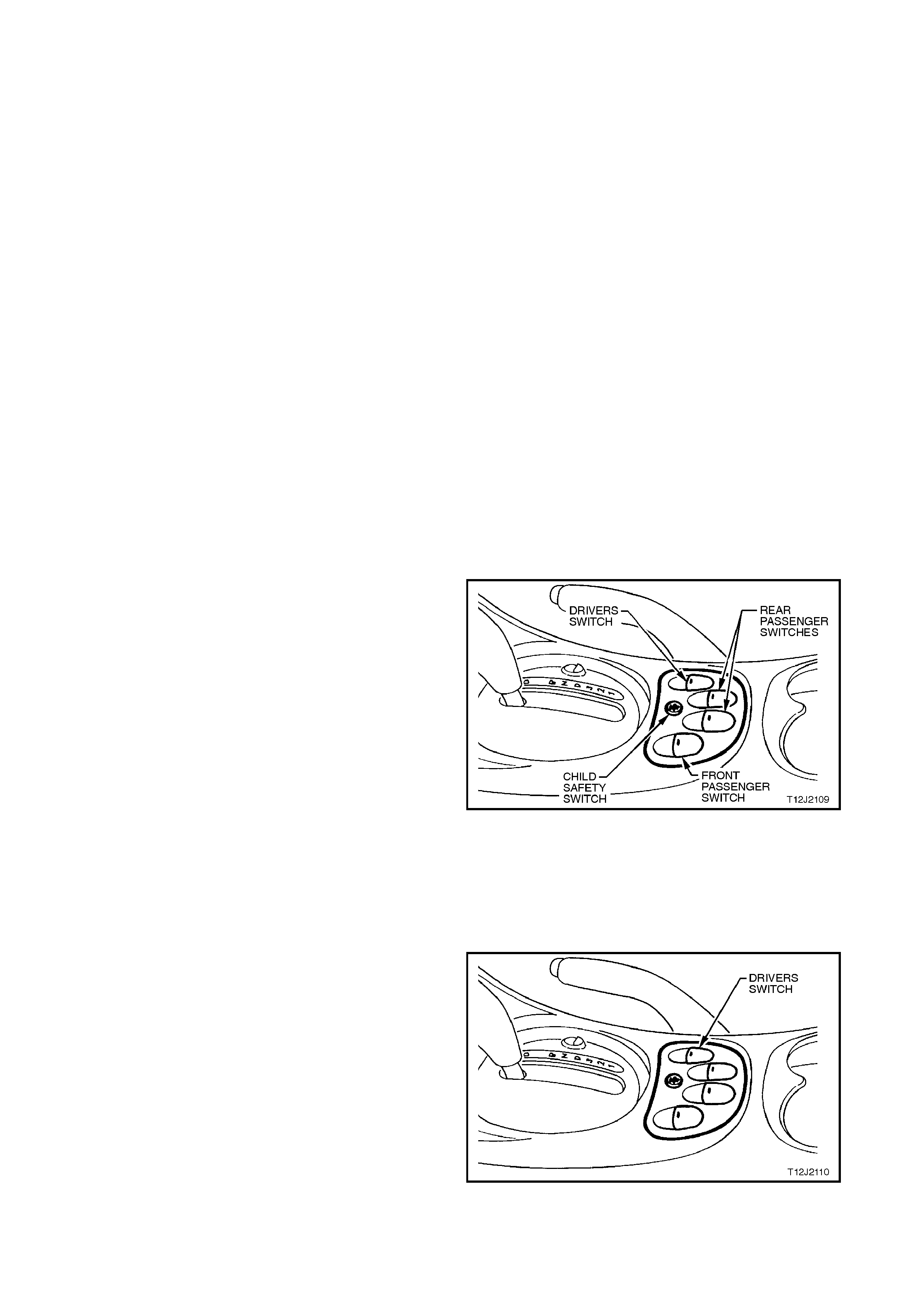
SYSTEM CHECK
PREREQUISITE CONDITION
The child safety switch must be switched OFF. This
will be indicated by the green light emitting diodes
(LED) in each of the rear door rocker switches being
illuminated.
SYSTEM ACTIVE
System active is indicated by the illumination of the
rocker switches.
When the ignition switch is turned ON, all switches
are active.
With the ignition switch turned OFF, all switches will
remain active for 45 seconds after any door is
opened.
With the ignition switch turned OFF, all switches will
remain active for approximately 60 minutes,
PROVIDED THERE ARE NO OPEN DOORS.
Figure 12J-1-33
SYSTEM INACTIVE
Lights are not illuminated.
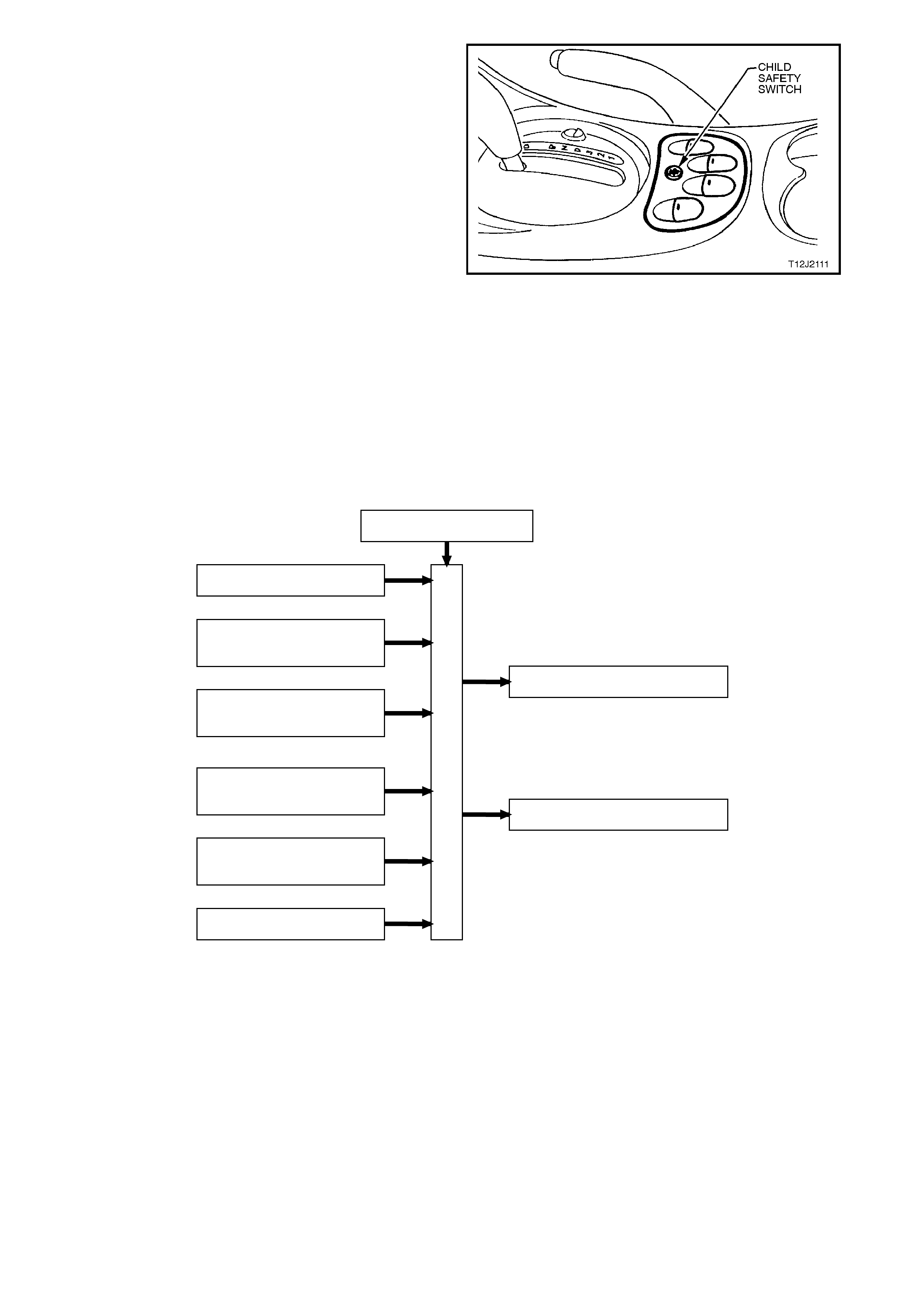
AUTOMATIC DOWN OPERATION OF DRIVER’S
WINDOW
With the driver’s window in the fully UP position and
the ignition switch turned to ON, press the driver
window switch to the window DOWN position for
more than 0.5 seconds and release.
The window will continue to lower automatically until
the fully DOWN position is reached.
To interrupt this function, press the UP button
momentarily.
Figure 12J-1-34
CHILD SAFETY SWITCH
When the child safety switch (override switch) is
OFF, the rear windows can be opened or closed from
the centre console switch assenbly or the rocker
switches in each of the rear doors.
To check the operation of this feature, proceed as
follows:
1. Ignition switched to ON.
2. Check that the green LED in each of the rear
door rocker switches is illuminated.
3. Open and close the r ear door windows using the
rocker switches in the rear doors.
4. Press the child saf ety switch button in the centre
of the switch assembly in the console as shown
in Fig. 12J-1-35.
5. Check that the green LED in each of the rear
door rocker switches extinguishes and that the
rear windows can only be raised or lowered from
the switch in the centre console.
Figure 12J-1-35
SYSTEM OVERVIEW
BATTERY POWER A6
B
O
D
Y
C
O
N
T
R
O
L
M
O
D
U
L
E
REMOTE RECEIVER
POWER WINDOW SYSTEM
IGNITION SWITCH ON D6
DRIVER'S DOOR JAMB
SWITCH C8
DRIVER'S WINDOW DOWN
SWITCH C14
DRIVER'S WINDOW UP
SWITCH C16
PASSENGER DOOR JAMB
SWITCHES C7
DRIVER'S WINDOW RELAY B2
POWER WINDOW RELAY A3
CIRCUIT OPERATION
A permanent magnet motor operates each of the power window mechanisms to raise or lower the window glass.
The direction in which the motor turns depends on the polarity of a voltage supplied to its terminals. The power
window switches, located in the centre console, or in the rear doors, control the polarity of the supply voltages.
The BCM has two main control functions in the power window system.
1. To control the operation of the power window relay and hence, power supply to the whole system.
2. To control the operation of the driver's side front window motor.
OPENING WINDOW - DRIVER'S DOOR
(Refer to Fig. 12J-1-38)
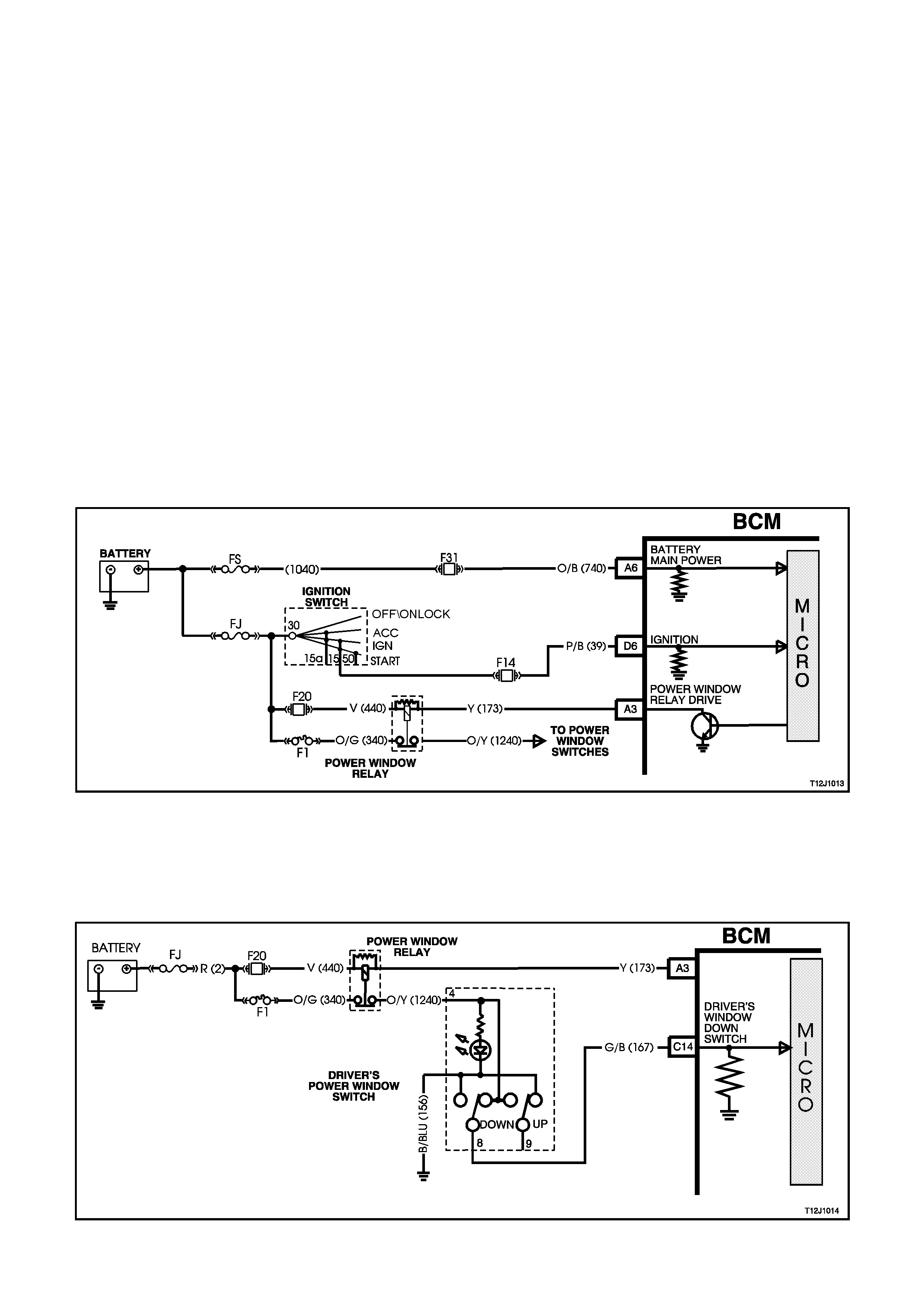
IGNITION ON INPUT SIGNAL
(Refer to Fig. 12J-1-36)
The BCM uses this input signal to determine when the ignition switch is in the IGN or START position. When the
ignition switch is in the IGN or START position, battery voltage is applied to the BCM term inal D6 from the ignition
switch and fuse F14 via circuit 39 (Pink/Black wire).
When the BCM receives an ignition on input it energises the power windows relay [voltage supplied by fuse F20
circuit 440 (Orange/Violet wire)] by earthing the relay’s pull-in coil via circuit 173 (yellow wire) and BCM terminal A3.
With the relay coil energis ed, the relay contacts clos e and power via fus ible link F J and cir cuit break er F 1 is applied
to the power window switches and each of the lights of the window switches (for rear door window switches, the
power window override switch in the RHF power window switch must be OFF). The opposite side of each light is
connected to earth, therefore the lights are illuminated (system active).
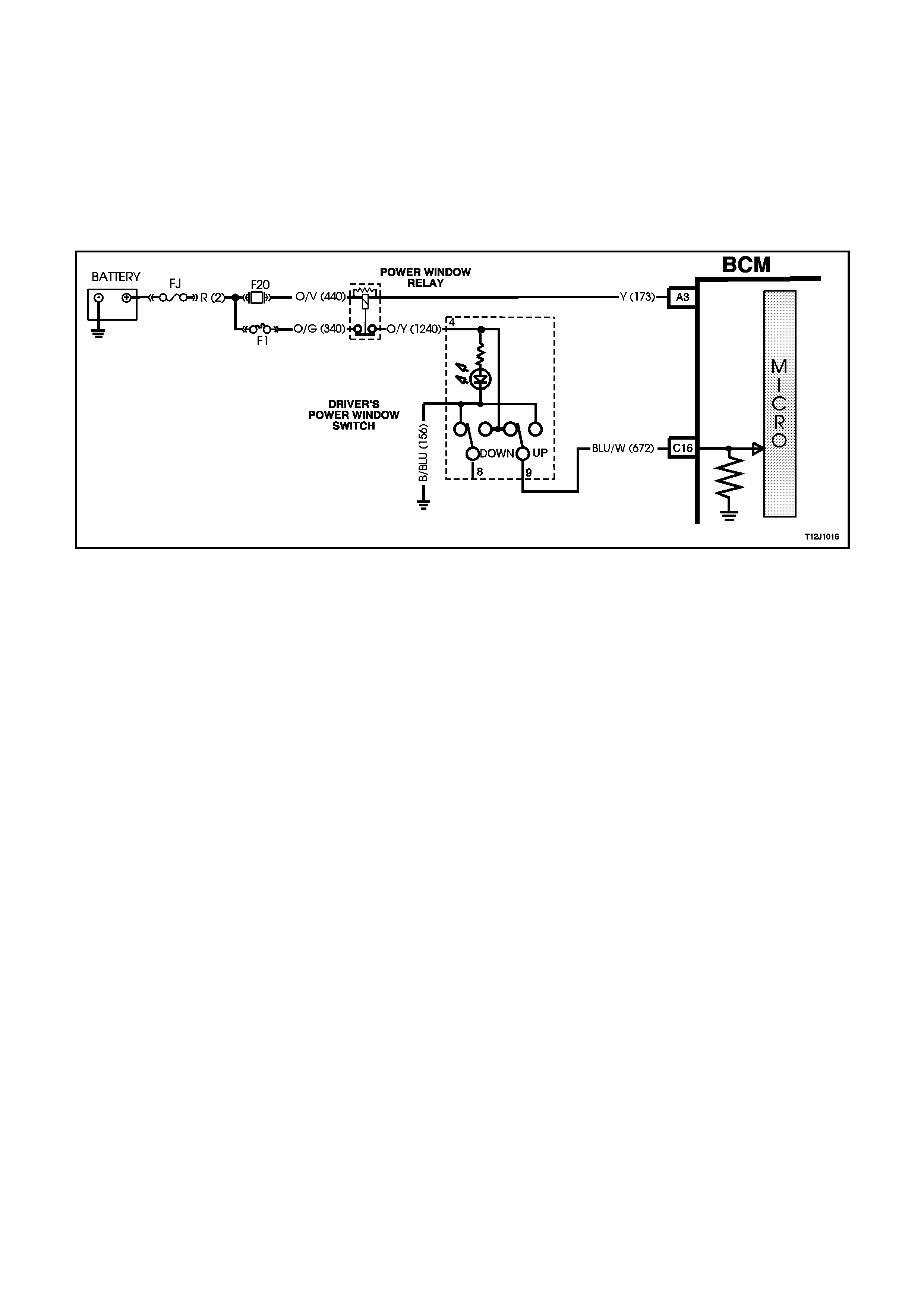
By depressing and releasing the driver's front window switch down button within 0.4 of a second (so as not to
engage the automatic down feature), this allows battery voltage from the power windows relay, circuit 1240
(Orange/Yellow wire) and the power window switch terminal 4, through to terminal 8 and then BCM terminal C14
(window down signal input).
The opposite side of the motor is connected to earth on circuit 672 (Blue/White wire) via power window switch
terminals 9 and 5 to circuit 156 (Black/Blue wire). This causes the motor arm ature to rotate, operating the window
regulator to lower the window.
As described under power windows general inf orm ation, the driver's window will automatic ally travel f ully downward
provided the power window switch down button is depressed for more than 0.4 seconds . The BCM m icroproces sor
senses the tim e the down button is depressed via ter minal C14 and energises the external relay so as to allow the
window to lower fully. The BCM senses this down signal and activates BCM terminal B2 to energise the drivers
window relay. Power is then fed through the relay (via circuit 673) and terminals 9 and 5 on the power window
switch.
Figure 12J-1-36
DRIVER'S FRONT WINDOW DOWN SWITCH INPUT SIGNAL
(Refer to Fig. 12J-1-37)
W ith the driver's front window switch down button depressed, battery voltage from the power windows relay, circ uit
1240 (Orange/Yellow wire), and the power window switch terminal 4, through to terminal 8 is applied to BCM
terminal C14 (window down signal input).
Figure 12J-1-37

When the BCM receives a driver 's f ront window down switch input signal it ener gises an ex ter nal relay. T his causes
the relay contacts to changeover, allowing battery voltage from the power windows relay contacts, to one side of the
driver's side power window motor on circuit 673 Green/Orange wire.
If the window is travelling downward and the down button is again depressed, the BCM m icroproces sor sens es this
(voltage again sensed at BCM terminal C14) and de-ener gises the external relay, the contacts open and the m otor
stops when the button is released.
Should the up button be momentarily depressed whilst the window is travelling downward, positive battery supply
connection is on both sides of the motor armature and the motor stops. If the up button is depressed whilst the
window is travelling downward, the window down function is cancelled. The window will then move upward as
described in the following text.

Figure 12J-1-38
CLOSING WINDOW
(Refer to Fig. 12J-1-40)
DRIVER'S FRONT WINDOW UP SWITCH INPUT SIGNAL
(Refer to Fig. 12J-1-39)
By depressing and holding down driver's front window up button, battery voltage from the power windows relay on
circuit 1240 (Orange/Yellow wire) is applied, via power window switch terminals 4 and 9, to the driver's side power
window motor on circuit 672 (Blue/White wire).
The opposite side to the motor on circuit 673 (Green/Orange wire) is connected to earth via the drivers window
relay, term inals 3 and 4 to earth on circuit 150 ( Black wire). This caus es the m otor arm atur e to rotate, operating the
window regulator to raise the window as long as the power window switch up button is depressed.
Figure 12J-1-39
WINDOW OPERATION - PASSENGER DOORS
Power is supplied to all the power window switches fr om the power window relay (to the rear door s witches provided
the power window override switch is off). If the power window override switch is on, (contacts between terminals 4
and 12 are open) the power supply to the rear door power window switches is interrupted.
With the switch buttons at rest, all switch contacts are connected to earth, circuit 156 (Black/Blue wire). By
depressing the appropr iate passenger's window switch down or up button, battery voltage fr om the power windows
relay, is applied to one side of the window motor , via the depres s ed switch button c ontac t. With the other s ide of the
motor connected to earth, the motor armature will rotate, operating the window regulator to raise or lower the
window as long as the window switch button is depressed.
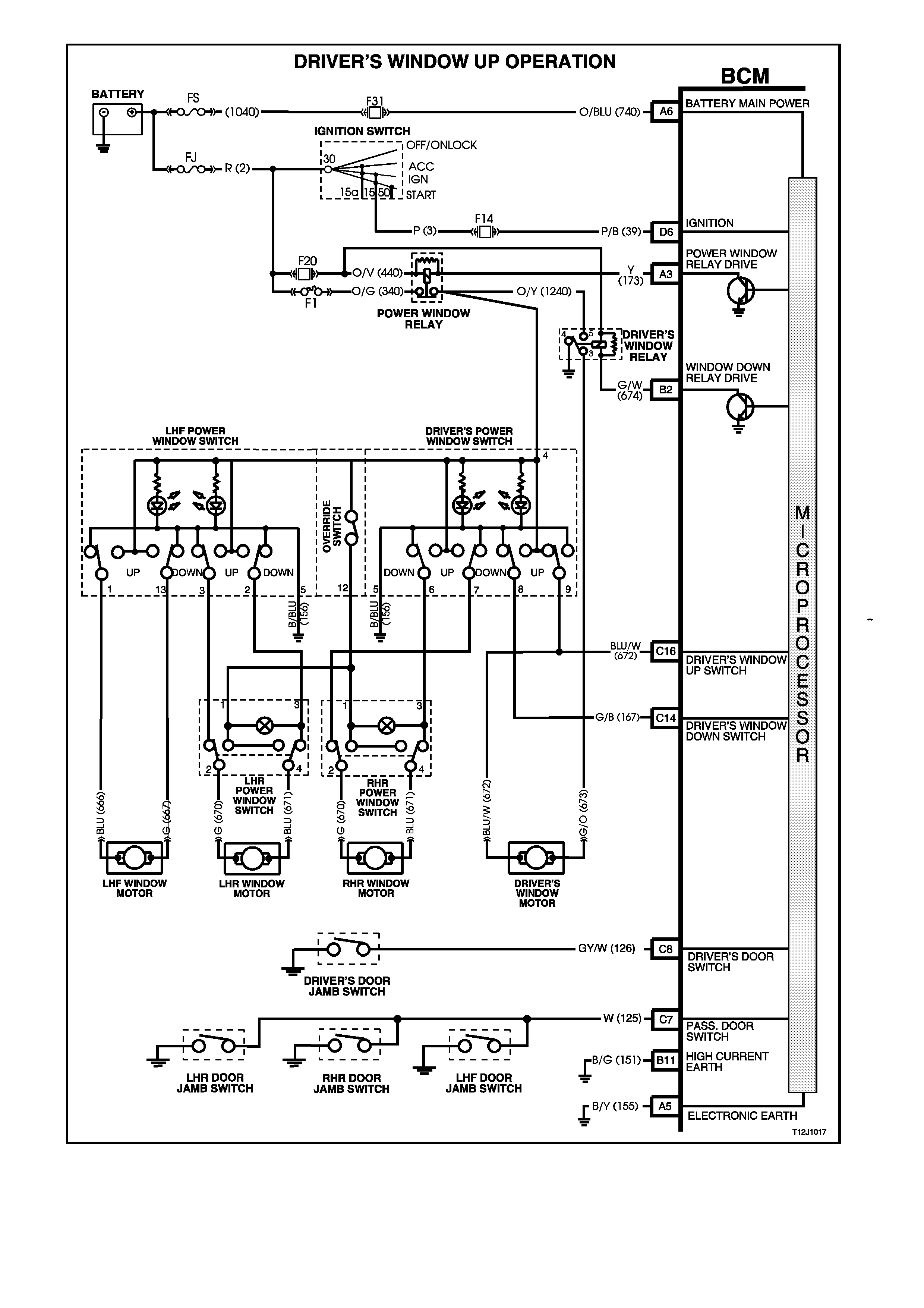
Figure 12J-1-40
1.7 ENGINE COOLING FAN, LOW SPEED CONTROL
NOTE:
The circuit diagrams shown in this General
Description Section are to aid in interpreting the
operation of the circuit and therefore, only the main
connectors and wiring colours are shown. For
complete circuits details, refer to either the relevant
diagnostic section or Section 12P WIRING
DIAGRAMS.
SYSTEM OVERVIEW
BATT ERY POWER A6
B
O
D
Y
C
O
N
T
R
O
L
M
O
D
U
L
E
A3 SERIAL DATA D2
P
C
M
A/C REQUEST
VEHICLE SPEED
B7 ENGINE COOLING LOW
SPEED FAN RELAY
ENGINE COOLANT
TEMPERATURE
GENERAL INFORMATION
(Refer to Figs. 12J-1-41 and 12J-1-42)
There are two, two speed electric engine cooling fan assemblies that provide the primary means of moving air
through the engine radiator. T hes e f ans ar e placed between the radiator and the engine and have their own shr oud.
These fans are used on all vehicles even if they are not equipped with air conditioning. There is no fan in front of the
A/C condenser.
Two, two speed electric engine cooling fans are used to cool engine coolant flowing through the radiator, and if
fitted, refrigerant flowing through the A/C condenser. The engine cooling fan motors have four terminals, two
negative and two positive terminals . T he two positive ter minals ar e per manently connected to battery voltage. W hen
one of the negative terminals is earthed, the fan motors will operate at low speed. When both negative terminals are
earthed, the fans will operate at high speed.
The two speed electric fan's low speed can be enabled when the low speed engine cooling fan m icro relay (located
in the engine compartment relay housing) is energised by the BCM via a request from the Powertrain Control
Module (PCM). T he PCM will request low speed fan enable and disable via ser ial data com munication to the BCM
on circuit 1221 (Red/Black wire). After the PCM requests a change in the state of the low speed relay (ie. OFF to
ON or ON to OFF) , the BCM will send a ser ial data response m essage back to the PCM c onfirm ing it received the
message. A failure in this response communication will set a PCM DTC.
Figure 12J-1-41
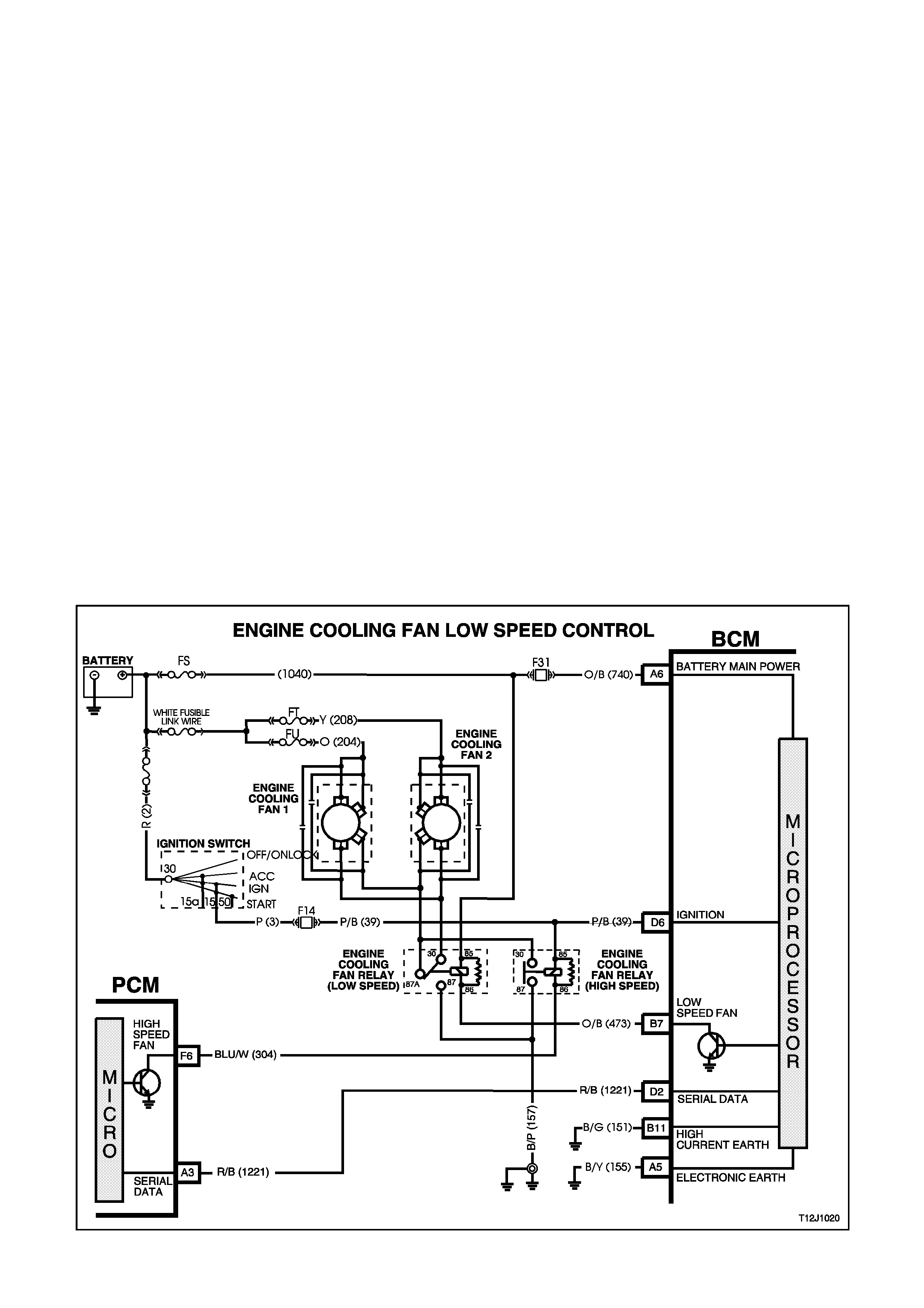
The engine cooling low speed fan relay is energised by the BCM earthing terminal B7, circuit 473 (Orange/Black
wire). This causes the relay contacts to switch over from 30-87A to 30-87 and is connected to earth via circuit 157
(Black/Pink wire), is earthed through the relay and to the low speed fan terminal on circuit 533 (Blue/Yellow wire).
The other low speed f an term inal is connected to batter y voltage via circuit 204 (Orange wire) on F AN 1 and circuit
208 (Yellow wire) on FAN 2.
The PCM determines when to enable the low speed fan r elay based on inputs f rom the A/C request signal, Cooling
Temperature Sensor (CTS) and the Vehicle Speed Sensor (VSS).
The low speed cooling fan relay will be turned ON' when:
• A/C request indicated (YES) and the vehicle speed is less than 30 km/h.
- OR -
• A/C pressure is greater than 1500 kPa.
- OR -
• Coolant temperature is greater than 104ºC. (V6) or 95ºC. (V8)
- OR -
• If the engine cooling tem per atur e is above 117ºC when the ignition switch is tur ned OF F, the relay is energis ed
for approximately 4 minutes. This is known as ‘LOW FAN RUN ON’.
• If an engine coolant temperature sensor fault is detected, such as DTC 14, 15, 16 or 17.
The PCM will request the BCM to switch off the low speed cooling fan relay when the following conditions have
been met:
• Coolant temperature less than 99ºC. (V6) or 90ºC. (V8)
• A/C request not indicated (NO).
- OR -
• Coolant temperature less than 99ºC.
• A/C request indicated (YES) and the vehicle speed greater than 50 km/h.
• A/C pressure is less than 1170 kPa.
Figure 12J-1-42

1.8 AUTOMATIC LIGHT CONTROL
GENERAL INFORMATION
The autom atic light control (lights off ) featur e is designed to autom atically switch the headlamps and par king lam ps
off when the driver leaves the vehicle.
NOTE:
Since this system is safety related, it is mandatory that in the event of a system failure, the default status of the
BCM light control output is in the on state when the ignition switch is in the IG N pos ition. T his will give direct contr ol
of the lights to the headlamp switch.
The sequence of events required to switch the lights off automatically is as follows:
1. The vehicle road speed input to the BCM indic ates s peed is les s than 10 kilom etr es per hour and ther e has not
been a sudden loss of speed (ignition being switched OFF with the vehicle travelling above 10 km/h).
2. The BCM senses that the ignition switch is turned from ON to OFF and remains in the off position.
3. The headlamp switch has not been turned on after the ignition switch was turned off.
4. The BCM senses the driver's door has been opened and turns the lights off.
W hen the ignition switch is turned back to IGN position, the lights will turn back on to the position selected by the
headlamp switch and the mode of headlamps operation [ie. high or low beam or f og lamps ( if fitted)] deter mined by
the position of the relevant switches.
Turning the headlamp switch off deactivates the auto lights system.
NOTE:
The c ircuit diagrams shown in this General Descr iption Section are to aid in interpreting the operation of the circ uit
and therefore, only the main connectors and wiring colours are shown. For com plete circuits details, ref er to either
the relevant diagnostic section or Section 12P WIRING DIAGRAMS.
CIRCUIT OPERATION
(Refer to Fig. 12J-1-43)
POWER SUPPLIES
Battery voltage is applied to the low, high beam and fog lamp (if fitted) relays from fusible link FQ, circuit 2 (Red
wire) and fuses F29 and F30.
Battery voltage is applied to the parking lam p relay from fusible link FQ circ uit 2 (Red wire) and fus e F4, circuit 840
(Orange/White wire).
The BCM controls the operation of the exterior light circuits by enabling its internal control circuit, which provides the
earth circuit for the relays.
H BEAM RELAY EARTH CIRCUIT
The earth circuit for the high beam headlamp relay is via circuit 10, (Blue/Yellow wire), through the headlamp and
turn signal control (flash/dip) switch assembly, circuit 147 (White/Black wire), headlamp switch contacts to BCM
terminal D14, circuit 1150 (Black wire) and then to earth through internal switching.
BEAM RELAY EARTH CIRCUIT
The earth circuit for the low beam headlamp relay is via circuit 103 (White wire), through the headlamp and turn
signal control ( f las h/dip) s witch as sembly, circuit 147 (White/Blac k wire), headlam p s witch c ontacts to BCM ter minal
D14, circuit 1150 (Black wire) and then to earth through internal switching.
KING LAMP RELAY EARTH CIRCUIT
The earth circuit for the parking lamp relay is via circuit 49 (Blue wire), the closed parking lamps contacts in the
headlamp switch, through BCM terminal D14, circuit 1150 (Black wire) and then to earth through internal switching.
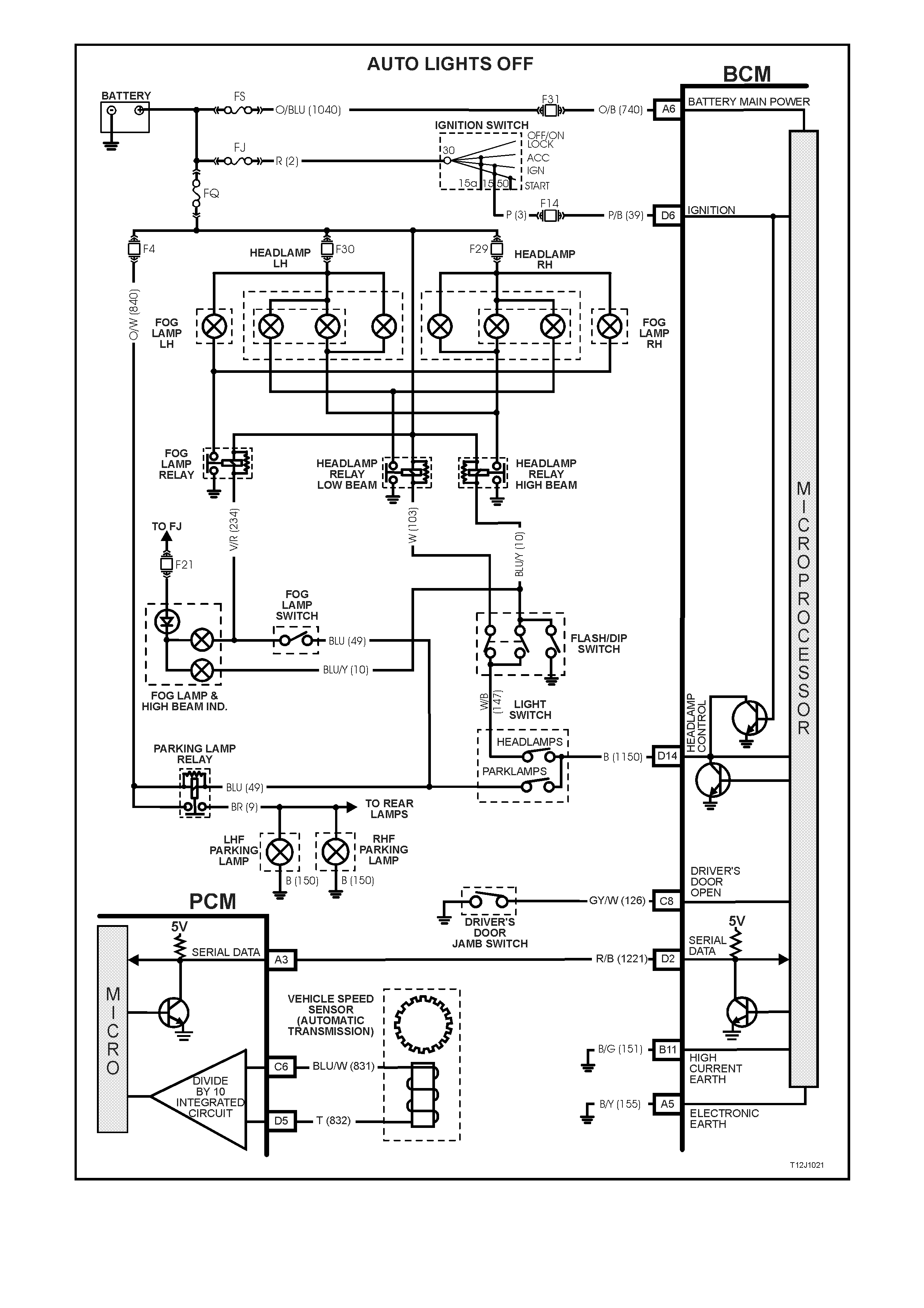
Figure 12J-1-43
SYSTEM OVERVIEW
BATTERY POWER A6
B
O
D
Y
C
O
N
T
R
O
L
M
O
D
U
L
E
HEADLAMP SWITCH D14
IGNITION SWITCH ON D6
DRIVER'S DOOR JAMB
SWITCH C8
VEHICLE SPEED SENSOR
SERIAL DATA MAIN D2
PCM
AUTO LIGHTS OFF
HEADLAMP RELAY D14
PARKING LAMP RELAY D14
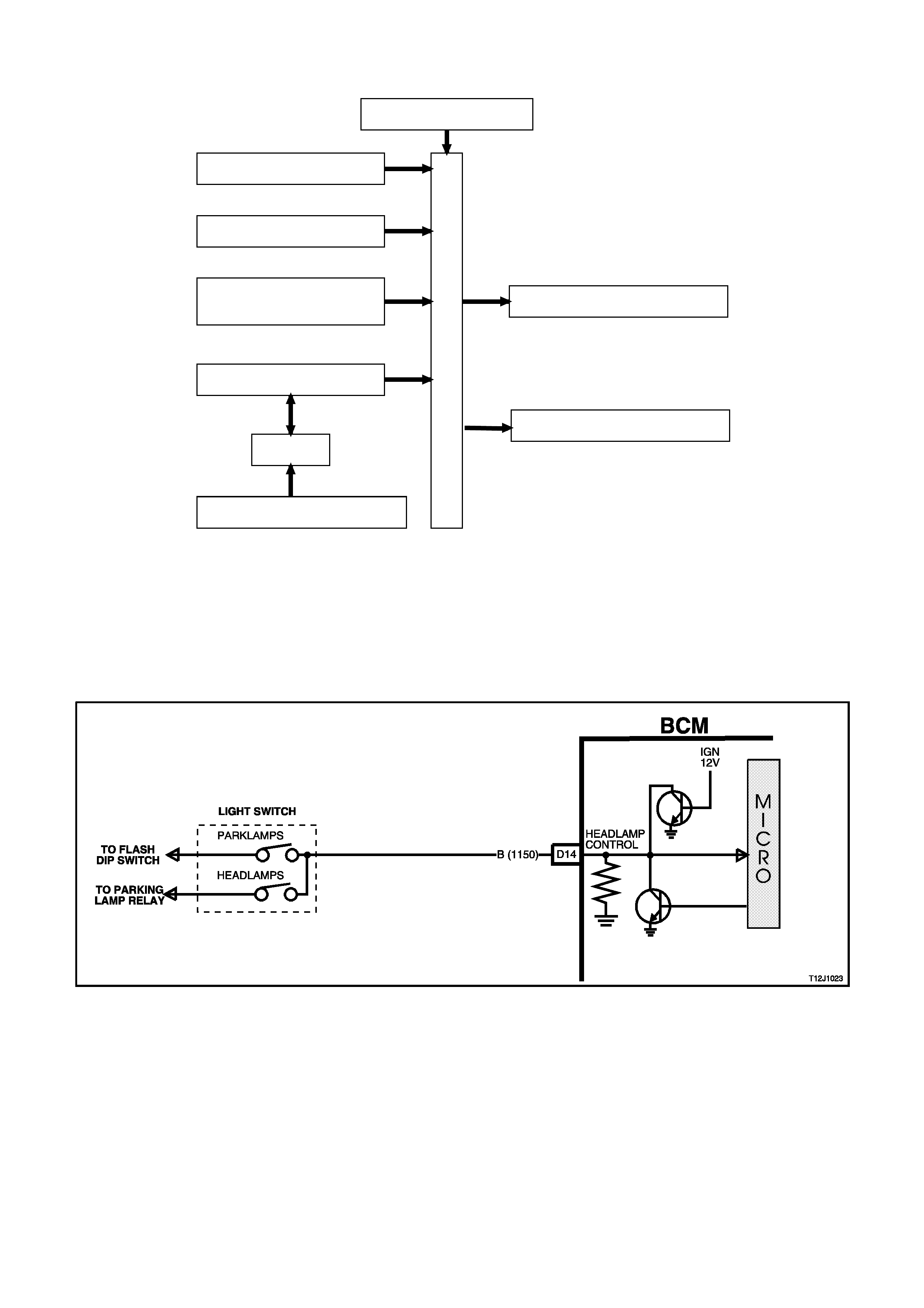
HEADLAMP CONTROL INPUT SIGNAL
(Refer to Fig. 12J-1-44)
The BCM monitors the voltage on term inal D14 to determine the pos ition of the headlamp and par king light switch.
When the headlamps or parking lights are on, the voltage at BCM terminal D14 will be less than 0.2 volts . When the
automatic lights of f s ystem has tur ned the lights of f, the voltage at ter m inal D14 will be 12 volts . If the light s witch is
turned off , the voltage at term inal D14 will be less than 0.2 volts. T he BCM sees this low voltage at term inal D14 as
a change in status of the light switch and will turn the auto lights system off. The lights will then turn back on with the
change in the position of the switch.
Figure 12J-1-44
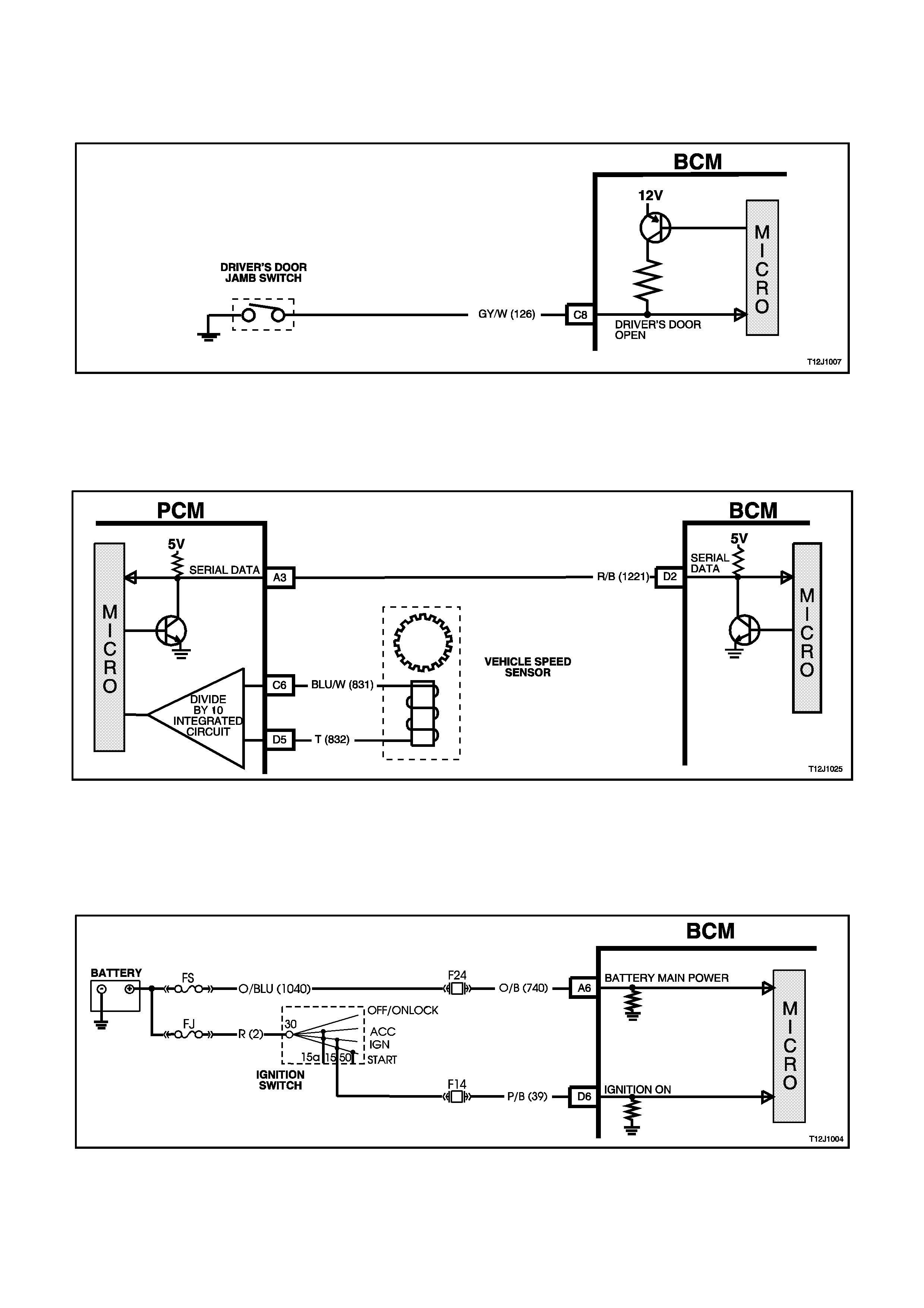
DRIVER’S DOOR OPEN INPUT SIGNAL
(Refer to Fig. 12J-1-45)
W hen the dr iver’s door is opened, BCM ter minal C8 is connected to earth via circuit 126 (White/G rey wire) and the
driver's door jamb switch. This causes the voltage at terminal C8 to pulled low, less than 0.2 volts (driver's door
open). This low voltage at terminal C8 is seen by the BCM as the driver's door open input signal.
Figure 12J-1-45
VEHICLE SPEED SIGNAL
(Refer to Fig. 12J-1-46)
BCM terminal D2, serial data bus, is connec ted to the PCM via circuit 1221 (Red/Blac k wire). It is via the ser ial data
bus line that the BCM receives data relating to the speed of the vehicle.
Figure 12J-1-46
IGNITION SWITCH ON INPUT SIGNAL
(Refer to Fig. 12J-1-47)
The BCM uses this input signal to determine when the ignition switch is in the IGN or START position. When the
ignition switch is in the IGN or START position, battery voltage is applied to the BCM term inal D6 from the ignition
switch and fuse F14 via circuit 39 (Pink/Black wire).
Figure 12J-1-47
1.9 WIPER SYSTEM
GENERAL INFORMATION
This system controls the front intermittent and rear wiper function. The wiper dwell on vehicles with low series
BCM’s uses fixed dwell periods of approximately eight seconds (this is not adjustable). The rear wipers are
synchronised to the front wipers when the front wipers are in the intermittent wipe m ode. Due to the different wipe
action between front and rear wipers, the rear wipe will start one quarter second bef ore the front wipe. Additionally,
the rear wiper will wipe continuously when the vehicle is put into reverse gear and the rear wiper switch is on
(com munication between the PCM and BCM via serial data bus). This option can be changed, via TECH 2, so the
rear wiper will wipe continuously when the vehicle is put into reverse gear and the front wiper switch is on.
The front and rear wipers employ a ‘wipe after wash’ function where, if the relevant washer pum p switch has been
pressed for more than 0.5 seconds, the wipers start sweeping at a low speed continuously until the washer pump
has been disengaged, following which, the wiper will be held on for a calculated time period so that the following
number of sweeps can be completed:
• 1 additional sweep if washer switch is pressed for less than 1 second.
• 2 additional sweeps if washer switch is pressed for less than 1.5 second.
• 3 additional sweeps if washer switch is pressed for more than 1.5 second
In order to cor rec tly perform the number of additional s weeps, the wiper motor park switch is monitored. This allows
the wiper supply power to be transferred to the park switch at the optimum time.
NOTE:
The c ircuit diagram s shown in this Gener al Descr iption Section are to aid in inter preting the operation of the circuit
and therefore, only the main connectors and wiring colours are shown. For com plete circuits details, ref er to either
the relevant diagnostic section or Section 12P WIRING DIAGRAMS.
SYSTEM OVERVIEW
WIPER MOTOR LOW SPEED A 2
REAR W IPER MOTOR A4
FRONT AND REAR W IPER SYSTEM
BATTERY POWER A6
B
O
D
Y
C
O
N
T
R
O
L
M
O
D
U
L
E
REA R WIPER
SWITCH D7
FRONT WASHER
SWITCH D18
FR ONT WIPER INTERMITTENT
SWITCH D10
WIPER MOTOR PARK
SWITCH B9
SERIAL DATA MAIN D2
PCM
REVERSE GEA R (PSA)
REA R WASHER SWITCH
SWITCH D19
CIRCUIT OPERATION
(Refer to Figs. 12J-1-53 and 12J-1-54)
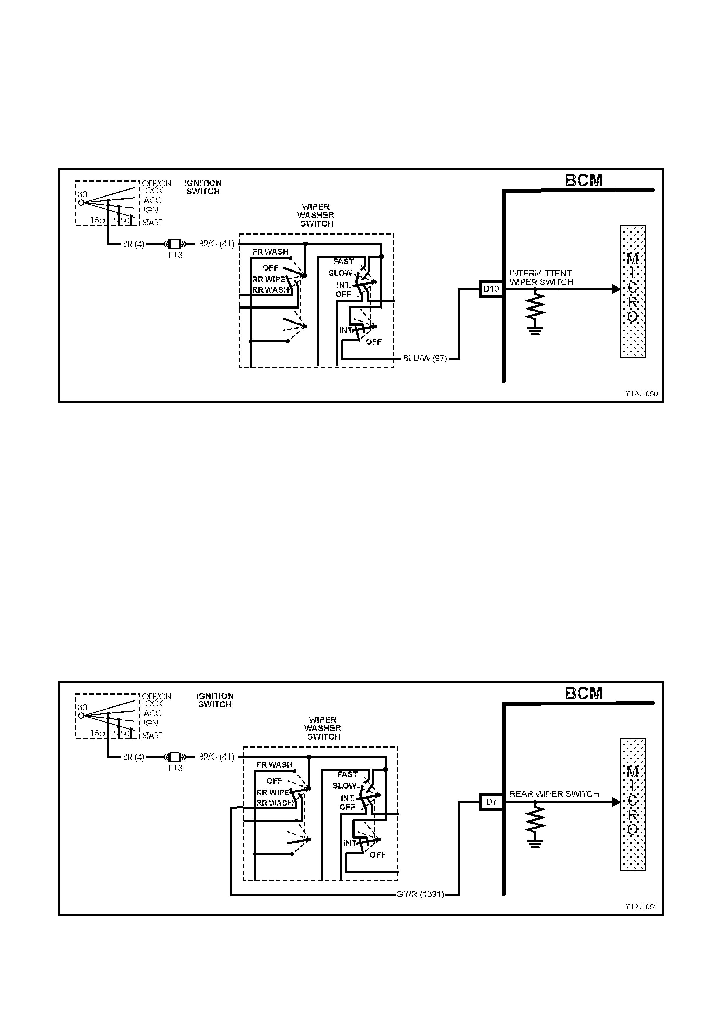
FRONT INTERMITTENT WIPER SWITCH INPUT SIGNAL
(Refer to Fig. 12J-1-48)
Placing the wiper/washer switch in the intermittent (INT) position causes battery voltage, via fusible link FJ, the
ignition switch contacts, fuse F18, circuit 41 (Brown/Green wire) and the wiper washer switch INT contacts to be
applied to BCM terminal D10, circuit 97 (Blue/White wire). This voltage at D10 is seen by the BCM as the
intermittent wiper input signal.
Figure 12J-1-48
This then enables the BCM to ener gis e the intermittent wiper relay. This c auses batter y voltage f rom f us e F18 to be
applied to the wiper motor low speed circ uit, circ uit 95 (Green wire), thr ough the wiper switch term inals to, c ircuit 91
(Grey/Red wire). This voltage will cause the wiper motor armature to rotate, which intern causes the wiper motor
park switch contacts to change over from A-B to A-C.
Once the m otor armature starts to rotate, battery voltage will be applied to BCM term inal B9 from fuse F18, circuit
41 (Brown/Green wire), through the wiper motor park s witch contacts (A and C) and circuit 196 (Yellow wire). Once
the wiper motor enters its 'parked' region the wiper park switch contacts change over from A-C to A-B, BCM
term inal B9 will now be connected to earth thr ough c irc uit 196 (Yellow wire) the wiper motor par k s witch c ontacts A-
B and circuit 152 (Black /White wire). This ac tion c auses the voltage at ter minal B9 to go fr om battery voltage to less
than 0.2 volts. T his low voltage at B9 is seen by the BCM as the park s witch input signal. T he BCM will then turn off
the intermittent wiper relay and the wiper motor will stop rotating.
REAR WIPER SWITCH INPUT SIGNA L
(Refer to Fig. 12J-1-49)
Placing the wiper washer switch in the rear wipe position causes battery voltage, via fusible link FJ, the ignition
switch contacts, fus e F18, circ uit 41 (Brown/Green wire) and the wiper washer switch rear c ontacts to be applied to
BCM terminal D7, circuit 1391 (Grey/Red wire). This voltage at D7 is seen by the BCM as the rear wiper input
signal.
Figure 12J-1-49
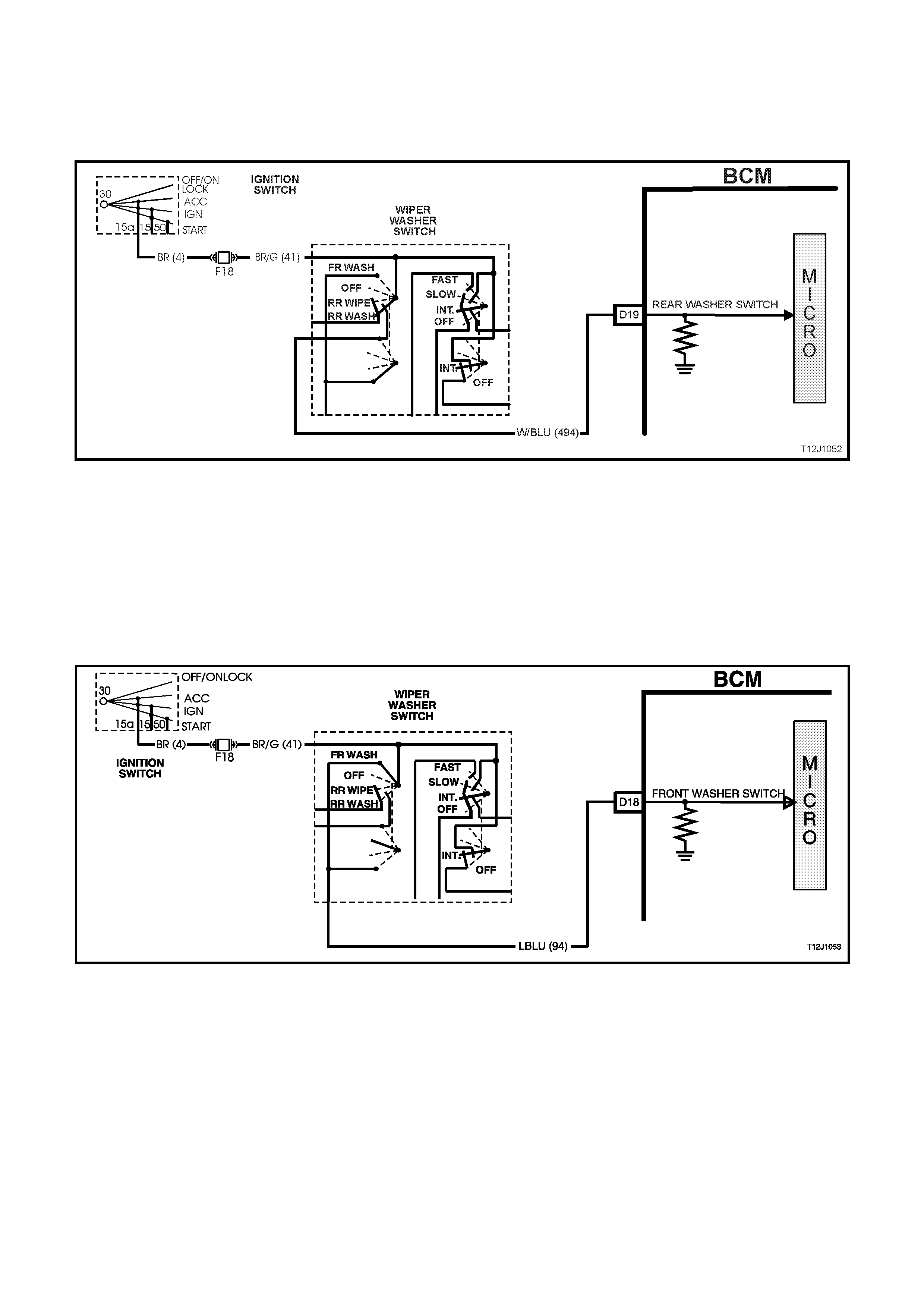
REAR WINDOW WASHER SWITCH INPUT SIGNAL
(Refer to Fig. 12J-1-50)
W hen the rear washer pump switch is activated, battery voltage is applied to the washer pump and BCM terminal
D19 from fuse F18, circuit 41 (Brown/Green wire), the washer switch contacts, circuit 494 (W hite/Blue wire). This
causes the voltage at BCM ter m inal D19 to go fr om less than 0.2 volts to 12 volts. T his voltage is s een by the BCM
as the rear washer switch input signal.
Figure 12J-1-50
FRONT WINDOW WASHER SWITCH INPUT SIGNAL
(Refer to Fig. 12J-1-51)
W hen the washer pump switch is activated, battery voltage is applied to the washer pump and BCM terminal D18
from fuse F18, circuit 41 (Brown/Green wire), the washer switch contacts, circuit 94 (Light Blue wire). This causes
the voltage at BCM terminal D18 to go from less than 0.2 volts to 12 volts . This voltage is seen by the BCM as the
washer switch input signal. T he length of time that this voltage is present at BCM term inal D18 will determ ine how
many additional wiper sweeps will occur.
The BCM determines the number of sweeps the wipers have completed by monitoring the voltage at terminal B9,
park switch input, as the voltage at B9 will go from 12 volts to less than 0.2 volts at the completion of each sweep.
Figure 12J-1-51
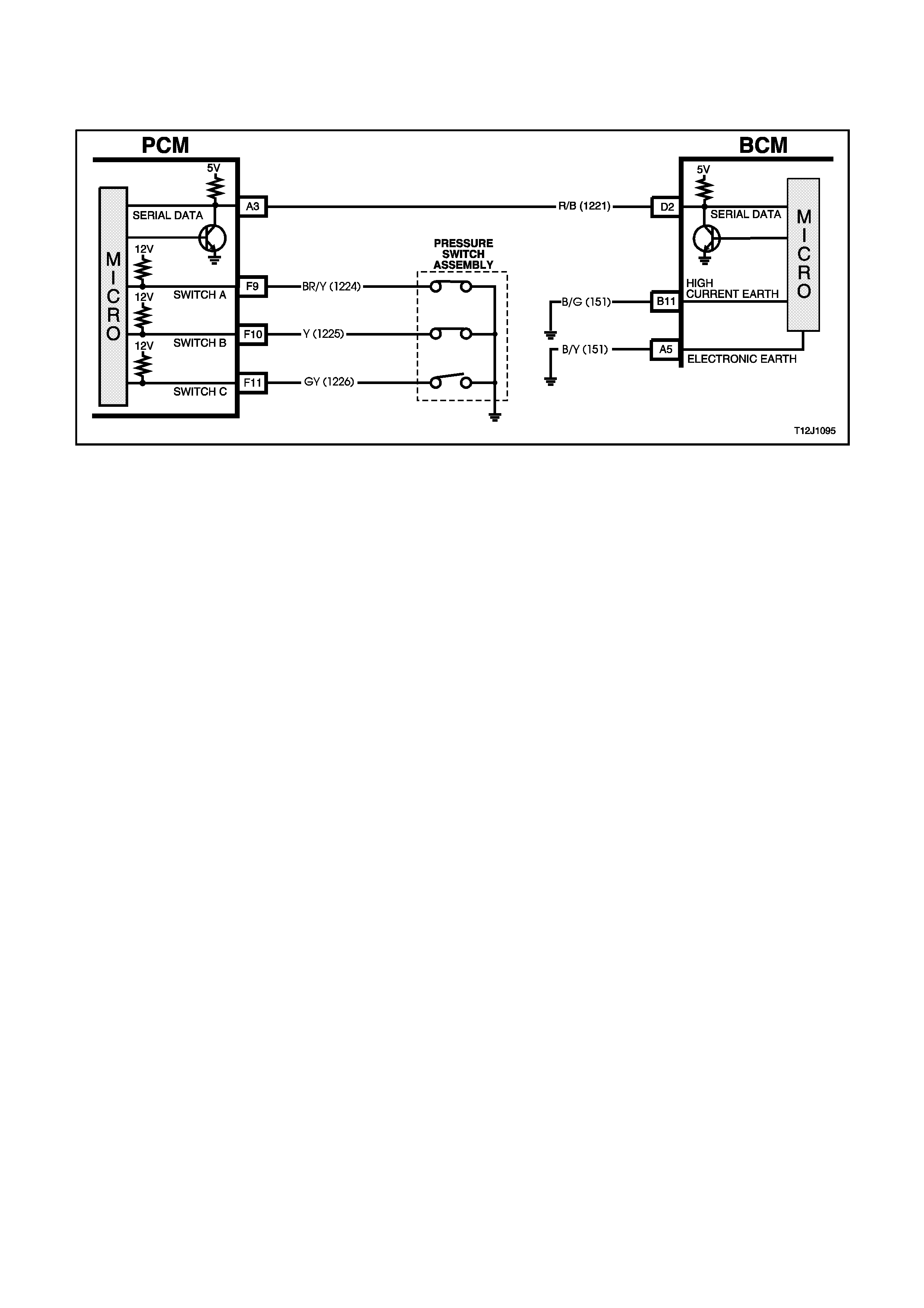
REVERSE GEAR INPUT SIGNAL
(Refer to Fig. 12J-1-52)
BCM terminal D2, serial data bus, is connec ted to the PCM via circuit 1221 (Red/Blac k wire). It is via the ser ial data
bus link that the BCM receives data relating the selection of reverse gear.
Figure 12J-1-52
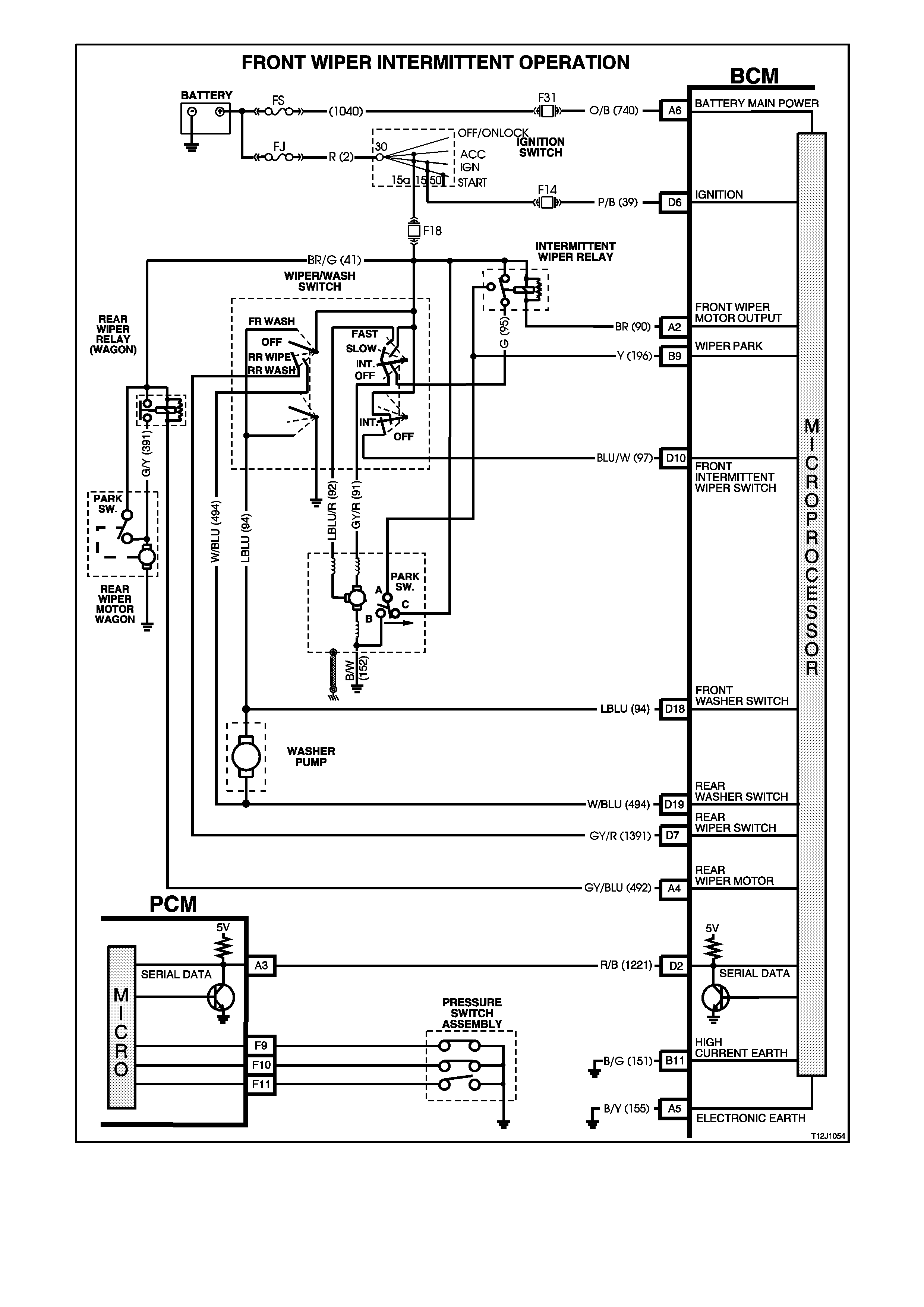
Figure 12J-1-53

Figure 12J-1-54
1.10 DOME LAMP DELAY CONTROL
GENERAL INFORMATION
(Refer to Fig. 12J-1-58)
The interior lighting is controlled by the BCM or the dome lamp switch (incorporated in the overhead lamp/switch
assem bly). The interior lighting is activated when any door is opened, unlock ed with the remote c oded k ey, or when
the dome lamp switch is operated.
The interior lighting operates continuously whilst any door is open. After all doors have been closed, the lamp
remains active for an additional 30 seconds.
If the lighting has been activated by a BCM control system or action, the dome lamp switch will turn the interior
lighting off when the dome lam p switch is switched f rom DOOR to OF F. T his m eans that the switch can c urtail any
delay time initiated as well as switch the lighting off whilst a door is open. With the dome lamp switch in the ON
position, BCM control of the interior lighting is overridden.
The interior lighting is s witched on upon c entral door unloc king for 30 s ec onds . If the ignition is turned on dur ing this
delay, the interior lighting will be switched off immediately. Interior lighting is also switched off upon central door
locking, except if the dome lamp switch is turned on or if a passenger door is open. It will then be extinguished
when all doors are closed.
NOTE:
The c ircuit diagrams shown in this General Descr iption Section are to aid in interpreting the operation of the circ uit
and therefore, only the main connectors and wiring colours are shown. For complete circuit details, refer to either
the relevant diagnostic section or Section 12P WIRING DIAGRAMS.
SYSTEM OVERVIEW
B
O
D
Y
C
O
N
T
R
O
L
M
O
D
U
L
E
C24 DOME LAMP
DO ME LAMP D E L AY
BATTERY POWER A6
IGNITION SWITCH ON D6
REMOTE RECEIVER D1
PASSENGER DOOR JAMB
SWITCHES C7
DRIVER'S DOOR JAMB
SWITCH C8
CIRCUIT OPERATION
Battery voltage is applied to all interior lamps via f us e F 6 and c irc uit 1140 (O r ange/Black wire). The oppos ite s ide of
the dome lamps are connected to earth via circuit 174 (White/Green wire) and BCM terminal C24. The BCM
controls the operation of the dome lamps connected to this earth by energising its internal dome lamp relay contacts
to close, completing the circuit to earth.
IGNITION SWITCH ON INPUT SIGNAL
(Refer to Fig. 12J-1-55)
The BCM uses this input signal to determine when the ignition switch is in the IGN or START position. When the
ignition switch is in either of these positions, battery voltage is applied to the BCM terminal D6 from the ignition
switch and fuse F14 via circuit 39 (Pink/Black wire).
Figure 12J-1-55
PASSENGER DOOR OPEN INPUT SIGNAL
(Refer to Fig. 12J-1-56)
When any passenger door is opened, BCM terminal C7 is connected to earth via circuit 125 (W hite wire) and the
passenger door jamb switch. This c aus es the voltage at ter minal C7 to be pulled low, less than 0.2 volts (pas s enger
door open). This low voltage at terminal C7 is seen by the BCM as the passenger door open input signal.
Figure 12J-1-56
DRIVER’S DOOR OPEN INPUT SIGNAL
(Refer to Fig. 12J-1-57)
W hen the dr iver’s door is opened, BCM ter minal C8 is connected to earth via circuit 126 (G rey/White wire) and the
driver’s door jam b switch. This causes the voltage at ter minal C8 to be pulled low, les s than 0.2 volts ( driver’s door
open). This low voltage at terminal C8 is seen by the BCM as the driver’s door open input signal.
Figure 12J-1-57
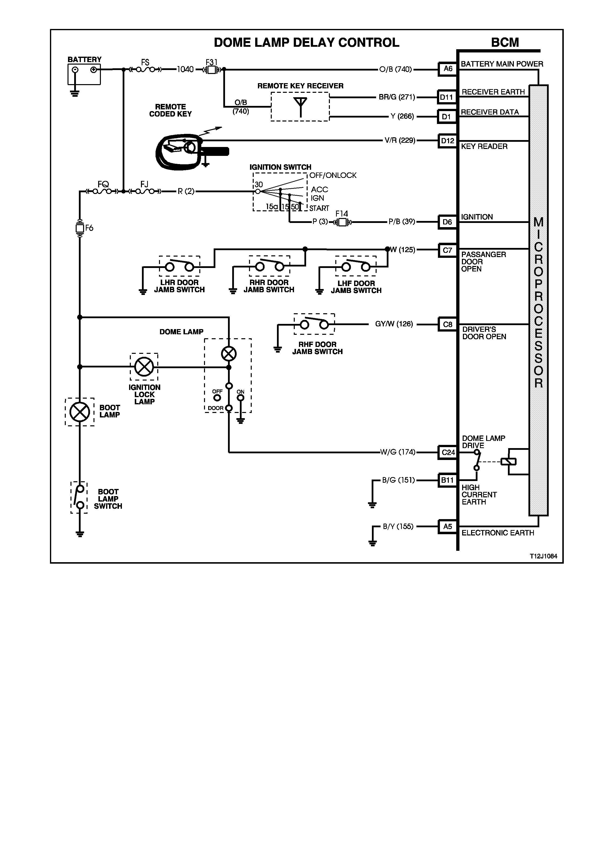
Figure 12J-1-58
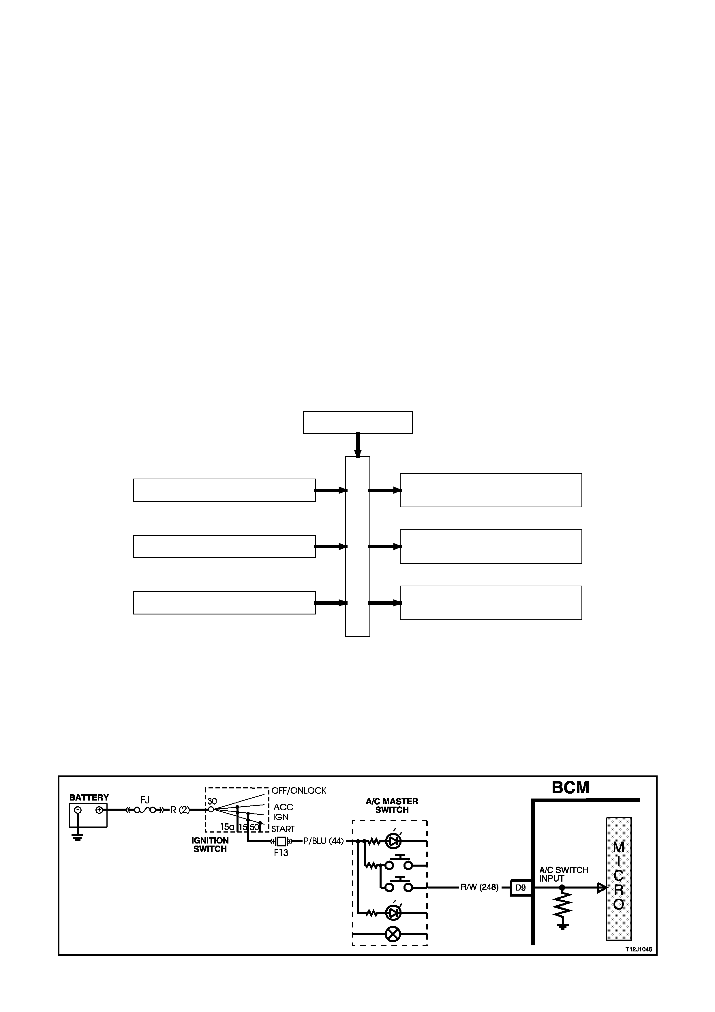
1.11 AIR CONDITIONING INTERFACE
GENERAL INFORMATION
The air-c onditioning interf ace is us ed to turn the air c onditioning system on and of f. T he BCM reads the m om entary
air conditioning switch signal, m onitors f an speed and, if the ignition is on, then r equests the PCM to turn on the air
conditioning compressor, via the serial data bus, normal mode m essage The air conditioning status LED is turned
on by the BCM when the air conditioning system is active (if the ignition is turned on) and will toggle with the air
conditioning select switch. The status will be remembered when the ignition is switched from ON to OFF or when
the blower is off but will reset to off when the battery is disconnected. If the blower is off and the air conditioning
select button is pressed, then the next tim e the blower is s witched on, the air conditioning status will also com e on.
Turning the ignition off will cancel this button press function.
The blower fan is controlled by the blower fan inhibit relay, which suspends blower fan operation during cranking
(via the acces sories feed to this control relay). The BCM blower inhibit relay control output will only allow operation
with the ignition in the ON position and ther efore, inhibit the operation of this relay while the ignition switch is in the
ACC position.
NOTE 1:
The BCM has provis ion f or an air c onditioning ther mostat to pr event the evapor ator f r om icing up. In the abs ence of
this thermostat, the input is connected to ignition.
NOTE 2:
The c ircuit diagrams shown in this General Descr iption Section are to aid in interpreting the operation of the circ uit
and therefore, only the main connectors and wiring colours are shown. For complete circuit details, refer to either
the relevant diagnostic section or Section 12P WIRING DIAGRAMS.
SYSTEM OVERVIEW
IGNITION SW ITCH D6
B
C
M
BLOW ER FAN B3
A IR CONDITIONING SWITCH D9
BA TTERY POWER A6
AIR CONDITIONING INTERFACE
B8 A IR CONDITIONING
STA TUS LED
B1 A IR CONDITIONING
INHIBIT RELAY
D2 SERIAL DATA
MAIN
CIRCUIT OPERATION
(Refer to Fig. 12J-1-62)
AIR CONDITIONING SWITCH INPUT SIGNAL
(Refer to Fig. 12J-1-59)
Activating the air conditioning switch causes battery voltage, via the ignition switch contacts, fuse F13 circuit 44
(Pink/ Blue wire) and the air conditioning switch to be applied to BCM term inal D9. T his voltage is s een by the BCM
as the air conditioning switch input signal.
Figure 12J-1-59
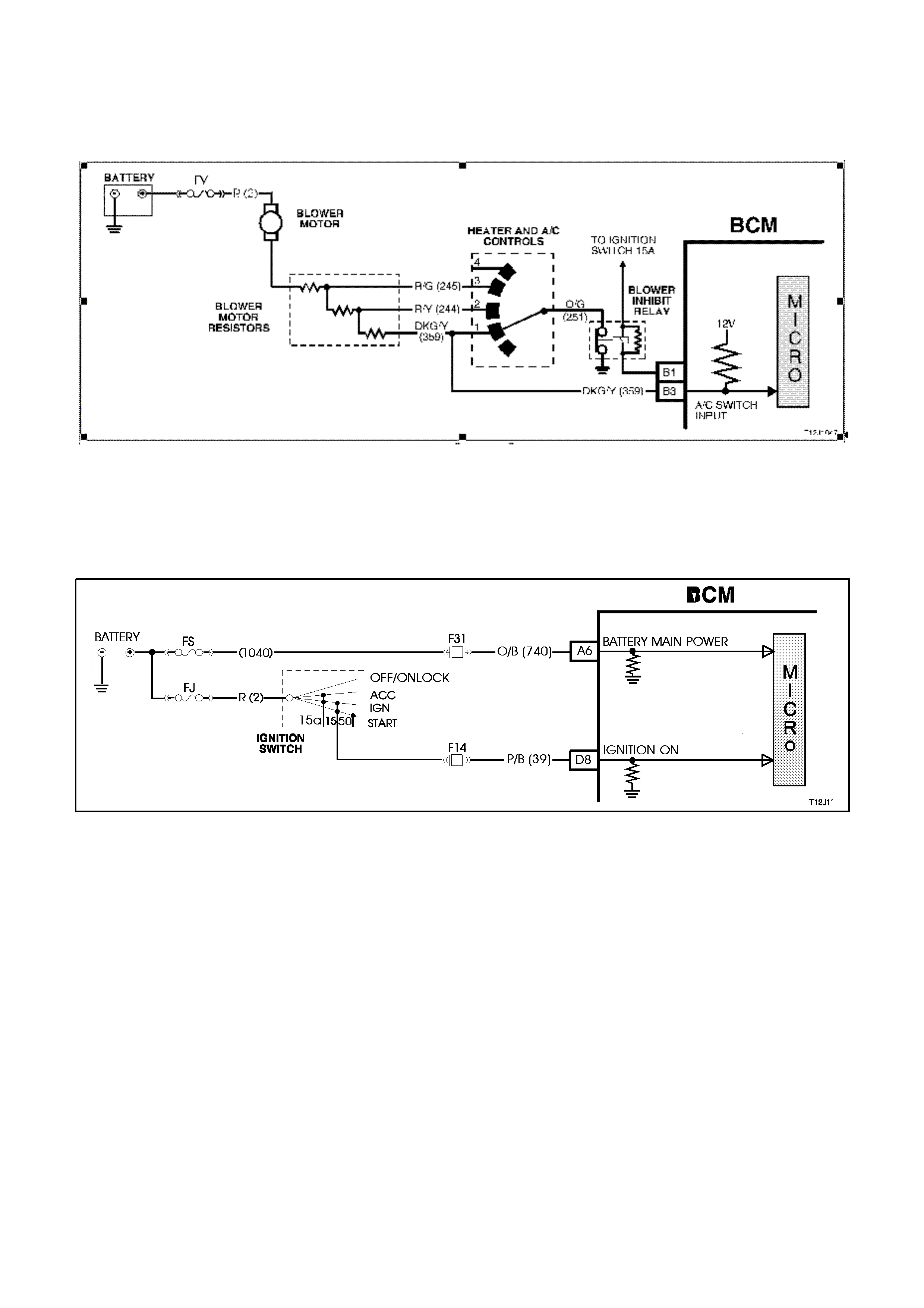
BLOWER MOTOR INPUT SIGNAL
(Refer to Fig. 12J-1-60)
The blower motor input signal m onitors the operating state of the blower m otor. W hen the blower motor is running
the BCM input B3 is pulled to ground via circuit 359 (Dark Green/Yellow wire), the blower switch, circuit 251
(Orange/G reen wire) and the blower inhibit relay. This will cause the voltage at BCM term inal B3 to go from battery
voltage to less than 0.3 volts. This low voltage is seen by the BCM as meaning the blower is on.
Figure 12J-1-60
IGNITION SWITCH ON INPUT SIGNAL
(Refer to Fig. 12J-1-61)
The BCM uses this input signal to determine when the ignition switch is in the IGN or START position. When the
ignition switch is in the IGN or START position, battery voltage is applied to the BCM term inal D6 from the ignition
switch and fuse F14 via circuit 39 (Pink/Black wire).
Figure 12J-1-61
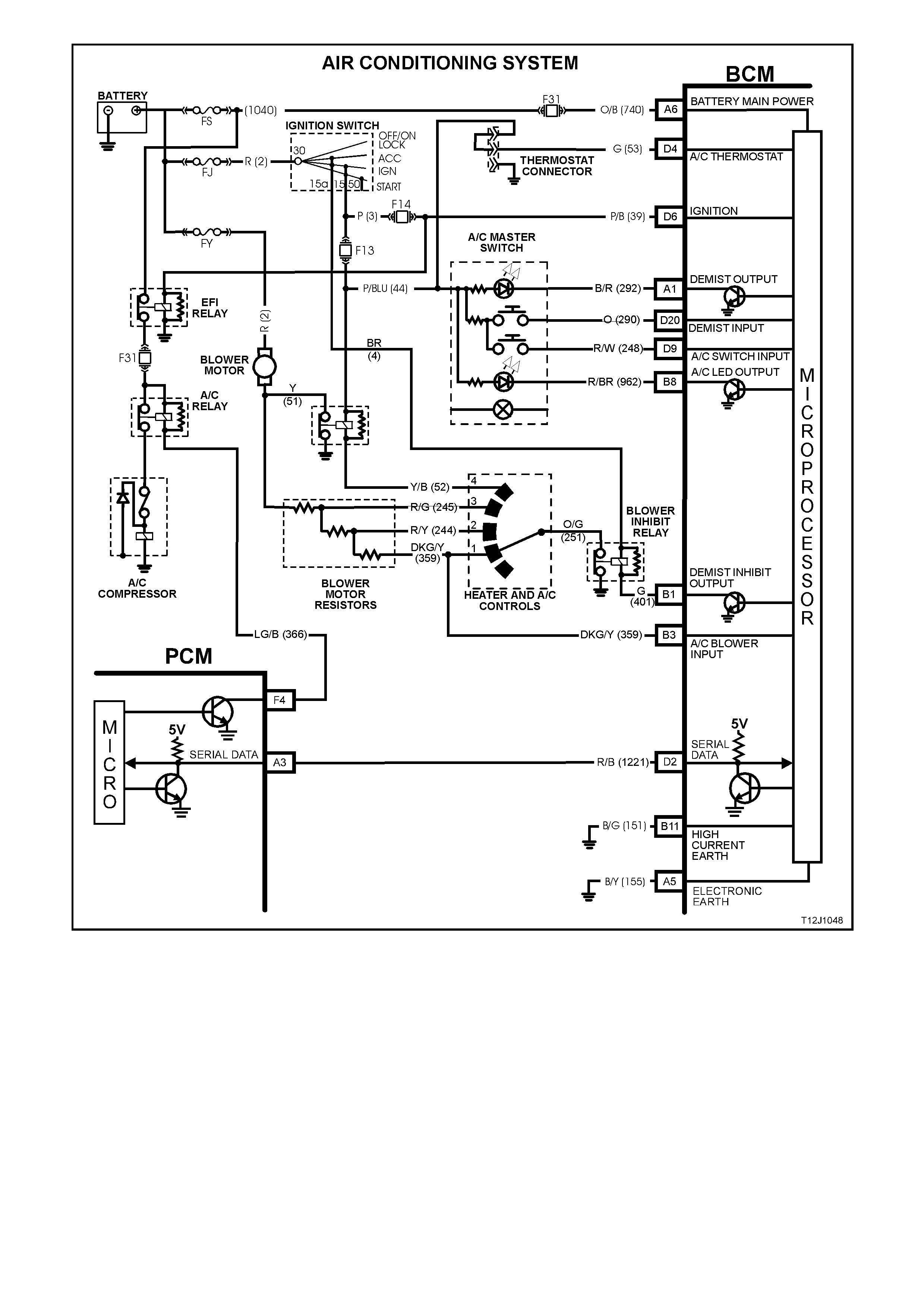
Figure 12J-1-62
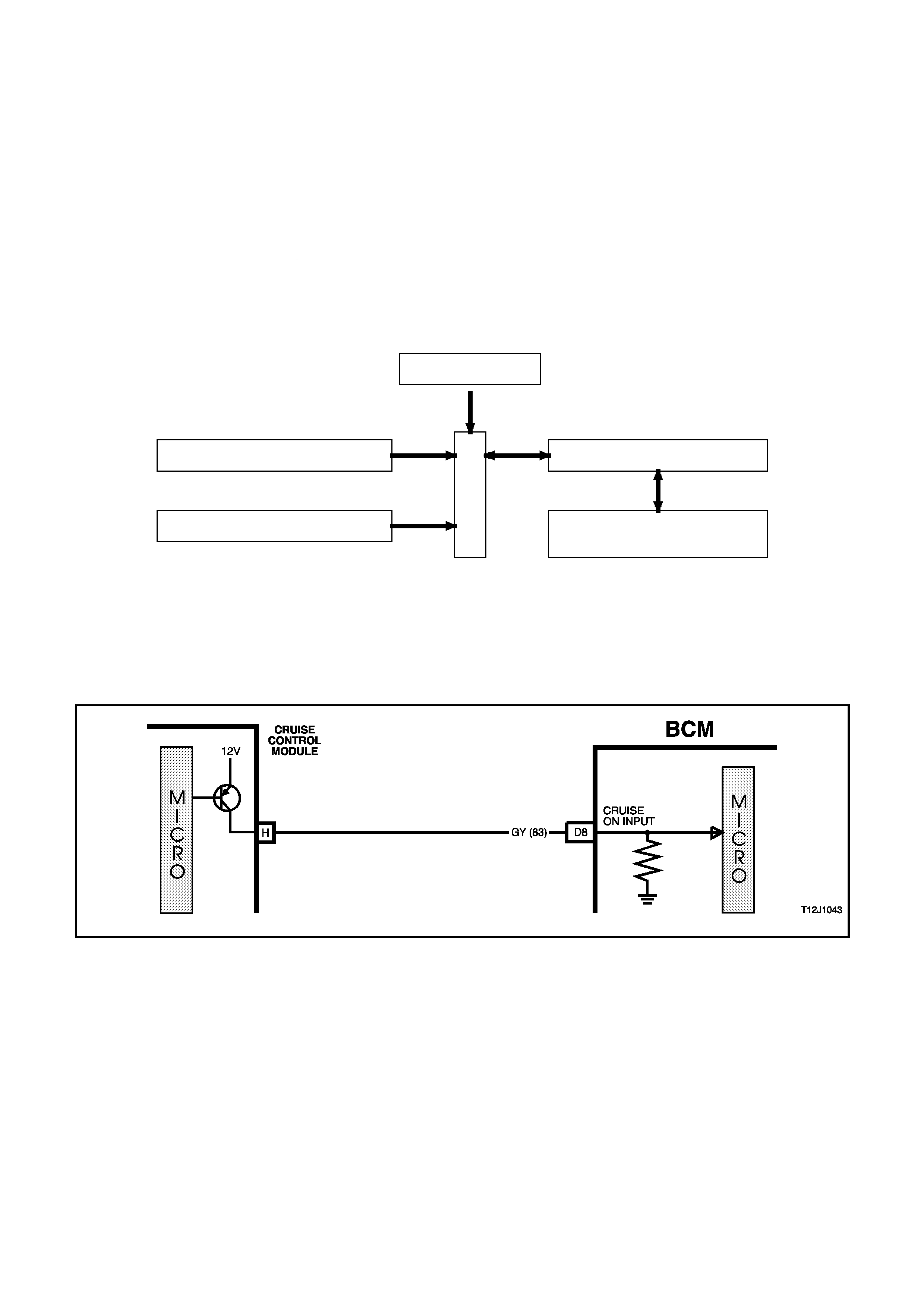
1.12 CRUIS E CONTROL INTERFACE
GENERAL INFORMATION
The cruise control module uses an input on the BCM to send a serial data message to the instruments.
When the cruise control module is powered up via the cruise control on/off switch the cruise control module
activates an input of the BCM. The BCM sees this line as active and sends a serial data m es sage to the instr um ent
cluster to turn it’s ‘cruise on’ lamp on.
NOTE:
The c ircuit diagrams shown in this General Descr iption Section are to aid in interpreting the operation of the circ uit
and therefore, only the main connectors and wiring colours are shown. For complete circuit details, refer to either
the relevant diagnostic section or Section 12P WIRING DIAGRAMS.
SYSTEM OVERVIEW
B
C
M
CRUISE CONTROL INTERFACE
BATTERY POWER A6
D3 SERIAL DATAIGNITION SWITCH ON D6
CRUISE ON D8 INSTRUMENTS
CRUISE ON LAMP
CIRCUIT OPERATION
(Refer to Figs. 12J-1-63 and 12J-1-64)
When the cruise control is turned on, the cruise control module activates its cruise ‘on’ output to the BCM. The BCM
input D8, circuit 83 (Grey wire) rises from less than 0.2 volts to approxim ately battery voltage. W hen this happens,
the BCM senses this as a ‘cruise on’ signal and communicates (via the auxiliary serial data bus) with the
instruments to turn the ‘cruise on’ lamp.
Figure 12J-1-63
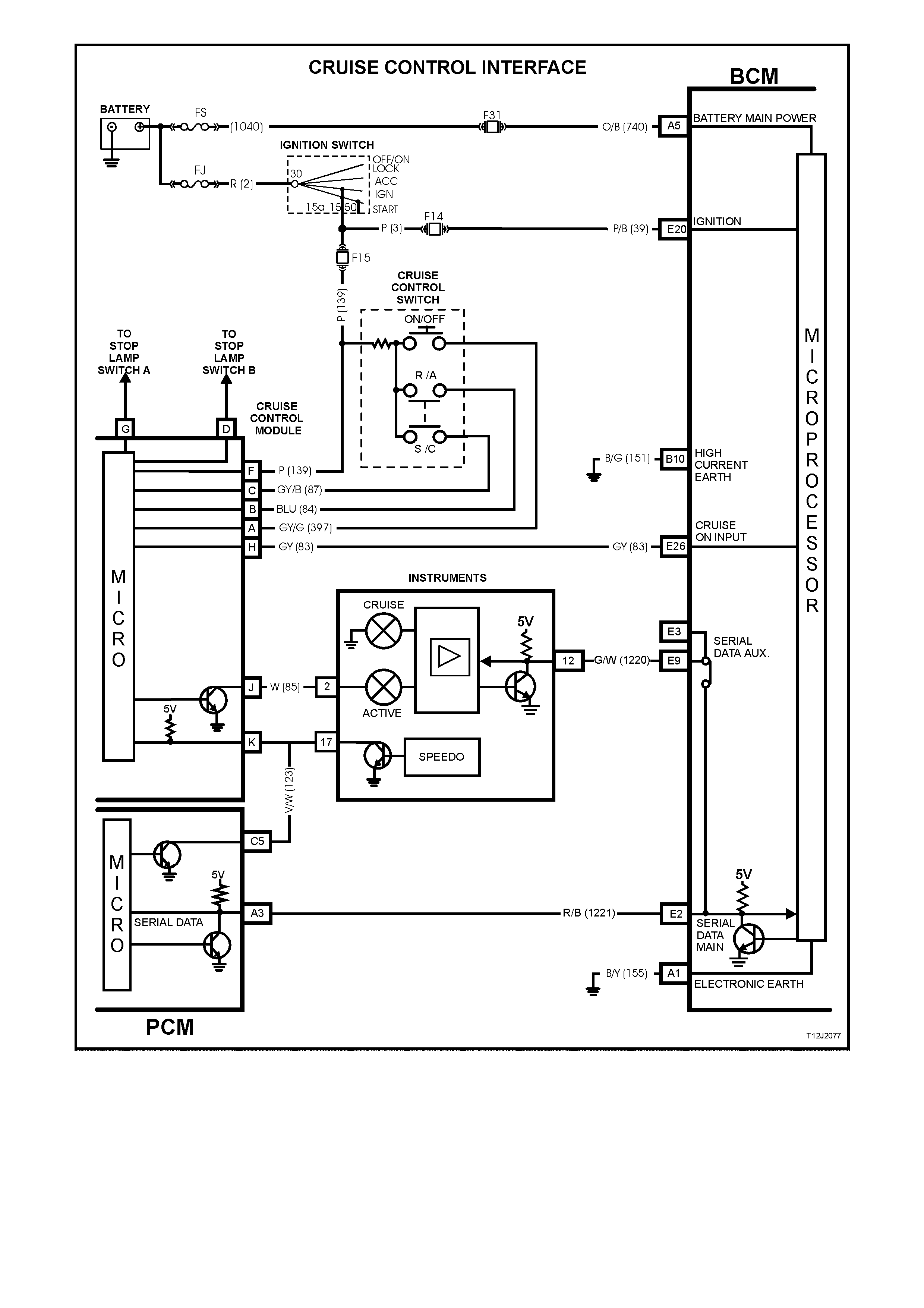
Figure 12J-1-64
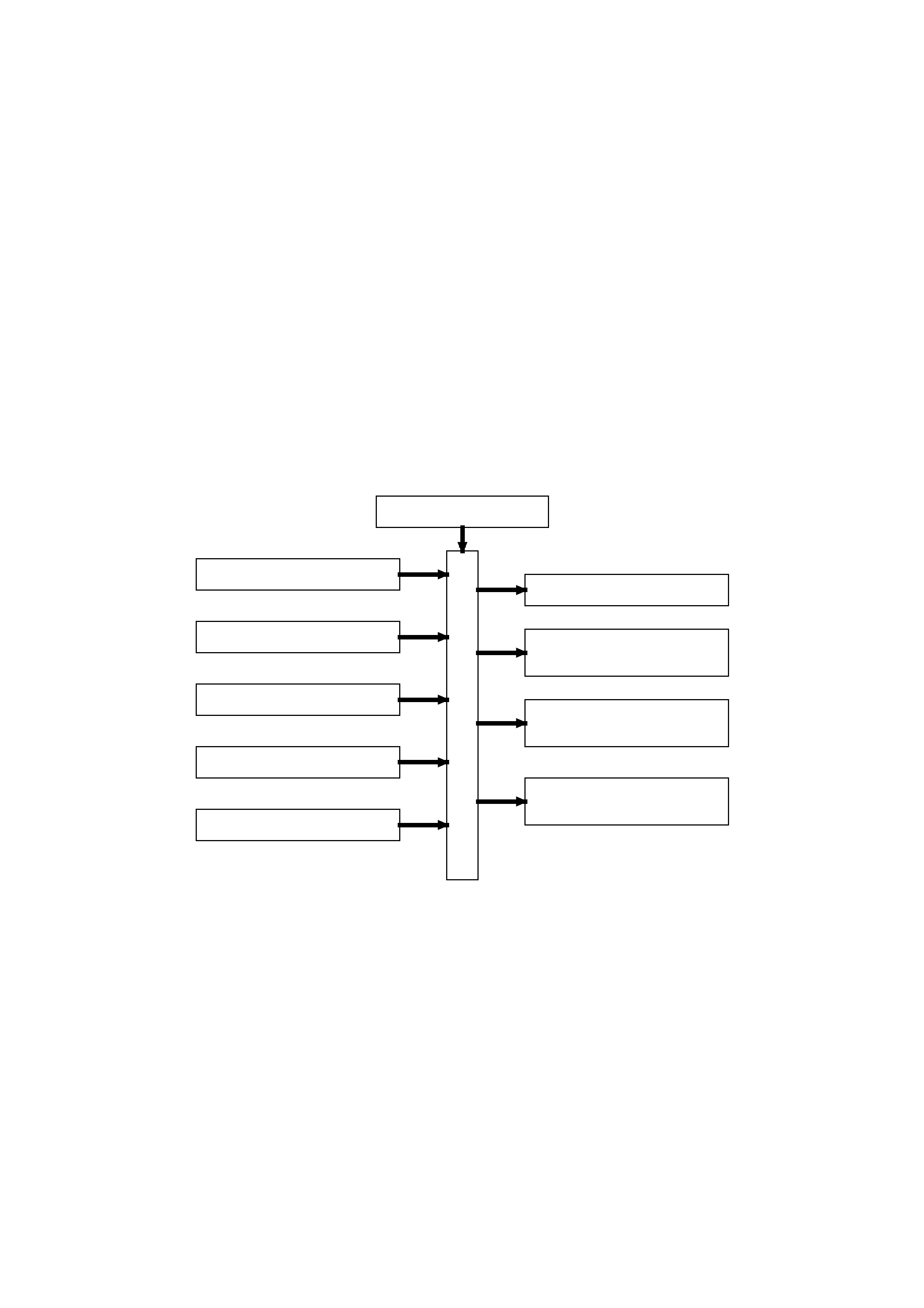
1.13 SRS DEPLOYMENT VEHICLE SHUTDOWN
GENERAL INFORMATION
In the event of SRS (Supplem ental Res tr aint System) deployment, the Sensing Diagnos tic Modules ( SDM) will send
serial data via the auxiliary serial data bus to advise various vehicle systems to take appropriate shutdown action.
The BCM will monitor this serial data (via the auxiliary serial data bus), and perform the following actions once the
appropriate data is identified and the vehicle speed is zero km/h for longer than 10 seconds:
• Turn the dome lamp on continuously
• Unlock all doors
The dom e lam ps will be switched off when the ignition switch is cycled from off to on or when the BCM is reset (ie.
the battery is disconnected).
NOTE 1:
The PCM (Powertrain Control Module) also monitors this serial data, and performs a vehicle shut down once the
appropriate data is identified and the vehicle speed is zero km/h for longer than 10 seconds.
NOTE 2:
The c ircuit diagrams shown in this General Descr iption Section are to aid in interpreting the operation of the circ uit
and therefore, only the main connectors and wiring colours are shown. For com plete circuits details, ref er to either
the relevant diagnostic section or Section 12P WIRING DIAGRAMS.
SYSTEM OVERVIEW
BATTERY POWER A6
DOOR LOCK POWER B10
IGNITION SWITCH ON D6
C24 DOME LAMP
C26 DOOR UNLOCK
DRIVE
C12 DOOR DEA DLOCK
DRIVE
C3 DRIVER'S DOOR
UNLOCK DRIVE
SRS SERIAL DATA AUX. D13
SERIAL DATA AUX. D3
SE RIAL DATA MAIN D2
B
O
D
Y
C
O
N
T
R
O
L
M
O
D
U
L
E
SRS VEHICLE SHUTDOWN SY STEM
CIRCUIT OPERATION
SRS SERIAL DATA BUS (SERIAL DATA)
(Refer to Fig. 12J-1-65)
In the event of SRS deployment, the SDM will send ser ial data via serial data bus to the BCM, where a physical link
to the serial data auxiliary bus enables the SDM to advise various systems, via serial data, to take appropriate
action. This includes the BCM.
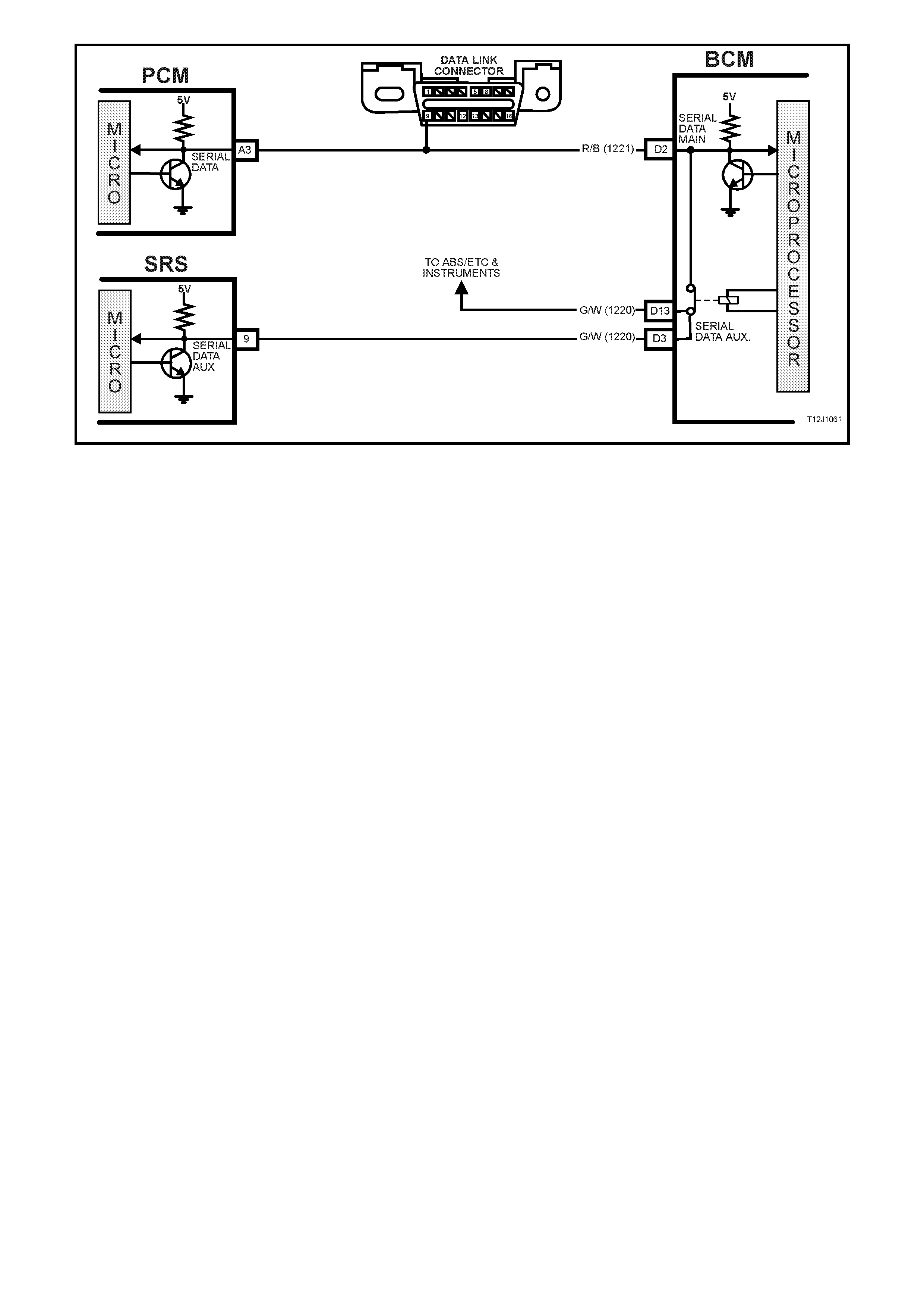
Figure 12J-1-65

2. SERVICE OPERATIONS
2.1 SAFETY AND PRECAUTIONARY MEASURES
1. Whenever performing any electric welding on a vehicle, disconnect wiring harness connectors from the BCM.
2. Never subject the BCM to temperatures above 85°C, (eg. paint oven), always remove BCM first if this
temperature is to be exceeded.
3. Ensure that all wiring harness connectors are connected solidly and that battery terminals are thoroughly clean.
4. When charging the battery, disconnect it from the vehicle's electrical system.
5. Never connect or disconnect the BCM wiring harness connectors when the ignition is switched ON.
6. Never disconnect the battery from the electrical system while the engine is running.
7. Reconnecting battery cable terminals to the battery will cause a reset.
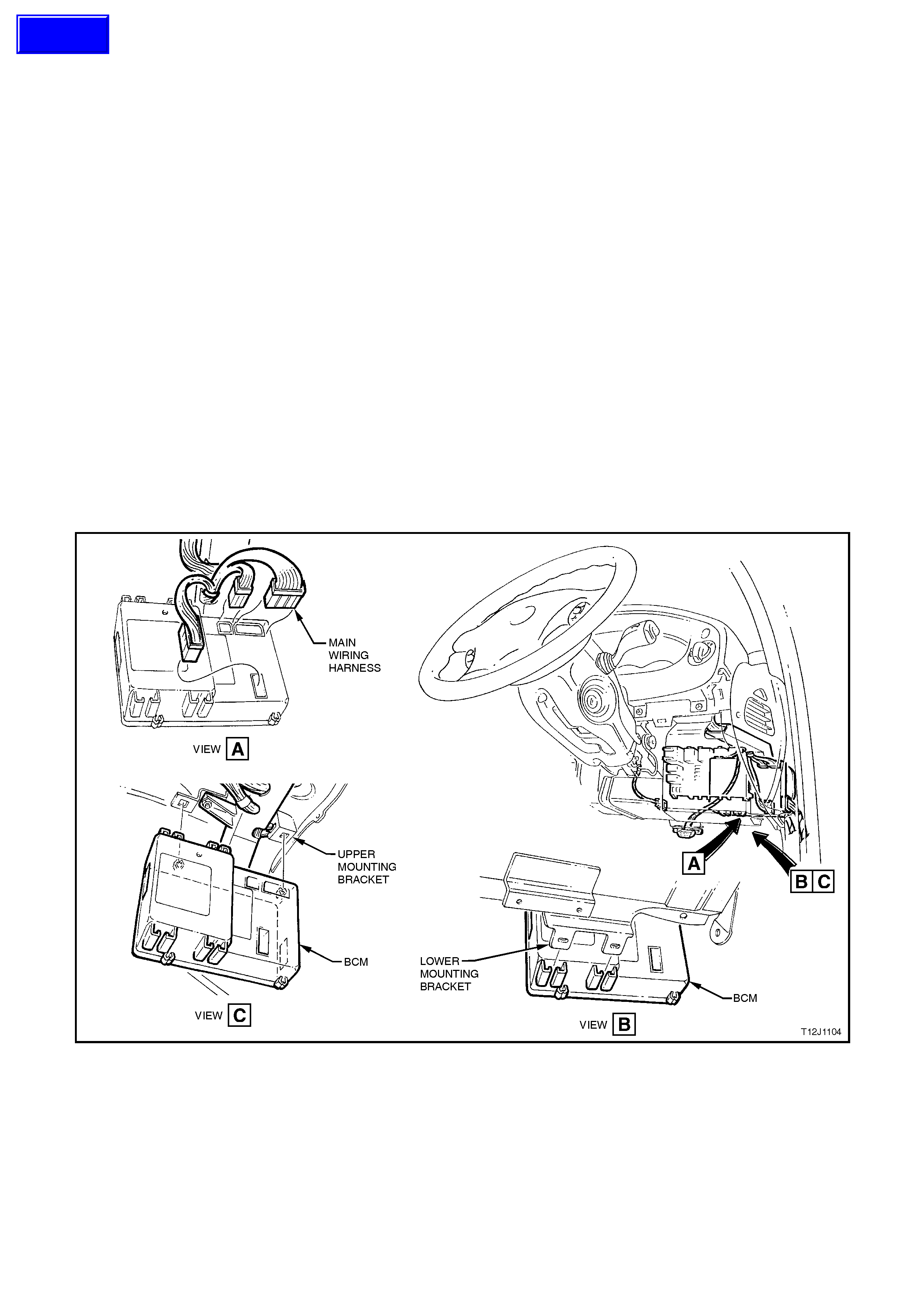
2.2 LOW SERIES BCM
REMOVE
1. Disconnect battery earth lead.
2. Remove right hand instrument panel lower trim assembly, refer to Section 1A3 INSTRUMENT PANEL.
3. Remove BCM f rom mounting br ackets by pushing the bottom of the BCM towards the front of the vehic le until
the BCM disengages from the lower mounting bracket. T hen by grasping the BCM, gently pull the BCM down
(remembering that the wiring harnesses are still connected), disengaging it from the upper m ounting bracket.
Refer to Fig. 12J-1-66.
4. Depress tangs on wiring harness connectors on BCM and pull connectors from module.
NOTE:
If car r ying out BCM diagnostic checks as desc r ibed in the appropr iate diagnos tic tes t in this Sec tion, leave all wiring
harness connectors installed in the BCM. If required, reconnect battery earth lead.
REINSTALL
Installation of the BCM is the r evers e of the r emoval proc edure, ens ur ing that the BCM is firmly installed in the BCM
mounting brackets.
BCM LINK TO PCM
Connect TECH 2 to DLC and select the following:
Diagnostics / (V) 1997 / VT Commodore / Body / Body Control Module / Security / BCM Link to PCM and follow
TECH instructions.
For additional information regarding TECH 2 and TECH 2 test modes (including this linking procedure), refer to
3 TECH 2 DIAGNOSIS FOR BCM in this Section.
Figure 12J-1-66
Techline

2.3 REMOTE CODE D KEY
PERFORMANCE CHECK
During a performance check of the remote coded key, be sure to check all keys that are assigned to the vehicle.
Two checks have been incorporated in the TECH 2 software. T hese two checks include a REMOTE KEY SIGNAL
test that is used for checking the RF output and if the signal is recognised by the BCM. The second check is the
REMOTE KEY I.D. which is used to check if a remote coded key has been assigned to the BCM.
For more details on these TECH 2 checks, refer to 3.3 TECH 2 SCREEN DISPLAYS in this Section.
Check that the remote coded key can successfully lock and unlock the doors at a distance of approximately four
meters from the vehicle.
If one remote coded key fails to make the system respond, the problem is in that particular remote coded key.
After replacing a key due to a suspected discharged or faulty battery, first insert the key into the ignition and cycle
from OFF - ON - OFF. This is necessary as there may be a need to synchronise the rolling codes between the
remote coded key and the BCM. If the codes are not synchronised, the remote control of the central door locking
system will not work.
REPLACE
NOTE 1:
Before replacing a suspected faulty remote control key, ensure the following steps are carried out.
• Carry out the Remote Control Function Fault Diagnosis as per the diagnostic chart in this Section.
• If the key still presents a problem, ensure that the key pin is making contact with the remote coded key reader
assembly. Insert the key into the ignition and cycle from OFF - ON - OFF. This is necessary as there may be
a need to synchronise the rolling codes between the remote control key and the BCM. The remote coded key
would only be considered faulty if it will not allow the engine to start when used in the ignition switch with the
theft deterrent system armed (LED flashing).
Avoid testing the remote coded key with the system disarmed (LED not flashing), in this situation, a faulty remote
coded key will allow the engine to start, being in the 30 second time frame before the system passively arms itself.
NOTE 2:
Replacement of a remote coded key will necessitate programming with the BCM to accept the new remote coded
key serial output data. The programming of the rem ote coded key can only be perform ed by an authorised Holden
service outlet or authorised locksmiths when provided with the correct security information.
1. Loosen and remove the two remote coded key housing screws.
2. Grab hold of key tip and pull it from the remote coded key housing.
3. While holding new remote coded key housing, loosen and remove the remote coded key housing screws.
Assemble the key into the new remote coded key housing.
4. Insert the two remote coded key housing screws and start threads by hand. Tighten screws to the correct
torque specification (to complete earth circuit within key).
REMOTE CODED KEY HOUSING
SCREW TORQUE SPECIFICATION 0.7 - 0.9
Nm
5. Carry out programming of remote coded key.
6. Insert remote coded key into the ignition and cycle from OFF - ON - OFF to synchronise codes.
7. Carry out check of theft deterrent and central door locking systems using the remote coded key.
NOTE 3:
The remote c ontrol k ey is a sealed for lif e unit (non rem ovable batter y), therefor e the housing cannot be separ ated.
The battery life expectancy is approximately five to ten years.
NOTE 4:
To protect the electric door lock actuators from overheating if/when the door locks are operated repeatedly in
succes sion, the BCM is program med to prevent door lock operation f or a shor t period (m aximum 20 s econds) . This
is normal operation and not to be confused as a defective remote coded key or BCM.
Techline
Techline
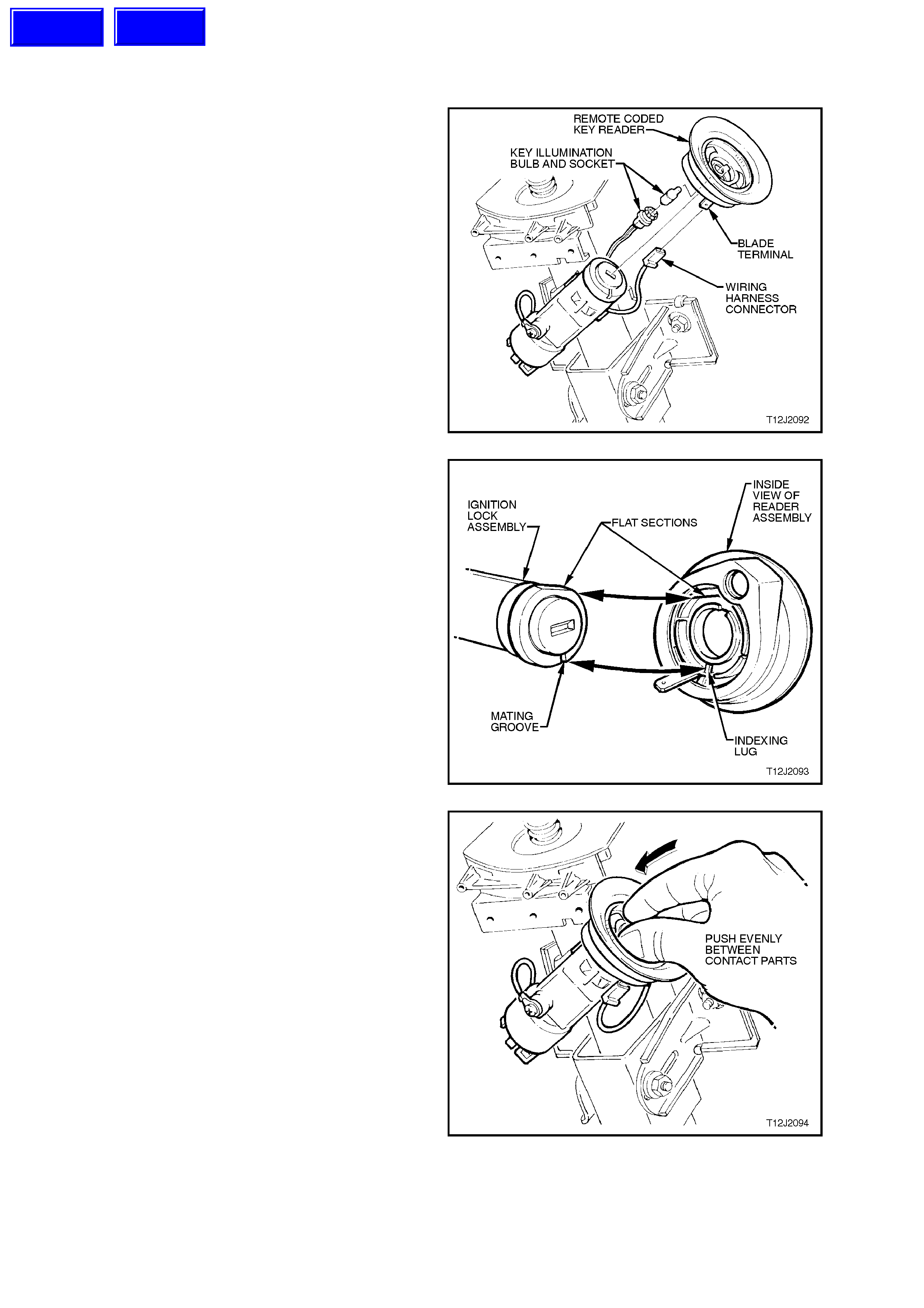
2.4 RE MOTE CODED KEY READER
REMOVE
1. Release steering column height adjuster lever
and completely lower steering column, lock
lever in this position.
CAUTION:
Disable the SRS (Air Bag), refer to in Section
12M SUPPLEMENTAL RESTRAINT SYSTEM.
2. Remove the ignition key from the ignition
switch.
3. Remove steering column upper and lower
covers, refer to Section 9A STEERING.
4. Disconnect wiring harness connector and
ignition lock illumination socket and bulb from
key reader assembly, then carefully pull key
reader assembly from ignition lock assembly
housing.
Figure 12J-1-67
REINSTALL
Installation of the remote key reader assembly is
the reverse of the removal procedure, noting the
following points:
1. Align the flat sec tions of the remote k ey reader
assem bly with the ignition lock ass embly, refer
to Fig. 12J-1-68.
Figure 12J-1-68
2. Gently press key reader assembly onto ignition
lock by pushing on the centre of the key
reader, in between the two contact strips, until
key seats onto the ignition lock, Fig. 12J-1-69.
3. Ensure that the wiring harness connector and
ignition lock illumination bulb and socket are
securely fitted onto key reader assembly.
4. On completion of reinstallation, insert the
ignition key and check the key reader
assembly operation.
NOTE:
Enable the SRS (Air Bag), refer to Section 12M
SUPPLEMENTAL RESTRAINT SYSTEM.
Figure 12J-1-69
Techline
Techline
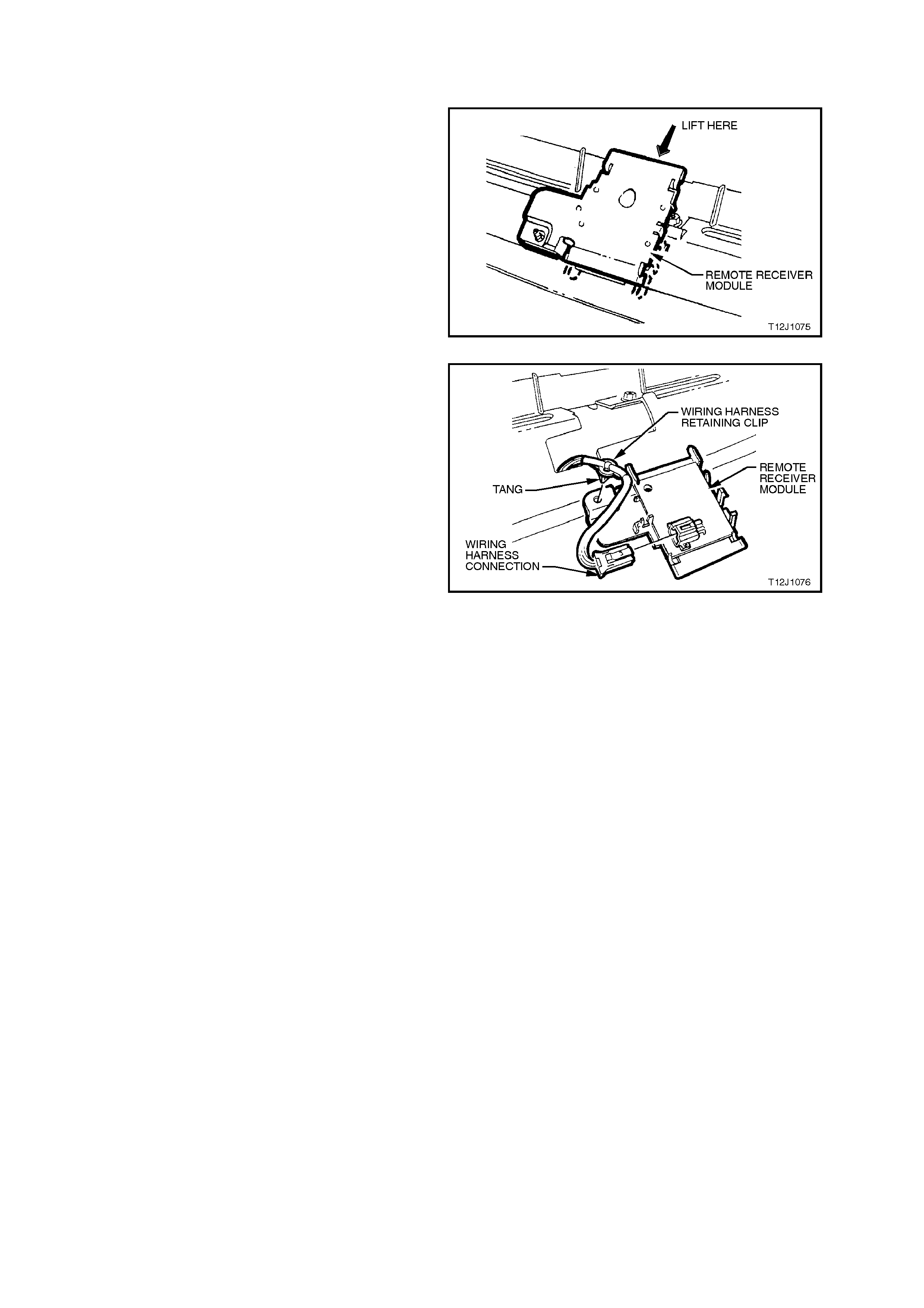
2.5 REMOTE RE CEIVER MODULE
REMOVE
1. Remove LH and RH demist grilles, refer to
Section 1A3 INSTRUMENT PANEL.
2. Gently pry the front of the remote receiver
module up and towards rear of vehicle.
Figure 12J-1-70
3. Disconnect wiring harness connector.
4. Remove wiring harness retaining clip from
rem ote receiver m odule by squeezing tangs of
clip together and pushing clip through sun
sensor / remote receiver module aperture.
5. Remove remote receiver module.
REINSTALL
Installation of the remote receiver module is the
reverse of the removal procedure. Figure 12J-1-71

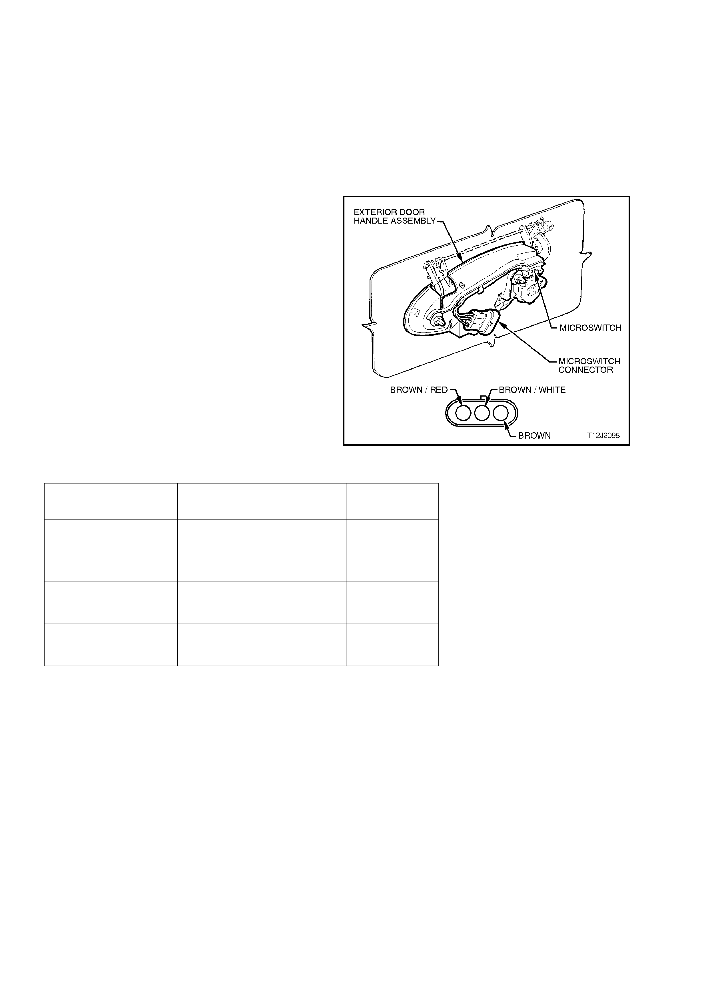
2.7 DOOR LOCK MICROSW ITCHES
On VT Series Models, there are two door lock
microswitches that are fitted to the drivers door
exterior handle. The microswitches are part of the
driver’s door exterior handle assembly and are not
serviced separately. Therefore, to remove the
exterior door handle and microswitch assembly,
refer to Section 1A5 FRONT AND REAR DOOR
ASSEMBLIES.
TEST
1. Remove door inner trim panel, refer to
Section 1A5 FRONT AND REAR DOOR
ASSEMBLIES.
2. Using an ohmmeter connected to the various
terminals, check operation of the
microswitches as per the follow table:
NOTE:
If any of the readings are not as specif ied, replace
the exterior door handle and micr oswitch as s embly,
refer to Section 1A5 FRONT AND REAR DOOR
ASSEMBLIES.
Figure 12J-1-72
LOCK POSITION TERMINALS (WIRE
COLOURS) VALUE
Rest position Brown/Red to Brown/White
Brown/Red to Brown
Brown/White to Brown
Open circuit
Open circuit
Open circuit
Held in lock position Brown/Red to Brown
Brown/Red to Brown/White
Continuity
Open circuit
Held in unlock position Brown/Red to Brown/White
Brown/Red to Brown
Continuity
Open circuit


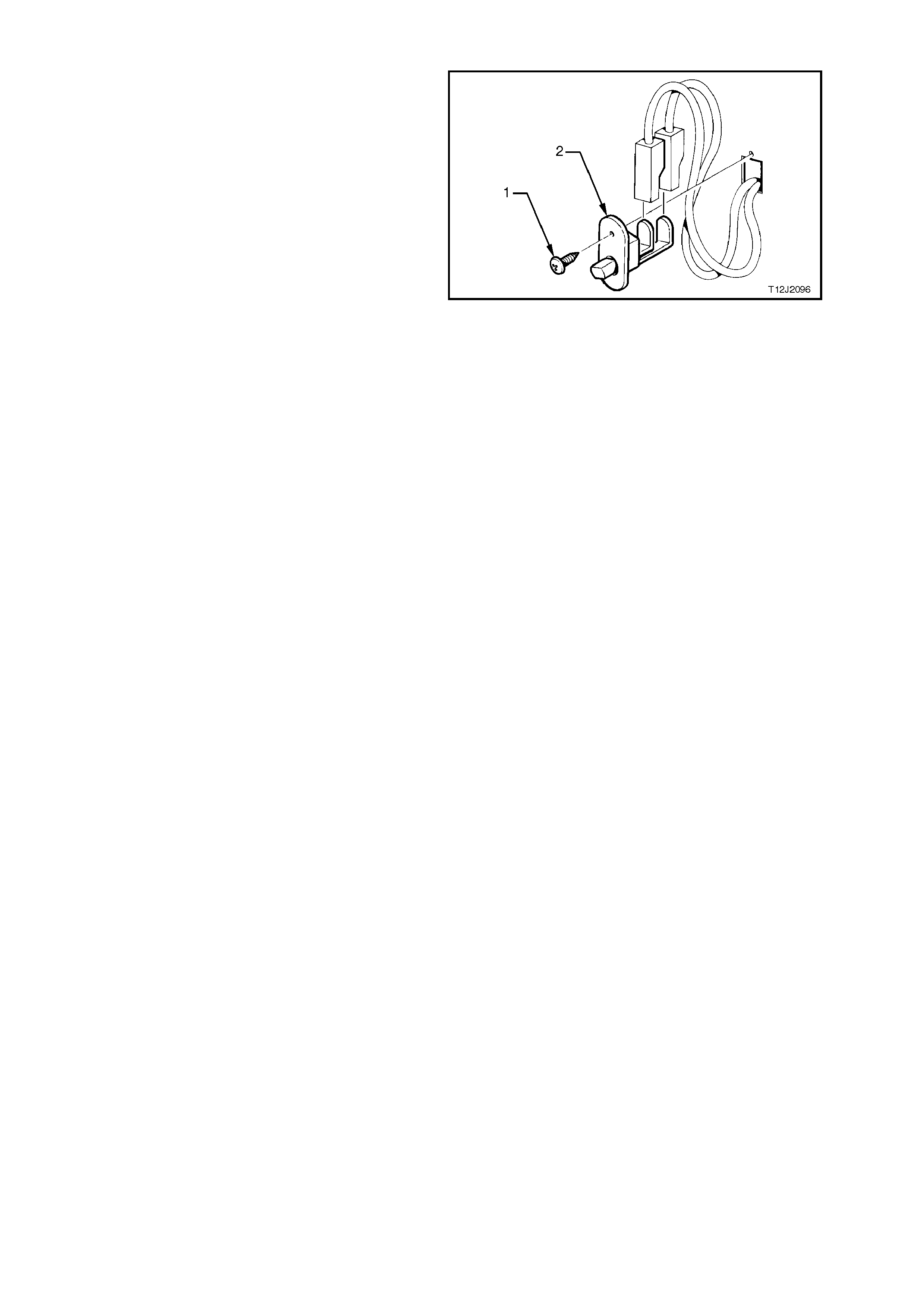
2.10 DOOR JAMB SWITCHES
The door j amb s witches are installed in eac h of the
door hinge pillars. When the door of the vehicle is
closed, a plunger in the switch is depressed,
creating an open circuit in the earth circuit. When
the door is opened, the plunger is released and
completes the circuit to earth.
REMOVE
1. Remove door jamb switch retaining screw (1).
2. Remove door jamb switch (2) f rom door hinge
pillar, taking car e not to damage the door jamb
switch wiring harness.
3. Disconnect wiring harness connectors.
REINSTALL
Installation of the door j am b switches is the revers e
of the removal procedure.
Figure 12J-1-73

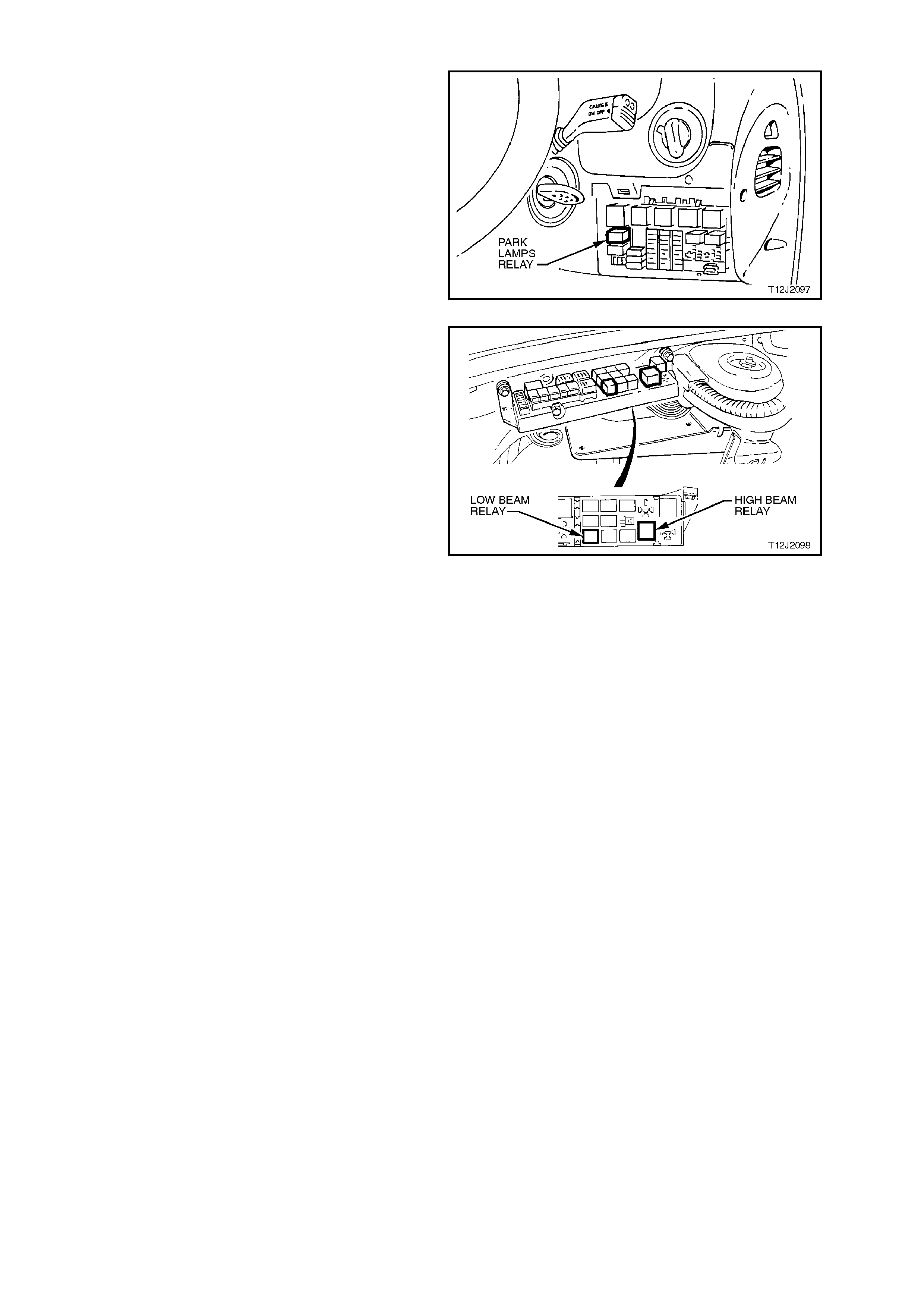
2.12 HEADLAMP AND PARK LAMP RELAYS
Fig. 12J-1-74 shows the location of the park lamps
relay (located inside the vehicle, attached to the
fuse panel).
Access to the relay / fuse panel is by lowering the
instrument panel right hand cover assembly. Refer
to Section 1A3 INSTRUMENT PANEL for the
procedure on how to remove this cover.
Figure 12J-1-74
Fig. 12J-1-75 shows the location of the headlamp
high and low beam relays (located inside the
engine compartment relay housing).
Figure 12J-1-75

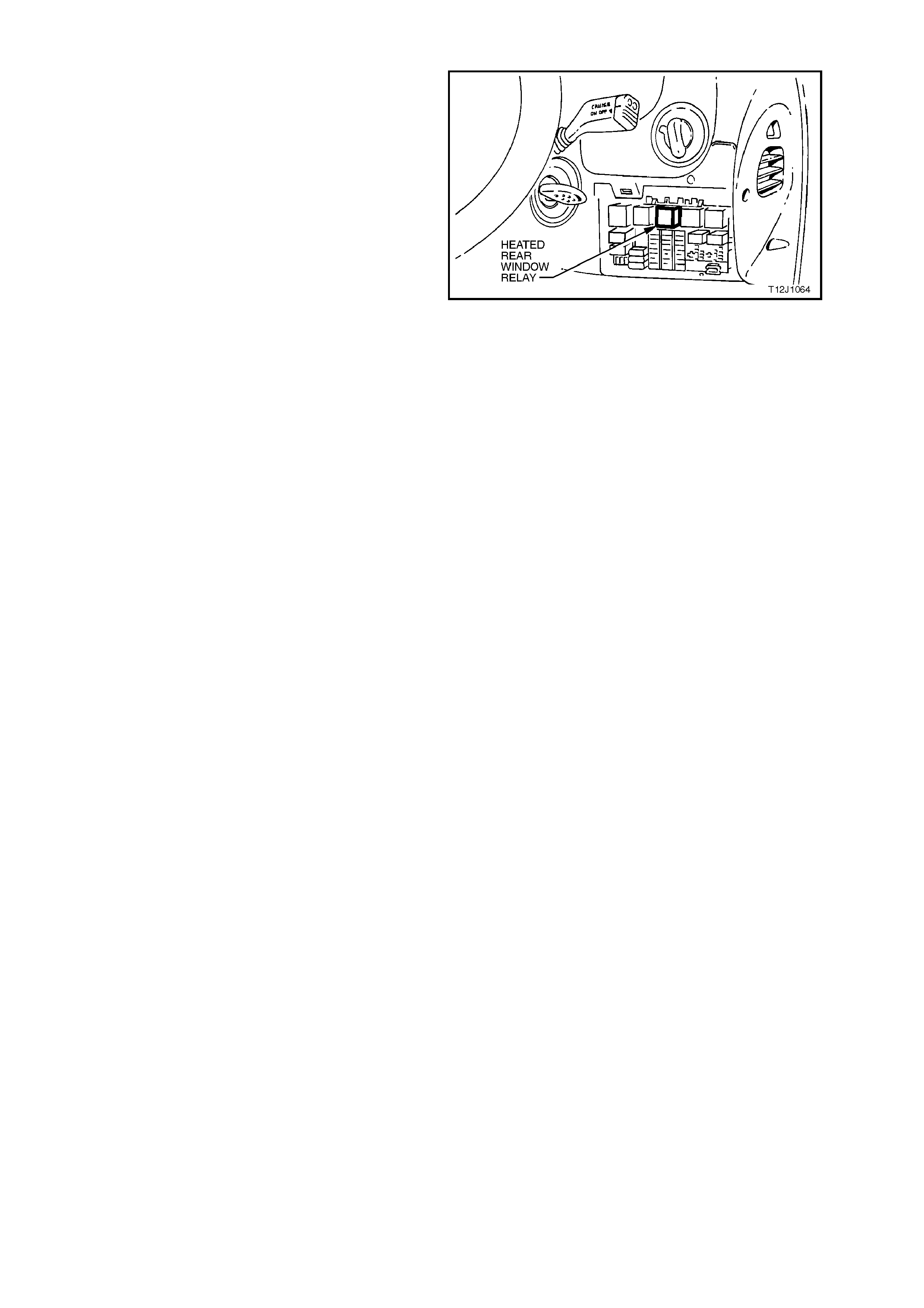
2.14 HE ATED REAR WINDOW RELAY
Fig. 12J-1-76 s hows the location of the heated rear
window relay (located inside the vehicle, attached
to the fuse panel).
Access to the relay / fuse panel is by lowering the
instrument panel right hand cover assembly. Refer
to Section 1A3 INSTRUMENT PANEL for the
procedure on how to remove this cover.
Figure 12J-1-76


2.16 VEHICLE SPEED SENSOR
MANUAL TRANSMISSION
For vehicle speed sensor removal, testing and installation instructions, refer to Section 12C INSTRUMENTS,
WIPERS/WASHERS & HORN.
AUTOMATIC TRANSMISSION
For vehicle speed sensor removal, testing and installation instructions, refer to
Section 6C1 ENGINE MANAGEMENT - V6 ENGINE or Section 6C2 ENGINE MANAGEMENT - V8 ENGINE.

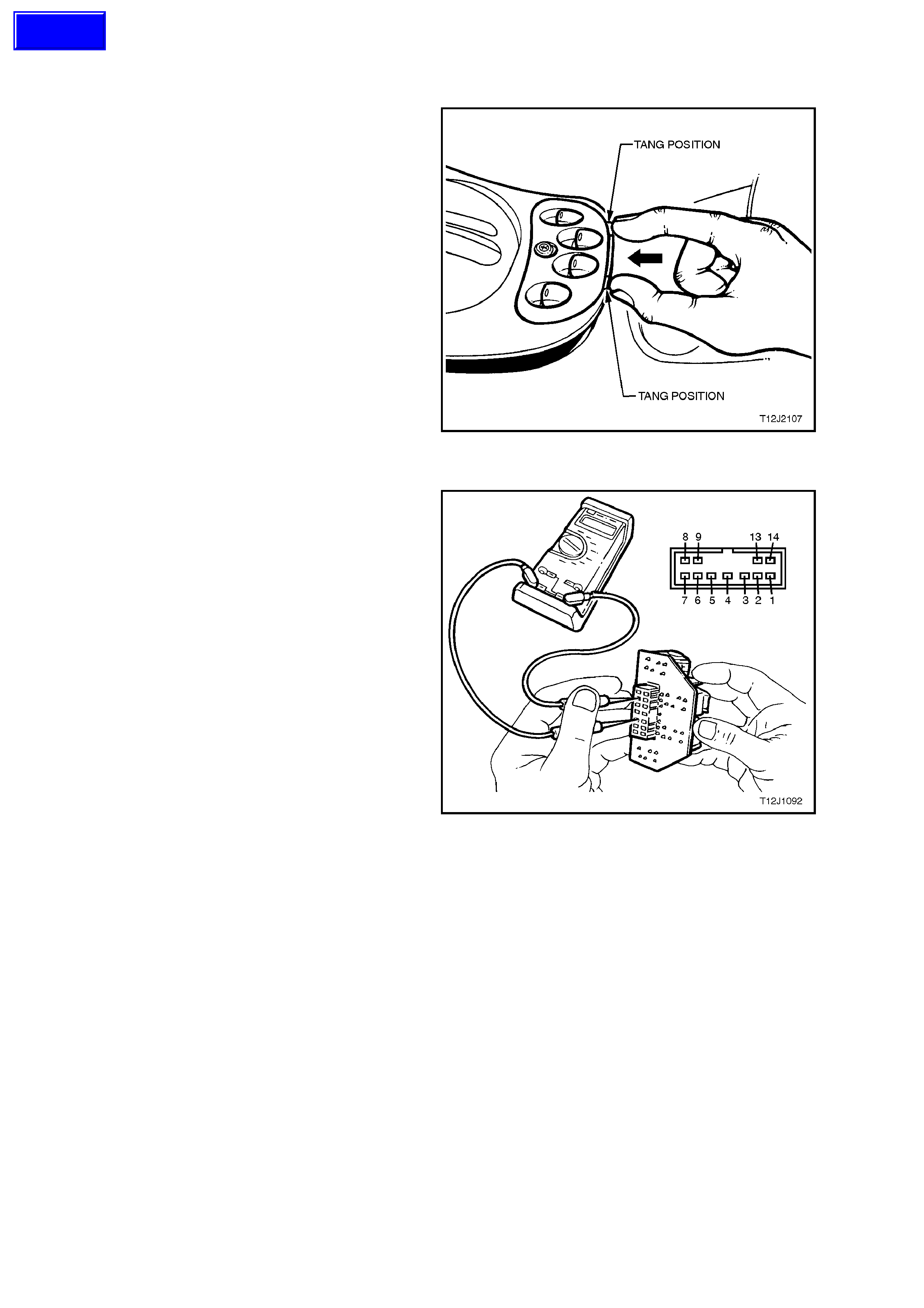
2.18 FRONT AND REAR DOOR POWER WINDOW SWITCH
REMOVE
1. Raise the centre console cap, refer to
Section 1A3 INSTRUMENT PANEL AND
CONSOLE.
2. From the rear of the centre console cap,
push the tangs securing the power window
switch and push the power window switch
upward, releasing it from the console cap.
3. Depress wiring harness retaining tang and
disconnect wiring harness connector,
remove power window switch.
TEST
NOTE:
Do not allow skin to contact the power window
circuit board when checking for continuity.
Figure 12J-1-77
With the power window switch rem oved, using an
ohmmeter connected to the various terminals,
check operation of the switch as per the following
table:
NOTE:
If any of the readings are not as specified,
replace the power window switch assembly.
Figure 12J-1-78
Techline

SWITCH POSITION TERMINALNUMBERS VALUE
RHF Up
Rest
Down
4 and 9
5 and 8
5 and 9
4 and 8
Continuity
Continuity
Continuity
Continuity
LHF Up
Rest
Down
4 and 14
5 and 1
5 and 14
4 and 1
Continuity
Continuity
Continuity
Continuity
RHR Up
Rest
Down
4 and 7
5 and 6
5 and 7
4 and 6
Continuity
Continuity
Continuity
Continuity
LHR Up
Rest
Down
4 and 3
5 and 2
5 and 3
4 and 2
Continuity
Continuity
Continuity
Continuity
Override In
Switch Out 4 and 13
4 and 13 Open circuit
Continuity
REINSTALL
Installation of the front and rear door power window
switch is the reverse of the removal procedure.
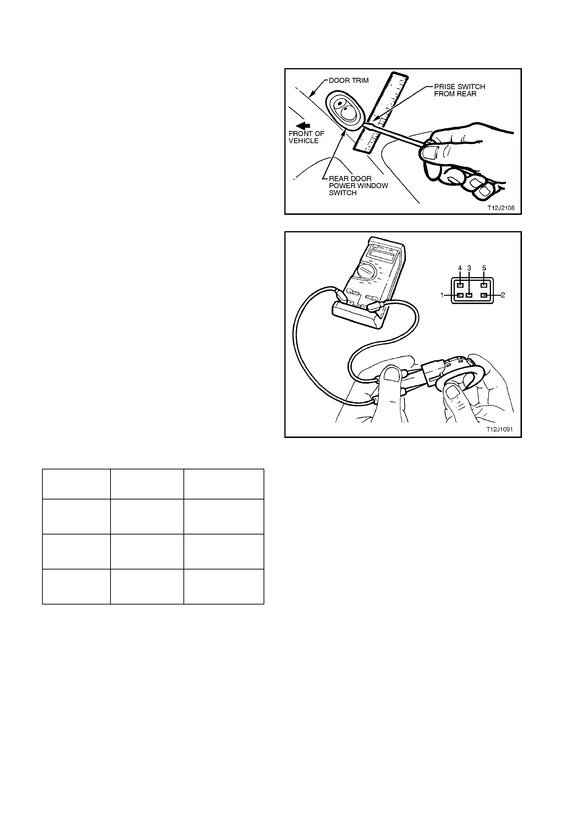
2.19 REAR DOOR POWER WINDOW S WITCHES
REMOVE
1. From the rear of the rear door power window
switch, prise the appropriate switch from the
door trim, taking care not to damage door trim.
2. Lift out rear door power window switch from
door trim until wiring harness connector
passes out through console opening.
3. Depress wiring harness retaining tang and
disconnect wiring harness connector, remove
switch.
Figure 12J-1-79
TEST
NOTE:
Do not allow skin to contact the power window
circuit board when checking for continuity.
With the power window switch removed, using an
ohmmeter connected to the various terminals,
check operation of the switch as per the follow
table:
NOTE:
If any of the readings are not as specified, replace
the power window sw itch assembly.
Figure 12J-1-80
SWITCH
POSITION TERMINAL
NUMBERS VALUE
Up 1 and 3
2 and 4
Continuity
Continuity
Rest 1 and 3
2 and 5
Continuity
Continuity
Down 1 and 3
2 and 5
Continuity
Continuity
REINSTALL
Installation of the rear door power window switch is
the reverse of the removal procedure.
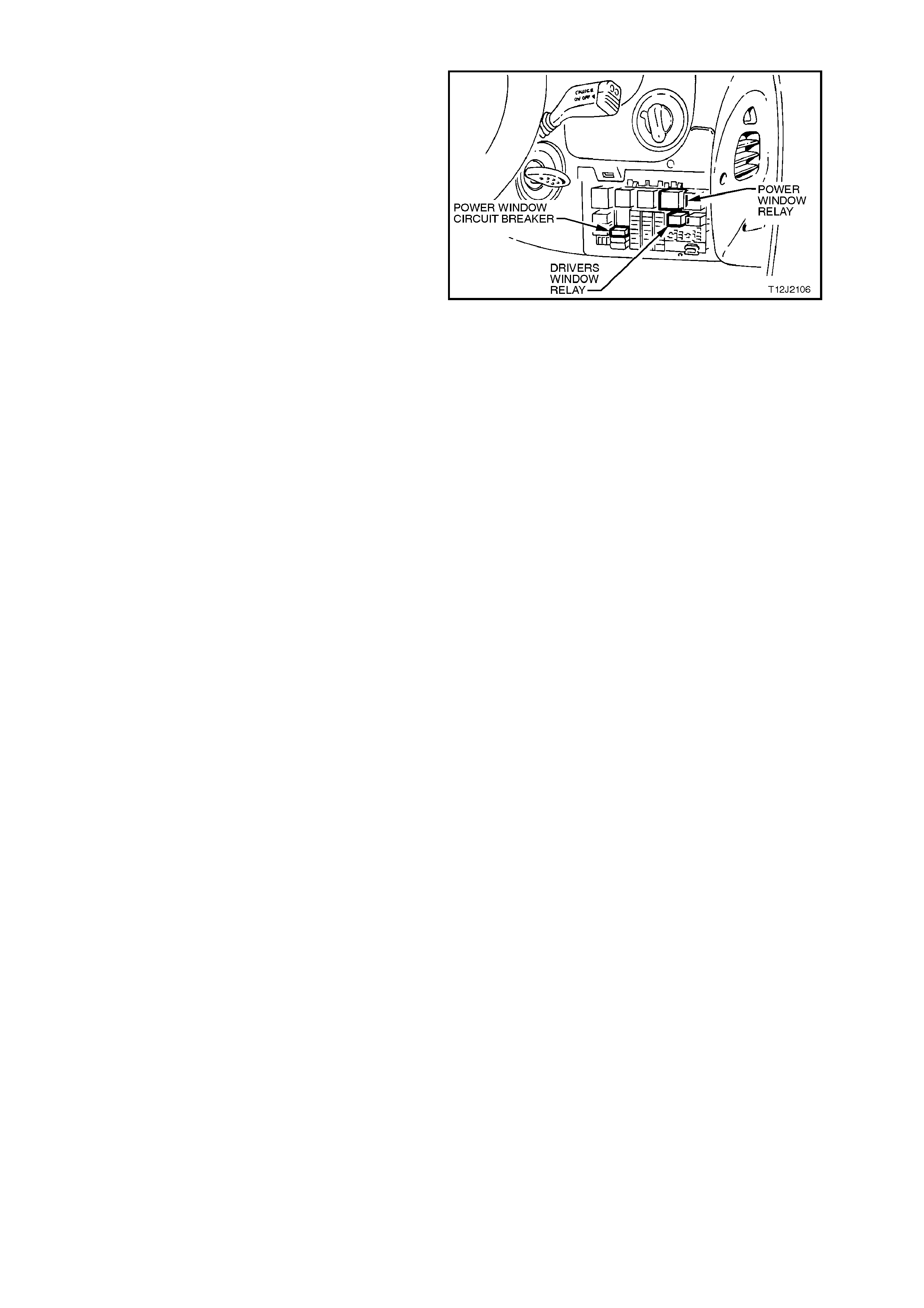
2.20 POWER WINDOW RELAYS AND CIRCUIT BREAKER
Fig. 12J-1-81 shows the location of the power
window relays and circuit breaker (located inside
the vehicle, attached to the fuse panel).
Access to the relay / fuse panel is by lowering the
instrument panel right hand cover assembly. Refer
to Section 1A3 INSTRUMENT PANEL for the
procedure on how to remove this cover.
Figure 12J-1-81
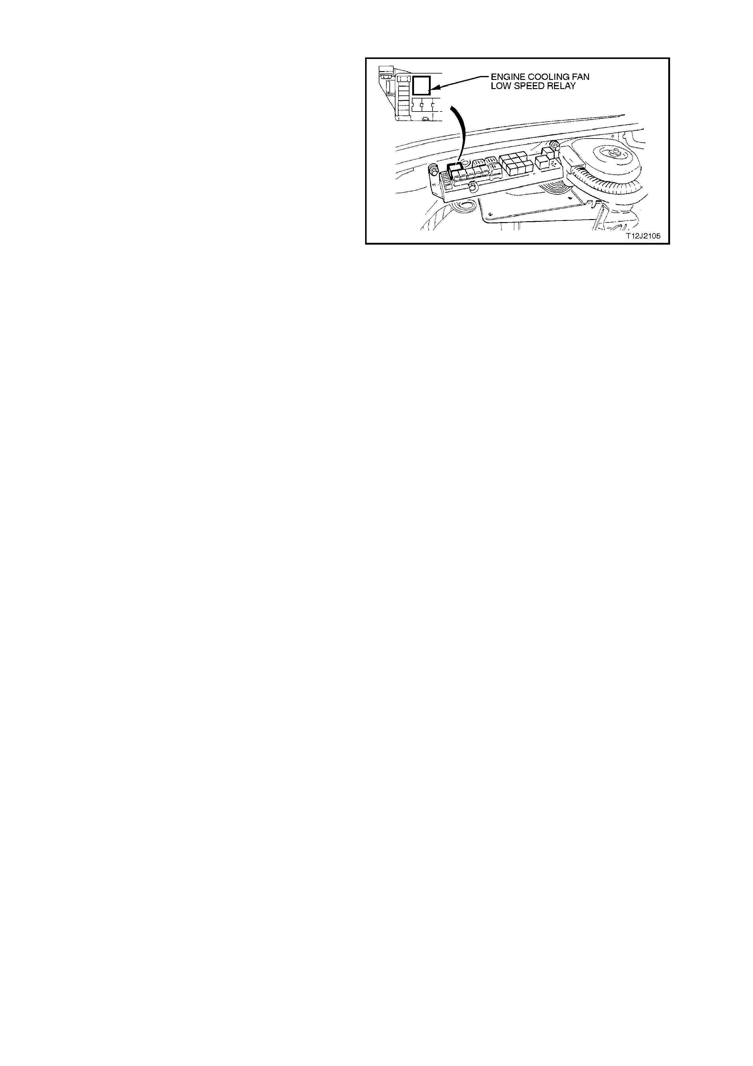
2.21 ENGINE COOLING FAN LOW SPEED RELAY
Fig. 12J-1-82 shows the location of the engine
cooling fan low speed relay (located inside the
engine compartment relay housing).
Figure 12J-1-82


3. TECH 2 DIAGNOSIS FOR BCM
3.1 BASIC KNOWLEDGE REQUIRED
Before attem pting to diagnose the c ontrol or assist of the various vehicle electrical s ys tems contr olled by the BCM,
you must have a good understanding of electrical system basics and the use of circuit testing tools. W ithout this
basic knowledge it will be difficult to use the diagnostic procedures detailed in this Section.
Some elec trical basics, troubleshooting procedures and hints as well as the use of cir cuit testing tools are cover ed
in Section 12P, WIRING DIAGRAMS.
Basic Electrical Circuits - You should understand the basic theory of electricity, series and parallel circuits, and
voltage drops across series resistors. You should know the meaning of voltage (volts), current (amps), and
resistanc e (ohms). You should understand what happens in a circuit with an open or shorted wire (s horted either to
voltage or earth). You should also be able to read and understand a wiring diagram.
Use of Circuit Testing Tools - You should know how to use a jum per lead to tes t cir cuits . You should be f amiliar with
the use of a high input impedance (10 Megohm) digital type multimeter such as tool No. J39200 or equivalent and
be able to measure voltage, current, and resistance. You should be familiar with the proper use of the TECH 2
Diagnostic Scan Tool.
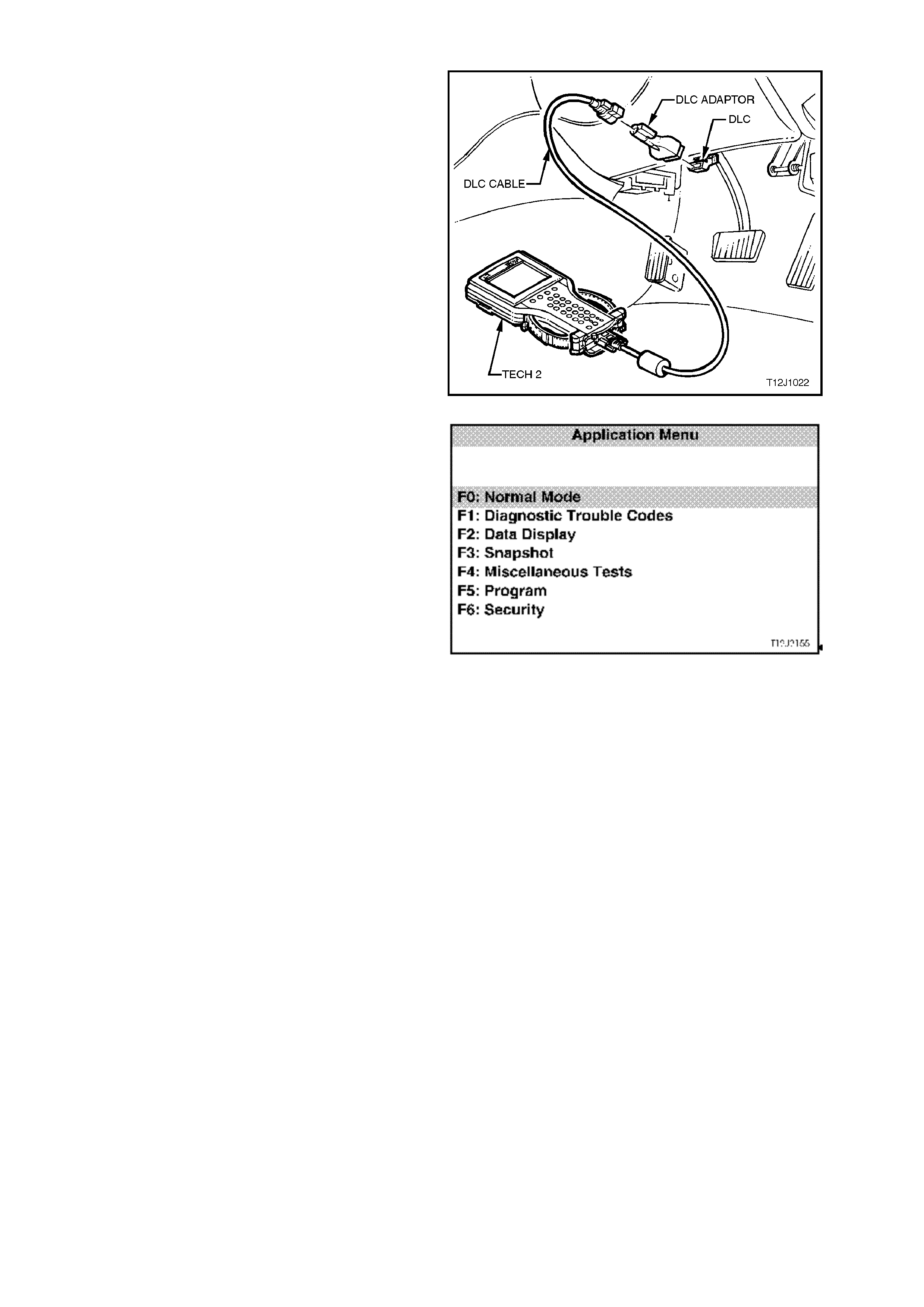
3.2 CONNECTING TE CH 2
TECH 2, with the appropriate software, cables and
adaptors, when connected to the Data Link
Connector (DLC) is capable of reading BCM serial
data. The DLC is connected to the instrument panel
lower right hand trim, to the right of the steering
column.
For additional general information on
connecting and operating TECH 2 , refer to
Section 0C TECH 2.
Figure 12J-1-83
TECH 2 has seven test modes for diagnosing the
BCM. The seven test modes are as follows:
Mode F0: Normal Mode
In this mode, the Tech 2 monitors the
communication between control modules on the
serial data line. The information displayed on the
TECH 2 screen in this mode is what the BCM is
communicating to the other modules via the serial
data line.
Mode F1: Diagnostic Trouble Codes
In this test mode, current Diagnos tic Trouble Codes
(DT C’s) s tored in the c ontrol modules m em or y may
be displayed or cleared.
Mode F2: Data Display
In this test mode, TECH 2 displays the status of
inputs and outputs of the BCM.
Mode F3: Snapshot
In this test mode, Tech 2 captures BCM data
before and after a forced manual trigger.
Mode F4: Miscellaneous Tests
In this test mode, Tech 2 performs various
functional tests to assist in pr oblem isolation during
trouble shooting.
Mode F5: Program
In this test mode, Tech 2 allows the programming
of various features by turning the feature OFF or
ON, or adjusting settings (ie. Two Stage Unlock).
Mode F6: Security
In this test m ode, T ech 2 pr ovides the user with the
capability of: linking the PCM to the BCM, reading
security information (ie. radio pin numbers), and
programming security features (ie. keys).
Figure 12J-1-84
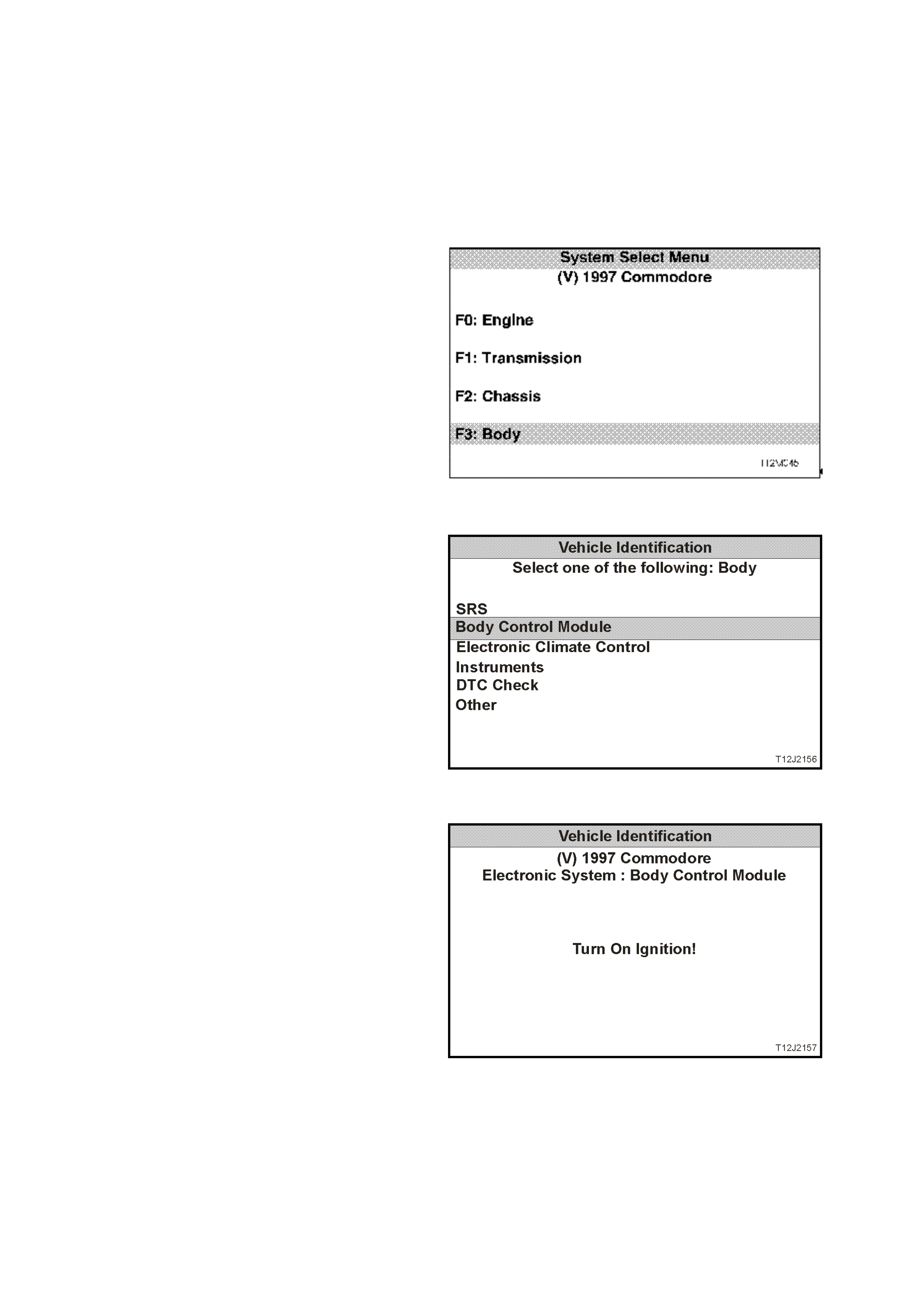
3.3 TECH 2 TEST MODES AND DISPLAYS FOR BCM DIAGNOSIS
As a prerequisite to this diagnostic section is for the
user to be familiar with the proper use of TECH 2,
the following illustrates only the major TECH 2
screen displays and provide a brief explanation of
their function for diagnosing the BCM. If additional
information is r equired on the oper ation of TECH 2,
reference should be made to either Section 0C
TECH 2 or the TECH 2 OPERATORS MANUAL.
System Select Menu
W ith TECH 2 c onnected to the DLC and turned on,
F0: DIAGNOSTICS selected from the MAIN
MENU, the correct MODEL YEAR and VEHICLE
TYPE must be selected for access to the SYSTEM
SELECT MENU.
Select F3: BODY.
This mode contains all functions to test, diagnose,
monitor and program the vehicles body systems
including the BCM as well as providing the
opportunity to check all DTC’s that may be set in
the vehicle.
Figure 12J-1-85
Body Application Menu
Once F3: BO DY has been selec ted from the s elect
menu, BCM can be selected.
Select Body Control Module and press enter to
continue.
NOTE:
If inform ation regarding DT C’s set for the vehicle is
required, select DTC CHECK and press enter to
continue. To return to the BCM mode option from
the DTC CHECK mode option screen display,
simply press the EXIT key on TECH 2.
Once the BCM has been selec ted and entered, the
following two SYSTEM IDENTIFICATION screens
will appear which require action. Figure 12J-1-86
System Identification
Turn the ignition ON (as requested) and press
CONFIRM soft key to continue.
Figure 12J-1-87
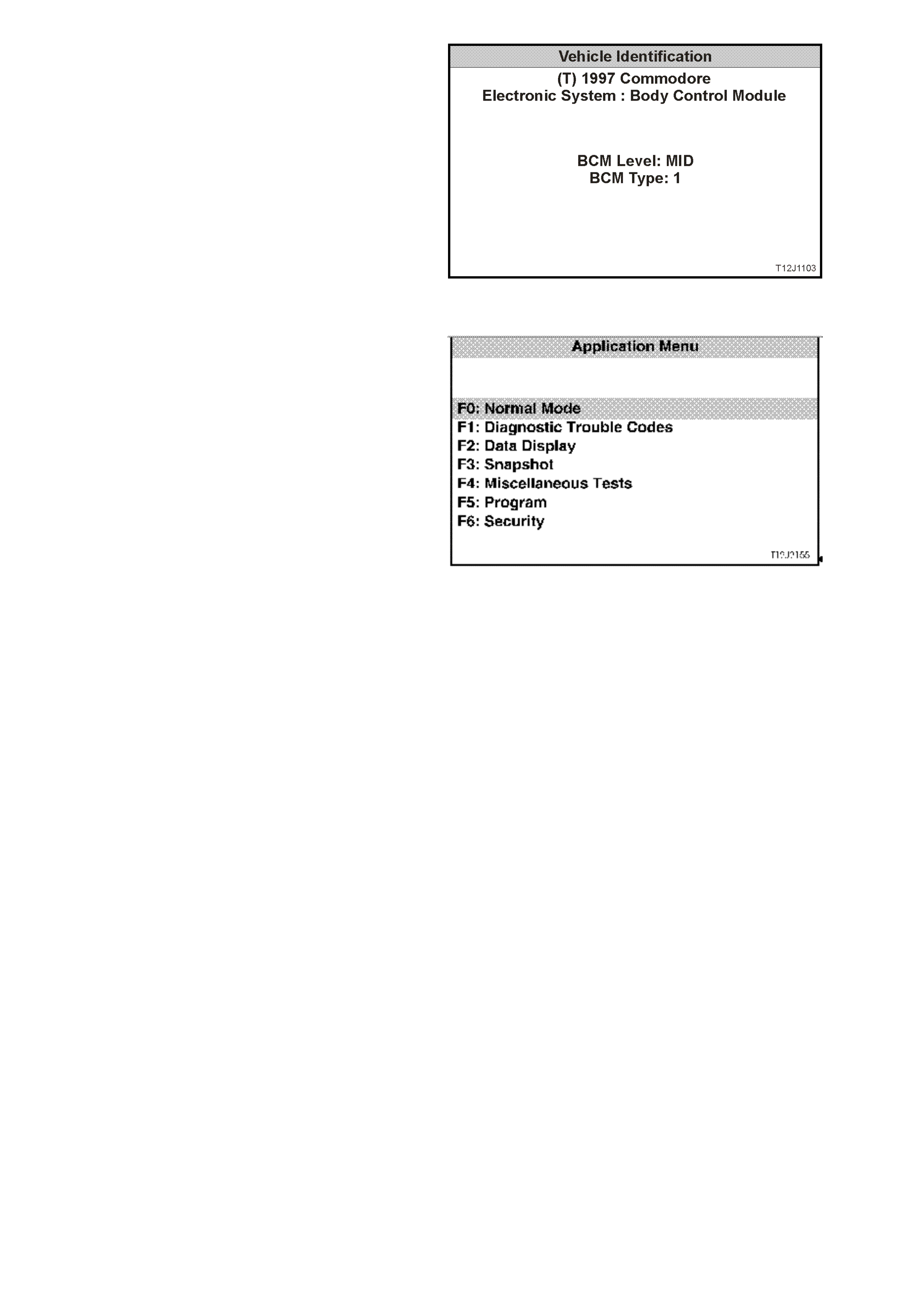
The SYSTEM IDENTIFICATION screen will then
display the control module level and type. Press the
CONFIRM soft key to continue to the BCM
APPLICATION MENU.
Figure 12J-1-88
Application Menu
The following functions will now be available:
F0: Normal Mode
F1: Diagnostic Trouble Codes
F2: Data display
F3: Snapshot
F4: Miscellaneous Tests
F5: Program
F6: Security
Figure 12J-1-89

F0: NORMAL MODE
In the F0: Norm al Mode, inf orm ation that the BCM is c om m unicating to other c ontrol m odules, via the ser ial data
line, is displayed.
The table below lists each item in the Normal Mode, together with a brief description of its meaning.
DATA STREAM /
SCREEN DISPLAY DESCRIPTION EXPECTED READING
Ignition Status Displays current state of ignition switch as sensed by
the BCM. On 12 Volts / Off 0 Volts
Ignition Off Time Displays the length of time since the ignition was last
switched off. XX minutes
Instrument Lamps Displays instrument illumination level. 0 % / 100 %
Lights On Displays current status of headlamp switch. Yes / No
Ambient Light Level This feature is only available for vehicles with high
series BCM’s (Calais). 0
Boot Status Displays boot switch status. Open / Closed
Rear Lamp Status This feature is only available for vehicles with high
series BCM’s (Calais). Okay
Front Wiper Status Displays front wiper drive status. On / Off
Front Auto wiper Status This feature is unavailable at present. Off
Cruise Control Input
Signal Displays cruise control status. On / Off
A/C Request (Air
Conditioning) Displays A/C request status. On / Off
BCM Lower Fan Drive Displays low speed fan drive status. On / Off
BCM Chime (Body
Control Module) This feature is unavailable at present. Off
Key User Displays which remote coded key is in use. 1 / 2
BCM DTC Status Display will advise if any BCM DTC's are set. No DTC’s / DTC’s Set

F1: DIAGNOSTIC TROUBLE CODES
The following functions will be available in this
mode:
F0: Read Current DTC Information - a listing of all
(if any) current DTC’s that have been set by the
BCM will be displayed. A short description of what
the DTC is, is also displayed in this mode.
F1 Clear DTC Information - simply select F1:
CLEAR CODES, press the ENTER button on
TECH 2 and confirm the action as instructed by
TECH 2.
The following chart sets out all the possible BCM
DTC’s as indicated by TECH 2 for Low Series
BCM’s.
Refer to the relevant diagnostic chart in this Section
when attempting rectification of a system problem
or failure.
Figure 12J-1-90
BCM DIAGNOSTIC TROUBLE CODES
DTC CODE DESCRIPTION REFER
1 Output overload - sets if the BCM’s output
protection circuitry detects an output driver
overload. This will cause all BCM output drives to
be set to the inactive state. The BCM will then
attempt to drive all outputs approximately every
10ms, thus causing all active BCM output drives
to repeatedly switch from an active to an inactive
state until the fault condition is remedied.
NOTE:
The BCM is unable to identify which output is
being overloaded.
This DTC can be set by any one of the BCM outputs being
shorted to battery positive, therefore, if DTC 1 is set, refer to
section relevant to driver complaint (if any).
For a listing of all BCM outputs, refer to the MID SERIES
BCM TERMINAL IDENTIFICATION chart in 1 GENERAL
DESCRIPTION in this Section.
NOTE:
DTC 1 can also be set by electrical transients, therefore, if
DTC 1 is set and there are no noticeable problems with the
vehicle, clear DTC and check function of BCM outputs. If
DTC does not reset and BCM outputs are functioning
correctly, disregard DTC 1
2 Slip Ring Failure - sets if the number of failed slip
ring reads exceeds a programmable percentage
of all slip ring reads (approximately 18 failed slip
ring reads out of 100 good slip ring reads).
4.5 THEFT DETERRENT, in this Section to rectify problem.
7 PCM Data Lost - sets when the BCM does not
receive responses from the PCM or receives
incorrectly formatted responses from the PCM
within three seconds of normal serial data bus
activity.
The three second time out period is reset
whenever the following conditions occur:
• Ignition switched from OFF to ON.
• A good PCM poll response is received from
the PCM.
• A key has been programmed.
• BCM has just been reset.
4.2 SERIAL DATA COMMUNICATION, in this Section to
rectify problem.
8 PCM Vehicle Speed Data Unstable - sets if the
BCM receives two consecutive road speed
updates from the PCM with a magnitude
difference of 30 km/h.
(This DTC can also be set by wheel spin)
Connect TECH 2 to DLC, select Engine / Data Display, scroll
to Vehicle Speed, road test vehicle and note if screen
displays actual vehicle speed. If it does not display actual
vehicle speed, refer to Section 6C1 POWERTRAIN
MANAGEMENT - V6 ENGINE or Section 6C2
POWERTRAIN MANAGEMENT - V8 ENGINE. If screen
does display actual vehicle speed, replace BCM.
17 Serial Data Bus Fault - sets if the BCM cannot
detect six consecutive messages on the serial
data bus. This trouble code indicates either a
short circuit on the bus or if two or more modules
send a message at the same time.
4.2 SERIAL DATA COMMUNICATION, in this Section to
rectify problem.

F2: DATA DISPLAY
In this test mode, TECH 2 checks if the BCM is actually receiving an input or inputs from the appropriate sensor/s or
actuator/s for the system being diagnosed.
If the sensor/s or actuator/s input/s are not being received, then c arry out the relevant system diagnos is as defined
in this Section.
If the sens or/s or actuator /s input/s ar e being rec eived, go to the appr opriate F 4: BCM T EST mode to c omm and the
BCM via TECH 2 to operate the system output.
Should the system output or actuator not function correctly, conduct relevant system diagnosis as defined in this
Section. If system wiring and output actuator are OK, replace BCM.
A description explaining the display and, where applicable, affected terminals is included in the charts below.
NOTE:
W hen the T ECH 2 is com m unicating with the BCM, it also determ ines what type of BCM is f itted to the vehic le and
therefore only the relevant data list and functional tests will be displayed.
DATA LIST
SCREEN DISPLAY DESCRIPTION TERMINAL AFFECTED
BCM LEVEL Displays what level of BCM is fitted to the vehicle.
The screen should display LOW or MID depending on
whether vehicle is fitted with power windows.
If fuse F31 or circuits 740 and/or 1040 are open circuited,
communication with the BCM will not be possible. If these
circuits are OK, refer to 4.2 SERIAL DATA
COMMUNICATION in this Section.
-
BCM TYPE Displays what type of BCM is fitted to the vehicle.
The screen will display the type of BCM fitted to the vehicle
(TYPE 1).
If fuse F31 or circuits 740 and/or 1040 are open circuited,
communication with the BCM will not be possible. If these
circuits are OK, refer to 4.2 SERIAL DATA
COMMUNICATION in this Section.
-
VEHICLE SPEED Displays vehicle speed input to BCM via the main SDI
(circuit 1221).
If vehicle speed cannot be displayed in the BCM Data
Display mode, road test vehicle and check if it can be
displayed in the Engine Data Display mode. If it can not be
displayed, refer to Section 6C1 POWERTRAIN
MANAGEMENT - V6 ENGINE or Section 6C2
POWERTRAIN MANAGEMENT - V8 ENGINE. If vehicle
speed can be displayed in the Engine Data Display mode,
replace BCM.
D2
SLIP RING
ENABLED Screen display may flash from NO to YES briefly when BCM
receives a correct key reading. If BCM does not receive a
correct key reading, screen will flash between NO YES
continuously until a correct reading is achieved.
If screen does not change as described, refer to 4.5 THEFT
DETERRENT in this Section.
D12
IGNITION SWITCH Displays current state of ignition switch as sensed by the
BCM.
Will display ON with ignition switch in IGN or START
positions and OFF in ACC or OFF positions.
If screen display doesn’t change as described, check
circuitry between ignition switch and BCM, and ignition
switch contacts. If circuit and switch are OK, BCM is faulty.
D6

SCREEN DISPLAY DESCRIPTION TERMINAL AFFECTED
CENTRAL
LOCKING Displays the current state of the BCM’s internal central door
locking relays.
When locking the central door locking system, either
remotely or by turning the RH door key switch, the screen
display changes to ALL LOCK. If the RH door key switch is
activated a second time, the screen will display
DEADLOCKED.
When unlocking the system by turning the RHF door key
switch, the screen display changes from ALL LOCKED or
DEADLOCKED to ALL UNLOCK.
Unlocking remotely, the screen display changes from ALL
LOCKED or DEADLOCKED to DRIVER UNLOCK on first
press (If vehicle is programmed with two stage unlocking)
and second button press, the screen displays ALL
UNLOCK.
If screen display does not change as described, refer to 4.3
CENTRAL DOOR LOCKING and carry out FUNCTIONAL
CHECK - CENTRAL DOOR LOCKING.
-
DRIVER’S DOOR
UNLOCK SWITCH Displays RHF door lock actuator / key switch input to BCM.
With doors locked, screen displays OFF, unlocking the
driver’s door or all doors, screen will change to ON.
If the circuit from BCM terminal C20 is open circuited, the
passenger’s doors cannot be unlocked by the RHF door
lock key switch.
C20
PASSENGER’S
DOOR UNLOCK
SWITCH
Displays passenger door lock actuator switch inputs to the
BCM.
With doors locked, screen displays OFF, unlocking the
passenger doors, screen changes to ON.
If the circuit from BCM terminal C9 is open circuited, the
passenger doors cannot be unlocked. The screen display
will also remain unchanged.
C9
LOCK SWITCH
STATUS Displays the front doors lock actuator inputs to the BCM.
When doors are locked, by activating either of the front door
lock actuators (snib), screen displays ON. When doors are
unlocked, screen displays OFF.
If circuit is open, doors can not be locked from the front door
lock actuators (snib), but system can be locked remotely.
If screen display does not change as described, refer to 4.3
CENTRAL DOOR LOCKING in this Section and carry out
FUNCTIONAL CHECK - CENTRAL DOOR LOCKING.
C21
DEADLOCK
SWITCH Displays RHF door lock microswitch input to BCM.
With RHF door lock cylinder in the unlocked and locked
position, screen displays OFF. Display will change to
DEADLOCK when the door lock cylinder is turned to the
deadlock position.
If circuit 197 is open circuited, doors cannot be locked or
deadlocked by turning the RHF door lock cylinder and
screen display will remain off. However, doors can be
locked and deadlocked remotely.
If screen display does not change as described, refer to 4.3
CENTRAL DOOR LOCKING in this Section and carry out
FUNCTIONAL CHECK - CENTRAL DOOR LOCKING.
C22

SCREEN DISPLAY DESCRIPTION TERMINAL AFFECTED
DOME LAMP DRIVE Display changes from OFF to ON as dome lamp is turned
ON or when the remote coded key UNLOCK button is
depressed. Display goes OFF when the ignition is turned
ON. This check confirms if the BCM internal circuitry is
operating(a relay within the BCM will be heard to click as the
drive is turned on).
If circuit 174 between the BCM, terminal C25 and the
interior lighting is open circuited, the interior lighting will not
come on.
If screen display does not change as described, refer to
4.12 DOME LAMP DELAY CONTROL in this Section.
C24
HEADLAMP
SWITCH Displays status of switch during auto off period only .
Display changes from OFF to ON as headlamps delay
period is in progress. This check confirms that the BCM
internal switching is operating. Display goes to OFF when
the headlamp auto off is cancelled.
If screen does not change as described, refer to 4.10
AUTOMATIC LIGHTS OFF CONTROL in this Section.
D14
HEADLAMP DRIVE With the ignition turned on, screen displays ON, turning the
ignition off, the screen will still display ON. Turn headlamps
on, scroll ignition from on to off and open the driver’s door,
screen will change from ON to OFF and headlamps will go
out.
If screen does not change as described, refer to 4.10
AUTOMATIC LIGHTS CONTROL OFF in this Section.
D14
DRIVER’S DOOR Displays the driver’s door jamb switch input to the BCM.
When the driver’s door is open, the screen display should
be OPEN, and when the door is closed, the screen should
display CLOSED.
If screen does not change as described, refer to 4.5 THEFT
DETERRENT in this Section.
C8
PASSENGER
DOORS Displays the passenger’s door jamb switch input to the
BCM.
When the passenger’s door is open, the screen display
should be OPEN, and when the door is closed, the screen
should display CLOSED.
If screen does not change as described, refer to 4.5 THEFT
DETERRENT in this Section.
C7
FRONT WASHER
PUMP SWITCH Displays front washer pump switch input to BCM.
With ignition on and the washer pump switch activated,
screen display changes from OFF to ON.
If circuit 94, between the BCM and the wiper/w asher switch
is open circuited, the wipe after wash function will not
operate.
If screen display does not change, check circuit 94 between
BCM terminal D18 and wiper/washer switch (including
wiper/washer switch contacts), refer to Section 12C
INSTRUMENTS, WIPER/WASHER AND HORN.
D18

SCREEN DISPLAY DESCRIPTION TERMINAL AFFECTED
WIPER PARK
SWITCH Displays input to BCM.
With wipers in the park position, screen displays ON. With
wipers operating, display will change to OFF and
momentarily go to ON as wipers operate through the park
region.
If circuit 196, between the BCM and the wiper motor is open
circuited, the screen will display ON all the time and wipers
will not park when turned off.
If screen display remains ON with wipers operating, check
for open circuit between BCM terminal B9 and wiper motor,
carry out checks of wiper motor, refer to Section 12C
INSTRUMENTS, WIPER/WASHER AND HORN.
B9
FRONT WIPER
INTERMITTENT
SWITCH
Displays wi per/washer switch intermittent switch contacts
input to BCM.
With ignition on and wiper/washer switch set to the
intermittent position, screen display changes to ON.
If circuit 97, between the BCM and the wiper/w asher switch
is open circuited, there will be no intermittent wiper function.
If screen display does not change, check circuit 97 between
BCM terminal D10 and wiper/washer switch (including
wiper/washer switch contacts), refer to Section 12C
INSTRUMENTS, WIPER/WASHER AND HORN.
D10
INTERMITTENT
WIPER DRIVE With wipers operating in the intermittent mode, screen
displays ON. With wipers in the parked position, and in 1st or
2nd speed, screen displays off.
If screen displays are not as described, refer to 4.11 WIPER
CONTROL SYSTEM in this Section.
-
FRONT WIPER
DWELL TIME Displays wiper/washer switch dwell time input to the BCM.
The wiper dwell on vehicles with a low series BCM is a fixed
dwell period of approximately 8.0 seconds and is non-
adjustable.
If wipers do not operate intermittently when selected, check
for open in circuit 97 between BCM terminal D10 and
wiper/washer switch (including wiper/washer dwell control
adjustment contacts, refer to Section 12C INSTRUMENTS,
WIPER/WASHER AND HORN.
D10
REAR WASH PUMP
SWITCH Displays rear washer pump switch input to BCM.
With ignition on and the washer pump switch activated,
screen display changes from OFF to ON.
If circuit 494, between the BCM and the wiper/w asher switch
is open circuited, the wipe after wash function will not
operate.
If screen display does not change, check circuit 494
between BCM terminal D19 and wiper/washer switch
(including wiper/washer switch contacts), refer to Section
12C INSTRUMENTS, WIPER/WASHER AND HORN.
D19
REAR WIPER
SWITCH Displays rear wiper switch input to BCM.
With ignition on and the rear wiper switch in the on position,
screen will change from OFF to ON (this applies to wagon
only, on sedan models, the screen will always display OFF).
If screen displays are not as described, refer to 4.11 WIPER
CONTROL SYSTEM in this Section.
D7
HEATED REAR
WINDOW DRIVE With ignition on, screen display changes from OFF to ON as
the heated rear window is turned on, and then to off as
switch is turned off. Also, if turned on, it will remain on for
fifteen minutes, provided the switch is not reactivated and
the screen will then display OFF. This check confirms that
the BCM internal circuitry is operating.
-

SCREEN DISPLAY DESCRIPTION TERMINAL AFFECTED
HEATED REAR
WINDOW SWITCH Displays heated rear window switch input to BCM.
Display will change from OFF to ON as switch is depressed
and held on. Release switch and display will change to OFF.
If screen does not change, check wiring between BCM
terminal D20 and heated rear window switch and heated
rear window switch contacts, refer to 4.7 HEATED REAR
WINDOW in this Section.
D20
POWER WINDOW
SWITCH Displays input to BCM.
With power windows enabled, screen displays OFF. With
driver’s window switch down button activated, screen
displays DOWN. With driver’s window switch up button
activated, screen displays UP.
If screen does not display DOWN when the down button is
activated and the window automatic down function does not
work, check for open circuit between BCM terminal C14 and
the driver’s side power window switch.
C14 (Down)
C16 (Up)
WINDOW AUTO
DOWN DRIVE Screen display changes from OFF to ON when the driver’s
side power window switch automatic down button is
activated and functioning. Will also display ON when down
button is activated, but with automatic down feature not
functioning.
If the driver’s side power window operates normally except
for the automatic down feature, and all system inputs are
determined to be OK, then BCM is faulty.
-
POWER WINDOW
RELAY Displays the power window relay status as determined by
the BCM internal circuitry. The relay is enabled by the BCM
earthing circuit 173.
With the power window switch enabled (lights in power
switch illuminated), screen displays ENABLED. With the
system OFF, screen displays DISABLED.
If the screen displays ENABLED but the lights in the power
window switch do not illuminate, check for open in wiring to
BCM terminal A3.
If screen displays are not as described, refer to 4.8 POWER
WINDOW SYSTEM in this Section.
A3
CRUISE CONTROL
INPUT SIGNAL Displays the cruise control on/off switch input status to the
BCM.
With ignition on, each activation of the cruise on/off switch
will toggle the screen display to the next state, ie. OFF to
ON or ON to OFF.
If the screen display changes as described, but the cruise
control CRUISE lamp in the instrument cluster does not
illuminate, refer to 4.14 CRUISE CONTROL in this Section.
If screen display does not change, refer to Section 12E
CRUISE CONTROL.
D8
A/C SWITCH Displays air conditioning switch input to BCM.
Display will change from OFF to ON as switch is depressed
and held on. Release switch and display will change to OFF.
If screen does not change, check wiring between BCM
terminal D9 and air conditioning switch and air conditioning
switch contacts, refer to 4.13 AIR CONDITIONING
INTERFACE in this Section.
D9
A/C INDICATOR Displays the status of the air conditioning system.
With ignition on, and blower fan on, will display ON when
the A/C switch is switched on, and OFF when switch is
switched off.
If screen does not change, refer to 4.13 AIR
CONDITIONING INTERFACE in this Section.
-

SCREEN DISPLAY DESCRIPTION TERMINAL AFFECTED
A/C BLOWER
SWITCH Displays air conditioning blower switch input to BCM.
Display will change from OFF to ON when switch is
switched to from off to on.
If screen does not change, refer to 4.13 AIR
CONDITIONING INTERFACE in this Section.
B3
A/C BLOWER
INHIBIT RELAY With the ignition in the accessories or on positions, screen
will display ON. If screen does not change to ON, refer to
4.13 AIR CONDITIONING INTERFACE in this Section.
B1
BOOT RELAESE
SWITCH Displays boot release switch input to BCM.
With the boot release switch (located in glove compartment)
in the rest position, screen displays OFF. With switch held
in, switch displays ON.
If screen does not change as described, refer to 4.4 BOOT
RELEASE in this Section.
D16
BOOT SOLENOID
DRIVE Provided the vehicle speed is less than 15 km/h, depressing
the boot release button on the remote coded key will cause
the screen display to change from CLOSED to OPEN as the
BCM internal relay is activated.
If screen does not change or boot release does not operate,
refer to 4.4 BOOT RELEASE in this Section.
-
OVERRIDE STATUS This screen displays that status of the theft deterrent
systems override function. TECH 2 will display SECURITY
OFF when the theft deterrent system has been overridden,
ie. When the BCM has not received any serial data from the
remote coded key and the ignition switch has been turned
ON for approximately two hours.
If the status does not change, refer to 4.5 THEFT
DETERRENT diagnosis in this Section
-
SECURITY LED Displays current state of the BCM’s theft deterrent system
LED driver condition. If the LED is flashing, ie. system
armed, the screen will pulse between ON and OFF.
NOTE:
TECH 2 and security LED are synchronised.
This checks that the BCM is turning on and off the voltage
supply.
If TECH 2 screen display does not change, the BCM is
faulty.
If TECH 2 screen display does change, but the LED does
not flash, check for open in wiring from BCM to LED
A8
INDICATORS When the BCM activates the indicators via its internal relay,
the screen display alternates between ON and OFF as the
indicators flash.
This checks that the BCM is pulsing its internal relay,
thereby supplying voltage from BCM terminal B5 to
terminals B4 and B12. If screen display does not change as
described, BCM is faulty.
If screen display does change as described, but the
indicators do not flash, check for open circuit in wiring from
BCM output terminals B4 and B12 or input to BCM terminal
B5 (refer to 4.5 THEFT DETERRENT diagnosis in this
Section).
B4, B5, B12

SCREEN DISPLAY DESCRIPTION TERMINAL AFFECTED
PASSIVE MODE With the theft deterrent system in passive arm state, screen
displays should be ON (theft deterrent LED flashing). -
REMOTE DOOR
SIGNAL Screen display changes to UNLOCK then OFF when
remote coded key unlock button is depressed. Changes to
LOCK to OFF when lock button is depressed.
If the screen displays INVALID KEY continuously when the
remote coded key is depressed, and the BCM does not
operate, that particular remote coded key is not coded to the
BCM (refer to 4.6 REMOTE RECEIVER/KEY in this
Section).
NOTE:
Due to the fact that the screen changes when the remote
coded key is depressed, is confirmation that there is an RF
output from the remote coded key and that it is recognised
by the BCM either as correct or invalid.
-
REMOTE BOOT
SIGNAL Screen display changes to OPEN then OFF when the boot
release button on the remote coded key is depressed.
If the screen displays INVALID KEY continuously when the
boot release button on the remote coded key is depressed,
and the BCM does not operate, that particular remote coded
key is not coded to the BCM (refer to 4.6 REMOTE
RECEIVER/KEY in this Section).
NOTE:
Due to the fact that the screen changes when the remote
coded key is depressed, is confirmation that there is an RF
output from the remote coded key and that it is recognised
by the BCM either as correct or invalid.
-
REMOTE KEY
NUMBER Depressing a button on the remote coded key enables the
BCM to read the key’s security code information. If the
remote coded key has been programmed to the BCM, the
screen displays the remote coded key user number that has
been assigned to it during the programming process.
A BCM can have up to 31 different remote coded keys
programmed into it.
-
SERIAL DATA BUS
ISOLATION Displays serial data bus isolation internal switch status.
During normal operations (ignition on, cranking or engine
running) the serial data bus isolation switch will be closed
and screen displays NORMAL. If engine will not start within
0.5 seconds of being cranked, the serial data bus isolation
switch will open (isolating auxiliary serial data bus) for a
maximum period of 5 seconds, during this time, screen
display will change to DATA CUTOFF
If screen displays are not as described, refer to 4.2 SERIAL
DATA COMMUNICATION in this Section.
-
LOW FAN DRIVE This checks the BCM’s ability to turn on it’s internal driver to
earth, thus enabling the engine cooling low speed fan.
With the low speed fan not operating, screen displays OFF.
With fan operating, screen displays ON.
DTC STATUS Display will advise if any BCM DTC's are set.
Screen will display No DTC’s if there are no DTC’s or DTC’s
Set if there are any BCM DTC’s set.
-

PART NUMBER
SCREEN DISPLAY DESCRIPTION TERMINAL AFFECTED
PART NUMBER With the theft deterrent system disarmed, TECH 2 displays
the last two digits of the Holden part number for the BCM
fitted to the vehicle (ie. 86).
This information can be checked against the part number
label attached to the BCM case, refer Fig. 12J-1-1 in this
Section.
F3: SNAPSHOT
In this mode, TECH 2 captures data before and after a forced manual trigger.
The purpose of the SNAPSHOT test mode is to help isolate an intermittent or transient problem by storing BCM
data parameters just before and just after a problem occurs.

F4: MISCELLANEOUS TESTS
In this test mode, Tech 2 performs various functional tests to assist in problem isolation during trouble shooting.
If a vehicle component is commanded by TECH 2 to operate and the TECH 2 screen display changes as per this
com mand, yet the com ponent does not operate, check for a f aulty circuit between the BCM and the com ponent (ie.
If low speed cooling f an is com m anded ON, TECH 2 sc reen displays LOW SPEED CO OLING FAN ON yet the low
speed cooling fan is physically not ON, then check cooling fan wiring between the BCM and the low speed cooling
fan, including cooling fan, for open or short circuit).
To operate any of the m iscellaneous tes ts, sim ply select the appr opriate functional tes t from the m iscellaneous test
application menu and follow the instructions as per TECH 2.
When the Miscellaneous Tests option is selected, the following options will become available.
NOTE:
additional application menu screens will be displayed for Lamps, Wiper Tests, and Security Systems.
• Lamps: If lamps ar e s elec ted, an additional applic ation menu will be displayed offering additional f unc tional tes ts
of the vehicles lighting system.
• Dome: In this mode, TECH 2 commands the BCM to switch on and off the interior lighting.
If the interior lighting does not operate, refer to 4.12 DOME LAMP DELAY CONTROL diagnosis in this
Section.
• Lamp Delay Drive: In this m ode with the ignition OFF and the headlam ps and park lam ps turned ON, T ECH
2 commands the BCM to switch OFF and ON the vehicle park lamps and headlamps.
If lamps do not switch of f when com manded, r ef er to 4.10 AUTO M ATIC LIGHT S OFF CONTROL diagnos is
in this Section.
• Indicators: In this mode, TECH 2 commands the BCM to switch ON and OFF the turn signal indicator lamps,
including the warning lamps in the instrument cluster.
If the turn signal lamps do not operate when commanded by TECH 2, refer to 4.5 THEFT DETERRENT
diagnosis in this Section.
• A/C Test: In this mode, TECH 2 commands the BCM to switch the A/C on/off switch LED on and off.
If LED status does not change when commanded, refer to 4.13 AIR CONDITIONING INTERFACE in this
Section.
• Low Fan: In this mode, TECH 2 commands the BCM to switch ON and then OFF, (will switch OFF automatically
after a short period provided the PCM is not commanding the low fan on) the engine cooling low speed fan relay.
If the engine cooling low speed fan does not operate in this mode, refer to 4.9 ENGINE COOLING LOW
SPEED FAN CONTROL diagnosis in this Section.
• Data Bus Isolator: In this mode, the BCM data bus isolator switch can be opened or closed.
To check if the data bus isolator is operating, start engine, command the data bus isolator switch open with
TECH 2 and hold the right arrow key down for 10 seconds. When the data bus isolator switch is opened for more
than 10 seconds with the engine running, the engine check light in the instrument cluster will illuminate (no
DTC’s will be set).
If the data bus isolator will not change state, refer to 4.2 SERIAL DATA COMMUNICATION diagnosis, in this
Section.
NOTE:
The Data Bus Isolator will only be held open for 5 seconds unless the right arrow key is held down.
• Central Locking: In this mode, TECH 2 commands the BCM to operate all door lock actuators.
If door locks do not operate, refer to 4.3 CENTRAL DOOR LOCKING diagnosis in this Section.
• Heated Rear Window : In this mode, the rear window demister can be turned on and off.
When switched on, the heated rear window switch LED is illuminated and the relay can be heard to operate.
If the LED does not illuminate or the r elay does not click when operated, r efer to 4.7 HEATED REAR WINDOW
in this Section.
• Wiper Tests: If Wipers are selected, an additional application menu will be displayed offering extra functional
tests of the vehicles wiper system.
• Front Wipers: In this mode, the front windshield wipers can be driven ON and OFF.
• Rear Wipers: In this mode, the rear screen wipers can be driven ON and OFF.
If the wipers to not operate when commanded by TECH 2, refer to 4.11 WIPER CONTROL SYSTEM in this
Section.
• Window Down: In this mode, the driver’s window can be driven down.

NOTE:
Before entering and conducting this test, ensure that driver's side power window is fully up.
If the power window auto down function does not operate when commanded by TECH 2, ref er to 4.8 POWER
WINDOW SYSTEMS diagnosis in this Section.
• Power Window Relay: In this mode, TECH 2 commands the BCM to turn off the power window relay.
If the power relay is disabled, the power window will not function. If power windows still function while disabled,
refer to 4.8 POWER WINDOW SYSTEM diagnosis in this Section.
• Security System: If the security system mode is selected, an additional application menu will be displayed
offering additional functional tests of the vehicles security system.
• Security LED: In this m ode, TECH 2 comm ands the BCM to turn the theft deterrent alert indicator LED ON
and OFF.
If the thef t deterrent LED does not operate in this m ode, refer to 4.5 THEFT DETERRENT diagnosis in this
Section.
• Boot Release: In this mode, TECH 2 commands the BCM to activate the sedan rear compartment lock
actuator.
If the boot release does not work in this mode, refer to 4.4 BOOT RELEASE diagnosis in this Section.
• Alarm Output: In this mode, the alarm status output can be switched on or off (this feature is for an after
market alarm system).

F5: PROGRAM
In this test mode, TECH 2 allows the programming of various features by turning the feature OFF or ON, or
adjusting settings to suit individual owner requests.
To operate any of the programming features, simply select the appropriate function to be changed from the
Program Application Menu and follow the instructions as per TECH 2.
When the Program option is selected, the following choices will become available.
• Rear Wiper Control: In this mode, the rear wiper control can be disabled. By disabling this feature, it will change
the rear wiper continuously sweeping the tailgate screen when the rear intermittent wiper is activated and
reverse gear is selected to, continuously sweeping the tailgate screen when the front wiper is activated and
reverse gear is selected.
• Tw o Stage Unlo cking: In this m ode, the two stage door unlock feature ( one press of rem ote c oded k ey unlock
button will unlock the driver’s door only, a second press will open all doors)” can be disabled, thus enabling
single stage unlock (one press of remote coded key unlock button will unlock all doors).

F6: SECURITY
In this test mode, Tech 2 provides the user with the capability of: linking the PCM to the BCM, reading security
information (ie. radio pin numbers), and programming security features (ie. keys).
NOTE:
A precondition to all security features is: the theft deterrent system must be disarmed and the ignition must be
switched ON with a programmed remote coded key.
When the Security option is selected, the following choices will become available.
• BCM Link to PCM : If the BCM is replaced, the new BCM mus t be linked to the PCM otherwise, the vehicle will
not crank. Likewise, if the PCM is replaced, the new PCM must be security linked to the BCM.
By selecting this mode, after the new BCM or PCM has been installed, TECH 2 will security link these
components. Once BCM link to PCM is selected, simply follow the instructions of TECH 2.
• Security Information: If this mode is selected, the following vehicle security information is displayed.
• Radio PIN
• Mechanical Key Number
• Glove Box Key
• Program
NOTE:
Programming features are only available to Authorised Holden Dealers. Consult separate literature for further
details.

4. DIAGNOSIS
4.1 PREREQUISITES TO DIAGNOSIS AND TROUBLESHOOTING
PRELIMINARY SYSTEM REQUIREMENTS
The prerequisites before proceeding with system checks are:
• Ensure no moisture is present in the wiring harness connections in either A-pillar.
• Ensure that sound earth connections are available for all f unctioning components, particularly at the body earth
connection (fender panel inner stud, adjacent to the battery).
• Ensure the battery is in good condition and adequately charged (above 11.5 volts) before carrying out any
electrical checks.
SAFETY REQUIREMENTS
Disconnect the battery when carrying out work which involves the risk of an electrical short circuit.
Do not touch mechanical components during function checks, to avoid the risk of a hand being caught in the
mechanism.
CHECKING EQUIPMENT
TECH 2 diagnostic tool.
A digital multimeter, with a minimum 20 Megohm impedance MUST be used when undertaking any electrical
checks on these systems.
Exercise care when taking readings from wiring harness connectors. It is preferred that the back probing method
with individual connectors is employed wherever possible, to avoid terminal damage and subsequent connection
failure.
When carrying out wiring checks as directed to by the diagnostic charts, rather than probe terminals and connectors
with incorrect sized m ultimeter connec tions, use the adaptors contained in c onnector test adaptor kit KM-609. This
will prevent any possibility of spreading or damaging wiring harness terminals.
IMPORTANT:
• ENSURE THAT THE IGNITION IS TURNED OFF AND THE BATTERY EARTH LEAD IS DISCONNECTED
BEFORE ANY TEST THAT REQUIRES DISCONNECTION OR RECONNECTION OF ANY OF THE BCM
CONNECTORS.
• When checking the complete system, the exact order of the test steps should be observed.
• If the required nominal value is not achieved in any stage, then the problem m ust be rectif ied before proc eeding
further.
• Unless the multimeter being used has an auto ranging function, check that the correct range, as specified, is
selected before the test is carried out.
• It will be necessary to lower the BCM down to gain access to BCM wiring harness connectors, refer to
2.2 LOW SERIES BCM in this Section.
• Testing of the various system s will involve gaining acc ess to specif ic wiring harnes s c onnectors . For the loc ation
of these connectors, refer to Section 12N FUSES AND WIRING HARNESSES.
Techline

KEY READER CIRCUIT DIAGNOSIS
INTERMITTENT OPERATION
Preliminary Checks
• Check for loose key shaft.
• Check for correct screws.
• Correct length of remote key shaft. (Check shaft against a known good key).
• Remove the key shaft, clean the earth contact, key shaft and reinstall the key shaft. If screws won’t retain or if
the screw threads are deformed, then replace the screws.
STEP ACTION YES NO
1. • Is the case cracked along the weld line, or are there
visible gaps (at the sides only)? Refer to Figure
12J-1-89A. Replace Key. Go to step 2.
2. • Are any of the buttons collapsed , depressed or
damaged? Replace Key. Go to step 3.
3. • With the Theft Deterrent LED flashing, insert the remote
key into the ignition switch and slowly turn to the ‘ON’
position.
• Does the Theft Deterrent LED stop flashing?
Go to step 4. Go to step 6.
4. • With the Theft Deterrent LED off, turn the remote key to
the ‘START’ position.
• Does the vehicle start? Go to step 5
Refer to 4.5
Theft Deterrent
diagnosis in
this Section.
5 • Does the customer complain that occasionally the
Traction Control Light remains ‘ON’ or Theft Deterrent
LED continues to flash at a quicker rate after starting? Go to step 7. Go to step 6.
6. • Connect a multimeter between a known good earth and
one of the reader slip rings.
• Apply a thick tape over the remote key contact pin and
insert into the ignition switch.
• Is there on the slip ring 4 - 6V AC constantly when the
remote key is turned to the ‘ON’ position?
• At end of test, remove tape from the remote key.
Go to step 7. Go to step 8.
7. • Check integrity of ignition barrel earth by-:
Visually inspecting earth strap on ignition lock
housing.
Checking tightness of earth strap.
Checking for continuity to known good earth.
• Is ignition barrel earth OK?
Vehicle built
prior to
15/8/01,
Go to Step 10.
Vehicle built
after 15/8/01
Go to Step 11.
Repair or
replace faulty
components.
Recheck circuit
to verify repair.
8. • With a multimeter check for continuity between BCM and
remote key reader.
• Is there continuity? Go to step 9.
Repair open
circuit.
Recheck circuit
to verify repair.
9. • Disconnect appropriate BCM connector (Refer to Wiring
Diagrams)
• With the ignition switch in the ‘OFF’ position check for a
short to B+/Earth on the slip ring.
• Is there a short?
Repair short
circuit.
Recheck
circuit to verify
repair.
Call Australian
Arrow on
03 9785 0792
10. • Align Key reader
- Remove key reader and align the locating rib on the
Reader with the ignition barrel.
• Does the vehicle start?
Verify repair.
Return vehicle
to customer
and monitor.
Go to step 11.

STEP ACTION YES NO
11. • Check for a slip ring contact as per following procedure -:
- Remove starter relay from the engine bay to prevent
the vehicle from cranking.
- Disconnect Remote key reader connector by access
from under steering column cover.
- Ensure the Theft Deterrent LED is flashing, and
slowly turn key and hold in crank position.
- While holding in crank position, reconnect the reader
connector.
- Does the Theft Deterrent LED switch off (has key
been read)?
- Remove ignition key, rotate it 180 degrees, insert into
the ignition switch and check contact with the
second slip ring with the same method.
• Did the or Theft Deterrent LED stop flashing in both first
and second slip ring tests?
Call Australian
Arrow on
03 9785 0792 Go to step 12.
12. • Check for worn or relaxed key reader contacts as per
following procedure -:
- With or Theft Deterrent LED flashing, turn key to
Accessories position.
- Apply outward pre-load to key, by pulling on key
gently away from reader.
- While monitoring or Theft Deterrent LED, quickly turn
key from Accessory to crank position.
- Visually inspect for the key contact pin making
contact with the slip ring.,
- Remove ignition key, rotate it 180 degrees, insert into
the ignition switch and check contact with the second
slip ring with the same method.
• Did the Theft Deterrent LED stop flashing?
Vehicle built
prior to May
98, Replace
Remote Key.
Vehicle built
post May 98,
Call Australian
Arrow on
03 9785 0792
Replace with
full circle slip
ring assembly.
REMOTE OPERA TION
Diagnostic Aids:
Prior to fur ther diagnosis, technicians should be aware of the following system functions:
• There is a 2 second delay on the remote boot release
• The central locking system will time-out as a result of multiple activation of the lock or unlock remote
buttons.
• Loss of rolling code synchronisation can be rectified by cycling the key in ignition.
• Metal objects such as other keys on the key ring or key tags can effect range if folded over the remote key
head.
• If the reported problem is specific to one area, radio or TV towers can effect key range and performance.
• Damaged key casing may cause moisture ingress resulting in premature key failure.
STEP ACTION YES NO
1. • Is the case cracked along the weld line, or are there
visible gaps (at the sides only)? Refer to Figure
12J-1-89A. Replace Key. Go to step 2.
2. • Are any of the buttons collapsed , depressed or
damaged? Replace Key. Go to step 3.

STEP ACTION YES NO
3. • With all doors closed and unlocked, insert the remote into
the driver’s door lock barrel and turn anti-clockwise.
• Do all doors lock? Go to step 5. Go to step 4.
4. • Does the Dome lamp remain on with the ignition in the
‘ON’ position and all the doors closed?
Inspect door
jamb switches
or circuit for
short to earth.
Refer to 4.3
Central Door
Locking
diagnosis in this
Section.
5 • With all doors closed and unlocked, operate the
DOOR/LOCK button on the remote key within 4 metres of
the driver’s side ‘B’ pillar.
• Do all doors lock?
Go to step 6. Go to step 7.
6. • Vehicles with remote boot operation,
- Operate the BOOT button on the remote key for at
least 2 seconds within 2 metres of the rear of the
vehicle.
• Does the boot solenoid activate?
Refer diagnostic
aids above then
Go to step 10. Go to step 8
7. • Does the remote key operate intermittently while
tapping it? Replace Key. Go to step 8.
8. • Connect TECH 2 to the DLC.
• Proceed to the BCM Data List mode and select REMOTE
DOOR and REMOTE BOOT signals.
• Operate the UNLOCK/LOCK/BOOT button on the remote
key.
• Does the Screen Display change to show either
‘UNLOCK’ or ‘LOCK’ or ‘OPEN’?
For Door
unlocking
problems, call
Australian
Arrow on
03 9785 0792.
For boot release
problems refer
to 4.4 Boot
Release
diagnosis in this
Section.
Go to Step 9.
9. • Connect TECH 2 to the DLC of another fully functional
VT/WH vehicle.
• Proceed to the BCM Data List mode and select REMOTE
DOOR and REMOTE BOOT signals.
• Operate the UNLOCK/LOCK/BOOT button on the remote
key.
• Does the Screen Display change to show ‘INVALID
KEY’?
Go to Step 10. Replace
Remote Key.
10. • Test receiver/sunsensor
- Confirm normal 4 metre remote range is achievable
with passenger compartment cool.
- Use a 150 Watt lamp applied to the remote receiver
for 5 minutes maximu m.
Recheck remote range – is it less than 4 metres from the
drivers side door when hot but more than 4 metres range
when cold?
Replace
receiver or
sunsensor
Call Australian
Arrow Customer
Service on
03 9785 0792
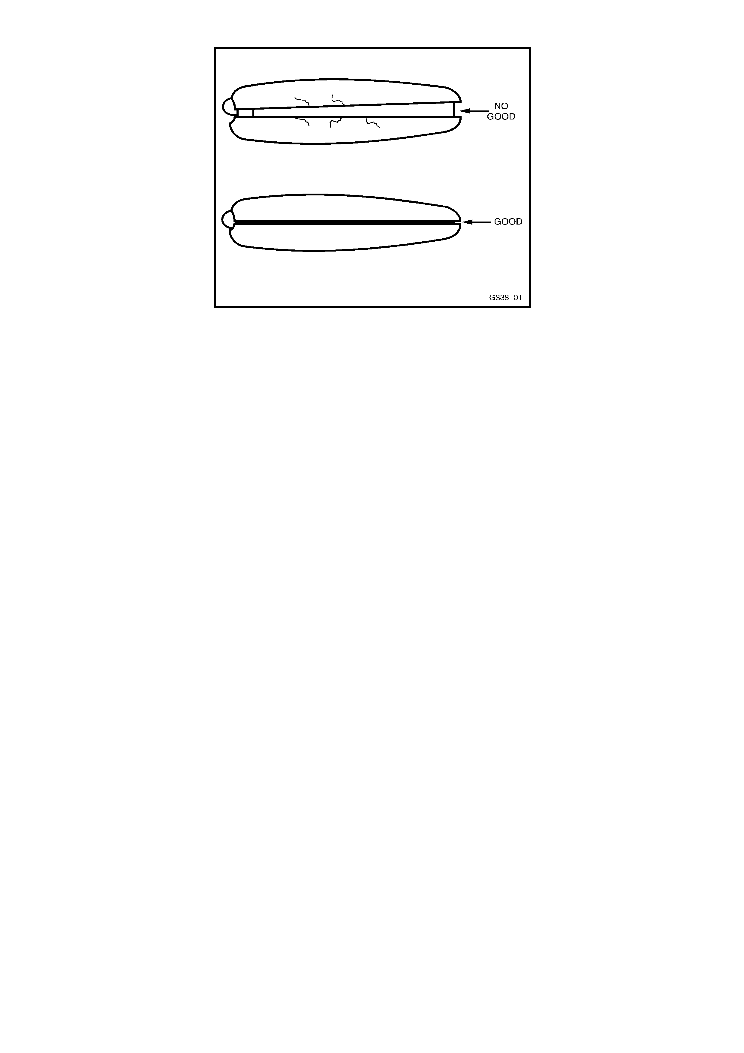
Figure 12J-1-89A

4.2 SERIAL DATA COMMUNICATION
Figure 12J-1-90
GENERAL INFORMATION
The VT Series Model uses a Bus Master communication system where the BCM is the Bus Master.
The BCM periodically polls (surveys) each device on the bus and requests status data.
The devices connected to the bus are:
• Body Control Module (BCM).
• Powertrain Control Module (PCM).
• Instrument cluster (INS).
• Antilock Brake System / Electronic Traction Control (ABS/ETC).
• Supplemental Restraint System (SRS).
• External diagnostic scan tool (TECH 2).
The data provided by each device may be utilised by any device connected to the bus.
Each device has a unique response “Message
Identifier Word” (MIW) for ease of identification.
The bus m aster (BCM) polls each device with a serial data m essage which includes that devices MIW . The device
responds by putting a serial data m essage back onto the bus. T he devices m essage includes its MIW and data, of
which is retrieved and utilised by any device on the bus requiring it.
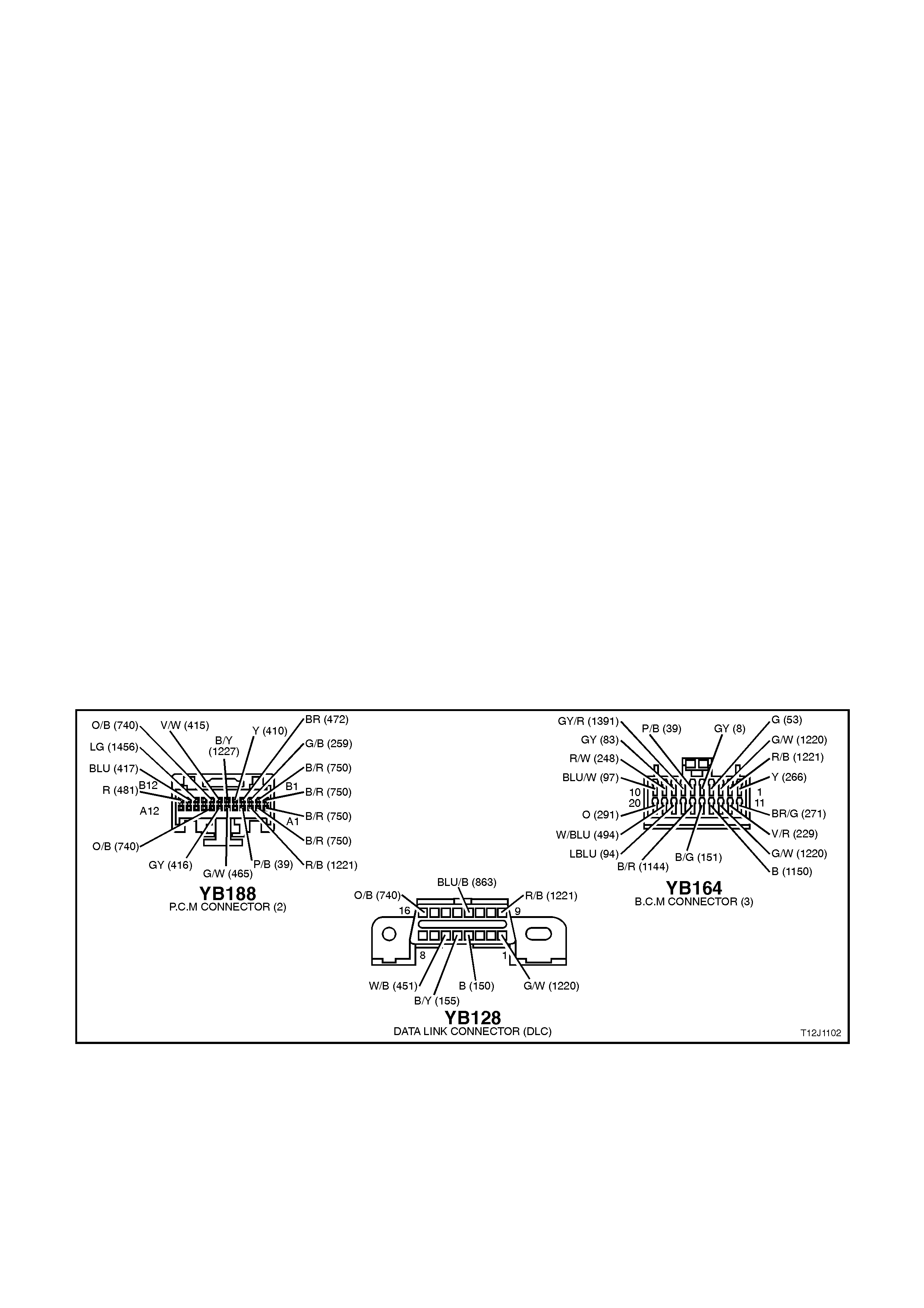
Excluding the PCM, the BCM polls eac h devic e f or a status update onc e ever y 300 millisec onds . T he BCM polls the
PCM twice every 300 milliseconds.
W hen the ignition is switched from OFF to ON, the BCM will communicate with the PCM, via the main serial data
line (circuit 1221), for antitheft purposes and TECH 2 will be able to communicate with any module via the ALDL
mode. If the BCM does not receive an OK TO START message from the PCM within 0.5 seconds of the ignition
being switched on, the auxiliary serial data line (circuit 1220) is isolated via switching within the BCM.
The isolation of the auxiliary serial data line during this period eliminates any possibility of a device failur e other than
the PCM or BCM, causing a problem on the bus, inhibiting antitheft communications. This period (know as short
loop time) continues until the PCM responds with an acknowledgment or a maximum of five seconds after which the
BCM will switch to the standard polling sequence.
Following successful antitheft communications, the BCM begins sequential polling of devices on the bus and normal
system operation is established.
When the ignition is switched OFF, the BCM continues to poll, allowing for TECH 2 communications and external
control of the bus prior to the ignition being switched ON.
TEST DESCRIPTION
The numbers below refer to step numbers diagnostic chart.
1. Ensures TECH 2 is functioning correctly.
2. Checks if TECH 2 can communicate with the BCM.
3. Checks if TECH 2 can communicate with the PCM.
4. Checks if TECH 2 can communicate with all the devices (SRS, ABS/ETC, INS) on the auxiliary serial data line.
5. Determ ines if ther e is a f ault in the s er ial data circ uit ( 1221) between the BCM and PCM by starting the engine.
If serial data was lost while the engine was running, the engine will restart but there will be a one second delay .
6. Checks continuity of circuit 1221 between the BCM and the DLC.
7. Checks if main serial data line crash is cause by control m odule interference connected to the auxiliary serial
data line, or a short battery + or earth on the auxiliary data line.
8. Checks for correct voltage on the serial data line.
9. Checks if the PCM is causing interface on the serial data line.
10. Checks integrity of circuit 1221 between the BCM and PCM, and if there is a problem with the PCM.
11. Checks to es tablis h whether lost c ommunication between m odules on the aux iliary serial data line and TECH 2
is due to an open in circuit 1221 or the module itself.
12. Checks to establish whether loss of c omm unication on the auxiliary serial data line is due to an open in circuit
1221 or the BCM.
Figure 12J-1-91

SERIAL DATA COMMUNICATION
STEP ACTION VALUE YES NO
1. • Connect TECH 2 to DLC.
• Turn ignition ON.
• Push power button on TECH 2.
• Does TECH 2 power up (screen
will illuminate display TECH 2)?
Go to Step 2. Go to TECH 2
diagnosis, refer to
Section 0C
TECH 2.
2. • With TECH 2 still connected and
ignition ON, select Diagnostics /
Body / Body Control Module.
• Does TECH 2 display BCM
system identification information
(BCM level and type)?
Go to Step 3. Go to Step 5.
3. • With TECH 2 still connected,
ignition ON, exit BODY and select
Diagnostics / Engine / Engine
Type (ie V6, V8).
• Does TECH 2 display PCM
system identification information
(ie. prom identification)?
Go to Step 4. Go to Step 12.
4. • With TECH 2 still connected,
ignition ON, exit Engine
Diagnostics and select Body /
DTC Check / DTC Check.
• Can TECH 2 communicate with
all control modules fitted to the
vehicle (if NO DATA is displayed
next to a control module, then
there is no communication
between TECH 2 and that control
module)?
NOTE:
If vehicle is not equipped with a
particular feature, ie. ECC, No Data
will be displayed next to this module
in the TECH 2 display.
System OK. Go to Step 13.
5. • Will the engine crank and start
immediately the key is turned
from off to start (no delay)?
Go to Step 6. Go to Step 8.
6. • Turn ignition OFF.
• Back probe DLC connector
YB128, terminal 9, circuit 1221
(Red/Black wire) and BCM
connector YB164, terminal D2,
circuit 1221 (Red/Black wire) with
an Ohmmeter.
• Is value as specified?
Below
1 ohm Go to Step 7. Check and repair
open in circuit
1221 between
DLC and BCM.
Recheck and
verify repair.
7. • Disconnect control modules on
auxiliary serial data line (ABS,
ABS/ETC, SRS, INS) one at a
time checking each time if TECH
2 can communicate with the BCM
(refer to Step 2).
• Does communication between the
BCM and TECH 2 resume after
disconnecting any of the control
modules?
Go to suspect
control module
diagnosis in
the relevant
Section.
Check and repair
short to B+ or
earth in circuit
1220.
Recheck and
verify repair.

STEP ACTION VALUE YES NO
8. • Turn ignition ON.
• Back probe DLC connector
YB128, terminal 9, circuit 1221
(Red/Black wire) with a Voltmeter
to earth.
• Is voltage as specified?
Fluctuates
between
3 and 5
volts
Go to Step 9. Go to Step 10.
9. • Disconnect PCM.
• Can TECH 2 communicate with
the BCM (refer to Step 2)?
Go to PCM
diagnostics in
Section 6C1
POWERTRAIN
MANAGEMENT
- V6 ENGINE
or
Section 6C2
POWERTRAIN
MANAGEMENT
- V8 ENGINE.
Go to theft
deterrent
diagnosis, refer
4.4 THEFT
DETERRENT in
this Section.
10. • Disconnect PCM.
• Can TECH 2 communicate with
the BCM (refer to Step 2)?
Go to PCM
diagnostics in
Section 6C1
POWERTRAIN
MANAGEMENT
- V6 ENGINE
or
Section 6C2
POWERTRAIN
MANAGEMENT
- V8 ENGINE.
Go to Step 11.
11. • Disconnect BCM and TECH 2.
• Check integrity (ie. Short to B+,
short to earth, and continuity) of
circuit 1221 (Red/Black wire)
between BCM and DLC, and
PCM and DLC.
• Is circuit 1221 OK?
Go to theft
deterrent
diagnosis, refer
to 4.4 THEFT
DETERRENT in
this Section.
Repair circuit 1221
as necessary.
Recheck and
verify repair.
12. • Turn ignition OFF.
• Back probe BCM connector
YB164, terminal D2, circuit 1221
(Red/Black wire) and PCM
connector YB188, terminal A3,
circuit 1221 (Red/Black wire) with
an Ohmmeter.
• Is value as specified?
Below
1 ohm Go to PCM
diagnostics in
Section 6C1
POWERTRAIN
MANAGEMENT
- V6 ENGINE
or
Section 6C2
POWERTRAIN
MANAGEMENT
- V8 ENGINE.
Check and repair
open in circuit
1221 between
PCM and BCM.
13. • In Step 4, was TECH 2 able to
communicate with at least one of
the control modules on the
auxiliary serial data line (ABS,
ABS/ETC, INS, SRS)?
NOTE:
TECH 2 will display No Data next to
a control module that it can not
communicate with in the DTC Check
mode.
Go to Step 14. Go to Step 15.

STEP ACTION VALUE YES NO
14. • Check continuity between BCM
and suspect control module in
circuit 1220 (Green/White wire).
• Does continuity exist?
Go to suspect
control module
diagnosis in the
relevant Section.
Repair open in
circuit 1220
between suspect
control module
and the BCM.
Recheck and
verify repair.
15. • Check continuity between BCM
and all control modules on the
auxiliary serial data line.
• Does continuity exist?
Replace BCM,
refer to 2.2 LOW
SERIES BCM in
this Section.
Recheck and
verify repair.
Repair open in
circuit 1220.
Recheck and
verify repair.
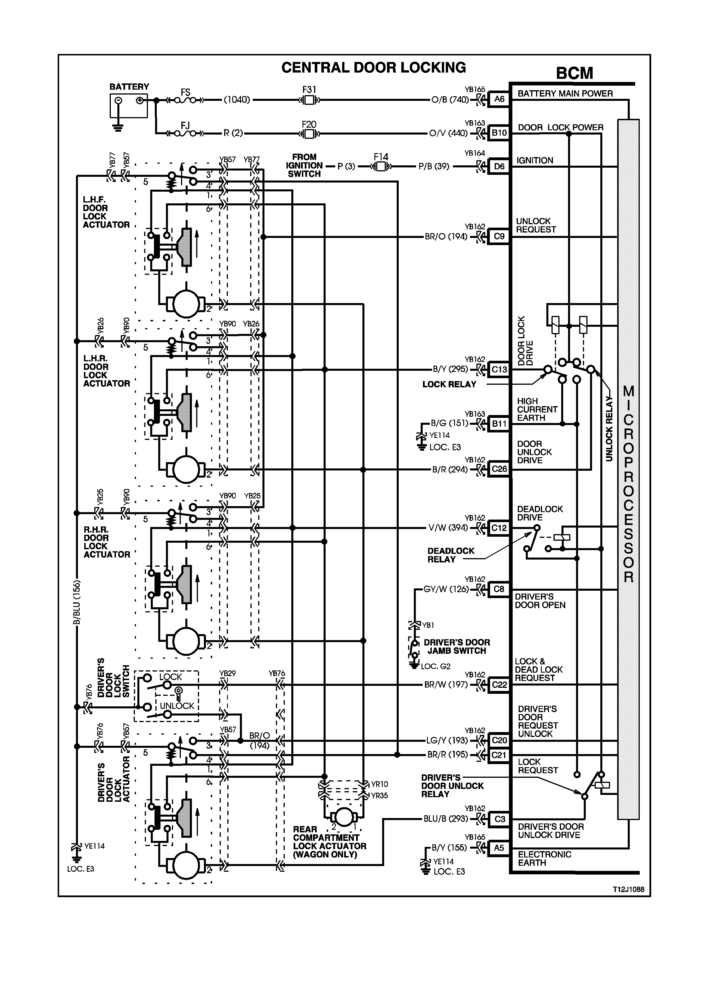
4.3 CENTRAL DOOR LOCKING
Figure 12J-1-92

GENERAL INFORMATION
The central door lock ing system provides for lock ing and unlock ing of all doors and tailgate (station wagon m odels)
as well as enhanced locking or 'deadlock' (doors only).
The system incorporates the following functions:
1. Door and tailgate locking activated via:
Driver's door lock actuator (mechanically linked to door interior snib and door latch).
Left hand front passenger’s door lock actuator (mechanically linked to interior snib button).
Driver’s door lock cylinder microswitches, which are also mechanically linked to the door latch, and therefore
linked to the actuators. VT Series Models require microswitch activation to force lock (and unlock) without
moving the actuator.
Pressing the lock button on remote coded key (provided all doors are closed).
2. Door and tailgate unlocking via:
All door lock actuators (mechanically linked to door interior snib).
Pressing the unlock button on remote coded key.
The driver’s door lock cylinder can also be moved independently of the actuator, allowing unlocking of the
driver’s door latch in the case where the actuator is struck down, ie. deadlock when the battery is discharged.
3. Single and Two Stage Unlocking
The BCM is capable of operating in either of two unlock modes, either two or single stage unlock. The BCM, as
fitted to the vehicle is programmed to operate the central door locking system in the two stage unlock mode.
TWO STAGE UNLOCK
In the two stage unlock m ode, when the rem ote coded key unlock button is depressed for 0.25 s econds, the BCM,
on receiving the unlock request from the remote coded key via the remote receiver, will unlock the driver’s door
only. If the remote coded key unlock button is depressed again f or 0.25 seconds the BCM, on receiving the second
unlock request from the remote coded key, will unlock all passenger doors.
Or alternatively, if the remote coded key is depressed continuously for 0.5 seconds, the BCM, on receiving the
unlock request from the remote coded key, will unlock all doors; first the driver’s door, then all passenger doors.
SINGLE STAGE UNLOCK
In single stage unlock mode, when the remote coded key unlock button is depressed for 0.25 seconds or longer,
the BCM on receiving the unlock request from the remote coded key, will unlock all doors simultaneously.
With TECH 2, the BCM can be pr ogrammed to operate in either two stage or s ingle stage unloc k (depending on the
vehicle’s owner or operator requirements).
If a short circuit exists on either the lock or unlock signal inputs, the opposing input is still able to perform its
function. This enables the doors to be unlocked when a short circuit exists on the lock input or vice-versa.
To protect the motors used in the door and tailgate lock actuators, in the event of multiple activations within a
defined time period, the system will time-out and protect the motors from damage. After a fixed time delay, the
system will re-activate as normal.
The deadlock feature provides for mechanical jamming of the door lock actuators. This is achieved electrically via
the driver's door lock cylinder microswitch.
NOTE:
Deadlock is inhibited whilst the ignition is on.
SYSTEM CHECK
The operation of the Central Door Locking System is independent of the ignition being switched ON or OFF.
Deadlock refers to the electrical means that can be activated to ensure vehicle security by inhibiting door lock
operation.
Even though the electronic theft deterrent system, via the remote coded key, can activate the doors locks, it does
not engage the electrical 'blocking' of the doors (deadlocking).
CENTRAL LOCKING AND UNLOCKING
Operation of this system can be effected as follows;
1. Driver’s door, outside key and inside locking (snib) button (locking and unlocking).
2. Left hand front passenger door inside locking (snib) button (locking and unlocking)
3. Rear passenger doors inside locking (snib) button (only unlocking is possible).
DEADLOCK
The deadlocking feature applies to all four doors, but not to the luggage compartment lid or tailgate.
After the deadlocking feature device has been engaged, unlocking is possible at the driver’s door from outside, by
inserting the key into the driver’s door lock cylinder and turning the key to the unlock position or by activating the
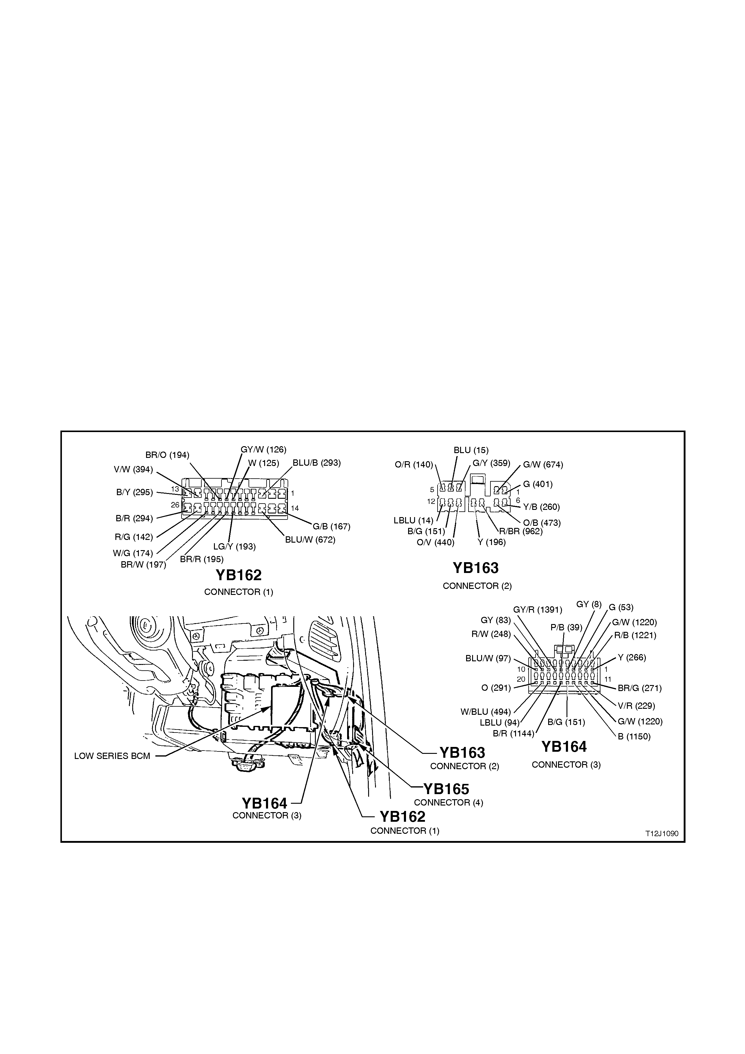
unlock button on the remote key unlocks the deadlocks on all doors. Either method only unlocks the driver’s door
when two stage unlocking is enabled.
To ensure access to the vehicle if the electrical system should fail (discharged battery), after the system has been
engaged, the driver’s door lock cylinder can be moved independently of the actuator and therefore allowing
unlocking of the driver’s door latch.
The rear com partment lid or tailgate can be lock ed/unlock ed when the mechanical deadloc king f eature is ac tuated,
while leaving the doors secured.
NOTE:
Deadlocking is not possible with the ignition in the ON position.
OVERHEATING PREVENTION
In the event of multiple activations within a defined tim e period, the central door lock ing system will be deactivated
and remain inoperative for a defined time period to prevent the door actuators from overheating. After a fixed time
delay, the system will re-activate and operate as normal.
DIAGNOSTICS
NOTE:
W hen inves tigating a com plaint of a centr al door system lock ing problem or m alfunction, always start the diagnosis
with the functional check in this Section.
The func tional check is a quick check of the central door lock ing system that will ref er the reader to the appropr iate
diagnostic chart in this Section.
W hen conducting the central door locking diagnostic tests, some procedures require locking and unlocking of the
door lock mechanism. Therefore, as an aid in testing, leave the appropriate door open and use a screw driver to
rotate the door lock mechanism to the locked position.
Figure 12J-1-93

FUNCTIONAL CHECK - CENTRAL DOOR LOCKING
STEP ACTION VALUE YES NO
1. • All doors locked.
• Operate unlock button on
remote coded key within 4
metres of driver’s side B pillar.
• Does driver’s door unlock (2
stage unlocking) or all doors
(single stage unlocking)?
Go to Step 3. Go to Step 2.
2. • All doors locked.
• Insert ignition key into driver’s
door lock cylinder and operate
door unlock microswitch (turn
key to unlock position).
• Do all doors unlock?
Go to remote
receiver
diagnosis, refer
to 4.6 REMOTE
RECEIVER/KEY
in this Section.
Go to Part A
UNLOCKING
DOORS,
DRIVER’S DOOR
LOCK CYLINDER
MICROSWITCH
3. • All doors unlocked.
• Ignition off.
• All doors closed.
• Operate lock button on remote
coded key within 4 metres of
driver’s side B pillar.
• Do all doors lock?
Go to Step 5. Go to Step 4.
4. • All doors unlocked.
• All doors closed.
• Insert ignition key into driver’s
door lock cylinder and operate
door lock microswitch (turn key
to lock position).
• Do all doors lock?
Go to remote
receiver
diagnosis, refer
to 4.6 REMOTE
RECEIVER/KEY
in this Section.
Go to Part B
LOCK DOORS,
DRIVER’S DOOR
LOCK CYLINDER
MICROSWITCH
5. • All doors locked.
• All doors closed.
• Insert ignition key into driver’s
door lock cylinder and operate
door unlock microswitch (turn
key to unlock position).
• Do all doors unlock?
Go to Step 6. Go to Part A
UNLOCKING
DOORS,
DRIVER’S DOOR
LOCK CYLINDER
MICROSWITCH
6. • All doors closed.
• Insert ignition key into driver’s
door lock cylinder and operate
door lock microswitch (turn key
to lock position).
• Do all doors lock?
Go to Step 7. Go to Part B
LOCK DOORS,
DRIVER’S DOOR
LOCK CYLINDER
MICROSWITCH
7. • All doors locked (not
deadlocked).
• Activate driver’s door snib
(unlock).
• Do all doors unlock?
Go to Step 8. Go to Part C
UNLOCK
DOORS,
DRIVER’S DOOR
ACTUATOR
(SNIB).
8. • All doors closed.
• All doors unlocked.
• Activate driver’s door snib (lock).
• Do all doors lock?
Go to Step 9. Go to Part D
LOCK DOORS,
DRIVER’S DOOR
ACTUATOR
(SNIB).

STEP ACTION VALUE YES NO
9. • All doors locked (not
deadlocked).
• Activate each passenger’s door
snib (unlock).
• Do all doors unlock (each snib)?
Go to Step 10. Go to Part E
UNLOCK
DOORS,
PASSENGER’S
DOOR
ACTUATOR
(SNIB).
10. • All doors closed.
• All doors unlocked.
• Activate left hand front
passenger’s door snib (lock).
• Do all doors lock?
Go to
Step 11 (wagon)
or
Go to
Step 13 (sedan).
Go to Part F
LOCK DOORS,
PASSENGER’S
LHF DOOR
ACTUATOR
(SNIB).
11. • Tailgate locked.
• Insert ignition key into driver’s
door lock cylinder and operate
door unlock microswitch (turn
key to unlock position).
• Does tailgate unlock?
Go to Step 12. Go to Part G
UNLOCK
TAILGATE.
12. • Tailgate unlocked.
• Insert ignition key into driver’s
door lock cylinder and operate
door lock microswitch (turn key
to lock position).
• Does tailgate lock?
Go to Step 13. Replace tailgate
lock actuator,
refer to
Section 1A4
REAR
COMPARTMENT
LID AND
TAILGATE.
13. • Doors unlocked.
• Insert ignition key into driver’s
door lock cylinder and deadlock
doors (turn key to lock twice
sequentially).
• Are all doors deadlocked?
Go to Step 14. Go to Part H
DEADLOCKING
DOORS.
14. • Doors deadlocked.
• Insert ignition key into driver’s
door lock cylinder and operate
door unlock microswitch (turn
key to unlock position).
• Do all doors unlock?
System OK. Go to Part I
UNLOCKING
DOORS FROM
DEADLOCK.

PART A - UNLOCKING DOORS, DRIVER’S DOOR LOCK CYLINDER MICROSWITCH
TEST DESCRIPTION
The numbers below refer to step numbers in the following diagnostic chart.
1. Uses TECH 2 to unlock all doors (establish whether problem is with the output or the input of the BCM.
2. Uses TECH 2 to check for false DRIVERS UNLOCK signal.
3. Checks if false DRIVERS DOOR UNLOCK signal initiated by BCM.
5. Checks for battery voltage at input to BCM.
6. Checks for earth to door actuators at output of BCM.
7. Checks circuit 394.
8. Checks for driver’s door unlock drive when commanded by TECH 2.
9. Checks for passenger doors unlock drive when commanded by TECH 2.
10. Checks circuits 293 and 294 / actuators.
11. Checks for high current earth at BCM.
12. Uses TECH 2 to check for DRIVERS DOOR UNLOCK SWITCH UNLOCK signal at microprocessor of BCM.
13. Checks DRIVER’S UNLOCK SWITCH UNLOCK signal at input to BCM.
14. Checks circuit 193.
15. Checks circuit 156 / microswitch.
16. Checks if false DRIVER’S DOOR UNLOCK signal initiated by driver’s door actuator.
17. Checks if false DRIVER’S DO OR UNLOCK signal initiated by driver’s door lock cylinder m icroswitch / short to
earth, circuit 193.
UNLOCKING DOORS, DRIVER’S DOOR LOCK CYLINDER MICROSWITCH
STEP ACTION VALUE YES NO
1. • Doors locked.
• Connect TECH 2 to the DLC.
• Select Body / Body Control
Module / Miscellaneous Tests /
Central Locking and conduct test
as instructed by TECH 2 (both
driver and all).
• Do all doors unlock?
Go to Step 2. Go to Step 4.
2. • Doors locked (driver’s door snib
down).
• With TECH 2 still connected,
exit Miscellaneous Test and
select Data Display.
• Scroll to Driver’s Door Unlock
Switch.
• Does screen display Driver’s
Door Unlock Switch Unlock?
Go to Step 3. Go to Step 12.
3. • With TECH 2 still connected and
Driver’s Unlock Switch
displayed, disconnect BCM
connector YB162.
• Does screen display Drivers
Door Unlock Switch Unlock?
Replace BCM,
refer to 2.2 LOW
SERIES BCM in
this Section.
Recheck and
verify repair
Go to Step 16.
4. • While conducting test in Step 1,
did at least one passenger door
unlock?
Go to Step 7. Go to Step 5.
5. • Back probe BCM connector
YB163, terminal B10, circuit 440
(Orange/Violet wire) with a
Voltmeter to earth.
• Is voltage as specified?
12 volts Go to Step 6. Check and repair
circuit 440
(including
fuse F20).
Recheck and
verify repair.

STEP ACTION VALUE YES NO
6. • Disconnect BCM connector
YB162.
• Back probe BCM, terminal C12,
circuit 394 (Violet/White wire)
with an Ohmmeter to earth.
• Is reading as specified?
Below
1 ohm Go to Step 7. Go to Step 11.
7. • Reconnect BCM connector
YB162 and back probe all door
actuator connectors YB57/YB90,
terminal 1, circuit 394
(Violet/White wire) with an
Ohmmeter to earth.
• Is reading as specified?
Below
1 ohm Go to Step 8. Repair open in
circuit 394.
Recheck and
verify repair.
8. • Doors locked.
• Back probe BCM connector
YB162, terminal C3, circuit 293
(Blue/Black wire) with a
Voltmeter to earth
• Connect TECH 2 to DLC.
• Select Body / Body Control
Module / Miscellaneous Tests /
Central Lock.
• Conduct test as instructed by
TECH 2 and unlock doors (both
driver and all).
• Is voltage as specified?
12 volts
for 0.7
seconds
Go to Step 9. Replace BCM,
refer to 2.2 LOW
SERIES BCM in
this Section.
Recheck and
verify repair
9. • Door locked.
• Back probe BCM connector
YB162, terminal C26, circuit 294
(Black/Red wire) wi th a
Voltmeter to earth.
• Repeat TECH 2 Central Lock
Test and unlock doors (both
driver and all).
• Is voltage as specified?
12 volts
for 0.7
seconds
Go to Step 10. Replace BCM,
refer to 2.2 LOW
SERIES BCM in
this Section.
Recheck and
verify repair
10. • Back probe all door actuator
connectors YB57/YB90, terminal
2, circuit 293 (Blue/Black wire)
and circuit 294 (Black/Red wire)
with a Voltmeter to earth.
• Repeat TECH 2 Central Lock
Test and unlock doors (both
driver and all).
• Is voltage as specified?
12 volts
for 0.7
seconds
Go to door lock
actuator
adjustment
procedure in
Section 1A5
FRONT & REAR
DOOR ASM.
Repair open in
circuit 293 or 294.
Recheck and
verify repair.
11. • Back probe BCM connector
YB163, terminal B11, circuit 151
(Black/Green wire) with an
Ohmmeter to earth.
• Is reading as specified?
Below
1 ohm Replace BCM,
refer to 2.2 LOW
SERIES BCM in
this Section.
Recheck and
verify repair.
Repair open in
circuit 151.
Recheck and
verify repair

STEP ACTION VALUE YES NO
12. • Connect TECH 2 to DLC.
• Select Body / Body Control
Module / Data Display and scroll
to Driver’s Door Unlock Switch.
• Insert ignition key into driver’s
door lock cylinder and operate
door unlock microswitch (turn
key to unlock position).
• Does screen display Driver’s
Unlock Switch Unlock?
Replace BCM,
refer to 2.2 LOW
SERIES BCM in
this Section.
Recheck and
verify repair
Go to Step 13.
13. • Back probe BCM connector
YB162, terminal C20, circuit 193
(Light Green/Yellow wire) with
an Ohmmeter to earth.
• Insert ignition key into driver’s
door lock cylinder and operate
door unlock microswitch (turn
key to unlock position).
• Is reading as specified?
Below
1 ohm Replace BCM,
refer to 2.2 LOW
SERIES BCM in
this Section.
Recheck and
verify repair.
Go to Step 14.
14. • Back probe driver’s door lock
cylinder switch connector YB29,
circuit 193 (Light Green/Yellow
wire) with an ohmmeter to earth.
• Operate driver’s door lock
switch.
• Is vale as specified?
Below
1 ohm Repair open in
circuit 193.
Recheck and
verify repair.
Go to step 15.
15. • Back probe driver’s door cylinder
switch connector YB29, circuit
156 (Black/Blue wire) with an
Ohmmeter to earth.
• Is reading as specified?
Below
1 ohm Replace driver’s
door exterior
handle
assembly, refer
to Section 1A5
FRONT & REAR
DOOR ASM.
Repair open in
circuit 156.
Recheck and
verify repair.
16. • With TECH 2 still connected and
Driver’s Unlock Switch
displayed, reconnect BCM
connector YB162.
• Disconnect Driver’s door
actuator connector YB57.
• Does screen display Driver’s
Door Unlock Switch Unlock?
Go to Step 17. Go to door lock
actuator
adjustment
procedure in
Section 1A5
FRONT & REAR
DOOR ASM.
17. • With TECH 2 still connected and
Driver’s Door Unlock Switch
displayed, disconnect driver’s
door lock cylinder switch
connector YB29.
• Does screen display Driver’s
Door Unlock Switch Unlock?
Check and
repair short in
circuit 193
(Light Green/
Yellow wire).
Replace driver’s
door exterior
handle assembly,
refer Section 1A5
FRONT & REAR
DOOR ASM.

PART B - LOCK DOORS, DRIVER’S DOOR LOCK CYLINDER MICROSWITCH
TEST DESCRIPTION
The numbers below refer to step numbers in the following diagnostic chart.
1. Uses TECH 2 to lock all doors (establish whether problem is with the output or the input of the BCM.
2. Uses TECH 2 to check for false DEADLOCK SWITCH signal.
3. Checks if false DEADLOCK SWITCH signal initiated by BCM.
4. Uses TECH 2 to check for DRIVERS DOOR CLOSED signal at microprocessor of BCM.
5. Checks for earth to driver’s door actuators at output of BCM.
6. Checks for earth to passenger’s door actuators at output of BCM.
7. Checks for door lock drive when commanded by TECH 2.
8. Checks circuit 295 / actuators.
10. Uses TECH 2 to check for DEADLOCK SWITCH LOCK signal at microprocessor of BCM.
11. Checks DRIVER’S DEADLOCK SWITCH LOCK signal at input to BCM.
12. Checks circuit 197.
13. Checks circuit 156 / microswitch.
14. Checks if f alse DEADLO CK SWIT CH LOCK signal initiated by driver’s door loc k c ylinder micros witch / shor t to
earth, circuit 197.
LOCK DOORS, DRIVER’S DOOR LOCK CYLINDER MICROSWITCH
STEP ACTION VALUE YES NO
1. • All doors closed.
• Connect TECH 2 to the DLC.
• Select Body / Body Control
Module / Miscellaneous Tests /
Central Lock and conduct test as
instructed by TECH 2.
• Do all doors lock?
Go to Step 2. Go to Step 4.
2. • Doors unlocked.
• With TECH 2 still connected,
exit Miscellaneous Test and
select Data Display.
• Scroll to Deadlock Switch.
• Does screen display Deadlock
Switch Deadlock?
Go to Step 3. Go to Step 10.
3. • With TECH 2 still connected and
Driver’s Lock Switch displayed,
disconnect BCM connector
YB162.
• Does screen display Drivers
Lock Switch Lock?
Replace BCM,
refer to 2.2 LOW
SERIES BCM in
this Section.
Recheck and
verify repair.
Go to Step 14.
4. • All doors closed.
• With TECH 2 still connected,
exit Miscellaneous Test and
select Data Display.
• Scroll to Drivers
Door/Passenger’s Door.
• All doors closed
• Does screen display both
Driver’s Door Closed and
Passenger’s Door Closed?
Go to Step 5 Go to Step 9.

STEP ACTION VALUE YES NO
5. • Disconnect BCM connector
YB162.
• Back probe BCM terminal C3,
circuit 293 (Blue/Black wire) with
an Ohmmeter to earth.
• Is reading as specified?
Below
1 ohm Go to Step 6. Replace BCM,
refer to 2.2 LOW
SERIES BCM in
this Section.
Recheck and
verify repair.
6. • Back probe BCM terminal C26,
circuit 294 (Black/Red wire) with
an Ohmmeter to earth.
• Is reading as specified?
Below
1 ohm Go to Step 7. Replace BCM,
refer to 2.2 LOW
SERIES BCM in
this Section.
Recheck and
verify repair.
7. • Reconnect BCM connector
YB162.
• All doors closed.
• Connect TECH 2 to the DLC.
• Select Body / Body Control
Module / Miscellaneous Tests /
Central Lock.
• Back probe BCM connector
YB162, terminal C13, circuit 295
(Black/Yellow wire) w ith a Refer
to 2.2 to earth.
• Conduct door lock test as
instructed by TECH 2 and lock
all doors.
• Is voltage as specified?
12 volts
for 0.7
seconds
Go to Step 8. Replace BCM,
refer to 2.2 LOW
SERIES BCM in
this Section.
Recheck and
verify repair.
8. • With TECH 2 still connected and
Miscellaneous Tests / Central
Locking selected, back probe all
door actuator connectors
YB90/YB57, terminal 6, circuit
295 (Black/Yellow wire) with a
Voltmeter to earth.
• Conduct door lock actuator test
as instructed by TECH 2.
• Is voltage as specified?
12 volts
for 0.7
seconds
Go to door lock
actuator
adjustment
procedure in
Section 1A5
FRONT AND
REAR DOOR
ASSEMBLIES.
Check and repair
open in circuit 295
Recheck and
verify repair.
9. • With TECH 2 still connected and
Data Displ ay Selected, scroll to
Driver’s Door and Passenger
Door display.
• Disconnect BCM connector
YB162.
• Does screen display both
Driver’s Door Closed and
Passenger’s Door Closed?
Check and
repair faulty door
jamb switches,
or short to
ground in circuit
125/126.
Recheck and
verify repair.
Replace BCM,
refer to 2.2 LOW
SERIES BCM in
this Section.
Recheck and
verify repair.
10. • With TECH 2 still connected and
Data Displ ay selected, scroll to
Deadlock Switch.
• Insert ignition key into driver’s
door lock cylinder and operate
door lock microswitch (turn key
to lock position).
• Does screen display Deadlock
Switch Deadlock?
Replace BCM,
refer to 2.2 LOW
SERIES BCM in
this Section.
Recheck and
verify repair.
Go to Step 11.

STEP ACTION VALUE YES NO
11. • Back probe BCM connector
YB162, terminal C22, circuit 197
(Brown/White wi re) with an
Ohmmeter to earth.
• Insert ignition key into driver’s
door lock cylinder and operate
door lock microswitch (turn key
to lock position).
• Is reading as specified?
Below
1 ohm Replace BCM,
refer to 2.2 LOW
SERIES BCM in
this Section.
Recheck and
verify repair.
Go to Step 12.
12. • Back probe driver’s door lock
cylinder switch connector YB29,
circuit 197 (Brown/White wire)
with an Ohmmeter to earth.
• Insert ignition key into driver’s
door lock cylinder and operate
door lock microswitch (turn key
to lock position).
• Is reading as specified?
Below
1 ohm Repair open in
circuit 197.
Recheck and
verify repair.
Go to Step 13.
13. • Back probe driver’s door lock
cylinder switch connector YB29,
circuit 156 (Blue/Black wire) with
an Ohmmeter to earth.
• Is reading as specified?
Below
1 ohm Replace driver’s
door exterior
handle
assembly, refer
Section 1A5
FRONT AND
REAR DOOR
ASSEMBLIES.
Repair open in
circuit 156.
Recheck and
verify repair.
14. • With TECH 2 still connected and
Driver’s Lock Switch displayed,
reconnect BCM connector
YB162.
• Disconnect Driver’s door lock
cylinder switch connector YB29.
• Does screen display Deadlock
Switch Deadlock?
Repair short to
earth in
circuit 197.
Recheck and
verify repair.
Replace driver’s
door exterior
handle assembly,
refer Section 1A5
FRONT AND
REAR DOOR
ASSEMBLIES.

PART C - UNLOCK DOORS, DRIVER’S DOOR ACTUATOR (SNIB)
TEST DESCRIPTION
The numbers below refer to step numbers in the following diagnostic chart.
1. Checks driver’s door snib unlock signal (earth) at driver’s door actuator when operating driver’s door snib
UNLOCK.
2. Checks circuit 156 / driver’s door actuator.
UNLOCK DOORS, DRIVER’S DOOR ACTUATOR (SNIB)
STEP ACTION VALUE YES NO
1. • All doors locked.
• Back probe driver’s door
actuator connector YB57,
terminal 3, circuit 193 (L
Green/Yellow wire) with an
Ohmmeter to a sound earth.
• Unlock doors using driver’s snib
button.
• Is reading as specified?
Below
1 ohm Check and
repair open in
circuit 193.
Recheck and
verify repair.
Go to Step 2.
2. • Back probe driver’s door
actuator connector YB57,
terminal 5, circuit 156
(Black/Blue wire) with an
Ohmmeter to earth.
• Is reading as specified?
Below
1 ohm Go to door lock
actuator
adjustment
procedure in
Section 1A5
FRONT AND
REAR DOOR
ASSEMBLIES.
Check and repair
open in circuit
156. Recheck and
verify repair.
PART D - LOCK DOORS, DRIVER’S DOOR ACTUATOR (SNIB)
TEST DESCRIPTION
The numbers below refer to step numbers in the following diagnostic chart.
1. Uses TECH 2 to check for false LOCK SWITCH STATUS LOCK signal.
2. Checks if false LOCK SWITCH STATUS LOCK signal initiated by BCM.
3. Uses TECH 2 to check for LOCK SWITCH STATUS LOCK signal at microprocessor of BCM.
4. Checks for LOCK SWITCH STATUS LOCK signal at input to BCM.
5. Checks circuit 195 / driver’s door actuator.
6. Checks if false LOCK SWITCH STATUS LOCK signal initiated by driver’s door actuator.
7. Checks if false LOCK SWITCH STATUS LOCK signal initiated by LHF passenger door / short to earth in circuit
195.
LOCK DOORS, DRIVER’S DOOR ACTUATOR (SNIB)
STEP ACTION VALUE YES NO
1. • All doors locked.
• Connect TECH 2 to DLC.
• Select Body / Body Control
Module / Data Display and scroll
to Lock Switch Status.
• Does screen display Lock
Switch Status Lock?
Go to Step 2. Go to Step 3.
2. • With TECH 2 still connected and
Lock Switch Status displayed,
disconnect BCM connector
YB162.
• Does screen display Lock
Switch Status Lock?
Replace BCM,
refer to 2.2 LOW
SERIES BCM in
this Section.
Recheck and
verify repair.
Go to Step 6.

STEP ACTION VALUE YES NO
3. • Lock doors using driver’s snib
button.
• Does screen display Lock
Switch Status Lock?
Replace BCM,
refer to 2.2 LOW
SERIES BCM in
this Section.
Recheck and
verify repair.
Go to Step 4.
4. • Back probe BCM connector
YB162, terminal C21, circuit 195
(Brown/Red wire) with an
Ohmmeter to earth.
• Lock doors using driver’s snib
button.
• Is value as specified?
Below
1 ohm Replace BCM,
refer to 2.2 LOW
SERIES BCM in
this Section.
Recheck and
verify repair.
Go to Step 5.
5. • Back probe driver’s door
actuator connector YB57,
terminal 4, circuit 195
(Brown/Red wire) with an
Ohmmeter to earth.
• lock doors using driver’s snib
button.
• Is value as specified?
Below
1 ohm Check and
repair open in
circuit 195.
Recheck and
verify repair.
Go to door lock
actuator
adjustment
procedure in
Section 1A5
FRONT AND
REAR DOOR
ASSEMBLIES.
6. • With TECH 2 still connected and
Lock Switch Status displayed,
reconnect BCM connector
YB162.
• Disconnect Driver’s door
actuator connector YB57.
• Does screen display Lock
Switch Status Lock?
Go to Step 7. Go to door lock
actuator
adjustment
procedure in
Section 1A5
FRONT AND
REAR DOOR
ASSEMBLIES.
7. • With TECH 2 still connected and
Lock Switch Status displayed,
disconnect LHF passenger door
actuator connector YB57.
• Does screen display Lock
Switch Status Lock?
Check and
repair short to
earth in
circuit 195.
Recheck and
verify repair.
Go to door lock
actuator
adjustment
procedure in
Section 1A5
FRONT AND
REAR DOOR
ASSEMBLIES.

PART E - UNLOCK DOOR, PASSENGER DOOR ACTUATORS (SNIB)
TEST DESCRIPTION
The numbers below refer to step numbers in the following diagnostic chart.
2. Check s non operating passenger door s nib unlock signal ( earth) at non operating actuator when operating it’s
snib UNLOCK
3. Uses TECH 2 to check for false PASSENGER UNLOCK SWITCH UNLOCK (passenger doors) signal.
4. Checks if false PASSENGER UNLOCK SWITCH UNLOCK signal initiated by BCM.
5. Uses T ECH 2 to check for PASSENGER UNLO CK SW IT CH UNLOCK signal at m icroproc essor of BCM while
operating each of the passenger door snibs.
6. Checks for PASSENGER UNLOCK SWITCH UNLOCK signal at input to BCM while operating each of the
passenger door snibs.
7. Checks circuit 194.
8. Checks circuit 156 / each passenger door actuator
9. Checks if false PASSENGER UNLOCK SWITCH UNLOCK signal initiated by any of the passenger door
actuators / short to earth in circuit 194.
10. Checks circuit 156 / passenger door actuator (non operating door actuator).
UNLOCK DOOR, PASSENGER DOOR ACTUATORS (SNIB)
STEP ACTION VALUE YES NO
1. • All doors locked.
• Unlock each passenger
door using each snib
button.
• Does at least one
passenger door snib
unlock all doors?
Go to Step 2. Go to Step 3.
2. • All door lock snibs down.
• Back probe actuator
connector, terminal 3 of
suspect door actuator
(unlock switch), circuit 194
(Brown/Orange wire) with
an Ohmmeter to earth.
• Operate suspect door lock
snib button.
• Is reading as specified?
Below
1 ohm Repair open in
circuit 194.
Recheck and
verify repair.
Go to Step 10.
3. • All doors locked.
• Connect TECH 2 to DLC.
• Select Body / Body
Control Module / Data
Display.
• Scroll to Passenger Door
Unlock Switch.
• Does screen display
Passenger Door Unlock
Switch Unlock?
Go to Step 4. Go to Step 5.
4. • With TECH 2 still
connected and Passenger
Door Unlock Switch
displayed, disconnect
BCM connector YB162.
• Does screen display
Passenger Door Unlock
Switch Unlock?
Go to Step 9. Replace BCM,
refer to 2.2 LOW
SERIES BCM in
this Section.
Recheck and
verify repair.

STEP ACTION VALUE YES NO
5. • All doors locked.
• With TECH 2 still
connected and Passenger
Door Unlock Switch
displayed unlock each
passenger door using
each snib button.
• Does the screen display
Passenger Door Unlock
Switch Unlock for at least
one of the passenger
doors?
Replace BCM,
refer to 2.2 LOW
SERIES BCM in
this Section.
Recheck and
verify repair.
Go to Step 6.
6. • All doors locked.
• Back probe BCM
connector YB162,
terminal C9, circuit 194
(Brown/Orange wire) with
an Ohmmeter to earth.
• Unlock each doors using
each snib button.
• Is value as specified for at
least one of the
actuators?
NOTE:
Lock each door lock actuator
after each test.
Below
1 ohm Replace BCM,
refer to 2.2 LOW
SERIES BCM in
this Section.
Recheck and
verify repair.
Go to Step 7.
7. • Back probe each
passenger door actuator
connector, terminal 3,
circuit 194 (Brown/Orange
wire) with an Ohmmeter to
earth.
• Unlock each passenger
doors using each snib
button.
• Is the reading as specified
for all actuators?
NOTE:
Lock each door lock actuator
after each test.
Below
1 ohm Repair open in
circuit 194.
Recheck and
verify repair.
Go to Step 8.
8. • Back probe each
passenger door actuator
connector, terminal 5,
circuit 156 (Black/Blue
wire) with an Ohmmeter to
earth.
• Is the reading as specified
for all actuators?
Below 1
ohm Go to door lock
actuator
adjustment
procedure in
Section 1A5
FRONT AND
REAR DOOR
ASSEMBLIES.
Repair open in
circuit 156.
Recheck and
verify repair.

STEP ACTION VALUE YES NO
9. • Reconnect BCM
connector YB162.
• With TECH 2 still
connected and Passenger
Door Unlock Switch
displayed, disconnect
each passenger door
actuator connector one at
a time.
• Does screen display
change from Passenger
Door Unlock Switch
Unlock to Passenger Door
Unlock Switch Off when
disconnecting any of the
passenger door actuator
connectors?
Go to door lock
actuator
adjustment
procedure in
Section 1A5
FRONT AND
REAR DOOR
ASSEMBLIES.
Check actuator
which caused
display to
change from
UNLOCK to
OFF.
Check and repair
short to earth in
circuit 194.
Recheck and
verify repair.
10. • Back probe actuator
connector, terminal 5 of
suspect door actuator/s,
circuit 156 (Black/Blue
wire) with an Ohmmeter to
earth.
• Is reading as specified?
Below
1 ohm Go to door lock
actuator
adjustment
procedure in
Section 1A5
FRONT AND
REAR DOOR
ASSEMBLIES.
Check suspect
actuator/s.
Repair open in
circuit 156.
Recheck and
verify repair.
PART F - LOCK DOORS, LHF PASSENGER DOOR ACTUATOR (SNIB)
TEST DESCRIPTION
The numbers below refer to step numbers in the following diagnostic chart.
1. Checks LHF passenger door snib lock signal (earth) when operating it’s snib button.
LOCK DOOR, LHF PASSENGER DOOR ACTUATOR (SNIB)
STEP ACTION VALUE YES NO
1. • All doors closed.
• All door lock snibs up.
• Back probe LHF passenger door
actuator connector YB57,
terminal 4, circuit 195
(Brown/Red wire) with an
Ohmmeter to earth.
• Lock LHF passenger door using
it’s snib button.
• Is the reading as specified?
Below
1 ohm Repair open in
circuit 195.
Recheck and
verify repair.
Go to door lock
actuator
adjustment
procedure in
Section 1A5
FRONT AND
REAR DOOR
ASSEMBLIES.
Check LHF
passenger door
actuator.

PART G - UNLOCK TAILGATE
TEST DESCRIPTION
The numbers below refer to step numbers in the following diagnostic chart.
1. Checks for unlock drive at rear compartment lock actuator when commanded by TECH 2.
2. Checks for earth at rear compartment lock actuator.
UNLOCK TAILGATE
STEP ACTION VALUE YES NO
1. • Doors and tailgate locked.
• Connect TECH 2 to DLC.
• Select BODY / BODY CONTROL
MODULE / MISCELLANEOUS
TEST / CENTRAL LOCK.
• Back probe tailgate lock actuator
connector YR35, terminal 1,
circuit 294 (Black/Red wire) with a
Voltmeter to earth.
• Conduct door unlock test as
instructed by TECH 2.
• Is the voltage as specified?
12 volts
for 0.7
seconds
Go to Step 2. Repair open in
circuit 294.
Recheck and
verify repair.
2. • Back probe tailgate lock actuator
connector YR35, terminal 2,
circuit 295 (Black/Yellow wire)
with an Ohmmeter to earth.
• Is reading as specified?
Below
1 ohm Replace tailgate
lock actuator,
refer to
Section 1A4
REAR
COMPARTMENT
LID AND
TAILGATE.
Check and repair
open in
circuit 295.
Recheck and
verify repair.
PART H - DEADLOCKING DOORS
TEST DESCRIPTION
The numbers below refer to step numbers in the following diagnostic chart.
1. Uses TECH 2 to check for false IGNITION ON signal at microprocessor of BCM.
2. Checks for correct IGNITION SIGNAL at input of BCM.
3. Checks for deadlock drive at output of BCM when commanded by TECH 2.
DEADLOCKING DOORS
STEP ACTION VALUE YES NO
1. • Turn ignition OFF.
• Connect TECH 2 to DLC.
• Select BODY / BODY
CONTROL MODULE / DATA
DISPLAY and scroll to
IGNITION SWITCH.
• Does screen display IGNITION
SWITCH ON?
Go to Step 2. Go to Step 3.
2. • Back probe BCM connector
YB164, terminal D6, circuit 39
(Pink/Black wire) with a
Voltmeter to earth.
• Is voltage as specified?
Turn
ignition
OFF.
0 volts
Turn
ignition
ON.
12 volts
Replace BCM,
refer to 2.2 LOW
SERIES BCM in
this Section.
Recheck and
verify repair.
Check and repair
short to battery
positive, circuit 39
/ ignition switch.

STEP ACTION VALUE YES NO
3. • All doors unlocked / closed.
• With TECH 2 still connected,
exit Data Display and select
miscellaneous tests / central
lock.
• Back probe BCM connector
YB162, terminal C12, circuit 394
(Violet/White wire) with a
Voltmeter to earth.
• Conduct test and instructed by
TECH 2 and deadlock doors.
• Is voltage as specified?
12 volts
for 0.7
seconds
Go to door lock
actuator
adjustment
procedure in
Section 1A5
FRONT AND
REAR DOOR
ASSEMBLIES
Replace BCM,
refer to 2.2 LOW
SERIES BCM in
this Section.
Recheck and
verify repair.
PART I - UNLOCKING DOORS FROM DEADLOCK
TEST DESCRIPTION
The numbers below refer to step numbers in the following diagnostic chart.
1. Uses TECH 2 to unlock all doors (establish whether problem is with the output or the input of the BCM.
2. Uses TECH 2 to check for false DRIVER’S DOOR UNLOCK signal.
3. Checks if false DRIVER’S DOOR UNLOCK signal initiated by BCM.
5. Checks for battery voltage at input to BCM.
6. Checks for high current earth at BCM.
7. Checks for earth to door actuators at output of BCM.
8. Checks for earth to door actuators at output of BCM.
9. Checks circuit 394.
10. Checks circuit 295.
11. Checks for drivers door unlock drive at output of BCM when commanded by TECH 2.
12. Checks for passenger doors unlock drive at output of BCM when commanded by TECH 2.
13. Checks circuits 294 and 293 / all door actuators by commanding unlock via TECH 2.
14. Uses TECH 2 to check for DRIVER’S DOOR UNLOCK SWITCH UNLOCK signal at microprocessor of BCM.
15. Checks DRIVER’S DOOR UNLOCK SWITCH UNLOCK signal at input to BCM.
16. Checks circuit 193.
17. Checks circuit 156 / microswitch.
18. Checks if false DRIVER’S DOOR UNLOCK signal initiated by driver’s door actuator.
19. Checks if false DRIVER’S DO OR UNLOCK signal initiated by driver’s door lock cylinder m icroswitch / short to
earth, circuit 193.
UNLOCKING DOORS FROM DEADLOCK
STEP ACTION VALUE YES NO
1. • Doors deadlocked.
• Connect TECH 2 to the DLC.
• Select Body / Body Control
Module / Miscellaneous Tests /
Central Lock.
• Conduct all doors unlock test as
instructed by TECH 2.
• Do all doors unlock?
Go to Step 2. Go to Step 4.

STEP ACTION VALUE YES NO
2. • Doors unlocked.
• With TECH 2 still connected,
exit Miscellaneous Test and
select Data Display.
• Scroll to Driver’s Door Unlock
Switch.
• Does screen display Driver’s
Door Unlock Switch Unlock?
Go to Step 3. Go to Step 14.
3. • With TECH 2 still connected and
Driver’s Unlock Switch
displayed, disconnect BCM
connector YB162.
• Does screen display Driver’s
Door Unlock Switch Unlock?
Replace BCM,
refer to 2.2 LOW
SERIES BCM in
this Section.
Recheck and
verify repair.
Go to Step 18.
4. • While conducting test in Step 1,
did at least one passenger door
unlock?
Go to Step 9. Go to Step 5.
5. • Back probe BCM connector
YB163, terminal B10, circuit 440
(Orange/Violet wire) with a
Voltmeter to earth.
• Is voltage as specified?
12 volts Go to Step 6. Check and repair
circuit 440
(including
fuse F20).
Recheck and
verify repair
6. • Back probe BCM connector
YB163, terminal B11, circuit 151
(Black/Green wire) with an
Ohmmeter to earth.
• Is value as specified?
Below
1 ohm Go to Step 7. Check and repair
circuit 151.
Recheck and
verify repair.
7. • Disconnect BCM connector
YB162.
• Back probe terminal C12, circuit
394 (Violet/White wire) with an
Ohmmeter to earth.
• Is value as specified?
Below
1 ohm Go to Step 8. Replace BCM,
refer to 2.2 LOW
SERIES BCM in
this Section.
Recheck and
verify repair
8. • Back probe BCM terminal 13,
circuit 295 (Black/Yellow wire)
with an Ohmmeter to earth.
• Is value as specified?
Below
1 ohm Go to Step 9. Replace BCM,
refer to 2.2 LOW
SERIES BCM in
this Section.
Recheck and
verify repair
9. • Back probe all door actuator
connectors YB57/YB90, terminal
1, circuit 394 (Violet/White wire)
and BCM terminal C12 with an
Ohmmeter.
• Is value as specified?
Below
1 ohm Go to Step 10. Check and repair
circuit 394.
Recheck and
verify repair.
10. • Back probe all door actuator
connectors YB57/YB90, terminal
6, circuit 295 (Black/Yellow wire)
and BCM terminal C13 with an
Ohmmeter.
• Is value as specified?
Below
1 ohm Go to Step 11. Check and repair
circuit 295.
Recheck and
verify repair

STEP ACTION VALUE YES NO
11. • Disconnect BCM connector
YB162.
• Back probe BCM connector
YB162, terminal C3, circuit 293
(Blue/Black wire) with a
Voltmeter to earth.
• Select Body / Body Control
Module / Miscellaneous Test /
Central Lock.
• Conduct test as instructed by
TECH 2.
• Is voltage as specified?
12 volts
for 0.7
seconds
Go to Step 12. Replace BCM,
refer to 2.2 LOW
SERIES BCM in
this Section.
Recheck and
verify repair
12. • Back probe BCM connector
YB162, terminal C26, circuit 294
(Black/Red wire) wi th a
Voltmeter to earth.
• Repeat TECH 2 Central Lock
test and lock doors.
• Is voltage as specified?
12 volts
for 0.7
seconds
Go to Step 13. Replace BCM,
refer to 2.2 LOW
SERIES BCM in
this Section.
Recheck and
verify repair.
13. • Back probe all door actuator
connectors YB57/YB90, terminal
2, circuit 293 (Blue/Black wire)
and circuit 294 (Black/Red wire)
with a Voltmeter to earth.
• Repeat TECH 2 Central Lock
test and lock doors.
• Is voltage as specified?
12 volts
for 0.7
seconds
Go to door lock
actuator
adjustment
procedure in
Section 1A5
FRONT AND
REAR DOOR
ASSEMBLIES.
Repair open in
circuit 293 or 294.
Recheck and
verify repair.
14. • With TECH 2 still connected and
Driver’s Door Unlock Switch
displayed, insert ignition key into
driver’s door lock cylinder and
operate door unlock microswitch
(turn key to unlock position).
• Does screen display Driver’s
Door Unlock Switch Unlock?
Replace BCM,
refer to 2.2 LOW
SERIES BCM in
this Section.
Recheck and
verify repair.
Go to Step 15.
15. • Back probe BCM connector
YB162, terminal C20, circuit 193
(Light Green/Yellow wire) with
an Ohmmeter to earth.
• Insert ignition key into driver’s
door lock cylinder and operate
door unlock microswitch (turn
key to unlock position).
• Is reading as specified?
Below
1 ohm Replace BCM,
refer to 2.2 LOW
SERIES BCM in
this Section.
Recheck and
verify repair
Go to Step 16.
16. • Back probe driver’s door lock
cylinder switch connector YB29,
circuit 193 (Light Green/Yellow
wire) with an Ohmmeter to earth.
• Insert ignition key into driver’s
door lock cylinder and operate
door unlock microswitch (turn
key to unlock position).
• Is reading as specified?
Below
1 ohm Repair open in
circuit 193.
Recheck and
verify repair.
Go to Step 17.

STEP ACTION VALUE YES NO
17. • Back probe driver’s door lock
cylinder switch connector YB29,
circuit 156 Black(/Blue wire) with
an Ohmmeter to earth.
• Is reading as specified?
Below
1 ohm Replace driver’s
door exterior
handle assembly,
refer Section 1A5
FRONT AND
REAR DOOR
ASSEMBLIES.
Repair open in
circuit 156.
Recheck and
verify repair.
18. • With TECH 2 still connected and
Driver’s Door Unlock Switch
displayed, reconnect BCM
connector YB162.
• Disconnect Driver’s door
actuator connector YB57.
• Does screen display Driver’s
Door Unlock Switch Unlock?
Go to Step 17. Go to door lock
actuator
adjustment
procedure in
Section 1A5
FRONT AND
REAR DOOR
ASSEMBLIES
19. • With TECH 2 still connected and
Driver’s Door Unlock Switch
displayed, disconnect driver’s
door lock cylinder switch
connector YB29.
• Does screen display Driver’s
Door Unlock Switch Unlock?
Check and repair
short in circuit 193
(Light Green/
Yellow wire).
Replace driver’s
door exterior
handle assembly,
refer Section 1A5
FRONT AND
REAR DOOR
ASSEMBLIES.
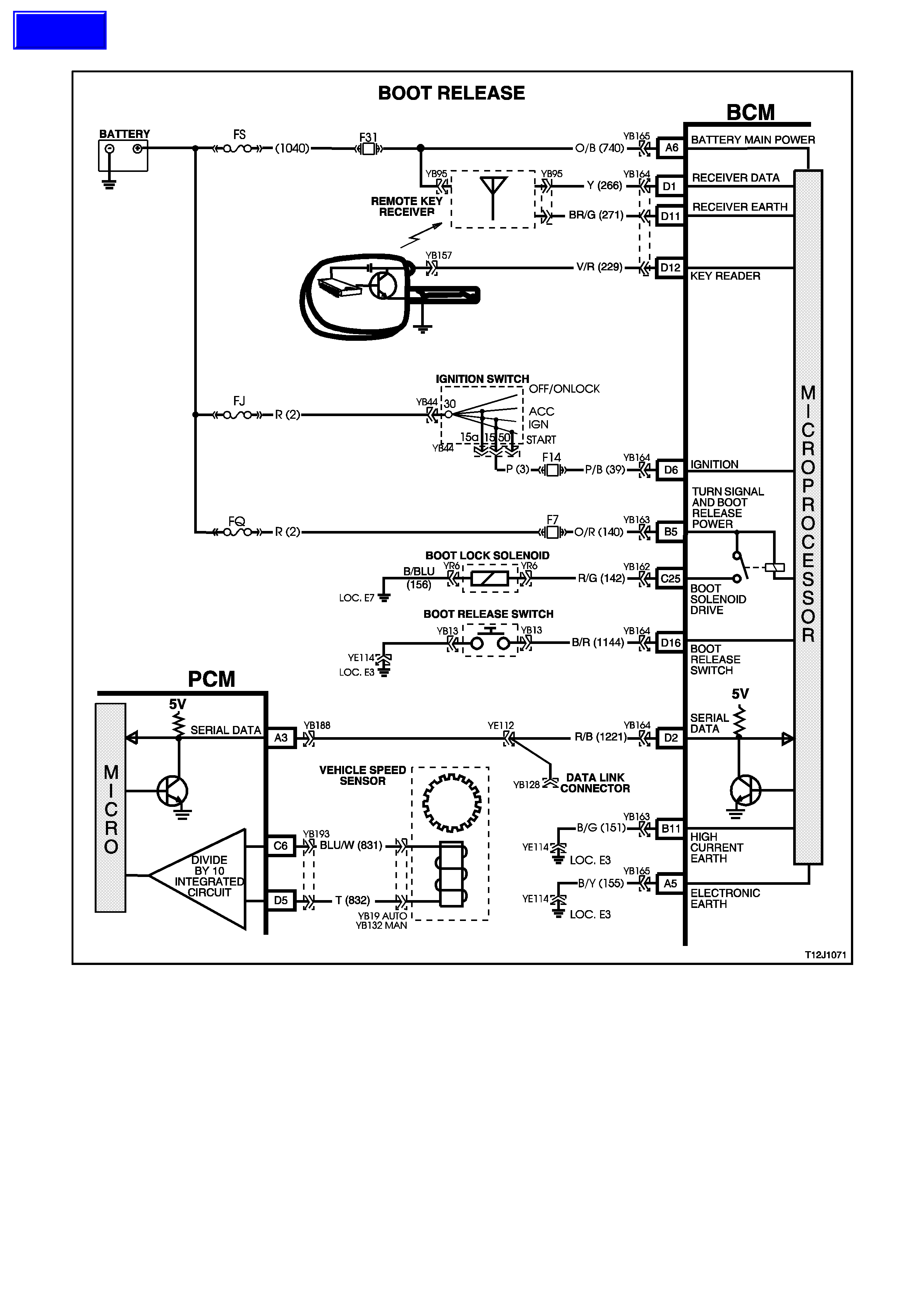
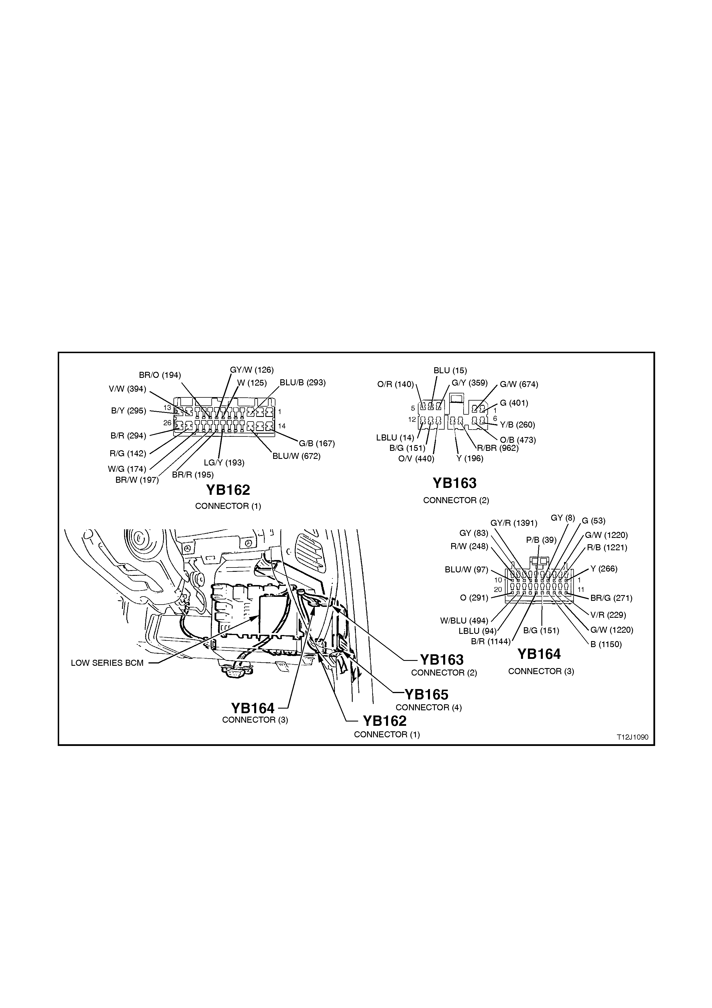
CIRCUIT DESCRIPTION:
The rear com partm ent loc k actuator is controlled by pressing the rear com par tm ent loc k switch located in the glove
compartment. The BCM will monitor the rear compartment lock switch and inhibit the boot release if the vehicle
speed is above 15 km/h.
TEST DESCRIPTION:
The numbers below refer to step numbers in the following diagnostic chart.
1-2 Functional check to determine if system is functioning correctly or if faulty, determines if fault is with remote
receiver/key or with boot release system.
3. Uses TECH 2 to operate the rear com partment lock actuator to establish whether problem is with the input or
output of BCM.
4. Uses TECH 2 to check BOOT RELEASE SWITCH ON signal at microprocessor of BCM.
5. Check s for rear c ompartm ent lock actuator drive signal at the output of the BCM when com manded by TECH
2.
6. Checks circuit 142.
7. Checks circuit 156 and rear compartment lock actuator.
8. Checks for battery voltage supply at BCM (turn signal / boot solenoid supply).
9. Checks for BOOT SWITCH signal at input of BCM.
10. Checks circuit 1144.
11. Checks circuit 155 and rear compartment lock switch.
Figure 12J-1-95

BOOT RELEASE
STEP ACTION VALUE YES NO
1. • Activate boot release lock switch
in glove compartment with vehicle
speed below 15 km/h.
• Does the rear compartment lid
open?
Go to Step 2. Go to Step 3.
2. • Close rear compartment lid.
• Press the boot release button on
the remote coded key (within two
metres of the rear of the vehicle).
• Does rear compartment lid open?
System OK. Go to remote
receiver
diagnosis, refer
to 4.6 REMOTE
RECEIVER/
KEY in this
Section.
3. • Connect TECH 2, ignition ON.
• Select Body / Body Control
Module / Miscellaneous Tests /
Security System / Boot Release.
• Conduct test as instructed by
TECH 2.
• Does boot lid open?
Go to Step 4. Go to Step 5.
4. • With TECH 2 still connected, exit
Miscellaneous Tests, select Data
Display and scroll to Boot
Release Switch.
• Press boot release button in glove
compartment.
• Does the screen display change
to Boot Release Switch On?
Replace BCM,
refer to 2.2 LOW
SERIES BCM in
this Section.
Recheck and
verify repair.
Go to Step 9.
5. • Back probe BCM connector
YB162, terminal C25, circuit 142
(Red/Green wire) with a Voltmeter
to earth.
• Repeat TECH 2 Boot Release
test and press release button in
glove compartment.
• Are voltages as specified?
Test not
conducted
0 volts
Test
conducted
12 volts
Go to Step 6. Go to Step 8.
6. • Back probe actuator connector
YR6, circuit 142 (Red/Green wire)
with Voltmeter to earth.
• Repeat TECH 2 Boot Release
test and press release button in
glove compartment.
• Are voltages as specified?
Test not
conducted
0 volts
Test
conducted
12 volts
Go to Step 7. Repair open or
short in
circuit 142.
Recheck and
verify repair.
7. • Back probe actuator connector
YR6 circuit 156 (Black/Blue wire)
with an Ohmmeter to earth.
• Is reading as specified?
Below
1 ohm Replace rear
compartment lock
actuator, refer to
Section 1A4 REAR
COMPARTMENT
LID AND
TAILGATE.
Repair open in
circuit 156.
Recheck and
verify repair.
8. • Back probe BCM connector
YB163, terminal B5, circuit 140
(Orange/Red wire) with a
Voltmeter to earth.
• Is voltage as specified?
battery + Replace BCM,
refer to 2.2 LOW
SERIES BCM in
this Section.
Recheck and
verify repair.
Check and
repair open or
short in circuit
140 (including
fuse F7).
Recheck and
verify repair.

STEP ACTION VALUE YES NO
9. • Back probe BCM connector
YB164, terminal D16, circuit 1144
(Black/Red wire) wi th an
Ohmmeter to earth.
• Activate the rear compartment
lock switch.
• Is value as specified?
Below
1 ohm Replace BCM,
refer to 2.2 LOW
SERIES BCM in
this Section.
Recheck and
verify repair.
Go to Step 10.
10. • Back probe rear compartment
lock switch connector YB13,
circuit 1144 (Black/Red wire) with
a Ohmmeter to earth.
• Activate the rear compartment
lock switch.
• Is value as specified?
Below
1 ohm Repair open or
short in circuit
1144. Recheck
circuit to verify
repair.
Go to Step 11.
11. • Back probe rear compartment
lock switch connector, YB13,
circuit 155 (black/Yellow wire)
with an Ohmmeter to earth.
• Is reading as specified?
Below
1 ohms Replace rear
compartment lock
switch, refer to
Section 1A4 REAR
COMPARTMENT
LID AND
TAILGATE.
Repair open in
circuit 155.
Recheck and
verify repair.
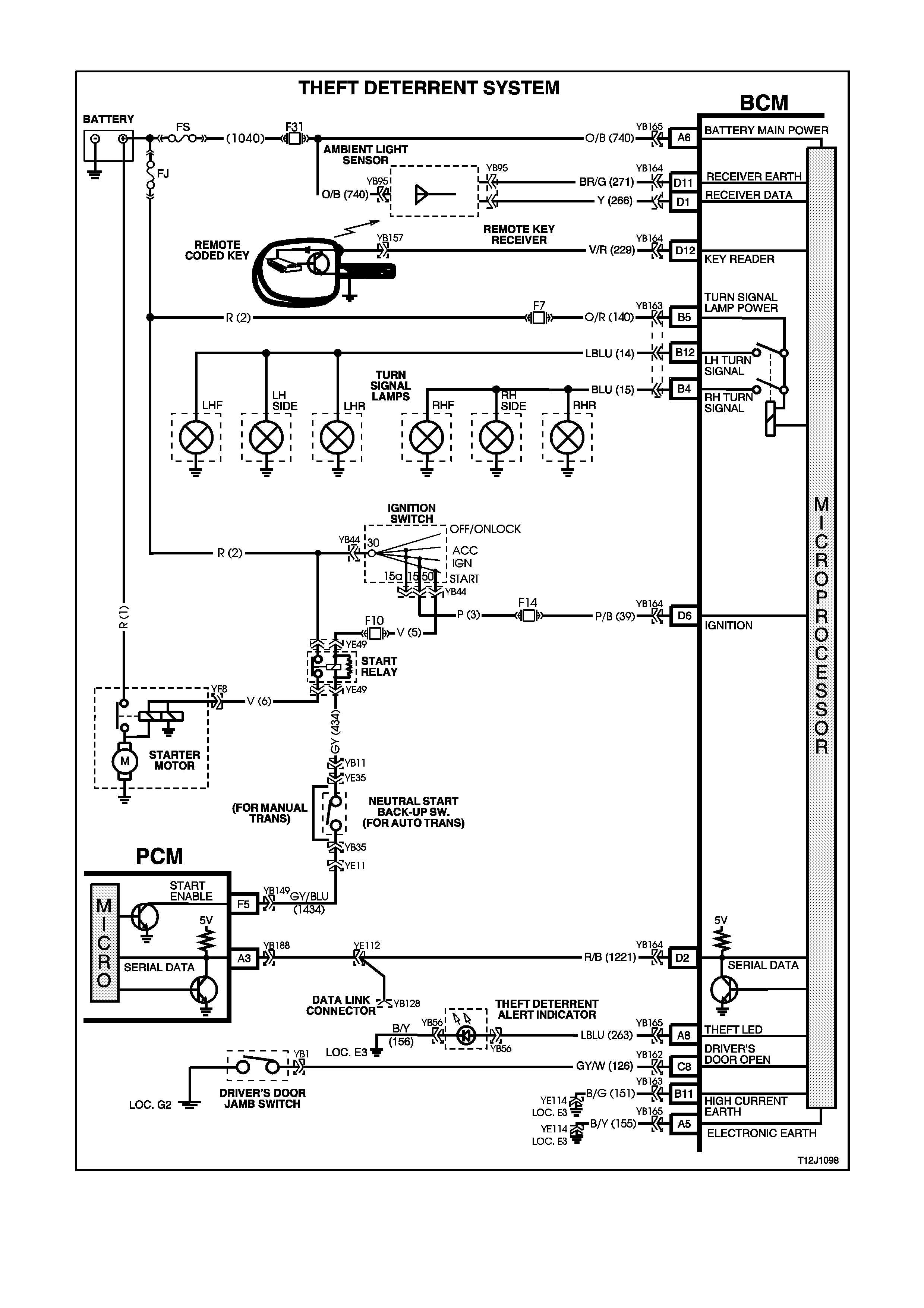
4.5 THEFT DETERRENT
Figure 12J-1-96

CIRCUIT DESCRIPTION:
The theft deterrent system can be armed by pressing the lock button on the remote coded key when the driver’s
door is closed or passively armed autom atically by the BCM 30 s econds af ter the ignition is switched of f. When the
system is armed, the Powertrain Control Module (PCM) prevents the engine from starting.
The theft deterrent system can be disarmed in three ways:-
By press ing the unlock button on the r emote c oded key. This will unlock doors, turn the interior light on and dis arm
the system for 30 seconds.
By inserting the remote coded key into the ignition switch cylinder and turning the ignition to the ON position. This
causes the BCM to read a security code serial data output from the remote coded key contact pin, via the remote
coded key reader assembly.
The system can also be disarmed by turning the ignition on for approximately two hours (timed override).
Should the system not disar m (thef t deterrent LED of f) when the ignition switch is turned to the ON position (ie. due
to a mis aligned or faulty rem ote coded k ey reader or faulty remote coded k ey), then press the button on the rem ote
key to disarm the theft deterrent system.
The remote coded key is powered by it’s own internal battery. If the battery fails, the remote coded key can be
powered by the rem ote coded key reader once the k ey is inserted into the ignition c ylinder and turned to either the
ON or START positions.
When pressing the lock button on the remote coded key to arm the system, the indicators will flash once and the
theft deterrent alert indicator (LED) will begin to flash.
W hen pressing the unlock button on the rem ote coded key to disarm the system, the indicator s will flash twice and
the theft deterrent alert indicator (LED) will go out.
When the ignition is turned on, the BCM polls the PCM and sends an encrypted BCM remote coded key security
code.
The PCM c ompares the received sec urity code with it’s stored security code (configur ed in produc tion or via TECH
2) and if the codes match, the PCM will enable injector fuelling and engine crank.
The PCM will return an OK TO START mes sage which tells the BCM to jum p fr om the SHO RT LOO P mode to the
LONG LOOP mode.
TEST DESCRIPTION:
The numbers below refer to step numbers in the following diagnostic chart.
1-10 Functional check of system.
11. Checks if doors are not locking due to central door locking system or remote receiver/remote key.
12. Re-synchronisation of remote key rolling code in event of rolling code misalignment.
14. Uses TECH 2 to operate indicators (establish whether problem is with the BCM or other external problem).
15. Checks turn signal input at input to BCM.
16. Checks turn signal output at output of BCM when commanded by TECH 2.
17. Uses TECH 2 to operate the theft deterrent LED (establis h whether problem is with the BCM or other external
problem).
18. Checks for theft deterrent LED output drive form the BCM when commanded by TECH 2.
19. Checks for short to earth in circuit 263 causing LED to be faulty.
20. Checks circuit 263.
21. Checks circuit 156 for open to establish if circuit is faulty or theft deterrent LED is faulty.
22. Checks if problem is confined to the key reader or remote serial data transfer.
23. Checks for poor remote coded key shaft earth contact.
24. Checks for poor contact of remote coded key pin with remote coded key reader.
25. Checks if problem is with remote coded key by trying a known good remote coded key.
26. Checks for BCM signal at remote key reader.
27. Checks ignition switch/cylinder earth.
28. Uses TECH 2 to check IGNITION ON signal at microprocessor of BCM.
29. Checks circuit 229 for open to establish if circuit is faulty or BCM is faulty.
30. Checks for short to earth in circuit 229.
31. Checks ignition ON signal at input to BCM.
32. Uses TECH 2 to check for PASSIVE MODE OFF signal at microprocessor of BCM to establish if fault is with
the BCM or PCM.
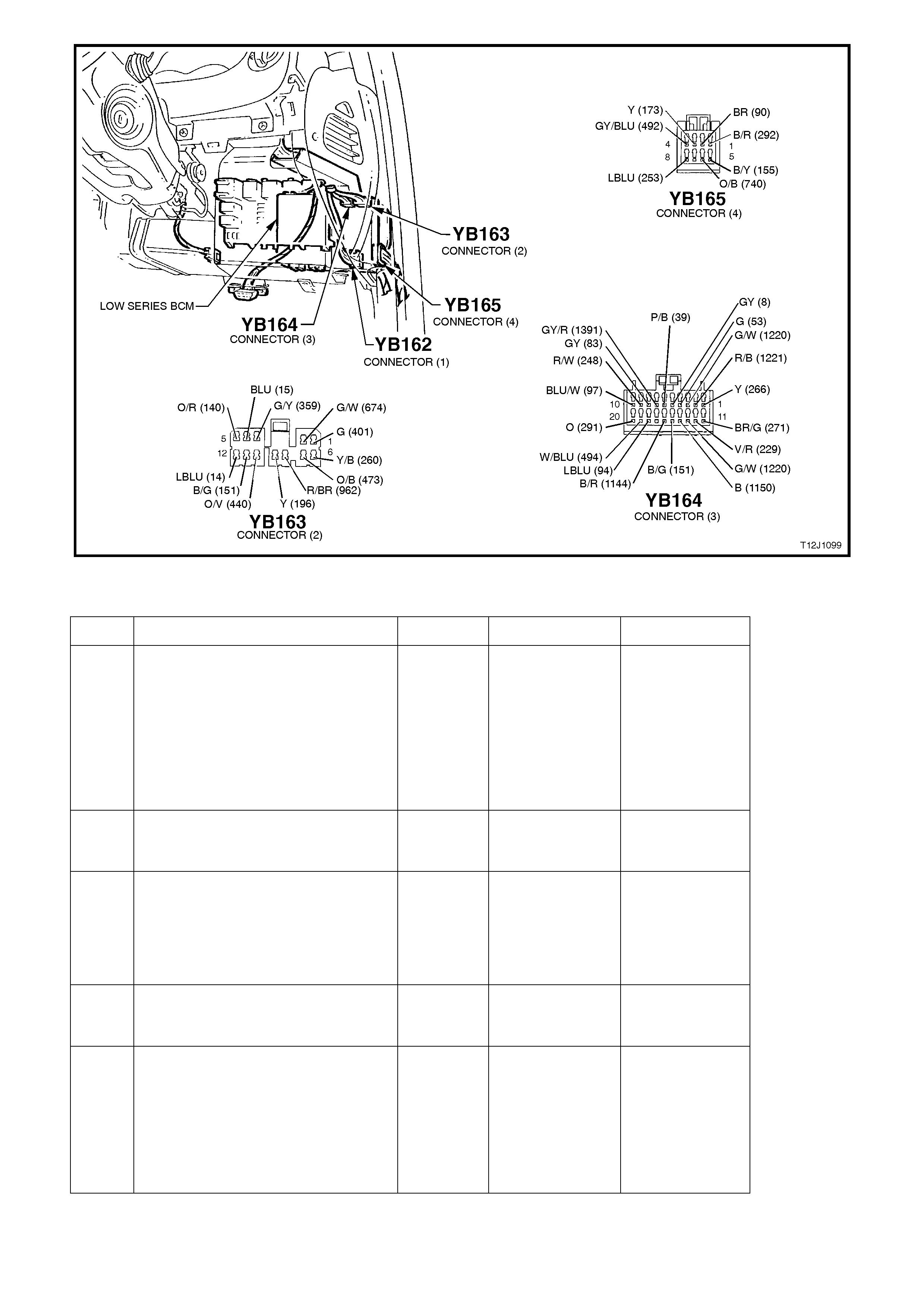
Figure 12J-1-97
THEFT DETERRENT
STEP ACTION VALUE YES NO
1. • Close and lock all doors.
• Operate remote key UNLOCK
button within 4 meters of the
driver’s side B pillar.
• Does the driver’s door unlock (2
stage unlocking programmed) or
all doors unlock (single stage
unlocking programmed)?
Go to Step 2. Go to Step 11.
2. •In Step 1, did all indicator lights
flash twice (both left and right
hand sides)?
Go to Step 3. Go to Step 13.
3. •In Step 1, did the dome lamp
illuminate? Go to Step 4. Go to dome lamp
delay diagnosis,
refer 4.12 DOME
LAMP DELAY
CONTROL in this
Section.
4. •In Step 1, did the theft deterrent
LED go out immediately and
begin flashing 30 seconds latter?
Go to Step 5. Go to Step 17.
5. •Close all doors.
•Arm theft deterrent sy stem by
operating the LOCK button on
the remote coded key within 4
metres of the driver’s side B
pillar.
•Did all doors lock?
Go to Step 6. Go to central
door locking
diagnosis, refer
to 4.3 CENTRAL
DOOR LOCKING
in this Section.

STEP ACTION VALUE YES NO
6. •In Step 5, did the dome lamp go
out immediately upon activating
the lock button?
Go to Step 7. Go to dome lamp
delay diagnosis,
refer 4.12 DOME
LAMP DELAY
CONTROL in this
Section.
7. •In Step 5, did all indicator lights
flash once (both left and right
hand sides)?
Go to Step 8. Replace BCM,
refer to 2.2 LOW
SERIES BCM in
this Section.
Recheck and
verify repair.
8. •Is the theft deterrent LED
flashing? Go to Step 9. Replace BCM,
refer to 2.2 LOW
SERIES BCM in
this Section.
Recheck and
verify repair.
9. •Unlock vehicle with remote
coded key and wait for the
vehicle to passively arm (theft
deterrent LED flashing).
•With vehicle passively armed),
insert the ignition key into ignition
switch and turn to the ON
position.
•Does the theft deterrent LED
extinguish?
Go to Step 10. Go to Step 22.
10. •Turn the ignition key to the
START position.
•Does the vehicle crank and
start?
System OK. Go to Step 32.
11. •Insert ignition key into driver’s
door lock cylinder and operate
door unlock microswitch (turn
key to unlock position).
•Do all doors unlock?
Go to Step 12. Go to central
door locking
diagnosis, refer
to 4.3 CENTRAL
DOOR LOCKING
in this Section.
12. •Insert ignition key into ignition
switch and cycle from OFF - ON
- OFF.
•Remove key and lock doors with
driver’s door lock cylinder switch.
•Operate UNLOCK button on
remote key within 4 metres of
driver’s door B pillar.
•Does the driver’s door unlock (2
stage unlocking programmed) or
all doors unlock (single stage
unlocking programmed)?
Go to Step 2. Go to remote
receiver
diagnosis, refer
to 4.6 REMOTE
RECEIVER/KEY
in this Section.
13. •In Step 2, did at least one side of
vehicle’s indicators flash twice
(either left or right hand side)?
Go to Step 16. Go to Step 14.

STEP ACTION VALUE YES NO
14. •Driver’s door closed.
•Connect TECH 2 to DLC.
•Select Body / Body Control
Module / Miscellaneous Tests /
Lamps / Indicators.
•Conduct test as instructed by
TECH 2.
•Do all indicator lights illuminate?
Go to Central
Door Locking
diagnosis. Refer
to 4.3 CENTRAL
DOOR LOCKING
in this Section..
Go to Step 15.
15. •Back probe BCM connector
YB163, terminal B5, circuit 140
(Orange/Red wire) with a
Voltmeter to earth.
•Is voltage as specified?
Approx.
12 volts Go to Step 16. Check and repair
open in circuit
140 (including
fuse F7),
recheck and
verify repair.
16. •Back probe BCM connector
YB163, terminals B12 and B4,
circuits 14 & 15 (Light Blue wire
and Blue wire respectively) with
a Voltmeter to earth.
•Repeat Tech 2 Indicator
Illumination test as per Step 14.
•Is voltage as specified?
Approx.
12 volts Check and
repair circuits
14 (LH indicator)
and/or
15 (RH indicator).
Recheck and
verify repair
Replace BCM,
refer to 2.2 LOW
SERIES BCM in
this Section.
Recheck and
verify repair.
17. •Connect TECH 2 to DLC.
•Select Body / Body Control
Module / Miscellaneous Tests /
Security System / Security LED.
•Conduct test as instructed by
TECH 2.
•Does theft deterrent LED
illuminate?
Replace BCM,
refer to 2.2 LOW
SERIES BCM in
this Section.
Recheck and
verify repair.
Go to Step 18.
18. •Back probe BCM connector
YB165, terminal A8, circuit 263
(Light Blue wire) with a Voltmeter
to earth.
•Repeat Security LED test as per
Step 17.
•Are voltages as specified?
Approx
5 volts
LED on
Approx
0 volts
LED off
Go to Step 20. Go to Step 19.
19. •Back probe BCM connector
YB165, terminal A8, circuit 263
(Light Blue wire) with an
ohmmeter to earth.
•Is value as specified?
Below
1 ohm. Repair short in
circuit 263.
Recheck and
verify repair.
Replace BCM,
refer to 2.2 LOW
SERIES BCM in
this Section.
Recheck and
verify repair.
20. •Back probe theft deterrent LED
connector YB56, circuit 263
(Light Blue wire) with a Voltmeter
to earth.
•Repeat Security LED test as per
Step 17.
•Are voltages as specified?
Approx
5 volts
LED on
Approx
0 volts
LED off
Go to Step 21. Check and repair
open in circuit
263. Recheck
and verify repair.
21. •Back probe theft deterrent LED
connector YB56, circuit 156
(Black/Yellow wire) with a
Ohmmeter to earth.
•Is value as specified?
Below
1 ohm Replace theft
deterrent LED,
refer to 12C
INSTRUMENTS,
WIPERS /
WASHER &
Repair open in
circuit 156.
Recheck and
verify repair.

HORN.
STEP ACTION VALUE YES NO
22. •With the ignition key in the ON
position, operate the unlock
button on the remote coded key.
•Does the theft deterrent LED go
out?
Go to Step 23. Go to remote
receiver
diagnosis, refer
to 4.6 REMOTE
RECEIVER/KEY
in this Section.
23. •Remove remote key, key shaft
and clean earth contact (shaft
earth).
•Reinstall key shaft and tighten
screws to the correct torque
specification (0.7 - 0.9 Nm).
•With system passively armed
(theft deterrent LED flashing),
insert key into ignition switch and
turn key to the ON position.
•Does the theft deterrent LED go
out?
Go to Step 10. Go to Step 24.
24. •Turn ignition key to the ON
position.
•Visually check to see if remote
coded key contact pin is making
good contact with remote key
reader (slip ring).
•Is remote coded key contact pin
making good contact?
Go to Step 25. Check and
repair: remote
key reader or
align. of remote
key reader (refer
step 12) or length
of key shaft or
remote key
contact pin
25. •Check function of second remote
key.
•Is second key OK?
Replace remote
coded key, refer
to 2.3 REMOTE
CODED KEY in
this Section.
Go to Step 26
26. •Isolate remote coded key contact
pin (use a thick piece of paper to
cover pin).
•Insert key into ignition switch and
turn key to the ON position.
•Measure voltage at the remote
coded key reader (slip ring) to a
sound earth.
•Is voltage as specified?
Fluctuates
between
4 - 6 volts
AC
Go to Step 27. Go to Step 28.
27. •Check ignition switch earth using
an Ohmmeter connected
between the ignition switch
housing a sound earth point.
•Is value as specified?
Below
100 ohms Replace BCM,
refer to 2.2 LOW
SERIES BCM in
this Section.
Recheck and
verify repair.
Check and repair
open or poor
earth connection
at ignition switch.
Recheck and
verify repair.
28. •Connect TECH 2 to DLC.
•Select Body / Body Control
Module / Data Display.
•Turn ignition ON as instructed by
TECH 2.
•Scroll to Ignition Switch display.
•Does screen display Ignition
Switch On?
Go to Step 29. Go to Step 31.

STEP ACTION VALUE YES NO
29. •Back probe BCM connector
YB164, terminal D12, circuit 229
(Violet/Red wire) with a
Voltmeter to earth.
•With remote coded key contact
pin isolated (covered with thick
paper), insert ignition key into
ignition switch and turn ignition
switch to the ON position.
•Is voltage as specified?
Fluctuates
between
4 - 6 volts
AC
Check and repair
open in circuit
229 or remote
key reader,
Recheck and
verify repair.
Go to Step 30.
30. •Check circuit 229 (Violet/Red
wire) for short to earth.
•Is circuit 229 OK?
Check and repair
short in circuit
229. Recheck
and verify repair.
Replace BCM,
refer to 2.2 LOW
SERIES BCM in
this Section.
Recheck and
verify repair.
31. •Back probe BCM connector
YB164, terminal D6, circuit 39
(Pink/Black wire) with a
Voltmeter to earth.
•Turn ignition ON.
•Is voltage as specified?
Approx.
12 volts Replace BCM,
refer to 2.2 LOW
SERIES BCM in
this Section.
Recheck and
verify repair.
Check and repair
open in circuit 39
(including
fuse F14).
Recheck and
verify repair.
32. •Connect TECH 2 to DLC.
•Select Body / Body Control
Module / Data Display and scroll
to Passive Mode.
•With system disarmed (theft
deterrent LED off), does the
screen display Passive Mode
OFF?
Go to PCM
diagnostics in
Section 6C1
POWERTRAIN
MANAGEMENT -
V6 ENGINE
or
Section 6C2
POWERTRAIN
MANAGEMENT -
V8 ENGINE
Replace BCM,
refer to 2.2 LOW
SERIES BCM in
this Section.
Recheck and
verify repair.
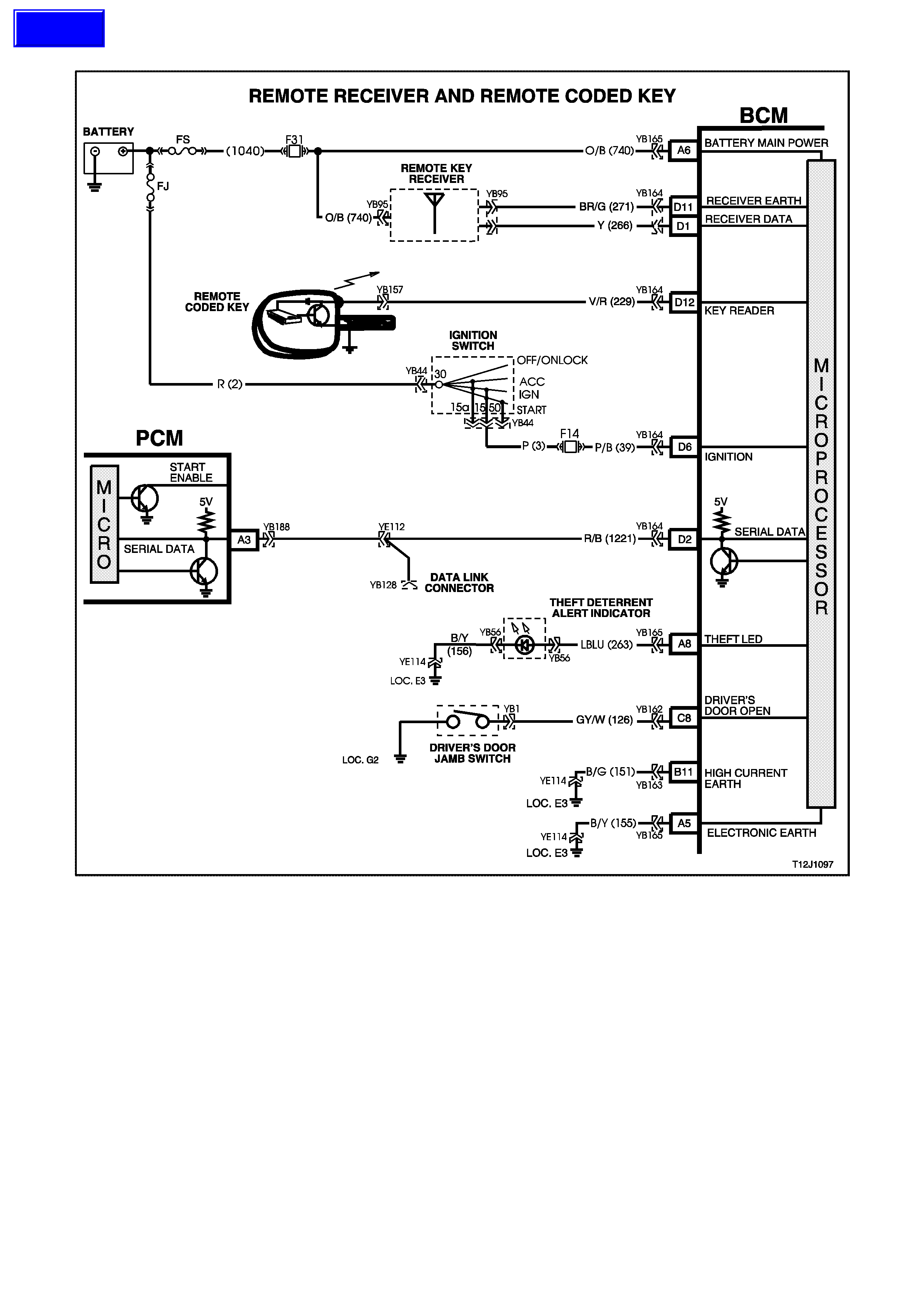
4.6 REMOTE RECEIVER/KEY
Figure 12J-1-98
CIRCUIT DESCRIPTION:
When operating the UNLOCK button on the remote coded k ey within four metr es of the driver’s s ide B pillar f or 0.25
seconds, a Radio Frequency (RF) signal is transmitted. The BCM receives this unlock request from the remote
coded key via the remote receiver, located in the instrument panel between the demist grille. The BCM then
proceeds to unlock all the doors (single stage unlock) or just the driver’s door (two stage unlock), disarm the theft
deterrent system, turn on the dome lamp and flash the indicators twice.
W hen operating the LOCK button on the remote coded key within four meters of the driver’s door B pillar for 0.25
seconds, an RF signal is again transmitted. The RF signal (lock request) is received by the BCM via the remote
receiver. The BCM then proceeds to lock all doors, arm the theft deterrent system, turn the dome lamp off (if
illuminated) and flash the indicators once.
When operating the boot release button on the r em ote coded k ey within two m eter s of the boot for 0.5 s econds, an
RF signal is transmitted to the BCM via the remote receiver. The BCM then proceeds to activate the rear
compartment lock actuator (provided the vehicle speed is less than 15 km/h).
The remote coded key is powered by it’s own internal battery. If this battery fails, no RF signal will be transmitted
when operating the lock, unlock and boot release buttons. However, if the battery does lose power, the remote
coded key reader has the ability to power the k ey once it is inserted into the ignition switch k ey c ylinder and tur ned
to the IGN or START positions. This will then enable theft deterrent disarming.
Techline
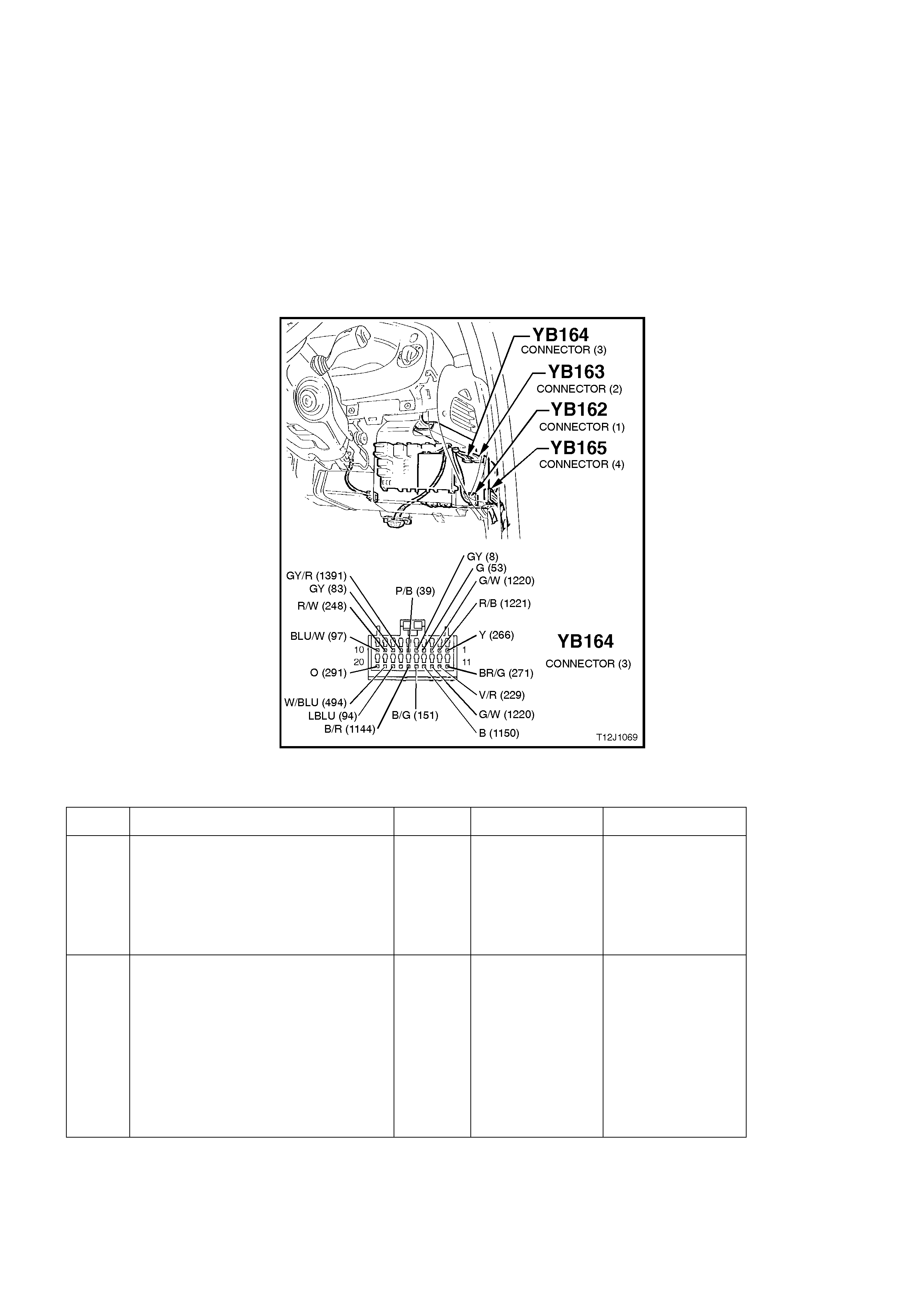
TEST DESCRIPTION:
The numbers below refer to step numbers in the following diagnostic chart.
1-7. Functional check to determine if system is functioning correctly or if faulty, determines if fault is with remote
receiver/key, central locking system or theft deterrent system.
8. Uses TECH 2 to check remote key signal - establish whether problem is with BCM or if further diagnosis is
required.
9. Uses TECH 2 to check for a remote key signal from a fully functional VT Series vehicle to establish whether
problem is with remote key or if further diagnosis is required.
10. Checks for power supply to remote receiver.
11. Checks circuit 271.
12. Checks circuit 266.
13. Check s if problem is due to faulty BCM or rem ote receiver by swapping rem ote receiver with a fully f unctional
unit.
Figure 12J-1-99
REMOTE RECEIVER/KEY
STEP ACTION VALUE YES NO
1. • Close and lock all doors.
• Insert ignition key into driver’s
door lock cylinder switch.
• Operate unlock / lock.
• Do all doors unlock and lock?
Go to Step 2. Go to central door
locking diagnosis,
refer to 4.3
CENTRAL DOOR
LOCKING in this
Section.
2. • Insert ignition key into driver’s
door lock cylinder switch and
unlock door.
• With theft deterrent LED
flashing, insert ignition key into
ignition switch and turn key to
the ON position.
• Does the theft deterrent LED
turn off?
Go to Step 3. Go to theft
deterrent
diagnosis, refer to
4.5 THEFT
DETERRENT in
this Section.

STEP ACTION VALUE YES NO
3. • Insert ignition key into driver’s
door lock cylinder switch and
lock all doors.
• Operate the UNLOCK button on
the remote coded key within 2
metres of the driver’s door B
pillar.
• Does the driver’s door only (two
stage unlock) or all doors (single
stage unlock) unlock?
Go to Step 4. Go to Step 8.
4. • When performing Step 3, did all
of the following occur when the
UNLOCK button on the remote
coded key was pressed?
Indicators flash twice.
Dome lamp illuminate (dome
lamp switch in doors position).
Theft deterrent LED go out.
Go to Step 5. Go to theft
deterrent
diagnosis, refer to
4.5 THEFT
DETERRENT in
this Section.
5. • Close all doors.
• Operate LOCK button on remote
coded key within 2 metres of
driver’s door B pillar.
• Do all doors lock?
Go to Step 6. Go to Step 8.
6. • When performing Step 5, did all
of the following occur when the
LOCK button on the remote
coded key was pressed?
Theft deterrent LED began
flashing.
Indicators flashed once.
Dome lamp went out (if
illuminated & with switch in the
doors position).
Go to Step 7. Go to theft
deterrent
diagnosis, refer to
4.5 THEFT
DETERRENT in
this Section.
7. • Press the boot release button on
the remote coded key (within two
metres of the rear of the vehicle)
for two seconds.
• Does rear compartment lid lock
actuator solenoid activate?
System OK. Go to Step 8.
8. • Connect TECH 2 to the DLC.
• Select Body / Body Control
Module / Data Display.
• Scroll to Remote Door Signal
and Remote Boot Signal screen
display.
• Operate UNLOCK, LOCK and
BOOT buttons on the remote
coded key.
• Does the screen display change
for the remote door signal
change from Off to Unlock /
Lock to Off and the remote boot
signal change from Off to Open
to Off?
Replace BCM,
refer to 2.2 LOW
SERIES BCM in
this Section.
Recheck and
verify repair.
Go to Step 9.

STEP ACTION VALUE YES NO
9. • On a VT Series vehicle with a
fully functional remote coded key
and receiver, connect TECH 2 to
the DLC.
• Select Body / Body Control
Module / Data Display.
• Scroll to Remote Door Signal
and Remote Boot Signal screen
display.
• Operate UNLOCK, LOCK and
BOOT buttons on the remote
coded key.
• Does the screen display change
for the remote door signal
change from Off to Unlock /
Lock and the remote boot signal
change from Off to Invalid to
Off?
Go to Step 10. Programme a
new remote
coded key, refer
to 2.3 REMOTE
CODED KEY in
this Section.
Recheck and
verify repair
10. • Return to original vehicle with
suspected faulty remote coded
key/receiver.
• Back probe remote receiver
connector YB95, circuit 740
(Orange/Black wire) with a
Voltmeter to earth.
• Is voltage as specified?
battery + Go to Step 11. Check and repair
open or short in
circuit 740.
recheck and verify
repair.
11. • Check integrity of circuit 271
(Brown/Green wire).
• Is circuit 271 OK?
Below
1 ohm Go to Step 12. Repair circuit 271
as necessary.
Recheck and
verify repair.
12. • Check integrity of circuit 266
(Yellow wire).
• Is circuit 271 OK?
Below
1 ohm Go to Step 13. Repair circuit 266
as necessary.
Recheck and
verify repair.
13. • Replace remote receiver with a
known functional one and
connect TECH 2 to the DLC.
• Select Body / Body Control
Module / Data Display.
• Scroll to Remote Door Signal
screen display.
• Operate UNLOCK and LOCK
button on the remote coded key.
• Does the screen display change
from Off to Unlock / Lock Off?
Replace remote
receiver, refer to
2.5 REMOTE
RECEIVER
MODULE in this
Section.
Recheck and
verify repair.
Replace BCM,
refer to 2.2 LOW
SERIES BCM in
this Section.
Recheck and
verify repair.
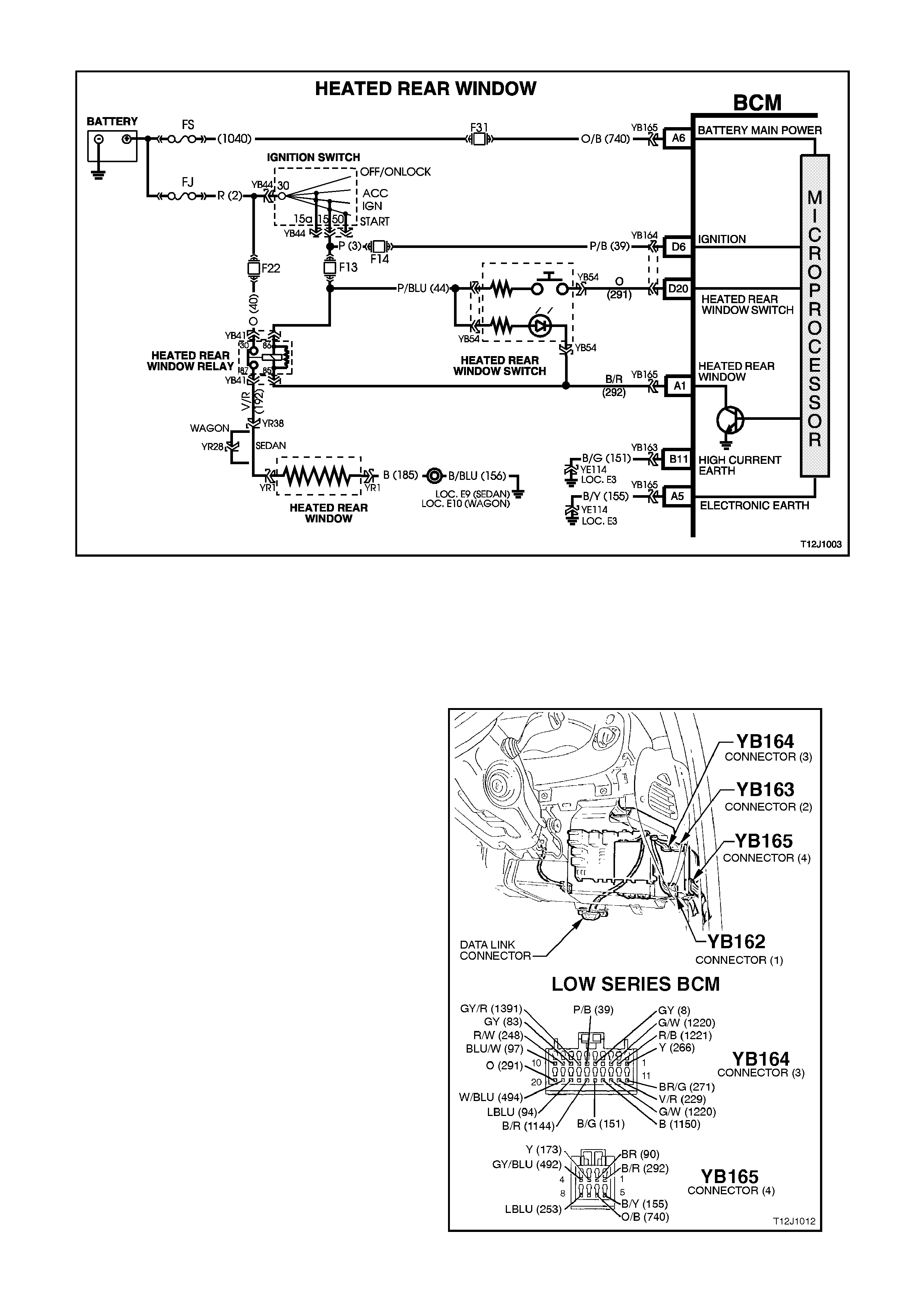
4.7 HEATED REAR WINDOW
Figure 12J-1-100
CIRCUIT DESCRIPTION:
Driver control of the rear window demister is from the heated rear window switch located in the instrument facia.
Pressing this momentary type contact switch will toggle the heating element in the rear window ON and OFF. The
heating is allowed to continue for 15 minutes and each new activation of the switch resets the delay timer. The
demis ting of the r ear window is only allowed when the ignition is ON and def aults to the O FF s tate when the ignition
is cycled from OFF to ON.
TEST DESCRIPTION:
The numbers below refer to step numbers in the
following diagnostic chart.
1 & 2 Functional check of heated rear window
system.
3. Uses TECH 2 to check for the heated rear
window switch input at the microprocessor of
the BCM when the switch is activated.
4. Check s the heated rear window drive signal at
the output of the BCM when connected to
TECH 2.
5. Checks circuit 292 (Black/Red wire).
6. Checks the heated rear window LED (in the
momentary switch).
8. Checks the heated rear window switch input,
at input of BCM.
9. Checks circuit 291 (Orange wire).
10. Checks heated rear window switch.
11. Checks circuit 44 (Pink/Blue wire).
13. Checks for B+ at relay.
14. Checks heated rear window relay.
15. Checks circuit 192.
16. Checks circuit 185.
17. Checks circuit 40/fuse F22.
18. Checks circuit 44.
19. Checks circuit 292. Figure 12J-1-101

HEATED REAR WINDOW
STEP ACTION VALUE YES NO
1. •Turn ignition ON.
•Operate the heated rear window
switch.
•Does the LED illuminate?
Go to Step 2. Go to Step 3.
2. •Does the rear window demist? System OK. Go to Step 12.
3. •Turn ignition ON.
•Connect TECH 2 to DLC.
•Select Body / Body Control
Module / data Display and scroll
to heated Rear Window Switch.
•Depress and hold the heated
rear window switch.
•Does TECH 2 display Heated
Rear Window Switch On?
Go to Step 4. Go to Step 8.
4. •Ignition ON.
•Back probe BCM connector
YB165, terminal A1, circuit 292
(Black/Red wire) with jumper
lead connected to earth.
•Does heated rear window LED
illuminate?
Replace BCM,
refer to 2.2 LOW
SERIES BCM in
this Section.
Recheck and
verify repair.
Go to Step 5.
5. •Back probe heated rear window
switch connector YB54, circuit
292 (Black/Red wire) with
jumper lead connected to earth.
•Repeat TECH 2 Heated Rear
Window test and turn heated
rear window On.
•Is voltage as specified?
0 volts Repair open in
circuit 292.
Recheck circuit
and verify repair.
Go to Step 6.
6. •Turn ignition ON.
•Back probe heated rear window
switch connector YB54, circuit
44 (Pink/Blue wire) with
Voltmeter to earth.
•Is voltage as specified?
12 volts Replace heated
rear window
switch.
Recheck circuit
to verify repair.
Go to Step 7.
7. •Check fuse F13.
•Is fuse OK?
Repair open in
circuit 44.
Recheck and
verify repair
Replace fuse F13.
Recheck circuit to
verify repair.
8. •Turn ignition ON.
•Back probe BCM connector
YB164, terminal D20, circuit 291
(Orange wire) with a Voltmeter
to earth.
•Depress and hold the heated
rear window switch.
•Is voltage as specified?
12 volts Replace BCM,
refer to 2.2 LOW
SERIES BCM in
this Section.
Recheck and
verify repair.
Go to Step 9.

STEP ACTION VALUE YES NO
9. •Turn ignition ON.
•Back probe heated rear window
switch connector YE54, circuit
291 (Orange wire) with an
Voltmeter to earth.
•Depress and hold the heated
rear window switch.
•Is voltage as specified?
12 volts Repair open in
circuit 291.
Recheck and
verify repair.
Go to Step 10.
10. •Turn ignition ON.
•Back probe heated rear window
switch connector YB54, circuit
44 (Pink/Blue wire) with a
Voltmeter to earth.
•Is voltage as specified?
12 volts Replace heated
rear window
switch.
Recheck and
verify repair.
Go to Step 11.
11. •Check fuse F13.
•Is fuse OK?
Repair open in
circuit 44.
Recheck and
verify repair.
Replace fuse F13.
Recheck circuit to
verify repair.
12. •Operate heated rear window
switch.
•Can relay be heard to operate?
Go to Step 13. Go to Step 18.
13. •Back probe heated rear window
relay connector YB41, terminal
30, circuit 40 (Orange wire) with
a Voltmeter to earth.
•Is voltage as specified?
12 volts Go to Step 14. Go to Step 17.
14. •Back probe heated rear window
relay connector YB41, terminal
87, circuit 192 (Violet/Red wire)
with a Voltmeter to earth.
•Operate heated rear window
switch.
•Is voltage as specified?
12 volts Go to Step 15. Replace heated
rear window relay.
Recheck and
verify repair.
15. •Back probe heated rear window
connector YR1, circuit 192
(Violet/Red wire) with a
Voltmeter to earth.
•Operate headed rear window
switch.
•Is voltage as specified?
12 volts Go to Step 16. Repair open in
circuit 192.
Recheck and
verify repair.
16. •Back probe heated rear window
connector YR1, circuit 185
(Black wire) with an Ohmmeter
to earth.
•Is reading as specified?
Below
1 ohm Replace or repair
heated rear
window.
Repair open in
circuit 185.
Recheck and
verify repair.
17. •Check fuse F22.
•Is fuse OK?
Repair open in
circuit 40.
Recheck and
verify repair.
Replace fuse F22.
Recheck and
verify repair.

STEP ACTION VALUE YES NO
18. •Back probe heated rear window
relay connector YB41, terminal
86, circuit 44 (Pink/Blue wire)
with a Voltmeter to earth.
•Is voltage as specified?
12 volts Go to Step 19 Repair open in
circuit 44.
Recheck and
verify repair.
19. •Back probe heated rear window
relay connector YB41, terminal
85, circuit 292 (Black/red wire)
with a jumper lead connected to
earth.
•Ignition On.
•Can the relay be heard to
operate?
Repair open in
circuit 292.
Recheck and
verify repair.
Replace heated
rear window relay.
Recheck and
verify repair.
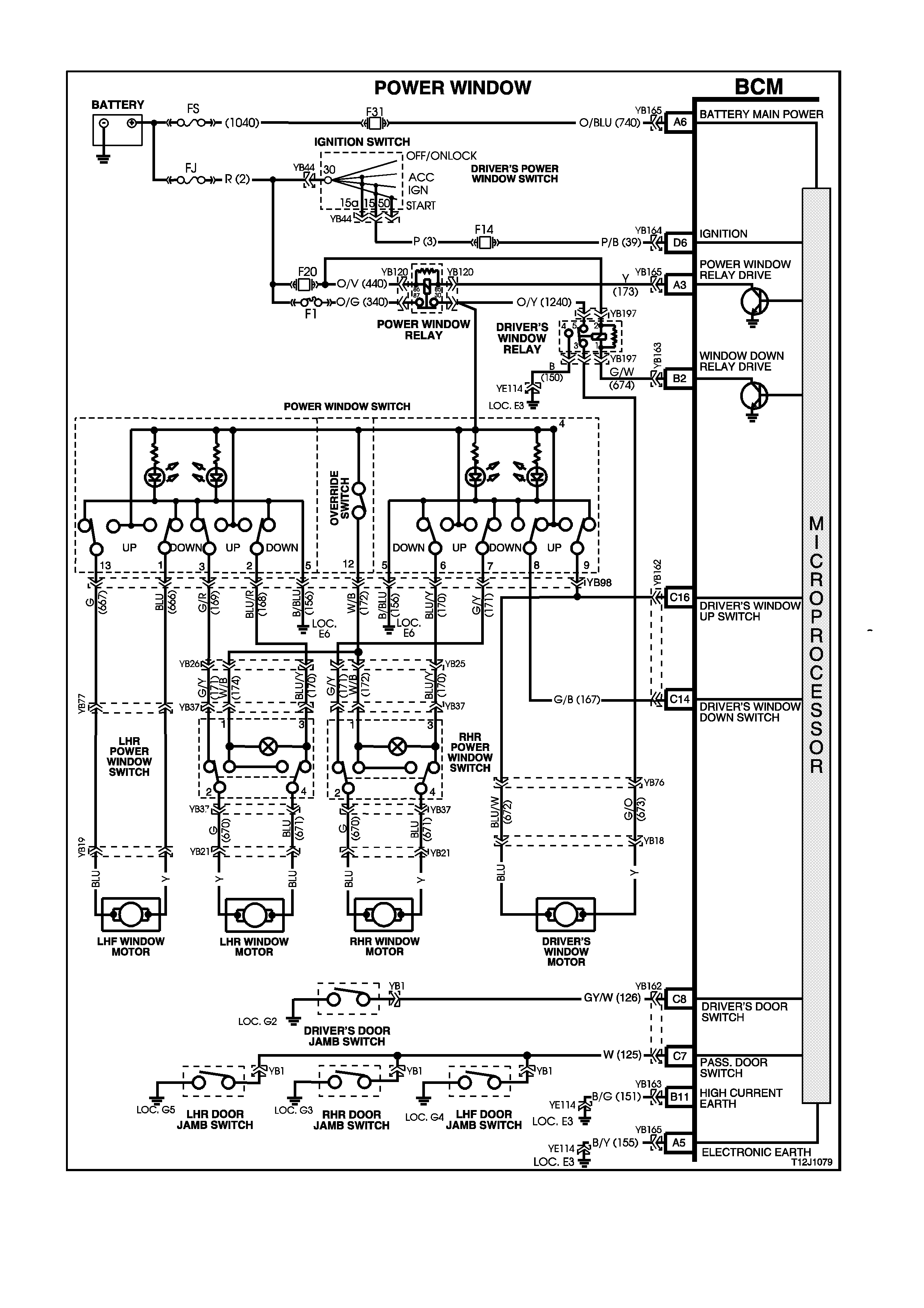
4.8 POWER WINDOW SYSTEM
Figure 12J-1-102

CIRCUIT DESCRIPTION:
The BCM controls the positive power supply to all window motors and the automatic down of the driver’s door
window (via driver’s window down relay) which is activated when the driver’s power window down button is
depressed for more than 0.4 seconds.
Once activated, the automatic down feature is cancelled by pulling the driver’s power window switch upwards and
releasing it. In this case, the window will remain stationary until another activation takes place (up or down button
activated).
W ith the ignition ON, power is supplied to the window sys tem continuous ly. When the ignition is switched OFF and
no door has been opened, power is supplied to the window system for a maxim um of one hour. In the event of any
door being opened, power is supplied to the system f or 45 seconds maximum, timed f rom when the first door was
opened.
When the doors are remotely unlocked (using the remote coded key) power is supplied to the system for 45
seconds. The delay is cancelled when the doors are locked by the remote coded key.
TEST DESCRIPTION:
The numbers below refer to step numbers in the following diagnostic chart.
1-17. Functional check of system.
20. Checks for driver’s window down input signal at input of BCM/circuit 167.
21. Checks driver’s window relay output drive signal at the BCM.
22. Checks circuit 674.
23. Checks circuit 440.
24. Checks circuit 1240.
25. Checks driver’s window relay.
26. Checks circuit 673.
27. Checks driver’s window motor.
28. Checks circuit 167 (front and rear door power window switch assembly).
29. Checks circuit 672 (front and rear door power window switch assembly).
30. Uses TECH 2 to check the ignition input at the microprocessor of the BCM.
31. Checks the power window relay output drive signal at the BCM.
33. Checks circuit 1240.
34. Checks circuit 156 (front and rear door power window switch assembly).
35. Checks for ignition signal at input of BCM.
36. Checks circuit 173.
37. Checks circuit 440 / fuse F20.
38. Checks circuit 340 / fuse F1.
39. Checks driver’s window up signal at output of front and rear door power window switch assembly.
40. Checks circuit 150.
41. Checks driver’s power window relay / correct output drive from BCM.
42. Checks driver’s window up signal at input of BCM.
43. Checks front and rear door power window switch assembly (LHF window down).
44. Checks circuit 667.
45. Checks front and rear door power window switch assembly (LHF window down, earth).
46. Checks circuit 666.
47. Checks front and rear door power window switch assembly (RHR wi ndow down).
48. Checks circuit 170 (RHR window system).
49. Checks RHR power window switch (RHR door).
50. Checks circuit 671 (RHR window system).
51. Checks front and rear door power window switch assembly (RHR window down, earth).
52. Checks circuit 171 (RHR window system).
53. Checks RHR power window switch (RHR door).
54. 54.Checks circuit 670 (RHR window system).
55. Checks front and rear door power window switch assembly (LHR window down).
56. Checks circuit 168 (LHR window system).
57. Checks LHR power window switch (LHR door).
58. Checks circuit 671 (RHR window system).
59. Checks front and rear door power window switch assembly (LHR window down, earth).
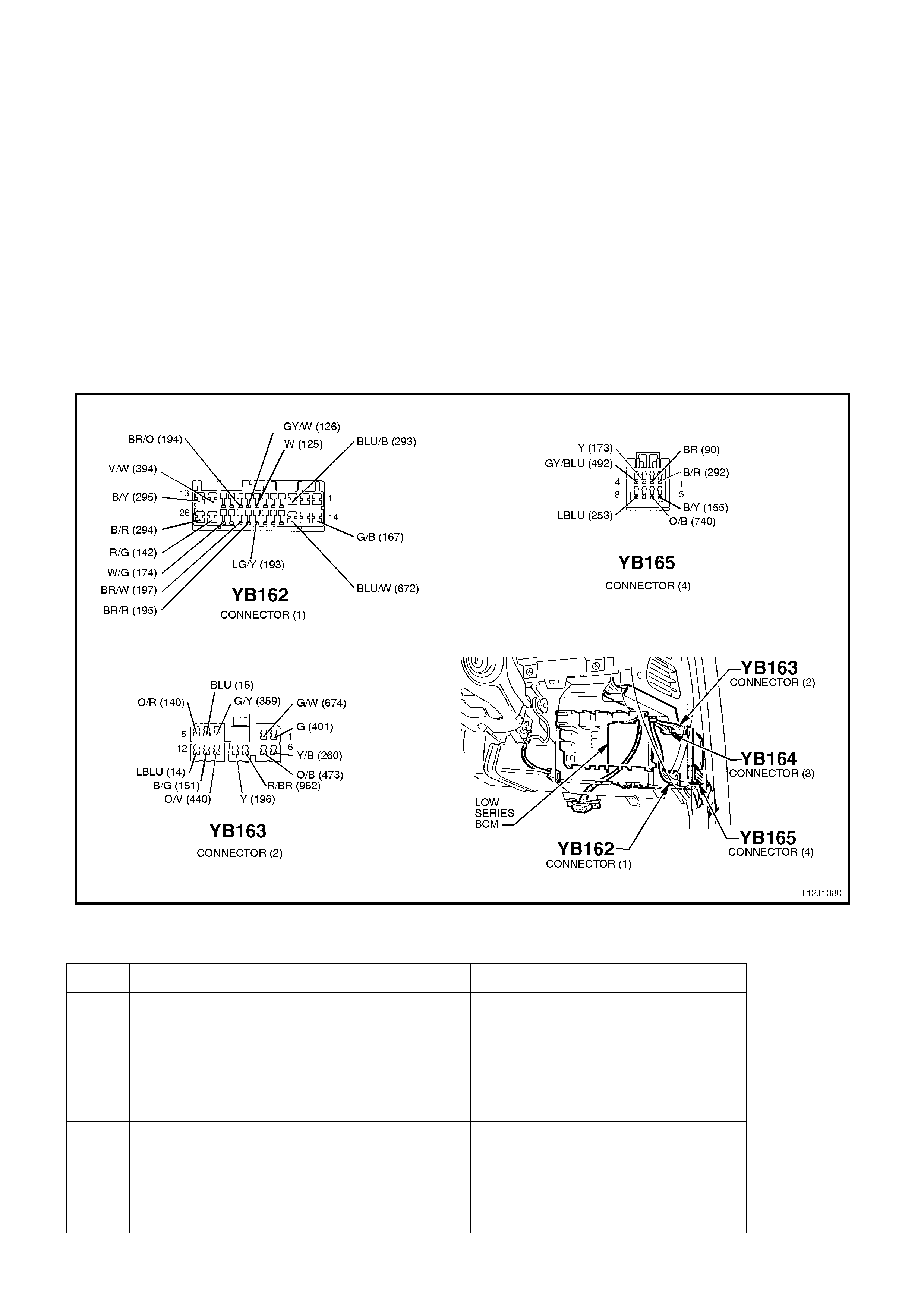
60. Checks circuit 169 (LHR window system).
61. Checks LHR power window switch (LHR door).
62. Checks circuit 670 (LHR window system).
64. Checks override switch (front and rear door power window switch assembly).
65. Checks circuit 172 (RHR window system).
67. Checks circuit 172 (LHR window system).
68. Uses TECH 2 to check the DRIVER’S DOOR OPEN signal input at the microprocessor of the BCM.
69. Checks for DRIVER’S DOOR OPEN signal at the input of the BCM.
70. 70.Checks circuit 126 (driver’s door jamb switch).
71. Uses TECH 2 to check PASSENGER DOOR OPEN signal input at the microprocessor of the BCM.
73. Checks for PASSENGER DOOR OPEN signal at the input of the BCM.
74. Checks for false output drive from the BCM or f ault in wiring / relay pr oblem, c ausing the window sys tem to be
on constantly.
NOTE:
The following diagnostic chart assumes that the power windows are free from mechanical faults, ie. damaged
window regulator or badly worn guide channel rubbers.
Figure 12J-1-103
POWER WINDOW SYSTEM
STEP ACTION VALUE YES NO
1. •Turn ignition ON.
•Operate driver’s window down
button for one second and
release.
•Does the window travel all the
way down automatically?
Go to Step 2. Go to Step 18.
2. •Turn ignition ON.
•Operate the driver’s window up
button.
•Does the window travel up
when activating the button?
Go to Step 3. Go to Step 39.

STEP ACTION VALUE YES NO
3. •Turn ignition ON.
•Operate driver’s window down
button for one second and
release.
•As the window is travelling
down automatically, operate the
driver’s up button momentarily
and release.
•Does the window stop?
Go to Step 4. Go to Step 42.
4. •All doors closed.
•Turn ignition OFF.
•Remotely lock doors.
•Is power supply to window
system interrupted (green
indicator lights in front and rear
power window switch
extinguished)?
Go to Step 5. Go to Step 74.
5. •Remotely unlock doors.
•Is power supplied to the window
system (green indicator lights in
front and rear power window
switch illuminated)?
Go to Step 6. Replace BCM,
refer to 2.2 LOW
SERIES BCM in
this Section.
Recheck and
verify repair.
6. •Doors closed.
•Turn ignition ON.
•Turn ignition OFF.
•Open driver’s door.
•Is power to the window system
interrupted after 45 seconds
(green indicator lights in front
and rear power window switch
extinguished)?
Go to Step 7. Go to Step 68.
7. •Doors closed.
•Turn ignition ON.
•Turn ignition OFF.
•Open any passenger door.
•Is power to the window system
interrupted after 45 seconds
(green indicator lights in front
and rear power window switch
extinguished)?
Go to Step 8. Go to Step 71.
8. •Turn ignition ON.
•Operate LHF power window
down button (front and rear
door power window switch).
•Does LHF window travel down?
Go to Step 9. Go to Step 43.
9. •Turn ignition ON.
•Operate LHF power window up
button (front and rear door
power window switch).
•Does LHF window travel up?
Go to Step 10. Replace front and
rear door power
window switch,
refer to 2.18
FRONT AND
REAR DOOR
POWER
WINDOW
SWITCH, in this
Section.

STEP ACTION VALUE YES NO
10. •Turn ignition ON.
•Operate RHR power window
down button on front and rear
door power window switch.
•Does RHR window travel
down?
Go to Step 11. Go to Step 47.
11. •Turn ignition ON.
•Operate RHR power window up
button on front and rear door
power window switch.
•Does RHR window travel up?
Go to Step 12. Replace front and
rear door power
window switch,
refer to 2.18
FRONT AND
REAR DOOR
POWER
WINDOW
SWITCH, in this
Section.
12. •Turn ignition ON.
•Operate LHR power window
down button on front and rear
door power window switch.
•Does LHR window travel down?
Go to Step 13. Go to Step 55.
13. •Turn ignition ON.
•Operate LHR power window up
button on front and rear door
power window switch.
•Does LHR window travel up?
Go to Step 14. Replace front and
rear door power
window switch,
refer to 2.18
FRONT AND
REAR DOOR
POWER
WINDOW
SWITCH, in this
Section.
14. •Ensure power window override
switch is o ff.
•Turn ignition ON.
•Operate RHR window down
button on RHR door.
•Does RHR window travel
down?
Go to Step 15. Go to Step 63.
15. •Ensure power window override
switch is o ff.
•Turn ignition ON.
•Operate RHR window up button
on RHR door.
•Does RHR window travel up?
Go to Step 16. Replace RHR
power window
switch, refer to
2.19 REAR
DOOR POWER
WINDOW
SWITCHES, in
this Section.
16. •Ensure power window override
switch is o ff.
•Turn ignition ON.
•Operate LHR power window
down button on LHR door.
•Does LHR window travel down?
Go to Step 17. Go to Step 66.

STEP ACTION VALUE YES NO
17. •Ensure power window override
switch is o ff.
•Turn ignition ON.
•Operate LHR power window up
button on LHR door.
•Does LHR window travel up?
System OK. Replace LHR
power window
switch, refer to
2.19 REAR
DOOR POWER
WINDOW
SWITCH, in this
Section.
18. •Turn ignition ON.
•Are green indicator lights
illuminated in the front and rear
door power window switch?
Go to Step 19. Go to Step 30.
19. •Turn ignition ON.
•Operate the driver’s window
button
•Does the driver’s window travel
down whilst holding the button
down?
Replace BCM,
refer to 2.2 LOW
SERIES BCM in
this Section.
Recheck and
verify repair.
Go to Step 20.
20. •Back probe BCM connector
YB162, terminal C14, circuit
167 (Green/Black wire) with a
Voltmeter to earth.
•Turn ignition ON.
•Operate the driver’s window
down button.
•Is voltage as specified
12 volts Go to Step 21. Go to Step 28.
21. •Back probe BCM connector
YB163, terminal B2, circuit 673
(Green/Orange wire) with
voltage to earth.
•Turn ignition ON.
•Operate the driver’s window
down button.
•Is voltage as specified?
0 volts Go to Step 22. Replace BCM,
refer to 2.2 LOW
SERIES BCM in
this Section.
Recheck and
verify repair.
22. •Back probe driver’s window
relay connector, YB197,
terminal 1, circuit 674
(Green/White wire) with a
Voltmeter to earth.
•Turn ignition ON.
•Operate the driver’s window
down button.
•Is voltage as specified?
0 volts Go to Step 23. Repair open in
circuit 674.
Recheck and
verify repair
23. •Back probe driver’s window
relay connector, YB197,
terminal 2, circuit 440
(Orange/Violet wire) with a
Voltmeter to earth.
•Turn ignition ON.
•Is voltage as specified?
12 volts Go to Step 24. Repair open in
circuit 440.
Recheck and
verify repair.

STEP ACTION VALUE YES NO
24. •Back probe driver’s window
relay connector YB197, terminal
5, circuit 1240 (Orange/Yellow
wire) with a Voltmeter to earth.
•Turn ignition ON.
•Is voltage as specified?
12 volts Go to Step 25. Repair open in
circuit 1240.
Recheck and
verify repair.
25. •Back probe driver’s window
relay connector YB197, terminal
3, circuit 673 (Green/Orange
wire) with a Voltmeter to earth.
•Turn ignition ON.
•Operate the driver’s window
down button.
•Is voltage as specified?
12 volts Go to Step 26. Replace driver’s
window relay
26. •Back probe driver’s window
motor connector, YB18, circuit
673 (Green/Orange wire) with a
Voltmeter to earth.
•Turn ignition ON.
•Operate driver’s window down
button.
•Is voltage as specified?
12 volts Go to Step 27. Repair open in
circuit 673.
Recheck and
verify repair.
27. •Back probe driver’s window
motor connector, YB18, circuit
672 (Blue/White wire) with an
Ohmmeter to earth.
•Is reading as specified?
Below
1 ohm Replace driver’s
window motor,
refer to Section
1A5 FRONT &
REAR DOORS
Go to Step 29.
28. •Back probe front and rear door
power window switch assembly
connector YB98, terminal 8
circuit 167 (Green/Black wire)
with a Voltmeter to earth.
•Turn ignition ON.
•Operate the driver’s window
down button.
•Is voltage as specified?
12 volts Repair open in
circuit 167.
Recheck and
verify repair
Replace front and
rear door power
window switch,
refer to 2.18
FRONT AND
REAR DOOR
POWER
WINDOW
SWITCH, in this
Section.
29. •Back probe front and rear door
power window switch assembly
connector YB98, terminal 9
circuit 672 (Blue/White wire)
with an Ohmmeter to earth.
•Is reading as specified?
Below
1 ohm Repair open in
circuit 672.
Recheck and
verify repair.
Replace front and
rear door power
window switch,
refer to 2.18
FRONT AND
REAR DOOR
POWER
WINDOW
SWITCH, in this
Section.
30. •Connect TECH 2 to DLC.
•Select Body / Body Control
Module / Data Display and
scroll to Ignition Switch.
•Cycle ignition switch ON and
OFF.
•Does screen Ignition Switch
display change status form On
to Off as ignition is cycled?
Go to Step 31. Go to Step 35.

STEP ACTION VALUE YES NO
31. •Back probe BCM connector
YB165, terminal A3 circuit 173
(Yellow wire) with a Voltmeter to
earth.
•Turn ignition ON.
•Is voltage as specified?
0 volts Go to Step 32. Replace BCM,
refer to 2.2 LOW
SERIES BCM in
this Section.
Recheck and
verify repair.
32. •Back probe power window relay
connector YB120, terminal 30
circuit 1240 (Orange/Yellow
wire) with a Voltmeter to earth.
•Turn ignition ON.
•Is voltage as specified?
12 volts Go to Step 33. Go to Step 36.
33. •Back probe front and rear door
power window switch assembly
connector YB98, terminal 4
circuit 1240 (Orange/Yellow
wire) with a Voltmeter to earth.
•Turn ignition ON.
•Is voltage as specified?
12 volts Go to Step 34. Repair open in
circuit 1240.
Recheck and
verify repair
34. •Back probe front and rear door
power window switch assembly
connector YB98, terminal 5
circuit 156 (Black/Blue wire)
with an Ohmmeter to earth.
•Is voltage as specified?
Below
1 ohm Replace front
and rear door
power window
switch, refer to
2.18 FRONT
AND REAR
DOOR POWER
WINDOW
SWITCH, in this
Section.
Repair open in
circuit 156.
Recheck and
verify repair.
35. •Back probe BCM connector
YB164, terminal D6 circuit 39
(Pink/Black wire) with a
Voltmeter to earth.
•Turn ignition ON.
•Is voltage as specified?
12 volts Replace BCM,
refer to 2.2 LOW
SERIES BCM in
this Section.
Recheck and
verify repair.
Check and repair
fault in circuit 39
(including fuse
F14). Recheck
and verify repair.
36. •Back probe power window relay
connector YB120, terminal 85
circuit 173 (Yellow wire) with a
Voltmeter to earth.
•Turn ignition ON.
•Is voltage as specified?
0 volts Go to Step 37. Repair open in
circuit 173.
Recheck and
verify repair.
37. •Back probe power window relay
connector YB120, terminal 86
circuit 440 (Orange/Violet wire)
with a Voltmeter to earth.
•Turn ignition ON.
•Is voltage as specified?
12 volts Go to Step 38. Check and repair
fault in circuit 440
(including fuse
F20). Recheck
and verify repair.
38. •Back probe power window relay
connector YB120, terminal 87
circuit 340 (Orange/Green wire)
with a Voltmeter to earth.
•Turn ignition ON.
•Is voltage as specified?
12 volts Replace power
window relay. Check and repair
fault in circuit 340
(including fuse F1
- check for
excessive current
in circuit if fuse is
tripped). Recheck
and verify repair.

STEP ACTION VALUE YES NO
39. •Back probe front and rear door
power window switch assembly
connector YB98, terminal 9,
circuit 672 (Blue/White wire)
with a Voltmeter to earth.
•Turn ignition ON.
•Operate the driver’s window up
button.
•Is voltage as specified?
12 volts Go to Step 40. Replace front and
rear door power
window switch,
refer to 2.18
FRONT AND
REAR DOOR
POWER
WINDOW
SWITCH, in this
Section.
40. •Back probe driver’s window
relay connector YB193, terminal
4, circuit 150 (Black wire) with
an Ohmmeter to earth.
•Is reading as specified?
Below
1 ohm Go to Step 41. Repair open in
circuit 150.
Recheck and
verify repair.
41. •Back probe BCM connector
YB163, terminal B2, circuit 674
(Green/White wire) with a
Voltmeter to earth.
•Turn ignition ON.
•Is voltage as specified?
12 volts Replace driver’s
window relay. Replace BCM,
refer to 2.2 LOW
SERIES BCM in
this Section.
recheck and verify
repair
42. •Back probe BCM connector
YB162, terminal C16, circuit
672 (Blue/White wire) with a
Voltmeter to earth.
•Operate driver’s window up
button.
•Is voltage as specified?
12 volts Replace BCM,
refer to 2.2 LOW
SERIES BCM in
this Section.
recheck and
verify repair.
Repair open in
circuit 672.
Recheck and
verify repair.
43. •Back probe front and rear door
power window switch connector
YB98, terminal 1, circuit 667
(Green wire) with a Voltmeter to
earth.
•Operate LHF window down
button.
•is voltage as specified?
12 volts Go to Step 44. Replace front and
rear door power
window switch,
refer to 2.18
FRONT AND
REAR DOOR
POWER
WINDOW
SWITCH, in this
Section.
44. •Back probe LHF window motor
connector YB19, circuit 667
(Green wire) with a Voltmeter to
earth.
•Open any passenger door.
•Operate LHF window down
button.
•is voltage as specified?
12 volts Go to Step 45. Repair open in
circuit 667.
45. •Back probe front and rear door
power window switch connector
YB98, terminal 13 circuit 667
(Green wire) with an Ohmmeter
to earth.
•Is reading as specified?
Below
1 ohm Go to Step 46. Replace front and
rear door power
window switch,
refer to 2.18
FRONT AND
REAR DOOR
POWER
WINDOW
SWITCH, in this
Section.

STEP ACTION VALUE YES NO
46. •Back probe LHF window motor
connector YB19, circuit 666
(Blue wire) with an Ohmmeter
to earth.
•Is reading as specified?
Below
1 ohm Replace LHF
window motor,
refer to Section
1A5 FRONT &
REAR DOORS
Repair open in
circuit 666.
Recheck and
verify repair.
47. •Back probe front and rear door
power window switch assembly
connector YB98, terminal 1
circuit 170 (Blue/Yellow wire)
with a Voltmeter to earth.
•Turn ignition ON.
•Operate RHR window down
switch at the front and rear door
power window switch assembly.
•Is voltage as specified?
12 volts Go to Step 48. Replace front and
rear door power
window switch,
refer to 2.18
FRONT AND
REAR DOOR
POWER
WINDOW
SWITCH, in this
Section.
48. •Back probe RHR power window
switch assembly connector
YB37(at RHR door) terminal 3
circuit 170 (Blue/Yellow wire)
with a Voltmeter to earth.
•Turn ignition ON.
•Operate RHR window down
switch at the front and rear door
power window switch assembly.
•Is voltage as specified?
12 volts Go to Step 49. Repair open in
circuit 170.
Recheck and
verify repair.
49. •Back probe RHR window switch
connector YB37 (at RHR door),
terminal 4, circuit 671 (Blue
wire) with a Voltmeter to earth.
•Turn ignition ON.
•Operate RHR power window
down button on the front and
rear door power window switch
•Is voltage as specified?
12 volts Go to Step 50. Replace RHR
power window
switch, refer to
2.19 REAR
DOOR POWER
WINDOW
SWITCH, in this
Section.
50. •Back probe RHR window motor
connector YB21, circuit 671
(Blue wire) with a Voltmeter to
earth.
•Turn ignition ON.
•Operate RHR power window
down button on the front and
rear door power window switch
•Is voltage as specified?
12 volts Go to Step 51. Repair open in
circuit 671.
Recheck and
verify repair.
51. •Back probe front and rear door
power window switch assembly
connector YB98, terminal 7,
circuit 171 (Green/Yellow wire)
with an Ohmmeter to earth.
•Is reading as specified?
Below
1 ohm Go to Step 52. Replace front and
rear door power
window switch,
refer to 2.18
FRONT AND
REAR DOOR
POWER
WINDOW
SWITCH, in this
Section.

STEP ACTION VALUE YES NO
52. •Back probe RHR power window
switch connector YB37 (at RHR
door), circuit 171 (Green/Yellow
wire) with an Ohmmeter to
earth.
•Is reading as specified?
Below
1 ohm Go to Step 53. Repair open in
circuit 169.
Recheck and
verify repair.
53. •Back probe RHR power window
switch connector YB37 (at RHR
door), terminal 2, circuit 670
(Green wire) with an Ohmmeter
to earth.
•Is reading as specified?
Below
1 ohm Go to Step 54. Replace RHR
power window
switch, refer to
2.19 REAR
DOOR POWER
WINDOW
SWITCH, in this
Section.
54. •Back probe RHR window motor
connector YB21, circuit 670
(Green wire) with an Ohmmeter
to earth.
•Is reading as specified?
Below
1 ohm Replace RHR
window motor,
refer to 1A5
FRONT & REAR
DOOR
ASSEMBLIES.
Repair open in
circuit 670.
Recheck and
verify repair.
55. •Back probe front and rear door
power window switch assembly
connector YB98 terminal 2,
circuit 168 (Blue/Red wire) with
a Voltmeter to earth.
•Turn ignition ON.
•Operate LHR power window
down switch on front and rear
door power window switch.
•Is value as specified?
12 volts Go to Step 56. Replace front and
rear door power
window switch,
refer to 2.18
FRONT AND
REAR DOOR
POWER
WINDOW
SWITCH, in this
Section.
56. •Back probe LHR power window
switch connector YB37 (at LHR
door), circuit 168 (Blue/Red
wire) with a Voltmeter to earth.
•Turn ignition ON.
•Operate LHR power window
down button on front and rear
door power window switch.
•Is voltage as specified?
12 volts Go to Step 57. Repair open in
circuit 168.
Recheck and
verify repair.
57. •Back probe LHR power window
switch connector YB37 (at LHR
door), terminal 4, circuit 671
(Blue wire) with a Voltmeter to
earth.
•Turn ignition ON.
•Operate LHR power window
down button on front and rear
door power window switch.
•Is voltage as specified?
12 volts Go to Step 58. Replace LHR
power window
switch, refer to
2.19 REAR
DOOR POWER
WINDOW
SWITCH, in this
Section.

STEP ACTION VALUE YES NO
58. •Back probe LHR window motor
connector YB21, circuit 671
(Blue wire) with a Voltmeter to
earth.
•Turn ignition ON.
•Operate LHR window button on
front and rear door power
window switch.
•Is voltage as specified?
12 volts Go to Step 59. Repair open in
circuit 671.
Recheck and
verify repair.
59. •Back probe front and rear door
power window switch assembly
connector YB98, terminal 3,
circuit 169 (Green/Red wire)
with an Ohmmeter to earth.
•Is reading as specified?
Below
1 ohm Go to Step 60. Replace front and
rear door power
window switch,
refer to 2.18
FRONT AND
REAR DOOR
POWER
WINDOW
SWITCH, in this
Section.
60. •Back probe LHR window switch
connector (at LHR door) YB37,
circuit 169 (Green/Red wire with
an Ohmmeter to earth.
•Is value as specified?
Below
1 ohm Go to Step 61. Repair open in
circuit 169.
Recheck and
verify repair.
61. •Back probe LHR window switch
connector (at LHR door) YB37,
terminal 2, circuit 670 (Green
wire) with an Ohmmeter to
earth.
•Is the value as specified?
Below
1 ohm Go to Step 62. Replace LHR
power window
switch, refer to
2.19 REAR
DOOR POWER
WINDOW
SWITCH, in this
Section.
62. •Back probe LHR window motor
connector YB21, circuit 670
(Green wire) with an Ohmmeter
to earth.
•Is reading as specified?
Below
1 ohm Replace LHR
window motor,
refer to 1A5
FRONT & REAR
DOOR
ASSEMBLIES.
Repair open in
circuit 670.
Recheck and
verify repair.
63. •Turn ignition ON.
•Is the green indicator light
illuminated the RHR door power
window switch?
Replace RHR
power window
switch, refer to
2.19 REAR
DOOR POWER
WINDOW
SWITCH, in this
Section.
Go to Step 64.
64. •Turn ignition ON.
•Ensure power window override
switch is o ff.
•Back probe front and rear door
power window switch connector
YB98, terminal 12, circuit 172
(White/Black wire) with a
Voltmeter to earth.
•Is voltage as specified?
12 volts Go to Step 65. Replace front and
rear door power
window switch,
refer to 2.18
FRONT AND
REAR DOOR
POWER
WINDOW
SWITCH, in this
Section.

STEP ACTION VALUE YES NO
65. •Back probe RHR power window
switch connector (at RHR door)
YB37, terminal 1, circuit 172
(White/Black wire) with a
Voltmeter to earth.
•Turn ignition ON.
•Is voltage as specified?
12 volts Replace RHR
power window
switch, refer to
2.19 REAR
DOOR POWER
WINDOW
SWITCH, in this
Section.
Repair open in
circuit 172.
Recheck and
verify repair.
66. •Turn ignition ON.
•Is the green indicator light
illuminated the LHR door power
window switch?
Replace LHR
power window
switch, refer to
2.19 REAR
DOOR POWER
WINDOW
SWITCH, in this
Section.
Go to Step 67.
67. •Back probe LHR power window
switch connector (at LHR door)
YB37, terminal 1, circuit 172
(White/Black wire) with a
Voltmeter to earth.
•Turn ignition ON.
•Is voltage as specified?
12 volts Replace LHR
power window
switch, refer to
2.19 REAR
DOOR POWER
WINDOW
SWITCH, in this
Section.
Repair open in
circuit 172.
Recheck and
verify repair.
68. •Driver’s door closed.
•Connect TECH 2 to DLC.
•Select Body / Body Control
Module / Data Display and
scroll to Drivers Door.
•Open driver’s door.
•Does screen display Drivers
Door Open?
Replace BCM,
refer to 2.2 LOW
SERIES BCM in
this Section.
recheck and
verify repair.
Go to Step 69.
69. •Back probe BCM connector
YB162, terminal C8, circuit 126
(Grey/White wire) with a
Voltmeter to earth.
•Turn ignition ON.
•Driver’s door open.
•Is voltage as specified?
0 volts Replace BCM,
refer to 2.2 LOW
SERIES BCM in
this Section.
Recheck and
verify repair.
Go to Step 70.
70. •Back probe driver’s door jamb
switch connector YB1, circuit
126 (Grey/White wire) and BCM
connector YB162, terminal C8,
circuit 126 (Grey/White wire)
with an Ohmmeter.
•Is reading as specified?
Below
1 ohm Replace drivers
door jamb
switch, refer
2.10 DOOR
JAMB
SWITCHES in
this Section.
Repair open in
circuit 126.
Recheck and
verify repair.
71. •Passenger doors closed.
•Connect TECH 2 to DLC.
•Select Body / Body Control
Module / Data Display and
scroll to Passenger Doors.
•Open and close each
passenger door while watching
TECH 2 screen display.
•Does screen display Passenger
Door Open for every door as it
is opened?
Replace BCM,
refer to 2.2 LOW
SERIES BCM in
this Section.
Recheck and
verify repair.
Go to Step 72.

STEP ACTION VALUE YES NO
72. •In Step 71, did screen display
change from Passenger Doors
Closed to Open when a t least
one of the passenger doors was
opened?
Check and
replace faulty
door jamb
switch. Recheck
and verify repair.
Go to Step 73.
73. •Back probe BCM connector
YB162, terminal C7, circuit 125
(White wire) with a Voltmeter to
earth.
•Open any passenger door.
•Is voltage as specified?
0 volts Replace BCM,
refer to 2.2 LOW
SERIES BCM in
this Section.
Recheck and
verify repair.
Repair open in
circuit 125.
74. •Disconnect BCM connector
YB165 from BCM.
•Is the power supply to the
window system interrupted
(indicator lights in power
window switch turn off)?
Replace BCM,
refer to 2.2 LOW
SERIES BCM in
this Section.
Recheck and
verify repair.
Check for short to
earth, circuit 173
or short to B+,
circuit 1240
and power
window relay.
Recheck and
verify repair.
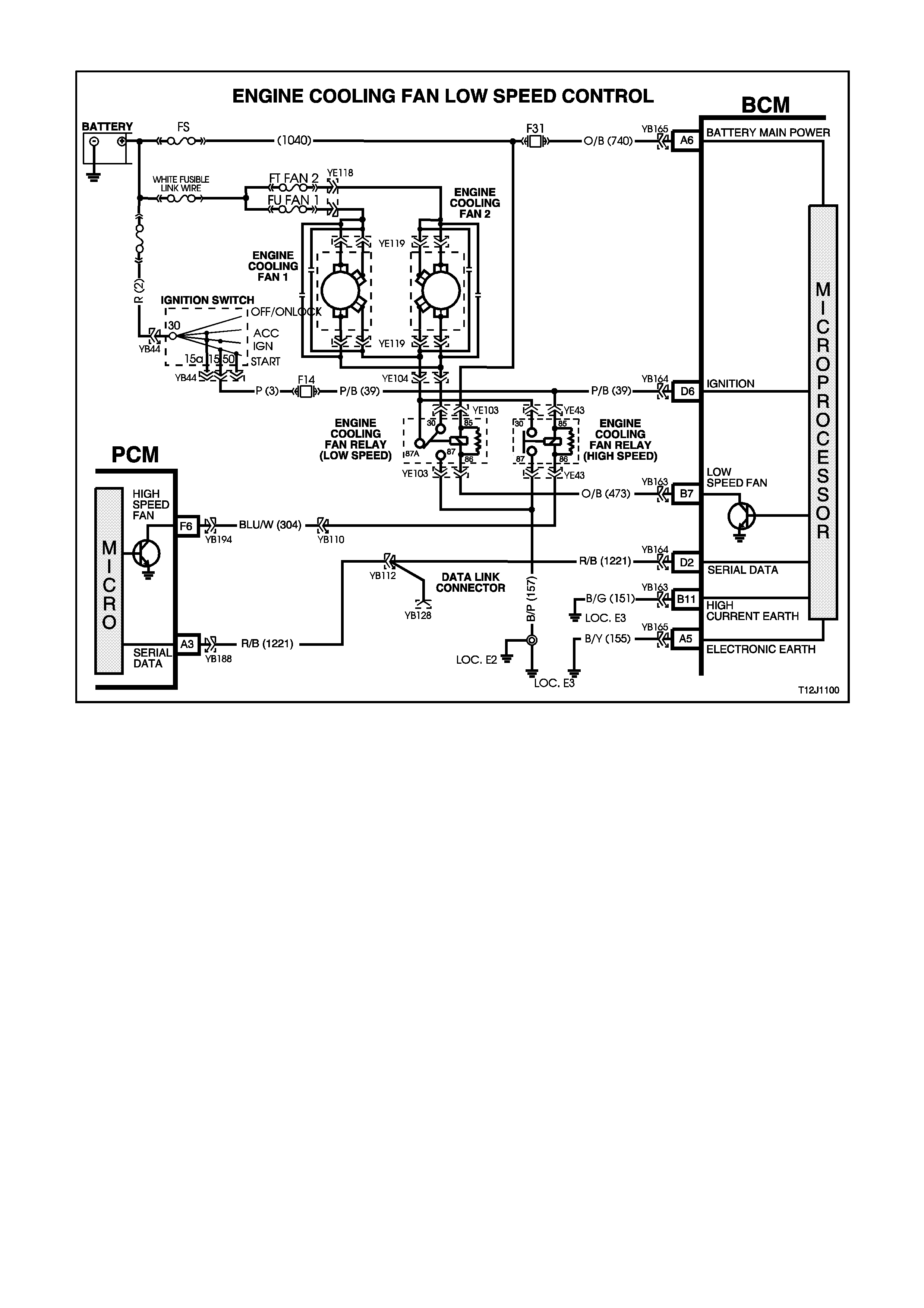
4.9 ENGINE COOLING FAN, LOW SPEED CONTROL
Figure 12J-1-104
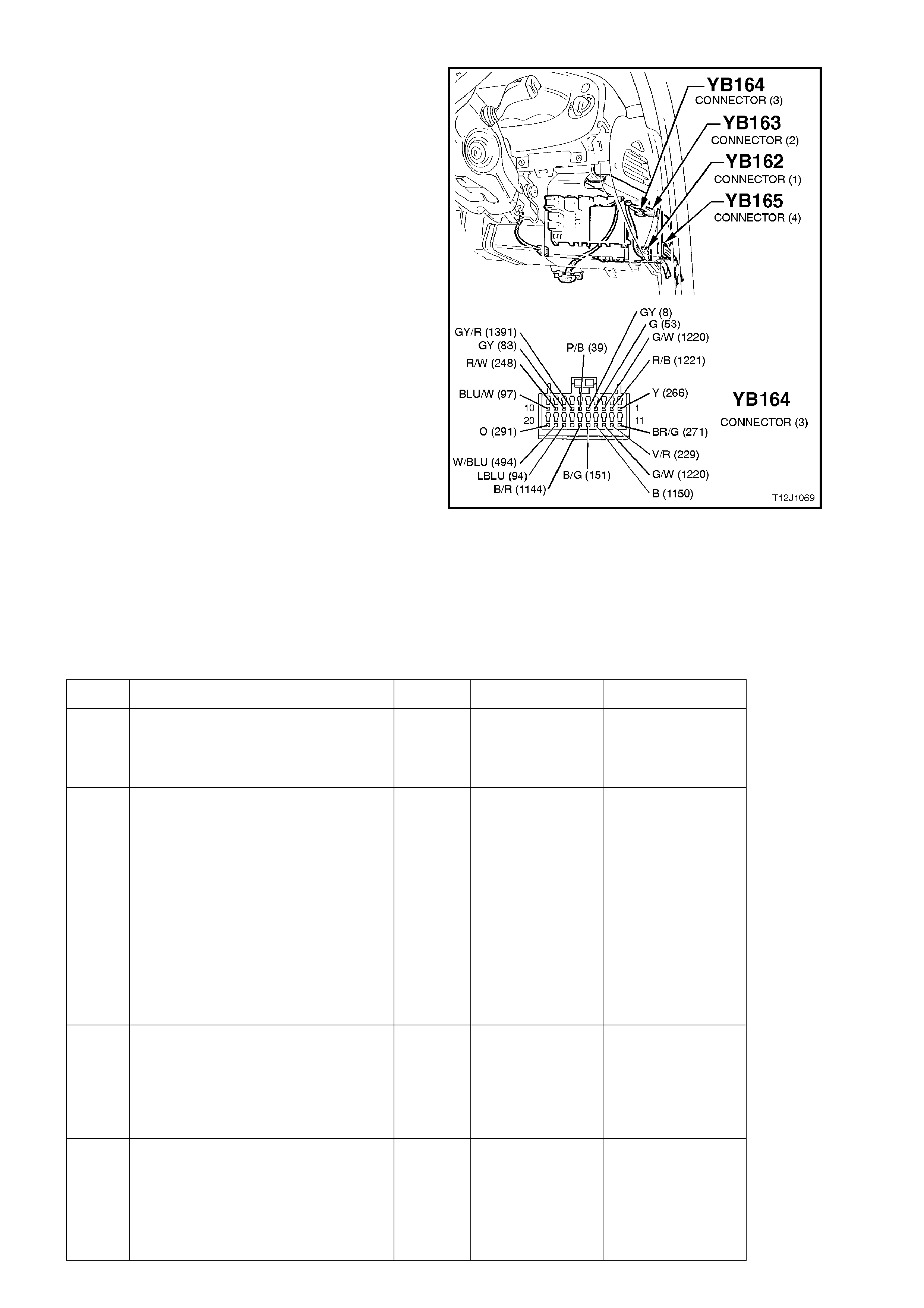
CIRCUIT DESCRIPTION:
The two speed electric engine cooling fan’s low
speed is enabled when the low speed engine
cooling fan micro relay (located in the engine
compartment relay housing) is energised by the
BCM via a request from the Powertrain Control
Module (PCM). The PCM will request low speed
fan enable and disable via the serial data
communications - main bus.
W hen the ignition switch is turned from ON to O FF
and the fan run on bit has been set by the PCM
(engine coolant temperature above 117°C. The
BCM will continue to energise the low speed engine
cooling fan m ic ro relay for four m inutes 15 seconds
(fan run on).
TEST DESCRIPTION:
The numbers below refer to step numbers in the
following diagnostic chart.
2. Uses TECH 2 to command the BCM to turn
the low speed fan on.
3. Check s f or 12 volt s upply to the engine cooling
fan low speed fan (coil).
4. Checks for low speed fan drive signal at output
of BCM.
5. Checks circuit 473 (Orange/Black wire).
6. Checks circuit 1040 (Orange/Blue wire).
7. Checks circuit 157 (Black/Pink wire).
8. Checks engine cooling fan for low speed relay.
9. Check s circuit 533 ( Blue/Yellow & Black wires)
/ and engine cooling fan motor.
Figure 12J-1-105
ENGINE COOLING FAN, LOW SPEED CONTROL
STEP ACTION VALUE YES NO
1. •With the engine coolant
temperature greater than 104
ºC, is the low speed fan
enabled?
System OK. Go to Step 2.
2. •Connect TECH 2 to the DLC.
•Select Body / Body Control
Module / Miscellaneous Tests /
Low Fan.
•Conduct Low Speed Fan test as
instructed by TECH 2 and
enable the low speed fan.
•Is the low speed fan enabled?
Go to PCM /
Temperature
sensor
diagnosis in
Section 6C1
POWERTRAIN
MANAGEMENT
- V6 ENGINE
or
Section 6C2
POWERTRAIN
MANAGEMENT
- V8 ENGINE.
Go to Step 3.
3. •Back probe engine cooling fan
motor connector YE119, circuit
208 (Green wire) with a
Voltmeter to earth.
•Is voltage as specified?
12 volts Go to Step 4. Check and repair
open in circuit 208
(including fusible
link F7).
Recheck and
verify repair.
4. •Back probe BCM connector
YB163, terminal B7, circuit 473
(Orange/Black wire) with a
jumper lead connected to earth.
•Does the low speed fan turn
on?
Replace BCM,
refer to 2.2 LOW
SERIES BCM in
this Section.
Recheck and
verify repair.
Go to Step 5.

STEP ACTION VALUE YES NO
5. •Back probe engine cooling fan
low speed relay connector
YE103, terminal 86, circuit 473
(Orange/Black wire) with a
jumper lead connected to earth.
•Does the low speed fan turn
on?
0 volts Repair open in
circuit 473.
Recheck and
verify repair.
Go to Step 6.
6. •Back probe engine cooling fan
low speed relay connector
YE103, terminal 85, circuit 1040
(Orange/Blue wire) with a
Voltmeter to earth.
•Is voltage as specified?
12 volts Go to Step 7. Repair open in
circuit 1040.
Recheck and
verify repair.
7. •Back probe engine cooling fan
low speed relay connector
YE103, terminal 87, circuit 157
(Black/Pink wire) with an
Ohmmeter to earth.
•Is value as specified?
Below
1 ohm Go to Step 8. Repair open in
circuit 157.
Recheck and
verify repair.
8. •Back probe engine cooling fan
low speed relay connector
YE103, terminal 30, circuit 533
(Blue/Yellow w ire) with an
Ohmmeter to earth.
•Connect TECH 2 to DLC.
•Select Body / Body Control
Module / Miscellaneous Tests /
Low Fan.
•Conduct Low Speed Fan test as
instructed by TECH 2 and
enable the low speed fan.
•Is value as specified?
Below
1 ohm Go to Step 9. Replace engine
cooling fan low
speed relay.
Recheck and
verify repair.
9. •Back probe engine cooling fan
motor connector YE119, circuit
533 (Black wire) with an
Ohmmeter to earth.
•Connect TECH 2 to the DLC.
•Select Body / Body Control
Module / Miscellaneous Tests /
Low Fan.
•Conduct Low Speed Fan test as
instructed by TECH 2 and
enable the low speed fan.
•Is value as specified?
12 volts Replace engine
cooling fan
motor, refer to
either Section
6B1 ENGINE
COOLING - V6
ENGINE
or
Section 6B2
ENGINE
COOLING - V8
ENGINE.
Recheck and
verify repair.
Repair open in
circuit 533.
Recheck and
verify repair.
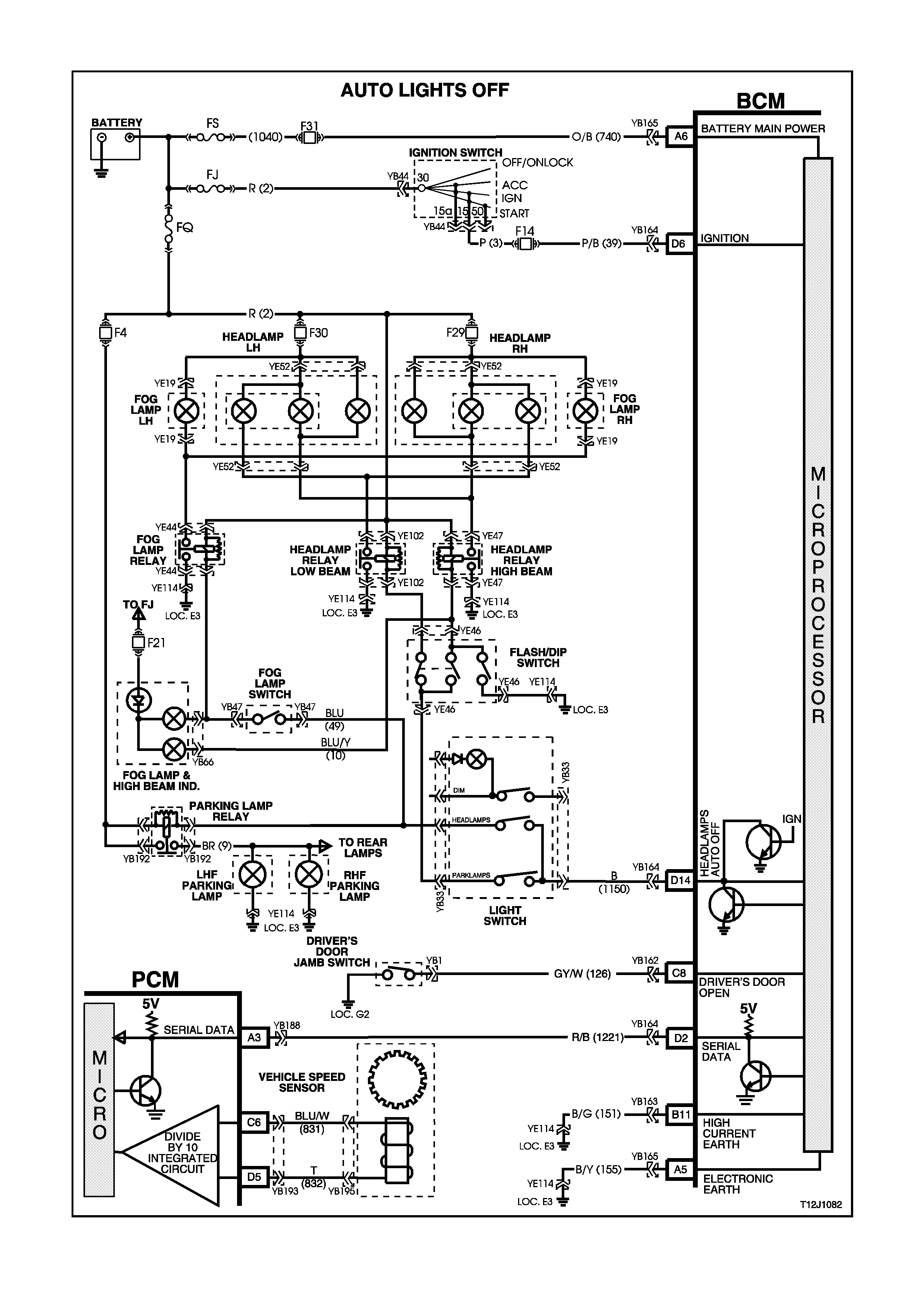
4.10 AUTOMATIC LIGHTS OFF CONTROL
Figure 12J-1-106

CIRCUIT DESCRIPTION:
The automatic lights off control feature is designed
to automatically switch the headlights and parking
lights off when the driver leaves the vehicle.
In the event of a system failure, the default status
of the BCM light control output is in the ON state
when the ignition is in the ON position. This will give
direct control of the lights to the headlamp switch.
The sequence of events required to switch the
lights off automatically is as follows:
1. The vehicle road speed input to the BCM
indicates the vehicle speed is less than 10
km /h and there has not been a s udden loss of
speed (ignition being switched off with the
vehicle travelling above 10 km/h).
2. The BCM senses that the ignition switch is
turned from ON to OFF and remains in the
OFF position.
3. The headlamp switch has not been turned on
after the ignition switch was turned off.
4. The BCM senses the driver’s door has been
opened and turns the lights off.
When the ignition switch is turned back to the IGN
position, the lights will turn back on to the position
selected by the headlamp switch and mode of
headlamp operation.
Turning the headlamp switch off, deactivates the
auto lights off system.
TEST DESCRIPTION:
The numbers below refer to step numbers in the
following diagnostic chart.
1-6. Functional check of headlamp and park lamp
system.
7. Tests fail safe function.
8. Tests to establish whether problem is due to
no output drive from the BCM or circuit
problem beyond the BCM.
9. Checks circuit 1150.
10. Uses TECH 2 to check for DRIVER’S DOOR
OPEN signal at microprocessor of BCM.
11. Uses T ECH 2 to for f alse IGNIT ION ON signal
at microprocessor of BCM.
12. Checks for correct ignition signal level.
13. Checks DRIVER’S DOOR OPEN signal at
input of BCM.
14. Checks circuit 126.
15. Tests for fals e output drive from BCM or short
circuit in lamp circuits.
Figure 12J-1-107
Figure 12J-1-108

AUTOMATIC LIGHTS OFF CONTROL
STEP ACTION VALUE YES NO
1. •Turn ignition OFF.
•Turn headlamp switch from
OFF position to PARKLAMP
position.
•Are the park lamps on?
Go to Step 2. Go to Step 6.
2. •Turn ignition OFF.
•Turn headlamp switch from
PARKLAMP position to
HEADLAMP position.
•Are the headlamps on?
Go to Step 3. Check and repair
headlamp switch
assembly, fault in
wiring harness to
headlamp relay
and headlamp
circuits (including
fuses and
headlamp relay ).
Recheck and
verify repair.
3. •Turn ignition ON.
•Driver’s door closed.
•Headlamp switch in
HEADLAMP position.
•Turn ignition OFF.
•Open driver’s door.
•Do the headlamps turn off?
Go to Step 4. Go to Step 10.
4. •After headlamps have
automatically be turned off from
test Step No. 3, turn the ignition
ON.
•Open driver’s door.
•Do headlamps turn ON?
Go to Step 5. Replace BCM,
refer to 2.2 LOW
SERIES BCM in
this Section.
Recheck and
verify repair.
5. •Driver’s door open.
•Following on from test Step 4,
turn ignition OFF (headlamps
will turn OFF).
•Turn headlamp switch from the
HEADLAMP position to the
OFF position.
•Turn headlamp switch from the
OFF position to the
HEADLAMP position.
•Do headlamps turn on?
System OK. Replace BCM,
refer to 2.2 LOW
SERIES BCM in
this Section.
Recheck and
verify repair.
6. •Turn ignition OFF.
•Turn headlamp switch to the
HEADLAMP position.
•Are the headlamps on?
Check and
repair headlamp
switch
assembly, fault
in wiring
harness to park
lamp relay and
parking lamps
(including fuses
and park
lamp relay).
Recheck and
verify repair.
Go to Step 7.

STEP ACTION VALUE YES NO
7. •Turn ignition ON.
•Turn headlamp switch to
HEADLAMP position.
•Are the headlamps on?
Replace BCM,
refer to 2.2 LOW
SERIES BCM in
this Section.
Recheck and
verify repair.
Go to Step 8.
8. •Disconnect BCM connector
YB164 and back probe terminal
D14 (harness earth) circuit
1150 (Black wire) with a jumper
wire and connect to a sound
earth point.
•Turn headlamp switch to
PARKLAMP position.
•Do park lamps turn on?
12 volts Replace BCM,
refer to 2.2 LOW
SERIES BCM in
this Section.
Recheck and
verify repair.
Go to Step 9.
9. •Reconnect BCM connector
YB164 and back probe terminal
D14 circuit 1150 (Black wire)
and headlamp switch connector
YB33 circuit 1150 (Black wire)
with an Ohmmeter.
•Is value as specified?
Below
1 ohm Check and
repair headlamp
switch
assembly, fault
in wiring
harness to park
lamp relay and
parking lamps
(including fuses
and park lamp
relay), and
headlamp
circuits.
Recheck and
verify repair.
Repair open in
circuit 1150.
Recheck and
verify repair.
10. •Connect TECH 2 to DLC.
•Select Body / Body Control
Module / Data Display and
scroll to Driver’s Door.
•Open driver’s door.
•Does screen display Driver’s
Door Open?
Go to Step 11. Go to Step 13.
11. •With TECH 2 still connected
and Data Display selected,
scroll to Ignition Switch.
•Turn ignition OFF.
•Does screen display Ignition
On?
Go to Step 12. Go to Step 15.
12. •Turn ignition OFF.
•Back probe BCM connector
YB165, terminal D6, circuit 39
(Pink/Black wire) with a
Voltmeter to earth.
•Is voltage as specified?
Ignition
OFF
0 volts
Replace BCM,
refer to 2.2 LOW
SERIES BCM in
this Section.
Recheck and
verify repair.
Check and repair
fault in wiring
(particularly short
to B+) in circuit 39
or faulty I
gnition switch.
Recheck and
verify repair.
13. •Driver’s door open.
•Back probe BCM connector
YB162, terminal C8, circuit 126
(Grey/White wire) with a
Voltmeter to earth.
•Is voltage as specified?
Below
0.5 volts Replace BCM,
refer to 2.2 LOW
SERIES BCM in
this Section.
Recheck and
verify repair
Go to Step 14.

STEP ACTION VALUE YES NO
14. •Disconnect BCM connector
YB162.
•Back probe BCM connector
YB162, harness end, terminal
C8, circuit 126 (Grey/White
wire) and driver’s door jamb
switch connector YB1, circuit
126 (Grey/White wire) with an
Ohmmeter.
•Is Value as specified?
Below
1 ohm Replace driver’s
door jamb
switch, refer
2.10 DOOR
JAMB
SWITCHES in
this Section.
Recheck and
verify repair.
Repair open in
circuit 126.
Recheck and
verify repair.
15. •Turn ignition OFF.
•Headlamp switch in the
HEADLAMP position.
•Driver’s door open.
•Disconnect BCM connector
YB164.
•Do headlamps turn off?
Replace BCM,
refer to 2.2 LOW
SERIES BCM in
this Section.
Recheck and
verify repair.
Check and repair
short circuit in
wiring to relays
and earth end of
lamps, faulty
relays (beyond
terminal D14).
Recheck and
verify repair.
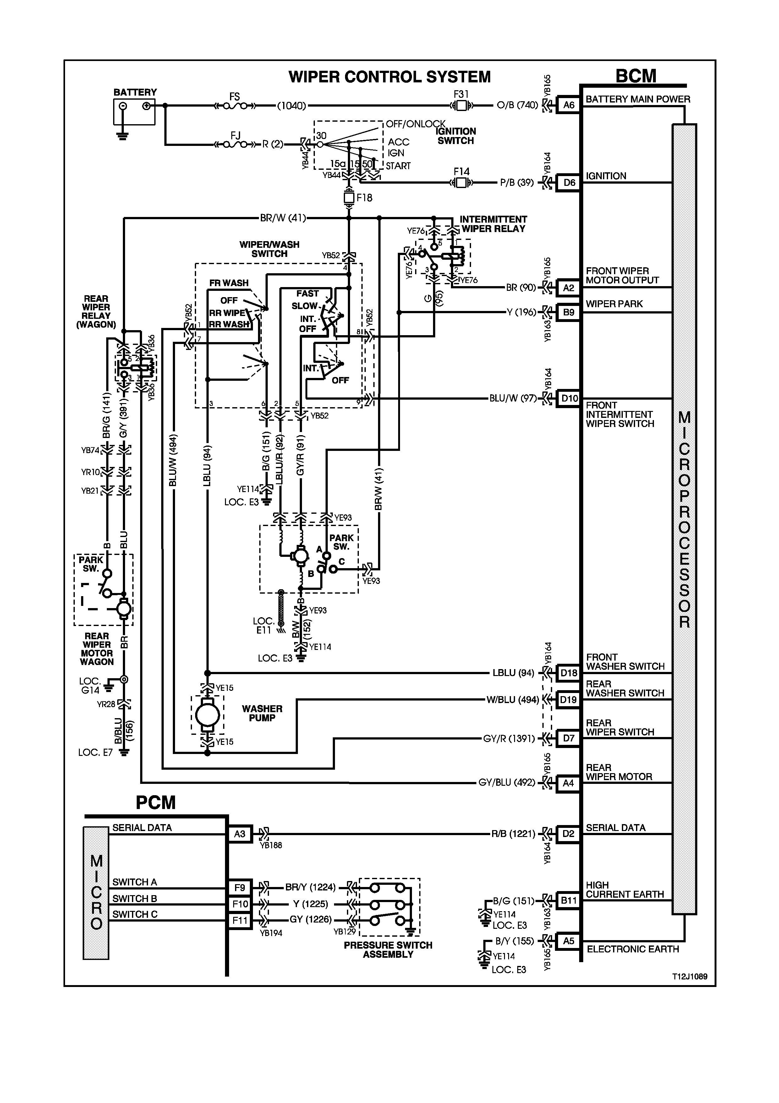
4.11 WIPER CONTROL SYSTEM
Figure 12J-1-109
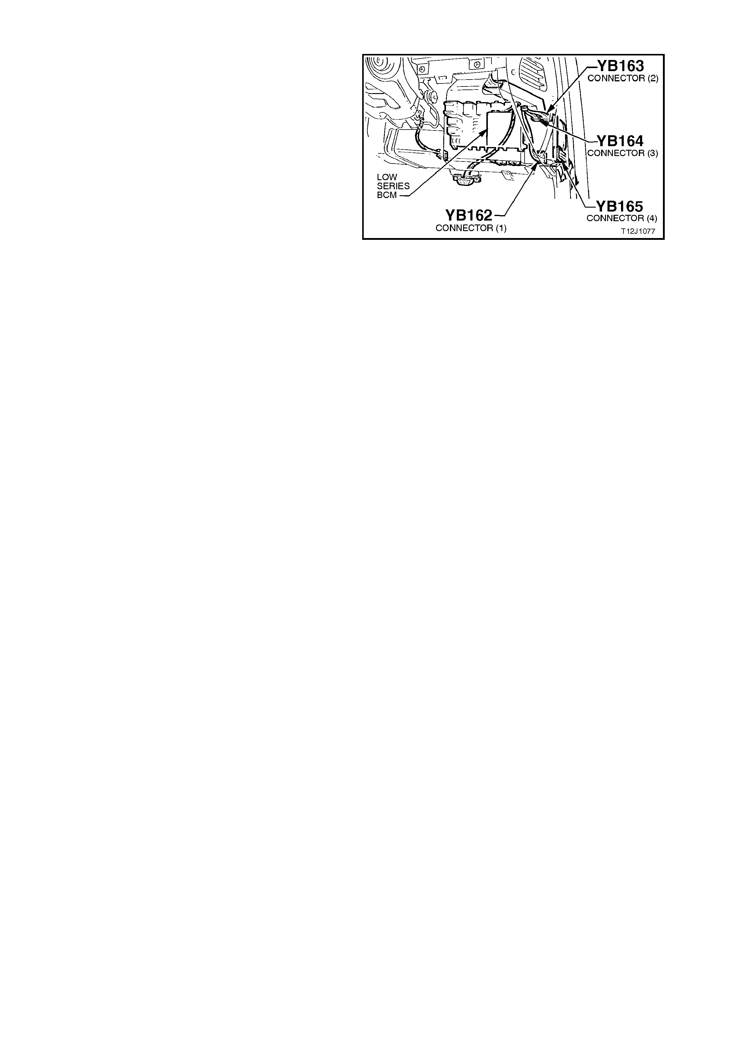
CIRCUIT DESCRIPTION:
This system controls the front intermittent and rear
wiper function. The wiper dwell on vehicles with a
low series BCM has a fixed dwell period of
approxim ately eight seconds and is non -adjustable.
The rear wipers (on wagon models) are
synchronised to the front wipers when the front
wipers are in intermittent m ode. Due to the differ ent
wiper action between front and rear wipers, the
wipers will start one quarter of a sec ond before the
front wipers. If the option is set, the rear wiper
(wagon models with automatic transmission only)
has the added func tion of wiping continuously when
the vehicle is in reverse gear (communication
between the PCM and BCM via the serial data bus)
and the rear wiper/washer switch is turned on.
The front and rear wipers employ a “wipe after
wash” function where, if the relevant washer pump
switch has been pressed for more than 0.5
seconds, the wipers start sweeping at a low speed
continuously until the washer pump has been
disengaged. Following which, the wiper will be held
on for a c alculated tim e period so that the f ollowing
number of sweeps can be completed:
•One additional sweep if washer switch pressed
for less than 1 second.
•Two additional sweeps if washer switch is
pressed for less than 1.5 seconds.
•Three additional sweeps if washer switch is
pressed for more than 1.5 seconds
In order to correctly perform the number of
additional sweeps, the wiper motor park switch is
monitored. This allows the wiper supply power to
be transferred to the park switch at the optimum
time.
Figure 12J-1-110
TEST DESCRIPTION:
The numbers below refer to step numbers in the following diagnostic chart.
1-11. Functional check of wiper control system.
12. Uses TECH 2 to operate front wiper (establishes whether problem is with input or output of BCM).
13 Uses TECH 2 to check for INTERMITTENT WIPER/WASHER SWITCH ON signal at microprocessor of BCM.
14. Checks for 12 volt supply to terminals 1 and 5 of intermittent relay.
15. Checks for BCM output drive of intermittent wiper relay when commanded by TECH 2.
16. Checks circuit 90.
17. Checks intermittent wiper relay.
18. Checks for 12 volts at wiper motor when commanded by TECH 2.
19. 19.Checks circuit 152 / wiper motor.
20. Checks circuit 95.
21. Checks circuit 91 / wiper/washer switch.
22. Checks INTERMITTENT WIPER/WASHER SWITCH ON signal at input to BCM.
23. Checks circuit 97.
24. Checks circuit 41 / wiper/washer switch.
25. Uses TECH 2 to check for WIPER PARK SW signal at microprocessor of BCM.
26. Checks if continuous wiper operation is due to faulty wiper/washer switch / continuous drive from intermittent
relay.
27. Checks WIPER PARK SW signal at input to BCM.
28. Checks circuit 41.
29. Checks circuit 196 / wiper motor assembly (internal park switch).
30 Checks for short in circuit 90, causing relay to be always driven.
31. Checks intermittent wiper relay.
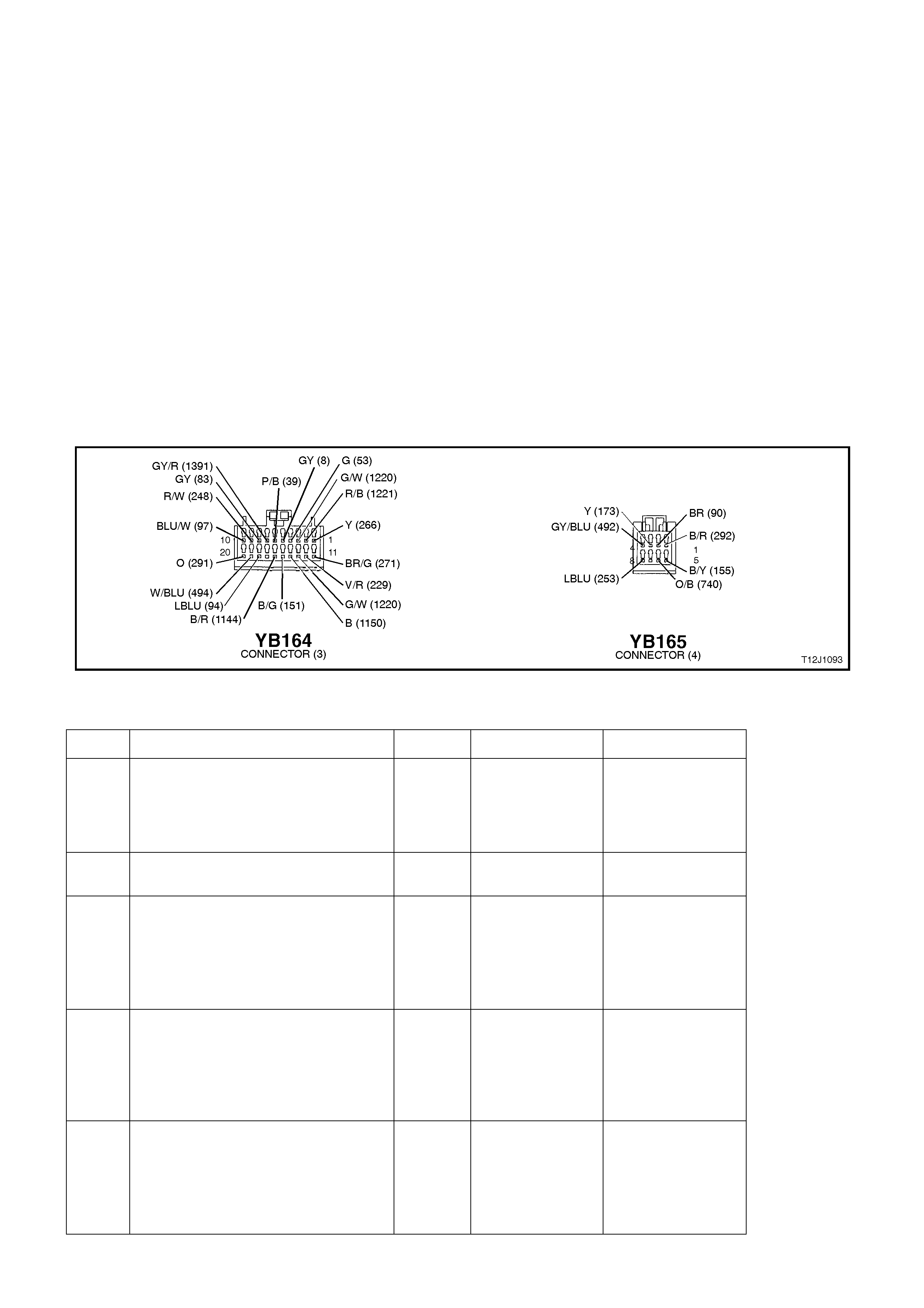
32. Checks FRONT WASHER SW signal at input to BCM.
33 Checks circuit 94 / wiper/washer switch.
34 Uses TECH 2 to operate rear wiper (establish whether problem is with input or output of BCM).
35 Uses TECH 2 to check REAR WIPE SWITCH ON signal at microprocessor of BCM.
36 Checks for 12 volt supply to terminal 2 and 5 of rear wiper relay.
37. Checks for BCM output drive of rear wiper relay when commanded by TECH 2 at rear wiper relay.
38. Checks rear wiper relay.
39. Checks circuit 391.
40. Checks rear wiper motor, circuit 156.
41. Checks for BCM output drive of rear wiper relay at BCM when commanded by TECH 2.
42. Checks REAR WIPER SW signal to BCM.
43. Checks circuit 139 / wiper/washer switch.
44. Checks for short in circuit 492, causing relay to be always driven.
45. Checks rear wiper relay.
46. Checks REAR WASHER SWITCH signal at input to BCM.
47. Checks circuit 494 / wiper/washer switch.
Uses TECH 2 to check REVERSE GEAR signal at microprocessor of PCM.
Uses TECH2 to check reverse gear signal on the serial data bus.
Figure 12J-1-111
WIPER CONTROL SYSTEM
STEP ACTION VALUE YES NO
1. •Turn ignition to ACC.
•Turn the wiper/washer switch to
INTERMITTENT position.
•Does the front wiper sweep?
Go to Step 2. Go to Step 12.
2. •In Step 1, did the front wiper
only sweep once? Go to Step 3. Go to Step 25.
3. •While carrying out Step 1, time
the period between each
sweep.
•Is the delay period as
specified?
8
seconds Go to Step 4. Replace BCM,
refer to 2.2 LOW
SERIES BCM in
this Section.
Recheck and
verify repair.
4. •Turn ignition to ACC.
•Operate the front wash switch
for 2 seconds.
•Does the front wiper commence
continuous operation?
Go to Step 5. Go to Step 32.
5. •In Step 4, did the front wipers
continue for three additional
sweeps after the front wash
switch was released?
Sedan - System
OK.
Wagon - Go to
Step 6.
Replace BCM,
refer to 2.2 LOW
SERIES BCM in
this Section.
Recheck and
verify repair.

STEP ACTION VALUE YES NO
6. •Turn ignition to ACC.
•Turn the wiper/washer switch to
REAR WIPE position.
•Does the rear wiper sweep?
Go to Step 7. Go to Step 34.
7. •In Step 6, did the rear wiper
only sweep once? Go to Step 8. Go to Step 44.
8. •While carrying out Step 6, time
the period between each
sweep.
•Is the delay period as
specified?
8
seconds Go to Step 9. Replace BCM,
refer to 2.2 LOW
SERIES BCM in
this Section.
Recheck and
verify repair.
9. •Turn ignition to ACC.
•Operate the rear wash switch
for 2 seconds.
•Does the rear wiper commence
continuous operation?
Go to Step 10. Go to Step 46.
10. •Turn ignition to ACC.
•Turn the wiper/washer switch to
INTERMITTENT position and
REAR WIPER position.
•Are the front and rear wipers
synchronised?
Go to Step 11. Replace BCM,
refer to 2.2 LOW
SERIES BCM in
this Section.
Recheck and
verify repair.
11. •Using TECH 2, ensue the “rear
wipe continuous operation”
option is active (Body / Body
Control Module / Program /
Rear Wiper Control).
•Turn ignition ON.
•Turn the front intermittent
wipers on.
•Do the rear wipers operate
continuously when reverse gear
is selected?
System OK. Go to Step 48.
12. •Connect TECH to DLC.
•Select Body / Body Control
Module / Miscellaneous Tests /
Wiper Tests / Front Wipers.
•Turn Ignition to the ACC
position and conduct test as
instructed by TECH 2.
•Do front wipers sweep
continuously?
Go to Step 13. Go to Step14.
13. •With TECH 2 still connected,
exit Miscellaneous Tests and
select Data Display.
•Scroll to Front Wiper
Intermittent Switch.
•Turn ignition to the ACC
position.
•Turn the wiper/washer switch to
INTERMITTENT position.
•Does screen display Front
Wiper Intermittent Switch On?
Replace BCM,
refer to 2.2 LOW
SERIES BCM in
this Section.
Recheck and
verify repair.
Go to Step 22.

STEP ACTION VALUE YES NO
14. •Turn ignition to the ACC
position.
•Back probe intermittent wiper
relay connector YE76, terminal
5 and 1, circuit 41
(Brown/Green wire) with a
Voltmeter tot earth.
•Is voltage as specified?
12 volts Go to Step 15. Check and repair
open in circuit 41
(including fuse
F18 and
ignition switch).
Recheck and
verify repair.
15. •Back probe BCM connector
YB165, terminal A2, circuit 90
(Brown wire) with a jumper le ad
connected to earth.
•Do wipers sweep?
0 volts Replace BCM,
refer to 2.2 LOW
SERIES BCM in
this Section.
Recheck and
verify repair.
Go to Step 16.
16. •Back probe intermittent wiper
relay connector YE76, terminal
2, circuit 90 (Brown wire) with a
jumper lead connected to earth.
•Do wipers sweep?
0 volts Check and
repair open in
circuit 90.
Recheck and
verify repair.
Go to Step 17.
17. •Back probe intermittent wiper
relay connector YE76, terminal
3, circuit 95 (Green wire) with a
Voltmeter to earth.
•Turn ignition to the ACC
position and conduct TECH 2
Front Wiper test.
•Is voltage as specified?
12 volts Go to Step 18. Replace
intermittent
wiper relay.
Recheck and
verify repair.
18. •Back probe wiper motor
connector YE93, circuit 91
(Grey/Red wire) with a
Voltmeter to earth.
•Turn ignition to the ACC
position and repeat TECH 2
Front Wiper test.
•Is voltage as specified?
12 volts Go to Step 19. Go to Step 20.
19. •Back probe front wiper motor
connector YE93, circuit 152
(Black/White wire) with an
Ohmmeter to earth.
•Is value as specified?
Below
1 ohm Replace front
wiper motor
assembly, refer
to Section 12C
INSTRUMENTS
, WIPERS /
WASHERS &
HORN.
Check and repair
open in
circuit 152.
Recheck and
verify repair.
20. •Back probe wiper/washer
switch connector YB52,
terminal 8, circuit 95 (Green
wire) with a Voltmeter to earth.
•Turn ignition to the ACC
position and repeat TECH 2
Front Wiper test.
•Is voltage as specified?
12 volts Go to Step 21. Check and repair
open in circuit 95.
Recheck and
verify repair.

STEP ACTION VALUE YES NO
21. •Back probe wiper/washer
switch connector YB52,
terminal 5, circuit 91 (Grey/Red
wire) with a Voltmeter to earth.
•Turn ignition to the ACC
position and repeat TECH 2
Front Wiper test.
•Is voltage as specified?
12 volts Check and
repair open in
circuit 91.
Recheck and
verify repair.
Replace
wiper/washer
switch, refer to
Section 12C
INSTRUMENTS,
WIPERS /
WASHERS &
HORN.
22. •Turn ignition to ACC.
•Back probe BCM connector
YB164, terminal D10, circuit 97
(Blue/White wire) with a
Voltmeter to earth.
•Turn the wiper/washer switch to
INTERMITTENT position.
•Is voltage as specified?
12 volts Replace BCM,
refer to 2.2 LOW
SERIES BCM in
this Section.
Recheck and
verify repair.
Go to Step 23.
23. •Turn ignition to ACC.
•Back probe wiper/washer
switch connector YB52,
terminal 9, circuit 97
(Blue/White wire) with a
Voltmeter to earth.
•Turn the wiper/washer switch to
INTERMITTENT position.
•Is voltage as specified?
12 volts Check and
repair open in
circuit 97.
Recheck and
verify repair.
Go to Step 24.
24. •Turn ignition to ACC.
•Back probe wiper/washer
switch connector YB52,
terminal 4, circuit 41
(Brown/White wi re) with a
Voltmeter to earth.
•Is voltage as specified?
12 volts Replace
wiper/washer
switch, refer to
Section 12C
INSTRUMENTS
, WIPERS /
WASHERS &
HORN.
Check and repair
open in circuit 41
(including
fuse F18).
Recheck and
verify repair.
25. •Connect TECH 2 to DLC.
•Select Body / Body Control
Module / Data Display and
scroll to Wiper Park Switch.
•Turn the wiper/washer switch to
INTERMITTENT position.
•Does screen display Wiper
Park Switch On when wiper is
in the park position and Wiper
Park Switch Off when wiper is
operating?
Go to Step 26. Go to Step 27.
26. •Turn ignition to ACC.
•Turn the wiper/washer switch to
INTERMITTENT position.
•Remove intermittent wiper
relay.
•Do wipers operate
continuously?
Replace
wiper/washer
switch, refer to
Section 12C
INSTRUMENTS
, WIPERS /
WASHERS &
HORN.
Go to Step 30.

STEP ACTION VALUE YES NO
27. •Turn ignition to ACC.
•Turn the wiper/washer switch to
INTERMITTENT position.
•Back probe BCM connector
YB163, terminal B9, circuit 196
(Yellow wire) with a Voltmeter to
earth.
•Are voltages as specified?
12 volts
while
operatin
g
0 volts
in park
Replace BCM,
refer to 2.2 LOW
SERIES BCM in
this Section.
Recheck and
verify repair.
Go to Step 28.
28. •Turn ignition to ACC.
•Back probe wiper motor
connector YE93, circuit 41
(Brown/White wi re) with a
Voltmeter to earth.
•Is voltage as specified?
12 volts Go to Step 29. Check and repair
open in circuit 41.
Recheck and
verify repair.
29. •Turn ignition to ACC.
•Turn the wiper/washer switch to
INTERMITTENT position.
•Back probe wiper motor
connector YE93, circuit 196
(Yellow wire) with a Voltmeter to
earth.
•Are values as specified?
12 volts
while
operatin
g
0 volts
in park
Check and
repair open in
circuit 196.
Recheck and
verify repair.
Replace front
wiper motor, refer
to Section 12C
INSTRUMENTS,
WIPERS /
WASHERS &
HORN.
30. •Turn ignition to ACC.
•Remove intermittent relay.
•Disconnect BCM connector
YB165.
•Back probe intermittent wiper
relay connector YE76, circuit 90
(Brow n wire) with an Ohmmeter
to earth.
•Is value as specified?
Below
1 ohm Check and
repair short to
earth in
circuit 90.
Recheck and
verify repair.
Go to Step 31
31. •Reconnect BCM connector
YB165.
•Swap intermittent wiper relay
with a known good relay.
•Turn ignition to ACC.
•Turn the wiper/washer switch to
INTERMITTENT position.
•Does only one sweep occur?
Replace
intermittent
wiper relay.
Recheck and
verify repair.
Replace BCM,
refer to 2.2 LOW
SERIES BCM in
this Section.
Recheck and
verify repair.
32. •Turn ignition to ACC.
•Back probe BCM connector
YB164, terminal D18, circuit 94
(Light Blue wire) with a
Voltmeter to earth.
•Operate front wash switch.
•Is voltage as specified?
12 volts Replace BCM,
refer to 2.2 LOW
SERIES BCM in
this Section.
Recheck and
verify repair.
Go to Step 33.
33. •Turn ignition to ACC.
•Back probe wiper/washer
switch connector YB52,
terminal 3, circuit 94 (L Blue
wire) with a Voltmeter to earth.
•Operate front wash switch.
•Is voltage as specified?
12 volts check and repair
open in circuit
94. Recheck
and verify repair.
Replace
wiper/washer
switch, refer to
Section 12C
INSTRUMENTS,
WIPERS /
WASHERS &
HORN.

STEP ACTION VALUE YES NO
34. •Connect TECH 2 to DLC.
•Select Body / Body Control
Module / Miscellaneous Tests /
Wiper Tests / Rear Wiper.
•Turn ignition to the ACC
position and conduct test as
instructed by TECH 2.
•Does rear wiper operate
continuously?
Go to Step 35. Go to Step 36.
35. •Turn ignition to ACC.
•With TECH 2 still connected,
exit Miscellaneous Tests and
select Data Display.
•Scroll to Rear Wiper Switch.
•Turn wiper/washer switch to
REAR WIPE position.
•Does screen display Rear
Wiper Switch On?
Replace BCM,
refer to 2.2 LOW
SERIES BCM in
this Section.
Recheck and
verify repair.
Go to Step 42.
36. •Turn ignition to ACC.
•Back probe rear wiper relay
connector YB36, terminals 2
and 5, circuit 41 (Brown/Green
wire) with a Voltmeter to earth.
•Is voltage as specified?
12 volts Go to Step 37. Check and repair
open in circuit 41.
Recheck and
verify repair.
37. •Back probe rear wiper relay
connector YB36, terminal 1,
circuit 492 (Grey/Blue wire) with
a jumper lead connected to
earth.
•Does rear wiper operate?
Go to Step 41. Go to Step 38.
38. •Back probe rear wiper relay
connector YB36, terminal 3,
circuit 391 (Green/Yellow wire)
with a Voltmeter to earth.
•Connect a jumper lead between
wiper relay connector, terminal
1 and earth.
•Turn ignition to the ACC
position.
•Is voltage as specified?
12 volts Go to Step 39. Replace rear
wiper relay.
Recheck and
verify repair.
39. •Back probe rear wiper motor
connector YR21, circuit 391
(Green/Yellow wire) with a
Voltmeter to earth
•Connect a jumper lead between
wiper relay connector, terminal
1 and earth.
•Turn ignition to the ACC
position.
•Is voltage as specified?
12 volts Go to Step 40. Check and repair
open in
circuit 391.
Recheck and
verify repair.
40. •Back probe rear wiper motor
earth connection with an
Ohmmeter to earth.
•Is value as specified?
Below
1 ohm Replace rear
wiper motor,
refer Section
12C INST,
WIPERS/
WASHERS &
HORN.
Check and repair
rear wiper motor
earth connection.
Recheck and
verify repair.

STEP ACTION VALUE YES NO
41. •Back probe BCM connector
YB165, terminal A4, circuit 492
(Grey/Blue wire) with a jumper
lead connected to earth.
•Turn ignition to the ACC
position.
•Does the rear wiper operate?
Replace BCM,
refer to 2.2 LOW
SERIES BCM in
this Section.
Recheck and
verify repair.
Check and repair
circuit 492 as
necessary.
Recheck and
verify repair.
42. •Turn ignition to ACC.
•Back probe BCM connector
YB164, terminal D7, circuit 139
(Grey/Red wire) with a
Voltmeter to earth.
•Turn wiper/washer switch to
REAR WIPE position.
•Is voltage as specified?
12 volts Replace BCM,
refer to 2.2 LOW
SERIES BCM in
this Section.
Recheck and
verify repair.
Go to Step 43.
43. •Turn ignition to ACC.
•Back probe wiper washer
switch connector YB52,
terminal 1, circuit 1391
(Grey/Red wire) with a
Voltmeter to earth.
•Turn wiper/washer switch to
REAR WIPE position.
•Is voltage as specified?
12 volts Check and
repair open in
circuit 1391.
Recheck and
verify repair.
Replace
wiper/washer
switch, refer to
Section 12C
INST., WIPERS /
WASHERS &
HORN
44. •Remove rear wiper relay.
•Disconnect BCM connector
YB165.
•Back probe rear relay connector
YB36, terminal 1, circuit 492
(Grey/Blu e wire) with an
Ohmmeter to earth.
•Is value as specified?
Below
1 ohm Check and
repair short to
earth in
circuit 492.
Recheck and
verify repair.
Go to Step 45.
45. •Reconnect BCM connector
YB165.
•Replace rear wiper relay with a
known good relay.
•Turn ignition to ACC.
•Turn wiper/washer switch to
REAR WIPE position.
•Does only one rear wipe sweep
occur?
Replace rear
wiper relay.
Recheck and
verify repair.
Go to Step 49.
46. •Turn ignition to ACC.
•Back probe BCM connector
YB164, terminal D19, circuit
494 (White/Blue wire) with a
Voltmeter to earth.
•Operate rear wash switch.
•Is voltage as specified?
12 volts Replace BCM,
refer to 2.2 LOW
SERIES BCM in
this Section.
Recheck and
verify repair.
Go to Step 47

STEP ACTION VALUE YES NO
47. •Turn ignition to ACC.
•Back probe wiper/washer
switch connector YB52,
terminal 7, circuit 494
(White/Blue wire) with a
Voltmeter to earth.
•Operate rear washer switch.
•Is voltage as specified?
12 volts Check and
repair open in
circuit 494,.
Recheck and
verify repair.
Replace
wiper/washer
switch, refer to
Section 12C
INST., WIPERS /
WASHERS &
HORN.
48. •Connect TECH 2 to DLC.
•Turn ignition to ACC.
•Vehicle in reverse gear.
•Select ENGINE / NORMAL
MODE.
•Scroll to COMMANDED GEAR
display.
•Does screen display R?
Replace BCM,
refer to 2.2 LOW
SERIES BCM in
this Section.
Recheck and
verify repair.
Go to PCM
diagnostics in
Section 6C1
POWERTRAIN
MANAGEMENT -
V6 ENGINE
or
Section 6C2
POWERTRAIN
MANAGEMENT -
V8 ENGINE.
49. •Connect TECH 2 to DLC.
•Turn ignition to ACC.
•Vehicle in neutral gear.
•Select ENGINE / NORMAL
MODE.
•Scroll to COMMANDED GEAR
display.
•Does screen display R?
Go to PCM
diagnostics in
Section 6C1
POWERTRAIN
MANAGEMENT
- V6 ENGINE
or
Section 6C2
POWERTRAIN
MANAGEMENT
- V8 ENGINE.
Replace BCM,
refer to 2.2 LOW
SERIES BCM in
this Section.
Recheck and
verify repair.
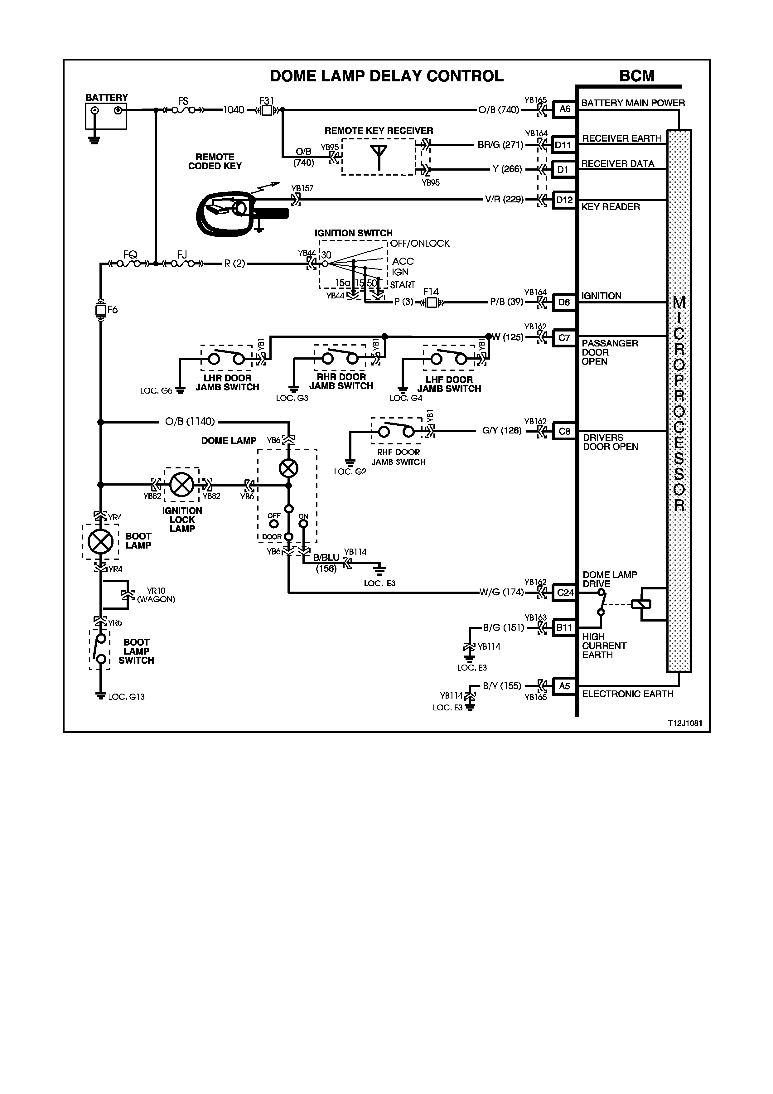
4.12 DOME LAMP DELAY CONTROL
Figure 12J-1-112
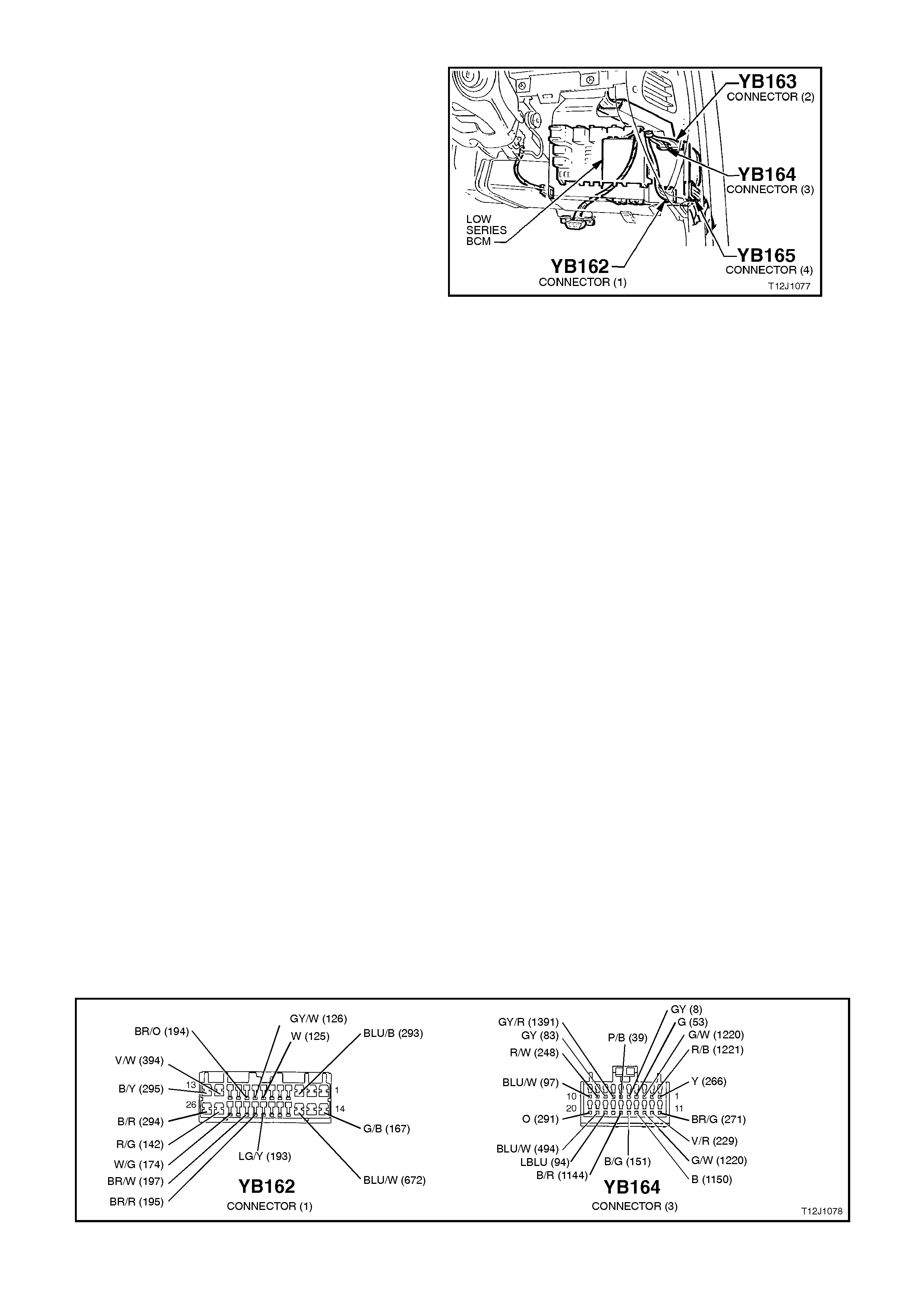
CIRCUIT DESCRIPTION:
The interior lighting is c ontrolled by the BCM, or the
dome lamp switch (incorporated in the overhead
dome lamp and switch assembly). The interior
lighting is activated when any door is opened, the
doors are unlocked with the remote coded key or
when the dome lamp switch is operated.
The interior lighting operates continuously whilst
any door is open. After all door s have been closed,
the lamp will remain activated for an additional 30
seconds.
If the interior lighting has been activated by a BCM
control system action, the dome lamp switch will
turn the interior lighting off when it is switched from
the DOOR to the OFF position. This means that
the switch can curtail any delay time indicated as
well as switch the lighting off whilst a door is open.
With the dome lamp switch in the ON position,
BCM control of the interior lighting is overridden.
The interior lighting is switched on upon central
door unlocking for 30 seconds. If the ignition is
turned on during this per iod, the interior lighting will
be switched off immediately. Interior lighting is also
switched off upon centr al door lock ing, exc ept if the
dome lamp switch is turned on.
TEST DESCRIPTION:
The numbers below refer to step numbers in the
following diagnostic chart.
1-6. Functional check of dome lamp system.
7. Checks dome lamp globe.
8. Checks circuit 1140/fuse F6.
9. Check s circuit 156 and dom e lamp and s witch
assembly.
10. Checks dome lamp drive output at BCM.
11. Checks circuit 174 and dom e lamp and switch
assembly.
12. Uses TECH 2 to check for passenger door
signal at microprocessor of BCM.
13. Checks BCM for f alse output drive, circuit 174
and dome lamp and switch assembly.
14. Checks passenger door jamb circuit and
switches.
15. Checks driver’s door jamb switch signal at
input of BCM.
16. Checks circuit 126.
17 & 18. Checks passenger door jamb switch
signal at input of BCM.
19. Checks ignition signal at input of BCM.
Figure 12J-1-113
Figure 12J-1-114

DOME LAMP DELAY CONTROL
STEP ACTION VALUE YES NO
1. •Switch the dome lamp switch to
the ON position.
•Does the dome lamp
illuminate?
Go to Step 2. Go to Step 7.
2. •Dome lamp switch in DOOR
position.
•All doors locked.
•Unlock doors with remote key.
•Does dome lamp turn on?
Go to Step 3. Go to Step 10.
3. •Dome lamp switch in DOOR
position.
•Dome lamp on (doors open).
•Close doors and lock with
remote key.
•Does dome lamp turn off
immediately?
Go to Step 4. Go to Step 12.
4. •Dome lamp switch in DOOR
position.
•Doors closed but unlocked
(dome lamp off).
•Open driver’s door.
•Does dome lamp illuminate
Go to Step 5. Go to Step 15.
5. •Dome lamp switch in DOOR
position.
•Doors closed but unlocked
(dome lamp off).
•Open any passenger door.
•Does dome lamp illuminate?
Go to Step 6. Go to Step 17.
6. •Dome lamp switch in DOOR
position.
•With doors closed, lock then
unlock doors with remote key.
•Within 30 seconds, turn ignition
to the ON position.
•Does the dome lamp turn off
immediately?
System OK. Go to Step 19.
7. •Check dome lamp globe.
•Is globe OK?
Go to Step 8. Replace globe.
Recheck and
verify repair.
8. •Back probe dome lamp and
switch assembly connector
YB6, circuit 1140 (Orange/Black
wire) with a Voltmeter to earth.
•Is voltage as specified?
12 volts Go to Step 9. Check and repair
fault in
circuit 1140
(including
fuse F6).
Recheck and
verify repair.
9. •Back probe dome lamp and
switch assembly connector
YB6, circuit 156 (Black/Blue
wire) with an Ohmmeter to
earth.
•Is reading as specified?
Below
1 ohm Replace dome
lamp and switch
assembly, refer
12B LIGHTING
SYSTEM.
Recheck and
verify repair.
Repair open in
circuit 156.
Recheck and
verify repair.

STEP ACTION VALUE YES NO
10. •Turn ignition OFF.
•Back probe BCM connector
YB162, terminal C24, circuit
174 (White/Green wire) with an
Ohmmeter to earth.
•With doors closed, lock and
unlock doors using remote key.
•Within 30 seconds of unlocking
doors, is reading as specified?
Below
1 ohm Go to Step 11 Replace BCM,
refer to 2.2 LOW
SERIES BCM in
this Section.
Recheck and
verify repair
11. •Back probe BCM connector
YB162, terminal C24, circuit
174 (White/Green wire) and
dome lamp and switch
assembly connector YB6, circuit
174 (White/Green wire) with an
Ohmmeter.
•Is reading as specified?
Below
1 ohm Replace dome
lamp and switch
assembly, refer
12B LIGHTING
SYSTEM.
Recheck and
verify repair.
Repair open in
circuit 174.
Recheck and
verify repair.
12. •Passenger doors closed.
•Connect TECH 2 to DLC.
•Select Body / Body Control
Module / Data Display and
scroll to Passenger Doors.
•Does the screen display
Passengers Doors Closed?
Go to Step 13. Go to Step 14.
13. •Dome lamp switch in DOOR
position.
•Disconnect BCM connector
YB162.
•Does dome lamp turn off?
Replace BCM,
refer to 2.2 LOW
SERIES BCM in
this Section.
Recheck and
verify repair.
Check and repair
either short in
circuit 174 or
faulty dome lamp
and switch
assembly.
Recheck and
verify repair.
14. •TECH 2 still connected and
Data Displ ay selected, scroll to
Passenger Doors.
•Disconnect BCM connector
YB162.
•Does screen display Passenger
Doors Closed?
Check and
repair either
short in circuit
125 or faulty
passenger door
jamb switch
assembly.
Recheck and
verify repair.
Replace BCM,
refer to 2.2 LOW
SERIES BCM in
this Section.
Recheck and
verify repair.
15. •Driver’s door open.
•Back probe BCM connector
YB162, terminal C8, circuit 126
(Grey/White wire) with a
Voltmeter to earth.
•Is voltage as specified?
Below
0.5 volts Replace BCM,
refer to 2.2 LOW
SERIES BCM in
this Section.
Recheck and
verify repair.
Go to Step 16.
16. •Back probe BCM connector
YB162, terminal C8, circuit 126
(Grey/White wire) and driver’s
door jamb switch connector
YB1, circuit 126 (Grey/White
wire) with an Ohmmeter.
•Is reading as specified.
Below
1 ohm Replace driver’s
door jamb
switch, refer to
2.10 DOOR
JAMB
SWITCHES in
this Section.
Recheck and
verify repair.
Repair open in
circuit 126.
Recheck and
verify repair.

STEP ACTION VALUE YES NO
17. •Back probe BCM connector
YB162, terminal C7, circuit 125
(White wire) with a Voltmeter to
earth.
•Open and close each
passenger door.
•Is voltage as specified when
opening each of the passenger
doors?
Below
0.5 volts Replace BCM,
refer to 2.2 LOW
SERIES BCM in
this Section.
Recheck and
verify repair.
Go to Step 18.
18. •While performing test in Step
17, was voltage as specified at
least one of the passenger
doors?
Check and
repair either
open in relevant
passenger door
jamb circuit or
fault door jamb
switch.
Repair open in
circuit 125.
Recheck and
verify repair.
19. •Back probe BCM connector
YB164 terminal D6, circuit 39
(Pink/Black wire) with a
Voltmeter to earth.
•Turn ignition ON.
•Is voltage as specified?
12 volts Replace BCM,
refer to 2.2 LOW
SERIES BCM in
this Section.
Recheck and
verify repair.
Repair open in
circuit 39
(including fuse F4
and
ignition switch).
Recheck and
verify repair.
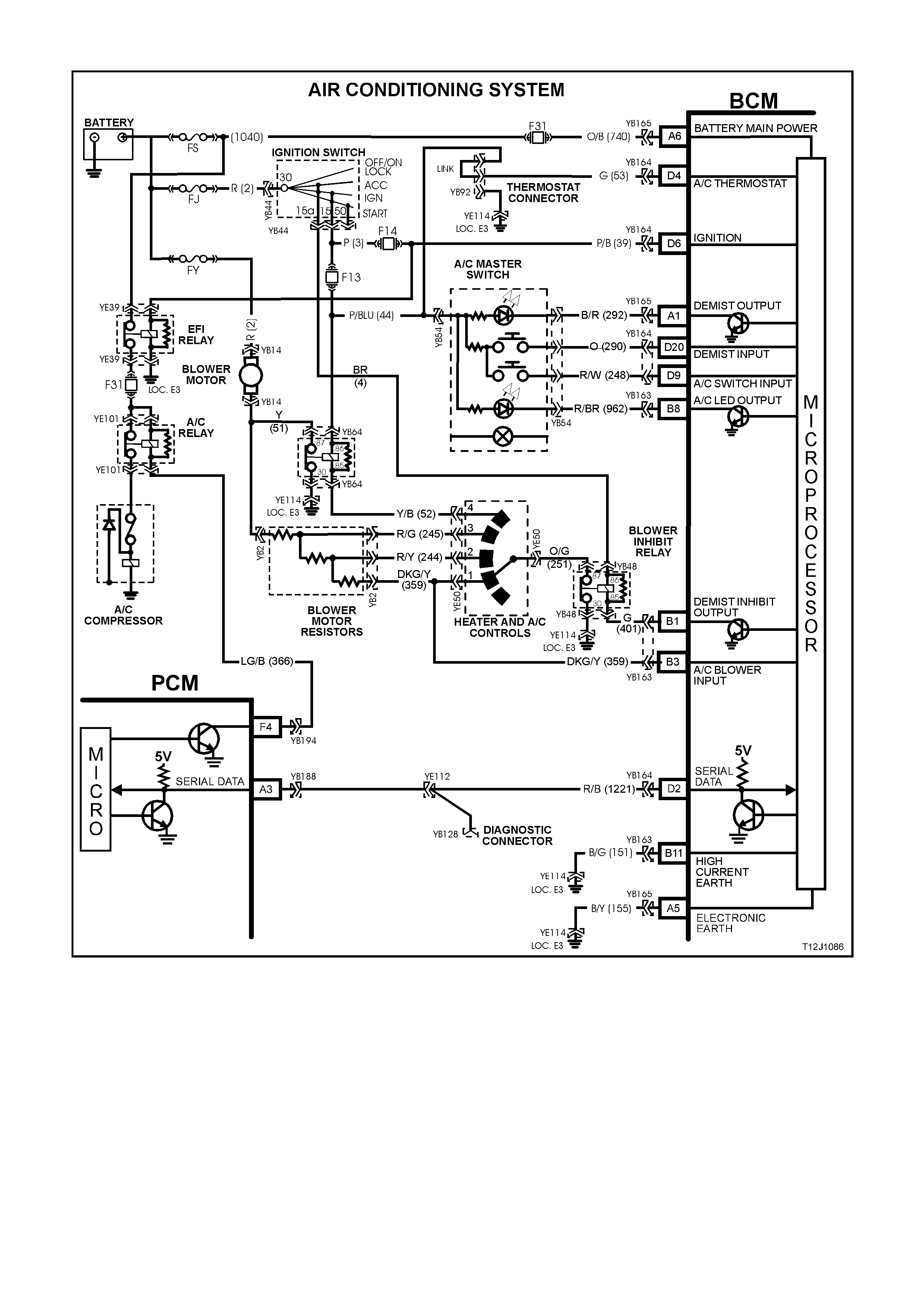
4.13 AIR CONDITIONING INTERFACE
Figure 12J-1-115

CIRCUIT DESCRIPTION:
The air-conditioning interface is used to turn the air
conditioning system on and of f . The BCM reads the
momentary air conditioning switch signal, monitors
fan speed and if the ignition is on the BCM requests
the PCM to turn on the air conditioning c ompres so r.
The air conditioning status LED is turned on by the
BCM when the air conditioning system is active (if
the ignition is turned on) and will toggle with the air
conditioning select switch. The status will be
rem ember ed when the ignition is s witched from ON
to OFF or when the blower is of f but will reset to of f
when the battery is disconnected. If the blower is off
and the air conditioning select button is pressed,
then the next tim e the blower is switched on, the air
conditioning status will also come on. Turning the
ignition off will cancel this button press function.
Figure 12J-1-116
The blower fan is controlled by the blower fan inhibit relay, which suspends blower fan operation during
cranking (via the accessories feed to this control relay). The BCM blower inhibit relay control output will only
allow operation with the ignition in the ON position and therefore, inhibit the operation of this relay while the
ignition switch is in the ACC position.
NOTE:
The BCM has provision for an air conditioning thermostat to prevent the evaporator from icing up. In the
absence of this thermostat, the input is connected to ignition.
TEST DESCRIPTION:
The numbers below refer to step numbers in the following diagnostic chart.
1-5. Functional check of air conditioning system.
6. Checks blower inhibit relay output switch.
7. Checks circuit 251.
8. Checks heater and air conditioning control switch.
9. Checks battery positive feed to blower motor.
10. By-passes the resistor assembly (blower motor) to determine problem with blower motor assembly.
11. Checks blower inhibit relay output from BCM.
12. Checks battery positive at blower inhibit relay.
13. Checks circuit 401.
14. Checks circuit 150 including blower inhibit relay.
15. Uses TECH 2 to check IGNITION ON signal at microprocessor of BCM.
16. Checks ignition ON signal at input of BCM.
17. Checks blower motor circuit 51.
18. Uses TECH 2 to conduct air conditioning compressor/air conditioning status LED test.
19. Uses TECH 2 to check air conditioning select ON/OFF signal at microprocessor of BCM.
20. Uses TECH 2 to check BLOWER FAN ON signal at microprocessor of BCM.
21. Test to determine if air conditioning status LED is not illuminated due to BCM or other circuits.
22. Checks for battery positive supply to air conditioning master switch assembly.
23. Checks circuit 962 and air conditioning master switch assembly.
24. Checks AIR CONDITIONING SELECT signal at input to BCM.
25. Checks circuit 248 and air conditioning master switch assembly.
26. Checks BLOWER FAN ON signal at input to BCM.
27. Checks if TECH 2 is able to communicate to driver’s via the serial data bus.
28. Checks AIR CONDITIONING THERMOSTAT ON signal at input to BCM.
29. Uses TECH 2 to command the PCM to switch the air conditioning compressor on.
30. Checks blower relay drive signal.
31. Checks battery positive feed to blower relay.
32. Checks blower relay sw itch output.
33. Checks circuit 52 and heater and air conditioning control switch
34. Checks circuit 150 and blower relay.

Figure 12J-1-117
AIR CONDITIONING INTERFACE
STEP ACTION VALUE YES NO
1. •Turn ignition ON.
•Heater and air conditioning
control switch speed 1.
•Does blower motor operate?
Go to Step 2. Go to Step 6.
2. •Turn ignition ON.
•Heater and air conditioning
control switch speed 1.
•Toggle air conditioning select
switch.
•Does air conditioning status
LED illuminate?
Go to Step 3. Go to Step 18.
3. •Turn ignition ON.
•Heater and air conditioning
control switch speed 1.
•Toggle air conditioning select
switch to ON.
•Does air conditioning
compressor operate?
Go to Step 4. Go to Step 27.
4. •Turn ignition ON.
•Heater and air conditioning
control switch speed 4.
•Does blower motor operate?
Go to Step 5. Go to Step 30.
5. •Turn ignition ON.
•Heater and air conditioning
control switch speed 4.
•Toggle air conditioning select
switch to ON.
•Does air conditioning
compressor operate?
System OK. Check blower
motor resistor
assembly,
refer to 2 AIR
CONDITIONING.
6. •Turn ignition ON.
•Back probe blower inhibit relay
connector YB48, terminal 87,
circuit 251 (Orange/Green wire)
with a Voltmeter to earth.
•Is voltage as specified?
100
mVolts Go to Step 7. Go to Step 11.
7. •Back probe heater and air
conditioning control switch
connector YB50, circuit 251
(Orange/Green wire) with a
Voltmeter to earth.
•Is voltage as specified?
100
mVolts Go to Step 8. Repair open in
circuit 251.
Recheck circuit to
verify repair.

STEP ACTION VALUE YES NO
8. •Back probe heater and air
conditioning control switch
connector YB50, circuit 359
(Dark Green/Yellow wire) with
an Voltmeter to earth.
•Is voltage as specified?
100
mVolts Go to Step 9. Replace heater
and air
conditioning
control switch,
refer to 2 AIR
CONDITIONING.
9. •Back probe blower motor
connector YB14, circuit 2 (Red
wire) with a Voltmeter to earth.
•Is voltage as specified?
12 Volts Go to Step 10. Check and repair
fault in circuit 2
(including fusible
link FY).
Recheck and
verify repair
10. •Disconnect blower motor
resister connector YB2.
•Back probe blower resistor
connector YB2 (harness end)
circuit 51 (Yellow wire) with a
jumper lead and connect to
earth.
•Does the blower motor
operate?
Check blower
motor resistor. Go to Step 17.
11. •Turn ignition ON.
•Back probe BCM connector
YB163, terminal B1, circuit 401
(Green wire) with a jumper lead
connected to earth.
•Does the blower motor
operate?
Go to Step 15. Go to Step 12.
12. •Turn ignition ON.
•Back probe blower inhibit relay
connector YB48, terminal 86,
circuit 4 (Brown wire) with a
Voltmeter to earth.
•Is voltage as specified?
12 Volts Go to Step 13. Check and repair
fault in circuit 4.
Recheck and
verify repair
13. •Back probe blower inhibit relay
connector YB48, terminal 85,
circuit 401 (Green wire) with a
jumper lead connected to earth.
•Turn ignition ON.
•Does the blower motor
operate?
Check and
repair fault in
circuit 401.
Recheck and
verify repair.
Go to Step 14.
14. •Back probe blower inhibit relay
connector YB48, terminal 30,
circuit 150 (Black wire) with an
Ohmmeter to earth.
•Is value as specified?
Below
1 ohm Replace blower
inhibit relay.
Recheck and
verify repair.
Check and repair
open in circuit 150
Recheck and
verify repair.
15. •Connect TECH2 to DLC.
•Select Body / Body Control
Module / Data Display and
scroll to Ignition Switch.
•With ignition on, does screen
display Ignition On?
Replace BCM,
refer to 2.2 LOW
SERIES BCM in
this Section.
Recheck and
verify repair.
Go to Step 16.

STEP ACTION VALUE YES NO
16. •Turn ignition ON.
•Back probe BCM connector
YB164, terminal D6, circuit 39
(Pink/Black wire) with a
Voltmeter to earth.
•Is voltage as specified?
IGN ON,
12 Volts
IGN
OFF
0 Volts
Replace BCM,
refer to 2.2 LOW
SERIES BCM in
this Section.
Recheck and
verify repair.
Check and repair
fault in circuit 39
(including
fuse F14).
Recheck and
verify repair.
17. •Back probe blower motor
connector YB14, circuit 51
(Yellow w ire) with a jumper lead
and connect to earth.
•Does blower motor operate?
Check and
repair open in
circuit 51.
Recheck and
verify repair.
Replace blower
motor, refer to
2 AIR
CONDITIONING.
18. •Connect TECH 2 to DLC.
•Select Body / Body Control
Module / Miscellaneous Tests /
Lamps / A/C Test.
•Conduct test as instructed by
TECH 2 and switch the A/C
compressor status LED on.
•Does Air conditioning status
LED illuminate?
Go to Step 19. Go to Step 21.
19. •With TECH 2 connected, exit
Miscellaneous Test and select
Data Display.
•Scroll to A/C Switch.
•Does screen display AC Switch
On / Off when toggling air
conditioning select switch?
Go to Step 20. Go to Step 24.
20. •With TECH 2 connected and
Data Displ ay selected, scroll to
A/C Blower Switch.
•Switch heater and air
conditioning control switch to
speed 1.
•Does screen display A/C Blower
Switch On?
Replace BCM,
refer to 2.2 LOW
SERIES BCM in
this Section.
Recheck and
verify repair.
Go to Step 26.
21. •Turn ignition ON.
•Back probe BCM connector
YB163, terminal B8, circuit 962
(Red/Brown wire) with a jumper
lead and connect to earth.
•Does air conditioning status
LED illuminate?
Replace BCM,
refer to 2.2 LOW
SERIES BCM in
this Section.
Recheck and
verify repair
Go to Step 22.
22. •Back probe air conditioning
master switch connector YB54,
circuit 44 (Pink/Blue wire) with a
Voltmeter to earth.
•Turn ignition ON.
•Is voltage as specified?
12 Volts Go to Step 23. Check and repair
fault in circuit 44
(including
fuse F13).
Recheck and
verify repair.

STEP ACTION VALUE YES NO
23. •Turn ignition ON.
•Back probe air conditioning
master switch connector YB54,
circuit 962 (Red/Brown wire)
with a jumper lead and
connector to earth.
•Does air conditioning status
LED illuminate?
Check and
repair open in
circuit 962.
Recheck and
verify repair.
Replace heater
and air
conditioning
control switch,
refer to 2 AIR
CONDITIONING.
24. •Turn ignition ON.
•Back probe BCM connector
YB164, terminal D9, circuit 248
(Red wire) with a Voltmeter to
earth.
•Is voltage as specified when
activation air conditioning
switch?
Switch
closed
(held in)
12 Volts
Switch
open
(rest
position)
0 volts
Replace BCM,
refer to 2.2 LOW
SERIES BCM in
this Section.
Recheck and
verify repair.
Go to Step 25.
25. •Turn ignition ON.
•Back probe air conditioning
master switch connector YB54,
circuit 248 (Red/White wire)
with a Voltmeter to earth.
•Is voltage as specified when
activation air conditioning
switch?
Switch
closed
(held in)
12 Volts
Switch
open
(rest
position)
0 volts
Check and
repair open in
circuit 248.
Recheck and
verify repair.
Replace heater
and air
conditioning
control switch,
refer to 2 AIR
CONDITIONING.
26. •Turn ignition ON.
•Back probe BCM connector
YB163, terminal B3, circuit 359
(Dark Green/Yellow wire) with a
Voltmeter to earth.
•Is voltage as specified?
100
mVolts Replace BCM,
refer to 2.2 LOW
SERIES BCM in
this Section.
Recheck and
verify repair.
Check and repair
open in circuit
359. Recheck and
verify repair.
27. •Connect TECH 2 to DLC.
• Select Body / Body Control
Module.
•Does TECH 2 display system
identification information (BCM
type)?
Go to Step 28 Go to serial data
communications
diagnosis, refer to
4.1 SERIAL DATA
COM. in this
Section.
28. •Turn ignition ON.
•Back probe BCM connector
YB164, terminal D4, circuit 53
(Green wire) with a Voltmeter to
earth.
•Is voltage as specified?
Go to Step 29. Check and repair
open in circuit 53
(including
fuse F14).
Recheck and
verify repair.
29. •With TECH 2 connected, exit
Body and select Engine /
appropriate engine / Data
Display / Miscellaneous Tests
and command AC Compressor
On.
•Does air conditioning
compressor operate?
Replace BCM,
refer to 2.2 LOW
SERIES BCM in
this Section.
Recheck and
verify repair.
Go to PCM
diagnosis, in
Sections 6C1
POWERTRAIN
MANAGEMENT -
V6 ENGINE
or
Section 6C2
POWERTRAIN
MANAGEMENT -
V8 ENGINE.
12 Volts

STEP ACTION VALUE YES NO
30. •Turn ignition ON.
•Switch heater and air
conditioning control switch to
speed 4.
•Back probe blower relay
connector YB64, terminal 85,
circuit 52 (Yellow/Black wire)
with a Voltmeter to earth.
•Is voltage as specified?
100
mVolts Go to Step 31. Go to Step 33.
31. •Turn ignition ON.
•Back probe blower relay
connector YB64, terminal 86,
circuit 44 (Pink/Blue wire) with a
Voltmeter to earth.
•Is value as specified?
12 Volts Go to Step 32. Check and repair
open in circuit 44.
Recheck and
verify repair.
32. •Turn ignition ON.
•Switch heater and air
conditioning control switch to
speed 4.
•Back probe blower relay
connector YB64, terminal 87,
circuit 51 (Yellow wire) with a
Voltmeter to earth
•Is voltage as specified?
100
mVolts Check and
repair open in
circuit 51.
Recheck and
verify repair
Go to Step 34.
33. •Turn ignition ON.
•Switch heater and air
conditioning control switch to
speed 4.
•Back probe heater and air
conditioning control switch
connector YB50, circuit 52
(Yellow/Black wire) with a
Voltmeter to earth.
•Is voltage as specified?
100
mVolts Check and
repair open in
circuit 52.
Recheck and
verify repair.
Replace heater
and air
conditioning
control switch,
refer to 2 AIR
CONDITIONING.
34. •Back probe blower relay
connector YB64, terminal 30,
circuit 150 (Black wire) with a
Voltmeter to earth.
•Is voltage as specified?
100
mVolts Replace blower
relay.
Recheck and
verify repair.
Check and repair
open in
circuit 150.
Recheck and
verify repair.
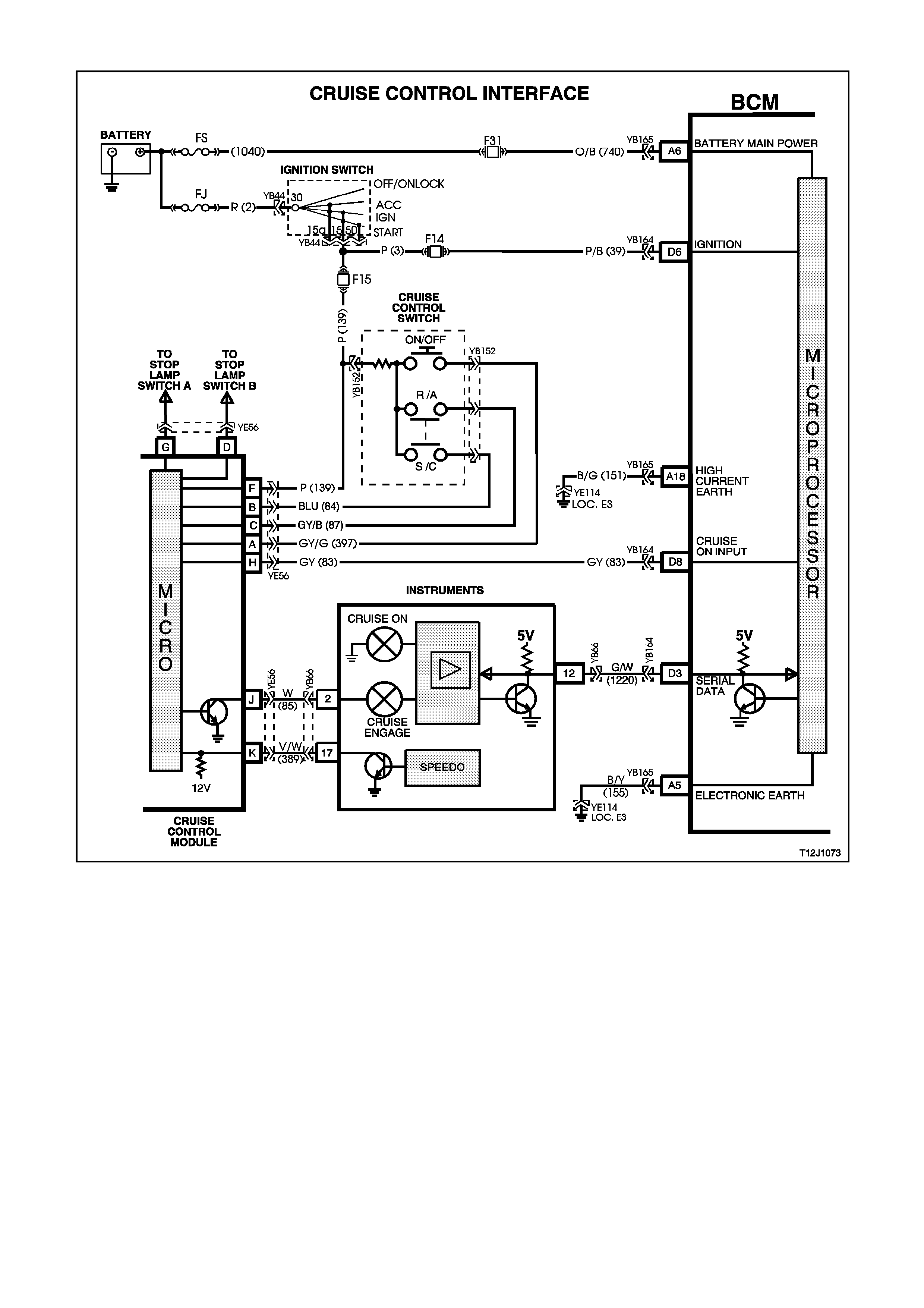
4.14 CRUISE CONTROL INTERFACE
Figure 12J-1-118
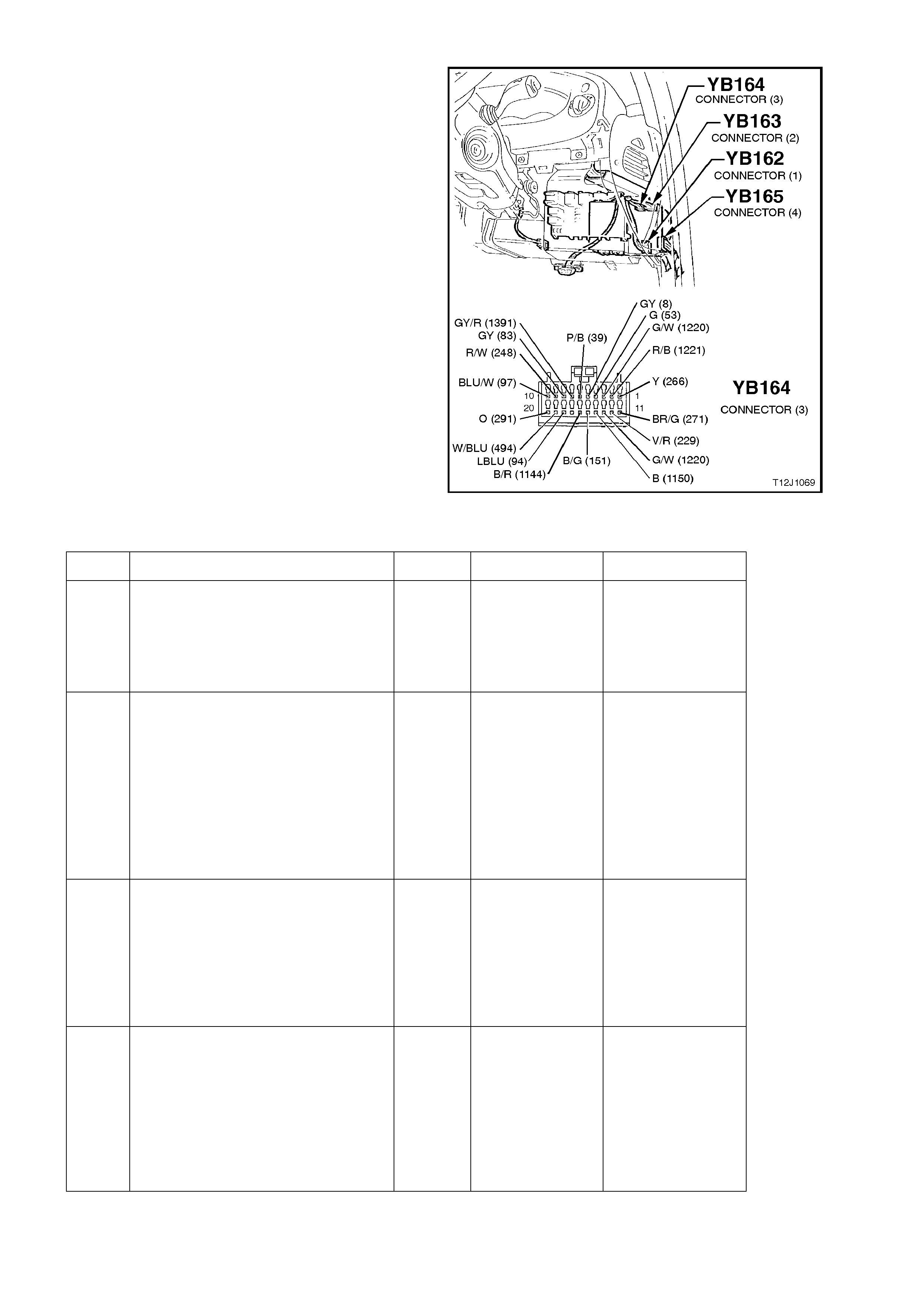
CIRCUIT DESCRIPTION:
The cruise control module is powered up by the
action of the cruise control ON/OFF switch. It then
activates an input of the BCM which in tur n sends a
serial data message, via the auxiliary serial data
line to the instrument cluster to turn the CRUISE
lamp ON. The ignition must be ON for the BCM to
communicate with the instrument cluster.
TEST DESCRIPTION:
The numbers below refer to step numbers in the
following diagnostic chart.
5. Uses TECH 2 to command the CRUISE lamp
in the instrument cluster on.
6. Checks for the ‘ignition’ signal at the input of
the BCM.
7. Check s f or the ‘cr uise on’ signal at the input of
the BCM.
8. Checks for the ‘cruise on’ signal at the output
of the cruise control module.
Figure 12J-1-119
CRUISE CONTROL INTERFACE
STEP ACTION VALUE YES NO
1. •Turn ignition ON.
•Press the cruise control
ON/OFF switch.
•Does the cruise control
CRUISE lamp change state?
System OK. Go to Step 2.
2. •Connect TECH 2 to the DLC.
•Turn ignition ON.
•Select Diagnostics.
•Select: Model Year.
•Select: VT Commodore.
•Does the SYSTEM
SELECTION menu appear on
TECH 2 screen?
Go to Step 3. Go to serial data
communications
diagnosis, refer to
4.1 SERIAL DATA
COM. in this
Section.
3. •With TECH 2 still connected
and ignition on, select Body /
Body Control Module / Data
Display.
•Scroll to Ignition Switch.
•Does screen display Ignition
Switch On?
Go to Step 4. Go to Step 6.
4. •With TECH 2 connected and
Data Displ ay selected, scroll to
Cruise Control Input Signal.
•Press the cruise control
ON/OFF button.
•Does the screen change from
Cruise Control Input Signal Off
to On as the switch is pressed?
Go to Step 5. Go to Step 7.

STEP ACTION VALUE YES NO
5. •With TECH 2 still connected,
exit Body, select Instruments /
Miscellaneous Tests / Lamps
and command the CRUISE
lamp on.
•Does the CRUISE lamp in the
instrument cluster illuminate?
Replace BCM,
refer to 2.2 LOW
SERIES BCM in
this Section.
Recheck and
verify repair.
Go to Instruments
diagnosis in
Section 12C
INSTRUMENTS,
WIPERS /
WASHERS &
HORN
6. •Back probe BCM connector
YB164, terminal D6, circuit 39
(Pink/Black wire) with a
Voltmeter to earth.
•Are voltages as specified?
Turn
ignition
ON.,
approx.
12 volts
Turn
ignition
OFF.
0 volts
Replace BCM,
refer to 2.2 LOW
SERIES BCM in
this Section.
Recheck and
verify repair.
Repair open or
short in circuit 39
(including fuse
F14 and switch).
Recheck circuit to
verify repair.
7. •Turn ignition ON.
•Back probe BCM connector
YB164, terminal D8, circuit 83
(Grey wire ) with a Voltmeter to
earth.
•Press cruise cont rol ON/OFF
switch.
•Does the voltage toggle from
12V - 0V - 12V?
Replace BCM,
refer to 2.2 LOW
SERIES BCM in
this Section.
Recheck and
verify repair.
Go to Step 8.
8. •Turn ignition ON.
•Back probe cruise control
connector YE56, terminal H,
circuit 83 (Grey wire ) with a
Voltmeter to earth.
•Press cruise cont rol ON/OFF
switch.
•Does the voltage toggle from
12V - 0V - 12V?
Repair open or
short in
circuit 83.
Recheck circuit
to verify repair.
Go to Cruise
control diagnosis
in Section 12E
CRUISE
CONTROL.
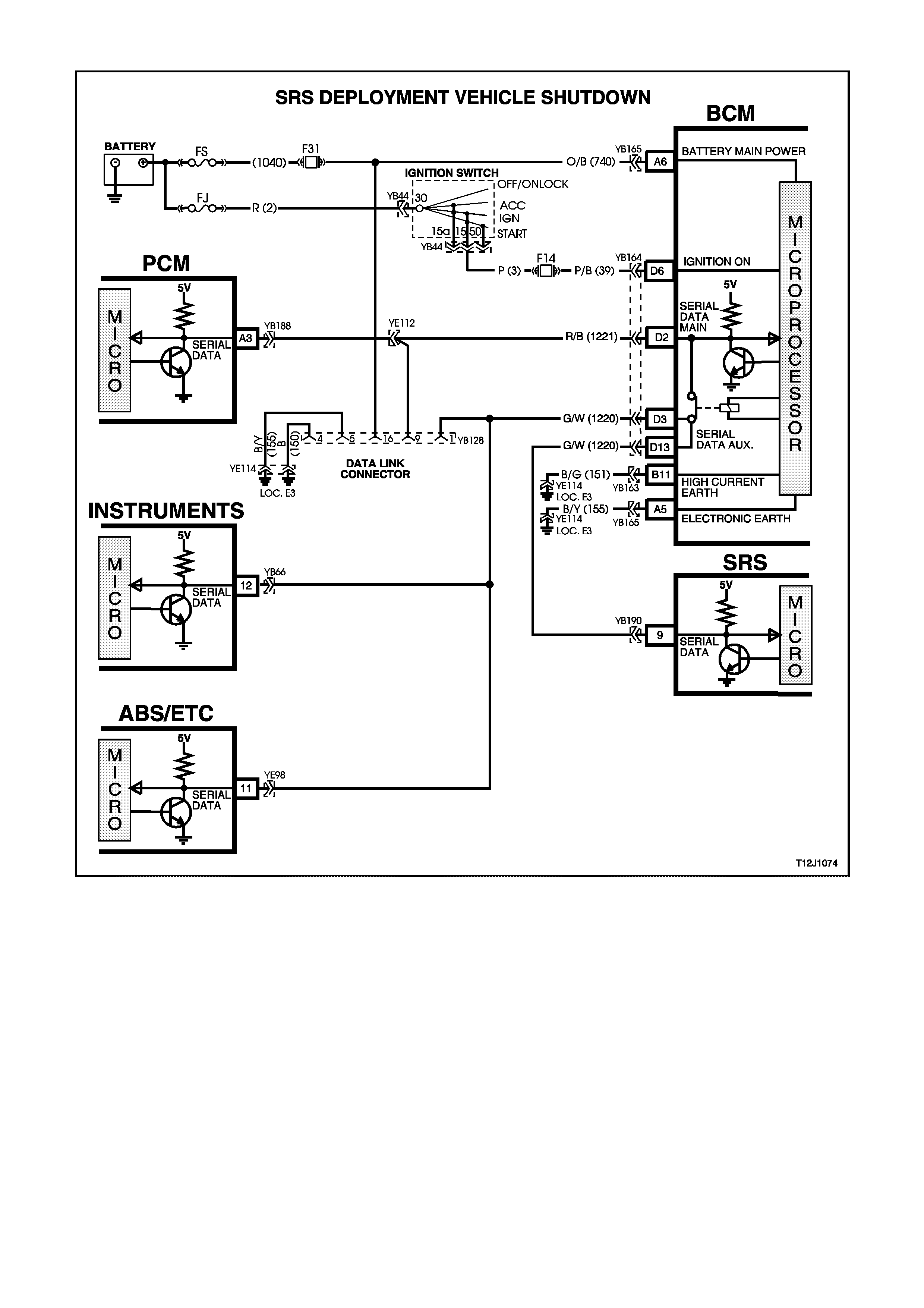
4.15 SRS DEPLOYMENT VEHICLE SHUTDOWN
Figure 12J-1-120
CIRCUIT DESCRIPTION:
In the event of SRS (Supplemental Restraint System) deployment, the Sensing Diagnostic Module (SDM) sets a
flag and sends serial data via the SRS Serial Data (SDI) bus to the BCM. Within the BCM, the SRS SDI bus is
linked to the auxiliary serial data via a wire link. The SDM advises various vehicle systems via the auxiliary bus to
take appropriate shutdown action.
The BCM will monitor this serial data and perform the following actions once the appropriate data is identified and
the vehicle speed is zero for 10 seconds:
1. Turn the dome lamp ON continuously.
2. Unlock all doors.
The dom e lam p will be switched O FF when the ignition switch is cycled fr om O FF to O N, or when the BCM is res et
(ie. via battery disconnection)
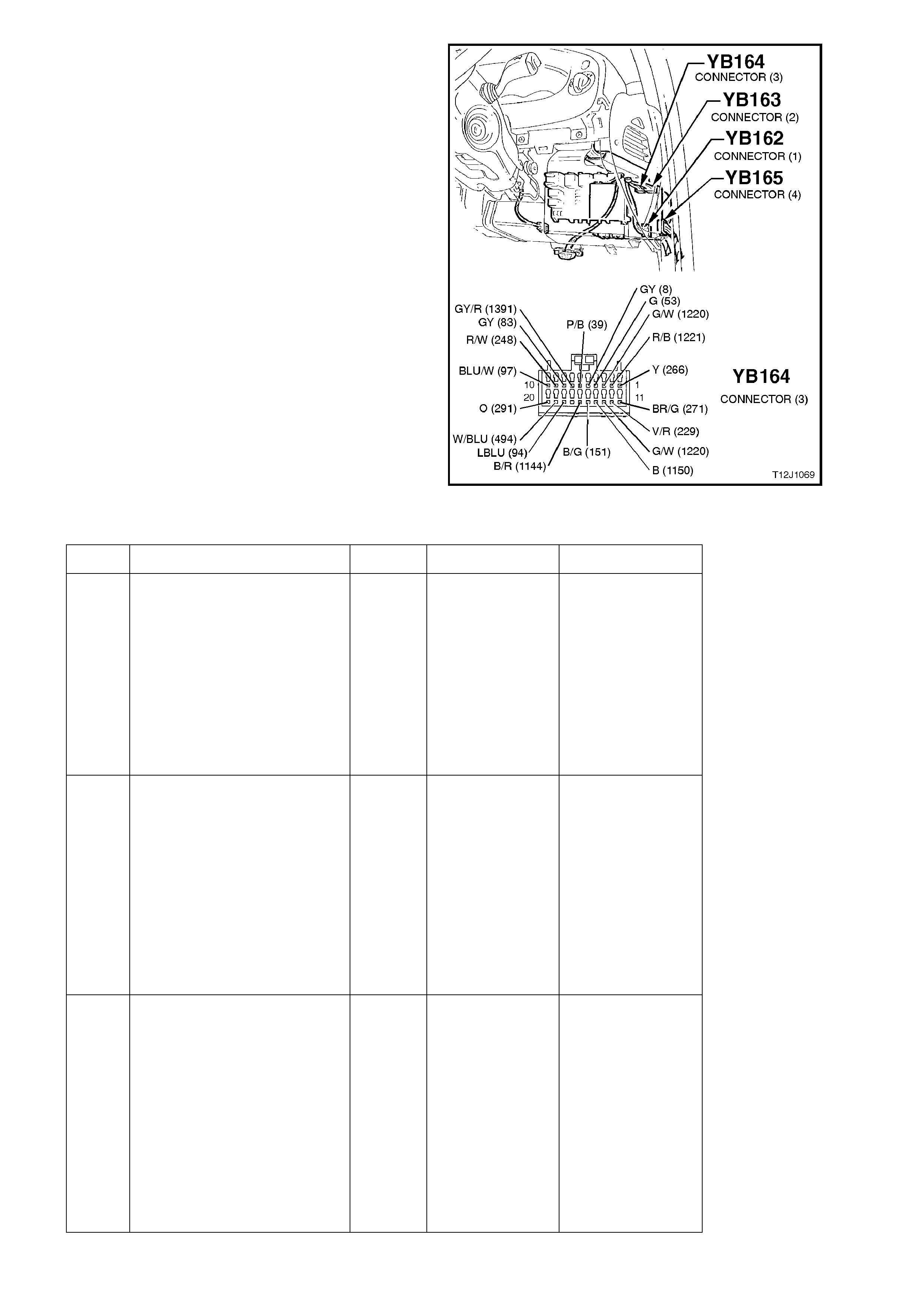
TEST DESCRIPTION:
The numbers below refer to step numbers in the
diagnostic chart below.
1. Checks the Main SDI bus communication.
2 & 3. Checks Auxiliary SDI bus communication to
the SDM and instruments.
4. Checks the BCM internal link, SRS SDI bus
connection to the SDI auxiliary bus.
5. Checks circuit 1220 (Green/W hite wire) (BCM
to SDM).
NOTE:
This diagnostic c hart ass um es that the centr al door
locking system, dome lamp and indicator functions
(controlled by the BCM) are operating correctly.
Figure 12J-1-121
SRS DEPLOYMENT VEHICLE SHUTDOWN
STEP ACTION VALUE YES NO
1. •Connect TECH 2 to the
DLC.
•Select Body / Body
Control Module.
•Turn ignition ON (as
requested by TECH 2).
•Does screen display
BCM system
identification?
Go to Step 2. Go to serial data
communications
diagnosis, refer to
4.1 SERIAL DATA
COM. in this
Section.
2. •With TECH 2 still
connected, exit Body
Control Module selection.
•Select Body / SRS.
•Turn ignition ON (as
requested by TECH 2).
•After five seconds, is
TECH 2 able to
communicate with the
SDM?
Go to SRS
diagnosis in
Section 12M.
Go to Step 3.
3. •With TECH 2 still
connected, exit SRS
selection.
•Select Body /
Instruments.
•Turn ignition ON (as
requested by TECH 2).
•After five seconds, is
TECH 2 able to
communicate with the
instruments?
Go to Step 4. Go to serial data
communications
diagnosis, refer to
4.1 SERIAL DATA
COM. in this
Section.

STEP ACTION VALUE YES NO
4. •Turn ignition OFF.
•Back probe BCM
connector YB164,
terminal D13, circuit 1220
(Green/White wire) and
BCM connector YB164,
terminal D3, circuit 1220
(Green/White wire) with
an Ohmmeter.
•Is value as specified?
Below
1 ohm Go to Step 5. Replace BCM,
refer to 2.2 LOW
SERIES BCM in
this Section.
Recheck and
verify repair
5. •Turn ignition OFF.
•Back probe BCM
connector YB164,
terminal D13, circuit 1220
(Green/White wire) and
SDM connector YB190,
terminal 9, circuit 1220
(Green/white wire) with
an Ohmmeter.
•Is value as specified?
Below
1 ohm Go to SRS
diagnosis in
Section 12M,
SRS.
Repair open in
circuit 1220.
Recheck circuit to
verify repair.
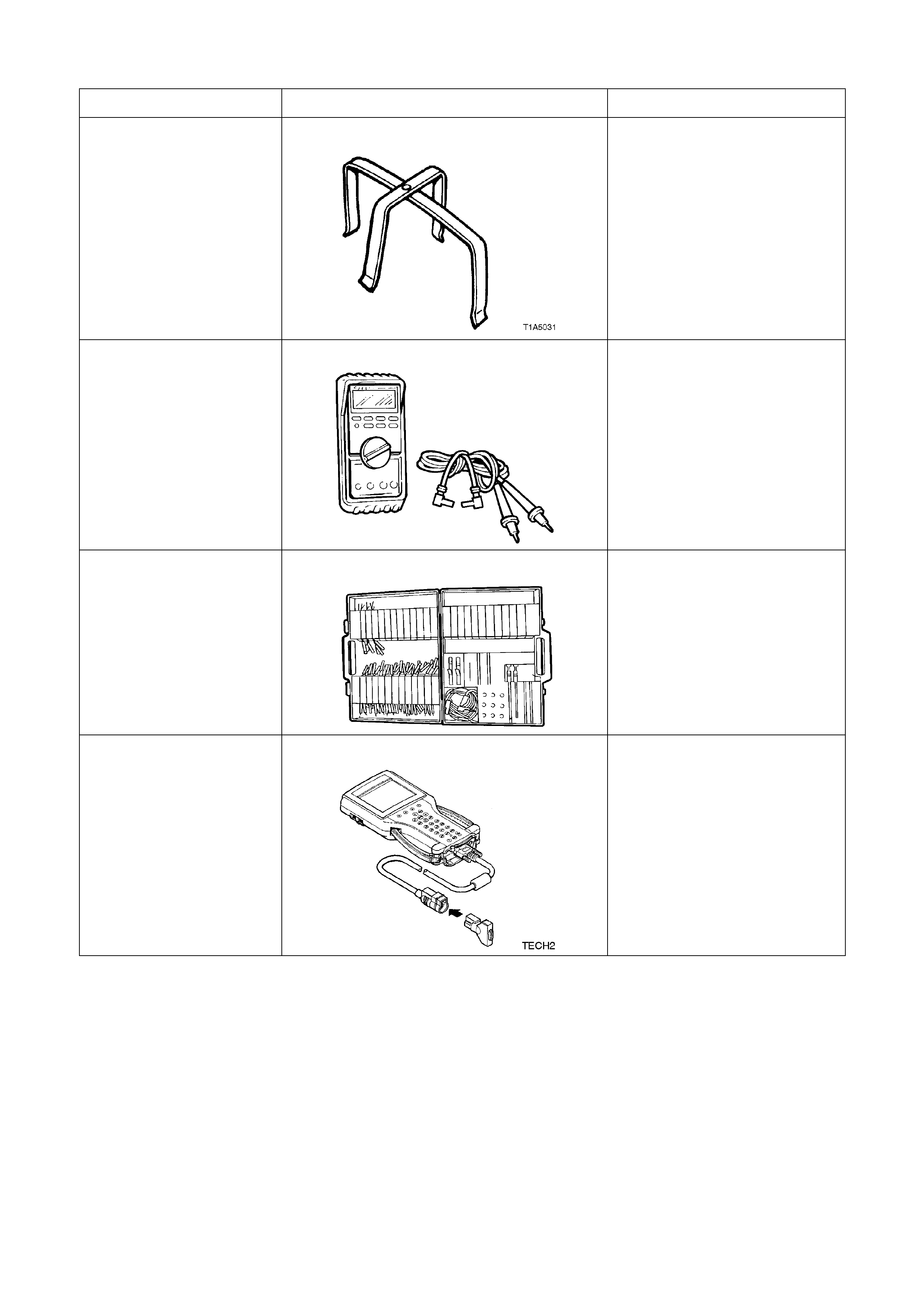
5. SPECIAL TOOLS
TOOL NO. REF IN TEXT TOOL DESCRIPTION COMMENTS
AU455 CONNECTOR BODY REMOVER MANDATORY TOOL USED TO
REMOVE THE DOOR WIRING
HARNESS CONNECTOR
FROM THE A AND B PILLARS
J39200 DIGITAL MULTIMETER TOOL NO. J39200
PREVIOUSLY RELEASED, OR
USE COMMERCIALLY
AVAILABLE EQUIVALENT.
MUST HAVE 10 MEG OHM
INPUT IMPEDANCE
KM-609 CONNECTOR TEST ADAPTOR KIT PREVIOUSLY RELEASED
FOR V CAR. USED IN
CONJUNCTION WITH A
MULTIMETER FOR
MEASURING VOLTAGES AND
RESISTANCES WITHOUT
DAMAGING WIRING
HARNESS CONNECTORS
TECH 2 DIAGNOSTIC SCAN TOOL MANDATORY TOOL USED
FOR DIAGNOSIS OF VEHICLE
ELECTRICAL SYSTEMS