
SECTION J - OPTIONS AND ACCESSORIES
CAUTION:
HSV vehicles are equipped with a Supplemental Restraint System (SRS). An SRS
consists of seat belt pre-tensioners (fitted to all front seats), and a driver’s-side air
bag or a driver’s-side air bag AND a passenger’s-side air bag. Refer to CAUTIONS,
Section 12M, before performing any service operation on or around SRS
components, the steering mechanism or wiring. Failure to follow the CAUTIONS
could result in personal injury or unnecessary SRS system repairs.
PURPOSE
The purpose of this supplement is to provide information on the special options and accessories fitted to the HSV
VT and HSV VS models . T his inf or mation is designed to s upplement that c ontained in the Holden VT and VS ser ies
Service Information CD’s and details are given where differences occur between the HSV models and standard
Holden models . A s er ies of ins tr uc tion drawings detail the des ign c hanges and indicate s pec if ic part number s , fitting
instructions and relevant notes for vehicle servicing.
NOTE:
If specific technical data on a HSV model is not contained in this supplement, obtain data for that model from the
relevant Holden VT or VS series Service Manual Supplement. References are made throughout this section to
Holden Series Service Information CD’s, to assist in providing information for specific service operations.
CAUTION:
W hen hois ting (or j acking) HSV models , ensure that the lifting head of the hoist lifts on the chas sis before the arm
of the hoist contacts the side-skirt

SUNROOF
GENERAL
The HSV specific Sunroof is f itted as standard equipm ent on HSV Senator and Grange m odels and is available as
an option on other HSV VT m odels. The Sunroof is a tinted glass, electrically operated, two-way sliding and tilting
type, equipped with an internal sliding blind and fr ont edge wind deflector. T he Sunroof is oper ated by a roc k er type
switch (which is back-lit) centr ally located in the vehicle's headlining in f ront of the Sunroof vent aperture. Sunroof s
are equipped with a Sunroof Control Unit which provides several pre-programmed functions and the facility to
programme an additional option.
The pr e-programmed functions are:
Soft touch
By a single touch of the switch the roof can be fully opened to the max imum tilt position or the m axim um slide
position.
Variable tilt position
The panel c an be closed f rom tilt in f our steps by continuously press ing the switch and r eleasing in the des ired
position
Jamming protection (Safety Feature)
When closing the sunroof by soft touch or by autoclose, the sunroof automatically opens when it encounters an
obstacle. The roof will continue to try to close until the obstacle is removed.
Autoclose function
Three seconds after switching off the ignition the sunroof will close automatically. This can be prevented by
pressing the switch once within 3 seconds after the ignition is switched off.
One - way closing
This feature always closes the panel from above, assuring a flush fit of the panel.
The optional programmable function is:
Comfort position in the sliding range
W ith this f eature you will be able to program a preset stopping position of the panel in the sliding range of the
sunroof. The panel will stop at the preset position when opened via the soft touch operation.

OPERATION
Panel movement into the venting and sliding positions is controlled by:
Continuous control (pressing the switch longer than 0.3 seconds):
Full control over the panel movement in slide position
Releasing the switch will stop the panel movement
A full stop in maximum slide and closed position.
Four steps down tilt adjustment (pressing the switch longer than 0.3 seconds):
When closing the sunroof from minimum tilt position by pressing the switch continuously, the panel will stop
briefly in four intermediate positions.
Releasing the switch will stop the panel movement.
To continue the stepped operation, press the switch again.
One touch contro l (pressing and releasing the switch within 0.3 seconds):
Automatic panel movement towards full open or full closed position (slide and tilt).
Anti-jamming protection while closing.
The panel movement can be interrupted by pressing the switch.
Auto-close:
When the ignition is switched off, the roof will close after a 3-second delay.
Anti-jamming protection while closing.
Pressing the switch within 3 seconds after the ignition switch off will cancel Auto-close.
Closing the roof is still possible after Auto-close has been active.
Auto-close will not be activated if any other function is active.
Programming memory position
Any position in the sliding range of the panel can be programmed as a “comfort position”.
The panel will stop at that position when opened by One touch control.
One way closing
To ensure perfect positioning of the panel after closing, the panel will always close from above (even when
closed from a slide position).
Interior trim -
Sunshade
Sunshade operation depends on panel movement as below:
Moving the glass panel to tilt pos ition, the sunshade automatic ally opens to a vent position and can be m oved
to full open position by hand.
Moving the glass panel into s lide position, the sunshade will m ove together and can also be further opened by
hand.
Closing the sunshade always has to be done manually. The sunshade can only be closed com pletely when the
glass panel is in closed position.
Wind deflector
The wind defector automatically comes up when the panel moves into sliding positions and goes down when
the panel closes again.
SERVICE OPERATIONS
NOTE:
Dealers are to contact Hollandia Sunroofs directly by telephone on (02)9540-4811 before carrying out any service
operation on the Sunroof.
Several Fault Diagnosis Charts are included in this section. These charts list Possible Causes and Solutions and
provide a reference to a particular paragraph to resolve the fault. Some recommended solutions refer to the
Installation Manual and the relevant extr acts f rom that m anual ar e included at the rear of this s ection. Also included
in this section is Figure J- 1 which shows an exploded view of the sunroof construction.
FAILURES
Repair Advice For Mechanical Failures
PROBLEM POSSIBLE CAUSE SOLUTION
While cycling the panel from tilt to
close it begins sliding rearward Blocking catch is broken Replace blocking catch, see 3.10
While cycling fully open panel
forward, it begins tilting under roofskin Blocking catch is broken Replace blocking catch, see 3.10
Panel is misaligned side to side Timing of drive cables
incorrect Retime drive cables, see 3.5
Panel sliding too slowly (with 13.5V
power supply panel should not take
more than 7 sec. to cycle from full
retraction to closure)
Weak battery
Misaligned panel creating drag
or friction
Weak motor. Test as indicated
in 2.2.4
Dirty mechanism
Charge or replace
Retime drive cables, see 3.5
Replace motor, see 3.1
Clean and grease mechanism or
replace if necessary, see 3.9
Glass panel stopping prematurely Sunroof control unit adjusted
improperly
Obstacle in mechanism or
guide track
Synchronise sunroof control unit,
see 3.3
Find object and remove
Sunshade fails to open when glass
panel is opened to tilt position. Retraction mechanism broken Replace retraction mechanism,
see 3.8.
Repair Advice For Rattling Noises
PROBLEM POSSIBLE CAUSE SOLUTION
Drainchannel rattles Inspect for insulator tape
between drainchannel and
mechanism
Add insulator tape
Steel panel ventilation tray rattling Curvature of front ventilation
tray incorrect
Insufficient contact between
rail and ventilation tray
tumbling mechanism
Wires insufficientl y secured
Correct curvature, manual
adjustment
Correct rear side ventilation tray
to improve rail contact
Secure wires
Rattling in motor area Cover plate on motor has
loose screws Tighten coverplate screws

Repair Advice For Wind Noises
PROBLEM POSSIBLE CAUSE SOLUTION
Panel closed, excessive windnoise Glass panel seal not tight to
trimring
Blocking catch broken
Correct glass panel adjustment,
see 3.11 or installation manual
5.3
Replace blocking catch, see 3.10
Panel vented emitting whistling sound Vinyl headliner material
wrapped around sunshade too
thin, creating large wind
channel between rail and side
of sunshade
Place insulating tape along either
outboard edge of sunshade to
close channel.
See installation manual 4.1.5
Steel panel vented emitting whistling
sound Vinyl headliner material
wrapped around trimtray too
thin, creating large wind
channel between rail and side
of trimtray
Place insulating tape along either
outboard edge of trimtray to
close channel. See installation
manual 4.1.5
Repair Advice For Water Leaks
PROBLEM POSSIBLE CAUSE SOLUTION
Water coming through panel opening
area Blocked draintubes
Misaligned or kinked
draintubes
Housing frame distorted,seal
to rail disconnected
Rear rail bracket has broken
seal
Inspect draintubes clean
opening, blow out tubes
Correct routing of draintubes.
See installation manual 3.2
Correct frame curvature if
necessary reseal rail to frame
Reseal at rear rail seal point, see
3.9
Headliner wet in front Either frame seam has
inco rrect seal Reseal at seam
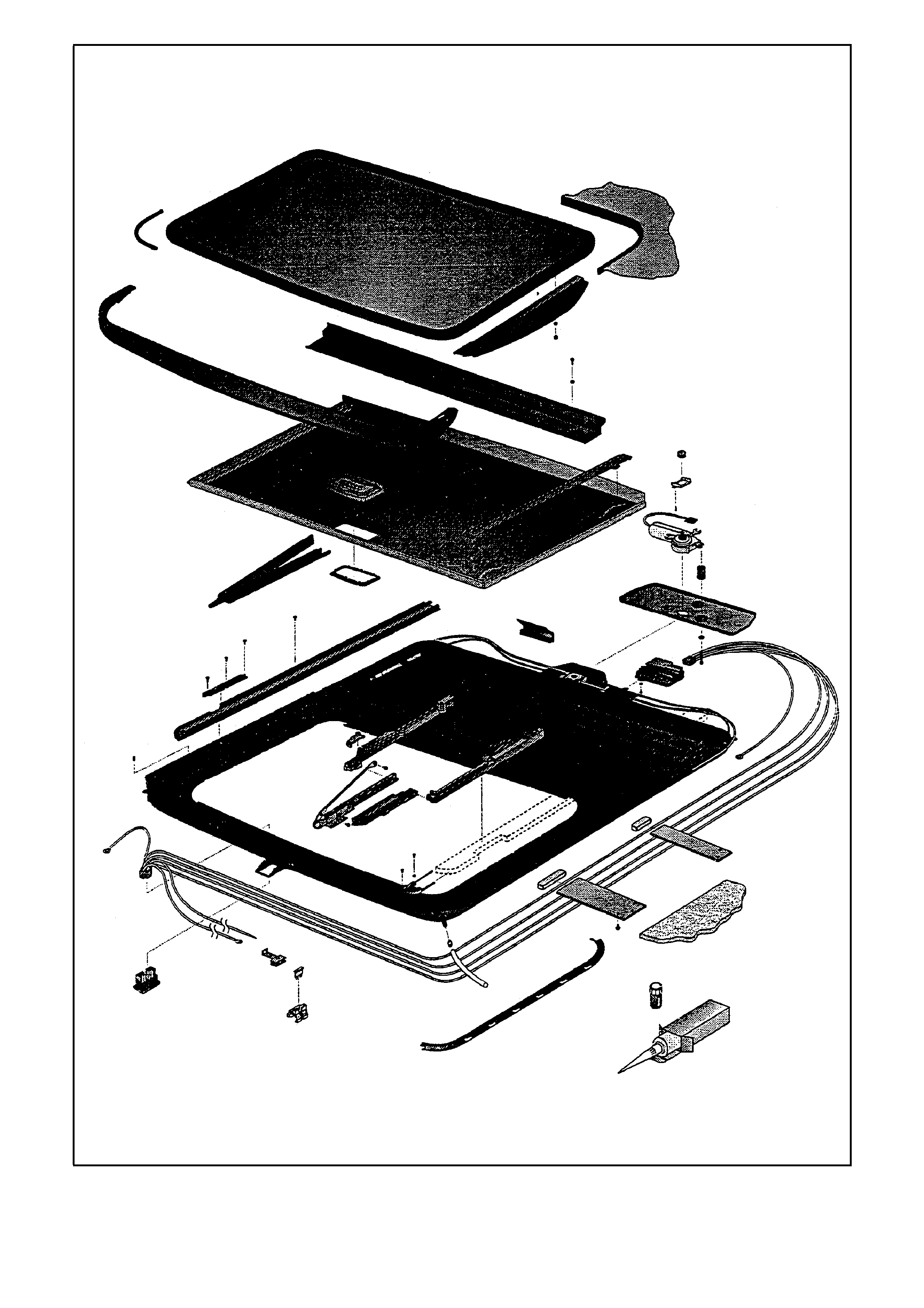
Figure J-1 - HSV Sunroof - Exploded View

TESTING ELECTRICAL COMPONENTS
Make sure that during the test of electrical components, the TVS unit is connected to a power source containing 12
to 14V. If the Sunroof is installed, the battery needs to be attached and operable. During testing the
ignition/accessory switch should be on. This test can be accomplished with a test light or voltage meter. Cable
harness and motor inspection requires the headliner to be removed.
Fuse
Visually inspect the fuse for damage.
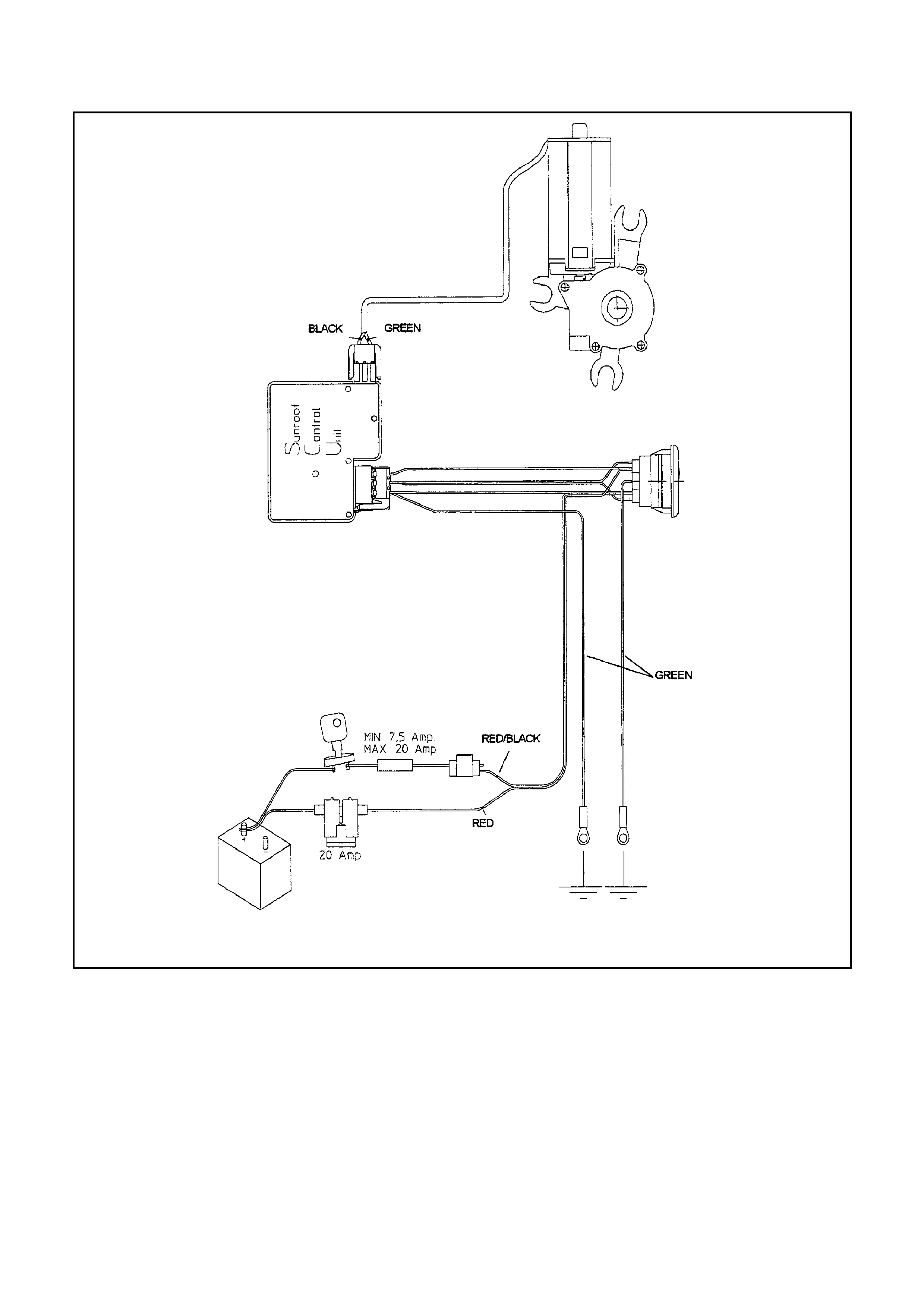
Wire harness
Check if the power supply on the red and red/black wires is OK. Inspect for broken/damaged wires. Inspect for
proper connection to the sunroof control unit. The wire harness connector is numbered to aid in proper installation:
1 = red
2 = brown / red
3 = brown
4 = green
5 = red / black
Switch
Inspect for proper power supply to the TVS operating switch, accomplished by using a test light on the connector at
the switch bracket, operate switch connector to assure movement in front and rear sliding positions.
Motor
Disconnect the motor wire (green/black) from the sunroof control unit. Dismount the motor. Using a double wire of
sufficient length, connect direct to battery, inspect the motor for proper operation in both directions. This is
accomplished by reversing the connection of the double wire. The motor has an inbuilt thermal cut-out device that
automatically switches the motor off during periods of overload. After a cooling down period the motor will function
properly.
Sunroof Control Unit
Testing is covered in the electric trouble-shooting guide. The following failures could be the result of a broken
Sunroof Control Unit
Auto close function defective.
Soft touch operation defective
Comfort position can not be programmed
4 step down option defective
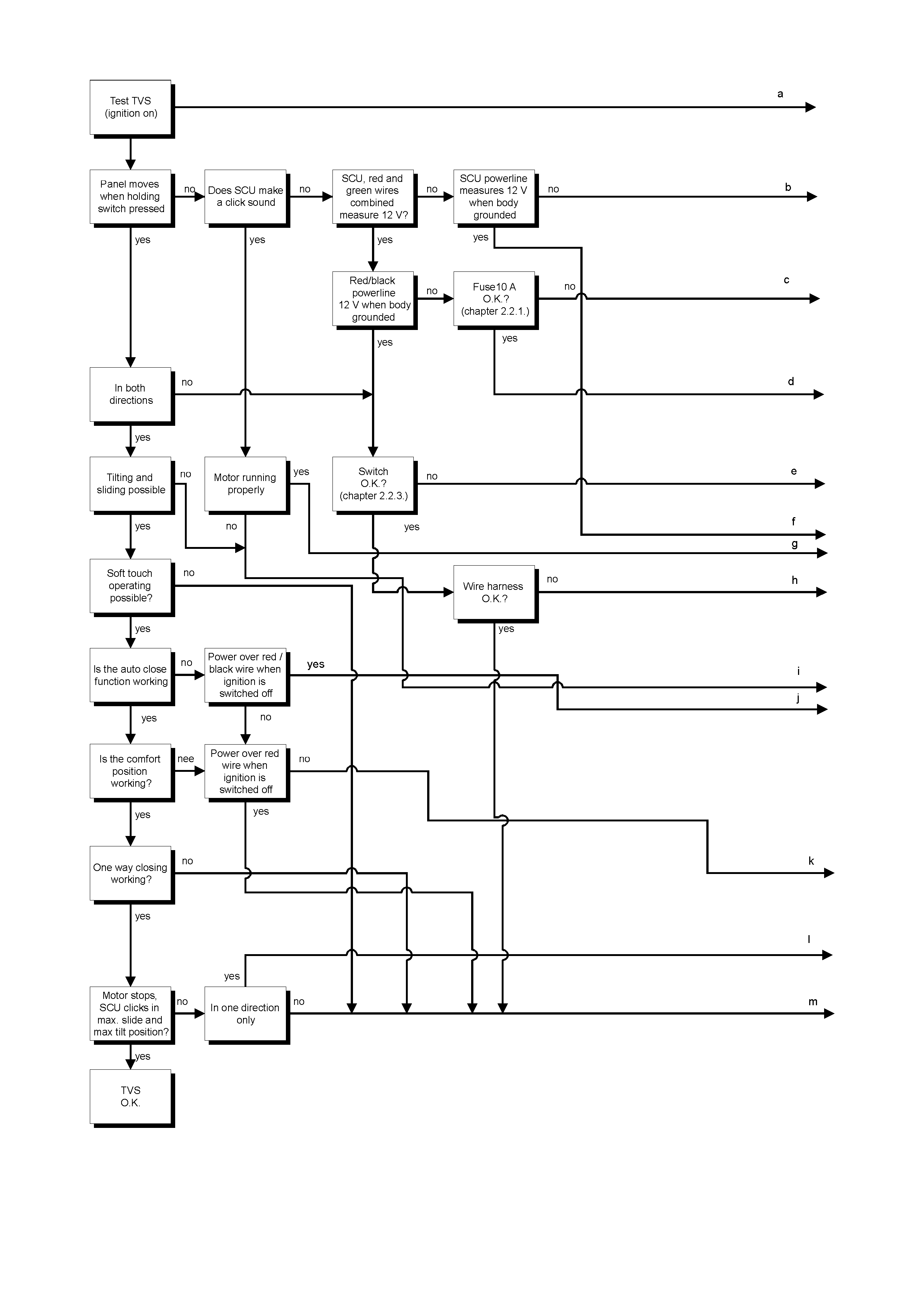
ELECTRICAL TROUBLE SHOOTING TABLE
Table 1 of 2
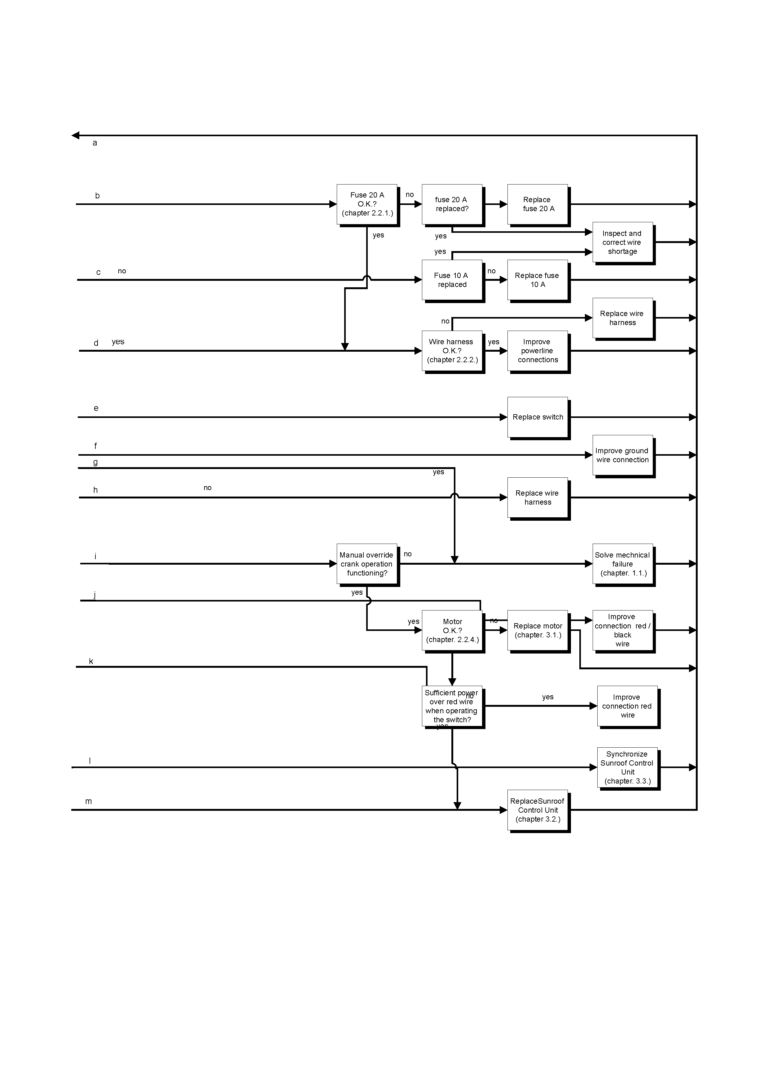
Table 2 of 2

REPAIRS
This chapter describes all repairs for the TVS 40 series.
3.1 MOTOR REPLACEMENT
1. Remove or drop rear of headliner to access motor cover.
2. Remove cover, motor now drops down.
3. Disconnect the motor wire from the sunroof control unit.
4. Connect new motor to sunroof control unit.
5. Inspect motor for proper operations in both directions.
6. Remount motor and motor cover
7. Inspect the unit for proper electrical and mechanical functioning.
8. Reinstall headliner.
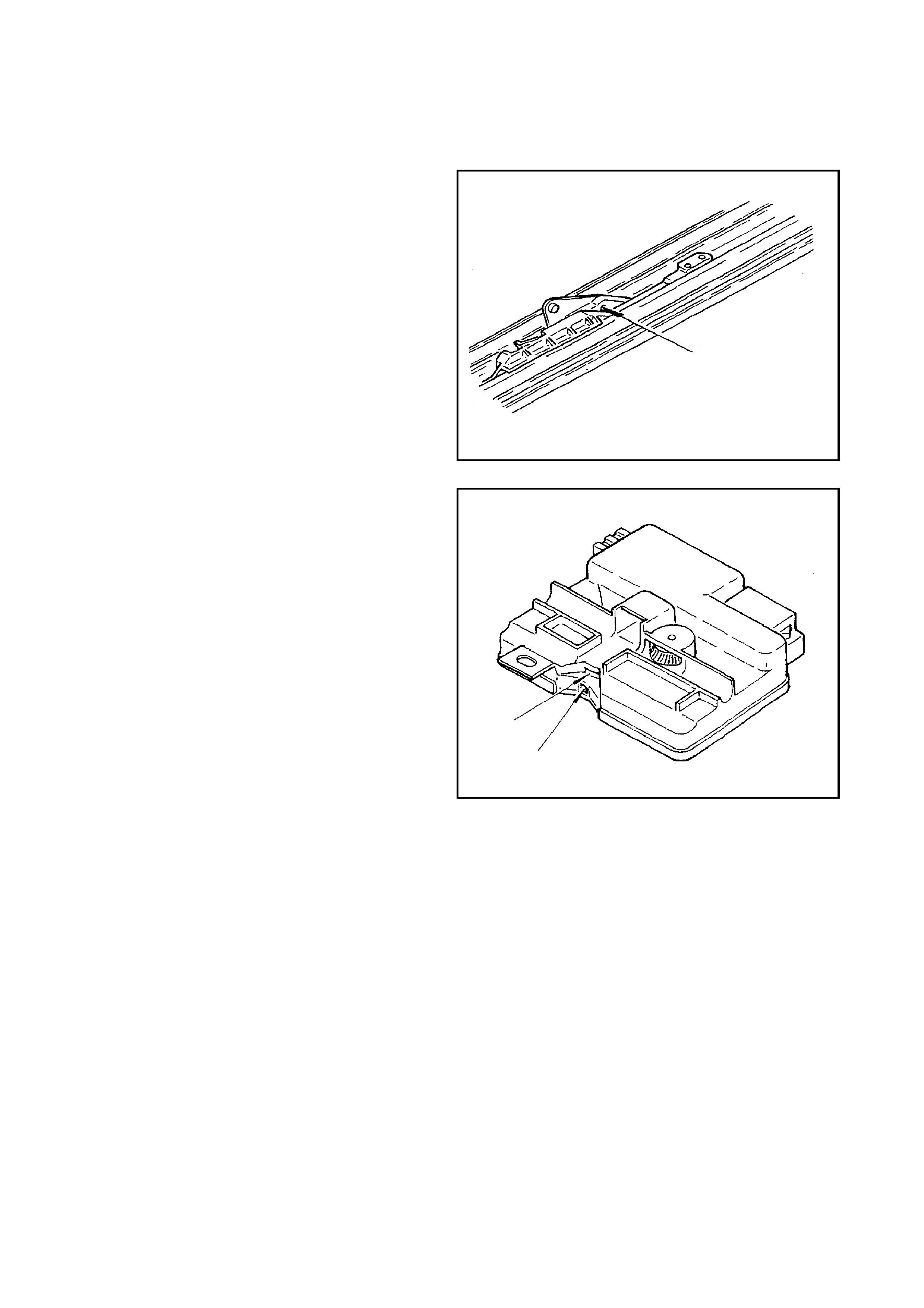
3.2 SUNROOF CONTROL UNIT (S.C.U.) - REPLACEMENT
1. Remove or drop rear of headliner to access
motor cover.
2. Utilising a manual crank, vent the panel
completely.
3. Remove the LH mechanism cover.
4. Utilising the manual crank, close the glass
panel (1.5 revolutions) access the 2.5 mm
brass hole with a pin. Venting the panel, turn
crank 0.25 revolution forward. The pin stops
the mechanism at the desired location (see
Figure J-3).
5. Remove cover, motor now drops down.
6. Disconnect the motor wire from the S.C.U and
remove the motor.
7. Disconnect the wire harness from the S.C.U.
8. Remove the S.C.U. with screw, drop the front,
slide back.
Figure J-3
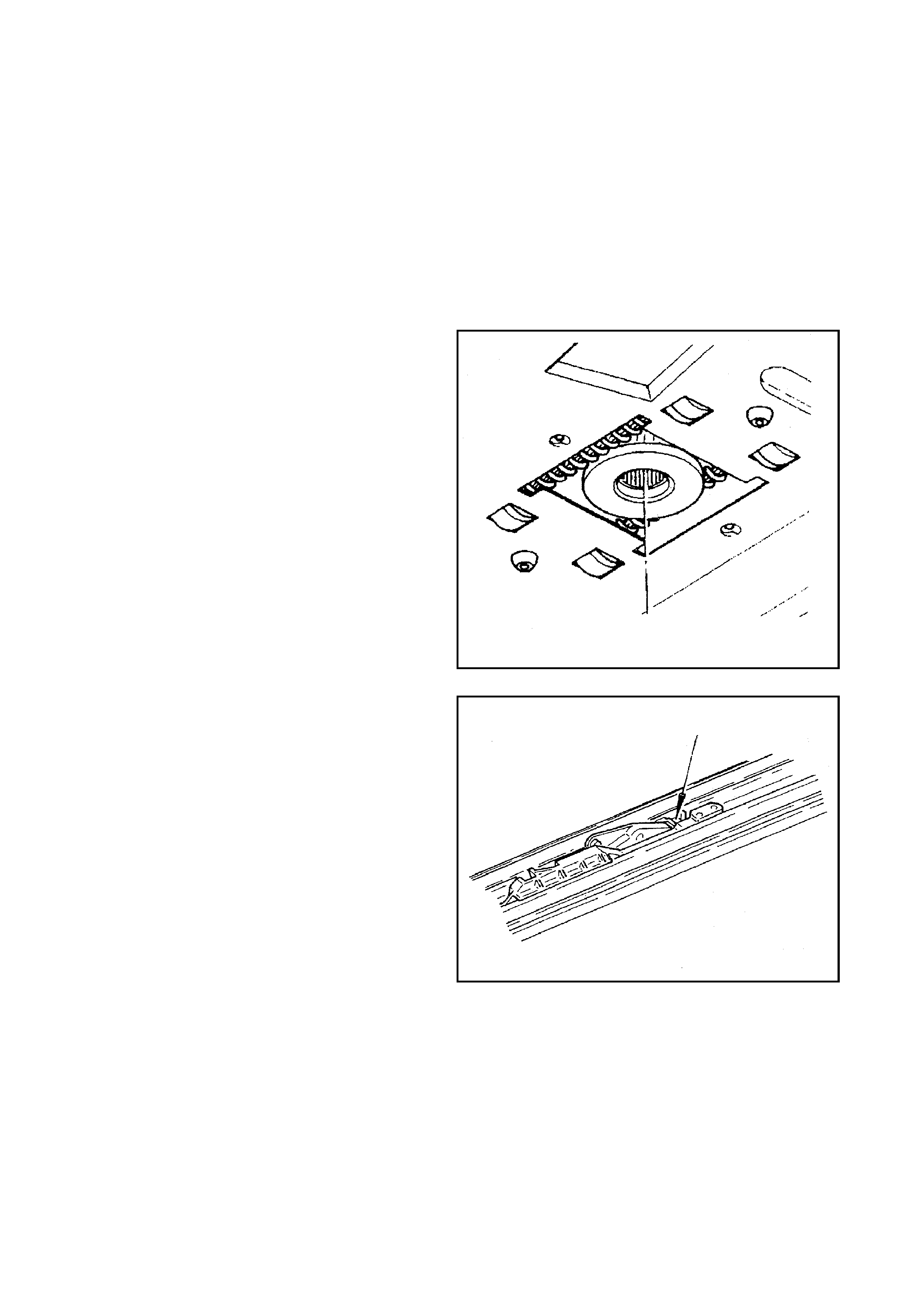
9. Inspect the new S.C.U. for proper alignment of
spots on gearwheel (see Figure J -4). Dropping
the front of the S.C.U. low enough for cable
clearance slide forward, engage lip of cable
plate in S.C.U. slot. Straighten S.C.U.
horizontally and tighten screw.
Figure J-4
NOTE:
If the spots are not aligned, turn the top mount
cable gear until each spot appears aligned over
one another in the view finders.
10. Reconnect both wire connectors to the S.C.U.
and remount motor and cover.
11. Check proper functioning of sunroof
12. Mount headliner.
13. Remount the LH mechanism cover.

3.3 SYNCHRONIZATION OF THE SUNROOF CONTROL UNIT (S.C.U.)
1. Remove or drop rear of headliner to access
motor cover.
2. Utilising the manual crank, vent the panel
completely.
3. Remove the LH mechanism cover.
4. Utilising the manual crank, close the glass
panel (1.5 revolutions) access the 2.5 mm
brass hole with a pin. Venting the panel, turn
crank 0.25 revolution forward. The pin stops
the mechanism at the desired location (see
Figure J-3).
5. Remove cover, motor now drops down.
6. Disconnect the motor wire from the S.C.U.
7. Disconnect the wire harness from the S.C.U.
8. Remove the S.C.U. with screw, drop the front,
slide back.
9. To align the two spots in the view f inders, turn
the exposed black cable gear mounted in top
center of the S.C.U. W hen each spot appears
directly in line with the other, top to bottom,
stop
NOTE:
If the spots are not aligned turn the top mount
cable gear until each appears aligned over one
another in the view finders.
10. Remount S.C.U. dropping the front of the
S.C.U. low enough for cable clearance, slide
forward, engage lip of cable plate in S.C.U.
slot. Straighten S.C.U. horizontally and tighten
screw.
11. Reconnect both wire connectors to the S.C.U.
12. Check proper functioning of sunroof
13. Mount headliner.
14. Remount the LH mechanism cover.
3.4 DRIVE CABLES REPLACEMENT
1. Remove covers, panel, drain channel, wind
deflector and sunshade or trim tray and
ventilation tray and adjustment bracket.
2. Place mechanism in closed position.
3. Remove rear of headliner to access motor
cover.
4. Remove motor cover, motor now drops down.
5. Disconnect the motor wire from the sunroof
control unit.
6. Remove the S.C.U. with screw, drop the front,
slide back.
7. Remove the gearwheel housing by removing
the two screws.
8. Remove gearwheel by inserting screwdriver,
push forward, it drops down (see Figure J-5).
Figure J-5
9. Place a screwdriver in the mechanism as
indicated in Figure J-6. Push this mechanism
rearward into the slide position. Continue
pushing backwards by placing hand on fr ont of
mechanism, 3 locator screws become
accessible.
10. Rem ove the locator being c areful to r em em ber
the positioning of screws and the blocking
catch.
11. Pull mechanism all the way forward.
12. Push the mechanism into tilt position as in step
9. Be sure you do not inadvertently dislodge
the mechanism. Keep the front of the
mechanism down.
13. Remove the front screw and slide the
retraction mechanism forward. Do not take
out.
14. Slide mechanism in tilt position further forward.
15. Remove the torx screw which connects the
curve on panel to the adjustment bracket.
Remove the aluminium curve on panel from
the long lever. Pivot the adjustment bracket
forward.
Figure J-6.
16. You can now see the cable. Lift out cable and
pull forward out of the guide rail track.
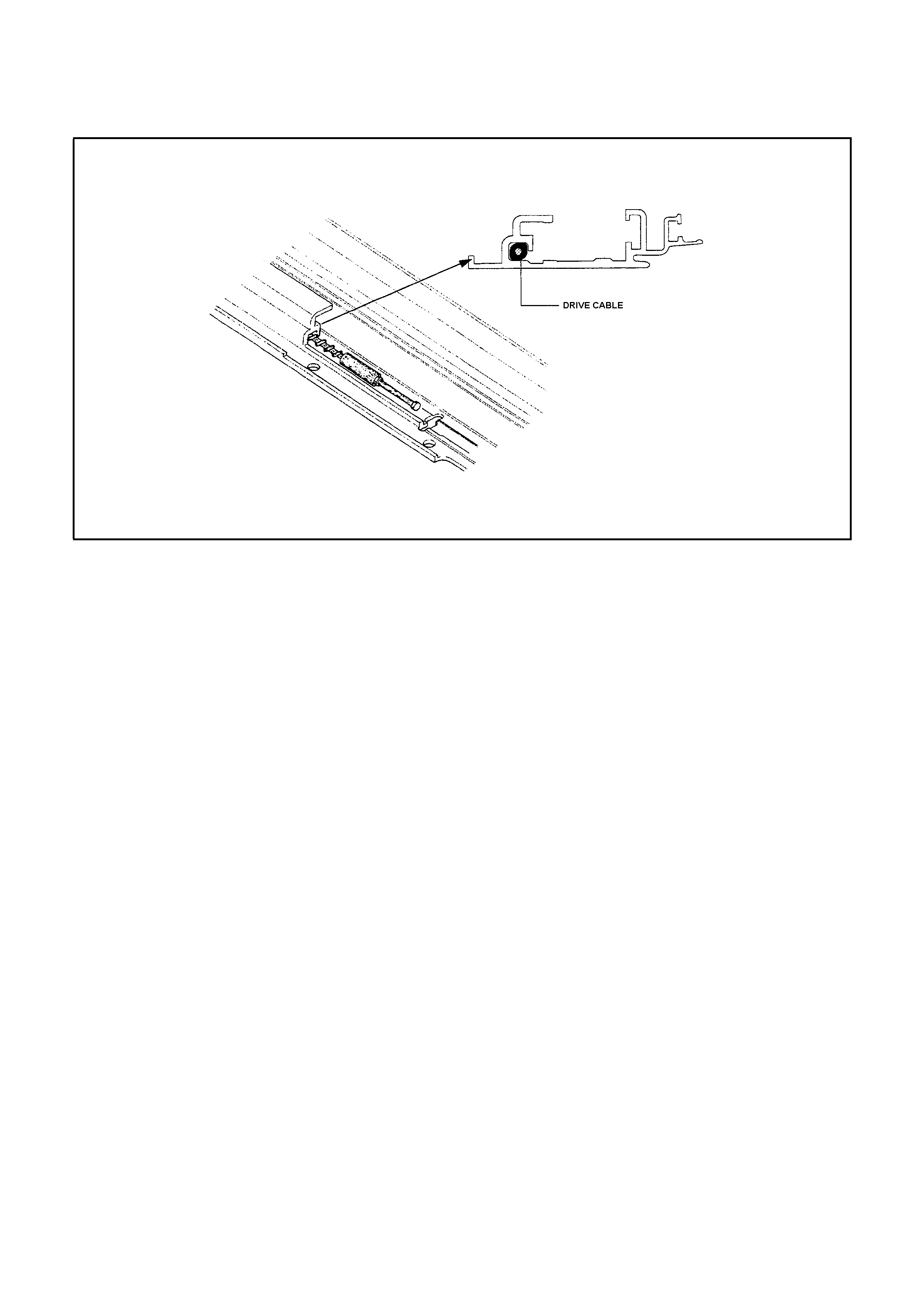
17. Inspec t for proper length of new cable, grease
and slide into rail. Make sure the oval shaped
copper head of the cable seats firmly and
diagonally across the guide channel (see
Figure J-7).
Figure J-7
18. To check that cable is positioned properly
grasp long lever in tilt position with one hand,
the pivoting adjustment bracket in the other
hand and slide backwards, it should slide into
place (if blocked turn cable slightly to reseat
copper oval head properly).
19. Pivot arm of adjustment bracket back down
into place. Slide the curve on panel back into
place over cap on long lever and rem ount the
torx screw.
20. Push m echanism into slide position as in step
9 (hold adjustment bracket stable while doing
so). If mechanism stops after approximately
100 mm (4 in.) preventing a full rearward
positioning, you failed to hold the adjustment
bracket stable, repeat step 20.
21. Slide whole mechanism rearwards to allow
remounting of locator.
22. Slide the retraction rearwards, remount screw
and locator.
23. Repeat steps 10 through 22 to replace other
cable.
24. Slide both LH/RH mechanisms to the front
position.
25. Push LH/RH mechanisms to closed position.
Insert a pin in each 2.5 mm brass hole.
(pointed object). Slide mechanism forward
until pin stops the mechanisms movement at
the desired location (see Figure J-3).
26. Mount the new gearwheel. Being sure to
center it evenly between the walls of the hole
in the motor bracket. Note that the core or
center of the gear has splines (teeth). The
splines do not extend completely to one side
of the gears inner core. This is the down
(bottom) side for mounting (see Figure J-5).

27. Mount the new gearwheel housing.
28. Mount the sunroof control unit. Inspect to be
sure the two timing spots are aligned in the
view finders (top to bottom ) (s ee Figure J-4).
Dropping the front of the S.C.U. low enough
for cable clearance slide forward, engage lip
of cable plate in S.C.U. slot. Straighten S.C.U.
horizontally and tighten screw.
NOTE:
If the timing spots are not aligned, turn the top
mount cable gear until each appears aligned over
one another in the view finders (see Figure J-4).
29. Connect the motor to the sunroof control unit
(wire one way connector).
30. Remount motor and cover, replace screws.
31. Inspect the sunroof for proper electrical and
mechanical functioning.
32. Remount headliner.
33. Remount adjustment bracket, sunshade or
ventilation tray and trim tray, drain channel,
panel, winddeflector and mechanism covers.
34. Final inspection of unit.

3.5 TIMING OF THE DRIVE CABLES
1. Fully tilt panel
2. Remove LH/RH mechanism covers.
3. Fully close panel.
4. Drop rear of headliner to access motor cover plate.
5. Remove motor cover, motor now drops down.
6. Disconnect sunroof control unit wires and remove the motor.
7. Dismount sunroof control unit with screw, drop the front and slide back.
8. Remove the gearwheel housing by removing the two screws.
9. Remove gearwheel by inserting screwdriver, push forward, it drops down (see Figure J-5).
10. Push m echanisms LH/RH to closed pos ition. Acces s each 2.5 m m br ass hole with a pin ( pointed objec t). Slide
mechanism forward until pin stops the mechanisms movement at the desired location (see Figure J-3).
11. Mount the new gearwheel. Being sure to center it evenly between the walls of the hole in the motor bracket.
Note that the core or center of the gear has splines (teeth). The splines do not extend completely to one side of
the gears inner core. This is the down (bottom) side for mounting (see Figure J-5).
12. Mount the new gearwheel housing.
13. Mount the sunroof control unit. Inspect to be s ure the two white timing spots ar e aligned in the view finder (top
to bottom) (see Figure J-4). Dropping the front of the S.C.U. low enough for cable clearance slide forward,
engage lip of cable plate in S.C.U. slot. Straighten S.C.U. horizontally and tighten screw.
NOTE:
If the white tim ing spots are not aligned, tur n the top m ount cable gear until each appears aligned over one another
in the view finders (see Figure J-4).
14. Connect the motor to the sunroof control unit. (wire one way connector).
15. Remount motor and cover, replace screws.
16. Inspect the sunroof for proper electrical and mechanical functioning.
17. Remount headliner.
18 Remount the LH mechanism cover.
19. Final inspection of unit.

3.6 ADJUSTMENT BRACKET REPLACEMENT
1. Fully tilt panel.
2. Remove the panel.
3. Remove adj ustm ent brack et by rem oving front retaining c lip and torx s crew. T he adjus tment brack et is m oved
sideways from the long lever in rear and mechanism in front.
4. Remove the curve on panel by taking off retaining clip. Mount curve on panel to new adjustment bracket.
5. Reverse above sequences to reinstall the adjustment bracket.
6. Remount panel.
7. Inspect sunroofs electrical and mechanical functioning.

3.7 SEAL REPLACEMENT TVS 40 SERIES
1. Dismount LH / RH mechanism covers, glass panel and exterior covers.
2. Remove seal from panel.
3. Remove all foreign debris from around glass frame.
4. Install new seal, beginning at center front of glass frame retaining channel.
5. Utilising your thumbs, insert seal with enough pressure to be sure of flushness (tight to frame).
6. Trim the glass seal length. when cutting excess leave approximately 6 mm extra then work it into retaining
channel.
7. Remount the panel.
8. Mount the LH / RH mechanism cover.

3.8 RETRACTION MECHANISM REPLACEMENT
1. Retract panel completely.
2. Remove the wind deflector.
3. Remove the two screws and take the retraction mechanism forwards out of rail.
4. Install new retraction mechanism in rail.
5. Remount the wind deflector.
6. Inspect for proper functioning.

3.9 GUIDE RAIL MECHANISM REPLACEMENT
1. Remove LH/RH mechanism covers, panel,
drain channel, wind deflector and sunshade.
2. Tilt mechanism completely.
3. Fully retract mechanism.
4. Remove the locator, retraction mechanism
and rail screw.
5. Remove wind deflector mounting nuts.
6. Slide rail sideways to unlock, then lift front up.
7. With rail front up, grasp retractor mechanism
and remove.
8. Fully close mechanism.
9. Lift and pull rail slowly forward over
mechanism, as soon as the front of drive
cable appears at end of guide, lift out cable,
now pull mechanism carefully forward and lift
out. Inspect the new replacement mechanism
for cleanliness and completeness.
10. Slide the mechanism rearward out of rail for
cable installation access.
11. Install cable, then push mechanism forward on
rail (maintain access to rear rail area).
12. Apply a bend of liquid butyl as indicated on
Figure J-8.
13. Slide rail rearward over mechanism and drive
cable while holding the front of the m echanis m
in place. As soon as the rail is fully extended
rearward, drop the f ront to fram e and push rail
rearward into rail stop. Line up the s crew holes
for proper positioning.
14. Retract mechanism totally.
15. Lift front of rail to reinstall retractor
mechanism.
16. Drop rail down, push inboard until it “locks” in
place.
17. Remount all new rail screws starting at front
for proper positioning. Use original positioning
of screws by size.
Figure J-8
18. Replace wind deflector mounting nuts loosely.
19. Tilt mechanism completely.
20. Inspect for proper mechanical functioning of
mechanism.
21. Remount sunshade, drain channel, panel and
wind deflector.
22. Inspect functioning of sunroof, reinstall LH/RH
mechanism covers.

3.10 BLOCKING CATCH REPLACEMENT
1. Remove the LH/RH mechanism covers and panel.
2. Fully retract mechanism.
3. Remove locator.
4. Fully tilt mechanism.
5. Remove blocking catch by lifting out.
6. Clean out broken blocking catch debris.
7. Install new blocking catch in mec hanism, inser t circular eye stud into mec hanism m aking sur e second sm aller
stud falls cleanly into mechanism slot.
8. Fully retract mechanism.
9. Remount locator.
10. Inspect for proper mechanical functioning.
11. Remount the panel and LH/RH mechanism covers.
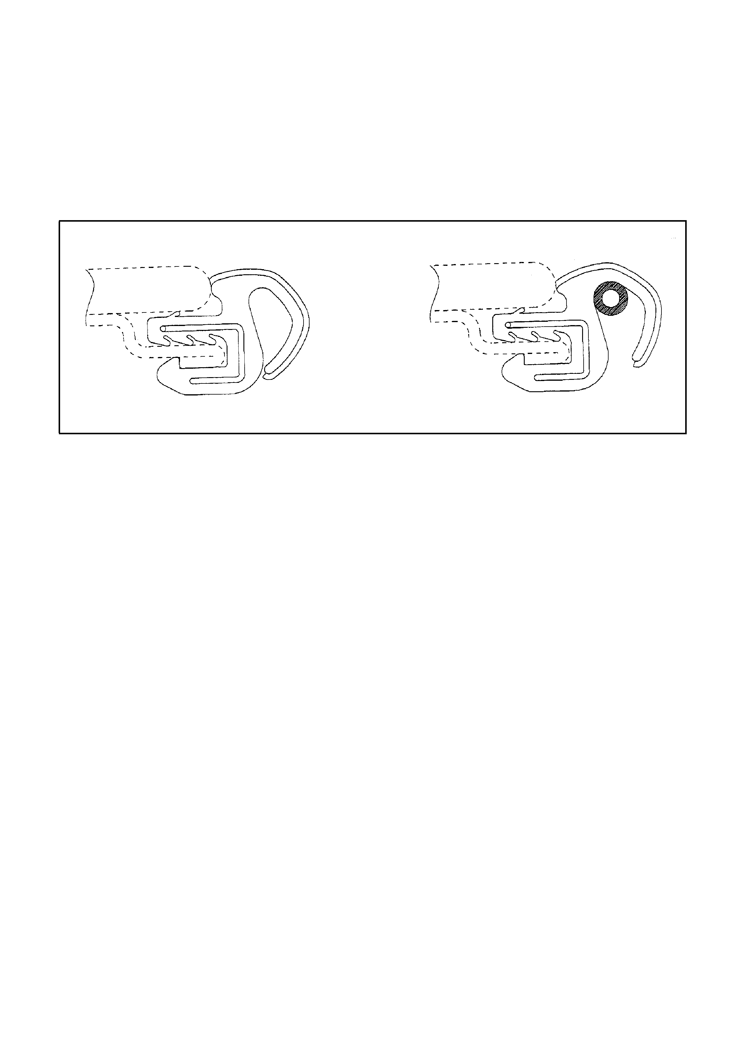
3.11 SEAL ADJUSTMENT
The proper positioning of the panel should result in the seal firmly contacting either the EPDM trim ring or flanged
metal circ umfer ence of the sunroof opening. If the panel fits properly but gaps remain between seal and tr im ring it
can be corrected as follows:
1. Adjust panel properly against the rear of the trim profile (according to instructions in the installation manual
Chapter 5.3).
2. With a grease pencil mark the boundaries of insufficient contact on the panel (at the front).
3. Remove panel.
4. In the areas marked, a spacer will be inserted inside the rubber seal. (see Figure J-9). Use a vinyl tube with
outer diameter of 3 mm (.12 in) for spacer material.
5. Glue the spacer material to the seal with super glue.
Figure J-9
6. Remount panel and adjust according to the installation manual Chapter 5.3.
EXTRACTS FROM THE HOLLANDIA INSTALLATION MANUAL
SIDE SUPPORT BRACKETS CENTRE AND REAR
1. Remove clamps and gluetemplate after 30
seconds, Leave the jacks in place! Check
the curvature of the car roof near the
centrebrace with curvature gauge. If the car
roof is more curved than the curvature gauge
then a correction can be made by slightly
raising the jacks until the curvature of the
roofskin is equal to the curvature gauge.
If the curvature of the roofskin less curved
than the curvature gauge then a correction
can be made by lowering the jacks a little bit
until the curvature of the roofskin is equal to
the curvature of the curvature gauge.
NOTE:
Excessive correction can cause distortion in the
roofskin.
2. For each car model the side support brackets
have to be cut and bent to fit. Bending, cutting
and punching equipment can facilitate this
work. Place the wide brackets on each side
close to the centrebrace. The small brackets
are mounted as far to the rear as possible,
between the side rail and the frame.
3. The plastic cover m ust be on the bracket side
supporting the TVS frame.
4. Wrap paper masking tape around the part of
the bracket that will be attached to the side
rails. This avoids possible creaking.
5. Mount the support brackets to the side rails
with the supplied self tapping screws.
6. Remove the jacks.
7. Check the curvature of the car after installing
the support brackets.
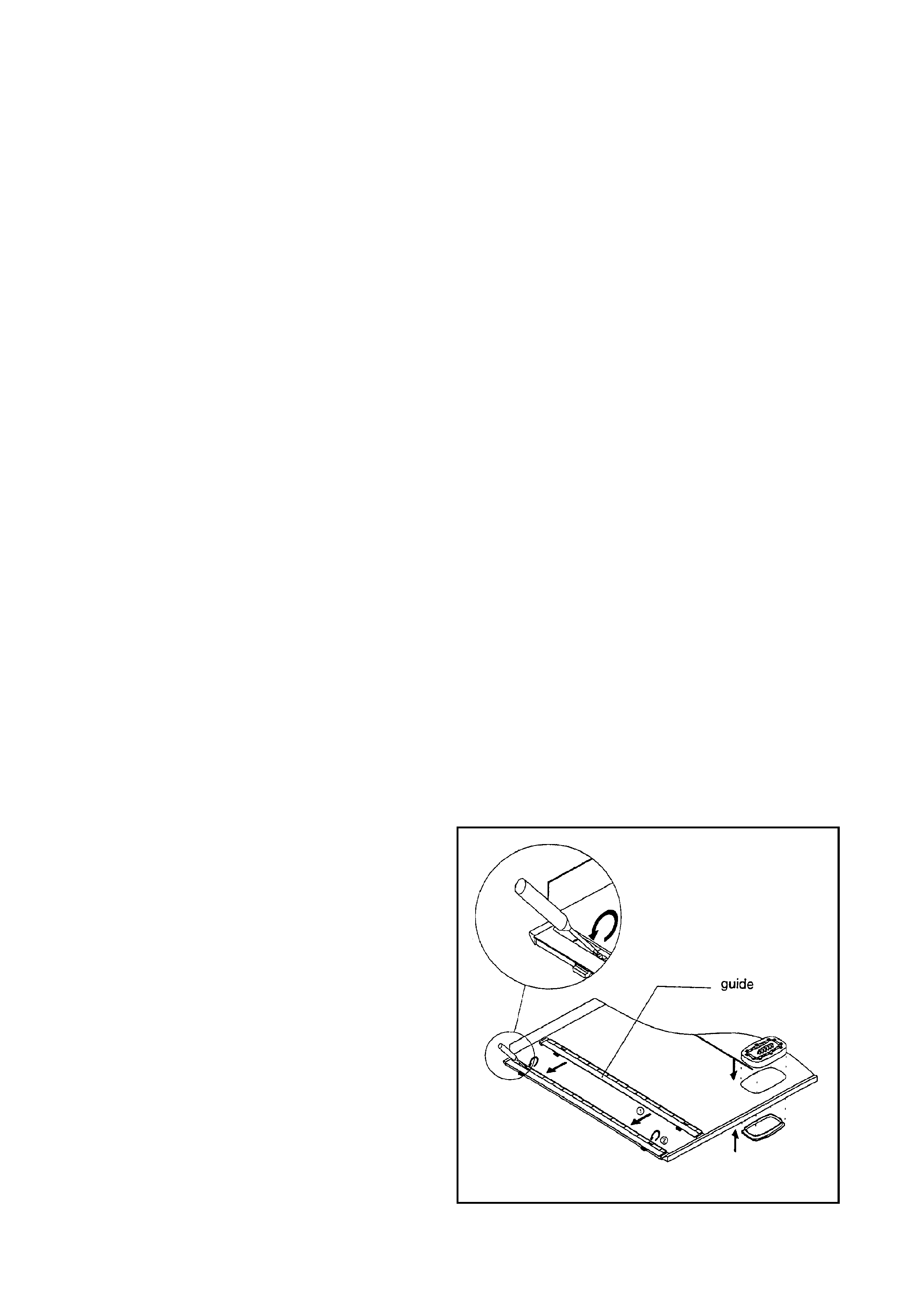
INTERIOR TRIMMING
5. Mount the left and a right guide by placing the
integrated slide through the opening in the
side of the sunshade.
Lift the springs up with a screwdriver to apply
tension on the springs (see Figure 10).
Figure 10 - Finishing The Sunshade
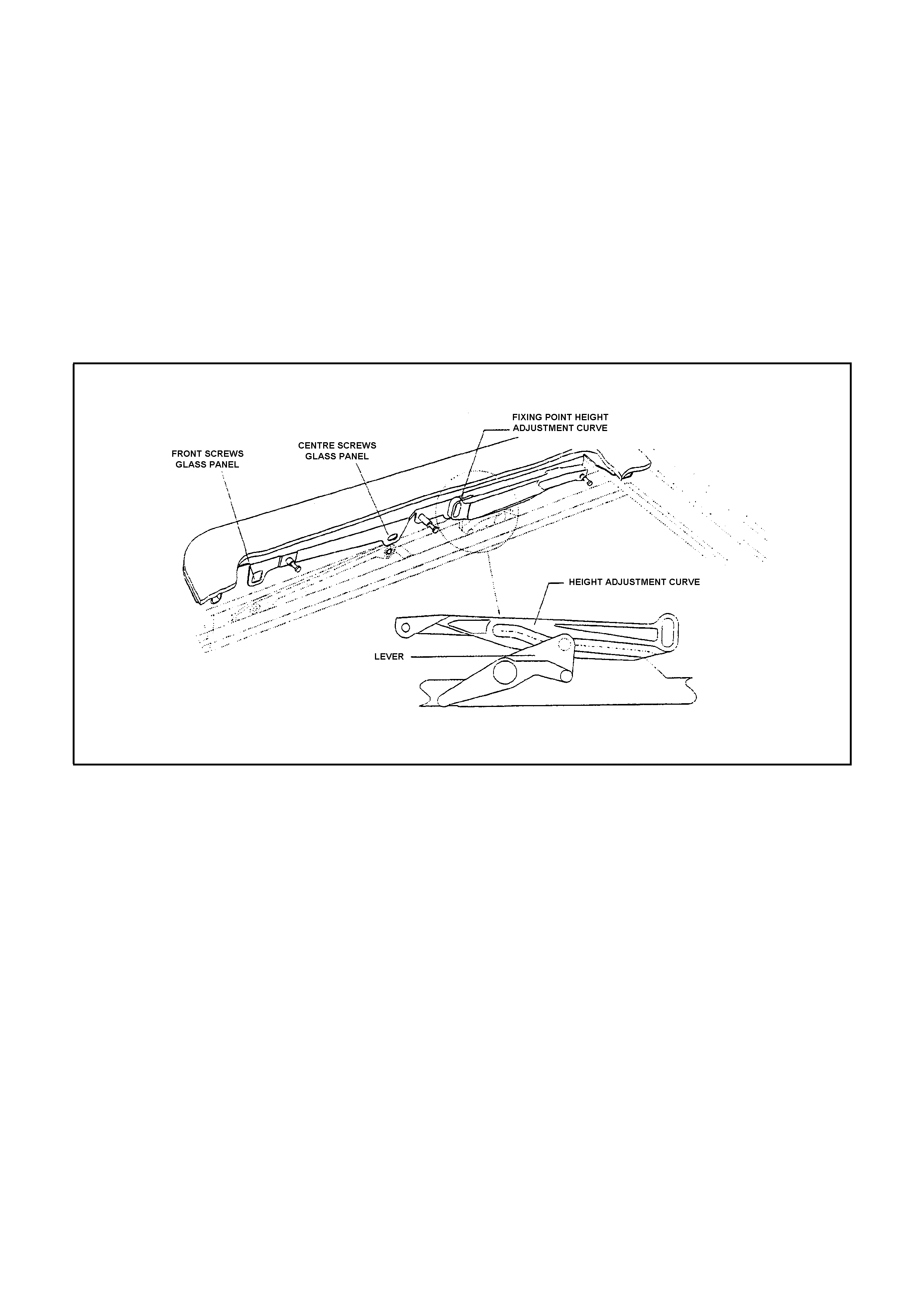
GLASS PANEL (TVS 40)
1. Slide mechanism to tilt position.
2. Inspect rubber seal and glass panel for damage.
3. Place the height adjustable curve, (which is at the rear of the glass panel), over the mechanism. Place vertical
front lip on panel between RH and LH mechanisms.
4. Lift the mechanism mounting bracket from the inside and install 2 front and centre screws, leaving the 4
screws loose.
5. Put glass panel in closed position.
6. Adjust the glass panel to the front. Check with for example a business card the tension of the seal against the
trim ring at the rear.
7. Tighten both centre screws.
8. Adjust height at the front and tighten front screws.
9. Adjust height at the rear by loosening Torx screws of the adjustment curve, adjust the glass level with roof skin
and tighten screws (see Figure 14).
Torque for all M5 screws is 3.5 Nm.
Figure 14 - Adjust The Glass Panel
10. Check functioning of mechanism and adjustments. Repeat operation 6 till 9 to readjust the glass panel if
necessary.

FIRE EXTINGUISHER
GENERAL
HSV VT models are fitted with a HSV design fire extinguisher. The extinguisher is located in the rear luggage
compartment.
SERVICE OPERATIONS
The fire extinguisher should be subjected to a regular visual inspection in accordance with the instructions on the
extinguisher. Par ticularly, the extinguisher should be inspec ted for dam age and to ensure that the integral pres sure
gauge registers the appropriate internal pressure. When discharged or when the internal pressure is outside the
prescribed limits, the extinguishers should be serviced and re-charged by an appropriate supplier. New
extinguishers are available through the HSV spare parts systems.

HSV INTEGRATED SECURITY SYSTEM
GENERAL
The new HSV Integrated Secu rity System (ISS) is fitted as s tandard equipment to all HSV VT and VS m odels. T he
ISS is a micro-processor controlled immobiliser which automatically isolates essential electrical circuits when the
ISS is armed and acc es s or y or ignition ‘ON’ is detected. The immobiliser is disar med us ing a valid ignition key code
and uniquely coded black tags which contain a small chip incorporating specific codes. The HSV ISS has been
improved for the VT range of vehicles. The vehicle no longer requires use of the black ISS tag each time the vehicle
is star ted. The ISS rec ords the ignition k ey code and will disarm when a valid vehic le ignition k ey is detected at the
key slip ring. Up to seven vehicle ignition keys and seven ISS black tags can be assigned to the vehicle if required.
NOTE:
IF THE KEY-HEAD BECOMES UNSERVICEABLE AND FAILS TO DISARM THE ISS, THE ISS MAY BE
DISARMED USING THE BLACK TAG UNTIL A REPLACEMENT KEY IS INTRODUCED.
INTRODUCING NEW KEYS
A red MASTER TAG is also supplied with each ISS. T his tag is used to place the ISS into `Learn’ m ode: touching
the red tag to the status monitor (located in the glove box ) will caus e the LED f lash rate to incr ease which indicates
that learn mode is operative. In this mode, codes for lost tags/keys may be overwritten and new keys/tags m ay be
introduced as follows:
With the ISS in learn m ode, insert ignition k ey and turn ignition switch to ‘IGN ON’ position. T he status m onitor
will change to indicate ignition k ey code has been s uccess fully stored (LED goes of f). ISS will retur n to nor mal
mode. Retouch red tag if more ignition keys are to be introduced.
With ISS in learn mode, touch new black tag to receptacle for approximately 2 secs. Status monitor LED will
change to indicate key code has been successfully stored (LED on). ISS will return to normal mode. Retouch
red tag if more black tags are to be introduced.
NOTE:
THE ISS WILL RECOGNISE SEVEN KEY AND TAG CODES. IF A TAG OR KEY IS LOST, THE
REMAINING/NEW CODES MUST BE ENTERED SEVEN T IMES TO ENSURE THAT THE CO DE FO R T H E LOST
KEY OR TAG HAS BEEN OVERWRITTEN AND CANNOT DISARM THE ISS.
NOTE:
RED TAGS MUST BE STORED IN A SECURE LOCATION REMOTE FROM THE VEHICLE. DO NOT STORE
RED TAG IN VEHICLE. LO SS OF A RED TAG WILL REQ UIRE REPLACEMENT OF T HE ISS SYSTEM IF KEYS
ARE LOST OR DAMAGED
VICE OPERATIONS
If an ignition key has been damaged and does not transfer a valid code, the ISS may be disarmed by touching a
valid black tag to the status monitor: this will transmit code to the BCM and enable vehicle start No periodic
servicing of the ISS is required and no additional information is provided or available on the system. HSV dealers
are not authorised to carry out any servicing operations on the ISS system. All requests for information and/or
assistanc e are to be f orwarded directly to the Service Manager at HSV. Bef ore mak ing this request and at any time
that correct operation of the ISS is suspected, the following functional check should be performed:
Check ISS status monitor (located in glovebox) to ensure ISS is in armed mode—i.e. slow flash
Place a piece of tape over the ignition key slip ring contact to break the electrical circuit between ignition key
and ignition barrel slip ring,
Turn key to start position—vehicle should not start.
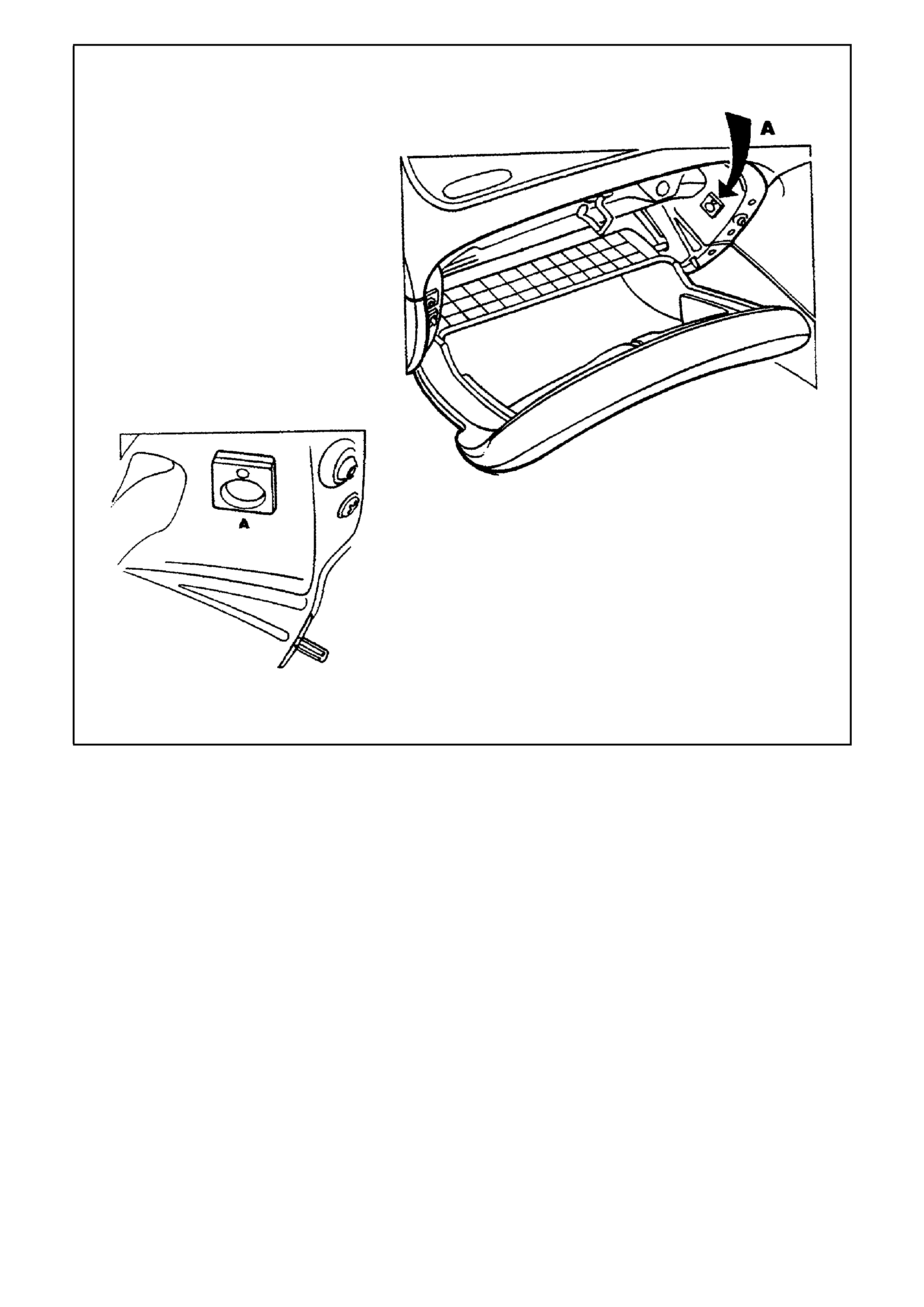
Figure J-10 - HSV VT ISS System
ELECTROCHROMIC M IRRORS
GENERAL
Electrochromic mirrors are a standard fitment to all VT Senator Signature Estate vehicles and to all vehicles fitted
with a Sunroof. The mirror features an electronically controlled mirror cell which changes colour in response to an
applied electrical voltage. This allows autom atic dark ening of the m irror during night dr iving when the headlamps of
a following vehicle shine on an integrated light s ensor. T his function only operates when the integral sens or detec ts
low ambient (i.e. at night time). The mirror also incorporates two manually operated map lights - separately switched
for passenger and driver. (Lights also illuminate in conjunction with interior lamp when activated by door switches.
The mirror operates automatically however, an AUTO/MANUAL switch provides the driver with the option for the
mirror to be darkened during low ambient light conditions regardless of presence or absence of following
headlamps. When reverse gear is selected, the mirror automatically lightens.
SERVICE OPERATIONS
No specific servicing of the m irror is required. T o replace m ap light globes use a s mall s crew driver to pris e out the
lens assembly to reveal a wedge-base five watt (5.0 W) globe (see Figure J-11). Refit lens assembly by inserting
the end closest to centre of m irror f irst - ens ure lam p bulb pass es through hole in s ide of lens assem bly. The m irror
is fitted with a short harness which connects to the HSV electrochromic mirror harness above the headlining near
the mirror: this harness runs across the headlining and down the `A’ Pillar to the main wiring harness which provides
connections to the battery, door switch, ignition, reverse lamps and ground.
Figure J-11 - HSV Electrochromic Mirror
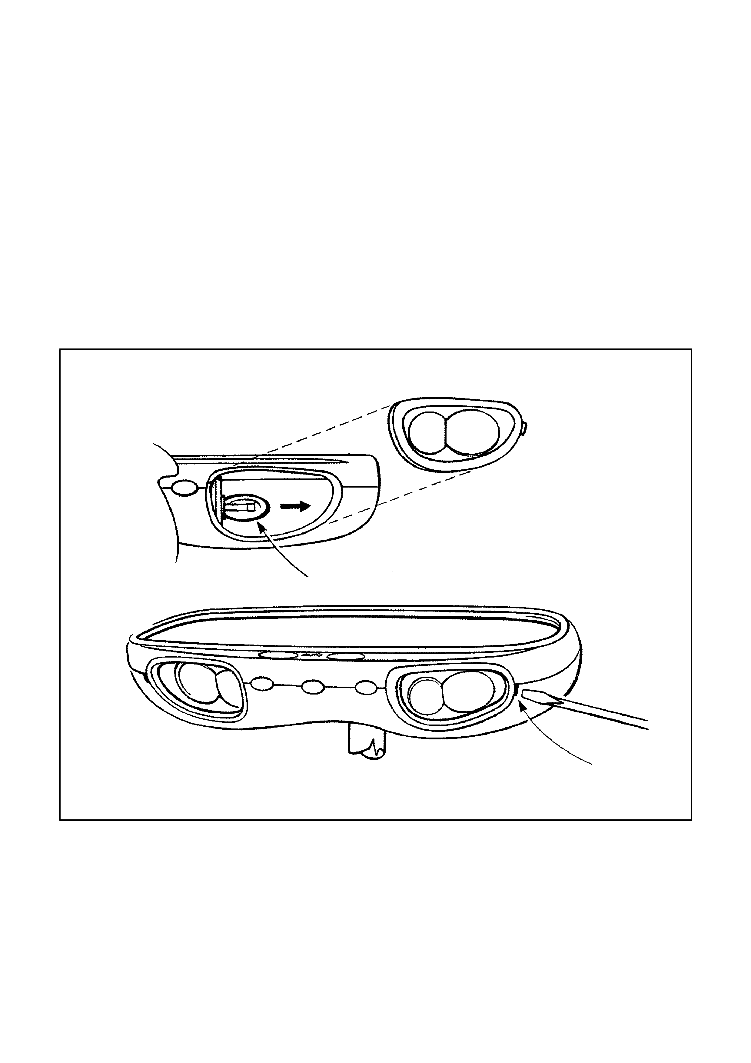
HSV FOG LAMPS
GENERAL
HSV Fog lamps are fitted directly to the front fas cia of all HSV VT models except Manta (which is fitted with GMHA
lamp s) . The HSV lamp s us e a glas s c onvex r ef lector to provide a wide-angle beam c onc entrated in a r ange of 30 to
40 metres in front of the lamp. The external lens incorporates a clear horizontal section .
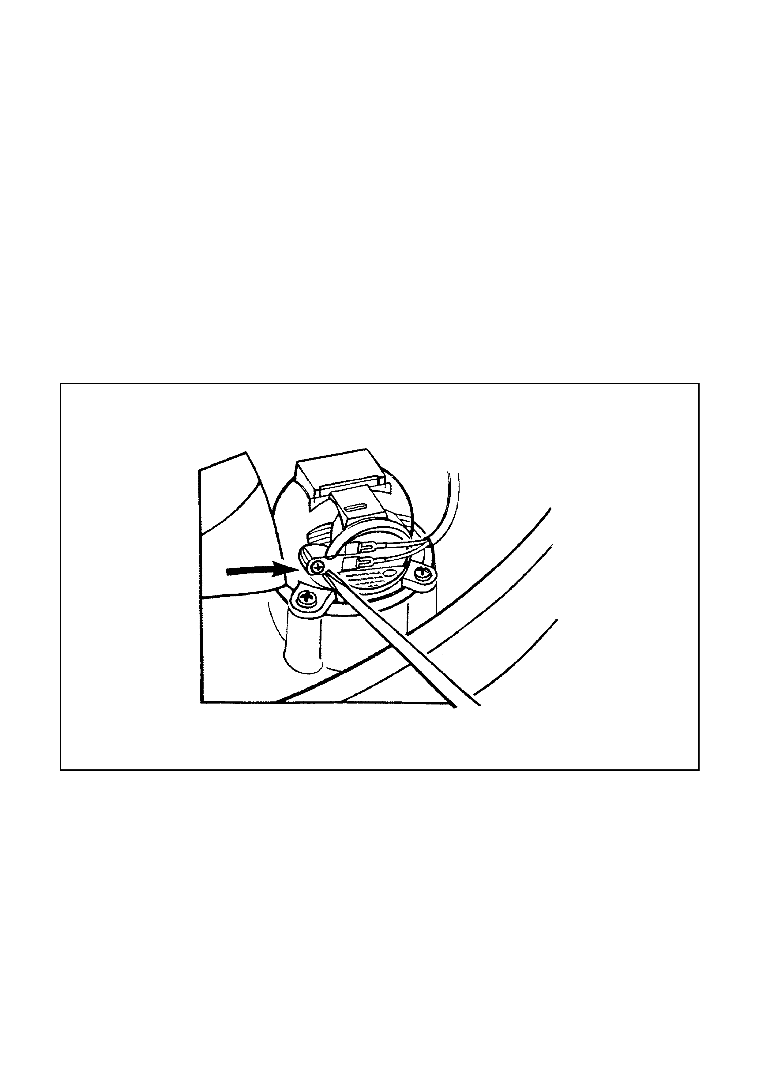
SERVICE OPERATION
No periodic ser vicing of the HSV lam ps is r equired however, occ asional r e-alignm ent may be necessar y. Alignm ent
is altered by m inute adjustm ents of the three mounting sc rews. Fog lamps are adjusted to foc us on a central ‘HOT
SPOT ’ 5.0 centim etres below the above ground height of the lam p (with the car levelled to norm al operating height)
at a distance of 25 metres from the bumper bar of the vehicle. Globes may be replaced without altering the
alignment by removing a water-tight access cover on the underside of the lamp (see Figure J-12): unclip the two
spring clips which retain the globe carrier at the focal point of the reflector. Replacement fog lamps available
through HSV are identified as follows
12C-970601 LAMP FOG LEFT HAND
12C-970602 LAMP FOG RIGHT HAND
NOTE:
CONDENSATION MAY APPEAR ON THE LENS OF THE FOG LAMP WHEN APPROPRIATE AMBIENT
CONDITIONS EXIST. THIS CONDENSATION WILL CLEAR AS THE AMBIENT CONDITIONS CHANGE OR
AFTER FOUR OR FIVE MINUTES OPERATION OF THE FOG LAMPS
Figure J-12 - HSV Fog Lamps