
SECTION 2 - SERVICE OPERATIONS
CAUTION:
This vehicle will be equipped with a Supplemental Restraint System (SRS). A SRS will
consist of either seat belt pre-tensioners and a driver's side air b ag, or seat belt pre-
tensioners and a driver's and front passenger's side air bags. Refer to CAUTIONS,
Section 12M, before performing any service operation on, or around any SRS
components, the steering mechanism or wiring. Failure to follow the CAUTIONS
could result in SRS d eployment, result ing in po ssible person al injury or unnecessary
SRS system repairs.
IMPORTANT:
When any LPG system component has been replaced or overhauled, or when the engine assembly has been
replaced or overhauled, the adaptive learn drive cycle procedures must be carried out as described in. This is
because the values st ored in the Adaptive Digital Pr ocess or operational c ells apply only to the previous condition of
the engine or components.
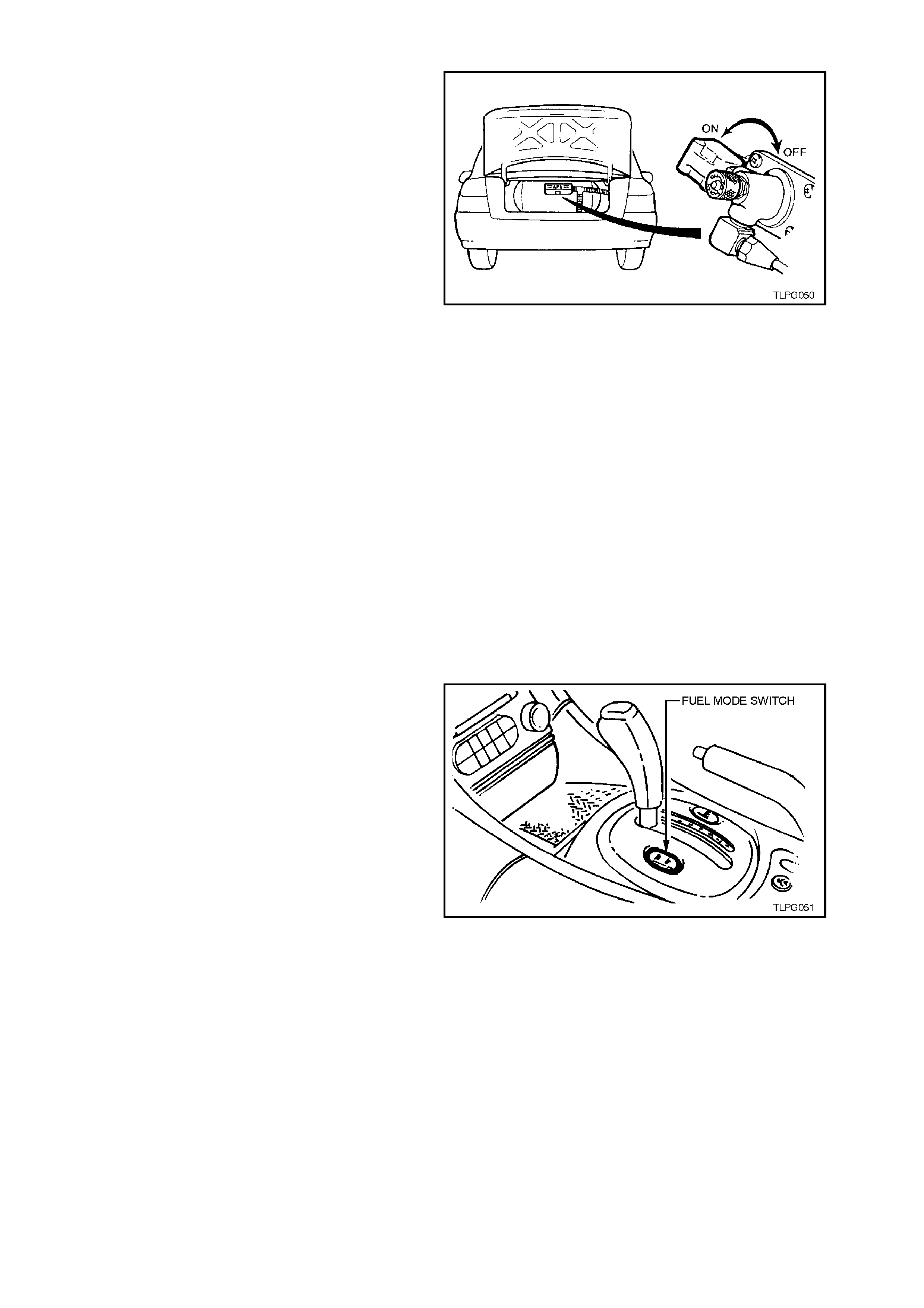
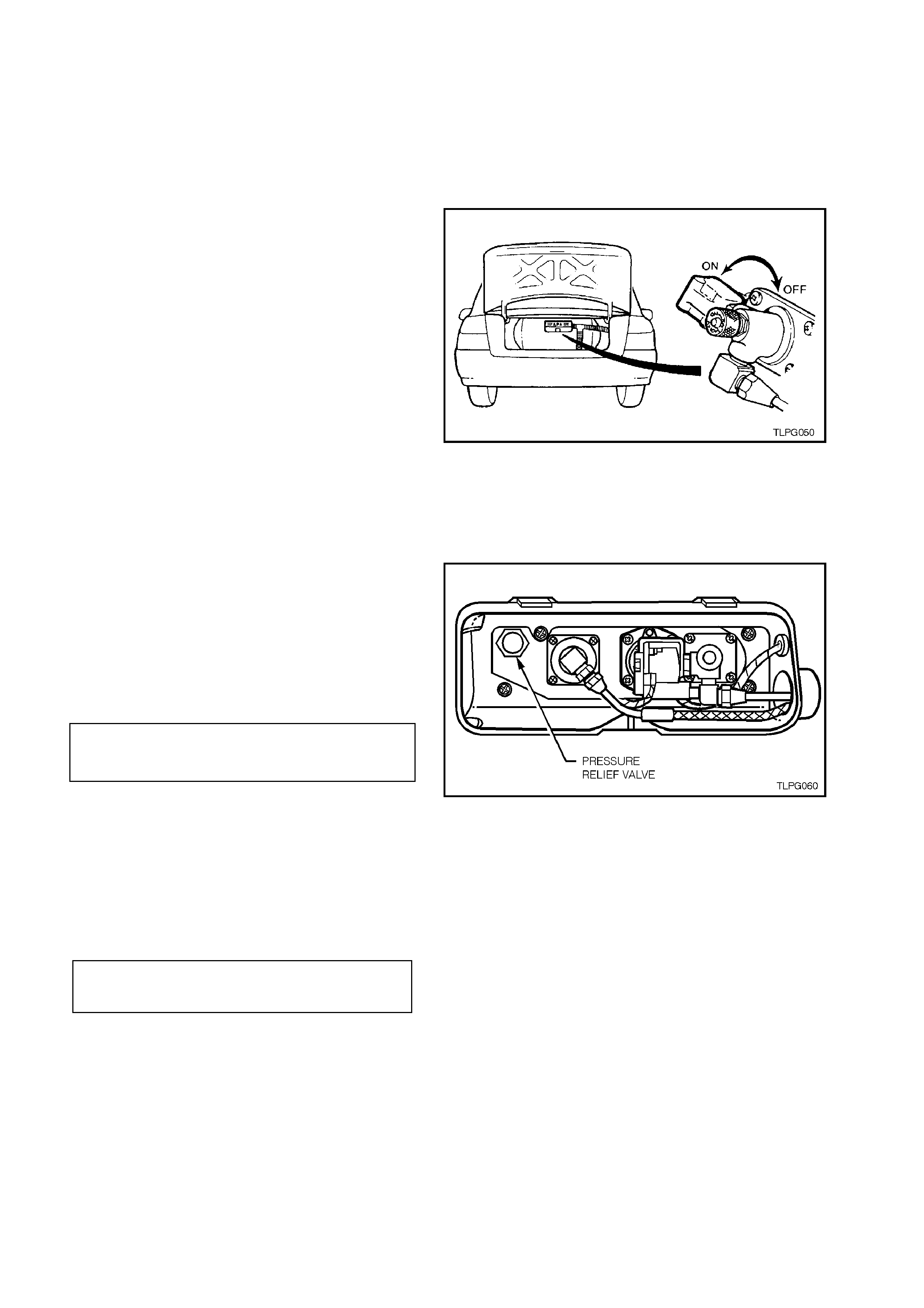
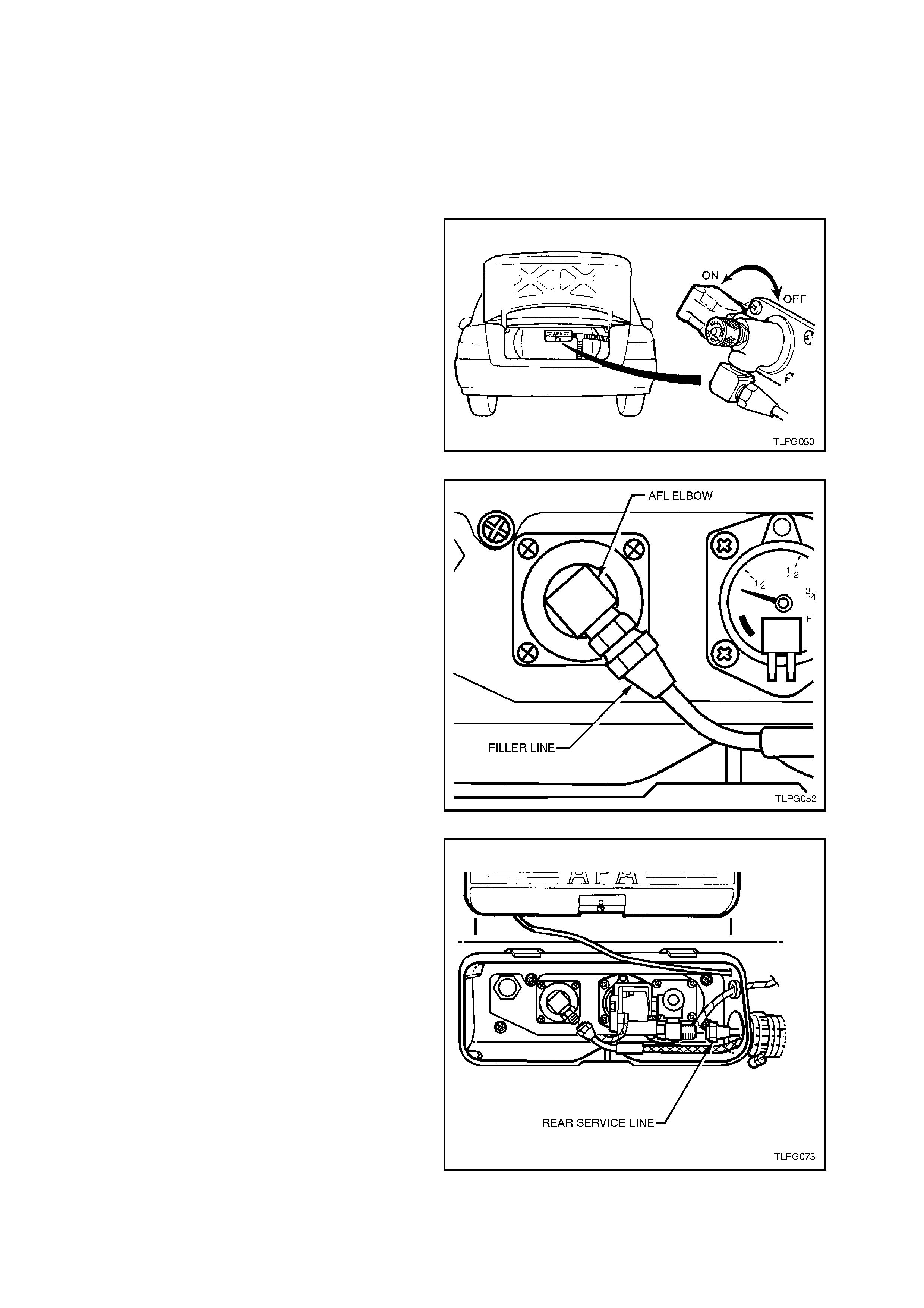
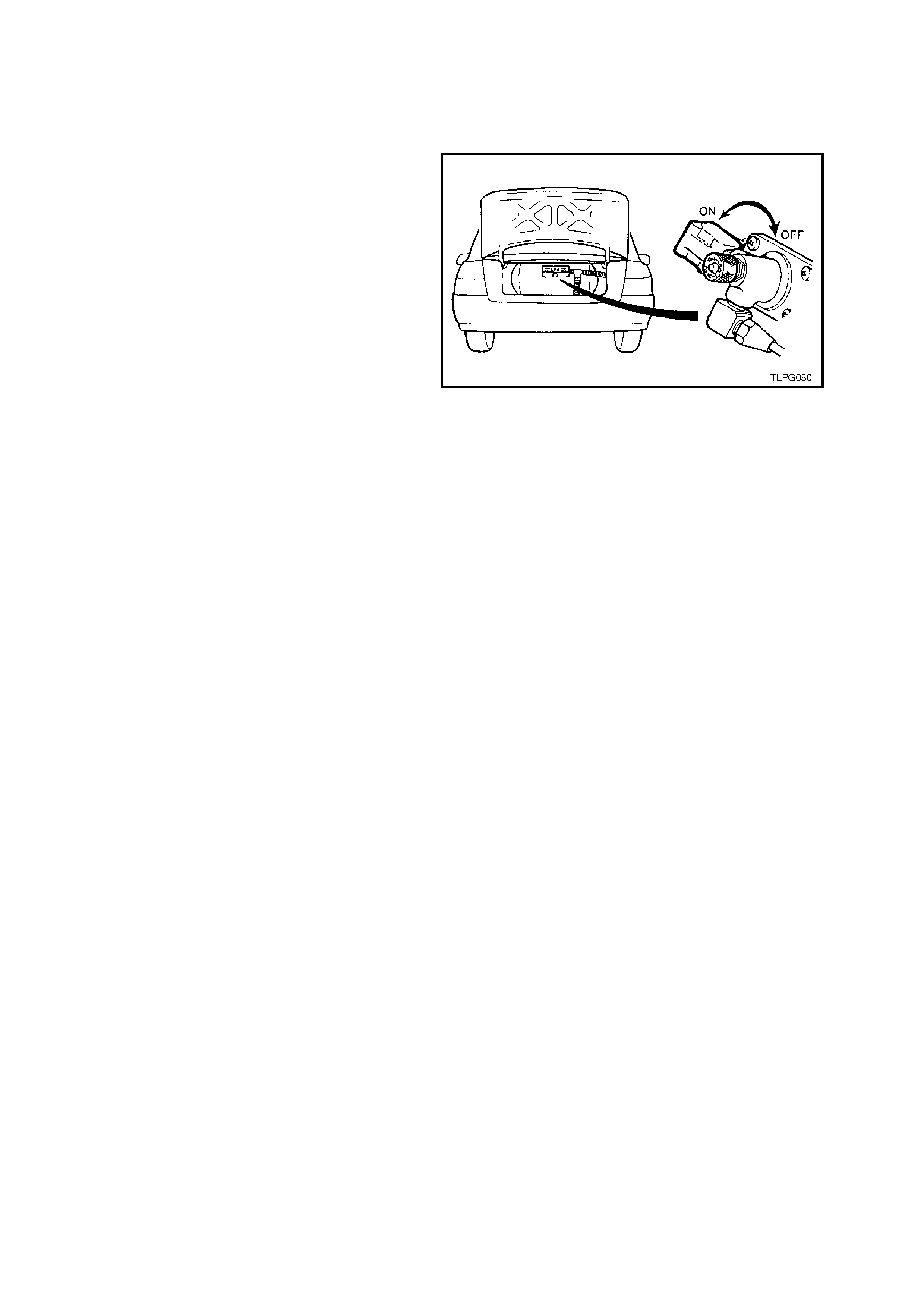
2.1 DRAINING THE SERVICE LINES
WARNING:
The vehicle CANNOT be operated on LPG in the
works hop, unless the works hop is a "Spec ialis t G as
Workshop" (in accordance with the current
Australian Standards AS2746 - 1985) and LPG is
specifically required for testing.
Therefore, at the completion of the following
procedure, with the manual ser vice valve c losed, all
the LPG in the service lines is exhausted and the
vehicle running on petrol, then and only then can
the vehicle be driven into the workshop.
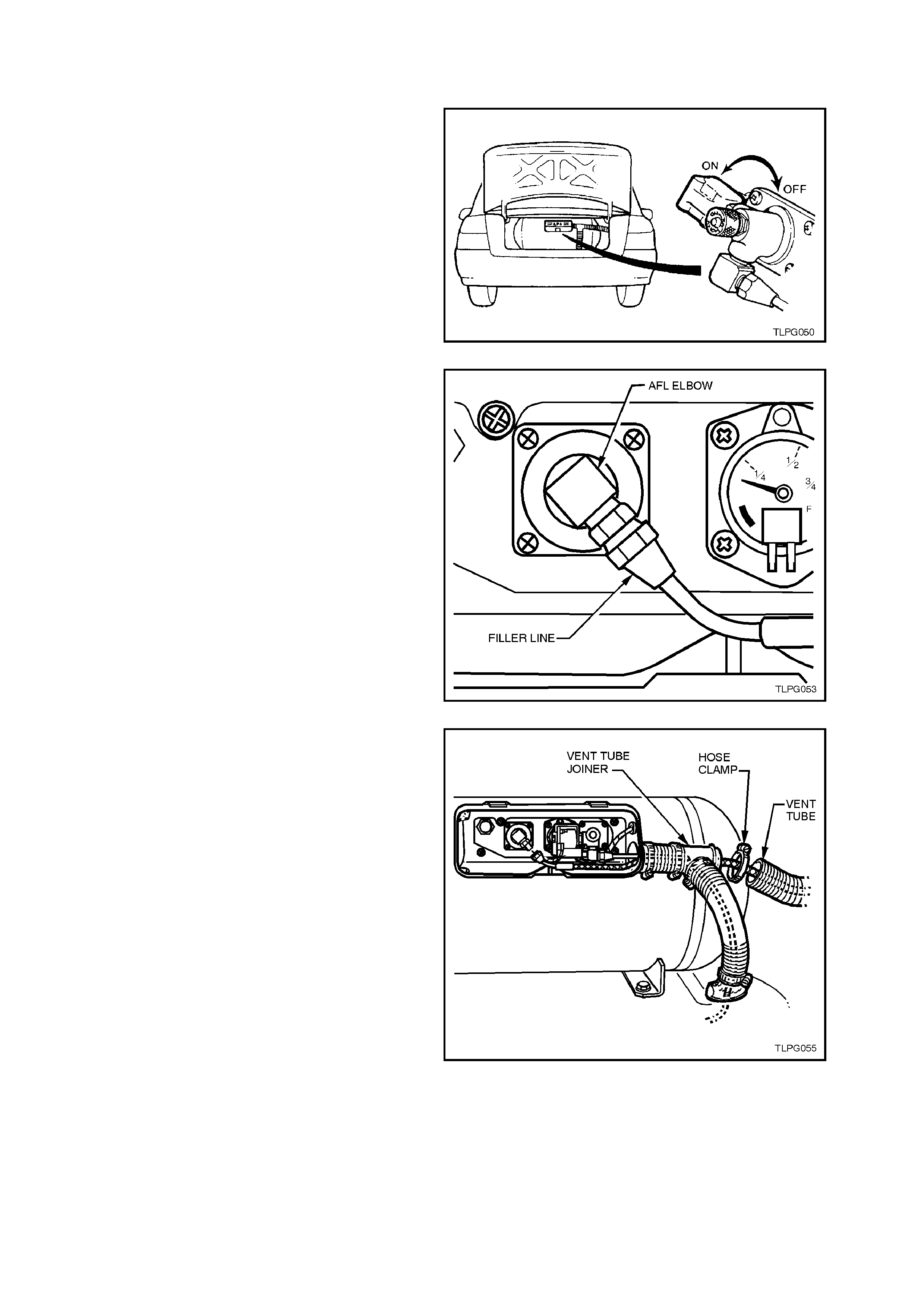
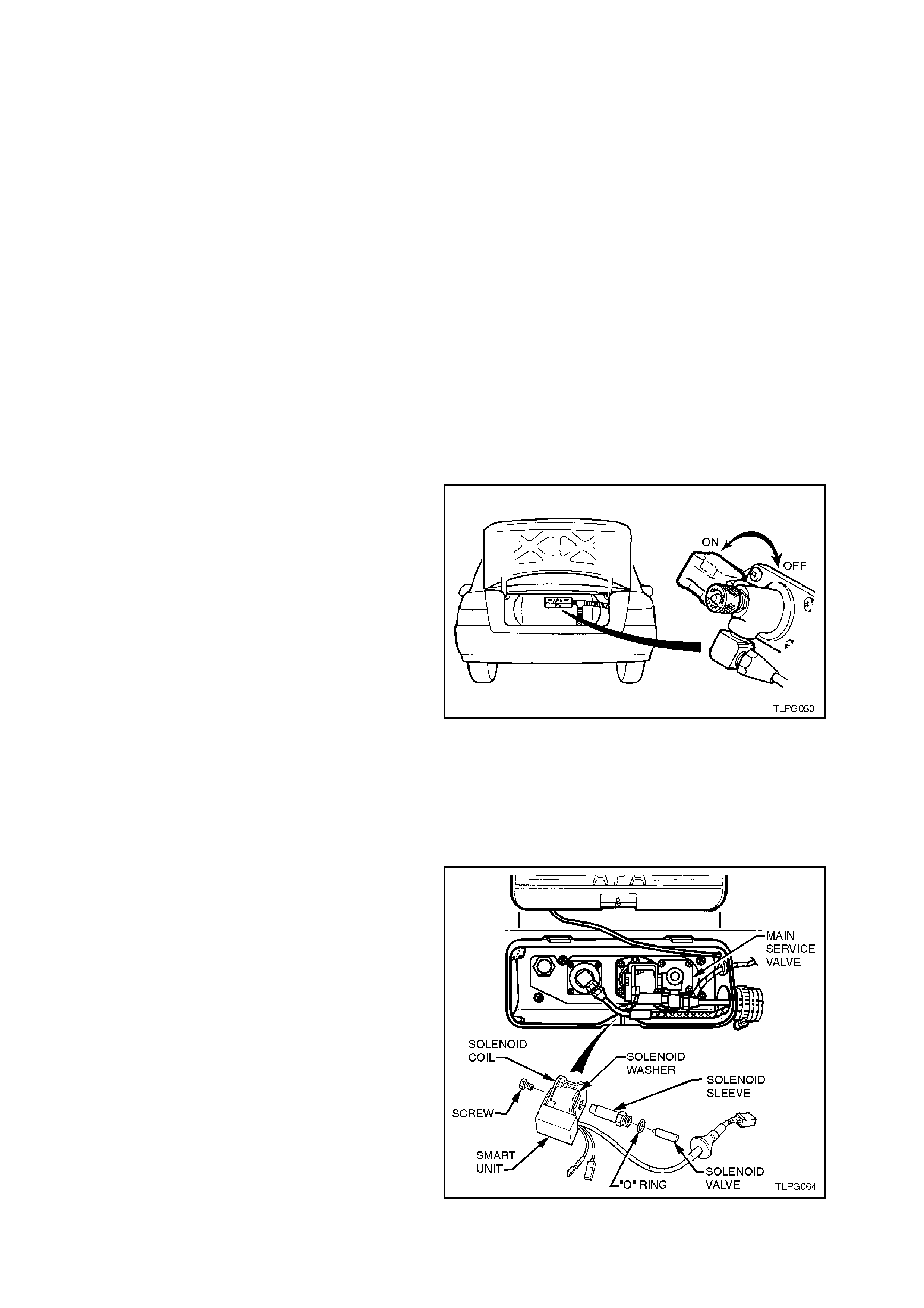
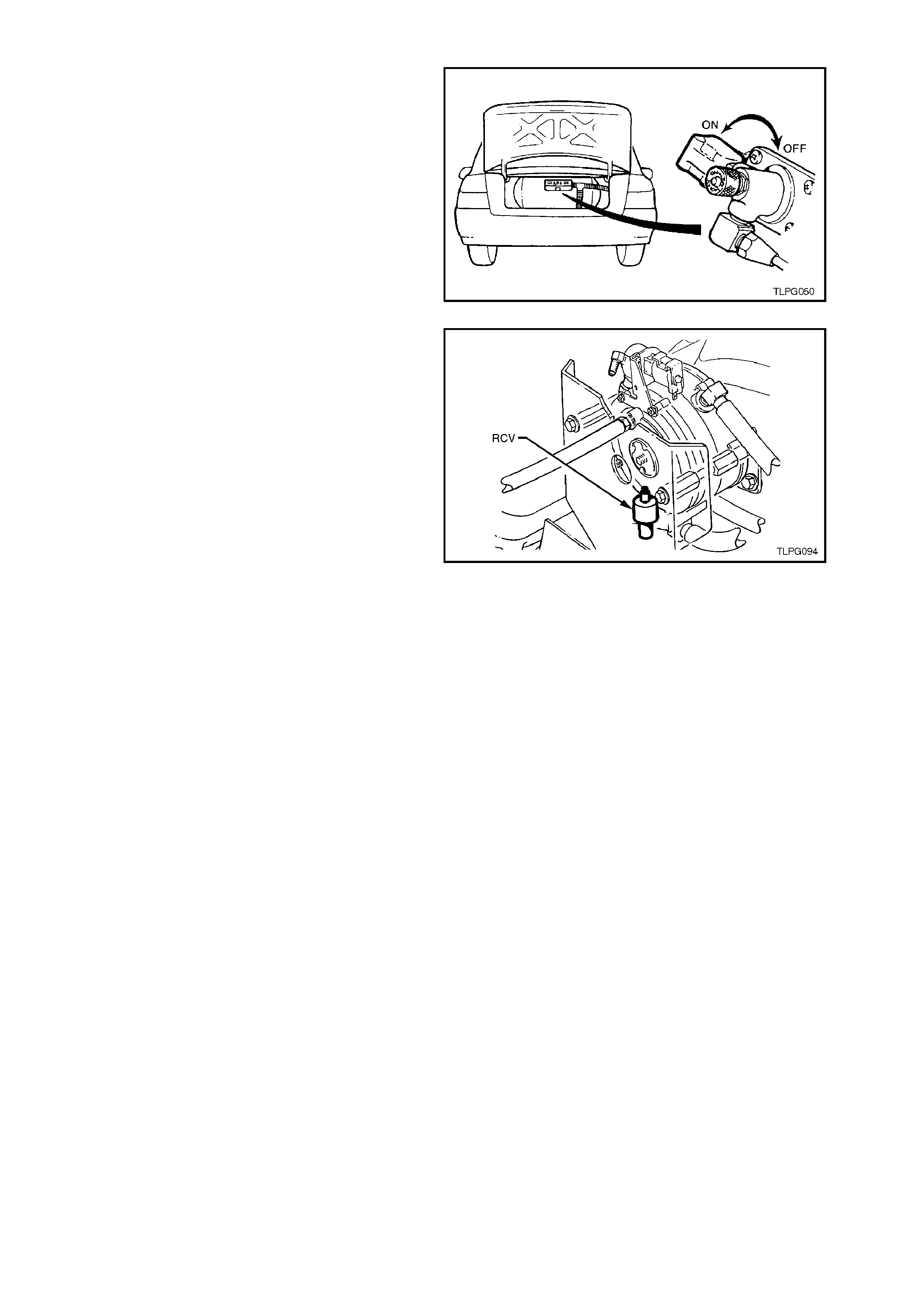
1. Park the vehicle in a well ventilated area, away
from any ignition source.
2. Remove the LPG cylinder valve box cover.
3. Turn 'OFF' the manual service valve.
CAUTION:
If at any time the manual service valve becomes
stuck, no service operations on the system will
be possible. Should for any reason the valve
stick, the cylinder will have to be returned to
the cylinder manufacturer (APA) to arrange a
replacement cylinder.
Contact: APA Industries
190 Colchester Road
Kilsyth
Victoria 3137
Phone - (03) 9720 2855
Fax - (03) 9761 4495
Email - APA @ APAIND.COM.AU
Figure 2-1
4. Place the fuel mode switch in the 'LPG'
position.
5. Start the engine and allow to run on LPG until
the engine stalls, then crank the engine
several times to ensure the service lines are
empty of LPG.
6. Place the fuel mode switch in the 'PETROL'
position.
NOTE 1:
Disconnect the battery earth lead before performing
any service operations.
NOTE 2:
If it is not pos s ible to star t and run the engine out of
LPG, the service lines should be cracked open to
allow them to be emptied of LPG in accordance
with the current Australian Standards AS 2746 -
1985.
Figure 2-2
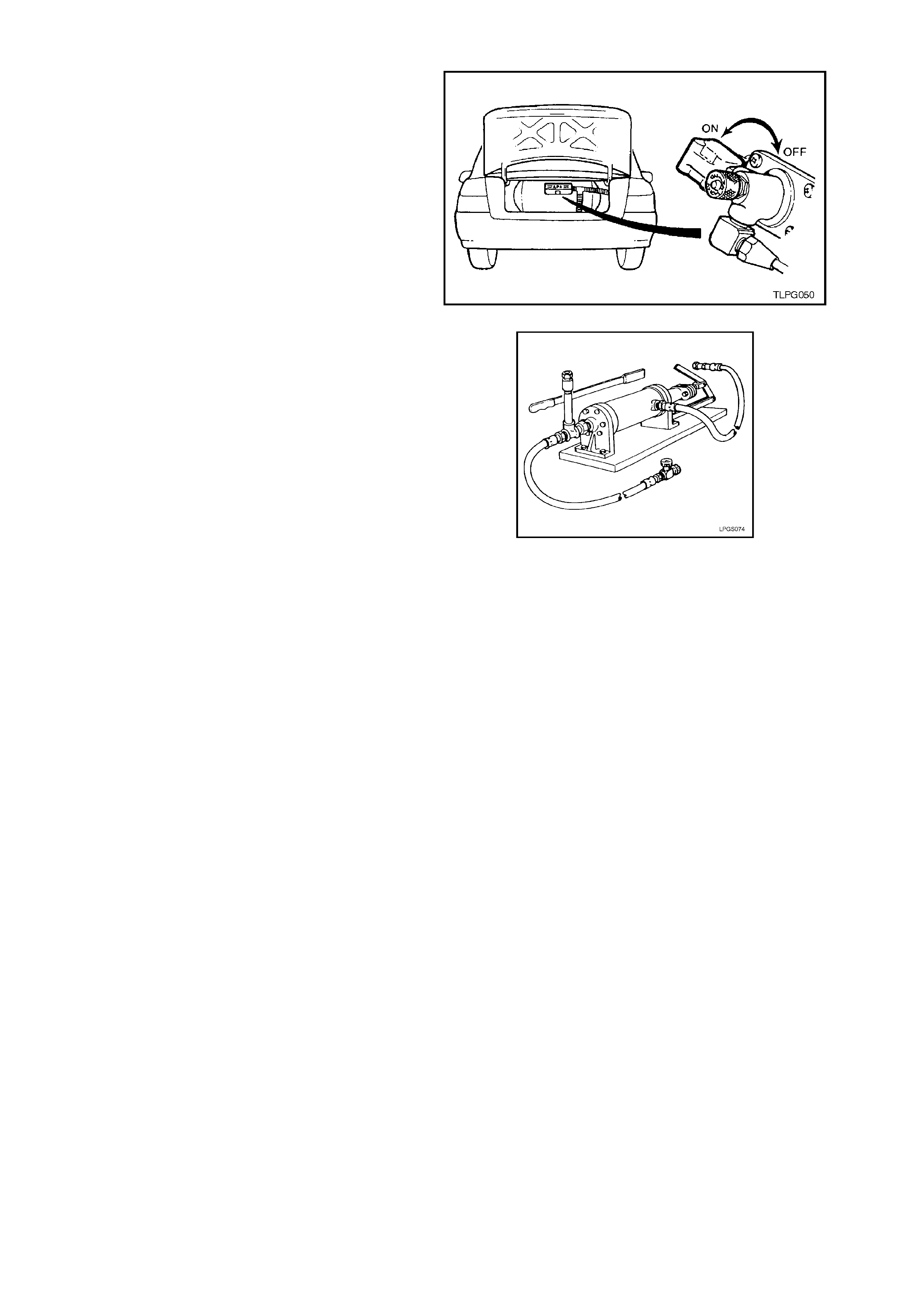
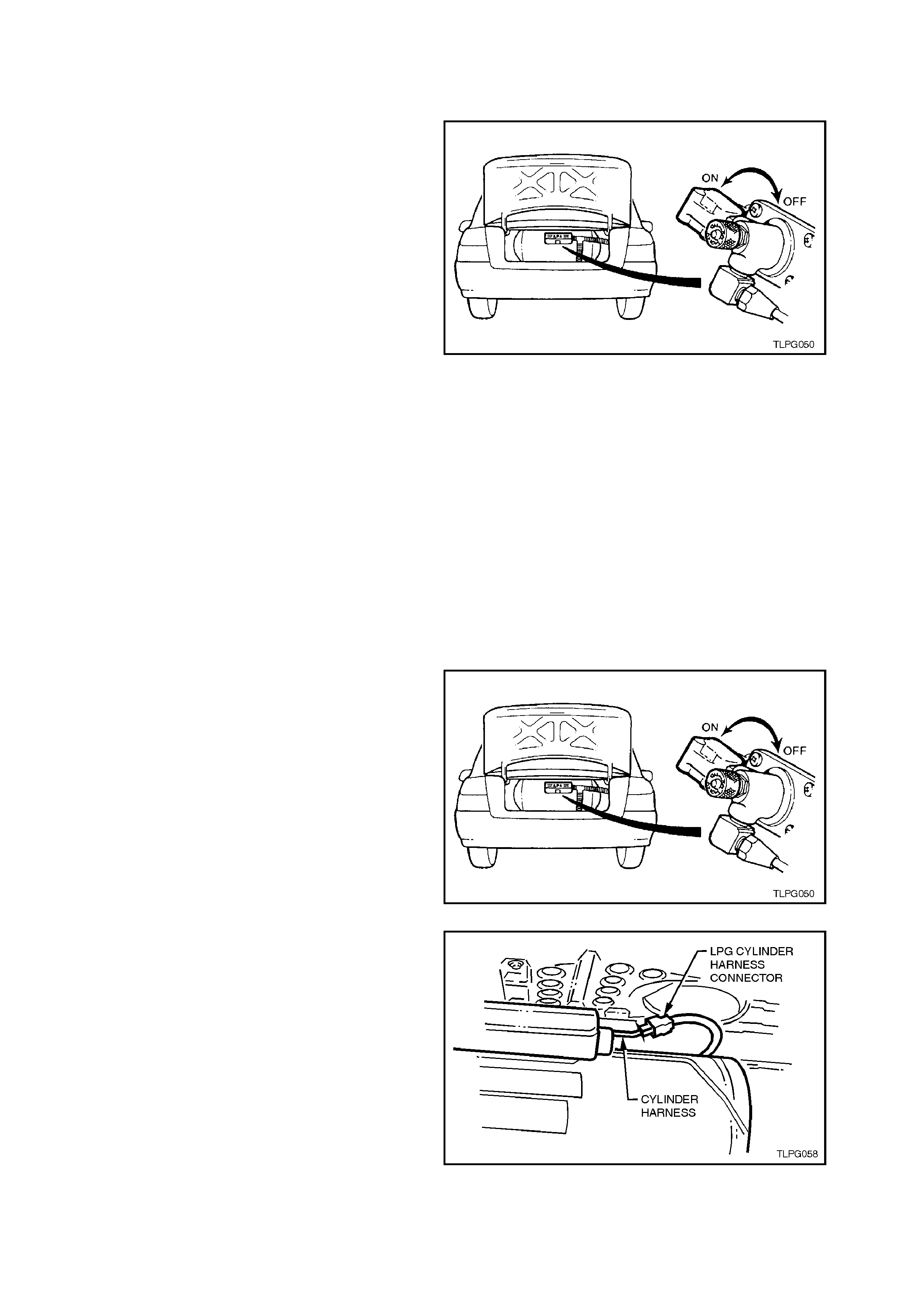
2.2 LPG CYLINDE R UNLOADING PROCEDURE
1. Park the vehic le in a well ventilated area, away
from any ignition source.
2. Drain the LPG service lines, refer to
2.1 DRAINING THE SERVICE LINES in this
Section.
3. Ensure the manual service valve is turned
'OFF' and the battery earth lead is
disconnected.
4. Remove rear service line, refer
2.13 SERVICE LINES in this Section.
Figure 2-3
5. Connect an LPG pump (such as an Apollo
LPG pump or equivalent, refer
Section 7. SPECIAL TOOL S) to solenoid and
manual service valve assembly connection.
6. Pump out the LPG cylinder following the
instructions as outlined by the LPG pump
manufacturer for the particular pump you are
using and in accordance with the current
Australian Standards AS2746 - 1985.
CAUTION:
The LPG cylinder MUST be pumped out until
completely empty. Figure 2-4
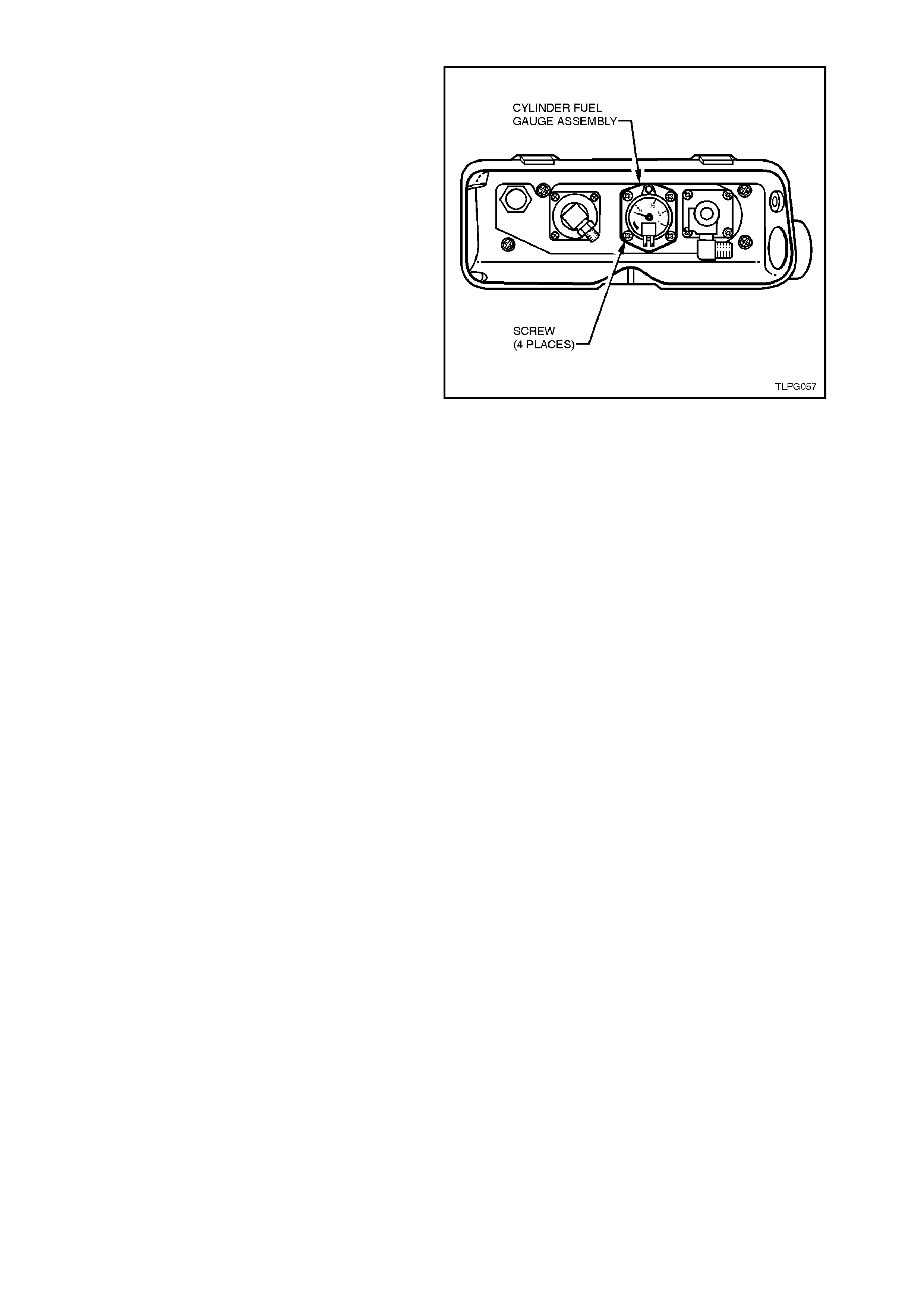
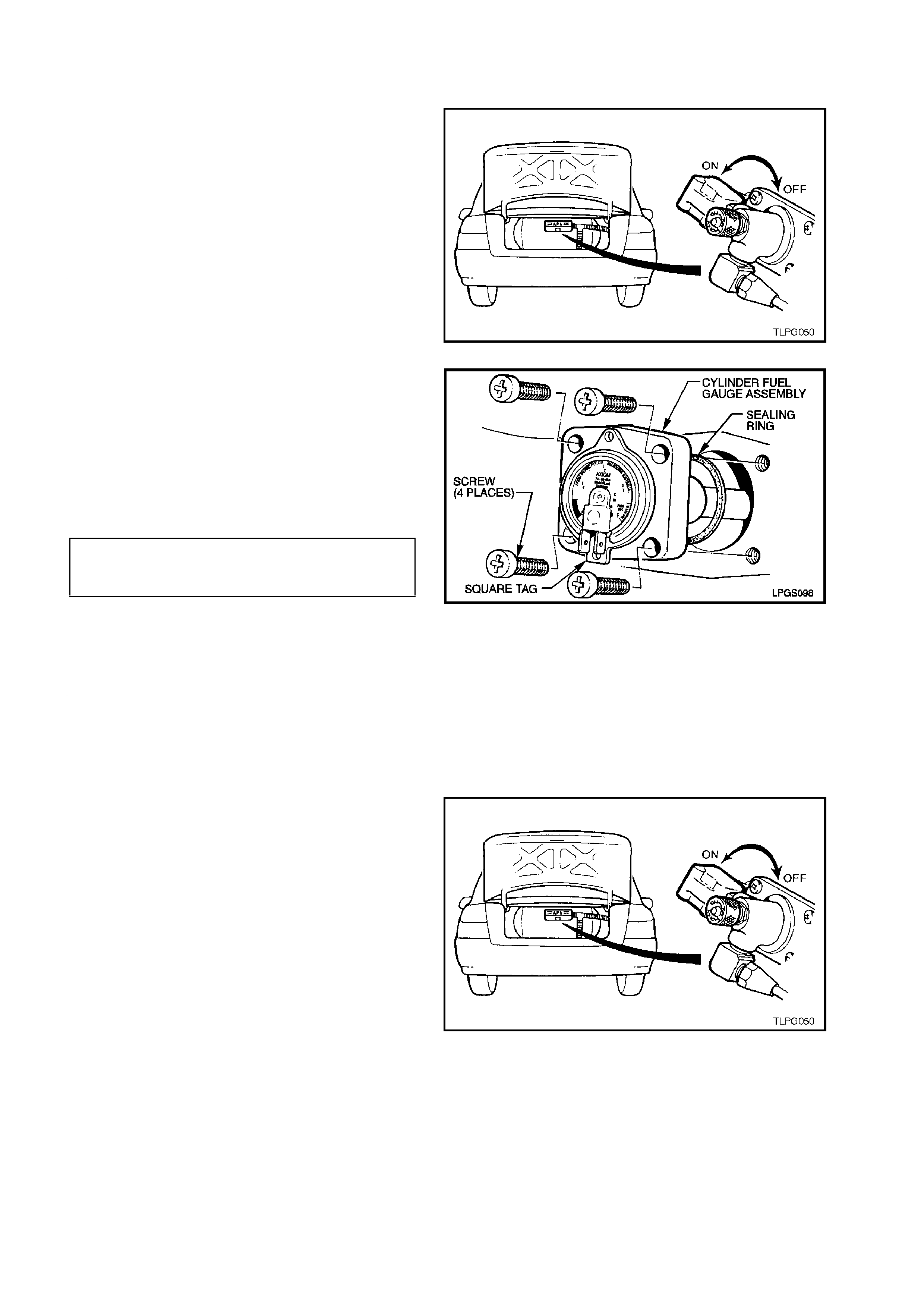
7. When you are sure the LPG cylinder is
completely empty, open the manual service
valve. Remove wiring connections from fuel
gauge and unscrew the cylinder fuel gauge
assembly retaining screws one turn and then
rock the cylinder fuel gauge assembly to
relieve any residual pressure in the LPG
cylinder.
NOTE:
To remove the fuel gauge, it will be necessary to
remove the smart unit and solenoid valve from the
manual service valve and the filler line from the
AFL valve, refer to the relevant service operations
in this Section for additional information on
removing these components.
8. Continue to loosen cylinder fuel gauge
assembly screws one turn at a time. Continue
rocking the cylinder fuel gauge assembly to
ensure the LPG cylinder has no residual
pressure. Remove cylinder fuel gauge
assembly scre ws.
9. Remove cylinder fuel gauge assembly, being
careful not to damage the float.
10. Purge the LPG cylinder with nitrogen to ensure
there is no residue of LPG in the cylinder.
CAUTION:
AFTER ANY VALVE OR COMPONENT HAS
BEEN REMOVED AND REINSTALLED TO THE
LPG CYLINDER, THE LPG CY LINDER MUST BE
PRESSURE AND LEAK TESTED IN
ACCORDANCE WITH THE CURRENT
AUSTRALIAN STANDARD AS2030.1 BEFORE
THE LPG CYLINDER IS PUT BACK INTO
SERVICE IN THE VEHICLE.
Figure 2-5
11. Reinstall cylinder fuel gauge assembly, refer
2.12 CYLINDER FUEL GAUGE ASSEMBLY
in this Section.
2.3 LEAK TESTING
The following leak test procedure is to be carried
out on the LPG system high pressure com ponents
and is to be performed at each normal
maintenance service.
The leak test is to be carried out in the open air in a
well-ventilated area, away from any ignition source
and PRIOR to bringing the vehicle into the
workshop.
COMBUSTIBLE GAS DETECTORS
If a com bustible gas detector is to be used for leak
testing of the LPG system, the combustible gas
detector should be capable of detecting 25 parts
per million (P.P.M.) of LPG in air. A detector such
as a LD-9001 LP Gas Leak Detector or equivalent
is recommended.
Whichever leak detector is used, it is important to
follow the manufacturer's instructions in regard to
adjustment and setting the instrument prior to
conducting the leak test.
Care in interpretation is necessary, as the detector
can respond to the presence of any of several
vapours that are combustible, some of which may
not be LPG, such as oil smears, joining
compounds, etc. They may also detect residual
LPG vapours that are present for reasons other
than leakage, and which must be cleared before a
valid test for leakage can be made.
If a leak is present, a detector will signal its
existence but not its size, and will indicate its
general location, but may not be able to locate it
exactly. So, a proving or follow up check with foam
is often desirable.
Figure 2-6
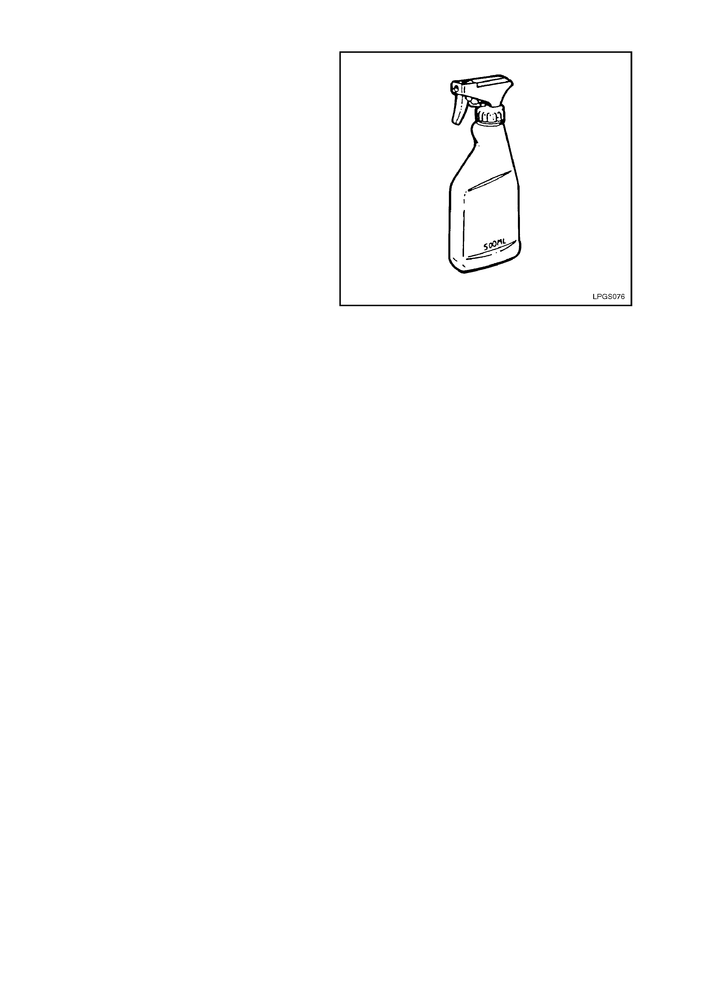
FOAM
If foam is to be used, the foaming agent should be
a propriety leak tes t s olution, f or mulated spec if ic ally
for the purpose, s uch as G am eco Leak Check TM or
a similar solution. T he solution should be fres h and
the whole of the area to be tested should be
coated, and time allowed for bubbles to form. All
areas under test must be able to be observed
during the leak test.
W hichever foaming agent is used, it is impor tant to
follow the manufacturer's instructions.
Foam testing is more effective for small leaks.
Large leak s tend to blow the solution away from the
leak without forming a bubble, so care in
application is necessary.
The leak test is performed by directing a spray of
solution at each of the possible leak points in the
high pressure side of the system.
After applying the solution, look c ar ef ully for no less
than 15 seconds.
A leak is indicated by the presence of gas bubbles
(foaming) in the solution at the leak source.
NOTE:
LPG IS HEAVIER THAN AIR SO TEST
THOROUGHLY BELOW ALL COMPONENTS
AND FITTINGS.
If a leak is detected at a joint, the relevant
component/s must be rem oved as described in the
appropriate component service operation in this
Section, all mating threads thoroughly cleaned,
then resealed using the specified sealant and
tightened to the correct torque specification. Once
installed, thoroughly leak test the component/s
again.
At the completion of each test, dry the leak test
area of the foaming agent with low pressure
compressed air or shop cloths and spray
imm ediate area with a water dispersing agent such
as WD40 or RP7, etc.
Figure 2-7
LEAK TEST PROCEDURE
With 3 litres of LPG in the LPG cylinder, leak test
the com plete LPG s ystem f ollowing the instr uctions
below
1. Park the vehicle in a dry, well ventilated area.
DO NOT SMOKE OR ALLOW NAKED FLAMES
OR ANY IGNITION SOURCE NEAR THE
VEHICLE DURING THE TESTING OPERATIONS.
2. Ensure the vehicle is operating on LPG and
run the engine for at least 30 seconds to fully
pressurise the system, then stop the engine.

3. The recommended sequence of testing is as
follows:
A. Referring to Figure 2-8, view A, open rear
compartment lid, remove the valve box
cover and leak test at and around the:
Pressure relief v alve (1).
AFL inlet elbow to AFL (2).
Rear service line to AFL inlet elbow
connection (3).
AFL to LPG cylinder (4).
Cylinder fuel gauge assembly (5).
Solenoid and manual service valve
assembly (6).
Solenoid and manual service valve
assembly to LPG cylinder (7).
Rear service line to solenoid and manual
service valve assembly connection (8).
B. Referring to Figure 2-8, view B:
Open filler box door and leak test at and
around the filler valve check ball (22).
Remove the rear c ompartm ent carpet from
the right side wheelhouse to gain acces s to
the inner side of the filler valve assembly,
refer to Section 1A1 BODY. Leak test at
and around the filler line to filler valve
connection.
C. Referring to Figure 2-8, view C, raise rear
of vehicle and support on safety stands,
refer to Section 0A GENERAL
INFORMATION for the location of jacking
points. Leak test at around the:
Rear service line to intermediate service
line joiner connection (9).
Intermediate service line to rear service
line joiner connector (10).
D. Referring to F igure 2-8, view D, leak test in
the engine compartment at and around the:
Intermediate service line to front service
line joiner connection (11).
Front service line to intermediate service
line joiner connection (12).
E. Referr ing to Figure 2-8, view E, leak test in
the engine compartment at and around the:
Front ser vice line to loc kof f inlet c onnec tion
(13).
Lockoff inlet connection to lockoff (14).
Lockoff to lockoff outlet connection (15).
Lockoff outlet connection to converter (16).
Lockoff (17, 18, 19).
Converter mounting faces (20).
At the com pletion of the leak test, c lose the manual
service valve, start the engine and run the engine
until all the LPG in the service line is exhausted.
With the engine stopped, switch to ‘petrol’ and s tart
the engine. The vehicle can now be driven into the
workshop.
NOTE:
The vehicle cannot be operated on LPG in the
works hop unless the work shop is a “Spec ialist Gas
W ork shop”, ref er to Australian Standard AS 2746 -
1985.
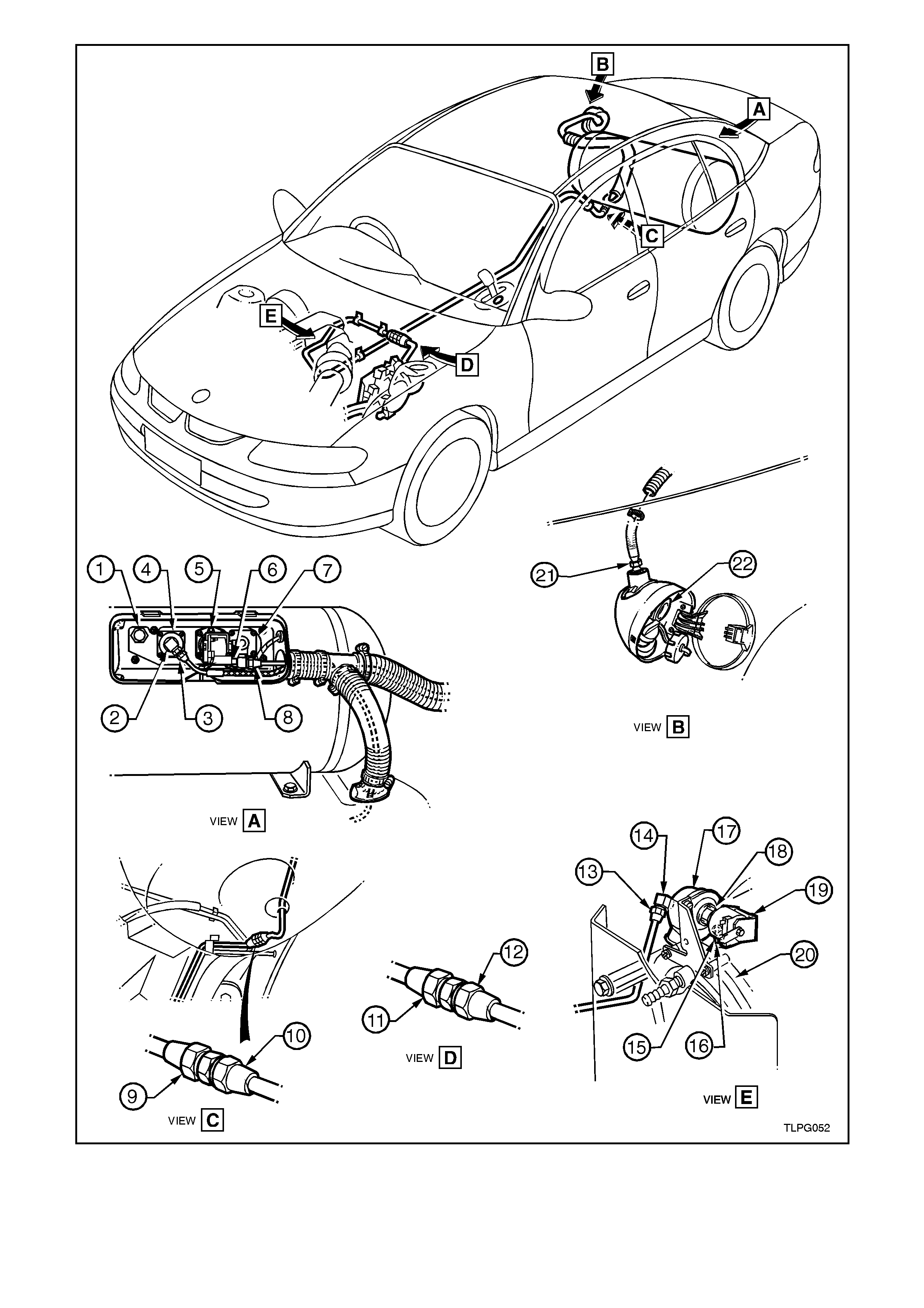
Figure 2-8
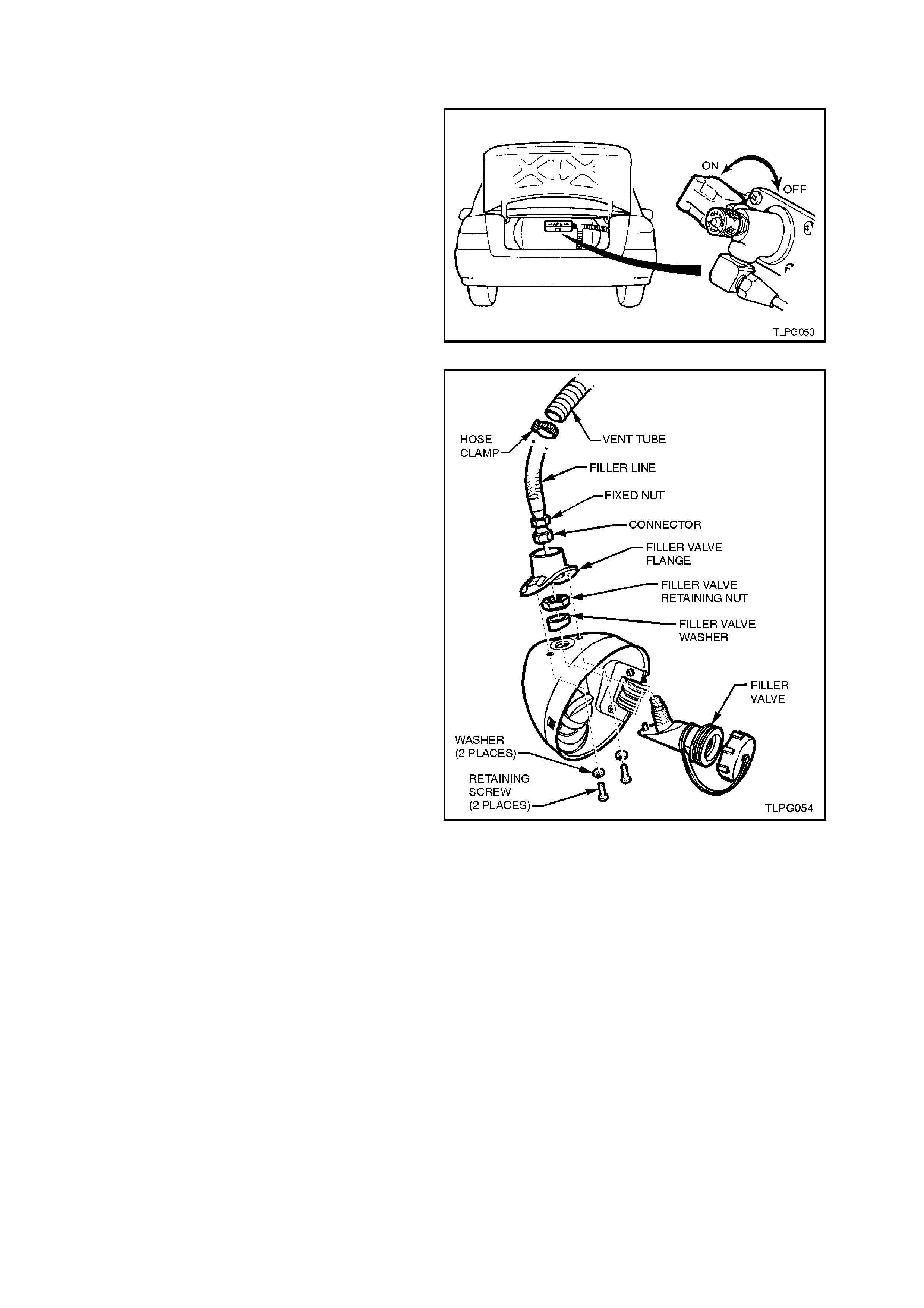
2.4 FILLER VALVE
REMOVE
1. Park the vehic le in a well ventilated area, away
from any ignition source.
2. Drain the LPG service lines, refer
2.1 DRAINING THE SERVICE LINES in this
Section.
3. Ensure the manual service valve is turned
'OFF' and the battery earth lead is
disconnected.
4. Remove the rear c ompartment car pet f r om the
right hand side wheelhouse to gain access to
the inner side of the f iller valve ass embly, ref er
to Section 1A1 BODY.
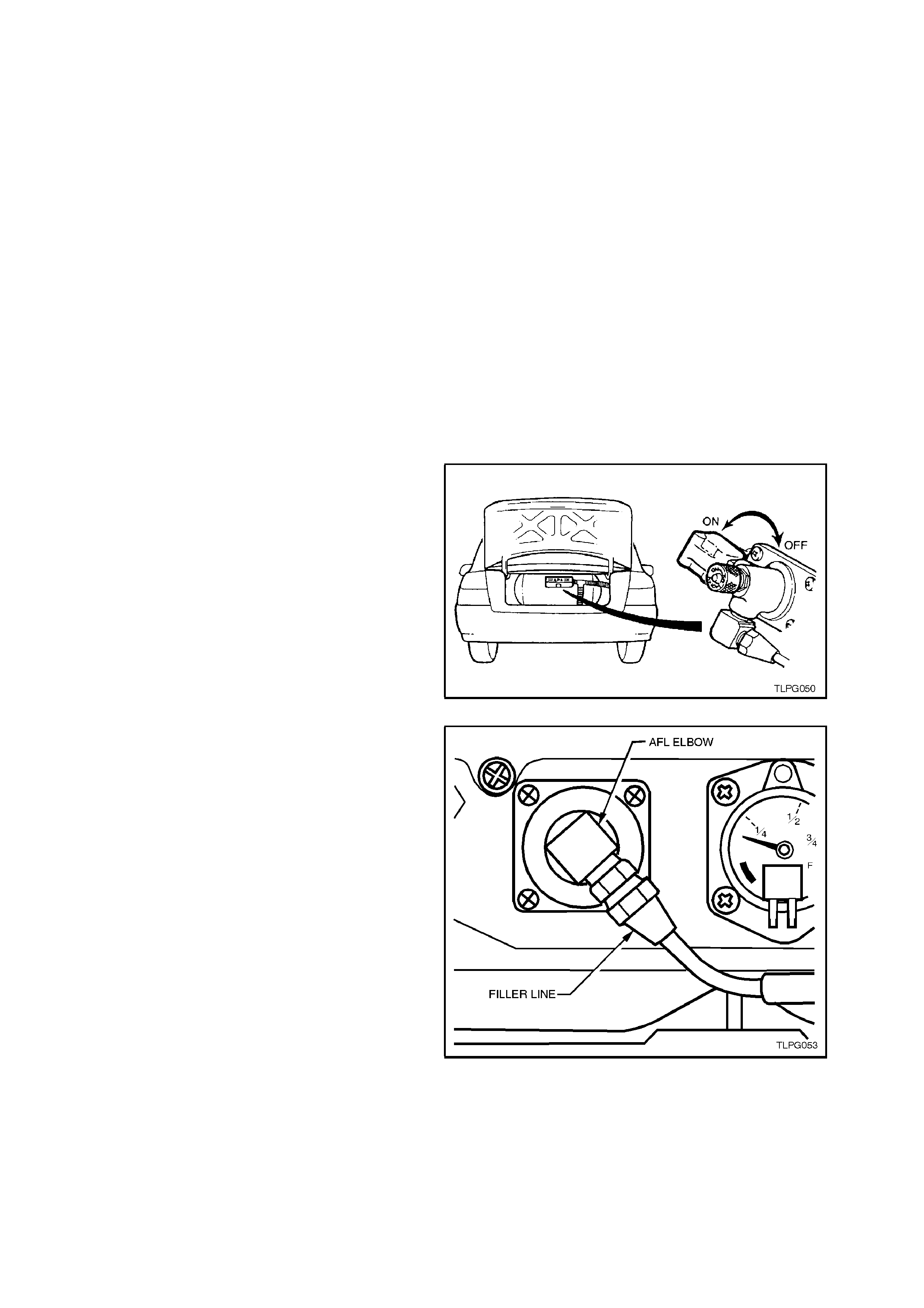
5. Loosen the vent tube hose clamp at the inner
side of the filler valve and pull vent tube away
from the filler valve flange to gain access to
the filler line connector.
6. Crack open the filler line connector from the
filler valve and allow the residual gas to
escape.
7. Unscrew the filler line connector from the filler
valve and move filler line and vent tube away
from the filler valve flange.
CAUTION:
The filler line may contain LPG under pressure.
8. Remove the two screws securing the filler
valve flange to the rear quarter panel and
using a wide bladed screwdriver, carefully
prise the filler valve flange from the rear
quarter panel.
NOTE:
The filler valve flange is adher ed to the rear quar ter
panel with silicon.
9. Loosen and remove filler valve retaining nut
and remove filler valve.
Figure 2-9
Figure 2-10
REINSTALL
1. Clean filler valve and filler line connector
mating threads.
2. Install filler valve and tighten filler valve
retaining nut to the correct torque
specification.
FILLER VALVE RETAINING NUT
TO FILLER VALVE 50.0 - 60.0 Nm
TORQUE SPECIFICATION
3. Apply silicon sealer, to Holden specification
HN 1886, to mating surface and all voids of
filler valve flange. Install filler valve flange and
tighten retaining screws to the correct torque
specification.
FILLER VALVE FLANGE
RETAINING SCREW 7.0 - 9.0 Nm
TORQUE SPECIFICATION
4. Apply Loctite 577 sealant to filler valve
threads, connect filler line connector to filler
valve and tighten to the correct torque
specification.
FILLER LINE CONNECTION TO
FILLER VALVE 12.0 - 18.0 Nm
TORQUE SPECIFICATION
5. Reconnect battery earth lead.
6. Leak test LPG system, refer to
2.3 LEAK TESTING in this Section.
7. Reinstall vent tube to filler valve flange.
8. Reinstall rear compartment carpet, refer to
Section 1A1 BODY.
2.5 FILLER LINE
REMOVE
1. Park the vehic le in a well ventilated area, away
from any ignition source.
2. Drain the LPG service lines, refer
2.1 DRAINING THE SERVICE LINES in this
Section.
3. Ensure the manual service valve is turned
'OFF' and the battery earth lead is
disconnected.
Figure 2-11
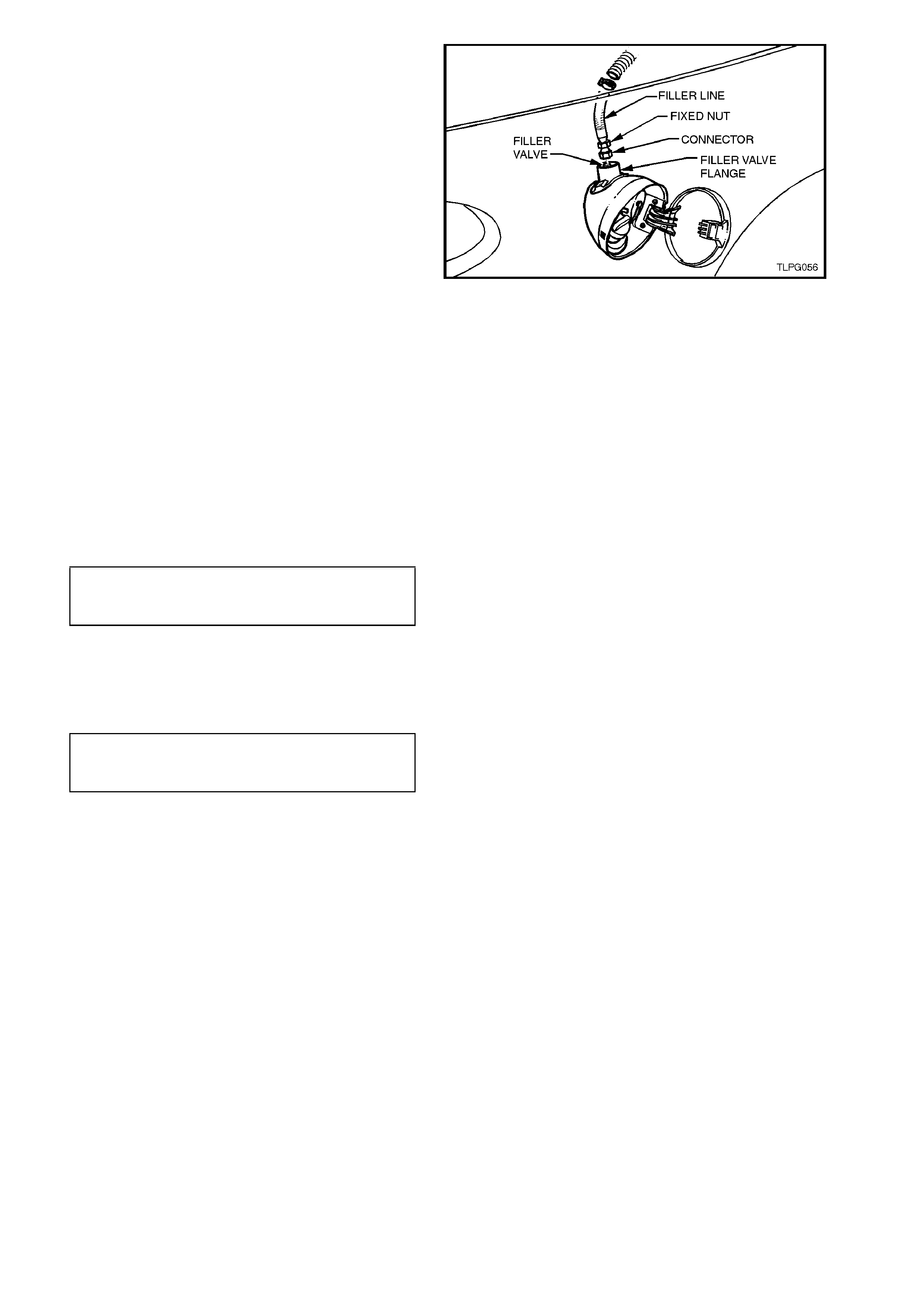
4. From inside the LPG cylinder valve box, while
holding AFL elbow, crack open filler line to
AFL elbow connector and allow residual LPG
to escape.
CAUTION:
The filler line will contain LPG under pressure.
Once all the LPG in the line has dispersed,
unscrew filler line connector completely from
AFL elbow.
Figure 2-12
5. Disconnect vent tube from vent tube joiner at
the right side of joiner, refer to Fig 2-13.
Figure 2-13
6. Remove the rear c ompartment car pet f r om the
right hand side wheelhouse to gain access to
the inner side of the f iller valve ass embly, ref er
to Section 1A8 BODY.
7. Loosen vent tube hose clam p at the inner side
of the filler valve and pull vent tube from filler
valve flange to gain access to the filler line
connector.
8. Loosen and unscrew the filler line connector
from the filler valve.
9. Move filler line and vent tube away from filler
valve flange and pull filler line out of vent tube
(at filler valve end) until filler line is clear of the
vent tube connector.
10. W ithdraw filler line from vent tube at vent tube
connector.
Figure 2-14
REINSTALL
Reinstallation of the filler line is the reverse of the
removal procedure, noting the following:
1. Ensure the filler line mating threads, filler valve
threads, and AFL valve threads are free of
sealant or contaminants.
2. Apply Loctite 577 sealant to filler valve threads
and tighten filler line to filler valve to the correct
torque specification
FILLER LINE CONNECTOR TO
FILLER VALVE 12.0 - 18.0 Nm
TORQUE SPECIFICATION
3. Apply Loctite 577 sealant to AFL valve threads
and tighten filler line to AFL valve to the correct
torque specification
FILLER LINE CONNECTOR
TO AFL VALVE 12.0 - 18.0 Nm
TORQUE SPECIFICATION
4. Leak test LPG system, refer to 2.3 LEAK
TESTING in this Section.
2.6 LPG CYLINDE R
CAUTION:
AFTER ANY VALVE OR COMPONENT HAS
BEEN REMOVED AND REINSTALLED TO THE
LPG CYLINDER, THE LPG CYLINDER M UST BE
PRESSURE AND LEAK TESTED IN
ACCORDANCE WITH CURRENT AUSTRALIAN
STANDARD AS2030.1 BEFORE THE LPG
CYLINDER IS REFITTED TO THE VEHICLE.
NOTE:
THE LPG CYLINDER M UST BE PRESSURE AND
LEAK TESTED ACCORDING TO THE LAWS OF
THE STATE IN WHICH THE VEHICLE IS
REGISTERED. THIS TESTING MUST ONLY BE
DONE BY A LICENSED INSTALLER OR
TESTING STATION.
REMOVE
1. Park the vehicle in a well ventilated area, away
from any ignition source.
2. Drain the service lines of LPG, refer
2.1 DRAINING THE SERVICE LINES in this
Section.
3. Ensure the manual service valve is turned
'OFF' and the battery earth lead is
disconnected.
4. Unload the LPG cylinder of LPG, refer
2.2 LPG CYLINDER UNLOADING
PROCEDURE in this Section.
Figure 2-15
5. From inside the LPG cylinder valve box, while
holding AFL elbow, crack open filler line to AFL
elbow connector and allow residual LPG to
escape.
CAUTION:
The filler line will contain LPG under pressure.
Once all the LPG in the line has dispersed,
unscrew filler line connector completely from
AFL elbow.
6. Remove the rear service line, refer
2.13 SERVICE LINES in this Section.
Figure 2-16
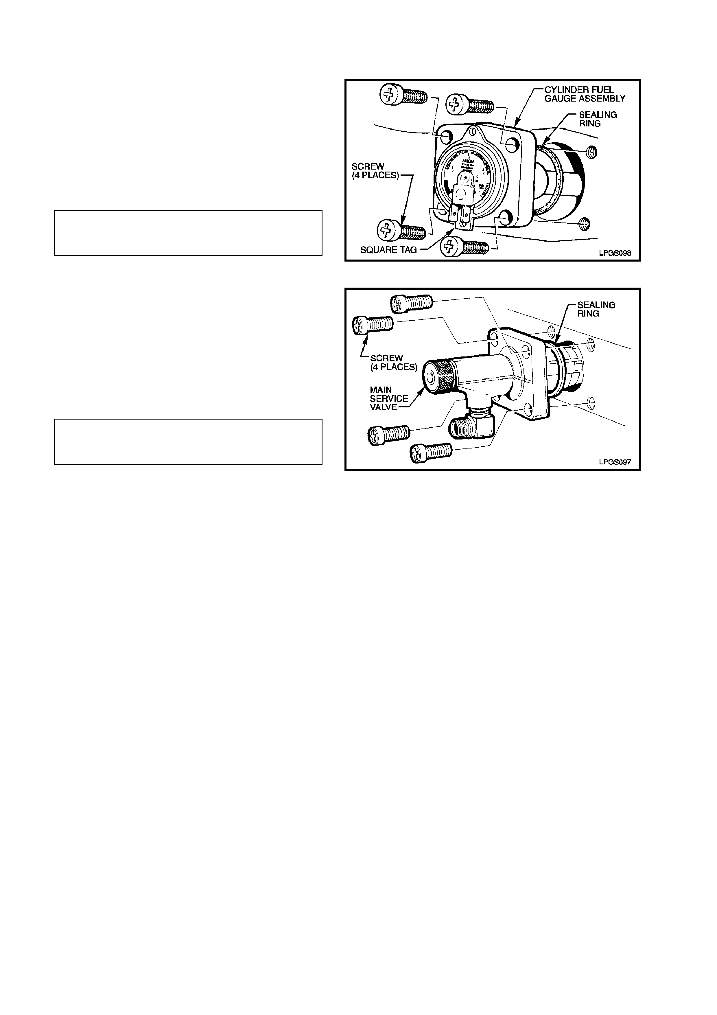
7. Disconnect LPG body harness connector from
LPG cylinder harness connector, refer to Fig 2-
17.
Figure 2-17
8. Remove rear seat back, refer
Section 1A7 SEATS AND SEA T BELTS.
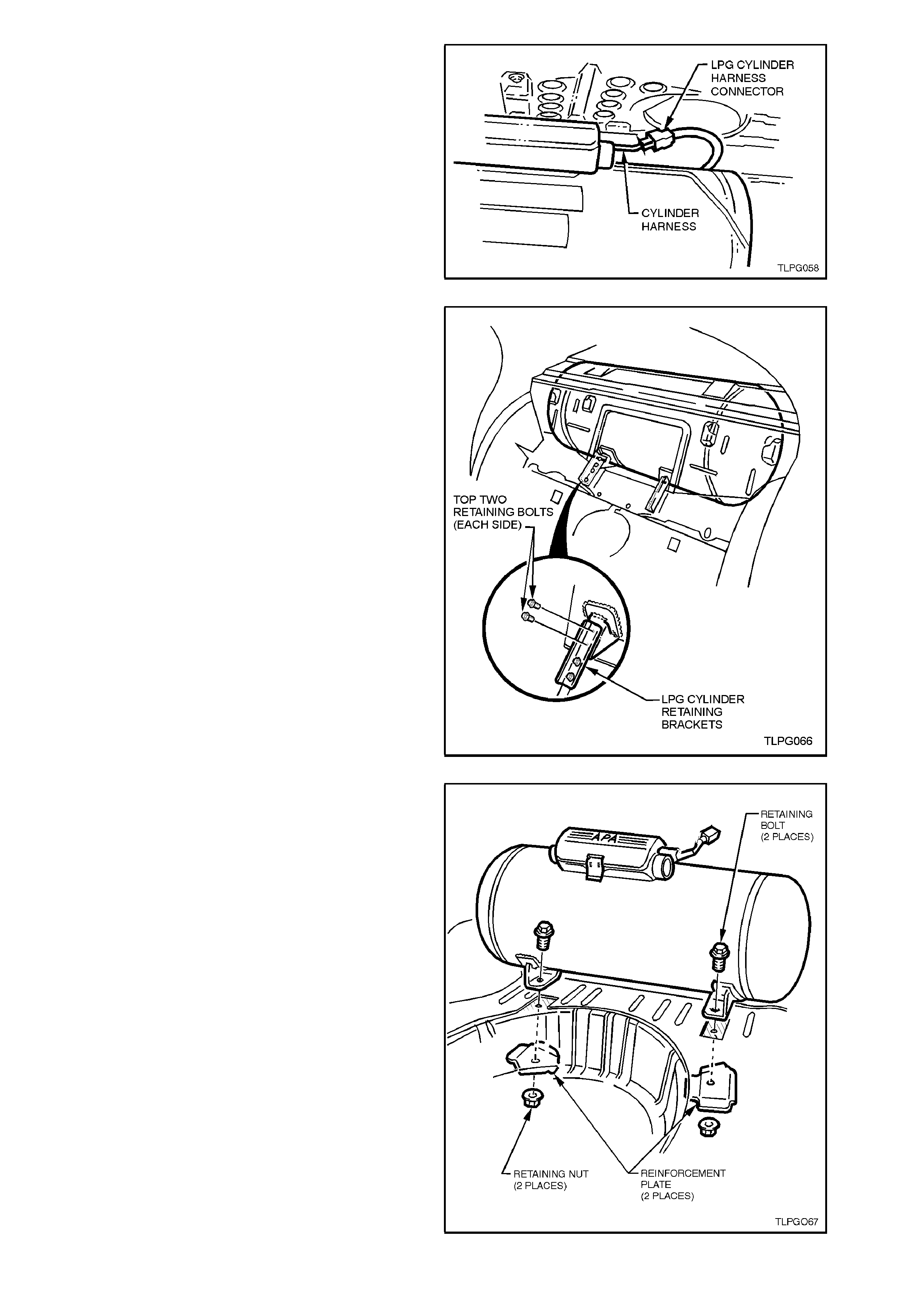
9. Remove the top two retaining bolts on each
side of the LPG cylinder retaining brackets,
refer Fig 2-18.
Figure 2-18
10. Fold back rear com partment car pet away from
LPG cylinder rear mounting points.
11. The following operation requires the aid of an
assistant.
From beneath the vehicle, remove the two
LPG cylinder retaining nuts and reinforcement
plates while the assistant holds the mounting
bolts in the luggage compartment from
rotating.
12. Remove LPG cylinder from rear compartment.
Figure 2-19

REINSTALL
Reinstallation of the LPG cylinder is the reverse of
the removal procedure, noting the following:
1. Ensure the two LPG cylinder reinforcement
plates are installed and all fasteners are
tightened to the correct torque specification.
FRONT LPG CYLINDER
RETAINING BOLTS 10.0 - 12.0 Nm
TORQUE SPECIFICATION
REAR LPG CYLINDER
RETAINING NUT 70.0 - 90.0 Nm
TORQUE SPECIFICATION
2. Clean rear service line mating threads on
solenoid and manual service valve assembly,
intermediate to rear service line joiner, both
rear service line connectors, AFL valve and
filler line connector.
3. Apply Loctite 577 sealant to intermediate to
rear service line joiner threads, ensuring that
flared surfaces are free of sealant and
contaminants. Assemble rear service
connector to intermediate to rear service line
joiner, refer 2.13 SERVICE LINES, in this
Section.
4. Apply Loctite 577 sealant to solenoid and
manual service valve assembly threads,
ensuring that flared surfaces are free of
sealant and contaminants. Install rear service
line connector to solenoid and manual service
valve assembly, refer 2.13 SERVICE LINES,
in this Section.
5. Tighten both rear service line connectors to
the correct torque specification.
REAR SERVICE LINE
CONNECTORS
TORQUE SPECIFICATION 12.0 - 18.0 Nm
6. Apply Loctite 577 sealant to LPG cylinder AF L
elbow threads, ensuring that flared surfaces
are free of sealant and contaminants. Install
filler line c onnector to LPG c ylinder AFL elbow
and tighten filler line connector to the correct
torque specification.
FILLER LINE CONNECTOR
TO AFL ELBOW SCREW 12.0 - 18.0 Nm
TORQUE SPECIFICATION
7. Leak test LPG system, refer
2.3 LEAK TESTING in this Section.
2.7 SOLENOID AND MANUAL SERVICE VALVE ASSEMBLY
CAUTION:
If at any time the manual service valve
becomes stuck, no service operations on the
system will be possible. Should for any reason
the valve stick, the cylinder will have to be
returned to the cylinder manufacturer (APA) to
arrange a replacement cylinder.
Contact: APA Industries
190 Colchester Road
Kilsyth
Victoria 3137
Phone -(03) 9720 2855
Fax - (03) 9761 4495
Email [email protected]M.AU
NOTE:
The m anual service valve is three valves in one. A
manual shut off valve, an electrically operated
solenoid valve and an excess flow valve.
EXCESS-FLOW VALVE TEST
CAUTION:
ENSURE THERE ARE NO NAKED FLAMES OR
OTHER SOURCES OF IGNITION IN THE
VICINITY.
ENSURE ALL SAFETY PRECAUTIONS LISTED
AT THE FRONT OF THIS SECTION ARE
ADHERED TO WHILE PERFORMING THIS
TEST.
DO NOT PERFORM THIS TEST ON A VEHICLE
WITH A HOT ENGINE.
1. Park the vehic le in a well ventilated area, away
from any ignition source.
2. Drain the service lines of LPG, refer
2.1 DRAINING THE SERVICE LINES in this
Section.
3. Ensure the manual service valve is turned
'OFF' and the battery earth lead is
disconnected.
Figure 2-20
4. Remove the smart unit and solenoid
assembly, including the solenoid valve, refer to
2.8 SMART UNIT AND SOLENOID VALVE, in
the Section.
5. Reinstall the solenoid sleeve (with o-ring)
WITHOUT the solenoid valve.
Figure 2-21
6. Disconnect the front service line at the lockoff
valve to allow LPG to flow from this line when
the manual service valve is opened, refer to
2.13 SERVICE LINES in this Section.
7. Quickly open the manual service valve and
listen for the sound of the excess-flow valve
operating.
8. If the excess flow valve is operating correctly,
it can be heard to click shut when the manual
service valve is opened quickly.
CAUTION:
TO ENSURE THAT THE LEAST AMOUNT OF
LPG ESCAPES INTO TH E ATMO SPHERE, O NLY
OPEN THE M ANUAL SERVICE VALVE FOR T HE
MINIMAL TIME POSSIBLE TO PERFORM THIS
TEST.
Figure 2-22
9. Reinstall the front service line to the lockoff
valve as per the reinstallation procedure in
2.13 SERVICE LINES in this Section.
10. Remove the solenoid sleeve on the manual
service valve. Reinstall the solenoid valve,
solenoid sleeve and smart unit as per the
reinstallation procedure in
2.8 SMART UNIT AND SOLENOID VALVE in
this Section.
11. Leak test LPG system, refer
2.3 LEAK TESTING in this Section.
12. Once installed, check vehicle operation on
LPG and petrol.
REPLACE
1. Park the vehic le in a well ventilated area, away
from any ignition source.
2. Drain the LPG service lines, refer
2.1 DRAINING THE SERVICE LINES in this
Section.
3. Ensure the manual service valve is turned
'OFF' and the battery earth lead is
disconnected.
4. Unload the LPG cylinder of LPG, refer to
2.2 LPG CYLINDER UNLOADING
PROCEDURE, steps 4 to 10, in this Section.
Figure 2-23
5. Disconnect LPG body harness connec tor from
LPG cylinder harness connector, refer to Fig
2-24.
Push LPG cylinder harness back into cylinder
valve box area.
Figure 2-24
6. If not already removed, remove solenoid
assembly from manual valve, refer
2.8 SMART UNIT AND SOLENOID VALVE in
this Section.
7. Unscrew the four manual service valve
attaching screws and remove manual service
valve from LPG cy linder, refer to Fig. 2-26.
8. Install new cylinder fuel gauge assembly to
LPG cylinder sealing ring, install cylinder fuel
gauge assembly taking care to install
assembly with gauge up the right way. Install
and tighten cylinder fuel gauge assembly
attaching screws to the correct torque
specification. Reconnect wiring harness
connectors to gauge terminals.
CYLINDER FUEL GAUGE ASSEMBLY
TO LPG CYLINDER ATTACHING 5.0 - 7.0 Nm
SCREW TORQUE SPECIFICATION
Figure 2-25
9. Install new manual service valve to LPG
cylinder sealing ring and the new manual
service valve assembly. Take care to install
the valve so that the valve elbow for the
service line connection is pointing In the
correct direction. Install and tighten the four
manual service valve attaching screws to the
correct torque specification.
MANUAL SERVICE VALVE TO LPG
CYLINDER ATTACHING SCREW 5.0 - 7.0 Nm
TORQUE SPECIFICATION
10. Reconnect LPG body wiring harness
connector to LPG cylinder harness connector
and reinstall grommet.
11. Reinstall rear service line, refer
2.13 SERVICE LINES in this Section.
12. Pressure and leak test LPG cylinder in
accordance with the current Australian
Standard AS2030.1
13. Carry out system leak testing, refer
2.3 LEAK TESTING in this Section.
Figure 2-26
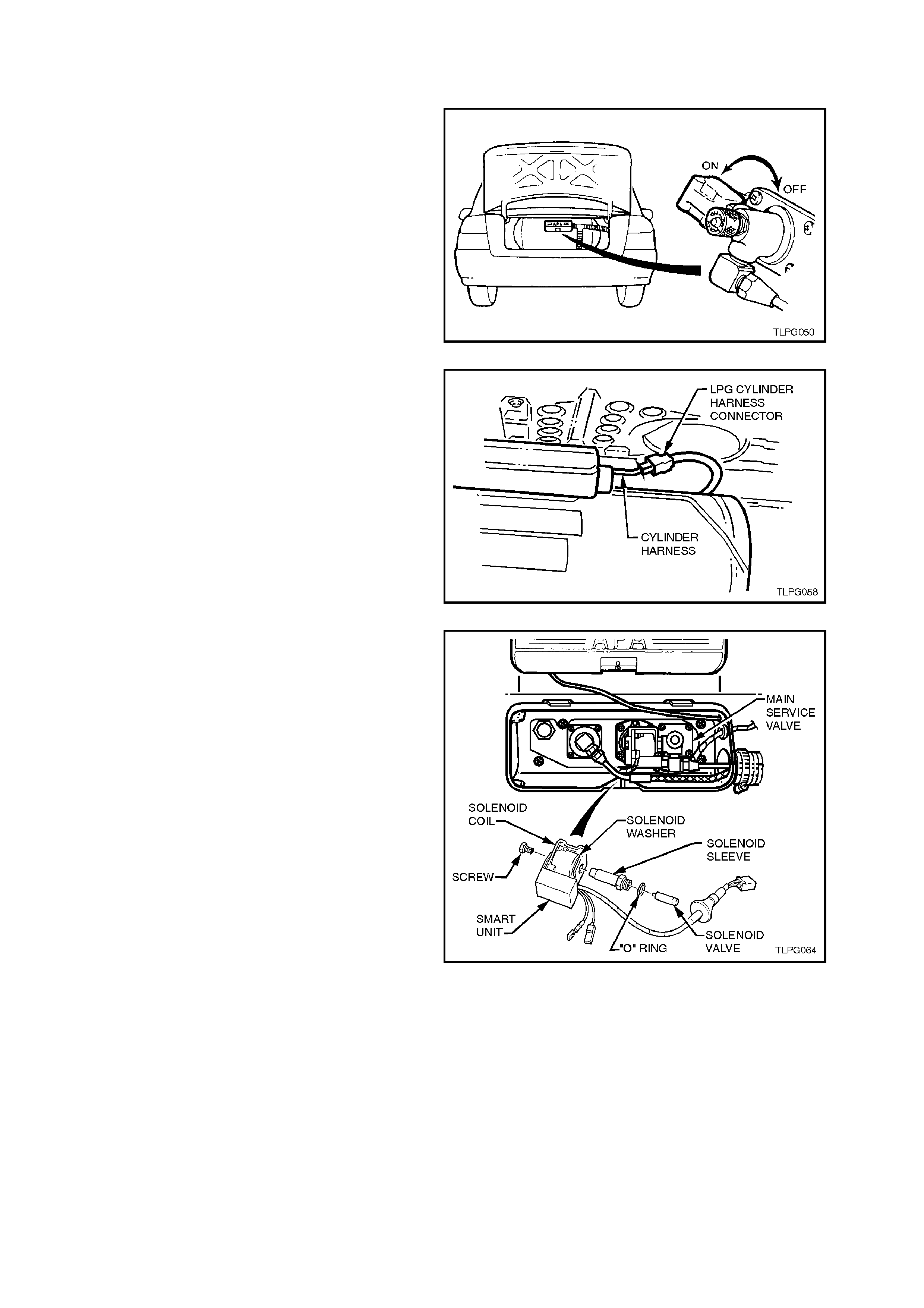
2.8 SMART UNIT AND SOLENOID VALVE
REMOVE
1. Park the vehic le in a well ventilated area, away
from any ignition source.
2. Drain the service lines of LPG, refer
2.1 DRAINING THE SERVICE LINES in this
Section.
3. Ensure the manual service valve is turned
'OFF' and the battery earth lead is
disconnected.
Figure 2-27
4. Disconnect LPG cylinder harness connector
from LPG cylinder harness connector.
Push LPG cylinder harness back into cylinder
valve box area.
Figure 2-28
5. Remove smart unit retaining screw from end
of the assembly.
6. Slide the smart unit and solenoid coil from the
manual service valve.
7. Loosen and remove solenoid sleeve from
manual service valve, ensuring that solenoid
valve is also removed.
Separate solenoid valve from the sleeve.
Discard the solenoid sleeve to manual service
valve 'O' ring.
8. Disconnect LPG cylinder harness connectors
from cylinder contents gauge terminals.
NOTE:
To aid in disconnection the connectors from the
cylinder contents gauge, remove the contents
gauge (two screws) from the LPG cylinder and then
disconnect the harness connectors, refer
2.12 CYLINDER FUEL GAUGE ASSEMBLY -
CONTENTS GAUGE in this Section for additional
information on removing the contents gauge.
Figure 2-29

REINSTALL
Reinstallation of the smart unit and solenoid coil to
the manual service valve is the reverse of removal
procedures, noting the following points:
1. Ensure new 'O' ring is fitted to solenoid sleeve.
2. Tighten solenoid sleeve to the manual service
valve to the correct torque specification.
SOLENOID SLEEVE TO MANUAL
SERVICE VALVE
TORQUE SPECIFICATION 15 - 18 Nm
3. Once installed, ensure that the smart unit
retaining screw is tightened to the correct
torque specification.
SMART UNIT
RETAINING SCREW
TORQUE SPECIFICATION 1 - 3 Nm
4. Leak test LPG system, refer to
2.3 LEAK TESTING in this Section.
5. Once installed, check vehicle operation on
LPG and petrol.
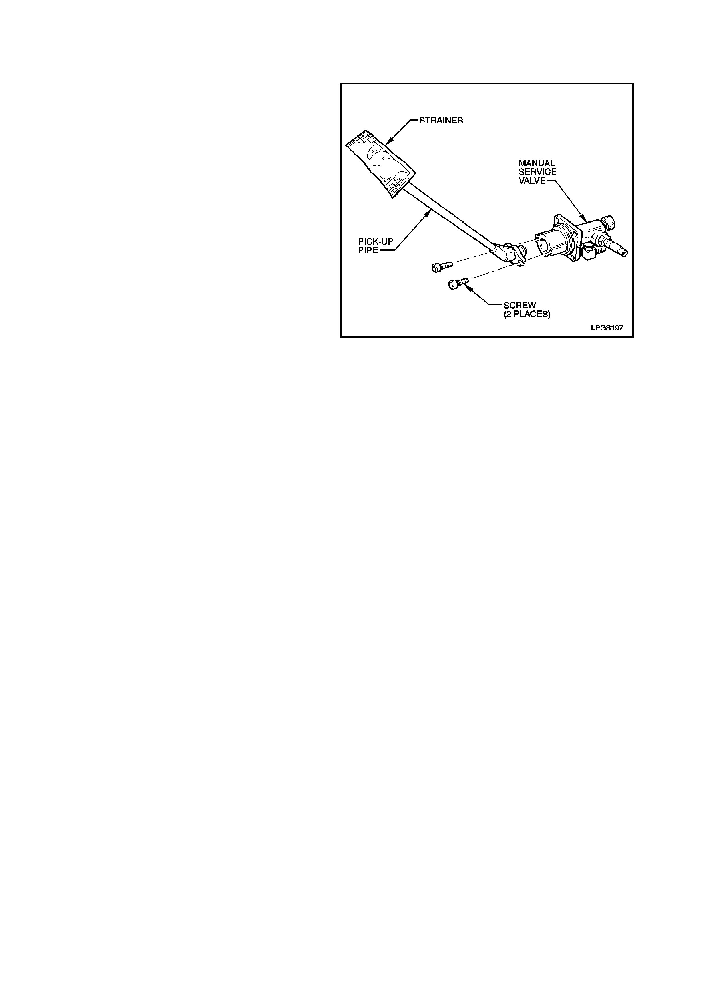
2.9 PICK-UP PIPE AND STRAINER
REMOVE
1. Remove the solenoid and manual service
valve, refer 2.7 SOLENOID AND MANUAL
SERVICE VALVE ASSEMBLY in this Section.
2. Remove the two screws retaining the LPG
pick-up pipe to the manual service valve and
twist the pick-up pipe out of manual service
valve.
REINSTALL
Reinstallation of the LPG pick-up pipe and strainer
is the reverse of the removal procedure, noting the
following point.
Ensure the o-ring on the end of the pick-up pipe is
installed correctl y.
Figure 2-30
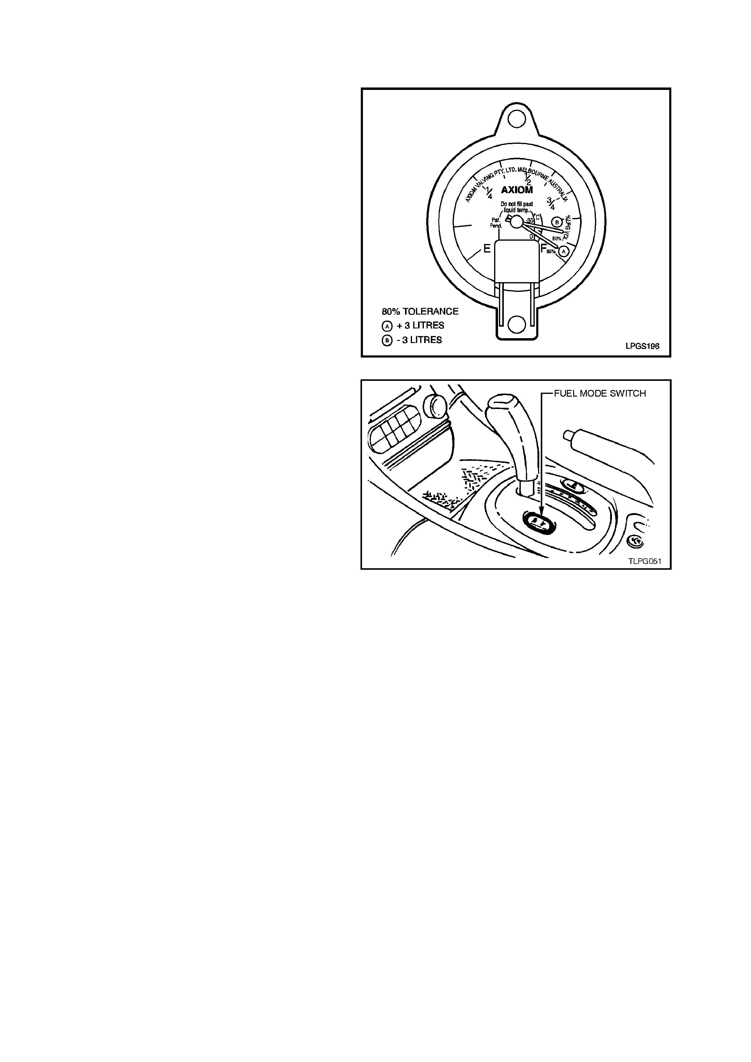
2.10 AUTOMATIC FILL LIMITER
TEST
NOTE:
When performing this test, the vehicle must be on
level ground.
1. Fill the LPG cylinder until the automatic fill
limiter cuts out.
2. Check the LPG c ontents gauge at the cylinder.
If the gauge reads approximately 80% +/- 3%
full, the automatic fill limiter is operating
correctly. If the gauge is reading outside this
specification, the remaining part of this
procedure must be performed:
NOTE:
It is advisable to bounce the vehicle a couple of
times when checking the gauge reading to remove
any hysteresis that may be present in the gauge
which would create an inaccurate reading.
Figure 2-31
3. The vehic le must be operated on LPG until the
LPG cylinder is completely empty of LPG.
NOTE 1:
The vehicle operator should be advised that the
vehicle should be operated on LPG until the LPG
cylinder is completely empty. Once emptied, the
vehicle should then be driven to the dealership on
petrol.
NOTE 2:
It is impossible to switch the f uel mode f rom LPG to
petrol while the vehicle is moving. Therefore, the
vehicle operator must select a location where
running out of LPG will not present a traffic hazard
or danger.
4. Check the fuel contents gauge on the LPG
cylinder is displaying empty and the engine will
not start with the fuel mode switch in the 'LPG '
position.
5. Fill the LPG cylinder and note the number of
litres taken.
The LPG cylinder 'fallible' capacity is 74 litres ± 2
litres.
Figure 2-32
NOTE 3:
If at any time the LPG cylinder is overfilled, the
contents of the cylinder must be reduced to a safe
level by either running the engine NON-STOP on
LPG for suf fic ient tim e to consum e the ex cess fuel,
or rem oving the exces s fuel f rom the LPG cylinder,
refer 2.2 LPG CYLINDER UNLOADING
PROCEDURE in this Section.
NOTE 4:
If the LPG cylinder fallible capacity is within the
specified limits yet the initial test failed (the gauge
was reading outside the specified parameters),
check the calibration of the contents gauge. Refer
to 2.12 CYLINDER FUEL GAUGE ASSEMBLY
(Contents Gauge) in this Section.
REPLACE
The automatic fill limiter should only be replaced if
it proves to be faulty.
1. Park the vehic le in a well ventilated area, away
from any ignition source.
2. Drain the LPG service lines, refer
2.1 DRAINING THE SERVICE LINES in this
Section.
3. Ensure the manual service valve is turned
'OFF' and the battery earth lead is
disconnected.
4. Unload the LPG cylinder of LPG, refer 2.2
LPG CYLINDER UNLOADING PROCEDURE
in this Section. Figure 2-33
5. From inside the LPG cylinder valve box, while
holding AFL elbow, crack open filler line to
AFL elbow connector and allow residual LPG
to escape.
CAUTION:
The filler line will contain LPG under pressure.
Once all the LPG in the line has dispersed,
unscrew filler line connector completely from
AFL elbow.
Figure 2-34
6. Unscr ew the four autom atic fill lim iter retaining
screws and remove automatic fill limiter from
the LPG cylinder.
Figure 2-35
7. Install new automatic fill lim iter to LPG cylinder
sealing ring and the autom atic fill limiter. Tak e
care to install the automatic fill lim iter the right
way up. Install and tighten the four automatic
fill limiter attaching screws to the correct
torque specification.
AUTOMATIC F ILL LIMITER TO LPG
CYLINDER ATTACHING SCREW 5.0 - 7.0 Nm
TORQUE SPECIFICATION
Figure 2-36
8. Install new cylinder fuel gauge assembly to
LPG cylinder sealing ring, install cylinder fuel
gauge assembly taking care to install
assembly with gauge up the right way. Install
and tighten cylinder fuel gauge assembly
attaching screws to the correct torque
specification. Reconnect wiring harness
connectors to gauge terminals.
CYLINDER FUEL GAUGE ASSEMBLY
TO LPG CYLINDER ATTACHING 5.0 - 7.0 Nm
SCREW TORQUE SPECIFICATION
Figure 2-37
9. Apply Loctite 577 sealant to filler line
connector threads, ensuring that flared
surf aces ar e f ree of sealant and contaminants .
Connect filler line to AFL elbow and tighten to
the correct torque specification.
FILLER LINE CONNECTOR TO
AFL ELBOW SCREW 12.0 - 18.0 Nm
TORQUE SPECIFICATION
10. Pressure and leak test LPG cylinder in
accordance with the current Australian
Standard AS2030.1.
11. Carry out system leak testing, refer
2.3 LEAK TESTING in this Section.
Figure 2-38
2.11 PRESSURE RELIEF VALVE
NOTE:
The press ure relief valve should only be replaced if
it proves to be leaking.
REPLACE
1. Park the vehic le in a well ventilated area, away
from any ignition source.
2. Drain the service lines of LPG, refer
2.1 DRAINING THE SERVICE LINES in this
Section.
3. Ensure the manual service valve is turned
'OFF' and the battery earth lead is
disconnected.
4. Unload the LPG cylinder of LPG, refer
2.2 LPG CYLINDER UNLOADING
PROCEDURE in this Section.
5. Using a 1 1/16 inch socket and breaker bar,
loosen and remove the pressure relief valve
from the LPG cy linder.
NOTE:
It may be necessary to install a tube over the end of
the breaker bar to enable greater leverage to be
applied for loosening the valve.
Figure 2-39
6. Ensure that new relief valve and LPG cylinder
mating threads are clean.
Apply an anaerobic sealant, such as
Permabond A129 to the valve threads and a
small amount to the cylinder mating threads.
7. Tighten pressure relief valve to the correct
torque specification.
PRESSURE RELIEF VALVE
TO LPG CYLINDER 60 - 65 Nm
TORQUE SPECIFICATION
8. Install new cylinder fuel gauge assembly to
LPG cylinder sealing ring, install cylinder fuel
gauge assembly taking care to install
assembly with gauge up the right way. Install
and tighten cylinder fuel gauge assembly
attaching screws to the correct torque
specification.
CYLINDER FUEL GAUGE ASSEMBLY
TO LPG CYLINDER ATTACHING 5.0 - 7.0 Nm
SCREW TORQUE SPECIFICATION
9. Pressure and leak test LPG cylinder in
accordance with the current Australian
Standard AS2030.1.
10. Carry out system leak testing, refer
2.3 LEAK TESTING in this Section.
Figure 2-40
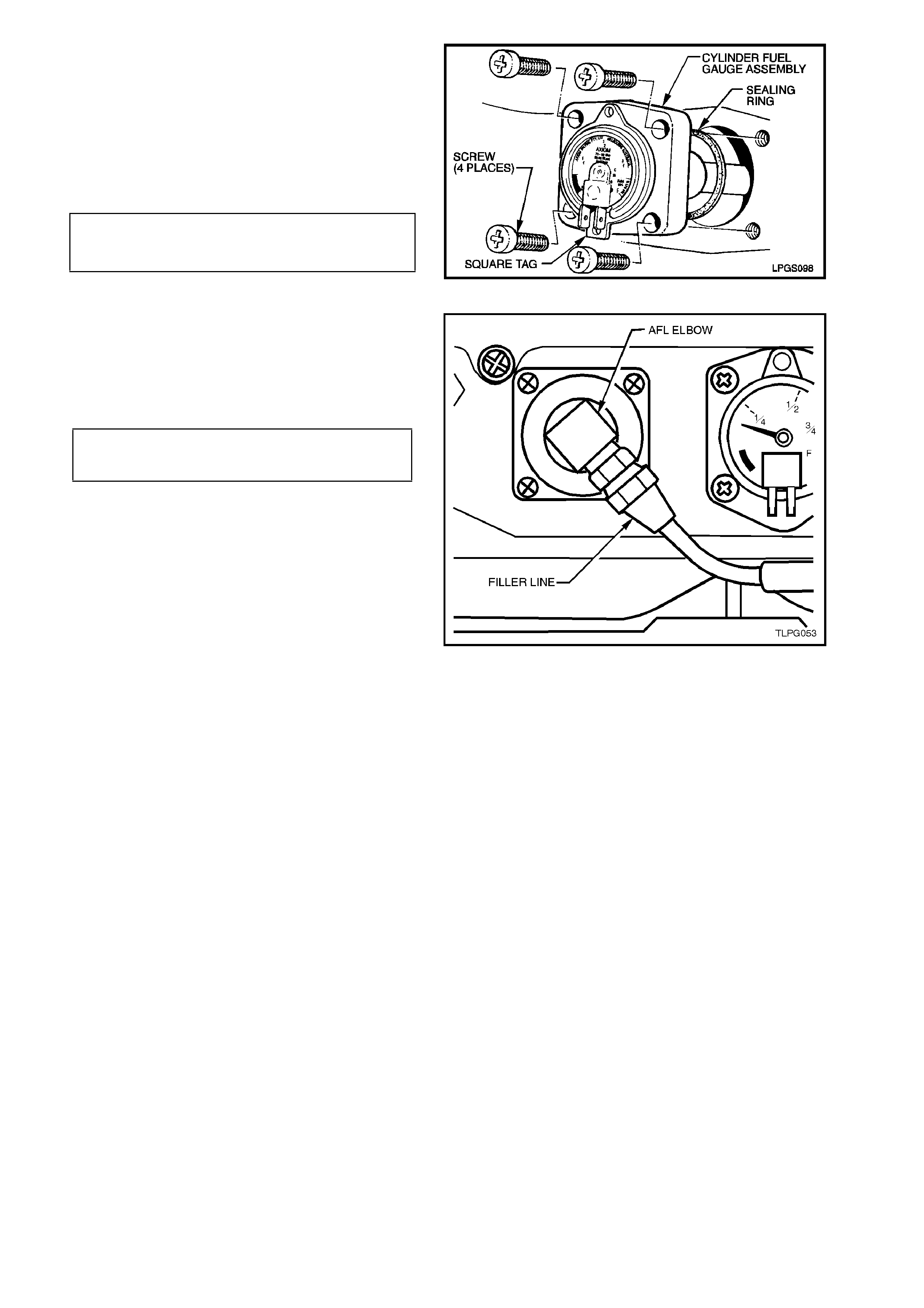
2.12 CYLINDER FUEL GAUGE ASSEMBLY
REPLACE
1. Park the vehic le in a well ventilated area, away
from any ignition source.
2. Drain the LPG service lines, refer
2.1 DRAINING THE SERVICE LINES in this
Section.
3. Ensure the manual service valve is turned
'OFF' and the battery earth lead is
disconnected.
4. Unload the LPG cylinder of LPG, refer
2.2 LPG CYLINDER UNLOADING
PROCEDURE in this Section.
Figure 2-41
5. Install new cylinder fuel gauge assembly to
LPG cylinder sealing ring, install cylinder fuel
gauge assembly taking care to install
assembly with gauge up the right way. Install
and tighten cylinder fuel gauge assembly
attaching screws to the correct torque
specification. Reconnect wiring harness
connectors to gauge terminals.
CYLINDER FUEL GAUGE ASSEMBLY
TO LPG CYLINDER ATTACHING 5.0 - 7.0 Nm
SCREW TORQUE SPECIFICATION
6. Pressure and leak test LPG cylinder in
accordance with the current Australian
Standard AS2030.1.
7. Carry out system leak testing, refer
2.3 LEAK TESTING in this Section.
Figure 2-42
CONTENTS GAUGE
REMOVE
1. Ensure the manual service valve is turned
'OFF' and the battery earth lead is
disconnected.
2. Remove the smart unit and solenoid valve
from the manual service valve, refer to
2.8 SMART UNIT AND SOLENOID VALVE in
this Section.
Figure 2-43
3. Loosen the contents gauge retaining screws (2
places) and remove the contents gauge away
from the LPG cy linder.
4. Disconnect the wiring harness connectors
from the contents gauge terminals and remove
contents gauge.
CAUTION:
DO NOT REMOVE THE FOUR SCREWS
RETAINING THE CYLINDER FUEL GAUGE
ASSEMBLY TO LPG CYLINDER.
Figure 2-44
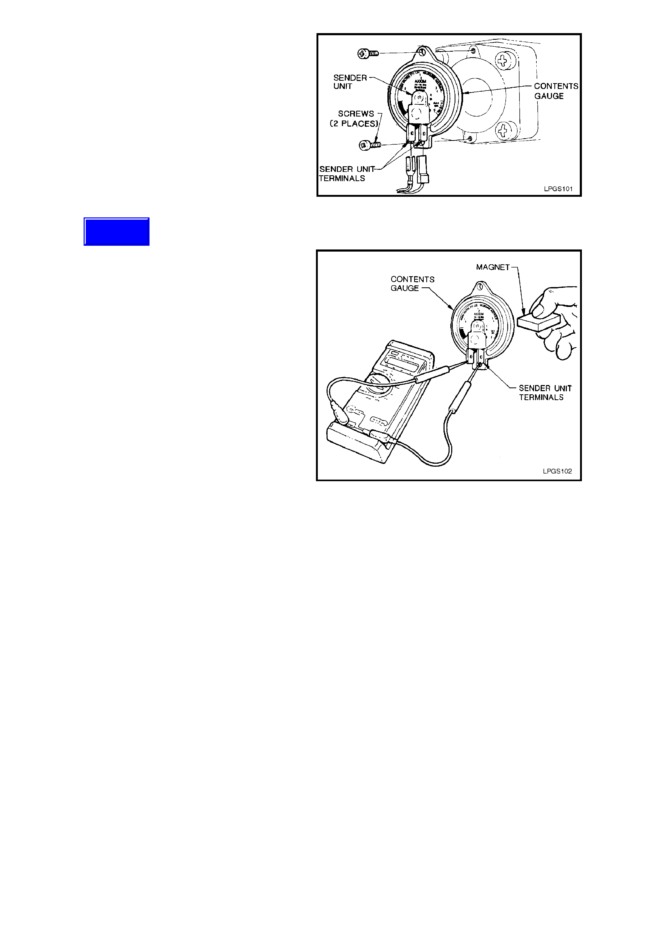
TEST
1. Connect an ohmmeter to the contents gauge
sender unit terminals.
2. Place a magnet behind the contents gauge,
rotate the magnet to change the position of
gauge needle, resistance should vary from
approximately 40 ohms empty to
approximately 255 ohms full.
If the needle does not move in relation to the
movement of the magnet or the resistance
does not meet specification, the contents
gauge must be replaced.
Figure 2-45
REINSTALL
1. Reconnect wiring harness connectors to
contents gauge terminals.
2. Install contents gauge to cylinder fuel gauge
assembly. Install and tighten contents gauge
attaching screws.
3. Reinstall the smart unit and solenoid valve on
the manual service valve, refer to
2.8 SMART UNIT AND SOLENOID VALVE in
this Section.
4. Reconnect battery earth lead.
Techline
2.13 SERVICE LINES
FRONT SERVICE LINE
REMOVE
1. Park the vehic le in a well ventilated area, away
from any ignition source.
2. Drain the service lines of LPG, refer
2.1 DRAINING THE SERVICE LINES in this
Section.
3. Ensure the manual service valve is turned
'OFF' and the battery earth lead is
disconnected.
Figure 2-46
4. Loosen and disconnect front service line
connector from LPG lockoff connection, refer
Fig. 2-47.
5. W hile holding f ront to inter mediate service line
joiner from turning, loosen and disconnect
front service line connector from joiner and
remove front service line.
Figure 2-47
REINSTALL
1. Clean mating thr eads of new fr ont s ervic e line,
LPG lockoff connection and front to
intermediate service line joiner connector.
2. Apply Loctite 577 sealant to LPG lockoff
connection and front to intermediate service
line joiner threads, ensuring that flared
surfaces are free of sealant and contaminants.
Assemble f ront s er vic e line connec tor s to LPG
lockoff connection and service line joiner and
tighten to the correct torque specification.
FRONT SERVICE LINE TO
LOCKOFF CONNECTOR
AND JOINER
TORQUE SPECIFICATION
12.0 - 15.0
Nm
NOTE:
Ensure the front service line does not chafe or
come in contact with the body or other
components.
3. Leak test LPG system, refer
2.3 LEAK TESTING in this Section.
INTERMEDIATE SERVICE LINE
The intermediate service line is incorporated into
the fuel and brake pipe harness assembly and,
therefore, not serviced separately. For additional
information, refer to Section 8A FUEL TANK.
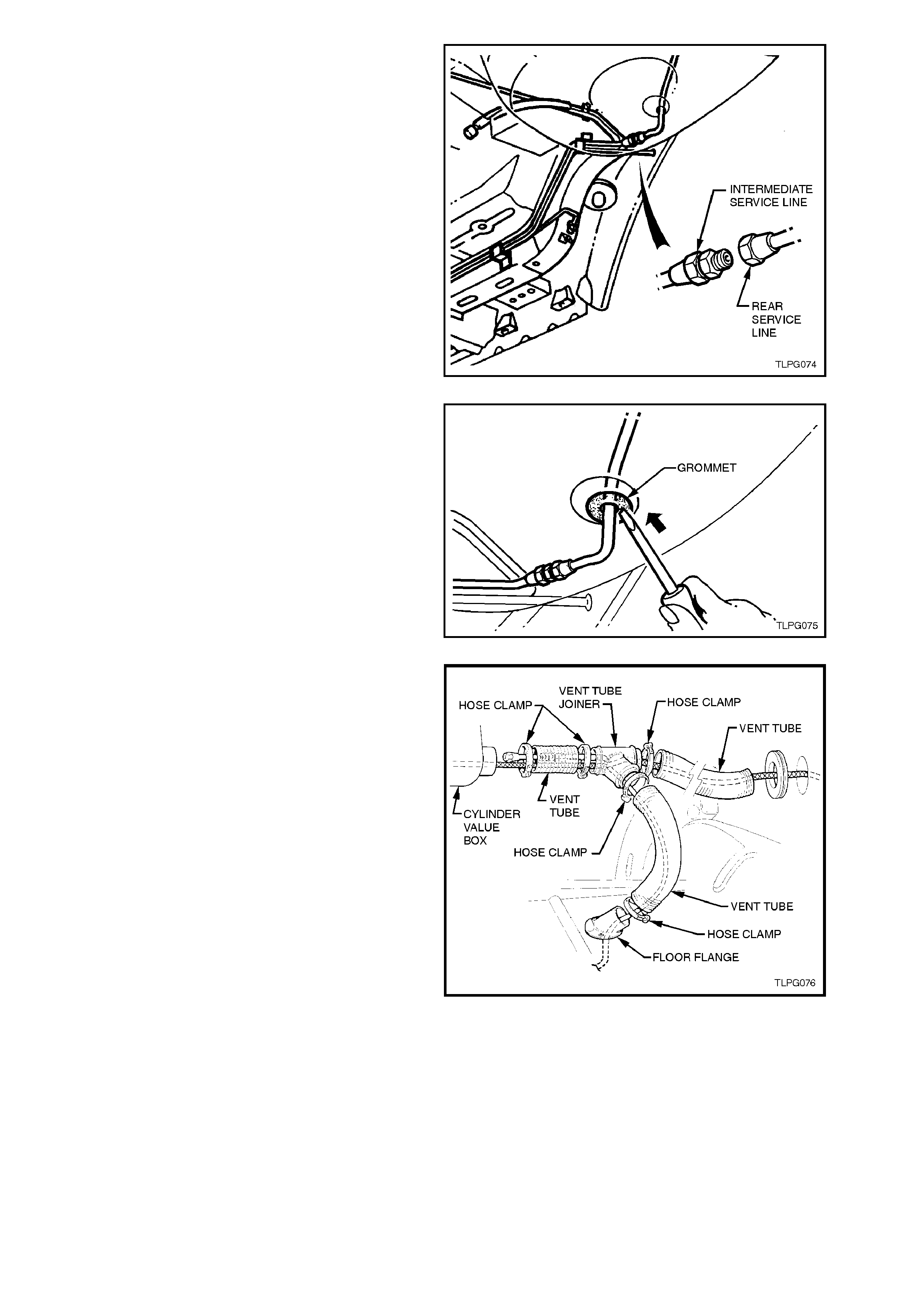
REAR SERVICE LINE
REMOVE
1. Park the vehicle in a well ventilated area, away
from any ignition source.
2. Drain the service lines of LPG, refer
2.1 DRAINING THE SERVICE LINES in this
Section.
3. Ensure the manual service valve is turned
'OFF' and the battery earth lead is
disconnected.
Figure 2-48
4. From inside the LPG cylinder valve box, while
holding AFL elbow, crack open filler line to
AFL elbow connector and allow residual LPG
to escape.
CAUTION:
The filler line will contain LPG under pressure.
Once all the LPG in the line has dispersed,
unscrew filler line connector completely from
AFL elbow.
Figure 2-49
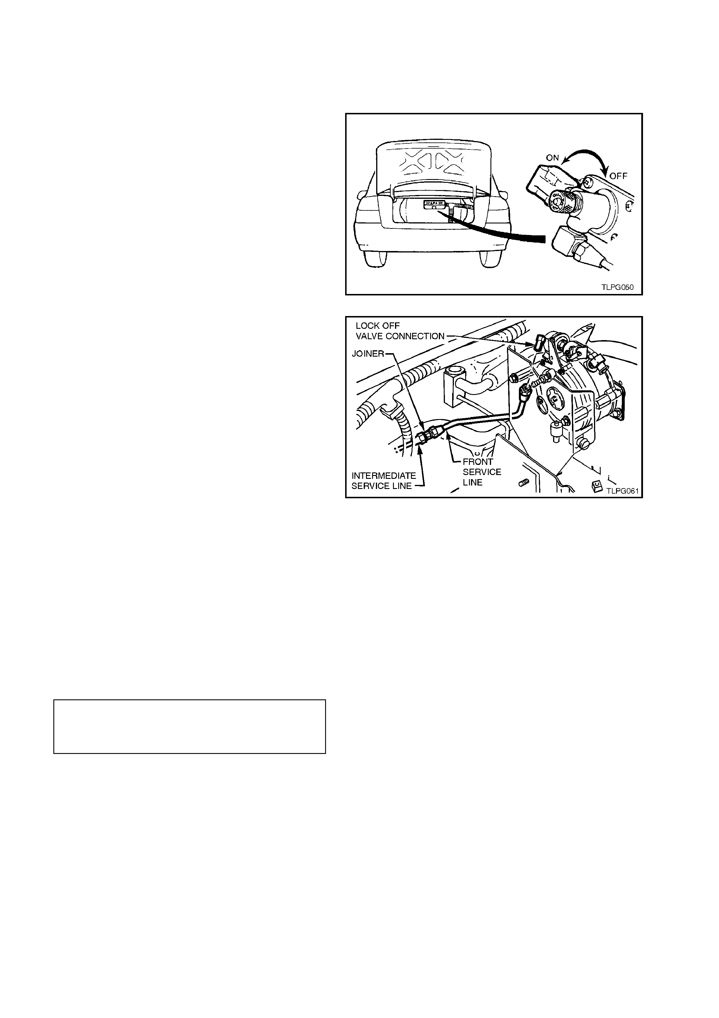
5. From inside the LPG cylinder valve box,
loosen and unscrew the rear service line
connector from solenoid and manual service
valve assembly, refer to Fig. 2-50.
Figure 2-50
6. Jack up rear of vehicle and support on safety
stands, refer to Section 0A GENERAL
INFORMATION for location of jacking points.
7. While holding the intermediate to rear service
line joiner from turning, loosen and unscrew
the rear service connector from the service
line joiner, refer Fig 2-51.
Figure 2-51
8. From under vehicle, push the rear service line
grommet up through body, refer Fig. 2-52.
9. Pull rear service line down until the rear
service line c onnector c lears the cylinder valve
box.
Figure 2-52
10. Disconnect vent tubes at: cylinder valve box,
vent tube joiner (3 clamps), and floor flange,
refer Fig. 2-53.
Remove vent tubes and vent tube joiner from
rear service line (piece by piece).
11. Remove rear service line through luggage
compartment.
Figure 2-53
REINSTALL
Reinstallation of the r ear service line is the reverse
of the removal procedure, noting the following:
1. Clean rear service line mating threads on
solenoid and manual service valve assembly,
intermediate to rear service line joiner, both
rear ser vice line connec tors, AF L valve m ating
threads and filler line connector.
2. Reinstall grommet into body before installing
the vent tubes.
3. Apply Loctite 577 sealant to intermediate to
rear service line joiner threads, solenoid and
manual service valve assembly threads, and
AFL valve threads, ensuring that flared
surfaces are free of sealant and contaminants.
4. Tighten rear service line and filler line
connections to the correct torque
specifications.
REAR SERVICE LINE
CONNECTIONS
TORQUE SPECIFICATION 12.0 - 18.0 Nm
FILLER LINE TO AFL
VALVE CONNECTION
TORQUE SPECIFICATION 12.0 - 18.0 Nm
NOTE:
Ensure the rear service line and filler lines do not
chafe or come in contact with the body or other
components.
5. Tighten vent tube hose clamps to the correct
torque specification.
VENT TUBE HOSE CLAMP
TORQUE SPECIFICATION 1.0 - 3.0
Nm
6. Leak test LPG system, refer
2.3 LEAK TESTING in this Section.
2.14 LPG LOCKOFF
REMOVE
1. Park the vehic le in a well ventilated area, away
from any ignition source.
2. Drain the service lines of LPG, refer
2.1 DRAINING THE SERVICE LINES in this
Section.
3. Ensure the manual service valve is turned
'OFF' and the battery earth lead is
disconnected.
Figure 2-54
4. Disconnect LPG lockoff harness connector
from LPG lockoff.
Figure 2-55
5. Loosen and disconnect front service line to
LPG lockoff connection.
Figure 2-56
6. Remove the two screws securing the
converter heat shield to the converter and
remove heat shield.
Figure 2-57
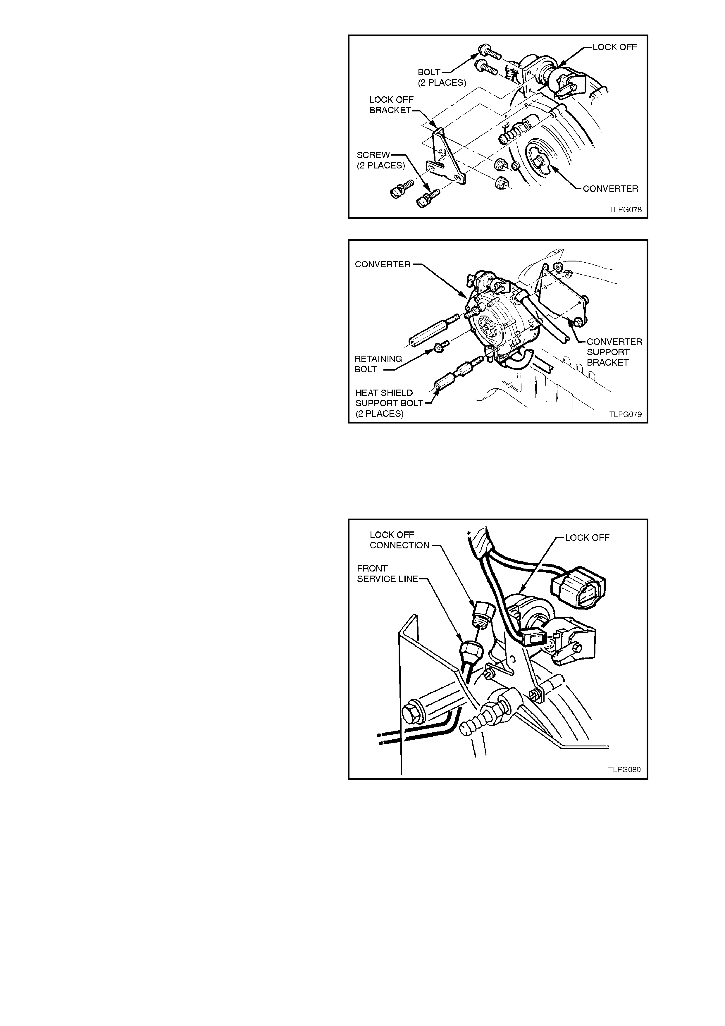
7. Remove the two screws securing the lockoff
bracket to the converter.
8. Remove the two sc rews and nuts s ecuring the
lockoff bracket to the lockoff and remove
lockoff bracket.
Figure 2-58
9. Loosen LPG lockoff outlet connection at
converter.
10. Loosen and remove the two heat shield
support bolts and the converter retaining bolt.
11. Lift up converter as far as possible and
unscrew LPG lockoff assembly from
converter.
12. Lower converter down into its mounting
position and temporally install converter to
converter support bracket.
Figure 2-59
FILTER ELEMENT REPLACEMENT
The following filter elem ent replacement procedure
can be performed with or without the LPG lockoff
installed to the converter.
CAUTION:
If conducting the following procedure with the
LPG lockoff still installed to the converter, the
service lines must first be d rained of LPG, ref er
2.1 DRAINING THE SERVICE LINES in this
Section.
NOTE:
A filter element replacement kit is available and
contains the following components:
LPG lockof f cup to valve body attaching scr ew
'O' ring.
LPG lockoff to valve body gasket.
Filter element.
Cup lid to valve body 'O' ring.
Bobbin to valve body 'O' ring.
Mobile coil assembly.
Filter Element replacement is as follows:
1. If necessary, loosen and disconnect front
service line connector from LPG lockoff
straight nipple connection.
2. Disconnect LPG engine harness lockoff
terminal LP4G from LPG lockoff spade
terminal.
Figure 2-60
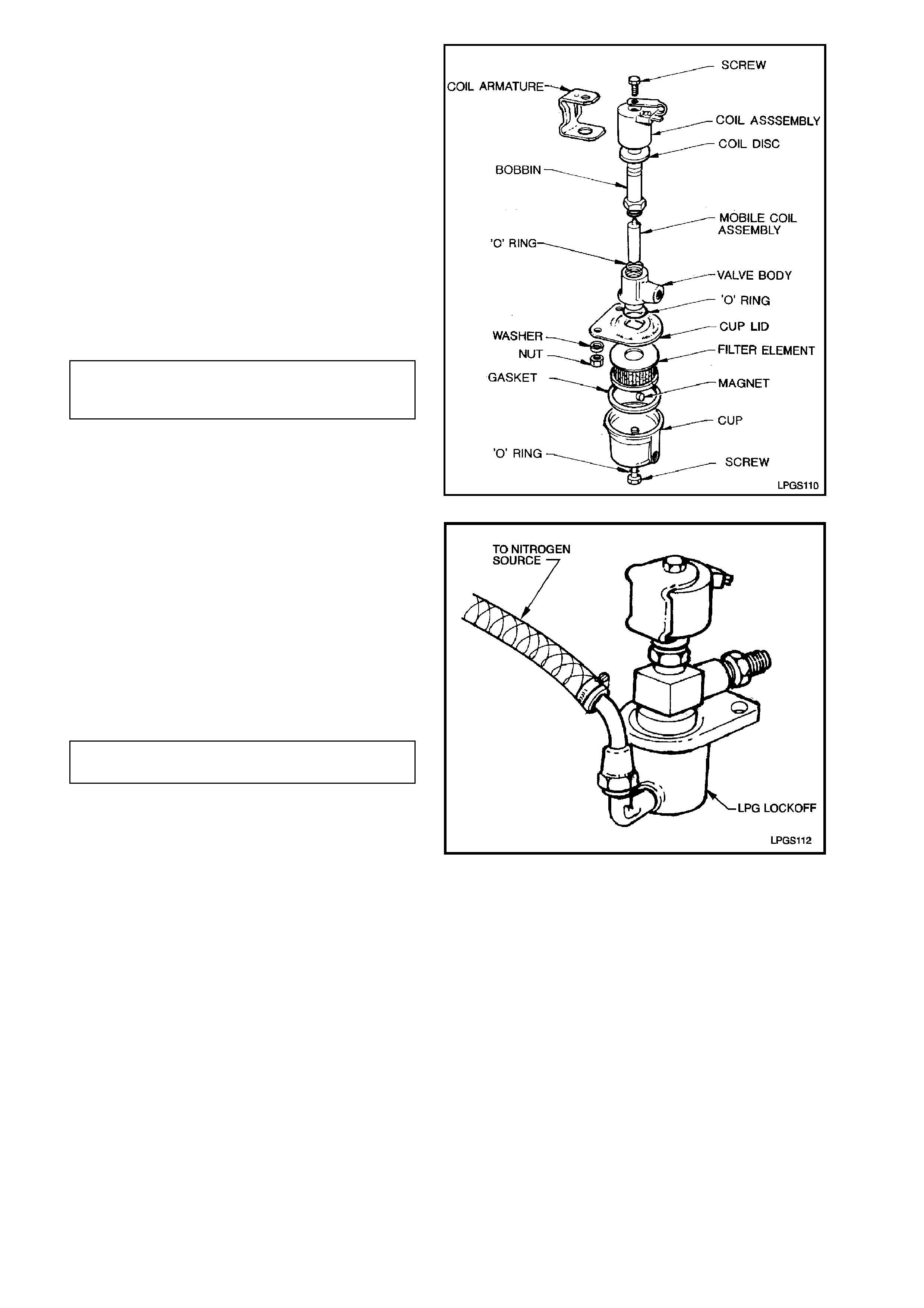
3. Loosen and remove LPG lockoff cup to valve
body attaching screws. Separate cup
assembly from valve body.
Remove cup lid from cup, remove filter
element.
Remove and discard cup lid to valve body 'O'
ring and attaching screw to cup sealing 'O'
ring.
4. Replace filter, 'O' rings and cup gasket with
new parts.
5. Reassem bly is the reverse of the disassem bly
procedure. Ensure that the magnet is cleaned
and located in the cup.
6. Tighten the cup to valve body attaching screw
to the correct torque specification.
LPG LOCKOFF CUP TO VALVE BODY
ATTACHING SCREW 3.0 - 5.0 Nm
TORQUE SPECIFICATION
Figure 2-61
7. Connect inlet of LPG lockoff to pressurised
nitrogen.
Check for any flow of nitrogen from the LPG
lockoff outlet fitting.
The LPG lockoff should completely block off
the flow of nitrogen up to the specified
pressure rating.
If the LPG lockoff allows any amount of the
pressurised nitrogen to flow the LPG lockoff
should be replaced.
LPG LOCKOFF PRESSUERE 1200
RATING SPECIFICATION kPa
Figure 2-62
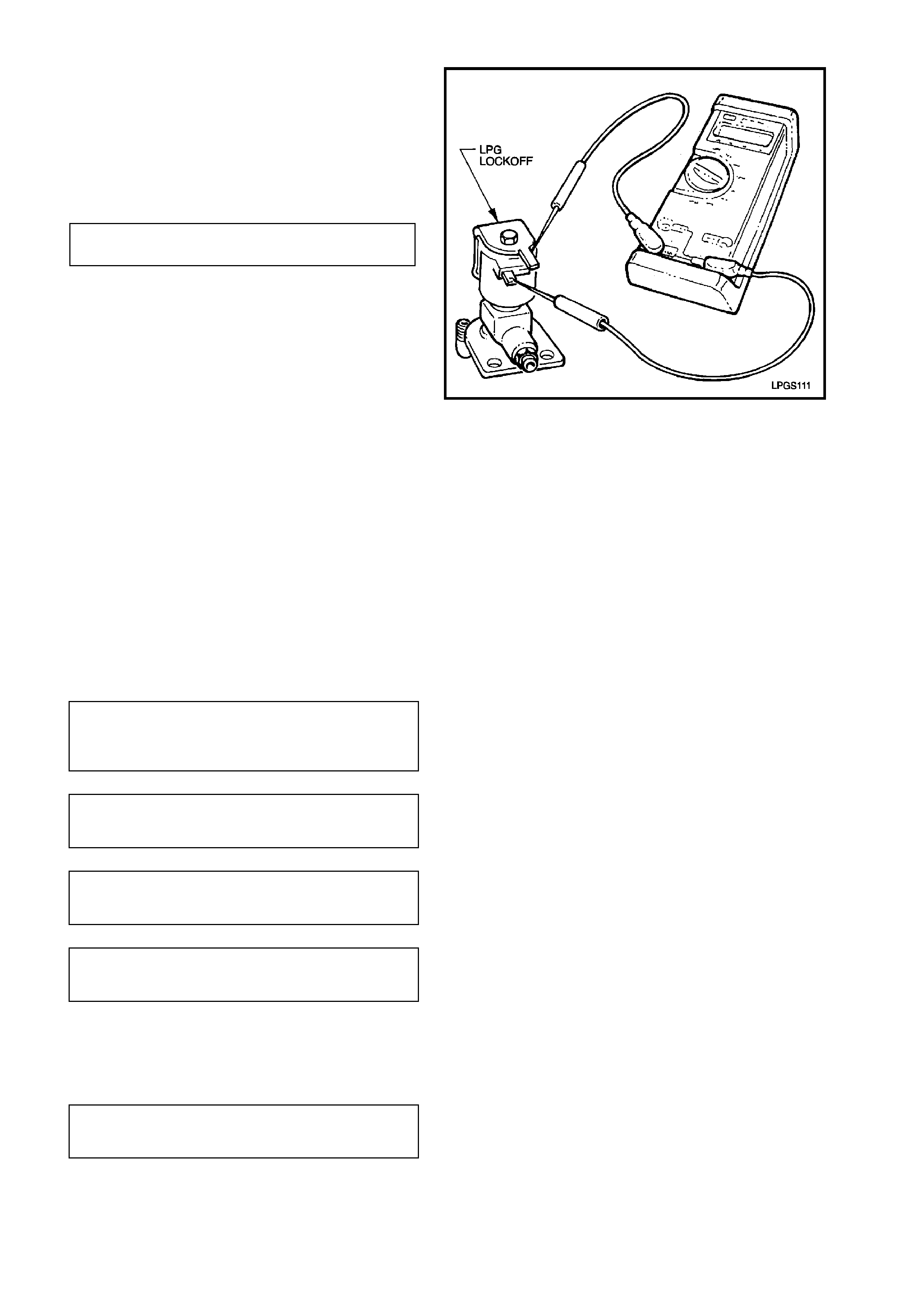
TEST
1. Check for continuity or short circuit of the
solenoid coil winding by placing the probes of
an ohmm eter on the two terminals of the LPG
lockoff.
If the measured resistance value is not to
specification the LPG lockoff should be
replaced.
LPG LOCKOFF COIL 17 - 27 OHMS
RESISTANCE @ 20°C
Figure 2-63
REINSTALL
Reinstallation of the LPG lockoff is the reverse of
the removal procedure noting the following:
1. Clean mating threads of LPG lockoff inlet,
outlet connection and front service line
connectors.
2. Apply Loctite 577 sealant to LPG lockoff inlet
threads install LPG lockoff to the converter
and tighten securely, if necessary, further
tighten to align lockoff and lockoff bracket.
3. Tighten all fasteners to the correct torque
specification
LOCKOFF BRACKET TO
CONVERTER
ATTACHING SCREW
TORQUE SPECIFICATION
3.0 - 5.0
Nm
CONVERTER RETAINING BOLT TO
SUPPORT BRACKET
TORQUE SPECIFICATION 10.0 - 12.0
Nm
HEAT SHEILD SUPPORT BOLT TO
SUPPORT BRACKET
TORQUE SPECIFICATION 10.0 - 12.0
Nm
HEAT SHEILD RETAINING SCREW
TO HEAT SHEILD SUPPORT BOLT
TORQUE SPECIFICATION 3.0 - 5.0 Nm
4. Apply Loctite 577 to lockoff connector and
tighten front service line to LPG lockoff
connector to the correct torque specification.
FRONT SERVICE LINE
CONNECTOR TO LPG LOCKOFF
TORQUE SPECIFICATION 12.0 - 15.0
Nm
5. Leak test LPG system, refer
2.3 LEAK TESTING in this Section.
2.15 CONVERTER
CONVERTER ON VEHICLE TEST PROCEDURE
REMOVE
(Refer to Fig. 2-65)
1. Park the vehic le in a well ventilated area, away
from any ignition source.
2. Drain the service lines of LPG, refer
2.1 DRAINING THE SERVICE LINES in this
Section.
3. Ensure the manual service valve is turned
'OFF' and the battery earth lead is
disconnected.
4. Remove plug from the converter primary test
port and install straight test nipple into
converter primary test port.
5. Connect the pressure gauge hose to the
straight nipple and to the HI connection of the
0-5 PSID pressure gauge of LPG tes t kit ( refer
Section 7 SPECIAL TOOL S at the end of this
Section).
6. Remove plug from the converter secondary
test port and install test elbow into secondary
test port.
7. Connect vacuum gauge hose to secondary
test elbow and the LO connection of 0-10
INCHES W.C. vacuum gauge LPG test kit 1.
Figure 2-64
8. Turn 'ON' m anual service valve and check test
connections for leaks.
9. With fuel mode switch in LPG position start
engine and allow to idle.
NOTE:
If engine will not start, crank the engine and record
pressures.
10. Converter primary pressure should be 1.0-1.5
psi (7-10 kPa).
11. Disconnect FCV to converter balance line at
converter.
12. Secondary converter pressure should be
negative 1-1.5 inches W.C. (negative 24-38
mm W.C.).
13. Reconnect balance line and secondary
pressure gauge should fluctuate from 1 - 5
inches W.C. (24-38 mm W.C.)
14. Turn 'OFF' engine, gauges should hold
pressure for at least 5 minutes.
Figure 2-65
REMOVE
1. Park the vehic le in a well ventilated area, away
from any ignition source.
2. Drain the service lines of LPG, refer
2.1 DRAINING THE SERVICE LINES in this
Section.
3. Ensure the manual service valve is turned
'OFF' and the battery earth lead is
disconnected.
4. Depressurise engine cooling system by
removing radiator cap in two stages.
CAUTION:
DO NOT REMOVE RADIATOR CAP WHILE THE
ENGINE COOLANT TEMPERATURE IS ABOVE
50oC AS PERSONAL INJURY MAY RESULT. Figure 2-66
5. Place drain tray beneath vehicle. Loosen
clamps securing engine coolant hoses to
converter coolant inlet and outlet elbows.
Remove c oolant hoses from converter and lay
back away from converter.
Figure 2-67
6. Disconnect LPG lockoff harness connector
from LPG lockoff.
7. Remove diagnostic interconnect connector
assembly from LPG lockoff retaining bracket.
Figure 2-68
8. Loosen and disconnect front service line to
LPG lockoff inlet connection.
Figure 2-69
9. Remove the two screws securing the
converter heat shield to the converter and
remove heat shield.
Figure 2-70
10. Remove FCV balance hose from converter
connections.
11. Loosen mixer to converter vapour hose clamp
at converter vapour outlet and disconnect
vapour hose from converter.
Figure 2-71
12. Loosen and remove the two heat shield
support bolts and the converter retaining bolt.
13. Remove converter assembly .
Figure 2-72
14. Remove engine coolant inlet and outlet
elbows, vapour outlet, FCV balance hose
connection and lockoff assembly if required.
If carrying out the following overhaul
procedure on the converter assembly, loosen
and unscrew the LPG lockoff to converter
connection, remove the connection and LPG
lockoff from the converter.

OVERHAUL
Under normal operating conditions, installation of a complete repair kit in a converter should only be necessary at
the time or distance intervals specified in the VT OWNERS HANDBOOK LPG leaflet, or if the converter has been
out of service for some time causing the gaskets and diaphragms to deteriorate, or after the converter has been
stored after being used.
Refer to Figure 2-73 for identification of the converter assembly components.
The converter repair kit contains the following components:
Diaphragm cover to regulator body attaching screws.
Primary diaphragm.
Hand primer washer.
Secondary diaphragm.
Secondary seat.
Primary diaphragm cover to regulator body screws.
Regulator body to heat exchanger body gasket.
Heat exchanger sponge.
Primary valve seat.
Heat exchanger cover to body gasket.
Heat exchanger cover to body attaching screws.
All other converter components are available separately, refer to the VT Parts Information for details.
Figure 2-73
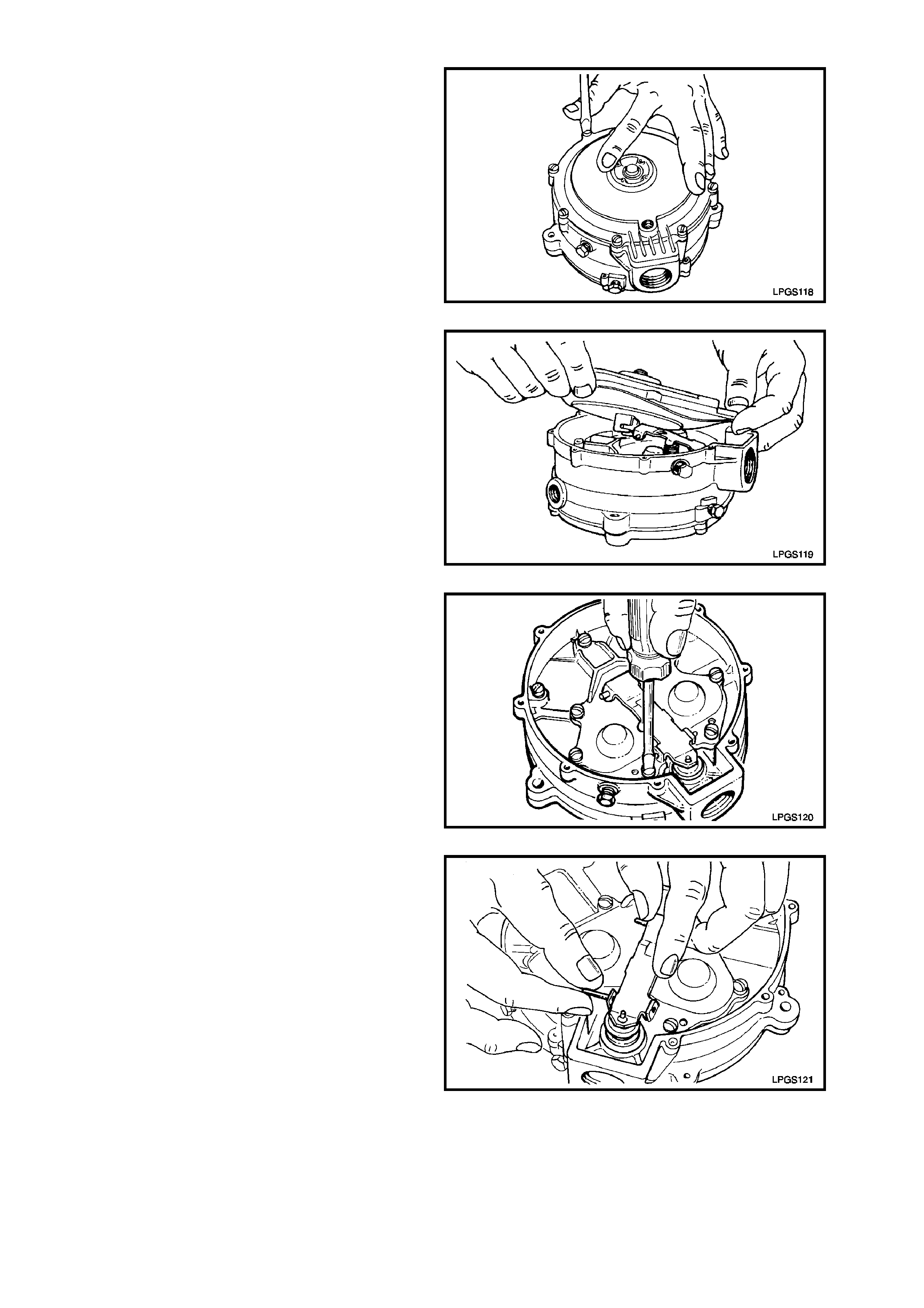
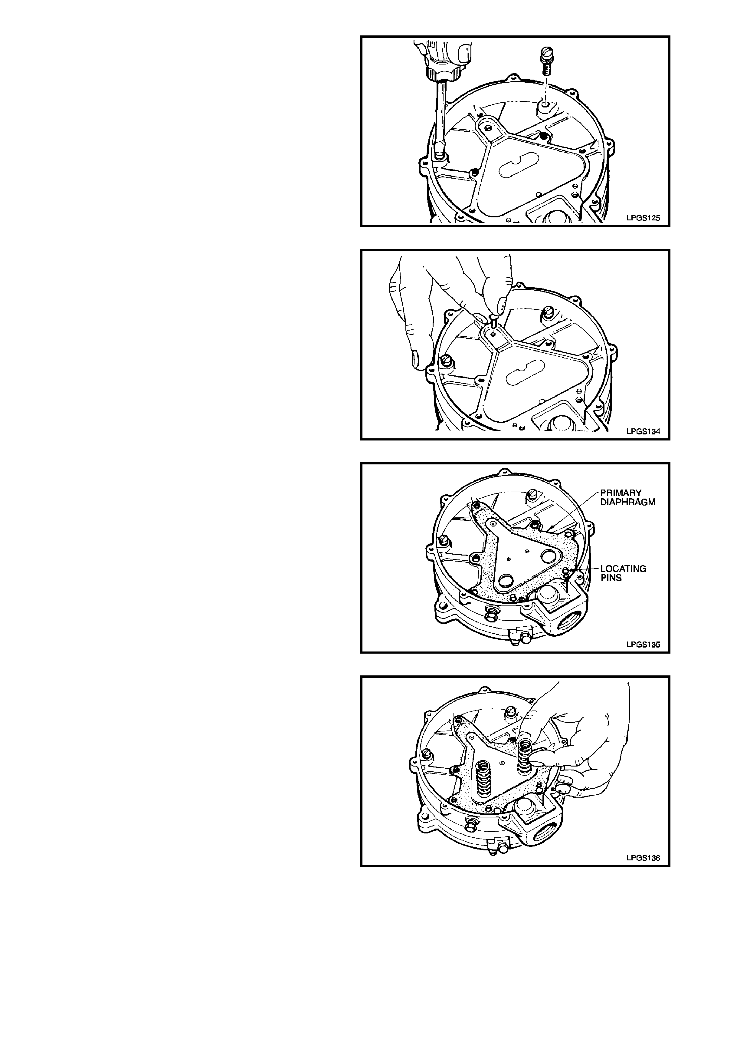
DISASSEMBLE
1. Loosen and remove the eight diaphragm c over
to regulator body attaching screws.
Figure 2-74
2. Lift up diaphragm cover and diaphragm from
regulator body.
Move diaphragm cover and diaphragm away
from low pressure outlet by approximately 25
mm to disengage the two prongs of the
diaphragm link from the secondary diaphragm
lever.
3. Remove diaphragm cover and diaphragm
from regulator body
Figure 2-75
4. Loosen and remove primary diaphragm cover
to regulator body screw that retains sec ondary
diaphragm lever fulcrum pin.
Figure 2-76
5. Slide secondary diaphragm lever fulcrum pin
from primary diaphragm cover and remove.
Figure 2-77
6. Remove secondary diaphragm lever and
spring from primary diaphragm cover.
Figure 2-78
7. Remove the remaining six primary diaphragm
cover to regulator body retaining screws.
NOTE:
Removal of these screws releases the primary
diaphragm cover from the regulator body thereby,
allowing the primary diaphragm springs to be
released.
Figure 2-79
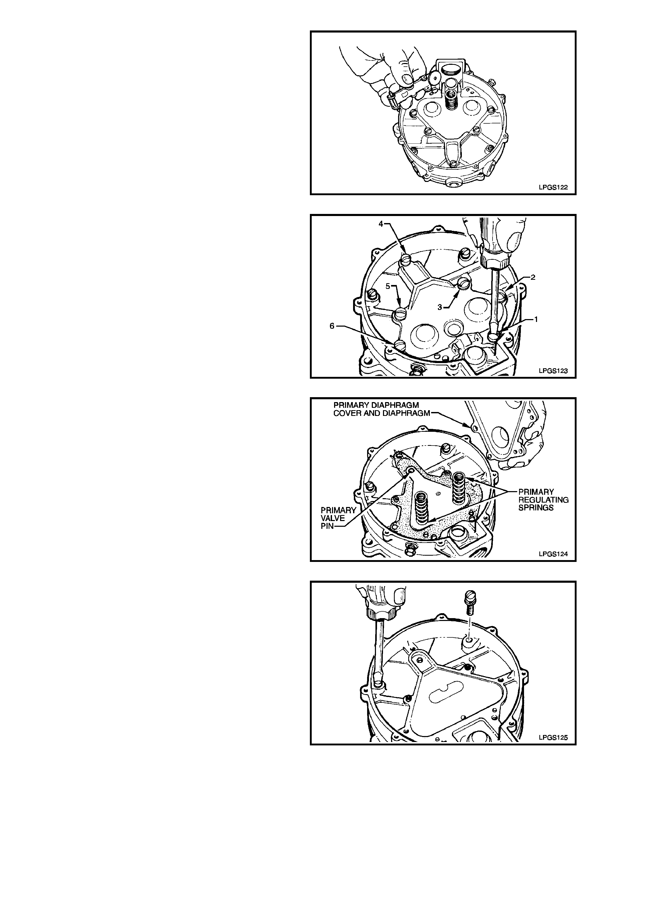
8. Remo ve primar y diaphragm cover and prim ary
diaphragm springs from regulator body.
Rem ove primary diaphragm and pr imary valve
pin from regulator body.
Figure 2-80
9. Loosen and remove the two remaining
regulator body to heat exchanger body
attaching screws.
Figure 2-81
10. Loosen and separate r egulator body fr om heat
exchanger body. Discard gasket.
Figure 2-82
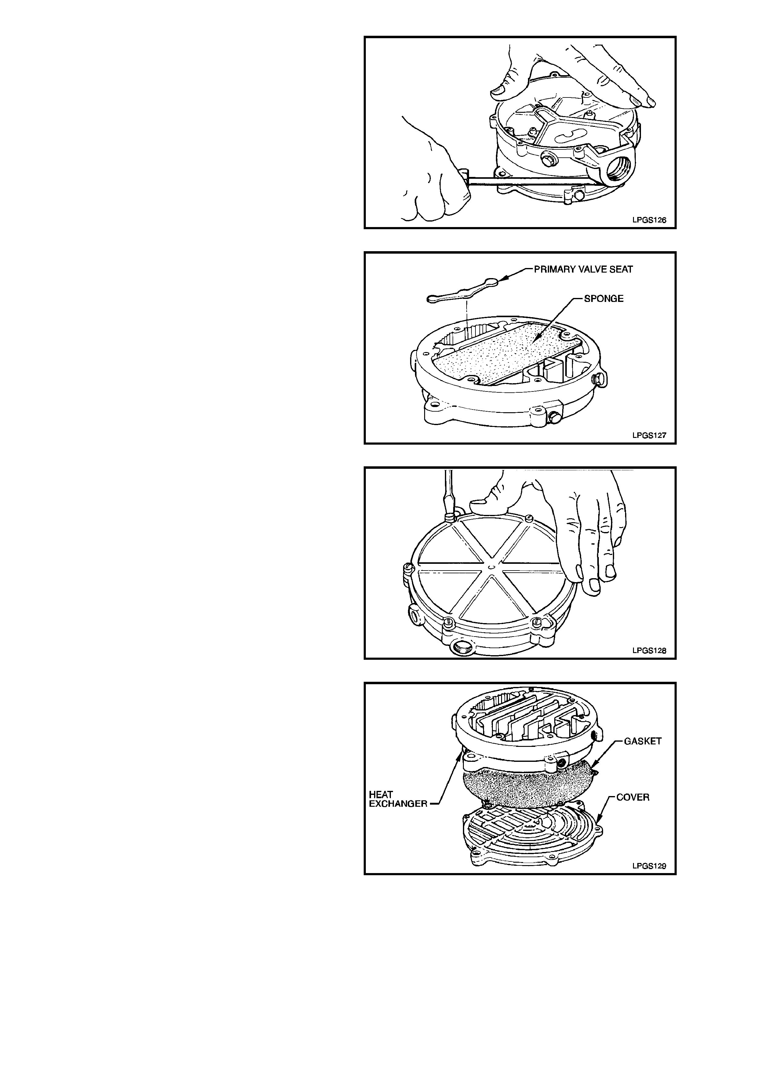
11. Remo ve and discar d primary seat and sponge
from hear exchanger body.
Figure 2-83
12. Loosen and remove heat exchanger cover to
heat exchanger body attaching screws.
Figure 2-84
13. Separate heat exchanger cover from heat
exchanger body and discard gasket.
Figure 2-85
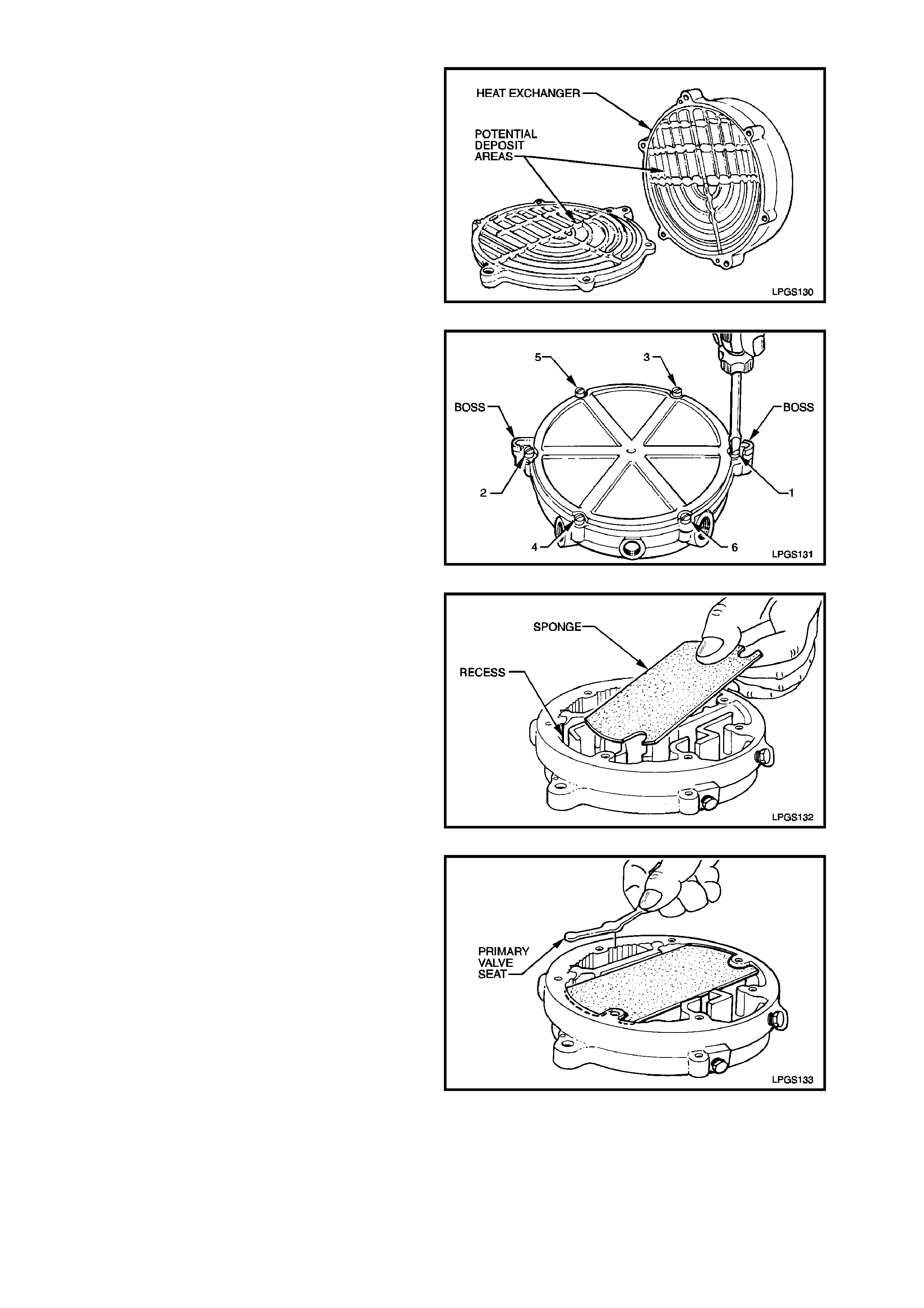
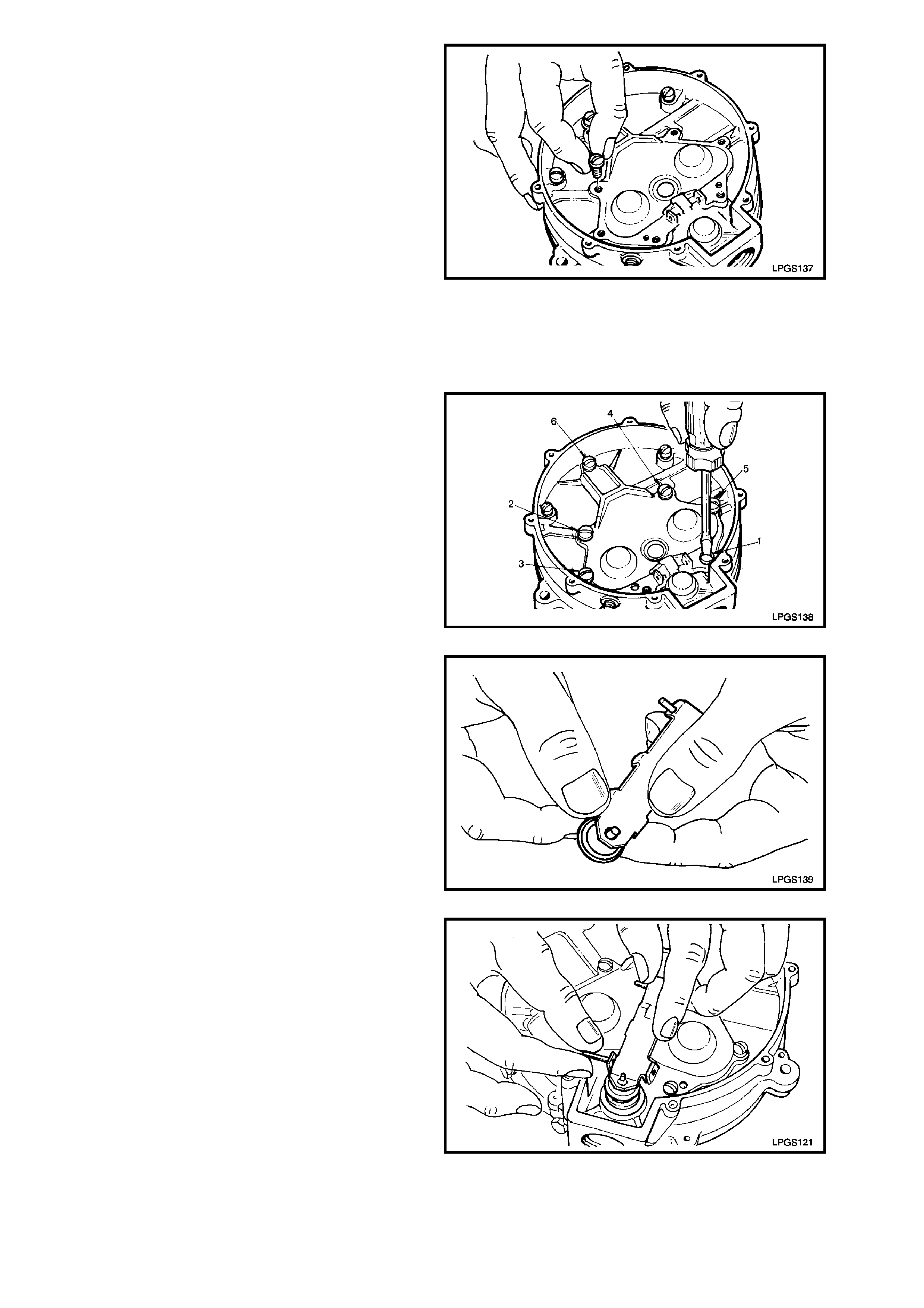
REASSEMBLE
1. Clean all parts in a suitable cleaning solution
and thoroughly dry and inspect all
components.
Care should be taken to clean all deposits
from heat exchanger body.
Figure 2-86
2. Using a new gasket, reassemble heat
exchanger cover to heat exchanger body,
matching mounting bosses in cover with those
on exchanger body. Install and tighten
attaching screws securely and in the sequence
shown.
Figure 2-87
3. Place sponge in cast recess on heat
exchanger body.
NOTE:
Sponge must be accurately located in recess.
Figure 2-88
4. Install new primary seat into heat exchanger
body.
Figure 2-89
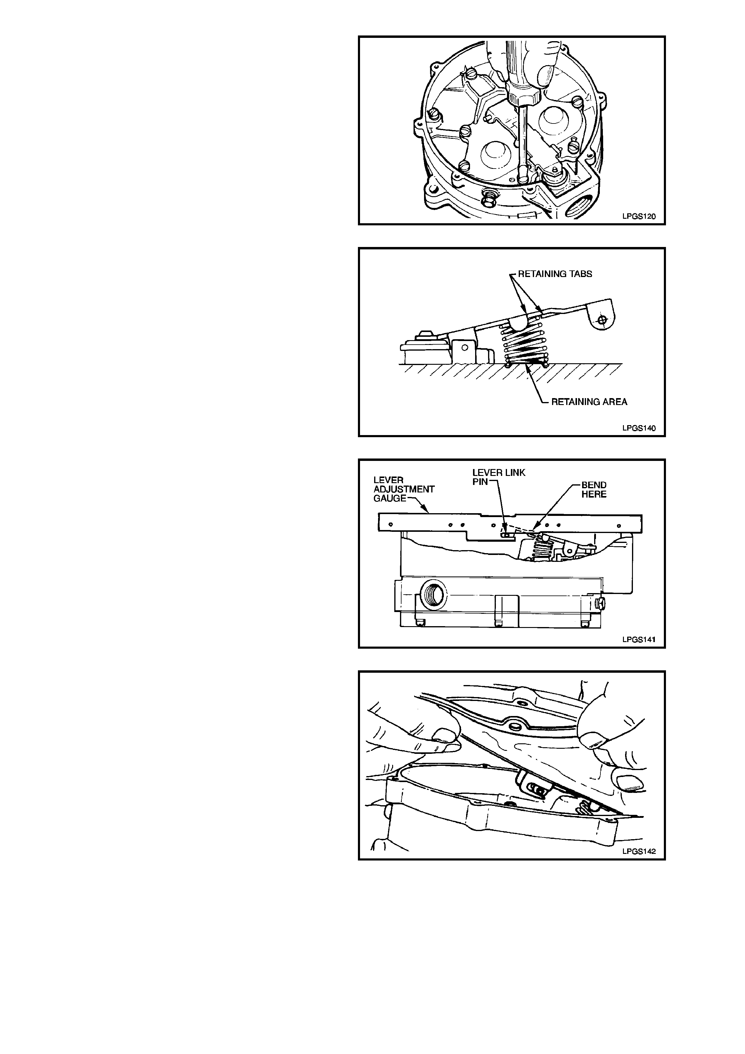
5. Place regulator body to heat exchanger gasket
on primary pin boss and two locating pins on
underside of regulator body.
Use two screws to locate regulator body and
gasket on heat exchanger as shown.
Tighten screws just until head engages
regulator body.
Figure 2-90
6. Place primary valve pin into regulator body
hole.
Figure 2-91
7. Install primary diaphragm over locating pins
and screw bosses in regulator body. This is
essential so as to ensure proper alignment
and assembly of primary diaphragm springs
and primary diaphragm cover.
Figure 2-92
8. Place the two primary diaphragm springs upon
locating perches on the back plate of the
primary diaphragm assembly.
Figure 2-93
9. Place the primary diaphragm cover over
primary diaphragm springs and push cover
down on the springs until it contacts the
regulator body.
NOTE:
Cups in the primary diaphragm cover are used to
locate the primary diaphragm springs. The springs
must locate in these cups.
10. While holding down the primary diaphragm
cover, insert the six cover to regulator body
attaching screws ensuring that the two shallow
headed screws are installed in the correct
locations (screws shown as 2 and 4 in Fig. 2-
95).
NOTE:
Do not install the attaching screw used to retain the
secondary diaphragm lever fulcrum pin at this
stage.
Figure 2-94
11. Tighten primary diaphragm cover screws until
they contact the cover.
Then tighten screws securely and in the order
shown.
Figure 2-95
12. Remove old secondary seat from secondary
diaphragm lever and replace with a new seat.
Figure 2-96
13. Reinstall secondary diaphragm lever to
primary diaphragm cover.
Insert fulcrum pin whilst holding the lever in
place.
Figure 2-97
14. Reinstall remaining primary diaphragm cover
to regulator body attaching screw used to
retain fulcrum pin. Tighten screw securely.
Figure 2-98
15. Reinstall secondary diaphragm lever spring by
slipping it under the secondary diaphragm
lever.
Ensure that the spring is correctly located
between the retaining tangs on the lever and
also the retaining area in the primary
diaphragm cover.
Figure 2-99
16. Using the secondary diaphragm lever
adjustment gauge, (part of LPG TEST KIT
ITK-1, refer Section 7 SPECIAL TOOLS at
the end of this Section), ensure that the resting
position of the secondary diaphragm lever is
within specification as shown in Fig. 2-100.
Height of secondary lever link pin should
correspond to the slot in the measuring gauge.
If the height of the secondary diaphragm lever
link pin is not to specification then gently bend
the secondary diaphragm lever until the
specified height is achieved.
Figure 2-100
17. Assemble the new secondary diaphragm by
attaching the secondary diaphragm slots to the
secondary diaphragm lever link pin.
Figure 2-101
Refer to Fig. 2-102 for the correct relationship
of the diaphragm on the lever link pin.
Figure 2-102
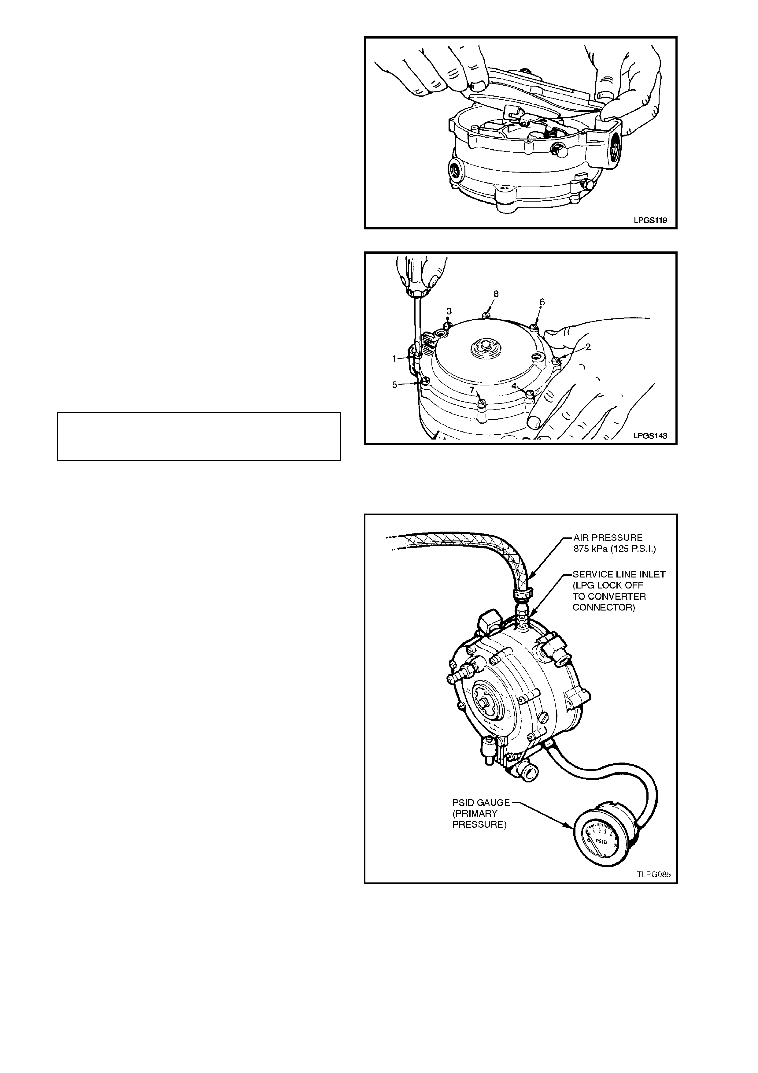
18. Install diaphragm cover onto regulator body,
ensuring that secondary diaphragm is correctly
located between cover and regulator body.
Install attaching screws and tighten until all
screws contact the cover.
Continue to tighten the attaching screws in the
sequence shown until all are seated, then
torque screws to the correct torque
specification.
DIAPHRAGM COVER TO REGULATOR
BODY ATTACHING SCREW 3.0 - 5.0 Nm
TORQUE SPECIFICATION Figure 2-103
CONVERTER OFF VEHICLE TEST
With the converter removed from the vehicle, refer
2.15 CONVERTER - REMOVE procedure in this
Section, proceed as follows:
1. Remove plug from the converter primary test
point and install straight test nipple into
converter primary test point.
2. Connect the pressure gauge hose to the
straight test nipple and to the 'HI' connection of
the of the 0 - 5 PSID pressure gauge of LPG
test kit 1.
3. Remove plug from the converter secondary
test point and install test elbow into secondary
test point.
4. Connect vacuum gauge hose to test elbow
and the 'LOW' connection of 0 - 10 INCHES
W.C. vacuum gauge of LPG test kit 1.
5. Remove converter to LPG lockoff connector
from LPG lockoff and reinstall into converter.
Tighten connector securely.
6. Connect an air supply into the converter to
LPG lockoff connector and adjust air supply
pressure to 875 kPa (125 psi).
7. Note the pressure reading on the primary
pressure gauge. Primary converter pressure
should be 7 - 10 kPa (1.0 - 1.5 psi).
8. Disconnect air supply, The converter should
hold primary pressure for at least five minutes.
NOTE:
The following step involves the use of a domestic
vacuum cleaner as a vacuum source.
Figure 2-104
9. Reconnect regulated air supply to the
converter to LPG lockoff connector. While
watching the primary pressure gauge, bring
the vacuum nozzle of the vacuum cleaner to
the converter vapour outlet. W hen the primar y
pressur e gauge needle m oves (indic ating s tart
point of vapour supply out of secondary), note
and record the secondary vacuum gauge
reading.
Secondary converter pressure should be
negative 1 - 1.5 inches W.C. (negative 24 - 38
mm W.C.).
If during this test the specified primary and/or
secondary pressures cannot be achieved, the
converter must be overhauled as per previous
instructions in this Section.
Figure 2-105
REINSTALL
Reinstallation of the converter is the reverse of the
removal procedure, noting the following points:
1. If removed, ensure that the engine coolant
inlet and outlet elbows, vapour outlet, FCV
balance hose connection threads and
converter mating threads are clean.
Apply Loctite 567 sealant to coolant and
vapour elbow threads and tighten these
elbows to positions shown in Fig. 2-106.
2. Ensure that the LPG lockoff to converter
connector and front service line to lockoff
connector mating threads are clean.
If removed, also clean LPG lockoff connector
and LPG lockoff mating threads.
Apply Loctite 577 sealant to LPG lockoff
connector ensuring that flared surfaces are
free of sealant and contaminants. Install LPG
lockoff connector to LPG lockoff and tighten
securely.
Install LPG lockof f to the converter and tighten
securely and if necessary, further tighten it so
as to align it with the retaining bracket.
Figure 2-106
3. Tighten all fasteners to the correct torque
specification
LOCKOFF BRACKET
TO CONVERTER
ATTACHING SCREW
TORQUE SPECIFICATION
3.0 - 5.0
Nm
CONVERTER RETAINING BOLT
TO SUPPORT BRACKET
TORQUE SPECIFICATION 10.0 - 12.0 Nm
HEAT SHEILD SUPPORT BOLT
TO SUPPORT BRACKET
TORQUE SPECIFICATION 10.0 - 12.0 Nm
HEAT SHEILD RETAINING
SCREW TO HEAT
SHEILD SUPPORT BOLT
TORQUE SPECIFICATION
3.0 - 5.0
Nm
4. Apply Loctite 577 to lockoff connector and
tighten front service line to LPG lockoff
connector to the correct torque specification.
FRONT SERVICE LINE
CONNECTOR TO LPG LOCKOFF
TORQUE SPECIFICATION 12.0 - 15.0 Nm
5. Leak test LPG system, refer
2.3 LEAK TESTING in this Section.
6. Refill cooling system with coolant to the
correct concentration level, refer
2.3 CHECKING AND FILLING COOLING
SYSTEM, and pressure test the system, refer
2.7 PRESSURE TESTING.
2.16 REGULATOR CHECK VALVE (RCV )
TEST
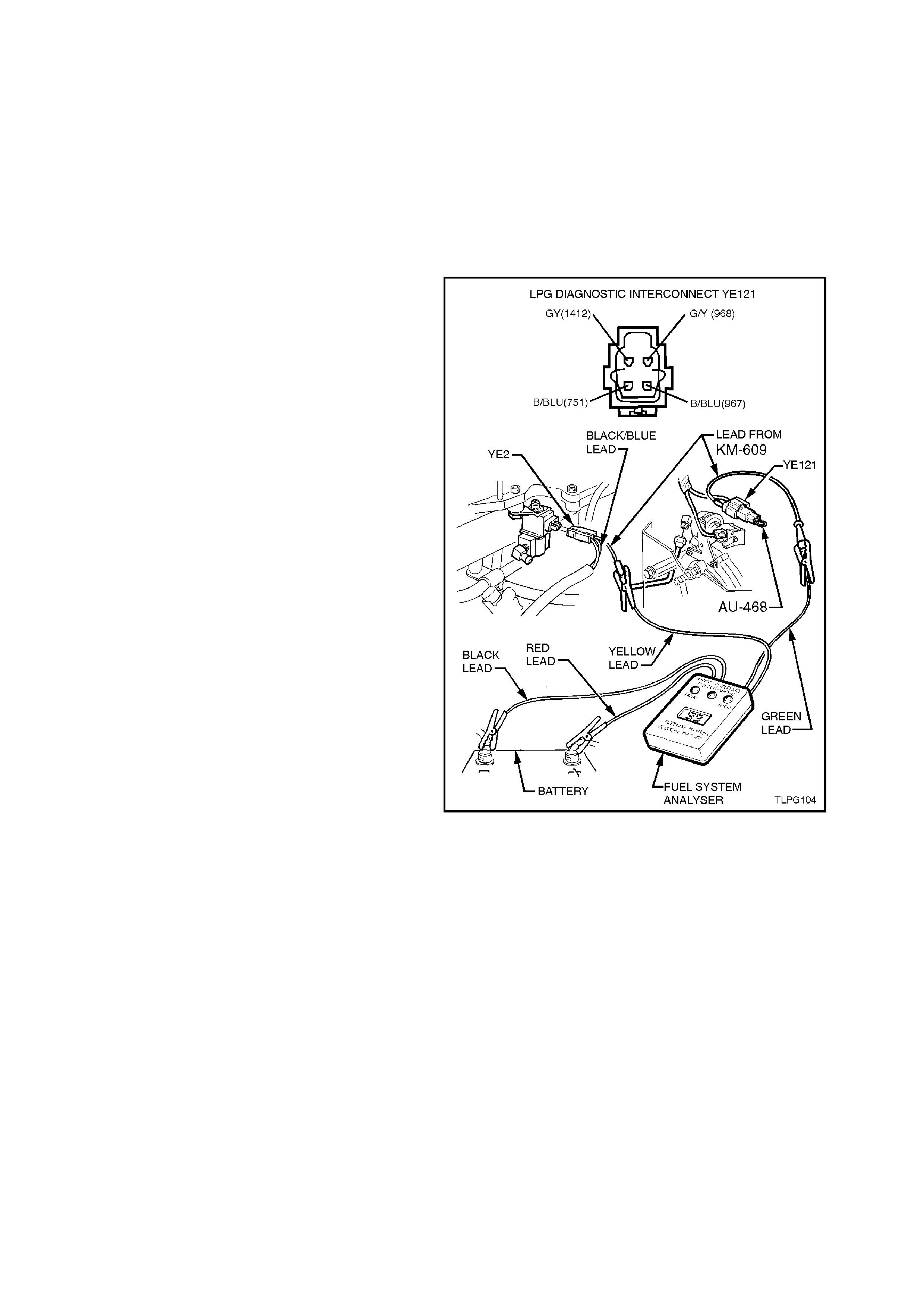
1. Connect the black lead of the Fuel System
Analyser (FSA) to the negative battery
terminal.
NOTE:
The black lead of the FSA should be the first lead
connected and the last lead disconnect.
2. Connect the red lead of the FSA to the batter y
positive terminal.
3. Using an appropriate connecter lead from KM-
609, connect the green lead from the FSA to
the LPG diagnostic interconnect, YE121, grey
wire (circuit 1412), refer to Fig. 2-107.
4. Using an appropriate connecter lead from KM-
609, back probe FCV wiring harness
connector YE2, black/blue wire (circuit 1062)
and connect it to the yellow lead from the F SA,
refer to Fig. 2-107.
NOTE:
The FSA should display 99. If the FSA does not
display 99, check FSA connections to the battery,
FCV and diagnostic interconnect connector. If
these connections are okay and the FSA has no
display, the FSA is faulty.
Figure 2-107
5. Start the engine and take note of the duty
cycles displayed on the FSA.
6. Place a finger over the RCV atmospheric port
(large opening) and take note of the duty
cycles displayed on the FSA, refer to Fig. 2-
108.
There should be little or no change in the duty
cycle.
7. Place a 3/8” inside diameter hose over the
RCV atmospheric port (large opening). Apply a
small amount of air pressure to the open end
of the hose ( physically blow through hose) and
take note of the duty cycles displayed on the
FSA.
If duty cycles do not change, it indicates the
RCV is not opening as requir ed and should be
replaced.
Figure 2-108
REMOVE
1. Park the vehic le in a well ventilated area, away
from any ignition source.
2. Drain the service lines of LPG, refer
2.1 DRAINING THE SERVICE LINES in this
Section.
3. Ensure the manual service valve is turned
'OFF' and the battery earth lead is
disconnected.
Figure 2-109
4. If necessary, remove the two screws securing
the heat shield to the converter heat shield
support bolts and remove heat shield.
5. Unscrew the RCV from the converter.
REINSTALL
Reinstallation of the RCV is the reverse of the
removal procedure.
Figure 2-110
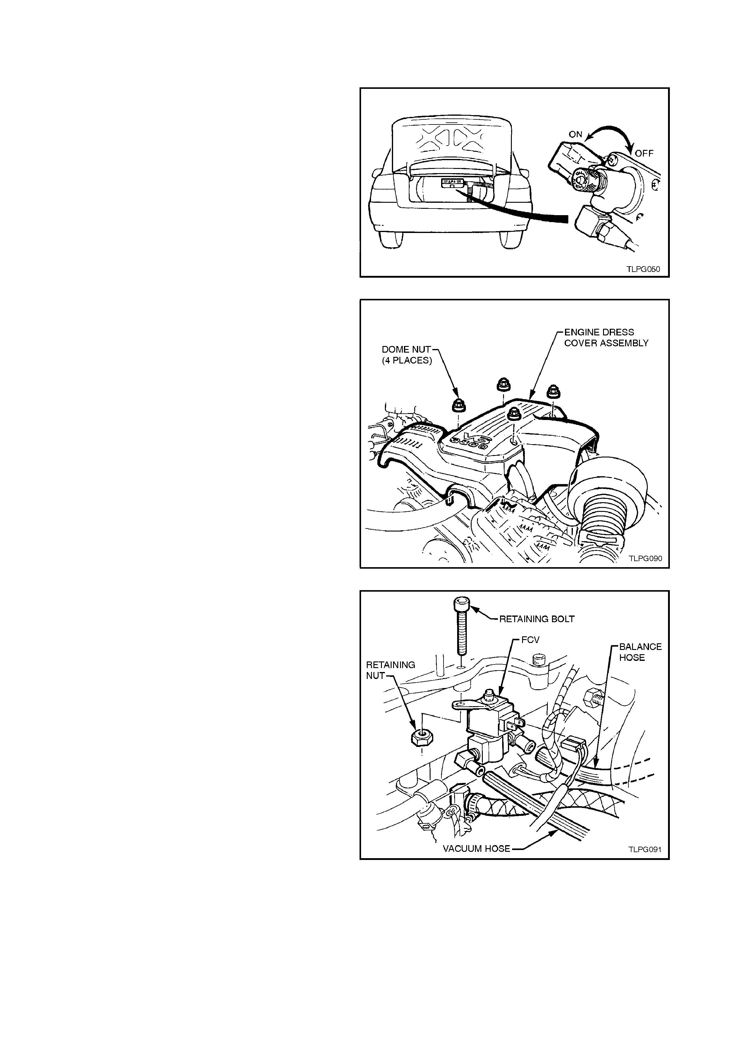
2.17 FUEL CONTROL VALVES
REMOVE
1. Park the vehic le in a well ventilated area, away
from any ignition source.
2. Drain the service lines of LPG, refer
2.1 DRAINING THE SERVICE LINES in this
Section.
3. Ensure the manual service valve is turned
'OFF' and the battery earth lead is
disconnected.
Figure 2-111
4. Remove the four nuts securing the engine
dress cover and remove cover.
Figure 2-112
5. Disconnect LPG wiring harness connector
from FCV, refer to Fig. 2-113 in this Section.
6. Remove balance hos e and vacuum hose f rom
FCV.
7. Loosen and remove FCV retaining bolt and nut
and remove FCV.
Figure 2-113
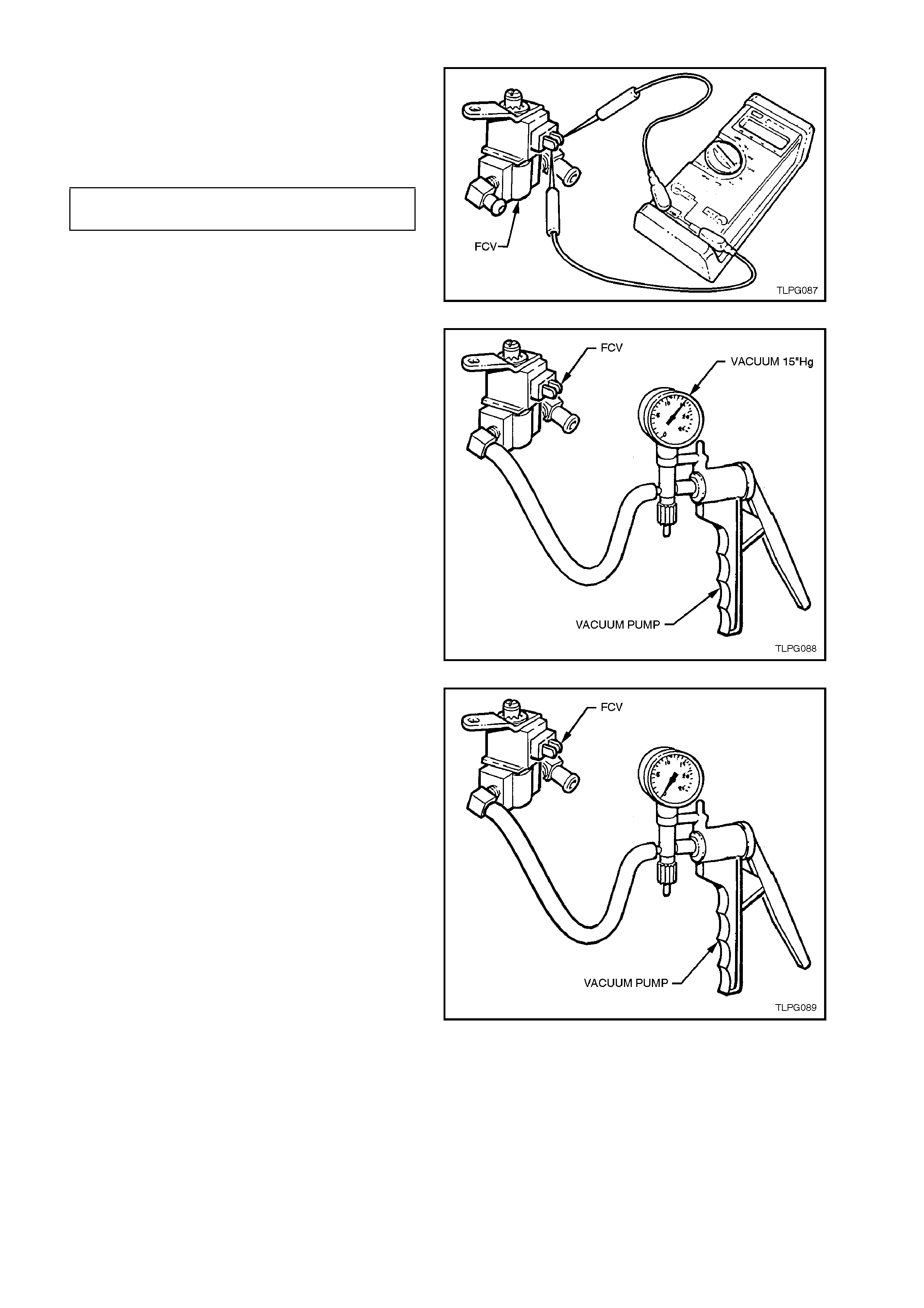
TEST
1. Connect an Ohmmeter to coil terminals of
FCV, refer to Fig. 2-114.
If the coil resistance of the FCV is not as
specified, the fuel control valve should be
replaced.
FUEL CONTROL VALVE 20 - 28 OHMS
COIL RESISTANCE @ 20°C
Figure 2-114
2. Connect a vacuum pump such as Tool No.
J23738-A, to the vacuum connector of the fuel
control valve assembly, refer Fig. 2-115.
3. Operate the vacuum pump until 15 inches Hg.
of vacuum is applied to the FCV.
Figure 2-115
4. Note the time taken for the vacuum to bleed
off through the FCV.
If 15 inches Hg. Of vac uum cannot be c r eated,
or the bleed off time is less than three to five
seconds, then the FCV should be replaced.
Figure 2-116
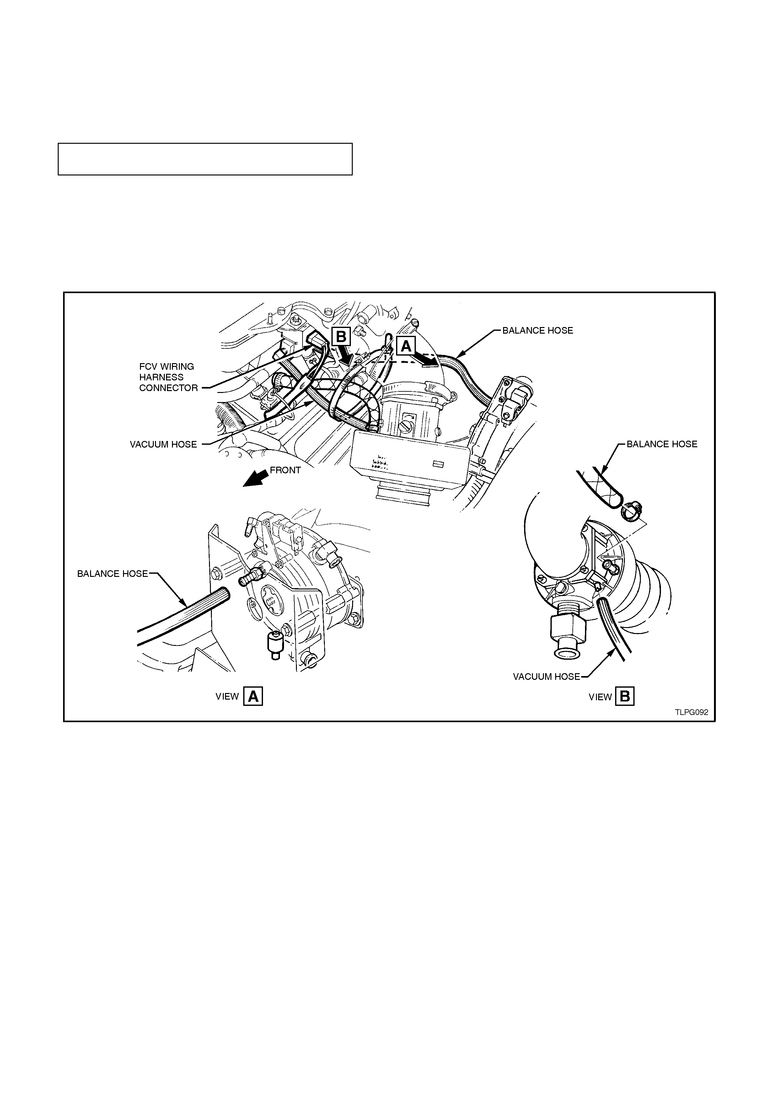
REINSTALL
Reinstallation of the FCV is the reverse of the
removal procedure noting the following:
1. Ensure FCV retaining nut is tightened the to
the correct torque specification.
FCV RETAINING NUT
TORQUE SPECIFICATION 3.0 - 5.0
Nm
2. Ensure hoses are routed correctly, refer to
Fig.
2-117 .
3. Connect LPG wiring harness connector to
FCV, ensuring that it is routed correctly, refer
Fig. 2-117 in this Section.
Figure 2-117
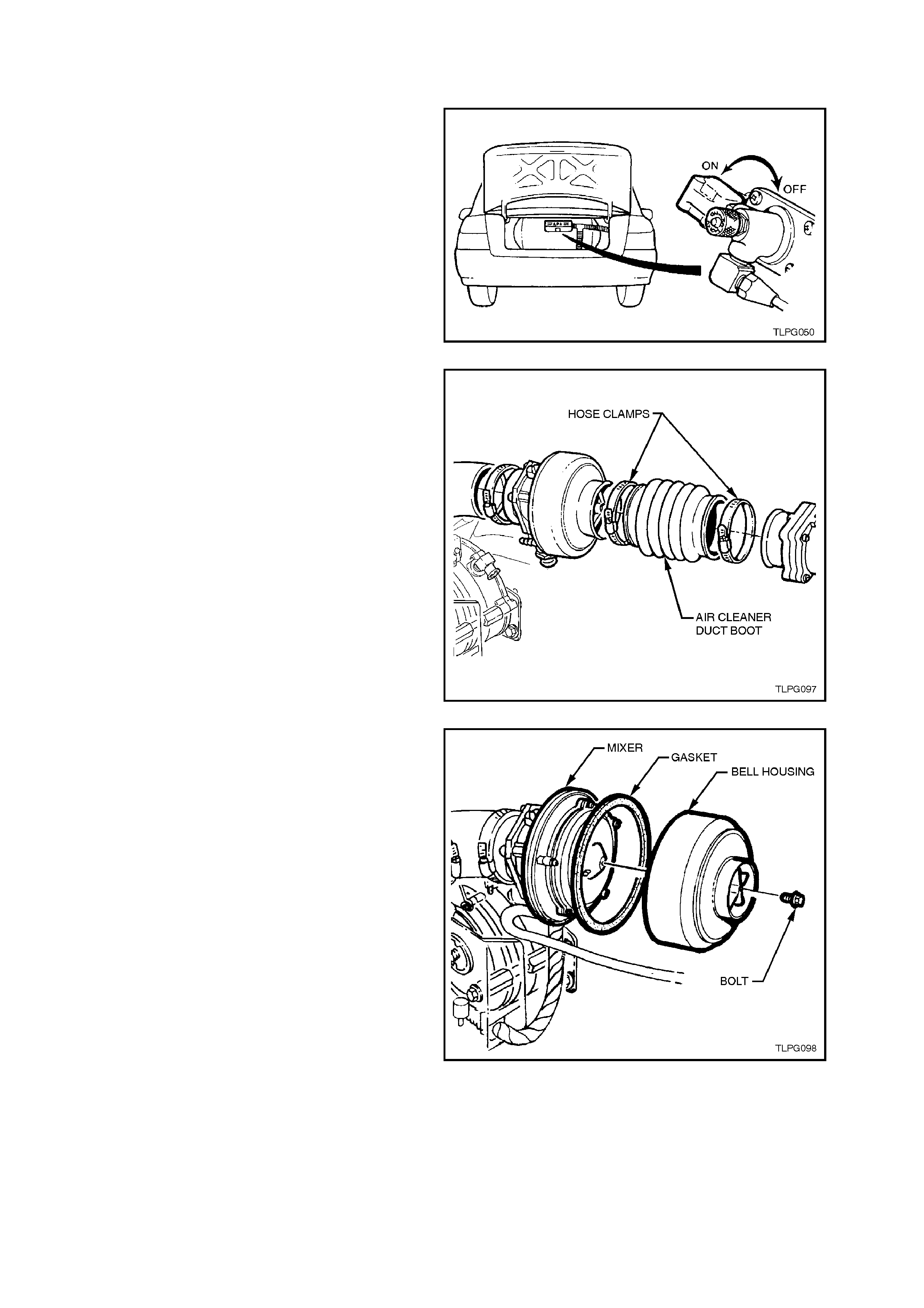
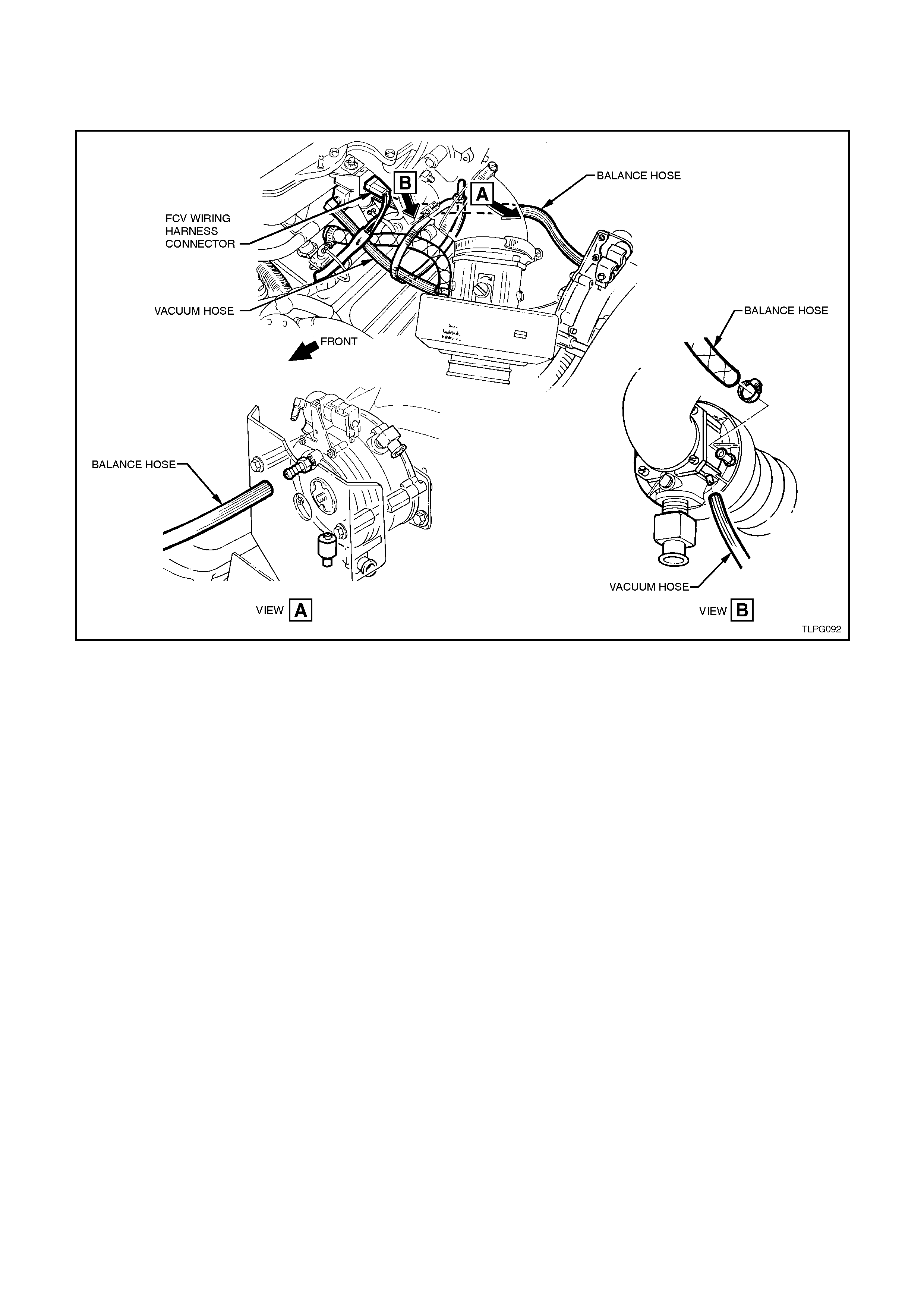
2.18 MIXER
TEST
1. Park the vehic le in a well ventilated area, away
from any ignition source.
2. Drain the service lines of LPG, refer
2.1 DRAINING THE SERVICE LINES in this
Section.
3. Ensure the manual service valve is turned
'OFF' and the battery earth lead is
disconnected.
Figure 2-118
4. Loosen clamps on either end of air duct boot,
between mixer and MAF sensor, remove air
duct boot.
Figure 2-119
5. Loosen and remove bell housing to air valve
cover attaching bolt and separate bell housing
and gasket from mixer body.
Figure 2-120
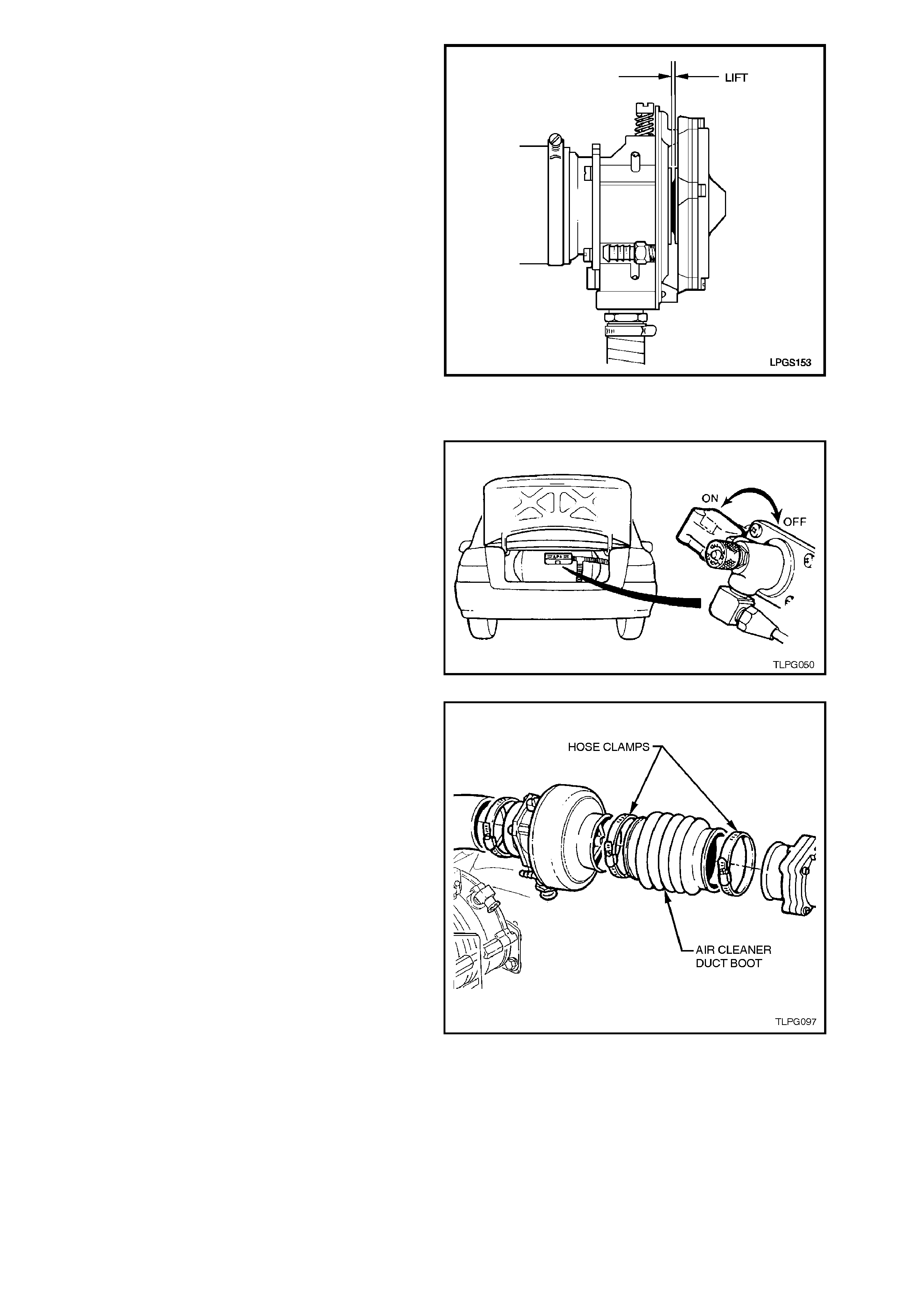
6. With fuel mode switch in 'PETROL' position
start engine and allow to idle.
7. Observe mixer diaphragm position. Diaphragm
should lift slightly as engine is cranked. Also,
diaphragm lift should increase as engine RPM
is increased.
8. If diaphragm does not lift as RPM increases,
check for vacuum leaks between mixer and
throttle body. If no vacuum leaks, overhaul
mixer, refer 2.18 MIXER - OVERHAUL this
Section.
Figure 2-121
REMOVE
1. Park the vehic le in a well ventilated area, away
from any ignition source.
2. Drain the service lines of LPG, refer
2.1 DRAINING THE SERVICE LINES in this
Section.
3. Ensure the manual service valve is turned
'OFF' and the battery earth lead is
disconnected.
Figure 2-122
4. Loosen clamps on either end of air duct boot,
between mixer and MAF sensor, remove air
duct boot.
Figure 2-123
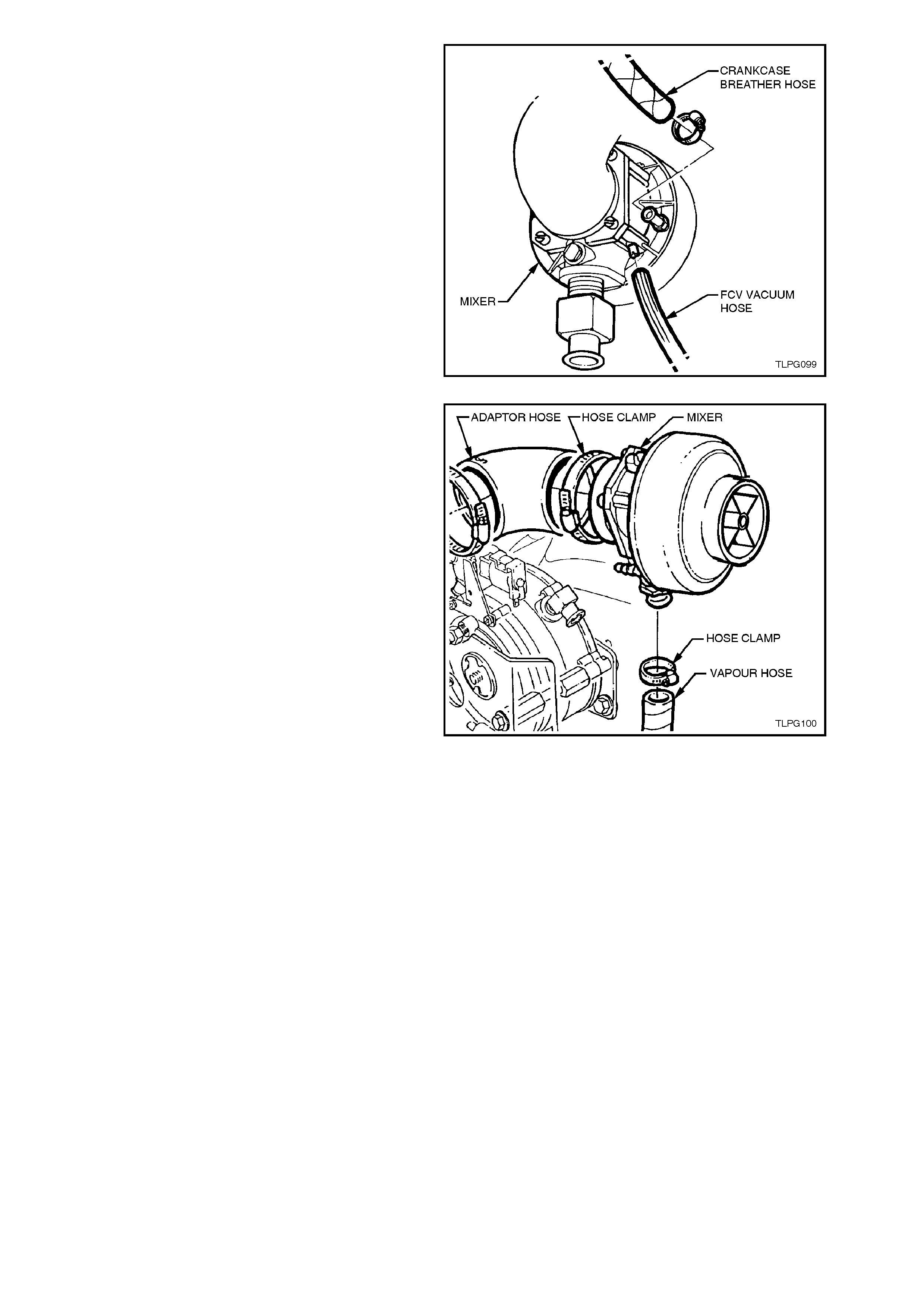
5. Disconnect the FCV vacuum supply hose and
crankcase breather hose from the mixer
assembly connector.
Figure 2-124
6. Loosen the air cleaner duct boot and adaptor
hose clamps at the mixer ends.
Pull the air cleaner duct boot from the mixer
and then pull the mixer from the adaptor hose.
7. Loosen vapour hose to mixer inlet clamp and
disconnect vapour hose.
Figure 2-125
OVERHAUL
For identification of the various parts within the
mixer assembly refer to Figure 2-126.
NOTE 1:
There is no repair kit available for the mixer
overhaul procedure. All mixer components are
available separately, refer to the latest VT Parts
Information for details.
NOTE 2:
The mixer and components for the mixer on VT
Series Models are not interchangeable with
components from previous models.
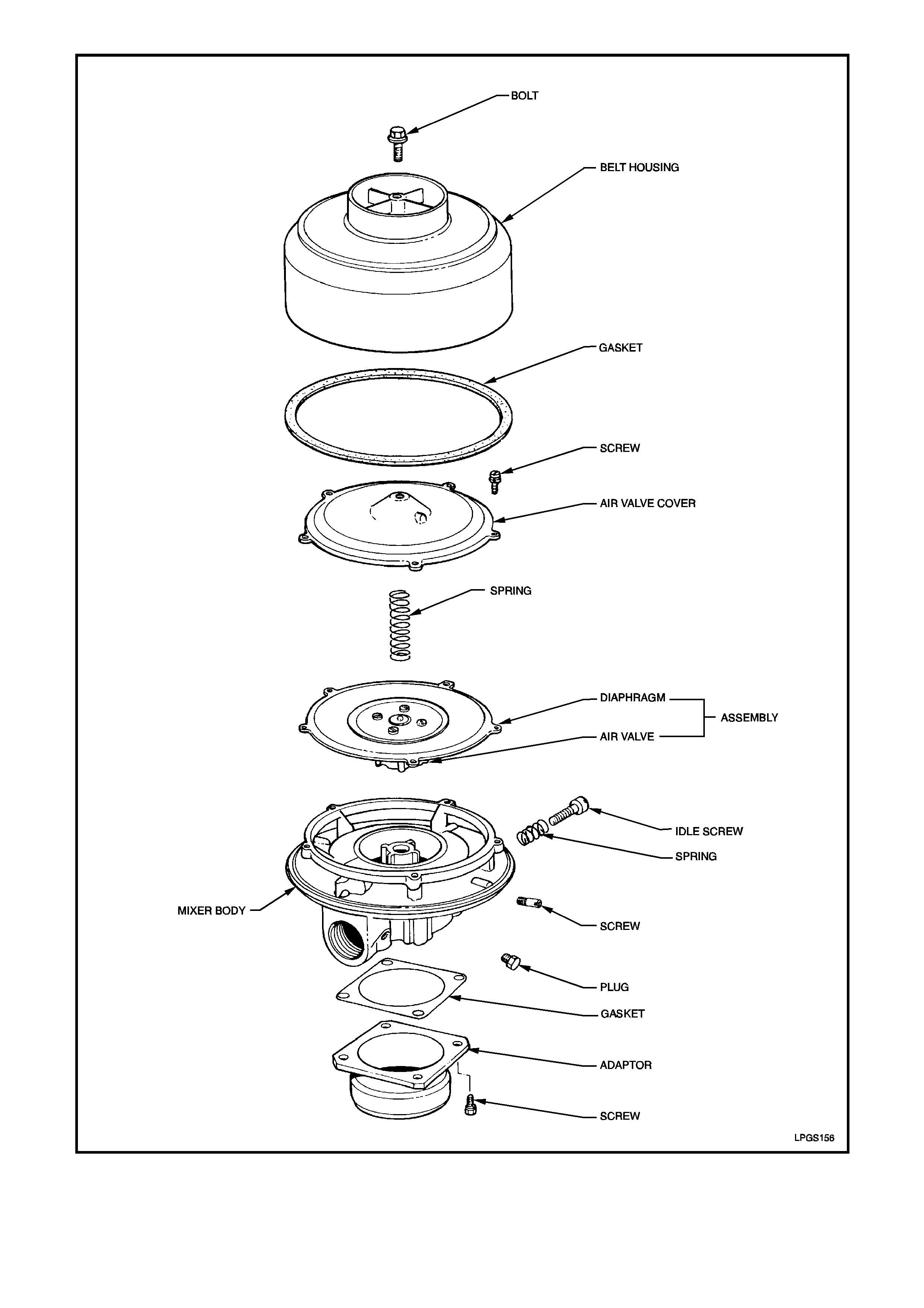
Figure 2-126
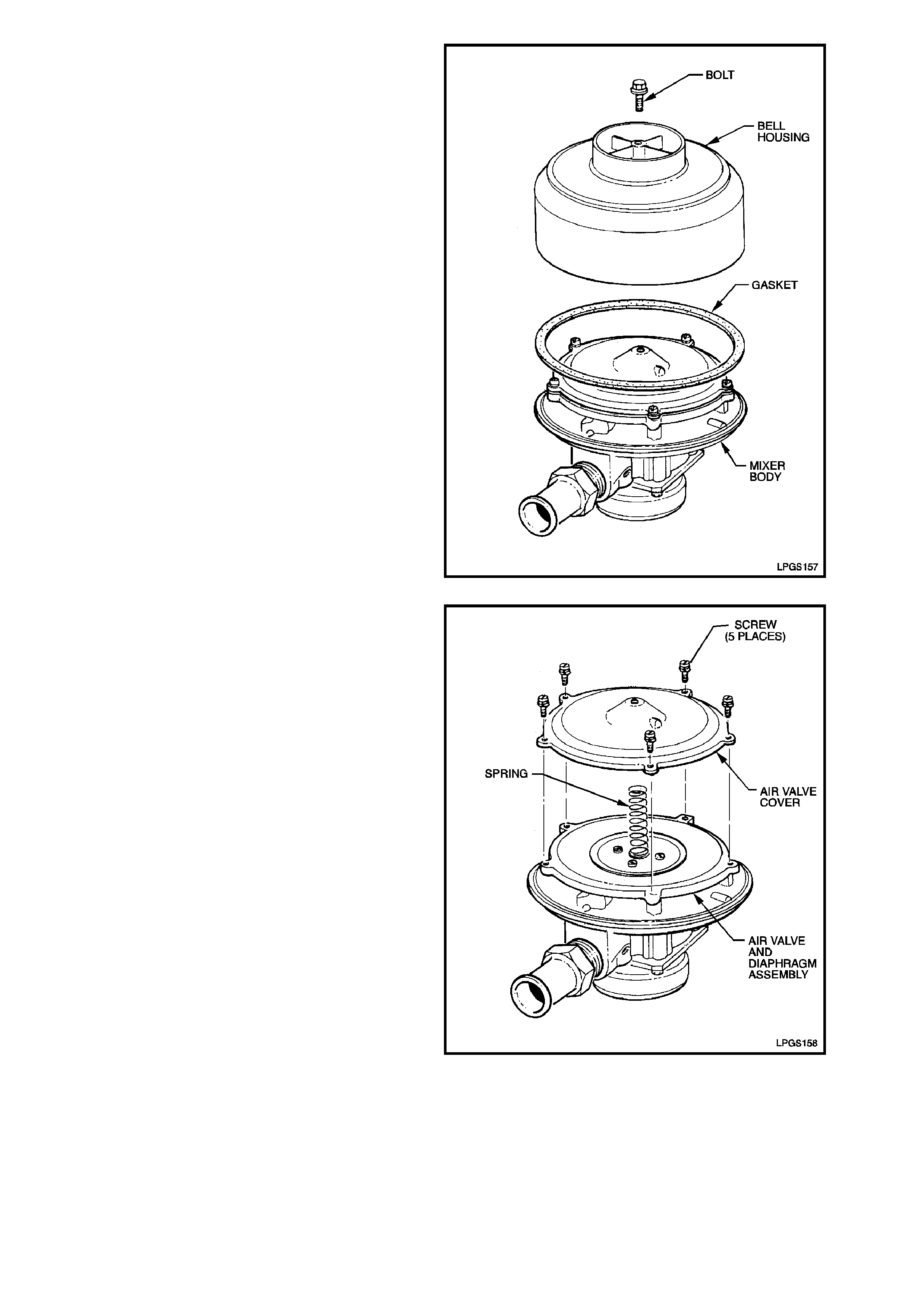
1. Loosen and remove bell housing to air valve
cover attaching bolt and separate bell housing
and gasket from mixer body.
Figure 2-127
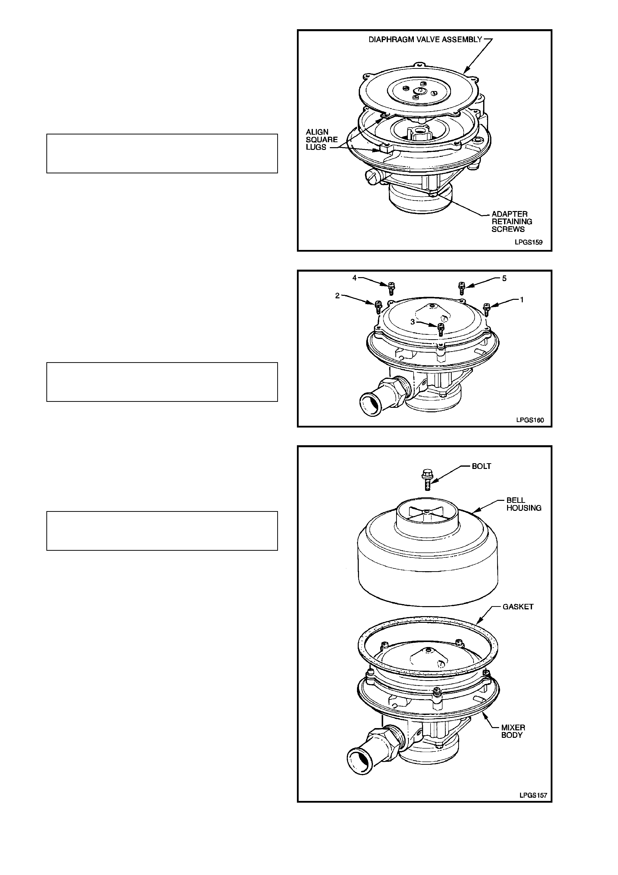
2. Remove the five air valve cover to mixer body
attaching screws and remove air valve cover
from mixer body.
Remove spring, diaphragm and air valve
assembly from mixer body.
Check condition of diaphragm and spring for
wear or damage and replace if necessary.
Figure 2-128
3. Clean all parts in a suitable cleaning solution
and inspect condition.
4. If the air valve was removed from the
diaphragm, reassemble the air valve to the
diaphragm ensuring that the air valve r ing is in
position between the air valve and the
diaphragm.
AIR VALVE TO DIAPHRAGM
ATTACHING SCREW 2.0 - 2.5 Nm
TORQUE SPECIFICATION
5. Place the diaphragm and air valve assembly
into the mixer body ensuring that the
diaphragm locating square lug is aligned with
the square locating lug on the mixer body.
Figure 2-129
6. Locate the spring onto the diaphragm and
install the air valve cover assembly to the
mixer body.
7. Install the five air valve cover to mixer body
attaching screws and tighten in the sequence
shown to the correct torque specification.
AIR VALVE COVER TO MIXER
BODY ATTACHING SCREW 7.5 - 9.0 Nm
TORQUE SPECIFICATION
Figure 2-130
8. Install new bell housing to mixer body gasket
onto mixer body. Locate bell housing onto
mixer body and install attaching bolt and
tighten to the correct torque specification.
BELL HOUSING TO AIR VALVE
COVER ATTACHING BOLT 1.0 - 3.0 Nm
TORQUE SPECIFICATION
Figure 2-131
REINSTALL
Reinstallation of the mixer is the reverse of the removal procedure noting the following point:
1. Ensure that FCV vacuum hose is routed correctly and connected to the mixer connections, refer Fig. 2-132 in
this Section.
Figure 2-132
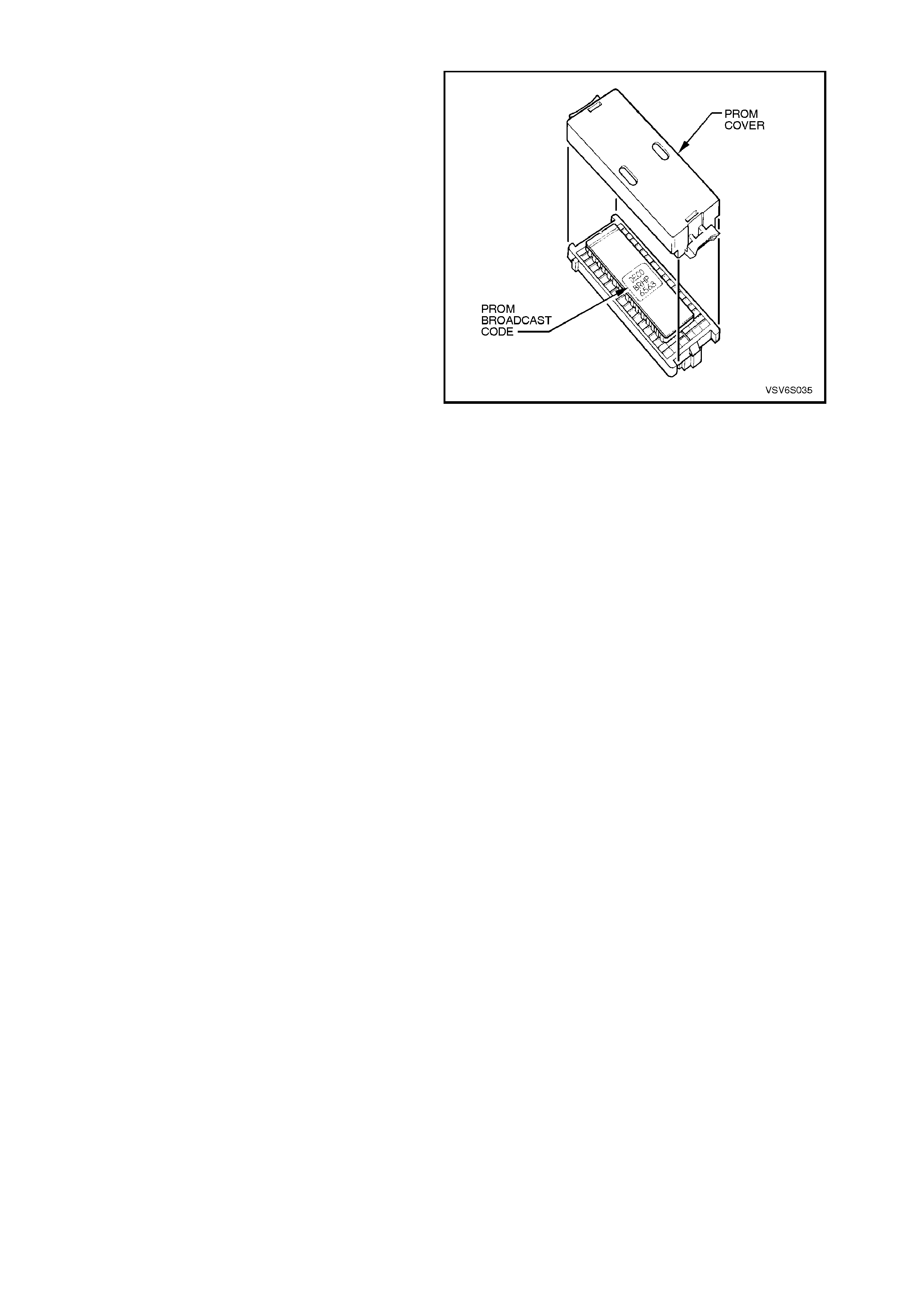
2.19 PROM
A specific PROM is used in the PCM for vehicles
fitted with option KL7, LPG system. For
identification, refer Fig. 2-133.
NOTE :
At time of publication, the PROM broadcast code
for vehicles with LPG was BWLR (TECH 2
identification 1278), however, when PROM
identification is necessar y, ref erence should always
be made to the latest service literature.
REPLACE
For details of PROM replacement refer to
Section 6C1-3 SERVICE OPERATIONS - V6
ENGINE.
Figure 2-133
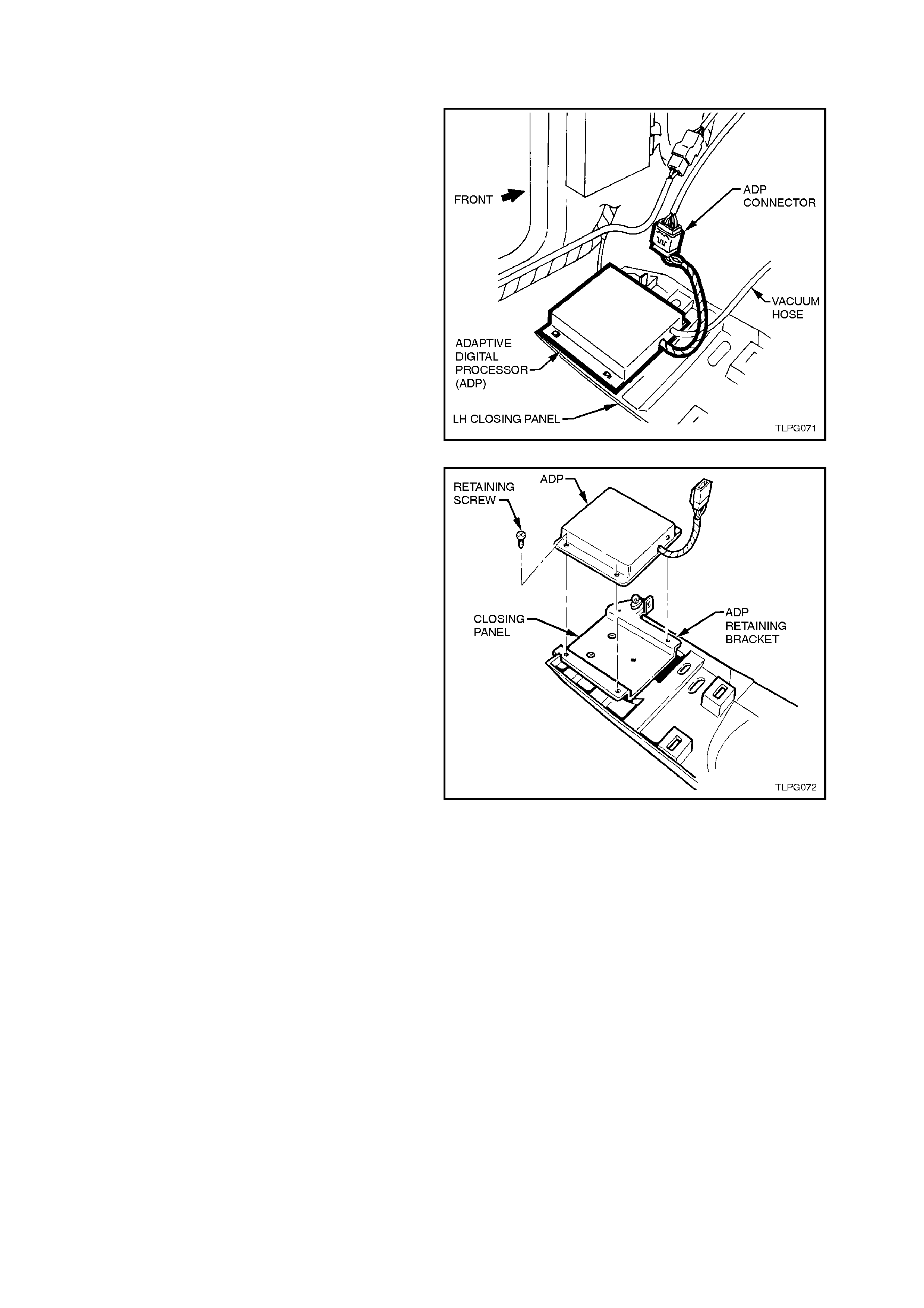
2.20 ADAPTIVE DIGITAL PROCESSOR
REMOVE
1. Disconnect battery earth lead.
2. Lower LHF instrument panel lower closing
panel, refer to Section 1A3 INSTRUMENT
PANEL AND CONSOLE.
3. Disconnect LPG body harness ADP connec tor
from ADP.
4. Disconnect vacuum line from ADP connection.
Figure 2-134
5. Remove the four ADP to ADP retaining
bracket attaching screws and remove ADP.
REINSTALL
Reinstallation of the ADP is the reverse of the
removal procedure.
Figure 2-135
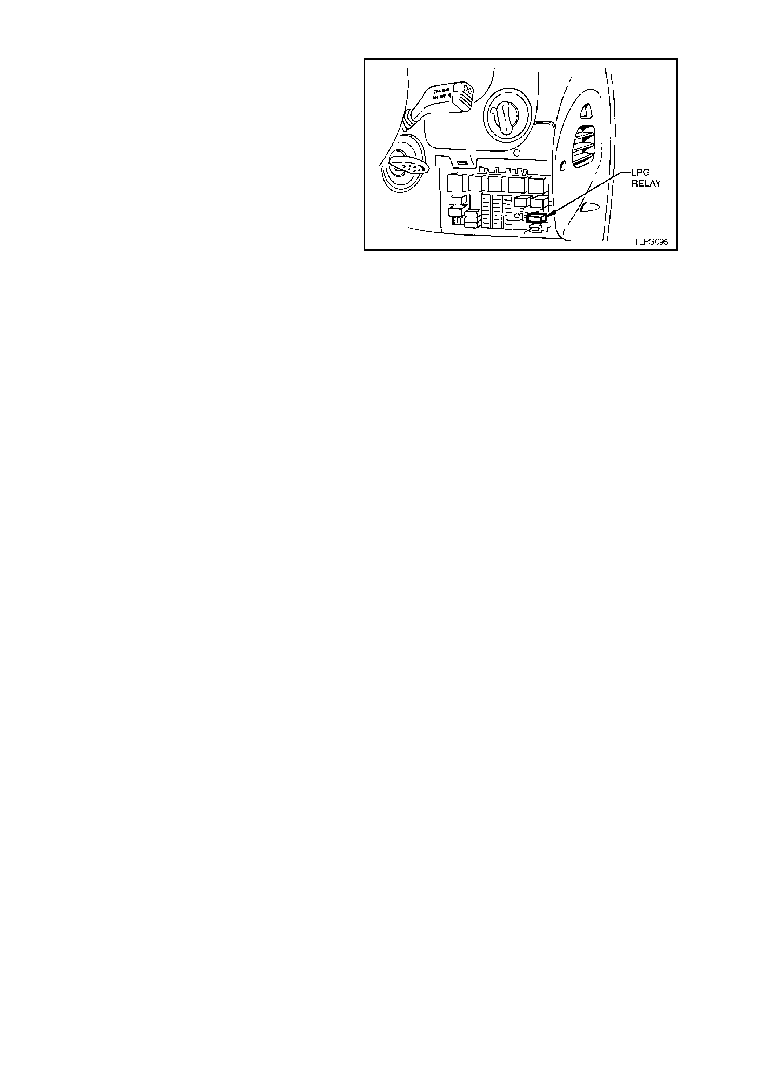
2.21 LPG RELAY
Figure 2-136 shows the location of the LPG relay
(located inside the vehicle, attached to the fuse
panel).
Access to the relay / fuse panel is by lowering the
instrument panel right hand cover assembly. Refer
to Section 1A3 INSTRUMENT PANEL for the
procedure on how to remove this cover.
Figure 2-136
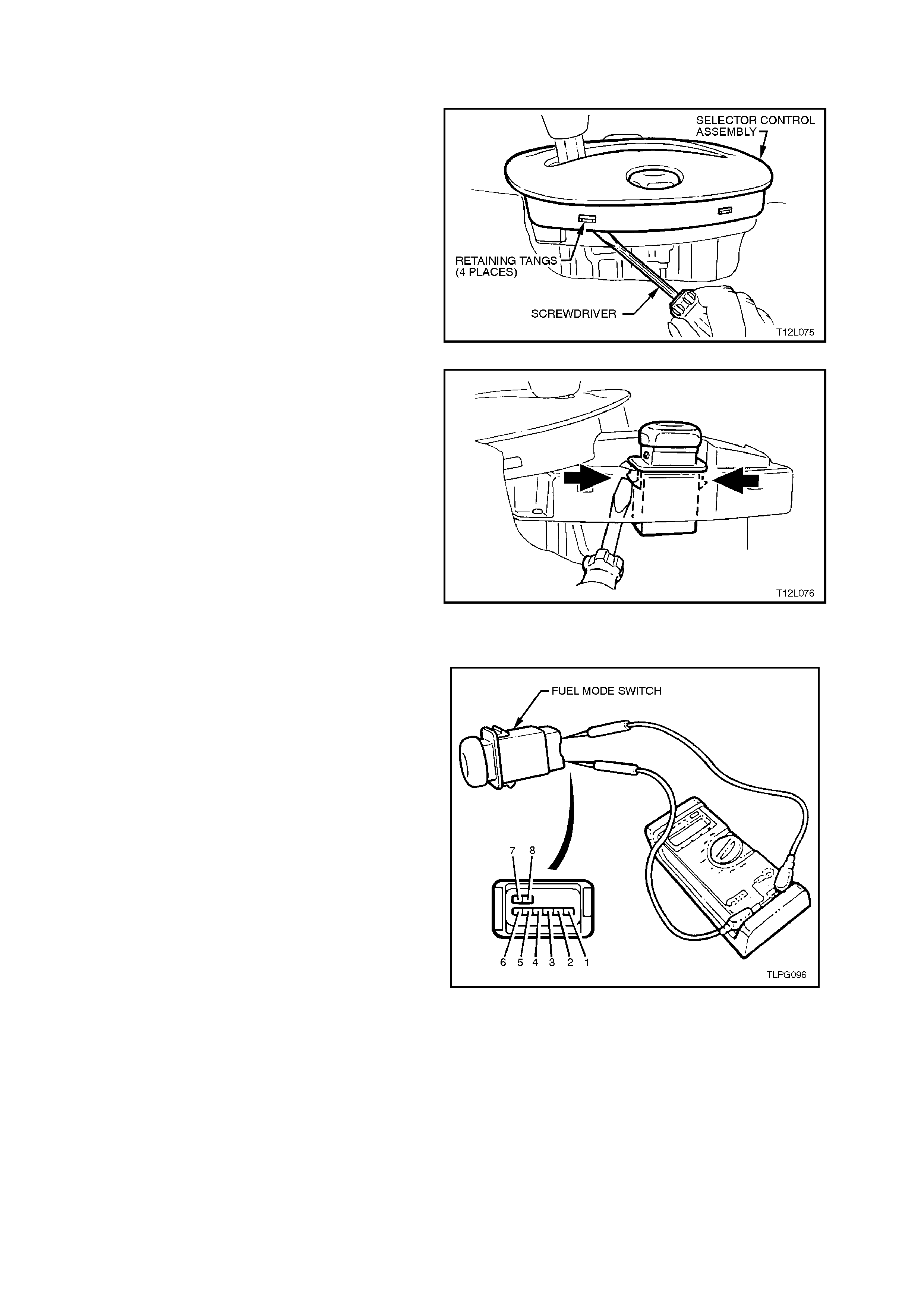
2.22 FUEL MODE SWITCH
REMOVE
1. Remove centre console assembly, refer to
Section 1A3 INSTRUMENT PANEL AND
CONSOLE.
2. Pry shift indicator away from retaining tangs on
selector control assembly and move shift
indicator forward (move shift indicator as far
forward as possible with shift selector lever still
installed) to allow switch to be removed
upwards from selector control assembly.
Figure 2-137
3. From under top of selector control assembly,
using a screw driver, push retaining tangs on
the fuel control switch inward while pushing
switch up and remove.
4. Disconnect wiring harness connector and
remove switch.
Figure 2-138
TEST
Using an ohmmeter connected to the fuel mode
switch, check for continuity between the following
terminals with the switch held IN:
Ter. 1 and Ter. 2
Ter. 1 and Ter. 5
Ter. 2 and Ter. 5
If the ohmmeter indicates an open circuit, replace
the switch assembly.
REINSTALL
Installation of the fuel m ode switch is the r everse of
the removal operation.
Figure 2-139
2.23 ADAP TIVE DIGITAL PROCESSOR SET-UP PROCEDURE
GENERAL INFORMATION
The Adaptive Digital Processor (ADP) controls the
air fuel ratio while the engine is operating on LPG.
The ADP must go through a learning process to
update the operational cells within its m emor y. The
ADP memory clearing, ADP initialisation, idle
mixture adjustment and adaptive learn drive cycle
must be carried out as outlined as follows, to
ensure correct operation of the LPG system.
NOTE:
The following procedures must be carried out
when any LPG system component (mixer,
converter, FCV and ADP) has been replaced or
overhauled, or when the engine assembly has
been replaced or overhauled. This is because
the values stored in the ADP operational cells
apply only to the previous condition of the
engine or components.
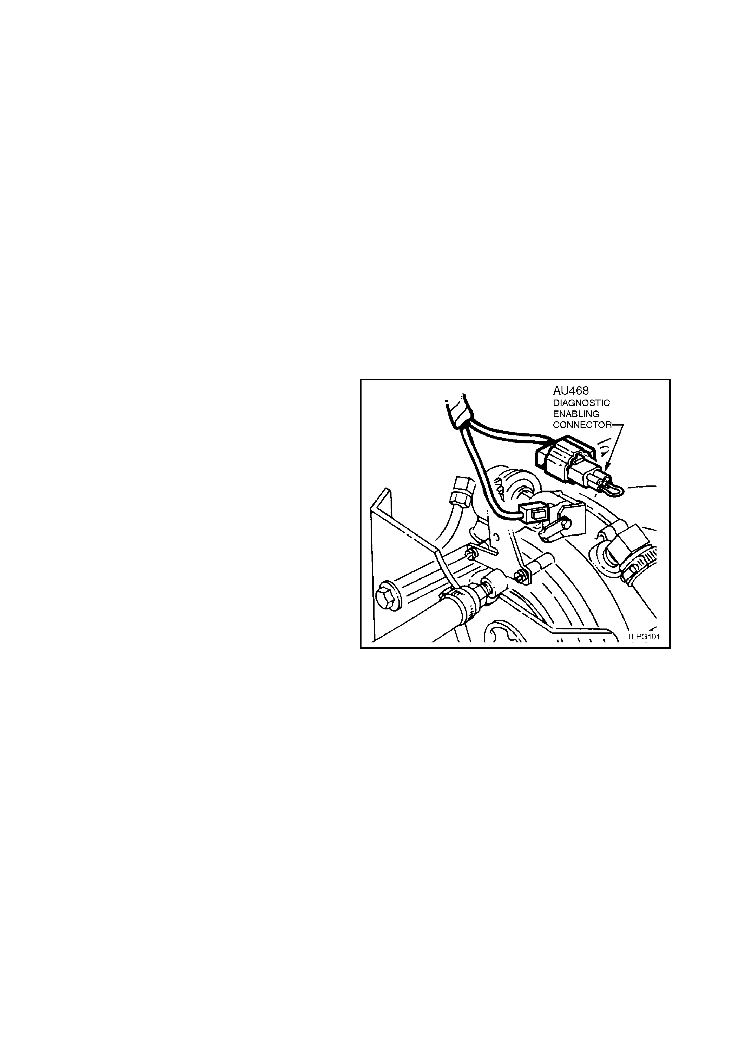
CLEARING ADP MEMORY
The ADP memory can be cleared by installing the
diagnostic enabling connector (AU 468) into the
LPG diagnostic interconnect connector, YE121
(connector located next to the LPG lockoff) while
the engine is at idle and under no load condition f or
approximately 60 seconds.
The system can then be reset by removing the
diagnostic enabling connector (AU 468) from the
LPG diagnostic interconnect, YE121 and following
the following instructions on ADAPTIVE LEARN
DRIVE CYCLE PROCEDURE.
Figure 2-140
ADAPTIVE LEARN DRIVE CYCLE PROCEDURE
Once the diagnostic enabling connector (AU 468)
is removed from the LPG diagnostic interconnect
connector, YE121 the ADP enters its fast learn
mode. The mixture control will alter as the ADP
learns the operation of the system during the drive
cycle.
The drive c ycle is a lear ning process of the ADP. It
is essential to combine all operational aspects of
the vehicle during the drive cycle to allow the ADP
to update its operational cells.
ADP INITIALISATION
1. Connect the black lead of the Fuel System
Analyser (FSA) to the negative battery
terminal.
NOTE:
The black lead of the FSA should be the first lead
connected and the last lead disconnect.
2. Connect the red lead of the FSA to the batter y
positive terminal.
3. Reinstall the diagnostic enabling connector
(AU 468) into the LPG diagnostic interconnect
connector, YE121.
4. Using an appropriate connecter lead from KM-
609, back probe the diagnostic interconnect
connector YE121, grey wire (circuit 1412) and
connect it to the green lead from the FSA,
refer to Fig. 2-141.
5. Using an appropriate connecter lead from KM-
609, back probe FCV wiring harness
connector YE2, black/blue wire (circuit 1062)
and connect it to the yellow lead from the F SA,
refer to Fig. 2-141.
NOTE:
The FSA should display 99. If the FSA does not
display 99, check FSA connections to the battery,
FCV and diagnostic interconnect connector. If
these connections are okay and the FSA has no
display, the FSA is faulty.
6. Turn 'OFF' all accessories, place transmission
in park and apply the park brake.
7. W ith the f uel mode s witch in the LPG position,
turn ignition 'ON', and Fuel Control Valve
(FCV) should be clicking and FSA should be
displaying a fixed 45%-55% duty cycle.
Figure 2-141
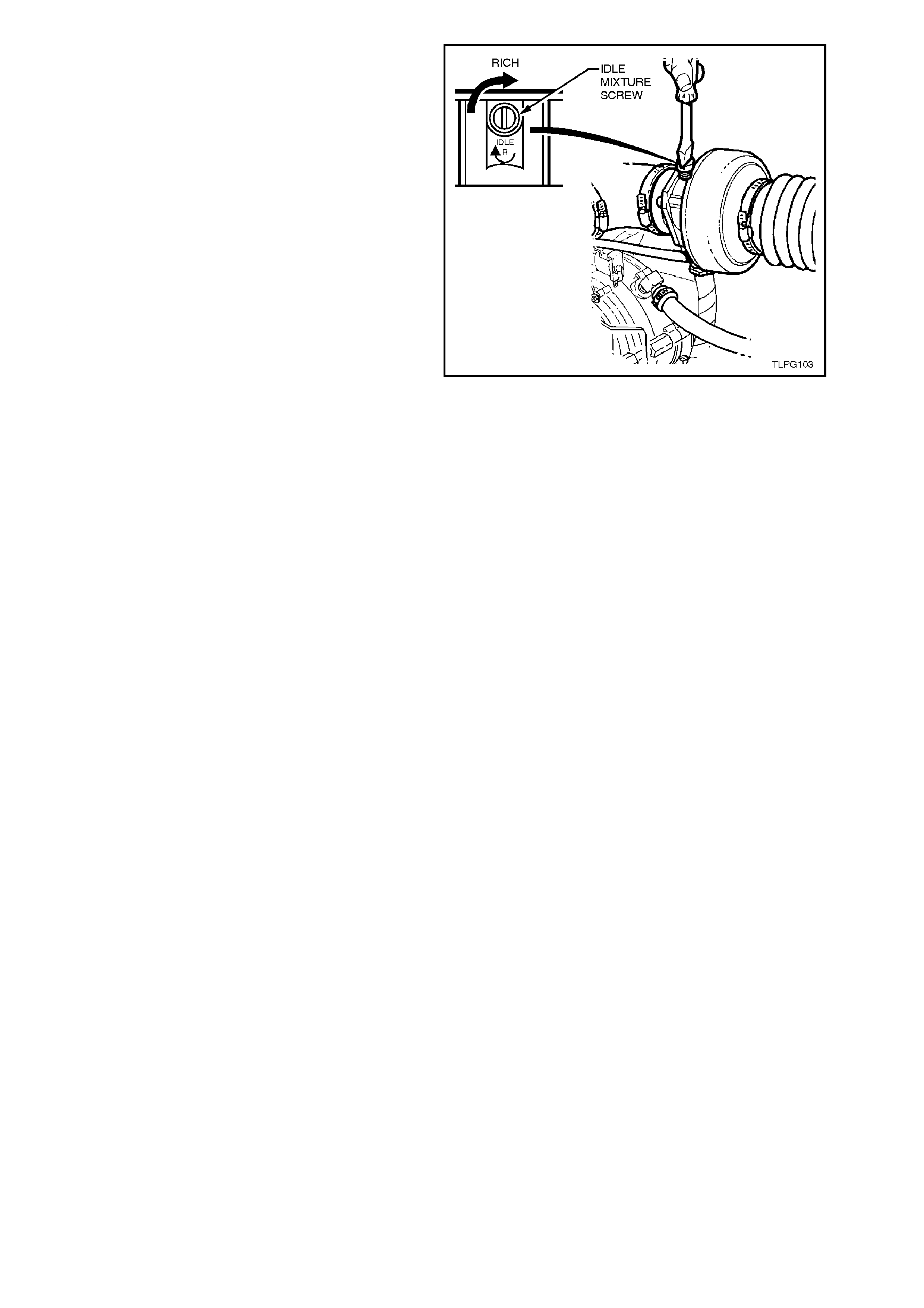
8. W ith the f uel mode s witch in the LPG position,
start the engine and with no load on the
engine, air conditioning off (if fitted), all
electrical consumers turned off and park
position selected, allow engine and oxygen
sensor to reach operating temperature.
9. Adjust the idle mixture by turning the idle
mixture screw on the mixer until a smooth
transition of the FSA indicator lam ps has been
achieved.
If no trans ition can be achieved and the rich or
lean FSA indicator light is c onstantly ON, ref er
to the following note.
NOTE:
If a transition of the FSA indicator lamps cannot be
achieved during the initialisation period regardless
of the idle screw position, continue with the
'ADAPTIVE LEARN DRIVE CYCLE' in this
Section. After appr oximately one minute of idle, you
should obtain transition of the FSA lamps.
10. Allow the engine to idle for 60 seconds while
monitoring the FSA lamps for transition. This
time period will allow the engine and fuel
mixture to stabilise.
11. Remove the diagnostic enabling connector
(AU 468) from the LPG diagnostic
interconnect connector, YE121 while the
engine is still idling. Allow the engine to idle
with the diagnostic enabling connector
removed for 60 seconds, then turn the engine
off.
The next time the engine is started, the ADP
will enter the first of its 3 eight m inute adaptive
learn cycles.
Figure 2-142

ADAPTIVE LEARN DRIVE CYCLE
Once the diagnostic enabling connector has been
removed, the ADP enters the first of the 3 eight
minute adaptation cycles. The mixture control will
change as the ADP learns the operation of the
mixer at various load conditions.
The drive c ycle is a lear ning process of the ADP. It
is important to combine all operational aspects of
the vehicle to allow the ADP to load its operational
cells.
Start the engine and perform the Adaptive Learn
Drive Cycle as outlined as follows. This will include:
1. For the first eight minutes, the operator must
simulate as many drivability conditions as
possible.
2. Perform four wide open throttle transitions;
accelerate the vehicle from idle to 100 km/h
and then allow the vehicle to slow down
without any throttle movement.
3. Perform steady driving conditions from 60
km/h, 80 km/h and 100 km/h, holding the
required speed at each level for 2 minutes at
each duration. Allow the vehicle to slow down
each time without any throttle movement.
4. Finish the 24 minute drive cycle by continuing
with normal city and highway driving.
NOTE:
The above driving conditions ar e for the drive c ycle
in the ADP to record the var ious oper ational modes
of the system during the learn mode.
It should be noted that the eight minute drive cycle
is the absolute minimum that should be conducted
by the technician, prior returning the vehicle back
to the owner.
If the engine is turned off prior to the expire of the
first eight minutes, all of the adapted memory will
be lost and will require a further eight m inute drive
cycle.
As noted previously, the minimum drive cycle
requirement for the installer is eight minutes, but
there is a further two eight minute adaptation
cycles remaining. The owner of the vehicle can
complete these, or the technician can continue the
full 24 minute period.
NOTE:
If the FSA displays a low duty c ycle i.e. 25 - 30, this
indicates a lean c ondition with the drive c ycle (refer
step 1). After completion of the first 8 minute drive
cycle, stabilise the engine and note the idle duty
cycle. You should see an improvement of
approxim ately 10 duty cycles (35 - 40). This is due
to the mixer stabilising and is within the operating
requirements (Best operating parameters are:
minimum 25 duty cycles, maximum 85 duty
cycles).

2.24 COOLANT HOSES
Coolant hoses for the LPG system are installed as shown in the following illustration.
Hose connections should be thoroughly cleaned before installing any new hoses.
After a hose is fitted, always refill the cooling system with the correct concentration of coolant, refer
2.3 CHECKING AND FILLING COOLING SYSTEM and pressure test cooling system, refer
2.7 PRESSURE TESTING in Section 6B1-1 ENGINE COOLING - V6 ENGINE.
CAUTION:
Always wear protective safety glasses when working with spring type hose clamps. Failure to do so could
result in eye injury
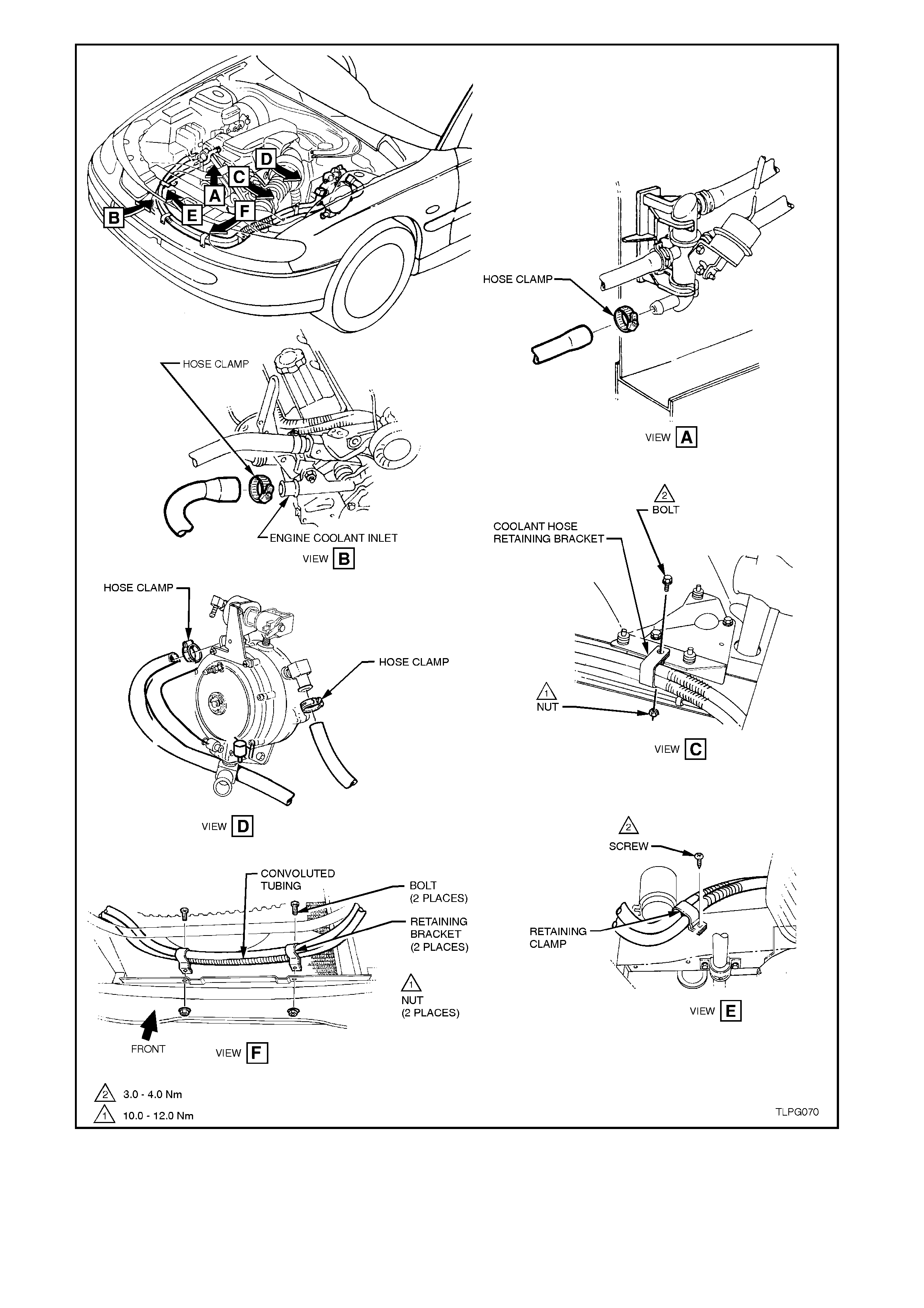
Figure 2-143
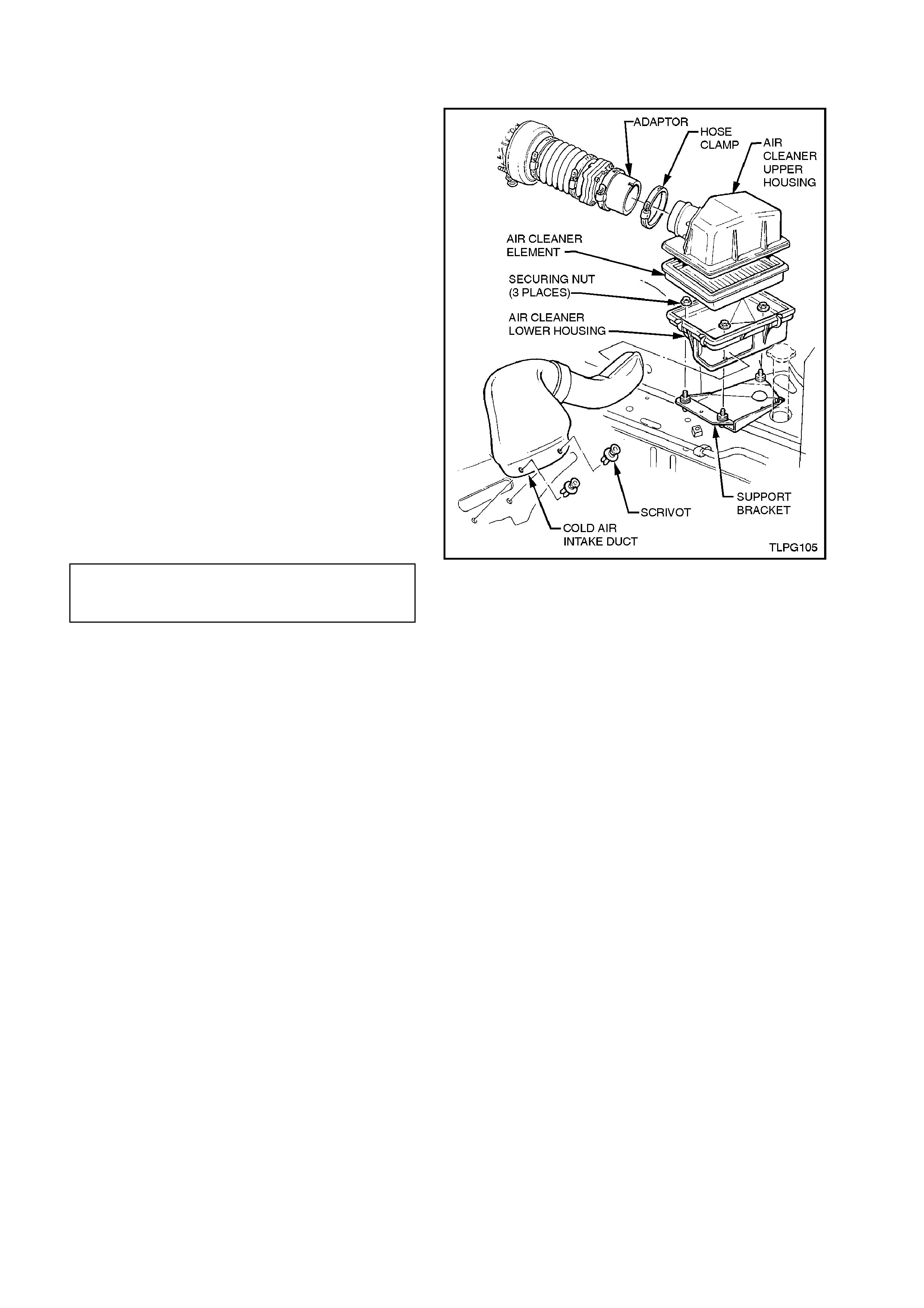
2.25 AIR CLEANER ASSEMBLY
REMOVE
1. Loosen air duct adaptor located closest to the
air cleaner assembly.
2. Disconnect air duct from air cleaner assembly.
3. Unclip the clips holding the air cleaner upper
housing in place.
4. Remove air cleaner upper housing and air
cleaner element assembly.
5. Remove the two scrivets securing the cold air
intake duct to the front panel, disengage cold
air intake duct from lower housing and
remove cold air intake duct.
6. Remove the three nuts securing the air
cleaner lower housing to the air cleaner
support bracket and remove lower housing.
REINSTALL
Reinstallation of the air cleaner assembly is the
reverse of the removal procedure, noting the
following:
1. Ensure all fasteners are tightened to the
correct torque specification.
AIR CLEANER LOWER HOUSING
SECURRING NUT 5.0 - 7.0 Nm
TORQUE SPECIFICATION
Figure 2-144

2.26 AFTER INSTALLATION CHECK
GENERAL INFORMATION
At the 1,500 km (or 1 month) it is a requirement of
General Motors -Holden's Automotive Limited A.B.N.
84 006 893 232 that the following ‘After Installation
Check’ be performed.
All items in this check list must be checked to ensure
they have been adjusted or installed as outlined as
per the service information.
UNDERBODY (Tick the appropriate boxes)
CHECK OK REPAIR
1. Rear service line and intermediate service line
connected to union (under vehicle) and
connectors tightened to the correct torque
specification.
!!!
2. Service lines correctly routed and retaining clips
installed. !!!
3. LPG cylinder correctly installed and attaching
nuts tightened to the correct torque specification. !!!

REAR COMPARTMENT (Tick the appropriate boxes)
CHECK OK REPAIR
1. Floor flange installed and silicone sealer applied. !!!
2. Service line vent tube installed to floor flange and
retaining clamps tightened. !!!
3. Service line vent tube installed to joiner and
retaining clamp tightened. !!!
4. Filler line connected to joiner and LPG cylinder
high pressure inlet elbow and filler line
connectors tightened to the correct torque
specification.
!!!
5. Filler installed correctly and retaining cap screws
tightened to the correct torque specification. !!!
6. Filler lid operates without binding and shuts
flush, AFL sticker is affixed to inside of filler lid. !!!
7. Rear service line connected to solenoid and
manual service valve assembly and connector
tightened to the correct torque specification.
!!!
8. LPG cylinder level sender and smart unit
harness connector is connected to LPG body
harness connector (LP5).
!!!
9. Rear compartment carpet and quarter trim
carpet have been reinstalled and are positioned
correctly.
!!!

UNDER BONNET (Tick the appropriate boxes)
CHECK OK REPAIR
1. The vapour line to mixer and vapour line to
converter retaining clamps are installed and
tightened.
!!!
2. The vapour line and vacuum hoses are
connected and routed correctly. !!!
3. Converter and converter bracket installed and
retaining bolts are tightened to the correct torque
specification.
!!!
4. Coolant pipe hose clamps fitted and tightened.
Coolant and vapour hoses correctly routed to
avoid contact with engine or body parts.
!!!
5. Fuel control valve (FCV) installed and FCV
retaining bolt tightened to the correct torque
specification.
!!!
6. Air intake tube installed, clamps and mounting
screw tightened to the correct torque
specification.
!!!
7. Air cleaner assembly and MAF sensor installed. !!!
8. Intermediate LPG line P clamps installed on
cockpit module and tightened to the correct
torque specification.
!!!

LEAK CHECK
With at least 3 litres of LPG in the cylinder, leak test the complete LPG system as outlined in 2.3 LEAK TESTING
in this Section. Note: the following points must be tested. (Tick the appropriate boxes)
CHECK OK REPAIR
1. Pressure relief valve. !! !
2. Solenoid and manual service valve assembly to
LPG cylinder. !! !
3. Solenoid and manual service valve assembly. !! !
4. Rear service line to solenoid and manual service
valve assembly connector. !! !
5. LPG cylinder fuel gauge assembly. !! !
6. AFL inlet elbow to LPG cylinder. !! !
7. Rear service line to AFL inlet elbow connector. !! !
8. AFL to LPG cylinder. !! !
9. Filler valve to filler line. !! !
10. Filler valve check ball. !! !
11. Rear service line to intermediate service line
joiner connection. !! !
12. Intermediate service line to rear service line
joiner connection. !! !
13. Intermediate service line to front service line
joiner connection. !! !
14. Front service line to intermediate service line
joiner connection. !! !
15. Front service line to LPG lockoff inlet connection. !! !
16. LPG lockoff inlet connection to LPG lockoff. !! !
17. LPG lockoff. !! !
18. LPG lockoff to LPG lockoff outlet connection. !! !
19. LPG lockoff outlet connection to converter. !! !