
SECTION 1 - PRINCIPLES OF OPERATION
CAUTION:
This vehicle will be equipped with a Supplemental Restraint System (SRS). A SRS will
consist of either seat belt pre-tensioners and a driver's side air bag , or seat belt pre-
tensioners and a driver's and front passenger's side air bags. Refer to CAUTIONS,
Section 12M, before performing any service operation on, or around any SRS
components, the steering mechanism or wiring. Failure to follow the CAUTIONS
could result in SRS d eployment, resultin g in po ssible personal in jury or unnecessary
SRS system repairs.
1. GENERAL INFORMATION
As of May 1998, the Liquefied Petroleum Gas (LPG) option KL7 becomes available for VT Series W agon Models.
This LPG system essentially carries over from the LPG system fitted to VT Series Sedans with changes to:
components rearward of the body C pillar, different routing for the ADP vacuum line, and a new toroidal shaped
LPG tank which fits inside the spare wheel compartment.
Additionally, VT Executive Wagon Models have a higher strength wheel to accommodate the increased vehicle
mas s. T hese wheels c an be identified by a white paint mark on the outer face of the wheel, between the wheel stud
holes.
If there is ever a need to replace the drive wheels on VT Wagon Models, always check the latest spare parts
information, to ensure the correct wheel is selected.
Coinciding with the release of LPG for VT W agon Models, comes the introduction of an accessory LPG kit for VT
Sedan Models. This accessory LPG kit is essentially the same as that fitted to VT Sedans in production, with the
exception of: the service lines, the service line retainment, wiring harness, fuel mode switch and LPG relay.
As of 27/07/1999, VT Sedans fitted with traction control can also be fitted with the accessory LPG system. It is
impor tant to note that when the LPG s ystem is in operation mode, the trac tion control system will be disabled. T he
driver of the vehicle will be made aware of this by the illumination of the ‘trac off’ lamp on the instrument panel.
The quickest and easiest way to distinguish between a production fitted or an accessory fitted LPG system on VT
Series Sedans is by the location of the fuel m ode switch. On production fitted LPG systems , the fuel mode switch is
located in the centre console, next to the tr ansmiss ion selector lever. On acc essory fitted LPG system s, the switch
is located in the instrument panel centre facia.
For General Information, Safety Precautions, Principles of Operation, Service Operations, Diagnosis, Specifications,
Torque Wrench Specifications, and Special Tools not listed in this publication, refer
VT SEDAN WITH FACTORY FIT LPG SYSTEM of the VT Series Service Information CD.
Fig. 1-1 shows the location of the LPG com ponents f itted to VT Series Wagon Models and Fig. 1-2 shows the LPG
operation for VT Series Wagon Models.
Techline
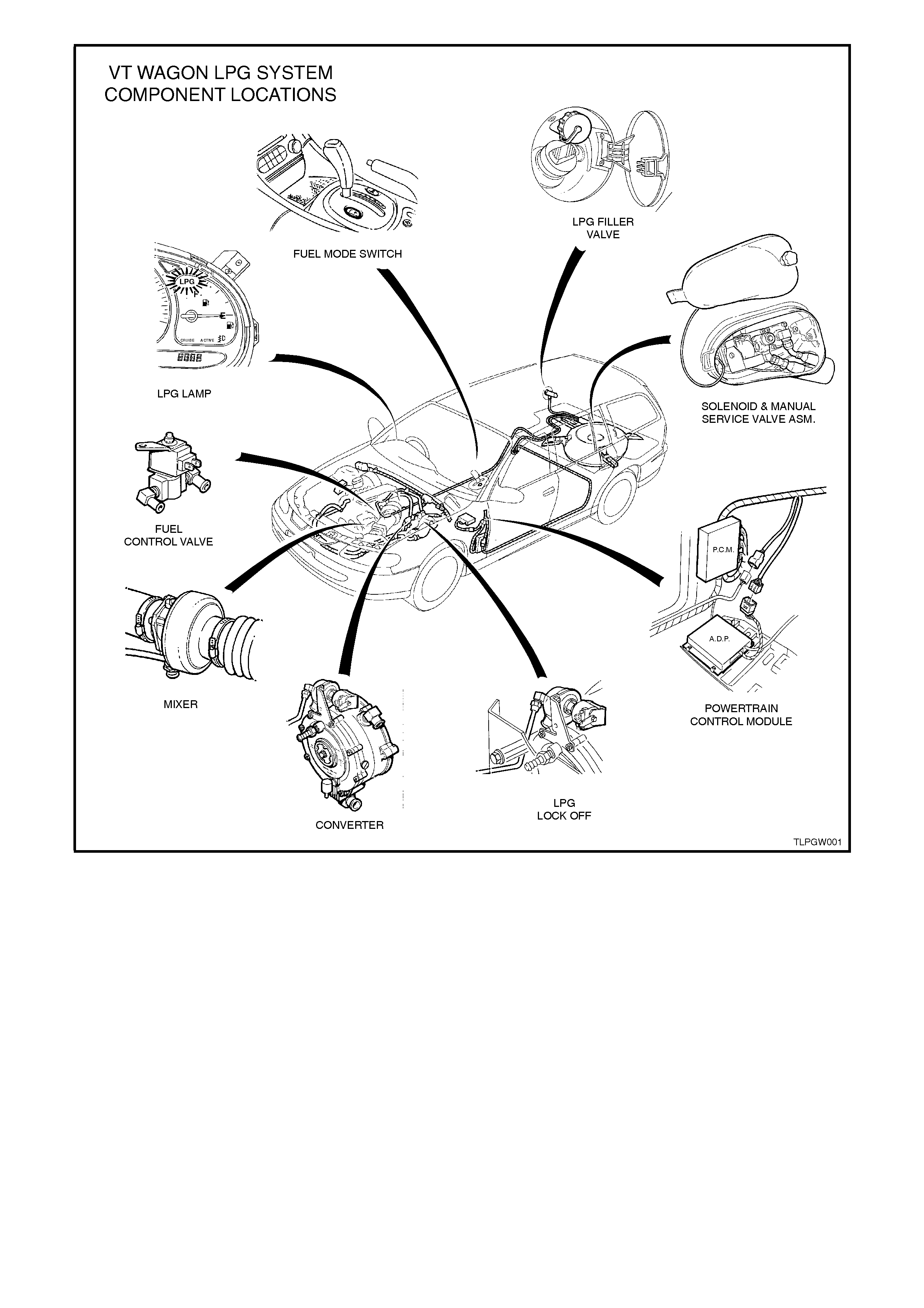
Figure 1-1
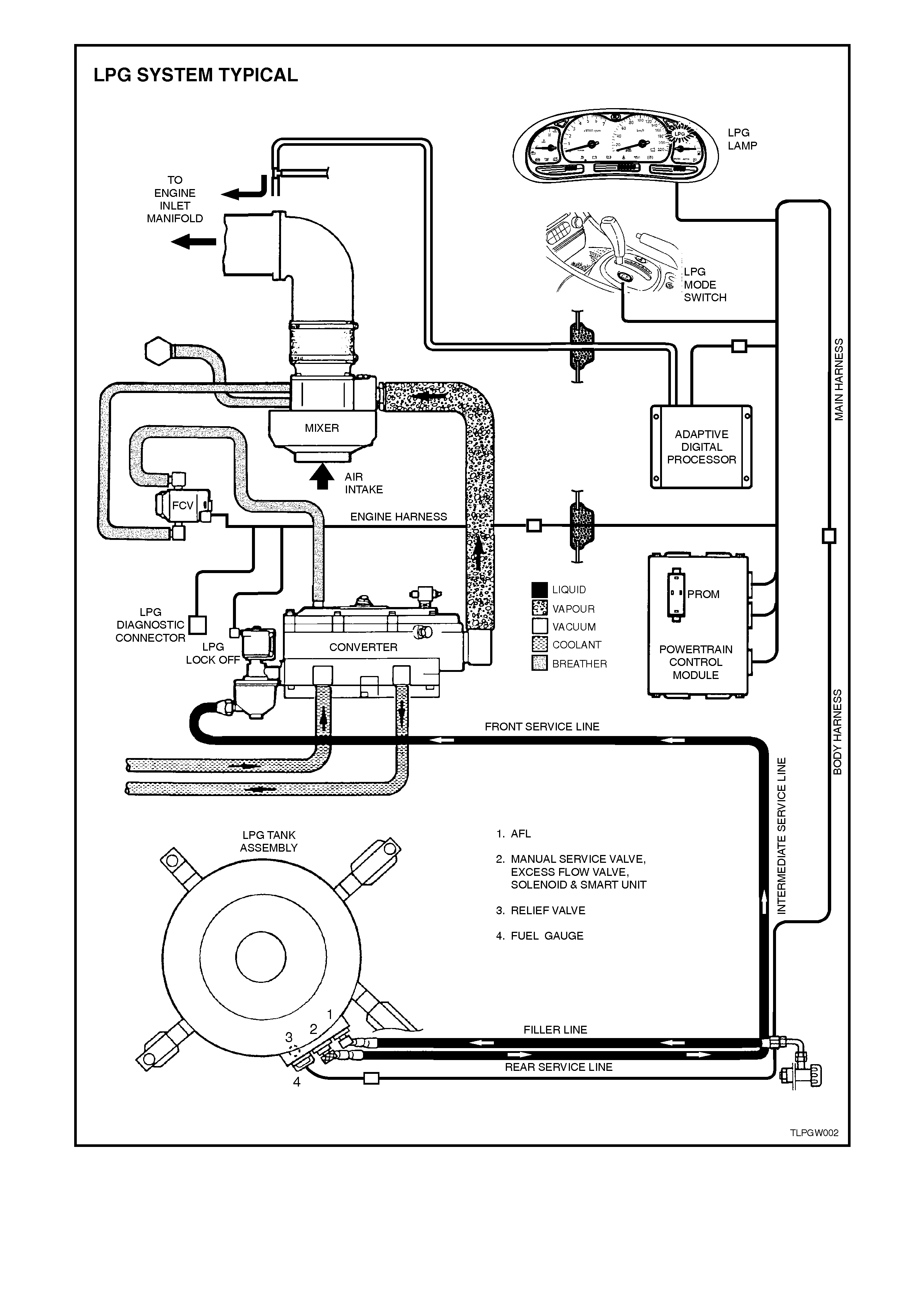
Figure 1-2

1.1 SAFETY PRECAUTIONS
Safety precautions for VT Series Sedans with an accessory LPG system and VT Series Wagons production fitted
LPG systems are essentially the same as VT Series sedans with production fitted LPG systems, therefore refer to
Section 1.1 SAFETY PRECAUTIONS in VT Sedan With Production LPG of the VT Series Service Information CD,
noting the following points:
When draining the service lines, unloading the LPG tank or performing a leak test, refer to the various Service
Operations.
1.2 LPG TANK
The LPG tank on VT Wagon Models is a toroidal
shaped tank which is designed to fit within the
spare wheel compartment in the luggage
compartment (the spare wheel is relocated). LPG
tanks are made of carbon steel and manufactured
to stringent safety standards. LPG must be stored
at approximately 750 kPa at 20°C to remain a
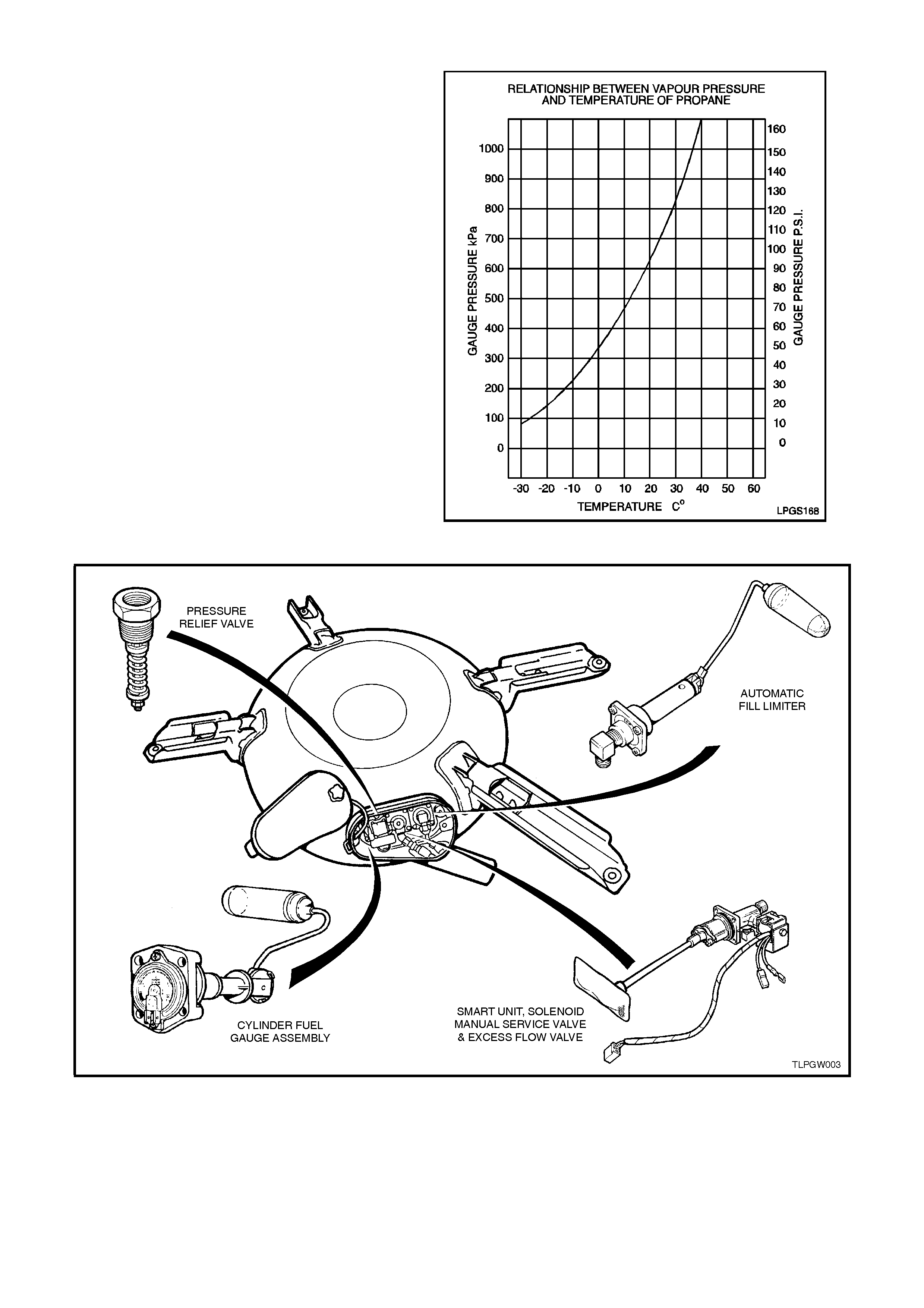
liquid. The vapour pres s ure ins ide the LPG tank will
vary with ambient temperature, as the ambient
temperature rises so does the vapour pressure,
refer Fig.1-3.
The LPG tank is heat treated during manufacture
and MUST NOT be heated or welded in any way
during servicing or installation.
The LPG tank fitted to VT Wagon Models has a
gas tight compartment (valve box), which contains
the following components: (refer Fig. 1-4)
Automatic Fill Limiter (AFL), Tank Fuel Gauge
Assembly, Smart Unit, Solenoid and Manual
Service Valve Assembly and a Pressure Relief
Valve. These components are either screwed into
or onto the LPG tank. As the LPG tank is located in
the luggage compartment, if any of these
components were to leak, or there was an excess
pressure discharge, the LPG would be vented to
atmosphere via a vent hose and will not vent into
the vehicle. Figure 1-3
Figure 1-4
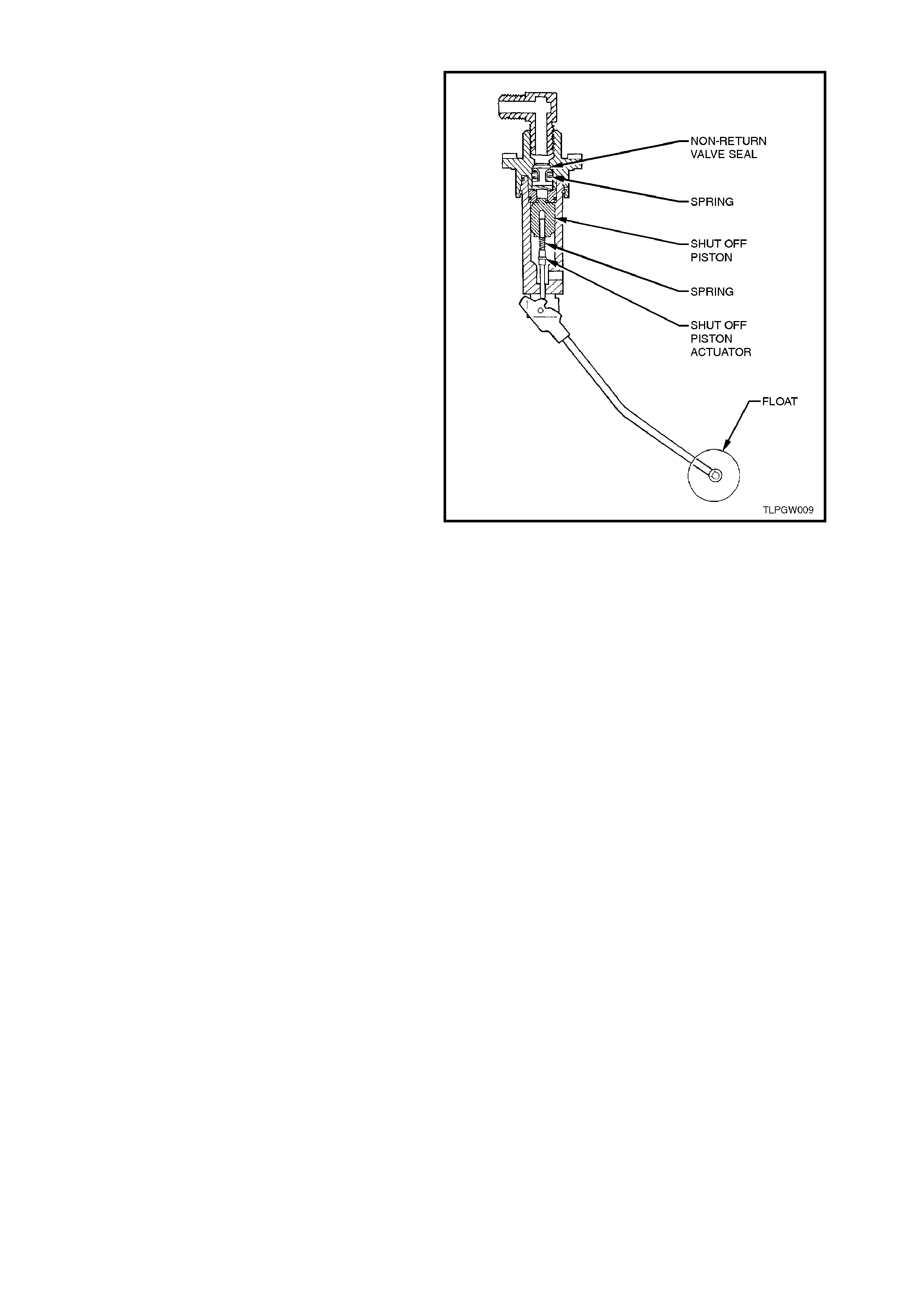
1.3 AUTOMATIC FILL LIMITER
The Autom atic Fill Limiter (AFL) f itted to VT Wagon
models is retained to the LPG tank by four screws
with the filler line c onnec ted to the inlet elbow of the
AFL. When the tank is being filled with liquid LPG,
the AFL float rises with the liquid in the LPG tank
and shuts off the valve when the tank is 80% full.
The remaining 20% of the tank volume is
necessary vapour space to allow for the expansion
of the liquid that occurs as the temperature of the
liquid increases.
Figure 1-5
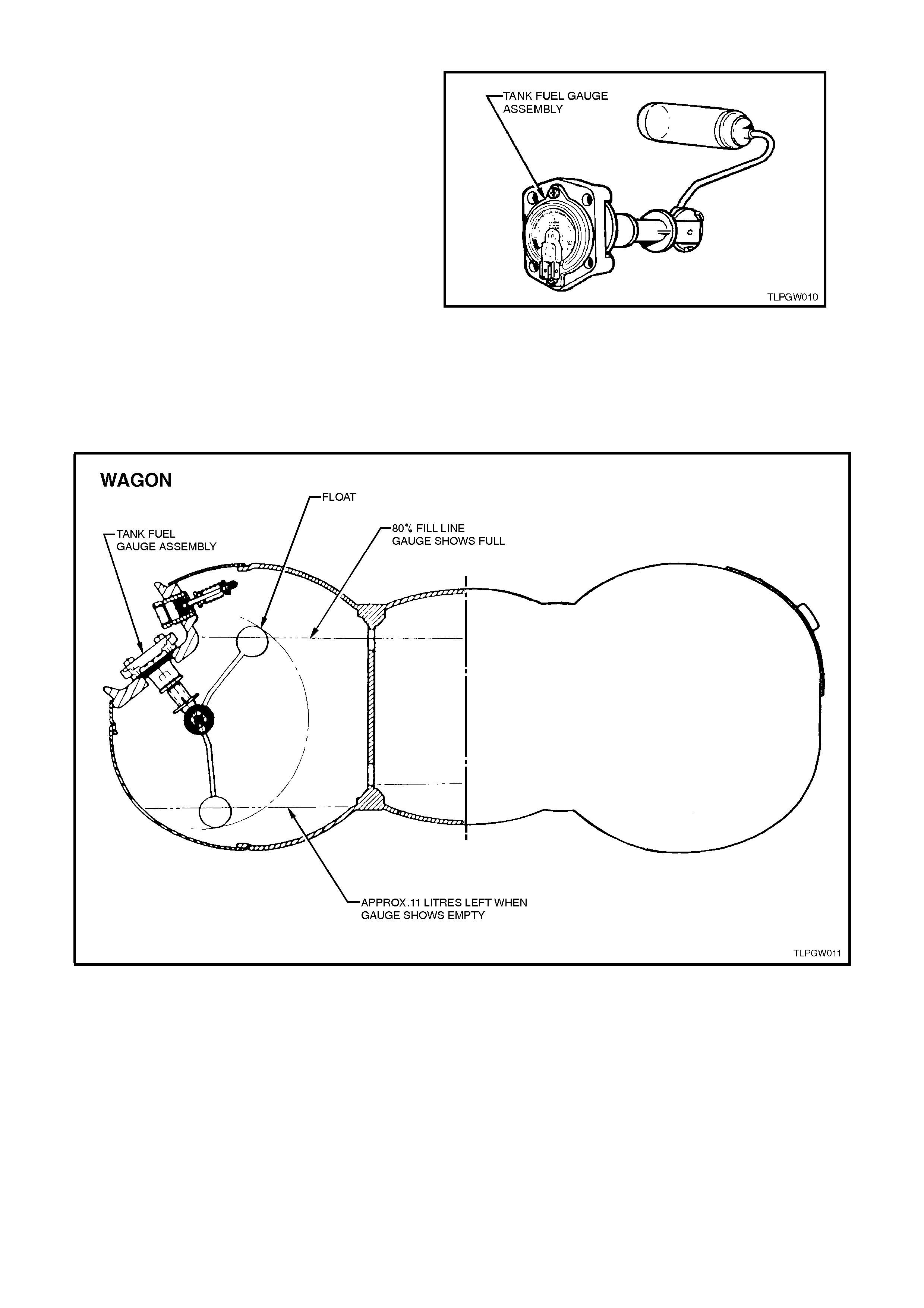
1.4 TANK FUEL GAUGE ASSEMBLY
The tank fuel gauge assembly fitted to VT Wagon
Models has a f loat similar to a petrol gauge sender
unit, as the liquid level in the LPG tank ris es so too
does the float. The float is connected to a magnet
within the assembly. Any change in the position of
the liquid level is transmitted to the fuel contents
gauge via the float and m agnet. The m agnetic field
produced by the magnet causes the fuel contents
gauge mounted on the ex terior of the tank to move
in relation to the magnet's position.
The fuel contents gauge will show full when the
liquid level in the tank is at 80%. The fuel gauge
sender unit within the fuel contents gauge has a
variable resistor which will vary its resistance from
approximately 40 ohms when the tank is empty to
approxim ately 255 ohms when the tank is full. This
change in resistance is sensed by the instrument
fuel gauge. The instrument fuel gauge will display
the contents of the LPG tank when operating on
LPG and the contents of the petrol fuel tank when
operating on petrol.
Figure 1-6
Figure 1-7
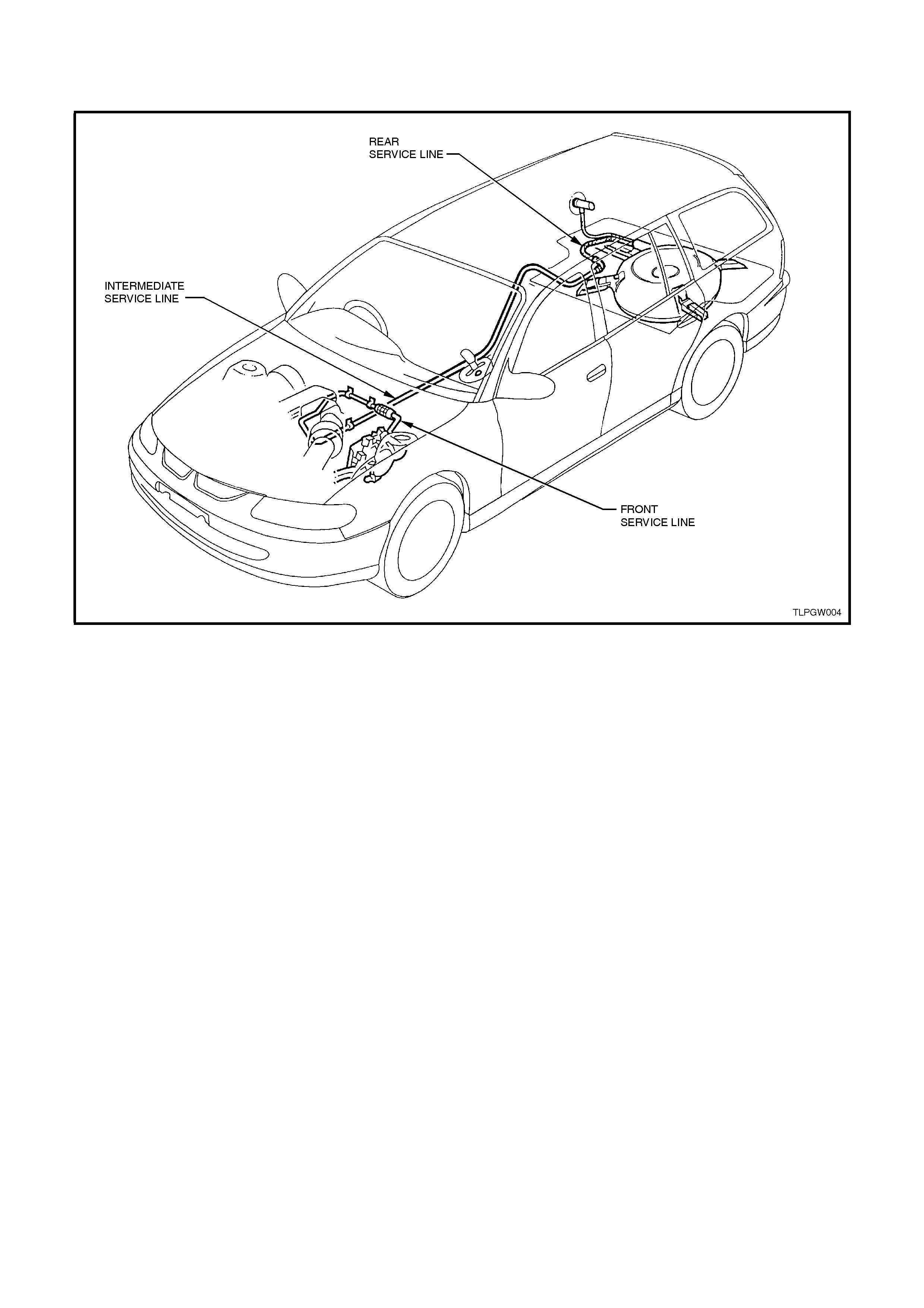
1.5 SERVICE LINE
The service line carries the liquid LPG from the solenoid and manual service valve to the LPG lockoff. The service
line consists of three major components; the front, intermediate and rear service lines.
Figure 1-8