
SECTION 0C - TECH 2
Click on the button for more information. CAUTION:
This vehicle will be equipped with a Supplemental Restraint System (SRS). A SRS will
consist of either seat belt pre-tensioners and a driver's side air bag, or seat belt pre-
tensioners and a driver's and front passenger's side air bags. Refer to CAUTIONS,
Section 12M, before performing any service operation on, or around any SRS
components, the steering mechanism or wiring. Failure to follow the CAUTIONS
could result in SRS deplo yment, resulting in possible p ersonal injury or unnecessary
SRS system repairs.
CAUTION:
This vehicle may be equipped w ith LPG (Liquefied Petroleum Gas). In the interests of
safety, the LPG fuel system should be isolated by turning 'OFF' the manual service
valve and then draining the L PG service lines, before any servi ce work is carried out
on the vehicle. Refer to the LPG leaflet included with the Owner's Handbook for
details or LPG Section 2 for more specific servicing information.
1. GENERAL INFORM ATION
The Tech 2 is a hand-held diagnostic computer designed specifically to help you diagnose and repair electronic
systems used on holden vehicles.
When the TECH 2 is attached to a vehicle it can be a very versatile tool. With its large, easy-to-read display, the
TECH 2 guides you step-by-step through the testing procedures. You respond to the TECH 2 through the keyboard
commanding it to:
• Conduct the test you want to run
• Retrieve the diagnostic data you want
• Control the function you want to monitor
The TECH 2 gets its power from the vehicle to be tested and communicates or interfaces with the vehicle electronic
systems through the Data Link Connector (DLC). TECH 2 can communicate with the following control modules, if
the vehicle is equipped with these systems.
• Body Control Module (BCM).
• Powertrain Control Module (PCM).
• Instrument (INS).
• Supplemental Restraint System (SRS).
• Antilock Braking System / Electronic Traction Control System (ABS/ETC).
When connected to the DLC, the TECH 2 can read Diagnostic Trouble Codes (DTC) and diagnostic data.
Depending on the application selected, TECH 2 can also control some systems for troubleshooting or automatic
testing.
Techline
Techline
Techline
Techline
Techline
Techline
Techline
Techline
Techline
Techline
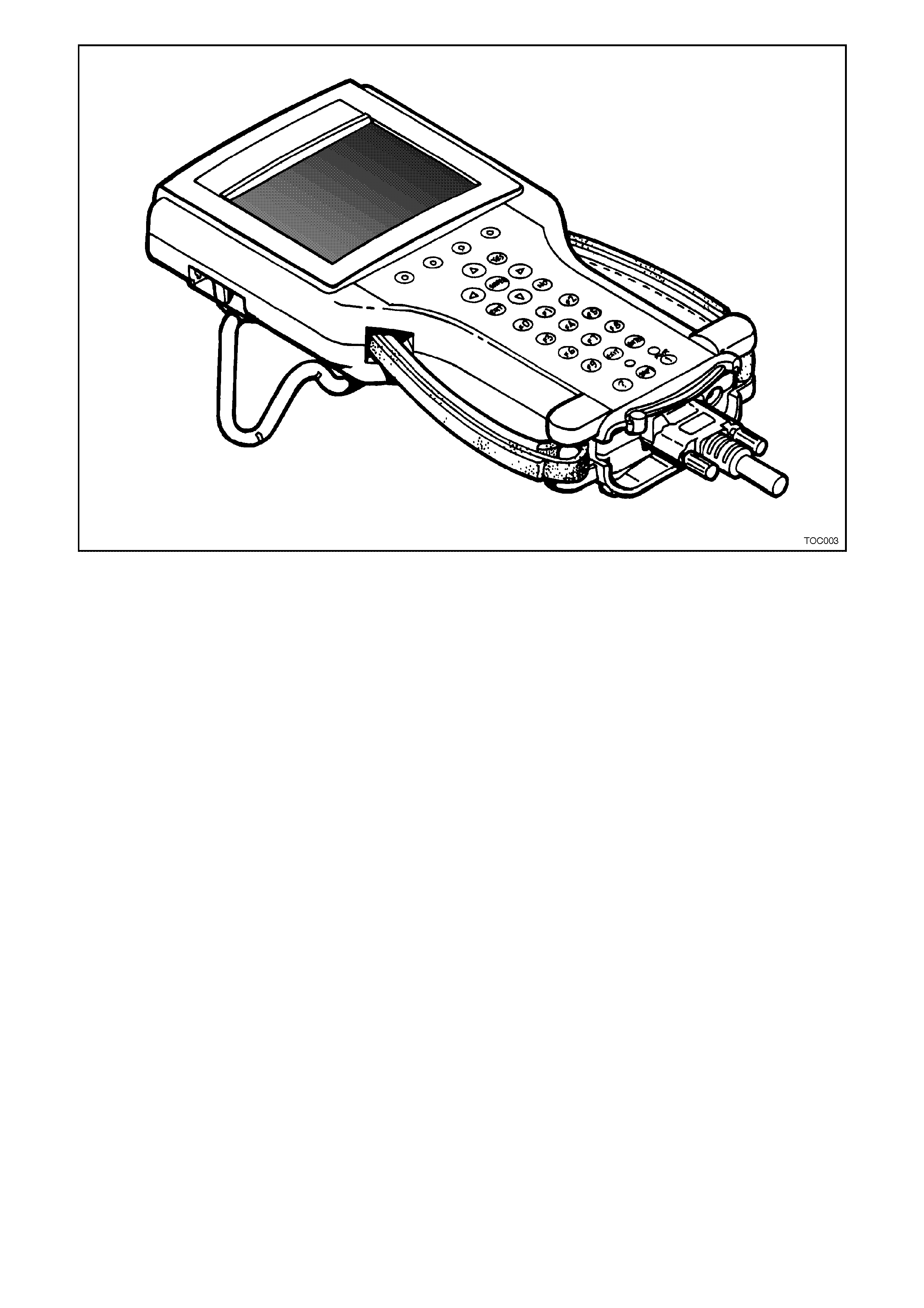
Figure 0C-1 TECH 2
1.1 FEATURES OF THE TECH 2
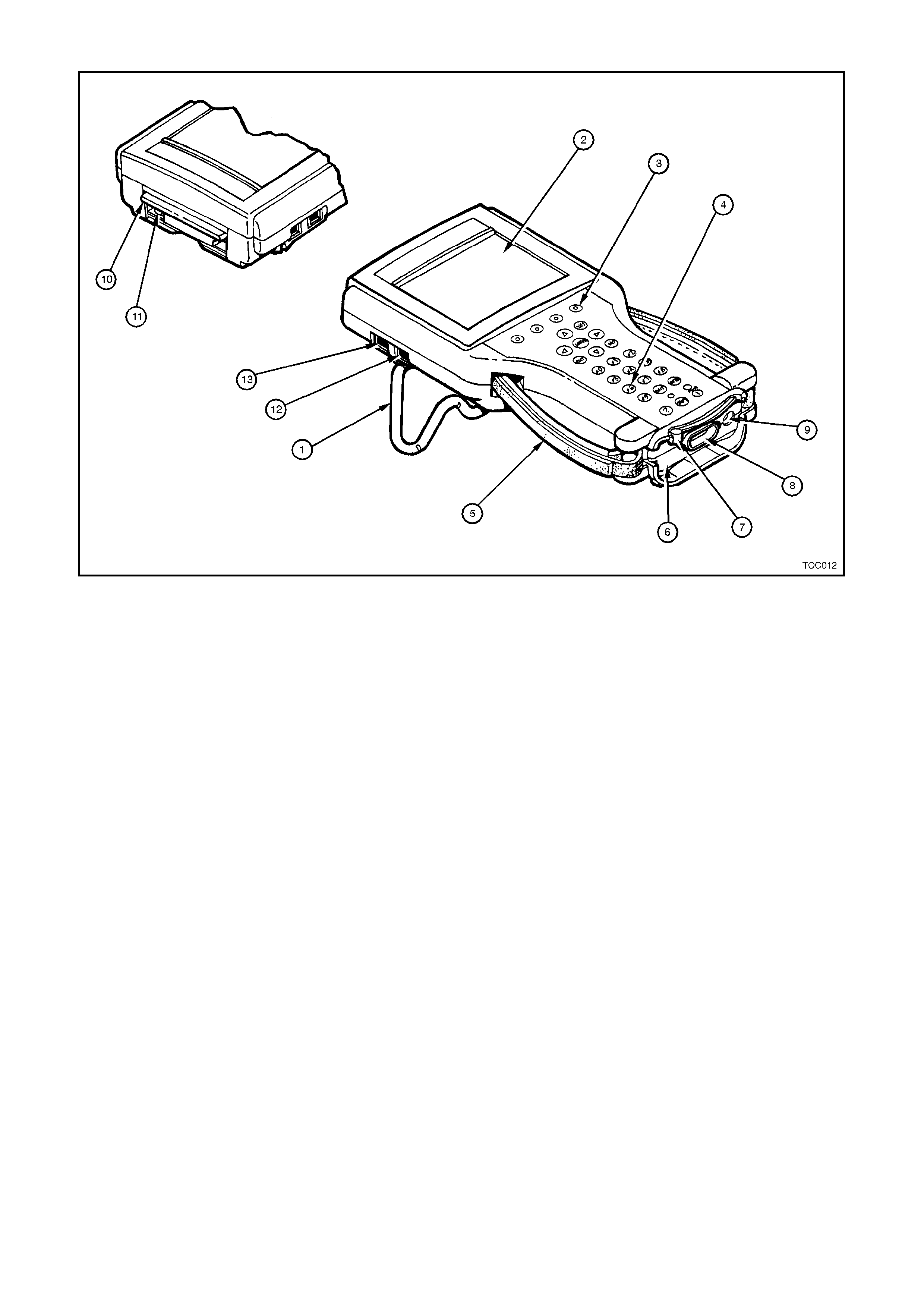
Figure 0C-2 Features of TECH 2
1. Tilt Stand 2. Display 3. Soft Keys
4. Keypad 5. Adjustable Hand Strap 6. Vehicle Communication Interface (VCI)
7. VCI Latching Lever 8. DLC Connector 9. Power Jack
10. PCMCIA Cover 11. PCMCIA Release Button 12. RS-232 Communication Port
13. RS-485 Communication Port
SIZE
The TECH 2 is 305 mm x 152.5 mm x 50.8 mm and weighs approximately 1 kg. This weight is about the same as
the Tech 1.
POWERFUL
The TECH 2 is a tool that is designed to work for many years to come. Because it is extremely more powerful than
the Tech 1, the TECH 2 will be able to help you diagnose vehicles for the foreseeable future.
In the past, as communication from the various microprocessors has evolved, either new tools were created or
adapters were created. The TECH 2 is designed to evolve with the vehicle. Because it uses a Vehicle
Communication Interface (VCI) as an adapter to the DLC, the tool can be updated by a simple change of the VCI
module. This allows hardware updating of the TECH 2 without requiring adapters such as the Switched Adapter
which was used by the Tech 1.
DISPLAY
A large screen, Monochrome Liquid Crystal Display (LCD) which measures 100 x 76 mm is used on the TECH 2.
This allows nine parameters to be seen on screen at the same time. The screen has graphics capabilities which
allow graphs to be plotted on the screen to aid diagnosis. The tool may, in the future, allow some additional graphic
images to be displayed which will help diagnose vehicle systems.
The TECH 2 has an adjustable contrast control to allow the user to change brightness and contrast of the display.
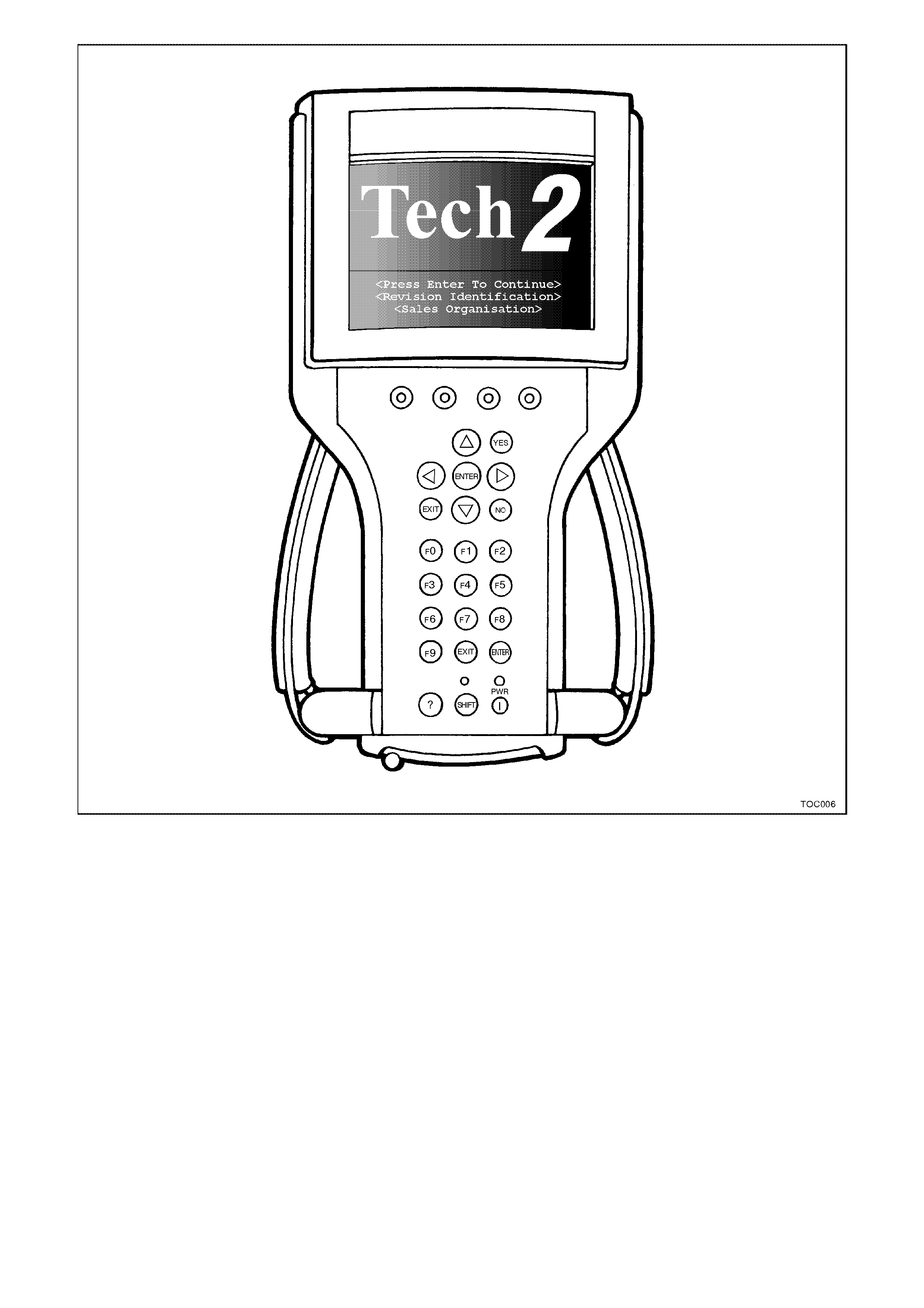
Figure 0C-3 TECH 2 Display
SCREEN AREAS
The screen is broken down into five areas. By looking at the information which is displayed in each area, the user
may use the tool more efficiently.
• Title area
• Message area
• Display/select area
•Full text area*
• Soft key area
*The "full text" area is always a complete description of the highlighted line in the "display/select" area.
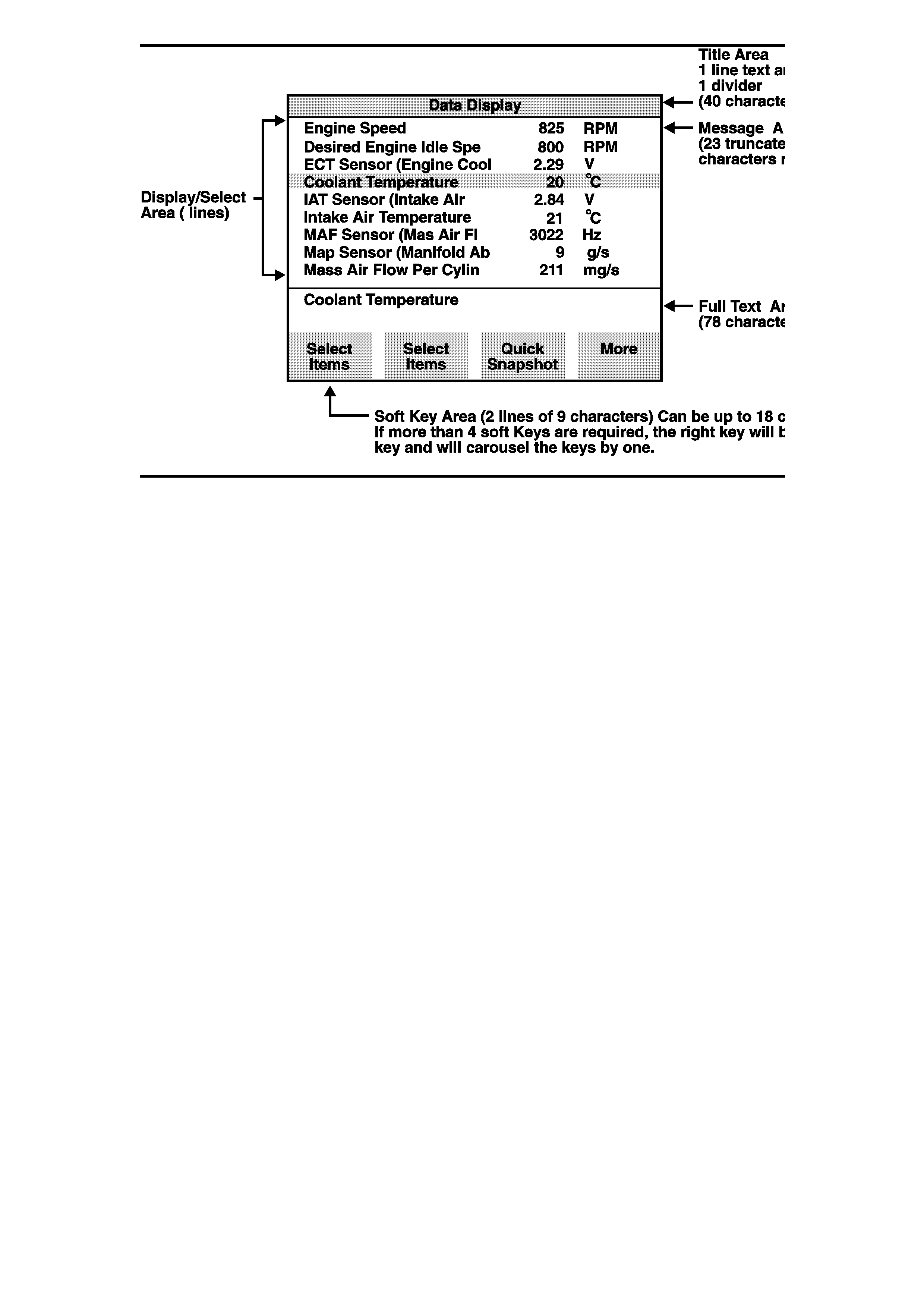
Figure 0C-4 TECH 2 Screen Areas
KEYPAD
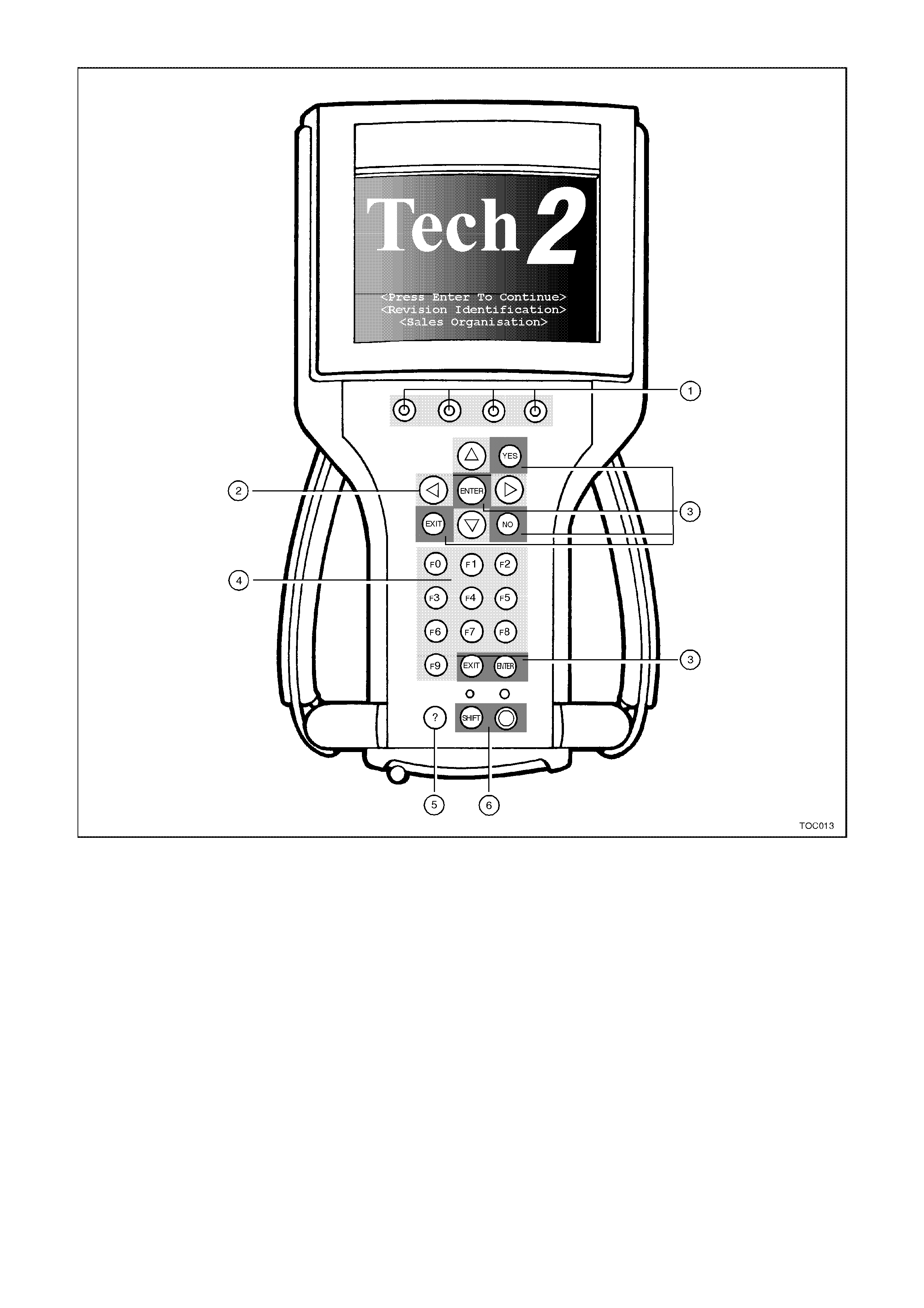
Figure 0C-5 Keypad
1. Soft Keys 2. Selection Keys 3. Action Keys
4. Function Keys 5. Help Key 6. Control Keys
KEYP AD LAYOUT
The keypad of the TECH 2 contains 27 keys. Within these keys are 23 keys which are pre-defined and four keys
which are referred to as soft keys. The soft key usage will change depending on which part of an application is
being used. Following is a definition of the key usage for the pre-defined keys.
SOFT KEYS
There are four keys on the TECH 2 which will have changing usage within an application. Soft key functions are
software driven. This means that the soft key function may change in different areas of the software. The left most
soft key at the Main Menu will be used to Clear Vehicle, while in Snapshot the same key position may change Units.
The ability of the soft keys to perform different tool operations at different times increases the versatility of the TECH
2.

SELECTION KEYS
The arrow keys are used for screen movement to make a selection. There are four arrow keys. The Up and Down
arrows move the highlight bar one line at a time. If they are held, the highlight bar will scroll. The Left and Right
arrow keys will move the highlight a page at a time. Left arrow moves the highlight up (previous page) and Right
arrow moves the highlight down (next page). The arrow keys are used to move the highlight bar to a position to
make a selection, or to move the display to allow more information to be viewed.
ACTION KEYS
There are a group of keys which are referred to as Action keys. As the name implies, action keys will make an
action take place on the TECH 2 tool. The action keys are YES, NO, ENTER, and EXIT.
YES — Confirms a positive response to a question.
NO — Confirms a negative response to a question.
ENTER (2 keys) — Indicates a selection has been made.
EXIT (2 keys) — Returns user to a previous menu selection.
FUNCTION KEYS
The function keys (F0 - F9) allow direct selection of a choice from a menu.
Help Key
Help (?) accesses a tool help function which is specific to the current operation of the TECH 2.
CONTROL KEYS
There are two keys which are used to control the TECH 2 itself. These are the SHIFT and PWR (Power) key s. The
SHIFT key will access screen contrast control. To adjust contrast during the current power cycle of the TECH 2, use
the following procedure.
Press the SHIFT key (The yellow light will turn on).
Use the Up arrow to Increase screen brightness and contrast or the Down arrow to Decrease screen brightness
and contrast.
Press the SHIFT key (the yellow light will turn off).
This procedure will only adjust the contrast for the duration of this power cycle of the TECH 2. If the power is turned
off and then back on again, the contrast will change to a default value. The default setting is covered in the TECH 2
User’s Guide.
Be aware that if the yellow SHIFT light is on, only the Up/Down arrow keys and the EXIT keys are active.
There is a PWR (Power) switch for TECH 2 which will control turning the TECH 2 on and off. A green indicator will
illuminate when the TECH 2 is switched on.
THUMB ACTION
The TECH 2 is designed for one handed operation. The unit is balanced to allow one hand to comfortably hold and
operate the tool. Straps on the sides of the tool are adjustable to help hold the TECH 2 in one hand. The keypad
configuration is designed for thumb usage while holding the tool in either the left or right hand. It is suggested to use
the selection and action keys instead of the function keys as some TECH 2 screens require making selections from
a list on screen. In these cases there may not be a function key equivalent.
PCMCIA CARD
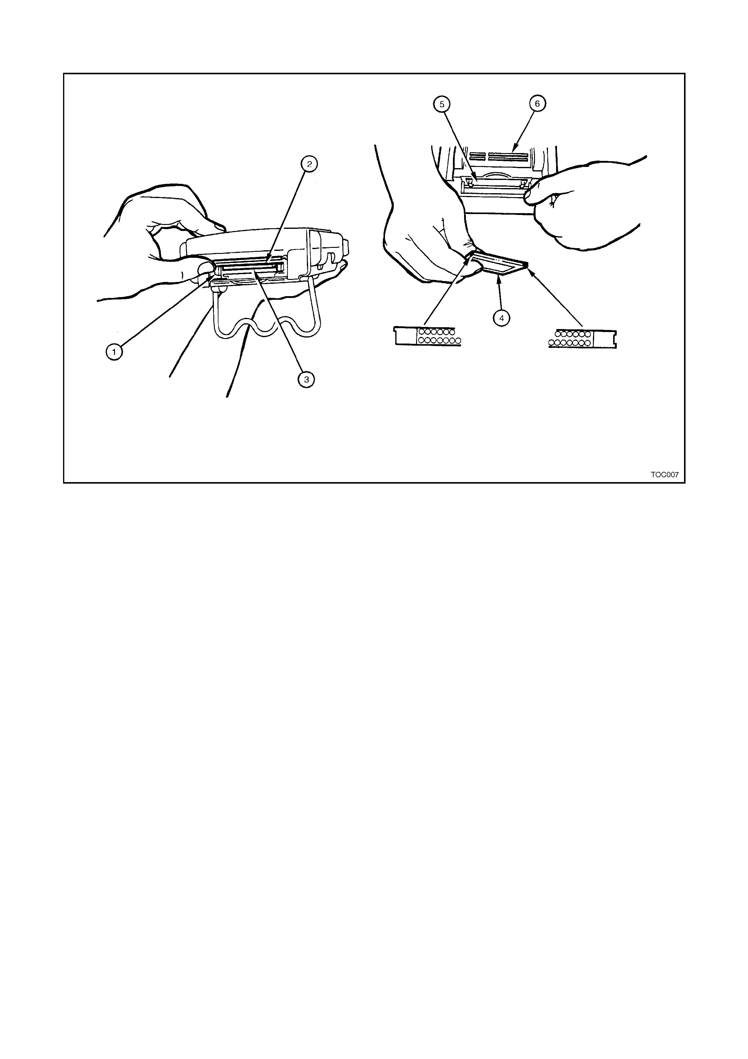
Figure 0C-6 PCMCIA Card
1. PCMCIA Release Button 2. In Use Upper PCMCIA Slot 0 3. Empty Lower PCMCIA Slot 1
4. TECH 2 PCMCIA Card 5. PCMCIA Cover 6. Underneath Side of TECH 2
The TECH 2 uses a Personal Computer Memory Card Industry Association (PCMCIA) standard memory card for
storage of diagnostic functions and applications. The memory card has a capacity of 10 Megaby tes which is ten
times the amount of memory of the Tech 1 Mass Storage Cartridge (MSC). Because there is more memory, there is
storage capability for two snapshots. This will allow comparison of before/after type conditions on a vehicle being
serviced.
The PCMCIA card is accessed through a door on top of the unit, and should not normally require removal. The card
is ejected by pushing the arrow button pointing to card to be removed. Cards are notched to allow insertion only one
way. When re-inserting the card make sure that it fully seats into the TECH 2. The PCMCIA card fits into slot zero
which is closest to the screen. There is a second slot for possible future expansion. The second slot is identified as
slot one.
NOTE:
The PCMCIA card is sensitive to magnetism and static electricity so care should be taken in the handling of
the card.
A write protect slide mechanism is on the top edge of the card. The correct position is to the middle of the card
(unlocked). If the write protect is in the locked position, snapshots will not be able to be stored, and Service
Programming will not work.
TECH 2 and PCMCIA card will be updated by connecting to a Technical Information System (TIS).
The software that operates the TECH 2 is stored on the PCMCIA card. The contents of the card are not distinct
applications. All of the applications share a single database of information on the TECH 2's PCMCIA card.
VEHICLE COMMUNICATION INTERFACE MODULE
The TECH 2 uses a Vehicle Communication Interface (VCI) module, located in the bottom of the unit to act as an
interface between the vehicle and the internal workings of the TECH 2. This allows the TECH 2 to communicate to
many different types of data systems on vehicles.
Data is transmitted between the vehicle and the TECH 2 through the DLC cable. Power for the TECH 2 is also sent
through the VCI module. Power can either come through the DLC cable or from the power jack on the bottom of the
VCI module. Internally, the VCI module protects the TECH 2 against reverse polarity power connections.
During normal usage of the TECH 2, there is no reason to remove the VCI module. In the future, if different types of
data communication are used on the vehicle, the VCI module could be changed to extend the useful life of the
TECH 2 even further. To remove the VCI module, refer to the TECH 2 User's Guide.
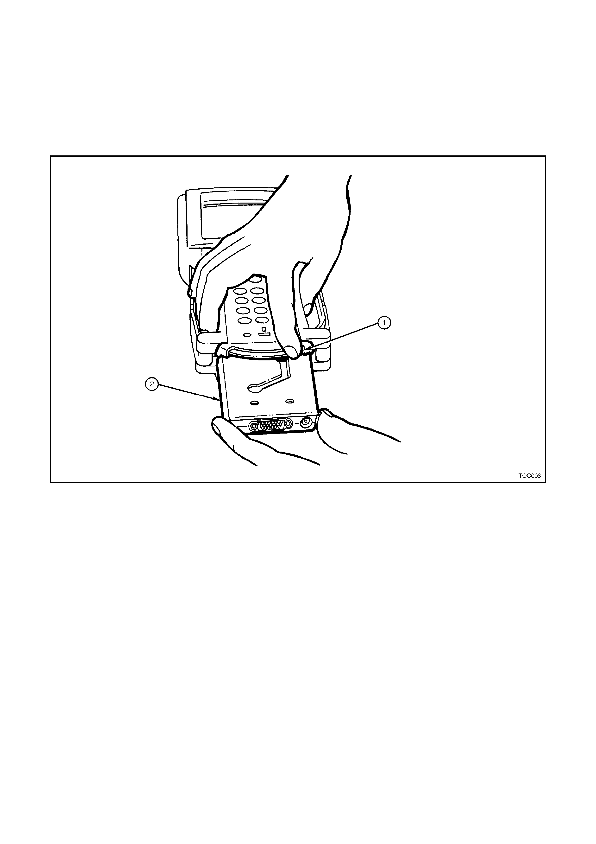
Figure 0C-7 VCI Module
1. VCI Module Lever (moved all the way to the right) 2. VCI Module
SERIAL PORTS
TECH 2 also has two serial port connections for communication to other computers such as TIS. These ports are
the RS-232 and the RS-485. The RS-232 is used for connecting to TIS for updating the contents of applications on
the TECH 2. To perform Service Programming with the TECH 2 the RS-232 port is also used.
The RS-485 is currently not used, but may in the future allow for other tool capabilities.
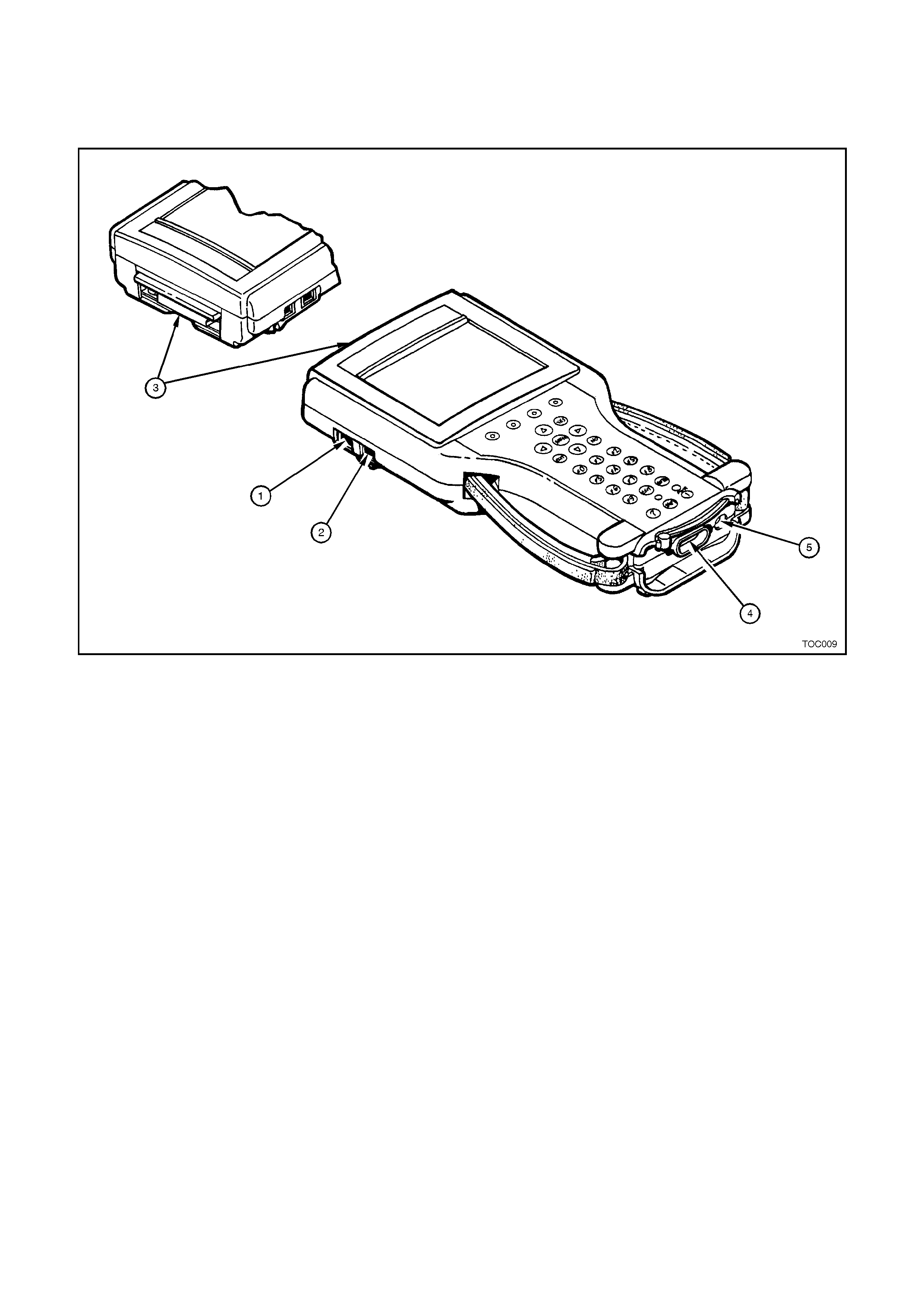
Figure 0C-8 Serial Ports
1. RS-485 Port 2. RS-232 Port 3. PCMCIA Slots
4. DLC Connector 5. Power Jack Connector
ADAPTERS FOR TECH 2
The TECH 2 includes a selection of cables and adapters to accommodate a variety of operating conditions and
functions.
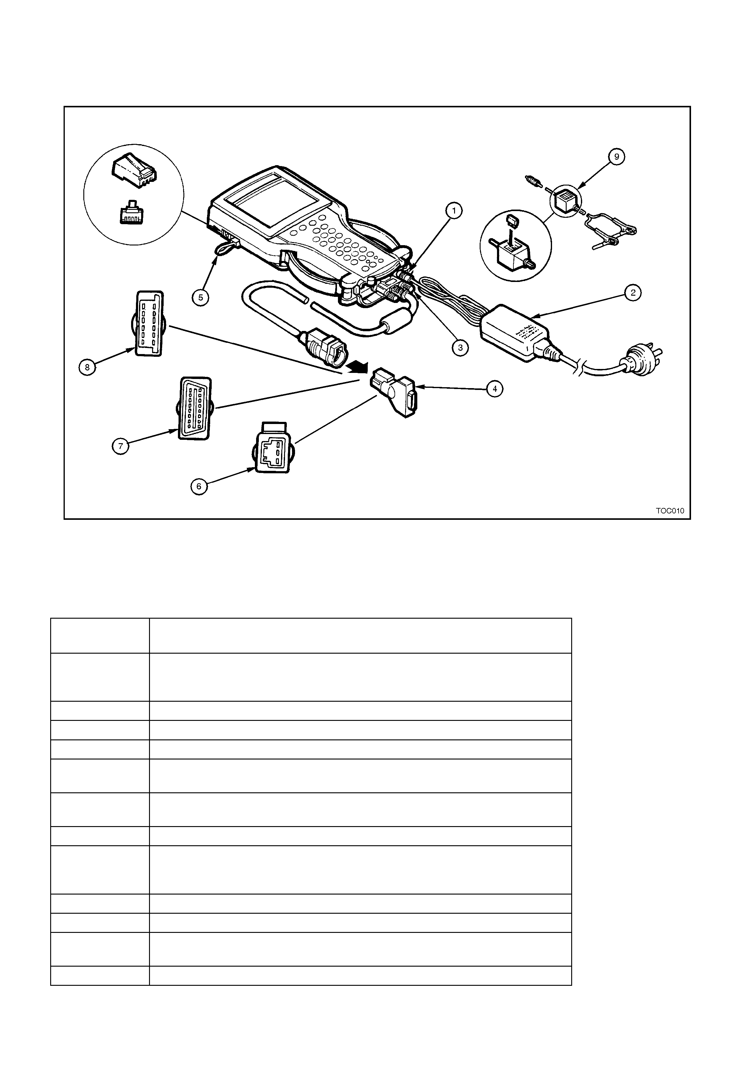
Figure 0C-9 Adapters for TECH 2
1. Power Jack 2. Power Supply 3. DLC Cable
4. DLC Loopback Connector 5. RS-232 Loopback Connector 6. Opel/Isuzu/Geo 3/19 Pin Adapter
7. SAE 16/19 Pin Adapter 8. NAO 12/19 Pin Adapter 9. Battery Power Cable
PRODUCT
NUMBER PRODUCT NAME
3000115 Universal 100 - 240 Volt AC power supply with 3000114 w all socket
cable. This adapter should only be used for powering the TECH 2 while
away from the vehicle such as while connected to a TIS.
3000095 DLC Cable.
3000096 Cigarette Lighter Power Cable - Supplies 12V power to the TECH 2.
3000097 Battery Power Cable - Supplies 12V power to the TECH 2.
3000098 SAE 16/19 Pin Adapter - Connects the TECH 2 to some 1995 vehicles,
and most 1996 and newer vehicles.
3000099 NAO 12/19 Adapter - Allows the TECH 2 to connect on vehicles built
prior to 1996.
3000102 Opel/Isuzu/Geo 3/19 Adapter.
3000109 DLC Loopback Connector - Used to diagnose the DLC capability of the
TECH 2. It can either be connected to the end of the DLC cable or to the
DLC cable connection point on the tool.
3000110 RS-232 Cable.
3000111 RS-232 DB9 Adapter.
3000112 RS-232 Loopback Connector - Used to diagnose the RS-232 function of
the TECH 2.
3000116 Storage Case.
1.2 CONNECTIONS
To use the TECH 2, proper connections will need
to be made. These connections include power and
the DLC. Power for the TECH 2 normally comes
from the DLC. If no power is available at the DLC,
or if using the TECH 2 away from the vehicle,
another source of power should be used. On-
vehicle power connection may also come from the
cigarette lighter adapter or from the battery clip
adapter. When using one of the adapters, connect
to the jack at the back of the DLC cable connection.
The 12V adapters have fuses in them to help
protect the TECH 2 wiring.
The TECH 2 AC power adapter should NOT be
used while the TECH 2 is c onnec ted to a vehicle as
data errors may occur. Instead, the AC power
adapter is designed to be used while away from
vehicle. The TECH 2 will work between 8-20 volts
and about 0.75 amps.
The TECH 2 will also at times be required to be
connected to a Personal Computer (PC) to
communicate with The Technical Information
System (TIS). This connection is m ade via the RS-
232 communication port. A Hardware key is
required when the Service Programming System
(SPS) is being utilised.
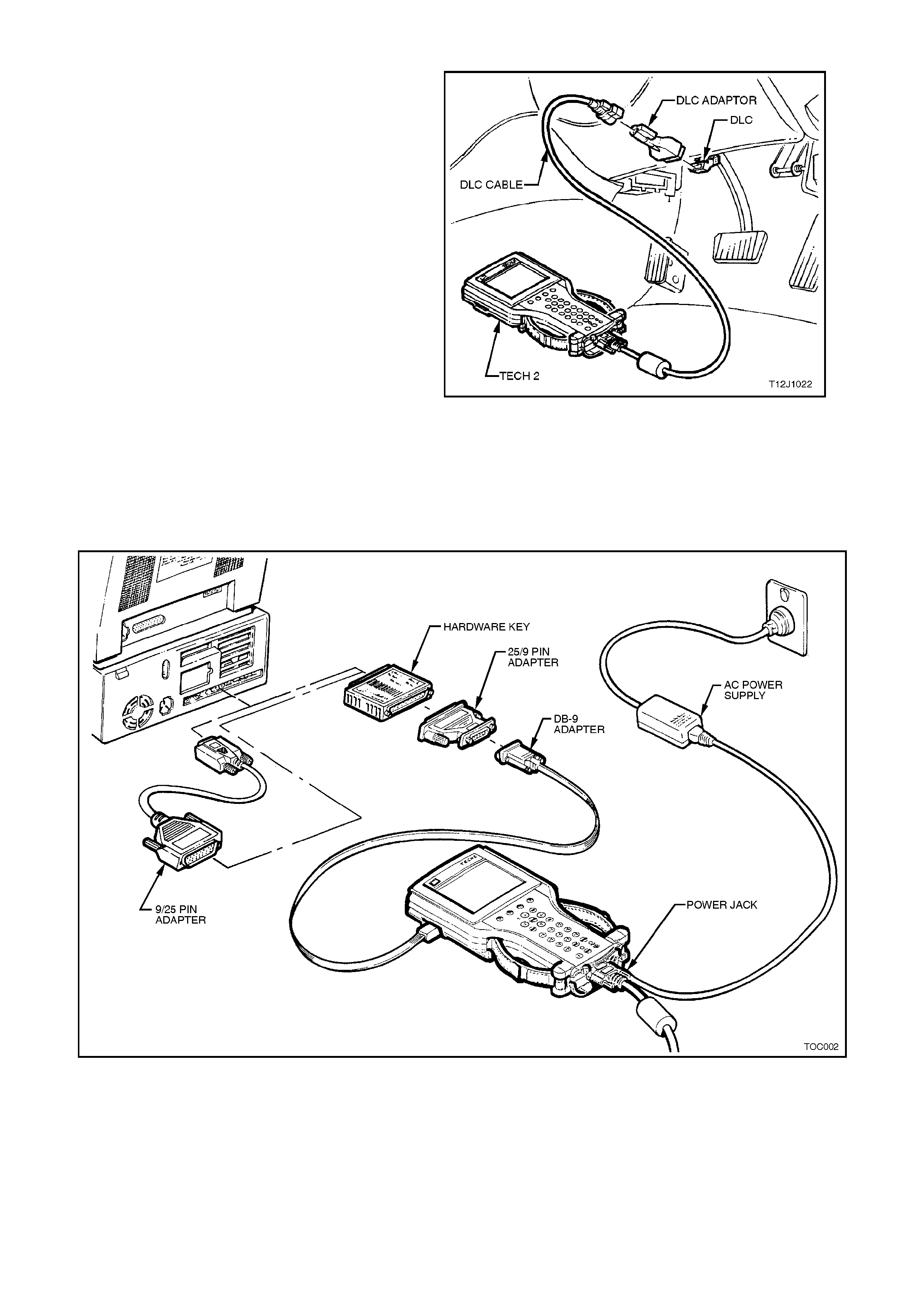
Figure 0C-10 Connecting TECH 2 to the DLC
Figure 0C-10 Connection of Power Jack to TECH 2 DLC Cable and Connection of the RS-232 Serial Communication
2. PROGRAMMI NG TECH 2
2.1 GENERAL INFORMATION
Before TECH 2 can be used on a vehicle it will
have to be programmed with the latest software.
TECH 2 programming is used to update TECH 2.
The TIS-CD ROM contains the current TECH 2
applications (program) and up to two preceding
versions in various languages. TECH 2 can be
programmed using the following procedure.
1. Connect the RS-232 cable to the TECH 2 RS-
232 communication port.
2. Connect the other end of the RS-232 cable to
the DB-9 and then connect the DB-9 adapter
to the serial communication port of your
computer.
NOTE: If your computer has a 25 pin serial
com munication por t you will need to fit the 25/9 pin
adapter between the 9 pin DB-9 adapter and the
serial communication port.
3. Connect the AC power supply to the TECH 2
power jack.
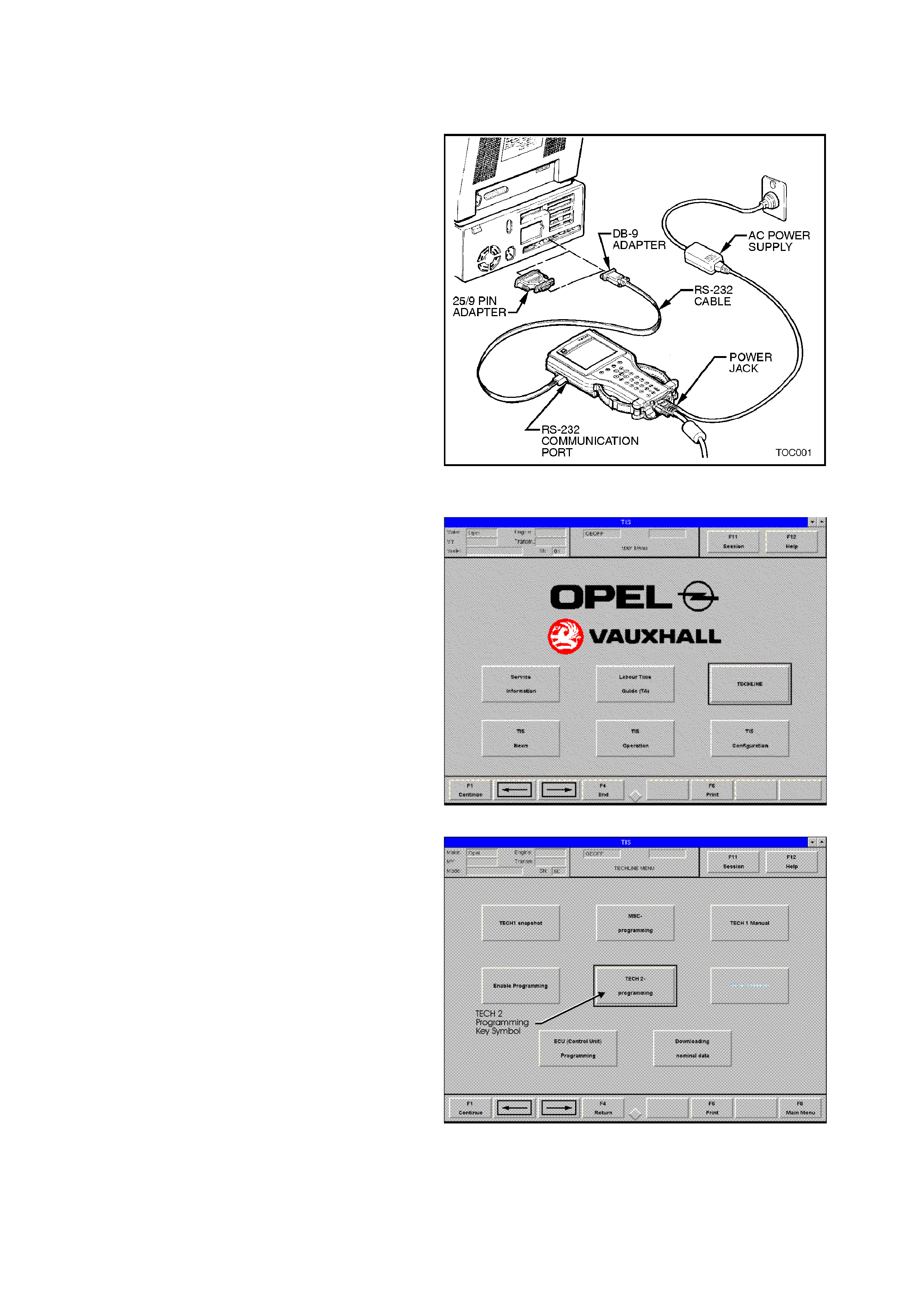
4. Press the
PWR button to turn on TECH 2. Figure 0C-12 Connecting TECH 2 to the PC
5. From windows double-click the TIS Icon to
begin TIS.
6. Click on
NEW SESSION or press ENTER.
7. Pos ition the selection window with the ←
←←
← or →
→→
→
key on the TECHLINE key symbol.
8. Select
F1 Continue or press ENTER to open
TECHLINE.
Figure 0C-13 TIS Main Menu
9. Position the selection window with the ←
←←
← or
→
→→
→ key on the TECH 2 programming key
symbol.
10. Select F1 Continue or press ENTER to
continue.
Figure 0C-14 Techline Menu
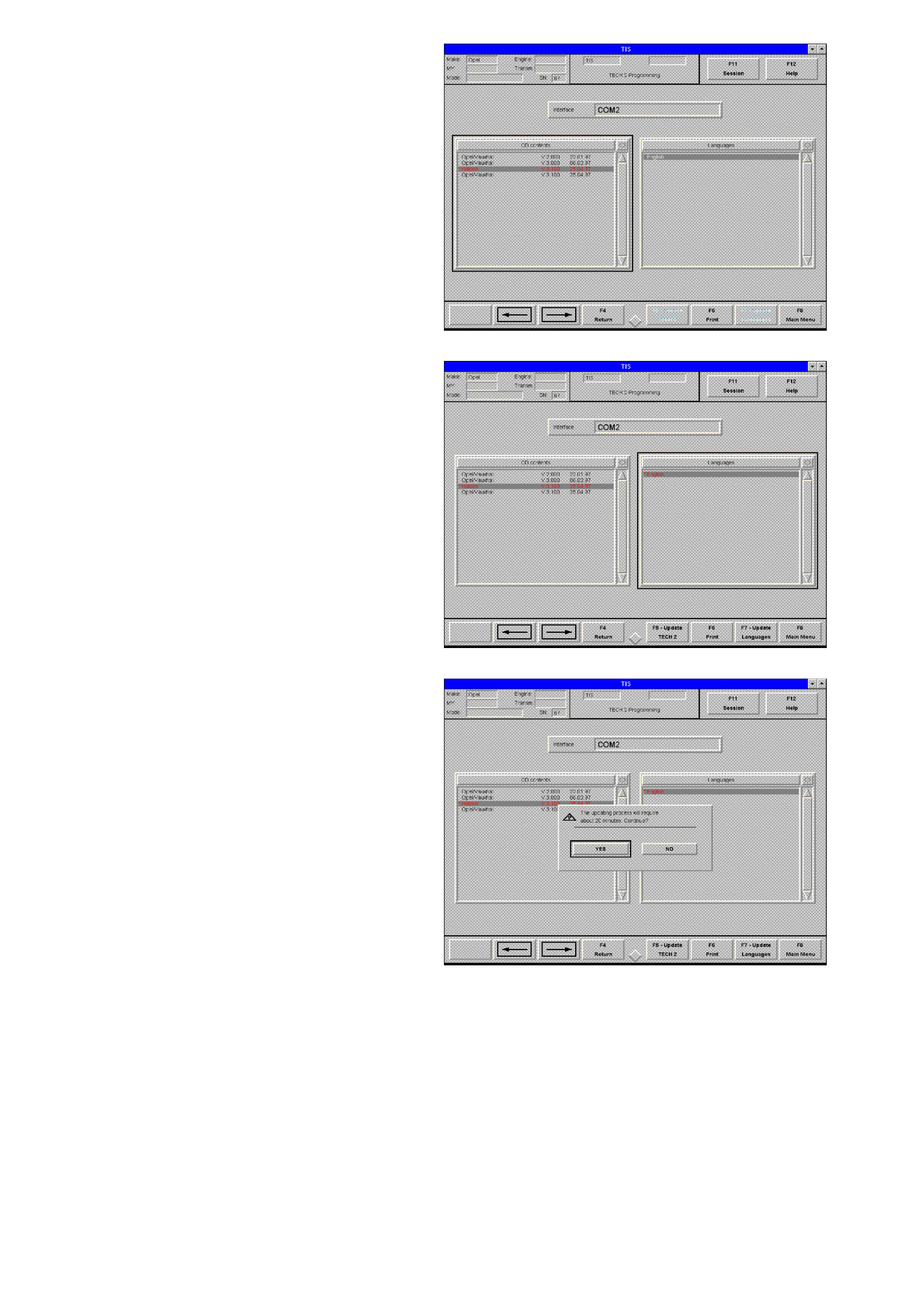
11. Using the ↑
↑↑
↑ or ↓
↓↓
↓ key, move the highlight bar to
the desired Holden TECH 2 application, (you
should select the latest version) and press
ENTER to turn the selection on.
Figure 0C-15 Desired TECH 2 Application
12. Position the selection window with the ←
←←
← or
→
→→
→ key on the Languages selection list.
13. Using the ↑
↑↑
↑ or ↓
↓↓
↓ key, move the highlight bar to
the desired language, English and press
ENTER to turn the selection on.
Figure 0C-16 Desired Language
14. Select F5-Update TECH 2 and then YES to
begin the TECH 2 Update.
15. TECH 2 will now be updated to the application
you have selected. The screen display will
indicate the progress of the download as a
percentage. Do not interrupt the connection
until directed.
Figure 0C-17 F5 Update

16. W hen the sc reen opposite is displayed, switch
off TECH 2 and then select OK or press
ENTER.
17. Select F8 M ain Menu, F4 End and then YES
to exit TIS.
18. Disconnect the power s upply from the T ECH 2
power supply jack. Disconnect the RS-232
cable from the TECH 2 RS-232
communication port. Disconnect the RS-232
cable from the serial communication port of
your computer.
19. TECH 2 has been success fully updated and is
now ready for use.
Figure 0C-18 Programming Completed Screen Display
3. USING TECH 2 ON THE VEHICLE
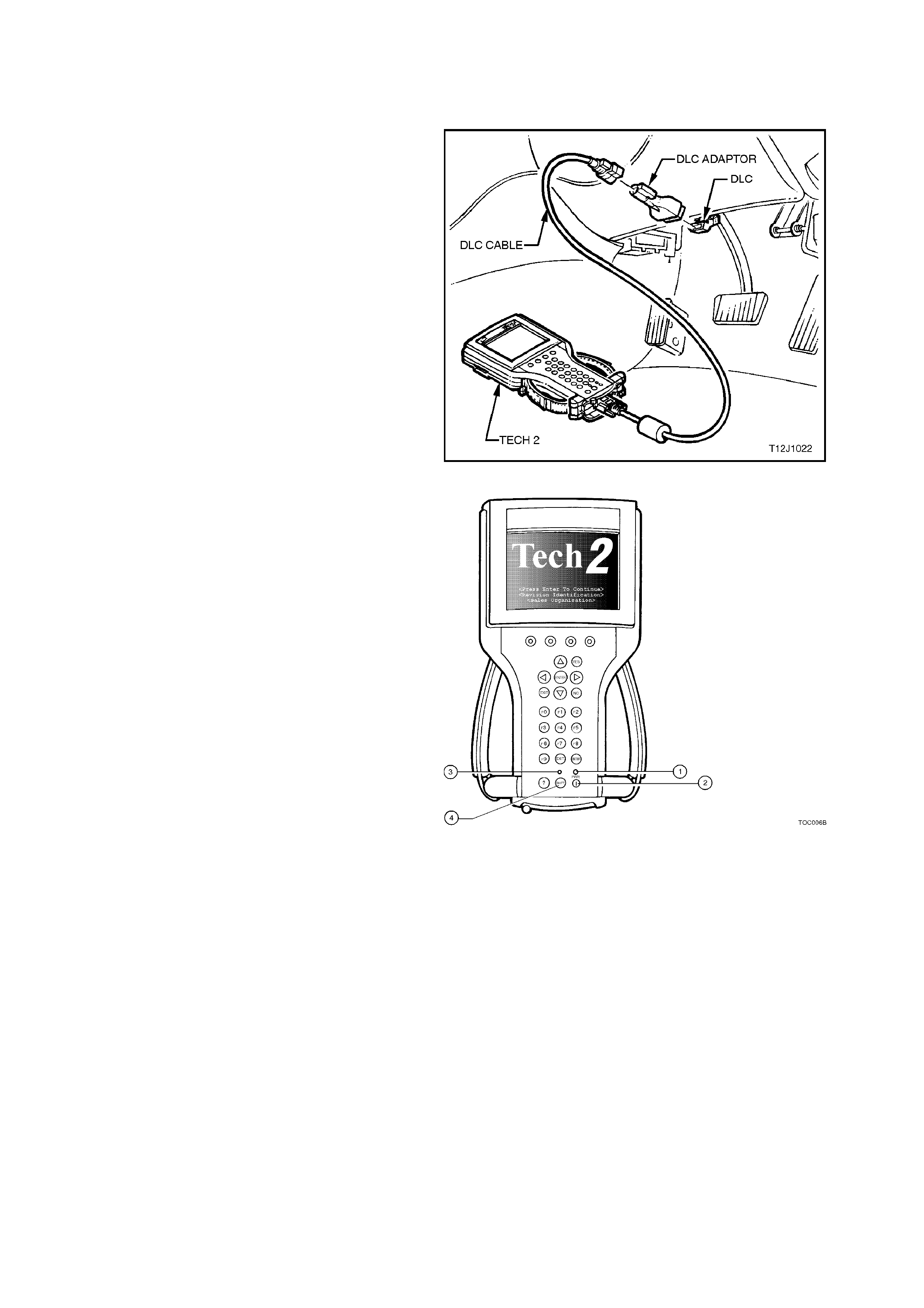
3.1 CONNECTING THE TE CH 2 TO THE VEHICLE
1. Connect TECH 2 to the vehicle DLC, with the
DLC cable and the 16/19 pin adapter.
Figure 0C-19 Connecting the TECH 2 to the Vehicle
2. Switch the unit on by pressing the power
button. A green light should come on
indicating that the tool is receiving power.
NOTE:
At this time the technician should see the Power
On Self Test (POST) run. The POST is a built in
diagnostic self test for the TECH 2 that should find
most common system faults. The POST is run on
every power up to ensure the best operation of the
tool. After the c om pletion of the PO ST, the T ECH 2
unit will briefly show the POST results. If POST
passes, the tool will continue onto the title screen. If
POST fails , results of all test s will be disp layed, and
this should show which test failed. POST failures
may be classified as fatal or non-fatal. A fatal error
will not allow the user to continue using the tool.
Failure of the keypad would be an example of a
fatal error. Non-fatal errors found during the POST
will allow continued use of the TECH 2, but with
some limitations. If either a fatal or non-fatal error
occurs, refer to the Troubleshooting section of the
TECH 2 User's Guide.
1. Power Status Indicator Light
2. PWR (Power) Key
3. SHIFT Key Status Indicator Light
4. SHIFT Key
3. At the TECH 2 title screen press the ENTER
key to continue.
Figure 0C-20 TECH 2 PWR and SHIFT Keys
4. A selec tion can be m ade from the Main Menu,
either by using a function key or by using the
arrow keys to highlight a menu choice and
pressing ENTER.
NOTE:
You will then need to supply some additional
information to the T ECH 2. This r equir es navigation
through a series of lists (called picklists). On some
menus or picklis ts, the user can us e a func tion key
to mak e a menu s election, but mos t of the picklis ts
require using the selection and action keys. If a
mistake is made in the selection process, or if a
different application or function is desired, press
EXIT to back up one level. Within an application,
there m ay be sof t keys which are available for use.
These soft keys allow access to additional tool
functions without exiting a current tool function. Soft
keys are made up of sets which will appear
together. To see the next set of soft keys, select
the More soft key.
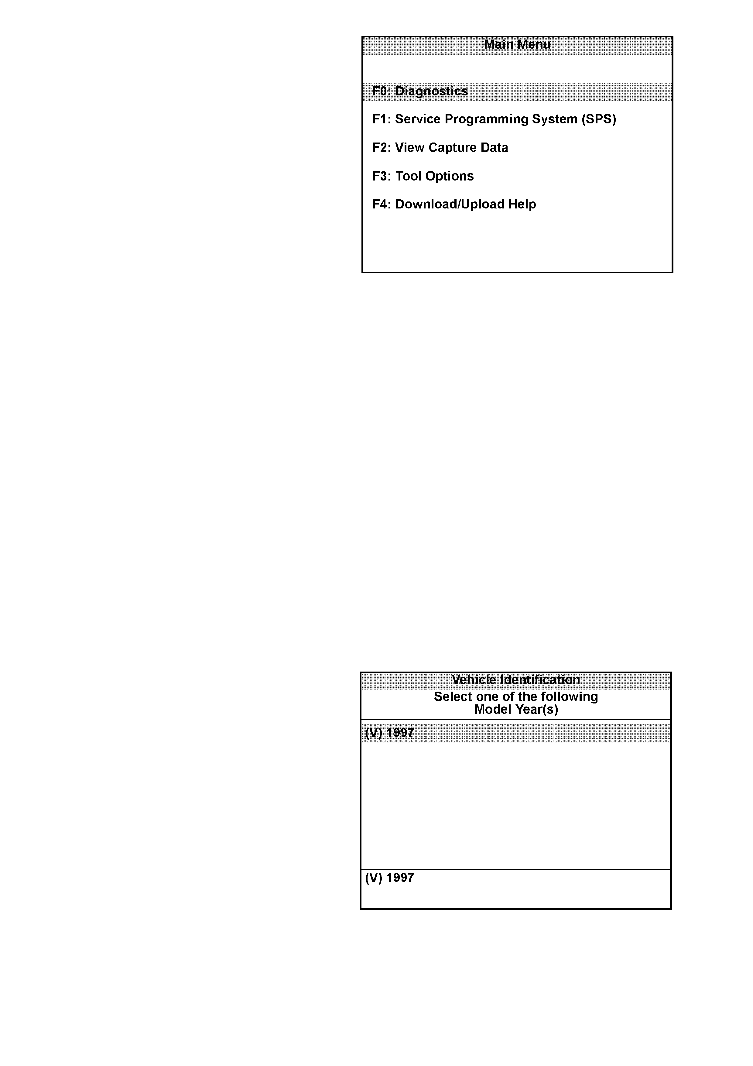
Figure 0C-21 TECH 2 Main Menu
The TECH 2 Main Menu contains the following:
F0: Diagnostics
Contains all functions to test, diagnose, monitor
and program the different vehicle sy stems.
F1: Service Programming System (SPS)
SPS is used in conjunction with Technical
Information System (TIS) to program vehicle
control units. This feature is not used on the VT
Commodore Series of Vehicles.
F2: View Capture Data
Contains all functions to work with one or two
previously recorded snapshots on one or two
vehicles. This function is to enable the viewing of
captured data without a vehicle.
F3: Tool Options
Contains the TECH 2 self test, set clock , set units,
set screen contrast and Getting Started.
F4: Download/Upload Help
Contains help information on the downloading and
uploading from the TECH 2 to the TIS CD-ROM.
5. Select the correct Model Year with the arrow
keys and the press ENTER. The Vehicle
identification screen will then be displayed.
Figure 0C-22 TECH 2 Vehicle Identification Menu
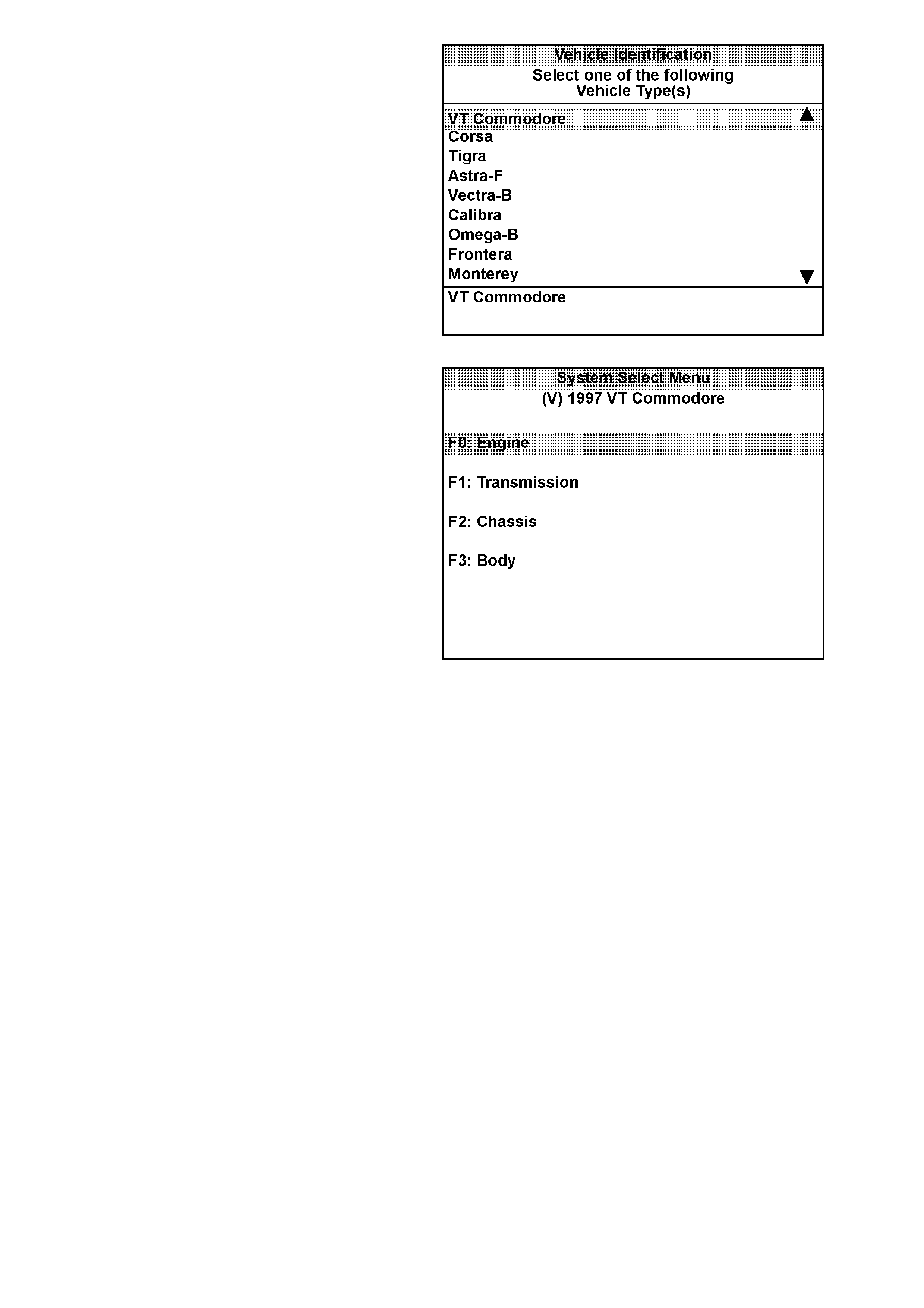
6. Select the correct Vehicle Type with the arrow
keys and the press ENTER. The System
Select Menu will then be displayed.
Figure 0C-23 TECH 2 Vehicle Identification
7. The desired system can be selected from the
System Select Menu with the function keys or
with arrow keys and then press ENTER.
F0: Engine contains all functions to test,
diagnose, and monitor the engine systems that
communicate with the TECH 2 via the
Powertrain Control Module (PCM).
F1: Transmission contains all functions to
test, diagnose, monitor and program the
transmission systems that communicate with
the TECH 2 via the Powertrain Contr ol Module
(PCM).
F2: Chassis contains all functions to test,
diagnose, monitor and program the vehicles
chassis systems; ABS and Electronic Traction
Control modules.
F3: Body contains all functions to test,
diagnose, monitor and program the vehicles
body systems; Body Control Module,
Electronic Climate Control, Instruments and
Supplemental Restraint System.
Figure 0C-24 TECH 2 System Select Menu
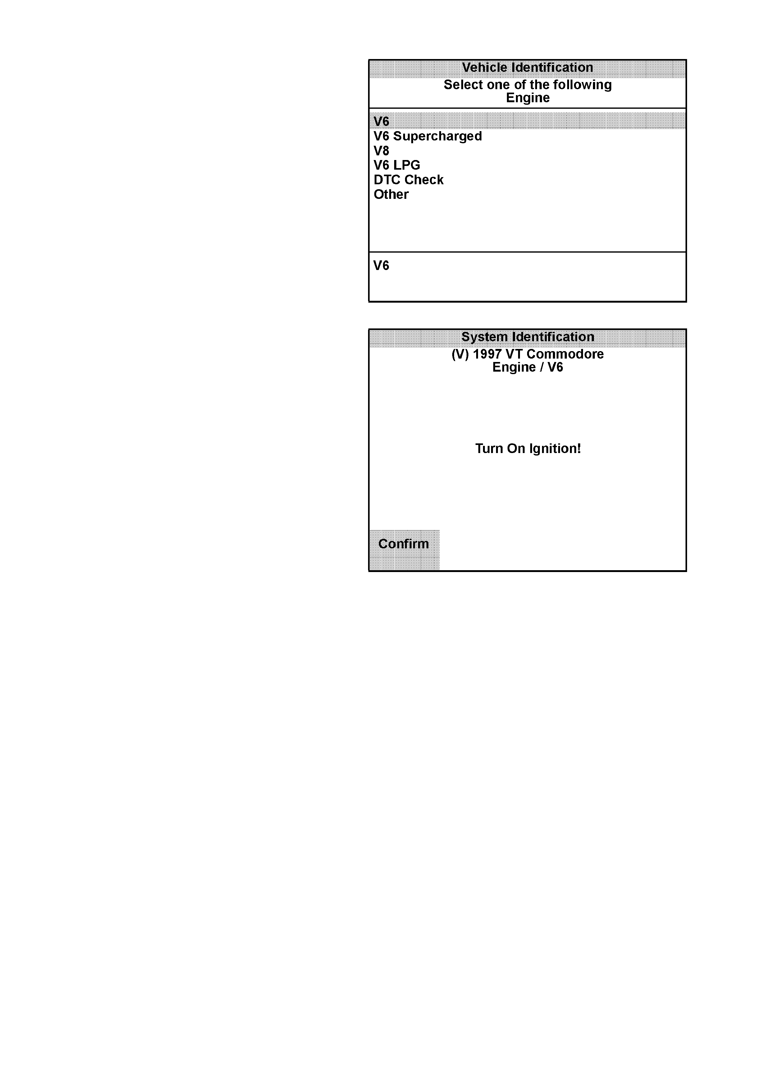
3.2 ENGINE APPLICATION MENU
1. Select the correct engine from the Vehicle
Identification Menu with the arrow keys, then
press ENTER.
Figure 0C-25 Vehicle Identification Menu
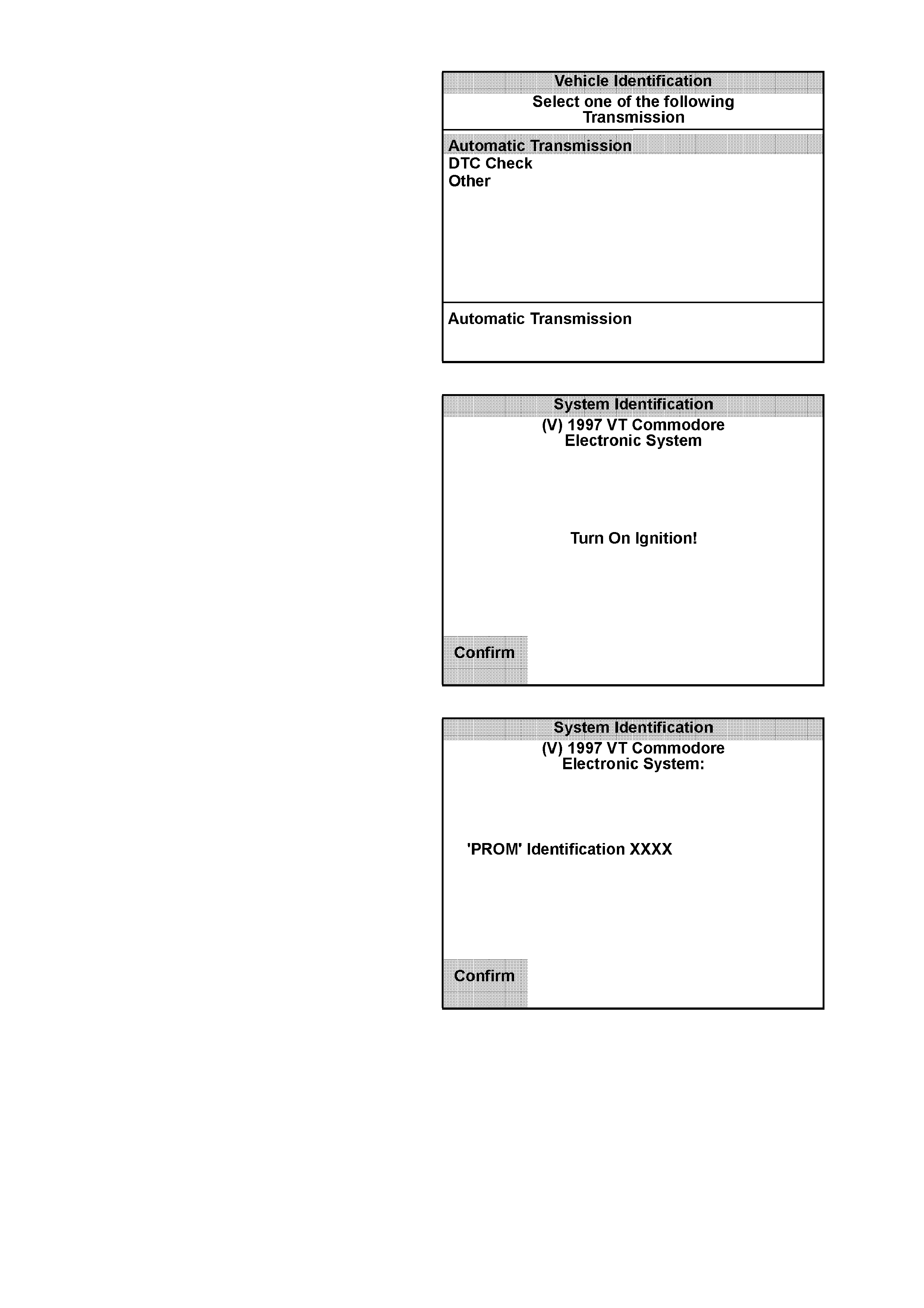
2. T urn on the ignition and pres s the Conf irm s of t
key.
Figure 0C-26 System Identification Menu

3. The System Identification screen will then
display the PROM Identification. The PROM
identification will vary with engine type and
software le vel. Press the Confirm soft k ey, the
engine application menu will then be
displayed.
NOTE:
If TECH 2 is able to communicate with the PCM the
PROM Identification will be displayed.
NOTE:
If TECH 2 is unable to communicate with the PCM
a loss of communication screen will briefly be
displayed before TECH 2 returns to the Main Menu.
The following functions can be selected from
the engine application menu:
F0: Normal Mode
F1: Diagnostic Trouble Codes
F2: Data Display
F3: Snapshot
F4: Miscellaneous Tests
F5: Function Tests
F6: Field Service
F7: Stall Data
NOTE:
Functions may vary depending on the application
selected. Refer to Section 6C1 POWERTRAIN
MANAGEMENT V6 or Section 6C2
POWERTRAIN MANAGEMENT V8 for further
information.
Figure 0C-27 System Identification Menu
3.3 TRANSMISSION APPLICATION MENU
1. Select the correct transmission from the
Vehicle Identification Menu with the arrow
keys, then press ENTER and follow the sc r een
instructions.
Figure 0C-28 Vehicle Identification Menu
2. T urn on the ignition and pr es s the Confirm sof t
key.
Figure 0C-29 System Identification
3. The System Identification screen will then
display the PROM Identification. The PROM
identification will vary with software level.
Press the Confirm soft key, the transmission
application menu will then be displayed.
The following functions are available in the
transmission application menu:
F0: Normal Mode
F1: Diagnostic Trouble Codes
F2: Data Display
F3: Snapshot
F4: Miscellaneous Tests
F5: Function Tests
F6: Field Service
NOTE:
Functions may vary depending on the application
selected. Refer to Section 6C1 POWERTRAIN
MANAGEMENT V6 or Section 6C2
POWERTRAIN MANAGEMENT V8 for further
information.
Figure 0C-30 System Identification
3.4 CHASSIS APPLICATION MENU
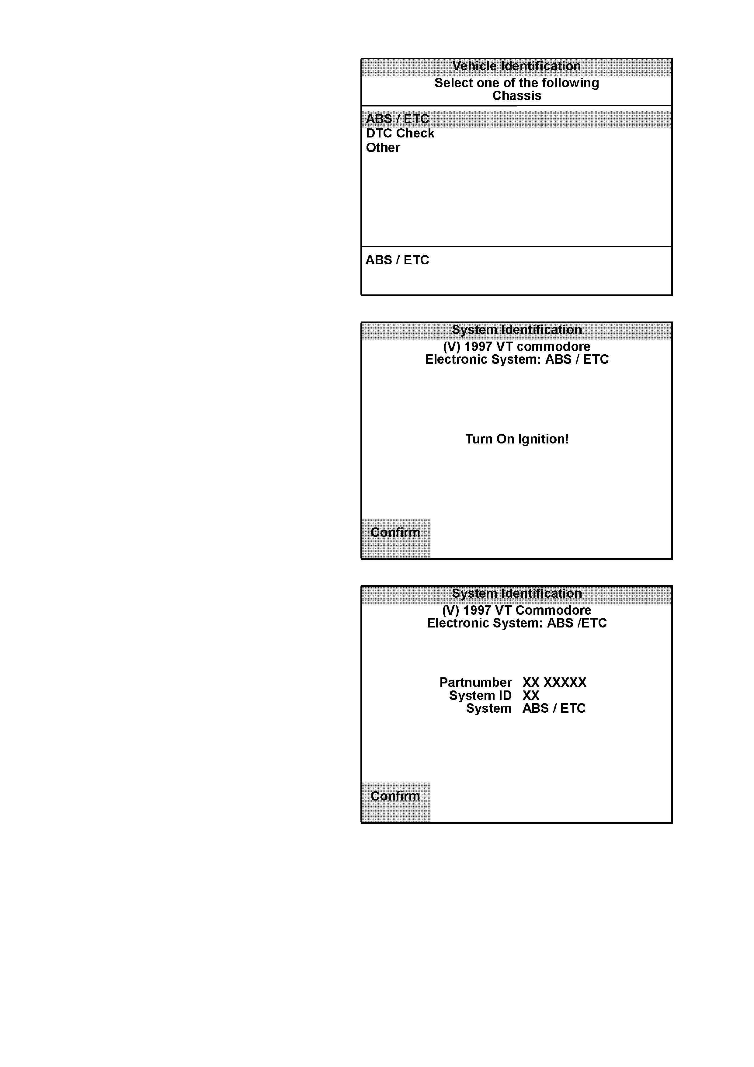
1. Select the correct chassis system from the
Vehicle Identification Menu with the arrow
keys, then press ENTER and follow the
instructions on the screen.
Figure 0C-31 Vehicle Identification Menu
2. T urn on the ignition and pr es s the Confirm sof t
key.
Figure 0C-32 System Identification
The System Identification screen will then
display the control module Partnumber,
System Identification and if the system is an
ABS or an ABS/ETC system.
3. Press the Confirm soft key, the ABS/ETC
application menu will then be displayed.
The following functions are available in the
ABS/ETC chassis application menu:
F0: Normal Mode
F1: Diagnostic Trouble Codes
F2: Data Display
F3: Snapshot
F4: Miscellaneous Tests
NOTE:
Functions may vary depending on the application
selected. Refer to Section 12L ABS AND
ABS/ETC for further Information.
Figure 0C-33 System Identification
3.5 BODY APPLICATION MENU
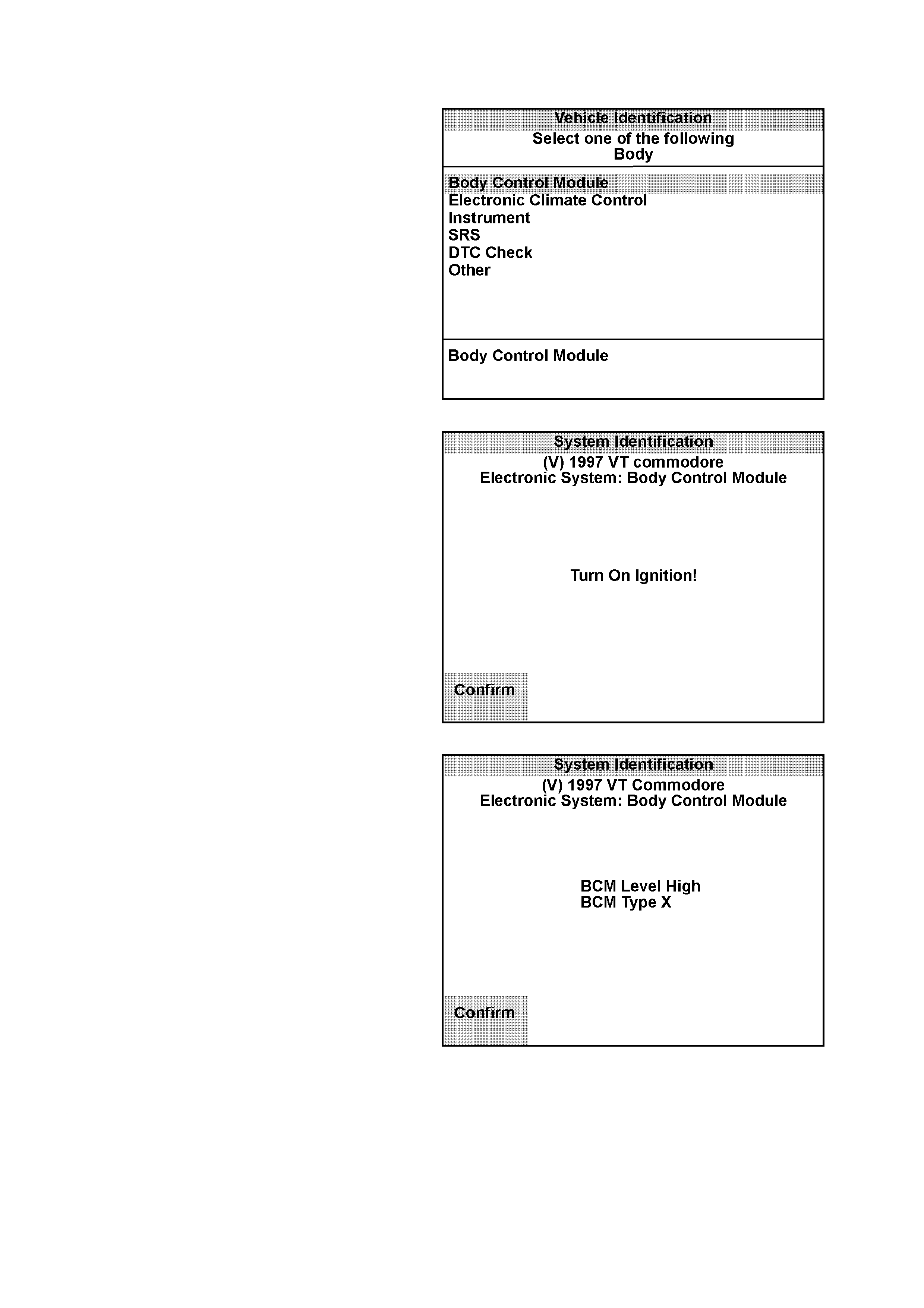
BODY CONTROL MODULE
1. Select Body Control Module from the Vehicle
Identification Menu with the arrow keys, then
press ENTER.
Figure 0C-34 Vehicle Identification Menu
2. Turn on the ignition and press the Confirm
soft key.
Figure 0C-35 System Identification
The System Identification screen will then
display the following information:
BCM Level
BCM Type
3. Press the Confirm soft key, the BCM
application menu will then be displayed.
The following functions are available in the
BCM application menu:
F0: Normal Mode
F1: Diagnostic Trouble Codes
F2: Data Display
F3: Snapshot
F4: Miscellaneous Tests
F5: Program
F6: Security
NOTE:
Functions may vary depending on the application
selected. Refer to Section 12J-1 LOW SERIES
BODY CONTROL MODULE or 12J-2 HIGH
SERIES BODY CONTROL MODULE for further
Information.
Figure 0C-36 System Identification
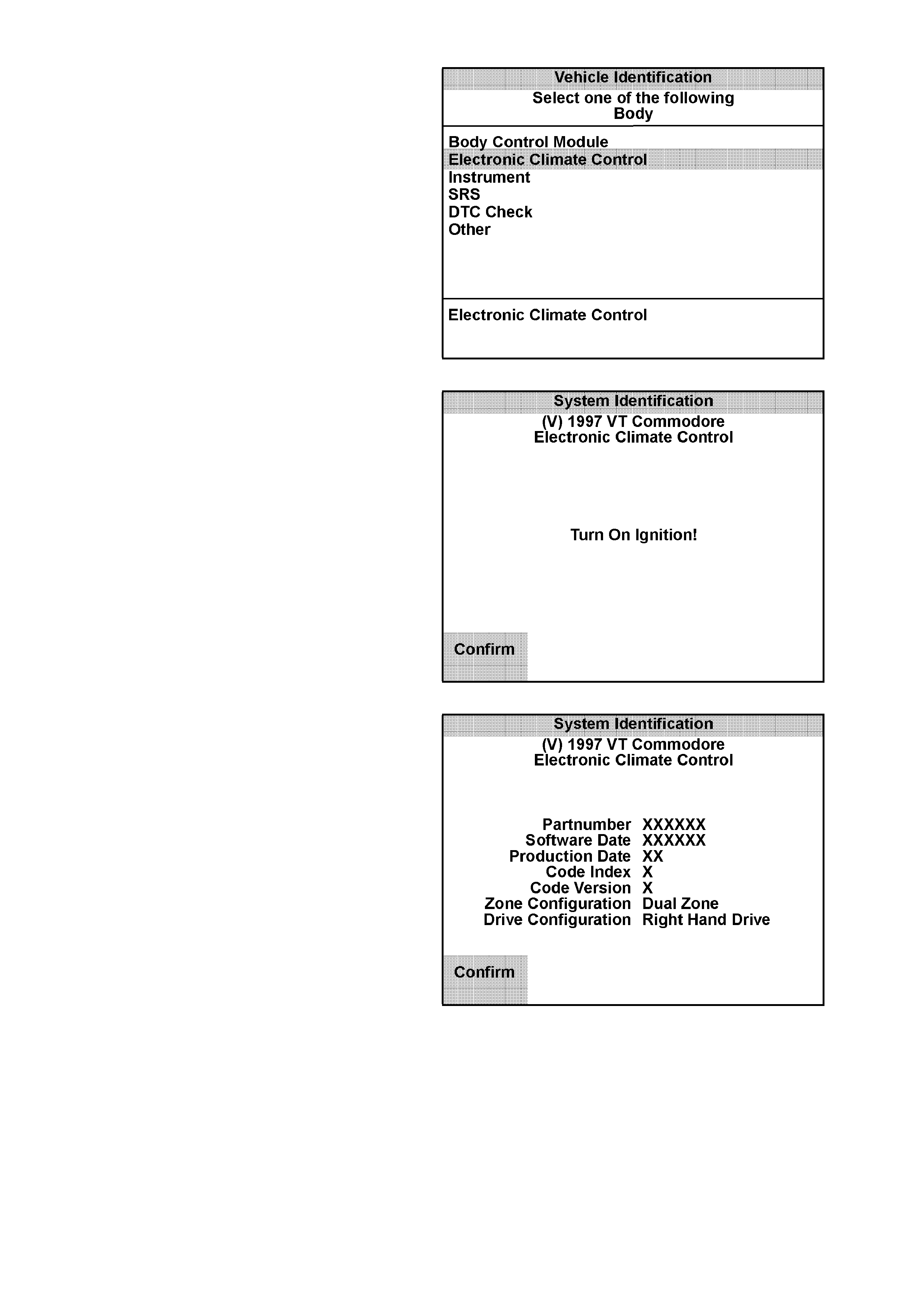
ELECTRONIC CLIMATE CONTROL
1. Select Electronic Climate Control from the
Vehicle Identification Menu with the arrow
keys, then press ENTER.
Figure 0C-37 Vehicle Identification Menu
2. Turn on the ignition and press the Confirm
soft key.
Figure 0C-38 System Identification
The System Identification screen will then
display the following information:
Partnumber
Software Date
Production Date
Code Index
Code Version
Zone Configuration
Drive Configuration
3. Press the Confirm soft key, the engine
application menu will then be displayed.
The following functions are available in the
BCM application menu:
F0: Normal Mode
F1: Diagnostic Trouble Codes
F2: Data Display
F3: Snapshot
F4: Miscellaneous Tests
F5: Program
NOTE:
Functions may vary depending on the application
selected. Refer to the Section 2F AIR
CONDITIONING - ECC DIAGNOSTICS for further
Information.
Figure 0C-39 System Identification
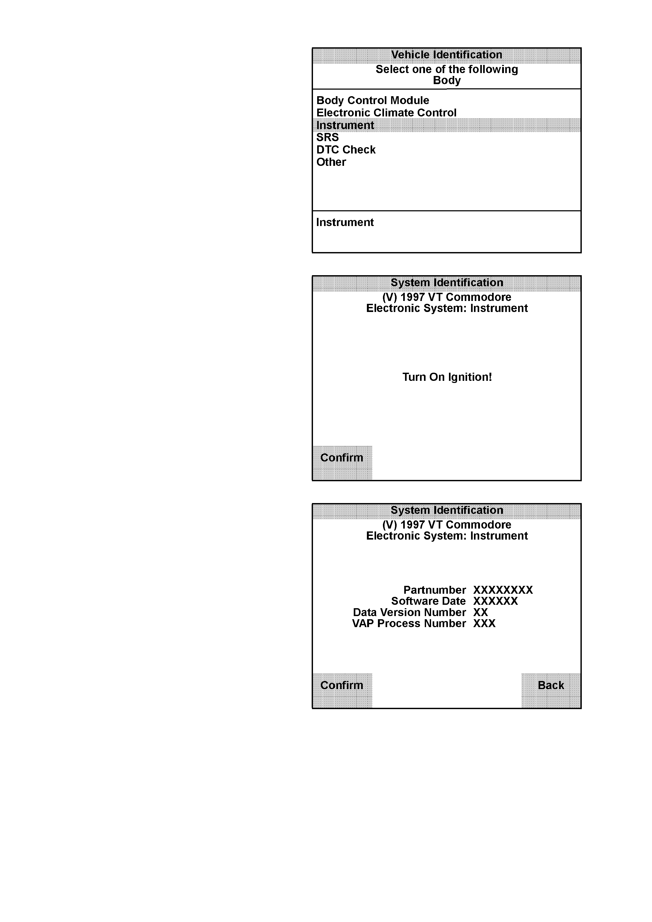
INSTRUMENT
1. Select Instrument from the Vehicle
Identification Menu with the arrow keys, then
press ENTER.
Figure 0C-40 Vehicle Identification Menu
2. Turn on the ignition and press the Confirm
soft key.
Figure 0C-41 System Identification
The System Identification screen will then
display the Partnumber, if the More soft key is
pressed the Software Date, Data Version
Number and the VAP Process Number will
also be displayed.
Figure 0C-42 System Identification
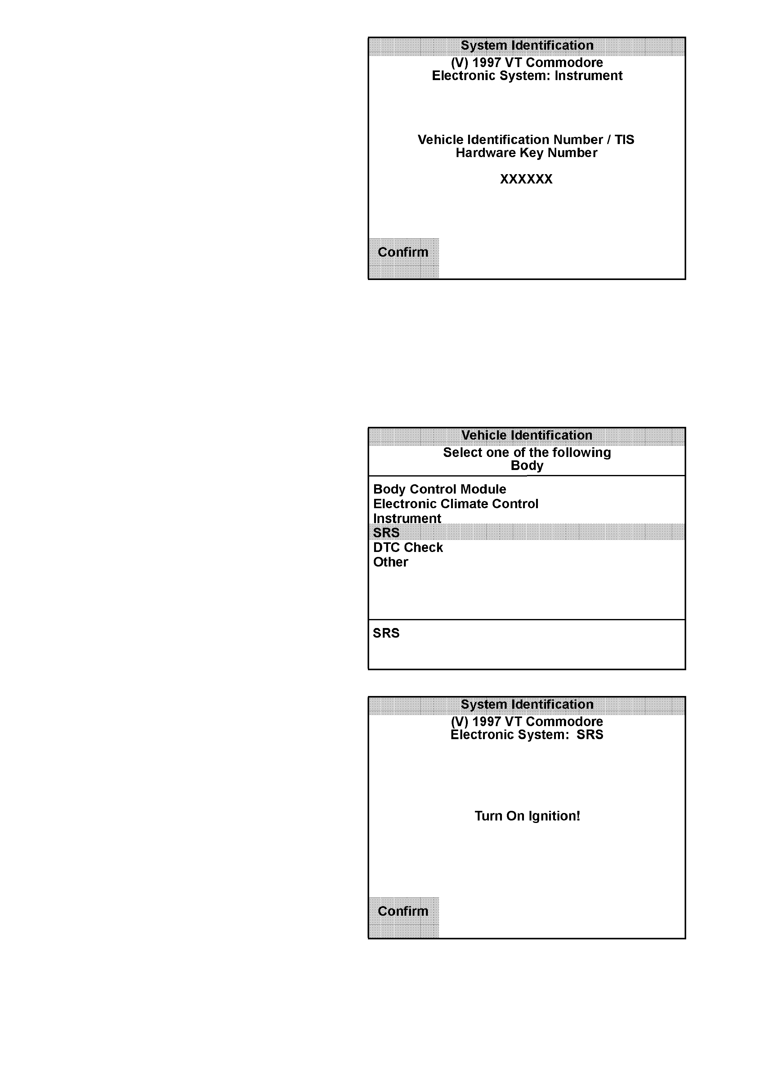
3. Press the Confirm soft key, TECH 2 will then
display either the Vehicle Identification
Number or the TIS Hardware Key Number if
the Odometer has been reset.
4. Press the Confirm soft key again, the
Instrument application menu will then be
displayed.
The following functions are available in the
Instrument application menu:
F0: Normal Mode
F1: Diagnostic Trouble Codes
F2: Data Display
F3: Snapshot
F4: Miscellaneous Tests
F5: Program
NOTE:
Functions may vary depending on the application
selected. Refer to the Section 12C INSTRUMENT
WIPERS, WASHERS AND HORN for further
Information.
Figure 0C-43 VIN or TIS Hardware Key Number
SUPPLEMENTAL RESTRAINT SYSTEM (SRS)
1. Select SRS from the Vehicle Identification
Menu with the arrow keys, then press ENTER.
Figure 0C-44 Vehicle Identification Menu
2. T urn on the ignition and pr es s the Confirm sof t
key.
Figure 0C-45 System Identification
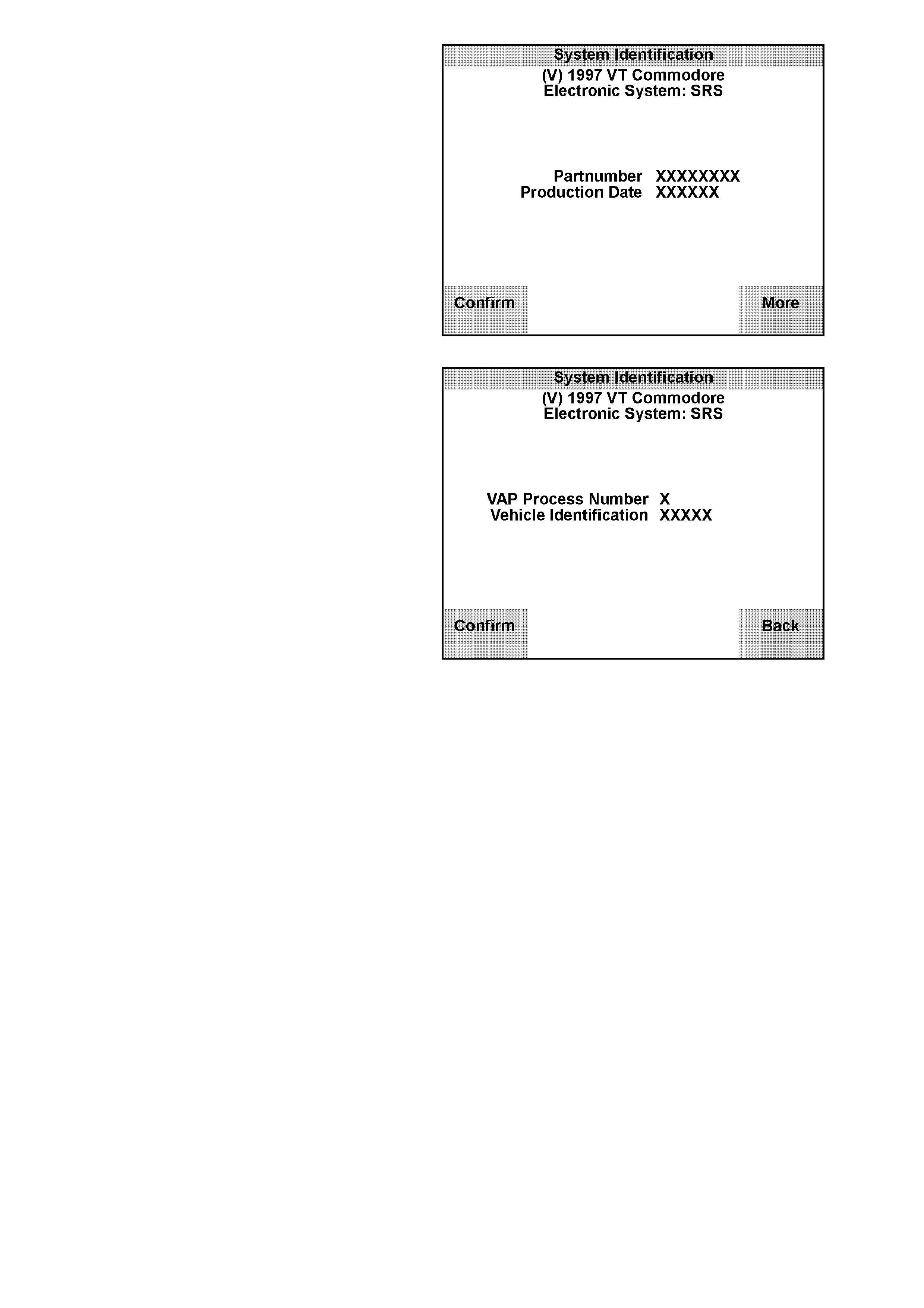
The System Identification screen will then
display the following information:
Partnumber
Production Date
Figure 0C-46 System Identification
3. If the More soft key is pressed TECH 2 will
display the VAP Process Number and Vehicle
Identification Number.
4. Press the Confirm soft key, the SRS
application menu will then be displayed.
The following functions are available in the
SRS application menu:
F0: Normal Mode
F1: Diagnostic Trouble Codes
F2: Data Display
F3: Snapshot
F4: Program
NOTE:
Functions may vary depending on the application
selected. Refer to Section 12M SUPPLEMENTAL
RESTRAINT SYSTEM for further Information. Figure 0C-47 VAP Process Number
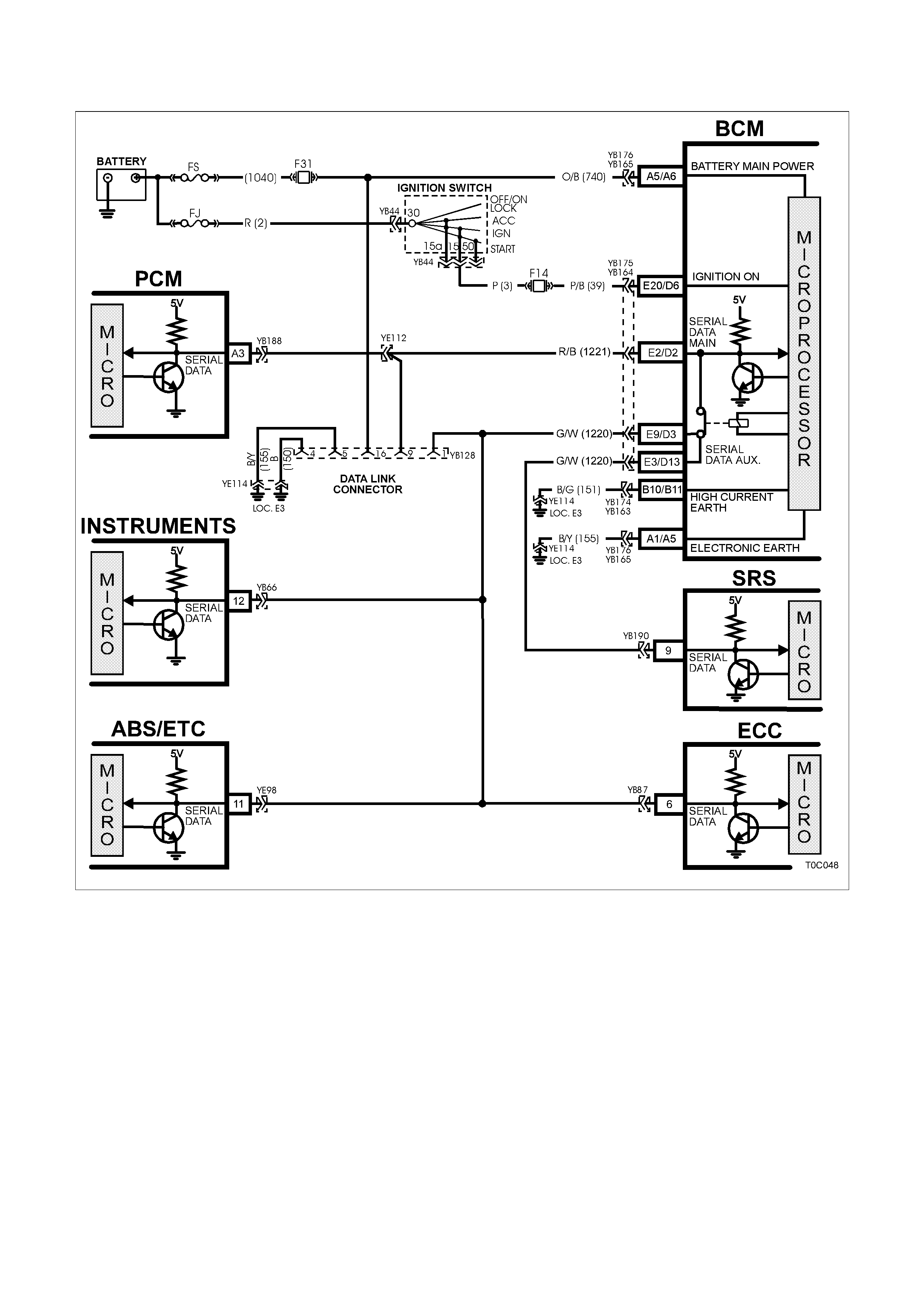
4. TECH 2 DIAGNOSIS
Figure 0C-48 Serial Data Circuit

GENERAL INFORMATION
TECH 2 communicates with the vehicle via the
serial data bus circuit 1221. Circuit 1221 is
connected to terminal 9 of the DLC (YB128) and
the serial data earth circuit is via terminal 5 of the
DLC and circuit 155. The power supply for T ECH 2
is from fuse F31 via circuit 740 to terminal 16 of the
DLC. The earth circuit is via terminal 4 and circuit
150.
TECH 2 can communicate with the following
control modules, if the vehicle is equipped with
these systems.
• Body Control Module (BCM).
• Powertrain Control Module (PCM).
• Instrument (INS).
• Supplemental Restraint System (SRS).
• Antilock Braking System / Electronic Traction
Control System (ABS/ETC).
Test Description
The numbers below refer to step numbers on the
following diagnostic chart.
1. Checks if TECH 2 is being powered up.
2. Check s if TECH 2 is pr ogramm ed with correct
Holden software.
3. Checks if TECH 2 can communicate with BCM
If TECH 2 can communicate with BCM, serial
data circuit 1221 is OK.
4. Checks continuity of serial data earth circuit.
5. Checks if fusible link FS is OK.
6. Checks if fuse F31 is OK.
7. Check if battery voltage is available for TECH
2.
8. Check s if an earth circ uit is available f or T ECH
2.
9. All vehicle circuits have been found to be OK,
fault must be with TECH 2 or an intermitted
fault is causing TECH 2 not to operate
correctly.

STEP ACTION VALUE YES NO
1. • Connect TECH 2 to the
vehicle DLC, with the
DLC cable and the
16/19 pin adapter.
• Switch on TECH 2 by
pressing the PWR
button.
• Does a green light
above the PWR button
come ON?
Go to Step 2. Go to Step 5.
2. • Does TECH 2 display
Title Screen illuminate
and display:
TECH 2
Press [ENTER] To
Continue
Software Version: 3.100
Holden 1997
(Software Version should
be greater than 3.100)
Go to Step 3. Program
TECH 2 PCMCIA
Card refer to
PROGRAMMING
TECH 2 is this
Section.
3. • At the TECH 2 title
screen press the Enter
key.
• Select F0: Diagnostics /
1997 / VT Commodore /
F3: Body / Body Control
Module.
• Turn on ignition and
press the confirm soft
key.
• Does TECH 2 display
the BCM System
Identification Screen?
TECH 2 is
functioning
correctly, refer to
system specific
diagnostics if you
cannot
communicate with a
specific control
module.
Go to Step 4.
4. • Using an ohmmeter
check continuity of
circuit 155
(Black/Yellow wire)
between DLC (YB128)
terminal 5 and a known
good earth.
• Is there continuity?
Go to BCM
diagnosis
SERIAL DATA
COMMUNICATION
Section 12J1 Low
Series,
Section 12J2 High
Series.
Repair open in
circuit 155 between
DLC terminal 5 and
earth LOC. E3.
5. • Is Fusible link FS OK? Go to Step 6. Replace fusible link
and check cause of
blown fusible link.
Verify Repair.

STEP ACTION VALUE YES NO
6. • Is Fuse F31 OK? Go to Step 7. Replace fuse and
check cause of
blown fuse.
Verify Repair.
7. • Check for voltage
between DLC (YB128)
terminals 4 and 16.
• Is voltage at specified
value?
B+ Go to Step 9. Go to Step 8.
8. • Ignition off.
• Check for voltage
between DLC (YB128)
terminals 16 and a
known good earth.
• Is voltage above
specified value?
B+ Repair open in
circuit 150 between
DLC Connector
terminal 4 and earth
LOC. E3.
Verify Repair.
Repair open in
circuit 740 and
1040 between DLC
Connector terminal
16 and fusible link
FS.
Verify Repair.
9. • Perform TECH 2 Self
Test using 240 V AC
power supply. (Refer to
TECH 2 User’s Guide).
• Does TECH 2 pass Self
Test?
Check for incorrect
terminal sizing of
DLC YB128 or
intermittent fault in
DLC circuits.
Send TECH 2 out
for repair.
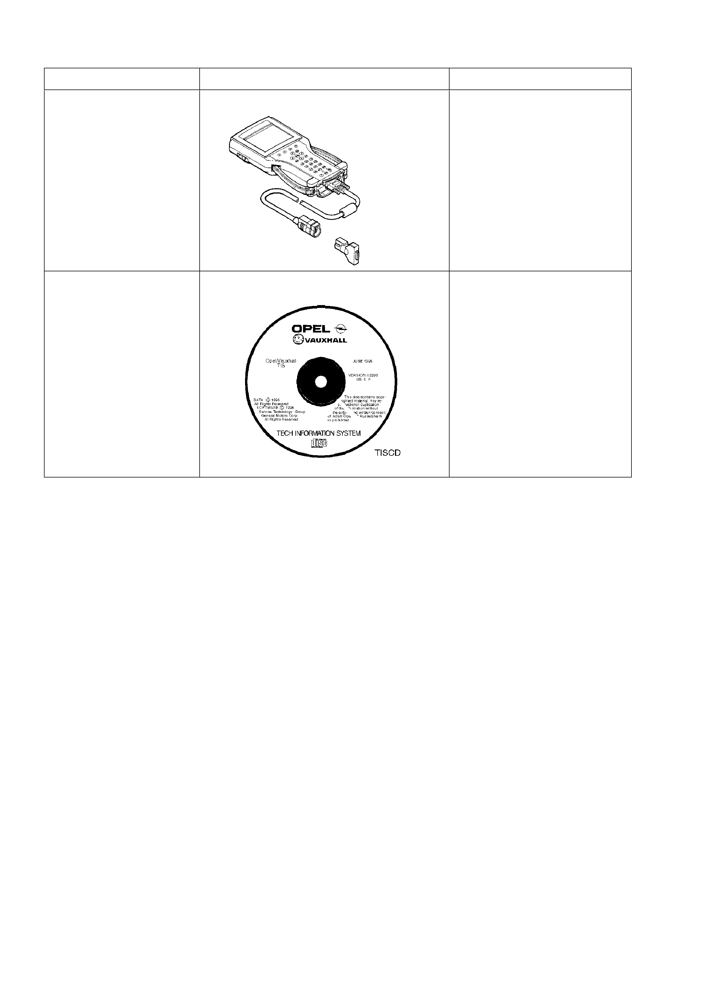
5. SPECIAL TOOLS
TOOL NO. REF IN TEXT TOOL DESCRIPTION COMMENTS
TECH 2 DIAGNOSTIC SCAN TOOL PREVIOUSLY RELEASED
TECHNICAL
INFORMATION SYSTEM
(TIS)
TIS CD ROM PREVIOUSLY RELEASED