
SECTION 12J-2 - HIGH SERIES BODY
CONTROL MODULE
CAUTION:
This vehicle will be equipped with a Supplemental Restraint System (SRS). A SRS will
consist of either seat belt pre-tensioners and a driver's side air bag , or seat belt pre-
tensioners and a driver's and front passenger's side air bags. Refer to CAUTIONS,
Section 12M, before performing any service operation on, or around any SRS
components, the steering mechanism or wiring. Failure to follow the CAUTIONS
could result in SRS d eployment, resultin g in po ssible personal in jury or unnecessary
SRS system repairs.
CAUTION:
This vehicle may be equipped with LPG (Liquefied Petroleum Gas). In the interests of
safety, the LPG fuel system should be isolated by turning 'OFF' the manual service
valve an d then draining t he LPG service lines, befo re any service w ork is carried out
on the vehicle. Refer to the LPG leaflet included with the Owner's Handbook for
details or LPG Section 2 for more specific servicing information.
1. GENERAL DESCRIPTI ON
A Body Control Module (BCM) combines into one central module, the control or assist of various vehicle electrical
systems or features, rather than having individual modules for each system or feature.
High Series Australian Arrow BCM’s are fitted as standard equipment on all VT Series Berlina and Calais Models.
NOTE:
Two levels of High Series Australian Arrow BCM’s have been released, a LUX level for Berlina Models and the HI
level for Calais. If a service operation or diagnostic procedure requires that a High Series BCM must be replaced,
ensure that the correct BCM level is reinstalled for the particular level of vehicle.
Figure 12J-2-1 illustrates the identification details for the High Series BCM. External identification can be made by
referring to the last three digits of the BCM part number.
Specific TECH 2 software has been developed f or use with the TECH 2 diagnostic scan tool to assist with various
vehicle electrical system fault finding, including the various BCM functions and controls.
The connection for TECH 2 for the High Series Australian Arrow BCM serial data communication is via the Data
Link Connector (DLC), attached to the instrument panel lower right hand trim, to the left of the steering column,
refer Fig.12J-2-2.
The Australian Arrow High Series BCM is located beneath the instrument cluster, to the right of the steering column,
refer to Fig. 12J-2-2.
Techline
Techline
Techline
Techline
Techline
Techline
Techline
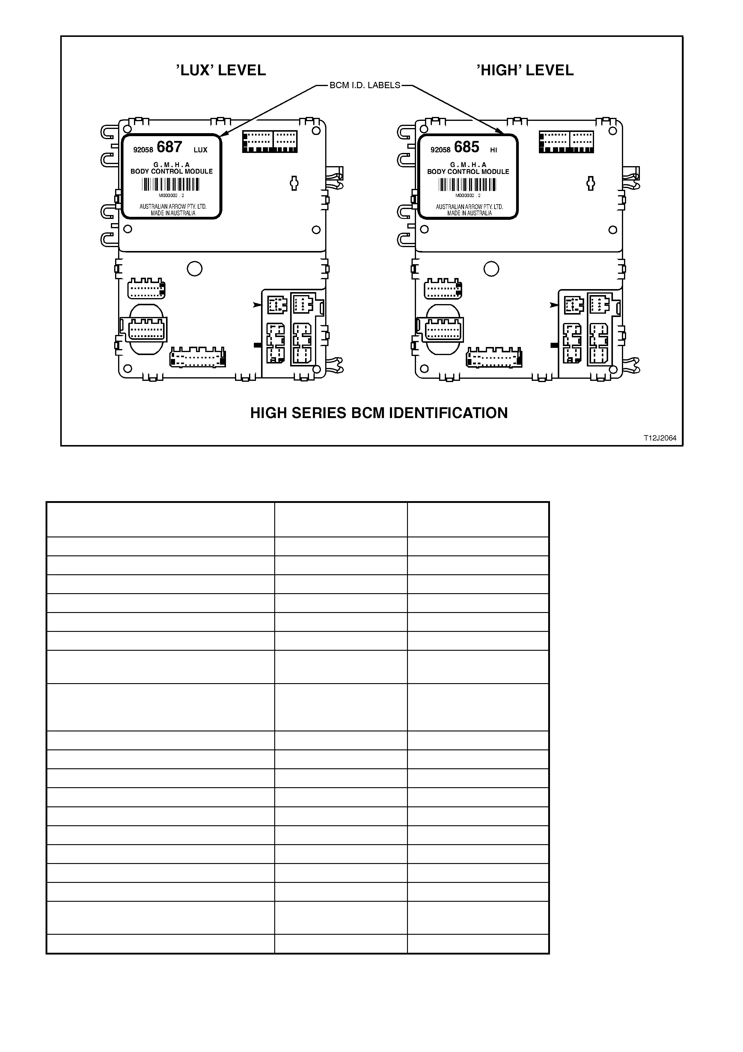
Figure 12J-2-1
BODY CONTROL MODULE FEATURES
BCM FEATURE LEVEL 2 (BERLINA)
LUX - 687 LEVEL 3 (CALAIS)
HI - 685
Central door locking A A
Boot release with speed interlock A A
Power window system A A
Power antenna control A A
Dome lamp delay control A A
Rear lamp failure warning lamp control N/A A
Road speed dependent and variable
dwell wiper control - front AA
Intermittent and synchronised to front
rear wiper control with full wipe in
reverse gear (wagon only)
AN/A
Speed sensitive power steering N/A A
Instrument dimming control A A
Automatic lights OFF (variable) A A
Automatic lights ON - twilight sentinel N/A A
Engine disable A A
Alarm A A
Engine cooling low speed fan control A A
Priority key system N/A A
Cruise control interface A A
SRS (air bag) deployment vehicle
shutdown AA
Serial data interface A A
N/A = NOT AVAILABLE
A = AVAILABLE
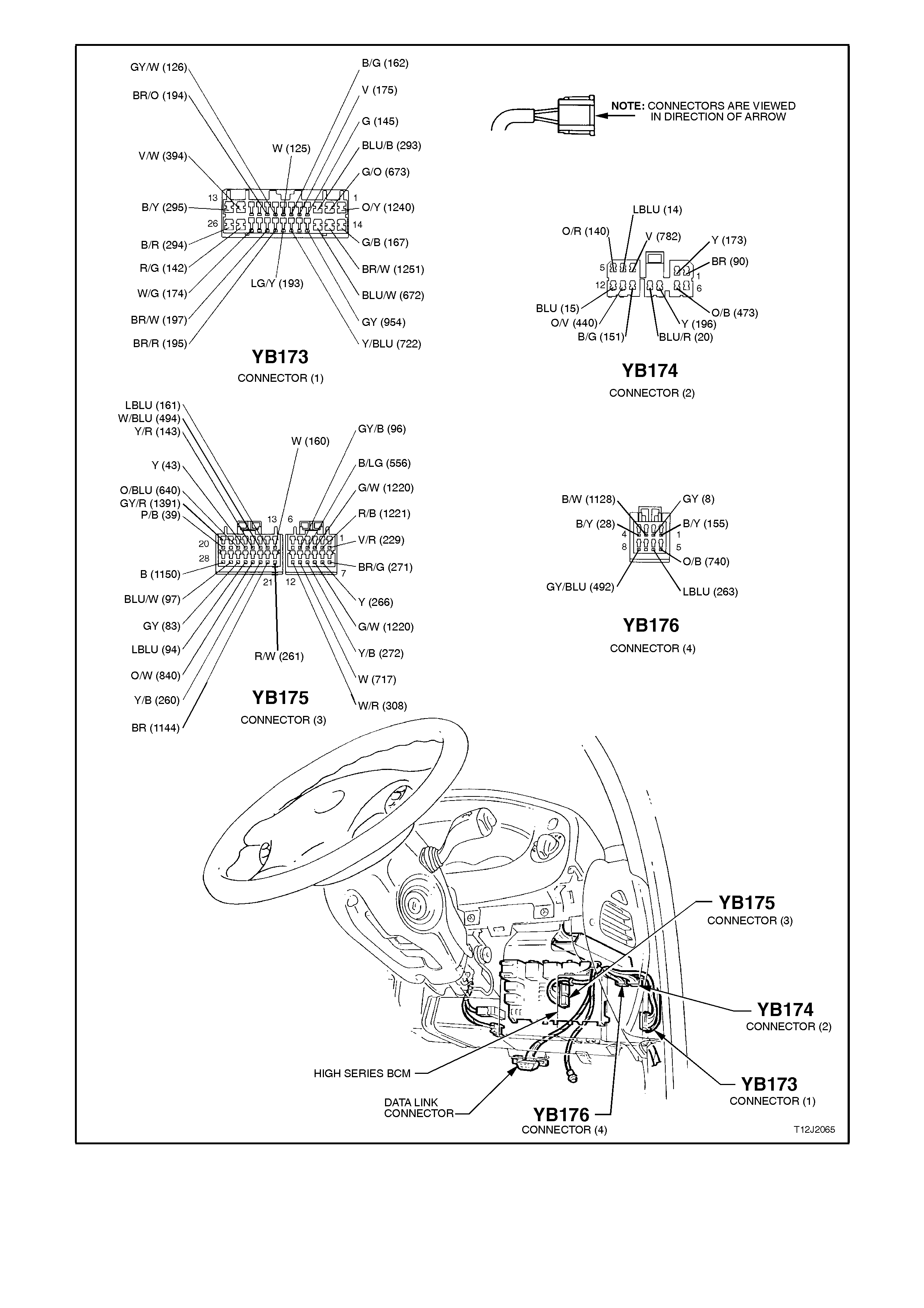
Figure 12J-2-2

HIGH SERIES BCM TERMINAL IDENTIFICATION
YB176 CONNECTOR 4
PIN
NO. DESCRIPTION CIRCUIT WIRE
COLOUR CIRCUIT TYPE
A1 EARTH (ELECTRONIC) 155 B/Y E
A2 INSTRUMENT ILLUMINATION
OUTPUT 8GYO
A3 THEFT DETERRENT HORN
OUTPUT 1128 B/W O
A4 HORN OUTPUT 28 B/Y 0
A5 BATTERY POSITIVE 740 O/B P
A6 THEFT DETERRENT LED
OUTPUT 263 LBLU O
A7 NC
A8 REAR WIPER OUTPUT 492 GY/BLU O
YB174 CONNECTOR 2
PIN
NO. DESCRIPTION CIRCUIT WIRE
COLOUR CIRCUIT TYPE
B1 WIPER OUTPUT 90 BR O
B2 POWER WINDOW OUTPUT 173 Y O
B3 PRIORITY KEY ONE OUTPUT 782 V O
B4 LEFT INDICATOR OUTPUT 14 LBLU O
B5 INDICATOR POWER 140 O/R P
B6 NC
B7 LOW FAN SPEED OUTPUT 473 O/B O
B8 WIPER PARK INPUT 196 Y PD/O
B9 NC
B10 POWER EARTH 151 B/G E
B11 DOOR LOCK POWER 440 O/V P
B12 RIGHT INDICATOR OUTPUT 15 BLU O

YB173 CONNECTOR 1
PIN
NO. DESCRIPTION CIRCUIT WIRE
COLOUR CIRCUIT TYPE
C1 WINDOW POWER INPUT 1240 O/Y P
C2 WINDOW MOTOR OUTPUT 673 G/O O
C3 DRIVERS DOOR UNLOCK
OUTPUT 293 BLU/B O
C4 ANTENNA DRIVE OUTPUT 145 G O
C5 DOME ON INPUT 175 V PD
C6 BOOT LAMP INPUT 162 B/G PPU
C7 PASSENGER DOOR AJAR
INPUT 125 W PPU
C8 DRIVERS DOOR AJAR INPUT 126 GY/W PPU
C9 PASSENGERS DOOR
UNLOCK INPUT 194 BR/O PU
C10 NC
C11 NC
C12 DEADLOCK OUTPUT 394 V/W O
C13 ALL DOORS, LOCK OUTPUT 295 B/Y O
C14 WINDOW DOWN INPUT 167 G/B PD
C15 STOP/TAIL SENSE INPUT 1251 BR/W I
C16 WINDOW UP INPUT 672 BLU/W PD
C17 ANTENNA DIRECTION
OUTPUT 954 GY O
C18 NC
C19 DOME - DOOR INPUT 722 Y/BLU PD
C20 UNLOCK INPUT 193 LG/Y PPU
C21 LOCK INPUT 195 BR/R PPU
C22 DEADLOCK REQUEST
INPUT 197 BR/W PPU
C23 NC
C24 DOME LAMP OUTPUT 174 W/G O
C25 BOOT OUTPUT 142 R/G O
C26 PASSENGER DOOR
UNLOCK OUTPUT 294 B/R O

YB175 CONNECTOR 3
PIN
NO. DESCRIPTION CIRCUIT WIRE
COLOUR CIRCUIT TYPE
E1 SLIP RING 229 V/R I/O
E2 SERIAL DATA INTERFACE
MAIN BUS 1221 R/B I/O
E3 AIRBAG SERIAL DATA
INTERFACE BUS 1220 G/W I/O
E4 POWER STEERING
SOLENOID OUTPUT 556 B/LG O
E5 WIPER DWELL INPUT 96 GY/B PU
E6 NC
E7 RECEIVER EARTH 271 BR/G E
E8 RECEIVER DATA 266 Y I
E9 SERIAL DATA INTERFACE
AUXILIARY BUS 1220 G/W I/O
E10 TWILIGHT INPUT (AMBIENT
LIGHT SENSOR) 272 Y/B I
E11 INSTRUMENT DIMMER
INPUT 717 W PU
E12 AUTO LIGHTS EARTH
OUTPUT 308 W/R O
E13 ANTENNA DOWN INPUT 160 W PPU
E14 ANTENNA UP INPUT 161 LBLU PPU
E15 REAR WASHER INPUT 494 W/BLU PD
E16 RADIO ON INPUT 143 Y/R PD
E17 ACCESSORIES INPUT 43 Y PD, P
E18 STOP LAMP FUSE INPUT 640 O/BLU PD
E19 REAR WIPER INPUT 1391 GY/R PD
E20 IGNITION INPUT 39 P/B PD, P
E21 BONNET SWITCH INPUT 261 R/W PPU
E22 BOOT RELEASE INPUT 1144 B/R PPU
E23 BONNET SWITCH INPUT 260 Y/B PD
E24 PARK LAMP FUSE INPUT 840 O/W PD
E25 FRONT SCREEN
WASH/WIPE INPUT 94 LBLU PU
E26 CRUISE CONTROL ON
INPUT 83 GY PD
E27 FRONT SCREEN
INTERMITTEN T AUTO WIPE
INPUT
97 BLU/W PD
E28 LIGHTS OFF EARTH
OUTPUT 1150 B O
GLOSSARY
E – Earth O – Output P - Power
PU - Pull up PPU - Pulsed pull up PD - Pull down
I – Input I/O - Input / Output NC - No circuit
B - Black W - White R - Red P - Pink
O - Orange Y - Yellow V - Violet BLU - Blue
G - Green LG - Light green BR - Brown GY - Grey
T - Tan LBLU - Light blue DKBLU - Dark blue

1.1 SE RIAL DATA COMMUNICATION (BUS MASTER)
GENERAL INFORMATION
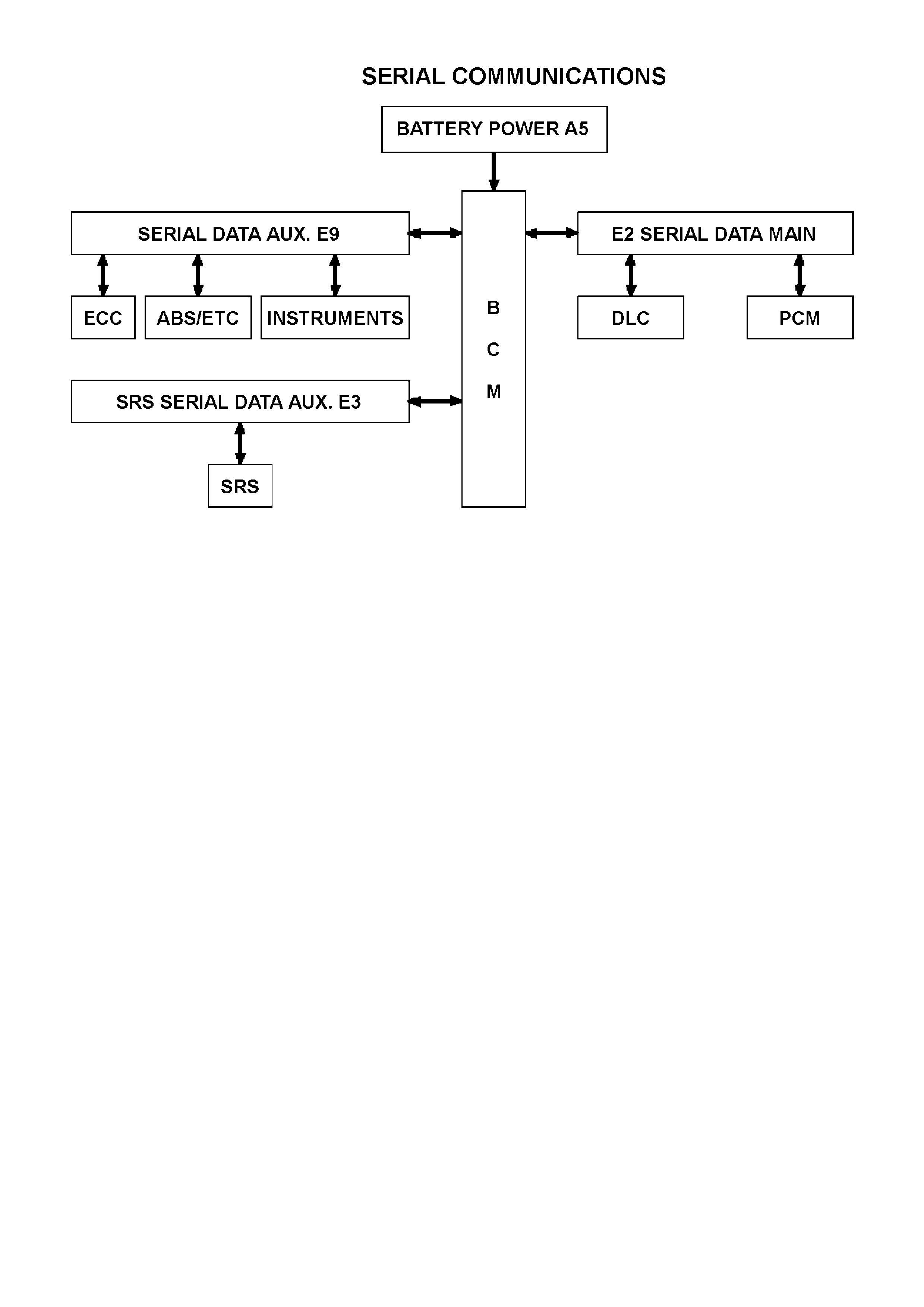
The VT Series Model uses a BUS MASTER communication system, where the BCM is the bus master.
The BCM periodically polls (surveys) each device on the bus and requests status data.
The devices connected to the bus are:
• Body Control Module (BCM)
• Powertrain Control Module (PCM)
• Electronic Climate Control (ECC)
• Instrument cluster (INS)
• Antilock Brake/Electronic Traction Control System (ABS/ETC)
• Supplemental Restraint System (SRS)
• External diagnostic tool (TECH 2)
The data provided by each device may be utilised by any device connected to the bus.
Each device has a unique response Message Identifier Word (MIW) for ease of identification.
The bus master (BCM) polls each control module with a serial data message which includes that control modules
MIW. The polled control module responds by putting a serial data message onto the bus which includes its own
MIW and data, which is retrieved and utilised by any control module requiring it.
The BCM polls each device for a status update, once every 300 milliseconds. The exception to this being the PCM
which is polled twice every 300 milliseconds.
When the ignition switch is turned from the OFF position to the ON position, the BCM will communicate with the
PCM for antitheft purposes. If the BCM does not receive a message OK TO START from the PCM within 0.5
seconds of the ignition being switched on, the auxiliary bus is isolated via switching within the BCM.
The isolation of the auxiliary data bus during this period eliminates the possibility of a device failure other than the
BCM or PCM causing a problem on the bus and inhibiting antitheft communications.
This period is known as ‘Short Loop Time’, continues until the PCM responds with an acknowledgment or a
maximum period of 5 seconds, after which the BCM will switch to the standard poling sequence.
Following successful antitheft communications, the BCM begins sequential polling of devices on the bus and normal
system operation is established.
When the ignition switch is in the OFF position, the BCM continues to poll, allowing for TECH 2 communications
and external control of the bus prior to the ignition being switched on.
NOTE:
The circuit diagrams shown in this General Description Section are to aid in interpreting the operation of the circuit
and therefore, only the main connectors and wiring colours are shown. For complete circuit details, refer to either
the relevant diagnostic section or Section 12P WIRING DIAGRAMS.
SYSTEM OVERVIEW
INPUTS / OUTPUTS
SERIAL DATA SIGNAL - MAIN
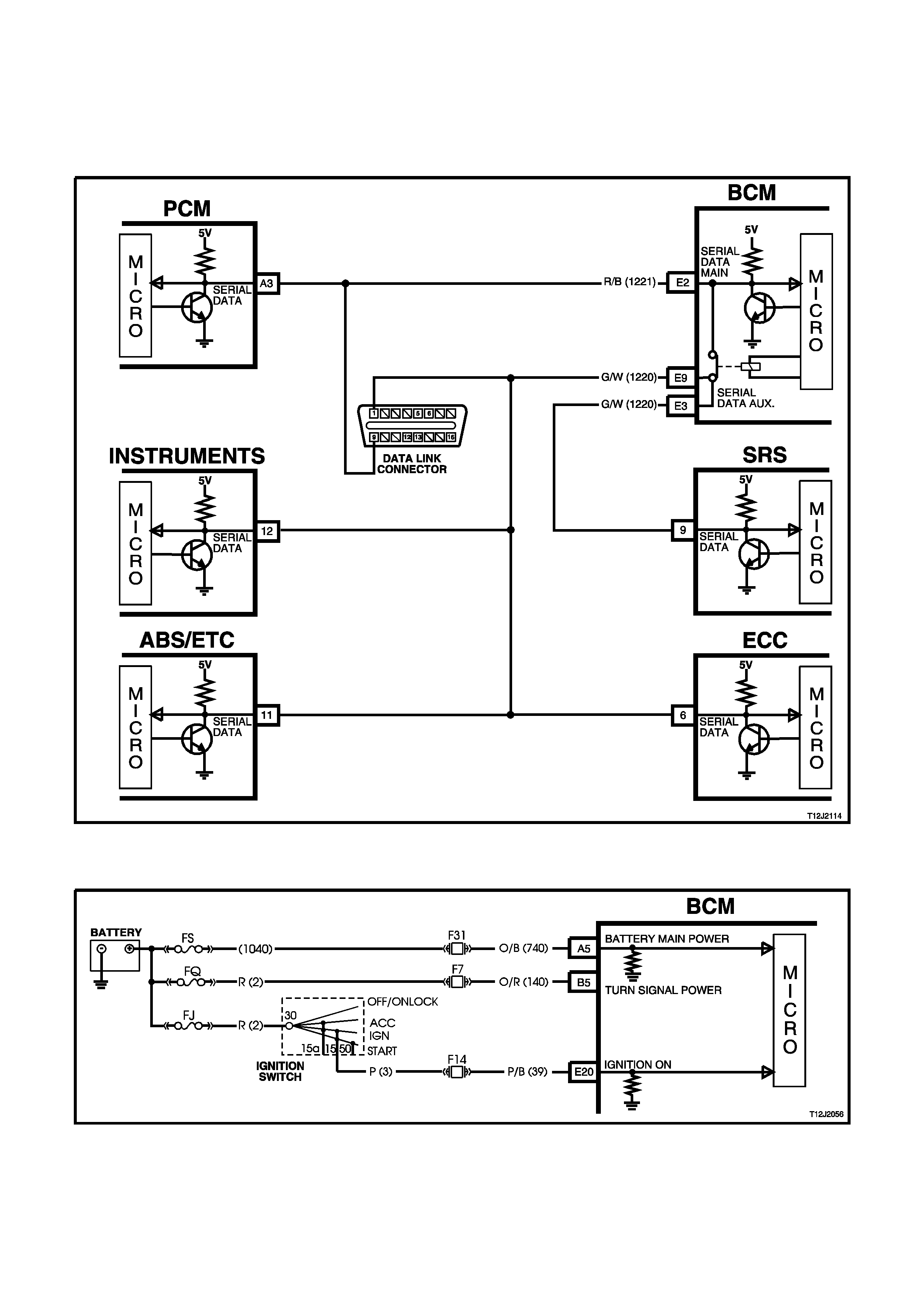
BCM terminal E2, serial data signal - main, refer Fig. 12J-2-3, is connected to the PCM and DLC via circuit 1221
(Red/Black wire). It is via this line that the BCM communicates with the PCM and external devices connected to the
DLC, at all times.
SERIAL DATA SIGNAL - AUXILIARY
BCM terminals E9 and E3, serial data signal - auxiliary, refer Fig. 12J-2-3, is connected to the INS, ABS/ETC and
SRS modules via circuit 1220 (Green/White wire). It is via this line that the BCM communicates with these devices,
after successful anti theft communications between the PCM and BCM (via the serial data - main line when the
ignition switch is turned from the OFF to ON position).
During anti theft communications, the serial data - auxiliary line is isolated from the serial data - main line via
switching within the BCM, if the BCM does not receive an OK TO START message from the PCM within 0.5
seconds of the ignition being switched on.
INPUTS
IGNITION SWITCH ON INPUT SIGNAL
The BCM uses this input signal to determine when the ignition switch is in the IGN or START position. When the
ignition switch is in the IGN or START position, battery voltage is applied to the BCM terminal E20 from the ignition
switch and fuse F14 via circuit 39 (Pink/Black wire), Refer to Fig. 12J-2-4.
Figure 12J-2-3
Figure 12J-2-4

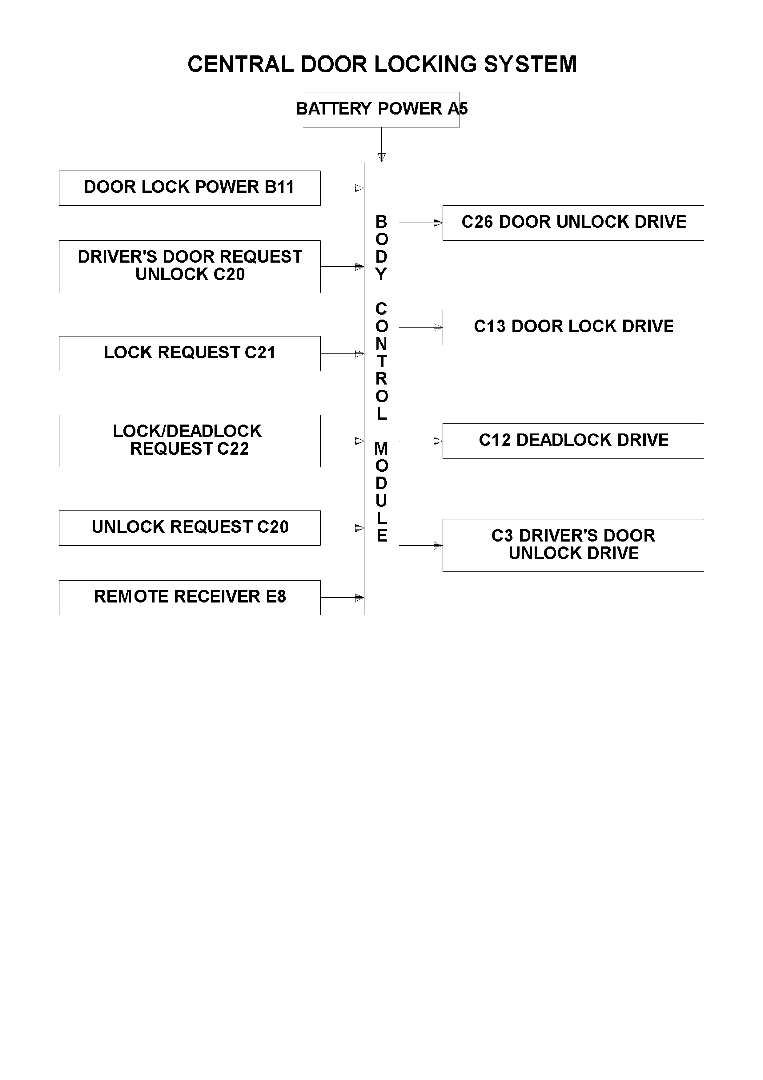
1.2 CENTRAL DOOR LOCKING SYSTEM
GENERAL INFORMATION
NOTE:
The circuit diagrams shown in this General Description Section are to aid in interpreting the operation of the circuit
and therefore, only the main connectors and wiring colours are shown. For complete circuit details, refer to either
the relevant diagnostic section or to Section 12P WIRING DIAGRAMS.
The central door locking system provides for locking and unlocking of all doors and tailgate (station wagon models)
as well as enhanced locking or 'deadlock' (doors only).
The system incorporates the following functions:
1. 1. Door and tailgate locking activated via:
Driver's door lock actuator (mechanically linked to door interior snib and door latch).
Left hand front passenger’s door lock actuator (mechanically linked to interior snib button).
Driver’s door key barrel micro switches, which are also mechanically linked to the door latch, and therefore
linked to the actuators. VT Series Models require micro switch activation to force lock (and unlock) without
moving the actuator.
Pressing the lock button on remote coded key (provided all doors are closed).
2. 2. Door and tailgate unlocking via:
All door lock actuators (mechanically linked to door interior snib).
Micro switch in driver’s door.
Pressing the unlock button on remote coded key.
The driver’s door key barrel can also be moved independently of the actuator, allowing unlocking of the driver’s
door latch in the case where the actuator is stuck down, ie. deadlock when the battery is discharged.
3. Single and Two Stage Unlocking
The BCM is capable of operating in either of two unlock modes, either two or single stage unlock. The BCM, as
fitted to the vehicle is programmed to operate the central door locking system in the two stage unlock mode.
TWO STAGE UNLOCK
In the two stage unlock mode, when the remote coded key unlock button is depressed for 0.25 seconds, the BCM,
on receiving the unlock request from the remote coded key, via the remote receiver, will unlock the driver’s door
only. If the remote coded key unlock button is depressed again for 0.25 seconds the BCM, on receiving the second
unlock request from the remote coded key, will unlock all passenger doors.
Or alternatively, if the remote coded key is depressed continuously for 0.5 seconds, the BCM, on receiving the
unlock request from the remote coded key, will unlock all doors, first the driver’s door, then all passenger doors.
SINGLE STAGE UNLOCK
In single stage unlock mode, when the remote coded key unlock button is depressed for 0.25 seconds or longer,
the BCM on receiving the unlock request from the remote coded key, via the remote receiver, will unlock all doors
simultaneously.
With TECH 2, the BCM can be programmed to operate in either two stage or single stage unlock (depending on the
vehicle’s owner or operator requirements).
If a short circuit exists on either the lock or unlock signal inputs, the opposing input is still able to perform its
function. This enables the doors to be unlocked when a short circuit exists on the lock input or vice-versa.
To protect the motors used in the door and tailgate lock actuators, in the event of multiple activation's within a
defined time period, the system will 'time-out' and protect the motors from damage. After a fixed time delay, the
system will re-activate as normal.
The deadlock feature provides for mechanical jamming of the door lock actuators. This is achieved electrically via
the driver's door key barrel micro-switch.
NOTE:
Deadlock is inhibited whilst the ignition is switched ON.
Operation of the Central Door Locking System is also affected by the Theft Deterrent System, refer to 1.3 THEFT
DETERRENT SYSTEM in this Section.
SYSTEM CHECK
The operation of the Central Door Locking System
is independent of the ignition being switched ON or
OFF.
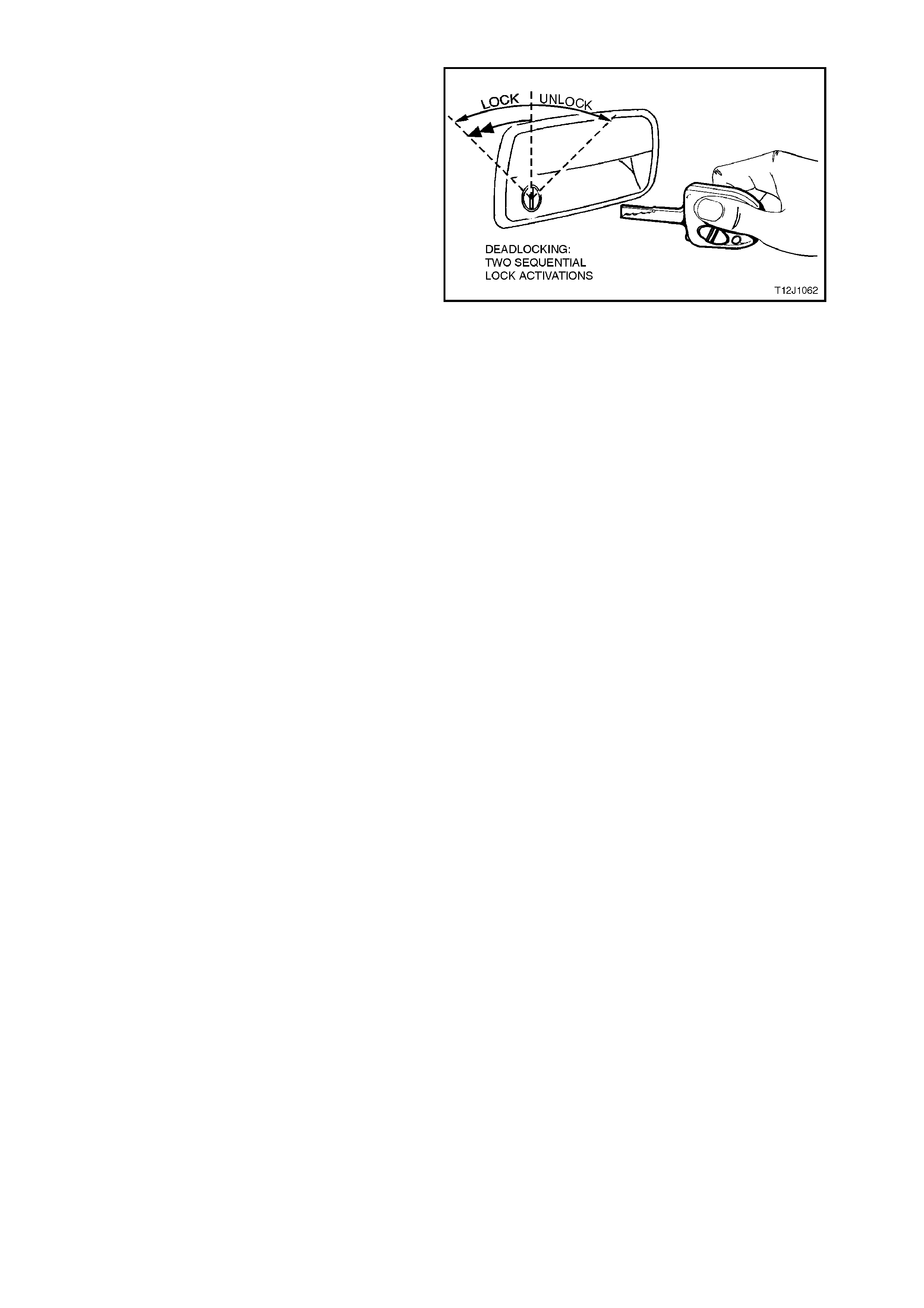
Figure 12J-2-5 shows the key positions on the
driver’s door for the various key locking functions.
Deadlock refers to the electrical m eans that c an be
activated to ensure vehicle security by inhibiting
door lock operation.
Even though the electronic theft deterrent system,
via the remote coded key, can activate the door
locks, it does not engage the electrical 'block ing' of
the doors (deadlocking).
Figure 12J-2-5
CENTRAL LOCKING AND UNLOCKING
Operation of this system can be effected as
follows;
1. Driver’s door, outside key and inside locking
(snib) button.
2. Left hand front passenger door inside locking
(snib) button (locking and unlocking)
3. Rear passenger doors inside locking (snib)
button (only unlocking is possible).
DEADLOCK
The deadlocking feature applies to all four doors,
but not to the luggage compartment lid or tailgate.
After the deadlocking feature device has been
engaged, unlocking is possible at the driver’s door
from outside, by inserting the key into the driver’s
door lock c ylinder and turning the k ey to the unlock
position or activating the unlock button on the
rem ote key unlocks the deadlocks on all doors, but
only unlocks the driver’s door (only if 2 stage
unlocking has been enabled).
To ensure access to the vehicle if the electrical
system should fail (discharged battery), after the
system has been engaged, the driver’s door key
barrel can be m oved independently of the actuator
and therefore allowing unlocking of the driver’s
door latch.
The rear compartment lid or tailgate can be
locked/unlocked with the key when the mechanical
deadlocking feature is actuated, while leaving the
doors secured. However, if the theft deterrent
system has been activated, the alarm will sound
when the rear compartment lid is raised (sedans
only).
NOTE:
Deadlocking is not possible with the ignition on.

REMOTE CODED KEY CHECK
Check that the BCM locks all doors when the
remote coded key lock button is pressed, at a
distance within 4 metres from the driver’s side B
pillar.
When the remote coded key unlock button is
pressed the driver's side should unlock (vehicles
programmed for two stage unlock). Pressing the
unlock button again and all passenger doors (and
tailgate on station wagon models) should be
unlocked.
On vehicles programmed for single stage unlock,
the single press of the unlock button will unlock all
doors and tailgate on station wagon models.
If this test does not prove satisfactory, refer to
2.3 REMOTE CODED KEY in this Section for a
more detailed diagnosis before continuing with the
central locking system check.
Figure 12J-2-6
CHECKING THE DEADLOCK FEATURE
Open all windows.
Close all doors.
Actuate the deadlock feature f rom the dr iver’s door
with the key.
Check that all door lock buttons cannot be pulled
up. They are electrically blocked.
NOTE:
The door lock (snib) buttons can be pulled up
slightly, but they will be under tension.
OVERHEATING PREVENTION
In the event of multiple activations within a defined
time period, the central door locking system will be
deactivated and remain inoperative for a defined
time period to prevent the door actuators from
overheating. After a fixed time delay, the system
will re-activate and operate as normal.
SYSTEM OVERVIEW
CIRCUIT OPERATION
The door and tailgate locks are operated by reversible motors that receive voltage from relays within the BCM.
These relays operate the motors by applying battery voltage to one side of each motor and earth to the other side.
The central door locking system has four operational phases as follows:
1. Lock to Unlock
2. Unlock to Lock
3. Lock to Deadlock
4. Deadlock to Unlock
The circuit operation of each of these four phases is described as follows:
LOCK TO UNLOCK OPERATION
(Refer to Fig. 12J-2-10)
DRIVER’S DOOR REQUEST UNLOCK INPUT SIGNAL
(Refer to Fig. 12J-2-7)
When unlocking the doors and tailgate via the right hand front door lock cylinder barrel microswitch or interior snib
button, BCM terminal C20 (driver's door request unlock signal), is connected to earth by the driver’s door lock
actuator switch contacts changing position from terminals 4-5 to 3-5 or in the case of the driver’s door cylinder
barrel micro switch, C20 is connected to earth via the microswitch contacts, unlock position circuit 156 (Black/Blue
wire). This action causes the voltage on terminal C20, circuit 193 (Light Green/Yellow wire), to be pulled low, less
than 0.2 volt (Driver’s door unlocked). This low voltage at terminal C20 is seen by the BCM as a driver’s door
request unlock signal.
NOTE:
Manually activating any unlock request line will cause all doors to be unlocked.
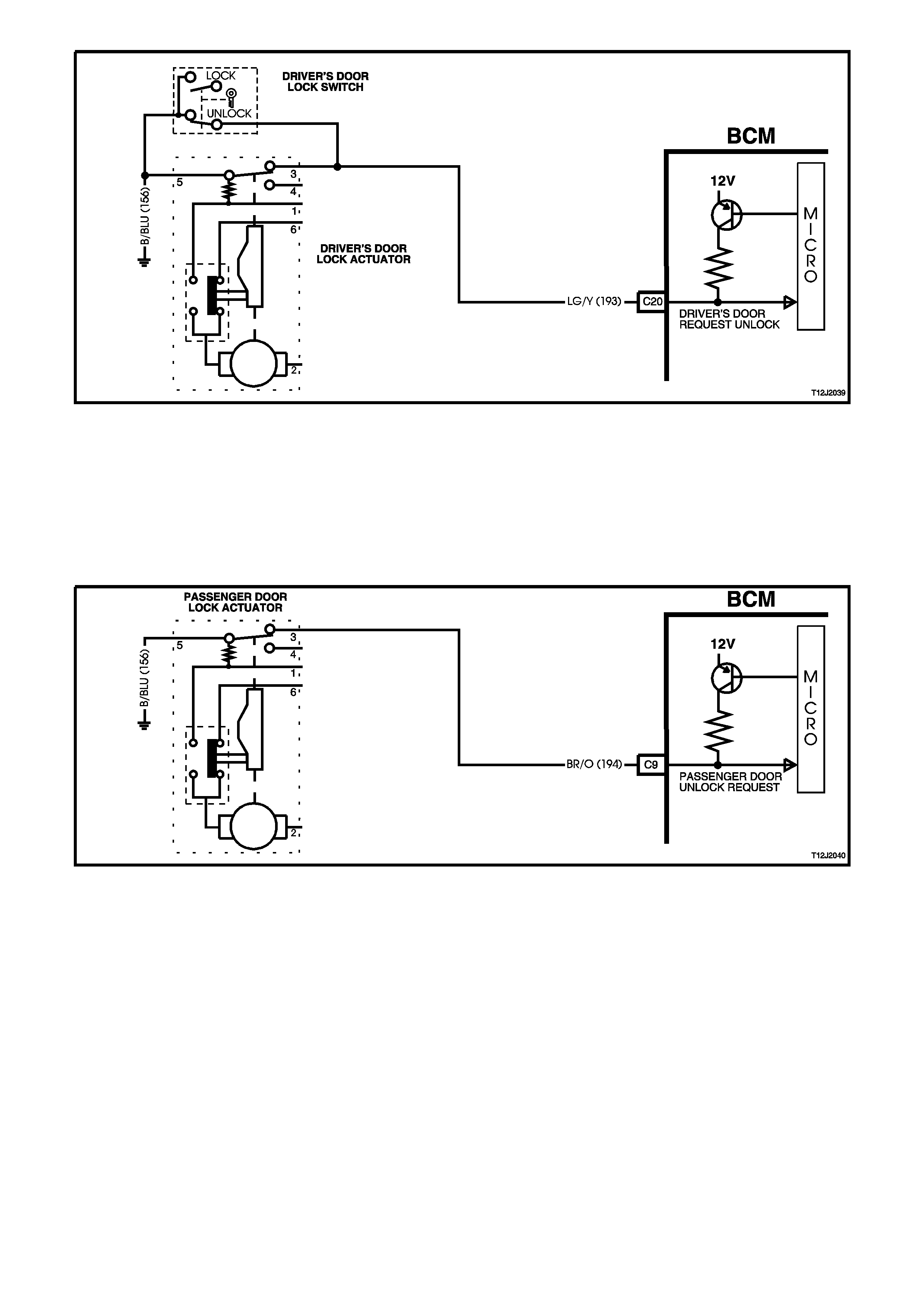
Figure 12J-2-7
PASSENGER DOOR UNLOCK REQUEST INPUT SIGNAL
(Refer to Fig. 12J-2-8)
When unlocking the doors via any passenger door interior snib button, BCM terminal C9 (passenger door unlock
request signal) is connected to earth by the activated passenger door lock actuator switch contacts, terminals 3,
circuit 194 (Brown/Orange wire) and 5, circuit 156 (Black/Blue wire). This action causes the voltage on terminal C9,
circuit 194 to be pulled low, less than 0.2 volt (doors unlocked). This low voltage at terminal C9 is seen by the BCM
as a passenger door unlock request signal.
A low voltage at terminal C20 or C9 is seen by the BCM as a system unlock request. This then enables the BCM to
energise the internal unlock relays for approximately 0.75 seconds. This causes the unlock relay contacts to close
and battery voltage is applied, via fuse F20, circuit 440 (Orange/Violet wire) and BCM terminals B11 and C26, to
terminal 2 of each of the passenger door lock actuators and to the tailgate lock actuator (station wagon models),
circuit 294 (Black/Red wire). Battery voltage is also applied, via fuse F20, circuit 440 (Orange/Violet wire) and BCM
terminals B11 and C3, to terminal 2 of the driver’s door lock actuator, via circuit 293 (Blue/Black wire).
The opposite terminal of the door lock actuators (terminal 1) is connected to earth via BCM terminal C12, circuit 394
(Violet/White wire) through the BCM internal deadlock relay contacts and BCM terminal B10, circuit 151
(Black/Green wire). This causes the door lock actuator motor armatures to rotate from the lock to the unlock
position, and the door lock actuator switch contacts to change from terminal 1 to 6. The rotation of the passenger
door lock actuator motor armatures also causes the door lock switch contacts to change from the lock to the unlock
position. The tailgate lock actuator motors are earthed via the BCM terminal C13, circuit 295 (Black/Yellow wire),
through the BCM internal lock relay contacts and BCM terminal B10 and circuit 151 (Black/Green wire).
REMOTE CODED KEY OPERATION
(Refer to Fig. 12J-2-9 for the remote receiver/key, Fig. 12J-2-11 for first stage of two stage unlock and Fig. 12J-2-12
for the second stage of two stage unlock)
TWO STAGE UNLOCK
If the BCM is operating in the two stage unlock mode and the remote coded key unlock button is depressed for 0.25
seconds, the BCM, on receiving the unlock request from the remote coded key, via remote receiver, activates the
microprocessor within the BCM, causing the driver’s door unlock relay to toggle to the unlock state, unlocking the
driver’s door only as described previously.
If the remote coded key unlock button is depressed again for 0.25 seconds, the microprocessor within the BCM, on
receiving the second unlock request from the remote coded key, will toggle the unlock relay contacts to the unlock
state and the passenger doors (and tailgate) will unlock as described previously.
If the remote coded key is depressed continuously for 0.5 seconds, the microprocessor within the BCM, on
receiving the unlock request from the remote coded key will unlock all doors, first the driver’s door, then all
passenger doors (and tailgate), as described previously.
SINGLE STAGE
If the BCM is operating in the single stage unlock mode and the remote coded key unlock button is depressed for
0.25 seconds, the microprocessor within the BCM, on receiving the RF unlock request from the remote coded key,
causes the unlock relay contacts to toggle to the unlock state, all doors (and tailgate) will then unlock as described
previously.
Figure 12J-2-9
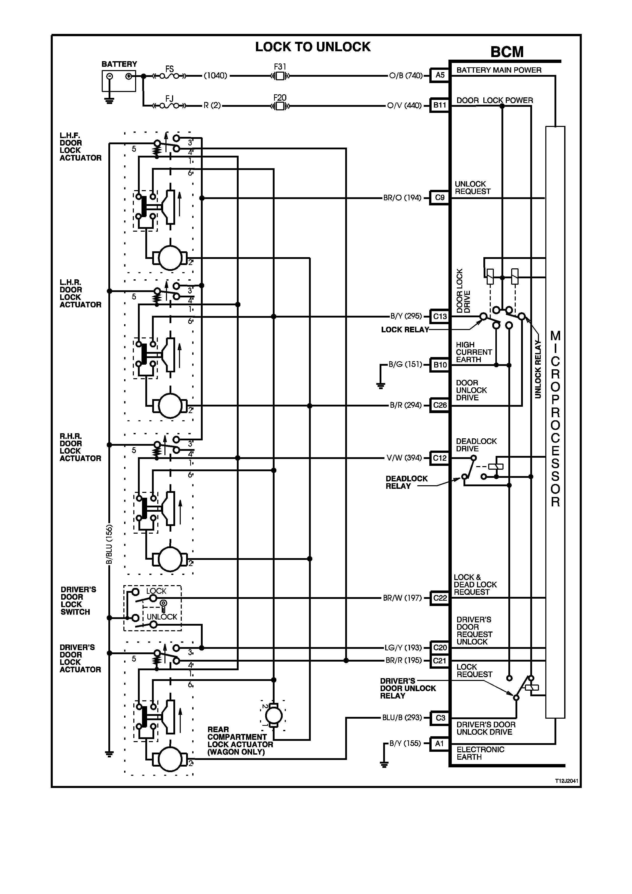
Figure 12J-2-10
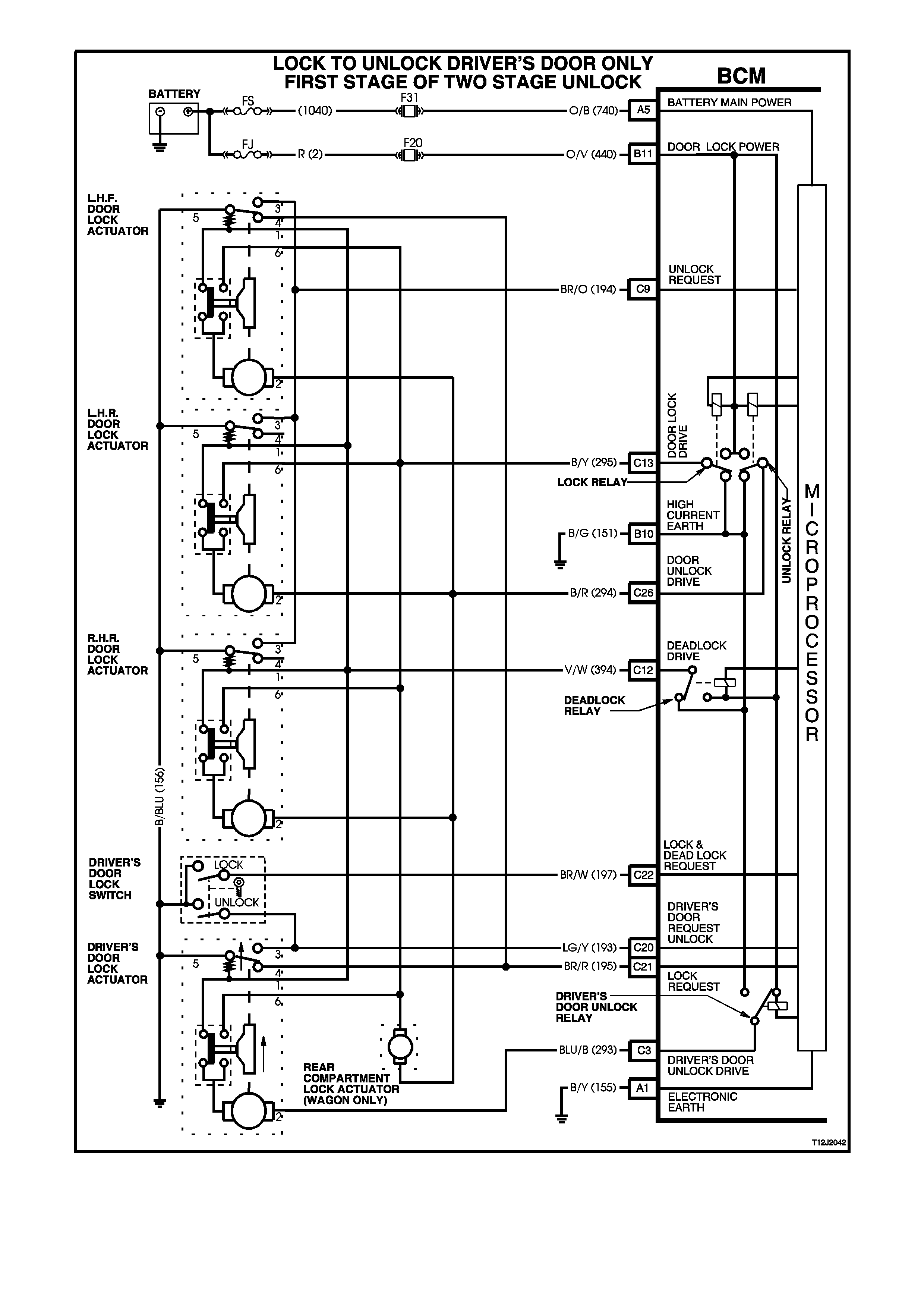
Figure 12J-2-11
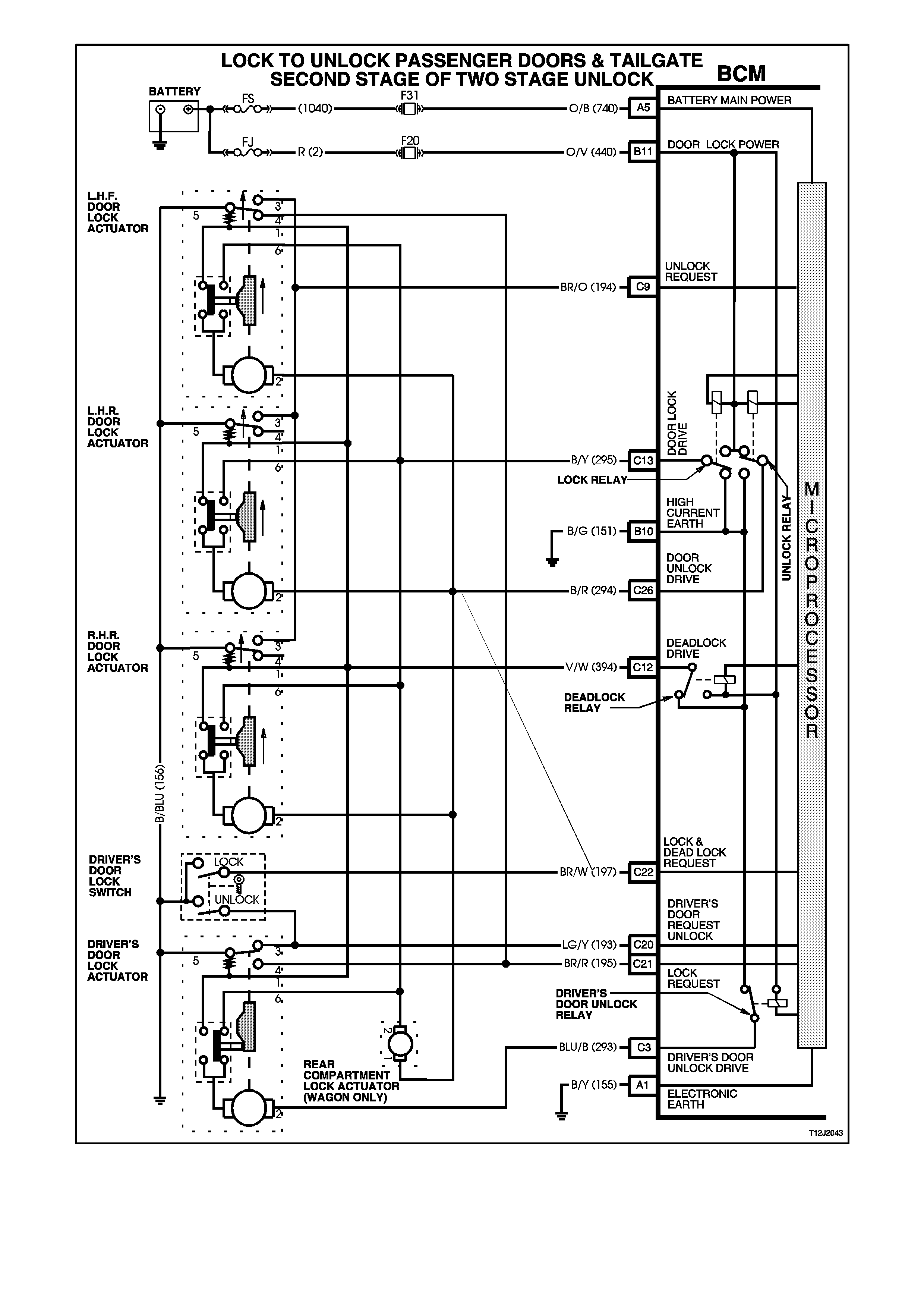
Figure 12J-2-12

UNLOCK TO LOCK OPERATION
(Refer to Fig.12J-2-15)
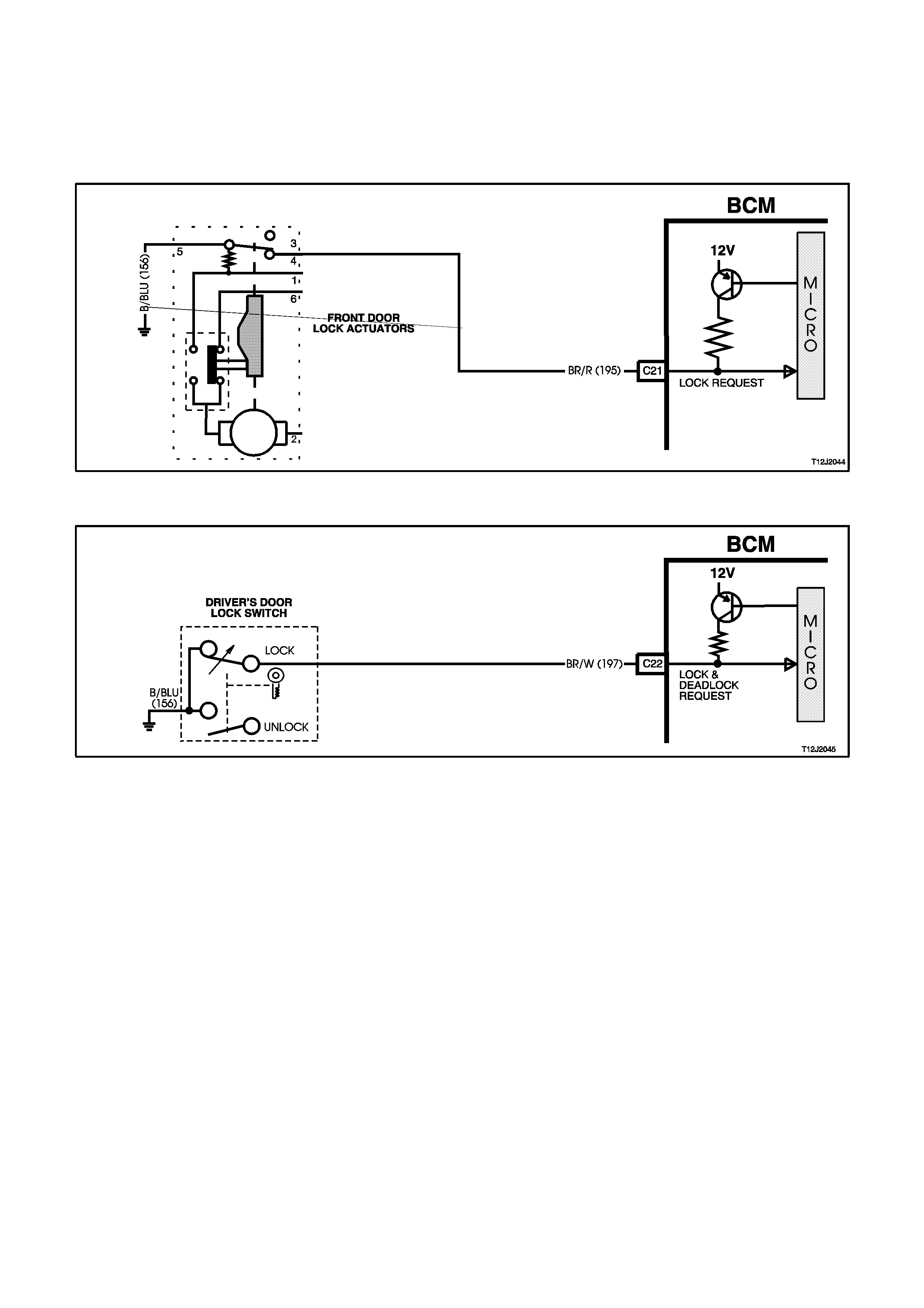
LOCK REQUEST
(Refer to Fig. 12J-2-13)
When locking the doors and tailgate via the driver’s or front passenger’s door interior snib button, the BCM terminal
C21, circuit 195 (Brown/Red wire), is connected to earth, circuit 156 (Black/Blue wire) by the driver’s or front
passenger’s door lock actuator key switch contacts changing over from terminals 3-5 to 4-5.
This action causes the voltage on terminal C12, circuit 195 (Brown/Red wire), to be pulled low, less than 0.2 volt
(doors locked).
This low voltage at terminal C21 is seen by the BCM as the system lock request.
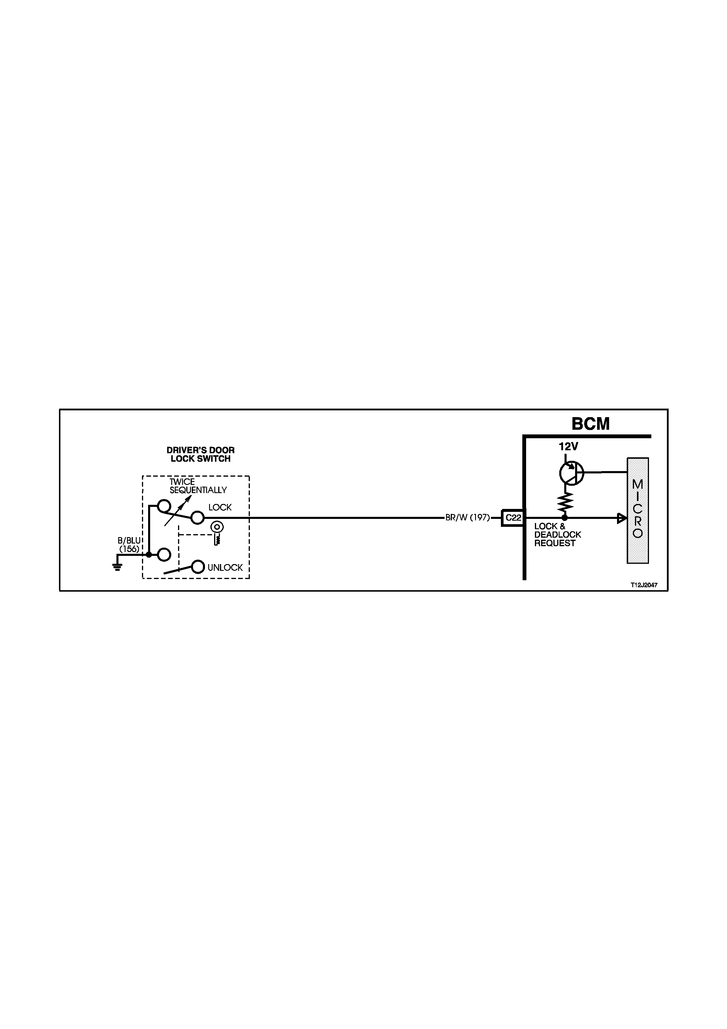
LOCK AND DEADLOCK REQUEST
(Refer to Fig. 12J-2-14)
When locking the doors and tailgate via the driver’s door cylinder barrel microswitch, BCM terminal C22
(lock/deadlock request signal) is connected to earth via the microswitch contacts, lock position, circuit 156
(Black/Blue wire). This action causes the voltage on terminal C22, circuit 197 (Brown/White wire) to be pulled low,
less than 0.2 volt (door locked). This low voltage at terminal C22 is seen by the BCM as the system lock request
(only if driver’s door is closed).
Either of these lock requests, via driver’s or front passenger’s snib buttons and driver’s door microswitch, then
enable the BCM to energise the internal lock relay for approximately 0.75 seconds, the lock relay contacts close and
battery voltage is applied, via fuse F20, circuit 440 (Orange/Violet wire) and BCM terminals B11 and C13, to
terminal 6 of each door lock actuator and to the tailgate actuator, circuit 295 (Black/Yellow wire).The opposite
terminal (terminal 2) of the passenger doors and tailgate door lock actuator motors is connected to earth through
BCM terminal C26, circuit 294 (Black/Red wire), the internal unlock relay contacts and through BCM terminal B10 to
earth, circuit 151 (Black/Green wire). The opposite terminal (terminal 2) of the driver’s door lock actuator motor is
connected to earth through BCM terminal C3, circuit 293 (Blue/Black wire), the internal driver’s door unlock relay
contacts and through BCM terminal B10 to earth, circuit 151 (Black/Green wire).
This allows the door lock actuator motor armatures to rotate to the lock position and causes the door lock actuator
switch contacts to change from terminals 6 to 1. This action disconnects the voltage supply to the door lock actuator
motor armatures, the armatures now have earth connection on both sides, with actuator terminals 6 earthed
through the deadlock relay terminals and through BCM terminal B10 to earth circuit 151 (Black/Green wire). This
causes an instantaneous halt to door lock actuator motor armature rotation.
This rotation of the passenger door lock actuator motor armatures also causes the passenger door lock switch
contacts to change to the lock position.
After approximately 0.75 seconds, the power to all the actuators via BCM terminal C13 circuit 295 (Black/Yellow
wire) is disconnected by the opening of the internal lock relay contacts.
REMOTE CODED KEY OPERATION
When locking the doors via the remote coded key, the RF output signal from the key (via remote receiver) activates
the microprocessor within the BCM, causing the door lock relay to be energised locking all doors (and tailgate) as
described previously. If any door does not lock either BCM terminal C20 (driver’s door request unlock) or C9
(Unlock request) will remain low, this low voltage is seen by the BCM as an unsuccessful attempt to lock all doors
and the BCM will cause the theft deterrent horns to sound momentarily (driver’s door must be closed).
Figure 12J-2-13
Figure 12J-2-14
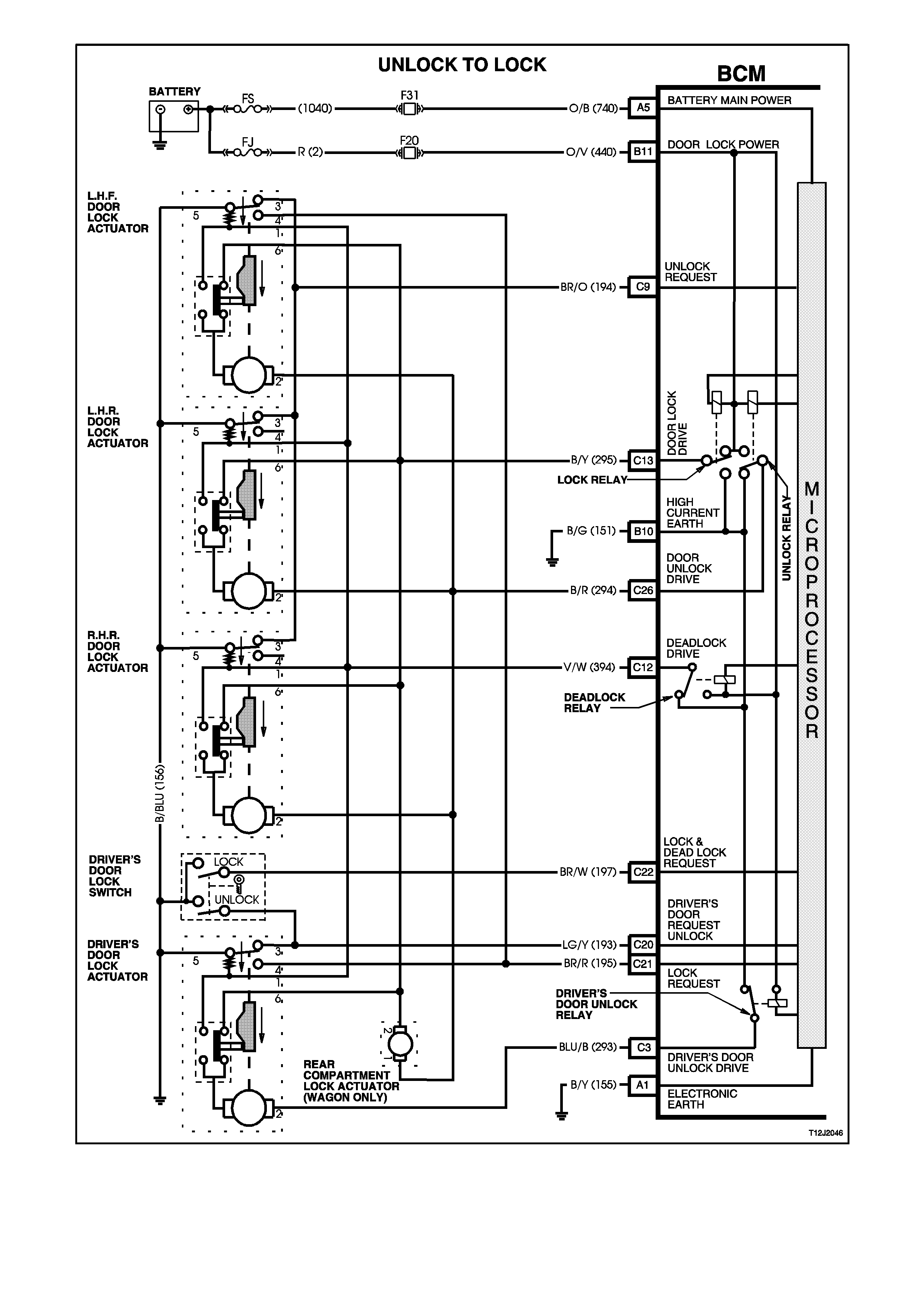
Figure 12J-2-15
UNLOCK TO DEADLOCK OPERATION
(Refer to Fig.12J-2-17)
LOCK / DEADLOCK REQUEST INPUT SIGNAL
(Refer to Fig.12J-2-16)
Deadlocking is activated after two sequential lock activation’s of the driver’s door lock switch. This action causes the
micro-switch contacts to change to the lock position. This connects BCM terminal C22 circuit 197 (Brown/White
wire) to earth via circuit 156 (Black/Blue wire), causing the voltage on terminal C22 to be pulled low, less than 0.2
volt.
This low voltage at terminal C22 is seen by the BCM as the system deadlock request. This enables the BCM to
energise the internal lock and deadlock relays for approximately 0.75 seconds, the lock and deadlock relays
contacts close and battery voltage is applied, via fuse F20, circuit 440 (Orange/Violet wire) and BCM terminals B11,
C13 and C12, circuit 295 (Black/Yellow wire) and 394 (Violet/White wire) to terminals 6 and 1 of each electric door
lock motor.
The opposite terminal (terminal 2) of all the passenger lock actuator motors is connected to earth through BCM
terminal C26, the internal unlock relay contacts and through BCM terminal B10 to earth, circuit 151 (Black/Green
wire). Terminal 2 of the driver’s door lock actuator motors is connected to earth through BCM terminal C3, the
internal driver’s door unlock relay contacts and through BCM terminal B10 to earth, circuit 151 (Black/Green wire).
This causes the door lock actuator motor armatures to rotate in the locking (downward) direction into the deadlock
position. This rotation of the door lock actuator motor armatures also causes the door lock actuator switch contacts
to change from terminals 6 to 1 to 6.
NOTE 1: The tailgate actuator is not designed to go to deadlock.
NOTE 2: Unlock to deadlock operation will only work if the driver’s door is closed and the ignition is off. If driver’s
door is open, door will not lock. If ignition is on, door will not deadlock.
Figure 12J-2-16

Figure 12J-2-17
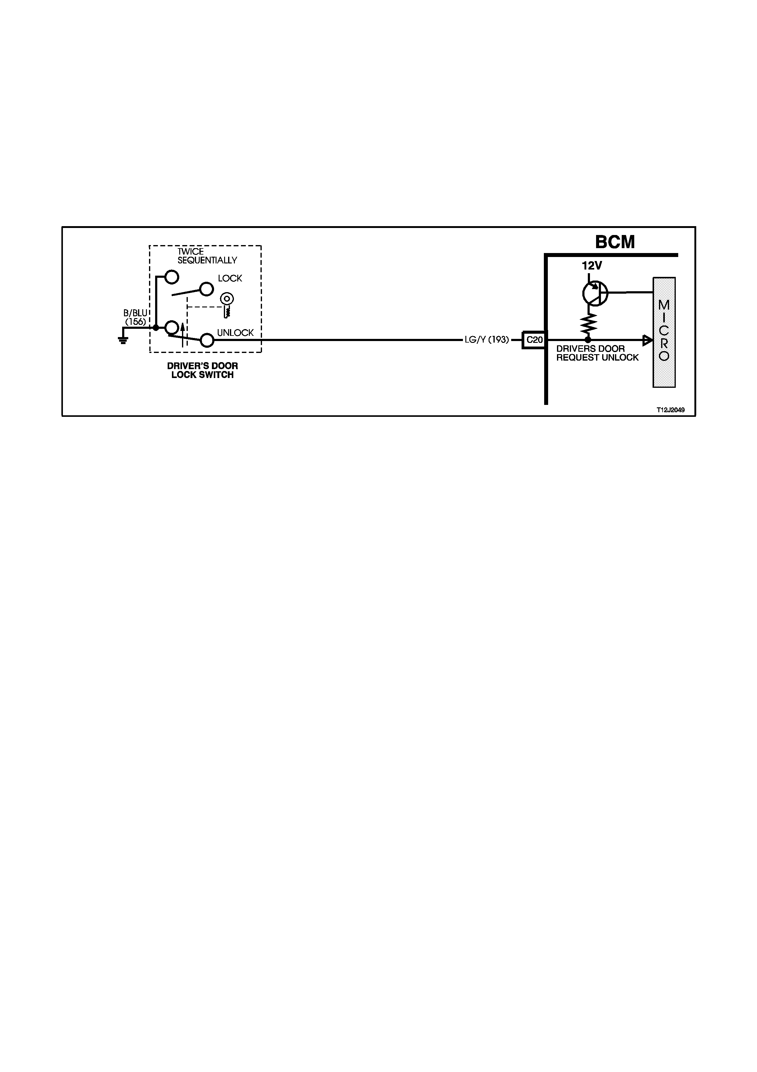
DEADLOCK TO UNLOCK OPERATION
(Refer to Figs. 12J-2-18 and 12J-2-19)
When unlocking the doors from the deadlock position by the driver’s door lock cylinder barrel, by turning to the
unlock position, the microswitch contacts change to the unlock position. This connects BCM terminal C20 circuit
193 (Lt. Green/Yellow wire), to earth via circuit 156 (Black/Blue wire), causing the voltage at terminal C20 to be
pulled low, less than 0.2 volts.
This low voltage at terminal C20 is seen by the BCM as the driver’s door unlock request signal. This then enables
the BCM to energise the internal unlock relays for approximately 0.75 seconds. This causes the relay contacts to
toggle and battery voltage is applied, via fuse F20, circuit 440 (Orange/Violet wire) and BCM terminals B11, C26
and C3 (drivers door unlock, drive, circuit 293 (Blue/Black wire) passenger’s door unlock, drive, circuit 294
(Black/Red wire)) to terminals 2 of each of the door lock actuators and to the tailgate lock actuator, circuit 294
(Black/Red wire).
Figure 12J-2-18
Initially, actuator terminal 6 is connected to earth via circuit 295 (Black/Yellow wire) through the BCM terminal C13,
through the internal lock relay contacts to terminal B10 to circuit 151 (Black/Green wire). This then allows the
passenger door lock actuator motor armatures to rotate from the deadlock toward the unlock position, causing the
passenger door lock actuator switch contacts to change from terminal 6 to 1. As terminal 1 is connected to earth via
circuit 394 (Violet/White wire) through terminal C12 of the BCM, the deadlock relay contacts to terminal B10 to
circuit 151 (Black/Green wire), the door lock actuator motor armatures will continue to rotate further to the unlock
position.
This rotation of the passenger door lock actuator motor armatures causes the door lock actuator switch contacts to
change back to terminal 6. This rotation of the passenger door actuator lock motor armatures also causes the
passenger door lock switch contacts to change to the unlock position.
NOTE:
Provided the ignition is off, the doors may be unlocked from the deadlock position by activating the unlock button on
the remote key. If set for two stage unlock, the drivers door will fully unlock (deadlock to unlock) and the remaining
passenger doors will go from the deadlock position to the lock position. If set for single stage unlock, all doors will
go from the deadlock position to the unlock position.
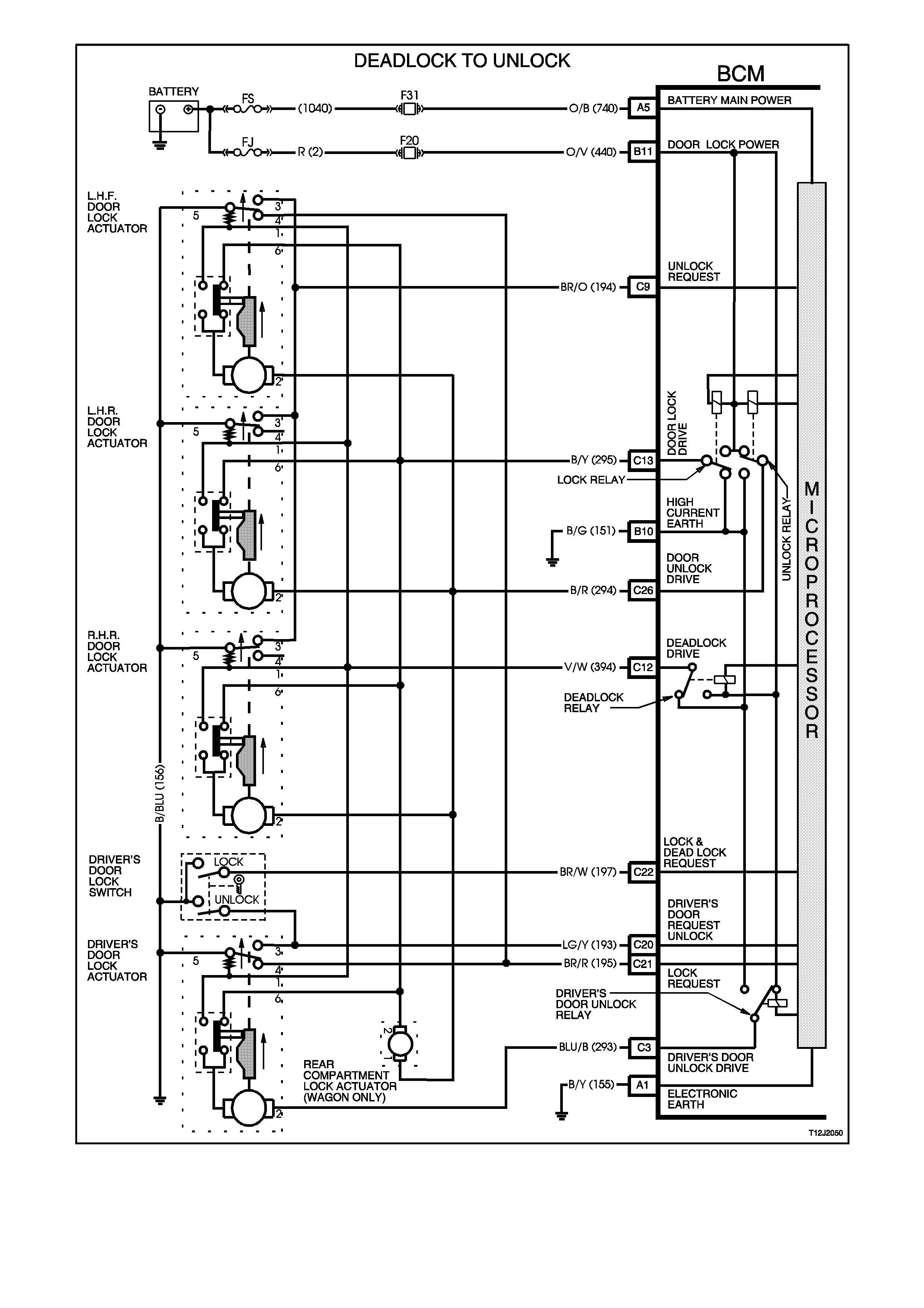
Figure 12J-2-19

1.3 THEFT DETERRENT SYSTEM
GENERAL INFORMATION
The theft deterrent system on VT Series Models uses a remote coded key to arm and disarm the system, and
where fitted, electrically lock or unlock all doors and tailgate (station wagon), or operate the boot unlock mechanism
(sedan models).
NOTE:
The circuit diagrams shown in this General Description Section are to aid in interpreting the operation of the circuit
and therefore, only the main connectors and wiring colours are shown. For complete circuit details, refer to either
the relevant diagnostic section or Section 12P WIRING DIAGRAMS.
SYSTEM OPERATION
When enabled, there are two modes of theft deterrent operation, armed and disarmed.
Armed
Once the theft deterrent system is enabled, it can be manually armed in one of two ways:
Actively, by pressing the lock button on the remote coded key or,
Passively, as the BCM will automatically arm 30 seconds after the ignition is turned off.
Disarmed
With the system disarmed, the engine management control module is enabled, allowing the engine to be started
when the ignition switch is turned to the run position.
The theft deterrent system can be disarmed in three ways:
1. Pressing the unlock button on the remote coded key. This unlocks the doors, turns the interior dome lamp on
and fully disarms the system for 30 seconds or,
2. By inserting the remote coded key into the ignition switch key barrel and turning the ignition to the ON or RUN
position. This causes the BCM to read a security code serial data output from the remote coded key contact pin
via the remote coded key reader assembly.
3. The system can also be disarmed by turning the ignition switch to the ON position for approximately two hours.
NOTE:
Should the engine crank for a brief period then stop when the ignition switch is turned to the START position (ie.
due to mis-aligned or a faulty remote coded key reader), pressing the unlock button on the remote coded key will
also disarm the theft deterrent system.
The theft deterrent system has a timed override function. The theft deterrent system can be overridden (disabled),
as for example in the event of a remote coded key failure, by turning the ignition switch to the ON position for
approximately two hours. The theft deterrent alert indicator LED will go out once the sy stem has been disabled and
normal starting of the vehicle can take place.
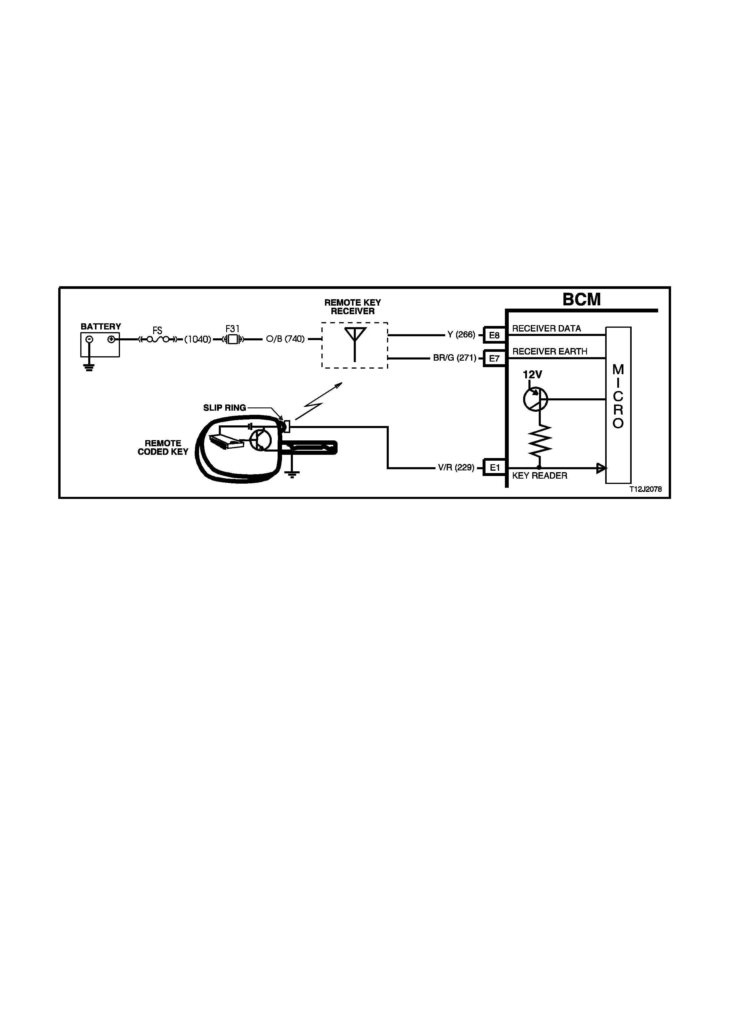
REMOTE CODED KEY
(Refer to Fig. 12J-2-20)
The theft deterrent system uses a remote coded key to arm and disarm the system, and electrically lock or unlock
all doors and tailgate (station wagon), or operate the boot unlock mechanism (sedan models).
The remote coded key is powered by its own internal battery. If its internal battery fails, the remote coded key can
be powered by the remote coded key reader once the key is inserted into the ignition switch key barrel and turned to
the IGN or START position.
The radio frequency transmitted by the remote key is received by the BCM remote receiver, located in the
instrument panel, between the demist ducts.
When the theft deterrent system is armed by pressing the remote coded key lock button, the indicators will flash
once and the theft deterrent alert indicator LED will begin to flash. Disarming the system by pressing the unlock
button will cause the indicators to flash twice and the theft deterrent alert indicator LED will stop flashing.
NOTE:
Passive arming of the system does not automatically operate the door locks or flash the indicators.
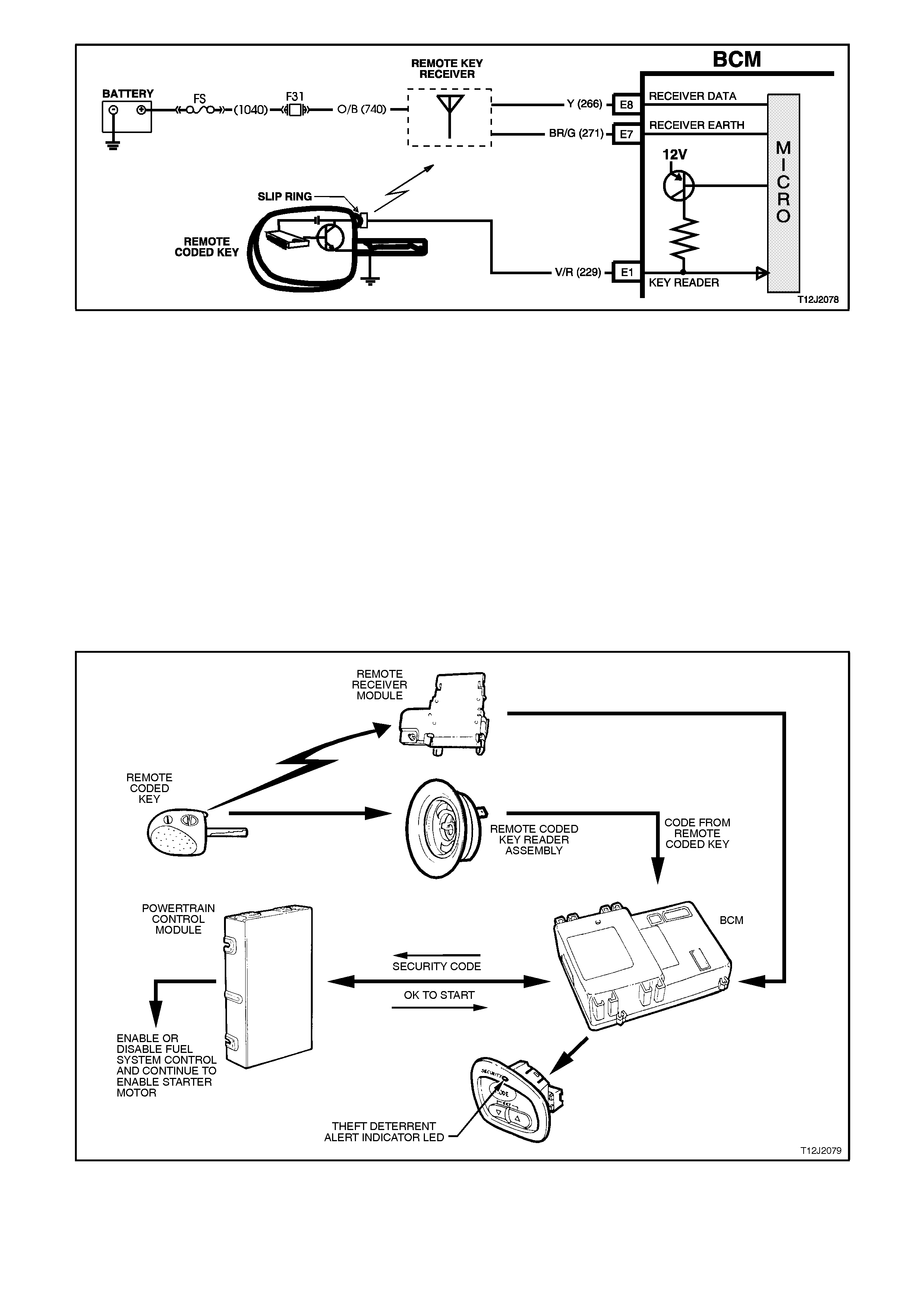
Figure 12J-2-20
THEFT DETERRENT ALERT INDICATOR LED
The theft deterrent alert indicator LED is used to indicate the state of the system. A flashing LED indicates that the
system is armed and consequently the vehicle cannot be started. When the LED is turned off, the BCM is disarmed
and the engine can be started.
On VT Series Models, the LED indicator is located in the trip computer switch facia.
OPERATION
(Refer to Fig. 12J-2-21)
When the ignition switch is turned to the ON position, the BCM polls the PCM and sends an encrypted BCM/key
security code. The security code is received by the BCM, via the remote key reader (slip ring) or via the remote
receiver in the event of no slip ring communication.
The PCM compares the received security code with its stored security code and if matched, the PCM will continue
to enable injector fuelling and engine crank.
The PCM will return a Valid Code message (OK TO START), which tells the BCM to jump from the short loop mode
to the long loop mode.
Figure 12J-2-21
SYSTEM OVERVIEW
CIRCUIT OPERATION
(Refer to Fig. 12J-2-26)
BATTERY POWER
(Refer to Fig. 12J-2-22)
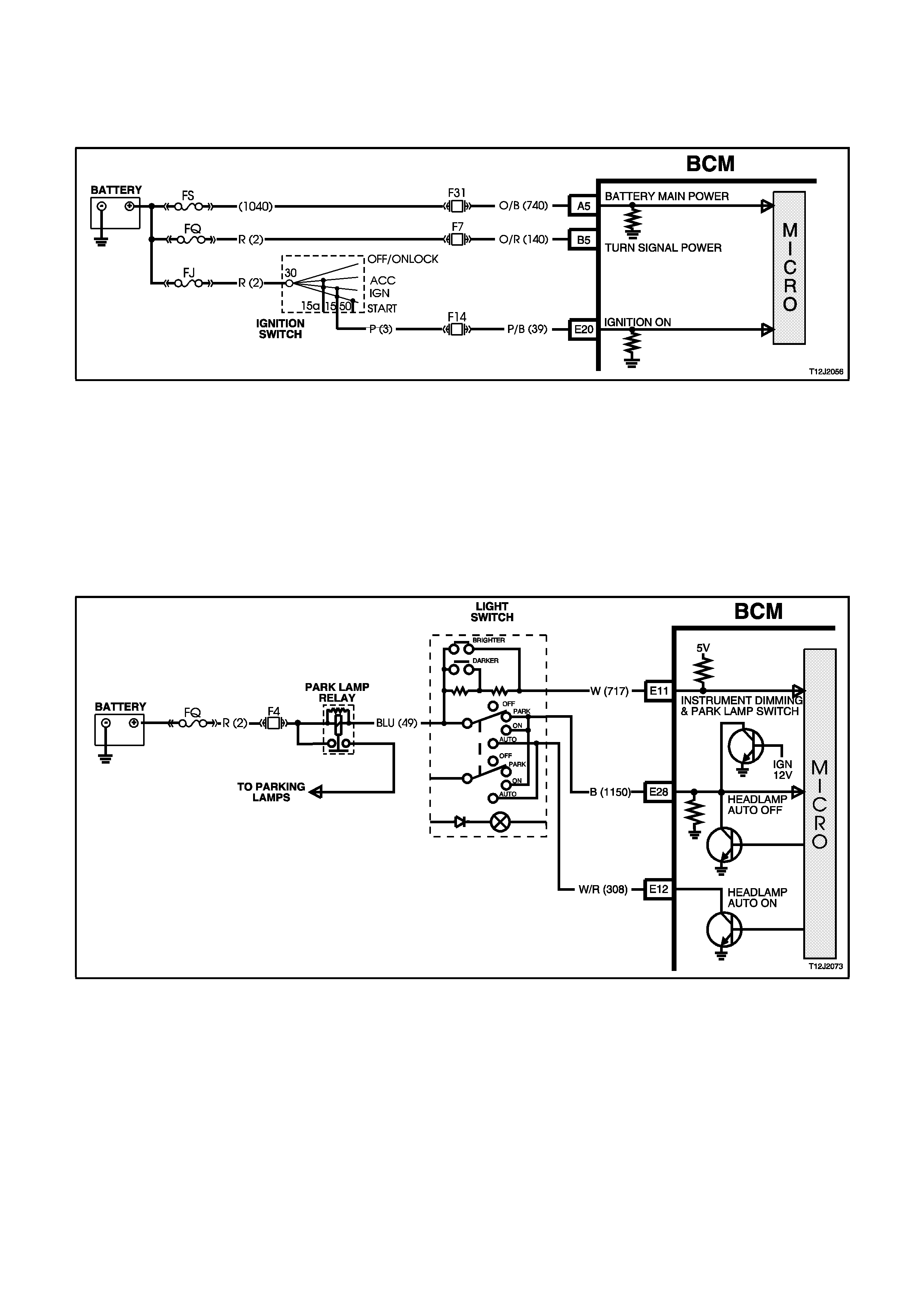
Battery voltage is applied to the BCM microprocessor from terminal A5 at all times from fusible link FS and fuse F31
via circuit 740 (Orange/Black wire).
INDICATORS POWER
(Refer to Fig. 12J-2-22)
Battery voltage is applied to BCM terminal B5 at all times from fusible link FQ and fuse F7 via circuit 140
(Orange/Red wire).
INPUTS
Ignition Switch ON Input Signal
(Refer to Fig. 12J-2-22)
The BCM uses this input signal to determine when the ignition switch is in the IGN or START position. When the
ignition switch is in the IGN or START position, battery voltage is applied to the BCM terminal E20 from the ignition
switch and fuse F14 via circuit 39 (Pink/Black wire).
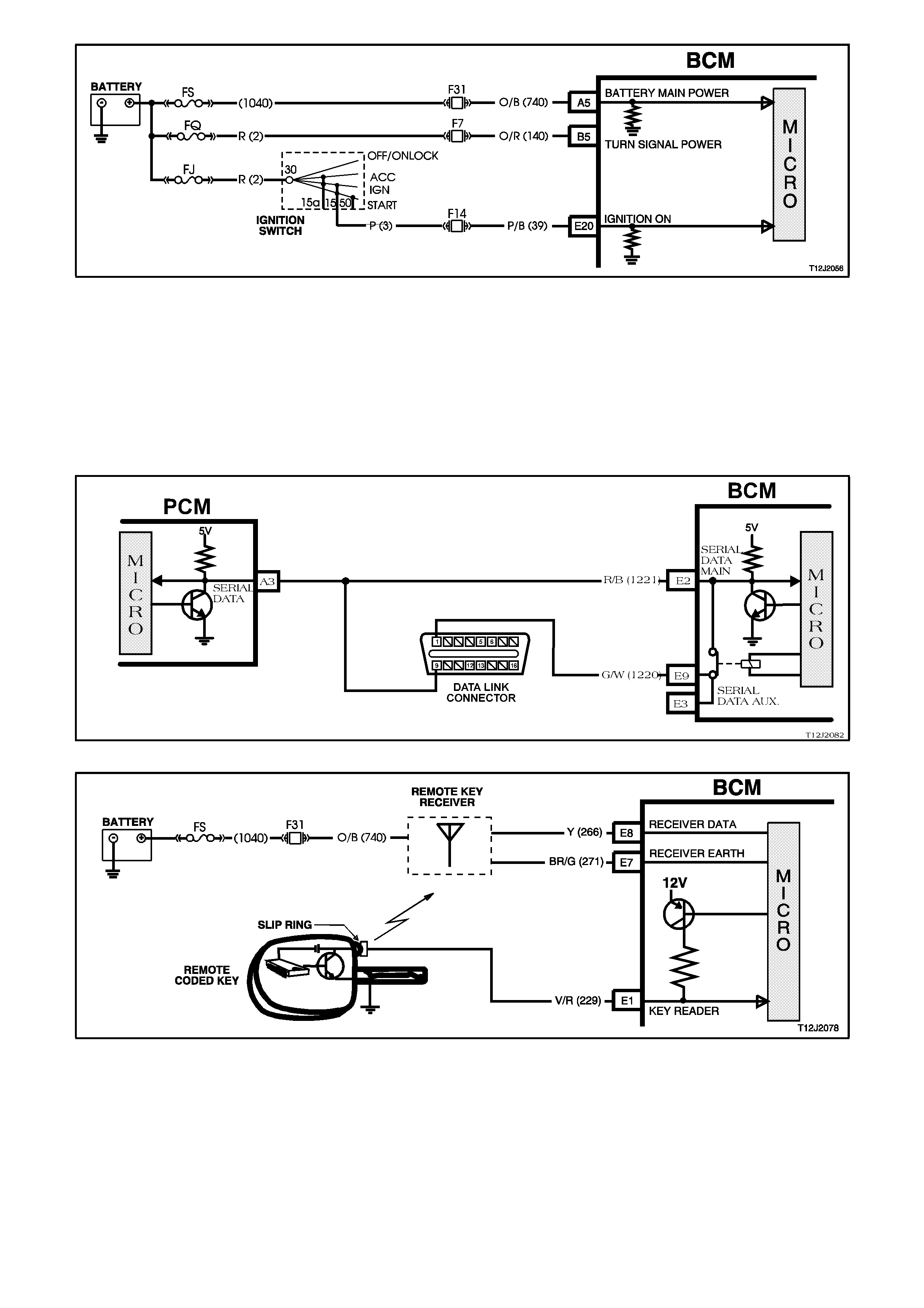
Figure 12J-2-22
BCM and Engine Control Module Communication (Serial Data)
(Refer to Figs. 12J-2-23 and 12J-2-24)
When the ignition switch is turned to the ON position, and the BCM has received a correct security code from the
key or key reader, the BCM will transmit the security code to the PCM. The PCM will compare that code with its own
stored code. If the security codes are the same, the PCM will continue to enable engine starting and also give the
BCM a ‘Valid Code’ message (OK TO START).
The serial data from the remote coded key is applied to BCM terminal E1, circuit 229 (Violet/Red wire)
Figure 12J-2-23
Figure 12J-2-24
Driver's Door Jamb Switch
(Refer to Fig. 12J-2-25)
The BCM uses this input signal to determine if the driver's front door is opened or closed. The BCM must sense that
the driver's door is closed before the theft deterrent system can be actively armed.
When the door is opened, the jamb switch earths terminal C8 via circuit 126 (Grey/White wire). This causes the
voltage at terminal C8 to be pulled low, less than 0.2 volt (driver's door open). This low voltage at terminal C8 is
seen by the BCM as the driver's door open input signal.
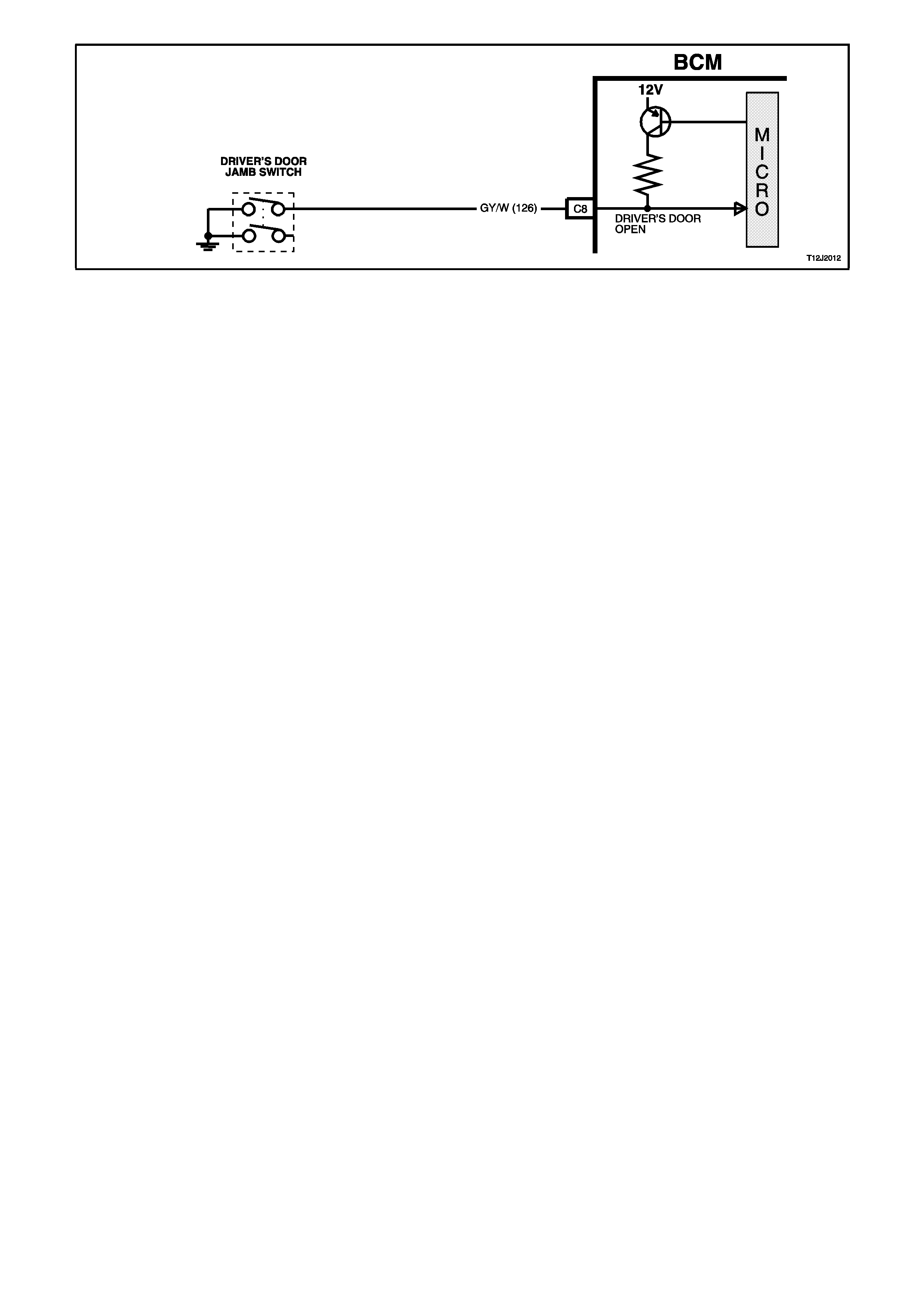
Figure 12J-2-25
OUTPUTS
(Refer to Fig. 12J-2-26)
Left Hand Indicators
The BCM controls the operation of the left hand indicators by pulsing its internal indicator relay. This causes the
indicator relay contacts to close and open a number of times. This allows battery voltage from terminal B5 to be
applied internally to terminal B4, to the left hand indicator lamps via circuit 14 (Light Blue wire).
Right Hand Indicators
The BCM controls the operation of the right hand indicators in the same manner as the left hand indicators. Pulsing
of its internal indicator relay causes the indicator relay contacts to close and open a number of times. This allows
battery voltage from terminal B5 to be applied internally to terminal B12, to the right hand indicator lamps via circuit
15 (Blue wire).
Theft Deterrent Alert Indicator LED
The theft deterrent alert indicator LED will continuously flash on and off whenever the system is armed. The BCM
controls the operation of the theft deterrent alert indicator LED by pulsing an internal switch on and off, which in turn
switches the voltage applied to the theft deterrent alert indicator LED via terminal A6, circuit 263 (Light Blue wire).
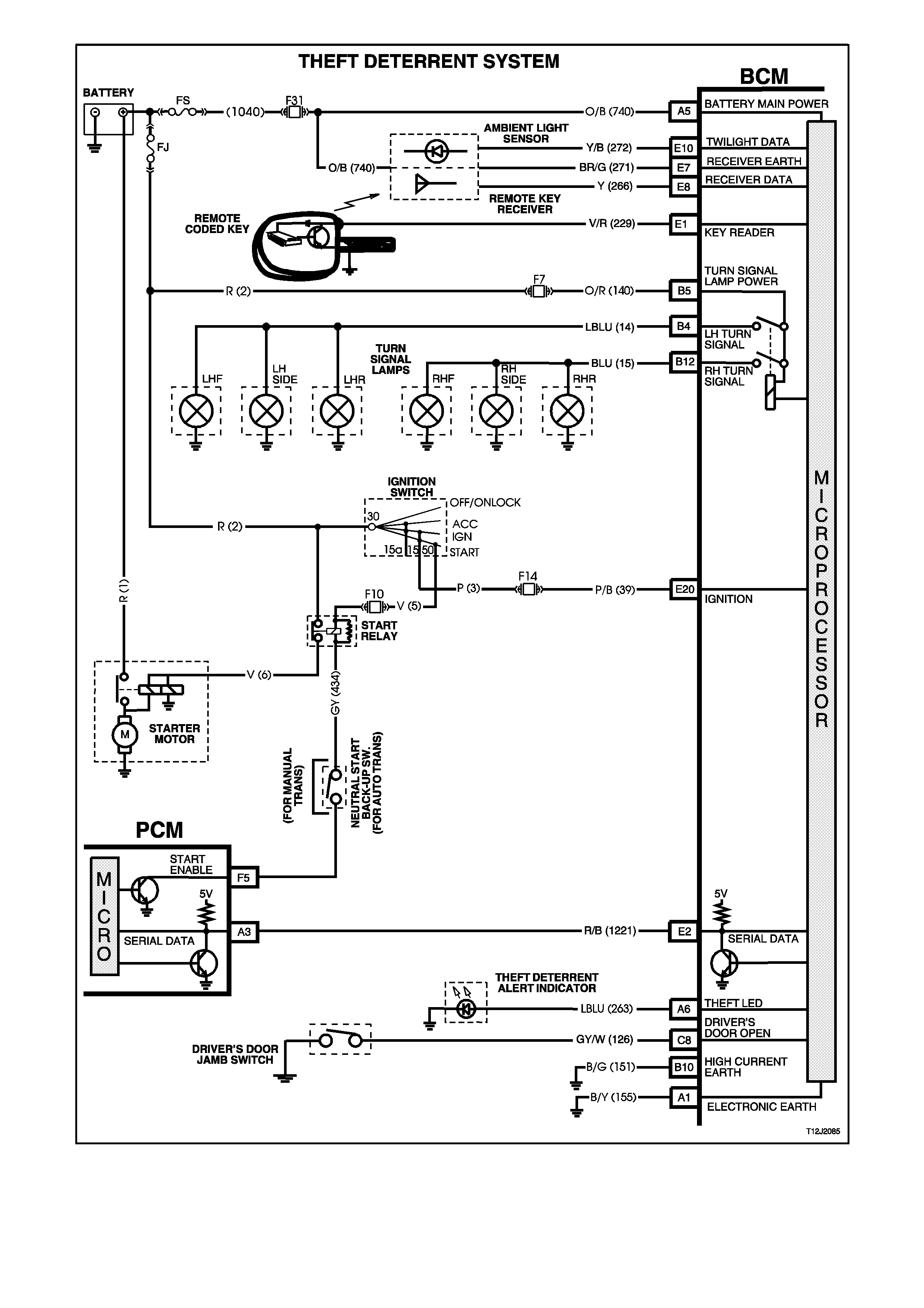
Figure 12J-2-26

1.4 ENTRY DETERRENT SYSTEM
GENERAL INFORMATION
The entry deterrent system, incorporated in the BCM, is designed to deter unwanted access to the vehicle's
passenger compartment by providing audible and visual warning (alarm) of illegal entry to the vehicle.
Arming of the theft and entry deterrent systems is by pressing the lock button on the remote coded key.
NOTE:
The entry deterrent system does not arm passively.
The remote coded key also incorporates a boot release function button.
An ultrasonic sensor option can also be fitted to the vehicle.
NOTE:
The circuit diagrams shown in this General Description Section are to aid in interpreting the operation of the circuit
and therefore, only the main connectors and wiring colours are shown. For complete circuit details, refer to either
the relevant diagnostic section or Section 12P WIRING DIAGRAMS.
Arming Operation
The entry deterrent system is armed by pressing the lock button on the remote coded key, the output signal from
the key, via the remote receiver, activates the microprocessor within the BCM, providing that the ignition is OFF and
the vehicle road speed input indicates speed is zero. Note that one continuous press of a button on the remote
coded key should cause only one arm/disarm operation. It is not possible to arm the system or remote lock the
doors with the driver's door open.
When the system is armed, the following actions take place:
1. All doors lock (and tailgate on Berlina station wagon).
2. All indicator lamps flash once.
3. The power antenna retracts.
4. The power window system deactivates.
5. The dome lamp is switched off (provided it has not been turned on by another system).
6. The theft deterrent alert indicator LED flashes (refer theft deterrent system operation description).
Triggered Operation
Once the entry deterrent system is armed, it is triggered by any one of the following inputs:
1. The bonnet being opened (or ultrasonic trigger).
2. The boot being opened.
3. Any door being opened.
4. Ignition being switched on.
If any of the previous conditions exist at the time of the system arming, they will be ignored until the fault condition is
cleared.
Once triggered, the system will operate as follows:
1. Flash all indicator lamps at a rate of one flash every two seconds.
2. Pulse all vehicle horns at a rate of one pulse per second.
3. Flash the dome lamp at a rate of one flash every two seconds.
Flashing of the indicators and dome lamp, and sounding of the horn/s will continue for a period of 30 seconds.
Disarming Procedure
The system is disarmed by:
A. Pressing the unlock button on the remote coded key. The RF output signal from remote coded key, via the
remote receiver, activates the microprocessor within the BCM.
Upon disarming the following actions take place:
1. All doors (and tailgate on Berlina station wagon) unlock.
2. All indicators lamps flash twice, however if the system has been triggered since being armed, they will flash
three times.
3. The dome lamp is activated for 30 seconds (normal delay cancellation conditions apply).
4. If the system has been triggered since being armed, the theft deterrent alert indicator LED will flash a code
indicating the triggered source, otherwise it will be turned off. This flashing code will be cancelled once the
ignition is switched on.
B. If the remote coded key is not working (eg. flat battery), turning the ignition on allows the BCM to provide a
power supply to the remote coded key to enable reading of the key security code. (the alarm may trigger
briefly)

Flash Codes
The system triggered flash codes emitted by the theft deterrent alert indicator LED flash at a defined flash rate with
a pause between codes. Pause are 1.5 seconds. Codes are repeated twice before moving to the next code.
Two flashes - bonnet (or ultrasonic sensor)
Three flashes - boot
Four flashes - passenger door
Five flashes - driver's door
Six flashes - ignition on
NOTE:
Alarm codes are stored in the BCM until cleared (BCM reset). To access this information, connect TECH 2 to the
DLC and select Body / Body Control Module / Diagnostic Trouble Codes / Read Alarm Code Information.
Remote Boot Release
The rear compartment lock actuator is controlled by pressing the boot button on the remote coded key. The RF
output signal from the remote coded key, via the remote receiver, activates the microprocessor within the BCM.
The rear compartment lock actuator is activated under the following conditions:
1. The boot button on the remote coded key has been pressed continuously for more than 0.5 seconds.
2. The vehicle road speed is less than or equal to fifteen kilometres per hour.
The remote boot release function also operates whilst the entry deterrent system is armed and the system will not
trigger from the remote opening of the boot. Whilst the boot input is inhibited, the bonnet input is similarly inhibited
against triggering the entry deterrent system (this is required for the operation of the ultrasonic sensor option).
After the boot has been closed for 30 seconds, the system will re-arm the boot and bonnet sensing to allow
triggering from the boot and bonnet.
Loss of Vehicle Battery Power
Whenever there is a re-connection of battery power to the BCM, the theft and entry deterrent systems will resume in
the same state as when the battery power was disconnected, except if the system was disarmed. If the system was
disarmed, it will default to passive arm.
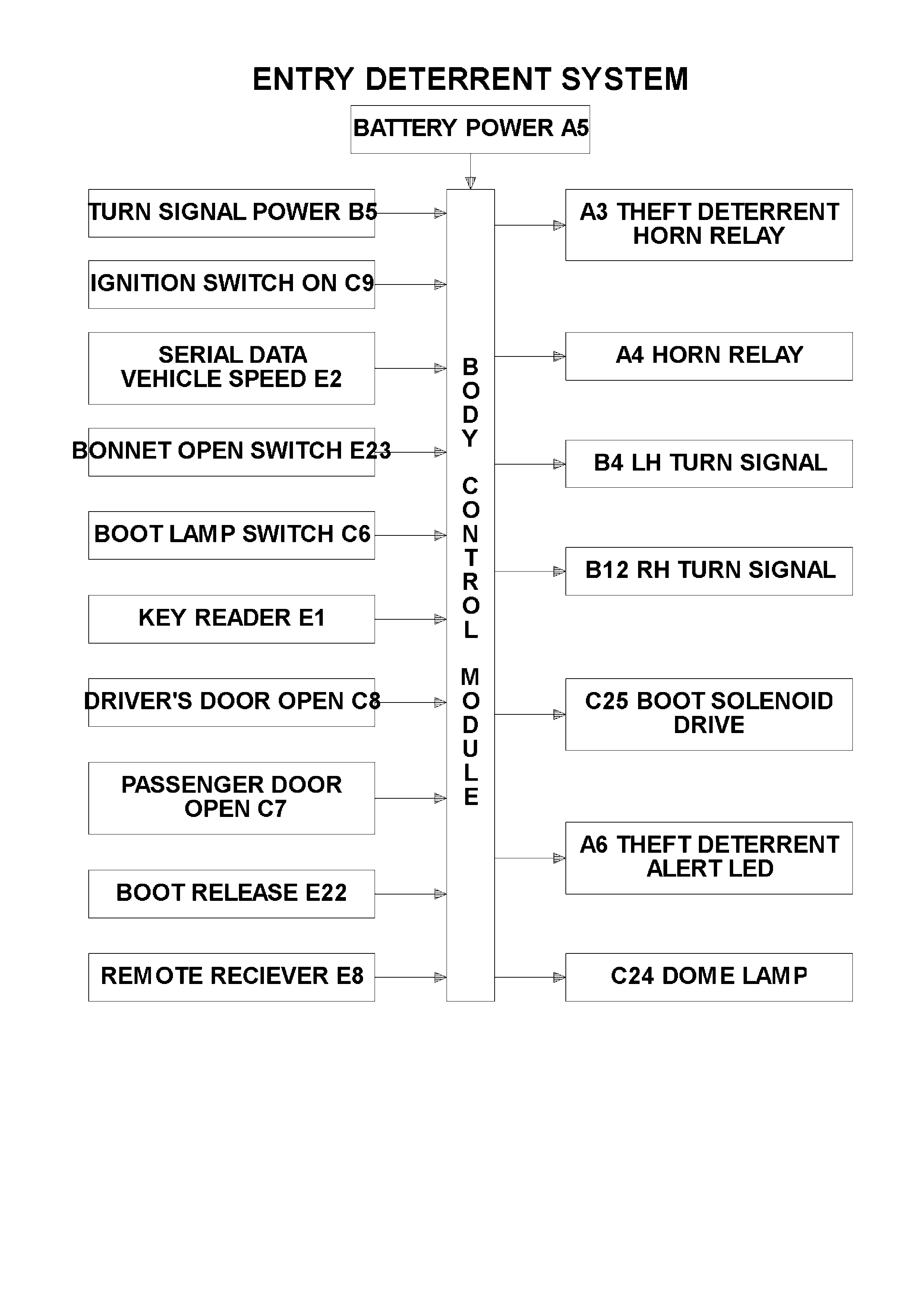
SYSTEM OVERVIEW
CIRCUIT OPERATION
(Refer to Fig. 12J-2-34)
Power Supplies
(Refer to Fig. 12J-2-27)
Battery Power
Battery voltage is applied to the BCM microprocessor from terminal A5 at all times from fusible link FS and fuse F31
via circuit 740 (Orange/Black wire).
Turn Signal Power
Battery voltage is applied to BCM terminal B5 at all times from fusible link FQ and fuse F7 via circuit 140
(Orange/Red wire).
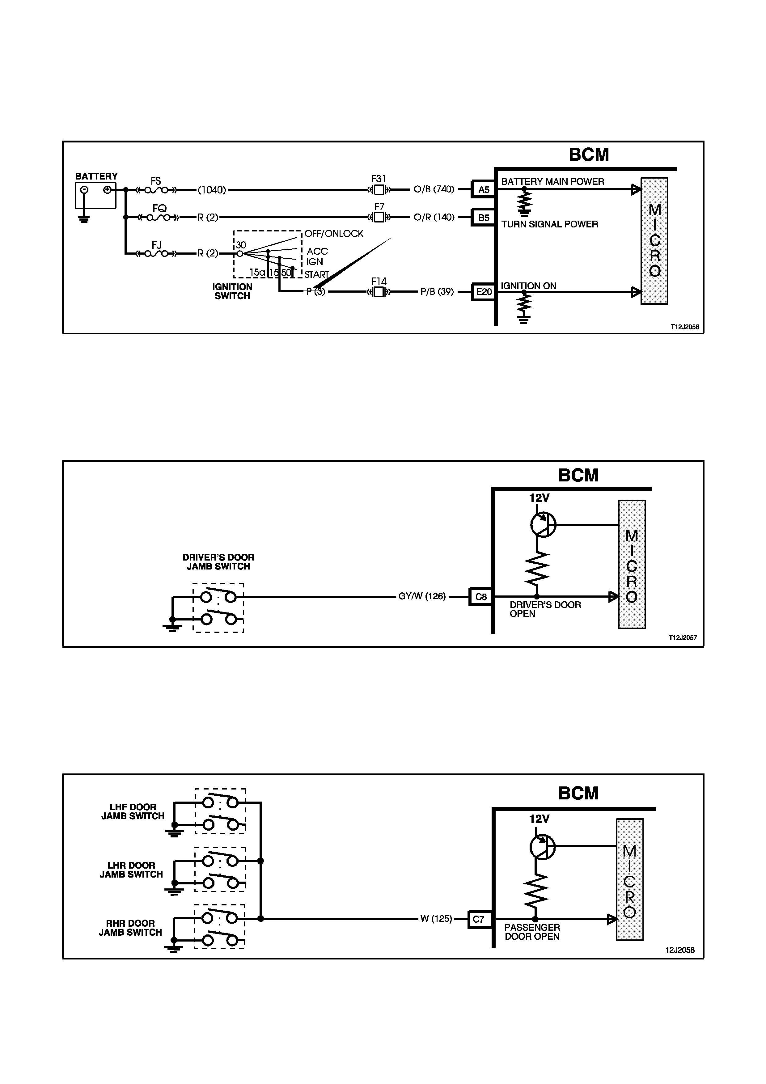
INPUTS
(Refer to Fig. 12J-2-27)
Ignition Switch ON Input Signal
The BCM uses this input signal to determine when the ignition switch is in the IGN or START position. When the
ignition switch is in the IGN or START position, battery voltage is applied to the BCM terminal E20 from the ignition
switch and fuse F14 via circuit 39 (Pink/Black wire).
Figure 12J-2-27
Driver's Door Jamb Switch Input Signal
(Refer to Fig. 12J-2-28)
The BCM uses this input signal to determine if the driver's front door is opened or closed. When the door is opened,
the jamb switch earth’s terminal C8 via circuit 126 (Grey/White wire). This causes the voltage at terminal C8 to be
pulled low, less than 0.2 volt (driver's door open). This low voltage at terminal C8 is seen by the BCM as the driver's
door open input signal.
Figure 12J-2-28
Passenger’s Door Jamb Switch Input Signal
(Refer to Fig. 12J-2-29)
The BCM uses this input signal to determine if any of the passenger doors are opened or if all passenger doors are
closed. If the right hand rear, left hand front or left hand rear door is open, terminal C7 is earthed through circuit 125
(White wire). This causes the voltage at terminal C7 to be pulled low, less than 0.2 volt (if any one of the passenger
doors is opened). This low voltage at terminal C7 is seen by the BCM as the passenger door open input signal.
Figure 12J-2-29
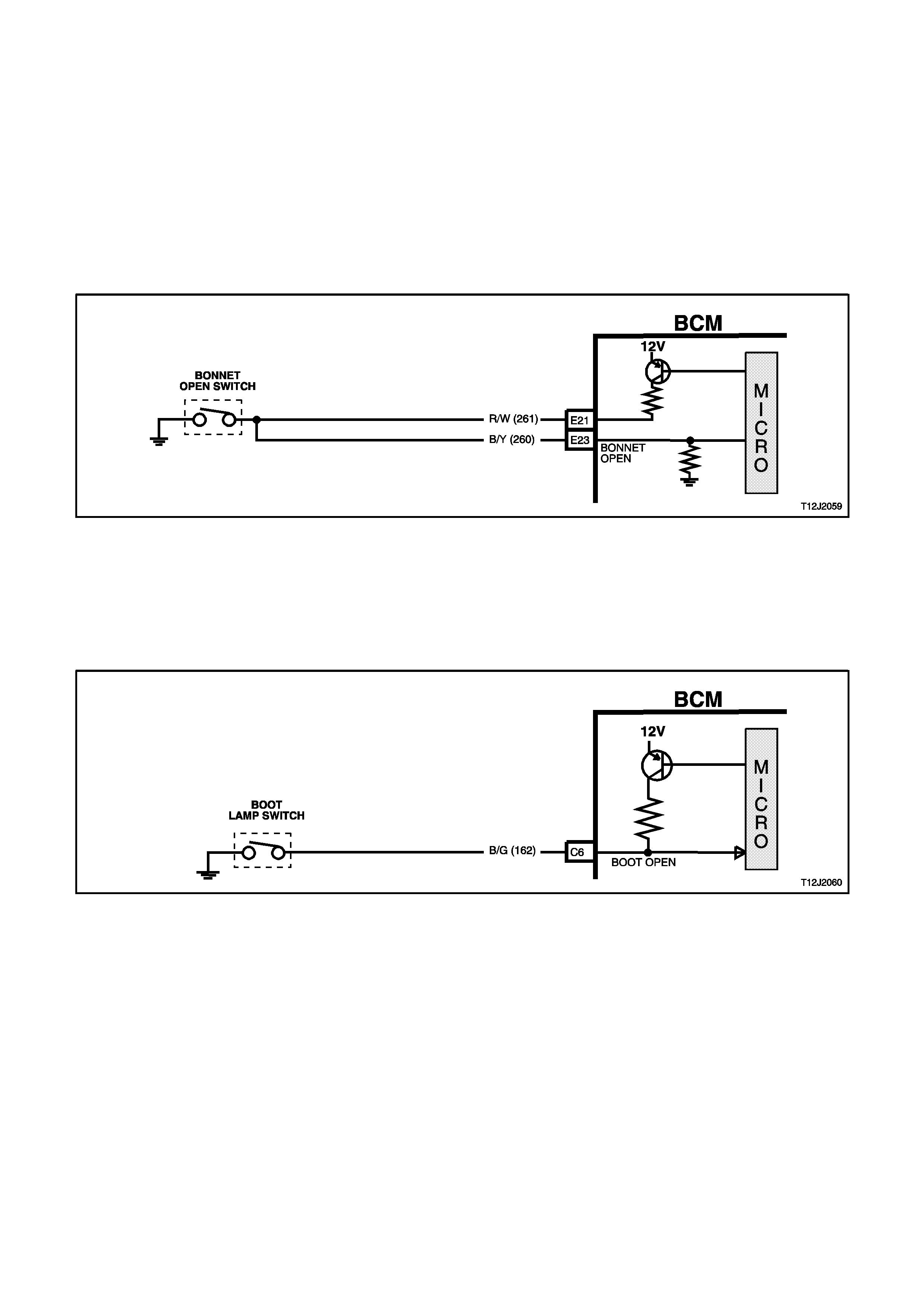
Bonnet Open Switch Input Signal
(Refer to Fig. 12J-2-30)
The BCM uses this input signal to determine if the bonnet is open or closed. When the bonnet is closed, battery
voltage from the BCM, via circuit 261 (Red/White wire) passes through the bonnet switch, via circuit 260
(Yellow/Black wire) and is applied to the BCM terminal E23. This high voltage at the BCM terminal E23 is seen by
the BCM as the bonnet closed input signal. In the event of an open circuit in either circuits 260 or 261, the BCM
internal pull down resistor ensures that the voltage at the input to the microprocessor is less than 0.2 volts. This low
voltage at the microprocessor is seen as the bonnet open signal. This is to ensure that if either of these two circuits
are tampered with, the alarm will be triggered.
When the bonnet is opened, the theft deterrent bonnet open switch closes and earth’s the BCM terminal E23
through circuit 260 (Yellow/Black wire). This action causes the voltage at the BCM terminal E23 to be pulled low,
less than 0.2 volts (bonnet open). This low voltage at BCM terminal E23 is seen by the BCM as the bonnet open
input signal.
Figure 12J-2-30
Boot Lamp Switch Input Signal (Sedan Models Only)
(Refer to Fig. 12J-2-31)
The BCM uses this input signal to determine if the boot is open or closed. When the boot is opened, the boot lamp
switch earth’s BCM terminal C6 through circuit 162 (Black/Green wire). This action causes the voltage at BCM
terminal C6 (Boot Open) to be pulled low, less than 0.2 volt). This low voltage at BCM terminal C6 is seen by the
BCM as the boot open input signal.
Figure 12J-2-31
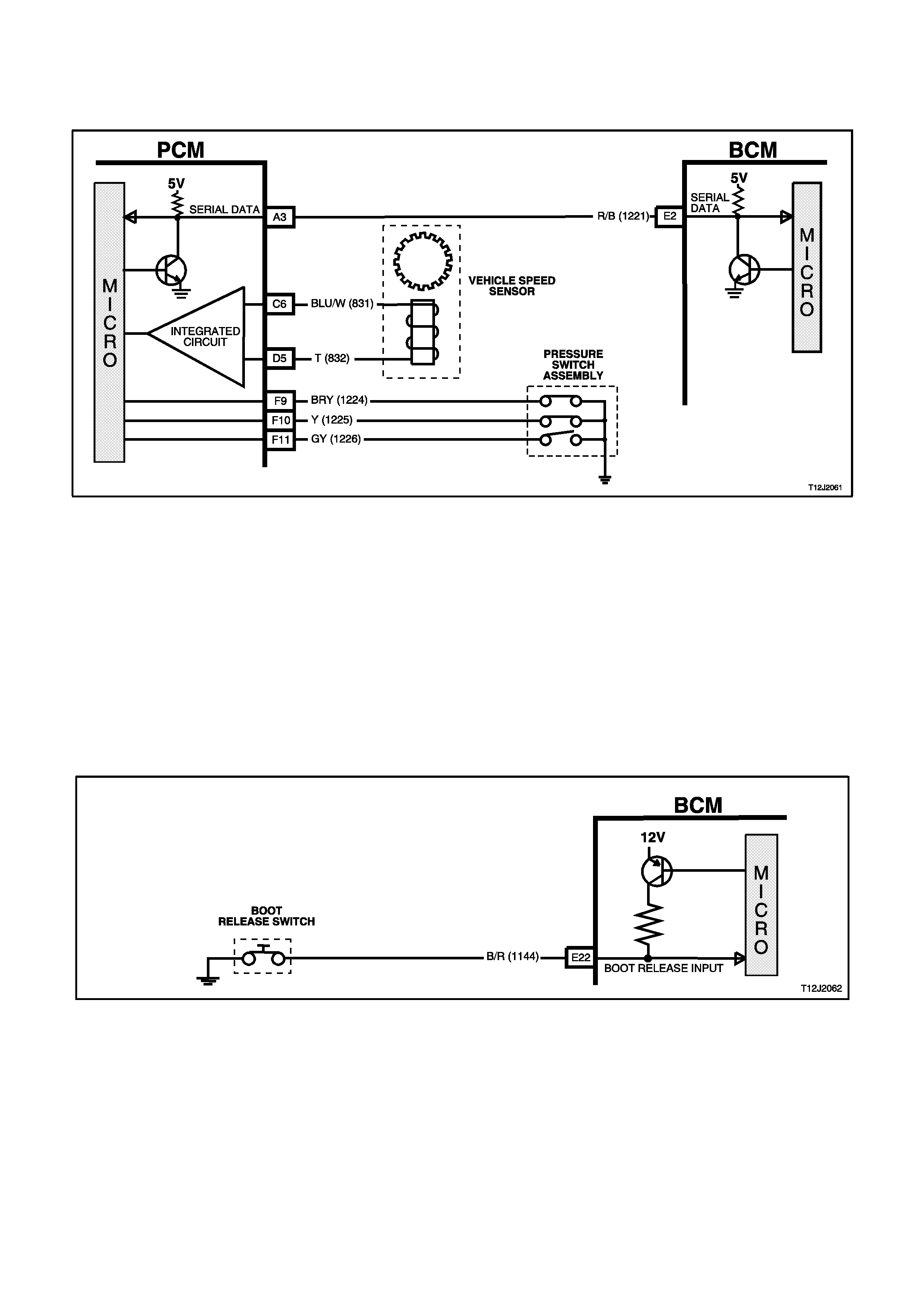
Vehicle Speed Signal
(Refer to Fig. 12J-2-32)
The BCM terminal E2, receives the vehicle speed from the PCM via the serial data communications bus, circuit
1221 (Red/Black wire).
Figure 12J-2-32
Remote Coded Key RF Signals
When the lock, unlock or boot button on the remote coded key is pressed the remote coded key transmits a Radio
Frequency (RF) signal. The BCM, on receiving any of these RF signals (via remote receiver), determines from the
signal received which button was pressed.
Boot Release input Signals
(Refer to Fig. 12J-2-33)
Pressing the rear compartment lock switch causes the contacts to close, connecting BCM terminal E22 to earth via
circuit 1144 (Black/Red wire). This action causes the voltage at terminal E22 to be pulled low, less than 0.2 volt.
This low voltage at terminal E22 is seen by the BCM as the boot release switch input signal.
NOTE:
The BCM will not activate the rear compartment lock actuator if the vehicle speed is above fifteen kilometres per
hour.
Figure 12J-2-33

OUTPUTS
Theft Deterrent Alert Indicator LED
The theft deterrent alert indicator LED will flash continuously on and off whenever the system is armed. The BCM
controls the operation of the theft deterrent alert indicator LED by pulsing an internal switch on and off, which in turn
allows the switching of the voltage applied to the theft deterrent alert indicator LED via terminal A6, circuit 263 (Light
Blue wire ).
Dome Lamp
Battery voltage is applied to all interior lamps via fuse F6 and circuit 1140 (Orange/Black wire). The opposite side of
the dome lamps are connected to earth via circuit 174 (White/Green wire) and BCM terminal C24. The BCM
controls the operation of the dome lamps connected to this earth circuit by energising its internal dome lamp relay
coil, this causes the internal relay contacts to close completing the circuit to earth.
Horn Relay
The BCM can control the operation of the vehicle horn/s by pulsing the horn relay coil to earth through terminal A4,
circuit 28 (Black/Y ellow wire).
Theft Deterrent Horn Relay
The BCM controls the operation of the theft deterrent horn by pulsing the theft deterrent horn relay coil to earth
through terminal A3, circuit 1128 (Black/White wire). The same circuit in the BCM earth’s this circuit and the horn
circuit.
Left Hand Indicators
The BCM controls the operation of the left hand indicators by pulsing its internal indicator relay. This causes the
indicator relay contacts to close and open a number of times. This allows battery voltage from terminal B5 to be
applied to terminal B4, to the left hand indicator lamps via circuit 14 (Light Blue wire).
Right Hand Indicators
The BCM controls the operation of the right hand indicators in the same manner as the left hand indicators. Pulsing
of its internal indicator relay causes the indicator relay contacts to close and open a number of times. This allows
battery voltage from terminal B5 to be applied to terminal B12, to the right hand indicator lamps via circuit 15 (Blue
wire).
Rear Compartment Lock Actuator
The BCM can activate the rear compartment lock actuator by energising its internal boot release relay. This will
apply battery voltage from terminal B5, through the boot release relay contacts and terminal C25 to the rear
compartment release actuator, circuit 142 (Red/Green wire). The earth circuit for the rear compartment solenoid is
via the body and main wiring harness.
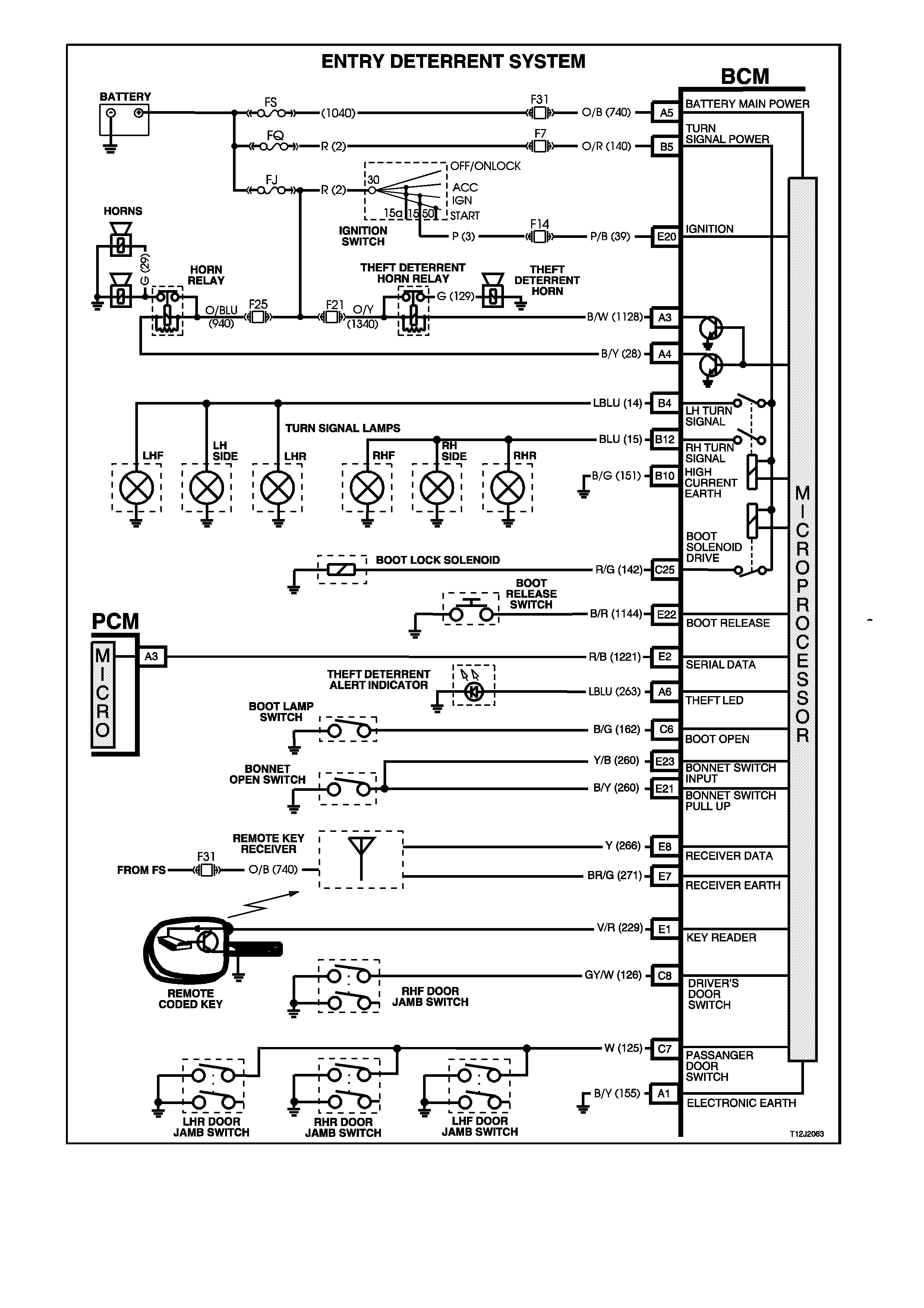
Figure 12J-2-34

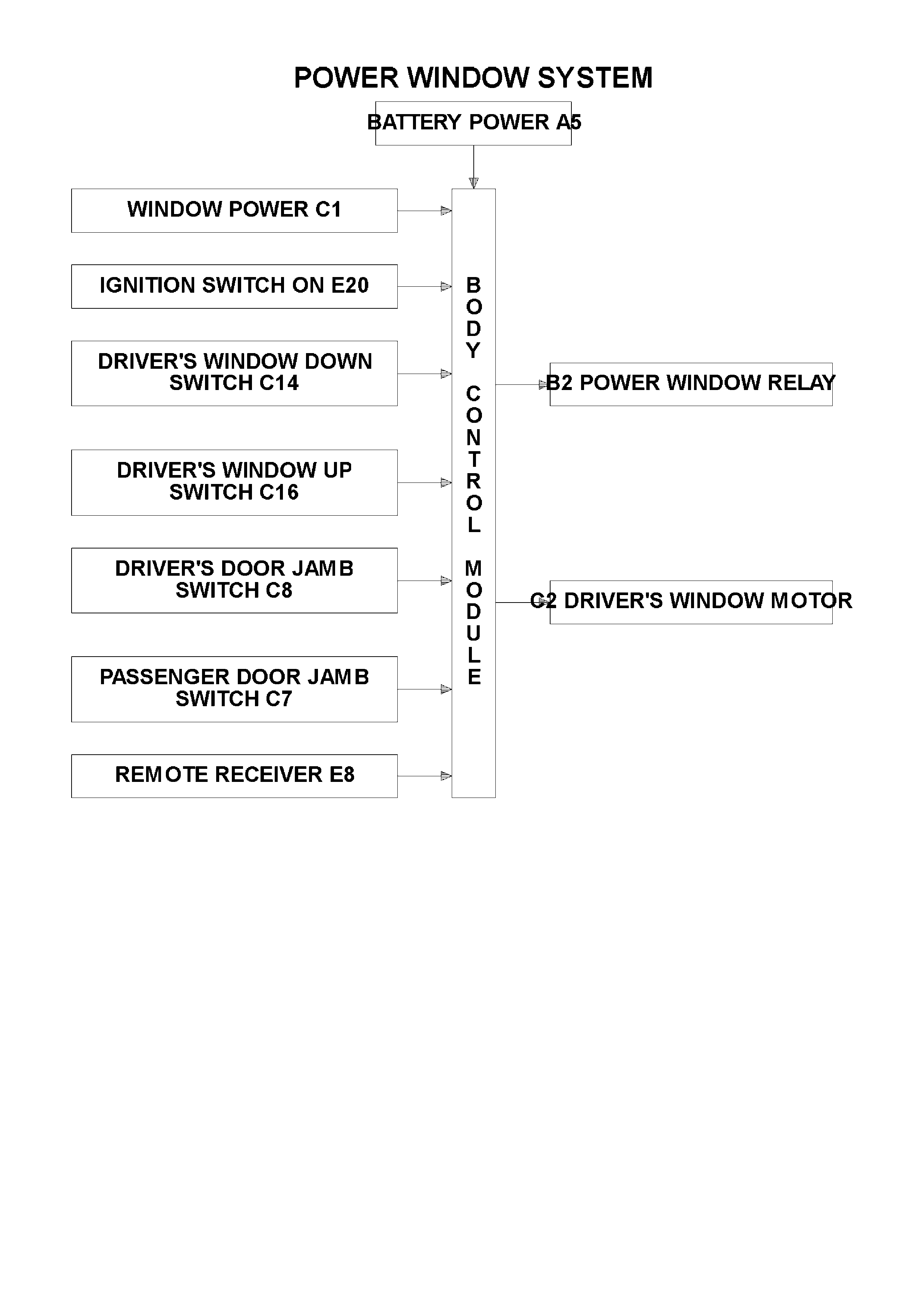
1.5 POWER WINDOW SYSTEM
GENERAL INFORMATION
The BCM controls the following functions of the power window system:
1. Control of positive supply to all door window motors.
2. Automatic down of driver's door window (activated when the driver's power window switch DOWN button is
depressed for more than 0.4 seconds).
Once activated, the automatic down feature is cancelled within 100 ms (0.1 seconds) after:
a. The driver's power window switch UP button is depressed following which the window will move upward or:
b. The driver's power window switch DOWN button is depressed and released. In this case, the window will
remain stationary until another activation (down or up button depressed) takes place.
c. With ignition on, power is supplied continuously to the window system.
d. When ignition is switched OFF and no door has been opened, power is supplied to the window system for a
maximum of 60 minutes.
e. In the event of any door being opened, power is supplied to the system for 45 seconds maximum, timed
from when any door was opened.
When the doors are remotely unlocked (by using the remote coded key) power is supplied to the system for 60
minutes and for a maximum of 45 seconds, once the door has been opened and the ignition has not been turned
ON. The delay is cancelled when the doors are locked by the remote coded key.
NOTE:
The circuit diagrams shown in this General Description Section are to aid in interpreting the operation of the circuit
and therefore, only the main connectors and wiring colours are shown. For complete circuit details, refer to either
the relevant diagnostic section or Section 12P WIRING DIAGRAMS.
SYSTEM CHECK
Prerequisite Condition
The child saf ety switch must be s witched O FF . T his
will be indicated by the green Light Emitting Diode
(LED) in each of the rear door rocker switches
being illuminated.
System Active
‘System active’ is indicated by the illumination of
the rocker switches.
W hen the ignition switch is turned ON, all switches
are active.
With the ignition switch turned OFF, all switches
will remain active for 45 seconds after any door is
opened. If during this 45 second per iod the driver’s
window switch is activated, the active period will be
extended a further 45 seconds.
With the ignition switch turned OFF, all switches
will remain active for approximately 60 minutes,
PROVIDED THERE ARE NO OPEN DOORS.
Figure 12J-2-35
System Inactive
Lights are not illuminated
Automatic DOWN Operation of Driver’s Window
With the drivers window in the fully UP position and
the ignition switch turned to ON, press the driver
window switch to the window DOWN position for
more than 0.4 seconds and release.
The window will continue to lower automatically
until the fully DOWN position is reached.
To interrupt this function, press the UP button
momentarily or press and release the down button.
Figure 12J-2-36
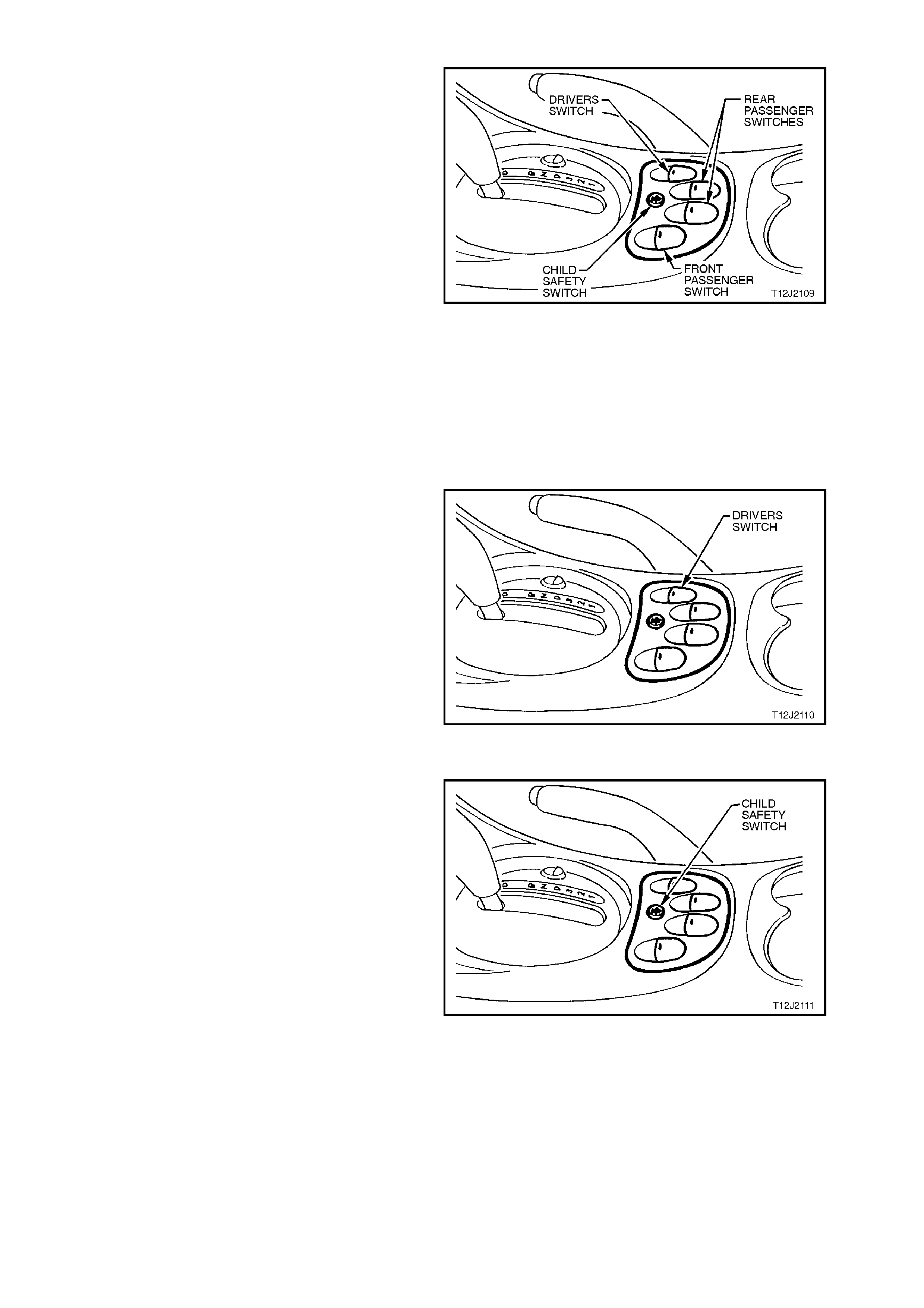
Child Safety Switch
When the child safety switch (override switch) is
OFF, the rear windows can be opened or closed
from the centre console switch assembly or the
rocker switches in each of the rear doors.
To check the operation of this feature, proceed as
follows:
1. Ignition switched to ON.
2. Check that the green LED in each of the rear
door rocker switches is illuminated.
3. Open and close the rear door windows using the
rocker switches in the rear doors.
4. Press the child saf ety switch button in the centre
of the switch assem bly in the console as shown
in the Fig. 12J-2-37.
5. Check that the green LED in each of the rear
door rocker switches extinguishes and that the
rear windows can only be raised or lowered
from the switch in the centre console.
Figure 12J-2-37
SYSTEM OVERVIEW
CIRCUIT OPERATION
A permanent magnet motor operates each of the power window mechanisms to raise or lower the window glass.
The direction in which the motor turns depends on the polarity of a voltage supplied to its terminals. The power
window switches, located in the centre console, or in the rear doors, control the polarity of the supply voltages.
The BCM has two main control functions in the power window system.
1. To control the operation of the power window relay and hence, power supply to the whole system.
2. To control the operation of the driver's side front window motor.

OPENING WINDOW - DRIVER'S DOOR
(Refer to Figs. 12J-2-40 and 12J-2-41
Ignition ON Input Signal
(Refer to Fig. 12J-2-38)
The BCM uses this input signal to determine when the ignition switch is in the IGN or START position. When the
ignition switch is in the IGN or START position, battery voltage is applied to the BCM terminal E20 from the ignition
switch and fuse F14 via circuit 39 (Pink/Black wire).
When the BCM receives an ignition ON input it energises the power windows relay (voltage supplied by fuse F20
circuit 440 Orange/Violet wire) by earthing the relay’s pull-in coil via circuit 173 (Yellow wire) and BCM terminal B2.
With the relay coil energised, the relay contacts close and power via fusible link FJ and circuit breaker F1 is applied
to the power window switches and each of the lights of the window switches (for rear door window switches, the
power window override switch in the front power window switch must be off). The opposite side of each light is
connected to earth, therefore the lights are illuminated (system active).
By depressing and releasing the driver's front window switch down button within 0.4 of a second (so as not to
engage the automatic down feature), this allows battery voltage from the power windows relay, circuit 1240
(Orange/Yellow wire), and the power window switch terminal 4, through to terminal 8 and then BCM terminal C14
(window down signal input), through the relay contacts and BCM terminal C2 to one side of the driver's side power
window motor on circuit 673 (Green/Orange wire).
The opposite side of the motor is connected to earth on circuit 672 Blue/White wire via power window switch
terminals 9 and 5 to circuit 156 (Black/Blue wire). This causes the motor armature to rotate, operating the window
regulator to lower the window.
As described under power windows general information, the driver's window will automatically travel fully downward
provided the power window switch down button is depressed for more than 0.4 seconds. The BCM microprocessor
senses the time the down button is depressed via terminal C14 and energises the internal relay so as to allow the
window to lower fully.
Figure 12J-2-38
Driver's Front Window Down Switch Input Signal
(Refer to Fig. 12J-2-39)
With the driver's front window switch down button depressed, battery voltage from the power windows relay, circuit
1240 (Orange/Yellow wire), and the power window switch terminal 4, through to terminal 8 is applied to BCM
terminal C14 (window down signal input).
Figure 12J-2-39

When the BCM receives a driver's front window down switch input signal it energises an internal relay. This causes
the relay contacts to changeover, allowing battery voltage from the power windows relay contacts, BCM terminal C1,
through the BCM internal relay contacts and BCM terminal C2 to one side of the driver's side power window motor
on circuit 673 (Green/Orange wire).
If the window is travelling downward and the down button is again depressed, the BCM microprocessor senses this
(voltage again sensed at BCM terminal C14) and de-energises the internal relay, the contacts open and the motor
stops.
Should the up button be momentarily depressed whilst the window is travelling downward, positive battery voltage is
applied to both sides of the motor armature and the motor stops. If the up button is continuously depressed whilst
the window is travelling downward, the window down function is cancelled. The window will then move upward as
described in the following text.

Figure 12J-2-40
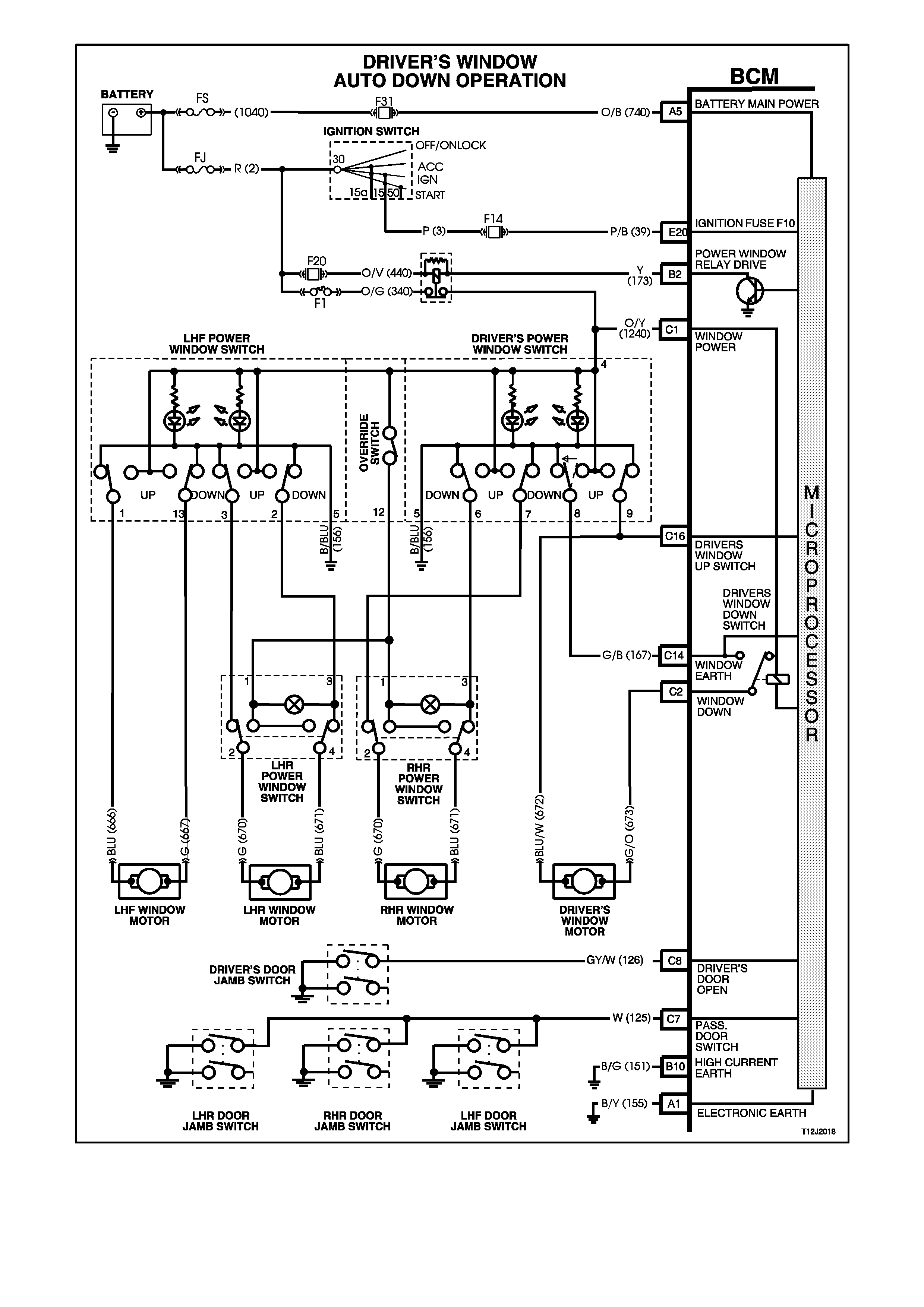
Figure 12J-2-41
CLOSING WINDOW
(Refer to Fig. 12J-2-43)
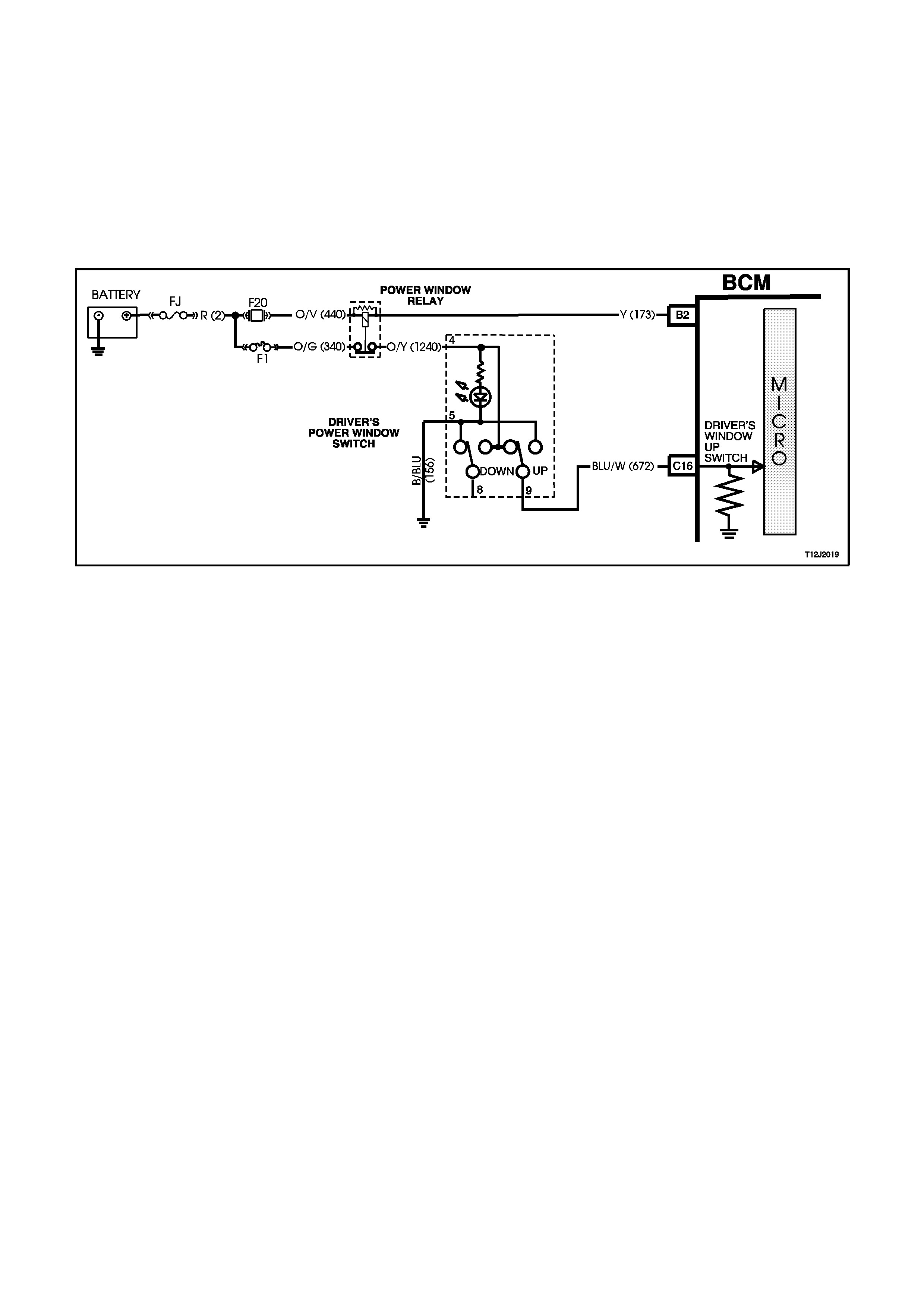
Driver's Front Window Up Switch Input Signal
(Refer to Fig. 12J-2-42)
By depressing and holding down driver's front window up button, battery voltage from the power windows relay
circuit 1240 (Orange/Yellow wire) is applied, via power window switch terminals 4 and 9, to the driver's side power
window motor circuit 672 (Blue/White wire).
The opposite side to the motor circuit 673 (Green/Orange wire) is connected to earth via BCM terminal C2, through
the BCM internal relay contacts, BCM terminal C14 to switch terminals 8 and 5 to earth on circuit 156 (Black/Blue
wire). This causes the motor armature to rotate, operating the window regulator to raise the window as long as the
power window switch up button is depressed.
Figure 12J-2-42
Window Operation - Passenger Doors
Power is supplied to all the power window switches from the power window relay (to the rear door switches provided
the power window override switch is off). If the power window override switch is on, (contacts between terminals 4
and 12 are open) the power supply to the rear door power window switches is interrupted.
With the switch buttons at rest, all switch contacts are connected to earth circuit 156 (Black/Blue wire). By
depressing the appropriate passenger's window sw itch down or up button, battery voltage from the power windows
relay, is applied to one side of the window motor, via the depressed switch button contact. With the other side of the
motor connected to earth, the motor armature will rotate, operating the window regulator to raise or lower the
window as long as the window switch button is depressed.
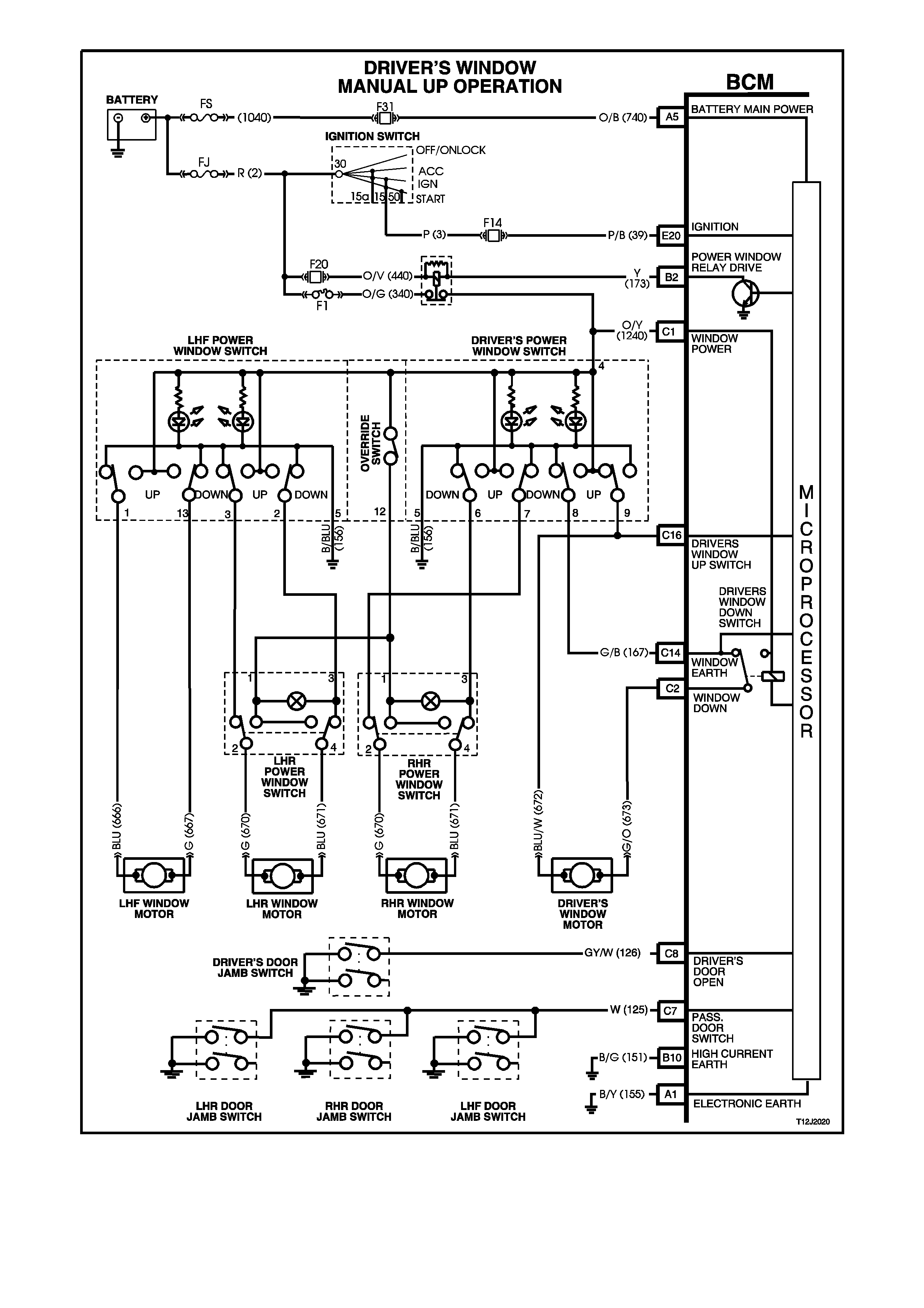
Figure 12J-2-43
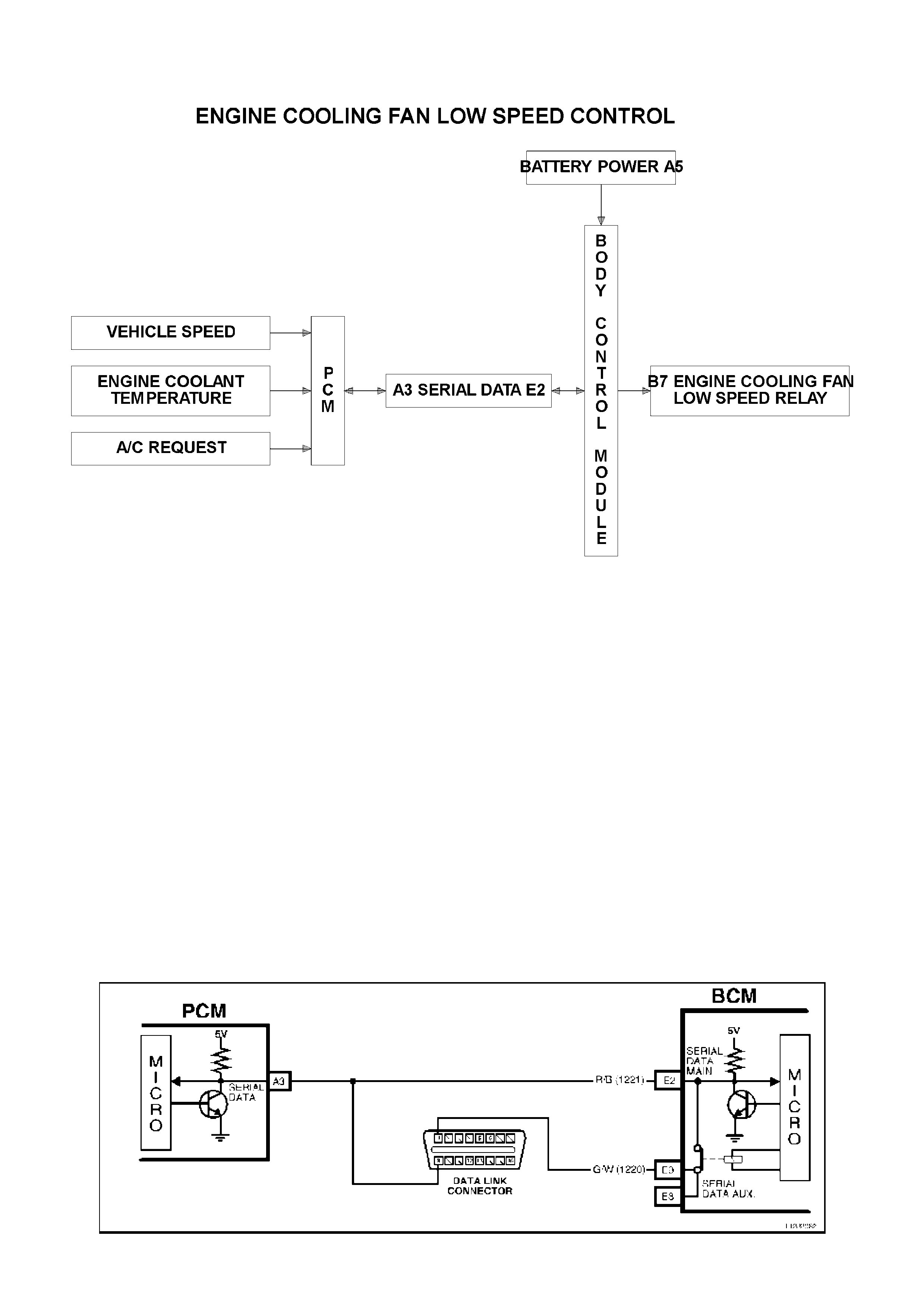
1.6 ENGINE COOLING FAN LOW SPEED CONTROL
SYSTEM OVERVIEW
GENERAL INFORMATION
(Refer to Figs. 12J-2-44 and 12J-2-45)
The engine has a two, two speed electric engine cooling fan assemblies that provide the primary means of moving
air through the engine radiator. These fans are placed between the radiator and the engine and have their own
shroud. These fans are used on all vehicles even if they are not equipped with air conditioning. There is no fan in
front of the A/C condenser.
The two, two speed electric engine cooling fans are used to cool engine coolant flowing through the radiator, and if
fitted, refrigerant flowing through the A/C condenser. The engine cooling fan motors have four terminals, two
negative and two positive terminals. The two positive terminals are permanently connected to battery voltage. When
one of the negative terminals is earthed, the fan motors will operate at low speed. When both negative terminals are
earthed, the fans operate at high speed.
The two speed electric fan's low speed can be enabled when the low speed engine cooling fan micro relay (located
in the engine compartment relay housing, labelled LO FAN) is energised by the BCM via a request from the
Powertrain Control Module (PCM). The PCM will request low speed fan enable and disable via serial data
communication to the BCM on circuit 1221 (Red/Black wire). After the PCM requests a change in the state of the
low speed relay (ie. OFF to ON or ON to OFF), the BCM will send a serial data response message back to the PCM
confirming it received the message. A failure in this response communication will set a PCM DTC 92.
NOTE:
The circuit diagrams shown in this General Description Section are to aid in interpreting the operation of the circuit
and therefore, only the main connectors and wiring colours are shown. For complete circuit details, refer to either
the relevant diagnostic section or Section 12P WIRING DIAGRAMS.
Figure 12J-2-44
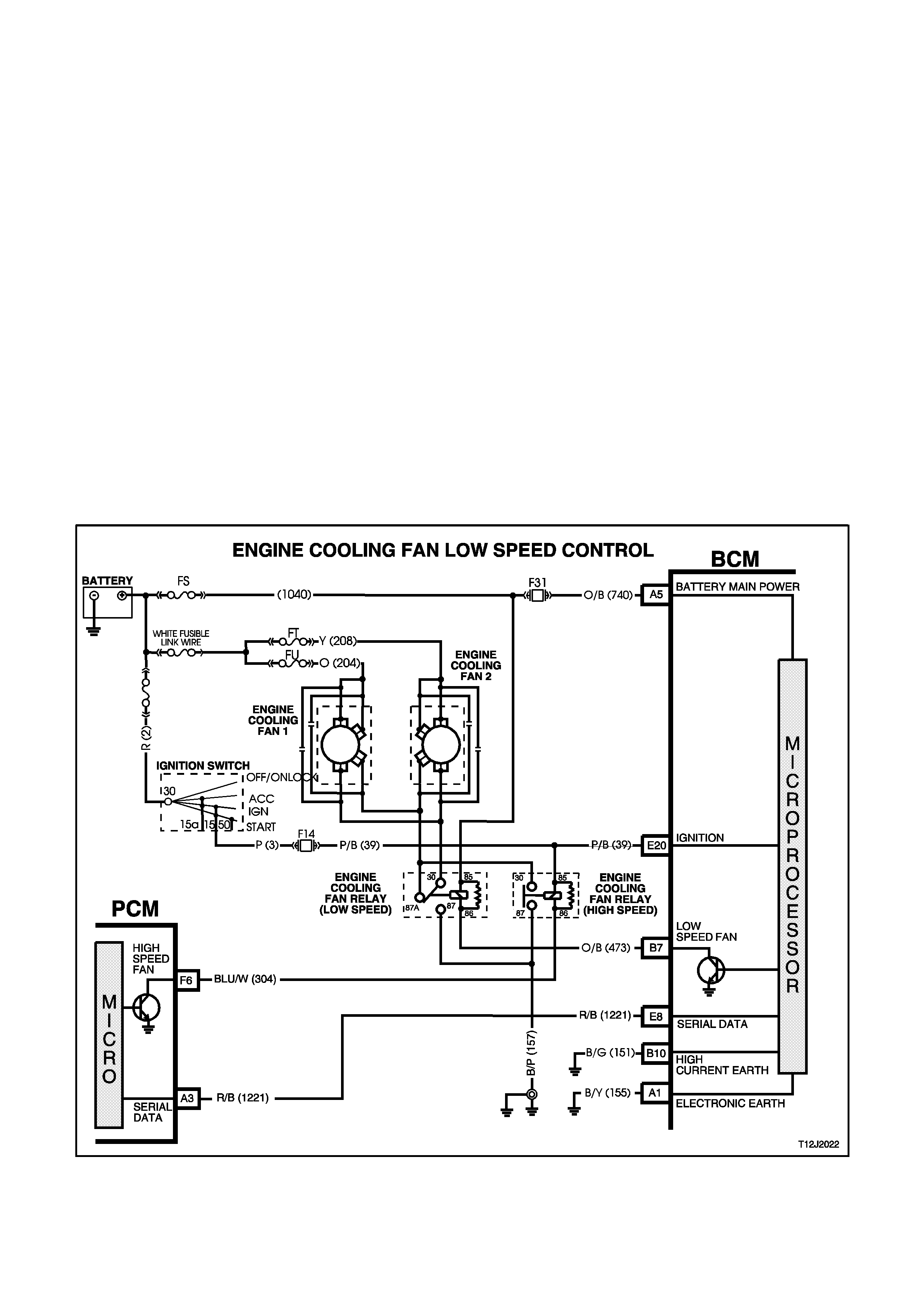
The engine cooling low speed fan relay is energised by the BCM earthing terminal B7, circuit 473 (Orange/Brown
wire). This causes the relay contacts to switch over from 30-87A to 30-87 and circuit 157 (Black/Pink wire) is
earthed through the relay and to the low speed fan terminal on circuit 533 (Blue/Yellow wire). The other low speed
fan terminal is connected to battery voltage via circuit 204 (Orange wire) on FAN 1 and circuit 208 (Yellow wire) on
FAN 2.
The engine cooling fan relay is energised by the BCM. The PCM determines when to enable the low speed fan,
based on inputs from the BCM serial data, Engine Coolant Temperature (ECT) sensor and the Vehicle Speed
Sensor (VSS).
The low speed cooling fan relay will be turned ON' when:
A/C request indicated (YES) and either,
the vehicle speed less than 30 km/h.
or
A/C pressure is greater than 1500 kPa.
or
Coolant temperature is greater than 104°C. (V6) or 95°C. (V8)
If the engine coolant temperature is greater than 117°C, when the ignition is switched off, the relay is energised
for approximately 4 minutes. This is known as LOW FAN RUN ON.
An engine coolant temperature sensor fault is detected , such as DTC 14, 15, 16 or 17.
The cooling fan low speed relay will be turned ‘OFF’ when any of the following conditions have been met:
Coolant temperature less than 99°C. (V6) or 90°C. (V8)
A/C request not indicated (NO).
A/C request indicated (YES) and the vehicle speed greater than 50 km/h and A/C pressure is less than 1170
kPa.
Figure 12J-2-45

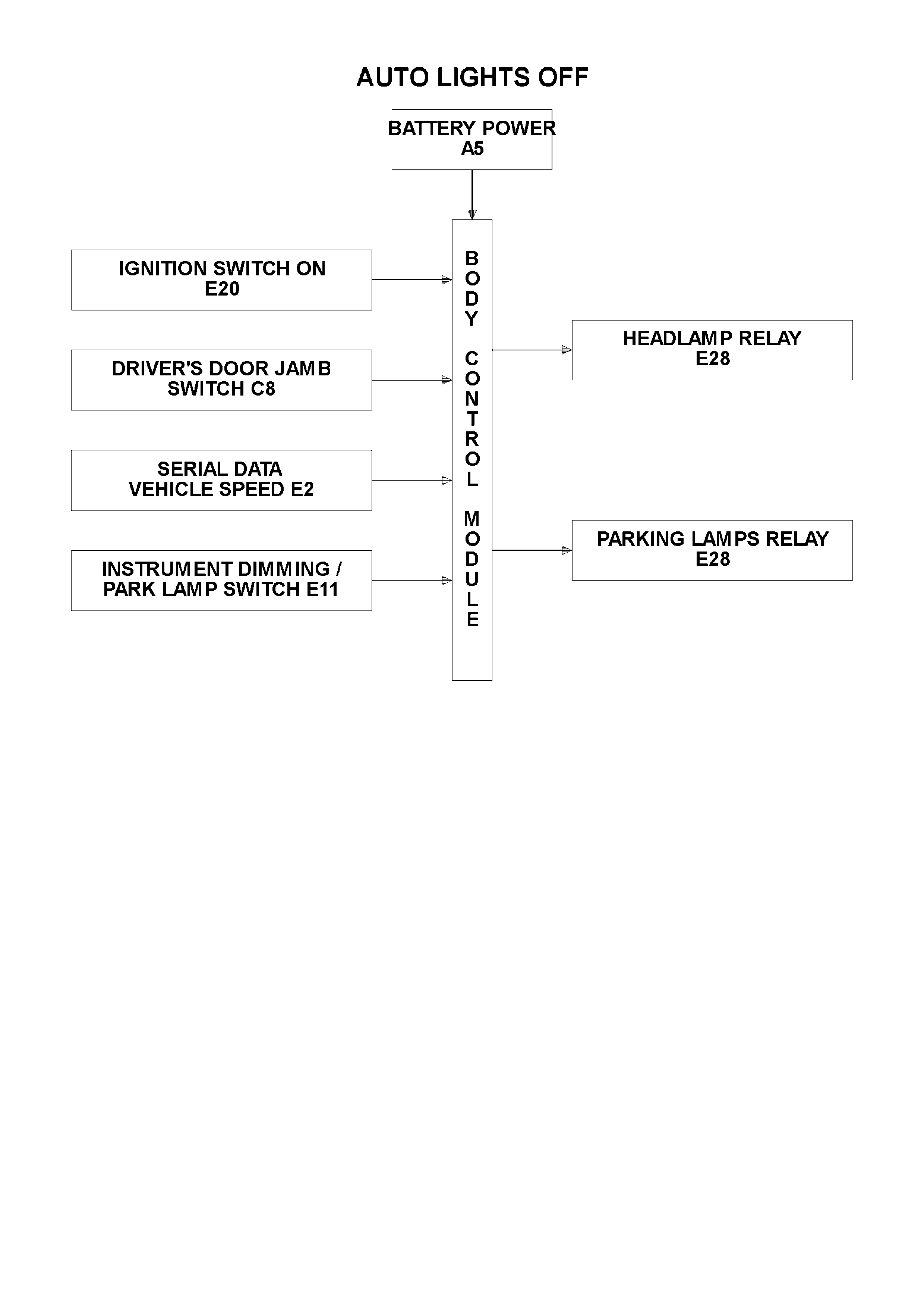
1.7 AUTOMATIC LIGHT CONTROL / AUTOMATIC LIGHTS OFF
(WITHOUT TWILIGHT SENTINEL)
GENERAL INFORMATION
The automatic light control (lights off) feature is designed to automatically switch the headlamps and parking lamps
off when the driver leaves the vehicle.
NOTE:
Since this system is safety related, it is mandatory that in the event of a system failure, the default status of the
BCM light control outputs are in the ON state when the ignition switch is in the IGN position. This will give direct
control of the lights to the headlamp switch.
The sequence of events required to switch the lights off automatically are as follows:
1. The vehicle road speed input to the BCM indicates speed is less than 10 kilometres per hour and there has not
been a sudden loss of speed (ignition being switched off with the vehicle travelling above 10 km/h).
2. The BCM senses that the ignition switch is turned from ON to OFF and remains in the off position.
3. The headlamp switch has not been turned on after the ignition switch was turned off.
4. The BCM senses the driver's door has been opened or that it is already open.
When the ignition switch is turned back to IGN position, the lights will turn back on to the position selected by the
headlamp switch and the mode of headlamps operation (ie. high or low beam or fog lamps [if fitted]) determined by
the position of the relevant switches.
Turning the headlamp switch off deactivates the automatic lights system.
There is a delay period before the automatic lights off feature deactivates the vehicle lights. This time period can be
set by the driver using the following procedure.
1. Turn ignition switch to the 'IGN' position, switch parking lamps on and close the driver's door.
2. Hold the headlamp switch instrument cluster illumination switch control lever in the down position continuously.
3. Turn the ignition switch off.
4. Open the driver's door.
This initiates the start of the time delay period.
5. Wait the required delay time period and release the illumination switch control lever.
This sets the time delay period and switches off the parking lamps.
The delay period adjustment is only possible whilst road speed input to the BCM is zero. A maximum of 180
seconds applies to the time delay period and the default setting is 0 seconds. The time delay period resets to
default value whenever the battery or fuse F31 is disconnected from the vehicle.
This time delay is also dependent on the priority key system. The time delay period can be set for the priority 1
and priority 2 keys. The time delay is recalled when the unlock button on the remote is pressed and is
dependent on whether priority 1 or priority 2 key is used.
NOTE:
The circuit diagrams shown in this General Description Section are to aid in interpreting the operation of the circuit
and therefore, only the main connectors and wiring colours are shown. For complete circuits details, refer to either
the relevant diagnostic section or Section 12P WIRING DIAGRAMS.
SYSTEM OVERVIEW
CIRCUIT OPERATION
(Refer to Fig. 12J-2-46)
Power Supplies
Battery voltage is applied to the low, high beam and fog lamps (if fitted) relays from fusible link FQ, circuit 2 (Red
wire) and fuses F30 and F29.
Battery voltage is applied to the parking lamps relay from fusible link FQ circuit 2 (Red wire) and fuse F4, circuit 840
(Orange/White wire).
The BCM controls the operation of the exterior light circuits by enabling its internal control circuit, which provides the
earth circuit for the relays.
High Beam Relay Earth Circuit
The earth circuit for the high beam headlamp relay is via circuit 10, (Blue/Yellow wire), through the headlamp and
turn signal control (flash/dip) switch assembly, circuit 147 (White/Black wire), headlamp switch contacts to BCM
terminal E28, circuit 1150 (Black wire) and then to earth through internal switching.
Low Beam Relay Earth Circuit
The earth circuit for the low beam headlamp relay is via 103 (White wire), through the headlamp and turn signal
control (flash/dip) switch assembly, circuit 147 (White/Black wire), headlamp switch contracts to BCM terminal E28,
circuit 1150 (Black wire) and then to earth through internal switching.
Parking Lamps Relay Earth Circuit
The earth circuit for the parking lamps relay is via circuit 49 (Blue wire), the closed parking lamps contacts in the
headlamp switch, through BCM terminal E28, circuit 1150 (Black wire) and then to earth through internal switching.
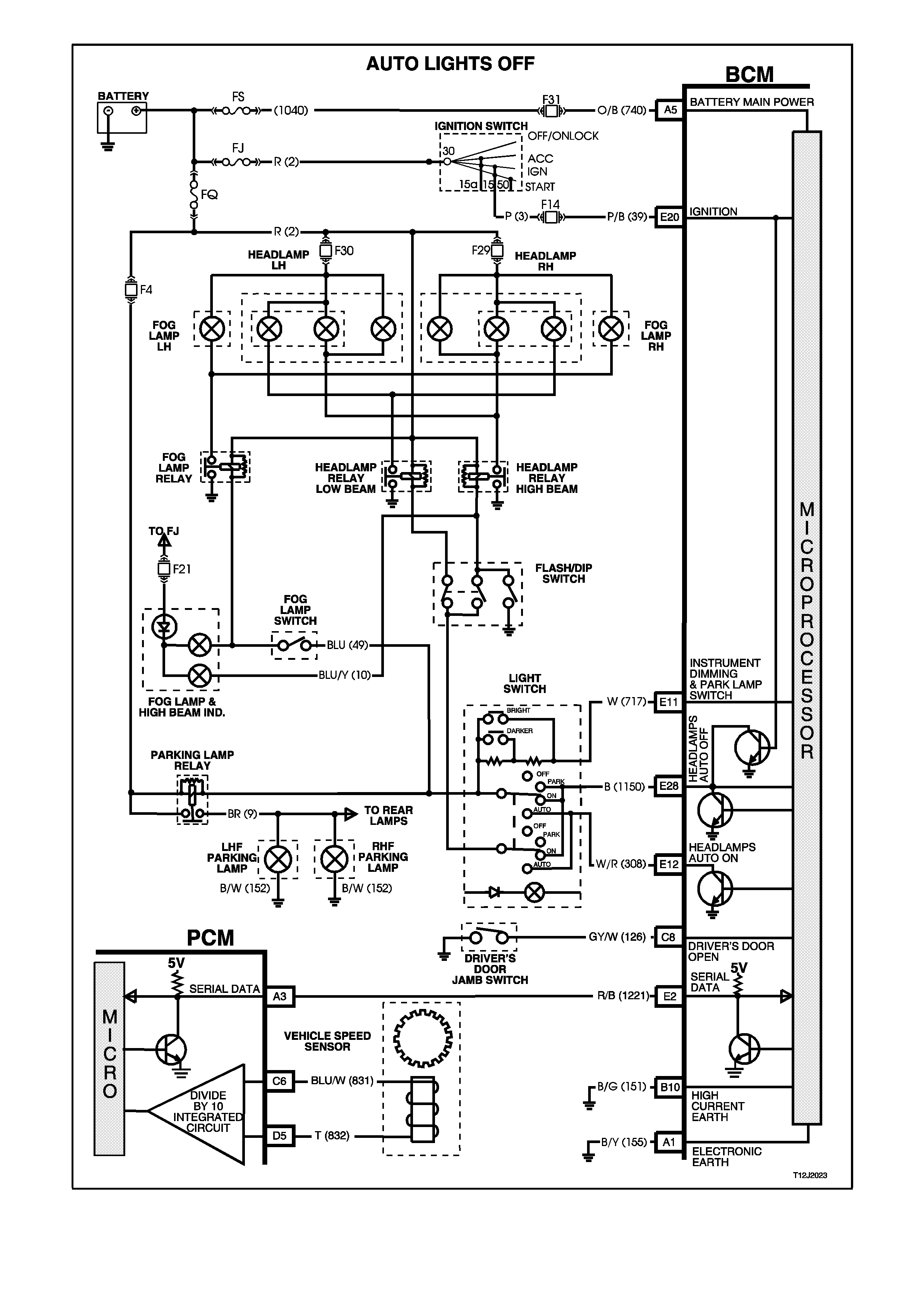
Figure 12J-2-46
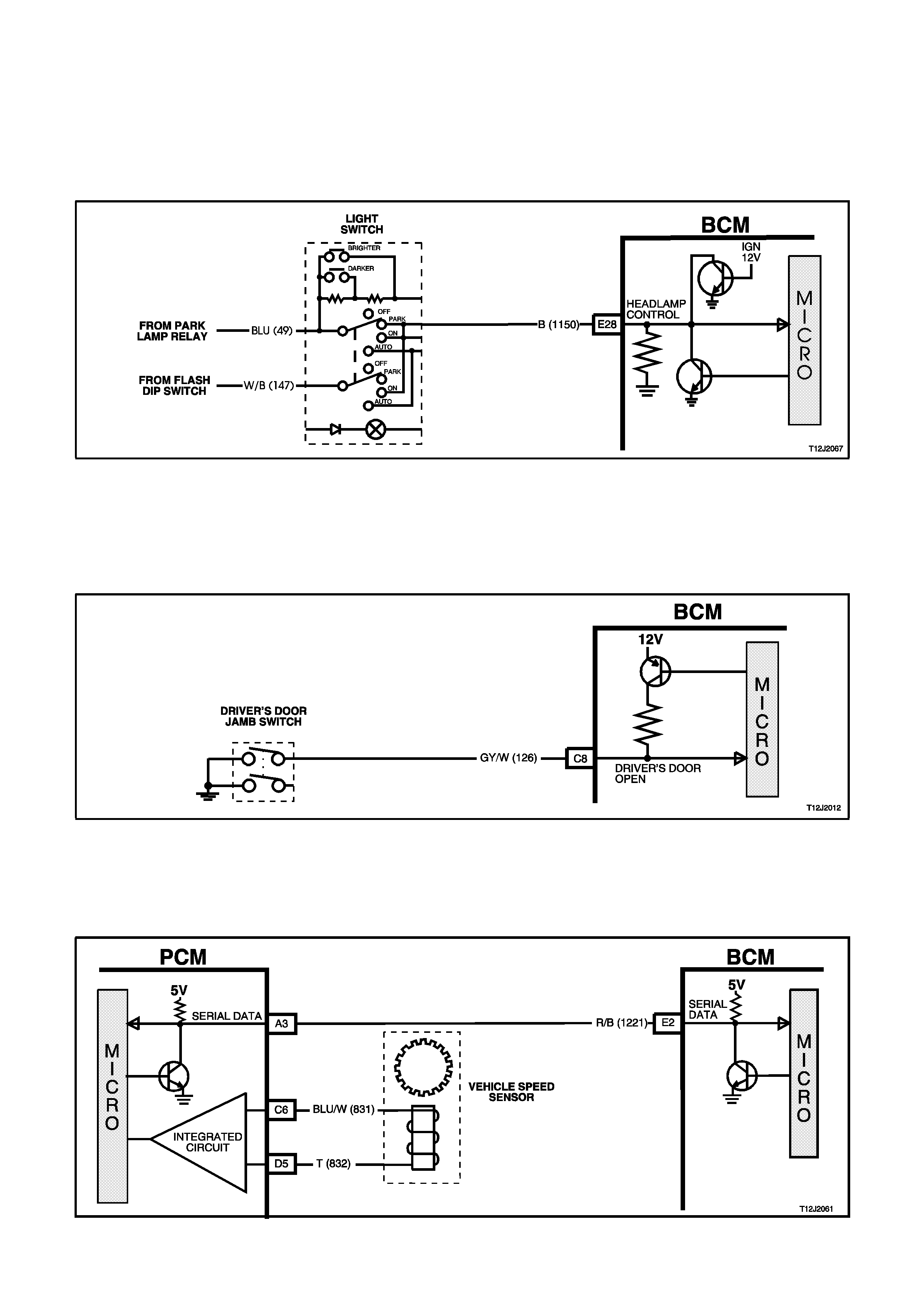
Headlamp Control Input Signal
(Refer to Fig. 12J-2-47)
The BCM monitors the voltage on terminal E28 to determine the position of the headlamp and parking lamp switch.
When the headlamps or parking lamp are on, the voltage at BCM terminal E28 will be less than 0.2 volt. When the
automatic headlamps OFF system has turned the lights off, the voltage at terminal E28 will be 12 volts. If the
headlamp switch is turned off, the voltage at terminal E28 will be less than 0.2 volt. The BCM sees this low voltage
at terminal E28 as a change in status of the headlamp switch and will turn the automatic lights system off. The lights
will then turn back on when a change in position of the switch occurs.
Figure 12J-2-47
Driver’s Door Open Input Signal
(Refer to Fig. 12J-2-48)
When the driver’s door is opened, BCM terminal C8 is connected to earth via circuit 126 (Grey/White wire) and the
driver's door jamb switch. This causes the voltage at terminal C8 to pulled low, less than 0.2 volt (driver's door
open). This low voltage at terminal C8 is seen by the BCM as the driver's door open input signal.
Figure 12J-2-48
Vehicle Speed Signal
(Refer to Fig. 12J-2-49)
The BCM terminal E2, receives the vehicle speed from the PCM via the serial data communications bus, circuit
1221 (Red/Black wire).
Figure 12J-2-49
Ignition Switch ON Input Signal
(Refer to Fig. 12J-2-50)
The BCM uses this input signal to determine when the ignition switch is in the IGN or START position. When the
ignition switch is in the IGN or START position, battery voltage is applied to the BCM terminal E20 from the ignition
switch and fuse F14 via circuit 39 (Pink/Black wire).
Figure 12J-2-50
Instrument Illumination Dimmer Switch Input
(Refer to Fig. 12J-2-51)
When the illumination switch lever is in the down position (DIM-), BCM terminal E11 is connected to earth via the
headlamp switch and the 2.7 kilohm resistor in the switch assembly. This causes the voltage at BCM terminal E11
to go from above 5 volts to approximately 1.3 volts. This voltage at BCM terminal E11 is seen by the BCM as the
input signal that determines the delay period for the automatic lights off feature for the period that the voltage is
present.
NOTE:
This circuit will only work while the headlamp switch is in the PARK or ON positions.
Figure 12J-2-51
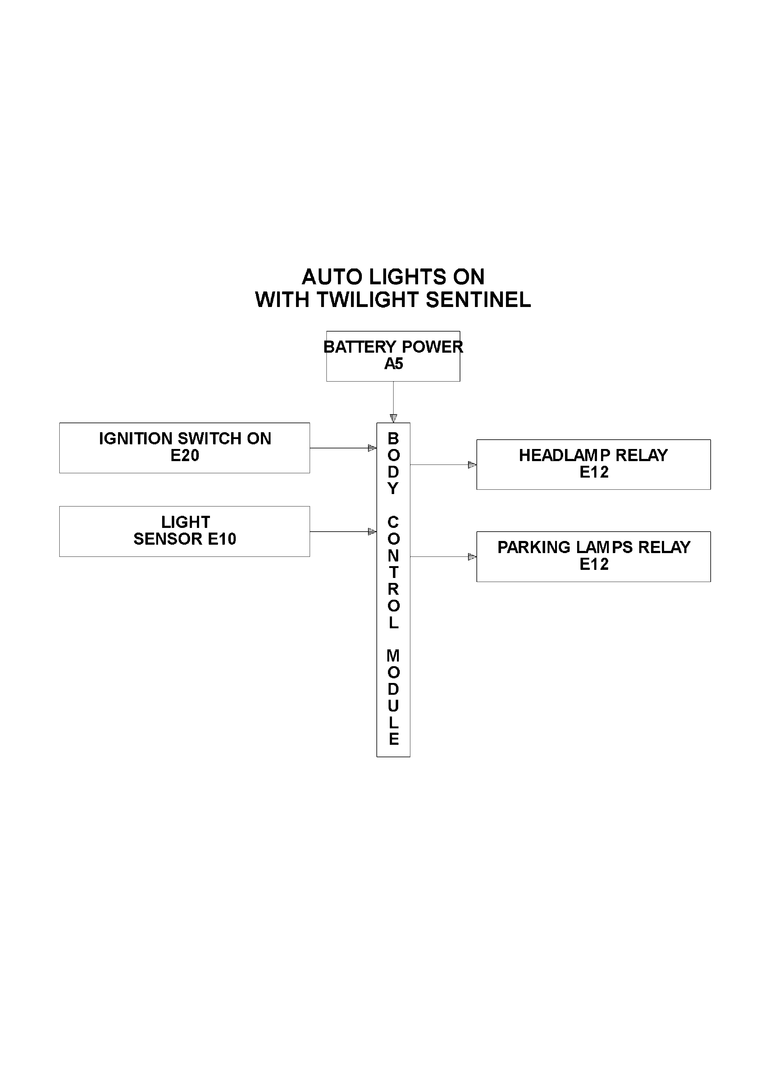
1.8 AUTOMATIC LIGHT CONTROL / AUTOMATIC LIGHTS ON AND OFF
(WITH TWILIGHT SENTINEL)
GENERAL INFORMATION
The automatic light control (lights on and off) feature (with twilight sentinel) turns the vehicle headlamps on and off,
depending on the outside light level. This feature will work only while the headlamp switch is in the Auto position and
the ignition on, the lights will operate as normal in other switch positions.
The operation of the headlamps when the ignition is switched off and the headlamp switch in the Auto position will
be the same as the Auto lights off operation.
A sensor is mounted in the instrument panel pad of the vehicle to monitor the amount of light in front of the vehicle.
The BCM monitors the output of this sensor and determines when the light levels are low enough to turn them on.
TECH 2 can be used to select several different ON/OFF light levels to suit the customer preferences.
SYSTEM OVERVIEW
CIRCUIT OPERATION
(Refer to Fig. 12J-2-54)
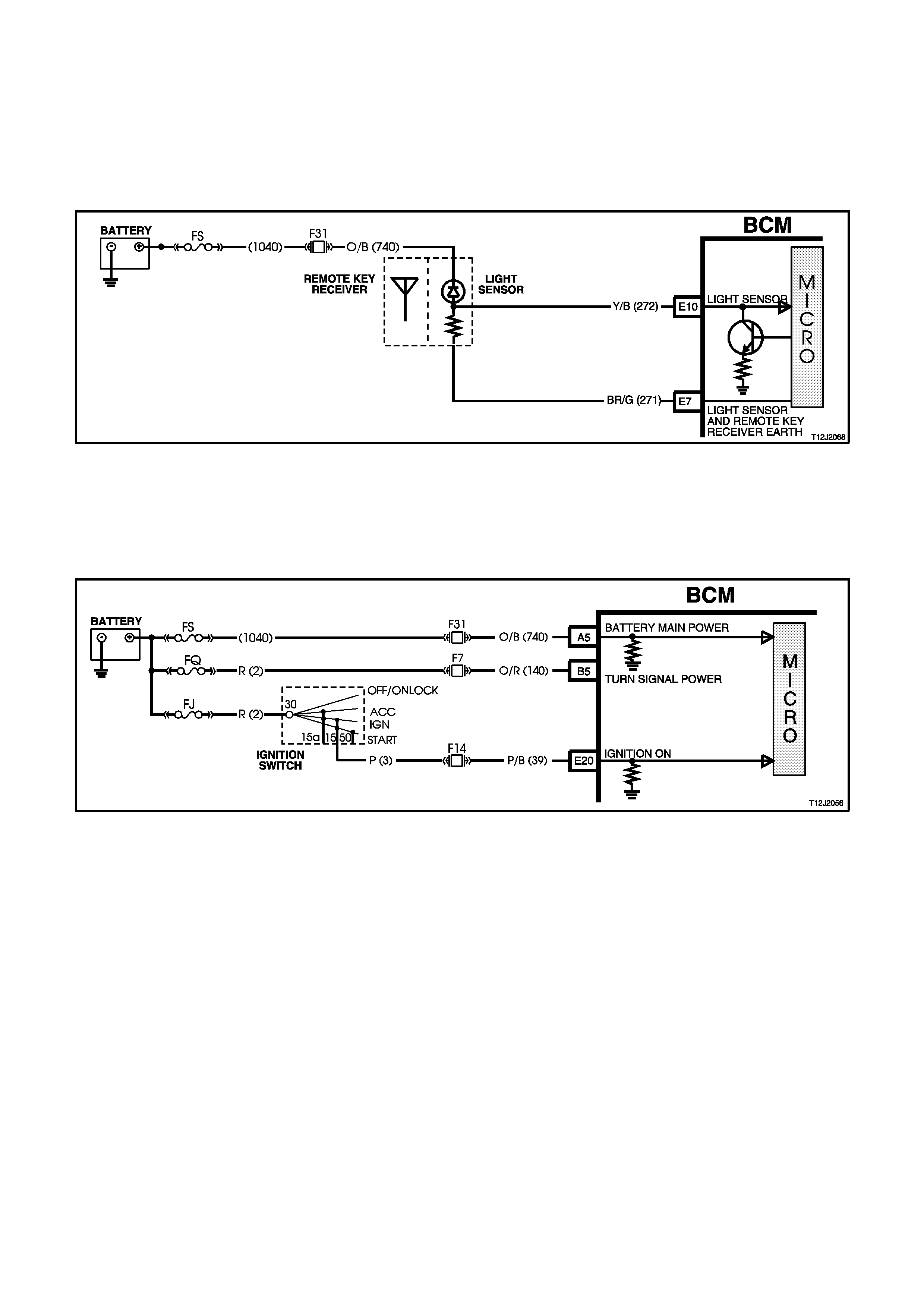
Light Sensor Control Input
(Refer to Fig. 12J-2-52)
The light sensor produces a voltage proportional to the amount of ambient light. This voltage can vary between 0
and 5 volts depending on the amount of light. The BCM determines the light value from the voltage on terminal E10,
circuit 272 (Yellow/Black wire). The BCM reads this input to determine if the headlamps should be on or off. TECH 2
should be used to measure the performance of the light sensor.
Figure 12J-2-52
Ignition Switch ON Input Signal
(Refer to Fig. 12J-2-53)
The BCM uses this input signal to determine when the ignition switch is on or off. When the ignition switch is in the
IGN or START position, battery voltage is applied to the BCM terminal E20 from the ignition switch and fuse F14 via
circuit 39 (Pink/Black wire).
Figure 12J-2-53
Power Supplies
Battery voltage is applied to the low and high beam relays from fusible link FQ, circuit 2 (Red wire) and fuses F30
and F29. Battery voltage is applied to the parking lamps relay from fusible link FQ, circuit 2 (Red wire) and fuse F4,
circuit 840 (Orange/White wire). The BCM controls the operation of the exterior lights by switching its internal
control circuit, which provides the earth circuit for the relays, on or off. If the ambient light level is low, the BCM will
energise the control circuit, turning the lights on. If the ambient light level is high, the BCM will de-energise the
control circuit, turning the lights off.
High Beam Relay Earth Circuit
The earth circuit for the high beam headlamp relay is via circuit 10 (Blue/Yellow wire), through the headlamp and
turn signal control switch assembly, circuit 147 (White/Black wire), headlamp switch contacts to BCM terminal E12,
circuit 308 (White/Red wire) and then to earth through the internal control circuit.
Low Beam Relay Earth Circuit
The earth circuit for the low beam headlamp relay is via circuit 103 (White wire), through the headlamp and turn
signal control switch assembly, circuit 147 (White/Black wire), headlamp switch contacts to BCM terminal E12,
circuit 308 (White/Red wire) and then to earth through the internal control circuit.
Parking lamps Relay Earth Cir cuit
The earth circuit for the parking lamps relay is via circuit 49 (Blue wire), the closed parking lamp contacts in the
headlamp switch, through the BCM terminal E12, circuit 308 (White/Red wire) and then to earth through the internal
control circuit.
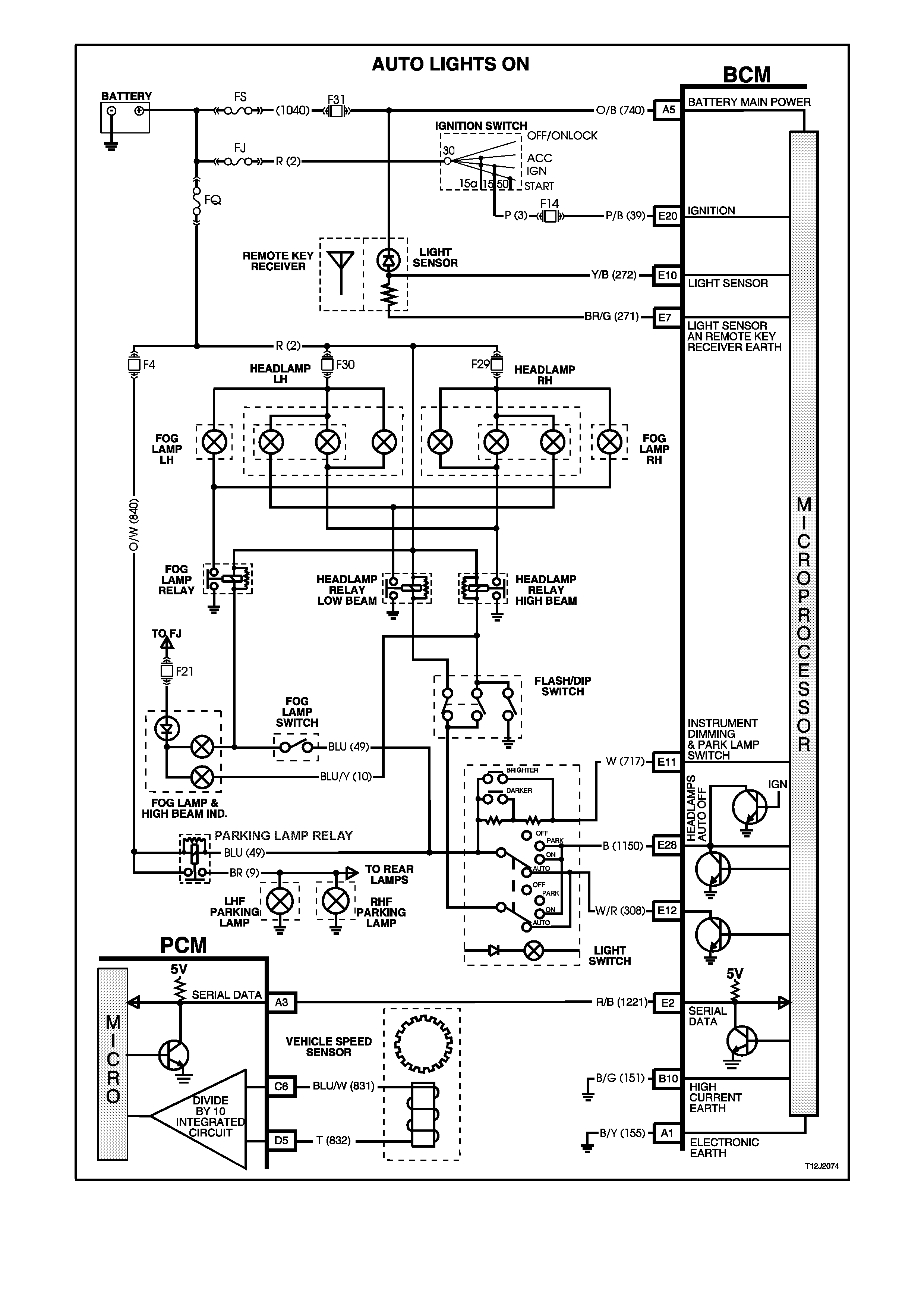
Figure 12J-2-54
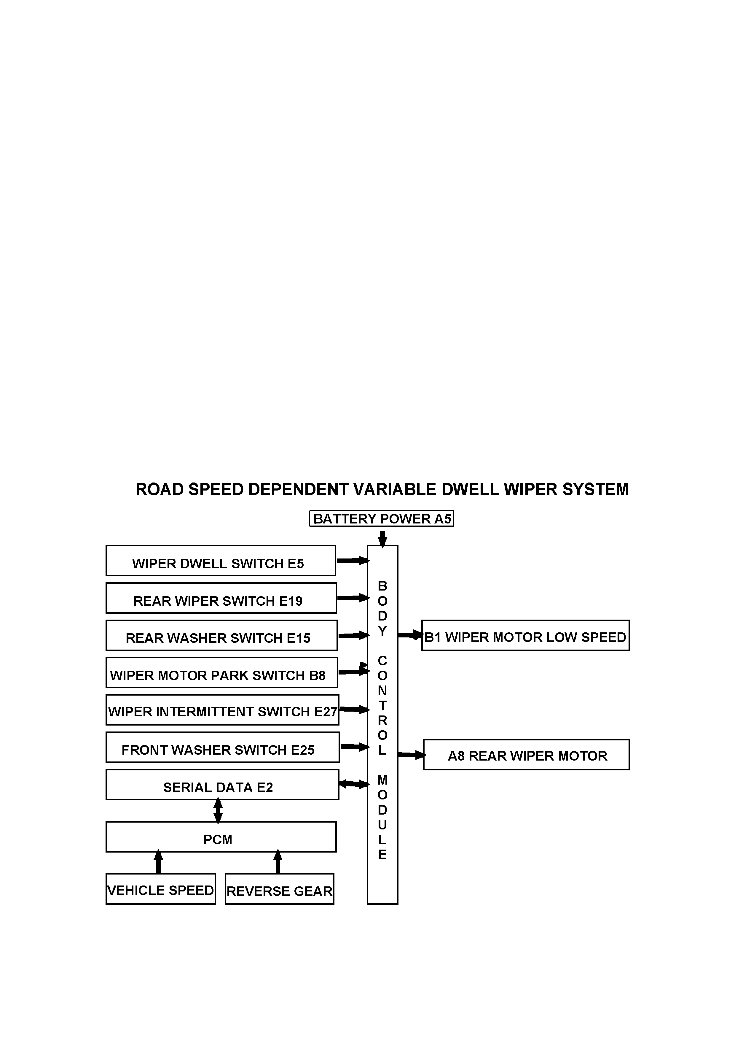
1.9 ROAD SPEED DEPENDENT VARIABLE DWELL WIPER SYSTEM
GENERAL INFORMATION
This system controls the intermittent dwell time of the windshield wiper motor. The dwell time is determined via a
combination of vehicle road speed and adjustable potentiometer (located in the wiper/washer left hand stalk control)
inputs to the BCM. In broad terms, the faster the vehicle travels, the shorter the dwell time of the wipers (time
between wiper sweeps).
The wipers employ a 'wipe after wash' function where, if the relevant washer pump switch has been pressed for
more than 0.5 seconds, the wipers start sweeping at low speed continuously until the washer pump has been
disengaged, following which the wiper will be held on for a calculated time period so that the following number of
sweeps can be completed:
• 1 additional sweep if washer switch is pressed for less than 1 second.
• 2 additional sweeps if washer switch is pressed for less than 1.5 seconds.
• 3 additional sweeps if washer switch is pressed for more than 1.5 seconds.
In order to correctly perform the number of additional sweeps, the wiper motor park switch is monitored. This allows
the wiper supply power to be transferred to the park switch at the optimum time.
NOTE:
The circuit diagrams shown in this General Description Section are to aid in interpreting the operation of the circuit
and therefore, only the main connectors and wiring colours are shown. For complete circuit details, refer to either
the relevant diagnostic section or Section 12P WIRING DIAGRAMS.
In addition to the system controlling the intermittent dwell time of the windshield wiper motor, it also controls the
function of the rear wiper motor on Berlina wagon models. The rear wiper will wipe continuously when the vehicle is
put into reverse gear and the rear wiper switch is on (communication between the PCM and BCM via serial data
bus). This option can be changed, via TECH 2, so the rear wiper will wipe continuously when the vehicle is put into
reverse gear and the front wiper switch is on.
SYSTEM OVERVIEW

CIRCUIT OPERATION
(Refer to Figs. 12J-2-61 and 12J-2-62
Intermittent Wiper Switch Input Signal
(Refer to Fig.12J-2-55)
Placing the wiper/washer switch in the intermittent (INT) position causes battery voltage, via fusible link FJ, the
ignition switch contacts, fuse F18, circuit 41 (Brown/Green wire) and the wiper washer switch INT contacts to be
applied to BCM terminal E27, circuit 97 (Blue/White wire). This voltage at E27 is seen by the BCM as the
intermittent wiper input signal.
This then enables the BCM to energise the intermittent wiper relay. This causes battery voltage from fuse F18 to be
applied to the wiper motor low speed circuit, circuit 95 (Green wire), through the wiper switch terminals to, circuit 91
(Grey/Red wire). This voltage will cause the wiper motor armature to rotate, which inturn causes the wiper motor
park switch contacts to change over from A-B to A-C.
Once the motor armature starts to rotate, battery voltage will be applied to BCM terminal B8 from fuse F18, circuit
41 (Brown/Green wire), through the wiper motor park switch contacts (A and C) and circuit 196 (Yellow w ire). Once
the wiper motor enters its 'parked' region, the wiper park switch contacts change over from A-C to A-B. BCM
terminal B8 will now be connected to earth through circuit 196 (Yellow wire), the wiper motor park switch contacts A-
B and circuit 152 (Black/White wire). This action causes the voltage at terminal B8 to go from battery voltage to less
than 0.2 volt. This low voltage at B8 is seen by the BCM as the park switch input signal. The BCM will then turn the
intermittent wiper relay off and the wiper motor will stop rotating.
Wiper Dwell Control Switch Input Signal
(Refer to Fig. 12J-2-56)
BCM terminal E5 is connected to earth through the windshield wiper dwell control switch, circuit 96 (Grey/Black
wire) and circuit 155 (Black/Yellow wire). Adjusting the switch from slow to fast will cause the potentiometer
(variable resistor) inside the switch to vary in resistance. This change in resistance will cause the voltage at BCM
terminal E5 to vary from approximately 0.6 to 2.5 volts. As the voltage increases, the intermittent wiper dwell time
decreases.
NOTE:
If the battery is disconnected and reconnected, it is necessary for the dwell pot to be rotated from one extreme to
the other so the BCM can learn the values and properly calculate the dwell value.
Figure 12J-2-55
Figure 12J-2-56
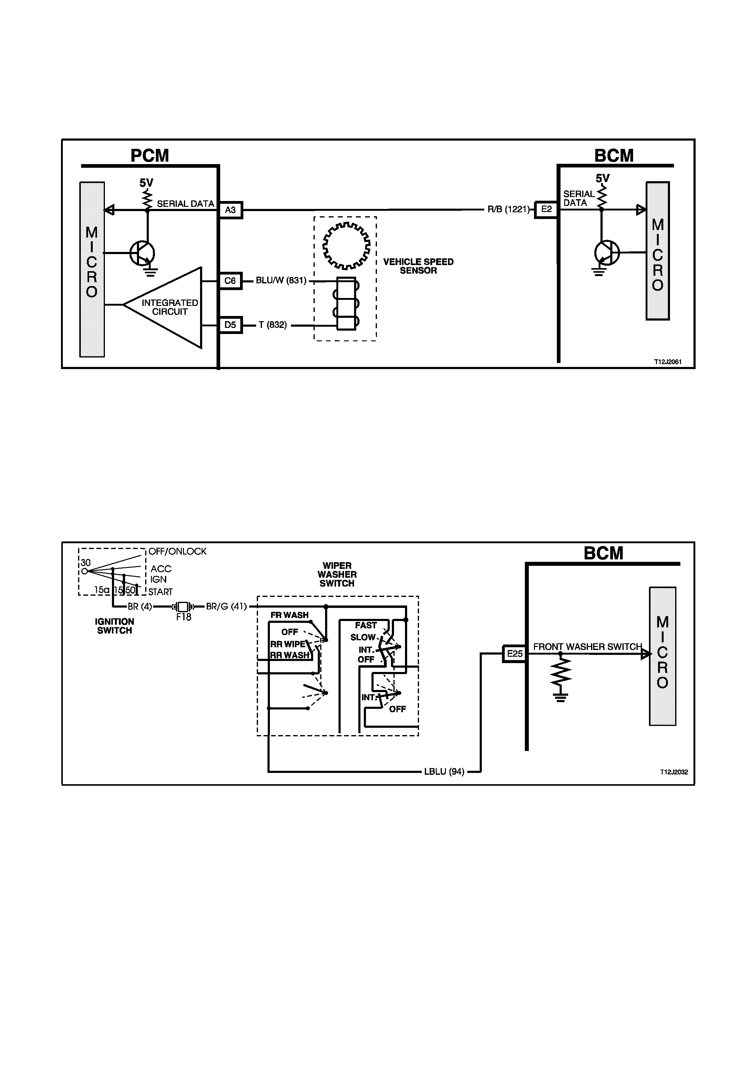
Vehicle Speed Input Signal and Reverse Gear Input
(Refer to Fig. 12J-2-57)
The BCM, terminal E2, receives vehicle speed information from the PCM via the serial communications bus, circuit
1221 (Red/Black wire). TECH 2 can be used to view the vehicle speed through the diagnostic connector.
Terminal E2 of the BCM receives data relating to the selection of reverse gear from the PCM via the serial data bus,
circuit 1221 (Red/Black wire).
Figure 12J-2-57
Window Washer Switch Input Signal
(Refer to Fig. 12J-2-58)
When the washer pump switch is activated, battery voltage is applied to the washer pump and BCM terminal E25
from fuse F18, circuit 41 (Brown/Green wire), the washer switch contacts and circuit 94 (L/Blue wire). This causes
the voltage at BCM terminal E25 to go from less than 0.2 volt to 12 volts. This voltage is seen by the BCM as the
washer switch input signal. The length of time this voltage is present at BCM terminal E25 will determine how many
additional wiper sweeps will occur.
The BCM determines the number of sweeps the wipers have completed by monitoring the voltage at terminal B8,
park switch input, as the voltage at B8 will go from 12 volts to less than 0.2 volt at the completion of each sweep.
Figure 12J-2-58
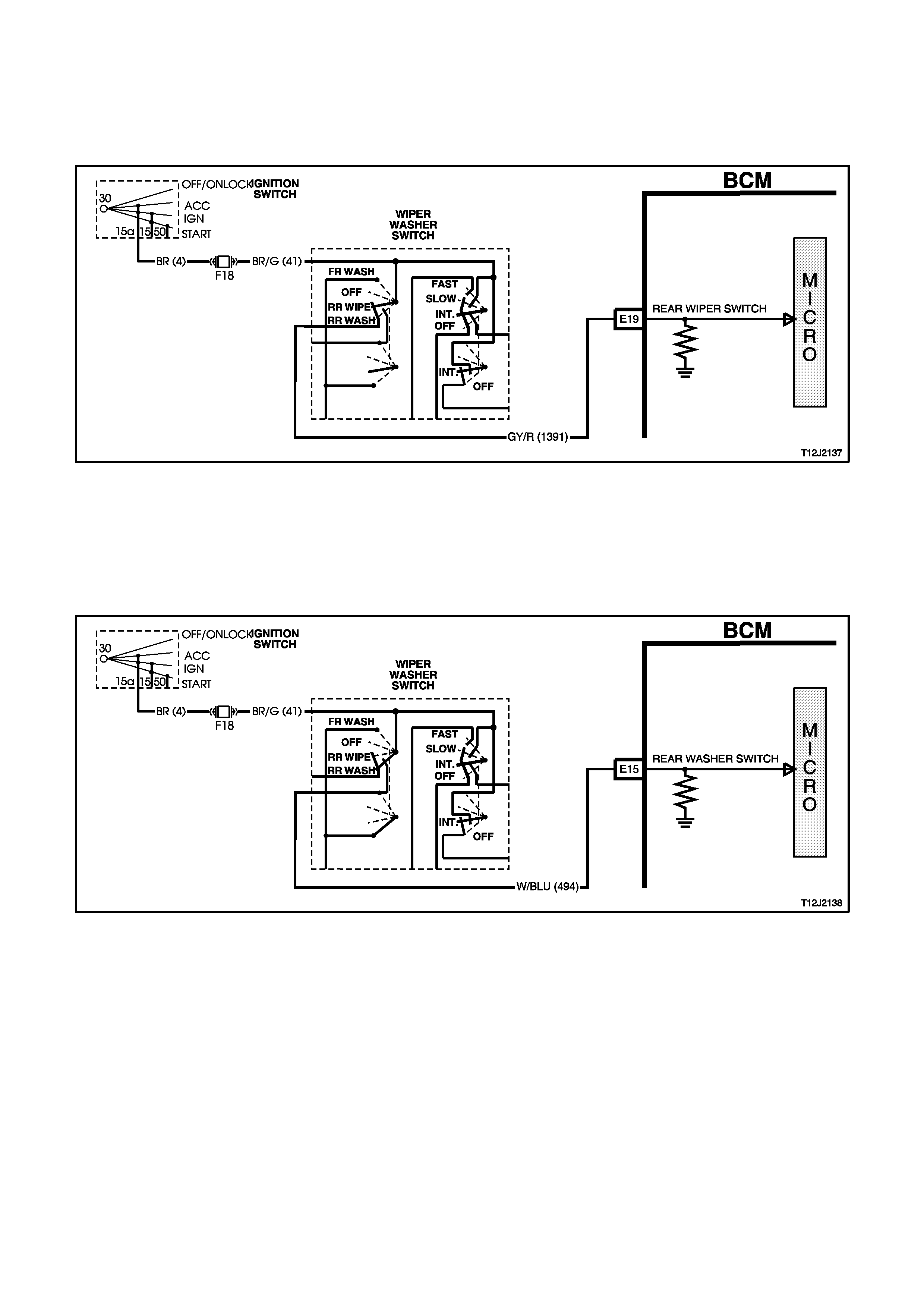
Rear Wiper Switch Input Signal
(Refer to Fig. 12J-2-59)
Placing the wiper washer switch in the rear wipe position causes battery voltage, via fusible link FJ, the ignition
switch contacts, fuse F18, circuit 41 (Brown/Green wire) and the wiper washer switch rear contacts to be applied to
BCM terminal E19, circuit 1391 (Grey/Red wire). This voltage at E19 is seen by the BCM as the rear wiper input
signal.
Figure 12J-2-59
Rear Window Washer Switch Input Signal
(Refer to Fig. 12J-2-60)
When the rear washer pump switch is activated, battery voltage is applied to the washer pump and BCM terminal
E15 from fuse F18, circuit 41 (Brown/Green wire), the washer switch contacts, circuit 494 (White/Blue wire). This
causes the voltage at BCM terminal E15 to go from less than 0.2 volt to 12 volts. This voltage is seen by the BCM
as the rear washer switch input signal.
Figure 12J-2-60
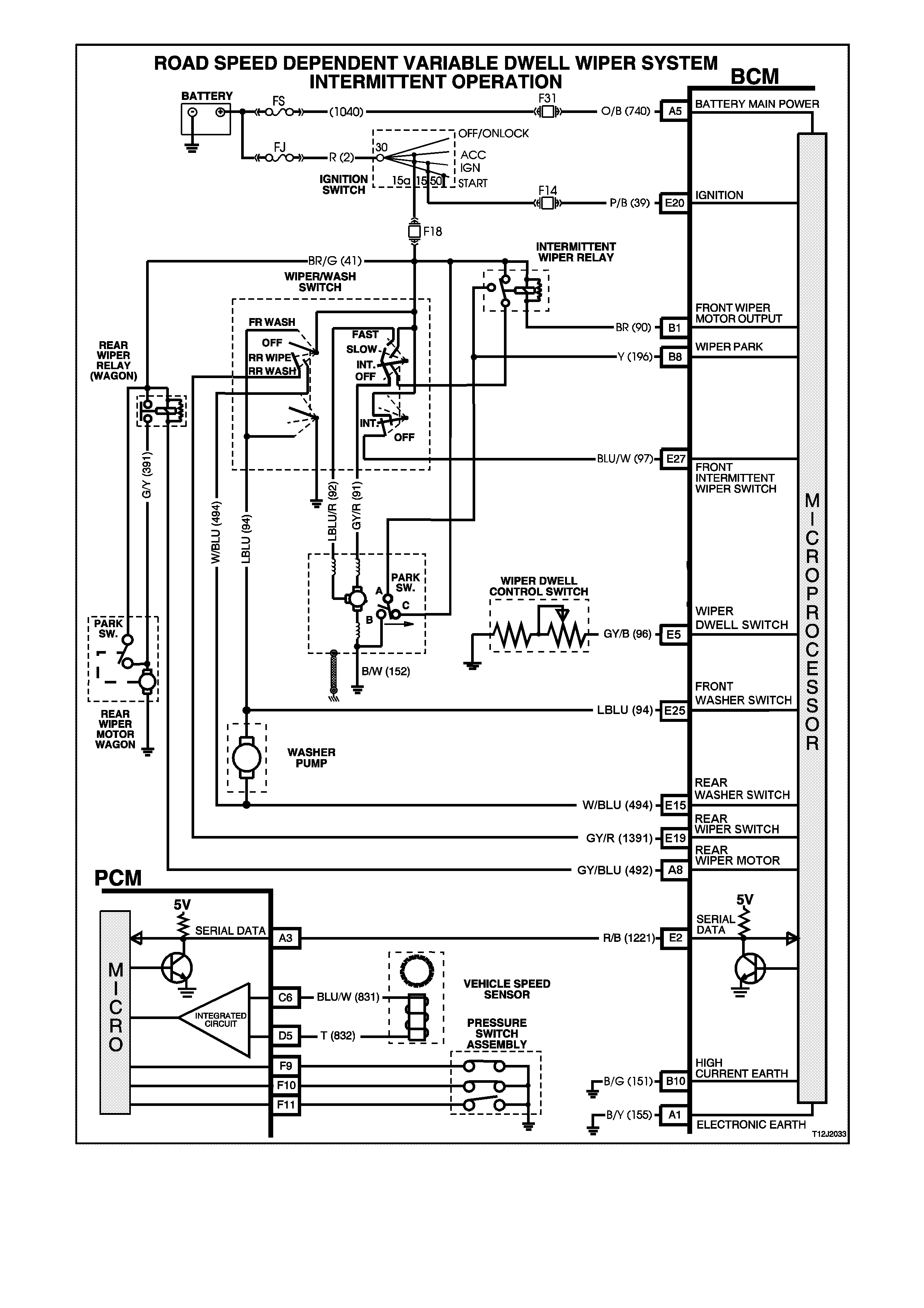
Figure 12J-2-61
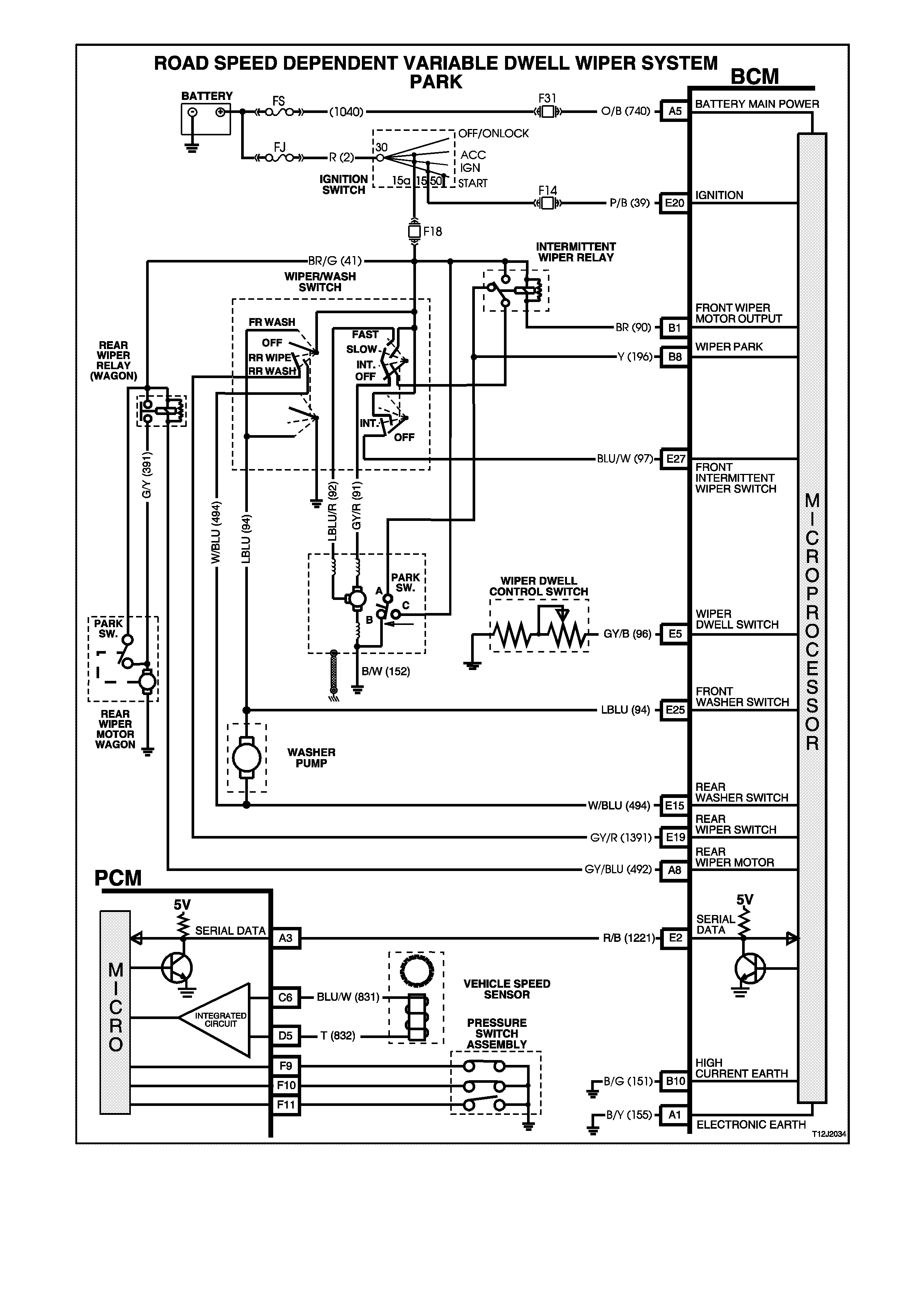
Figure 12J-2-62
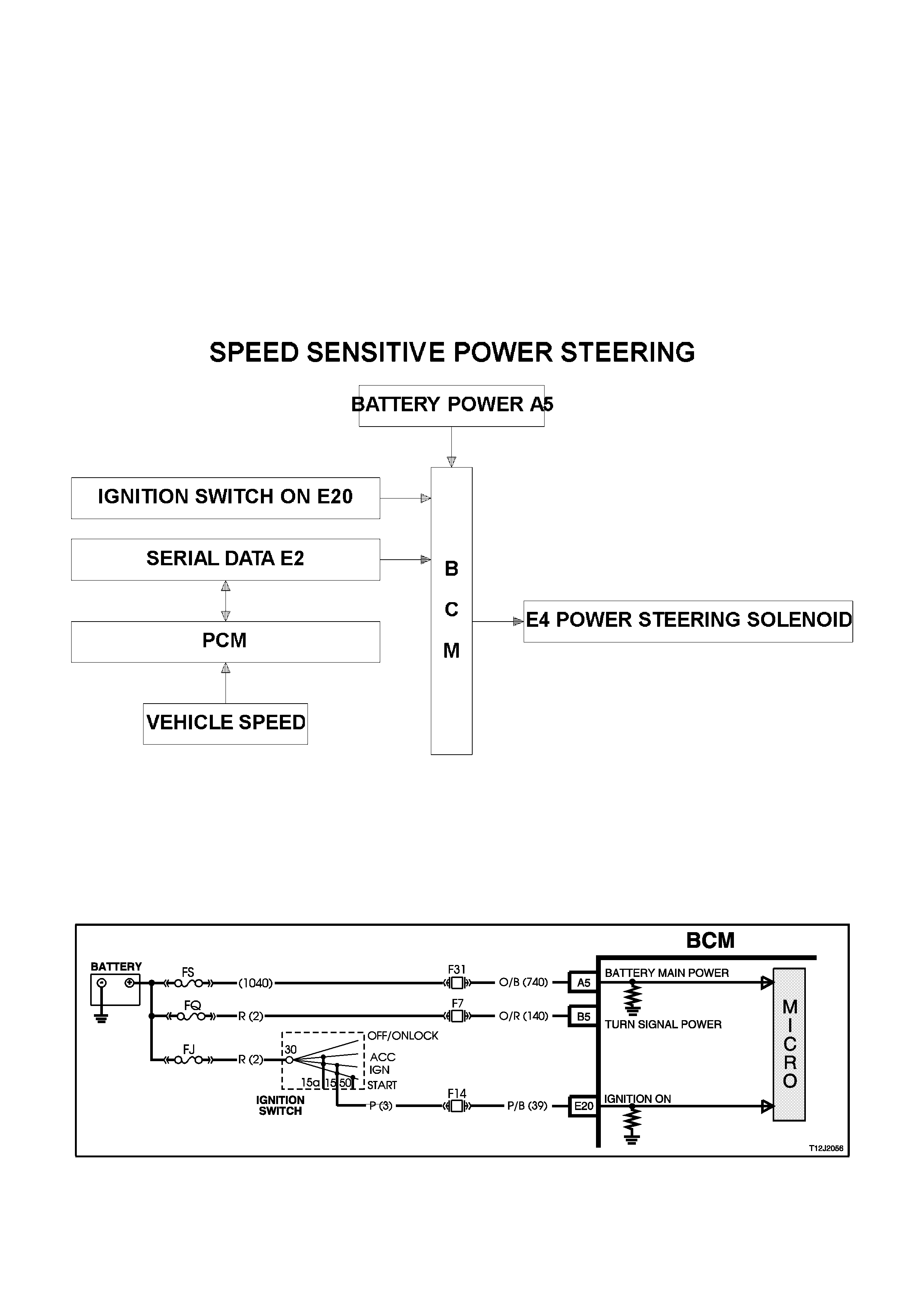
1.10 SPEED SENSITIVE POWER STEERING
GENERAL INFORMATION
This control system of the BCM varies the amount of power assistance given to the steering of the vehicle in order
to allow high boost at low speed or parking and low boost at high speeds for better centre steering performance.
The body control module contains a curve of speed versus boost (or control solenoid current) stored in memory.
The power steering boost is adjusted by accurately controlling the current flowing in the boost solenoid attached to
the steering gear valve housing. If the BCM detects a system malfunction the BCM will gradually change to a default
boost value at a predetermined rate.
NOTE:
The circuit diagrams shown in this General Description Section are to aid in interpreting the operation of the circuit
and therefore, only the main connectors and wiring colours are shown. For complete circuits details, refer to either
the relevant diagnostic section or the Wiring Diagrams.
SYSTEM OVERVIEW
CIRCUIT OPERATION
Ignition Switch ON Input Signal
(Refer to Fig. 12J-2-63)
The BCM uses this input signal to determine when the ignition switch is in the IGN or START position. When the
ignition switch is in the IGN or START position, battery voltage is applied to the BCM terminal E20 from the ignition
switch and fuse F14 via circuit 39 (Pink/Black wire).
Figure 12J-2-63
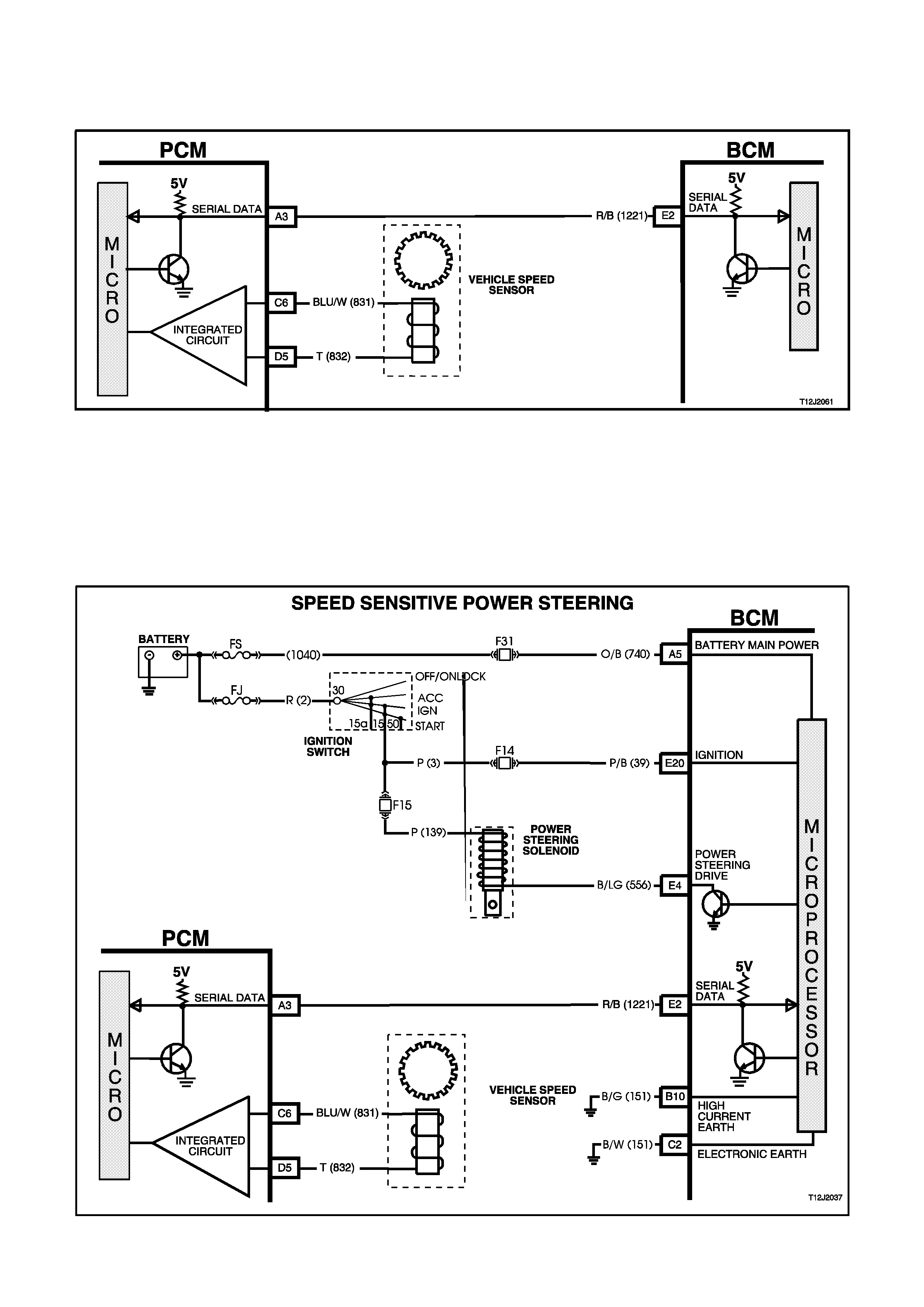
Vehicle Speed Input Signal
(Refer to Fig.12J-2-64)
The BCM, terminal E2, receives vehicle speed information from the PCM via the serial communications bus, circuit
1221 (Red/Black wire).
Figure 12J-2-64
Power Steering Solenoid
(Refer to Fig.12J-2-65)
Battery voltage is applied to the power steering solenoid from the ignition switch, circuit 3 (Pink wire), through fuse
F15, circuit 139 (Pink wire), with the opposite end of the solenoid winding connected to BCM terminal E4, circuit 556
(Black/L Green wire).
The BCM then controls the operation of the power steering solenoid by applying a pulse width modulated signal to
an internal switch, this earth’s the power steering solenoid.
Figure 12J-2-65
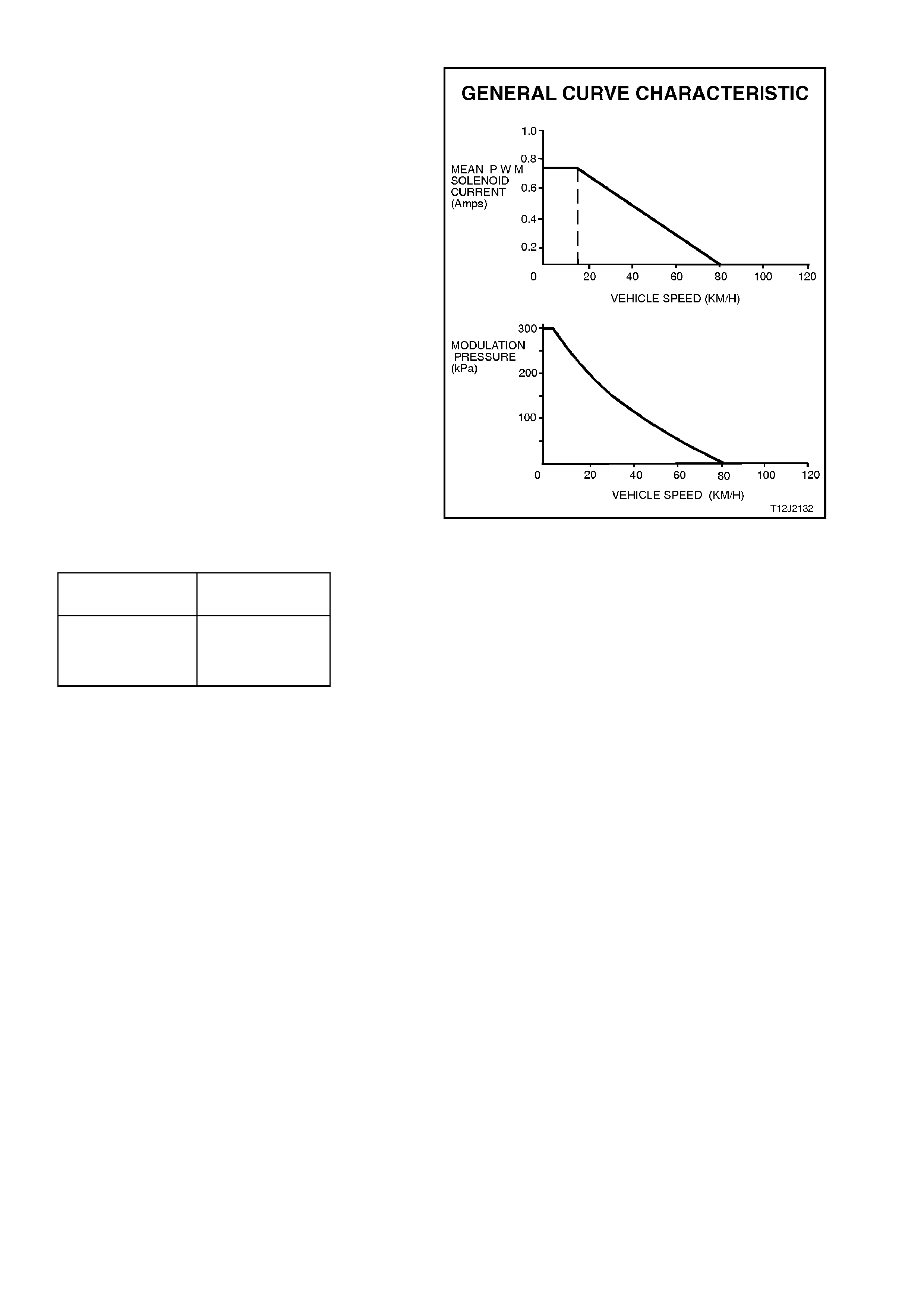
Solenoid Valve Operation
The BCM controls the operation of the boost
solenoid by supplying a Pulse Width Modulated
(PWM) signal to the solenoid that varies
proportionally with vehicle road speed. The signal is
modulated at a frequency of 167 Hz. As shown by
the typical diagram s in the F igure oppos ite both the
average PW M solenoid current and the modulated
pressure are relatively similar. Further, maximum
modulation pressure is only applied during parking
and up to a low speed of a few km/h.
Reference to the following table and the Figure
opposite shows the relative P.W .M. c urrent flow for
respective road speeds.
General Curve Characteristics
CURRENT
(Amp.) ROAD SPEED
(km/h)
0.75
0.45
0.0
0 - 12
40
80+
By changing the pulse width (tim e O N) of the s ignal
sent to the solenoid, the amount of assistance
delivered by the power steering can be varied.
When maximum assistance is required (low vehicle
speed), the BCM increases the signal duty cycle
ON tim e (lengthening the pulse width of the s ignal)
to approximately 50%. This will cause a current of
approximately 750 mA of flow through the solenoid.
As vehicle speed inc r eases , the BCM pr ogres s ively
decreases the assistance by decreasing the duty
cycle ON time (shortening the pulse width of the
signal) thereby decreasing the solenoid current
until zero current flow is achieved. At this point
minim um assistance will be delivered by the power
steering system.
When activated, the power steering solenoid
receives a Pulse Width Modulated (PWM) current
flow from the BCM that varies proportionally with
vehicle road speed.
From this point, the modulated pressure falls
progressively until, at approximately 80 km/h,
modulated pressure decreases to a minimum. It is
at this time also, that the solenoid receives no
further current pulses from the BCM.
Figure 12J-2-66 shows a typical speed sensitive
power steering pulse width modulated current flow.
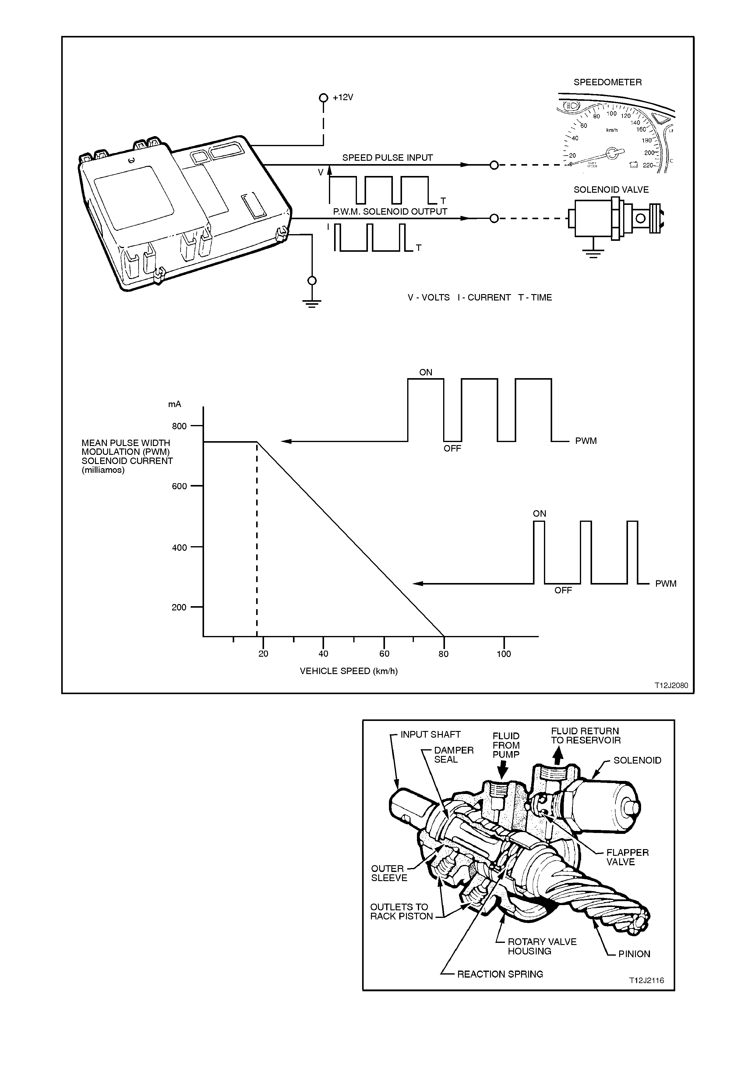
Figure 12J-2-66
The figure opposite illustrates a sectioned view
through the power s teering gear valve hous ing. T he
steering gear boost solenoid operates an internal
'flapper' valve, loc ated in the fluid return side of the
valve housing. The operation of the 'flapper' valve
causes changes in hydraulic pressure and allows
progressive movement of the steering gear valve
housing outer sleeve along the inner shaft valve
member. This movement of the outer sleeve
causes the change in steering gear boost
characteristics.
The most accurate method of testing the speed
sensitive power steering electrical system is by
using TECH 2.
The BCM has a spec ial des ign f eature inc or porated
so that when an open or short circuit is detected in
the drive circuits to the power steering solenoid, ie.
circuits 139 and 556, the BCM will automatically
switch the drive circuits accordingly. Figure 12J-2-67
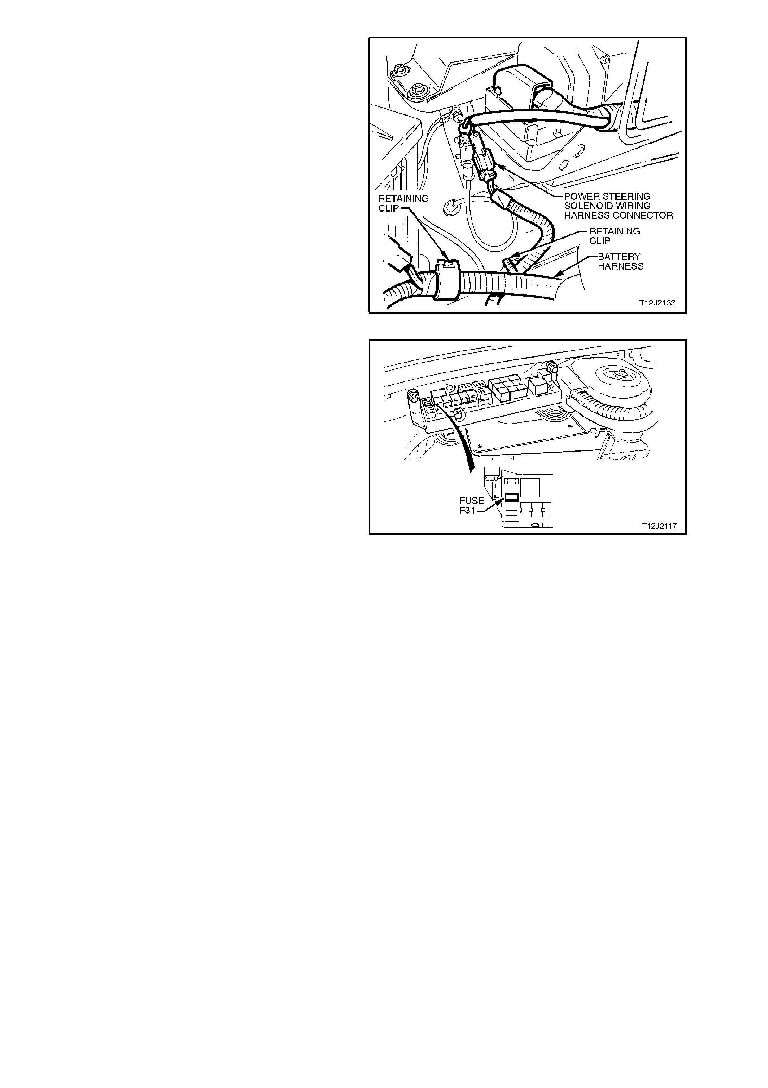
In the event of an interm ittent open circuit due to a
faulty connection, the BCM microprocessor may
need to be reset before carrying out testing.
When carrying out any testing on the system,
ensure that the ignition is switched off, otherwise if
a connection is broken anywhere in the circuit
(disconnecting power steering solenoid connector
from the main wiring harness connector YB63) the
control system in the BCM will turn power off to the
boost solenoid.
NOTE:
Even changing multimeter range selection while
connected to solenoid circ uitry, with ignition on, can
cause the system to default to low boost.
Figure 12J-2-68
To reset the complete BCM memory, switch ignition
off, remove fuse F31 from engine compartment
relay housing, then refit after approximately one
second.
When resetting of the BCM m icr oprocess or occ urs,
a clicking sound may be heard from within the BCM
if the dome lamp relay is active.
Power Steering Pumps
On vehicles f itted with High Series BCM, the power
steering pumps fitted ARE NOT the Droop Flow
type pumps as fitted to vehicles with Low Series
BCM. The difference in pumps is that the Non
Droop Flow type pumps do not incorporate the
metering needle valve in the pump outlet fitting.
Therefore, if replacing a power steering pump,
ensure the correct type is fitted.
Figure 12J-2-69
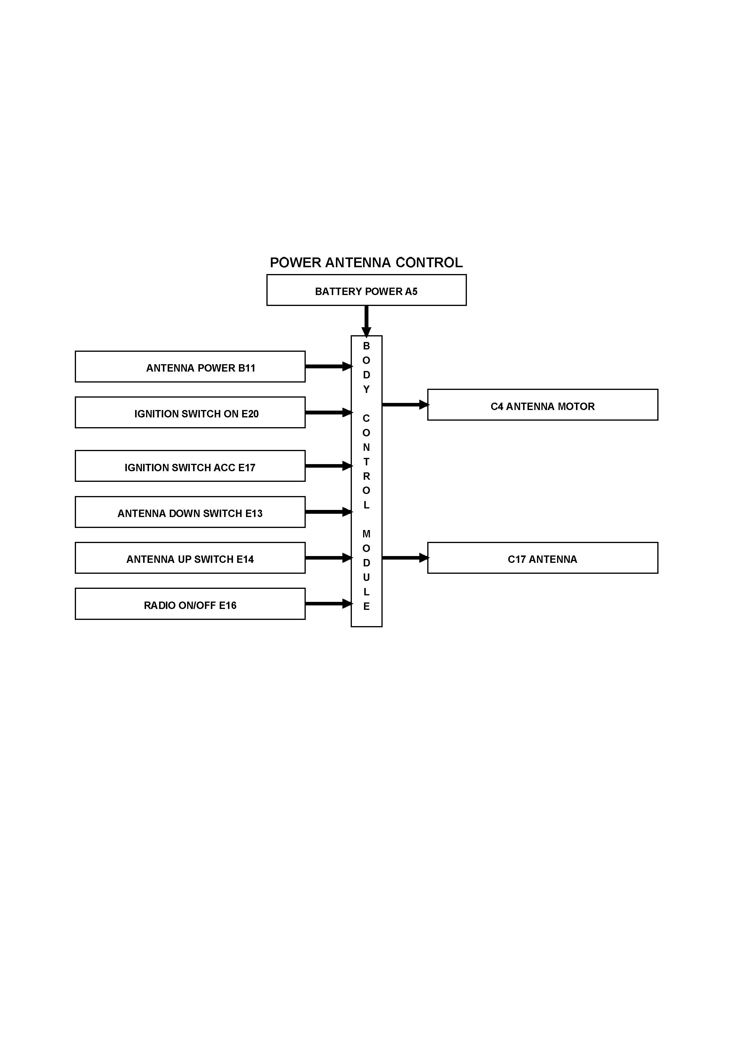
1.11 P O WER ANTENNA CONTROL
GENERAL INFORMATION
The BCM controls the power antenna operation. The power antenna has two inputs from the BCM.
1. BCM provides power to the antenna motor.
2. BCM controls antenna mast direction up or down.
The power antenna assembly incorporates maximum and minimum height limit switches and a slip clutch.
NOTE:
The circuit diagrams shown in this General Description Section are to aid in interpreting the operation of the circuit
and therefore, only the main connectors and wiring colours are shown. For complete circuit details, refer to either
the relevant diagnostic section or Section 12P WIRING DIAGRAMS.
SYSTEM OVERVIEW
Operation of the power antenna is as follows:
When the radio/cassette player ON signal (refer to Fig.12J-2-70) is sensed by the BCM, the antenna mast extends
to the same height it was when last in operation (provided antenna height memory option enabled).
If at some time the battery has been disconnected, the antenna height memory setting will be lost. In this case, the
antenna default height is 6 seconds of mast upward travel, which is approximately 60 centimetres above the fender
panel.
The antenna mast height memory is dependent on correct battery voltage, clean antenna mast and no kinks in the
mast cord. A tolerance of plus or minus 100 mm is acceptable for mast height.
When signals from the ANTENNA UP or ANTENNA DOWN switches are sensed, the antenna mast will move
accordingly. However, these switches do not operate when there is no signal sensed by the BCM from the
radio/cassette player or when accessory signal (ignition switch ACC position) is not present.
When the signal from the radio/cassette is turned off, operation of the antenna is as follows:
1. If the ignition switch is turned to the OFF (accessories off) position, there is a delay of approximately 15 seconds
before the antenna mast fully retracts.
2. If the ignition switch is turned to the ON (or ACC) position, the antenna mast will fully retract after 3 seconds.
During engine starting, the radio/cassette player 'on' signal is momentarily lost and during this time, it is assumed by
the BCM that the signal is still active as it senses both ignition and accessories inputs, as well as radio/cassette
player status signal. This enables the antenna operation and control is unaffected during engine cranking.
Operation of the power antenna is also affected by the theft deterrent system (antenna mast retracts when system
is armed).
The antenna mast height memory is also dependent on the priority key system. Antenna height memory can be set
and stored for the priority 1 and priority 2 keys. The antenna height memory is recalled when the unlock button on
the remote key is pressed, and is dependent on whether the priority 1 key or priority 2 key is used.
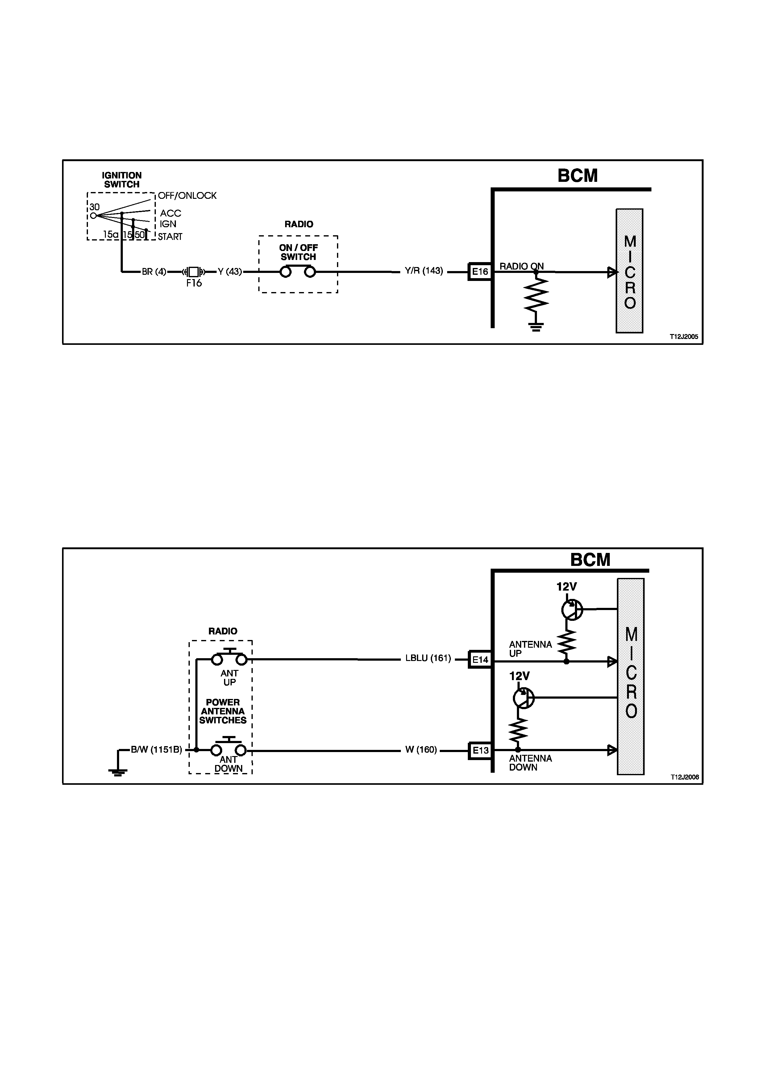
CIRCUIT OPERATION
(Refer to Figs. 12J-2-72 and 12J-2-74)
Radio On Input Signal (PD)
(Refer to Figure 12J-2-70)
When the radio/cassette player is turned on, battery voltage is applied to BCM terminal E16 via circuit 143
(Yellow/Red wire). This causes the voltage at terminal E16 to go from less than 0.2 volts (radio off) to 12 volts (radio
on), The voltage at terminal E16 is seen by the BCM as the radio ‘ON’, input signal.
Figure 12J-2-70
Antenna Up Switch Input Signal
(Refer to Fig. 12J-2-71)
When the antenna UP switch is depressed the voltage at BCM terminal E14 will be pulled low, less than 0.2 volts
(antenna up switch contacts closed). BCM terminal E14 is now connected to earth via circuit 161 (L/Blue wire), the
antenna UP switch and circuit 1151B (Black/White wire).
The earth applied to terminal E14 is seen by the BCM as the antenna UP input signal. The BCM then applies 12
volts to the antenna direction relay, in the power antenna assembly, from BCM terminal C17 via circuit 954 (Grey
wire). This energises the antenna direction relay causing the relay contacts to switch to the antenna UP position. As
battery voltage will also be applied to the antenna motor from BCM terminal C4, circuit 145 (Green wire) at this time
the antenna motor will rotate, driving the antenna mast upward. The earth circuit for the power antenna motor is via
the antenna earth lead.
Figure 12J-2-71
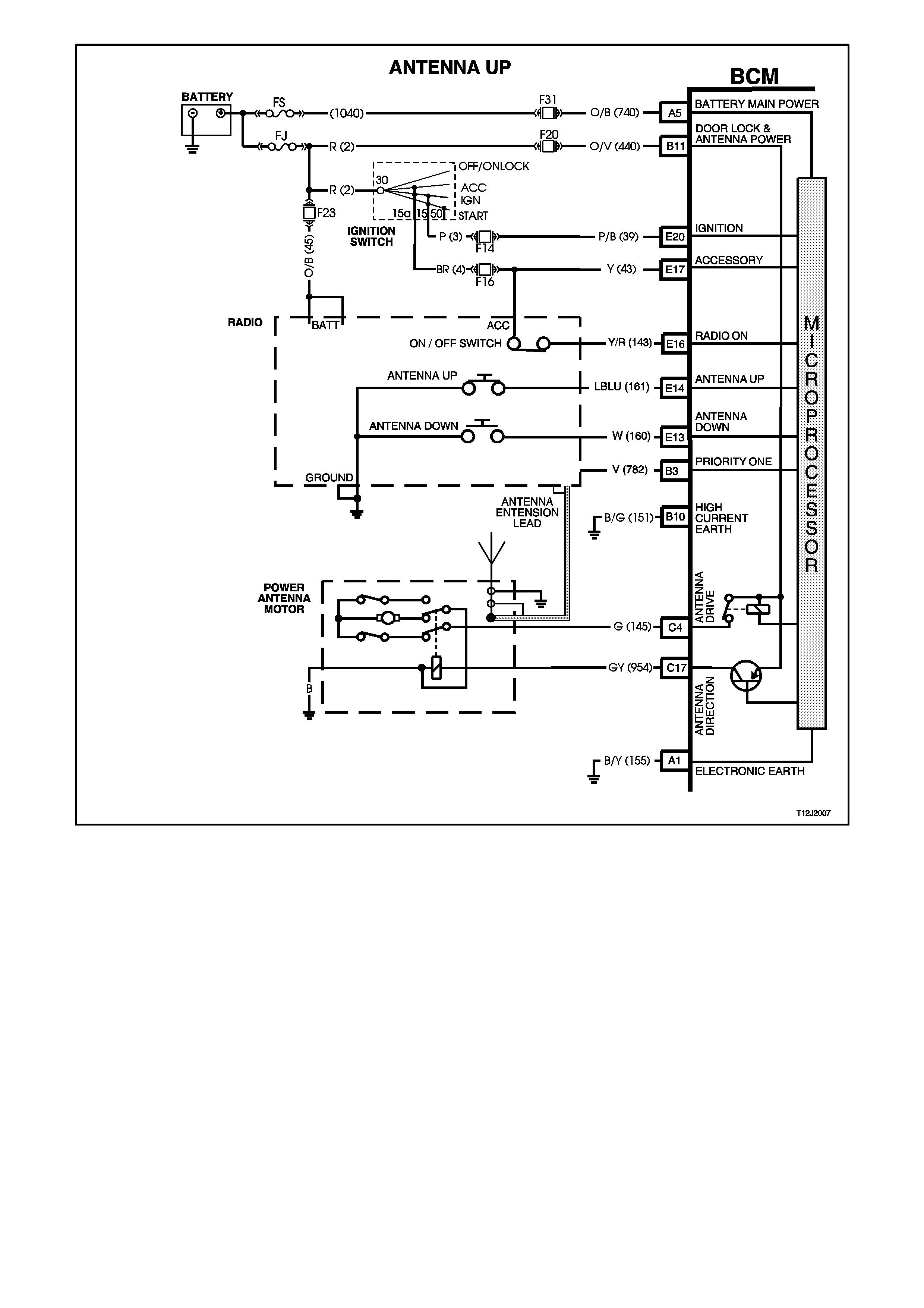
Figure 12J-2-72
Antenna Up Memory Height
When the radio \ cassette is turned ON, 12 volts is applied to BCM terminal E16 from the radio via circuit 143
(Yellow/Red wire). This causes the voltage at terminal E16 to go from less than 0.2 volt (radio 'off') to 12 volts (radio
'on').
This radio 'on' signal will cause the BCM to apply 12 volts to the antenna direction relay from BCM terminal C17 via
circuit 954 (Grey wire). This energises the antenna direction relay causing the relay contacts to switch to the
antenna UP position. The BCM will also energise its internal relay and battery voltage will be applied to the power
antenna motor for enough time to allow the power antenna motor armature to rotate and drive the antenna mast in
the upward direction to the same height it was when last in operation.
NOTE:
If battery supply from fuse F31 is lost at any time to the BCM, antenna memory will be lost and will need to be reset.
Antenna Down Switch Input Signa
(Refer to Fig. 12J-2-73)
The downward direction of travel of the power antenna is also controlled by the BCM. When the antenna DOWN
switch is depressed the voltage at BCM terminal E13 will be pulled low, less than 0.2 volt (antenna down switch
contacts closed). The BCM terminal E13 is now connected to earth via circuit 160 (White wire), the antenna DOWN
switch and circuit 1151B (Black/White wire). The earth applied to terminal E13 is seen by the BCM as the antenna
DOWN input signal.
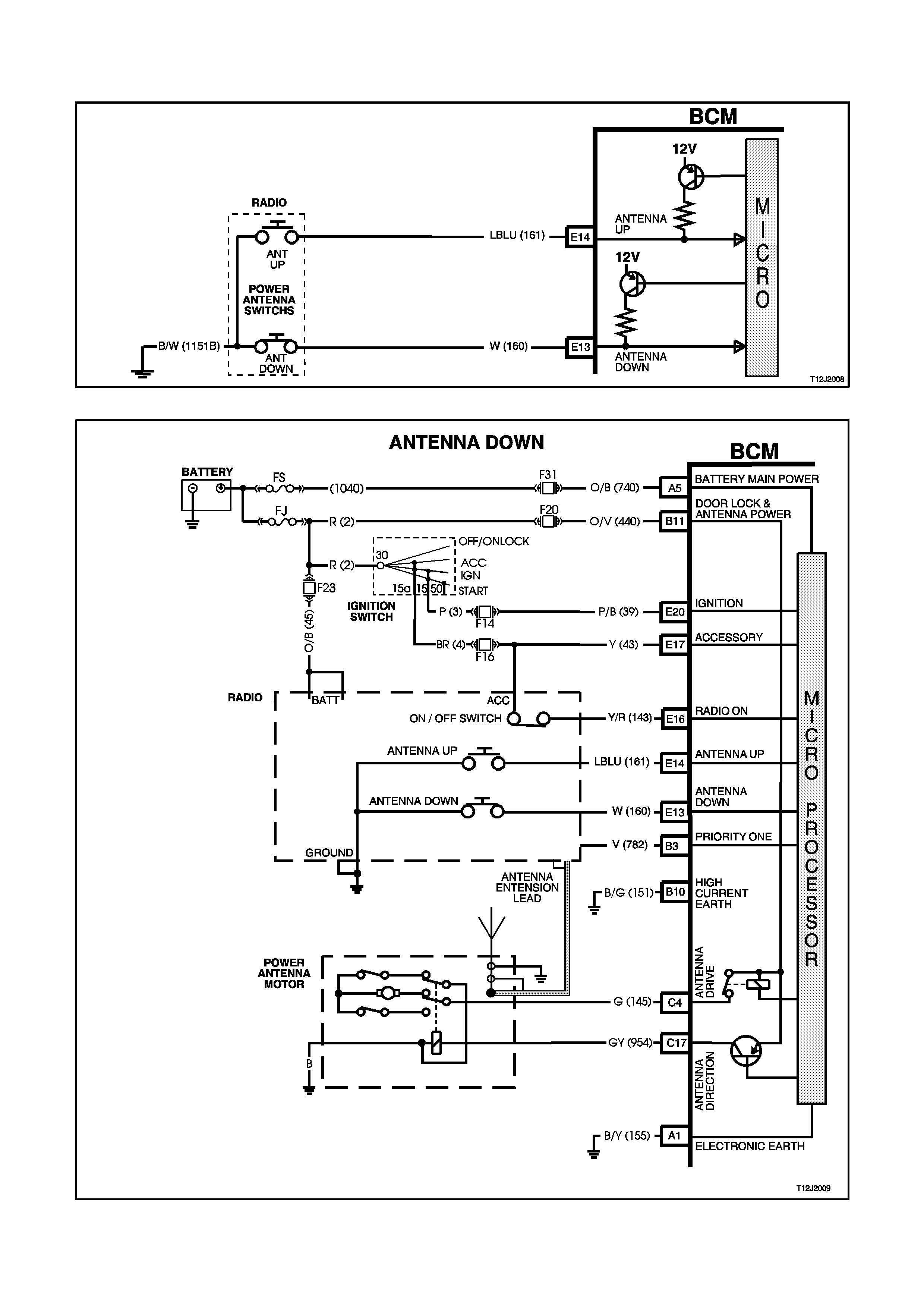
The BCM does not apply 12 volts to the antenna direction relay, therefore the antenna direction relay contacts will
remain in the DOWN position. As battery voltage will be applied to the antenna motor from BCM terminal C4 the
antenna motor armature will rotate, driving the antenna mast downward.
Figure 12J-2-73
Figure 12J-2-74

1.12 DOME LAMP DELAY CONTROL
GENERAL INFORMATION
NOTE:
The circuit diagrams shown in this General Description Section are to aid in interpreting the operation of the circuit
and therefore, only the main connectors and wiring colours are shown. For complete circuits details, refer to either
the relevant diagnostic section or Section 12P WIRING DIAGRAMS.
The interior lighting is controlled by the BCM or by the dome lamp switch (incorporated with the dome and reading
lamps cluster). The interior lighting is activated when any door is opened, unlocked with the remote coded key or
when the dome lamp switch is operated. The various modes of operation are as follows:
Operation with door opening:
The interior lighting operates for at least 30 minutes whilst any door is open. After all doors have been closed, the
lamp/s remains activated for an additional 30 seconds.
However, if the ignition is switched on, the delay time is cancelled and the lamp/s go off immediately.
Operation with dome lamp switch:
The dome lamp switch is a 3 position switch with; doors, OFF and ON positions which turns the interior lighting on
when closed. If the interior lighting has been activated by some other BCM control system or action, the dome lamp
switch will turn the interior lighting off when it is switched from ON to OFF (with the sole exception of dome light
flash when the theft deterrent system is triggered). This means that the switch can curtail any delay time initiated as
well as switch the lighting off whilst a door is open. The BCM also monitors the position of the doors and controls
the dome lamp accordingly.
When the interior lighting has been activated by the dome lamp switch, and the ignition is off, a delay time of 120
minutes applies.
Operation with central locking:
Provided the dome lamp switch is in the doors position, the interior lighting is switched on upon central door
unlocking for 30 seconds. If the ignition is turned on during this delay, the interior lighting will be switch off
immediately. Interior lighting is also switched off upon central door locking or deadlocking.
If any of the passenger doors are open while the doors are locked, the interior lighting will remain on. The lighting
will turn off immediately only when that particular door is closed.
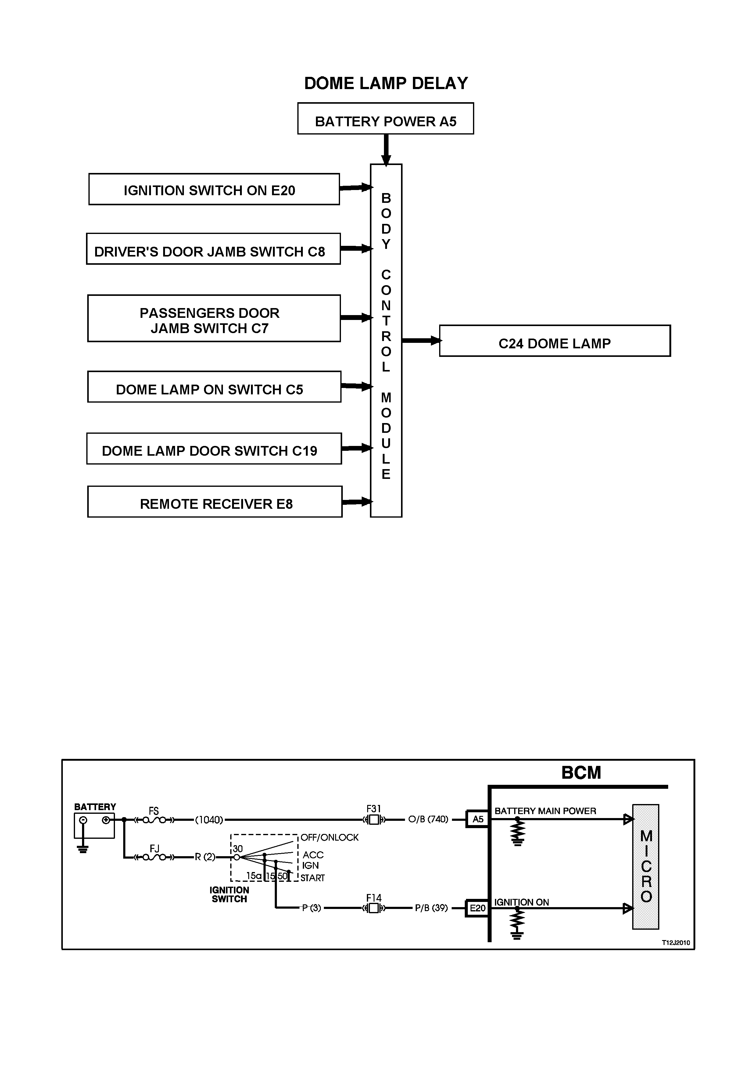
SYSTEM OVERVIEW
CIRCUIT OPERATION
(Refer to Fig. 12J-2-80)
Battery voltage is applied to all interior lights via fuse F6 and circuit 1140 (Orange/Black wire). The opposite side of
the dome lamps are connected to earth via circuit 174 (White/Green wire) and BCM terminal C24. The BCM
controls the operation of the dome lamps connected to this earth circuit by energising its internal dome lamp relay,
this causes the relay contacts to close completing the circuit to earth.
Ignition Switch ON Input Signal
(Refer to Fig. 12J-2-75)
The BCM uses this input signal to determine when the ignition switch is in the IGN or START position. When the
ignition switch is in the IGN or START position, battery voltage is applied to the BCM terminal E20 from the ignition
switch and fuse F14 via circuit 39 (Pink/Black wire).
Figure 12J-2-75
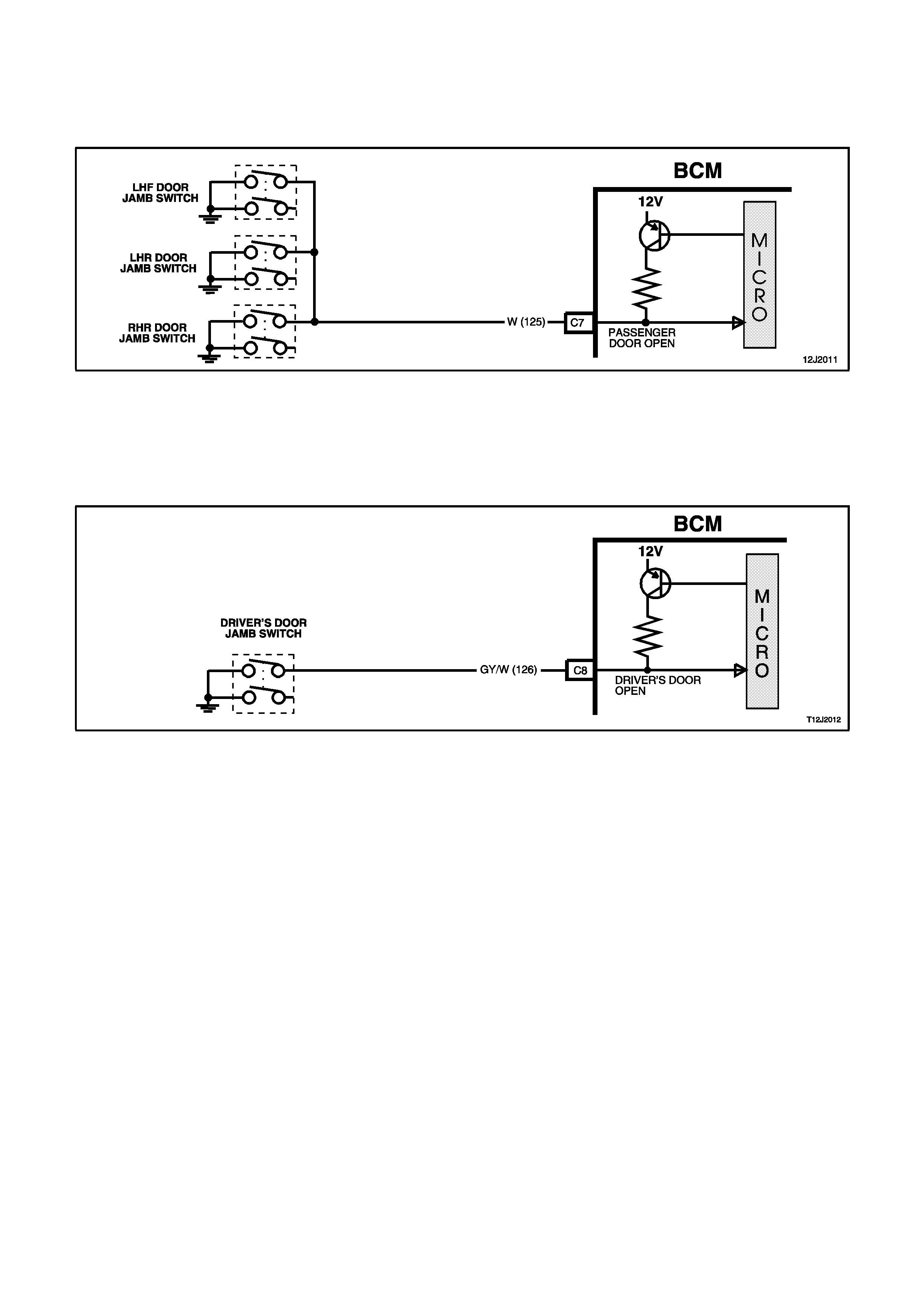
Passenger Door Open Input Signal
(Refer to Fig. 12J-2-76)
When any passenger door is opened, BCM terminal C7 is connected to earth via circuit 125 (White wire) and the
passenger door jamb switch. This causes the voltage at terminal C7 to be pulled low, less than 0.2 volt (passenger
door open). This low voltage at terminal C7 is seen by the BCM as the passenger door open input signal.
Figure 12J-2-76
Driver’s Door Open Input Signal
(Refer to Fig. 12J-2-77)
When the driver’s door is opened, BCM terminal C8 is connected to earth via circuit 126 (Grey/White wire) and the
driver’s door jamb switch. This causes the voltage at terminal C8 to be pulled low, less than 0.2 volt (driver's door
open). This low voltage at terminal C8 is seen by the BCM as the driver's door input signal.
Figure 12J-2-77
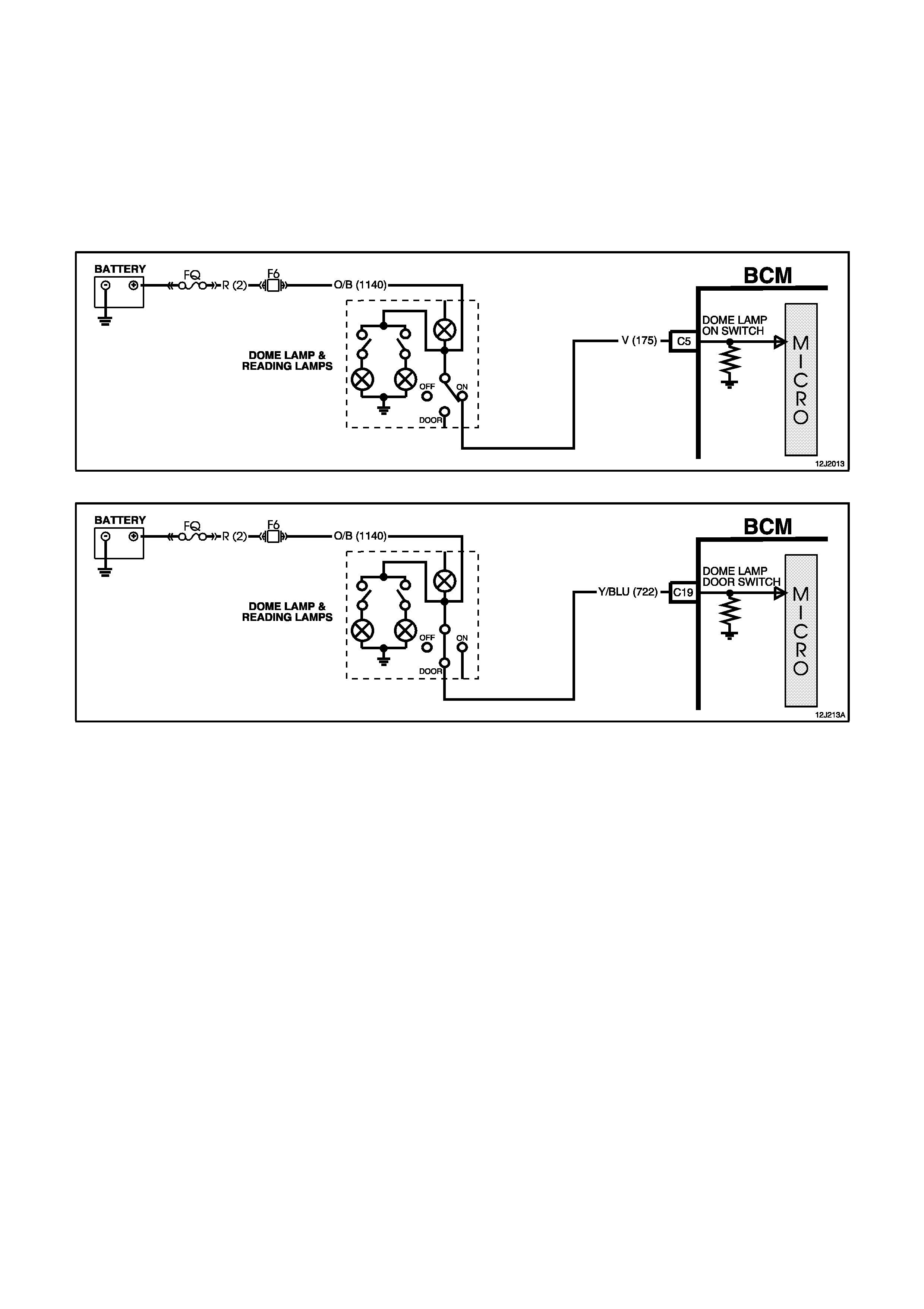
Dome Lamp Switch Input Signal
(Refer to Figs. 12J-2-78 and 12J-2-79)
Dome ON
When the dome lamp switch is in the ON position, battery voltage is applied to BCM terminal C5 from fuse F6 via
circuit 1140 (Orange/Brown wire), dome lamp switch contacts, and circuit 175 (Violet wire). This voltage at BCM
terminal C5 is seen by the BCM as the dome lamp switch on input signal.
Dome DOOR
When the dome lamp switch is switched to the DOOR position, battery voltage is applied to BCM terminal C19 from
fuse F6 via circuit 1140 (Orange/Black wire) dome lamp switch contacts and circuit 722 (Yellow/Blue wire). This
voltage at BCM terminal C19 is seen by the BCM as the dome lamp switch DOOR input signal.
Figure 12J-2-78
Figure 12J-2-79
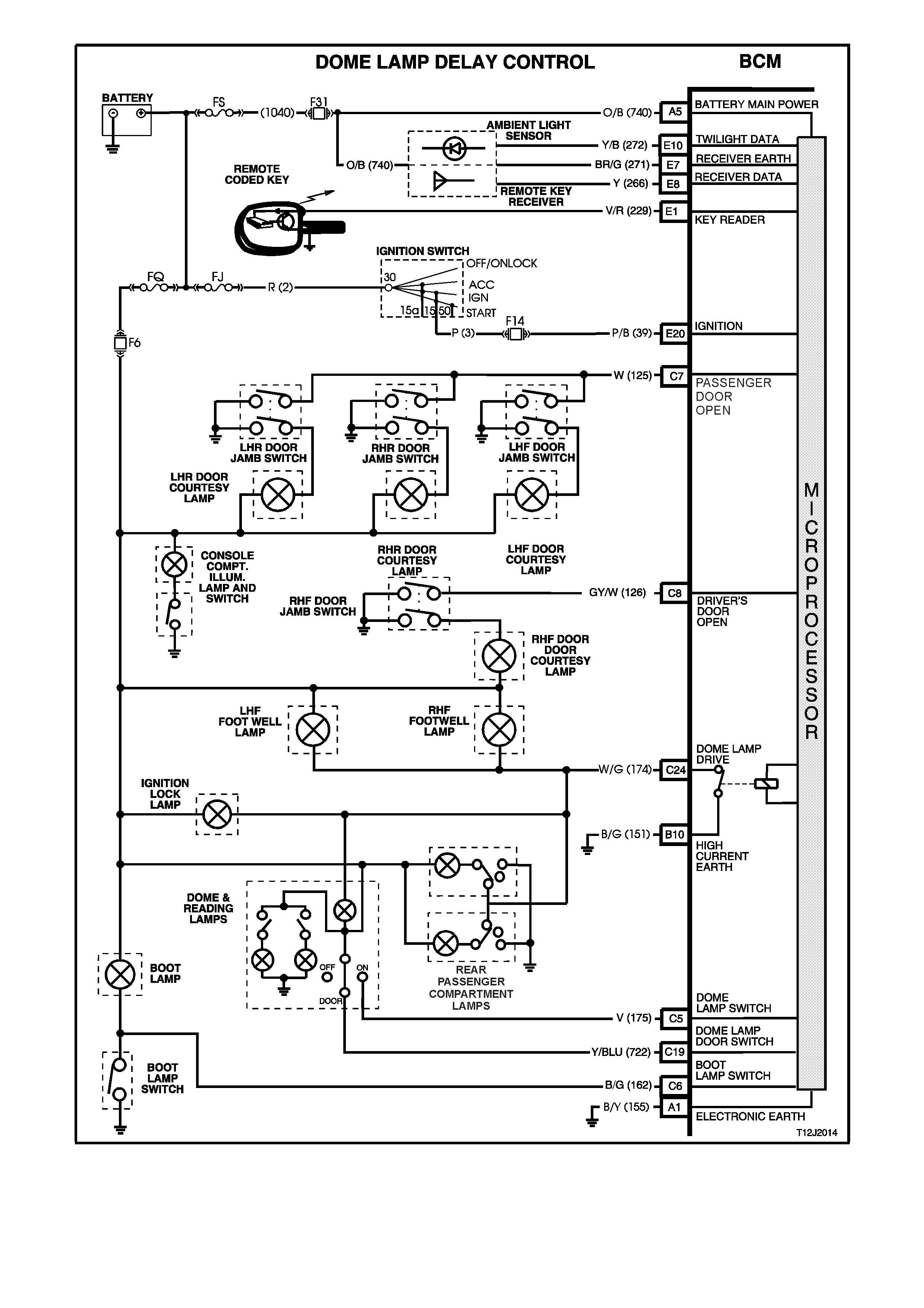
Figure 12J-2-80
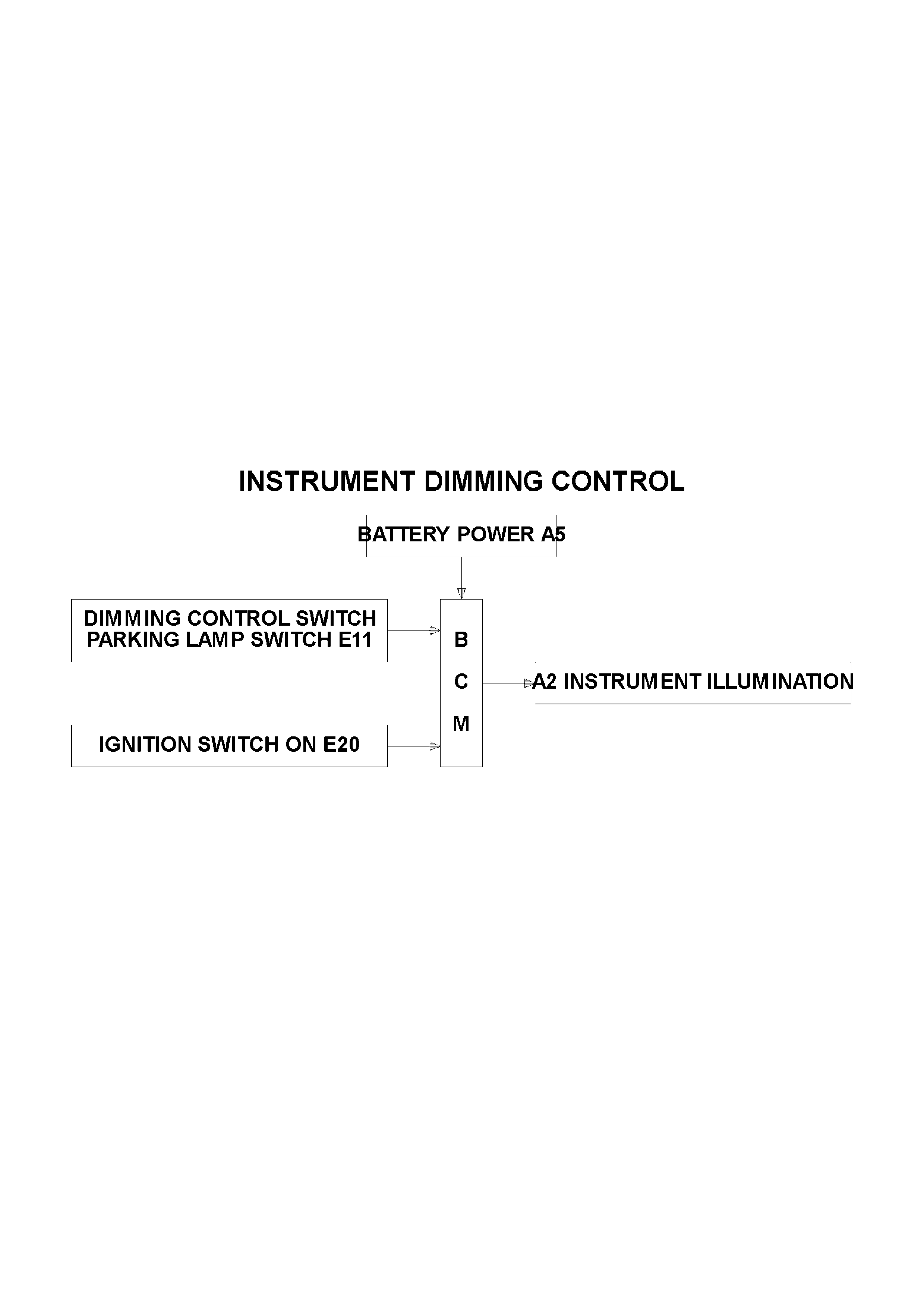
1.13 INSTRUME NT DIMMING CONTROL
GENERAL INFORMATION
The instrument dimming control allows for illumination level adjustment of the instrument dial faces, dash and
centre console illumination, as well as display windows of the trip computer, climate control and radio. The
illumination level is adjusted by moving the spring loaded control lever on the headlamp switch. The lever operates
two momentary contact switches within the headlamp switch. The dimmer drives to full load when both the ignition
is on and the parking lamps are switched off to give maximum illumination intensity. When the parking lamps are
switched on, the dimmer will operate according to the level previously set and provide the voltage variation
compensation required to maintain the same brightness, irrespective of the ignition switch position.
The instrument illumination intensity is also dependent on the priority key system. Instrument illumination intensity
can be set for priority 1 and 2 keys. The intensity is recalled when the unlock button or the remote key is pressed,
and is dependent on whether priority 1 or 2 key is used.
To decrease dash illumination intensity, the switch control lever must be held down for the required time for the
BCM to decrease instrument cluster and trip computer illumination intensity. To increase illumination intensity, the
switch control lever must be held up for the required time for the BCM to increase the illumination intensity.
NOTE:
The circuit diagrams shown in this General Description Section are to aid in interpreting the operation of the circuit
and therefore, only the main connectors and wiring colours are shown. For complete circuit details, refer to either
the relevant diagnostic section or Section 12P WIRING DIAGRAMS.
SYSTEM OVERVIEW
CIRCUIT OPERATION
(Refer to Fig. 12J-2-84)
The BCM controls the operation of the instrument illumination dimming by controlling the current flow through the
instrument illumination circuit. This is achieved by turning the instrument illumination earth circuit on and off. As the
on time increases, so to does the current flowing through the circuit. As this pulse width modulated current flow (on
time) increases, the instrument illumination intensity will also increase.
Battery voltage is applied to the trip computer display illumination from the ignition switch, via circuit 3 (Pink wire),
fuse F13 and circuit 44 (Pink/Blue wire). The earth circuit is via circuit 8 (Grey wire) through the BCM terminal A2.
Battery voltage is applied to the instrument cluster illumination lights, radio illumination and climate control
illumination from the parking illumination lamp relay to fuse F11, circuit 19 (Brown/White wire). The earth circuit is
via circuit 8 (Grey wire) through the BCM terminal A2.
NOTE:
The instrument cluster, radio, climate control and trip computer illumination lights are the only illumination lights that
are variable in intensity, this control is carried out by the BCM. All other switch or dash illumination lights are not
controlled via the BCM and therefore, all these lights are directly connected to earth.
Parking Lamps Switch Input Signal
(Refer to Fig. 12J-2-81)
When the parking lamps are turned on, the parking lamps relay is earthed through circuit 49 (Blue wire), the
parklamp switch contacts, circuit 1150 (Black wire), BCM terminal E28 and to earth via an internal switch. This
places a voltage at BCM terminal E11, approximately 2.5 volts (resistor dividing network dimmer resistors 5.4 kΩ
and BCM internal resistor). This enables the BCM to determine that the parking lamps are turned on and internal
switching is activated to turn on the instrument illumination lamps.
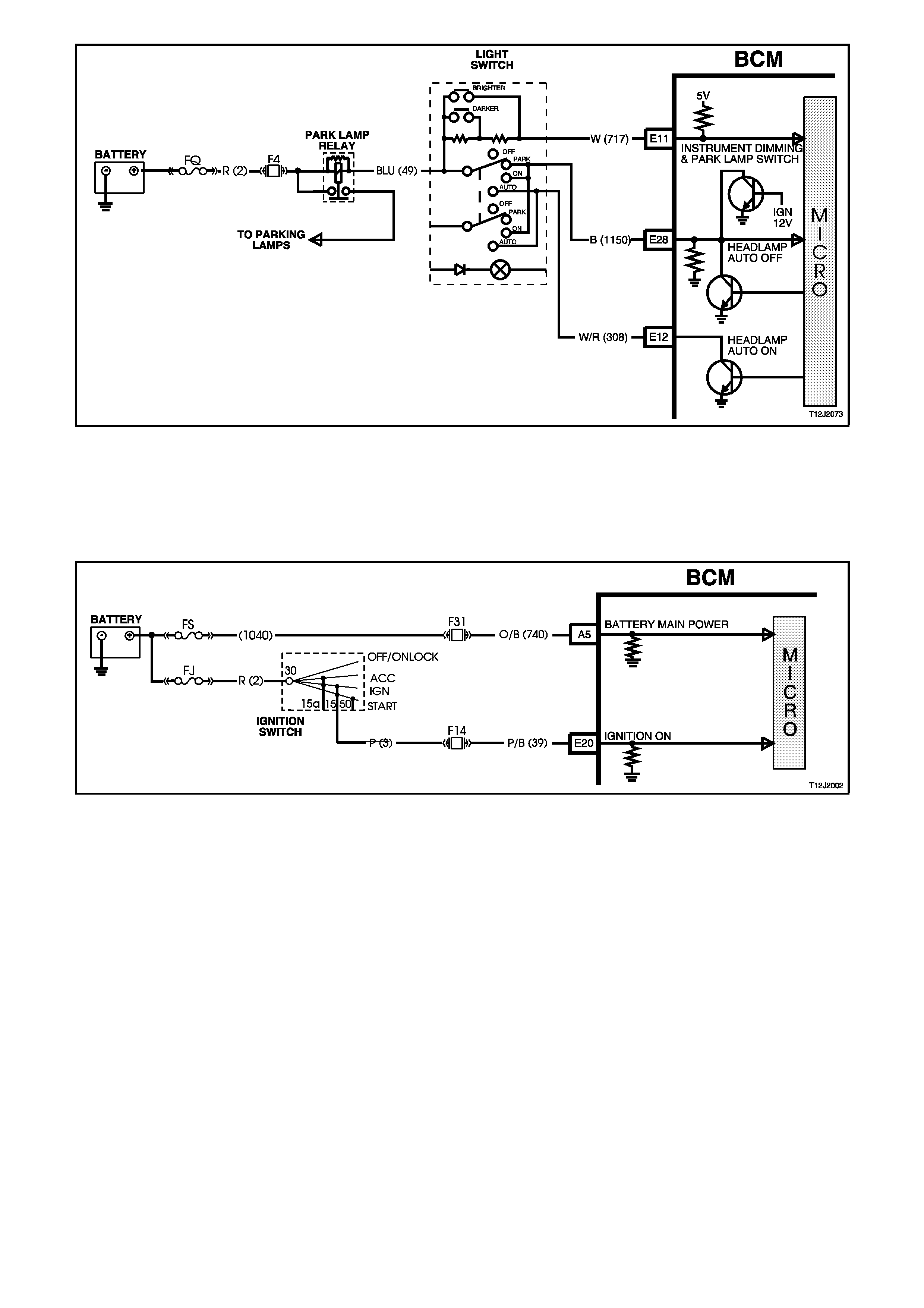
Figure 12J-2-81
Ignition Switch 'ON' Input Signal
(Refer to Fig. 12J-2-82)
When the ignition switch is in the IGN or START position, battery voltage is applied to BCM terminal E20 via circuit
39 (Pink/Black wire). This causes the voltage at terminal E20 to go from less than 0.2 volts (ignition OFF) to 12 volts
(ignition IGN or START). The voltage at terminal E20 is seen by the BCM as the ignition ON input signal.
Figure 12J-2-82
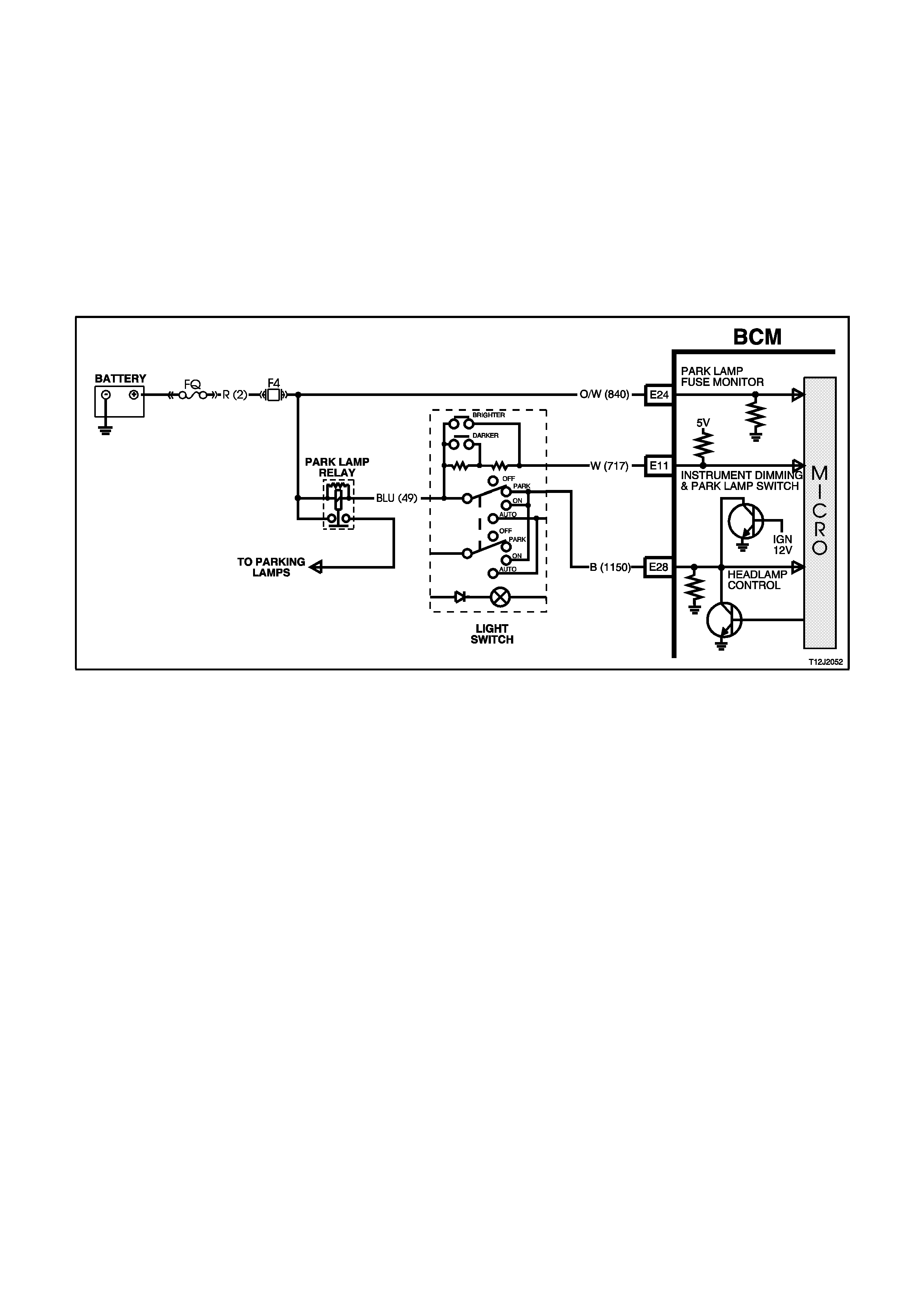
Illumination Dimmer Control Input Signal
(Refer to Fig. 12J-2-83)
BCM terminal E11 is connected to earth when the headlamp switch is in the park position, through the dimmer
control line via two 2.7 kohm series resistors in the spring loaded instrument illumination control lever on the
headlamp switch, the headlamp parking lamp switch contacts circuit 1150 (Black wire), BCM terminal YE28 to earth
via an internal switch.
With the headlamp switch in the OFF position, the voltage at BCM terminal E11 is approximately 8.0 volts. With the
headlamp switch in the PARK position, the voltage at the BCM terminal will be 2.5 volts. This enables the BCM to
determine that the parking lamps are turned on and internal switching is activated to turn on the instrument
illumination lamps. When the BCM detects the lamps are turned off, the instrument dimming output is set to full
brightness for the trip computer illumination.
When the headlamp switch control lever is held up (DIM +), both resistors are shorted and the voltage at BCM
terminal E11 should be approximately 0.2 volts. When the headlamp switch control lever is held down (DIM - ), one
of the two series resistors is shorted and the voltage at BCM terminal E11 should be approximately 1.5 volts.
Figure 12J-2-83
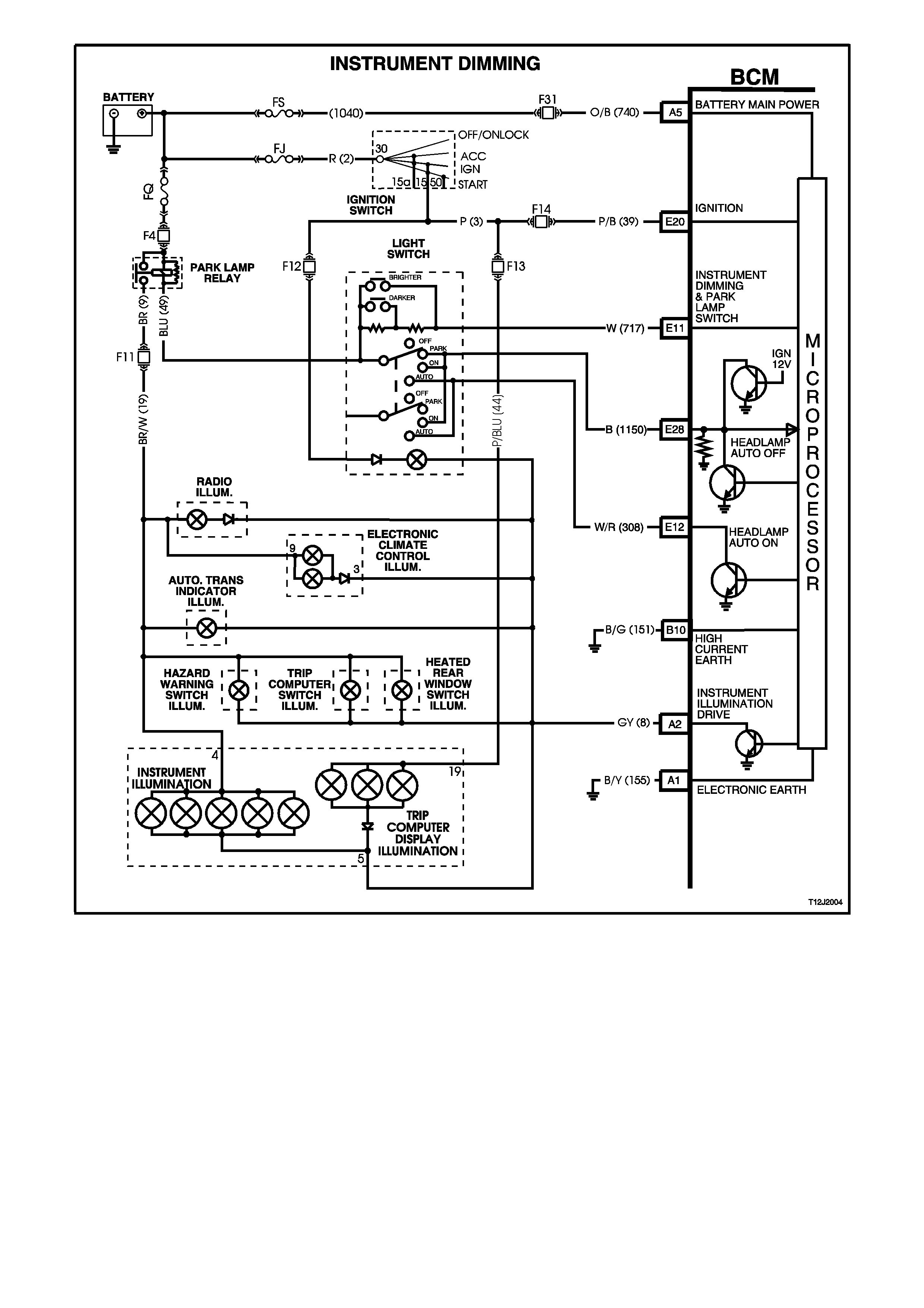
Figure 12J-2-84
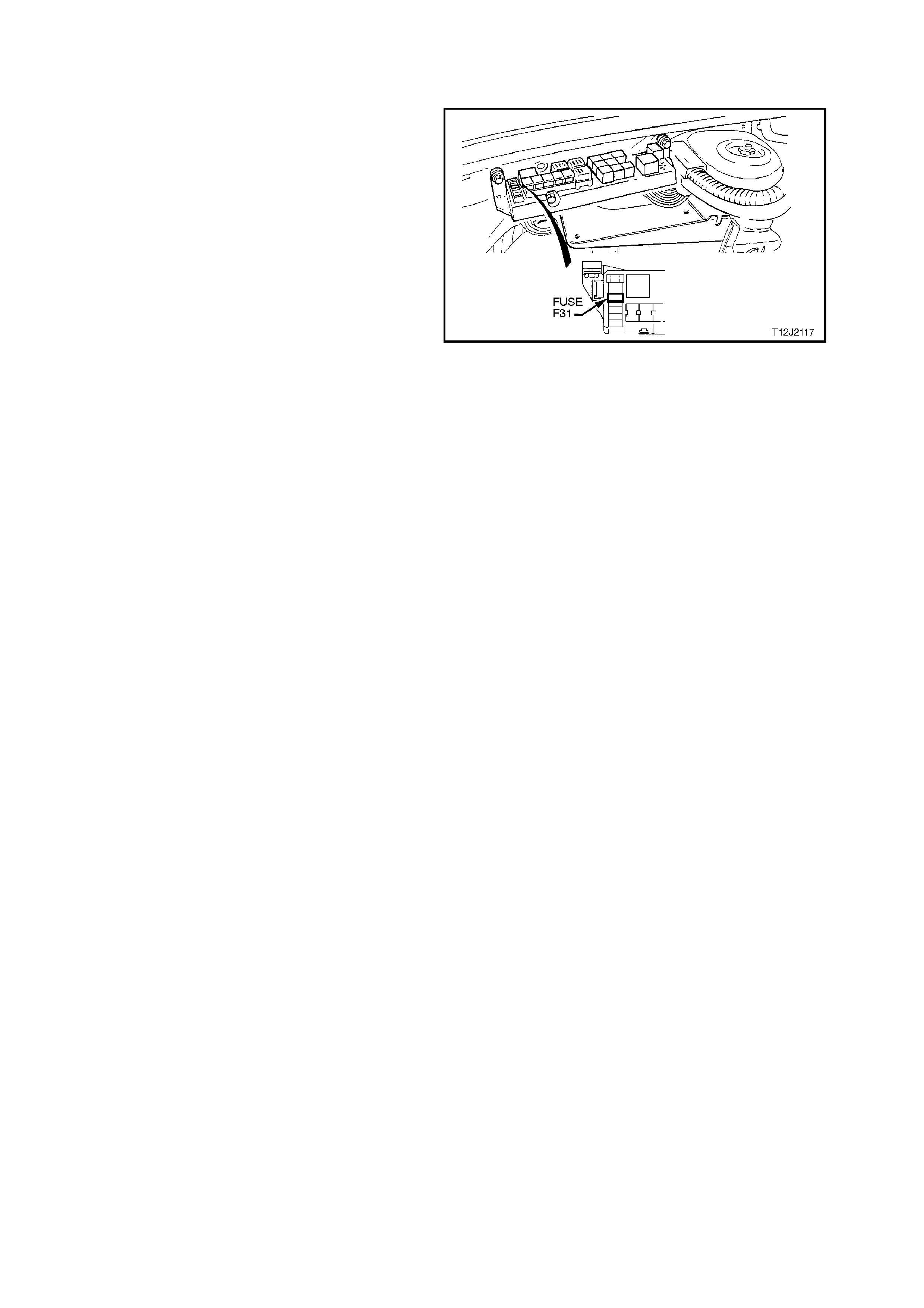
1.14 REAR LAMP FAILURE WARNING SYSTEM
GENERAL INFORMATION
This system monitors the tail, stop and license
plate lamps fo r bulb failures, as well as the integrity
of the fuses feeding these systems. The system
does not sense trailer lights and the system
integrity will not be aff ected if they are connected to
the vehicle.
The system is capable of detecting a single bulb
failure with the following circuit loads:
1. Tail lamps:
4 X 5 Watt = 20 Watt
2. Stop lamps:
2 X 21 + 1 X 18 Watt = 60 Watt
3. License plate lamps:
2 X 5 Watt = 10 Watt
NOTE:
Power ratings are at 12 Volts.
A rear lamp bulb or system failure warning to the
driver is conveyed via a warning light in the
instrument cluster with the following indications:
1. Steady illumination of the warning light with
tail/headlamps turned on indicates a rear tail
lamp failure is evident.
2. Steady illumination of warning light when the
brake pedal is depressed indicates a rear stop
lamp failure is evident.
The system only operates whilst the ignition is on
and any failure is cleared when ignition is switched
off.
A warning light test of 1.2 seconds is performed
whenever the ignition is switched on.
Figure 12J-2-85

NOTE:
If the battery is disconnected during any service
operation, a bulb relearn procedure has to be
carried out, refer to the following procedure.
Additionally, the ABS or ABS/ETC s ystem s must be
functional for the rear lamp failure to operate.
NOTE:
The circuit diagrams shown in this General
Description Section are to aid in interpreting the
operation of the c ircuit and therefor e, only the main
connectors and wiring colours are shown. For
com plete circuits details, r efer to either the r elevant
diagnostic section or Section 12P WIRING
DIAGRAMS.
REAR LAMP FAILURE WARNING SYSTEM BULB
RELEARN PROCEDURE
This procedure must be carried out if the battery
has been disconnected.
Ensure battery is fully charged and functional
before carrying out the following procedure:
1. Ensure all rear light bulbs are working.
Replace/repair any faulty bulbs/wiring.
2. Tur n ignition OFF, parking lam ps O FF and st op
lamps OFF.
3. Remove and reinstall fuse F31 from engine
compartment relay housing, to reset BCM.
4. Start engine and allow to idle.
5. Switch parking lamps ON.
6. Wait 5 seconds.
7. Press brake pedal and hold.
8. Wait 5 seconds.
9. Switch parking lamps OFF.
Wait 5 seconds.
10. Bulb relearn is now complete, turn engine OFF
and release brake pedal.
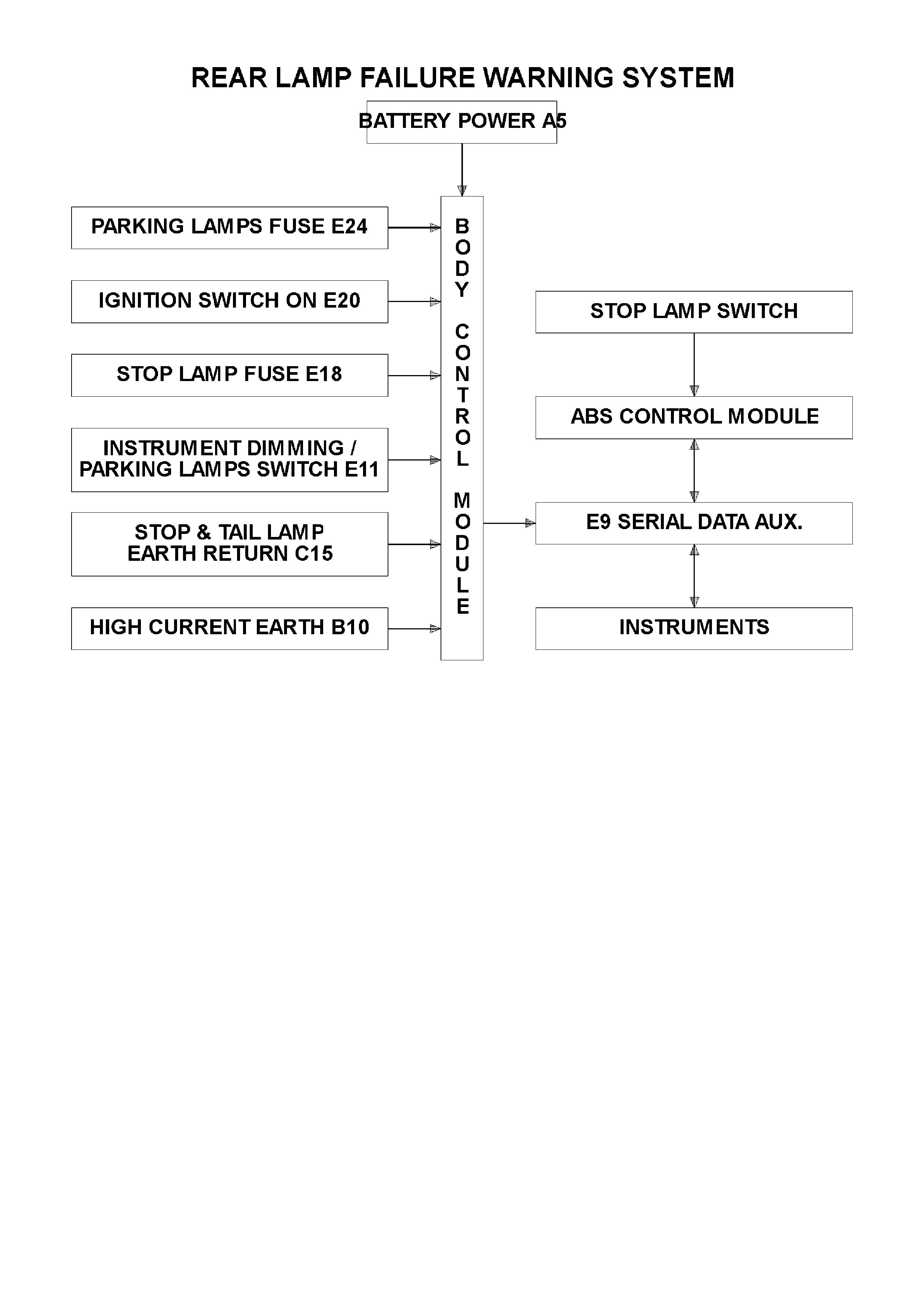
SYSTEM OVERVIEW
CIRCUIT OPERATION
(Refer to Fig. 12J-2-88)
The BCM monitors the stop and tail and licence plate lamps earth circuit current flow. The earth circuit for the stop
and tail lamps is through the BCM from terminal C15 circuit 1251 (Brown/White wire) to B10 circuit 151
(Black/Green wire).
Rear Lamp Failure Warning Lamp
When the ignition switch is turned to the IGN position, battery voltage is applied to the instrument cluster module,
the module will then turn the rear lamp failure warning light on for approximately 1.5 seconds. In the event of a stop,
tail or licence plate lamp failure, the BCM will send a serial data signal via the serial data bus to the instrument
cluster module which will turn the rear lamp failure light on.
Parking Lamp Fuse Monitor Input Signal
(Refer to Fig. 12J-2-86)
Battery voltage is applied to BCM terminal E24 from fuse F4, circuit 840 (Orange/White wire) and from circuit 2
(Red wire). If battery voltage is not available at E24 when the ignition switch is in the IGN position, the BCM
determines that the parking lamp fuse (or circuit) has failed and will illuminate the warning light via the serial data
bus.
Parking La mp Switch Input Signal
(Refer to Fig. 12J-2-86)
When the parking lamps are turned on, the instrument dimming series resistors are connected to earth via the
parking lamp switch contacts, BCM terminal E28 and an internal BCM transistor switched to ground. The voltage at
terminal E11 of the BCM is approximately 2.5 volts w hich is seen by the BCM as the parking lamps on input signal.
With the parking lamps on, the BCM will check the current flowing from terminals C15 to B10. If the current flow
does not match the learnt current flow (refer relearn procedure) the BCM will turn the warning light on, via the
auxiliary serial data bus.
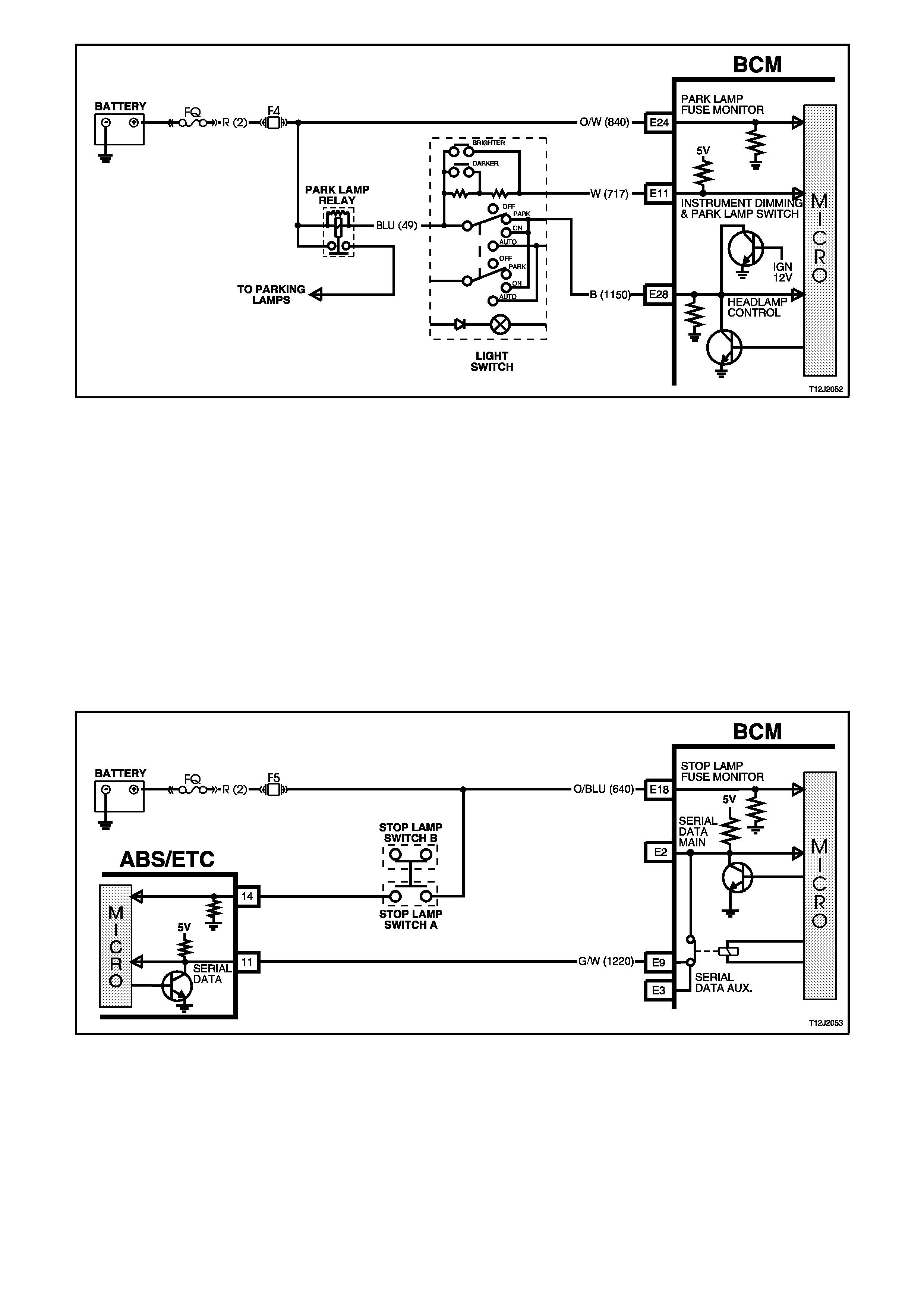
Figure 12J-2-86
Stop Lamp Fuse Monitor Input Signal
(Refer to Fig. 12J-2-87)
Battery voltage is applied to BCM terminal E18 from fuse F5, circuit 640 (Orange/Blue wire) and from circuit 2 (Red
wire). If battery voltage is not available at E18 when the ignition switch is in the IGN position, the BCM determines
that the stop lamp fuse (or circuit) has failed and will illuminate the warning lamp, via the serial data bus.
Stop Lamp Switch Input Signal
(Refer to Fig. 12J-2-87)
When the brake pedal is depressed the stop lamp switch contacts close and battery voltage is applied to the ABS
module from fuse F5 circuit 640 (Orange/Blue wire), the stop lamp switch contacts, circuit 20 (Blue/Red wire). This
action causes the ABS module to send a signal in the form of serial data to the BCM via the auxiliary serial data
bus. This serial data is interpreted by the BCM as the stop lamp switch input signal.
With the stop lamps on, the BCM will check the current flowing from terminals C15 to B10. If the current flow does
not match the learnt current flow (refer REAR LAMP FAILURE WARNING SYSTEM BULB RELEARN
PROCEDURE), the BCM will illuminate the warning lamp, via the auxiliary serial data bus.
Figure 12J-2-87
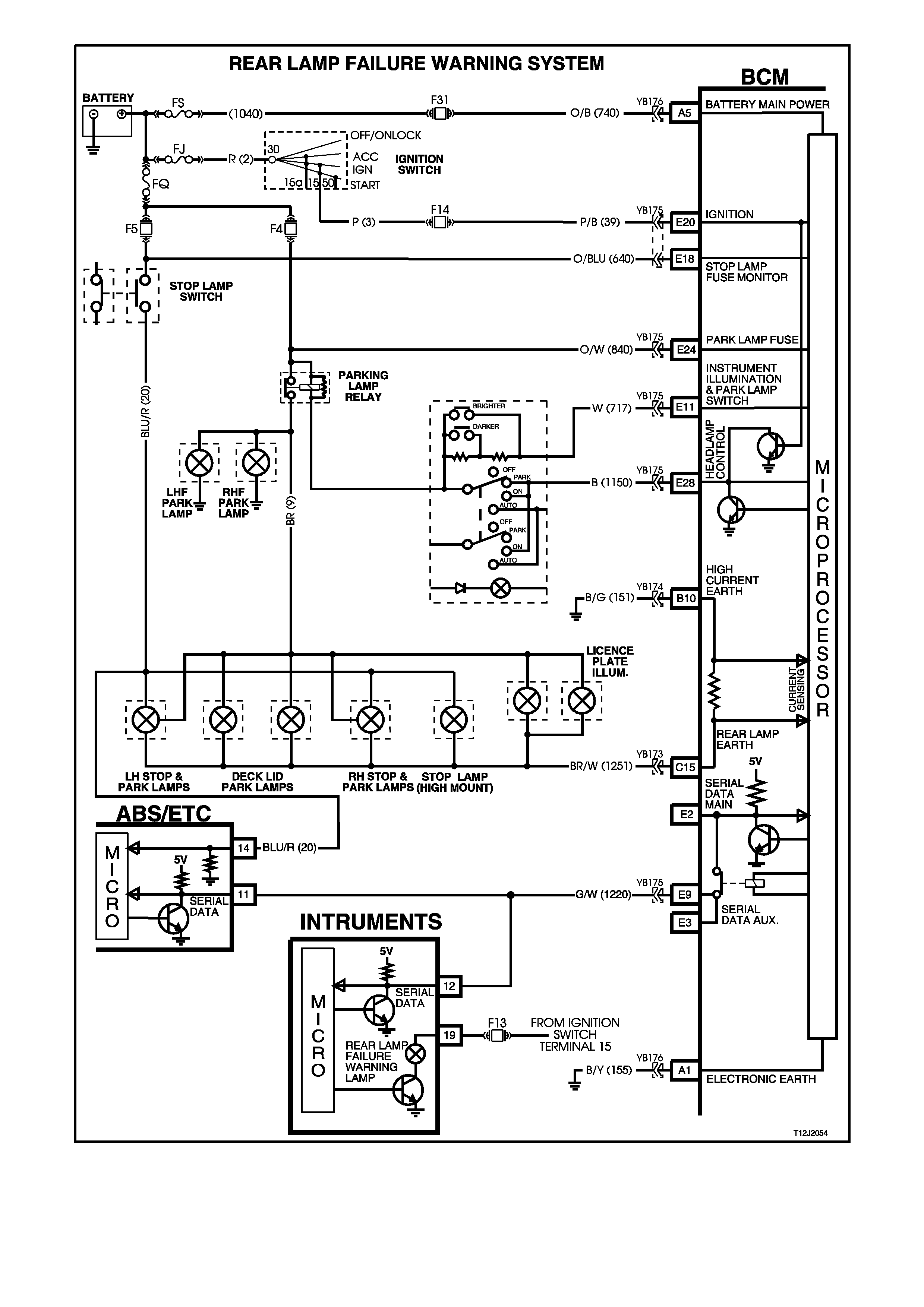
Figure 12J-2-88
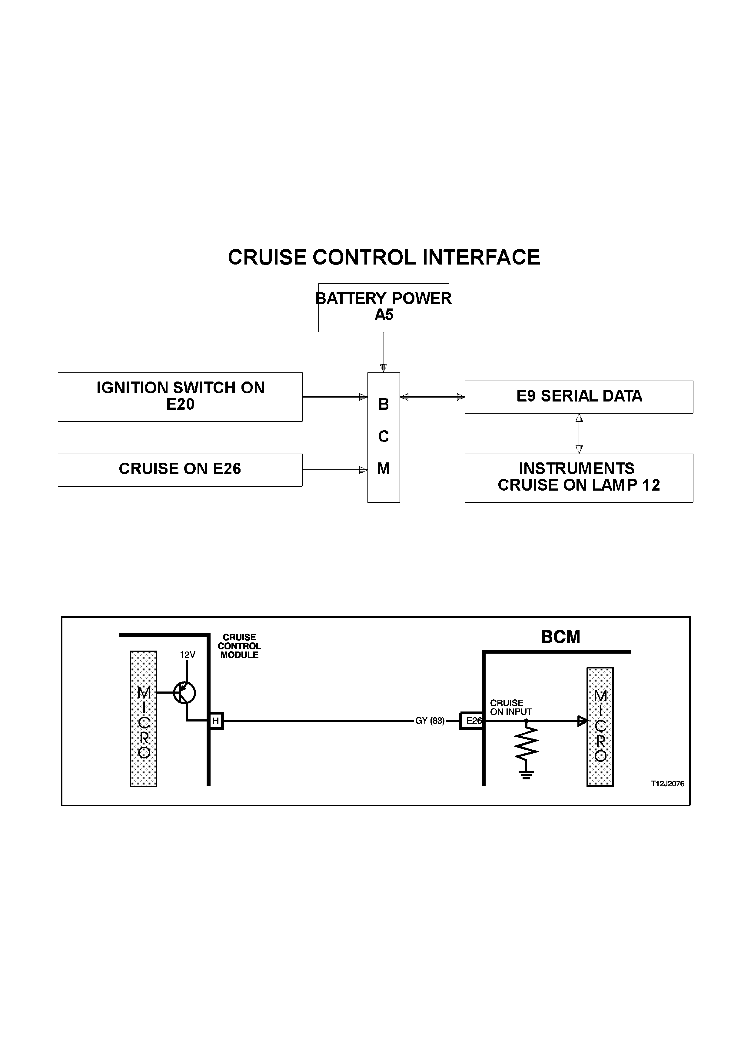
1.15 CRUIS E CONTROL INTERFACE
GENERAL INFORMATION
The cruise control module uses an input on the BCM to send a serial data message to the instruments.
When the cruise control module is powered up via the cruise control ON/OFF switch the cruise control module
activates an input of the BCM. The BCM sees this line as active and sends a serial data message to the instrument
cluster to turn it’s CRUISE light on.
NOTE:
The circuit diagrams shown in this General Description Section are to aid in interpreting the operation of the circuit
and therefore, only the main connectors and wiring colours are shown. For complete circuits details, refer to either
the relevant diagnostic section or Section 12P WIRING DIAGRAMS.
SYSTEM OVERVIEW
CIRCUIT OPERATION
(Refer to Figs. 12J-2-89 and 12J-2-90)
When the cruise control is turned on, the cruise control module activates its cruise ‘on’ output to the BCM. The BCM
input E26, circuit 83 (Grey wire) rises from less than 0.2 volt to approximately battery voltage. When this happens,
the BCM senses this as a cruise on signal and communicates with the instruments, via serial data bus (Aux) to turn
the CRUISE lamp on.
Figure 12J-2-89
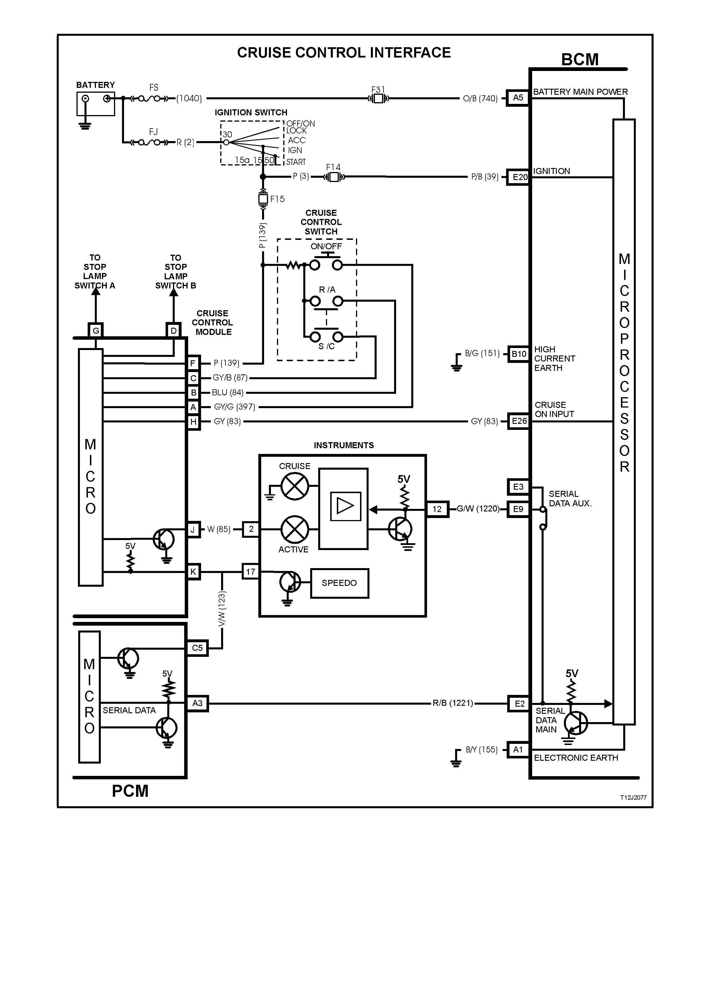
Figure 12J-2-90

1.16 PRIORITY KEY SYSTEM
GENERAL INFORMATION
The BCM provides the ability to remember two sets of system operating parameters. These operating parameters
are recalled when a specific remote key is used. When a priority one remote coded key is used, the BCM will recall
the operating parameters related to the priority one key. When a priority two key is used, the BCM will recall the
operating parameters related to the priority two key.
The operating parameters recalled are for the following functions:
• Time delay for automatic headlamps off.
• Antenna height memory.
• Instrument dimmer level.
These operating parameters are recalled when the UNLOCK button on the remote key is pressed or when the
ignition is turned to the ACC position, all operating parameters are maintained on a last used basis.
The BCM also communicates to other modules via the serial data bus, identifying which priority mode (priority one
or priority two) each module should be in.
The serial data bus priority information will be used by the following modules:
• Trip computer, mode and overspeed setting.
• Electronic Climate Control, all settings.
• Power / Economy switch position.
In addition the BCM also includes a priority output line.
The priority output line sets the radio’s priority mode. When this output is low, the radio settings are set for priority
one. When this output is high, the radio settings are set for priority two.
When a new remote key is programmed, it is assigned as the priority one key. All remaining remote keys become
priority two keys. Any remote key can be assigned as the priority one key using TECH 2, all other keys will then
become priority two keys.
NOTE:
The circuit diagrams shown in this General Description Section are to aid in interpreting the operation of the circuit
and therefore, only the main connectors and wiring colours are shown. For complete circuits details, refer to either
the relevant diagnostic section or Section 12P WIRING DIAGRAMS.
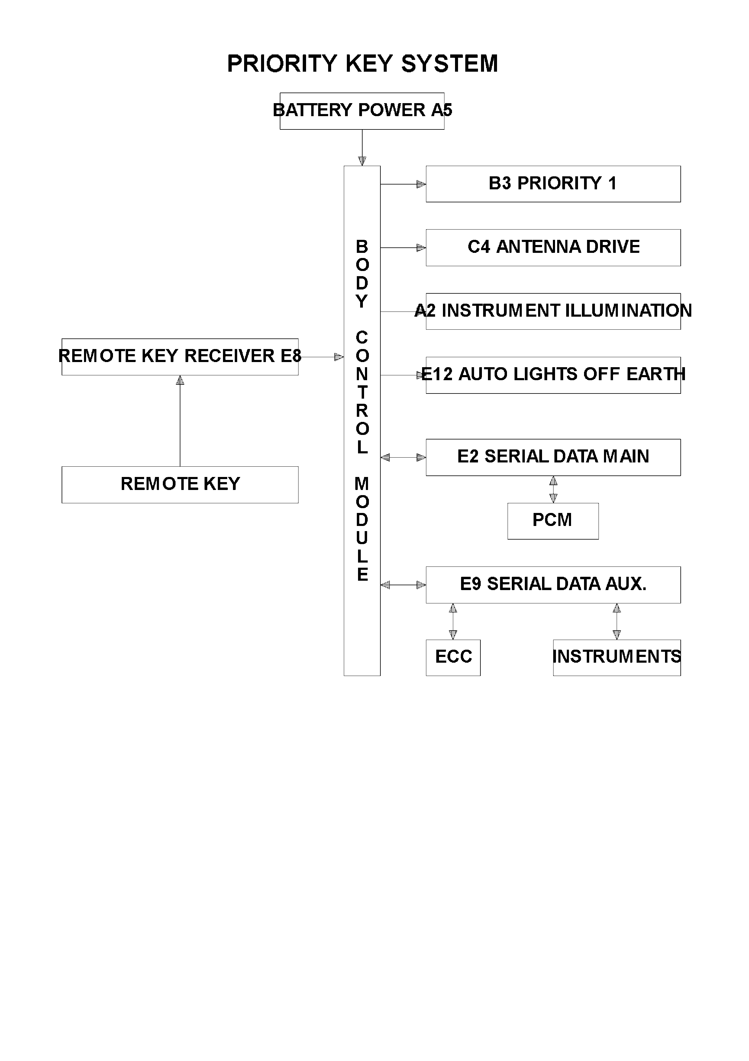
SYSTEM OVERVIEW

CIRCUIT OPERATION
(Refer to Figs. 12J-2-91 and 12J-2-92)
When the UNLOCK button on the remote key is activated or the ignition is switched on, the BCM will send serial
data via the serial data interface auxiliary bus to the trip computer, ECC module and PCM. Depending on which
remote key was activated (priority one or priority two), the BCM will identify via this serial data, which mode each
module should be in.
Figure 12J-2-91
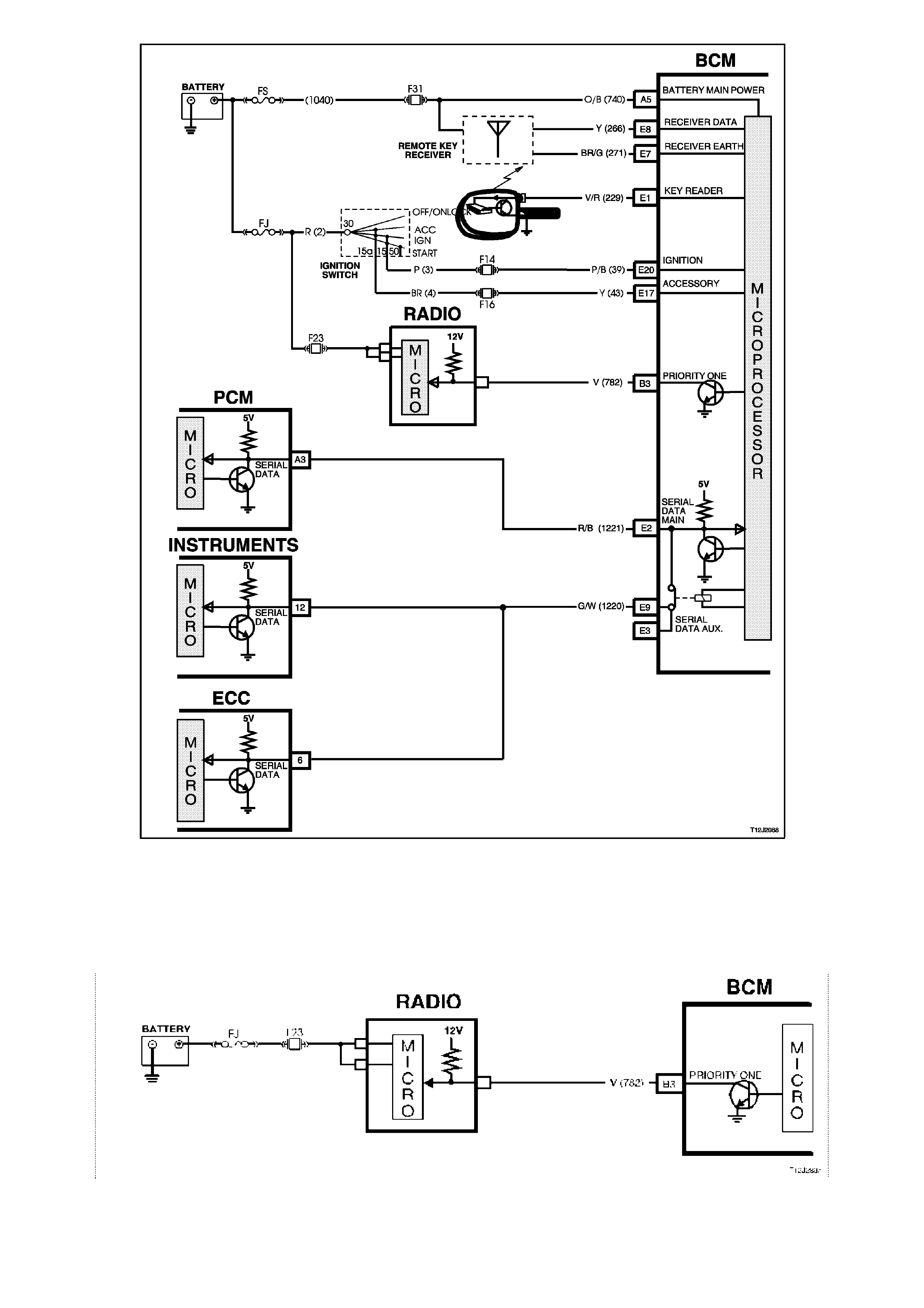
Figure 12J-2-92
Priority Key Mode
(Refer to Fig. 12J-2-93)
The priority one output line sets the radio’s priority mode. When the voltage on this output is pulled low, the radio
settings are set for priority one. When the voltage on this output is pulled high, the radio settings are set for priority
two.
Figure 12J-2-93
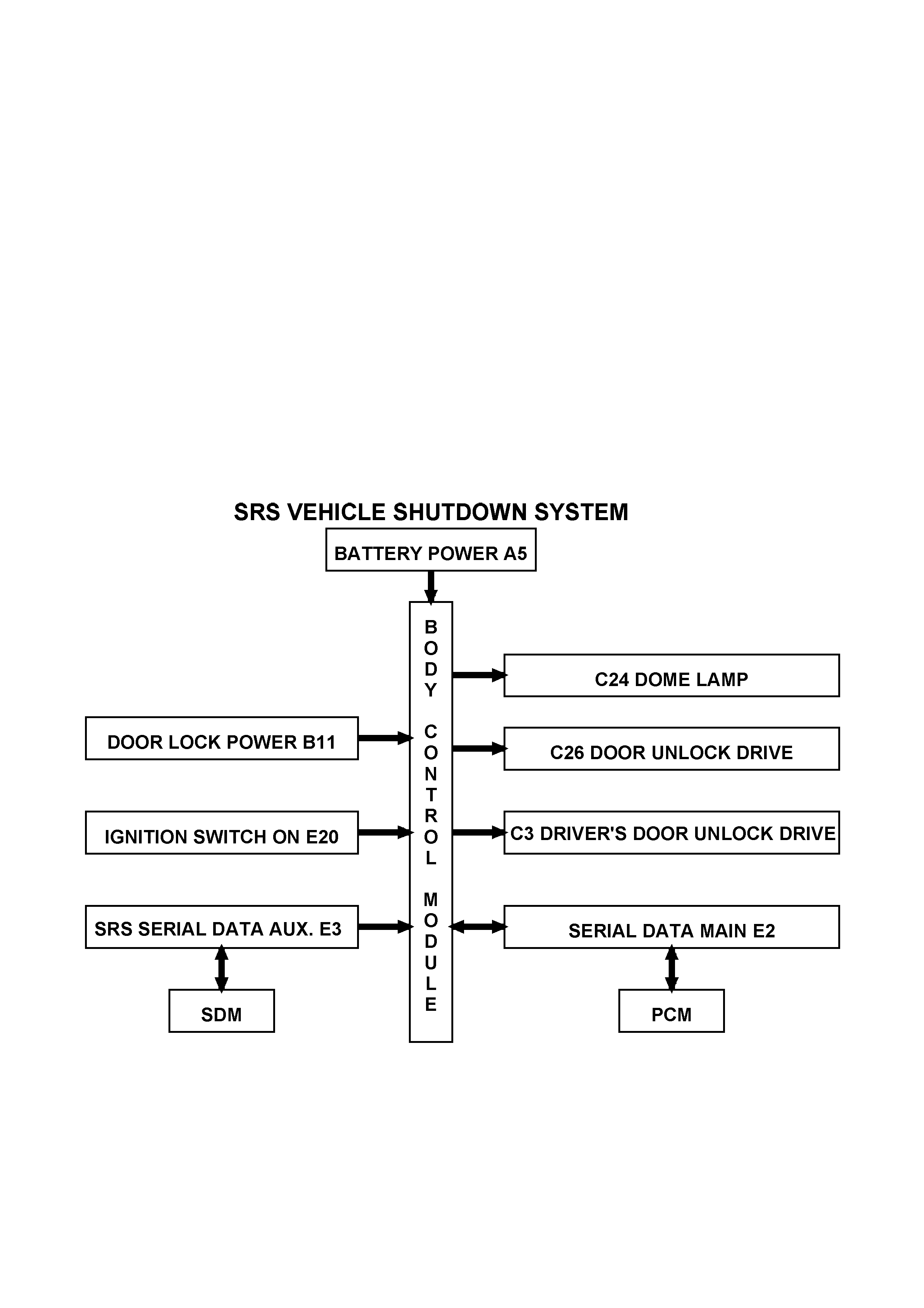
1.17 SRS DEPLOYMENT VEHICLE SHUTDOWN
GENERAL INFORMATION
In the event of SRS (Supplemental Restraint System) deployment, the Sensing Diagnostic Modules (SDM) will send
serial data via the auxiliary serial data bus to advise various vehicle systems to take appropriate shutdown action.
The BCM will monitor this serial data (via the auxiliary serial data bus), and perform the following actions once the
appropriate data is identified and the vehicle speed is zero km/h for longer than 10 seconds:
• Turn the dome lamp on continuously
• Unlock all doors
The dome lamps will be switched off when the ignition switch is cycled from off to on or when the BCM is reset (ie.
the battery is disconnected).
NOTE 1:
The PCM (Powertrain Control Module) also monitors this serial data (via the auxiliary serial data bus), and performs
a vehicle shut down once the appropriate data is identified and the vehicle speed is zero km/h for longer than 10
seconds.
NOTE 2:
The circuit diagrams shown in this General Description Section are to aid in interpreting the operation of the circuit
and therefore, only the main connectors and wiring colours are shown. For complete circuits details, refer to either
the relevant diagnostic section or Section 12P WIRING DIAGRAMS.
SYSTEM OVERVIEW
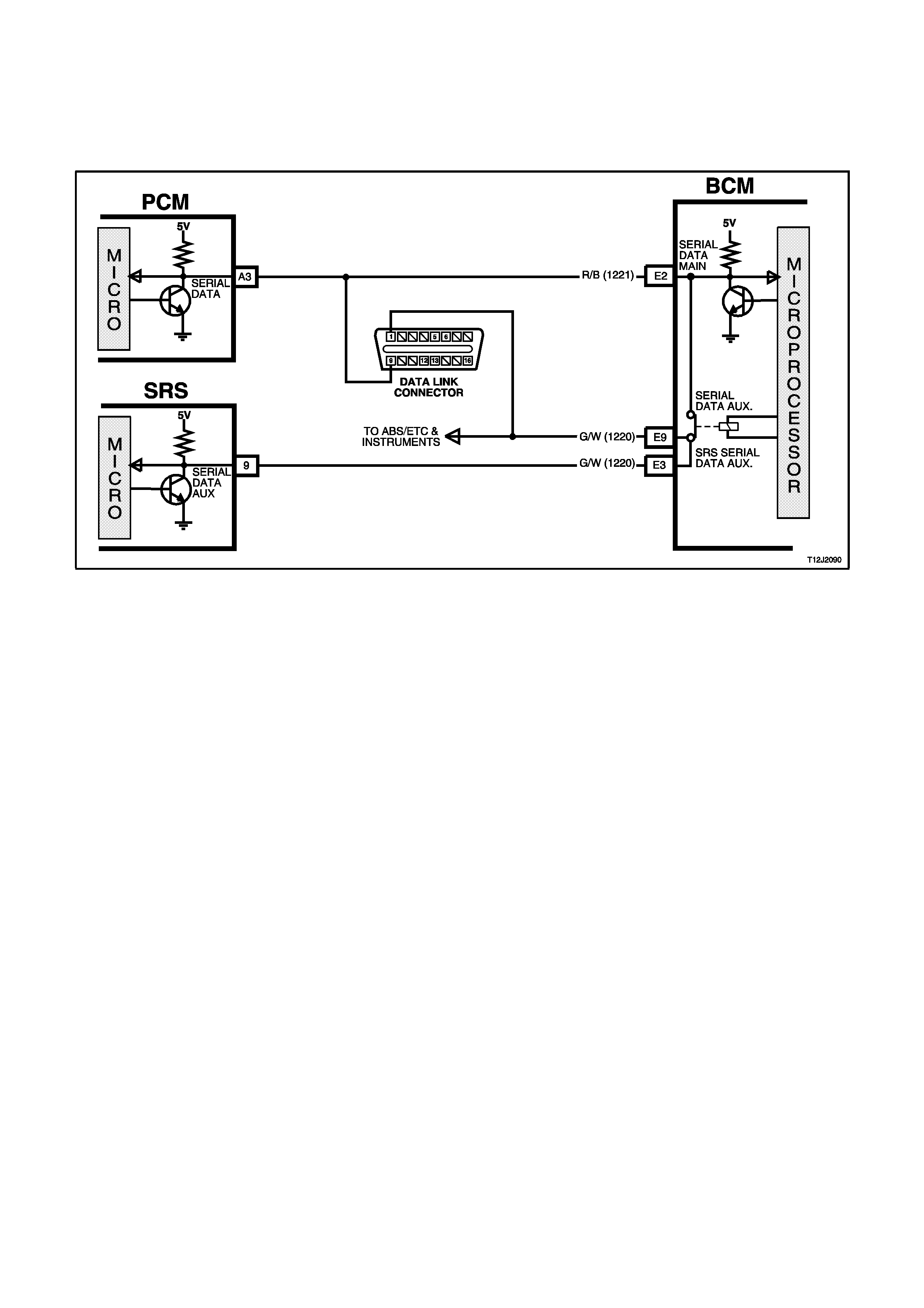
CIRCUIT OPERATION
SRS Serial Data Bus (Serial Data)
(Refer to Fig. 12J-2-94)
In the event of SRS deployment, the SDM will send serial data via the serial data bus to the BCM, where a physical
link to the serial data auxiliary bus enables the SDM to advise various systems, via serial data, to take appropriate
action. This includes the BCM.
Figure 12J-2-94

2. SERVICE OPERATIONS
2.1 SAFETY AND PRECAUTIONARY MEASURES
1. Whenever performing any electric welding on a vehicle, disconnect wiring harness connectors from the BCM.
2. Never subject the BCM to temperatures above 85°C, (eg. paint oven), always remove BCM first if this
temperature is to be exceeded.
3. Ensure that all wiring harness connectors are connected solidly and that battery terminals are thoroughly clean.
4. When charging the battery, disconnect it from the vehicle's electrical system.
5. Never connect or disconnect the BCM wiring harness connectors when the ignition is switched ON.
6. Never disconnect the battery from the electrical system while the engine is running.
7. Reconnecting battery cable terminals to the battery will cause a reset.
Following a BCM reset, the rear light failure warning system relearn procedure, headlight automatic off delay
period and power antenna height memory setting must be carried out. Refer to the various procedures in this
Section.
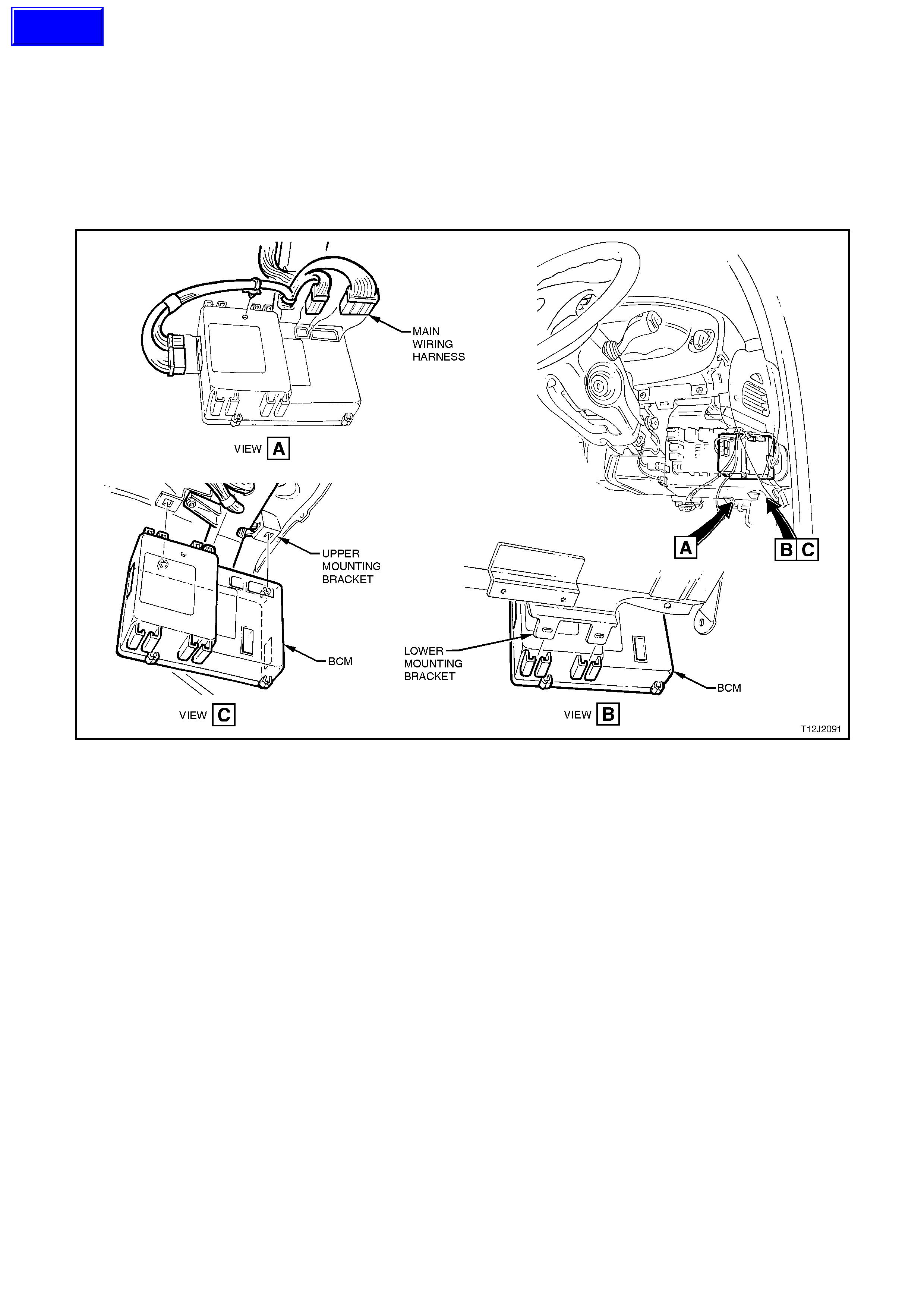
2.2 HIGH SERIES BCM
REMOVE
1. Disconnect battery earth lead.
2. Remove right hand instrument panel lower trim assembly, refer to Section 1A3 INSTRUMENT PANEL.
3. Remove BCM from mounting brackets by pushing the bottom of the BCM towards the front of the vehicle until
the BCM disengages from the lower mounting bracket. Then by grasping the BCM, gently pull the BCM down
(remembering that the wiring harnesses are still connected), disengaging the BCM from the upper mounting
bracket. Refer to Fig. 12J-2-95.
Figure 12J-2-95
4. Depress tangs on wiring harness connectors on BCM and pull connectors from module.
NOTE:
If carrying out BCM diagnostic checks as described in the appropriate diagnostic test in this Section, leave all wiring
harness connectors installed in the BCM. If required, reconnect battery earth lead.
REINSTALL
Installation of the BCM is the reverse of the removal procedure, ensuring that the BCM is firmly installed in the BCM
mounting brackets.
NOTE:
If the BCM is replaced, the new BCM must be security linked to the PCM as per the following procedure. If this
procedure is not performed, the vehicle will not crank.
BCM LINK TO PCM
Connect TECH 2 to DLC and select the following:
Diagnostics / (V) 1997 / VT Commodore / Body / Body Control Module / Security / BCM Link to PCM and follow
TECH instructions.
For additional information regarding TECH 2 and TECH 2 test modes (including this linking procedure), refer to
3. TECH 2 DIAGNOSIS FOR BCM in this Section.
Techline

2.3 REMOTE CODE D KEY
PERFORMANCE CHECK
During a performance check of the remote coded
key, be sure to check all keys that are assigned to
the vehicle.
Two checks have been inc or porated in the TECH 2
software. These two checks include a REMOTE
KEY SIGNAL test that is used for checking the RF
output and if the signal is recognised by the BCM.
The second check is the REMOTE KEY I.D. which
is used to check if a remote coded key has been
assigned to the BCM.
For more details on these TECH 2 checks, refer to
3.3 TECH 2 TEST MODES AND DISPLAYS FOR
BCM DIAGNOSIS in this Section.
Check that the remote coded key can successfully
lock and unlock the doors at a distance of
approximately four meters from the vehicle.
If one remote coded key fails to make the system
respond, the problem is in that particular remote
coded key.
After replacing a key due to a suspected
discharged or faulty battery, f irst insert the k ey into
the ignition and cycle from O FF - ON - O FF . T h is is
necessary as there may be a need to synchronise
the rolling codes between the remote coded key
and the BCM. If the codes are not synchronised,
the remote control of the central door locking
system will not work.
REPLACE
NOTE 1:
Before replacing a suspected faulty remote control
key, ensure the following steps are carried out.
• Carry out the Remote Control Function Fault
Diagnosis as per the diagnostic chart in this
Section.
• If the key still presents a problem, ensure that
the key pin is making contact with the remote
coded key reader assembly. Insert the key into
the ignition and cycle from OFF - ON - OFF.
This is necessary as there may be a need to
synchronise the rolling codes between the
remote control key and the BCM. The key
cycled in the ignition must be done with the thef t
deterrent alert indicator LED flashing (passively
armed). The remote coded key would only be
considered f aulty if it will not allow the engine to
start when used in the ignition switch with the
theft deterrent system armed (LED flashing),
refer 4.4 THEFT DETERRENT in this Section.
Avoid testing the remote coded key with the system
disarmed (LED not flashing), in this situation, a
faulty remote coded key will allow the engine to
start, being in the 30 second time frame before
the system passively arms itself.
Techline
Techline

NOTE 2:
Replacement of a remote coded key will
necessitate programming with the BCM to accept
the new remote coded key serial output data. The
program ming of the rem ote coded key can only be
performed by an authorised Holden service outlet
or authorised locksmiths when provided with the
correct security information .
1. Loosen and rem ove the two remote coded k ey
housing screws.
2. Grab hold of k ey tip and pull it from the rem ote
coded key housing.
3. W hile holding new remote coded key housing,
loosen and remove the remote coded key
housing screws. Assemble the key into the
new remote coded key housing.
4. Insert the two remote coded key housing
screws and start threads by hand. Tighten
screws to the correct torque specification (to
complete earth circuit within key).
REMOTE CODED KEY
HOUSING SCREW
TORQUE SPECIFICATION 0.7 - 0.9 Nm
5. Carry out programming of remote coded key.
6. Insert remote coded key into the ignition and
cycle from OFF - ON - OFF to synchronise
codes.
7. Carry out check of theft deterrent and central
door locking systems using the remote coded
key.
NOTE 3:
The rem ote control key is a sealed for lif e unit (non
removable battery), therefore the housing cannot
be separated. The battery life expectancy is
approximately five to ten years.
NOTE 4:
To protect the electric door lock actuators from
overheating if/when the door locks are operated
repeatedly in succession, the BCM is programmed
to prevent door lock operation for a short period
(maximum 20 seconds). This is normal operation
and not to be confused as a defective remote
coded key or BCM.
NOTE 5:
When a new remote key is programmed, it is
assigned sole use of one of the “priority one” key
memories. All remaining remote keys become
“priority two” keys. Old remote keys can be re-
assigned as the “priority one” through TECH 2.
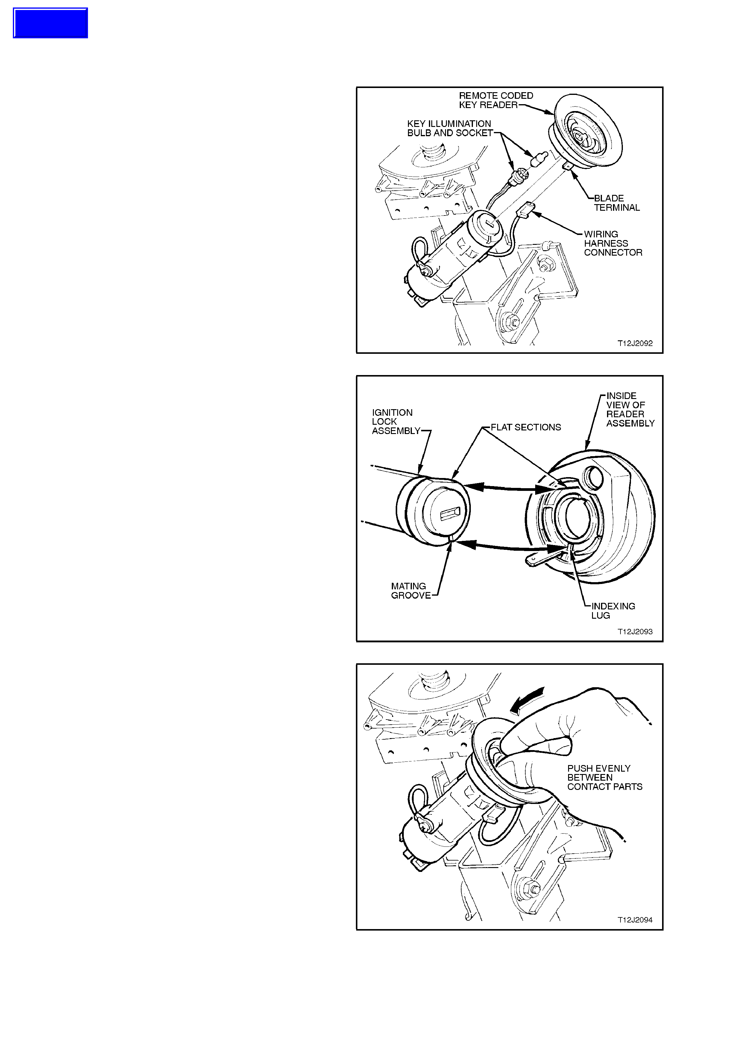
2.4 RE MOTE CODED KEY READER
REMOVE
1. Release steering column height adjuster lever
and completely lower steering column, lock
lever in this position.
CAUTION:
Disable the SRS (Air Bag), refer to Section 12M
SUPPPLEMENTAL RESTRAINT SYSTEM.
2. Remove the ignition key from the ignition switch.
3. Remove steering column upper and lower
covers, refer to Section 9A STEERING.
4. Disconnect wiring harness connector and
ignition lock illumination socket and bulb from
key reader assembly, then carefully pull key
reader assembly from ignition lock assembly
housing.
Figure 12J-2-96
REINSTALL
Installation of the remote key reader assembly is
the reverse of the removal procedure, noting the
following points:
1. Align the flat sections of the remote key reader
assembly with the ignition lock assembly, refer
to Fig. 12J-2-97
Figure 12J-2-97
2. Gently press key reader assembly onto ignition
lock by pushing on the centre of the key reader,
in between the two contact strips, until key seats
onto the ignition lock, refer to Fig. 12J-2-98.
3. Ensure that the wiring harness connector and
ignition lock illumination bulb and socket are
securely fitted onto key reader assembly.
4. On completion of reinstallation, insert the
ignition key and check the key reader assembly
operation.
NOTE:
Enable the SRS (Air Bag), refer to Section 12M
SUPPLEMENTAL RESTRAINT SYSTEM.
Figure 12J-2-98
Techline

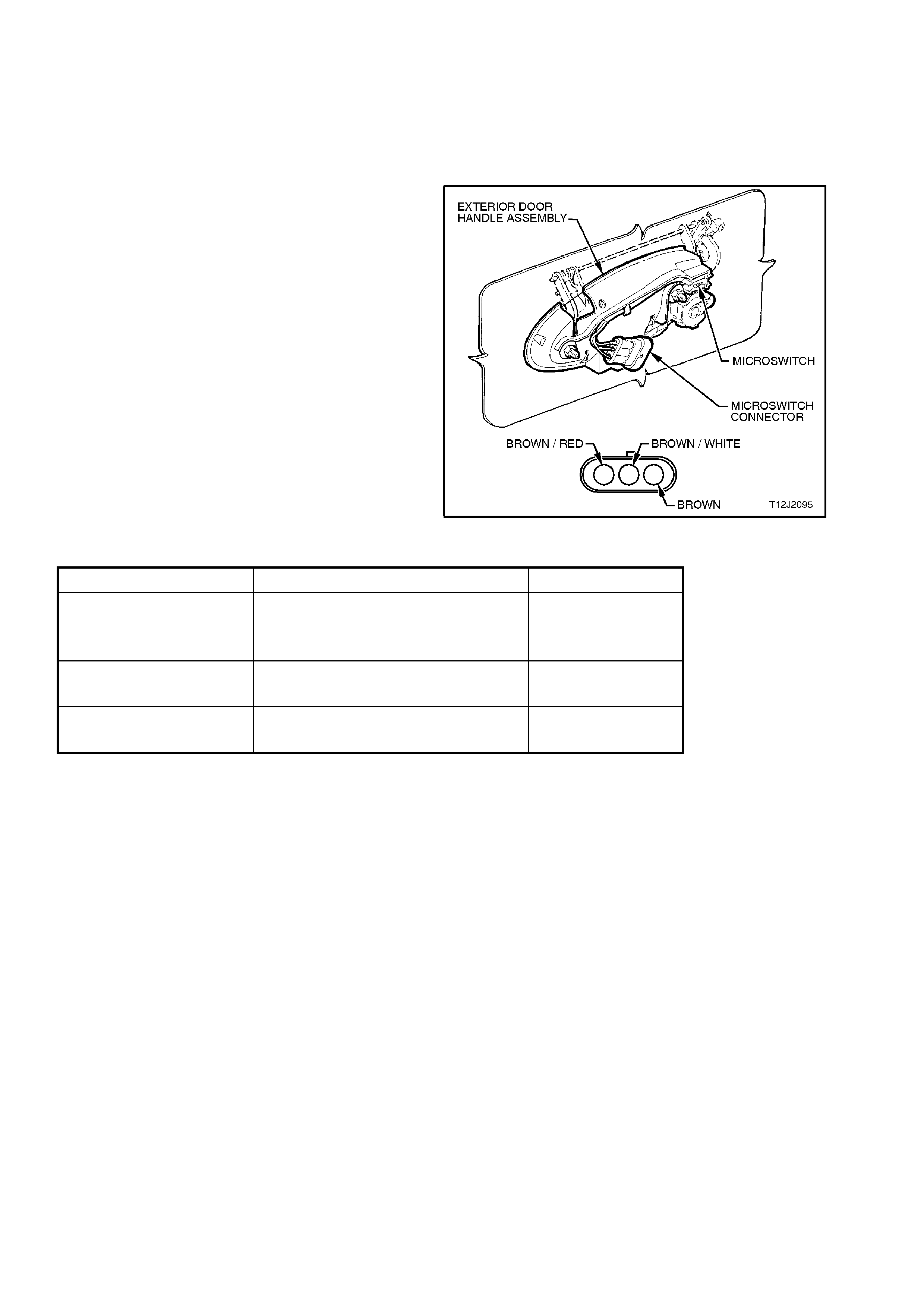
2.6 DOOR LOCK MICROSW ITCHES
On VT Series Models, there are two door lock microswitches that are fitted to the drivers door exterior handle. The
microswitches are part of the driver’s door exterior handle assembly and are not serviced separately. Therefore, to
remove the exterior door handle and microswitch assembly, refer to Section 1A5 FRONT AND REAR DOOR
ASSEMBLIES.
TEST
1. Remove door inner trim panel, refer to
Section 1A5 FRONT AND REAR DOOR
ASSEMBLIES.
2. Using an ohmmeter connected to the
various terminals, check operation of the
microswitches as per the following table:
NOTE:
If any of the readings are not as specif ied, replace
the exterior door handle and micr oswitch as s embly,
refer to Section 1A5 FRONT AND REAR DOOR
ASSEMBLIES.
Figure 12J-2-99
LOCK POSITION TERMINALS (WIRE COLOURS) VALUE
Rest position Brown/Red to Brown/White
Brown/Red to Brown
Brown/White to Brown
Open circuit
Open circuit
Open circuit
Held in lock position Brown/Red to Brown
Brown/Red to Brown/White Continuity
Open circuit
Held in unlock position Brown/Red to Brown/White
Brown/Red to Brown Continuity
Open circuit


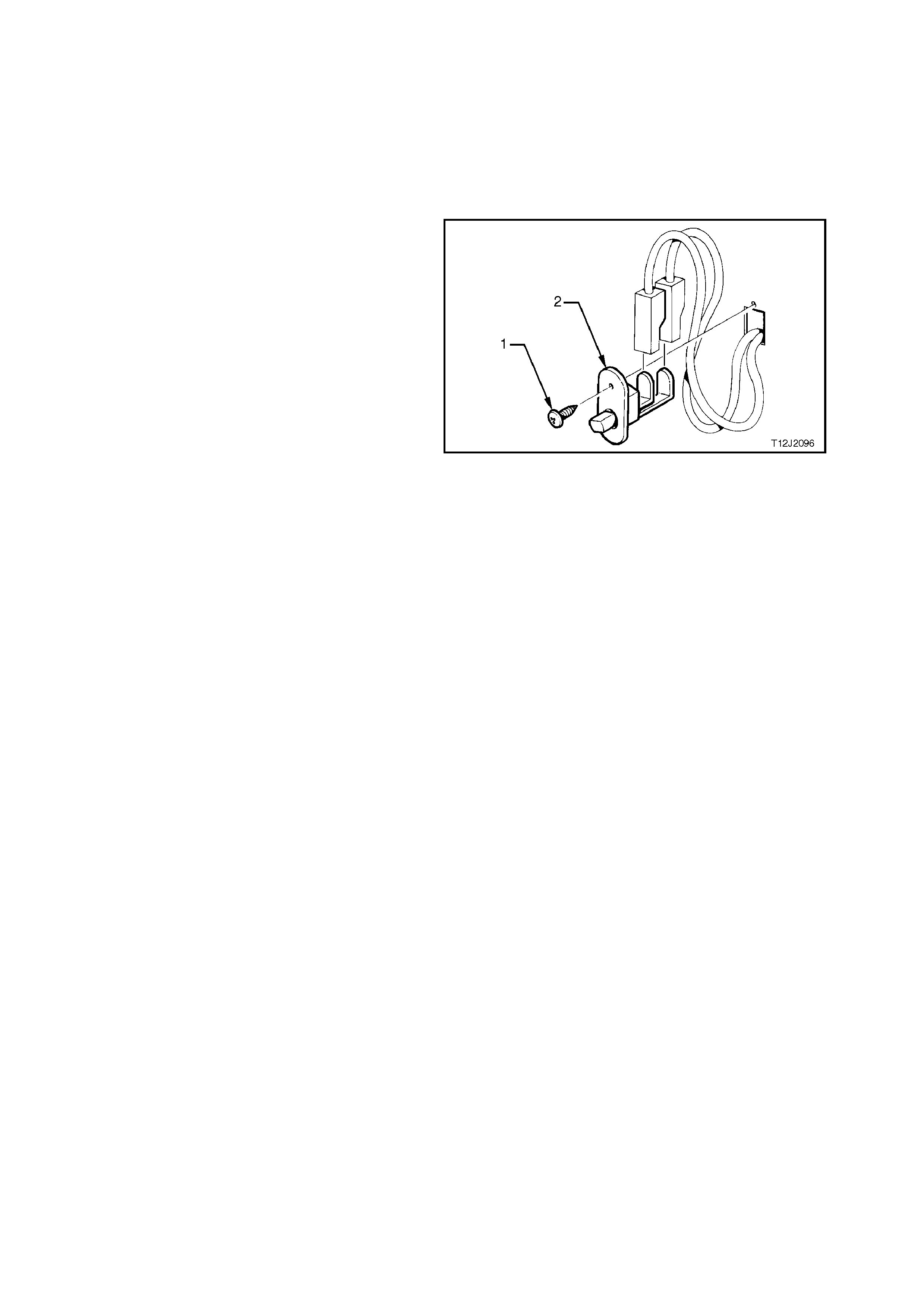
2.9 DOOR JAMB SWITCHES
The door j am b switches are installed in each of the
door hinge pillars. W hen the door of the vehicle is
closed, a plunger in the switch is depressed,
creating an open circuit in the earth circuit. When
the door is opened, the plunger is released and
completes the circuit to earth.
REMOVE
1. Remove door jamb switch retaining screw (1).
2. Remove door jamb switch (2) from door hinge
pillar, taking care not to damage the door jamb
switch wiring harness.
3. Disconnect wiring harness connectors.
Figure 12J-2-100
REINSTALL
Installation of the door j amb switches is the rever s e
of the removal procedure.

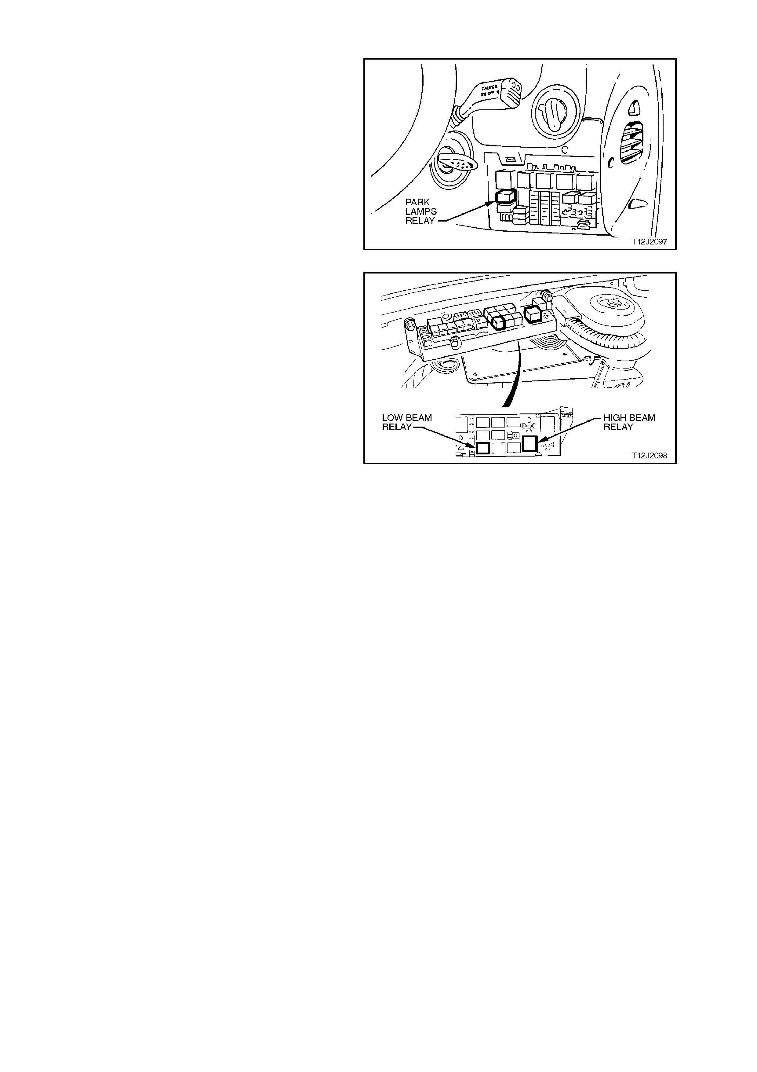
2.11 HEADLAMP AND PARK LAMP RELAYS
Fig. 12J-2-101 shows the location of the park lamp
relay (located inside the vehicle, attached to the
fuse panel).
Access to the relay / fuse panel is by lowering the
instrument panel right hand cover assembly. Refer
to Section 1A3 INSTRUMENT PANEL for the
procedure on how to remove this cover.
Figure 12J-2-101
Fig. 12J-2-102 shows the location of the headlamp
high and low beam relays (located inside the
engine compartment relay housing).
Figure 12J-2-102
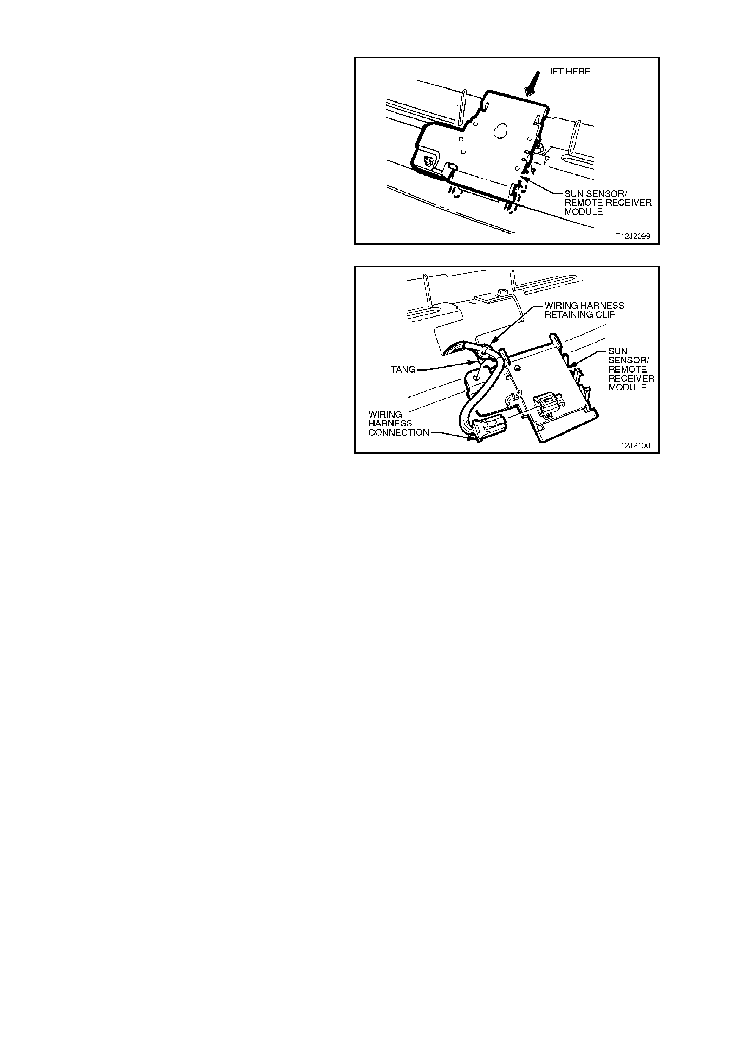
2.12 S UN SENSOR / REMOTE RE CE IVER MODULE
REMOVE
1. Remove LH and RH demist grilles, refer to
Section 1A3 INSTRUMENT PANEL.
2. Gently pry the f ront of the sun sens or / remote
receiver module up and towards rear of
vehicle.
Figure 12J-2-103
3. Disconnect wiring harness connector.
4. Remove wiring harnes s retaining clip fr om sun
sensor / r emote receiver module by squeezing
tangs of clip together and pushing clip through
sun sensor / remote receiver module aperture.
5. Remove sun sensor / remote receiver module.
REINSTALL
Installation of the sun sensor / remote receiver
module is the reverse of the removal procedure.
NOTE:
To program the sensitivity of the twilight sentinel,
refer to 3.3 TECH 2 TEST MODES AND
DISPLAYS FOR BCM DIAGNSOSIS in this
Section.
Figure 12J-2-104
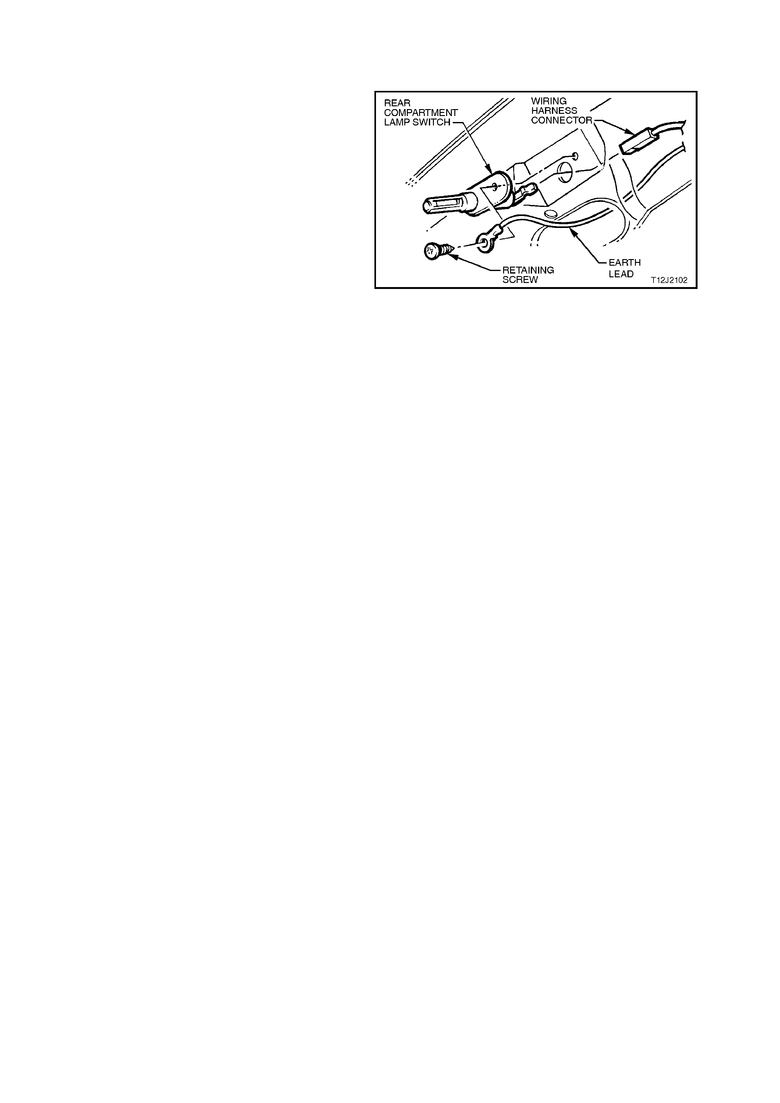
2.13 REAR COMPARTMENT LAMP SWITCH
REMOVE
NOTE:
The rear compartment lamp switch for sedan and
wagon models are the same except for the
location. The switch for sedan models is located in
the deck lid, to the right of the deck lid lock. The
switch for wagon models is located in the tailgate
assem bly, to the left of the tailgate loc k. Fig. 12J- 2-
105 shows the switch for sedan models
1. Remove rear compartment lamp switch
retaining screw.
2. Remove rear compartment lamp switch from
deck lid / tailgate, taking care not to dam age the
switches wiring harness.
3. Disconnect wiring harness and remove switch. Figure 12J-2-105
REINSTALL
Installation of the rear compartment lamp switch is
the reverse of the removal procedure.
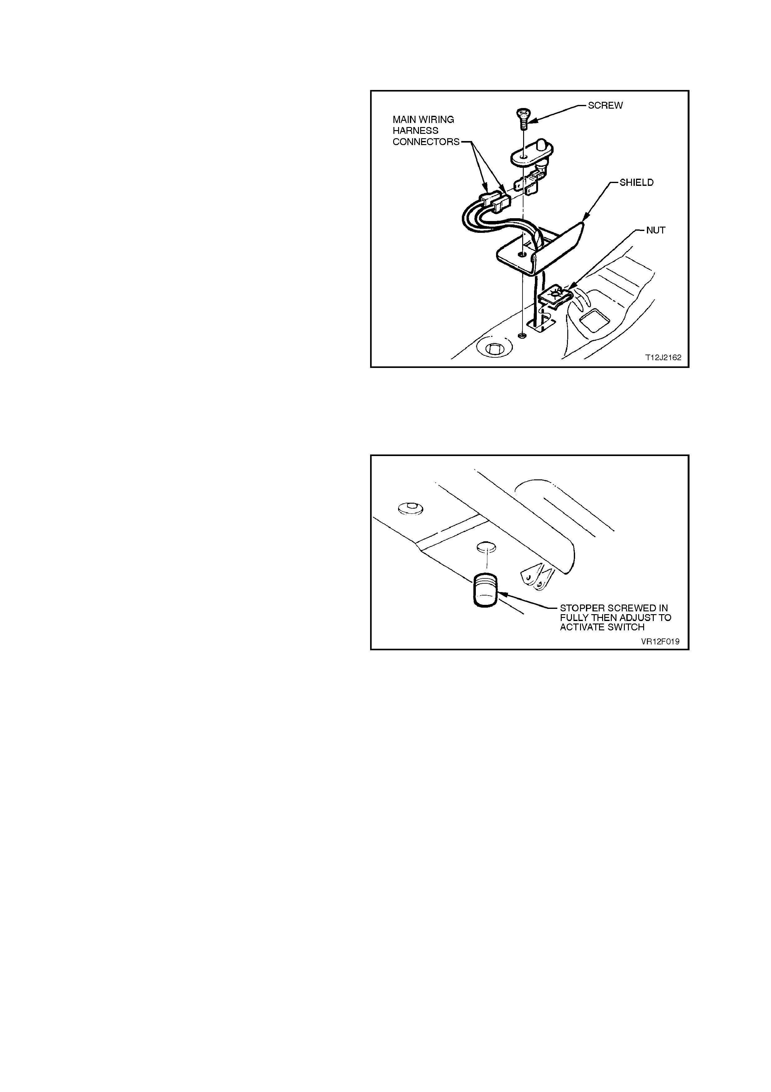
2.14 HOOD SWITCH
REMOVE
1. Remove hood switch retaining screw.
2. Remove hood s witch from support panel, taking
care not to damage the hood switch wiring
harness.
3. Disconnect wiring harness and remove switch.
Figure 12J-2-106
REINSTALL
Installation of the hood switch is the reverse of the
removal procedure.
NOTE:
The hood switch contacts are opened when the
hood is closed. This is accomplished by an
adjustable rubber stopper that is screwed into the
engine hood.
With the engine hood closed, the rubber stopper
must be adjusted so as to depress the switch
plunger.
Figure 12J-2-107
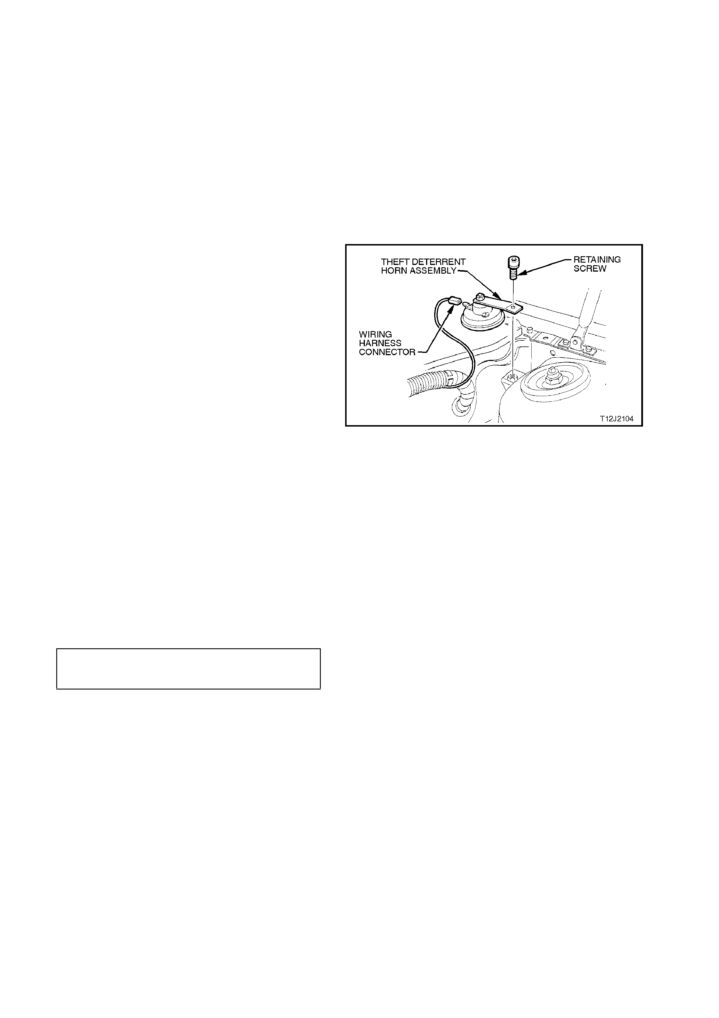
2.15 HORNS
Horn/s for VT Series Models are mounted on the
right hand front wheelhouse panel, behind the f ront
bumper bar assembly. For the Procedure on how
to remove, test and reinstall these horns, refer to
Section 12C INSTRUMENTS,
WIPERS/WASHERS & HORN.
On vehicles with the High Series BCM, an
additional theft deterrent horn is fitted inside the
engine compartment, behind the left hand strut
tower. For the procedure on how to remove and
reinstall this horn, refer to the following:
REMOVE
1. Disconnect theft deterrent horn wiring harness
connector.
2. Remove theft deterrent horn retaining screw
and remove horn assembly.
Figure 12J-2-108
TEST
For the Procedure on how to test the thef t deter rent
horn, refer to Section 12C INSTRUMENTS,
WIPERS/WASHERS & HORN.
REINSTALL
Installation of the theft deterrent hor n is the rever se
of the removal procedure, noting the following:
1. Ensure connector is installed correctly.
2. Ensure theft deterrent horn retaining screw is
tightened to the correct torque specification.
THEFT DETERRENT HORN
RETAINING SCREW 20 - 27 Nm
TORQUE SPECIFICATION
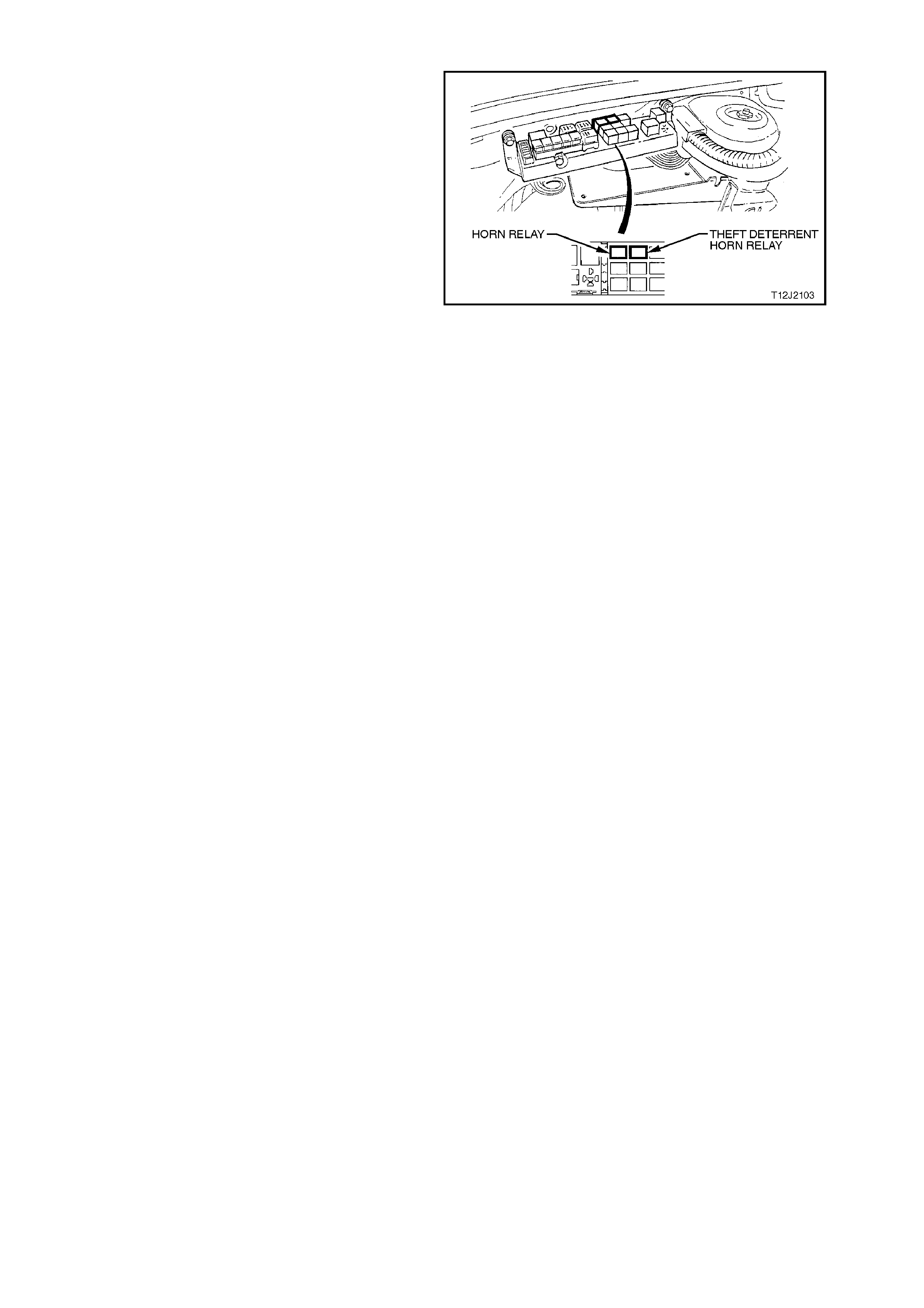
2.16 HORN RELAY
Fig. 12J-2-109 shows the location of the horn
relays (located inside the engine compartment relay
housing).
Figure 12J-2-109


2.18 VEHICLE SPEED SENSOR
MANUAL TRANSMISSION
For vehicle speed sensor removal, testing and reinstallation instructions, refer to Section 12C INSTRUMENTS,
WIPERS/WASHERS & HORN.
AUTOMATIC TRANSMISSION
For vehicle speed sensor removal, testing and reinstallation instructions, refer to Section 6C1 POWERTAIN
MANAGEMENT - V6 or Section 6C2 POWERTAI N MANAGEMENT - V8.

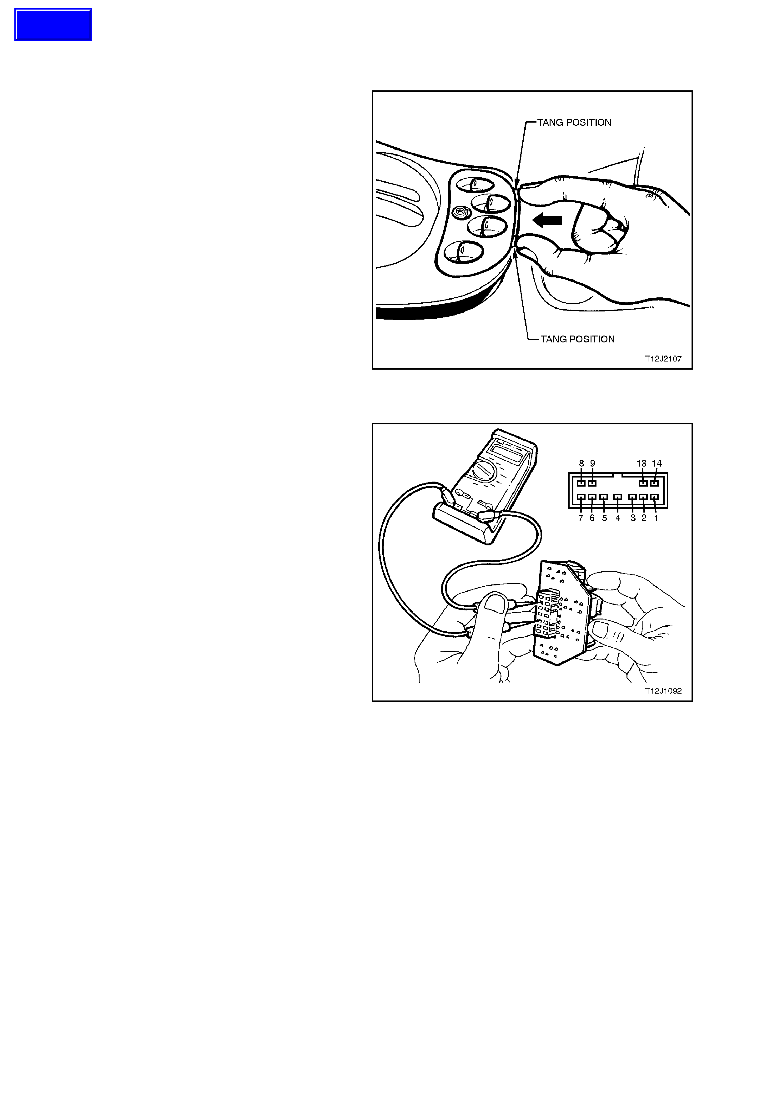
2.20 FRONT AND REAR DOOR POWER WINDOW S WITCH
REMOVE
1. Raise the centre console cap, refer to
Section 1A3 INSTRUMENT PANEL AND
CONSOLE.
2. From the rear of the centre console cap, push
the tangs securing the power window switch and
push the power window switch upward,
releasing it from the console cap.
3. Depress wiring harness retaining tang and
disconnect wiring harness connector, remove
power window switch.
.
Figure 12J-2-110
TEST
NOTE:
Do not allow skin to contact the power window
circuit board when checking for continuity With the
power window switch rem oved, using an ohmm eter
connected to the various terminals, check operation
of the switch as per the following table:
NOTE:
If any of the readings are not as specified, replace
the power window switch assembly.
Figure 12J-2-111
Techline

SWITCH
POSITION TERMINAL
NUMBERS VALUE
RHF Up
Rest
Down
4 and 9
5 and 8
5 and 9
4 and 8
Continuity
Continuity
Continuity
Continuity
LHF Up
Rest
Down
4 and 14
5 and 1
5 and 14
4 and 1
Continuity
Continuity
Continuity
Continuity
RHR Up
Rest
Down
4 and 7
5 and 6
5 and 7
4 and 6
Continuity
Continuity
Continuity
Continuity
LHR Up
Rest
Down
4 and 3
5 and 2
5 and 3
4 and 2
Continuity
Continuity
Continuity
Continuity
OverrideIn
Switch Out 4 and 13
4 and 13 Open circuit
Continuity
REINSTALL
Installation of the f r ont and r ear door power window
switch is the reverse of the removal procedure.
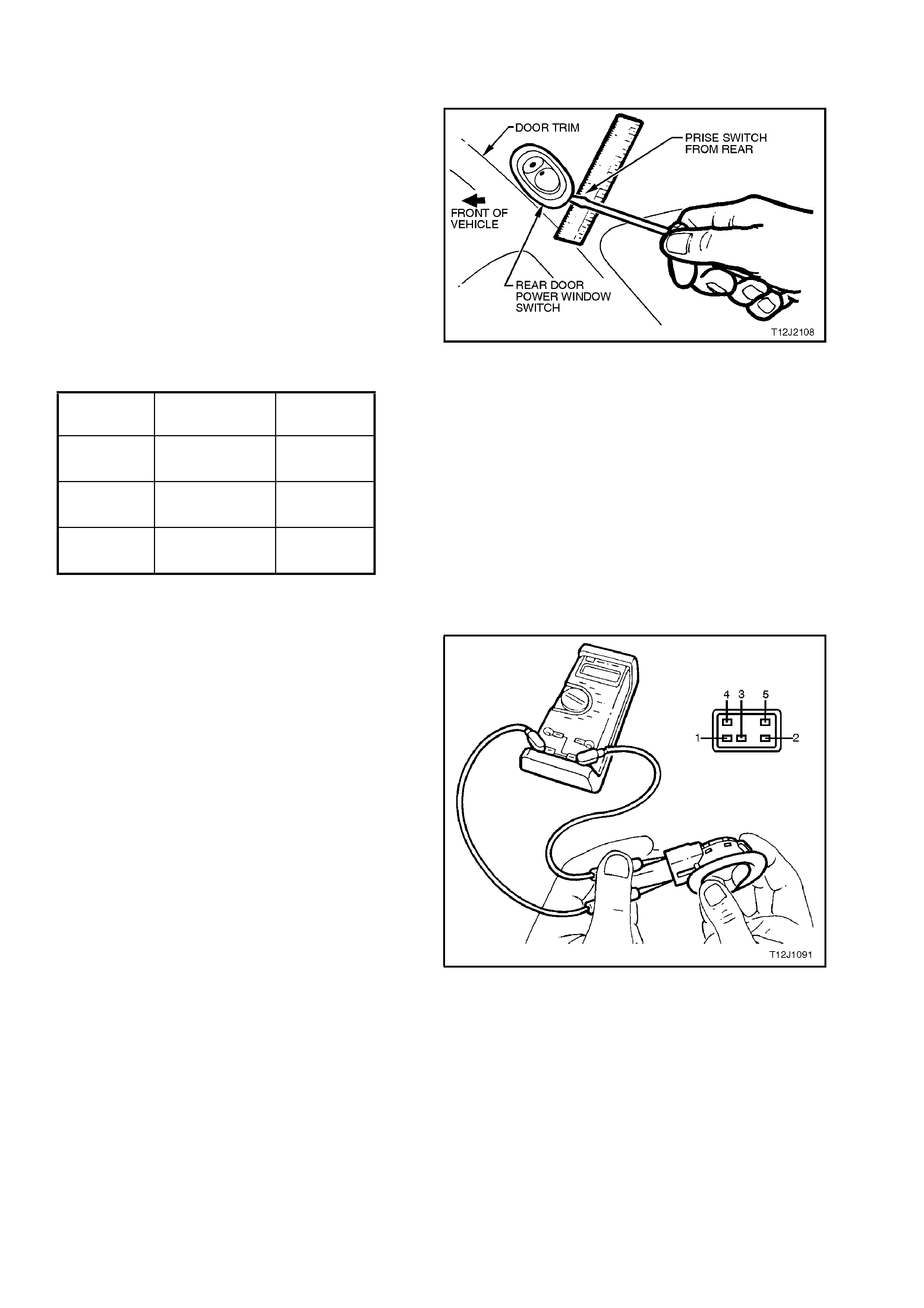
2.21 REAR DOOR POWER WINDOW S WITCHES
REMOVE
1. From the rear of the rear door power window
switch, prise the appropriate switch from the
door trim, taking care not to damage door trim.
2. Lift out rear door power window switch from
door trim until wiring harness connector passes
out through console opening.
3. Depress wiring harness retaining tang and
disconnect wiring harness connector, remove
switch.
Figure 12J-2-112
SWITCH
POSITION TERMINAL
NUMBERS VALUE
Up 1 and 3
2 and 4 Continuity
Continuity
Rest 1 and 3
2 and 5 Continuity
Continuity
Down 1 and 3
2 and 5 Continuity
Continuity
TEST
NOTE:
Do not allow skin to contact the power window
circuit board when checking for continuity.
With the power window switch removed, using an
ohmmeter connected to the various terminals,
check operation of the switch as per the following
table:
NOTE:
If any of the readings are not as specified, replace
the power window sw itch assembly.
Figure 12J-2-113
REINSTALL
Installation of the rear door power window switch is
the reverse of the removal procedure.
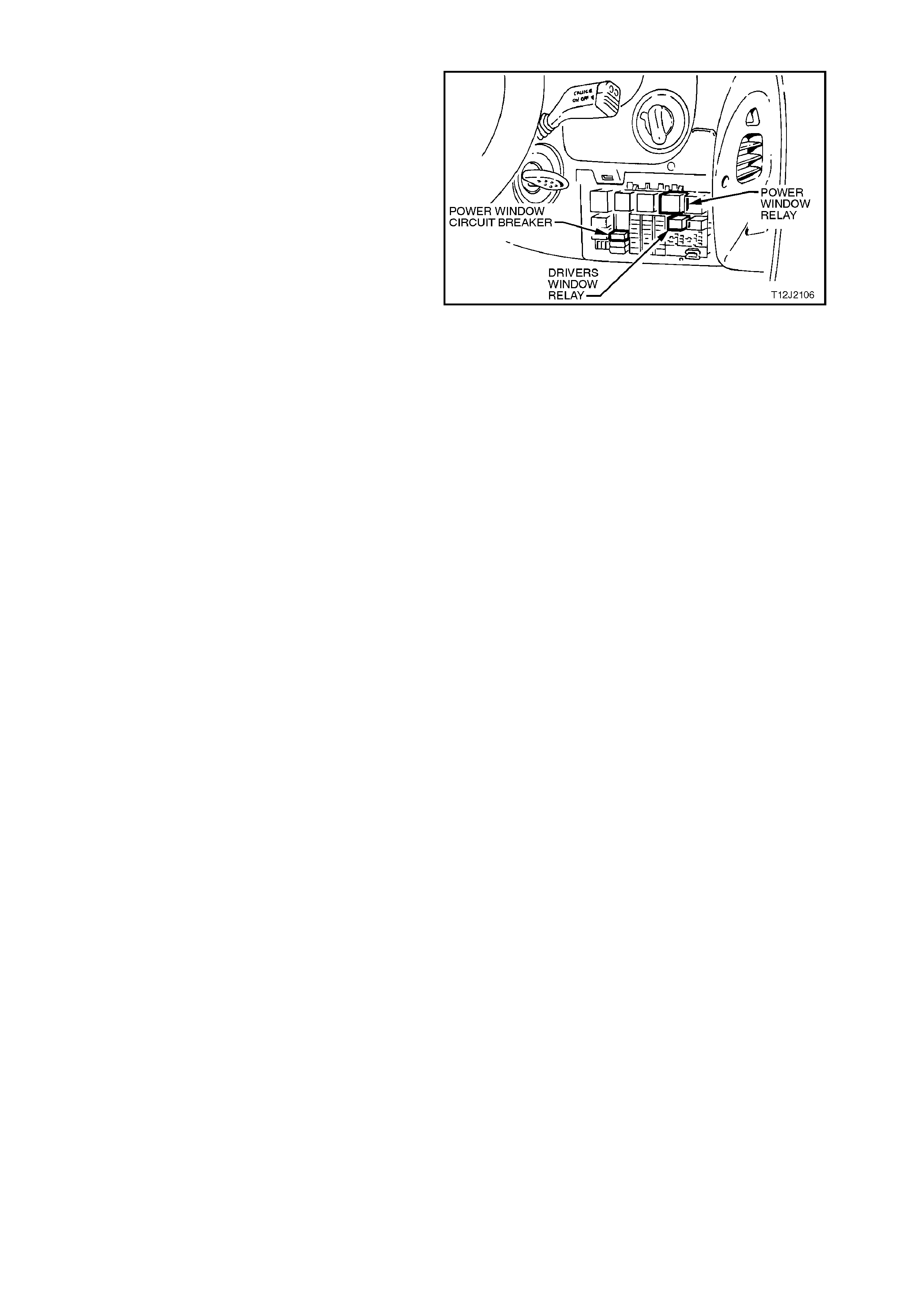
2.22 POWER WINDOW RELAYS AND CIRCUIT BREAKER
Fig. 12J-2-114 shows the location of the power
window relays and circuit breaker (located inside
the vehicle, attached to the fuse panel).
Access to the relay / fuse panel is by lowering the
instrument panel right hand cover assembly. Refer
to Section 1A3 INSTRUMENT PANEL for the
procedure on how to remove this cover.
Figure 12J-2-114
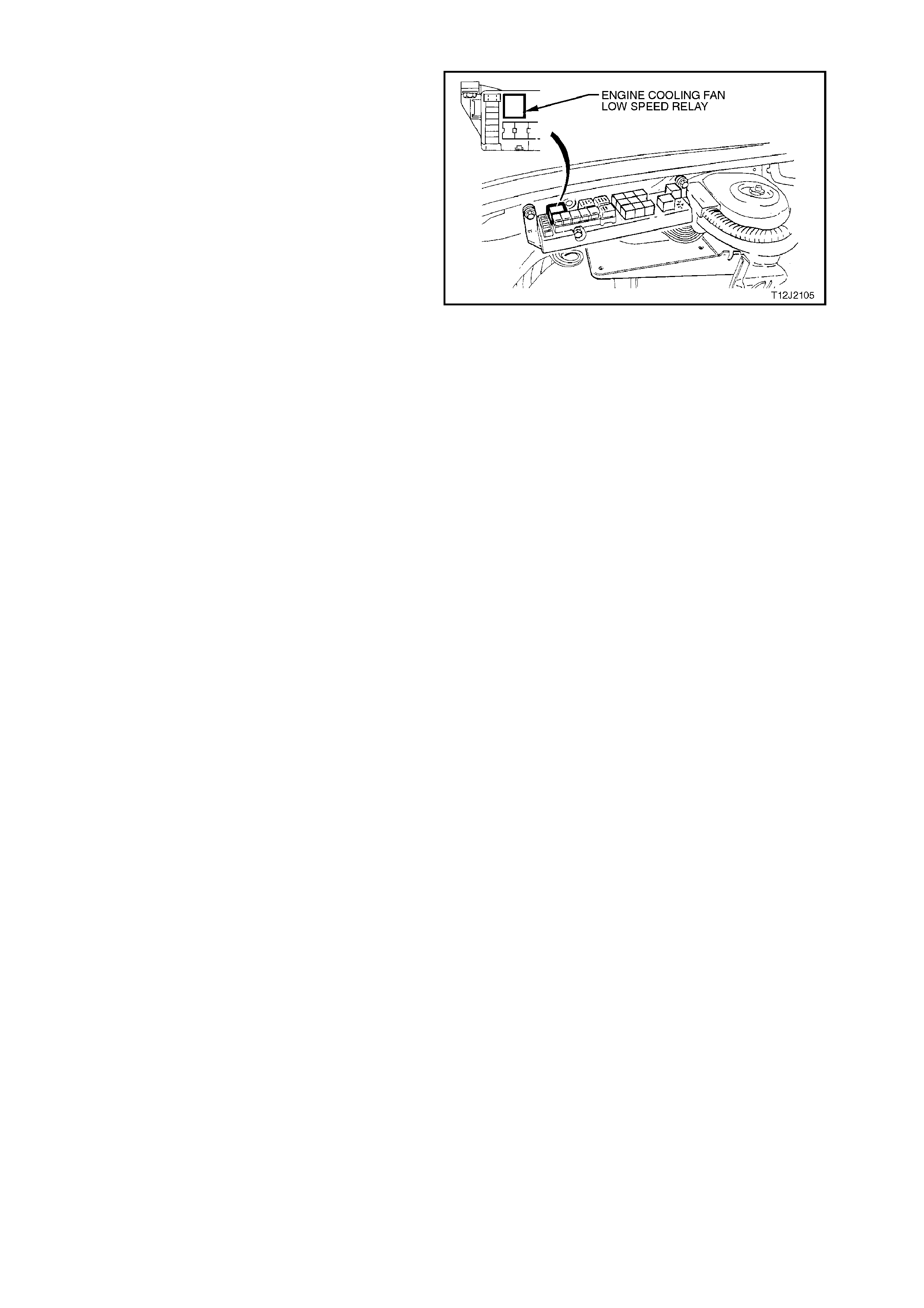
2.23 ENGINE COOLING FAN LOW SPEED RELAY
Fig. 12J-2-115 shows the location of the engine
cooling low speed fan relay (located inside the
engine compartment relay housing).
Figure 12J-2-115


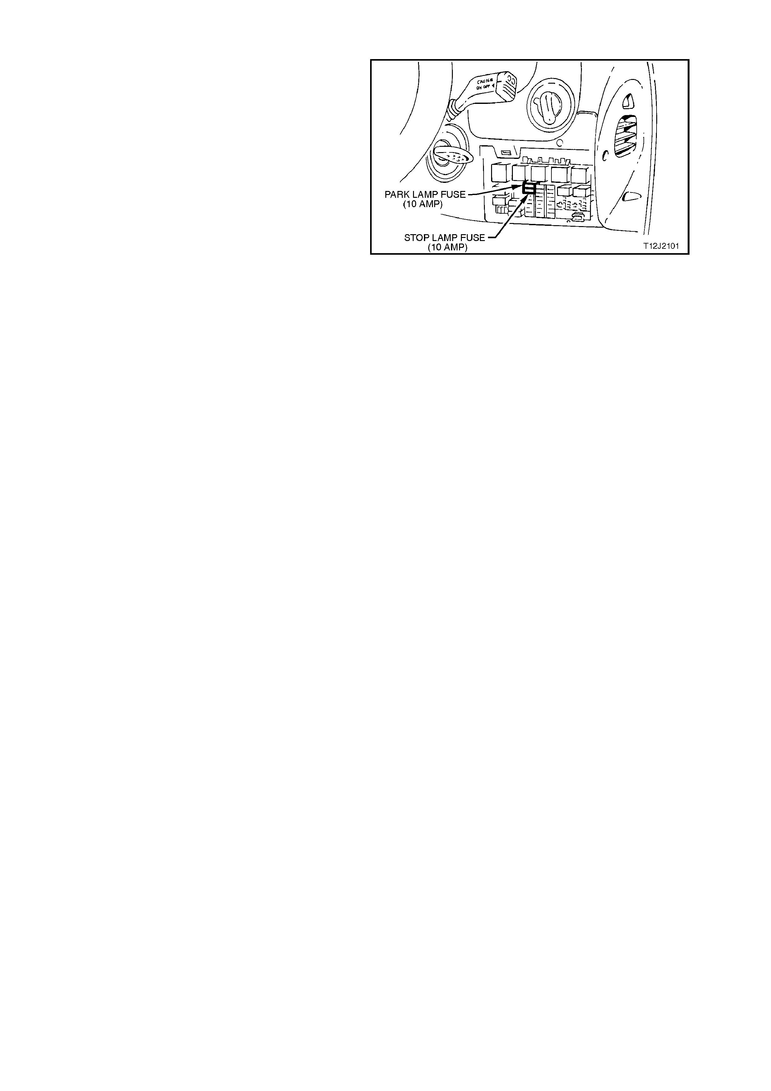
2.29 PARK AND STOP LAMP FUSES
Fig. 12J-2-116 shows the location of the park and
stop lamp fuses (located inside the vehicle,
attached to the fuse panel).
Access to the relay / fuse panel is by lowering the
instrument panel right hand cover assembly. Refer
TO Section 1A3 INSTRUMENT PANEL for the
procedure on how to remove this cover.
Figure 12J-2-116


3. TECH 2 DIAGNOSIS FOR BCM
3.1 BASIC KNOWLEDGE REQUIRED
Before attempting to diagnose the control or assist of the various vehicle electrical systems controlled by the BCM,
you must have a good understanding of electrical system basics and the use of circuit testing tools. Without this
basic knowledge it will be difficult to use the diagnostic procedures detailed in this Section.
Some electrical basics, troubleshooting procedures and hints as well as the use of circuit testing tools are covered
in Section 12P WIRING DIAGRAMS.
Basic Electrical Circuits - You should understand the basic theory of electricity, series and parallel circuits, and
voltage drops across series resistors. You should know the meaning of voltage (volts), current (amps), and
resistance (ohms). You should understand what happens in a circuit with an open or shorted wire (shorted either to
voltage or earth). You should also be able to read and understand a wiring diagram.
Use of Circuit Testing Tools - You should know how to use a jumper lead to test circuits. You should be familiar with
the use of a high input impedance (10 Meg ohm) digital type multimeter such as tool No. J39200 or equivalent and
be able to measure voltage, current, and resistance. You should be familiar with the proper use of the TECH 2
Diagnostic Scan Tool.
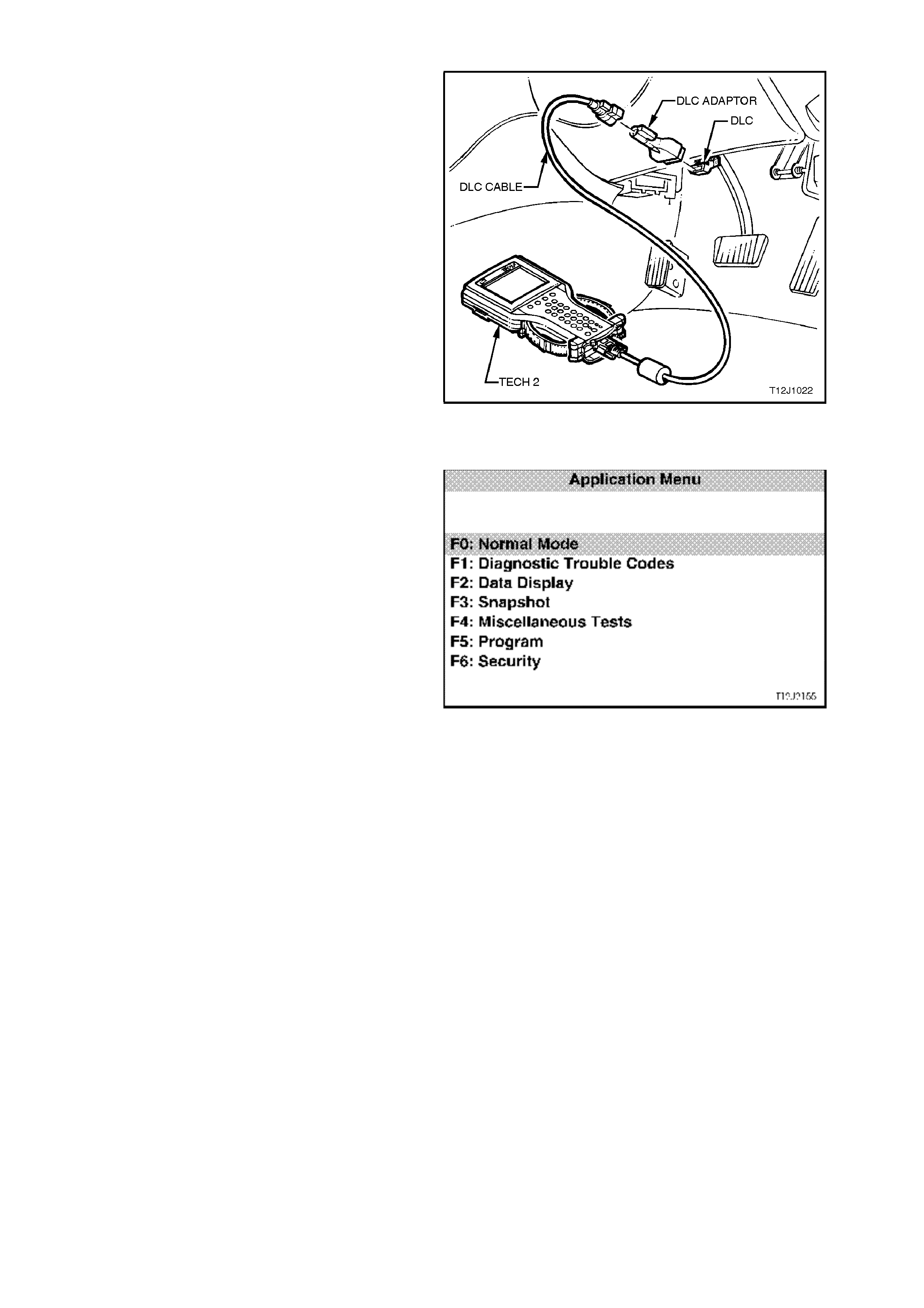
3.2 CONNECTING TE CH 2
TECH 2, with the appropriate software, cables and
adaptors, when connected to the Data Link
Connector (DLC) is capable of reading BCM serial
data. The DLC is connected to the instrument panel
lower right hand trim, to the right of the steering
column.
For additional general information on connecting
and operating TECH 2 , refer to
Section 0C TECH 2.
Figure 12J-2-117
TECH 2 has seven test modes for diagnosing the
BCM. The seven test modes are as follows:
Mode F0: Normal Mode
In this mode, the Tech 2 monitors the
communication between control modules on the
serial data line. The information displayed on the
TECH 2 screen in this mode is what the BCM is
communicating to the other modules via the serial
data line.
Mode F1: Diagnostic Trouble Codes
In this test mode, current Diagnos tic Trouble Codes
(DT C’s) s tored in the c ontrol modules m em or y may
be displayed or cleared.
Additionally, in this mode, entry deterrent alarm
codes, stored in the control modules memory can
be displayed and cleared.
Mode F2: Data Display
In this test mode, TECH 2 displays the status of
inputs and outputs of the BCM.
Mode F3: Snapshot
In this test mode, Tech 2 captures BCM data
before and after a forced manual trigger.
Mode F4: Miscellaneous Tests
In this test mode, Tech 2 performs various
functional tests to assist in pr oblem isolation during
trouble shooting.
Mode F5: Program
In this test mode, Tech 2 allows the programming
of various features by turning the feature OFF or
ON, or adjusting settings (ie. twilight sentinel
sensitivity).
Mode F6: Security
In this test m ode, T ech 2 pr ovides the user with the
capability of: linking the PCM to the BCM, reading
security information (ie. radio pin numbers), and
programming security features (ie. keys).
Figure 12J-2-118
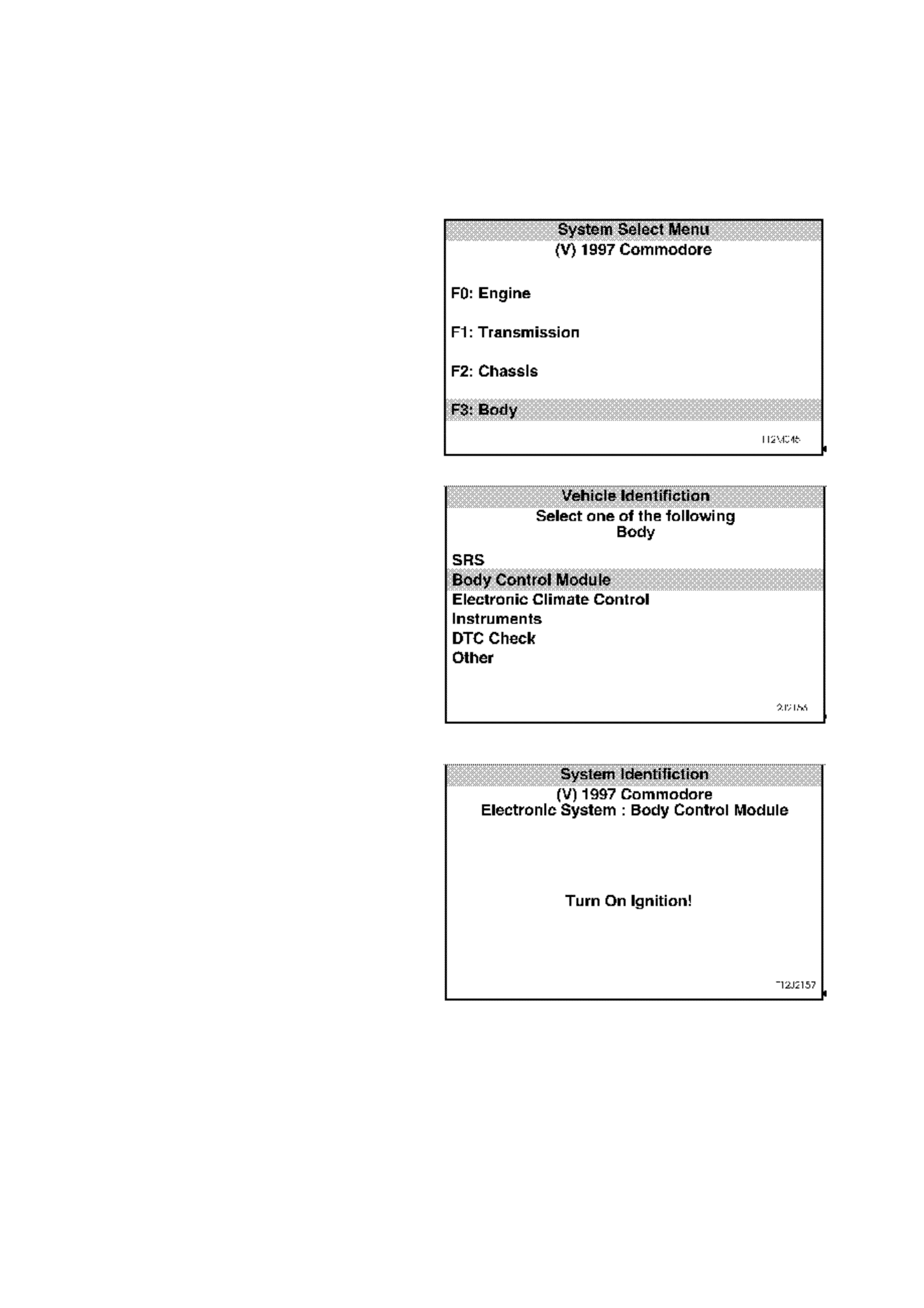
3.3 TECH 2 TEST MODES AND DISPLAYS FOR BCM DIAGNOSIS
As a prerequisite to this diagnostic section is for the
user to be familiar with the proper use of TECH 2,
the following illustrates only the major TECH 2
screen displays and provide a brief explanation of
their function for diagnosing the BCM. If additional
information is r equired on the oper ation of TECH 2,
reference should be made to either Section 0C
TECH 2 or the TECH 2 OPERATORS MANUAL.
System Select Menu
W ith TECH 2 c onnected to the DLC and turned on,
F0: DIAGNOSTICS selected from the MAIN
MENU, the correct MODEL YEAR and VEHICLE
TYPE must be selected for access to the SYSTEM
SELECT MENU.
Select F3: BODY.
This mode contains all functions to test, diagnose,
monitor and program the vehicles body systems
including the BCM as well as providing the
opportunity to check all DTC’s that may be set in
the vehicle.
Figure 12J-2-119
Body Application Menu
Once F3: BO DY has been selec ted from the s elect
menu, BCM can be selected.
Select Body Control Module and press enter to
continue.
NOTE:
If inform ation regarding DT C’s set for the vehicle is
required, select DTC CHECK and press enter to
continue. To return to the BCM mode option from
the DTC CHECK mode option screen display,
simply press the EXIT key on TECH 2.
Once the BCM has been selec ted and entered, the
following two SYSTEM IDENTIFICATION screens
will appear which require action. Figure 12J-2-120
System Identification
Turn the ignition ON (as requested) and press
CONFIRM soft key to continue.
Figure 12J-2-121
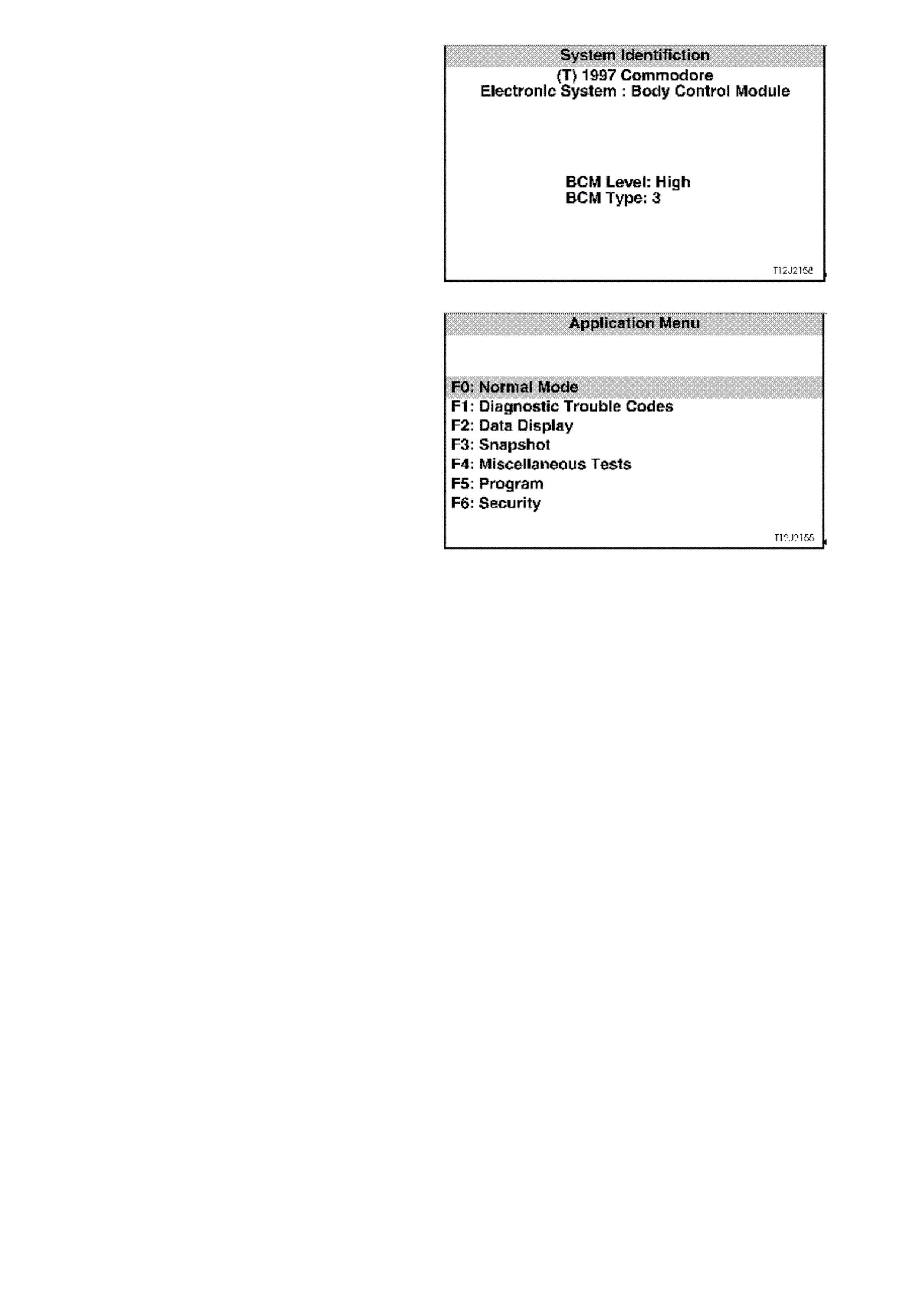
The SYSTEM IDENTIFICATION screen will then
display the control module level and type. Press the
CONFIRM soft key to continue to the BCM
APPLICATION MENU.
Figure 12J-2-122
Application Menu
The following functions will now be available:
F0: Normal Mode
F1: Diagnostic Trouble Codes
F2: Data display
F3: Snapshot
F4: Miscellaneous Tests
F5: Program
F6: Security
Figure 12J-2-123

F0: NORMAL MODE
In the F0: Normal Mode, information that the BCM is communicating to other control modules, via the serial data
line, is displayed.
The table below lists each item in the Normal Mode, together with a brief description of its meaning.
DATA STREAM /
SCREEN DISPLAY DESCRIPTION EXPECTED READING
Ignition Status Displays current state of
ignition switch as sensed by
the BCM.
On 12 volts / Off 0 volts
Ignition Off Time Displays the length of time
since the ignition was last
switched off.
XX minutes
Instrument Lamps Displays instrument
illumination level. 0 % / 100 %
Lights On Displays current status of
headlamp switch. Yes / No
Ambient Light Level Displays the ambient light
level from the sun load
sensor / remote receiver.
Between 0 and 254
Boot Status Displays boot switch status. Open / Closed
Rear Lamp Status Displays rear lamp circuit
status (including bulb
condition). If a fault is
detected in the circuit,
Service Request will be
displayed.
Okay / Service Request
Front Wiper Status Displays front wiper drive
status. On / Off
Front Auto Wiper Status This feature is unavailable
at present. Off
Cruise Control Input
Signal Displays status of cruise
control. On / Off
A/C Request (Air
Conditioning) This feature is not
applicable to high series
vehicles (with ECC),
therefore, will always
display OFF.
On / Off
BCM Lower Fan Drive Displays low speed fan
drive status. On / Off
BCM Chime (Body
Control Module) Displays status of BCM
chime. On / Off
Key User Displays priority key in use. 1 / 2
BCM DTC Status Display will advise if any
BCM DTC's are set. No DTC’s / DTC’s Set

F1: DIAGNOSTIC TROUBLE CODES
The following functions will be available in this
mode:
Read Current DTC Information - a listing of all (if
any) current DT C’s that have been set by the BCM
will be displayed. A short description of what the
DTC is, is also displayed in this mode.
Read Alarm Code Information - a description of
stored alarm codes (if any) will be displayed.
Clear DTC Information - simply select CLEAR
CODES, press the ENTER button on TECH 2 and
confirm the action as instructed by TECH 2.
Performing this function will also alarm codes.
The following chart sets out all the possible BCM
DTC’s as indicated by TECH 2.
Refer to the relevant diagnostic chart in this Section
when attempting rectification of a system problem
or failure.
Figure 12J-2-124
BCM DIAGNOSTIC TROUBLE CODES
DTC CODE DESCRIPTION REFER
1Output overload - sets if the BCM
output protection circuitry detects
an output driver overload. This will
cause all BCM output drives to be
set to the inactive state. The BCM
will then attempt to drive all outputs
approximately every 10ms, thus
causing all active BCM output
drives to repeatedly switch from an
active to an inactive state until the
fault condition is remedied.
NOTE:
The BCM is unable to identify which
output is being overloaded.
This DTC can be set by any one of the
BCM outputs being shorted to battery
positive, therefore, if DTC 1 is set, refer to
section relevant to driver complaint (if
any).
For a listing of all BCM outputs, refer to
the HIGH SERIES BCM TERMINAL
IDENTIFICATION chart in 1 GENERAL
DESCRIPTION in this Section.
NOTE:
DTC 1 can also be set by electrical
transients, therefore, if DTC 1 is set and
there are no noticeable problems with the
vehicle, clear DTC and check function of
BCM outputs. If DTC does not reset and
BCM outputs are functioning correctly,
disregard DTC 1
2Slip Ring Failure - sets if the
number of failed slip ring reads
exceeds a programmable
percentage of all slip ring reads
(approximately 18 failed slip ring
reads out of 100 good slip ring
reads).
4.4 THEFT DETERRENT, in this Section
to rectify problem.
3Power steering Open Circuit -
sets when the feedback from the
BCM commanded power steering
current is less than the desired
value by more than 25% of the
minimum achievable current.
4.12 SPEED SENSITIVE POWER
STEERING, in this Section to rectify this
problem.
4Power Steering Short Circuit -
sets whenever the power steering
current feedback circuit detects a
current in excess of that
commanded by the BCM.
4.12 SPEED SENSITIVE POWER
STEERING, in this Section to rectify this
problem.
5Tail Lamp Failure - sets when the
BCM detects a tail lamp failure that
turns the rear light failure warning
lamp ON in the instrument cluster.
4.16 REAR LAMP FAILURE WARNING
SYSTEM, in this Section to rectify the
problem.

BCM DIAGNOSTIC TROUBLE CODES
DTC CODE DESCRIPTION REFER
6Stop Lamp Failure - sets when the
BCM detects a stop lamp fail that
turns the rear light failure warning
lamp ON in the instrument cluster.
4.16 REAR LAMP FAILURE WARNING
SYSTEM, in this Section to rectify the
problem.
7PCM Data Lost - sets when the
BCM does not receive responses
from the PCM or receives
incorrectly formatted responses
from the PCM within three seconds
of normal serial data bus activity.
The three second time out period is
reset whenever the following
conditions occur:
• Ignition switched from OFF to
ON.
• A good PCM poll response is
received from the PCM.
• A key has been programmed.
• BCM has just been reset.
4.2 SERIAL DATA COMMUNICATION, in
this Section to rectify problem.
8PCM Vehicle Speed Data
Unstable - sets if the BCM receives
two consecutive road speed
updates from the PCM with a
magnitude difference of 30 km/h.
4.12 SPEED SENSITIVE POWER
STEERING (steps 10 & 11), in this
Section to rectify problem.
17 Serial Data Bus Fault - sets if the
BCM cannot detect six consecutive
messages on the serial data bus.
This trouble code indicates either a
short circuit on the bus or if two or
more modules send a message at
the same time.
4.2 SERIAL DATA COMMUNICATION, in
this Section to rectify problem.
F2: DATA DISPLAY
In this test mode, TECH 2 checks if the BCM is actually receiving an input or inputs from the appropriate sensor/s or
actuator/s for the system being diagnosed, eg. for power antenna mast adjustment, check that the radio on, power
antenna up or down switch inputs are being received.
If the sensor/s or actuator/s input/s are not being received, then carry out the relevant system diagnosis as defined
in this Section.
If the sensor/s or actuator/s input/s are being received, go to the appropriate F4: BCM TEST mode to command the
BCM via TECH 2 to operate the system output.
Should the system output or actuator not function correctly, conduct relevant system diagnosis as defined in this
Section. If system wiring and output actuator are OK, replace BCM.
A description explaining the display and, where applicable, affected terminals is included in the charts below.
NOTE:
When the TECH 2 is communicating with the BCM, it also determines what type of BCM is fitted to the vehicle and
therefore only the relevant data list and functional tests will be displayed.

DATA LIST
SCREEN
DISPLAY DESCRIPTION TERMINAL
AFFECTED
BCM LEVEL Displays what level of BCM is fitted to the vehicle.
The screen should display LUX on Berlina Models
and HIGH on Calais.
If fuse F31 or circuits 740 and/or 1040 are open
circuited, communication with the BCM will not be
possible. If these circuits are OK, refer to 4.2 SERIAL
DATA COMMUNICATION in this Section.
-
BCM TYPE Displays w hat type of BCM is fitted to the vehicle.
The screen will display the type of BCM fitted to the
vehicle (TYPE 1).
If fuse F31 or circuits 740 and/or 1040 are open
circuited, communication with the BCM will not be
possible. If these circuits are OK, refer to 4.2 SERIAL
DATA COMMUNICATION, in this Section.
-
BATTERY
VOLTAGE Displays battery voltage input to BCM.
If fuse F31 or circuits 740 and/or 1040 are open
circuited, communication with the BCM will not be
possible.
A5
VEHICLE
SPEED Displays vehicle speed input to BCM via the main
SDI (circuit 1221).
If vehicle speed cannot be displayed, refer to 4.11
ROADSPEED DEPENDENT VARIABLE DWELL
WIPER SYSTEM (Steps 51 and 55) diagnosis in this
Section.
E2
SLIP RING
ENABLED Screen display may flash from NO to YES briefly
when BCM receives a correct key reading. If BCM
does not receive a correct key reading, screen will
flash between NO YES continuously until a correct
reading is achieved.
If screen does not change as described, refer to 4.4
THEFT DETERRENT in this Section.
E1
IGNITION
SWITCH Displays current state of ignition switch as sensed by
the BCM.
Will display ON with ignition switch in IGN or START
positions and OFF in ACC or OFF positions.
If screen display doesn’t change as described, check
circuitry between ignition switch and BCM, and
ignition switch contacts. If circuit and switch are OK,
BCM is faulty.
E20
ACCESSORY
SWITCH Displays current state of accessory switch as sensed
by the BCM.
Will display ON with ignition switch in ACC or IGN
positions and OFF in START or OFF positions.
If screen display doesn’t change as described, check
circuitry between ignition switch and BCM, and
ignition switch contacts. If circuit and switch are OK,
BCM is faulty.
E17

SCREEN
DISPLAY DESCRIPTION TERMINAL
AFFECTED
CENTRAL
LOCKING Displays the current state of the BCM internal central
door locking relays.
When locking the central door locking system, either
remotely or by turning the RH door key switch, the
screen display changes to ALL LOCK. If the RH door
key switch is activated a second time, the screen will
display DEADLOCKED.
When unlocking the system by turning the RHF door
key switch, the screen display changes from ALL
LOCKED or DEADLOCKED to ALL UNLOCK.
Unlocking remotely, the screen display changes from
ALL LOCKED or DEADLOCKED to DRIVER
UNLOCK on first press (If vehicle is programmed with
two stage unlocking) and second button press, the
screen displays ALL UNLOCK.
If screen display does not change as described, refer
to 4.3 CENTRAL DOOR LOCKING and carry out
FUNCTIONAL CHECK - CENTRAL DOOR
LOCKING.
-
DRIVER’S
DOOR
UNLOCK
SWITCH
Displays RHF door lock actuator key switch input to
BCM.
With doors locked, screen displays OFF, unlocking
the driver’s door or all doors, screen will change to
ON.
If the circuit from BCM terminal C20 is open circuited,
the passenger’s doors cannot be unlocked by the
RHF door lock key switch.
C20
PASSENGER’S
DOOR
UNLOCK
SWITCH
Displays passenger door lock actuator switch inputs
to the BCM.
With doors locked, screen displays OFF, unlocking
the passenger doors, screen changes to ON.
If the circuit from BCM terminal C9 is open circuited,
the passenger doors cannot be unlocked. The screen
display w ill also remain unchanged.
C9
LOCK SWITCH
STATUS Displays the front doors lock actuator inputs to the
BCM.
When doors are locked, by activating either of the
front door lock actuators (snib), screen displays ON.
When doors are unlocked, screen displays OFF.
If circuit is open, doors can not be locked from the
front door lock actuators (snib), but system can be
locked remotely.
If screen display does not change as described, refer
to 4.3 CENTRAL DOOR LOCKING and carry out
FUNCTIONAL CHECK - CENTRAL DOOR LOCKING
in this Section.
C21
DEADLOCK
SWITCH Displays RHF door lock microswitch input to BCM.
With RHF door lock cylinder in the unlocked and
locked position, screen displays OFF. Display will
change to DEADLOCK when the door lock cylinder is
turned to the deadlock position.
If circuit 197 is open circuited, doors cannot be locked
or deadlocked by turning the RHF door lock cylinder
and screen display will remain off. However, doors
can be locked remotely.
If screen display does not change as described, refer
to 4.3 CENTRAL DOOR LOCKING and carry out
FUNCTIONAL CHECK - CENTRAL DOOR
LOCKING, in this Section.
C22

SCREEN
DISPLAY DESCRIPTION TERMINAL
AFFECTED
ILLUMINATION
SWITCH
POSITION
Displays instrument dimmer slide control input to
BCM.
With the ignition OFF, parking lamps OFF and
dimming switch control lever at the rest position,
screen displays OFF.
With the ignition and park lamps on and the control
lever held up, screen displays UP. With switch control
lever held down, screen displays DOWN.
If circuit 717 between BCM terminal E11 and
headlamp switch is open circuited, the screen will not
change and screen display will remain OFF.
If screen displays are not as described, refer to 4.15
INSTRUMENT DIMMING CONTROL in this Section.
E11
ILLUMINATION
VOLTAGE Displays instrument dimmer slide control input
voltage to BCM.
With the parking lamps ON and dimming switch
control lever at the rest position, screen displays 3.5
volts.
With the control lever held in the up position, screen
displays 0.2 volts. With the switch control lever in the
down position, the screen displays 2.2 volts.
If screen displays are not as described, refer to 4.15
INSTRUMENT DIMMING CONTROL in this Section.
E11
INSTRUMENT
LAMPS With ignition OFF and parking or headlamps OFF,
screen displays 100%, irrespective of switch control
lever position. With ignition ON and parking lamps off,
screen displays 100%, irrespective of switch control
lever position as the trip computer display in the
instrument cluster is illuminated.
With the ignition ON, Parking lamps ON and switch
control lever in the up position, the percentage of
instrument cluster illumination intensity will increase
to 100% (if not already at 100%).
Holding switch control lever down, screen will
gradually decrease to approximately 35%.
If circuit 717 between BCM terminal E11 and
headlamp switch is open circuited, the screen will not
change and screen display will remain OFF.
If screen displays are not as described, refer to 4.15
INSTRUMENT DIMMING CONTROL in this Section.
E11
DOME SWITCH Displays dome lamp switch input to BCM.
With dome lamp switch in off, screen displays OFF,
changes to ON when switch is turned ON, and
changes to DOOR when switch is turned to the door
position.
If circuit 174 between the BCM, terminal C24 and the
interior lighting is open circuited, the interior lighting
will not come on.
If screen display does not change as described, refer
to 4.14 DOME LAMP DELAY CONTROL in this
Section.
C24

SCREEN
DISPLAY DESCRIPTION TERMINAL
AFFECTED
DOME LAMP
DRIVE Display changes from OFF to ON as dome lamp is
turned ON or when the remote coded key UNLOCK
button is depressed. Display goes OFF when the
ignition is turned ON. This check confirms if the BCM
internal circuitry is operating (a relay within the BCM
will be heard to click as the drive is turned on).
If circuit 174 between the BCM, terminal C24 and the
interior lighting is open circuited, the interior lighting
will not come on.
If screen display does not change as described, refer
to 4.14 DOME LAMP DELAY CONTROL in this
Section.
C24
LIGHTS OFF
DELAY Displays programmed automatic headlamps delay
period, if set (will display 0 sec. If not set). Refer to
1.7 AUTOMATIC LIGHT CONTROL / A UTOMA TIC
LIGHTS OFF (WITHOUT TWILIGHT SENTINEL) in
this Section.
If delay period will not set, refer to 4.9 AUTOMATIC
LIGHT CONTROL - AUTOMATIC LIGHTS OFF
(WITHOUT TWILIGHT SENTINEL) in this Section.
-
HEADLAMP
SWITCH Displays status of switch during auto off period only .
Display changes from OFF to ON as headlamps auto
off period is in progress. This check confirms that the
BCM internal switching is operating. Display goes to
OFF when the headlamp auto off is cancelled.
If screen does not change as described, refer to 4.9
AUTOMATIC LIGHT CONTROL - AUTOMATIC
LIGHTS OFF (WITHOUT TWILIGHT SENTINEL) in
this Section.
E12, E28
HEADLAMP
DRIVE With the ignition turned on, screen displays ON,
turning the ignition off, the screen will still display ON.
Turn headlamps on, scroll ignition from on to off and
open the driver’s door, screen will change from ON to
OFF and headlights will go out.
If screen does not change as described, refer to 4.9
AUTOMATIC LIGHT CONTROL - AUTOMATIC
LIGHTS OFF (WITHOUT TWILIGHT SENTINEL) in
this Section.
E28
AMBIENT
LIGHT
SENSOR
Displays ambient light level input to BCM.
When ambient light sensor (sun sensor / remote
receiver module) is covered (dark), display will show
approximately 0 volts. With bright light (sun light or for
testing purposes, a torch), display will be up to 5
volts.
If screen does not change as described, refer to 4.9
AUTOMATIC LIGHT CONTROL - AUTOMATIC
LIGHTS OFF (WITHOUT TWILIGHT SENTINEL) in
this Section.
E10
TWILIGHT
LEVEL Displays the programmed level of sensitivity - may be
set between 0 and 7 (4 is the default setting in
production).
If screen display is not as described, refer to 4.10
AUTOMATIC LIGHT CONTROL - AUTOMATIC
LIGHTS ON AND OFF (WITH TWILIGHT
SENTINEL) in this Section.
-

SCREEN
DISPLAY DESCRIPTION TERMINAL
AFFECTED
TWILIGHT
SENTINEL Will display ON when BCM determines lights should
be turned on, regardless of headlamp position.
If screen does not change as described, refer to 4.10
AUTOMATIC LIGHT CONTROL - AUTOMATIC
LIGHTS ON AND OFF (WITH TWILIGHT
SENTINEL) in this Section.
E7, E10
DRIVERS
DOOR Displays the driver’s door jamb switch input to the
BCM.
When the driver’s door is open, the screen display
should be OPEN, and when the door is closed, the
screen should display CLOSED.
If screen does not change as described, refer to 4.4
THEFT DETERRENT in this Section.
C8
PASSENGER
DOORS Displays the passenger’s door jamb switch input to
the BCM.
When the passenger’s door is open, the screen
display should be OPEN, and when the door is
closed, the screen should display CLOSED.
If screen does not change as described, refer to 4.5
ENTRY DETERRENT in this Section.
C7
STOP LAMP
SWITCH Displays stop lamp switch input to BCM.
When brake pedal is depressed and the ignition is on,
screen display changes from OFF to ON.
If screen does not change as described, refer to
Section 12L ABS & ABS/ETC diagnostics.
E18
STOP LAMP
BULB
CONDITION
With ignition ON and brake pedal depressed, screen
should display Okay. If screen displays FAILED,
check stop lamp bulbs, wiring between stop lamp
switch and rear lamp connectors, and between rear
lamp connectors and BCM.
NOTE:
If at any time the BCM has been reset, a rear lamp
failure warning system bulb relearn procedure must
be performed (refer to 1.14 REAR LIGHT FAILURE
WARNING SYSTEM in this Section).
C15
STOP LAMP
FUSE Displays stop lamp fuse F5 input to BCM.
Screen should display Okay. If screen displays
FAILED, check fuse F5, wiring between fuse F5 and
battery, and between fuse F5 and BCM.
E18
PARK LAMP
FUSE Displays parking lamp fuse F4 input to BCM.
Screen should display Okay. If screen displays
FAILED, check fuse F4, wiring between fuse F4 and
battery, and fuse F4 and the BCM.
E24
PARK LAMP
SWITCH Displays parking lamps switch input to BCM.
When the parking lamps are switched on, screen
display changes from OFF to ON.
If screen does not change as described, check
headlamp switch contacts or open circuit in wiring to
BCM terminal E11, refer to Section 12B LIGHTING
SYSTEM.
E11

SCREEN
DISPLAY DESCRIPTION TERMINAL
AFFECTED
PARK LAMP
BULB
CONDITION
With ignition ON and parking lamps on, screen
should display Okay. If screen displays FAILED,
check rear parking lamp bulbs, wiring between
headlamp switch and rear lamp connectors, and
between rear lamp connectors and BCM.
NOTE:
If at any time the BCM has been reset, a rear lamp
failure warning system bulb relearn procedure must
be performed (refer to 1.14 REAR LIGHT FAILURE
WARNING SYSTEM in this Section).
E11, E28
BULB FAILED
WARNING
LAMP
Checks BCM internal switching for illuminating the
rear lamps failure warning lamp. The warning lamp
will illuminate whenever a fault is detected.
If lamp does not work , refer to Section 12C
INSTRUMENTS, WIPERS/WASHERS & HORN.
If screen display does not change as described, the
BCM is faulty.
E9
LAMP CIRCUIT
CURRENT
STATUS
Will display OK if the BCM current flow is within
specifications. If current flow is higher than specified,
TECH 2 screen will display TOO HIGH. In this case,
check for installation of incorrect wattage rear lamp
bulbs, or causes of high current flow to rear lamps, ie.
Rear lamps shorted to together or shorted to earth.
-
STOP LAMP
CURRENT Displays current flow from rear lamps as detected by
the BCM.
With ignition off, parking lamps off and brake pedal
released, displays approximately 0.0 A.
With ignition off, parking lamps on and brake pedal
depressed, display s approximately 0.3 A.
With ignition off, parking lamps on and brake pedal
depressed, display s approximately 1.0 A.
C15
PARK LAMP
CURRENT Displays current flow from rear lamps as detected by
the BCM.
With ignition off, parking lamps off and brake pedal
released, displays approximately 0.0 A.
With ignition off, parking lamps on, displays
approximately 3.1 A.
With ignition off, parking lamps on and brake pedal
depressed, display s approximately 4.9 A.
With ignition off, parking lamps off and brake pedal
depressed, displays approximately 4.9A.
C15
FRONT
WASHER
PUMP SWITCH
Displays front washer pump switch input to BCM.
With ignition on and the washer pump switch
activated, screen display changes from OFF to ON.
If circuit 94, between the BCM and the wiper/washer
switch is open circuited, the wipe after wash function
will not operate.
If screen display does not change, check circuit 94
between BCM terminal E25 and wiper/washer switch
(including wiper/washer switch contacts), refer
Section 12C INSTRUMENTS, WIPER/WASHER &
HORN.
E25

SCREEN
DISPLAY DESCRIPTION TERMINAL
AFFECTED
WIPER PARK
SWITCH Displays input to BCM.
With wipers in the park position, screen displays ON.
With wipers operating, display will change to OFF and
momentarily go to ON as wipers operate through the
park region.
If circuit 196, between the BCM and the wiper motor
is open circuited, the screen will display ON all the
time and wipers will not park when turned off.
If screen display remains ON with wipers operating,
check for open circuit between BCM terminal B8 and
wiper motor, carry out checks of wiper motor, refer
Section 12C INSTRUMENTS, WIPER/WASHER &
HORN.
B8
FRONT WIPER
INTERMITTENT
SWITCH
Displays wiper/washer switch intermittent switch
contacts input to BCM.
With ignition on and wiper/washer switch set to the
intermittent position, screen display changes to ON.
If circuit 97, between the BCM and the wiper/washer
switch is open circuited, there will be no intermittent
wiper function.
If screen display does not change, check circuit 97
between BCM terminal E27 and wiper/washer switch
(including wiper/washer switch contacts), refer
Section 12C INSTRUMENTS, WIPER/WASHER &
HORN.
E27
INTERMITTENT
WIPER
VOLTAGE
Displays intermittent wiper potentiometer setting input
to BCM.
Displays between 0.9 and 3.9 volts depending on
potentiometer setting.
If screen does not change when potentiometer is
adjusted, refer to Section 12C INSTRUMENTS,
WIPERS/WASHERS & HORN.
E5
INTERMITTENT
WIPER DRIVE With wipers operating in the intermittent mode,
screen displays ON. With wipers in the parked
position, and in 1st or 2nd speed, screen displays off.
If screen displays are not as described, refer to 4.11
ROADSPEED DEPENDENT VARIABLE DWELL
WIPER SYSTEM in this Section.
-
FRONT WIPER
DWELL TIME Displays wi per/washer switch dwell control
adjustment at BCM.
With vehicle stationary, display will change from
approximately 5.0 SEC (seconds) at fastest setting to
approximately 25 SEC (seconds) at its slowest
setting as dwell control switch is adjusted from one
extreme to the other.
If screen display doesn’t change, or displays 5.0 SEC
continuously, check circuit 96, between BCM terminal
E5 and wiper/washer switch (including wiper/washer
dwell control adjustment contacts, refer Section 12C
INSTRUMENTS, WIPER/WASHER & HORN.
E5
FRONT AUTO
WIPER This feature is not implemented on VT Series
Models.
Screen will always display OFF.
-

SCREEN
DISPLAY DESCRIPTION TERMINAL
AFFECTED
REAR WASH
PUMP SWITCH Displays rear washer pump switch input to BCM.
With ignition on and the washer pump switch
activated, screen display changes from OFF to ON.
If circuit 494, between the BCM and the wiper/washer
switch is open circuited, the wipe after wash function
will not operate.
If screen display does not change, check circuit 494
between BCM terminal E15 and wiper/washer switch
(including wiper/washer switch contacts), refer to
Section 12C INSTRUMENTS, WIPER/WASHER &
HORN.
E15
REAR WIPER
SWITCH Displays rear wiper switch input to BCM.
With ignition on and the rear wiper switch in the on
position, screen will change from OFF to ON (this
applies to wagon only, on sedan models, the screen
will always display OFF).
Refer to 4.11 ROADSPEED DEPENDENT
VARIABLE DWELL WIPER SYSTEM in this Section.
E19
POWER
WINDOW
SWITCH
Displays input to BCM.
With power windows enabled, screen displays OFF.
With driver’s window switch down button activated,
screen displays DOWN. With driver’s window switch
up button activated, screen displays UP.
If screen does not display DOWN when the down
button is activated and the window automatic down
function does not work, check for open circuit
between BCM terminal C14 and the driver’s side
power window switch.
C14 (Down)
C16 (Up)
WINDOW
AUTO DOWN
DRIVE
Screen display changes from OFF to ON when the
driver’s side power window switch automatic down
button is activated and functioning. Will also display
ON when down button is activated, but with automatic
down feature not functioning.
If the driver’s side power window operates normally
except for the automatic down feature, and all system
inputs are determined to be OK, then BCM is faulty.
-
POWER
WINDOW
RELAY
Displays the power window relay status as
determined by the BCM internal circuitry. The relay is
enabled by the BCM earthing circuit 173.
With the power window switch enabled (lights in
power switch illuminated), screen displays ENABLED.
With the system OFF, screen displays DISABLED.
If the screen displays ENABLED but the lights in the
power window switch do not illuminate, check for
open in wiring to BCM terminal B2.
If screen displays are not as described, refer to 4.7
POWER WINDOW SYSTEM in this Section.
B2
CRUISE
CONTROL
INPUT SIGNAL
Displays the cruise control on/off switch input status
to the BCM.
With ignition on, each activation of the cruise on/off
switch will toggle the screen display to the next state,
ie. OFF to ON or ON to OFF.
If the screen display changes as described, but the
cruise control CRUISE lamp in the instrument cluster
does not illuminate, refer to 4.17 CRUISE CONTROL
INTERFACE in this Section.
If screen display does not change, refer to Section
12E CRUISE CONTROL.
E26

SCREEN
DISPLAY DESCRIPTION TERMINAL
AFFECTED
BONNET OPEN
SWITCH Displays bonnet switch input to BCM.
With bonnet closed (bonnet switch contacts open
circuit), screen displays OPEN. With bonnet open
(switch contacts close and the circuit is connected to
earth) screen will display CLOSED.
If circuit 260 is open circuited, the screen display will
remain OPEN.
If screen does not change as described, refer to 4.5
ENTRY DETERRENT in this Section.
E23
BOOT
RELAESE
SWITCH
Displays boot release switch input to BCM.
With the boot release switch (located in glove
compartment) in the rest position, screen displays
OFF. With switch held in, switch displays ON.
If screen does not change as described, refer to 4.5
ENTRY DETERRENT in this Section.
E22
BOOT LAMP
SWITCH Displays rear compartment (boot) lamp switch input
to the BCM.
With rear compartment lid closed (rear compartment
lamp switch contacts open), screen displays OFF.
With the rear compartment lid open (the switch
contacts close and the circuit is connected to earth),
screen will display ON.
If circuit 162 is open circuited, the screen display will
remain ON.
If screen does not change as described, refer to 4.5
ENTRY DETERRENT in this Section.
C6
BOOT
SOLENOID
DRIVE
Provided the vehicle speed is less than 15 km/h,
depressing the boot release button on the remote
coded key will cause the screen display to change
from CLOSED to OPEN as the BCM internal relay is
activated.
If screen does not change or boot release does not
operate, refer to 4.5 ENTRY DETERRENT in this
Section.
-
RADIO STATUS Displays radio ON/OFF status input to BCM.
The radio on signal is required to enable the antenna
mast to extend.
With the radio turned off, screen displays OFF. With
radio on and the ignition in the ACC or IGN positions,
screen displays ON.
If screen does not change as described, check circuit
143 between BCM and radio.
E16
POWER
ANTENNA Displays BCM output state of BCM internal switch.
If circuit 954 is open circuited from the BCM, the
antenna mast will not extend.
With the radio off, the power antenna screen displays
OFF. With ignition in the ON or ACC position, and
radio on, screen will display AUTO UP. When
antenna mast finishes extending, screen displays
OFF.
At this position (mast extended), switch the radio off
and as the mast retracts, screen will display AUTO
DOWN.
If screen does not change as described, refer to 4.13
POWER ANTENNA CONTROL in this Section.
C17

SCREEN
DISPLAY DESCRIPTION TERMINAL
AFFECTED
ANTENNA
SWITCH
POSITION
Displays antenna switch input to BCM.
With switches in the rest position, screen displays
OFF. With radio on and ignition on, if up switch is
depressed, screen will display UP SWITCH, if down
switch is depressed, screen will display DOWN
SWITCH.
If screen does not change as described, refer to 4.13
POWER ANTENNA CONTROL in this Section.
E13, E14
OVERRIDE
STATUS This screen displays that status of the theft deterrent
systems override function. TECH 2 will display
SECURITY OFF when the theft deterrent system has
been overridden, ie. when the BCM has not received
any serial data from the remote coded key and the
ignition switch has been turned ON for approximately
two hours.
If the status does not change, refer to 4.4 THEFT
DETERRENT diagnosis in this Section.
-
SECURITY LED Displays current state of the BCM theft deterrent
system LED driver condition. If the LED is flashing, ie.
system armed, the screen will pulse between ON and
OFF.
NOTE:
TECH 2 and security LED are synchronised.
This checks that the BCM is turning on and off the
voltage supply.
If TECH 2 screen display does not change, the BCM
is faulty.
If TECH 2 screen display does change, but the LED
does not flash, check for open in wiring from BCM to
LED.
A6
INDICATORS When the BCM activates the indicators via it’s internal
relay, the screen display alternates between ON and
OFF as the indicators flash.
This checks that the BCM is pulsing its internal relay,
thereby supplying voltage from BCM terminal B5 to
terminals B4 and B12. If screen display does not
change as described, BCM is faulty.
If screen display does change as described, but the
indicators do not flash, check for open circuit in wiring
from BCM output terminals B4 and B12 or input to
BCM terminal B5. (Refer to 4.4 THEFT DETERRENT
diagnosis in this Section).
B4, B5, B12
PASSIVE
MODE With the theft deterrent system in passive arm state,
screen displays should be ON (theft deterrent LED
flashing).
-
ALARM MODE With the theft deterrent system enabled (theft
deterrent LED flashing), and the system disarmed,
screen displays DISARMED. Press the LOCK button
on the remote coded key (doors closed) and centrally
lock all doors, the display should change to ARMED.
-
ALARM With the system armed and not triggered, the screen
displays INACTIVE. When the system is triggered,
the screen display changes to TRIGGERED.
-
THEFT
DETERENT
HORN
When the system is disarmed, or armed and not
triggered, the screen displays OFF. When the system
is triggered, the screen changes to ON. This action
checks if the BCM is switching ON or OFF it’s internal
driver, enabling terminals A3 and A4 to be earthed
(sounding horns).
A3, A4

SCREEN
DISPLAY DESCRIPTION TERMINAL
AFFECTED
REMOTE
BOOT SIGNAL Screen display changes to UNLOCK then OFF when
the boot release button on the remote coded key is
depressed.
If the screen displays INVALID KEY continuously
when the boot release button on the remote coded
key is depressed, and the BCM does not operate,
that particular remote coded key is not coded to the
BCM (refer to 4.20 REMOTE RECEIVER/KEY in this
Section).
NOTE:
Due to the fact that the screen changes when the
remote coded key is depressed, is confirmation that
there is an RF output from the remote coded key and
that it is recognised by the BCM either as correct or
invalid.
-
REMOTE
DOOR SIGNAL Screen display changes to UNLOCK then OFF when
remote coded key unlock button is depressed.
Changes to LOCK to OFF when lock button is
depressed.
If the screen displays INVALID KEY continuously
when the remote coded key is depressed, and the
BCM does not operate, that particular remote coded
key is not coded to the BCM (refer to 4.20 REMOTE
RECEIVER/KEY in this Section).
NOTE:
Due to the fact that the screen changes when the
remote coded key is depressed, is confirmation that
there is an RF output from the remote coded key and
that it is recognised by the BCM either as correct or
invalid.
-
REMOTE KEY
USER Depressing a button on the remote coded key
enables the BCM to read the key’s security code
information. If the remote coded key has been
programmed to the BCM, the screen displays the
remote coded key user number that has been
assigned to it during the programming process.
A BCM can have up to 31 different remote coded
keys programmed into it.
-
KEY PRIORITY
SIGNAL Depressing the UNLOCK button on the remote coded
key enables the BCM to read the key’s security
information. If the remote coded key has been
programmed to the BCM, the screen will display the
remote coded key’s priority number that it has been
assigned.
NOTE:
There can be only one priority one key, all other keys
are priority two.
-
RADIO
PRIORITY
DRIVE
Display BCM output to radio.
With ignition switch in the off position, screen displays
OFF, with ignition switch in the ACC or IGN positions,
screen will display either 1 or 2 depending on which
key was inserted into the ignition (priority key 1 or 2).
If screen displays are not as described, refer to 4.18
PRIORITY KEY SYSTEM IN THIS Section.
B3

SCREEN
DISPLAY DESCRIPTION TERMINAL
AFFECTED
SERIAL DATA
BUS
ISOLATION
Displays serial data bus isolation internal switch
status.
During normal operations (ignition on, cranking or
engine running) the serial data bus isolation switch
will be closed and screen displays NORMAL. If
engine will not start within 0.5 seconds of being
cranked, the serial data bus isolation switch will open
(isolating auxiliary serial data bus) for a maximum
period of 5 seconds, during this time, screen display
will change to DATA CUTOFF
If screen displays are not as described, refer to 4.2
SERIAL DATA COMMUNICATION in this Section.
-
LOW FAN
DRIVE This checks the BCM’s ability to turn on it’s internal
driver to earth, thus enabling the engine cooling low
speed fan.
With the low speed fan not operating, screen displays
OFF. With fan operating, screen displays ON.
B7
DTC STATUS Display will advise if any BCM DTC's are set.
Screen will display No DTC’s if there are no DTC’s, or
DTC’s Set if there are any BCM DTC’s set.
-
POWER STEERING
SCREEN
DISPLAY DESCRIPTION TERMINAL
AFFECTED
VEHICLE
SPEED Displays vehicle speed input to BCM via the main SDI
(circuit 1221). E2
If vehicle speed cannot be displayed, refer to 4.12
SPEED SENSITIVE POWER STEERING diagnosis
in this Section.
DESIRED PS
CURRENT
(POWER
STEERING)
With ignition ON, TECH 2 displays BCM current flow
control of power steering solenoid.
With rear of vehicle supported on safety stands, drive
vehicle and current flow indication on TECH 2 will
gradually reduce to approx. 0 mA at a vehicle speed
of 80 km/h.
If power steering current does not change, refer to
4.12 SPEED SENSITIVE POWER STEERING
diagnosis in this Section.
E4
DTC STATUS Display will advise if any BCM DTC's are set.
Screen will display No DTC’s if there are no DTC’s, or
DTC’s Set if there are any BCM DTC’s set.
-
PART NUMBER
SCREEN
DISPLAY DESCRIPTION TERMINAL
AFFECTED
PART NUMBER With the theft deterrent system disarmed, TECH 2
displays the last two digits of the Holden part number
for the BCM fitted to the vehicle (ie. 85).
This information can be checked against the part
number label attached to the BCM case, refer Fig.
12J-2-1 in this Section.

F3: SNAPSHOT
In this mode, TECH 2 captures data before and after a forced manual trigger.
The purpose of the SNAPSHOT test mode is to help isolate an intermittent or transient problem by storing BCM
data parameters just before and just after a problem occurs.
F4: MISCELLANEOUS TESTS
In this test mode, Tech 2 performs various functional tests to assist in problem isolation during trouble shooting.
If a vehicle component is commanded by TECH 2 to operate and the TECH 2 screen display changes as per this
command, yet the component does not operate, check for a faulty circuit between the BCM and the component (ie.
If low speed cooling fan is commanded ON, TECH 2 screen displays LOW SPEED COOLING FAN ON yet the low
speed cooling fan is physically not ON, then check cooling fan wiring between the BCM and the low speed cooling
fan, including cooling fan, for open or short circuit).
To operate any of the miscellaneous tests, simply select the appropriate functional test from the miscellaneous test
application menu and follow the instructions as per TECH 2.
When the Miscellaneous Tests option is selected, the following options will become available.
NOTE:
Additional application menu screens will be displayed for Lamps, Wiper Tests, and Security Systems.
• Lamps: If lamps are selected, an additional application menu will be displayed offering additional functional tests
of the vehicle’s lighting system.
• Dome: In this mode, TECH 2 commands the BCM to switch on and off the interior lighting.
If the interior lighting does not operate, refer to 4.14 DOME LAMP DELA Y CONTROL diagnosis in this
Section.
• Lamp Delay Drive: In this mode with the ignition OFF and the headlamps and park lamps turned ON, TECH
2 commands the BCM to switch OFF and ON the vehicle park lamps and headlamps.
If lamps do not switch off when commanded, refer to 4.9 AUTOMATIC LIGHT CONTROL - AUTOMATIC
LIGHTS OFF (WITHOUT TWILIGHT SENTINEL) diagnosis in this Section
• Indicators: In this mode, TECH 2 commands the BCM to switch ON and OFF the turn signal indicator
lamps, including the warning lamps in the instrument cluster.
If the turn signal lamps do not operate when commanded by TECH 2, refer to 4.4 THEFT DETERRENT
diagnosis in this Section.
• Bulb Fail Lamp: In this mode and with ignition switched ON, TECH 2 commands the BCM to switch on and
off rear light failure warning light in the instrument cluster.
If the lamp in the instrument cluster will not turn ON, refer to 4.16 REAR LAMP FAILURE WARNING SYSTEM
diagnosis in this Section.
• Illumination: In this mode, TECH 2 commands the BCM to brighten or dim the instrument cluster and trip
computer illumination lamps.
If the instrument cluster and trip computer illumination lamps intensity does not change when commanded by
TECH 2, refer to 4.15 INSTRUMENT DIMMING CONTROL diagnosis in this Section.
NOTE:
If the ignition is OFF and the park lamps are ON, only the instrument cluster lamps will be affected. If the
ignition is ON and the park lamps are ON, both the instrument cluster and trip computer will be affected
• Twilight Sentinel: In this mode, with the
ignition on and the headlamp switch in the
Auto position, TECH 2 commands the BCM
to turn the headlamps on and off.
If lamps do not switch off or on when commanded, refer to 4.10 AUTOMATIC LIGHT CONTROL -
AUTOMATIC LIGHTS ON AND OFF (WITH TWILIGHT SENTINEL) diagnosis in this Section.
• Low Fan: In this mode, TECH 2 commands the BCM to switch ON and then OFF, (will switch OFF automatically
after a short period provided the PCM is not commanding the low fan on) the engine cooling low speed fan relay.
If the engine cooling low speed fans do not operate in this mode, refer to 4.8 ENGINE COOLING LOW SPEED
FAN CONTROL diagnosis in this Section.
• Data Bus Isolator: In this mode, the BCM data bus isolator switch can be opened or closed.
To check if the data bus isolator is operating, while commanding the data bus isolator open with TECH 2, start
engine and monitor the trip computers “instant fuel consumption” display while varying the engine speed. When
the data bus isolator switch is opened, the trip computers instant fuel consumption display will not update.
• If the data bus isolator will not change state, refer to 4.2 SERIAL DATA COMMUNICATION diagnosis, in this
Section.

NOTE:
The Data Bus Isolator will only be held open for 5 seconds.
• Central Locking: In this mode, TECH 2 commands the BCM to operate all door lock actuators.
If door locks do not operate, refer to 4.3 CENTRAL DOOR LOCKING diagnosis in this Section.
• Wiper Tests: If Wipers are selected, an additional application menu will be displayed offering extra functional
tests of the vehicles wiper system.
• Front Wipers: In this mode, the front windshield wipers can be driven ON and OFF.
• Rear Wipers: In this mode, the rear screen wipers can be driven ON and OFF.
If the wipers to not operate when commanded by TECH 2, refer to 4.11 ROADSPEED DEPENDENT
VARIABLE DWELL WIPER SYSTEM in this Section.
• Window Down: In this mode, the driver’s window can be driven down.
NOTE:
Before entering and conducting this test, ensure that driver's side power window is fully up.
If the power window auto down function does not operate when commanded by TECH 2, refer to 4.7 POWER
WINDOW SYSTEM diagnosis in this Section.
• Antenna: In this mode, TECH 2 commands the BCM to raise or lower the antenna.
If the antenna mast does not operate, refer to 4.13 POWER ANTENNA CONTROL diagnosis in this Section.
• Horn: In this mode, the horn can be switched ON.
If the vehicles horns do not sound when commanded by TECH 2, refer to 4.5 ENTRY DETERRENT diagnosis in
this Section.
• Power Steering: In this test, TECH 2 commands the BCM to vary the current flow through the power steering
solenoid, thereby varying the amount of power steering assist.
For this test, start the engine and allow to idle.
With engine idling, rock steering wheel from side to side while pressing the INCREASE or DECREASE soft keys
(alternatively, press and hold the left arrow key and then press and hold the right arrow key) on TECH 2 to
command changes in power steering assistance.
As changes are made to the commanded current flow, a noticeable difference in the effort to rock the steering
wheel should be felt.
If during test, the effort required to rock the steering wheel from side to side does not change, and there are no
faults detected by the BCM, (no BCM DTC’s set), carry out steering gear checks as per Section 9B, SPEED
SENSITIVE POWER STEERING.
• Power Window Relay: In this mode, TECH 2 commands the BCM to turn off the power window relay.
If the power relay is disabled, the power window will not function. If power windows still function while disabled, refer
to 4.7 POWER WINDOW SYSTEM diagnosis in this Section.
• Security System: If the security system mode is selected, an additional application menu will be displayed
offering additional functional tests of the vehicles security system.
• Security LED: In this mode, TECH 2 commands the BCM to turn the theft deterrent alert indicator LED ON
and OFF.
If the theft deterrent LED does not operate in this mode, refer to 4.4 THEFT DETERRENT diagnosis in this
Section.
• Boot Release: In this mode, TECH 2 commands the BCM to activate the sedan rear compartment lock
actuator.
If the boot release does not work in this mode, refer to 4.6 BOOT RELEASE diagnosis in this Section.
• Theft Horn: In this mode, the theft deterrent horns can be switched ON.
If the vehicles theft deterrent horns do not sound when commanded by TECH 2, refer to 4.5 ENTRY
DETERRENT diagnosis in this Section.
• Key Priority: In this mode, the priority key status can be switched from priority one to priority two or priority
two to priority one.
If the priority mode does not change status when commanded by TECH 2, refer to 4.18 PRIORITY KEY
SYSTEM diagnosis in this Section.

F5: PROGRAM
In this test mode, TECH 2 allows the programming of various features by turning the feature OFF or ON, or
adjusting settings to suit individual owner requests.
To operate any of the programming features, simply select the appropriate function to be changed from the
Program Application Menu and follow the instructions as per TECH 2.
When the Program option is selected, the following choices will become available.
• Rear Wiper Control: In this mode, the rear wiper intermittent control can be disabled. By disabling this feature, it
will change the rear wiper continuously sweeping the tailgate screen when the rear intermittent wiper is activated
and reverse gear is selected to continuously sweeping the tailgate screen when the front wiper is activated and
reverse gear is selected.
• Antenna Height Memory: In this mode, the antenna height memory can be switched off, resulting in the
antenna mask fully extending each time the radio is switched on.
• Two Stage Unlocking: In this mode, the two stage door unlock feature (one press of remote coded key unlock
button will unlock the driver’s door only, a second press will open all doors) can be disabled, thus enabling single
stage unlock (one press of remote coded key unlock button will unlock all doors).
• Set Key to Priority: In this mode, the priority key in the ignition sw itch can be set to become priority one.
• Twilight Sentinel: In this mode, the sensitivity of the twilight sentinel can be adjusted from 0 to 7. All vehicles
will have the twilight sentinel set to a default value of 4. If the driver requests the lights to come on latter (when it
is darker), the sensitivity of the twilight sentinel should be adjusted down (towards 0). If the driver requests the
lights to come on earlier (when it is lighter), the sensitivity of the twilight sentinel should be adjusted up (towards
7).
F6: SECURITY
In this test mode, Tech 2 provides the user with the capability of: linking the PCM to the BCM, reading security
information (ie. radio pin numbers), and programming security features (ie. keys).
NOTE:
A precondition to all security features is: the theft deterrent system must be disarmed and the ignition must be
switched ON with a programmed remote coded key.
When the Security option is selected, the following choices will become available.
• BCM Link to PCM: If the BCM is replaced, the new BCM must be linked to the PCM otherwise, the vehicle will
not crank. Likewise, if the PCM is replaced, the new PCM must be security linked to the BCM.
By selecting this mode, after the new BCM or PCM has been installed, TECH 2 will security link these components.
Once BCM link to PCM is selected, simply following the instructions of TECH 2.
• Security Information: If this mode is selected, the following vehicle security information is displayed.
• Radio PIN
• Mechanical Key Number
• Glove Box Key
• Program: Programming features are only available to Authorised Holden Dealers. Consult separate literature for
further details.

4. DIAGNOSIS
4.1 PREREQUISITES TO DIAGNOSIS AND TROUBLESHOOTING
PRELIMINARY SYSTEM REQUIREMENTS
The prerequisites before proceeding with system checks are:
• Ensure no moisture is present in the wiring harness connections in either A-pillar.
• Ensure that sound earth connections are available for all functioning components, particularly at the body earth
connection (fender panel inner stud, adjacent to the battery).
• Ensure the battery is in good condition and adequately charged (above 11.5 volts) before carrying out any
electrical checks.
SAFETY REQUIREMENTS
Disconnect the battery when carrying out work which involves the risk of an electrical short circuit.
Do not touch mechanical components during function checks, to avoid the risk of a hand being caught in the
mechanism.
CHECKING EQUIPMENT
TECH 2 scan tool.
A digital multimeter, with a minimum 10 Megohm impedance MUST be used when undertaking any electrical
checks on these systems.
Exercise care when taking readings from wiring harness connectors. It is preferred that the back probing method
with individual connectors is employed wherever possible, to avoid terminal damage and subsequent connection
failure.
When carrying out wiring checks as directed to by the diagnostic charts, rather than probe terminals and connectors
with incorrect sized multimeter connections, use the adaptors contained in connector test adaptor kit KM-609. This
will prevent any possibility of spreading or damaging wiring harness terminals.
IMPORTANT:
ENSURE THAT THE IGNITION IS TURNED OFF AND THE BATTERY EARTH LEAD IS DISCONNECTED
BEFORE ANY TEST THAT REQUIRES DISCONNECTION OR RECONNECTION OF ANY OF THE BCM
CONNECTORS.
• When checking the complete system, the exact order of the test steps should be observed.
• If the required nominal value is not achieved in any stage, then the problem must be rectified before proceeding
further.
• Unless the multimeter being used has an auto ranging function, check that the correct range, as specified, is
selected before the test is carried out.
• It will be necessary to lower the BCM down to gain access to BCM wiring harness connectors, refer to
2.2 HIGH SERIES BCM in this Section.
• Testing of the various systems will involve gaining access to specific wiring harness connectors. For the
location of these connectors, refer to Section 12N FUSES AND WIRING HARNESSES.
Techline

KEY READER CIRCUIT DIAGNOSIS
INTERMITTENT OPERATION
Preliminary Checks
• Check for loose key shaft.
• Check for correct screws.
• Correct length of remote key shaft. (Check shaft against a known good key).
• Remove the key shaft, clean the earth contact, key shaft and reinstall the key shaft. If screws won’t retain or if
the screw threads are deformed, then replace the screws.
STEP ACTION YES NO
1. • Is the case cracked along the weld line, or are there
visible gaps (at the sides only)? Refer to Figure
12J-2-124A. Replace Key. Go to step 2.
2. • Are any of the buttons collapsed , depressed or
damaged? Replace Key. Go to step 3.
3. • With the Theft Deterrent LED flashing, insert the remote
key into the ignition switch and slowly turn to the ‘ON’
position.
• Does the Theft Deterrent LED stop flashing?
Go to step 4. Go to step 6.
4. • With the Theft Deterrent LED off, turn the remote key to
the ‘START’ position.
• Does the vehicle start? Go to step 5
Refer to 4.4
Theft Deterrent
diagnosis in
this Section.
5 • Does the customer complain that occasionally the
Traction Control Light remains ‘ON’ or Theft Deterrent
LED continues to flash at a quicker rate after starting?
Go to step 7. Go to step 6.
6. • Connect a multimeter between a known good earth and
one of the reader slip rings.
• Apply a thick tape over the remote key contact pin and
insert into the ignition switch.
• Is there on the slip ring 4 - 6V AC constantly when the
remote key is turned to the ‘ON’ position?
• At end of test, remove tape from the remote key.
Go to step 7. Go to step 8.
7. • Check integrity of ignition barrel earth by-:
Visually inspecting earth strap on ignition lock
housing.
Checking tightness of earth strap.
Checking for continuity to known good earth.
• Is ignition barrel earth OK?
Vehicle built
prior to
15/8/01,
Go to Step 10.
Vehicle built
after 15/8/01
Go to Step 11.
Repair or
replace faulty
components.
Recheck circuit
to verify repair.
8. • With a multimeter check for continuity between BCM and
remote key reader.
• Is there continuity? Go to step 9.
Repair open
circuit.
Recheck circuit
to verify repair.
9. • Disconnect appropriate BCM connector (Refer to Wiring
Diagrams)
• With the ignition switch in the ‘OFF’ position check for a
short to B+/Earth on the slip ring.
• Is there a short?
Repair short
circuit.
Recheck
circuit to verify
repair.
Call Australian
Arrow on
03 9785 0792
10. • Align Key reader
- Remove key reader and align the locating rib on the
Reader with the ignition barrel.
• Does the vehicle start?
Verify repair.
Return vehicle
to customer
and monitor.
Go to step 11.

STEP ACTION YES NO
11. • Check for a slip ring contact as per following procedure -:
- Remove starter relay from the engine bay to prevent
the vehicle from cranking.
- Disconnect Remote key reader connector by access
from under steering column cover.
- Ensure the Theft Deterrent LED is flashing, and
slowly turn key and hold in crank position.
- While holding in crank position, reconnect the reader
connector.
- Does the Theft Deterrent LED switch off (has key
been read)?
- Remove ignition key, rotate it 180 degrees, insert into
the ignition switch and check contact with the
second slip ring with the same method.
• Did the or Theft Deterrent LED stop flashing in both first
and second slip ring tests?
Call Australian
Arrow on
03 9785 0792 Go to step 12.
12. • Check for worn or relaxed key reader contacts as per
following procedure -:
- With or Theft Deterrent LED flashing, turn key to
Accessories position.
- Apply outward pre-load to key, by pulling on key
gently away from reader.
- While monitoring or Theft Deterrent LED, quickly turn
key from Accessory to crank position.
- Visually inspect for the key contact pin making
contact with the slip ring.,
- Remove ignition key, rotate it 180 degrees, insert into
the ignition switch and check contact with the second
slip ring with the same method.
• Did the Theft Deterrent LED stop flashing?
Vehicle built
prior to May
98, Replace
Remote Key.
Vehicle built
post May 98,
Call Australian
Arrow on
03 9785 0792
Replace with
full circle slip
ring assembly.
REMOTE OPERA TION
Diagnostic Aids:
Prior to fur ther diagnosis, technicians should be aware of the following system functions:
• There is a 2 second delay on the remote boot release
• The central locking system will time-out as a result of multiple activation of the lock or unlock remote
buttons.
• Loss of rolling code synchronisation can be rectified by cycling the key in ignition.
• Metal objects such as other keys on the key ring or key tags can effect range if folded over the remote key
head.
• If the reported problem is specific to one area, radio or TV towers can effect key range and performance.
• Damaged key casing may cause moisture ingress resulting in premature key failure.
STEP ACTION YES NO
1. • Is the case cracked along the weld line, or are there
visible gaps (at the sides only)? Refer to Figure
12J-2-124A. Replace Key. Go to step 2.
2. • Are any of the buttons collapsed , depressed or
damaged? Replace Key. Go to step 3.
3. • With all doors closed and unlocked, insert the remote into
the driver’s door lock barrel and turn anti-clockwise.
• Do all doors lock? Go to step 5. Go to step 4.

STEP ACTION YES NO
4. • Does the Dome lamp remain on with the ignition in the
‘ON’ position and all the doors closed? Inspect door
jamb switches
or circuit for
short to earth.
Refer to 4.3
Central Door
Locking
diagnosis in this
Section.
5. • With all doors closed and unlocked, operate the
DOOR/LOCK button on the remote key within 4 metres of
the driver’s side ‘B’ pillar.
• Do all doors lock?
Go to step 6. Go to step 7.
6. • Vehicles with remote boot operation,
- Operate the BOOT button on the remote key for at
least 2 seconds within 2 metres of the rear of the
vehicle.
• Does the boot solenoid activate?
Refer diagnostic
aids above then
Go to step 10. Go to step 8
7. • Does the remote key operate intermittently w h ile
tapping it? Replace Key. Go to step 8.
8. • Connect TECH 2 to the DLC.
• Proceed to the BCM Data List mode and select REMOTE
DOOR and REMOTE BOOT signals.
• Operate the UNLOCK/LOCK/BOOT button on the remote
key.
• Does the Screen Display change to show either
‘UNLOCK’ or ‘LOCK’ or ‘OPEN’?
For Door
unlocking
problems, call
Australian
Arrow on
03 9785 0792.
For boot release
problems refer
to 4.6 Boot
Release
diagnosis in this
Section.
Go to Step 9.
9. • Connect TECH 2 to the DLC of another fully functional
VT/WH vehicle.
• Proceed to the BCM Data List mode and select REMOTE
DOOR and REMOTE BOOT signals.
• Operate the UNLOCK/LOCK/BOOT button on the remote
key.
• Does the Screen Display change to show ‘INVALID
KEY’?
Go to Step 10. Replace Remote
Key .
10. • Test receiver/sunsensor
- Confirm normal 4 metre remote range is achievable
with passenger compartment cool.
- Use a 150 Watt lamp applied to the remote receiver
for 5 minutes maximum.
Recheck remote range – is it less than 4 metres from the
drivers side door when hot but more than 4 metres range
when cold?
Replace
receiver or
sunsensor
Call Australian
Arrow Customer
Service on
03 9785 0792
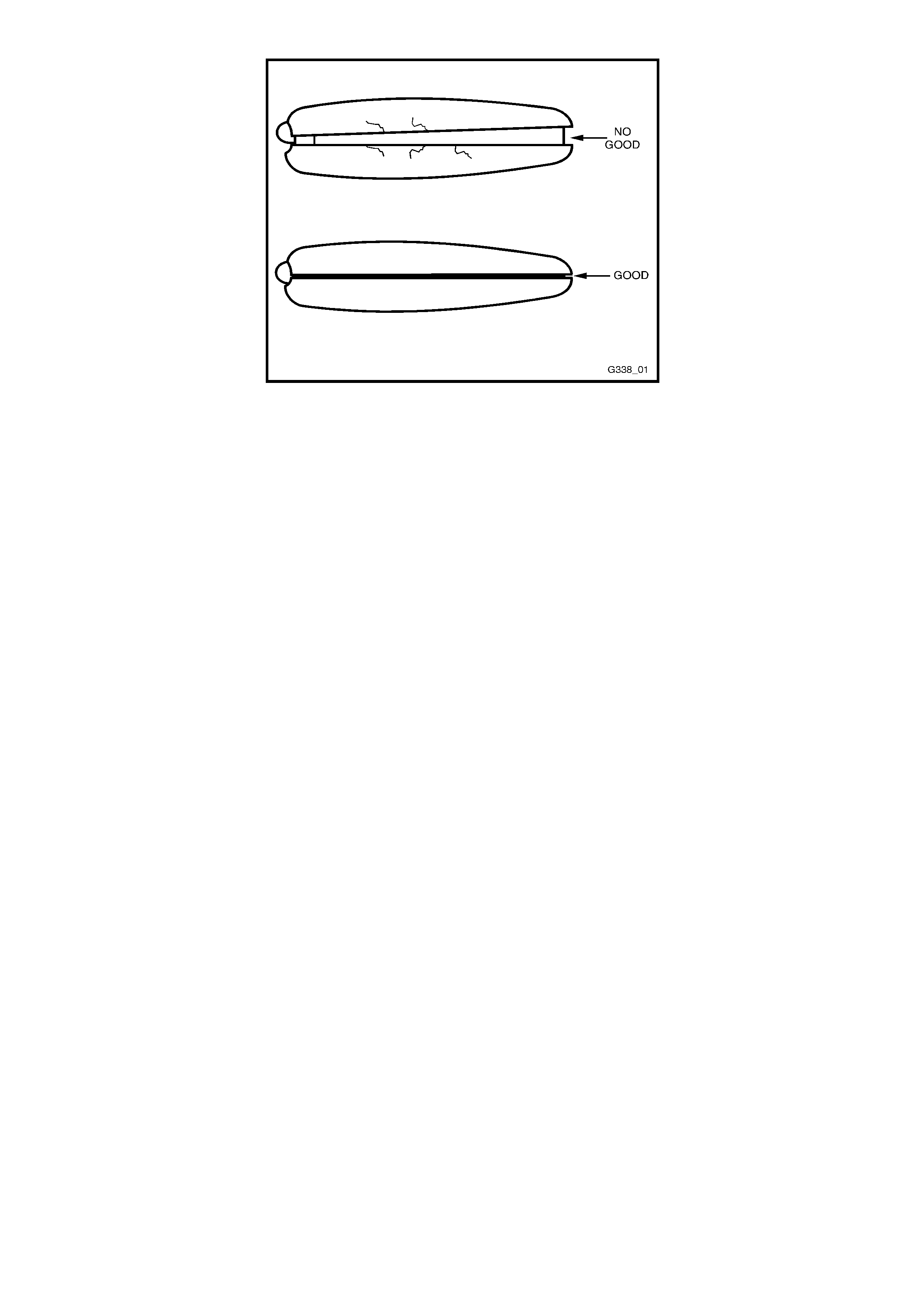
Figure 12J-2-124A
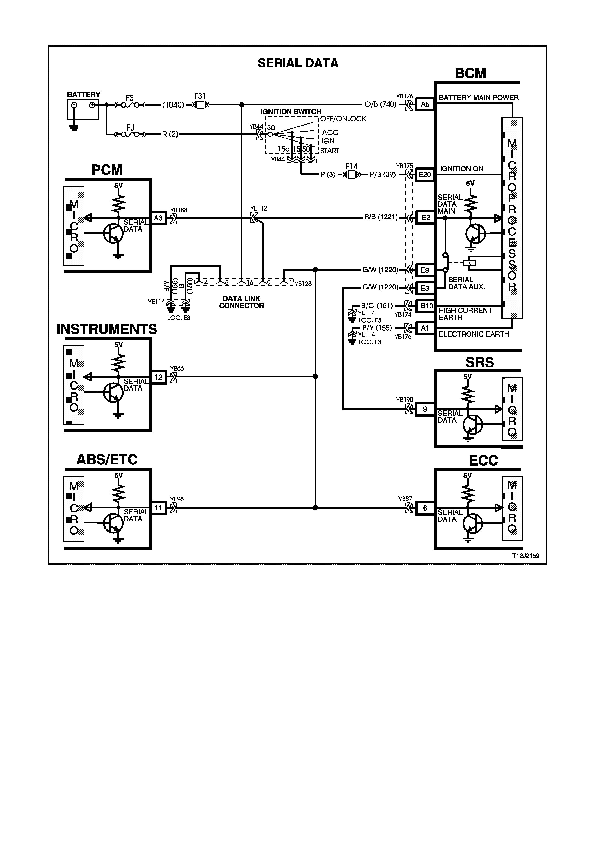
4.2 SERIAL DATA COMMUNICATION
Figure 12J-2-125
GENERAL INFORMATION
The VT Series Model uses a Bus Master communication system, where the BCM is the Bus Master.
The BCM periodically polls (surveys) each device on the bus and requests status data.
The devices connected to the bus are:
• Body Control Module (BCM)
• Powertrain Control Module (PCM)
• Instrument cluster (INS)
• Antilock Brake System / Electronic Traction Control (ABS/ETC)
• Supplemental Restraint System (SRS)
• Electronic Climate Control (ECC)
• External diagnostic scan tool (TECH 2)
The data provided by each device may be utilised by any device connected to the bus.
Each device has a unique response Message Identifier Word (MIW) for ease of identification.
The bus master (BCM) polls each control module with a serial data message which includes the BCM’s MIW. The
other control modules respond by putting a serial data message back onto the bus. The other control modules
message includes its own MIW and data, of which is retrieved and utilised by any device on the bus requiring it.
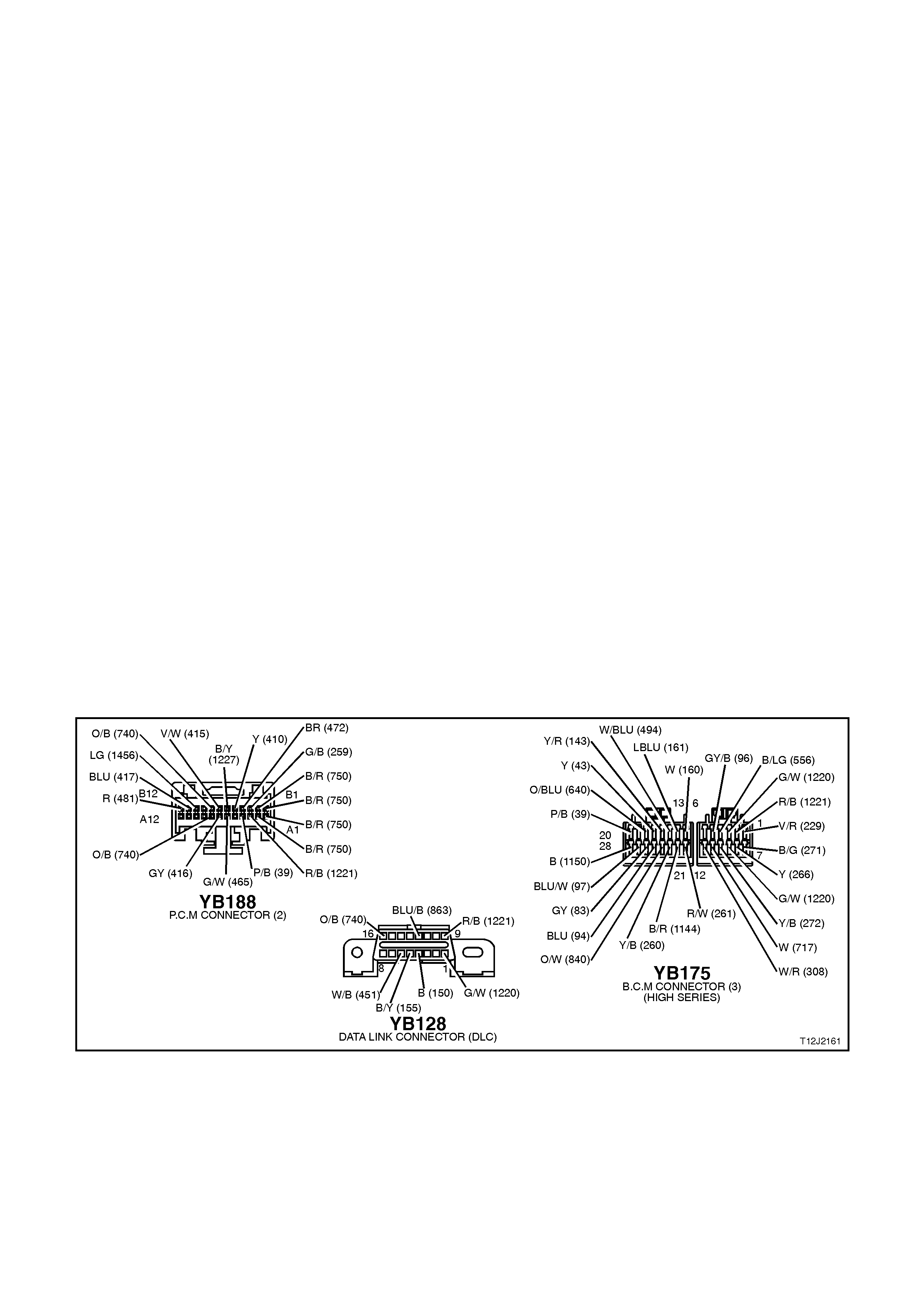
Excluding the PCM, the BCM polls each device for a status update once every 300 milliseconds. The BCM polls the
PCM twice every 300 milliseconds.
When the ignition is switched from OFF to ON, the BCM will communicate with the PCM, via the main serial data
line (circuit 1221), for antitheft purposes and TECH 2 will be able to communicate with any module via the ALDL
mode. If the BCM does not receive an OK TO START message from the PCM within 0.5 seconds of the ignition
being switched on, the auxiliary serial data line (circuit 1220) is isolated via switching within the BCM.
The isolation of the auxiliary serial data line during this period eliminates any possibility of a device failure other than
the PCM or BCM causing a problem on the bus and inhibiting antitheft communications. This period (know as short
loop time) continues until the PCM responds with an acknowledgment or a maximum of 5 seconds, after which the
BCM will switch to the standard polling sequence.
Following successful antitheft communications, the BCM begins sequential polling of devices on the bus and normal
system operation is established.
When the ignition is switched OFF, the BCM continues to poll, allowing for TECH 2 communications and external
control of the bus prior to the ignition being switched ON.
TEST DESCRIPTION
The numbers below refer to step numbers in the following diagnostic chart.
1. Ensures TECH 2 is functioning correctly.
2. Checks if TECH 2 can communicate with the BCM.
3. Checks if TECH 2 can communicate with the PCM.
4. Checks if TECH 2 can communicate with all the devices (SRS, ABS/ETC, ECC, INS) on the auxiliary serial data
line.
5. Determines if there is a fault in the serial data circuit (1221) between the BCM and PCM by starting the engine. If
serial data was lost while the engine was running, the engine will restart but there will be a one second delay.
6. Checks continuity of circuit 1221 between the BCM and the DLC.
7. Checks if main serial data line crash is cause by control module interference connected to the auxiliary serial
data line, or a short battery + or earth on the auxiliary data line.
8. Checks for correct voltage on the serial data line.
9. Checks if the PCM is causing interface on the serial data line.
10. Checks integrity of circuit 1221 between the BCM and PCM, and if there is a problem with the PCM.
11. Checks to establish whether lost communication between modules on the auxiliary serial data line and TECH 2
is due to an open in circuit 1221 or the module itself.
12. Checks to establish whether loss of communication on the auxiliary serial data line is due to an open in circuit
1221 or the BCM.
Figure 12J-2-126

STEP ACTION VALUE YES NO
1. • Connect TECH 2 to
DLC.
• Turn ignition ON.
• Push power button on
TECH 2.
• Does TECH 2 power
up (screen will
illuminate display
TECH 2)?
Go to Step 2. Go to TECH 2
diagnosis, refer
to Section 0C
TECH 2 .
2. • With TECH 2 still
connected and ignition
ON, select
DIAGNOSTICS /
BODY / BODY
CONTROL MODULE.
• Does TECH 2 display
BCM system
identification
information (BCM level
and type)?
Go to Step 3. Go to Step 5.
3. • With TECH 2 still
connected, ignition
ON, exit BODY and
select DIAGN O STICS
/ ENGINE / ENGINE
TYPE (ie V6).
• Does TECH 2 display
PCM system
identification
information (ie. prom
identification)?
Go to Step 4. Go to Step 12.
4. • With TECH 2 still
connected, ignition
ON, exit ENGINE
DIAGNOSTICS and
select BODY / DTC
CHECK / DTC
CHECK.
• Can TECH 2
communicate with all
control modules fitted
to the vehicle (if NO
DATA is displayed next
to a control module,
then there is no
communication
between TECH 2 and
that control module)?
System OK. Go to Step 13.
5. • Will the engine crank
and start immediately
the key is turned from
off to start (no delay)?
Go to Step 6. Go to Step 8.

STEP ACTION VALUE YES NO
6. • Turn Ignition OFF
• Back probe DLC
connector YB128,
terminal 9, circuit 1221
(Red/Black wire) and
BCM connector
YB175, terminal E2,
circuit 1221 (Red/Black
wire) with an
Ohmmeter.
• Is value as specified?
Below
1 ohm Go to Step 7. Check and
repair open in
circuit 1221
between DLC
and BCM.
Recheck and
verify repair.
7. • Disconnect control
modules on auxiliary
serial data line
(ABS/ETC, ECC, SRS,
INS) one at a time
checking each time if
TECH 2 can
communicate with the
BCM (refer to Step 2).
• Does communication
between the BCM and
TECH 2 resume after
disconnecting any of
the control modules?
Go to suspect
control module
diagnosis in the
relevant Section.
Check and
repair short to
B+ or earth in
circuit 1220.
Recheck and
verify repair.
8. • Turn ignition ON.
• Back probe DLC
connector YB128,
terminal 9, circuit 1221
(Red/Black wire) with a
volt meter to earth.
• Is voltage as
specified?
Fluctuates
between
3 and 5
volts
Go to Step 9. Go to Step 10.
9. • Disconnect PCM.
• Can TECH 2
communicate with the
BCM (refer to Step 2)?
Go to PCM
diagnostics in
Section 6C1
POWERTRAIN
MANAGEMENT
- V6 ENGINE
or
Section 6C2
POWERTRAIN
MANAGEMENT
- V8 ENGINE.
Go to theft
deterrent
diagnosis, refer
4.4 THEFT
DETERRENT in
this Section.
10. • Disconnect PCM.
• Can TECH 2
communicate with the
BCM (refer to Step 2)?
Go to PCM
diagnostics in
Section 6C1
POWERTRAIN
MANAGEMENT
- V6 ENGINE
or
Section 6C2
POWERTRAIN
MANAGEMENT
- V8 ENGINE.
Go to Step 11.

STEP ACTION VALUE YES NO
11. • Disconnect BCM and
TECH 2.
• Check integrity (ie.
Short to B+, short to
earth, and continuity)
of circuit 1221
(Red/Black wire)
between BCM and
DLC, and PCM and
DLC.
• Is circuit 1221 OK ?
Go to theft
deterrent
diagnosis, refer
4.4 THEFT
DETERRENT in
this Section.
Repair circuit
1221 as
necessary.
Recheck and
verify repair.
12. • Turn ignition OFF.
• Back probe BCM
connector YB175,
terminal E2, circuit
1221 (Red/Black wire)
and PCM connector
YB188, terminal A3,
circuit 1221 (Red/Black
wire) with an
Ohmmeter.
• Is value as specified?
Below
1 ohm Go to PCM
diagnostics in
Section 6C1
POWERTRAIN
MANAGEMENT -
V6 ENGINE
or
Section 6C2
POWERTRAIN
MANAGEMENT -
V8 ENGINE.
Check and repair
open in circuit
1221 between
PCM and BCM.
13. • In Step 4, was TECH 2
able to communicate
with at least one of the
control modules on the
auxiliary serial data
line (ABS/ETC, INS,
ECC, SRS)?
• NOTE:
• TECH 2 will display
NO DATA next to a
control module that it
can not communicate
with in the DTC
CHECK mode.
Go to Step 14. Go to Step 15.
14. • Check continuity
between BCM and
suspect control module
in circuit 1220
(Green/White wire).
• Does continuity exist?
Go to suspect
control module
diagnosis in the
relevant Section.
Repair open in
circuit 1220
between suspect
control module
and the BCM.
Recheck and
verify repair.
15. • Check continuity
between BCM and all
control modules on the
auxiliary serial data
line.
• Does continuity exist?
Replace BCM,
refer to 2.2 HIGH
SERIES BCM in
this Section.
Recheck and
verify repair.
Repair open in
circuit 1220.
Recheck and
verify repair.
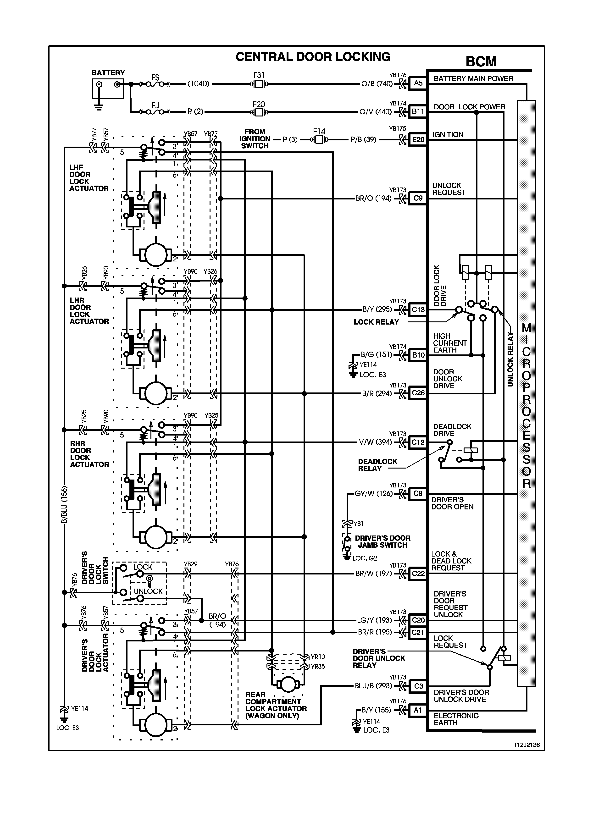
4.3 CENTRAL DOOR LOCKING
Figure 12J-1-127

GENERAL INFORMATION
The central door locking system provides for locking and unlocking of all doors and tailgate (station wagon models)
as well as enhanced locking or deadlock (doors only).
The system incorporates the following functions:
1. Door and tailgate locking activated via:
Driver's door lock actuator (mechanically linked to door interior snib and door latch).
Left-hand front passenger’s door lock actuator (mechanically linked to interior snib button).
Driver’s door lock microswitches, which are also mechanically linked to the door latch, and therefore linked to the
actuators. VT Series Models require microswitch activation to force lock (and unlock) without moving the
actuator.
Pressing the lock button on remote coded key (provided the driver’s door is closed).
2. Door and tailgate unlocking via:
All door lock actuators (mechanically linked to door interior snib).
Pressing the unlock button on remote coded key.
The driver’s door lock cylinder can also be moved independently of the actuator, allowing unlocking of the driver’s
door latch in the case where the actuator is stuck down, ie. deadlock when the battery is discharged.
3. Single and Two Stage Unlocking
The BCM is capable of operating in either of two unlock modes, either two or single stage unlock. The BCM, as
fitted to the vehicle, is programmed to operate the central door locking system in the two stage unlock mode.
Two Stage Unlock
In two stage unlock mode, when the remote coded key unlock button is depressed for 0.25 seconds, the BCM, on
receiving the unlock request from the remote coded key via the remote receiver, will unlock the driver’s door only. If
the remote coded key unlock button is depressed again for 0.25 seconds the BCM, on receiving the second unlock
request from the remote coded key, will unlock all passenger doors.
Or alternatively, if the remote coded key is depressed continuously for 0.5 seconds, the BCM, on receiving the
unlock request from the remote coded key, will unlock all doors; first the driver’s door, then all passenger doors.
Single Stage Unlock
In single stage unlock mode, when the remote coded key unlock button is depressed for 0.25 seconds or longer,
the BCM on receiving the unlock request from the remote coded key, will unlock all doors simultaneously.
With TECH 2, the BCM can be programmed to operate in either two stage or single stage unlock (depending on the
vehicle’s owner or operator requirements).
If a short circuit exists on either the lock or unlock signal inputs, the opposing input is still able to perform its
function. This enables the doors to be unlocked when a short circuit exists on the lock input or vice-versa.
To protect the motors used in the door and tailgate lock actuators, in the event of multiple activation's within a
defined time period, the system will time-out and protect the motors from damage. After a fixed time delay, the
system will re-activate as normal.
The deadlock feature provides for mechanical jamming of the door lock actuators. This is achieved electrically via
the driver's door lock microswitch.
NOTE:
Deadlock is inhibited whilst the ignition is on.
SYSTEM CHECK
The operation of the Central Door Locking System is independent of the ignition being switched ON or OFF.
'Deadlock' refers to the electrical means that can be activated to ensure vehicle security by inhibiting door lock
operation.
Even though the electronic theft deterrent system, via the remote coded key, can activate the lock on each door, it
does not engage the deadlocking of the doors.
Central Locking and Unlocking
Operation of this system can be effected as follows;
1. Driver’s door, outside key and inside locking (snib) button (locking and unlocking).
2. Left-hand front passenger door inside locking (snib) button (locking and unlocking)
3. Rear passenger doors inside locking (snib) button (only unlocking is possible).
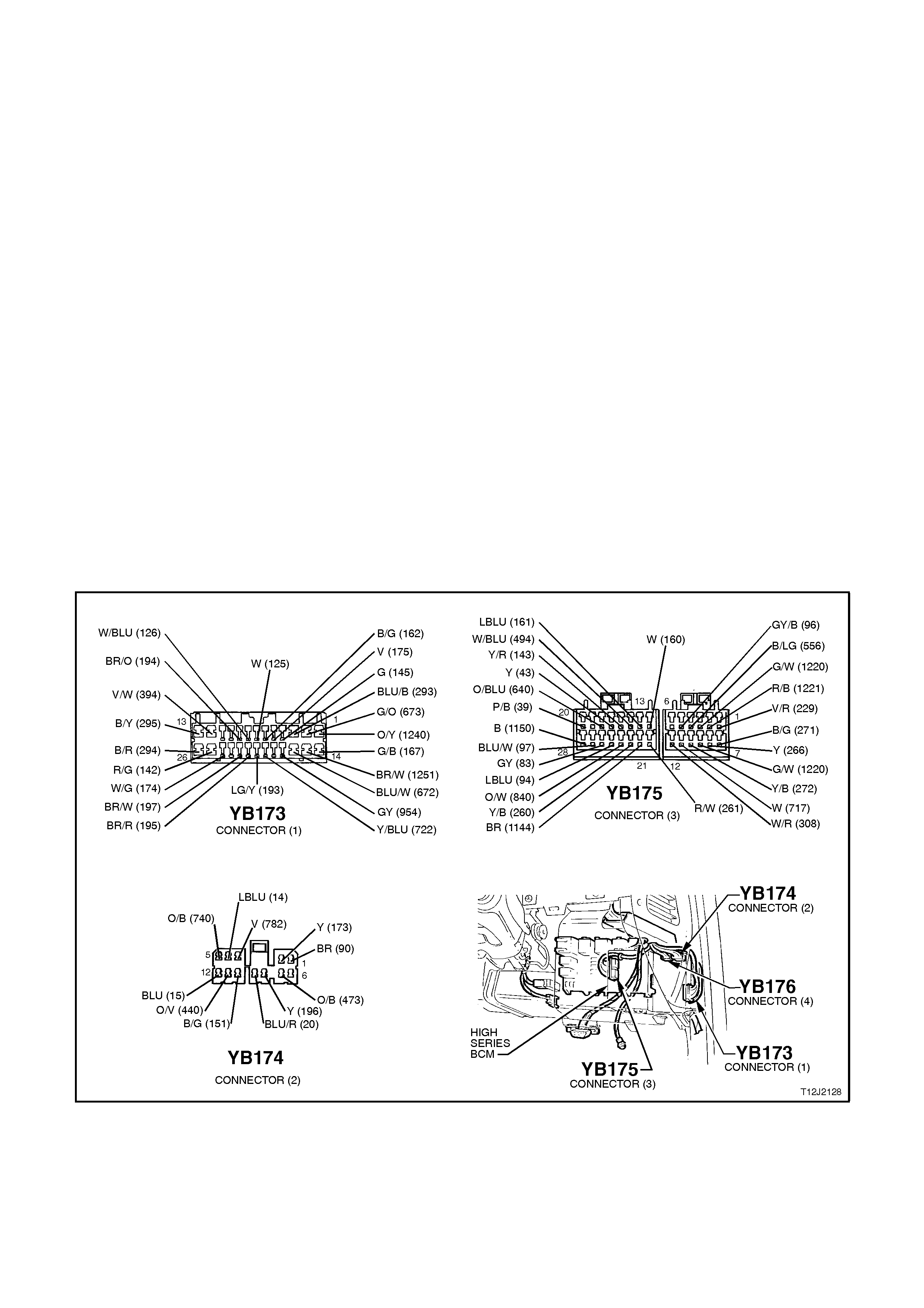
Deadlock
The deadlocking feature applies to all four doors, but not to the luggage compartment lid or tailgate.
After the deadlocking feature device has been engaged, unlocking is possible at the driver’s door from outside, by
inserting the key into the driver’s door lock cylinder and turning the key to the unlock position or by activating the
unlock button on the remote key to unlock the deadlocks on all doors. Either method only unlocks the driver’s door
when the two stage unlocking is enabled.
To ensure access to the vehicle if the electrical system should fail (discharged battery), after the system has been
engaged, the driver’s door lock cylinder can be moved independently of the actuator and therefore allowing
unlocking of the driver’s door latch.
The rear compartment lid or tailgate can be locked/unlocked when the mechanical deadlocking feature is actuated,
while leaving the doors secured. However, if the theft deterrent system has been activated, the alarm will sound
when the rear compartment lid is raised (sedans only).
NOTE:
Deadlocking is not possible with the ignition in the ON position.
Overheating Prevention
In the event of multiple activation's within a defined time period, the central door locking system will be deactivated
and remain inoperative for a defined time period to prevent the door actuators from overheating. After a fixed time
delay, the system will re-activate and operate as normal.
Diagnostics
NOTE:
When investigating a complaint of a central door system locking problem or malfunction, always start the diagnosis
with the functional check in this Section.
The functional check is a quick check of the central door locking system that will refer the reader to the appropriate
diagnostic chart in this Section.
When conducting the central door locking diagnostic tests, some procedures require locking and unlocking of the
door lock mechanism. Therefore, as an aid in testing, leave the appropriate door open and use a screw driver to
rotate the door lock mechanism to the locked position.
Figure 12J-2-128

STEP ACTION VALUE YES NO
1. • All doors locked.
• Operate unlock button
remote coded key
within 4 metres of
driver’s side B pillar.
• Does driver’s door
unlock (2 stage
unlocking) or all doors
(single stage
unlocking)?
Go to Step 3. Go to Step 2.
2. • All doors locked.
• Insert ignition key into
driver’s door lock
cylinder and operate
door unlock
microswitch (turn key
to unlock position).
• Do all doors unlock?
Go to remote
receiver
diagnosis, refer
4.20 REMOTE
RECEIVER/KEY
in this Section.
Go to Part A
UNLOCKING
DOORS,
DRIVER’S DOOR
LOCK
MICROSWITCH.
3. • All doors unlocked.
• All doors closed.
• Operate lock button on
remote coded key
within 4 metres of
driver’s side B pillar.
• Do all doors lock?
Go to Step 5. Go to Step 4.
4. • All doors unlocked.
• All doors closed.
• Insert ignition key into
driver’s door lock
cylinder and operate
door lock microswitch
(turn key to lock
position).
• Do all doors lock?
Go to remote
receiver
diagnosis, refer
4.20 REMOTE
RECEIVER/KEY
in this Section.
Go to Part B
LOCK DOORS,
DRIVER’S DOOR
LOCK
MICROSWITCH.
5. • All doors locked.
• All doors closed.
• Insert ignition key into
driver’s door lock
cylinder and operate
door unlock
microswitch (turn key
to unlock position).
• Do all doors unlock?
Go to Step 6. Go to Part A
UNLOCKING
DOORS,
DRIVER’S DOOR
LOCK
MICROSWITCH.
6. • All doors closed.
• Insert ignition key into
driver’s door lock
cylinder and operate
door lock microswitch
(turn key to lock
position).
• Do all doors lock?
Go to Step 7. Go to Part B
LOCK DOORS,
DRIVER’S DOOR
LOCK
MICROSWITCH
7. • All doors locked (not
deadlocked).
• Activate driver’s door
snib (unlock).
• Do all doors unlock?
Go to Step 8. Go to Part C
UNLOCK
DOORS,
DRIVER’S DOOR
ACTUATOR
(SNIB).

STEP ACTION VALUE YES NO
8. • All doors closed.
• Activate driver’s door
snib (lock).
• Do all doors lock?
Go to Step 9. Go to Part D
LOCK DOORS,
DRIVER’S DOOR
ACTUATOR
(SNIB)
9. • All doors locked (not
deadlocked).
• Activate each
passenger’s door snib
(unlock).
• Do all doors unlock
(each snib)?
Go to Step 10. Go to Part E
UNLOCK
DOORS,
PASSENGER’S
DOOR
ACTUATOR
(SNIB).
10. • All doors closed.
• Activate left hand front
passenger’s door snib
(lock).
• Do all doors lock?
Go to Step 11
(wagon)
or
Go to Step 13
(sedan).
Go to Part F
LOCK DOORS,
PASSENGER’S
LHF DOOR
ACTUATOR
(SNIB).
11. • Tailgate locked.
• Insert ignition key into
driver’s door lock
cylinder and operate
door unlock
microswitch (turn key
to unlock position).
• Does tailgate unlock?
Go to Step 12. Go to Part G
UNLOCK
TAILGATE.
12. • Tailgate unlocked.
• Insert ignition key into
driver’s door lock
cylinder and operate
door lock microswitch
(turn key to lock
position).
• Does tailgate lock?
Go to Step 13. Replace tailgate
lock actuator,
refer to
1A4 REAR
COMPARTMENT
LID AND
TAILGATE.
13. • Doors unlocked.
• Insert ignition key into
driver’s door lock
cylinder and deadlock
doors (turn key to lock
twice sequentially).
• Are all doors
deadlocked?
Go to Step 14. Go to Part H
DEADLOCKING
DOORS.
14. • Doors deadlocked.
• Insert ignition key into
driver’s door lock
cylinder and operate
door unlock
microswitch (turn key
to unlock position).
• Do all doors unlock?
System OK. Go to Part I
UNLOCKING
DOORS FROM
DEADLOCK.

PART A - UNLOCKING DOORS, DRIVER’S DOOR LOCK MICROSWITCH
TEST DESCRIPTION
The numbers below refer to step numbers in the following diagnostic chart.
1. Uses TECH 2 to unlock all doors (establish whether problem is with the output or the input of the BCM
2. Uses TECH 2 to check for false DRIVERS UNLOCK signal.
3. Checks if false DRIVERS UNLOCK signal initiated by BCM.
5. Checks for battery voltage at input to BCM.
6. Checks for earth to door actuators at output of BCM.
7. Checks circuit 394.
8. Checks for driver’s door unlock drive when commanded by TECH 2.
9. Checks for passenger doors unlock drive when commanded by TECH 2.
10. Checks circuits 293 and 294 / actuators.
11. Checks for high current earth at BCM.
12. Uses TECH 2 to check for DRIVERS UNLOCK SWITCH UNLOCK signal at microprocessor of BCM.
13. Checks DRIVER’S UNLOCK SWITCH UNLOCK signal at input to BCM - circuit 193.
14. Checks circuit 156 / microswitch.
15. Checks if false DRIVER’S UNLOCK signal initiated by driver’s door actuator.
16. Checks if false DRIVER’S UNLOCK signal initiated by driver’s door lock microswitch / short to earth, circuit
193.
STEP ACTION VALUE YES NO
1. • Doors locked.
• Connect TECH 2 to
the DLC.
• Select BODY / BODY
CONTROL MODULE /
MISCELLANEOUS
TESTS / CENTRAL
LOCK and conduct
test as instructed by
TECH 2.
• Do all doors unlock?
Go to Step 2. Go to Step 4.
2. • Doors locked.
• With TECH 2 still
connected, exit
MISCELLANEOUS
TEST and select
DATA DISPLAY.
• •Scroll to
DRIVER’S UNLOCK
SWITCH.
• Does screen display
DRIVER’S UNLOCK
SWITCH UNLOCK?
Go to Step 3. Go to Step 12.
3. • With TECH 2 still
connected and
DRIVERS UNLOCK
SWITCH displayed.
• Disconnect BCM
connector YB173.
• Does screen display
DRIVERS UNLOCK
SWITCH UNLOCK?
Replace BCM Go to Step 15.
4. • While conducting test
in Step 1, did at least
one passenger door
unlock?
Go to Step 7. Go to Step 5.

STEP ACTION VALUE YES NO
5. • Back probe BCM
connector YB174,
terminal B11, circuit
440 (Orange/Violet
wire) w ith a Voltmeter
to earth.
• Is voltage as
specified?
12 volts Go to Step 6. Check and repair
circuit 440
(including fuse
F20). Recheck
and verify repair.
6. • Back probe BCM
connector YB173,
terminal C12, circuit
394 (Violet/White wire)
with an Ohmmeter to
earth.
• Is reading as
specified?
Below
1 ohm Go to Step 7. Go to Step 12.
7. • Back probe all door
actuator connectors
YB57/YB90, terminal
1, circuit 394
(Violet/White wire) with
an Ohmmeter to earth.
• Is reading as
specified?
Below
1 ohm Go to Step 8. Repair open in
circuit 394.
Recheck and
verify repair.
8. • Doors locked.
• Back probe BCM
connector YB173,
terminal C3, circuit 293
(Blue /Black wire) with
a Voltmeter to earth.
• Connect TECH 2 to
DLC.
• Select BODY / BODY
CONTROL MODULE /
MISCELLANEOUS
TESTS / CENTRAL
LOCK.
• Conduct test as
instructed by TECH 2
and unlock doors.
• Is voltage as
specified?
12 volts
for 0.7
seconds
Go to Step 9. Replace BCM,
refer to 2.2 HIGH
SERIES BCM in
this Section.
Recheck and
verify repair.
9. • Door locked.
• Back probe BCM
connector YB173,
terminal C26, circuit
294 (Black/Red wire)
with a Voltmeter to
earth.
• Repeat TECH 2
CENTRAL LOCK test
and unlock doors.
• Is voltage as
specified?
12 volts
for 0.7
seconds
Go to Step 10. Replace BCM,
refer to 2.2 HIGH
SERIES BCM in
this Section.
Recheck and
verify repair.

STEP ACTION VALUE YES NO
10. • Back probe all door
actuator connectors
YB57/YB90, terminal
2, circuit 293
(Blue/Black wire) and
circuit 294 (Black/Red
wire) w ith a Voltmeter
to earth.
• Repeat TECH 2
CENTRAL LOCK test
and unlock doors.
• Is voltage as
specified?
12 volts
for 0.7
seconds
Go to door lock
actuator
adjustment
procedure in
Section 1A5
FRONT AND
REAR DOOR
ASSEMBLIES.
Repair open in
circuit 293 or 294.
Recheck and
verify repair.
11. • Back probe BCM
connector YB174,
terminal B10, circuit
151 (Black/Green wire)
with an Ohmmeter to
earth.
• Is reading as
specified?
Below
1 ohm Replace BCM,
refer to 2.2 HIGH
SERIES BCM in
this Section.
Recheck and
verify repair.
Repair open in
circuit 151.
Recheck and
verify repair.
12. • Connect TECH 2 to
DLC
• Select BODY / BODY
CONTROL MODULE /
DATA DISPLAY and
scroll to DRIVER’S
UNLOCK SWITCH
• Insert ignition key into
driver’s door lock
cylinder and operate
door unlock
microswitch (turn key
to unlock position).
• Does screen display
DRIVER’S UNLOCK
SWITCH UNLOCK?
Replace BCM,
refer to 2.2 HIGH
SERIES BCM in
this Section.
Recheck and
verify repair.
Go to Step 13.
13. • Back probe BCM
connector YB173,
terminal C20, circuit
193 (LGreen/Yellow
wire) with an
Ohmmeter to earth.
• Insert ignition key into
driver’s door lock
cylinder and operate
door unlock
microswitch (turn key
to unlock position).
• Is reading as
specified?
Below
1 ohm Replace BCM,
refer to 2.2 HIGH
SERIES BCM in
this Section.
Recheck and
verify repair.
Go to Step 14.
14.
• Back probe driver’s
door lock switch
connector YB29, circuit
156 (Black/Blue wire)
with an Ohmmeter to
earth.
• Is reading as
specified?
Below
1 ohm Replace driver’s
door exterior
handle assembly,
refer Section 1A5
FRONT AND
REAR DOOR
ASSEMBLIES.
Repair open in
circuit 156.
Recheck and
verify repair.

STEP ACTION VALUE YES NO
15.
• With TECH 2 still
connected and
DRIVER’S UNLOCK
SWITCH displayed,
reconnect BCM
connector YB173.
• Disconnect driver’s
door actuator
connector YB57.
• Does screen display
DRIVERS UNLOCK
SWITCH UNLOCK?
Go to Step 17 Go to door lock
actuator
adjustment
procedure in
Section 1A5
FRONT AND
REAR DOOR
ASSEMBLIES
16.
• With TECH 2 still
connected and
DRIVER’S UNLOCK
SWITCH displayed,
disconnect driver’s
door lock switch
connector YB29.
• Does screen display
DRIVER’S UNLOCK
SWITCH UNLOCK?
Check and repair
short in
circuit 193
(LGreen/
Yellow wire).
Replace driver’s
door exterior
handle assembly,
refer Section 1A5
FRONT AND
REAR DOOR
ASSEMBLIES.
PART B - LOCK DOORS, DRIVER’S DOOR LOCK MICROSWITCH
TEST DESCRIPTION
The numbers below refer to step numbers in the following diagnostic chart.
1. Uses TECH 2 to lock all doors (establish whether problem is with the output or the input of the BCM.
2. Uses TECH 2 to check for false DRIVER’S LOCK signal.
3. Checks if false DRIVER’S LOCK signal initiated by BCM.
4. Uses TECH 2 to check for DRIVER’S DOOR CLOSED signal at microprocessor of BCM.
5. Checks for earth to driver’s door actuators at output of BCM.
6. Checks for earth to passenger’s door actuators at output of BCM.
7. Checks for door lock drive when commanded by TECH 2.
8. Checks circuit 295 / actuators.
10. Uses TECH 2 to check for DRIVER’S LOCK SWITCH LOCK signal at microprocessor of BCM.
11. Checks DRIVER’S LOCK SWITCH LOCK signal at input to BCM.
12. Checks circuit 197.
13. Checks circuit 156 / microswitch.
14. Checks if false DRIVER’S LOCK signal initiated by driver’s door lock microswitch / short to earth, circuit 197.

STEP ACTION VALUE YES NO
1. • All doors closed.
• Connect TECH 2 to
the DLC.
• Select BODY / BODY
CONTROL MODULE /
MISCELLANEOUS
TESTS / CENTRAL
LOCK and conduct
test as instructed by
TECH 2.
• Do all doors lock?
Go to Step 2. Go to Step 4.
2. • Doors unlocked.
• With TECH 2 still
connected, exit
MISCELLANEOUS
TEST and select
DATA DISPLAY.
• Scroll to DRIVER’S
LOCK SWITCH.
• Does screen display
DRIVER’S LOCK
SWITCH LOCK?
Go to Step 3. Go to Step 10.
3. • With TECH 2 still
connected and
DRIVERS LOCK
SWITCH displayed.
• Disconnect BCM
connector YB173.
• Does screen display
DRIVERS LOCK
SWITCH LOCK?
Replace BCM,
refer to 2.2 HIGH
SERIES BCM in
this Section.
Recheck and
verify repair.
Go to Step 14.
4. • All doors closed.
• With TECH 2 still
connected, exit
MISCELLANEOUS
TEST and select
DATA DISPLAY.
• Scroll to DRIVERS
DOOR.
• Does screen display
DRIVER’S DOOR
CLOSED?
Go to Step 5. Go to Step 9.
5. • Back probe BCM
connector YB173,
terminal C3, circuit 293
(Blue /Black wire) with
an Ohmmeter to earth.
• Is reading as
specified?
Below
1 ohm Go to Step 6. Replace BCM,
refer to 2.2 HIGH
SERIES BCM in
this Section.
Recheck and
verify repair.
6. • Back probe BCM
connector YB173,
terminal C26, circuit
294 (Black/Red wire)
with an Ohmmeter to
earth.
• Is reading as
specified?
Below
1 ohm Go to Step 7. Replace BCM,
refer to 2.2 HIGH
SERIES BCM in
this Section.
Recheck and
verify repair.

STEP ACTION VALUE YES NO
7. • All doors closed.
• Connect TECH 2 to
the DLC.
• Select BODY / BODY
CONTROL MODULE /
MISCELLANEOUS
TESTS / CENTRAL
LOCK.
• Back probe BCM
connector YB173,
terminal C13, circuit
295 (Black/Yellow
wire) w ith a Voltmeter
to earth.
• Conduct door lock test
as instructed by TECH
2.
• Is voltage as
specified?
12 volts
for 0.7
seconds
Go to Step 8. Replace BCM,
refer to 2.2 HIGH
SERIES BCM in
this Section.
Recheck and
verify repair.
8. • With TECH 2 still
connected and
MISCELLANEOUS
TESTS / CENTRAL
LOCKING selected,
back probe all door
actuator connectors
YB90/YB57, terminal
6, circuit 295
(Black/Yellow wire)
with a Voltmeter to
earth.
• Conduct door lock
actuator test as
instructed by TECH 2.
• Is voltage as
specified?
12 volts
for 0.7
seconds
Go to door lock
actuator
adjustment
procedure in
Section 1A5
FRONT AND
REAR DOOR
ASSEMBLIES.
Check and repair
open in circuit 295
Recheck and
verify repair.
9. • With TECH 2 still
connected and DATA
DISPAY selected,
scroll to DRIVERS
DOOR display.
• Disconnect BCM
connector YB173.
• Does screen display
DRIVERS DOOR
CLOSED?
Check and repair
faulty door jamb
switch, or short to
ground in
circuit 126
Recheck and
verify repair.
Replace BCM,
refer to 2.2 HIGH
SERIES BCM in
this Section.
Recheck and
verify repair.
10. • With TECH 2 still
connected and DATA
DISPLAY selected,
scroll to DRIVER’S
LOCK SWITCH.
• Insert ignition key into
driver’s door lock
cylinder and operate
door lock microswitch
(turn key to lock
position).
• Does screen display
DRIVER’S LOCK
SWITCH LOCK?
Replace BCM,
refer to 2.2 HIGH
SERIES BCM in
this Section.
Recheck and
verify repair.
Go to Step 11.

STEP ACTION VALUE YES NO
11. • Back probe BCM
connector YB173,
terminal C22, circuit
197 (Brown/White
wire) with an
Ohmmeter to earth.
• Insert ignition key into
driver’s door lock
cylinder and operate
door lock microswitch
(turn key to lock
position).
• Is reading as
specified?
Below
1 ohm Replace BCM,
refer to 2.2 HIGH
SERIES BCM in
this Section.
Recheck and
verify repair.
Go to Step 12.
12. • Back probe driver’s
door lock switch
connector YB29, circuit
197 (Brown/White
wire) with an
Ohmmeter to earth.
• Insert ignition key into
driver’s door lock
cylinder and operate
door lock microswitch
(turn key to lock
position)
• Is reading as
specified?
Below
1 ohm Repair open in
circuit 197.
Recheck and
verify repair.
Go to Step 13.
13. • Back probe driver’s
door lock switch
connector YB29, circuit
156 (Black/Blue wire)
with an Ohmmeter to
earth.
• Is reading as
specified?
Below
1 ohm Replace driver’s
door exterior
handle assembly,
refer Section 1A5
FRONT AND
REAR DOOR
ASSEMBLIES.
Repair open in
circuit 156.
Recheck and
verify repair.
14. • With TECH 2 still
connected and
DRIVERS LOCK
SWITCH displayed,
reconnect BCM
connector YB173.
• Disconnect Driver’s
door lock switch
connector YB29.
• Does screen display
DRIVERS LOCK
SWITCH LOCK?
Repair short to
earth in circuit
197. Recheck and
verify repair.
Replace driver’s
door exterior
handle assembly,
refer to Section
1A5 FRONT AND
REAR DOOR
ASSEMBLIES.

PART C - UNLOCK DOORS, DRIVER’S DOOR ACTUATOR (SNIB)
TEST DESCRIPTION
The numbers below refer to step numbers in the following diagnostic chart.
1. Checks driver’s door snib unlock signal (earth) at driver’s door actuator when operating driver’s door snib
UNLOCK.
2. Checks circuit 156 / driver’s door actuator.
UNLOCK DOORS, DRIVER’S DOOR ACTUATOR (SNIB)
STEP ACTION VALUE YES NO
1. • All doors locked.
• Back probe driver’s
door actuator
connector YB57,
terminal 3, circuit 193
(L Green/Yellow wire)
with an Ohmmeter to a
sound earth.
• Unlock doors using
driver’s snib button.
• Is reading as
specified?
Below
1 ohm Check and repair
open in circuit 193
Recheck and
verify repair.
Go to Step 2.
2. • Back probe driver’s
door actuator
connector YB57,
terminal 5, circuit 156
(Black/Blu e wire) with
an Ohmmeter to earth.
• Is reading as
specified?
Below
1 ohm Go to door lock
actuator
adjustment
procedure in
Section 1A5
FRONT AND
REAR DOOR
ASSEMBLIES.
Check and repair
open in
circuit 156.
Recheck and
verify repair.
PART D - LOCK DOORS, DRIVER’S DOOR ACTUATOR (SNIB)
TEST DESCRIPTION
The numbers below refer to step numbers in the following diagnostic chart.
1. Uses TECH 2 to check for false ACTUATOR LOCK SWITCH LOCK signal.
2. Checks if false ACTUATOR LOCK SWITCH LOCK signal initiated by BCM.
3. Uses TECH 2 to check for ACTUATOR LOCK SWITCH LOCK signal at microprocessor of BCM.
4. Checks for ACTUATOR LOCK SWITCH LOCK signal at input to BCM.
5. Checks circuit 195 / driver’s door actuator.
6. Checks if false ACTUATOR LOCK SWITCH LOCK signal initiated by driver’s door actuator.
7. Checks if false ACTUATOR LOCK SWITCH LOCK signal initiated by LHF passenger door / short to earth in
circuit 195.

STEP ACTION VALUE YES NO
1. • All doors locked.
• Connect TECH 2 to
DLC.
• Select BODY / BODY
CONTROL MODULE /
DATA DISPLAY and
scroll to ACTUATOR
LOCK SWITCH.
• Does screen display
ACTUATOR LOCK
SWITCH LOCK?
Go to Step 2. Go to Step 3.
2. • With TECH 2 still
connected and
ACTUATOR LOCK
SWITCH displayed,
disconnect BCM
connector YB173.
• Does screen display
ACTUATOR LOCK
SWITCH LOCK?
Replace BCM,
refer to 2.2 HIGH
SERIES BCM in
this Section.
Recheck and
verify repair.
Go to Step 6.
3. • Lock doors using
driver’s snib button.
• Does screen display
ACTUATOR LOCK
SWITCH LOCK?
Replace BCM,
refer to 2.2 HIGH
SERIES BCM in
this Section.
Recheck and
verify repair.
Go to Step 4.
4. • Back probe BCM
connector YB173,
terminal C21, circuit
195 (Brown/Red wire)
with an Ohmmeter to
earth.
• Lock doors using
driver’s snib button.
• Is value as specified?
Below
1 ohm Replace BCM,
refer to 2.2 HIGH
SERIES BCM in
this Section.
Recheck and
verify repair.
Go to Step 5.

STEP ACTION VALUE YES NO
5. • Back probe driver’s
door actuator
connector YB57,
terminal 4, circuit 195
(Brown/Red wi re) with
an Ohmmeter to earth.
• Lock doors using
driver’s snib button.
• Is value as specified?
Below
1 ohm Check and repair
open in
circuit 195.
Recheck and
verify repair.
Go to door lock
actuator
adjustment
procedure in
Section 1A5
FRONT AND
REAR DOOR
ASSEMBLIES.
6. • With TECH 2 still
connected and
ACTUATOR LOCK
SWITCH displayed,
reconnect BCM
connector YB173.
• Disconnect driver’s
door actuator
connector YB57.
• Does screen display
ACTUATOR LOCK
SWITCH LOCK?
Go to Step 7. Go to door lock
actuator
adjustment
procedure in
Section 1A5
FRONT AND
REAR DOOR
ASSEMBLIES.
7. • With TECH 2 still
connected and
ACTUATOR LOCK
SWITCH displayed,
disconnect LHF
passenger door
actuator connector
YB57.
• Does screen display
ACTUATOR LOCK
SWITCH LOCK?
Check and repair
short to earth in
circuit 195.
Recheck and
verify repair.
Go to door lock
actuator
adjustment
procedure in
Section 1A5
FRONT AND
REAR DOOR
ASSEMBLIES.
PART E - UNLOCK DOORS, PASSENGER’S DOOR ACTUATORS (SNIB)
TEST DESCRIPTION
The numbers below refer to step numbers in the following diagnostic chart.
1. Checks non operating passenger door snib unlock signal (earth) at non operating actuator when operating it’s
snib UNLOCK
2. Uses TECH 2 to check for false ACTUATOR UNLOCK SWITCH UNLOCK (passenger doors) signal.
3. Checks if false ACTUATOR UNLOCK SWITCH UNLOCK signal initiated by BCM.
5. Uses TECH 2 to check for ACTUATOR UNLOCK SWITCH UNLOCK signal at microprocessor of BCM while
operating each of the passenger door snibs.
6. Checks for ACTUATOR UNLOCK SWITCH UNLOCK signal at input to BCM while operating each of the
passenger door snibs.
7. Checks circuit 194.
8. Checks circuit 156 / each passenger door actuator
9. Checks if false ACTUATOR UNLOCK SWITCH UNLOCK signal initiated by any of the passenger door
actuators / short to earth in circuit 194.
10. Checks circuit 156 / passenger door actuator (non operating door actuator).

STEP ACTION VALUE YES NO
1. • All doors locked.
• Unlock each
passenger door using
each snib button.
• Does at least one
passenger door snib
unlock all doors?
Go to Step 2. Go to Step 3.
2. • Back probe actuator
connector, terminal 3
of suspect door
actuator (unlock
switch), circuit 194
(Brown/Orange wire)
with an Ohmmeter to
earth.
• Operate suspect door
lock snib button.
• Is reading as
specified?
Below
1 ohm Repair open in
circuit 194.
Recheck and
verify repair.
Go to Step 10.
3. • All doors locked.
• Connect TECH 2 to
DLC.
• Select BODY / BODY
CONTROL MODULE /
DATA DISPALY.
• Scroll to ACTUATOR
UNLOCK SWITCH.
• Does screen display
ACTUATOR UNLOCK
SWITCH UNLOCK?
Go to Step 4. Go to Step 5.
4. • With TECH 2 still
connected and
ACTUATOR UNLOCK
SWITCH displayed,
disconnect BCM
connector YB173.
• Does screen display
ACTUATOR UNLOCK
SWITCH UNLOCK?
Replace BCM,
refer to 2.2 HIGH
SERIES BCM in
this Section.
Recheck and
verify repair.
Go to Step 9.
5. • All doors unlocked.
• With TECH 2 still
connected and
ACTUATOR UNLOCK
SWITCH displayed
unlock each passenger
door using each snib
button.
• Does the screen
display ACTUATOR
UNLOCK SWITCH
UNLOCK for at least
one of the passenger
doors?
Replace BCM,
refer to 2.2 HIGH
SERIES BCM in
this Section.
Recheck and
verify repair.
Go to Step 6.

STEP ACTION VALUE YES NO
6. • All doors unlocked.
• Back probe BCM
connector YB173,
terminal C9, circuit 194
(Brown/Orange wire)
with an Ohmmeter to
earth.
• Unlock each doors
using each snib button.
• Is value as specified
for at least one of the
actuators?
Below
1 ohm Replace BCM,
refer to 2.2 HIGH
SERIES BCM in
this Section.
Recheck and
verify repair.
Go to Step 7.
7. • Back probe each
passenger door
actuator connector,
terminal 3, circuit 194
(Brown/Orange wire)
with an Ohmmeter to
earth.
• Unlock each
passenger doors using
each snib button.
• Is the reading as
specified for all
actuators?
Below
1 ohm Repair open in
circuit 194.
Recheck and
verify repair.
Go to Step 8.
8. • Back probe each
passenger door
actuator connector,
terminal 5, circuit 156
(Black/Blu e wire) with
an Ohmmeter to earth.
• Is the reading as
specified for all
actuators?
Below
1 ohm Go to door lock
actuator
adjustment
procedure in
Section 1A5
FRONT AND
REAR DOOR
ASSEMBLIES.
Repair open in
circuit 156.
Recheck and
verify repair.

STEP ACTION VALUE YES NO
9. • Reconnect BCM
connector YB173.
• With TECH 2 still
connected and
ACTUATOR UNLOCK
SWITCH displayed,
disconnect each
passenger door
actuator connector one
at a time.
• Does screen display
change from
ACTUATOR UNLOCK
SWITCH UNLOCK to
ACTUATOR UNLOCK
SWITCH OFF when
disconnecting any of
the passenger door
actuator connectors?
Go to door lock
actuator
adjustment
procedure in
Section 1A5
FRONT AND
REAR DOOR
ASSEMBLIES
Check actuator
which caused
display to
change from
UNLOCK to OFF.
Check and repair
short to earth in
circuit 194.
Recheck and
verify repair.
10. • Back probe actuator
connector, terminal 5
of suspect door
actuator/s, circuit 156
(Black/Blu e wire) with
an Ohmmeter to earth.
• Is reading as
specified?
Below
1 ohm Go to door lock
actuator
adjustment
procedure in
Section 1A5
FRONT AND
REAR DOOR
ASSEMBLIES.
Check suspect
actuator/s.
Repair open in
circuit 156.
Recheck and
verify repair.
PART F - LOCK DOORS, LHF PASSENGER DOOR ACTUATOR (SNIB)
TEST DESCRIPTION
The numbers below refer to step numbers in the following diagnostic chart.
1. Checks LHF passenger door snib lock signal (earth) when operating it’s snib button.
STEP ACTION VALUE YES NO
1. • All doors closed.
• Back probe LHF
passenger door
actuator connector
YB57, terminal 4,
circuit 195 (Brown/Red
wire) with an
Ohmmeter to earth.
• Unlock LHF passenger
door using it’s snib
button.
• Is the reading as
specified?
Below
1 ohm Repair open in
circuit 195.
Recheck and
verify repair.
Go to door lock
actuator
adjustment
procedure in
Section 1A5
FRONT AND
REAR DOOR
ASSEMBLIES.
Check LHF
passenger door
actuator.

PART G - UNLOCK TAILGATE
TEST DESCRIPTION
The numbers below refer to step numbers in the following diagnostic chart.
1. Checks for unlock drive at rear compartment lock actuator when commanded by TECH 2.
2. Checks for earth at rear compartment lock actuator.
STEP ACTION VALUE YES NO
1. • Doors and tailgate
locked.
• Connect TECH 2 to
DLC.
• Select BODY / BODY
CONTROL MODULE /
MISCELLANEOUS
TEST / CENTRAL
LOCK.
• Back probe tailgate
lock actuator
connector YR35,
terminal 1, circuit 294
(Black/Red wire) wi th a
Voltmeter to earth.
• Conduct door unlock
test as instructed by
TECH 2.
• Is the voltage as
specified?
12 volts
for 0.7
seconds
Go to Step 2. Repair open in
circuit 294
Recheck and
verify repair.
2. • Back probe tailgate
lock actuator
connector YR35,
terminal 2, circuit 295
(Black/Yellow wire)
with an Ohmmeter to
earth.
• Is reading as
specified?
Below
1 ohm Replace tailgate
lock actuator,
refer to Section
1A4 REAR
COMPARTMENT
LID AND
TAILGATE.
Check and repair
open in
circuit 295.
Recheck and
verify repair.
PART H - DEADLOCKING DOORS
TEST DESCRIPTION
The numbers below refer to step numbers in the following diagnostic chart.
1. Uses TECH 2 to check for false IGNITION ON signal at microprocessor of BCM.
2. Checks for correct IGNITION SIGNAL at input of BCM.
3. Checks for deadlock drive at output of BCM when commanded by TECH 2.

STEP ACTION VALUE YES NO
1. • Ignition OFF.
• Connect TECH 2 to
DLC.
• Select BODY / BODY
CONTROL MODULE /
DATA DISPLAY and
scroll to IGNITION
SWITCH.
• Does screen display
IGNITION SWITCH
ON?
Go to Step 2. Go to Step 3.
2. • Back probe BCM
connector YB175,
terminal E20, circuit 39
(Pink/Bl ack wire) wi th
a Voltmeter to earth.
• Is voltage as
specified?
Ignition
OFF
0 volts
Ignition
ON
12 volts
Replace BCM,
refer to 2.2 HIGH
SERIES BCM in
this Section.
Recheck and
verify repair.
Check and repair
short to
battery positive,
circuit 39 /
ignition switch.
3. • All doors unlocked /
closed.
• With TECH 2 still
connected, exit DATA
DISPLAY and select
MISCELLANEOUS
TESTS / CENTRAL
LOCK.
• Back probe BCM
connector YB173,
terminal C12, circuit
394 (Violet/White wire)
with a Voltmeter to
earth.
• Conduct test and
instructed by TECH 2
and deadlock doors.
• Is voltage as
specified?
12 volts
for 0.7
seconds
Go to door lock
actuator
adjustment
procedure in
Section 1A5
FRONT AND
REAR DOOR
ASSEMBLIES.
Replace BCM,
refer to 2.2 HIGH
SERIES BCM in
this Section.
Recheck and
verify repair.

PART I - UNLOCKING DOORS FROM DEADLOCK
TEST DESCRIPTION
The numbers below refer to step numbers in the following diagnostic chart.
1. Uses TECH 2 to unlock all doors (establish whether problem is with the output or the input of the BCM.
2. Uses TECH 2 to check for false DRIVERS UNLOCK signal.
3. Checks if false DRIVER’S UNLOCK signal initiated by BCM.
5. Checks for battery voltage at input to BCM.
6. Checks for high current earth at BCM.
7. Checks for earth to door actuators at output of BCM.
8. Checks for earth to door actuators at output of BCM.
9. Checks circuit 394.
10. Checks circuit 295.
11. Checks for driver’s door unlock drive at output of BCM when commanded by TECH 2.
12. Checks for passenger doors unlock drive at output of BCM when commanded by TECH 2.
13. Checks circuits 294 and 293 / all door actuators by commanding unlock via TECH 2.
14. Uses TECH 2 to check for DRIVER’S UNLOCK SWITCH UNLOCK signal at microprocessor of BCM.
15. Checks DRIVER’S UNLOCK SWITCH UNLOCK signal at input to BCM.
16. Checks circuit 193.
17. Checks circuit 156 / microswitch.
18. Checks if false DRIVER’S UNLOCK signal initiated by driver’s door actuator.
19. Checks if false DRIVER’S UNLOCK signal initiated by driver’s door lock microswitch / short to earth, circuit
193.
STEP ACTION VALUE YES NO
1. • Doors deadlocked.
• Connect TECH 2 to
the DLC.
• Select BODY / BODY
CONTROL MODULE /
MISCELLANEOUS
TESTS / CENTRAL
LOCK.
• Conduct all doors
unlock test as
instructed by TECH 2.
• Do all doors unlock?
Go to Step 2. Go to Step 4.
2. • Doors unlocked.
• With TECH 2 still
connected, exit
MISCELLANEOUS
TEST and select
DATA DISPLAY.
• Scroll to DRIVER’S
UNLOCK SWITCH.
• Does screen display
DRIVER’S UNLOCK
SWITCH UNLOCK?
Go to Step 3. Go to Step 14.
3. • With TECH 2 still
connected and
DRIVERS UNLOCK
SWITCH displayed,
disconnect BCM
connector YB173.
• Does screen display
DRIVERS UNLOCK
SWITCH UNLOCK?
Replace BCM,
refer to 2.2 HIGH
SERIES BCM in
this Section.
Recheck and
verify repair.
Go to Step 18.

STEP ACTION VALUE YES NO
4. • While conducting test
in Step 1, did at least
one passenger door
unlock?
Go to Step 9. Go to Step 5.
5. • Back probe BCM
connector YB174,
terminal B11, circuit
440 (Orange/Violet
wire) w ith a Voltmeter
to earth.
• Is voltage as
specified?
12 volts Go to Step 6. Check and repair
circuit 440
(including
fuse F20).
Recheck and
verify repair.
6. • Back probe BCM
connector YB174,
terminal B10, circuit
151 (Black/Green wire)
with an Ohmmeter to
earth.
• Is reading as
specified?
Below
1 ohm Go to Step 7. Check and repair
circuit 151.
Recheck and
verify repair.
7. • Back probe BCM
connector YB173,
terminal C12, circuit
394 (Violet/White wire)
with an Ohmmeter to
earth.
• Is reading as
specified?
Below
1 ohm Go to Step 8. Replace BCM,
refer to 2.2 HIGH
SERIES BCM in
this Section.
Recheck and
verify repair.
8. • Back probe BCM
connector YB173,
terminal C13, circuit
295 (Black/Yellow
wire) with an
Ohmmeter to earth.
• Is reading as
specified?
Below
1 ohm Go to Step 9 Replace BCM,
refer to 2.2 HIGH
SERIES BCM in
this Section.
Recheck and
verify repair.
9. • Back probe all door
actuator connectors
YB57/YB90, terminal
1, circuit 394
(Violet/White wire) with
an Ohmmeter to earth.
• Is reading as
specified?
Go to Step 10 Check and repair
circuit 394.
Recheck and
verify repair.
10. • Back probe all door
actuator connectors
YB57/YB90, terminal
6, circuit 295
(Black/Yellow wire)
with an Ohmmeter to
earth.
• Is reading as
specified?
Go to Step 11. Check and repair
circuit 295.
Recheck and
verify repair.

STEP ACTION VALUE YES NO
11. • Back probe BCM
connector YB173,
terminal C3, circuit 293
(Blue /Black wire) with
a Voltmeter to earth.
• Connect TECH 2 to
DLC.
• Select BODY / BODY
CONTROL MODULE /
MISCELLANEOUS
TEST / CENTRAL
LOCK.
• Conduct test as
instructed by TECH 2.
• Is voltage as
specified?
12 volts
for 0.7
seconds
Go to Step 12. Replace BCM,
refer to 2.2 HIGH
SERIES BCM in
this Section.
Recheck and
verify repair.
12. • Back probe BCM
connector YB173,
terminal C26, circuit
294 (Black/Red wire)
with a Voltmeter to
earth.
• Repeat TECH 2
CENTRAL LOCK test
and lock doors.
• Is voltage as
specified?
12 volts
for 0.7
seconds
Go to Step 13. Replace BCM,
refer to 2.2 HIGH
SERIES BCM in
this Section.
Recheck and
verify repair.
13. • Back probe all door
actuator connectors
YB57/YB90, terminal
2, circuit 293
(Blue/Black wire) and
circuit 294 (Black/Red
wire) w ith a Voltmeter
to earth.
• Repeat TECH 2
CENTRAL LOCK
TEST and unlock all
doors.
• Is voltage as
specified?
12 volts
for 0.7
seconds
Go to door lock
actuator
adjustment
procedure in
Section 1A5
FRONT AND
REAR DOOR
ASSEMBLIES
Repair open in
circuit 293 or 294.
Recheck and
verify repair.
14. • With TECH 2 still
connected and
DRIVER’S UNLOCK
SWITCH displayed,
insert ignition key into
driver’s door lock
cylinder and operate
door unlock
microswitch (turn key
to unlock position).
• Does screen display
DRIVER’S UNLOCK
SWITCH UNLOCK?
Replace BCM,
refer to 2.2 HIGH
SERIES BCM in
this Section.
Recheck and
verify repair.
Go to Step 15.

STEP ACTION VALUE YES NO
15. • Back probe BCM
connector YB173,
terminal C20, circuit
193 (LGreen/Yellow
wire) with an
Ohmmeter to earth.
• Insert ignition key into
driver’s door lock
cylinder and operate
door unlock
microswitch (turn key
to unlock position).
• Is reading as
specified?
Below
1 ohm Replace BCM,
refer to 2.2 HIGH
SERIES BCM in
this Section.
Recheck and
verify repair.
Go to Step 16.
16. • Back probe driver’s
door lock switch
connector YB29, circuit
193 (LGreen/Yellow
wire) with an
Ohmmeter to earth.
• Insert ignition key into
driver’s door lock
cylinder and operate
door unlock
microswitch (turn key
to unlock position).
• Is reading as
specified?
Below
1 ohm Repair open in
circuit 193.
Recheck and
verify repair.
Go to Step 17.
17. • Back probe driver’s
door lock switch
connector YB29, circuit
156 (Black/Blue wire)
with an Ohmmeter to
earth.
• Is reading as
specified?
Below
1 ohm Replace driver’s
door exterior
handle assembly,
refer Section 1A5
FRONT AND
REAR DOOR
ASSEMBLIES.
Repair open in
circuit 156.
Recheck and
verify repair.
18. • With TECH 2 still
connected and
DRIVERS UNLOCK
SWITCH displayed,
reconnect BCM
connector YB173.
• Disconnect driver’s
door actuator
connector YB57.
• Does screen display
DRIVERS UNLOCK
SWITCH UNLOCK?
Go to Step 19. Go to door lock
actuator
adjustment
procedure in
Section 1A5
FRONT AND
REAR DOOR
ASSEMBLIES.
19. • With TECH 2 still
connected and
DRIVERS UNLOCK
SWITCH displayed
disconnect driver’s
door lock switch
connector YB29.
• Does screen display
DRIVER’S UNLOCK
SWITCH UNLOCK?
Check and repair
short in
circuit 193
(LGreen/
Yellow wire).
Replace driver’s
door exterior
handle assembly,
refer Section 1A5
FRONT AND
REAR DOOR
ASSEMBLIES.

4.4 THEFT DETERRENT
Figure 12J-2-129

CIRCUIT DESCRIPTION
The theft deterrent system can be armed by pressing the lock button on the remote coded key when the driver’s
door is closed or passively armed automatically by the BCM 30 seconds after the ignition is switched off. When the
system is armed, the Powertrain Control Module (PCM) prevents the engine from starting.
The theft deterrent system can be disarmed in three ways:
1. By pressing the unlock button on the remote coded key. This will unlock doors, turn the interior light on and
disarm the system for 30 seconds.
2. By inserting the remote coded key into the ignition switch cylinder and turning the ignition to the ON position.
This causes the BCM to read a security code serial data output from the remote coded key contact pin, via the
remote coded key reader assembly .
3. The system can also be disarmed by turning the ignition on for approximately two hours (timed override).
Should the system not disarm (theft deterrent LED off) when the ignition switch is turned to the ON position (ie. due
to a misaligned or faulty remote coded key reader or faulty remote coded key), then press the button on the remote
key to disarm the theft deterrent system.
The remote coded key is powered by it’s own internal battery. If the battery fails, the remote coded key can be
powered by the remote coded key reader once the key is inserted into the ignition cylinder and turned to either the
ON or START positions.
When pressing the lock button on the remote coded key to arm the system, the indicators will flash once and the
theft deterrent alert indicator (LED) will begin to flash.
When pressing the unlock button on the remote coded key to disarm the system, the indicators will flash twice and
the theft deterrent alert indicator (LED) will go out.
When the ignition is turned on, the BCM polls the PCM and sends an encrypted BCM remote coded key security
code (via the slip ring or remote receiver in the event of no slip ring communication).
The PCM compares the received security code with its stored security code (configured in production or via TECH
2) and if the codes match, the PCM will enable injector fuelling and engine crank.
The PCM will return an OK TO START message which tells the BCM to jump from the SHORT LOOP mode to the
LONG LOOP mode.
TEST DESCRIPTION
The numbers below refer to step numbers diagnostic chart.
1-10 Functional check of system.
11. Checks if doors are not locking due to central door locking system or remote receiver/remote key.
12. Re-synchronisation of remote key rolling code in event of rolling code misalignment.
14. Uses TECH 2 to operate indicators (establish whether problem is with the BCM or other external problem).
15. Checks turn signal input at input to BCM.
16. Checks turn signal output at output of BCM when commanded by TECH 2.
17. Uses TECH 2 to operate the theft deterrent LED (establish whether problem is with the BCM or other external
problem).
18. Checks for theft deterrent LED output drive form the BCM when commanded by TECH 2.
19. Checks circuit 263 for short to earth, causing LED to be inoperative.
20. Checks circuit 263.
21. Checks circuit 155 for open to establish if circuit is faulty or theft deterrent LED is faulty.
22. Checks if problem is confined to the key reader or remote serial data transfer.
23. Checks for poor remote coded key shaft earth contact.
24. Checks for poor contact of remote coded key pin with remote coded key reader.
25. By using second ‘good’ key, determines if problem is with remote key.
26. Checks for BCM signal at remote key reader.
27. Checks ignition switch/cylinder earth.
28. Uses TECH 2 to check IGNITION ON signal at microprocessor of BCM.
29. Checks circuit 229 for open to establish if circuit is faulty or BCM is faulty.
30. Checks circuit 229 for short to earth.
31. Checks ignition ON signal at input to BCM.
32. Uses TECH 2 to check for PASSIVE MODE OFF signal at microprocessor of BCM to establish if fault is with
the BCM or PCM.
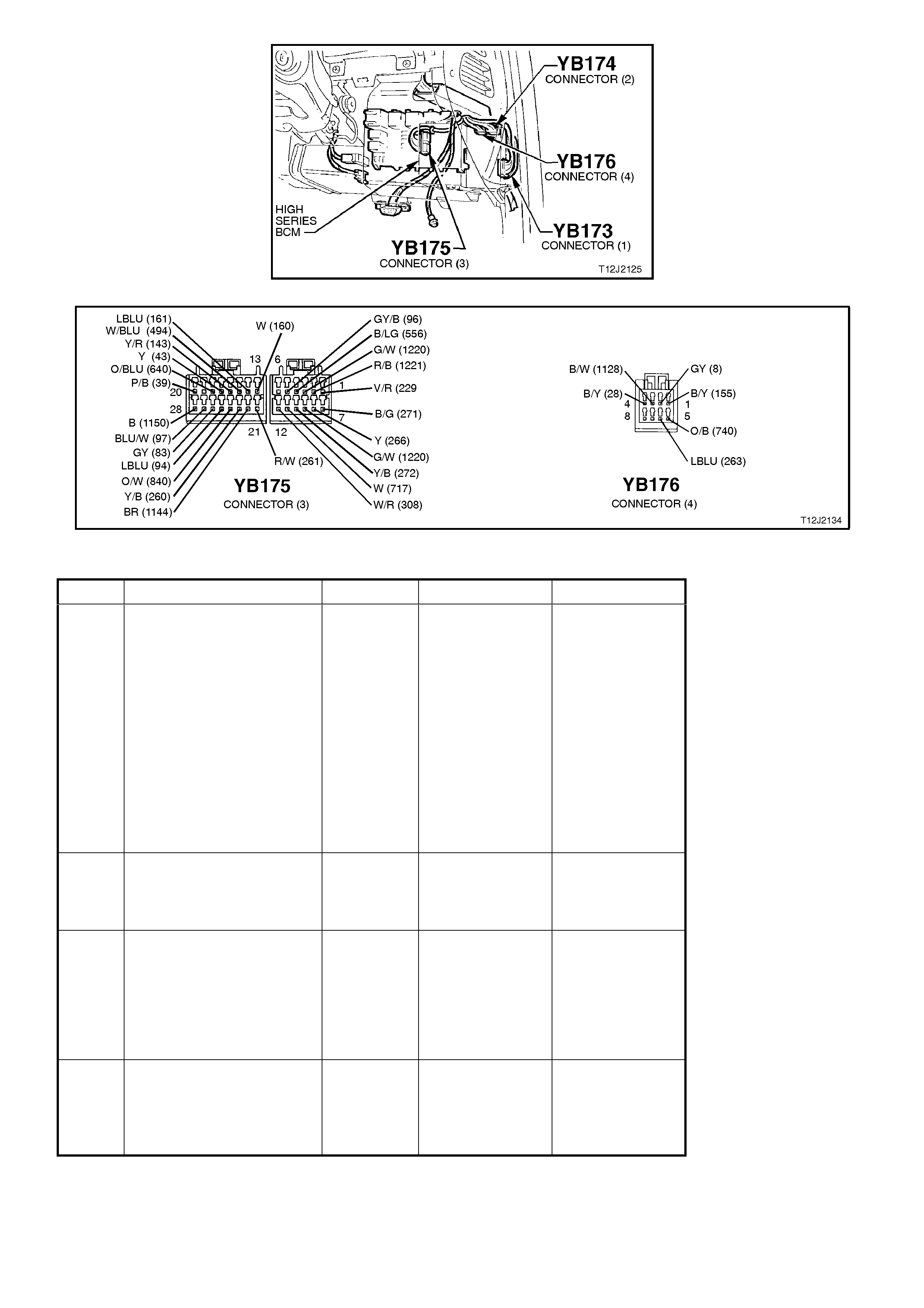
Figure 12J-2-130
Figure 12J-2-131
STEP ACTION VALUE YES NO
1. • Close and lock all
doors.
• Operate remote key
UNLOCK button within
4 meters of the driver’s
side B pillar.
• Does the driver’s door
unlock (2 stage
unlocking
programmed) or all
doors unlock (single
stage unlocking
programmed)?
Go to Step 2. Go to Step 11.
2. • In Step 1, did all
indicator lights flash
twice (both left-hand
and right-hand sides)?
Go to Step 3. Go to Step 13.
3. • In Step 1, did the
dome lamp illuminate? Go to Step 4. Go to dome
lamp delay
diagnosis, refer
to 4.14 DOME
LAMP DELAY
CONTROL in
this Section.
4. • In Step 1, did the theft
deterrent LED go out
immediately and begin
flashing 30 seconds
latter.
Go to Step 5. Go to Step 17.

STEP ACTION VALUE YES NO
5. • Close all doors.
• Arm theft deterrent
system by operating
the LOCK button on
the remote coded key
within 4 metres of the
driver’s side B pillar.
• Did all doors lock?
Go to Step 6. Go to central
door locking
diagnosis, refer
to 4.3 CENTRAL
DOOR
LOCKING in this
Section.
6. • In Step 5, did the
dome lamp go out
immediately upon
activating the lock
button?
Go to Step 7. Go to dome
lamp delay
diagnosis, refer
to 4.14 DOME
LAMP DELAY
CONTROL in
this Section.
7. • In Step 5, did all
indicator lights flash
once (both left-hand
and right-hand sides)?
Go to Step 8. Replace BCM,
refer to 2.2
HIGH SERIES
BCM in this
Section.
Recheck and
verify repair.
8. • Is the theft deterrent
LED flashing? Go to Step 9. Replace BCM,
refer to 2.2
HIGH SERIES
BCM in this
Section.
Recheck and
verify repair.
9. • Unlock vehicle with
remote key and wait
for theft deterrent
system to passively
arm (theft deterrent
LED flashing).
• With vehicle passively
armed, insert the
ignition key into ignition
switch and turn to the
ON position.
• Does the theft
deterrent LED
extinguish?
Go to Step 10. Go to Step 22.
10. • Turn the ignition key to
the START position.
• Does the vehicle crank
and start?
System OK. Go to Step 32.
11. • Insert ignition key into
driver’s door lock
cylinder and operate
door unlock
microswitch (turn key
to unlock position).
• Do all doors unlock?
NOTE: Alarm will sound.
Go to Step 12. Go to central
door locking
diagnosis, refer
to 4.3 CENTRAL
DOOR
LOCKING in this
Section.

STEP ACTION VALUE YES NO
12. • Insert ignition key into
ignition switch and
cycle from OFF - ON -
OFF.
• Remove key and lock
doors with driver’s door
lock cylinder switch.
• Operate UNLOCK
button on remote key
within 4 metres of
driver’s door B pillar.
• Does the driver’s door
unlock (2 stage
unlocking
programmed) or all
doors unlock (single
stage unlocking
programmed)?
Go to Step 2. Go to remote
receiver
diagnosis, refer
4.20 REMOTE
RECEIVER/KEY
in this Section.
13. • In Step 2, did at least
one side of vehicle’s
indicators flash twice
(either left-hand or
right-hand side)?
Go to Step 16. Go to Step 15
14. • Driver’s door closed.
• Connect TECH 2 to
DLC.
• Select BODY / BODY
CONTROL MODULE /
MISCELLANEOUS
TESTS / LAMPS /
INDICATORS.
• Conduct test as
instructed by TECH 2.
• Do all indicator lights
illuminate?
Replace BCM,
refer to 2.2
HIGH SERIES
BCM in this
Section.
Recheck and
verify repair.
Go to Step 15.
15. • Back probe BCM
connector YB174,
terminal B5, circuit 140
(Orange/Red wire) with
a Voltmeter to earth.
• Is voltage as
specified?
Approx.
12 volts Go to Step 16. Check and
repair open in
circuit 140
(including
fuse F7).
Recheck and
verify repair.
16. • Back probe BCM
connector YB174,
terminal B4 and B12,
circuits 14 (Light Blue
wire and Blue wire
respectively) with a
Voltmeter to earth.
• Repeat INDICATOR
ILLUMINATION test as
per Step 15.
• Is voltage as
specified?
Approx.
12 volts Check and
repair circuits 14
(LH indicator)
and/or 15 (RH
indicator).
Recheck and
verify repair.
Replace BCM,
refer to 2.2
HIGH SERIES
BCM in this
Section.
Recheck and
verify repair.

STEP ACTION VALUE YES NO
17. • Connect TECH 2 to
DLC.
• Select BODY / BODY
CONTROL MODULE /
MISCELLANEOUS
TESTS / SECURITY
SYSTEM / SECURITY
LED.
• Conduct test as
instructed by TECH 2.
• Does theft deterrent
LED illuminate?
Replace BCM,
refer to 2.2
HIGH SERIES
BCM in this
Section.
Recheck and
verify repair.
Go to Step 18
18. • Back probe BCM
connector YB176,
terminal A6, circuit 263
(Light Blue wire) with a
Voltmeter to earth
• Repeat SECURITY
LED test as per Step
17.
• Are voltages as
specified?
Approx.
5 volts -
LED on
Approx.
0 volts -
LED off
Go to Step 20. Go to Step 19
19. • Back probe BCM
connector YB176,
terminal A6, circuit 263
(Light Blue wire) with
an Ohmmeter to earth.
• Is value as specified?
Below
1 ohm Check and
repair short in
circuit 263.
Recheck and
verify repair.
Replace BCM,
refer to 2.2
HIGH SERIES
BCM in this
Section.
Recheck and
verify repair.
20. • Back probe theft
deterrent LED
connector YB56, circuit
263 (Light Blue wire)
with a Voltmeter to
earth
• Repeat SECURITY
LED test as per Step
17.
• Is voltage as
specified?
Approx.
12 volts Go to Step 21. Check and
repair open in
circuit 263.
Recheck and
verify repair.
21. • Back probe theft
deterrent LED
connector YB56, circuit
263 (Light Blue wire)
with a Ohmmeter to
earth.
• Is value as specified?
Below
1 ohm Replace theft
deterrent LED,
refer 12C
INSTRUMENTS,
WIPERS /
WASHER &
HORN.
Repair open in
circuit 156.
Recheck and
verify repair.
22. • With the ignition key in
the ON position,
operate the unlock
button on the remote
coded key.
• Does the theft
deterrent LED go out?
Go to Step 23. Go to remote
receiver
diagnosis, refer
to 4.20
REMOTE
RECEIVER/KEY
in this Section.

STEP ACTION VALUE YES NO
23. • Remove remote key,
key shaft.
• Clean earth contact
(shaft earth).
• Reinstall key shaft and
tighten screws to the
correct torque
specification (0.7 - 0.9
Nm).
• With system passively
armed (theft deterrent
LED flashing), insert
key into ignition switch
and turn key to the ON
position.
• Does the theft
deterrent LED go out?
Go to Step 10. Go to Step 24.
24. • Turn ignition key to the
ON position.
• Visually check to see if
remote coded key
contact pin is making
good contact with
remote key reader (slip
ring).
• Is remote coded key
contact pin making
good contact?
Go to Step 25. Check and
repair as
necessary:
remote key
reader (slip ring),
alignment of
remote key
reader (refer
step 12), length
of key shaft and
remote key
contact pin.
25. • Check function of
second remote key.
• •Is second key
OK?
Replace suspect
key. Go to Step 26.
26. • Isolate remote coded
key contact pin (use a
thick piece of paper to
cover contact pin).
• Insert key into ignition
switch and turn key to
the ON position.
• Measure voltage at the
remote coded key
reader (slip ring) to a
sound earth.
• Is voltage as
specified?
Fluctuates
between
4 - 6 volts
AC
Go to Step 27. Go to Step 28.
27. • Check ignition switch
earth using an
Ohmmeter connected
between the ignition
switch housing a
sound earth point.
• Is value as specified?
Below
100 ohms Replace BCM,
refer to 2.2
HIGH SERIES
BCM in this
Section.
Recheck and
verify repair.
Check and
repair open or
poor earth
connection at
ignition switch /
cylinder,
Recheck and
verify repair.

STEP ACTION VALUE YES NO
28. • Connect TECH 2 to
DLC.
• Select BODY / BODY
CONTROL MODULE /
DATA DISPLAY.
• Turn ignition ON as
instructed by TECH 2.
• Scroll to IGNITION
SWITCH.
• Does screen display
IGNITION SWITCH
ON?
Go to Step 29. Go to Step 31.
29. • Back probe BCM
connector YB175,
terminal E1, circuit 229
(Violet/Red wire) with a
Voltmeter to earth.
• With remote coded key
contact pin isolated
(covered with thick
paper), insert ignition
key into ignition switch
and turn ignition switch
to the ON position.
• Is voltage as
specified?
Fluctuates
between
4 - 6 volts -
AC
Check and
repair open in
circuit 229
or remote
key reader.
Recheck and
verify repair.
Go to Step 30.
30. • Check circuit 229
(Violet/Red wire) for
short to earth.
• Is circuit 229 OK?
Check and
repair short in
circuit 229.
Recheck and
verify repair.
Replace BCM,
refer to 2.2
HIGH SERIES
BCM in this
Section.
Recheck and
verify repair.
31. • Back probe BCM
connector YB175,
terminal E20, circuit 39
(Pink/Bl ack wire) wi th
a Voltmeter to earth.
• Turn ignition ON.
• Is voltage as
specified?
Approx.
12 volts Replace BCM,
refer to 2.2
HIGH SERIES
BCM in this
Section.
Recheck and
verify repair.
Check and
repair open in
circuit 39
(including
fuse F14).
Recheck and
verify repair.
32. • Connect TECH 2 to
DLC.
• Select BODY / BODY
CONTROL MODULE /
DATA DISPLAY.
• Scroll to PASSIVE
MODE.
• With system disarmed
(theft deterrent LED
off), does the screen
display PASSIVE
MODE OFF?
Go to PCM
diagnostics in
Section 6C1
POWERTRAIN
MANAGEMENT
- V6 ENGINE
or
Section 6C2
POWERTRAIN
MANAGEMENT
- V8 ENGINE.
Replace BCM,
refer to 2.2
HIGH SERIES
BCM in this
Section.
Recheck and
verify repair.
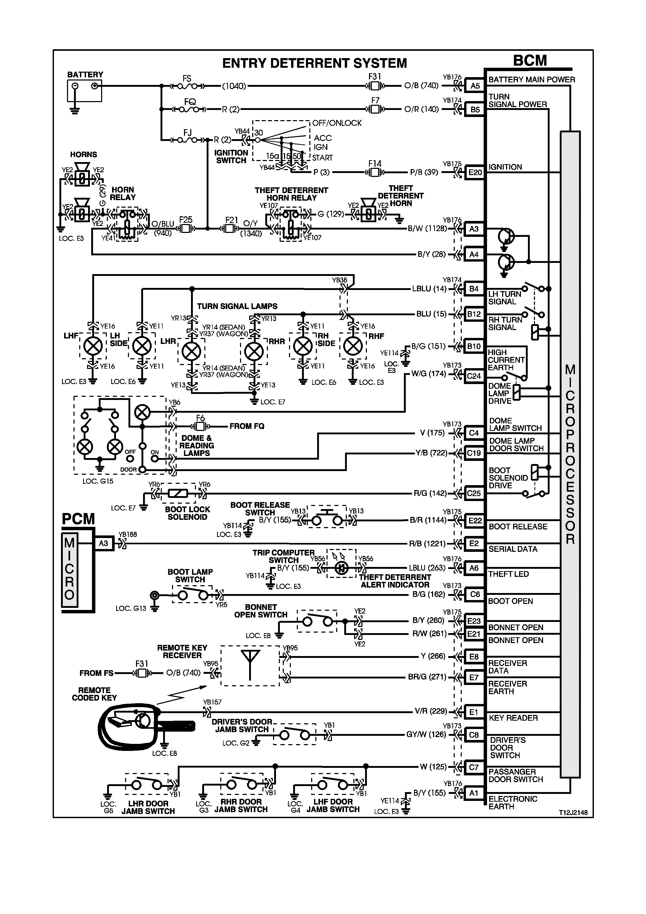
4.5 ENTRY DETERRENT
Figure 12J-2-132

CIRCUIT DESCRIPTION
The entry deterrent system, incorporated in the BCM, is designed to deter unwanted access to the vehicle's
passenger compartment by providing audible and visual warning (alarm) of illegal entry to the vehicle.
Arming of the theft and entry deterrent systems is by pressing the lock button on the remote coded key.
NOTE:
The entry deterrent system does not arm passively.
The remote coded key also incorporates a boot release function button.
An ultrasonic sensor option can also be fitted to the vehicle.
Arming Operation
The entry deterrent system is armed by pressing the lock button on the remote coded key. The output signal from
the key, via the remote receiver, activates the microprocessor within the BCM (via circuit 266), providing that the
ignition is OFF and the vehicle road speed input indicates speed is zero. Note that one continuous press of a button
on the remote coded key should cause only one arm/disarm operation. It is not possible to arm the system or
remote lock the doors with the driver's door open.
When the system is armed, the following actions take place:
1. All doors lock (and tailgate on Berlina station wagon).
2. All indicator lights flash once.
3. The power antenna retracts.
4. The power window system deactivates.
5. The dome light is switched off (provided it has not been turned on by another system).
6. The theft deterrent alert indicator LED flashes (refer to theft deterrent system operation description).
Triggered Operation
Once the entry deterrent system is armed, it is triggered by any one of the following inputs:
1. The bonnet being opened (circuit 260).
2. The boot being opened (circuit 162).
3. Any door being opened (circuit 126).
4. Ignition being switched on (circuit 39).
If any of the previous conditions exist at the time of the system arming, they will be ignored until the fault condition is
cleared.
Once triggered, the system will operate as follows:
1. Flash all indicator lights at a rate of one flash every two seconds.
2. Pulse all vehicle horns at a rate of one pulse per second.
3. Flash the dome light at a rate of one flash every two seconds.
Flashing of the indicators and dome lamp, and sounding of the horn/s will continue for a period of 30 seconds.
Disarming Procedure
The system is disarmed by:
A. Pressing the unlock button on the remote coded key. The RF output signal from remote coded key, via the
remote receiver, activates the microprocessor within the BCM (via circuit 266).
Upon disarming the following actions take place:
1. All doors (and tailgate on Berlina station wagon) unlock.
2. All indicators lights flash twice, however if the system has been triggered since being armed, they will flash
three times.
3. The dome light is activated for 30 seconds (normal delay cancellation conditions apply).
4. If the system has been triggered since being armed, the theft deterrent alert indicator LED will flash a code
indicating the triggered source, otherwise it will be turned off. This flashing code will be cancelled once the
ignition is switched on.
B. If the remote coded key is not working (eg. flat battery), turning the ignition on allows the BCM to provide a
power supply to the remote coded key to enable reading of the key security code.
Flash Codes
The system triggered flash codes emitted by the theft deterrent alert indicator LED flash at a defined flash rate with
a 1.5 second between codes. Codes are repeated twice before moving to the next code.
Two flashes - bonnet (or ultrasonic sensor)
Three flashes - boot
Four flashes - passenger door
Five flashes - driver's door
Six flashes - ignition on
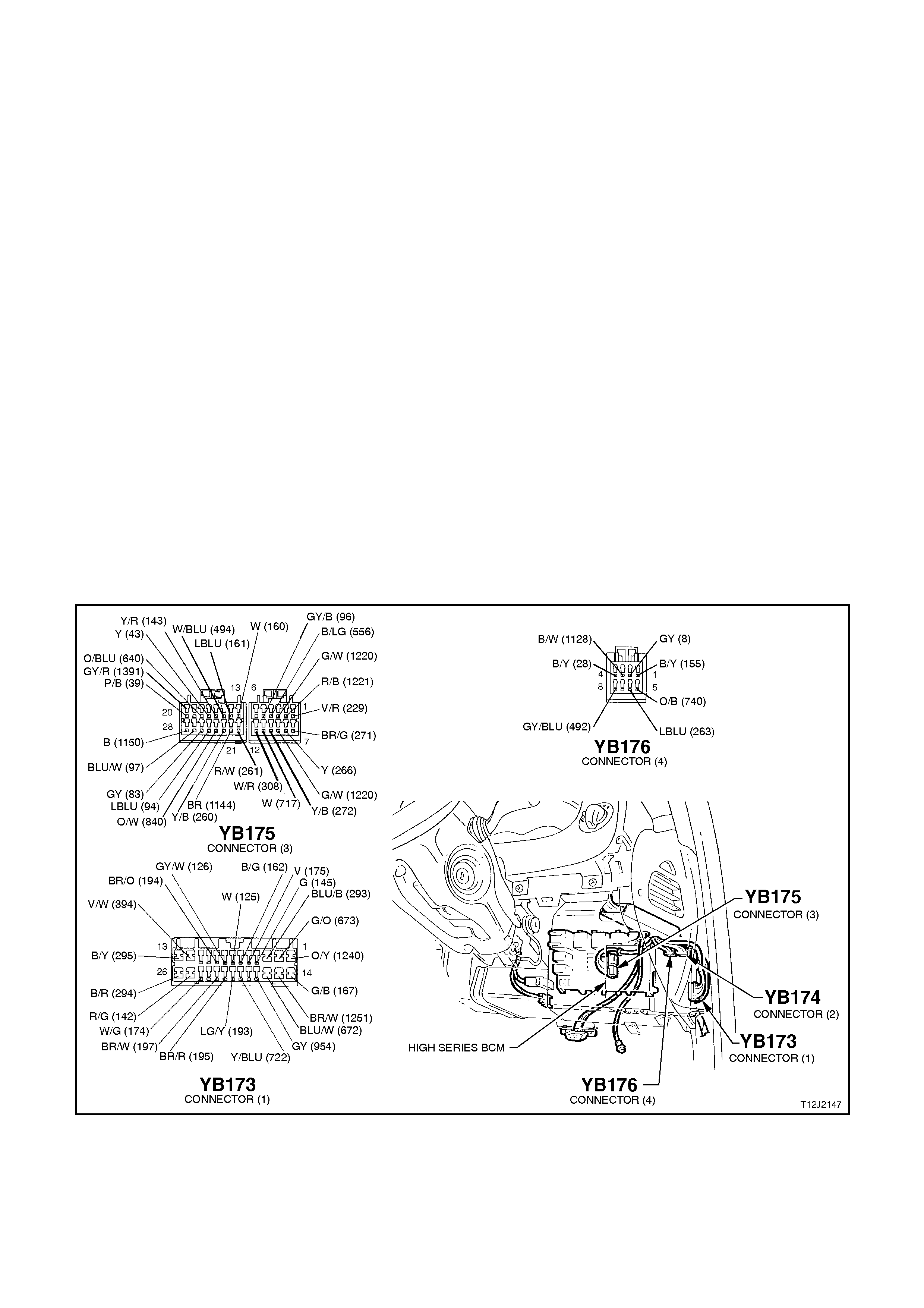
TEST DESCRIPTION
The numbers below refer to step numbers in the following diagnostic chart.
1-15. Functional check of system to help isolate fault.
16. Uses TECH 2 to check DRIVER’S DOOR OPEN signal at microprocessor at BCM.
17. Checks DRIVER’S DOOR OPEN signal at input to BCM.
18. Uses TECH 2 to activate entry deterrent horn to determine if fault is with output of BCM.
19. Uses TECH 2 to activate the horn to determine if fault is with input or output of BCM.
20. Checks theft deterrent horn output drive from BCM.
21. Checks circuit 1128.
22. Checks theft deterrent relay.
23. Checks horn drive from BCM.
24. Checks circuit 28.
25. Checks horn relay.
26. Determines if fault is with individual passenger door jamb switch.
27. Uses TECH 2 to check PASSENGER DOOR OPEN signal at microprocessor of BCM.
28. Checks PASSENGER DOOR OPEN signal at input to BCM.
29. Uses TECH 2 to check BOOT OPEN signal at microprocessor of BCM.
30. Checks BOOT OPEN signal at input to BCM.
31. Checks circuit 162 and boot lamp switch (including earth).
32. Uses TECH 2 to check BONNET OPEN signal at microprocessor of BCM.
33. Checks BONNET OPEN signal at input to BCM.
34. Checks circuit 260 and bonnet switch (including earth).
35. Uses TECH 2 to check IGNITION ON signal at microprocessor of BCM.
36. Checks IGNITION ON signal at input to BCM.
Figure 12J-2-133

STEP ACTION VALUE YES NO
1. • Ensure all windows are
in the down position.
• Close all doors.
• Arm the system by
operating the LOCK
button on the remote
coded key.
• Do all doors lock?
Go to Step 2. Go to central door
locking system
diagnosis, refer to
4.3 CENTRAL
DOOR LOCKING
in this Section.
2. • When the LOCK
button on the remote
coded key was
pressed in Step 1, did
all indicators flash at
once?
Go to Step 3. Go to theft
deterrent
diagnosis, refer to
4.4 THEFT
DETERRENT
SYSTEM in this
Section.
3. • When the LOCK
button on the remote
coded key was
pressed in Step 1, did
the theft deterrent LED
begin to flash
(assuming vehicle was
fully disarmed)?
Go to Step 4. Go to theft
deterrent
diagnosis, refer to
4.4 THEFT
DETERRENT
SYSTEM in this
Section.
4. • Lift driver’s door snib
and open driver’s door.
• Is horn triggered?
Go to Step 5. Go to Step 16.
5. • In Step 4, does both
the theft deterrent horn
and standard vehicle
horns sound?
Go to Step 6. Go to Step 18.
6. • In Step 4, do both
indicators and dome
lamp flash once every
two seconds?
Go to Step 7. Replace BCM,
refer to 2.2 HIGH
SERIES BCM in
this Section.
Recheck and
verify repair.
7. • Disarm the alarm by
pressing the UNLOCK
button on the remote
coded key.
• Do indicators flash 3
times and the theft
deterrent LED emit a
flash code of five?
Go to Step 8. Replace BCM,
refer to 2.2 HIGH
SERIES BCM in
this Section.
Recheck and
verify repair.

STEP ACTION VALUE YES NO
8. • Turn ignition from OFF
- ON - OFF to cancel
flash code (set in Step
4).
• Arm the system by
pressing the LOCK
button on the remote
coded key.
• Test front passenger
door input by opening
the passenger door to
trigger alarm, then
disarm the system by
operating the UNLOCK
button on the remote
coded key. Observe
the theft deterrent LED
flash code, then cancel
the code by cycling the
ignition (OFF - ON -
OFF).
• Repeat this action for
both the rear
passenger doors.
• Does the opening of
each passenger door
(when system is
armed) trigger alarm?
Go to Step 9. Go to Step 26.
9. • While observing the
flash code in Step 8,
did the theft deterrent
LED emit a flash code
of four for each
passenger door?
Go to step 10. Replace BCM,
refer to 2.2 HIGH
SERIES BCM in
this Section.
Recheck and
verify repair.
10. • Arm the system by
pressing the LOCK
button on the remote
coded key.
• Open the boot using
the ignition key in the
lock.
• Is alarm triggered?
Go to Step 11. Go to Step 29.
11. • Disarm the alarm by
pressing the UNLOCK
button on the remote
coded key.
• Is the theft deterrent
LED emitting a flash
code of three?
Go to Step 12. Replace BCM,
refer to 2.2 HIGH
SERIES BCM in
this Section.
Recheck and
verify repair.
12. • Arm the system by
pressing the LOCK
button on the remote
coded key.
• Open the bonnet.
• Is alarm triggered?
Go to Step 13. Go to Step 32.

STEP ACTION VALUE YES NO
13. • Disarm the alarm by
pressing the UNLOCK
button on the remote
coded key.
• Is the theft deterrent
LED emitting a flash
code of two?
Go to Step 14. Replace BCM,
refer to 2.2 HIGH
SERIES BCM in
this Section.
Recheck and
verify repair.
14. • Arm the system by
pressing the LOCK
button on the remote
coded key.
• Place a thick piece of
paper over the slip ring
contact pin on the
remote coded key.
• From outside the
vehicle (doors closed),
insert the key into the
ignition switch and turn
to the ON position.
• Is the alarm triggered?
Go to Step 15. Go to Step 35.
15. • Disarm the alarm by
pressing the UNLOCK
button on the remote
coded key.
• Is the theft deterrent
LED emitting a flash
code of six?
System OK. Replace BCM,
refer to 2.2 HIGH
SERIES BCM in
this Section.
Recheck and
verify repair.
16. • Disarm the alarm by
pressing the UNLOCK
button on the remote
coded key.
• Connect TECH 2 to
the DLC.
• Select BODY / BODY
CONTROL MODULE /
DATA DISPLAY.
• Scroll to DRIVERS
DOOR screen display.
• Open and close the
driver’s door.
• Does the screen
display the state of the
driver’s door (open or
closed)?
Replace BCM,
refer to 2.2 HIGH
SERIES BCM in
this Section.
Recheck and
verify repair.
Go to Step 17.
17. • Back probe BCM
connector YB173,
terminal C8, circuit 126
(Grey/White wire) wi th
a Voltmeter to earth.
• Open and close the
driver’s door.
• Are voltages as
specified?
Door
open -
0 volts
Door
closed -
3 volts
Replace BCM,
refer to 2.2 HIGH
SERIES BCM in
this Section.
Recheck and
verify repair.
Check and repair
circuit 126 and
driver’s door
jamb switch.
Recheck and
verify repair.

STEP ACTION VALUE YES NO
18. • Disarm the alarm by
pressing the UNLOCK
button on the remote
coded key.
• Connect TECH 2 to
DLC.
• Select BODY / BODY
CONTROL MODULE /
MISCELLANEOUS
TESTS / SECURITY
SYSTEM / THEFT
HORN.
• Conduct test as
instructed by TECH 2.
• Does the theft
deterrent system horn
sound?
Go to Step 19. Go to Step 20.
19. • With TECH 2
connected, select
BODY / BODY
CONTROL MODULE /
MISCELLANEOUS
TESTS / HORN.
• Conduct test as
instructed by TECH 2.
• Does the vehicle horn
sound?
Replace BCM,
refer to 2.2 HIGH
SERIES BCM in
this Section.
Recheck and
verify repair.
Go to Step 23.
20. • Back probe BCM
connector YB176,
terminal A3, circuit
1128 (Black/White
wire) w ith a Voltmeter
to earth.
• Disarm the alarm by
pressing the UNLOCK
button on the remote
coded key.
• Repeat THEFT HORN
test as per Step 18.
• Is voltage as
specified?
Approx.
1 volt
ON
Approx
12 volts
OFF
Go to Step 21. Replace BCM,
refer to 2.2 HIGH
SERIES BCM in
this Section.
Recheck and
verify repair.
21. • Back probe theft
deterrent horn relay
connector YE107,
terminal 2, circuit 1128
(Black/White wire) with
a Voltmeter to earth.
• Disarm the alarm by
pressing the UNLOCK
button on the remote
coded key.
• Repeat THEFT HORN
test as per Step 18.
• Is voltage as
specified?
Approx.
1 volt
ON
Approx
12 volts
OFF
Go to Step 22. Check and repair
open in
circuit 1128.
Recheck and
verify repair.

STEP ACTION VALUE YES NO
22. • Replace theft deterrent
horn relay with a
known functional one.
• Repeat Step 18 again.
• Does the theft
deterrent horn sound?
Replace horn
relay.
Recheck and
verify repair.
Check and repair
fuse F21, circuits
1340 and
129 or theft
deterrent horn.
Recheck and
verify repair.
23. • Back probe BCM
connector YB176,
terminal A4, circuit 28
(Black/Yellow wire)
with a jumper lead to
earth.
• Does the horn sound?
Replace BCM,
refer to 2.2 HIGH
SERIES BCM in
this Section.
Recheck and
verify repair.
Go to Step 24.
24. • Back probe horn relay
connector YE41,
terminal 85, circuit 28
(Black/Yellow wire)
with a jumper lead to
earth.
• Does the horn sound?
Check and repair
open in circuit 28.
Recheck and
verify repair.
Go to Step 25.
25. • Replace horn relay
with a known functional
one.
• Repeat Step 24 again.
• Do standard vehicle
horns sound?
Replace horn
relay.
Recheck and
verify repair.
Check and repair
fuse F25, circuits
940 and
29 or horn.
Recheck and
verify repair.
26. • In Step 8, did at least
one passenger door
trigger the alarm?
Check and repair
fault in circuit 125
between suspect
door and door
jamb switch of
suspect door.
Recheck and
verify repair.
Go to Step 27.
27. • Disarm the alarm by
pressing the UNLOCK
button on the remote
coded key.
• Connect TECH 2 to
the DLC.
• Select BODY / BODY
CONTROL MODULE /
DATA DISPLAY.
• Scroll to PASSENGER
DOOR screen display.
• Open and close the
passenger door.
• Does the screen
display state the status
of the door (ie.
Open/closed)?
Replace BCM,
refer to 2.2 HIGH
SERIES BCM in
this Section.
Recheck and
verify repair.
Go to Step 28.

STEP ACTION VALUE YES NO
28. • Back probe BCM
connector YB173,
terminal C7, circuit 125
(White wire) with a
Voltmeter to earth.
• Open any passenger
door.
• Is voltage as
specified?
Below
0.5 volt Replace BCM,
refer to 2.2 HIGH
SERIES BCM in
this Section.
Recheck and
verify repair.
Check and repair
open in
circuit 125.
Recheck and
verify repair.
29. • Disarm the alarm by
pressing the UNLOCK
button on the remote
coded key.
• Connect TECH 2 to
the DLC.
• Select BODY / BODY
CONTROL MODULE /
DATA DISPLAY.
• Scroll to BOOT
SWITCH screen
display.
• Open and close the
boot lid.
• Does the screen
display state the of the
boot switch (will display
open when boot lid
closed)?
Replace BCM,
refer to 2.2 HIGH
SERIES BCM in
this Section.
Recheck and
verify repair.
Go to Step 30.
30. • Back probe BCM
connector YB173,
terminal C6, circuit 162
(Black/Green wire)
with a Voltmeter to
earth.
• Open boot.
• Is voltage as
specified?
Below
0.5 volts Replace BCM,
refer to 2.2 HIGH
SERIES BCM in
this Section.
Recheck and
verify repair.
Go to Step 31.
31. • Back probe boot lamp
switch connector YR5,
circuit 162
(Black/Green wire)
with a Ohmmeter to
earth.
• Open boot.
• Is value as specified?
Below
1 ohm Check and repair
open in circuit
162. Recheck and
verify repair.
Check and
repair/replace
boot switch
(including
switch earth).
Recheck and
verify repair.

STEP ACTION VALUE YES NO
32. • Disarm the alarm by
pressing the UNLOCK
button on the remote
coded key.
• •Connect TECH 2
to the DLC.
• Select BODY / BODY
CONTROL MODULE /
DATA DISPLAY.
• Scroll to BONNET
SWITCH screen
display.
• Open and close
bonnet.
• Does the screen
display the state of the
bonnet switch (will
display open when
bonnet is closed)?
Replace BCM,
refer to 2.2 HIGH
SERIES BCM in
this Section.
Recheck and
verify repair.
Go to Step 33.
33. • Disconnect BCM
connector YB175 and
back probe harness
end of terminals E23
and E21, circuits 260
(Black/Yellow wire)
and 261 (Red/White
wire) with an
Ohmmeter to earth.
• Open bonnet.
• Are values as
specified?
Below
1 ohm
(both
circuits)
Replace BCM,
refer to 2.2 HIGH
SERIES BCM in
this Section.
Recheck and
verify repair.
Go to Step 34.
34. • Reconnect BCM
connector YB173.
• Open Bonnet.
• Back probe bonnet
switch connector YE2,
circuit 260
(Black/Yellow wire)
with an Ohmmeter to
earth.
• Is value as specified?
Below
1 ohm Check and repair
open in circuits
260 and/or 261.
Recheck and
verify repair.
Check and
repair/replace
bonnet switch
(including
switch earth).
Recheck and
verify repair.

STEP ACTION VALUE YES NO
35. • Disarm the alarm by
pressing the UNLOCK
button on the remote
coded key.
• Connect TECH 2 to
the DLC.
• Select BODY / BODY
CONTROL MODULE /
DATA DISPLAY.
• Scroll to IGNITION
SWITCH screen
display.
• Turn ignition ON.
• Does the screen
display IGNITION ON?
Replace BCM,
refer to 2.2 HIGH
SERIES BCM in
this Section.
Recheck and
verify repair.
Go to Step 36.
36. • Back probe BCM
connector YB175,
terminal E20, circuit 39
(Pink/Bl ack wire) wi th
a Voltmeter to earth.
• Turn ignition ON.
• Is voltage as
specified?
12 volts
(ignition
on)
Replace BCM,
refer to 2.2 HIGH
SERIES BCM in
this Section.
Recheck and
verify repair.
Check and repair
open in circuit 39
(including fuse
F14 and
ignition switch).
Recheck and
verify repair.
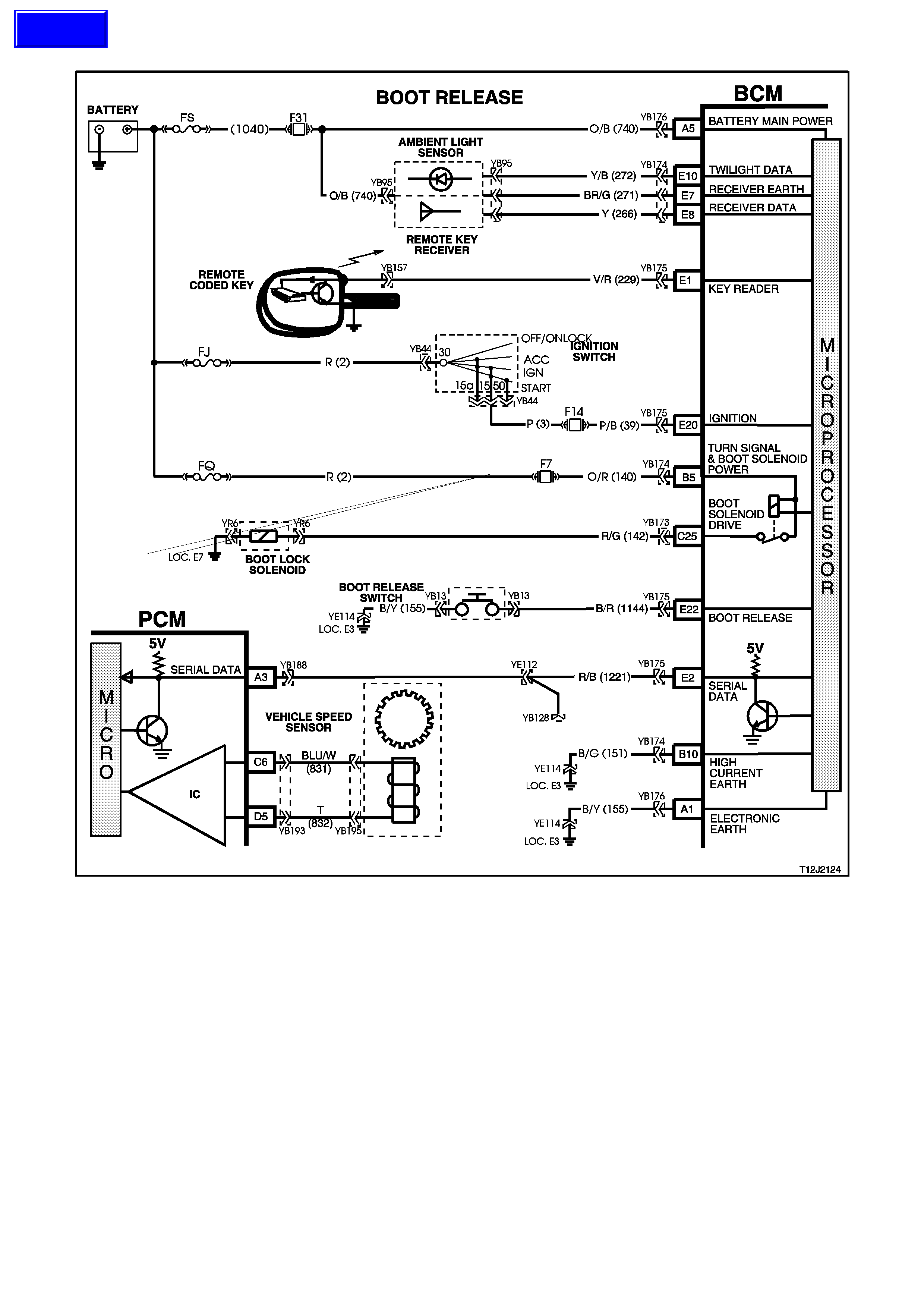
4.6 BOOT RELEASE
Figure 12J-2-134
CIRCUIT DESCRIPTION
The rear compartment lock actuator is controlled by pressing the rear compartment lock switch located in the glove
compartment. The BCM will monitor the rear compartment lock switch and inhibit the boot release if the vehicle
speed is above 15 km/h.
Techline
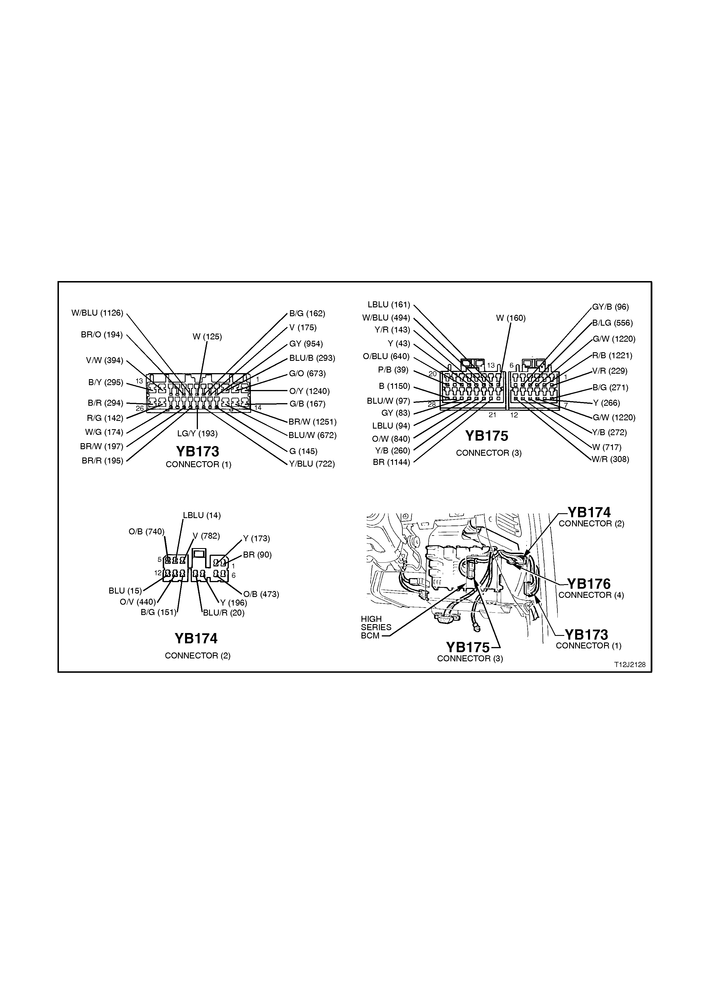
TEST DESCRIPTION
The numbers below refer to step numbers in the following diagnostic chart.
1. Functional check to determine if system is functioning correctly or if faulty, determines if fault is with remote
receiver/key or with boot release system.
3. circuit 155 and rear compartment lock switch. Uses TECH 2 to operate the rear compartment lock actuator to
establish whether problem is with the input or output of BCM.
4. Uses TECH 2 to check BOOT RELEASE SWITCH ON signal at microprocessor of BCM.
5. Checks for rear compartment lock actuator drive signal at the output of the BCM when commanded by TECH
2.
6. Checks circuit 142.
7. Checks circuit 156 and rear compartment lock actuator.
8. Checks for battery voltage supply at BCM (turn signal / boot solenoid supply).
9. Checks for BOOT SWITCH signal at input of BCM.
10. Checks circuit 1144.
11. Checks
Figure 12J-2-135

STEP ACTION VALUE YES NO
1. • Activate boot release
button in glove
compartment with
vehicle speed below 15
km/h.
• Does the rear
compartment lid open?
Go to Step 2. Go to Step 3.
2. • Close rear compartment
lid.
• Press the boot release
button on the remote
coded key (within 2
metres of the rear of the
vehicle).
• Does rear compartment
lid open?
System OK. Go to remote
receiver
diagnosis, refer to
4.20 REMOTE
RECEIVER/KEY
in this Section.
3. • Connect TECH 2 to
DLC.
• Select BODY / BODY
CONTROL MODULE /
MISCELLANEOUS
TESTS / SECURITY
SYSTEM / BOOT
RELEASE.
• Conduct test as
instructed by TECH 2.
• Does rear compartment
lid open?
Go to Step 4. Go to Step 5.
4. • With TECH 2 still
connected, exit
MISCELLANEOUS
TESTS and select
DATA DISPLAY.
• Scroll to BOOT
RELEASE SWITCH
screen display.
• Press boot release
button in glove
compartment.
• Does the screen display
change to BOOT
RELEASE SWITCH
ON?
Replace BCM,
refer to 2.2 HIGH
SERIES BCM in
this Section.
Recheck and
verify repair.
Go to Step 9.
5. • Back probe BCM
connector YB173,
terminal C25, circuit 142
(Red/Green wire) with a
Voltmeter to earth.
• Repeat BOOT
RELEASE test as per
Step 3.
• Are voltages as
specified?
Test not
conducted:
0 volt
Test
conducted:
12 volts
Go to Step 6. Go to Step 8.

STEP ACTION VALUE YES NO
6. • Back probe actuator
connector YR6, circuit
142 (Red/Green wire)
with Voltmeter to earth.
• Repeat BOOT
RELEASE test as per
Step 3.
• Are voltages as
specified?
Test not
conducted:
0 volt
Test
conducted:
12 volts
Go to Step 7. Repair open or
short in
circuit 142.
Recheck and
verify repair.
7. • Back probe actuator
connector YR6 circuit
156 (Black/Blue wire)
with an Ohmmeter to
earth.
• Is reading as specified?
Below
1 ohm Replace rear
compartment lock
actuator, refer to
Section 1A4
REAR
COMPARTMENT
LID AND
TAILGATE.
Repair open in
circuit 156
Recheck and
verify repair.
8. • Back probe BCM
connector YB174,
terminal B5, circuit 140
(Orange/Red wire) with
a Voltmeter to earth.
• Is voltage as specified?
Battery + Replace BCM,
refer to 2.2 HIGH
SERIES BCM in
this Section.
Recheck and
verify repair.
Check and repair
open or short in
circuit 140
(including
fuse F7).
Recheck and
verify repair.
9. • Back probe BCM
connector YB175,
terminal E22, circuit
1144 (Black/Red wire)
with a Ohmmeter to
earth.
• Activate the boot
release button.
• is value as specified?
Below
1 ohm Replace BCM,
refer to 2.2 HIGH
SERIES BCM in
this Section.
Recheck and
verify repair.
Go to Step 10.
10. • Back probe rear
compartment lock
switch connector YB13,
circuit 1144 (Black/Red
wire) with a Voltmeter to
earth.
• Activate the rear
compartment lock
switch.
• Is value as specified?
Below
1 ohm Repair open or
short in circuit
1144. Recheck
circuit to verify
repair.
Go to Step 11.
11. • Back probe rear
compartment lock
switch connector, YB13,
circuit 155 (Black/Yellow
wire) with an Ohmmeter
to earth.
• Is reading as specified?
Below
1 ohm Replace rear
compartment lock
switch, refer to
Section 1A4
REAR
COMPARTMENT
LID AND
TAILGATE.
Repair open in
circuit 155.
Recheck and
verify repair.
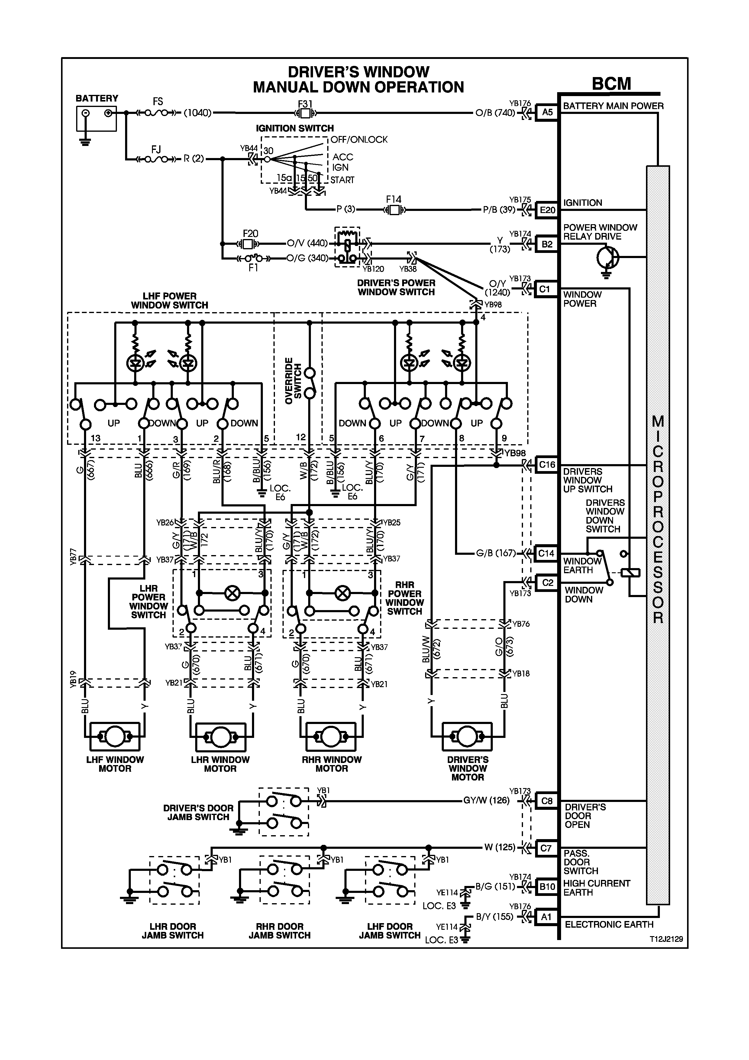
4.7 POWER WINDOW SYSTEM
Figure 12J-2-136
CIRCUIT DESCRIPTION
The BCM controls the positive power supply to all window motors and the automatic down of the driver’s door
window which is activated when the driver’s power window down button is depressed for more than 0.4 seconds.

Once activated, the automatic down feature is cancelled by pulling the driver’s power window switch upwards and
releasing it. In this case, the window will remain stationary until another activation takes place (up or down button
activated).
With the ignition ON, power is supplied to the window system continuously. When the ignition is switched OFF and
no door has been opened, power is supplied to the window system for a maximum of one hour. In the event of any
door being opened, power is supplied to the system for 45 seconds maximum, timed from when the first door was
opened.
When the doors are remotely unlocked (using the remote coded key) power is supplied to the system for 45
seconds. The delay is cancelled when the doors are locked by the remote coded key.
TEST DESCRIPTION
The numbers below refer to step numbers in the following diagnostic chart.
1-17. Functional check of system.
20. Checks for driver’s window down input signal at input of BCM/circuit 167.
21. Checks driver’s window down relay and contacts within BCM.
22. Checks circuit 673.
23. Checks driver’s window motor.
24. Checks for driver’s window down input signal at output of the front and rear door power window switch
assembly.
25. Checks circuit 672 (front and rear door power window switch assembly).
26. Uses TECH 2 to check the ignition input at the microprocessor of the BCM.
27. Checks the power window relay output drive signal at the BCM.
28. Checks for power window system voltage at the input of the BCM.
29. Checks circuit 1240.
30. Checks circuit 156.
31. Checks for ignition signal at input of BCM.
32. Checks circuit 173.
33. Checks circuit 440.
34. Checks circuit 340.
35. Checks power window relay.
36. Checks driver’s window up signal at output of front and rear door power window switch assembly.
37. Checks front and rear door power window switch assembly .
38. Checks circuit 672 (front and rear door power window switch assembly to BCM).
39. Uses TECH 2 to check the DRIVER’S DOOR OPEN signal input at the microprocessor of the BCM.
40. Checks for DRIVER’S DOOR OPEN signal at the input of the BCM.
41. Checks circuit 126.
42. Uses TECH 2 to check PASSENGER DOOR OPEN signal input at the microprocessor of the BCM.
44. Checks for PASSENGER DOOR OPEN signal at the input of the BCM.
45. Checks front and rear door power window switch assembly (LHF window down).
46. Checks circuit 667.
47. Checks front and rear door power window switch assembly (LHF window down, earth).
48. Checks circuit 666.
49. Checks front and rear door power window switch assembly (RHR window down).
50. Checks circuit 170 (RHR window system).
51. Checks RHR power window switch (RHR door).
52. Checks circuit 671 (RHR window system).
53. Checks front and rear door power window switch assembly (RHR window down, earth).
54. Checks circuit 171 (RHR window system).
55. Checks RHR power window switch (RHR door).
56. Checks circuit 670 (RHR window system).
57. Checks front and rear door power window switch assembly (LHR window down).
58. Checks circuit 170 (LHR window system).
59. Checks LHR power window switch (LHR DOOR).
60. Checks circuit 671 (LHR window system).
61. Checks front and rear door power window switch assembly(LHR window down, earth).
62. Checks circuit 171 (LHR window system).
63 Checks LHR power window switch (LHR door).
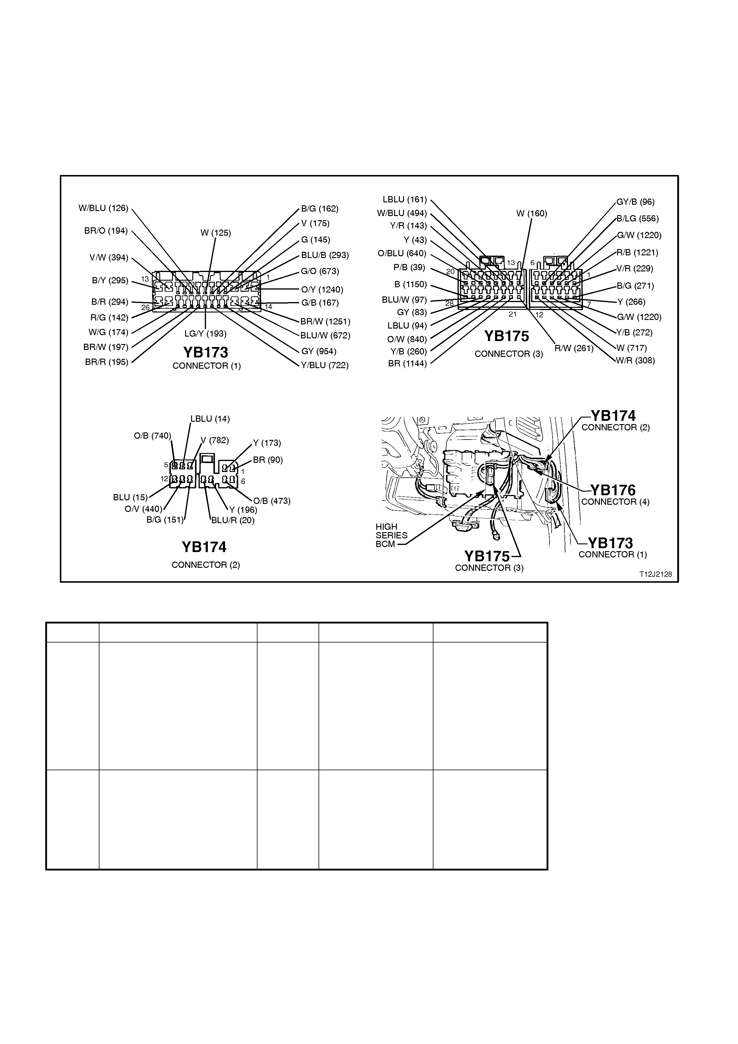
64. Checks circuit 670 (LHR window system.
66. Checks override switch (front and rear door power window switch assembly).
67. Checks circuit 172 (RHR window system).
69. Checks circuit 172 (LHR window system).
70. Checks for false output drive from BCM or wiring / relay problem causing window system ON always.
NOTE:
This diagnostic chart assumes that the power windows are free from mechanical faults, ie. damaged window
regulator or badly worn guide channel rubbers.
Figure 12J-2-137
STEP ACTION VALUE YES NO
1. • Turn ignition ON.
• Operate driver’s
window down button
for one second and
release.
• Does the window travel
all the way down
automatically?
Go to Step 2. Go to Step 18.
2. • Turn ignition ON.
• Operate the driver’s
window up button.
• Does the window travel
up when activating the
button?
Go to Step 3. Go to Step 36.

STEP ACTION VALUE YES NO
3. • Turn ignition ON.
• Operate driver’s
window down button
for one second and
release.
• As the window is
travelling down
automatically, operate
the up button
momentarily and
release.
• Does the window stop?
Go to Step 4. Go to Step 38.
4. • All doors closed.
• Ignition OFF.
• Remotely lock doors.
• Is power supply to
window system
interrupted (green
indicator lights in front
and rear power window
switch extinguished)?
Go to Step 5. Go to Step 70.
5. • Remotely unlock
doors.
• Is power supplied to
the window system
(green indicator lights
in front and rear power
window switch
illuminated)?
Go to Step 6. Replace BCM,
refer to 2.2 HIGH
SERIES BCM in
this Section.
Recheck and
verify repair.
6. • Doors closed.
• Turn ignition ON.
• Ignition OFF.
• Open driver’s door.
• Is power to the window
system interrupted
after 45 seconds
(green indicator lights
in front and rear power
window switch
extinguished)?
Go to Step 7. Go to Step 39.
7. • Doors closed.
• Turn ignition ON.
• Ignition OFF.
• Open any passenger
door.
• Is power to the window
system interrupted
after 45 seconds
(green indicator lights
in front and rear power
window switch
extinguished)?
Go to Step 8. Go to Step 42.

STEP ACTION VALUE YES NO
8. • Ignition ON.
• Operate LHF power
window down button
(front and rear door
power window switch).
• Does LHF window
travel down?
Go to Step 9. Go to Step 45.
9. • Turn ignition ON.
• Operate LHF power
window up button
(front and rear door
power window switch).
• Does LHF window
travel up?
Go to Step 10. Replace front and
rear door power
window switch,
refer to 2.20
FRONT AND
REAR DOOR
POWER
WINDOW
SWITCH in this
Section.
10. • Turn ignition ON.
• Operate RHR power
window down button
on front and rear door
power window switch.
• Does RHR window
travel down?
Go to Step 11. Go to Step 49.
11. • Turn ignition ON.
• Operate RHR power
window up button on
front and rear door
power window switch.
• Does RHR window
travel up?
Go to Step 12. Replace front and
rear door power
window switch,
refer to 2.20
FRONT AND
REAR DOOR
POWER
WINDOW
SWITCH in this
Section.
12. • Turn ignition ON.
• Operate LHR power
window down button
on front and rear door
power window switch.
• Does LHR window
travel down?
Go to Step 13. Go to Step 57.
13. • Turn ignition ON.
• Operate LHR power
window up button on
front and rear door
power window switch.
• Does LHR window
travel up?
Go to Step 14. Replace front and
rear door power
window switch,
refer to 2.20
FRONT AND
REAR DOOR
POWER
WINDOW
SWITCH in this
Section.
14. • Ensure power window
override switch is off.
• Ignition ON.
• Operate RHR window
down button on RHR
door.
• Does RHR window
travel down?
Go to Step 15. Go to Step 65.

STEP ACTION VALUE YES NO
15. • Ensure power window
override switch is off.
• Ignition ON.
• Operate RHR window
up button on RHR
door.
• Does RHR window
travel up?
Go to Step 16. Replace RHR
power window
switch, refer to
2.21 REAR
DOOR POWER
WINDOW
SWITCHES in
this Section.
16. • Ensure power window
override switch is off.
• Turn ignition ON.
• Operate LHR power
window down button
on LHR door.
• Does LHR window
travel down?
Go to Step 17. Go to Step 68.
17. • Ensure power window
override switch is off.
• Turn ignition ON.
• Operate LHR power
window up button on
LHR door.
• Does LHR window
travel up?
System OK. Replace LHR
power window
switch, refer to
2.21 REAR
DOOR POWER
WINDOW
SWITCHES in
this Section.
18. • Turn ignition ON.
• Are green indicator
lights illuminated in the
front and rear door
power window switch?
Go to Step 19. Go to Step 26.
19. • Turn ignition ON.
• Operate the driver’s
window button.
• Does the driver’s
window travel down
whilst holding the
button down?
Replace BCM,
refer to 2.2 HIGH
SERIES BCM in
this Section.
Recheck and
verify repair.
Go to Step 20.
20. • Back probe BCM
connector YB173,
terminal C14, circuit
167 (Green/Black wire)
with a Voltmeter to
earth.
• Turn ignition ON.
• Operate the driver’s
window down button.
• Is voltage as
specified?
12 volts Go to Step 21. Go to Step 24.

STEP ACTION VALUE YES NO
21. • Back probe BCM
connector YB173,
terminal C2, circuit 673
(Green/Orange wire)
with voltage to earth.
• Turn ignition ON.
• Operate the driver’s
window down button
for more than one
second.
• Is voltage as
specified?
12 volts Go to Step 22. Replace BCM,
refer to 2.2 HIGH
SERIES BCM in
this Section.
Recheck and
verify repair.
22. • Back probe driver’s
window motor
connector, YB18,
circuit 673
(Green/Orange wire)
with a Voltmeter to
earth.
• Operate the driver’s
window down button
for more than one
second.
• Is voltage as
specified?
12 volts Go to Step 23. Repair open in
circuit 673.
Recheck and
verify repair.
23. • Back probe driver’s
window motor
connector YB18, circuit
672 (Blue/White wire)
with an Ohmmeter to
earth (switch in rest
position).
• Is reading as
specified?
Below
1 ohm Replace driver’s
window motor
assembly, refer to
Section 1A5
FRONT & REAR
DOOR
ASSEMBLIES
Go to Step 25.
24. • Back probe the front
and rear door power
window switch
assembly connector
YB98, terminal 8,
circuit 167
(Green/Black wire)
with a Voltmeter to
earth.
• Turn ignition ON.
• Operate driver’s
window down button.
• Is voltage as
specified?
12 volts Repair open in
circuit 167.
Recheck and
verify repair.
Replace front and
rear door power
window switch,
refer to 2.20
FRONT AND
REAR DOOR
POWER
WINDOW
SWITCH in this
Section.
25. • Back probe the front
and rear door power
window switch
assembly connector
YB98, terminal 9,
circuit 672 (Blue/White
wire) with an
Ohmmeter to earth.
• Is reading as
specified?
Below
1 ohm Repair open in
circuit 672.
Recheck and
verify repair.
Replace front and
rear door power
window switch,
refer to 2.20
FRONT AND
REAR DOOR
POWER
WINDOW
SWITCH in this
Section.

STEP ACTION VALUE YES NO
26. • Connect TECH 2 to
DLC.
• Select BODY / BODY
CONTROL MODULE /
DATA DISPLAY.
• Scroll to IGNITION
SWITCH.
• Turn ignition OFF.
• Turn ignition ON.
• Does screen switch
from IGNITION
SWITCH ON to
IGNITION SWITCH
OFF and back to
IGNITION SWITCH
ON?
Go to Step 27. Go to Step 31.
27. • Back probe BCM
connector YB174,
terminal B2 circuit 173
(Yellow wire) with a
jumper lead to earth.
• Turn ignition ON.
• Are the green indicator
lights in the front and
rear window switches
illuminated?
0 volt Replace BCM,
refer to 2.2 HIGH
SERIES BCM in
this Section.
Recheck and
verify repair.
Go to Step 28.
28. • Back probe BCM
connector YB173,
terminal C21, circuit
1240(Orange/Yellow
wire) with a voltmeter
to earth.
• Turn ignition ON
• Is voltage as
specified?
12 volts Go to Step 29. Go to Step 32.
29. • Back probe front and
rear door power
window switch
assembly connector
YB98, terminal 4 circuit
1240 (Orange/Yellow
wire) w ith a Voltmeter
to earth.
• Turn ignition ON.
• Is voltage as
specified?
12 volts Go to Step 30. Repair open in
circuit 1240.
Recheck and
verify repair.
30. • Back probe front and
rear door power
window switch
assembly connector
YB98, terminal 5 circuit
156 (Black/Blue wire)
with an Ohmmeter to
earth.
• Is value as specified?
Below
1 ohm Replace front and
rear door power
window switch,
refer to 2.20
FRONT AND
REAR DOOR
POWER
WINDOW
SWITCH in this
Section.
Repair open in
circuit 156.
Recheck and
verify repair.

STEP ACTION VALUE YES NO
31. • Back probe BCM
connector YB175,
terminal E20 circuit 39
(Pink/Bl ack wire) wi th
a Voltmeter to earth.
• Turn ignition ON.
• Is voltage as
specified?
12 volts Replace BCM,
refer to 2.2 HIGH
SERIES BCM in
this Section.
Recheck and
verify repair.
Check and repair
fault in circuit 39
(including
fuse F14).
Recheck and
verify repair.
32. • Back probe power
window relay
connector YB120,
terminal 85 circuit 173
(Yellow wire) with a
jumper lead to earth.
• Are the green indicator
lights in the front and
rear window switches
illuminated?
Repair open in
circuit 173.
Recheck and
verify repair.
Go to Step 33.
33. • Back probe power
window relay
connector YB120,
terminal 86 circuit 440
(Orange/Violet wire)
with a Voltmeter to
earth.
• Is voltage as
specified?
12 volts Go to Step 34. Check and repair
fault in circuit 440
(including
fuse F20).
Recheck and
verify repair.
34. • Back probe power
window relay
connector YB120,
terminal 87 circuit 340
(Orange/Green wire)
with a Voltmeter to
earth.
• Is voltage as
specified?
12 volts Go to Step 35. Check and repair
fault in circuit 340
(including fuse F1
- check for
excessive current
in circuit if fuse F1
is tripped).
Recheck and
verify repair.
35. • Back probe power
window relay
connector YB120,
terminal 30 circuit
1240 (Orange/Yellow
wire) w ith a Voltmeter
to earth.
• Turn ignition ON.
• Is voltage as
specified?
12 volts Repair open in
circuit 1240.
Recheck and
verify repair.
Replace power
window relay
Recheck and
verify repair.
36. • Back probe front and
rear door power
window switch
connector YB98,
terminal 9 circuit 672
(Blue /White wire) w ith
a Voltmeter to earth.
• Turn ignition ON.
• Operate the driver’s
window up button.
• Is voltage as
specified?
12 volts Go to Step 37. Replace front and
rear door power
window switch,
refer to 2.20
FRONT AND
REAR DOOR
POWER
WINDOW
SWITCH in this
Section.
ACTION VALUE YES NO

STEP
37. • Back probe front and
rear door power
window switch
connector YB98,
terminal 8 circuit 167
(Green/Black wire)
with a Ohmmeter to
earth.
• Is reading as
specified?
Below
1 ohm Replace BCM,
refer to 2.2 HIGH
SERIES BCM in
this Section.
Recheck and
verify repair.
Replace front and
rear door power
window switch,
refer 2.20 FRONT
AND REAR
DOOR POWER
WINDOW
SWITCH in this
Section.
38. • Back probe BCM
connector YB173,
terminal C16 circuit
672 (Blue/White wire)
with a Voltmeter to
earth.
• Turn ignition ON.
• Operate the driver’s
window up button.
• Is voltage as
specified?
12 volts Replace BCM,
refer to 2.2 HIGH
SERIES BCM in
this Section.
Recheck and
verify repair.
Repair open in
circuit 672.
Recheck and
verify repair.
39. • Driver’s door closed.
• Connect TECH 2 to
DLC.
• Select BODY / BODY
CONTROL MODULE /
DATA DISPLAY.
• Scroll to DRIVER’S
DOOR CLOSED.
• Open driver’s door.
• Does screen display
DRIVERS DOOR
OPEN?
Replace BCM,
refer to 2.2 HIGH
SERIES BCM in
this Section.
Recheck and
verify repair.
Go to Step 40.
40. • Back probe BCM
connector YB173,
terminal C8, circuit 126
(Grey/White wire) wi th
a Voltmeter to earth.
• Driver’s door open.
• Is voltage as
specified?
Below
0.5 volt Replace BCM,
refer to 2.2 HIGH
SERIES BCM in
this Section.
Recheck and
verify repair.
Go to Step 41.
41. • Back probe driver’s
door jamb switch
connector YB1, circuit
126 (Grey/White wire)
and BCM connector
YB173, terminal C8,
circuit 126 (Grey/White
wire) with an
Ohmmeter.
• Is reading as
specified?
Below
1 ohm Replace driver’s
door jamb switch,
refer to 2.9 DOOR
JAMB
SWITCHES.
Repair open in
circuit 1126.
Recheck and
verify repair.

STEP ACTION VALUE YES NO
42. • Passenger doors
closed.
• Connect TECH 2 to
DLC.
• Select BODY / BODY
CONTROL MODULE /
DATA DISPLAY.
• Scroll to PASSENGER
DOORS CLOSED.
• Open and close each
passenger door while
watching TECH 2
screen display.
• Does screen display
PASSENGER DOOR
OPEN for every door
as it is opened?
Replace BCM,
refer to 2.2 HIGH
SERIES BCM in
this Section.
Recheck and
verify repair.
Go to Step 43.
43. • In Step 42, did screen
display PASSENGER
DOOR OPEN for at
least one of the
passenger doors?
Check and
replace faulty
door jamb
switch/circuit,
refer to 2.9 DOOR
JAMB
SWITCHES in
this Section
Recheck and
verify repair.
Go to Step 44.
44. • Back probe BCM
connector YB173,
terminal C7, circuit 125
(White wire) with a
Voltmeter to earth.
• Open any passenger
door.
• Is voltage as
specified?
0 volts Replace BCM,
refer to 2.2 HIGH
SERIES BCM in
this Section.
Recheck and
verify repair.
Repair open in
circuit 125
Recheck and
verify repair.
45. • Back probe front and
rear door power
window switch
connector YB98,
terminal 1 circuit 667
(Green wire) with a
Voltmeter to earth.
• Turn ignition ON.
• Is voltage as
specified?
12 volts Go to Step 46. Replace front and
rear door power
window switch,
refer to 2.20
FRONT AND
REAR DOOR
POWER
WINDOW
SWITCH in this
Section.
46. • Back probe LHF
window motor
connector YB19, circuit
667 (Green wire) with
a Voltmeter to earth.
• Turn ignition ON.
• Operate LHF window
down switch.
• Is voltage as
specified?
12 volts Go to Step 47. Repair open in
circuit 666.
Recheck and
verify repair.

STEP ACTION VALUE YES NO
47. • Back probe front and
rear door power
window switch
connector YB98,
terminal 13 circuit 667
(Green wire) with an
Ohmmeter to earth.
• Is reading as
specified?
Below
1 ohm Go to Step 48. Replace front and
rear door power
window switch,
refer to 2.20
FRONT AND
REAR DOOR
POWER
WINDOW
SWITCH in this
Section.
48. • Back probe LHF
window motor
connector YB19, circuit
666 (Blue wire) with an
Ohmmeter to earth.
• Is reading as
specified?
Below
1 ohm Replace LHF
window motor
assembly, refer to
Section 1A5
FRONT & REAR
DOOR
ASSEMBLIES.
Repair open in
circuit 666.
Recheck and
verify repair.
49. • Back probe front and
rear door power
window switch
connector YB98,
terminal 6, circuit 170
(Blue /Yel low wire) with
a Voltmeter to earth.
• Turn ignition ON.
• Operate RHR power
window down button
on the front and rear
door power window
switch.
• Is voltage as
specified?
12 volts Go to Step 50. Replace front and
rear door power
window switch,
refer to 2.20
FRONT AND
REAR DOOR
POWER
WINDOW
SWITCH in this
Section.
50. • Back probe RHR
power window switch
connector YB37 (at
RHR door) terminal 3,
circuit 170
(Blue /Yel low wire) with
a Voltmeter to earth.
• Turn ignition ON.
• Operate RHR power
window down button
on the front and rear
door power window
switch.
• Is voltage as
specified?
12 volts Go to Step 51. Repair open in
circuit 170.
Recheck and
verify repair.

STEP ACTION VALUE YES NO
51. • •Back probe RHR
power window switch
connector YB37 (at
RHR door) terminal 4,
circuit 671 (Blue wire)
with a Voltmeter to
earth.
• Turn ignition ON.
• Operate RHR power
window down button
on the front and rear
door power window
switch.
• Is voltage as
specified?
12 volts Go to Step 52. Replace RHR
power window
switch, refer to
2.21 REAR
DOOR POWER
WINDOW
SWITCHES in
this Section.
52. • Back probe RHR
window motor
connector YB21, circuit
671 (Blue wire) with a
Voltmeter to earth.
• Turn ignition ON.
• Operate RHR power
window down button
on the front and rear
door power window
switch.
• Is voltage as
specified?
12 volts Go to Step 53. Repair open in
circuit 671.
Recheck and
verify repair.
53. • Back probe front and
rear door power
window switch
connector YB98,
terminal 7, circuit 171
(Green/Yellow wire)
with an Ohmmeter to
earth.
• Is reading as
specified?
Below
1 ohm Go to Step 54. Replace front and
rear door power
window switch,
refer to 2.20
FRONT AND
REAR DOOR
POWER
WINDOW
SWITCH in this
Section.
54. • Back probe RHR
power window switch
connector (at the RHR
door) YB37, circuit 171
(Green/Yellow wire)
with an Ohmmeter to
earth.
• Is value as specified?
Below
1 ohm Go to Step 55. Repair open in
circuit 171.
Recheck and
verify repair.
55. • Back probe RHR
power window switch
connector (at RHR
door) YB37 terminal 2,
circuit 670 (Green
wire) with an
Ohmmeter to earth.
• Is value as specified?
Below
1 ohm Go to Step 56. Replace RHR
power window
switch, refer to
2.21 REAR
DOOR POWER
WINDOW
SWITCHES in
this Section.

STEP ACTION VALUE YES NO
56. • Back probe RHR
window motor
connector YB21, circuit
670 (Green wire) with
an Ohmmeter to earth.
• Is reading as
specified?
Below
1 ohm Replace RHR
window motor,
refer to
Section 1A5
FRONT & REAR
DOOR
ASSEMBLIES.
Repair open in
circuit 670.
Recheck and
verify repair.
57. • Back probe front and
rear door power
window switch
connector YB98,
terminal 2, circuit 168,
(Blue/Red wire) with a
Voltmeter to earth.
• Turn ignition ON.
• Operate LHR window
button on front and
rear door power
window switch.
• Is voltage as
specified?
12 volts Go to Step 58. Replace front and
rear door power
window switch,
refer to 2.20
FRONT AND
REAR DOOR
POWER
WINDOW
SWITCH in this
Section.
58. • Back probe LHR
power window switch
connector YB37,
terminal 3, circuit 170
(Blue /Yel low wire) with
a Voltmeter to earth.
• Turn ignition ON.
• Operate LHR window
button on front and
rear door power
window switch.
• Is voltage as
specified?
12 volts Go to Step 59 Repair open in
circuit 170
Recheck and
verify repair.
59. • Back probe LHR
power window switch
connector YB37,
terminal 4, circuit 671
(Blue wire) with a
Voltmeter to earth.
• Turn ignition ON.
• Operate LHR window
button on front and
rear door power
window switch.
• Is voltage as
specified?
12 volts Go to Step 60. Replace LHR
power window
switch, refer to
2.21 REAR
DOOR POWER
WINDOW
SWITCHES in
this Section.
60. • Back probe LHR
window motor
connector YB21, circuit
671 (Blue wire) with a
Voltmeter to earth.
• Turn ignition ON.
• Operate LHR window
down button at front
and rear door power
window switch
• Is reading as
specified?
12 volts Go to Step 61. Repair open in
circuit 671.
Recheck and
verify repair.

STEP ACTION VALUE YES NO
61. • Back probe front and
rear door power
window switch
connector YB98,
terminal 3, circuit 169
(Green/Red wire) with
an Ohmmeter to earth.
• Is reading as
specified?
Below
1 ohm Go to Step 62. Replace front and
rear door power
window switch,
refer to 2.20
FRONT AND
REAR DOOR
POWER
WINDOW
SWITCH in this
Section.
62. • Back probe LHR
window switch
connector (at LHR
door) YB37, circuit 171
(Green/Yellow wire
with an Ohmmeter to
earth.
• Is value as specified?
Below
1 ohm Go to Step 63. Repair open in
circuit 171
Recheck and
verify repair.
63. • Back probe LHR
window switch
connector (at LHR
door) YB37, terminal 2,
circuit 670 (Green
wire) with an
Ohmmeter to earth.
• Is the value as
specified?
Below
1 ohm Go to Step 64. Replace LHR
power window
switch, refer to
2.21 REAR
DOOR POWER
WINDOW
SWITCHES in
this Section
64. • Back probe LHR
window motor
connector YB21, circuit
670 (Green wire) with
an Ohmmeter to earth.
• Is reading as
specified?
Below
1 ohm Replace LHR
window motor,
refer to
Section 1A5
FRONT & REAR
DOOR
ASSEMBLIES
Repair open in
circuit 670
Recheck and
verify repair.
65. • Turn ignition ON.
• Is the green indicator
light illuminated the
RHR door power
window switch?
Replace RHR
power window
switch, refer to
2.21 REAR
DOOR POWER
WINDOW
SWITCHES in
this Section.
Go to Step 66.
66. • Turn ignition ON.
• Ensure power window
override switch is off.
• Back probe front and
rear door power
window switch
connector YB98,
terminal 12, circuit 172
(White/Black wire) with
a Voltmeter to earth.
• Is voltage as
specified?
12 volts Go to Step 67. Replace front and
rear door power
window switch,
refer to 2.20
FRONT AND
REAR DOOR
POWER
WINDOW
SWITCH in this
Section.

STEP ACTION VALUE YES NO
67. • Back probe RHR
power window switch
connector (at RHR
door) YB37, terminal 1,
circuit 172
(White/Black wire) with
a Voltmeter to earth.
• Turn ignition ON.
• Is voltage as
specified?
12 volts Replace RHR
power window
switch, refer to
2.21 REAR
DOOR POWER
WINDOW
SWITCHES in
this Section.
Repair open in
circuit 172
Recheck and
verify repair.
68. • Turn ignition ON.
• Is the green indicator
light illuminated the
LHR door power
window switch?
Replace LHR
power window
switch, refer to
2.21 REAR
DOOR POWER
WINDOW
SWITCHES in
this Section.
Go to Step 69.
69. • Back probe LHR
power window switch
connector (at LHR
door) YB37, terminal 1,
circuit 172
(White/Black wire) with
a Voltmeter to earth.
• Turn ignition ON.
• Is voltage as
specified?
Replace LHR
power window
switch, refer to
2.21 REAR
DOOR POWER
WINDOW
SWITCHES in
this Section.
Repair open in
circuit 172.
70. • Disconnect BCM
connector YB174.
• Is power supply to
window system
interrupted (ie. green
indicator lights in
power window switch
go out)?
Replace BCM,
refer to 2.2 HIGH
SERIES BCM in
this Section.
Recheck and
verify repair.
Check and repair
short to earth in
circuit 173 and
short to B+ in
circuit 1240,
including
driver’s power
window relay.
Recheck and
verify repair.
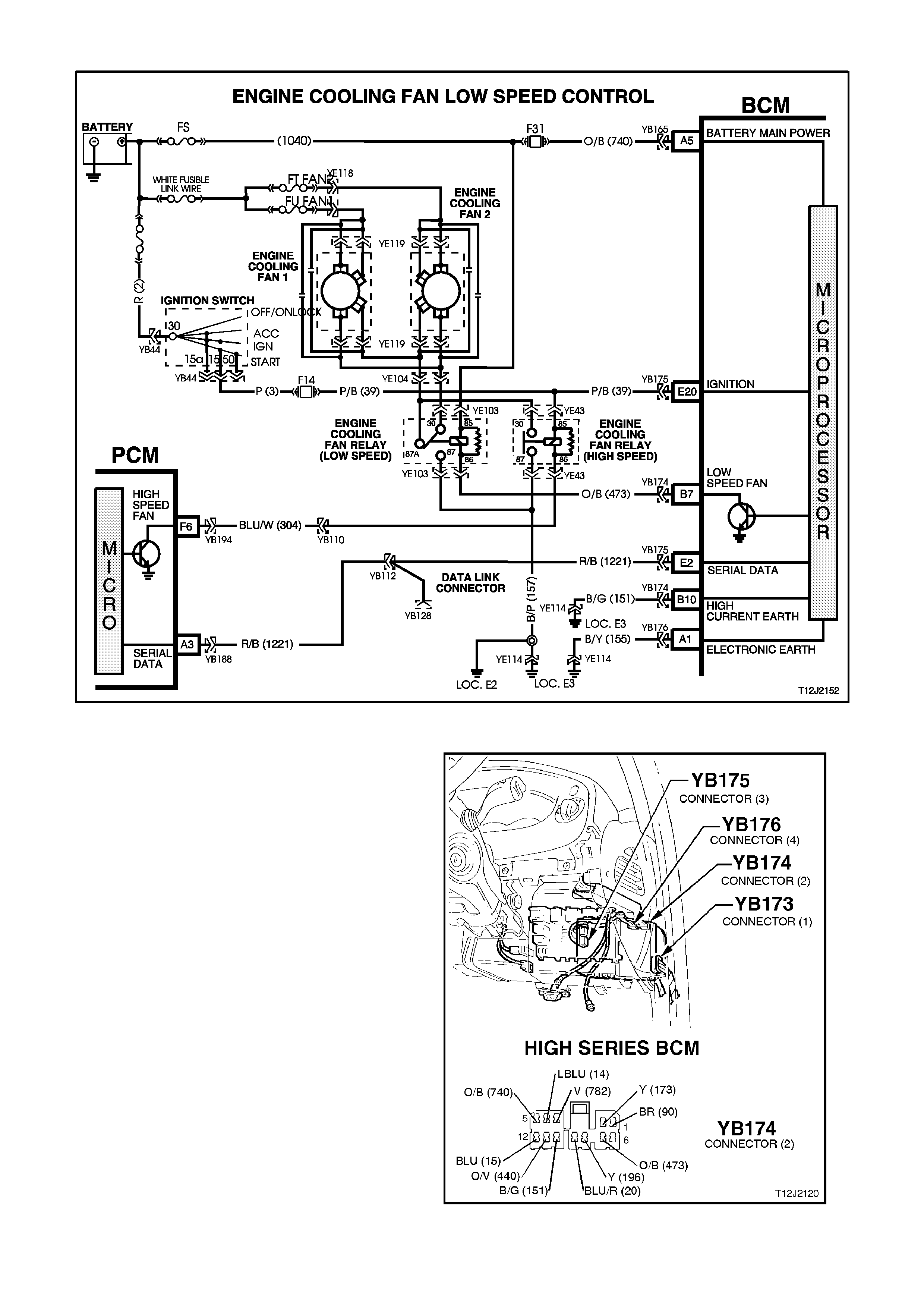
4.8 ENGINE COOLING FAN LOW SPEED CONTROL
Figure 12J-2-138
CIRCUIT DESCRIPTION
The two, two speed electric engine cooling fans,
low speed is enabled when the low speed engine
cooling fan micro relay (located in the engine
compartment relay housing) is energised by the
BCM via a request from the Powertrain Control
Module (PCM). The PCM will request low speed
fan enable and disable via the serial data
communications - m ain bus, c ircuit 1221. T he PCM
determines when to enable the low speed fan
based on inputs form the A/C request signal,
cooling temperature sensor and vehicle speed
sensor.
When the ignition switch is turned f rom O N to OFF ,
if the FAN RUN ON bit has been set by the PCM
(coolant temperature above 117°C), the BCM will
continue to energise the low speed cooling fan
mic ro relay for f our m inutes 15 s econds ( fan r un on
time).
Figure 12J-2-139

TEST DESCRIPTION
The numbers below refer to step numbers in the following diagnostic chart.
1. Functional check of low speed cooling fan operation.
2. Uses TECH 2 to command the BCM to turn the low speed fan on.
3. Checks for battery voltage supply to engine cooling fan motor.
4. Checks low speed fan drive signal at output of BCM when.
5. Checks circuit 473.
6. Checks circuit 1040.
7. Checks circuit 157.
8. Checks engine cooling low speed fan relay.
9. Checks circuit 533 and engine cooling fan motor.
STEP ACTION VALUE YES NO
1. • With the engine
coolant temperature
greater than 104°C, is
the low speed fan
enabled?
System OK. Go to Step 2.
2. • Connect TECH 2 to
the DLC.
• Select BODY / BODY
CONTROL MODULE /
MISCELLANEOUS
TESTS / LOW FAN.
• Conduct test as
instructed by TECH 2
and enable the low
speed fan.
• Is the low speed fan
enabled?
Go to PCM /
Temperature
sensor diagnosis
in Section 6C1
POWERTRAIN
MANAGEMENT -
V6 ENGINE or
Section 6C2
POWERTRAIN
MANAGEMENT -
V8 ENGINE.
Go to Step 3.
3. • Back probe engine
cooling fan motor
connector YE119,
circuit 208 (Green
wire) w ith a Voltmeter
to earth.
• Is voltage as
specified?
12 volts Go to Step 4. Check and repair
open in
circuit 208.
Recheck and
verify repair.
4. • Back probe BCM
connector YB174,
terminal B7, circuit 473
(Orange/Black wire)
with a jumper lead to
earth.
• Does low speed fan
turn on?
0 volts Replace BCM,
refer to 2.2 HIGH
SERIES BCM in
this Section.
Recheck and
verify repair.
Go to Step 5.
5. • Back probe engine
cooling fan low speed
relay connector
YE103, terminal 86,
circuit 473
(Orange/Black wire)
with a jumper lead to
earth.
• Does low speed fan
turn on?
0 volts Go to Step 6. Check and repair
open in
circuit 473.
Recheck and
verify repair.

STEP ACTION VALUE YES NO
6. • Back probe engine
cooling fan low speed
relay connector
YE103, terminal 85,
circuit 1040
(Orange/Pink wire)
with a Voltmeter to
earth.
• Is voltage as
specified?
12 volts Go to Step 7. Check and repair
open in
circuit 1040.
Recheck and
verify repair.
7. • Back probe engine
cooling fan low speed
relay connector
YE103, terminal 87,
circuit 157 (Black/Pink
wire) with an
Ohmmeter to earth.
• Is value as specified?
Below
1 ohm Go to Step 8. Check and repair
open in
circuit 157.
Recheck and
verify repair.
8. • Back probe engine
cooling fan low speed
relay connector
YE103, terminal 30,
circuit 533
(Blue /Yel low wire) with
an Ohmmeter to earth.
• Connect TECH 2 to
the DLC.
• Select BODY / BODY
CONTROL MODULE /
MISCELLANEOUS
TESTS / LOW FAN.
• Conduct test as
instructed by TECH 2
and enable the low
speed fan.
• Is value as specified?
Below
1 ohm Go to Step 9. Replace engine
cooling low speed
fan relay.
Recheck and
verify repair.
9. • With TECH 2 still
connected, back probe
engine cooling fan
motor connector
YE119, circuit 553
(Black wire) with an
Ohmmeter to earth.
• Repeat TECH 2 LOW
SPEED FAN test as
again.
• Is value as specified?
Below
1 ohm Replace engine
cooling fan motor,
refer to either
Section 6B1
ENGINE
COOLING -
V6 ENGINE
or
Section 6B2
ENGINE
COOLING -
V8 ENGINE.
Recheck circuit to
verify repair.
Repair open in
circuit 533.
Recheck circuit to
verify repair .
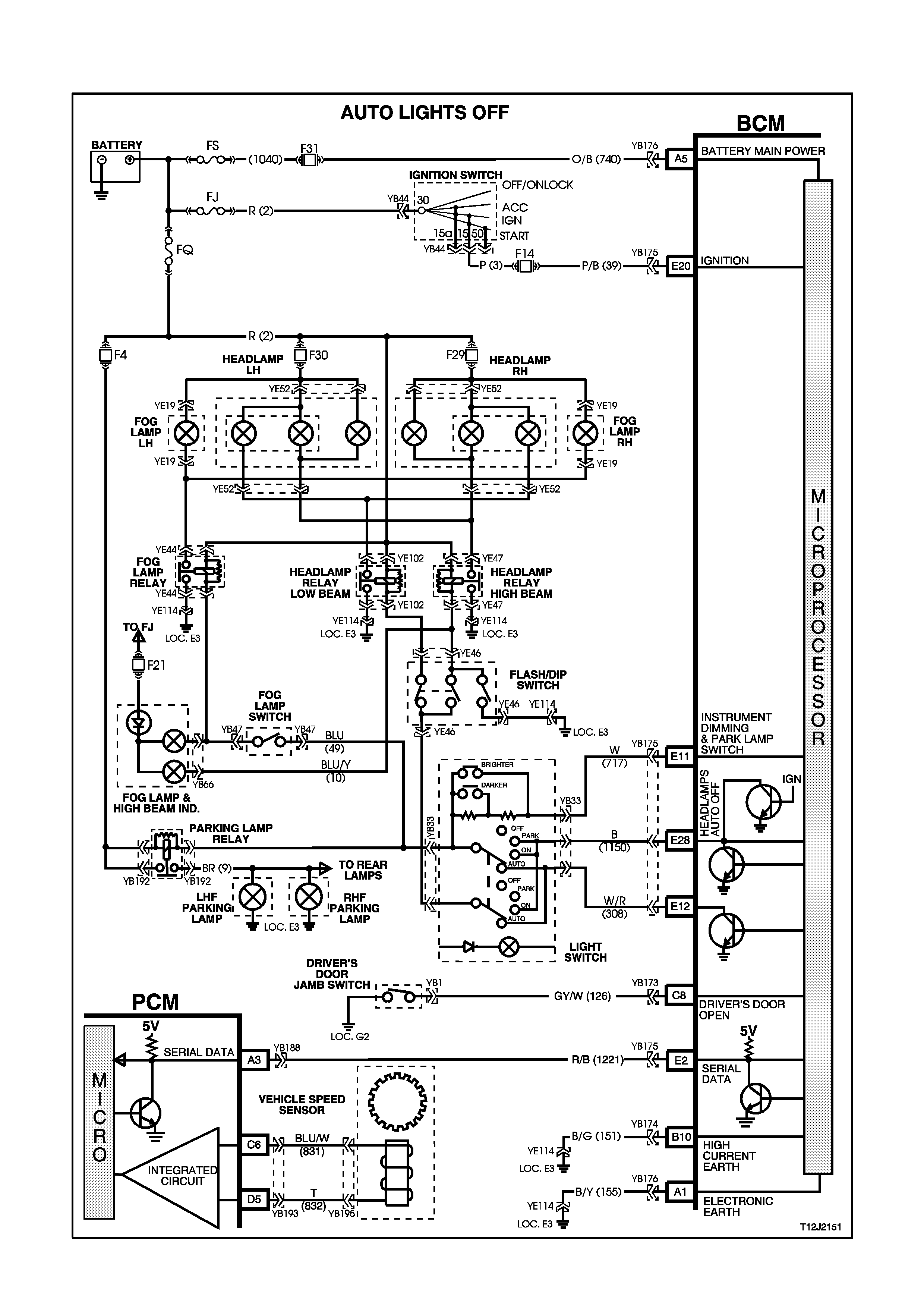
4.9 AUTOMATIC LIGHT CONTROL - AUTOMATIC LIGHTS OFF (WITHOUT TWILIGHT
SENTINEL)
Figure 12J-2-140
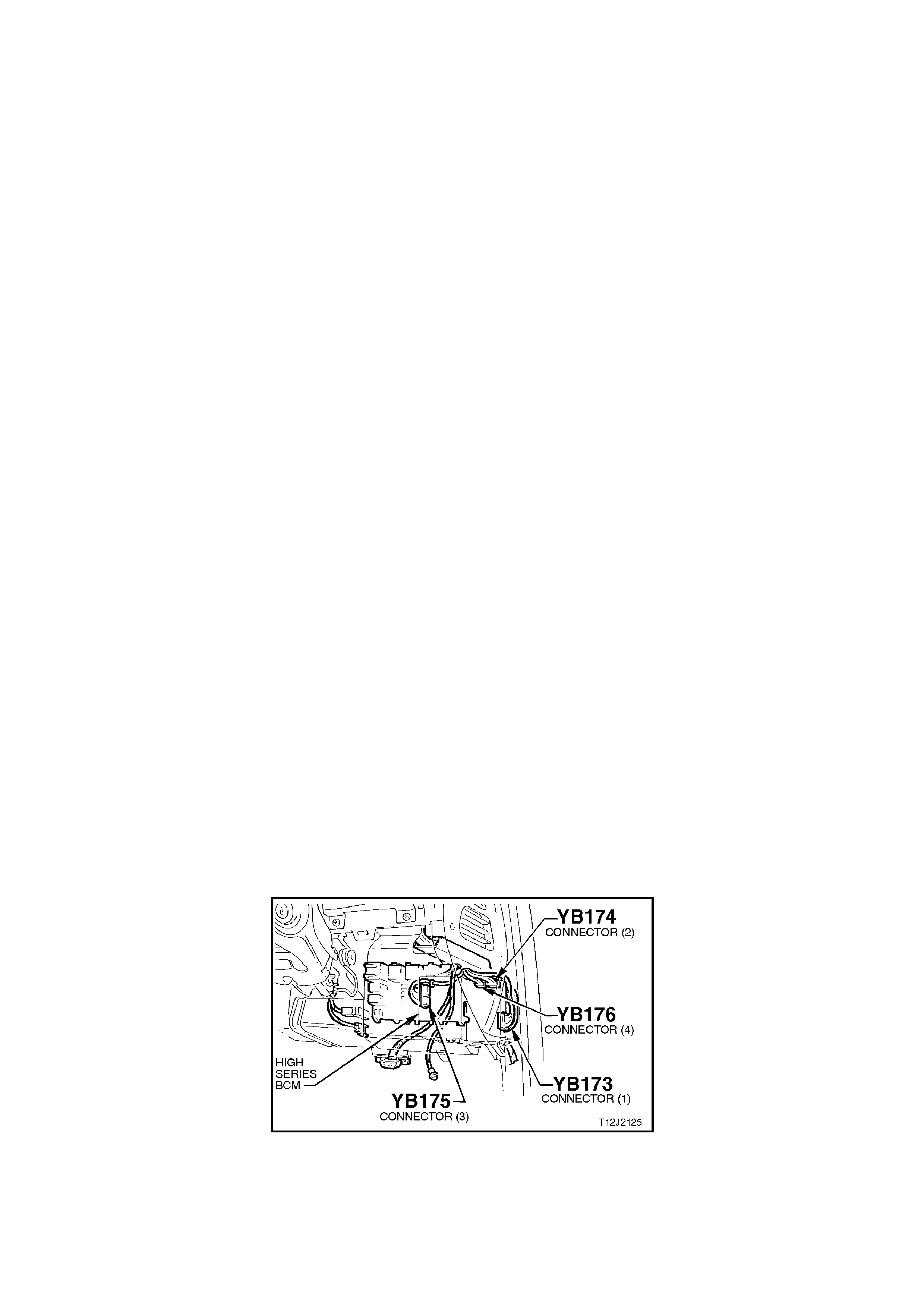
CIRCUIT DESCRIPTION
The automatic light control (lights off) feature is designed to automatically switch the headlights and parking lights
off when the driver leaves the vehicle.
NOTE:
Since this system is safety related, it is mandatory that in the event of a system failure, the default status of the
BCM light control outputs are in the on state when the ignition switch is in the 'IGN' position. This will give direct
control of the lights to the headlamp switch.
The sequence of events required to switch the lights off automatically is as follows:
1. The vehicle road speed input to the BCM indicates speed is less than 10 kilometres per hour and there has not
been a sudden loss of speed (ignition being switched off with the vehicle travelling above 10 km/h).
2. The BCM senses that the ignition switch is turned from ON to OFF and remains in the off position.
3. The headlights switch has not been turned on after the ignition switch was turned off.
4. The BCM senses the driver's door has been opened or that it is already open.
When the ignition switch is turned back to 'IGN' position, the lights will turn back on to the position selected by the
headlamp switch and the mode of headlights operation (ie. high or low beam or fog light [if fitted]) determined by the
position of the relevant switches.
Turning the headlamp switch off deactivates the automatic lights system.
A delay period before the automatic lights off feature deactivates the vehicle lights can be set by following a set
procedure (refer to 1.7 AUTOMATIC LIGHT CONTROL / A UTOMATIC LIGHTS OFF (WITHOUT TWILIGHT
SENTINEL) in this Section for more information about this feature).
NOTE:
This time delay is also dependent on the priority key system. The time delay period can be set for the priority 1 and
priority 2 keys. The time delay is recalled when the unlock button on the remote is pressed and is dependent on
whether priority 1 or priority 2 key is used.
TEST DESCRIPTION
The numbers below refer to step numbers in the following diagnostic chart.
1-8. Functional check of automatic light control system.
10. Functional check of fail safe.
11. Test to establish whether problem is due to no output drive from BCM or circuit problem beyond BCM.
12. Checks circuit 1150.
13. Uses TECH 2 to check for DRIVER’S DOOR OPEN signal at microprocessor of BCM.
14. Uses TECH 2 to check IGNITION signal at microprocessor of BCM.
15. Checks for correct ignition signal at input to BCM.
16. Checks DRIVER’S DOOR OPEN signal at input to BCM.
17. Checks circuit 126 and driver’s door jamb switch.
18. Checks for false output drive from BCM or short circuit in lamp circuits.
19. Uses TECH 2 to check ILLUMINATION DIM- signal at microprocessor of BCM.
20. Checks ILLUMINATION DIM- signal at input to BCM.
21. Checks circuit 717 and headlamp switch assembly.
Figure 12J-2-141

Figure 12J-2-142
STEP ACTION VALUE YES NO
1. • Remove and reinstall
fuse F31 (to reset the
automatic lights off
time delay period to 0
seconds).
• Turn ignition OFF.
• Turn headlamp switch
from the OFF to
PARKLAMPS position.
• Do the park lamps turn
ON?
Go to Step 2. Go to Step 9.
2. • With ignition OFF, turn
headlamp switch from
the PARKLAMPS to
HEADLAMPS position.
• Do the headlamps turn
ON?
Go to Step 3. Check and repair
headlamp switch,
fault in wiring
harness to
headlamp relay s
and circuits
including fuses
and relays.
Recheck and
verify repair.
3. • Turn ignition ON.
• Close driver’s door.
• Turn headlamp switch
to the HEADLAMP
position.
• Turn ignition OFF.
• Open the driver’s door.
• Do the headlamps turn
off?
Go to Step 4. Go to Step 13.
4. • From Step 3. (ignition
OFF, driver’s door
open, headlamp switch
in the HEADLAMP
position and headlights
off), turn Ignition ON.
• Do headlamps turn
back ON?
Go to Step 5. Replace BCM,
refer to 2.2 HIGH
SERIES BCM in
this Section.
Recheck and
verify repair.
5. • Turn ignition from ON
to OFF.
• Open driver’s door
(headlamps OFF).
• Turn headlamp switch
from HEADLAMPS to
OFF to HEADLAMPS.
• Do headlamps turn ON
(system override)?
Go to Step 6. Replace BCM,
refer to 2.2 HIGH
SERIES BCM in
this Section.
Recheck and
verify repair.

STEP ACTION VALUE YES NO
6. • Turn ignition ON.
• Turn headlamp switch
to the HEADLAMP
position.
• Close driver’s door.
• Hold the illumination
level switch in the down
position (DIM -).
• Turn ignition OFF.
• Open driver’s door
(initiate start of time
delay period).
• Do headlamps remain
ON (illumination level
switch held down)?
Go to Step 7. Go to Step 19.
7. • With illumination level
switch held down from
Step 6, wait the
requested time delay
and release switch.
• Do headlamps turn
OFF?
Go to Step 8. Go to instrument
illumination
diagnosis, refer to
4.15
INSTRUMENT
DIMMING
CONTROL in this
Section.
8. • Close driver’s door.
• Turn ignition ON
(headlamps On).
• Turn ignition OFF.
• Open driver’s door.
• Do headlamps turn
OFF (after time delay
period as set in Step 6
and 7)?
System OK. Replace BCM,
refer to 2.2 HIGH
SERIES BCM in
this Section.
Recheck and
verify repair.
9. • Turn ignition OFF.
• Turn headlamp switch
to HEADLAMPS
position.
• Do headlamps turn
ON?
Check and verify
headlamp switch
and park
lamp circuits.
Recheck and
verify repair.
Go to Step 10.
10. • Turn headlamp switch
to PARKLAMP
position.
• Turn ignition ON.
• Do headlamps turn
ON?
Replace BCM,
refer to 2.2 HIGH
SERIES BCM in
this Section.
Recheck and
verify repair.
Go to Step 11.
11. • Remove BCM
connector YB175 and
back probe harness
end of connector,
terminal E28, circuit
1150 (Black wire) with
a jumper lead and
connect to a sound
earth.
• Turn headlamp switch
to the PARKLAMP
position.
• Do park lamps turn
ON?
Replace BCM,
refer to 2.2 HIGH
SERIES BCM in
this Section.
Recheck and
verify repair.
Go to Step 12.

STEP ACTION VALUE YES NO
12. • Reconnect BCM
connector YB175.
• Back probe BCM
connector YB175,
terminal E28, circuit
1150 (Black wire) and
headlamp switch
connector YB33, circuit
1150 (Black wire) with
an Ohmmeter.
• Is value as specified?
Below
1 ohm Check and repair
headlamp switch
assembly, fault in
wiring harness to
head and park
lamp relays
and/or park lamps
(inc. fuses, head
and park
lamp relays).
Recheck and
verify repair.
Check and repair
open in
circuit 1150.
Recheck and
verify repair.
13. • Connect TECH 2 to
DLC.
• Select BODY / BODY
CONTROL MODULE /
DATA DISPLAY.
• Scroll to DRIVERS
DOOR display.
• Open driver’s door.
• Does screen display
DRIVERS DOOR
OPEN?
Go to Step 14. Go to Step 16.
14. • With TECH 2 still
connected and DATA
DISPLAY selected,
scroll to IGNITION
SWITCH display.
• With ignition OFF, does
screen display
IGNITION SWITCH
ON?
Go to Step 15. Go to Step 18.
15. • Turn ignition OFF.
• Back probe BCM
connector YB175,
terminal E20, circuit 39
(Pink/Black wire) with a
Voltmeter to earth.
• Is voltage as specified?
0 volts Replace BCM,
refer to 2.2 HIGH
SERIES BCM in
this Section.
Recheck and
verify repair.
Check and repair
fault in wiring
(particularly short
to Battery +) in
circuit 39 or faulty
ignition switch.
Recheck and
verify repair.
16. • Open driver’s door.
• Back probe BCM
connector YB173,
terminal C8, circuit 126
(Grey/White wire) wi th
a Voltmeter to earth.
• Is voltage as specified?
Below
0.5 volts Replace BCM,
refer to 2.2 HIGH
SERIES BCM in
this Section.
Recheck and
verify repair.
Go to Step 17.
17. • Disconnect BCM
connector YB173 and
back probe harness
end of terminal C8,
circuit 126 (Grey/White
wire) and driver’s door
jamb switch connector
YB1, circuit 126
(Grey/White wire) wi th
an Ohmmeter.
• Is value as specified?
Below
1 ohm Replace driver’s
door jamb switch,
refer to 2.10
DOOR JAMB
SWITCH in
this Section.
Recheck and
verify repair.
Check and repair
open in
circuit 126.
Recheck and
verify repair.

STEP ACTION VALUE YES NO
18. • Disconnect BCM
connector YB175.
• Turn headlamp switch
to Headlamp position.
• Do headlamps switch
OFF?
Replace BCM,
refer to 2.2 HIGH
SERIES BCM in
this Section.
Recheck and
verify repair.
Check and repair
short to earth in
wiring to relays
and/or earth end
of headlamps,
faulty relays
(beyond BCM
terminal E28).
Recheck and
verify repair.
19. • Connect TECH 2 to
DLC.
• Select BODY / BODY
CONTROL MODULE /
DATA DISPLAY.
• Turn the headlamp
switch to HEADLAMP
position.
• Scroll to
ILLUMINATION
SWITCH POSITION
display.
• Activate DIM - control
on the illumination
switch.
• Does screen display
ILLUMINATION
SWITCH POSITION
down?
Replace BCM,
refer to 2.2 HIGH
SERIES BCM in
this Section.
Recheck and
verify repair.
Go to Step 20.
20. • With headlamp switch
still in HEADLAMP
position, back probe
BCM connector YB175,
terminal E11, circuit
717 (White wire) with a
Voltmeter to earth.
• Turn ignition ON.
• Hold the illumination
control switch in the
DIM - position.
• Is voltage as specified?
Approx.
1.6 volts Replace BCM,
refer to 2.2 HIGH
SERIES BCM in
this Section.
Recheck and
verify repair.
Go to Step 21.
21. • Check integrity of
circuit 717 (White wire).
• Is circuit 717 OK?
Below
1 ohm Replace
headlamp switch,
refer to
Section 12B
LIGHTING
SYSTEM.
Check and repair
circuit 717 as
necessary.
Recheck and
verify repair.
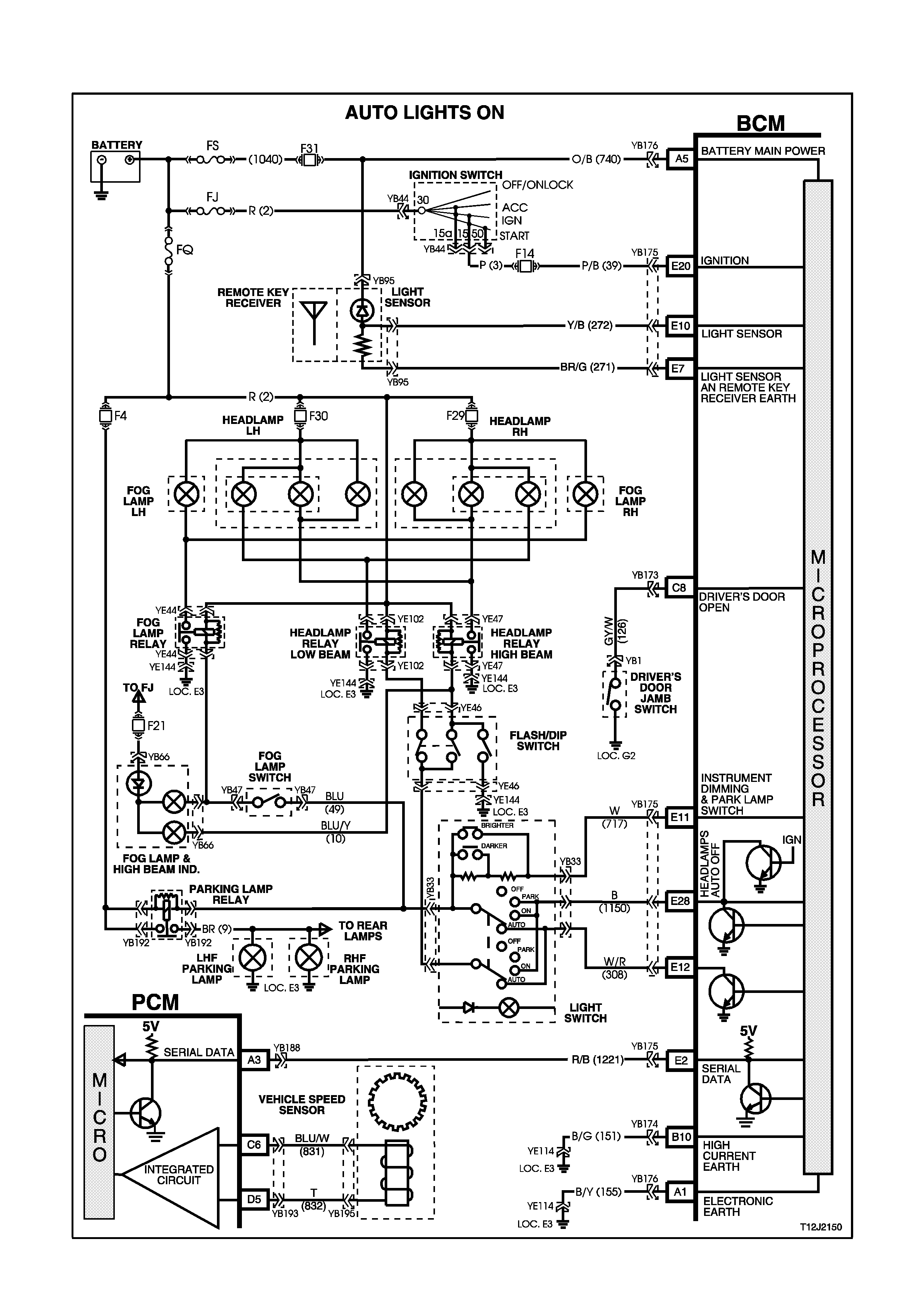
4.10 AUTOMATIC LIGHT CONTROL - AUTOMATIC LIGHTS ON AND OFF (WITH TWILIGHT
SENTINEL)
Figure 12J-2-143
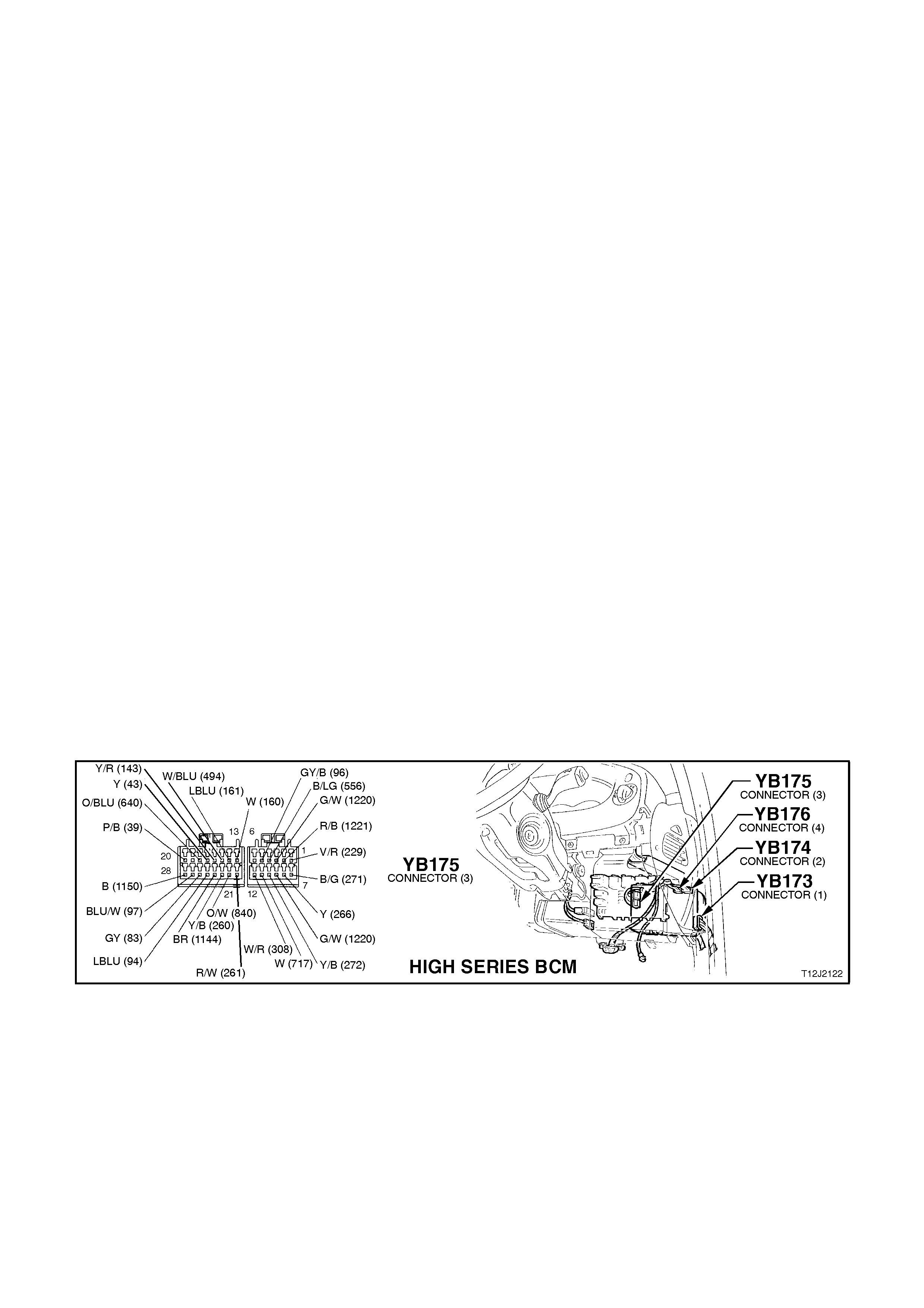
CIRCUIT DESCRIPTION
The automatic light control, lights on and off feature with twilight sentinel, turns the vehicle headlights on and off,
depending on the outside light level. This feature will only work while the headlamp switch is in the AUTO position
and the ignition is switched ON. The lights will operate as normal in other switch positions.
The light sensor is part of the sun sensor / remote receiver module and is located in the instrument panel pad of the
vehicle between the demist ducts. The light sensor is used to monitor the amount of light in front of the vehicle. The
BCM monitors the output of this sensor via circuit 272 and determines when the light levels are low enough to turn
the lights on.
TECH 2 can be used to select several different ON/OFF light levels to suit the customer preferences. The automatic
lights off feature works as per normal (automatic lights off without twilight sentinel) during automatic light control
(including auto lights off delay period).
Diagnostic Aids
If a driver complains of the headlamps coming on to early (during daylight), or to late (well after dusk), the sensitivity
of the twilight can be programmed using TECH 2.
By adjusting the sensitivity down (below the default value of 4) the headlamps will turn on later.
By adjusting the sensitivity up (above the default value of 4) the headlamps will turn on earlier.
TEST DESCRIPTION
The numbers below refer to step numbers in the following diagnostic chart.
1-3. Functional check of automatic light control system.
5. Uses TECH 2 to operate headlights in the AUTO position to establish whether problem is with input or output of
BCM.
6. Checks for power and earth to sun sensor / remote receiver module.
7. Uses TECH 2 to check LIGHT SENSOR LEVEL signal at microprocessor of BCM.
8. Checks for BCM output drive of AUTO LIGHTS ON.
9. Checks circuit 308.
10. Checks for battery voltage supply at sun sensor/remote receiver module (circuit 740).
11. Checks circuit 271.
12. Checks LIGHT SENSOR LEVEL signal at input to BCM.
13. Checks circuit 272.
14. Uses TECH 2 to turn headlights off in the AUTO position to establish whether problem is with output or input of
BCM.
15. Checks LIGHT SENSOR LEVEL signal at input to BCM.
16. Tests for false output drive from BCM or short circuit in wiring.
Figure 12J-2-144

STEP ACTION VALUE YES NO
1. • Turn ignition ON.
• Turn headlamp switch
to AUTO position.
• Cover the sun
sensor/remote receiver
module assembly.
• Do the headlamps turn
ON?
Go to Step 2. Go to Step 4.
2. • With ignition still ON
and headlamp switch
in AUTO position,
uncover the sun
sensor/remote receiver
module.
• Shine a torch on the
sun sensor/remote
receiver module.
• Do the headlamps
switch OFF?
Go to Step 3. Go to Step 14.
3. • Does the automatic
lights off feature
(including delay time)
operate with the light
switch in the AUTO
position when the
ignition is switched off
and the driver’s door is
open?
System OK. Go to automatic
lights off
diagnosis, refer to
4.9 AUTOMATIC
LIGHT CONTROL
- AUTOMATIC
LIGHTS OFF
(WITHOUT
TWILIGHT
SENTINEL) in this
Section.
4. • Do lights operate
normally in the PARK
and HEADLAMP
positions?
Go to Step 5. Go to automatic
lights off
diagnosis, refer to
4.9 AUTOMATIC
LIGHT CONTROL
- AUTOMATIC
LIGHTS OFF
(WITHOUT
TWILIGHT
SENTINEL) in this
Section.
5. • Connect TECH 2 to
DLC.
• Select BODY / BODY
CONTROL MODULE /
MISCELLANEOUS
TESTS / LAMPS /
TWILIGHT SENTINEL.
• Turn headlamp switch
to AUTO position.
• Conduct test as
instructed by TECH 2.
• Do headlamps turn
ON?
Go to Step 6. Go to Step 8.

STEP ACTION VALUE YES NO
6. • Check operation of the
remote coded key
receiver by locking and
unlocking doors using
remote coded key
LOCK and UNLOCK
button.
• Does remote coded
key receiver operate?
Go to Step 7. Go to Step 10.
7. • Connect TECH 2 to
DLC.
• Select BODY / BODY
CONTROL MODULE /
DATA DISPLAY.
• Scroll to AMBIENT
LIGHT SENSOR
display.
• Cover the sun
sensor/remote receiver
module assembly.
• Does screen display
AMBIENT LIGHT
SENSOR 0V?
Replace BCM,
refer to 2.2 HIGH
SERIES BCM in
this Section.
Recheck and
verify repair.
Go to Step 12.
8. • Back probe BCM
connector YB175,
terminal E12, circuit
308 (White/Red wire)
with a jumper lead to
earth.
• Turn headlamp switch
to AUTO position.
• Do lights come on?
0 volt Replace BCM,
refer to 2.2 HIGH
SERIES BCM in
this Section.
Recheck and
verify repair.
Go to Step 9.
9. • Back probe BCM
connector YB175,
terminal E12, circuit
308 (White/Red wire)
light switch connector
YB33, circuit 308,
(White/Red wire) with
an Ohmmeter and
check for continuity.
• Does continuity exist?
Replace light
switch, refer to
Section 12B
LIGHTING
SYSTEM.
Check and repair
open in
circuit 308.
Recheck and
verify repair.
10. • Back probe sun
sensor/remote receiver
module connector
YB95, circuit 740
(Orange/Black wire)
with a Voltmeter to
earth.
• Is voltage as
specified?
12 volts Go to Step 11. Check and repair
open in
circuit 740.
Recheck and
verify repair.
11. • Check integrity of
circuit 271
(Brown/Green wire).
• Is circuit 271 OK?
Go to Step 7. Check and repair
circuit 271 as
necessary.
Recheck and
verify repair.

STEP ACTION VALUE YES NO
12. • Back probe BCM
connector YB175,
terminal E10, circuit
272 (Yellow/Black
wire) w ith a Voltmeter
to earth.
• Turn ignition ON.
• Cover the sun
sensor/remote receiver
module assembly.
• Is voltage as
specified?
Less
than
0.5 volts
Replace BCM,
refer to 2.2 HIGH
SERIES BCM in
this Section.
Recheck and
verify repair.
Go to Step 13.
13. • Check integrity of
circuit 272
(Yellow/Brown wire).
• Is circuit 272 OK?
Replace sun
sensor/ remote
receiver module,
refer to 2.12 SUN
SENSOR
/REMOTE
RECEIVER
MODULE in this
Section.
Check and repair
circuit 272 as
necessary.
Recheck and
verify repair.
14. • Connect TECH 2 to
DLC.
• Select BODY / BODY
CONTROL MODULE /
MISCELLANEOUS
TEST / LAMPS /
TWILIGHT SENTINEL.
• Turn ignition ON.
• Turn light switch to
AUTO position.
• Conduct test as
instructed by TECH 2
and command lights
off.
• Do lights turn off when
commanded?
Go to Step 15. Go to Step 16.
15. • Back probe BCM
connector YB175,
terminal E10, circuit
272 (Yellow/Black
wire) w ith a Voltmeter
to earth.
• Turn ignition ON.
• Shine a torch on the
sun sensor/remote
module.
• Is voltage as
specified?
5 volts Replace BCM,
refer to 2.2 HIGH
SERIES BCM in
this Section.
Recheck and
verify repair.
Replace sun
sensor/ remote
receiver module,
refer to 2.12 SUN
SENSOR
/REMOTE
RECEIVER
MODULE in this
Section.
16. • Turn light switch to
AUTO position.
• Disconnect BCM
connector YB175.
• Do headlamps turn
off?
Replace BCM,
refer to 2.2 HIGH
SERIES BCM in
this Section.
Recheck and
verify repair.
Check and repair
short as
necessary in
wiring to relays
and/or earth end
of lamps or
faulty relays
(beyond BCM
terminal E12).
Recheck and
verify repair.
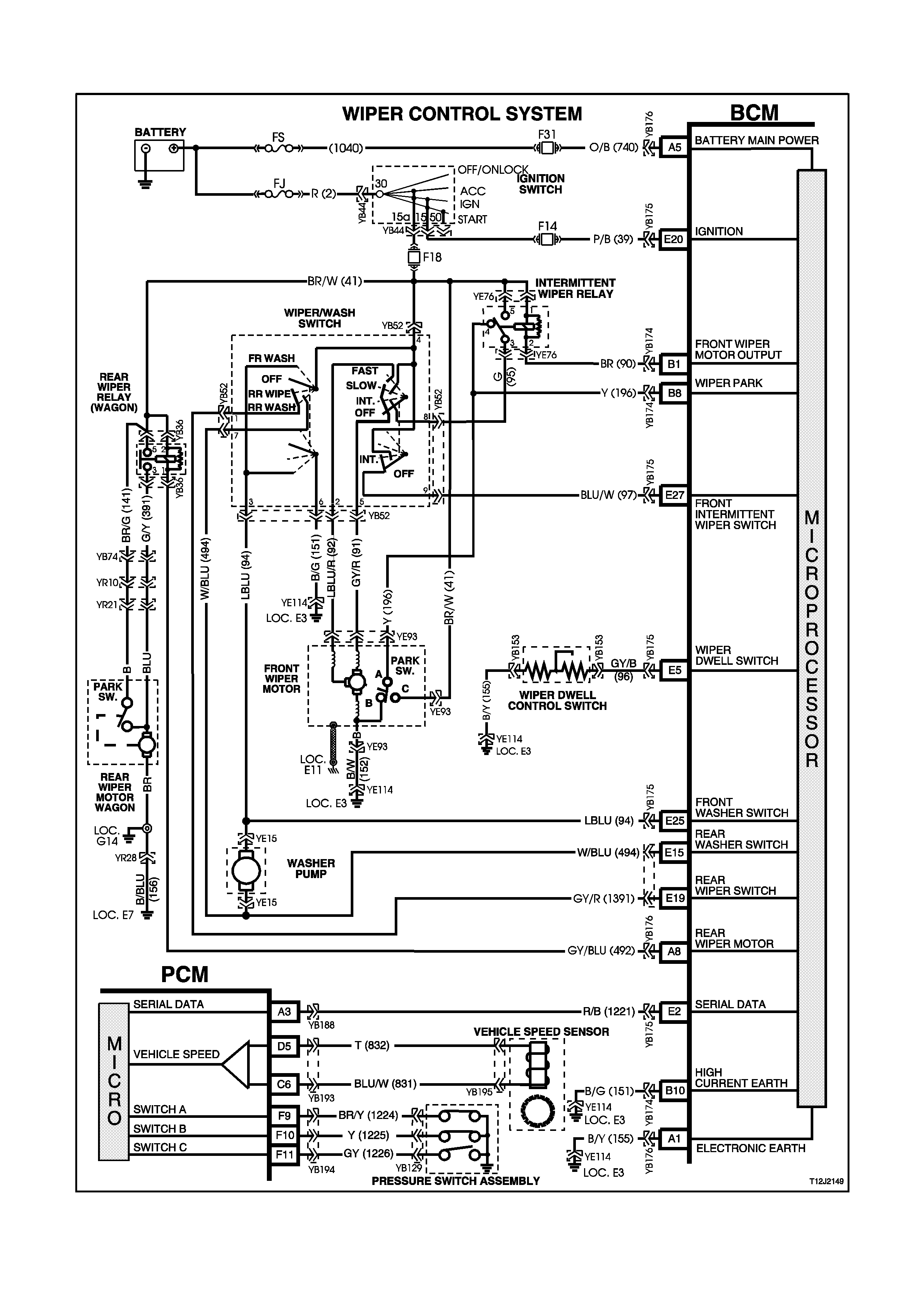
4.11 ROADSPEED DEPENDENT VARIABLE DWELL WIPER SYSTEM
Figure 12J-2-145

CIRCUIT DESCRIPTION
This system controls the front intermittent and rear wiper function. The front wiper dwell on vehicles with high series
BCM’s is dependant on the vehicles road speed and the position of the adjustable potentiometer located on the
wiper control stalk. The faster the vehicle travels, the shorter the dwell time.
The operation of the intermittent rear wiper (Berlina Wagon) is totally independent of the operation of the front
intermittent wiper except when the vehicle is stationary and the ignition is in the accessories position. In this
situation the front and rear intermittent wipers will be synchronised. Due to different wipe action between front and
rear wipers, the rear wiper will start 0.25 seconds before the front wiper.
If the option is set, the rear wiper has the added function of wiping continuously when the vehicle is in reverse gear
(communication between the PCM and BCM via the serial data bus, circuit 1221) and the rear wiper switch is turned
ON.
The front and rear wipers employ a “wipe after wash” function where, if the relevant washer pump switch has been
pressed for more than 0.5 seconds, the wipers start sweeping at a low speed continuously until the washer pump
has been disengaged. Following which, the wiper will be held on for a calculated time period so that the following
number of sweeps can be completed:
• One additional sweep if washer switch pressed for less than 1 second.
• Two additional sweeps if washer switch is pressed for less than 1.5 seconds.
• Three additional sweeps if washer switch is pressed for more than 1.5 seconds
In order to correctly perform the number of additional sweeps, the wiper motor park switch is monitored by the BCM
via circuit 196. This allows the wiper supply power to be transferred to the park switch at the optimum time.
TEST DESCRIPTION
The numbers below refer to step numbers in the following diagnostic chart.
1-12. Functional check of wiper control system.
13. Uses TECH 2 to operate front wiper (establishes whether problem is with input or output of BCM).
14 Uses TECH 2 to check for INTERMITTENT WIPER/WASHER SWITCH ON signal at microprocessor of
BCM.
15. Checks for 12 volt supply to terminals 1 and 5 of intermittent relay.
16. Checks BCM output drive of intermittent wiper relay.
17. Checks circuit 90.
18. Checks intermittent wiper relay.
19. Checks for 12 volts at wiper motor when commanded by TECH 2.
20. Checks circuit 152 / wiper motor.
21. Checks circuit 95.
22. Checks circuit 91 / wiper/washer switch.
23. Checks INTERMITTENT WIPER/WASHER SWITCH ON signal at input to BCM.
24. Checks circuit 97.
25. Checks circuit 41 / wiper/washer switch.
26. Uses TECH 2 to check for WIPER PARK SWITCH signal at microprocessor of BCM.
27. Checks if continuous wiper operation is due to faulty wiper/washer switch / continuous drive from intermittent
relay
28. Checks WIPER PARK SWITCH signal at input to BCM.
29. Checks circuit 41.
30. Checks circuit 196 / wiper motor assembly (internal park switch).
31. Checks for short in circuit 90, causing relay to be always driven.
32. Checks intermittent wiper relay.
33. Checks FRONT WASHER SWITCH signal at input to BCM.
34. Checks circuit 94 / wiper/washer switch.
35. Uses TECH 2 to operate rear wiper (establish whether problem is with input or output of BCM).
36. Uses TECH 2 to check REAR WIPE SWITCH ON signal at microprocessor of BCM.
37. Checks for 12 volt supply to terminal 2 and 5 of rear wiper relay .
38. Checks BCM output drive of rear wiper relay at rear wiper relay.
39. Checks rear wiper relay.
40. Checks circuit 391.
41. Checks rear wiper motor, circuit 156.
42. Checks BCM output drive of rear wiper relay at BCM.
43. Checks REAR WIPER SWITCH signal to BCM.
44. Checks circuit 139 / wiper/washer switch.
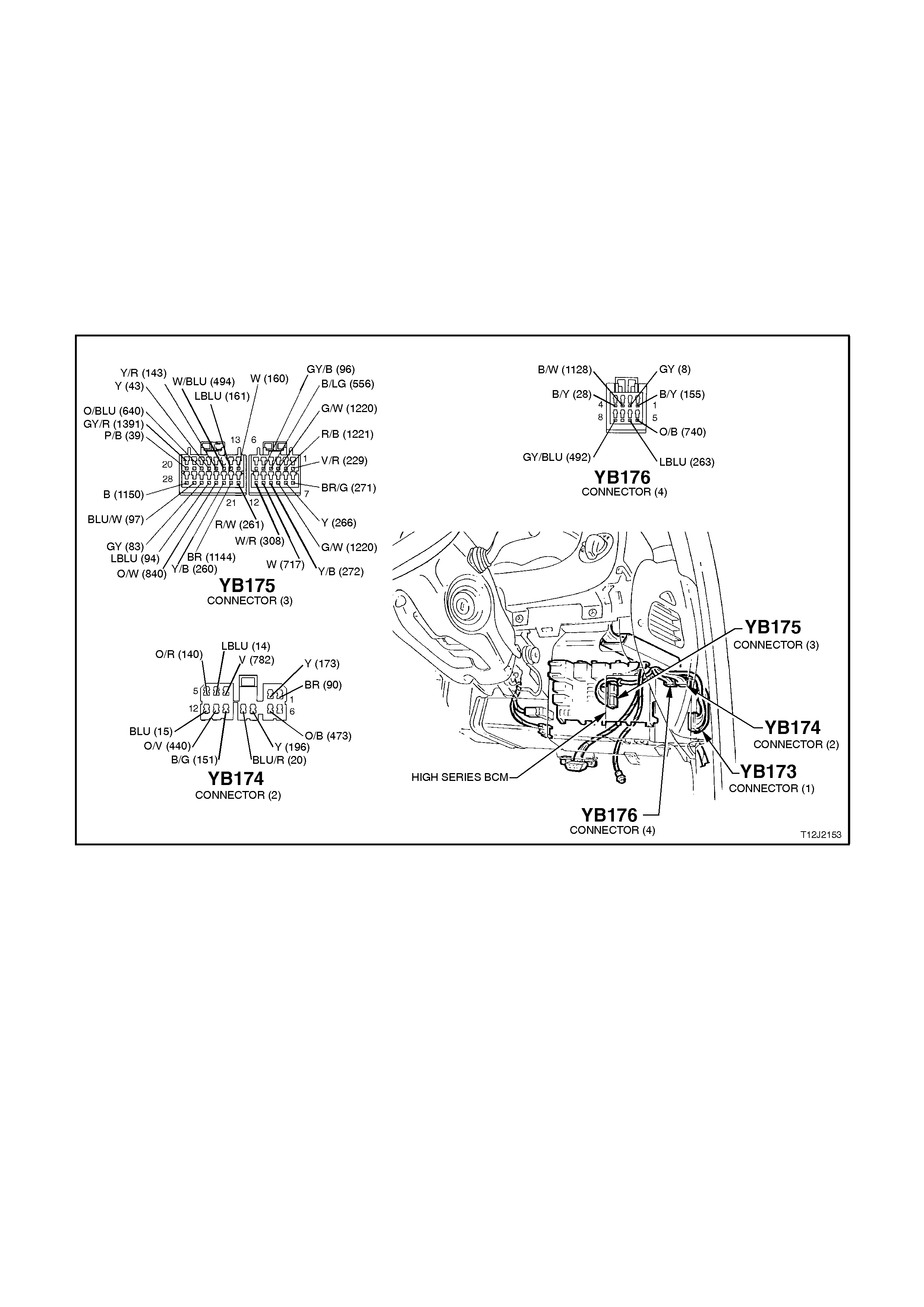
45. Checks for short in circuit 492, causing relay to be always driven.
46. Checks rear wiper relay.
47. Checks REAR WASHER SWITCH signal at input to BCM.
48. Checks circuit 494 / wiper/washer switch.
49. Uses TECH 2 to check REVERSE GEAR signal at microprocessor of PCM.
50. Uses TECH 2 to check WIPER DWELL TIME signal at microprocessor of BCM.
51. Uses TECH 2 to check VEHICLE ROAD SPEED signal at microprocessor of BCM.
52. Checks WIPER DWELL SIGNAL (correct resistance) at input of BCM.
53. Checks circuit 96.
54. Checks circuit 155 and wiper dwell control switch.
55. Uses TECH 2 to check VEHICLE ROAD SPEED signal at microprocessor of PCM.
56. Uses TECH 2 to check reverse gear signal at microprocessor on the serial data bus.
Figure 12J-2-146

STEP ACTION VALUE YES NO
1. • Turn ignition to ACC.
• Turn the wiper/washer
switch to
INTERMITTENT
position.
• Does the front wiper
sweep?
Go to Step 2. Go to Step 13.
2. • Adjust the wiper dwell
control to the fastest
setting.
• Does only one wiper
sweep occur (not
continuous)?
Go to Step 3. Go to Step 26.
3. • Road test vehicle with
wiper switch set to
INTERMITTENT
position.
• Does wiper dwell vary
as wiper dwell control
varied and/or vehicle
speed varied as
specified?
0 km/h
min:
4 sec
max.
24 sec
greater
than 40
km/h min:
cont.
max. 10
sec
Go to Step 4. Go to Step 50.
4. • Turn ignition to ACC.
• Operate the front wash
switch for 2 seconds.
• Does the front wiper
commence continuous
operation?
Go to Step 5. Go to Step 33.
5. • In Step 4, did the front
wipers continue for
three additional sweeps
after the front wash
switch was released?
Sedan - System
OK.
Wagon - Go to
Step 6.
Replace BCM,
refer to 2.2 HIGH
SERIES BCM in
this Section.
Recheck and
verify repair.
6. • Turn ignition to ACC.
• Turn the wiper/washer
switch to REAR WIPE
position.
• Does the rear wiper
sweep?
Go to Step 7. Go to Step 35.
7. • In Step 6, did the rear
wiper only sweep once
(not continuous)?
Go to Step 8. Go to Step 45.
8. • While carrying out Step
6, time the period
between each sweep.
• Is the delay period as
specified?
Approx. 8
seconds Go to Step 9. Replace BCM,
refer to 2.2 HIGH
SERIES BCM in
this Section.
Recheck and verify
repair.
9. • Turn ignition to ACC.
• Operate the rear wash
switch for 2 seconds.
• Does the rear wiper
commence continuous
operation?
Go to Step 10. Go to Step 45.

10. • Turn ignition to ACC.
• Turn the wiper/washer
switch to
INTERMITTENT
position and REAR
WIPER position.
• Vehicle speed 0 km/h.
• Are the front and rear
wipers synchronised?
Go to Step 11. Replace BCM,
refer to 2.2 HIGH
SERIES BCM in
this Section.
Recheck and verify
repair.
11 • Using TECH 2, ensue
the “rear wipe
continuous operation”
option is active.
• Turn ignition ON.
• Turn the front
intermittent wipers on.
• Do the rear wipers
operate continuously
when reverse gear is
selected?
System OK. Go to Step 48.
12 • Connect TECH 2 to
DLC.
• Select BODY / BODY
CONTROL MODULE?
MISCELLANEOUS
TESTS / WIPER
TESTS / FRONT
WIPER.
• Turn ignition to ACC.
• Conduct test as
instructed by TECH 2.
• Do front wipers sweep
continuously?
Go to Step 13. Go to Step14.
13 • With TECH 2 still
connected, select exit
MISCELLANEOUS
TESTS and select
DATA DISPLAY.
• Scroll to FRONT
WIPER
INTERMITTENT
SWITCH display.
• Turn ignition to ACC.
• Turn the wiper/washer
switch to
INTERMITTENT
position.
• Does screen display
FRONT WIPER
INTERMI TTENT ON?
Replace BCM,
refer to 2.2 HIGH
SERIES BCM in
this Section.
Recheck and verify
repair.
Go to Step 22.
14 • Turn ignition to ACC.
• Back probe intermittent
wiper relay connector
YE76, terminal 5 and 1,
circuit 41 (Brown/Green
wire) with a Voltmeter to
earth.
• Is voltage as specified?
12 volts Go to Step 15. Check and repair
open in circuit 41
(including fuse
F18 and
ignition switch).
Recheck and verify
repair.
STEP ACTION VALUE YES NO

STEP ACTION VALUE YES NO
15 • Back probe BCM
connector YB174,
terminal B1, circuit 90
(Brow n wire) with a
jumper lead to earth.
• Do wipers sweep?
Replace BCM,
refer to 2.2 HIGH
SERIES BCM in
this Section.
Recheck and verify
repair.
Go to Step 16.
16 • Back probe intermittent
wiper relay connector
YE76, terminal 2, circuit
90 (Brown wire) with a
jumper lead to earth.
• Do wipers sweep?
Check and repair
open in circuit 90.
Recheck and verify
repair.
Go to Step 17.
17. • Connect TECH 2 to
DLC.
• Turn ignition On
• Select BODY / BODY
CONTROL MODULE /
MISCELLANEOUS
TESTS / WIPER
TESTS / FRONT
WIPER and conduct
test as instructed by
TECH 2.
• Back probe intermittent
wiper relay connector
YE76, terminal 3, circuit
95 (Green wire) with a
Voltmeter to earth.
• Is voltage as specified?
12 volts Go to Step 18. Replace
intermittent
wiper relay.
Recheck and verify
repair.
18. • With TECH 2 still
connected, ignition in
the ACC position, back
probe wiper motor
connector YE93, circuit
91 (Grey / Red wi re)
with a Voltmeter to
earth.
• Repeat TECH 2 FRONT
WIPER test as per Step
17.
• Is voltage as specified?
12 volts Go to Step 19. Go to Step 20.
19 • Back probe front wiper
motor connector YE93,
circuit 152 (Black/White
wire) with an Ohmmeter
to earth.
• Is value as specified?
Below
1 ohm Replace front wiper
motor assembly,
refer to 12C
INSTRUMENTS,
WIPERS /
WASHERS &
HORN.
Check and repair
open in
circuit 152.
Recheck and verify
repair.
20. • With TECH 2 still
connected, ignition in
the ACC position, back
probe wiper/washer
switch connector YB52,
terminal 8, circuit 95
(Green wire) with a
Voltmeter to earth.
• Repeat TECH 2 FRONT
WIPER test as per Step
17.
• Is voltage as specified?
12 volts Go to Step 21. Check and repair
open in circuit 95.
Recheck and verify
repair.

STEP ACTION VALUE YES NO
21. • With TECH 2 still
connected, ignition in
the ACC position, back
probe wiper/washer
switch connector YB52,
terminal 5, circuit 91
(Grey/Red wire) with a
Voltmeter to earth.
• Repeat TECH 2 FRONT
WIPER test as per Step
17.
• Is voltage as specified?
12 volts Check and repair
open in circuit 91.
Recheck and verify
repair.
Replace
wiper/washer
switch, refer to
Section 12C
INSTRUMENTS,
WIPERS /
WASHERS &
HORN.
22. • Turn ignition to ACC.
• Back probe BCM
connector YB175,
terminal E27, circuit 97
(Blue/White wire) with a
Voltmeter to earth.
• Turn the wiper/washer
switch to
INTERMITTENT
position.
• Is voltage as specified?
12 volts Replace BCM,
refer 2.2 HIGH
SERIES BCM in
this Section.
Recheck and verify
repair.
Go to Step 23.
23. • Turn ignition to ACC.
• Back probe
wiper/washer switch
connector YB52,
terminal 9, circuit 97
(Blue/White wire) with a
Voltmeter to earth.
• Turn the wiper/washer
switch to
INTERMITTENT
position.
• Is voltage as specified?
12 volts Check and repair
open in circuit 97.
Recheck and verify
repair.
Go to Step 24.
24. • Turn ignition to ACC.
• Back probe
wiper/washer switch
connector YB52,
terminal 4, circuit 41
(Brown/White wire) with
a Voltmeter to earth.
• Is voltage as specified?
12 volts Replace
wiper/washer
switch, refer to
Section 12C
INSTRUMENTS,
WIPERS /
WASHERS &
HORN.
Check and repair
open in circuit 41
(including
fuse F18).
Recheck and verify
repair.

STEP ACTION VALUE YES NO
25. • Connect TECH 2 to
DLC.
• Turn ignition to ACC.
• Select BODY /BODY
CONTROL MODULE /
DATA DISPLAY.
• Scroll to WIPER PARK
SWITCH display.
• Turn the wiper/washer
switch to
INTERMITTENT
position.
• Does screen display
WIPER PARK SWITCH
ON when wiper is in the
park position and
WIPER PARK SWITCH
OFF when wiper is
operating?
Go to Step 26. Go to Step 27.
26. • Turn ignition to ACC.
• Turn the wiper/washer
switch to
INTERMITTENT
position.
• Remove intermittent
wiper relay.
• Do wipers operate
continuously?
Replace
wiper/washer
switch, refer to
Section 12C
INSTRUMENTS,
WIPERS /
WASHERS &
HORN.
Go to Step 30.
27. • Turn ignition to ACC.
• Turn the wiper/washer
switch to
INTERMITTENT
position.
• Back probe BCM
connector YB174,
terminal B8, circuit 196
(Yellow wire) with a
Voltmeter to earth.
• Are voltages as
specified?
12 volts
while
operating
0 volts
in park
Replace BCM,
refer to 2.2 HIGH
SERIES BCM in
this Section.
Recheck and verify
repair.
Go to Step 28.
28. • Turn ignition to ACC.
• Back probe wiper motor
connector YE93, circuit
41 (Brown/White wire)
with a Voltmeter to
earth.
• Is voltage as specified?
12 volts Go to Step 29. Check and repair
open in circuit 41.
Recheck and verify
repair.
29. • Turn ignition to ACC.
• Turn the wiper/washer
switch to
INTERMITTENT
position.
• Back probe wiper motor
connector YE93, circuit
196 (Yellow w ire) with a
Voltmeter to earth.
• Are values as specified?
12 volts
while
operating
0 volts
in park
Check and repair
open in
circuit 196,
Recheck and verify
repair.
Replace front wiper
motor, refer to
Section 12C
INSTRUMENTS,
WIPERS /
WASHERS &
HORN.

STEP ACTION VALUE YES NO
30. • Turn ignition to ACC.
• Remove intermittent
relay.
• Disconnect BCM
connector YB174.
• Back probe intermittent
wiper relay connector
YE76, circuit 90 (Brown
wire) with an Ohmmeter
to earth.
• Is value as specified?
Below
1 ohm Check and repair
short to earth in
circuit 90.
Recheck and verify
repair.
Go to Step 31
31. • Reconnect BCM
connector YB174.
• Swap intermittent wiper
relay with a known good
relay.
• Turn ignition to ACC.
• Turn the wiper/washer
switch to
INTERMITTENT
position.
• Does only one sweep
occur?
Replace
intermittent
wiper relay.
Recheck and verify
repair.
Replace BCM,
refer to 2.2 HIGH
SERIES BCM in
this Section.
Recheck and verify
repair.
32. • Turn ignition to ACC.
• Back probe BCM
connector YB174,
terminal E25, circuit 94
(L Blue wire) with a
Voltmeter to earth.
• Operate front wash
switch.
• Is voltage as specified?
12 volts Replace BCM,
refer to 2.2 HIGH
SERIES BCM in
this Section.
Recheck and verify
repair.
Go to Step 33.
33. • Turn ignition to ACC.
• Back probe
wiper/washer switch
connector YB52,
terminal 3, circuit 94 (L
Blue wire) with a
Voltmeter to earth.
• Operate front wash
switch.
• Is voltage as specified?
12 volts check and repair
open in circuit 94,
Recheck and verify
repair.
Replace
wiper/washer
switch, refer to
Section 12C
INSTRUMENTS,
WIPERS /
WASHERS &
HORN.
34. • Connect TECH 2 to
DLC.
• Turn ignition to ACC.
• Select BODY / BODY
CONTROL MODULE /
MISCELLANEOUS
TESTS / WIPER
TESTS / REAR WIPER.
• Conduct test as
instructed by TECH 2.
• Does rear wiper
operate?
Go to Step 33. Go to Step 36.

STEP ACTION VALUE YES NO
35. • Turn ignition to ACC.
• With TECH 2 still
connected, exit
MISCELLANEOUS
TESTS and select
DATA DISPLAY and
scroll to REAR WIPE
SWITCH.
• Turn wiper/washer
switch to REAR WIPE
position.
• Does screen display
REAR WIPE SWITCH
ON?
Replace BCM,
refer to 2.2 HIGH
SERIES BCM in
this Section.
Recheck and verify
repair.
Go to Step 42.
36. • Turn ignition to ACC.
• Back probe rear wiper
relay connector YB36,
terminals 2 and 5,
circuit 41 (Brown/Green
wire) with a Voltmeter to
earth.
• Is voltage as specified?
12 volts Go to Step 37. Check and repair
open in circuit 41.
Recheck and verify
repair.
37. • Turn ignition to ACC.
• Back probe rear wiper
relay connector YB36,
terminal 1, circuit 492
(Grey/Blue wire) with a
jumper lead to earth.
• Does rear wiper
operate?
Go to Step 41. Go to Step 38.
38. • Turn ignition to ACC.
• Back probe rear wiper
relay connector YB36,
terminal 3, circuit 391
(Green/Yellow wire) with
a Voltmeter to earth.
• Use a jumper lead and
connect the rear wiper
relay, terminal 1 to
earth.
• Is voltage as specified?
12 volts Go to Step 39. Replace rear
wiper relay.
Recheck and verify
repair.
39. • Turn ignition to ACC.
• Back probe rear wiper
motor connector YR21,
circuit 391
(Green/Yellow wire) with
a Voltmeter to earth.
• Use a jumper lead and
connect the rear wiper
relay, terminal 1 to
earth.
• Is voltage as specified?
12 volts Go to Step 40. Check and repair
open in
circuit 391.
Recheck and verify
repair.
40. • Back probe rear wiper
motor earth connection
with an Ohmmeter to
earth.
• Is value as specified?
Below
1 ohm Replace rear wiper
motor, refer to
Section 12C
INSTRUMENTS,
WIPERS /
WASHERS &
HORN.
Check and repair
rear wiper motor
earth connection.
Recheck and verify
repair.

STEP ACTION VALUE YES NO
41. • Turn ignition to ACC.
• Back probe BCM
connector YB176,
terminal A8, circuit 492
(Grey/Blue wire) with a
jumper lead to earth.
• Does rear wiper
operate?
Replace BCM,
refer to 2.2 HIGH
SERIES BCM in
this Section.
Recheck and verify
repair.
Check and repair
circuit 492.
Recheck and verify
repair.
42. • Turn ignition to ACC.
• Back probe BCM
connector YB175,
terminal E19, circuit 139
(Grey/Red wire) with a
Voltmeter to earth.
• Turn wiper/washer
switch to REAR WIPE
position.
• Is voltage as specified?
12 volts Replace BCM,
refer to 2.2 HIGH
SERIES BCM in
this Section.
Recheck and verify
repair.
Go to Step 43.
43. • Turn ignition to ACC.
• Back probe wiper
wa sher switch
connector YB52,
terminal 1, circuit 139
(Grey/Red wire) with a
Voltmeter to earth.
• Turn wiper/washer
switch to REAR WIPE
position.
• Is voltage as specified?
12 volts Check and repair
open in
circuit 139.
Recheck and verify
repair.
Replace
wiper/washer
switch, refer to
Section 12C
INSTRUMENTS,
WIPERS /
WASHERS &
HORN.
44. • Remove rear wiper
relay.
• Disconnect BCM
connector YB176.
• Back probe rear relay
connector YB36,
terminal 1, circuit 492
(Grey/Blue wire) with an
Ohmmeter to earth.
• Is value as specified?
Below
1 ohm Check and repair
short to earth in
circuit 492.
Recheck and verify
repair.
Go to Step 45.
45. • Reconnect BCM
connector YB176.
• Replace rear wiper relay
with a known good
relay.
• Turn ignition to ACC.
• Turn wiper/washer
switch to REAR WIPE
position.
• Does only one rear wipe
sweep occur (not
continuos)?
Replace rear
wiper relay.
Recheck and verify
repair.
Go to Step 55.

STEP ACTION VALUE YES NO
46. • Turn ignition to ACC.
• Back probe BCM
connector YB175
terminal E15, circuit 494
(White/Blue wire) with a
Voltmeter to earth.
• Operate rear wash
switch.
• Is voltage as specified?
12 volts Replace BCM,
refer to 2.2 HIGH
SERIES BCM in
this Section.
Recheck and verify
repair.
Go to Step 47.
47. • Turn ignition to ACC.
• Back probe
wiper/washer switch
connector YB52,
terminal 7, circuit 494
(White/Blue wire) with a
Voltmeter to earth.
• Operate rear wash
switch.
• Is voltage as specified?
12 volts Check and repair
open in circuit 494.
Recheck and verify
repair.
Replace
wiper/washer
switch, refer to
Section 12C
INSTRUMENTS,
WIPERS /
WASHERS &
HORN.
48. • Connect TECH 2 to
DLC.
• Turn ignition to ACC.
• Vehicle in reverse gear.
• Select ENGINE /
NORMAL MODE.
• Scroll to COMMANDED
GEAR display
• Does screen display R?
Replace BCM,
refer to 2.2 HIGH
SERIES BCM in
this Section.
Recheck and verify
repair.
Go to PCM
diagnostics in
Section 6C1
POWERTRAIN
MANAGEMENT -
V6 ENGINE
or
Section 6C2
POWERTRAIN
MANAGEMENT -
V8 ENGINE.
49. • Connect TECH 2 to
DLC.
• Vehicle stationary.
• Turn ignition to ACC.
• Select BODY / BODY
CONTROL MODULE /
DATA DISPLAY.
• Scroll to FRONT
WIPER DWELL TIME.
• Vary wiper dwell control
switch on wiper washer
switch stalk from max.
to min. dwell time.
• Does screen display as
specified?
Min
dwell
time:
5 sec.
Max.
dwell
time:
24 sec.
Go to Step 50. Go to step 51.
50. • With TECH 2 still
connected and BCM
DATA DISPLAY
selected, scroll to
VEHICLE SPEED and
road test vehicle.
• Does TECH 2 indicate
correct road speed?
Replace BCM,
refer 2.2 HIGH
SERIES BCM in
this Section.
Recheck and verify
repair.
Go to Step 54.

STEP ACTION VALUE YES NO
51. • Disconnect BCM
connector YB175.
• Back probe BCM
connector YB175
(harness end), terminal
E5, circuit 96 (Grey/Blue
wire) with an Ohmmeter
to earth.
• Vary wiper dwell control
switch on wiper washer
switch stalk from max.
to min. dwell time.
• Are values as specified?
Min. dwell
6.0
K/ohms
Max.
700 ohms
Replace BCM,
refer to 2.2 HIGH
SERIES BCM in
this Section.
Recheck and verify
repair.
Go to Step 52.
52. • Back probe dwell
control switch connector
YB153, circuit 96
(Grey/Blue wire) with an
Ohmmeter to earth.
• Vary wiper dwell control
switch on wiper washer
switch stalk from max.
to min. dwell time.
• Are values as specified
Min.
dwell
6.0
K/ohms
Max.
700 ohms
Check and repair
circuit 96 as
necessary.
Recheck and verify
repair.
Go to Step 53.
53. • Back probe dwell
control switch connector
YB153, circuit 155
(Black/Yellow wire) with
an Ohmmeter to earth.
• Is value as specified?
Below
1 ohm Replace
wiper/washer
switch, refer to
Section 12C
INSTRUMENTS,
WIPERS /
WASHERS &
HORN.
Check and repair
open in circuit 155.
recheck and verify
repair.
54. • With TECH 2 still
connected, exit BODY
selection and select
ENGINE / NORMAL
MODE and scroll to
VEHICLE SPEED.
• Roadtest vehicle again.
• Does TECH 2 indicate
correct road speed?
Replace BCM,
refer 2.2 HIGH
SERIES BCM in
this Section.
Recheck and verify
repair.
Go to PCM
diagnostics in
Section 6C1
POWERTRAIN
MANAGEMENT -
V6 ENGINE
or
Section 6C2
POWERTRAIN
MANAGEMENT -
V8 ENGINE.
55. • Place vehicle in neutral
gear.
• Connect TECH to DLC.
• Select ENGINE /
NORMAL MODE and
scroll to COMMANDED
GEAR.
• Does screen display
COMMANDED GEAR
R?
Go to PCM
diagnostics in
Section 6C1
POWERTRAIN
MANAGEMENT -
V6 ENGINE
or
Section 6C2
POWERTRAIN
MANAGEMENT -
V8 ENGINE.
Replace BCM,
refer to 2.2 HIGH
SERIES BCM in
this Section.
Recheck and verify
repair.
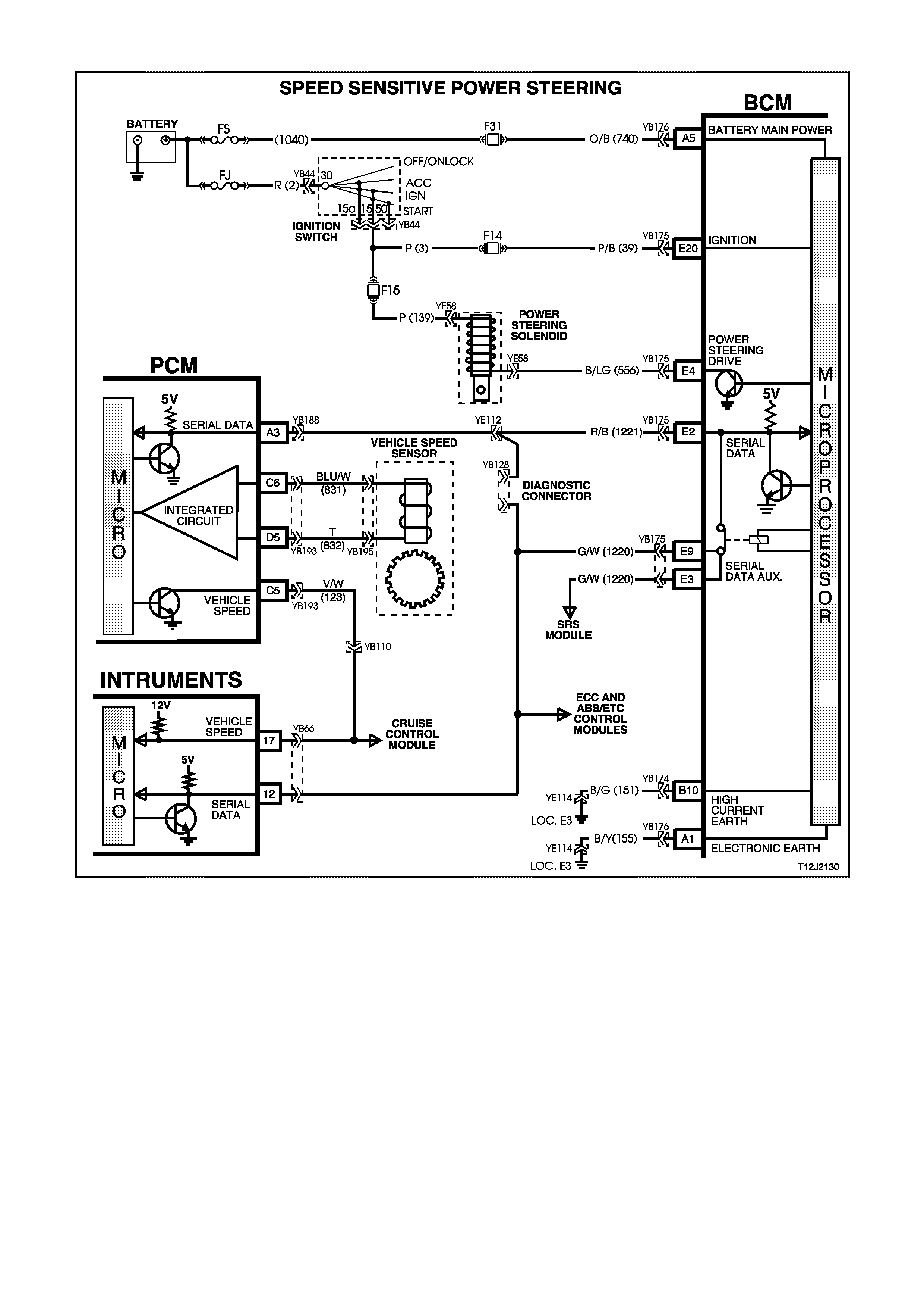
4.12 SPEED SENSITIVE POWER STEERING
Figure 12J-2-147
CIRCUIT DESCRIPTION
The control system of the BCM varies the amount of power assistance given to the steering of the vehicle in order
to allow high boost at low speed or parking and low boost at high speeds for better on centre steering performance.
The BCM contains a curve of speed versus boost (or control solenoid current) stored in memory.
The power steering boost is adjusted by accurately controlling the current flowing in the boost solenoid attached to
the steering gear valve housing.
In the event of any of the following faults, the system will default to no power steering boost: power failure, open
circuits on either side of the power steering solenoid (DTC 5), short circuit to earth on the power steering side of the
solenoid (DTC 5), and short circuit to battery voltage on the BCM side of the solenoid (DTC 6).
In the event of a short circuit to earth on the BCM side of the solenoid (DTC 5), the system will go to more than full
boost until condition stops and then will default to no boost.
If any of these faults are intermittent, cycling the ignition from OFF to ON will return the system to normal until the
fault re-occurs.
In the event of road speed information loss, the system will default to full boost.
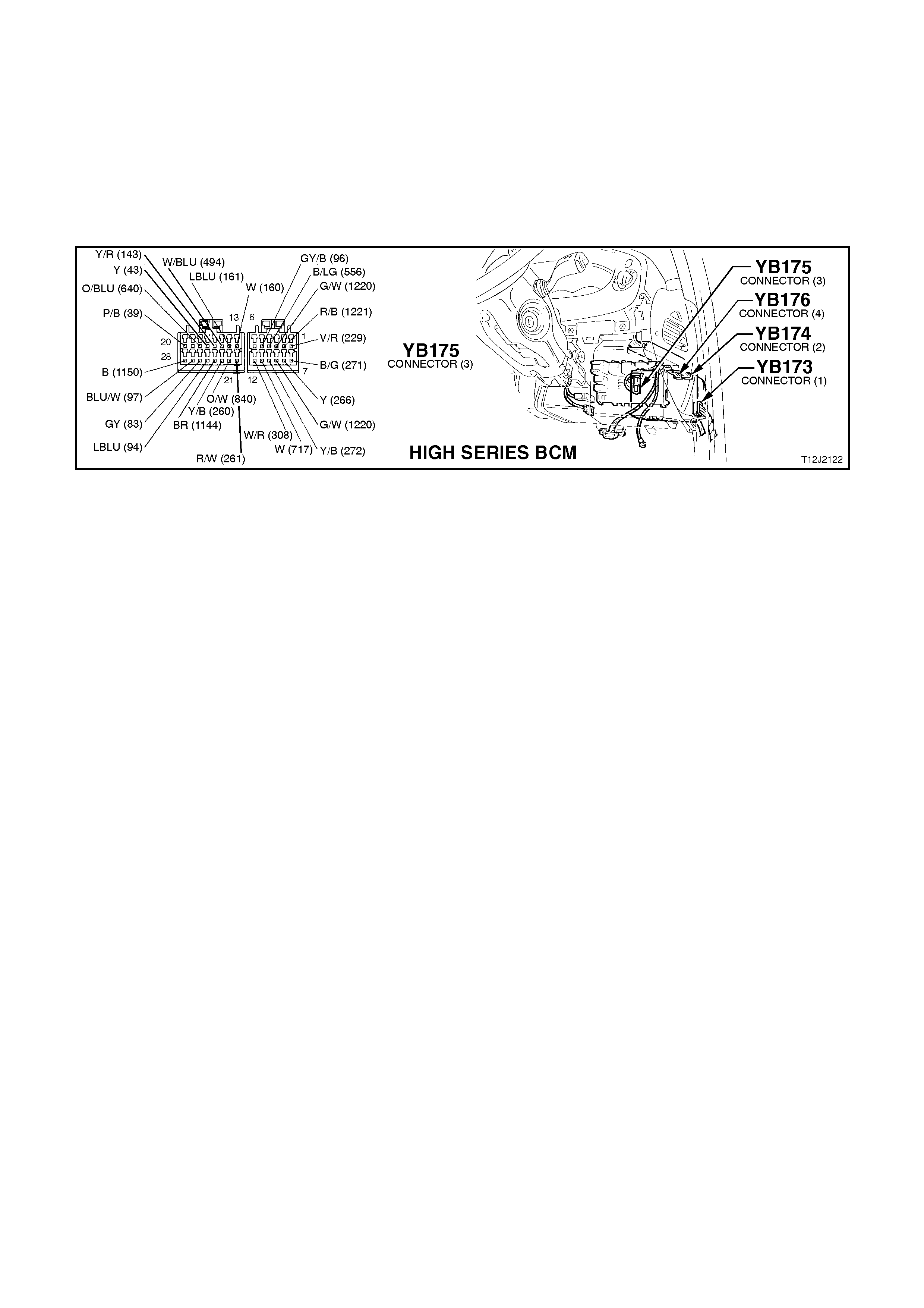
TEST DESCRIPTION
The numbers below refer to step numbers in the following diagnostic chart.
5. Checks circuit 139 (including fuse F15).
6. Checks power steering solenoid.
7. Checks circuit 556.
8. Checks BCM for power steering output drive.
9. Checks for serial data communications.
10. Checks for vehicle speed data at the microprocessor of BCM.
11. Checks for vehicle speed data at the microprocessor of BCM.
Figure 12J-2-148

STEP ACTION VALUE YES NO
1. • Start engine and allow
to idle.
• Is there any power
steering boost?
Go to Step 2. Go to Step 5.
2. • Accelerating vehicle
from rest and note
power steering boost.
• Does power steering
boost reduce?
Go to Step 3. Go to Step 9.
3. • Is speed sensitive
power steering
operation erratic,
requiring ignition to be
cycled from OFF to ON
to return system to
normal (DTC 5 set)?
Check for
intermittent short
to earth or open in
circuits 556 and
139 and repair as
necessary.
Recheck and
verify repair.
Go to Step 4.
4. • Is speed sensitive
power steering
operation erratic,
requiring ignition to be
cycled from OFF to ON
to return system to
normal (DTC 4 set)?
Check for
intermittent short
to battery voltage
in circuit 556 and
repair as
necessary.
Recheck and
verify repair.
System OK.
5. • Back probe power
steering solenoid
connector YE58, circuit
139 (Pink wire) with a
Voltmeter to earth.
• Turn ignition ON.
• Is voltage as
specified?
12 volts Go to Step 6. Check and repair
fault in circuit 139
(including fuse
F15) Recheck
and verify repair.
6. • Disconnect power
steering solenoid
connector YE58.
• Back probe power
steering solenoid
connector terminals
(solenoid side) with an
Ohmmeter.
• Is reading as
specified?
7.5 to
8.5
ohms @
20°C
Go to Step 7. Replace power
steering solenoid,
refer to Section
9B SPEED
SENSITIVE
POWER
STEERING.
7. • Back probe BCM
connector YB175,
terminal E4, circuit 556
(Black/L Green wire)
and power steering
solenoid connector
YE58 circuit 556
(Black/L Green wire)
with an Ohmmeter.
• Is reading as
specified?
Below
1 ohm Go to Step 8. Repair open in
circuit 556.
Recheck circuit to
verify repair.

STEP ACTION VALUE YES NO
8. • Disconnect power
steering solenoid
connector YE58 and
using appropriate
jumper leads from KM-
609, reconnect circuit
139 and connect an
ammeter in series in
circuit 556.
• Turn ignition ON.
• Connect TECH 2 to
DLC.
• Select BODY / BODY
CONTROL MODULE /
MISCELLANEOUS
TESTS / POWER
STEERING.
• Conduct test as
instructed by TECH 2.
• Does value displayed
by amp meter vary as
the level of assist is
varied?
Go to
DIAGNOSIS in
Section 9A
STEERING and
Section 9B
SPEED
SENSITIVE
POWER
STEERING.
Replace BCM,
refer to 2.2 HIGH
SERIES BCM in
this Section.
Recheck and
verify repair.
9. • Connect TECH 2 to
DLC.
• Select BODY / BODY
CONTROL MODULE.
• Is the SYSTEM
IDENTIFICATION
screen display ed in the
TECH 2 display?
Go to Step 10. Go to serial data
communications
diagnosis, refer to
4.1 SERIAL DATA
COM. in this
Section.
10. • With TECH 2 still
connected and ignition
ON, exit BODY
selection and select
ENGINE / DATA
DISPLAY .
• Scroll to VEHICLE
SPEED.
• Road test vehicle.
• Does screen display
the actual vehicle
speed as the vehicle
speed varies?
Go to Step 11. Go to PCM
DIAGNOSIS in
either 6C1
POWERTRAIN
MANAGEMENT -
V6 ENGINE
or
Section 6C2
POWERTRAIN
MANAGEMENT -
V8 ENGINE.
11. • With TECH still
connected and ignition
ON, exit ENGINE
selection and select
BODY / BODY
CONTROL MODULE /
DATA DISPLAY.
• Scroll to VEHICLE
SPEED.
• Road test vehicle.
• Does screen display
the actual vehicle
speed as the vehicle
speed varies?
Go to Step 8. Replace BCM,
refer to 2.2 HIGH
SERIES BCM in
this Section.
Recheck and
verify repair.
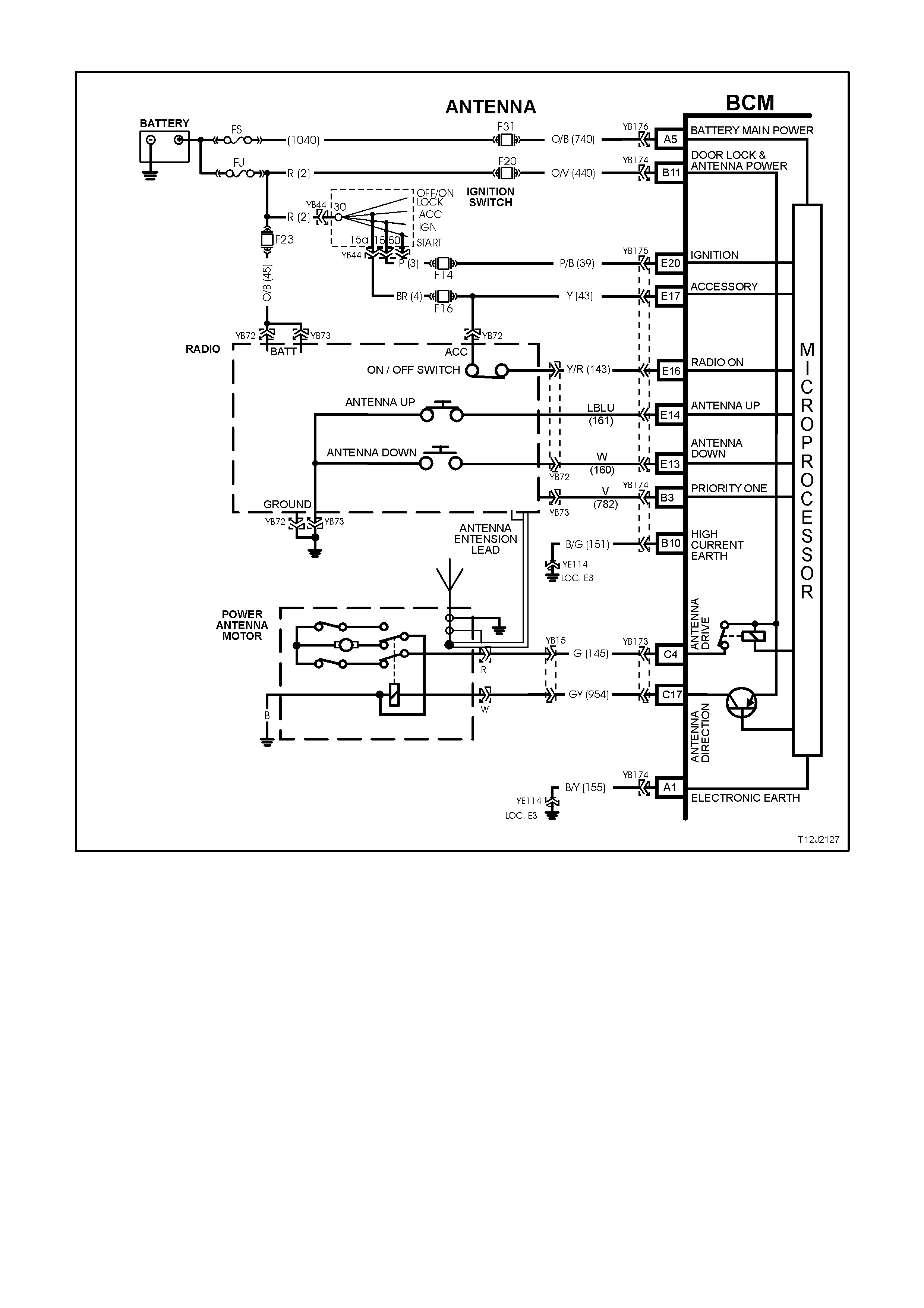
4.13 P O WER ANTENNA CONTROL
Figure 12J-2-149
CIRCUIT DESCRIPTION
The BCM controls the power antenna operation by providing power to the antenna motor and controlling antenna
direction, up and down.
When the radio ON signal is sensed by the BCM, the antenna mast extends to a pre-determined height, dependent
on whether priority one or priority two key was used to access the vehicle. (Two antenna height memories can be
stored by the BCM, one for each priority key, and is recalled when the UNLOCK button on the remote key is
depressed).
If at some stage the battery is disconnected, the antenna height memory setting will be lost. In this case, the
antenna default height is 6 seconds of mast upward travel.
When signals from the ANTENNA UP or ANTENNA DOWN switches are sensed, the antenna mast will move
accordingly. However, the switches do not operate when there is no signal sensed by the BCM from the radio or
when the accessories signal (ignition switch in ACC position) is not present.
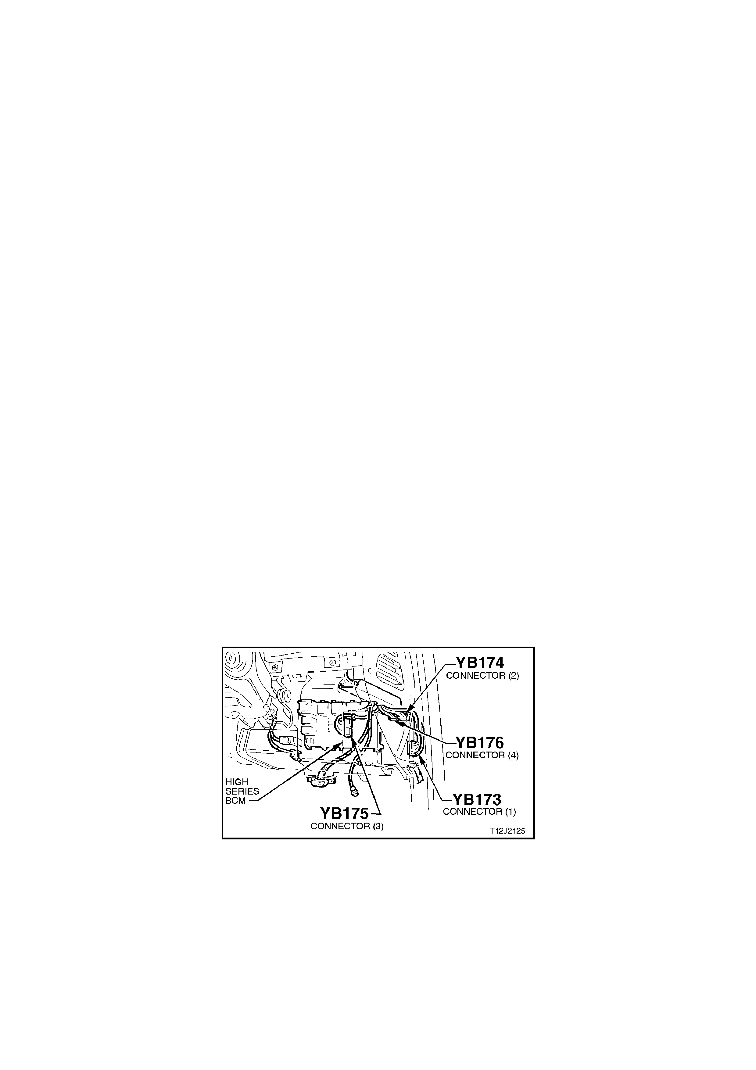
When the signal from the radio is turned OFF, operation of the antenna is as follows:
1. If the ignition switch is turned to the OFF (ACC OFF) position, there is a delay of approximately 15 seconds
before the antenna mast fully retracts
2. If the ignition switch is turned to the ON (or ACC ON) position, the antenna mast will fully retract
immediately. However, a maximum delay of three seconds is acceptable.
During engine starting, the radio signal is momentarily lost and during this time, it is assumed by the BCM that the
signal is still active as it senses both IGNITION and ACCESSORIES inputs, as well as the radio signal. This
enables the antenna operation and control is unaffected during engine cranking.
Operation of the power antenna is also affected by the theft deterrent system (antenna mast retracts when system
is armed).
TEST DESCRIPTION
The numbers below refer to step numbers in the following diagnostic chart.
5. Uses TECH 2 to check for the accessories input at the microprocessor of the BCM when the ignition switch is
in the ACC position.
6. Uses TECH 2 to check for the radio ON signal input at the microprocessor of the BCM.
7. Checks for antenna drive signal at output of BCM, when commanded by TECH 2.
8. Checks circuit 145 (Green wire).
9. Checks for ANTENNA DIRECTION signal at output of BCM, when commanded by TECH 2.
10. Checks circuit 954 (Grey/Yellow wire).
11. Checks ACCESSORY signal at input of BCM.
12. Checks RADIO ON signal at input of BCM.
13. Checks circuit 143 (Yellow/Red wire).
14. Checks for ACCESSORY supply to radio.
15. Uses TECH 2 to check ANTENNA DOWN SWITCH input at the microprocessor of the BCM when switch is
activated.
16. Checks for ANTENNA DIRECTION signal at output of BCM, when activating the antenna down switch.
17. Checks for ANTENNA DRIVE signal at output of BCM when activating the antenna down switch.
18. Checks ANTENNA DOWN SWITCH input at input of BCM.
19. Checks circuit 160 (White wire).
20. Uses TECH 2 to check for ANTENNA UP SWITCH at the microprocessor of the BCM, when the switch is
activated.
21. Checks ANTENNA UP SWITCH input at input of BCM.
22. Checks circuit 161 (Light Blue wire).
23. Uses TECH 2 to check RADIO ON signal input at the microprocessor of the BCM.
24. Checks RADIO ON input at input of BCM.
Figure 12J-2-150

Figure 12J-2-151
STEP ACTION VALUE YES NO
1. • Turn ignition to ACC
and switch radio ON.
• Does antenna mast
extend automatically?
Go to Step 2. Go to Step 5.
2. • Operate antenna
DOWN switch.
• Does antenna mast
retract?
Go to Step 3. Go to Step 15.
3. • Operate antenna UP
switch.
• Does antenna mast
extend?
Go to Step 4. Go to Step 20.
4. • Switch radio OFF.
• Does antenna retract
immediately (three
second delay is
acceptable)?
System OK. Go to Step 23.
5. • Connect TECH 2 to
the DLC.
• Select BODY / BODY
CONTROL MODULE /
DATA DISPLAY.
• Scroll to ACCESSORY
SWITCH.
• Turn ignition to ACC.
• Does screen display
ACCESSORY
SWITCH ON?
Go to Step 6. Go to Step 11.
6. • With TECH 2 still
connected and DATA
DISPLAY selected,
scroll to RADIO
STATUS.
• Turn ignition to ACC
and radio ON.
• Does screen display
RADIO STATUS ON?
Go to Step 7. Go to Step 12.

STEP ACTION VALUE YES NO
7. • With TECH 2 still
connected, exit DATA
DISPLAY and select
MISCELLANEOUS
TESTS / ANTENNA.
• Back probe BCM
connector YB173,
terminal C4, circuit 145
(Green wire) with a
Voltmeter to earth.
• Turn ignition to ACC
and switch radio ON.
• Conduct test as
instructed by TECH 2
and extend the
antenna mast.
• Is the voltage as
specified?
12 volts Go to Step 8. Check fuse F20, if
it is OK, replace
BCM, refer to 2.2
HIGH SERIES
BCM in
this Section.
Recheck and
verify repair.
8. • With TECH 2 still
connected, back probe
power antenna motor
connector, terminal R,
circuit 145 (Green
wire) w ith a Voltmeter
to earth.
• Turn ignition to ACC
and switch radio ON.
• Repeat TECH 2
ANTENNA test and
extend antenna mast.
• Is the voltage as
specified?
12 volts Go to Step 9. Repair open in
circuit 145.
Recheck circuit
and verify repair.
9. • With TECH 2 still
connected, disconnect
BCM connector YB173
and back probe BCM
connector terminal
C17 with a Voltmeter
to earth.
• Turn ignition to ACC
and switch radio ON.
• Repeat TECH 2
ANTENNA test and
extend antenna mast.
• Is the voltage as
specified?
Approx.
10 volts Go to Step 10. Replace BCM,
refer to 2.2 HIGH
SERIES BCM in
this Section.
Recheck and
verify repair.
10 • Check integrity of
circuit 954 (Grey wire).
• Is circuit 954 OK?
Replace antenna
motor, refer.
Section 12D
AUDIO SYSTEM.
Recheck and
verify repair.
Repair circuit 954
as necessary.
Recheck and
verify repair.
11. • Back probe BCM
connector YB175,
terminal E17, circuit 43
(Yellow wire) with a
Voltmeter to earth
• Is voltage as
specified?
12 volts Replace BCM,
refer to 2.2 HIGH
SERIES BCM in
this Section.
Recheck and
verify repair.
Repair fault in
circuit 43
(including
fuse F16).
Recheck and
verify repair.

STEP ACTION VALUE YES NO
12. • Back probe BCM
connector YB175,
terminal E16, circuit
143 (Yellow/Red wire)
with a Voltmeter to
earth.
• Is voltage as
specified?
12 volts Replace BCM,
refer to 2.2 HIGH
SERIES BCM in
this Section.
Recheck and
verify repair.
Go to Step 13.
13. • Back probe Radio
connector YB72, circuit
143 (Yellow/Red wire)
with a Voltmeter to
earth.
• Is voltage as
specified?
12 volts Repair open in
circuit 143.
Recheck and
verify repair.
Go to Step 14.
14. • Back probe radio
connector YB72, ACC
terminal with a
Voltmeter to earth.
• Is voltage as
specified?
12 volts Go to Radio
system diagnosis
in Section 12D
AUDIO SYSTEM.
Repair fault in
circuit 4 (including
fuse F16).
Recheck and
verify repair.
15. • Connect TECH 2 to
DLC.
• Turn ignition to ACC
and switch radio ON.
• Select BODY / BODY
CONTROL MODULE /
DATA DISPLAY.
• Scroll to ANTENNA
SWITCH POSITION
and operate antenna
mast down switch.
• Does screen display
ANTENNA SWITCH
POSITION DOWN
SWITCH?
Go to Step 16. Go to Step 18.
16. • Back probe BCM
connector YB173,
terminal C17, circuit
954 (Grey wire) wi th a
Voltmeter to earth.
• Operate antenna mast
down switch.
• Is voltage as
specified?
Below
0.5 volt Go to Step 17. Replace BCM,
refer to 2.2 HIGH
SERIES BCM in
this Section.
Recheck and
verify repair.
17. • Back probe BCM
connector YB173,
terminal C4, circuit 145
(Green wire) with a
Voltmeter to earth.
• Operate antenna mast
down switch.
• Is voltage as
specified?
12 volts Replace antenna
motor, refer to
Section 12D
AUDIO SYSTEM.
Recheck and
verify repair.
Replace BCM,
refer to 2.2 HIGH
SERIES BCM in
this Section.
Recheck and
verify repair.

STEP ACTION VALUE YES NO
18. • Back probe BCM
connector YB175,
terminal E13, circuit
160 (White wire) with a
Voltmeter to earth.
• Operate antenna mast
down switch.
• Is voltage as
specified?
Below
0.5 volt Replace BCM,
refer to 2.2 HIGH
SERIES BCM in
this Section.
Recheck and
verify repair.
Go to Step 19.
19. • Check integrity of
circuit 160 (White
wire).
• Is circuit 160 OK?
Go to Radio
system diagnosis
in Section 12D
AUDIO SYSTEM.
Repair circuit 160
as necessary.
Recheck and
verify repair.
20. • Connect TECH 2 to
DLC.
• Turn ignition to ACC
and turn radio ON.
• Select BODY / BODY
CONTROL MODULE /
DATA DISPLAY.
• Scroll to ANTENNA
SWITCH POSITION
and operate antenna
mast up switch.
• Does screen display
ANTENNA SWITCH
POSITION UP
SWITCH?
Replace BCM,
refer to 2.2 HIGH
SERIES BCM in
this Section.
Recheck and
verify repair.
Go to Step 21.
21. • Back probe BCM
connector YB175,
terminal E14, circuit
161 (Light Blue wire)
with a Voltmeter to
earth.
• Operate antenna mast
up switch.
• Is voltage as
specified?
Below
0.5 volt Replace BCM,
refer to 2.2 HIGH
SERIES BCM in
this Section.
Recheck and
verify repair.
Go to Step 22.

STEP ACTION VALUE YES NO
22. • Check integrity of
circuit 161 (Light Blue
wire).
• Is circuit 161 OK?
0 volt Go to Radio
system diagnosis
in Section 12D
AUDIO SYSTEM.
Repair circuit 161
as necessary.
Recheck and
verify repair.
23. • Connect TECH 2 to
DLC.
• Turn ignition to ACC
and switch radio OFF.
• Select BODY / BODY
CONTROL MODULE /
DATA DISPLAY.
• Scroll to RADIO
STATUS.
• Does screen display
RADIO STATUS OFF?
Replace BCM,
refer to 2.2 HIGH
SERIES BCM in
this Section.
Recheck and
verify repair.
Go to Step 24.
24. • Back probe BCM
connector YB175,
terminal E16, circuit
143 (Yellow/Red wire)
with a Voltmeter to
earth.
• Is voltage as
specified?
Below
0.5 volt Replace BCM,
refer to 2.2 HIGH
SERIES BCM in
this Section.
Recheck and
verify repair.
Go to Radio
system diagnosis
in Section 12D
AUDIO SYSTEM.
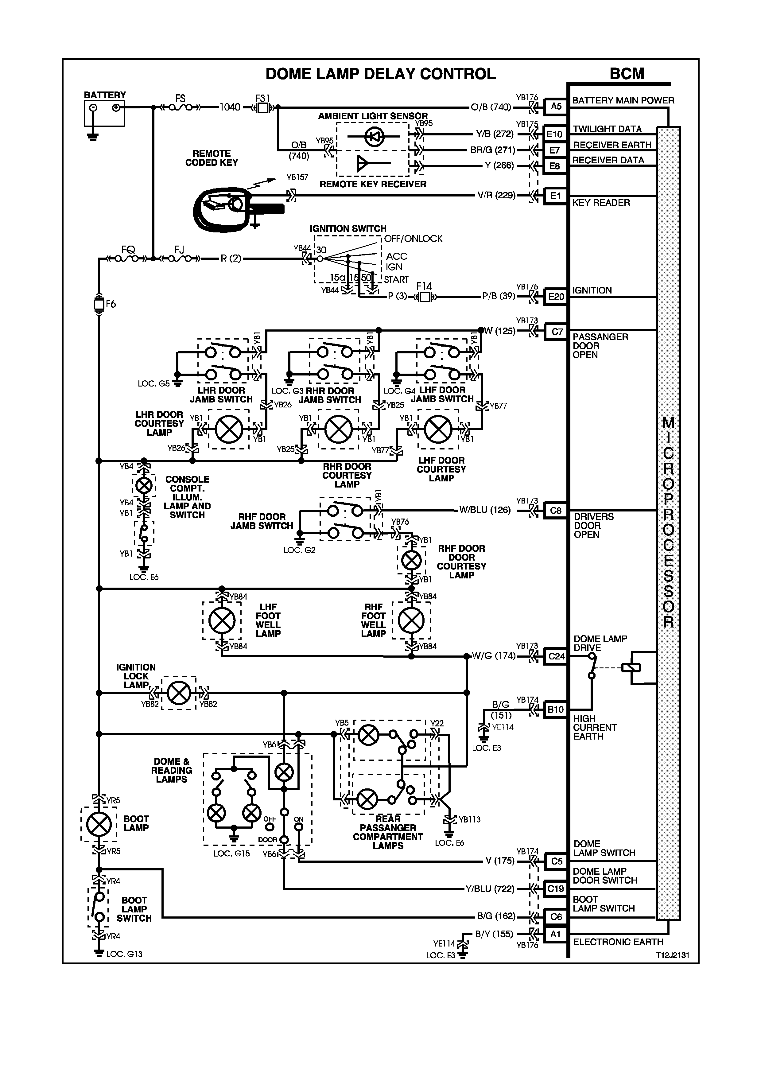
4.14 DOME LAMP DELAY CONTROL
Figure 12J-2-152
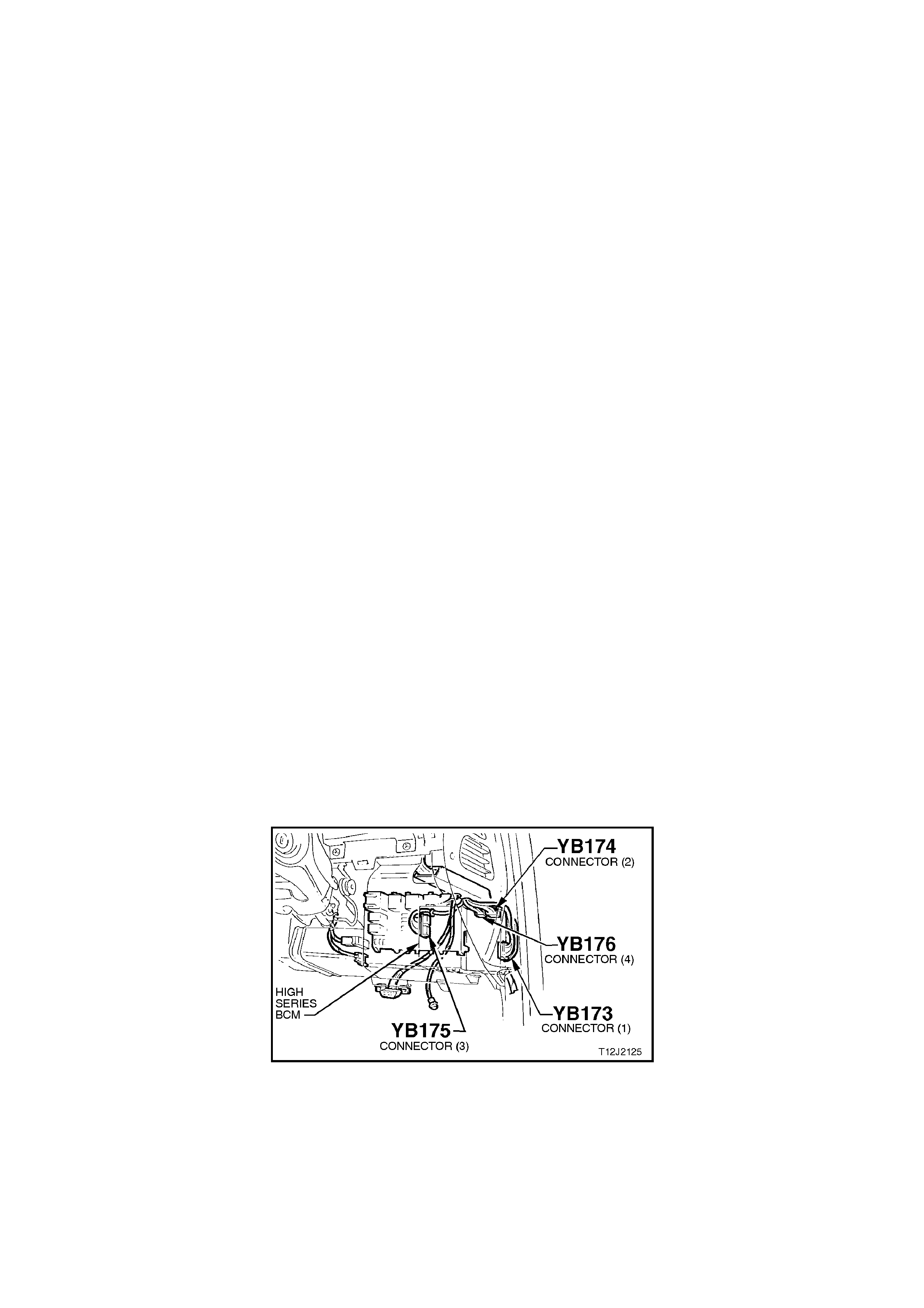
CIRCUIT DESCRIPTION
The interior lighting is controlled by the BCM, or the dome lamp switch (incorporated in the overhead dome lamp
and switch assembly). The interior lighting is activated when any door is opened, the doors are unlocked with the
remote coded key, when the dome lamp switch is operated, or if the theft deterrent system has been activated.
The interior lighting operates continuously whilst any door is open. After all doors have been closed, the lamp will
remain activated for an additional 30 seconds.
The BCM monitors the DOORS and ON positions and controls the dome lamp accordingly.
If the interior lighting has been activated by a BCM control system action, the dome lamp switch will turn the interior
lighting off when it is switched from the DOOR to the OFF position. This means that the switch can curtail any delay
time indicated as well as switch the lighting off whilst a door is open. The exception to this is if the theft deterrent
system has been triggered. In this case, even with the switch in the OFF position, the dome lamp will flash.
The interior lighting is switched on upon central door unlocking for 30 seconds. If the ignition is turned on during this
period, the interior lighting will be switched off immediately. Interior lighting is also switched off upon central door
locking, except if the dome lamp switch is turned on or if a door remains open.
With the dome lamp switch in the ON position, and the ignition turned off, the interior lighting will switch off after two
hours.
TEST DESCRIPTION
The numbers below refer to step numbers in the following diagnostic chart.
1-6. Functional check of dome lamp system.
8. Uses TECH 2 to check for DOME LAMP SWITCH DOOR signal at microprocessor of BCM.
9. Checks dome lamp globe and fuse F6.
10. Uses TECH 2 to drive dome lamp.
11. Checks dome lamp DOOR signal at input of BCM.
12. Checks dome lamp drive output from BCM with the use of TECH 2.
13. Checks circuit 174.
14. Checks circuit 1140 and dome lamp and switch assembly.
15. Checks circuit 722 and dome lamp and switch assembly.
16. Checks BCM for false output drive, circuit 174 and dome lamp and switch assembly.
17. Uses TECH 2 to check for DOME LAMP SWITCH ON signal at microprocessor of BCM in the event of a false
signal causing the dome lamp to come on.
19. Checks driver’s door jamb signal at input of BCM.
20. Checks circuit 126.
21. Checks passenger door jamb signal at input of BCM.
23. Uses TECH 2 to check for DOME LAMP SWITCH ON signal at microprocessor of BCM.
24. Checks for DOME LAMP SWITCH ON signal at input to BCM.
25. Checks circuit 175 and dome lamp and switch assembly.
26. Checks ignition signal at input of BCM.
Figure 12J-2-153

Figure 12J-1-154
STEP ACTION VALUE YES NO
1. • Dome lamp switch in
DOOR position.
• All doors locked.
• Unlock doors with
remote key.
• Does dome lamp turn
on?
Go to Step 2. Go to Step 7.
2. • Dome lamp switch in
DOOR position.
• Dome lamp on (doors
open).
• Close doors and lock
with remote key.
• Does dome lamp turn
off immediately?
Go to Step 3. Go to Step 16.
3. • Dome lamp switch in
DOOR position.
• Doors closed but
unlocked (dome lamp
off).
• Open driver’s door.
• Does dome lamp
illuminate?
Go to Step 4. Go to Step 19.
4. • Dome lamp switch in
DOOR position.
• Doors closed but
unlocked (dome lamp
off).
• Open any passenger
door.
• Does dome lamp
illuminate?
Go to Step 5. Go to Step 21.
5. • Dome lamp switch in
DOOR position.
• Doors closed (dome
lamp off).
• Turn dome lamp
switch to ON position.
• Does dome lamp turn
on?
Go to Step 6. Go to Step 23.

STEP ACTION VALUE YES NO
6. • Dome lamp switch in
DOOR position.
• With doors closed,
lock then unlock doors
with remote key.
• Within 30 seconds,
turn ignition to the ON
position.
• Does the dome lamp
turn off immediately?
System OK. Go to Step 26.
7. • Switch the dome lamp
switch to the ON
position.
• Does the dome lamp
illuminate?
Go to Step 8. Go to Step 9.
8. • Connect TECH 2 to
DLC.
• Select BODY / BODY
CONTROL MODULE /
DATA DISPLAY.
• Scroll to DOME
SWITCH.
• Does screen display
DOME SWITCH
DOOR?
Replace BCM,
refer to 2.2 HIGH
SERIES BCM in
this Section.
Recheck and
verify repair.
Go to Step 11.
9. • Check dome lamp
globe and fuse F6.
• Is globe OK?
Go to Step 10. Replace globe
and/or fuse F6.
Recheck and
verify repair.
10. • Connect TECH 2 to
DLC.
• Select BODY / BODY
CONTROL MODULE /
MISCELLANEOUS
TESTS / LAMPS /
DOME.
• Conduct test as
instructed by TECH 2
and command dome
lamp on.
• Does the dome lamp
illuminate
Go to Step 8. Go to Step 12.
11. • Dome lamp switch in
DOOR position.
• Back probe BCM
connector YB173,
terminal C19 circuit
722 (Yellow/Blue wire)
with a Voltmeter to
earth.
• Is voltage as
specified?
12 volts Replace BCM,
refer to 2.2 HIGH
SERIES BCM in
this Section.
Recheck and
verify repair.
Go to Step 15.

STEP ACTION VALUE YES NO
12. • Disconnect BCM
connector YB173 and
back probe terminal
C24 with an Ohmmeter
to earth.
• Repeat DOME LAMP
test (Step 10).
• Is reading as
specified?
Below
1 ohm Go to Step 13. Replace BCM,
refer to 2.2 HIGH
SERIES BCM in
this Section.
Recheck and
verify repair.
13. • Reconnect BCM
connector YB173 and
back probe terminal
C24, circuit 174
(White/Green wire)
and dome lamp and
switch assembl y
connector YB6, circuit
174 (White/Green
wire) with an
Ohmmeter.
• Is reading as
specified?
Below
1 ohm Go to Step 14. Repair open in
circuit 174.
Recheck and
verify repair.
14. • Back probe dome
lamp and switch
assembly connector
YB6, circuit 1140
(Orange/Brown wire)
with a Voltmeter to
earth.
• Is voltage as
specified?
12 volts Replace dome
lamp and switch
assembly, refer
12B LIGHTING
SYSTEM.
Recheck and
verify repair.
Check and repair
fault in
circuit 1140.
Recheck and
verify repair.
15. • Dome lamp switch in
DOOR position.
• Back probe dome
lamp and switch
assembly connector
YB6, circuit 722
(Yellow/Blue wire) with
a Voltmeter to earth.
• Is voltage as
specified?
12 volts Repair open in
circuit 722.
Recheck and
verify repair.
Replace dome
lamp and switch
assembly, refer
12B LIGHTING
SYSTEM
Recheck and
verify repair.
16. • Dome lamp switch in
DOOR position.
• Disconnect BCM
connector YB173.
• Does dome lamp turn
off?
Go to Step 17. Check and repair
either short in
circuit 174 or
faulty dome lamp
and switch
assembly.
Recheck and
verify repair.

STEP ACTION VALUE YES NO
17. • Re-connect BCM
connector YB173.
• Dome lamp switch in
DOOR position.
• Connect TECH 2 to
DLC.
• Select BODY / BODY
CONTROL MODULE /
DATA DISPLAY.
• Scroll to DOME
SWITCH.
• Does screen display
DOME SWITCH ON?
Go to Step 18. Replace BCM,
refer to 2.2 HIGH
SERIES BCM in
this Section.
Recheck and
verify repair.
18. • Dome lamp switch in
DOOR position.
• Back probe BCM
connector YB173,
terminal C5, circuit 175
(Violet wire) with a
Voltmeter to earth.
• Is voltage as
specified?
12 volts Check and repair
circuit 175 for
short to B+ or
replace dome
lamp and switch
assembly, refer to
12B LIGHTING
SYSTEM.
Recheck and
verify repair.
Replace BCM,
refer to 2.2 HIGH
SERIES BCM in
this Section.
Recheck and
verify repair.
19. • Driver’s door open.
• Dome lamp switch in
DOOR position.
• Back probe BCM
connector YB173,
terminal C8, circuit 126
(White/Blue wire) with
a Voltmeter to earth.
• Is voltage as
specified?
Below
0.5 volts Replace BCM,
refer to 2.2 HIGH
SERIES BCM in
this Section.
Recheck and
verify repair.
Go to Step 20.
20. • Back probe BCM
connector YB173,
terminal C8, circuit
1126 (White/Blue wire)
and driver’s door jamb
switch connector YB1,
circuit 1126
(White/Blue wire) with
an Ohmmeter.
• Is reading as
specified?
Below
1 ohm Replace driver’s
door jamb switch,
refer to 2.10
DOOR JAMB
SWITCHES in
this Section
Recheck and
verify repair.
Repair open in
circuit 1126.
Recheck and
verify repair.
21. • Back probe BCM
connector YB173,
terminal C7, circuit 125
(White wire) with a
Voltmeter to earth.
• Open and close each
passenger door.
• Is voltage as specified
when opening each of
the passenger doors?
Below
0.5 volts Replace BCM,
refer to 2.2 HIGH
SERIES BCM in
this Section.
Recheck and
verify repair.
Go to Step 22.

STEP ACTION VALUE YES NO
22. • While performing test
in Step 21, was voltage
as specified at least
one of the passenger
doors?
Check and repair
either open in
relevant
passenger door
jamb circuit or
faulty door jamb
switch.
Repair open in
circuit 125.
Recheck and
verify repair.
23. • Dome lamp switch in
ON position.
• Connect TECH 2 to
DLC.
• Select BODY / BODY
CONTROL MODULE /
DATA DISPLAY.
• Scroll to DOME
SWITCH.
• Does screen display
DOME SWITCH ON?
Replace BCM,
refer to 2.2 HIGH
SERIES BCM in
this Section.
Recheck and
verify repair.
Go to Step 24.
24. • Dome lamp switch in
ON position.
• Back probe BCM
connector YB173,
terminal C5, circuit 175
(Violet wire) with a
Voltmeter to earth.
• Is voltage as
specified?
12 volts Replace BCM,
refer to 2.2 HIGH
SERIES BCM in
this Section.
Recheck and
verify repair.
Go to Step 25.
25. • Dome lamp switch in
ON position.
• Back probe dome
lamp and switch
assembly connector
YB6, circuit 175 (Violet
wire) w ith a Voltmeter
to earth.
• Is voltage as
specified?
12 volts Repair open in
circuit 175.
Recheck and
verify repair.
Replace dome
lamp and switch
assembly, refer
12B LIGHTING
SYSTEM.
Recheck and
verify repair.
26. • Back probe BCM
connector YB175
terminal E20, circuit 39
(Pink/Bl ack wire) wi th
a Voltmeter to earth.
• Turn ignition ON.
• Is voltage as
specified?
12 volts Replace BCM,
refer to 2.2 HIGH
SERIES BCM in
this Section.
Recheck and
verify repair.
Check and repair
open in circuit 39
(including
fuse F14).
Recheck and
verify repair.
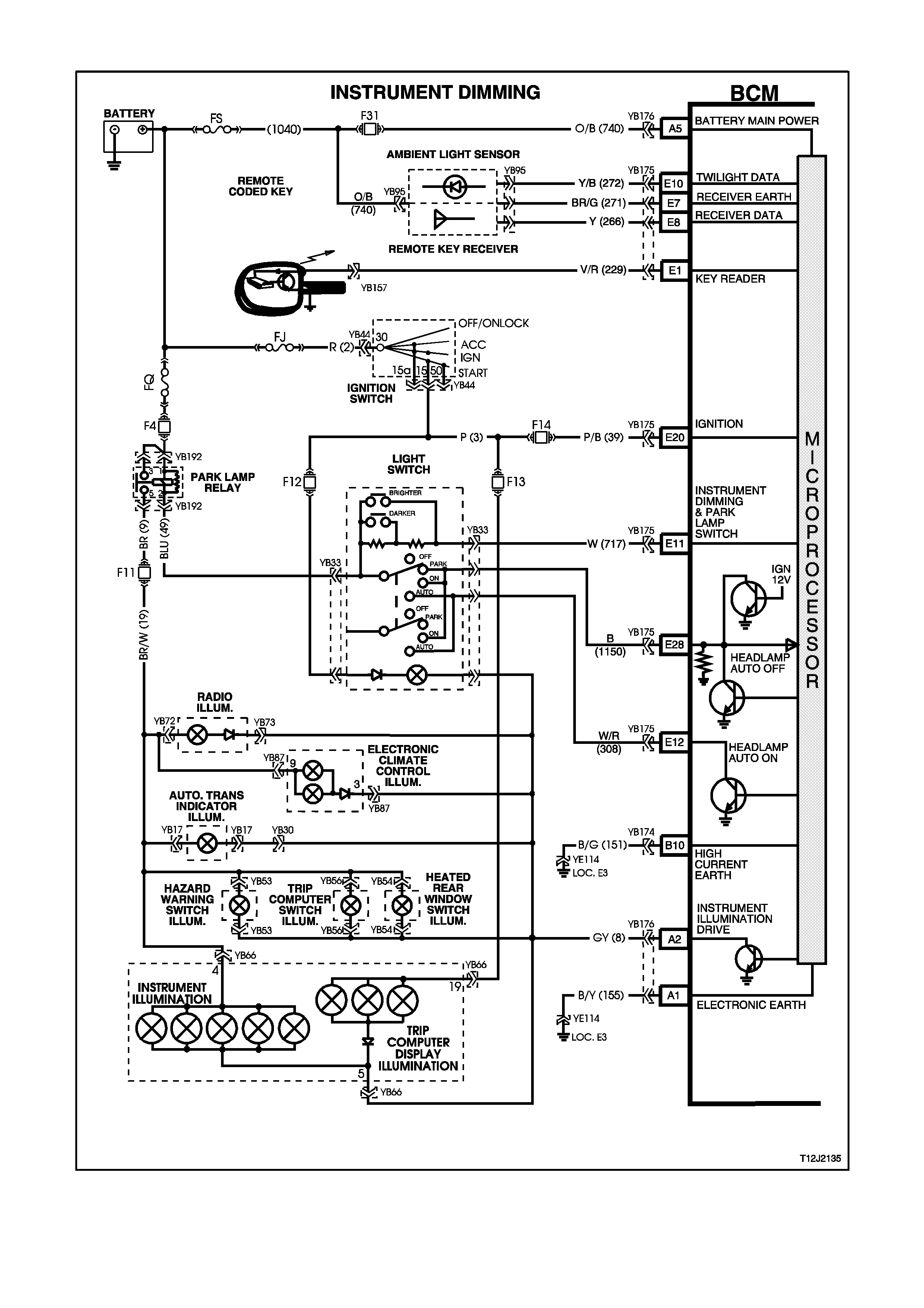
4.15 INSTRUME NT DIMMING CONTROL
Figure 12J-2-155
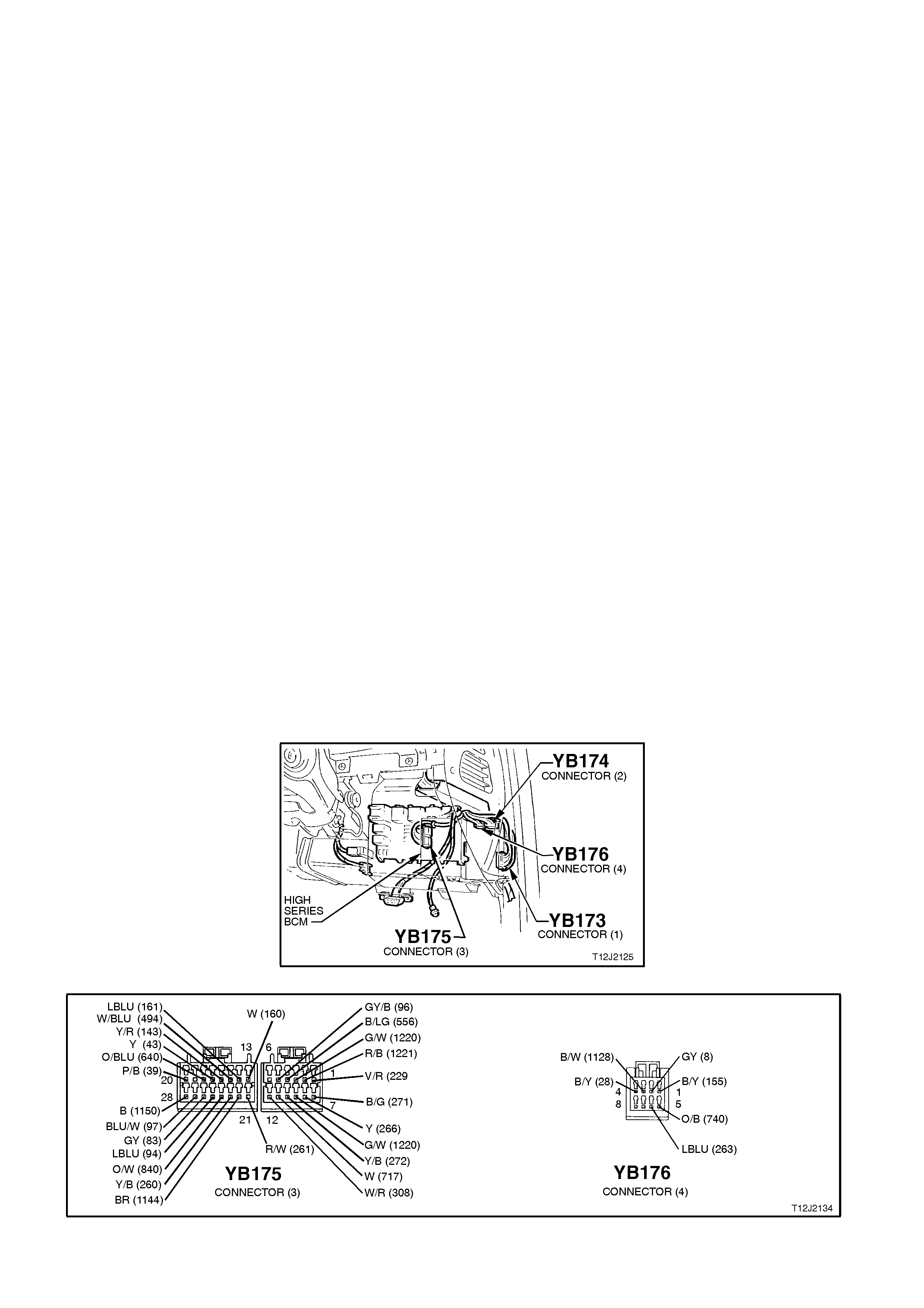
CIRCUIT DESCRIPTION
The BCM controls the illumination level of the instrument dial faces, all dash and centre console illumination and
display windows of the trip computer, Electronic Climate Control (ECC) and radio.
The illumination level is adjusted by two momentary contact switches, located in the headlamp switch assembly, for
ramping the illumination intensity up and down.
The dimmer drives to full load when both the ignition is on and the park lamps are off. This gives maximum
brightness to the trip computer, ECC and radio windows. When the park lamps are switched on, the dimmer
operates according to the level previously set (is also dependant on which remote coded key was used; priority one
or priority two).
The dimmer control inputs are resistor encoded onto the one input line (including the park lamps input). A ‘bright’
input will occur when there is 0 ohms reference to the park lamp control output (DIM + activated) and a ‘dim’ input
will occur when there is 2.7 kohms reference to the park lamp control output (DIM - activated). This line is at 5.4
kohms at rest point. The system default is full load when the line is open circuit. The default dimmer intensity is full
load, and will default to this if the battery is disconnected from the vehicle.
TEST DESCRIPTION
The numbers below refer to step numbers in the following diagnostic chart.
6. Uses TECH 2 to check for IGNITION signal at microprocessor of BCM.
7. Checks circuit 44, including fuse F13.
8. Check illumination output drive from BCM.
9. Checks circuit 8.
10. Checks for IGNITION signal at input of BCM.
11. Checks parking lamp circuit.
12. Checks circuit 19, including fuse 11.
13. Uses TECH 2 to check for park lamp switch signal at microprocessor of BCM.
14. Uses TECH 2 to check for Dim + switch signal at microprocessor of BCM.
15. Uses TECH 2 to check for Dim - switch signal at microprocessor of BCM.
16. Uses TECH 2 to vary illumination level
17. Checks for park lamp switch signal at input to BCM.
18. Checks circuit 717.
19. Checks light switch (illumination resistors).
20. Checks for Dim + signal at input of BCM.
21. Checks for Dim - signal at input of BCM.
22. Checks for short in circuit 8 or BCM that is causing illumination level not to vary.
Figure 12J-1-156
Figure 12J-1-157

STEP ACTION VALUE YES NO
1. • Turn ignition ON.
• Does trip computer
illuminate?
Go to Step 2. Go to Step 6.
2. • Turn ignition ON.
• Light switch in PARK
position.
• Is instrument panel
illuminated?
Go to Step 3. Go to Step 11.
3. • Ignition ON.
• Light switch in PARK
position.
• Activate DIM + button
located in the light
switch assembl y.
• Does instrument panel
illumination ramp up to
full?
Go to Step 4. Go to Step 13.
4. • Turn ignition ON.
• Light switch in PARK
position.
• Activate the DIM -
button located in the
light sw itch assembly.
• Does instrument panel
illumination fade until
fully off?
Go to Step 5. Go to Step 13.
5. • When operating
Priority One and
Priority Two keys, is
the illumination level as
set previously?
System OK. Go to priority key
system diagnosis,
refer to 4.18
PRIORITY KEY
SYSTEM in this
Section.
6. • Connect TECH 2 to
DLC.
• Turn ignition ON.
• Select BODY / BODY
CONTROL MODULE /
DATA DISPLAY.
• Scroll to IGNITION
SWITCH.
• Does screen display
IGNITION SWITCH
ON?
Go to Step 7. Go to Step 10.
7. • Turn ignition ON.
• Back probe instrument
panel cluster
connector YB66, circuit
44 (Pink/Blue wire)
with a Voltmeter to
earth.
• Is voltage as
specified?
12 volts Go to Step 8. Check and repair
fault in circuit 44
(including
fuse F13).
Recheck and
verify repair.

STEP ACTION VALUE YES NO
8. • Turn ignition ON.
• Back probe BCM
connector YB176,
terminal A2, circuit 8
(Grey wire) wi th a
jumper lead to earth.
• Does trip computer
illuminate fully?
0 volts Replace BCM,
refer to 2.2 HIGH
SERIES BCM in
this Section.
Recheck and
verify repair.
Go to Step 9.
9. • Turn ignition ON.
• Back probe instrument
panel cluster
connector YB66, circuit
8 (Grey wire) with a
jumper lead to earth.
• Does trip computer
illuminate fully?
0 volts Repair open in
circuit 8.
Recheck and
verify repair.
Go to Instruments
diagnosis in
Section 12C
INSTRUMENTS,
WIPERS /
WASHERS AND
HORNS.
10. • Turn ignition ON.
• Back probe BCM
connector YB175,
terminal E20, circuit 39
(Pink/Bl ack wire) wi th
a Voltmeter to earth.
• Is voltage as
specified?
12 volts Replace BCM,
refer to 2.2 HIGH
SERIES BCM in
this Section.
Recheck and
verify repair.
Check and repair
fault in circuit 44
(including
fuse F13).
Recheck and
verify repair.
11. • Light switch in PARK
position.
• Back probe parking
lamp relay connector
YB192, terminal 5,
circuit 9 (Brown wire
with Voltmeter to earth.
• Is voltage as
specified?
12 volts Go to Step 12. Go to automatic
lights off
diagnosis, refer
4.9 AUTOMATIC
LIGHT CONTROL
- AUTOMATIC
LIGHTS OFF
(WITHOUT
TWILIGHT
SENTINEL) in this
Section.
12. • Light switch in PARK
position.
• Back probe instrument
panel cluster
connector YB66, circuit
19 (Brown/White wire)
with a Voltmeter to
earth.
• Is voltage as
specified?
12 volts Go to Instrument
diagnostics in
Section 12C
INSTRUMENTS,
WIPERS /
WASHERS AND
HORNS.
Check and repair
fault in circuit 19
(including
fuse F11).
Recheck and
verify repair.

STEP ACTION VALUE YES NO
13. • Turn ignition ON.
• Turn headlamp switch
to the PARK position.
• Illumination switch
OFF (centre position).
• Connect TECH 2 to
DLC.
• Select BODY / BODY
CONTROL MODULE /
DATA LIST and scroll
to PARK LAMP
SWITCH.
• Does screen display
PARK LAMP SWITCH
ON?
Go to Step 14. Go to Step 17
14. • Turn ignition ON.
• Turn headlamp switch
to the PARK position.
• With TECH 2
connected, and DATA
DISPLAY selected,
scroll to
ILLUMINATION
SWITCH POSITION.
• Activate the DIM +
button.
• Does screen display
INSTRUMENT
SWITCH POSITION
UP?
Go to Step 15. Go to Step 20.
15. • Turn ignition ON.
• Turn headlamp switch
to the PARK position.
• With TECH 2
connected, and DATA
DISPLAY selected,
scroll to
ILLUMINATION
SWITCH POSITION.
• Activate the DIM -
button.
• Does screen display
INSTRUMENT
SWITCH POSITION
DOWN?
0 volt Go to Step 16. Go to Step 21.

STEP ACTION VALUE YES NO
16. • Turn ignition ON.
• Turn headlamp switch
to the PARK position.
• With TECH 2
connected, exit DATA
DISPLAY and select
MISCELLANEOUS
TESTS / LAMPS /
ILLUMINATION.
• Conduct test and vary
illumination level
up/down.
• Does illumination level
vary?
Replace BCM,
refer to 2.2 HIGH
SERIES BCM in
this Section.
Recheck and
verify repair.
Go to Step 22.
17. • Turn ignition ON.
• Turn headlamp switch
to the PARK position.
• Turn illumination
switch OFF (centre
position).
• Back probe BCM
connector YB175,
terminal E11, circuit
717 (White wire) with a
Voltmeter to earth.
• Is voltage as
specified?
Approx.
2.6 - 3.4
volts
Replace BCM,
refer to 2.2 HIGH
SERIES BCM in
this Section.
Recheck and
verify repair.
Go to Step 18.
18. • Check integrity of
circuit 717 (White
wire).
• Is circuit 717 OK?
Go to Step 19. Repair circuit 717
as necessary.
Recheck and
verify repair.
19. • Disconnect headlamp
switch connector YB33
and back probe switch
terminals (switch end),
circuits 49 and 717
with an Ohmmeter.
• Is value as specified?
5.4
kohms Replace BCM,
refer to 2.2 HIGH
SERIES BCM in
this Section.
Recheck and
verify repair.
Replace light
switch assembl y,
refer to Section
12B LIGHTING
SYSTEM.

STEP ACTION VALUE YES NO
20. • Turn ignition ON.
• Turn headlamp switch
to the PARK position.
• Back probe BCM
connector YB175,
terminal E11, circuit
717 (White wire) with a
Voltmeter to earth.
• Activate DIM + button.
• Is value as specified?
Less
than 0.5
volts
Replace BCM,
refer to 2.2 HIGH
SERIES BCM in
this Section.
Recheck and
verify repair.
Replace light
switch assembl y,
refer Section 12B
LIGHTING
SYSTEM.
21. • Turn ignition ON.
• Turn headlamp switch
to the PARK position.
• Back probe BCM
connector YB175,
terminal E11, circuit
717 (White wire) with a
Voltmeter to earth.
• Activate DIM - button.
• Is voltage as
specified?
Approx.
1.8 volts Replace BCM,
refer to 2.2 HIGH
SERIES BCM in
this Section.
Recheck and
verify repair.
Replace light
switch assembl y,
refer to Section
12B LIGHTING
SYSTEM.
22. • Turn ignition ON.
• Turn headlamp switch
to the PARK position.
• Disconnect BCM
connector YB176.
• Does instrument
illumination go out?
Replace BCM,
refer to 2.2 HIGH
SERIES BCM in
this Section.
Recheck and
verify repair.
Check and repair
short in circuit 8
(Grey wire).
Recheck and
verify repair.
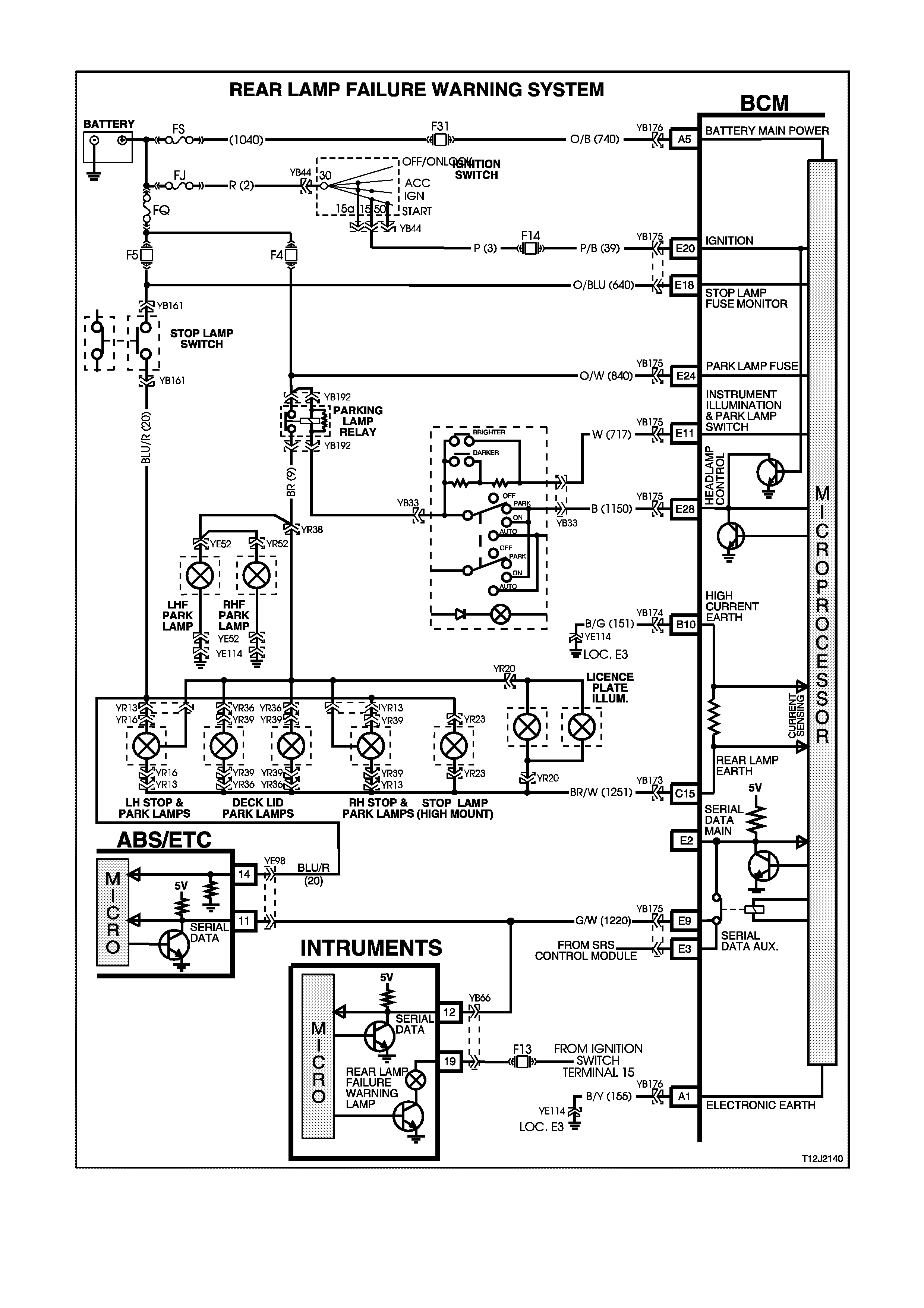
4.16 REAR LAMP FAILURE WARNING SYSTEM
Figure 12J-2-158

CIRCUIT DESCRIPTION
The BCM monitors the tail, stop and licence plate lamps for bulb failures, earth circuits, current flow, as well as the
integrity of the fuses feeding these systems.
When the ignition is turned on, battery voltage is applied to the instrument cluster module which in turn illuminates
the rear lamp failure warning light for approximately 1.5 seconds. In the event of a stop, tail or licence plate lamp
failure, the BCM will send a serial data message via the auxiliary serial data bus to the instrument cluster module
which will turn the rear lamp failure light ON.
Steady illumination of the rear lamp failure warning light with the tail/headlamps turned ON, indicates a rear tail lamp
failure is evident.
Steady illumination of the rear lamp failure warning light when the brake pedal is depressed, indicates a stop lamp
failure is evident.
The BCM monitors both the parking lamp and stop lamp fuses. If battery voltage is not present at both BCM inputs
when the ignition is turned ON, the BCM determines that either fuse has failed and will illuminate the rear lamp
warning light via the auxiliary data bus.
When the parking lamps are turned ON, the BCM checks the current flowing from the light circuits through the BCM
and if this current does not match the pre-learnt current flow (refer to 1.14 REAR LAMP FAILURE WARNING
SYSTEM - REAR LAMP FAILURE WA RNING SYSTEM BULB RELEARN PROCEDURE in this Section) the BCM
will turn the rear lamp warning light ON (via the auxiliary serial data bus).
When the brake pedal is depressed, battery voltage is applied to the ABS or ABS/ETC control module which in turn
sends a signal in the form of serial data to the BCM via the auxiliary serial data bus. This data is interpreted by the
BCM as the stop lamp switch input signal. The BCM then checks the current flowing from the rear lamp circuits
through the BCM and if this current does not match the pre-learnt current flow, it turns the rear lamp failure warning
light ON (via the auxiliary serial data bus).
TEST DESCRIPTION
The numbers below refer to step numbers in the following diagnostic chart.
1-6 Functional check of system.
7. Uses TECH 2 to check STOP LAMP FUSE signal integrity at microprocessor of BCM.
8. Checks STOP LAMP FUSE signal integrity at input to BCM.
9. Uses TECH 2 to check PARK LAMP FUSE signal integrity at microprocessor of BCM.
10. Checks PARK LAMP FUSE signal integrity at input to BCM.
11. Uses TECH 2 to check BULB LAMP FAIL signal at microprocessor of BCM.
12. Visual check of tail lamp operation determines if one or all lights are operational.
13. By performing a relearn procedure, determines if BCM is faulty.
14. Visual check of tail lamps.
15. Checks circuit 151 for open circuit.
16. Checks circuit 1251 for open circuit.
17. Uses TECH 2 to determine if fault is with the instrument cluster by checking BULB LAMP FAILURE signal at
microprocessor of BCM.
18. Uses TECH 2 to check PARK LAMPS ON signal at microprocessor of BCM.
20. Checks PARK LAMPS ON signal at input to BCM.
23. Checks STOP LAMP ON signal at microprocessor of BCM.
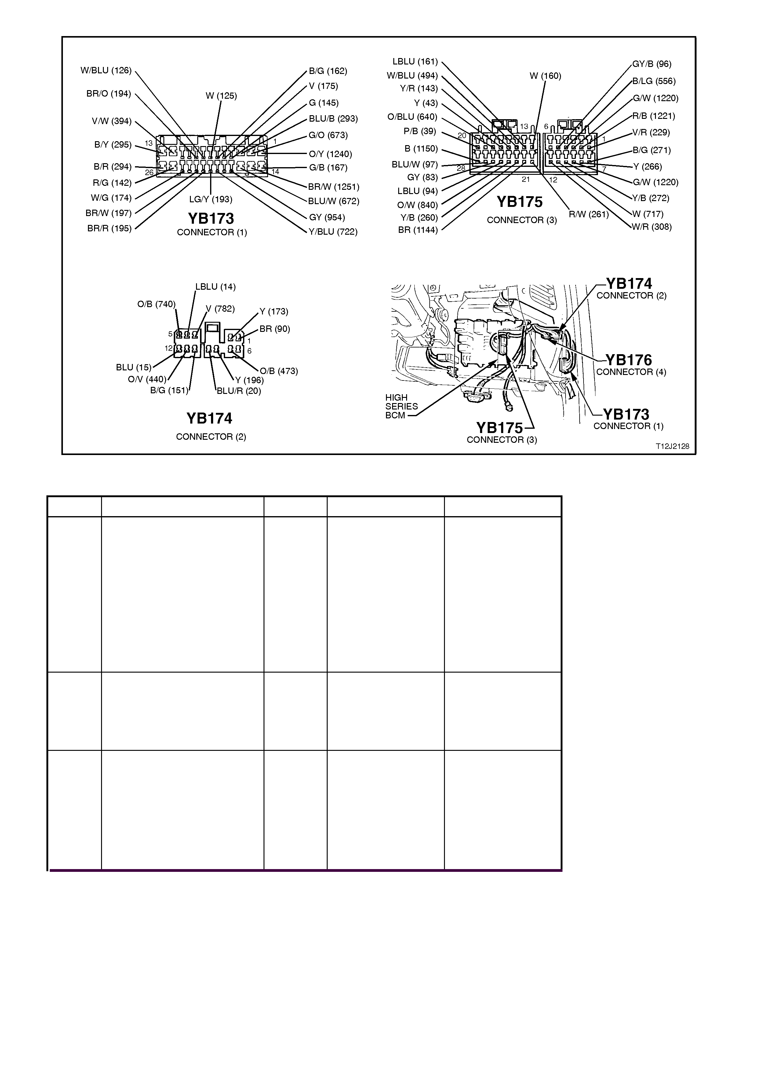
Figure 12J-1-159
STEP ACTION VALUE YES NO
1. • Turn ignition OFF.
• Turn headlamp switch
to the OFF position.
• Ensure foot is OFF
brake pedal.
• Turn ignition ON.
• Does rear light failure
warning lamp
illuminate?
Go to Step 2. Go to Instruments
diagnosis in
Section 12C
INSTRUMENTS,
WIPERS /
WASHERS AND
HORNS.
2. • In Step 1, did the rear
lamp failure warning
light go out after
approximately 2
seconds?
Go to Step 3. Go to Step 7.
3. • Turn ignition OFF.
• Turn headlamp switch
to the PARK position.
• Turn ignition ON.
• Does rear light failure
warning lamp
illuminate?
Go to Step 12. Go to Step 4.

STEP ACTION VALUE YES NO
4. • Turn ignition OFF.
• Turn headlamp switch
to the OFF position.
• Remove one rear tail
lamp bulb.
• Turn headlamp switch
to the PARK position.
• Turn ignition ON.
• Does rear light failure
warning lamp
illuminate?
Go to Step 5. Go to Step 17.
5. • Turn ignition OFF.
• Reinstall rear tail lamp
bulb.
• Turn headlamp switch
to the OFF position.
• Turn ignition ON and
depress brake pedal.
• Does rear light failure
warning lamp
illuminate?
Go to Step 21. Go to Step 6.
6. • Turn ignition OFF.
• Remove one stop lamp
bulb.
• Turn headlamp switch
to the OFF position.
• Turn ignition ON and
depress brake pedal.
• Does rear light failure
warning lamp
illuminate?
System OK. Go to Step 23.
7. • Turn Ignition OFF.
• Turn headlamp switch
to the OFF position.
• Ensure foot is OFF
brake pedal.
• Connect TECH 2 to
DLC.
• Select BODY / BODY
CONTROL MODULE /
DATA LIST.
• Turn ignition ON.
• Scroll to STOP LAMP
FUSE.
• Does screen display
STOP LAMP FUSE
FAILED?
Go to Step 8. Go to Step 9.
8. • Back probe BCM
connector YB175,
terminal E18, circuit
640 (Orange/Blue wire)
with a Voltmeter to
earth.
• Is voltage as
specified?
Approx.
12 volts Replace BCM,
refer 2.2 HIGH
SERIES BCM in
this Section.
Recheck and
verify repair.
Check and repair
open in circuit 640
(including fuse
F5 and fusible
link FQ).
Recheck and
verify repair.

STEP ACTION VALUE YES NO
9. • With TECH 2 still
connected and DATA
DISPLAY selected,
scroll to PARK LAMP
FUSE.
• Does screen display
PARK LAMP FUSE
FAILED?
Go to Step 10. Go to Step 11.
10. • Back probe BCM
connector YB175,
terminal E24, circuit
840 (Orange/White
wire) w ith a Voltmeter
to earth.
• Is voltage as
specified?
Approx.
12 volts Replace BCM,
refer to 2.2 HIGH
SERIES BCM in
this Section.
Recheck and
verify repair.
Check and repair
open in circuit 840
(including
fuse F4 and
fusible link FQ).
Recheck and
verify repair.
11. • Ensure headlamp
switch is in the off
position and foot is off
the brake pedal.
• With TECH 2 still
connected and DATA
DISPLAY selected,
scroll to BULB FAILED
WARNING LAMP.
• Turn ignition OFF then
ON.
• Does screen display
BULB FAILED
WARNING LAMP ON?
Replace BCM,
refer to 2.2 HIGH
SERIES BCM in
this Section.
Recheck and
verify repair.
Go to Instruments
diagnosis in
Section 12C
INSTRUMENTS,
WIPERS /
WASHERS AND
HORNS.
12. • Turn headlamp switch
to the PARK position.
• Check to see if all tail
lamps are illuminated.
• Are
all tail lamps
illuminated?
Go to Step 13. Go to Step 14.
13. • Conduct relearn
procedure as detailed
in 1.14 REAR LAMP
FAILURE WARNING
SYSTEM in this
Section.
• Turn ignition ON.
• Turn headlamp switch
to the PARK position.
• Does rear light failure
warning lamp go out
after approximately 2
seconds?
Go to Step 4. Replace BCM,
refer to 2.2 HIGH
SERIES BCM in
this Section.
Recheck and
verify repair.
14. • While carrying out
Step 12, did at least
one tail lamp
illuminate?
Check and repair
faulty bulb or tail
lamp circuit,
Recheck and
verify repair.
Go to Step 15.

STEP ACTION VALUE YES NO
15. • Turn ignition OFF.
• Disconnect BCM
connector YB174 and
back probe terminal
B10 on the harness
end, circuit 151 (Black
wire) with an
Ohmmeter to earth.
• Is value as specified?
Below
1 ohm Go to Step 16 Repair open in
circuit 151.
Recheck and
verify repair.
16. • Turn ignition ON.
• Back probe BCM
connector YB173,
terminal C15, circuit
1251 (Brown/White
wire) with a jumper
lead to earth.
• Turn headlamp switch
to PARK position.
• Do lamps illuminate?
Replace BCM,
refer to 2.2 HIGH
SERIES BCM in
this Section.
Recheck and
verify repair.
Repair open in
circuits 1251 and
or 9 (including
park lamp relay).
Recheck and
verify repair.
17. • Turn ignition OFF.
• Connect TECH 2 to
the DLC.
• Turn ignition ON.
• Turn headlamp switch
to the PARK position.
• Select BODY / BODY
CONTROL MODULE /
DATA DISPLAY.
• Scroll to BULB FAILED
WARNING LAMP.
• Does screen display
BULB FAILED
WARNING LAMP ON?
Go to Instruments
diagnosis in
Section 12C
INSTRUMENTS,
WIPERS /
WASHERS AND
HORNS.
Go to Step 18.
18. • With TECH 2 still
connected, DATA
DISPLAY selected,
ignition ON and
headlamp switch
turned to the PARK
position, scroll to
PARK LAMP SWITCH.
• Does screen display
PARK LAMP SWITCH
ON?
Go to Step 19. Go to Step 20.

STEP ACTION VALUE YES NO
19. • Reinstall tail lamp bulb.
• Carry out relearn
procedure as detailed
in 1.14 REAR LIGHT
FAILURE WARNING
SYSTEM in this
Section.
• Remove tail lamp bulb
again.
• Turn headlamp switch
to the PARK position.
• Turn ignition ON.
• Does rear light failure
warning lamp
illuminate?
Go to Step 5. Replace BCM,
refer to 2.2 HIGH
SERIES BCM in
this Section.
Recheck and
verify repair.
20. • Turn ignition ON.
• Turn headlamp switch
to the PARK position.
• Back probe BCM
connector YB175,
terminal E11, circuit
717 (White wire) with a
Voltmeter to earth.
• Is voltage as
specified?
2.2 volts Replace BCM,
refer to 2.2 HIGH
SERIES BCM in
this Section.
Recheck and
verify repair.
Check and repair
open in circuit 717
(including
headlamp switch).
21. • Turn ignition ON.
• Depress brake pedal
and check to see if
stop lamps illuminate.
• Are all stop lamps
illuminated?
Go to Step 22. Check and repair
faulty bulb or stop
lamp circuit,
Recheck and
verify repair.

STEP ACTION VALUE YES NO
22. • Carry out relearn
procedure as detailed
in 1.14 REAR LAMP
FAILURE WARNING
SYSTEM in this
Section.
• Turn ignition ON and
depress brake pedal.
• Does rear light failure
warning lamp go out
after approximately 2
seconds?
Go to Step 6. Replace BCM,
refer to 2.2 HIGH
SERIES BCM in
this Section.
Recheck and
verify repair.
23. • Connect TECH 2 to
DLC.
• Turn ignition ON.
• Select BODY / BODY
CONTROL MODULE /
DATA DISPLAY.
• Scroll to STOP LAMP
SWITCH and depress
brake pedal.
• Does screen display
STOP LAMP SWITCH
ON?
Go to Step 24. Go to ABS and
ABS/ETC
diagnosis in
Section 12L ABS
& ABS/ETC.
24. • Reinstall rear stop
lamp bulb.
• Carry out relearn
procedure as detailed
in 1.14 REAR LAMP
FAILURE WARNING
SYSTEM in this
Section.
• Remove sto p lamp
bulb again.
• Turn ignition ON and
depress brake pedal.
• Does rear light failure
warning lamp
illuminate?
System OK. Replace BCM,
refer to 2.2 HIGH
SERIES BCM in
this Section.
Recheck and
verify repair.
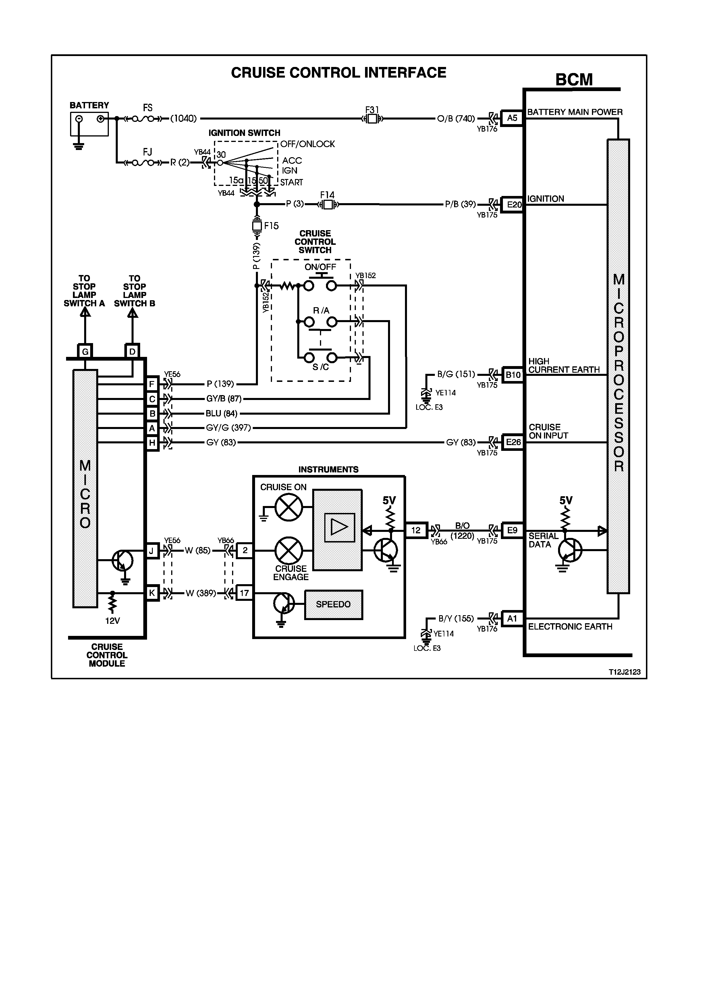
4.17 CRUISE CONTROL INTERFACE
Figure 12J-2-160
CIRCUIT DESCRIPTION
The cruise control module is powered up by the action of the cruise control ON/OFF switch. It then activates an
input of the BCM which in turn sends a serial data message, via the auxiliary serial data line to the instrument
cluster to turn the CRUISE lamp ON. The ignition must be ON for the BCM to communicate with the instrument
cluster.
Test Description
The numbers below refer to step numbers in the following diagnostic chart.
5. Uses TECH 2 to command the CRUISE lamp in the instrument cluster on.
6. Checks for the ‘ignition’ signal at the input of the BCM.
7. Checks for the ‘cruise on’ signal at the input of the BCM.
8. Checks for the ‘cruise on’ signal at the output of the cruise control module.

Figure 12J-2-161
STEP ACTION VALUE YES NO
1. • Turn ignition ON.
• Press the cruise
control ON/OFF
switch.
• Does the cruise control
CRUISE lamp change
state?
System OK. Go to Step 2.
2. • Connect TECH 2 to
the DLC.
• Select BODY / BODY
CONTROL MODULE,
turn ignition ON as
instructed and press
CONFIRM.
• Does TECH 2
communicate with the
BCM, by displaying
SYSTEM
IDENTIFICATION
information?
Go to Step 3. Go to serial data
communications
diagnosis, refer to
4.1 SERIAL DATA
COM. In this
Section
3. • With TECH 2 still
connected.
• Turn ignition ON.
• Select DATA
DISPLAY.
• Scroll to IGNITION
SWITCH.
• Does screen display
IGNITION SWITCH
ON?
Go to Step 4. Go to Step 6.
4. • With TECH 2 still
connected and DATA
DISPLAY selected,
scroll to CRUISE
CONTROL INPUT
SIGNAL.
• Press the cruise
control ON/OFF
button.
• Does the screen
change status from
CRUISE CONTROL
INPUT SWITCH ON to
OFF as cruise control
ON/OFF button is
pressed?
Go to Step 5. Go to Step 7.

STEP ACTION VALUE YES NO
5. • With TECH 2 still
connected, exit BODY
CONTROL MODULE
and select
INSTRUMENTS /
MISCELLANEOUS
TESTS / LAMPS /
CRUISE CONTROL
ON LAMP.
• Conduct test as
instructed by TECH 2
and command the
CRUISE lamp on.
• Does the CRUISE
lamp in the instrument
cluster illuminate?
Replace BCM,
refer to 2.2 HIGH
SERIES BCM in
this Section.
Recheck and
verify repair.
Go to Instruments
diagnosis in
Section 12C
INSTRUMENTS,
WIPERS /
WASHERS AND
HORNS.
6. • Back probe BCM
connector YB175,
terminal E20, circuit 39
(Pink/Bl ack wire) wi th
a Voltmeter to earth.
• Are voltages as
specified?
Ignition
ON,
approx.
12 volts
Ignition
OFF
0 volts
Replace BCM,
refer to 2.2 HIGH
SERIES BCM in
this Section.
Recheck and
verify repair.
Repair open or
short in circuit 39
(including
fuse F14).
Recheck circuit to
verify repair.
7. • Turn ignition ON.
• Back probe BCM
connector YB175,
terminal E26, circuit 83
(Grey wire) wi th a
Voltmeter to earth.
• Press cruise control
ON/OFF switch.
• Does the voltage
toggle from 12 volts to
0 volts to 12 volts?
Replace BCM,
refer to 2.2 HIGH
SERIES BCM in
this Section.
Recheck and
verify repair.
Go to Step 8.
8. • Turn ignition ON.
• Back probe cruise
control connector
YE56, terminal H,
circuit 83 (Grey wire)
with a Voltmeter to
earth.
• Press cruise control
ON/OFF switch.
• Does the voltage
toggle from 12 volts to
0 volts to 12 volts?
Repair open or
short in circuit 83.
Recheck circuit to
verify repair.
Go to Cruise
control / diagnosis
in Section 12E
CRUISE
CONTROL.
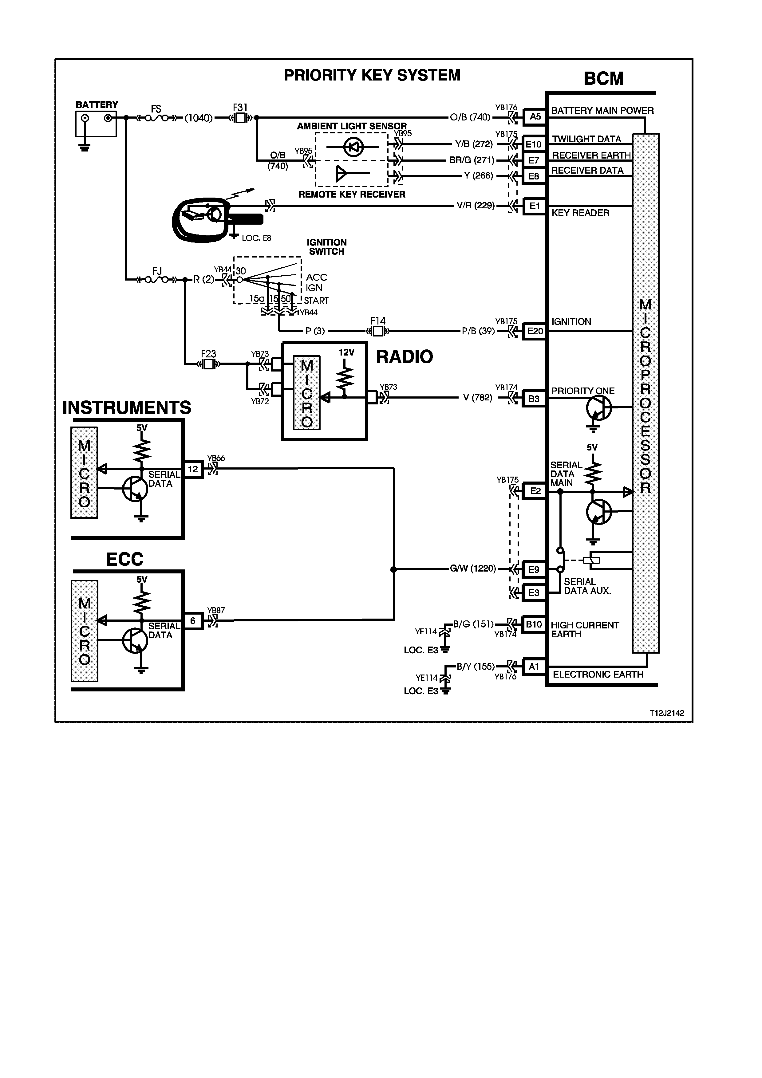
4.18 PRIORITY KEY SYSTEM
Figure 12J-2-162
CIRCUIT DESCRIPTION
The BCM provides an additional memory for one of the remote keys (priority one). The normal priority memory
(priority two) is used for all other keys.
The BCM stores two separate sets of parameters, one for each key for the following functions:
• Time delay for automatic headlights off.
• Antenna height memory.
• Instrument dimmer level.
These memories are recalled when the unlock button on the remote coded key is pressed and all memories are
maintained on a last used basis.
The BCM also communicates to other modules (ECC instrument modules) via the auxiliary serial data bus (circuit
1220), identifying which priority key mode (priority one or two) each module should be in.
In addition, the BCM also includes a priority output line (priority one, circuit 782). The priority one output line sets the
radio’s priority mode. When the priority one output is pulled low , the radio settings are set for priority key one.
When a new remote coded key is programmed, it is assigned sole use of one of the priority one key memories. All
remaining remote keys become priority two. Old remote key s can be re-assigned as the priority one key through
TECH 2.
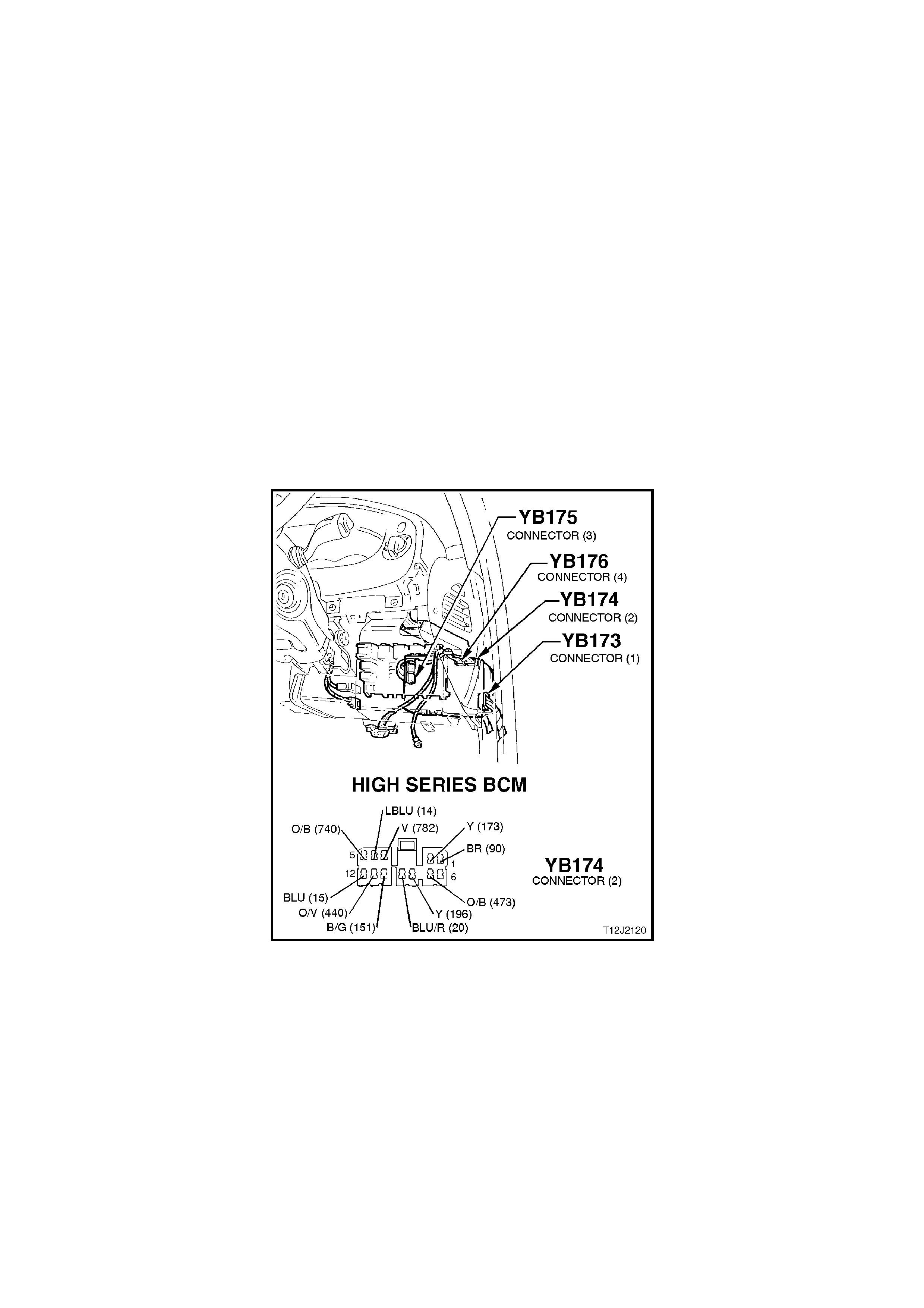
Pre-requisites for priority key system diagnosis
NOTE:
The following procedure must be completed prior to diagnosing the system.
1. Ensure both remote key s are present.
2. Operate unlock button on first of the remote coded keys.
3. Connect TECH 2 to the DLC
4. Insert first remote coded key into ignition switch and turn to the ON position.
5. Using TECH 2, re-program first key to PRIORITY ONE.
6. Turn ignition switch to the OFF position.
7. Set all priority system function settings for this key (ie. antenna height, radio stations, etc.).
8. Press unlock button on the second remote coded key and set all priority function settings for this key.
TEST DESCRIPTION
The numbers below refer to step numbers in the following diagnostic chart.
1-6. Functional check of priority key system.
7. Uses TECH 2 to check if BCM is communicating with the instruments to determine if fault is with instrument
cluster or if there is a serial data communication fault.
8. Checks priority one output from BCM.
9. Checks circuit 782 (Violet wire) for open circuit.
10. Uses TECH 2 to check priority state of remote keys.
Figure 12J-2-163

STEP ACTION VALUE YES NO
1. • Operate the UNLOCK
button on both of the
priority one and priority
two remote coded keys
alternatively.
• Check the automatic
headlight off time delay
memories as set in
pre-requisite
diagnostic test in this
Section.
• Is the automatic
headlamp off delay
memory recalled for
both keys?
Go to Step 2. Go to Step 10.
2. • Operate the UNLOCK
button on both of the
priority one and priority
two remote coded keys
alternatively.
• Check the antenna
height memory as set
in pre-requisite
diagnostic test in this
Section.
• Is the antenna height
memory recalled for
both keys?
Go to Step 3. Replace BCM,
refer to 2.2 HIGH
SERIES BCM in
this Section.
Recheck and
verify repair.
3. • Operate the UNLOCK
button on both of the
priority one and priority
two remote coded keys
alternatively.
• Check the instrument
dimmer level memory
as set in pre-requisite
diagnostic test in this
Section.
• Is the instrument
dimmer level memory
recalled for both keys?
Go to Step 4. Replace BCM,
refer to 2.2 HIGH
SERIES BCM in
this Section.
Recheck and
verify repair.
4. • Operate the UNLOCK
button on both of the
priority one and priority
two remote coded keys
alternatively.
• Check the trip
computer, mode and
overspeed setting
memories as set in
pre-requisite
diagnostic test in this
Section.
• Are the trip computer,
mode and overspeed
setting memories
recalled for both keys?
Go to Step 5. Go to Step 7.

STEP ACTION VALUE YES NO
5. • Operate the UNLOCK
button on both of the
priority one and priority
two remote coded keys
alternatively.
• Check the climate
control setting memory
as set in pre-requisite
diagnostic test in this
Section.
• Is the climate control
setting memory
recalled for both keys?
Go to Step 6. Go to ECC
diagnosis, refer
Section 2C AIR
CONDITIONING.
6. • Operate the UNLOCK
button on both of the
priority one and priority
two remote coded keys
alternatively.
• Check the radio setting
memory as set in pre-
requisite diagnostic
test in this Section.
• Is the radio setting
memory recalled for
both keys?
System OK. Go to Step 8.
7. • Connect TECH 2 to
DLC.
• Select BODY /
INSTRUMENTS turn
ignition ON, as
instructed and press
CONFIRM.
• Does TECH 2
communicate with the
instruments, by
displaying SYSTEM
IDENTIFICATION
information?
Go to Instruments
diagnosis in
Section 12C
INSTRUMENTS,
WIPERS /
WASHERS AND
HORNS.
Go to serial data
communication
diagnosis, refer
4.2 SERIAL DATA
COM. in this
Section.
8. • Remove BCM
connector YB174 and
back probe harness
side of terminal B3,
circuit 782 (Violet wire)
with a jumper lead to
earth.
• Turn ignition and radio
ON.
• By connecting and
disconnecting jumper
lead, do radio settings
change?
Replace BCM,
refer to 2.2 HIGH
SERIES BCM in
this Section.
Recheck and
verify repair.
Go to Step 9.

STEP ACTION VALUE YES NO
9. • Check integrity of
circuit 782 (Violet
wire).
• Is value as specified?
Go to radio
diagnosis, refer
Section 12D
AUDIO SYSTEM.
Repair circuit 782
as necessary.
Recheck and
verify repair.
10. • Connect TECH 2 to
DLC.
• Select BODY / BODY
CONTROL MODULE /
DATA DISPLAY and
scroll to KEY
PRIORITY SIGNAL.
• Operate the UNLOCK
button on both the
priority one and priority
two remote keys
alternatively.
• Does screen display
alternate between 1
and 2?
Replace BCM,
refer to 2.2 HIGH
SERIES BCM in
this Section.
Recheck and
verify repair.
Go to Step 11.
11. • In Step 10, are both
remote keys set to
priority one?
Programme new
remote coded
key.
Using TECH 2,
program one of
the remote keys
to priority one.
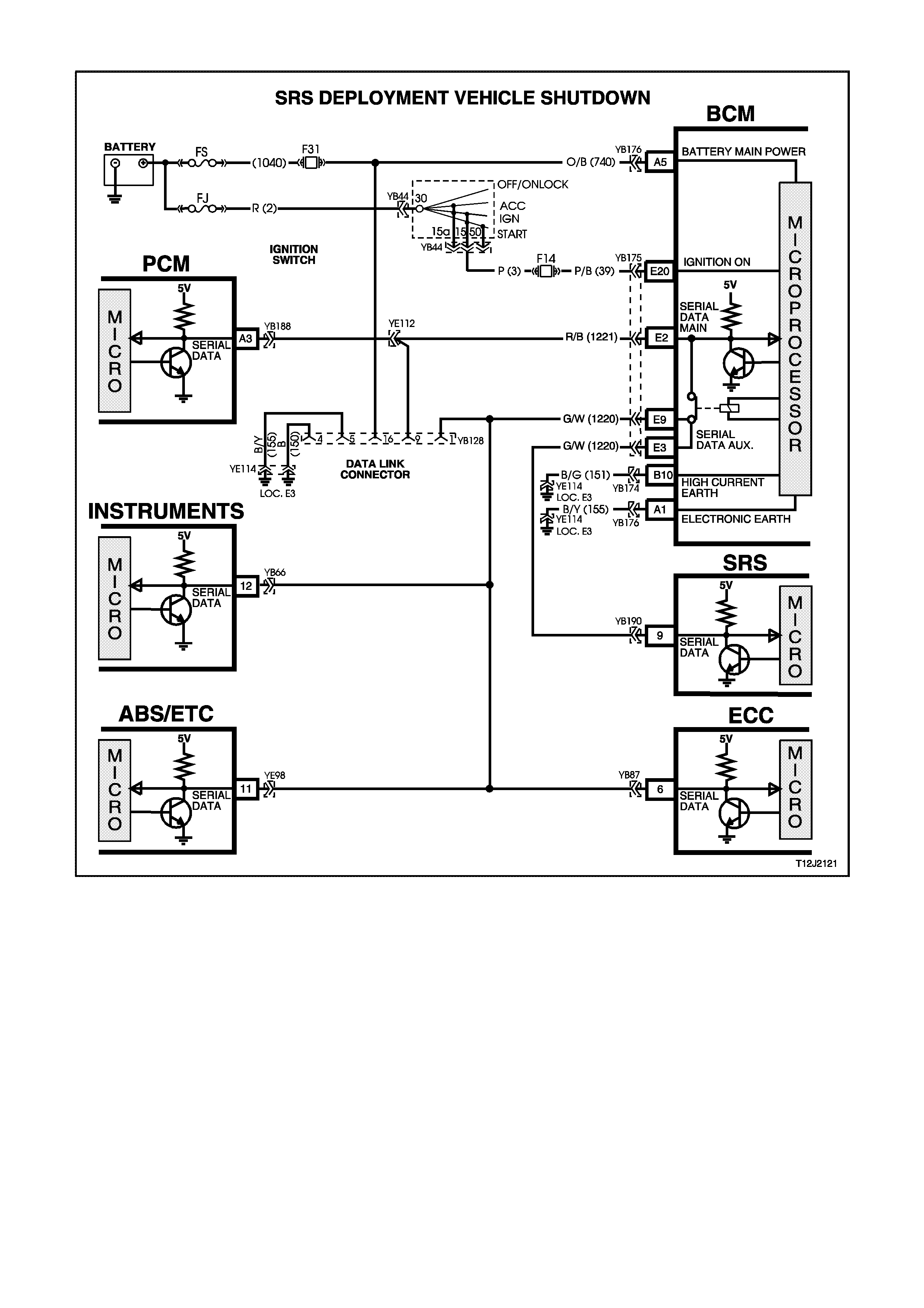
4.19 SRS DEPLOYMENT VEHICLE SHUTDOWN
Figure 12J-2-164
CIRCUIT DESCRIPTION
In the event of SRS (Supplemental Restraint System) deployment, the Sensing Diagnostic Module (SDM) sets a
flag and sends serial data via the SRS Serial Data Interface (SDI) bus to the BCM. Within the BCM, the SRS SDI
bus is linked to the auxiliary serial data interface via a wire link. The SDM advises various vehicle systems via the
auxiliary SDI bus to take appropriate shutdown action.
1. The BCM will monitor this serial data and perform the following actions once the appropriate data is identified
and the vehicle speed is zero for 10 seconds:
2. Turn the dome lamp ON continuously.
3. Unlock all doors.
4. The dome lamp will be switched OFF when the ignition switch is cycled from OFF to ON, or when the BCM is
reset (ie. via battery disconnection).
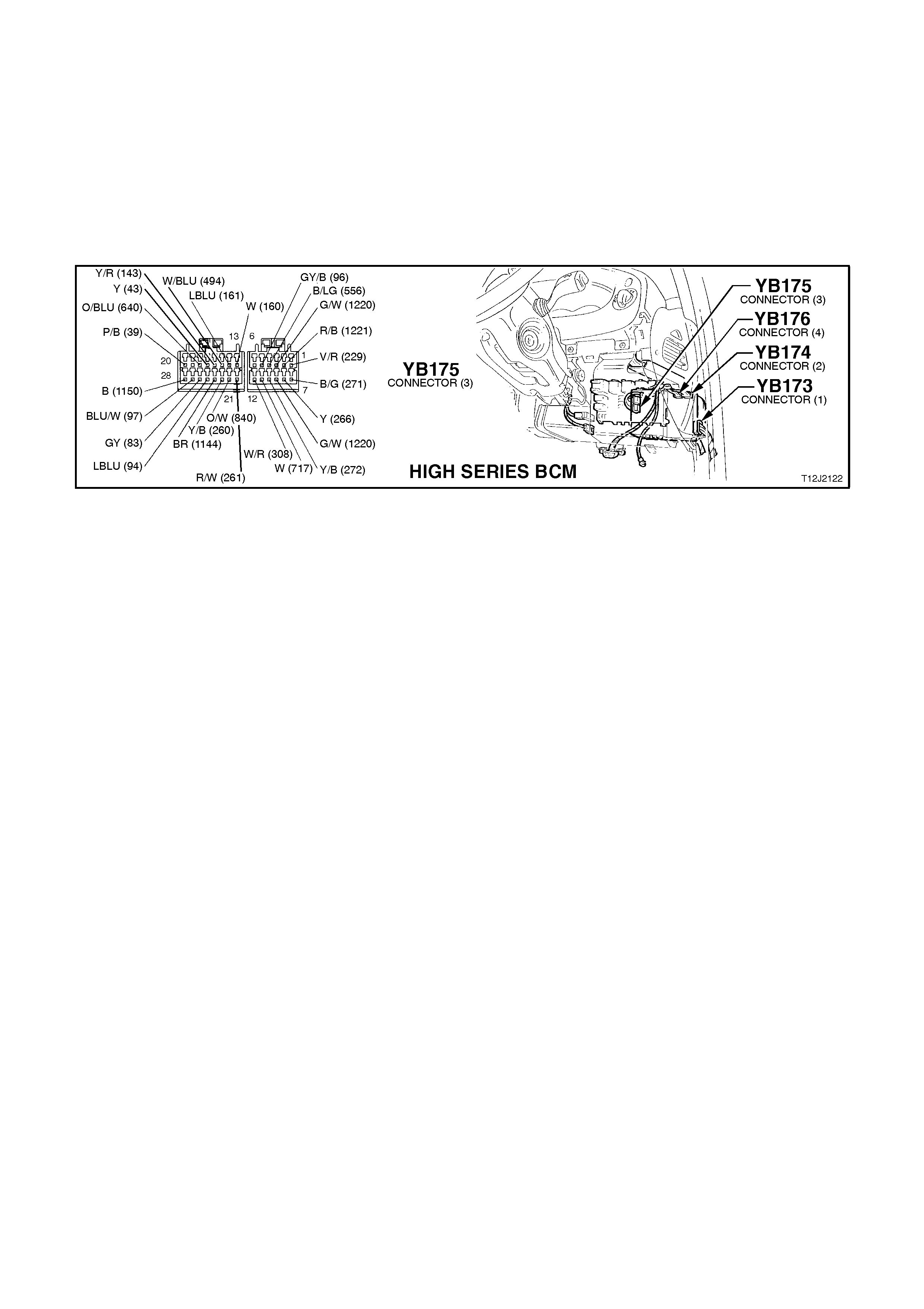
TEST DESCRIPTION
The numbers below refer to step numbers on the diagnostic chart below.
1. Checks the Main SDI bus communication.
2 & 3. Checks Auxiliary SDI bus communication to the SDM and instruments.
4. Checks the BCM internal link, SRS SDI bus connection to the SDI auxiliary bus.
5. Checks circuit 1220 (Green/White wire) (BCM to SDM).
NOTE:
This diagnostic chart assumes that the central door locking system and dome lamp functions (controlled by the
BCM) are operating correctly.
Figure 12J-2-165

STEP ACTION VALUE YES NO
1. • Connect TECH 2 to
the DLC.
• Select BODY / BODY
CONTROL MODULE.
• Turn ignition ON (as
requested by TECH 2).
• Does screen display
BCM system
identification?
Go to Step 2. Go to serial data
communications
diagnosis, refer to
4.1 SERIAL DATA
COM. In this
Section.
2. • With TECH 2 still
connected, exit BODY
CONTROL MODULE
selection.
• Select BODY / SRS.
• Turn ignition ON (as
requested by TECH 2).
• After 5 seconds, is
TECH 2 able to
communicate with the
SDM?
Go to SRS
diagnosis in
Section 12M SRS.
Go to Step 3.
3. • With TECH 2 still
connected, exit SRS
selection.
• Select BODY /
INSTRUMENTS.
• Turn ignition ON (as
requested by TECH 2).
• After 5 seconds, is
TECH 2 able to
communicate with the
instruments?
Go to Step 4. Go to serial data
communications
diagnosis, refer
4.1 SERIAL DATA
COM. In this
Section.
4. • Ignition OFF.
• Back probe BCM
connector YB175,
terminal E9, circuit
1220 (Green/White
wire) and BCM
connector YB175,
terminal E3, circuit
1220 (Green/White
wire) with an
Ohmmeter.
• Is reading as
specified?
Below
1 ohm Go to Step 5. Replace BCM,
refer to 2.2 HIGH
SERIES BCM in
this Section.
Recheck and
verify repair.
5. • Ignition OFF.
• Back probe BCM
connector YB175,
terminal E3, circuit
1220 (Green/White
wire) and SDM
connector YB190,
terminal 9, circuit 1220
(Green/White wire)
with an Ohmmeter.
• Is reading as
specified?
Below
1 ohm Go to SRS
diagnosis in
Section 12M SRS.
Repair open in
circuit 1220.
Recheck circuit to
verify repair.

4.20 REMOTE RECEIVER/KEY
Figure 12J-2-166
CIRCUIT DESCRIPTION
When operating the UNLOCK button on the remote coded key within 4 metres of the driver’s side B pillar for 0.25
seconds, a Radio Frequency (RF) signal is transmitted. The BCM receives this unlock request from the remote
coded key via the remote receiver, located in the instrument panel between the demist grille. The BCM then
proceeds to unlock all the doors (single stage unlock) or just the driver’s door (two stage unlock), disarm the theft
and entry deterrent systems, turn on the dome lamp, and flash the indicators twice.
When operating the LOCK button on the remote coded key within 4 meters of the driver’s door B pillar for 0.25
seconds, an RF signal is again transmitted. The RF signal (lock request) is received by the BCM via the remote
receiver. The BCM then proceeds to lock all doors, arm the theft and entry deterrent systems, turn the dome lamp
off (if illuminated), and flash the indicators once.
When operating the boot release button on the remote coded key within 2 meters of the boot for 0.5 seconds, an
RF signal is transmitted to the BCM via the remote receiver. The BCM then proceeds to activate the rear
compartment lock actuator (provided the vehicle speed is less than 15 km/h).
The remote coded key is powered by it’s own internal battery. If this battery fails, no RF signal will be transmitted
when operating the lock, unlock and boot release buttons. However, if the battery does lose power, the remote
coded key reader has the ability to power the key once it is inserted into the ignition switch key cylinder and turned
to the IGN or START positions. This will then enable theft deterrent disarming.
Techline
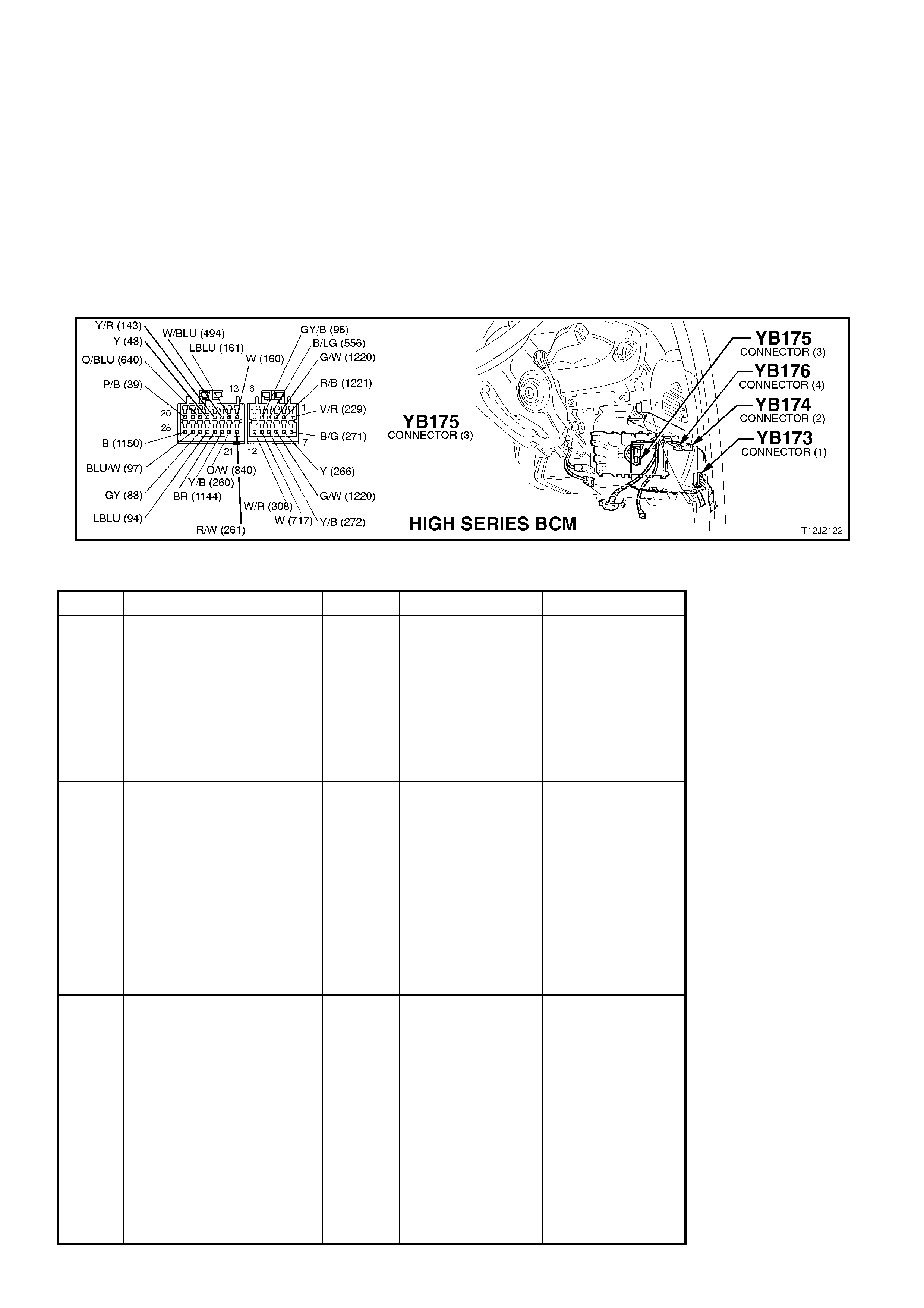
TEST DESCRIPTION
The numbers below refer to step numbers in the following diagnostic chart.
1-7. Functional check to determine if system is functioning correctly or if faulty, determines if fault is with remote
receiver/key, central locking system or theft deterrent system.
8. Uses TECH 2 to check remote key signal - establish whether problem is with BCM or if further diagnosis is
required.
9. Uses TECH 2 to check for a remote key signal from a fully functional VT Series vehicle to establish whether
problem is with remote key or if further diagnosis is required.
10. Checks for power supply to remote receiver.
11. Checks circuit 271.
12. Checks circuit 266.
13. Checks if problem is due to faulty BCM or remote receiver by swapping remote receiver with a fully functional
unit.
Figure 12J-2-167
STEP ACTION VALUE YES NO
1. • Close and lock all
doors.
• Insert ignition key into
driver’s door lock
cylinder.
• Operate unlock / lock.
• Do all doors unlock
and lock?
Go to Step 2. Go to central door
locking diagnosis,
refer 4.3
CENTRAL DOOR
LOCKING in this
Section.
2. • Insert ignition key into
driver’s door lock
cylinder and unlock
door.
• With theft deterrent
LED flashing, insert
ignition key into ignition
switch and turn key to
the ON position.
• Does the theft
deterrent LED turn off?
Go to Step 3. Go to theft
deterrent
diagnosis, refer
4.5 THEFT
DETERRENT in
this Section.
3. • Insert ignition key into
driver’s door lock
cylinder and lock all
doors.
• Operate the UNLOCK
button on the remote
coded key within 2
metres of the driver’s
door B pillar.
• Does the driver’s door
only (two stage unlock)
or all doors (single
stage unlock) unlock?
Go to Step 4. Go to Step 8.

STEP ACTION VALUE YES NO
4. • When performing Step
3, did all of the
following occur when
the UNLOCK button on
the remote coded key
was pressed?
• Indicators flash twice
• Dome lamp illuminate
(dome lamp switch in
doors position)
• Theft deterrent LED go
out
Go to Step 5. Go to theft
deterrent
diagnosis, refer to
4.5 THEFT
DETERRENT in
this Section.
5. • Close all doors.
• Operate LOCK button
on remote coded key
within 2 metres of
driver’s door B pillar.
• Do all doors lock?
Go to Step 6. Go to Step 8.
6. • When performing Step
5, did all of the
following occur when
the LOCK button on
the remote coded key
was pressed?
• Theft deterrent LED
began flashing
• Indicators flashed once
• Dome lamp went out (if
illuminated & with
switch in the doors
position).
Go to Step 7. Go to theft
deterrent
diagnosis, refer to
4.5 THEFT
DETERRENT in
this Section.
7. • Press the boot release
button on the remote
coded key (within 2
metres of the rear of
the vehicle) for 2
seconds.
• Does rear
compartment lid lock
actuator solenoid
activate?
System OK. Go to Step 8.

STEP ACTION VALUE YES NO
8. • Connect TECH 2 to
the DLC.
• Select BODY / BODY
CONTROL MODULE /
DATA DISPLAY.
• Scroll to REMOTE
DOOR SIGNAL and
REMOTE BOOT
SIGNAL screen
display.
• Operate UNLOCK,
LOCK and BOOT
buttons on the remote
coded key.
• Does the screen
display change for the
remote door signal
change from OFF to
UNLOCK / LOCK to
OFF and the remote
boot signal change
from OFF to OPEN to
OFF?
Replace BCM,
refer to 2.2 HIGH
SERIES BCM in
this Section.
Recheck and
verify repair.
Go to Step 9.
9. • On a VT Series vehicle
with a fully functional
remote coded key and
receiver, connect
TECH 2 to the DLC.
• Select BODY / BODY
CONTROL MODULE /
DATA DISPLAY.
• Scroll to REMOTE
DOOR SIGNAL and
REMOTE BOOT
SIGNAL screen
display.
• Operate UNLOCK,
LOCK and BOOT
buttons on the remote
coded key.
• Does the screen
display change for the
remote door signal
change from OFF to
UNLOCK / LOCK and
the remote boot signal
change from OFF to
INVALID to OFF?
Go to Step 10. Programme a
new remote
coded key, refer
to 2.3 REMOTE
CODED KEY in
this Section.
Recheck and
verify repair.
10. • Return to original
vehicle with suspected
faulty remote coded
key/receiver.
• Back probe remote
receiver connector
YB95, circuit 740
(Orange/Black wire)
with a Voltmeter to
earth.
• Is voltage as
specified?
Battery
+Go to Step 11. Check and repair
open or short in
circuit 740.
Recheck and
verify repair.

STEP ACTION VALUE YES NO
11. • Check integrity of
circuit 271
(Brown/Green wire)
between BCM
connector YB175,
terminal E7 and
remote receiver
connector YB95.
• Is circuit 271 OK?
Go to Step 12. Repair circuit 271
as necessary.
Recheck and
verify repair.
12. • Check integrity of
circuit 266 (Yellow
wire) between BCM
connector YB175,
terminal E8 and
remote receiver
connector YB95.
• Is circuit 266 OK?
Go to Step 13. Repair circuit 266
as necessary.
Recheck and
verify repair.
13. • Replace remote
receiver with a known
functional one and
connect TECH 2 to the
DLC.
• Select BODY / BODY
CONTROL MODULE /
DATA DISPLAY.
• Scroll to REMOTE
DOOR SIGNAL screen
display.
• Operate UNLOCK and
LOCK button on the
remote coded key.
• Does the screen
display change from
OFF to UNLOCK /
LOCK to OFF?
Replace remote
receiver, refer 2.5
REMOTE
RECEIVER
MODULE in
this Section.
Recheck and
verify repair.
Replace BCM,
refer to 2.2 HIGH
SERIES BCM in
this Section.
Recheck and
verify repair.
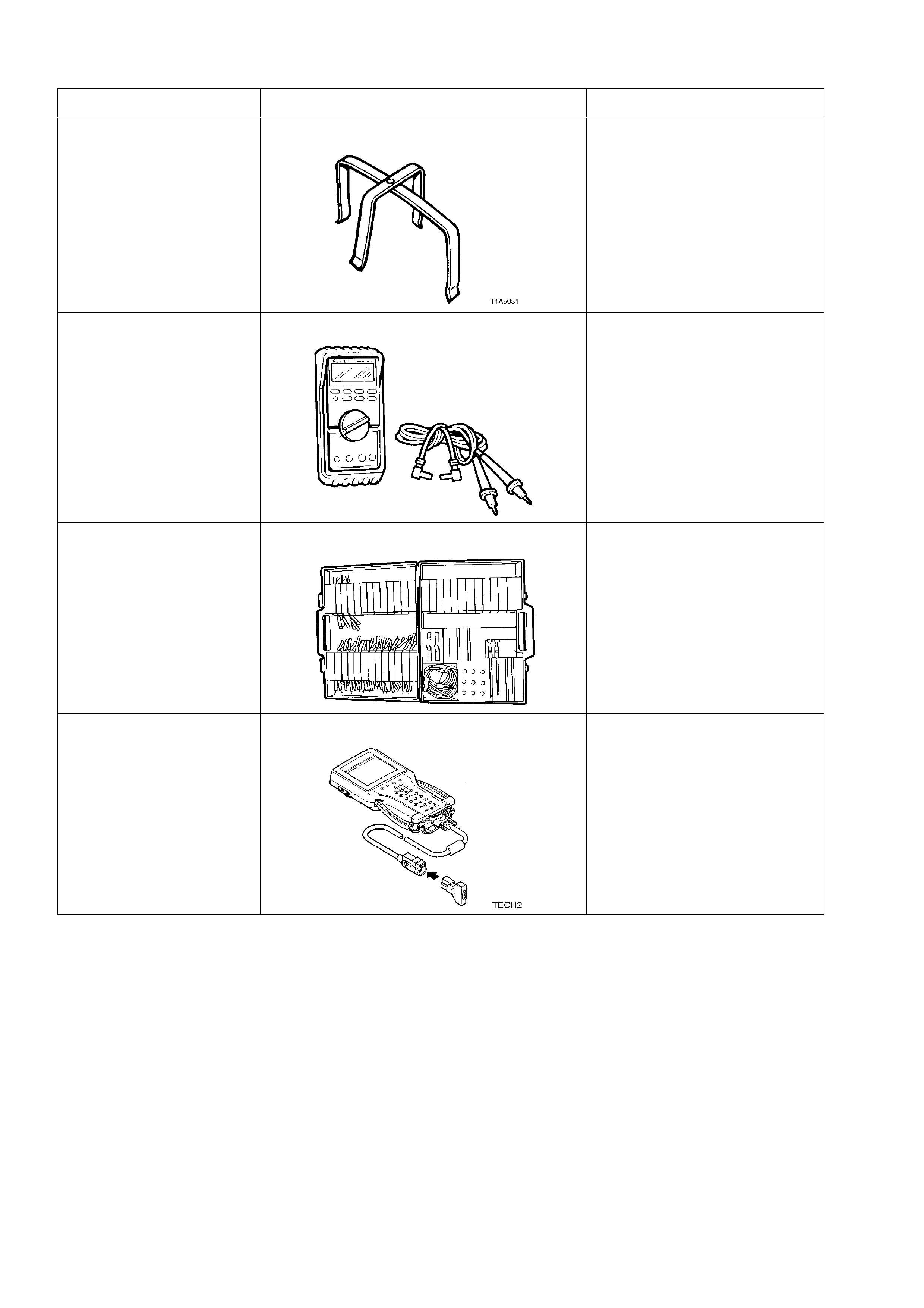
5. SPECIAL TOOLS
TOOL NO. REF IN TEXT TOOL DESCRIPTION COMMENTS
AU455 CONNECTOR BODY REMOVER MANDATORY TOOL USED TO
REMOVE THE DOOR WIRING
HARNESS CONNECTOR
FROM THE A AND B PILLARS
J39200 DIGITAL MULTIMETER TOOL NO. J39200
PREVIOUSLY RELEASED, OR
USE COMMERCIALLY
AVAILABLE EQUIVALENT.
MUST HAVE 10 MEG OHM
INPUT IMPEDANCE
KM-609 CONNECTOR TEST ADAPTOR KIT PREVIOUSLY RELEASED
FOR V CAR. USED IN
CONJUNCTION WITH A
MULTIMETER FOR
MEASURING VOLTAGES AND
RESISTANCES WITHOUT
DAMAGING WIRING
HARNESS CONNECTORS
TECH 2 DIAGNOSTIC SCAN TOOL MANDATORY TOOL USED
FOR DIAGNOSIS OF VEHICLE
ELECTRICAL SYSTEMS