
SECTION 12M - SUPPLEMENTAL RESTRAINT
SYSTEM (VERSION 6.2)
CAUTION:
This vehicle will be equipped with a Supplemental Restraint System (SRS). A SRS will
consist of either seat belt pre-tensioners and a driver's side air bag, or seat belt pre-
tensioners and a driver's and front passenger's side air bags. Refer to CAUTIONS,
Section 12M, before performing any service operation on, or around any SRS
components, the steering mechanism or wiring. Failure to follow the CAUTIONS
could result in SRS deplo yment, resulting in possible p ersonal injury or unnecessary
SRS system repairs.
CAUTION:
This vehicle may be equipped with LPG (Liquefied Petroleum Gas). In the interests of
safety, the LPG fuel system should be isolated by turning 'OFF' the manual service
valve and then draining the LPG serv ice lines, before any service w ork is carried out
on the vehicle. Refer to the LPG leaflet included with the Owner's Handbook for
details or LPG Section 2 for more specific servicing information.
1. GENERAL INFORMATION
The Supplemental Restraint System (SRS) with driver's and front passenger's air bags, is standard fitment to VT
Series Acclaim, Berlina and Calais models. Driver's air bag only, is standard equipment on all other VT Series
Models.
The fitment of front passenger's air bags is available on other VT Series Models, refer to Holden's Sales Information
for option availability.
The SRS is intended as a supplement to the protection offered by the driver and front passenger seat belts by
deploying an air bag from the centre of the steering wheel and (when fitted) a passenger’s side air bag from the top
left hand side of the instrument panel pad assembly during certain frontal crashes. Seat belt pre-tensioners are also
activated.
Deployment of the air bag/s and seat belt pre-tensioners is automatic, making the SRS a passive restraint. The
driver does not control the operation or activation of the system. The system operates if the vehicle is involved in
certain frontal (or near frontal) impacts. The frontal impact would normally be within a 60 degree window, occurring
up to 30 degrees off the centre line of the vehicle, refer to Fig. 12M-2. The SRS has the ability to command the
deployment of the seat belt pre-tensioners only or the deployment of all restraint devices. Activation is not designed
to occur in rollovers, side impacts, or rear impacts, where air bag inflation would not provide any driver/front
passenger protection benefit.
Techline

The following pre-conditions determine the operation of the SRS system:
NOTE:
The figures quoted below are the minimum required for the SRS to deploy and are the equivalent of a head on
contact between the vehicle and a barrier or other immovable object.
In most accident scenarios, the vehicle speed required to activate the pre-tensioners and air bags would be
much greater than these values.
Pre-
tensioner Air Bag/s
No Deployment 15 km/h* 20 km/h**
Complete
Deployment 20 km/h* 28 km/h**
Inflation/Tension
Time 5 m/sec 30 m/sec
Max. Displacement
Free Moving Mass 3.0 cm 12.5 cm
* If the vehicle is travelling below 15 km/h and is involved in a frontal (or near frontal) collision, the seat belt pre-
tensioner will not deploy, between 15 and 20 km/h, the pre-tensioner may or may not deploy, and over 20 km/h, the
pre-tensioners will deploy.
** If the vehicle is travelling below 20 km/h and is involved in a frontal (or near frontal) collision, the air bag/s will not
deploy, between 20 and 28 km/h, the air bag/s may or may not deploy, and over 28 km/h, the air bag/s will deploy.
Figure 12M-1
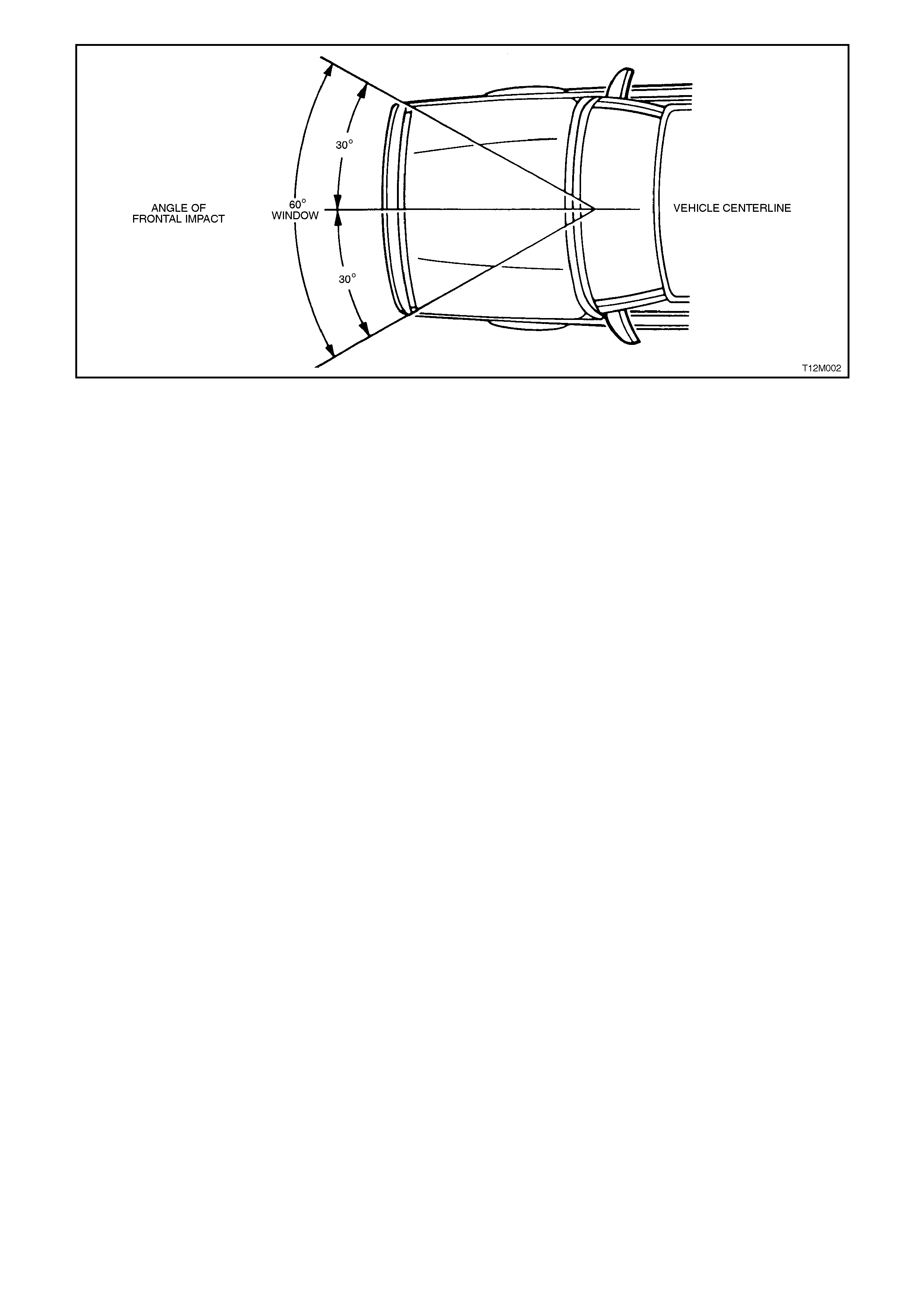
Figure 12M-2
For deployment to occur, numerous factors must be taken into account. For instance, the crush area of the other
vehicle (if involved in the crash), its mass and speed would all contribute to raising or lowering the force required for
deployment to occur as designed. Also, the angle of impact force may not be within the 60 degree window for SRS
deployment to occur, although the physical damage to the vehicle may appear that it was.
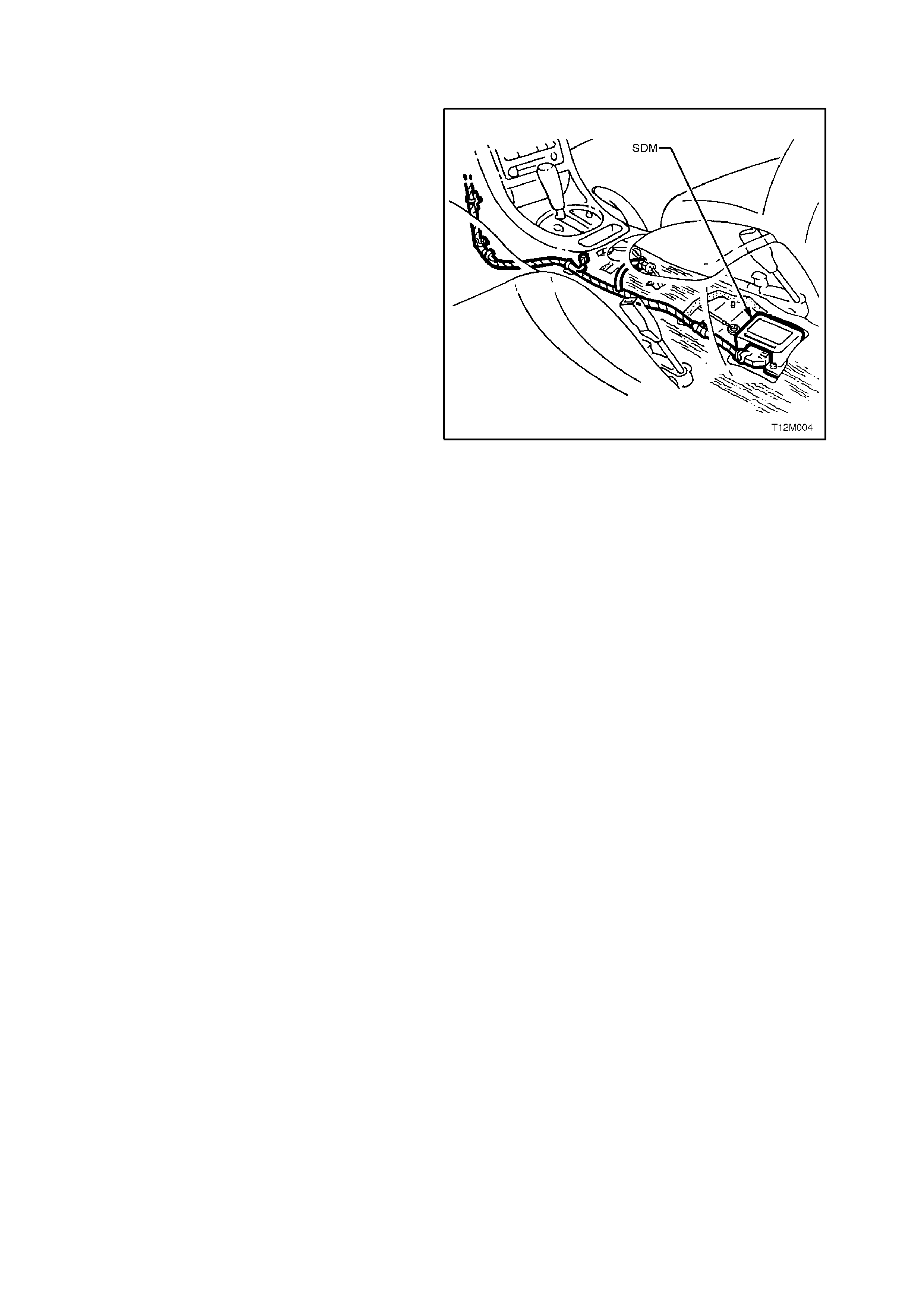
The sensors that control the air bag and seat belt pre-tensioner deployment are incorporated in the Sensing and
Diagnostic Module (SDM), located beneath the centre console.
Regular maintenance of SRS is not required. If at anytime the SRS warning lamp comes on whilst driving or does
not come on when the vehicle is started, there is a system fault and this must be rectified as soon as possible.
The TECH 2 diagnostic scan tool is programmed to assist with VT electrical diagnosis and problem solving,
including SRS.
TECH 2 connects to the SRS serial data communication information via the Data Link Connector (DLC), attached to
the instrument panel lower right hand trim, to the right of the steering column. For additional information on DLC
location and system diagnosis, refer to 3. DIAGNOSTICS in this Section. For additional and more comprehensive
information regarding TECH 2, refer to Section 0C TECH 2.
IMPORTANT:
Accessory type or after market bull bars or such devices not approved by Holden's and fitted to a vehicle
with SRS may adversely affect the vehicles desired threshold characteristics for SRS deployment.
On vehicles with front passenger's air bag, accessory type or after market type dash panel carpet covers,
or the like MUST NOT be installed, as this will greatly inhibit the performance of the air bag and front
passenger's safety in the event of an air bag deployment.
Fitting of accessories such as drink holders, cassette racks additional mirrors, etc. are not permitted in the
immediate deployment area of the front passenger's air bag as these may be ripped off and propelled
towards the vehicle's occupants when the air bag is deployed.
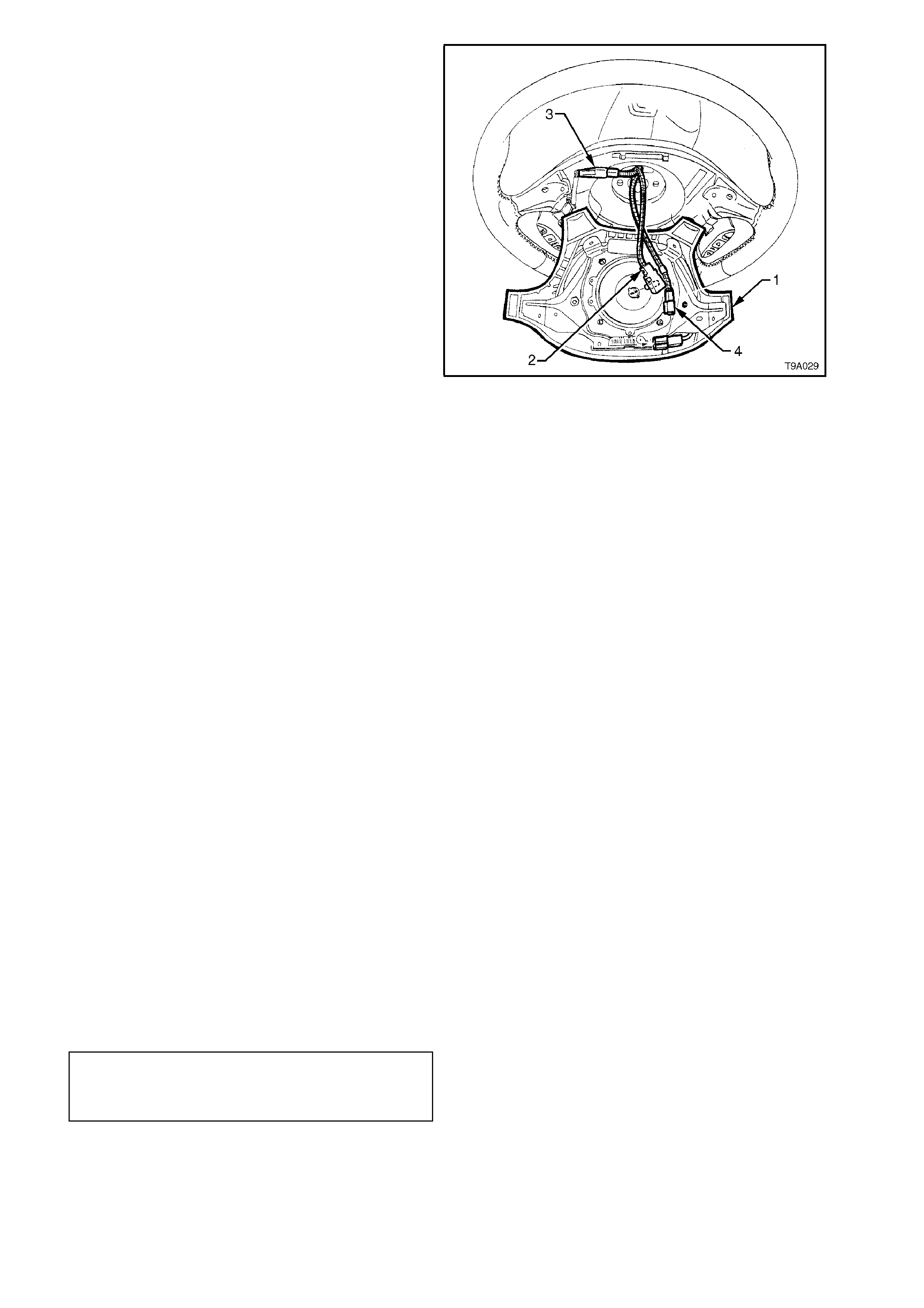
Figure 12M-3, below, illustrates the locations within the passenger compartment of the SRS components.
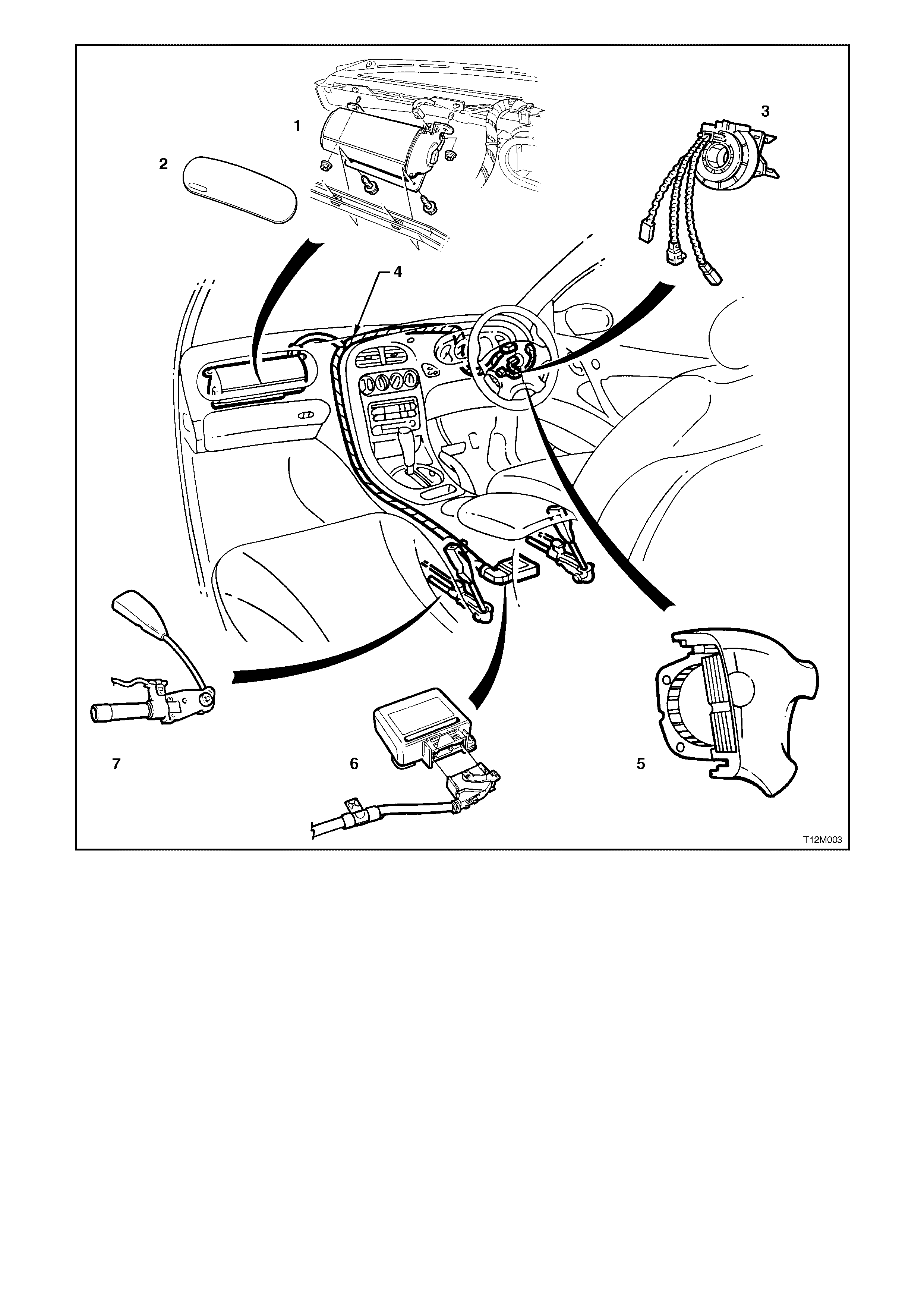
Figure 12M-3
1. Front passenger’s side air bag inflator assembly.
2. Passenger Air Bag (PAB) door.
3. Clock spring coil assembly.
4. SRS wiring harness (part of main wiring harness).
5. Horn bar and driver’s side air bag inflator module.
6. Sensing and Diagnostic Module (SDM).
7. Seat belt pre-tensioner assembly.
The SRS system operates the air bag inflator module/s in four stages (refer to Figs. 12M-4 and 12M-5) to protect
the driver and front seat passenger (if front passenger side air bag is installed) during a crash.
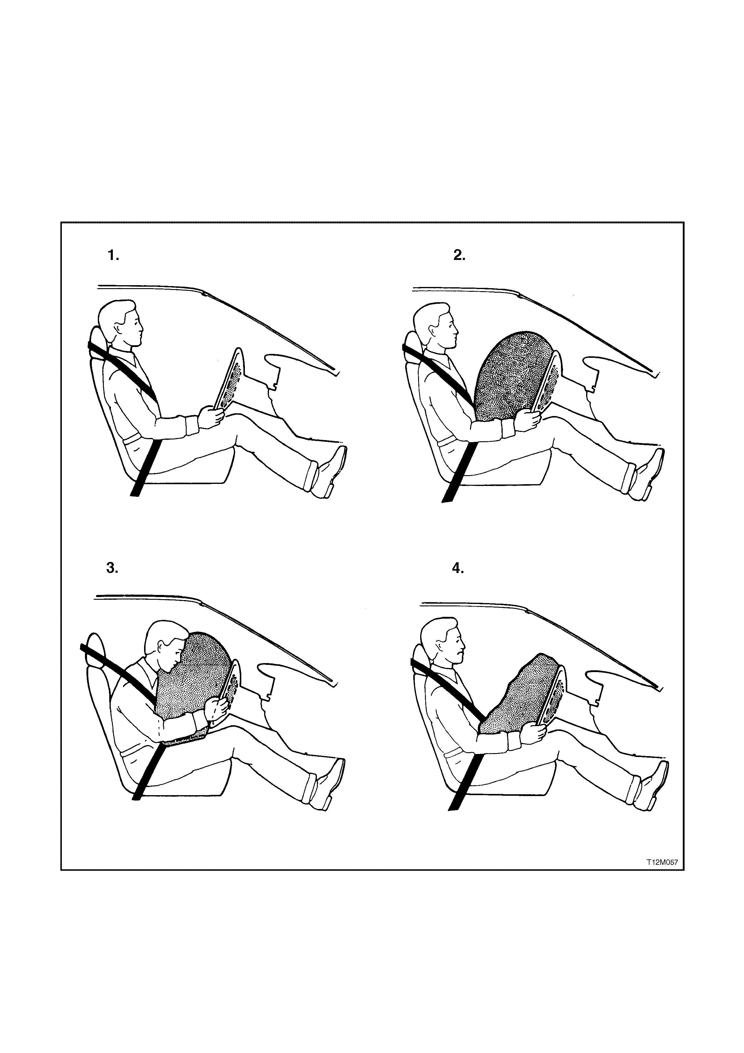
NOTE:
If air bags are deployed, they will both deploy simultaneously.
1. Before Deployment: The SRS is in a state of readiness, unless the Sensing and Diagnostic Module (SDM)
detects a fault and alerts the vehicle driver via the SRS warning lamp in the instrument cluster warning lamp
panel.
2. Fully Deployed: The air bag/s are inflated and the SDM records the data related to the SRS conditions and
operation.
3. During Restraint: The force of the crash causes the head and upper torso of the front passenger and/or driver
to move forward into the inflated air bag/s.
4. End of Crash: The air bag/s deflate within several seconds after deployment.
Figure 12M-4
1. Before deployment 3. During restraint
2. Fully deployed 4. End of crash
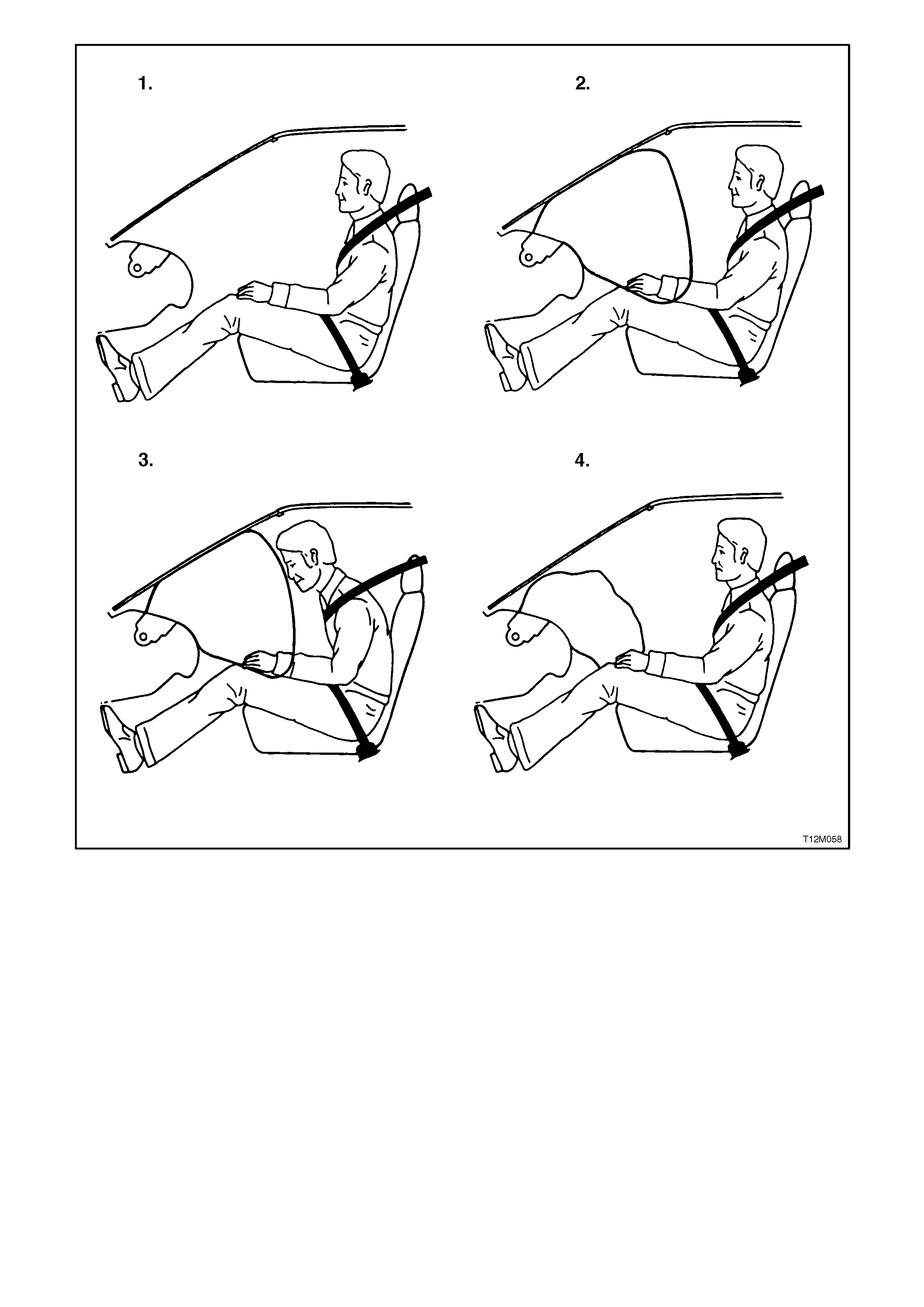
Figure 12M-5
1. Before deployment 3. During restraint
2. Fully deployed 4. End of crash
1.1 SYSTEM COMPONENTS
SENSING AND DIAGNOSTIC MODULE
The Sensing and Diagnostic Module (SDM), which
is mounted under the centre console assembly,
consists of an electronic acceleration sensor
system, electronic control system, energy storage
devices, self diagnostics, fault memory and crash
event recording facility.
The primary function of the SDM, as part of the
SRS, is to sense crash events and discriminate
between non-deployment and required deployment
events.
The SDM is a centralised, self contained crash
sensing and triggering system that requires no
additional external sensing inputs. The SDM also
performs continual tests on the pre-tensioners and
air bag circuits for the front seat belt pre-tensioners,
the driver's air bag and (if fitted) front passenger's
air bag.
In the case of a deployment event, the function of
the sensing system is to initiate the pre-tensioners
or pre-tensioners and air bag/s in a timely manner
in order to protect the vehicle occupant/s.
Secondary to this, the SDM can diagnose system
faults which may prevent air bag deployment or
increase the probability of an inadvertent
deployment and warn the driver in the case of a
system fault.
The SDM is designed for a one time deployment
use only, and must be replaced after a
deployment. If deployment occurs and the SDM
is not replaced, the SRS warning lamp in the
instrument cluster will be continually
illuminated.
Figure 12M-6
Integrated in the SDM are two piezoelectric sensors
(crash sensor) that constantly monitor the
acceleration data of the vehicle. Microprocessors
within the SDM com par e the signals f rom thes e two
sensors to a set of values stored in the processor
memory. If the processed values exceed their set
of stored values, the SDM provides an AC output
signal to ignite the pyrotechnic gas generators in
the pre-tensioners or the pre-tensioners and air
bag/s.
An energy reserve (capacitor) in the SDM stores
sufficient energy to activate the air bag/s in the
event of the electrical system being damaged by
the impact.
The electronic diagnostic facility within the SDM
constantly monitors the electrical circuits and the
firing circuit. Faults that occur in the system are
stored in the m em or y and the SRS warning lam p in
the instrument cluster warning lamp panel will be
switched on.
The SDM performs the following functions:
It continuously monitors the SRS electrical circuits.
It controls the SRS warning lamp in the instrument
cluster to alert the vehicle driver of a detected
system fault.
It has an energy reserve that provides back-up
power (in case the vehicle system power lost
during a crash) to operate the air bag inflator
module/s.
NOTE:
Due to the presence of energy storage devices
within the SDM, servicing of any SRS component
should not be attempted within 10 seconds after
disabling the system.
During deployment, it records and stores SRS and
crash event information:
- Diagnostic Trouble Codes (DTCs) for
detected faults.
- SRS warning lamp operation data.
It comm unic ates diagnostic information thr ough the
Data Link Connector (DLC) for the following
purposes:
- System checks at the vehicle assembly plant.
- Service diagnosis (using TECH 2).
- Transm itting of c rash event rec ording data f or
post Crash analysis.
For details on connecting TECH 2 to the DLC, ref er
to 3.4 TECH 2 DIAGNOSTICS in this Section, or
for more detailed information regarding TECH 2,
refer to Section 0C TECH 2.
Additionally, in the event of SRS deployment, the
SDM will send serial data via the auxiliary serial
data bus (circuit 1220) to advise various vehicle
systems to take appropriate shutdown action.
The PCM monitors this serial data and performs a
vehicle shutdown once the appropriate data is
identified and the vehicle speed is zero for more
than 10 seconds.
The BCM also monitors this serial data and
performs the f ollowing actions onc e the appr opriate
data is identified and the vehicle speed is zero for
more than 10 seconds:
Turn the dome lamp on continuously.
Unlock all doors.
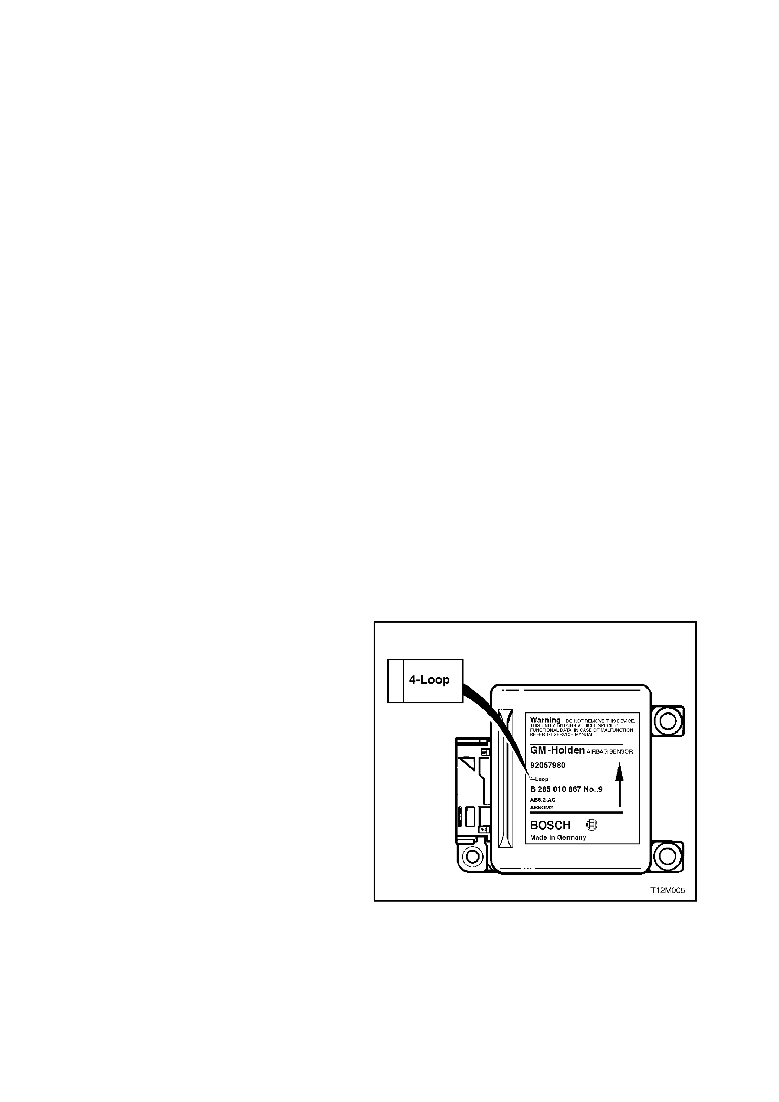
For VT Series Models, two different and non
interchangeable SDMs are released:
• 3-Loop system - for pre-tensioners and driver's
air bag only.
• 4-Loop system - for pre-tensioners, driver's air
bag and front passenger's air bags.
To identify the different SDMs, refer to the
identification label on the top of the SDM. Figure
12M-7 shows the identification label for the 4 loop
system.
NOTE:
Always refer to the latest VT spare parts
microfiche/Part Finder information for the latest part
numbers when ordering SRS components.
Figure 12M-7
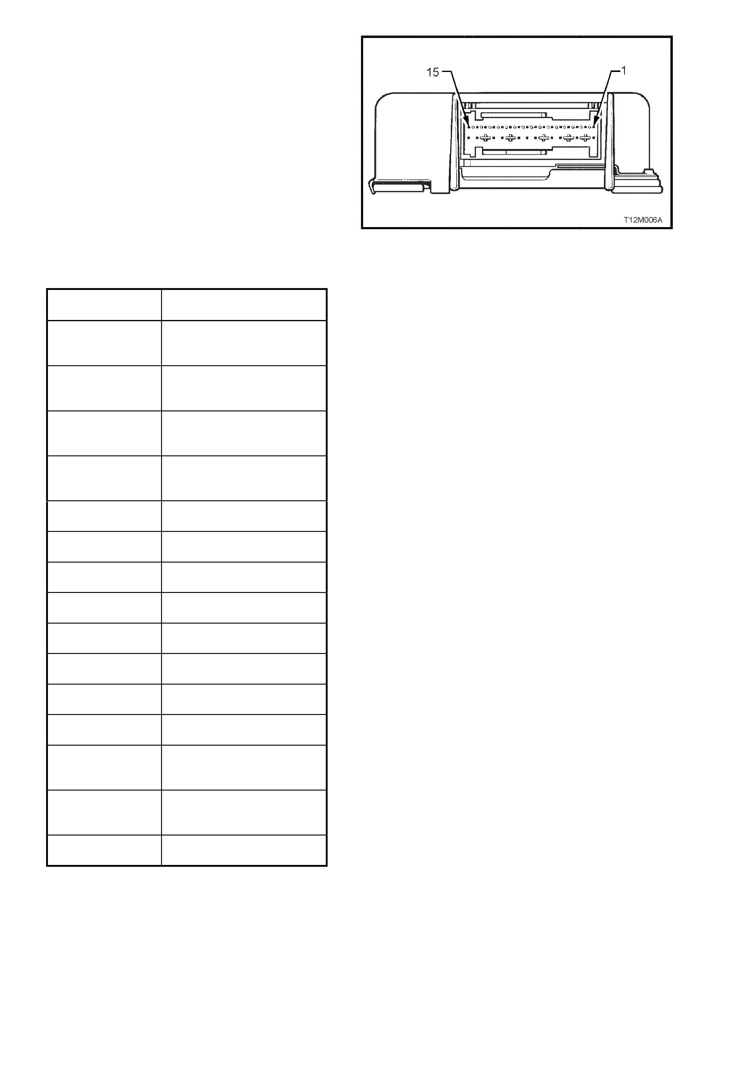
Figure 12M-8
SDM Terminal Assignments
TERMINAL NO. FUNCTION
1 Left hand pre-tensioner,
plus
2 Left hand pre-tensioner,
minus
3 Right hand pre-tensioner,
plus
4 Right hand pre-tensioner,
minus
5 Ignition
6 Not used
7 Not used
8Earth
9 Serial data
10 Driver’s air bag, plus
11 Driver’s air bag, minus
12 Not Used
13 Front passenger’s air bag,
plus
14 Front passenger’s air bag,
minus
15 Not Used
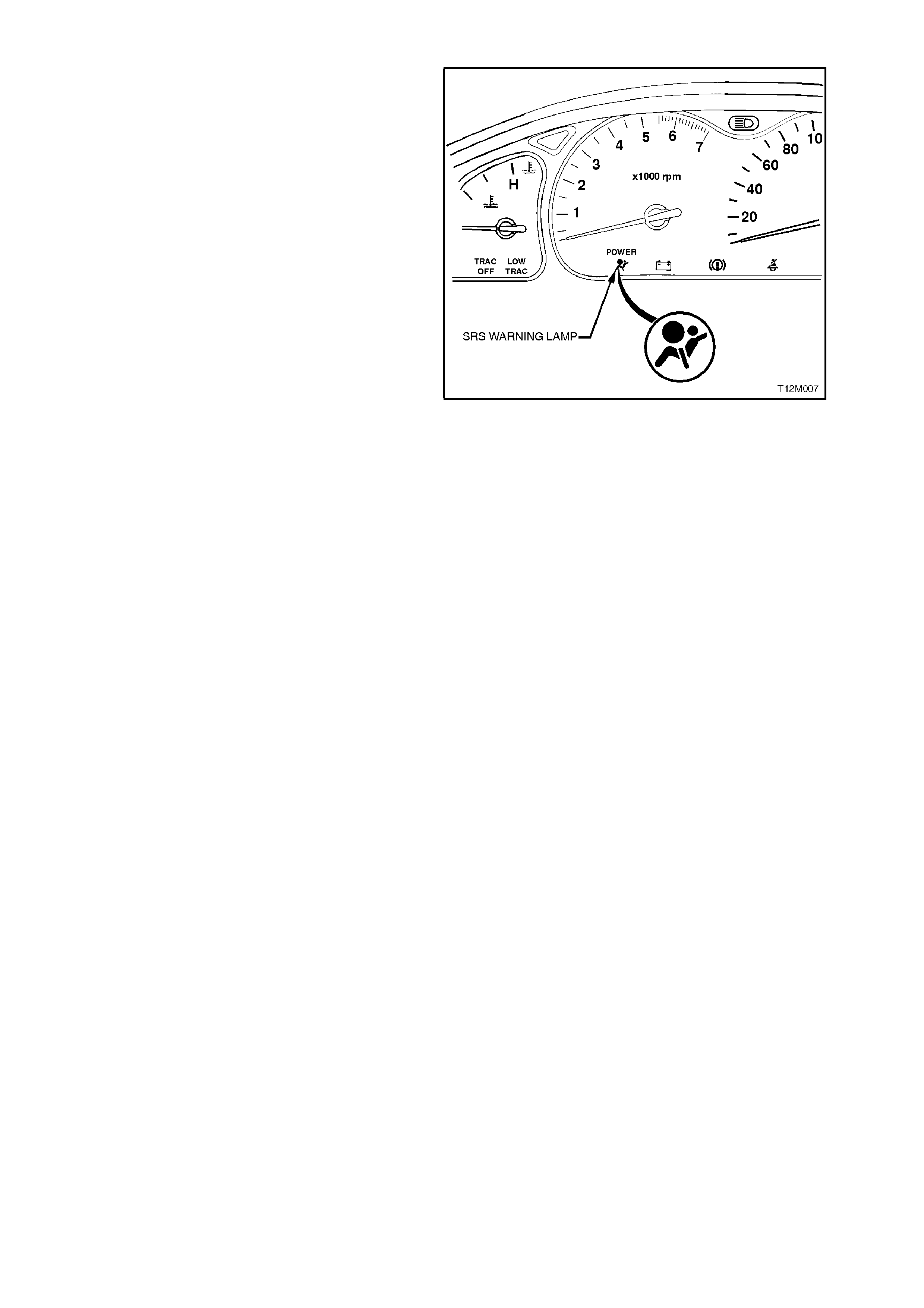
SRS WARNING LAMP
The SRS warning lam p is located in the instrum ent
cluster warning, refer to Fig. 12M-9.
The SRS warning lamp is controlled by the SDM,
via the serial data circuit and will illuminate to warn
the driver that the system has been disabled or
there is a fault in the system.
The SRS warning lamp will illuminate when :
The ignition is switched ON, the SRS warning
lamp will be illuminated for approximately 5
seconds to indicate the system start-up
sequence. During this period the SDM
performs a system wiring and self check. If no
system faults are detected, the SRS warning
lamp will be switched OFF.
If communication is lost between the SDM and
the instruments (for example SDM wiring
harness YB190 disconnected or no BCM poll)
the SRS warning lamp will be illum inated when
the ignition is first switched ON, it will then be
turned OFF for approximately 2 seconds and
then commanded ON constantly until the fault
is remedied (communication resumed) (No
DTC will be set).
If battery voltage is below 9 volts or above 20
volts the SRS warning lamp will be illuminated
and remain illuminated until the problem is
resolved (No DTC will be set).
If the SRS is deployed, the SRS warning lamp
will be illuminated until the problem is resolved
(No DTC will be set).
If one or more current or history Diagnostic
Trouble Codes (DTC's) are detected when the
ignition is switched ON, the SRS warning lamp
will illuminate and remain illuminated until the
DTC is cleared. Additionally, 3 seconds after
the ignition is switched ON, an audible warning
chime will sound.
During an ignition cycle, if the SDM detects a
current DTC, the SRS warning lamp will be
illuminated. If dur ing this cycle, the current DTC
fault condition clears, a history DTC will be
logged in the SDM and the SRS warning lamp
will still remain illuminated.
When TECH 2 is communicating with the SDM,
the SRS warning lamp will be illuminated and
the SRS will be disabled.
For all DTC details, refer to 3 DIAGNOSTICS in
this Section.
Figure 12M-9
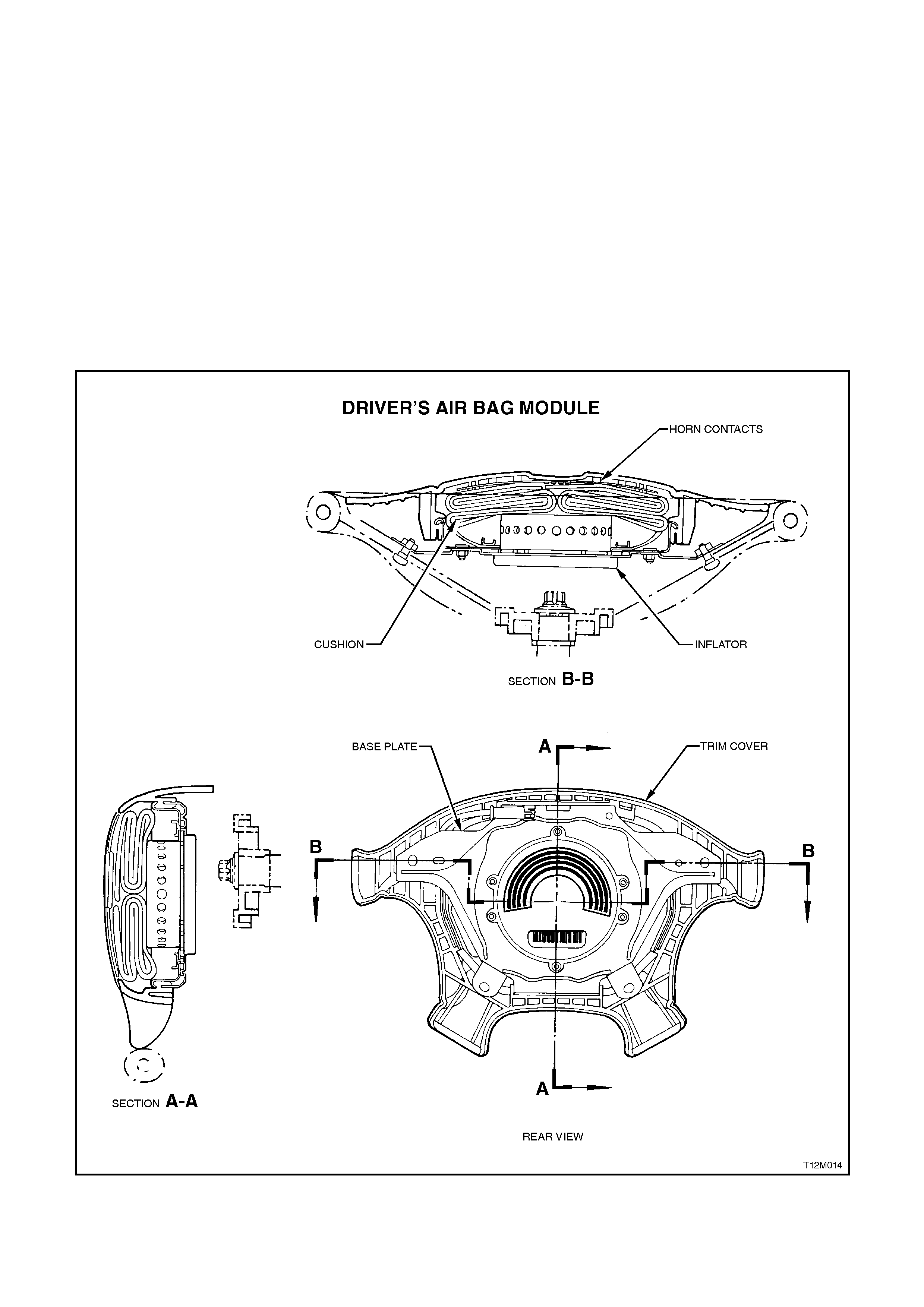
HORN BAR AND AIR BAG INFLATOR MODULE ASSEMBLY
The horn pad is incorporated into the air bag inflator module.
The horn bar (which is incorporated into the air bag inflator module) and air bag inflator module assembly contain
the following parts:
A trim cover with seams for separation during inflation.
A horn contact which is attached to the underside of the trim cover.
A cloth cushion mounted to the base plate and folded.
An electro-chemical module.
A base plate, fastened to the steering wheel with four tamper proof Torx screws
IMPORTANT:
THE HORN BAR AND AIR BAG MODULE ASSEMBLY COMPONENTS ARE NOT REPAIRABLE.
UNDER NO CIRCUMSTANCES ARE THE COMPONENTS OF THE HORN BAR AND AIR BAG MODULE
ASSEMBLY TO BE DISASSEMBLED. THE ASSEMBLY CONTAINS A PYROTECHNIC GAS GENERATOR AND
THE AIR BAG FOLD IS CRITICAL TO AIR BAG PERFORMANCE AND DRIVER SAFETY.
Figure 12M-10
The air bag inflator module (inflator) contains several components (refer to Fig. 12M-11 which shows a ty pical
inflator assembly):
An Electro Explosive Device (EED), with:
An electrical heating element (called an initiator).
A small amount of Lead Styphnate covered with a mixture of Titanium Hydride and Potassium Perchlorate.
An enhancer pack with approximately 3 grams of Baron Potassium Nitrate.
A propellant based on Sodium Azide.
During deployment, the air bag inflator module operates in the following sequence:
The EED initiator receives current from the SDM and begins the chemical reaction by igniting the Lead Styphnate
and the mixture of Titanium Hydride and Potassium Perchlorate.
The EED ignites the Baron Potassium Nitrate in the enhancer pack.
The enhancer's pack chemical reaction causes the Sodium Azide propellant to rapidly produce Nitrogen gas.
The Nitrogen gas pushes the air bag, which separates the steering wheel horn bar trim cover and inflates.
As the air bag inflates, some of the Nitrogen begins to exit into the passenger compartment through vent holes of a
calibrated size. (Allowing the gas to escape in this manner allows for deflation and also enhances the cushioning
effect).
After deployment, the surface of the cushion may contain a powdery residue. This powder consists primarily of corn
starch (used to lubricate the cushion) and by-products of the chemical reaction. Sodium Hydroxide dust is produced
as a by-product of the deployment reaction.
The Sodium Hydroxide then quickly reacts with atmospheric moisture and is converted to Sodium Carbonate and
Sodium Bicarbonate (baking soda). Therefore, it is unlikely that Sodium Hydroxide will be present after deployment.
As a precaution however, gloves and safety glasses are recommended when handling a deployed air bag to prevent
any possible irritation of the skin or eyes.
Figure 12M-11
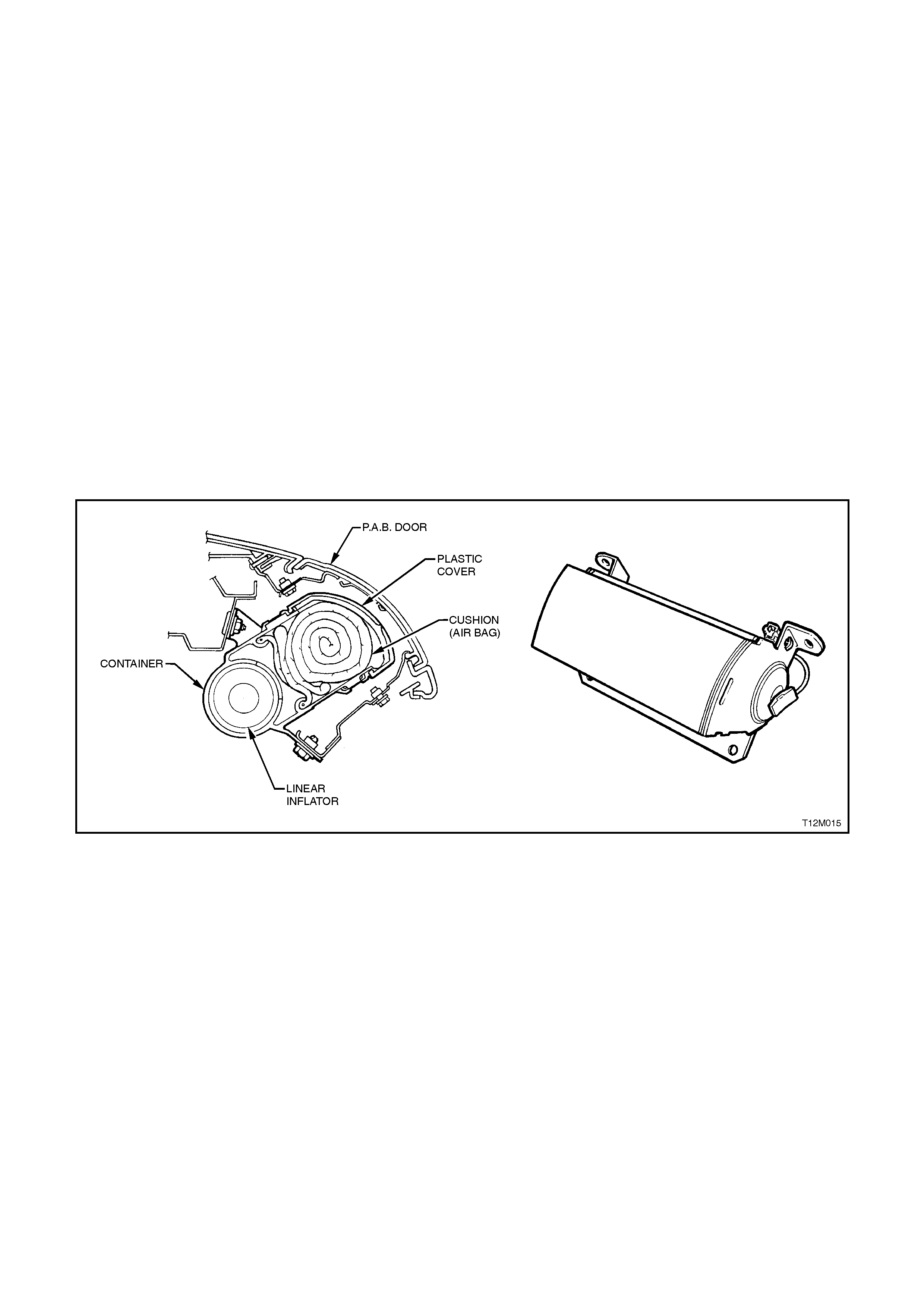
FRONT PASSENGER'S INFLATOR MODULE A SSEMBLY
The front passenger inflator module assembly contains the following parts:
A container, fastened to the dash panel with stud nuts and bolts.
A cloth cushion mounted in the container and folded.
A protective plastic cover over the cushion and hinged to the container to allow the cushion to expand during
inflation.
An electro-chemical module.
The front passenger's air bag deploys through a cut out in the instrument panel pad assembly substrate and a
Passenger Air bag (PAB) door. The PAB door assembly is a skin and foam laminate over an injection moulded
plastic insert with a sheet metal hinge heat staked to the rear surface. This assembly is then attached, using four
screws, to the instrument panel pad assembly.
WARNING:
COMPONENTS OF THE FRONT PA SSENGER'S SIDE AIR BAG INFLATOR MODULE ARE NOT REPAIRABLE.
UNDER NO CIRCUMSTANCES ARE THE COMPONENTS OF THE FRONT PASSENGER'S AIR BAG
INFLATOR MODULE TO BE DISASSEMBLED. THE AIR BAG INFLATOR MODULE CONTAINS A
PYROTECHNIC GAS GENERATOR AND THE AIR BAG FOLD IS CRITICAL TO AI R BAG PERFORMANCE
AND FRONT PASSENGER SAFETY.
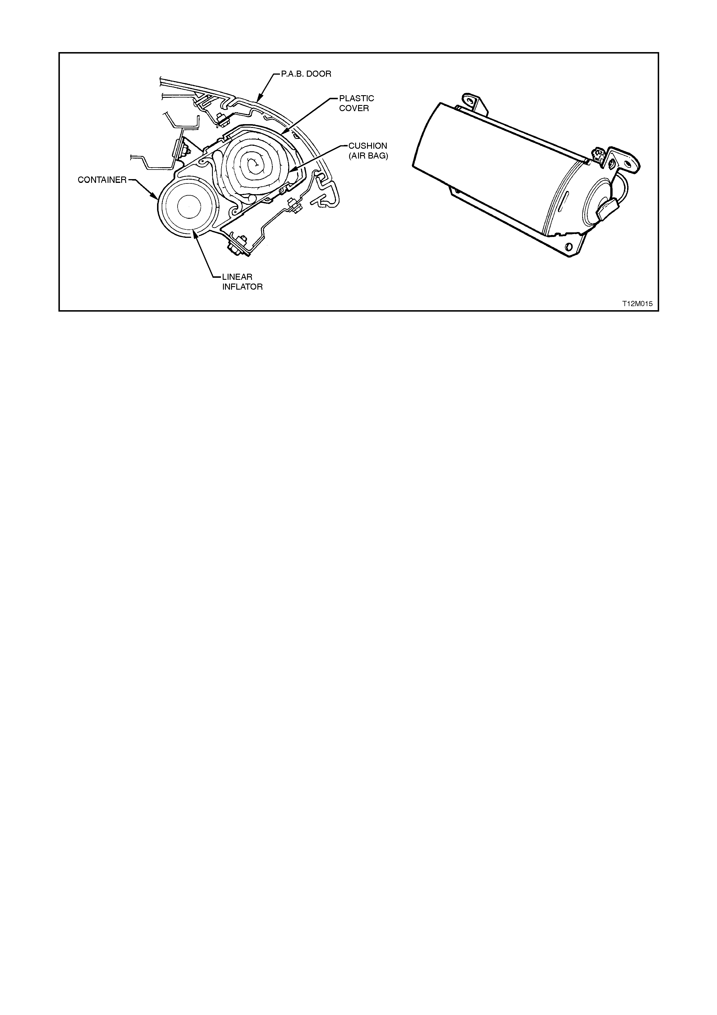
Figure 12M-12
The linear inflator contains several components (refer to Fig. 12M-13 which shows a typical inflator assembly):
An Electro Explosive Device (EED), with:
An electrical heating element (called an initiator) and a fuse.
A small amount of Lead Styphnate covered with a mixture of Titanium Hydride and Potassium Perchlorate.
An enhancer pack with Boron Potassium Nitrate.
A propellant based on Sodium Azide.
During deploy ment, the front passenger's air bag inflator module operates in three stages:
The EED initiator receives current from the SDM and begins the chemical reaction by igniting the Boron Potassium
Nitrate in the enhancer pack.
The enhancer pack's chemical reaction causes the Sodium Azide propellant to rapidly produce Nitrogen gas.
The Nitrogen gas pushes the air bag, which separates the protective cover, pushes the hinged PAB door and
inflates.
As the air bag inflates, some of the Nitrogen begins to exit into the passenger compartment through vent holes of a
calibrated siz e.
Internal tethering controls the fill and placement of the air bag, to maximise the benefits to the front passenger.
In some deployment conditions, the windshield may be broken by the opening of the Passenger Air bag Door when
the air bag deploys.
As with the drivers' side air bag, the surface of the front passenger's air bag may contain a powdery residue after
deployment. This powder consists primarily of corn starch (used to lubricate the cushion as it inflates) and by-
products of the chemical reaction. Sodium Hydroxide dust is produced as a by-product of the deployment reaction.
The Sodium Hydroxide then quickly reacts with atmospheric moisture and is converted to Sodium Carbonate and
Sodium Bicarbonate (baking soda). Therefore, it is unlikely that Sodium Hydroxide will be present after deployment.
As a precaution however, gloves and safety glasses are recommended when handling a deployed air bag to prevent
any possible irritation of the skin or eyes.

Figure 12M-13
CLOCK SPRING COIL ASSEMBLY
The clock spring coil assembly has the following
parts:
1. A pigtail wiring harness that connects to the air
bag inflator module at the top of the steering
column (connector YB147).
2. A lower wiring harness connector which is
incorporated with the clock spring coil outer
housing assembly.
3. A rotating inner hub which engages with the rear
of the steering wheel.
4. A ribbon wire assembly that provides an
unbroken connection between the SDM and air
bag inflator module as the steering wheel is
rotated during vehicle operation.
5. The coil assembly also has pigtail wiring
harnesses and wires in the ribbon wire
assembly for the horn contacts in the steering
wheel horn bar and, if fitted, the remote audio
controls (not shown).
Figure 12M-14
The coil assembly operates in the following
manner:
When the steering wheel is in the straight-ahead
position, the inner hub and outer housing are
aligned to provide approximately 2.5 turns of the
steering wheel in either direction.
When the steering wheel is turned in a clockwise
direction (r ight turn), the inner hub winds the ribbon
wire as it rotates with the steering wheel.
When the steering wheel is turned in an anti-
clockwise direction (left turn), the inner hub
unwinds the ribbon wire as it rotates with the
steering wheel.
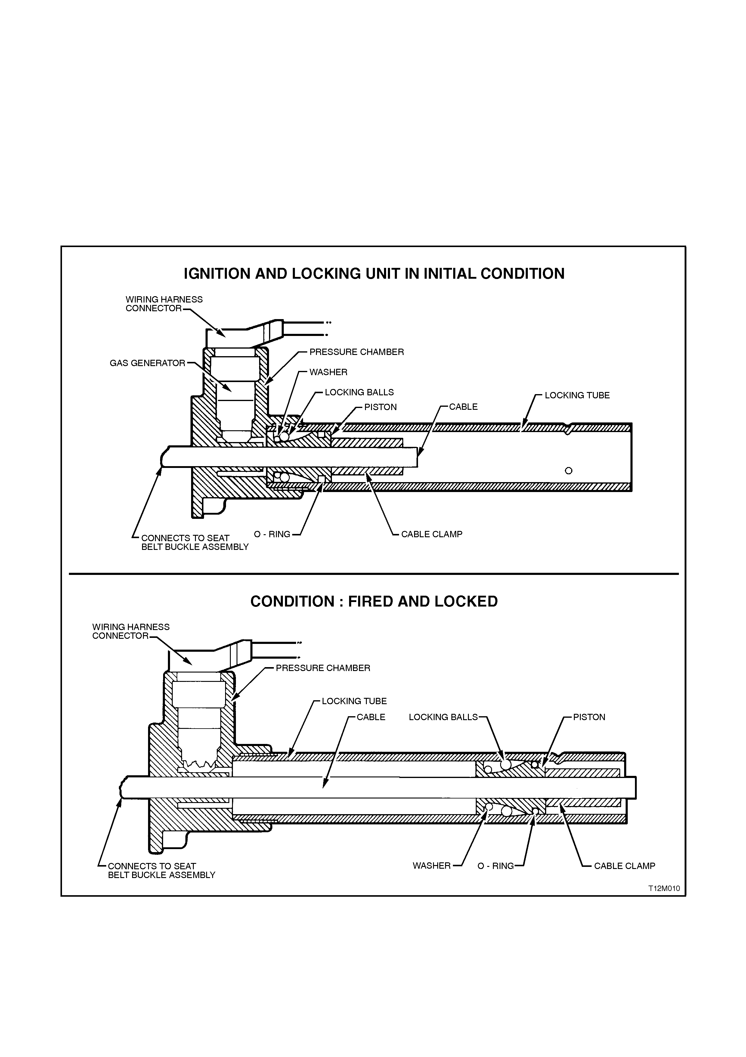
SEAT BELT PRE-TENSIONERS
The driver and front seat passenger seat belts are equipped with a pyrotechnical seat belt pre-tensioner. The
purpose of these pre-tensioners is in the case of a frontal collision, to remove all webbing slack from the seat belt
before the occupant has moved, relative to the vehicle.
The seat belt pre-tensioners have a gas generator complete with an igniter connected to a cylinder. Inside the
cylinder is a piston connected to a cable, the other end of which is connected to the belt buckle assembly.
When an ignition signal from the SDM is sent to the igniter, the gas generator is activated driving the piston down
the cylinder. This action tightens the cable around a roller which pulls the buckle towards the seat taking up the
slack in the seat belt. The tensioner can take up about 9 cm of slack. The outer plastic tube on the buckle assembly
is destroyed during activation. The piston is prevented from moving back up the cylinder by a series of locking balls
once the piston has taken up all the slack in the seat belt.
Figure 12M-15 shows the pre-tensioner assembly before and after the pre-tensioner has been fired.
Figure 12M-15
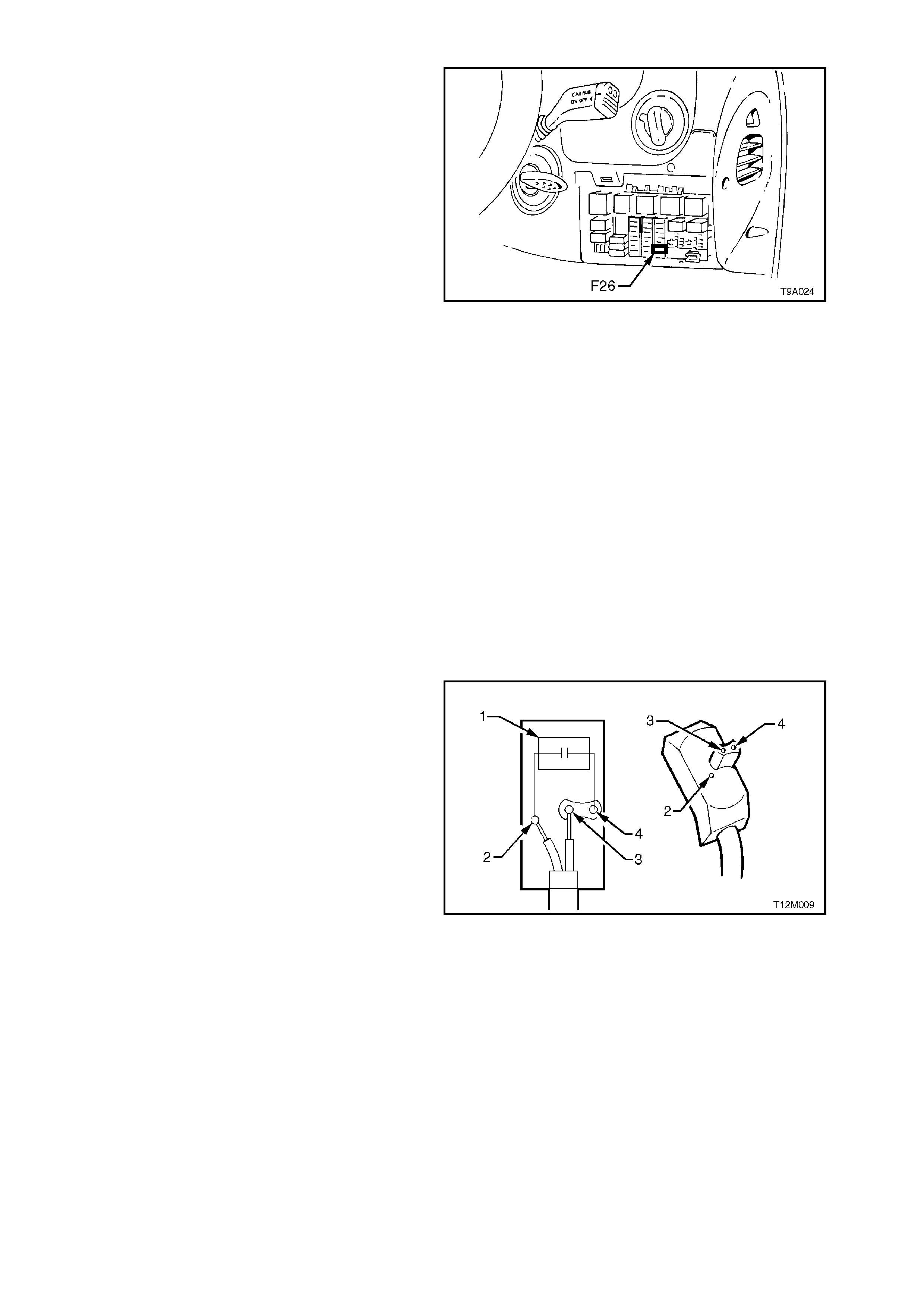
SRS FUSE
The SDM is supplied voltage from the ignition
switch, via fuse F26, located in the passenger
compartment fuse panel.
Access to this fuse panel is by grasping the top
edge of each side of the instrument panel right
hand cover with the finger tips and pulling the top
edge out, to free the retaining lugs from the clips.
NOTE:
Fuse F13 (instrument fuse), located in the
passenger compartment fuse panel, is also used
for the SRS warning lamp circuit.
Figure 12M-16
WIRING HARNESS
The SRS wiring harness is incorporated with the
main wiring harness and contains the necessary
wiring to interconnect the various system
components.
There is no specific wiring harness for vehicles
without a passenger side air bag, rather, the
additional wire for this connection is taped back to
the SRS wiring harness.
Although the SRS harness is incorporated with the
main wiring harness, it can still be identified by the
yellow PVC tubing or yellow tape covering the
harness wiring. The majority of the specific SRS
wiring harness connectors are either coloured
yellow or have a yellow retaining clip or slide to
identify them as SRS connec tors. O ne exception to
this is the wiring harness connector YB190 for the
SDM, which is coloured orange.
The connectors on the SRS wiring harness which
interface with the igniters have an in-built capacitor
which is connected in series with the trigger circuit.
The purpose of the capacitor is to prevent
unintentional triggering of the SRS by blocking any
Direct Current (DC) in the circuit.
Figure 12M-17 illustrates the SRS wiring harness
connector with an in-built capacitor. The connector
consists of:
1. Capacitor.
2. A “Service Hole” to aid in diagnosis of the
system.
3 & 4. Terminals.
Special wiring repair procedures have been
developed for use on the SRS due to the sensitive
nature of the circuitry. The procedures described in
2.8 SRS WIRING REPAIR in this Section is the
only recommended and approved SRS wiring
repair m ethod. No alternative repair methods are
to be used.
Figure 12M-17
WARNING LABELS
In order to provide adequate warning of the SRS operation and service requirement to the vehicle's owner or driver
and service technicians, SRS warning labels are located on the driver's side sun visor, front passenger's side sun
visor (vehicles with front passenger's air bag), in the engine compartment (engine cooling fan shroud), and on the
steering wheel hub, refer to Fig. 12M-18.
IMPORTANT:
If at any time the engine cooling fan shroud, driver's or front passenger's sun visor or steering wheel is replaced,
ensure that the appropriate warning label is applied to the replacement part.
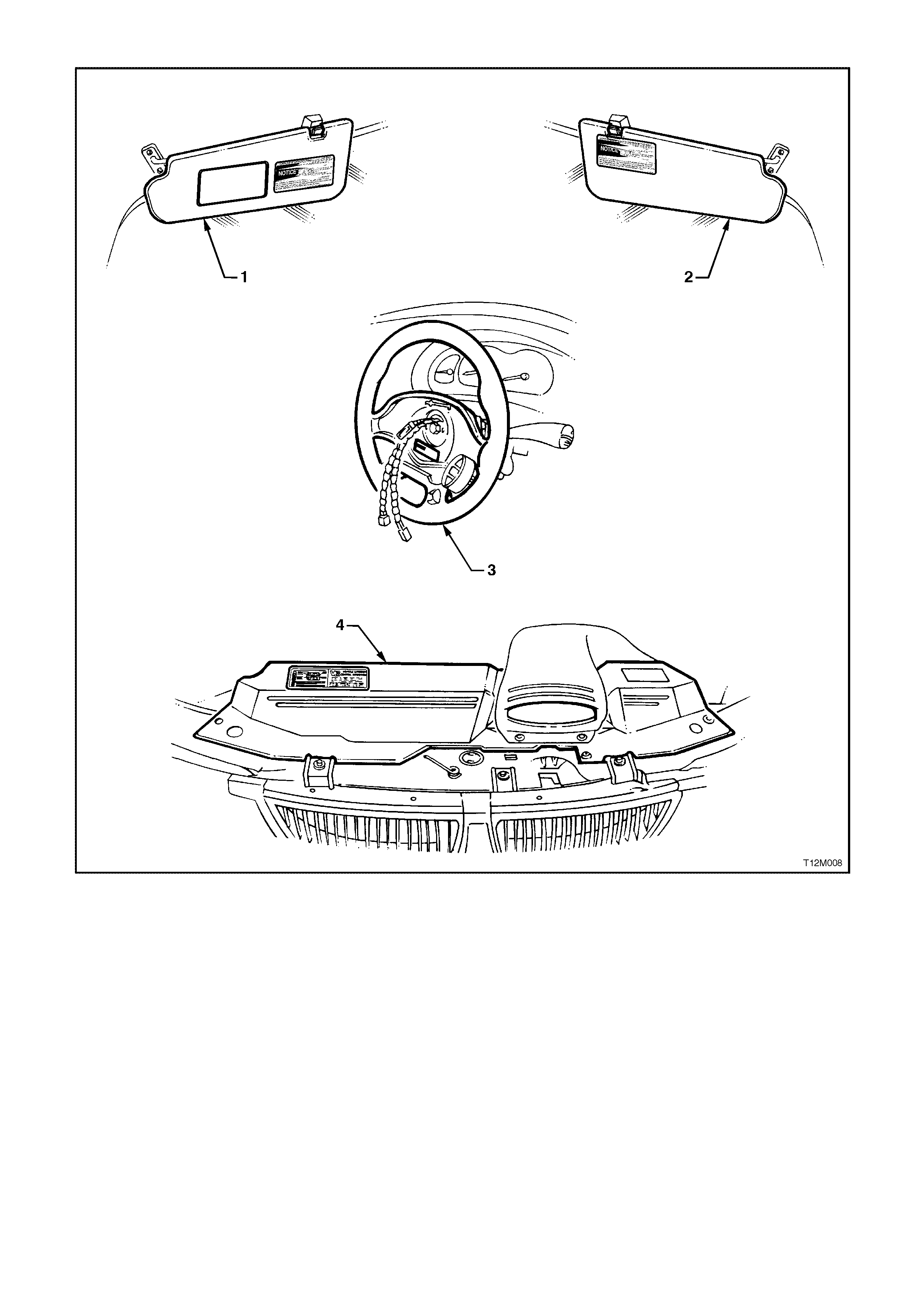
Figure 12M-18
1. Passenger’s side sun visor. 3. Steering wheel (horn bar and air bag inflator
removed)
2. Driver’s side sun visor. 4. Engine cooling fan shroud.

2. SERVICE OPERATIONS
2.1 SAFETY PRECAUTIONS
1. Do not use a fast battery charger for starting the vehicle.
2. Never disconnect the battery from the vehicle's electrical system while the engine is running.
3. Disconnect the battery from the vehicle's electrical system before fast battery charging.
4. Never disconnect or connect the SDM connector with the ignition turned on.
5. After an accident, the individual SRS components must be replaced if the following circumstances apply:
a. Deformation of the SDM. (If the floor pan is deformed where the SDM is mounted, it must be repaired).
b. Pre-tensioners, horn bar and air bag inflator module, front passenger's air bag inflator module that have not
been triggered, but are damaged.
c. Pre-tensioners, horn bar and air bag inflator module, front passenger's air bag inflator module or SDM
assemblies that have been triggered.
In an accident which was severe enough to deploy the pre-tensioners but not severe enough to deploy air
bag/s; any seat belt worn in the accident, the pre-tensioners and the front seat guide rail and adjuster
assemblies must be replaced.
If the horn bar and air bag inflator module or front passenger's air bag inflator module have also deployed;
the steering column, clock spring coil, steering wheel, instrument panel pad, front passenger air bag inflator
support rail assembly, PAB door assembly and instrument panel pad name plate badge.
NOTE:
DAMAGED OR DEFECTIVE COMPONENTS OF THE SYSTEM MUST NOT BE REPAIRED, BUT MUST
ALWAYS BE REPLACED.
7. When fasteners are removed, always reinstall them in the same location from which they were removed. If a
fastener needs to be replaced, use a fastener with the correct part number for that application. If a fastener
with the correct part number is not available, a fastener of equal size and strength (or stronger) may be used.
Fasteners that should not be reused, and those requiring thread locking compound will be identified in this
Section. The correct torque value must be used when installing fasteners that require it. If these conditions are
not adhered to, parts or system damage could result.
8. The windshield plays an active part during the deployment of the front passenger's air bag. The strength of the
windshield and its urethane adhesive is critical to ensure that the front seat passenger is correctly protected
during deployment. Replacement windshield glass and adhesives complying to Holden's specifications may
only be used.
Only use the correct urethane adhesive when installing a windshield to maintain original installation integrity.
Failure to use the correct product will result in poor retention of the glass. For vehicles with front passenger
side air bag, the windshield must be replaced properly so that occupant protection provided by the SRS is
maintained.
9. Sensing and Diagnostic Module.
Take care when handling the SDM. Never strike or jar the module or body structure adjacent to the module in a
manner which could cause deployment of the pre-tensioner’s or air bag/s.
10. Undeployed air bag inflator module.
When carrying a live (undeployed) air bag inflator module, ensure that it is pointed away from you. In case of
an accidental deployment, the air bag will then deploy with minimal chance of injury.
When placing a live air bag inflator module on a bench or other surface, always face the assembly up, away
from the surface. This is necessary in order to provide free space for the air bag to expand, in case of
accidental deployment. Also, never place anything on top of air bag inflator module.
Never carry the driver's air bag inflator module by the horn bar contact wires on the underside of the assembly.
If still connected, never carry the pre-tensioner’s or the front passenger's inflator module by its wiring harness
lead.
Do not apply power to the module except as specified in this Section.
Do not attempt to make any repairs to the module/s. A damaged or defective horn bar and air bag inflator
module or front passenger's air bag inflator module assembly must be replaced.
Do not weld, solder, braze, hammer, machine, drill, or otherwise heat seat belt pre-tensioners or air bag inflator
modules.
11. Deployed air bag inflator module/s.
Always wear gloves and safety glasses when handling a deployed pre-tensioner, horn bar and air bag inflator
module or front passenger air bag inflator module. The surface of these components may contain chemicals
(eg. Sodium Hydroxide) as a result of the gas generated during combustion. This can irritate your skin. Wash
hands with mild soap and water afterwards.
12. Steering column.

During any service operation that requires removal and reinstallation of a steering column fitted with an air bag
inflator module, always carry the steering column with two hands and with the steering wheel away from your
body. Never carry the column by one hand or with steering wheel tow ard you.
Never set a steering column on the floor with the steering wheel toward the floor.
NOTE:
During any service operation that requires removal of a steering column, ensure that the steering shaft is locked to
the column to prevent any possibility of allowing the steering shaft to rotate and possibly damaging the clock spring
coil ribbon wire. For details of locking the steering shaft to the column, refer to Section 9A, STEERING.
CAUTION:
When performing service on or around SRS components or wiring, follow the procedures listed in this
Section to temporarily disable the SRS. Failure to follow these procedures could result in possible SRS
deployment, personal injury or otherwise unnecessary SRS repairs.
7. 7. Disconnecting the battery WILL NOT immediately deactivate the SRS. A residual energy reserve in the
SDM is incorporated to enable the pre-tensioners and air bag/s to deploy in the event of a battery failure. The
SDM has the power to deploy the air SRS for up to 10 seconds after the battery has been disconnected or the
ignition turned off.
8. 8. The SDM can maintain sufficient voltage to cause a deployment for up to 10 seconds after the ignition
switch is turned OFF or the battery is disconnected. Many of the service operations require disconnection of
the battery to avoid an accidental deployment of the pre-tensioners or air bag/s.
9. 9. When carrying out steering gear removal and reinstallation procedures, remove the ignition key from the
ignition lock and ensure that the steering column is locked. If this operation is not carried out and the steering
wheel is spun while the steering gear is removed, the clock spring coil will be destroyed. This will result in the
SDM setting a DTC and non-deployment of the driver’s air bag.
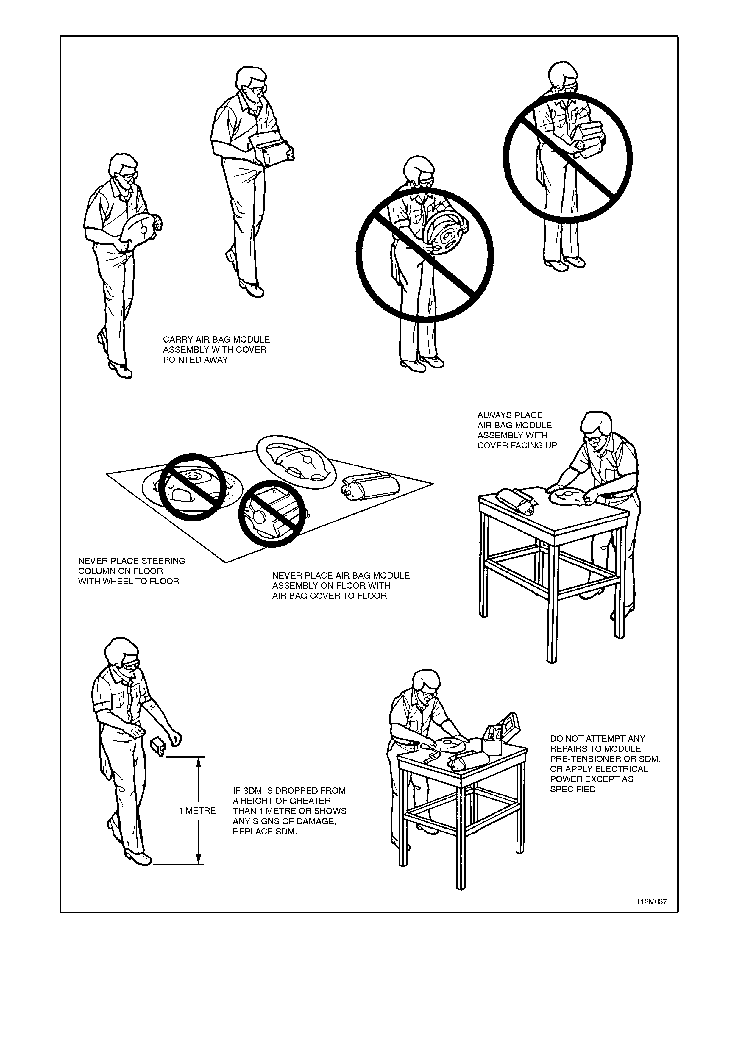
Figure 12M-19

2.2 SYSTEM DISABLING AND ENABLING P ROCEDURE
DISABLING THE SRS
NOTE:
This disabling procedure applies only to VT Series Models which have an AC firing SRS. Conventional SRS
with DC firing such as VS Series Models have a more complex disabling procedure. Always refer to the
appropriate Section for SRS disabling and enabling procedures.
Disconnect both the battery earth and power leads and wait at least 10 seconds before performing any work on the
vehicle.
CAUTION:
The SDM can maintain sufficient voltage to cause SRS deployment for up to 10 seconds after the ignition
switch is turned OFF or the battery is disconnected.
ENABLING THE SRS
NOTE:
Ensure all wiring harness connectors are connected before reconnecting the battery leads.
1. Reconnect both the battery power and earth leads.
2. Switch ignition on, and observe the SRS warning lamp in the instrument cluster. The warning lamp should be
illuminated for approximately 5 seconds. During this period the SDM performs a wiring and self check.
If no system faults are detected, the SRS warning lamp will be switched off. If the warning lamp remains
illuminated and an audible alarm chimes, or the warning lamp illuminates 2 seconds after it was originally
switched off, an SRS fault is present. Refer to 3 DIAGNOSTICS in this Section to rectify fault.
2.3 HORN BAR AND AIR BAG MODULE ASSEMBLY
If conducting the following operation on an air bag
that has deployed, ensure that you are wearing
safety glasses and gloves to pr otect your eyes and
hands from possible irritation when handling the
deployed horn bar and air bag inflator module
assembly.
After the horn bar and air bag inflator module
assem bly has been deployed, the surf ace of the air
bag may contain a powdery residue. This powder
consists primarily of corn starch (used to lubricate
the bag as it inflates) and by-products of the
chemical reaction. Sodium hydroxide dust is
produced as a by-product of the deployment
reaction. T he sodium hydroxide then quick ly r eacts
with atmospheric moisture and is converted to
sodium carbonate and sodium bicarbonate (baking
soda). Therefore, it is unlikely that sodium
hydroxide will be present after deployment. As a
precaution, however, gloves and s af ety glasses are
recommended to prevent any possible irritation of
the skin or eyes.
REMOVE
1. Disable the SRS, refer to
2.2 SYSTEM DISABLING AND ENABLING
PROCEDURE in this Section.
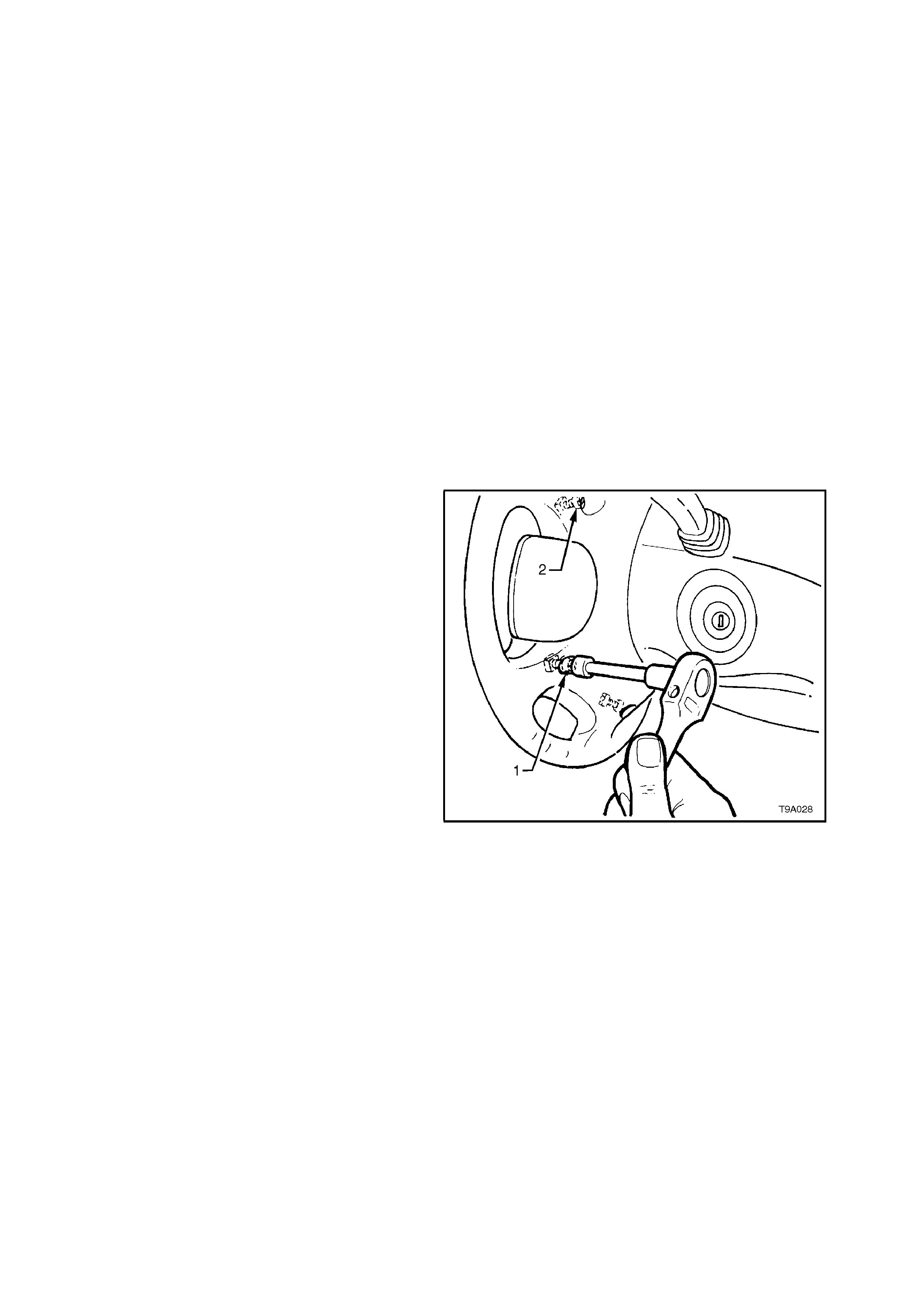
2. Using a number T 30H Torx bit (1) , c ommercially
available or Tool No. ETX30H and a suitable
holder such as Tool No. J25359-8, loosen and
rem ove four sc rews (2) f rom the r ear of s teering
wheel securing the horn bar and air bag inflator
module assembly to the steering wheel.
Figure 12M-20
3. Lift up horn bar and air bag inflator module
assembly (1) from the steering wheel, remove
the yellow clock spring to inflator assembly
connection (2) and disconnect wiring harness
connectors (3 and 4) from rear of assembly,
refer to Fig 12M-21.
NOTE:
If removing a horn bar and air bag inflator module
assembly from a steering wheel fitted with stereo
controls (as shown), take extreme care when
disconnecting the left hand horn pad connector (3)
from the stereo control wiring connector otherwise
damage to the stereo control wiring could result.
Remove horn bar and air bag inflator module
assembly.
CAUTION:
When carrying a live (undeployed) horn bar and
air bag inflator module assembly, make sure
the bag opening in the horn bar is pointed away
from you. Never carry the horn bar and air bag
inflator module assembly by the horn bar wires
or connectors on the underside of the
assembly. In case of an accidental deployment,
the bag will then deploy with minimal chance of
injury.
When placing a live horn bar and air bag
inflator module assembly on a bench or other
surface, always face the bag and horn bar up,
away from the surface. Never rest the horn bar
and air bag inflator module assembly with the
horn bar f ace down . This is necessary so th at a
free space is provided to allow the air bag to
expand in the unlikely event of accidental
deployment. Otherwise, personal injury may
result.
Figure 12M-21
REINSTALL
1. Lift horn bar and air bag inflator module
assembly up to steering wheel and reconnect
all wiring harness connectors to rear of
assembly.
2. Seat horn bar and air bag inflator module
assembly on steering wheel, ensuring wiring is
not exposed or trapped between air bag
inflator module and steering wheel hub.
3. Using number T30H Torx bit. Tool No.
ETX 30H and suitable holder such as T ool No.
J25359-8, install and tighten four screws into
rear of steering wheel to secure horn bar and
air bag inflator module assembly to the
steering wheel. Tighten screws to the correct
torque specification.
HORN BAR AND AIR BAG MODULE
ASSEMBLY TO STEERING WHEEL
SECURING SCREW
TORQUE SPECIFICATION 10 - 14 Nm

4. Enable the SRS, refer to
2.2 SYSTEM DISABLING AND ENABLING
PROCEDURE in this Section.
5. Switch ignition on, and observe the SRS
warning lamp in the instrument cluster. The
warning lamp should be illuminated for
approximately 5 seconds. During this per iod of
time the SDM performs a wiring and self
check.
If no system faults are detected, the SRS
warning lamp will be switched off. If the
warning lamp remains illuminated and an
audible alarm chimes, or the warning lamp
illuminates 2 seconds after it was originally
switched off, an SRS fault is pr esent. Ref er to
3 DIAGNOSTICS in this Section to rectify
fault.
HORN BAR AND AIR BA G MODULE ASSEMBLY SCRAPPING PROCEDURE
During the course of a vehicle's useful life, certain
situations may arise which will necessitate the
disposal of a live (undeployed) hor n bar and air bag
inflator m odule assembly. The f ollowing infor mation
covers proper procedures for deploying a live
assembly.
CAUTION:
Failure to follow proper Supplemental Restraint
System (SRS) horn bar and air bag inflator
module assembly disposal procedures can
result in air bag deployment which may cause
personal injury. T he undeployed air bag inflator
module contains substances that can cause
severe illness or personal injury if the sealed
container is damaged during disposal.
In situations which require deployment of a live
horn bar and air bag inflator module assembly,
deployment may only be accomplished outside the
vehicle. The horn bar and air bag inflator module
assembly needs to be removed so the SRS wiring
harness with the capacitor built into the connector
can be removed. Intentional deployment of the
horn bar and air bag inflator module can not be
accomplished using a 12 volt DC supply with the
capacitor in the SRS circuit.
Horn Bar and Air Bag Module Deployment
Outside Vehicle
There m ay be some cir cum stanc es that requir e the
deployment of a horn bar and air bag inflator
module ass em bly befor e a vehicle is to be retur ned
to service. For example, situations in which the
vehicle will be returned to an owner after a
functionally or cosm etically malf unctioning horn bar
and air bag inflator module assembly is replaced.
Deployment and disposal of a malfunctioning air
bag inflator module is, of course, subject to any
required retention period.
For deployment of a live ( undeployed) horn bar and
air bag inflator module assembly outside the
vehicle, the deployment procedure must be
followed exactly. Always wear safety glasses during
the deployment procedure until the assembly is
removed. Before performing the procedure you
should be familiar with servicing the SRS and with
proper handling of the horn bar and air bag inflator
module assembly.
The following must be read fully and understood
before performing the actual procedure.
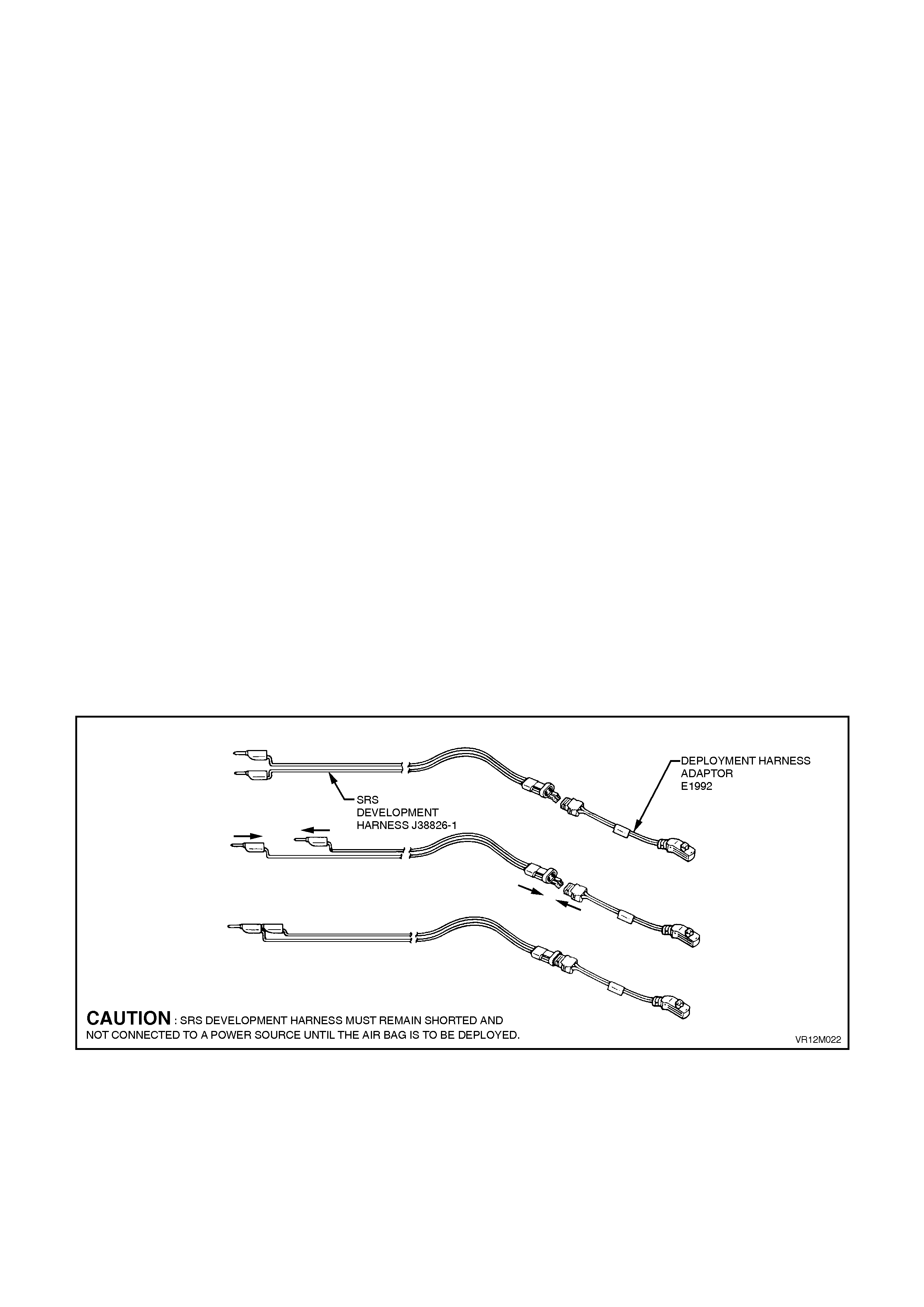
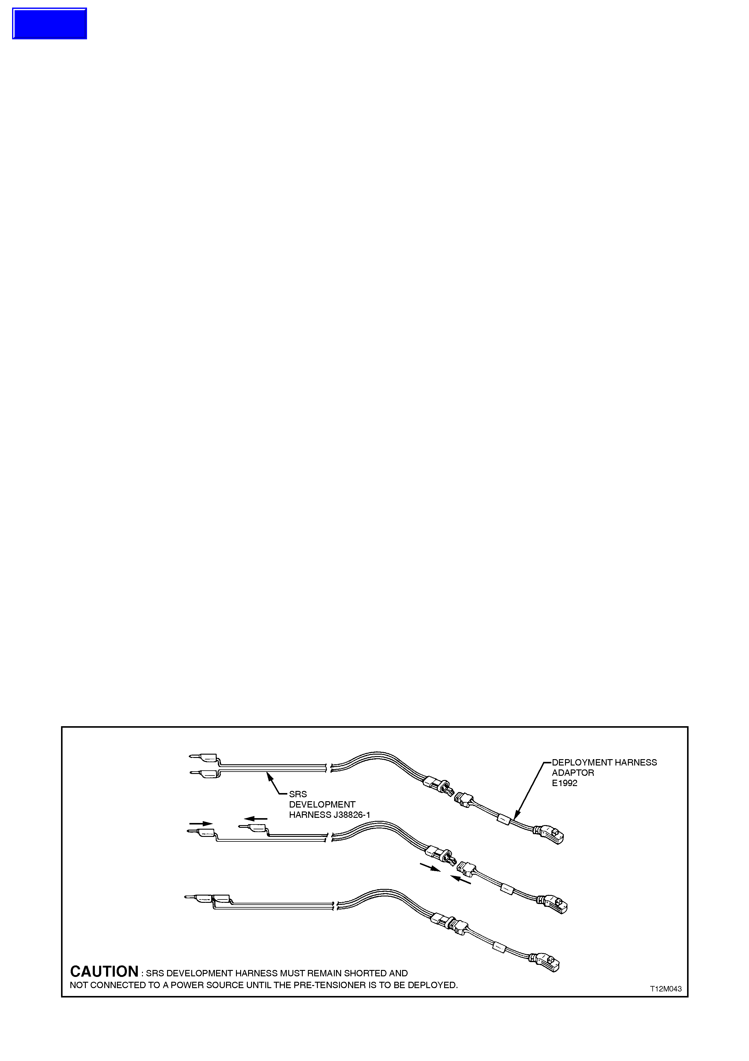
The following procedure requires use of J38826-1
SRS deployment harness with adaptor E1992. Do
not attempt procedure without J38826-1 and
E1992.
CAUTION:
Failure to follow procedures in the order listed
may result in personal injury. Never connect
deployment harness to any power source
before connecting deployment harness to the
horn bar and air bag inflator module assembly.
The deployment harness must remain shorted
and not be connected to a power source until
the horn bar and air bag inflator module
assembly is ready to be deployed. The module
will immediately deploy the air bag when a
power source is connected to it. Wear safety
glasses and gloves throughout this entire
deployment and disposal procedure.
1. Turn ignition switch OFF and put on safety
glasses.
2. Inspect J38826-1 SRS deployment harness
and adaptor, E1992 for damage. If harness or
adaptor is damaged, discard and obtain a
replacement.
3. Short two SRS deployment harness leads
together by fully seating one banana plug into
the other. SRS deployment harness MUST
remain shorted and NOT connected to a
power source until the air bag is to be
deployed.
4. Connect the appropriate pigtail adaptor to the
SRS deployment harness.
Figure 12M-22
5. Remove horn bar and air bag inflator module
assembly from vehicle, refer to
2.3 HORN BAR AND AIR BAG MODULE
ASSEMBLY in this Section.
CAUTION:
When storing a live horn bar and air bag
inflator module assembly or when leav ing a liv e
assembly unattended on a bench or other
surface, always face the assembly with the
horn bar up and aw ay from the surface. This is
necessary so that a free space is provided to
allow the air bag to expand in th e un likely event
of accidental deployment. Failure to follow
procedures may result in personal injury.
6. Place the assembly on a work bench or other
surface away from all loose or flammable
objects with its horn bar facing up, away from
the surface.
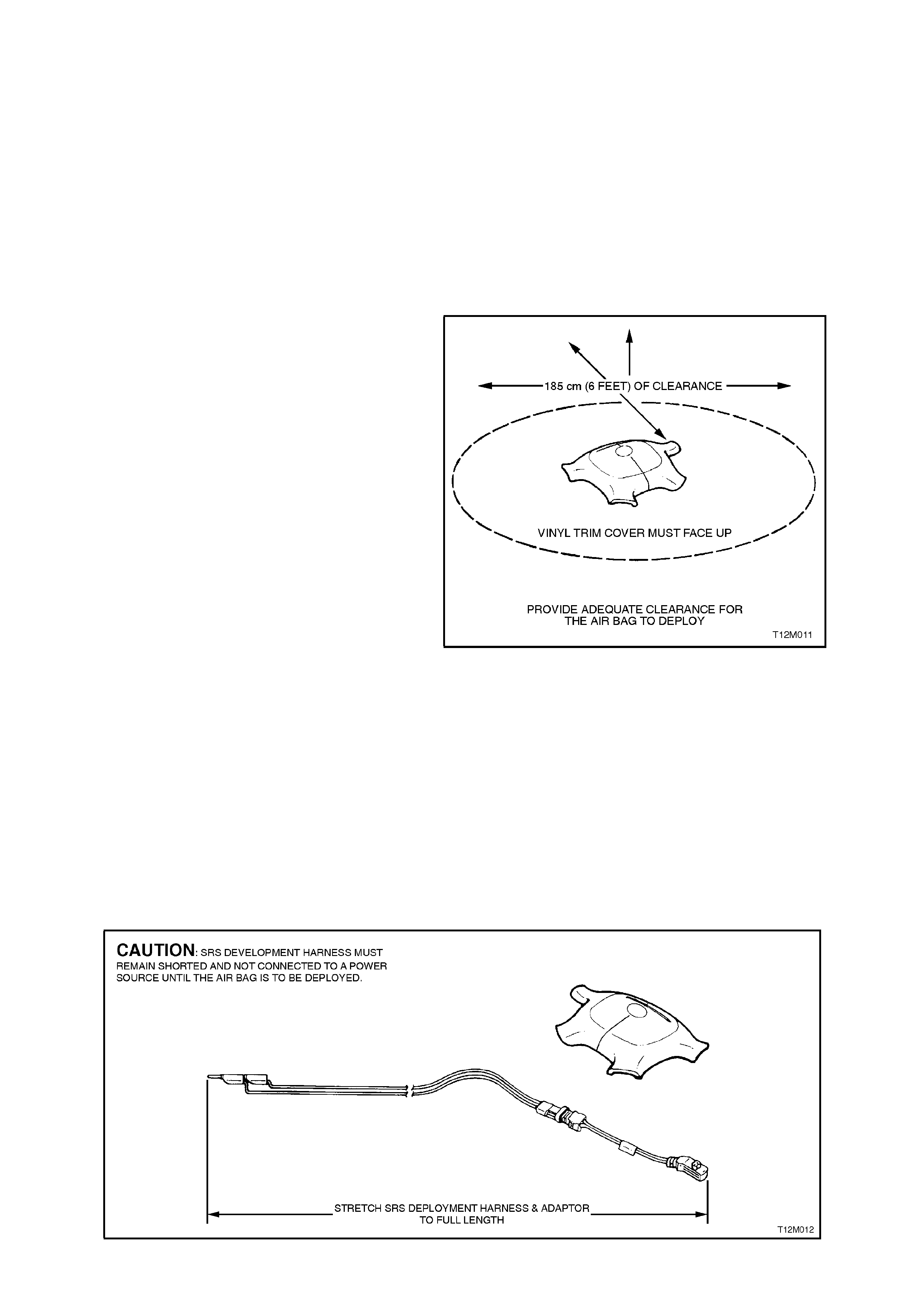
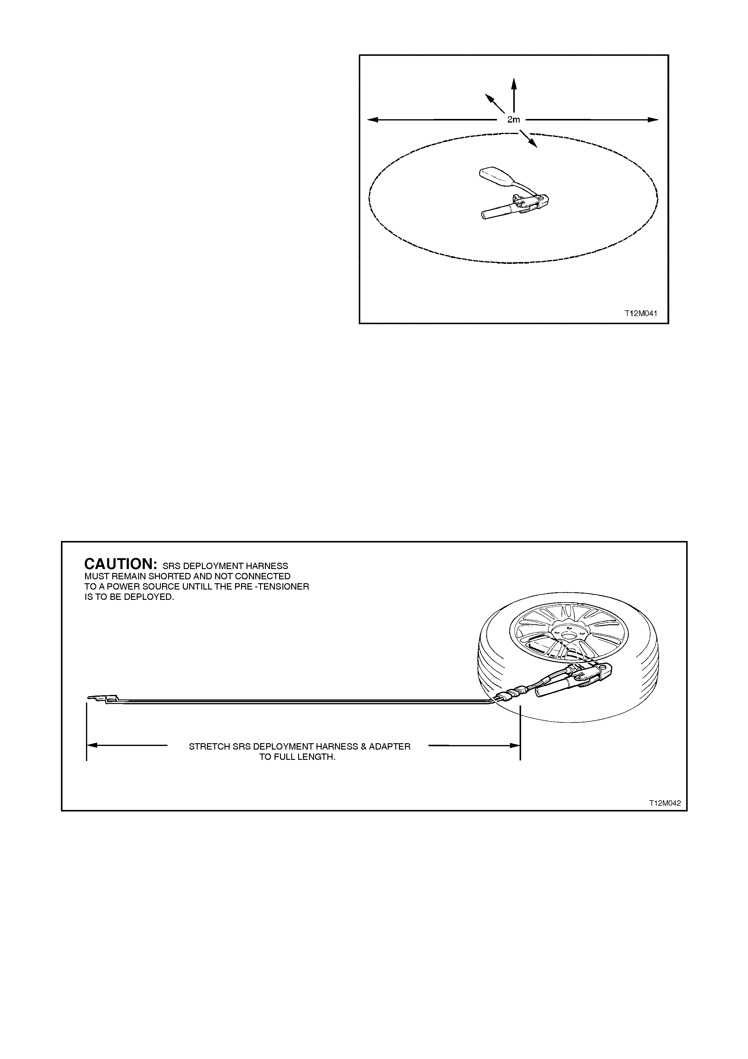
7. Clear a spac e on the ground about 2 metr es in
diameter where the assem bly is to deployed. A
paved, outdoor location where there is no
activity is preferred. If an outdoor location is
not available, a space on the workshop floor
where there is no activity and sufficient
ventilation is recommended. Ensure no loose
or flammable objects are within the
deployment area.
8. Place the assembly, with its horn bar facing
up, on the ground in the space just cleared.
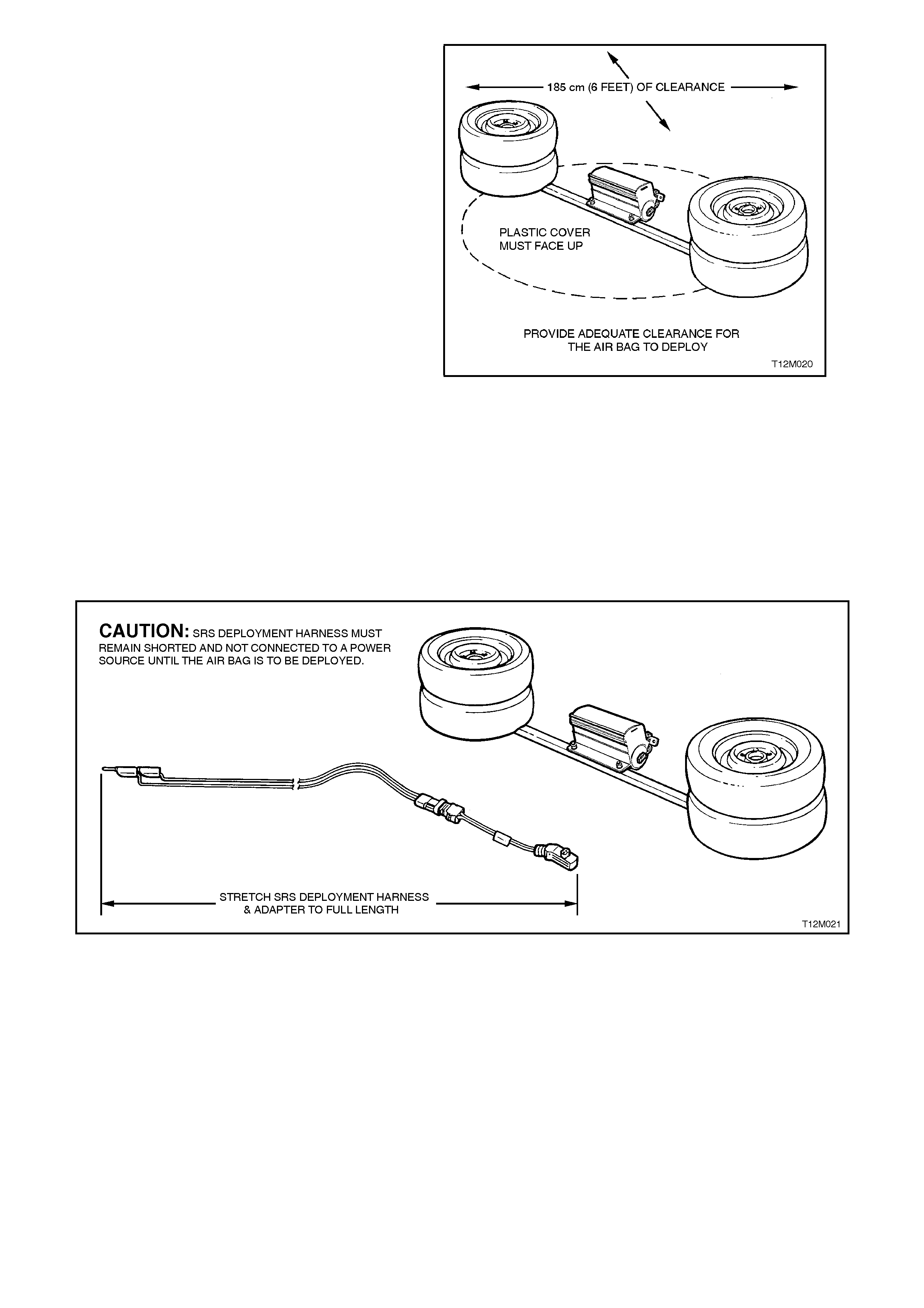
9. Stretch the SRS deployment harness and
adaptor from the horn bar and air bag inflator
module assembly to its full length.
Place a power source near the shorted end of
the SRS deployment harness. Recommend
application: 12 volts minimum, 2 amps
minimum (a vehicle battery is suggested).
Connect the horn bar and air bag inflator
module ass embly to the adaptor E1992 on the
SRS deployment harness.
Figure 12M-23
CAUTION:
The deployment harness M UST remain shorted
and NOT connect ed to a pow er source until th e
air bag is to be deployed. The module will
immediately deploy the air bag when a power
source is connected to it.
Figure 12M-24
12. Verify that the area around the horn bar and
air bag inflator module assem bly is clear of all
people and loose or flammable objects.
13. Verify that the horn bar and air bag inflator
module assembly is resting with horn bar
facing up.
14. Notify all people in the immediate area that
you intend to deploy the horn bar and air bag
inflator m odule assem bly. T he deploym ent will
be accompanied by an explosion which may
startle the uninformed.
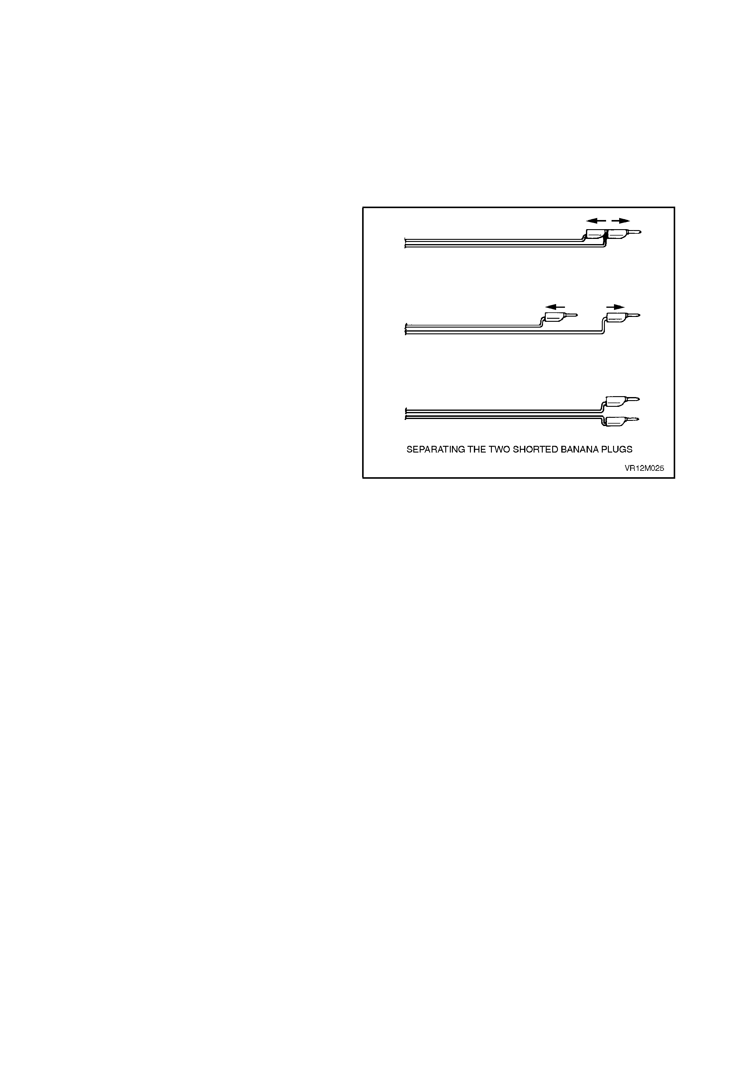
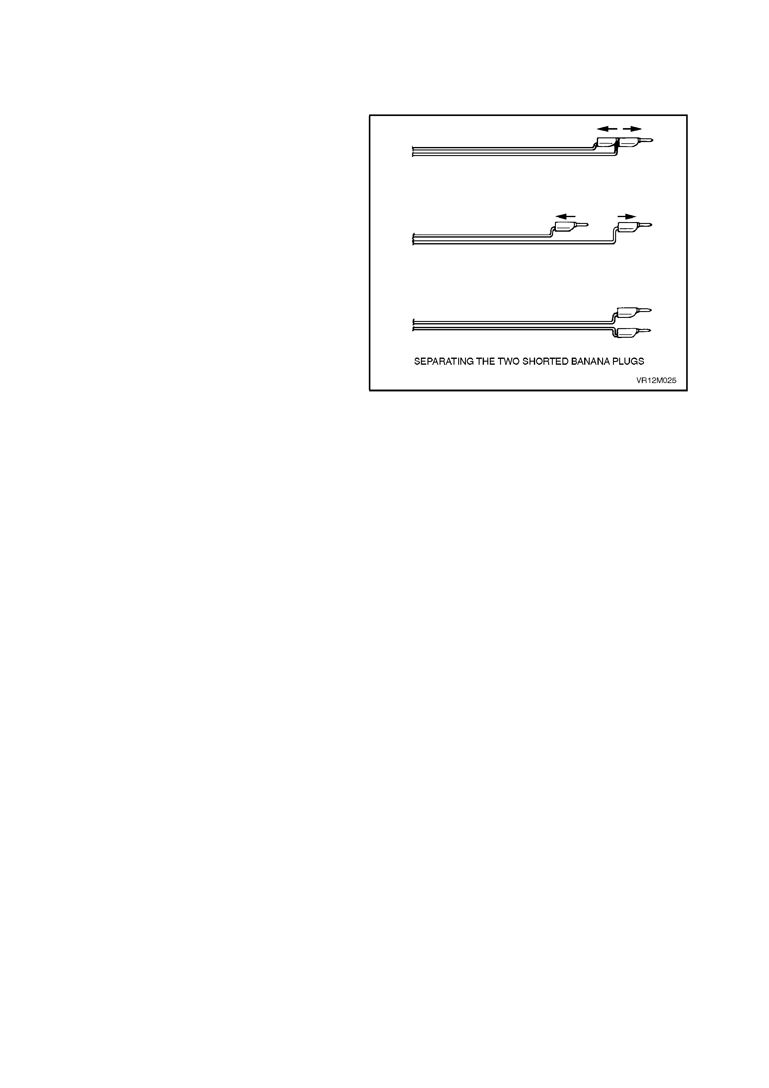
15. Separate the two banana plugs on the SRS
deployment harness.
NOTE:
1. When the air bag deploys, the rapid gas
expansion will create an ex plos ion. Notif y all people
in the immediate area that you intend to deploy the
module.
NOTE:
2. When the air bag deploys, the assembly may
jump about 30 cm vertically. This is a normal
reaction of the module to the forc e of the rapid gas
expansion inside the air bag.
CAUTION:
The deployment harness MUST remain shorted
and NOT connected t o a pow er sou rce until the
air bag is to be deployed. The module will
immediately deploy the air bag when a power
source is connected to it. Connecting the
deployment harness to the power source
should always be the last step prior to
deployment of the air bag. Failure to follow
procedures in the order listed may result in
personal injury.
Figure 12M-25
16. Connect SRS deployment harness leads to
the power source to immediately deploy the
horn bar and air bag inflator module assembly.
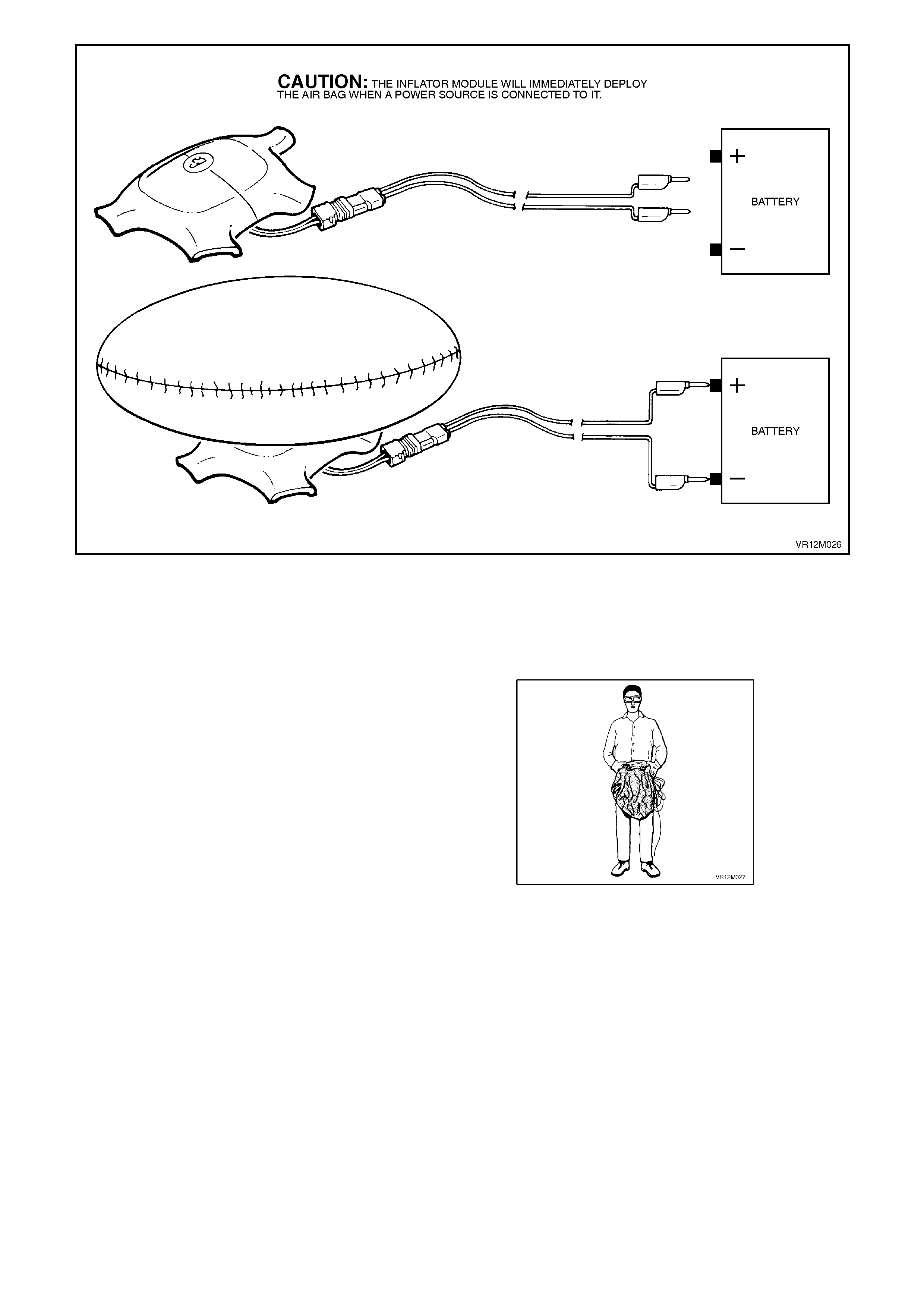
Figure 12M-26
17. Disconnect the SRS deployment har ness f rom
the power source.
18. Short the two SRS deployment harness leads
together by fully seating one banana plug into
the other.
19. Ensure that you are wearing safety glasses
and gloves to protect your eyes and hands
from pos sible ir ritation and heat when handling
the deployed horn bar and air bag inflator
module assembly.
After the horn bar and air bag inflator module
assem bly has been deployed, the surface of the air
bag may contain a powdery residue. This powder
consists primarily of corn starch (used to lubricate
the bag as it inflates) and by-products of the
chemical reaction. Sodium hydroxide dust is
produced as a by-product of the deployment
reaction. The sodium hydroxide then quickly reacts
with the atmospheric moisture and is converted to
sodium carbonate and sodium bicarbonate (baking
soda). Therefore, it is unlikely that sodium
hydroxide will be present after deployment. As a
precaution, however, gloves and saf ety glasses are
recommended to prevent any possible irritation of
the skin or eyes.
Figure 12M-27

CAUTION:
Safety precautions must be observed when
handling a deployed horn bar and air bag
inflator module assembly. After deployment,
the metal surfaces of the module will be very
hot. Do not touch these metal areas of the
module for about 10 minutes after deployment.
Do not p lace the deployed ho rn bar and air bag
inflator module assembly near any flammable
objects. If the deployed horn bar and air bag
inflator module assembly must be moved
before it has cooled, wear gloves and handle by
the air bag or the horn bar.
20. Disconnect the adaptor E1992 from the
module as soon as possible af ter deploym ent.
This will prevent damage to the adaptor or
SRS deployment harness due to possible
contact with the hot module canister. The
adaptor and SRS deployment harness are
designed to be reused. They should, however,
be inspected for damage after each
deployment and replaced if necessary.
21. Dispose of the deployed horn bar and m odule
assembly through normal refuse channels
after it has cooled for at least 10 minutes.
22. Wash your hands with mild soap and water
afterward.
Deployed Air bag Module Handling
After the module has been deployed, the surface of
the air bag may contain a powdery residue. This
powder consists primarily of corn starch (used to
lubricate the bag as it inflates) and by products of
the chemical reaction. Sodium hydroxide dust is
produced as a by product of the deployment
reaction. T he sodium hydroxide then quick ly r eacts
with atmospheric moisture and is converted to
sodium carbonate and sodium bicarbonate (baking
soda). Therefore, it is unlikely that sodium
hydroxide will be present after deployment. As a
precaution, however, gloves and s af ety glasses are
recommended to prevent any possible irritation of
the skin or eyes.
2.4 FRONT PASSENGER'S AIR BAG MODULE ASSEMBLY
If conducting the following operation on an air bag
that has deployed, ensure that you are wearing
safety glasses and gloves to pr otect your eyes and
hands from possible irritation when handling the
deployed air bag inflator module assembly.
After the air bag inflator module assembly has
been deployed, the surface of the air bag may
contain a powdery residue. This powder consists
primarily of corn starch (used to lubricate the bag
as it inflates) and by products of the chemical
reaction. Sodium hydroxide dust is produced as a
by-product of the deploym ent reaction. T he sodium
hydroxide then quickly reacts with the atmospheric
moisture and is converted to sodium carbonate and
sodium bicarbonate (baking soda). Therefore, it is
unlikely that sodium hydroxide will be present after
deployment. As a precaution, however, gloves and
safety glasses are recommended to prevent any
possible irritation of the skin or eyes.
REMOVE
1. Disable the SRS, refer to 2.2 SYSTEM
DISABLING AND ENABLING PROCEDURE
in this Section.
2. Rem ove instrum ent panel pad assem bly, ref er
to Section 1A3 INSTRUMENT PANEL AND
CONSOLE.
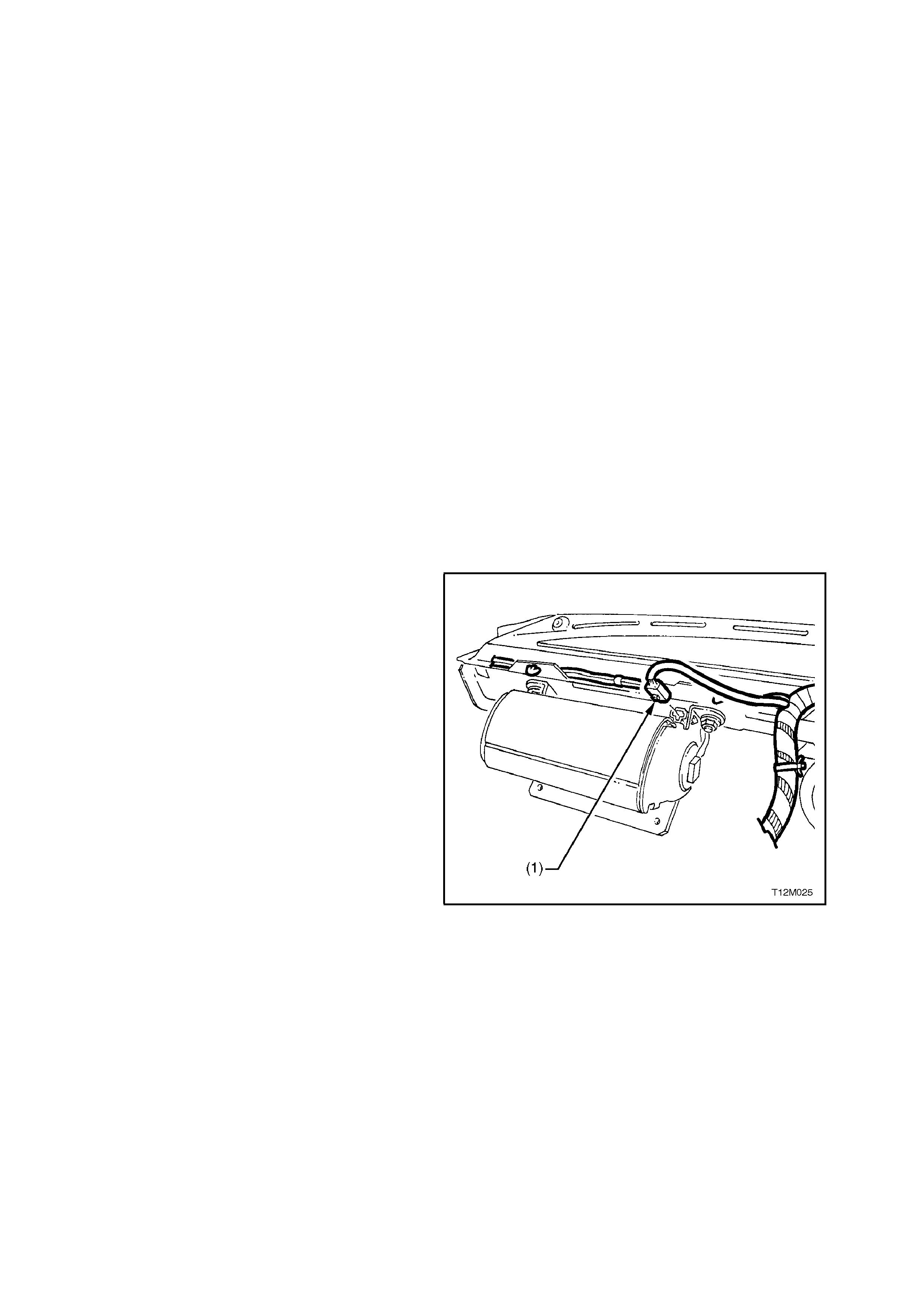
3. Disconnect the passenger’s air bag module
wiring harness connector, YB200 (1) from air
bag module assembly.
NOTE:
Do not disconnect the passenger’s air bag wiring
harness connector YB208.
Figure 12M-28
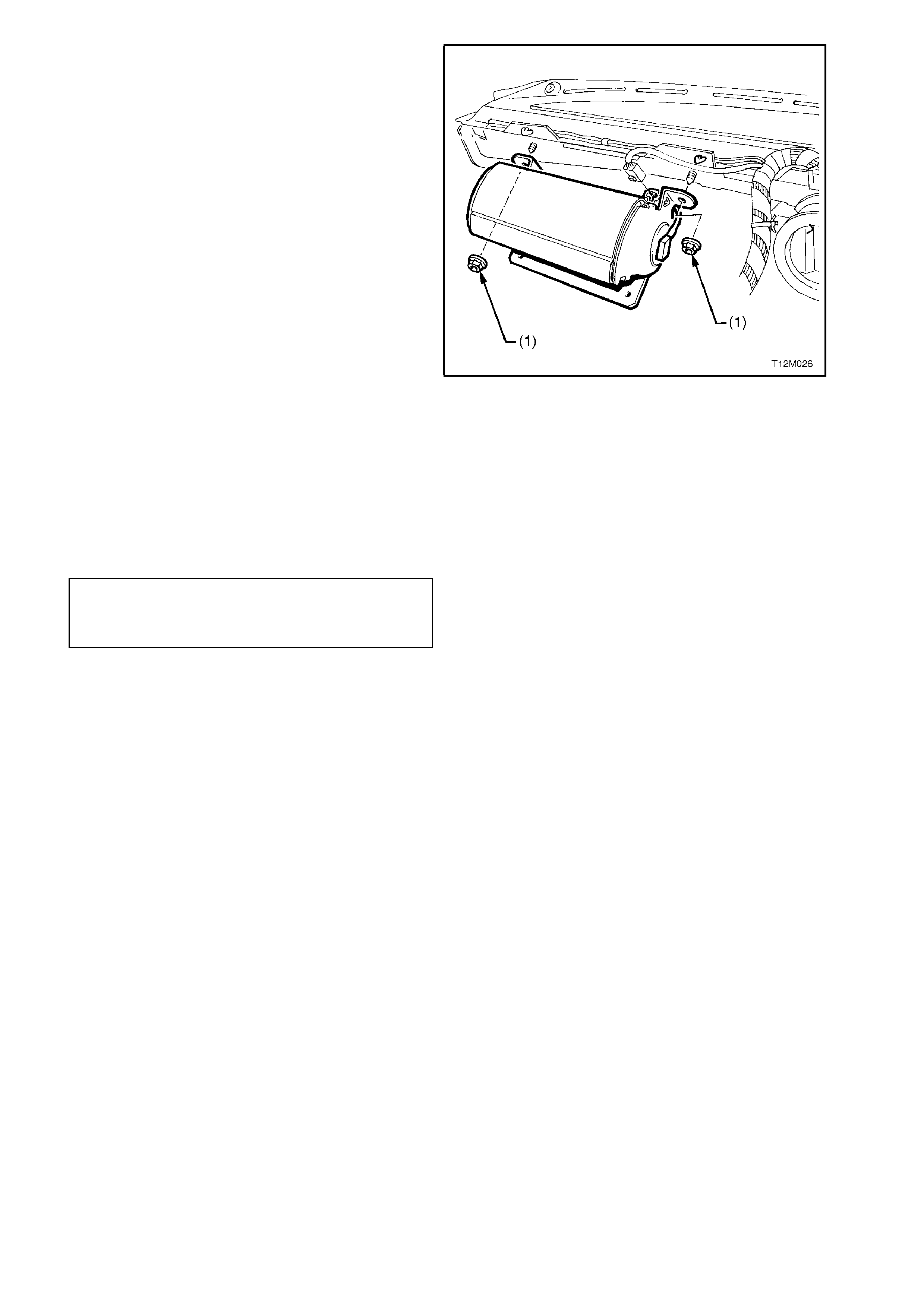
4. Remove passenger’s air bag inflator module
assem bly to dash panel attaching nuts (1) and
remove module assembly.
CAUTION:
When carrying a live (undeployed) front
passenger's air bag inflator module assembly,
make sure the bag opening is pointed away
from you. In case of an accidental deployment,
the bag will then deploy with minimal chance of
injury. When placing a liv e front passenger' s air
bag inflator module assembly on a bench or
other surface, always face with the air bag up,
away from the surface. Never rest the air bag
inflator module assembly with the air bag face
down. This is necessary so that a free space is
provided to allow the air bag to expand in the
unlikely event of accidental deployment.
Otherwise, personal injury may result. Figure 12M-29
REINSTALL
1. Assemble front passenger's air bag inflator
module onto position, over the dash panel
upper two mounting studs.
2. Install air bag inflator module to dash panel
attaching nuts and tighten to the correct
torque specification.
FRONT PASSENGER'S AIR BAG
MODULE TO DASH PANEL
ATTACHING NUT
TORQUE SPECIFICATION 15 - 25 Nm
3. Reinstall ins tr ument panel pad ass embly, ref er
to Section 1A3 INSTRUMENT PANEL AND
CONSOLE.
4. Enable the SRS, refer to 2.2 SYSTEM
DISABLING AND ENABLING PROCEDURE
in this Section.
5. Switch ignition on, and observe the SRS
warning lamp in the instrument cluster. The
warning lamp should be illuminated for
approximately 5 seconds.
During this period the SDM performs a wiring
and self check.
If no system faults are detected, the SRS
warning lamp will be switched off. If the
warning lamp remains illuminated and an
audible alarm chimes, or the warning lamp
illuminates 2 seconds after it was originally
switched off, an SRS fault is pr esent. Ref er to
3 DIAGNOSTICS in this Section to rectify
fault.

FRONT PASSENGER'S AIR BAG MODULE ASSEMBLY SCRAPPING PROCEDURE
During the course of a vehicle's useful life, certain situations may arise which will necessitate the disposal of a live
(undeployed) air bag inflator module assembly. The following information covers proper procedures for deploying a
live front passenger's air bag inflator module assembly.
CAUTION:
Failure to follow proper Supplemental Restraint System (SRS) air bag inflator module assembly disposal
procedures can result in air bag deployment which may cause personal injury. The undeployed air bag
inflator module contains substances that can cause severe illness or personal injury if the sealed container
is damaged during disposal.
In situations which require deployment of a live front passenger’s air bag inflator module assembly, deployment may
only be accomplished outside the vehicle. The passenger’s air bag inflator module assembly needs to be removed
so the SRS wiring harness with the capacitor built into the connector can be removed. Intentional deployment of the
passenger’s air bag inflator module can not be accomplished using a 12 volt DC supply with the capacitor in the
SRS circuit.
Front Passenger's Air bag Module Deployment Outside Vehicle
There may be some circumstance that require the deployment of the front passenger's air bag inflator module
assembly before a vehicle is to be returned to service. For example, situations in which the vehicle will be returned
to an owner after a functionally or cosmetically deficient front passenger's air bag inflator module assembly is
replaced. Deployment and disposal of a malfunctioning air bag inflator module is, of course, subject to any required
retention period.
For deployment of a live (undeployed) front passenger's air bag inflator module assembly outside the vehicle, the
deployment procedure must be followed exactly. ALWAYS wear safety glasses during the deployment procedure
until the assembly is removed. Before performing the procedure you should be familiar with servicing the SRS and
with proper handling of the front passenger's air bag inflator module assembly.
The following must be read fully and understood before performing the actual procedure.
The following procedure requires use of J38826-1 SRS deployment harness with adaptor E1992. Do not attempt
procedure without J38826-1 and E1992.
NOTE:
Adaptor E1992 was previously released as the deployment harness adaptor for the horn bar and air bag module
only. On VT Series Models, this harness adaptor is to be used for the deployment of all SRS components. If the
previously released passenger’s side air bag module, J38826-2 is used for deployment, the procedure will not work
as the SRS wiring harness capacitor would remain in the deployment circuit. If the SRS wiring harness capacitor
remains in the circuit, deployment using a 12 volt DC power supply is not possible.
CAUTION:
Failure to follow procedures in the order listed may result in personal injury. Never connect deployment
harness to any power source before connecting deployment harness to the front passenger's air bag
inflator module assembly. The deployment harness must remain shorted and not be connected to a power
source until the front passenger's air bag inflator module assembly is ready to be deployed. The module
will immediately deploy the air bag when a power source is connected to it. Wear safety glasses and gloves
throughout this entire deployment and disposal procedure .
1. Turn ignition switch OFF and put on safety glasses.
2. Inspect J38826-1 SRS deployment harness and adaptor E1992 for damage. If harness or adaptor is damaged,
discard and obtain a replacement.
3. Short two SRS deployment harness leads together by fully seating one banana plug into the other. SRS
deployment harness MUST remain shorted and NOT connected to a power source until the air bag is to be
deployed.
4. Connect the appropriate pigtail adaptor to the SRS deployment harness.
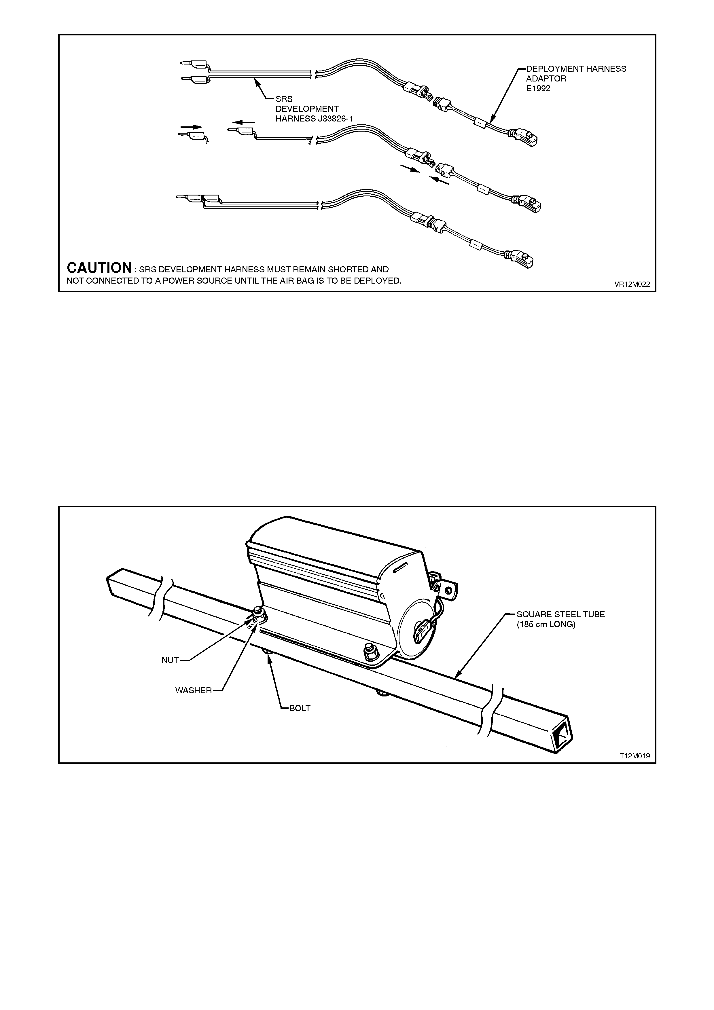
Figure 12M-30
5. Remove the front passenger's air bag inflator module assembly from vehicle, refer to
2.4 FRONT PASSENGER’S AIR BA G MODULE ASSEMBLY in this Section.
CAUTION:
When storing a live front passenger's side air bag inflator module assembly or when leaving a live
assembly unattended on a bench or other surface, always face the assembly with the air bag up and away
from the surface. This is necessary so that a free space is provided to allow the air bag to expand in the
unlikely event of accidental deployment. Failure to follow procedures may result in personal injury.
6. Using a 2 metre long square steel tube with suitable sized and positioned holes, bolt the tubing to the lower
bracket of the air bag inflator module assembly as shown in Fig. 12M-31.
7. Position two wheel and tyre assemblies on each end of the tubing as shown in Fig. 12M-32.
Figure 12M-31
8. Clear a spac e on the gr ound about 2 metres in
diameter where the assem bly is to deployed. A
paved, outdoor location where there is no
activity is preferred. If an outdoor location is
not available, a space on the workshop floor
where there is no activity and sufficient
ventilation is recommended. Ensure no loose
or flammable objects are within the
deployment area.
9. Ensure the front passenger's air bag inflator
module assembly is positioned with its air bag
facing up.
10. Stretch the SRS deployment harness and
adaptor from the front passenger's air bag
inflator module assembly to its full length.
Place a power source near the shorted end of
the SRS deployment harness. Recommended
application: 12 volts minimum, 2 amps
minimum (a vehicle battery is suggested).
Connect adaptor E1992 and SRS deployment
harness lead J38826-1 to the front
passenger's air bag inflator module assembly.
Figure 12M-32
CAUTION:
The deployment harness M UST remain shorted
and NOT conn ected to a pow er source until th e
air bag is to be deployed. The module will
immediately deploy the air bag when a power
source is connected to it.
Figure 12M-33
12. Verify that the area around the front
passenger's air bag inflator module assembly
is clear of all people and loose or flammable
objects.
13. Verify that the passenger’s air bag inflator
module assembly is resting with air bag
facing up.
14. Notify all people in the immediate area that
you intend to deploy the air bag inflator
module assembly. The deployment will be
accompanied by an explosion which may
startle the uninformed.
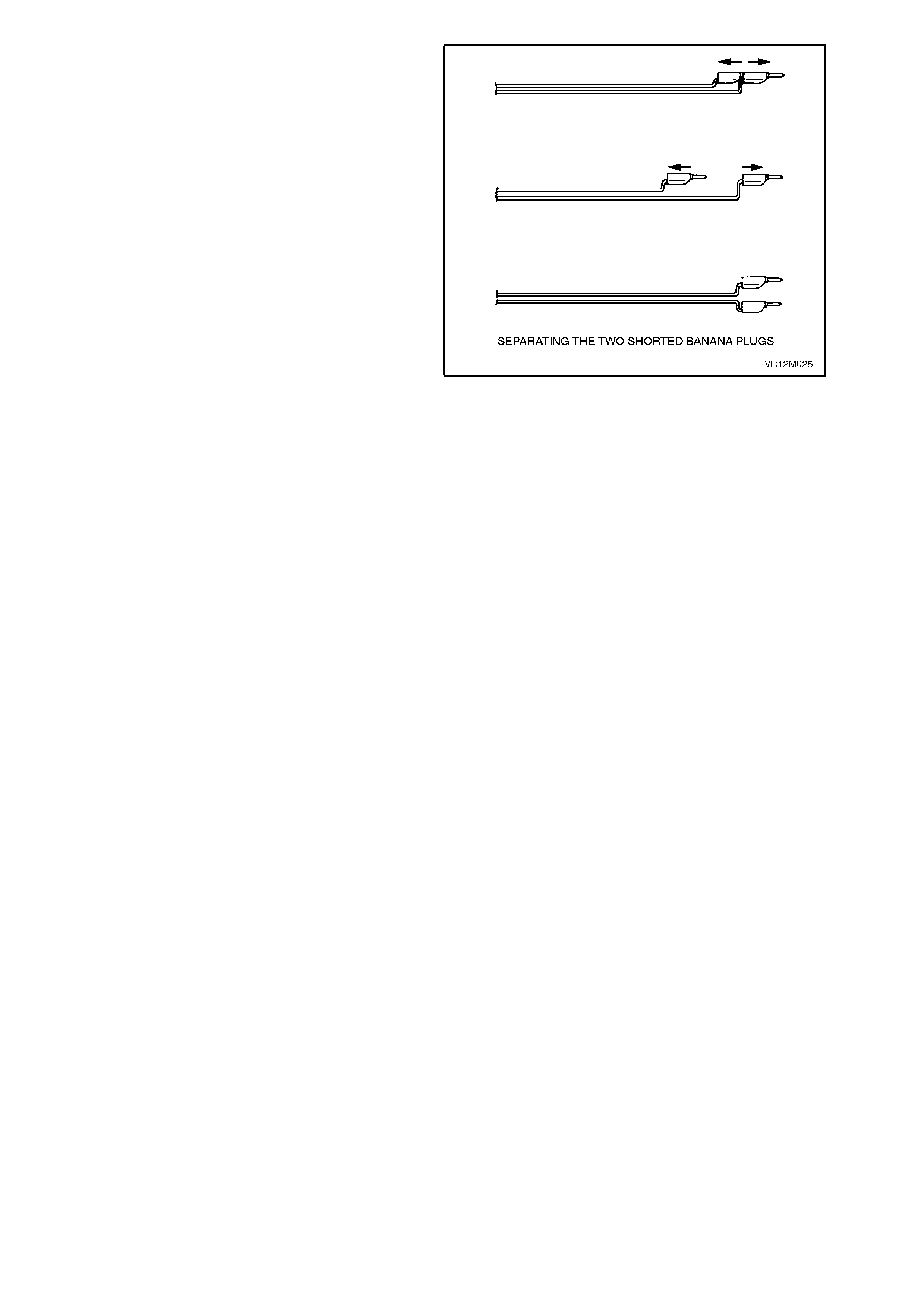
15. Separate the two banana plugs on the SRS
deployment harness.
NOTE:
1. When the air bag deploys, the rapid gas
expansion will create an ex plos ion. Notif y all people
in the immediate area that you intend to deploy the
module.
NOTE:
2. When the air bag deploys, the assembly may
jump vertically. This is a normal reaction of the
module to the force of the rapid gas expansion
inside the air bag.
CAUTION:
The deployment harness MUST remain shorted
and NOT connected t o a pow er sou rce until the
air bag is to be deployed. The module will
immediately deploy the air bag when a power
source is connected to it. Connecting the
deployment harness to the power source
should always be the last step prior to
deployment of the air bag. Failure to follow
procedures in the order listed may result in
personal injury.
Figure 12M-34
16. Connect SRS deployment harness leads to
the power source to immediately deploy the
front passenger's air bag inflator module
assembly.
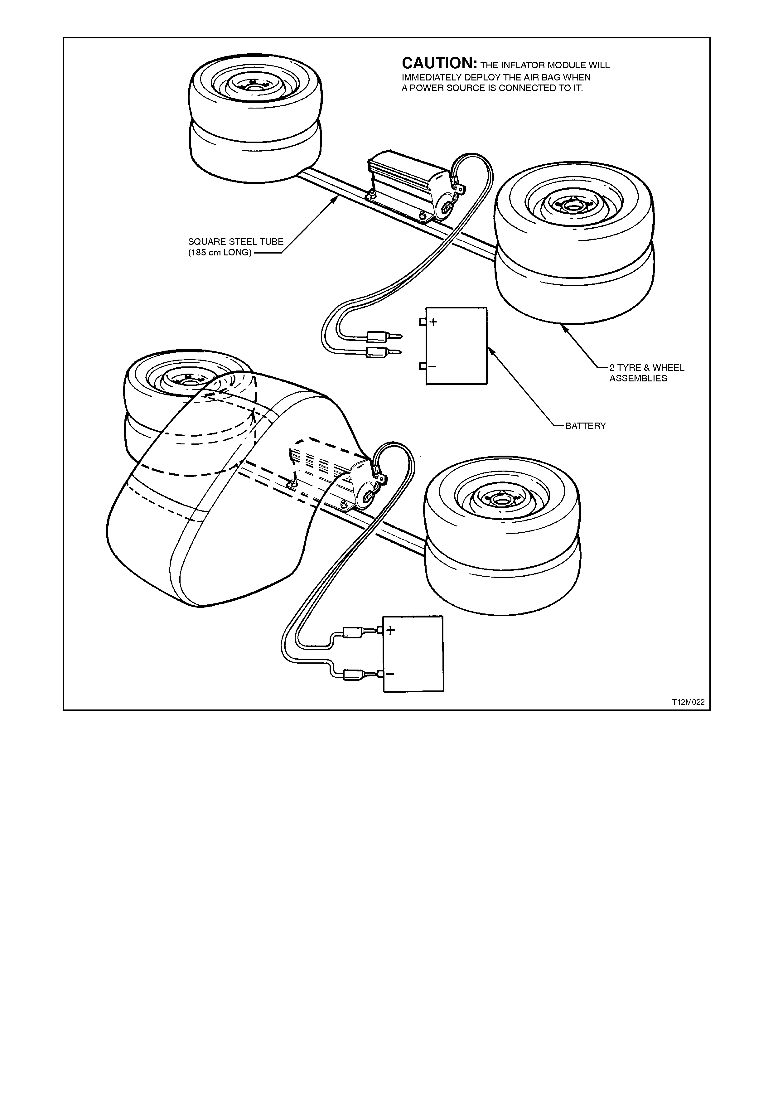
Figure 12M-35
17. Disconnect the SRS deployment har ness f rom
the power source.
18. Short the two SRS deployment harness leads
together by fully seating one banana plug into
the other.

19. Ensure that you are wearing safety glasses
and gloves to protect your eyes and hands
from pos sible ir ritation and heat when handling
the deployed horn bar and air bag inflator
module assembly.
After the air bag inflator module assem bly has
been deployed, the surf ace of the air bag m ay
contain a powdery residue. This powder
consists primarily of corn starch (used to
lubricate the bag as it inflates) and by -products
of the chemical reaction. Sodium hydroxide
dust is produced as a by-product of the
deployment reaction. The sodium hydroxide
then quickly reacts with the atmospheric
moisture and is converted to sodium
carbonate and sodium bicarbonate (baking
soda). Therefore, it is unlikely that sodium
hydroxide will be present after deployment. As
a precaution, however, gloves and safety
glasses are recommended to prevent any
possible irritation of the skin or eyes. Figure 12M-36
CAUTION:
Safety precautions must be observed when
handling a deployed horn bar and air bag
inflator module assembly. After deployment,
the metal surfaces of the module will be very
hot. Do not touch these metal areas of the
module for about 10 minutes after deployment.
Do not p lace the deployed ho rn bar and air bag
inflator module assembly near any flammable
objects. If the deployed horn bar and air bag
inflator module assembly must be moved
before it has cooled, wear gloves and handle by
the air bag or the horn bar.
20. Disconnect the adaptor E1992 from the
module as soon as possible af ter deploym ent.
This will prevent damage to the adaptor or
SRS deployment harness due to possible
contact with the hot module canister. The
adaptor and SRS deployment harness are
designed to be reused. They should, however,
be inspected for damage after each
deployment and replaced if necessary.
21. Dispose of the deployed air bag assembly
through normal refuse channels after it has
cooled for at least 10 minutes.
22. Wash your hands with mild soap and water
afterward.
Deployed Module Handling
After the module has been deployed, the surface of
the air bag may contain a powdery residue. This
powder consists primarily of corn starch (used to
lubricate the bag as it inflates) and by-products of
the chemical reaction. Sodium hydroxide dust is
produced as a by-product of the deployment
reaction. T he sodium hydroxide then quick ly r eacts
with atmospheric moisture and is converted to
sodium carbonate and sodium bicarbonate (baking
soda). Therefore, it is unlikely that sodium
hydroxide will be present after deployment. As a
precaution, however, gloves and s af ety glasses are
recommended to prevent any possible irritation of
the skin or eyes.
2.5 SEAT BELT BUCKLE AND PRE-TENSIONER ASSEMBLY
REMOVE AND REINSTALL
As the seat belt pre-tensioner assembly is part of the front seat belt buckle assembly, refer to Section 1A7 SEAT
AND SEAT BELT ASSEMBLIES for all Service Operations related to the removal and reinstallation of pre-tensioner
assembly.
PRE-TENSIONER ASSEMBLY SCRAPPING PROCEDURE
During the course of a vehicle's useful life, certain situations may arise which will necessitate the disposal of a live
(undeployed) pre-tensioner assembly. The following information covers proper procedures for deploying a live pre-
tensioner assembly.
CAUTION:
Failure to follow proper Supplemental Restraint System (SRS) pr e-tensioner assembly disposal procedures
can result in pre-tensioner deployment which may ca use personal injury.
In situations which require deployment of a live pre-tensioner assembly, deployment may only be accomplished
outside the vehicle. The pre-tensioner needs to be removed and the SRS wiring harness with the capacitor built into
the connector removed. Intentional deployment of the pre-tensioner assembly can not be accomplished using a 12
volt DC supply with the capacitor in the SRS circuit.
Pre-tensioner Assembly Deployment Outside Vehicle
For deployment of a live (undeployed) pre-tensioner assembly outside the vehicle, the deployment procedure must
be followed exactly. ALWAYS wear safety glasses during this deployment procedure. Before performing the
procedure you should be familiar with servicing the SRS and with proper handling of the pre-tensioner assembly.
The following must be read fully and understood before performing the actual procedure.
The following procedure requires use of J38826-1 SRS deployment harness with adaptor E1992. Do not attempt
procedure without J38826-1 and E1992.
NOTE:
Adaptor E1992 was previously released as the deployment harness adaptor for the horn bar and air bag module
only. On VT Series Models, this harness adaptor is to be used for the deployment of all SRS components.
CAUTION:
Failure to follow procedures in the order listed may result in personal injury. Never connect deployment
harness to any power source before connecting deployment harness to the pre-tensioner assembly. The
deployment harness must remain shorted and not be connected to a power source until the pre-tensioner
assembly is ready to be deployed. The pre-tensioner will deploy immediately a power source is connected
to it. Wear safety glasses and gloves throughout this entire deployment and disposal procedure.
1. Turn ignition switch OFF and put on safety glasses.
2. Inspect J38826-1 SRS deployment harness and adaptor E1992 for damage. If harness or adaptor is damaged,
discard and obtain a replacement.
3. Short two SRS deployment harness leads together by fully seating one banana plug into the other. SRS
deployment harness MUST remain shorted and NOT connected to a power source until the pre-tensioner is to
be deployed.
4. Connect the deployment harness adaptor (E1992) to the SRS deployment harness (J38826-1).
Figure 12M-37
Techline
5. Remove the appropriate pre-tensioner
assem bly from the vehicle, r efer to Section 1A7
SEAT AND SEAT BELT ASSEMBLY.
NOTE:
Leave pre-tensioner to s eat assem bly retaining bolt
installed in the pre-tensioner once removed from
the seat assembly.
6. Clear a space on the ground about 2 metres in
diameter where the pre-tens ioner as sem bly is to
deployed. A paved, outdoor location where there
is no activity is preferred. If an outdoor location
is not available, a space on the workshop floor
where there is no activity and sufficient
ventilation is rec omm ended. Ensure no loose or
flammable objects are within the deployment
area.
7. Stretch the SRS deployment harness and
adaptor from the pre-tensioner assembly to its
full length.
8. Connect adaptor E1992 and SRS deployment
harness lead J38826-1 to the pre-tensioner
assembly.
CAUTION:
The deployment harness MUST remain shorted
and NOT connected to a power source until the
pre-tensioner as sembly is to be deployed. The pr e-
tensioner assem bly will im mediately deploy when a
power source is connected to it.
9. Position a wheel and tyre assembly over the
pre-tensioner assembly, refer to Fig. 12M-39.
Figure 12M-38
Figure 12M-39
10. Place a power sourc e near the shorted end of
the SRS deployment harness. Recommended
application: 12 volts minimum, 2 amps
minimum (a vehicle battery is suggested).
11. Verify that the area around the pre-tensioner
assembly is clear of all people and loose or
flammable objects.
12. Notify all people in the immediate area that
you intend to deploy the pre-tensioner
assembly. The deployment will be
accompanied by an explosion which may
startle the uninformed.
15. Separate the two banana plugs on the SRS
deployment harness.
NOTE:
When the pre-tensioner deploys, the rapid gas
expansion will create an ex plos ion. Notif y all people
in the immediate area that you intend to deploy the
pre-tensioner.
CAUTION:
The deployment harness MUST remain shorted
and NOT connected t o a pow er sou rce until the
pre-tensioner is to be deployed. The pre-
tensioner will immediately deploy when a
power source is connected to it. Connecting
the deployment harness to the power source
should always be the last step prior to
deployment of the pre-tensioner. Failure to
follow procedures in the order listed may result
in personal injury. Figure 12M-40
16. Connect SRS deployment harness leads to
the power source to immediately deploy the
pre-tensioner assembly.
17. Disconnect the SRS deployment har ness f rom
the power source.
18. Short the two SRS deployment harness leads
together by fully seating one banana plug into
the other.
19. To prevent damage to the adaptor or SRS
deployment harness, disconnect the adaptor
E1992 from the pre-tensioner as soon as
possible after deployment. The adaptor and
SRS deployment harness are designed to be
reused. They should, however, be inspected
for damage after each deployment and
replaced if necessary.
20. Dispose of the deployed pre-tensioner
assembly through normal refuse channels.
2.6 CLOCK SPRING COIL
IMPORTANT:
Absolutely no wire, connector or terminal repairs
are to be attempted on the clock spring coil If the
clock spring coil is damage in any way, REPLACE
IT.
REMOVE
1. Disable the SRS, refer to
2.2 SYSTEM DISABLING AND ENABLING
PROCEDURE in this Section.
2. Remove horn bar and air bag inflator module,
refer to 2.3 HORN BAR AND AIR BAG
MODULE ASSEMBLY in this Section.
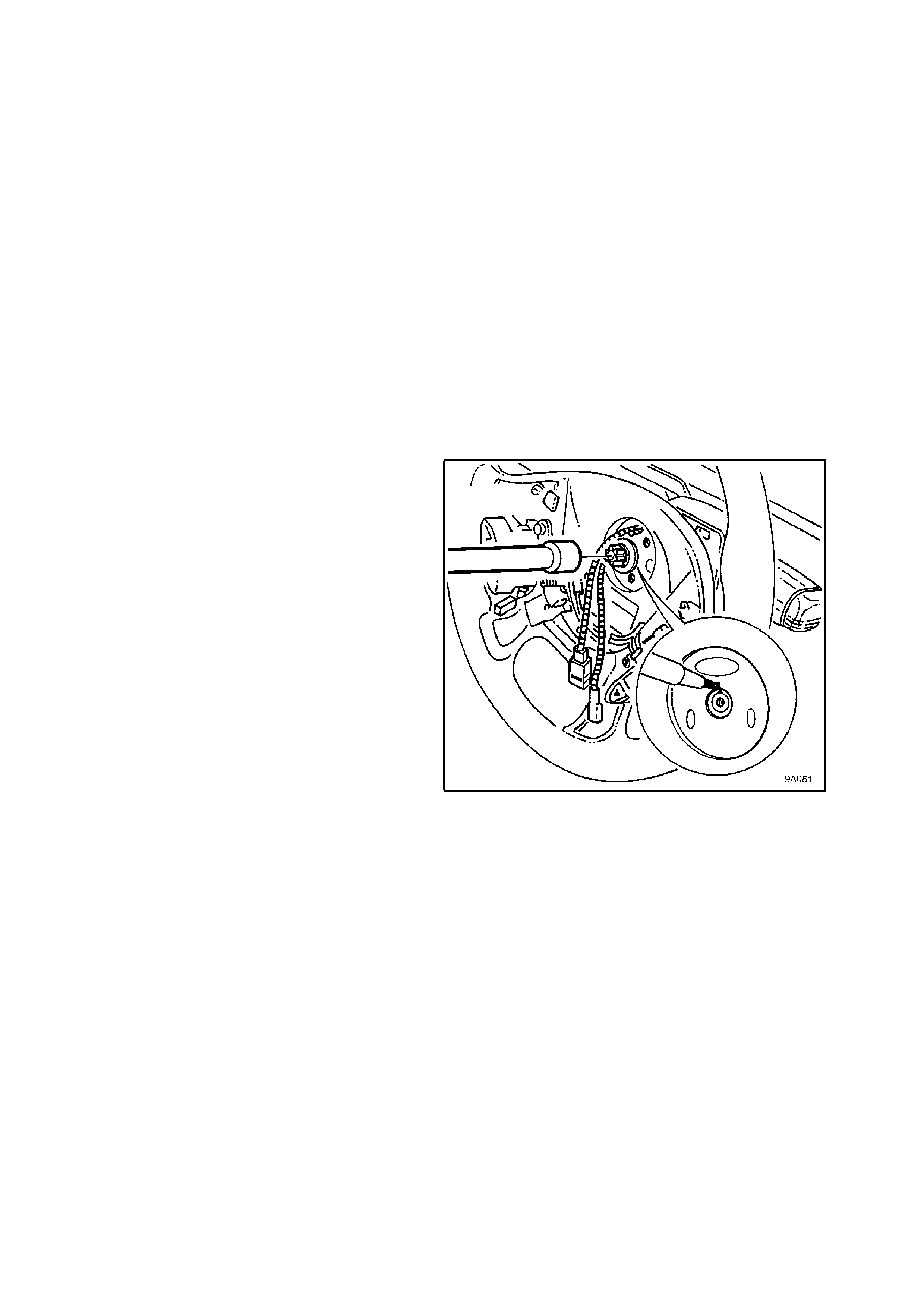
3. Ensure the front wheels and the steering
wheel are in the straight ahead position and
remove keys from ignition switch.
NOTE 1: This is important to ensure that clock
spring coil is locked when the steering wheel is
removed to prevent the steering shaft from being
rotated.
4. To aid the installation of the steering wheel to
it’s original position, sc r ibe an aligning mark on
the steering wheel centre section and steering
shaft. A felt tipped pen could also be used.
NOTE 2:
Do not use a centre punch for this operation.
5. Using a commercially available Torx E20
socket, remove the steering wheel retaining
bolt.
6. Remove the steering wheel from the steering
shaft splines and feed the clock spring coil
wiring and connectors through the steering
wheel aperture.
NOTE 3:
When the steering wheel is removed, check that
the green coloured tang has engaged the inner
clock spring coil member to lock it in the centralised
position.
NOTE 4:
With the increased diameter of the steering shaft
and the angle of the locating bevel, it is not usually
necessary to require a puller to remove the steering
wheel. However, if a puller is required, refer to
Section 9A STEERING.
Figure 12M-41
7. Lower instrument panel right hand cover
assembly (fuse panel cover) by grasping the
top edge on either side of the steering colum n
with the finger tips and pulling the top edge
out, to free the retaining lugs from the clips.
8. Release steering column height adjuster,
completely lower steering column and leave
lever in the release position.
9. Remove the upper steering column cover by
applying a small amount of pressure on the
lower steering column cover (pushing towards
instrum ent cluster ) while lifting the upper cover
upwards and rearwards.
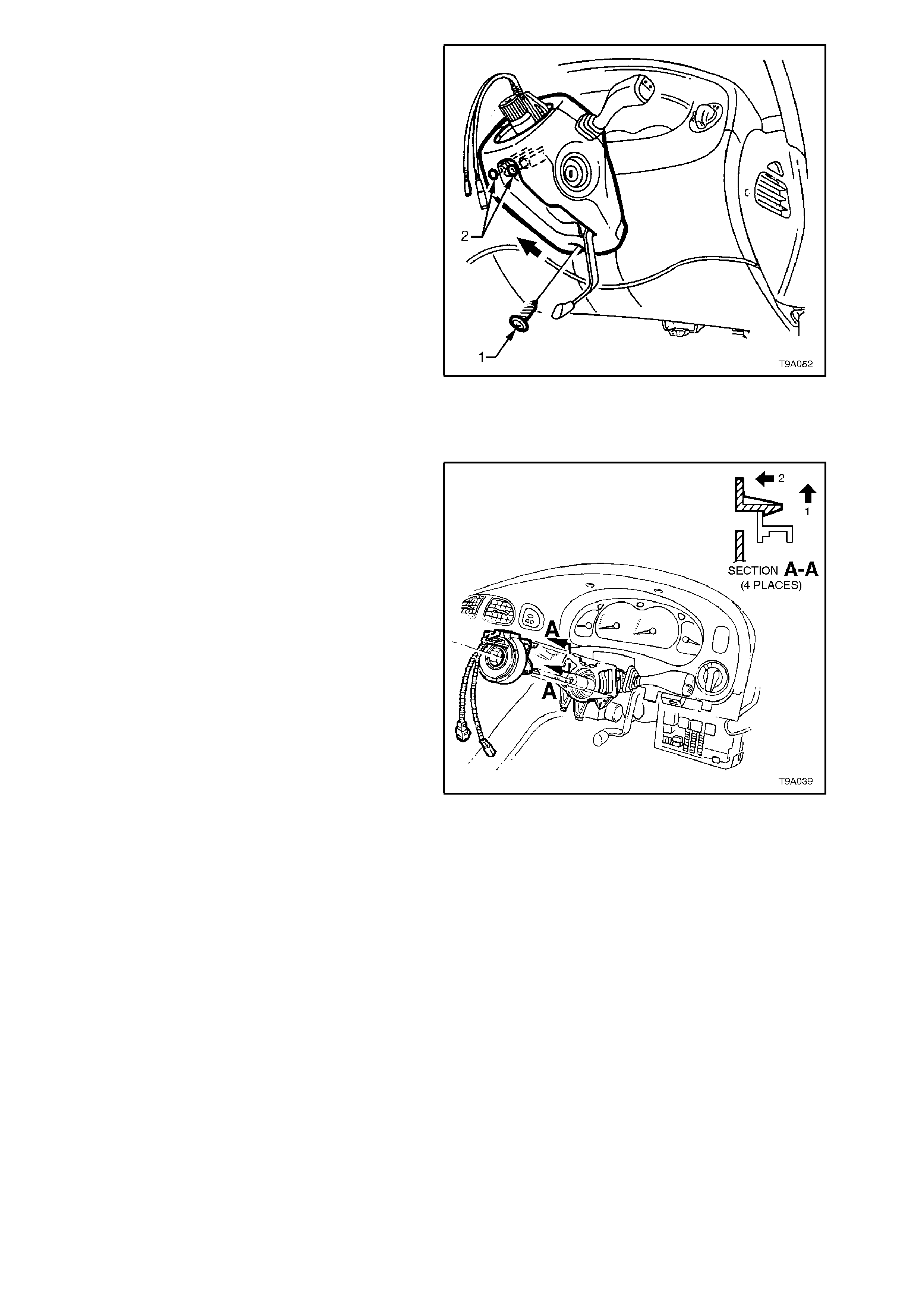
10. Remove screw (1) securing the lower cover to
the steering column.
11. Push the lower steering column cover up
towards the top of the steering c olumn (arr ow)
to release the two retaining tangs (2) on the
steering column, refer to Fig. 12M-42.
12. While feeding the remote coded key reader
outer surround from the lower cover, remove
the lower steering column cover.
Figure 12M-42
13. Disengage the two top locking tangs on the
clock spring coil assembly by lifting first in
direction (1) then pulling the clock spring coil
assem bly in direction (2), ref er to Fig. 12M-43.
Repeat for the lower two tangs, then remove
clock spring coil assembly from the steering
column.
Figure 12M-43
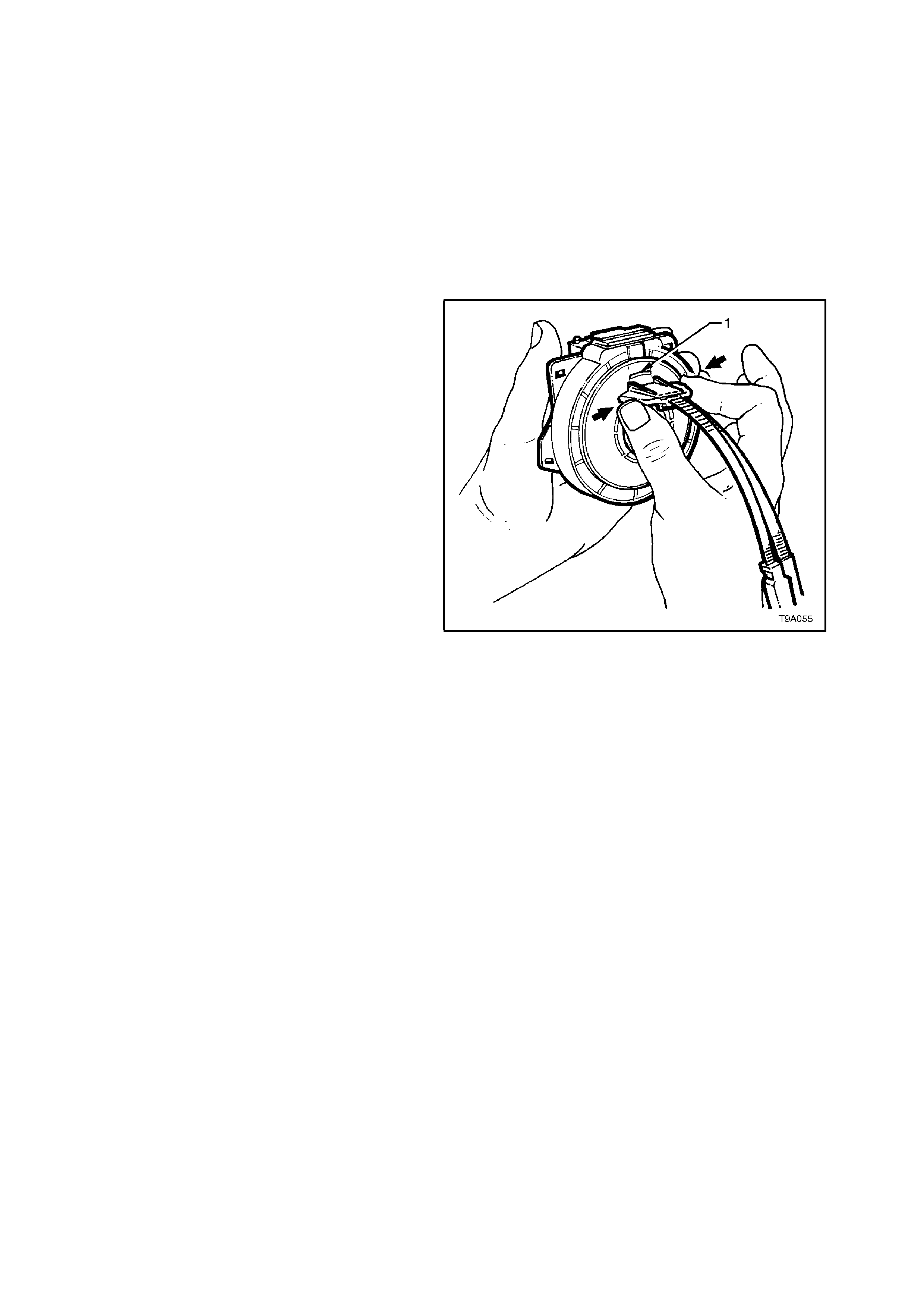
CENTRING THE CLOCK SPRING COIL
NOTE:
The following procedure must be followed
when reusing a clock spring coil that has been
removed from a steering column without the
steering wheel or clock spring coil being
centred.
1. Ensure that steering gear is in centralised
position before installing the clock spring coil
assembly, otherwise irreparable damage to
the clock spring coil may result. Refer to
Section 9A STEERING for details on
centralising the steering gear.
2. Hold the clock spr ing coil outer hous ing by one
hand while holding each of the two locking
lugs inward with the other hand, refer to Fig.
12M-44.
Rotate the inner member of the clock spring
coil in a clockwise direction until a mechanical
stop is felt.
While still holding the two locking lugs as
before, rotate the inner member of the clock
spring coil in an anti-clockwise direction for
approximately 2.5 turns, until the green
indexing tab (1) is s een in the upper window of
the clockspring coil assembly.
Release the lock ing lugs and the inner rotor of
the clock spring coil assembly should now be
locked to the outer member with the clock
spring coil in the centralised position.
Figure 12M-44

REINSTALL
Installation of the c lock spr ing coil is the reverse of
removal procedures, noting the following points:
1. Ensure that steering gear is in centralised
position before installing the clock spring coil
assembly, otherwise irreversible damage to
the clock spring coil may result. Refer to
Section 9A STEERING for details on
centralising the steering gear.
2. With the clock spring coil assembly locked in
the centralised position, install clock spring
coil ass embly over the end of steer ing c olumn,
indexing the lower locating pins on the clock
spring coil with the matching holes in the
switch housing.
NOTE:
If the clock spring coil assembly was removed
without being centred, refer to the previous service
procedure; CENTRING THE CLOCK SPRING
COIL in this Section.
3. Push the clock spring coil assembly onto the
switch housing until the f our loc king tangs f ully
engage.
4. Install the steering wheel to steering shaft,
aligning marks made prior to removal and
ensuring the drive tang of the clock spring coil
is aligned with the steering wheel aperture.
NOTE:
This action automatically releases the clock spring
coil centralising lock.
5. After cleaning the threadlock residue from the
bolt threads, apply Loctite 242 or equivalent, to
Holden Specific ation HN 1256 Clas s 2, Type 2
to bolt threads. Install and tighten steering
wheel retaining bolt to the correct torque
specification using a commercially available
Torx E20 socket.
STEERING WHEEL RETAINING 40 - 50
BOLT TORQUE SPECIFICATION Nm
6. Reinstall horn bar and air bag inflator m odule,
refer to 2.3 HORN BAR AND AIR BAG
MODULE ASSEMBLY in this Section.
7. Enable the SRS, refer to 2.2 SYSTEM
DISABLING AND ENABLING PROCEDURE
in this Section.
8. Switch ignition on, and observe the SRS
warning lamp in the instrument cluster. The
warning lamp should be illuminated for
approximately 5 seconds. During this per iod of
time the SDM performs a wiring and self
check.
If no system faults are detected, the SRS
warning lamp will be switched off. If the
warning lamp remains illuminated and an
audible alarm chimes, or the warning lamp
illuminates 2 seconds after it was originally
switched off, an SRS fault is pr esent. Ref er to
3 DIAGNOSTICS in this Section to rectify
fault.
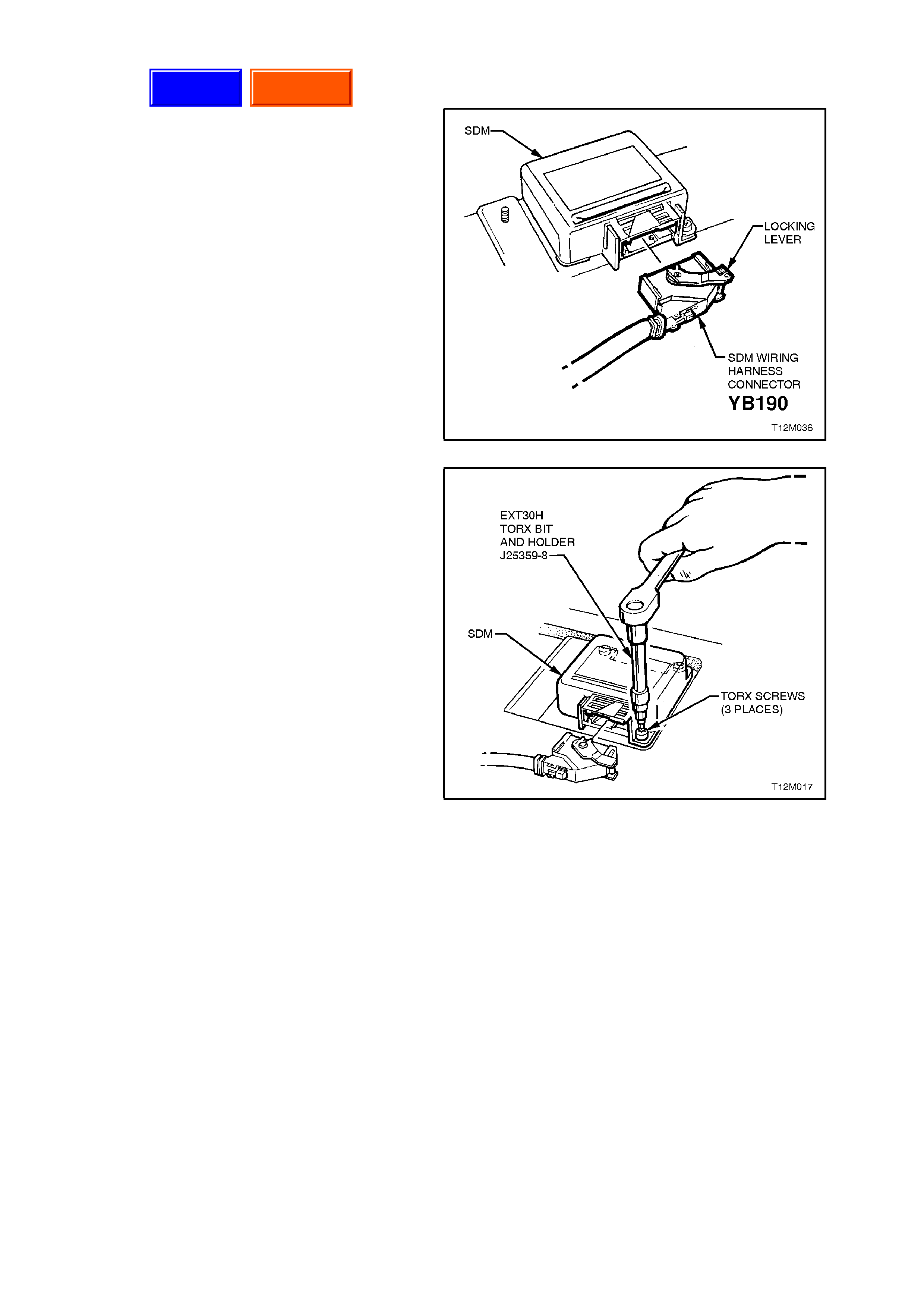
2.7 SE NS I NG AND DIAGNOSTIC MODULE (SDM)
REMOVE
1. Disable the SRS, refer to
2.2 SYSTEM DISABLING AND ENABLING
PROCEDURE in this Section.
2. Rem ove the centre console as sembly, refer to
Section 1A3 INSTRUMENT PANEL AND
CONSOLE.
3. Lift up SRS wiring harness connector locking
lever and pull harness connector out of SDM.
Figure 12M-45
4. Using a number T30H Torx bit, Tool No.
ETX30H and suitable holder such as Tool No.
J25359-8, loosen and remove SDM to floor
attaching screws.
5. Remove SDM.
Figure 12M-46
Campaign
Techline

REINSTALL
Installation of the SDM is the reverse of removal
procedures, noting the following points:
1. Ensure that the directional arrow on the SDM
identification label is pointing towards the front
of the vehicle.
2. Using a number T30H Torx bit, Tool No.
ETX 30H and suitable holder such as T ool No.
J25359-8, tighten SDM to floor attaching
screws to the correct torque specification.
NOTE:
The main earth connection for the SDM is via
the attach ing screw s to t he f loor. T hese screw s
must make good contact with the floor and not
be overtightened.
SENSING AND DIAGNOSTIC
MODULE TO FLOOR ATTACHING
SCREW TORQUE SPECIFICATION 7 - 11 Nm
3. Connect the SRS wiring harness connector,
ensuring that connector is fully seated into
SDM module and the locking lever is locked
down.
4. Enable the SRS, refer to
2.2 SYSTEM DISABLING AND ENABLING
PROCEDURE in this Section.
5. Switch ignition on, and observe the SRS
warning lamp in the instrument cluster. The
warning lamp should be illuminated for
approximately 5 seconds. During this period
the SDM performs a wiring and self check.
If no system faults are detected, the SRS
warning lamp will be switched off. If the
warning lamp remains illuminated and an
audible alarm chimes, or the warning lamp
illuminates 2 seconds after it was originally
switched off, an SRS fault is pr esent. Ref er to
3 DIAGNOSTICS in this Section to rectify
fault.

2.8 SRS WIRING REPAIR
Special wiring repair procedures have been
developed for use on the Supplemental Restraint
System (SRS) due to the sensitive nature of the
circuitry. These specific procedures and
instructions must be followed when working with
SRS wiring, and wiring components (such as
connectors and terminals). Terminal Repair Kit,
Tool No. J 38125-A contains s pecial 'sealed s plices '
for use in repairing SRS wiring.
A special crimping tool, heat torch, and instruction
manual for these splices are also included in the
kit.
Two critical features of the sealed splices are a
special heat shrink sleeve with sealing adhesive to
produce an environmentally sealed splice and a
cross hatched (knurled) core crimp to provide
necessary contact integrity for the sensitive, low
energy circuits.
Terminal Repair Kit J38125-A also serves as a
generic terminal repair kit. The kit contains a large
sampling of common GM electrical terminals and
the correct tools to attach them to wires and
rem ove them fr om connec tor s. The terminals in the
kit are NOT to be used to replace damaged
terminals in the SRS wiring.
THE FOLLOWING PROCEDURES FOR
REPAIRING SRS WIRING IS THE ONLY
RECOMMENDED AND APPROVED REPAIR
METHOD. NO ALTERNATIVE REPAIR
METHODS ARE TO BE USED.
SRS WIRE PIGTAIL REPAIR
Ensure to read and understand the instruction
repair manual before conducting SRS wiring
repairs using this kit.
If a wiring pigtail (a wire or wires attached directly
to the device, not by a connector) is damaged, the
entire component (with pigtail) must be replaced.
An examples of a 'pigtail' component is the clock
spring coil. Absolutely no wire, connector or
terminal repairs are to be attempted on the clock
sprin g coil. REPLACE THE COMPONENT.
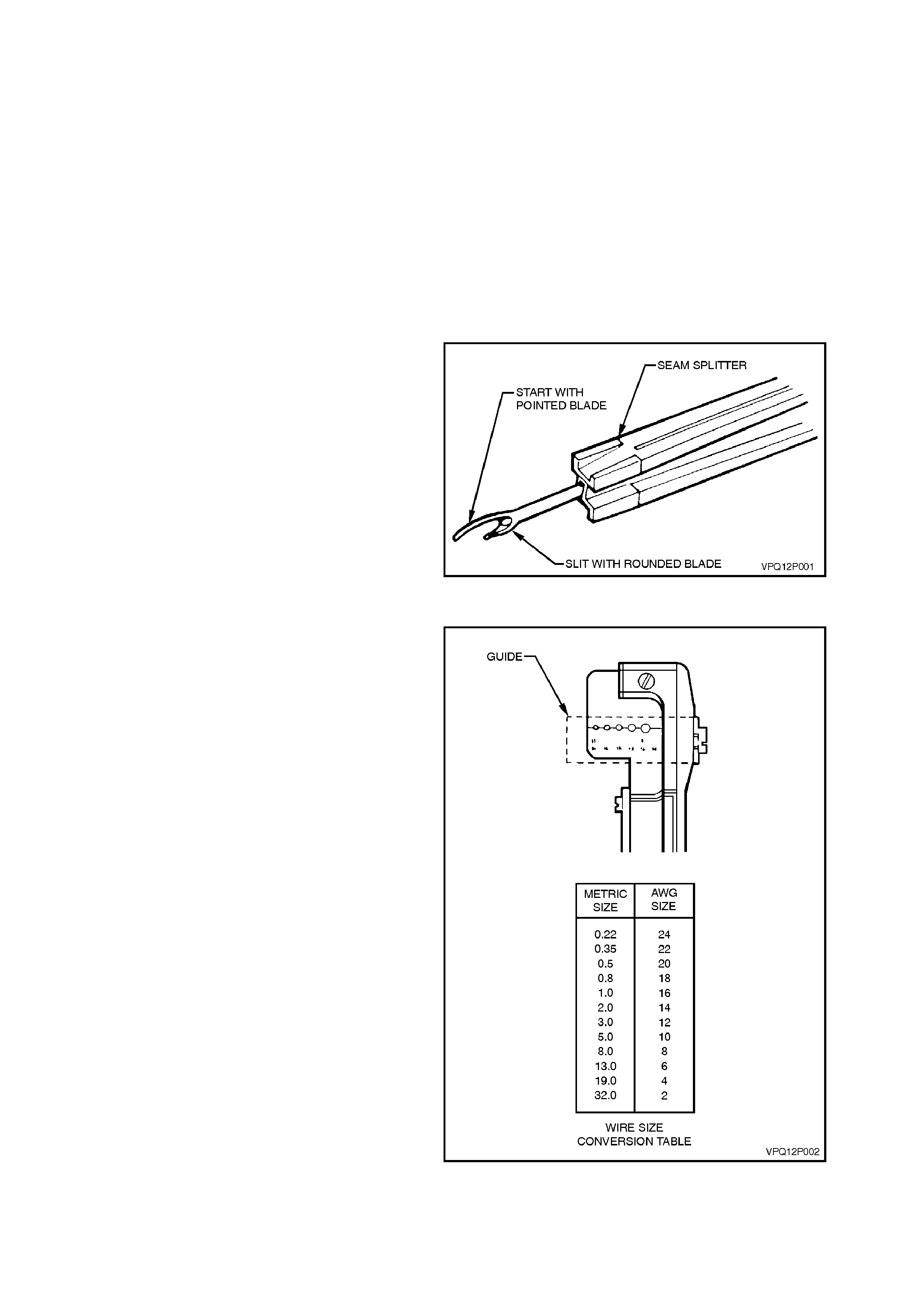
SRS WIRING REPAIR
NOTE:
Before conducting SRS wiring repair, disable
the SRS, refer to 2.2 SYST EM DISABLING AND
ENABLING PROCEDURE in this Section.
If any wiring, except the pigtail, is damaged, the
wiring should be repaired by splicing in a new
section of wire of the same gauge size (0.5, 0.8,
1.0, etc.). The splices and Splice Crimping Tool
from Terminal Repair Kit J38125-A must be used
for these repairs.
The following wiring repair procedures must be
used to ensure the integrity of the sealed splice
application.
Step One: Open the Harness
If the harness is taped, remove the tape. T o avoid
wire insulation damage use a sewing 'seam splitter
(available from sewing supply stores) to cut open
the main wiring harness (for additional details of
seam splitter, refer to Section 12P WIRING
DIAGRAMS). The crimp and sealed splice sleeves
may be used on all types of ins ulation except tefzel
and coaxial and m ay only be us ed to f or m a one-to-
one splice.
Figure 12M-47
Step Two: Cut the Wire
Begin by cutting as little wire off the harness as
possible. You may need the extra length of wire
later. You may decide to cut more wire to change
the location of a splice. You may have to adjust
splice locations to be certain that each splice is at
least 40 mm away from other splices, harness
branches, or connectors.
NOTE:
Do not nick or cut any copper stra nds as this
could limit the current-carrying capabilities of
the wire.
Step Three: Strip the Insulation
NOTE:
The following procedures must be followed in
the order listed. If wire strands are damaged,
the procedure must be repeated until a clean
strip with all wire strands intact is obtained.
If it is necessary to add a length of wire to the
existing harness, be certain to use the same size
as the original wire.
To find the correct wire size either find the wire size
on the SRS wiring diagram or measure wire size
with a wire gauge.
If unsure about the wire size, begin with the largest
opening in the wire stripper and work down until
achieving a clean strip of the insulation. Strip
approximately 7.5 mm of insulation from each wire
to be spliced. Be careful to avoid nicking or cutting
any of the strands. Check the stripped wire for
nicks or cut strands. If the wire is damaged, repeat
this procedure after removing the damaged
section.
Figure 12M-48
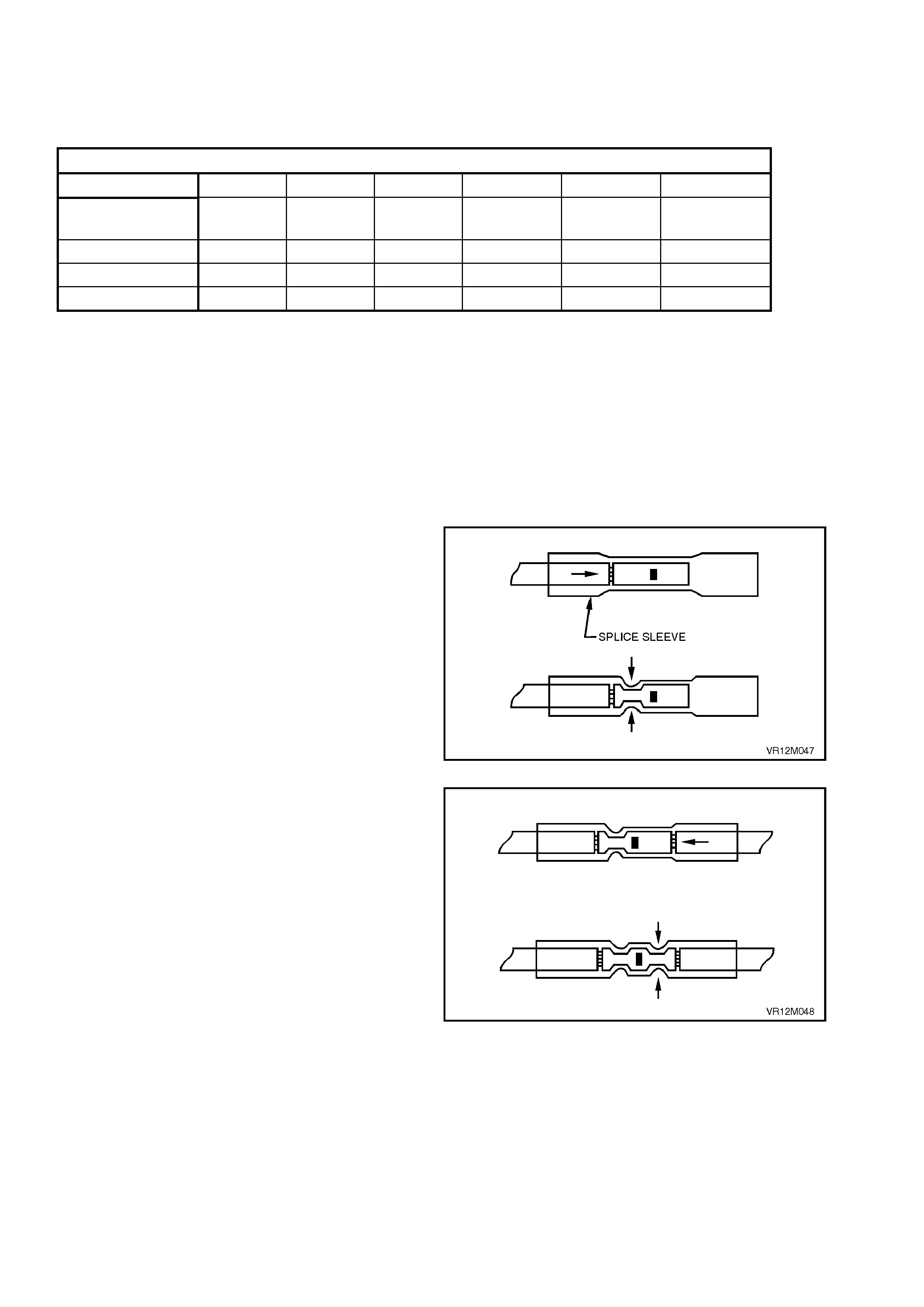
Step Four: Se lect and Position the Splice Sleeve
Select the proper sealed s plice sleeve acc ording to
wire size. The splice sleeves and tool nests are
colour coded (refer to following chart).
WIRE SIZE (mm)
0.5 0.8 1.0 2.0 3.0 5.0
SPLICE CRIMP
PART No IN KIT.
12089189 SALMON SALMON
12089190 BLUE BLUE
12089191 YELLOW YELLOW
Using the Splice Crimp T ool (part of kit J38125-A),
position the splice sleeve in the proper colour nest
of the hand crimp tool. Place the splice sleeve in
the nest so that the cr imp f alls midway between the
end of the barrel and the stop.
The s leeve has a stop in the m iddle of the barrel to
prevent the wire from going f urther. Clos e the hand
crimper handles slightly to hold the splice sleeve
firmly in the proper nest.
Step Five: Insert Wires Into Splice Sleeve and Crimp
Insert the wire into the splice sleeve until it hits the
barrel stop and close the handles of the Crim p T ool
tightly until the crimper handles open when
released. The crimper handles will not open until
the proper amount of pressure is applied to the
splice sleeve.
Figure 12M-49
Gently tug both ends of the wire to ensure that
crimp is secu re.
Repeat Steps 4 and 5 for opposite end of the
splice.
Figure 12M-50
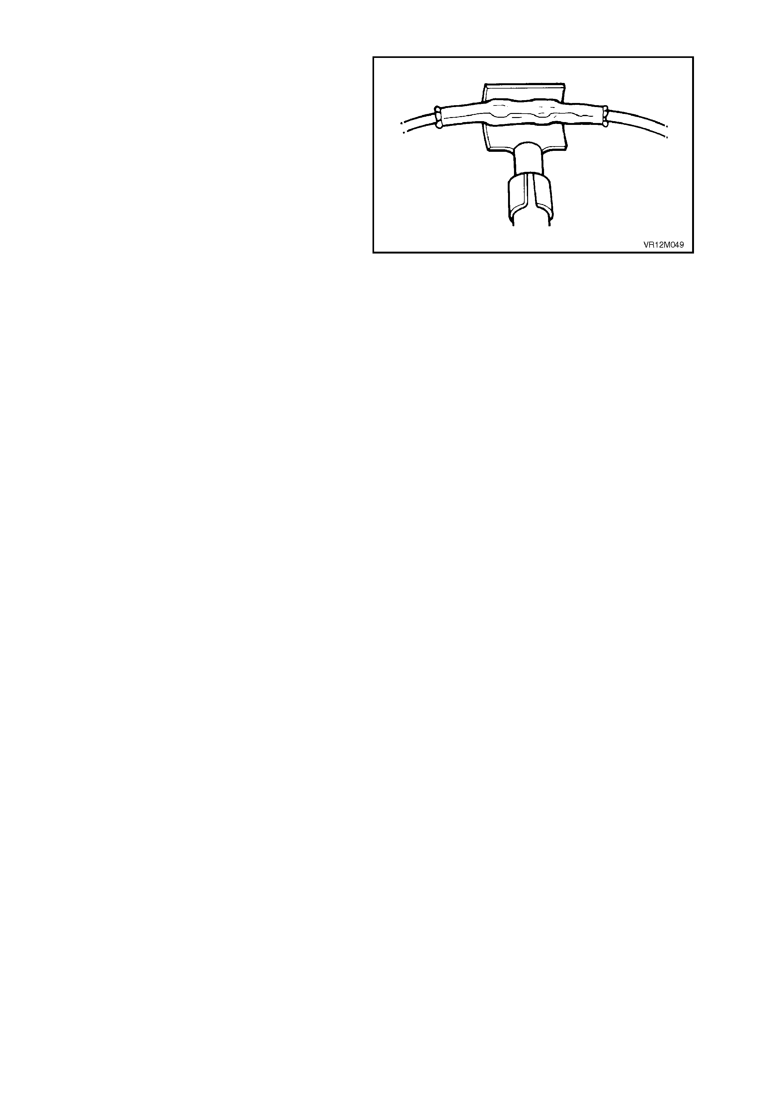
Step Six: Shrink the Insulation around the Splice
Bring the ultratorch (part of J38125-A) to operating
temperature.
Using the torch, apply heat where the barrel is
crimped.
Gradually move the heat barrel from the centre
toward each end of the tubing, softening and
shrinking the tubing completely as the heat is
moved along the insulation. A small amount of
sealant will come out of the end of the tubing when
sufficient shrinking is achieved. Allow the splice
sleeve to cool.
Figure 12M-51
Step Seven: Close the Harness
Ensure that SRS has been disabled.
Using a multimeter, check continuity of repaired
wiring. If wiring is OK, tape the harness wires.
NOTE:
Only check wiring continuity from the SDM wiring
harness connector (YB190) using Tool No. KM-
609-20 and a m ultim eter. If KM-609-20 is not used,
damage to the SDM connector terminals will
result.
SRS WIRING SPLICE REPAIR
If any of the original equipm ent splices ( three wires
or more) in the SRS wiring are damaged they
should be repaired by applying a new splice (not
sealed) from the Terminal Repair Kit J38125-A.
Carefully follow the instructions included in the kit
for proper splice clip application. Cloth duct tape
may be substituted for splice tape if necessary.


2.10 REPAIRS AND INSPECTIONS REQUIRED AFTER AN ACCIDENT
If any SRS components are damaged, they must be replaced. If SRS component mounting points are damaged,
they must be repaired or replaced.
Never use SRS components from another vehicle.
CAUTION:
Proper operation of the SRS requires that any repairs to the vehicle structure must return it to its original
production configuration.
The steering column must be dimensionally inspected, whether deployment occurred or not, refer to
Section 9A STEERING, Checking Steering Column for Accident Damage.
If a vehicle is involved in an accident which was severe enough to deploy the pre-tensioners but not severe enough
to deploy air bag/s, the following components must be replaced:
∙Any seat belt worn in the accident.
∙Seat belt pre-tensioners.
∙Front seat guide rail and adjuster assembly (provided seat was occupied in accident).
∙Sensing and Diagnostic Module.
If a vehicle is involved in an accident where the seat belt pre-tensioners and the air bag/s are deployed, the
following components must be replaced:
∙Any seat belt worn in the accident.
∙Seat belt pre-tensioners.
∙Front seat guide rail and adjuster assemblies (provided seat was occupied in accident).
∙Horn bar and air bag inflator module assembly.
∙Sensing and Diagnostic Module.
∙Clock spring coil.
∙Steering column.
∙Steering wheel.
∙The front passenger's air bag inflator module (vehicles with front passenger's air bag).
∙The instrument panel pad and PAB door assembly (vehicles with front Passenger's air bag).
∙Instrument panel pad name plate (vehicles with front passenger's air bag).
∙Front passenger air bag inflator support rail assembly (vehicles with front passenger's air bag).

3. DIAGNOSTICS
3.1 BASIC KNOWLEDGE REQUIRED
Before attempting to diagnose the Supplemental Restraint System (SRS) you must have a good understanding of
electrical system basics and the use of circuit testing tools. Without this basic knowledge it will be difficult to use the
diagnostic procedures detailed in this Section.
Some electrical basics, as well as basic troubleshooting procedures and hints as the use of circuit testing tools are
covered in Section 12P, WIRING DIA GRAMS.
Basic Electrical Circuits - You should understand the basic theory of electricity, series and parallel circuits, and
voltage drops across series resistors. You should know the meaning of voltage (volts), current (amps), and
resistance (ohms). You should understand what happens in a circuit with an open or shorted wire (shorted either to
voltage or earth). You should also be able to read and understand a wiring diagram.
Additionally, a knowledge of AC theory including; inductance, capacitance and impedance would be useful.
Use of Circuit Testing Tools - You should know how to use a jumper lead to test circuits. You should be familiar with
the use of a high input impedance (10 Meg ohm) digital type multimeter such as Tool No. J39200 or equivalent and
be able to measure voltage, current, and resistance. You should be familiar with the proper use of the TECH 2
Diagnostic Scan Tool.
Techline

3.2 PRELIMINARY SYSTEM DIAGNOSIS
When investigating any complaint of an SRS problem or malfunction, always begin diagnosis with a circuit check,
refer to 3.6 DIAGNOSTIC CHARTS, CHART A - DIAGNOSTIC CIRCUIT CHECK in this Section.
The diagnostic circuit check is a preliminary procedure that checks to ensure the SDM is communicating on the
serial data line as well as helping to identify the problem and directing the reader to the appropriate diagnostic chart
in this Section.

3.3 SRS SELF DIAGNOSTICS
The SRS has a self diagnostic facility that can detect and isolate SRS problems or failures. When a problem or
failure is detected, the Sensing and Diagnostic Module (SDM) sets a fault code that represents that particular
problem or failure. All of the fault codes will cause the SRS warning lamp to be illuminated and depending on the
fault, the SDM may disable the SRS.
If present, diagnosable system faults are detected by the SDM during an initialisation process when the ignition is
first turned on. Upon first detection of an external system fault condition, the SDM records the failure and is classed
as an 'Intermittent Failure'. If the fault condition is maintained to meet the failure duration conditions described in the
diagnostic charts in this Section for the individual system problem, the fault then becomes a current Diagnostic
Trouble Code (DTC). If the fault duration conditions are not meet, the intermittent fault is cleared from the SDM.
Current DTC's are permanently stored in the SDM's memory in the sequence of occurrence. When the fault
conditions are no longer met, the DTC will retain its sequence of occurrence, but the DTC will become a History
DTC.
DTC storage in the SDM of history DTC’s is limited to the first DTC logged for each of the four loops, ie. if a DTC 13
(Driver’s air bag circuit short to earth) was logged in history, and the SDM sensed a short to battery + in the driver’s
air bag circuit, DTC 15 would be held as a current DTC during the particular ignition cycle, but would not become a
history DTC and therefore removed from the SDM’s memory when the ignition is switched off.
CURRENT DTC'S
Current DTC's when detected are stored in the SDM's RAM during the current ignition cycle and then maintained in
an EEPROM. Current DTC's are set or cleared based on the condition of the SRS during ignition on or continuous
monitoring of the current ignition cycle.
NOTE:
A current DTC can be identified on the TECH 2 display by the word ‘Current’ between the DTC number and the
DTC description. The word ‘History’ between the DTC number and the DTC description indicates that the DTC
displayed is a history DTC.
Additionally, the display will advise whether the DTC (both current or history) has been set on the current ignition
cycle by displaying the word ‘frozen’, in brackets next to the word current or history. A precondition for this additional
display is that the DTC must be present for longer than 10 seconds.
Current DTC's will be reset to History DTC's upon the next diagnostic test sequence that the fault conditions are not
met. Current DTC's can be cleared (changed to history DTC) by removing the fault conditions.
Using TECH 2 to clear current DTC's will clear the DTC's, but if the fault conditions still exist, the current DTC's will
set again.
DTC's stored in the SDM memory can only be displayed using the TECH 2 diagnostic scan tool
The TECH 2 communicates with Sensing and Diagnostic Module (SDM) serial data via the Data Link Connector
(DLC), which is attached to the instrument panel lower right hand trim, to the right of the steering column (refer to
3.4 TECH 2 DIAGNOSTICS in this Section).
HISTORY DTC'S
History DTC's are set upon the clearing of a current DTC fault condition. History DTC's are maintained by the SDM
over multiple ignition cycles in the EEPROM. The SDM can only clear history DTC's from its EEPROM by a clear
DTC's serial data message via TECH 2.
CLEARING FAULT CODES
Once any system fault has been rectified, any fault codes stored in the Sensing and Diagnostic Module's memory
can be erased by using TECH 2 "Clear DTC's" selection, refer to 3.4 TECH 2 DIAGNOSTICS in this Section.
IMPORTANT:
Once DTC's have been cleared, be sure to verify proper system operation and absence of any fault codes
when clearing procedure is completed.
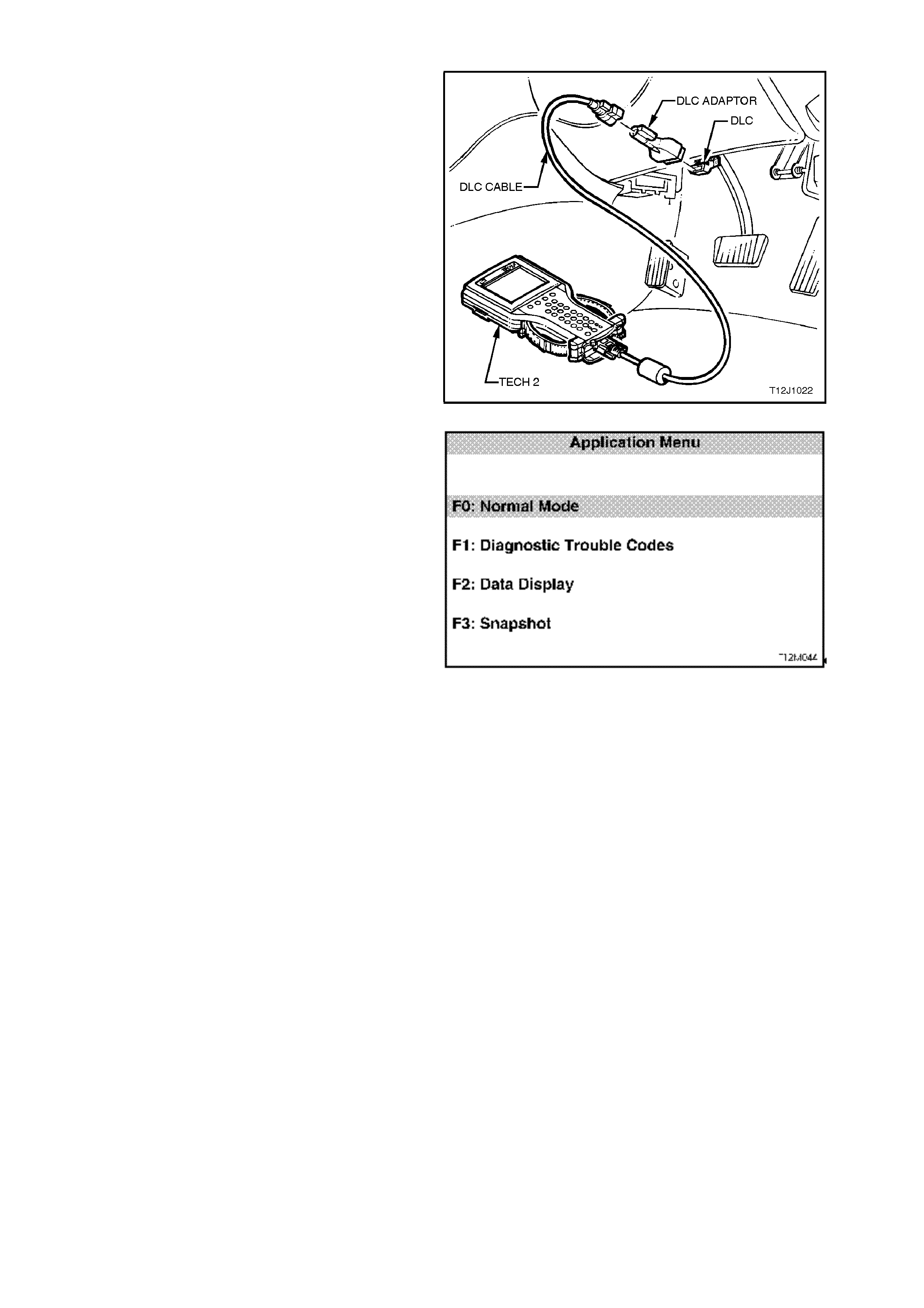
3.4 TECH 2 DIAGNOSTICS
TECH 2, with the appropriate software, cables and
adaptors, when connected to the Data Link
Connector (DLC) is capable of reading SRS serial
data. The DLC is connected to the instrument panel
lower right hand trim, to the right of the steering
column.
For additional general information on connecting
and operating TECH 2 , refer to
Section 0C TECH 2.
Figure 12M-52
TECH 2 has four test modes for diagnosing the
SRS. The four test modes are as follows:
Mode F0: Normal Mode
In this mode, the TECH 2 monitors the
communication between control modules on the
serial data line. The information displayed on the
TECH 2 screen in this mode is what the SDM is
communicating to the other modules via the serial
data line.
Mode F1: Diagnostic Trouble Codes
If F1: Diagnostic Trouble Codes is selected, a
selection list is displayed which contains:
F0: Read DTC Information - Once this mode is
selected, both current and history Diagnostic
Trouble Codes (DTC’s) stored in the control
modules memory may be displayed. Additionally,
the display will advise whether the DTC (both
current or history) has been set on the current
ignition cycle by displaying the word ‘frozen’, in
brackets next to the word current or history. A
precondition for this additional display is that the
DTC must be present for longer than 10 seconds.
F1: Clear DTC Information - once this mode is
selected, DTC’s stored in the control module
memory may be cleared.
Mode F2: Data Display
In this test mode, TECH 2 displays the status of
inputs and outputs of the SRS.
Mode F3: Snapshot
In this test mode, the TECH 2 captures SRS data
before and after a forced manual trigger.
Figure 12M-53
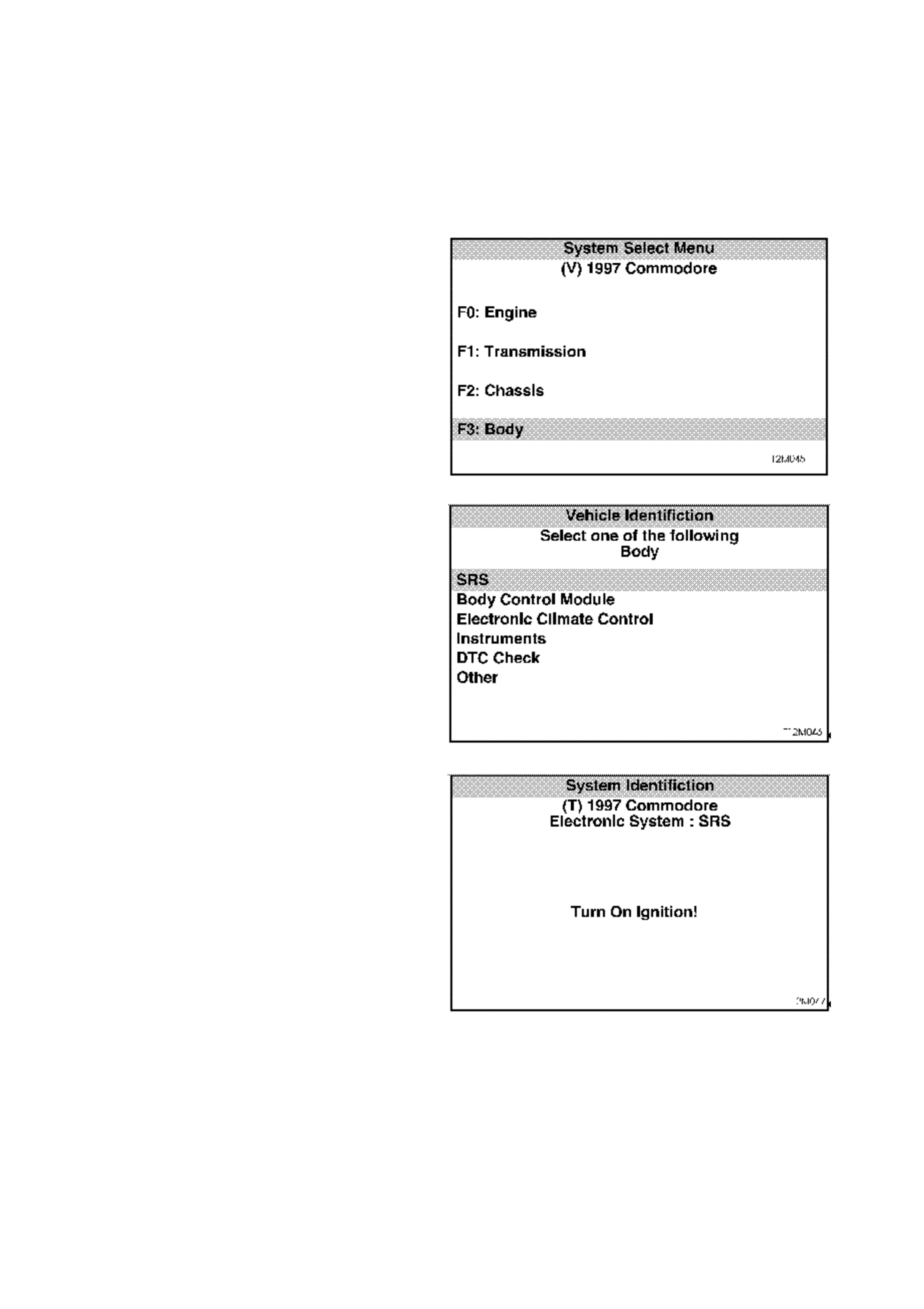
3.5 TECH 2 TEST MODES AND DISPLAYS FOR SRS DIAGNOSIS
As a prerequisite to this diagnostic section is for the
user to be familiar with the proper use of TECH 2,
the following illustrate only the major TECH 2
screen displays and provide a brief explanation of
their function for diagnosing the SRS. If additional
information is r equired on the operation of TECH 2,
reference should be made to either
Section 0C TECH 2 or the TECH 2 Operators
Manual.
System Select Menu
With TECH 2 connected to the DLC, the F0:
Diagnostics selected from the Main Menu, the
correct Model Year and Vehicle Type must be
selected for access to the System Select Menu.
Select F3: Body.
This mode contains all functions to test, diagnose,
monitor and program the vehicles body systems
including the SRS as well as providing the
opportunity to check all DTC’s that m ay be set in the
vehicle.
Figure 12L-54
Body Application Menu
Once F3: Body has been selected from the System
Select Menu, SRS can be selected.
Select SRS.
NOTE:
If information regarding DTC’s set for the vehicle is
required, select DTC Check and press enter to
continue. T o retur n to the SRS mode option from the
DTC Check mode option screen display, simply
press the EXIT key on TECH 2.
Once the SRS has been selected, the following two
System Identification screens will appear which
require action. Figure 12L-55
System Identification
Turn the ignition ON (as requested) and press
CONFIRM soft key to continue.
Figure 12L-56
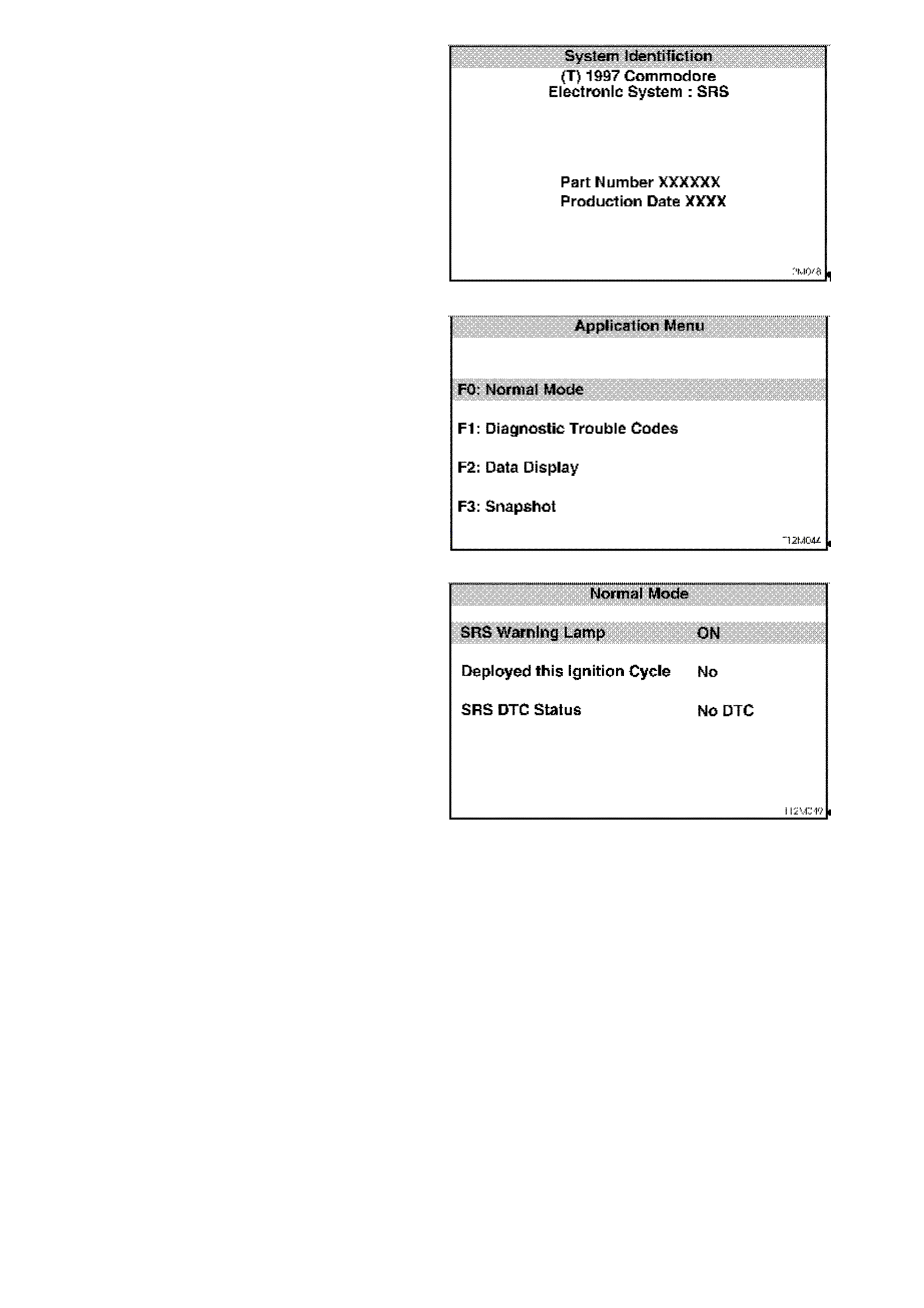
The System Identification screen will then display the
control module part number and production date.
Press the CO NFIRM sof t k ey to continue to the SRS
Application Menu.
NOTE:
There are different control modules for SRS which
are depended on the system configuration (3 loops
for pre-tensioners and driver’s air bag only, and 4
loops for pre-tensioners and driver’s and
passenger’s air bags) in the system. Always refer to
the latest Holden spare par ts m icrofiche / CD for the
correct part number information.
Figure 12L-57
Application Menu
The following functions will now be available:
F0: Normal Mode
F1: Diagnostic Trouble Codes
F2: Data Display
F3: Snapshot
Figure 12L-58
F0: Normal Mode
In the F0: Norm al Mode, inform ation that the SDM is
communicating to other control modules, via the
serial data line, is displayed.
For example: As displayed opposite, the SRS
warning lamp status is ON. This means the SDM is
communicating with the instruments requesting the
SRS warning lamp to be displayed.
Figure 12L-59

F1: Diagnostic Trouble Codes
If F1: Diagnostic Trouble Codes is selected, a
selection list is displayed which contains:
F0: Read DTC Information - If this mode is
selected, a listing of all (if any) DTC’s that have been
set by the SDM will be displayed. Information
displayed with the DTC num ber /s that have been set
is; a short description of what the DTC is, whether it
is a current or history code, and, if the DTC has
been set for more than 10 seconds on the current
ignition cycle, the word ‘frozen’ will be displayed in
brackets next to the word current or history.
NOTE:
If any DTC’s are set, reference should be made to
the relevant diagnostic charts in this section.
F1: Clear DTC Information - DTC’s can be cleared
in this mode by simply selecting F1: CLEAR DTC
INFORMATION, pressing the ENTER button on
TECH 2 and confirming the action as instructed by
TECH 2.
The following table sets out all the possible
diagnostic trouble codes as indicated by TECH 2.
Figure 12L-60
DTC CODE DESCRIPTION
13 Driver’s air bag, circuit short to earth
14 Driver’s belt pre-tensioner, circuit short to earth
15 Driver’s air bag, circuit short to battery
16 Driver’s pre-tensioner, circuit short to battery
23 Passenger’s air bag, circuit short to earth
24 Passenger’s pre-tensioner, circuit short to earth
25 Passenger’s air bag, circuit short to battery
26 Passenger’s pre-tensioner, circuit short to battery
31 Driver’s air bag, open circuit, loop capacitance too low
32 Driver’s air bag, short circuit, loop capacitance too high
33 Passenger’s air bag, open circuit, loop capacitance too low
34 Passenger’s air bag, short circuit, loop capacitance too high
35 Driver’s pre-tensioner, open circuit, loop capacitance too low
36 Driver’s pre-tensioner, short circuit, loop capacitance too high
37 Passenger’s pre-tensioner, open circuit, loop capacitance too low
38 Passenger’s pre-tensioner, short circuit, loop capacitance too high
53 Configuration mismatch: too little or too many loops in SRS
(3 loops in a 4 loop system or 4 loops in a 3 loop system)
55 Internal SDM fault

F2: Data Display
In this test mode, TECH 2 displays the status of inputs and outputs of the SRS.
The following table lists each item contained in the data stream together with a brief description of its meaning.
DATA STREAM / SCREEN
DISPLAY DESCRIPTION
Battery Voltage Displays current battery voltage (approximately 12
Volts).
Driver Air bag Loop
Resistance Displays the resistance in the driver’s air bag (loop 1)
circuit. The resistance should be approximately 2
ohms. If the resistance of this circuit is less than 1 ohm
or greater than 8 ohms, a DTC will be set. (ohms)
Driver Air bag Loop
Capacitance Displays the capacitance in the driver’s air bag (loop 1)
circuit. The capacitance should be approximately 470
nF. If the capacitance reading is outside ± 14% of this
specification, a DTC will be set. (nF)
Driver Pre-tensioner Loop
Resistance Displays the resistance in the driver’s pre-tensioner
(loop 4) circuit. The resistance should be approximately
2 ohms. If the resistance of this circuit is less than 1
ohm or greater than 8 ohms, a DTC will be set. (ohms)
Driver Pre-tensioner Loop
Capacitance Displays the capacitance in the driver’s pre-tensioner
(loop 4) circuit. The capacitance should be
approximately 470 nF. If the capacitance reading is
outside ± 14% of this specification, a DTC will be set.
(nF)
Passenger Air bag Loop
Resistance Displays the resistance in the passenger’s air bag (loop
2) circuit. The resistance should be approximately 2
ohms. If the resistance of this circuit is less than 1 ohm
or greater than 8 ohms, a DTC will be set. (ohms)
Passenger Air bag Loop
Capacitance Displays the capacitance in the passenger’s air bag
(loop 2) circuit. The capacitance should be
approximately 470 nF. If the capacitance reading is
outside ± 14% of this specification, a DTC will be set.
(nF)
Passenger Pre-tensioner Loop
Resistance Displays the resistance in the passenger’s pre-
tensioner (loop 3) circuit. The resistance should be
approximately 2 ohms. If the resistance of this circuit is
less than 1 ohm or greater than 8 ohms, a DTC will be
set. (ohms)
Passenger Pre-tensioner Loop
Capacitance Displays the capacitance in the passenger’s pre-
tensioner (loop 3) circuit. The capacitance should be
approximately 470 nF. If the capacitance reading is
outside ± 14% of this specification, a DTC will be set.
(nF)
SRS Lamp Displays the current state of the SDM’s internal SRS
warning lamp driver. (on / off)
DTC Status Will display ‘No DTC’ or ‘DTC’s Set’ to indicate if any
system faults (DTC’s) are detected by the SDM. (No
DTC’s / DTC’s set)
Driver Air Bag Loop Display indicates whether the SDM has been
programmed for the driver’s air bag loop circuit
(enabled / disabled).
Driver Pre-tensioner Loop Display indicates whether the SDM has been
programmed for the driver’s pre-tensioner loop circuit
(enabled / disabled).
Passenger Air Bag Loop Display indicates whether the SDM has been
programmed for the passenger’s air bag loop circuit
(enabled / disabled).
Passenger Pre-tensioner Loop Display indicates whether the SDM has been
programmed for the passenger’s pre-tensioner loop
circuit (enabled / disabled).

DATA STREAM / SCREEN
DISPLAY DESCRIPTION
Lamp Check Display indicates the status of the SRS warning lamp
during the lamp check (first 5 seconds after the ignition
is switched on). (on / off)
Battery Voltage (after 3 sec) Displays the vehicle system input voltage to the SDM. If
voltage is below 9 volts or above 20 volts for more than
3 seconds, the SRS warning lamp is switched on. (<9
Volts / okay / >20 Volts)
Air Bag and Pre-tensioner
Deployed Display indicates whether the SDM has triggered an air
bag and pre-tensioner deployment. If the SDM has
triggered a deployment of the SRS, the SDM must be
replaced. (yes / no)
Pre-tensioner Deployed Display indicates whether the SDM has triggered a pre-
tensioner deployment only. If the SDM has triggered a
deployment of the SRS, the SDM must be replaced.
(yes / no)
Energy Reserve Display indicates if the status of the energy reserve. If
the battery voltage falls below 7.5 volts, the energy
reserve will be switched on. (on / off)
Serial Data From Instrument Display indicates whether the instrument configuration
of the SRS is correct. The instruments must be
programmed for the SRS configuration of the vehicle;
pre-tensioners only , pre-tensioners and drivers air bag,
or pre-tensioners and drivers and passengers air bag.
(yes / no)
BCM Poll Display indicates whether the SDM is receiving a
request (a poll via the serial data line) from the BCM for
its status of deployment and malfunction data.
(Received / Not Received)
Mode F3: Snapshot
In this test mode, the TECH 2 captures SRS data before and after a forced manual trigger.

3.6 DIAGNOSTIC CHARTS
INTRODUCTION
The following diagnostic charts are designed to provide fast and efficient fault location of the SRS. The diagnostic
charts contain: a ‘diagnostic chart’, pertinent information, circuit diagrams, and where necessary, the steps are
explained by the corresponding numbered paragraphs.
The following figure (Fig. 12M-61) illustrates the terminal layout of the various connectors used in the system. This
illustration should be used in conjunction with the diagnostic chart circuit diagrams when checking circuit faults if the
connector diagram is not included in the chart.
When carrying out wiring checks as directed to by the diagnostic charts, rather than probe terminals and connectors
with incorrect sized multimeter connections, use the adaptors contained in connector test adaptor kit KM-609 and
test lead set KM-609-20 in conjunction with SRS Diagnostic Test Kit SD28280. This will prevent any possibility of
spreading or damaging wiring harness terminals and later on causing a system intermittent failure.
Figure 12M-62 illustrates the correct use and installation of the various components of the SRS Diagnostic Test Kit
SD28280 and test lead set KM-609-20.
IMPORTANT:
UNDER NO CIRCUMSTANCES IS 12 VOLTS TO BE APPLIED TO THE DUMMY LOAD; SD28280B, AS THIS
WILL DAMAGE THE INTERNAL RESISTOR IN THE LOAD, RENDERING THE DUMMY LOAD USELESS FOR
ANY FURTHER DIAGNOSTIC WORK.
ENSURE THAT AT THE COMPLETION OF ANY DIAGNOSTIC PROCEDURE, ALL DIAGNOSTIC TOOLS ARE
REMOVED AND ALL SRS COMPONENTS ARE CORRECTLY RECONNECTED.
Techline
Techline
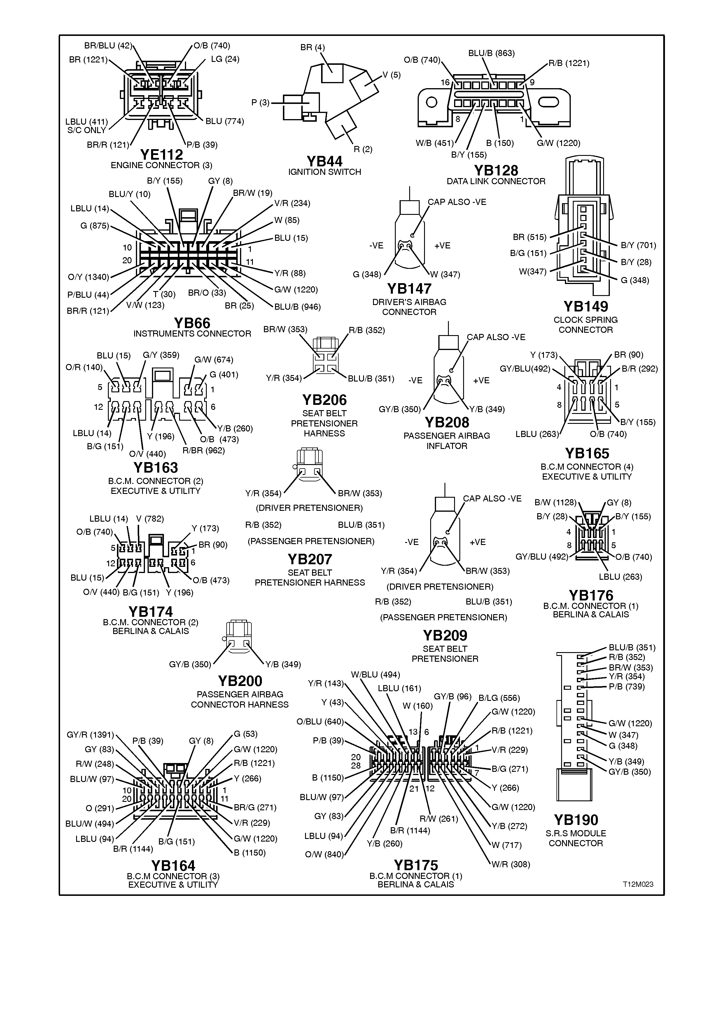
Figure 12M-61
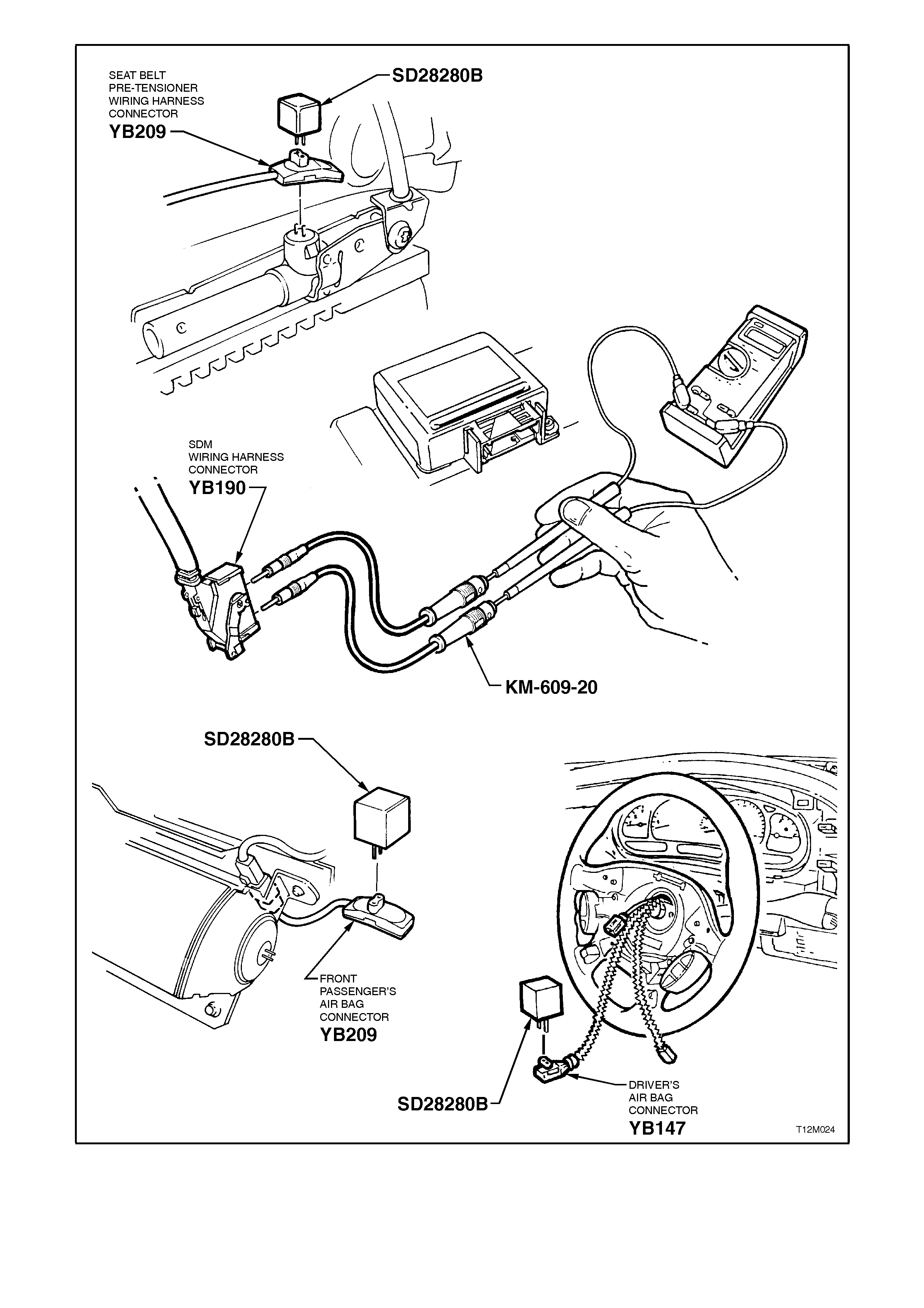
Figure 12M-62
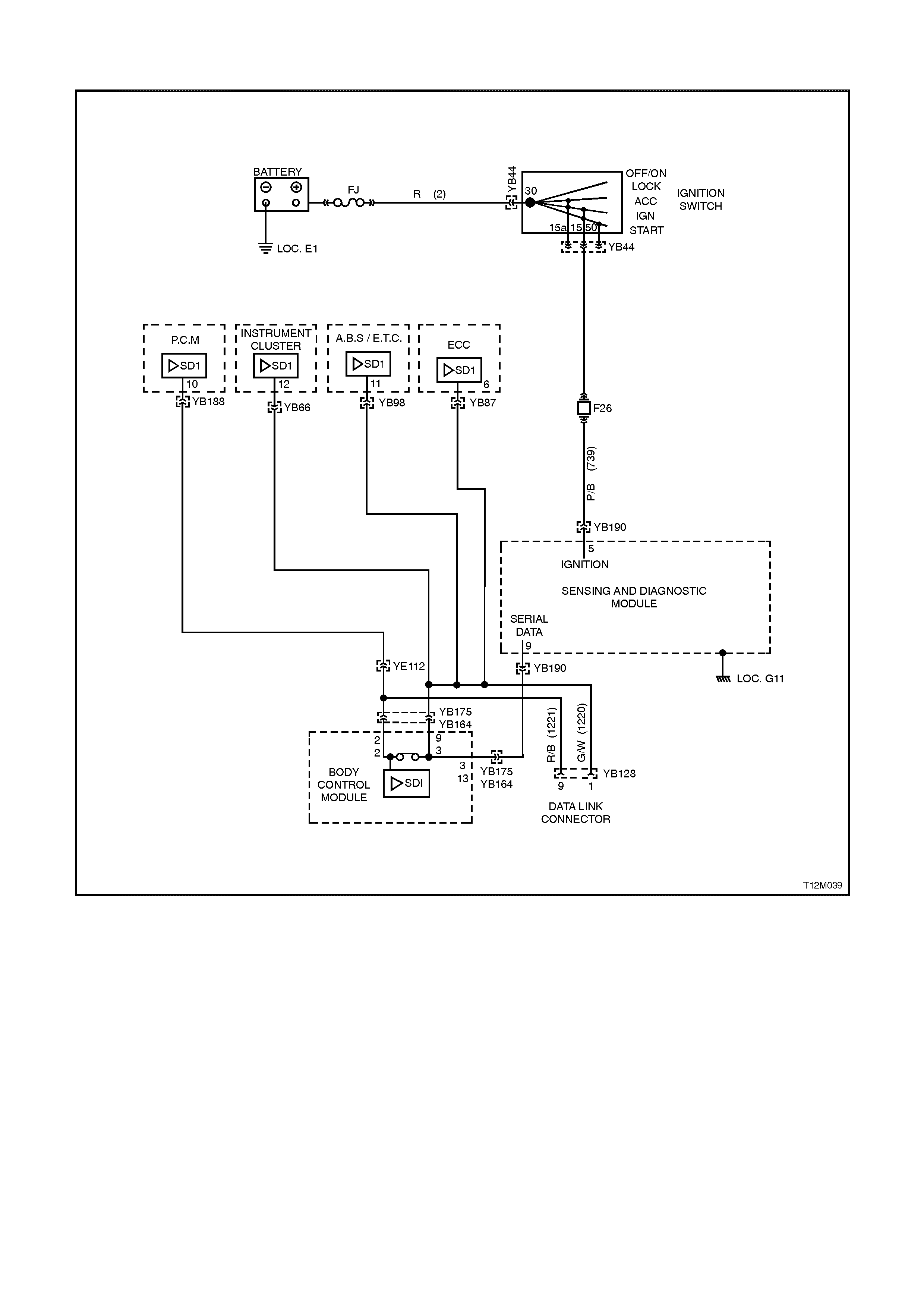
CHART A - DIAGNOSTIC CIRCUIT CHECK
Figure 12M-63
CIRCUIT DESCRIPTION
When investigating any complaint of an SRS problem or malfunction, always begin diagnosis with the following
diagnostic circuit check. This check is a preliminary procedure that checks to ensure the SDM is communicating on
the serial data line as well as helping to identify a problem or malfunction and directing the reader to the appropriate
diagnostic chart in this Section.
With TECH 2 connected to the DLC and the ignition switched on, TECH 2 should display serial data
communication. If TECH 2 does not display serial data, the serial data circuit maybe open of shorted.
There are several other control modules that are connected to the serial data line (PCM, BCM, ABS/ASR, ECC,
instruments and SDM). ANY one of these control modules could cause a fault on the serial data line. This fault
could result in TECH 2 not being able to display serial data.

TEST DESCRIPTION:
The numbers below refer to step numbers in diagnostic chart ‘A’
1-2. This test is a functional check of the SRS warning lamp during a system self check.
3. Checks to see if TECH 2 can communicate with the SDM.
4. Uses TECH 2 to check for DTC’s.
5. Determines if there is a fault in the serial data circuit (1221) between the BCM and PCM by starting the engine.
If serial data was lost while the engine was running, the engine will restart but there will be a one second delay.
6. Checks fuse F26 and circuit 739 for short to earth.
7. Checks for power to SDM.
8. Checks earth connection at SDM.
9. Checks for continuity in circuit 1220 between SDM and BCM to determine if SDM is faulty.
10. Checks if fault is with BCM or open in circuit 1220 between BCM and SDM.
NOTES ON DIAGNOSTIC CHART:
1. Refer to 3.4 TECH 2 DIAGNOSTICS in this Section for connecting and using TECH 2.
2. Refer to Section 12P WIRING DIAGRAMS for procedures on checking wiring faults.
3. To ensure none of the other control modules on the serial data circuit are causing this voltage problem, unplug
each control module, one at a time, to isolate the short to voltage.
STEP ACTION VALUE YES NO
1. ∙Turn ignition ON
while monitoring the
SRS warning lamp in
the instrument
cluster.
∙Does the SRS
warning lamp
illuminate?
Go to Step 2. Go to CHART B -
‘SRS’ WARNING
LAMP
INOPERATIVE,
in this Section.
2. ∙After five seconds of
the ignition being
switched ON, does
the SRS warning
lamp turn OFF?
Fault not present. Go to Step 3
3. ∙Connect TECH 2 to
DLC (refer to
NOTE 1 above).
∙Select Body / SRS /
Turn ignition ON.
∙Does TECH 2 display
System Identification
(ie. SDM part
number)?
Go to Step 4. Go to Step 5.
4. ∙With TECH 2
connected, select
Body / SRS /
Diagnostic Trouble
Codes / Read DTC
Information.
∙Are there any DTC’s
set?
Check and repair
fault causing DTC
to set, refer to
relevant
diagnostic chart in
this Section.
Go to CHART C
‘SRS’ WARNING
LAMP
ILLUMINATED
(NO DTC’S
STORED), in this
Section.
5. ∙Will the engine crank
and start immediately
the key is turned
from off to start (no
delay)?
Go to Step 6. Go to PCM
diagnostics in
Section 6C1
POWERTRAIN
MANAGEMENT -
V6 ENGINE
or
Section 6C2
POWERTRAIN
MANAGEMENT -
V8 ENGINE.

STEP ACTION VALUE YES NO
6. ∙Check SDM fuse F26
in instrument panel
compartment.
∙Is fuse OK?
Go to Step 7. Check and repair
short to earth in
circuit 739.
Replace fuse
F26. Recheck
and verify repair.
7. ∙Turn Ignition ON.
∙Disconnect SDM
connector YB190.
∙Using SRS test lead
set KM-609-20,
measure voltage
between the SDM
connector YB190,
terminal 5, circuit 739
(Pink/Black wire) and
earth (refer to
NOTE 2 above).
∙Is voltage as
specified?
Battery
+Go to Step 8. Check and repair
open in circuit
739. Recheck
and verify repair.
8. ∙Turn ignition OFF.
∙Check for continuity
between SDM earth
(location G11) and a
known good earth
(refer to NOTE 2
above).
∙Does continuity
exist?
Go to Step 9. Repair earth as
necessary.
Recheck and
verify repair.
9. ∙Disconnect SDM
connector YB190.
∙Check for continuity
in circuit 1220
(Green/White wire)
between BCM and
SDM by back probing
BCM connector
YB164, terminal 3
(Low Series BCM) or
YB175, terminal 9
(High Series BCM)
and using SRS test
lead set KM-609-20,
probe SDM
connector YB190,
terminal 9 (refer to
NOTE 2 above).
NOTE:
Use SRS test lead set
KM-609-20 to probe
terminals on
connector YB190.
∙Does continuity
exist?
Replace SDM,
refer to 2.7
SENSING AND
DIAGNOSTIC
MODULE (SDM)
in this Section.
Recheck circuit to
verify repair.
Go to Step 10.
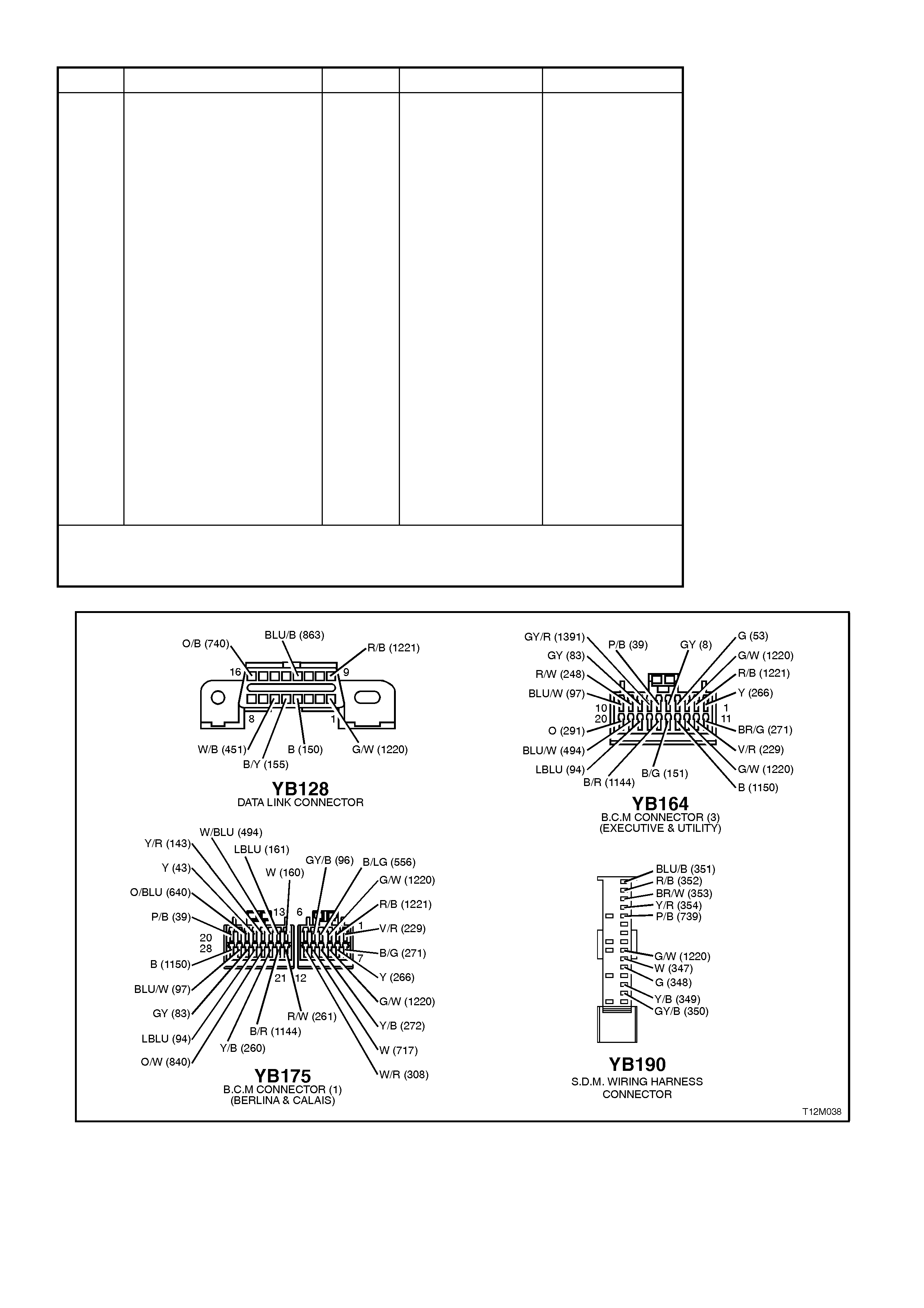
STEP ACTION VALUE YES NO
10. ∙Disconnect BCM
connector YB164
(Low Series BCM) or
YB175 (Hight Series
BCM).
∙With SDM connector
YB190 disconnected,
check for continuity
between BCM
connector YB164,
terminal 13 or
YB175, terminal 3
and SDM connector
YB190, terminal 9
(refer to NOTE 2
above).
NOTE:
Use SRS test lead set
KM-609-20 to probe
terminals on connector
YB190.
∙Does continuity
exist?
Replace BCM,
refer to
Section 12J-1
LOW SERIES
BCM
or
Section 12J-2
HIGH SERIES
BCM.
Repair open in
circuit 1220
between SDM
and BCM.
Recheck and
verify repair.
WHEN ALL DIAGNOSIS AND REPAIRS ARE COMPLETED, ENSURE ALL SRS
COMPONENTS ARE RECONNECTED, CLEAR ALL DTC’S, ENABLE THE SRS AND
VERIFY CORRECT OPERATION
Figure 12M-64
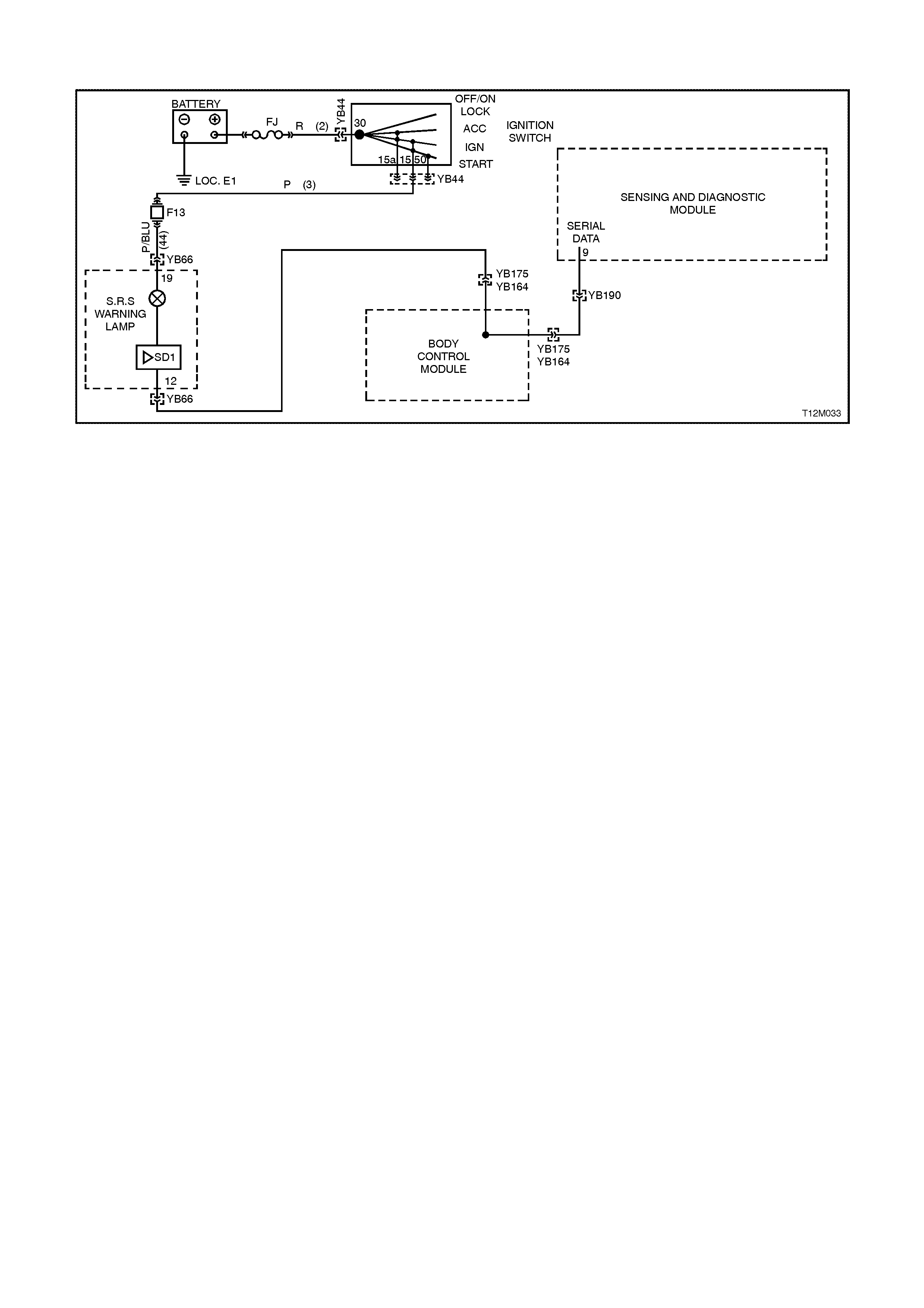
CHART B - SRS WARNING LAMP INOPERATIVE
Figure 12M-65
CIRCUIT DESCRIPTION
Battery voltage is supplied to the SRS warning lamp with the ignition switch in the IGN or START positions through
fuse F13 (located in the passenger compartment fuse panel). To illuminate the lamp, the SDM sends a serial data
message to the instrument cluster, requesting the SRS lamp to illuminate.
The SRS warning lamp will be illuminated when:
The ignition is switched ON (system wiring and self check) and if no faults are detected, the SRS warning lamp will
be turned OFF.
If communication is lost between the SDM and the instrument cluster.
If the instrument cluster has not been programmed for 3 or 4 loop system (configuration problem).
If battery voltage is below 9 volts or above 20 volts.
If the SRS is deployed.
If one or more current or history Diagnostic Trouble Codes (DTC's) are detected when the ignition is switched ON.
During an ignition cycle, if the SDM detects a current DTC, the SRS warning lamp will be illuminated.
If the energy reserve in the SDM is switched ON (battery voltage less than 7.5 volts). When TECH 2 is
communicating with the SDM.
TEST DESCRIPTION:
The numbers below refer to step numbers in diagnostic chart B.
1. This test checks for any DTC's that may cause the SRS warning lamp to be inoperative.
2. This test determines if the SDM is faulty by using TECH 2 to drive the warning lamp on.
3. This is a simple test to determine if power is being supplied to the instrument cluster warning lamps (the SRS
and ABS warning lamps share a common power source).
4. This step determines if the warning lamp bulb or socket is defective.
5. This test checks for a faulty voltage supply to the warning lamp
NOTES ON DIAGNOSTIC CHART:
1. Refer to 3.4 TECH 2 DIAGNOSTICS in this Section for connecting and using TECH 2.
2. Refer to Section 12P WIRING DIAGRAMS for procedures on checking wiring faults.

STEP ACTION VALUE YES NO
1. ∙Install TECH 2 to
DLC and select Body
/ SRS / Diagnostic
Trouble Codes /
Read DTC
Information (refer to
NOTE 1 above).
∙Are any DTC's set?
Repair conditions
which set DTC's.
Recheck and
verify repair.
Go to Step 2.
2. ∙With TECH 2 still
connected, select
Body / Instruments /
Miscellaneous Tests
/ Lamps and
command the SRS
warning lamp
ON.(refer to
NOTE 1 above).
∙Does SRS warning
lamp illuminate?
Replace SDM,
refer to 2.7
SENSING &
DIAGNOSTIC
MODULE (SDM)
in this Section.
Recheck circuit to
verify repair.
Go to Step 3.
3. ∙Disconnect TECH 2
from DLC.
∙Turn ignition on
whilst observing ABS
warning lamp.
∙Does ABS warning
lamp illuminate for
approximately 5
seconds then turn
OFF?
Go to Step 4. Go to Step 5.
4. ∙Remove instrument
cluster, refer to
Section 12C
INSTRUMENTS,
WIPERS/WASHERS
AND HORN.
∙Remove SRS
warning lamp bulb
and socket from
instrument cluster
and check warning
lamp bulb condition.
∙Is bulb and socket
OK?
Replace
instrument
cluster, refer to
Section 12C
INSTRUMENTS,
WIPERS /
WASHERS AND
HORNS.
Replace SRS
warning lamp bulb
and/or socket.
Recheck and verify
repair.
5. ∙Remove instrument
cluster, refer to
Section 12C
INSTRUMENTS,
WIPERS/WASHERS
AND HORN.
∙Switch ignition on
and measure voltage
between connector
YB66, terminal 19,
circuit 44 (Pink/Blue
wire) and earth (refer
to NOTE 2 above).
∙Is voltage as
specified?
Battery
+Fault not present.
Check all system
wiring harness
connectors and
terminals. Repair
as necessary and
recheck system to
verify repair.
Check fusible link
FJ and fuse F13.
Check wiring
between ignition
switch and
instrument cluster
connector YB66.
Check ignition
switch contacts.
Recheck circuit to
verify repair.
WHEN ALL DIAGNOSIS AND REPAIRS ARE COMPLETED, ENSURE ALL SRS
COMPONENTS ARE RECONNECTED, CLEAR ALL DTC’S, ENABLE THE SRS AND
VERIFY CORRECT OPERATION

Figure 12L-66
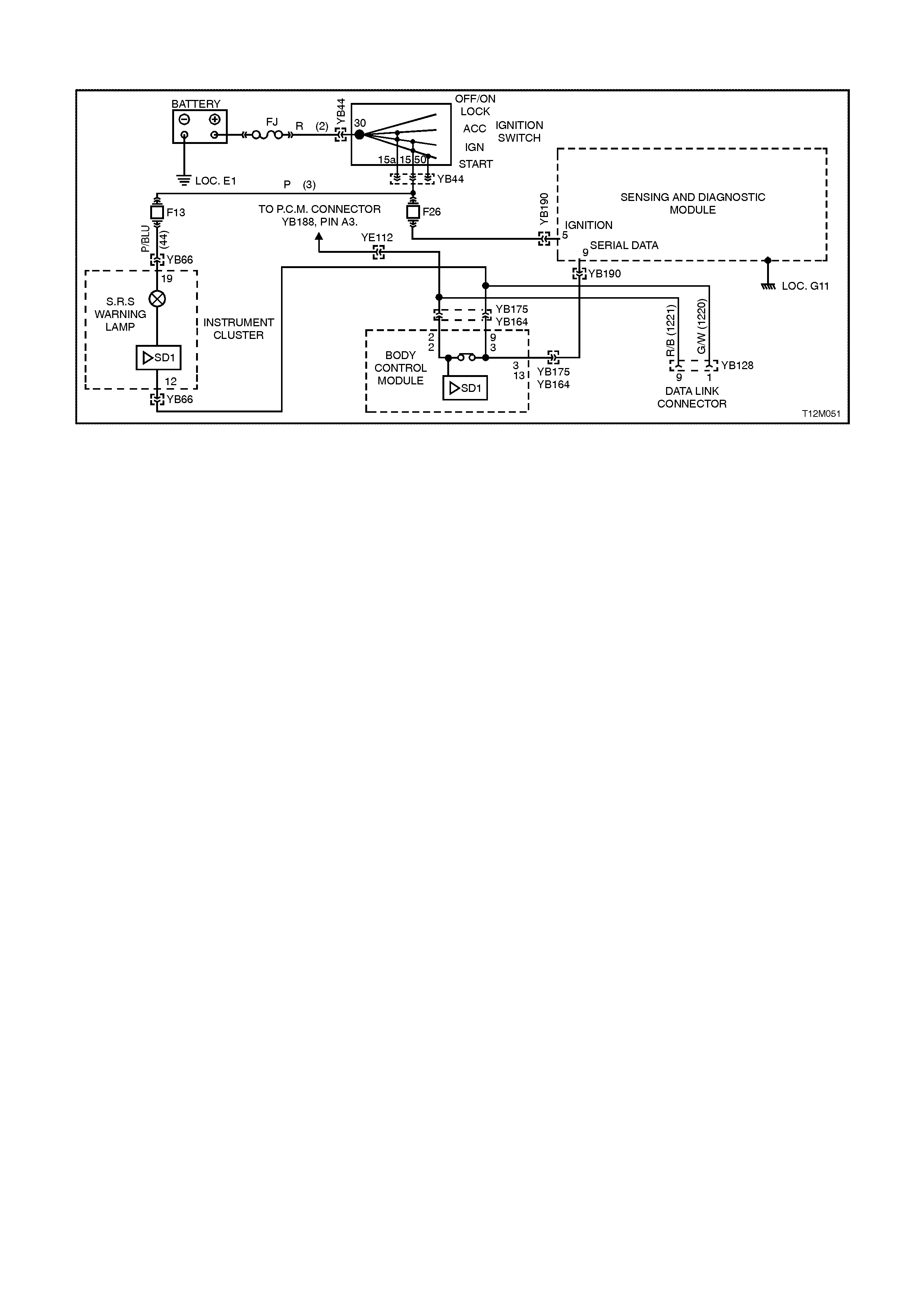
CHART C - SRS WARNING LAMP ILLUMINATED (NO DTC’S STORED)
Figure 12M-67
CIRCUIT DESCRIPTION
Battery voltage is supplied to the SRS warning lamp with the ignition switch in the IGN or START positions through
fuse F13 (located in the passenger compartment fuse panel). To illuminate the lamp, the SDM sends a serial data
message to the instrument cluster (circuit 1220), requesting the SRS lamp to illuminate.
When the ignition is switched ON, the SRS warning lamp should illuminate for approximately five seconds to
indicate the system start up sequence / system wiring and self check. If no system faults are detected, the SRS
warning lamp will be switched OFF.
If a fault is detected (either during this system check or during the ignition cycle), the SRS warning lamp will either
remain ON until the fault is remedied or if a DTC is set, until it is cleared. If a fault is remedied during an ignition
cycle, unless the fault caused a DTC to set, the SRS warning lamp will turn OFF immediately.
The SRS SDM will send a serial data message to the instrument cluster requesting the lamp be illuminated if it
detects any of the following: If the instrument cluster has not been programmed correctly for a 3 or 4 loop system
(configuration problem). If battery voltage is below 9 volts or above 20 volts. If the energy reserve in the SDM is
switched ON (battery voltage less than 7.5 volts). If the SRS is deployed. If the SDM does not receive a poll from
the BCM. If one or more current or history DTC's are detected when the ignition is switched ON. During an ignition
cycle, if the SDM detects a current DTC, the SRS warning lamp will be illuminated. When TECH 2 is communicating
with the SDM.
The SRS warning lamp will also be illuminated if communication is lost (no serial data) between the SDM and the
instrument cluster.
TEST DESCRIPTION:
The numbers below refer to step numbers in diagnostic chart ‘B’
1. Ensures the Diagnostic Circuit Check was performed which determines if there is a serial data communication
fault and checks if any DTC’s are set.
2. Checks if fault is current or intermittent.
3. Using TECH 2, this step checks if the instruments have been configured correctly (3 loop or 4 loop system).
4. Using TECH 2, this step checks the voltage supply to the SDM. If battery voltage to the SDM falls below 9 volts
or above 20 volts for more than 3 seconds, the SRS warning lamp is switched on.
5. Checks generator output.
6. Determines if the ignition input voltage at the SDM is approximately the same as what the generator output
voltage was during Step 5.
7. Checks SDM earth connection.
8. Using TECH 2, this step checks if the energy reserve has been switched on. If the voltage supply to the SDM
falls below 7.5 volts, the energy reserve in the SDM is switched on.
9. Using TECH 2, this step checks if the SDM has deployed the SRS.

NOTES ON DIAGNOSTIC CHART:
1. Refer to 3.4 TECH 2 DIAGNOSTICS in this Section for connecting and using TECH 2.
2. Refer to Section 12P WIRING DIAGRAMS for procedures on checking wiring faults.
3. Fault Intermittent; connect TECH 2 to DLC, select F3 Body / SRS / DATA DISPLAY and monitor the following
to see if TECH 2 display changes state while wiggling circuit wires and/or road testing vehicle:
BATTERY VOLTAGE (AFTER 3 SEC)
AIR BAG & PRE-TENSIONER DEPLOYED
PRE-TENSIONER DEPLOYED
ENERGY RESERVE
CONFIGURATION FROM INSTRUMENTS
BCM POLL
Repair fault as necessary, recheck circuit to verify repair.
4. Refer to Section 6D1-1 CHARGING SYSTEM - V6 ENGINE or Section 6D2-1 CHARGING SYSTEM - V8
ENGINE for generator testing details.
5. If the vehicle is involved in an accident in which the SRS was deployed (even if only pre-tensioners where
deployed) refer to 2.10 REPAIRS AND INSPECTION REQUIRED AFTER AN ACCIDENT for information on
system components that need to be replaced.
STEP ACTION VALUE YES NO
1.
∙ Was the Diagnostic
Circuit Check
preformed?
Go to Step 2. Go to CHART A -
DIAGNOSTIC
CIRCUIT CHECK
in this Section.
2. ∙Turn ignition ON.
∙Does SRS warning
lamp remain
illuminated after 5
seconds?
Go to Step 3. Fault intermittent,
refer to
NOTE 3 above.
3. ∙Connect TECH 2 to
DLC and select Body
/ SRS / Data Display
and scroll to SERIAL
DATA FROM
INSTRUMENTS
(refer to NOTE 1
above).
∙Does TECH 2 display
configuration from
instruments is
CORRECT?
Go to Step 4. Program
instruments, refer
to Section 12C
INSTRUMENTS,
WIPERS /
WASHERS AND
HORNS.
4. ∙With TECH 2
connected, and Body
/ SRS / Data Display
selected, scroll to
BATTERY
VOLTAGE (AFTER 3
SEC).
∙Does TECH 2 display
battery voltage (after
3 sec) is OKAY?
Go to Step 8. Go to Step 5.
5. ∙Carry out checks of
generator output
(refer to NOTE 4
above).
∙Is generator output
OK?
Go to Step 6. Repair generator
as necessary.
Recheck and
verify repair.

STEP ACTION VALUE YES NO
6. ∙Disconnect SDM
connector YB190.
∙Start engine, turn
headlamps ON and
raise engine idle
speed to
approximately 2500
RPM.
∙Using Tool KM-609-
20, check voltage
between SDM wiring
harness connector
YB190, terminal 5,
circuit 739 and a
known good earth
(refer to NOTE 2
above).
∙Is the voltage
measured
approximately the
same as measured
during Step 5
(generator output
tests)?
Go to Step 7. Check and repair
circuit 739 as
necessary.
Recheck and
verify repair.
7. ∙Check for continuity
between earth
location G11 (at
SDM) and SDM
(refer to NOTE 2
above).
∙Is the earth circuit
OK?
Replace SDM,
refer to 2.7
SENSING &
DIAGNOSTIC
MODULE (SDM)
in this Section.
Recheck circuit to
verify repair
Check and repair
earth as
necessary.
Recheck and
verify repair.
8. ∙With TECH 2
connected, and Body
/ SRS / Data Display
selected, scroll to
ENERGY RESERVE.
∙Does TECH 2 display
energy reserve OFF?
Go to Step 9. Go to Step 5.
9. ∙With TECH 2
connected, and Body
/ SRS / Data Display
selected, scroll to
AIR BAG & PRE-
TENSIONER
DEPLOYED and
PRE-TENSIONER
DEPLOYED.
∙Does TECH 2 display
either Air bag & pre-
tensioner deployed
YES or pre-tensioner
deployed YES?
Replace SDM,
refer to 2.7
SENSING AND
DIAGNOSTIC
MODULE (SDM)
in this Section.
(see NOTE 5
above). Recheck
circuit to verify
repair.
Refer to BCM Air
Bag Deployment
vehicle shutdown
diagnostics in
Section 12J-1
LOW SERIES
BCM
or
Section 12J-2
HIGH SERIES
BCM.
WHEN ALL DIAGNOSIS AND REPAIRS ARE COMPLETED, ENSURE ALL SRS
COMPONENTS ARE RECONNECTED, CLEAR ALL DTC’S, ENABLE THE SRS AND
VERIFY CORRECT OPERATION

Figure 12L-68

DTC 13 - DRIVER'S AIR BAG, CIRCUIT SHORT TO EARTH
Figure 12M-69
CIRCUIT DESCRIPTION
At ignition on, and on a constant monitoring cycle of every 300 milliseconds during the ignition cycle, the SDM
performs a system self check. If the SDM detects a resistance to earth of less than 4 kohms in either the positive or
negative inflator circuit for more than 10 seconds, a current (frozen) DTC 13 will set.
DTC 13 will set If circuits 347 (Driver’s air bag positive side) and/or 348 (driver’s air bag negative side) are shorted
to earth.
When DTC 13 sets, the SDM illuminates the SRS warning lamp and sets a ‘current’ DTC 13. Should the fault
conditions detected by the SDM clear during the same ignition cycle, the current code will clear and become a
‘history’ DTC 13. The SRS warning lamp will remain on for the remainder of the ignition cycle.
If a DTC 13 is set, the SRS warning lamp is illuminated on each ignition cycle, even if the DTC is set as a history
DTC, until the fault conditions for setting DTC 13 are rectified and the DTC (current or history) can then be cleared
from the SDM via TECH 2.
If DTC 13 is set, the SRS, including the driver’s air bag, will still be operational.
TEST DESCRIPTION:
Number/s below refer to Step numbers in the following diagnostic chart.
2. TECH 2 in this mode should display approximately 2.2 ohms if the driver's air bag loop circuit is OK.
3. & 4. If screen display changes during a wiring 'wiggle' test, a fault with the wiring is at that location.
5. Tool SD28280B is a dummy load taking the place of the horn bar and driver's air bag inflator module. If
TECH 2 displays the correct resistance of the dummy load, the system fault is in the horn bar and driver's
air bag inflator module assembly.
This test checks the wiring between the SDM wiring harness connector YB190, terminal 10 and the horn bar and
driver's air bag inflator module connector YB147 for faults.
This test checks the wiring between the SDM wiring harness connector YB190, terminal 11 and the horn bar and
driver's air bag inflator module connector YB147 for faults.
NOTES ON DIAGNOSTIC CHART
1. For all wiring harness checking procedures, refer to Section 12P WIRING DIA GRAMS.
2. Refer to 2.8 SRS WIRING REPAIR in this Section before conducting any SRS wiring harness repairs.
3. Refer to Section 12N FUSES & WIRING HARNESSES for SRS wiring harness routing.
Resistance cannot be measured between the two terminals in connector YB147 as the in-built capacitor blocks
measurement. Therefore, a ‘service hole’ is incorporated into the connector for fault tracing. Refer to 1.1 SYSTEM
COMPONENTS, WIRING HARNESS in this Section for more details on this type of connector.
TECH 2 screen display only needs to change status to indicate a short to earth in the SRS wiring harness. The
actual DTC may not be displayed and in some instances an incorrect DTC may be displayed. If any DTC other than
DTC 13 is displayed during this test, unless they become Frozen DTC’s no action needs to be taken other than
repairing the short to earth in the driver’s air bag circuit. If another DTC becomes frozen, other than DTC 13, refer to
the relevant diagnostic chart in this Section.

Figure 12M-70
STEP ACTION VALUE YES NO
1. ∙Connect TECH 2 to
DLC.
∙Select Body / SRS /
Diagnostic Trouble
Codes / Read DTC
Information.
∙Does TECH 2 display
DTC 13 as a Current
DTC?
Go to Step 2. Go to Step 3.
2. ∙With TECH 2 still
connected, select
Body / SRS / Data
Display and scroll to
DRIVER AIR BAG
LOOP
RESISTANCE.
∙Does TECH 2 display
approximately '2.2
OHMS'?
Go to Step 3. Go to Step 5.
3. ∙Remove steering
column upper and
lower cover.
∙With TECH 2 still
connected, select
Diagnostic Trouble
Codes / Clear DTC
information and clear
all (if any) DTC’s.
∙Select Diagnostic
Trouble Codes /
Read DTC
Information, 'wiggle'
SRS wiring harness
at all locations
between the SDM
and the clock spring
coil and monitor
TECH 2 screen
display.
∙Does TECH 2 screen
display change status
from No Diagnostic
Trouble Codes, refer
to NOTE 5 above ?
Go to Step 4. Fault not present.
Check all system
wiring harness
connectors, and
terminals.
Clear DTC and
recheck system.

STEP ACTION VALUE YES NO
4. ∙Inspect wiring at
point where TECH 2
screen display
changes. If
necessary split open
wiring harness.
∙Is fault identifiable?
Make repairs as
necessary
(refer to
NOTE 2 above).
Clear DTC and
recheck system to
verify repair.
Replace SRS
wiring harness
(refer to
NOTE 3 above).
Clear DTC and
recheck system
to verify repair.
5. ∙Disable the SRS,
refer to 2.2
DISABLING AND
ENABLING
PROCEDURE in this
Section.
∙Remove horn bar
and driver's air bag
inflator module, refer
to 2.3 HORN BAR
AND AIR BAG
MODULE
ASSEMBLY in this
Section.
∙Connect Tool No.
SD28280B to SRS
wiring harness
connector YB147.
∙With TECH 2 still
connected, select
Body / SRS / Data
Display and scroll to
DRIVER AIR BAG
LOOP
RESISTANCE.
∙Does TECH 2 display
approximately '3.0
OHMS'?
Replace horn bar
and driver's air
bag inflator
module assembly,
refer to 2.3 HORN
BAR AND AIR
BAG MODULE
ASSEMBLY in
this Section.
Clear DTC and
recheck system to
verify repair.
Go to Step 6.

STEP ACTION VALUE YES NO
6. ∙Disconnect SDM
wiring harness
connector YB190
from the SDM.
∙Remove Tool
SD28280B from
YB147.
∙Using Tool KM-609-
20, check wiring
between SDM wiring
harness connector
YB190, terminals 10
and driver's air bag
inflator module
connector YB147,
circuits 347 (White
wire) for short to
earth (refer to
NOTE 1 above).
∙Is all OK?
Go to Step 7. Make repairs as
necessary
(refer to
NOTE 2 above).
Clear DTC and
recheck system
to verify repair.
7. ∙With SDM wiring
harness connector
YB190 disconnected
from the SDM and
using Tool KM-609-
20, check wiring
between SDM wiring
harness connector
YB190, terminal 11
and driver's air bag
inflator module
connector YB147,
circuit 348 (Green
wire) for a short to
earth (refer to
NOTES 1 and 4
above).
∙Is all OK?
Replace SDM,
refer to 2.7
SENSING AND
DIAGNOSTIC
MODULE in this
Section. Recheck
circuit to verify
repair.
Make repairs as
necessary
(refer to
NOTE 2 above).
Clear DTC and
recheck system
to verify repair.
WHEN ALL DIAGNOSIS AND REPAIRS ARE COMPLETED, ENSURE ALL SRS
COMPONENTS ARE RECONNECTED, CLEAR ALL DTC’S, ENABLE THE SRS AND
VERIFY CORRECT OPERATION

DTC 14 - DRIVER'S PRE-TENSIONER, CIRCUIT SHORT TO EARTH
Figure 12M-71
CIRCUIT DESCRIPTION
At ignition on, and on a constant monitoring cycle of every 300 milliseconds during the ignition cycle, the SDM
performs a system self check. If the SDM detects a resistance to earth of less than 4 kohms in either the positive or
negative circuit for more than 10 seconds, a current (frozen) DTC 14 will set.
DTC 14 will set if circuits 353 (driver’s pre-tensioner positive side) and/or 354 (driver’s pre-tensioner negative side)
are shorted to earth.
When DTC 14 sets, the SDM illuminates the SRS warning lamp and sets a current DTC 14. Should the fault
conditions detected by the SDM clear during the same ignition cycle, the current code will clear and become a
history DTC 14. The SRS warning lamp will remain on for the remainder of the ignition cycle.
If a DTC 14 is set, the SRS warning lamp is illuminated on each ignition cycle, even if the DTC is set as a history
DTC, until the fault conditions for setting DTC 14 are rectified and the DTC (current or history) can then be cleared
from the SDM via TECH 2.
If DTC 14 is set, the SRS, including the driver’s pre-tensioner, will still be operational.
TEST DESCRIPTION
Number/s below refer to step numbers in the following diagnostic chart.
2. TECH 2 in this mode should display approximately 2.2 ohms if the driver's pre-tensioner loop circuit is OK.
3. & 4. If screen display changes during a wiring 'wiggle' test, a fault with the wiring is at that location.
5. Tool SD28280B is a dummy load taking the place of the pre-tensioner assembly. If TECH 2 displays the
correct resistance of the dummy load, the system fault is in the pre-tensioner assembly.
6. This test checks the wiring between the SDM wiring harness connector YB190, terminal 3 and the driver's pre-
tensioner connector YB209 for faults.
7. This test checks the wiring between the SDM wiring harness connector YB190, terminal 4 and the driver's pre-
tensioner connector YB209 for faults.
NOTES ON DIAGNOSTIC CHART
1. For all wiring harness checking procedures, refer to Section 12P WIRING DIAGRAMS.
2. Refer to 2.8 SRS WIRING REPAIR in this Section before conducting any SRS wiring harness repairs.
3. Refer to Section 12N, FUSES & WIRING HARNESSES for SRS wiring harness routing.
Resistance cannot be measured between the two terminals in connector YB209 as the in-built capacitor blocks
measurement. Therefore, a ‘service hole’ is incorporated into the connector for fault tracing. Refer to 1.1 SYTSEM
COMPONENTS, WIRING HARNESS in this Section for more details on this type of connector.
TECH 2 screen display only needs to change status to indicate a short to earth in the SRS wiring harness. The
actual DTC may not be displayed and in some instances an incorrect DTC may be displayed. If any DTC other than
DTC 14 is displayed during this test, unless they become Frozen DTC’s no action needs to be taken other than
repairing the short to earth in the driver’s pre-tensioner circuit. If another DTC becomes frozen, other than DTC 14,
refer to the relevant diagnostic chart in this Section.
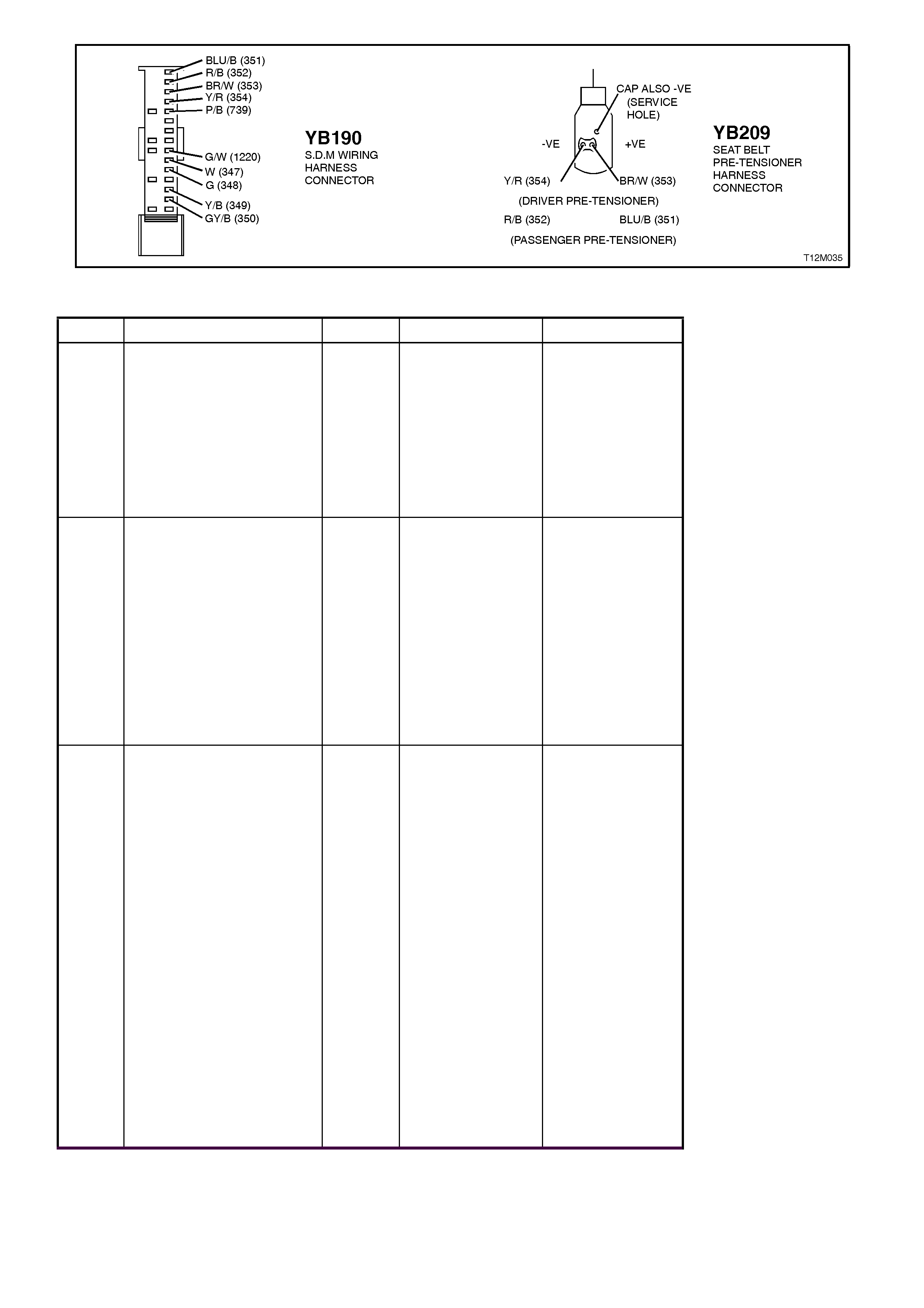
Figure 12M-72
STEP ACTION VALUE YES NO
1. ∙Connect TECH 2 to
DLC.
∙Select Body / SRS /
Diagnostic Trouble
Codes / Read DTC
Information.
∙Does TECH 2 display
DTC 14 as a Current
DTC?
Go to Step 2. Go to Step 3.
2. ∙With TECH 2 still
connected to DLC,
select Body / SRS /
Data Display and
scroll to 'DRIVER’S
PRE-TENSIONER
LOOP
RESISTANCE'.
∙Does TECH 2 display
approximately '2.2
OHMS'?
Go to Step 3. Go to Step 5.
3. ∙With TECH 2 still
connected, select
Diagnostic Trouble
Codes / Clear DTC
information and clear
all (if any) DTC’s.
∙Select Diagnostic
Trouble Codes /
Read DTC
Information, 'wiggle'
SRS wiring harness
at all locations
between the SDM
and the pre-tensioner
while monitoring
TECH 2 screen
display.
∙Does TECH 2 screen
display change status
from No Diagnostic
Trouble Codes, refer
to NOTE 5 above ?
Go to Step 4. Fault not present.
Check all system
wiring harness
connectors, and
terminals.
Clear DTC and
recheck system.

STEP ACTION VALUE YES NO
4. ∙Inspect wiring at
point where TECH 2
screen display
changes. If
necessary split open
wiring harness.
∙Is fault identifiable?
Make repairs as
necessary
(refer to
NOTE 2 above).
Clear DTC and
recheck system to
verify repair.
Replace SRS
wiring harness
(refer to
NOTE 3 above).
Clear DTC and
recheck system
to verify repair.
5. ∙Disable the SRS,
refer to 2.2
DISABLING AND
ENABLING
PROCEDURE in this
Section.
∙Disconnect driver's
pre-tensioner wiring
harness connector
YB209 from pre-
tensioner.
∙Connect Tool No.
SD28280B to SRS
wiring harness
connector YB209.
∙With TECH 2 still
connected, select
Body / SRS / Data
Display and scroll to
'DRIVER’S PRE-
TENSIONER LOOP
RESISTANCE'.
∙Does TECH 2 display
approximately '3.0
OHMS'?
Replace driver's
pre-tensioner
assembly, refer to
Section 1A7
SEAT AND SEAT
BELT
ASSEMBLIES.
Clear DTC and
recheck system to
verify repair.
Go to Step 6.

STEP ACTION VALUE YES NO
6. ∙Disconnect SDM
wiring harness
connector YB190
from the SDM.
∙Remove Tool
SD28280B from
YB209.
∙Using Tool KM-609-
20, check wiring
between SDM wiring
harness connector
YB190, terminals 3
and driver's pre-
tensioner connector
YB209, circuit 353
(Brown/White w ire)
for short to earth
(refer to NOTE 1
above).
∙Is all OK?
Go to Step 7. Make repairs as
necessary
(refer to
NOTE 2 above).
Clear DTC and
recheck system
to verify repair.
7. ∙With SDM wiring
harness connector
YB190 disconnected
from the SDM and
using Tool KM-609-
20, check wiring
between SDM wiring
harness connector
YB190, terminal 4
and driver's pre-
tensioner connector
YB209, circuit 354
(Yellow/Red wire) for
a short to earth (refer
to NOTES 1 and 4
above).
∙Is all OK?
Replace SDM,
refer to 2.7
SENSING AND
DIAGNOSTIC
MODULE in this
Section. Recheck
circuit to verify
repair.
Make repairs as
necessary
(refer to
NOTE 2 above).
Clear DTC and
recheck system
to verify repair.
WHEN ALL DIAGNOSIS AND REPAIRS ARE COMPLETED, ENSURE ALL SRS
COMPONENTS ARE RECONNECTED, CLEAR ALL DTC’S, ENABLE THE SRS AND
VERIFY CORRECT OPERATION
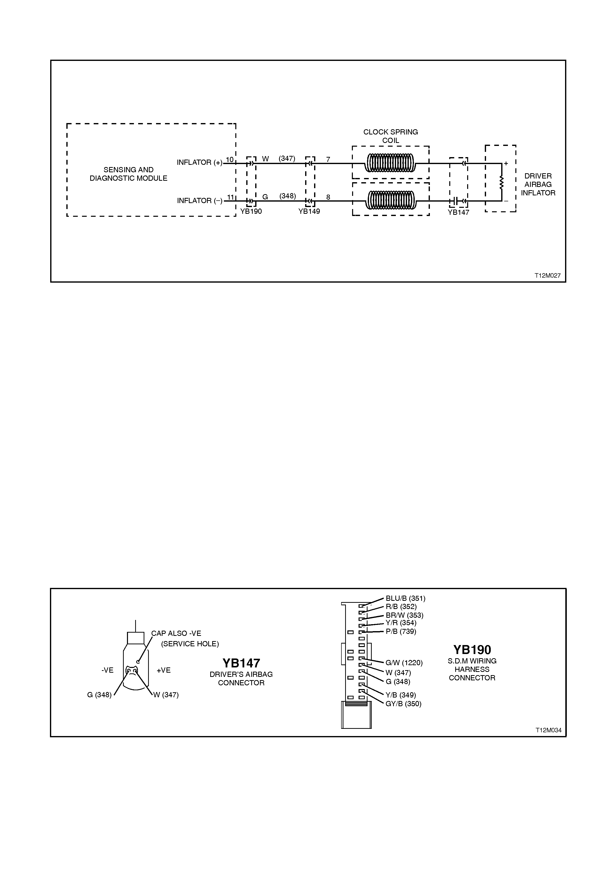
DTC 15 - DRIVER'S AIR BAG, CIRCUIT SHORT TO BATTERY
Figure 12M-73
CIRCUIT DESCRIPTION
At ignition on, and on a constant monitoring cycle of every 300 milliseconds during the ignition cycle, the SDM
performs a system self check. If the SDM detects a resistance to battery supply is less than 30 kohms in either the
positive and/or negative circuit for more than 10 seconds, a current (frozen) DTC 15 will set.
DTC 15 will set if circuits 347 (driver’s air bag positive side) and/or 348 (driver’s air bag negative side) are shorted to
battery +.
When DTC 15 sets, the SDM illuminates the SRS warning lamp and sets a current DTC 15. Should the fault
conditions detected by the SDM clear during the same ignition cycle, the current code will clear and become a
history DTC 15. The SRS warning lamp will remain on for the remainder of the ignition cycle.
If a DTC 15 is set, the SRS warning lamp is illuminated on each ignition cycle, even if the DTC is set as a history
DTC, until the fault conditions for setting DTC 15 are rectified and the DTC (current or history) can then be cleared
from the SDM via TECH 2.
If DTC 15 is set, the SRS, including the driver’s air bag, will still be operational.
NOTES ON DIAGNOSTIC CHART
1. For all wiring harness checking procedures, refer to Section 12P WIRING DIA GRAMS
2. Refer to 2.8 SRS WIRING REPAIR in this Section before conducting any SRS wiring harness repairs.
3. Resistance cannot be measured between the two terminals in connector YB147 as the in-built capacitor blocks
measurement. Therefore, a ‘service hole’ is incorporated into the connector for fault tracing. Refer 1.1
SYTSEM COMPONENTS, WIRING HARNESS in this Section for more details on this type of connector.
Figure 12M-74
STEP ACTION VALUE YES NO
1. ∙Disable the SRS,
refer to 2.2
DISABLING AND
ENABLING
PROCEDURE in this
Section.
∙Remove horn bar
and driver's air bag
inflator module, refer
to 2.3 HORN BAR
AND AIR BAG
MODULE
ASSEMBLY in this
Section.
∙Disconnect SDM
wiring harness
connector YB190
from the SDM.
∙Reconnect battery.
∙Using Tool KM-609-
20, check wiring
between SDM wiring
harness connector
YB190, terminals 10
and 11 and driver's
air bag connector
YB147, circuits 347
(White wire) and 348
(Green wire) for short
to battery + (refer to
NOTES 1 and 3
above).
∙Is all OK?
Replace SDM,
refer to 2.7
SENSING AND
DIAGNOSTIC
MODULE in this
Section. Recheck
circuit to verify
repair.
Make repairs as
necessary
(refer to
NOTE 2 above).
Clear DTC and
recheck system
to verify repair.
WHEN ALL DIAGNOSIS AND REPAIRS ARE COMPLETED, ENSURE ALL SRS
COMPONENTS ARE RECONNECTED, CLEAR ALL DTC’S, ENABLE THE SRS AND
VERIFY CORRECT OPERATION

DTC 16 - DRIVER'S PRE-TENSIONER, CIRCUIT SHORT TO BATTERY
Figure 12M-75
CIRCUIT DESCRIPTION
At ignition on, and on a constant monitoring cycle of every 300 milliseconds during the ignition cycle, the SDM
performs a system self check. If the SDM detects a resistance to battery supply is less than 30 kohms in either the
positive and/or negative circuit for more than 10 seconds, a current (frozen) DTC 16 will set.
DTC 16 will set if circuits 353 (driver’s pre-tensioner positive side) and/or 354 (driver’s pre-tensioner negative side)
are shorted to battery +.
When DTC 16 sets, the SDM illuminates the SRS warning lamp and sets a current DTC 16. Should the fault
conditions detected by the SDM clear during the same ignition cycle, the current code will clear and become a
history DTC 16. The SRS warning lamp will remain on for the remainder of the ignition cycle.
If a DTC 16 is set, the SRS warning lamp is illuminated on each ignition cycle, even if the DTC is set as a history
DTC, until the fault conditions for setting DTC 16 are rectified and the DTC (current or history) can then be cleared
from the SDM via TECH 2.
If DTC 16 is set, the SRS, including the driver’s pre-tensioner, will still be operational.
NOTES ON DIAGNOSTIC CHART
1. For all wiring harness checking procedures, refer to Section 12P WIRING DIA GRAMS.
2. Refer to 2.8 SRS WIRING REPAIR in this Section before conducting any SRS wiring harness repairs.
3. Resistance cannot be measured between the two terminals in connector YB209 as the in-built capacitor blocks
measurement. Therefore, a ‘service hole’ is incorporated into the connector for fault tracing. Refer to 1.1
SYTSEM COMPONENTS, WIRING HARNESS in this Section for more details on this type of connector.
Figure 12M-76
STEP ACTION VALUE YES NO
1. ∙Disable the SRS,
refer to 2.2
DISABLING AND
ENABLING
PROCEDURE in this
Section.
∙Disconnect driver's
pre-tensioner wiring
harness connector
YB209 from pre-
tensioner.
∙Disconnect SDM
wiring harness
connector YB190
from the SDM.
∙Reconnect battery.
∙Using Tool KM-609-
20, check wiring
between SDM wiring
harness connector
YB190, terminals 3
and 4 and driver's
pre-tensioner
connector YB209,
circuits 353
(Brown/White w ire)
and 354 (Yellow/Red
wire) for short to
battery + (refer to
NOTES 1 and 3
above).
∙Is all OK?
Replace SDM,
refer to 2.7
SENSING AND
DIAGNOSTIC
MODULE in this
Section. Recheck
circuit to verify
repair.
Make repairs as
necessary
(refer to
NOTE 2 above).
Clear DTC and
recheck system
to verify repair.
WHEN ALL DIAGNOSIS AND REPAIRS ARE COMPLETED, ENSURE ALL SRS
COMPONENTS ARE RECONNECTED, CLEAR ALL DTC’S, ENABLE THE SRS AND
VERIFY CORRECT OPERATION

DTC 23 - PASSENGER'S AIR BAG, CIRCUIT SHORT TO EARTH
Figure 12M-77
CIRCUIT DESCRIPTION
At ignition on, and on a constant monitoring cycle of every 300 milliseconds during the ignition cycle, the SDM
performs a system self check. If the SDM detects a resistance to earth of less than 4 kohms in either the positive or
negative inflator circuit for more than 10 seconds, a current (frozen) DTC 23 will set.
DTC 23 will set if circuits 349 (pass. air bag positive side) and/or 350 (Pass. air bag negative side) are shorted to
earth.
When DTC 23 sets, the SDM illuminates the SRS warning lamp and sets a current DTC 23. Should the fault
conditions detected by the SDM clear during the same ignition cycle, the current code will clear and become a
history DTC 23. The SRS warning lamp will remain on for the remainder of the ignition cycle.
If a DTC 23 is set, the SRS warning lamp is illuminated on each ignition cycle, even if the DTC is set as a history
DTC, until the fault conditions for setting DTC 23 are rectified and the DTC (current or history) can then be cleared
from the SDM via TECH 2.
If DTC 23 is set, the SRS, including the passenger’s air bag, will still be operational.
TEST DESCRIPTION
Number/s below refer to Step numbers in the following diagnostic chart.
1. Uses TECH 2 to check if DTC 23 is current or history.
2. TECH 2 in this mode should display approximately 2.2 ohms if the passenger’s air bag loop circuit is OK.
3. & 4. If screen display changes during a wiring 'wiggle' test, a fault with the wiring is at that location.
5. Tool SD28280B is a dummy load taking the place of the passenger’s air bag inflator module. If TECH 2
displays the correct resistance of the dummy load, the system fault is in the passenger's air bag inflator module
assembly.
This test checks the wiring between the SDM wiring harness connector YB190, terminal 13 and the passenger's air
bag inflator module connector YB208 for faults.
This test checks the wiring between the SDM wiring harness connector YB190, terminal 14 and the passenger's air
bag inflator module connector YB208 for faults.
NOTES ON DIAGNOSTIC CHART
1. For all wiring harness checking procedures, refer to Section 12P WIRING DIA GRAMS.
2. Refer to 2.8 WIRING REPAIR in this Section before conducting any SRS wiring harness repairs.
3. Refer to Section 12N FUSES & WIRING HARNESSES for SRS wiring harness routing.
Resistance cannot be measured between the two terminals in connector YB208 as the in-built capacitor blocks
measurement. Therefore, a ‘service hole’ is incorporated into the connector for fault tracing. Refer to 1.1 SYTSEM
COMPONENTS, WIRING HARNESS in this Section for more details on this type of connector.
TECH 2 screen display only needs to change status to indicate a short to earth in the SRS wiring harness. The
actual DTC may not be displayed and in some instances an incorrect DTC may be displayed. If any DTC other than
DTC 23 is displayed during this test, unless they become Frozen DTC’s no action needs to be taken other than
repairing the short to earth in the passenger’s air bag circuit. If another DTC becomes frozen, other than DTC 23,
refer to the relevant diagnostic chart in this Section.
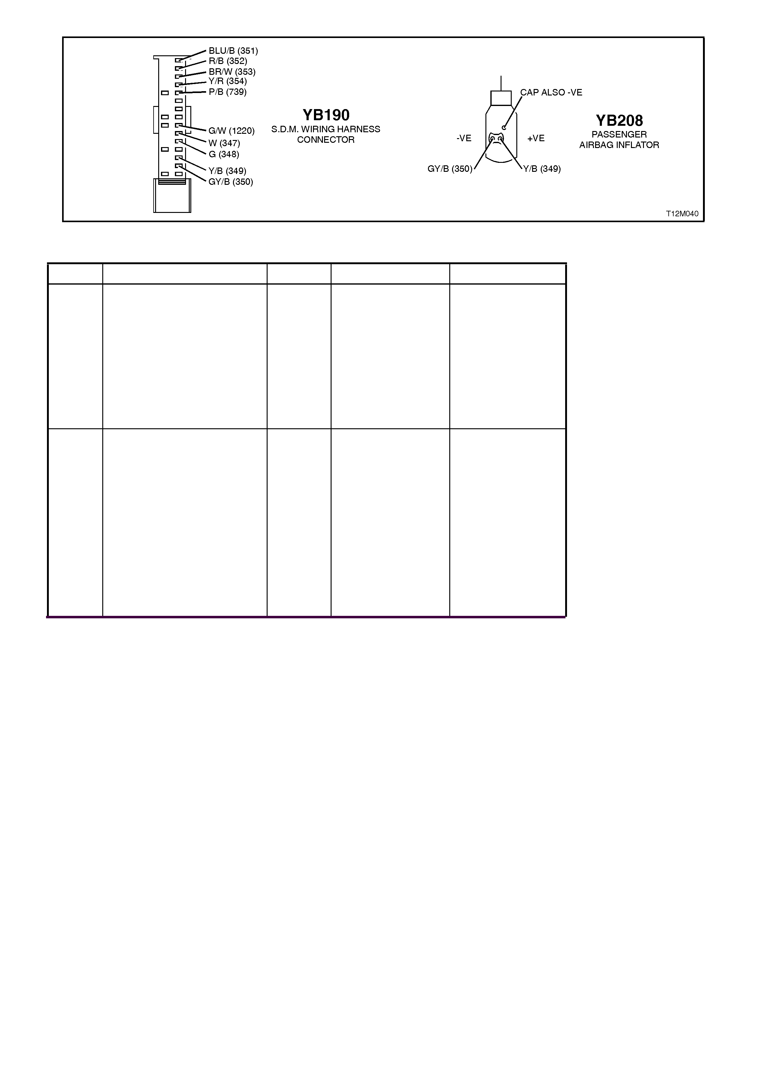
Figure 12M-78
STEP ACTION VALUE YES NO
1. ∙Connect TECH 2 to
DLC.
∙Select Body / SRS /
Diagnostic Trouble
Codes / Read DTC
Information.
∙Does TECH 2 display
DTC 23 as a Current
DTC?
Go to Step 2. Go to Step 3.
2. ∙With TECH 2 still
connected to DLC,
select Body / SRS /
Data Display and
scroll to
PASSENGER’S AIR
BAG LOOP
RESISTANCE'.
∙Does TECH 2 display
approximately '2.2
OHMS'?
Go to Step 3. Go to Step 5.

STEP ACTION VALUE YES NO
3. ∙Remove instrument
panel compartment
to gain access to
passenger’s air bag,
refer to Section 1A3
INSTRUMENT
PANEL AND
CONSOLE.
∙With TECH 2 still
connected, select
Diagnostic Trouble
Codes / Clear DTC
information and clear
all (if any) DTC’s.
∙Select Diagnostic
Trouble Codes /
Read DTC
Information, 'wiggle'
SRS wiring harness
at all locations
between the SDM
and the passenger’s
air bag wiring
harness connector
YB208, while
monitoring TECH 2
screen display.
∙Does TECH 2 screen
display change status
from No Diagnostic
Trouble Codes, refer
to NOTE 5 above ?
Go to Step 4. Fault not present.
Check all system
wiring harness
connectors, and
terminals.
Clear DTC and
recheck system.
4. ∙Inspect wiring at
point where TECH 2
screen display
changes. If
necessary split open
wiring harness.
∙Is fault identifiable?
Make repairs as
necessary
(refer to
NOTE 2 above).
Clear DTC and
recheck system to
verify repair.
Replace SRS
wiring harness
(refer to
NOTE 3 above).
Clear DTC and
recheck system
to verify repair.

STEP ACTION VALUE YES NO
5. ∙Disable the SRS,
refer to 2.2
DISABLING AND
ENABLING
PROCEDURE in this
Section.
∙Disconnect
passenger’s air bag
inflator module wiring
harness connector
YB208.
∙Connect Tool No.
SD28280B to SRS
wiring harness
connector YB208.
∙With TECH 2 still
connected, select
Body / SRS / Data
Display and scroll to
PASSENGER’S AIR
BAG LOOP
RESISTANCE'.
∙Does TECH 2 display
approximately '3.0
OHMS'?
Replace
passenger’s air
bag inflator
module assembly,
refer to 2.4
FRONT
PASSENGER’S
AIR BAG
MODULE
ASSEMBLY in
this Section.
Clear DTC and
recheck system to
verify repair.
Go to Step 6.

STEP ACTION VALUE YES NO
6. ∙Disconnect SDM
wiring harness
connector YB190
from the SDM.
∙Remove Tool
SD28280B from
YB208.
∙Using Tool KM-609-
20, check wiring
between SDM wiring
harness connector
YB190, terminals 13
and passenger’s air
bag inflator module
connector YB208,
circuit 349
(Yellow/Black wire)
for short to earth
(refer to NOTE 1
above).
∙Is all OK?
Go to Step 7. Make repairs as
necessary
(refer to
NOTE 2 above).
Clear DTC and
recheck system
to verify repair.
7. ∙With SDM wiring
harness connector
YB190 disconnected
from the SDM and
using Tool KM-609-
20, check wiring
between SDM wiring
harness connector
YB190, terminal 14
and passenger’s air
bag inflator module
connector YB208,
circuit 350
(Grey/Black wire ) for
a short to earth (refer
to NOTES 1 and 4
above).
∙Is all OK?
Replace SDM,
refer to 2.7
SENSING AND
DIAGNOSTIC
MODULE in this
Section.
Recheck circuit to
verify repair.
Make repairs as
necessary
(refer to
NOTE 2 above).
Clear DTC and
recheck system
to verify repair.
WHEN ALL DIAGNOSIS AND REPAIRS ARE COMPLETED, ENSURE ALL SRS
COMPONENTS ARE RECONNECTED, CLEAR ALL DTC’S, ENABLE THE SRS AND
VERIFY CORRECT OPERATION

DTC 24 - PASSENGER’S PRE-TENSIONER, CIRCUIT SHORT TO EARTH
Figure 12M-79
CIRCUIT DESCRIPTION
At ignition on, and on a constant monitoring cycle of every 300 milliseconds during the ignition cycle, the SDM
performs a system self check. If the SDM detects a resistance to earth of less than 4 kohms in either the positive or
negative circuit for more than 10 seconds, a current (frozen) DTC 24 will set.
DTC 24 will set if circuits 351 (pass. pre-tensioner positive side) and/or 352 (pass. pre-tensioner negative side) are
shorted to earth.
When DTC 24 sets, the SDM illuminates the SRS warning lamp and sets a current DTC 24. Should the fault
conditions detected by the SDM clear during the same ignition cycle, the current code will clear and become a
history DTC 24. The SRS warning lamp will remain on for the remainder of the ignition cycle.
If a DTC 24 is set, the SRS warning lamp is illuminated on each ignition cycle, even if the DTC is set as a history
DTC, until the fault conditions for setting DTC 24 are rectified and the DTC (current or history) can then be cleared
from the SDM via TECH 2.
If DTC 24 is set, the SRS, including the passenger’s pre-tensioner, will still be operational.
TEST DESCRIPTION
Number/s below refer to step numbers in the following diagnostic chart.
2. TECH 2 in this mode should display approximately 2.2 ohms if the driver's pre-tensioner loop circuit is OK.
3. & 4. If screen display changes during a wiring 'wiggle' test, a fault with the wiring is at that location.
5. Tool SD28280B is a dummy load taking the place of the pre-tensioner assembly. If TECH 2 displays the
correct resistance of the dummy load, the system fault is in the pre-tensioner assembly.
6. This test checks the wiring between the SDM wiring harness connector YB190, terminal 1 and the
passenger’s pre-tensioner connector YB209 for faults.
7. This test checks the wiring between the SDM wiring harness connector YB190, terminal 2 and the
passenger’s pre-tensioner connector YB209 for faults.
NOTES ON DIAGNOSTIC CHART
1. For all wiring harness checking procedures, refer to Section 12P WIRING DIA GRAMS.
2. Refer to SRS 2.8 WIRING REPAIR in this Section before conducting any SRS wiring harness repairs.
3. Refer Section 12N FUSES & WIRING HARNESSES for SRS wiring harness routing.
Resistance cannot be measured between the two terminals in connector YB209 as the in-built capacitor blocks
measurement. Therefore, a ‘service hole’ is incorporated into the connector for fault tracing. Refer to 1.1 SYTSEM
COMPONENTS, WIRING HARNESS in this Section for more details on this type of connector.
TECH 2 screen display only needs to change status to indicate a short to earth in the SRS wiring harness. The
actual DTC may not be displayed and in some instances an incorrect DTC may be displayed. If any DTC other than
DTC 24 is displayed during this test, unless they become Frozen DTC’s no action needs to be taken other than
repairing the short to earth in the passenger’s pre-tensioner circuit. If another DTC becomes frozen, other than DTC
24, refer to the relevant diagnostic chart in this Section.
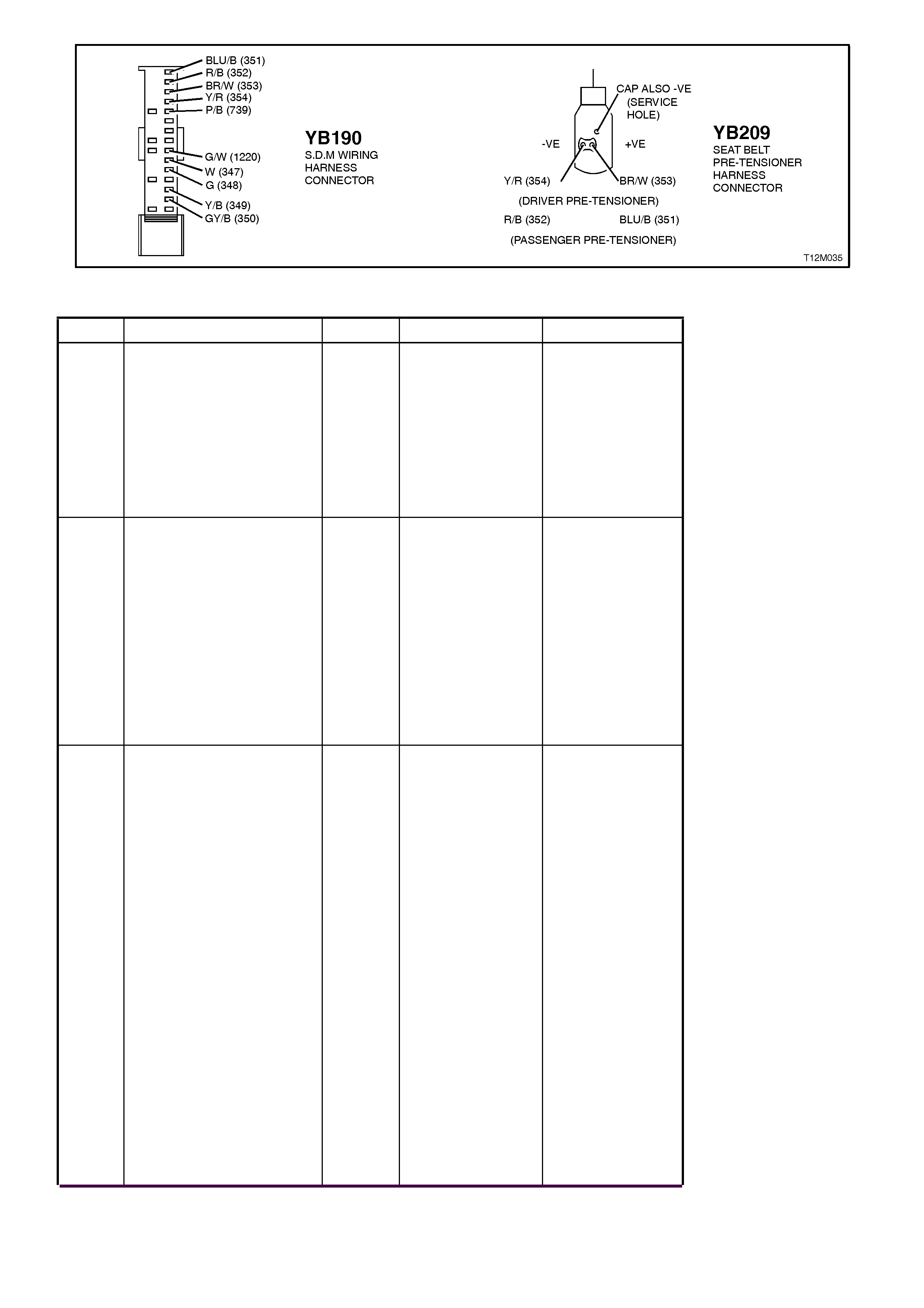
Figure 12M-80
STEP ACTION VALUE YES NO
1. ∙Connect TECH 2 to
DLC.
∙Select Body / SRS /
Diagnostic Trouble
Codes / Read DTC
Information.
∙Does TECH 2 display
DTC 24 as a Current
DTC?
Go to Step 2. Go to Step 3.
2. ∙With TECH 2 still
connected, select
Body / SRS / Data
Display and scroll to
'PASSENGER’S
PRE-TENSIONER
LOOP
RESISTANCE'.
∙Does TECH 2 display
approximately '2.2
OHMS'?
Go to Step 3. Go to Step 5.
3. ∙With TECH 2 still
connected, select
Diagnostic Trouble
Codes / Clear DTC
information and clear
all (if any) DTC’s.
∙Select Diagnostic
Trouble Codes /
Read DTC
Information, 'wiggle'
SRS wiring harness
at all locations
between the SDM
and the passenger’s
pre-tensioner wiring
harness connector
YB209, while
monitoring TECH 2
screen display.
∙Does TECH 2 screen
display change status
from No Diagnostic
Trouble Codes, refer
to NOTE 5 above ?
Go to Step 4. Fault not present.
Check all system
wiring harness
connectors, and
terminals.
Clear DTC and
recheck system.

STEP ACTION VALUE YES NO
4. ∙Inspect wiring at
point where TECH 2
screen display
changes. If
necessary split open
wiring harness.
∙Is fault identifiable?
Make repairs as
necessary
(refer to
NOTE 2 above).
Clear DTC and
recheck system to
verify repair.
Replace SRS
wiring harness
(refer to
NOTE 3 above).
Clear DTC and
recheck system
to verify repair.
5. ∙Disable the SRS,
refer to 2.2
DISABLING AND
ENABLING
PROCEDURE in this
Section.
∙Disconnect
passenger’s pre-
tensioner wiring
harness connector
YB209 from pre-
tensioner.
∙Connect Tool No.
SD28280B to SRS
wiring harness
connector YB209.
∙With TECH 2 still
connected, select
Body / SRS / Data
Display and scroll to
'PASSENGER’S
PRE-TENSIONER
LOOP
RESISTANCE'.
∙Does TECH 2 display
approximately '3.0
OHMS'?
Replace
passenger’s pre-
tensioner
assembly, refer to
Section 1A7
SEAT AND SEAT
BELT
ASSEMBLIES.
Clear DTC and
recheck system to
verify repair.
Go to Step 6.

STEP ACTION VALUE YES NO
6. ∙Disconnect SDM
wiring harness
connector YB190
from the SDM.
∙Remove Tool
SD28280B from
YB209.
∙Using Tool KM-609-
20, check wiring
between SDM wiring
harness connector
YB190, terminals 1
and passenger’s pre-
tensioner connector
YB209, circuit 351
(Blue/Brown wire) for
short to earth (refer
to NOTE 1 above).
∙Is all OK?
Go to Step 7. Make repairs as
necessary
(refer to
NOTE 2 above).
Clear DTC and
recheck system
to verify repair.
7. ∙With SDM wiring
harness connector
YB190 disconnected
from the SDM and
using Tool KM-609-
20, check wiring
between SDM wiring
harness connector
YB190, terminal 2
and passenger’s pre-
tensioner connector
YB209, circuit 352
(Red/Black wire) for
a short to earth (refer
to NOTES 1 and 4
above).
∙Is all OK?
Replace SDM,
refer to 2.7
SENSING AND
DIAGNOSTIC
MODULE in this
Section. Recheck
circuit to verify
repair.
Make repairs as
necessary
(refer to
NOTE 2 above).
Clear DTC and
recheck system
to verify repair.
WHEN ALL DIAGNOSIS AND REPAIRS ARE COMPLETED, ENSURE ALL SRS
COMPONENTS ARE RECONNECTED, CLEAR ALL DTC’S, ENABLE THE SRS AND
VERIFY CORRECT OPERATION

DTC 25 - PASSENGER'S AIR BAG, CIRCUIT SHORT TO BATTERY
Figure 12M-81
CIRCUIT DESCRIPTION
At ignition on, and on a constant monitoring cycle of every 300 milliseconds during the ignition cycle, the SDM
performs a system self check.
If the SDM detects a resistance to battery supply is less than 30 kohms in either the positive and/or negative circuit
for more than 10 seconds, a current (frozen) DTC 25 will set.
DTC 25 will set if circuits 349 (passenger’s air bag positive side) and/or 350 (passenger’s air bag negative side) are
shorted to battery +.
When DTC 25 sets, the SDM illuminates the SRS warning lamp and sets a current DTC 25. Should the fault
conditions detected by the SDM clear during the same ignition cycle, the current code will clear and become a
history DTC 25. The SRS warning lamp will remain on for the remainder of the ignition cycle.
If a DTC 25 is set, the SRS warning lamp is illuminated on each ignition cycle, even if the DTC is set as a history
DTC, until the fault conditions for setting DTC 25 are rectified and the DTC (current or history) can then be cleared
from the SDM via TECH 2.
If DTC 25 is set, the SRS, including the passenger’s air bag, will still be operational.
NOTES ON DIAGNOSTIC CHART
1. For all wiring harness checking procedures, refer to Section 12P WIRING DIA GRAMS.
2. Refer to 2.8 SRS WIRING REPAIR in this Section before conducting any SRS wiring harness repairs.
Resistance cannot be measured between the two terminals in connector YB208, as the inbuilt capacitor blocks
measurement. Therefore, a ‘service hole’ is incorporated into the connector for fault tracing. Refer to 1.1 SYTSEM
COMPONENTS, WIRING HARNESS in this Section for more details on this type of connector.
Figure 12M-82

STEP ACTION VALUE YES NO
1. ∙Disable the SRS,
refer to 2.2
DISABLING AND
ENABLING
PROCEDURE in this
Section.
∙Disconnect
passenger’s air bag
inflator module wiring
harness connector
YB208.
∙Disconnect SDM
wiring harness
connector YB190
from the SDM.
∙Reconnect battery.
∙Using Tool KM-609-
20, check wiring
between SDM wiring
harness connector
YB190, terminals 13
and 14 and
passenger’s air bag
connector YB208,
circuits 349
(Yellow/Black wire)
and 350 (Grey/Black
wire) for short to
battery + (refer to
NOTES 1 and 3
above).
∙Is all OK?
Replace SDM,
refer to 2.7
SENSING AND
DIAGNOSTIC
MODULE in this
Section. Recheck
circuit to verify
repair.
Make repairs as
necessary
(refer to
NOTE 2 above).
Clear DTC and
recheck system
to verify repair.
WHEN ALL DIAGNOSIS AND REPAIRS ARE COMPLETED, ENSURE ALL SRS
COMPONENTS ARE RECONNECTED, CLEAR ALL DTC’S, ENABLE THE SRS AND
VERIFY CORRECT OPERATION
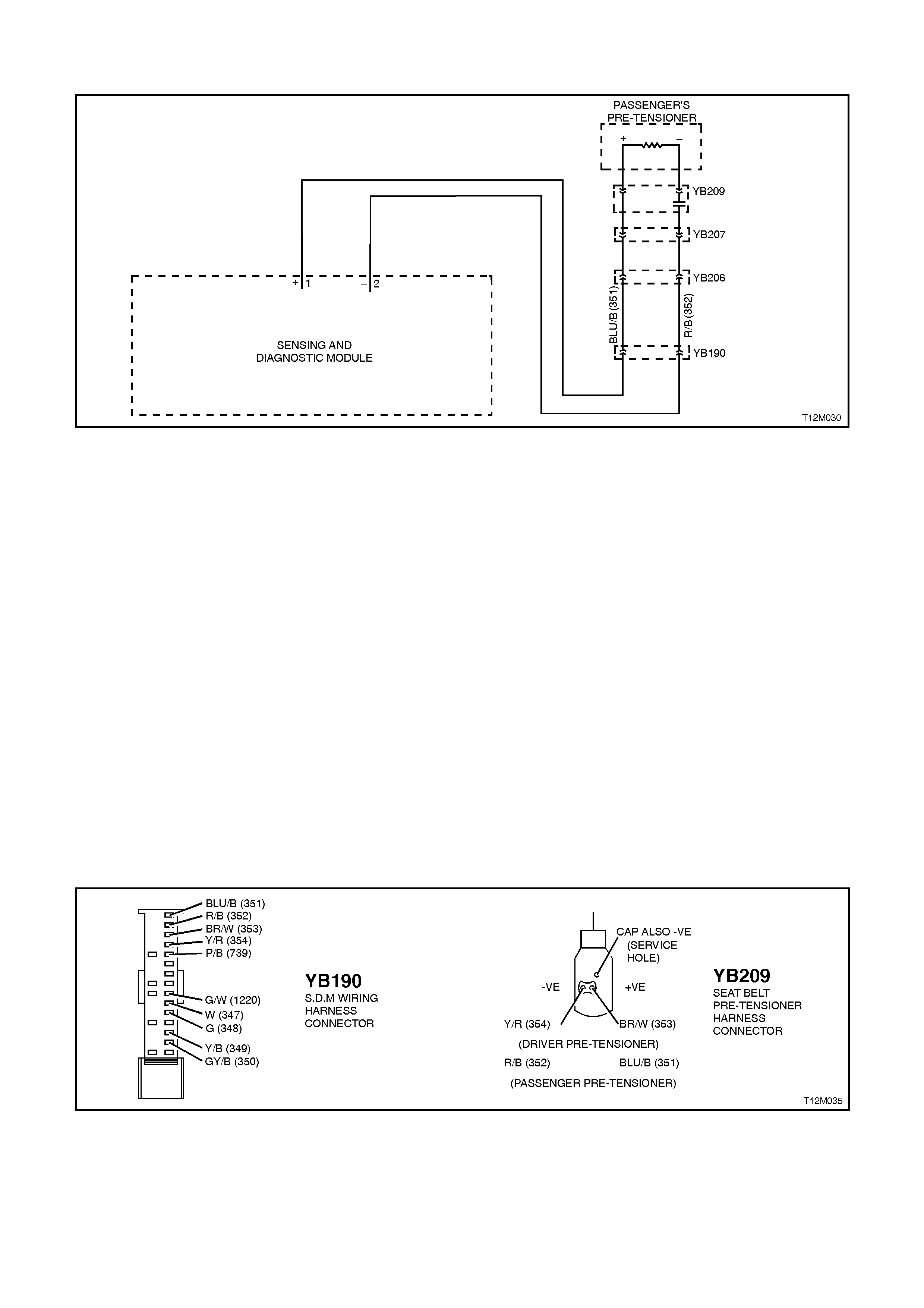
DTC 26 - PASSENGER'S PRE-TENSIONER, CIRCUIT SHORT TO BATTERY
Figure 12M-83
CIRCUIT DESCRIPTION
At ignition on, and on a constant monitoring cycle of every 300 milliseconds during the ignition cycle, the SDM
performs a system self check.
If the SDM detects a resistance to battery supply is less than 30 kohms in either the positive and/or negative circuit
for more than 10 seconds, a current (frozen) DTC 26 will set.
DTC 26 will set if circuits 351 (passenger’s pre-tensioner positive side) and/or 352 (passenger’s pre-tensioner
negative side) are shorted to battery +.
When DTC 26 sets, the SDM illuminates the SRS warning lamp and sets a current DTC 26. Should the fault
conditions detected by the SDM clear during the same ignition cycle, the current code will clear and become a
history DTC 26. The SRS warning lamp will remain on for the remainder of the ignition cycle.
If a DTC 26 is set, the SRS warning lamp is illuminated on each ignition cycle, even if the DTC is set as a history
DTC, until the fault conditions for setting DTC 26 are rectified and the DTC (current or history) can then be cleared
from the SDM via TECH 2.
If DTC 26 is set, the SRS, including the passenger’s pre-tensioner, will still be operational.
NOTES ON DIAGNOSTIC CHART
1. For all wiring harness checking procedures, refer to Section 12P WIRING DIA GRAMS.
2. Refer to 2.8 SRS WIRING REPAIR in this Section before conducting any SRS wiring harness repairs.
3. Resistance cannot be measured between the two terminals in connector YB209, as the in-built capacitor
blocks measurement. Therefore, a ‘service hole’ is incorporated into the connector for fault tracing. Refer to 1.1
SYTSEM COMPONENTS, WIRING HARNESS in this Section for more details on this type of connector.
Figure 12M-84

STEP ACTION VALUE YES NO
1. ∙Disable the SRS,
refer to 2.2
DISABLING AND
ENABLING
PROCEDURE in this
Section.
∙Disconnect the SRS
wiring harness
connector YB209
from the passenger’s
pre-tensioner
assembly.
∙Disconnect SDM
wiring harness
connector YB190
from the SDM.
∙Reconnect battery.
∙Using Tool KM-609-
20, check wiring
between SDM wiring
harness connector
YB190, terminals 1
and 2 and
passenger’s pre-
tensioner connector
YB209, circuits 351
(Blue/Black wire) and
352 (Red/Black wire)
for short to battery +
(refer to NOTES 1
and 3 above).
∙Is all OK?
Replace SDM,
refer to 2.7
SENSING AND
DIAGNOSTIC
MODULE in this
Section. Recheck
circuit to verify
repair.
Make repairs as
necessary
(refer to
NOTE 2 above).
Clear DTC and
recheck system
to verify repair.
WHEN ALL DIAGNOSIS AND REPAIRS ARE COMPLETED, ENSURE ALL SRS
COMPONENTS ARE RECONNECTED, CLEAR ALL DTC’S, ENABLE THE SRS AND
VERIFY CORRECT OPERATION
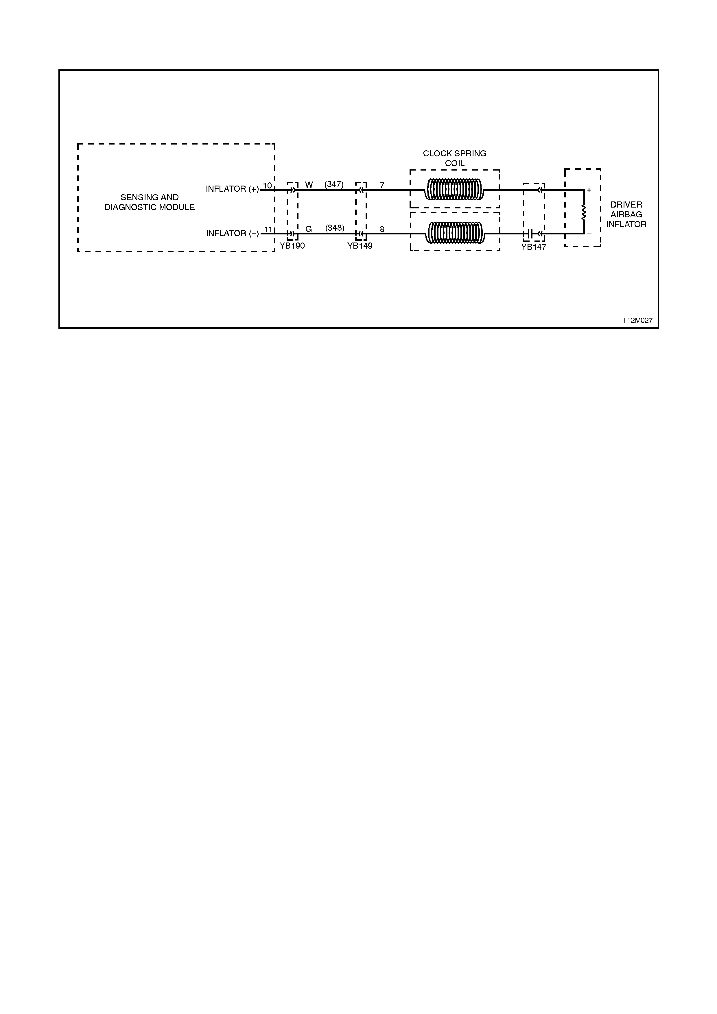
DTC 31 - DRIVERS AIR BAG OPEN CIRCUIT, LOOP CAPACITANCE TOO LOW
Figure 12M-85
CIRCUIT DESCRIPTION
At ignition on, and on a constant monitoring cycle of every 300 milliseconds during the ignition cycle, the SDM
performs a system self check.
If the SDM detects a resistance in the driver’s air bag circuit that is too high (greater than 8 ohm) or the capacitance
too low (less than 404 nF) for longer than 10 seconds, a current (frozen) DTC 31 will set.
DTC 31 will set if circuits 347 or 348, (including the horn bar and air bar assembly and the clock spring coil) are
open circuited.
When DTC 31 sets, the SDM illuminates the SRS warning lamp and sets a current DTC 31. Should the fault
conditions detected by the SDM clear during the same ignition cycle, the current code will clear and become a
history DTC 31. The SRS warning lamp will remain on for the remainder of the ignition cycle.
If a DTC 31 is set, the SRS warning lamp is illuminated on each ignition cycle, even if the DTC is set as a history
DTC, until the fault conditions for setting DTC 31 are rectified and the DTC (current or history) can then be cleared
from the SDM via TECH 2.
If DTC 31 is set, dependent on where the fault is, the driver’s air bag may not operate.
TEST DESCRIPTION
Number/s below refer to step numbers in the following diagnostic chart.
Uses TECH 2 to check if DTC 31 is current or history.
Checks for intermittent fault by monitoring TECH 2 screen. If screen display changes during a wiring 'wiggle' test, a
fault with the wiring is at that location.
Tool SD28280B is a dummy load taking the place of the driver’s horn bar and air bag assembly. If DTC 31 becomes
a history DTC with dummy load connected, the system fault is in the driver’s horn bar and air bag assembly.
Checks if open circuit is in the clock spring coil. If the clock spring coil is disconnected from the system, and
terminals 7 & 8 in connector YB149 bridged together, DTC 31 will become a history DTC if the clock spring coil is
faulty.
Checks circuit 347 for open circuit.
Checks circuit 348 for open circuit.
NOTES ON DIAGNOSTIC CHART
1. For all wiring harness checking procedures, refer to Section 12P WIRING DIA GRAMS.
Refer to 2.8 SRS WIRING REPA IR in this Section before conducting any SRS wiring harness repairs.
TECH 2 screen display only needs to change status to indicate an open circuit. The actual DTC may not be
displayed and in some instances an incorrect DTC may be displayed. If any DTC other than DTC 31 is displayed
during this test, unless they become Frozen DTC’s no action needs to be taken other than repairing the open in the
driver’s air bag circuit. If another DTC becomes frozen, other than DTC 31, refer to the relevant diagnostic chart in
this Section.

Figure 12M-86
STEP ACTION VALUE YES NO
1. ∙Install TECH 2 to
DLC
∙Select Body / SRS /
Diagnostic Trouble
Codes / Read DTC
Information
∙Is DTC 31 current?
Go to Step 3. Go to Step 2.
2. ∙Remove steering
column upper and
lower cover.
∙With TECH 2 still
connected, select
Diagnostic Trouble
Codes / Clear DTC
information and clear
all (if any) DTC’s.
∙Select Diagnostic
Trouble Codes /
Read DTC
Information, 'wiggle'
SRS wiring harness
at all locations
between the SDM
and the clock spring
coil while monitoring
the TECH 2 screen
display.
∙Does TECH 2 screen
display change status
from No Diagnostic
Trouble Codes, refer
to NOTE 3 above ?
Make repairs as
necessary
(refer to
NOTE 2 above).
Clear DTC and
recheck system to
verify repair.
Fault not present.
Check all system
wiring harness
connectors, and
terminals.
Clear DTC and
recheck system.

STEP ACTION VALUE YES NO
3. ∙Disable the SRS,
refer to 2.2
DISABLING AND
ENABLING
PROCEDURE in this
Section.
∙Remove horn bar
and driver's air bag
inflator module, refer
to 2.3 HORN BAR
AND AIR BAG
MODULE
ASSEMBLY in this
Section.
∙Connect Tool No.
SD28280B to SRS
wiring harness
connector YB147.
∙Reconnect battery.
∙Connect TECH 2 to
DLC.
∙Select Body / SRS /
Diagnostic Trouble
Codes / Read DTC
Information.
∙Is DTC 31 still
current?
Go to Step 4. Replace horn bar
and driver's air
bag inflator
module
assembly, refer to
2.3 HORN BAR
AND AIR BAG
MODULE
ASSEMBLY in
this Section.
Clear DTC and
recheck system
to verify repair.
4. ∙Disable the SRS,
refer to 2.2
DISABLING AND
ENABLING
PROCEDURE in this
Section.
∙Disconnect SRS
wiring harness
connector YB149
from clock spring coil
assembly.
∙Reconnect battery.
∙Using a suitable
jumper wire from KM-
609, bridge
connector YB149,
terminals 7 and 8
together.
∙With TECH 2 still
connected, select
Body / SRS /
Diagnostic Trouble
Codes / Read DTC
Information
∙Does DTC 31
become history?
Replace clock
sprin g coil
assembly, refer to
2.6 CLOCK
SPRING COIL in
this Section. Clear
all DTC’s and
recheck system to
verify repair.
Go to Step 5

STEP ACTION VALUE YES NO
5. ∙Disable the SRS,
refer to 2.2
DISABLING AND
ENABLING
PROCEDURE in this
Section.
∙Disconnect SDM
wiring harness
connector YB190
from the SDM.
∙Using Tool KM-609-
20, check wiring
between SDM wiring
harness connector
YB190, terminals 10
and clock spring coil
connector YB149,
terminal 7, circuits
347 (White wire) for
open (refer to
NOTE 1 above).
∙Is all OK?
Go to Step 6. Make repairs as
necessary
(refer to
NOTE 2 above).
Clear DTC and
recheck system
to verify repair.
6. ∙With SDM wiring
harness connector
YB190 disconnected
from the SDM and
using Tool KM-609-
20, check wiring
between SDM wiring
harness connector
YB190, terminal 11
and clock spring coil
connector YB149,
terminal 8, circuits
348 (Green wire) for
open (refer to NOTE
1 above).
∙Is all OK?
Replace SDM,
refer to 2.7
SENSING AND
DIAGNOSTIC
MODULE in this
Section. Recheck
circuit to verify
repair.
Make repairs as
necessary
(refer to
NOTE 2 above).
Clear DTC and
recheck system
to verify repair.
WHEN ALL DIAGNOSIS AND REPAIRS ARE COMPLETED, ENSURE ALL SRS
COMPONENTS ARE RECONNECTED, CLEAR ALL DTC’S, ENABLE THE SRS AND
VERIFY CORRECT OPERATION

DTC 32 - DRIVERS AIR BAG, SHORT CIRCUIT, LOOP CAPACITANCE TOO HIGH
Figure 12M-87
CIRCUIT DESCRIPTION
At ignition on, and on a constant monitoring cycle of every 300 milliseconds during the ignition cycle, the SDM
performs a system self check.
If the SDM detects a resistance in the driver’s air bag circuit that is too low (less than 1 ohm) or the capacitance too
high (greater than 535 nF) for longer than 10 seconds, a current (frozen) DTC 32 will set.
DTC 32 will set if circuits 347 or 348, (including the horn bar and air bar assembly and the clock spring coil) are
shorted to earth.
When DTC 32 sets, the SDM illuminates the SRS warning lamp and sets a current DTC 32. Should the fault
conditions detected by the SDM clear during the same ignition cycle, the current code will clear and become a
history DTC 32. The SRS warning lamp will remain on for the remainder of the ignition cycle.
If a DTC 32 is set, the SRS warning lamp is illuminated on each ignition cycle, even if the DTC is set as a history
DTC, until the fault conditions for setting DTC 32 are rectified and the DTC (current or history) can then be cleared
from the SDM via TECH 2.
If DTC 32 is set, dependent on where the fault is, the driver’s air bag may not operate.
TEST DESCRIPTION
Number/s below refer to step numbers in the following diagnostic chart.
Uses TECH 2 to check if DTC 32 is current or history.
Checks for intermittent fault by monitoring TECH 2 screen. If screen display changes during a wiring 'wiggle' test, a
fault with the wiring is at that location.
Tool SD28280B is a dummy load taking the place of the driver’s horn bar and air bag assembly. If DTC 32 becomes
a history DTC with dummy load connected, the system fault is in the driver’s horn bar and air bag assembly.
Checks if short circuit is in the clock spring coil. If the clock spring coil is disconnected from the system, a DTC 31
(open circuit) will set and DTC 31 will become history. If DTC 31 sets and DTC 32 becomes history, the clock spring
coil is faulty.
Checks circuit 347 for short circuit.
Checks circuit 348 for short circuit.
NOTES ON DIAGNOSTIC CHART
1. For all wiring harness checking procedures, refer to Section 12P WIRING DIA GRAMS.
Refer to 2.8 SRS WIRING REPA IR in this Section before conducting any SRS wiring harness repairs.
TECH 2 screen display only needs to change status to indicate a short circuit. The actual DTC may not be displayed
and in some instances an incorrect DTC may be displayed. If any DTC other than DTC 32 is displayed during this
test, unless they become Frozen DTC’s no action needs to be taken other than repairing the short in the driver’s air
bag circuit. If another DTC becomes frozen, other than DTC 32, refer to the relevant diagnostic chart in this Section.
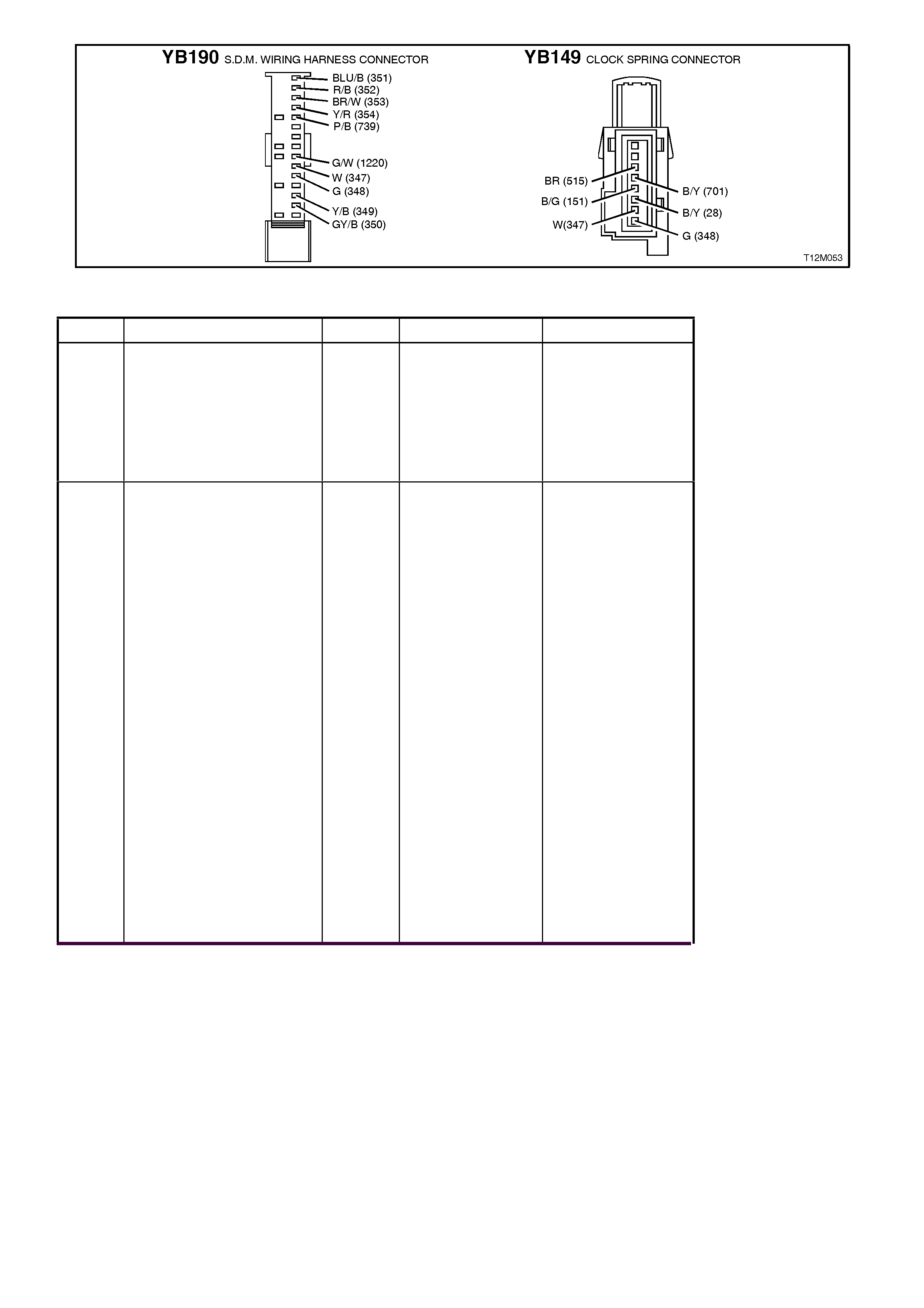
Figure 12M-88
STEP ACTION VALUE YES NO
1. ∙Install TECH 2 to
DLC
∙Select Body / SRS /
Diagnostic Trouble
Codes / Read DTC
Information
∙Is DTC 32 current?
Go to Step 3. Go to Step 2.
2. ∙Remove steering
column upper and
lower cover.
∙With TECH 2 still
connected, select
Diagnostic Trouble
Codes / Clear DTC
information and clear
all (if any) DTC’s.
∙Select Diagnostic
Trouble Codes /
Read DTC
Information, 'wiggle'
SRS wiring harness
at all locations
between the SDM
and the clock spring
coil while monitoring
the TECH 2 screen
display.
∙Does TECH 2 screen
display change status
from No Diagnostic
Trouble Codes, refer
to NOTE 3 above ?
Make repairs as
necessary
(refer to
NOTE 2 above).
Clear DTC and
recheck system to
verify repair.
Fault not present.
Check all system
wiring harness
connectors, and
terminals.
Clear DTC and
recheck system.

STEP ACTION VALUE YES NO
3. ∙Disable the SRS,
refer to 2.2
DISABLING AND
ENABLING
PROCEDURE in this
Section.
∙Remove horn bar
and driver's air bag
inflator module, refer
to 2.3 HORN BAR
AND AIR BAG
MODULE
ASSEMBLY in this
Section.
∙Connect Tool No.
SD28280B to SRS
wiring harness
connector YB147.
∙Reconnect battery.
∙Connect TECH 2 to
DLC.
∙Select Body / SRS /
Diagnostic Trouble
Codes / Read DTC
Information.
∙Is DTC 32 still
current?
Go to Step 4. Replace horn bar
and driver's air bag
inflator module
assembly, refer to
2.3 HORN BAR
AND AIR BAG
MODULE
ASSEMBLY in this
Section.
Clear DTC and
recheck system to
verify repair.
4. ∙Disable the SRS,
refer to 2.2
DISABLING AND
ENABLING
PROCEDURE in this
Section.
∙Disconnect SRS
wiring harness
connector YB149
from clock spring coil
assembly.
∙Reconnect battery.
∙With TECH 2 still
connected, select
Body / SRS /
Diagnostic Trouble
Codes / Read DTC
Information
∙Is DTC 31 current
and DTC 32 history?
Replace clock
sprin g coil
assembly, refer to
2.6 CLOCK
SPRING COIL in
this Section. Clear
all DTC’s and
recheck system to
verify repair.
Go to Step 5

STEP ACTION VALUE YES NO
5. ∙Disable the SRS,
refer to 2.2
DISABLING AND
ENABLING
PROCEDURE in this
Section.
∙Disconnect SDM
wiring harness
connector YB190
from the SDM.
∙Using Tool KM-609-
20, check wiring
between SDM wiring
harness connector
YB190, terminals 10
and clock spring coil
connector YB149,
terminal 7, circuits
347 (White wire) for
short (refer to
NOTE 1 above).
∙Is all OK?
Go to Step 6. Make repairs as
necessary
(refer to
NOTE 2 above).
Clear DTC and
recheck system to
verify repair.
6. ∙With SDM wiring
harness connector
YB190 disconnected
from the SDM and
using Tool KM-609-
20, check wiring
between SDM wiring
harness connector
YB190, terminal 11
and clock spring coil
connector YB149,
terminal 8, circuits
348 (Green wire) for
short (refer to NOTE
1 above).
∙Is all OK?
Replace SDM,
refer to 2.7
SENSING AND
DIAGNOSTIC
MODULE in this
Section. Recheck
circuit to verify
repair.
Make repairs as
necessary
(refer to
NOTE 2 above).
Clear DTC and
recheck system to
verify repair.
WHEN ALL DIAGNOSIS AND REPAIRS ARE COMPLETED, ENSURE ALL SRS
COMPONENTS ARE RECONNECTED, CLEAR ALL DTC’S, ENABLE THE SRS AND
VERIFY CORRECT OPERATION

DTC 33 - PASSENGER'S AIR BAG OPEN CIRCUIT, LOOP CAPACITANCE TOO LOW
Figure 12M-89
CIRCUIT DESCRIPTION
At ignition on, and on a constant monitoring cycle of every 300 milliseconds during the ignition cycle, the SDM
performs a system self check.
If the SDM detects a resistance in the passenger’s air bag circuit that is too high (greater than 8 ohm) or the
capacitance too low (less than 404 nF) for longer than 10 seconds, a current (frozen) DTC 33 will set.
DTC 33 will set if circuits 349 or 350 (including the passenger’s air bag inflator module) are open circuit.
When DTC 33 sets, the SDM illuminates the SRS warning lamp and sets a current DTC 33. Should the fault
conditions detected by the SDM clear during the same ignition cycle, the current code will clear and become a
history DTC 33. The SRS warning lamp will remain on for the remainder of the ignition cycle.
If a DTC 33 is set, the SRS warning lamp is illuminated on each ignition cycle, even if the DTC is set as a history
DTC, until the fault conditions for setting DTC 33 are rectified and the DTC (current or history) can then be cleared
from the SDM via TECH 2.
If DTC 33 is set, dependent on where the fault is, the passenger’s air bag may not operate.
TEST DESCRIPTION
Number/s below refer to step numbers in the following diagnostic chart.
Uses TECH 2 to check if DTC 33 is current or history.
Checks for intermittent fault by monitoring TECH 2 screen. If screen display changes during a wiring 'wiggle' test, a
fault with the wiring is at that location.
Tool SD28280B is a dummy load taking the place of the passenger’s air bag inflator module. If DTC 33 becomes a
history DTC with dummy load connected, the system fault is in the passenger’s air bag inflator module.
Checks if open circuit is in the SRS connector harness. If connector YB200 is disconnected and it’s terminal’s are
bridged together, DTC 33 will become a history DTC if this connector harness is faulty.
Checks circuit 349 for open circuit.
Checks circuit 350 for open circuit.
NOTES ON DIAGNOSTIC CHART
1. For all wiring harness checking procedures, refer to Section 12P WIRING DIA GRAMS.
Refer to 2.8 SRS WIRING REPA IR in this Section before conducting any SRS wiring harness repairs.
TECH 2 screen display only needs to change status to indicate an open circuit. The actual DTC may not be
displayed and in some instances an incorrect DTC may be displayed. If any DTC other than DTC 33 is displayed
during this test, unless they become Frozen DTC’s no action needs to be taken other than repairing the open in the
passenger’s air bag circuit. If another DTC becomes frozen, other than DTC 33, refer to the relevant diagnostic
chart in this Section.
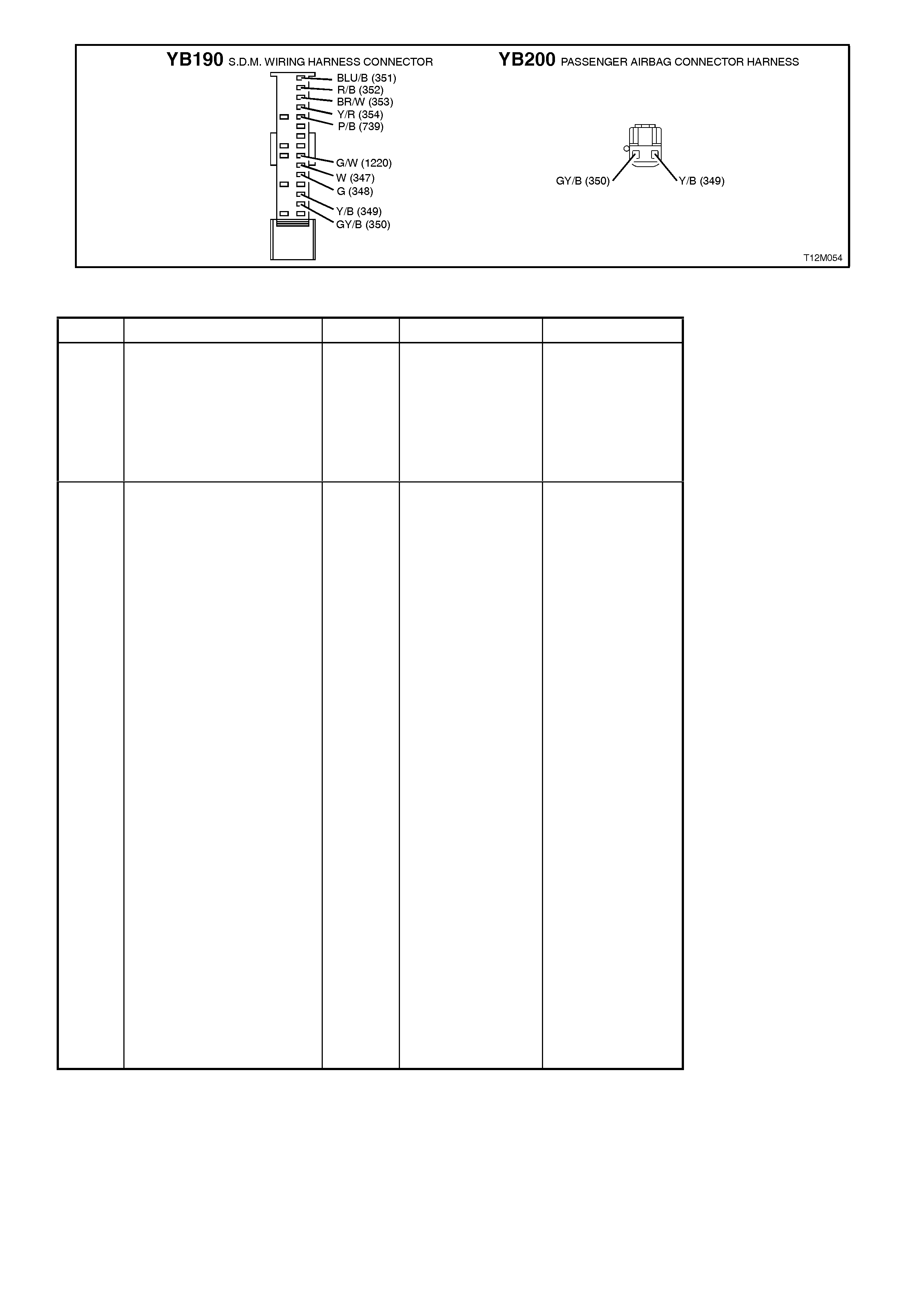
Figure 12M-90
STEP ACTION VALUE YES NO
1. ∙Install TECH 2 to
DLC
∙Select Body / SRS /
Diagnostic Trouble
Codes / Read DTC
Information
∙Is DTC 33 current?
Go to Step 3. Go to Step 2.
2. ∙Remove instrument
panel compartment
to gain access to
passenger’s air bag,
refer to Section 1A3
INSTRUMENT
PANEL AND
CONSOLE.
∙With TECH 2 still
connected, select
Diagnostic Trouble
Codes / Clear DTC
information and clear
all (if any) DTC’s.
∙Select Diagnostic
Trouble Codes /
Read DTC
Information, 'wiggle'
SRS wiring harness
at all locations
between the SDM
and the passenger’s
air bag wiring
harness connector
YB208, while
monitoring TECH 2
screen display.
∙Does TECH 2 screen
display change status
from No Diagnostic
Trouble Codes, refer
to NOTE 3 above ?
Make repairs as
necessary
(refer to
NOTE 2 above).
Clear DTC and
recheck system to
verify repair.
Fault not present.
Check all system
wiring harness
connectors, and
terminals.
Clear DTC and
recheck system.

STEP ACTION VALUE YES NO
3. ∙Disable the SRS,
refer to 2.2
DISABLING AND
ENABLING
PROCEDURE in this
Section.
∙Disconnect the
passenger’s air bag
inflator module wiring
harness connector
YB208.
∙Connect Tool No.
SD28280B to SRS
wiring harness
connector YB208.
∙Reconnect battery.
∙Connect TECH 2 to
DLC.
∙Select Body / SRS /
Diagnostic Trouble
Codes / Read DTC
Information
∙Is DTC 33 still
current?
Go to Step 4. Replace
passenger’s air
bag inflator
module
assembly, refer to
2.4 FRONT
PASSENGER’S
AIR BAG
MODULE
ASSEMBLY in
this Section.
Clear DTC and
recheck system
to verify repair.
4. ∙Disable the SRS,
refer to 2.2
DISABLING AND
ENABLING
PROCEDURE in this
Section.
∙Disconnect SRS
wiring harness
connector YB200
from passenger’s air
bag inflator module
connector harness.
∙Reconnect battery.
∙Using a suitable
jumper wire from KM-
609, bridge terminals
in connector YB200
together.
∙With TECH 2 still
connected, select
Body / SRS /
Diagnostic Trouble
Codes / Read DTC
Information
∙Does DTC 33
become history?
Replace SRS
connector
harness (harness
between
passenger air bag
inflator module
and connector
YB200). Clear all
DTC’s and
recheck system to
verify repair.
Go to Step 5

STEP ACTION VALUE YES NO
5. ∙Disable the SRS,
refer to 2.2
DISABLING AND
ENABLING
PROCEDURE in this
Section.
∙Disconnect SDM
wiring harness
connector YB190
from the SDM.
∙Using Tool KM-609-
20, check wiring
between SDM wiring
harness connector
YB190, terminals 13
and SRS wiring
harness connector
YB200, circuit 349
(Yellow/Black wire)
for open (refer to
NOTE 1 above).
∙Is all OK?
Go to Step 6. Make repairs as
necessary
(refer to
NOTE 2 above).
Clear DTC and
recheck system
to verify repair.
6. ∙With SDM wiring
harness connector
YB190 disconnected
from the SDM and
using Tool KM-609-
20, check wiring
between SDM wiring
harness connector
YB190, terminal 14
and SRS wiring
harness connector
YB200, circuit 350
(Grey / Black wire)
for open (refer to
NOTE 1 above).
∙Is all OK?
Replace SDM,
refer to 2.7
SENSING AND
DIAGNOSTIC
MODULE in this
Section. Recheck
circuit to verify
repair.
Make repairs as
necessary
(refer to
NOTE 2 above).
Clear DTC and
recheck system
to verify repair.
WHEN ALL DIAGNOSIS AND REPAIRS ARE COMPLETED, ENSURE ALL SRS
COMPONENTS ARE RECONNECTED, CLEAR ALL DTC’S, ENABLE THE SRS AND
VERIFY CORRECT OPERATION
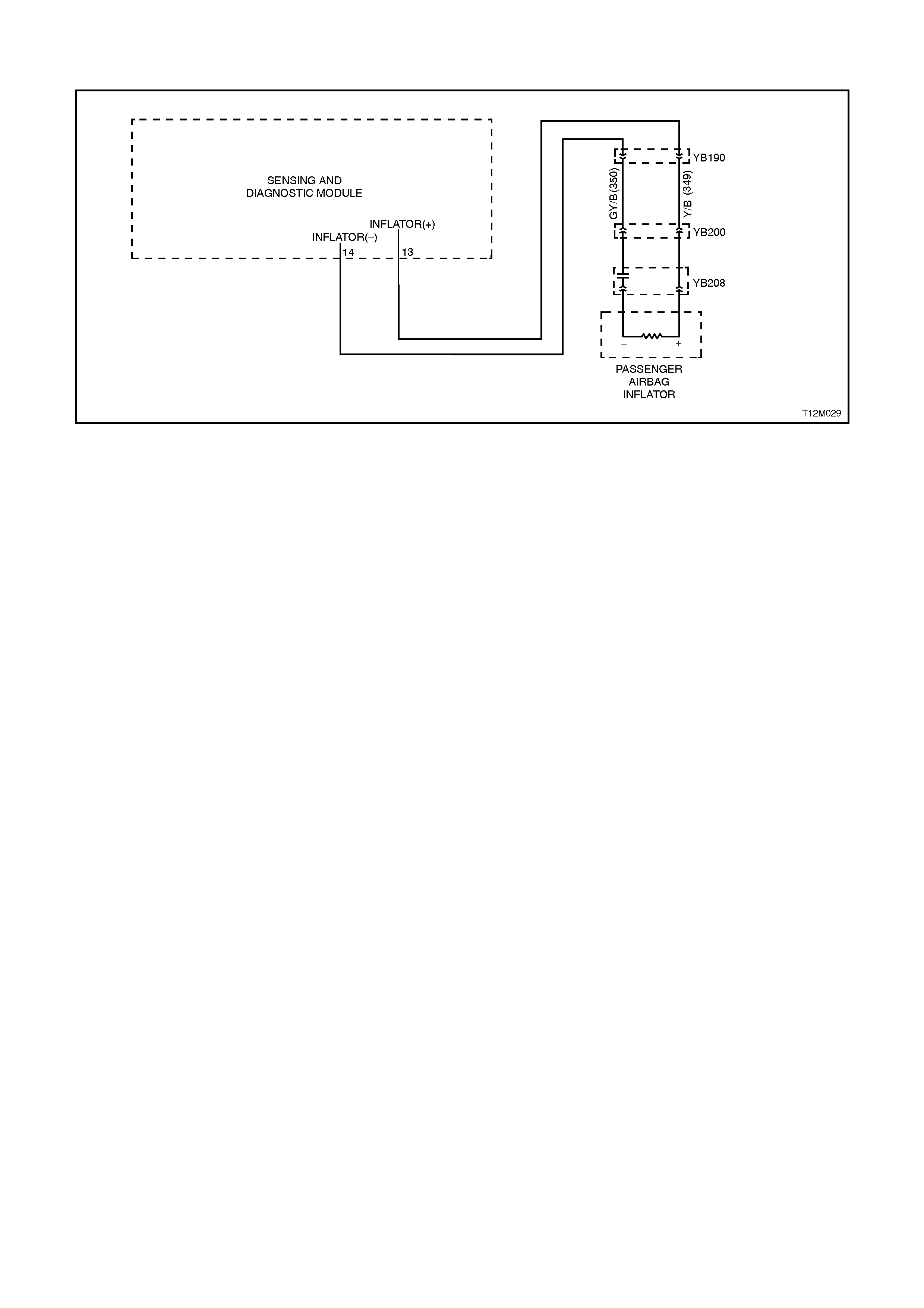
DTC 34 - PASSENGER’S AIR BAG SHORT CIRCUIT, LOOP CAPACITANCE TOO HIGH
Figure 12M-91
CIRCUIT DESCRIPTION
At ignition on, and on a constant monitoring cycle of every 300 milliseconds during the ignition cycle, the SDM
performs a system self check.
If the SDM detects a resistance in the passenger’s air bag circuit that is too low (less than 1 ohm) or the
capacitance too high (greater than 535 nF) for longer than 10 seconds, a current (frozen) DTC 34 will set.
DTC 34 will set if circuits 349 or 350, (including the passenger’s air bag inflator module assembly) are shorted to
earth.
When DTC 34 sets, the SDM illuminates the SRS warning lamp and sets a current DTC 34. Should the fault
conditions detected by the SDM clear during the same ignition cycle, the current code will clear and become a
history DTC 34. The SRS warning lamp will remain on for the remainder of the ignition cycle.
If a DTC 34 is set, the SRS warning lamp is illuminated on each ignition cycle, even if the DTC is set as a history
DTC, until the fault conditions for setting DTC 34 are rectified and the DTC (current or history) can then be cleared
from the SDM via TECH 2.
If DTC 34 is set, dependent on where the fault is, the passenger’s air bag may not operate.
TEST DESCRIPTION
Number/s below refer to step numbers in the following diagnostic chart.
1. Uses TECH 2 to check if DTC 34 is current or history.
2. Checks for intermittent fault by monitoring TECH 2 screen. If screen display changes during a wiring 'wiggle'
test, a fault with the wiring is at that location.
3. Tool SD28280B is a dummy load taking the place of the passenger’s air bag inflator module. If DTC 34
becomes a history DTC with dummy load connected, the system fault is in the passenger’s air bag inflator
module.
3. Checks circuit 349 and 350 for short to earth.
NOTES ON DIAGNOSTIC CHART
1. For all wiring harness checking procedures, refer to Section 12P WIRING DIA GRAMS.
2. Refer to 2.8 SRS WIRING REPAIR in this Section before conducting any SRS wiring harness repairs.
3. Resistance cannot be measured between the two terminals in connector YB208, as the in-built capacitor
blocks measurement. Therefore, a ‘service hole’ is incorporated into the connector for fault tracing. Refer to 1.1
SYTSEM COMPONENTS, WIRING HARNESS in this Section for more details on this type of connector.
4. TECH 2 screen display only needs to change status to indicate a short circuit. The actual DTC may not be
displayed and in some instances an incorrect DTC may be displayed. If any DTC other than DTC 34 is
displayed during this test, unless they become Frozen DTC’s no action needs to be taken other than repairing
the short in the passenger’s air bag circuit. If another DTC becomes frozen, other than DTC 34, refer to the
relevant diagnostic chart in this Section.
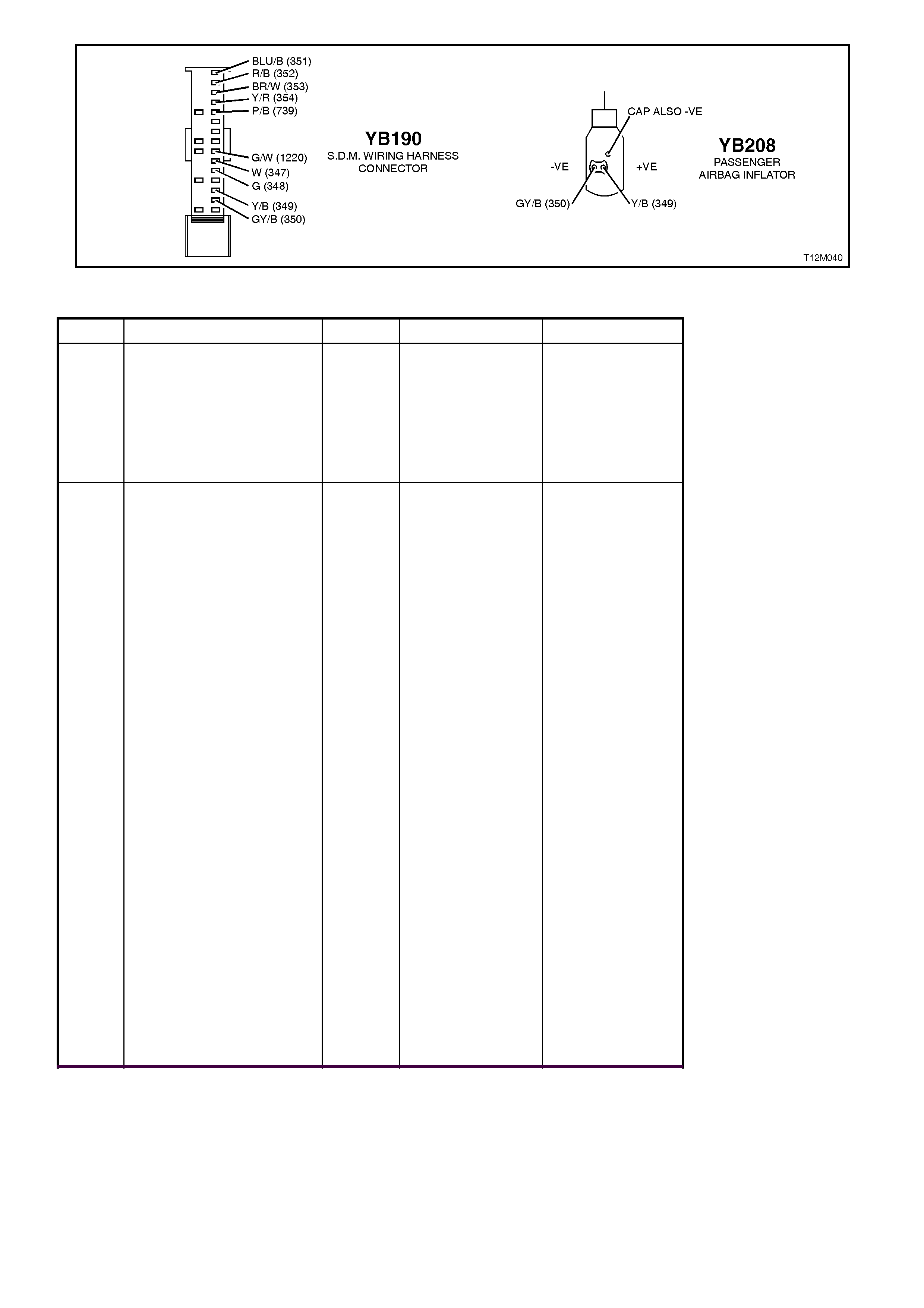
Figure 12M-92
STEP ACTION VALUE YES NO
1. ∙Install TECH 2 to
DLC
∙Select Body / SRS /
Diagnostic Trouble
Codes / Read DTC
Information
∙Is DTC 34 current?
Go to Step 3. Go to Step 2.
2. ∙Remove instrument
panel compartment
to gain access to
passenger’s air bag,
refer to Section 1A3
INSTRUMENT
PANEL AND
CONSOLE.
∙With TECH 2 still
connected, select
Diagnostic Trouble
Codes / Clear DTC
information and clear
all (if any) DTC’s.
∙Select Diagnostic
Trouble Codes /
Read DTC
Information, 'wiggle'
SRS wiring harness
at all locations
between the SDM
and the passenger’s
air bag wiring
harness connector
YB208, while
monitoring TECH 2
screen display.
∙Does TECH 2 screen
display change status
from No Diagnostic
Trouble Codes, refer
to NOTE 4 above ?
Make repairs as
necessary
(refer to
NOTE 2 above).
Clear DTC and
recheck system to
verify repair.
Fault not present.
Check all system
wiring harness
connectors, and
terminals.
Clear DTC and
recheck system.

STEP ACTION VALUE YES NO
3. ∙Disable the SRS,
refer to 2.2
DISABLING AND
ENABLING
PROCEDURE in this
Section.
∙Disconnect the
passenger’s air bag
inflator module wiring
harness connector
YB208.
∙Connect Tool No.
SD28280B to SRS
wiring harness
connector YB208.
∙Reconnect battery.
∙Connect TECH 2 to
DLC.
∙Select Body / SRS /
Diagnostic Trouble
Codes / Read DTC
Information.
∙Is DTC 34 still
current?
Go to Step 4. Replace
passenger’s air
bag inflator
module
assembly, refer to
2.4 FRONT
PASSENGER’S
AIR BAG
MODULE
ASSEMBLY in
this Section.
Clear DTC and
recheck system
to verify repair.
4. ∙Disable the SRS,
refer to 2.2
DISABLING AND
ENABLING
PROCEDURE in this
Section.
∙Disconnect SDM
wiring harness
connector YB190
from the SDM.
∙Using Tool KM-609-
20, check wiring
between SDM wiring
harness connector
YB190, terminals 13
and 14 and
passenger’s air bag
inflator module
connector YB208,
circuits 349
(Yellow/Black wire)
and 350 (Grey/Black
wire) for short to
earth (refer to
NOTES 1 and 3
above).
∙Is all OK?
Replace SDM,
refer to 2.7
SENSING AND
DIAGNOSTIC
MODULE in this
Section. Recheck
circuit to verify
repair.
Make repairs as
necessary
(refer to
NOTE 2 above).
Clear DTC and
recheck system
to verify repair.
WHEN ALL DIAGNOSIS AND REPAIRS ARE COMPLETED, ENSURE ALL SRS
COMPONENTS ARE RECONNECTED, CLEAR ALL DTC’S, ENABLE THE SRS AND
VERIFY CORRECT OPERATION
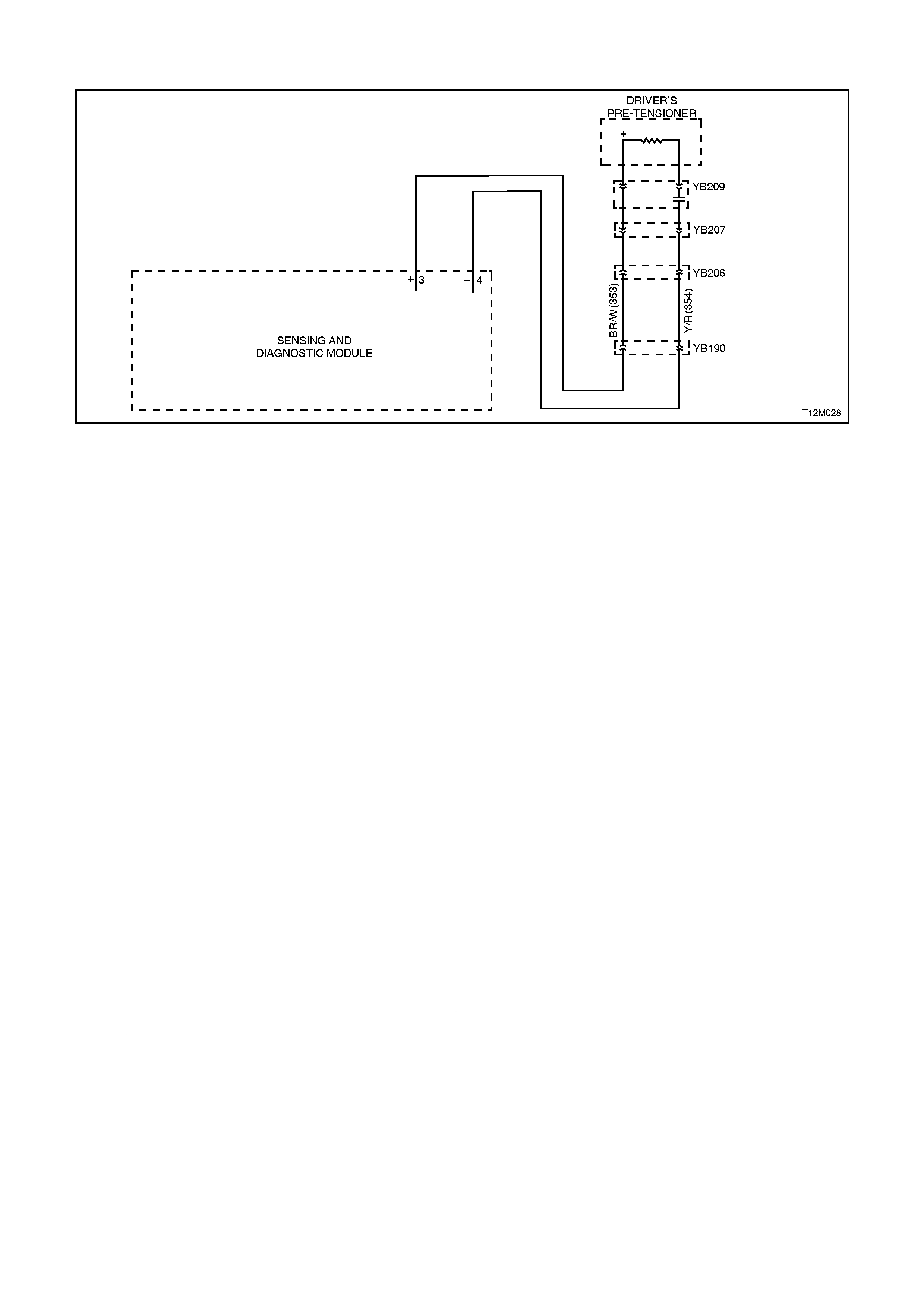
DTC 35 - DRIVER’S PRE-TENSIONER OPEN CIRCUIT, LOOP CAPACITANCE TOO LOW
Figure 12M-93
CIRCUIT DESCRIPTION
At ignition on, and on a constant monitoring cycle of every 300 milliseconds during the ignition cycle, the SDM
performs a system self check.
If the SDM detects a resistance in the driver’s pre-tensioner circuit that is too high (greater than 8 ohm) or the
capacitance too low (less than 404 nF) for longer than 10 seconds, a current frozen DTC 35 will set.
DTC 35 will set if circuits 353 or 354 (including the driver’s pre-tensioner assembly) are open circuit.
When DTC 35 sets, the SDM illuminates the SRS warning lamp and sets a current DTC 35. Should the fault
conditions detected by the SDM clear during the same ignition cycle, the current code will clear and become a
history DTC 35. The SRS warning lamp will remain on for the remainder of the ignition cycle.
If a DTC 35 is set, the SRS warning lamp is illuminated on each ignition cycle, even if the DTC is set as a history
DTC, until the fault conditions for setting DTC 35 are rectified and the DTC (current or history) can then be cleared
from the SDM via TECH 2.
If DTC 35 is set, dependent on where the fault is, the driver’s pre-tensioner may not operate.
TEST DESCRIPTION
Number/s below refer to step numbers in the following diagnostic chart.
Uses TECH 2 to check if DTC 35 is current or history.
Checks for intermittent fault by monitoring TECH 2 screen. If screen display changes during a wiring 'wiggle' test, a
fault with the wiring is at that location.
Tool SD28280B is a dummy load taking the place of the driver’s pre-tensioner assembly. If DTC 35 becomes a
history DTC with dummy load connected, the system fault is in the driver’s pre-tensioner assembly.
Checks if open circuit is in the SRS connector harness. If connector YB207 is disconnected and it’s
terminal’s are bridged together, DTC 35 will become a history DTC if this connector harness is faulty.
Checks circuit 353 for open circuit.
Checks circuit 354 for open circuit.
NOTES ON DIAGNOSTIC CHART
1. For all wiring harness checking procedures, refer to Section 12P WIRING DIA GRAMS.
Refer to 2.8 SRS WIRING REPA IR in this Section before conducting any SRS wiring harness repairs.
TECH 2 screen display only needs to change status to indicate a open circuit. The actual DTC may not be displayed
and in some instances an incorrect DTC may be displayed. If any DTC other than DTC 35 is displayed during this
test, unless they become Frozen DTC’s no action needs to be taken other than repairing the open in the driver’s
pre-tensioner circuit. If another DTC becomes frozen, other than DTC 35, refer to the relevant diagnostic chart in
this Section.
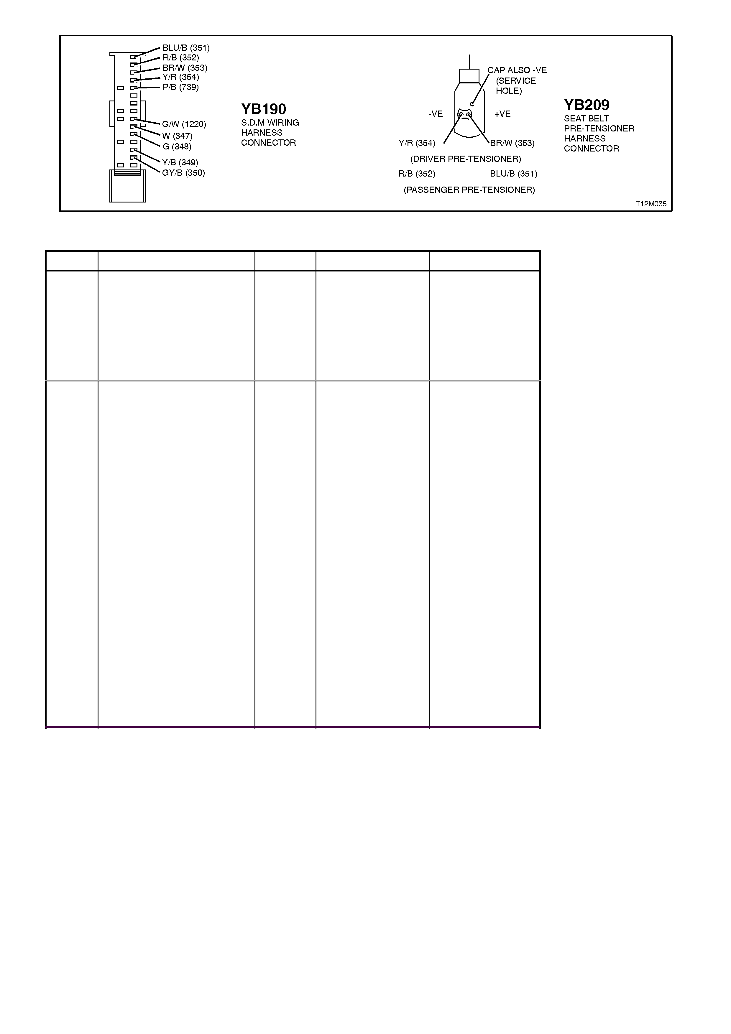
Figure 12M-94
STEP ACTION VALUE YES NO
1. ∙Connect TECH 2 to
DLC
∙Select Body / SRS /
Diagnostic Trouble
Codes / Read DTC
Information
∙Is DTC 35 current?
Go to Step 3. Go to Step 2.
2. ∙With TECH 2 still
connected, select
Diagnostic Trouble
Codes / Clear DTC
information and clear
all (if any) DTC’s.
∙Select Diagnostic
Trouble Codes /
Read DTC
Information, 'wiggle'
SRS wiring harness
at all locations
between the SDM
and the driver’s pre-
tensioner wiring
harness connector
YB209, while
monitoring TECH 2
screen display.
∙Does TECH 2 screen
display change status
from No Diagnostic
Trouble Codes, refer
to NOTE 3 above ?
Make repairs as
necessary
(refer to
NOTE 2 above).
Clear DTC and
recheck system to
verify repair.
Fault not present.
Check all system
wiring harness
connectors, and
terminals.
Clear DTC and
recheck system.

STEP ACTION VALUE YES NO
3. ∙Disable the SRS,
refer 2.2 DISABLING
AND ENABLING
PROCEDURE in this
Section.
∙Disconnect the
driver’s pre-tensioner
wiring harness
connector YB209.
∙Connect Tool No.
SD28280B to SRS
wiring harness
connector YB209.
∙Reconnect battery.
∙Connetc TECH 2 to
DLC.
∙Select Body / SRS /
Diagnostic Trouble
Codes / Read DTC
Information.
∙Is DTC 35 still
current?
Go to Step 4. Replace driver's
pre-tensioner
assembly, refer
Section 1A7
SEAT AND SEAT
BELT
ASSEMBLIES.
Clear DTC and
recheck system
to verify repair.
4. ∙Disable the SRS,
refer 2.2 DISABLING
AND ENABLING
PROCEDURE in this
Section.
∙Disconnect SRS
wiring harness
connector YB207
(located next to
driver’s seat) from
driver’s pre-tensioner
connector harness.
∙Reconnect battery.
∙Using a suitable
jumper wire from KM-
609, bridge terminals
in connector YB207
together.
∙With TECH 2 still
connected, select
Body / SRS /
Diagnostic Trouble
Codes / Read DTC
Information.
∙Does DTC 35
become history?
Replace SRS
connector
harness (harness
between driver’s
pre-tensioner and
connector
YB207). Clear all
DTC’s and
recheck system to
verify repair.
Go to Step 5.

STEP ACTION VALUE YES NO
5. ∙Disable the SRS,
refer 2.2 DISABLING
AND ENABLING
PROCEDURE in this
Section.
∙Disconnect SDM
wiring harness
connector YB190
from the SDM.
∙Using Tool KM-609-
20, check wiring
between SDM wiring
harness connector
YB190, terminals 3
and SRS wiring
harness connector
YB207, circuit 353
(Brown/White w ire)
for open (refer to
NOTE 1 above).
∙Is all OK?
Go to Step 6. Make repairs as
necessary
(refer to
NOTE 2 above).
Clear DTC and
recheck system
to verify repair.
6. ∙With SDM wiring
harness connector
YB190 disconnected
from the SDM and
using Tool KM-609-
20, check wiring
between SDM wiring
harness connector
YB190, terminal 4
and SRS wiring
harness connector
YB207, circuit 354
(Yellow / Red wire)
for open (refer to
NOTE 1 above).
∙Is all OK?
Replace SDM,
refer 2.7
SENSING AND
DIAGNOSTIC
MODULE in this
Section. Recheck
circuit to verify
repair.
Make repairs as
necessary
(refer to
NOTE 2 above).
Clear DTC and
recheck system
to verify repair.
WHEN ALL DIAGNOSIS AND REPAIRS ARE COMPLETED, ENSURE ALL SRS
COMPONENTS ARE RECONNECTED, CLEAR ALL DTC’S, ENABLE THE SRS AND
VERIFY CORRECT OPERATION

DTC 36 - DRIVER’S PRE-TENSIONER SHORT CIRCUIT, LOOP CAPACITANCE TOO HIGH
Figure 12M-95
CIRCUIT DESCRIPTION
At ignition on, and on a constant monitoring cycle of every 300 milliseconds during the ignition cycle, the SDM
performs a system self check.
If the SDM detects a resistance in the driver’s belt pre-tensioner circuit that is too low (less than 1 ohm) or the
capacitance too high (greater than 535 nF) for longer than 10 seconds, a current frozen DTC 36 will set.
DTC 36 will set if circuits 353 or 354, (including the belt pre-tensioner assembly) are shorted to earth.
When DTC 36 sets, the SDM illuminates the SRS warning lamp and sets a current DTC 36. Should the fault
conditions detected by the SDM clear during the same ignition cycle, the current code will clear and become a
history DTC 36. The SRS warning lamp will remain on for the remainder of the ignition cycle.
If a DTC 36 is set, the SRS warning lamp is illuminated on each ignition cycle, even if the DTC is set as a history
DTC, until the fault conditions for setting DTC 36 are rectified and the DTC (current or history) can then be cleared
from the SDM via TECH 2.
If DTC 36 is set, dependent on where the fault is, the driver’s belt pre-tensioner may not operate.
TEST DESCRIPTION
Number/s below refer to step numbers in the following diagnostic chart.
1. Uses TECH 2 to check if DTC 36 is current or history.
2. Checks for intermittent fault by monitoring TECH 2 screen. If screen display changes during a wiring 'wiggle'
test, a fault with the wiring is at that location.
3. Tool SD28280B is a dummy load taking the place of the driver’s pre-tensioner assembly. If DTC 36 becomes a
history DTC with dummy load connected, the system fault is in the driver’s pre-tensioner assembly.
4. Checks circuit 353 and 354 for short to earth.
NOTES ON DIAGNOSTIC CHART
1. For all wiring harness checking procedures, refer to Section 12P WIRING DIA GRAMS.
2. Refer to 2.8 SRS WIRING REPAIR in this Section before conducting any SRS wiring harness repairs.
3. Resistance cannot be measured between the two terminals in connector YB208, as the inbuilt capacitor blocks
measurement. Therefore, a ‘service hole’ is incorporated into the connector for fault tracing. Refer
1.1 SYTSEM COMPONENTS, WIRING HARNESS in this Section for more details on this type of connector.
4. TECH 2 screen display only needs to change status to indicate a short circuit. The actual DTC may not be
displayed and in some instances an incorrect DTC may be displayed. If any DTC other than DTC 36 is
displayed during this test, unless they become Frozen DTC’s no action needs to be taken other than repairing
the short in the driver’s pre-tensioner circuit. If another DTC becomes frozen, other than DTC 36, refer to the
relevant diagnostic chart in this Section.
Techline

Figure 12M-96
STEP ACTION VALUE YES NO
1. ∙Connect TECH 2 to
DLC
∙Select Body / SRS /
Diagnostic Trouble
Codes / Read DTC
Information.
∙Is DTC 36 current?
Go to Step 3. Go to Step 2.
2. ∙With TECH 2 still
connected, select
Diagnostic Trouble
Codes / Clear DTC
information and clear
all (if any) DTC’s.
∙Select Diagnostic
Trouble Codes /
Read DTC
Information, 'wiggle'
SRS wiring harness
at all locations
between the SDM
and the driver’s pre-
tensioner wiring
harness connector
YB209, while
monitoring TECH 2
screen display.
∙Does TECH 2 screen
display change status
from No Diagnostic
Trouble Codes, refer
to NOTE 4 above ?
Make repairs as
necessary
(refer to
NOTE 2 above).
Clear DTC and
recheck system to
verify repair.
Fault not present.
Check all system
wiring harness
connectors, and
terminals.
Clear DTC and
recheck system.

STEP ACTION VALUE YES NO
3. ∙Disable the SRS,
refer to 2.2
DISABLING AND
ENABLING
PROCEDURE in this
Section.
∙Disconnect the driver’
pre-tensioner wiring
harness connector
YB209.
∙Connect Tool No.
SD28280B to SRS
wiring harness
connector YB209.
∙Reconnect battery.
∙Connect TECH 2 to
DLC.
∙Select Body / SRS /
Diagnostic Trouble
Codes / Read DTC
Information.
∙Is DTC 36 still
current?
Go to Step 4. Replace driver's
pre-tensioner
assembly, refer to
Section 1A7
SEAT AND SEAT
BELT
ASSEMBLIES.
Clear DTC and
recheck system
to verify repair.
4. ∙Disable the SRS,
refer to 2.2
DISABLING AND
ENABLING
PROCEDURE In this
Section.
∙Disconnect SDM
wiring harness
connector YB190
from the SDM.
∙Using Tool KM-609-
20, check wiring
between SDM wiring
harness connector
YB190, terminals 3
and 4 and driver’s
pre-tensioner
connector YB209,
circuits 353
(Brown/White w ire)
and 354 (Yellow/Red
wire) for short to
earth (refer to NOTE
1 and 3 above).
∙Is all OK?
Replace SDM,
refer to 2.7
SENSING AND
DIAGNOSTIC
MODULE in this
Section. Recheck
circuit to verify
repair.
Make repairs as
necessary
(refer to
NOTE 2 above).
Clear DTC and
recheck system
to verify repair.
WHEN ALL DIAGNOSIS AND REPAIRS ARE COMPLETED, ENSURE ALL SRS
COMPONENTS ARE RECONNECTED, CLEAR ALL DTC’S, ENABLE THE SRS AND
VERIFY CORRECT OPERATION
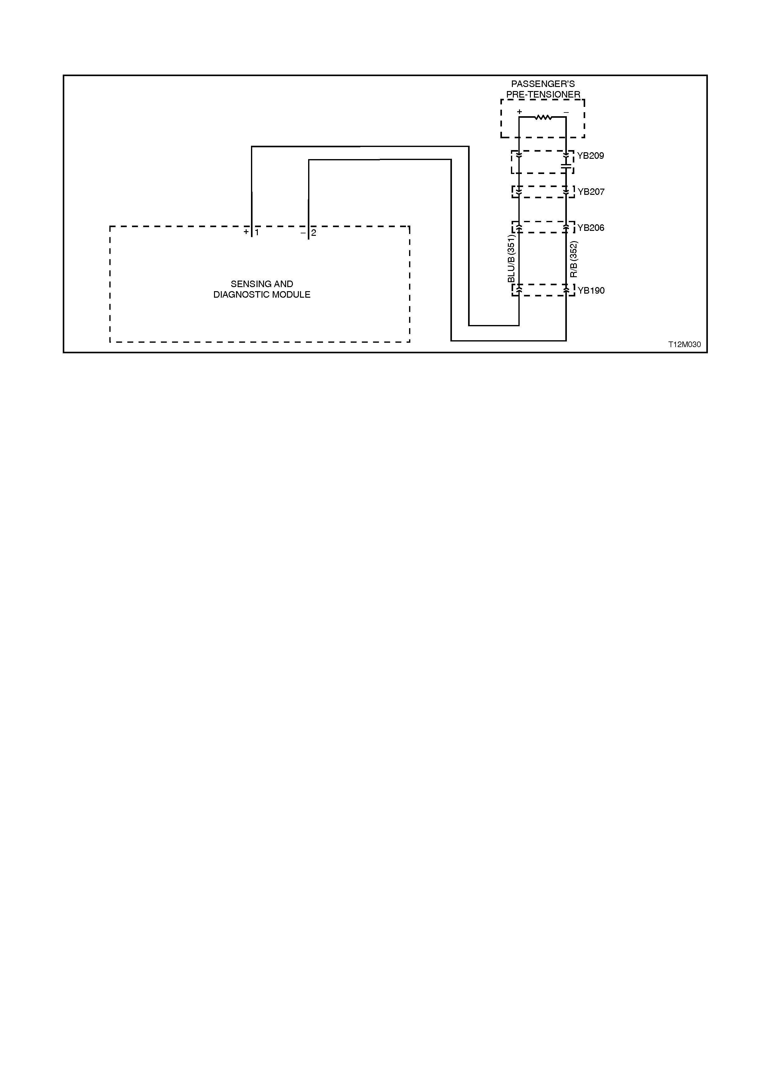
DTC 37 - PASSENGER'S PRE-TENSIONER OPEN CIRCUIT, LOOP CAPACITANCE TOO LOW
Figure 12M-97
CIRCUIT DESCRIPTION
At ignition on, and on a constant monitoring cycle of every 300 milliseconds during the ignition cycle, the SDM
performs a system self check.
If the SDM detects a resistance in the passenger’s pre-tensioner circuit that is too high (greater than 8 ohm) or the
capacitance too low (less than 404 nF) for longer than 10 seconds, a current (frozen) DTC 37 will set.
DTC 37 will set if circuits 351 or 352 (including the passenger’s pre-tensioner assembly) are open circuit.
When DTC 37 sets, the SDM illuminates the SRS warning lamp and sets a current DTC 37. Should the fault
conditions detected by the SDM clear during the same ignition cycle, the current code will clear and become a
history DTC 37. The SRS warning lamp will remain on for the remainder of the ignition cycle.
If a DTC 37 is set, the SRS warning lamp is illuminated on each ignition cycle, even if the DTC is set as a history
DTC, until the fault conditions for setting DTC 37 are rectified and the DTC (current or history) can then be cleared
from the SDM via TECH 2.
If DTC 37 is set, dependent on where the fault is, the passenger’s pre-tensioner may not operate.
TEST DESCRIPTION
Number/s below refer to step numbers in the following diagnostic chart.
1. Uses TECH 2 to check if DTC 37 is current or history.
2. Checks for intermittent fault by monitoring TECH 2 screen. If screen display changes during a wiring 'wiggle'
test, a fault with the wiring is at that location.
3. Tool SD28280B is a dummy load taking the place of the passenger’s pre-tensioner assembly. If DTC 37
becomes a history DTC with dummy load connected, the system fault is in the passenger’s pre-tensioner
assembly.
4. Checks if open circuit is in the SRS connector harness. If connector YB207 is disconnected and it’s terminal’s
are bridged together, DTC 37 will become a history DTC if this connector harness is faulty.
5. Checks circuit 351 for open circuit.
6. Checks circuit 352 for open circuit.
NOTES ON DIAGNOSTIC CHART
1. For all wiring harness checking procedures, refer to Section 12P WIRING DIA GRAMS.
2. Refer to 2.8 SRS WIRING REPAIR in this Section before conducting any SRS wiring harness repairs.
3. TECH 2 screen display only needs to change status to indicate a open circuit. The actual DTC may not be
displayed and in some instances an incorrect DTC may be displayed. If any DTC other than DTC 37 is
displayed during this test, unless they become Frozen DTC’s no action needs to be taken other than repairing
the open in the passenger’s pre-tensioner circuit. If another DTC becomes frozen, other than DTC 37, refer to
the relevant diagnostic chart in this Section.

Figure 12M-98
STEP ACTION VALUE YES NO
1. ∙Connect TECH 2 to
DLC
∙Select Body / SRS /
Diagnostic Trouble
Codes / Read DTC
Information.
∙Is DTC 37 current?
Go to Step 3. Go to Step 2.
2. ∙With TECH 2 still
connected, select
Diagnostic Trouble
Codes / Clear DTC
information and clear
all (if any) DTC’s.
∙Select Diagnostic
Trouble Codes /
Read DTC
Information, 'wiggle'
SRS wiring harness
at all locations
between the SDM
and the passenger’s
pre-tensioner wiring
harness connector
YB209, while
monitoring TECH 2
screen display.
∙Does TECH 2 screen
display change status
from No Diagnostic
Trouble Codes, refer
to NOTE 3 above ?
Make repairs as
necessary
(refer to
NOTE 2 above).
Clear DTC and
recheck system to
verify repair.
Fault not present.
Check all system
wiring harness
connectors, and
terminals.
Clear DTC and
recheck system.

STEP ACTION VALUE YES NO
3. ∙Disable the SRS,
refer to 2.2
DISABLING AND
ENABLING
PROCEDURE in this
Section.
∙Disconnect the
passenger’s pre-
tensioner wiring
harness connector
YB209.
∙Connect Tool No.
SD28280B to SRS
wiring harness
connector YB209.
∙Reconnect battery.
∙Connect TECH 2 to
DLC.
∙Select Body / SRS /
Diagnostic Trouble
Codes / Read DTC
Information.
∙Is DTC 37 still
current?
Go to Step 4. Replace
passenger’s pre-
tensioner
assembly, refer to
Section 1A7
SEAT AND SEAT
BELT
ASSEMBLIES.
Clear DTC and
recheck system
to verify repair.
4. ∙Disable the SRS,
refer to 2.2
DISABLING AND
ENABLING
PROCEDURE in this
Section.
∙Disconnect SRS
wiring harness
connector YB207
(located next to
driver’s seat) from
passenger’s pre-
tensioner connector
harness.
∙Reconnect battery.
∙Using a suitable
jumper wire from KM-
609, bridge terminals
in connector YB207
together.
∙With TECH 2 still
connected, select
Body / SRS /
Diagnostic Trouble
Codes / Read DTC
Information.
∙Does DTC 37
become history?
Replace SRS
connector
harness (harness
between driver’s
pre-tensioner and
connector
YB207). Clear all
DTC’s and
recheck system to
verify repair.
Go to Step 5

STEP ACTION VALUE YES NO
5. ∙Disable the SRS,
refer to 2.2
DISABLING AND
ENABLING
PROCEDURE in this
Section.
∙Disconnect SDM
wiring harness
connector YB190
from the SDM.
∙Using Tool KM-609-
20, check wiring
between SDM wiring
harness connector
YB190, terminals 1
and SRS wiring
harness connector
YB207, circuit 351
(Blue/Black wire) for
open (refer to
NOTE 1 above).
∙Is all OK?
Go to Step 6. Make repairs as
necessary
(refer to
NOTE 2 above).
Clear DTC and
recheck system
to verify repair.
6. ∙With SDM wiring
harness connector
YB190 disconnected
from the SDM and
using Tool KM-609-
20, check wiring
between SDM wiring
harness connector
YB190, terminal 2
and SRS wiring
harness connector
YB207, circuit 352
(Red/Black wire) for
open (refer to
NOTE 1 above).
∙Is all OK?
Replace SDM,
refer to 2.7
SENSING AND
DIAGNOSTIC
MODULE in this
Section. Recheck
circuit to verify
repair.
Make repairs as
necessary
(refer to
NOTE 2 above).
Clear DTC and
recheck system
to verify repair.
WHEN ALL DIAGNOSIS AND REPAIRS ARE COMPLETED, ENSURE ALL SRS
COMPONENTS ARE RECONNECTED, CLEAR ALL DTC’S, ENABLE THE SRS AND
VERIFY CORRECT OPERATION
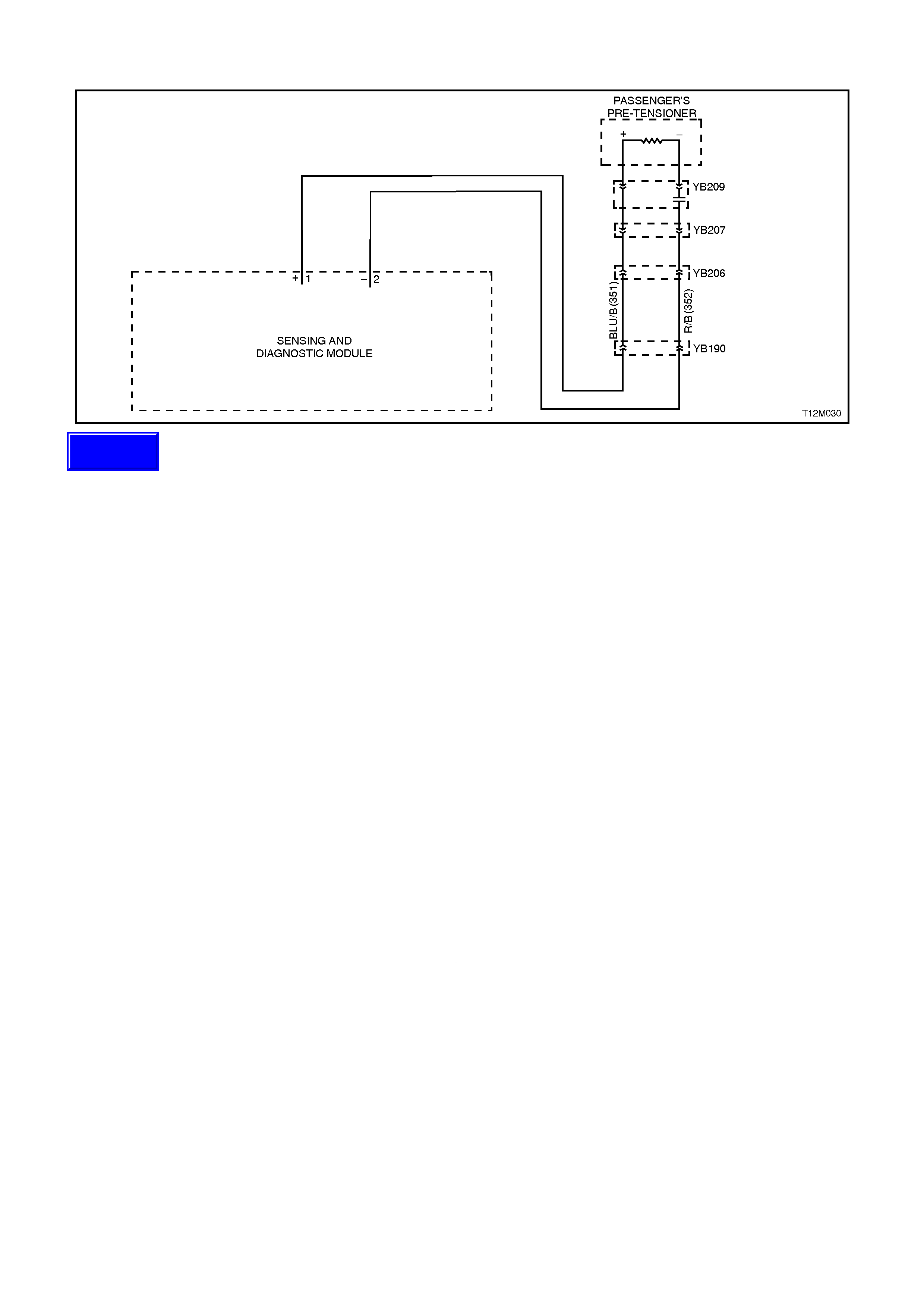
DTC 38 - PASSENGER'S PRE-TENSIONER SHORT CIRCUIT, LOOP CAPACITANCE TOO HIGH
Figure 12M-99
CIRCUIT DESCRIPTION
At ignition on, and on a constant monitoring cycle of every 300 milliseconds during the ignition cycle, the SDM
performs a system self check.
If the SDM detects a resistance in the passenger’s belt pre-tensioner circuit that is too low (less than 1 ohm) or the
capacitance too high (greater than 535 nF) for longer than 10 seconds, a current (frozen) DTC 38 will set.
DTC 38 will set if circuits 351 or 352, (including the belt pre-tensioner assembly) are shorted to earth.
When DTC 38 sets, the SDM illuminates the SRS warning lamp and sets a current DTC 38. Should the fault
conditions detected by the SDM clear during the same ignition cycle, the current code will clear and become a history
DTC 38. The SRS warning lamp will remain on for the remainder of the ignition cycle.
If a DTC 38 is set, the SRS warning lamp is illuminated on each ignition cycle, even if the DTC is set as a history
DTC, until the fault conditions for setting DTC 38 are rectified and the DTC (current or history) can then be cleared
from the SDM via TECH 2.
If DTC 38 is set, dependent on where the fault is, the passenger’s belt pre-tensioner may not operate.
TEST DESCRIPTION
Number/s below refer to step numbers in the following diagnostic chart.
1. Uses TECH 2 to check if DTC 38 is current or history.
2. Checks for intermittent fault by monitoring TECH 2 screen. If screen display changes during a wiring 'wiggle' test,
a fault with the wiring is at that location.
3. Tool SD28280B is a dummy load taking the place of the passenger’s pre-tensioner assembly. If DTC 38
becomes a history DTC with dummy load connected, the system fault is in the passenger’s pre-tensioner
assembly.
4. Checks circuit 351 and 352 for short to earth.
NOTES ON DIAGNOSTIC CHART
1. For all wiring harness checking procedures, refer to Section 12P WIRING DIA GRAMS.
2. Refer to 2.8 SRS WIRING REPAIR in this Section before conducting any SRS wiring harness repairs.
3. Resistance cannot be measured between the two terminals in connector YB208, as the in-built capacitor blocks
measurement. Therefore, a ‘service hole’ is incorporated into the connector for fault tracing. Refer to 1.1
SYSTEM COMPONENTS, WIRING HARNESS in this Section for more details on this type of connector.
4. TECH 2 screen display only needs to change status to indicate a short circuit. The actual DTC may not be
displayed and in some instances an incorrect DTC may be displayed. If any DTC other than DTC 38 is displayed
during this test, unless they become Frozen DTC’s no action needs to be taken other than repairing the short in
the passenger’s pre-tensioner circuit. If another DTC becomes frozen, other than DTC 38, refer to the relevant
diagnostic chart in this Section.
Techline

Figure 12M-100
STEP ACTION VALUE YES NO
1. ∙Connect TECH 2 to
DLC
∙Select Body / SRS /
Diagnostic Trouble
Codes / Read DTC
Information.
∙Is DTC 38 current?
Go to Step 3. Go to Step 2.
2. ∙With TECH 2 still
connected, select
Diagnostic Trouble
Codes / Clear DTC
information and clear
all (if any) DTC’s.
∙Select Diagnostic
Trouble Codes /
Read DTC
Information, 'wiggle'
SRS wiring harness
at all locations
between the SDM
and the passenger’s
pre-tensioner wiring
harness connector
YB209, while
monitoring TECH 2
screen display.
∙Does TECH 2 screen
display change status
from No Diagnostic
Trouble Codes, refer
to NOTE 3 above ?
Make repairs as
necessary
(refer to
NOTE 2 above).
Clear DTC and
recheck system to
verify repair.
Fault not present.
Check all system
wiring harness
connectors, and
terminals.
Clear DTC and
recheck system.

STEP ACTION VALUE YES NO
3. ∙Disable the SRS,
refer to 2.2
DISABLING AND
ENABLING
PROCEDURE in this
Section.
∙Disconnect the
passenger’s pre-
tensioner wiring
harness connector
YB209.
∙Connect Tool No.
SD28280B to SRS
wiring harness
connector YB209.
∙Reconnect battery.
∙Connect TECH 2 to
DLC.
∙Select Body / SRS /
Diagnostic Trouble
Codes / Read DTC
Information.
∙Is DTC 38 still
current?
Go to Step 4. Replace
passenger’s pre-
tensioner
assembly, refer to
Section 1A7
SEAT AND SEAT
BELT
ASSEMBLIES.
Clear DTC and
recheck system
to verify repair.
4. ∙Disable the SRS,
refer to 2.2
DISABLING AND
ENABLING
PROCEDURE in this
Section.
∙Disconnect SDM
wiring harness
connector YB190
from the SDM.
∙Using Tool KM-609-
20, check wiring
between SDM wiring
harness connector
YB190, terminals 1
and 2 and
passenger’s pre-
tensioner connector
YB209, circuits 351
(Blue/Black wire) and
352 (Red/Black wire)
for short to earth
(refer to NOTES 1
and 3 above).
∙Is all OK?
Replace SDM,
refer to 2.7
SENSING AND
DIAGNOSTIC
MODULE in this
Section. Recheck
circuit to verify
repair.
Make repairs as
necessary
(refer to
NOTE 2 above).
Clear DTC and
recheck system
to verify repair.
WHEN ALL DIAGNOSIS AND REPAIRS ARE COMPLETED, ENSURE ALL SRS
COMPONENTS ARE RECONNECTED, CLEAR ALL DTC’S, ENABLE THE SRS AND
VERIFY CORRECT OPERATION

DTC 53 - CONFIGURATION MISMATCH: TOO LITTLE OR TOO MANY LOOPS IN SRS
Figure 12M-101
CIRCUIT DESCRIPTION
The SDM will set a DTC 53 because it has been internally configured for a three loop system (vehicles with pre-
tensioners and driver's air bag only) or a four loop system (vehicles with pre-tensioners, driver's air bag and front
passenger's air bags) but at the same time has detected a mismatch with the actual vehicle configuration.
To identify the different SDMs, refer to the identification label on the top of the SDM. Figure 12M-101 shows the
identification label for the 4 loop system.
NOTE:
Always refer to the latest VT spare parts microfiche/Part Finder information for the latest part numbers when
ordering SRS components.
TECH 2 is capable of displaying the SDM part number; connect TECH 2 to DLC, select Diagnosis / Body / SRS /
Turn Ignition ON and the system identification screen will display the SDM part number.
As an aid to the technician to diagnose the source of the mismatch, always check for other DTC set in the system
first. Faults setting other DTC’s should be rectified first, all DTC’s cleared from the SDM and system retested to
determine if DTC 53 will set again. If DTC sets again, install the correct SDM.
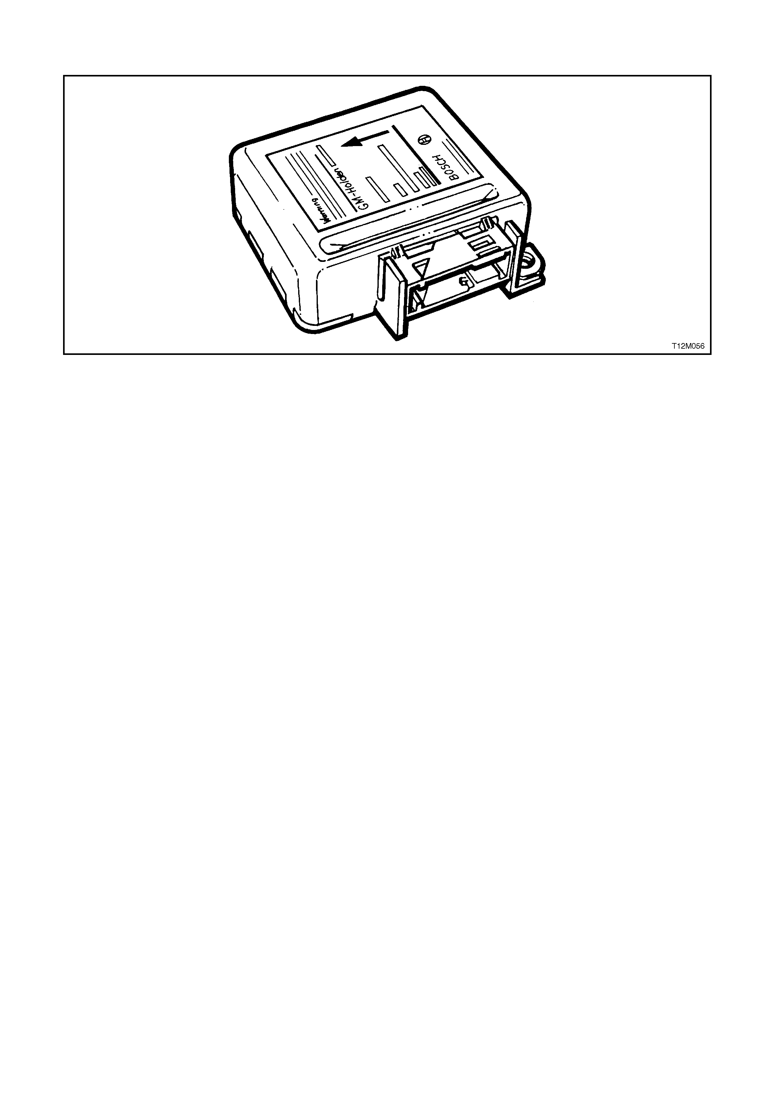
DTC 55 - INTERNAL SDM FAULT
Figure 12M-102
CIRCUIT DESCRIPTION
At ignition on, and on a constant monitoring cycle of every 300 milliseconds during the ignition cycle, the SDM
performs a system self check. If the SMD detects a fault in itself, a DTC 55 will be set and the SRS warning lamp
will be illuminated continuously with the ignition on.
If DTC 55 is set, the SRS may not operate and must be replaced.

4. TORQUE WRENCH SPECIFI CATIONS
Nm
Front passenger's air bag inflator module assembly
to dash panel attaching nuts 15 - 25
Horn bar and air bag inflator module assembly
to steering wheel securing screws 10 - 14
Seat Belt Buckle and Pre-tensioner Asm. Retaining
Bolt 45
Sensing and Diagnostic Module to floor attaching
screws 7 - 11
Steering wheel retaining bolt 40 - 50
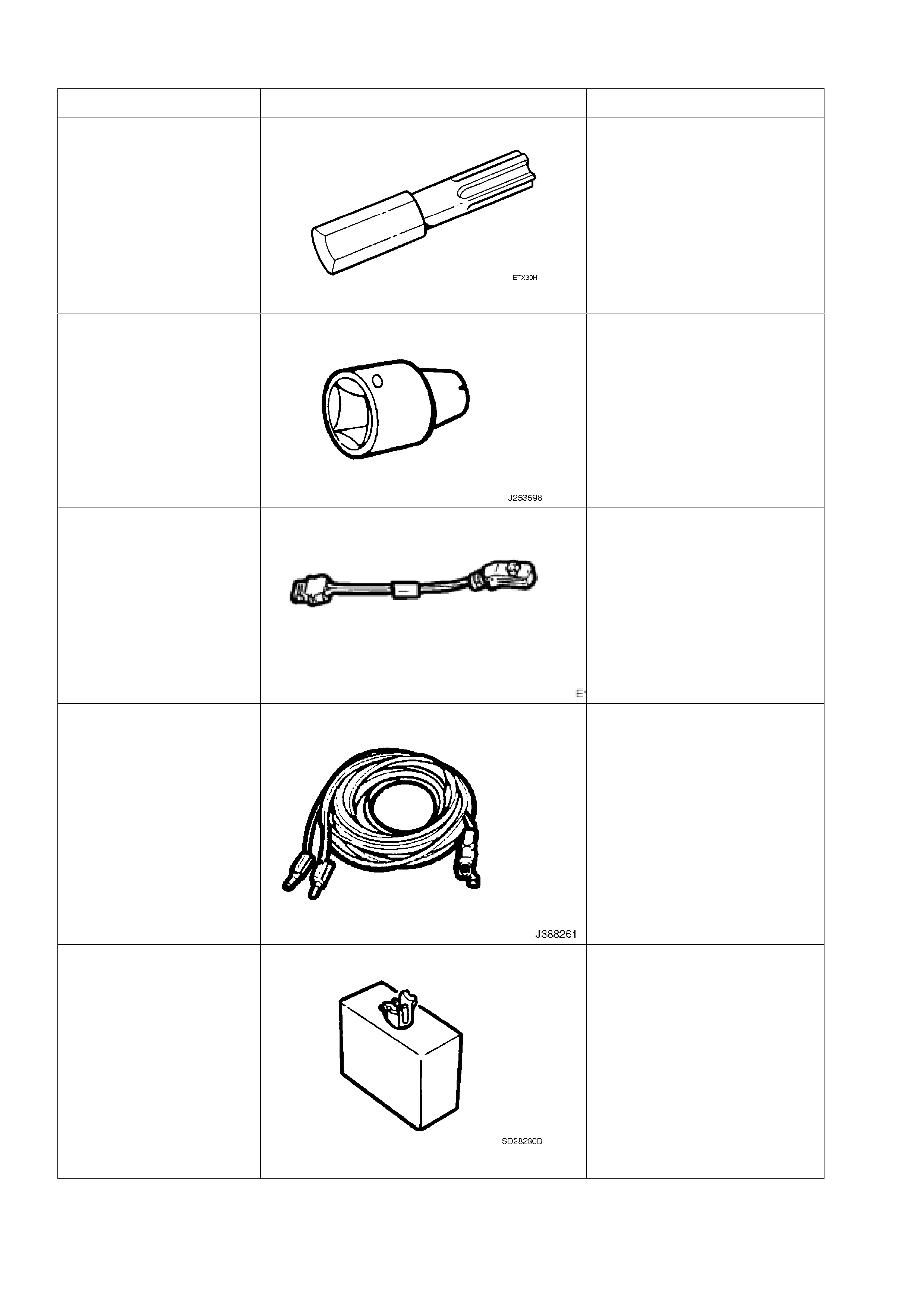
5. SPECIAL TOOLS
TOOL NO. REF IN TEXT TOOL DESCRIPTION COMMENTS
ETX30H T30H TORX BIT USE IN CONJUCTION WITH
J25359-8, (OR ETX55HLD)
TOR X BIT HOLDER
USED FOR REMOVING SDM
TO FLOOR ATTACHING
SCREWS AND HORN BAR
AND AIR BAG INFLATOR
MODULE ASSEMBLY TO
STEERING WHEEL
SECURING SCREWS
J25359-8 TORX BIT HOLDER PREVIOUSLY RELEASED
FOR V CAR
E1992 DEPLOYMENT HARNESS ADAPTOR PREVIOUSLY RELEASED
USED IN CONJUNCTION
WITH DEPLOYMENT
HARNESS J38826-1 FOR
DEPLOYING SRS
COMPONENTS WHEN
REMOVED FROM THE
VEHICLE
J38826-1 DEPLOYMENT HARNES PREVIOUSLY RELEASED
USED IN CONJUNCTION
WITH DEPLOYMENT
HARNESS ADAPTOR E1992
FOR DEPLOYING SRS
COMPONENTS WHEN
REMOVED FROM THE
VEHICLE
SD28280B DUMMY LOAD PREVIOUSLY RELEASED AS
PART OF SRS DIAGNOSTIC
KIT SD28280.
TOOLS AVAILABLE FROM:
EINSTEIN TECHNOLOGY
14 FARMILLO COURT
FERNTREE GULLY, VICTORIA
AUSTRALIA 3156
TELEPHONE NO. (03)
97528663
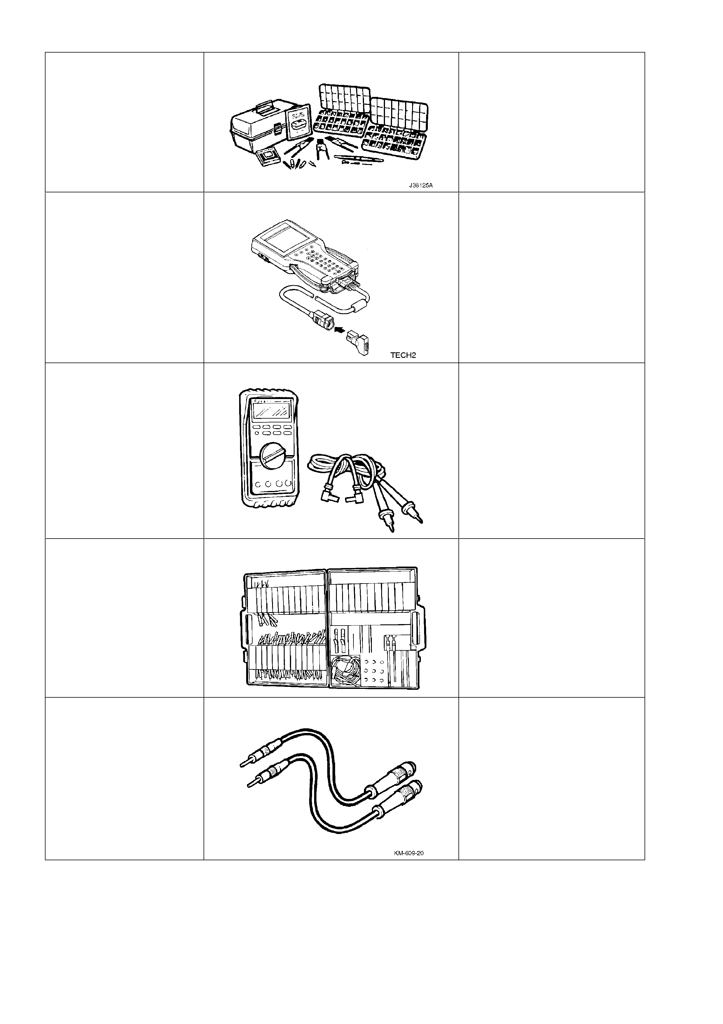
J38125-A TERMINAL REPAIR KIT PREVIOUSLY RELEASED.
MUST BE USED WHEN
REPAIRING SRS WIRING,
REFER TO 2.8 SRS WIRING
REPAIR IN THIS SECTION.
TECH 2 DIAGNOSTIC SCAN TOOL PREVIOUSLY RELEASED
J39200 DIGITAL MULTIMETER TOOL NO. J39200
PREVIOUSLY RELEASED, OR
USE COMMERCIALLY
AVAILABLE EQUIVALENT.
MUST HAVE 10 MEG OHM
INPUT IMPEDANCE AND BE
CAPABLE OF READING
CAPACITANCE
KM-609 ELECTRONIC KIT USED IN CONJUNCTION
WITH A MULTIMETER FOR
MEASURING VOLTAGES AND
RESISTANCE’S WITHOUT
DAMAGING WIRING
HARNESS CONNECTORS
KM-609-20 SRS TEST LEAD SET MANDATORY TOOL,
USED FOR PROBING SDM
CONNECTOR YB190 (ALSO
AVAILABLE AS PART OF KM-
609 ELECTRONIC KIT