SECTION 12N - FUSES, RELAYS AND WIRING
HARNESSES
CAUTION:
This vehicle will be equipped with a Supplemental Restraint System (SRS). A SRS will
consist of either seat belt pre-tensioners a driver's side air bag, or seat belt pre-
tensioners and a driver's and front passenger's side air bags. Refer to CAUTIONS,
Section 12M, before performing any service operation on or around any SRS
components, the steering mechanism or wiring. Failure to follow the CAUTIONS
could result in air bag deployment, resulting in possible personal injury or
unnecessary SRS system repairs.
CAUTION:
This vehicle may be equipped with LPG (Liquefied Petroleum Gas). In the interests of
safety, the LPG fuel system should be isolated by turning 'OFF' the manual service
valve and then draining the LPG serv ice lines, before any service w ork is carried out
on the vehicle. Refer to the LPG leaflet included with the Owner's Handbook for
details or LPG Section 2 for more specific servicing information.
CAUTION:
Whenever any component that forms part of the ABS or ABS/ASR (if fitted), is
disturbed during Service Operations, it is vital that the complete ABS or ABS/ASR
system is checked, using the procedure as detailed in 4 DIAGNOSIS, ABS or
ABS/ASR FUNCTION CHECK, in Section 12L ABS & ABS/ASR.
1. GENERAL INFORMATION
1.1 FUSES AND CIRCUIT BREAKERS
FUSES
All vehicle electrical circuits are protected against
damage which might occur because of short
circuits or overloads in the wiring system.
Protection is provided by a fuse, circuit breaker, or
fusible link.
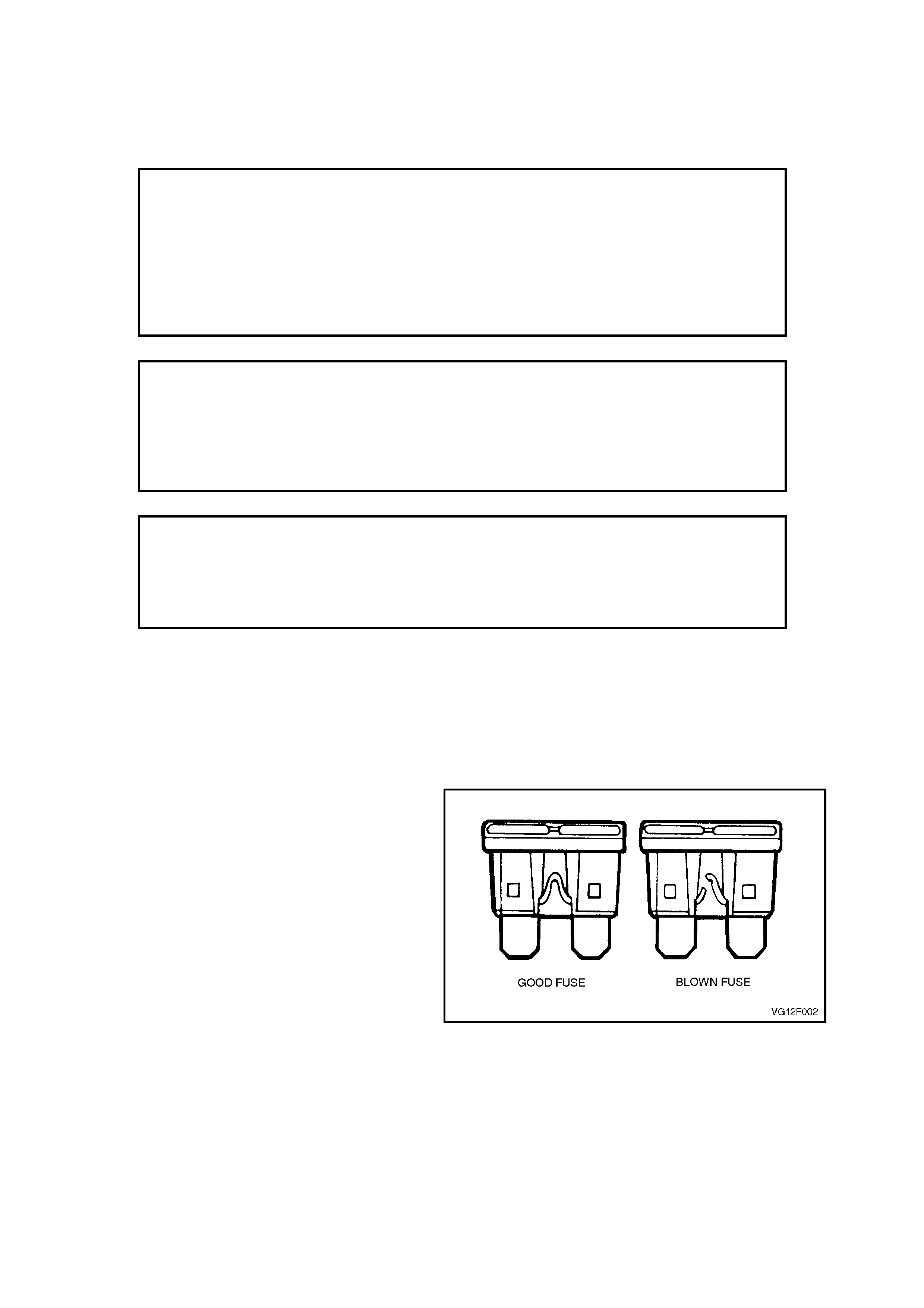
Fuses ar e the blade type mini fuse, with the curr ent
rating in amps indicated on top of the fuse
assembly, above the element, or by the colour of
the fuse.
Figure 12N-1

CURRENT RATING
(AMPS) FUSE COLOUR
3VIOLET
5TAN
7.5 BROWN
10 RED
15 BLUE
20 YELLOW
25 WHITE
30 GREEN
To determine whether or not a fuse has blown,
rem ove the suspec t fuse and exam ine the element
in the fuse for a break.
NOTE:
A blown fus e is caused by a fault. Replace a blown
fuse only with a fuse of the same rating. If the
replacement fuse blows, rectify the fault before
replacing the fuse again.
Fuses are located in two positions on VT Series
Models. One group is located in the fuse and relay
panel assembly, inside the vehicle passenger
compartment, behind the instrument panel lower
right hand side cover.
Access to the passenger compartment fuse and
relay panel assembly is by first adjusting the
steering column to it’s upper most position. Then
grasping the right hand side of the ins tr ument panel
lower cover firmly, pull the cover downward. Repeat
the procedure for the left hand side of the cover
and then allow it to swing down.
A label on the inside of the cover indicates the
circuits protected by each fuse, as well as
nominating relay function.
When reinstalling the cover, ensure that the
locating clips are correctly aligned, swing cover up
and ensure that the clips engage into their mating
retainers securely. Figure 12N-2
Fig. 12N-3 illustrates the passenger compartment
fuse and relay panel assembly, nominating fuse
number and each system protected by that fuse.
On vehicles with power operated windows, a 20
amp circuit breaker is installed in the passenger
compartment fuse and relay panel assembly at
fuse c avity F1. An additional 20 amp c irc uit br eaker
is included at fuse cavity F2 for the electrically
adjustable front seat operation.
A circuit break er is a c ircuit protec tion device which
will open circuit when the circuit c ur rent ex c eeds its
rating, and will close again after it cools.
The circuit breaker will continue to open and close
until the cause of the excess current is corrected.
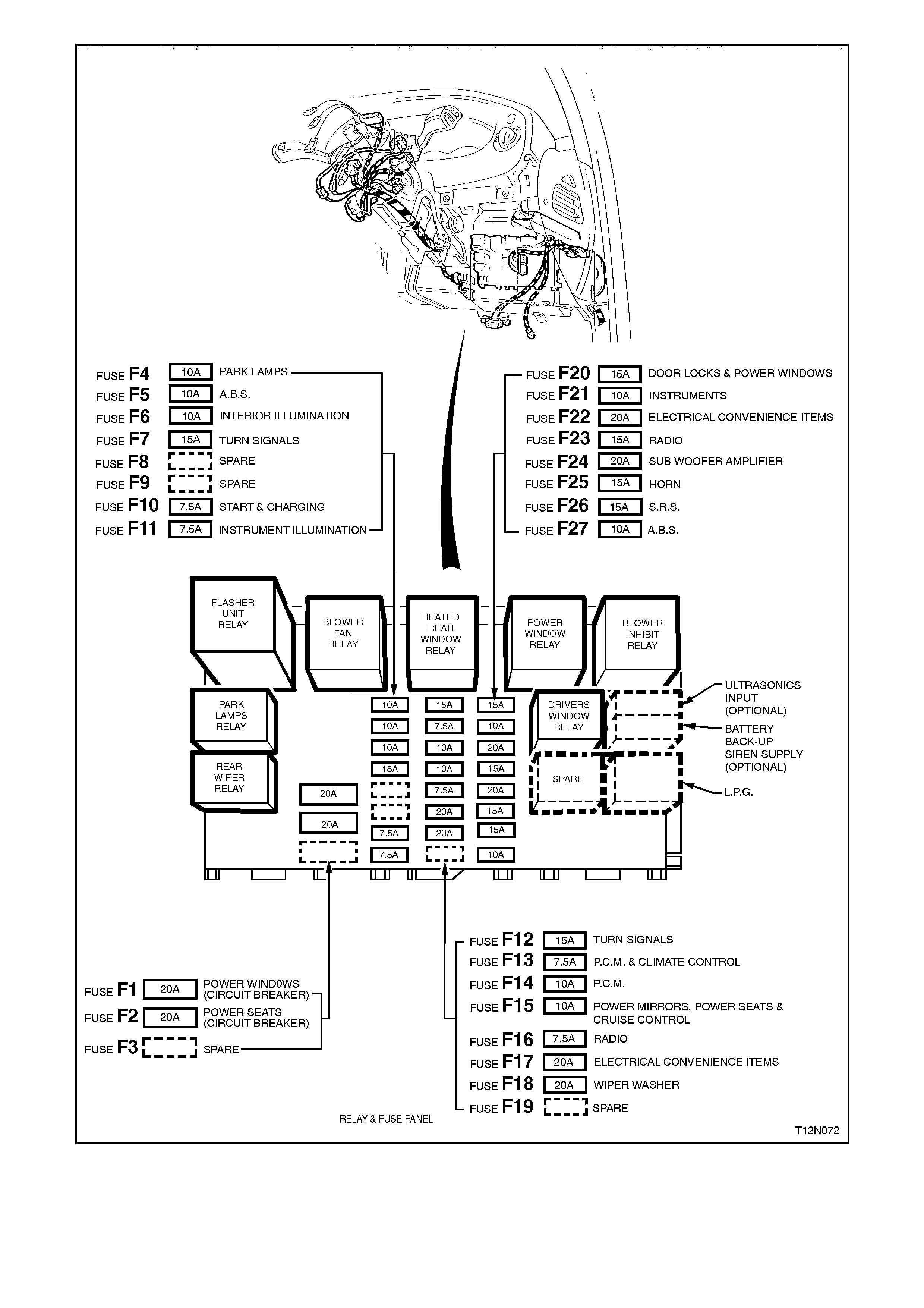
Figure 12N-3
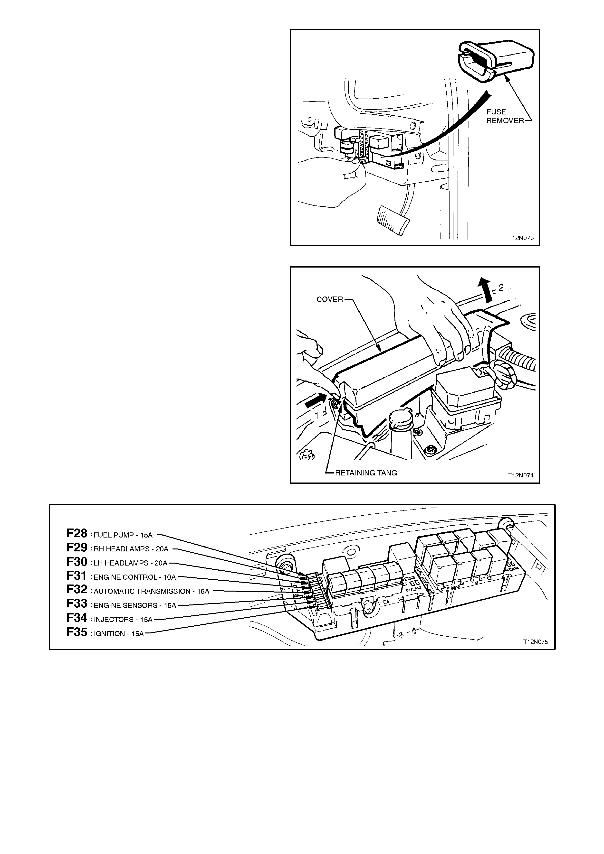
Included in the passenger compartment fuse and
relay panel assembly is a fuse remover. To use,
pull the remover from it’s location in the panel,
insert fully over the top of the fuse to be removed
and then pull fuse from the panel.
Figure 12N-4
The second group of fuses are located in the
engine compartment fuse and relay panel
assembly, situated forward of the right hand side
front suspension strut tower.
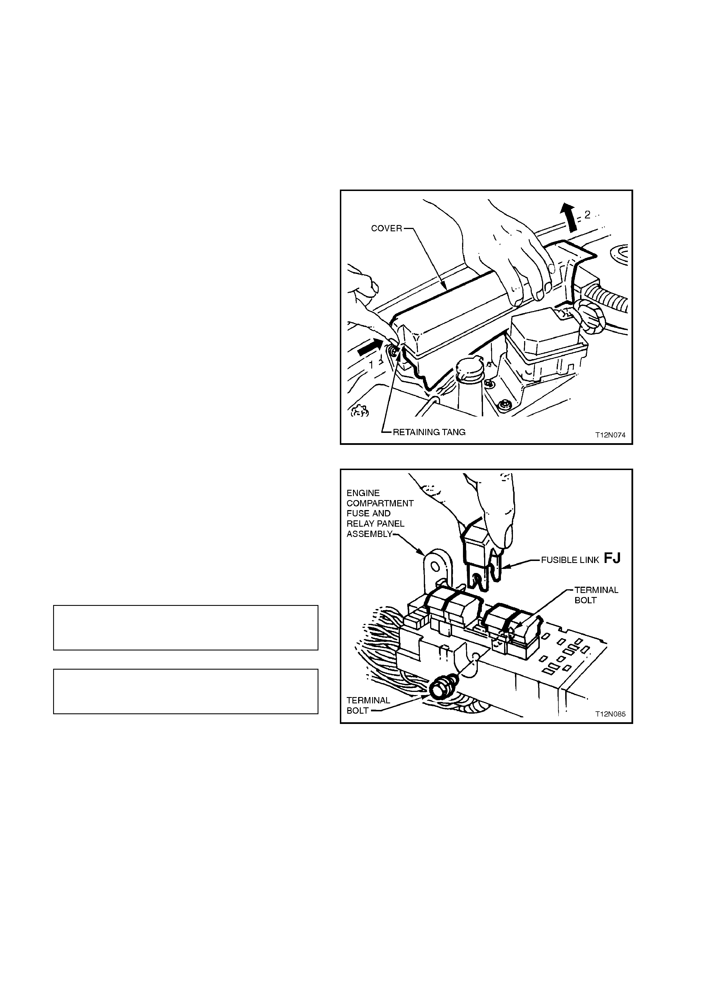
Access to the engine compartment fuse and relay
panel assembly is by removing the cover by first
depressing the c over retaining tang, refer Fig. 12N-
5 and then lifting the cover up and out from the
panel assembly.
Fig. 12N-6 illustrates the engine compartment fuse
and relay panel assem bly, nominating f use number
and each system protected by that fuse.
A label on the inside of the cover indicates the
circuits protected by each fuse, as well as
nominating relay function.
Use the fuse remover in the passenger
compartment fuse and relay panel assembly to
remove these fuses. Figure 12N-5
Figure 12N-6
FUSIBLE LINKS
The chassis and engine electrical wiring is
protected against short circuit damage by fusible
links contained in engine compartment fuse and
relay panel assembly, situated forward of the right
hand side front suspension strut tower.
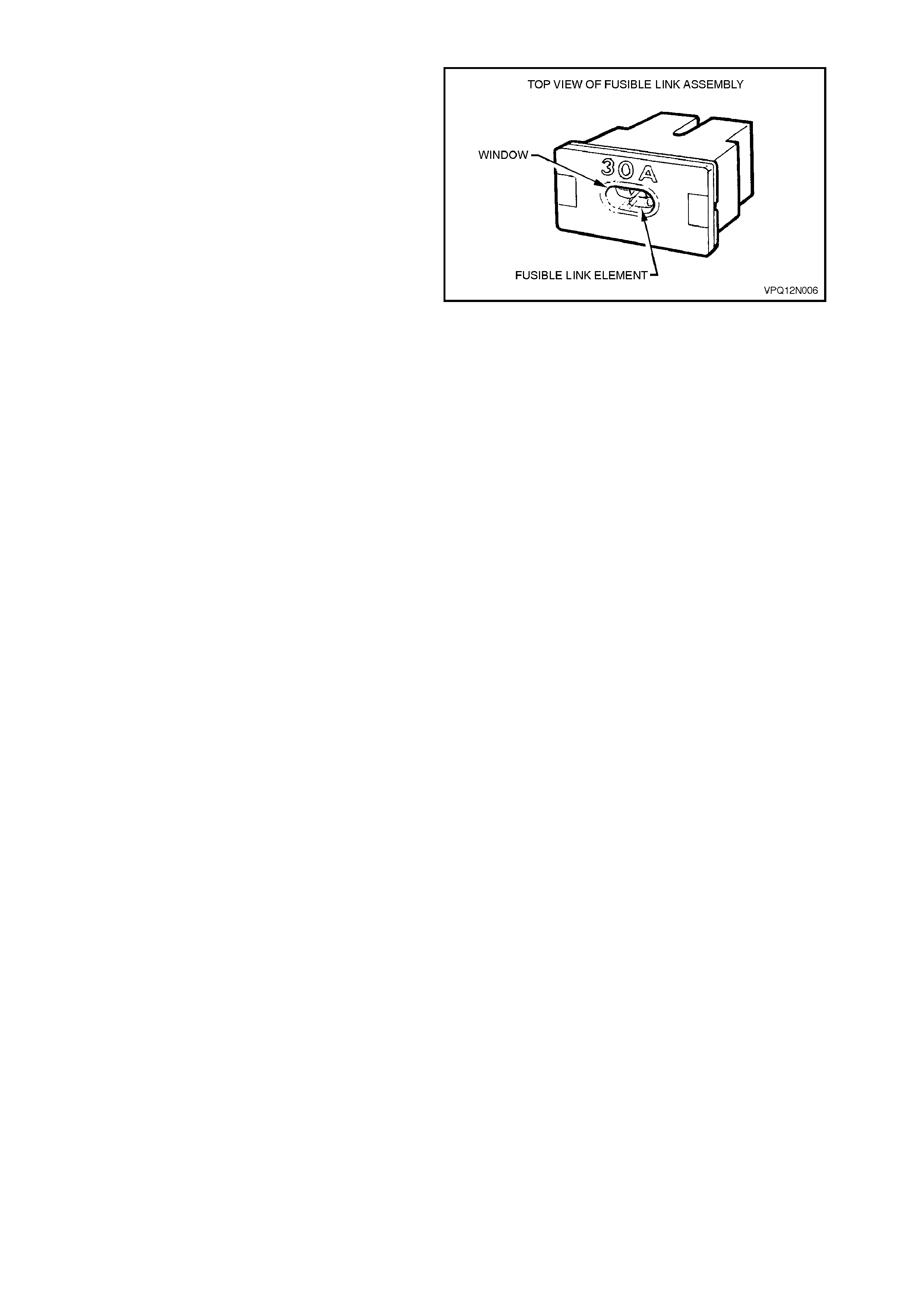
The fusible links are a plug in type, with an
inspection window which allows a visual; check of
the fusible link condition.
To determine whether or not a fusible link has
blown, examine the fusible link element for a break.
NOTE:
A blown fusible link in c aused by a fault. Replace a
blown fusible link only with a fusible link of the
same current rating. Fusible link current rating is
indicated on top of the assembly, adjacent to the
inspection window. If the replacement fusible link
blows, rectify the fault before replacing the fusible
link again.
Figure 12N-7
All fusible links c an be r emoved by pulling them out
of their housing sockets, except for the FS 60 A
ENGINE fus ible link and the two engine cooling fan
FT and F U 30 A fusible link s. Removal pr ocedures
for these fusible links are detailed in the
SERVICE OPERATIONS in this Section.
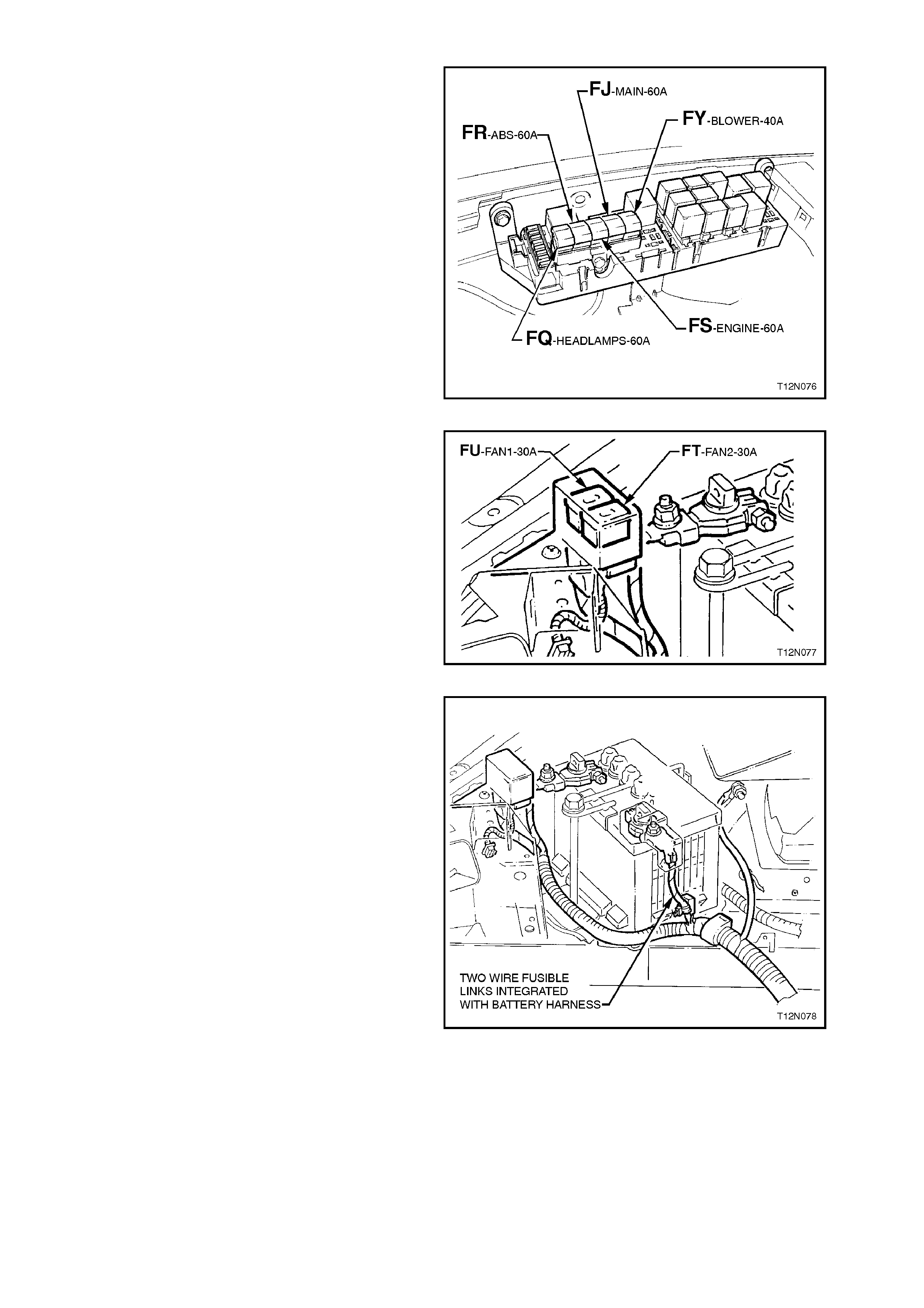
Fig. 12N-8 illustrates the engine compartment fuse
and relay panel assembly fusible link location,
identification and circuit protection functions.
Figure 12N-8
Two additional fusible links for the engine cooling
fan circuits are located in a separate housing
attached to the right hand side of the radiator
support panel.
Figure 12N-9
Two wire type fus ible link s are integrated as part of
the battery harness and are located near the
battery harness positive terminal.
Figure 12N-10
1.2 RELAYS
There are two groups of relays on VT Series
Models.
One group of relays is located in the passenger
com par tment f us e and relay panel assem b ly, inside
the vehicle passenger compartment, behind the
instrument panel lower right hand side cover.
Access to the passenger compartment fuse and
relay panel assembly is by first adjusting the
steering column to it’s upper most position. Then
grasping the right hand side of the ins tr ument panel
lower cover firmly, pull the cover downward. Repeat
the procedure for the left hand side of the cover
and then allow it to swing down, refer Fig. 12N-2 in
this Section.
A label on the inside of the cover nominated each
relay function as well as indicating the circuits
protected by each fuse.
Fig. 12N-11 illustrates the passenger compartm ent
fuse and relay panel assembly.
1. Rear Wiper Relay
2. Park Lamps Relay
3. Flasher Unit Relay
4. Blower Fan Relay
5. Heated Rear Window Relay
6. Power Window Relay
7. Blower Inhibit Relay
8. Drivers Window Relay
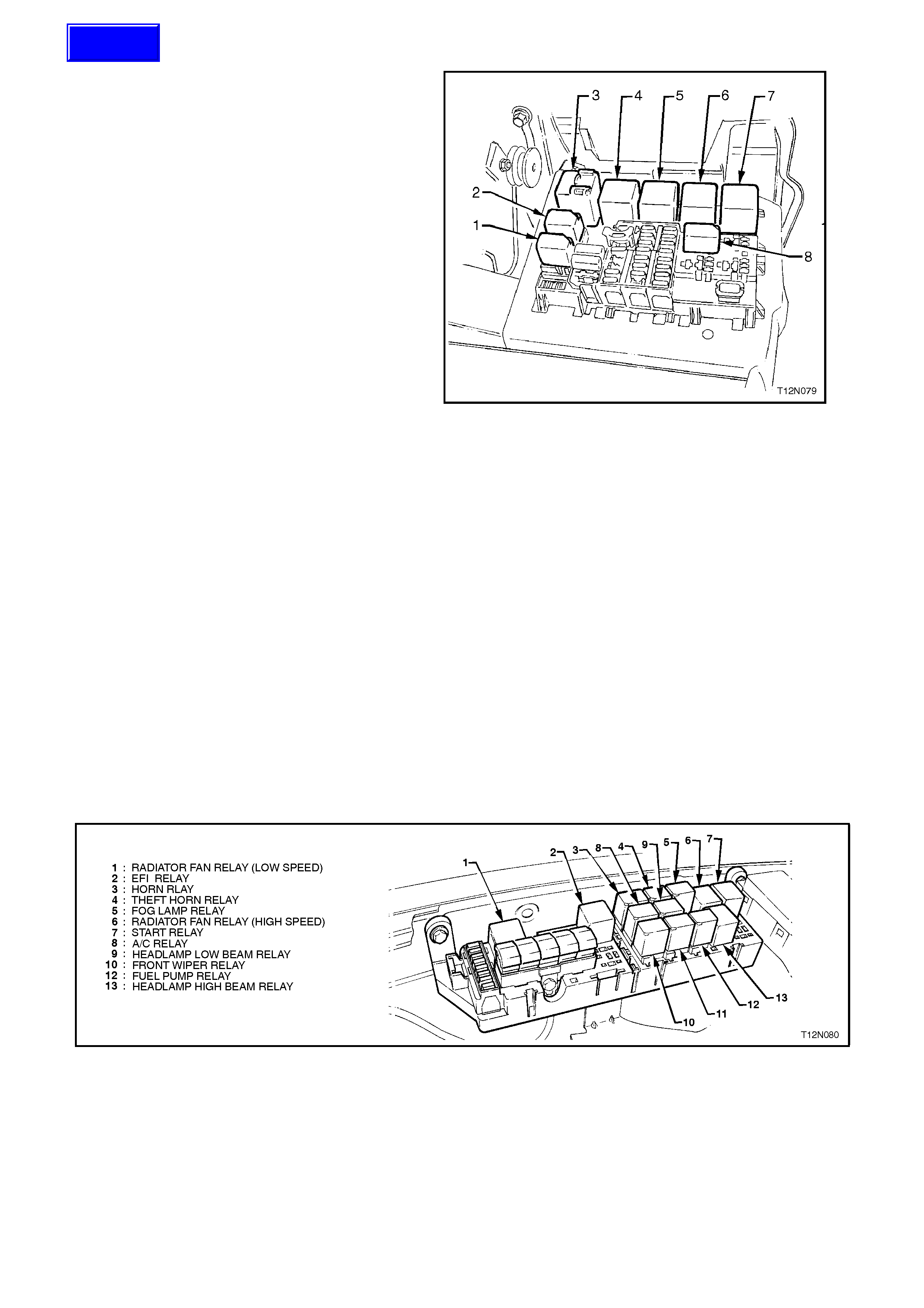
Additional relays are located in the engine
compartment fuse and relay panel assembly, refer
Fig. 12N-12.
Access to the relays in the engine compartment
fuse and relay panel assembly is by removing the
panel assembly cover, refer Fig. 12N-5 in this
Section.
A label on the inside of the cover nominated each
relay function as well as indicating the circuits
protected by each fuse.
Figure 12N-11
Figure 12N-12
Techline
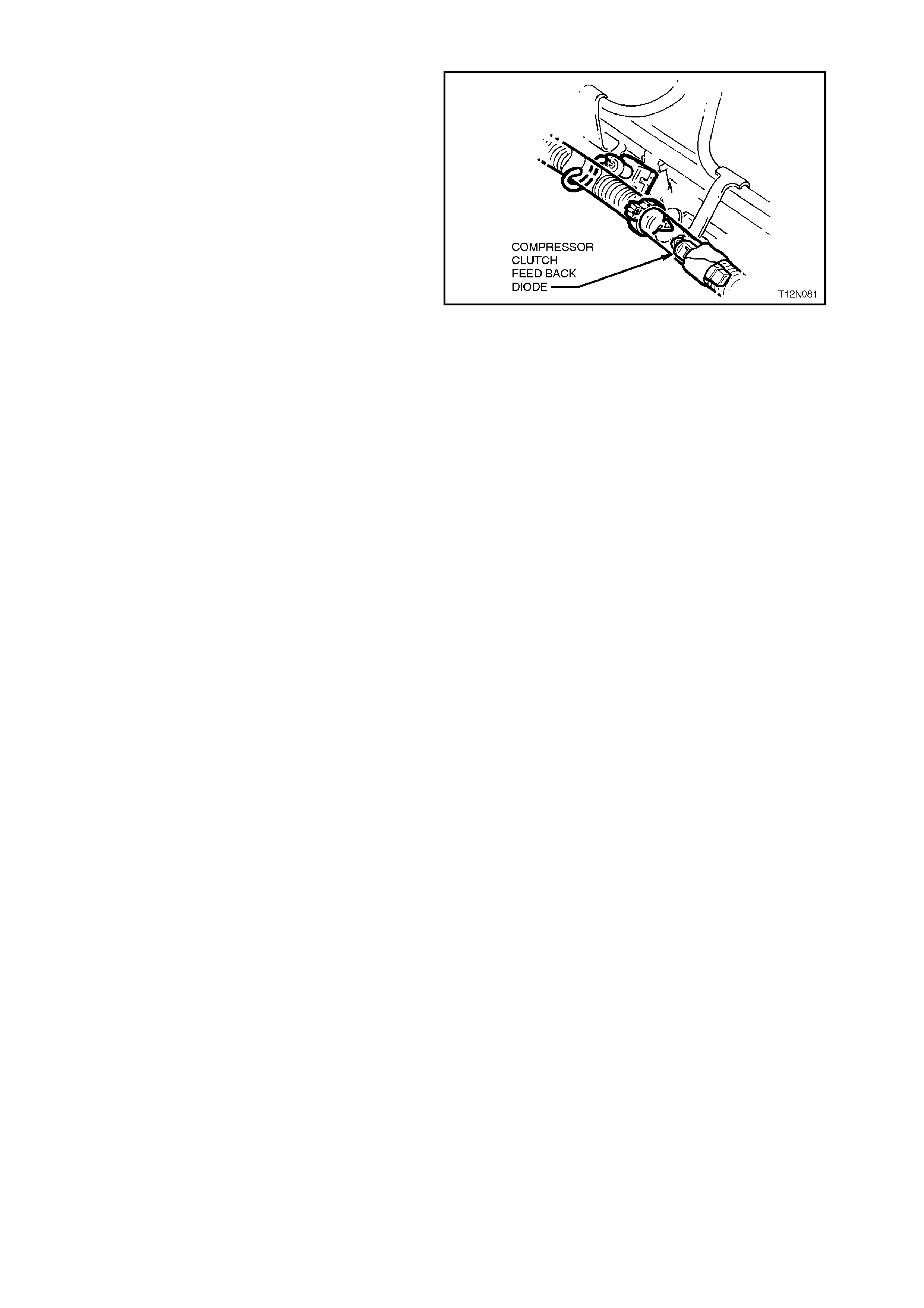
1.3 DIODES
On all vehicles with air conditioning, an air
conditioning compressor clutch feedback diode is
installed in the engine harness. Fig. 12N-13
illustrates typical installation of the diode.
For location of the air conditioning compressor
clutch feedback diode, refer to the following
diagrams in this Section
V6 - POWERTRAIN HARNESS - 3, item 14
V6 S/C - POWERTRAIN HARNESS - 9, item 7
V8 - POWERTRAIN HARNESS - 12, item 16
Figure 12N-13

1.4 WIRING HARNESSES
The following figure illustrates a plan view of a sedan and stationwagon showing the schematic location of the
various wiring harnesses used on VT Series Models.
For actual layout and connection of the various wiring harnesses refer to 3. WIRING INSTALLATION DIAGRAMS
in this Section.
For details on wiring harness repair procedures, refer to Section 12P WIRING DIAGRAMS.
Techline
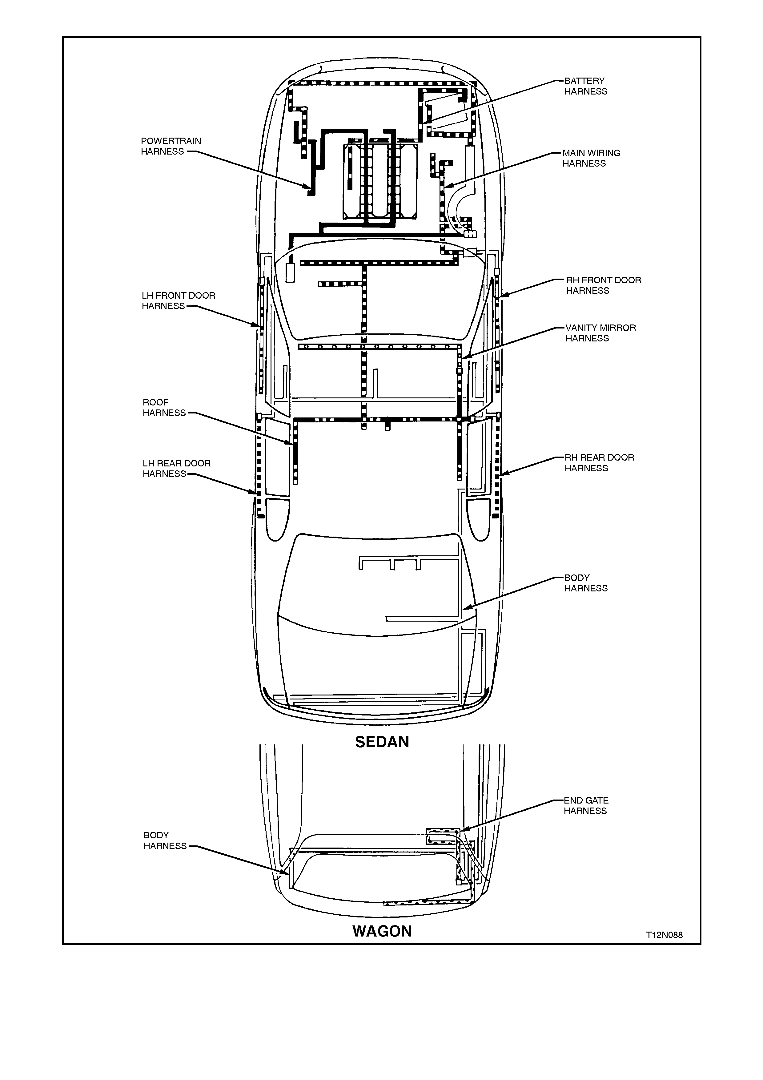
Figure 12N-14

1.5 WIRING HARNESS CONNECTORS
The majority of the wiring harness connectors used on VT Series Models are of an interlocking design.
The male and female connector bodies, when pushed together, are retained from being pulled apart by a tang on
one connector body. This tang locks into an appropriate section on the mating connector body.
Some connectors have anti-back combs fitted for increased connector terminal security.
For details on servicing the wiring harness connectors used in the vehicle, refer to Section 12P WIRING
DIAGRAMS.
NOTE:
Not all wiring harness connectors or terminals are serviced as separate items. For a listing of connectors or
terminals which are serviced, refer to the VT Series parts information.
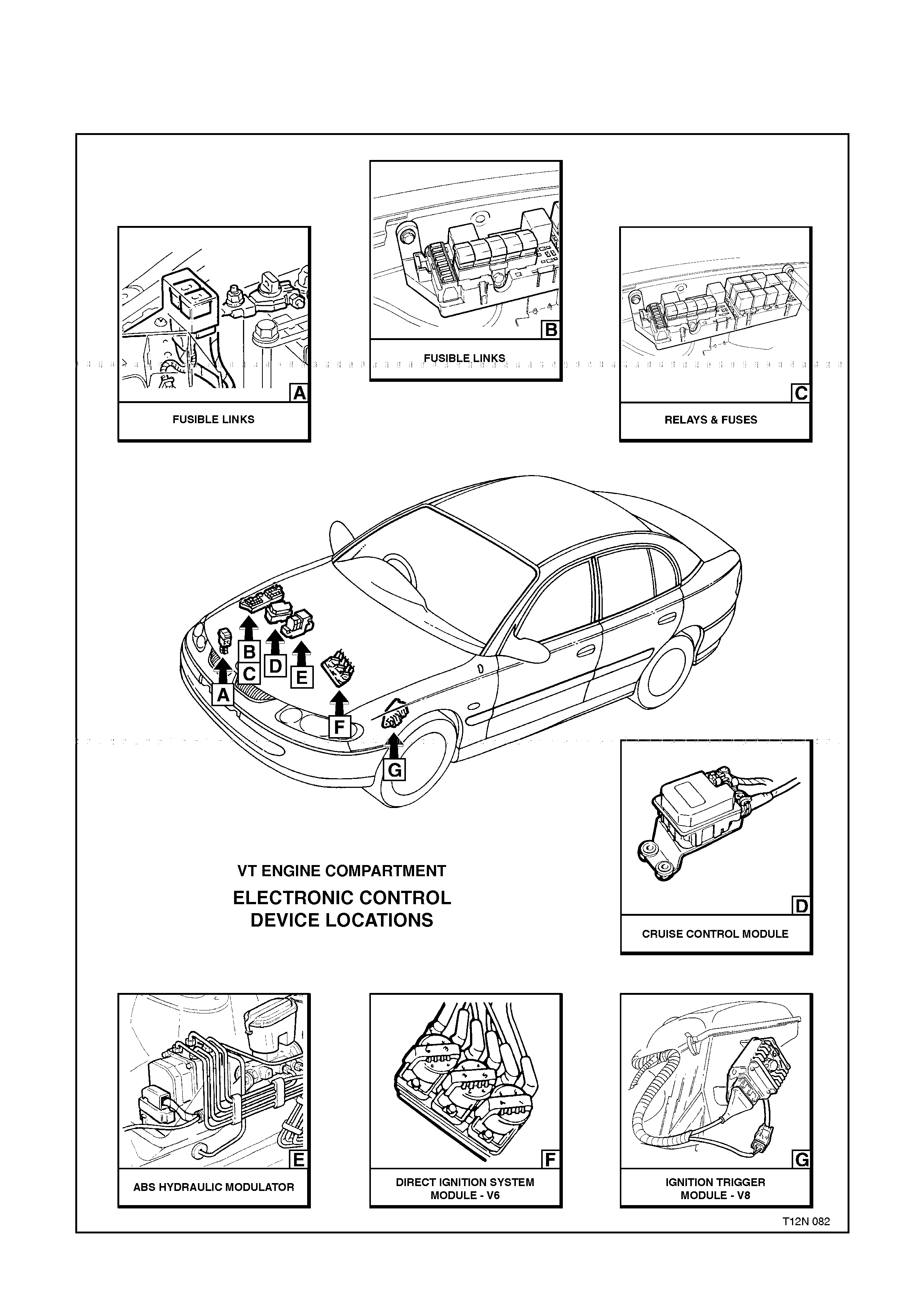
1.6 ELECTRONIC CONTROL DEV I CE LOCATIONS
The following figures illustrate the location of the various electronic control devices fitted to VT Series Models.
Ensure that the precautionary and special handling instructions are followed (where applicable) for each electronic
control device as described in the appropriate Section.
Figure 12N-15
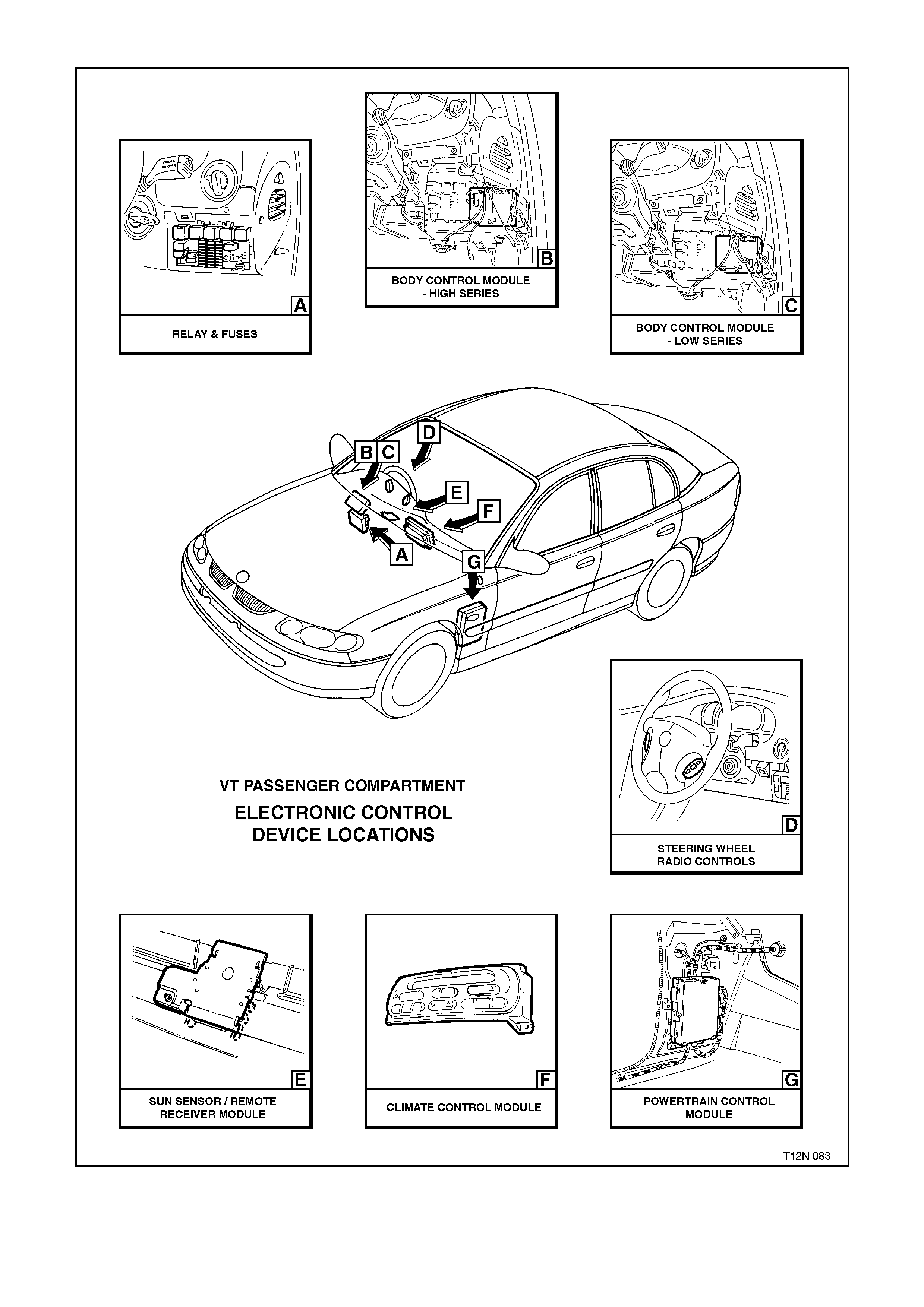
Figure 12N-16
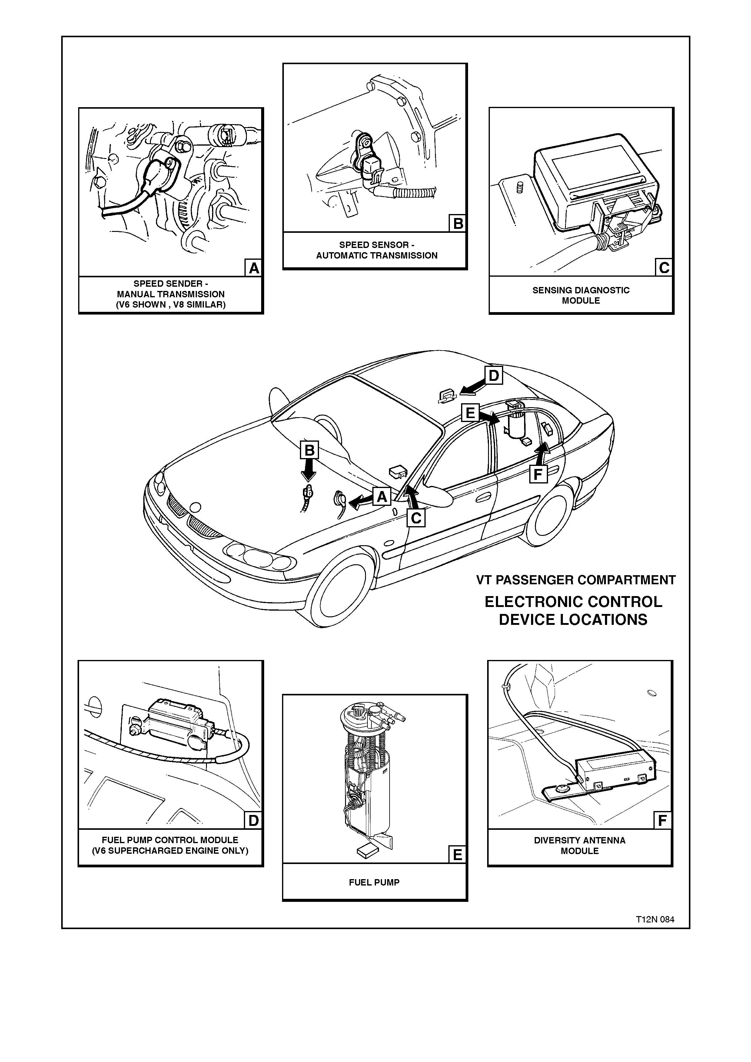
Figure 12N-17
2. SERVICE OPERATIONS
2.1 ENGINE COMPARTMENT FUSE AND RELAY PANEL ASSEMBLY FUSIBLE LINKS
REPLACE
NOTE:
All fusible links c an be r emoved by pulling them out
of the fuel and relay panel assembly sockets,
except for the FJ 60 A MAIN fusible link.
1. Depressing the retaining tang on the engine
com partm ent f uel and relay panel assem bly and
then lifting the cover up and out from the panel
assembly.
2. For all f us ible link s , other than the middle f us ible
link (FJ), just pull the link up and out from the
socket in the panel assembly.
3. Insert replacement fusible link into panel
socket and push down firmly.
Figure 12N-18
4. T o rem ove fusible link FJ, loos en lead to fusible
link terminal bolts, one on either side of the
fusible link, refer Fig. 12N-19, and pull fusible
link out from the panel assembly socket.
5. Insert replacem ent fusible link into panel sock et
and push down firmly.
6. Tighten lead to fusible link terminal bolts to the
correct torque specification.
FUSIBLE LINK TERMINAL
INNER BOLT 5 0 - 6.0 Nm
TORQUE SPECIFICATION
FUSIBLE LINK
TERMINAL OUTER BOLT 3 0 - 4.0 Nm
TORQUE SPECIFICATION
7. Reinstall engine compartment fuel and relay
panel assembly cover. Figure 12N-19
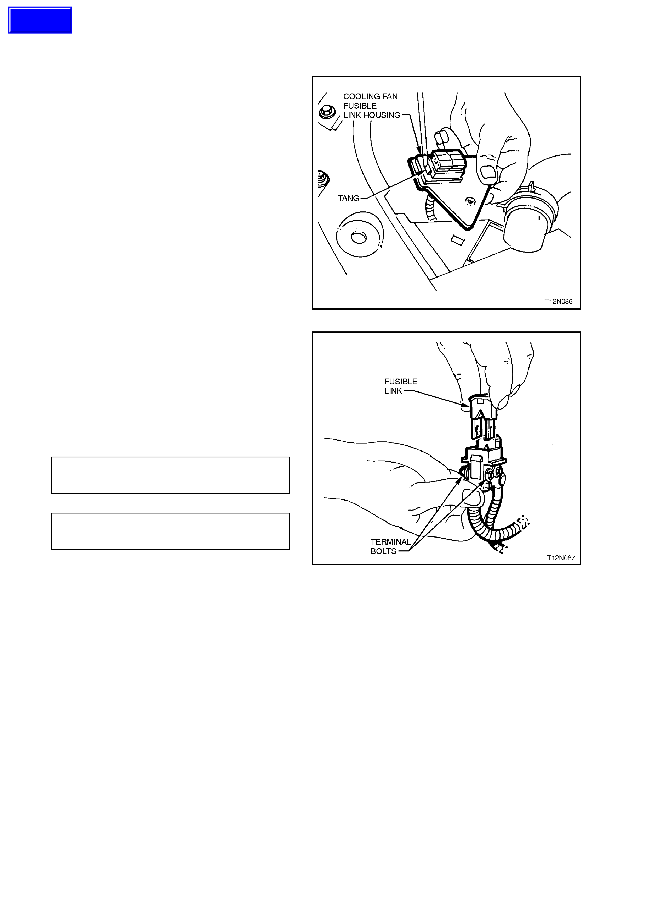
2.2 COOLING FAN FUSIBLE LINKS
REPLACE
1. Pull out tang on fusible link housing cover and
lift up and remove cover from housing.
2. Remove scr ew securing fus ible link housing to
radiator support panel and pull housing up
from support panel.
3. Using a screwdriver, lever back fusible link
housing retaining tang from fusible link socket
and push out fusible links from housing.
Figure 12N-20
4. Loosen lead to fusible link terminal bolts, one
on either side of the fusible link, refer Fig.
12N-21, and pull fusible link out from the
fusible link socket.
5. Insert replacement fusible link into socket and
push down firmly.
6. Tighten lead to fusible link ter m inal bolts to the
correct torque specification.
FUSIBLE LINK
TERMINAL BOLT (10 mm) 5 0 - 6.0 Nm
TORQUE SPECIFICATION
FUSIBLE LINK
TERMINAL BOLT (8 mm) 3 0 - 4.0 Nm
TORQUE SPECIFICATION
7. Reinstall fusible link housing cover. Figure 12N-21
Techline
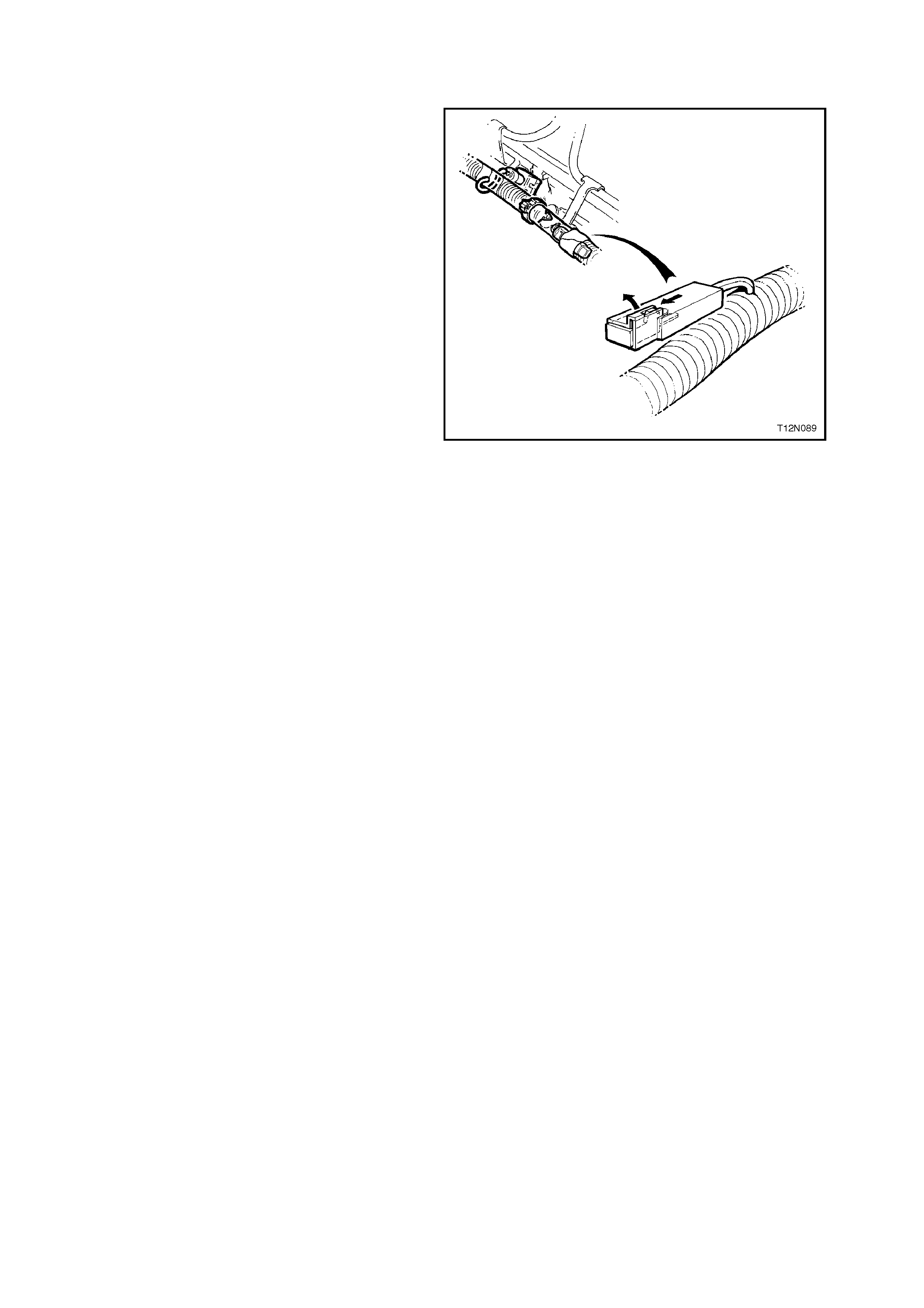
2.3 AIR CONDITIONING COMPRESSOR CLUTCH FEEDBACK DIODE
REPLACE
1. Locate diode, refer 1.3 DIODES in this
Section.
2. Remove tape securing diode connector to
wiring harness conduit.
3. Pull back diode retainer on diode connector
and then using a pair of fine long nosed plier s,
pull diode out from connector.
4. Insert diode into connector , aligning tab on the
side of the diode with the connector retainer.
5. Using suitable tape, secur e diode connector to
wiring harness conduit.
Figure 12N-22

2.4 WIRING RE P AIRS
When conducting wiring harness repairs that involve replacement of damaged terminal/s, remove terminals from
connector body and splice new terminal/s with wiring pigtail into wiring harness.
If a specific wiring harness terminal or connector body is damaged beyond repair, and the terminal or connector
body is not serviced, that particular wiring harness must be replaced.
Specific instruction on how to replace each individual wring harness are not included in this Section. Installation
details of wiring harnesses are included with the wiring installation diagrams in this Section.
NOTE:
Special wiring repairs pr ocedures have been developed for use on the ABS/ETC and SRS due to the
sensitive nature of their circuitry. The procedures are described in Section 12P WIRING DIAGRAMS and
are the only recommended and approved ABS/E TC and SR S wiring repair methods.

3. WIRI NG INSTALLATION DIAGRAMS
The following figures illustrate the vehicle wiring installation diagrams for VT Series Models.
NOTE:
Some of the following wiring installation diagrams illustrate the upper level harnesses which incorporate all
necessary wiring harness connectors for all production options. Depending on equipment level and vehicle model,
some of the connectors may be taped back to the harness when a particular option is not fitted, or the particular
level of harness fitted to the vehicle may not incorporate some of the connectors illustrated.
TOPICS
BATTERY HARNESS – 1
BATTERY HARNESS – 2
BATTERY HARNESS – 3
POWERTRAIN HARNESS – 1
POWERTRAIN HARNESS – 2
POWERTRAIN HARNESS – 3
POWERTRAIN HARNESS - 4
POWERTRAIN HARNESS – 5
POWERTRAIN HARNESS – 6
POWERTRAIN HARNESS – 7
POWERTRAIN HARNESS – 8
POWERTRAIN HARNESS – 9
POWERTRAIN HARNESS – 10
POWERTRAIN HARNESS – 11
POWERTRAIN HARNESS – 12
POWERTRAIN HARNESS – 13
POWERTRAIN HARNESS – 14
POWERTRAIN HARNESS – 15
POWERTRAIN HARNESS – 16
POWERTRAIN HARNESS – 17
POWERTRAIN HARNESS – 18
MAIN WIRING HARNESS – 1
MAIN WIRING HARNESS – 2
MAIN WIRING HARNESS – 3
MAIN WIRING HARNESS – 4
MAIN WIRING HARNESS – 5
MAIN WIRING HARNESS – 6
MAIN WIRING HARNESS – 7
MAIN WIRING HARNESS – 8
MAIN WIRING HARNESS – 9
MAIN WIRING HARNESS – 10
Techline
Techline

MAIN WIRING HARNESS – 11
MAIN WIRING HARNESS – 12
MAIN WIRING HARNESS – 13
MAIN WIRING HARNESS – 14
MAIN WIRING HARNESS – 15
MAIN WIRING HARNESS – 16
MAIN WIRING HARNESS – 17
MAIN WIRING HARNESS – 18
MAIN WIRING HARNESS – 19
MAIN WIRING HARNESS – 20
MAIN WIRING HARNESS – 21
MAIN WIRING HARNESS – 22
MAIN WIRING HARNESS – 23
MAIN WIRING HARNESS – 24
MAIN WIRING HARNESS – 25
MAIN WIRING HARNESS – 26
MAIN WIRING HARNESS – 27
DIVERSITY ANTENNA WIRING – 1
DIVERSITY ANTENNA AND WIRING – 2
CD CHANGER WIRING – 1
CD CHANGER WIRING – 2
BODY & ROOF WIRING HARNESSES – 1
BODY & ROOF WIRING HARNESSES – 2
BODY & ROOF WIRING HARNESSES – 3
BODY & ROOF WIRING HARNESSES – 4
BODY & ROOF WIRING HARNESSES – 5
BODY & ROOF WIRING HARNESSES – 6
BODY & ROOF WIRING HARNESSES – 7
BODY & ROOF WIRING HARNESSES – 8
BODY & ROOF WIRING HARNESSES – 9
BODY & ROOF WIRING HARNESSES – 10
BODY & ROOF WIRING HARNESSES – 11
BODY & TAILGATE WIRING HARNESSES – 1
BODY & TAILGATE WIRING HARNESSES – 2
BODY & TAILGATE WIRING HARNESSES – 3
BODY & TAILGATE WIRING HARNESSES – 4
FRONT DOOR HARNESS
REAR DOOR HARNESS
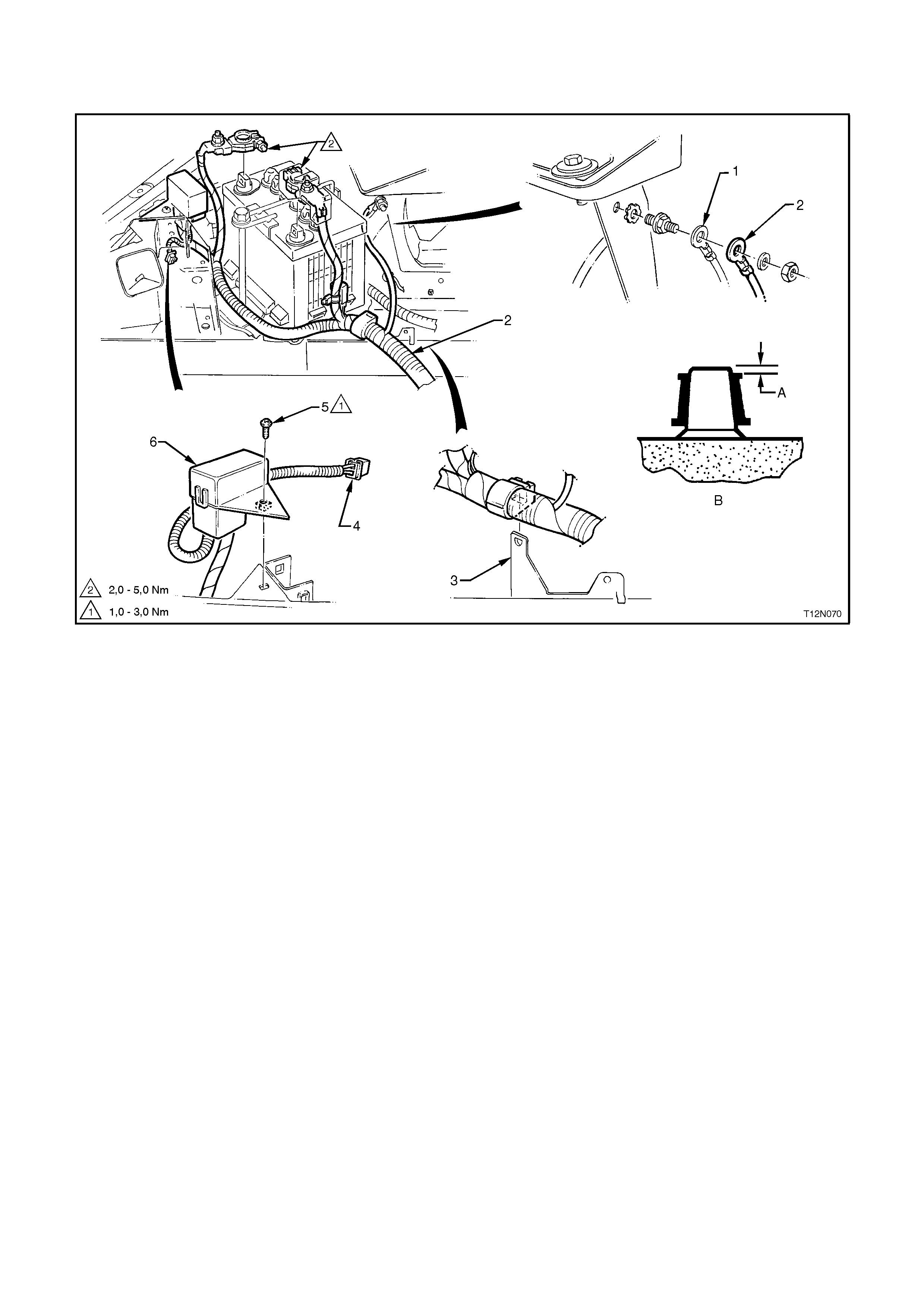
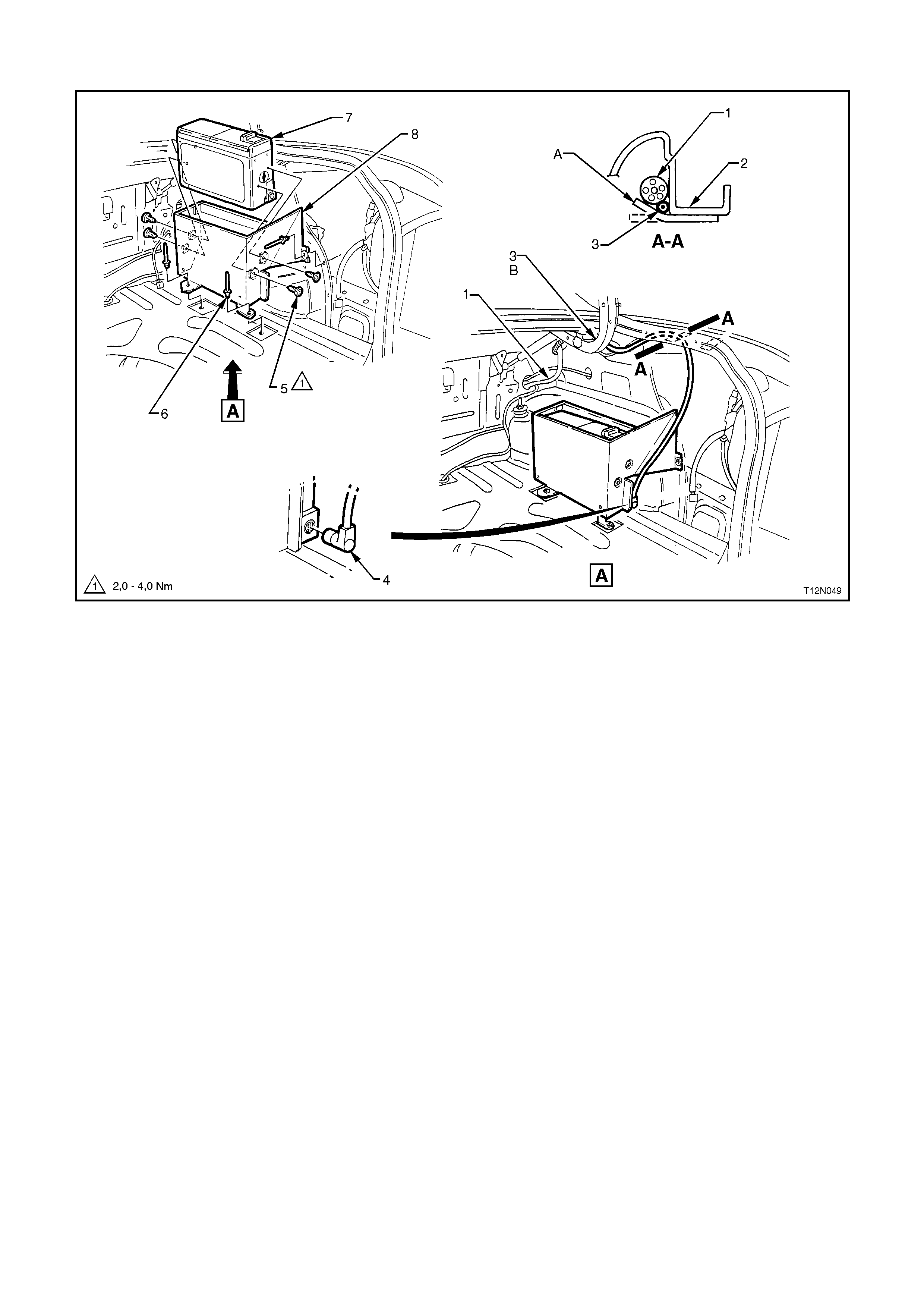
BATTERY HARNESS
BATTERY HARNESS - 1
All Models
Legend
1. Main Wiring Harness Body Earth Terminal
2. Battery Harness Body Earth Terminal
3. Battery Harness to Side Rail Bracket
4. Battery Harness Engine Condenser Fan Connector
5. Screw
6. Battery Harness Fusible Link Housing
A. Battery cable terminal must be fitted below top of battery post.
B. Section through battery posts - 2 places.
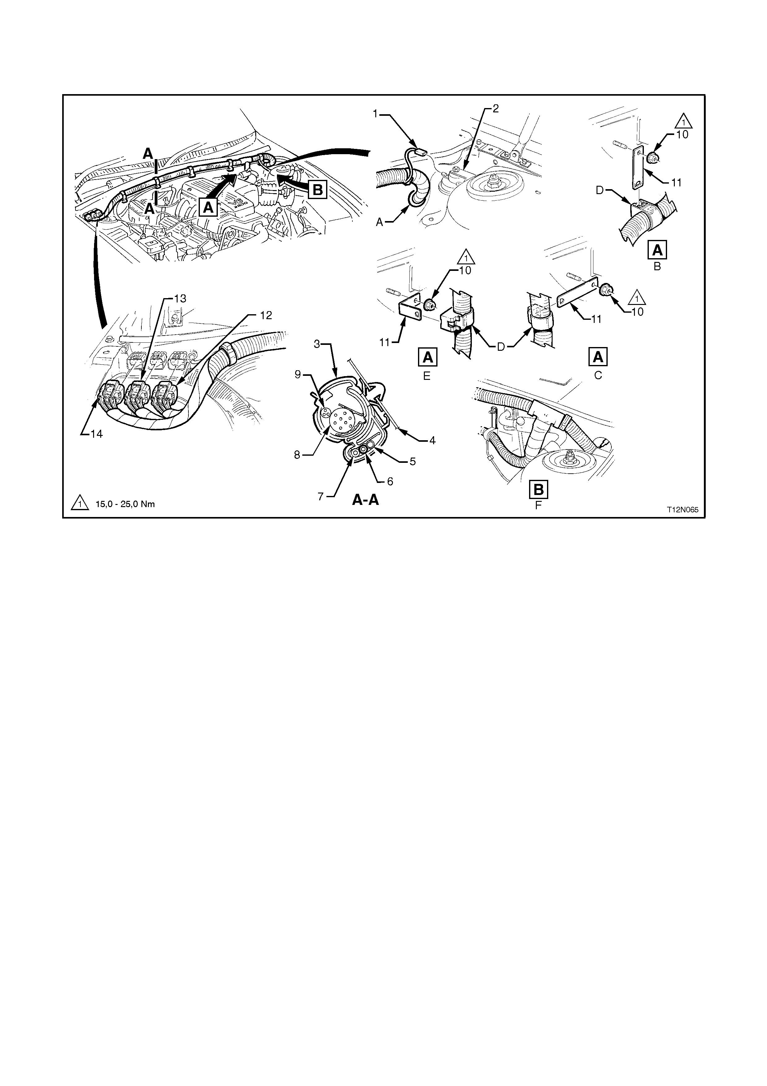
BATTERY HARNESS - 2
V6 Engines
Legend
1. Oil Cooler Pipes
2. Engine Mount Bolt
3. Battery Harness Earth Terminal
4. Main Wiring Harness
5. Engine Mount - Right Hand Side
6. Battery Harness Negative Terminal
7. Battery Harness To Main Wiring Harness Connector
8. Battery Harness Positive Terminal
9. Battery Harness Body Earth Terminal
10. Generator Connector
11. Battery Harness
A. V6 Non-Supercharged engine shown.
B. Vehicles with V6 Supercharged engine.
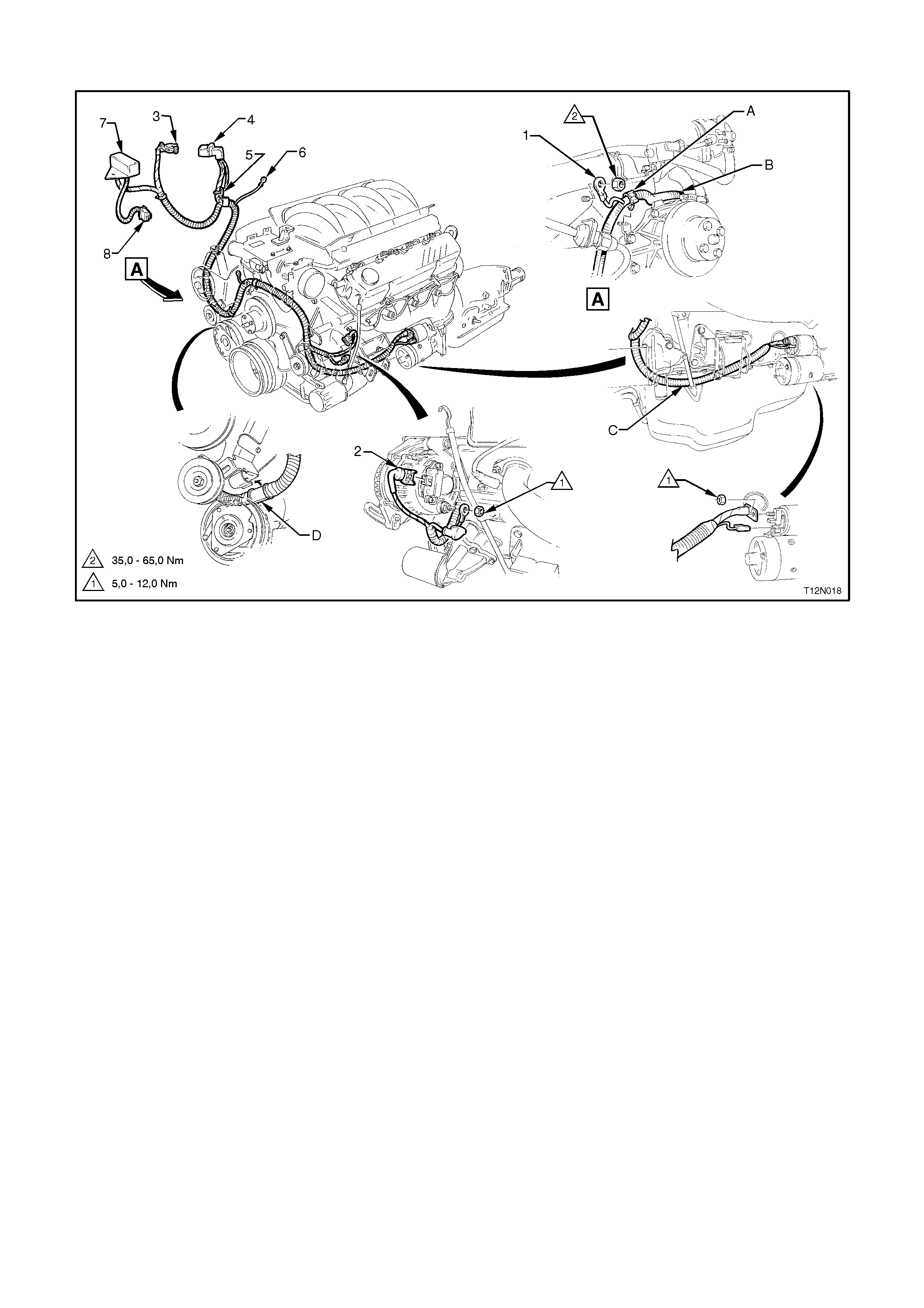
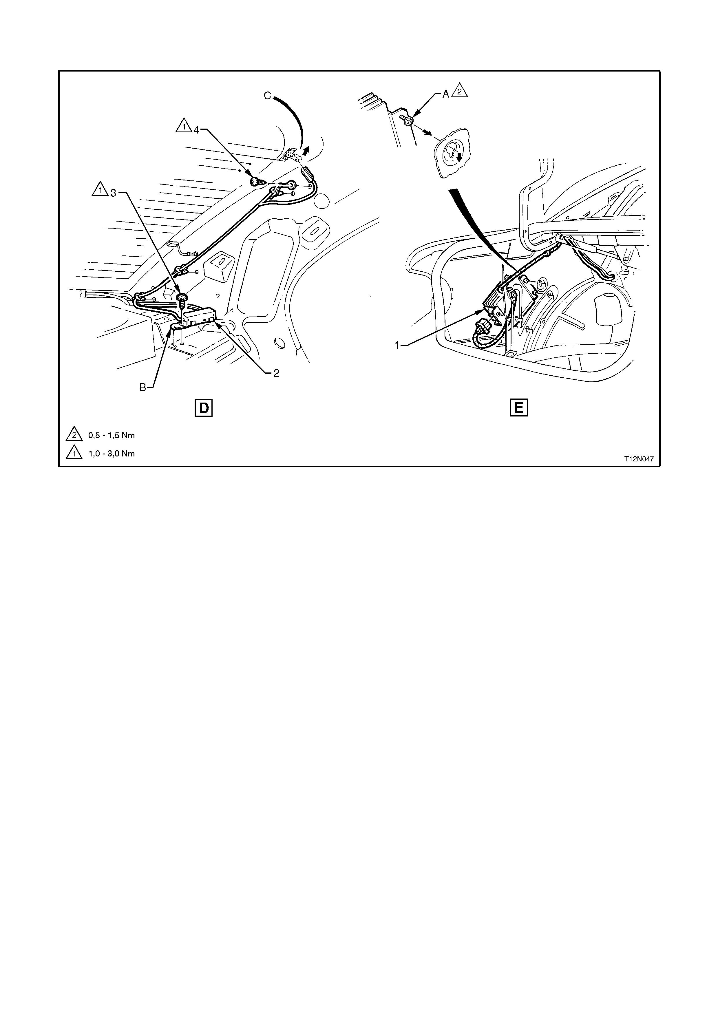
BATTERY HARNESS - 3
V8 Engine
Legend
1. Battery Harness Earth Terminal
2. Generator Connector
3. Battery Harness Negative Terminal
4. Battery Harness Positive Terminal
5. Battery Harness To Main Wiring Harness Connector
6. Battery Harness Body Earth Terminal
7. Battery Harness Fusible Link Housing
A. Battery Harness secured to bracket as shown.
B. Battery Harness routed behind hoses as shown.
C. Battery Harness routed between oil pan and dipstick as shown.
D. Battery Harness secured to power steering bracket as shown.
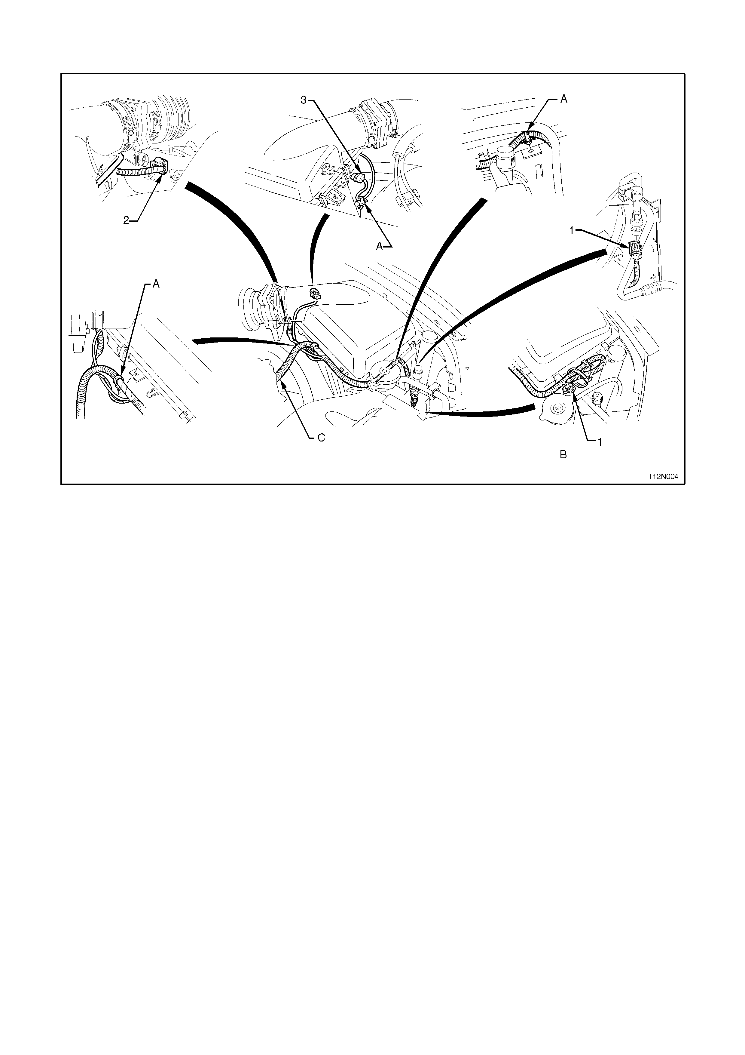
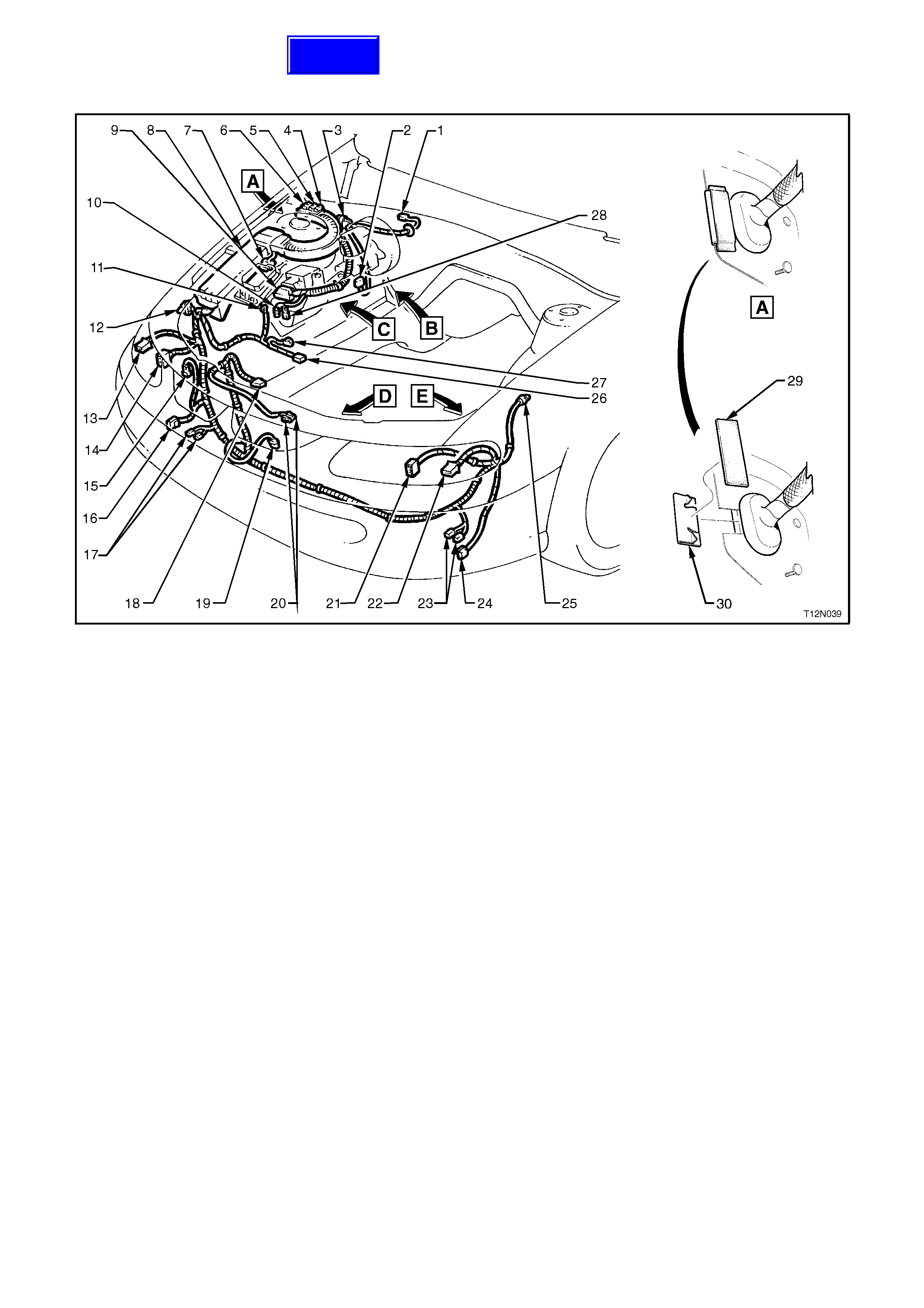
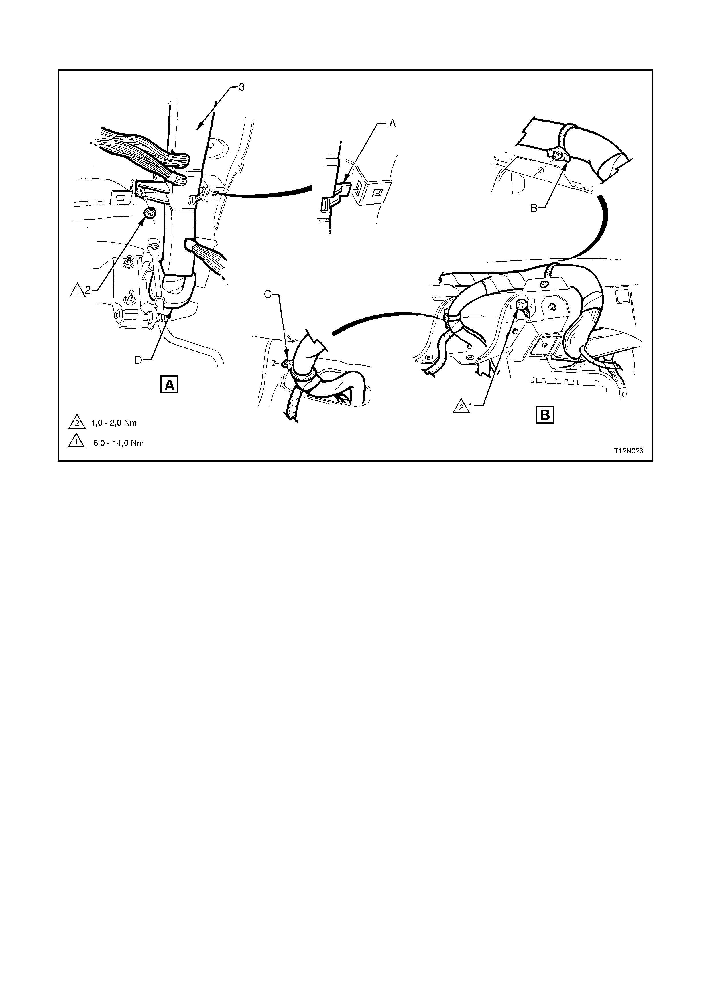
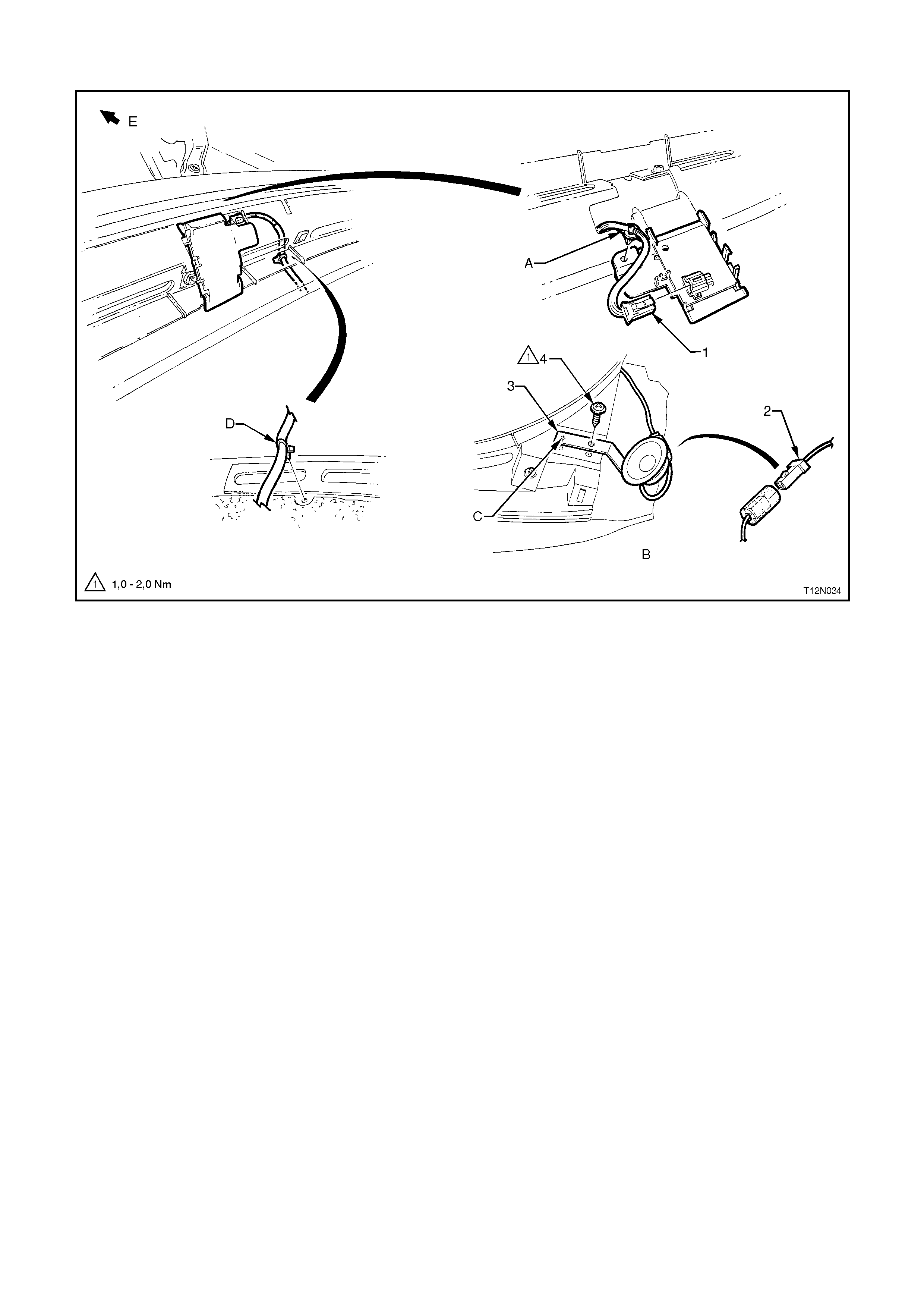
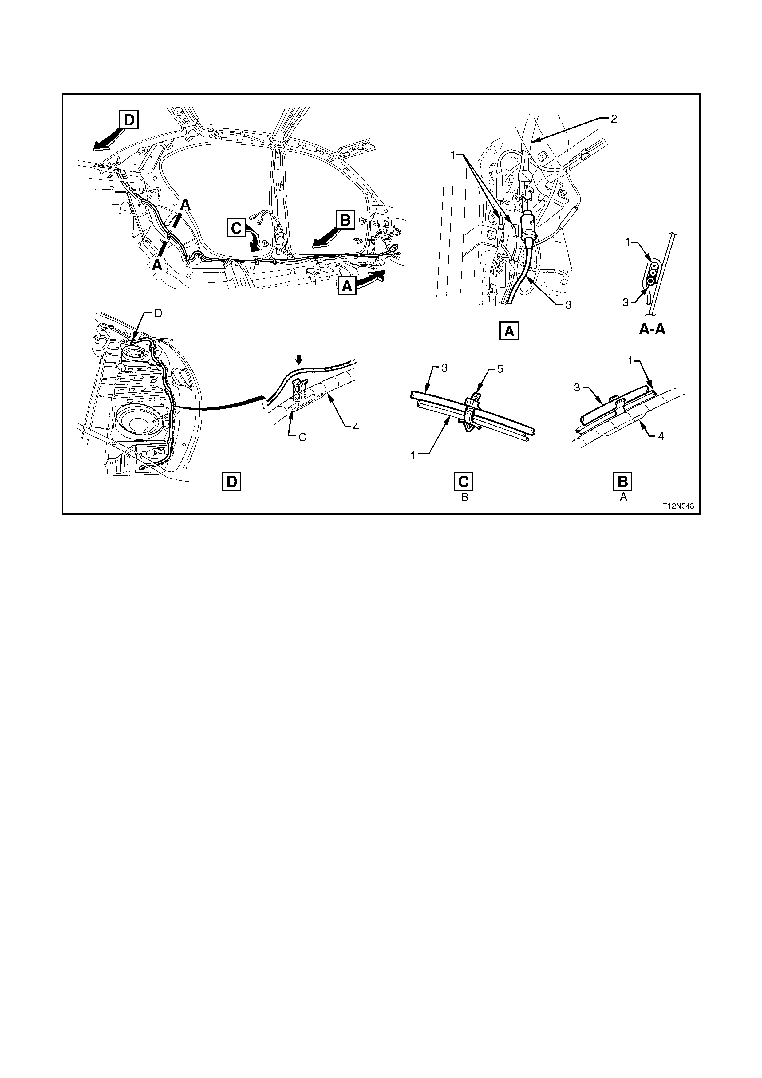
POWERTRAIN HARNESS
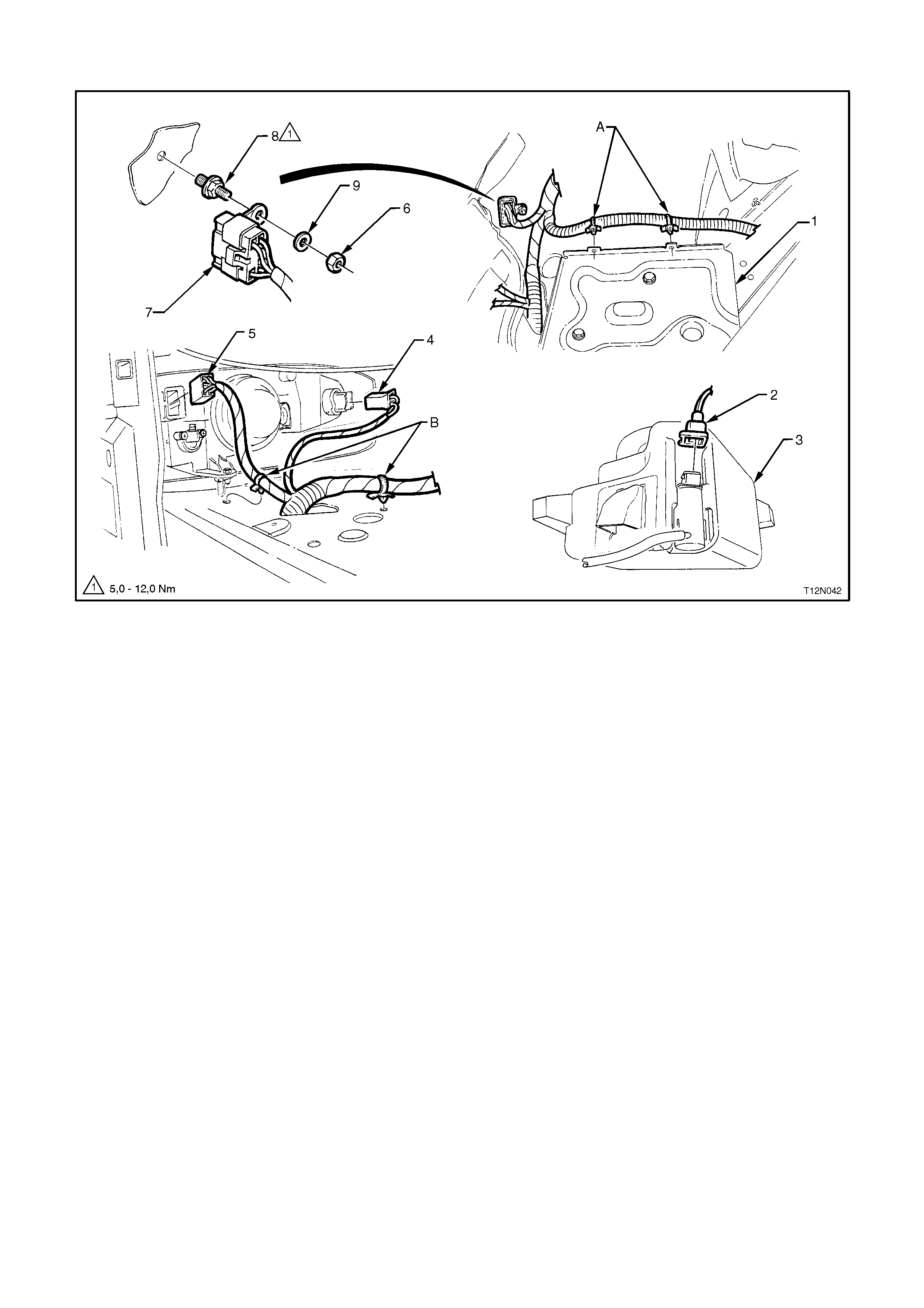
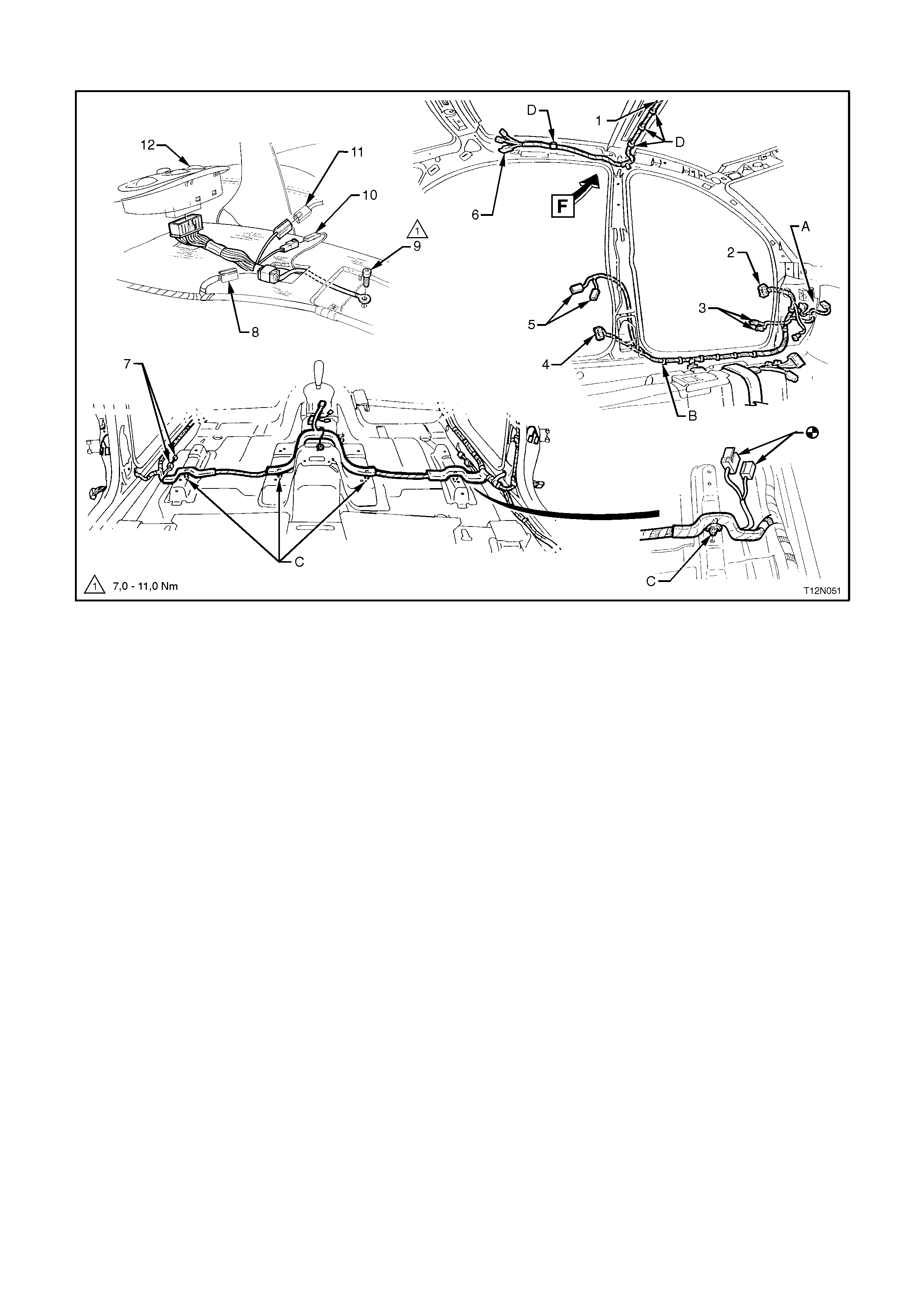
POWERTRAIN HARNESS - 1
All Models
Legend
1. Theft Deterrent Horn Connector
2. Theft Deterrent Horn
3. Clamp - 5 Places
4. Dash Upper Panel Assembly
5. Tailgate Washer Hose
6. Cruise Control Cable
7. Throttle Cable
8. Powertrain Harness
9. Main Wiring Harness - To Wiper Motor
10. Nut
11. Bracket
12. Powertrain Harness Engine Connector 1
13. Powertrain Harness Engine Connector 2
14. Powertrain Harness Engine Connector 3
A. For continuation, refer to POWERTRAIN HARNESS - 18 diagram in this Section.
B. View shows V6 Supercharged engine.
C. View shows V6 Non-Supercharged engine.
D. Harness retainer
E. View shows V8 engine.
F. View shows V6 Supercharged engine.
POWERTRAIN HARNESS - 2
V6 Non-Supercharged Engine
Legend
1. Powertrain Harness To Direct Ignition System Control Module Retainer
2. Direct Ignition System Control Module
3. Powertrain Harness To Direct Ignition System Control Module Connector
4. Coolant Temperature Sensor Connector
5. Camshaft Position Sensor Connector
6. Oil Pressure Sensor Connector
7. Knock Sensor, Right Hand Side
8. Battery Harness, refer to BATTERY HARNESS - 2 Diagram in this Section.
9. Powertrain Harness To Engine Earth Terminal
A. Powertrain Harness secured to bracket as shown.
B. Automatic transmission shown.
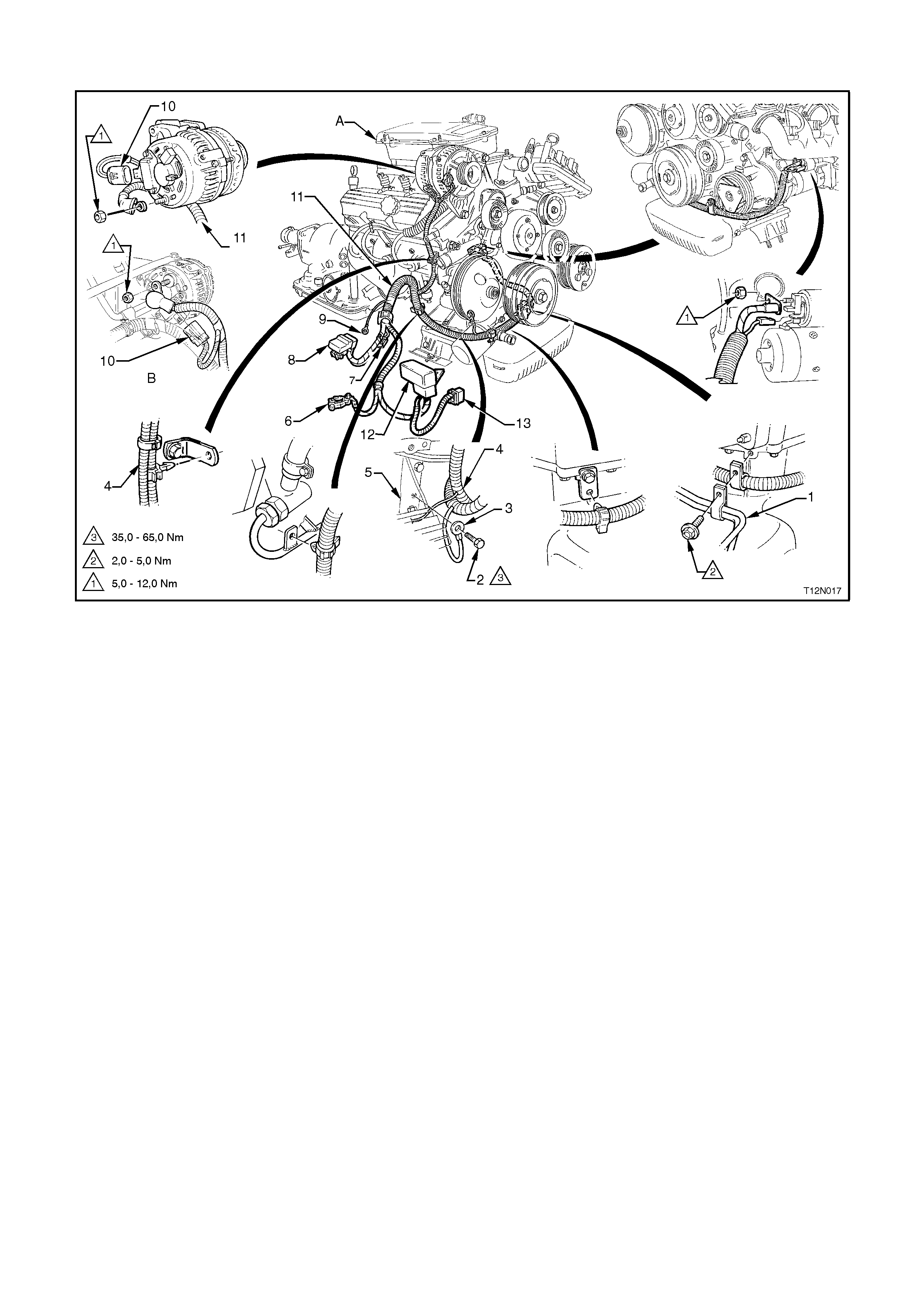
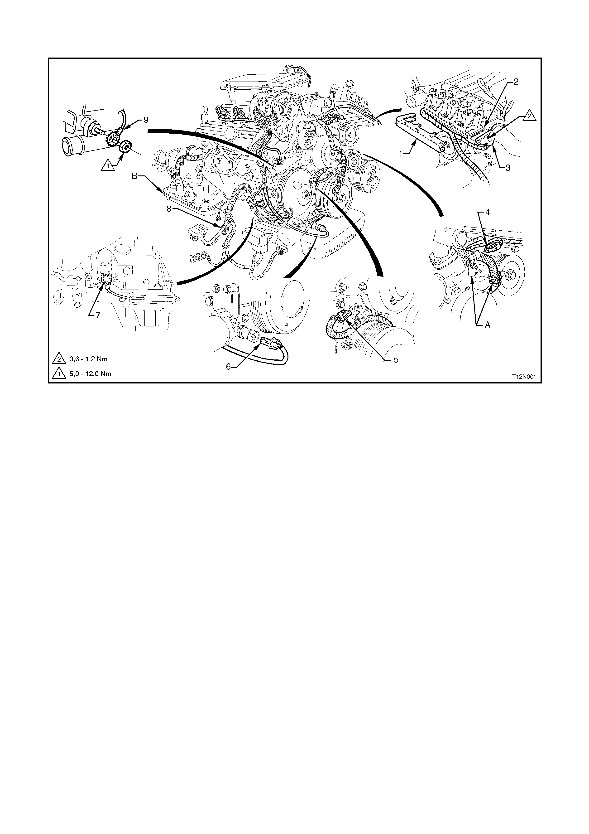
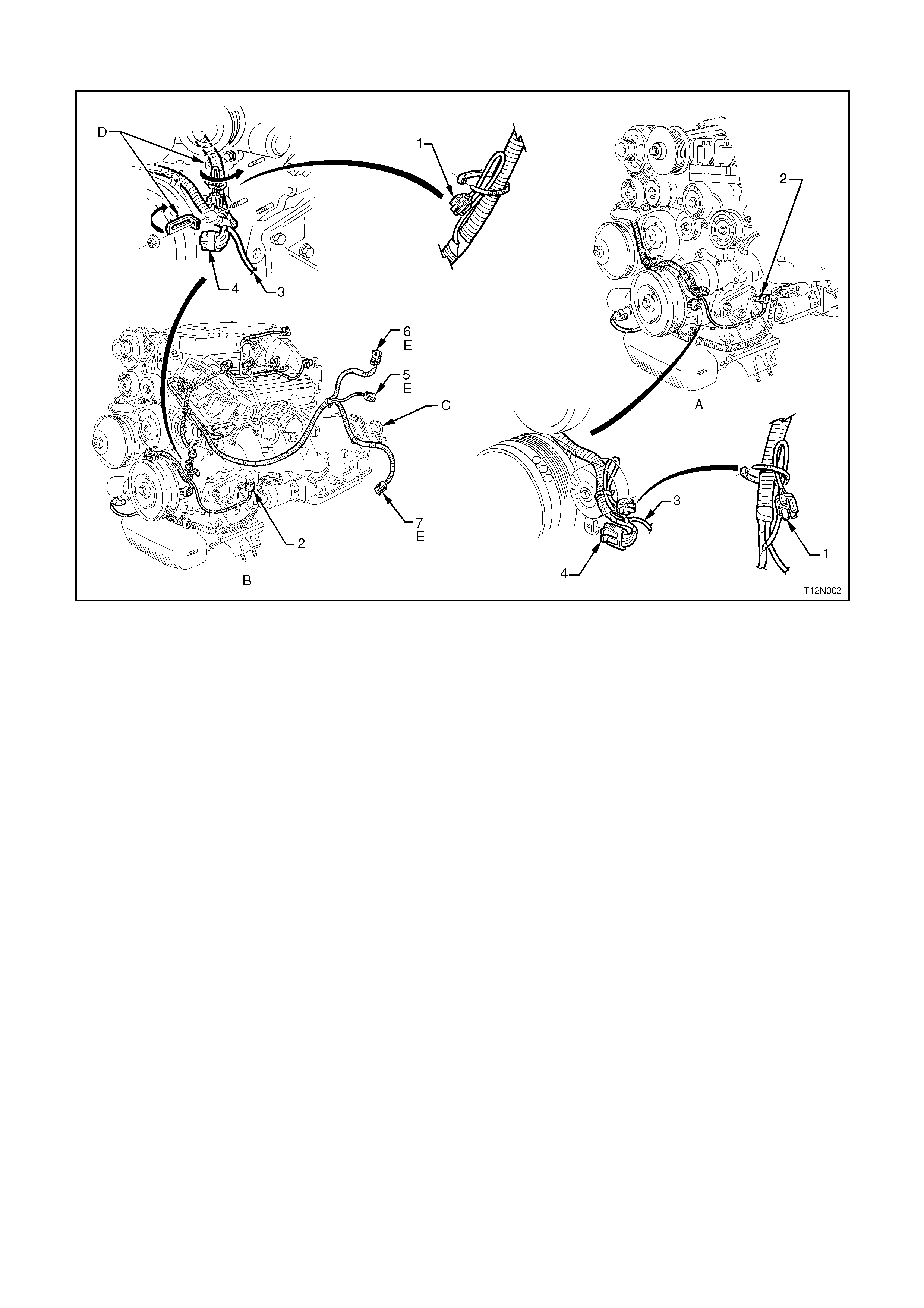
POWERTRAIN HARNESS - 3
V6 Non Supercharged Engine With A/C or ECC
Legend
1. Idle Air Control Motor Connector
2. Throttle Position Sensor Connector
3. Exhaust Gas Recirculation Valve Connector
4. Knock Sensor, Left Hand Side
5. A/C Compressor Connector
6. Intake Air Temperature Sensor Connector
7. Mass Air Flow Sensor Connector
8. A/C Pressure Transducer Connector
9. A/C Compressor Lead
10. Knock Sensor Lead, Left Hand Side
11. Crankshaft Position Sensor Connector
12. Idler Pulley
13. Fuel Injector Connector (6 Places)
14. Compressor Clutch Diode
A. For installation, refer to POWERTRAIN HARNESS - 4 diagram in this Section.
B. Clips bent over to retain Powertrain Harness.
C. Powertrain Harness routed through groove in crankshaft position sensor shield.
D. Powertrain Harness secured to inlet manifold as shown (6 places).
POWERTRAIN HARNESS - 4
V6 Engines with A/C or ECC
Legend
1. A/C Pressure Transducer Connector
2. Mass Air Flow Sensor Connector
3. Intake Air Temperature Sensor Connector
A. Powertrain Harness secured to air cleaner housing as shown.
B. View shows vehicles without A/C or Electronic Climate Control.
C. For continuation, refer to previous diagram in this Section, or to POWERTRAIN HARNESS - 10 diagram in
this Section.
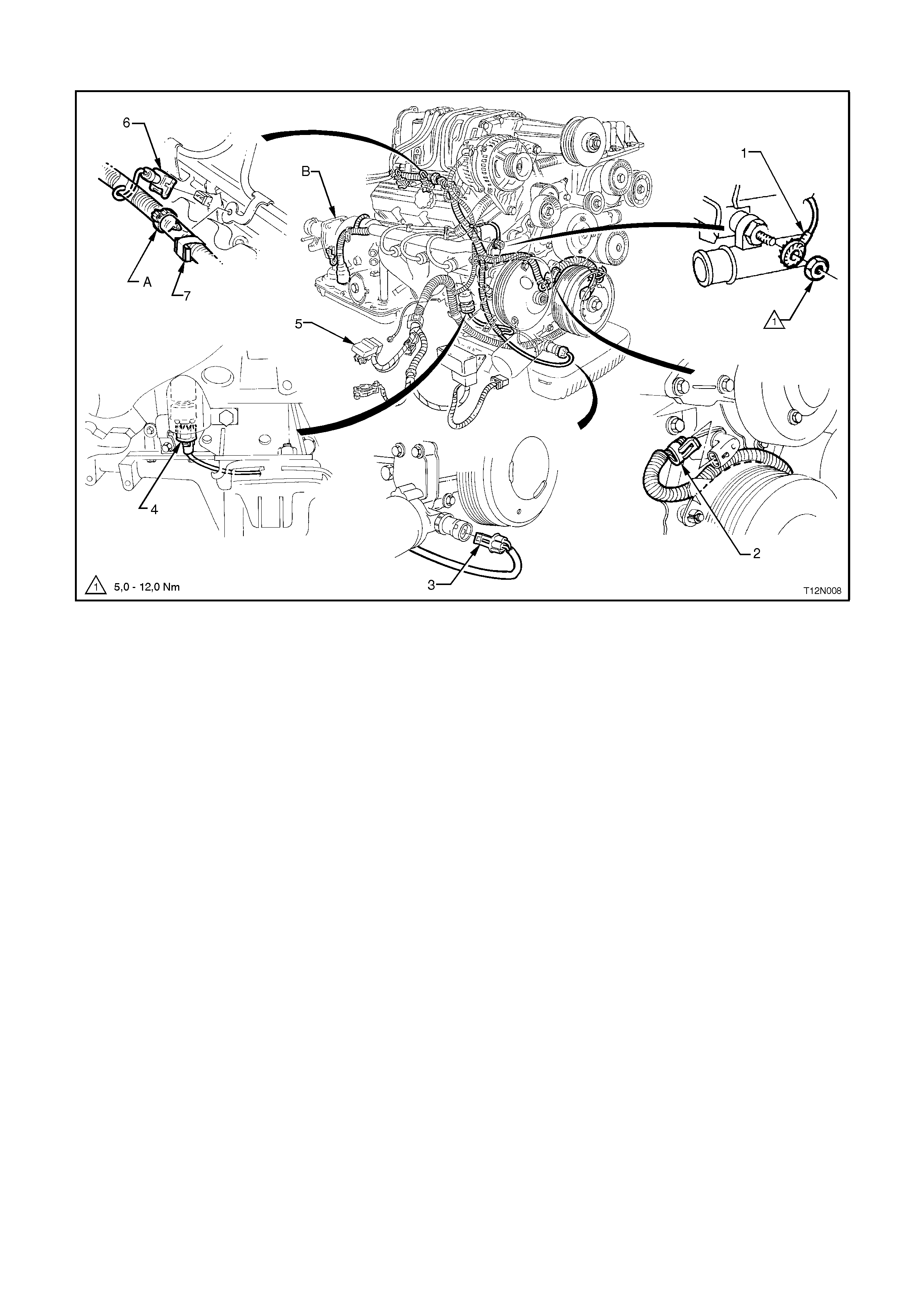
POWERTRAIN HARNESS - 5
V6 Engines Without A/C or ECC
Legend
1. A/C Compressor Connector
2. Knock Sensor, Left Hand Side
3. Knock Sensor Lead, Left Hand Side
4. Crankshaft Position Sensor Connector
5. Intake Air Temperature Sensor Connector
6. Mass Air Flow Sensor Connector
7. A/C Pressure Transducer Connector
A. V6 Supercharged engine shown.
B. V6 Non-Supercharged engine shown.
C. Automatic transmission shown.
D. Clips bent over to retain Powertrain Harness.
E. For installation, refer to the previous diagram in this Section.
POWERTRAIN HARNESS - 6
V6 Non-Superchar ged Engine With Automatic Transmission
Legend
1. Canister Purge Solenoid Connector
2. Exhaust Gas Oxygen Sensor Connector - Right Hand Side
3. Exhaust Gas Oxygen Sensor Connector - Left Hand Side
4. Powertrain Harness Earth Terminal
5. Powertrain Harness To Main Wiring Harness Connectors
6. Powertrain Harness to Powertrain Control Module Connectors
7. Tacho Signal Connector
8. Theft Deterrent System Horn Connector
A. Powertrain Harness secured to canister purge solenoid as shown.
B. View shows vehicle with automatic transmission.
C. Powertrain Harness.
For Views, B, C, D, E refer to next diagram in this Section.
POWERTRAIN HARNESS - 7
V6 Engines With Automatic Transmission
Legend
1. Plug
2. Neutral Start/Back-Up Lamp Switch Connector
3. Neutral Start/Back-Up Lamp Switch Connector To Transmission Lock
4. Powertrain Harness Pass Thru Connector
5. Powertrain Harness To Transmission Output Speed Sensor Connector
For location of Views B, C, D, E refer to previous diagram in this Section.
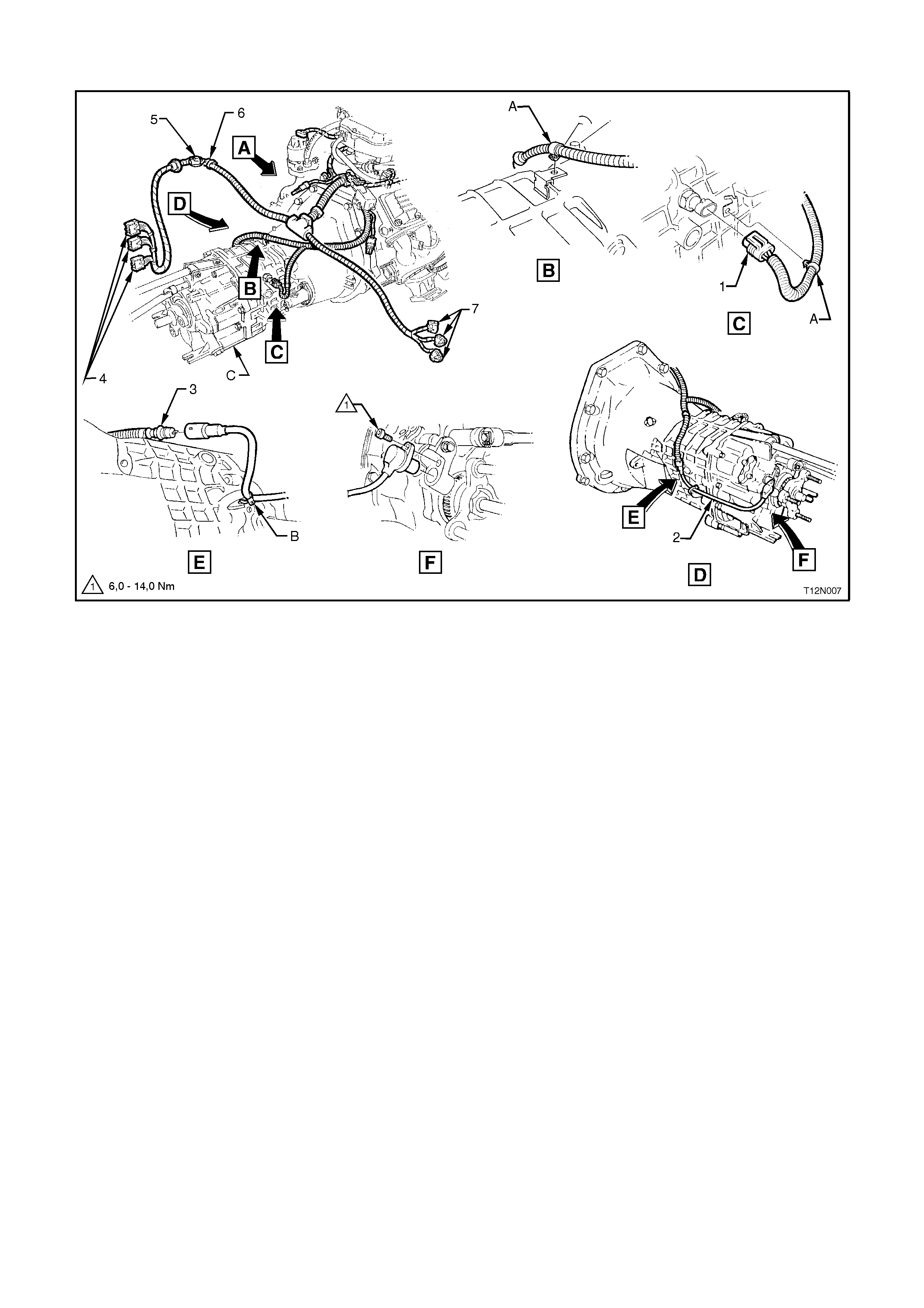
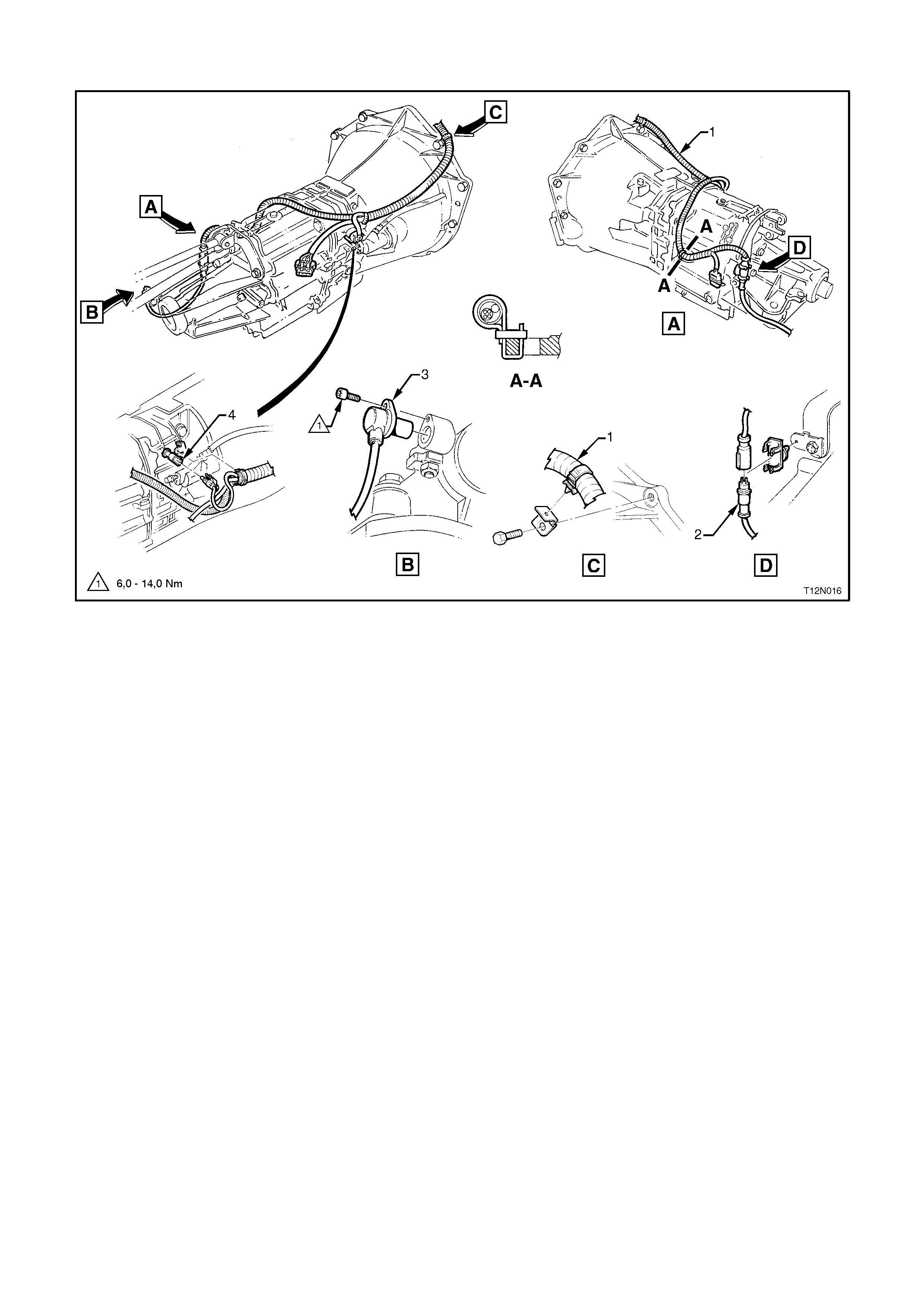
POWERTRAIN HARNESS - 8
V6 Non-Supercharged Engine With Manual Transmission
Legend
1. Back-Up Lamp Switch Connector
2. Transmission Output Speed Sensor Lead
3. Powertrain Harness To Transmission Output Speed Sensor Lead Connector
4. Powertrain Harness To Control Module Connectors
5. Tacho Signal Connector
6. Theft Deterrent System Horn Connector
7. Powertrain Harness To Main Wiring Harness Connectors
A. Powertrain Harness secured to transmission bracket as shown.
B. Transmission output speed sensor lead secured to transmission housing as shown.
C. Manual transmission shown. For automatic transmission, refer to POWERTRAIN HARNESS - 6 diagram in
this Section.
For location of View A, refer POWERTRAIN HARNESS - 6.
POWERTRAIN HARNESS - 9
V6 Supercharged Engine
Legend
1. Powertrain Harness To Engine Earth Terminal
2. Camshaft Position Sensor Connector
3. Oil Pressure Sensor Connector
4. Knock Sensor Connector, Right Hand Side
5. Battery Harness, refer to BATTERY HARNESS - 2 diagram in this Section
6. Fuel Injector (6 Places)
7. Compressor Clutch Diode
A. Powertrain harness secured to bracket as shown.
B. Automatic transmission shown.
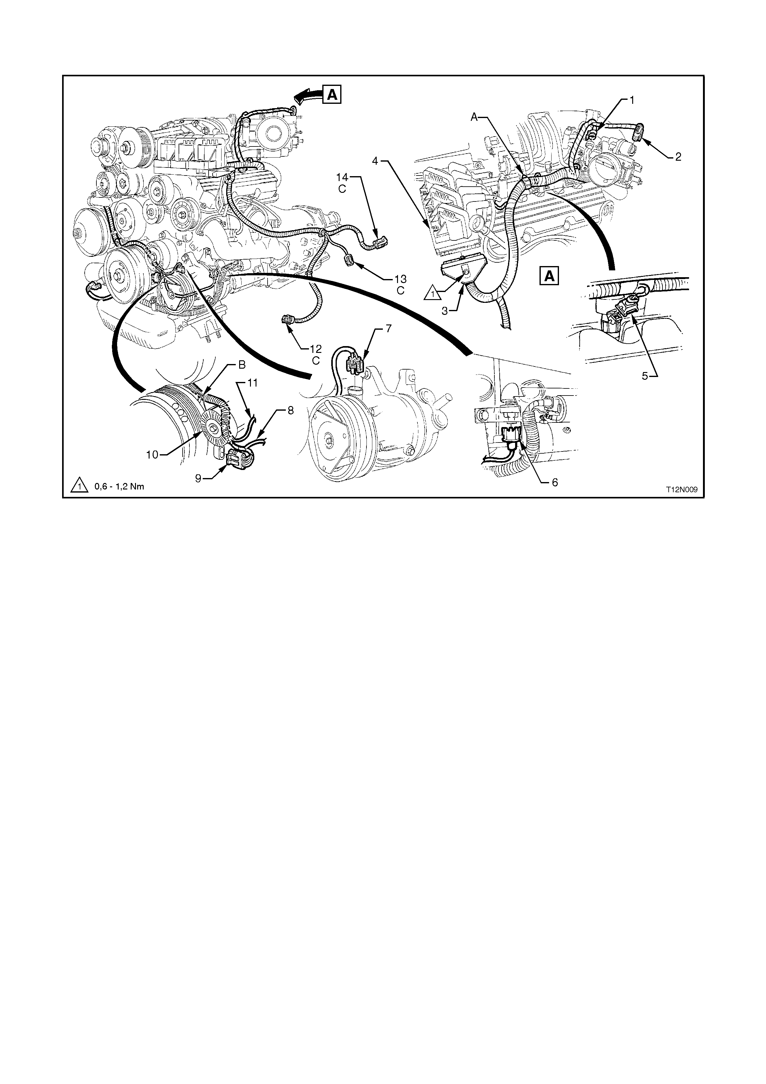
POWERTRAIN HARNESS - 10
V6 Supercharged Engine With A/C or ECC
Legend
1. Throttle Position Sensor Connector
2. Idle Air Control Motor Connector
3. Powertrain Harness To Direct Ignition System Control Module Connector
4. Direct Ignition System Control Module
5. Fuel Injector (6 Places)
6. Knock Sensor Connector, Left Hand Side
7. A/C Compressor Connector
8. A/C Compressor Connector Lead
9. Crankshaft Position Sensor Connector
10. Idler Pulley
11. Knock Sensor Lead, Left Hand Side
12. A/C Pressure Transducer Connector
13. Intake Air Temperature Sensor Connector
14. Mass Air Flow Sensor Connector
A. Powertrain Harness secured to bracket as shown.
B. Powertrain Harness routed through groove in crankshaft position sensor shield.
C. For installation, refer to POWERTRAIN HA RNESS - 4 diagram in this Section.
POWERTRAIN HARNESS - 11
V6 Supercharged Engine With Automatic Transmission
Legend
1. Boost Control Solenoid Connector
2. Coolant Temperature Sensor Connector
3. Powertrain Harness Earth Terminal
4. Exhaust Gas Oxygen Sensor Connector - Left Hand Side
5. Exhaust Gas Oxygen Sensor Connector - Right Hand Side
6. Canister Purge Solenoid Connector
7. Powertrain Harness To Main Wiring Harness Connectors
8. Powertrain Harness To Control Module Connectors
9. Tacho Signal Connector
10. Theft Deterrent System Horn Connector
A. Powertrain Harness secured to purge canister solenoid bracket as shown.
B. Automatic transmission shown.
C. Powertrain Harness secured to bracket as shown.
For location of Views B, C, D, E, refer to POWERTRAIN HARNESS - 7 diagram in this Section.
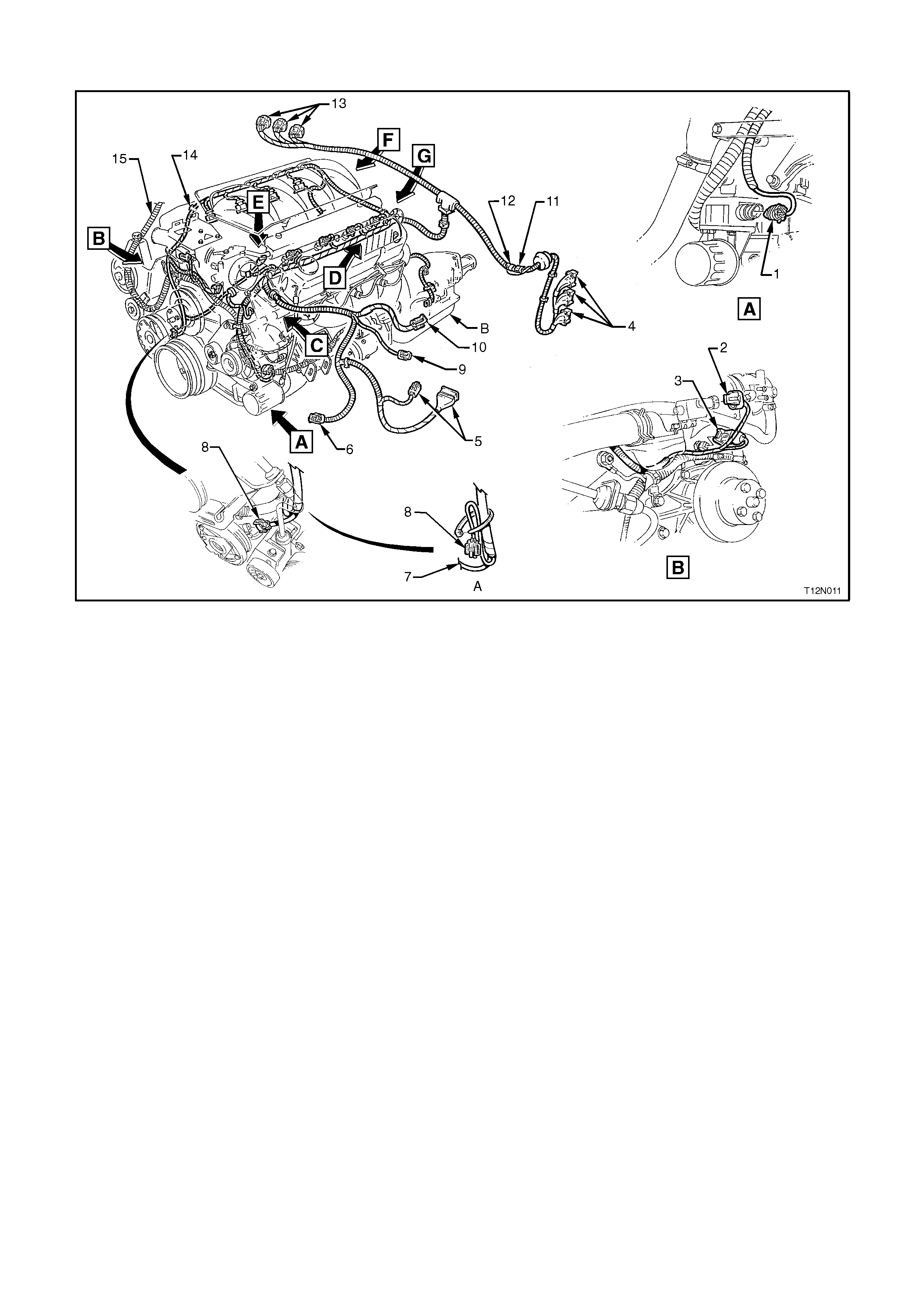
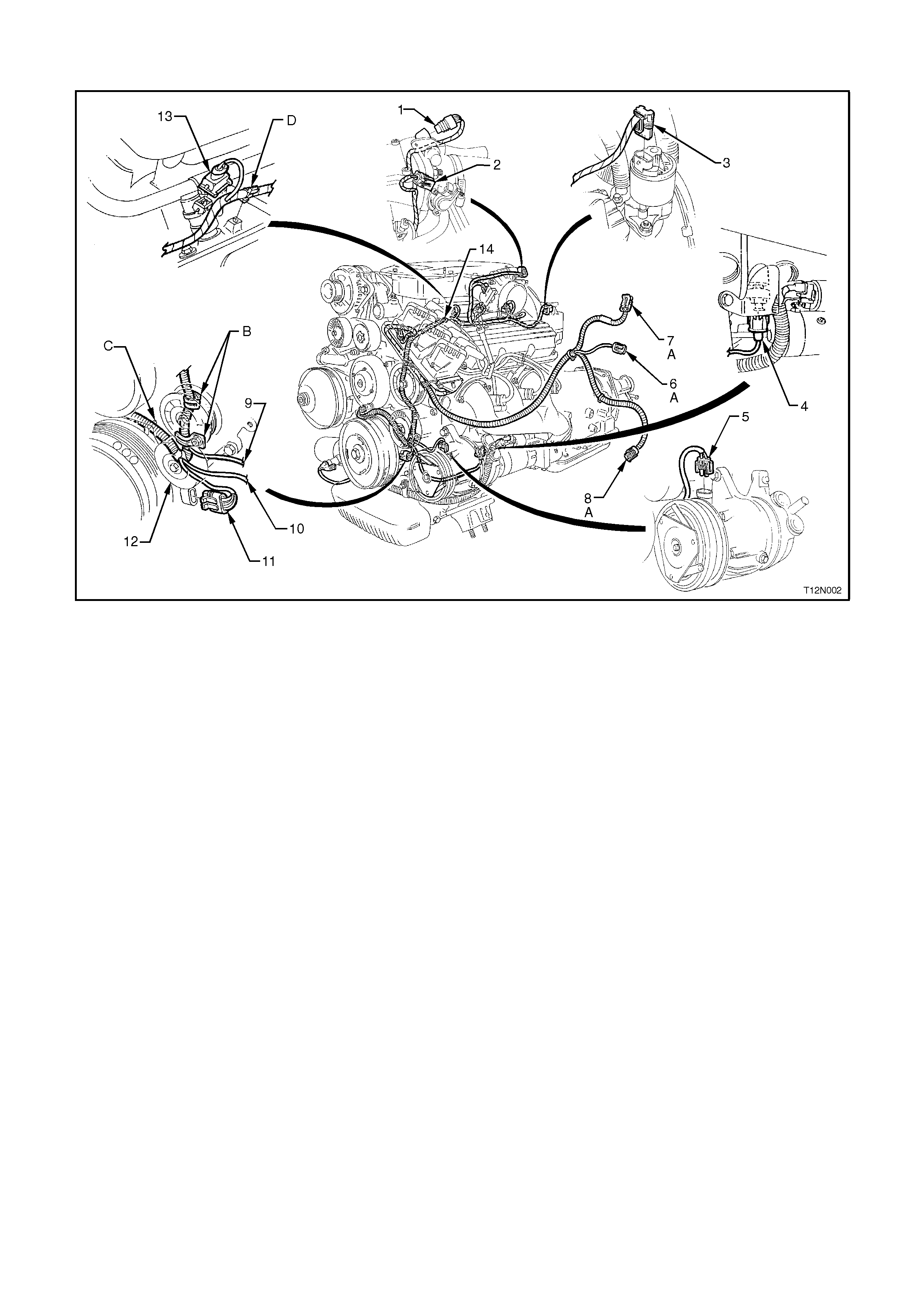
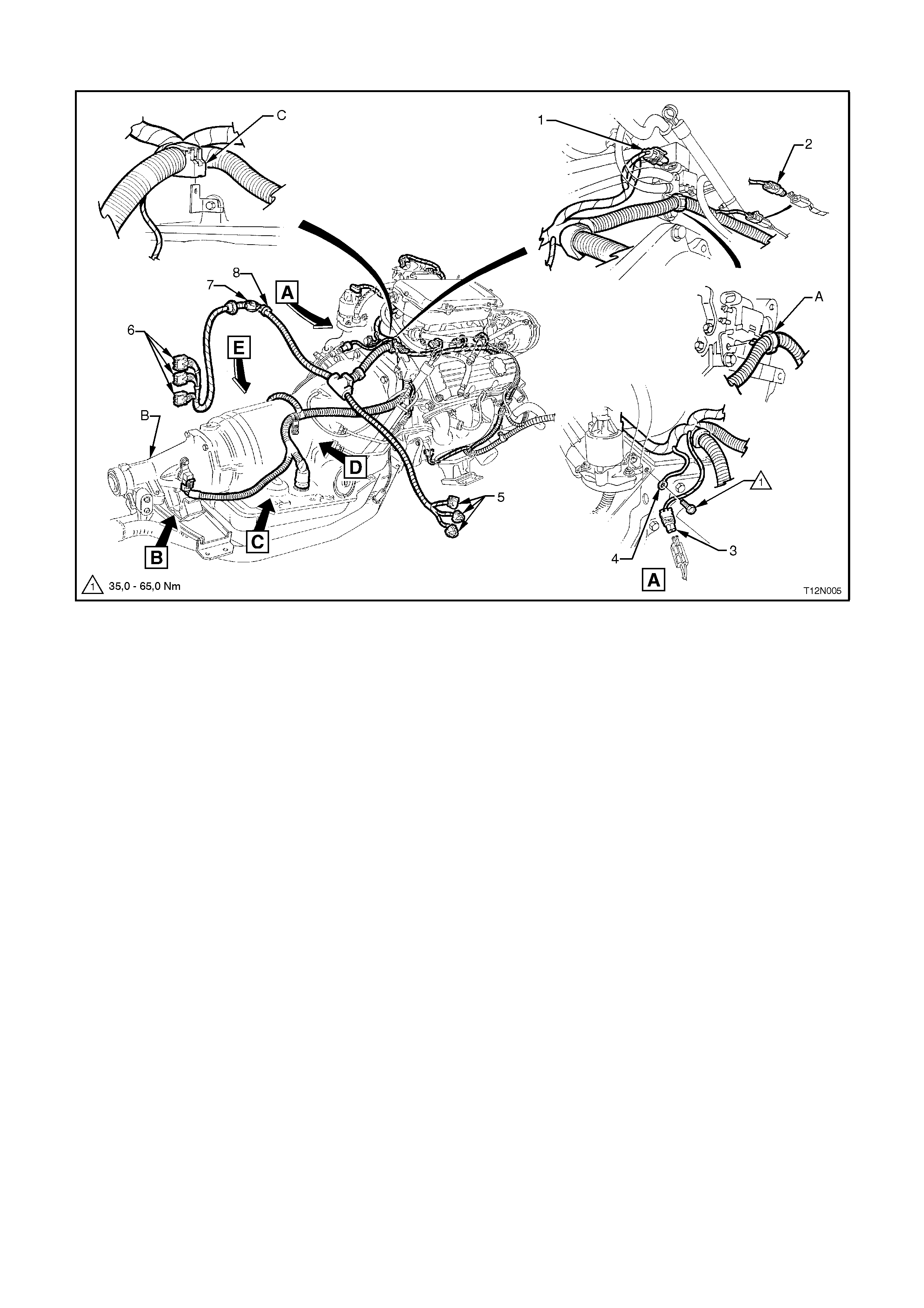
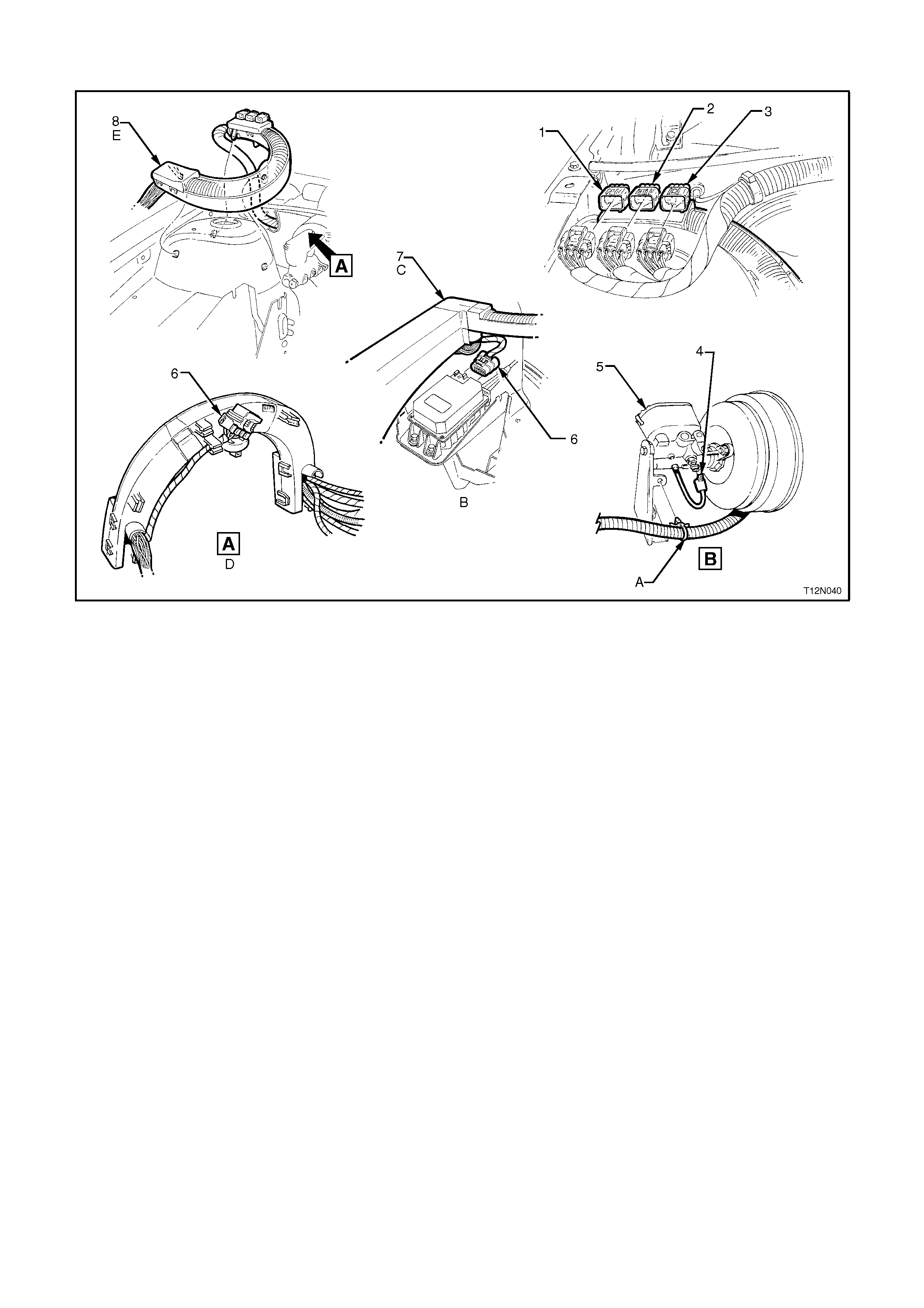
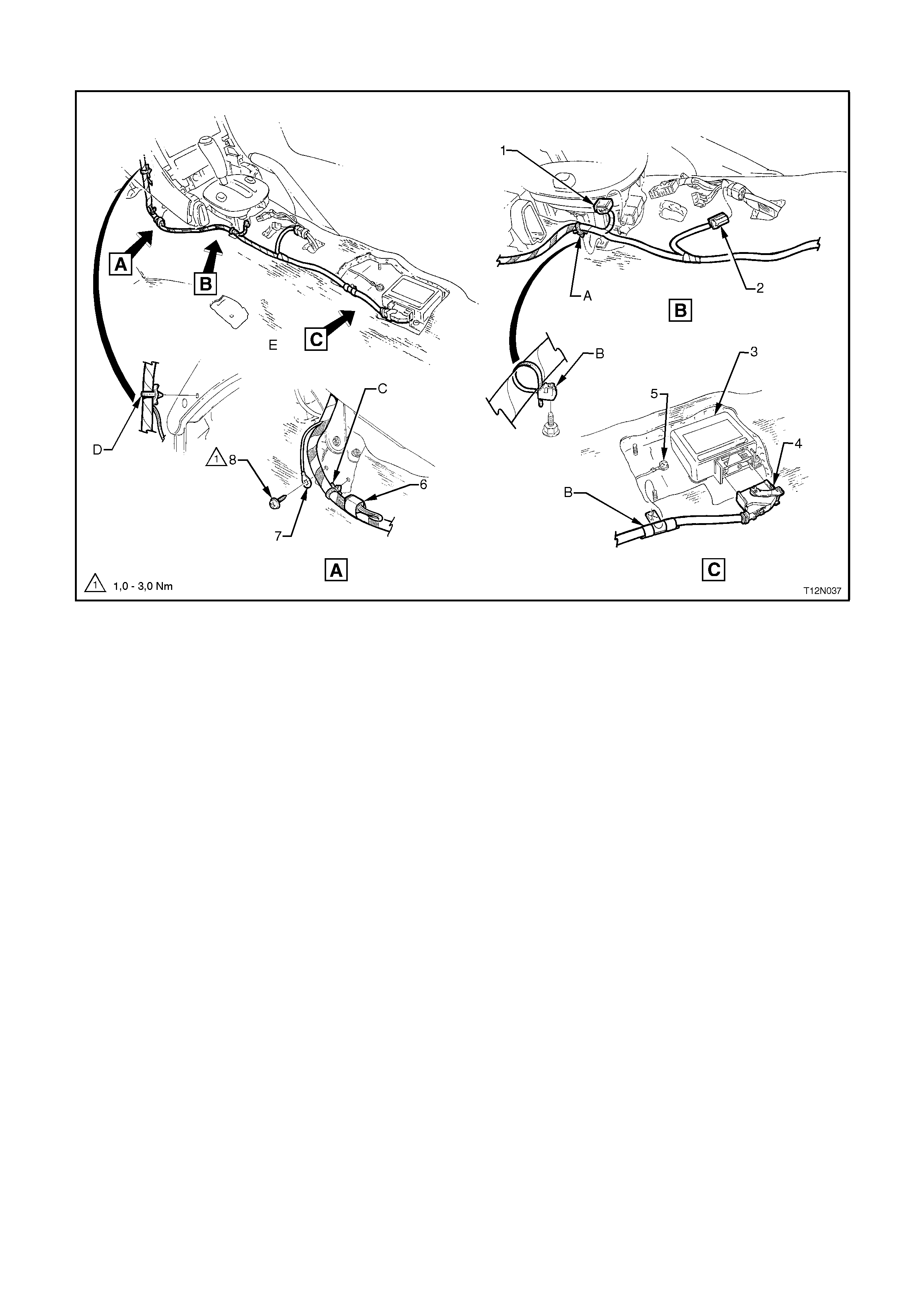
POWERTRAIN HARNESS - 12
V8 Engine With A/C or ECC
Legend
1. Powertrain Harness Earth Terminal And Retaining Bolt
2. Oil Pressure Sender Unit Connector
3. Canister Purge Solenoid Connector
4. Coolant Temperature Sensor Connector
5. Powertrain Harness To Control Module Connectors
6. Ignition Module Connectors
7. A/C Pressure Transducer Connector
8. Knock Sensor Lead
9. A/C Compressor Connector
10. Intake Air Temperature Sensor Connector
11. Mass Air Flow Sensor Connector
12. Tacho Signal Connector
13. Theft Deterrent System Horn Connector
14. Powertrain Harness To Main Wiring Harness Connectors
15. Battery Ha rness, refer to BATTERY HARNESS - 3 Diagram in this Section.
16. Compressor Clutch Diode
A. Vehicles without A/C or Electronic Climate Control.
B. Automatic transmission shown.
For location of Views C, D, E, refer to next diagram in this Section.
For location of View F, refer to POWERTRAIN HARNESS - 15 diagram in this Section.
For location of View G, refer to POWERTRAIN HARNESS - 16 diagram in this Section.
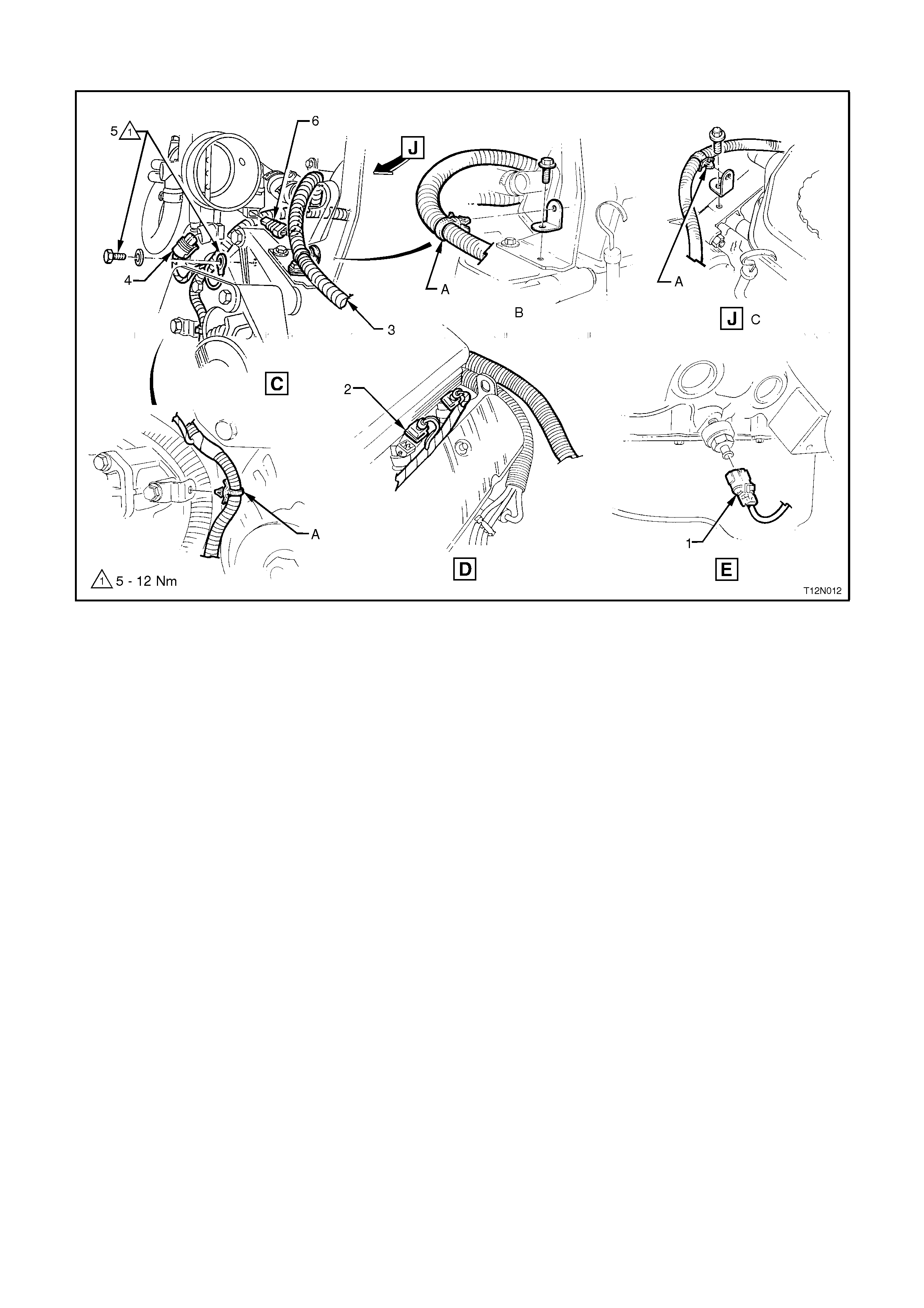
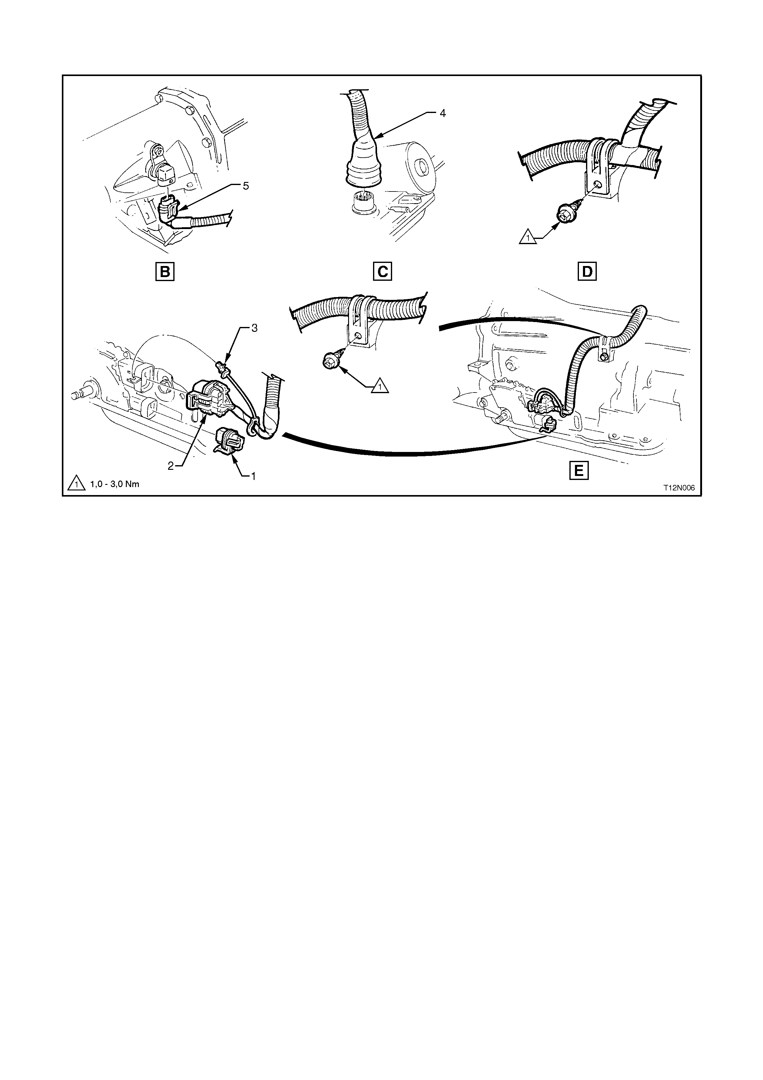
POWERTRAIN HARNESS - 13
V8 Engine With Cruise Control
Legend
1. Knock Sensor Connector
2. Injector (8 Places)
3. Powertrain Harness, for continuation refer to “C” in next diagram in this Section.
4. Throttle Position Sensor Connector
5. Powertrain Harness Earth Terminal and Bolt
6. Idle Air Control Valve Connector
A. Powertrain Harness secured to bracket as shown.
B. Vehicles fitted with cruise control.
C. Vehicles not fitted with cruise control.
POWERTRAIN HARNESS - 14
V8 Engine With A/C or ECC
Legend
1. Intake Air Temperature Sensor Connector
2. A/C Pressure Transducer Connector
3. Mass Air Flow Sensor Connector
A. Powertrain Harness secured to air cleaner housing as shown.
B. Vehicles not fitted with A/C or electronic climate control.
C. For continuation, refer to View Χ in the previous diagram in this Section.
For View L, refer to the next diagram in this Section.
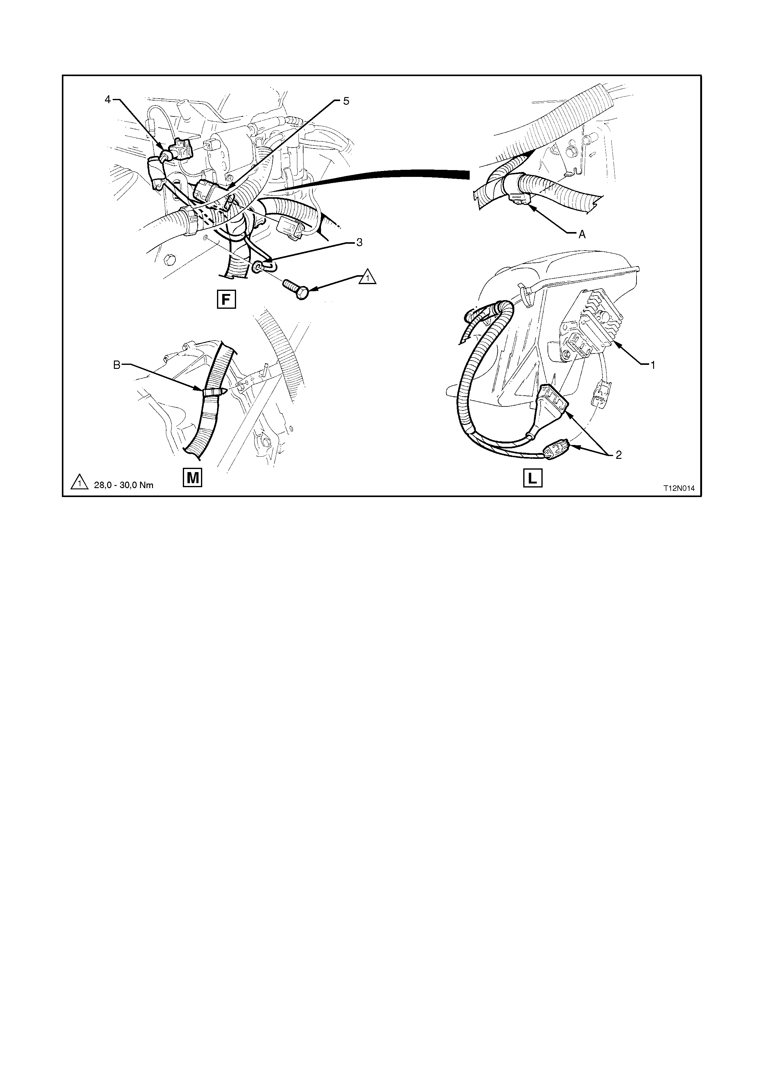
POWERTRAIN HARNESS - 15
V8 Engine
Legend
1. Ignition Module
2. Ignition Module Connectors
3. Powertrain Harness Earth Terminal
4. Ignition Coil Connector
5. Distributor Connector
A. Powertrain Harness secured to bracket as shown.
B. Powertrain Harness secured to dipstick as shown.
For location of View F, refer to POWERTRAIN HARNESS - 12 in this Section.
For location of View L, refer to the previous diagram in this Section.
For location of View M, refer to the next diagram in this Section.

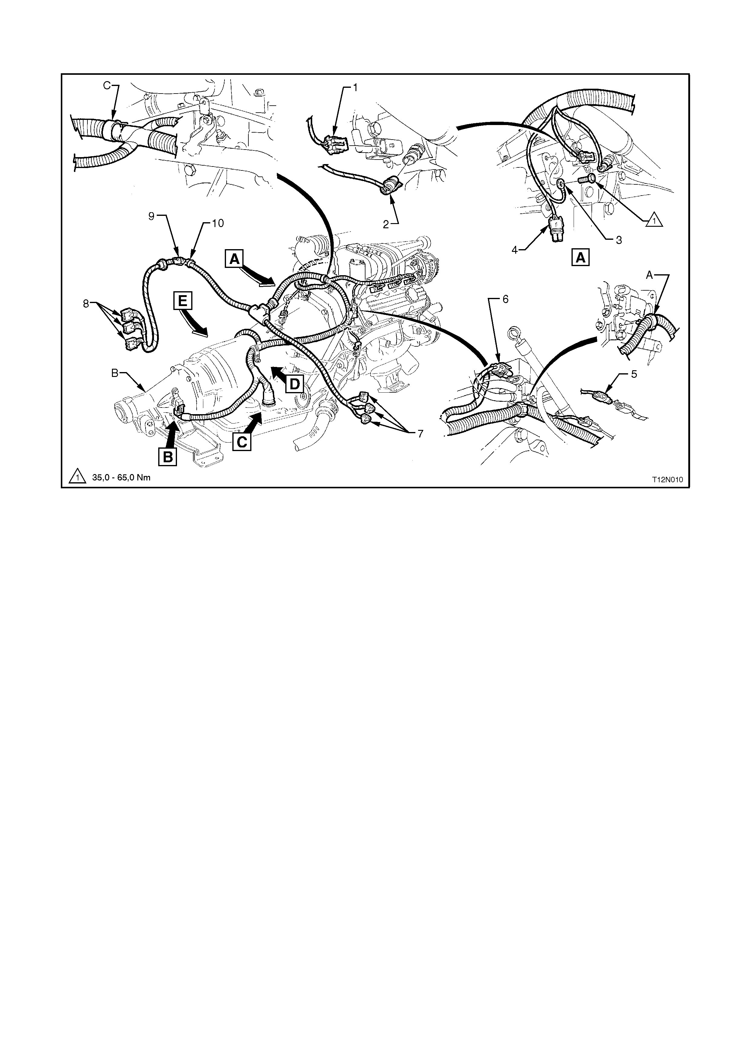
POWERTRAIN HARNESS - 16
V8 Engine With Automatic Transmission
Legend
1. Neutral Start/Back-Up Lamp Switch Connector To Switch Lock
2. Exhaust Gas Oxygen Sensor Connector - Left Hand Side
3. Plug
4. Neutral Start/Back-Up Lamp Switch Connector
5. Powertrain Harness Pass Thru Connector
6. Exhaust Gas Oxygen Sensor Connector - Right Hand Side
7. Powertrain Harness To Transmission Output Speed Sensor Connector
For View M, refer to previous diagram in this Section.
POWERTRAIN HARNESS - 17
V8 Engine With Manual Transmission
Legend
1. Powertrain Harness To Transmission Output Speed Sensor Connector
2. Exhaust Gas Oxygen Sensor Connector - Right Hand Side
3. Exhaust Gas Oxygen Sensor Connector - Left Hand Side
4. Back-Up Lamp Switch Connector
5. Transmission Output Speed Sensor And Lead
A. Powertrain Harness secured to bracket as shown.
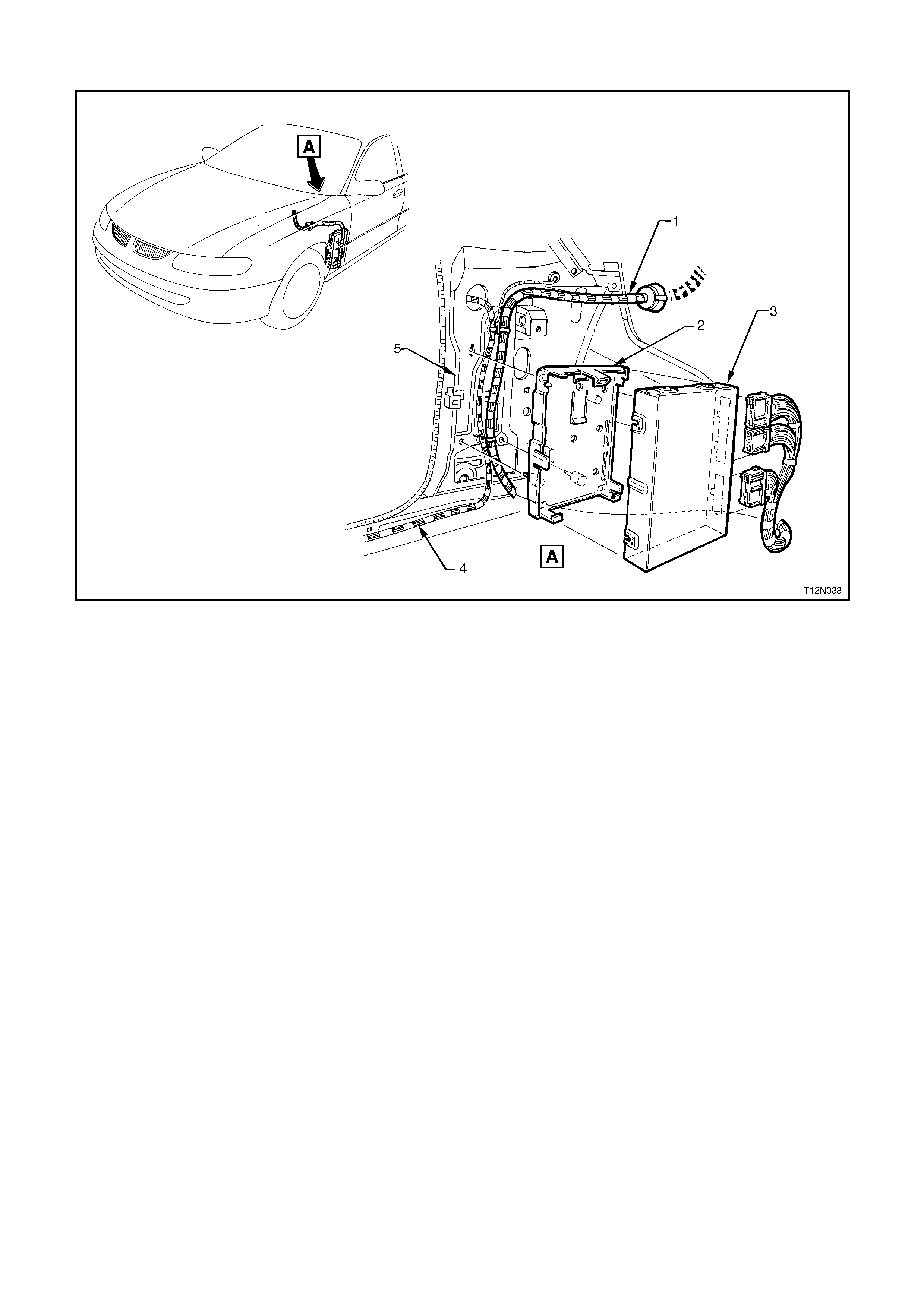
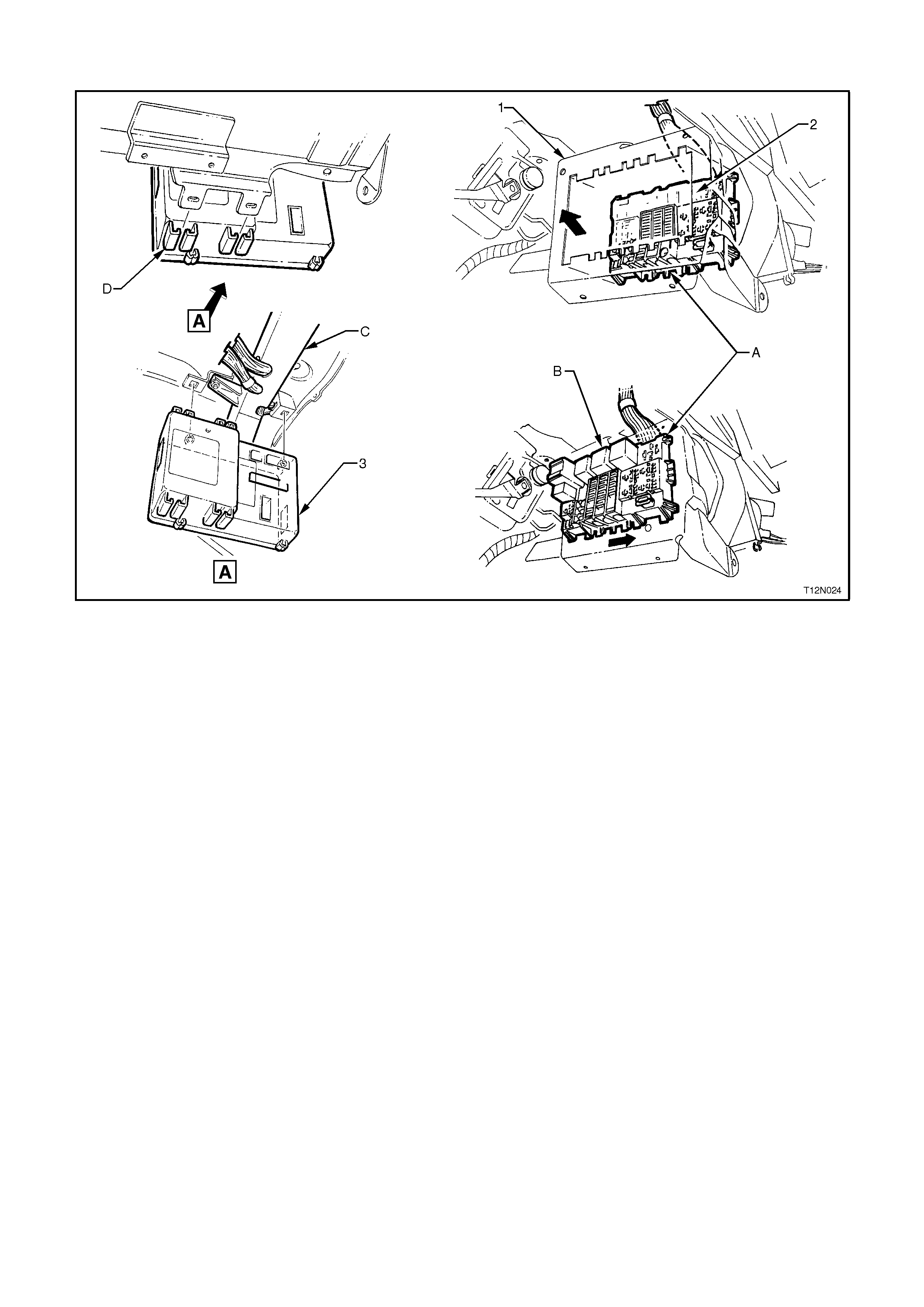
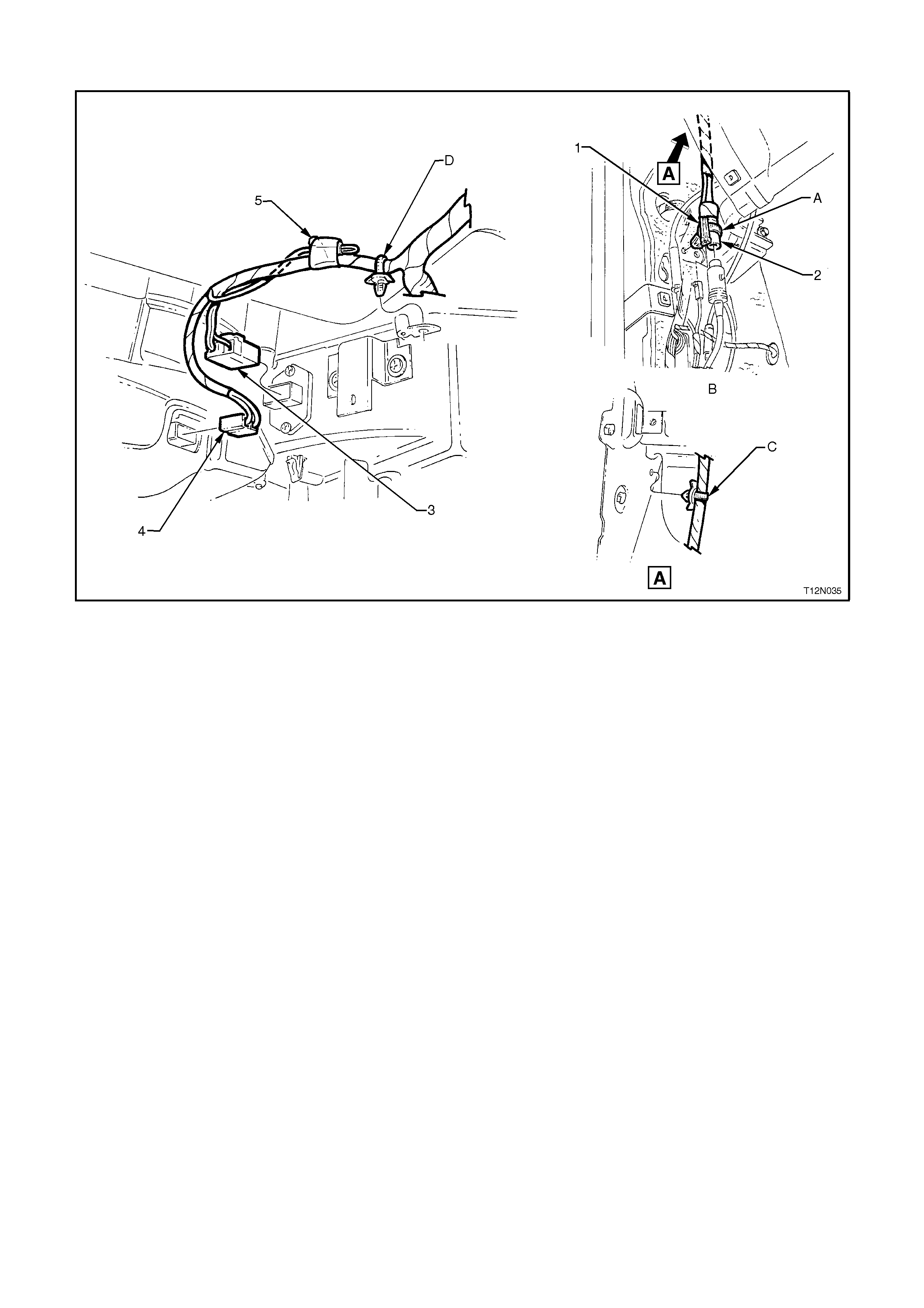
POWERTRAIN HARNESS - 18
Powertrain Control Module - All Models
Legend
1. Powertrain Harness
2 Powertrain Control Module Mounting Bracket
3. Powertrain Control Module
4 Body Wiring Harness
5 Cowl Panel - Left Hand Side
MAIN WIRING HARNESS
MAIN WIRING HARNESS - 1
Engine Compartment - All Models
Legend
1. Windshield Wiper Motor Connector
2 Brake Failure Warning Lamp Switch Connector
3. Diagnostic Interconnect Connector
4 Engine Harness (1) Connector
5 Engine Harness (2) Connector
6 Engine Harness (3) Connector
7. Cruise Control Actuator Connector (Executive with ABS Control, Berlina and Calais)
8. Relay Box
9. ABS Hydraulic Modulator/Integrated ECU Connector (Executive with ABS, Berlina and Calais)
10. ABS Wheel Speed Sensor - Right Hand Side (Executive with Cruise Control, Berlina and Calais)
11. Body Earth Terminal
12. Body Earth Terminal
13. Front Turn Signal Lamp Connector - Right Hand Side
14. Front Headlamp Connector - Right Hand Side
15. Washer Pump Connector
16. Fog Lamp Connector - Right Hand Side (SS and Calais)
17. Horn Connectors (2 Places) - Right Hand Side
18. Engine/Condenser Fan Motor Connector
19. Ambient Sensor Connector (Vehicles with Electronic Climate Control)
20. Theft Deterrent Hood Switch Connectors (2 Places)
21. Front Headlamp Connector - Left Hand Side
23. Front Turn Signal Lamp Connector - Left Hand Side
24. Fog Lamp Connector - Left Hand Side (SS and Calais)
25. ABS Wheel Speed Sensor - Left Hand Side (Executive with ABS, Berlina and Calais)
26. Battery Harness Connector
27. Battery Harness Connector
Techline

28. Power Steering Solenoid Connector
29. Sealing Patch Grommet
30. Grommet Insert
For View B, refer to the next diagram in this Section.
For View C, refer to Section 12L ABS/TCS.
For View D, refer to MAIN WIRING HARNESS - 5 diagram in this Section.
For View E, refer MAIN WIRING HARNESS - 7 diagram in this Section.
MAIN WIRING HARNESS - 2
Protector Assembly, Cruise Control And Engine Harness Connectors - All Models
Legend
1. Engine Harness Connector 3
2. Engine Harness Connector 2
3. Engine Harness Connector 1
4 Brake Failure Warning Lamp Switch Connector
5. Brake Master Cylinder & Brake Booster
6. Cruise Control Actuator Connector (Executive with Cruise Control, Berlina and Calais)
7. Relay Box
8. Protector Assembly
A. Harness attached to bracket as shown.
B. Executive Models with cruise control, Berlina Models and Calais.
C. For relay box installation, refer to the next diagram in this Section.
D. Executive Models without cruise control.
E. Protector assembly attached to strut tower as shown.

MAIN WIRING HARNESS - 3
Relay Box & Wiper Connectors - All Models
Legend
1. Screw
2 Windshield Wiper Motor. For Installation, refer to Section 12C INSTRUMENTS, WIPER/WASHER & HORN.
3. Windshield Wiper Connector
4. Relay Box Cover. Cover attached to box as shown.
5. Relay Box
A. For location, re fer to MAIN WIRING HARNESS - 1 diagram In this Section.
B. Main Wiring Harness pulled through dash upper panel as shown and grommet secured.
C. For relay & circuit breaker installation, refer to 1. GENERAL INFORMATION in this Section.
D. Relay box attached to cruise control mounting bracket as shown.
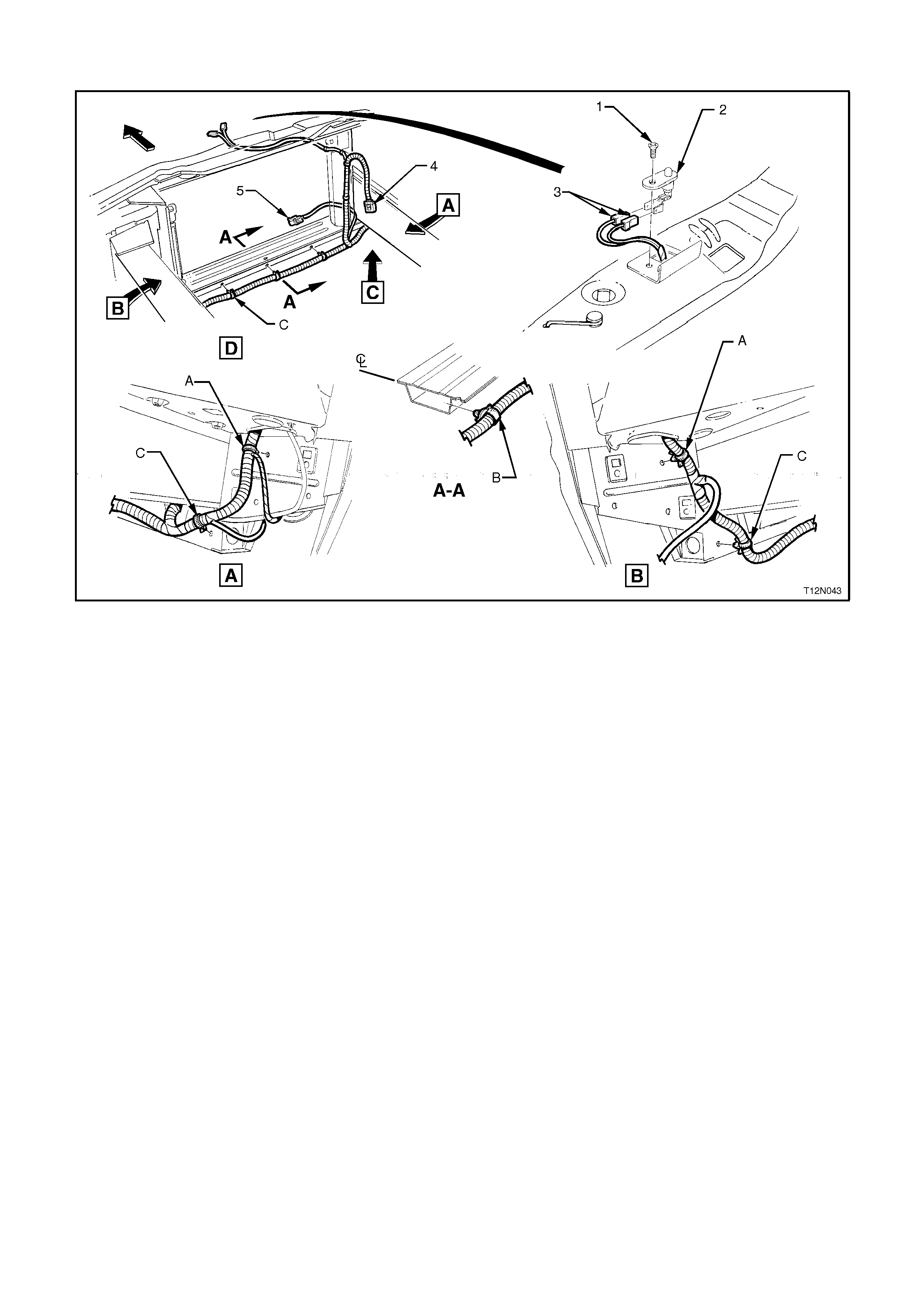
MAIN WIRING HARNESS - 4
Front Lamps, Body Earth And Washer Pump Connectors - All Models
Legend
1. Battery Tray
2. Washer Pump Connector
3 Washer Reservoir. For Installation, refer to Section 12C INSTRUMENTS, WIPER/WASHER & HORN.
4. Front Turn Signal Connector - Right Hand Side
5. Front Headlamp Connector - Right Hand Side
6. Nut
7. Body Earth Connector
8. Stud
9. Washer
A. Harness attached to battery tray as shown.
B. Harness leads attached to right hand side wheelhouse as shown.
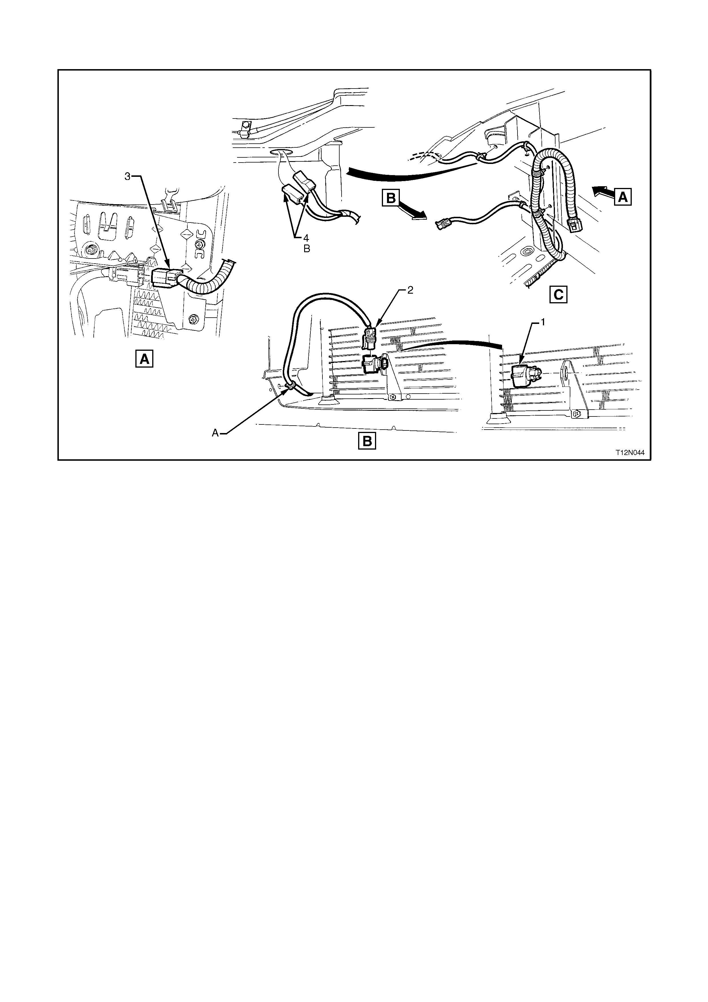
MAIN WIRING HARNESS - 5
Ambient Sensor, A/C Fan And Theft Deterrent Connectors - All Models
Legend
1. Screw
2. Theft Deterrent Hood Switch
3. Theft Deterrent Hood Switch Connectors
4 Main Wiring Harness To Engine/Condenser Fan Connector
5. Main Wiring Harness To Ambient Sensor Connector
A. Harness attached to front console panel as shown.
B. Blue strap aligned with centre line of vehicle as shown.
C. Harness attached to front crossmember as shown (5 places).
For View C, refer to the next diagram in this Section.
For location of View D, refer to MAIN WIRING HARNESS - 1 diagram in this Section.
MAIN WIRING HARNESS - 6
Ambient Sensor, A/C Fan And Theft Deterrent Connectors II - All Models
Legend
1. Ambient Sensor
2. Main Wiring Harness To Ambient Sensor Connector
3 Main Wiring Harness To Engine/Condenser Fan Connector
4. Theft Deterrent Hood Switch Connectors
A. Harness attached to crossmember closing plate as shown.
B. Connectors feed through front panel upper reinforcement to theft deterrent hood switch.
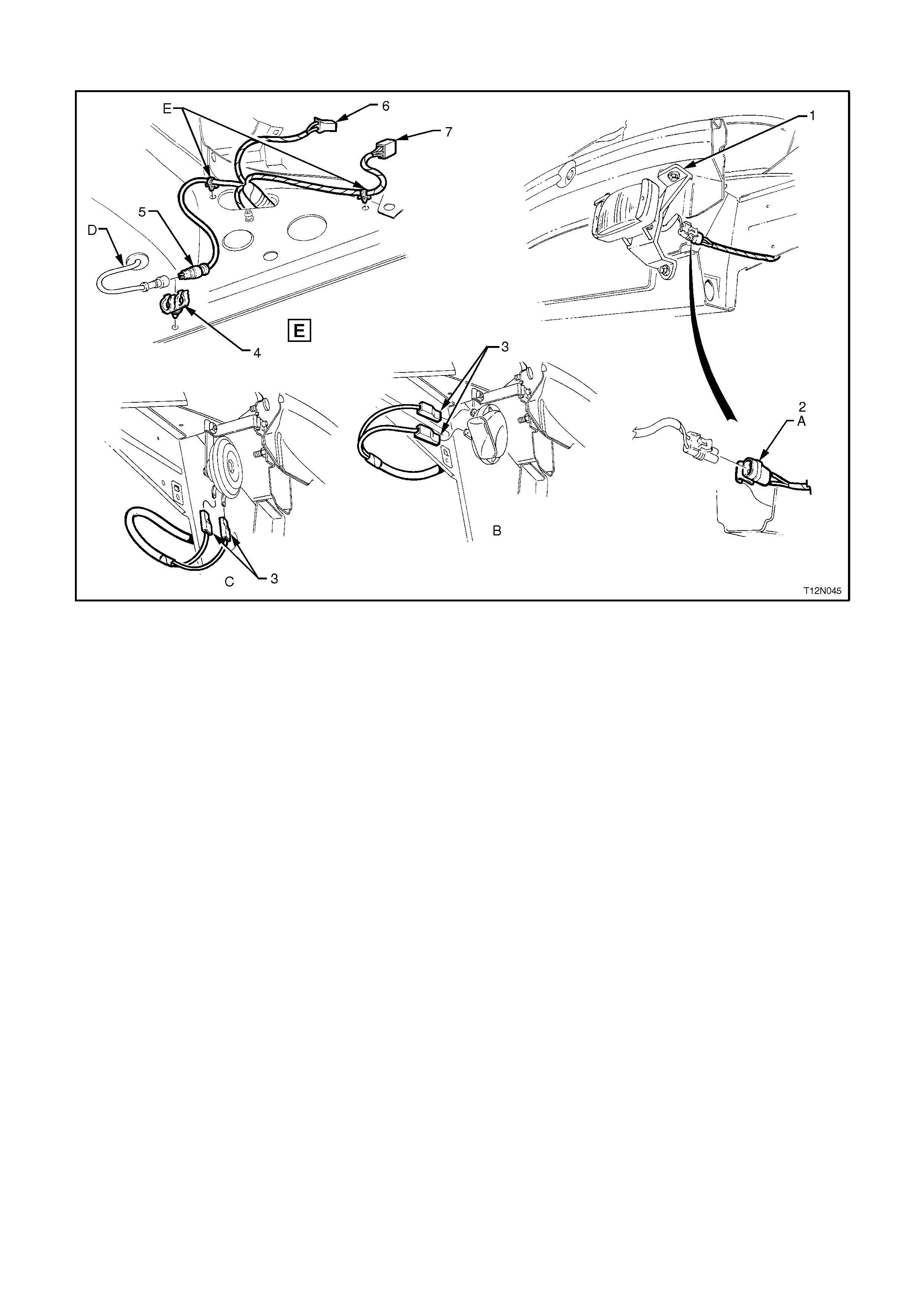
MAIN WIRING HARNESS - 7
Front Lamps, Fog Lamps And Horn Connections - All Models
Legend
1. Fog Lamp
2. Fog Lamp Connector - Left Hand Side.
3. Horn Connectors
4. Clip
5. ABS Wheel Speed Sensor Connector - Left Hand Side
6. Front Turn Signal Connector - Left Hand Side
For Right Hand Side, refer to MAIN WIRING HARNESS - 4 Diagram In This Section.
7. Headlamp Connector - Left Hand Side
For Right Hand Side, refer to MAIN WIRING HARNESS - 4 Diagram In This Section.
A. Connector clipped to body as shown.
B. Calais, right hand side shown. Similar for left hand side.
C. Executive and Berlina Models, right hand side shown.
D. For continuation, refer to Section 12L ABS & TCS.
E. Harness attached to wheelhouse panel as shown - left hand side.
For location of View E, refer to MAIN WIRING HARNESS - 1 diagram in this Section.
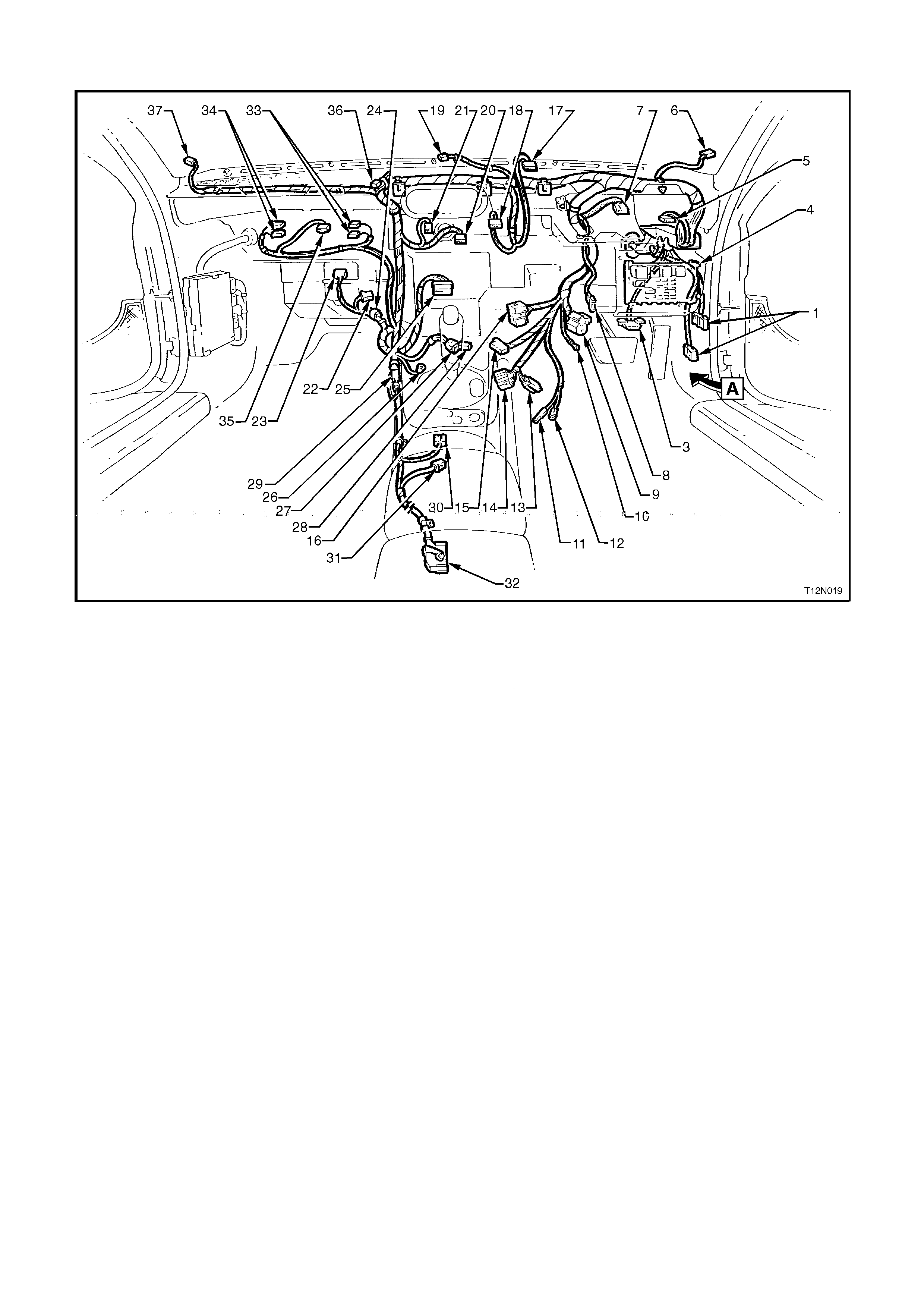
MAIN WIRING HARNESS - 8
Cockpit Module - Executive Models Without Cruise Control
Legend
1. Main Wiring Harness To Body Harness Connectors (2 Places)
2. Body Control Module Connector (3 Places) (NOT SHOWN - REFER TO MAIN WIRING HARNESS - 10
DIAGRAM IN THIS SECTION).
3. Data Link Connector
4. Passenger Compartment Fuel Panel
5. Headlamp Switch Connector
6. Right Hand Front Instrument Panel Speaker
7. Instrument Cluster Connector
8. Stop Lamp Switch Connector
9. Ignition Switch Connector
10. Ignition Key Earth Terminal
11. Ignition Key Reader
12. Ignition Lock Illumination Bulb Socket
13. Turn Signal Switch I Connector
14. Turn Signal Switch II Connector
15. Main Wiring Harness To Clock Spring Coil Connector
16. Windshield Wiper/Washer Switch Connector
17. Hazard Switch Connector
18. Trip Computer Connector
19. Receiver Connector
20. Blower Switch Connector
21. A/C Controls Connector
22. Fan Resistors Connector
23. Blower Motor Connector
24. Thermostat Amplifier Connector
25. Radio Connector
26. Radio Body Earth Terminal

27. Accessory Jack Connector
28. Accessory Jack Illumination Socket Connector
29. Cellular Phone/Auxiliary Connector
30. Automatic Transmission Selector Connector
31. Main Wiring Harness to Body Harness (Seat Belt Pre-Tensioner) Connector
32. Airbag Sensing Diagnostic Module Connector
33. Glove Box Switch Connectors (2 Places)
34. Glove Box Lamp Connectors (2 Places)
35. Boot Lock Switch Connector
36. Main Wiring Harness To Passenger Side Airbag Inflator Connector
37. Left Hand Front Instrument Panel Speaker
For View A, refer to MAIN WIRING HARNESS - 10 diagram in this Section.
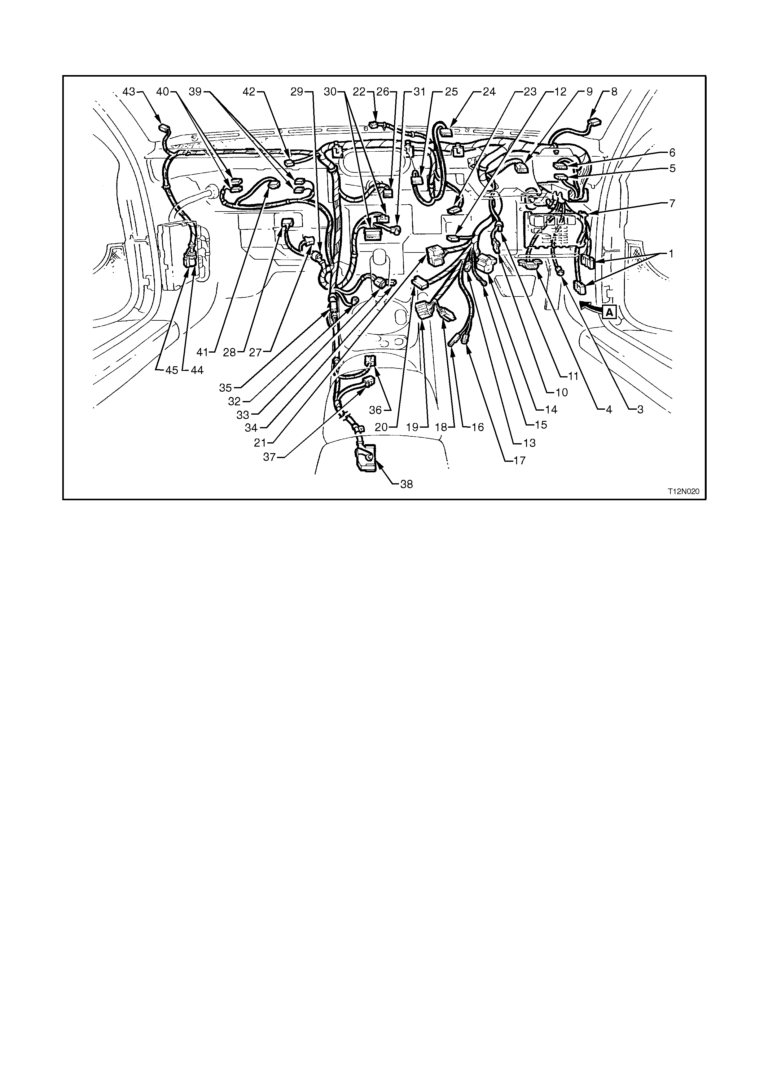
MAIN WIRING HARNESS - 9
Cockpit Module - Executive Models With Cruise Control, Berlina Models And Calais
Legend
1. Main Wiring Harness To Body Harness Connectors (2 Places)
2. Body Control Module Connectors (4 Places) (NOT SHOWN - REFER TO MAIN WIRING HARNESS - 10
DIAGRAM IN THIS SECTION).
3. Right Hand Front Footwell Lamp Connector (Not Used On Executive)
4 Data Link Connector
5. Fog Lamp Switch Connector
6. Headlamp Switch Connector
7. Passenger Compartment Fuel Panel
8. Right Hand Front Instrument Panel Speaker
9. Instrument Cluster Connector
10. Stop Lamp Switch Connector
11. Cruise Control Electrical Release Switch Connector
12. Cruise Control Switch Connector
13. Wiper Dwell Control Switch Connector (Not Used On Executive)
14. Ignition Switch Connector
15. Ignition Key Earth Terminal
16. Ignition Key Reader
17. Ignition Lock Illumination Bulb Socket
18. Turn Signal Switch I Connector
19. Turn Signal Switch II Connector
20. Main Wiring Harness To Clock Spring Coil Connector
21. Windshield Wiper/Washer Switch Connector
22. Solar Switch Connector
23. In-Car Sensor Connector (Not Used On Executive)
24. Hazard Switch Connector
25. Trip Computer Connector
26. Electronic Climate Control Module Connector (Not Used On Executive)

27. Fan Speed Control Switch Connector
28. Blower Motor Connector
29. Thermostat Amplifier Connector
30. Radio Connectors (2 Places)
31. Radio-CD Player Connector
32. Radio Body Earth Terminal
33. Accessory Jack Connector
34. Accessory Jack Illumination Socket Connector
35. Cellular Phone/Auxiliary Connector
36. Automatic Transmission Selector Connector
37. Main Wiring Harness to Body Harness (Seat Belt Pre-Tensioner) Connector
38. Airbag Sensing Diagnostic Module Connector
39. Glove Box Switch Connectors (2 Places)
40. Glove Box Lamp Connectors (2 Places)
41. Boot Lock Switch Connector
42. Main Wiring Harness To Passenger Side Airbag Inflator Connector
43. Left Hand Front Instrument Panel Speaker
44. CD Player Connector
45. Diversity Antenna Power Connector
For View A, refer to MAIN WIRING HARNESS - 10 diagram in this Section.
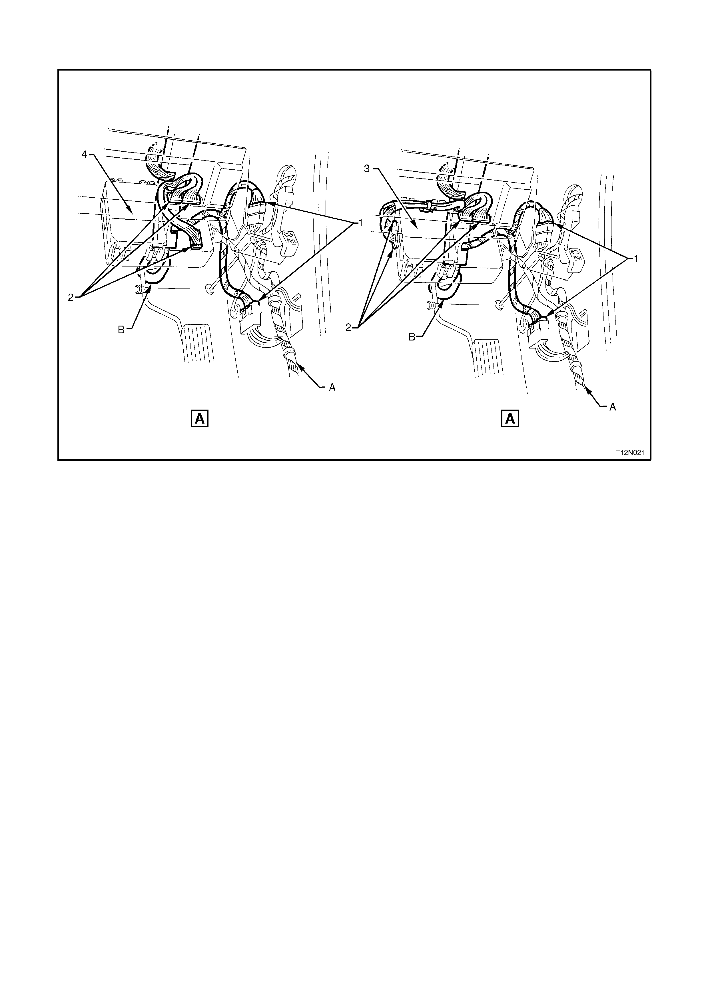
MAIN WIRING HARNESS - 10
Cockpit Module - All Models
Legend
1. Main Wiring Harness To Body Harness Connectors
2. Body Control Module Connectors
3. High Series Body Control Module
4. Low Series Body Control Module
A. Body Harness, for continuation refer to BODY & ROOF WIRING HARNESSES - 1 diagram in this Section.
B. For continuation, refer MAIN WIRING HARNESS - 1 diagram in the Section.
For location of View A, refer to the previous diagram in this Section or to the MAIN WIRING HARNESS - 8 diagram
in this Section.
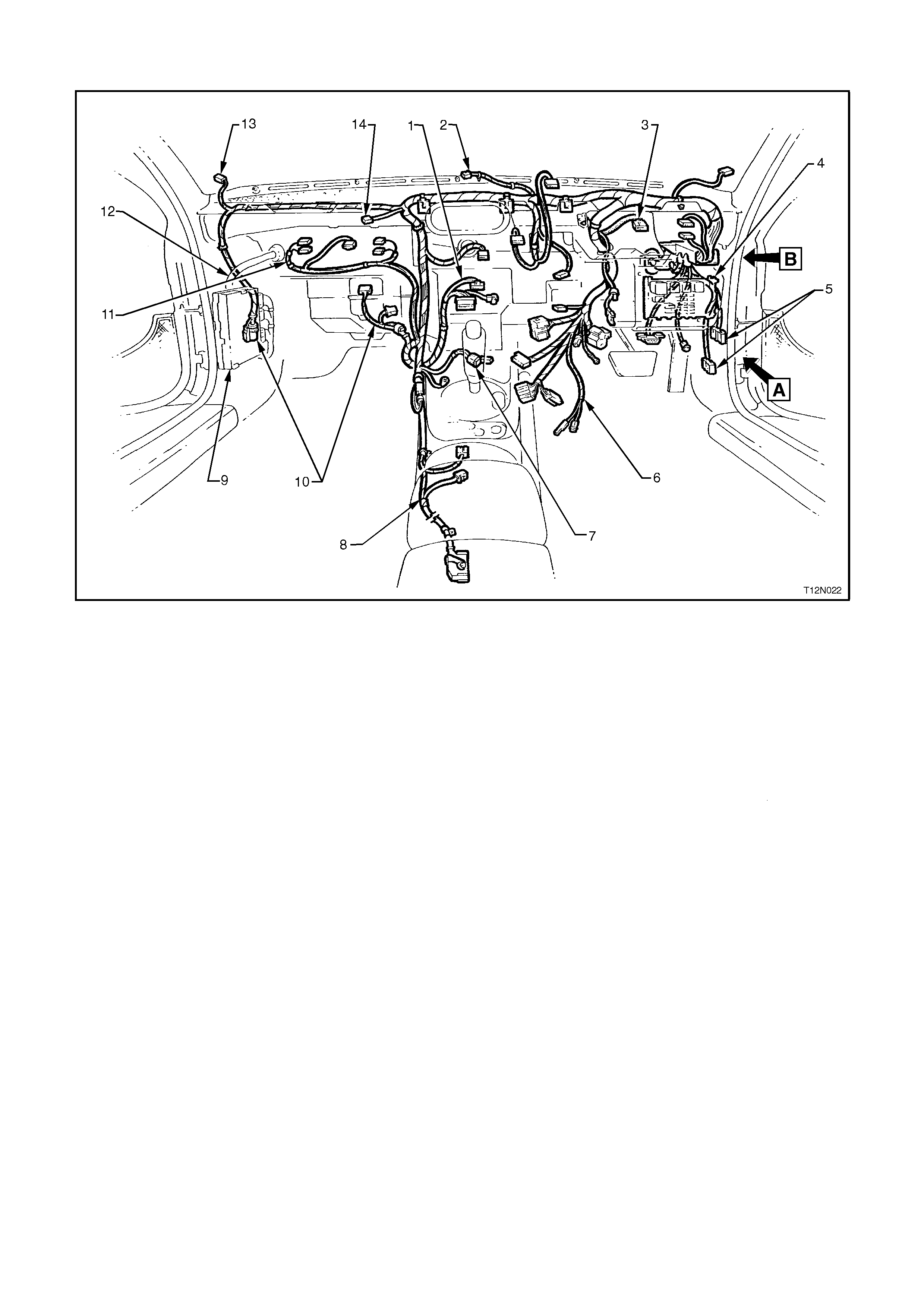
MAIN WIRING HARNESS - 11
Cockpit Module - All Models
Legend
1. Radio/Cassette/CD Player Connector, refer to MAIN WIRING HARNESS - 22 Diagram in ihis Section.
2. Solar Sensor Connector, refer to MAIN WIRING HARNESS - 24 Diagram in this Section.
3. Instrument Cluster Connector, refer to MAIN WIRING HARNESS - 20 Diagram in this Section.
4. Fuse Panel And Body Control Module, refer to MAIN WIRING HARNESS - 13 Diagram in this Section.
5. Main Wiring Harness To Body Harness Connectors, refer to BODY & ROOF WIRING HARNESSES - 1
Diagram in this Section.
6. Main Wiring Harness To Steering Column Connectors, refer to MAIN WIRING HARNESS - 15 & 16 Diagrams
in this Section.
7. Accessory Jack Connector, refer to MAIN WIRING HARNESS - 18 Diagram in this Section.
8. Transmission And Airbag Sensing Diagnostic Module Connectors, refer to MAIN WIRING HARNESS - 27
Diagram in this Section.
9. Powertrain Control Module, refer to Section 6C1 or Section 6C2.
10. Diversity Antenna/Heating, Ventilation And A/C Connectors, refer to MAIN WIRING HARNESS - 25 Diagram
in this Section.
11. Glovebox And Accessories Connectors, refer to MAIN WIRING HARNESS - 26 Diagram in this Section.
12. Powertrain Harness, refer to POWERTRAIN HARNESS - 5, 8, 11 & 12 Diagrams in this Section.
13. Left And Right Hand Side Instrument Panel Speakers Connectors, refer to MAIN WIRING HARNESS - 24
Diagram in this Section.
14. Main Wiring Harness To Passenger Side Airbag Inflator Connector, refer to MAIN WIRING HARNESS - 23
Diagram in this Section.
MAIN WIRING HARNESS - 12
Cockpit Module - All Models
Legend
1. Screw
2. Nut
3. Main Wiring Harness Cable Retainer
A. Main Wiring Harness cabin protector attached to dash panel cover assembly as shown.
B. Main Wiring Harness retainer attached to dash panel cover assembly as shown.
C. Main Wiring Harness retainer attached to steering column bracket as shown.
D. Refer to MAIN WIRING HARNESS - 1 diagram in this Section for sealing patch grommet and insert
installation.
For location of Views A and B refer to the previous diagram in this Section.
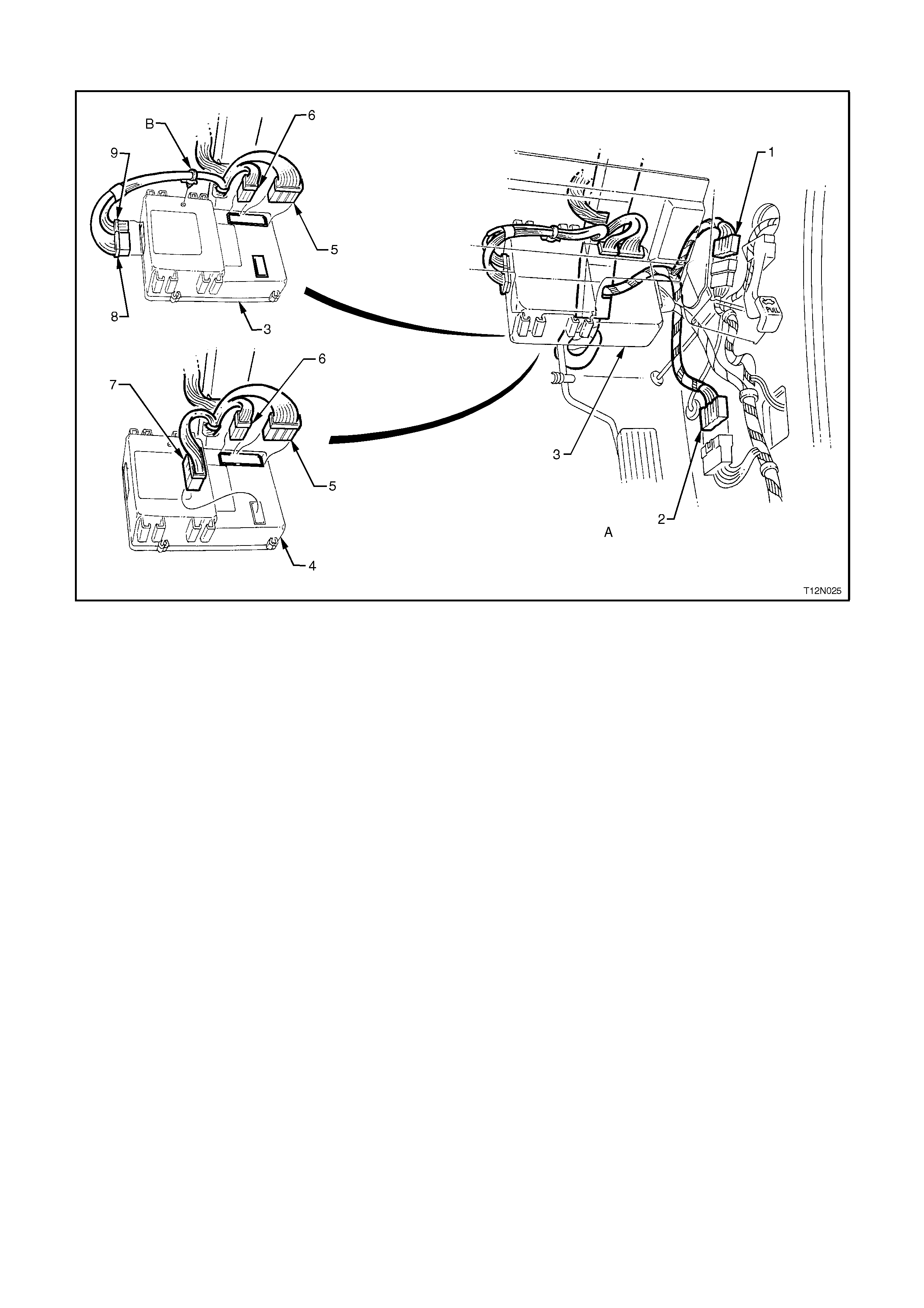
MAIN WIRING HARNESS - 13
Fuse Panel and Body Control Module - All Models
Legend
1. Steering Column Bracket Support
2. Passenger Compartment Fuse Panel
3. Body Control Module
A. Passenger compartment fuse panel is installed as shown.
B. For installation of relays, fuses and circuit breakers, refer to 1. GENERAL INFORMATION in this Section.
C. Main Wiring Harness cabin protector, refer to the previous diagram in this Section.
D. Body Control Module installed to instrument panel lower trim assembly as shown.
MAIN WIRING HARNESS - 14
Body Control Module And Body Harness Connectors - All Models
Legend
1. Main Wiring Harness To Body Harness Connector
2. Main Wiring Harness To Body Harness Connector
3. High Series Body Control Module
4. Low Series Body Control Module
5. Body Control Module Connector (A)
6. Body Control Module Connector (F)
7. Body Control Module Connector (B)
8. Body Control Module Connector (D)
9. Body Control Module Connector (C)
A. For body control module installation, refer to the previous diagram in this Section.
B. Main Wiring Harness clip attached to body control module as shown.
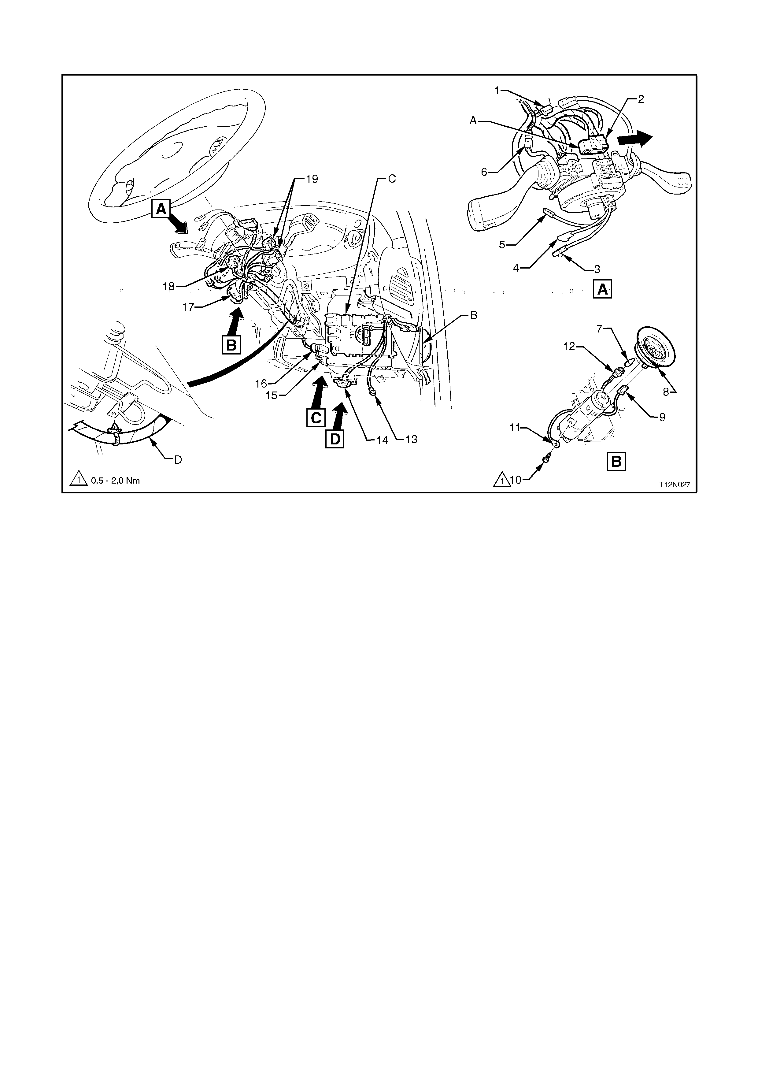
MAIN WIRING HARNESS - 15
Steering Column - Executive Models Without Cruise Control
Legend
1. Main Wiring Harness To Clock Spring Coil Connector
2. Airbag Inflator Connector
3. Remote Radio Control Connector
4. Horn Connector
5. Ignition Lock Illumination Bulb
6. Key Reader Slip Ring
7. Key Reader Slip Ring Connector
8. Screw
9. Ignition Key Earth Terminal
10. Ignition Lock Illumination Bulb Socket
11. Data Link Connector
12. Stop Lamps Switch Connector
13. Ignition Switch Connector
14. Windshield Wiper/Washer Connector
15. Turn Signal I And II Connectors
A. Clock spring coil connector installed and secured by locking retainer in direction of arrow shown.
B. For body control module installation, refer to MAIN WIRING HARNESS - 13 diagram in this Section.
C. For passenger compartment fuse panel installation, refer to MAIN WIRING HARNESS - 13 diagram in this
Section.
D. Main Wiring Harness attached to steering column as shown.
For location of Views C, and D, refer to MAIN WIRING HARNESS - 17 diagram in this Section.
MAIN WIRING HARNESS - 16
Steering Column - Executive Models With Cruise Control, Berlina Models And Calais
Legend
1. Cruise Control Switch Connector
2. Main Wiring Harness To Clock Spring Coil Connector
3. Airbag Inflator Connector
4. Remote Radio Control Connector
5. Horn Connector
6. Wiper Dwell Control Connector
7. Ignition Lock Illumination Bulb
8. Key Reader Slip Ring
9. Key Reader Slip Ring Connector
10. Screw
11. Ignition Key Earth Terminal
12. Ignition Lock Illumination Bulb Socket
13. Right Hand Front Footwell Lamp Connector
14. Data Link Connector
15. Stop Lamps Switch Connector
16. Cruise Control Electrical Release Switch Connector
17. Ignition Switch Connector
18. Windshield Wiper/Washer Connector
19. Turn Signal I And II Connectors
A. Clock spring coil connector installed and secured by locking retainer in direction of arrow shown.
B. For body control module installation, refer to MAIN WIRING HARNESS - 13 diagram in this Section.
C. For passenger compartment fuse panel installation, refer to MAIN WIRING HARNESS - 13 diagram in this
Section.
D. Main Wiring Harness attached to steering column as shown.
For location of Views C and D, refer to MAIN WIRING HARNESS - 17 diagram in this Section.
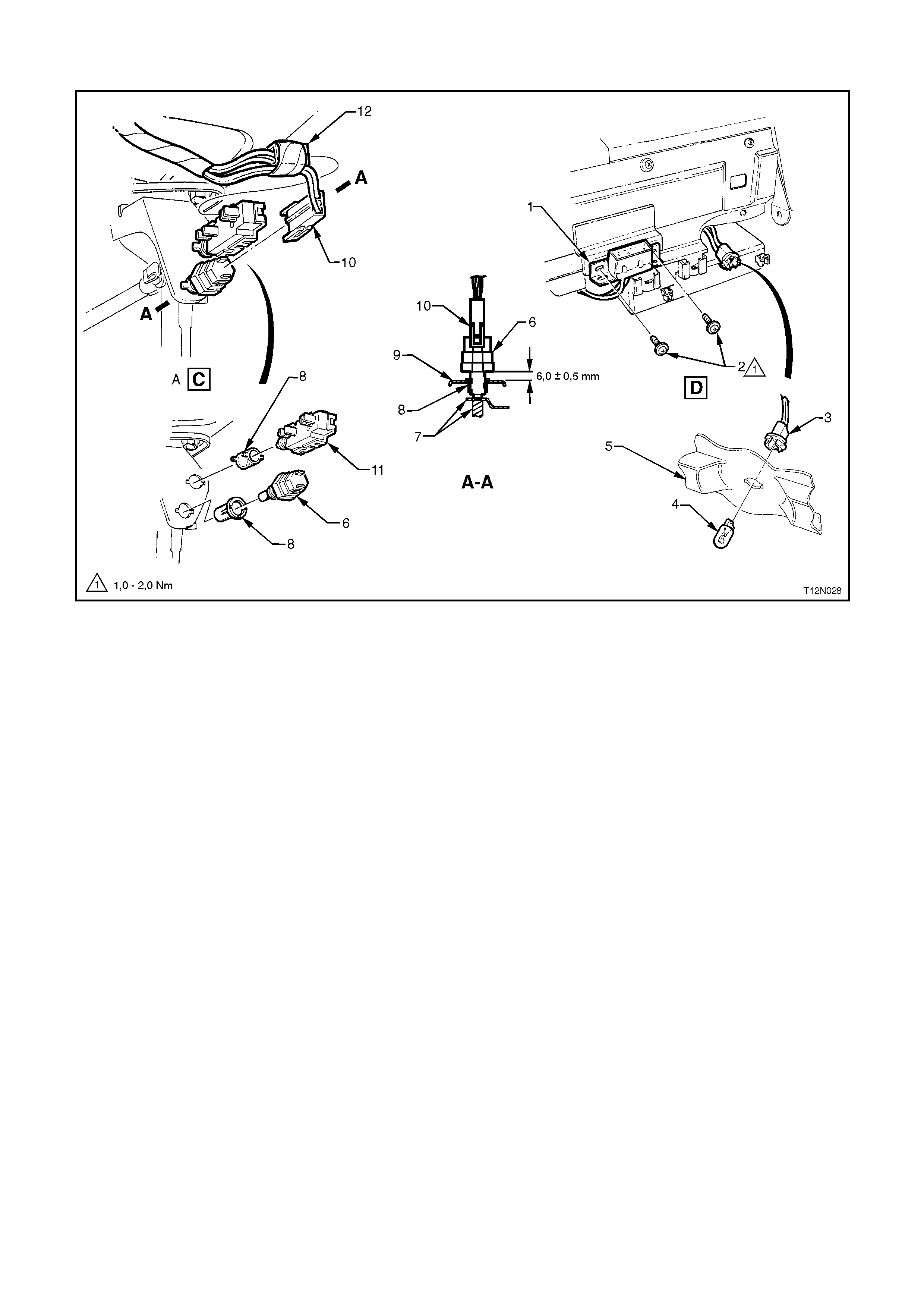
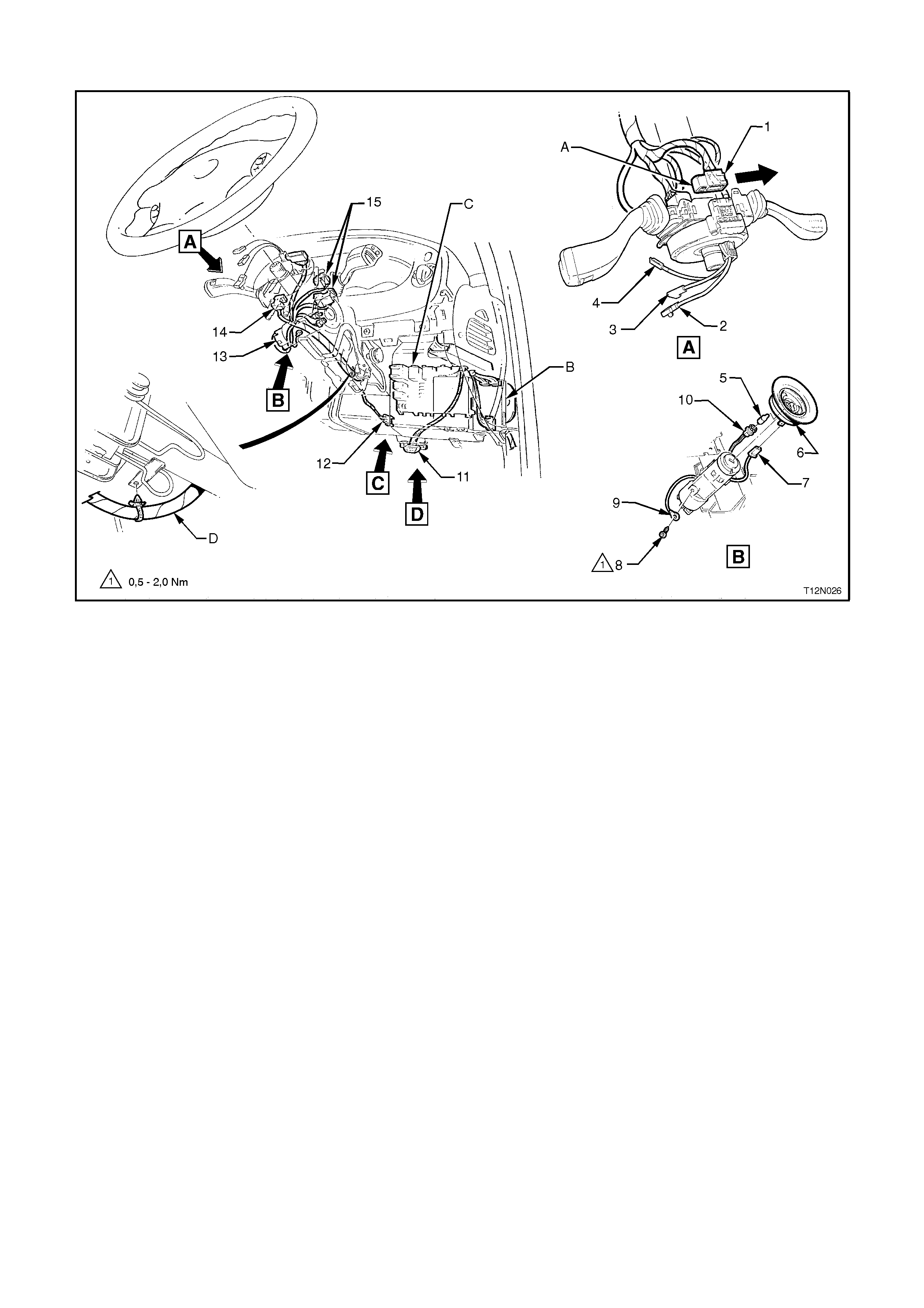
MAIN WIRING HARNESS - 17
Cruise Control, Stop La mp Switches, Data Link Connector & Footwell Lamps - All Models
Legend
1. Data Link Connector
2Screw
3. Footwell Lamp Connector - Right Hand Side
4. Footwell Lamp Bulb
5. Footwell Closing Panel
6. Stop Lamp Switch
7. Brake Pedal Assembly
8. Nut
9. Brake Pedal Support Bracket
10. Stop Lamp Switch Connector
11. Brake Pedal Cruise Control Electrical Release Switch - Vehicles with Cruise Control Only
12. Brake Pedal Cruise Control Electrical Release Switch Connector
A. View shows vehicle with cruise control and automatic transmission.
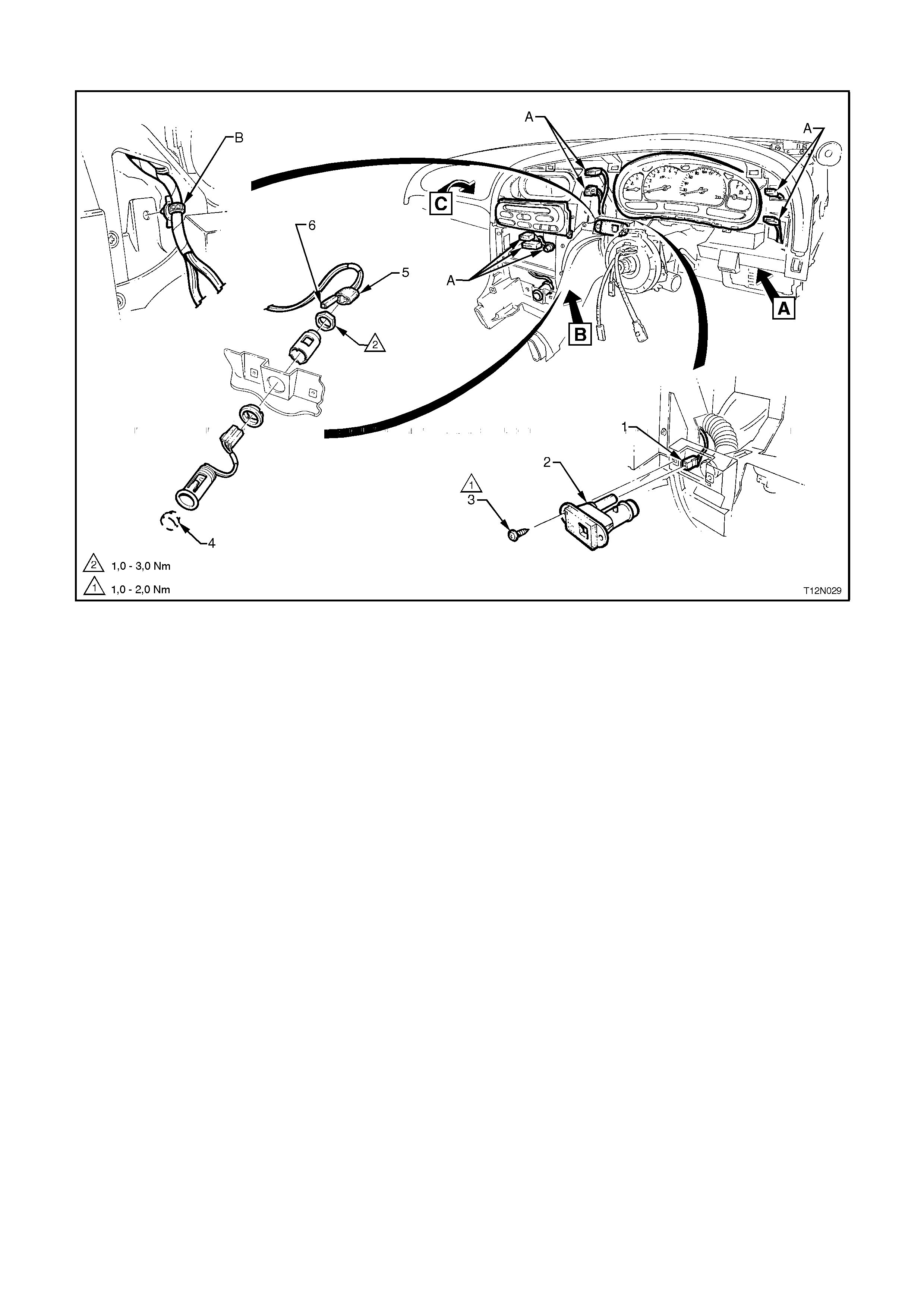
MAIN WIRING HARNESS - 18
Combined Instrument Assembly, Air Conditioning & Heating Controls - All Models
Legend
1. In-Car Sensor Connector
2In-Car Sensor
3. Screw
4. Plug
5. Accessory Jack Connector
6. Accessory Jack Illumination Connector
A. For connection to switches, refer to MAIN WIRING HARNESS - 21 and 22 diagrams in this Section.
B. Harness attached to heating, ventilation & air conditioning unit as shown.
For location of Views A, B & C, refer to the next diagram in this Section.
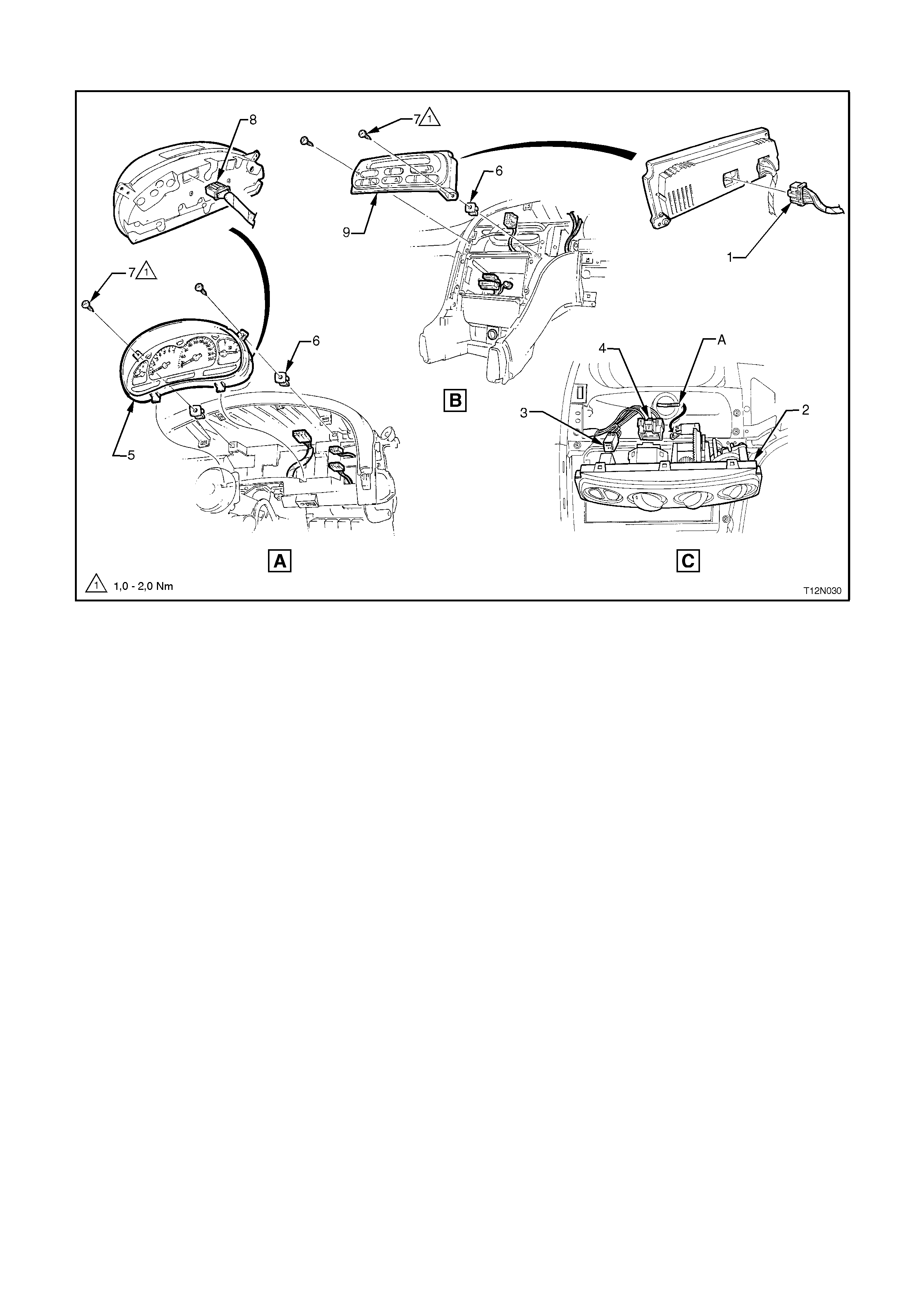
MAIN WIRING HARNESS - 19
Combined Instrument Assembly, Air Conditioning & Heating Controls - All Models
Legend
1. Electronic Climate Control Module Connector
2. Air Conditioning & Heating Control Assembly
3. Air Conditioning Controls Connector
4. Blower Switch Connector
5. Instrument Assembly
6. Nut - 2 Places
7. Screw - 2 Places
8. Instruments Connector
9. Electronic Climate Control Module
A. Lever attached to control assembly as shown.
For view locations, refer to the previous diagram in this Section.
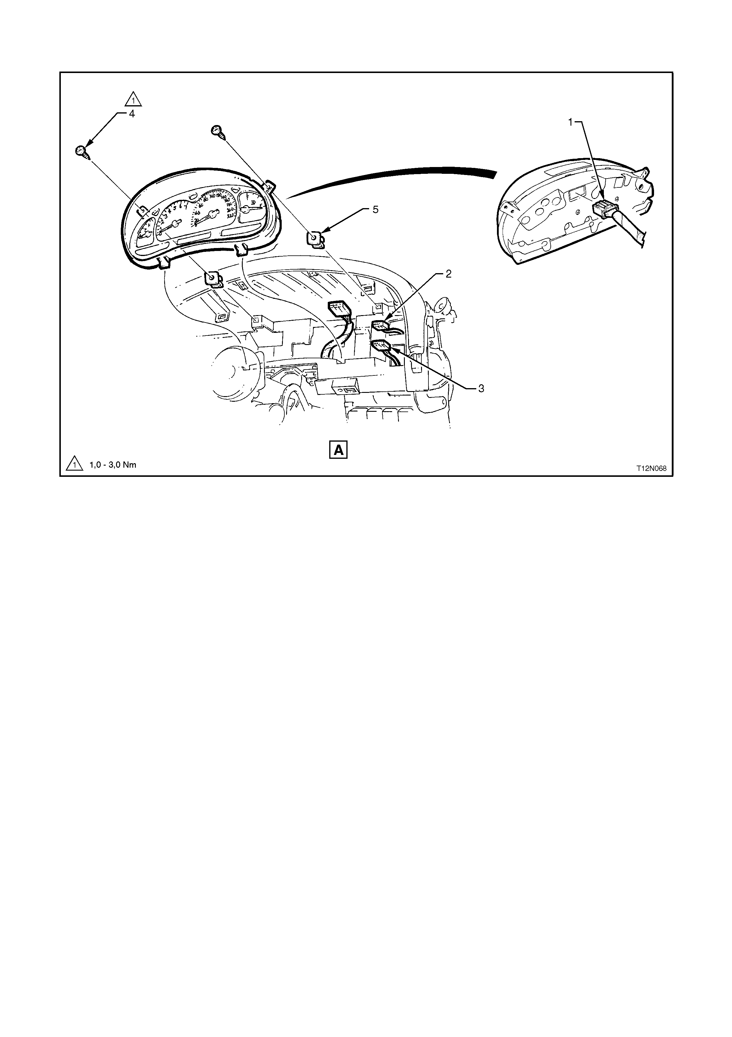
MAIN WIRING HARNESS - 20
Instruments - All Models
Legend
1. Main Wiring Harness Instrument Cluster Connector
2. Headlamp Switch Connector
3. Fog Lamp Switch Connector
4. Screw
5. Nut
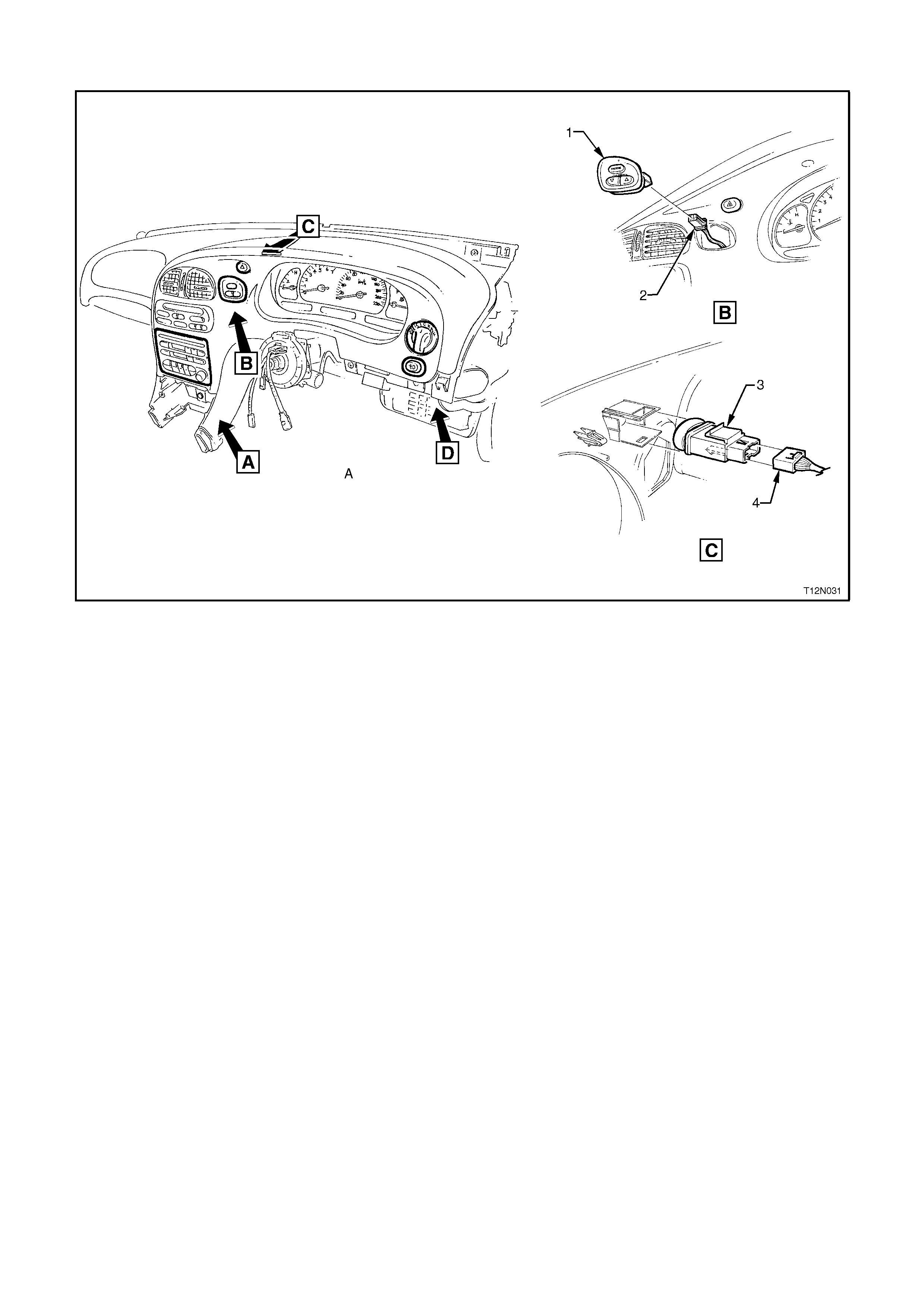
MAIN WIRING HARNESS - 21
Radio/Cassette/CD & Instrument Facia Switches - All Models
Legend
1. Trip Computer Switch
2. Trip Computer Switch Connector
3. Hazard Switch
4. Hazard Switch Connector
A. Calais shown
For location of Views A and D, refer to the next diagram in this Section.
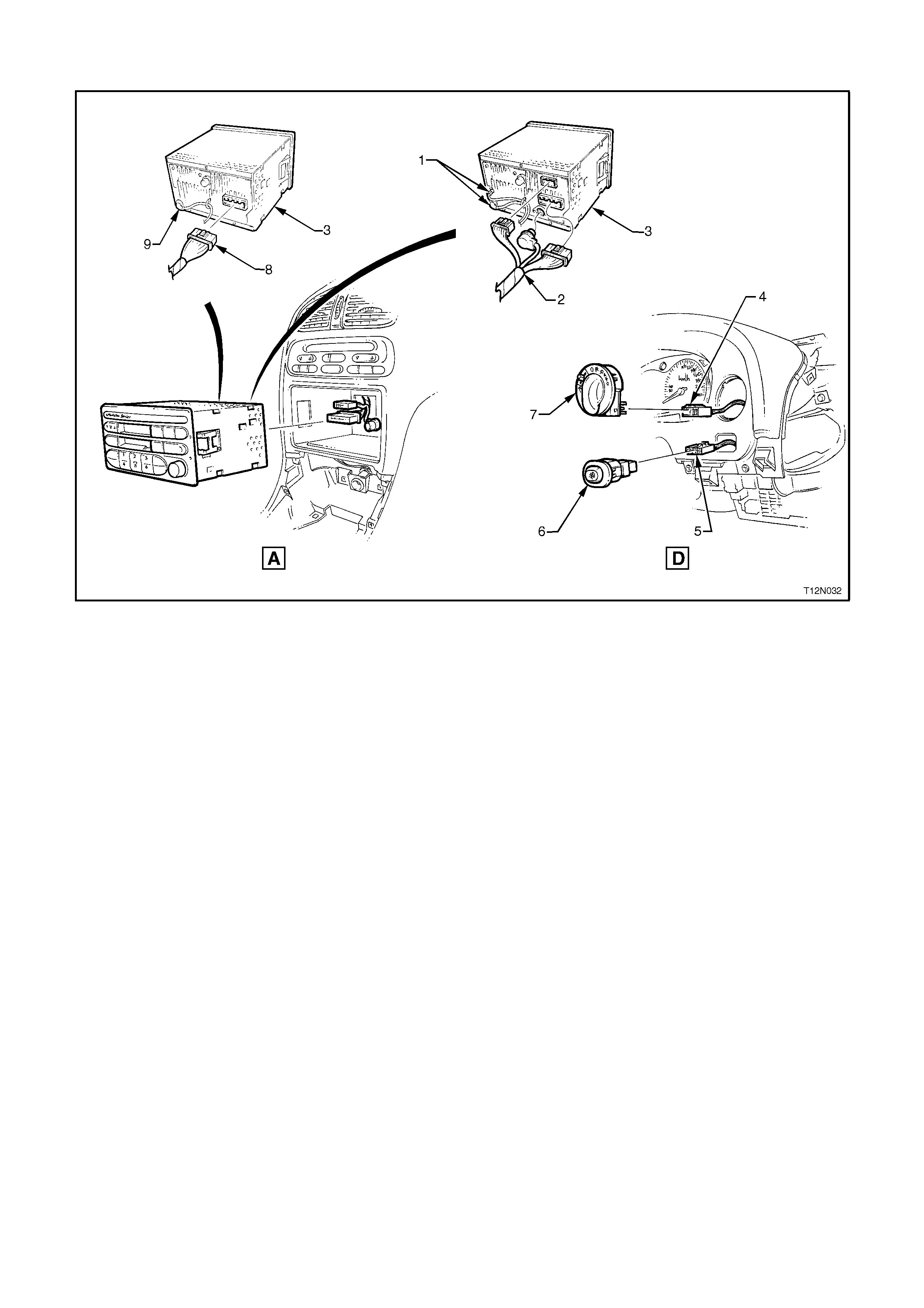
MAIN WIRING HARNESS - 22
Radio/Cassette/CD & Instrument Facia Switches - All Models
Legend
1. Diversity & Power Antenna Connectors
2. Radio/Cassette/CD Connectors
3. Radio/Cassette Unit
4. Headlamp Switch Connector
5. Fog Lamp Switch Connector
6. Fog Lamp Switch (Vehicles with Fog Lamps Only)
7. Headlamp Switch
8. Radio/Cassette Unit Connector
9. Antenna Connector
10. Radio/Cassette Unit
For location of Views A and D, refer to the previous diagram in this Section.
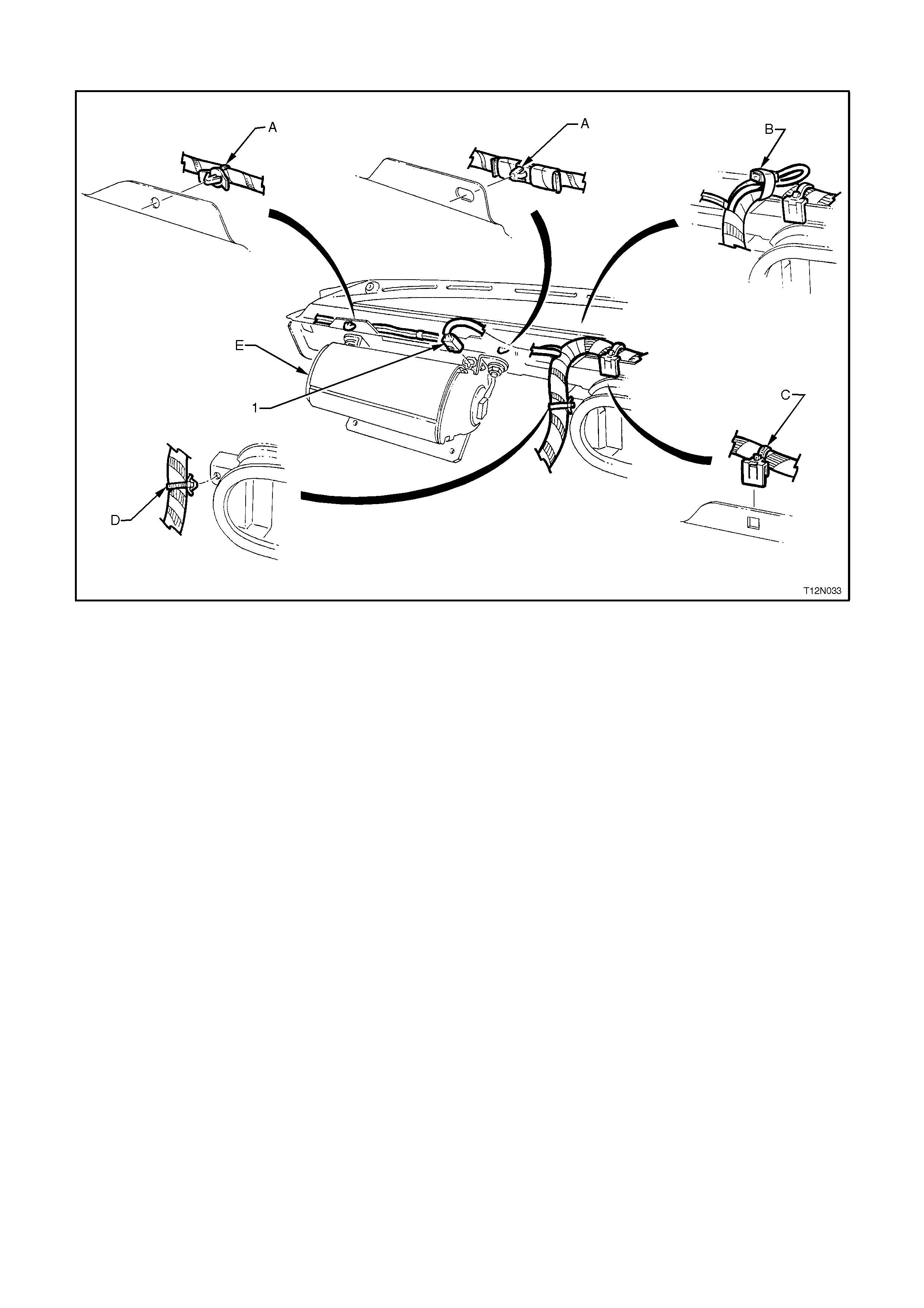
MAIN WIRING HARNESS - 23
Passenger Side Airbag Wiring - All Models
Legend
1. Passenger Side Airbag Connector
A. Harness attached to dash panel cover assembly as shown.
B. Passenger side airbag connector taped back as shown - vehicles without passenger side airbag.
C. Harness attached to dash panel cover assembly (3 places).
D. Harness attached to heating, ventilation & air conditioning unit as shown.
E. For passenger side airbag installation, refer to SECTION 12M, SUPPLEMENTAL RESTRAINT SYSTEM.
MAIN WIRING HARNESS - 24
Solar Sensor & Dash Speakers - All Models
Legend
1. Solar Sensor Connector
2. Dash Panel Front Speaker Connector
3. Dash Panel Front Speaker
4. Screw
A. Harness attached to solar sensor module as shown.
B. Right hand side dash panel front speaker shown.
C. Dash panel front speaker bracket aligned with locating pin.
D. Harness attached to dash panel cover assembly as shown.
E. Front of vehicle.
MAIN WIRING HARNESS - 25
Diversity Antenna & HVAC Connectors - All Models
Legend
1. Diversity Antenna Power Connector
2. CD Player Connector
3. Fan Speed Control Connector
4. Blower Motor Connector
5. Thermostat Amplifier Connector (Calais Only)
A. Harness attached to body as shown.
B. View shown for vehicles fitted with CD Changer Unit.
C. Harness attached to instrument panel carrier end as shown.
D. Harness attached to heating, ventilation & air conditioning unit as shown.

MAIN WIRING HARNESS - 26
Glove Box Connectors- All Models
Legend
1. Boot Lock Switch Connector
2 Boot Lock Switch
3. Glove Box Lamp Switch Connectors
4. Glove Box Lamp Switch
5. Glove Box Lamp Bulb
6. Glove Box Lamp Connectors
7. Glove Box Lamp Lens
A. Harness attached to glove box as shown.
MAIN WIRING HARNESS - 27
Transmission & SRS Sensing Diagnostic Module Connectors - All Models
Legend
1. Automatic Transmission Selector Connector
2 Main Wiring Harness To Body Harness Seat Belt Pre-Tensioner Connector
3. Airbag Sensing Diagnostic Module
4. Airbag Sensing Diagnostic Module Connector
5. Body Harness Earth Terminal
6. Cellular Phone Connector
7. Radio Body Earth Terminal
8. Screw
A. Harness attached to automatic transmission selector as shown.
B. Main wiring harness attached to stud as shown (vehicles with manual transmission).
C. Main wiring harness attached to tunnel as shown.
D. Main wiring harness attached to instrument panel carrier as shown.
E. Vehicle with automatic transmission shown.
DIVERSITY ANTENNA WIRING
DIVERSITY ANTENNA WIRING - 1
Calais
Legend
1. Diversity Antenna Extension Lead
2. Main Wiring Harness Diversity Antenna Power Connector, refer to MAIN WIRING HARNESS - 9 Diagram in
this Section.
3. Antenna Lead
4. CD Changer Harness, refer CD CHANGER WIRING - I - Calais Diagram in this Section.
5. Diversity Antenna Leads.
6. Body Wiring Harness
A. 3 places.
B. 2 places.
For Views D and E, refer to the next diagram in this Section.
DIVERSITY ANTENNA AND WIRING - 2
Calais
Legend
1. Amplifier
2. Diversity Antenna
3. Screw
4. Screw
A. Screw positioned through hole (4 places).
B. Tab located in slot as shown.
C. Tab bent after installation of diversity antenna connector in direction shown.
CD CHANGER WIRING
CD CHANGER WIRING - 1
Calais
Legend
1. Diversity Antenna Leads
2. Main Wiring Harness, refer to BODY & ROOF WIRING HARNESSES - 6 Diagram in this Section.
3. CD Changer Harness
4. Body Wiring Harness refer to BODY & ROOF WIRING HARNESSES - 2 Diagram in this Section.
5. Strap
A. 3 places.
B. 2 places.
C. Typical - 4 places.
D. For continuation, refer to the next diagram in this Section.
CD CHANGER WIRING - 2
Calais
Legend
1. Body Wiring Harness
2. Side Outer Panel
3. CD Changer Harness
4. CD Changer Harness Connection To CD Changer
5. Screw (Theft Deterrent) - 4 Places
6. Rivet (3 Places)
7. CD Changer Unit
8. CD Changer Unit Mounting Bracket
A. Clip bent to retain harness.
B. For continuation of CD harness, refer to the previous diagram in this Section.
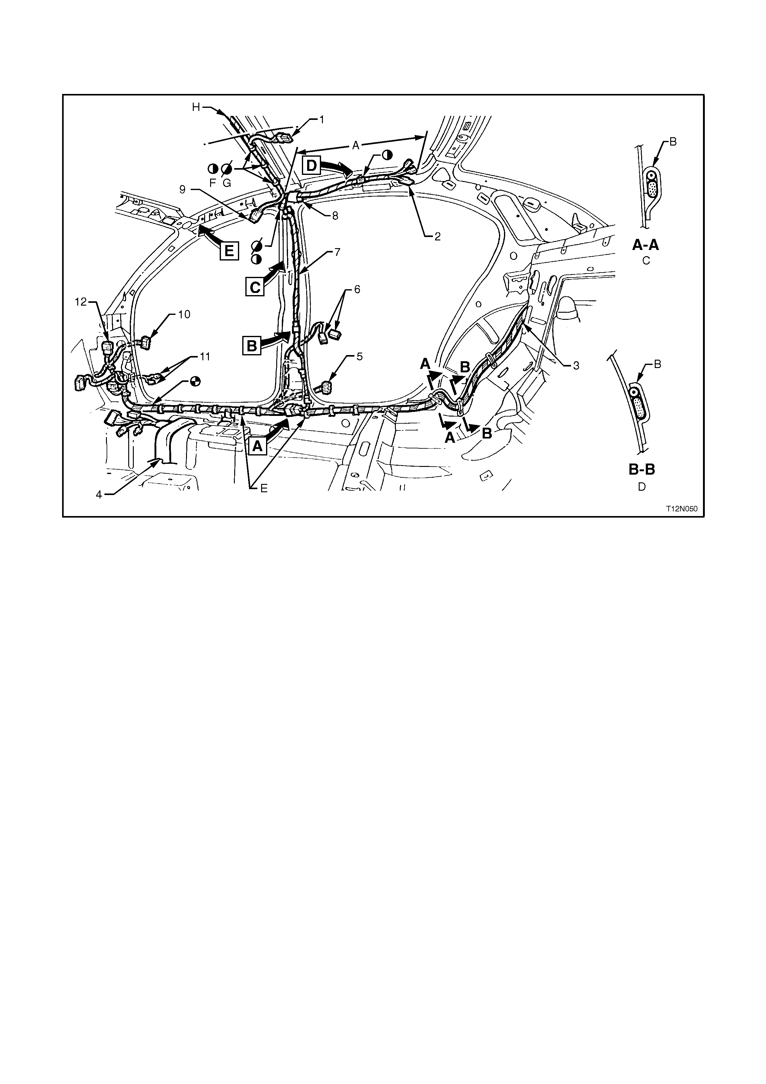
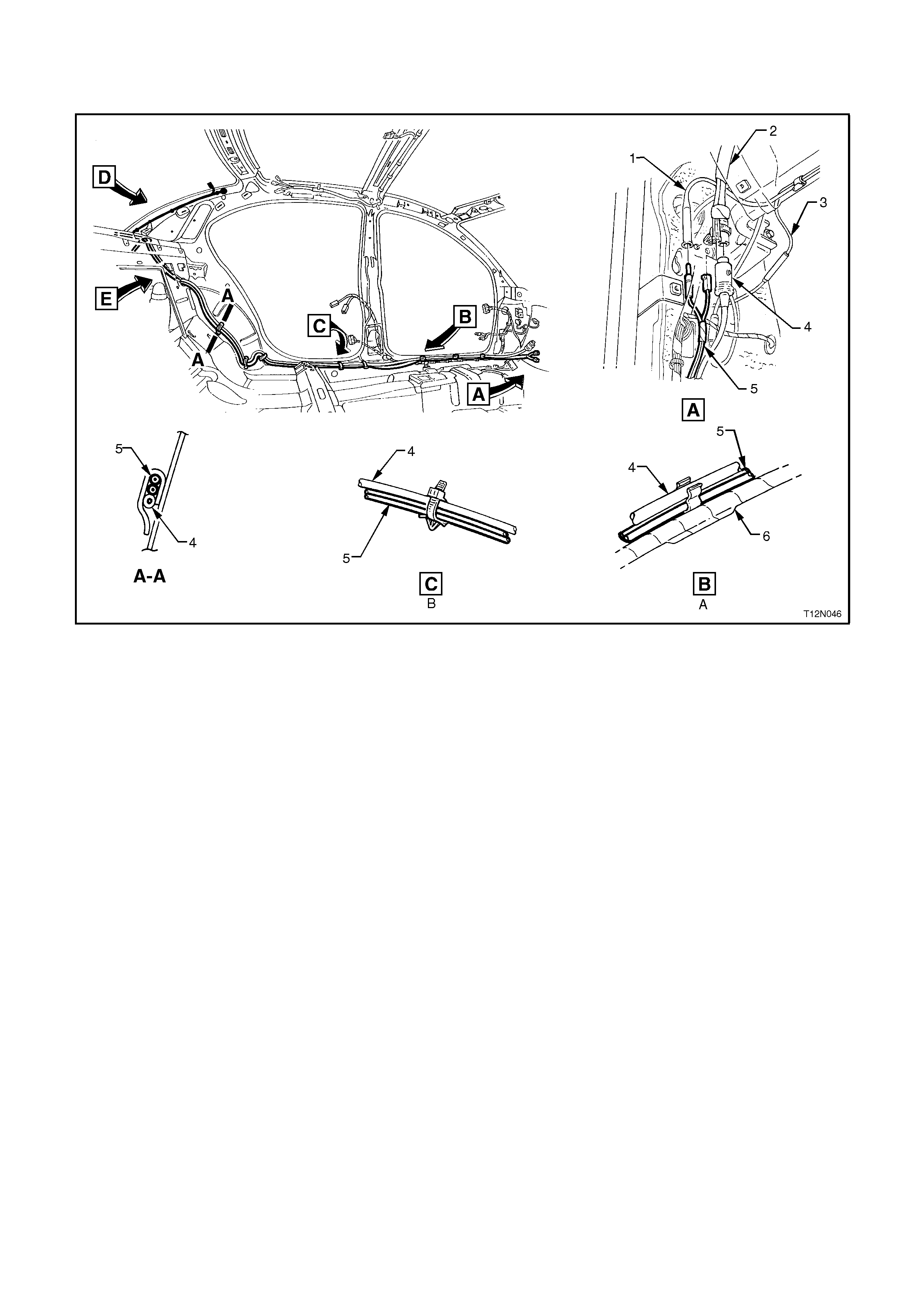
BODY & ROOF WIRING HARNESSES
BODY & ROOF WIRING HARNESSES - 1
Interior - Sedan Models
Legend
1. Dome Lamp Connector, refer to BODY & ROOF WIRING HARNESSES - 5 Diagram in this Section.
2. Rear Passenger Compartment Reading Lamp Connectors, refer to BODY & ROOF WIRING HARNESSES -
5 Diagram in this Section.
3. Body Wiring Harness, for continuation refer to BODY & ROOF WIRING HARNESSES - 7 Diagram in this
Section.
4. Body Wiring Harness - PreTensioner & Power Window Wiring, refer to the next diagram in this Section.
5. Rear Door Connector - Right Hand Side, refer to REAR DOOR HARNESS Diagram in this Section.
6. Rear Door Jamb Switch Connectors (Calais Shown), refer to BODY & ROOF WIRING HARNESSES - 5
Diagram in this Section.
7. Roof Lamps Wiring Harness
8. Visor Lamp Connector (Taped Back on Berlina)
9. Visor Lamp Connector - Calais, refer to BODY & ROOF HARNESSES - 4 Diagram in this Section.
10. Front Door Connector - Right Hand Side, refer to FRONT DOOR HARNESS Diagram in this Section.
11. Front Door Jamb Switch Connectors (Calais Shown), refer to BODY & ROOF WIRING HARNESSES - 5
Diagram in this Section.
12. Body Harness to Main Wiring Harness Connector, refer to BODY & ROOF WIRING HARNESSES - 3
Diagram in this Section.
A. Berlina and Calais only.
B. Clip bent to retain fuel filter door cable & body harness.
C. 1 place.
D. 2 places.
E. Harness clipped to underbody, refer to BODY & ROOF WIRING HARNESSES - 3 diagram in this Section.
F. Roof Harness clipped in 9 places - Berlina and Calais.
G. Roof Harness clipped in 4 places - Executive.
H. For continuation, to next diagram in this Section.
For Views A through E, refer to BODY & ROOF WIRING HARNESSES - 4 diagram in this Section.
BODY & ROOF WIRING HARNESSES - 2
Interior - All Models
Legend
1. Roof Harness, refer to the previous diagram in this Section.
2. Front Door Connector - Left Hand Side, refer to FRONT DOOR HARNESS Diagram in this Section.
3. Front Door Jamb Switch Connectors, refer to BODY & ROOF WIRING HARNESSES - 5 Diagram in this
Section.
4. Rear Door Connector - Left Hand Side, refer to REAR DOOR HARNESS Diagram in this Section.
5. Rear Door Jamb Switch Connectors, refer to BODY & ROOF WIRING HARNESSES - 5 Diagram in this
Section.
6. Rear Passenger Compartment Reading Lamp Connectors, refer BODY & ROOF WIRING HARNESSES - 5
Diagram in this Section.
7. Body Wiring Harness - PreTensioner & Power Window Connectors, refer to the next diagram in this Section.
8. Main Wiring Harness PreTensioner Connector
9. Screw
10. Park Brake Connector
11. Console Harness Connector
12. Power Window Switch Connector
A. For continuation, refer to the next diagram in this Section.
B. Harness clipped to underbody, refer to the next diagram in this Section.
C. Harness clipped to underbody as shown - 4 places.
D. For clipping, refer to BODY & ROOF WIRING HARNESSES - 4 diagram in this Section.
For location of View F, to BODY & ROOF WIRING HARNESSES - 4 diagram in this Section.
BODY & ROOF WIRING HARNESSES - 3
Interior - All Models
Legend
1. Turn Signal Connector - Right Hand Side
2. Body Harness to Main Wiring Harness Connector, refer to MAIN WIRING HARNESS - 14 Diagram in this
Section.
3. Body Harness to Main Wiring Harness Connector, refer to MAIN WIRING HARNESS - 14 Diagram in this
Section.
4. Body Harness To Body Control Module Connector, refer to MAIN WIRING HARNESS - 14 Diagram in this
Section.
5. Pre-Tensioner Connector
6. Power Window Connector
7. Footwell Lamp Connector
8. Power Antenna Connector
9. Turn Signal Connector - Left Hand Side
A. Body Wiring Harness attached to shroud side panel - 3 places.
B. For continuation, refer to BODY & ROOF WIRING HARNESSES - 1 diagram in this Section.
C. Body Wiring Harness attached to underbody as shown - 9 places.
D. Right hand side shown.
E. Main Wiring Harness connector clipped to shroud side panel - 2 places.
F. Front of vehicle.
G. Left hand side shown.
H. For continuation, refer to the previous diagram in this Section.
I. Body Wiring Harness attached to underbody as shown - 6 places.
BODY & ROOF WIRING HARNESSES - 4
Interior - All Models
Legend
1. Roof Harness Connector
2. Sun Visor Illumination Harness
3. Sun Visor
4. Roof Harness
5. Body Harness
A. Front of vehicle.
B. For clipping, refer to BODY & ROOF WIRING HARNESSES - 2 and 3 diagrams in this Section.
For location of Views A through E, refer to BODY & ROOF WIRING HA RNESSES - 1 diagram in this Section.
For location of View F, refer to BODY & ROOF WIRING HARNESSES - 2 diagram in this Section.
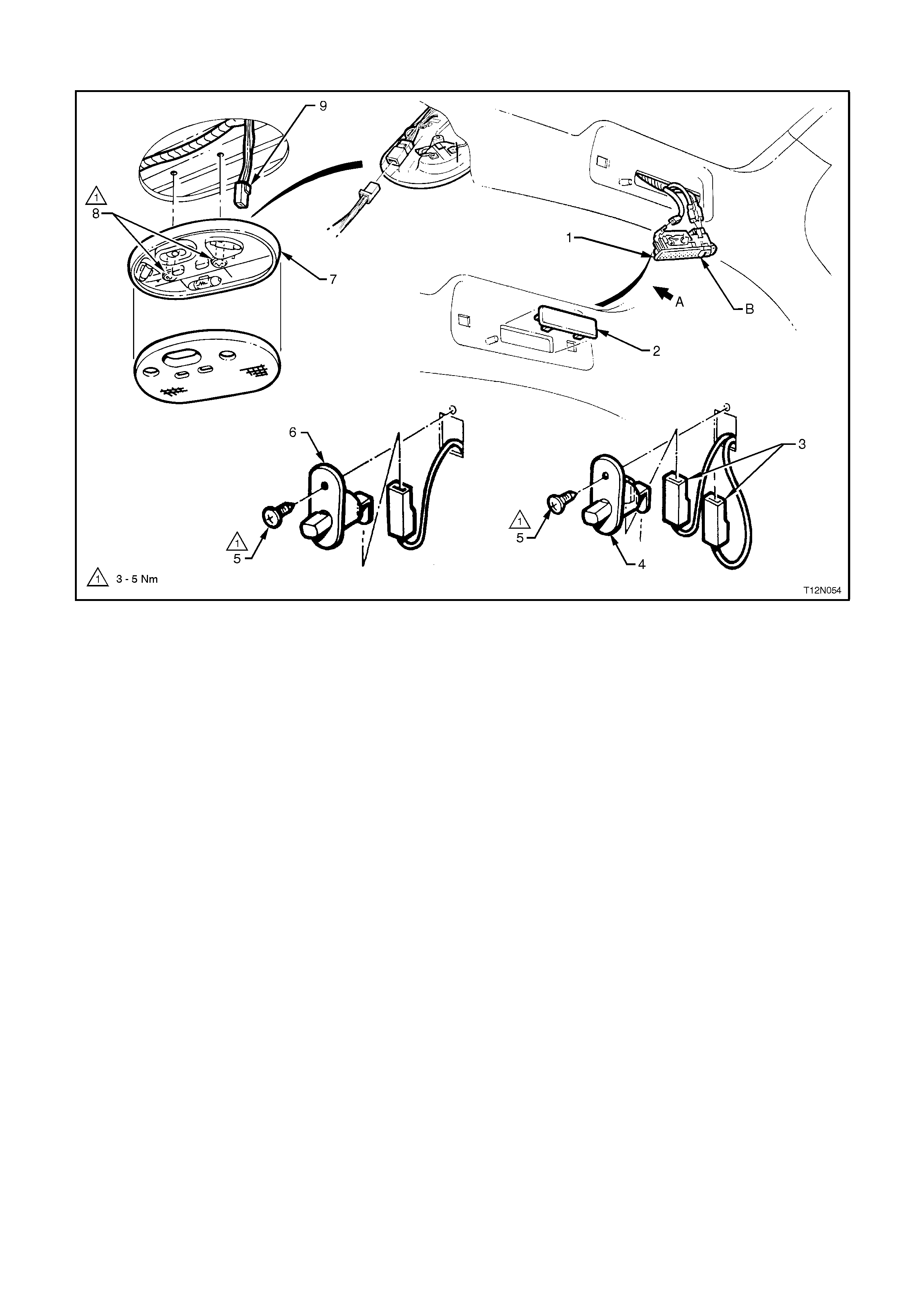
BODY & ROOF WIRING HARNESSES - 5
Dome & Rear Passenger Compartment Lamps - All Models
Legend
1. Rear Passenger Compartment Lamp Assembly - Berlina And Calais - 2 Places
2. Blank - Executive Models - 2 Places
3. Front/Rear Door Connectors - Left And Right Hand Sides
4. Door Jamb Switch - Calais
5. Screw
6. Door Jamb Switch - Executive and Berlina Models
7. Dome Lamp Assembly
8. Screws
9. Dome Lamp Connector
A. Front of vehicle
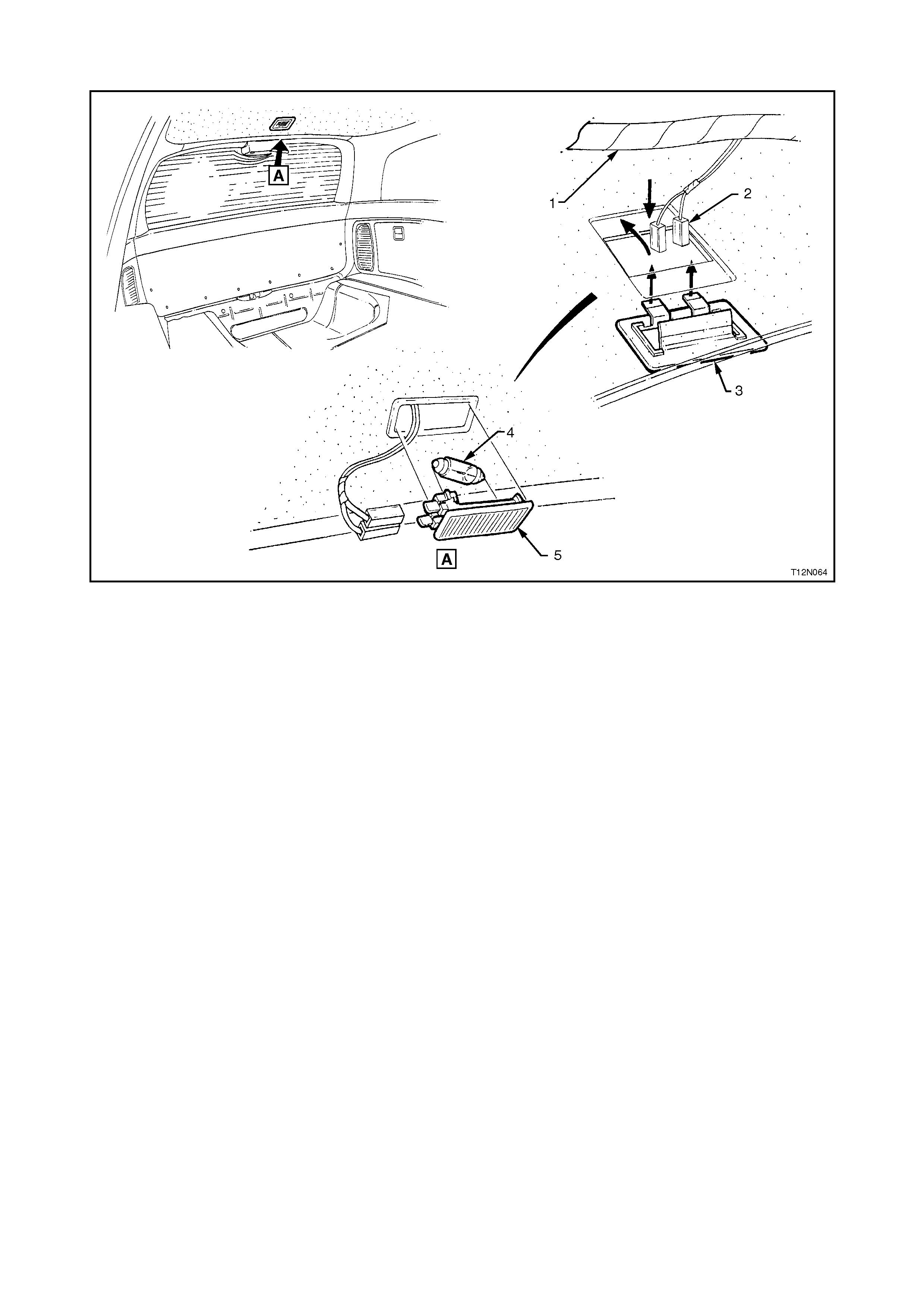
BODY & ROOF WIRING HARNESSES - 6
Parcel Shelf & Rear Compartment Lamp - Sedan Models
Legend
1. Rear Compartment Lamp Connectors
2. Rear Compartment Lamp Lens
3. High Mounted Stop Lamp
4. Heated Rear Window Demister Earth Lead
5. Washer
6. Screw
7. Rear Compartment Lamp Bulb
8. Rear Speaker Connector - Left Hand Side
9. Rear Speaker Connector - Right Hand Side
A. Tab bent once lead connector is installed.
B. Heated rear window lead clip to side inner panel - 2 places.
C. Calais only.
D. For continuation of subwoofer amplifier, refer to DIVERSITY ANTENNA & WIRING - 2 diagram in this
Section.
E. For continuation, refer to the next diagram in this Section.
F. Body harness clipped to rear seat upper panel - 7 places.
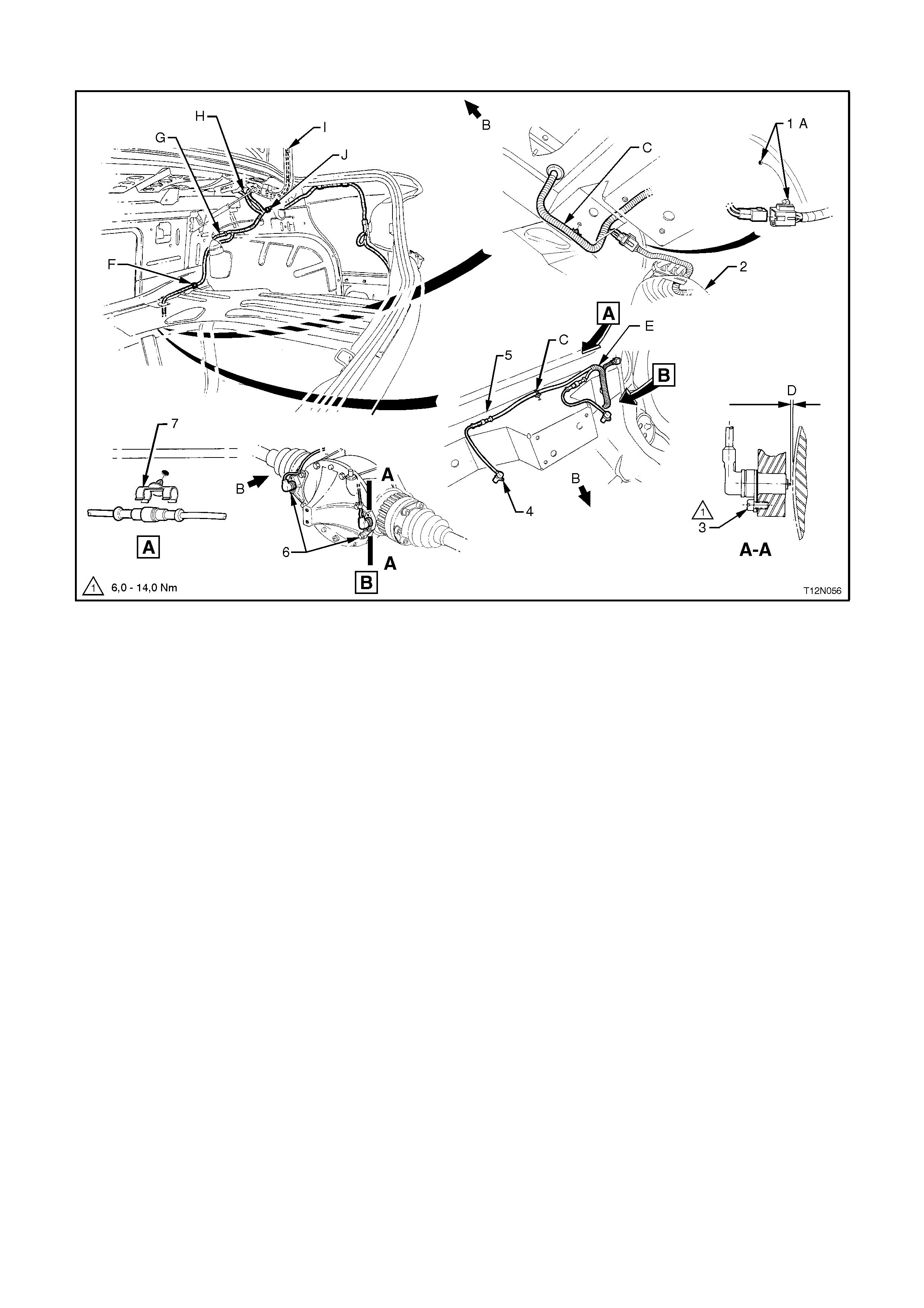
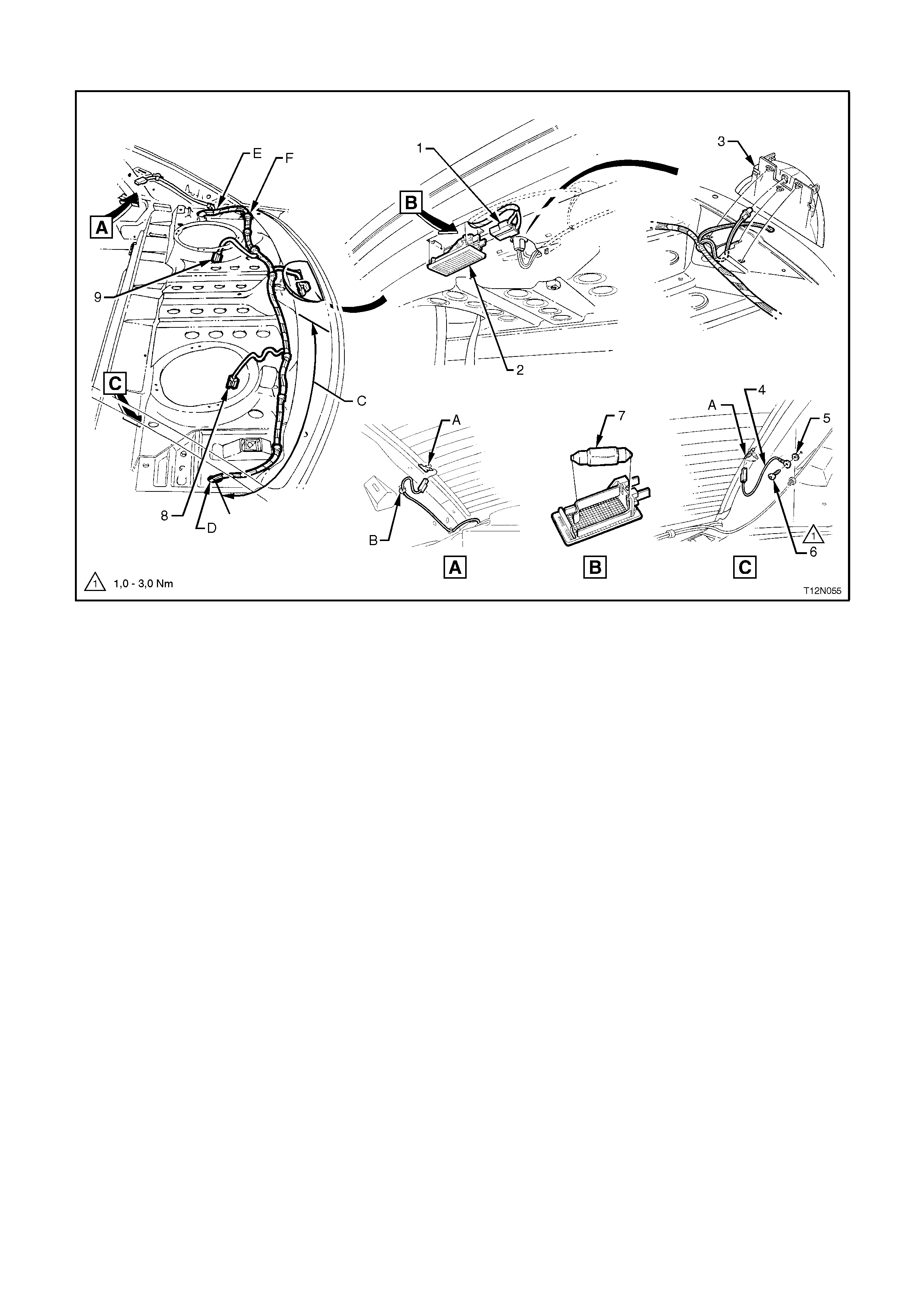
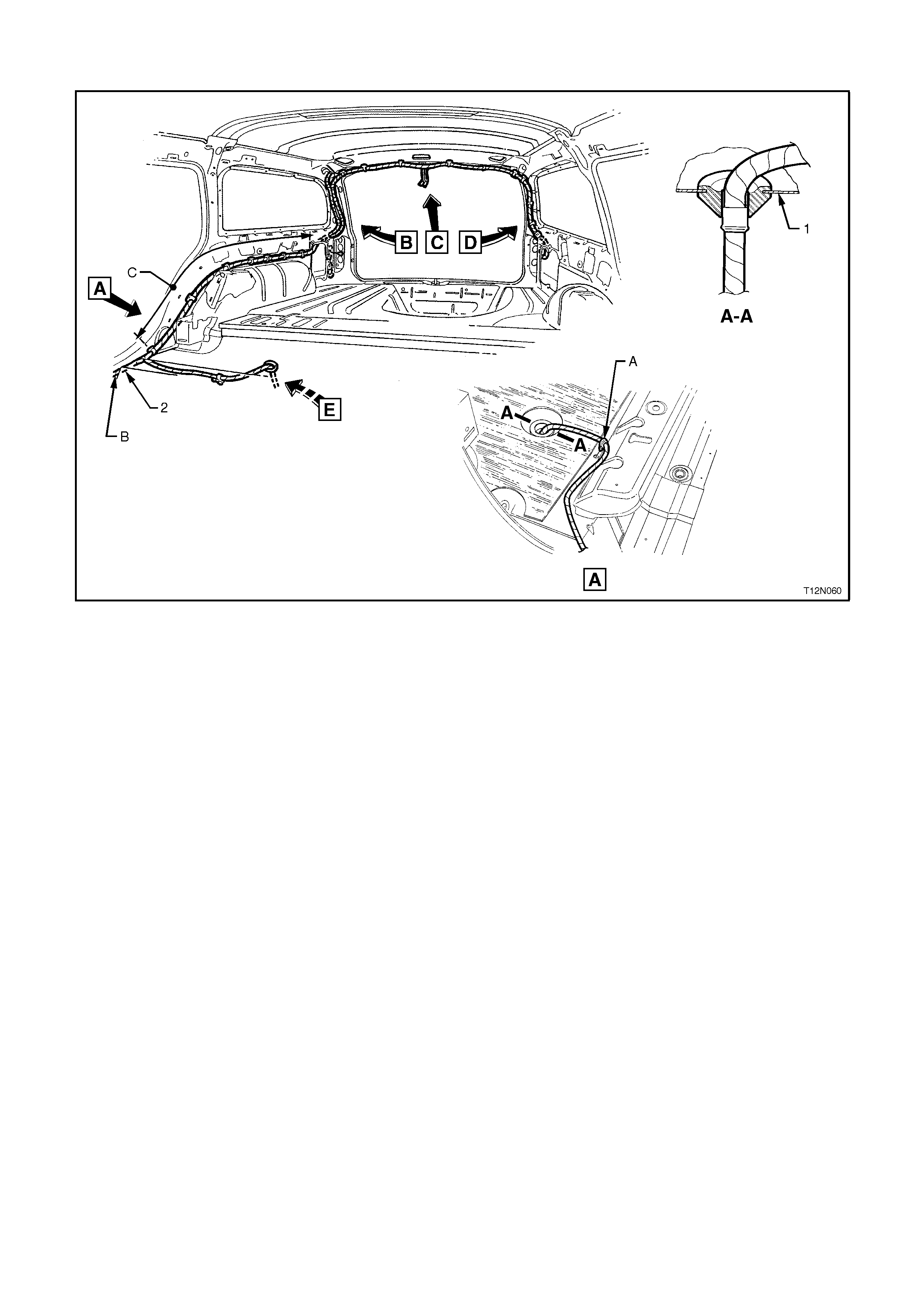
BODY & ROOF WIRING HARNESSES - 7
Rear Compartment, Fuel Tank & ABS - Sedan Models
Legend
1. Fuel Tank Harness Connector
2. Fuel Tank Assembly
3. Rear Wheel Speed Sensor Attaching Screw
4. Rear Wheel Speed Sensor - 2 Places
5. Rear Axle Crossmember
6. Differential Assembly With Rear Speed Sensors Installed
7. Retainer - 2 Places
A. Front of vehicle
B. Harness connector clip to rear longitudinal extension panel.
C. Body Wiring Harness clipped to rear axle crossmember - 2 places.
D. Shims used to achieve required clearance between tip of wheel speed sensor and pulse ring of 0.3 to 1.1 mm.
E. For station wagon models, refer to BODY & TAILGATE HARNESSES - 1 diagram in this Section.
F. Body Wiring Harness clipped to lower wheelhouse brace - right hand side.
G. For continuation, refer to BODY & ROOF WIRING HARNESSES - 1 diagram in this Section.
H. For continuation, refer to previous diagram in this Section.
l. For continuation, refer to BODY WIRING HARNESS - 9 diagram in this Section.
J. Body Wiring Harness clipped to side inner panel.
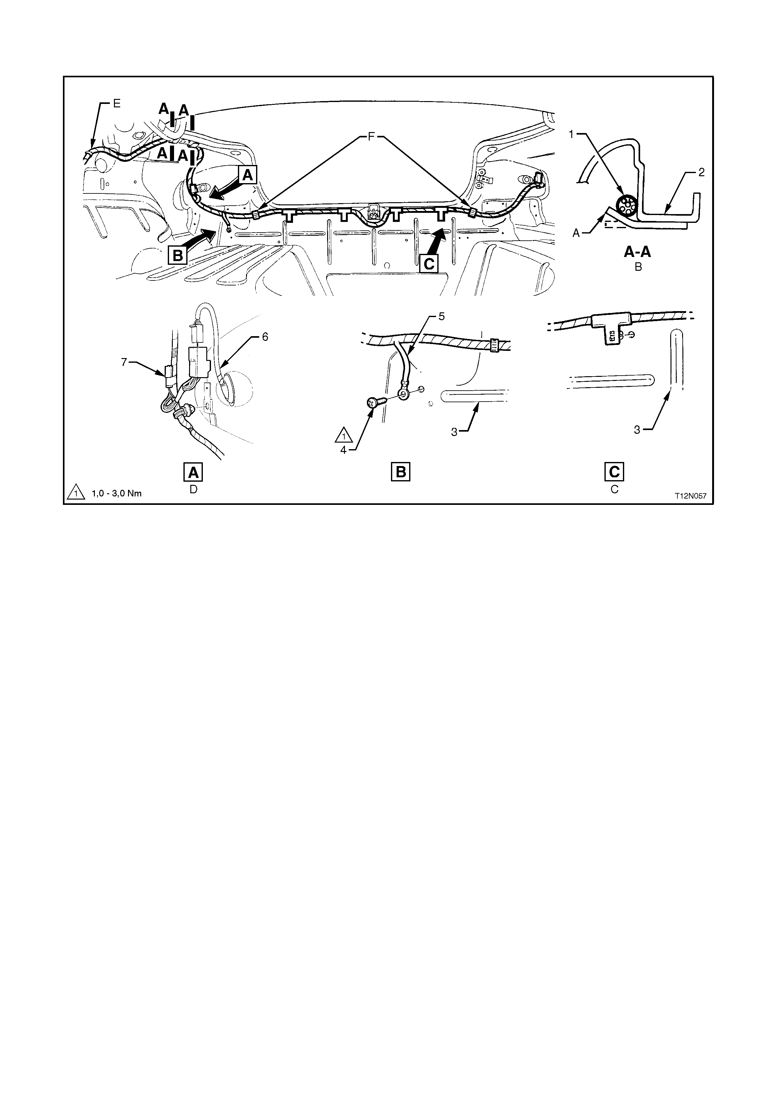
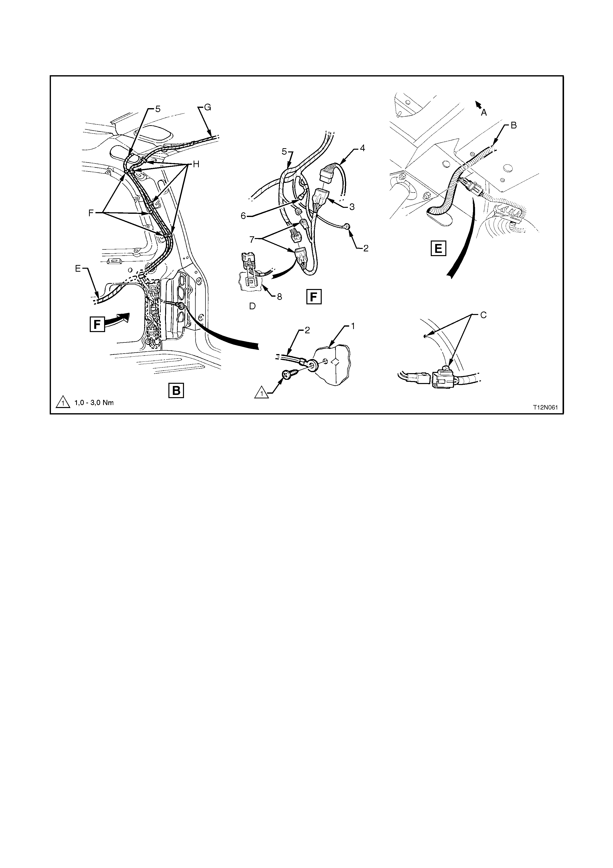
BODY & ROOF WIRING HARNESSES - 8
Rear Compartment - Sedan Models
Legend
1. Body Wiring Harness
2. Side Panel Outer Fuel Tank Assembly
3. Back Panel Lower Reinforcement
4. Screw
5. Body Earth Lead
6. Rear Quarter Lamp Lead - Right Hand Side
7. Left Hand Turn Trailer Connector (Tied Back)
A. Clip bent to retain harness.
B. 2 places.
C. Typical - 4 places.
D. Right hand side shown.
E. For continuation, refer to the previous diagram in this Section.
F. Harness clipped to back panel lower reinforcement - 2 places.
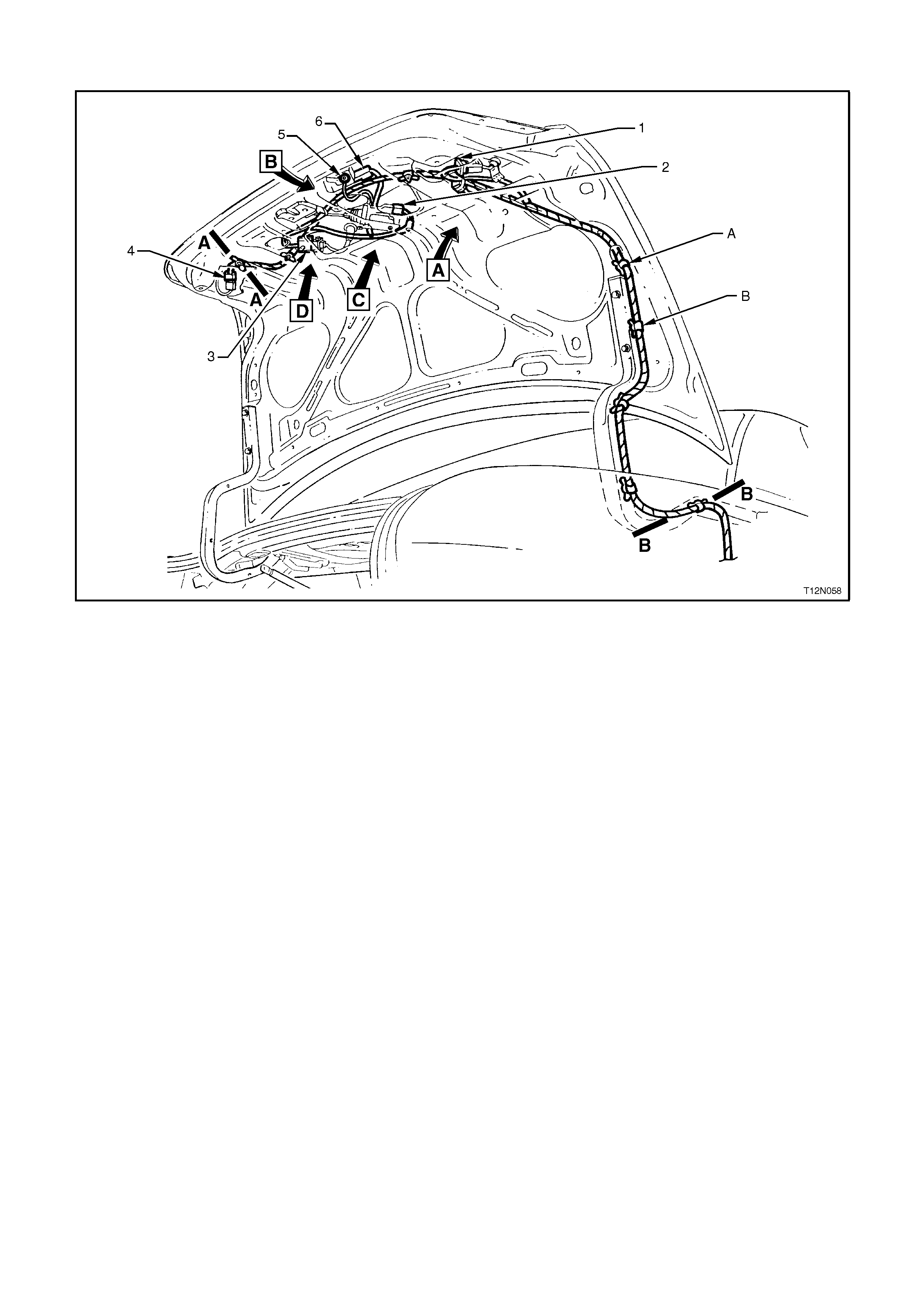
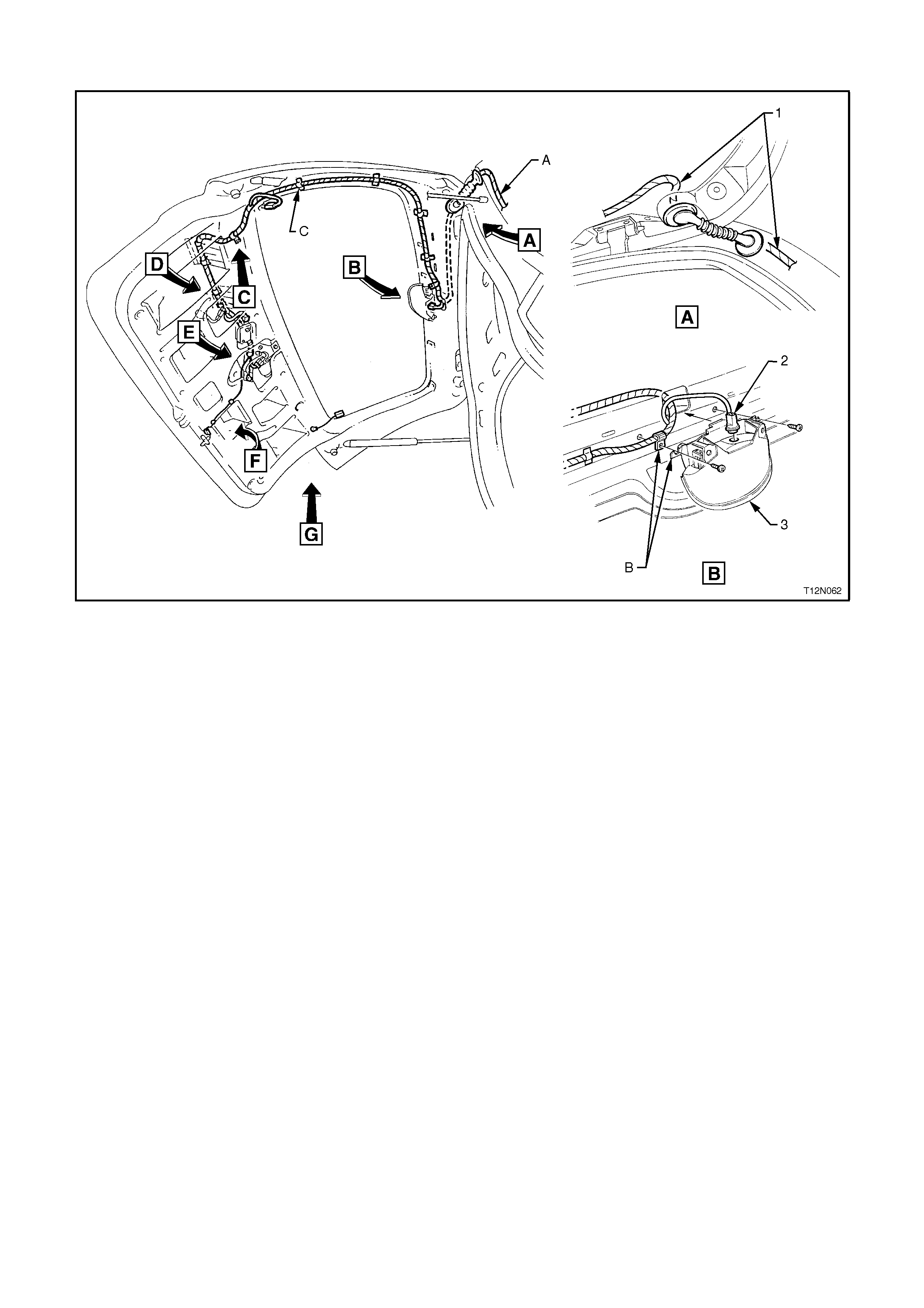
BODY & ROOF WIRING HARNESSES - 9
Decklid Wiring - Sedan Models
Legend
1. Reverse/Tail Lamp Connector - Right Hand Side
2. Rear Compartment Actuator Connector
3. Licence Plate Lamp Connector - Right and Left Hand Side
4. Reverse/Tail Lamp Connector - Left Hand Side
5. Body Wiring Harness - Decklid Earth Terminal
6. Rear Compartment Lamp Switch Connector
A. Body Wiring Harness clipped to decklid inner - 4 places.
B. Body Wiring Harness clipped to decklid hinge - 4 places.
For Vi ews A, B, C and D & Sections A-A and B-B, refer to the next diagram in this Section.

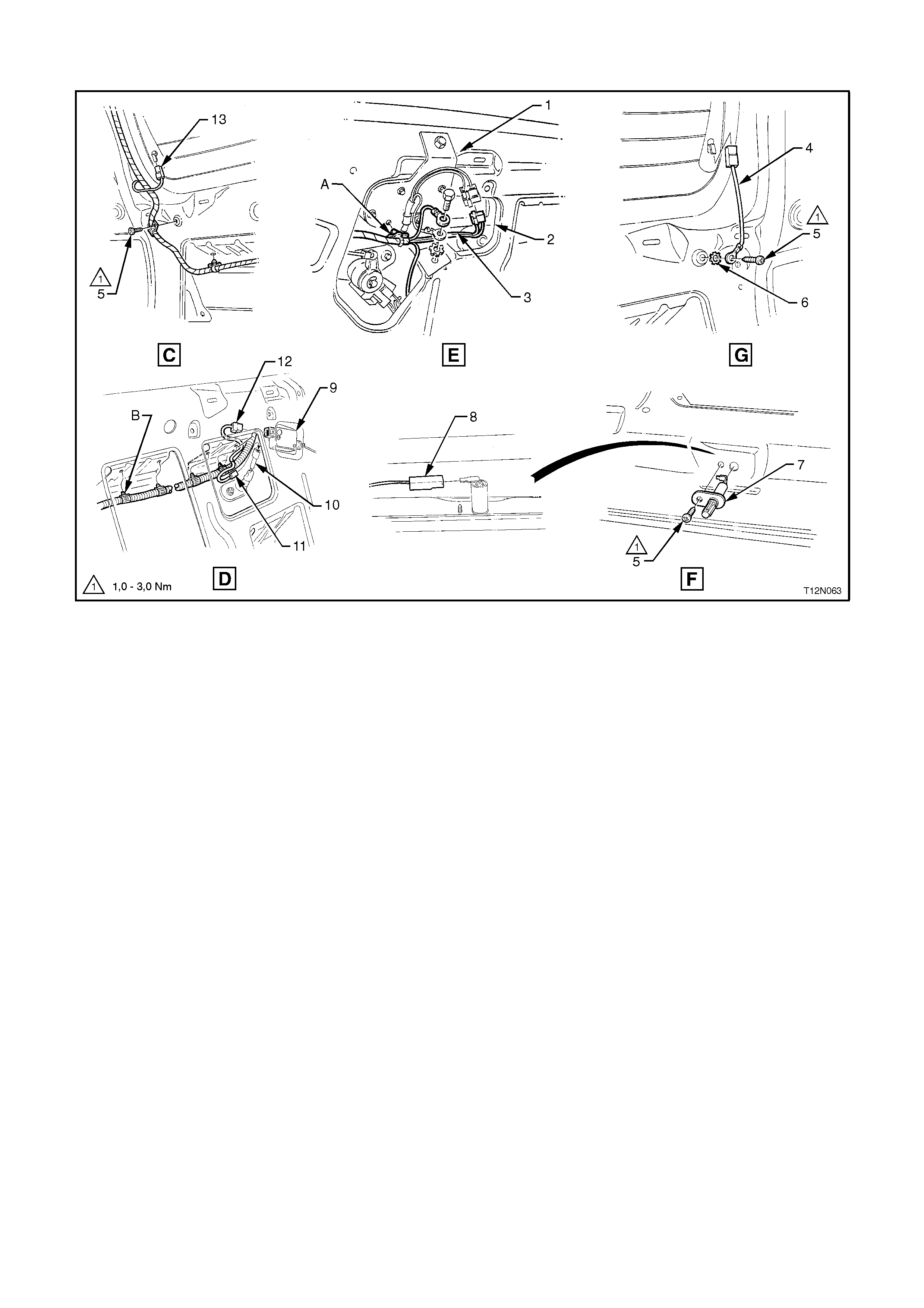
BODY & ROOF WIRING HARNESSES - 10
Interior - Station Wagon Models
Legend
1. Body Wiring Harness Rear Compartment Lamp Switch Connector
2. Rear Compartment Lamp Switch
3. Screw
4. Body Wiring Harness - Decklid Earth Terminal
5. Decklid Inner Panel
6. Decklid Hinge
7. Truck Lid Lamp & Moulding Assembly
8. Right and Left Hand Licence Plate Lamp Connector.
9. Body Wiring Harness Rear Compartment Lock Actuator Connector
10. Rear Compartment Lock Actuator
11. Reverse/Tail Lamp Connector
A. Typical - 5 places.
B. Typical - 4 places.
!Decklid lamp and moulding assembly lamp harness
BODY & ROOF WIRING HARNESSES - 11
Interior - Station Wagon Models
Legend
1. Rear Floor Panel Front
2. Body Wiring Harness
A. Body Wiring Harness clipped to rear floor panel front.
B. For continuation, refer to BODY & ROOF WIRING HARNESSES - 1 diagram in this Section.
C. Body Wiring Harness clipped to inner side panel - right hand side - 8 places.
For Views B and E, refer to the next diagram in this Section.
For Views C and D, refer to TAILGATE WIRING HARNESS - 3 diagram in this Section.
BODY & TAILGATE WIRING HARNESSES
BODY & TAILGATE WIRING HARNESSES - 1
Station Wagon Models
Legend
1. Side Panel Inner Extension Piece
2. Body Earth Lead
3. Rear Lamps Connector - Right Hand Side Rear
4. Rear Lamp Harness - Right Hand Side Rear
5. Tailgate Harness, refer to the next diagram in this Section.
6. Left Hand Turn Trailer Connector (Taped Back)
7. Tailgate Harness Connectors
8. Panel Inner - Right Hand Side
A. Front of vehicle.
B. ABS wiring, refer BODY & ROOF WIRING HARNESSES - 7 diagram in this Section.
C. Fuel tank harness connector clipped to rear longitudinal extension panel.
D. Typical - 2 places.
E. For continuation, refer to the previous diagram in this Section.
F. Tailgate harness clipped to inner side panel - right hand side - 3 places.
G. For continuation, refer to the next diagram in this Section.
H. Body Wiring Harness clipped to inner side panel - right hand side - 4 places.
BODY & TAILGATE WIRING HARNESSES - 2
Station Wagon Models
Legend
1. Tailgate Harness
2. High Mounted Stop Lamp Connector
3. High Lamp Stop Lamp
A. For continuation, refer to the previous diagram in this Section.
B. Harness retained between high mounted stop lamp and tailgate inner panel as shown.
C. Tailgate harness taped to tailgate inner panel - 4 places.
For Views C through G, refer to the next diagram in this Section.
BODY & TAILGATE WIRING HARNESSES - 3
Station Wagon Models
Legend
1. Tailgate Wiper Motor
2. Rear Window Wiper Motor Connector
3. Rear Window Wiper Motor Earth
4. Heated Rear Window Earth Lead
5. Screw
6. Washer
7. Rear Compartment Tailgate Lamp Switch
8. Rear Compartment Tailgate Lamp Switch Connector
9. Tailgate Actuator
10. Rear Licence Plate Lamp Connector
11. Tailgate To Rear Licence Plate Lamp Connector
12. Rear Compartment Lock Actuator Connector
13. Heated Rear Window Connector
A. Tailgate harness clipped to tailgate wiper motor as shown.
B. Tailgate harness clipped to tailgate inner panel - 4 places.
For location of Views C through G, refer to the previous diagram in this Section.
BODY & TAILGATE WIRING HARNESSES - 4
Rear Compartment Lamp - Station Wagon Models
Legend
1. Body Wiring Harness
2. Rear Compartment Lamp Connectors
3. Rear Compartment Lamp
4. Rear Compartment Lamp Bulb
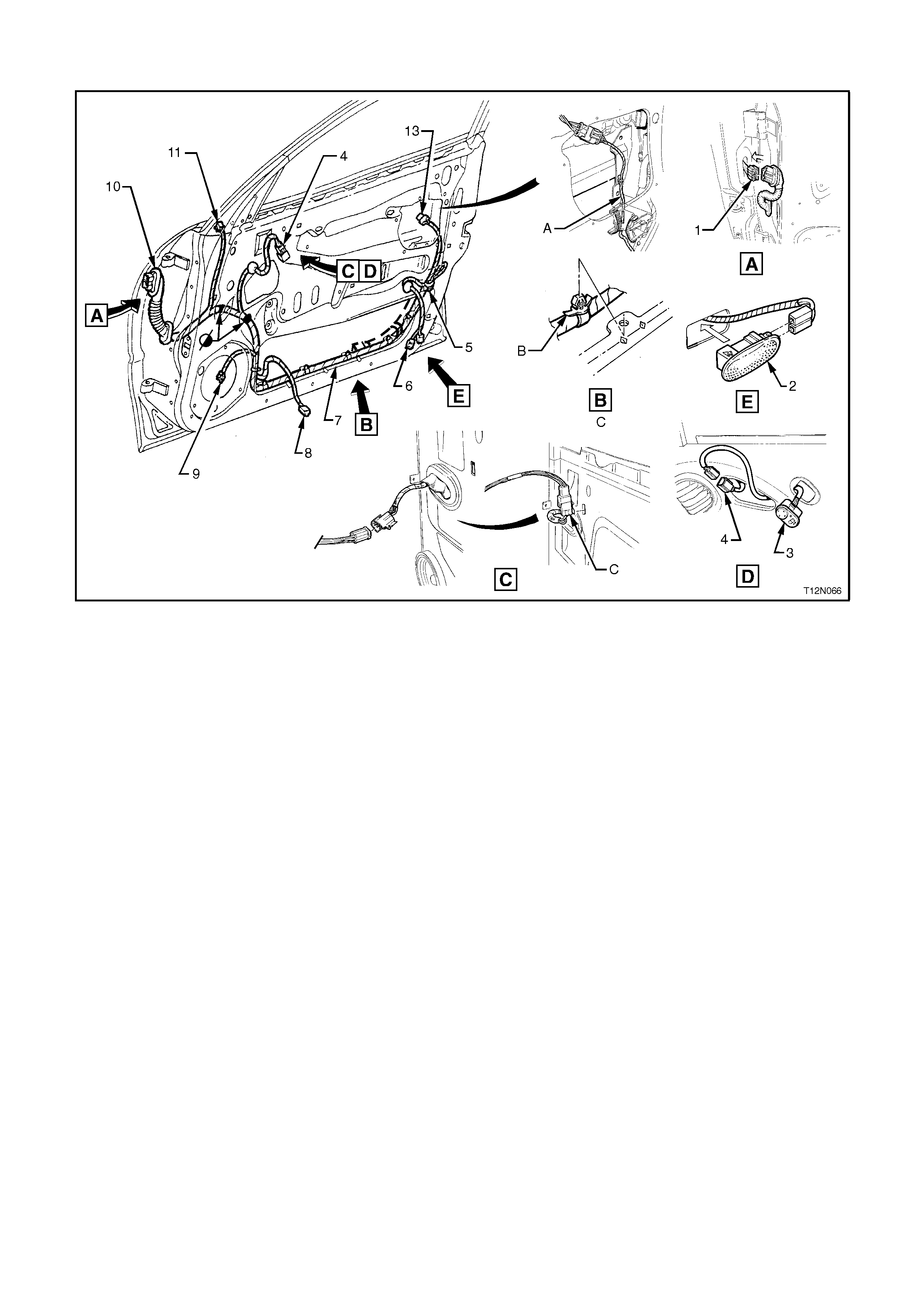
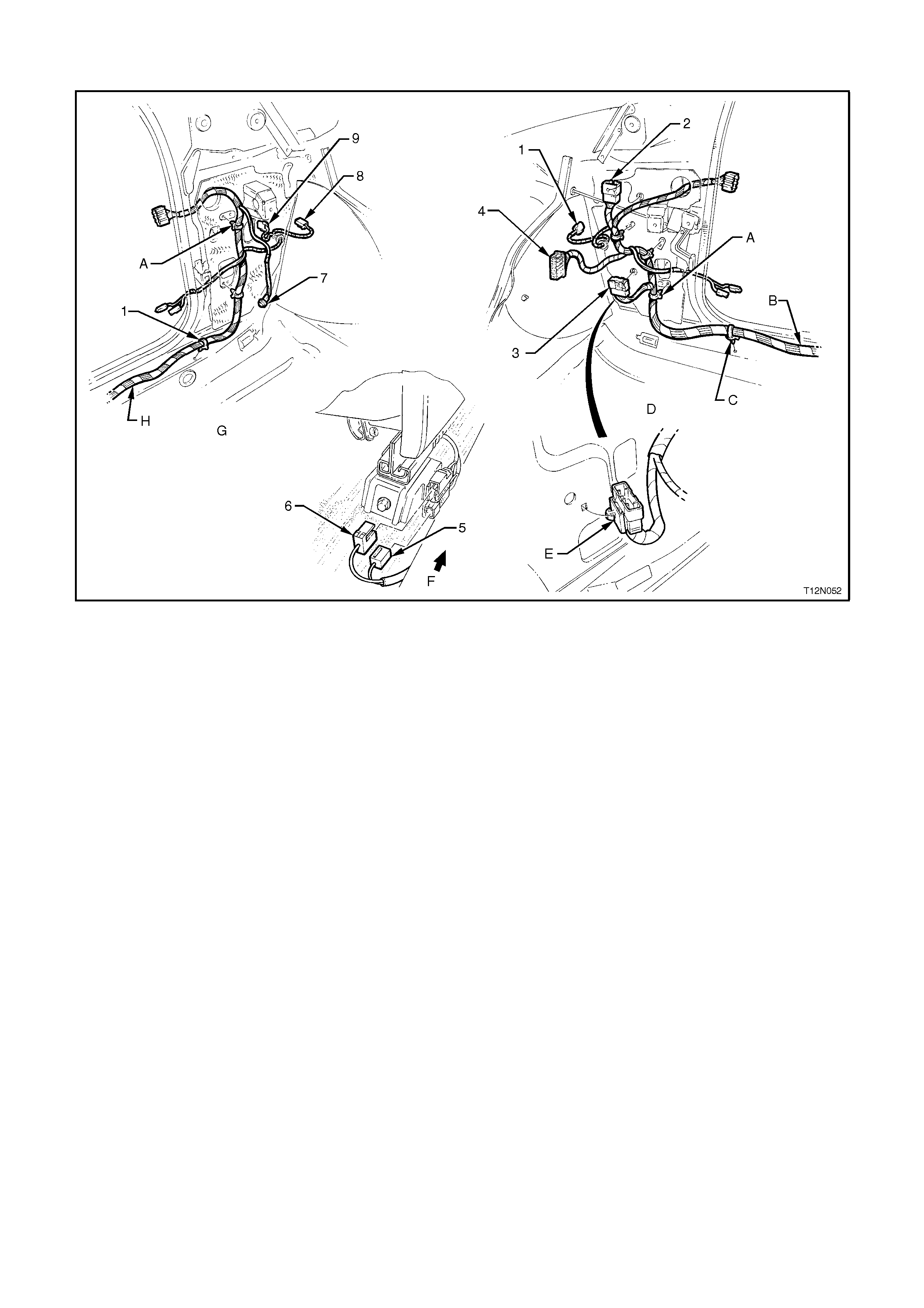
FRONT DOOR HARNESS
L Models
Legend
1. Body Harness Connector. For continuation, refer to BODY & ROOF WIRING HARNESSES - 1 Diagram in
this Section.
2. Door Courtesy Lamp - Calais
3. Exterior Rear Vision Mirror Switch
4. Exterior Rear Vision Mirror Switch Connector
5. Door Lock Actuator Connector
6. Courtesy Lamp Connectors - Calais
7. Door Harness
8. Window Lifter Motor Connector
9. Speaker Connector
10. Body Harness Connector
11. Exterior Mirror Connector
A. Harness routed as shown.
B. Door Harness clipped to door panels as shown.
C. Mirror switch connector clipped to door inner panel as shown.
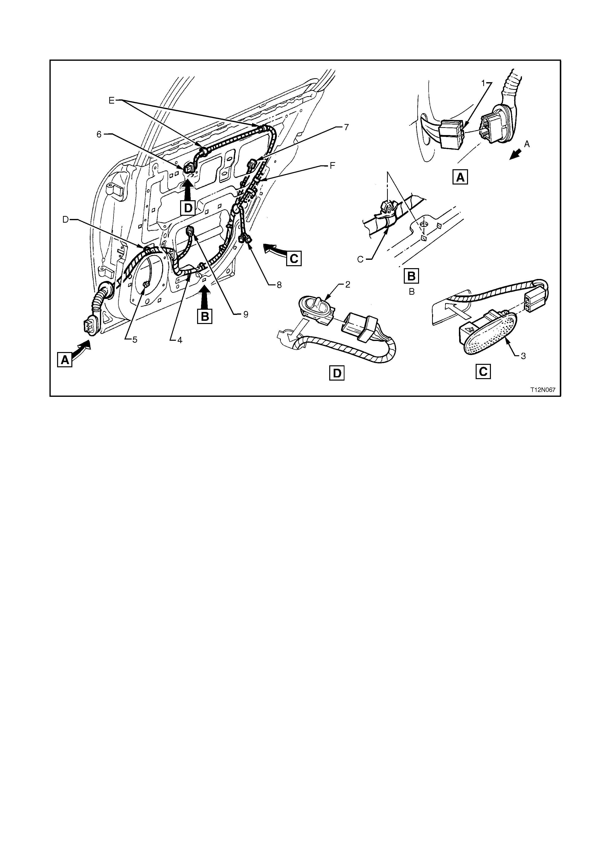
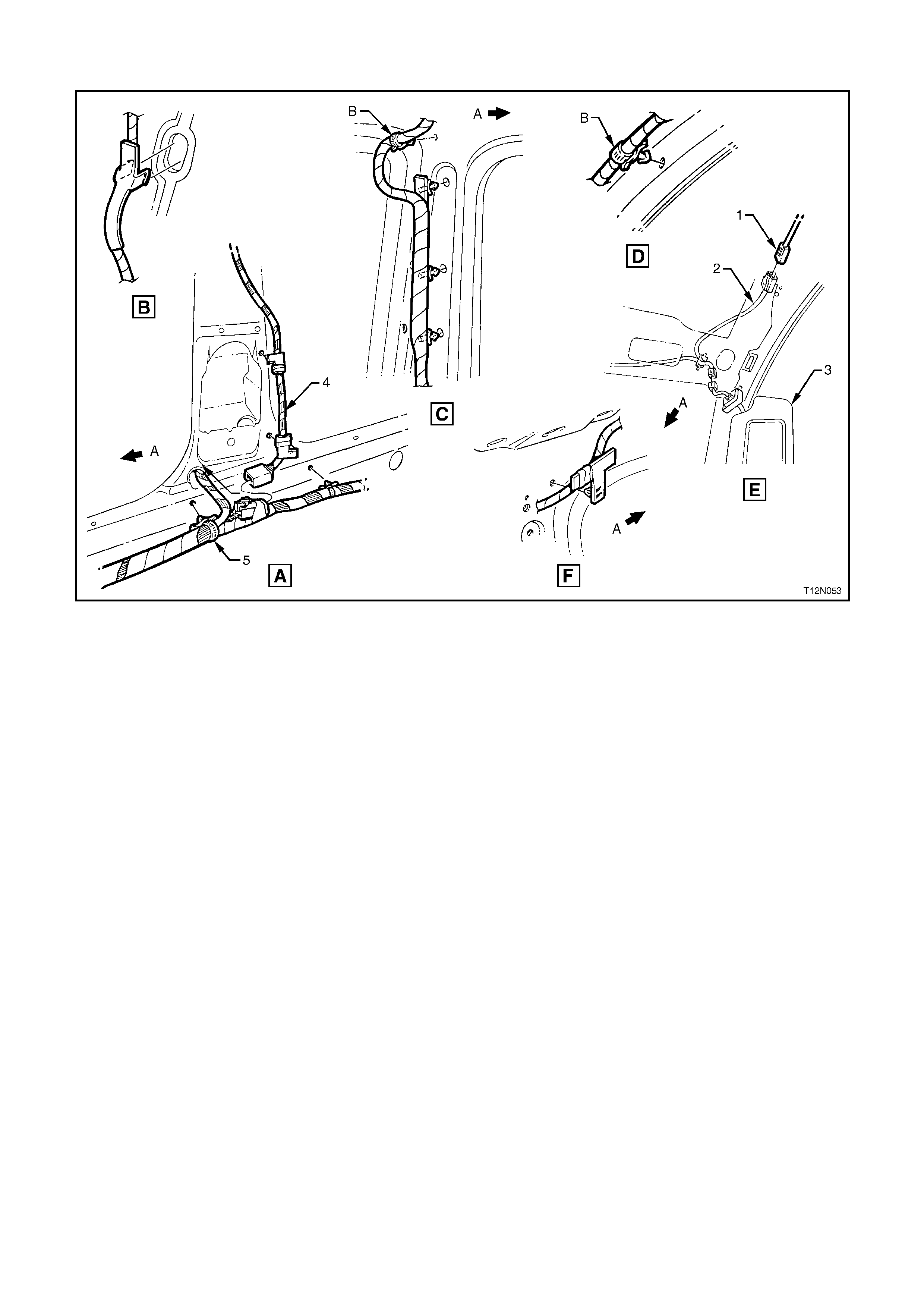
REAR DOOR HARNESS
All Models
Legend
1. Body Harness Connector. For continuation, refer to BODY & ROOF WIRING HARNESSES - 1 Diagram in
this Section.
2. Rear Window Lifter Switch
3. Courtesy Lamp - Calais
4. Door Harness
5. Speaker Connector
6. Rear Window Lifter Switch Connector
7. Door Lock Actuator Connector
8. Courtesy Lamp Connectors - Calais
9. Rear Window Lifter Motor Connector
A. Front of vehicle.
B. Typical - 7 places.
C. Door Harness clipped to inner door inner panel as shown.
D. Door Harness clipped to door inner panel.
E. Rear door inner seal pierced and then Door Harness clipped to rear door inner panel - 2 places.
F. Courtesy lamp connector taped backed on Berlina Models.