
SECTION 12P - WIRING DIAGRAMS
CAUTION:
This vehicle will be equipped with a Supplemental Restraint System (SRS). A SRS will
consist of either seat belt pretensioners and a driver’s side air bag, or seat belt pre-
tensioners and a driver’s and front passenger’s side air bags. Refer to CAUTIONS,
Section 12M, before performing any service operation on or around SRS
components, the steering mechanism or wiring. Failure to follow the CAUTIONS
could result in air bag deployment, resulting in possible personal injury or
unnecessary SRS system repairs.
CAUTION:
This vehicle may be equipped with LPG (Liquefied Petroleum Gas). In the interests of
safety, the LPG fuel system should be isolated by turning 'OFF' the manual service
valve and then draining the L PG service lines, before any service w ork is carried out
on the vehicle. Refer to the LPG leaflet included with the Owner's Handbook for
details or LPG Section 2 for more specific servicing information.
CAUTION:
Whenever any component that forms part of the ABS (if fitted), is disturbed during
Service Operations, it is vital that the complete ABS system is checked, using the
procedure as detailed in DIAGNOSIS, ABS FUNCTIONAL CHECK, in Section 12L ABS
& ABS/ETC.
1. GENERAL INFORMATION
The wiring diagrams contained in this Section are a separate systems approach to presenting vehicle wiring
information.
Additional wiring, wiring harness and specific wiring harness installation information is contained in
Section 12N FUSES, RELAYS AND WIRING HARNESSES.
Techline
Techline

2. ELECTRICAL CIRCUIT DIAGNOSIS
The system wiring diagrams should be referred to when diagnosing vehicle electrical problems.
These diagrams should ALWAYS be the starting point when troubleshooting electrical problems.
The diagrams illustrate how a particular circuit should work by design, and should be understood before trying to
determine why it does not work.
NOTE:
It is important to realise that no attempt is made on the diagrams to represent components and wiring as they
appear in the vehicle geographically .
For example, a metre length of wire is treated no differently in a wiring diagram from one which is only a few
centimetres long. Similarly, switches and other components are shown as simply as possible in schematic format
and in an inactivated state, with basic function only being shown.
The following six-step procedure is recommended when diagnosing a vehicle electrical problem.
STEP 1. Identify the Problem
Does a problem really exists?
To identify the problem, listen patiently and carefully to the owner/operator of the vehicle.
STEP 2. Specify the Problem
Question the owner/operator to establish:
Is there a problem?
What is the problem?
Where is the problem?
How serious or extensive is the problem?
How often does the problem occur?
Does a trend exist?
Perform a system check to be sure you understand what is wrong.
Do not waste time fixing only part of the problem. Do not begin disassembly of components or testing until you have
narrowed down the possible causes.
STEP 3. Investigate the Problem
Are you totally familiar with the system?
Read the system wiring diagram.
Study the diagram to understand how the affected circuit should work.
Check circuits that share wiring with the problem circuit. If the shared circuits operate correctly, then the shared
wiring must be OK. The cause of the problem must be within the wiring or components used by the problem circuit.
If several circuits fail at the same time, chances are the power (fuse) or earth circuit is faulty.
STEP 4. Develop Possible Causes
Make yourself a mental or written check list.
Ask y ourself would this cause the problem?
Use the system wiring diagram to develop a set of test points.
Narrow down the possible causes.
STEP 5. Isolate the Most Possible Cause
You must have the knowledge and the special tools/equipment.
Carry out the necessary tests and measurements as given in the appropriate system diagnosis, e.g. ENGINE
MANAGEMENT SYSTEM, CRUISE CONTROL, or at the test points that you have developed from the wiring
diagrams. TEST, DON'T GUESS.
Before replacing a component, check power, signal and earth wires at the component wiring harness connector. If
these check OK, the component is most likely to be faulty. FIND THE CAUSE AND REPAIR.
STEP 6. Verify
Test the repair.
Has the problem been fixed?
Ask y ourself why did the problem occur/part fail?
Will it happen again?
Have I created any other problems?
CURE THE CAUSE NOT THE EFFECT.
OPERATE THE CIRCUIT AND ROAD TEST THE VEHICLE BEFORE RETURNING IT TO THE CUSTOMER.
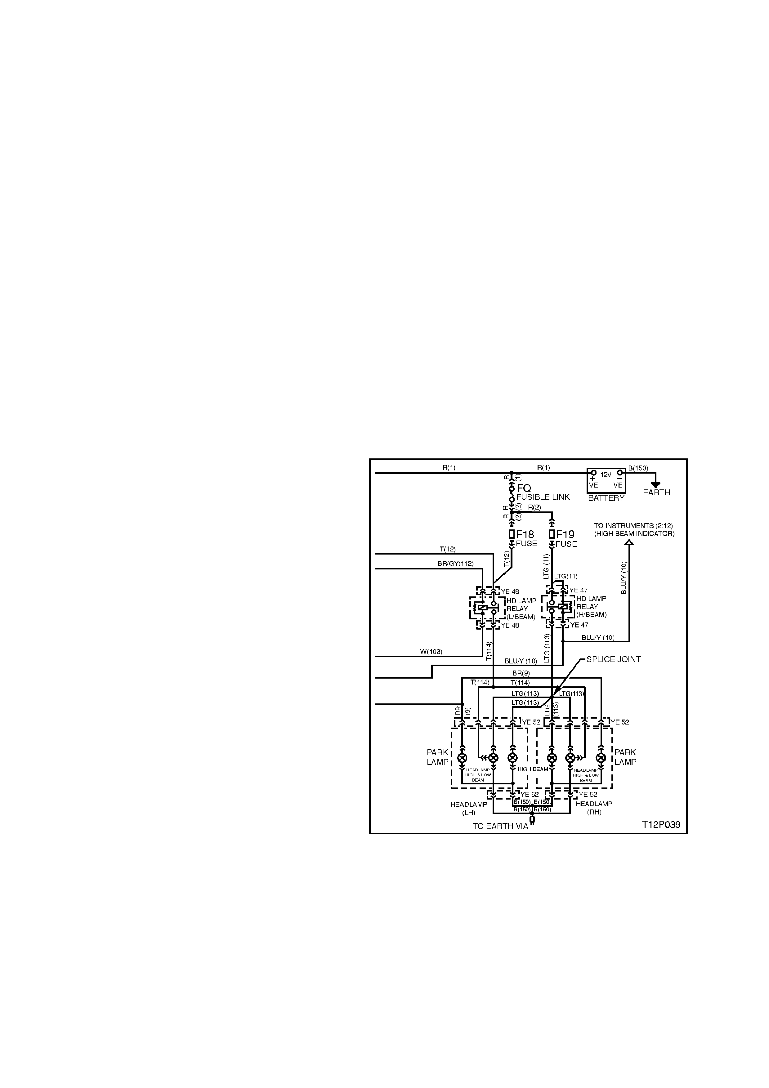
PROBLEM EXAMPLE
STEP 1. Identify the Problem
A customer brings in a vehicle reporting that the
headlamps are not operating correctly.
STEP 2. Specify the Problem
The driver is questioned and it is established that
the LHF headlamp is not operating on high beam,
or when the flash switch is operated.
STEP 3. Investigate the Problem
Perfor m a system check on the headlam p circuit. It
is noted that:
1. Headlamps operate correctly on low beam.
2. On high beam, the headlamp high beam
lamps operate correctly but the left hand
headlamp inboard high beam lamp does not
operate on high beam.
3. W hen the high beam f lash switch is operated,
the LHF headlamp inboard high beam lamp
still does not operate on high beam.
READ THE SYSTEM WIRING DIAGRAM.
This is the step that will save time and labour.
Remember, it is essential to understand how a
system should work, before trying to determine why
it doesn't work.
STEP 4. Develop Possible Causes
Once the circuit is understood, read the diagram
again, this time keeping in mind what you have
learned by operating the circuit. It is recomm ended
to read the System Wiring Diagram from the
battery positive terminal or fuse (being the source
of electrical supply) to battery negative terminal.
As both low beam headlamps work , fus ible link F Q,
fuse F18, the headlamp switch, low beam
headlamp relay, the earth circuit, and both low
beam headlamp filaments are OK. Furthermore,
since the RHF inboard high beam lamp works on
high beam and flash, fuse F19, the headlamp and
flash switch and the high beam head lamp relay are
OK.
Since the headlamp high beam is working co rrectly
the lead from the headlamp relay to splice 113A, B
& C must be OK. Therefore the fault must be
between splice 113A, B & C and the LHF headlam p
inboard high beam bulb.
The cause must be:
1. In lead 113, from splice 113A, B & C to
connector YE52.
2. In the lead from connector YE52 to the LHF
headlamp inboard high beam bulb.
3. The LHF headlamp bulb. Figure 12P-1
You have quickly narrowed the possible causes
down to a specific area and done no work on the
vehicle itself.
Read the system wiring diagram again and develop
a set of test points. Start from the positive to the
negative/earth.
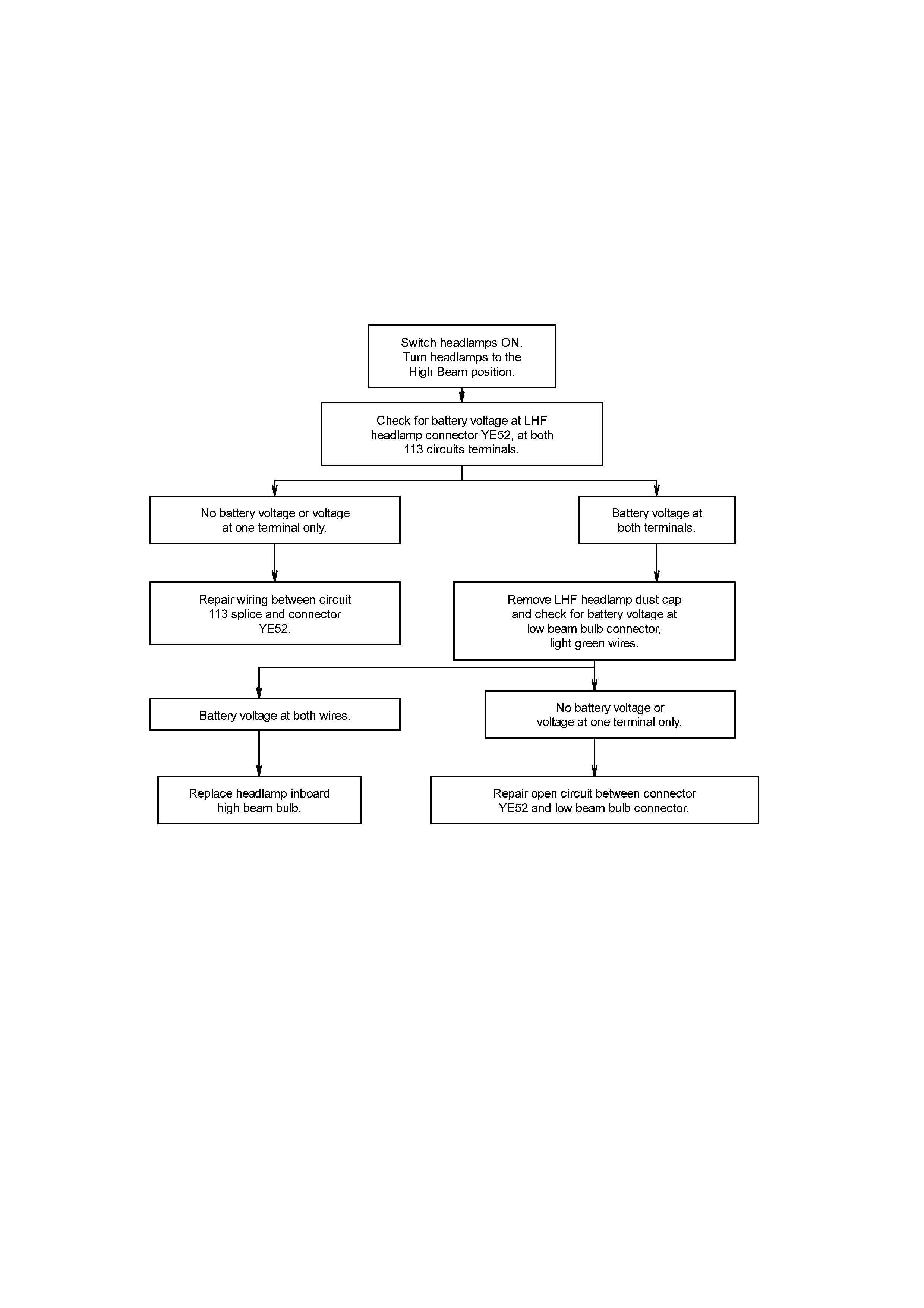
STEP 5. Isolate the Most Possible Cause
The following flow chart is an example of how to
isolate the cause of the problem. Remembering
that you have already determined that the fault is
between splice 113 and the LHF headlamp inboard
high beam bulb and you should check the simple
things first.
STEP 6. Verify
Test the repair by performing a system check on
the headlamp c irc uit. This of c our se m eans making
sure that both high beam lamps, both low beam
lamp s and high beam indicator are all work ing. Ask
yourself:
Has the problem been fixed?
Why did the problem occur/part fail?
Will it happen again?
Have I created any other problems?
CURE THE CAUSE NOT THE EFFECT.
OPERATE THE CIRCUIT AND ROAD TEST THE
VEHICLE BEFORE RETURNING IT TO THE
CUSTOMER.

3. TEST PROCEDURES
3.1 ELECTRICAL FAULT DIAGNOSIS
The proper operation of electrical circuits especially low amperage input/output circuits (electronic components etc)
depend upon good continuity between circuit connectors.
It is important before component replacement and/or during normal trouble shooting procedures that a thorough
visual inspection of all terminals or connectors is performed and any questionable mating connector/terminals be
repaired or replaced.
All mating surfaces should be clean, properly formed, clean and making positive contact.
Some typical causes of connector problems are:
1. Improperly formed contacts and/or connector plugs.
2. Damaged contacts or plugs due to improper engagement.
3. Corrosion, body sealer or other contaminants on the contact mating surfaces.
4. Incomplete mating of the connector halves during initial assembly or during subsequent trouble shooting or
repairs.
5. Tendency for connectors to come apart due to vibration and/or temperature cycling.
6. Terminal not fully seated in connector body (terminal backed out).
7. Inadequate terminal crimps to the wire or poor solder joint.
NOTE:
When inserting test probes during diagnosis always try to test from the back of the terminal and avoid spreading
terminals which may cause poor continuity.
IMPORTANT:
DO NOT BACKPROBE 'WEATHER PACK' TYPE CONNECTORS AS DAMAGE TO THE CABLE SEALS WILL
RESULT.
When carrying out wiring checks, rather than probe terminals and connectors with incorrect sized multimeter or test
lead connectors, use adaptors included in kit J35616-A or KM-609. This is will prevent any possibility of spreading
or damaging wiring harness terminals.
POSSIBLE ELECTRICAL MALFUNCTIONS
There are five possible electrical malfunctions, as follows:
1. Loss of battery power (loose connections/corrosion).
2. Defective device.
3. High resistance (dirty, loose or corroded connections).
4. Open circuit.
5. Earthed or short circuit.
Electrical circuits should be tested at:
1. Easily disconnected connections.
2. Easy to reach access points.

CIRCUIT FAULTS
The various failures that occur in a circuit will dictate what must be done to repair the problem. These failures can
be categorised as follows:
Open
An open circuit is a physical break in the path of current flow. In a series circuit, the circuit stops operating. In
parallel circuits, an open in one individual circuit will stop the operation of that particular circuit, but other individual
parallel circuits will continue to operate. The ohmmeter is useful in finding an open circuit with continuity checks.
Short to Earth
A short to earth is where the circuit is earthed due to an insulation breakage. The conductor touches earth, causing
a fuse or fusible link to blow. If there is no fuse, the circuit may burn, and even cause flames. If the short occurs
after the load, circuit control may be lost causing the circuit to operate when it is not wanted. The test light is a good
device in this case. Insert the test light in place of the fuse. Disconnect circuit components in a systematic and
logical manner. When the test light goes out, the part of the circuit with the short to earth will be found.
Short to Volta ge
The short to voltage is a condition where a circuit, due to insulation breakage, causes the conductor to contact the
voltage of another circuit. This will cause the circuit (or both circuits) to operate improperly. This problem can cause
odd things to occur and can be difficult to find. To locate this type of problem, a thorough examination, using the
diagnostic procedure described at the beginning of this Section, must be performed. Observe the symptoms to
recognise associated circuits involved. Isolation by removing fuses will help isolate the circuit branches involved.
Then voltage and resistance checks at strategic locations will isolate the problem.
High Resistance Problems
A high resistance problem is often hardest to find. This is a condition where it is important to use test meters. High
resistance can be caused by loose, dirty or corroded connectors. Current flow will be lowered, which can cause
incorrect circuit operation or inoperative components.
3.2 TROUBLESHOOTING TEST EQUIPMENT
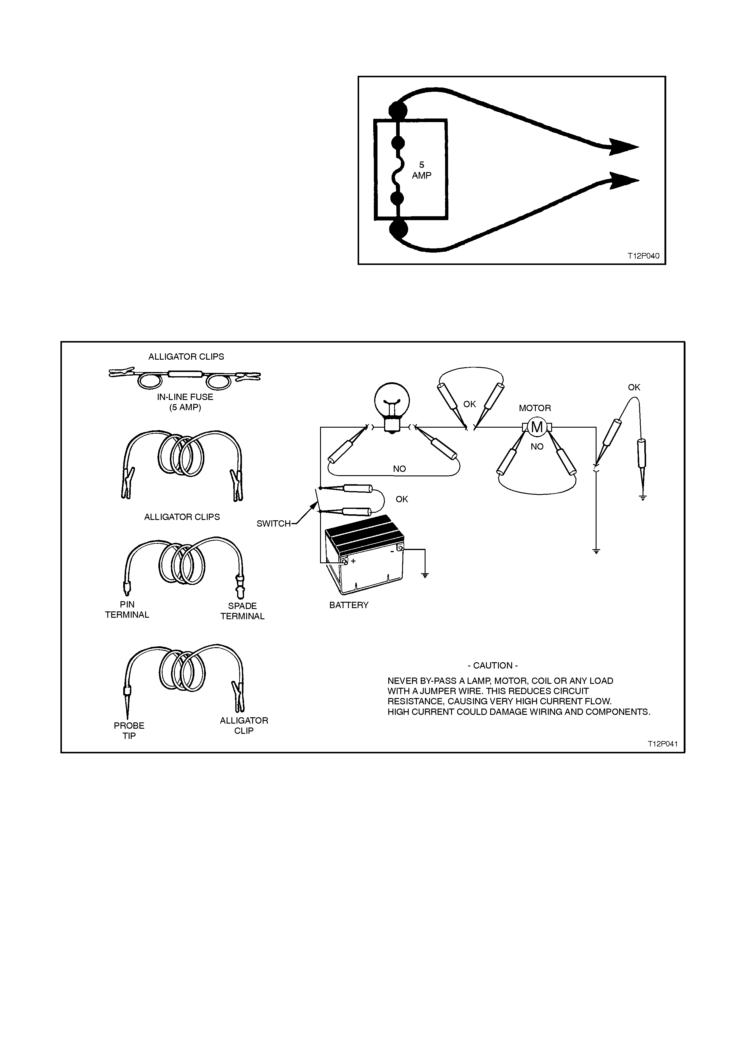
JUMPER WIRE
A jum per wire is an in-line fus e holder connec ted to
a set of test leads. It should have a five-amp fuse.
Use it for by-passing open circuits. Never use a
jumper wire across any load. This will cause a
direct battery short and blow the fuse. When
properly used, jumper wires are simple, effective
testing aids. They are used to c omplete a circ uit by
allowing current to 'jump' across a suspected open
or break, and so act as a test of continuity .
When a jumper wire is used, it replaces a
suspected faulty portion of a circuit with a known
good conductor. If the circuit works properly when
the jum per wire is in plac e, but does not without the
jum per wire, an open circuit is indicated in the area
that has been jumped. You should use a jumper
wire to by-pass only non-resistive parts of a circuit,
such as switches, connectors and sections of
wiring.
Figure 12P-2
Figure 12P-3
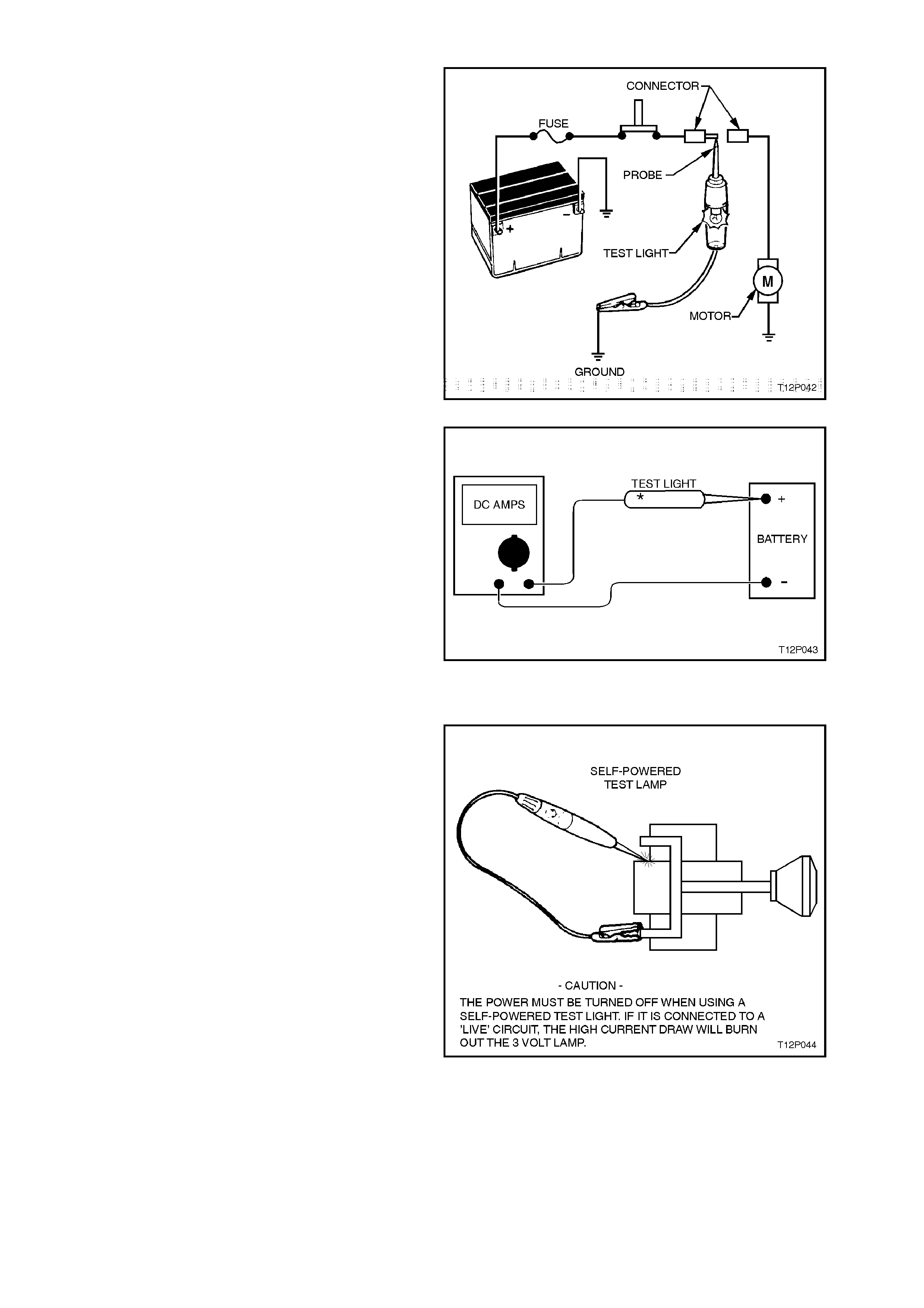
TEST LIGHT
A test light can be used to test for voltage. A test
light is m ade up of a 12 volt light bulb with a pair of
leads attached. After earthing one lead, touch the
other lead to various points along the circuit where
voltage should be present. When the bulb
illuminates, there is voltage present at the point
being tested.
CAUTION:
Never use a low-impedance test light on
circuits that contain solid-state components,
since damage to these components may result.
Figure 12P-4
W hen a test light is specif ied, a LOW -POWER test
light must be used. Do not use a high wattage test
light. While a particular brand of test light is not
suggested, a simple test on any test light will
ensure it's suitability for circuit testing. Connect an
accurate ammeter (such as the high-impedance
digital multimeter) in series with the test light being
tested, and power the test light - ammeter circuit
with the vehicle battery. If the ammeter indicates
less than 0.3 A (300 m A) current f low, the test light
is OK to use. If more than 0.3 A (300 mA), DO NOT
USE.
Figure 12P-5
SELF-POWERED TEST LIGHT
A self-powered test light is used to check for
continuity. This tool is made up of a 3 V light bulb,
battery and two leads. If the leads are touched
together, the bulb will illuminate.
A self-powered test light is used only on an
unpowered circuit. First, disconnect the vehicle's
battery, or remove the fuse which feeds the circuit
being worked on. Select two specific points along
the circuit thr ough which there s hould be continuity.
Connect one lead of the self-powered test light to
each point. If there is continuity, the test light's
circuit will be completed and the bulb will illuminate.
An increasing number of circuits include solid state
control modules. Voltages in these circuits should
be tested ONLY with a 10 Megohm or higher
impedance digital voltmeter or multimeter.
CAUTION:
Never use a self-powered test light on circuits
that contain solid-state components, since
damage to these components may result. Figure 12P-6

MULTIMETERS
Analogue versus Digital Meters
Digital multimeters (DMM) outperform most types of analogue meters for a variety of reasons. Digital multimeters
are more accurate. The internal circuitry is not the only factor affecting analogue meter accuracy. The pointer can
appear to be in different positions when the gauge is viewed from different angles. Digital displays leave no such
doubt about there reading.
The DMM shows a '+' symbol in front of the reading when the positive meter lead is connected to a positive power
source and the negative lead is connected to earth. If the DMM leads are reversed, a '-' symbol appears in front of
the reading to indicate reverse polarity.
A DMM, has an electronic digital readout of the value of the measurement being made. This type of meter has
electronic circuitry for precise measurements. It can be accurate within 0.1 percent, much more accurate than
analogue meters. The DMM is becoming the preferred choice for electrical diagnosis and testing, especially for
testing electronic systems.
The impedance of an analogue meter is less than 10 Megohm. A meter with less than 10 Megohm impedance must
not be used on circuits that contain solid state circuits, the low impedance of the meter could cause incorrect
readings and allow too much current to flow through the circuit being tested, which could damage sensitive
electronic components.
A DMM with at least 10 Megohm input impedance is needed for use on Holden vehicles. This input impedance
applies to the meter only when it is used on the voltage scale. This means that the meter resists loading down the
circuit being measured with a resistance of 10 million ohms. In other words, on automotive circuits, this high
resistance permits measurement of very sensitive circuits without damaging or altering them.
NOTE:
Impedance is the resistance to current flow through the meter, from one lead to the other lead. High input
impedance provides greater sensitivity, and prevents the meter from affecting the circuit being tested. Resistance is
measured in ohms. Impedance and resistance both mean 'opposition to current flow'.
VOLTAGE MEASUREMENT WITH A DMM
With the Volts DC mode selected, the DMM will operate as a voltmeter.
When using a voltmeter, the circuit power must be ON and the voltmeter MUST be connected with the correct
polarity. This means the red lead should be on the positive (+) side of the load or circuit and the black lead should
be on the negative (-) side of the load or circuit.
The voltmeter MUST be connected in parallel with the load or circuit. It has a high internal resistance and taps off a
small amount of current. The meter will display the voltage difference between the points where the meter leads are
attached. If the voltmeter is connected in series, the meter's high internal resistance will reduce the circuit current,
resulting in an incorrect reading.
Testing for correct supply voltage is usually the first thing measured in a circuit. If there is no voltage present, or if
the supply voltage is too high or too low, the voltage problem should be corrected before further testing.
NOTE:
Voltage readings should always be taken in parallel, i.e. across the load.
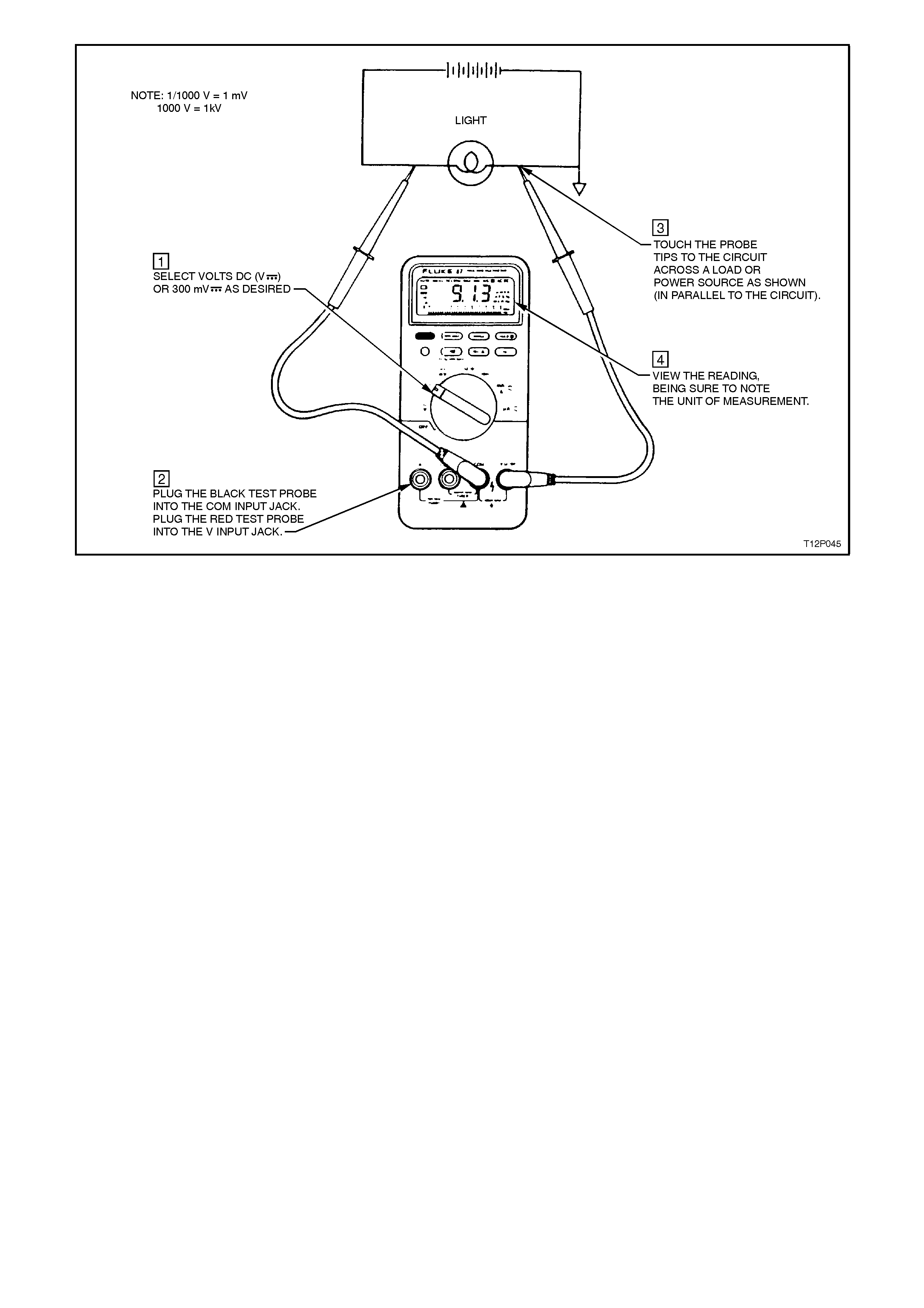
Figure 12P-7
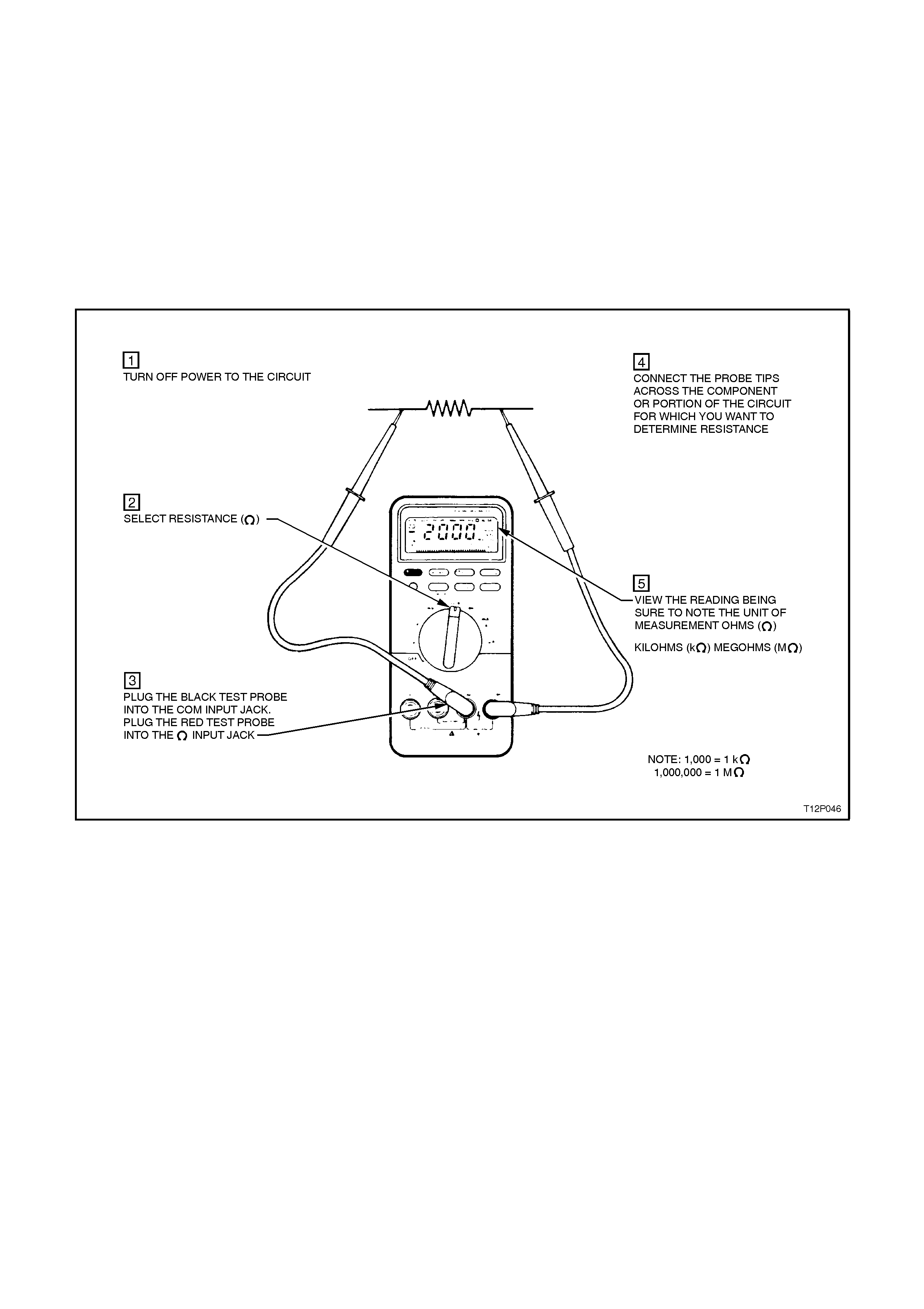
RESISTANCE TESTING WITH A DMM
With the resistance mode selected, the DMM will operate as an ohmmeter.
The ohmmeter can be connected without regard to polarity, unless there is a diode in the circuit. Always remember,
however, that an ohmmeter must NEVER be connected to a live circuit, which could blow a fuse in the meter or
damage the meter.
The ohmmeter has its own battery, which provides the necessary voltage for testing. If an ohmmeter is connected
into a 'live' circuit the ohmmeter will be damaged. Components or circuits MUST BE DISCONNECTED FROM THE
POWER SOURCE when being tested.
Resistance Test
Resistance measurements must be made with the circuit power OFF, otherwise damage to the meter or the circuit
may result.
If the DMM supplies less than 0.3 V DC test voltage for measuring resistance, it will be able to measure the values
of resistors that are isolated in a circuit by diodes or semiconductor junctions. This often allows you to test resistors
on a circuit board without unsoldering them.
Continuity Test
Continuity is a quick go/no-go test that distinguishes between an open and a closed circuit.
A DMM with a continuity beeper allows you to complete many continuity tests easily and quickly. The meter will
beep when it detects a closed circuit, so you don't have to look at the meter as you test. The level of resistance
required to trigger the beeper varies from model to model of DMM.
Continuity tests determine:
1. Good or blown fuses.
2. Open or shorted conductors.
3. Operation of switches.
4. Circuit paths.
NOTE:
Circuits which include any solid state control modules, such as the Powertrain Control Module (PCM), should be
tested only with a 10 Megohm or higher impedance digital multimeter.
Diodes and solid state components in a circuit can cause an ohmmeter to give a false reading. To find out if a
component is affecting a measurement, take a reading once, reverse the leads and take a second reading. If the
readings differ, the solid state component is affecting the measurement.
Diode Test
A diode is like an electronic switch. It can be turned ON if the voltage is above a certain level, generally about 0.6 V
for a silicon diode, and allows current to flow in one direction.
Some meters have a special mode called diode test. In this mode the readings across the diode should be 0.6 V to
0.7 V in one direction and indicate an open circuit in the other. This indicates a good diode. If both readings are
open circuit, the diode is open. If both readings indicate continuity, the diode is shorted.
Figure 12P-8
CURRENT MEASUREMENT WITH A DMM
With the AMPS DC mode selected, the DMM will operate as an ammeter.
An ammeter is an instrument which measures current flow in a circuit. For this reason ammeters MUST be
connected in series. The ammeter must also be connected into the circuit according to polarity.
Current measurements are different from other measurements made with a DMM. Current measurements are
made in series, unlike voltage or resistance measurements, which are made in parallel. The entire current being
measured flows through the meter. Also, the tests probes must be plugged into a different set of input jacks on the
meter.
CAUTION:
A common mistake is to leave the test leads plugged into the current input jacks and then attempt a voltage
measurement. This causes a direct short across the source voltage through the low-value resistor inside
the DMM and if the meter is not adequately protected, can cause extreme damage to the meter and to the
circuit, and injury to the operator.
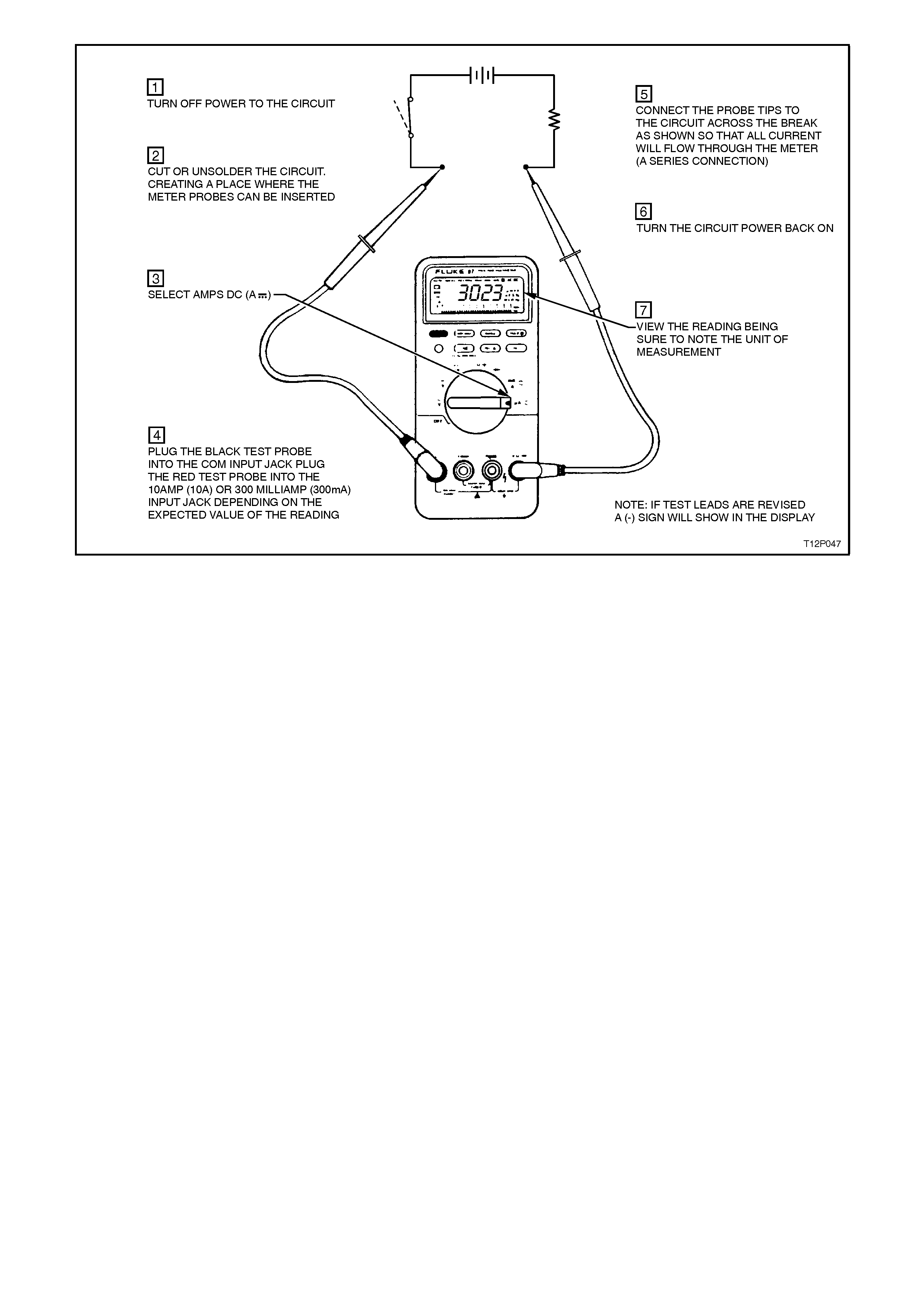
Figure 12P-9
4. DIAGNOSTIC TESTS
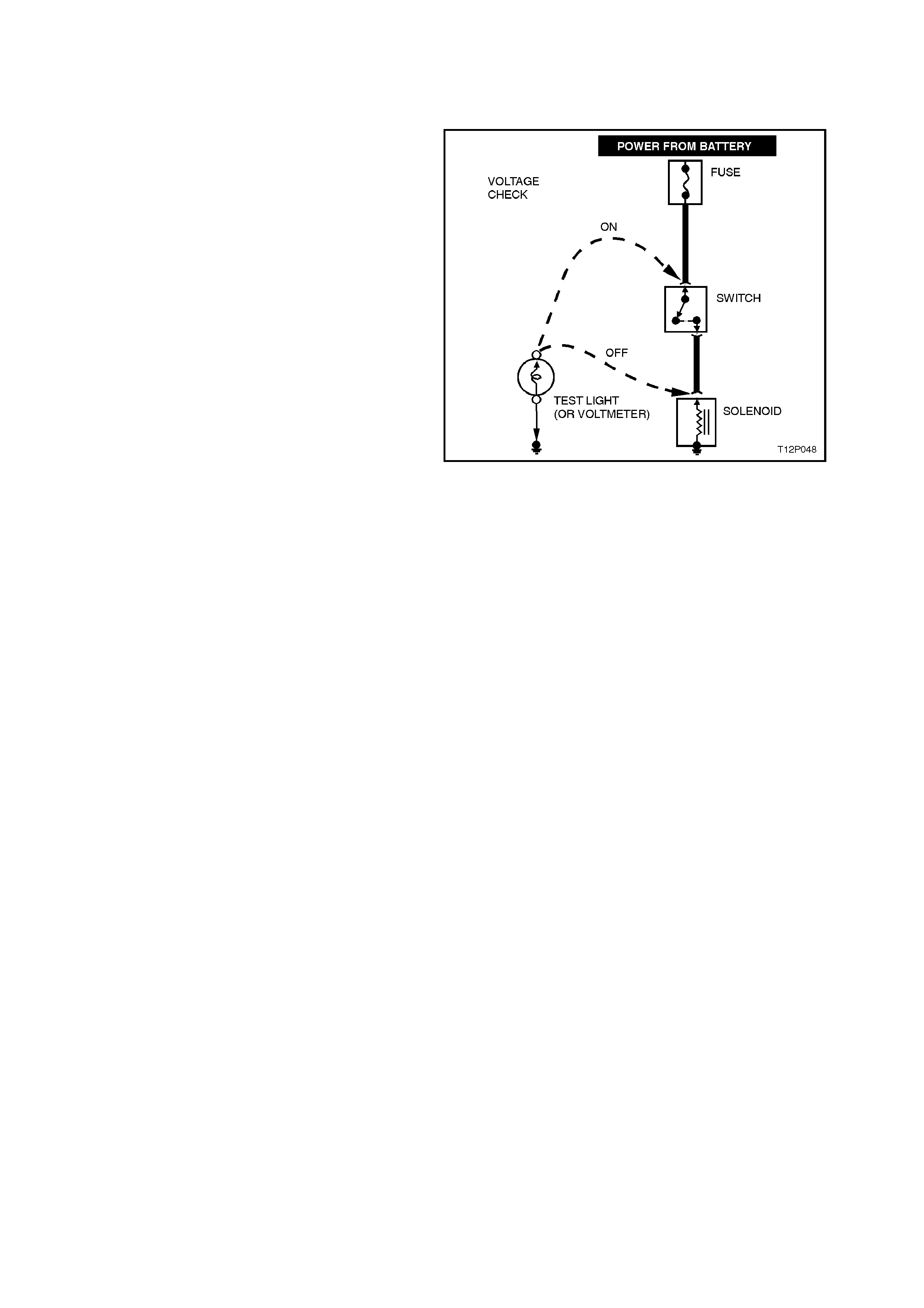
4.1 TESTING FOR VOLTAGE
1. Connect one lead of a test light to a good
earth. If using a voltmeter, ensure the
voltmeter 's negative lead is connected to earth
(battery negative).
2. Connect the other lead of the test light or
voltmeter to a selected test point ( connector or
terminal).
3. If the test light illuminates, there is voltage
present. If you are using a voltmeter, note the
voltage reading. It should be within one volt of
measured battery voltage, unless specified in
the system diagnosis, e.g. ENGINE
MANAGEMENT SYSTEM or CRUISE
CONTROL.
Figure 12P-10
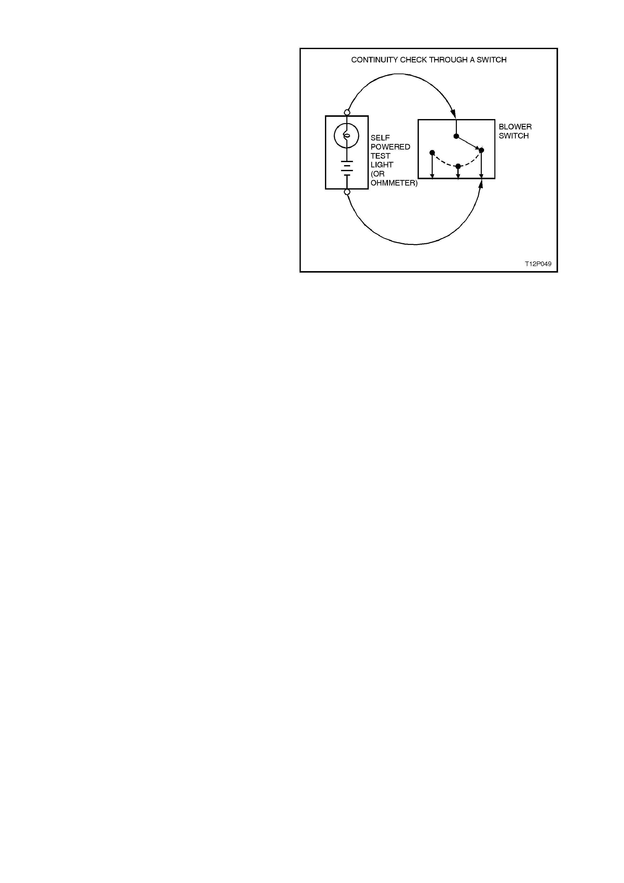
4.2 TESTING FOR CONTINUITY
1. Disconnect battery earth lead.
2. Connect one lead of a self-powered test light
or ohmmeter to one end of the part of the
circuit under test.
3. Connect the other lead to the other end of the
circuit.
4. If the self-powered test light illuminates, there
is continuity. If you are using an ohmmeter,
low or no resistance means good continuity.
Figure 12P-11
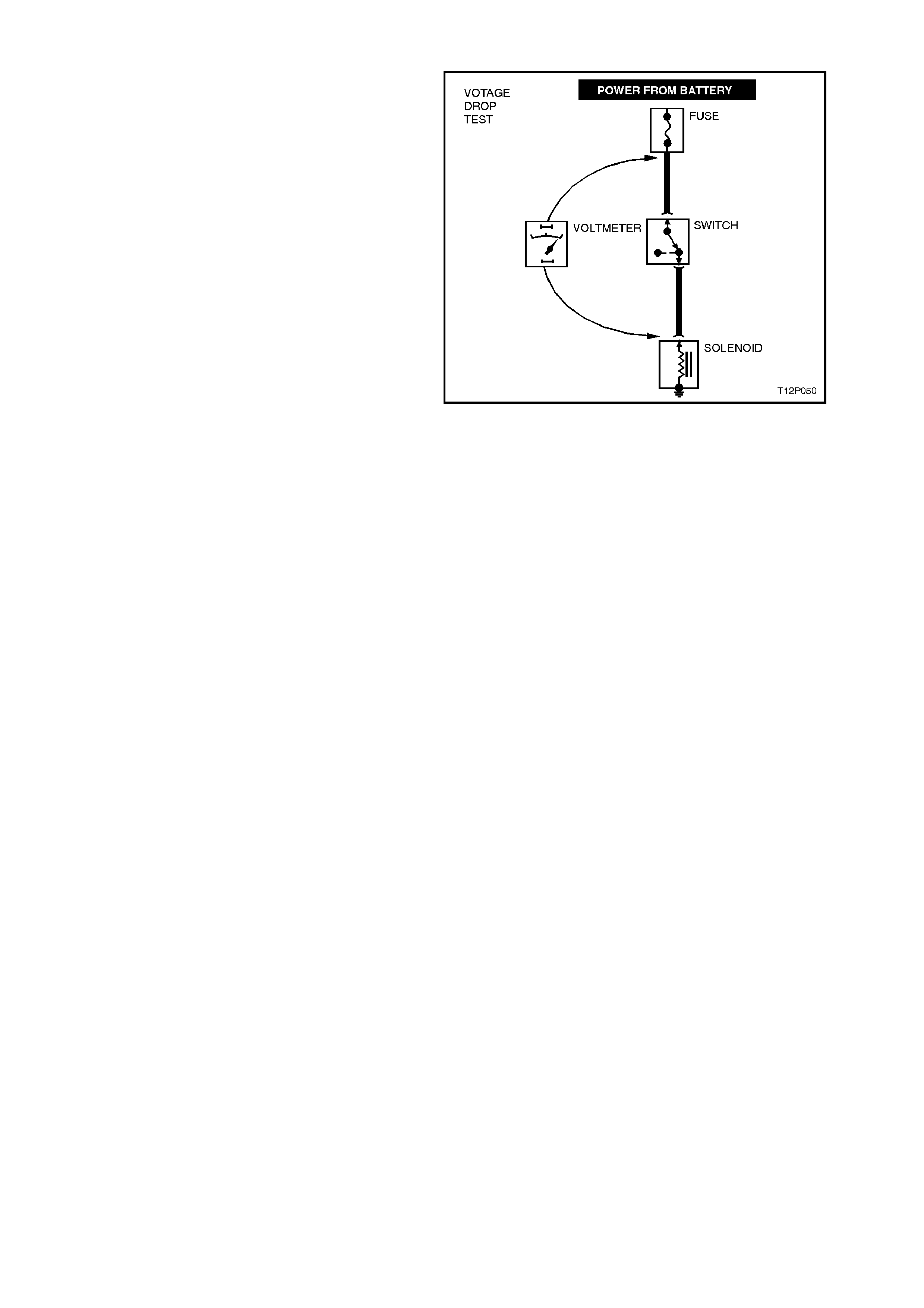
4.3 TESTING FOR VOLTAGE DROP
This test checks for voltage being lost along a wire
or through a connection or switch.
1. Connect the positive lead of a voltmeter to the
end of the wire (or to one side of the
connection or switch) which is closest to the
battery.
2. Connect the negative lead to the other end of
the wire (or other side of the connection or
switch).
3. Operate the circuit.
4. The voltmeter will show the difference in
voltage between the two points. A difference
(or drop) of more than one volt indicates a
problem.
Figure 12P-12
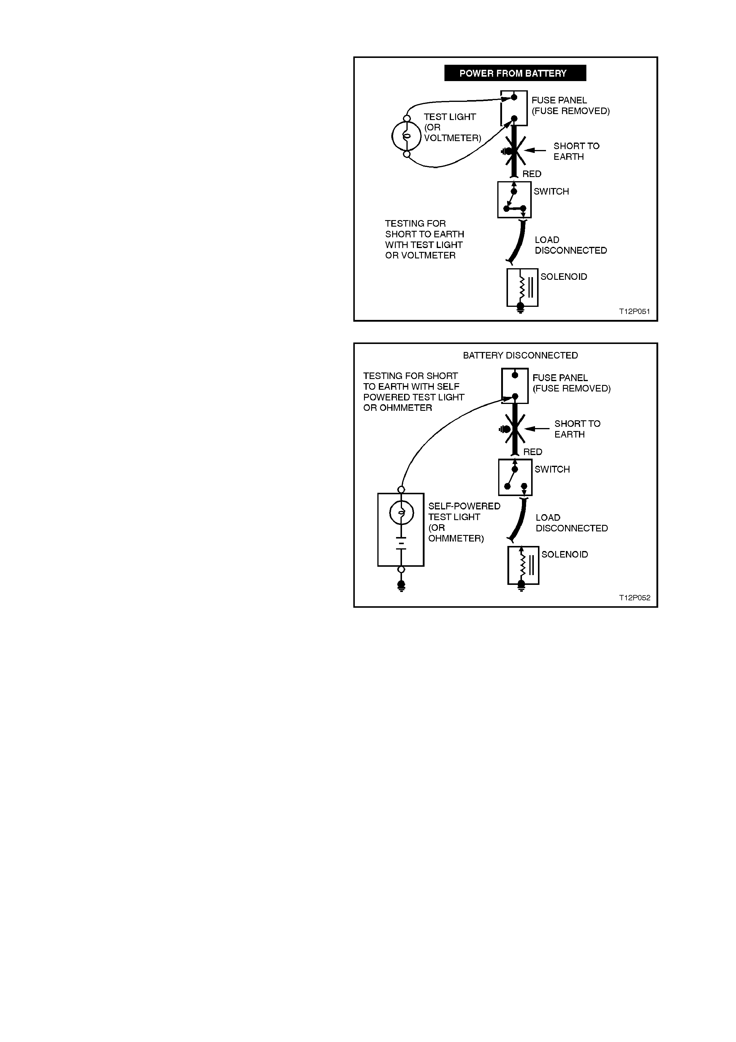
4.4 TESTING FOR SHORT TO EARTH
WITH A TEST LIGHT OR VOLTMETE R
1. Remove the blown fuse and disconnect the
load.
2. Connect a test light or voltmeter across the
fuse terminals (ensure that fuse block is
powered).
3. Beginning near the fuse block, wiggle the
harness from side to side. Continue this at
convenient points (about 150 mm apart) while
watching the test light or voltmeter.
4. If the test light illuminates, or the voltmeter
registers , there is a short to earth in the wiring
near that point.
Figure 12P-13
WITH A SELF-POWERED TEST LIGHT OR
OHMMETER
1. Remove the blown fuse and disconnect the
battery and load.
2. Connect one lead of a self-powered test light
or ohmmeter to the fuse terminal on the load
side.
3. Connect the other lead to a known good earth.
4. Beginning near the fuse block, wiggle the
harness from side to side. Continue this at
convenient points (about 150 mm apart) while
watching the self-powered test light or
ohmmeter.
5. If the self-powered test light illuminates or
flickers, or the ohmmeter changes or registers,
there is a short to earth in the wiring near that
point. Figure 12P-14

WITH A SHORT FINDER
A short finder is a device used for locating hidden shorts. These create a magnetic field in the shorted circuit and
allow you to read its location through body trim or sheet metal.
COMPASS
An ordinary magnetic compass is a valuable tool for use in locating earthed circuits. It makes use of the fact that a
wire carrying current creates a magnetic field. In circuits that are protected by a circuit breaker, a short or earth can
be quickly located by use of an ordinary magnetic compass. Turn on the circuit and start following the wiring with the
compass, the compass will 'kick' each time the circuit breaker closes. As the compass passes the point of the short
or earth, the compass will stop 'kicking'. Thus, the compass can pinpoint the problem without removing trim, cover
plates or tape. If the circuit is fused, the problem can be found in the same manner by substituting a circuit breaker
for the fuse.
CIRCUIT BREAKER
By using a circuit breaker as a substitute for a fuse, other tools can be more effectively used to find troubles. A turn
signal flasher makes a convenient circuit breaker. Solder a lead to each of the terminals of the turn signal flasher,
and each lead with a terminal from an old fuse. If this unit is inserted in the junction block in place of a fuse, it may
operate too fast to produce good compass needle deflection. To slow it down, insert a rheostat in series with the
flasher. By cutting in additional resistance, the flashing rate of the unit may be slowed down to produce good
compass needle deflection.
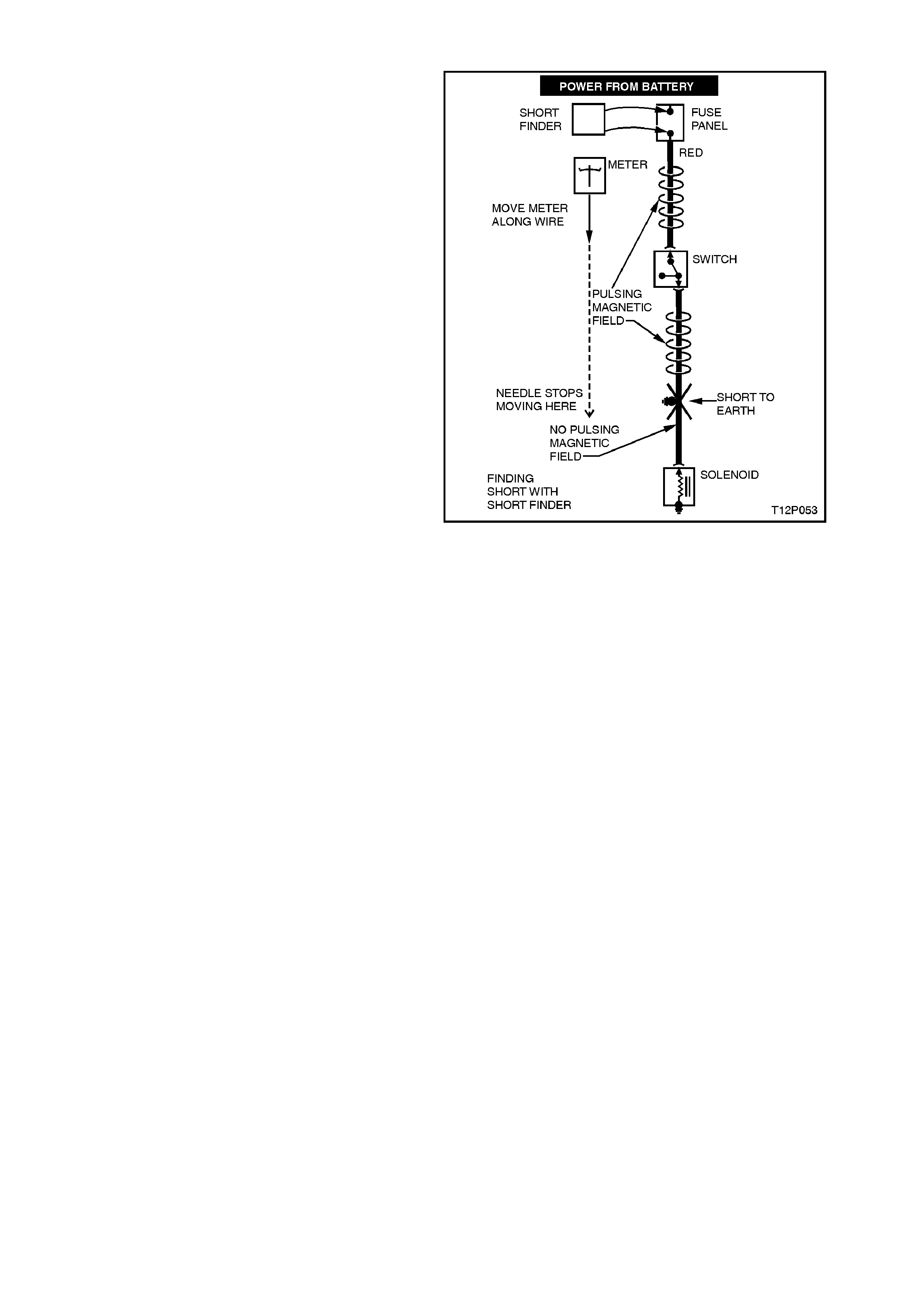
4.5 USING A SHORT FINDER
1. Remove the blown fuse, leaving the battery
connected.
2. Connect the short finder across the fuse
terminals.
3. Close all switches in series with the circuit you
are troubleshooting.
4. Operate the short finder. The short finder will
pulse current to the short. This creates a
pulsing magnetic field surrounding the circuit
wiring between the fuse block and the short.
5. Beginning at the fuse block, slowly move the
short finder meter along the circuit wiring. The
meter will show current pulses through sheet
metal and body trim. As long as the meter is
between the fuse block and the short, the
needle will move with each current pulse.
When you have moved the meter past the
point of the short, the needle will stop moving.
Exam ine the wiring in that area for the shor t to
earth.
NOTE:
Short finders are particularly useful for 'hidden'
shorts as the meter will read the short location
through body trim or sheet metal.
CAUTION:
Never use a short finder on circuits that contain
solid-state components, since damage to these
components may result.
Figure 12P-15
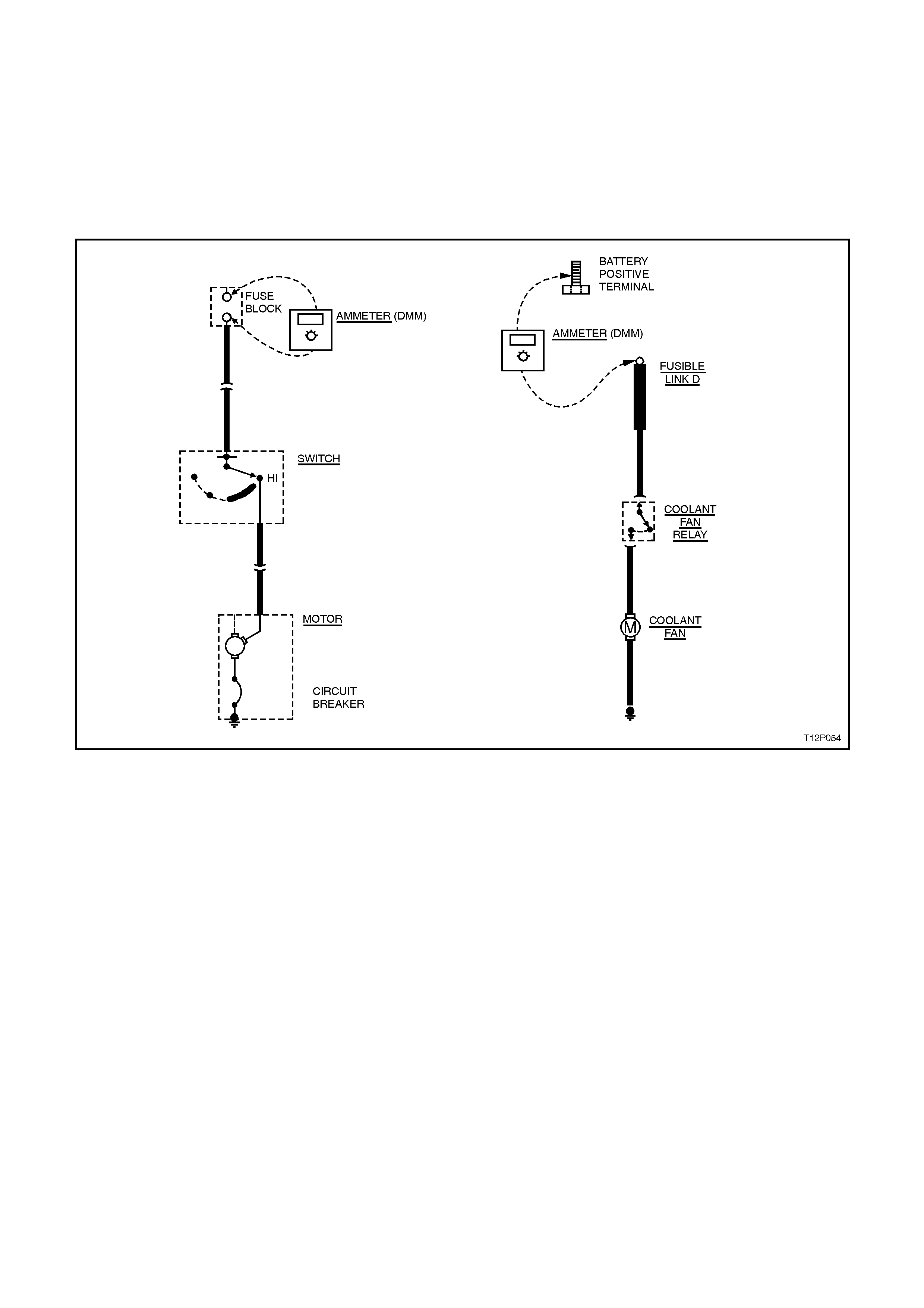
4.6 MEASURING CURRENT
To measure the current flowing in a circuit, the ammeter MUST be connected in series in the circuit. Current
measurements always involves a component being removed or disconnected from the circuit. The circuit current
flows through the meter, which displays the current in amps or milliamps.
Two commonly used locations for taking current measurements are at a fuse and at the battery.
CAUTION:
Never use a meter set on a current scale to measure voltage. Severe damage to the meter, the circuit, or
both will result.
Figure 12P-16

4.7 DIGITAL MULTIMETER
One of the most useful tools for today's vehicles is the multimeter. The multimeter is the combination of all of the
previously mentioned meters.
Here are some basic operating procedures for a multimeter. Obviously they vary from each manufacturer. The
manufacturer's operating instructions should be read and understood before you use the multimeter.
USE OF A MULTIMETER
1. Always turn meter 'off' when not in use.
2. Ensure meter reads zero on meter face.
3. If applicable, touch leads together then adjust resistance to zero each time a resistance range is selected or
changed.
4. If you are not sure of the reading you expect to get, always select the highest scale, then reduce to allow an
effective reading.
5. When measuring current draw, ensure the meter can handle the load and that the test leads are in the correct
jacks.
6. Treat the instrument with the respect it deserves.
And Remember! !!
A. Voltage readings are in parallel (i.e. over the load).
B. Current readings are in series (i.e. break the circuit and use meter leads to complete the open circuit).
C. Resistance: Disconnect all external power supply, this includes the discharging of capacitors in electronic
components.
SELECTION OF MULTIMETERS
The type of multimeter probably best suited is one that has internal protection (fused) so that it cannot be damaged
if, for example, voltage is put through when the meter is set on ohms. The fuse protects the meter and is the only
thing that has to be replaced.
One that you can use to carry out diode checks and also provide you with an audible signal.
An audible signal when carrying out continuity checks is also very beneficial when working under dashboards.
One that has a touch hold facility so when a reading is taken that reading will remain on the display after the leads
are removed.
A multimeter today also has to have a high impedance factor. The common analogue type multimeter may be
inadequate and may actually damage sensitive electronic circuitry. Analogue meters, due to their low internal
resistance (input impedance), draw too much power from the device they are testing for use on computers. Not only
that, but many analogue meters use 9 volts to power the resistance test; enough to destroy sensitive digital
components. Digital multimeters have much higher input impedance than analogue multimeters, generally 10 Meg
(million) ohms. The high impedance means that the meter will draw very little power from the device under test.
Aside from providing a more accurate measurement, this type of meter will not damage delicate electronic
components.
The multimeter used should also be able to test temperature, high amperages and so on. This would allow the one
tool to do a vast amount of work in the area of diagnosis.
Auto diagnosis is the art of the mechanical trade. To be able to fault find, rectify the fault and have the vehicle back
to the owner/operator with minimum delay is what leads to repeat business for the workshop. To do this you must
be able to refer to available literature, apply basic theories and use the correct test equipment.

4.8 DETECTING ELECTRICAL INTERMITTENTS
DIAGNOSTIC PROCEDURE
The following procedure can be used to detect intermittent terminal contact or a broken wire with an intermittent
connection inside its insulation.
Some digital multimeters, such as Tool No. J39200, have the ability to monitor current, resistance or voltage while
recording the minimum (MIN) and maximum (MAX) values measured.
When diagnosing circuits that have voltage applied, use the voltage setting to monitor a connector (or part of a
circuit) which is suspected of having an intermittent connection, but at the time is operating normally.
1. Connect the digital multimeter to both sides of a suspect connector (still connected) or from one end of a
suspect circuit to the other. This will continuously monitor the terminal contacts or length of wire being checked.
(Refer to following METER CONNECTIONS for examples of the various methods for connecting the meter to
the circuit).
2. Set the meter to read voltage. Since the MIN MAX mode does not use auto ranging, manually select the
voltage range necessary before proceeding.
3. Press the MIN MAX button. The meter should read 100 ms RECORD (100 millisecond record) and emit a 0.25
second beep. The meter is now ready to record and will generate an audible tone for any change in voltage. At
this point, press the PEAK MIN MAX button, which will record any voltage variations that occur for at least 1
millisecond.
4. Try to simulate the condition that is potentially causing an intermittent connection, either by wiggling
connections or wiring, test driving or performing other operations. If an open or resistance is created, a voltage
drop will occur and the meter will emit a tone for as long as the open or resistance exists. Any change in
voltage will cause the meter to emit a tone for no less than 0.25 second. (Listening for a tone while
manipulating wiring is very helpful for narrowing in on an intermittent connection.)
Use the MIN and MAX values when the meter is out of sight or sound range, in noisy areas or for test driving
when it may not be possible to monitor the meter.
To check the MIN and MAX recorded voltages, press MIN MAX button once for MAX and twice for MIN. A
variation between MIN and MAX recorded voltages (unless nearly 0 volts) suggests an intermittent open or
resistance exists and should be repaired as necessary. Refer to 5 WIRING REPAIR PROCEDURES for repair
procedures.
NOTE:
The 100 ms RECORD mode is NOT the amount of time allowed to perform a specific procedure. It is the amount of
time used to record each snapshot of information used for calculating AVG when in the MIN MAX mode.

CHECKING TERMINAL CONTACT
Before replacing a suspect faulty component, it is important to check terminal contact between a connector and the
component, or between in-line mating connectors.
Frequently, a diagnostic chart leads to a step that reads for example ‘Check for poor connection’. Mating terminals
must be inspected to ensure good terminal contact. A poor connection between the male and female terminals at a
connector may be the result of contamination or deformation.
Contamination is caused by the connector bodies being improperly connected, a missing or damaged connector
seal, or damage to the connector itself, exposing the terminals to moisture and dirt. Contamination, usually in the
engine compartment or underbody connectors, leads to terminal corrosion, causing an open circuit or intermittently
open circuit.
Deformation is caused by probing the mating side of a connector terminal without the proper adaptor, improperly
joining the connector bodies or repeatedly separating and reconnecting the connector bodies together. Deformation,
usually to the female terminal contact tang, can result in poor terminal contact, causing an open or intermittently
open circuit.
To check terminal contact:
1. Separate the connector bodies or connector for a component.
2. Inspect the connector bodies or component for contamination. Contamination will result in a white or green
build-up within the connector body or between the terminals, causing high resistance, intermittent contact, or
an open circuit. An engine compartment or underbody connector that shows signs of contamination should
either be replaced if it is serviced (refer to VT Parts information for connectors that are serviced) or replace the
relevant wiring harness.
3. Using an equivalent male terminal, check the retention force of the female terminal in question by inserting and
removing the male terminal to the female terminal in the connector body. Good terminal contact will require a
certain amount of force to separate the terminals.
4. Using a known good condition equivalent female terminal, compare the retention force of this terminal to the
female terminal in question by inserting and removing the male terminal. If the retention force is significantly
different between the two female terminals, replace the female terminal in question.
If a visual (physical) check does not reveal the cause of the problem, the vehicle may be able to be driven with a
DMM connected to the suspected circuit. An abnormal voltage reading when the problem occurs indicates the
problem may be in that circuit.
METER CONNECTIONS
The procedure for detecting intermittents was based on the digital multimeter set to read voltage. Whether using
current, voltage or resistance settings to detect intermittents, it will be necessary to connect the meter into the
circuit.
The following are examples of various methods of connecting the meter into a circuit to be checked.
1. Backprobe both ends of the connector and either hold meter leads in place while manipulating the connector
or, tape leads to the harness for continuous monitoring while performing other operations or while test driving.
IMPORTANT:
DO NOT BACKPROBE 'WEATHER PACK' TYPE CONNECTORS AS DAMAGE TO THE CABLE SEALS WILL
RESULT.
2. Disconnect the harness at both ends of a suspect circuit where it connects either to a component or to other
harnesses.
Use connector test adaptor kit, Tool No. J35616-A or KM-609 to connect meter onto the circuit.
Additional Information
NOTE:
Turn off power to the test circuit before attempting in-circuit resistance measurements to prevent false readings or
damage to the meter. Do not use the meter to measure resistance through a solid state module. Continuity tests
that work well for detecting intermittent shorts to earth can be performed by setting the meter to ohms when
pressing the PEAK MIN MAX button. An audible tone will be heard whenever the meter detects continuity for at
least 1 millisecond.
Quite often the instruction manual accompanying the multimeter is a good source of information and should be read
thoroughly before using the meter as well as kept on hand for reference during new procedures.

5. WIRI NG REPAIR PROCEDURES
5.1 GENERAL INFORMATION
Wiring harness terminals, terminal seals and connector bodies are generally not serviced individually, except for
some specific connector bodies.
Specific terminals, with seals (if fitted) are serviced only as an assembly with a wiring pigtail attached. Refer to VT
Parts Information for listing of serviced terminals and connector bodies.
When conducting wiring harness repairs that involve replacement of damaged terminal/s, remove terminal/s from
connector body (refer instructions in this Section) and splice new terminal/s with wiring pigtail into wiring harness
(refer instructions in this Section).
If a specific wiring harness terminal or connector body is damaged beyond repair, and the terminal or connector
body is not serviced, that particular wiring harness must be replaced.
Specific instructions on how to replace each individual wiring harness are not included in this service information.
Installation details of wiring harnesses are included on the wiring installation diagrams in Section 12N FUSES
AND WIRING HARNESSES.
5.2 PERFORMING WIRING HARNESS REPAIRS
CAUTION:
Special wiring repair procedures have been developed for use on the ABS and SRS
due to the sensitive nature of their circuitry. The procedures in 5.4 ABS AND SRS
WIRING REPAIR are the only recommended and approved ABS and SRS wiring repair
methods. The following wiring repair methods are not to be used on ABS or SRS
wiring.
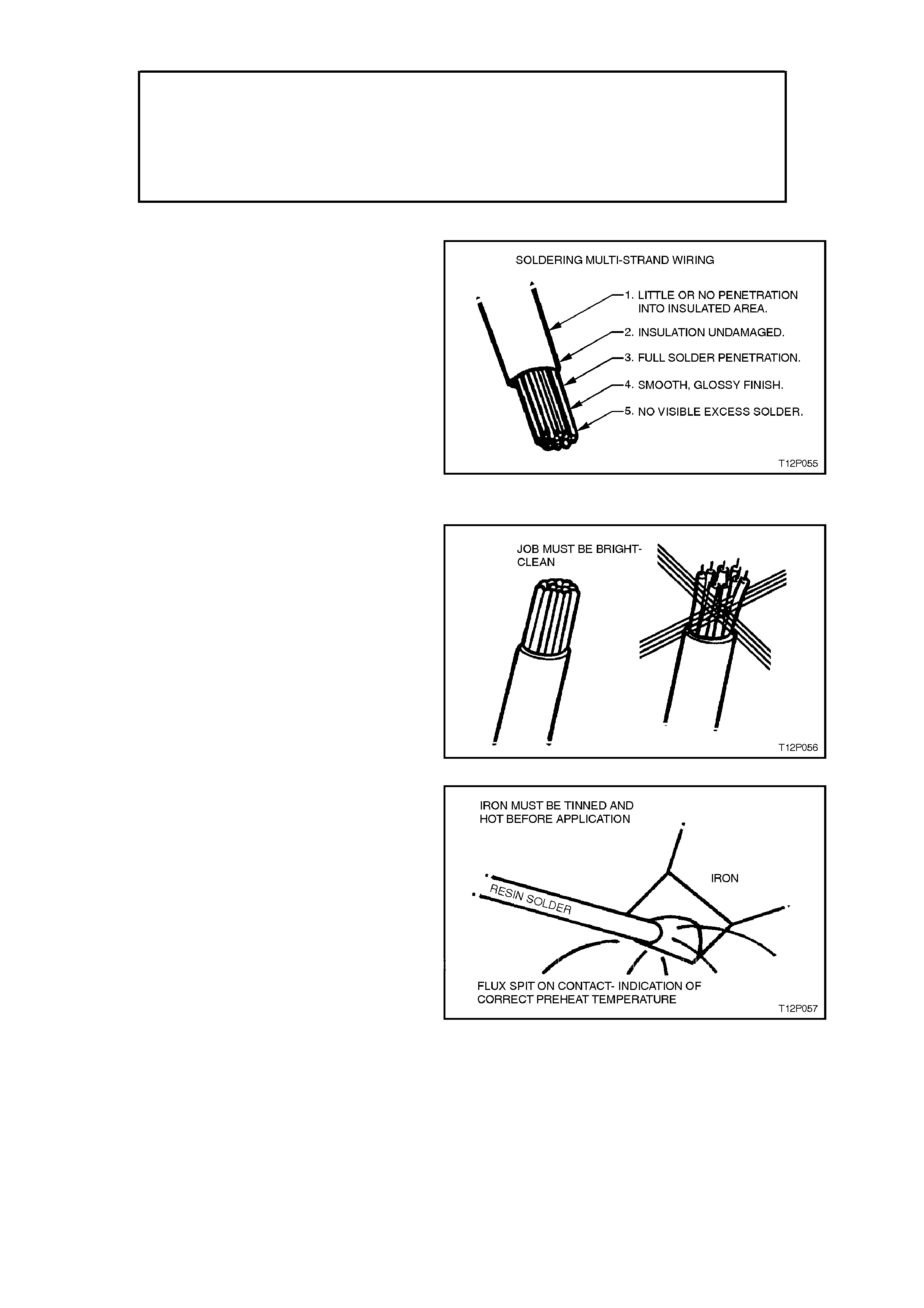
SOLDERING
These are the five points upon which an electrical
soldering joint is judged.
With electrical wiring only resin flux can be used.
Acid flux creates a corr osion problem that m akes it
unsuitable for this work.
Do not clean resin flux off after soldering as the
resin acts as an anti-corrosive to protect the
soldered area.
Figure 12P-17
THE 5 POINTS TO SOLDERING
Step 1. Soldering Preparation
The job m ust be clean and bright. Acid c orroded or
greasy wiring ends should be stripped back.
Keep the job and your hands clean at all times.
Figure 12P-18
Step 2. Iron Preparation
The iron must be tinned and hot BEFORE
application. For best results, preheat the iron to
slightly above solder melting point bef or e applying it
to the job.
This allows for heat loss on job contact.
The comm encement of 'flux spit' is an indication of
correct preheat temperature.
Figure 12P-19
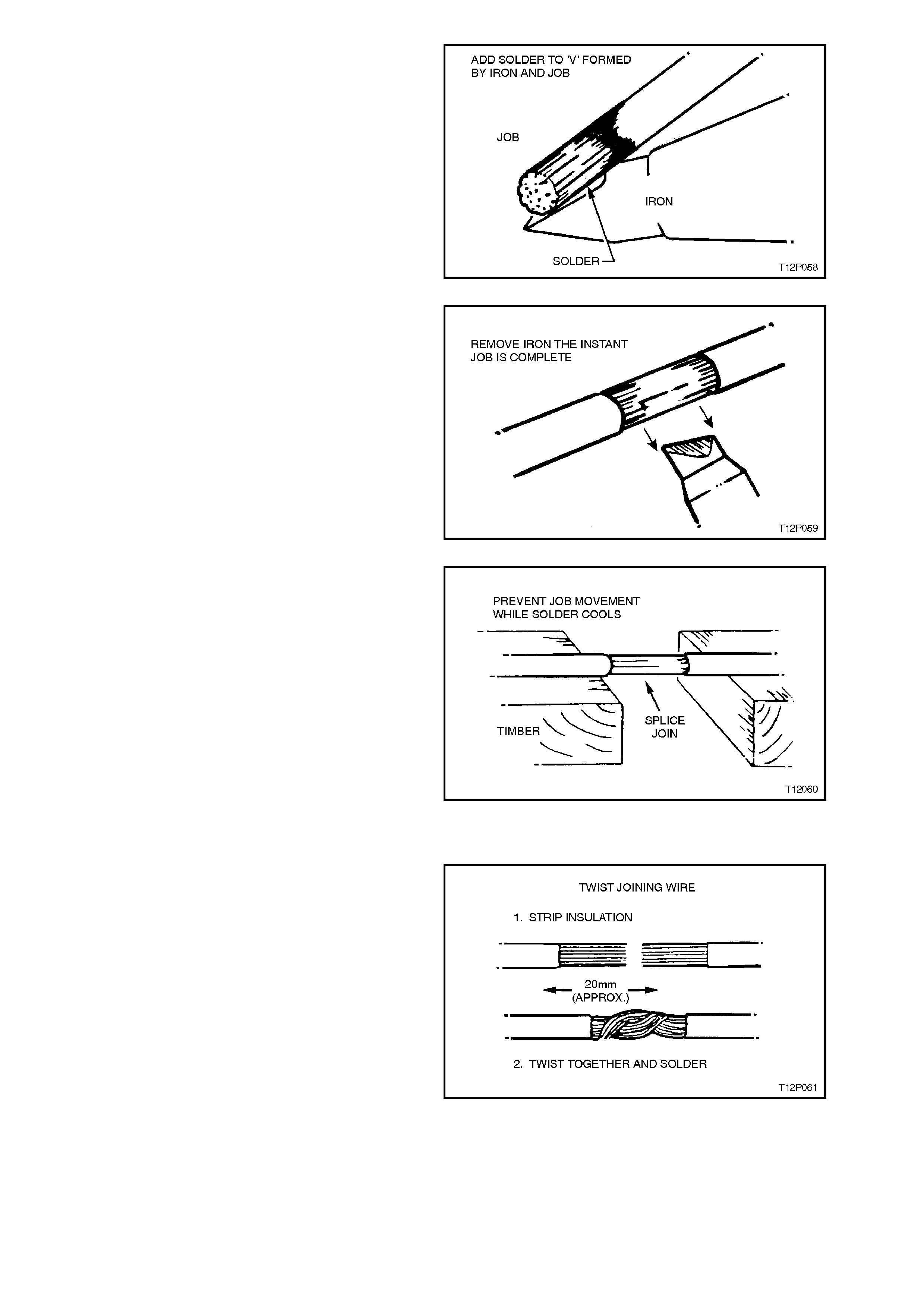
Step 3. Forming a Heat Bridge
Apply the full iron face to the job and immediately
add solder to the 'V' formed by the iron and the job.
The m elting s older speeds up the heat trans fer and
cuts down the job heat time considerably.
This is known as 'forming a heat bridge'.
Figure 12P-20
Step 4. Iron Removal
Remove the iron the instant the job is complete.
This is important to prevent the solder traveling
outside the intended deposit area.
Figure 12P-21
Step 5. Prevent Job Movement
Prevent job movement until the solder cools.
A soldering job can be weakened at this point if the
two components being joined, move in relation to
each other just as the liquid solder changes to a
solid state.
Having a 'second go' is undesirable as prolonged
heating is necessary to remelt the solder.
Arrange suppor t bef ore you start and use it until the
solder cools.
Figure 12P-22
JOINING WIRE
Twist Joint
The twist joint is simple and strong. Firstly strip 20
mm of insulation from each wire. Twist the strands
to compact them before twist joining them together
as shown. Complete the join by soldering. To
prevent a short or earthed circuit, remove all the
'spikes' from the join before insulating. Spikes can
be formed by wire strands or solder itself. These
can cut through the insulation.
Figure 12P-23
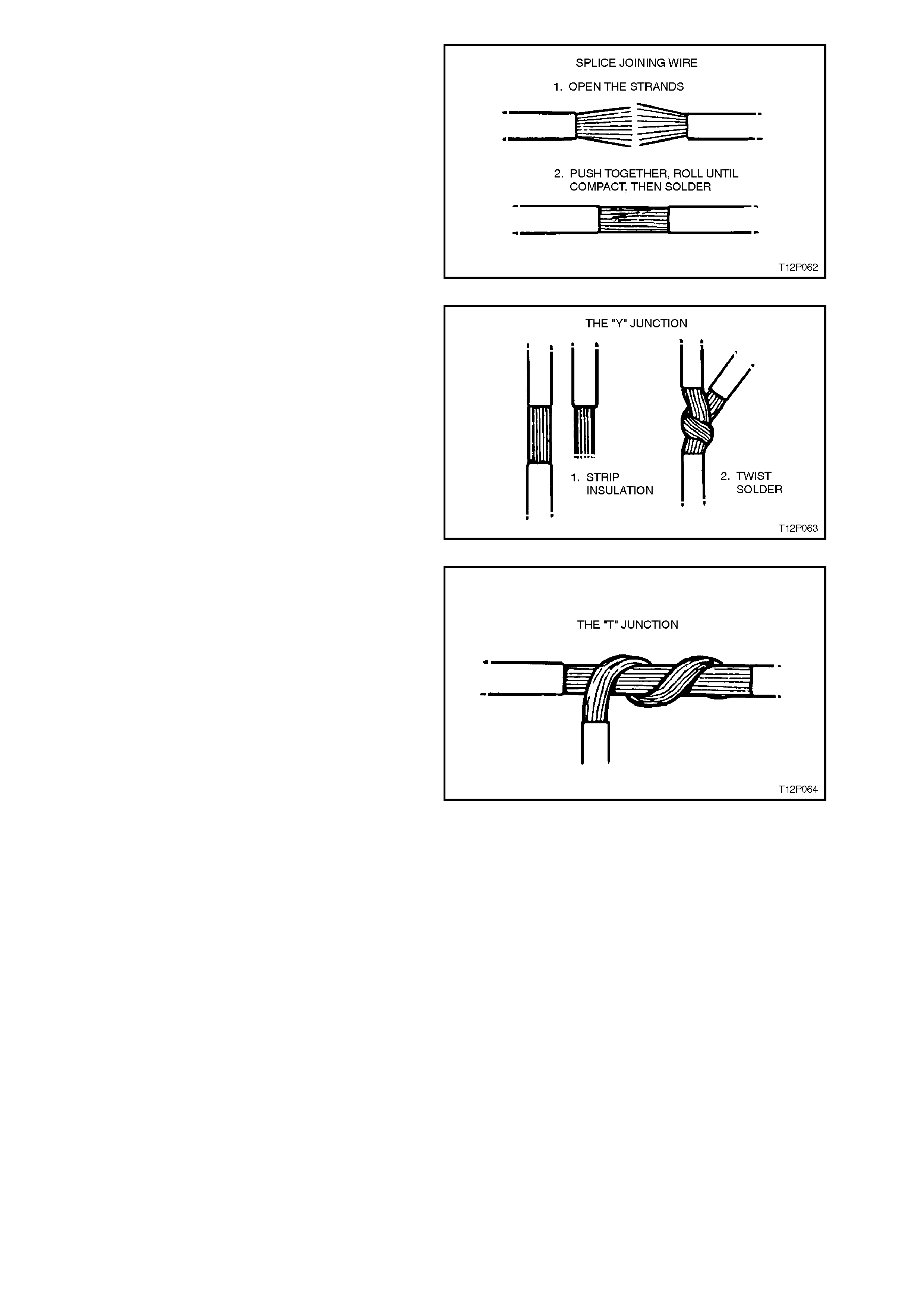
Splice Joint
To splice join conductors, strip back 20 mm of
insulation and spread the strands as shown. Push
the strands together and use you fingers to twist
the ends in opposite direc tions to com pact the join,
then solder. A good splice may be a little harder to
achieve but it m akes a neater join that is les s bulky
when taped.
Figure 12P-24
The Y Junction
The Y junction is used to install a branch
connection parallel with the original. Use a sharp
blade to remove part of the insulation from the
original wire, 20 mm should be sufficient. Strip the
branch wire by about the same amount then curl
the branch around the original. Solder the
connection. Use PVC tape to insulate the join.
Figure 12P-25
The T Junction
The T junction is used to achieve a 90 degree
branch connection.
The method is otherwise similar to the 'Y' junction.
Figure 12P-26
5.3 SPLICING WIRING USING SPLICE CLIPS
Splice clips are included in Terminal Repair Kit,
Tool No. J38125-A. The splice clip is a general
purpose wire repair device. It may not be
acceptable for applications having special
requirements such as moisture sealing.
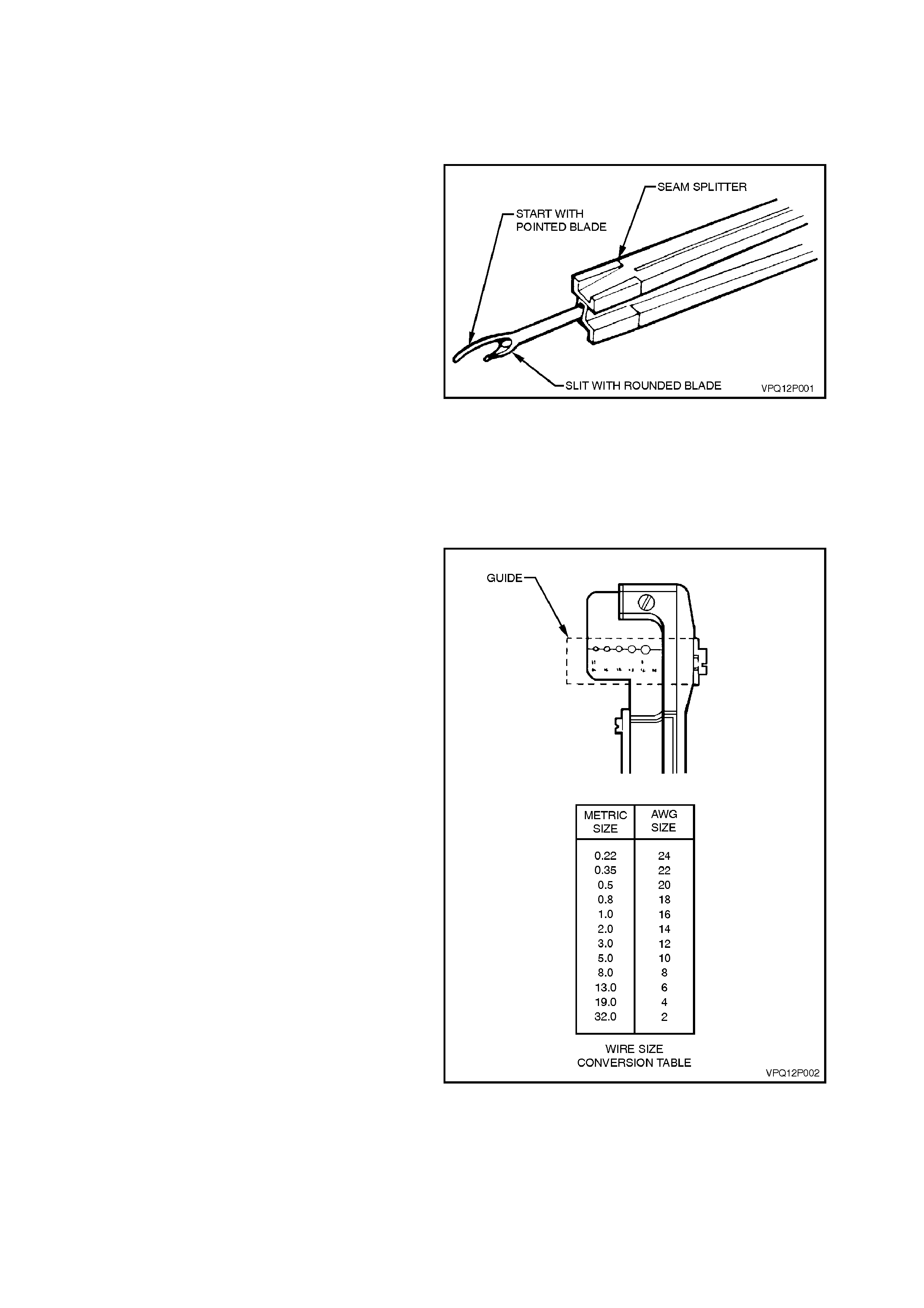
Step 1. Open the Harness
A wiring harness may be wrapped in tape or
enclosed in a plastic conduit. If it is conduit
encased, simply open the conduit and pull out the
desired wire. If the harness is wrapped in tape, a
seam splitter should be used to open the harness.
This prevents damage to the insulation of the wire
inside the harness. Seam splitters are readily
available from sewing supply stores.
W hen using a seam splitter, use the blade with the
pointed end to start a small split in the tape away
from any wires.
Use the blade with the rounded end to slit the tape
as far as neces sary. Be caref ul to avoid cutting into
any wire insulation.
Step 2. Cut the Wire
Leave as much wire on the harness as possible.
More can be cut off later to adjust the location of
the splice if necessary. The splice should be at
least 40 mm away from any other splices or outlets.
Figure 12P-27
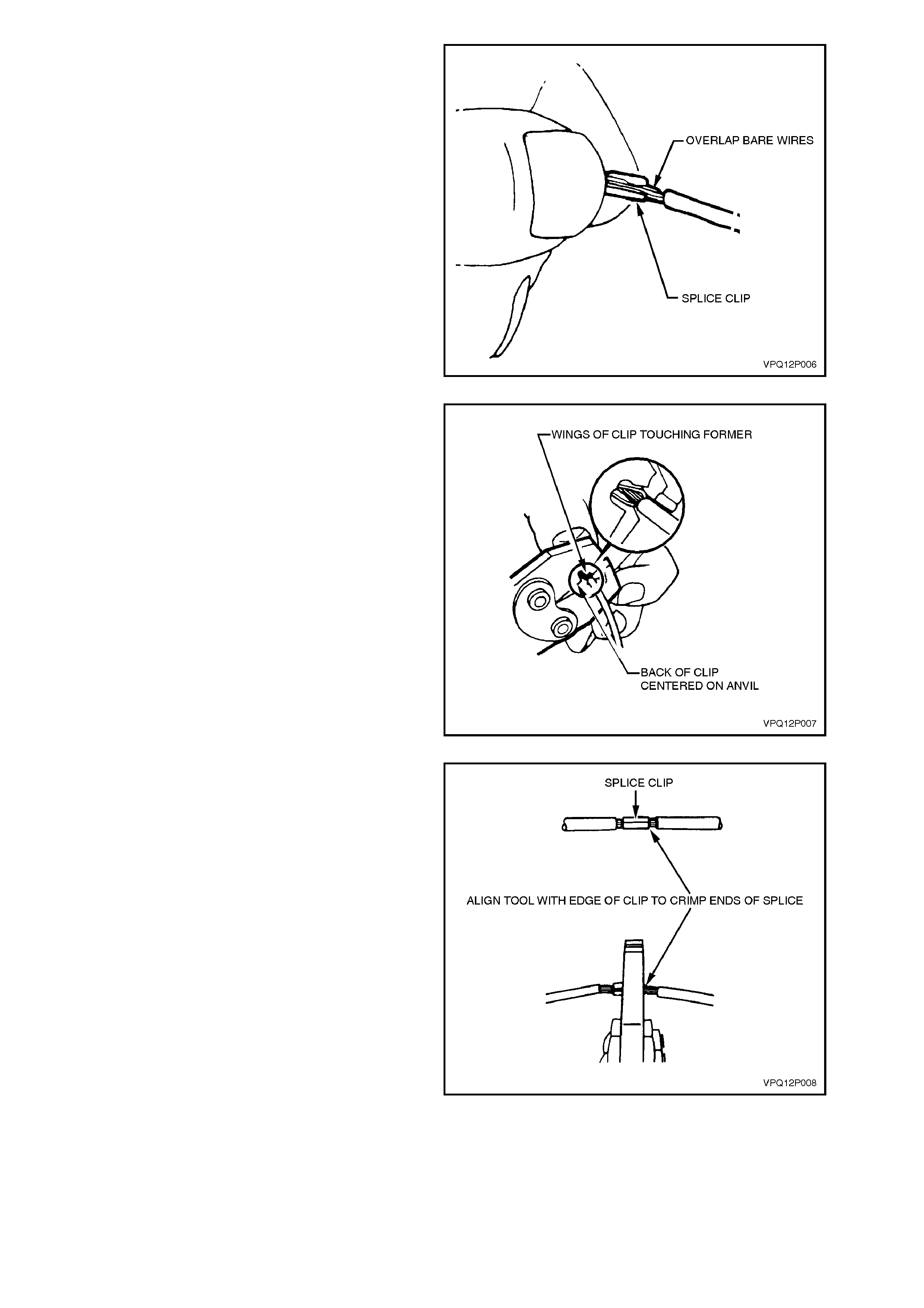
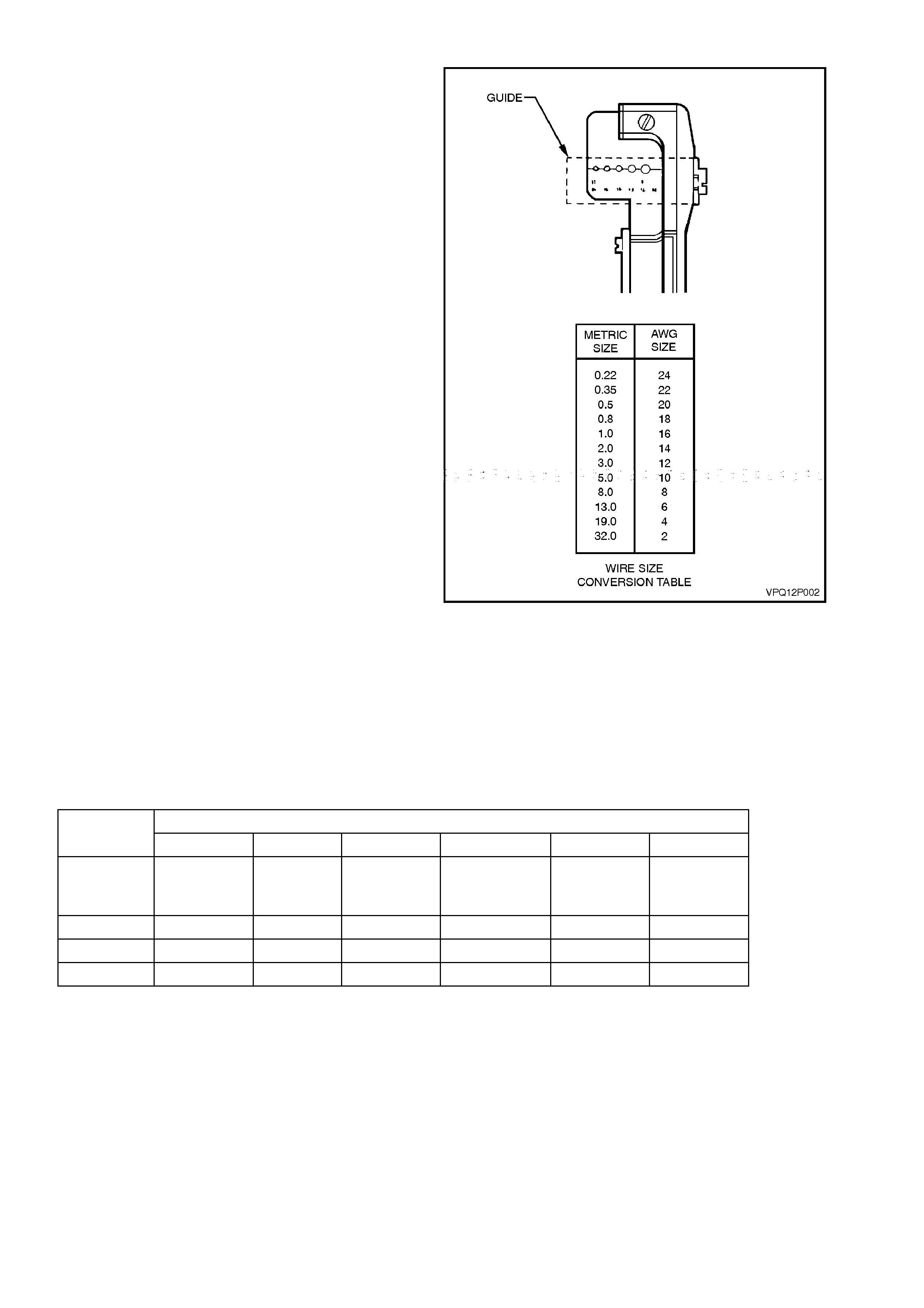
Step 3. Strip the Insulation
Find the wire size using a wire gauge (AWG).
A wire str ipper, labeled in AWG sizes, is needed f or
stripping away the insulation. If the wire size is not
known, start with the largest str ipper hole and work
down until a clean strip of insulation is removed
without nicking or cutting the wire. Set the stripper
guide to 7.5 mm strip.
Remember that the splice should be at least 40
mm away from any other splices or outlets.
Figure 12P-28

Follow these hints when using a wire stripper:
1. Hold both handles in your right hand, with
gripper jaws to the left.
2. Hold wire in your left hand and press the end
of the wire against the guide and up into the
correct notch of the upper blade.
3. Close left handle first, to grip the wire firmly
before cutting the insulation.
4. If the stripper castings stick open after
stripping the wire, pull the handles outward to
snap the tool closed.
Check the stripped wire for nicks or cut strands. If
the wire is damaged, repeat the procedure on a
new section of wire. The two stripped sections of
wire that are to be joined should be of equal length.
CAUTION:
Do not place your fingers between the gripper
casting and the cutter casting at any time. Do
not lay these castin gs ag ainst your h and s w h en
open. The stripper castings are designed to
snap shut when fully opened, and may cause
injury.
Figure 12P-29
Step 4. Crimp the Wires
Use the following figure to determine the correct
crimp size.
Figure 12P-30
Unlock the crimping tool .
Slightly close the clip with the nose of the crimping
tool as shown.
Figure 12P-31
Select the correc t anvil of the cr imper , from the clip
size table.
Overlap the two stripped wire ends and hold them
between the thumb and the forefinger of your left
hand as shown.
Centre the splice under the stripped wires and hold
in place with your forefinger as shown.
Figure 12P-32
Open the crimping tool fully, and rest one handle on
a firm, flat surface. Centre the back of the splice
clip on the proper anvil, and close the c rimping tool
to the point where the former touches the wings of
the clip. Check that the clip and wires are s till in the
correct position before closing the crimping tool
with steady pressure.
Figure 12P-33
Before crimping the ends of the clip, check for
these problems:
Wires do not extend beyond the clip in either
direction.
Strands of wire are not cut or loose.
Crimp the splice clip a second and third tim e, once
at each end. Do not let the crimping tool extend
beyond the edge of the clip when doing so.
Figure 12P-34
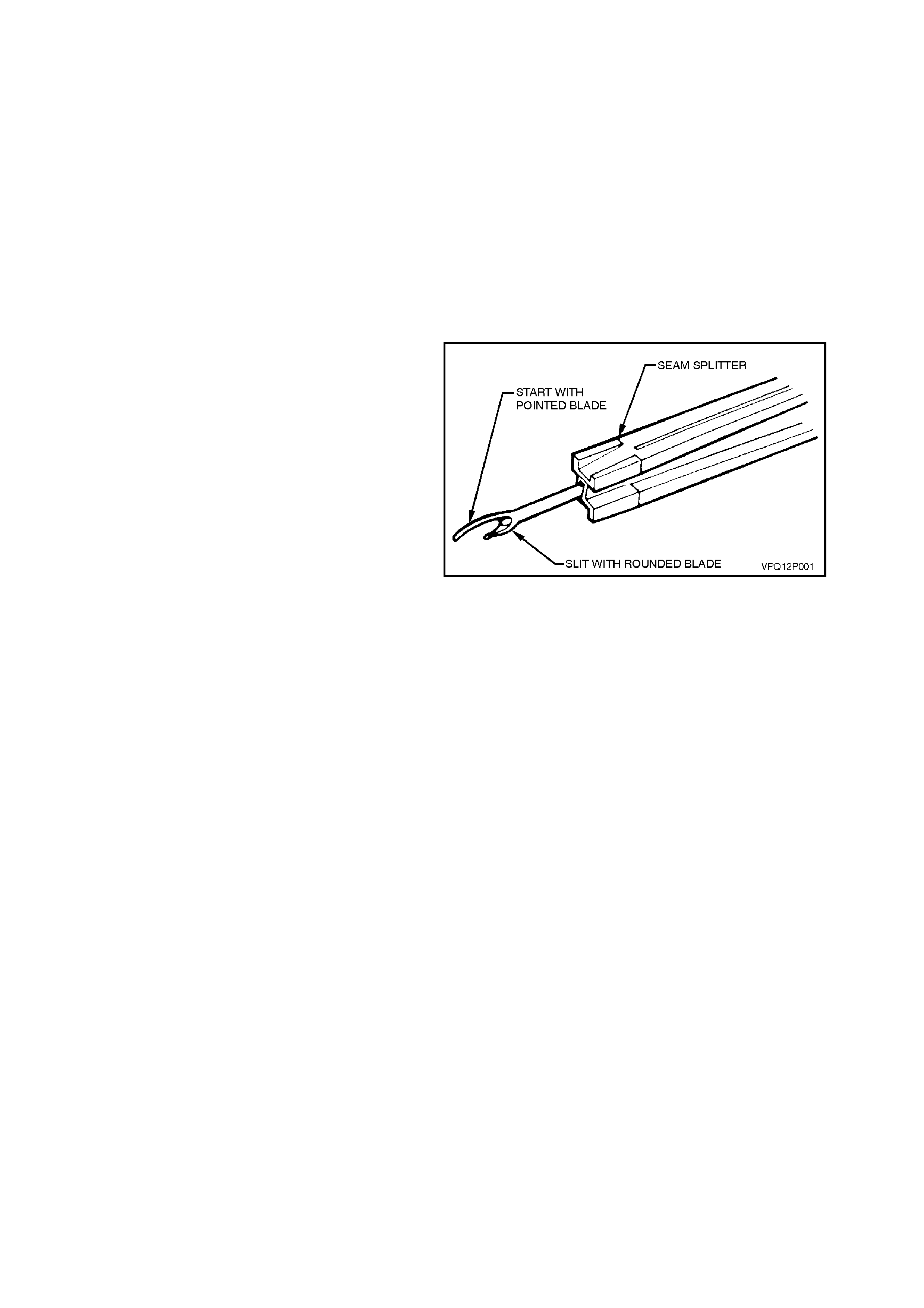
Step 5. Solder
Apply 50/50 resin core solder to the hole in the
back of the clip as shown.
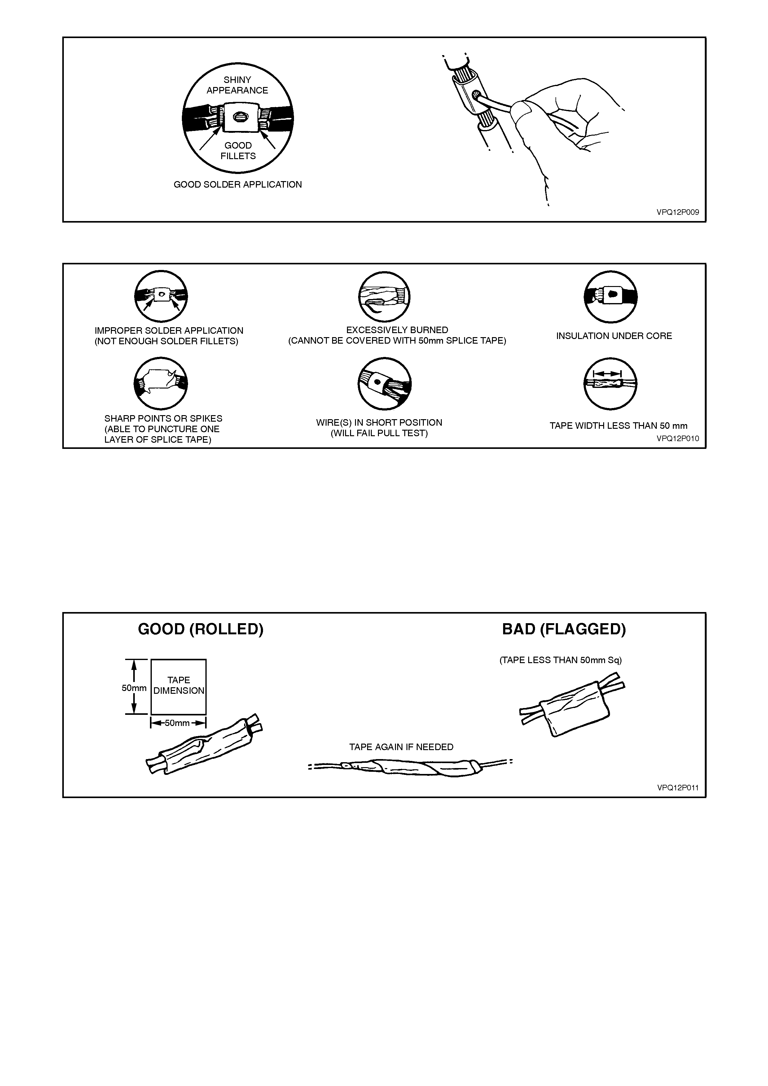
Figure 12P-35
Figure 12P-36
Follow the manufacturer's instructions for the solder equipment you are using or the soldering instructions in this
Section.
Step 6. Tape the Splice
Centre and roll tape around the splice joint.
If the wire is not in conduit or another harness covering, tape it again using a winding motion, entirely overlapping
the first piece.
Figure 12P-37

5.4 ABS AND SRS WIRING REPAIR
Special wiring repair procedures have been developed for use on the Anti-lock Braking System (ABS) and
Supplemental Restraint System (SRS) due to the sensitive nature of the circuitry. These specific procedures and
instructions must be followed when w orking with ABS and SRS wiring, and wiring components (such as connectors
and terminals). Terminal Repair Kit, Tool No. J38125-A contains special 'sealed splices' for use in repairing ABS
and SRS wiring.
A special crimping tool, heat torch, and instruction manual for these splices are also included.
Two critical features of the sealed splices are a special heat shrink sleeve with sealing adhesive to produce an
environmentally sealed splice and a cross hatched (knurled) core crimp to provide necessary contact integrity for
the sensitive, low energy circuits.
Terminal Repair Kit J38125-A also serves as a generic terminal repair kit. The kit contains a large sampling of
common GM electrical terminals and the correct tools to attach them to wires and remove them from connectors.
The terminals in the kit are NOT to be used to replace damaged terminals in the ABS and SRS wiring.
CAUTION:
THE FOLLOWING PROCEDURES FOR REPAIRING ABS AND SRS WIRING IS THE ONLY RECOMMENDED
AND APPROVED REPAIR METHOD. No alternative repair methods are to be used.
ABS AND SRS WIRE PIGTAIL REPAIR
Ensure to read and understand the instruction repair before conducting ABS and SRS wiring repairs using this kit.
If a wiring pigtail (a wire or wires attached directly to the device, not by a connector) is damaged, the entire
component (with pigtail) must be replaced.
Examples of 'pigtail' components are the wheel speed sensors or clock spring coil. Absolutely no wire, connector or
terminal repairs are to be attempted on the these components, REPLACE THE COMPONENT.
WIRING REPAIR
NOTE:
Before conducting SRS wiring repair, disable
the SRS, refer to Section 12M SUPPLEMENTAL
RESTRAINT SYSTEM.
If any wiring, except the pigtail, is damaged, the
wiring should be repaired by splicing in a new
section of wire of the same gauge size (0.5, 0.8,
1.0, etc.). The splices and Splice Crimping Tool
from Terminal Repair Kit J38125-A must be used
for these repairs.
The following wiring repair procedures must be
used to ensure the integrity of the sealed splice
application.
Step 1. Open the Harness
A wiring harness may be wrapped in tape or
enclosed in a plastic conduit. If it is conduit
encased, simply open the conduit and pull out the
desired wire. If the harness is taped, remove the
tape. To avoid wire insulation damage use a
sewing 'seam ripper' (available from sewing supply
stores) to cut open the main wiring harness. The
crimp and sealed splic e s leeves may be used on all
types of insulation except tefzel and coaxial and
may only be used to form a one-to-one splice.
Figure 12P-38
Step 2. Cut the Wire
Begin by cutting as little wire off the harness as
possible. You may need the extra length of wire
later. You may decide to cut more wire to change
the location of a splice. You may have to adjust
splice locations to be certain that each splice is at
least 40 mm away from other splices, harness
branches, or connectors.
NOTE:
Do not nick or cut any copper strands as this
could limit the current-carrying capabilities of
the wire.
Step 3. Strip the Insulation
NOTE:
The following procedures must be followed in
the order listed. If wire strands are damaged,
the procedure must be repeated until a clean
strip with all wire strands intact is obtained.
If it is necessary to add a length of wire to the
existing harness, be certain to use the same size
as the original wire.
To find the correct wire size either find the wire on
the ABS or SRS wiring diagram , or measur e with a
wire gauge.
If unsure about the wire size, begin with the largest
opening in the wire stripper and work down until
achieving a clean strip of the insulation. Strip
approximately 7.5 mm of insulation from each wire
to be spliced. Be careful to avoid nicking or cutting
any of the strands. Check the stripped wire for
nick s or cut strands . If the wire is damaged, repeat
this procedure after removing the damaged
section.
Step 4. Select and Position the Splice Sleeve
Select the proper sealed s plice sleeve according to
wire size. The splice sleeves and tool nests are
colour coded (refer to the following chart).
Figure 12P-39
WIRE SIZE (mm)
0.5 0.8 1.0 2.0 3.0 5.0
SPLICE
CRIMP
PART No.
12089189 SALMON SALMON
12089190 BLUE BLUE
12089191 YELLOW YELLOW
Using the J38125-A Splice Cr im p T ool, position the
splice sleeve in the proper colour nest of the hand
crimp tool. Place the splice sleeve in the nest so
that the crim p falls midway between the end of the
barrel and the stop.
The s leeve has a stop in the m iddle of the barrel to
prevent the wire from going f urther. Clos e the hand
crimper handles slightly to hold the splice sleeve
firmly in the proper nest.
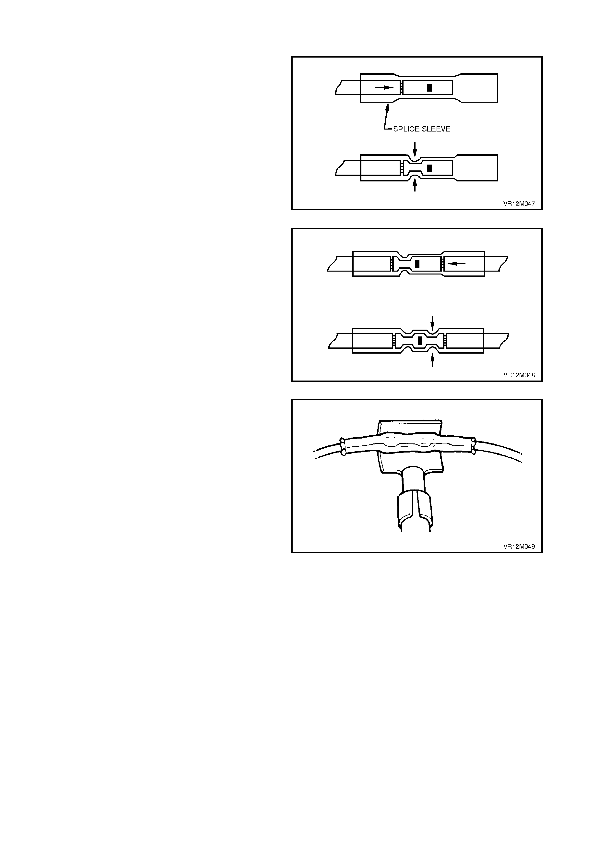
Step 5. Insert Wires Into Splice Sleeve and
Crimp
Insert the wire into the splice sleeve until it hits the
barrel stop and close the handles of the crimp tool
tightly until the crimper handles open when
released. The crimper handles will not open until
the proper amount of pressure is applied to the
splice sleeve.
Figure 12P-40
Gently tug both ends of the wire to ensure that
crimp is secu re.
Repeat Steps 4 and 5 for opposite end of the
splice.
Figure 12P-41
Step 6. Shrink the Insulation around the Splice
Bring the ultratorch (part of J38125-A) to operating
temperature.
Using the torch, apply heat where the barrel is
crimped.
Gradually move the heat barrel from the centre
toward each end of the tubing, softening and
shrinking the tubing completely as the heat is
moved along the insulation. A small amount of
sealant will come out of the end of the tubing when
sufficient shrinking is achieved. Allow the splice
sleeve to cool.
Figure 12P-42
Step 7. Close the Harness
Using a multimeter, check continuity of repaired
wiring. If wiring is OK, tape the harness wires.
ABS AND SRS WIRING SPLICE REPAIR
If any of the original equipm ent splices ( three wires
or more) in the ABS and SRS wiring are damaged
they should be repaired by applying a new splice
(not sealed) from the Terminal Repair Kit J38125-
A. Carefully follow the instructions included in the
kit f or proper splice c lip application. Cloth duct tape
may be substituted for splice tape if necessary.
5.5 TERMINAL REMOVAL
The following general terminal rem oval procedures
can be used on most types of connectors. The
removal procedures are divided into three general
groups:
Push-to-Seat, Pull-to-Seat and Weather Pack ®.
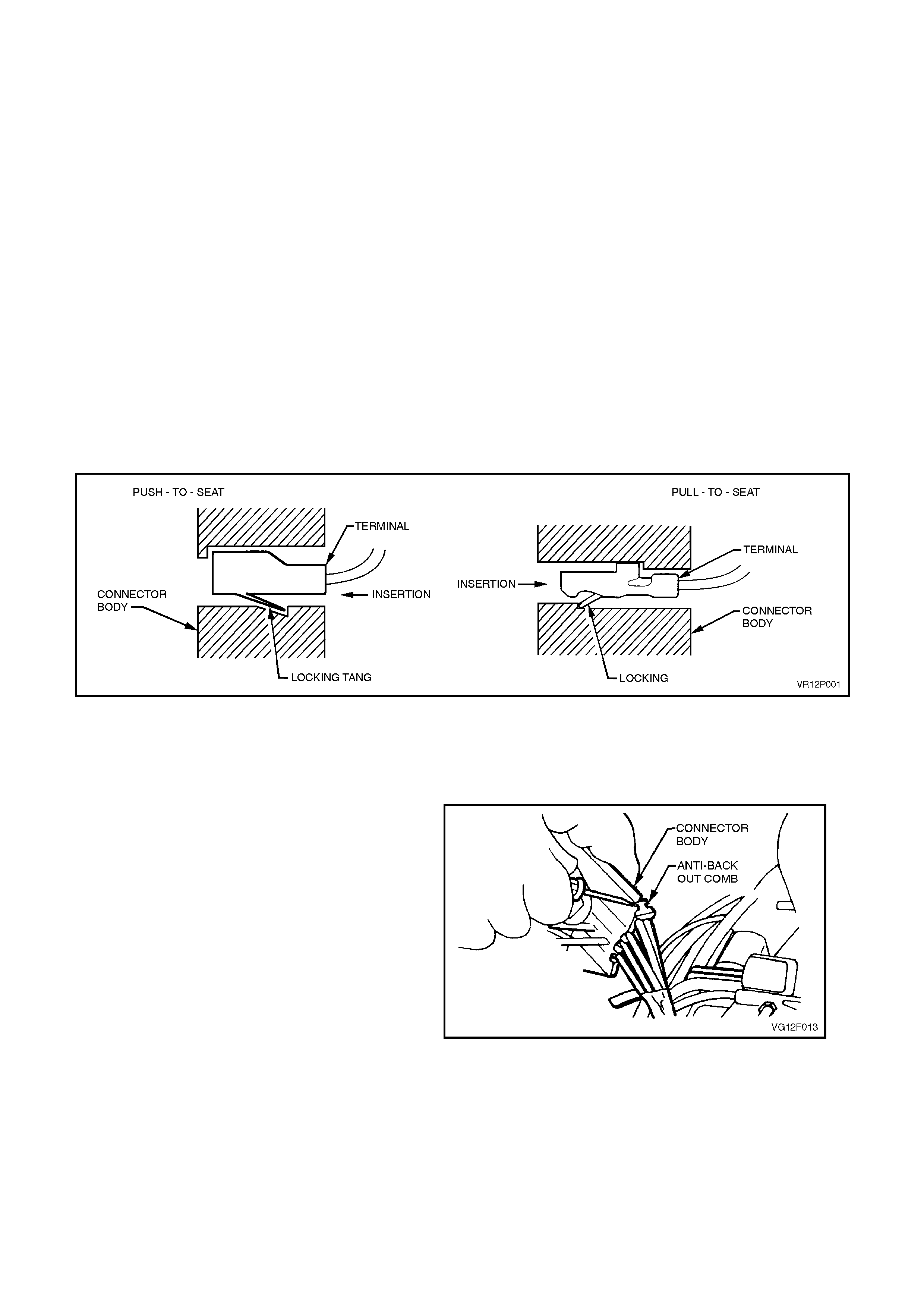
Push-to-Seat connectors are those which have the
terminal inserted in the rear of the connector body
when assem bled. Pull-to-Seat connec tors have the
terminal inserted in the front of the connector body
when assembled.
Use the proper pick(s) or tool(s) that apply to the
appropriate terminal and connector.
PUSH TO-SEAT AND PULL-TO-SEAT CONNECTORS
The following steps will enable repair of Push-to-
Seat or Pull-to-Seat type connectors. The s teps are
illustrated with typical connectors. Your connector
may differ, but the repair steps are similar. Some
connectors do not require all the steps shown. Sk ip
those that don't apply.
Figure 12P-43
1. Lift up connec tor body retaining tangs and pull
mating connector bodies apart, or disconnect
connector from component.
2. Remove any anti- backout com bs that may be
fitted to the connector.
Anti-backout combs are designed to keep the
terminal from backing out of the connector.
NOTE:
The anti-backout combs must be removed prior to
terminal removal and must be replaced when the
terminal is repaired and reseated.
Figure 12P-44
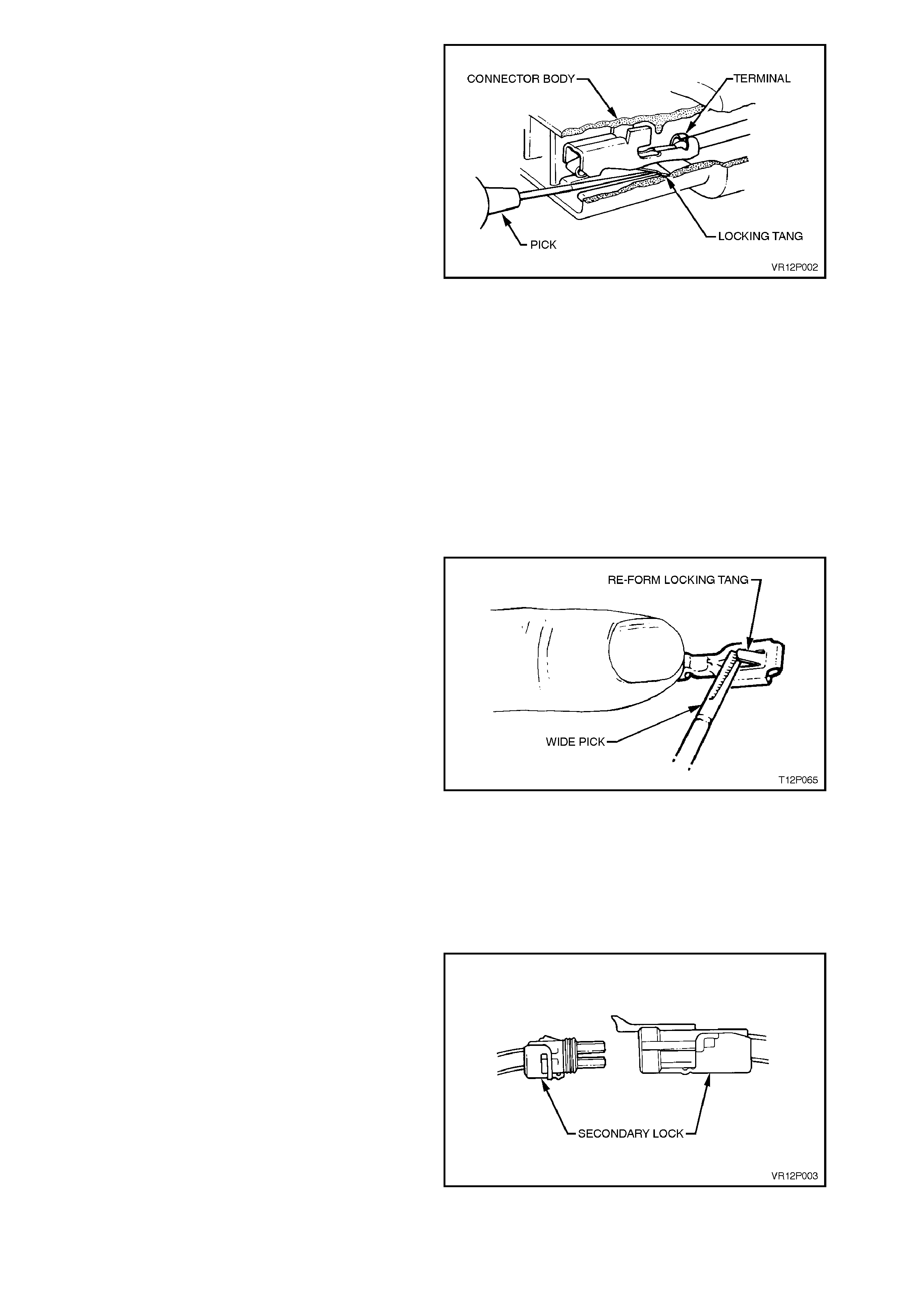
3. If fitted, open any connector secondary locks,
refer to Fig. 12 P-47.
A secondary lock aids in terminal retention
and is usually moulded as part of the
connector body.
4. Grasp the lead and push the terminal to the
forward most position. Hold the lead at this
position.
5. Locate the terminal lock tang in the connector
canal.
6. Insert the proper size pick (refer to Terminal
Repair Kit J38125-A) straight into the
connector canal at the mating end of the
connector.
7. Depress the locking tang to unseat the
terminal.
Push-to-Seat -Gently pull on the lead to
remove the terminal through the back of the
connector.
Pull-to-Seat -Gently push on the lead to
remove the terminal through the front of the
connector.
NOTE:
Never use force to remove a terminal from a
connector.
Figure 12P-45
8. Inspect terminal and connector for damage.
Repair or replac e parts as nec essar y. Refer to
VT Parts Information for availability of
terminal/pigtail or connector body assemblies
that are service separately.
9. Reform lock tang and reseat terminal in
connector body.
10. Reinstall any anti-backout combs and join
connector bodies.
Figure 12P-46
WEATHER PACK ®
Follow the steps below to rem ove Weather Pack ®
type terminals.
1. Lift up connec tor body retaining tangs and pull
mating connector bodies apart, or disconnect
connector from component.
2. If fitted, open secondary lock or remove anti-
backout comb (refer Fig. to 12P-47).
A secondary lock aids in terminal retention and
is usually moulded to the connector body.
Anti-backout combs are designed to keep the
terminal from backing out of the connector.
NOTE:
The anti-backout combs must be removed prior to
terminal removal and must be replaced when the
terminal is repaired and reseated.
Figure 12P-47
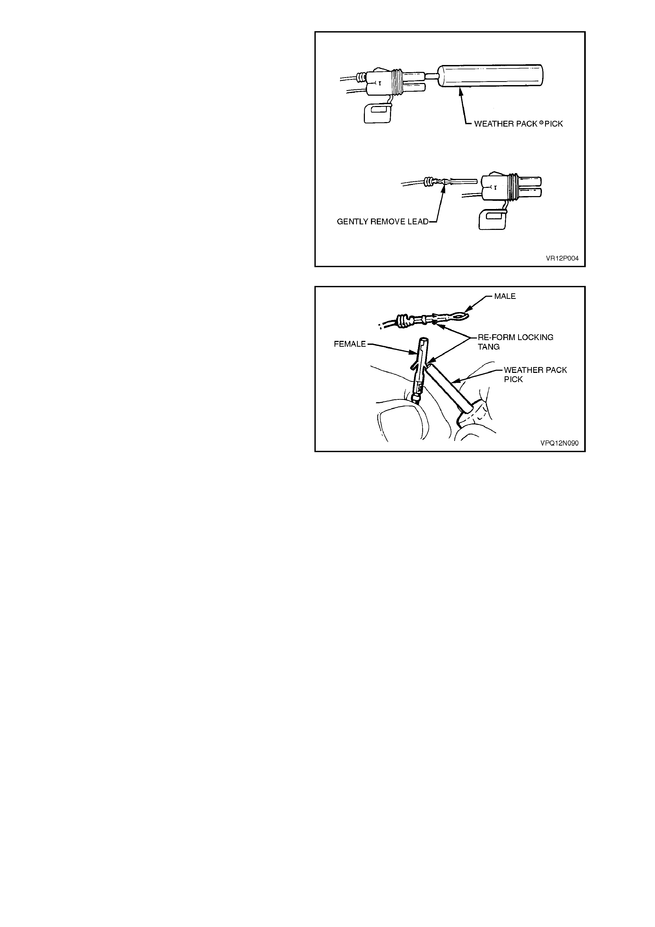
3. Grasp the lead and push the terminal to the
forward most position. Hold the lead at this
position.
4. Insert the Weather Pack
®
terminal removal
tool into the front (mating end) of the
connector cavity until it rests on the cavity
shoulder.
5. Gently pull on the lead to remove the terminal
through the back of the connector.
NOTE:
Never use force to remove a terminal from a
connector.
6. Inspect terminal and connector for damage.
Repair or replac e parts as neces sary. Refer to
VT Parts Information for availability of
terminal/pigtail or connector body assemblies
that are serviced separately.
Figure 12P-48
7. Reform lock tang and reseat terminal in
connector body.
8. Close secondary lock and reinstall connector
to component or mating connector.
Figure 12P-49
6. WIRING DIAGRAMS
CAUTION:
This vehicle will be equipped with a Supplemental Restraint System (SRS). A SRS will
consist of either seat belt pretensioners and a driver’s side air bag, or seat belt pre-
tensioners and a driver’s and front passenger’s side air bags. Refer to CAUTIONS,
Section 12M, before performing any service operation on or around SRS
components, the steering mechanism or wiring. Failure to follow the CAUTIONS
could result in air bag deployment, resulting in possible personal injury or
unnecessary SRS system repairs.
CAUTION:
This vehicle may be equipped with LPG (Liquefied Petroleum Gas). In the interests of
safety, the LPG fuel system should be isolated by turning 'OFF' the manual service
valve and then draining the LPG service lines, before any service w ork is carried out
on the vehicle. Refer to the LPG leaflet included with the Owner's Handbook for
details or LPG Section 2 for more specific servicing information.
CAUTION:
Whenever any component that forms part of the ABS (if fitted), is disturbed during
Service Operations, it is vital that the complete ABS system is checked, using the
procedure as detailed in DIAGNOSIS, ABS FUNCTIONAL CHECK, in Section 12L ABS
& ABS/ETC.
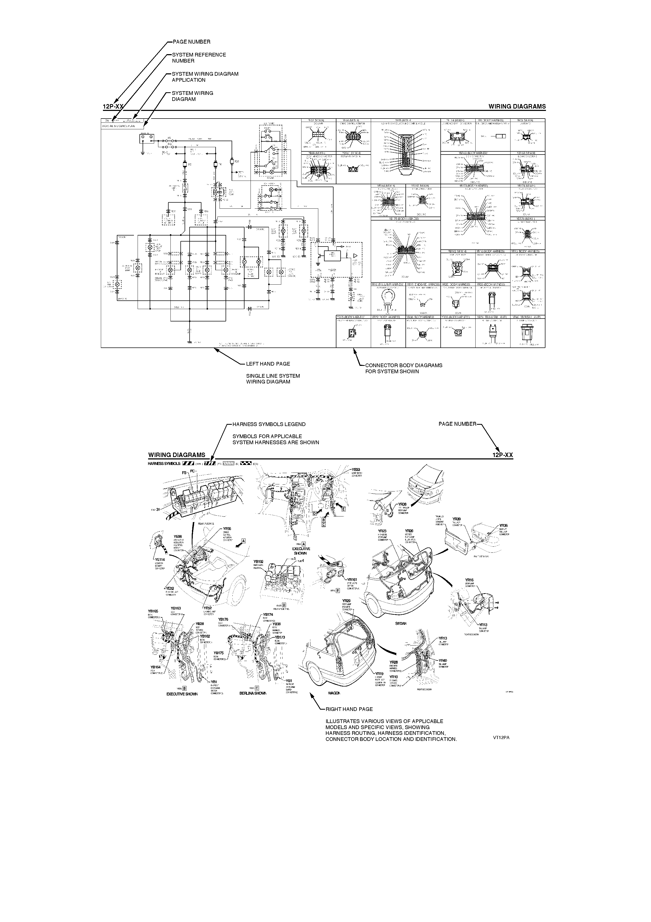
6.1 HOW TO USE THE SYSTEM WIRING DIAGRAMS
The vehicle's complete electrical wiring is divided into separate system wiring diagrams, i.e. Starting and Charging,
Fusible Links, Central Door Locking etc.
The following figure is an example of a typical sy stem wiring diagram.
When reading the system wiring diagrams, the following points should be noted:
1. Where possible, all wiring diagrams show the complete circuit from battery '+' terminal, through the system to
earth.
2. Refer to the next diagram for detailed explanation of the single line system wiring diagrams.
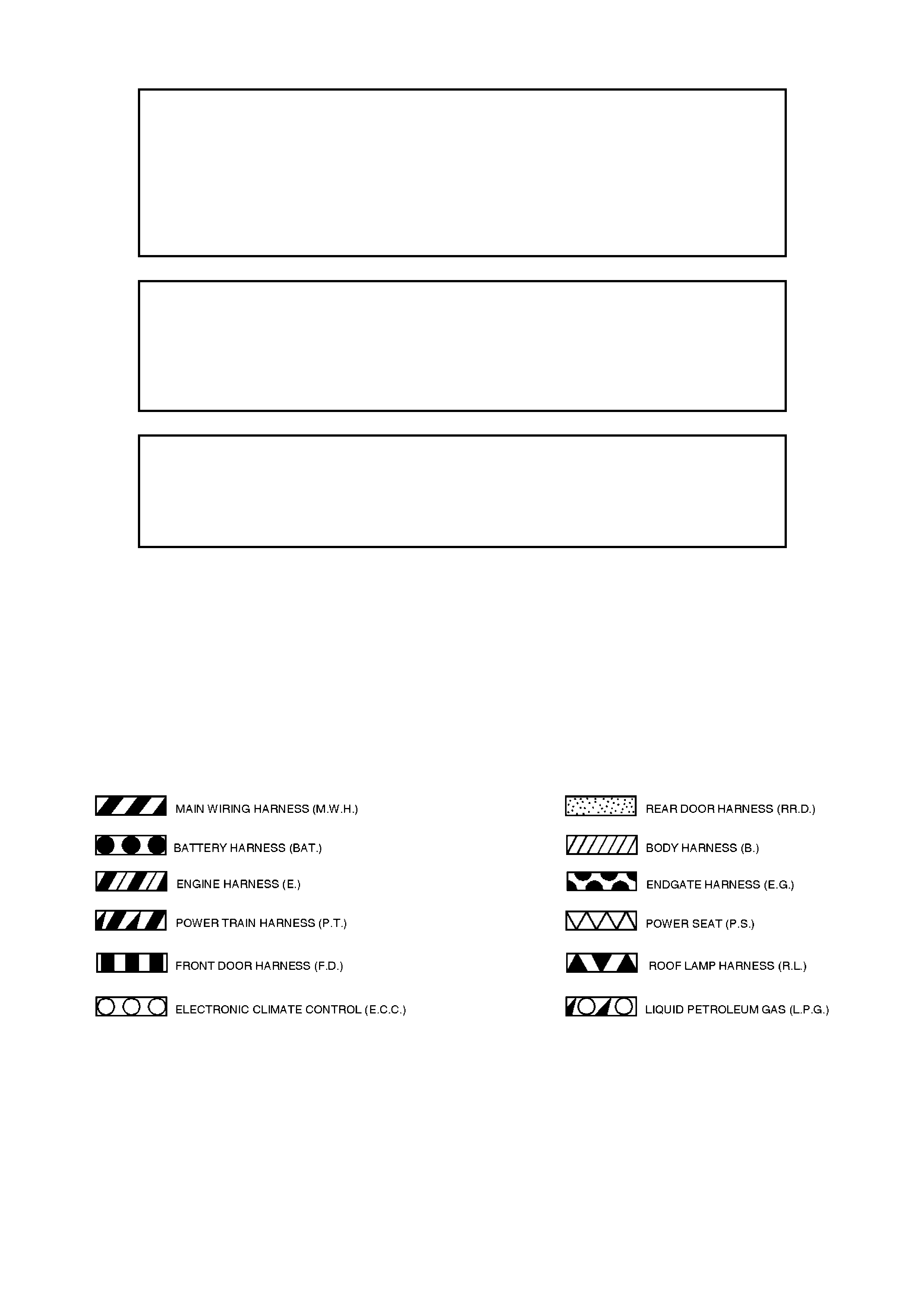
HARNESS SYMBOLS LEGEND

Single Line System Wiring Diagram Explanation
The following figure is the legend for the various relays, switches or components that are used on the system wiring
diagrams.
LEGEND
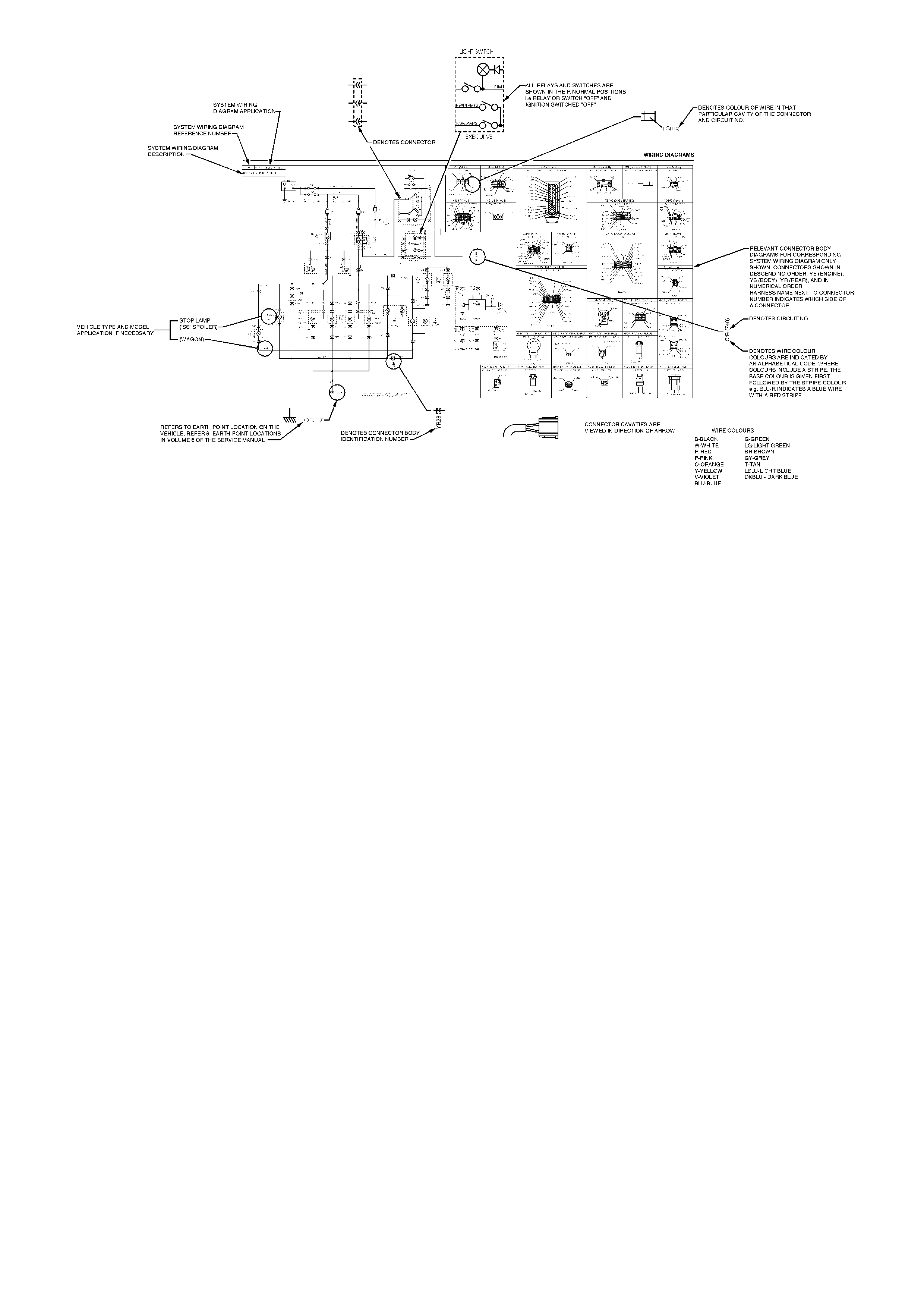

DIAGRAM NO. AND DIAGRAM DESCRIPTION
SYSTEM WIRING
DIAGRAM NO. SYSTEM WIRING DIAGRAM DESCRIPTION
0A How To Use System Wiring Diagrams
0B Single Line System Wiring Diagram Explanation
1 Power Distribution - All Models
2A Earth Paths – All Models
2B Earth Points – All Models
3 Diagnostic Connectors – All Models
4Starting & Charging - All Models
5A Powertrain Control Module (V6) – All Models
5B Powertrain Control Module (V8) - All Models
5C Powertrain Control Module (Supercharged Engine V6) - All Models
5D LPG Control Module (V6) – Executive & Berlina and Production Fitted LPG
6A Park, Fog & Headlamps – Executive
6B Park, Fog & Headlamps – Berlina
6C Park, Fog & Headlamps – Calais
7A Stop/Tail & Licence Plate Illumination - Executive & Berlina
7B Stop/Tail & Licence Plate Illumination - Calais
8Turn Signal & Back-Up Lamps – All Models
9A Interior Illumination – Executive
9B Interior Illumination – Berlina
9C Interior Illumination – Calais
10A Heating & Air Conditioning – Executive
10B Electronic Climate Control Air Conditioning - Berlina & Calais
11A Radio/Cassette & Power Antenna - Executive & Berlina
11B Radio/Cassette & Power Antenna - Calais
12 Central Door Locking - All Models
13A Power Windows – Executive
13B Power Windows - Berlina & Calais
14A Theft Deterrent System – Executive
14B Theft Deterrent System – Berlina & Calais
15 Cruise Control - All Models
16A Electrical Convenience Items (Includes Heated Rear Window, Accessory Jack and Rear
Compartment Lock) – Executive
16B Electrical Convenience Items (Includes Heated Rear Window, Accessory Jack and Rear
Compartment Lock) – Berlina & Calais
17A Instruments – Executive
17B Instruments - Berlina & Calais
18 Power Steering – Calais
19 Front & Rear Wiper/Washer - All Models
20 Horns - All Models
21 Anti-lock Braking & Traction Control - All Models
22 Supplemental Restraint System - All Models
22A Supplemental Restraint System - Version 6.2/8.0
22B Supplemental Restraint System - Version 8.1 (Side Air Bags)
23 Power Seats - All Models
24 Power Mirrors - All Models
7. SPECIAL TOOLS
TOOL NO. REF IN TEXT TOOL DESCRIPTION COMMENTS
J39200 DIGITAL MULTIMETER PREVIOULSY RELEASED, OR
USE COMMERICALLY
AVAILABLE EQUIVALENT
J35616-A
- OR -
KM-609
CONNECTOR TEST ADAPTOR KIT PREVIOULSY RELEASED
J38125-A TERMINAL REPAIR KIT PREVIOULSY RELEASED.
MUST BE USED WHEN
REPAIRING SRS OR ABS
WIRING, REFER TO
SECTION 5.4 IN THIS
SECTION
SELF POWERED TEST LIGHT PREVIOULSY RELEASED.
USE J21008-A OR
COMMERICALLY AVAILABLE
EQUIVALENT
TOOL NO. REF IN TEXT TOOL DESCRIPTION COMMENTS
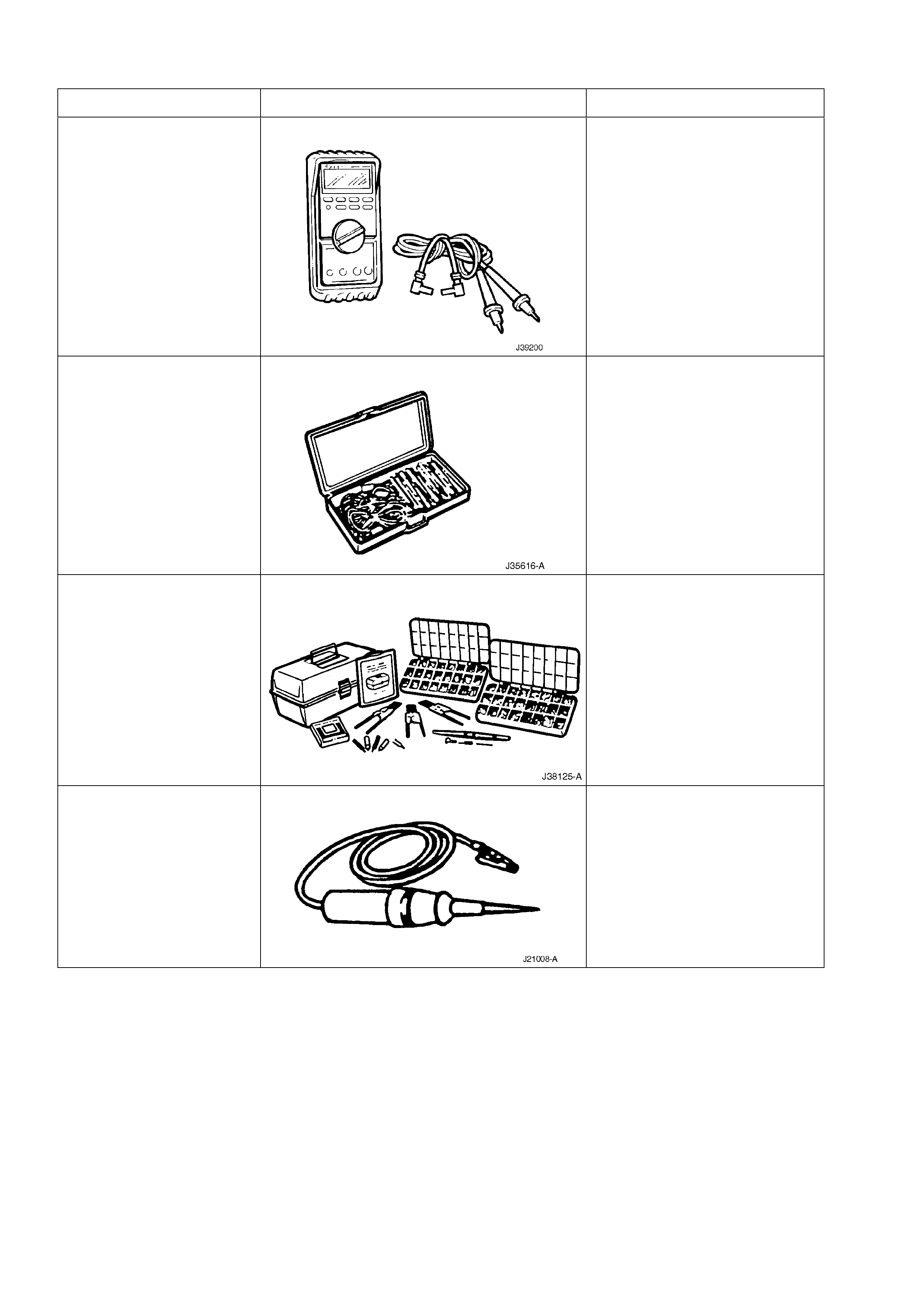
UNPOWERED TEST LIGHT PREVIOULSY RELEASED.
USE J34142-B OR
COMMERICALLY AVAILABLE
EQUIVALENT
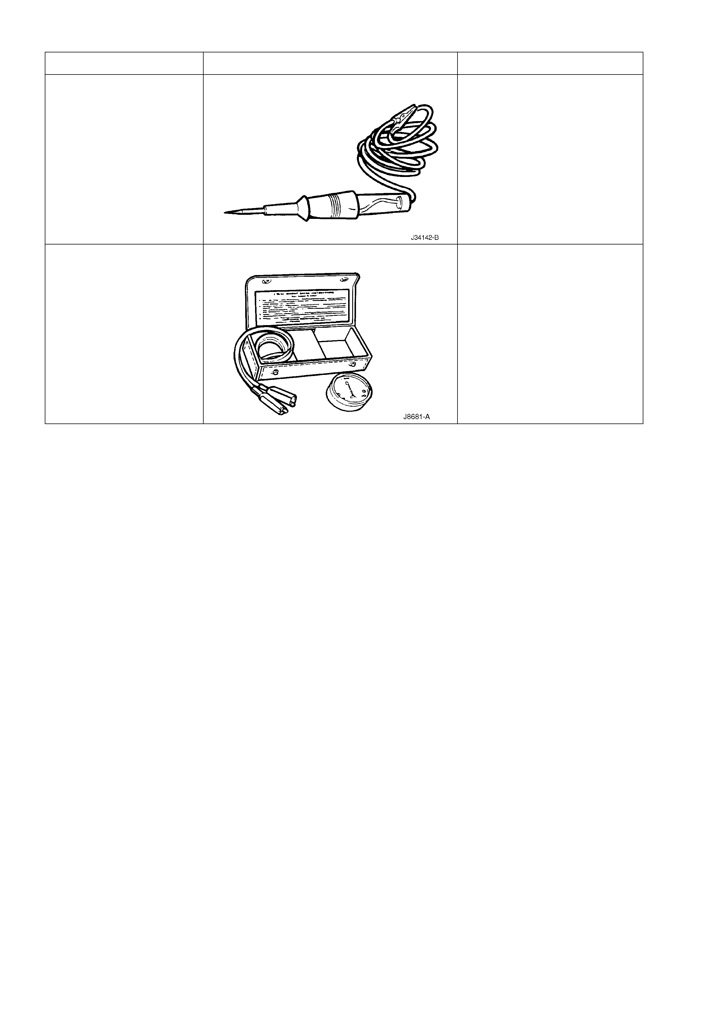
UNIVERSAL SHORT FINDER PREVIOULSY RELEASED.
USE J8681-A OR
COMMERICALLY AVAILABLE
EQUIVALENT