SECTION 1A2 - BODY DIMENSIONS
CAUTION:
This vehicle will be equipped with a Supplemental Restraint System (SRS). A SRS will
consist of either seat belt pre-tensio ners and a driver’s side air bag , or seat belt pre-
tensioners and a driver’s and front passenger’s side air bags. Refer to CAUTIONS,
Section 12M, before performing any service operation on or around SRS
components, the steering mechanism or wiring. Failure to follow the CAUTIONS
could result in SRS deplo yment, resulting in possible p ersonal injury or unnecessary
SRS system repairs.
CAUTION:
This vehicle may be equipped with LPG (Liquefied Petroleum Gas). In the interests of
safety, the LPG fuel system should be isolated by turning 'OFF' the manual service
valve and then draining the LPG serv ice lines, before any service w ork is carried out
on the vehicle. Refer to the LPG leaflet included with the Owner's Handbook for
details or LPG Section 2 for more specific servicing information.
1. GENERAL DESCRIPTI ON
The underbody of the VT Series is a completely new vehicle design. All sheetmetal, interior trim, air conditioning,
and lighting systems have been redesigned. Bumper fascias complement the new styling and accommodate below
bumper engine cooling entry. Head, turn signal and rear lamps are modified to suit design changes.

2. SERVICE OPERATIONS
2.1 BODY DIMENS IONS
Correct underbody alignment is essential, as any
misalignment of the underbody can adversely affect
suspension, fitment of doors, engine hood, tailgate
or rear compartment lid. The underbody should
therefore be aligned to within ±1.5 mm of
dimensions specified in Figures 1A2-1, 1A2-2, 1A2-
3, 1A2-4, 1A2-5, 1A2-6, 1A2-7, 1A2-8 and 1A2-9.
These dimensions should be accurately checked
with a tram gauge consisting of a parallel bar or
rod, fitted with two adjustable trammels, capable of
gauging all underbody dimensions specified.
In preparing for an underbody alignment check,
place the vehicle on a level surface with the weight
of the body supported at wheel locations.
Dimensions to holes are to be taken from the
centreline.
Body dimensions are to be taken to the outside
surface of the sheetmetal.
All dimensions are to be measured as shown.
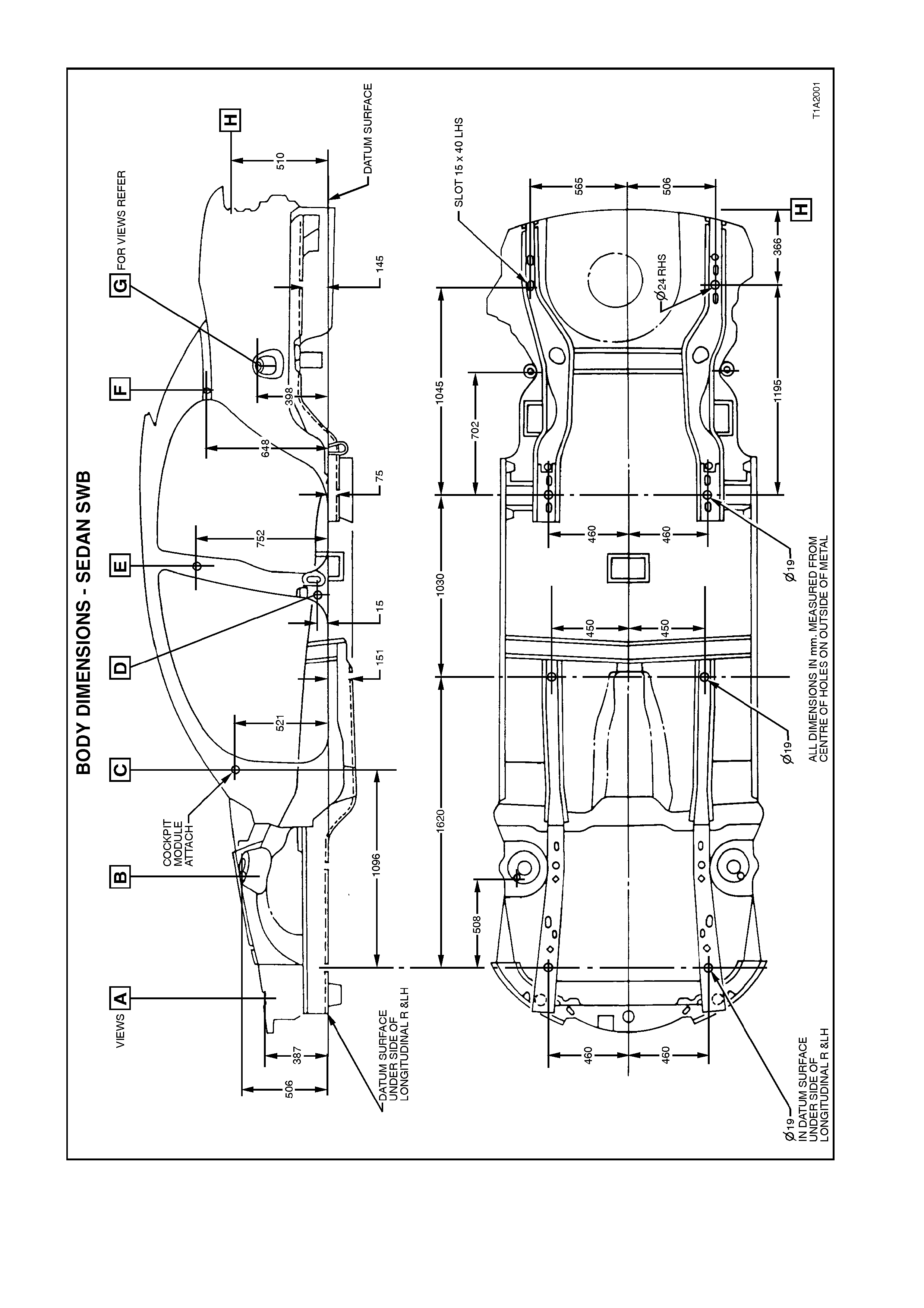
BODY DIMENSIONS - SEDAN SWB
Figure 1A2-1
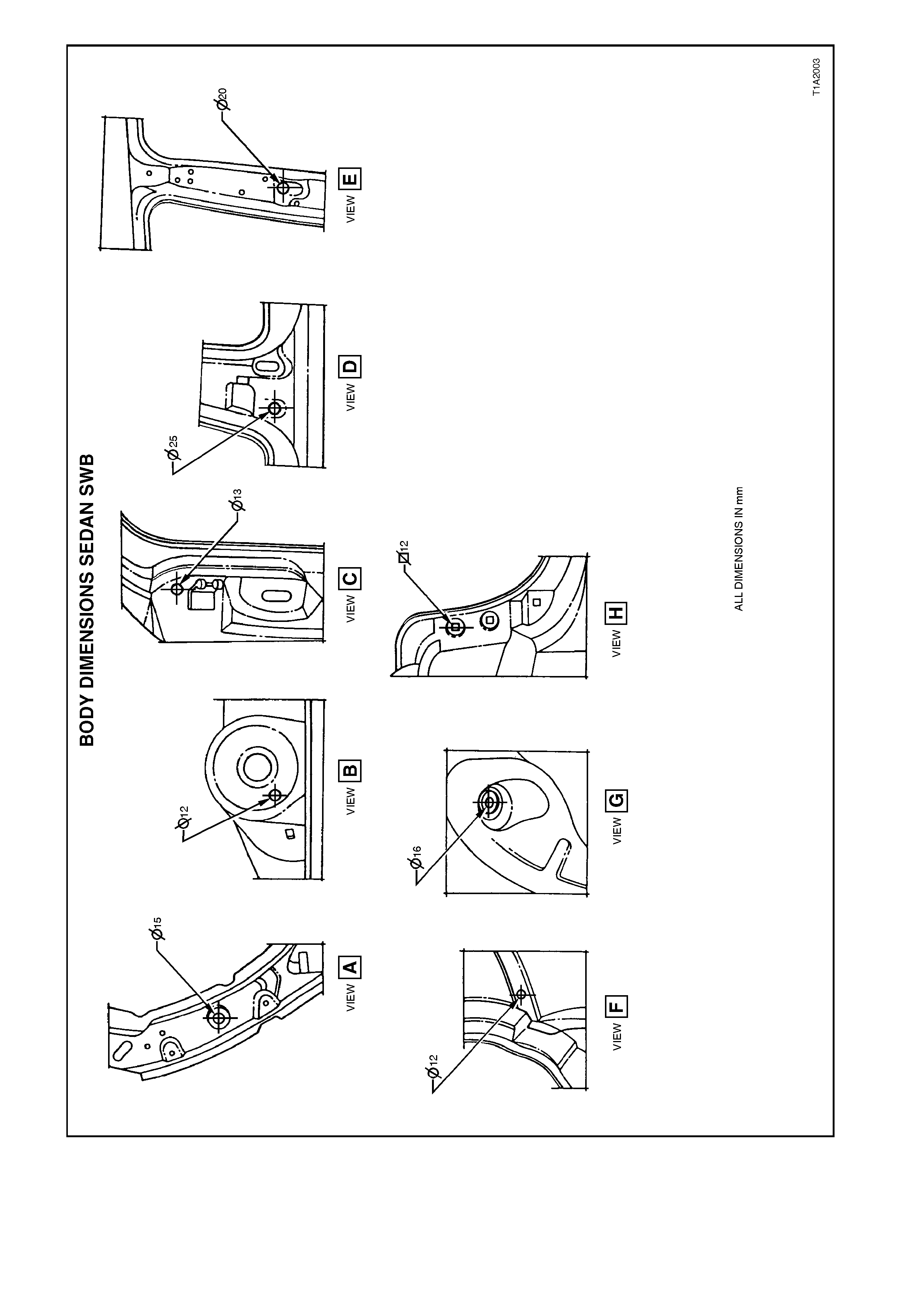
Figure 1A2-2
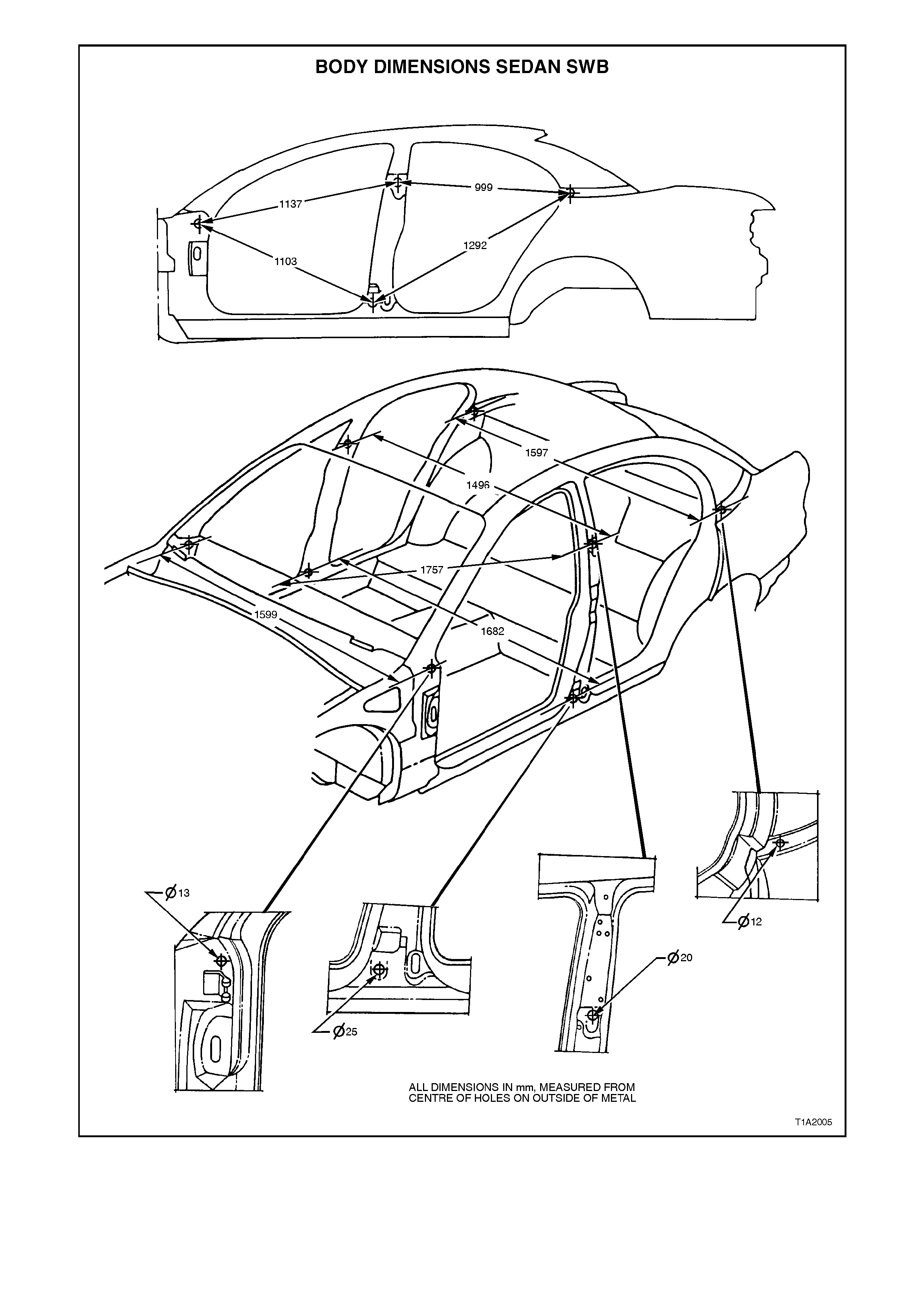
Figure 1A2-3
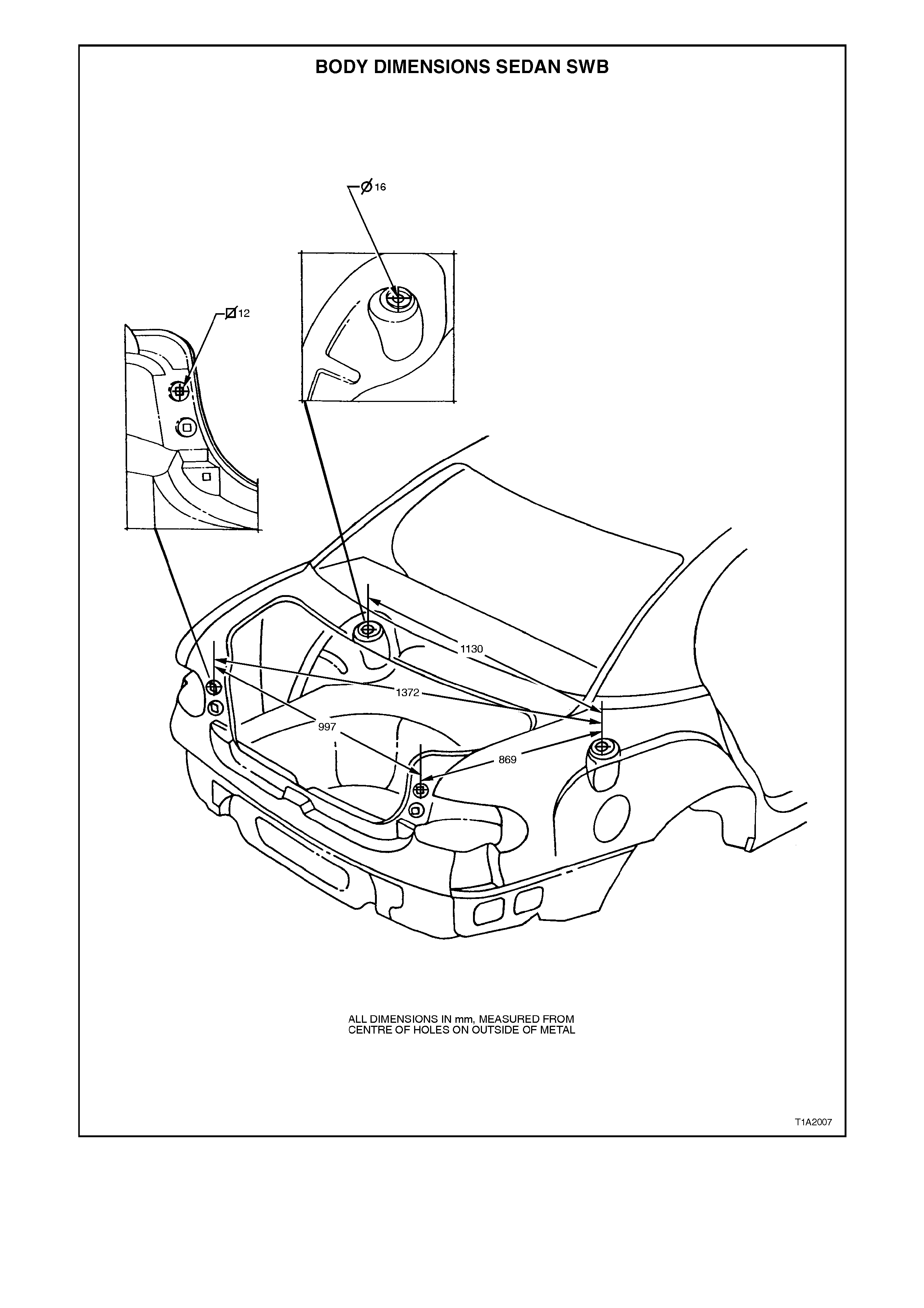
Figure 1A2-4
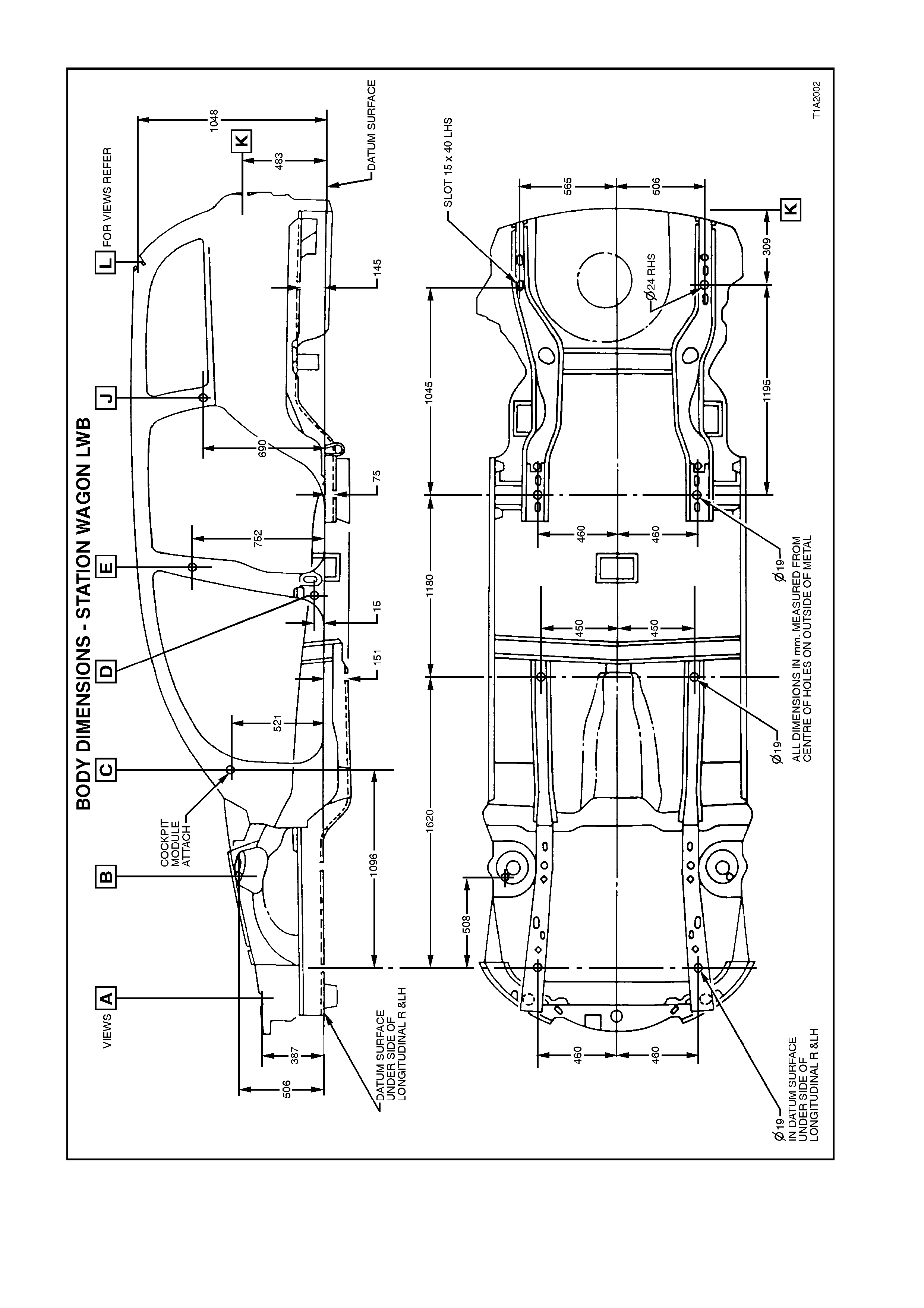
BODY DIMENSIONS - STATION WAGON LWB
Figure 1A2-5
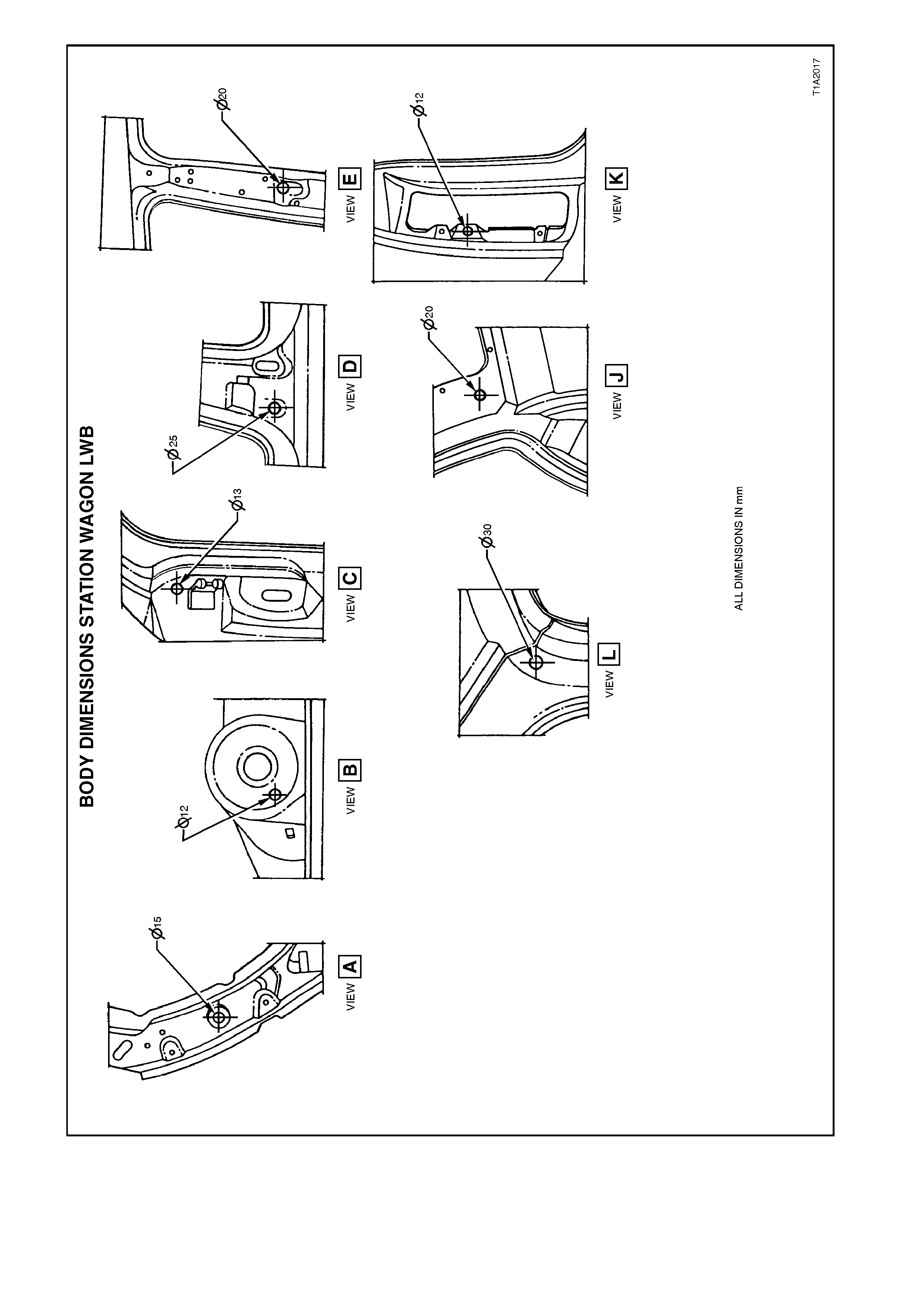
Figure 1A2-6
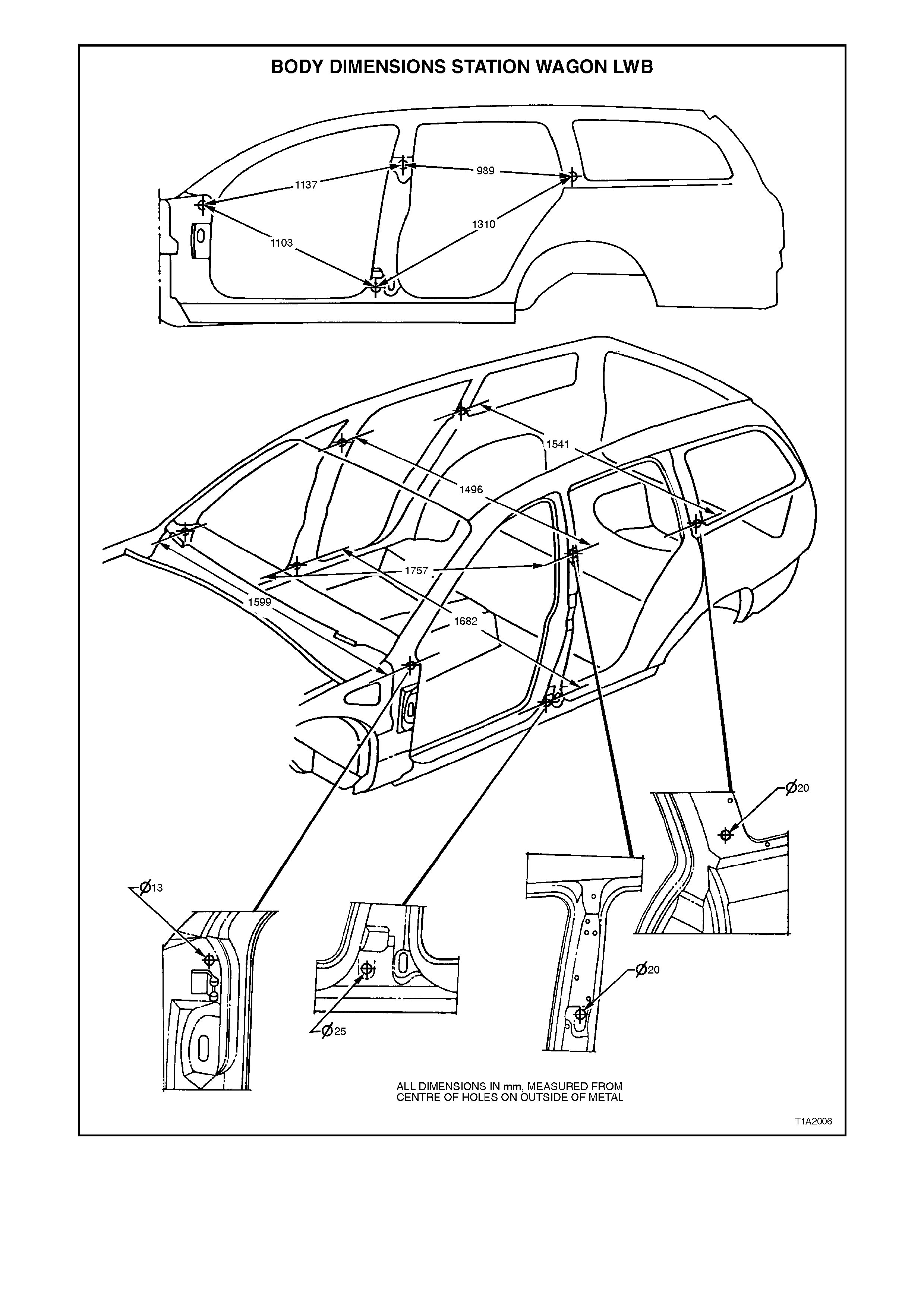
Figure 1A2-7
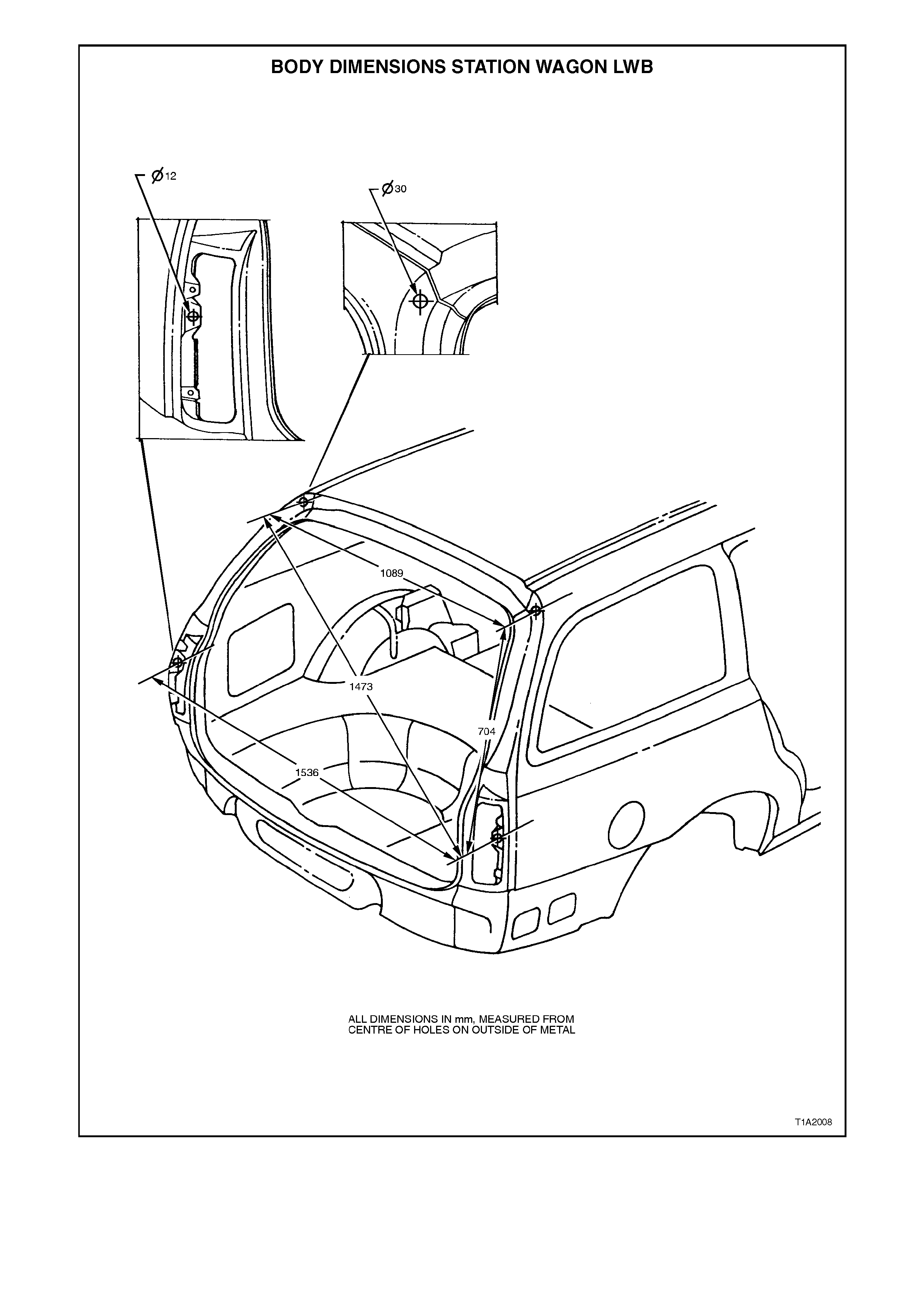
Figure 1A2-8
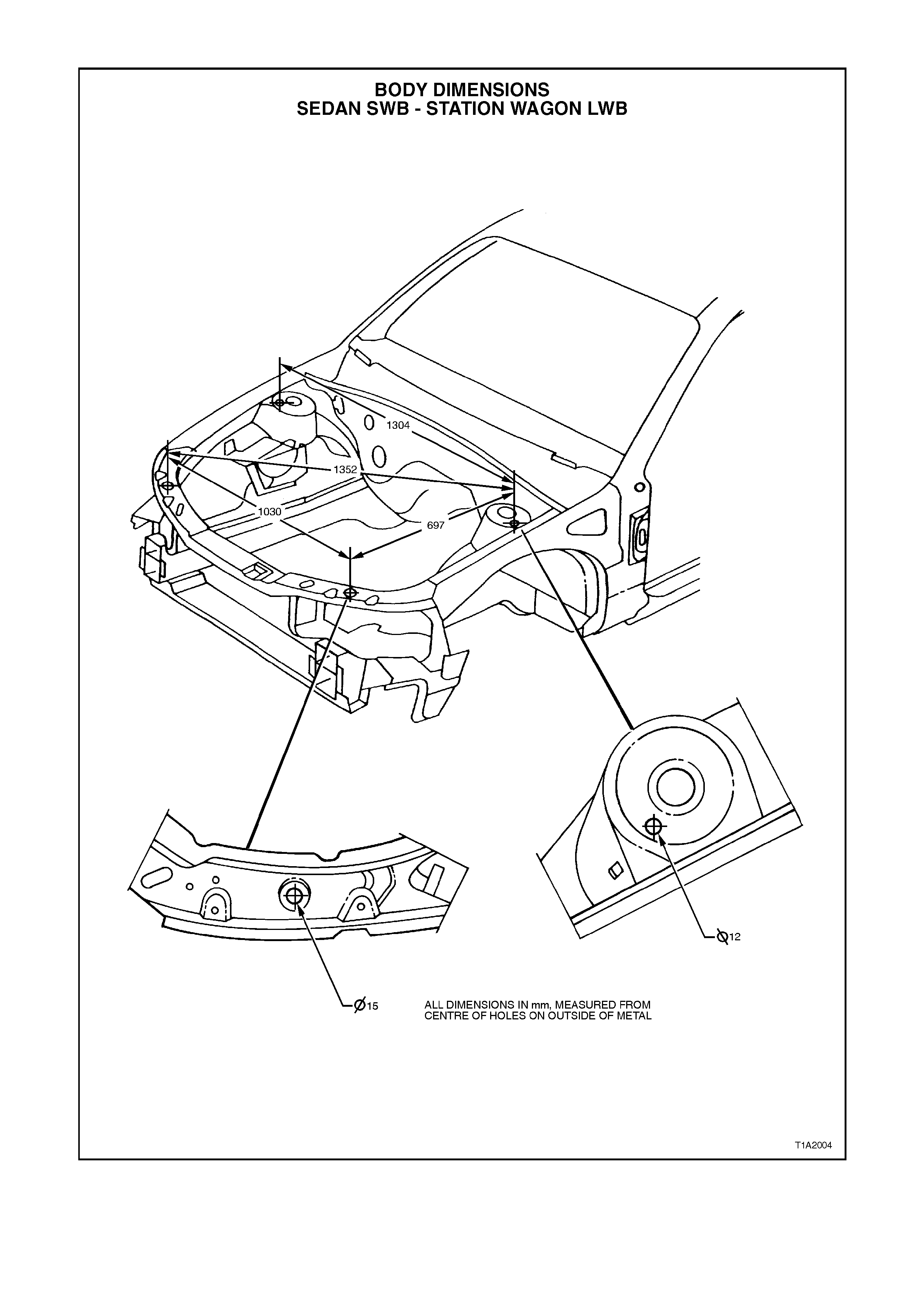
BODY DIMENSIONS - SEDAN SWB - STATION WAGON LWB
Figure 1A2-9
2.2 FRONT SUSPENSION CROSSMEMBER ALIGNMENT
NOTE:
Ensure that body dimensions are within specified
limits prior to commencing any crossmember
alignment. Refer to 2.1 BODY DIMENSIONS in
this Section.
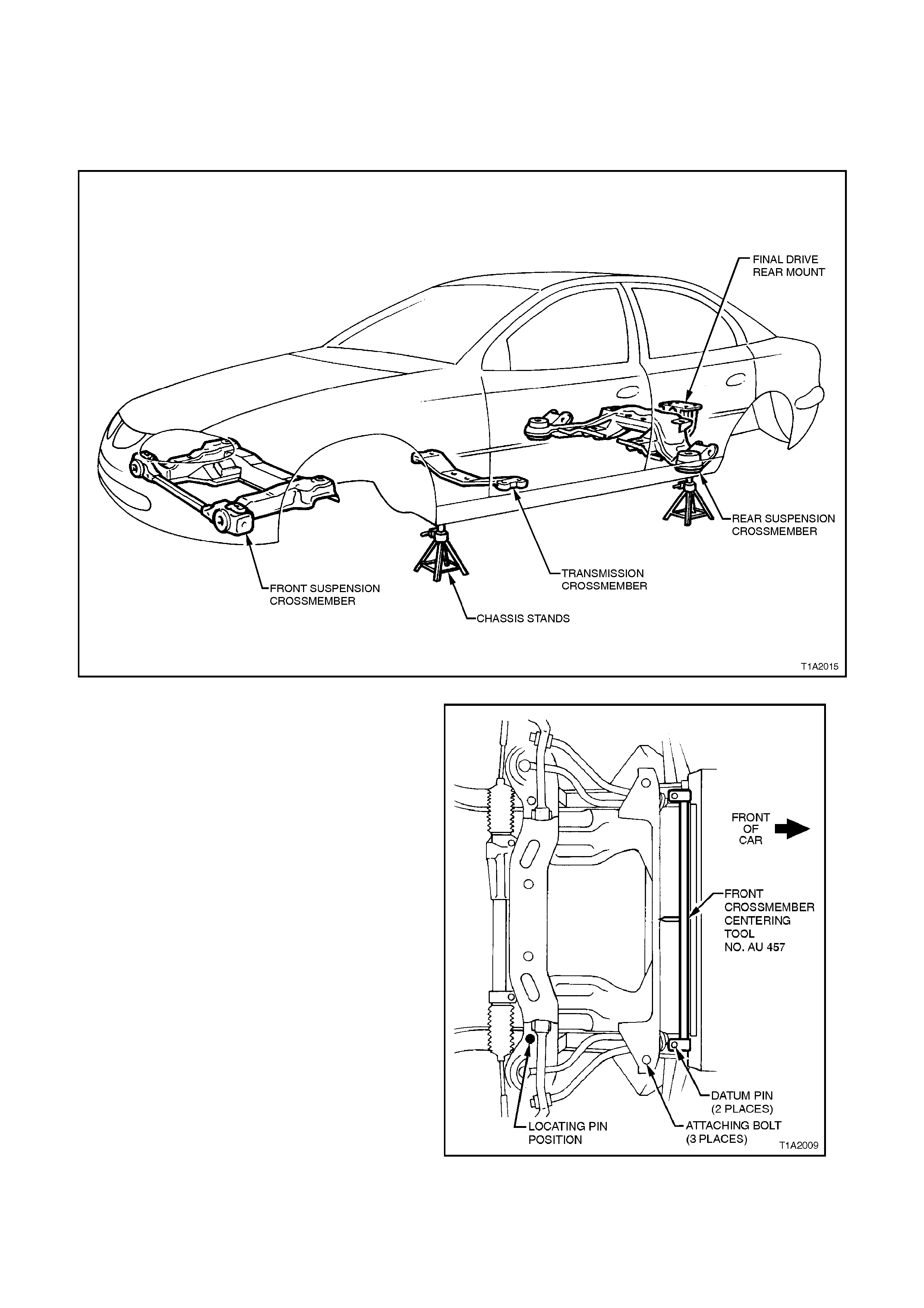
Figure 1A2-10
NOTE:
Front sus pension c r oss member c entring tool needs
to be held in position during the alignment
procedure. Therefore, assistance will be required
to complete this operation.
1. Using chassis stands support vehicle at hoist
pad locations.
2. Remove wheels, refer to Sectio n 10 W H EELS
AND TYRES.
3. Remove engine hood, refer to Section 1B
SHEETMETAL.
4. Support engine with overhead lifting device
and raise slightly to take weight off engine
mounts.
5. From underneath vehicle loosen front
crossmember attaching bolts.
6. Remove left rear attaching bolt and replace
with the locating pin from front suspension
crossmember centring tool No. AU 457.
7. Fit front suspension crossmember centring
tool No. AU 457.
NOTE:
Front suspension crossmember centring tool
locates into ∅ 19 mm body datum holes positioned
towards front of vehicle. Figure 1A2-11
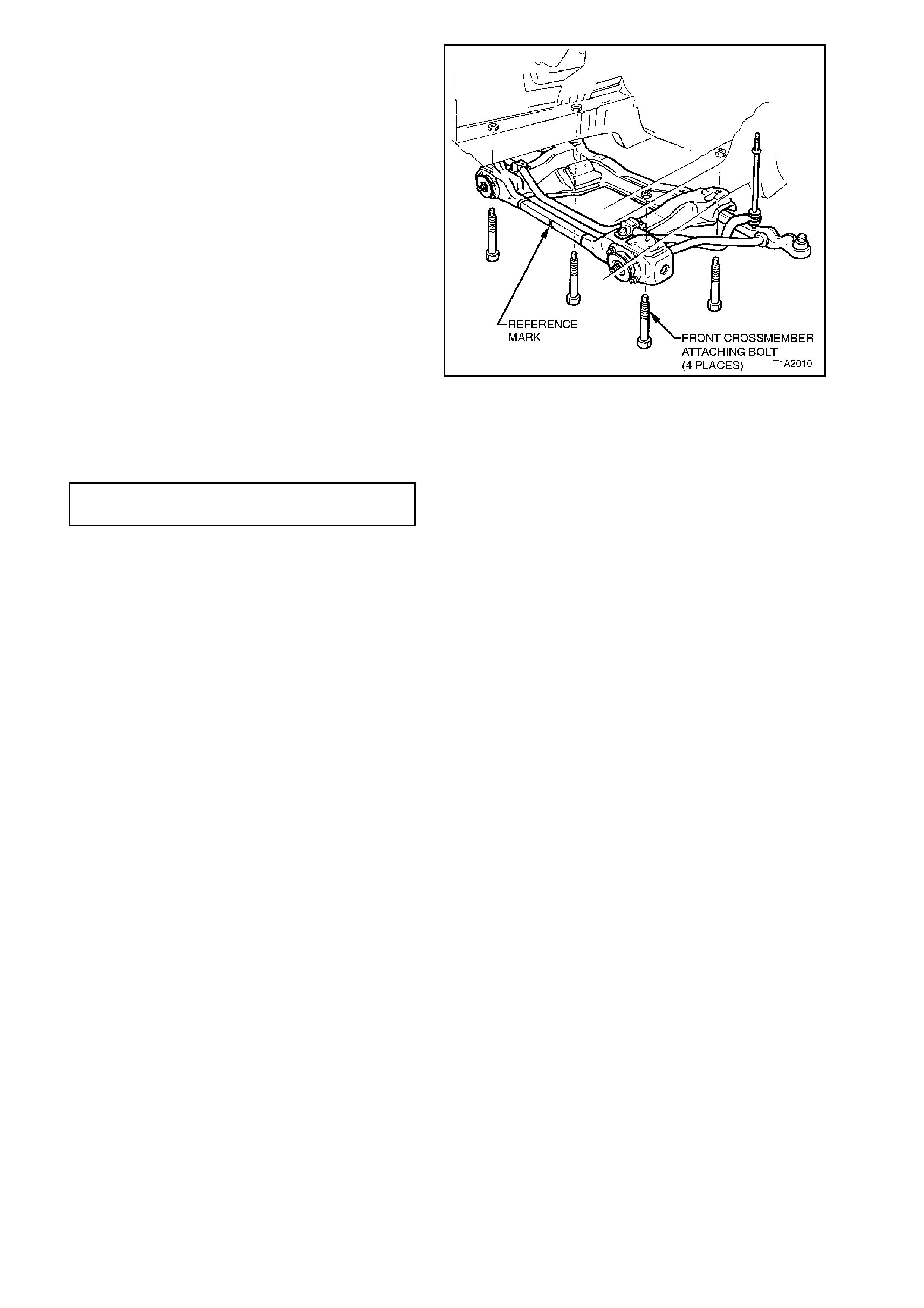
8. With the help of an assistant, manoeuvre the
front suspension crossmember so that the
reference mark on the crossmember is aligned
with the pointer on the centring tool.
NOTE:
Front suspension crossm ember has an ‘I’ stamped
on the front to aid in aligning to fixture pointer.
IMPORTANT:
Front suspension crossmember attaching bolts
mus t be renewed after each loosening and may be
replaced one at a time during this alignment
procedure.
Alignment of crossmember must be completed
within 20 minutes from installation of new bolts.
Attaching bolts are supplied with a micro-
encapsulated locking compound applied to threads
that will start to set immediately after installation
and will reach 20% adhesion after 30 minutes.
9. When crossmember is aligned, tighten the
three crossmember attaching bolts.
10. Remove locating pin.
CROSSMEMBER ATTACHING 120 - 125
BOLTS TORQUE SPECIFICATION Nm
11. Reinstall left rear crossmember attaching bolt
and washer and tighten.
Figure 1A2-12
12. Remove crossmember aligning fixture.
13. Gently lower engine and remove lifting device.
14. Attach wheels, refer to Section 10 WHEELS
AND TYRES.
15. Remove vehicle from chassis stands.
2.3 TRANSMISSION CROSSMEMBER ALIGNMENT
NOTE:
Ensure that body dimensions are within specified
limits prior to commencing any crossmember
alignment. Refer to 2.1 BODY DIMENSIONS in
this Section.
1. Using chassis stands support vehicle at hoist
pad locations.
2. From underneath the vehicle, support
transmission with a trolley jack and raise
slightly to take weight off transmission mount.
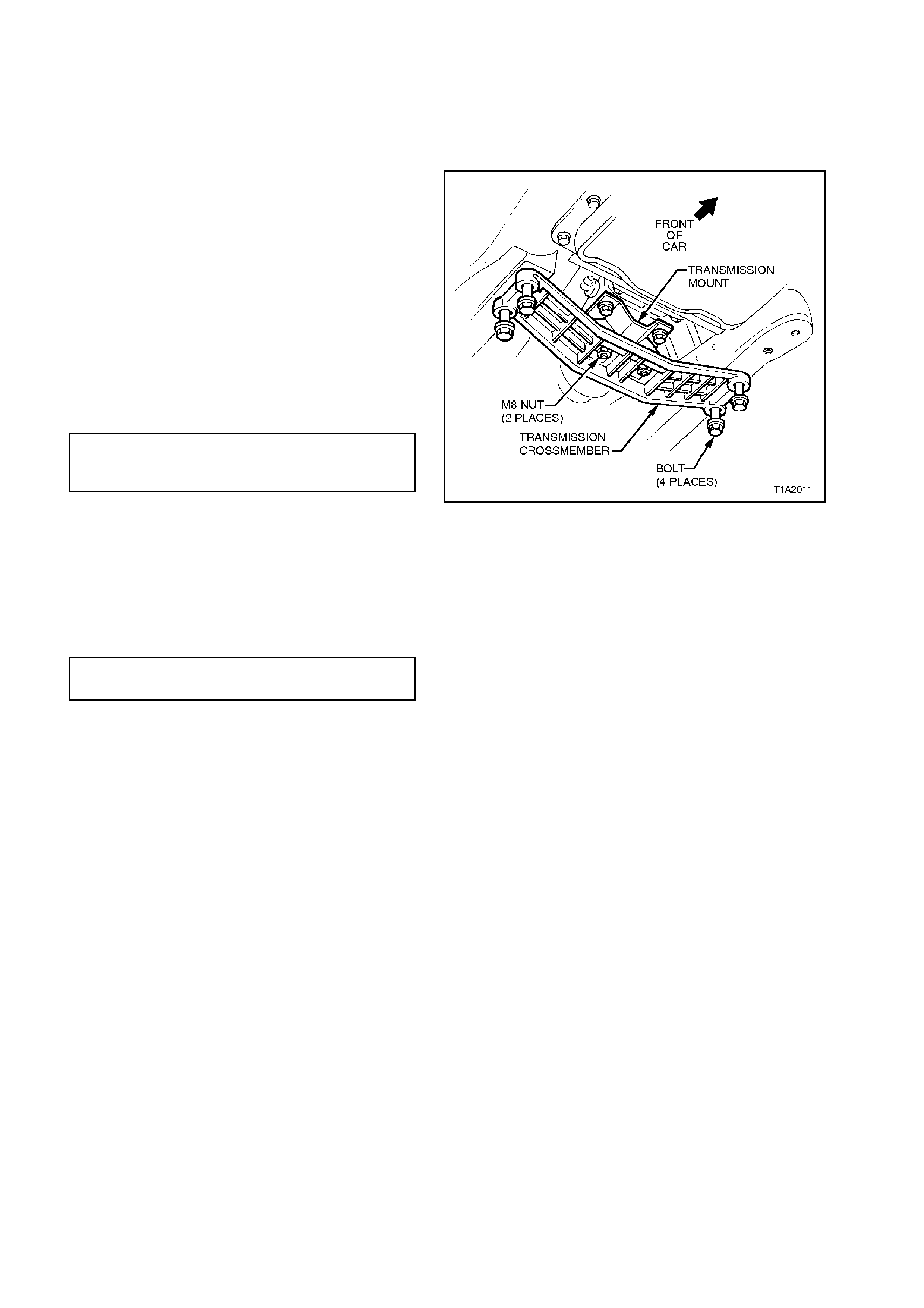
3. Remove two M8 nuts securing transmission
mount to transmission crossmember.
4. Loosen four attaching bolts securing
transmission crossmember to underbody.
5. Centralise transmission crossmember within
bolt holes.
6. Tighten the four attaching bolts.
TRANSMISSION CROSSMEMBER
ATTACHING BOLTS 50 - 65 Nm
TORQUE SPECIFICATION
7. With the help of an assistant manoeuvre the
transmission to ensure that the studs
protruding through the crossmember are
centralised within the stud holes.
8. Reinstall M8 nuts securing transmission mount
to transmission crossmember.
TRANSMISSION MOUNT M8 NUTS 20 - 30
TORQUE SPECIFICATION Nm
9. Gently lower trolley jack and remove from
under vehicle.
10. Remove vehicle from chassis stands.
Figure 1A2-13
2.4 REAR SUSPENSION CROSSMEMBER ALIGNMENT
NOTE:
Ensure that body dimensions are within specified
limits prior to commencing any crossmember
alignment. Refer to 2.1 BODY DIMENSIONS in
this Section.
NOTE:
Rear suspens ion crossm ember c entring tool needs
to be held in position during the alignment
procedure. Theref ore, as s istanc e will be required to
complete this operation.
1. Using chassis stands support vehicle at hoist
pad locations.
2. Remove wheels, refer to Sectio n 10 W H EELS
AND TYRES.
3. Remove intermediate muffler and pipe
assembly together with rear muffler and pipe
assembly refer to Section 8B EXHAUST
SYSTEM.
4. From underneath the vehicle, support final
drive with a trolley jack and raise slightly to
take weight off final drive mount.
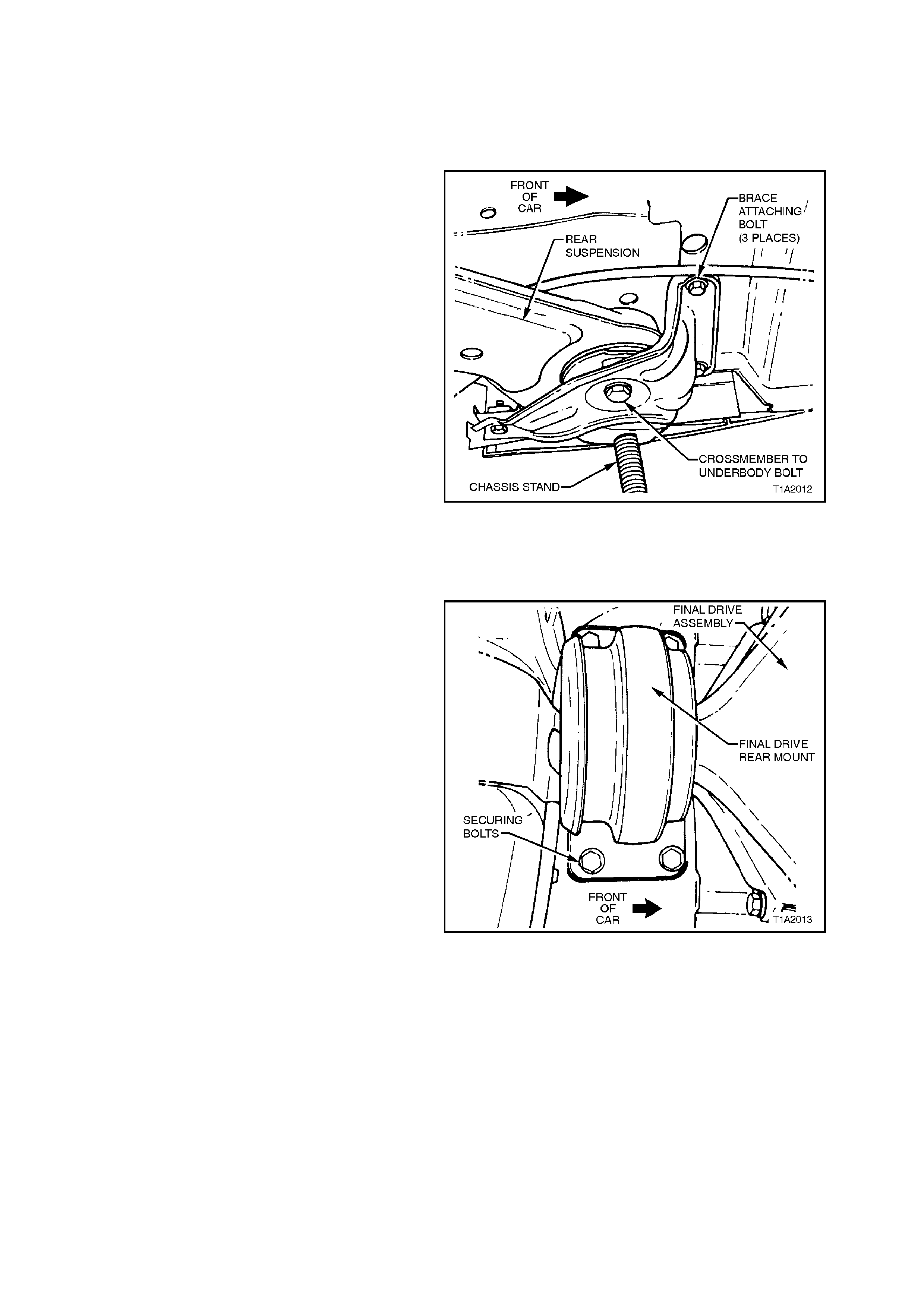
5. Loosen three M10 screws securing
crossmember to body brace lefthand side and
righthand side.
6. Loosen rear suspension crossmember
attaching bolts (M14) lefthand side and
right hand side.
Figure 1A2-14
7. Loosen four bolts securing final drive rear
mount.
IMPORTANT:
Rear suspension crossmember attaching bolts and
final drive rear mount attaching screws must be
renewed after each loos ening and m ay be replaced
one at a time during this alignment procedure.
Alignment of crossmember must be completed
within 20 minutes from installation of new bolts.
Attaching bolts are supplied with a micro
encapsulated locking compound applied to threads
that will start to set immediately after installation
and will reach 20% adhesion after 30 minutes.
Figure 1A2-15
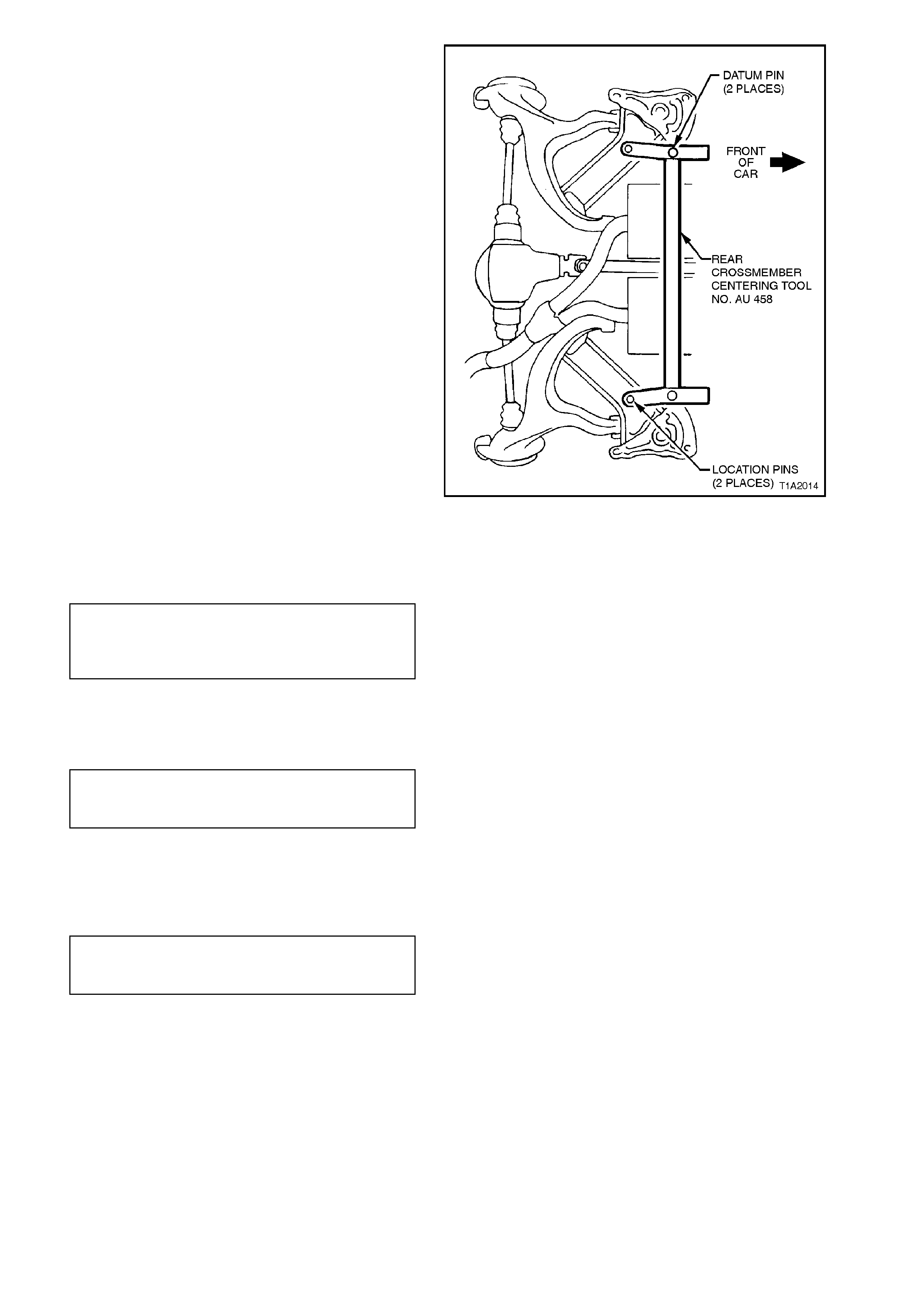
8. Fit rear suspension centring tool No. AU 458.
NOTE:
Rear suspension crossmember centring tool
locates into ∅ 19 mm body datum holes positioned
forward of rear suspension crossmember.
9. With the help of an assistant, manoeuvre the
rear suspension crossmember until the
location pins of the rear c ros s member centr ing
tool engages the alignment holes on the rear
suspension crossmember.
Figure 1A2-16
10. Tighten rear suspension crossmember
attaching bolts (M14) left-hand side and right-
hand side.
REAR SUSPENSION
CROSSMEMBER 125 Nm, rotate
ATTACHING BOLTS 30° - 45° with a
TORQUE SPECIFICATION min. of 135 Nm
11. Tighten four screws securing final drive rear
mount.
FINAL DRIVE REAR MOUNT
ATTACHING SCREWS 30 - 45 Nm
TORQUE SPECIFICATIONS
12. Tighten three M10 screws securing
crossmember to body brace lefthand side and
righthand side.
CROSSMEMBER M10
SECURING SCREWS 60 - 85 Nm
TORQUE SPECIFICATION
13. Remove rear crossmember centring tool.
14. Gently lower trolley jack and remove from
under vehicle.
15. Attach wheels, refer to Section 10 WHEELS
AND TYRES.
16. Remove vehicle from chassis stands.

3. TORQUE WRENCH SPECIFI CATIONS
Nm
Front crossmember attaching bolts 120 - 125
Transmission crossmember attaching bolts 50 - 65
Transmission mount securing nuts 20 - 30
Rear suspension crossmember attaching
bolts (M14) 125 Nm and rotate 30° - 45°
with a min. of 135 Nm
Final drive rear mount 30 - 45
Crossmember securing screws (M10) 60 - 85
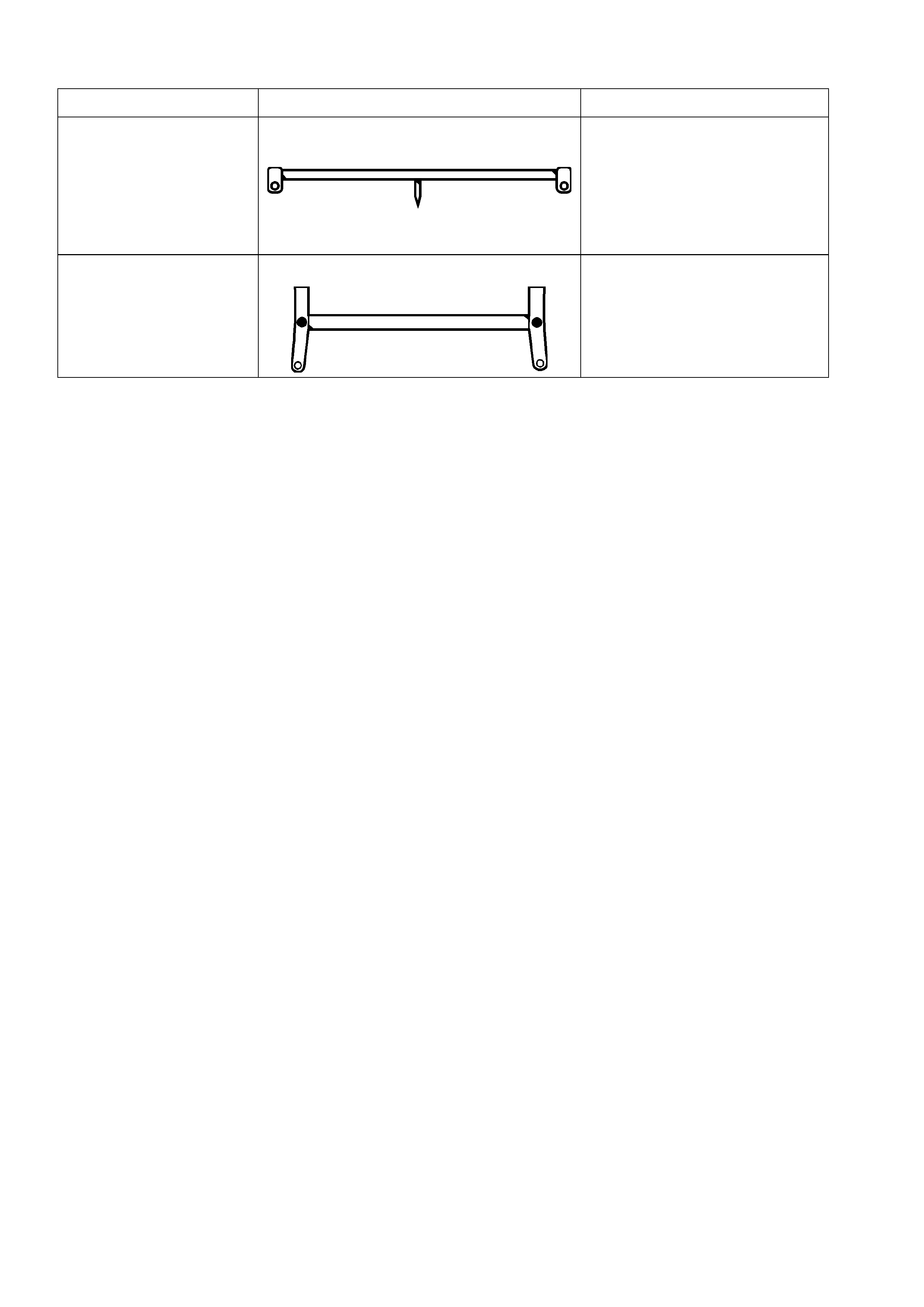
4. SPECIAL TOOLS
TOOL NO. REF IN TEXT TOOL DESCRIPTION COMMENTS
AU 457 FRONT CROSSMEMBER CENTRING
TOOL
AU 458 REAR CROSSMEMBER CENTRING TOOL