SECTION 1A3 - INSTRUMENT PANEL AND CONSOLE
Click on the button for more information.
CAUTION:
This vehicle will be equipped with a Supplemental Restraint System (SRS). A SRS will
consist of either seat belt pre-tensio ners and a driver’s side air bag , or seat belt pre-
tensioners and a driver’s and front passenger’s side air bags. Refer to CAUTIONS,
Section 12M, before performing any service operation on or around SRS
components, the steering mechanism or wiring. Failure to follow the CAUTIONS
could result in SRS deplo yment, resulting in possible p ersonal injury or unnecessary
SRS system repairs.
CAUTION:
This vehicle may be equipped with LPG (Liquefied Petroleum Gas). In the interests of
safety, the LPG fuel system should be isolated by turning 'OFF' the manual service
valve and then draining the LPG serv ice lines, before any service w ork is carried out
on the vehicle. Refer to the LPG leaflet included with the Owner's Handbook for
details or LPG Section 2 for more specific servicing information.
1. SERVICE OPERATIONS
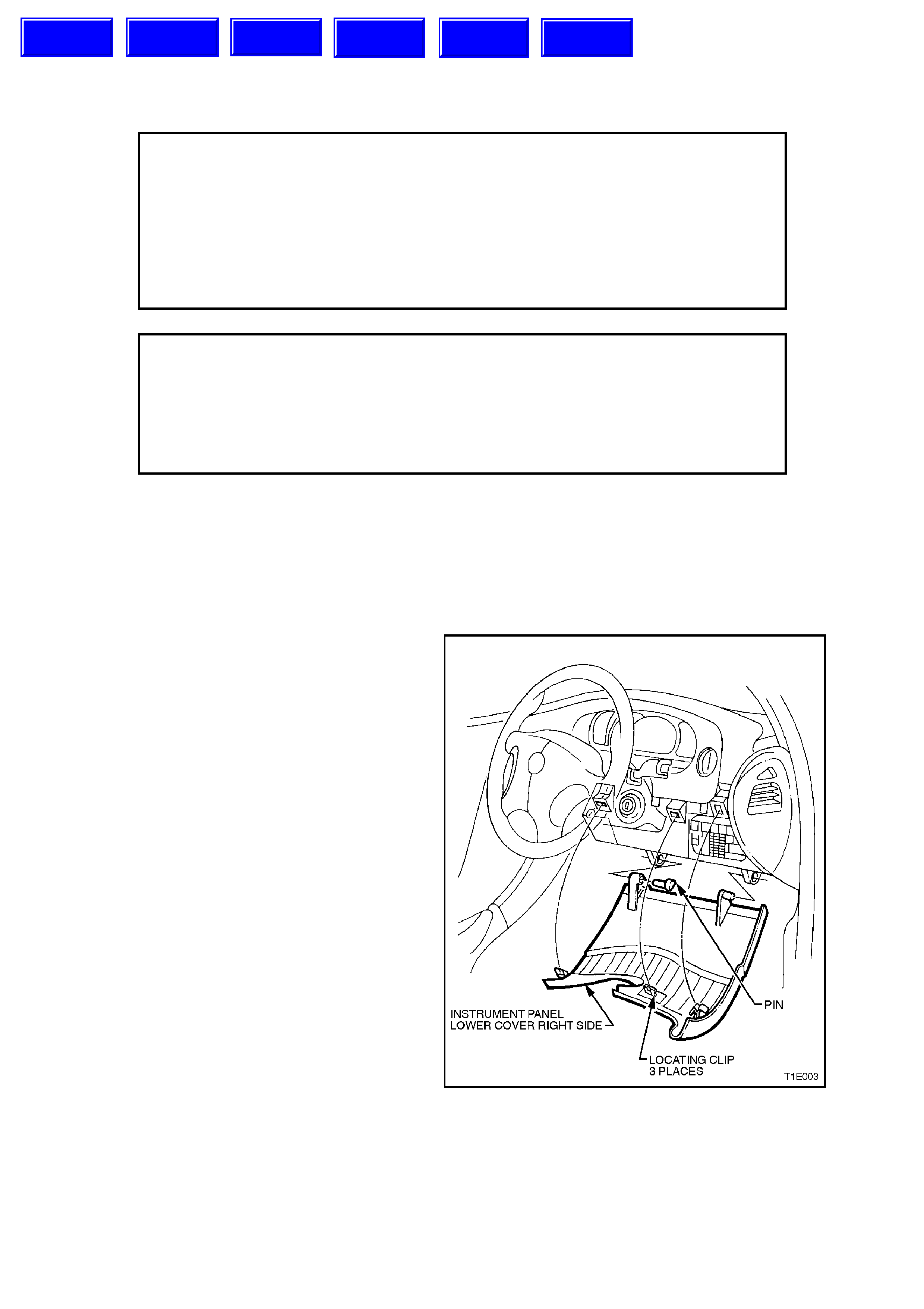
1.1 INSTRUME NT P ANEL LOWER COVER - RIGHT SIDE
REMOVE
1. Adjust steering wheel to upper most position.
Grasp right hand side of lower cover panel
firmly and pull towards rear of vehicle. Repeat
procedure f or lef t hand side of cover. Prise out
the left hand hinge pin using a flat blade
screwdriver.
Tilt the cover down on the left side and
disengage the right hand hinge pin and
remove panel.
Figure 1A3-1
REINSTALL
Reverse removal operations.
Techline
Techline
Techline
Techline
Techline
Techline
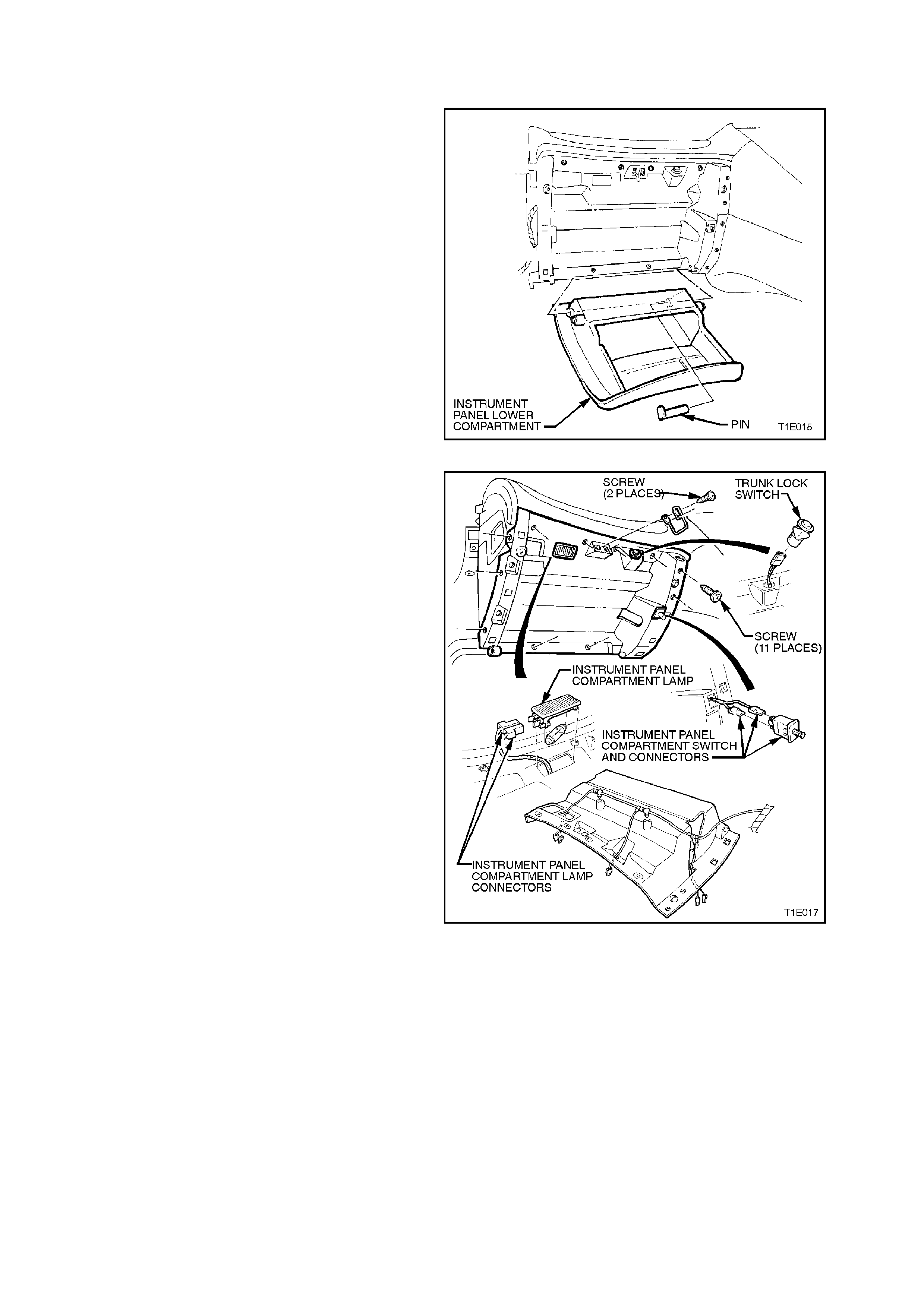
1.2 INSTRUMENT PANEL COMPARTMENT
REMOVE
1. Open the instrum ent panel lower com par tm ent
and lever the hinge pin from the right side.
Lower compartment and withdraw the pin.
Disengage travel limiting pegs by tilting
instrument panel lower compartment.
Figure 1A3-2
2. Remove 11 retaining screws from instrument
compartment roof, disconnect instrument
panel lamp connectors, trunk lock switch
connector, ins trum ent panel switch connectors
and unclip glove box wiring harness. Remove
instrument compartment roof.
Figure 1A3-3
REINSTALL
Reverse removal operations.
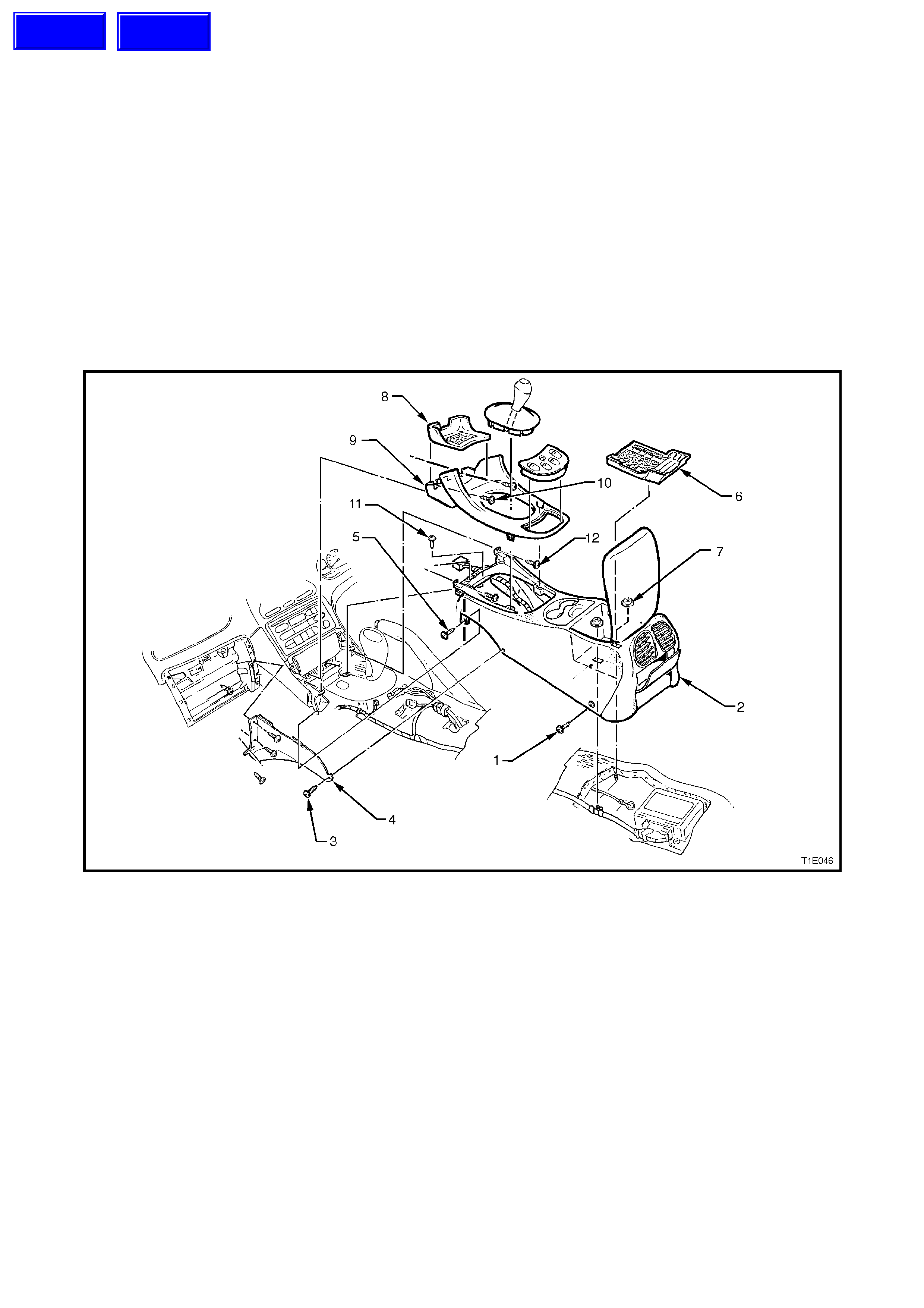
1.3 CENTRE CONSOLE
REMOVE
1. Slide front seats forward and remove the two rear screws(1), from the centre console(2). Slide front seats all the
way to the rear and remove the two screws (3) securing the rear of the centre facia side extensions (4) to the
centre cons ole. Carefully pull the rear of the centr e facia side ex tensions away f rom the console to gain access
to the two screws (5) securing centre console to transmission tunnel.
2. Open the centre console bin and remove the rubber insert (6). Remove the two retaining nuts (7).
3. For vehicles with m anual transm is sion, rem ove the gears hift k nob by rotating counter cloc kwise. Pr ise gears hift
boot from centre console.
4. Remove rubber cap (8) from tr ansmis sion console (9) and r emove two sc rews (10) fr om trans miss ion console.
Carefully prise out the transm ission cons ole, disconnecting the power window and console bin lamp harness es
where fitted.
5. Remove four screws (11) and (12) attaching the centre console to the instrument panel.
6. For vehicles with automatic transmission, place the selector lever in the ‘2’ position.
7. Remove centre console by lifting rear end up and pulling assembly out.
Figure 1A3-4
REINSTALL
Reverse removal operations.
Techline
Techline

1.4 INSTRUME NT P ANEL FACIA
REMOVE
1. Lower instrument panel lower cover - right
side.
For cars with manual transmission, remove
gearshift knob by rotating counter-clockwise
and prise gearshift boot from transmission
console.
2. Remove rubber insert from transmission
console cap and remove two screws securing
transmission console to instrument panel.
Prise out transmission console from centre
console, disc onnecting power window harness
where fitted. Refer to 1.3 CENT RE CONSOLE
in this Section.
3. Remove radio/cassette/CD from instrumnt
panel, use service tool 179 1308 0000 to
assist in removal.
Figure 1A3-5
4. Disconnect radio/cassette harness and if
fitted, CD connector. Doscpnnec t antenna and
if fitted, diversity antenna. For further
information refer to Section 12D RADIO in the
VT Series I Service Information.
Figure 1A3-6
Techline
Techline
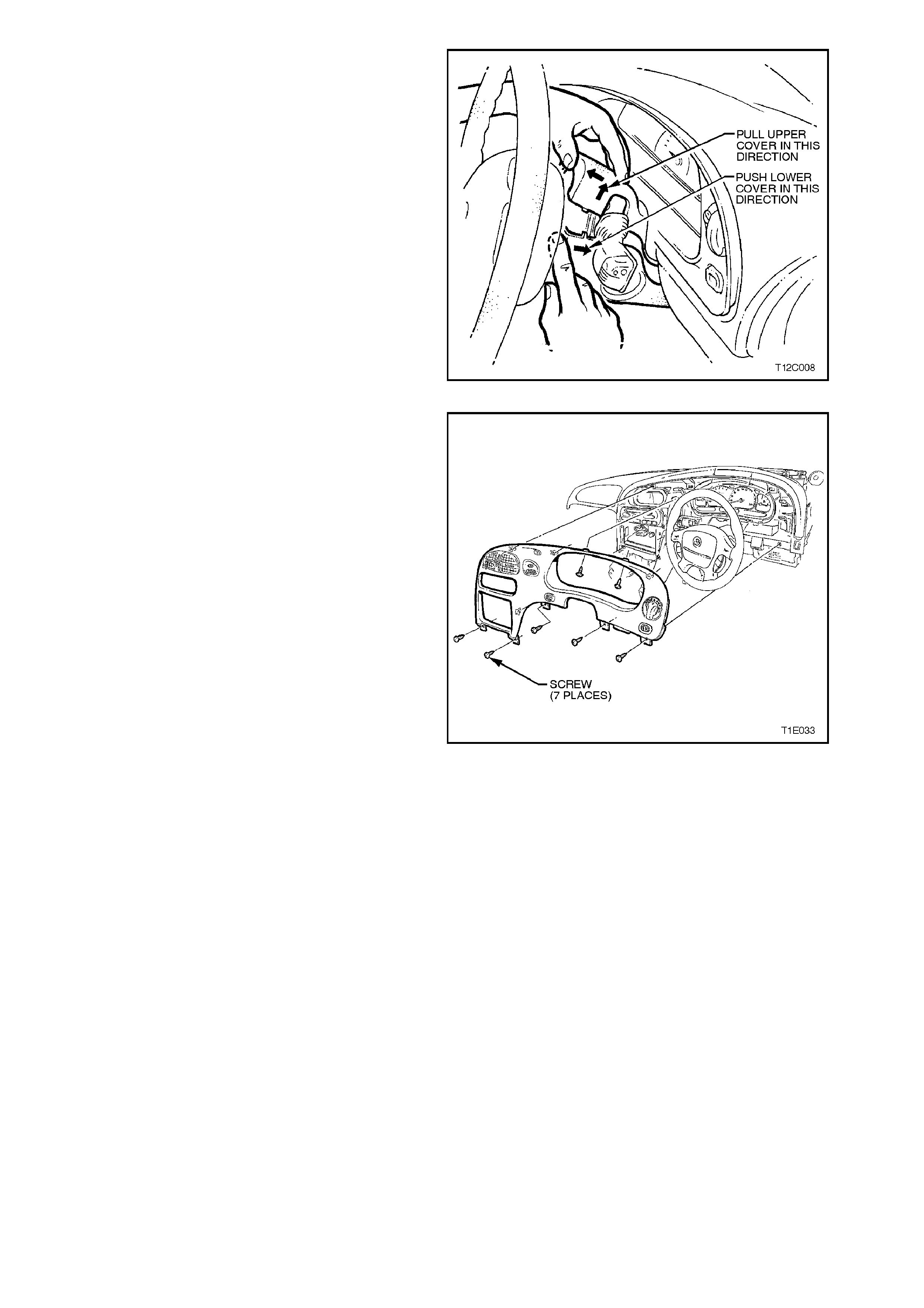
5. Remove single screw from the lower steering
colu mn cover.
6. Remove upper and lower steering covers.
Figure 1A3-7
7. Remove the seven screws retaining the
instrument facia assembly, and pull facia from
retaining clips.
NOTE:
Care must be taken to disconnect the headlamp
switch connector, fog lamp switch connector (if
fitted), trip computer switch connector (if fitted) and
hazard switch connector from main wiring harness.
Figure 1A3-8
REINSTALL
Reverse removal operations ensuring all
harnesses are reconnected prior to attaching facia
to retaining clips and replacing seven retaining
screws.
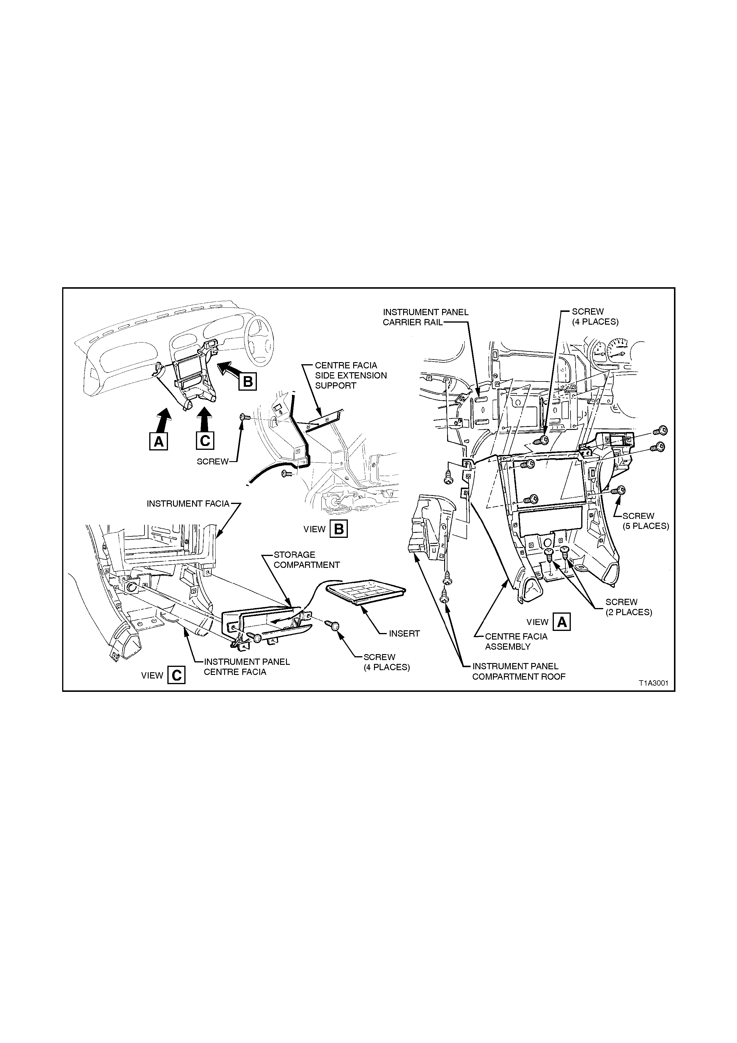
1.5 INSTRUMENT PANEL CENTRE FACIA ASSEMBLY
REMOVE
1. Remove instrument panel facia, refer to
1.4 INSTRUMENT PANEL FACIA in this
Section.
2. Remove two screws securing storage
compartment and remove storage
compartment.
3. Remove instrument panel compartment roof,
refer to 1.2 INSTRUMENT PANEL
COMPARTMENT in this Section.
4. Remove eight screws securing centre facia to
instrument panel carrier and remove centre
facia assembly.
Figure 1A3-9
REINSTALL
Reverse removal operations.
1.6 INSTRUMENT PANEL PAD ASSEMBLY
REMOVE
CAUTION:
Disable the SRS (Air Bag). Refer to DISABLING
THE SRS, Section 12M SRS.
1. Disconnect battery ground cable.
2. Remove instrument panel lower cover - right
side, instrument panel compartment, centre
console and instrument panel facia, refer to
1.1, 1.2, 1.3 and 1.4 in this Section.
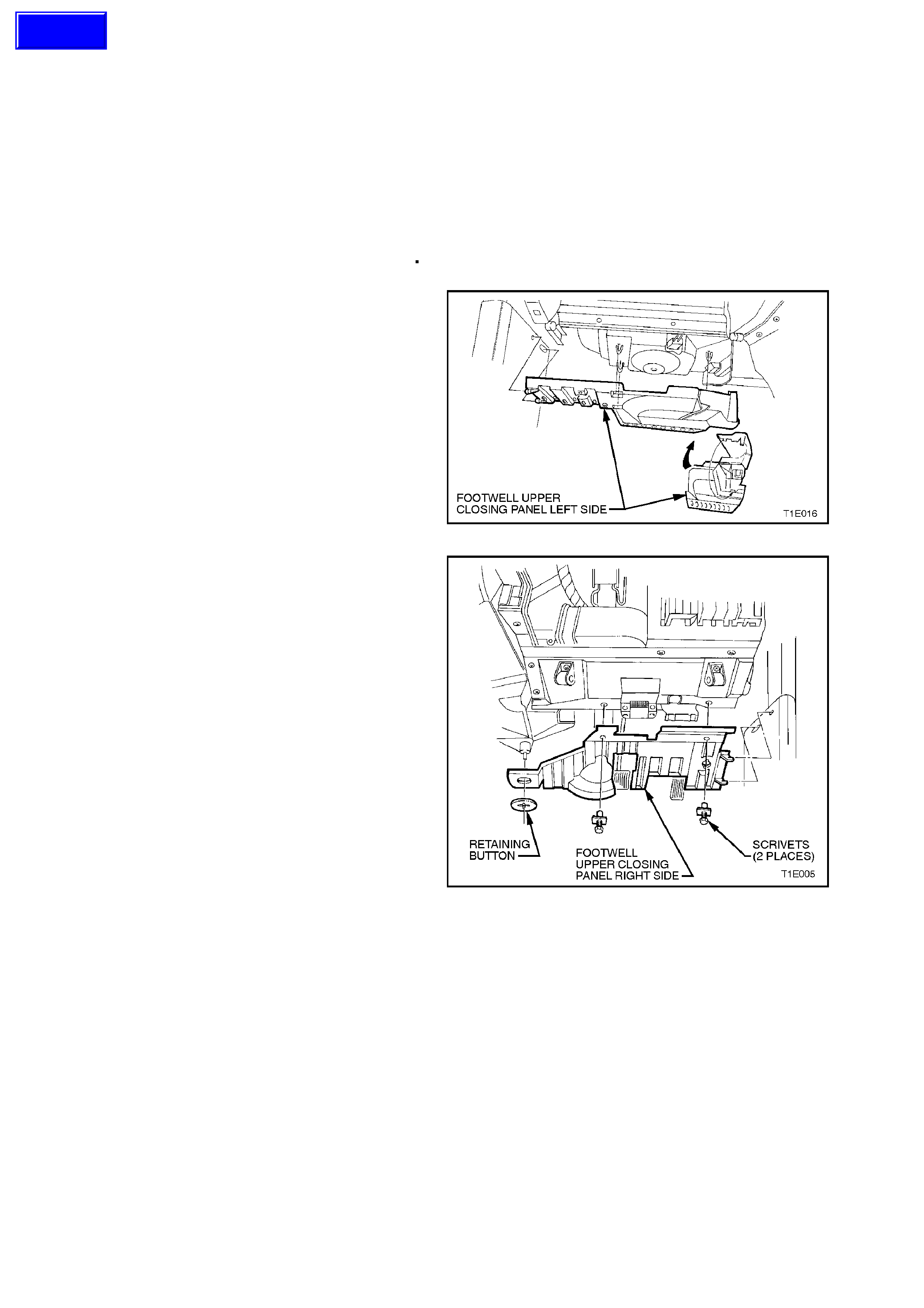
3. Unclip duct cover flap on right hand side of
footwell upper closing panel left side,
disengage locating lugs to passenger side
shroud lower and grab c losing panel f ir mly and
detach by pulling left side down first, then
disengage right side clip and remove panel.
4. Remove passenger side shroud lower trim
assembly, for further information refer to
Section 1A1 UNDERBODY.
Figure 1A3-10
5. Remove two scrivets and on vehicles fitted
with automatic tr ansm ission, prise off retaining
button and detach the footwell upper closing
panel right side.
Where fitted remove front footwell light. For
further information refer to Section 12B
LIGHTING SYSTEM.
Figure 1A3-11
Techline
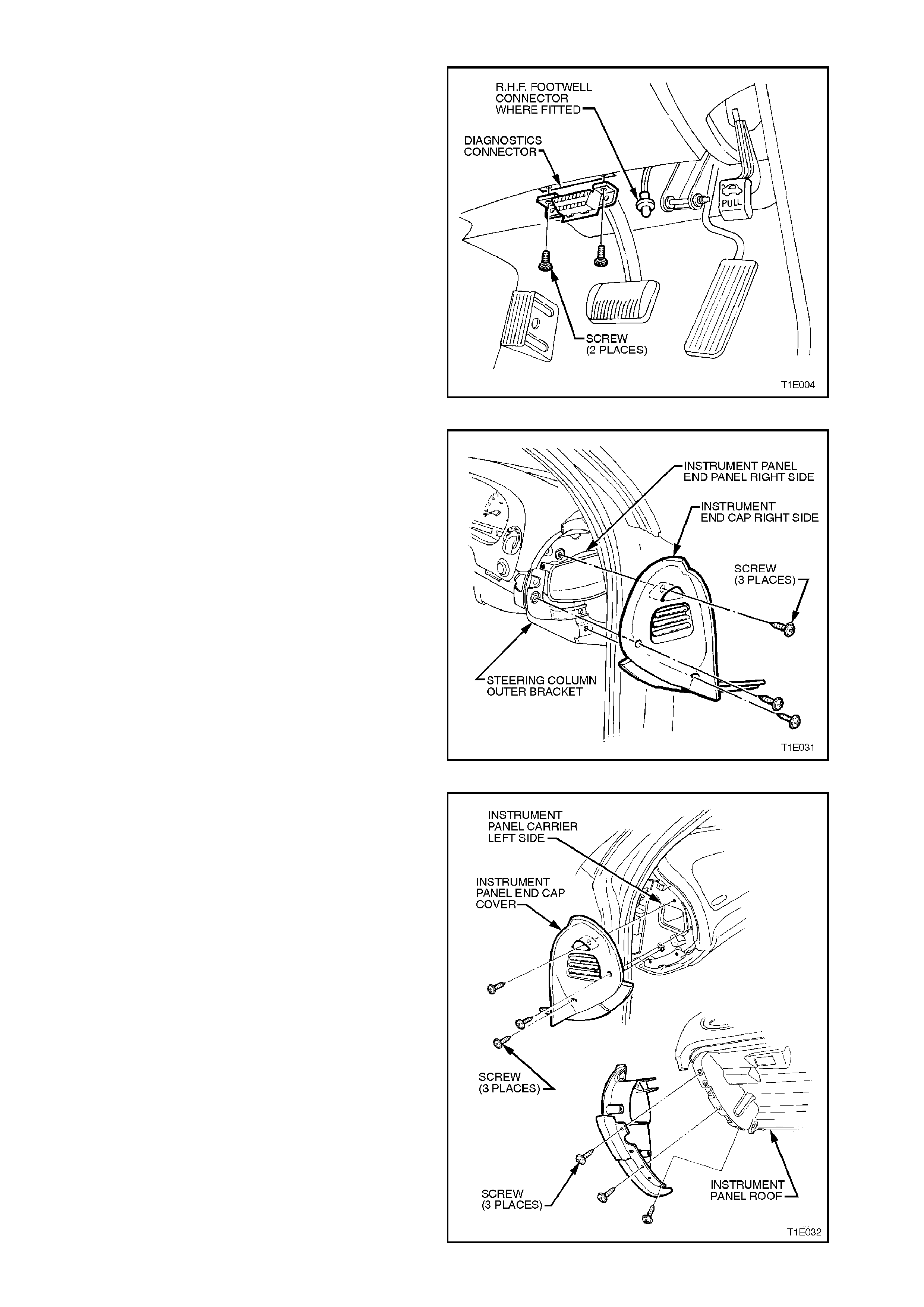
6. Remove two screws securing diagnostics
connector to instrument panel lower trim right
side assembly.
Figure 1A3-12
7. Remove three screws and remove instrument
panel end cap cover right hand side.
Figure 1A3-13
8. Remove six retaining screws for instrument
panel end cap cover left hand side.
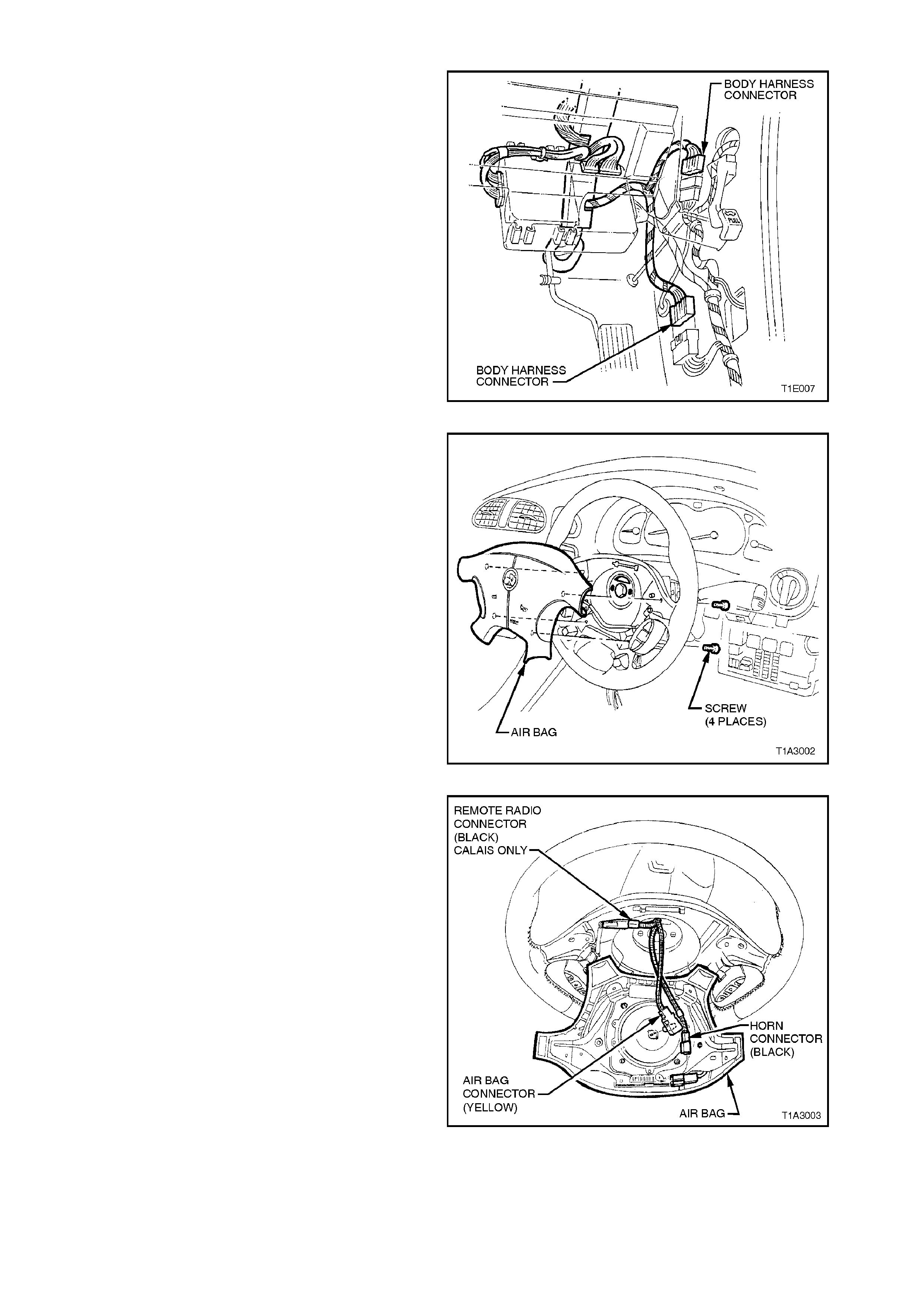
Figure 1A3-14
9. Remove driver’s side shroud lower trim
assembly, refer to
Section 1A1 UNDERBODY.
10. Separate the rear body harness and main
wiring harness at the connector.
Figure 1A3-15
11. Rem ove f our r etaining s cr ews s ecur ing air bag
to steering wheel.
Figure 1A3-16
12. Disconnect horn connector, airbag connector
and if fitted remote radio connector.
Figure 1A3-17
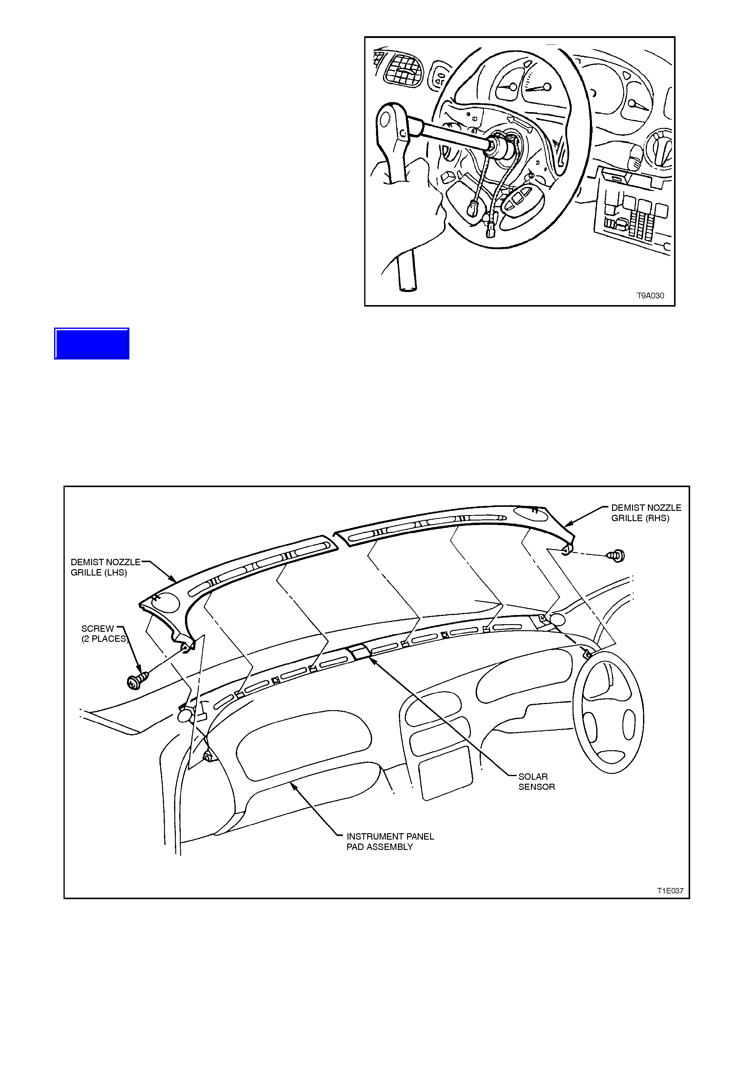
13. Using Torx driver remove single screw
securing steering wheel to steering column,
and remove steering wheel. Refer to
Section 9A STEERING.
Figure 1A3-18
15. Remove retaining screw from the demist
nozzle right hand and remove.
16. Remove retaining screw from the demist
nozzle left hand and remove.
NOTE:
Care must be taken not to dam age the sun sensor
when removing the demist grille.
Figure 1A3-19
Techline
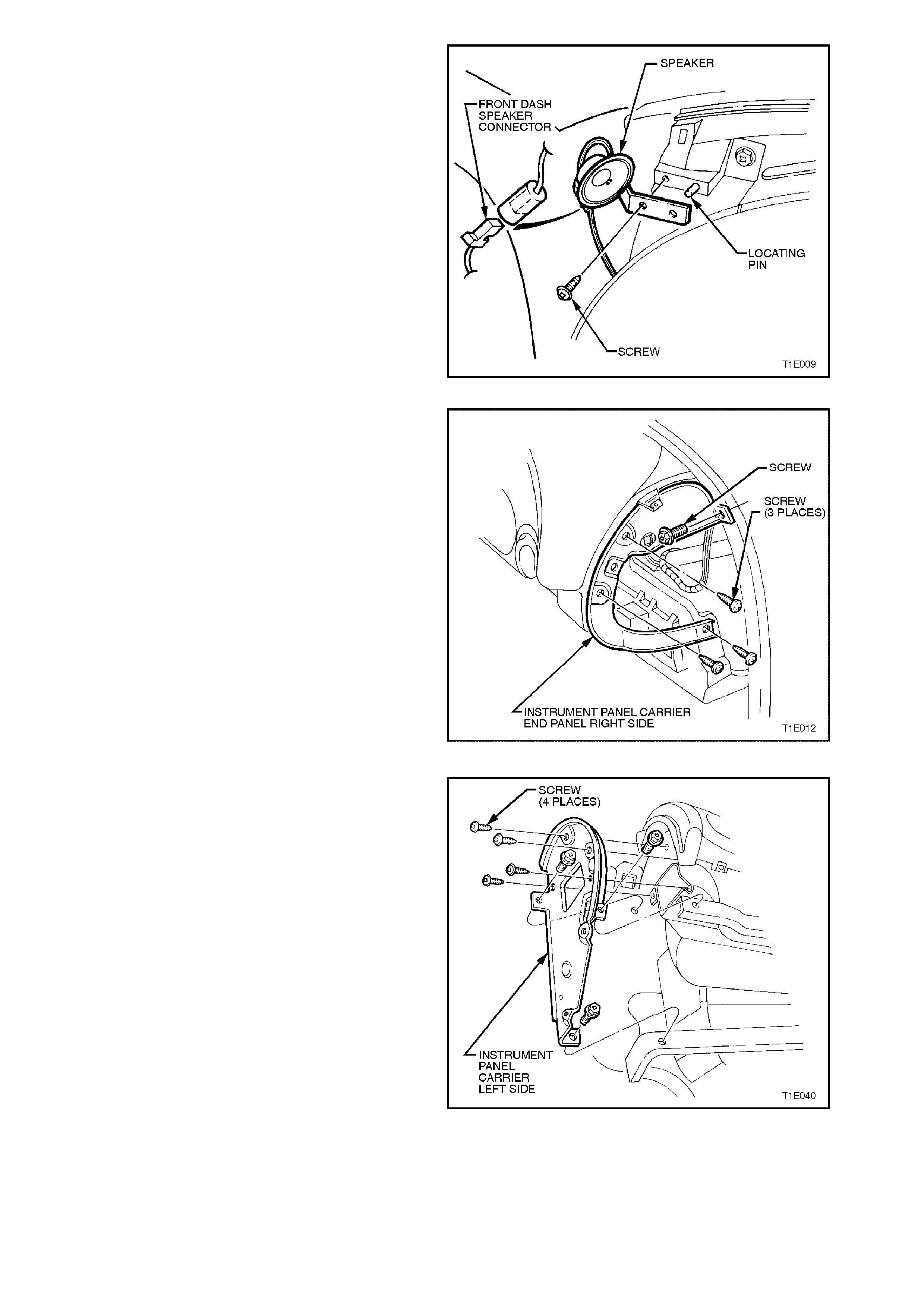
17. Disconnect left and right front dash speaker
harness connectors. Using a Phillip’s screw
driver, remove screw attaching front dash
speakers and remove both speakers.
Figure 1A3-20
18. Remove three retaining screws and one bolt
from instrument panel carrier end panel right
side and remove panel.
Figure 1A3-21
19. Remove four attaching screws securing
instrument panel carrier end panel left side
and two bolts attaching passenger air bag
support rail, lower left side rail, and remove
panel.
Figure 1A3-22
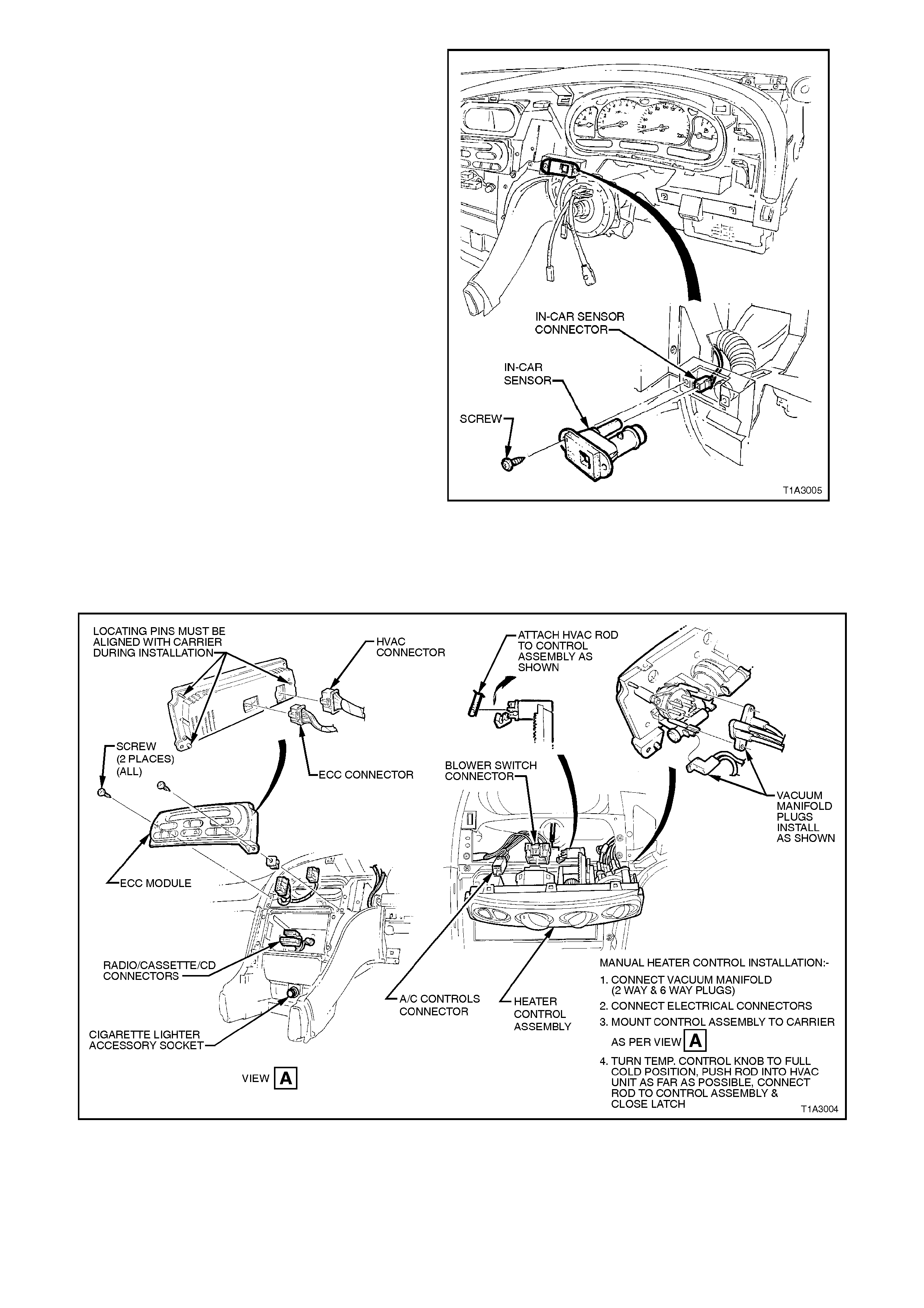
20. Remove the two attaching screws securing in-
car sensor (if fitted) and disconnect harness
connector, refer to Section 2D AIR
CONDITIONING – ECC – Description and
Operation in the VT Series I Service
Information.
21. Remove the screws securing centre facia
assembly and remove centre facia assembly,
refer to 1.5 INSTRUMENT PANEL CENTRE
FACIA ASSEMLY in this section.
Figure 1A3-23
22. Remove the screws securing the heater and
air conditioning controls and disconnect the
electrical connections. Remove heater control
assembly or ECC control unit, where fitted.
Figure 1A3-24
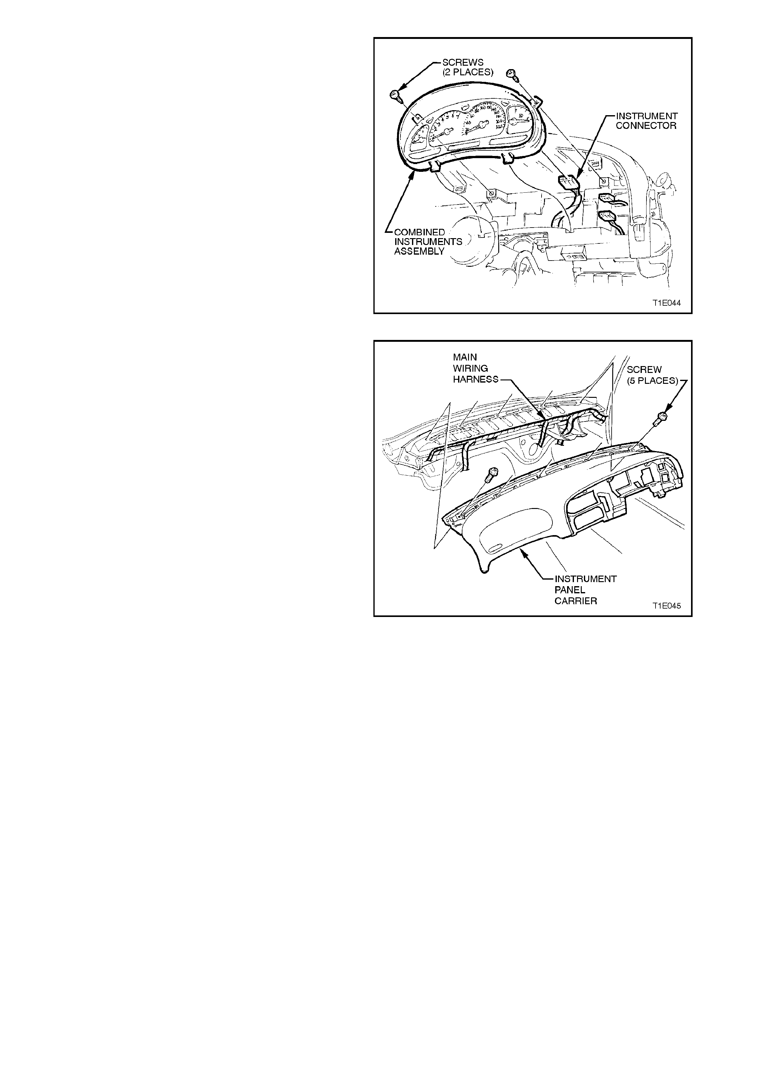
23. Remove the screws securing the combined
instruments assembly and disconnect
instruments connector.
Figure 1A3-25
24. Remove five screws securing the instrument
panel carrier and remove instrument panel
carrier.
Figure 1A3-26
REINSTALL
Reverse removal operations.
IMPORTANT:
Enable the SRS (Air Bag). Refer to ENABLING
THE SRS, Section 12M SRS.

2. TORQUE WRENCH SPECIFI CATIONS
Nm
Instrument panel compartment attaching screws 1 - 3
Instrument panel compartment lock striker
attaching screws 1 - 3
Centre console securing screws 1 - 3
Centre console bin retaining nuts 3 - 5
Transmission console retaining screws 1 - 3
Storage compartment securing screws 1 - 3
Screws securing transmission console cap to
instrument panel 1 - 3
Lower steering column shroud screw 0.5 - 2
Instrument facia assembly retaining screws 1 - 3
Storage compartment retaining screws 1 - 3
Cent re facia assembly securing screws 1 - 3
Diagnostics connector attaching screws 1 - 2
Instrument panel end cap cover attaching screws 1 - 3
Airbag securing screws 8 - 11.3
Steering wheel securing screw 40 - 50
Demist nozzle retaining screws 1 - 3
Front dash speaker connecting screws 1 - 2
Instrument panel carrier end panel attachment
screws 1 - 3
Instrument panel carrier panel attaching bolts 3 - 5
In-car sensor attaching screws 1 - 3
Heater and air conditioning controls securing
screws 1 - 3
Combined instruments assembly securing screws 1 - 3
Instrument panel carrier retaining screws 7 - 12
3. SPECIAL TOOLS
TOOL NO. REF IN TEXT TOOL DESCRIPTION COMMENTS
179 1308 0000 RADIO REMOVAL TOOL