SECTION 1A4 - REAR COMPARTMENT LID AND
TAILGATE
CAUTION:
This vehicle will be equipped with a Supplemental Restraint System (SRS). A SRS will
consist of either seat belt pre-tensio ners and a driver’s side air bag , or seat belt pre-
tensioners and a driver’s and front passenger’s side air bags. Refer to CAUTIONS,
Section 12M, before performing any service operation on or around SRS
components, the steering mechanism or wiring. Failure to follow the CAUTIONS
could result in SRS deplo yment, resulting in possible p ersonal injury or unnecessary
SRS system repairs.
CAUTION:
This vehicle may be equipped with LPG (Liquefied Petroleum Gas). In the interests of
safety, the LPG fuel system should be isolated by turning 'OFF' the manual service
valve and then draining the LPG serv ice lines, before any service w ork is carried out
on the vehicle. Refer to the LPG leaflet included with the Owner's Handbook for
details or LPG Section 2 for more specific servicing information.
1. SERVICE OPERATIONS
1.1 REAR COMPARTMENT LID ASSEMBLY - SEDAN
REMOVE
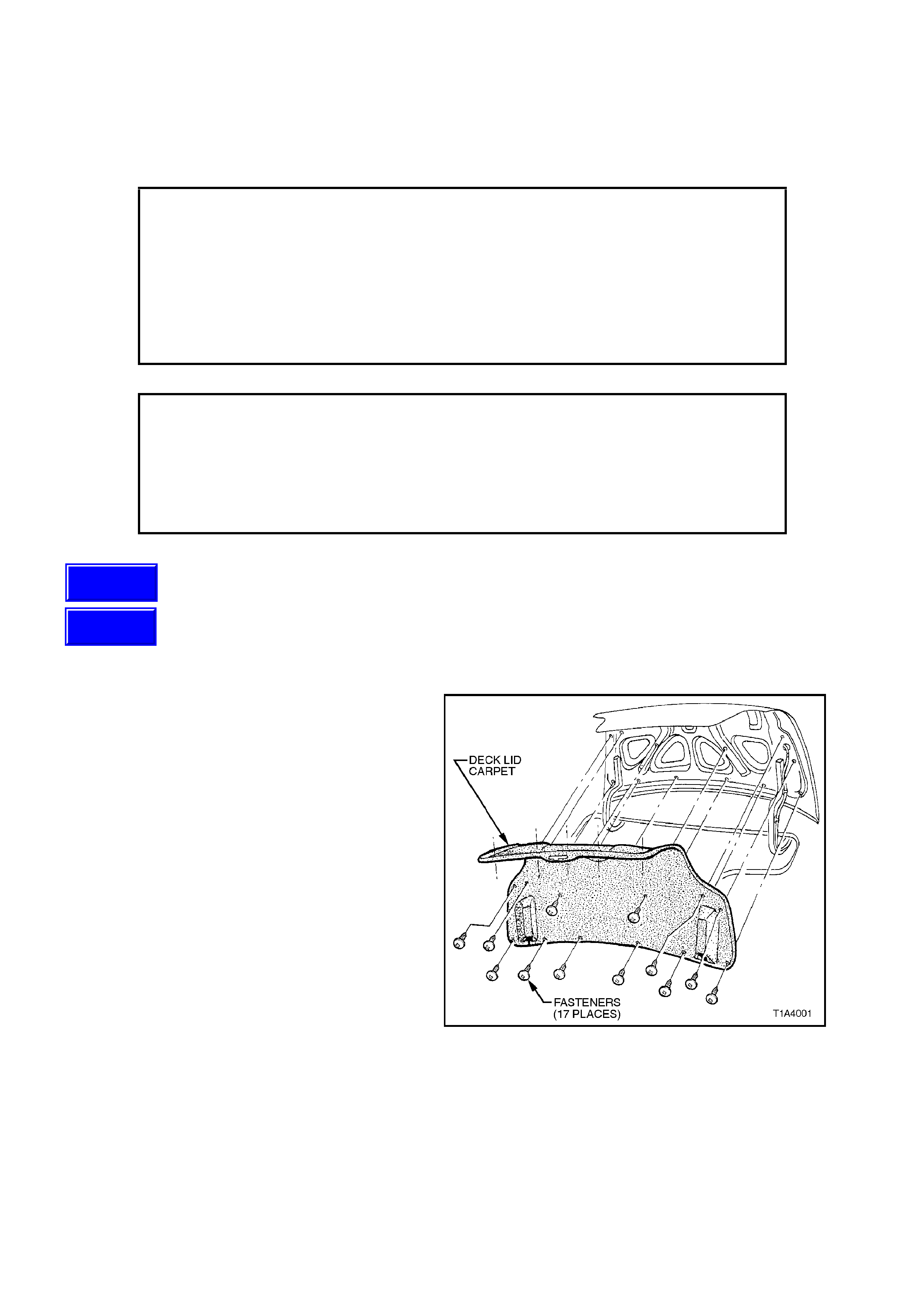
1. Remove decklid liner carpet by first removing
17 fasteners from decklid.
Figure 1A4-1
Techline
Techline
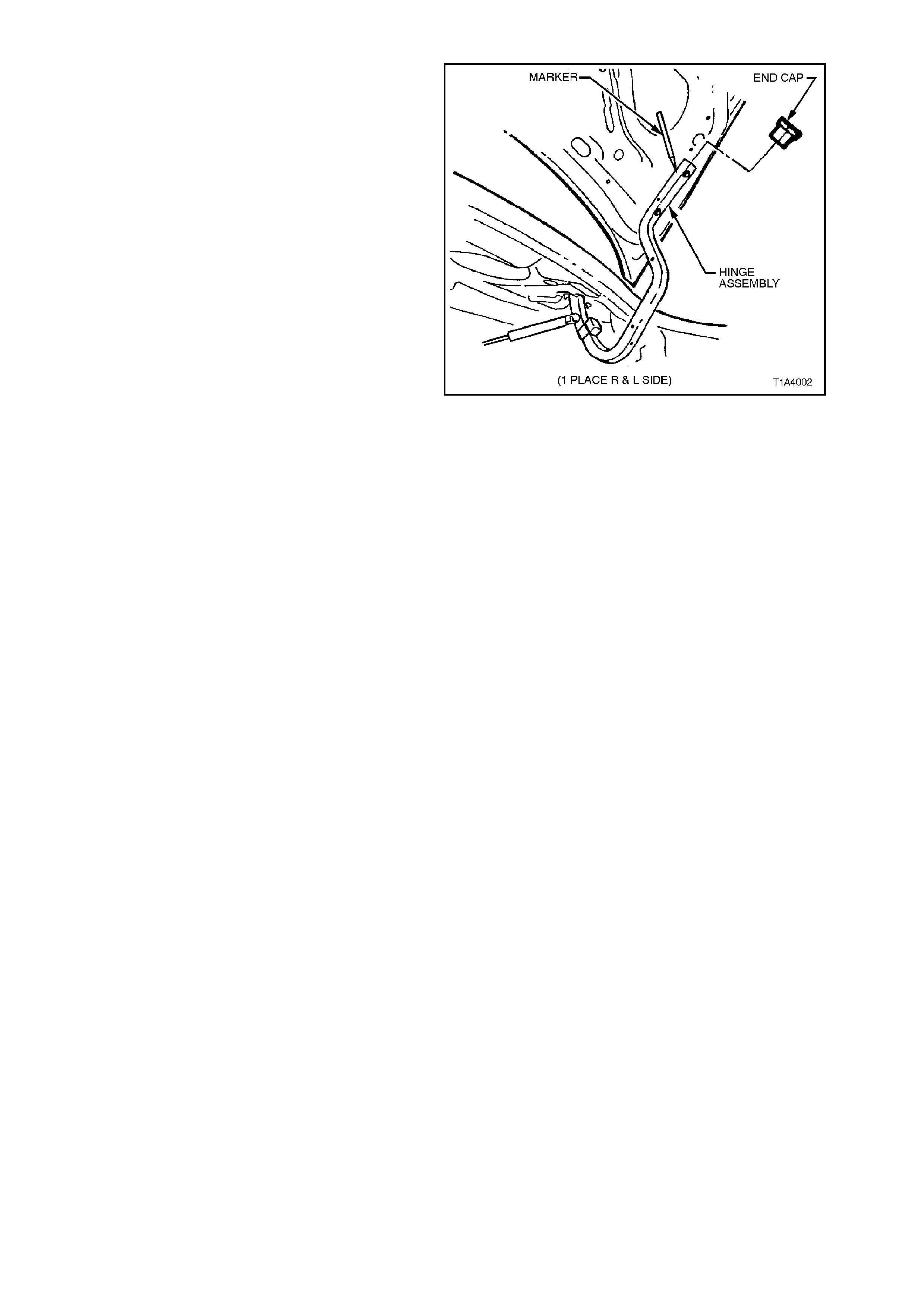
2. With the rear compartment lid raised, pencil
scribe location of hinges on the lid inner panel
to facilitate installation.
3. W ith the lid s upported, rem ove the hinge-to-lid
attaching bolts, removing the lid assembly.
Figure 1A4-2
REINSTALL
Reverse removal operations.
ADJUST
Elongated holes in the hinges provide forward and
rearward adjustment of the lid. Vertical height
adjustment at the hinge area of the lid can be
achieved as follows.
To raise the lid at the hinge area, place a shim
between the lid inner panel and hinge at the
forward attaching bolt hole location.
NOTE:
Following any adjustment of the rear compartment
lid, it is essential that the lid lock striker engages
correctly with the lid lock. Adjust the striker to
ensure positive engagement of the lock and to
achieve correct alignment between the rear
compartment lid and adjacent panels.
1.2 GAS STRUT - REAR COMPARTMENT LID - SEDAN
REMOVE
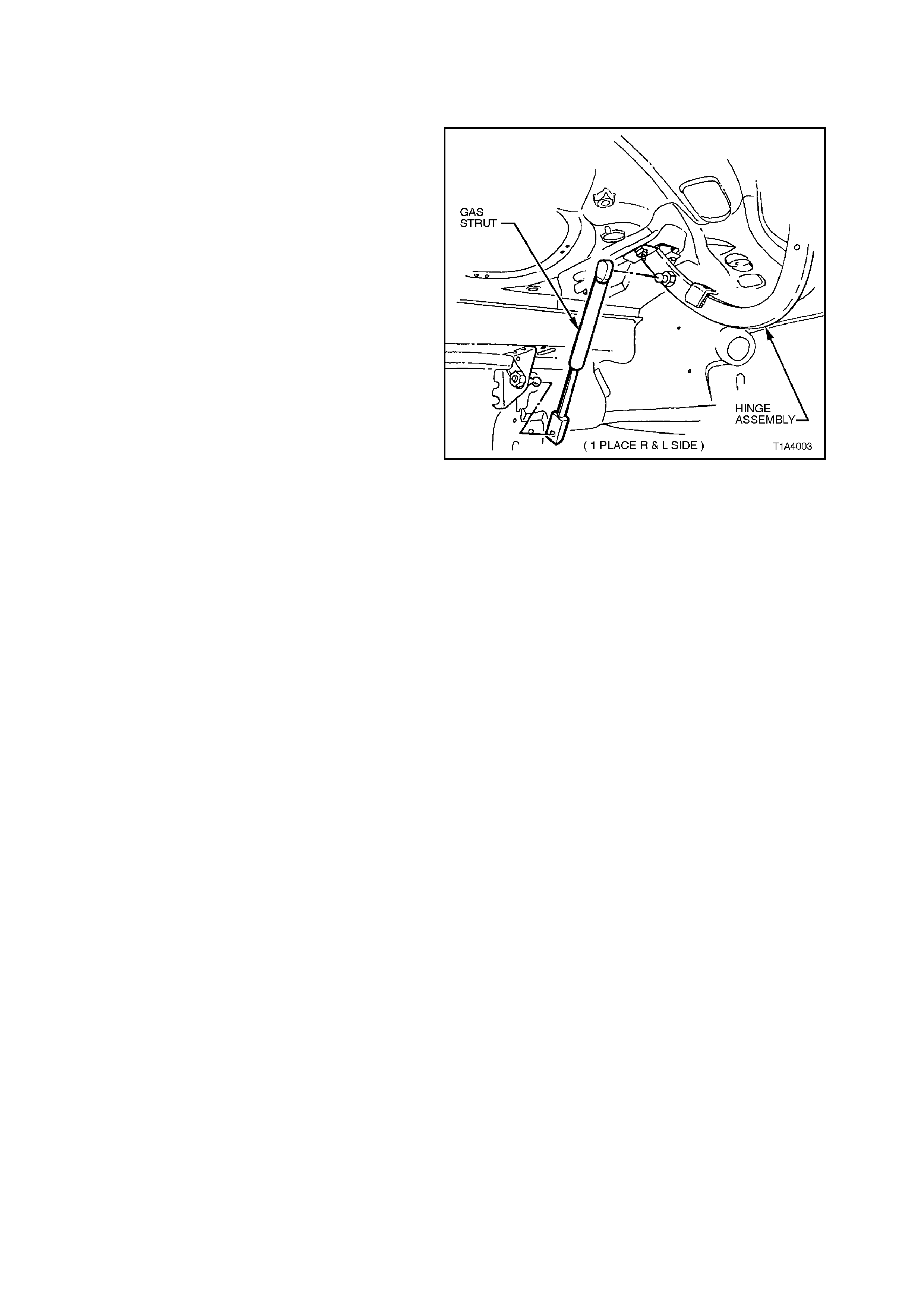
1. Raise and support the rear compartment lid.
2. Using a thin bladed screwdriver located under
the strut ball pivot spring, prise the spring
open. This will allow the strut to be pulled off
the ball pivot.
Figure 1A4-3
REINSTALL
Reverse removal operations.
1.3 LOCK CYLINDER - REAR COMPARTMENT LID - SEDAN
REMOVE
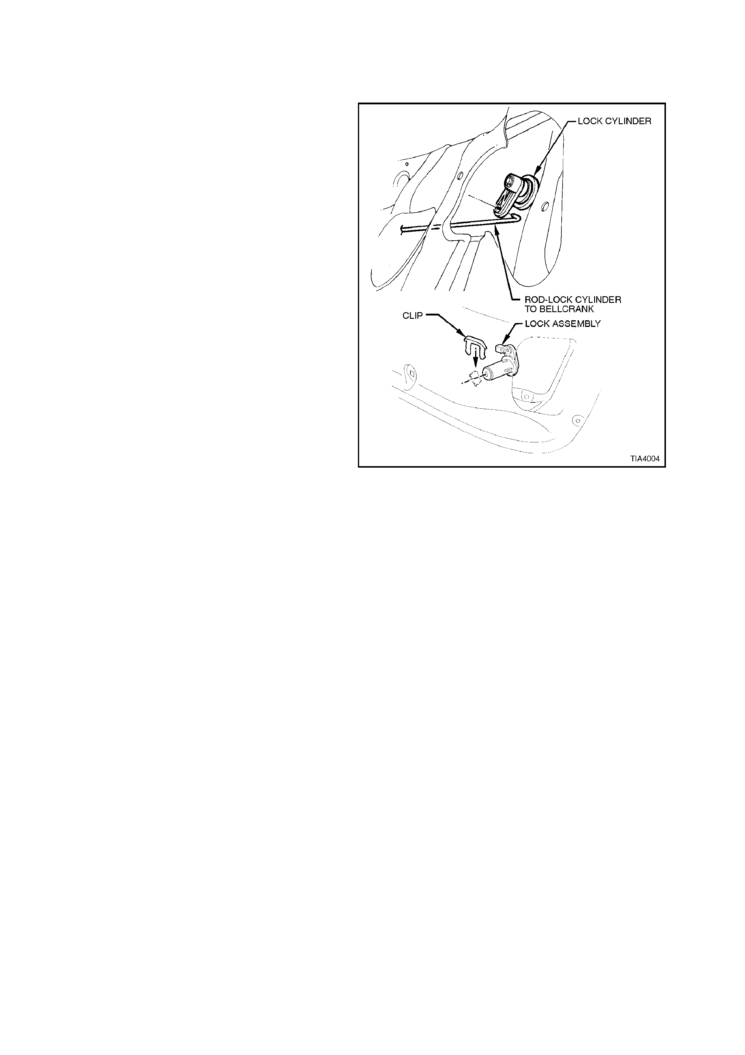
1. Remove decklid liner carpet by first removing
the 17 fasteners from decklid.
2. From within the rear compartment, disconnect
the lock cylinder connecting rod and remove
the lock cylinder retainer, remove the lock
cylinder.
Figure 1A4-4
REINSTALL
Reverse removal operations.
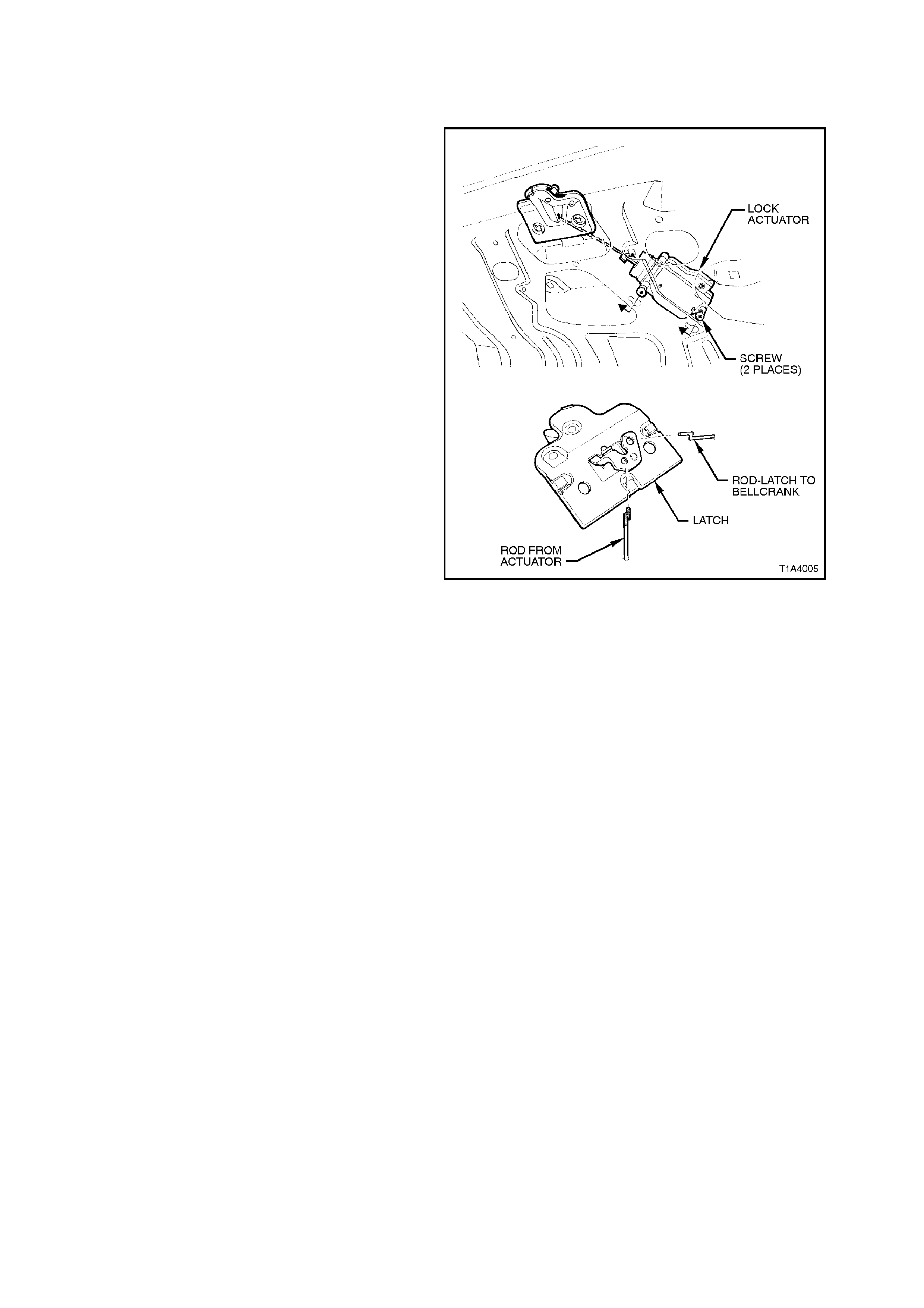
1.4 LATCH ASSEMBLY - REAR COMPARTMENT LID - SEDAN
REMOVE
1. Remove decklid liner carpet by first removing
the 17 fasteners from decklid.
2. With the rear compartment lid raised, remove
screws securing the lock assembly to the rear
compartment lid inner panel, disconnect cable
or actuator link.
Figure 1A4-5
REINSTALL
Reverse removal operations.
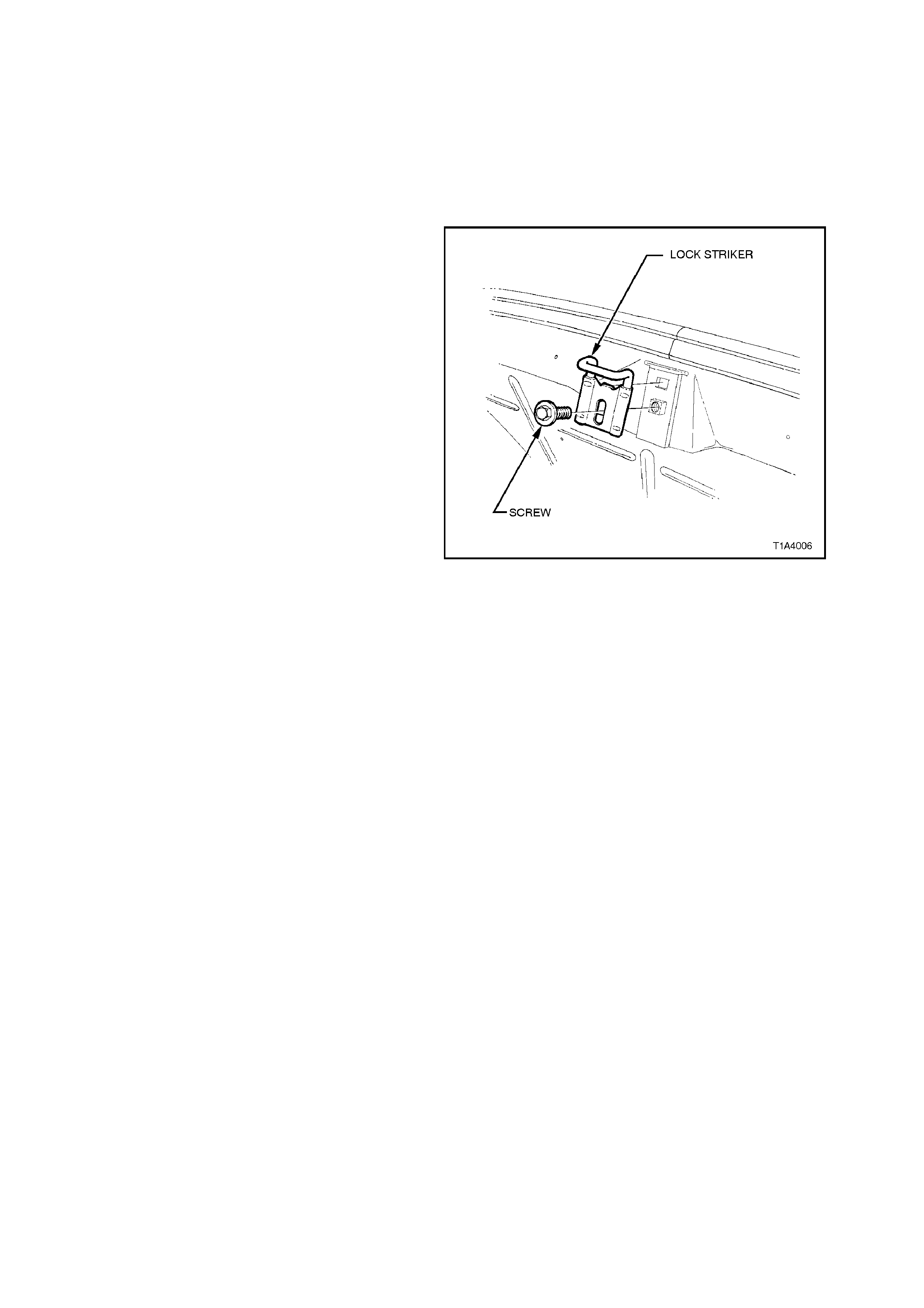
1.5 LOCK STRIKER - REAR COMPARTMENT LID - SEDAN
ADJUST
Loosen screws retaining lock striker and reposition
so striker engages correctly with the lock assembly.
Tighten screws before checking adjustment.
REMOVE
1. Remove crossmember cover.
2 With the rear compartment lid raised, pencil
scribe location of the striker on the rear end
inner panel to facilitate installation.
3. Remove the sc rew attaching the lock s triker to
the rear end inner panel and remove the
striker.
Figure 1A4-6
REINSTALL
Reverse removal operations.
NOTE:
An elongated hole in the lock striker provides
adjustment for the striker. Following any
adjustm ent of the strik er or rear co mpartm ent lid, it
is essential that the lid lock correctly engages the
striker.
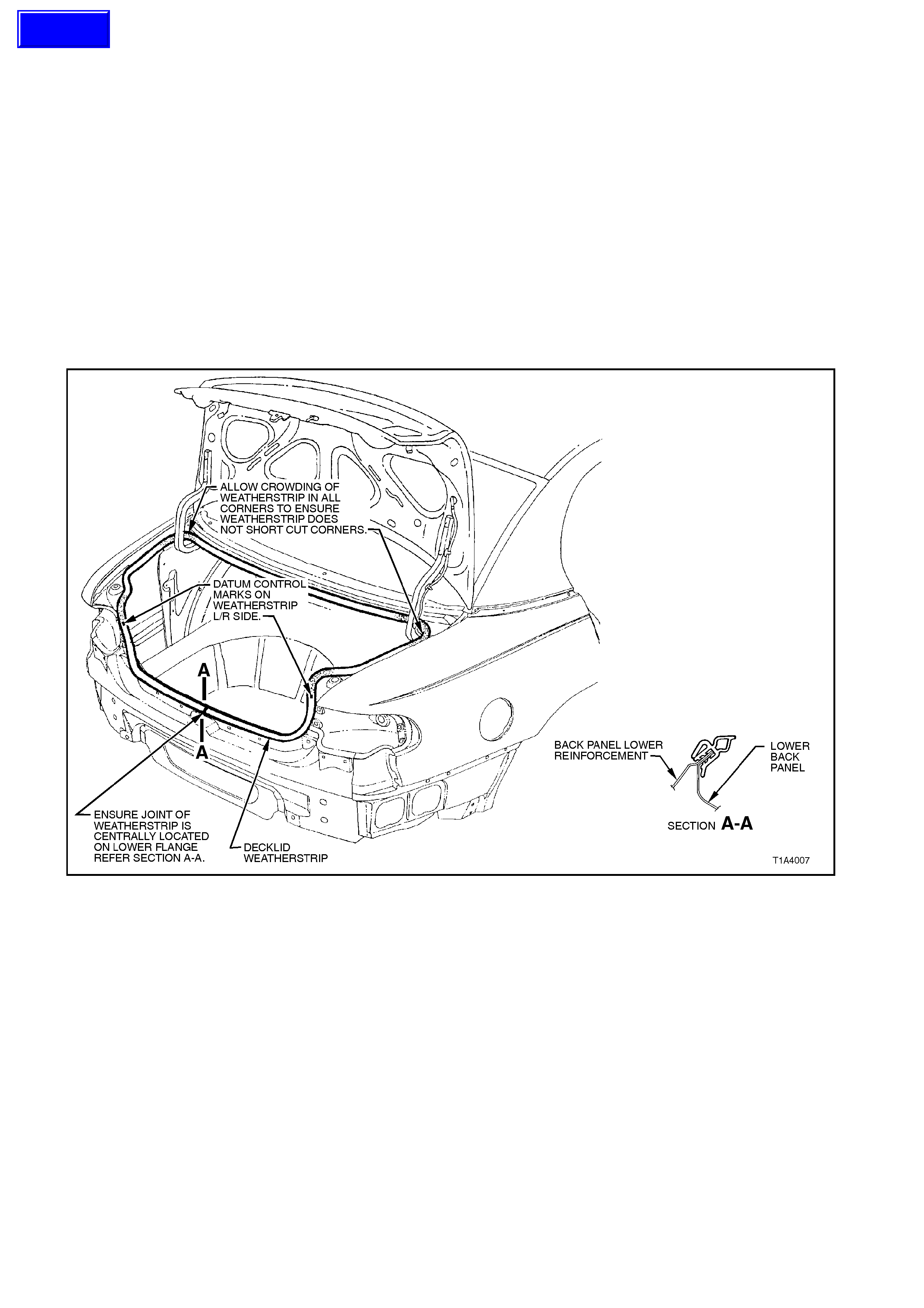
1.6 WEATHERSTRIP ASSEMBLY - REAR COMPARTMENT LID OPENING - SEDAN
DESCRIPTION
The one piece rear compartment lid opening
weatherstrip is a bulbous rubber ‘U’ section fitted
with an integral retaining system. It fits firmly over
the upturned flange of the rear compartment
opening.
NOTE:
When installing the weatherstrip assembly, locate
the longer side of the ‘U’ section on the outside of
the rear compartment opening upturned flange.
Align weatherstrip ‘first notch’ with panel join. Push
weatherstrip onto rear compartment opening
flange.
Figure 1A4-7
Techline
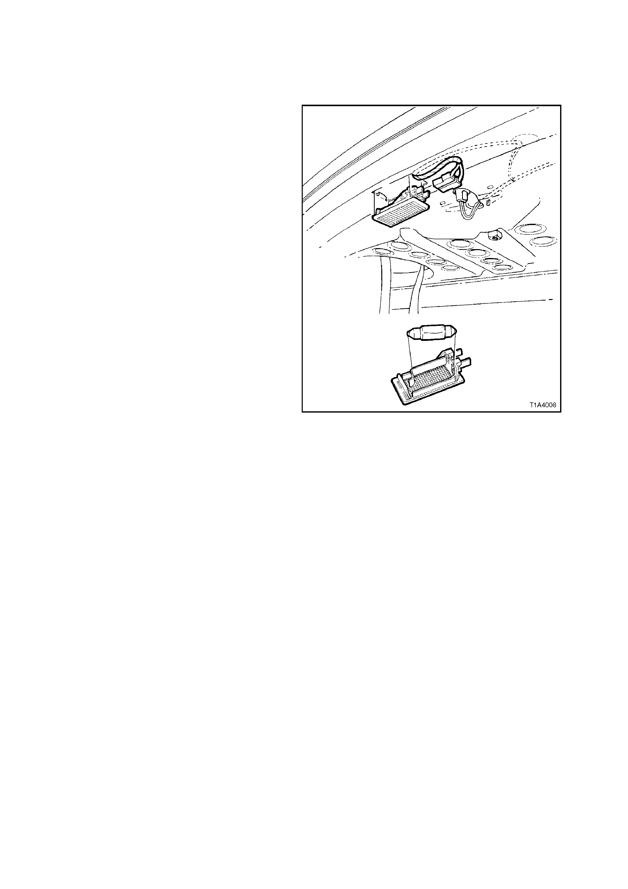
1.7 REAR COMPARTMENT LAMP ASSEMBLY - SEDAN
REMOVE
1. Disconnect battery ground cable.
2. With the rear compartment lid raised and
using the blade of a screwdriver located
between the lamp lens and rear compartment
inner panel, carefully prise the lamp assembly
out of the lamp aperture.
3. Disengage the electrical connector, removing
the lamp assembly.
Figure 1A4-8
REINSTALL
Reverse removal operations.
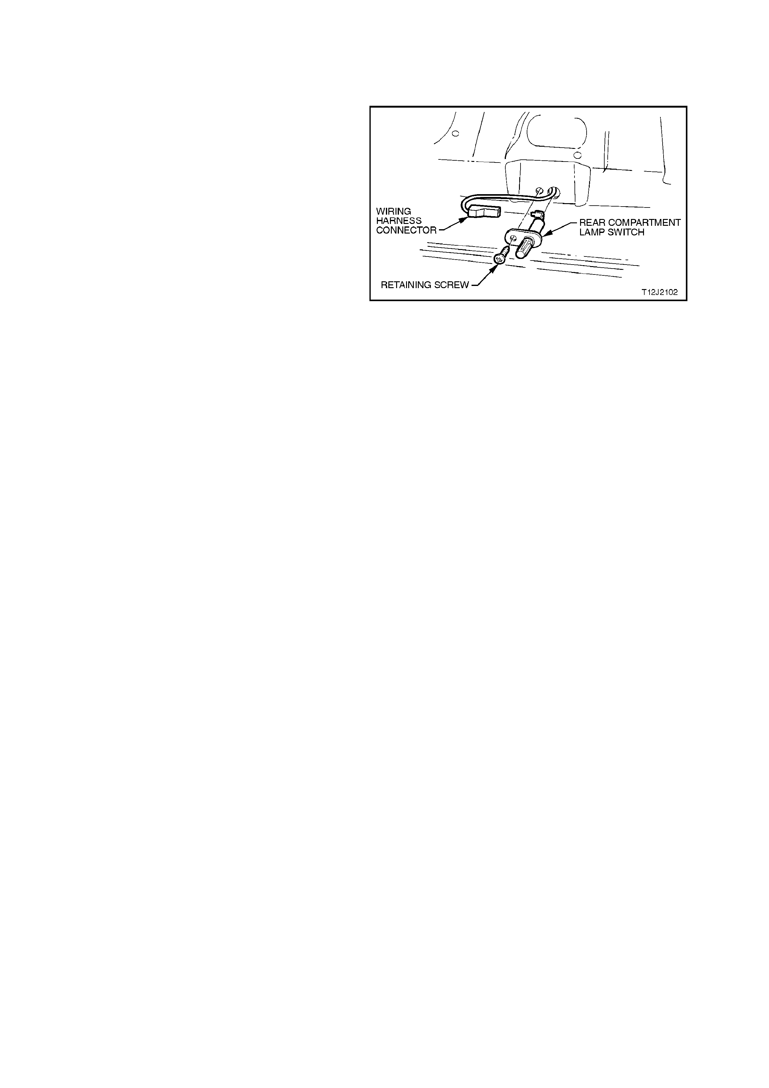
1.8 SWITCH ASSEMBLY - REAR COMPARTMENT LID LAMP - SEDAN
REMOVE
1. Disconnect battery earth lead.
2. With the rear compartment lid raised, remove
the screw securing the switch assembly to the
rear compartment lid.
3. Disengage the electrical connector and
remove the switch assembly.
Figure 1A4-9
REINSTALL
Reverse removal operations.
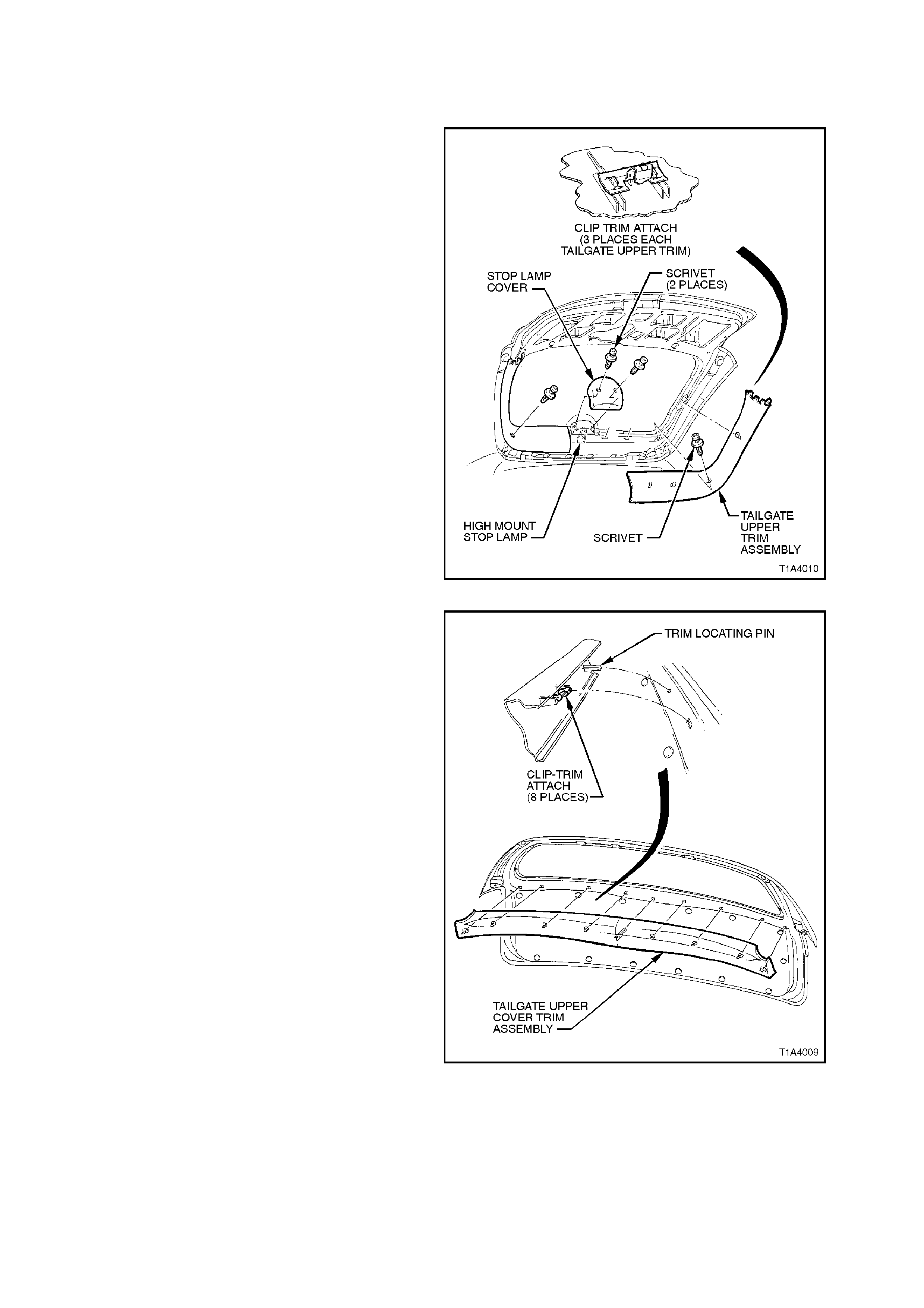
1.9 UPPER TRIM PANEL - TAILGATE - STATION WAGON
REMOVE
1. Remove high level stop lamp trim cover (two
scrivets).
2. Remove scrivets attaching tailgate upper trim
to tailgate (one per trim panel), unclip trim
retaining clips and remove trim panel.
Figure 1A4-10
3. Prise off tailgate upper trim cover.
NOTE:
There are eight clips attaching trim and a locating
pin.
Figure 1A4-11
REINSTALL
Reverse removal operations.
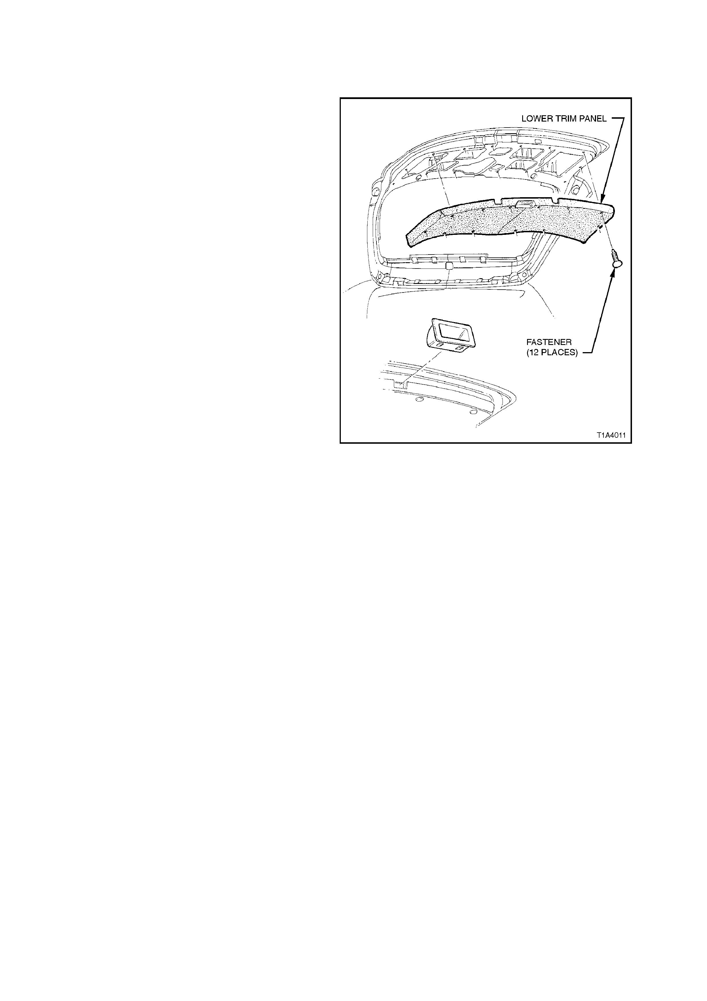
1.10 LOWER TRIM PANEL - TAILGATE - STATION WAGON
REMOVE
1. Remove tailgate upper trim panel, refer to
1.9 UPPER TRIM PANEL - TAILGATE -
STATION WAGON in this Section.
2. Using a screwdriver, gently prise out inner
tailgate lower handle from tailgate.
3. Using a suitable trim clip removal tool,
carefully prise out the 14 fasteners attaching
tailgate lower trim panel to tailgate and remove
tailgate trim panel.
Figure 1A4-12
REINSTALL
Reverse removal operations, locating concealed
trim button retainers in upper trim prior to
installation.
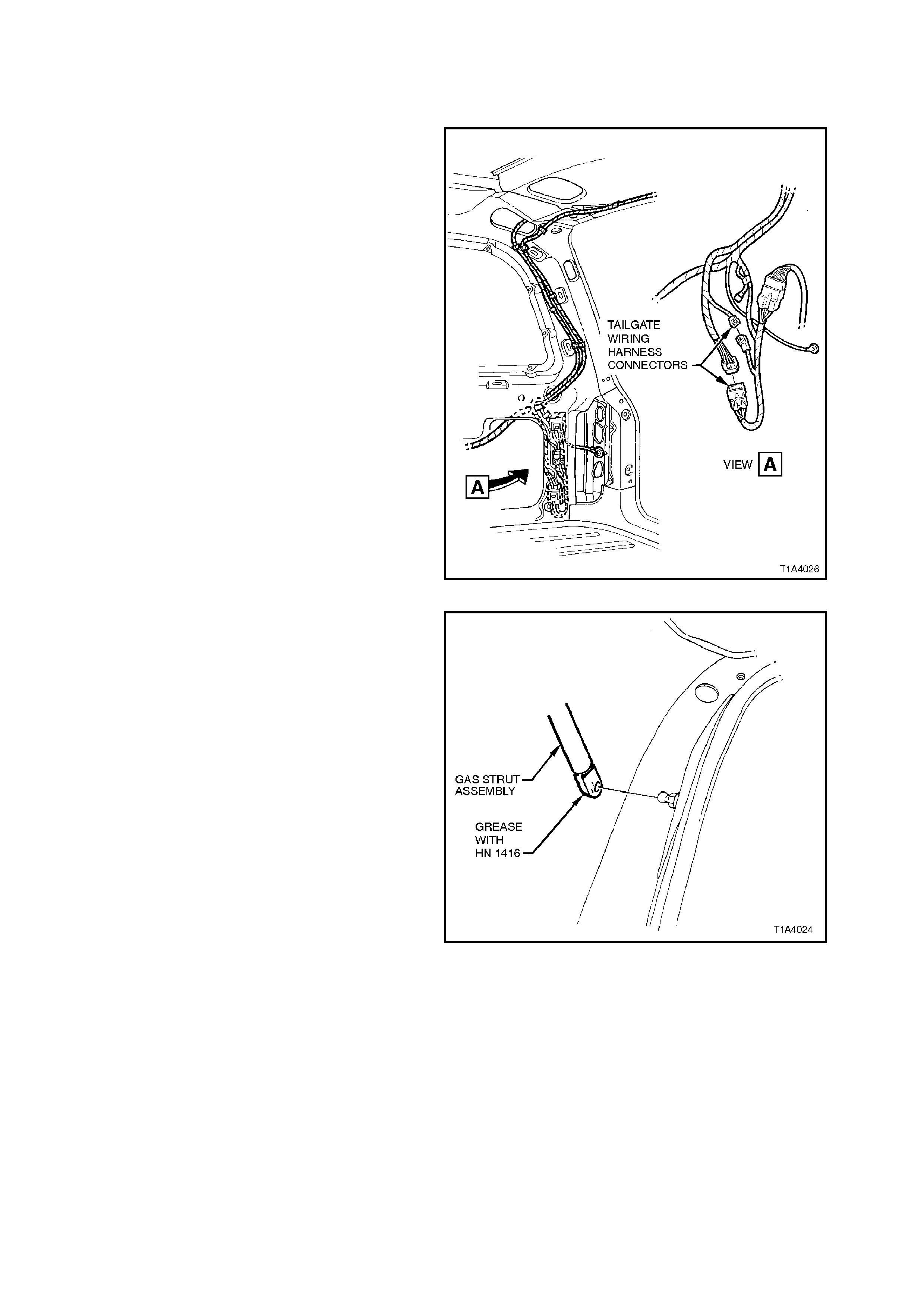
1.11 GAS STRUT ASSEMBLY -TAILGATE - STATION WAGON
REMOVE
1. With the tailgate supported in the raised
position and using a thin bladed screwdriver
located under the lower ball pivot spring, prise
the spring open. This will allow the strut to be
pulled off the ball pivot.
Figure 1A4-13
REINSTALL
Reverse removal operations.
1.12 TAILGATE ASSEMBLY - STATION WAGON
REMOVE
1. Disconnect battery earth lead.
2. Open the rear compartment storage panel
(driver’s side) and disconnect tailgate wiring
harness (two connectors). Disengage harness
grommet from inner tailgate opening and feed
harness through opening.
Figure 1A4-14
3. With the tailgate supported, remove the lower
connections of the gas strut assemblies, refer
to 1.11 GAS ST RUT ASSEMBLY - TAILGATE
- STATION WAGON in this Section.
Figure 1A4-15
NOTE:
Protect outer panel paint work with masking tape
before prising out nozzle.
4. Prise out the window washer nozzle from the
top of the tailgate outer panel, disconnect the
nozzle, then withdraw the washer hose from
the top of the tailgate inner panel.
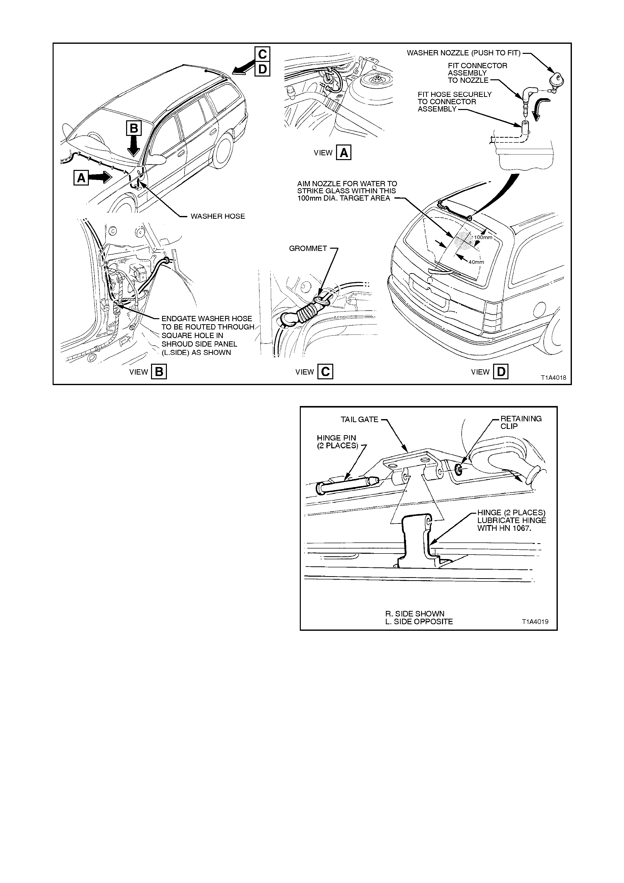
Figure 1A4-16
5. Remove hinge pin retainer clips, then with the
aid of an ass istant, rem ove the hinge pins and
remove the tailgate assembly.
Figure 1A4-17
REINSTALL
Reverse removal operations, ensuring that the
tailgate lock correctly engages the lock striker bolt.
If necessary, adjust the striker bolt to ensure
correct engagement with the tailgate lock and also
to ensure correct alignment between the tailgate
and adjacent body panels.
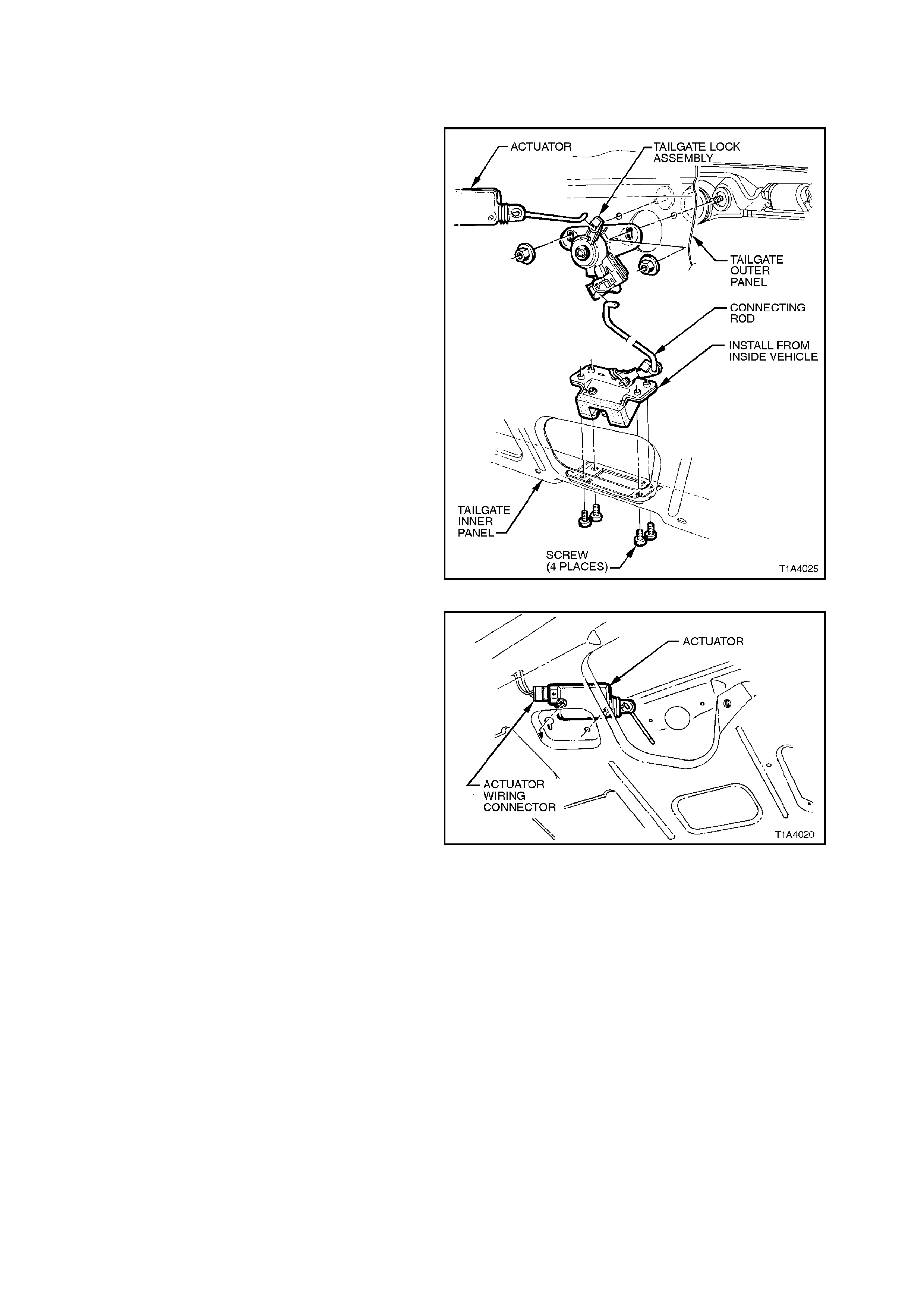
1.13 LATCH ASSEMBLY - TAILGATE -STATION WAGON
REMOVE
1. Remove the tailgate lower trim panel, refer to
1.10 LOWER TRIM PANEL - TAILGATE -
STATION WAGON in this Section.
2. From within the tailgate, disengage the push
button to lock connec ting rod, then rem ove the
screws securing the lock assembly to the
tailgate inner panel, removing the assembly.
Figure 1A4-18
3. If required, remove actuator by disconnecting
wiring connector and removing retaining
screw, rotating actuator to obtain clearance
through mount opening.
Figure 1A4-19
REINSTALL
Reverse removal operations.

1.14 LOCK STRIKER PLATE - TAILGATE - STATION WAGON
DESCRIPTION
The tailgate loc k s tr iker plate is sec ur ed by floating,
captive nuts in the lower member of the tailgate
opening. These floating nuts provide the lock
striker plate with horizontal, forward, rearward and
side to side adjustment with the use of a Torx
driver.
ADJUST
Loosen screws retaining lock striker and reposition
so striker correctly engages with the lock assembly.
Tighten screws before checking adjustment.
REMOVE
1. Remove crossmember cover trim.
2. Remove the lock striker retaining screws (two
screws) with a Torx driver.
3. Remove lock striker.
Figure 1A4-20
REINSTALL
Reverse removal operations.

1.15 PUSH BUTTON AND LOCK CYLINDER ASSEMBLY - TAILGATE -STATION WAGON
REMOVE
1. Remove tailgate lower trim panel, refer to
1.10 LOWER TRIM PANEL - TAILGATE -
STATION WAGON in this Section.
2. From within the tailgate, disengage the push
button to lock connecting rod.
3. Compress the tangs on the inner side of the
button assem bly, removing the assem bly from
the tailgate.
Figure 1A4-21
DISASSEMBLE
To disassemble the lock barrel assembly from the
latch housing assembly, remove the following:
1. E-clip
2. Latch actuator cover
3. Drive cam
4. Spring clip
5. Washer
6. Spring
NOTE:
The exterior lift handle is secured to the tailgate
outer panel with nuts. These nuts are accessible
from within the tailgate.
Figure 1A4-22
Techline

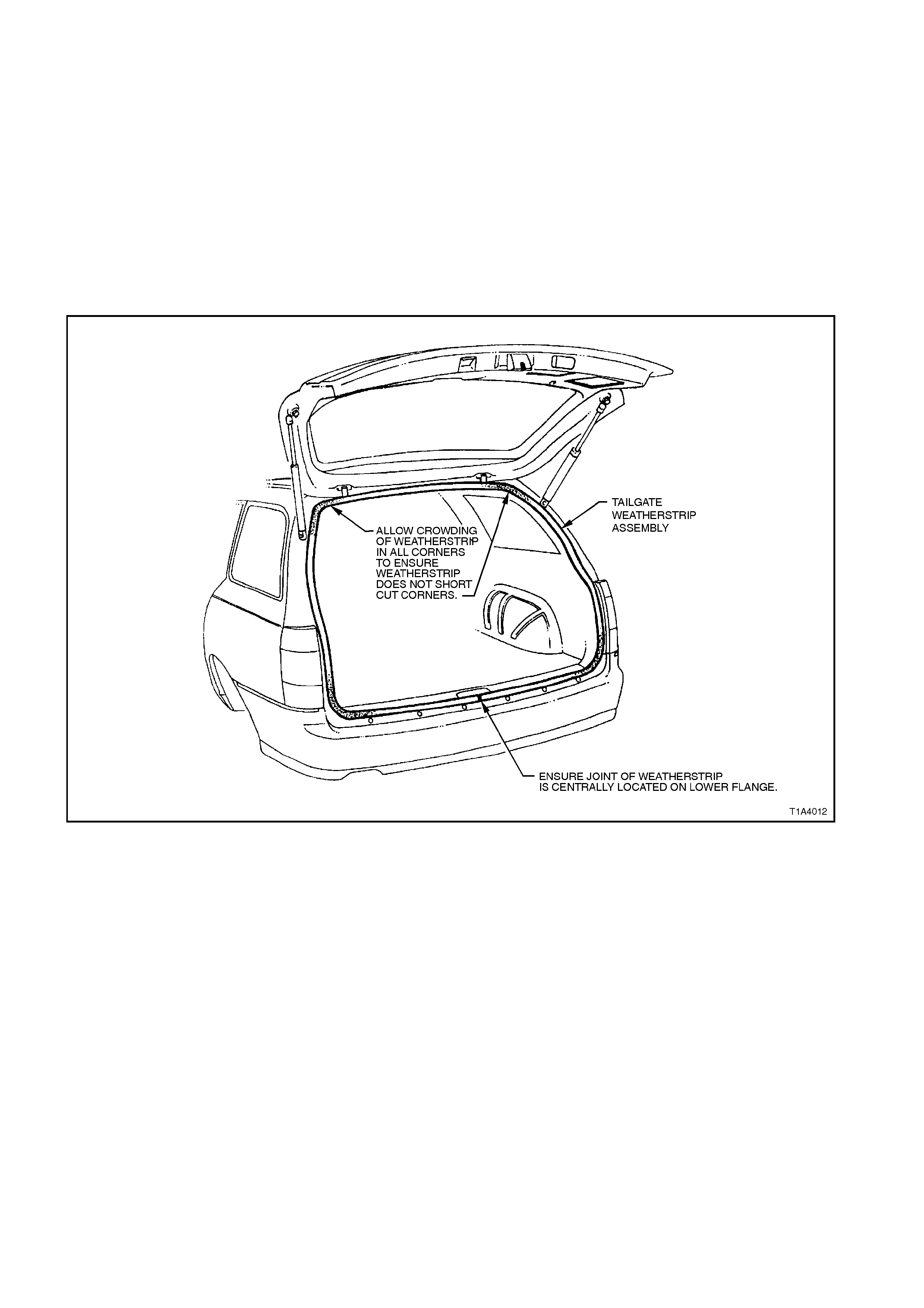
1.16 WEATHERSTRIP ASSEMBLY -TAILGATE OPENING - STATION WAGON
DESCRIPTION
The one piece tailgate opening weatherstrip is a
bulbous rubber ‘U’ section fitted with an integral
retaining system. It fits firmly over the upturned
flange of the tailgate opening.
NOTE:
When installing the weatherstrip assembly, locate
the longer side of the ‘U’ section on the outside of
the tailgate opening upturned flange. Joint m ust be
located centrally on lower surface.
Figure 1A4-23

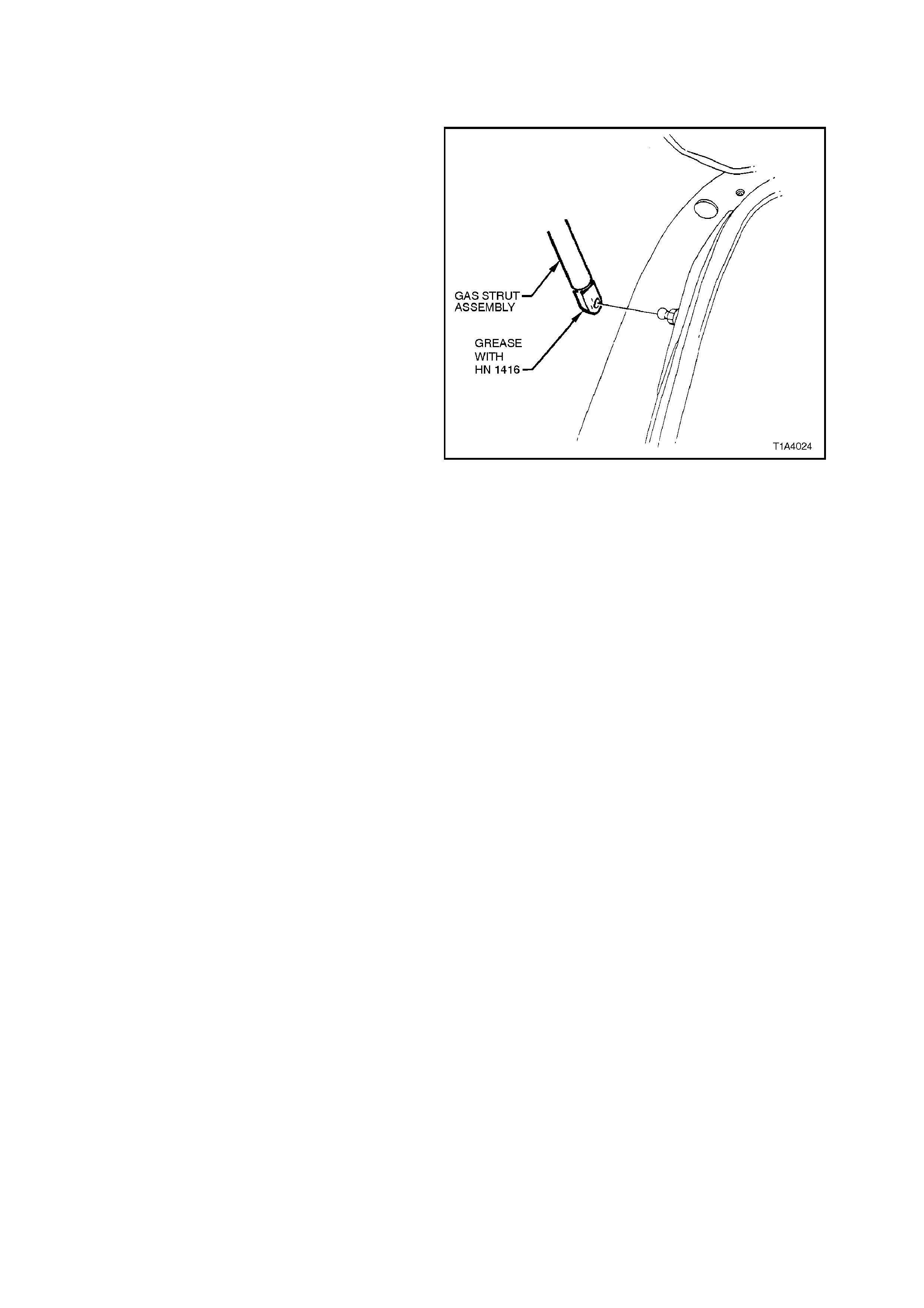
1.17 ACTUATOR ASSEMBLY - REAR COMPARTMENT LID LOCK - SEDAN
REMOVE
1. With the rear compartment lid raised remove
the rear compartment lid lock, refer to
1.4 LATCH ASSEMBLY - REAR
COMPARTMENT LID - SEDAN in this
Section, and disconnect the remote control
actuator actuating rod.
2. Remove the two screws securing the actuator
to the rear compartment lid, disconnect the
electrical connector, removing the actuator.
Figure 1A4-24
REINSTALL
Reverse removal operations.
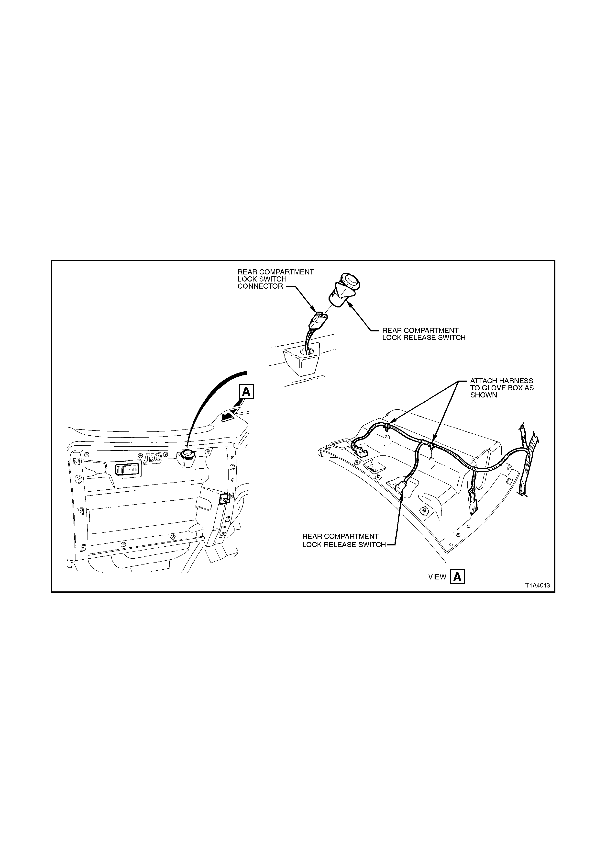
1.18 SWITCH ASSEMBLY - REAR COMPARTMENT LID LOCK ACTUATOR
REMOVE
1. Disconnect the battery ground cable.
2. Remove the instrument compartment, refer to
Section 1A3 INSTRUMENT PANEL AND
CONSOLE.
Disconnect the wiring harness connectors
from the instrument panel compartment lamp,
the boot lid switch and instrument panel
compartment switch to facilitate removal of
instrument panel compartment. Unclip wiring
harness from instrument panel compartment.
3. Squeeze the locking tabs on the boot lid switch
and remove from instrument panel
compartment.
Figure 1A4-25
REINSTALL
Reverse removal operations.

2. TORQUE WRENCH SPECIFI CATIONS
Nm
Rear compartment lamp switch attaching
screw 1 - 3
Lock assembly securin g screws 2 - 5
Lock striker attaching screw 15 - 35
Tailgate lock assembly securing screws 2 - 5
Actuator retaining screws 2 - 5