
SECTION 1A5 - FRONT & REAR DOOR ASSEMBLIES
CAUTION:
This vehicle will be equipped with a Supplemental Restraint System (SRS). A SRS will
consist of either seat belt pre-tensioners and a driver's side air bag, or seat belt pre-
tensioners and a driver's and front passenger's side air bags. Refer to CAUTIONS,
Section 12M, before performing any service operation on, or around any SRS
components, the steering mechanism or wiring. Failure to follow the CAUTIONS
could result in SRS deplo yment, resulting in possible p ersonal injury or unnecessary
SRS system repairs.
CAUTION:
This vehicle may be equipped with LPG (Liquefied Petroleum Gas). In the interests of
safety, the LPG fuel system should be isolated by turning 'OFF' the manual service
valve and then draining the LPG serv ice lines, before any service w ork is carried out
on the vehicle. Refer to the LPG leaflet included with the Owner's Handbook for
details or LPG Section 2 for more specific servicing information.
1. GENERAL DESCRIPTI ON
Front and rear door assemblies consist of outer panels which are hemmed at their outer edges, over the inner
panels. A rolled upper door frame retains the sliding glass run channels. Door hinge male sections are welded to
the door facings and the female sections to the body pillars. Door check and hold open links are located between
the door assemblies and the body pillars.
On front doors, double arm scissor type window regulators attached to the glass lifter channels and door inner
panels operate the front door sliding windows. Cable type mechanisms attached to the door inner panels and glass
lifter channels operate the rear door sliding windows.
Electric motors for operating the front and rear sliding windows are standard equipment on Berlina and Calais, and
optionally available on Executive models.
Lift bar exterior door handles operate the fork type door locks in conjunction with door lock striker bolts.
A two (2) key locking system uses a master key (with inbuilt remote security features) to operate all locks on the
vehicle. A secondary key , operates the glove compartment only. A snib locking button operates the door locks
internally.
The front door lock cylinder is of the ‘free turning’ design, preventing unlocking of the door by objects other than the
correct key. If any object, except the correct key, is inserted into the lock, the cylinder will rotate without unlocking
the door.
Electric door lock actuators and electric external rear vision mirrors are standard features on all models.
Door weatherstrips incorporate plastic clips which retain the weatherstrip in holes located around the outer lower
edge of the door inner panel. The upper section of the weatherstrip is retained in a channel which is an integral part
of the rolled section upper door frame.
Techline
Techline
Techline
2. SERVICE OPERATIONS
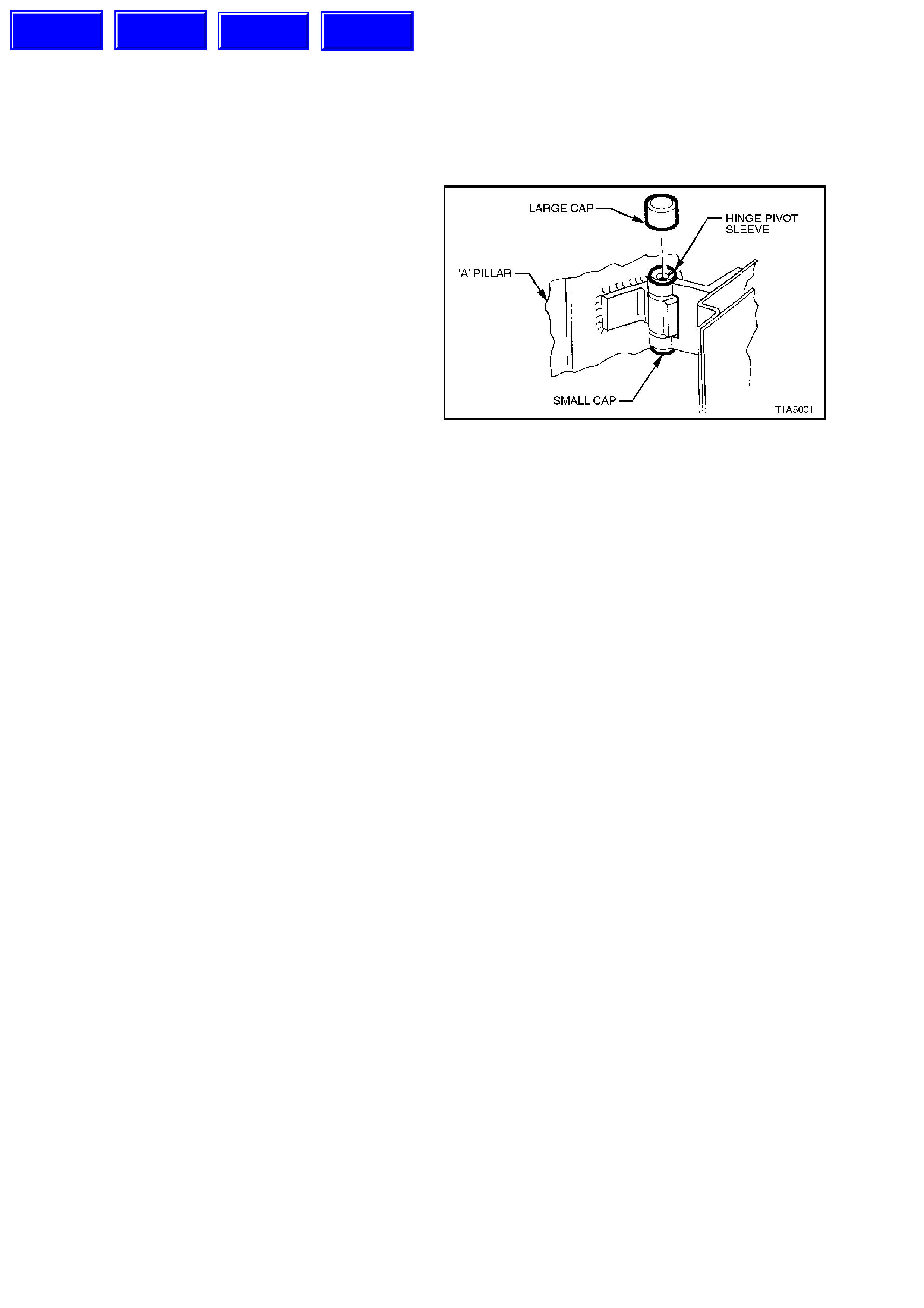
2.1 DOOR HINGE - LUBRICATION
1. Remove the large plastic cap from the door
hinge sleeve.
2. Using a grease gun, inject into the hinge pivot
sleeve with a lithium base gr ease (NLGI No. 1
Lithium base grease to Holden Specification
HN 1225).
3. Reinstall large plastic cap over door hinge
sleeve.
Figure 1A5-1
Techline
Techline
Techline
Techline
2.2 FRONT AND REAR DOOR ASSEMBLIES
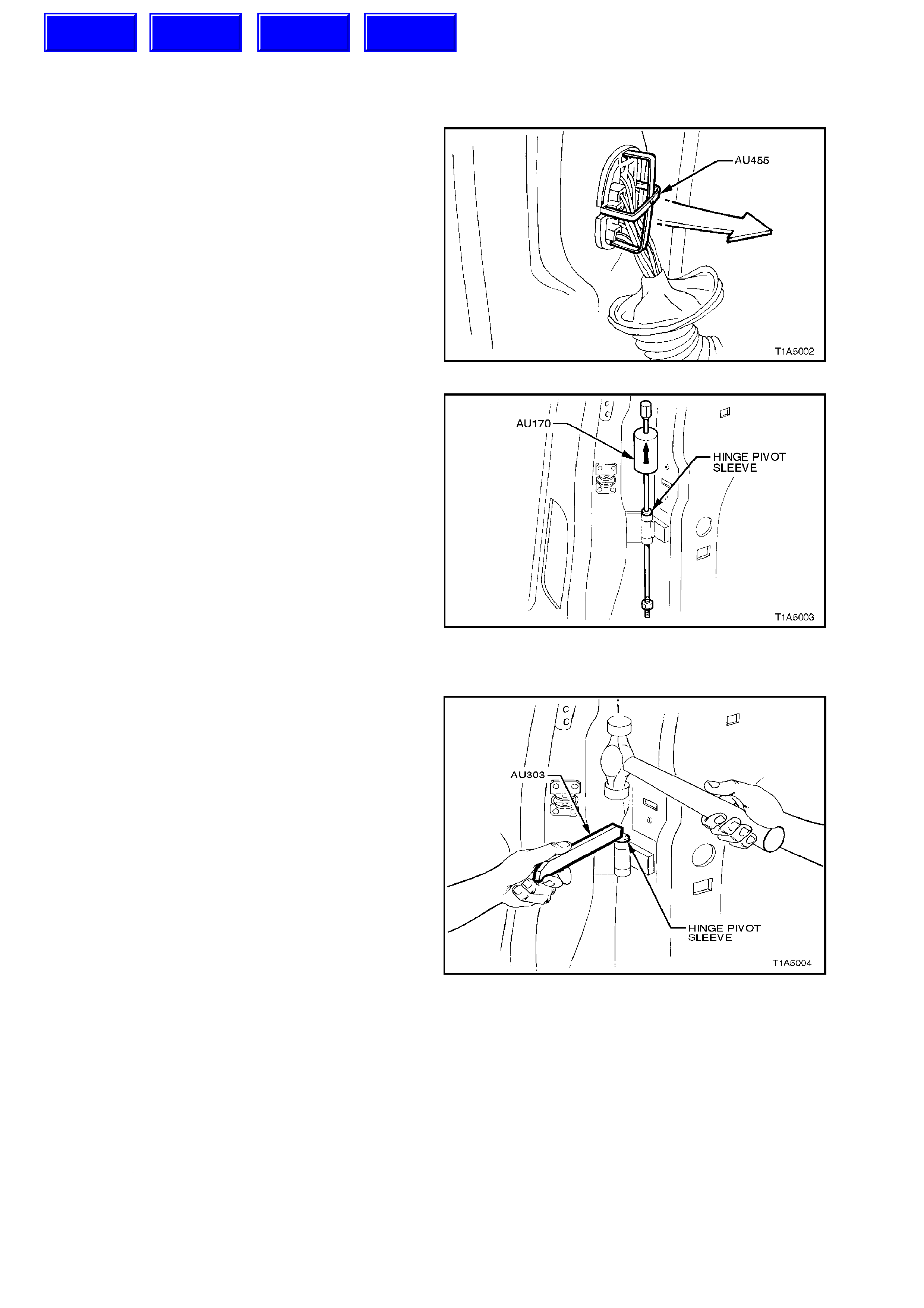
REMOVE
1. Disconnect the battery earth lead.
2. Remove grommet from door wiring harness
connector plug and insert T ool No. AU455 into
connector, depressing connector to door pillar
locking tangs. By gently pulling on wiring
harness, remove door wiring harness
connector plug from pillar and disconnect.
Figure 1A5-2
3. On front doors, tap the tapered sleeve
securing the link to the door check and hold-
open assembly upwards, removing the sleeve.
On rear doors, remove the bolt and nut
securing the link to the door check.
4. Using wooden block s or car jack s, suppor t the
door at its base.
5. Remove the plastic caps from the hinge
assemblies.
6. Using Tool No. AU170, hinge sleeve removal
tool, drive out the upper and lower hinge
sleeves (refer Fig. to 1A5- 3). Remove the door
assembly.
Figure 1A5-3
REINSTALL
Installation of the door is the rever s e of the r emoval
peration, noting the following:
1. Apply lithium base greas e (NLGI No. 1 Lithium
base grease to Holden Specif ication HN 1225)
to the hinge pivot sleeves prior to installation.
2. Use T ool No. AU303, illustrated in Fig. 1A5-3,
to install the hinge pivot sleeves.
Figure 1A5-4
ADJUST
Attention should be given to uniform margins and
alignment between the door and surrounding parts
when door adjustments are being carried out.
Uniform margins and alignment of front and rear
doors in relation to the body opening can be
achieved by setting the appropriate door hinge.
Use Tool No. AU184 to set door hinges.
Adjust hinges in conjunction with adjustment to
lock striker to achieve an acceptable door closing
effort with correct door lock to striker engagement.
Techline
Techline
Techline
Techline
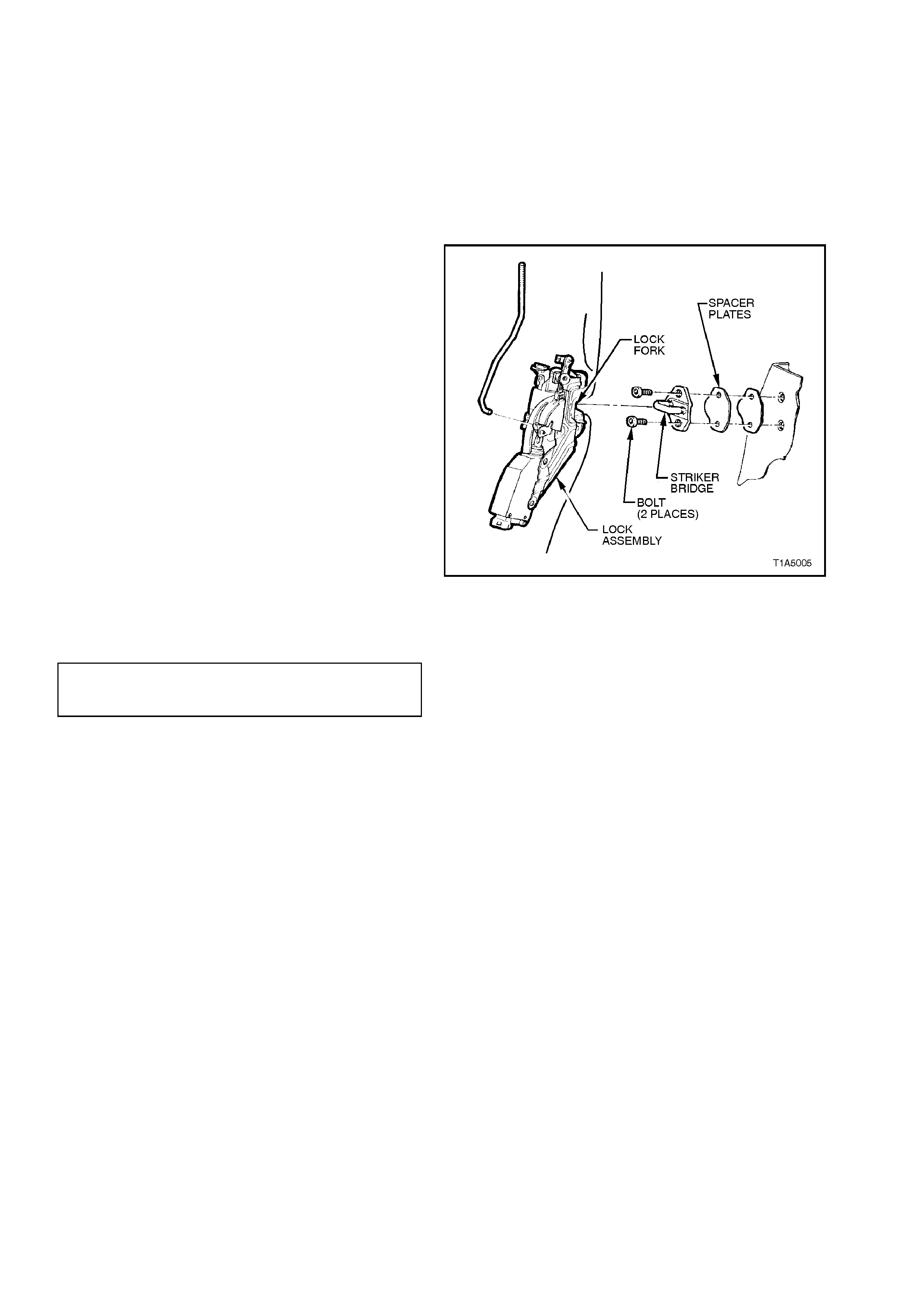
2.3 DOOR LOCK STRIKER ASSEMBLY
REMOVE OR ADJUST
1. Pencil scribe location of the striker assembly
on the body pillar to facilitate installation.
2. Using a Torx bit (30 T), loosen or remove the
striker assembl y.
REINSTALL
STRIKER ASSEMBLY
RETAINING BOLT
TORQUE SPECIFICATION 8 - 18 Nm
1. Align the strik er as sem bly so that the br idge of
the striker locates centrally in the lock fork
(refer to Fig. 1A5-5) as the door is being
closed. Securely tighten the striker assembly.
2. Correct engagement can be achieved by
vertical or horizontal adjustment of the door
lock striker assembly. Add or delete spacers
between the striker assembly and body pillar
to achieve correct engagement of the s tr ik er to
the lock.
NOTE:
If a replacement door is being fitted, it is sound
practice to remove the door lock striker assembly
and allow the door to hang free on the hinges. Set
the hinges as necessary to achieve correct
alignment and uniform margins, then reinstall the
striker and adjust.
3. When correct alignment of the striker
assem bly is achieved, tighten strik er ass embly
retaining bolts to the correct torque
specification.
Figure 1A5-5

2.4 DOOR WI NDOW REGULATOR HANDLE
REMOVE
Insert a commercially available window regulator
handle removal tool (such as J-9886-01) between
the base of the handle and the bearing plate and in
line with the arm of the handle as illustrated in Fig.
1A5-6. Disengage the horseshoe shaped retaining
spring, then remove the handle.
Figure 1A5-6
REINSTALL
1. Locate the retaining spring in the handle with
the open ends of the spring facing the handle
arm, pressing the spring into the engaged
position.
2. Place the handle bearing plate over the
window regulator splines with its raised face
towards the door.
3. Ensure that the handle is positioned
symmetrically with the handle on the opposite
door then press the handle onto the window
regulator splines until the horseshoe shaped
retaining spring engages the groove at the
base of the splines.
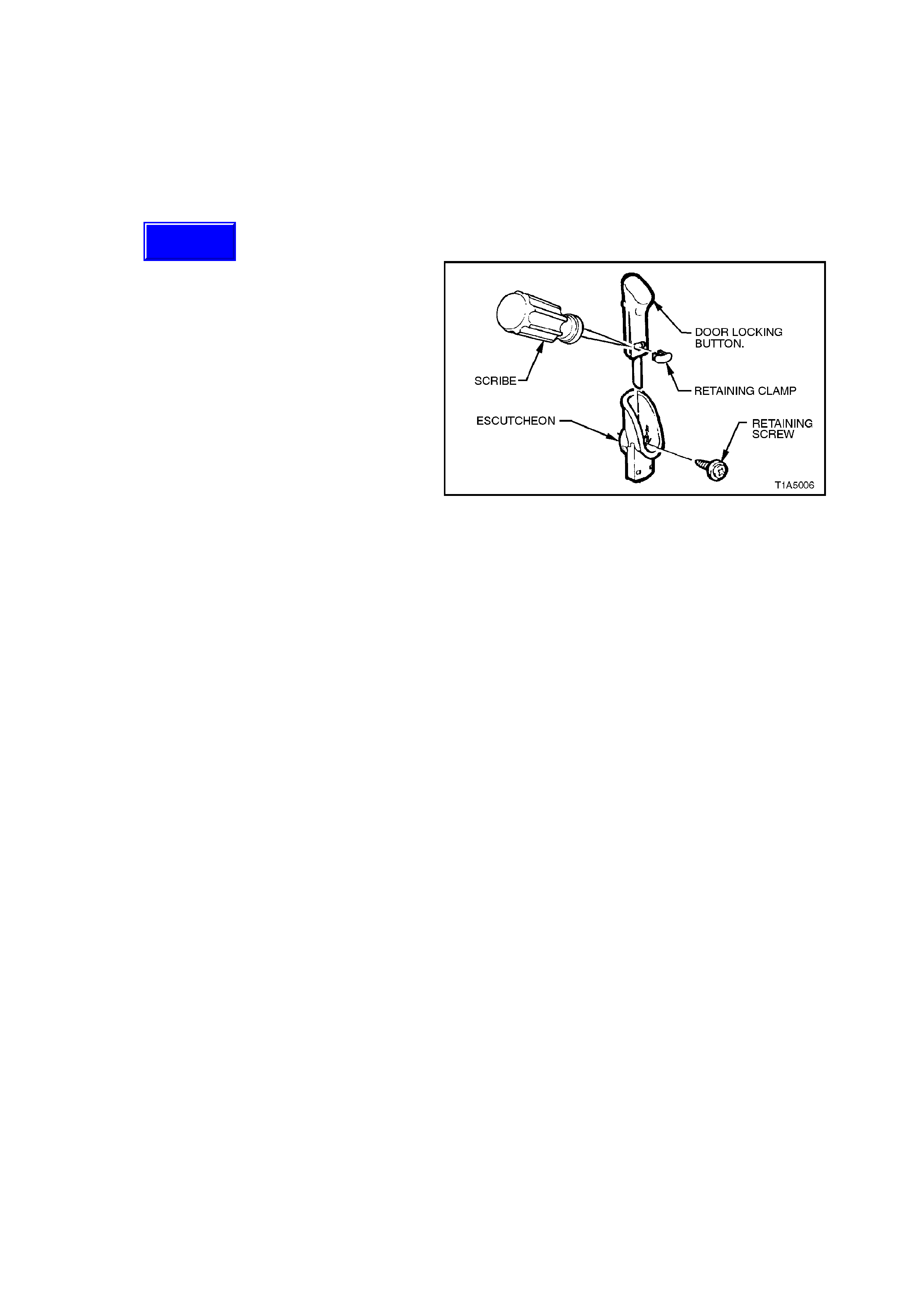
2.5 FRONT AND REAR DOOR INNER TRIM PANEL
NOTE:
When performing this service operation, the door
lock ing button retaining clam p will becom e dam age
and will need to be replaced. Therefore, before
carrying out this service operation, order a door
lock ing button retaining c lamp f rom your authoris ed
Holden parts outlet.
REMOVE
1. Disconnect battery earth lead.
2. Remove door window regulator handle (where
fitted), refer to 2.4 DOOR WINDOW
REGULATOR HANDLE in this Section.
3. Using a small flat bladed screw driver or
scribe, gently pry the orange retaining clamp
from the door lock ing button, tak ing c are not to
damage the door locking button. Remove the
door locking button.
NOTE 1:
The orange door lock ing button retaining clam p will
be damaged during this operation and therefore
must be replaced.
NOTE 2:
For the location of the components described in
the following steps, refer to Fig. 1A5-8.
Figure 1A5-7
4. Remove the screw securing the door locking
button escutcheon to the door inner trim panel
and remove the escutcheon.
5. Remove the screw securing the door remote
control handle ass embly to the door inner trim
panel and remove the door remote control
handle assembly in a forward direction.
6. Remove the door inner trim panel retaining
screw from the door remote handle assembly
aperture.
7. On front doors, remove the m irror inner cover
cap by gently prying cap away from door.
8. Remove the door inner trim panel retaining
screws from around the outside of the door
inner trim.
9. From the centre of the door, at the armrest,
push the centre of the door inner trim panel in
to unclip the catch behind the door inner trim
while lifting the door inner trim panel up and
out of inner channel, refer to Fig. 1A5-8, View
A.
NOTE:
Wiring harness connectors are still connected.
10. While supporting door inner trim panel,
remove all wiring harness connectors.
11. Remove door inner trim panel.
NOTE:
Figures 1A5-9 and 1A5-10 show the break down
of the front and rear door trim panel assemblies.
Techline

REINSTALL
Installation of the door inner trim panel is the
reverse of the removal operation, noting the
following:
1. Tighten all retaining screws to the correct
torque specification.
DOOR INNER TRIM PANEL
RETAINING SCREW
TORQUE SPECIFICATION 1 - 3 Nm
DOOR LOCKING BUTTON
ESCUTCHEON RETAINING SCREW
TORQUE SPECIFICATION 1 - 3 Nm
DOOR REMOTE CONTROL ANDLE
ASSEMBLY RETAINING SCREW
TORQUE PECIFICATION 1 - 3 Nm
2. Ensure the door remote handle assembly and
remote control rod are engaged before final
fitment.
3. Use a new door locking button retaining
clamp.
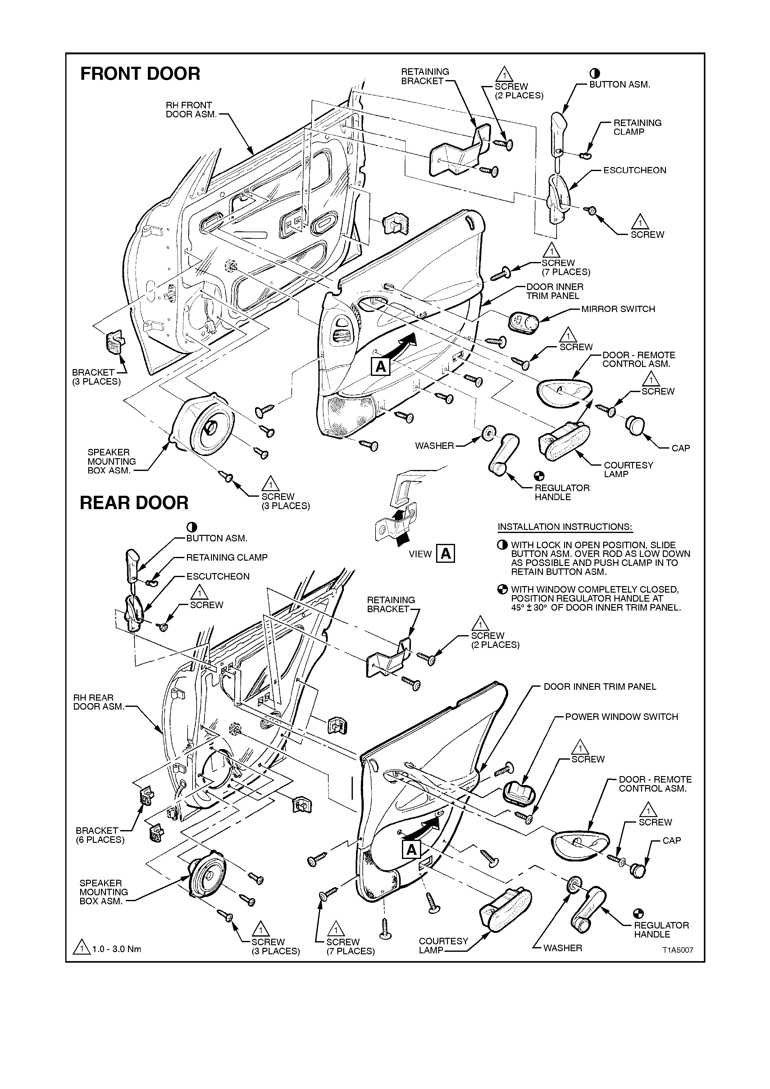
Figure 1A5-8
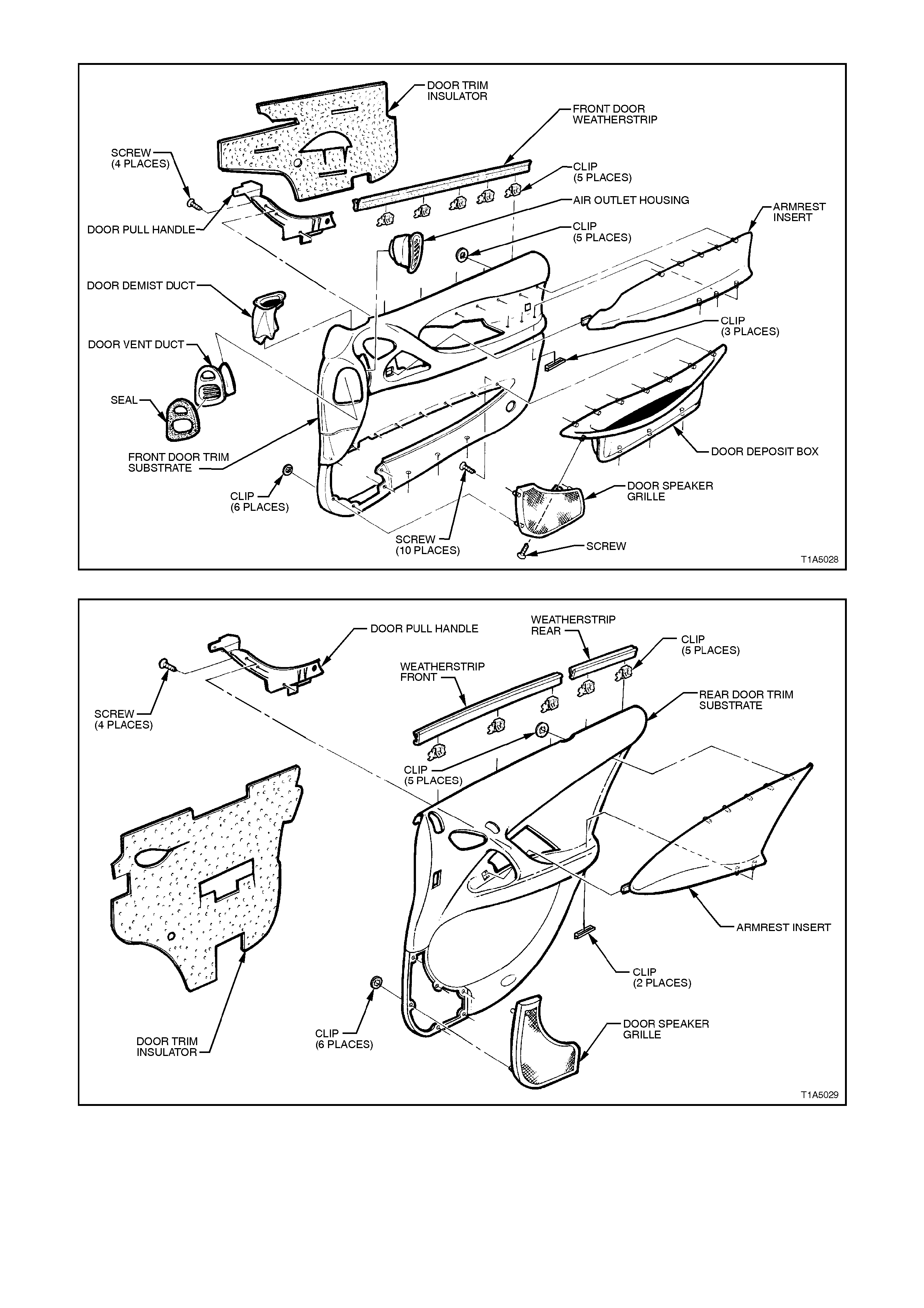
Figure 1A5-9
Figure 1A5-10
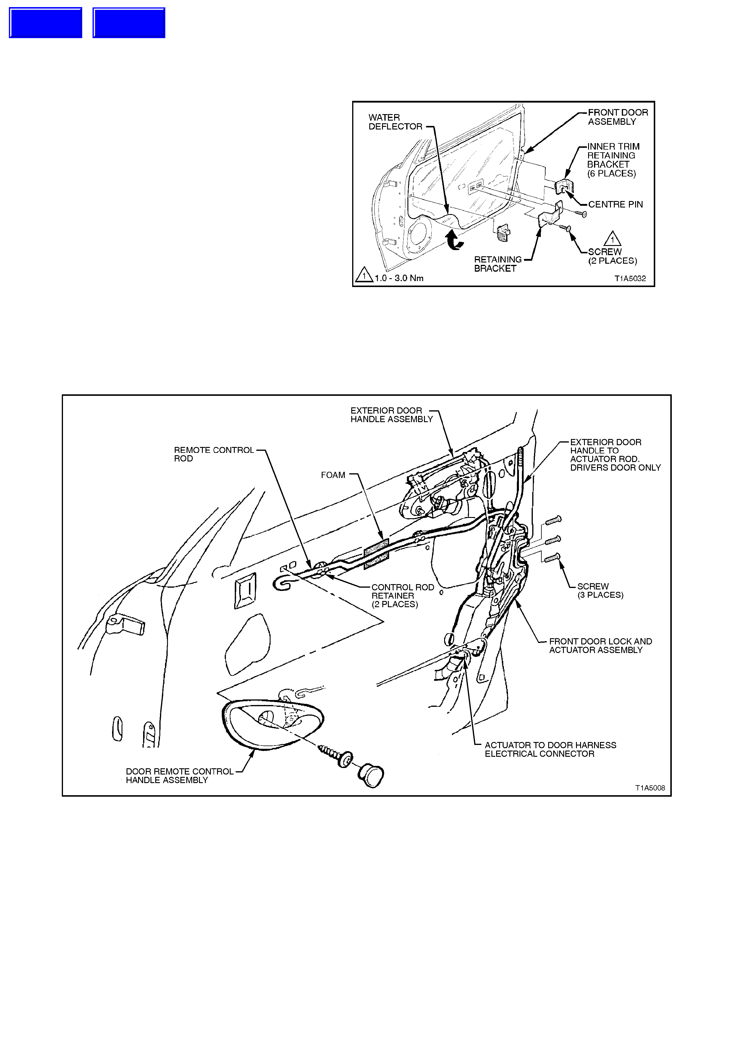
2.6 FRONT DOOR LOCK AND ACTUATOR ASSEMBLY
REMOVE
1. Disconnect battery ground cable.
2. Remove the door inner trim panel refer to
2.5 FRONT AND REAR DOOR INNER TRIM
PANEL, in this Section.
3. Remove the two screws securing the inner
trim panel retaining bracket to the door and
remove retaining bracket. Remove inner trim
retaining brackets by levering out the centre
pin of bracket.
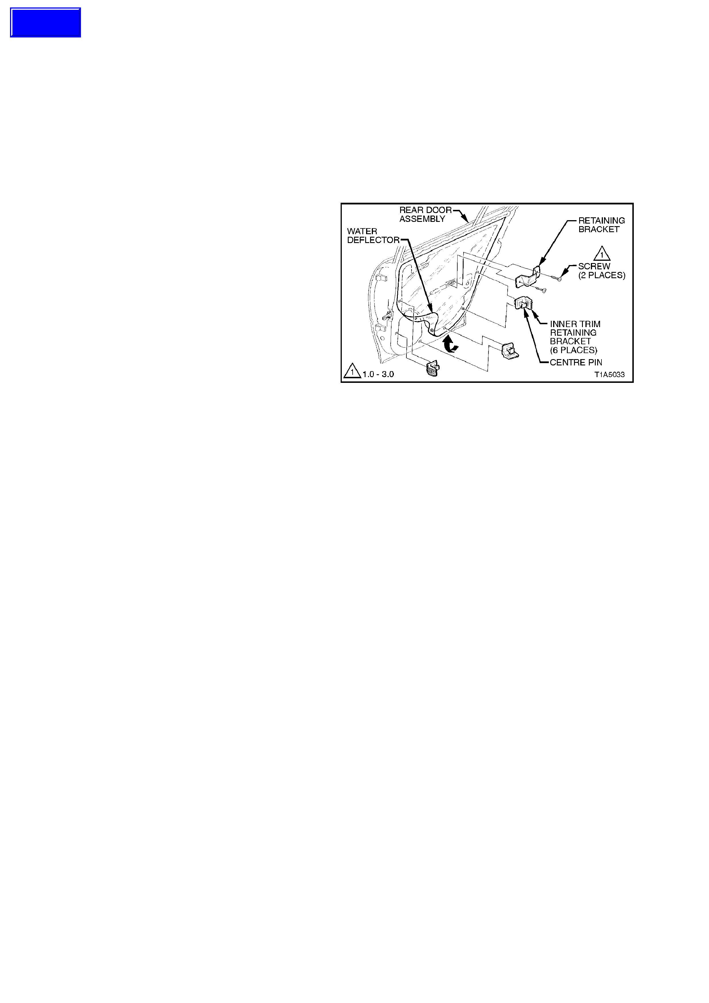
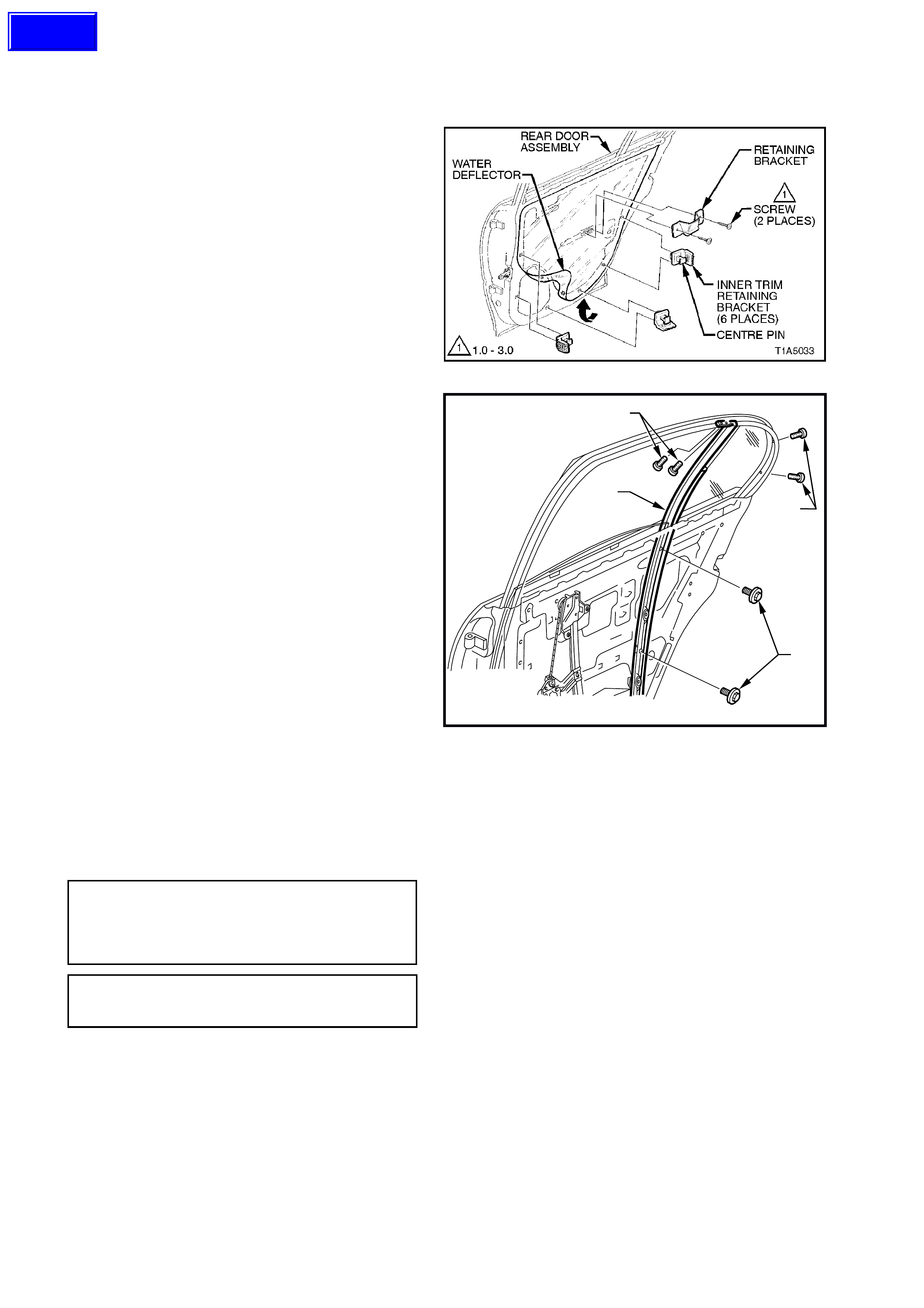
4. Carefully peel off the water deflector from the
door inner panel.
5. Disconnect the actuator to door harness
electrical connector then remove screws (3)
securing the door lock and actuator assembly
to door inner panel.
6. Disconnect actuator control rods from the
retainers then remove the assembly through
the aperture in the door inner panel.
Figure 1A5-11
Figure 1A5-12
Techline
Techline
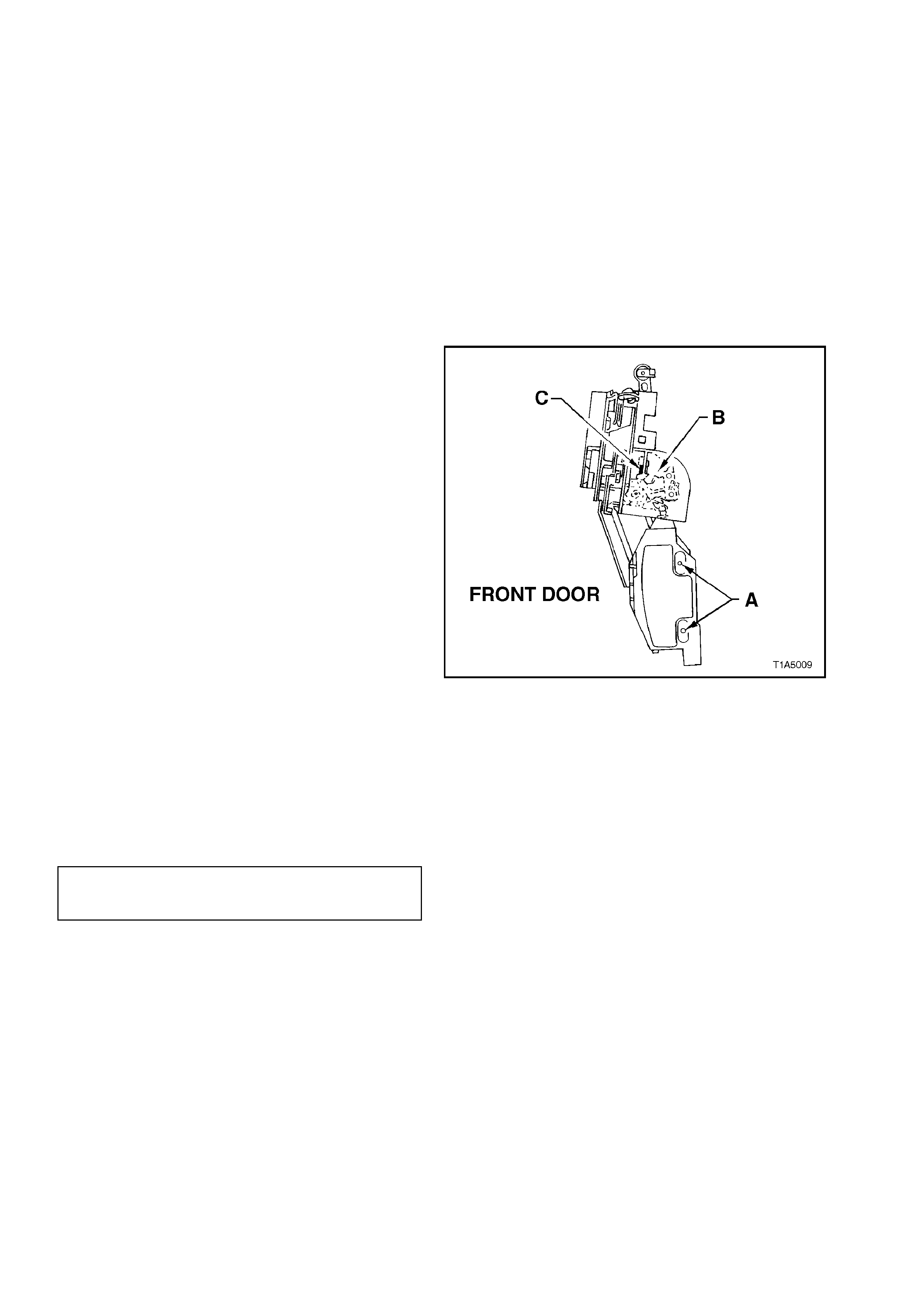
ADJUST
Adjustment of each door lock and actuator is
critical to ensure correct operation of the electric
door lock system.
The following adjustment procedure is to be
performed if a diagnostic test in Section 12J-1
LOW SERIES BCM or Section 12J-2 HIGH
SERIES BCM suggests that the door lock and
actuator assembly may be incorrectly adjusted, or if
any of the following symptoms occur:
•Ineffective deadlock operation.
•Failure to lock and unlock.
•Door lock actuator motors oscillate, ie.
machine gunning.
1. If not already done so, remove door lock and
actuator assembly.
2. Using the door lock ing button rod lever, LO CK
and UNLOCK the actuator mechanism,
checking that the actuator lever ‘B’ rests on
rubber pad ‘C’, refer to Fig. 1A5-13.
3. If required, loosen screws ‘A’ and reposition
the actuator m otor until the r equired position is
achieved.
4. Tighten actuator to motor screws securely
without moving the motor position.
Figure 1A5-13
REINSTALL
Installation of the front door lock and actuator
assembly is the reverse of the removal operation,
noting the following:
1. Tighten all retaining screws to the correct
torque specification.
DOOR LOCK AND ACTUATOR
ASSEMBLY RETAINING SCREW
TORQUE SPECIFICATION 3 - 5 Nm
2. Ensure that water deflector is sealed correctly
against door panel.
3. Use a new door locking button retaining
clamp.
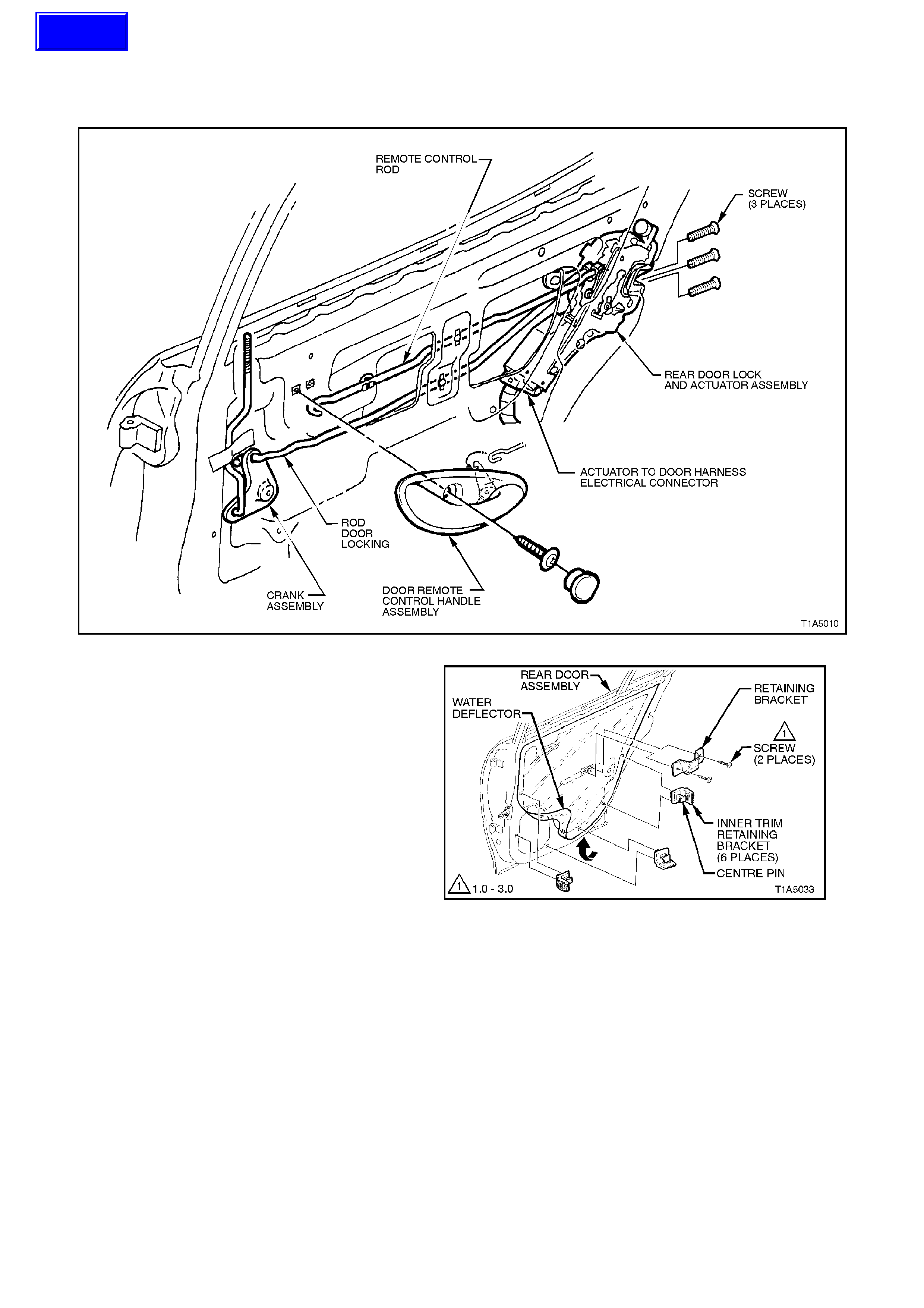
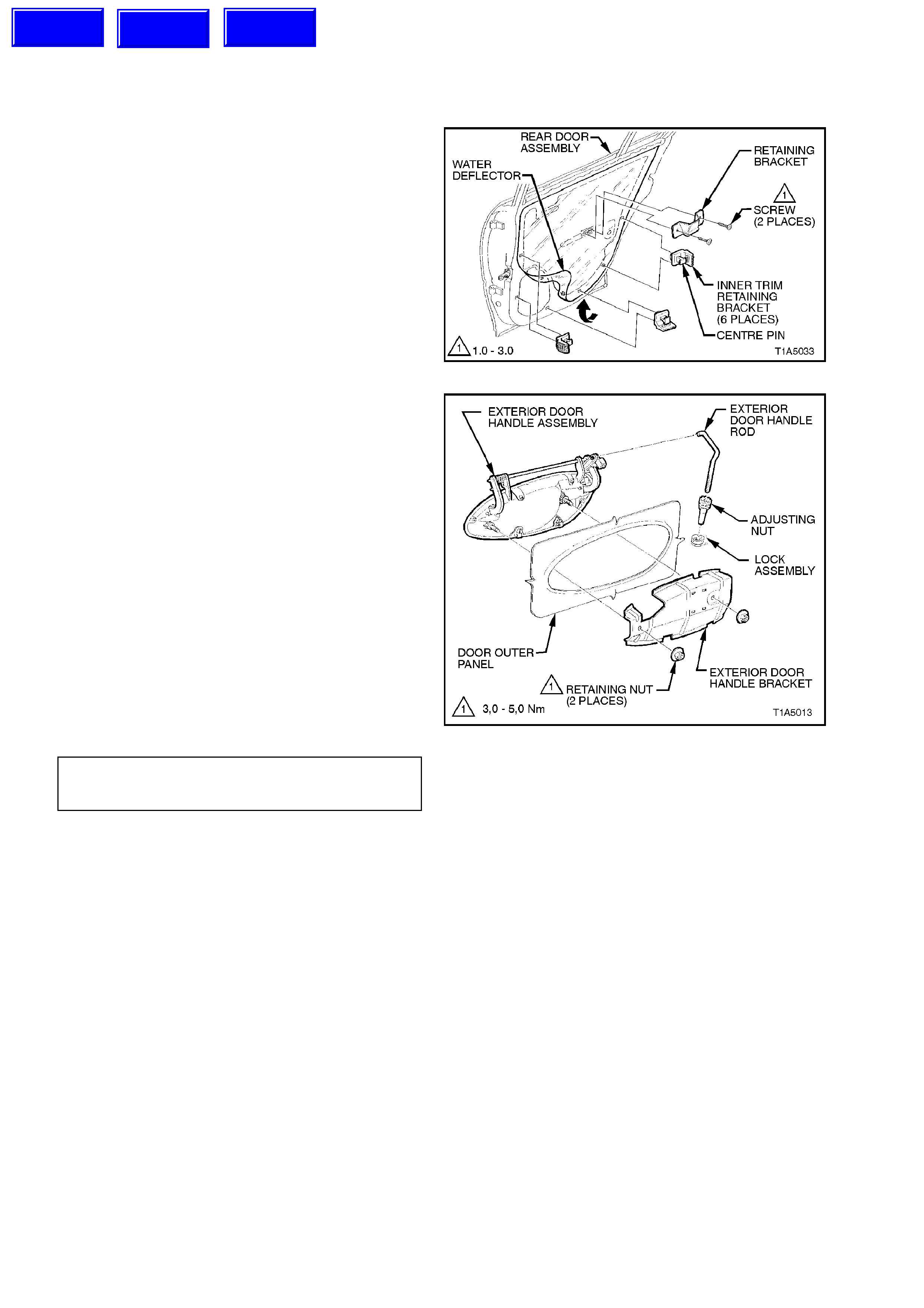
2.7 REAR DOOR LOCK AND ACTUATOR ASSEMBLY
REMOVE
Figure 1A5-14
1. Disconnect battery earth lead.
2. Remove the door inner trim panel, refer to
2.5 FRONT AND REAR DOOR INNER TRIM
PANEL, in this Section.
3. Remove the two screws securing the inner
trim panel retaining bracket to the door and
remove retaining bracket. Remove inner trim
retaining brackets by levering out the centre
pin of bracket.
4. Carefully peel off the water deflector from the
door inner panel.
5. Disconnect the actuator to door harness
electrical connector then remove screws (3)
securing the door lock and actuator assembly
to door inner panel.
6. Disconnect actuator control rods from the
retainers then remove the assembly through
the aperture in the door inner panel.
Figure 1A5-15
Techline
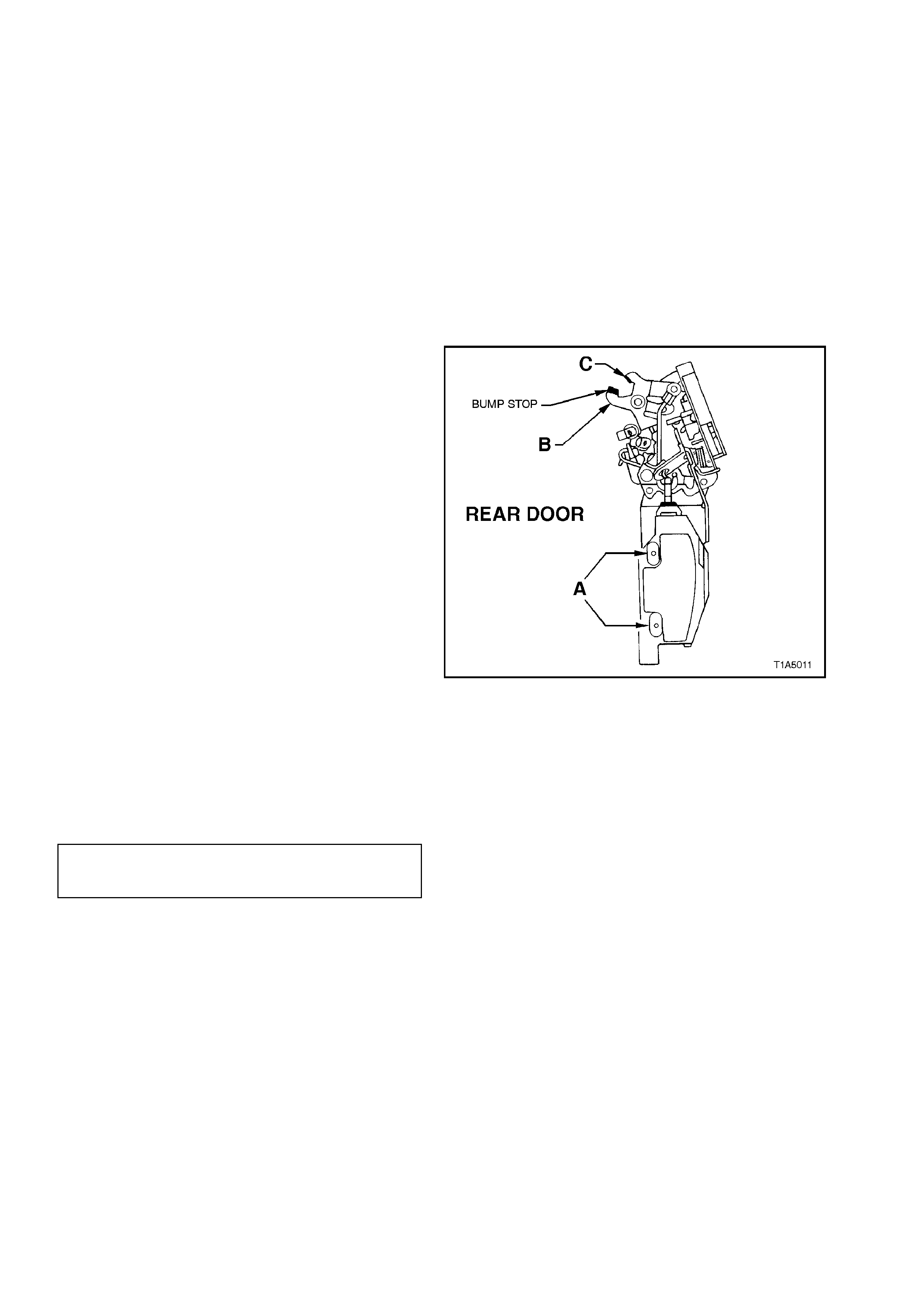
ADJUST
Adjustment of each door lock and actuator
assembly is critical to ensure correct operation of
the electric door lock system.
The following adjustment procedure is to be
performed if a diagnostic test in Section 12J-1
LOW SERIES BCM or Section 12J-2 HIGH
SERIES BCM suggests that the door lock and
actuator may be incorrectly adjusted, or if any of
the following symptoms occur:
•Ineffective deadlock operation.
•Failure to lock and unlock.
•Door lock actuator motors oscillate, i.e.
machine gunning.
1. If not already done so, remove door lock and
actuator assembly.
2. Using the door lock ing button rod lever, LO CK
and UNLOCK the actuator mechanism,
checking that the actuator bump stop ‘B’ rests
on actuator lever ‘C’, refer to Fig. 1A5-16
3. If required, loosen screws ‘A’ and reposition
the actuator m otor until the r equired position is
achieved.
4. Tighten actuator to motor screws without
moving the motor position.
Figure 1A5-16
REINSTALL
Installation of the front door lock and actuator
assembly is the reverse of the removal operation,
noting the following:
1. Tighten all retaining screws to the correct
torque specification.
DOOR LOCK AND ACTUATOR
ASSEMBLY RETAINING SCREW
TORQUE SPECIFICATION 3 - 5 Nm
2. Ensure that the water deflector is sealed
correctly against the door inner panel.
3. Use a new door locking button retaining
clamp.
2.8 FRONT DOOR EXTERIOR HANDLE AND LOCK CYLINDER ASSEMBLY
REMOVE
1. Disconnect battery earth lead.
2. Remove the door inner trim panel refer to
2.5 FRONT AND REAR DOOR INNER TRIM
PANEL in this Section.
3. Remove the two screws securing the inner
trim panel retaining bracket to the door and
remove retaining bracket. Remove inner trim
retaining brackets by levering out the centre
pin of bracket.
4. Carefully peel off the water deflector from the
door inner panel.
5. Driver’s door only; disconnect the door lock
cylinder control rod from the door lock and
actuator assembly by releasing the rod
retainer clip, refer to Fig. 1A5-18.
6. Driver’s door only; disconnect door lock
microswitch wiring harness connector at
exterior door handle.
7. Remove the two exter ior door handle retaining
nuts, and remove exterior door handle.
NOTE 1:
The exterior door handle bracket on the driver’s
door is an ass embly and consists of a microswitch,
door lock cylinder and bracket. These parts are
serviced and sold as an assembly only.
NOTE 2:
To test the door micr oswitch, depending on model
variant, refer to either Sect ion 12J-1 L O W SERIES
BCM or Section 12J-2 HIGH SERIES BCM.
NOTE 3:
Fig. 1A5-17 shows the driver ’s door ex terior handle
with microswitch and wiring harness. The
passenger door exterior handle is j ust a plain m etal
bracket.
Figure 1A5-17
Techline
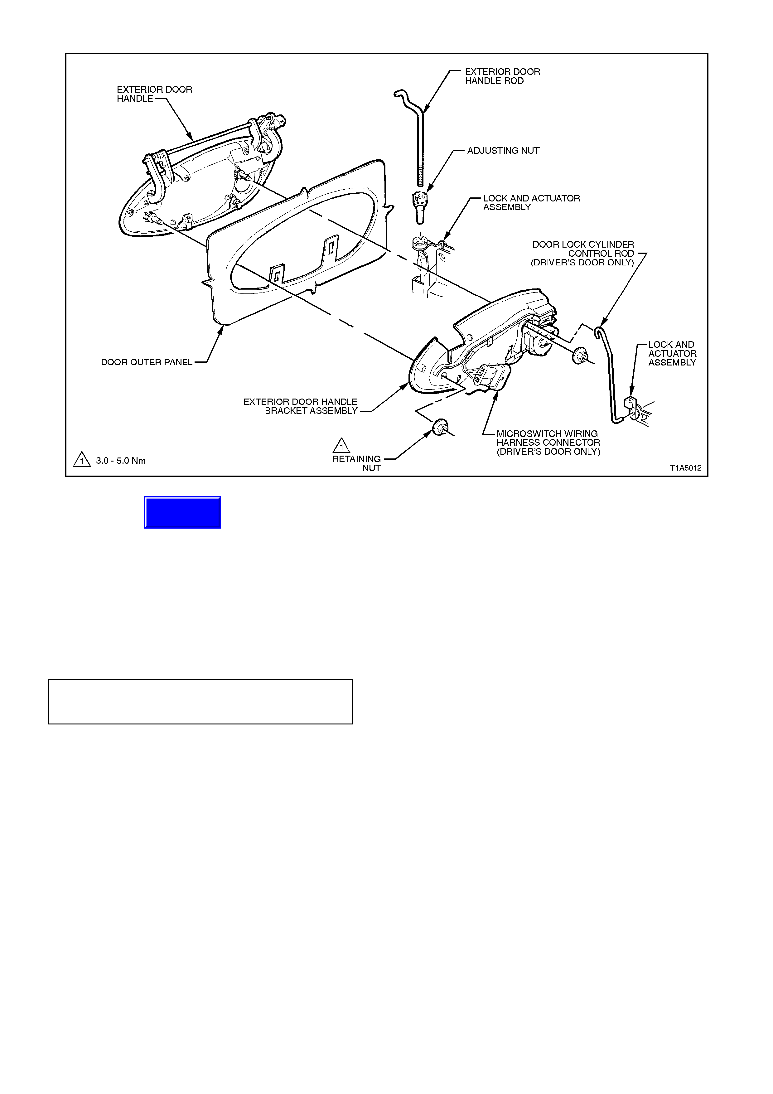
Figure 1A5-18
REINSTALL
Installation of the front door exterior handle
assembly is the reverse of the removal operation,
noting the following:
1. Ensure that the adjusting nut is seated in the
lock and actuator assembly before installing
the exterior door handle assembly retaining
nuts.
2. Tighten retaining nuts to the correct torque
specification.
EXTERIOR DOOR HANDLE
ASSEMBLY RETAINING NUT
TORQUE SPECIFICATION 3 - 5 Nm
3. Check and if necessary, adjust the exterior
door handle adjusting nut to allow latch
disengagement with striker when the exterior
door handle opening is 18° ± 5° from the rest
position.
4. Ensure the water deflector is sealed correctly
to door and use a new door locking button
retaining clamp.
Techline

RESET (‘FREE TURN’ LOCK CYLINDER)
NOTE:
If the ‘free turn’ lock cylinder becomes misaligned due to the insertion of the incorrect key, a foreign object or if the
correct key is not inserted fully when turned, the following procedure will need to be carried out.
1. Insert the key fully into the lock, preferably in the vertical position and turn the key slowly anti-clockwise - until a
click is felt.
2. Then slowly turn key clockwise - until a click is felt.
3. Return the key to the vertical position (if not already there) and withdraw the key.
4. Reinsert the key at the vertical position and check if the key will lock and unlock the vehicle.
NOTE:
If the key does not work properly, keep key in lock and turn key 180° anti-clockwise, then repeat the procedure.
2.9 REAR DOOR EXTERIOR HANDLE ASSEMBLY
REMOVE
1. Remove the door inner trim panel refer
2.5 FRONT AND REAR DOOR INNER TRIM
PANEL in this Section.
2. Remove the two screws securing the inner
trim panel retaining bracket to the door and
remove retaining bracket. Remove inner trim
retaining brackets by levering out the centre
pin of bracket.
3. Carefully peel off the water deflector from the
door inner panel.
Figure 1A5-19
EXTERIOR DOOR HANDLE
RETAINING NUT
TORQUE SPECIFICATION 3 - 5 Nm
3. Check and if necessary, adjust the exterior
door handle adjustment nut to allow latch
disengagement with striker when the exterior
door handle opening is 18° ± 5° from the rest
position.
4. Ensure the water deflector is sealed correctly
to the door panel.
5. Use a new door locking button retaining
clamp.
4. Remove the two exter ior door handle retaining
nuts, and remove exterior door handle.
REINSTALL
Reinstallation of the rear door exterior handle
assembly is the reverse of the removal operation,
noting the following:
1. Ensure that the adjuster nut is seated in the
lock assemble before installing the exterior
door handle assembly retaining nuts.
2. Tighten retaining nuts to the correct torque
specification.
Figure 1A5-20
Techline
Techline
Techline
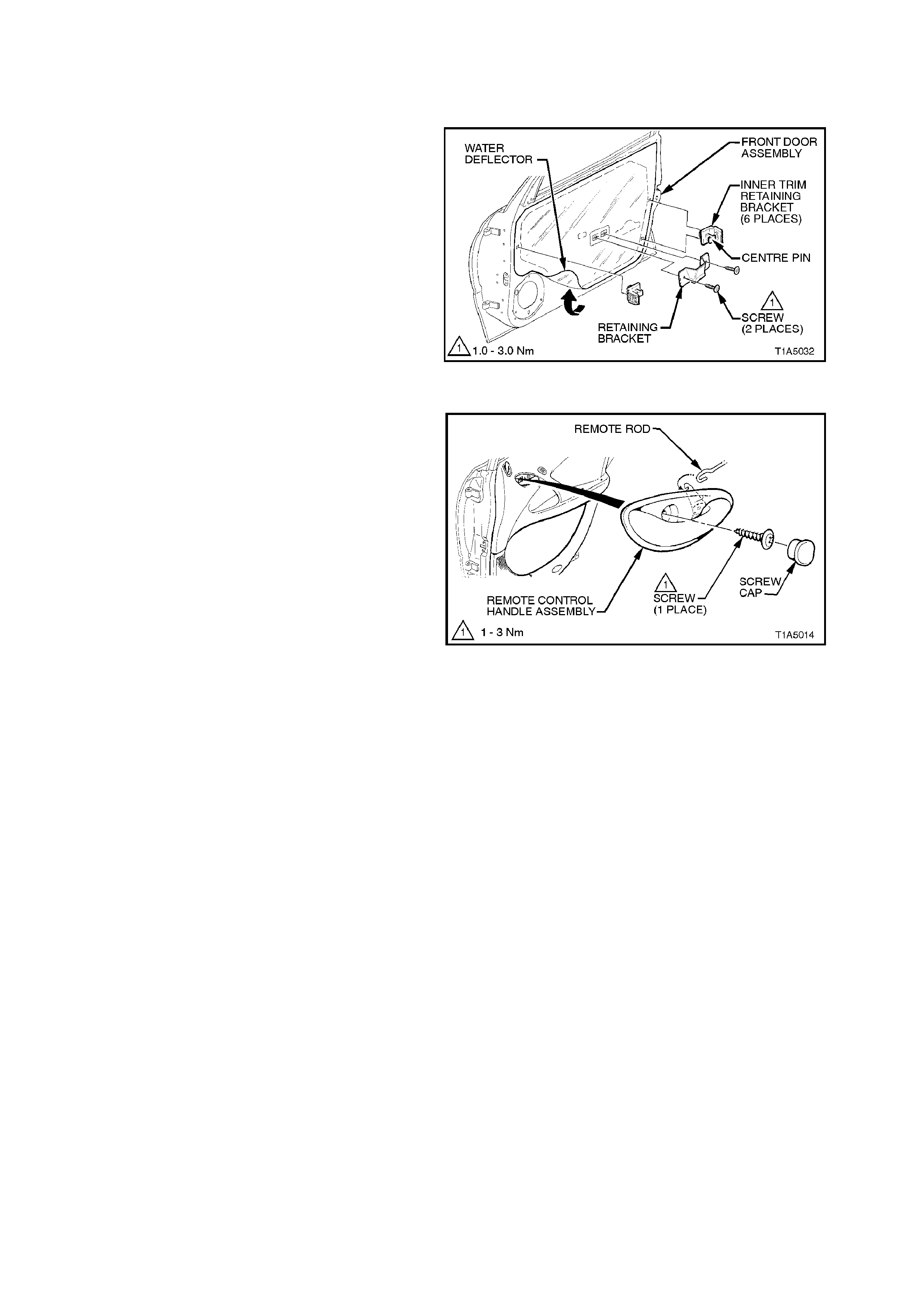
2.10 REMOTE CONTROL HANDLE AND ROD ASSEMBLY
REMOVE
1. Remove the screw cap and screw securing
the door remote control handle assembly to
the door inner panel and remove the door
remote control handle assembly in a forward
direction.
2. Remove the door inner trim panel refer to
2.5 FRONT AND REAR DOOR INNER TRIM
PANEL, in this Section.
3. Remove the two screws securing the inner
trim panel retaining bracket to the door and
remove retaining bracket. Remove inner trim
retaining brackets by levering out the centre
pin of bracket.
4. Carefully peel off the water deflector from the
door inner panel. Figure 1A5-21
5. Unclip the remote control handle rod from the
door inner panel (2 plac es) and disengage the
remote control handle rod from the door lock
and actuator assembly by releasing the
retainer clip.
REINSTALL
Installation of the remote control handle and rod
assembly is the reverse of the removal operation,
noting the following:
1. Ensure the door remote handle assembly and
remote control rod are engaged before final
fittment, refer to Fig. 1A5-22 in this Section.
2. Ensure the water deflector is sealed correctly
against the door panel.
3. Use a new door locking button retaining
clamp.
Figure 1A5-22
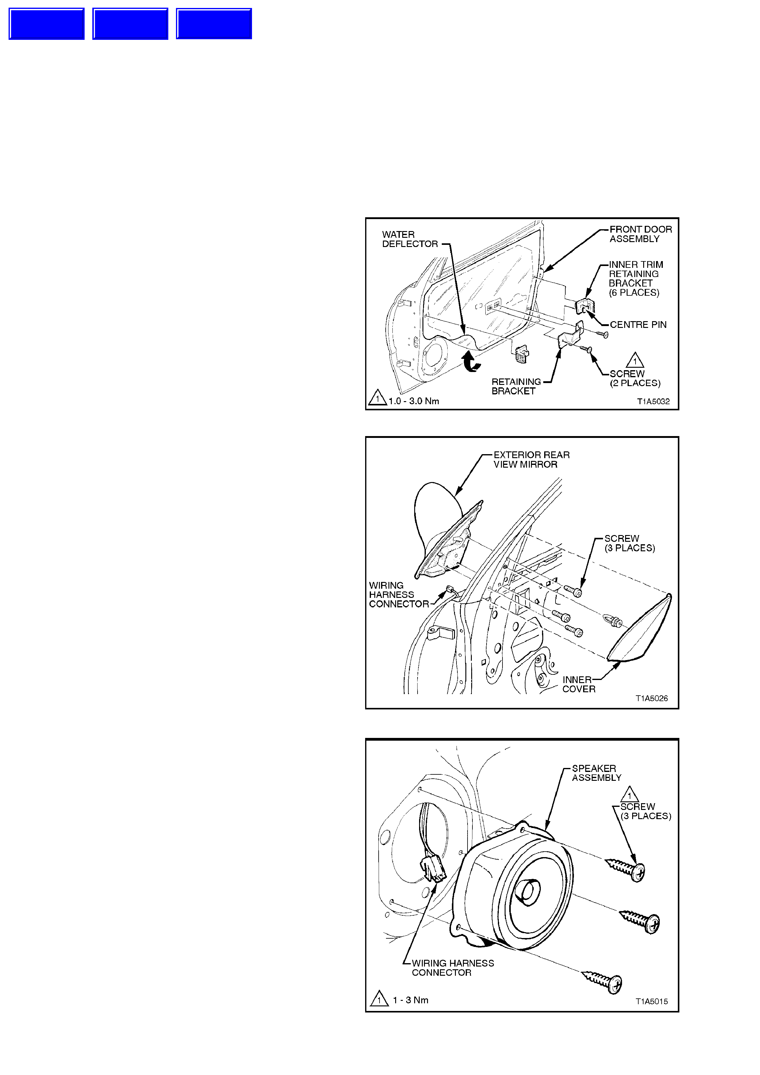
2.11 FRONT DOOR WINDOW AND REGULATOR ASSEMBLY
NOTE:
To remove, test and reinstall the power window
switch, depending on m odel variant, refer to either
Section 12J-1 LOW SERIES BCM or 12J-2 HIGH
SERIES BCM.
REMOVE
1. Remove the door inner trim panel refer to
2.5 FRONT AND REAR DOOR INNER TRIM
PANEL, in this Section.
2. Remove the two screws securing the inner
trim panel retaining bracket to the door and
remove retaining bracket. Remove inner trim
retaining brackets by levering out the centre
pin of bracket.
3. Carefully peel off the water deflector from the
door inner panel.
Figure 1A5-23
4. Remove the three screws securing the
external rear view to the door panel and while
supporting the mirror, disconnect the wiring
harness connector and remove the mirror.
Figure 1A5-24
5. Remove the three screws securing the
speaker assembly to the door inner panel,
remove speaker far enough to gain access to
wiring harness connector. Disconnect wiring
harness connector and remove speaker.
Figure 1A5-25
Techline
Techline
Techline
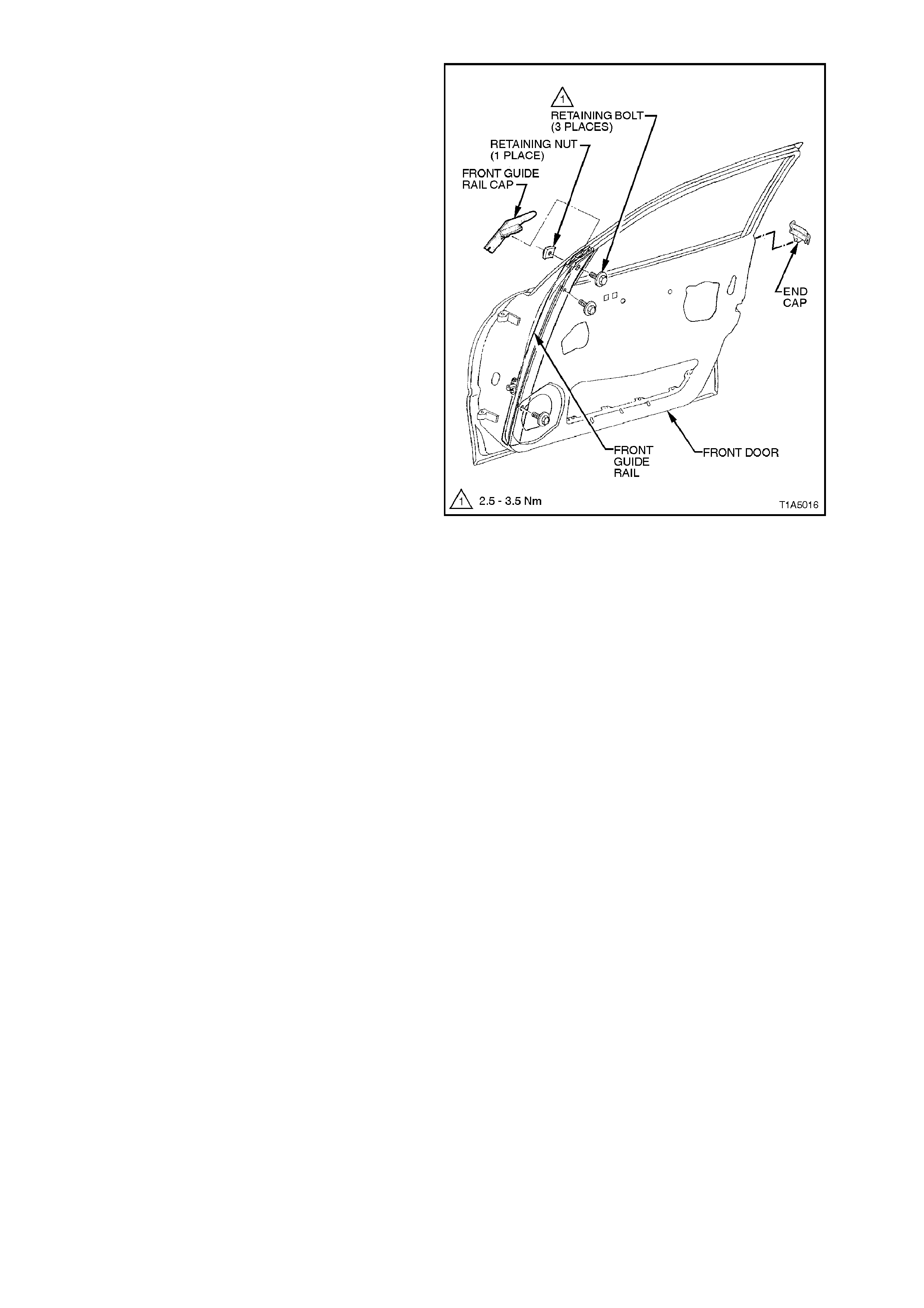
6. With window wound down approximately half
way, remove drop window weatherstrip from
front guide rail.
NOTE:
It is not necessary to remove drop window
weatherstrip completely, only from the front guide
rail.
7. Remove the three bolts securing the front
guide rail to the door panel and remove guide
rail downwards, refer to Fig. 1A5-26.
8. Remove guide rail cap from top of guide rail,
refer Fig. to 1A5-26.
NOTE:
The top guide ra il retaining nut is not welded to the
door and when the guide rail retaining bolt is
removed, this nut may become lost.
9. Gently pry the weatherstrip end cap from the
rear of the door, refer Fig. 1A5-26.
10. Remove the two attaching sc rews s ecur ing the
window regulator guide rail and slide the rail
out of window regulator guide runner, refer to
Fig. 1A5-27.
11. On vehicles with electrically operated window
regulators, disconnect wiring harness
connector from window regulator, refer to
Fig. 1A5-27.
12. While having and assistant support the
window, drill out rivets securing the window
regulator to the door panel, slide runners out
of window guide rails, and remove window
regulator through door inner panel aperture,
refer to Fig. 1A5-27.
13. Remove the window assembly.
Figure 1A5-26

REINSTALL
Installation of the front door window and regulator assembly is the reverse of the removal procedure, noting the
following:
1. Ensure all f rictional surf aces of the window regulator assem bly and ass ociated parts are adequately lubricated
with Lithium grease (to Holden Specification HN 1416).
2. Locate the regulator assembly inside the door, aligning the attaching holes in the assembly with the
corresponding holes in the door inner panel. Attach the regulator assembly to the door inner panel using
service replacement screws.
3. Install front guide rail cap before tightening front guide rail retaining bolt and nut.
4. Before installing door inner trim panel, adjust the front door window and regulator as per the following
adjustment procedure
5. Ensure the water deflector is correctly sealed against door inner panel.
6. Ensure the door rem ote contr ol handle as sembly and remote c ontrol r od are engaged before f inal f itment, ref er
to Fig. 1A5-22 in this Section.
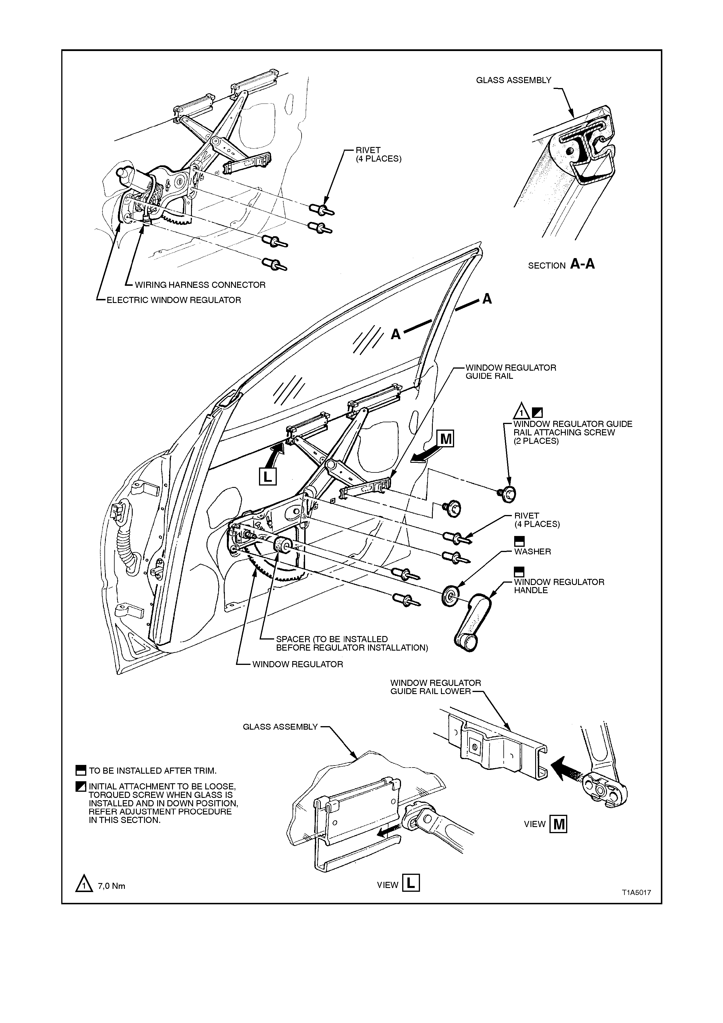
Figure 1A5-27
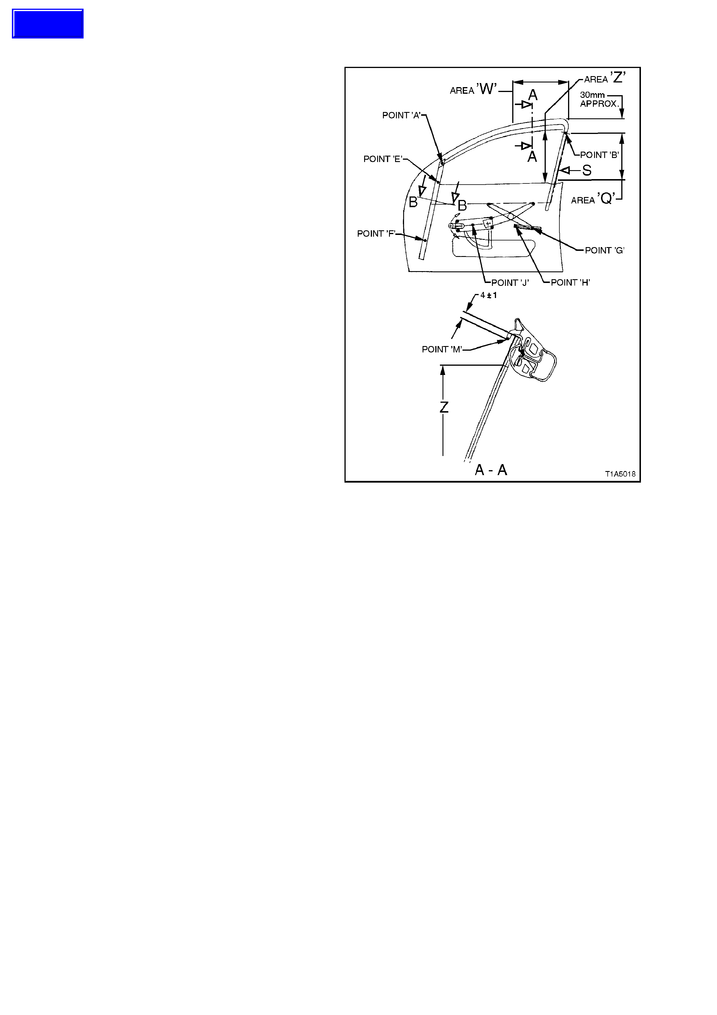
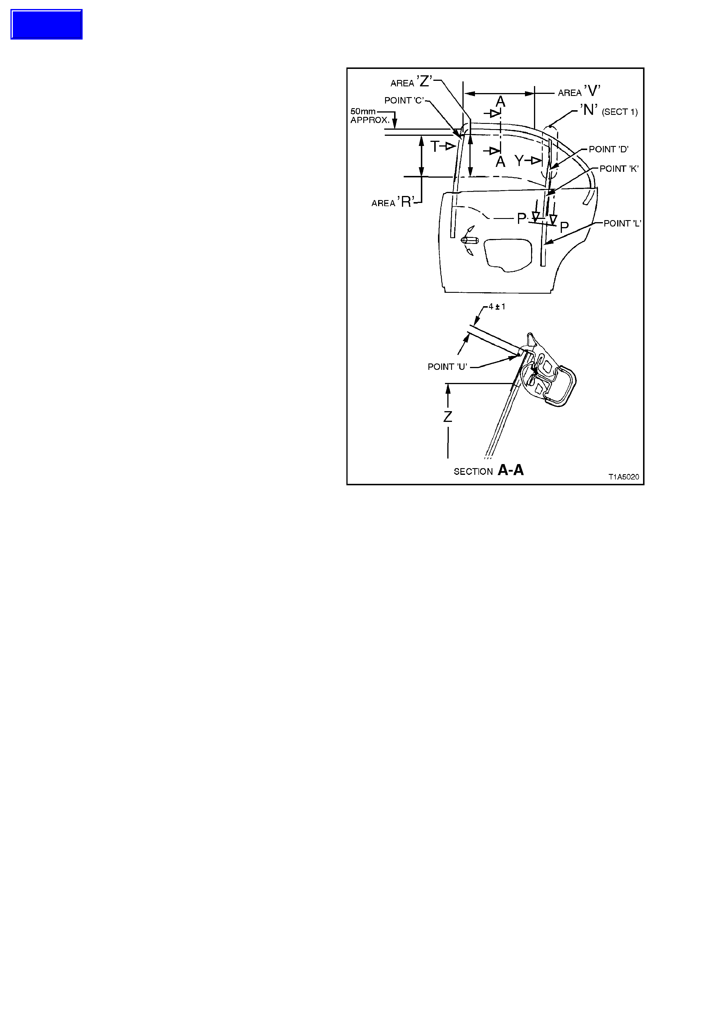
ADJUST
1. Adjust end stop, point ‘B’, at the rear of the
door so that there is a 1 mm gap below the
highest possible end stop position and tighten
attaching screw to approximately 2 Nm.
2. Wind the window glass up through area ‘Q’
while at the sam e time, press ing the rail which
is bonded to the rear edge of the glass, in the
direction of arrow S. Continue winding window
glass up until window glass is approximately
30 mm before the closed position.
3. Screw window regulator guide rail in position
without imposing any stresses by tightening
the rear attachment screw, point ‘G’, to 7 Nm.
4. Tighten the centr e attachm ent sc rew, point ‘E’,
of the front guide rail to 7 Nm while ensuring
that the window glass is held approxim ately 30
mm before the closed position.
5. W ind the window glass down to approxim ately
30 mm above the door belt moulding while at
the same time, pressing the rail which is
bonded to the rear edge of the glass, in the
direction of arrow S. Tighten the bottom
attachment screw, point ‘F’, for the front guide
rail to 7 Nm.
6. Screw window regulator guide rail in position
without imposing any stresses by tightening
the front attachment screw, point ‘H’, to 7 Nm.
7. W ind window glass up to a position where the
upper edge of the glas s is flus h with the upper
edge of the door m irror housing, as seen from
outside. In this position, the upper edge of the
glass must be parallel with point ‘M’ of the
glass run over area ‘W’.
8. Check cranking load of window glass in area
Z. If load feels excessive (more than 2.7 Nm)
re-adjust window glass by correcting the front
guide rail attachments, points ‘E’ and ‘F’.
9. Adjust end stop, point ‘A’, so that the end s top
contacts with the window glass and tighten
attaching screw to 7 Nm.
10. With the window in the closed position, adjust
end stop, point ‘J’, so that it contacts the
toothed sector of the window regulator, then
tighten attachment screw to 7 Nm.
Figure 1A5-28
Techline

11. Check upper edge of glass. If the deviation in
parallelism and engagement exceeds 1 mm,
re-adjust end stops at point ‘B’, and ‘A’ as
necessary, so that the upper edge of the glass
to the lip of the glass run at, point ‘M’ is within
a tolerance band of 3 to 5 mm.
12. Check the upper edge of the glass to ensure
that the lip of the glass run channel, point ‘M’,
is parallel over the area ‘W’.
The upper edge of the glass must be 4 mm
above the lip of the glass run channel, point
‘M’, over the area ‘W’.
If either the deviation in parallelism or insertion
depth exceed 1 mm, then the end stops at
points ‘B’, and ‘A’ as necessary, must be
readjusted so that the upper edge of the glass
is 3 to 5 mm above the lip of the glass run
channel, point ‘M’.
13. Tighten attachment screw for end stop, point
‘B’ to 4 Nm.
2.12 REAR DOOR WINDOW AND REGULATOR ASSEMBLY
NOTE:
To remove, test and reinstall the power window
switch, depending on model variant, refer to either
Section 12J-1 LOW SERIES BCM or Section 12J-2
HIGH SERIES BCM.
REMOVE
1. Wind rear window down.
2. Disconnect battery earth lead.
3. Remove the door inner trim panel refer to 2.5
FRONT AND REAR DOOR INNER TRIM
PANEL, in this Section.
4. Remove the two screws securing the inner
trim panel retaining bracket to the door and
remove retaining bracket. Remove inner trim
retaining brackets by levering out the centre
pin of bracket.
5. Carefully peel off the water deflector from the
door inner panel.
6. Remove the rear door drop window
weatherstrip.
7. Remove the two scr ews sec uring the guide r ail
to the top of the rear door.
8. Remove the two bolts securing the guide rail
to the door panel and remove guide rail from
door, outboard and upward.
9. On vehicles with electrically operated window
regulators, disconnect wiring harness
connector from window regulator, refer to Fig.
1A5-30.
Figure 1A5-29
10. While having an assistant support the rear
window glass, drill out the rivets securing the
window regulator assembly to the door inner
panel. Slide the window regulator guide
runners out of the window guides, and rem ove
window regulator through the aperture in the
door inner panel, refer to Fig. 1A5-30.
11. Remove door window glass.
Techline
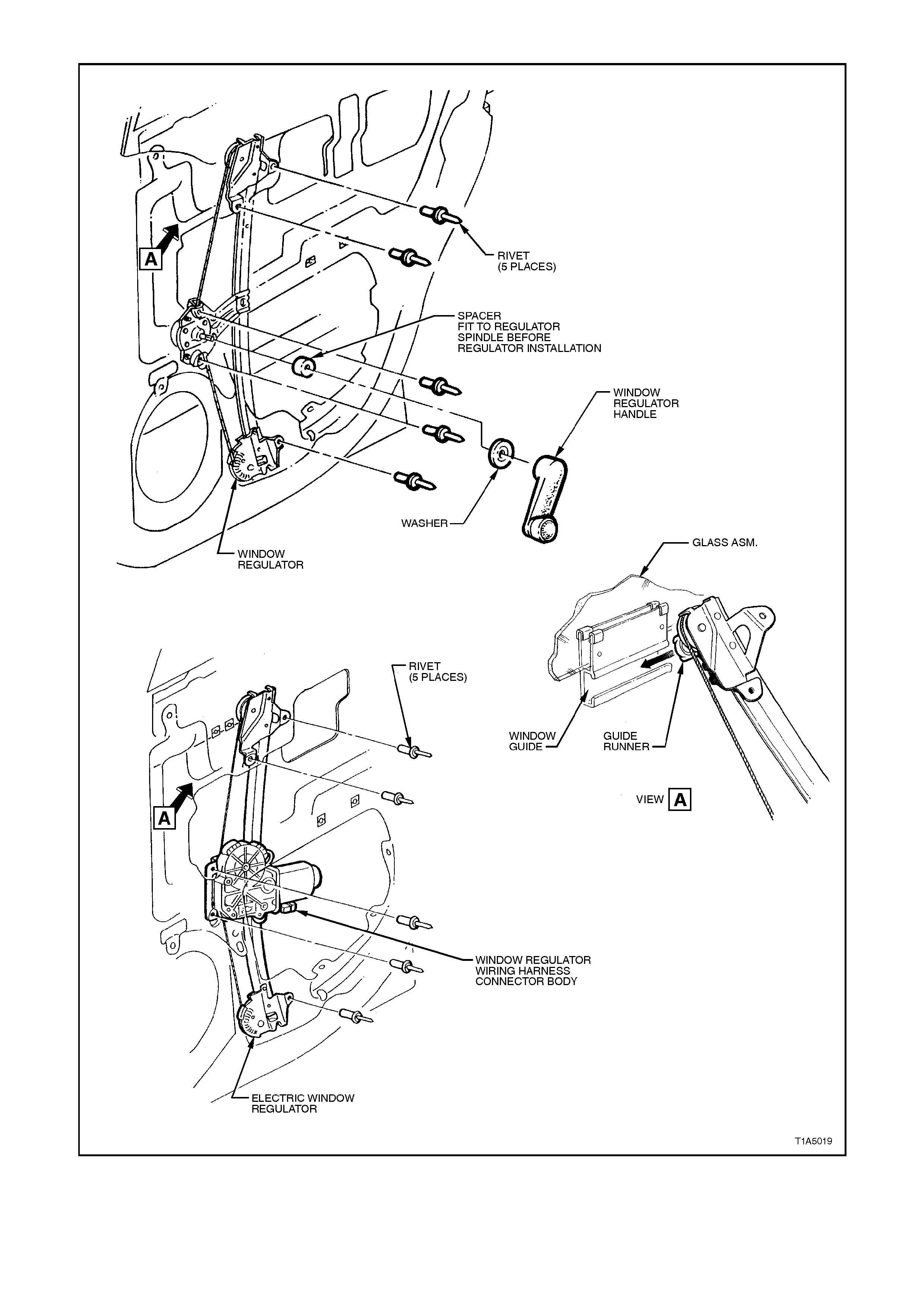
Figure 1A5-30

REINSTALL
Reinstallation of the rear door window and regulator assembly is the reverse of the removal operation, noting the
following:
1. Ensure all frictional surfaces of the window regulator assembly and associated parts are adequately lubricated
with Lithium grease (to Holden Specification HN 1416).
2. Locate the regulator assembly inside the door, aligning the attaching holes in the assembly with the
corresponding holes in the door inner panel. Attach the regulator assembly to the door inner panel using
service replacement screws.
NOTE:
On vehicles without power windows, ensure the spacer is fitted to the regulator spindle before installing the
regulator.
4. Before installing door inner trim panel, adjust the front door window and regulator as per the following
adjustment procedure.
5. Ensure the water deflector is correctly sealed against door inner panel.
6. Ensure the door remote handle assembly and remote control rod are engaged before final fitment, refer to
Fig. 1A5-22 in this Section.
ADJUST
1. Tighten end stop, point ‘D’ on the rear guide
rail to approximately 1 - 2 Nm.
2. Adjust end stop, point ‘C’, in the window fr ame
so that there is a 1 mm gap below the highest
possible end stop position and tighten
attaching screw to approximately 2 Nm.
3. Wind the window glass up through area ‘R’
while at the sam e time, press ing the rail which
is bonded to the front edge of the glas s, in the
direction of arrow ‘T’. Continue winding
window glass up until window glass is
approximately 30 mm before the closed
position.
4. Push the rear guide rail rearward, in the
direction of arrow ‘Y’, and tighten guide rail
attachment screws, points ‘K’ and ‘L’ to 7 Nm.
5. Check cranking load of window glass in area
Z. If load feels excessive (more than 2.7 Nm)
re-adjust window glass by correcting the rear
guide rail attachments, points ‘L’ and ‘K’.
6. Check upper edge of glass. If the deviation in
parallelism and engagement exceeds 1 mm,
re-adjust end stops at point ‘C’, and ‘D’ as
necessar y, so that the upper edge of the glass
to the lip of the glass run at, point ‘U’ is within
a tolerance band of 3 to 5 mm.
7. Check the upper edge of the glass to ensure
that the lip of the glass run channel, point ‘U’,
is parallel over the area ‘V’.
The upper edge of the glass must be 4 mm
above the lip of the glass run channel, point
‘U’, over the area ‘V’.
If either the deviation in parallelism or ins ertion
depth exceed 1 mm, then the end stops at
points ‘B’, and ‘A’ as necessary, must be
readjusted s o that the upper edge of the glass
is 3 to 5 mm above the lip of the glass run
channel, point ‘M’.
8. Tighten attachment screw for end stops, point
‘C’ and ‘D’ to 4 Nm.
Figure 1A5-31
Techline
2.13 REAR DOOR FIXED WINDOW GLASS
REMOVE
1. Disconnect battery earth lead.
2. Remove the door inner trim panel refer to
2.5 FRONT AND REAR DOOR INNER TRIM
PANEL in this Section.
3. Remove the two screws securing the inner
trim panel retaining bracket to the door and
remove retaining bracket. Remove inner trim
retaining brackets by levering out the centre
pin of bracket.
4. Carefully peel off the water deflector from the
door inner panel.
Figure 1A5-32
5. Remove the rear door drop window
weatherstrip from the rear guide rail (not
shown in Fig. 1A5-33).
6. Remove the two sc rews (1) s ecuring the guide
rail (3) to the top of the rear door.
7. Remove the two bolts (2) securing the guide
rail (3) to the door panel and remove guide rail
from door, outboard and upward
8. Roll back a section of the rear door
weatherstrip around the fixed window area, to
gain access to the two glass rubber securing
screws (4). Remove b oth screws (4)..
9 Prise the inner section of the fixed window
glass rubber f r om its pos ition in the door upper
frame and slide glass toward front of vehicle,
removing the glass assembly.
T1A5021
34
1
2
Figure 1A5-33
REINSTALL
Installation of the rear door stationary window
assembly is the reverse of the removal operation.
1. Tighten all fastening screws to the correct
torque specifications.
REAR DOOR FIXED GLASS
RETAINING SCREW AND
GUIDE RAIL TO 3.5 - 4.5 Nm
DOOR FRAME SCREW
TORQUE SPECIFICATION
GUIDE RAIL TO
DOOR PANEL BOLT 6.0 – 14.0 Nm
TORQUE SPECIFICATION
Techline

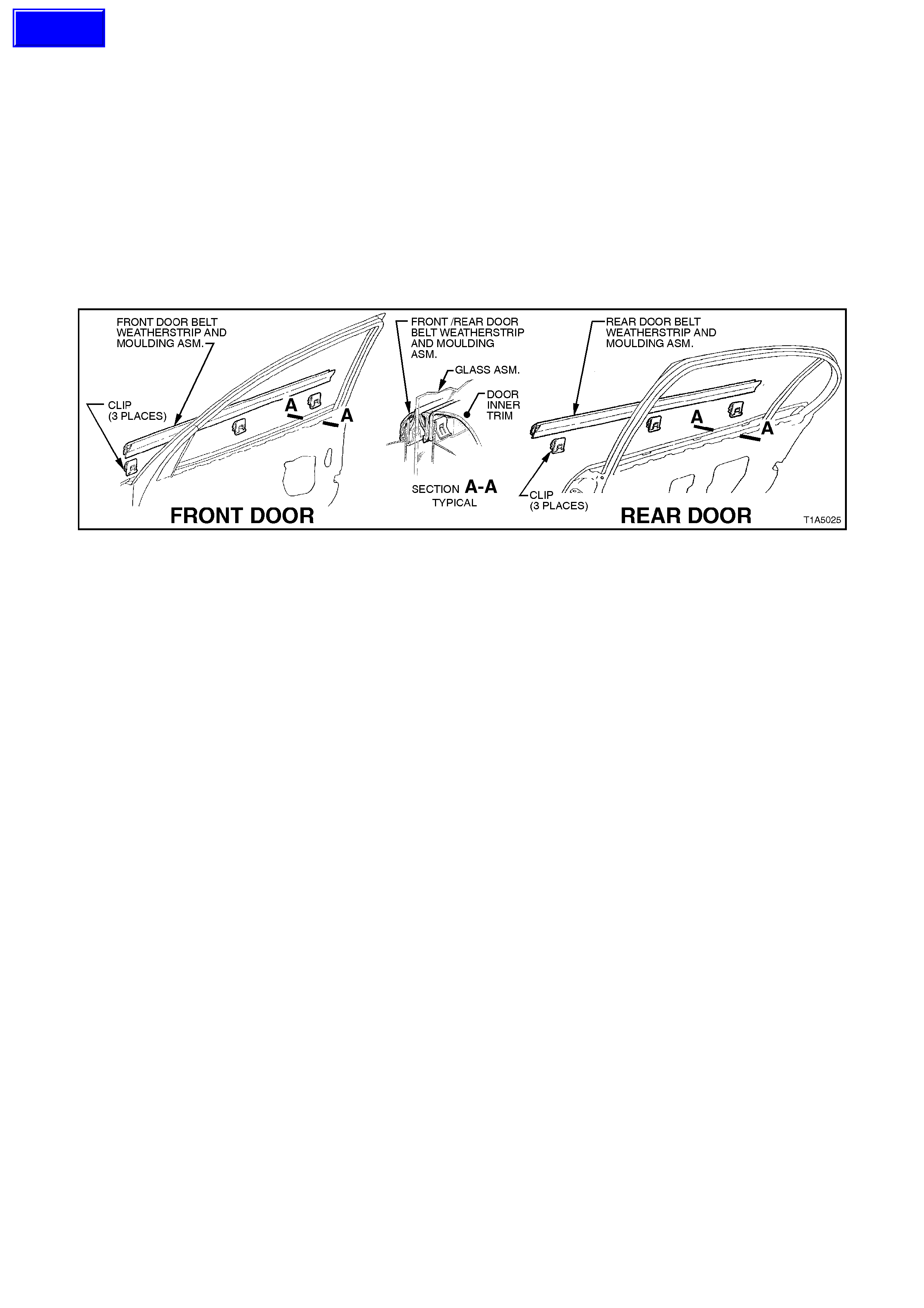
2.14 FRONT AND REAR DOOR UPPER WEATHERSTRIP ASSEMBLY
REMOVE
1. Progressively peel the drop window
weatherstrip away from around the door
window frame and guide rails.
2. Progressively remove the weatherstrip from
the lip on the door upper frame and the
retainer clips from the holes in the door
panels. Refer to Figs. 1A5-34 (front door) or
1A5-35 (rear door ).
Figure 1A5-34
Techline
Figure 1A5-35
REINSTALL
Installation of the door weatherstrips is the reverse of the removal operation, noting the following:
1. When installing weatherstrips, start installation process from the top corner of the door.
2.15 FRONT AND REAR DOOR OPENING WEATHERSTRIP
REMOVE
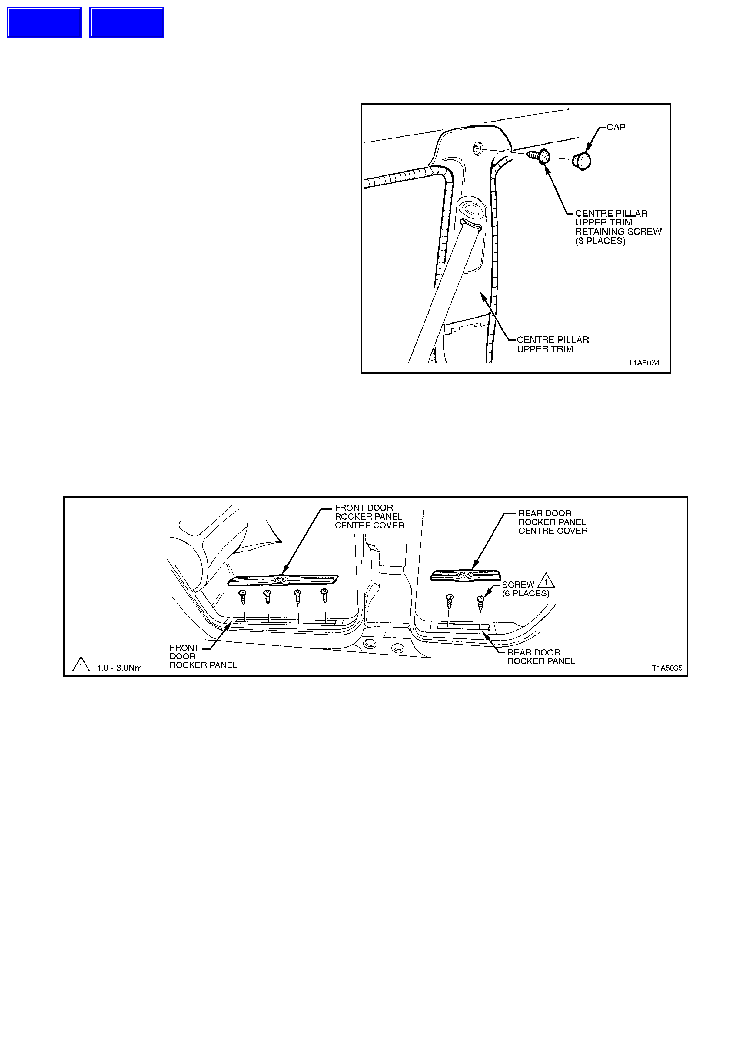
1. Remove centre pillar upper trim retaining
screw and gently pull trim back far enough to
gain access to door opening weatherstrip.
Figure 1A5-36
2. Loosen rocker panel by lifting up centre cover
and loosening the four screws (front door) or
two screws (rear door) and the one screw in
the centre, refer to Fig. 1A5-37.
3. Gently prise weatherstrip from door opening.
Figure 1A5-37
Techline
Techline

REINSTALL
Installation of the door opening weatherstrips is the
reverse of the removal procedure, noting the
following:
1. Align identification mark on weatherstrip with
the check link bracket, refer to Fig. 1A5-38.
•Front door - blue dot.
•Rear door, sedan - white dot.
•Rear door, wagon - y ellow dot.
2. Ensure weatherstrip lip sits over trim panels.
3. Tighten all screws to the correct torque
specification.
CENTRE PILLAR UPPER TRIM
RETAINING SCREW
TORQUE SPECIFICATION 1 - 3 Nm
ROCKER PANEL
RETAINING SCREW
TORQUE SPECIFICATION 1 - 3 Nm
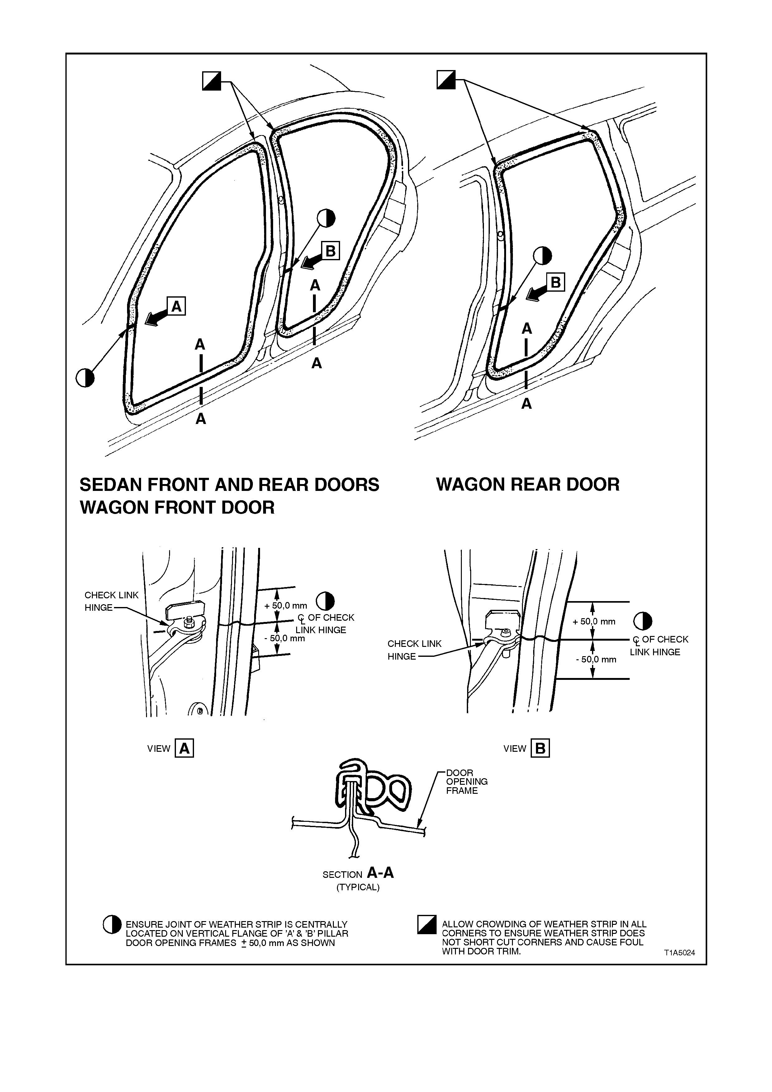
Figure 1A5-38
2.16 FRONT AND REAR DOOR BELT WEATHERSTRIP AND MOULDING ASSEMBLY
REMOVE
1. Front doors; remove the rear vision mirror assembly, refer to 2.17 EXTERIOR REAR VISION MIRROR
ASSEMBLY in this Section.
2. Prise the weatherstrip and moulding assembly off the door using fingers, taking care not to damage moulding.
REINSTALL
Installation of the door belt weatherstrip and moulding assembly is the reverse of the removal operations, noting the
following:
1 Locate the door belt weatherstrip and moulding assembly over the top of the door outer panel, then using palm
of the hand, firmly tap the assembly down, over the door outer upper flange.
Figure 1A5-39
Techline
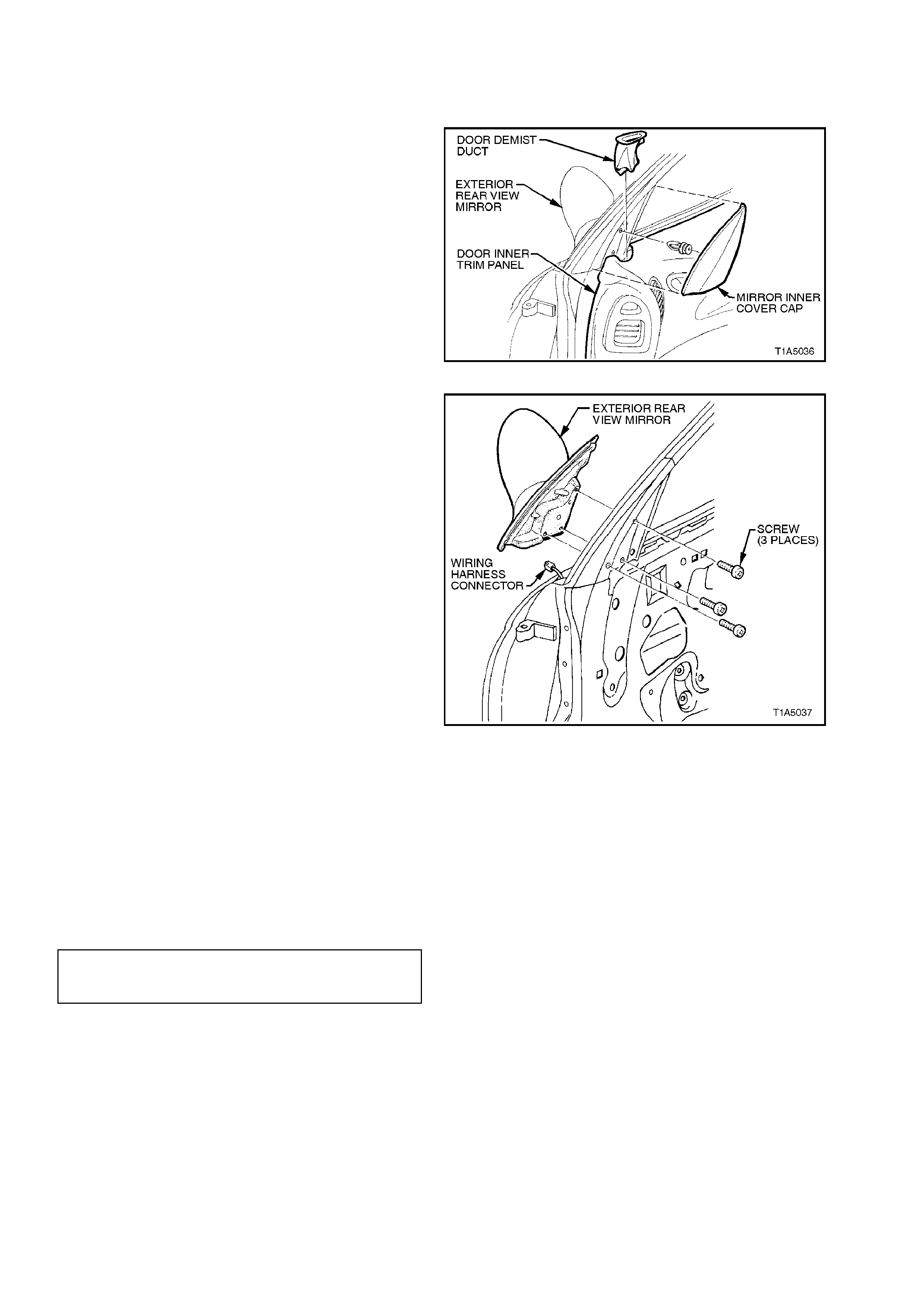
2.17 EXTERIOR REAR VISION MIRROR ASSEMBLY
REMOVE
NOTE:
For further information regarding the external rear
vision mirror, refer to Section 12H ELECTRIC
REAR VISION MIRRORS.
1. Disconnect battery earth lead.
2. Remove the mirror inner cover cap by gently
prying cap away from door.
3. Remove door demist duct to allow access to
the exterior rear vision mirror retaining screws
by pulling duct up and out of door trim.
Figure 1A5-40
4. Using a right-angled screw driver, remove the
three screws securing the mirror to the door
and while supporting the mirror, disconnect the
mirror wiring harness connector.
5. Remove mirror assembly.
NOTE:
Fig. 1A5-41 shows door with inner trim panel
removed. To remove the three exterior rear vision
mirror retaining screws, the inner door trim does
not have to be removed.
Figure 1A5-41
REINSTALL
Installation of the exterior rear vision mirror is the
reverse of the removal operation, noting the
following:
1. Ensure wiring harness and connector for the
mirror are correctly routed.
2. Ensure the three mirror to door securing
screws are tightened to the correct torque
specification.
MIRROR TO DOOR
SECURING SCREW
TORQUE SPECIFICATION 2.5 - 3.0 Nm
3. Ensure that when installing the door demist
duct, that it clips into position.
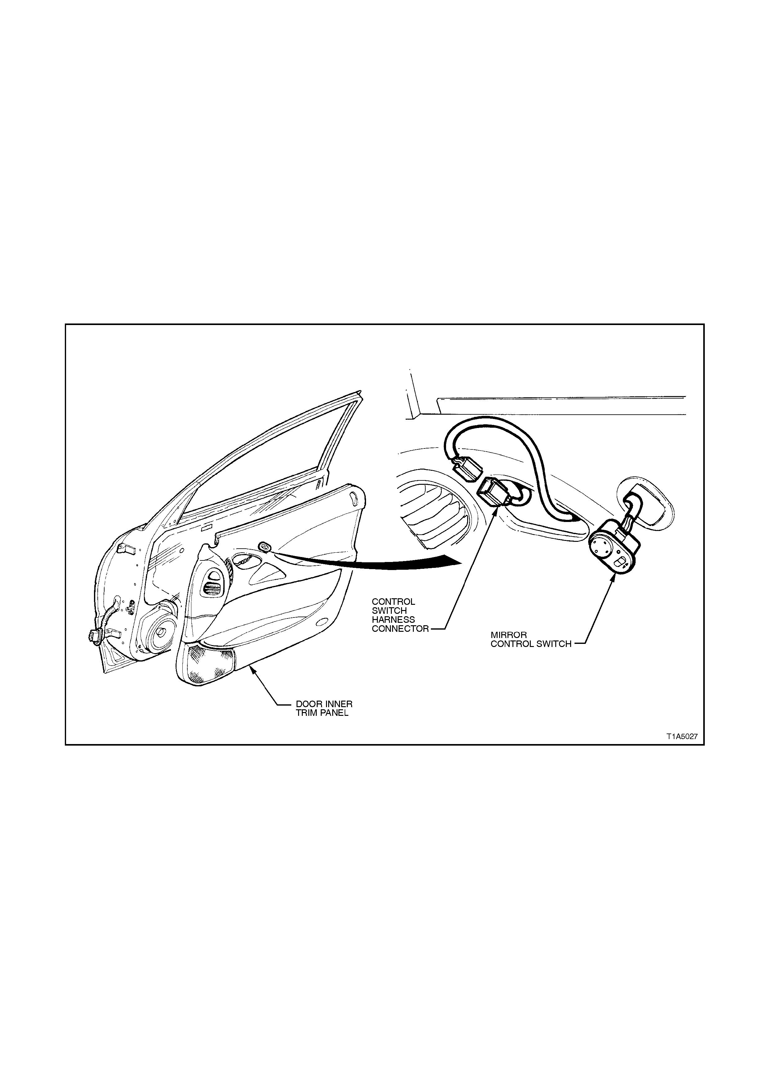
2.18 SWITCH - ELECTRIC EXTERIOR REAR VISION MIRROR CONTROL
NOTE:
For further information regarding the external rear
vision mirror and switch, refer to
Section 12H ELECTRIC REAR VISION
MIRRORS.
REMOVE
1. Remove door inner trim panel, refer to
2.5 FRONT AND REAR DOOR INNER TRIM
PANEL in this Section.
2. Disconnect the door electrical harness from
the control switch harness assembly.
3. From inside of door trim assembly, push the
control switch free and remove the switch.
Figure 1A5-42
REINSTALL
Installation of the exterior rear vision mirror control
switch is the reverse of the removal operation.

3. TORQUE WRENCH SPECIFI CATIONS
Nm
Door inner trim panel retaining screw 1.0 - 3.0
Door inner trim panel retaining bracket screw 1.0 - 3.0
Door lock and actuator assembly retaining screw 3.0 - 5.0
Door locking button escutcheon retaining screw 1.0 - 3.0
Door remote handle assembly retaining screw 1.0 - 3.0
Exterior rear vision mirror to door panel 2.5 - 3.0
Front exterior door handle retaining nut 3.0 - 5.0
Front guide rail retaining bolt 2.5 - 3.5
Rear door guide rail attachment bolt 6.0 - 14.0
Rear door guide rail attachment screw 3.5 - 4.5
Rear exterior door handle retaining nut 3.0 - 5.0
Speaker assembly retaining screw 1.0 - 3.0
Striker assembly retaining bolt 8.0 - 18.0
Window regulator guide rail attaching screw 7.0
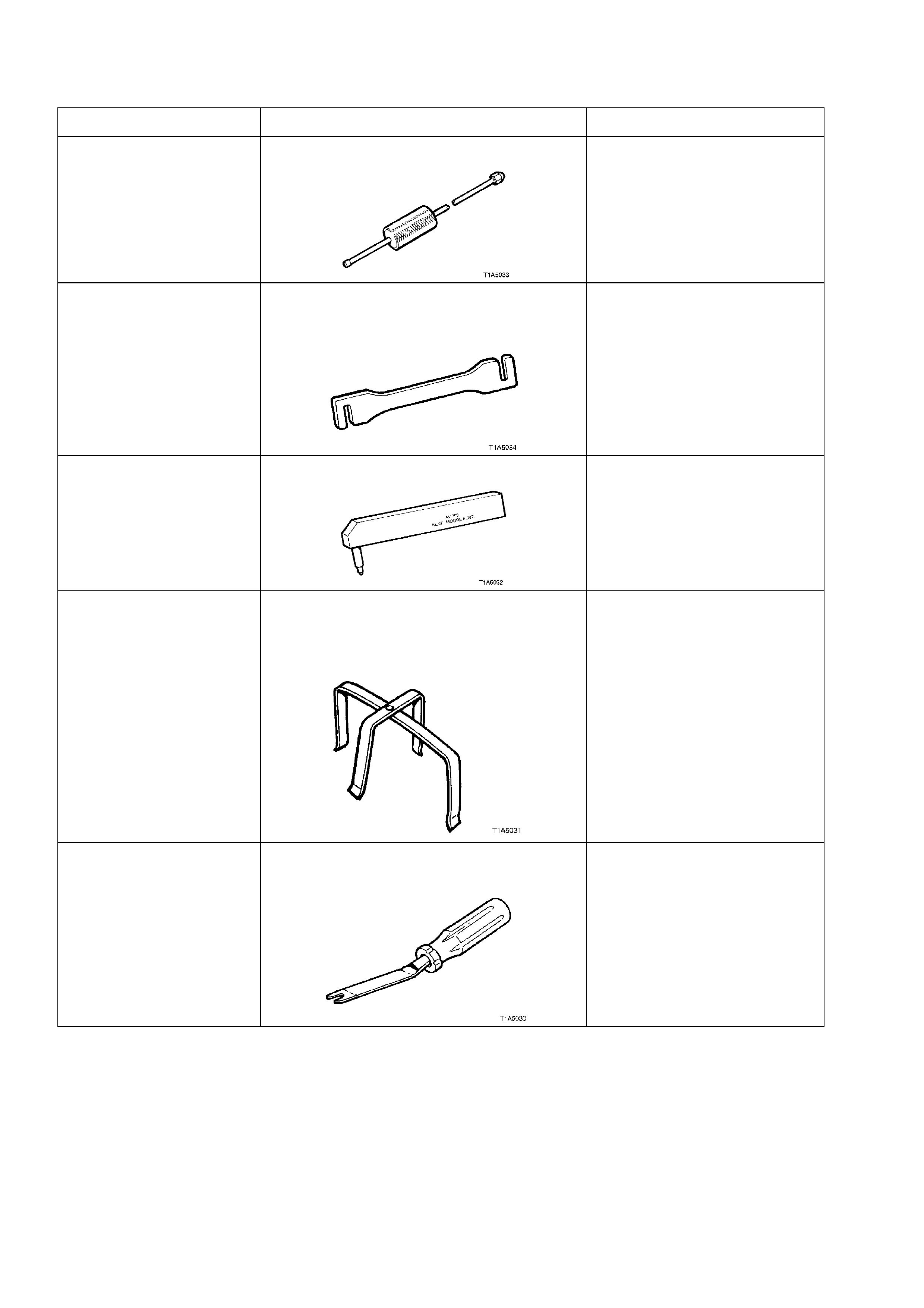
4. SPECIAL TOOLS
TOOL NO. REF IN TEXT TOOL DESCRIPTION COMMENTS
AU170 DOOR HINGE PIN REMOVAL TOOL PREVIOUSLY RELEASED
FOR
‘V’ CAR
AU184 DOOR HINGE SETTING TOOL
FOR FRONT AND REAR DOOR
ALIGNMENT
PREVIOUSLY RELEASED
FOR
‘V’ CAR
AU303 DOOR HINGE SLEEVE INSTALLER PREVIOUSLY RELEASED
FOR
‘V’ CAR
AU455 CONNECTOR BODY REMOVER
TO REMOVE THE DOOR WIRING
HARNESS CONNECTOR FROM A AND B
PILLARS.
MANDATORY TOOL
KM-317-A
- OR -
J-9886-01
WINDOW REGULATOR HANDLE
REMOVER ALSO COMMERCIALLY
AVAILABLE