SECTION 1A6 - STATIONARY GLASS
CAUTION:
This vehicle will be equipped with a Supplemental Restraint System (SRS). A SRS will
consist of either seat belt pre-tensio ners and a driver’s side air bag , or seat belt pre-
tensioners and a driver’s and front passenger’s side air bags. Refer to CAUTIONS,
Section 12M, before performing any service operation on or around SRS
components, the steering mechanism or wiring. Failure to follow the CAUTIONS
could result in SRS deplo yment, resulting in possible p ersonal injury or unnecessary
SRS system repairs.
CAUTION:
This vehicle may be equipped with LPG (Liquefied Petroleum Gas). In the interests of
safety, the LPG fuel system should be isolated by turning 'OFF' the manual service
valve and then draining the LPG serv ice lines, before any service w ork is carried out
on the vehicle. Refer to the LPG leaflet included with the Owner's Handbook for
details or LPG Section 2 for more specific servicing information.
1. GENERAL DESCRIPTI ON
Three different installation methods are used when installing stationary glass to VT Series Models.
The windshield, which is laminated and features a tinted upper band, the rear window on sedans, the tailgate glass
on station wagons, both of which have electrically heated demist facility, are all bonded in the body apertures with
urethane adhesive.
The rear quarter windows on station wagons utilise a self adhesive foam weatherstrip to seal the glass to the body.
The station wagon rear quarter windows are secured to the body opening by plastic screw on nuts.
Toughened safety glass is used for all the windows except the windshield.
For replacement of urethane adhesive bonded glasses, urethane adhesive kits have been developed and must be
used to maintain original installation requirements. Glass installed with urethane requires either partial or complete
removal of the urethane adhesive when replacing the glass. Partial removal of the urethane adhesive is referred to
as the ‘short method’. Complete removal of the urethane is known as the ‘long method’.
The short method is used where original urethane adhesive left on body opening pinch weld flanges after glass
removal can serve as a base for the new glass. This method would be used in cases of replacement of cracked
windshields or removal of glass that is intact. The amount of urethane left in the glass opening can be controlled
during glass removal, leaving the maximum amount of original urethane intact on the body opening flange.
The long method is to be used when the original urethane left in the window opening after glass removal cannot
serve as a base for replacement glass. This method would be used in cases needing metal work or where paint
refinishing is required in the opening; or in cases where the glass has been previously replaced, using the short
method. In such instances, the build up of urethane could position the glass too high in the opening. In these cases,
the original urethane is completely removed and replaced with new urethane during glass installation.
Techline
Techline
Techline
Techline

2. SERVICE NOTES
WARNING:
SAFET Y GLASSES AND WO RK GLOVES M UST BE
WORN AT ALL TIMES WHEN OPERATING WITH
GLASS.
NOTE:
Skinning (partial curing) of the urethane commences
after exposure to the atmosphere. At 23 degrees
Celsius and 50 percent relative humidity, skinning
commences after 30 minutes.
Complete curing of the urethane at this temperature
and humidity takes 72 hours.
The tools recommended for cutting out the adhesive
bonded glasses are :
1. Piano wire and T handles - AU390.
2. FEIN Special Cutter, Model Astlxe 636-5.
3. Stationary glass removal kit.
These tools are available from Kent-Moore Tool &
Equipment Division of SPX Australia.
3. SERVICE OPERATIONS
3.1 WINDSHIELD GLASS
REMOVE
The windshield glass removal procedure is the
same for both the short and long installation
methods with one exception.
If the short method installation is to be used, more
care must be taken during glass rem oval to ensure
that an even surface of the original remaining
urethane exists in the body opening to serve as a
base for the new urethane bead and the
replacement glass.
The windshield moulding is installed over the edge
of the windshield glass and can be removed by
pulling the moulding from the windshield opening
starting at the windshield lower corner, after
removal of the components as detailed below.
Mouldings are available for service replacement.
Refer to VT Series parts Information for details.
Figure 1A6-1
CAUTION:
Care must be taken during any operation involving
windshield removal or installation not to exert any
load on the windshield glass. Failur e to obs erve this
may result in damage to the glass.
1. To prevent damage to paint f inis h and tr im and
to minimise clean up, mask-up and place
protective covers over parts adjacent to the
windshield.
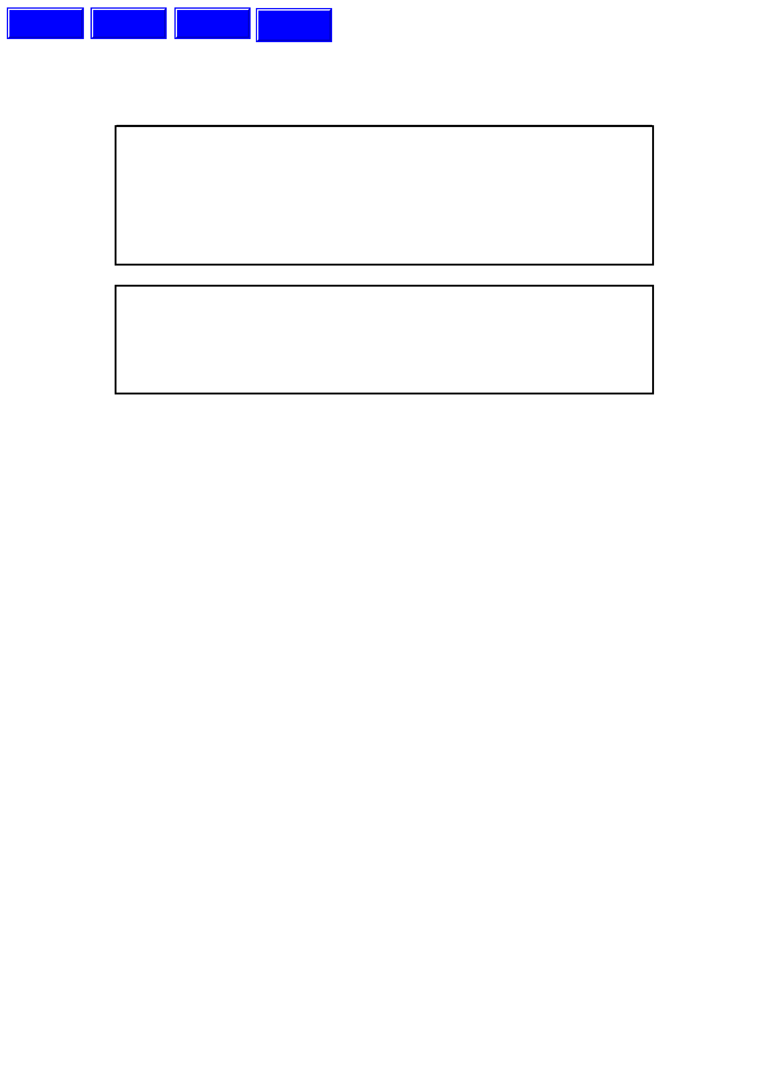
2. Remove windshield wiper arm and blade
assemblies refer Fig. 1A6-1.
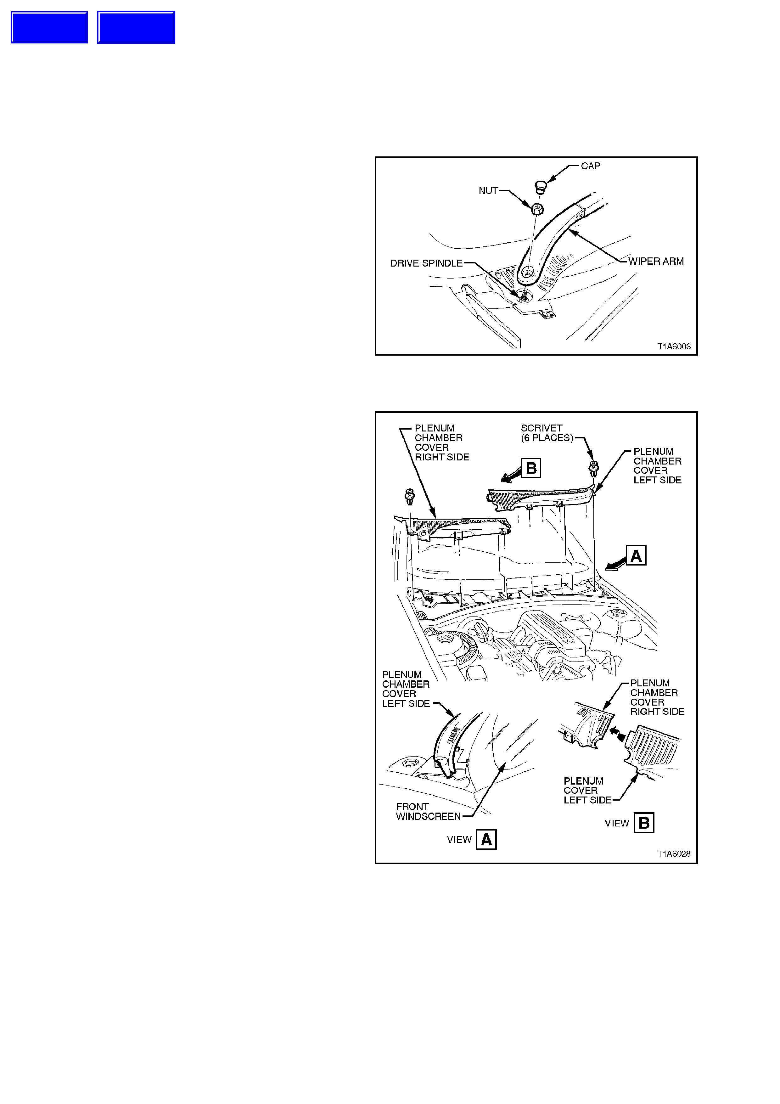
3. Remove six scrivets retaining both right and
left plenum covers.
Figure 1A6-2
Techline
Techline
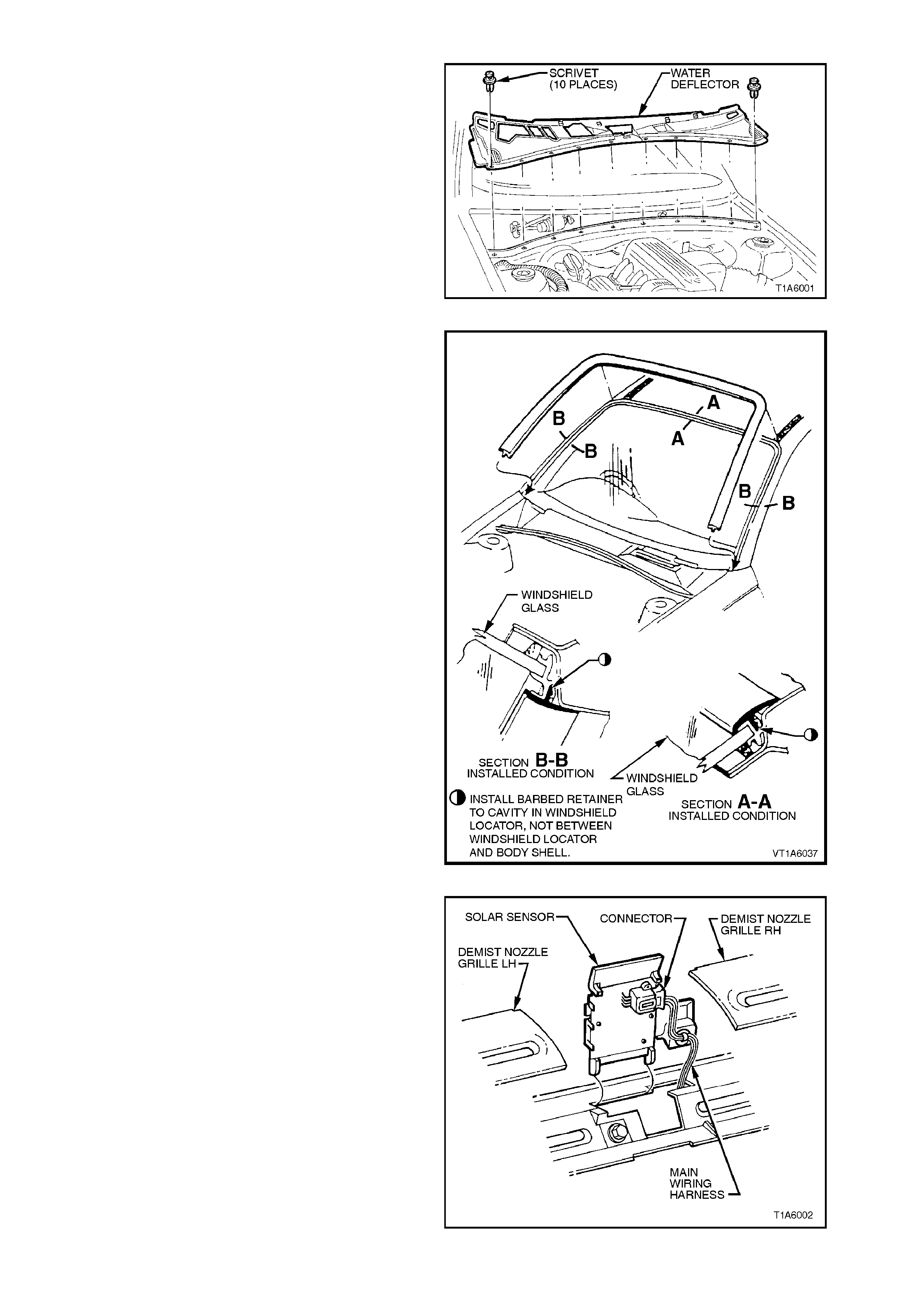
4. Remove ten scrivets retaining plenum water
deflector, pull deflector towards front of
vehicle, disengaging location tabs and remove
from vehicle, refer Fig. 1A6-3.
Figure 1A6-3
5. Remove windshield moulding cover by pulling
the moulding from the windshield opening,
starting at the windshield lower corner and
working around the opening.
Figure 1A6-4
6. Front inside vehicle, remove instrument panel
end cap cover right side and left side.
7. Remove the screws retaining the demist
nozzle right side and left side and remove the
demist nozzles. Refer to
Section 1A3, INSTRUMENT PANEL.
NOTE:
On all vehicles, care must be taken to avoid
damage to the sun sensor.
8. Remove interior mirror assembly by sliding
mirror base upwards.
9. Remove ‘A’ pillar trim assembly, refer to
Section 1A8, HEADLINING AND REAR END
TRIM.
Figure 1A6-5
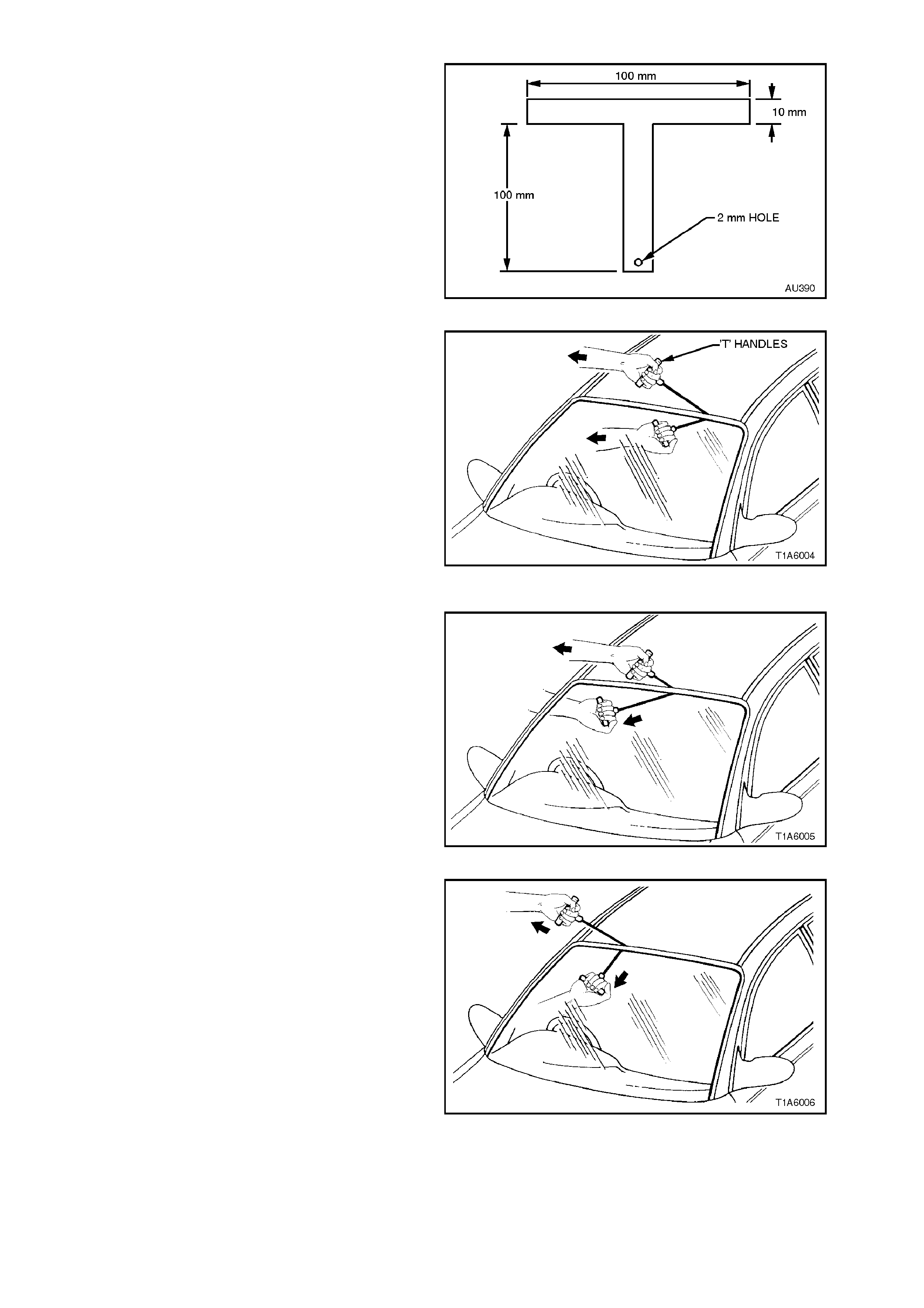
10. Using piano wire and T-handles AU 390 or
equivalent (refer Fig. 1A6-6 for dimensions),
thread one end of the piano wire through the
urethane, starting at the windshield upper
corner, pulling the end of the wire through with
pliers.
NOTE:
Use at least 700mm of wire between the T-handles.
NOTE:
Ensure that the headlining and other trim items are
not damaged.
Figure 1A6-6
11. Connect the wire to the remaining T-handle
and with the aid of an assistant, commence
cutting the urethane bead, keeping the outside
T-handle parallel to the edge of the glass using
the full length of the wire to prevent heat build
up in the wire.
NOTE:
To minimise damage to the interior of the vehicle,
the operator inside the vehicle should act as an
anchor point, holding the T-handle as close as
possible to the glass at all times, especially along
the lower edge of the windshield, while the out side
operator pulls the wire up to the interior T-handle in
a ‘walking’ motion refer Figs. 1A6-7, 1A6-8, 1A6-9,
and 1A6-10. Figure 1A6-7
Figure 1A6-8
Figure 1A6-9
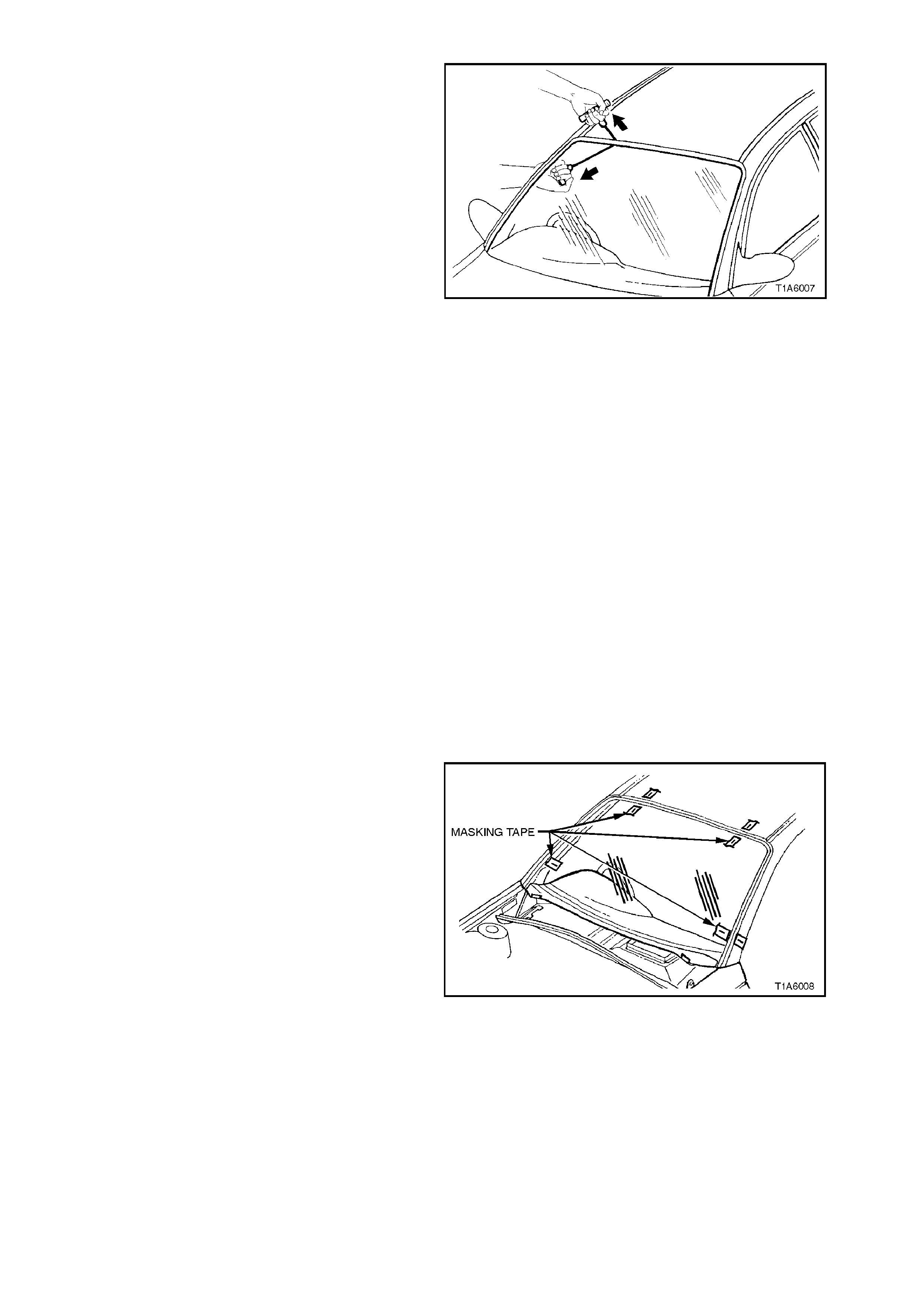
Figure 1A6-10
12. Carefully lift the windshield out of the body
aperture. If there is evidenc e of glas s adher ing
to the urethane, re-cut the area with the piano
wire.
13. If the original windshield is to be reinstalled,
place the windshield on a clean protected
surface, holding fixture etc.
NOTE:
The use of suction cups will greatly assist any
handling of the windshield.
14. Using a sharp scraper, carefully remove any
original urethane from the windshield. Clean
the windshield with a suitable oil free cleaning
agent. If a new windshield is to be installed,
clean the windshield with a suitable oil free
cleaning agent.
WARNING:
Do not use petroleum based solvents to clean
the windshield or body opening flange as the
presence of oil will prevent adhesion of the
new urethane/silicon.
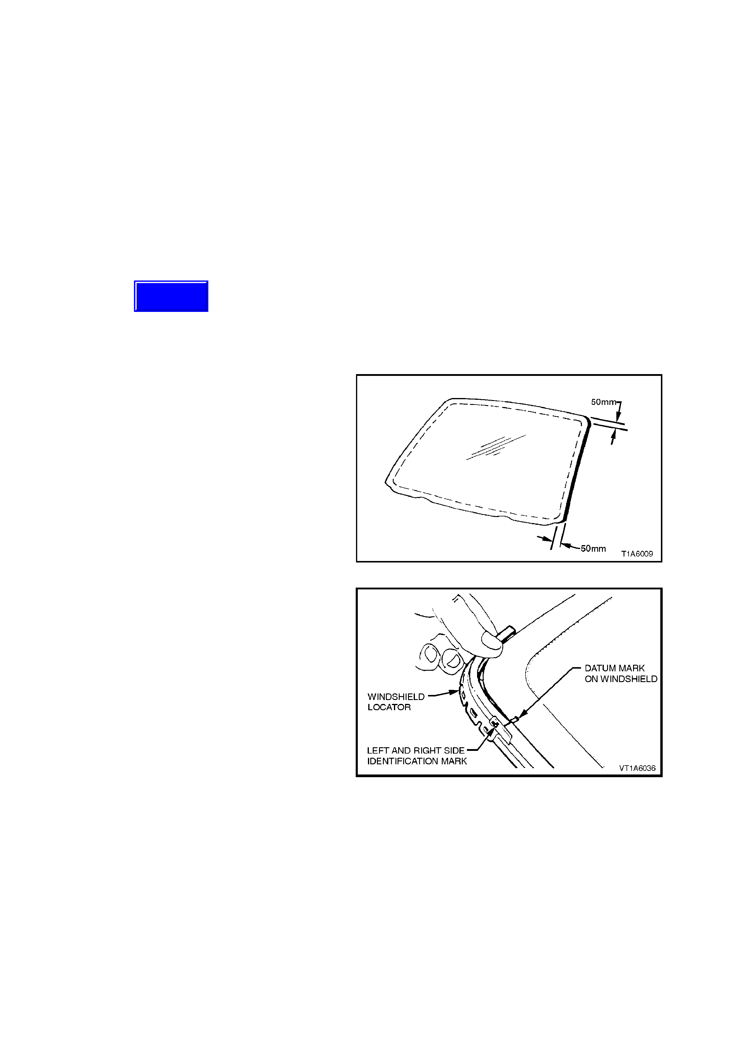
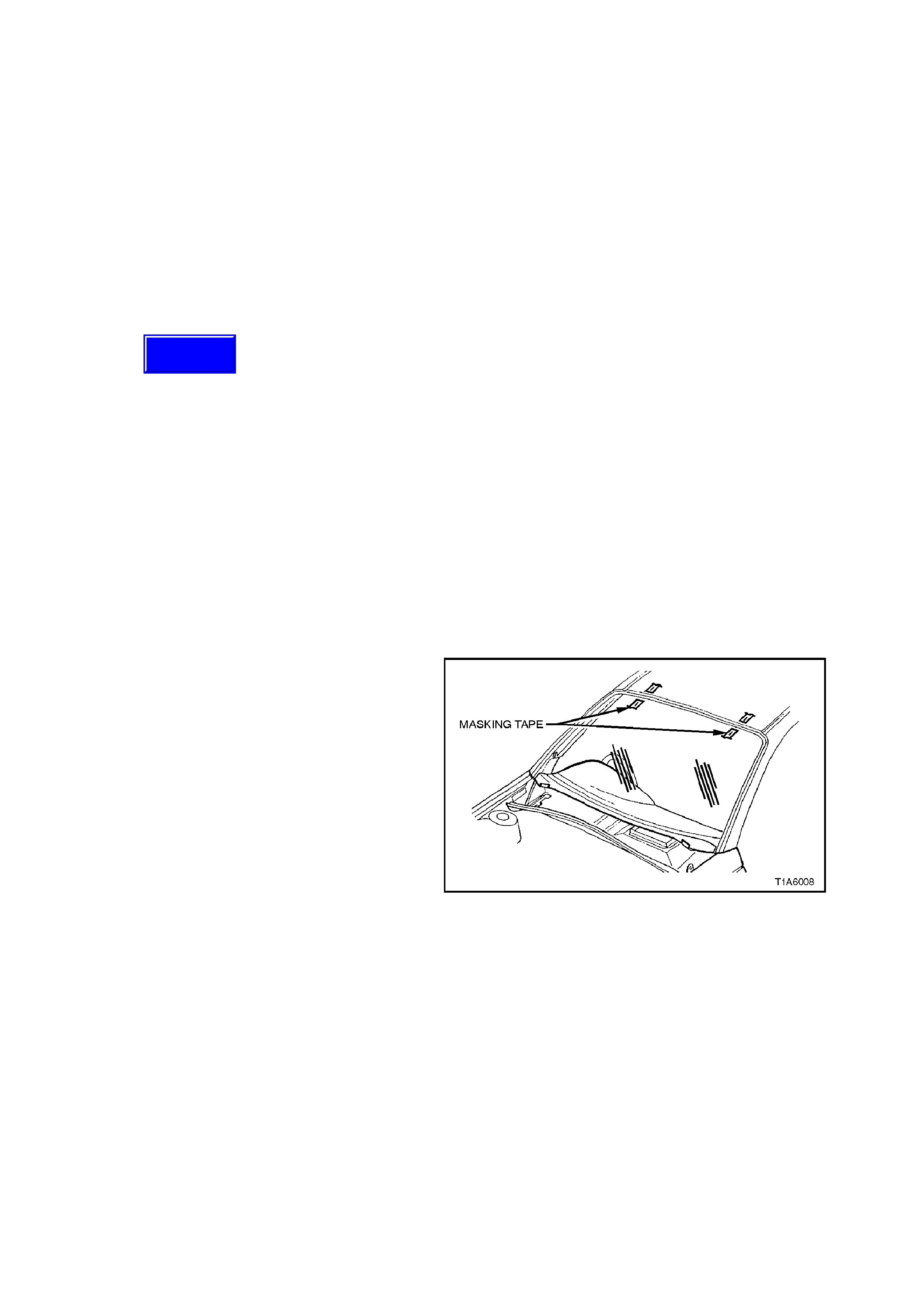
15 Correctly locate the windshield in the opening
then tape mark the outer top and side of the
windshield , pillar and roof, as illus tr ated in Fig.
1A6-11. This procedur e assis t the operators to
align the windshield in the correct horizontal
and vertical plane during final windshield
installation.
16. Remove and place the windshield face down
on a clean protected surface.
Figure 1A6-11
SHORT METHOD INSTALLATION
DESCRIPTION
Short method installation involves the maximum
amount of the original urethane being left intact on
the body opening to form a sound base for the
replacement adhesive and windshield.
This method is recommended when replacing a
cracked or broken windshield, or a leak condition
that cannot be overcome by using m inor water leak
repair procedures.
If material other than urethane has been used for
previous servicing of the windshield, the long
method installation procedure (complete removal of
adhesive) is mandatory to achieve an effective
glass to metal bond.
REINSTALL
1. Thoroughly clean the inner s urface and edges
of the windshield which are to contac t the new
urethane, using clean c loths and a s uitable oil-
free cleaning solvent.
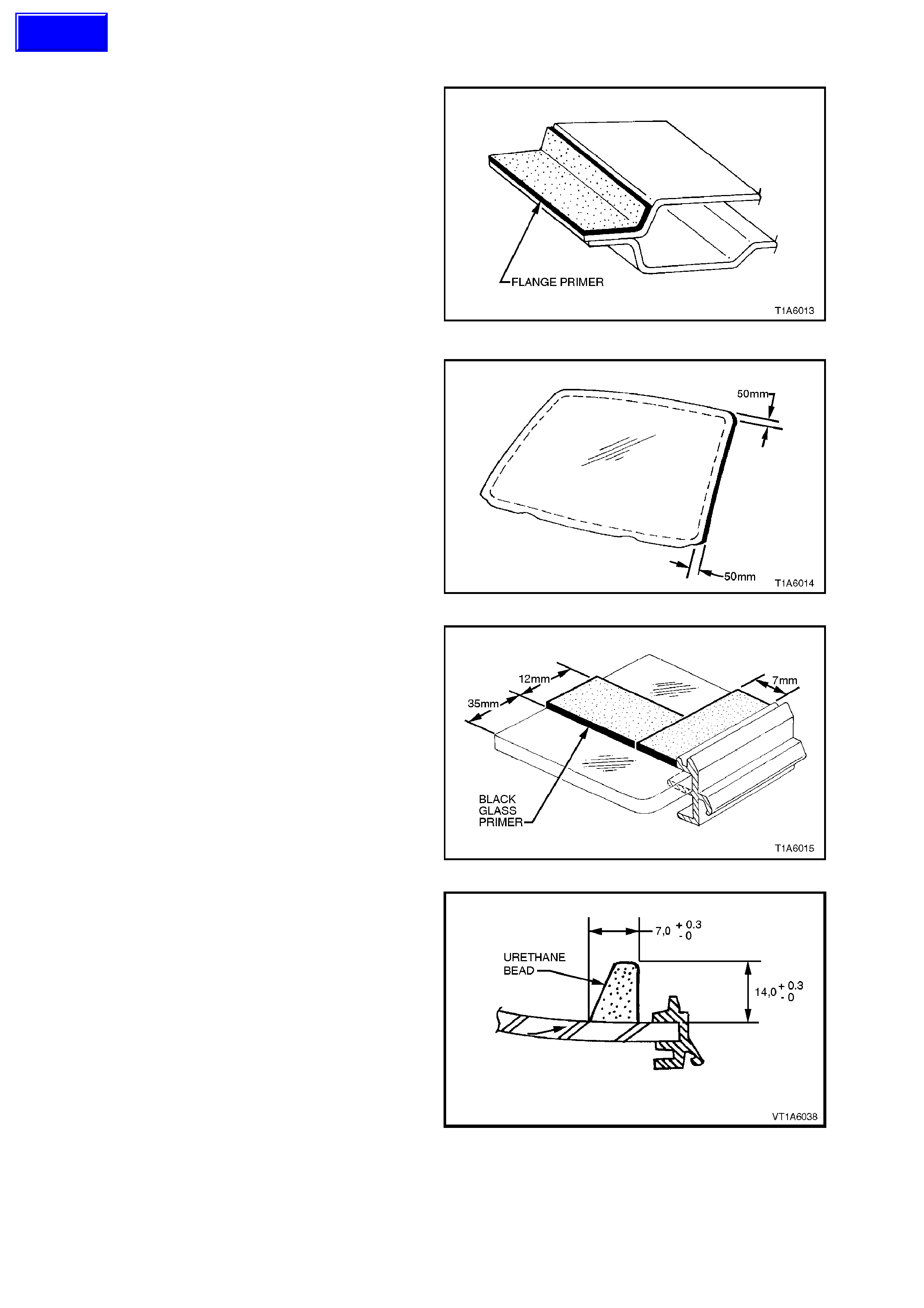
2. Apply clear glass primer to inner surface of
glass around the perimeter of the windshield
edge over the solid black c eramic pattern ( or a
width of 50 m m) and im m ediately wipe off with
a lint free rag.
Figure 1A6-12
3. Install locator windshield left side part No.
92078269 and locator windshield right side
part No. 92078270. Ensure locators are fitted
correctly to windshield glass and have a
clearance between side and top locators of
approx. 3 mm.
4. Install locator windshield upper part No.
92076026, ensure moulding is fitted correctly
to glass.
Figure 1A6-13
Techline
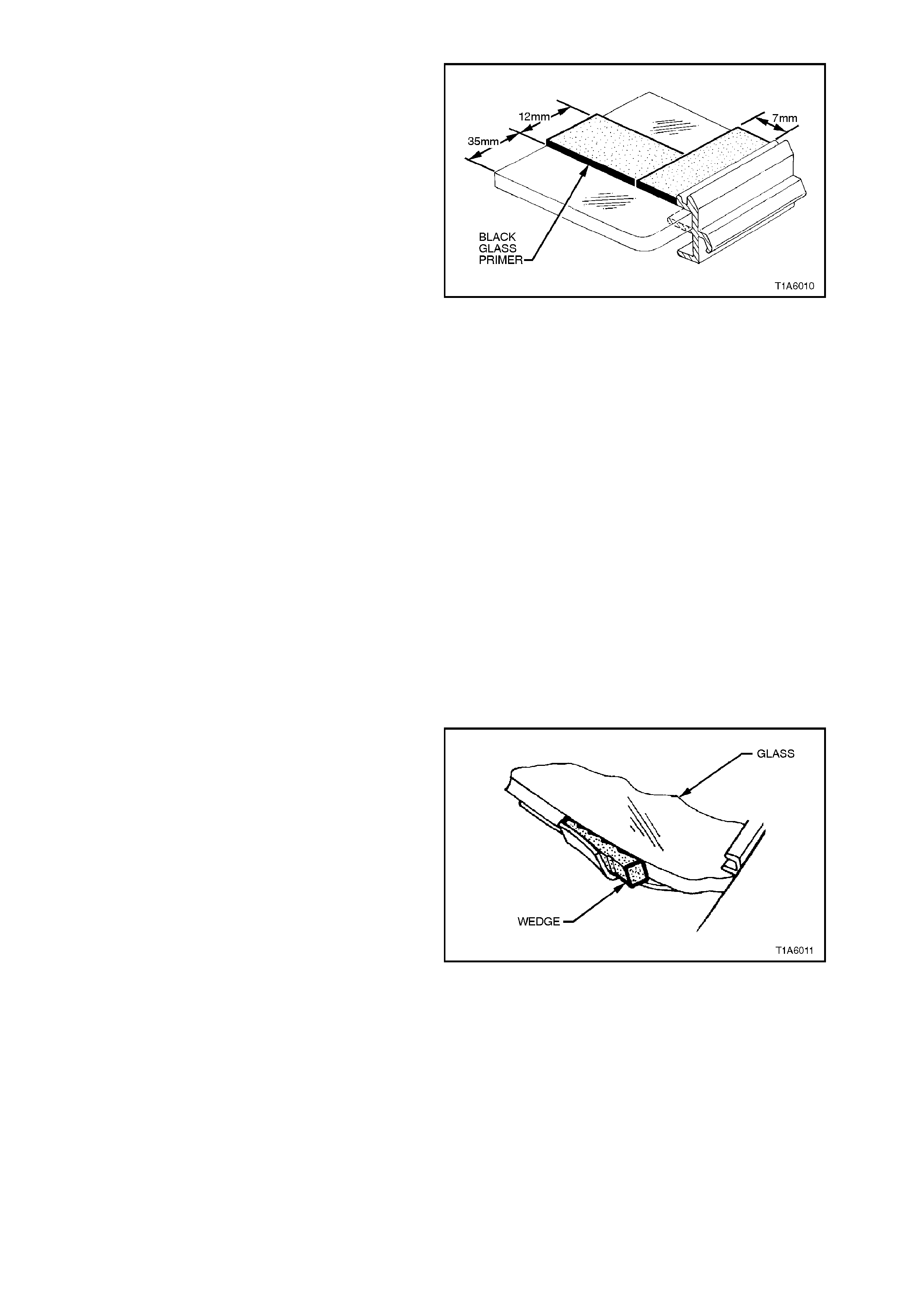
5. Using the applicator included in the
replacement kit, apply glass primer (black)
around the upper and side perimeter of the
windshield edge and 7 mm inboard to the
inner surface as illustrated in Fig. 1A6-14. On
the lower edge, repeat the operation at a
distance of 35 mm from the edge of the glass
in a band 12 mm wide.
6. Check for voids or looseness in original
urethane. Cut away any loose pieces of
urethane and, using a suitable spatula, paddle
fresh urethane or silicon smoothly into any
voids.
7. Using a hand or automatic applicator, apply a
smooth continuous bead of urethane
adhesive, such as Betaseal 554.02 or
equivalent, between the centre and outer
edge, on top of original urethane and around
entire perimeter of the body opening. The
urethane bead should be a minimum of
10 mm in diameter.
Figure 1A6-14
NOTE:
Urethane service kits are available from most
windshield agents. Manufacturer's instructions
should always be followed.
IMPORTANT:
On the lower section of the body opening, care
must be taken to ensure the urethane bead
diameter is such that when compressed by the
windshield installation, the vehicle identification
number is not obscured.
NOTE:
In cold weather, the placement of cartridges
adjacent to a source of warmth will assist the flow
of urethane when using a hand applicator.
8. With the aid of an assistant, install the
windshield, using the previously attached
masking tape on the roof and windshield to
ensure accurate installation. Use wedges
placed at the lower windshield edge to locate
glass vertically in windshield opening. Press
windshield firmly into position.
9. Check effectiveness of seating from inside of
the vehicle. Should any gaps in the sealing
exist, apply additional urethane on the outside
to fill these gaps. Using a flat bladed tool,
sm ooth the surface of the ur ethane around the
edge on the outside of the windshield to
ensure effective sealing.
10. Water test the windshield, using a moderate
spray of water.
NOTE:
Do not direct a heavy stream of water onto freshly
applied urethane. If a water leak is evident, apply
additional urethane to the leal area, using a flat
bladed tool to work urethane into source of leak.
Figure 1A6-15
IMPORTANT:
If silicon is used for spot sealing, allow a minimum
of one (1) hour to permit the silicon to skin and
adhere to the original urethane, prior to water
testing the repair.
11. Clean off any excess urethane/silicon using
Prepsol or white spirit. Clean the windshield,
then remove the masking tape previously
installed.
12. Identify datum marks on rear edge of
windshield moulding cover. If damaged
replace windshield moulding cover.
Figure 1A6-16
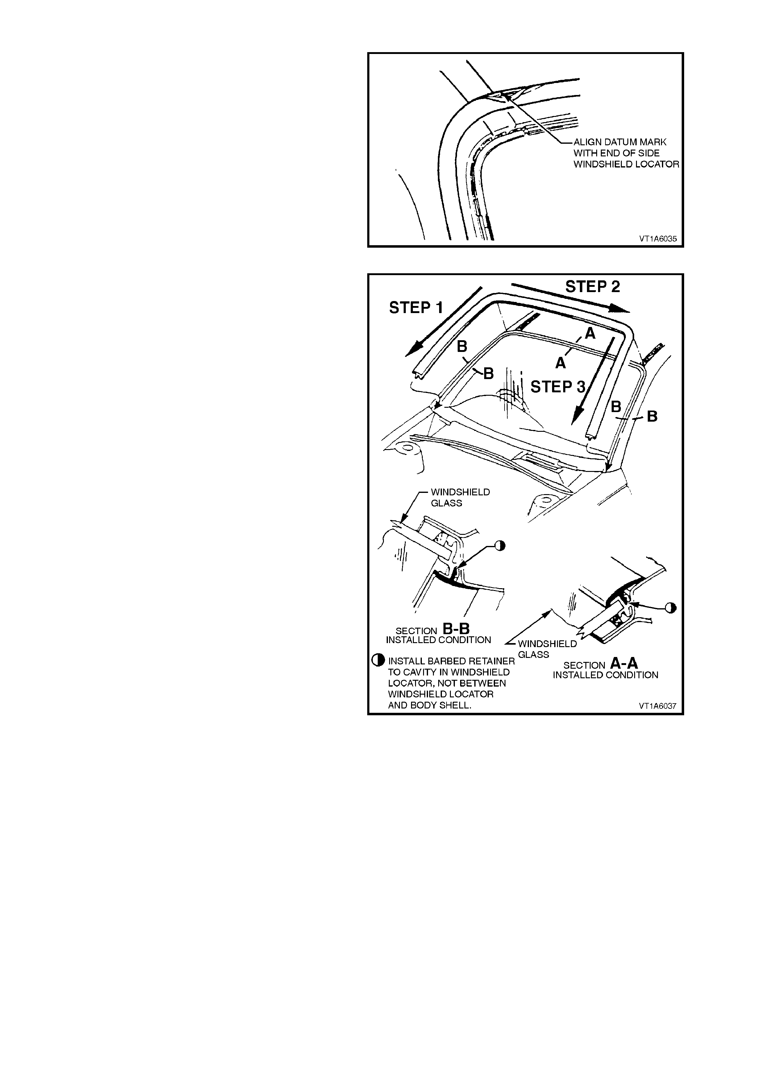
13. Begin installing windshield moulding cover at
top drivers side corner of windshield. Align
datum mark on windshield moulding cover
with end of windshield locator, refer to Fig.
1A6-16.
14. Clip windshield moulding cover in place
around upper corner of windshield. Insert drive
side lower end of windshield moulding cover
loosely behind top of guard, attach m oulding to
driver side windshield locator, working from
upper corner to lower corner of windshield
refer Fig. 1A6-17 step 1.
15. Install upper windshield moulding cover,
working from driver side upper corner to
passenger side upper c orner refer Fig. 1A6-17
step 2.
16. Insert passenger side lower end of windshield
moulding cover loosely behind top of guard
then attach moulding to passenger side
windshield locator, working from upper corner
to lower cor ner of windshield re fer Fig. 1A6-17
step 3.
NOTE:
Ensure barbed retainer on windshield moulding
cover engages to retainer cavity in windshield
locator and not between windshield locator and
body panel, refer Fig. 1A6-17, Section A-A and B-
B.
Figure 1A6-17
17. Reinstall plenum chamber water deflector,
right and left side plenum covers, and wiper
arm assemblies.
14. Reinstall interior mirror assembly.
NOTE:
Ensure that door windows are partially lowered to
eliminate pressure build up which can be caused
by slamming doors. A curing time of 24 hours is
recom mended, although the vehicle m ay be driven
after 5 hours, providing it is driven on a smooth
road at speeds not exceeding 80 km/h with door
windows partially lowered.
LONG METHOD INSTALLATION
DESCRIPTION
The long method replacement is used when
original urethane adhesive material cannot serve
as a base for the replacement windshield.
This method should be used on vehicles requiring
metal or paint repair to the windshield opening
when original adhesive is completely removed and
replaced with new urethane for windshield
installation.
This method is also used when the windshield has
been previously replaced, using the short method.
In such instances, the build-up of urethane could
position the windshield too high in the opening.
REMOVE
1. Remove the windshield (refer
3.1 WINDSHIELD GLASS in this section).
2. Using a knife or sharp scraper, remove the
original urethane from around the entire
perimeter of the windshield opening flange.
Body opening check
1. Thoroughly check the windshield body
opening flange for any irregularities before
installing the windshield.
NOTE:
It will be necessary to remove the windshield pillar
mouldings.
Refer Section 1A9 ‘HEADLINING & REAR END
TRIM’.
2. Use the windshield as a tem plate for check ing
correct alignment between the windshield and
body opening. If necessary, reform the body
opening flange to produce a uniform flange to
windshield contour.
CAUTION:
Care should be taken to ensure that glass does
not strike the windshield opening. Chipped
edges can lead to subsequent breakage of
glass.
3. Correctly locate the windshield in the opening
then tape mark the outer top and side of the
windshield , pillar and roof. This procedure
assist the operators to align the windshield in
the correct horizontal and vertical plane during
final windshield installation.
4. Remove and place the windshield face down
on a clean protected surface or fixture.
Figure 1A6-18
Techline
REINSTALL
1. Using one of the applicators in the
replacement kit, apply flange primer to any
section of the windshield opening flange that
has been cleaned back to bare m etal or to the
painted. Allow this primer to dry for 15
minutes.
DO NOT TOUCH PRIMED SURFACES
NOTE:
If the windshield pillar mouldings have been
removed, reinstall or replace as necessary.
2. Thoroughly clean the inner surface and edges
of the windshield to which the urethane is to be
applied, using clean cloths and a suitable oil
free cleaning solvent. Figure 1A6-19
3. Apply clear glass primer to inner surface of
glass around the perimeter of the windshield
edge over the width of the solid black ceram ic
pattern (or a width of 50 m m) and imm ediately
wipe off with a lint free rag.
4. Install locator windshield upper part No.
92076026, ensure moulding is fitted correctly
to glass.
5. Install locator windshield left side part No.
92078269 and locator windshield right side
part No. 92078270. Ensure locators are fitted
correctly to windshield glass and have a
clearance between side and top locators of
approx. 3 mm. Figure 1A6-20
6. Using the applicator included in the
replacement kit, apply glass primer (black)
around the upper and side perimeter of the
windshield edge and 7 mm inboard to the
inner surface. On the lower edge, repeat the
operation at a distance of 35 mm from the
edge of the glass in a band 12 mm wide.
Figure 1A6-21
7. Using a hand or automatic applicator, apply a
smooth continuous bead of urethane
adhesive, such as Betaseal 554.02 or
equivalent, between the centre and outer
edge, on top of original urethane and around
entire perimeter of the body opening. The
urethane bead dimensions should be as
shown in Fig. 1A6-22.
NOTE:
Urethane service kits are available from most
windshield agents around Aus tralia. Manufac turer’s
instructions should always be followed.
Figure 1A6-22
Techline

IMPORTANT:
On the lower section of the body opening, care
must be taken to ensure the urethane bead
diameter is such that when compressed by the
windshield installation, the vehicle identification
number is not obscured.
NOTE:
In cold weather, the placement of cartridges
adjacent to a source of warmth will assist the flow
of urethane when using a hand applicator.
8. With the aid of an assistant, install the
windshield, using the previously attached
masking tape on the roof and windshield to
ensure accurate installation. Use wedges
placed at the lower windshield edge to locate
glass vertically in the windshield opening.
Press windshield firmly into position.
9. Check effectiveness of sealing from inside of
the vehicle. Should any gaps in the sealing
exist, apply additional urethane on the outside
to fill these gaps. Using a flat bladed tool,
sm ooth the surface of the ur ethane around the
edge on the outside of the windshield to
ensure effective sealing.
10. Water test the windshield, using a moderate
spray of water.
NOTE:
Do not direct a heavy stream of water onto freshly
applied urethane. If a water leak is evident, apply
additional urethane to the leak area, using a flat
bladed tool to work urethane into source of leak.
IMPORTANT:
If silicon is used for spot sealing, allow a minimum
of one (1) hour to permit the silicon to skin and
adhere to the original urethane prior to water
testing the repair.
11. Clean off any excess urethane/silicon using
Prepsol or white spirit. Clean the windshield,
then remove the masking tape previously
installed.
12. Reinstall the windshield moulding cover , and if
damaged, new windshield moulding cover.
13. Reinstall plenum chamber water deflector,
right and left side plenum covers, and wiper
arm assemblies.
14. Reinstall interior mirror assembly.
CAUTION:
Ensure that door windows are partially lowered to
eliminate pressure build up which can be caused by
slamming doors. A curing time of 24 hours is
recommended, although the vehicle may be driven
after 5 hours, providing it is driven only on a smooth
road at speeds not exceeding 80 km/h.
3.2 MINOR WATER LEAK CORRECTION
1. Apply protective covering and masking tape
adjacent to the leak suspect area.
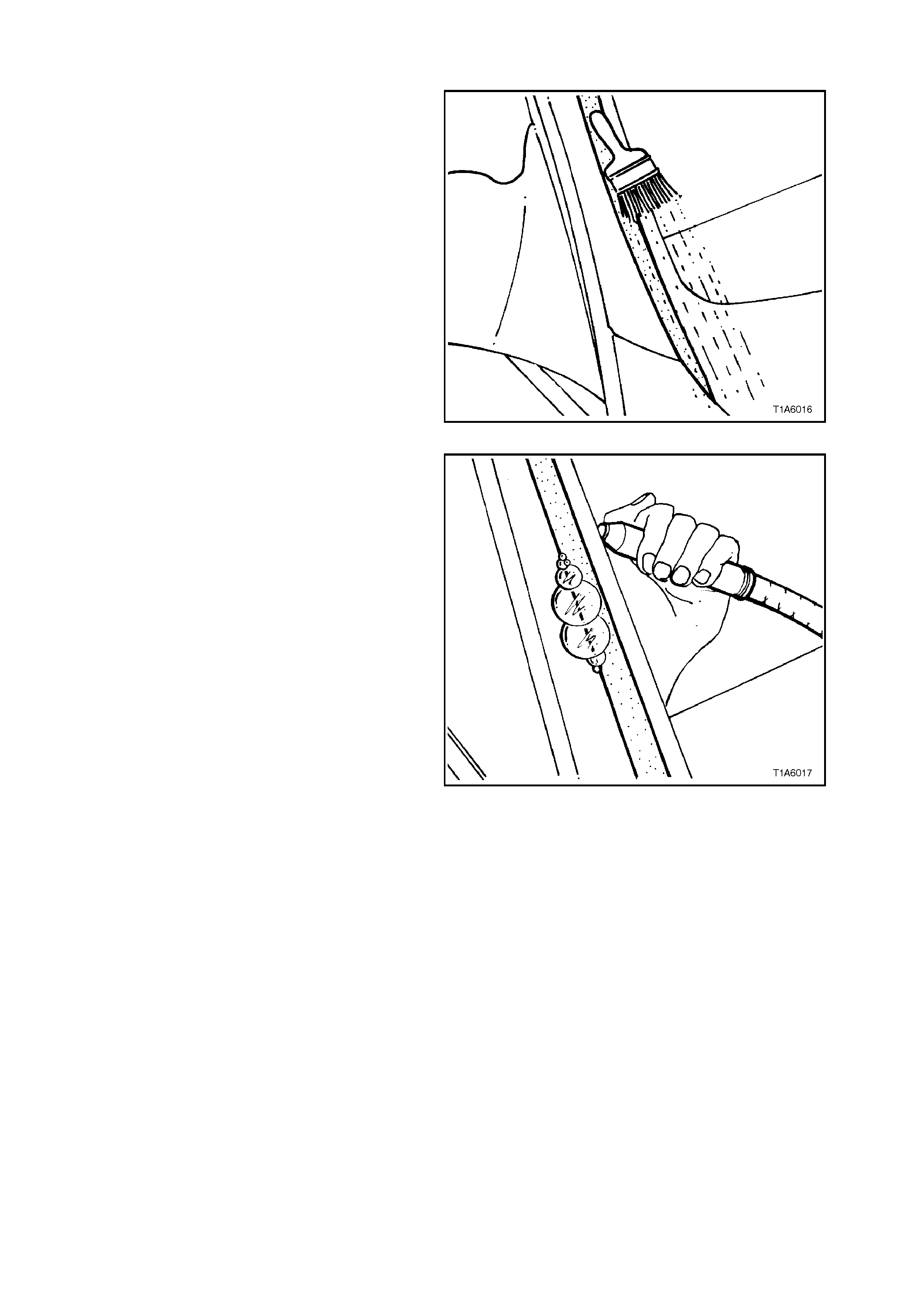
To determ ine the precise loc ation of the water leak ,
use the air/soap bubble leak test.
NOTE:
The soap/water solution can be applied with either
a spray applicator or brush.
2. Locate an air hose nozzle on the inside of the
windshield as illustrated in Fig. 1A6-20. Have
an assistant outside the vehicle apply a soapy
water solution opposite the air source. As a
medium air pressure (60kPa) is applied, soap
bubbles will form on the outside of the
windshield, indicating the location of the leak.
3. If the suspect leak area is not obvious,
commence the testing across the top and
down the sides until the leak loc ation has been
determined. Figure 1A6-23
4. Remove the windshield moulding (refer
preceding instructions) covering the leak
location then, if silicon is used, thoroughly dry
out the repair area with compressed air.
NOTE:
If urethane is being used, it is only necessary to
remove dust, foreign matter, etc. Water activates
the curing process of urethane.
5. Using a spatula, work fres h urethane or silicon
in and around the leak area.
6. If urethane has been used, leak test the repair,
using the air/soap bubble leak test or a non
pressurised water leak test.
IMPORTANT:
If silicon is used for spot sealing, allow a minimum
of one (1) hour to permit the silicon to skin and
adhere to the original urethane prior to testing the
repair.
Should the leak persist, apply additional
urethane/silicon until the leak has been corrected.
7. Reinstall any of the windshield moulding
removed to carry out the leak correction.
8. Clean windshield and adjacent paint finish,
then remove the masking tape and protective
covers.
Figure 1A6-24
3.3 REAR QUARTER WINDOW ASSEMBLY
STATION WAGON MODELS
REMOVE
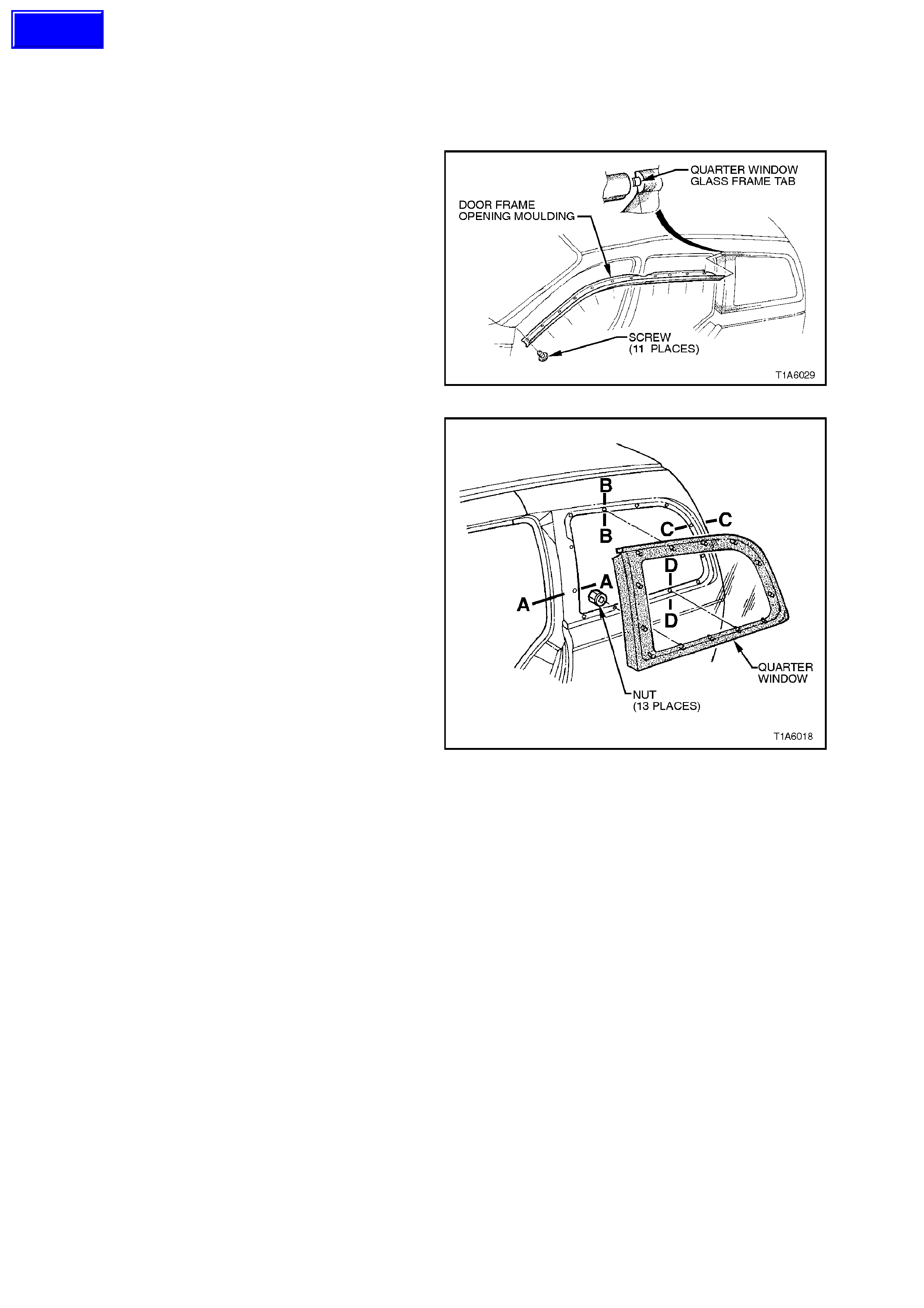
1. Partially remove the door frame opening
moulding right and left side (refer to
Section 1A9 EXTERIOR ORNAMENTATION)
and release quarter window glass frame tab.
2. Remove ‘MOULDING ASSEMBLY, QUARTER
WINDOW INNER TRIM’, refer to
Section 1A8, HEADLINING AND REAR END
TRIM.
Figure 1A6-25
3. Remove the plastic nuts securing the window
to the body opening and carefully lift the glass
from the vehicle.
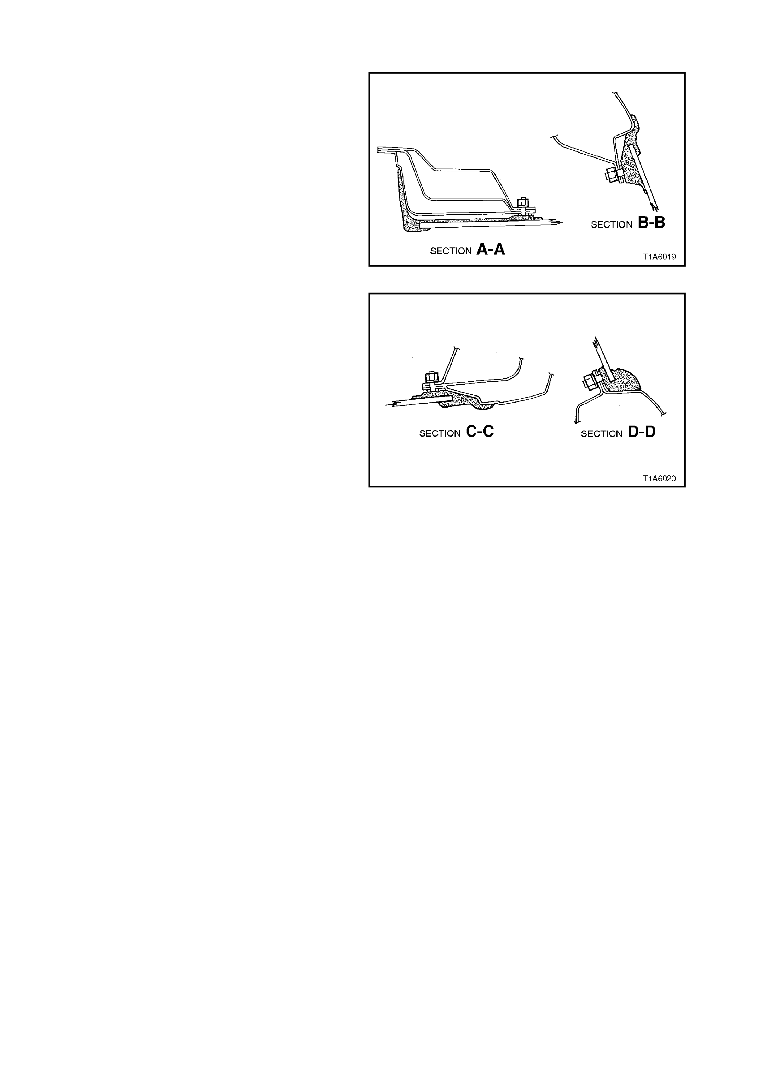
For sections A-A, and B-B refer to Fig. 1A6-27.
For sections C-C, and D-D refer to Fig. 1A6-28.
Figure 1A6-26
Techline
REINSTALL
Reverse removal operations with following revision.
Leave quarter window retaining nuts loose until
door frame opening moulding is fastened in
position. Position quarter window and tighten
quarter window retaining nuts.
CAUTION:
Nuts to be tightened to 2 Nm.
Figure 1A6-27
Figure 1A6-28
3.4 TAILGATE WINDOW-STATION WAGON
WARNING:
Safety glasses and work gloves must be worn
at all times when operating with glass.
NOTE:
Skinning (partial curing) of the urethane
commences after exposure to the atmosphere. At
23 degrees Celsius and 50 percent relative
humidity, skinning commences after 30 minutes.
Complete curing of urethane at this temperature
and humidity takes 72 hours.
REMOVE
1. Disconnect battery ground cable.
2. Place protective covering around tailgate
opening.
3. Remove rear wiper blade and arm assembly,
refer to Section 12C, ‘INSTRUMENTS,
WIPERS, WASHERS & HORNS’.
4. Remove rear window washer nozzle, refer to
Section 1A4, REAR COMPARTMENT LID
AND TAILGATE.
5. Should the glass be broken, carefully remove
all fragm ents of glass f rom the tailgate window
aperture.
6. Remove glass following the procedure set out
in Steps 10 through 13, 3.1 WINDSHIELD
GLASS - REMOVE in this Section, carefully
cut out the tail gate window.
NOTE:
It is not necessary to remove all traces of original
urethane. However, any original urethane remaining
must be smooth and firm.
7. Remove ‘UPPER TRIM PANEL-TAILGATE,
and ‘LOWER TRIM PANEL-TAILGATE’, refer
to Section 1A4, REAR COMPARTMENT LID
AND TAILGA TE’.
8. Remove electrical demist connectors.
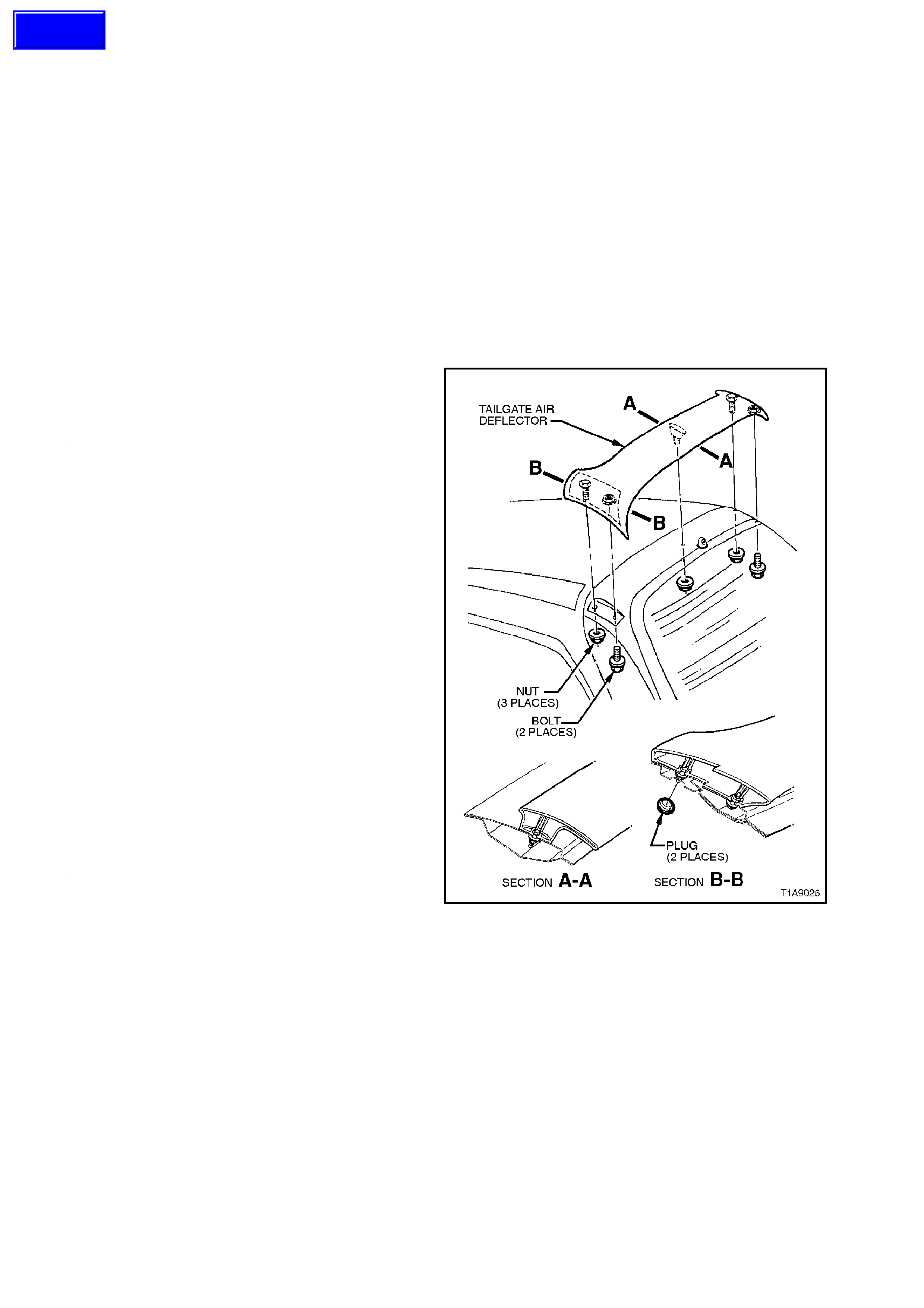
9. Remove three nuts and two screws securing
Tailgate Air Deflector, refer to Section 1A4,
‘REAR COMPARTMENT LID AND
TAILGATE’.Figure 1A6-29
Techline
LONG METHOD INSTALLATION
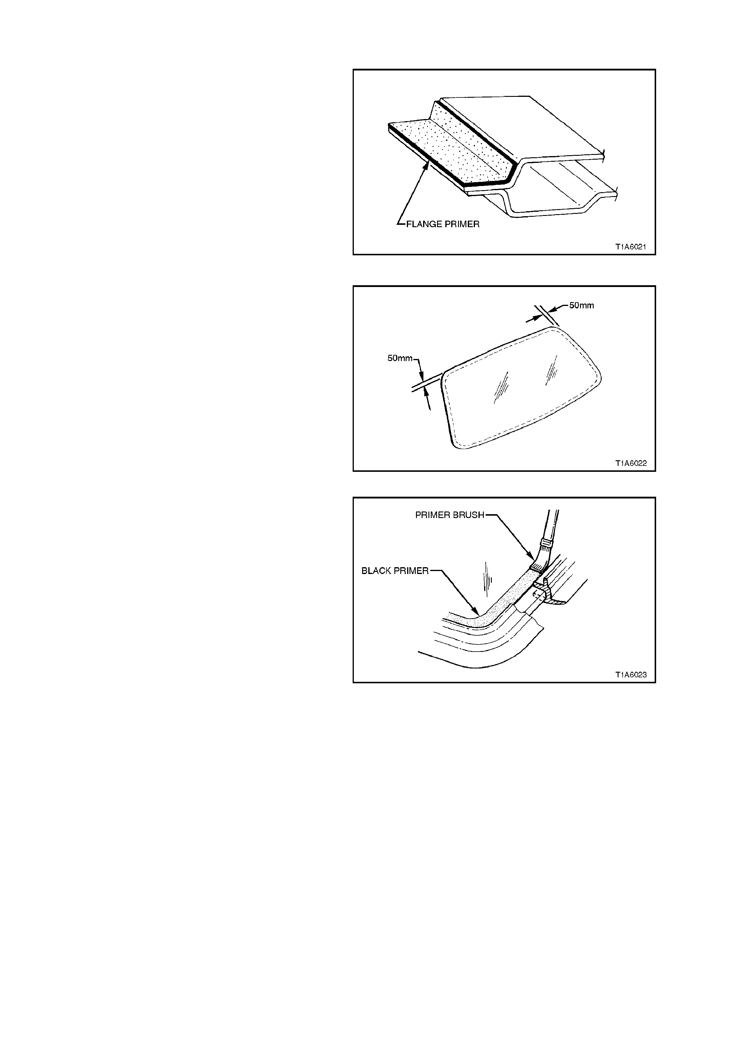
1. Using one of the applicators in the
replacement kit, apply flange primer to any
section of the windshield opening flange that
has been cleaned back to bare m etal or to the
painted. Allow this primer to dry for 15
minutes.
DO NOT TOUCH PRIMED SURFACES
NOTE:
If the tailgate opening mouldings have been
removed, reinstall or replace.
2. Thoroughly clean the inner surface and edges
of the tailgate glass to which the urethane is to
be applied, using clean cloths and a suitable
oil free cleaning solvent. Figure 1A6-30
3. Apply clear glass primer around the perimeter
of the tailgate glass.
4. Reinstall the tailgate moulding over the edge
of the glass, with moulding joint at centre line
upper side of glass, ensure moulding is fitted
correctly to glass.
Figure 1A6-31
5. Using the applicator included in the
replacement kit, apply glass primer (black)
around the perimeter of the tailgate glass.
6. Using a hand or automatic applicator, apply a
smooth continuous bead of urethane
adhesive, such as Betaseal 554.02 or
equivalent, between the centre and outer
edge, on top of original urethane and around
entire perimeter of the body opening. The
urethane bead should be a minim um of 6 mm
in diameter.
NOTE:
Urethane service kits are available from most agent
around Australia. Manufacturer’s instructions
should always be followed.
NOTE:
In cold weather, the placement of cartridges
adjacent to a source of warmth will assist the flow
of urethane when using a hand applicator.
Figure 1A6-32

7. W ith the aid of an assistant, ins tall the tailgate
glass using the previously attached masking
tape on the tailgate to ensure accurate
installation. Press the glass firmly into position.
8. Check effectiveness of sealing from inside of
the vehicle. Should any gaps in the sealing
exist, apply additional urethane on the outside
to fill these gaps. Using a flat bladed tool,
sm ooth the surface of the ur ethane around the
edge on the outside of the tailgate to ensure
effective sealing.
9. Water test the tailgate, using a moderate
spray of water.
NOTE:
Do not direct a heavy stream of water onto freshly
applied urethane. If a leak is evident, apply
additional urethane to the leak area, using a flat
bladed tool to work urethane into source of leak.
IMPORTANT:
If silicon is used for spot sealing, allow a minimum
of one (1) hour to permit the silicon to skin and
adhere to the original urethane prior to water
testing the repair.
10. Clean off any excess urethane/silicon using
Prepsol or white spirit. Clean the tailgate, then
remove the masking tape previously installed.
CAUTION:
Ensure that door windows are partially lowered to
eliminate pressure build up which can be caused by
slamming doors. A curing time of 24 hours is
recommended, although the vehicle may be driven
after 5 hours, providing it is driven only on a smooth
road at speeds not exceeding 80 km/h.
Figure 1A6-33
SHORT METHO D INSTALLATION
Refer 3.1 WINDSHIELD GLASS in this Section.
Note that the clear and black primers must follow
the entire perimeter of the tailgate glass

3.5 BACK WINDOW - SEDAN MODELS
REMOVE
1. Disconnect battery ground cable.
2. Place protective covering adjacent to back
window to protect trim and paint finish.
3. Remove the right and left side roof finisher
mouldings, refer to Section 1A9, EXTERIOR
ORNAMENTATION.
4. Remove ‘MOULDING ASSEMBLY, REAR
WINDOW INNER TRIM’, refer to
Section 1A8, HEADLINING AND REAR END
TRIM.
5. Disconnect back window electrical demist
connectors.
6. Remove back window glass following
procedure set out in Steps 10 through 13 in
3.1 WINDSHIELD GLASS-REMOVE, in this
Section, carefully cut out the back window
glass.
NOTE:
It is not necessary to remove all traces of original
urethane. However, any original urethane remaining
must be smooth and firm.
CAUTION:
When working with glass, the wearing of safety
glasses and work gloves is mandatory.
Opening Check
1. Thoroughly check the back window
opening flange for any irregularities before
installation of replacement window.
CAUTION:
Care should be tak en to ensure that glass does not
strike the back window opening. Chipped edges
can lead to subsequent breakage of glass.
2. Check and if necessary, re-form the body
flange to produce a uniform flange to glass
contour.
3. Correctly locate the glass in the opening, then
tape mark the outer top of glass and roof on
the right and left side. This procedure assists
the operators to align the glass in the correct
horizontal plane during final installation.
Techline
Techline
LONG METHOD INSTALLATION
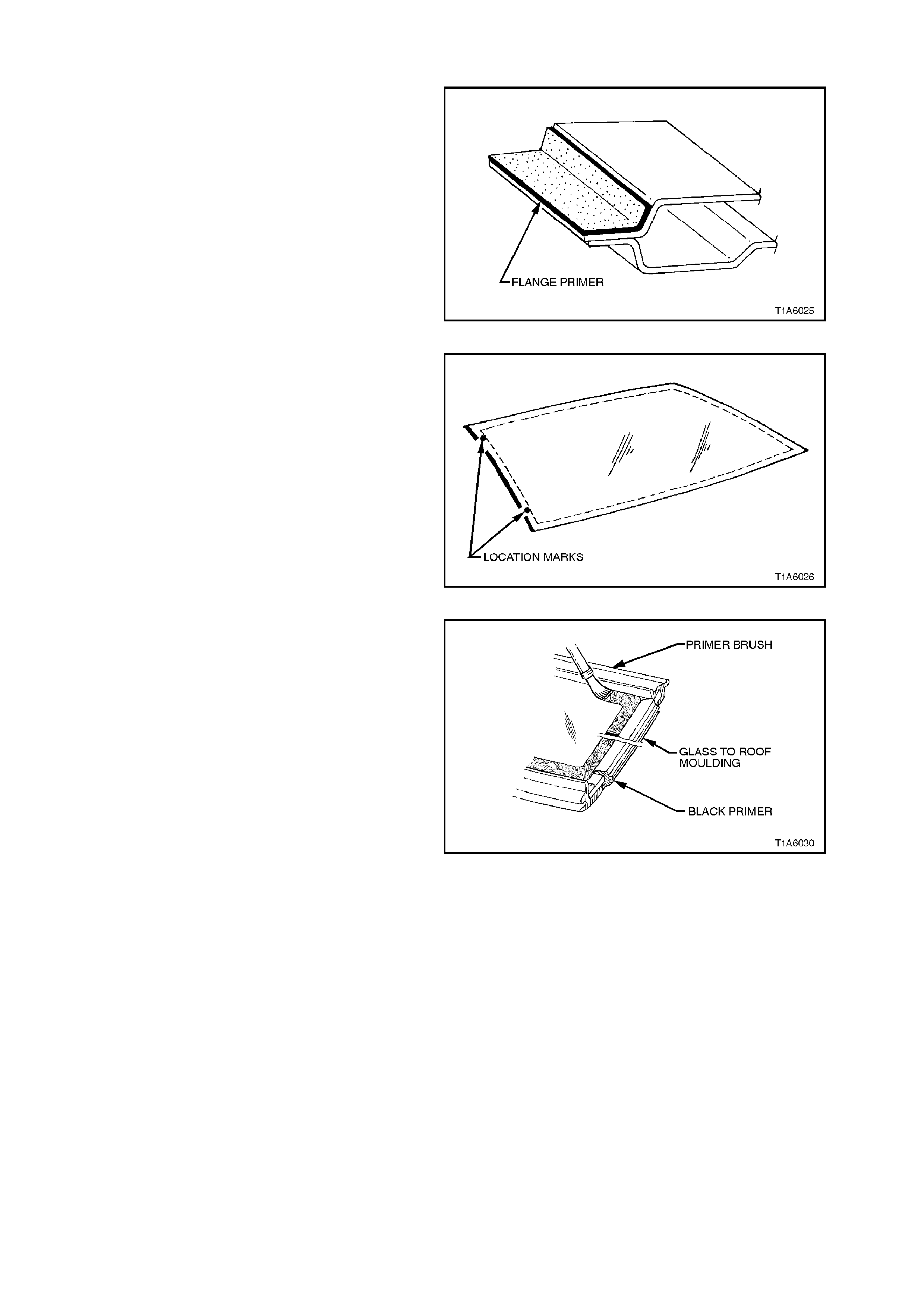
1. Using one of the applicators in the
replacement kit, apply flange primer to any
section of the back window opening flange that
has been cleaned back to bare m etal or to the
painted. Allow this primer to dry for 15
minutes.
DO NOT TOUCH PRIMED SURFACES
2. Thoroughly clean the inner surface and edges
of the back window glass to which the
urethane is to be applied, using clean cloths
and a suitable oil free cleaning solvent.
Figure 1A6-34
3. Apply clear glass primer around the perimeter
of the back window glass.
4. Reinstall the back window upper and lower
mouldings over the edge of the glass, ensure
moulding is fitted correctly to glass.
5. Reinstall two roof to glass retaining m ouldings
part No. 92057763 to left and right hand side
of glass . Ensure that m ouldings are pos itioned
to alignment marks, and are fitted correctly to
edge of glass.
Figure 1A6-35
6. Using the applicator included in the
replacement kit, apply glass primer (black)
around the perimeter of the bac k window glass
bonding surface over a width of 7,0 along the
inside edge of back window mouldings.
7. Using a hand or automatic applicator, apply a
smooth continuous bead of urethane
adhesive, such as Betaseal 554.02 or
equivalent, between the centre and outer
edge, on top of original urethane and around
entire perimeter of the body opening. The
urethane bead should be a minim um of 6 mm
in diameter.
NOTE:
Urethane service kits are available from most
windshield agent around Australia. Manufacturer’s
instructions should always be followed.
NOTE:
In cold weather, the placement of cartridges
adjacent to a source of warmth will assist the flow
of urethane when using a hand applicator.
Figure 1A6-36
8. With the aid of an assistant, install the back
window glass. Press the glass firmly into
position.
NOTE:
Ensure glass is centralised in body opening left to
right by checking the gap between the glass
moulding and “C” pillar.
NOTE:
Install back window glass in back window opening
within five minutes after application of urethane
adhesive.
Figure 1A6-37
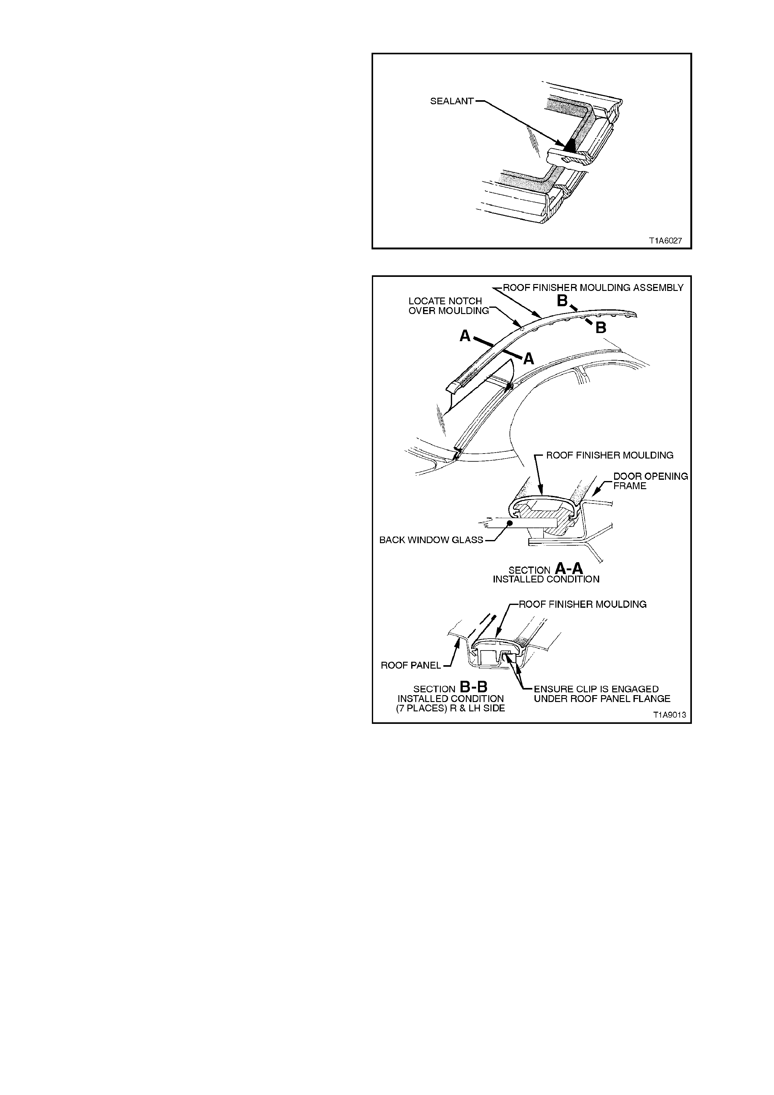
9. Engage roof finisher moulding assembly over
side moulding as shown in Figure 1A6-38 and
slide along until roof finisher moulding is in
position (refer Figure 1A6-39).
10. Re-engage roof finisher moulding assembly
clips along roof until roof finisher moulding
assembly sits flush against roof, refer
Section 1A9 ‘EXTERIOR
ORNAMENTATION’.
NOTE:
Front of roof finisher moulding must be installed
under windshield moulding cover.
IMPORTANT:
Roof finisher mouldings must be fitted within 10
minutes of installing glass.
Figure 1A6-38

NOTE:
Ensure that endcap of roof finisher moulding is
aligned with quarter panel to roof moulding.
12. Check effectiveness of sealing from inside of
the vehicle. Should any gaps in the sealing
exist, apply additional urethane on the outside
to fill these gaps. Using a flat bladed tool,
sm ooth the surface of the ur ethane around the
edge on the outside of the tailgate to ensure
effective sealing.
13. Water test using a moderate spray of water.
NOTE:
Do not direct a heavy stream of water onto freshly
applied urethane. If a leak is evident, apply
additional urethane to the leak area, using a flat
bladed tool to work urethane into source of leak.
IMPORTANT:
If silicon is used for spot sealing, allow a minimum
of one (1) hour to permit the silicon to skin and
adhere to the original urethane prior to water
testing the repair.
14. Clean off any excess urethane/silicon using
Prepsol or white spirit. Clean the body
opening, then remove the masking tape
previously installed.
CAUTION:
Ensure that door windows are partially lowered to
eliminate pressure build up which can be caused by
slamming doors. A curing time 24 hours is
recommended, although the vehicle may be driven
after 5 hours, provided it is driven only on a sm ooth
road at speeds not exceeding 80 km/h.
Figure 1A6-39
SHORT METHO D INSTALLATION
Refer 3.1 WINDSHIELD GLASS in this Section.
Note that the clear and black primers must follow
the entire perimeter of the back window glass.

4. TORQUE WRENCH SPECIFI CATIONS
Nm
Instrument Panel and Cap Cover Attachment Screws 1 - 3
Demist Nozzle Securing Screws 1 - 3
Quarter Window Retaining Nuts 2
Quarter Window Plastic Securing Nuts 1 - 3
Tailgate Air Deflector Securing Nuts and Screws 2 - 5
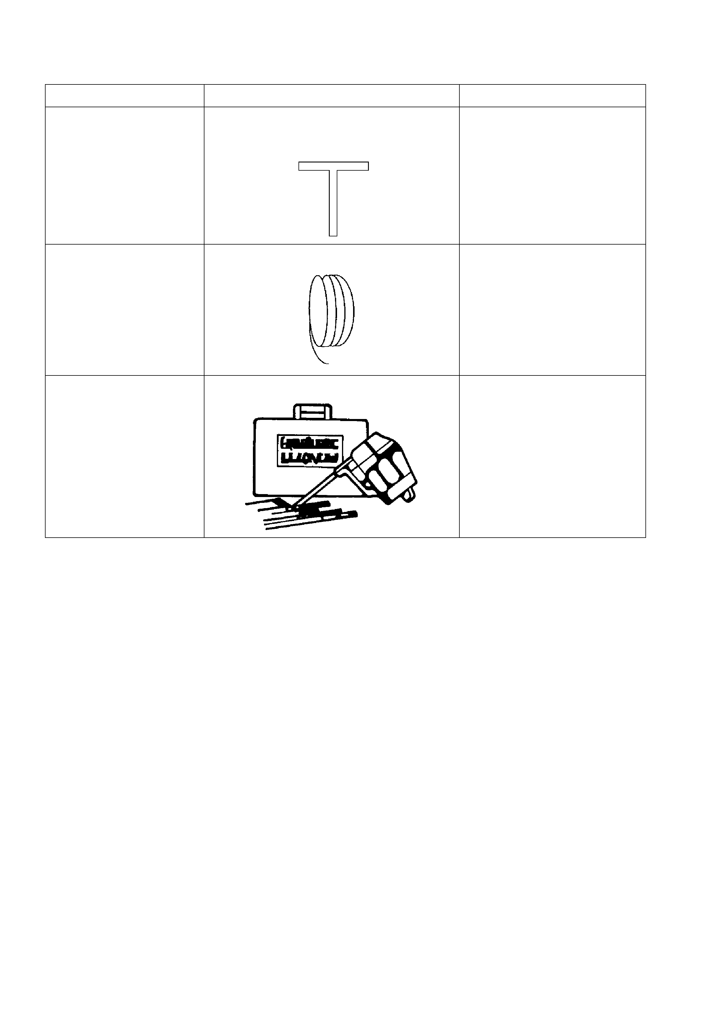
5. SPECIAL TOOLS
TOOL NO. REF IN TEXT TOOL DESCRIPTION COMMENTS
AU390 FABRICATED T HANDLE WINDSCREEN
REMOVAL TOOL AND PIANO WIRE
AU390-1 PIANO WIRE
J39032 STATIONARY GLASS REMOVAL TOOL