SECTION 1A7 - SEAT & SEAT BELT ASSEMBLIES
CAUTION:
This vehicle will be equipped with a Supplemental Restraint System (SRS). A SRS will
consist of either seat belt pre-tensioners and a driver's side air bag, or seat belt pre-
tensioners and a driver's and front passenger's side air bags. Refer to CAUTIONS,
Section 12M, before performing any service operation on, or around any SRS
components, the steering mechanism or wiring. Failure to follow the CAUTIONS
could result in SRS deployment, resu lting in possible perso nal in jury or u nnecessary
SRS system repairs.
CAUTION:
This vehicle may be equipped with LPG (Liquefied Petroleum Gas). In the interests of
safety, the LPG fuel system should be isolated by turning 'OFF' the manual service
valve and then draining the L PG service lines, before any service w ork is carried out
on the vehicle. Refer to the LPG leaflet included with the Owner's Handbook for
details or LPG Section 2 for more specific servicing information.
1. GENERAL DESCRIPTI ON
A four-way electric adjustable drivers seat (front up and down, and rear up and down) is fitted to all VT Series
Models except Calais Models. Calais models are fitted with an eight-way electric adjustable front passenger and
drivers seat (front up and down, rear up and down, forward and rearward (fore/aft), and reclining).
The four-way electric driver’s seat contains two electric, reversible motors. The front and rear heights of the seat are
controlled by separate lift motor and gearbox assemblies. Each motor can be operated independently of each other,
or operated together to raise or lower the seat.
The eight-way driver and passenger seats have two additional electric, reversible motors fitted. A separate fore and
aft movement motor and gearbox assembly controls the seats forward and rearward positioning. The fourth motor
controls the seat back reclining position.
A driver’s seat lumbar support is standard on all models, while a front passenger seat lumbar support is standard on
Acclaim, Berlina, S, SS and Calais models.
Front seat belt height adjusters provide the ability to raise and lower the seat belt from the shoulder for additional
comfort and are fitted as standard equipment on Calais.
The front seat belts also come, as standard equipment, with pyrotechnic seat belt pre-tensioners. These pre-
tensioners are connected into the SRS and are designed to restrain potentially fatal body movements upon impact
in a collision. Seat belt pre-tensioners work in conjunction with standard inertia reel seat belt retractors with webbing
clamps. For principles of operation and diagnosis of the seat belt pre-tensioner system, refer to
Section 12M SUPPLEMENTAL RESTRAINT SYSTEM.
NOTE:
If a seat belt pre-tensioner is deployed, the seat belt pre-tensioner assembly together with the seat adjuster,
guide rail assembly and control module (SDM) must be replaced.
The seat covers (except leather trim option) for the front seat back and cushion, and rear seat back and cushion
are bonded to the pad material. If the there is a need to replace the seat cover on any of these components, they
must be replaced as a cover and pad assembly. Only the covers for the rear seat armrests are replaceable as sub-
assemblies (separate cover and pad assembly).
All models feature access to the rear compartment through the rear seat back, either when the fold down tray is
lowered for sedans or via the 60/40 split rear seat on wagon models.
Techline
Techline
Techline
Techline
Techline
Techline
1.1 ELECTRIC SEAT ADJUSTMENT
WARNING:
For reasons of personal safety, the vehicle
must only be driven when the seat is adjusted
to the correct driving position. Do not adjust
the driver’s seat when the vehicle is moving as
the seat could move away from the driving
position, causing loss of control.
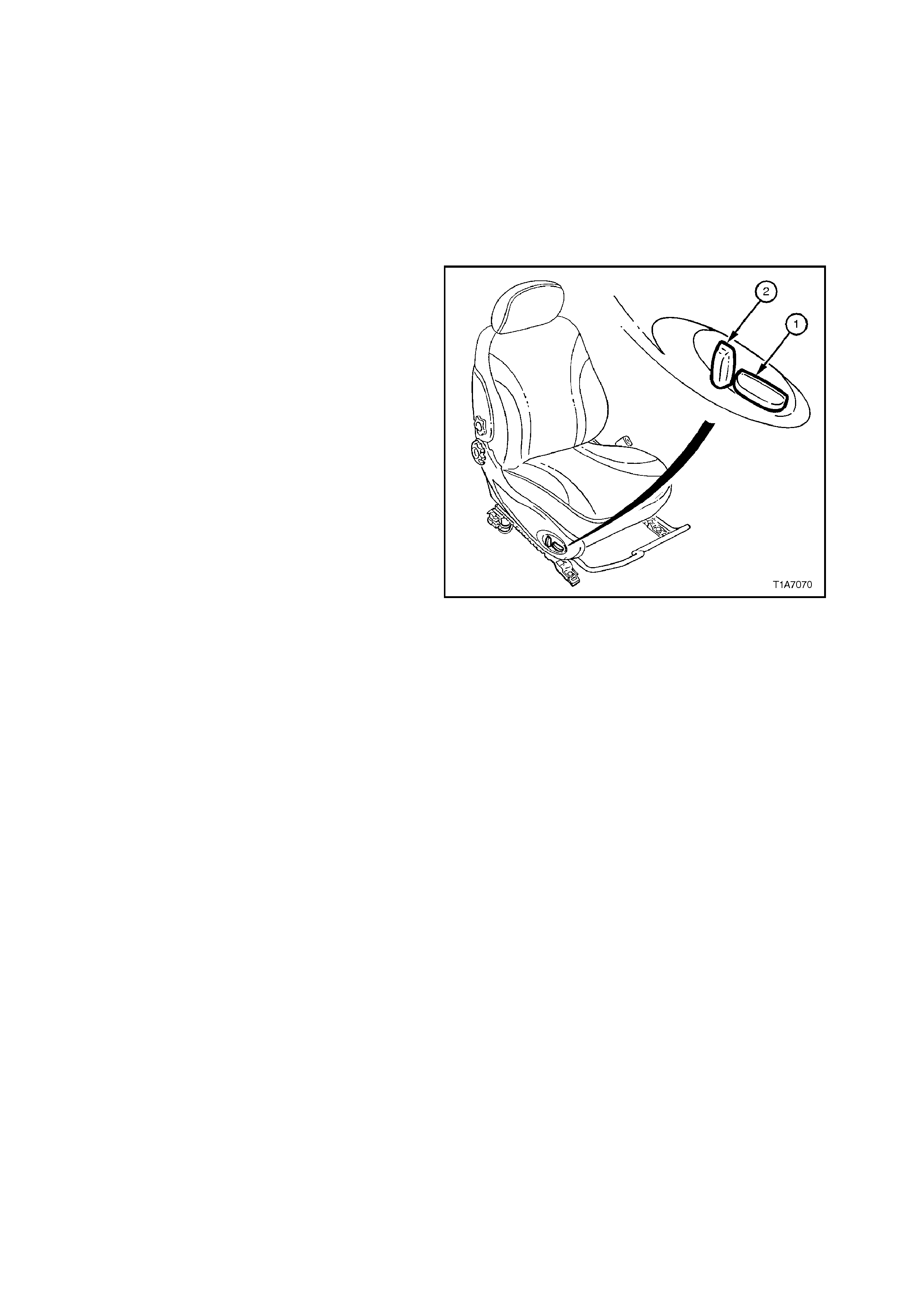
SEAT CONTROL ADJUSTMENT SWITCH ASSEMBLY
A seat control adjustment switch is fitted to the
outside of eac h seat fr am e where electric seats are
fitted. This switch assembly provides independent
control of:
1. Horizontal switch - f ront and rear height (up and
down movement) of seat, and on vehicles with
the eight way electric seats, this switch also
provides fore/aft movement.
2. Vertical switch (eight-way electric seats only) -
seat recliner angle.
Figure 1A7-1
To control the seat front and rear heights, and the
fore and aft movements, the appropriate electric
mo tor and gear box ass embly is driven which dr aws
in or extends out a mating worm shaf t which in turn
operates either the cross bar, for up and down
movement, or the seat guide rail for fore/aft
movem ent. By reversing the polarity of each of the
motors terminals, causes the motor to drive in the
reverse direction and therefore the seat will move
in the opposite direction.
The seat back recliner angle on Calais models is
adjusted by a recliner motor attached to the inner
seat back f ram e. T he m otor has a drive gear which
is meshed with a driven gear attached to the seat
back frame. Motor operation causes the rotation of
the drive gear which turns the driven gear and seat
back frame, thereby altering the seat back recliner
angle. Reversing the polarity of the recliner motor
terminals causes the motor to drive in the reverse
direction and the seat back moves in the opposite
direction.

2. SERVICE OPERATIONS
2.1 FRONT BUCKET SEAT ASSEMBLY
REMOVE
1. Position seat for easiest access to the four
seat retaining bolts and, if possible, the seat
should be fully raised and reclined fully
forward.
2. Disconnect battery earth lead.
3. If removing the driver’s seat, remove the
retaining screw from the driver’s side outer front
guide rail cover, refer to Fig. 1A7-2.
4. Remove the front outer guide rail covers, refer to
2.2 FRONT SEAT GUIDE RAIL COVERS in this
Section.
On driver’s seat, lift the outer front seat guide
rail cover over fuel filler door release lever.
5. Lift the two rear guide rail covers up and off the
guide rails.
6. Disconnect seat and seat belt wiring harness
connectors from outer side of seat.
7. Remove the f our bolts securing the front seat to
the floor and remove seat.
REINSTALL
Installation is the reverse of the rem oval operation,
noting the following:
1. Tighten all bolts to the correct torque
specification.
FRONT SEAT TO FLOOR SECURING 35 - 50
BOLT TORQUE SPECIFICATION Nm
2. Refer to Section 2.2 FRONT SEAT GUIDE
RAIL COVERS for procedure on how to
reinstall front seat guide rail cover.
3. Check operation of front seat mechanical and
electrical adjustments.
Techline
Techline
Techline
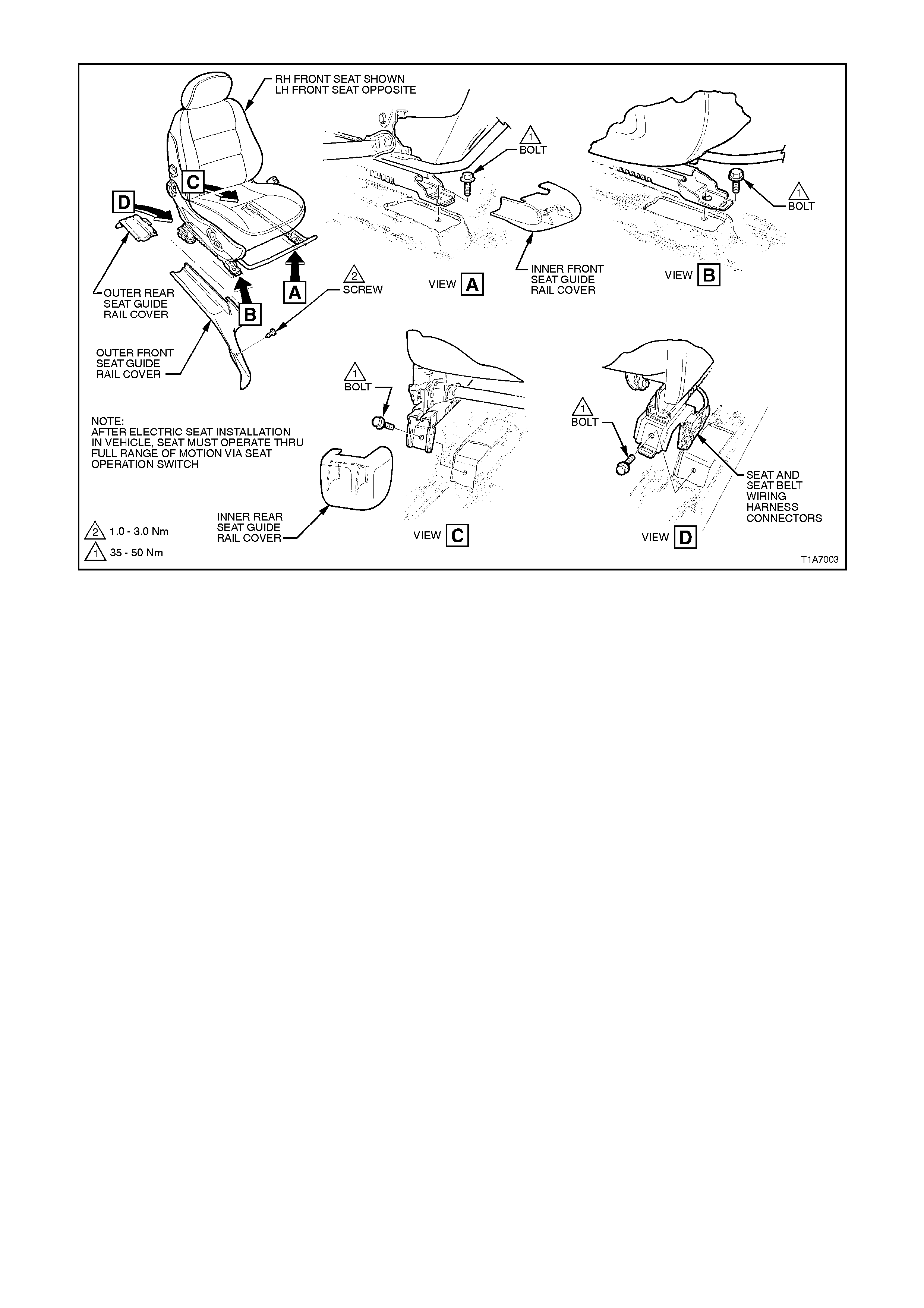
Figure 1A7-2
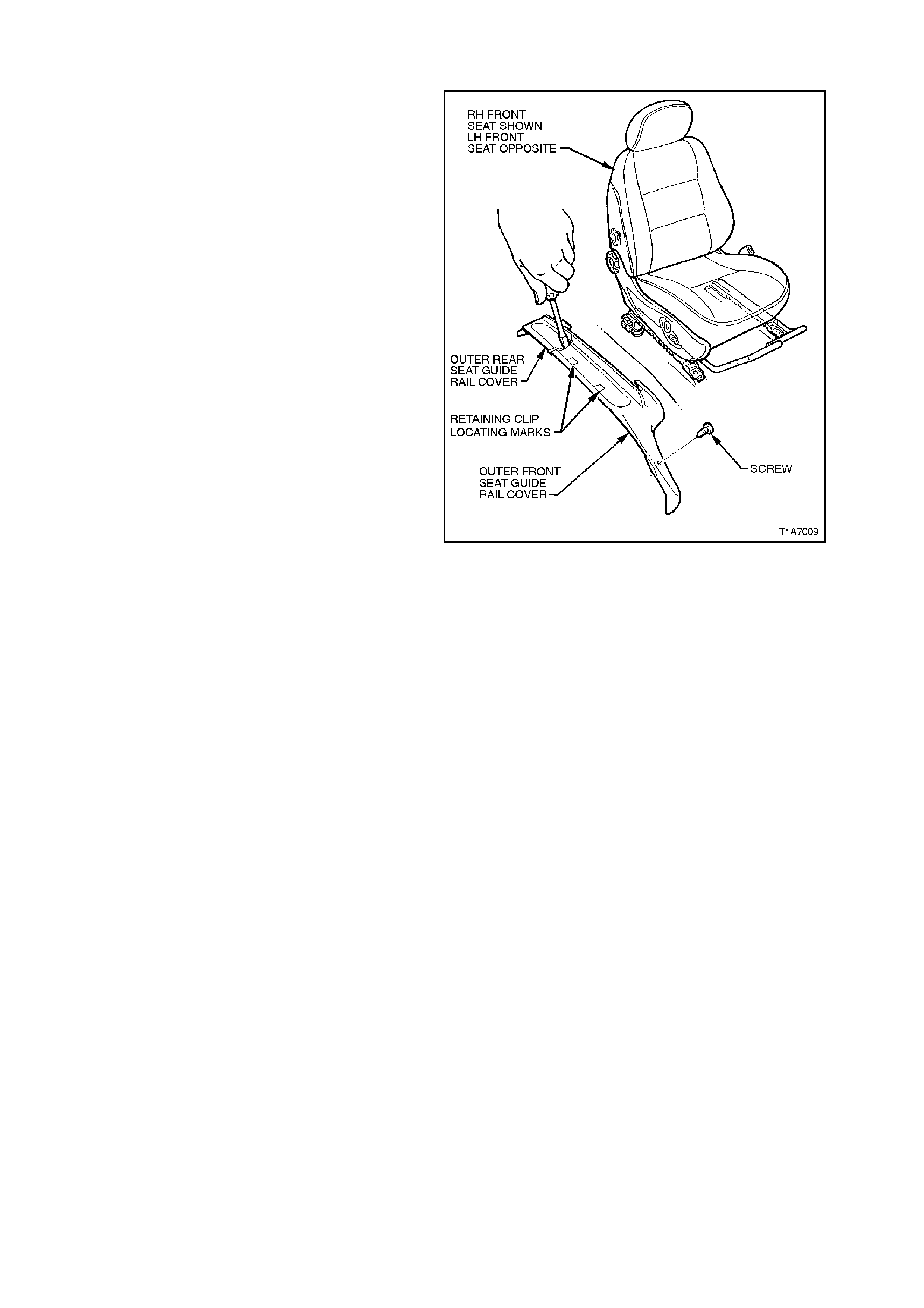
2.2 FRONT SEAT GUIDE RAIL COVERS
REMOVE
1. On drivers side, remove the retaining screw
from the drivers side outer front guide rail
cover, refer to Fig. 1A7-3.
2. Using a small screwdriver, push in the centre
of the front and rear outer seat guide rail
covers where the two parts meet, refer to Fig
1A7-3.
3. Remove the front outer guide rail covers by
lifting the outer edge of the front cover up and
pulling it forward. Lift driver’s outer front seat
guide rail cover over fuel filler door release
lever.
4. Lift the two rear guide rail covers up and off
the guide rails.
REINSTALL
1. Align the outer front seat guide rail c over’s two
retaining clips and push firmly to engage.
NOTE:
The two retaining clips on the side can be aligned
by using the alignment marks on the upper side of
the cover, refer to Fig. 1A7-3.
2. Push the front of the outer front s eat guide rail
cover down to engage cover with front of seat
rail.
3. On driver’s side, reinstall the retaining screw at
the front of the outer front seat guide rail
cover.
4. Install the outer rear seat guide rail cover
lower rear retainer over seat guide rail and
push outer rear seat guide rail cover forward to
engage with outer front seat guide rail cover.
Figure 1A7-3
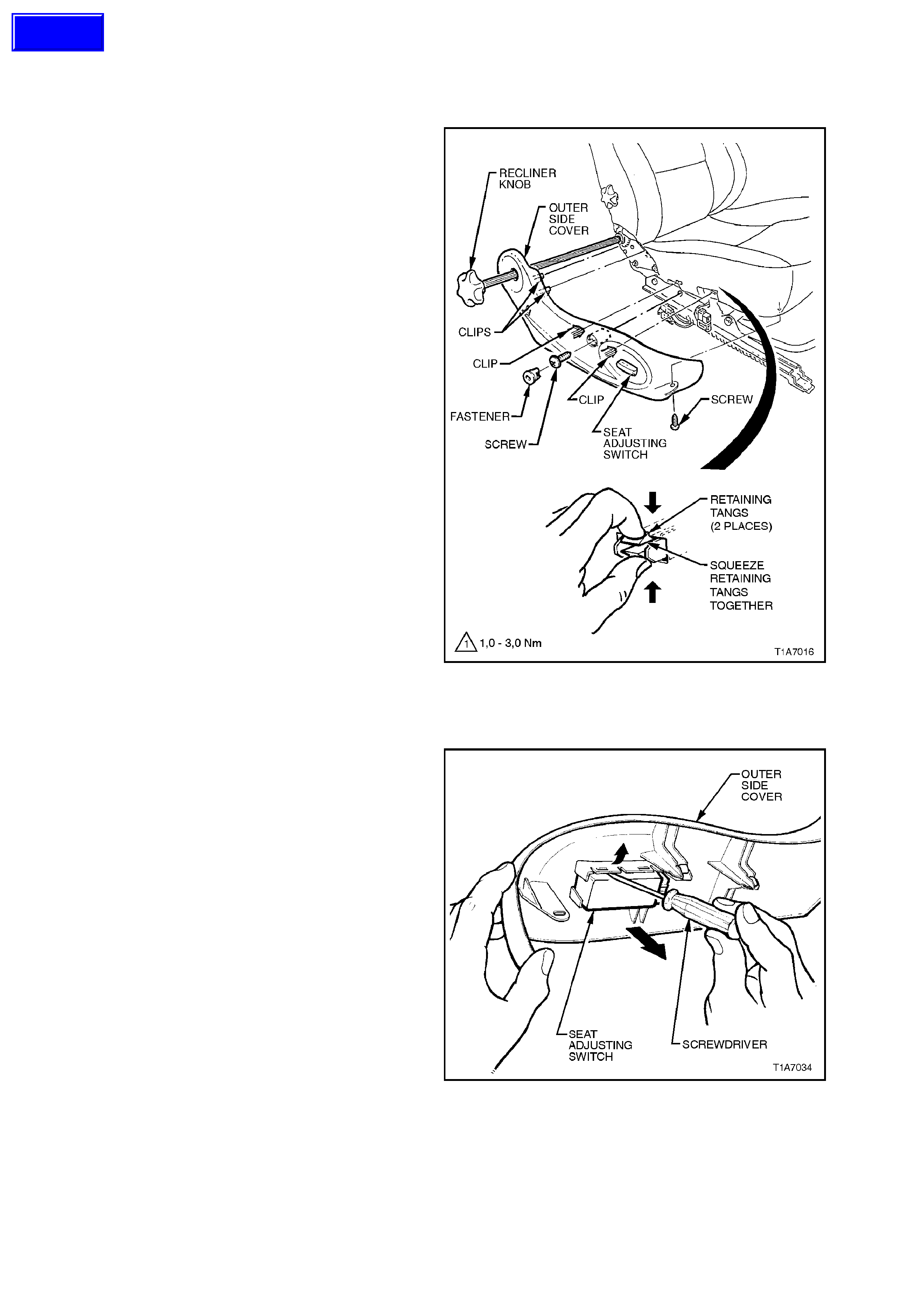
2.3 FRONT SEAT OUTER SIDE COVER AND SEAT ADJUSTING SWITCH ASSEMBLY
REMOVE
1. On a four- way seat, remove front seat inner
side cover, refer to Section 2.4 FRONT
SEAT INNER SIDE COVER.
2. On a four-way seat, from the inner side of the
seat assembly, gently tap the recliner shaft
towards the outer side of the seat assembly
(approximately 1 - 2 cm) using a pin punch.
3. On a four-way seat, fully withdraw the seat
back reclining knob and recliner shaft
assembly from the seat assembly.
4. Remove the screw from the front of the outer
side cover.
5. Remove the front seat outer side cover
fastener by rotating fastener anti-clockwise
(one quarter turn) and remove the screw
located behind this fastener .
6. Adjust the seat assembly to its highest
position.
7. Gently pull outer cover away from seat back
recliner (clip either side of recliner frame).
8. Reach up under the seat assembly and
squeeze the retaining tangs together (2
positions) on the inner side of the outer cover,
refer to Fig. 1A7-4 while gently pulling the
outer cover.
NOTE:
Only remove outer c over far enough away fr om the
seat cushion assembly to gain access to the seat
adjusting switch wiring harness.
9. Disconnect seat adjusting switch wiring
harness at the switch and rem ove outer cover
and switch assembly.
Figure 1A7-4
10 Remove the knob/s from the seat adjusting
switch by simply pulling them straight off.
11. On a four-way seat, gently pry the seat
adjusting switch f rom the outer side c over with
the aid of a screwdriver, refer Fig. 1A7-5.
On a eight-way switch, remove the three
screws securing the seat adjusting switch to
outer side cover and remove seat adjusting
switch.
NOTE:
Fig. 1A7-5 shows a four-way switch assembly.
Figure 1A7-5
Techline
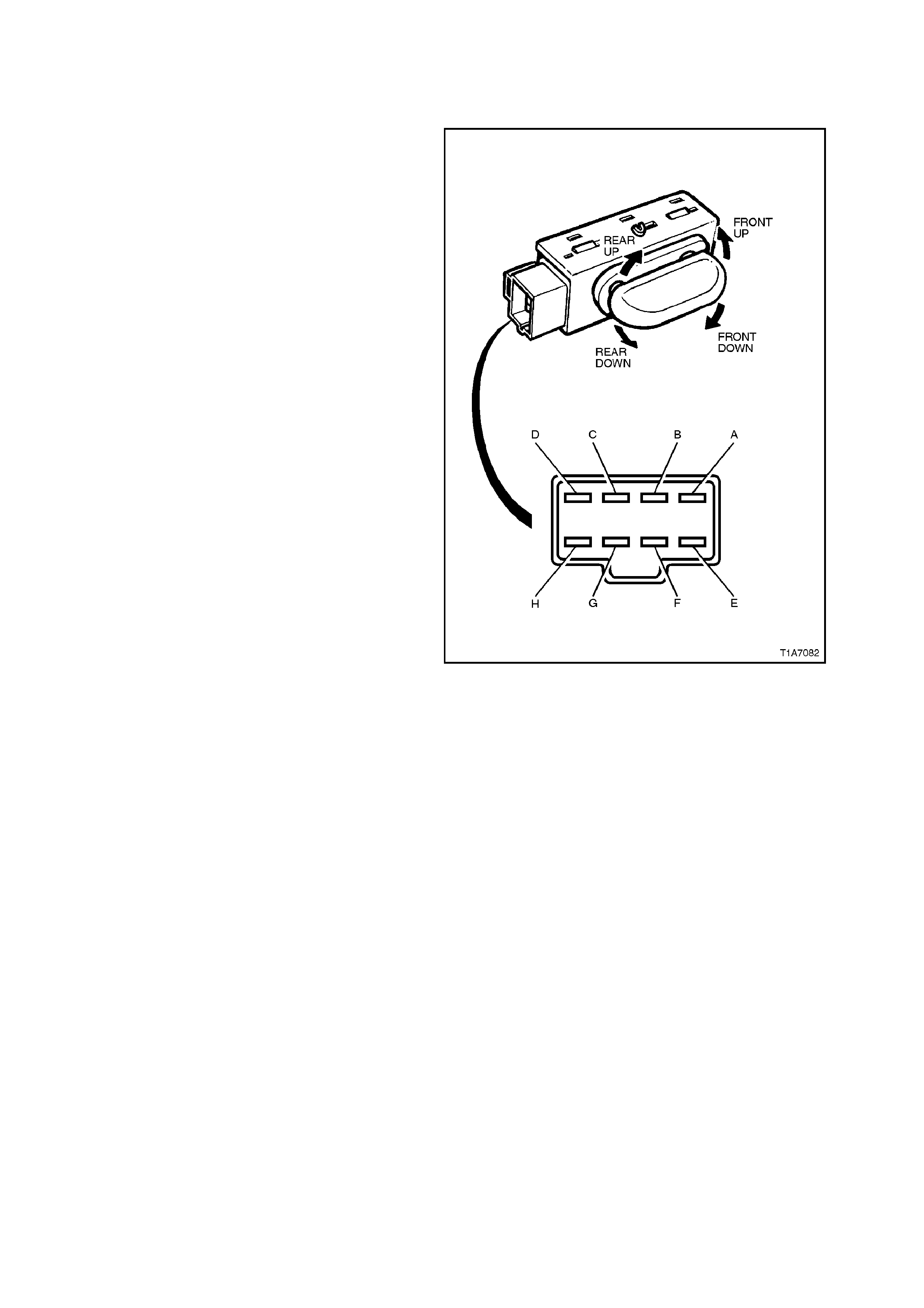
TEST
FOUR-WAY SEAT ADJUSTING SWITCH (UP
AND DOWN ONLY)
The four way seat adjusting switch assembly
contacts c an be check ed f or continuity between the
various term inals by referring to the following char t,
while referring to Fig. 1A7-6.
1. Attach Ohmmeter probes (using connector
leads from KM-609) to the appropriate switch
terminals nominated in the following chart.
2. Hold the switch in the nominated function
position as per the following chart while
referring to Fig. 1A7-6.
NOTE:
If any of the readings are not as specified, replace
the switch assembly.
SWITCH POSITION TERMINALS VALUE
REST C - E, F, G, H CONTINUITY
FRONT DOWN B - H CONTINUITY
FRONT UP B - E CONTINUITY
REAR DOWN B - G CONTINUITY
REAR UP B - F CONTINUITY
Figure 1A7-6
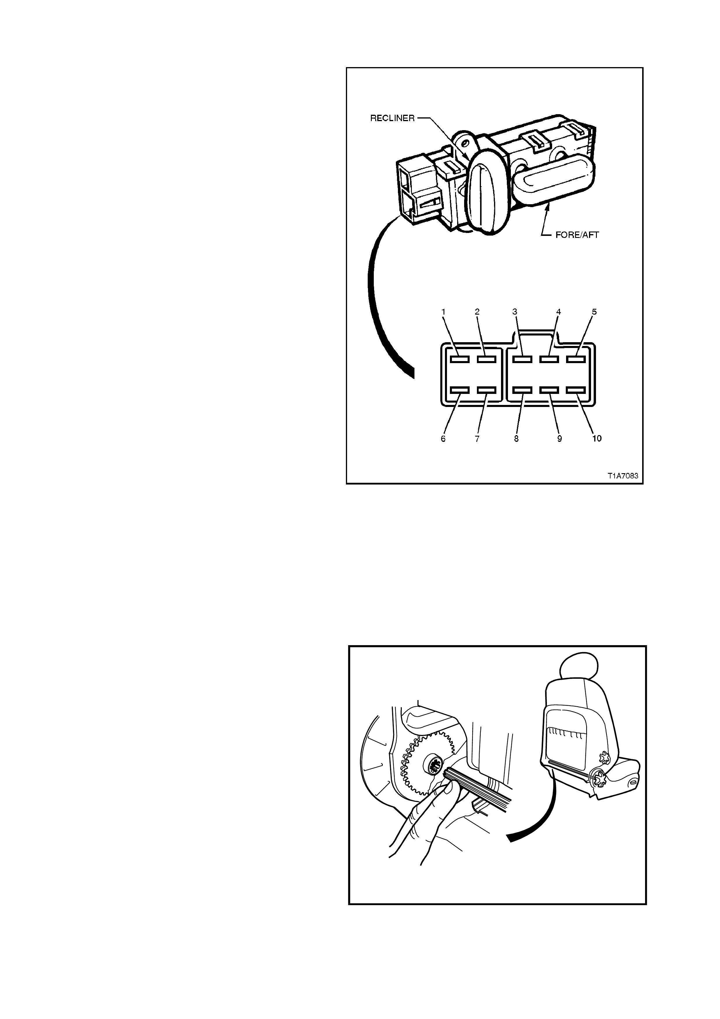
EIGHT-WAY SEAT ADJUSTING SWITCH (UP, DOWN, FORE/AFT AND RECLINE)
The eight-way seat adjusting switch assembly
contacts c an be check ed f or continuity between the
various term inals by referring to the following char t,
while referring to Fig. 1A7-7.
1. Attach ohmmeter probes (using connector
leads from KM-609) to the appropriate switch
terminals nominated in the following chart.
2. Hold the switch in the nominated function
position as per the following chart while
referring to Fig. 1A7-7.
NOTE:
If any of the readings are not as specified, replace
the switch assembly.
SWITCH
POSITION TERMINALS VALUE
REST 1 - 5 CO NTINUITY
RECLINER
(BACK) 1 - 2 CO NTINUITY
RECLINER
(FORWARD) 1 - 4 CONTINUITY
TRACK BACK
(AFT) 1 - 3 CONTINUITY
TRACK FORWARD
(FORE) 1 - 10 CONTINUITY
RH FRONT DOWN 1 - 9 CONTINUITY
LH FRONT DOWN 1 - 6 CONTINUITY
RH FRONT UP 1 - 6 CONTINUITY
LH FRONT UP 1 - 9 CONTINUITY
RH REAR DOWN 1 - 8 CONTINUITY
LH REAR DOWN 1 - 7 CONTINUITY
RH REAR UP 1 - 7 CONTINUITY
LH REAR UP 1 - 8 CONTINUITY
Figure 1A7-7
REINSTALL
Installation of the front seat outer side cover and
seat adjusting switch is the reverse of the removal
procedure, noting the following:
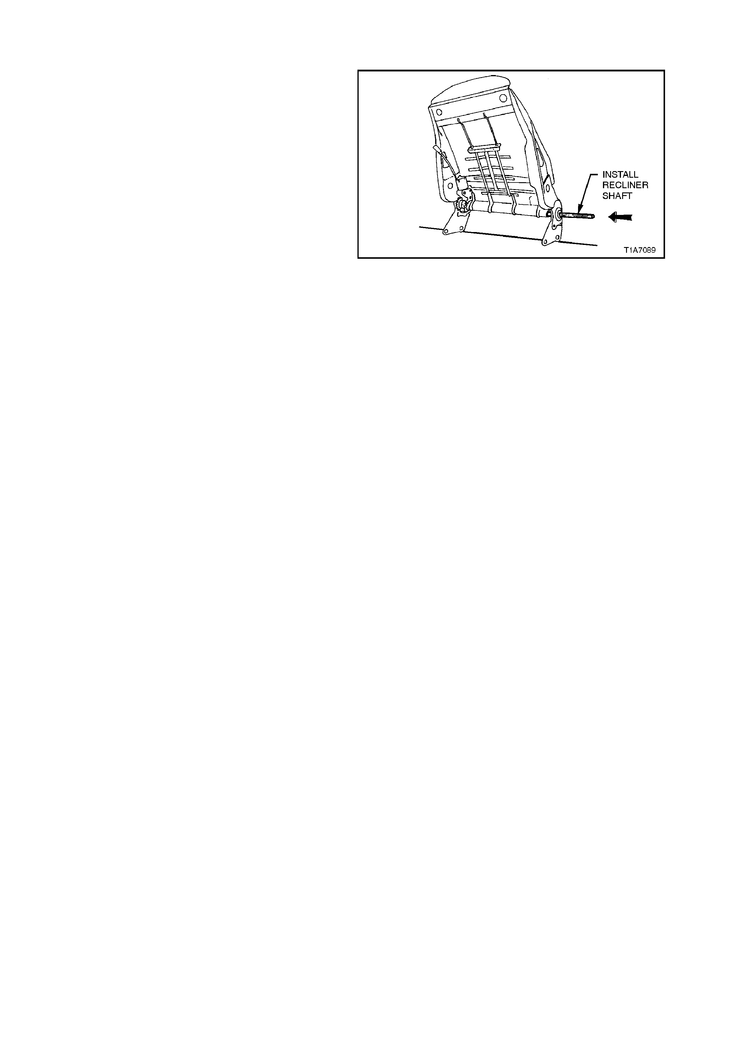
When reinstalling the front seat recliner shaft and
knob assem bly, ensure the s plines on the shaft are
aligned correctly, as per the following procedure:
NOTE: Do not force the recliner shaft into the
recliner shaft sleeve until the splines are aligned
correctly as this will damage the plastic recliner
shaft sleeve.
1. With your fingers inserted between the seat
back cover and the seat back, on the inboard
side of the front seat, align the splines by
guiding the recliner shaft into the recliner shaf t
sleeve.
2. With the recliner shaft aligned and seated in
the recliner shaft sleeve, firmly press on the
recliner knob until the recliner knob snaps into
position (a click will be heard).
T21A7501
Figure 1A7-8
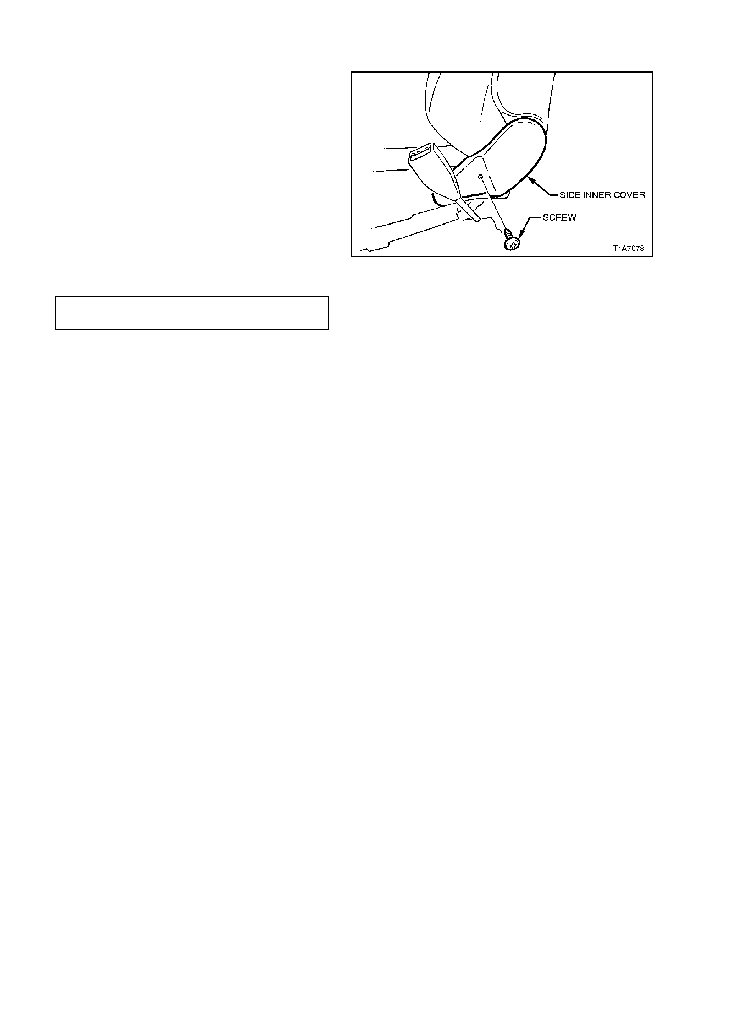
2.4 FRONT SE AT INNER SIDE COVER
REMOVE
1. Remove front seat assembly, refer to
2.1 FRONT BUCKET SEAT ASSEMBLY in
this Section.
2. 2. Remove sc rew securing side inner c over to
seat and remove inner side cover.
REINSTALL
Installation of the inner side cover is the reverse of
the removal operation, noting the following:
Ensure all fasteners are tightened to the correct
torque specification.
SIDE INNER COVER RETAINING 1.0 - 3.0
SCREW TORQUE SPECIFICATION Nm
Figure 1A7-9
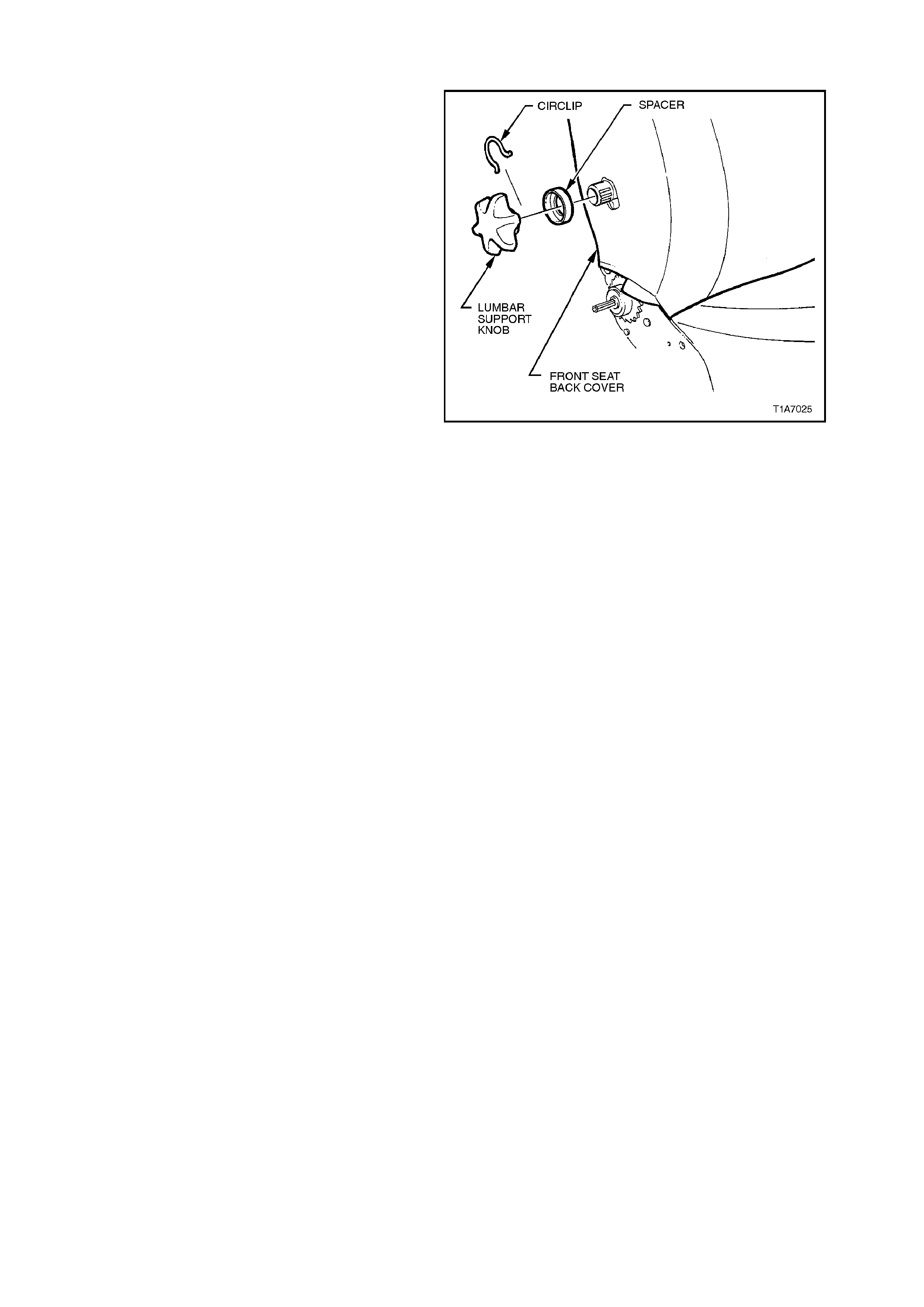
2.5 LUMBAR SUPPORT ADJUSTER KNOB
REMOVE
Remove lumbar support knob by pushing seat back
cover in far enough to expose circlip, remove circlip
and remove lumbar support adjusting knob, refer
Fig. to 1A7-9.
REINSTALL
1. Install circlip onto lumbar support adjusting
knob.
2. Ensure splines of lumbar support are correctly
aligned and push adjusting knob onto lumbar
adjuster shaft until circlip locks adjusting knob
into place.
Figure 1A7-10
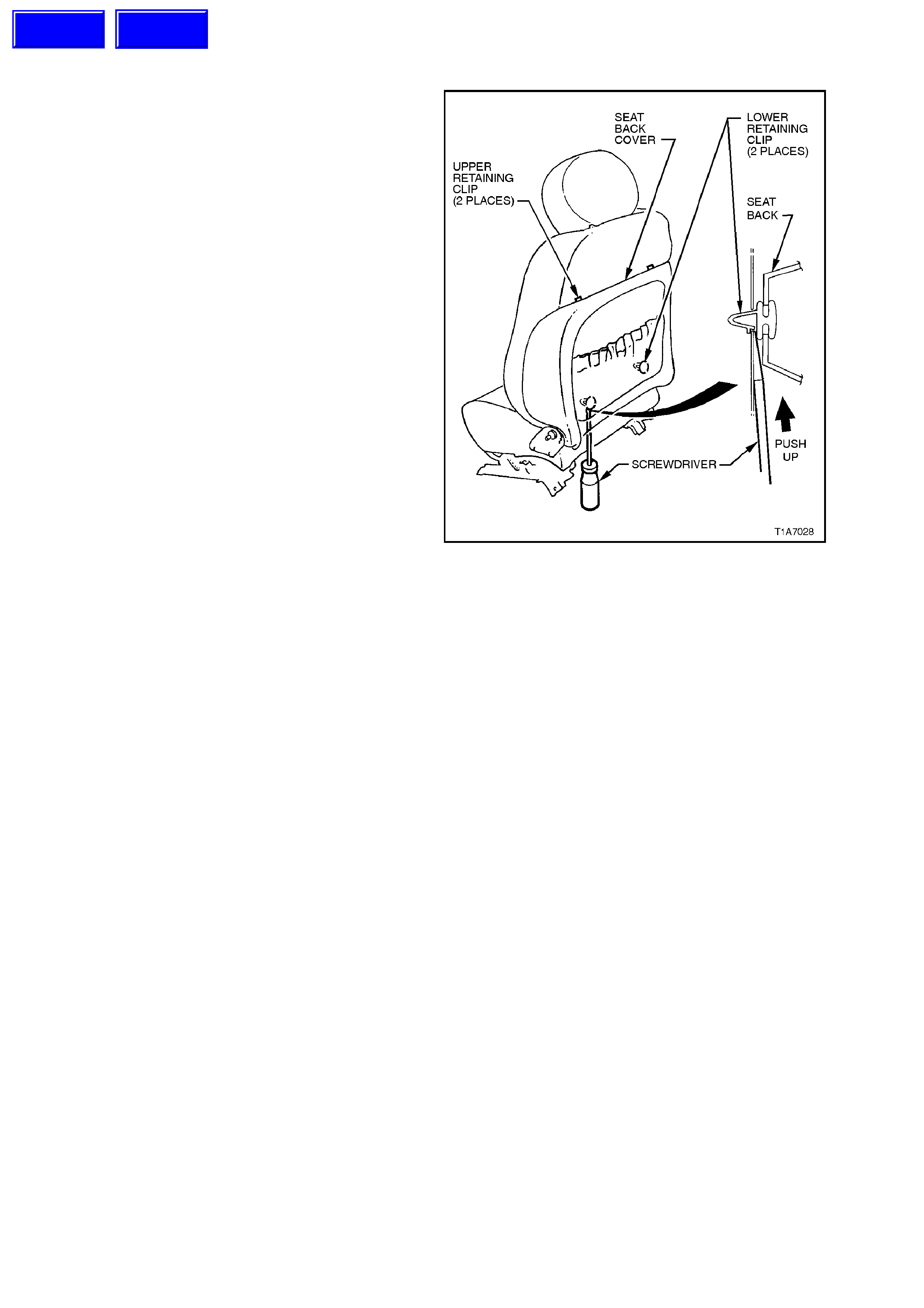
2.6 FRONT SE AT BACK COVER
REMOVE
1. Remove lumbar support adjusting knob, refer
to previous operation 2.5 LUMBAR SUPPORT
ADJUSTER KNOB in this Section.
2. Insert a screwdriver between the seat back
cover and seat back and push up on the
retaining clip (2 places) while pulling the
bottom of the back cover out, away from seat,
to release lower retaining clips, and then pull
back cover down to release top retainers.
Remove seat back cover.
REINSTALL
Installation of the front seat back cover is the
reverse of the removal operation.
Figure 1A7-11
Techline
Techline
2.7 FRONT SEAT CUSHION PAD AND COVER ASSEMBLY
REMOVE
1. Remove front seat assembly, refer to
2.1 FRONT BUCKET SEAT ASSEMBLY in
this Section.
2. Remove inner and outer side cover
assemblies, refer to
2.3 FRONT SEAT OUTER SIDE COVER AND
SEAT ADJUSTING SWITCH ASSEMBLY in
this Section.
3. On seats with electric recliner assemblies,
disconnect wiring harness connector for
recliner motor (located under rear of the front
seat assembly).
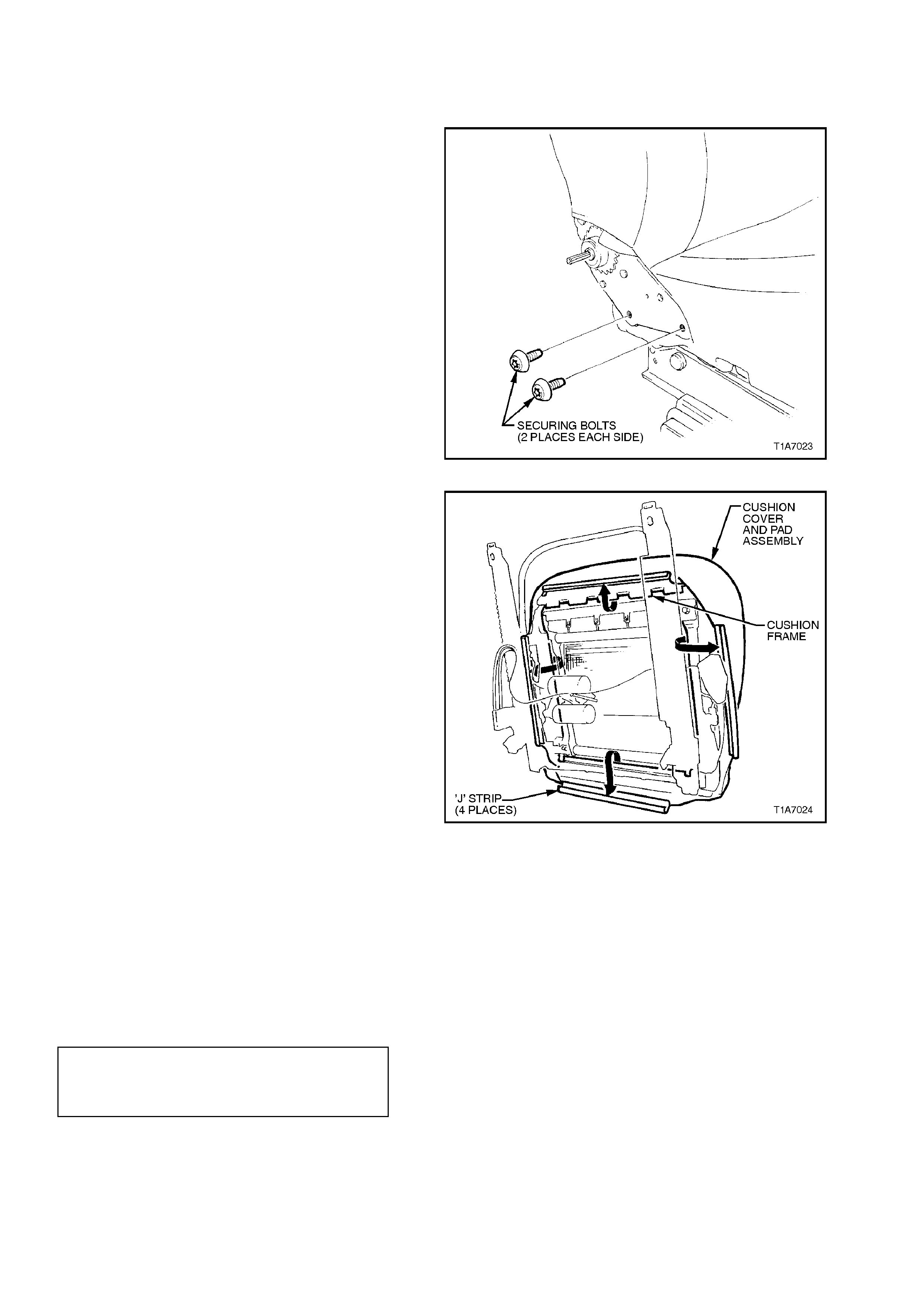
4. Remove the four Torx bolts securing the seat
back assembly to the seat adjuster and guide
rail assembly, remove seat back assembly.
Figure 1A7-12
5. From under seat cushion, pull the front and
side ‘J’ strips away from the seat frame.
6. Lift cover and pad assembly away from seat
frame and then release the rear ‘J’ strip.
Figure 1A7-13
REINSTALL
Installation is the reverse of the rem oval operation,
noting the following:
1. W hen installing the seat bac k assem bly to the
seat adjuster and guide rail assembly, ensure
there is a metal to metal contact of parts (no
trim material caught between).
2. Ensure all fasteners are tightened to the
correct torque specification.
SEAT BACK TO SEAT ADJUSTER
AND GUIDE RAIL ASSEMBLY
SECURING BOLT
TORQUE SPECIFICATION 27 Nm
2.8 FRONT SEAT BACK PAD AND COVER ASSEMBLY
REMOVE
1. Remove front seat assembly, refer to
2.1 FRONT BUCKET SEAT ASSEMBLY in
this Section.
2. Remove inner and outer side cover
assemblies, refer to
2.3 FRONT SEAT OUTER SIDE COVER AND
SEAT ADJUSTING SWITCH ASSEMBLY in
this Section.
3. On seats with electric recliner assemblies,
disconnect wiring harness connector for
recliner m otor (located under r ear of f ront seat
assembly).
4. Remove lumbar support knob by pushing seat
back cover in far enough to expose circlip,
remove circlip and remove lumbar support
adjusting knob, refer to Fig. 1A7-13.
Figure 1A7-14
5. Remove the front seat back cover assembly,
refer to 2.6 FRONT SEAT BACK COVER in
this Section.
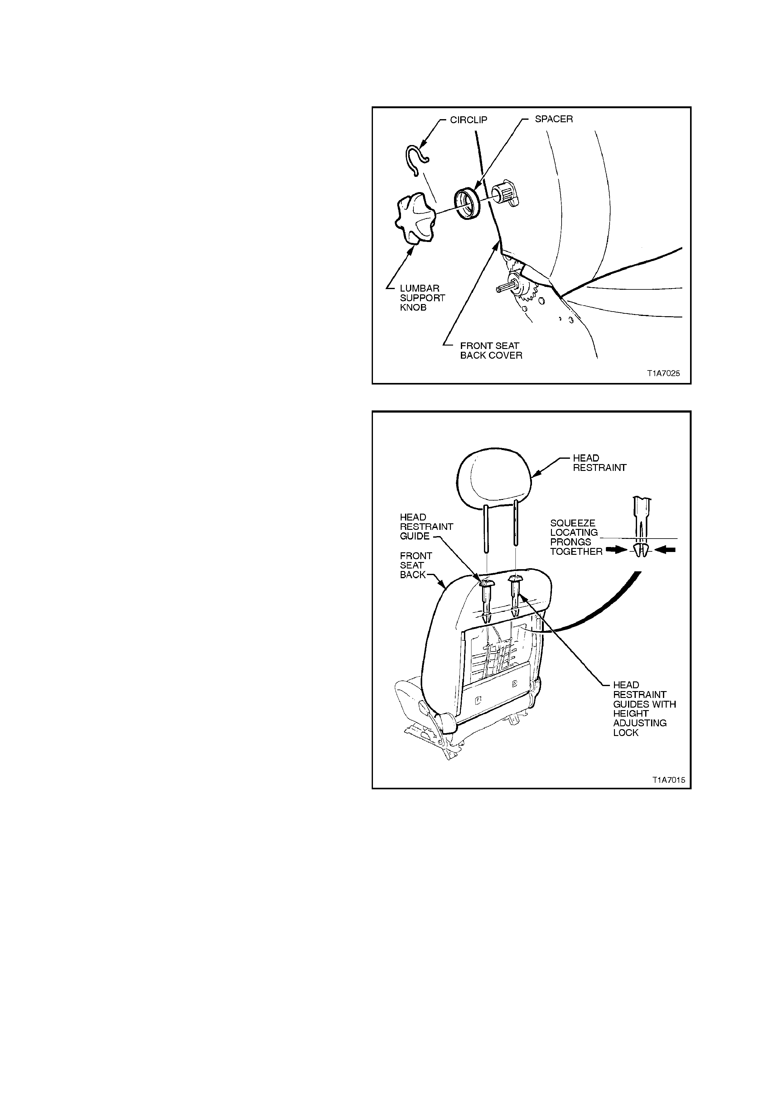
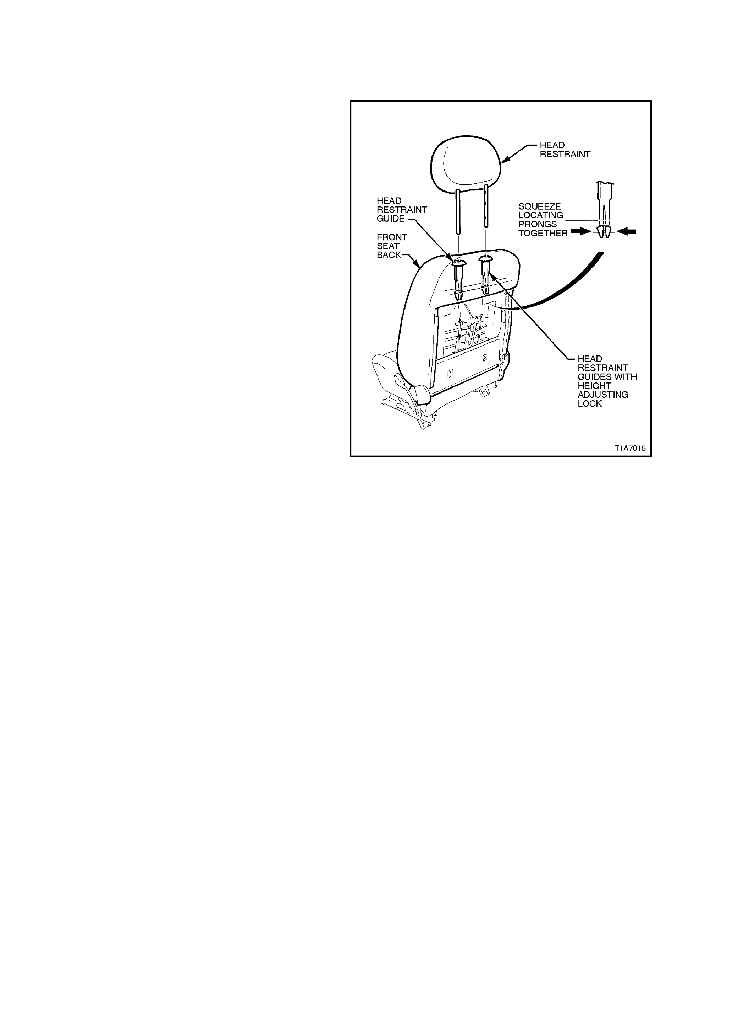
6. While holding head restraint height adjuster
lock in, pull head restraint completely out of
guide.
7. From the back of front seat, squeeze the
lock ing prongs of head restraint guide together
while pulling top of guide out of seat back
assembly, refer to Fig 1A7-14
Figure 1A7-15
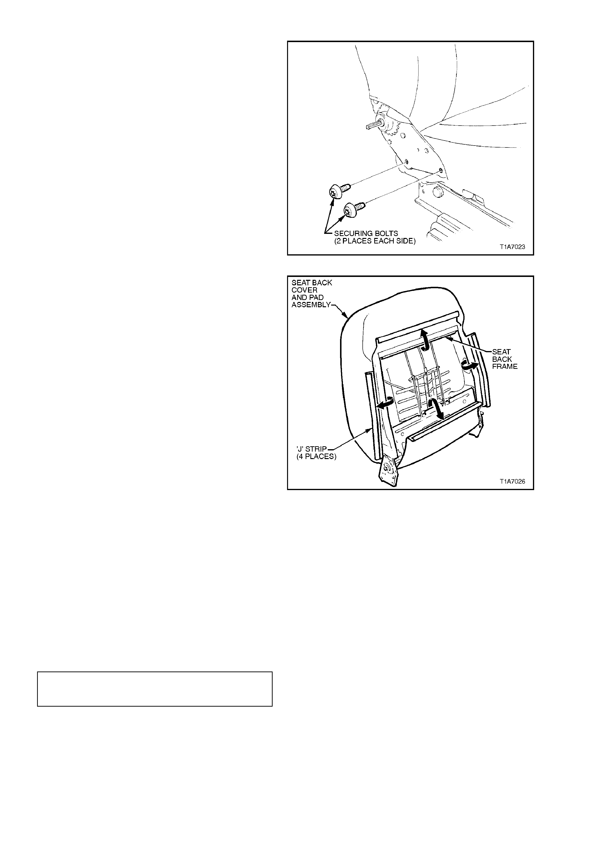
8. Remove the four bolts (two on each side)
securing the seat back assembly to the seat
height adjuster, remove seat back assembly.
Figure 1A7-16
9. Pull the four ‘J’ strips away from the seat
frame.
10. Lift cover and pad assembly away from seat
back frame.
Figure 1A7-17
REINSTALL
Installation is the reverse of the rem oval operation,
noting the following:
1. When installing the lumbar support adjusting
knob, ensure s plines are correc tly aligned and
circlip is installed onto adjusting knob before
inserting adjusting knob onto shaft.
2. Ensure the head restraint guide with adjusting
lock is installed on the correct side, ie. side
with notches on the head restraint.
3. Ensure all fasteners are tightened to the
correct torque specification
SEAT BACK TO SEAT HEIGHT
ADJUST ASSEMBLY SECURING
BOLT TORQUE SPECIFICATION 27 Nm
2.9 FRONT SEAT BACK FRAME, LUMBAR SUPPORT AND ADJUSTER ASSEMBLY
REMOVE
NOTE:
The lumbar support is part of the seat back frame
and can only be replaced as an assembly.
1. Remove front seat back cover and pad
assembly, refer to 2.8 FRONT SEAT BACK
PAD AND COVER ASSEMBLY in this
Section.
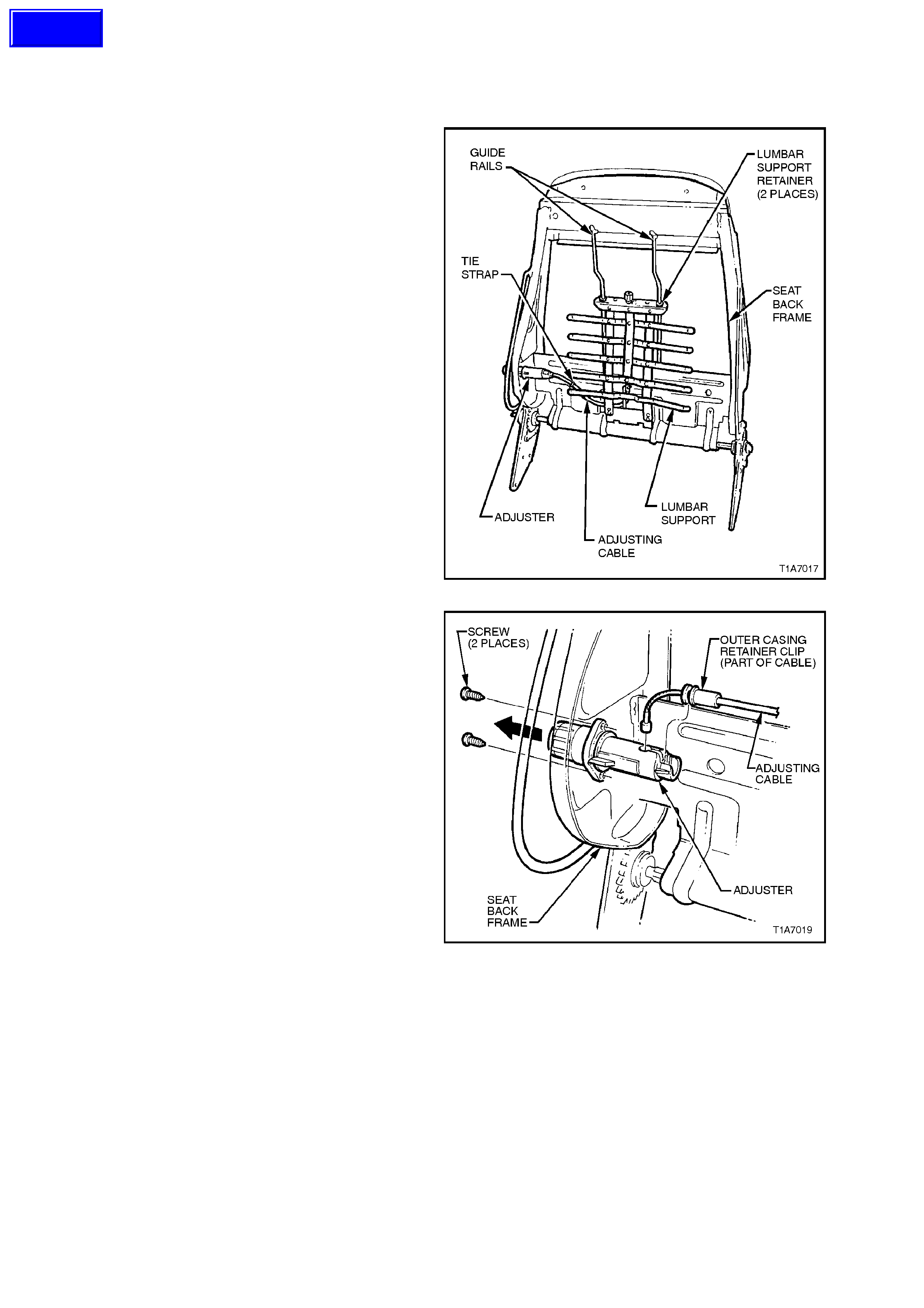
2. From the back of the front seat back frame,
disengage the lumbar support adjuster cable
wire tie clip by squeezing the tangs on the wire
tie retaining clip together and pushing wire tie
retaining clip through seat back frame.
3. Push the top of the lumbar support to
disengage the two retainers from the guide
rails on the seat bac k , allowing lumbar support
to swing freely.
4. While slightly compressing lumbar support
assembly by hand to release cable tension,
disengage adjuster cable from the top of the
lumbar support.
Figure 1A7-18
5. Remove adjusting cable from adjuster by
unclipping outer casing of cable from adjuster
and removing cable assembly.
6. Remove the two screws securing the
lumbar support adjuster to the seat back
frame and remove adjuster.
Figure 1A7-19
REINSTALL
Installation is the reverse of the rem oval operation,
noting the following:
Align hole in adjuster for adjusting cable ball by
turning the adjuster until access hole lines up,
insert cable into adjuster and push outer casing of
cable into locking seat of adjuster until it clicks.
Techline
2.10 FRONT SEAT CUSHION FRAME ASSEMBLY
REMOVE
1. Remove front seat cushion cover and pad
assembly, refer to 2.7 FRONT SEAT
CUSHION PAD AND COVER ASSEMBLY in
this Section.
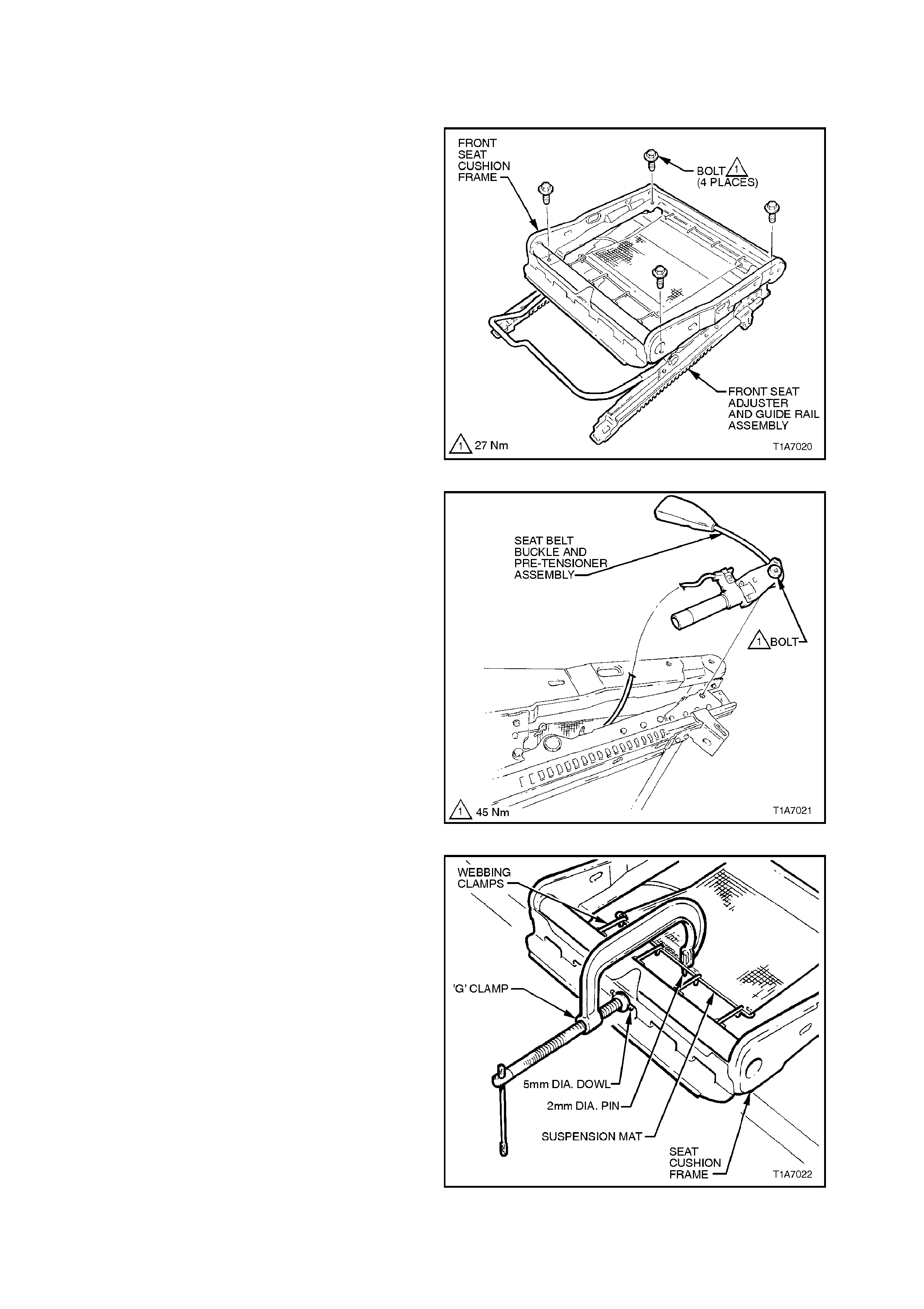
2. Remove the four bolts securing the front seat
cushion to adjuster and guide rail assembly.
Figure 1A7-20
NOTE:
Before disconnecting pre-tensioner wiring harness
connector, take note of wiring harness routing.
3. Disconnect seat belt pre-tensioner wiring
harness from seat frame.
4. Remove bolt securing seat belt buckle and
pre-tensioner assembly to frame and remove
seat belt buckle and pre-tensioner assembly.
Figure 1A7-21
5. Using a pre-fabricated tool:
‘G’ clamp with 5mm diameter metal dowel
welded to one end, approximately 40mm long
and a 2mm diam eter pin approx imately 20mm
long welded to the other end.
Using pre-fabricated tool, stretch the
suspension mat far enough to allow for
webbing clamps to be removed from seat
frame. Back ‘G’ clamp load off and remove
suspension mat.
NOTE:
When using pre-fabricated tool, use existing holes
in suspension mat to ensure that mat deformation
does not occur.
Figure 1A7-22

REINSTALL
Installation is the reverse of the rem oval operation,
noting the following:
1. Ensure all fasteners are tightened to the
correct torque specification.
FRONT SEAT CUSHION FRAME TO
SEAT GUIDE RAIL AND ADJUSTER
BOLT TORQUE SPECIFICATION 27 Nm
SEAT BELT BUCKLE AND
PRE- TENSIONER ASM. BOLT
TORQUE SPECIFICATION 45 Nm
2. Ensure the pre-tensioner and seat adjuster
motor wiring harness is routed correctly and
retained by wiring ties at each red spot tape
location.
3. When installing seat belt buckle and pre-
tensioner assembly ensure that the front
locating pin on the pre-tensioner assembly
aligns with seat frame.

2.11 FRONT SEAT ADJUSTER ASSEMBLIES
The front seat adjuster and guide rail assembly for non-electric seats are not serviceable due to safety restraints.
The front seat adjuster assembly on electric seats is also a non-serviceable item except for the drive motors and
(on eight-way electric seats) the drive shafts on the fore/aft motor.
If the adjuster assembly, drive motors or drive shafts need to be removed or replaced, refer to the individual service
operation for removing the seat cushion frame and drive motors from the adjuster assembly in this Section.
2.12 FRONT SEAT LIFT MOTORS
REMOVE
NOTE:
Illustrations for this ser vice operation s how the s eat
adjuster assembly removed from the seat
assembly. To perform this service operation, the
seat adjuster assembly does not have to be
removed from the seat assembly.
CAUTION:
When replacing front seat lift motors always
use new small and large clevis pins.
1. Remove front seat assembly, refer to
2.1 FRONT BUCKET SEAT ASSEMBLY in
this Section.
2. Disconnect lift motor wiring harness
connectors and cut wiring harness retaining
straps sec uring the lift m otor wiring harness to
the guide rails (note position of retaining
straps).
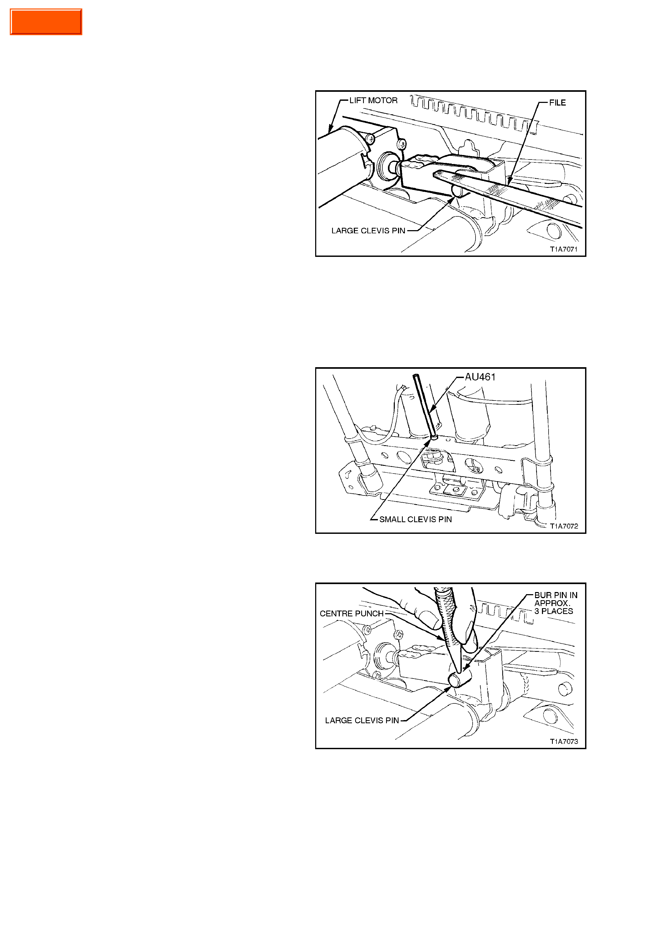
3. On the appropriate lift motor, file the retaining
burrs of f the large clevis pin, r efer to Fig. 1A7-
22, and gently tap the clevis pin out.
Figure 1A7-23
4. Using clevis pin removal punch AU461, tap the
sm aller clevis pin through the c ross br ace and
motor assembly, refer to Fig. 1A7-23.
5. Remove lift motor.
Figure 1A7-24
REINSTALL
Installation of the lift motor/s is the reverse of the
removal procedure, noting the following:
CAUTION:
Always use new small and large clevis pins.
1. Screw the yoke either in or out of lift motor
worm shaft to align the yoke with the cross
brace assembly.
2. Insert new large clevis pin and, using a centre
punch, burr the end of the clevis pin to pr event
it from coming out, refer Fig. to 1A7-24
(approx. 3 places).
3. Using new retaining straps secure seat
adjusting motor wiring harness to the seat
adjuster assembly in previously noted
positions (red spot tape).
Figure 1A7-25
Campaign
2.13 FRONT SEAT FORE/AFT MOVEMENT MOTOR
REMOVE
NOTE:
Illustrations for this ser vice operation s how the s eat
adjuster assembly removed from the seat
assembly. To perform this service operation, the
seat adjuster assembly does not have to be
removed from the seat assembly.
1. Remove front seat assembly, refer to
2.1 FRONT BUCKET SEAT ASSEMBLY in
this Section.
2. Disconnect fore/aft motor wiring harness
connector (located under front seat assembly).
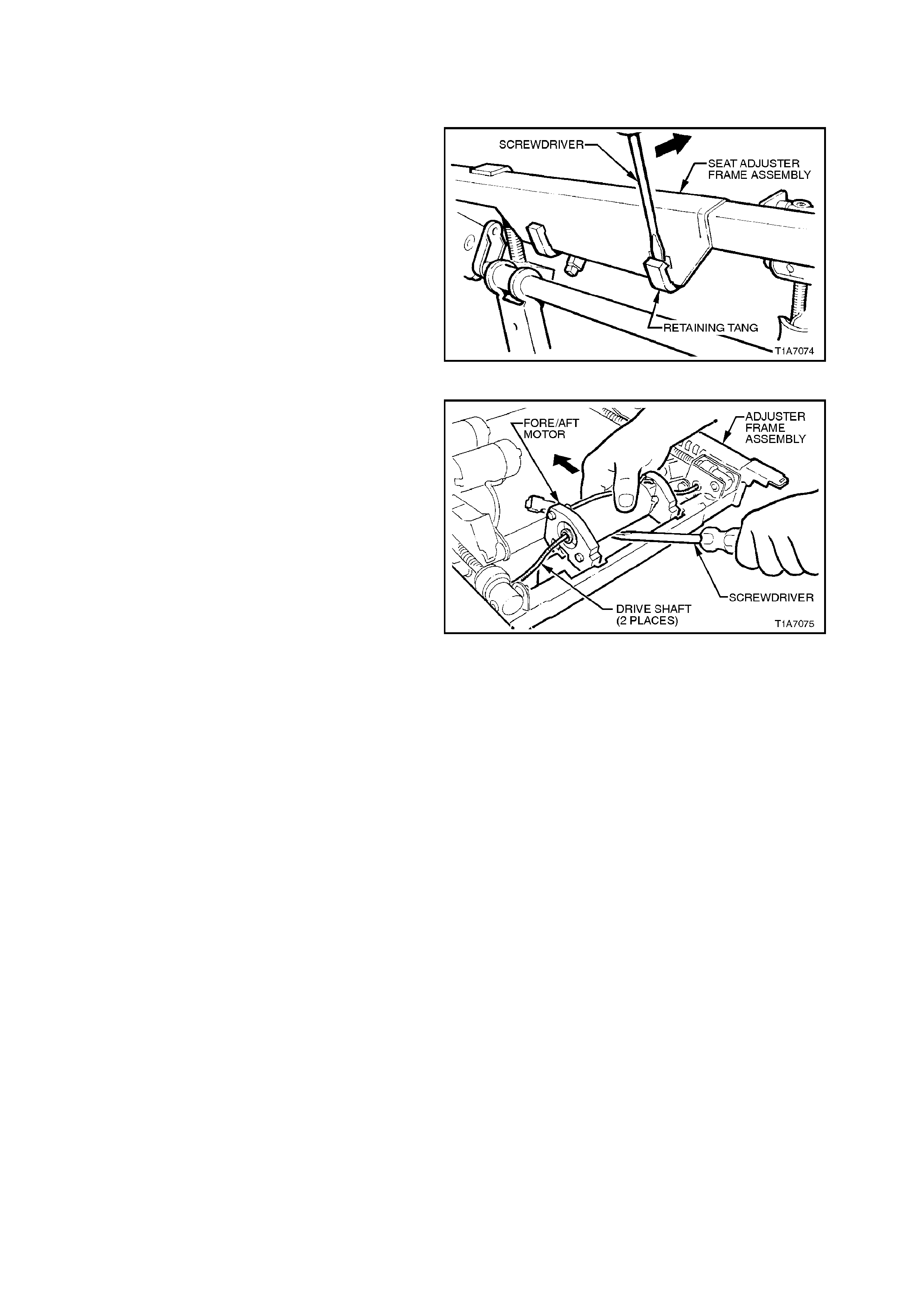
3. Using a screwdriver, gently lever the two
retaining tangs out of the seat adjuster frame
assembly, refer to Fig. 1A7-25 Figure 1A7-26
4. Using a scr ewdriver, lever f ore/aft m otor out of
seat adjuster frame assembly with both drive
shafts still attached.
NOTE:
Remove fore/aft motor far enough to remove drive
shafts taking care not to bend drive shafts any
more than necessary.
5. Remove drive shafts from fore/aft motor and
remove fore/aft motor.
Figure 1A7-27
REINSTALL
Installation of the fore/aft motor is the reverse of
the removal procedure, noting the following:
Insert drive shafts into fore/aft motor first, then
install drive shafts into gearbox and worm drive
assemblies while taking care not to bend drive
shafts any more than is necessary.

2.14 FRONT SEAT RECLINING MOTOR AND GEARBOX ASSEMBLY
REMOVE
1. Remove front seat back cover and pad
assembly, refer to 2.8 FRONT SEAT BACK
PAD AND COVER ASSEMBLY in this
Section.
2. Remove one of the two circlips retaining the
recliner drive shaft to the seat back frame at
the reclining m otor and gear box ass embly side
of the seat back frame.
Figure 1A7-28
3. Withdraw recliner drive shaft from seat back
frame far enough to disengage motor and
gearbox assembly.
Figure 1A7-29
4. Remove the two bolts and nuts securing the
recliner motor and gearbox assembly to the
seat back frame and remove motor and
gearbox assembly.
Figure 1A7-30
Techline
REINSTALL
Installation of the reclining motor and gearbox
assembly is the reverse of the removal procedure
noting the following:
1. Replace the two nylon lock nuts securing the
recliner motor and gearbox assembly to the
seat back frame.
2. W hen installing the rec liner drive shaf t, ensure
the splines are aligned evenly by placing the
bottom of the seat recliner plates on a bench,
refer to Fig 1A7-30.
Figure 1A7-31
2.15. FRONT SEAT HEAD RESTRAINT ASSEMBLY
REMOVE
1. Remove the lumbar support adjusting knob,
where required, refer to 2.5 LUMBAR
SUPPORT ADJUSTER KNOB in this Section.
2. Remove the front seat back cover assembly,
refer to 2.6 FRONT SEAT BACK COVER in
this Section.
3. While holding head restraint height adjuster
lock in, pull head restraint completely out of
guide.
4. From the back of front seat, squeeze the
lock ing prongs of head r est raint guide together
while pulling top of guide out of seat back
assembly, refer to Fig 1A7-32.
REINSTALL
Installation of the front seat head restraint
assembly is the reverse of the removal procedure
noting the following:
When installing head restraint guide, ensure that
locating slots in the s eat bac k align with k ey-way on
the head restraint guide and the head restraint
guide with adjusting lock is installed on the correct
side, ie. align with notches on the head restraint. Figure 1A7-32
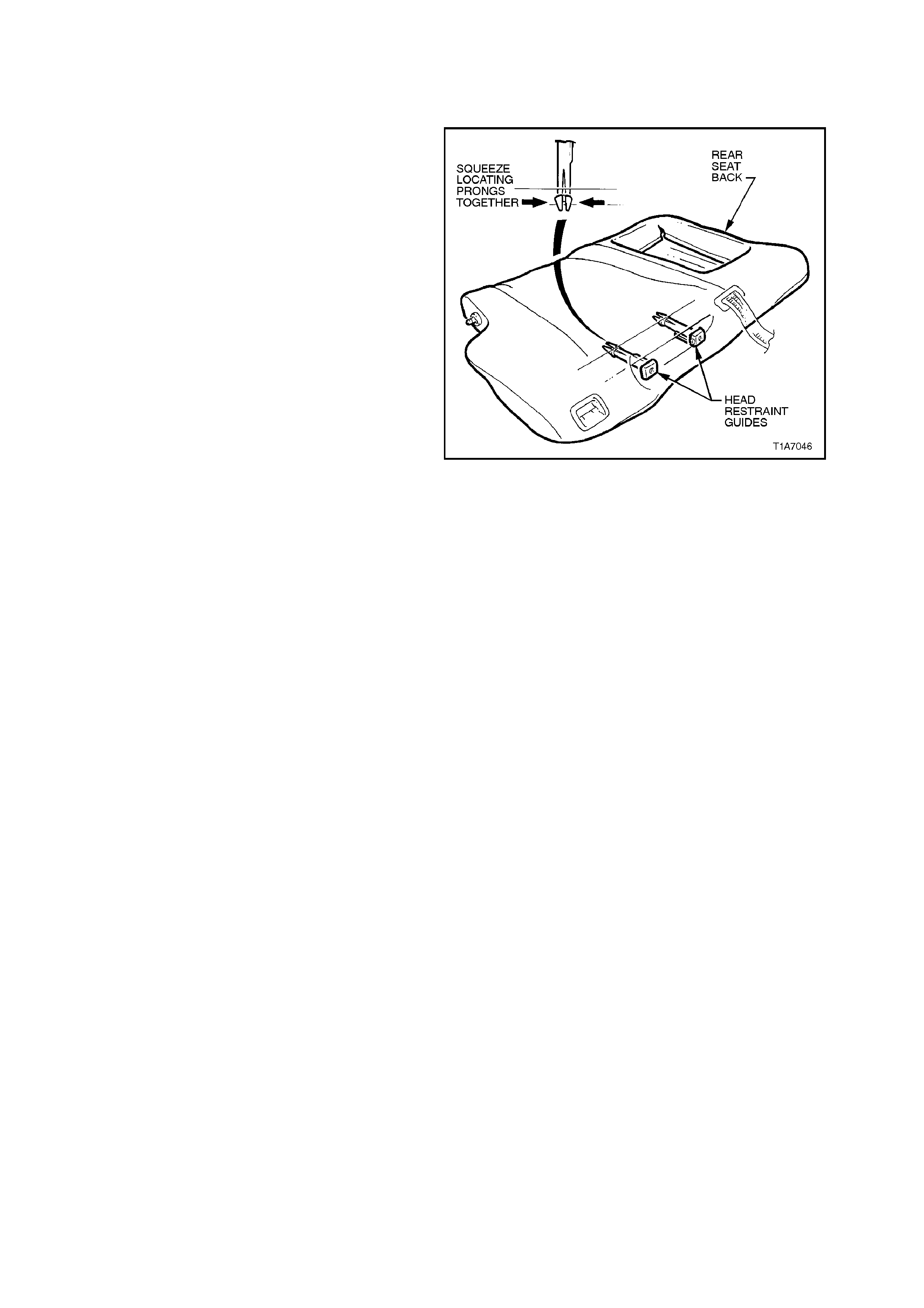
2.16 REAR SEAT HEAD RESTRAINT ASSEMBLY - SEDAN
REMOVE
1. Remove rear seat cushion assembly, refer to
2.18 REAR SEAT CUSHION AND BACK
ASSEMBLIES - SEDAN in this Section.
2. Remove appropriate side rear seat back, refer
to 2.18 REAR SEAT CUSHION AND BACK
ASSEMBLIES - SEDAN in this Section.
3. While holding head restraint height adjuster
lock in, pull head restraint completely out of
guide.
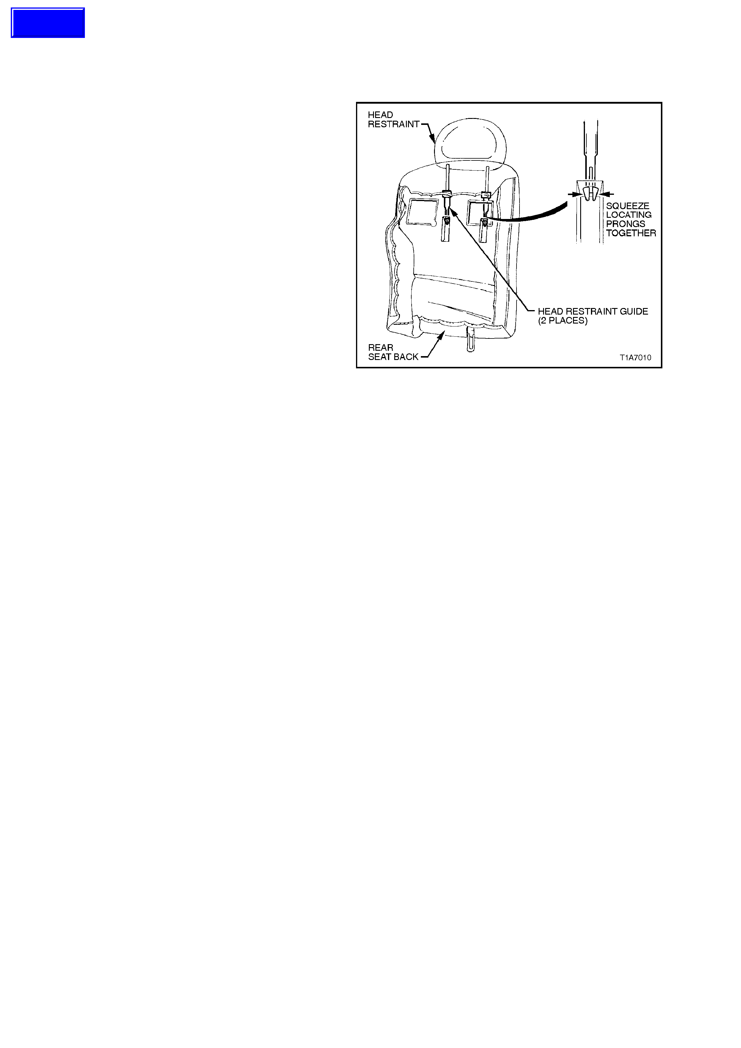
4. From the back of rear seat back (foam side)
squeeze the locking prongs of head restraint
guide together while pulling top of guide out of
seat back assembly, refer to Fig 1A7-33.
REINSTALL
Installation is the reverse of the removal procedure
noting the following:
When installing head restraint guide, ensure that
locating slots in the s eat bac k align with k ey-way on
the head restraint guide and the head restraint
guide with adjusting lock is installed on the correct
side, ie. align with notches on the head restraint.
Figure 1A7-33
Techline
2.17 REAR SEAT HEAD RESTRAINT ASSEMBLY - WAGON
REMOVE
1. While holding head restraint height adjuster
lock in, pull head restraint completely out of
guide.
2. Remove rear seat cover and pad assembly,
refer to 2.27 REAR SEAT BACK COVER
AND PAD ASSEMBLY - WAGON, Steps 1 -
16 in this Section.
3. Remove the head r estraint guides by reaching
in between seat back frame and pad
assembly, squeezing the head restraint guide
locating prongs together and pulling the top of
the guide (from outside of seat) up and out of
the seat back assembly.
REINSTALL
Installation of the r ear seat head r estraint ass em bly
is the reverse of the rem oval procedure, noting the
following:
When installing head restraint guide, ensure that
locating slots in the s eat bac k align with k ey-way on
the head restraint guide and the head restraint
guide with adjusting lock is installed on the correct
side, ie. align with notches on the head restraint.
Figure 1A7-34
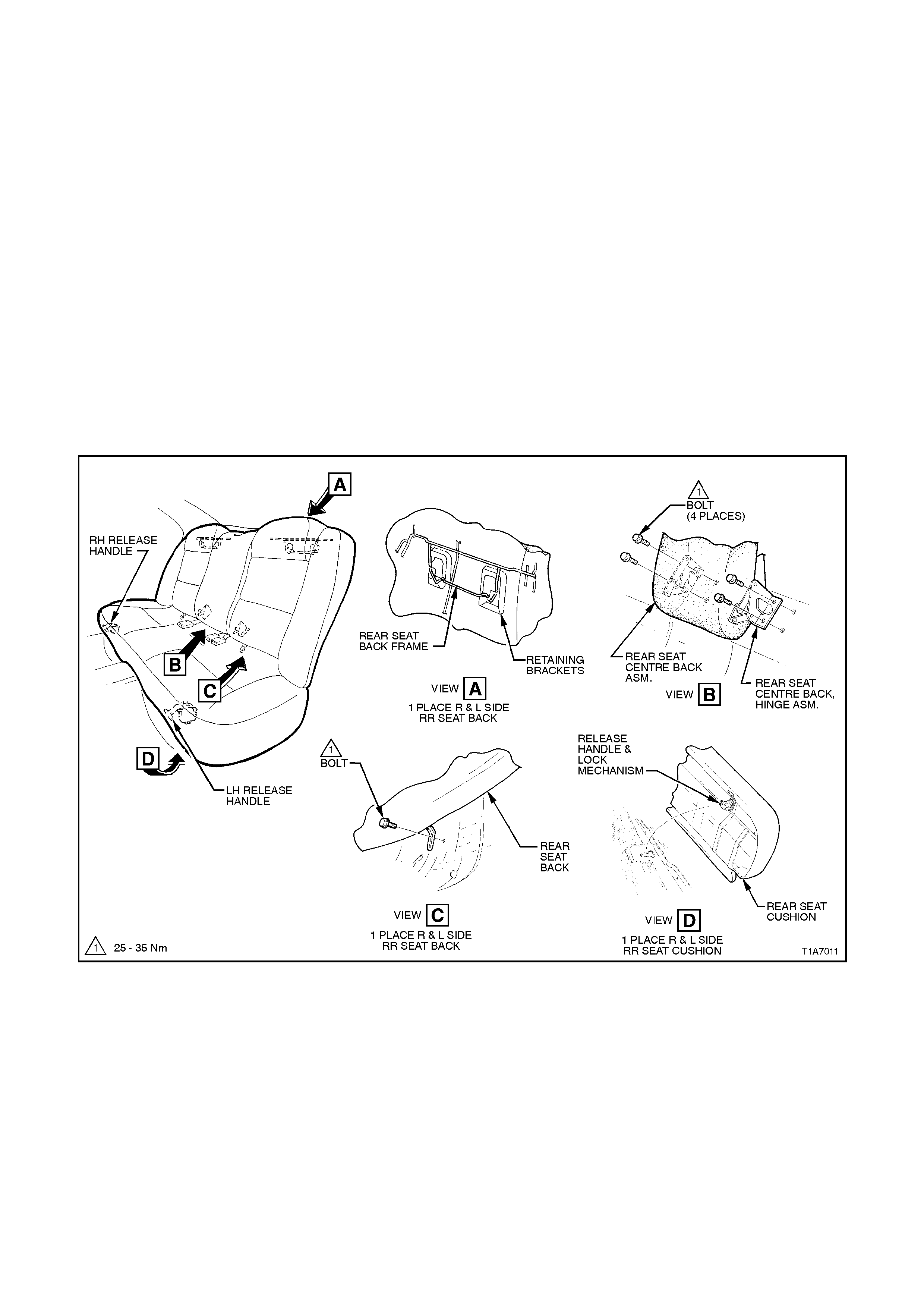
2.18 REAR SEAT CUSHION AND BACK ASSEMBLIES - SEDAN
REMOVE
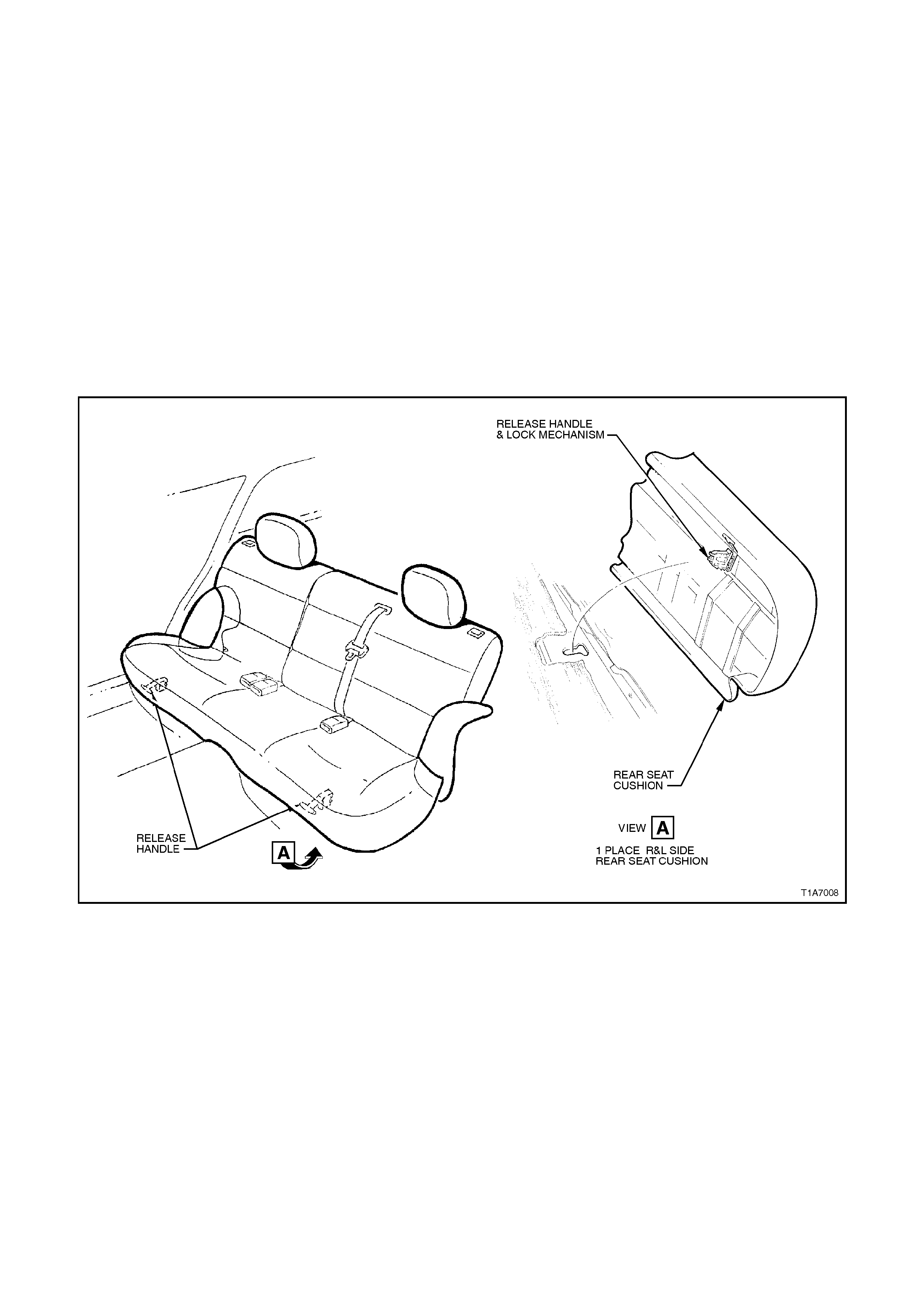
1. Lift front edge of rear seat cushion slightly to gain access to rear seat cushion release handles, refer to Fig.
1A7 - 35.
2. From either the left or right side of seat, pull release handle downwards towards the floor, while at the same
time lifting the front of the rear seat cushion until lock mechanism is released.
3. Repeat step 2 for opposite side of seat and remove rear seat cushion.
4. Detach and lower rear seat centre back.
5. Remove the two bolts securing the left and right seat back assemblies to the rear floor pan. Lift left and right
seat back assemblies up and out of retaining brackets in the rear compartment front panel. Remove left and
right seat back assemblies.
6. 6. Remove the four bolts securing the rear seat centre back hinge assembly and remove rear seat centre
back assembley.
REINSTALL
Installation of the rear seat cushion and back assemblies is the reverse of the removal operation.
Figure 1A7-35
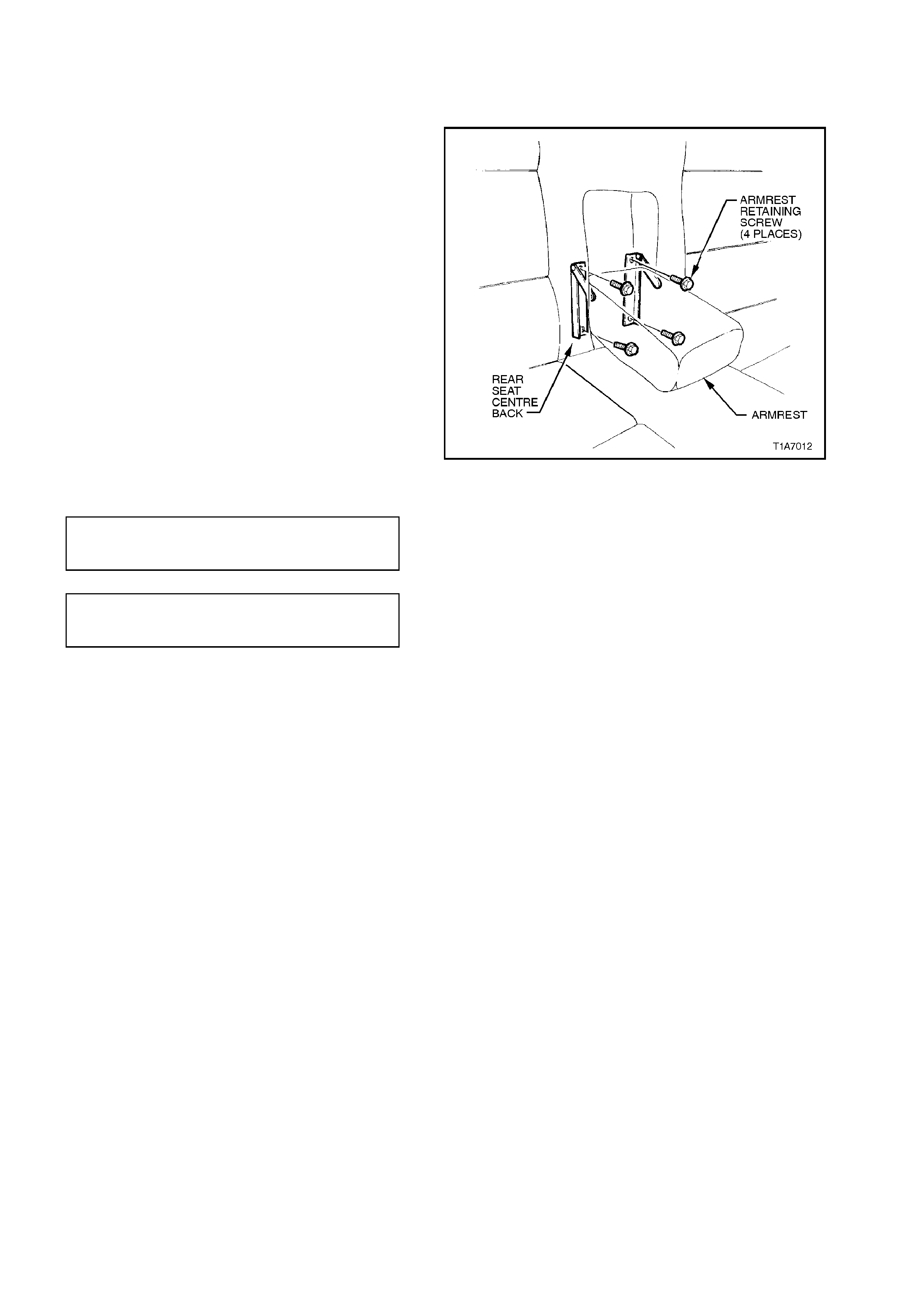
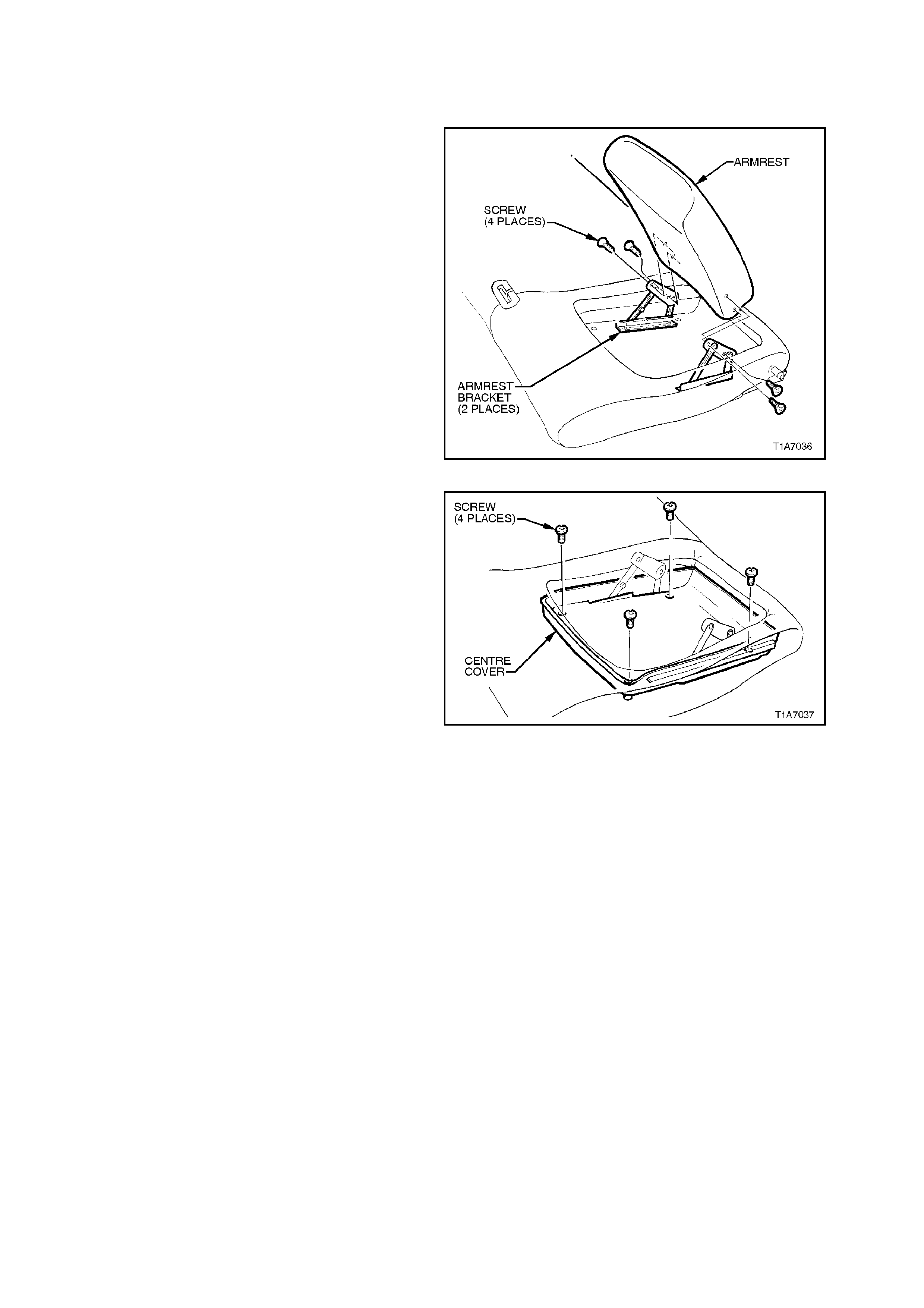
2.19 REAR SEAT BACK FLAP ARMREST - SEDAN
REMOVE
1. Lower armrest and move cloth trim to gain
access to the four armrest retaining screws.
2. Remove the f our ar m rest retaining screws and
remove armrest and hinge assembly.
3. Remove the four screws securing the armrest
to the hinge and remove armrest.
REINSTALL
Installation of the rear s eat back f lap armrest is the
reverse of the removal operation, noting the
following:
Ensure all bolts are tightened to the correct torque
specification
Figure 1A7-36
ARMREST TO HINGE
SECURING SCREWS
TORQUE SPECIFICATION 7 - 10 Nm
HINGE TO REAR SEAT BACK
FLAP RETAINING SCREW
TORQUE SPECIFICATION 3 - 5 Nm
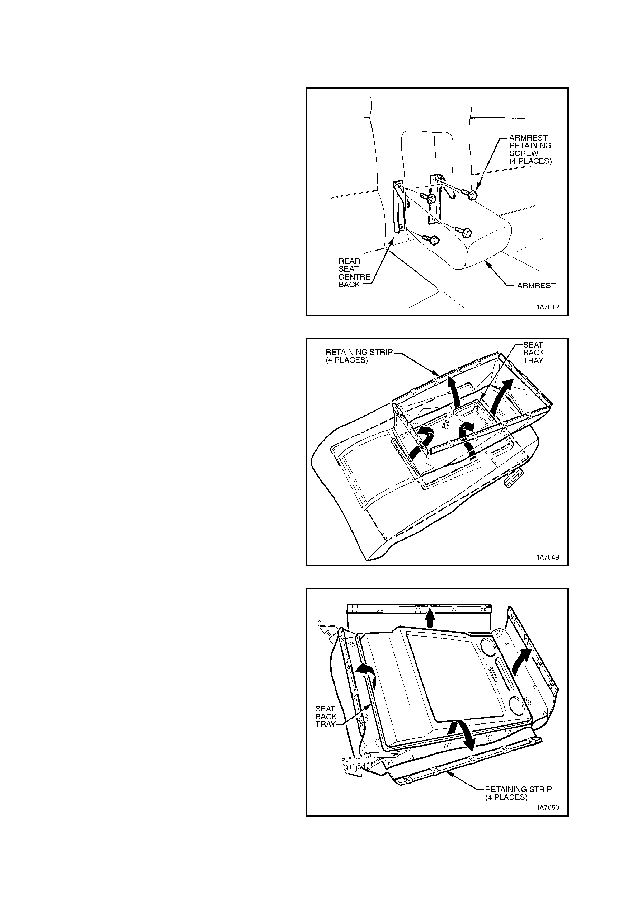
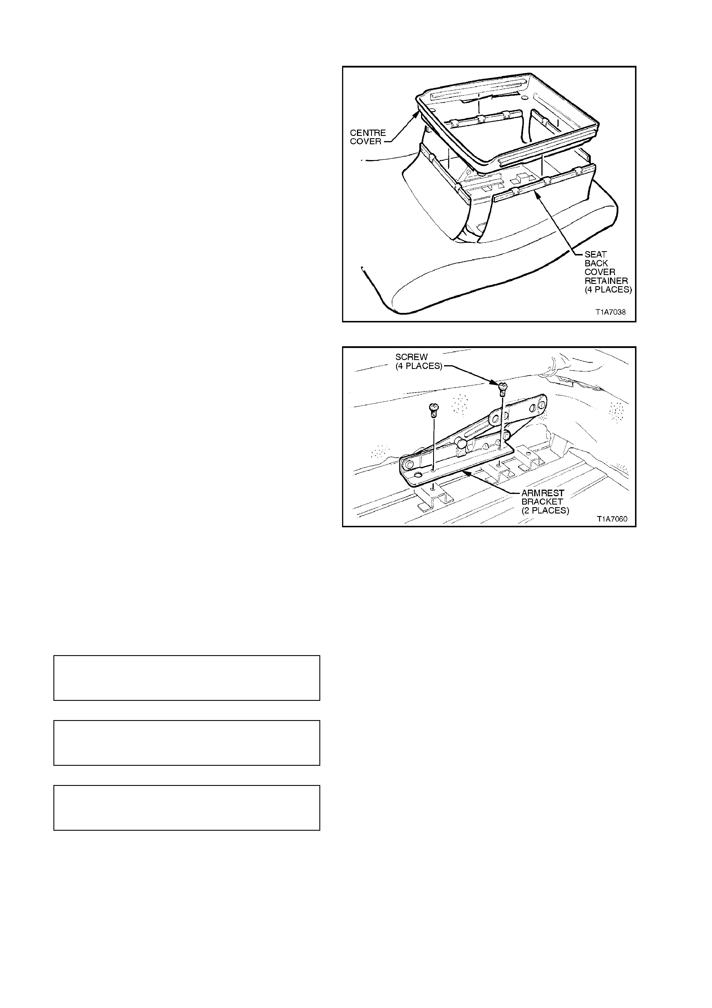
2.20 REAR SEAT BACK CENTRE COVER AND PAD ASSEMBLY - SEDAN
REMOVE
1. Remove rear seat c entre back assem bly, refer
to 2.18 REAR SEAT CUSHION AND BACK
ASSEMBLIES - SEDAN, in this Section.
2. Lower armrest and move cloth trim to gain
access to the four armrest retaining screws.
3. Remove the f our armr est r etaining s crews and
remove armrest and bracket assembly.
Figure 1A7-37
4. Pull the four seat cover retaining strips in the
centre of the seat back up and away from the
inside of the seat back tray, refer to Fig. 1A7-
37.
Figure 1A7-38
5. Pull the four seat cover retaining strips up from
the outer edge of the seat back tray, refer to
Fig. 1A7-39.
6. W hile f eeding the seat cover m aterial over the
release button and esc utcheon ass em bly, peel
the cover and pad assembly away from the
seat back tray.
Figure 1A7-39

REINSTALL
Reinstallation is the reverse of the removal
operation, noting the following:
Ensure all screws are tightened to the correct
torque specification
HINGE TO REAR SEAT FLAP
BACK RETAINING SCREW
TORQUE SPECIFICATION 3 - 5 Nm
2.21 RE AR SEAT BACK TRAY AND LOCK ACTUATOR - SEDAN
REMOVE
1. Remove rear seat back centre cover and pad
assembly, refer to 2.18 REAR SEAT
CUSHION AND BACK ASSEMBLIES -
SEDAN, in this Section.
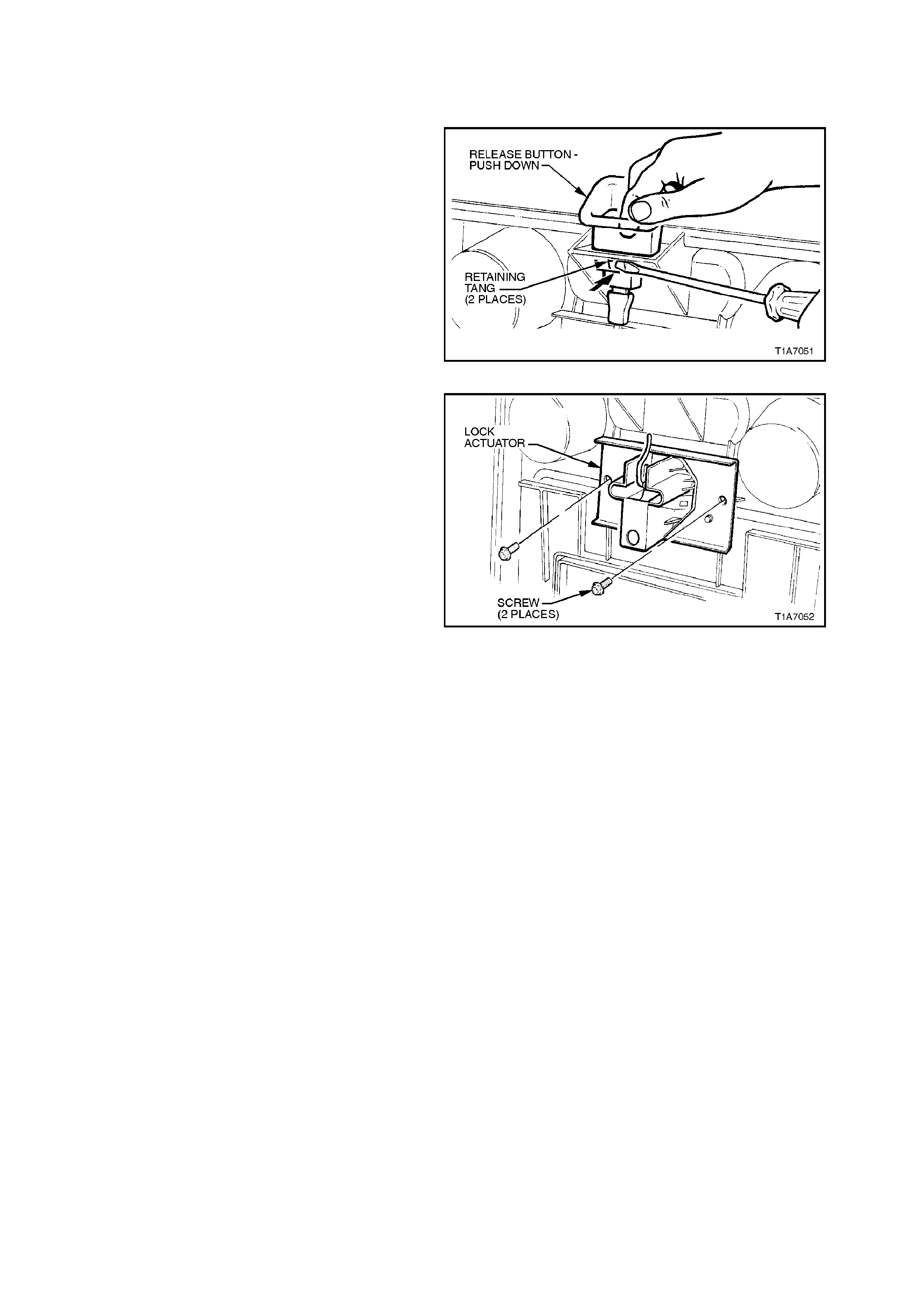
2. Disengage seat release button assembly
retaining tangs by pushing one of the tangs
through the seat back tray while pushing top of
button assembly forward. W hile holding top of
button, to prevent tang f r om r e-engaging, pus h
other tang in to disengage the release button.
Remove release button and escutcheon
assembly.
Figure 1A7-40
3. Remove the two screws securing the lock
actuator to the back tray and remove lock
actuator.
REINSTALL
Installation of the lock actuator is the revers e of the
removal procedure ensuring that the button
assembly and lock actuator rod are correctly
engaged.
Figure 1A7-41
2.22 RE AR SEAT BACK LOCK STRIKER - SEDAN
REMOVE
1. Remove left and right hand rear seat backs,
refer to 2.18 SEAT CUSHION AND BACK
ASSEMBLIES - SEDAN in this Section.
2. With centre seat back detached and lowered,
pry the two retaining clips securing the rear
seat back cover to the parcel shelf and remove
cover.
3. Remove the two sc rews securing the strik er to
the rear panel and remove striker.
Figure 1A7-42
REINSTALL
Installation of the rear seat lock striker is the
reverse of the rem oval procedure ensur ing that the
retaining screws are tightened to the corr ect torque
specification.
STRIKER RETAINING SCREW
TORQUE SPECIFICATION 25 - 35
Nm
2.23 REAR SEAT CUSHION - WAGON
REMOVE
1. Lift front of rear seat cushion slightly to gain access to rear seat cushion release handles, refer to Fig. 1A7-42.
2. From either the left or right side of seat, pull release handle downwards towards the floor, while at the same
time lifting the front of the rear seat cushion until lock mechanism is released.
3. Repeat step 2 for opposite side of seat.
4. Remove rear seat cushion assembly, taking care to pass centre seat belt assemblies through the elastic
retention loops on the rear seat cushion.
REINSTALL
1. Sit rear seat cushion into position and feed seat belt assemblies through the elastic retention loops.
2. Push rear seat cushion into back of seat and push down front of seat until locking mechanisms lock seat
cushion into position.
Figure 1A7-43

2.24 REAR SEAT BOLSTER - WAGON
REMOVE
1. Remove rear seat cushion, refer to
2.23 REAR SEAT CUSHION - WAGON in this
Section.
2. Lower rear seat back assembly.
3. Using a pair of pliers, squeeze tangs of the
upper bolster retaining clip together and pull
the bolster towards the front of the vehicle.
4. Lift bottom of bolster lower retaining tang
up and pull bolster forward, towards front of
vehicle.
REINSTALL
1. Insert bottom retaining tang of bols ter into s eat
back retaining bracket and push upper
retaining tab into retaining bracket.
2. Reinstall rear seat cushion, refer to
2.23 REAR SEAT CUSHION - WAGON in this
Section.
Figure 1A7-44
2.25 REAR SEAT BACK ASSEMBLIES - WAGON
REMOVE
1. Remove rear seat cushion, refer to
2.23 REAR SEAT CUSHION - WAGON in this
Section.
2. Remove rear seat back bolsters, refer to
2.24 REAR SEAT BOLSTER - WAGON in this
Section.
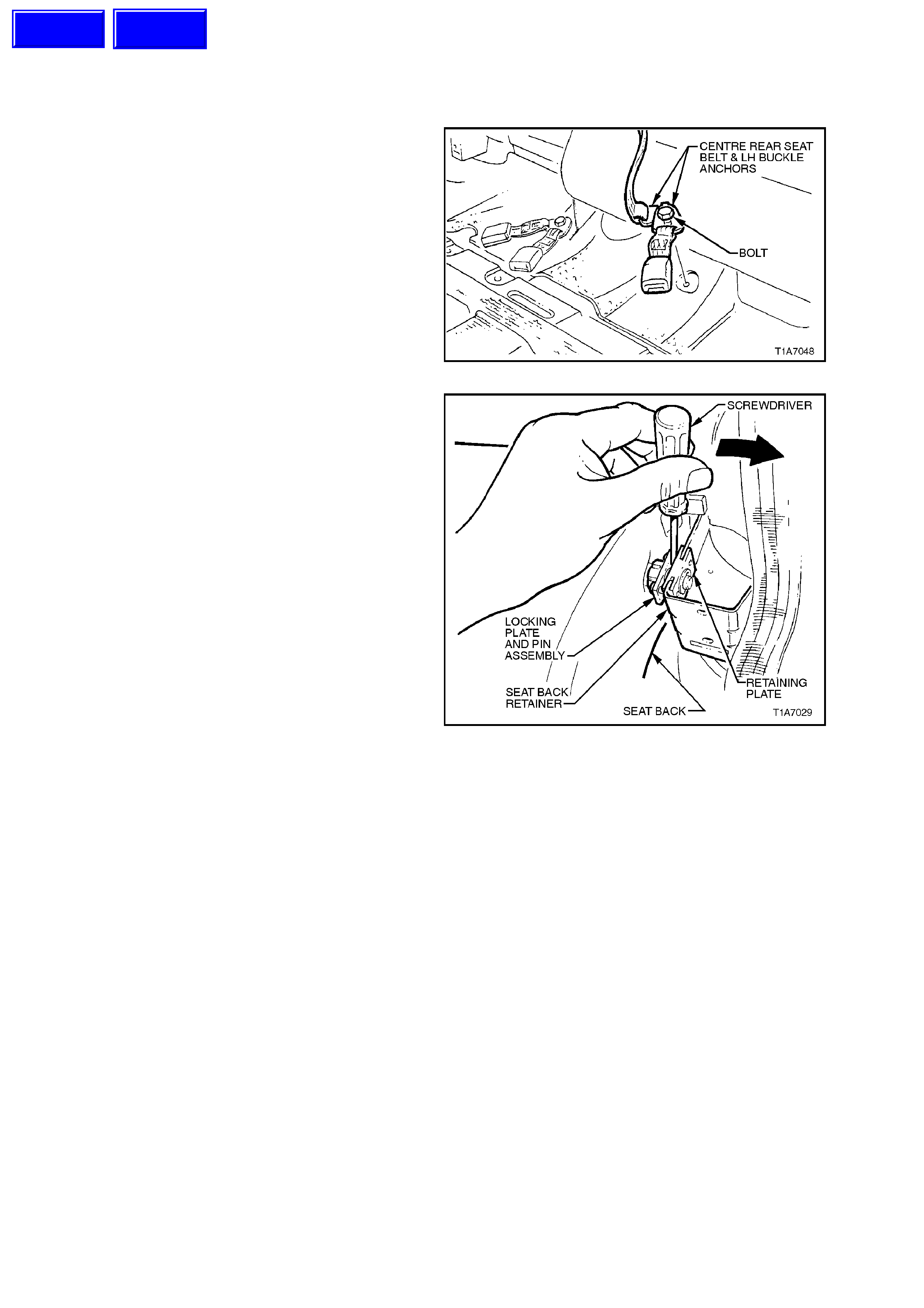
3. Remove the bolt securing the centre rear seat
belt and LH buckle anchors to the floor pan.
Figure 1A7-45
4. Unlatch and lower rear seat back assembly.
NOTE:
If seat back ass embly is not lowered, the seat back
locking plate and pin assembly will be damaged if
Step 5 is attempted.
5. Insert a screwdriver between seat back
retaining plate and locking plate and pin
assembly and gently prise apart to withdraw
pins from retaining plate.
6. Lift outer end of seat up out of seat back
retainer and pull seat back assembly towards
the door, withdrawing it from the seat back
centre hinge assembly.
7. Remove seat back.
Figure 1A7-46
REINSTALL
Installation is the revers e of the rem oval procedure
noting the following:
1. Install seat back in it’s lowered position.
2. Fold seat into upright position and locking
plate and pin assembly will automatically lock.
Techline
Techline
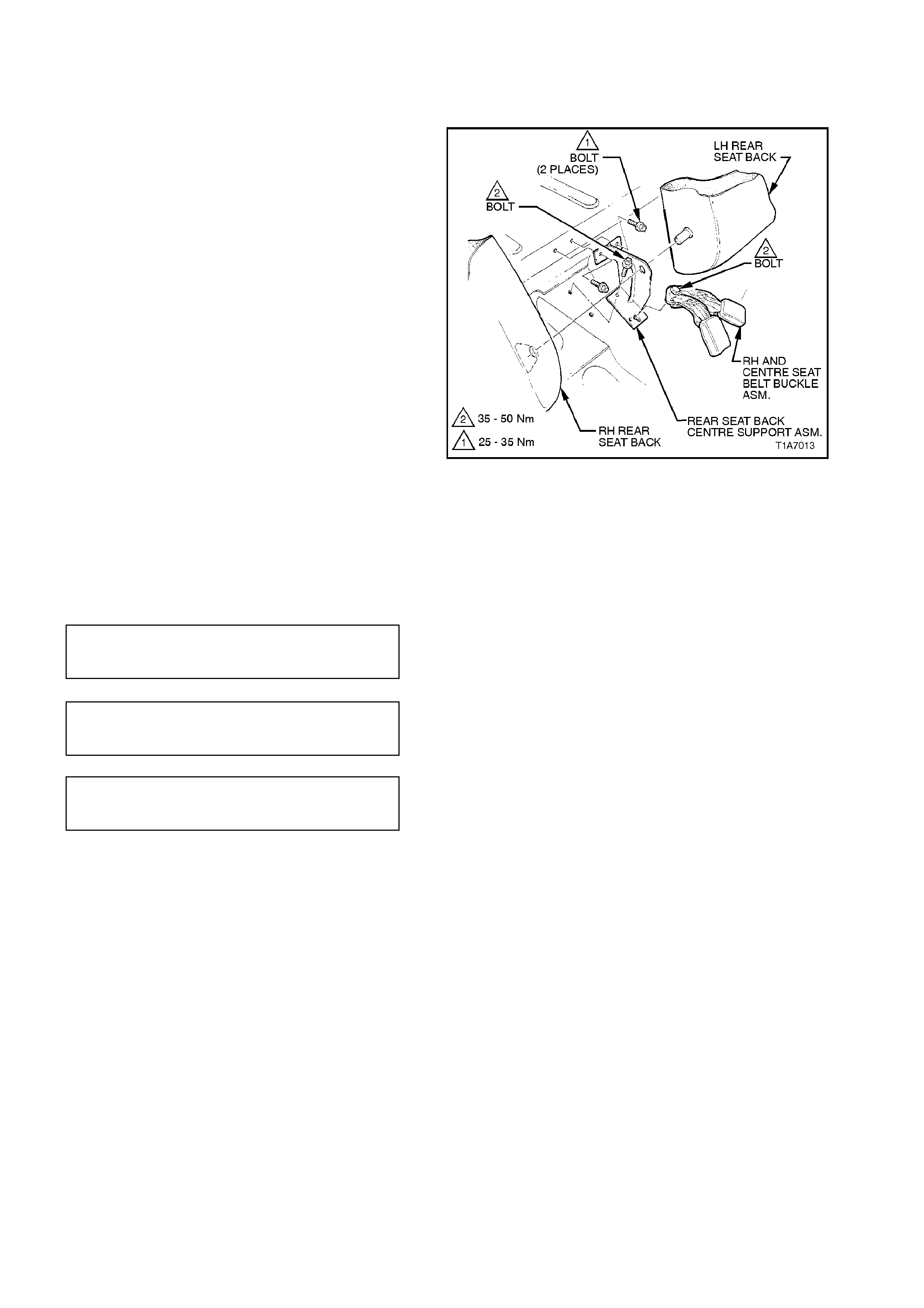
2.26 RE AR SEAT BACK CENTRE SUPPORT - WAGON
REMOVE
1. Remove rear seat cushion assembly, refer to
2.23 REAR SEAT CUSHION - WAGON in this
Section.
2. Remove rear seat back bolsters, refer to
2.24 REAR SEAT BOLST ER - WAGON in this
Section.
3. Remove rear seat back assemblies, refer to
2.25 REAR SEAT BACK ASSEMBLIES -
WAGON in this Section.
4. Remove the RH and centre seat belt buckle
assembly anchor bolt, refer to Fig. 1A7-47.
5. Remove the four bolts securing the seat back
centre support assembly to the floor pan, refer
1A7-47.
6. Remove centre support assembly.
Figure 1A7-47
REINSTALL
Installation of the rear seat back centre support is
the reverse of the removal operation, noting the
following:
Ensure all bolts are fastened to the correct torque
specifications
SEAT BELT BUCKLE ANCHOR
SECURING BOLT
TORQUE SPECIFICATION 35 - 50 Nm
CENTRE HINGE LOWER
SECURING BOLT
TORQUE SPECIFICATION 35 - 50 Nm
CENTRE HINGE UPPER
SECURING BOLT
TORQUE SPECIFICATION 25 - 35 Nm
2.27 REAR SEAT BACK COVER AND PAD ASSEMBLY - WAGON
REMOVE
NOTE:
When performing this service operation on Berlina
Models, the rear seat centre cover blanking plugs
will become damaged and will need to be replaced.
Therefore, before carrying out this service
operation, order four new blanking plugs from your
authorised Holden parts outlet.
1. Remove rear seat back, refer to
2.25 REAR SEAT BACK ASSEMBLIES -
WAGON in this Section.
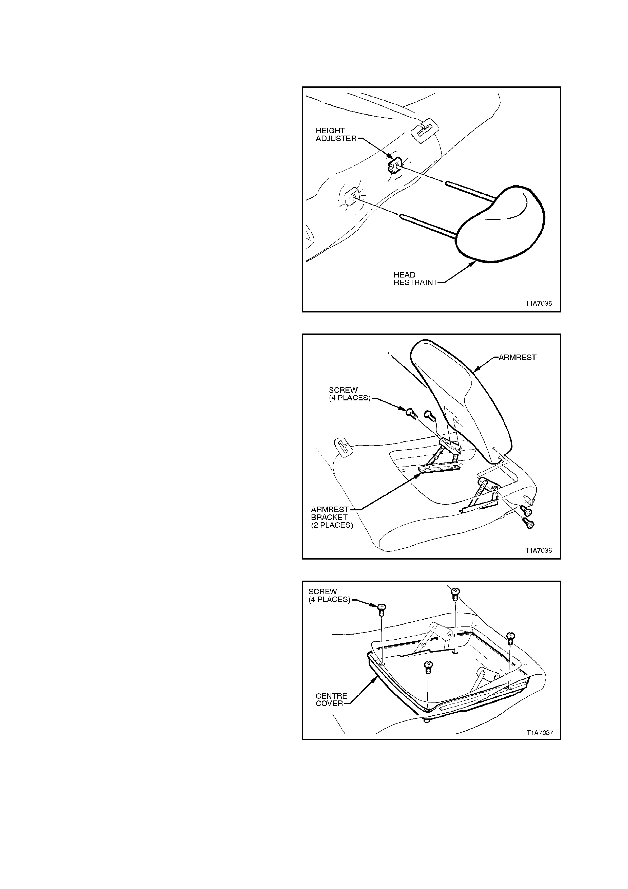
2. While holding the head restraint height
adjuster lock in, pull head restraint completely
out of guide.
Figure 1A7-48
3. On the LH rear seat back, remove the four
screws securing the armrest to armrest
bracket and remove armrest.
Figure 1A7-49
4. Pull the four blank ing plugs from the rear seat
back cover by inserting a scribe or small
screwdriver into the centre of the plug and
pulling them free. Take care not to damage
seat back cover.
NOTE:
The four blanking plugs will be dam aged dur ing this
operation and therefore must be replaced.
5. On the LH rear seat back, remove the four
screws securing the centre cover to the seat
back frame.
Figure 1A7-50
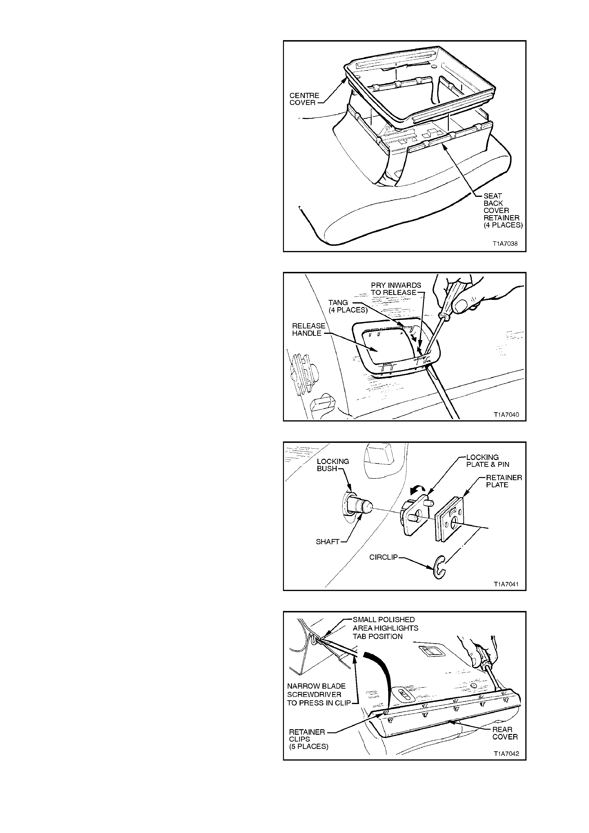
6. On the LH rear seat back , lift the centre cover
up and pull the seat back cover retainer away
from the four s ides of the centre c over , ref er to
Fig. 1A7-51.
Figure 1A7-51
7. Disengage the corners of the release handle
by inserting a screwdriver under one of the
corners of the release handle assembly while
at the same time prising the retaining tang
towards the centre of the release handle.
8. With one corner of the release handle
disengaged, hold the handle in the release
position (up) and disengage the remaining
three tangs by prising them inwards using a
screwdriver (towards centre of handle).
Remove handle assembly.
Figure 1A7-52
9. Remove the c irclip fr om the s eat back retainer
assembly and remove the r etainer plate ( metal
piece) from shaft.
10. Remove the retainer locking plate and pin by
twisting it off the locking bush.
NOTE:
The locking bush does not have to be removed
unless it is being replaced. This c an be ac hieved by
simply levering it off the shaft.
Figure 1A7-53
11. Remove the rear cover from the rear seat
back by inserting a small screwdriver under
the rear seat back cover and prying cover
away from seat back, refer to Fig. 1A7-54.
Figure 1A7-54
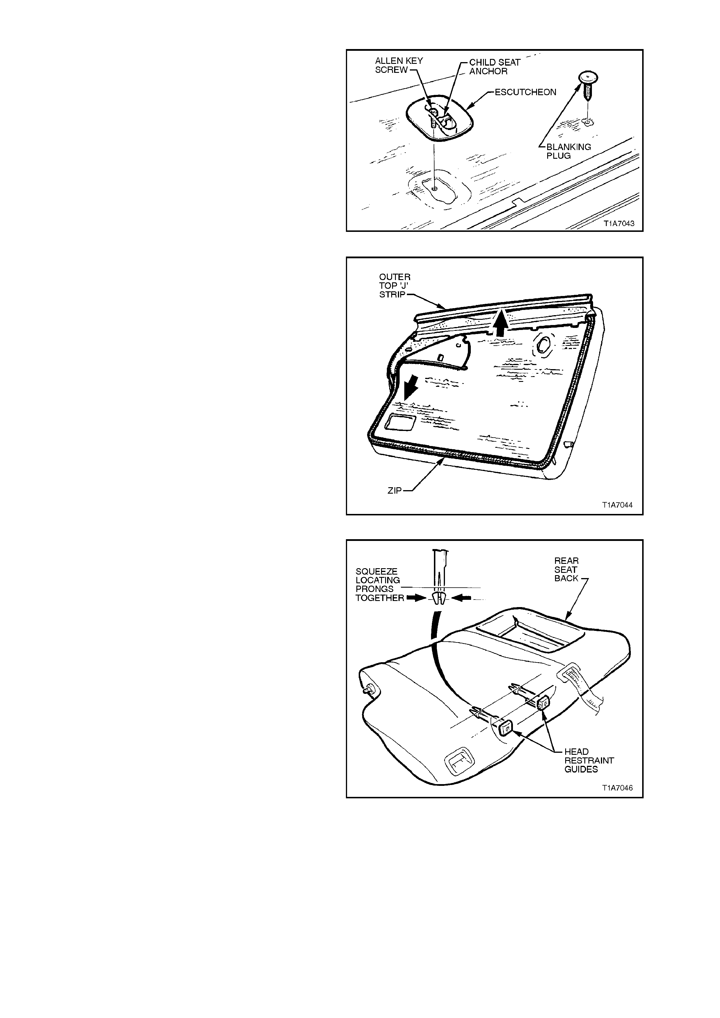
12. On the LH rear seat back, remove the child
seat anchor bolt to the rear seat back and
remove child seat anchor and escutcheon.
13. Prise c hild seat anc hor blanking plug fr om rear
seat back.
Figure 1A7-55
14. Pull the outer top ‘J’ strip from the seat back
frame, refer to Fig. 1A7-55.
NOTE:
To ease in the removal of the top ‘J’ strip, gently
lever strip away from frame using a screwdriver.
15. Unzip seat trim cover.
Figure 1A7-56
16. Rem ove the head restraint guides by reaching
in between seat back frame and pad
assembly, squeezing the head restraint guide
locating prongs together and pulling the top of
the guide (from outside of seat) up and out of
the seat back assembly.
Figure 1A7-57
17. Remove cover and pad away from seat back
frame, noting the following:
Feed the seat back c over material through the
seat back release button and escutcheon
assembly.
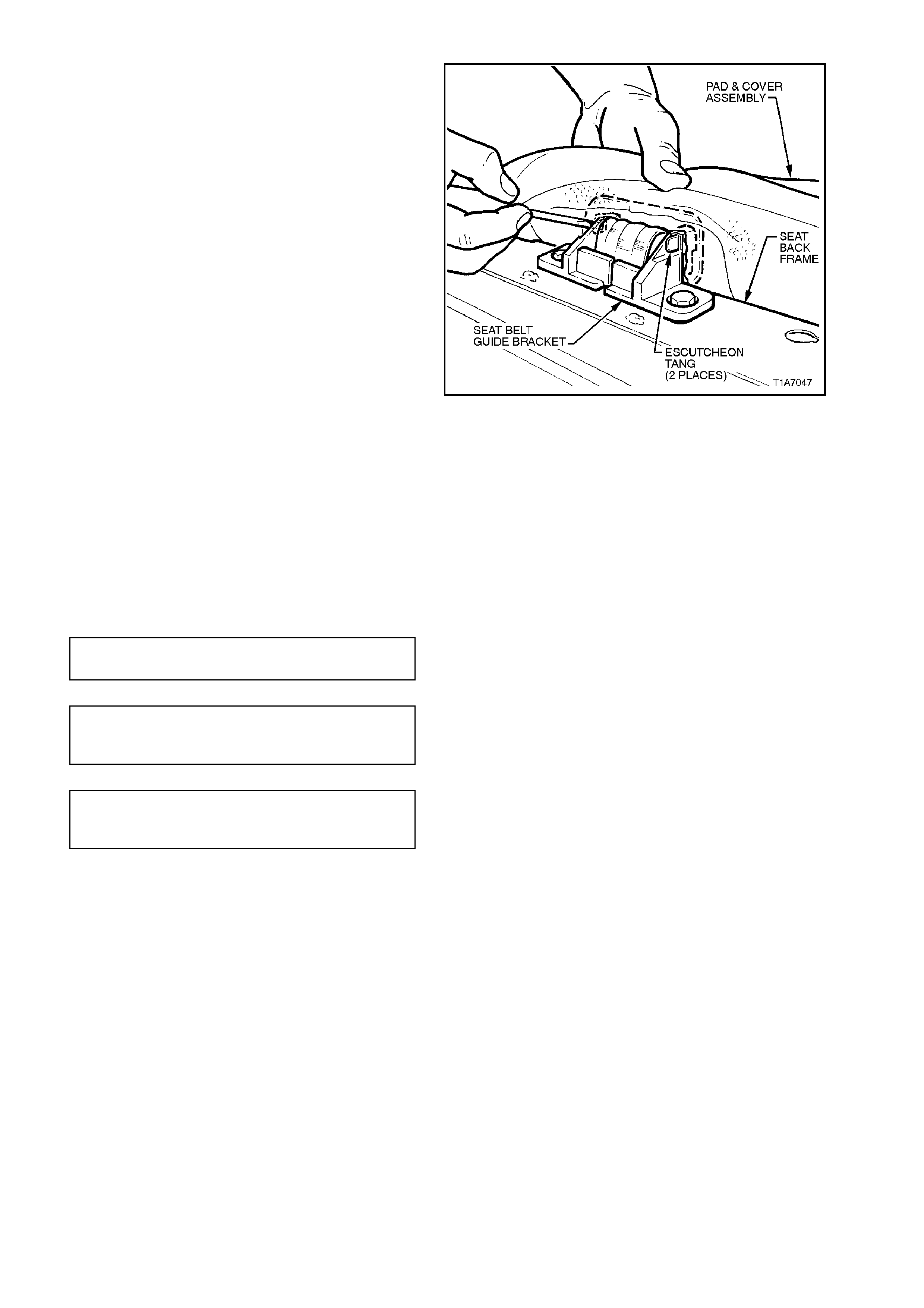
On the LH rear seat back , release centre seat
belt escutcheon from inside seat back by
pushing tangs of escutcheon through the seat
belt guide brack et assem bly, refer to Fig. 1A7-
58.
Figure 1A7-58
REINSTALL
Installation of the rear seat cover and pad
assembly is the reverse of the removal procedure,
noting the following:
1. If the locking bush for the seat back retainer
was removed, ensure that the retaining
grooves on the m ating shaft are c lean. (Plast ic
residue on shaft).
2. Tighten all fasteners to the correct torque
specification.
CHILD SEAT ANCHOR BOLT 15.0
TORQUE SPECIFICATION Nm
CENTRE COVER TO FRAME
RETAINING SCREW 2.5 Nm
TORQUE SPECIFICATION
ARMREST TO BRACKET
RETAINING SCREW 4.0 Nm
TORQUE SPECIFICATION
2.28 RE AR SEAT BACK LOCK, ACTUATOR, CABLE AND RELEASE BUTTON - WAGON
REMOVE
1. Remove rear seat back cover and pad
assembly, refer to 2.27 REAR SEAT BACK
COVER AND PAD ASSEMBLY - WAGON in
this Section.
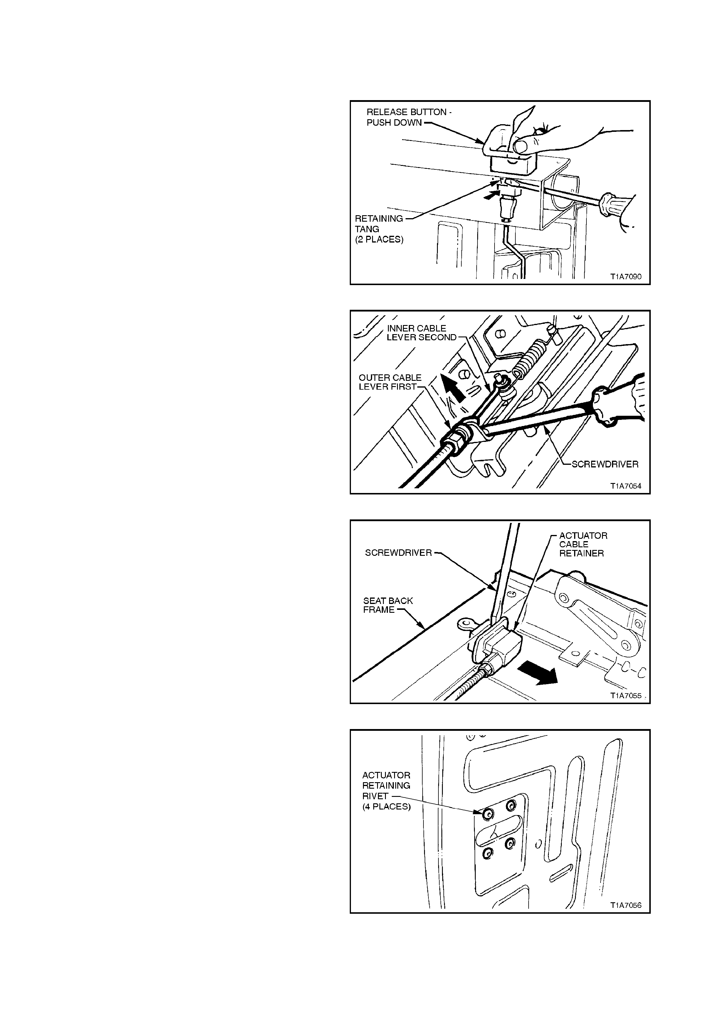
2. Using a screwdriver, depress tangs of release
button and pull release button from seat
frame.
Figure 1A7-59
3. On the LH rear seat back, lever outer part of
actuator cable from actuator and then the
inner part of cable from the actuator using a
small screwdriver.
Figure 1A7-60
4. On the LH rear seat back , lever actuator cable
retainer fr om s eat back f ram e with the aid of a
screwdriver.
NOTE:
When levering the actuator cable retainer f rom s eat
back frame, it is highly possible that the retaining
tangs will be damaged. If this occurs, the actuator
cable must be replaced.
5. On the LH rear seat back, remove tape
securing actuator cable to seat back frame
and remove cable.
NOTE:
Remember location off tape for reinstallation. Figure 1A7-61
6. From the rear side of the seat back, drill the
heads off the four rivets retaining the actuator
to the seat back frame, using a 6mm drill bit.
7. Knock body of rivet through seat back frame
and remove actuator.
Figure 1A7-62
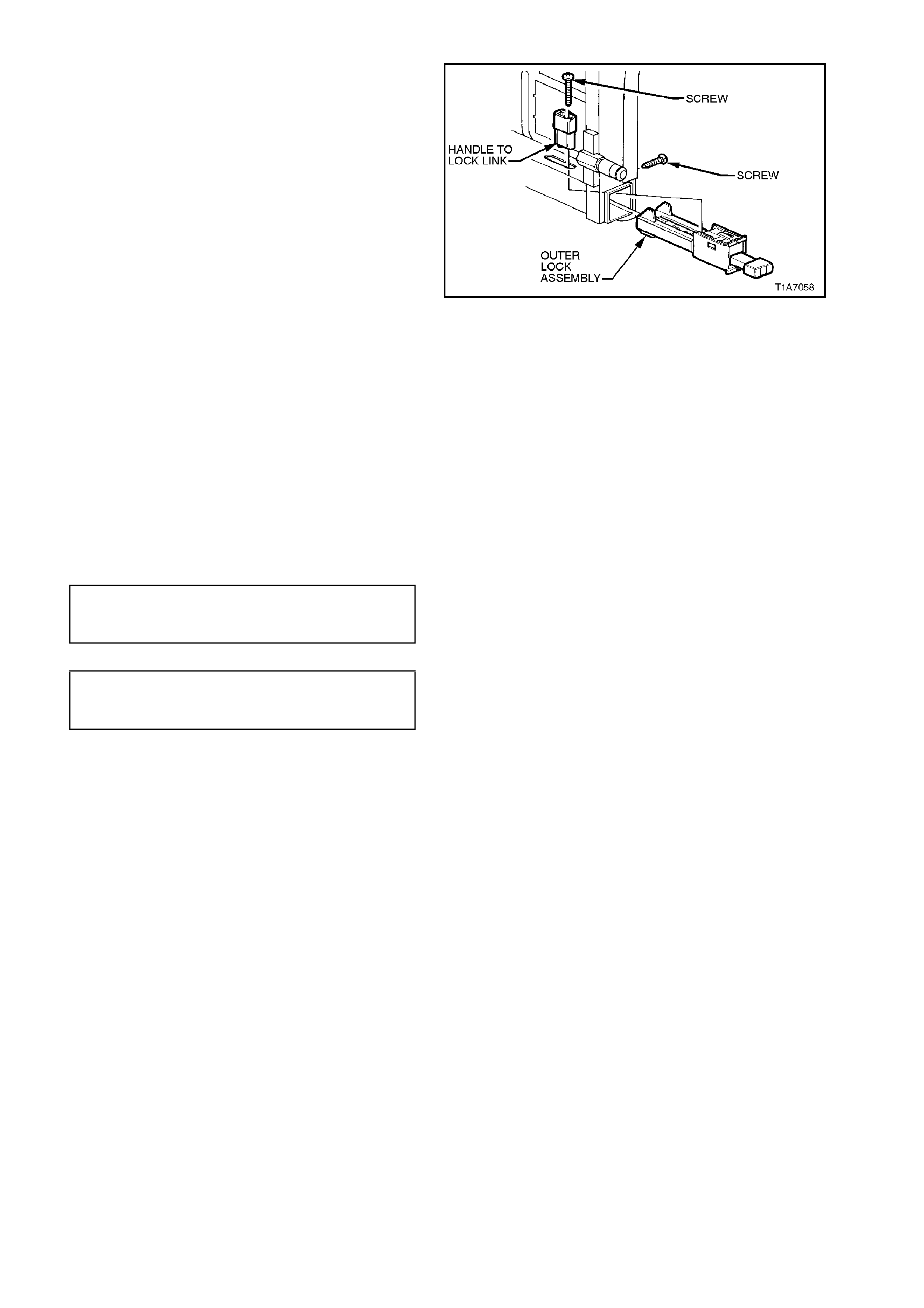
8. Remove the allen key screw from the release
handle to lock link and remove link. Slide lock
out of seat back frame.
Figure 1A7-63
REINSTALL
Installation of the rear seat back actuator, cable
and release button is the reverse of the removal
procedure, noting the following:
1. Use 3/16” steel pop rivets (not aluminium) to
retain the actuator to the seat back.
2. Place the actuator lock in the up position
before connecting the actuator cable.
3. Ensure the release button and the actuator
rod are aligned correctly.
4. Ensure all fasteners are tightened to the
correct torque specification:
SEAT BACK LOCK
ALLEN KEY SCREW 3.0 Nm
TORQUE SPECIFICATION
LH SEAT BACK LOCK
RETAINING SCREW 3.0 Nm
TORQUE SPECIFICATION
5. Check the function of the seat back lock by
operating the seat back lock at least three
times while observing the following:
•Ensure the locking pin on the centre lock
assembly engages fully with the rear seat
back centre s upport ass em bly when it is in the
lock position.
•Ensure the release button, when in the lock
position, sits flush with the escutcheon.
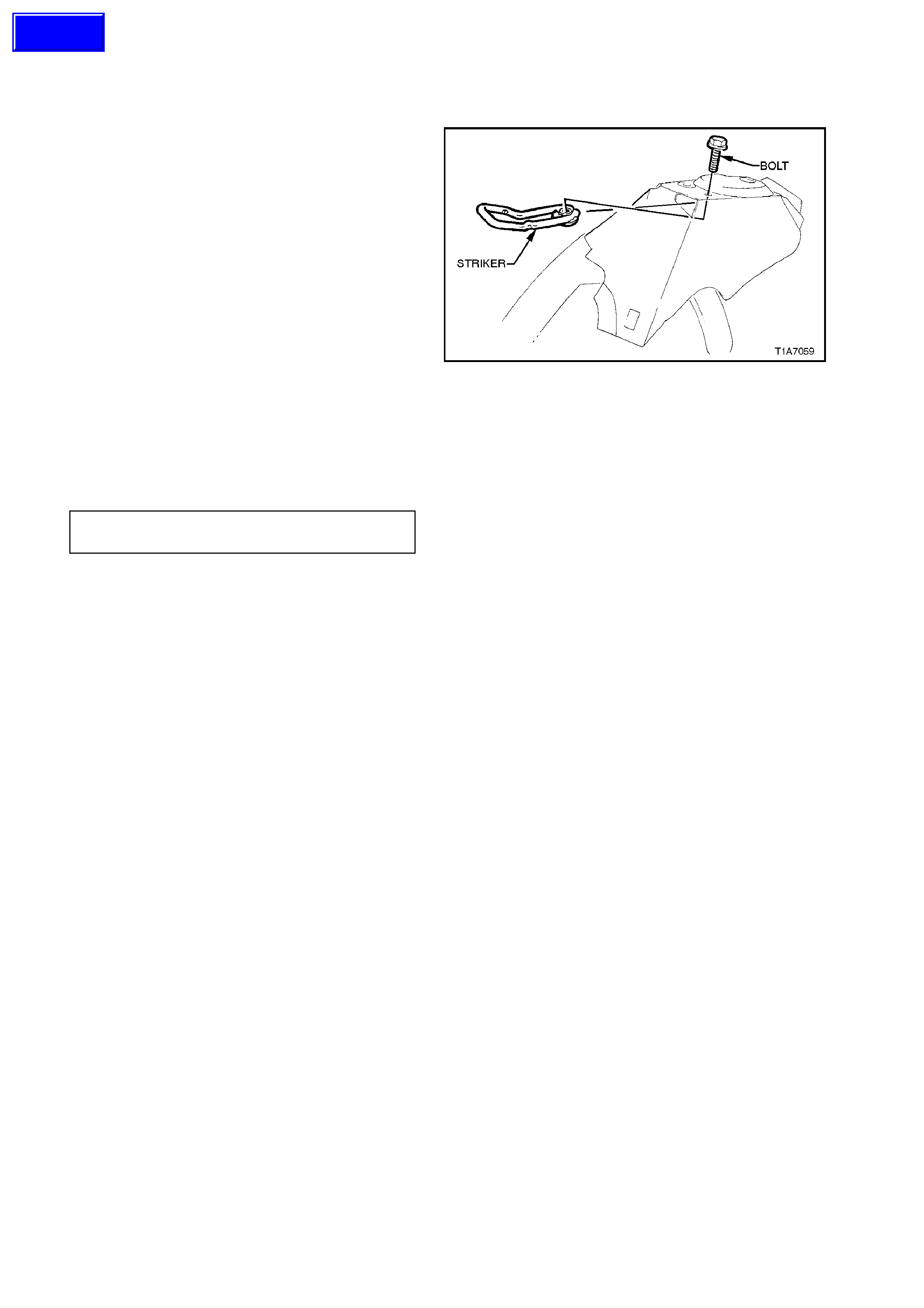
2.29 RE AR SEAT BACK LOCK STRIKER - WAGON
REMOVE
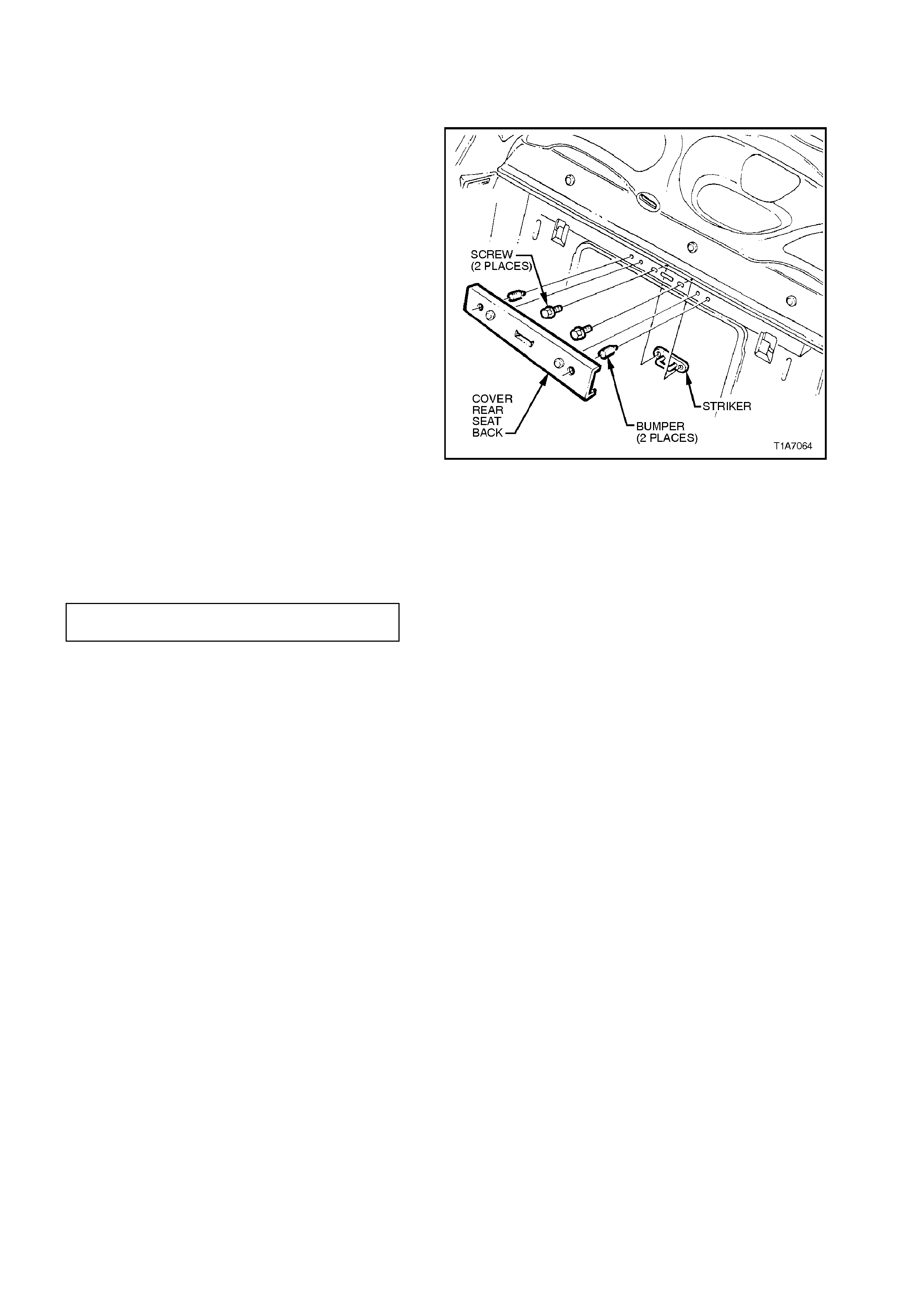
1. Remove carpet from rear quarter inner panel,
refer to Section 1A1 BODY.
2. Remove bolt securing the striker to the rear
quarter inner panel and remove striker and
bumper.
Figure 1A7-64
REINSTALL
Installation is the revers e of the rem oval procedure
noting the following:
Ensure all fasteners are tightened to the correct
torque specifications.
STRIKER RETAINING BOLT 25 - 35
TORQUE SPECIFICATION Nm
Techline
2.30 RE AR SEAT BACK ARMREST - W AGON
REMOVE
NOTE:
When performing this service operation, the rear
seat centre cover blanking plugs will become
damaged and will need to be replaced. Therefore,
before carrying out this service operation, order
four new blanking plugs from your authorised
Holden parts outlet.
1. Remove the four screws securing the armrest
to armrest bracket and remove armrest.
Figure 1A7-65
2. Pull the four blank ing plugs from the rear seat
back cover by inserting a scribe or small
screwdriver into the centre of the plug and
pulling them free. Take care not to damage
seat back cover.
NOTE:
The four blanking plugs will be dam aged dur ing this
operation and therefore must be replaced.
3. On the LH rear seat back, remove the four
screws securing the centre cover to the seat
back frame.
Figure 1A7-66
4. Lift the centre cover up and pull the seat back
cover retainer away from the four sides of the
centre cover, refer to Fig. 1A7-67.
Figure 1A7-67
5. Remove the four screws securing the armrest
brackets to the seat back frame and remove
the armrest brackets.
Figure 1A7-68
REINSTALL
Installation of the rear seat back armrest is the
reverse of the removal procedure, noting the
following:
Tighten all fasteners to the correct torque
specification.
ARMREST BRACKET TO FRAME
RETAINING SCREW 4.0 Nm
TORQUE SPECIFICATION
CENTRE COVER TO FRAME
RETAINING SCREW 2.5 Nm
TORQUE SPECIFICATION
ARMREST TO BRACKET
RETAINING SCREW 4.0 Nm
TORQUE SPECIFICATION
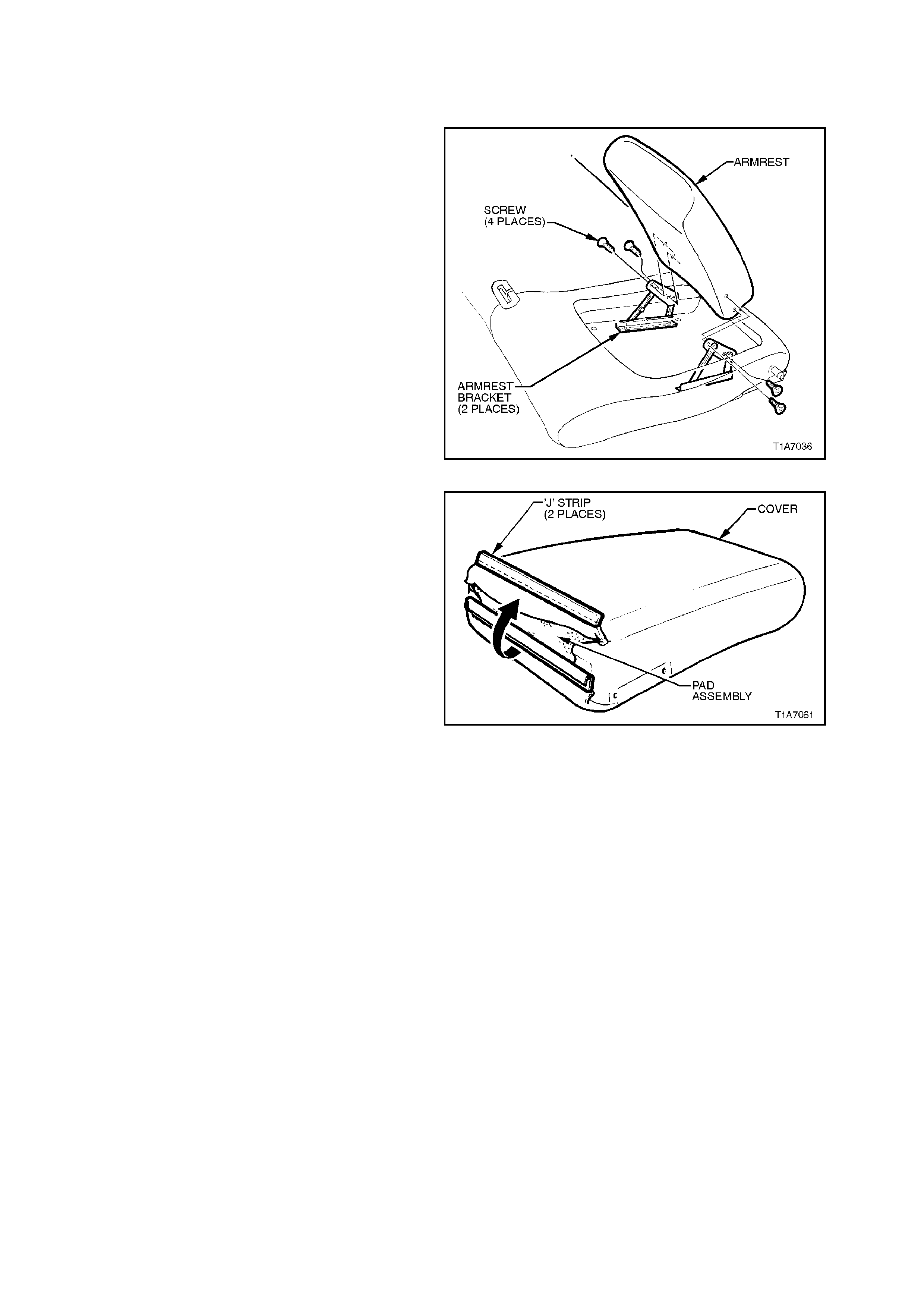
2.31 REAR SEAT BACK ARMREST COVER - WAGON
REMOVE
1. Remove the four screws securing the armrest
to armrest bracket and remove armrest.
Figure 1A7-69
2. At the bottom edge of the armrest, separate
the two ‘J’ strips by pulling the top layer over
the bottom layer of the cover.
3. Peel the armrest cover away from the pad
assembly.
Figure 1A7-70
REINSTALL
Installation of the rear seat back armrest cover is
the reverse of the removal procedure.

2.32 FRONT SEAT BELT RETRACTOR AND HEIGHT ADJUSTER ASSEMBLY
REMOVE
1. Remove front seat guide rail covers, refer to
2.2 FRONT SEAT GUIDE RAIL COVERS in
this Section.
2. Remove cap and bolt securing the seat belt
lower anchor to the floor pan, refer to Fig.
1A7-70.
3. Remove rocker panel cover, refer to
Section 1A1 UNDERBODY.
4. Remove upper and lower B pillar trims, refer
to Section 1A8, HEADLINING AND REAR
END TRIM. Feed seat belt sash, buckle and
anchor through upper B pillar trim.
5. Remove bolt securing seat belt guide to B
pillar or, on Calais with seat belt height
adjuster, from seat belt height adjuster, refer
to Fig. 1A7-70.
6. Remove the two screws securing the
intermediate wire type sash guide to the B
pillar and remove guide.
7. Remove the bolt securing the front seat belt
retractor assembly to the B pillar and remove
seat belt retractor assembly.
8. Calais only, rem ove the two bolts secur ing the
seat belt height adjuster to the B pillar and
remove height adjuster.
REINSTALL
Installation is the reverse of the rem oval operation,
noting the following:
1. Ensure all seat belt bolts are hand tightened a
minimum of 5 turns before using tools.
2. Tighten all bolts to the correct torque
specification.
SEAT BELT SECURING BOLT
TORQUE SPECIFICATION 35 - 50
Nm
Techline

Figure 1A7-71
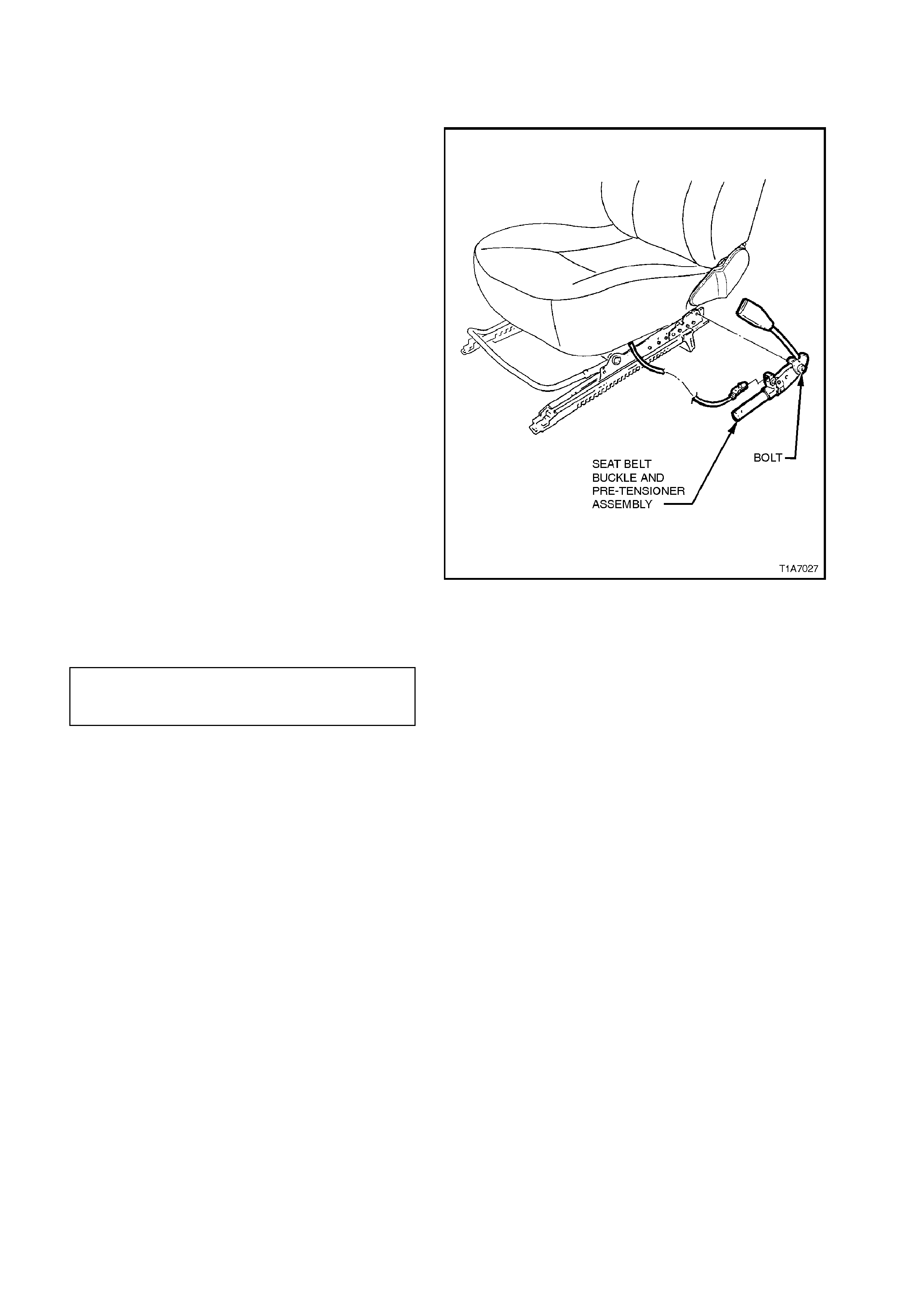
2.33 FRONT SEAT BELT BUCKLE AND PRE-TENSIONER ASSEMBLY
REMOVE
NOTE 1:
If a seat belt pre-tensioner is deployed, the seat
belt pre-tensioner assembly together with the seat
adjuster and guide rail assembly must be replaced.
NOTE 2:
If dispos ing of an undeployed seat belt buck le and
pre-tensioner assembly, refer to the disabling
procedure in Section 12M SUPPLEMENTAL
RESTRAINT SYSTEM.
1. Adjust seat to its rear most position and
disconnect battery.
2. Disconnect wiring harness connector from
seat belt buckle and pre-tensioner assembly.
3. Remove bolt securing seat belt buckle and
pre-tensioner assembly to frame and remove
seat belt buckle and pre-tensioner assembly.
REINSTALL
Installation is the reverse of the removal operation,
noting the following:
1. When installing seat belt buckle and pre-
tensioner assembly, ensure that the front
locating pin is aligned with seat frame.
2. Ensure all bolts are fastened to the correct
torque specifications.
SEAT BELT BUCKLE AND PRE-
TENSIONER ASSEMBLY BOLT 45 Nm
TORQUE SPECIFICATION
Figure 1A7-72

2.34 LEFT AND RIGHT HAND REAR SEAT BELT RETRACTOR ASSEMBLY - SEDAN
REMOVE
1. Remove rear seat cushion and either left or
right hand back seat assembly as applicable,
refer to 2.18 REAR SEAT CUSHION AND
BACK ASSEMBLIES - SEDAN.
2. Remove bolt securing the rear seat belt lower
anchor to the floor pan, refer to Fig. 1A7-72.
3. Remove seat belt escutcheon from C pillar
trim panel by gently prising the lower front of
the escutcheon away from trim.
NOTE:
The seat belt escutcheon may break if the upper
section is pried from the C pillar trim panel.
4. Remo ve C pillar trim panel assem bly, ref er to
Section 1A8 HEADLINING AND REAR END
TRIM. Feed seat belt sash, buckle, anchor
and escutcheon through C pillar panel trim.
5. Remove bolt securing sash guide to the C
pillar, refer to Fig. 1A7-73.
6. Remove bolt securing the rear seat belt
retractor assembly to the rear quarter inner
panel and remove seat belt retractor
assembly, refer to Fig. 1A7-73.
REINSTALL
Reinstallation is the reverse of the removal
operation, noting the following:
1. Ensure all seat belt bolts are hand tightened a
minimum of 5 turns before using tools.
2. Ensure that the threads of all seat belt lower
securing bolts are adequately sealed with a
non hardening sealer, to Holden’s
specification HN 1005 or HN 1044, refer to
Fig. 1A7-73.
3. Tighten all bolts to the correct torque
specification.
SEAT BELT SECURING BOLT
TORQUE SPECIFICATION 35 - 50
Nm
4. When installing the seat belt escutcheon onto
the C pillar, insert the rear upper clips of the
escutcheon into the C pillar then gently push
escutcheon into C pillar.
Techline
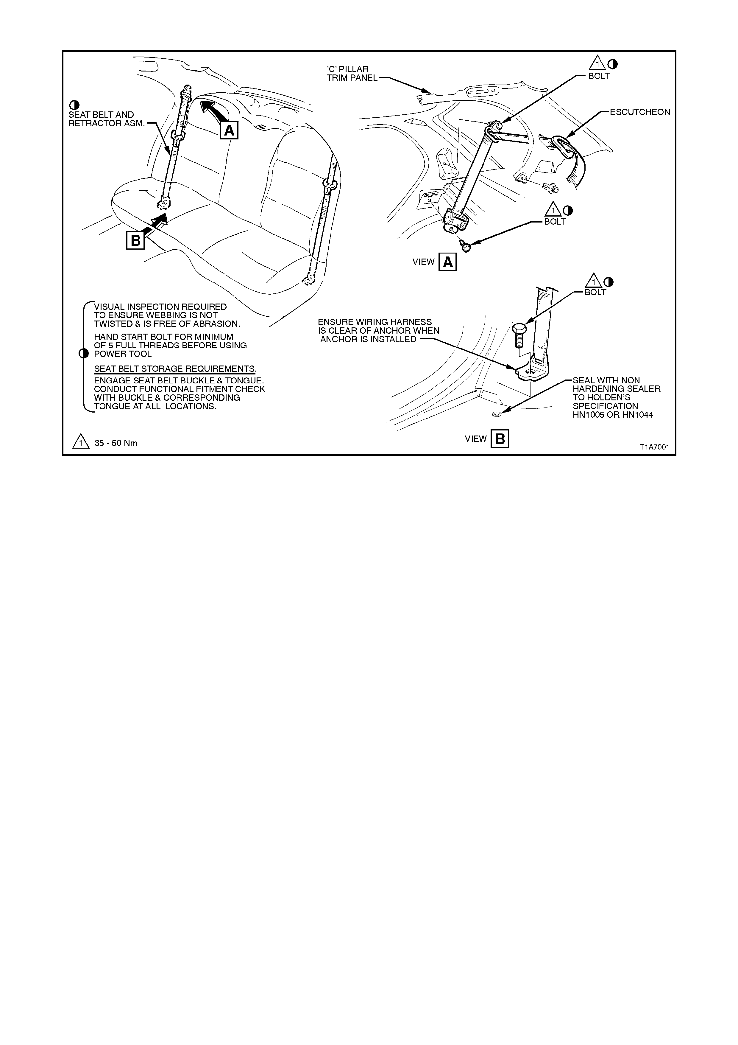
Figure 1A7-73

2.35 CENTRE REAR SEAT BELT RETRACTOR ASSEMBLY - SEDAN
REMOVE
1. Remove rear seat cushion, refer to
2.18 REAR SEAT CUSHION AND BACK
ASSEMBLIES - SEDAN in this Section.
2. Remove bolt securing the rear seat belt lower
anchor to the floor pan, refer to Fig. 1A7-73.
3. Detach and lower centre seat back assembly.
4. Gently prise front lower seat belt escutcheon
from parcel shelf.
5. Remove parcel shelf trim, refer to
Section 1A8 HEADLINING AND REAR END
TRIM. Feed seat belt sash, buckle, anchor
and escutcheon through parcel shelf trim.
6. 6. Remove bolt securing the centre seat belt
retractor assembly to the back panel and
remove seat belt retractor assembly, refer
Fig. 1A7-73.
REINSTALL
Installation of the centre rear seat belt retractor
assembly is the reverse of the removal operation,
noting the following:
1. Ensure all seat belt bolts are hand tightened a
minimum of 5 turns before using tools.
2. Ensure that the threads of all seat belt lower
securing bolts are adequately sealed with a
non hardening sealer, to Holden specification
HN 1005 or HN 1044, refer Fig. 1A7-74.
3. Tighten all bolts to the correct torque
specification.
SEAT BELT SECURING BOLT
TORQUE SPECIFICATION 35 - 50
Nm

2.36 LEFT HAND AND CENTRE REAR SEAT BELT BUCKLE ASSEMBLY - SEDAN
REMOVE
1. Remove rear seat cushion, refer to
2.18 REAR SEAT CUSHION AND BACK
ASSEMBLIES - SEDAN in this Section.
2. Remove bolt securing the rear seat belt buckle
anchor to the floor pan, refer to Fig. 1A7-74.
REINSTALL
Installation is the reverse of the rem oval operation,
noting the following:
1. Ensure all seat belt bolts are hand tightened a
minimum of 5 turns before using tools.
2. Ensure that the threads of seat belt buckle
anchor securing bolt is adequately sealed with
a non hardening sealer, to Holden’s
specification HN 1005 or HN 1044, refer Fig.
1A7-74.
3. Tighten all bolt to the correct torque
specification.
SEAT BELT BUCKLE ANCHOR
SECURING BOLT
TORQUE SPECIFICATION 35 - 50 Nm
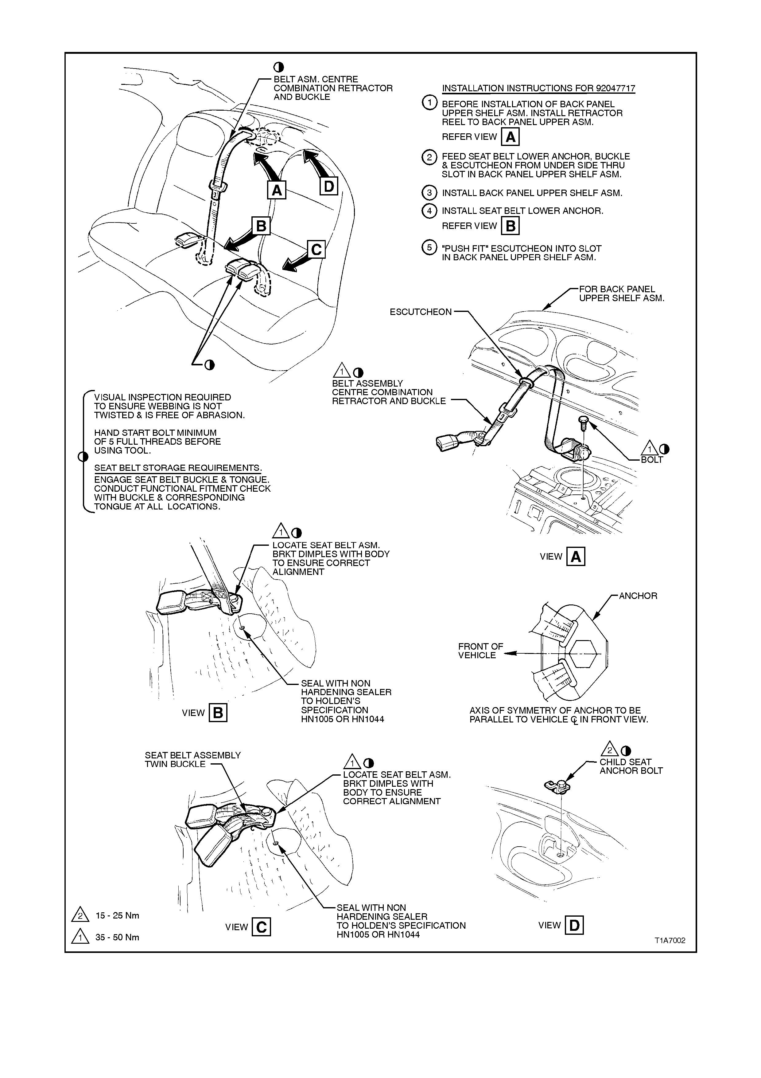
Figure 1A7-74
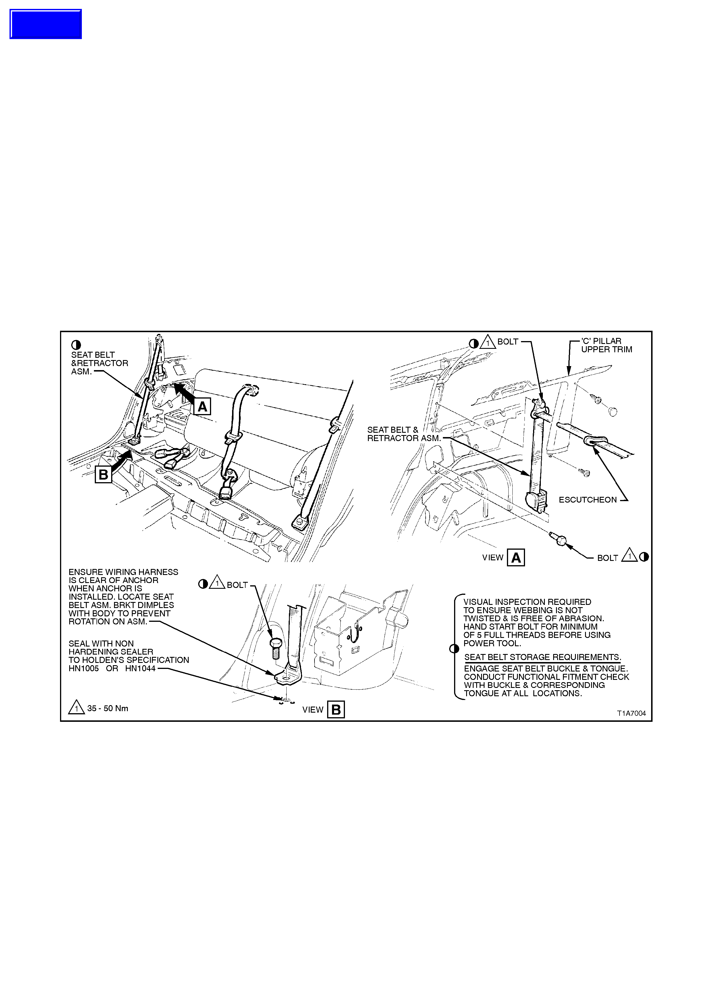
2.37 LEFT AND RIGHT HAND REAR SEAT BELT RETRACTOR ASSEMBLY - WAGON
REMOVE
1. Remove rear seat cushion, refer to 2.23 REAR SEAT CUSHION - WAGON in this Section.
2. Remove rear seat back bolsters, refer to 2.24 REAR SEAT BOLSTER - WAGON in this Section.
3. Remove bolt securing the rear seat belt lower anchor to the floor pan, refer to Fig. 1A7-75.
4. Unlatch and lower rear seat back.
5. Remove escutcheon from upper C pillar upper trim panel by gently prising the lower bottom face of escutcheon
out of trim.
NOTE:
The seat belt escutcheon may break if the upper section is pried from the C pillar upper trim panel.
6. Remove upper and lower C pillar trims, refer to Section 1A8 HEADLINING AND REAR END TRIM. Feed
seat belt sash, buckle, anchor and escutcheon through upper C pillar trim.
7. Remove bolt securing sash guide to the C pillar, refer to Fig. 1A7-75.
8. Remove bolt securing the rear seat belt retractor assembly to the rear quarter inner panel and remove seat belt
retractor and dust cover assembly, refer to Fig. 1A7-75.
Figure 1A7-75
Techline

REINSTALL
Reinstallation of the left and right hand rear seat
belt retractor assemblies is the reverse of the
removal operation, noting the following:
1. Ensure all seat belt bolts are hand tightened a
minimum of 5 turns before using tools.
2. Ensure that the threads of all seat belt lower
securing bolts are adequately sealed with a
non hardening sealer, to Holden’s
specification HN 1005 or HN 1044, refer to
Fig. 1A7-74.
3. Tighten all bolts to the correct torque
specification.
SEAT BELT SECURING BOLT
TORQUE SPECIFICATION 40 - 54
Nm
4. When installing the seat belt escutcheon into
the C pillar, insert the upper two clips of the
escutcheon into the C pillar then gently push
escutcheon into C pillar.
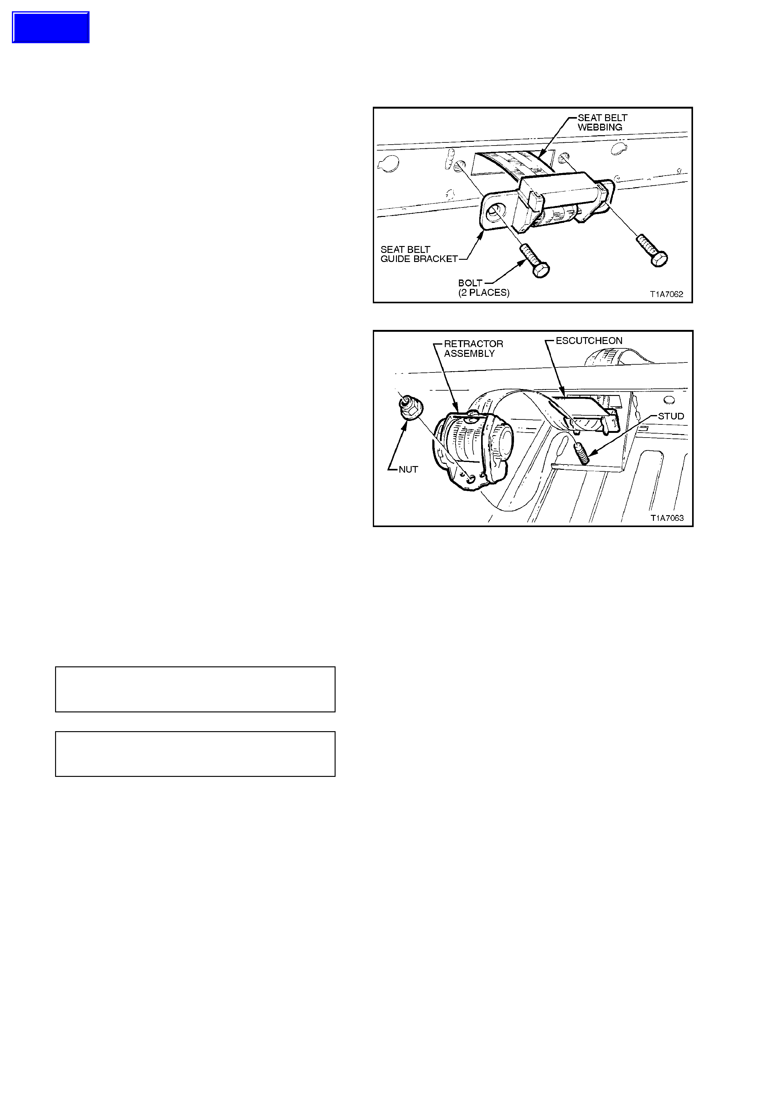
2.38 CENTRE REAR SEAT BELT RETRACTOR ASSEMBLY - WAGON
REMOVE
1. Remove rear seat back cover and pad
assembly, refer to 2.27 REAR SEAT COVER
AND PAD ASSEMBLY - WAGON in this
Section.
2. Remove the two bolts on the top of the seat
back frame securing the seat belt guide
bracket assembly.
3. Feed seat belt webbing through seat belt guide
bracket and remove seat belt guide bracket.
Figure 1A7-76
4. Remove the nut retaining the seat belt
retractor to the rear seat back frame.
5. Remove seat belt retractor f r om the stud in the
seat back frame.
6. Gently prise escutcheon from seat back
frame, feed seat belt webbing through seat
back frame and remove retractor assembly.
NOTE:
The seat belt retractor will not function unless the
seat back is in an upright position.
Figure 1A7-77
REINSTALL
Installation of the centre rear seat belt retractor
assembly is the reverse of the removal operation,
noting the following:
1. Ensure all fasteners are tightened to the
correct torque specification.
SEAT BELT GUIDE BRACKET
SECURING BOLT
TORQUE SPECIFICATION 20 - 22 Nm
SEAT BELT RETRACTOR
RETAINING NUT
TORQUE SPECIFICATION 35 50 Nm
2. If a new centre rear seat belt retractor
assembly is fitted, ensure the web clip is
removed after the retaining nut is tightened.
Techline
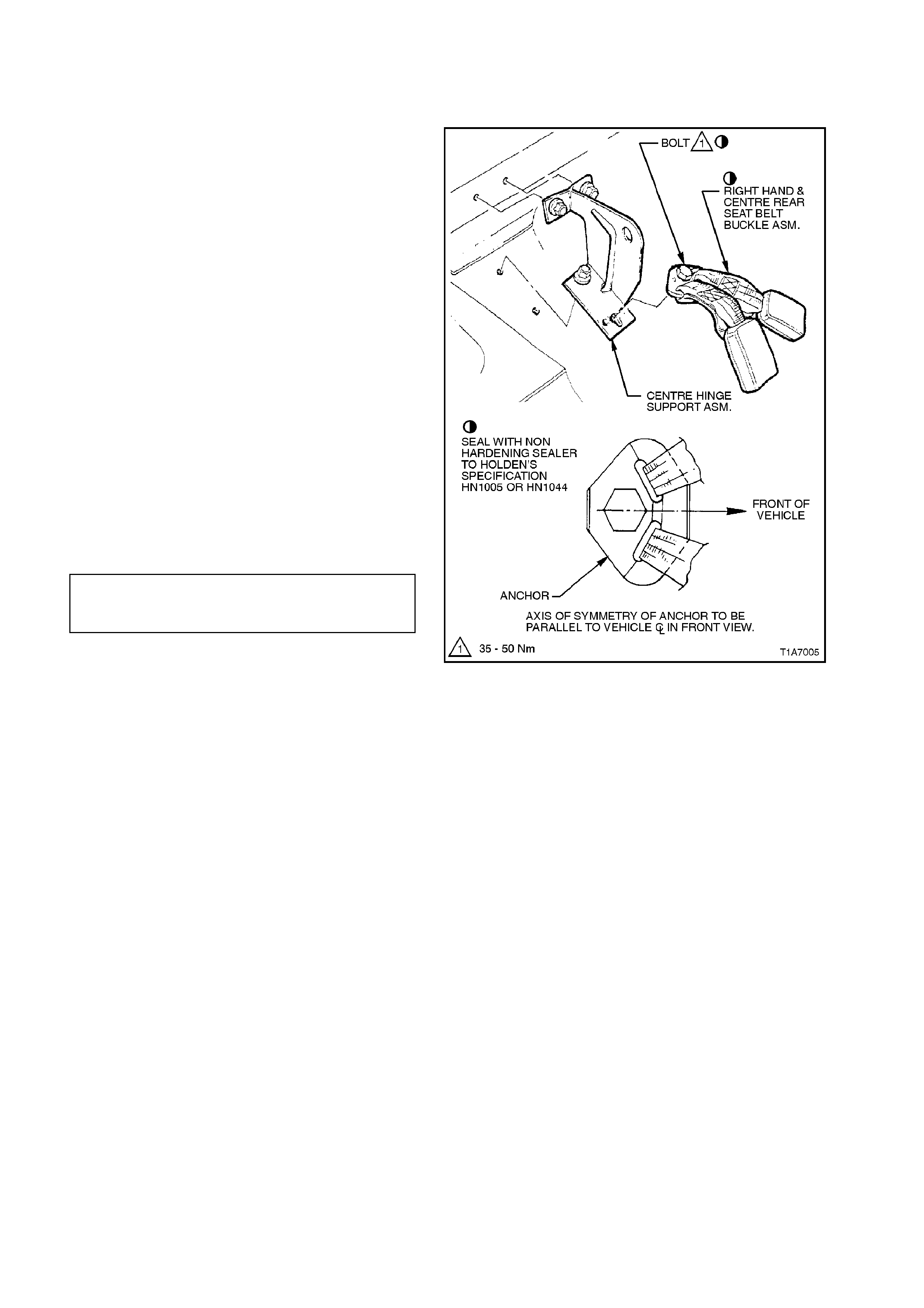
2.39 RIGHT HAND AND CENTRE REAR SEAT BELT BUCKLE ASSEMBLY - WAGON
REMOVE
1. Remove rear seat cushion, refer to
2.23 REAR SEAT CUSHION - WAGON in this
Section.
2. Remove bolt s ec uring the r ear s eat belt buc k le
anchor to the floor pan and seat back bracket,
refer to Fig. 1A7-78.
REINSTALL
Reinstallation of the right hand and centre rear seat
belt buckle assemblies is the reverse of the
removal operation, noting the following:
1. Ensure all seat belt bolts are hand tightened a
minimum of 5 turns before using tools.
2. Ensure that the threads of seat belt buckle
anchor securing bolt is adequately sealed with
a non hardening sealer, to Holden’s
specification HN 1005 or HN 1044, refer to
Fig. 1A7-78.
3. Tighten anchor bolt to the correct torque
specification ensuring that anchor plates are
located correctly, refer to Fig. 1A7-78.
SEAT BELT BUCKLE ANCHOR
SECURING BOLT 35 - 50 Nm
TORQUE SPECIFICATION
Figure 1A7-78
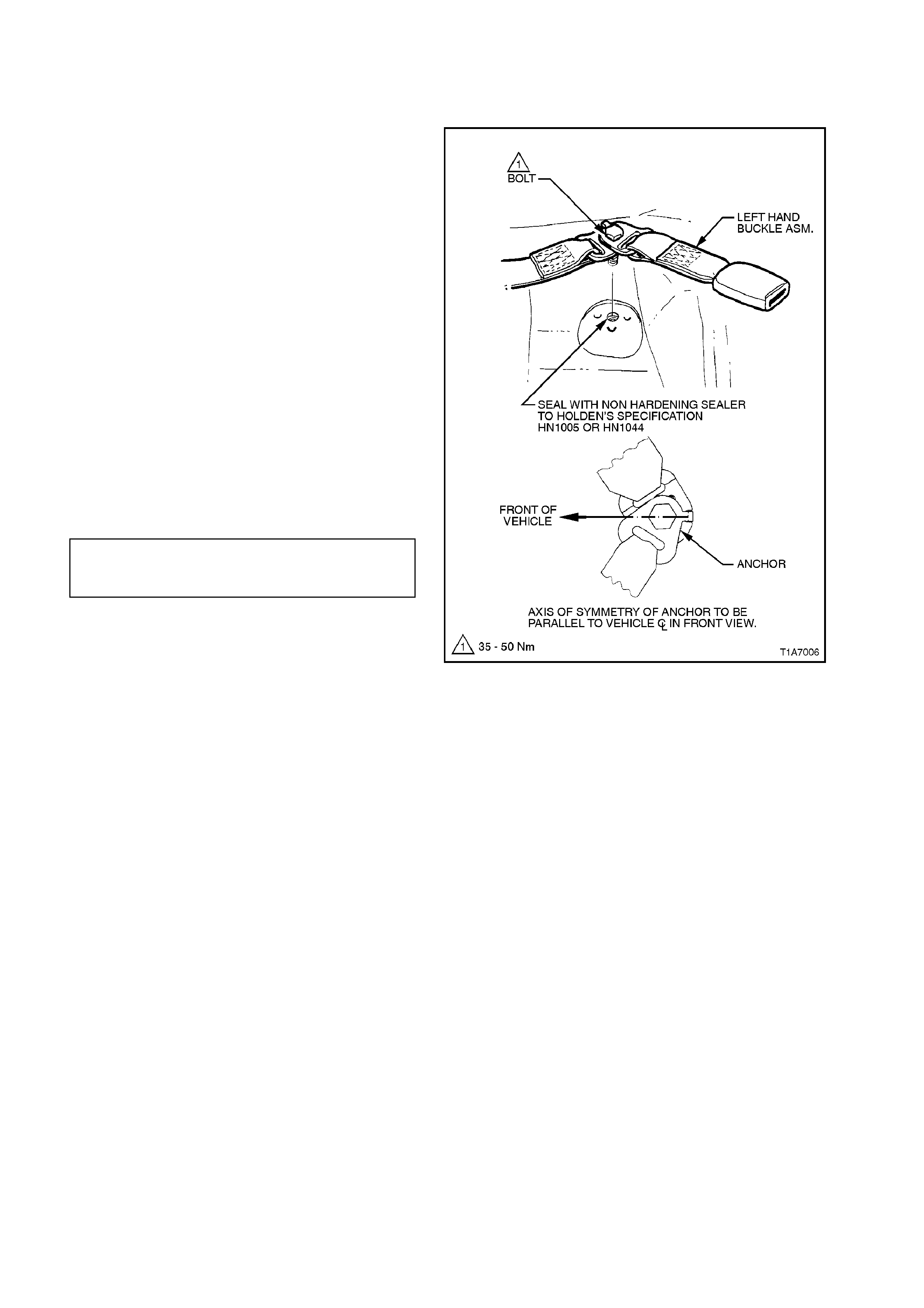
2.40 LEFT HAND REAR SEAT BELT BUCKLE ASSEMBLY - WAGON
REMOVE
1. Remove rear seat cushion, refer to
2.23 REAR SEAT CUSHION - WAGON in this
Section.
2. Remove bolt securing the rear seat belt buckle
anchor to the floor pan, refer to Fig. 1A7-79.
REINSTALL
Installation is the reverse of the removal operation,
noting the following:
1. Ensure all seat belt bolts are hand tightened a
minimum of 5 turns before using tools.
2. Ensure that the threads of seat belt buckle
anchor securing bolt is adequately sealed with
a non hardening sealer, to Holden’s
specification HN 1005 or HN 1044, refer to
Fig. 1A7-79.
3. Tighten anchor bolt to the correct torque
specification ensuring that anchor plates are
located correctly, refer to Fig. 1A7-79.
SEAT BELT BUCKLE ANCHOR
SECURING BOLT 35 - 50 Nm
TORQUE SPECIFICATION
Figure 1A7-79

3. DIAGNOSTICS
3.1. PREREQUISITES TO DIAGNOSIS AND TROUBLE SHOOTING
PRELIMINARY SYSTEM REQUIREMENTS
The prerequisites before proceeding with system checks are:
• Fusible link FJ and circuit breaker F2 must be checked before any electrical diagnostic checks are performed.
• Ensure no moisture is present in the main wiring harness to body wiring harness or seat harness connections.
• Ensure that sound earth connections are available for all functioning components.
• Ensure the battery is in good condition and adequately charged (above 11.5 Volts) before carrying out any
electrical checks.
SAFETY REQUIREMENTS
Disconnect the battery when carrying out work which involves the risk of an electrical short circuit.
Do not touch mechanical components during function checks, to avoid the risk of a hand being caught in the
mechanism.
CHECKING EQUIPMENT
An unpowered testlamp with a current draw of less than 3 Amps.
A digital multimeter, with a minimum 10 Megohm impedance MUST be used when undertaking any electrical
checks on these systems.
Exercise care when taking readings from wiring harness connectors. It is preferred that the back probing method
with individual connectors is employed wherever possible, to avoid terminal damage and subsequent connection
failure.
When carrying out wiring checks as directed to by the diagnostic charts, rather than probe terminals and connectors
with incorrect sized multimeter connections, use the adaptors contained in connector test adaptor kit KM-609. This
will prevent any possibility of spreading or damaging wiring harness terminals.
IMPORTANT:
• When checking, the exact order of the test steps should be observed.
• If the required nominal value is not achieved in any stage, then the problem must be rectified before
proceeding further.
• Unless the multimeter being used has an auto ranging function, check that the correct range, as specified, is
selected before the test is carried out.
3.2 VISUAL INSPECTION
When investigating any complaint of an electric seat problem or malfunction, start diagnosis with a visual inspection
of the system.
The visual inspection procedure may quickly identify the cause and illuminate the need for additional diagnosis, in
particular if the problem is a mechanical fault.
If the complaint condition can not be resolved by the visual inspection, proceed to the appropriate diagnostic chart in
this Section.
NOTE:
Diagnostic charts 3.3 to 3.7 in this Section relate to electrical faults only and assume there are no mechanical faults.
ELECTRIC SEAT VISUAL INSPECTION
GENERAL
ITEM INSPECT FOR CORRECTIVE ACTION
Operation of seat (noisy,
slow or no Foreign material causing seat to
bind. Remove foreign material.
operation at all). Dry components, build up of dirt
on moving components. Clean and apply Lithium
based grease (to Holden
specification HN 2073) to
noisy component.
Bent, loose or physically
damaged components. Repair or replace faulty
components.
WIRING CONNECTIONS & CIRCUIT BREAKER
ITEM INSPECT FOR CORRECTIVE ACTION
Seat and switch wiring
harness connectors. Loose connections at individual
motors. Ensure secure connections.
Loose connections at control
switch.
Loose connection at power
supply connector at side of seat
assembly.
Circuit breaker F2. Loose connection or not fitted. Ensure secure connection or
supply new circuit breaker.

3.3 ELECTRIC SEAT DOES NOT MOVE IN ANY DIRECTION
STEP ACTION VALUE YES NO
1. At the side of the front
seat assembly, back
probe power seat
connector YB116, circuits
540 and 156 with a test
lamp.
Does the test lamp
illuminate ?
Go to Step 4. Go to Step 2.
2. Disconnect body harness
from connector YB116.
Using a voltmeter,
measure voltage at
Orange/Black wire
connection and a sound
earth connection.
Is voltage as specified ?
Battery
+Go to Step 3. Check and repair
open or short in
circuit 540
(including fusible
link FJ and circuit
breaker F2),
recheck and verify
repair.
3. With body harness
connector YB116
disconnected, check for
continuity between
Black/Blue wire
connection and earth
location E6.
Does continuity exist ?
Circuit OK. Check and repair
earth circuit 156,
recheck and verify
repair.
4. Back probe seat switch
connector YB210 (8 way
seat or YB211 (4 way
seat), Red and Black wire
connections with a test
lamp.
Does the test lamp
illuminate ?
Go to Step 5. Check and repair
open in either Red
or Black wire
circuits between
seat switch
connector and
body harness
connector YB116
5. From under front seat
assembly, back probe any
one of the seat adjusting
motors wiring harness
connectors (YB212) with a
test lamp connected to
both sides of the
connector.
Operate the selected seat
adjusting motor.
Does the test lamp
illuminate ?
Replace seat
adjusting motors,
refer to the
appropriate
Service Operation
in this Section.
Replace seat
adjusting switch
assembly, refer to
2.3 FRONT SEAT
OUTER SIDE
COVER AND
SEAT
ADJUSTING
SWITCH
ASSEMBLY in
this Section.
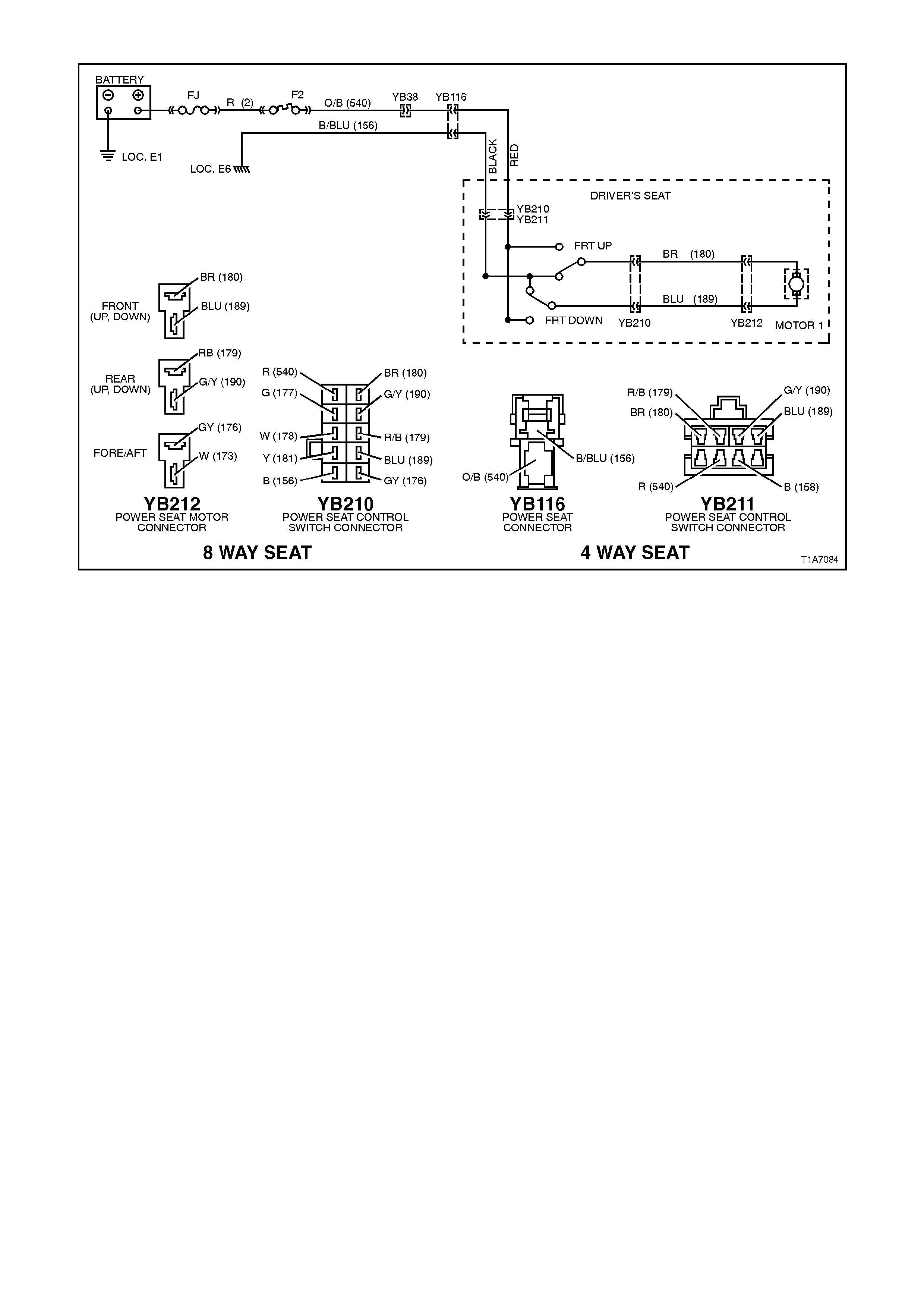
Figure 1A7-80
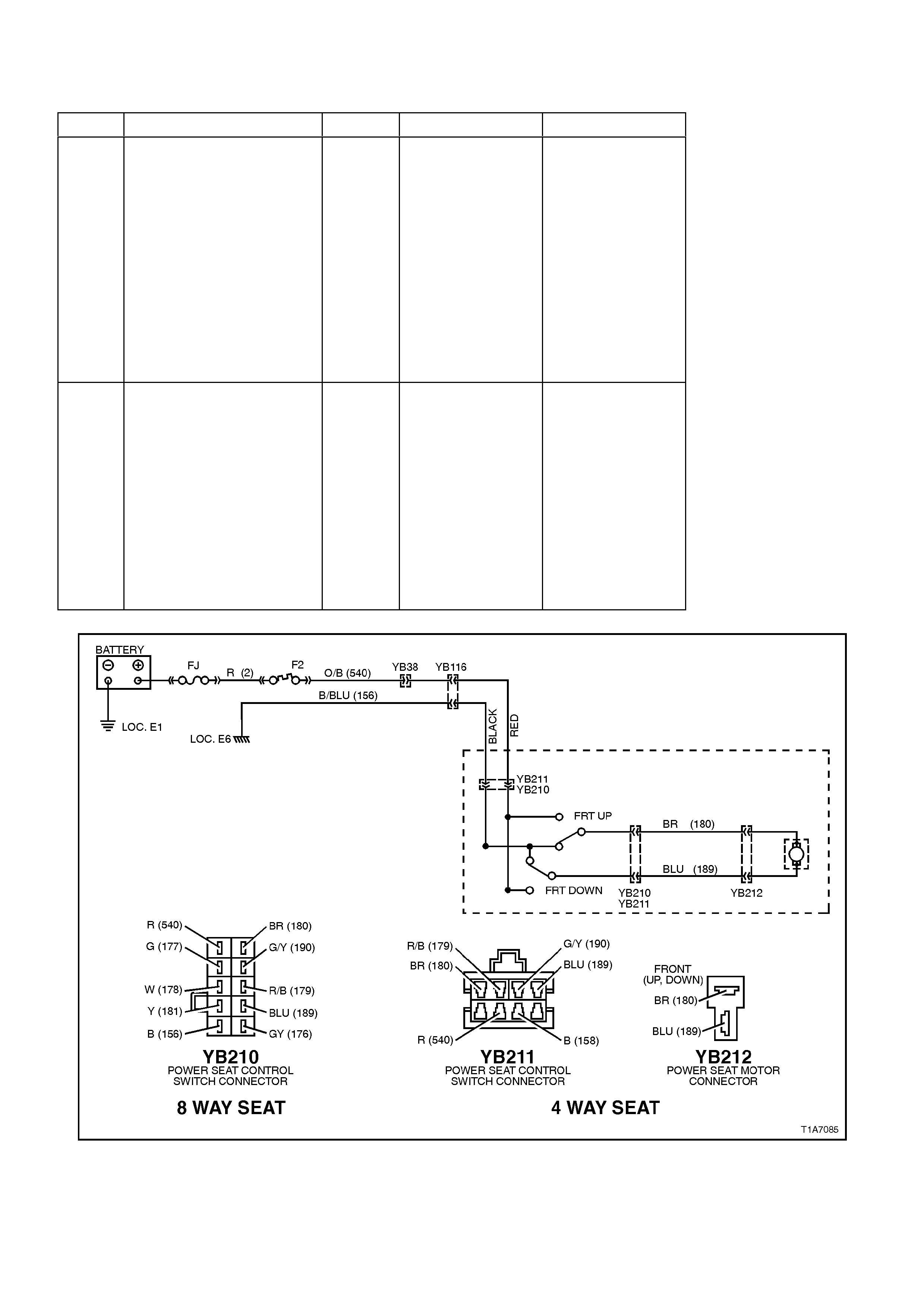
3.4 ELECTRIC SEAT FRONT UP AND DOWN OPERATION INOPERATIVE
STEP ACTION VALUE YES NO
1. From under front seat
assembly, back probe the
seat front lift motor wiring
harness connector
YB212, between circuit
180 (Brown wire) and
circuit 189 (Blue wire)
connections with a test
lamp.
Operate the seat front lift
motor.
Does the test lamp
illuminate ?
Replace the seat
front lift motor
assembly, refer
2.14 FRONT
SEAT LIFT
MOTOR in this
Section.
Go to Step 2.
2. Back probe seat switch
connector YB210 (8 way
seat) or YB211 (4 way
seat), between circuit 180
(Brown wire) and circuit
189 (Blue wire)
connections with a test
lamp.
Operate the seat front lift
motor.
Does the test lamp
illuminate ?
Check and repair
open in circuits
180 (Brown wire)
or circuit 189
(Blue wire )
between seat
adjusting switch
connector and
seat front lift
motor connector.
Recheck and
verify repair.
Replace seat
adjusting switch,
refer to 2.3
FRONT SEAT
OUTER SIDE
COVER AND
SEAT
ADJUSTING
SWITCH
ASSEMBLY in
this Section.
Figure 1A7-81
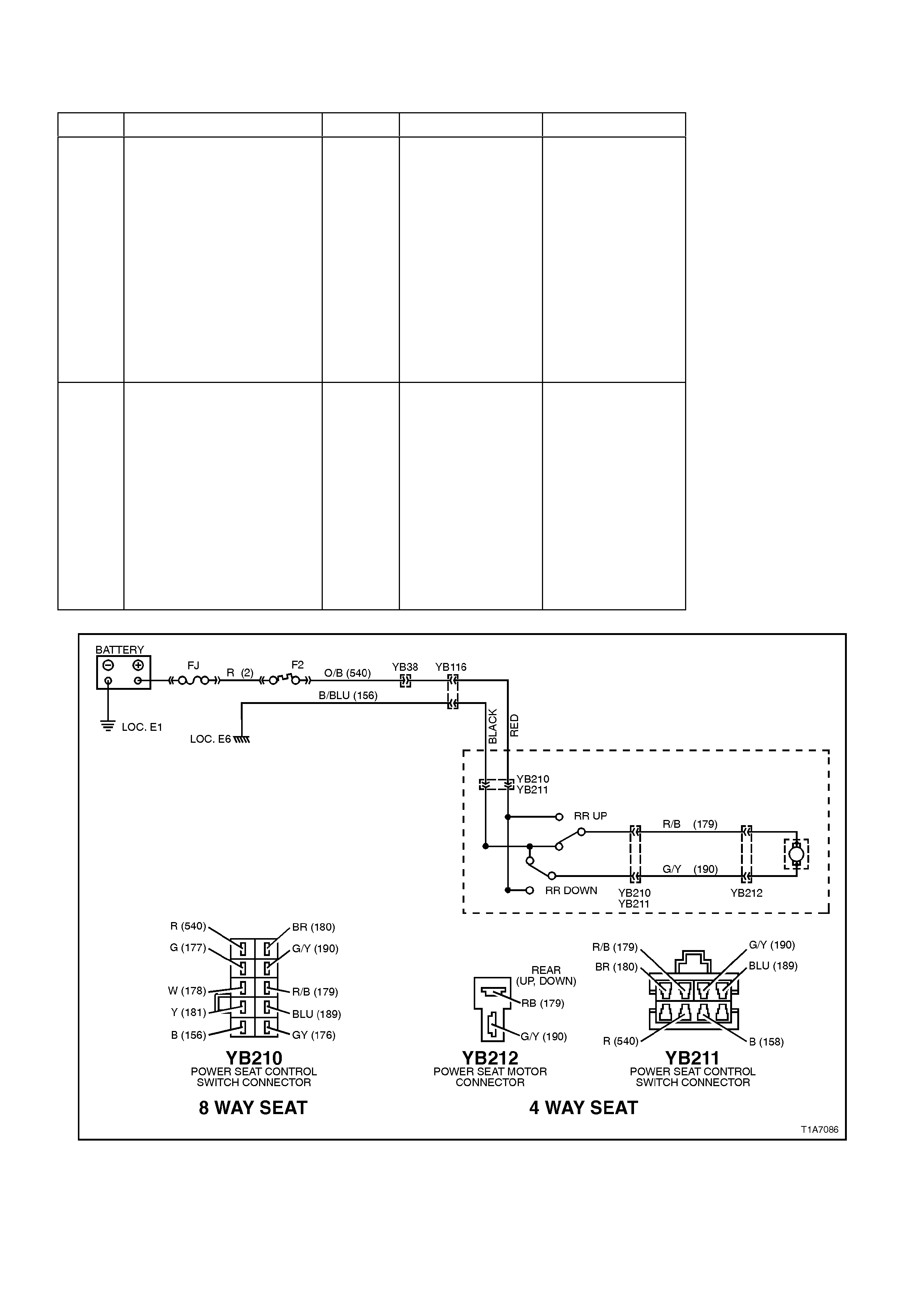
3.5 ELECTRIC SEAT REAR UP AND DOWN OPERATION INOPERATIVE
STEP ACTION VALUE YES NO
1. From under front seat
assembly, back probe the
seat rear lift motor wiring
harness connector
YB212, between circuits
179 (Red/Black wire) and
circuit 190 (Green/Yellow
wire) connections with a
test lamp.
Operate the seat rear lift
motor.
Does the test lamp
illuminate ?
Replace the seat
rear lift motor
assembly, refer to
2.14 FRONT
SEAT LIFT
MOTORS in this
Section.
Go to Step 2.
2. Back probe seat adjusting
switch connector, YB210
(8 way seat) or YB211 (4
way seat), circuits 179
(Red/Black wire) and
circuit 190 (Green/Yellow
wire) connections with a
test lamp.
Operate the seat rear lift
motor.
Does the test lamp
illuminate ?
Check and repair
open in circuits
179 (Red/Black
wire) or circuit 190
(Green/ Yellow
wire) between
seat adjusting
switch connector
and seat rear lift
motor connector.
Recheck and
verify repair.
Replace seat
adjusting switch,
refer to 2.3
FRONT SEAT
OUTER SIDE
COVER AND
SEAT
ADJUSTING
SWITCH
ASSEMBLY in
this Section.
Figure 1A7-82

3.6 ELECTRIC SEAT RECLINER INOPERATIVE
STEP ACTION VALUE YES NO
1. From under the front seat
assembly, back probe the
seat reclining motor wiring
harness connector
YB214, between circuits
177 (Green wire) and
circuit 181 (Yellow wire)
connections with a test
lamp.
Operate the seat reclining
lift motor.
Does the test lamp
illuminate ?
Go to Step 3. Go to Step 2.
2. Back probe seat adjusting
switch connector YB210,
between circuit 177
(Green wire) and circuit
181 (Yellow wire)
connections with a test
lamp.
Operate the seat reclining
motor.
Does the test lamp
illuminate ?
Check and repair
open in circuit 177
(Green wire) or
circuit 181 (Yellow
wire) between
seat adjusting
switch connector
and seat reclining
motor connector.
Recheck and
verify repair.
Replace seat
adjusting switch,
refer to 2.3
FRONT SEAT
OUTER SIDE
COVER AND
SEAT
ADJUSTING
SWITCH
ASSEMBLY in
this Section.
3. With seat reclining motor
and gearbox assembly
exposed (seat back cover
and pad removed),
visually inspect reclining
mechanism for cause of
fault, ie. bent drive shaft,
loose motor, etc.
Are there any visible faults
that would cause seat
recliner to be inoperative
?
Repair as
necessary.
Recheck and
verify repair.
Replace seat
reclining motor,
refer to 2.16
FRONT SEAT
RECLINING
MOTOR AND
GEARBOX
ASSEMBLY in
this Section.
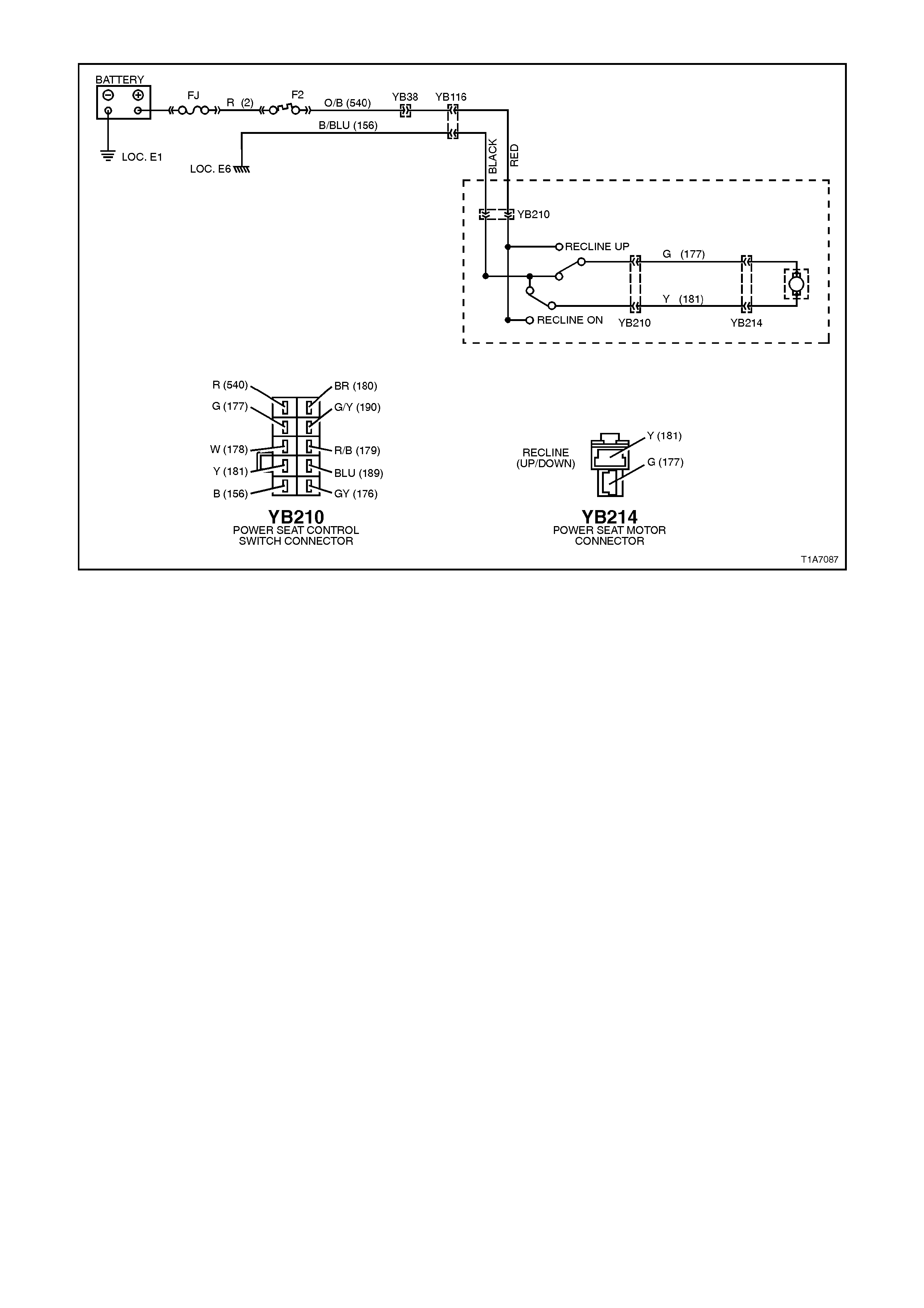
Figure 1A7-83
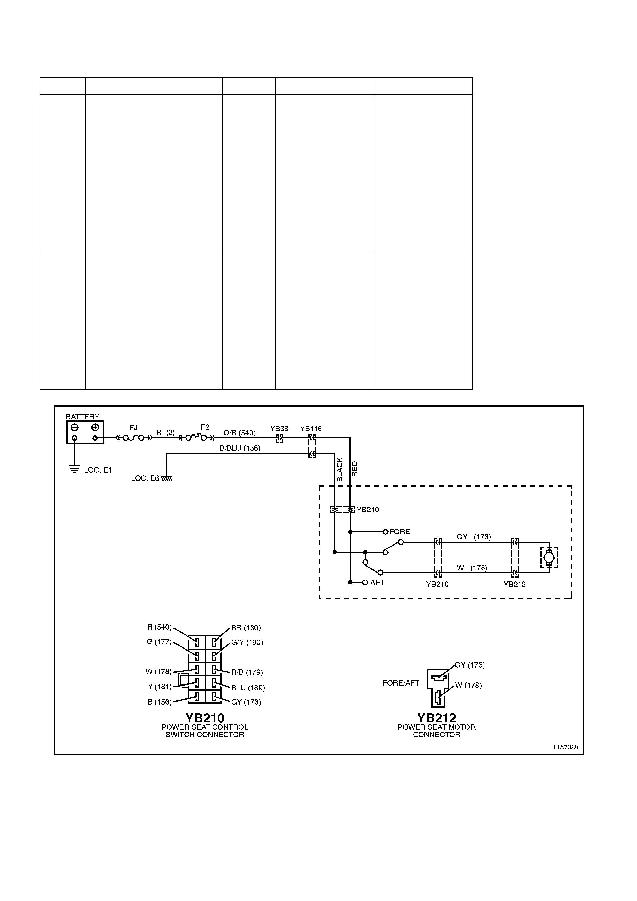
3.7 ELECTRIC SEAT FORWARD AND REARWARD OPERATION INOPERATIVE
STEP ACTION VALUE YES NO
1. Back probe the seat
fore/aft motor wiring
harness connector
YB212, between circuit
176 (Grey wire) and circuit
178 (White wire)
connections with a test
lamp.
Operate the seat fore/aft
motor.
Does the test lamp
illuminate ?
Replace the seat
fore/aft motor
assembly, refer to
2.15 FRONT
SEAT FORE/AFT
MOVEMENT
MOTOR in this
Section.
Go to Step 2.
2. Back probe seat adjusting
switch connector YB210,
between circuit 176 (Grey
wire) and circuit 178
(White wire) connections
with a test lamp.
Operate the seat fore/aft
motor.
Does the test lamp
illuminate ?
Check and repair
open in circuits
176 (Grey wire) or
circuit 178 (White
wire) between
seat adjusting
switch connector
and seat fore/aft
motor connector.
Recheck and
verify repair.
Replace seat
adjusting switch,
refer to 2.3
FRONT SEAT
OUTER SIDE
COVER AND
SEAT
ADJUSTING
SWITCH
ASSEMBLY in
this Section.
Figure 1A7-84

4. TORQUE WRENCH SPECIFI CATIONS
Nm
Armrest Bracket to Frame Retaining Screw 4.0
Armrest to Bracket Retaining Screw 4.0
Armrest to Bracket Securing Bolt - Sedan 7 - 10
B pillar Upper Trim Retaining Screw 1.0 - 3.0
Bracket to Seat Back Retaining Bolt 15 - 25
Centre Cover to Frame Retaining Screw 2.5
Centre Hinge Lower Securing Bolt 35 - 50
Centre Hinge Upper Securing Bolt 25 - 35
Child Seat Anchor Bolt 15 - 25
Front Seat Belt Guide Retaining Screw 2.4 - 3.4
Front Seat Cushion Frame to Seat Guide Railand Adjuster
Asm. Bolt 27
Front Seat to Floor Securing Bolt 35 - 50
Garnish Retaining Screw 2.0
LHR Seat Back Lock Retaining Screw 3.0
Outer Front Seat Guide Rail Cover 1.0 - 3.0
Rear Seat Back to Floor Retaining Bolt 25 - 30
Seat Back Lock Allen Key Screw 3.0
Seat Back to Height Adjuster Asm Securing Bolt 27
Seat Back to Seat Adjuster & Guide Rail Asm Securing Bolt 27
Seat Belt Buckle and Pre-tensioner Asm Bolt 45
Seat Belt Buckle Anchor Securing Bolt 35 - 50
Seat Belt guide bracket securing bolt 20 - 22
Seat Belt Retractor Retaining Nut 35 - 50
Seat Belt Securing Bolt 40 - 54
Side Inner Cover Retaining Screw 1.0 - 3.0
Striker Retaining Bolt - Wagon Seat Back 25 - 35
Striker Retaining Screw - Sedan Seat Back Lock 35
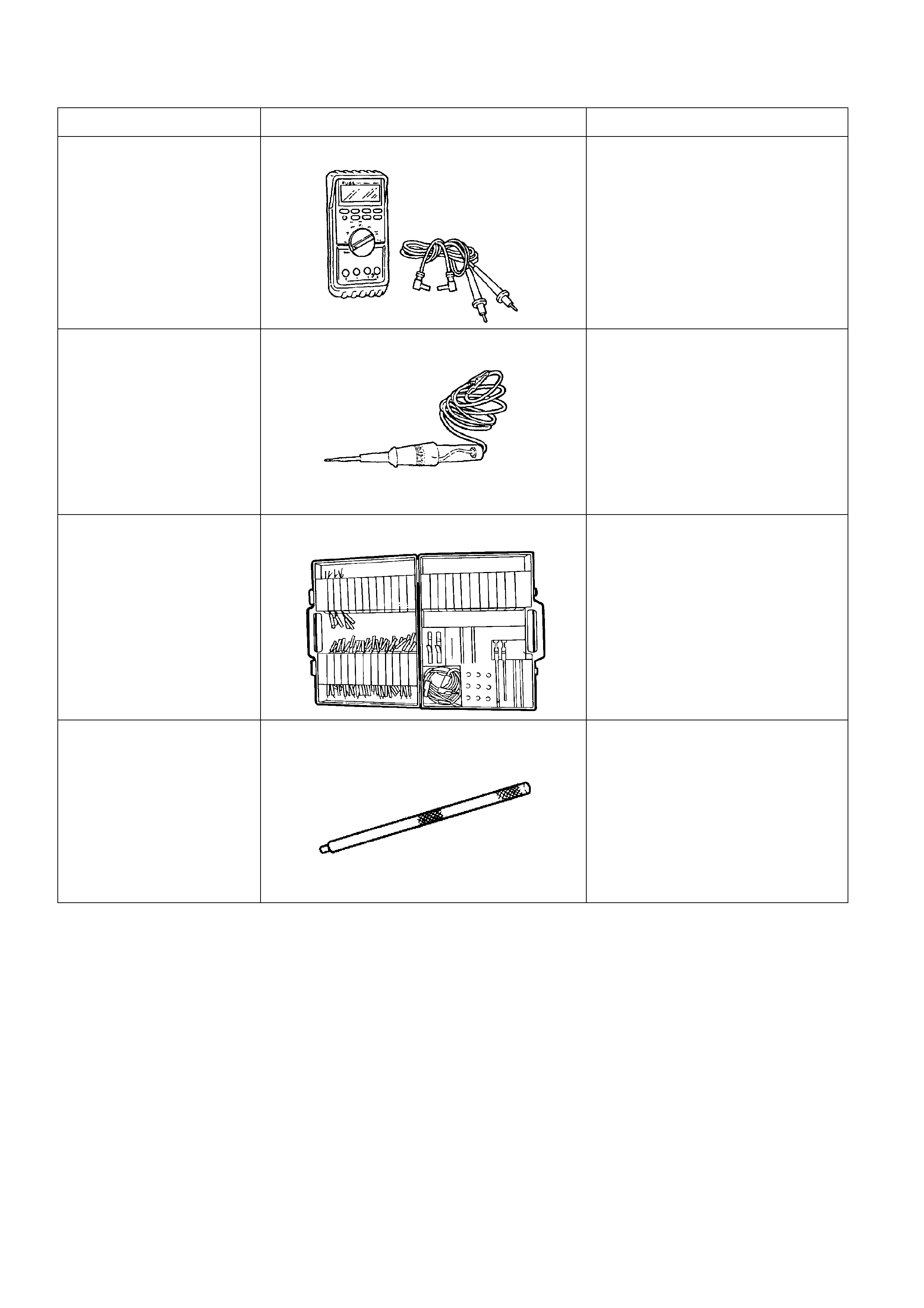
5. SPECIAL TOOLS
TOOL NO. REF IN TEXT TOOL DESCRIPTION COMMENTS
J39200 DIGITAL MULTIMETER TOOL NO. J39200 PREVIOUSLY
RELEASED, OR USE
COMMERCIALLY AVAILABLE
EQUIVALENT. MUST HAVE 10
MEG OHM INPUT IMPEDANCE
AND BE CAPABLE OF READING
FREQUENCIES
KM-609 ELECTRONIC KIT USED IN CONJUNCTION WITH A
MULTIMETER FOR MEASURING
VOLTAGES AND RESISTANCES
WITHOUT DAMAGING WIRING
HARNESS CONNECTORS
J-34142-B UNPOWERED TEST LIGHT COMMERCIALLY AVAILABLE.
MUST HAVE A CURRENT DRAW
OF LESS THAN 0.3 A
AU461 CLEVIS PIN REMOVAL PUNCH