SECTION 1A9 - EXTERIOR ORNAMENTATION
CAUTION:
This vehicle will be equipped with a Supplemental Restraint System (SRS). A SRS will
consist of either seat belt pre-tensioners and a driver's side air bag, or seat belt pre-
tensioners and a driver's and front passenger's side air bags. Refer to CAUTIONS,
Section 12M, before performing any service operation on, or around any SRS
components, the steering mechanism or wiring. Failure to follow the CAUTIONS
could result in SRS deplo yment, resulting in possible p ersonal injury or unnecessary
SRS system repairs.
CAUTION:
This vehicle may be equipped with LPG (Liquefied Petroleum Gas). In the interests of
safety, the LPG fuel system should be isolated by turning 'OFF' the manual service
valve and then draining the LPG serv ice lines, before any service w ork is carried out
on the vehicle. Refer to the LPG leaflet included with the Owner's Handbook for
details or LPG Section 2 for more specific servicing information.
1. GENERAL DESCRIPTI ON
Exterior ornamentation on VT Series Models includes:
• Body side mouldings for all model variants except ‘S’ and ‘SS’ models.
• Various name plates, emblems and decals depending on model variant.
• A windshield moulding cover.
• An air deflector for station wagons and an air spoiler for ‘S’ and ‘SS’ models.
• Door frame opening mouldings.
• ‘B’ pillar and quarter panel to roof mouldings.
• Roof finisher and side mouldings.
• Rocker panel skirts.
Exterior ornamentation components are secured to the body using various fasteners, double sided tape and
polyurethane adhesive.
Techline
Techline

2. SERVICE OPERATIONS
2.1 SERVICE NOTES
Numerous clips, fasteners, retainers, bushes, screws, nuts and contact adhesives are used to secure the various
exterior ornamentation components to the vehicle body. To locate the service information applicable a to a
particular component, refer to 2.2 PICTORIAL INDEX in this Section.
When removing, handling or installing exterior ornamentation components, the following care should be exercised:
1. Finishers adjacent to the component being removed should be covered with masking tape to prevent damage
to panels and paint work.
2. Removal of adhesive bonded nameplates and emblems is more easily achieved with the aid of a heat lamp
positioned adjacent to the part to be removed.
NOTE:
Ensure that the heat lamp is not too close to the body, or the heat to intense to adversely affect the paint finish.
3. Holes in body panels for screws, bolts, clips, etc. that could permit water entry into the body must be
adequately sealed with either a non-hardening sealer or presealed screws, clips, etc.
4. Using a clean cloth, clean the area of body surface where emblems, mouldings, etc. are to be applied with
‘Prepsol’ solvent or equivalent.
5. It is essential that the body temperature of the vehicle be at least 21°C before adhering adhesive bonded
components to the vehicle.

2.2 PICTORIAL INDEX
The following pictograph indexes provide a quick guide to finding the correct service procedure for the applicable
exterior ornamentation component. Within this Section, simply locate the appropriate component in Fig. 1A9-1, 2 or
3 and cross reference it in the table below the Figure.
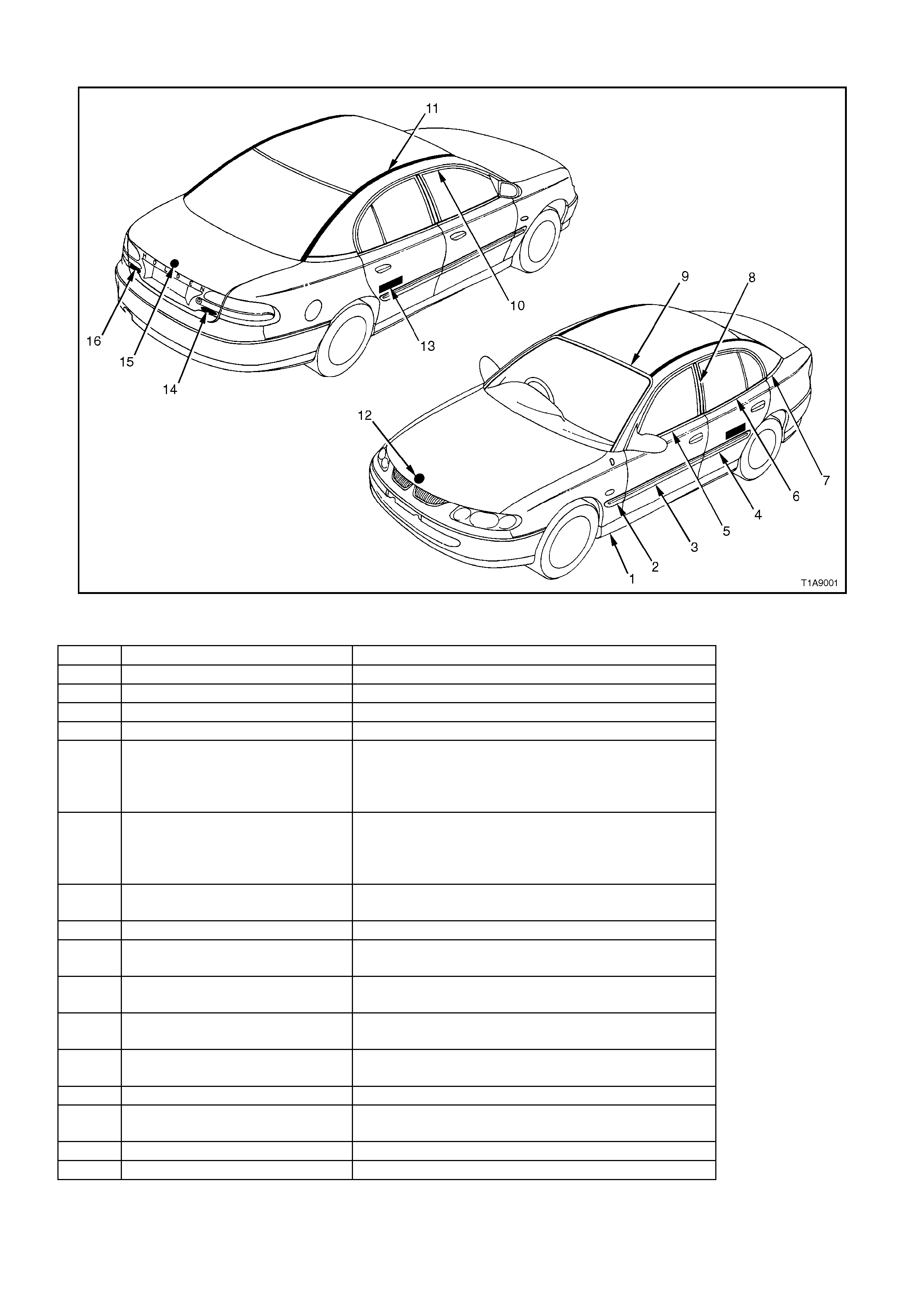
SEDAN - EXCLUDING 'S' & 'SS'
Figure 1A9-1
ITEM DESCRIPTION REFERENCE
1 Rocker panel skirt 2.3 ROCKER PANEL SKIRT in this Section
2 Front fender side moulding 2.4 BODY SIDE MOULDINGS in this Section
3 Front door side moulding 2.4 BODY SIDE MOULDINGS in this Section
4 Rear door side moulding 2.4 BODY SIDE MOULDINGS in this Section
5 Front door belt moulding 2.16 FRONT AND REAR DOOR BELT
WEATHERSTRIP AND MOULDING ASSEMBLY
in Section 1A5 FRONT AND REAR DOOR
ASSEMBLIES.
6 Rear door belt moulding 2.16 FRONT AND REAR DOOR BELT
WEATHERSTRIP AND MOULDING ASSEMBLY
in Section 1A5 FRONT AND REAR DOOR
ASSEMBLIES.
7 Quarter panel to roof moulding 2.5 QUARTER PANEL TO ROOF MOULDING
ASSEMBLY in this Section
8 ‘B’ pillar moulding 2.6 ‘B’ PILLAR MOULDING in this Section
9 Windshield moulding cover 2.7 WINDSHIELD MOULDING COVER in this
Section
10 Door frame opening moulding 2.8 DOOR FRAME OPENING MOULDING in this
Section
11 Roof finisher moulding 2.9 ROOF FINISHER MOULDING - SEDAN in this
Section
12 Emblem: ‘Lion’ 2.12 ‘LION’ EMBLEM - ENGINE HOOD in this
Section
13 Name plate: Calais 2.13 NAME PLATES AND DECALS in this Section
14 Name plate: Executive,
Acclaim, Berlina, Calais 2.13 NAME PLATES AND DECALS in this Section
15 Emblem: ‘Lion’ 2.12 ‘LION’ EMBLEM - DECK LID in this Section
16 Name pate: Commodore 2.13 NAME PLATES AND DECALS in this Section
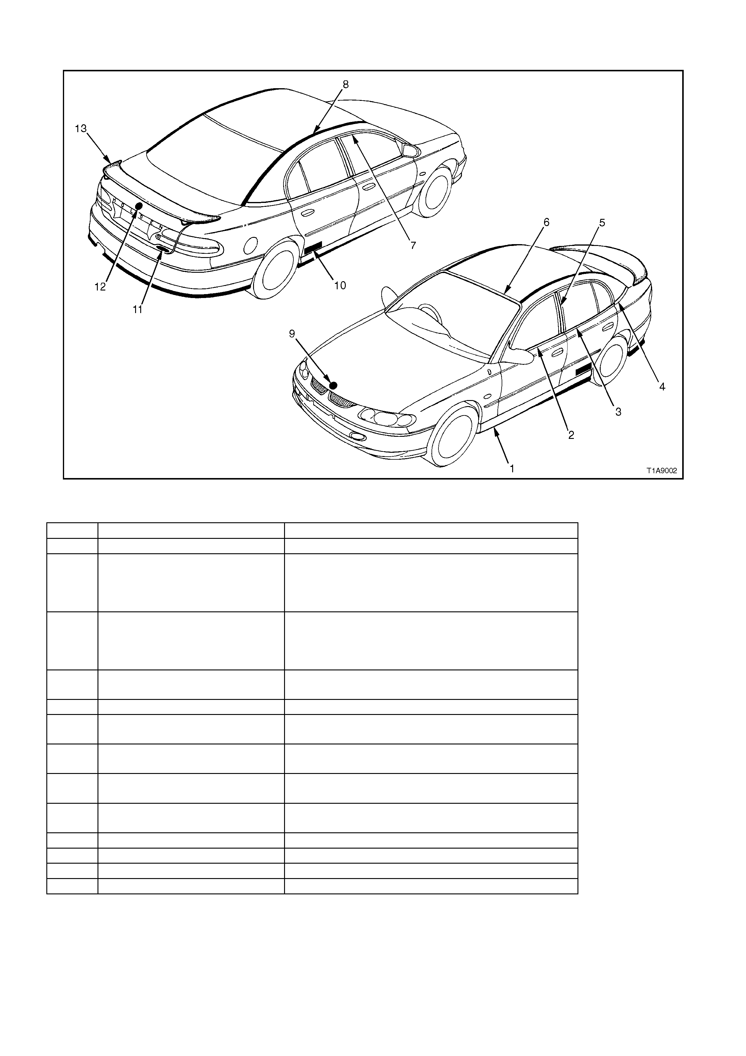
SEDAN - 'S' & 'SS'
Figure 1A9-2
ITEM DESCRIPTION REFERENCE
1 Rocker panel skirt 2.3 ROCKER PANEL SKIRT in this Section
2 Front door belt moulding 2.16 FRONT AND REAR DOOR BELT
WEATHERSTRIP AND MOULDING ASSEMBLY
in Section 1A5 FRONT AND REAR DOOR
ASSEMBLIES.
3 Rear door belt moulding 2.16 FRONT AND REAR DOOR BELT
WEATHERSTRIP AND MOULDING ASSEMBLY
in Section 1A5 FRONT AND REAR DOOR
ASSEMBLIES.
4 Quarter panel to roof moulding 2.5 QUARTER PANEL TO ROOF MOULDING
ASSEMBLY in this Section
5 ‘B’ pillar moulding 2.6 ‘B’ PILLAR MOULDING in this Section
6 Windshield moulding cover 2.7 WINDSHIELD MOULDING COVER in this
Section
7 Door frame opening moulding 2.8 DOOR FRAME OPENING MOULDING in this
Section
8 Roof finisher moulding 2.9 ROOF FINISHER MOULDING - SEDAN in this
Section
9 Emblem: ‘Lion’ 2.12 ‘LION’ EMBLEM - ENGINE HOOD in this
Section
10 Decal ‘SS’ 2.13 NAME PLATES AND DECALS in this Section
11 Name plate: ‘SS’ 2.13 NAME PLATES AND DECALS in this Section
12 Emblem: ‘Lion’ 2.12 ‘LION’ EMBLEM - DECK LID in this Section
13 Deck lid Air spoiler 2.15 DECK LID AIR SPOILER in this Section
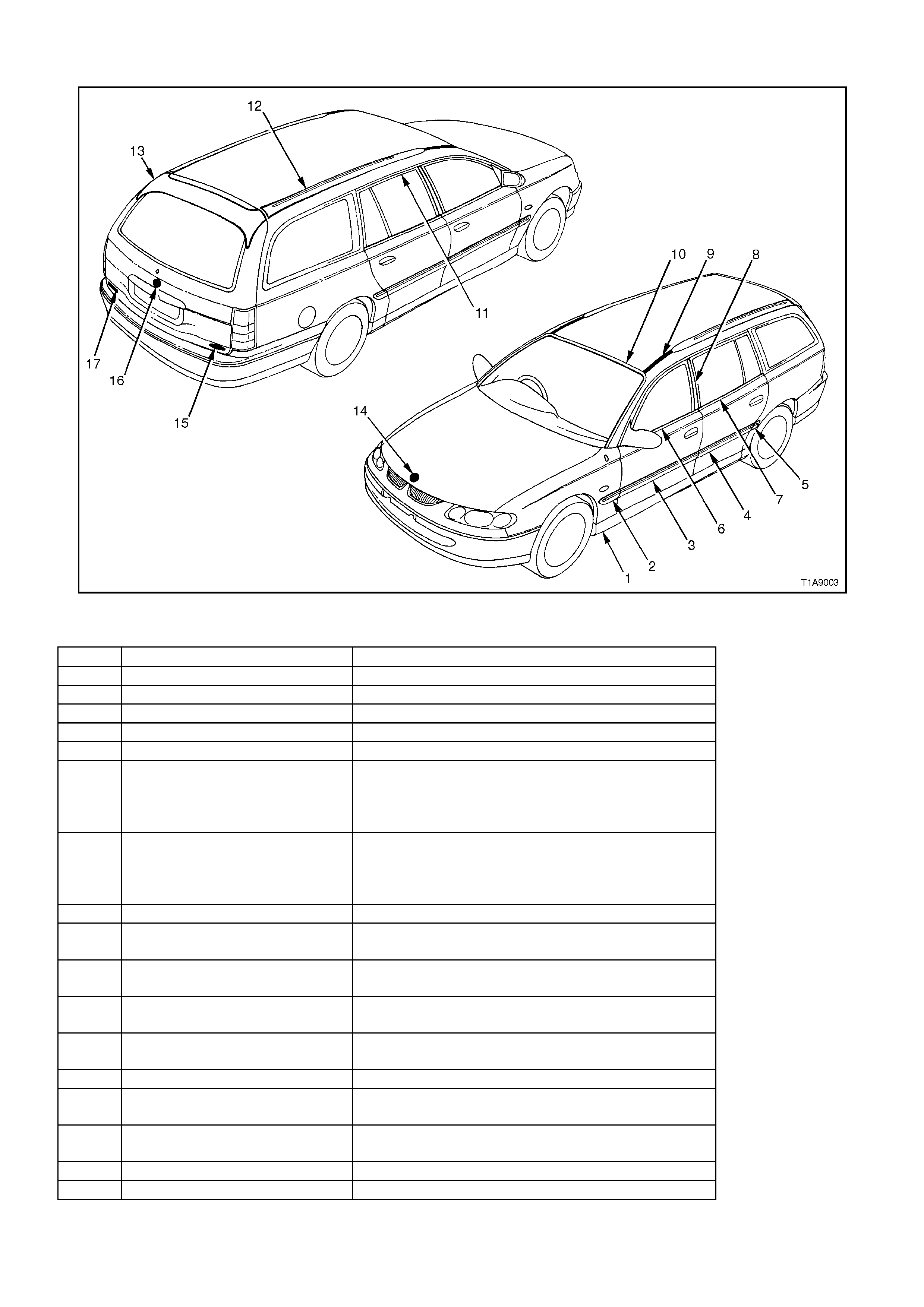
WAGON - EXECUTIVE, ACCLAIM & BERLINA
Figure 1A9-3
ITEM DESCRIPTION REFERENCE
1 Rocker panel skirt 2.3 ROCKER PANEL SKIRT in this Section
2 Front fender side moulding 2.4 BODY SIDE MOULDINGS in this Section
3 Front door side moulding 2.4 BODY SIDE MOULDINGS in this Section
4 Rear door side moulding 2.4 BODY SIDE MOULDINGS in this Section
5 Quarter panel side moulding 2.4 BODY SIDE MOULDINGS in this Section
6 Front door belt moulding 2.16 FRONT AND REAR DOOR BELT
WEATHERSTRIP AND MOULDING ASSEMBLY
in Section 1A5 FRONT AND REAR DOOR
ASSEMBLIES.
7 Rear door belt moulding 2.16 FRONT AND REAR DOOR BELT
WEATHERSTRIP AND MOULDING ASSEMBLY
in Section 1A5 FRONT AND REAR DOOR
ASSEMBLIES.
8 ‘B’ pillar moulding 2.6 ‘B’ PILLAR MOULDING in this Section
9 Roof finisher moulding 2.10 ROOF FINISHER MOULDING - WAGON in
this Section
10 Windshield moulding cover 2.7 WINDSHIELD MOULDING COVER in this
Section
11 Door frame opening moulding 2.8 DOOR FRAME OPENING MOULDING in this
Section
12 Roof side moulding 2.11 ROOF SIDE MOULDING - WAGON in this
Section
13 Tailgate air deflector 2.14 TAILGATE AIR DEFLECTOR in this Section
14 Emblem: ‘Lion’ 2.12 ‘LION’ EMBLEM - ENGINE HOOD in this
Section
15 Name plate: Executive,
Acclaim, Berlina 2.13 NAME PLATES AND DECALS in this Section
16 Emblem: ‘Lion’ 2.12 ‘LION’ EMBLEM - TAILGATE in this Section
17 Name plate: Commodore 2.13 NAME PLATES AND DECALS in this Section
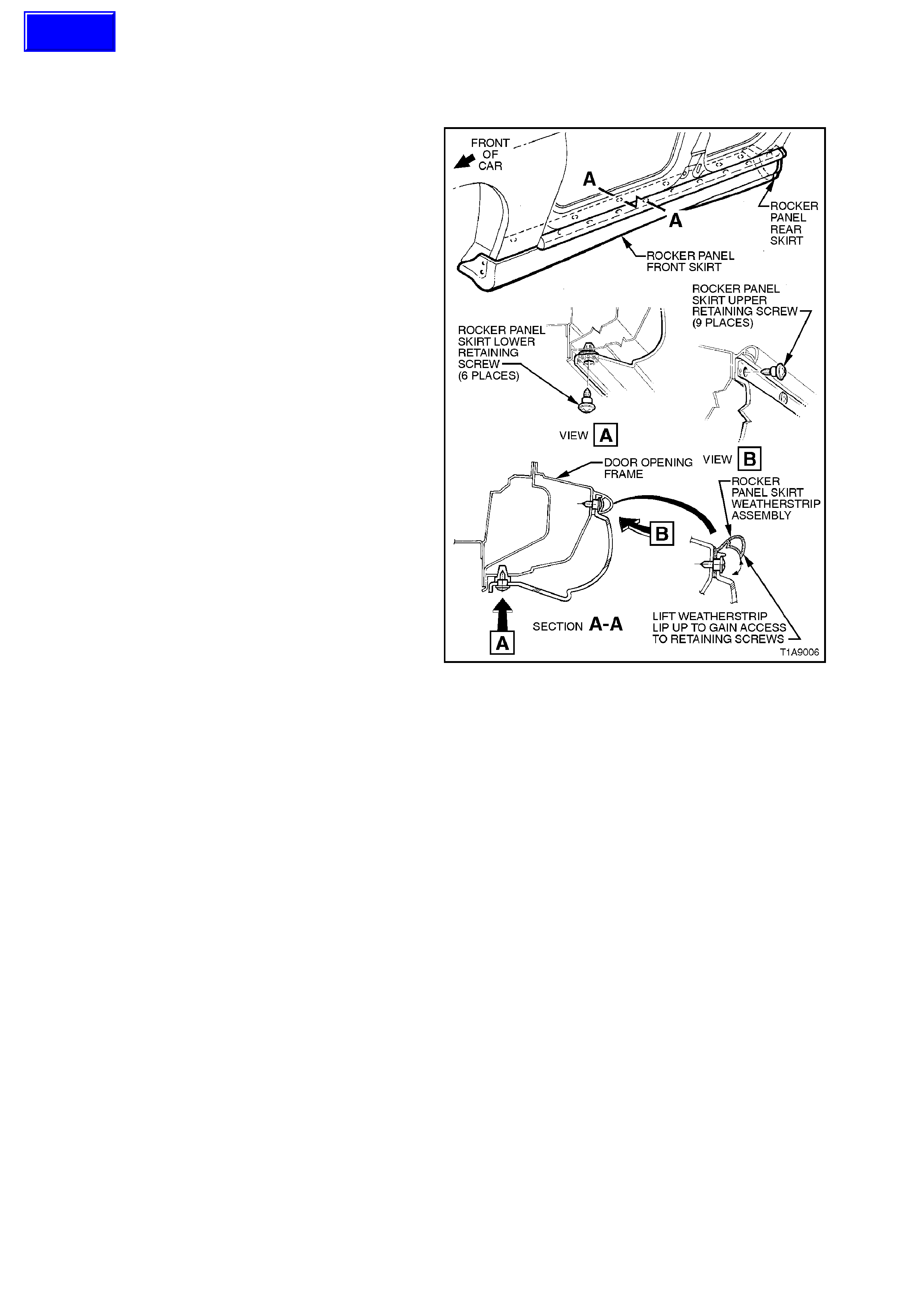
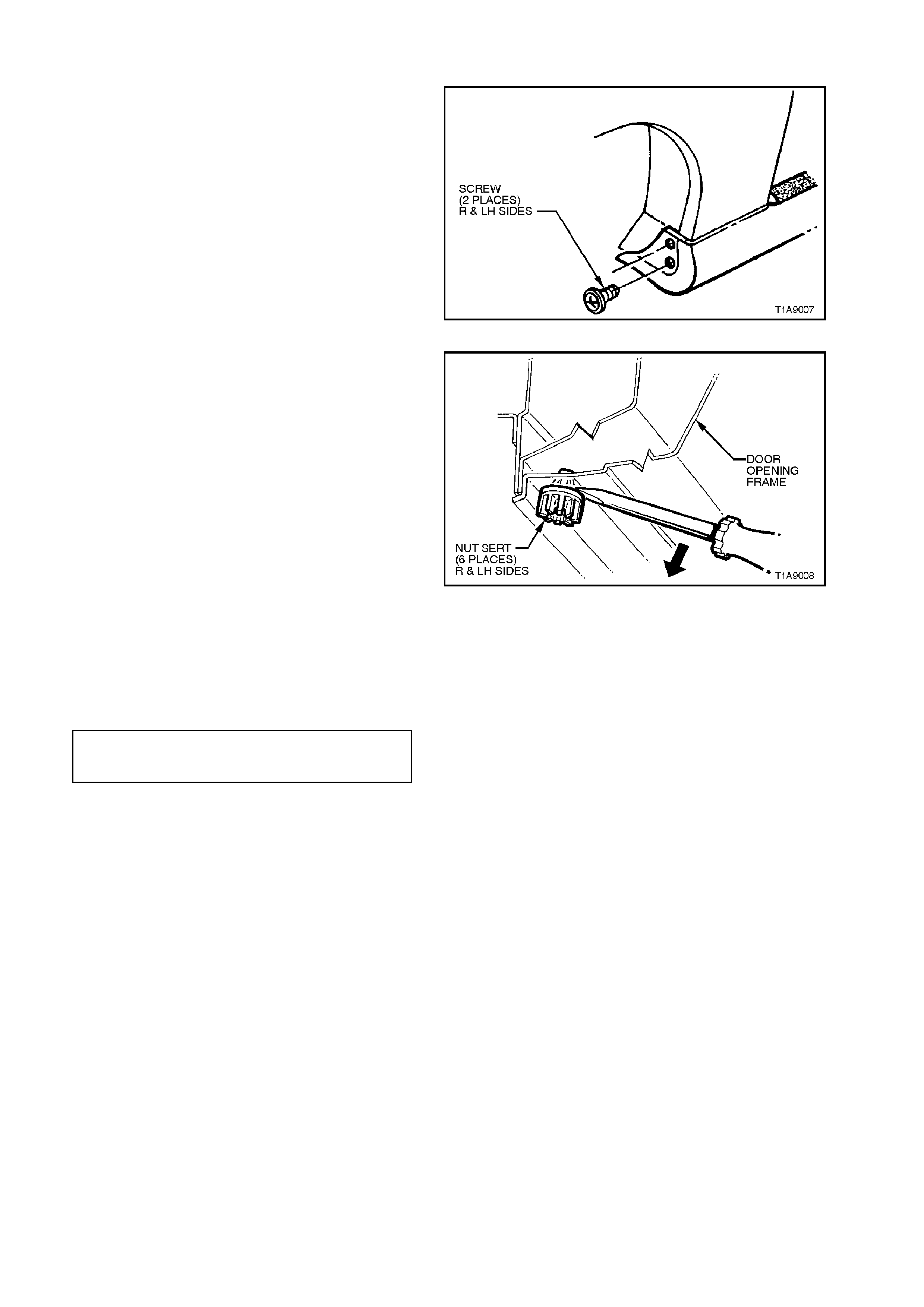
3. Remove the two screws securing the rocker
panel front skirt to the fender liner.
4. Slide rocker panel front skirt forward until it is
free from the rocker panel rear skirt, and
remove rocker panel front skirt.
5. Remove the two screws securing the rocker
panel rear skirt to the body and rem ove rock er
panel rear skirt.
Figure 1A9-5
6. If necessar y, remove the six nuts erts by gently
levering nutsert out from the body, taking care
not to damage paint work, refer to Fig. 1A9-6.
Figure 1A9-6
REINSTALL
Installation of the rocker panel front and rear sk irts
is the reverse of the removal operation, ensuring
that all fastener s are tightened to the c orr ec t torque
specification.
ROCKER PANEL SKIRT
RETAINING SCREWS 1 - 3 Nm
TORQUE SPECIFICATION
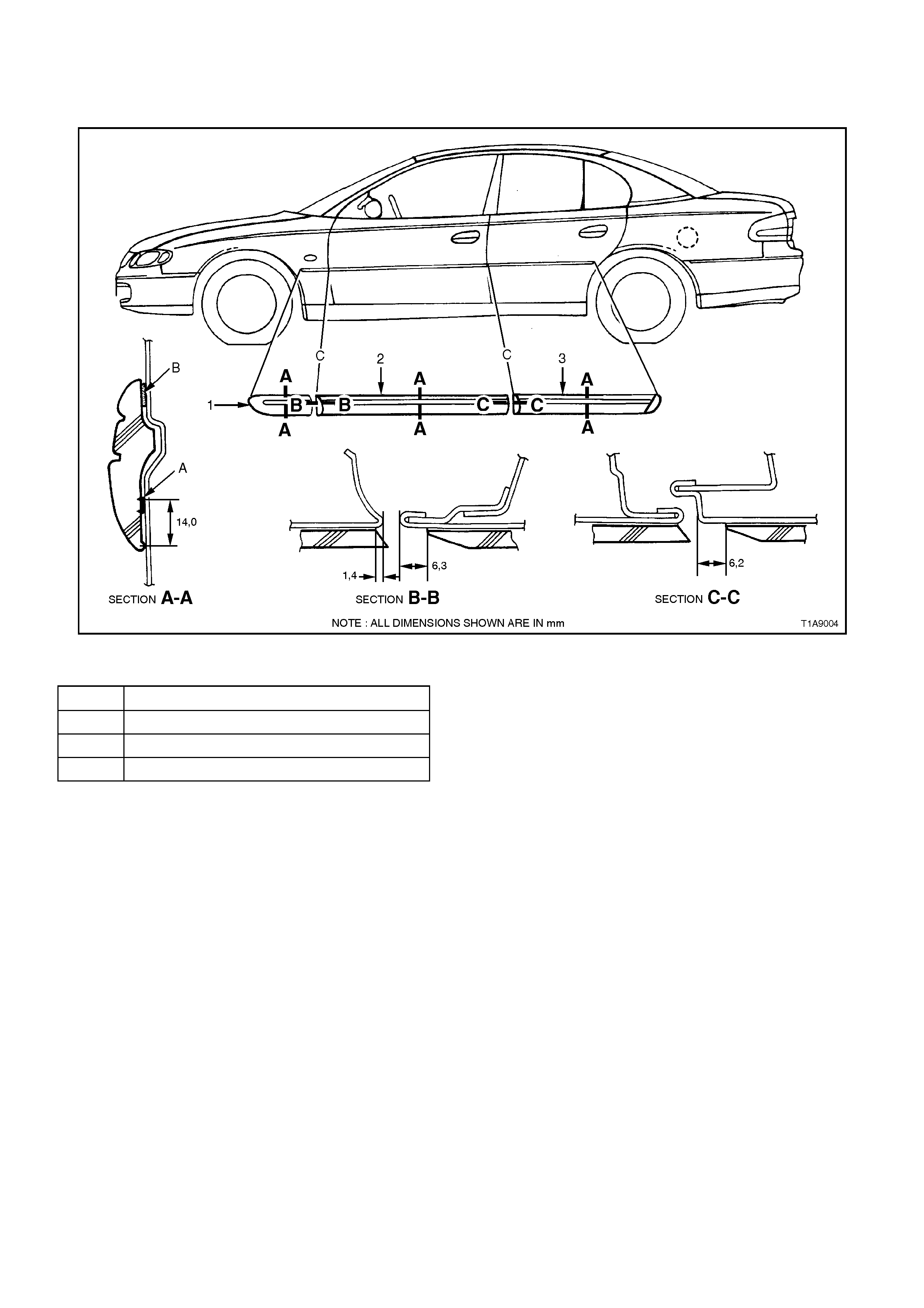
2.4 BODY SIDE MOULDINGS
SEDAN
Figure 1A9-7
ITEM DESCRIPTION
1. Front fender side moulding.
2. Front door side moulding.
3. Rear door side moulding.
SERVICE NOTES:
A Apply a 3.0 mm diameter bead of
polyurethane adhesive such as ‘Expandite
Betaseal 554.02’ or equivalent, to Holden
Specification HN 1890 over entire length of
mouldings.
B Double sided adhesive foam tape (part of
moulding assembly).
C Top edge of mouldings to be in line.
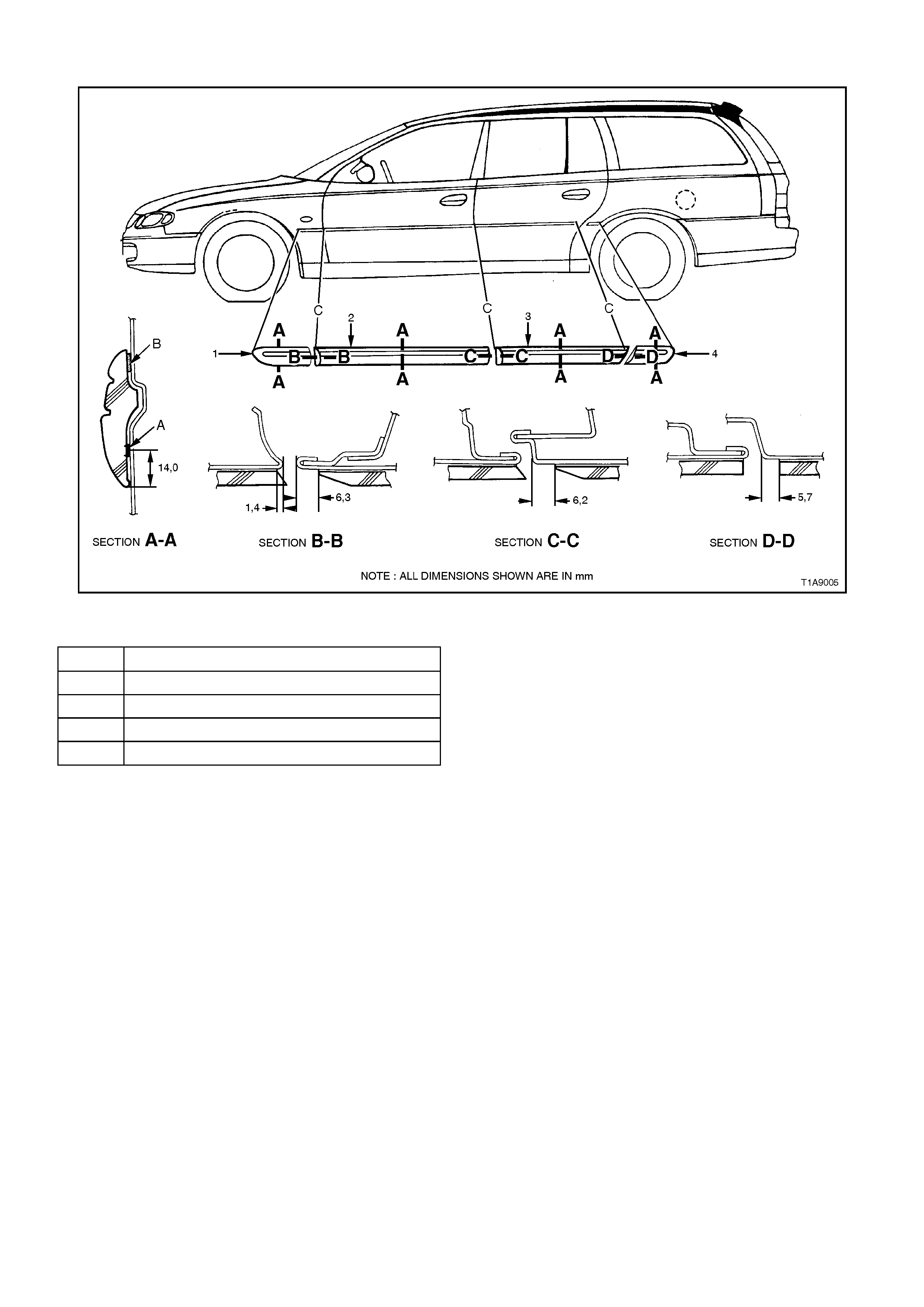
WAGON
Figure 1A9-8
ITEM DESCRIPTION
1. Front fender side moulding.
2. Front door side moulding.
3. Rear door side moulding.
4. Quarter panel side moulding.
SERVICE NOTES:
A Apply a 3.0 mm diameter bead of
polyurethane adhesive such as ‘Expandite
Betaseal 554.02’ or equivalent, to Holden
Specification HN 1890 over entire length of
mouldings.
B Double sided adhesive foam tape (part of
moulding assembly).
C Top edge of mouldings to be in line.
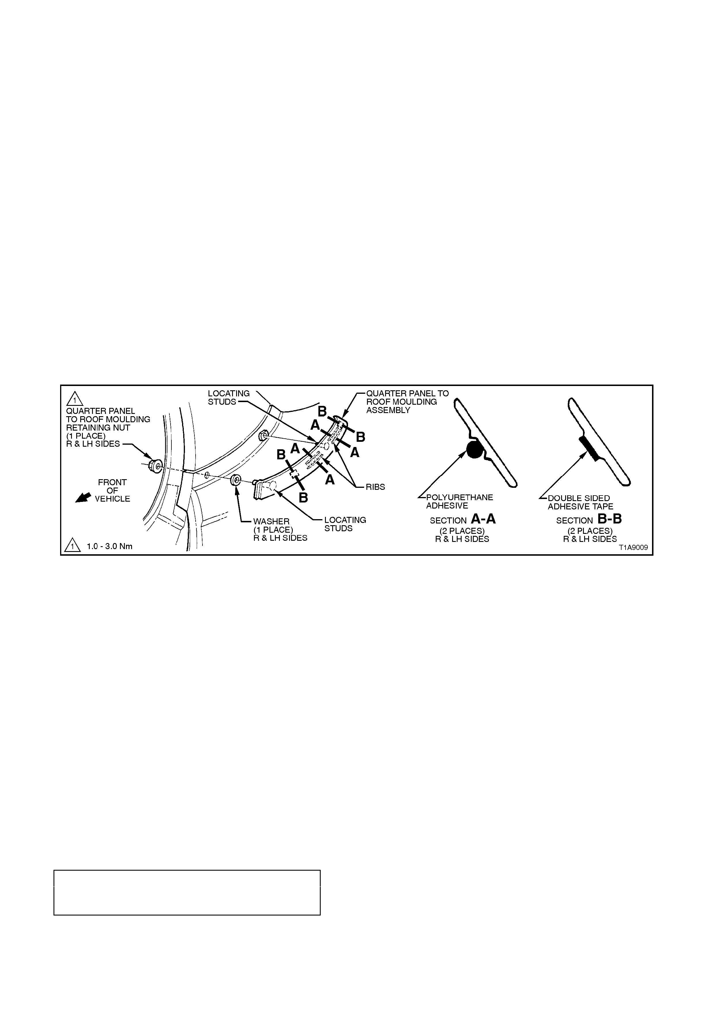
2.5 QUARTER PANEL TO ROOF MOULDING ASSEMBLY
REMOVE
1. Remove ‘C’ pillar trim panel assembly, refer to
Section 1A8 HEADLINING AND REAR END
TRIM, noting the following:
Only remove ‘C’ pillar tr im panel far enough to
gain access to the quarter panel to roof
moulding assembly retaining nut, inside the
quarter panel, refer to Fig. 1A9-9 .
NOTE:
Do not remove seat belt assembly.
2. Remove the quarter panel to roof moulding
retaining nut.
3. Using a piece of piano wire, carefully cut the
two beads of polyurethane adhesive from the
back of the quarter panel to roof moulding at
Section A-A and the double sided tape at
Section B-B in Fig. 1A9-9, noting to remove
and reinsert piano wire to get around locating
stud.
4. Remove quarter panel to roof moulding.
Figure 1A9-9
REINSTALL
Installation of the quarter panel to roof moulding
assembly is the reverse of the removal operation,
noting the following:
1. Apply an 8.0 mm bead of polyurethane
adhesive such as ‘Expandite Betaseal 554.02’
or equivalent, to Holden Specification HN
1890 to the inside of the moulding between
ribs, and for length of ribs in two places for
each moulding, refer to Section A-A,
Fig. 1A9-9
2. To hold the moulding in position while the
polyurethane adhesive cures, apply double
sided adhesive tape, type 5 or equivalent to
Holden Specification HN 2021, on the raised
flat area inside of m oulding (two places), refer
Section B-B Fig. 1A9-9.
3. Tighten all fasteners to the correct torque
specification.
QUARTER PANEL TO ROOF
MOULDING RETAINING NUT 1 -3 Nm
TORQUE SPECIFICATION
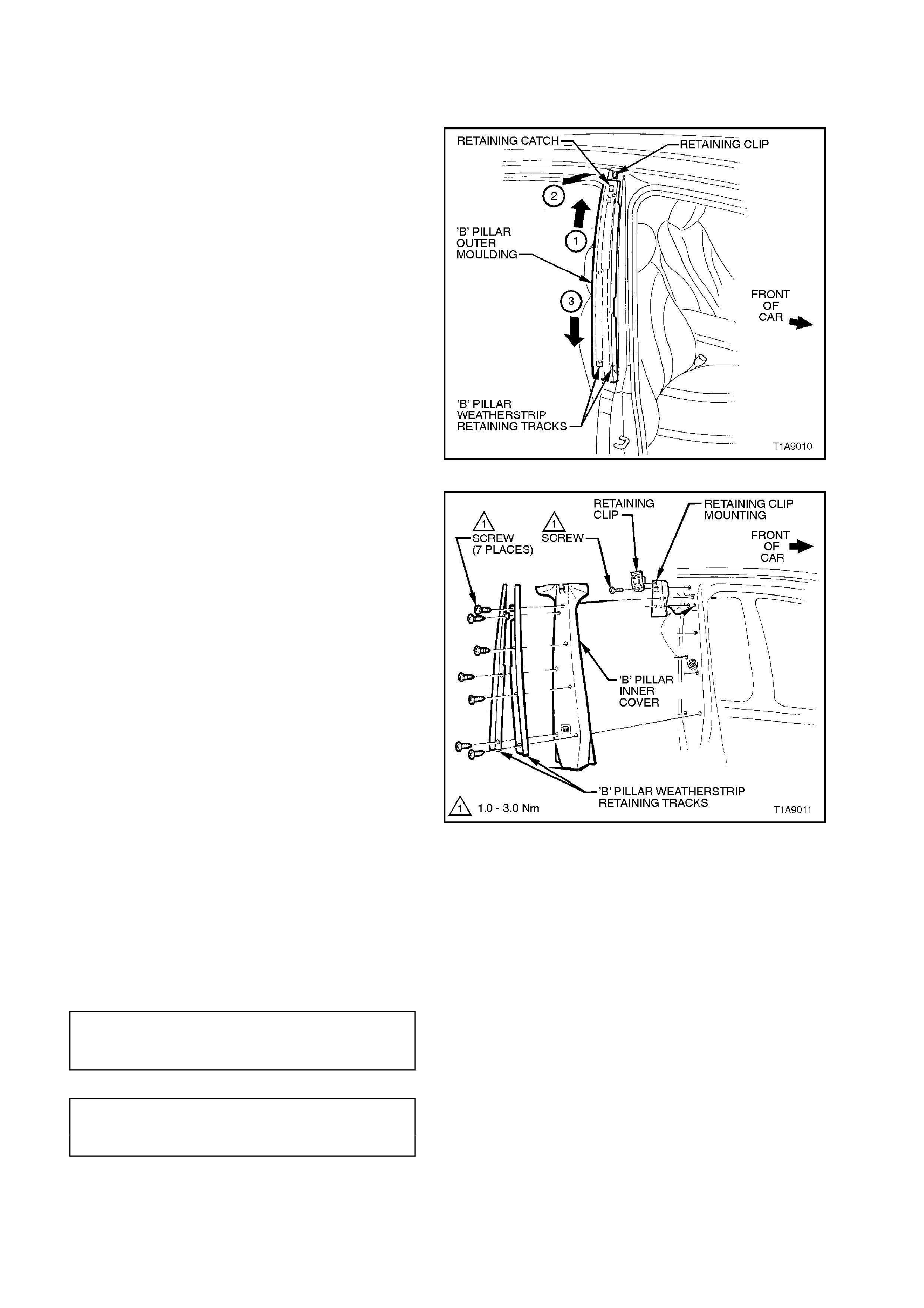
2.6 'B' PILLAR MOULDING
REMOVE
1. Open front and rear door on relevant side of
vehicle.
2. To release the outer moulding from the
retaining clip, push the outer moulding up by
hand slightly (1) while gently levering top of
moulding out and away from ‘B’ pillar (2).
3. With top of ‘B’ pillar released from retainer,
hold top of moulding out and slide moulding
down weatherstrip retaining tracks until
moulding rests on rear door hinge assembly
(3).
4. Jiggle outer moulding until it becomes free
from weatherstr ip retaining tr acks, and r emove
outer moulding.
Figure 1A9-10
5. Remove the door frame opening moulding,
refer to 2.8 DOOR FRAME OPENING
MOULDING in this Section.
6. Remove the seven screws securing the ‘B’
pillar weatherstrips retaining tracks to the ‘B’
pillar and remove weatherstrip assemblies.
7. Remove inner cover by pulling cover away
from ‘B’ pillar.
8. Remove the screw securing the moulding
retaining clip and m ounting to the ‘B’ pillar and
remove retaining clip and mounting.
Figure 1A9-11
REINSTALL
Installation of the ‘B’ pillar moulding is the reverse
of the removal procedure, noting the following:
1. Ensure the inner cover is seated correctly,
under door opening weatherstrips.
2. Ensure all fasteners are tightened to the
correct torque specification.
RETAINING CLIP
SECURING SCREW 1 - 3 Nm
TORQUE SPECIFICATION
WEATHERSTRIP ASSEMBLY
SECURING SCREW 1 - 3 Nm
TORQUE SPECIFICATION
3. Slide the outer moulding up and press it in at
the top so that it engages into the retaining
clip.
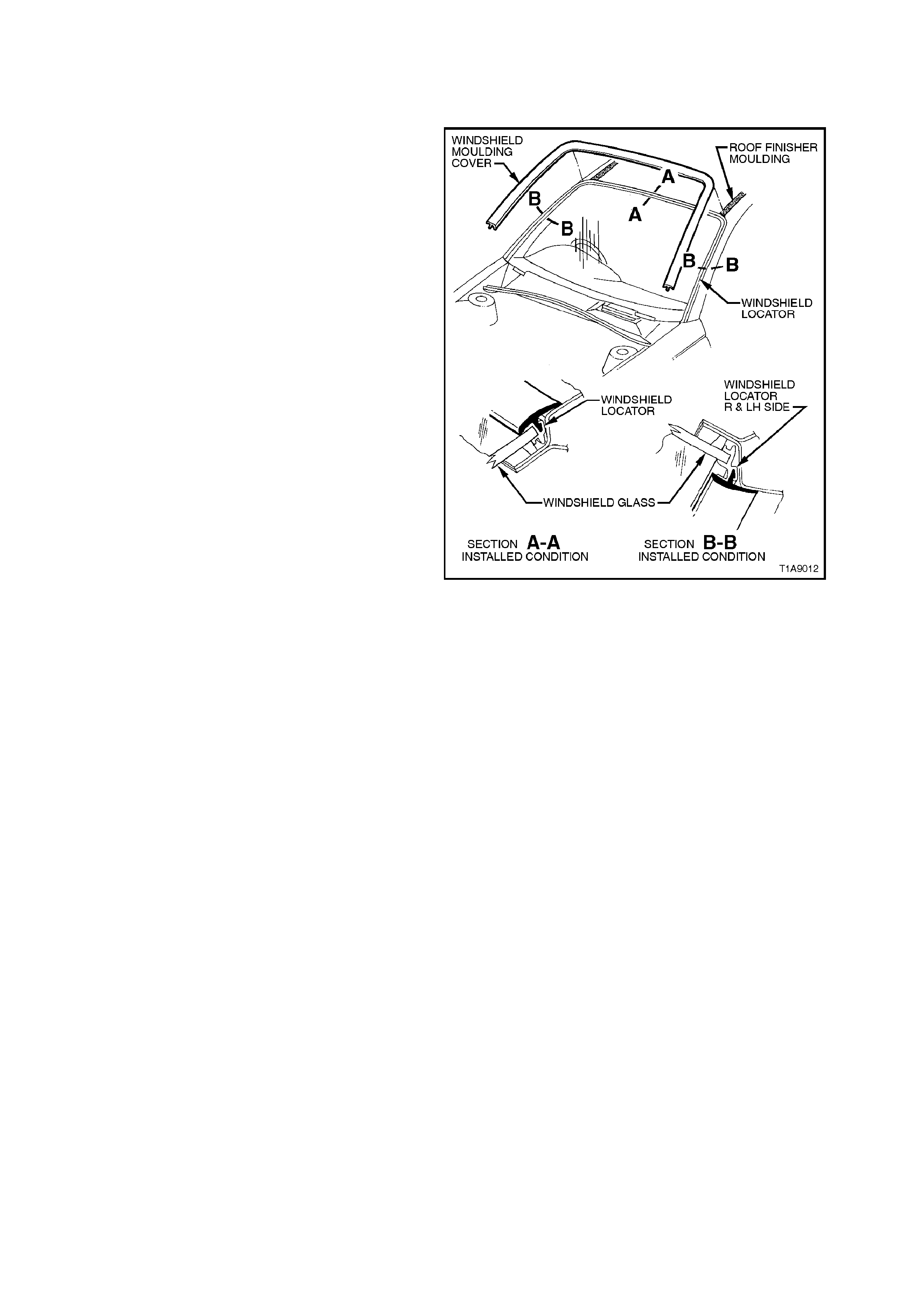
2.7 WI NDSHIELD MOULDING COVER
REMOVE
Starting at either corner of the windshield moulding
cover, gently pry windshield moulding cover out of
windshield locator and peel cover away from
windshield locator.
REINSTALL
Sit windshield moulding cover into position (place
each end of cover into locator f irst) and push cover
into windshield locator, ensuring that it is properly
engaged into locators, refer to Fig 1A9-12.
Figure 1A9-12
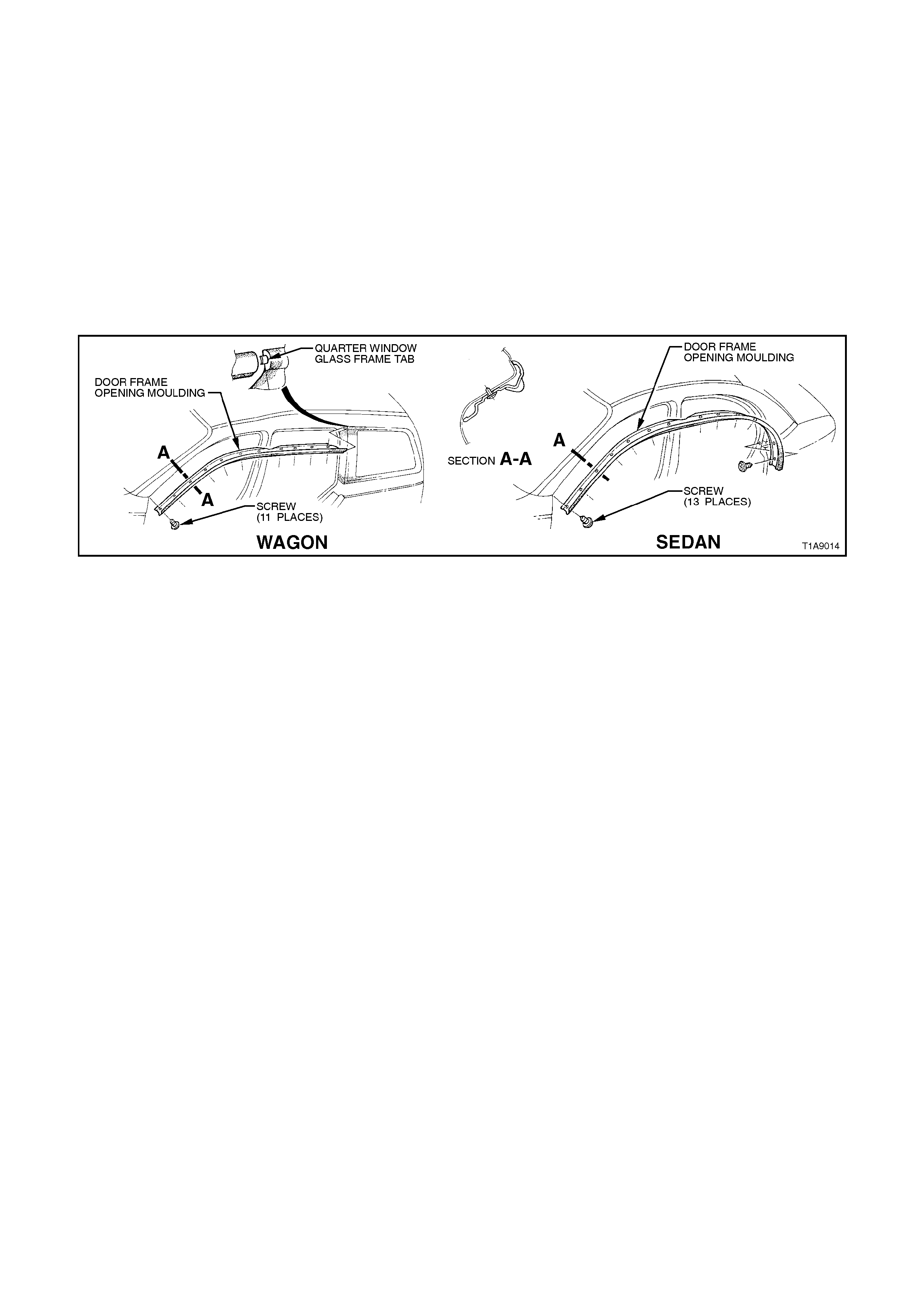
2.8 DOOR FRAME OPENING MOULDING
REMOVE
1. Open front and rear door on relevant side of vehicle.
2. Remove the screws (sedan - 13 places, wagon - 11 places) securing door frame opening moulding to body and
remove moulding.
NOTE:
On wagon models, remove moulding from the front first and slide forward slightly to disengage moulding from
quarter window glass frame tab, refer to Fig. 1A9-13.
REINSTALL
Installation is the reverse of the removal procedure.
Figure 1A9-13
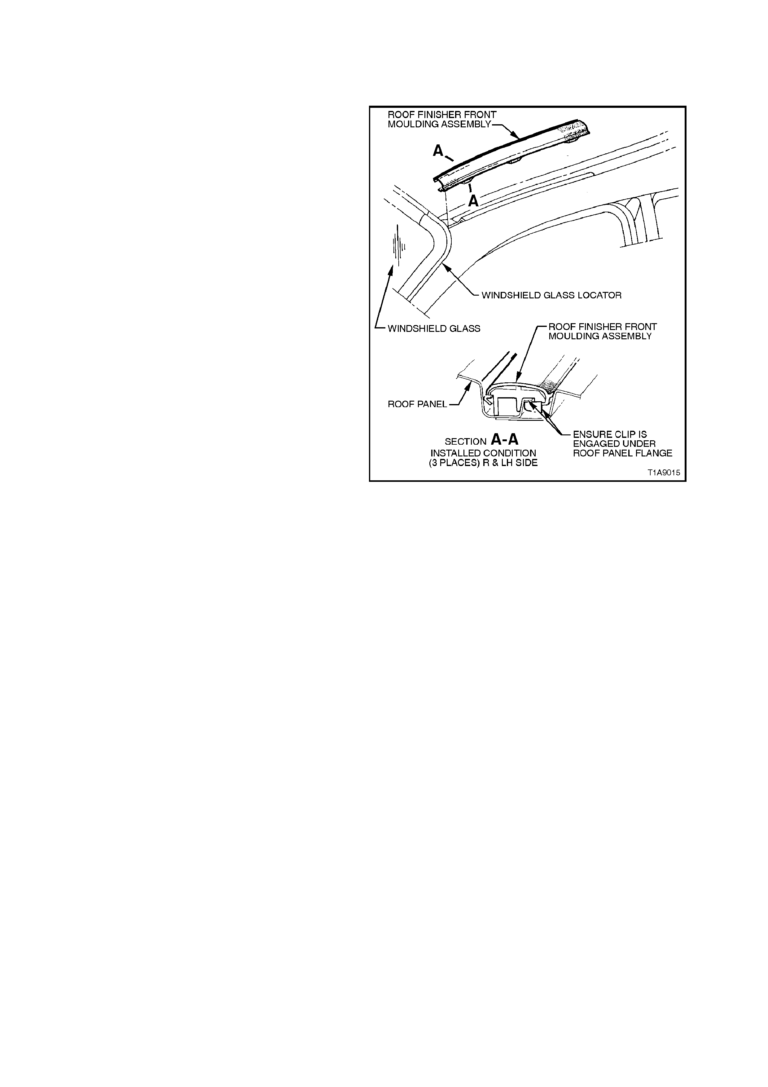
2.9 ROOF FINISHER MOULDING - SEDAN
REMOVE
1. Remove windshield moulding cover, refer to
2.7 WINDSHEILD M OULDING COVER in this
Section.
2. Using a screw driver with a clean shop rag
to prevent paint work damage, pry the front of
the roof finisher moulding out of the roof
channel between the top of the windscreen to
the top of the rear window.
3. Slide the roof finisher m oulding out of the side
moulding retaining channel (between rear
window and quarter panel).
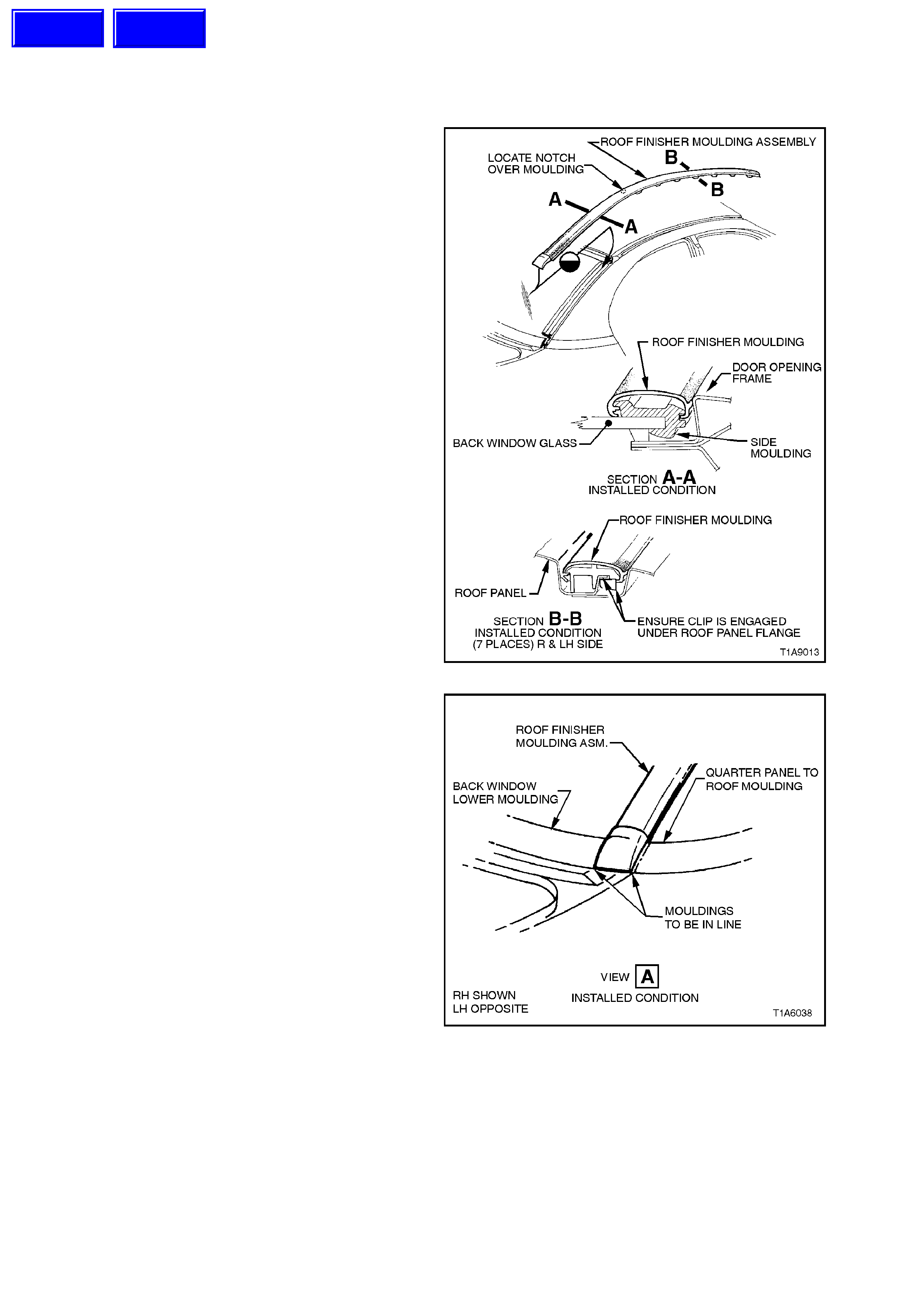
REINSTALL
1. Engage roof finisher moulding over side
moulding, refer to Fig 1A9-14, and slide along
until roof finisher moulding is in line with the
quarter panel to roof moulding and the back
window lower moulding, refer to Fig. 1A9-15.
2. Engage roof finisher moulding assembly clips
along roof until roof finisher moulding
assembly sits flush against the roof.
3. Install windshield moulding cover, refer to
2.7 WINDSHIELD M OULDING COVER in this
Section.
NOTE:
The roof finisher moulding must be installed under
the windshield moulding cover.
Figure 1A9-14
NOTE:
Ensure roof finisher moulding end cap is aligned
with quarter panel to roof moulding, refer to Fig
1A9-15.
Figure 1A9-15
Techline
Techline
2.10 ROOF FINISHER MOULDING - WAGON
REMOVE
Starting at the front of the moulding, pry moulding
out of roof channel and remove.
NOTE:
Take care not to damage paint work.
REINSTALL
Push moulding into channel, ensuring that the clip
is engaged under the roof panel flange, r ef er to F ig.
1A9-16.
Figure 1A9-16
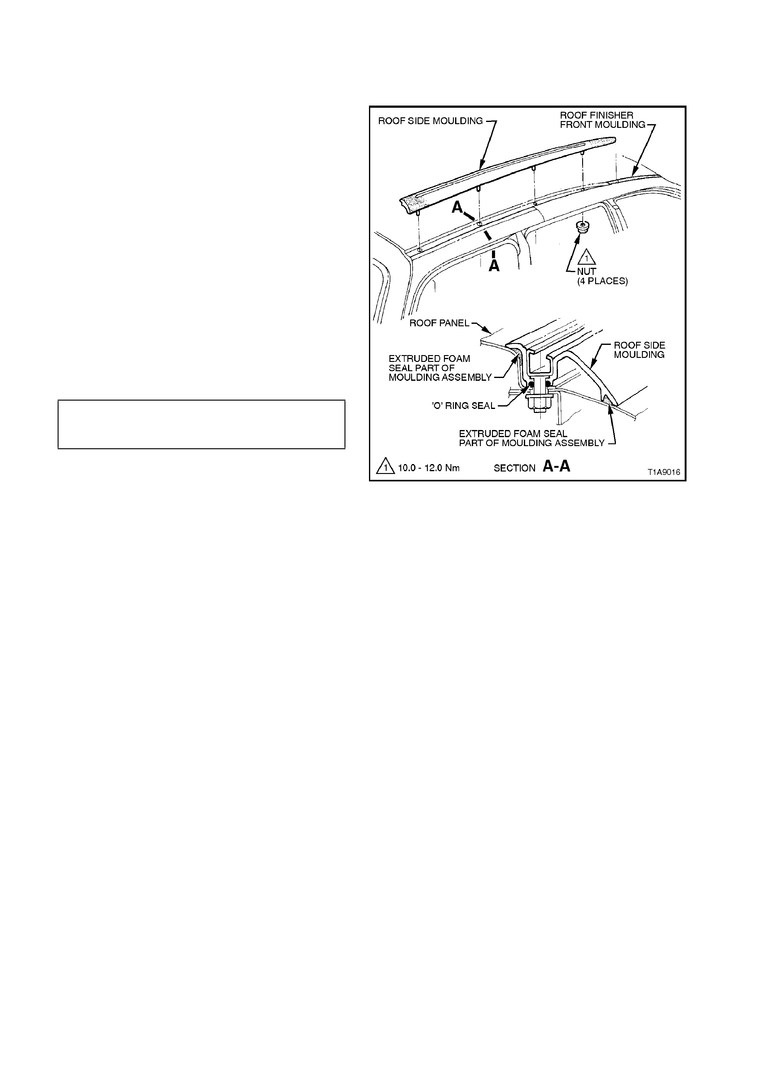
2.11 ROOF SIDE MOULDING - WAGON
REMOVE
1. Remove headlining, refer to
Section 1A8 HEADLINING AND REAR END
TRIM.
2. Loosen and remove the f our nuts securing the
roof side moulding to the roof panel and
remove roof side moulding by lifting roof side
moulding up until s tuds are f ree and then slide
rearward.
REINSTALL
Installation of the roof side moulding is the reverse
of the removal procedure, noting the following:
1. Ensure the O-ring seals are fitted to each of
the roof side moulding studs.
2. Ensure all fasteners are tightened to the
correct torque specification.
ROOF SIDE MOULDING
SECURING NUT 10 - 12 Nm
TORQUE SPECIFICATION
Figure 1A9-17
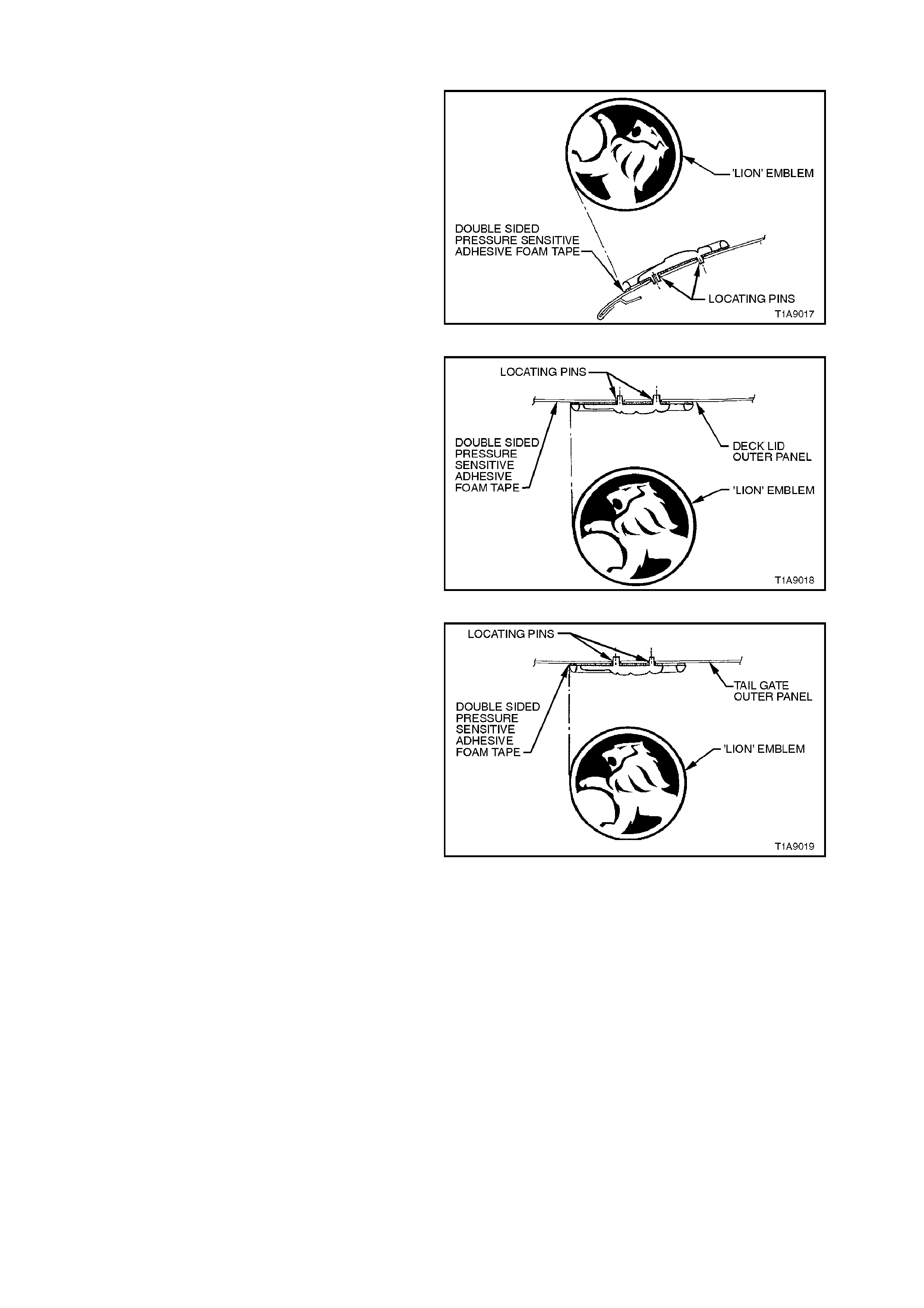
2.12 'LION' EMBLEM
ENGINE HOOD
Service notes
NOTE 1:
Before installation, remove release paper from
adhesive foam tape.
NOTE 2:
After removing release paper from adhesive foam
tape, ensure there is a band of adhesive foam tape
around base of locating pins.
Figure 1A9-18
DECK LID
Service notes
NOTE 1:
Before installation, remove release paper from
adhesive foam tape.
NOTE 2:
After removing release paper from adhesive foam
tape, ensure there is a band of adhesive foam tape
around base of locating pins.
Figure 1A9-19
TAILGATE
Service notes
NOTE 1:
Before installation, remove release paper from
adhesive foam tape.
NOTE 2:
After removing release paper from adhesive foam
tape, ensure there is a band of adhesive foam tape
around base of locating pins.
Figure 1A9-20
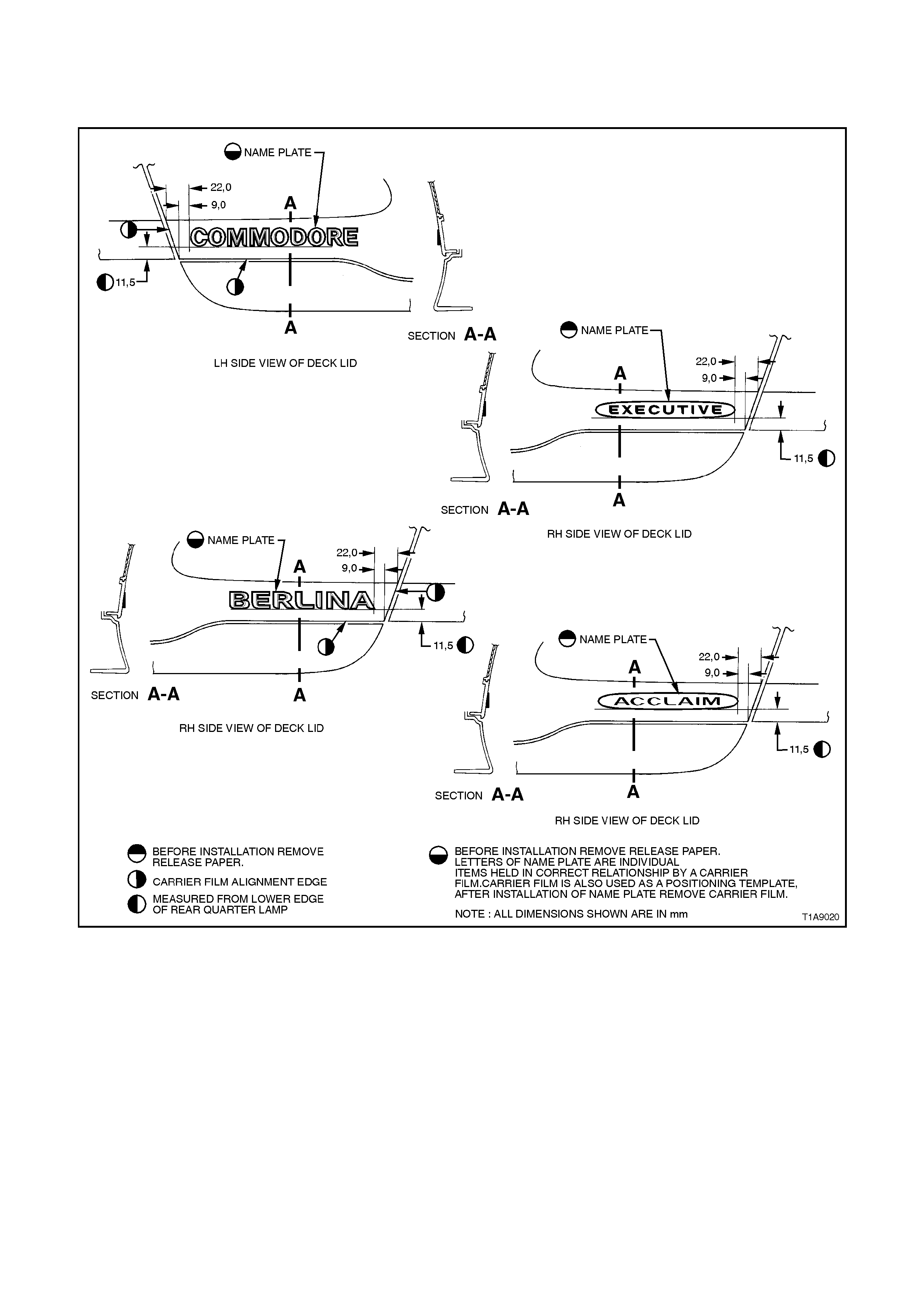
2.13 NAME PLATES AND DECALS
EXECUTIVE, BERLINA & ACCLAIM - SEDAN
Figure 1A9-21
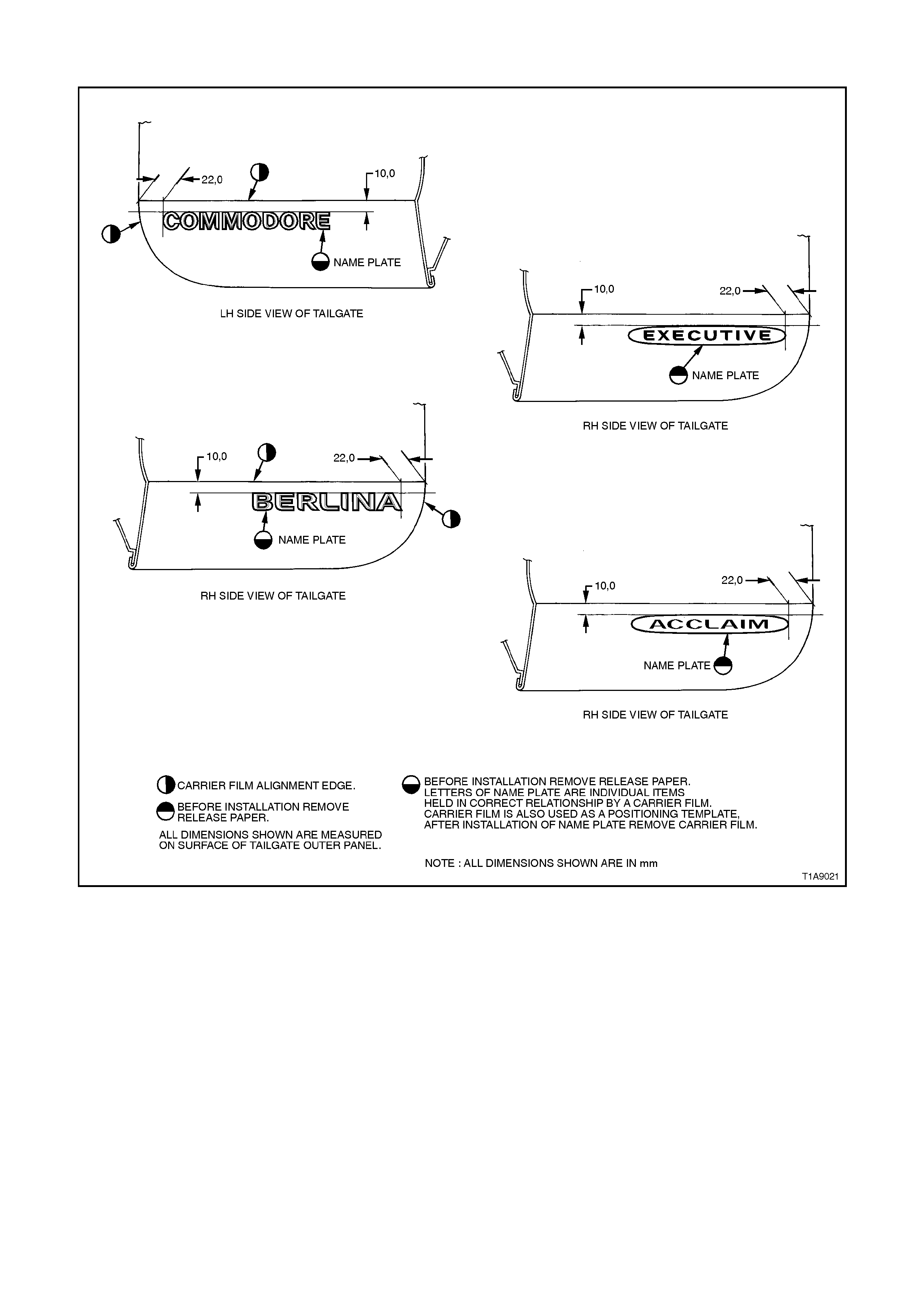
EXECUTIVE, BERLINA & ACCLAIM - WAGON
Figure 1A9-22
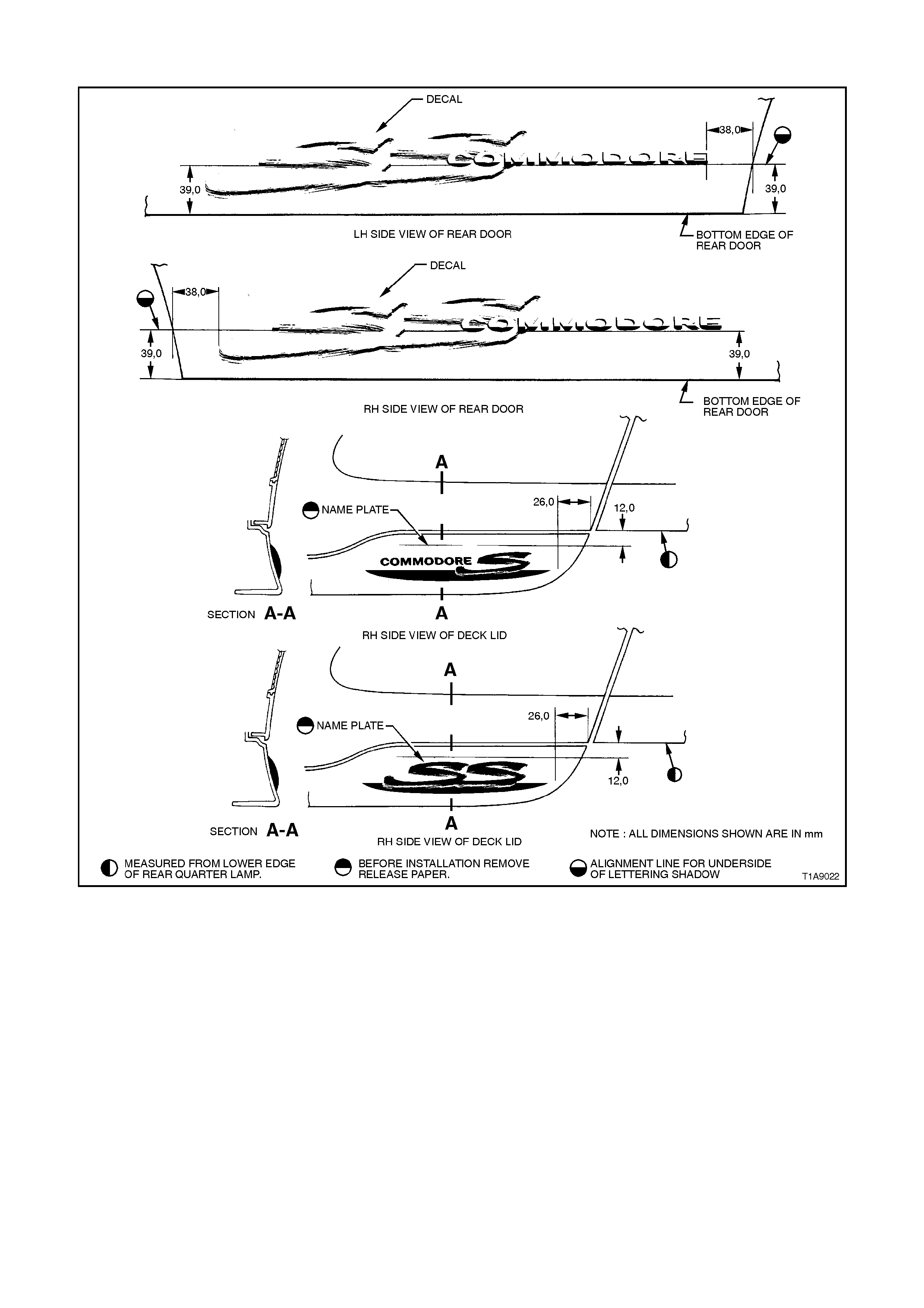
'S' AND 'SS'
Figure 1A9-23
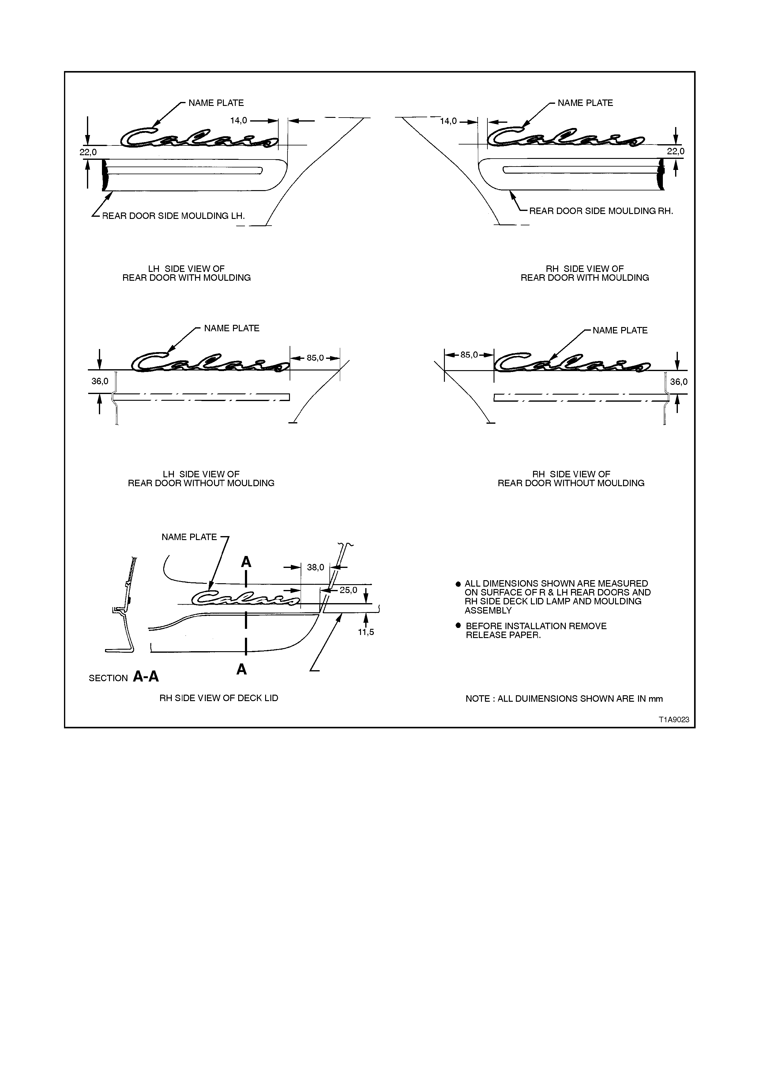
CALAIS
Figure 1A9-24
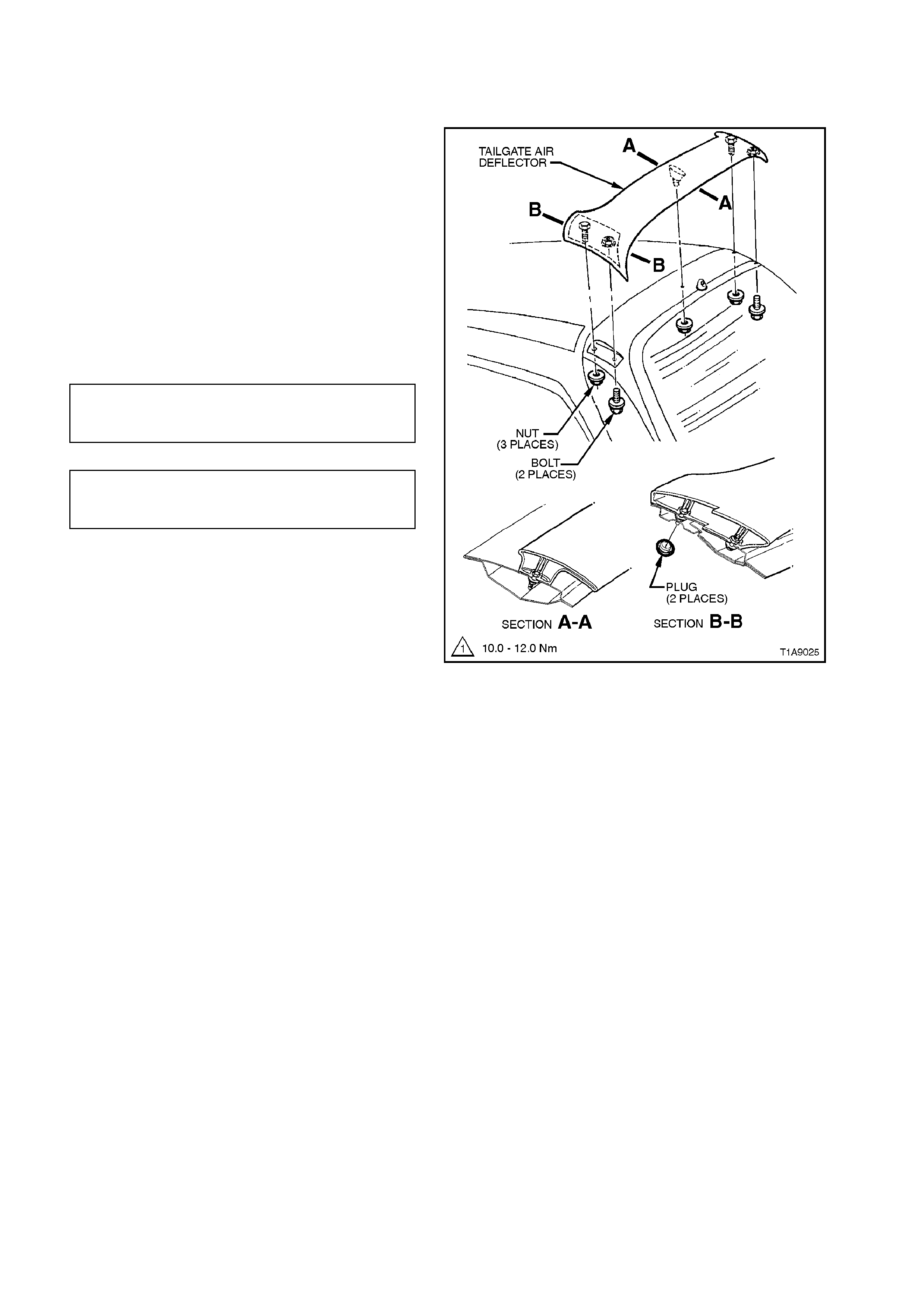
2.14 TAILGATE AIR DEFLECTOR
REMOVE
1. Remove trim panel and blanking plug from
tailgate, refer to Section 1A4 REAR
COMPARTMENT LID AND TAILGATE.
2. Rem ove the three nuts and two bolts securing
the air deflector to the tailgate and remove air
deflector.
REINSTALL
Installation of the tailgate air deflector is the reverse
of the removal procedure, noting the following:
Ensure all fasteners are tightened to the correct
torque specification.
AIR DEFLE CTOR TO TAILGATE
SECURING NUT 2 - 5 Nm
TORQUE SPECIFICATION
AIR DEFLE CTOR TO TAILGATE
SECURING BOLT 2 - 5 Nm
TORQUE SPECIFICATION
Figure 1A9-25

2.15 DE CK LID AIR SPOILER
REMOVE
1. With the deck lid raised, disconnect the
electrical connector to the high mount stop
lamp, refer to View A Fig. 1A9-26.
2. Remove the four nuts securing the spoiler to
the deck lid.
3. While feeding high mount stop lamp wiring
harness through access hole in deck lid,
remove the spoiler assembly.
REINSTALL
Installation of the deck lid spoiler is the reverse of
the removal procedure, noting the following:
1. Ensure the foam seals are installed between
the deck lid spoiler and the deck lid, refer to
Fig 1A9-26.
2. Ensure all fasteners are tightened to the
correct torque specification.
SPOILER ASSEMBLY TO DECK
LID SECURING NUT 2 - 5 Nm
TORQUE SPECIFICATION
Techline
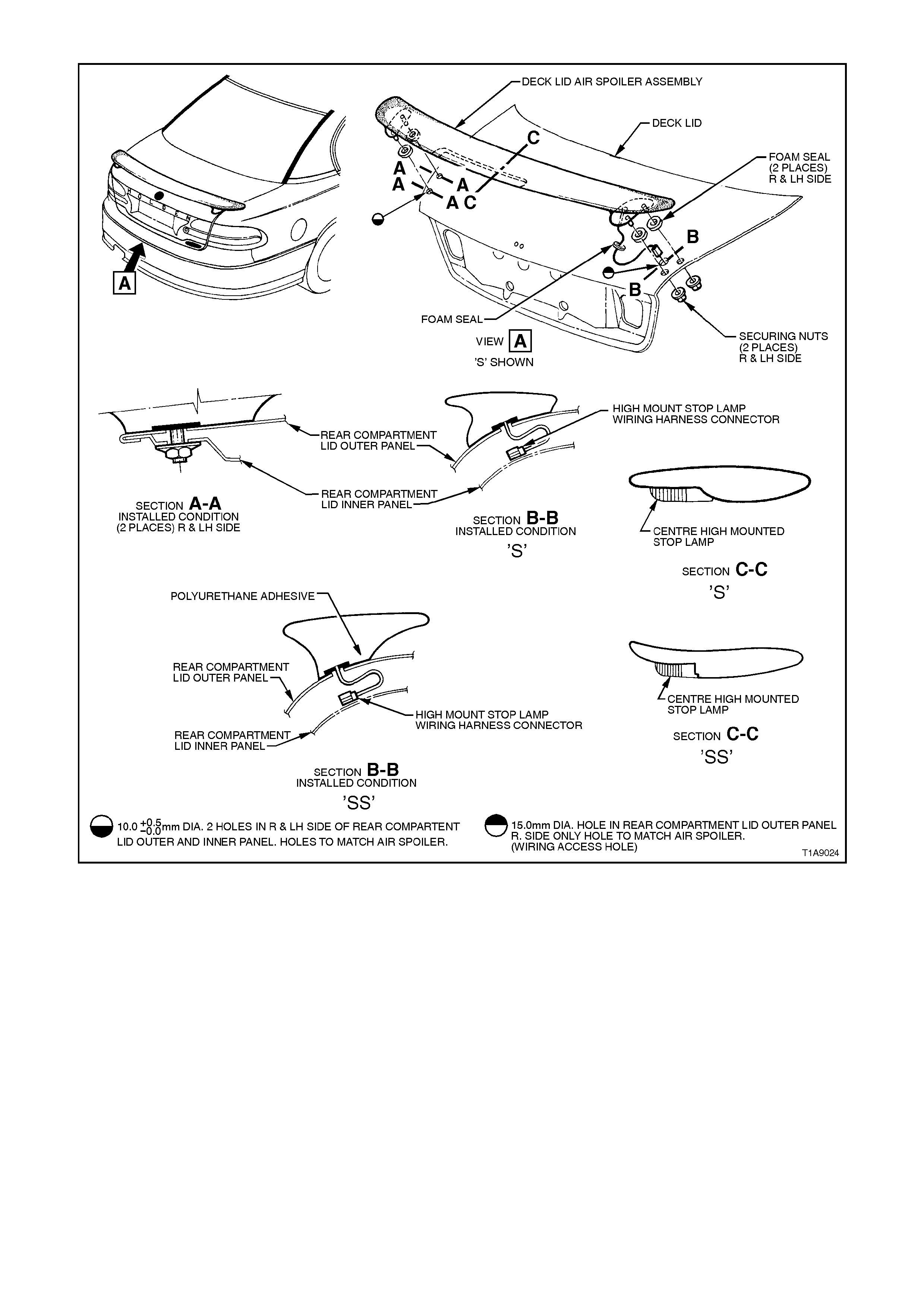
Figure 1A9-26

3. TORQUE WRENCH SPECIFI CATIONS
Nm
Rocker Panel Skirt Retaining Screw 1 - 3
Quarter Panel to Roof Moulding Retaining Nut 1 - 3
‘B’ Pillar Moulding Retaining Clip Retaining Screw 1 - 3
Weatherstrip Assembly Securing Screw 1 - 3
Roof Side Moulding Securing Nut 10 - 12
Spoiler Assembly to Deck Lid Securing Nut 2 - 5
Air Deflector to Tailgate Securing Nut 2 - 5
Air Deflector to Tailgate Securing Bolt 2 - 5