SECTION 1B - SHEET METAL
CAUTION:
This vehicle will be equipped with a Supplemental Restraint System (SRS). A SRS will
consist of either seat belt pre-tensio ners and a driver’s side air bag , or seat belt pre-
tensioners and a driver’s and front passenger’s side air bags. Refer to CAUTIONS,
Section 12M, before performing any service operation on or around SRS
components, the steering mechanism or wiring. Failure to follow the CAUTIONS
could result in SRS deplo yment, resulting in possible p ersonal injury or unnecessary
SRS system repairs.
CAUTION:
This vehicle may be equipped with LPG (Liquefied Petroleum Gas). In the interests of
safety, the LPG fuel system should be isolated by turning 'OFF' the manual service
valve and then draining the LPG serv ice lines, before any service w ork is carried out
on the vehicle. Refer to the LPG leaflet included with the Owner's Handbook for
details or LPG Section 2 for more specific servicing information.
1. GENERAL INFORMATION
VT Series front end sheet metal components consist of engine hood, front fender and front end panel, to which
homofocal headlamps are mounted. The engine hood assembly is hinged at the rear end and is supported in the
open position by two gas struts attached to the engine hood inner panel and to the front fender inner panel.
The hood lock release lever mounted beneath the right-hand side of the instrument panel, controls the hood lock
release spring. The engine hood when released from the locked position engages in a secondary safety catch which
can be released by inserting fingers beneath the leading edge of the engine hood.
A fuel filler door remote control is located between the driver's seat and sill panel on all models. The control
releases the fuel filler door when the lever is moved up.
2. SERVICE OPERATIONS
2.1 FRONT FENDER ASSEMBLY
REMOVE
1. Remove the front bumper bar assembly (refer to Section 1D BUMPER BARS).
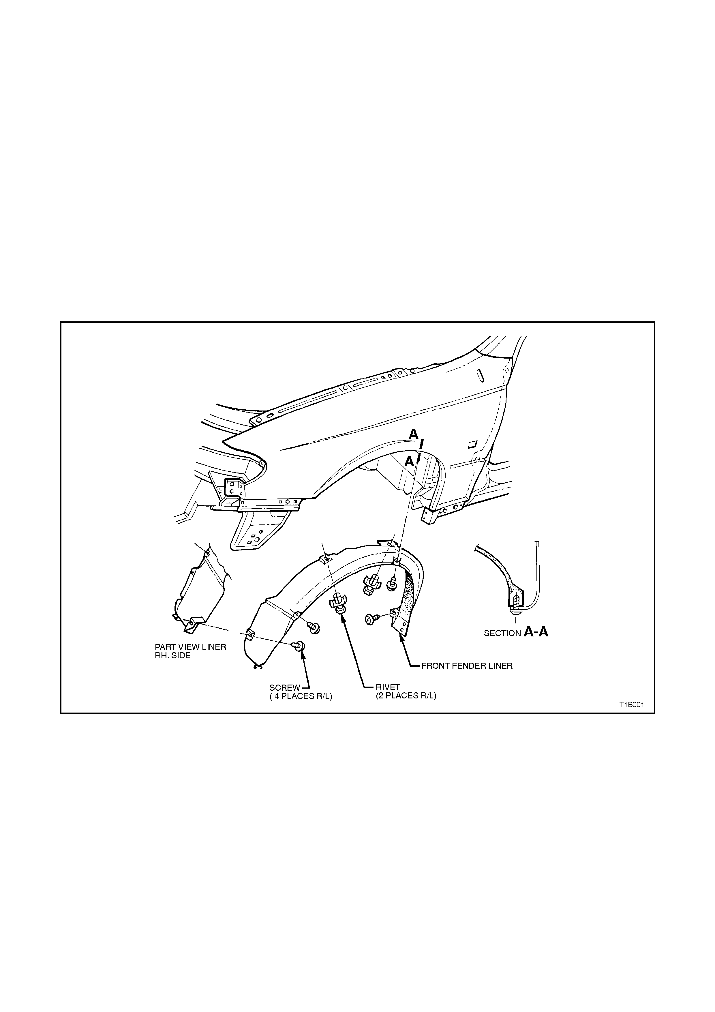
2. Remove the front fender liner, illustrated in Fig.1B-1, from the side which fender is to be removed.
3. If necessary, remove the radio antenna. Refer to Section 12D RADIO/CASSETTE PLAYER for electric
antenna details. The manual antenna is removed by detaching the nut at the upper end of the assembly.
4. Remove screws securing fender to the front end assembly illustrated in Fig. 1B-2.
5. Remove gas struts and screws securing gas struts to fender, refer to
2.2 ENGINE HOOD GAS STRUT ASSEMBLY in this Section.
6. Remove the screw and washer assemblies securing the lower and upper part of the fender to the front-end
assembly and the engine inner skirt panel, illustrated in Fig. 1B-2, removing the fender.
REINSTALL
Reverse removal operations.
Figure 1B-1
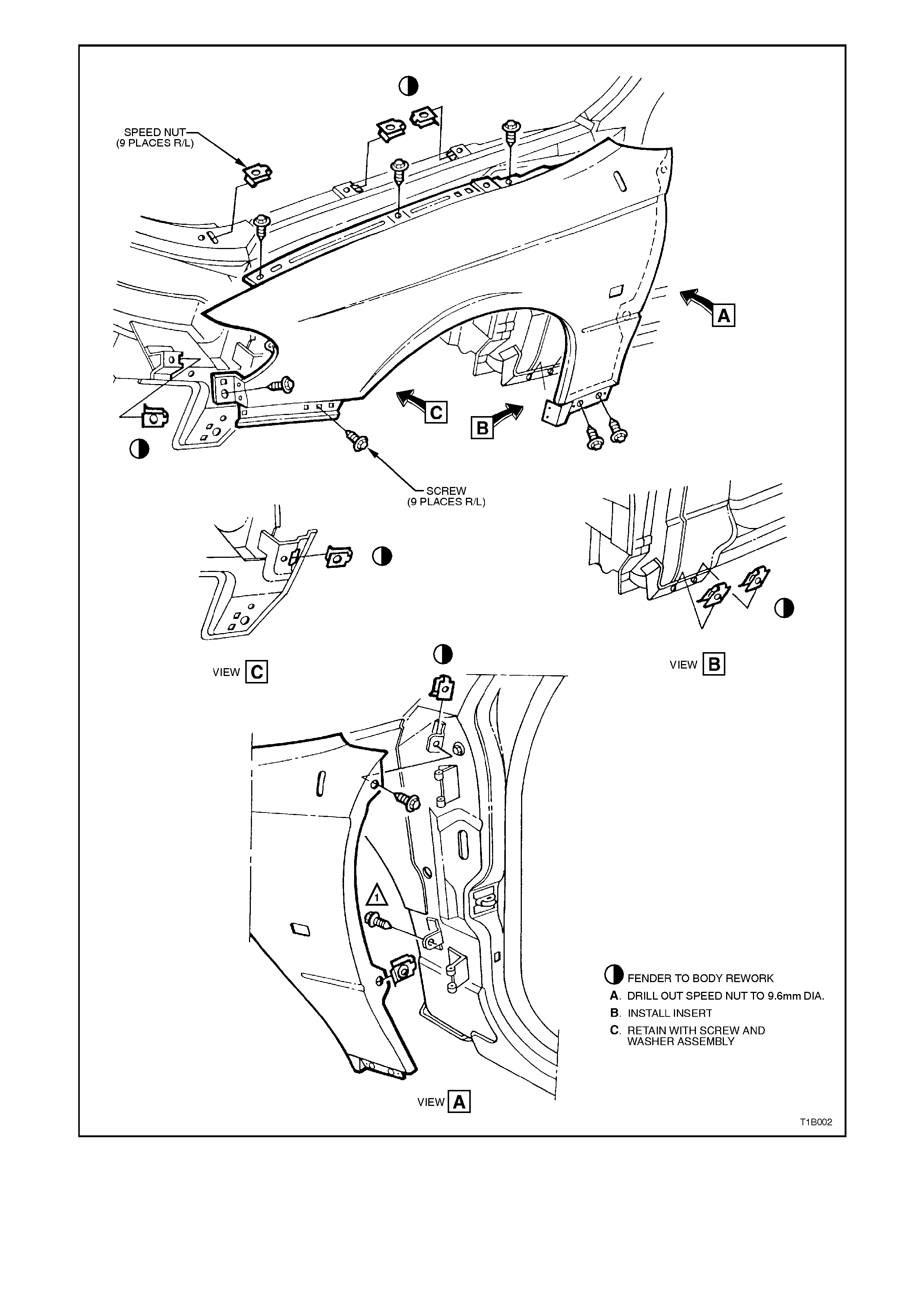
Figure 1B-2
2.2 ENGINE HOOD GAS STRUT ASSEMBLY
CAUTION:
Gas struts are filled with compressed gases
and therefore should never be subjected to
extreme heat, pressure or physical damage as
personal injury can result.
REMOVE
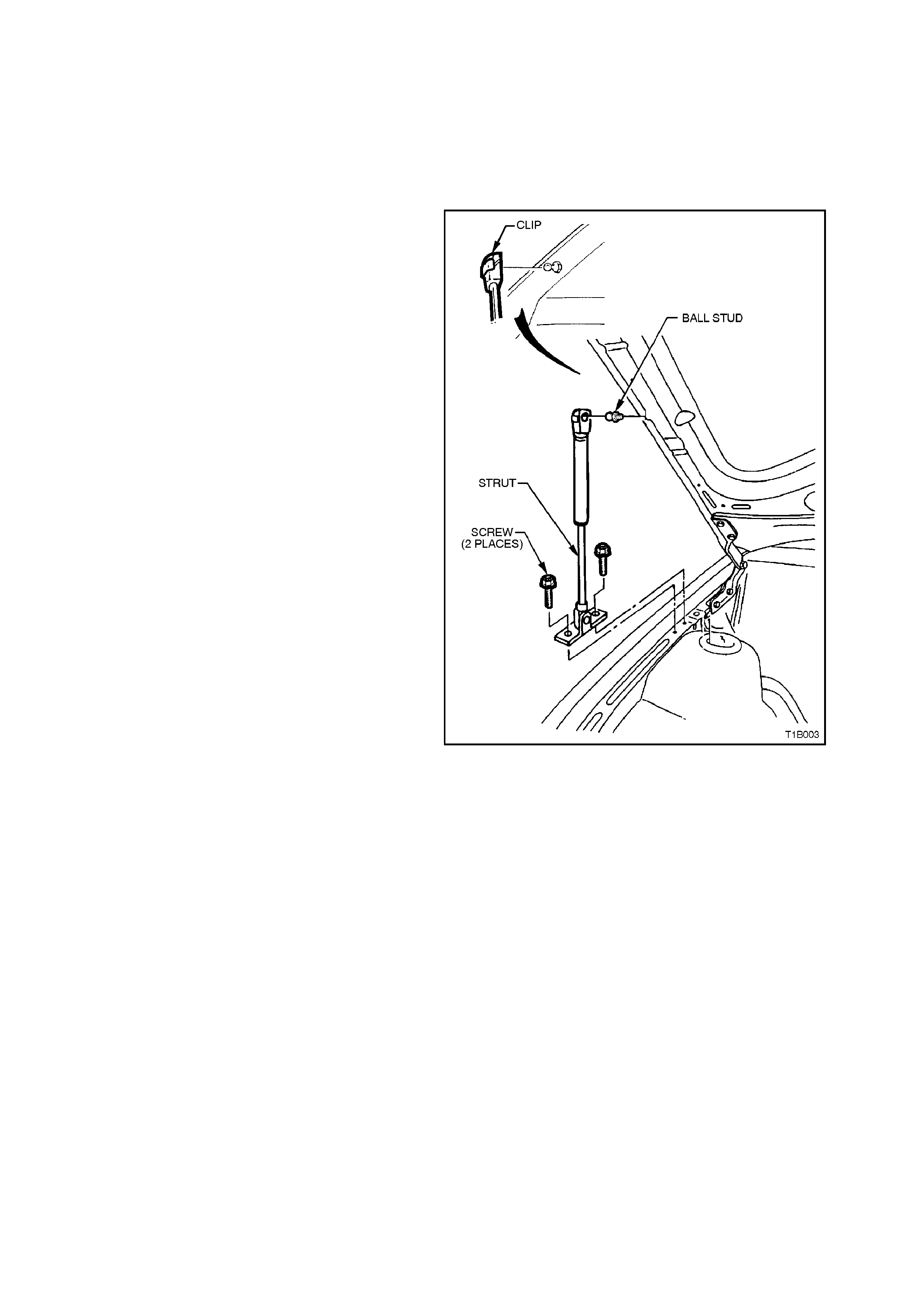
1. With the engine hood adequately supported,
rem ove the clips sec uring the engine hood gas
support strut then disconnect the strut from the
engine hood and front fender inner panel.
Figure 1B-3
REINSTALL
Reverse removal operations.

2.3 ENGINE HOOD ASSEMBLY
REMOVE
1. With the engine hood raised and supported, disconnect windshield washer tube and engine hood gas strut
assemblies from the engine hood inner panel.
2. With the engine hood adequately supported, remove the screw from the hinges (refer to Fig. 1B-4), removing
the assembly.
REINSTALL
Reverse removal operations.
ADJUST
When adjusting the engine hood assembly, uniform spacing and alignment between the engine hood and adjacent
parts is important.
Slotted holes in the hinge arms provide horizontal adjustment, whilst slots in the hinge support mounting to shroud
side provide vertical adjustment for the rear end of the engine hood.
Vertical adjustment for the front end of the engine hood is achieved by adjustment of the pilot pin and hood lock nut
in conjunction with the hood buffers located on the front of the engine hood inner panel (refer to Fig.1B-4).
Techline
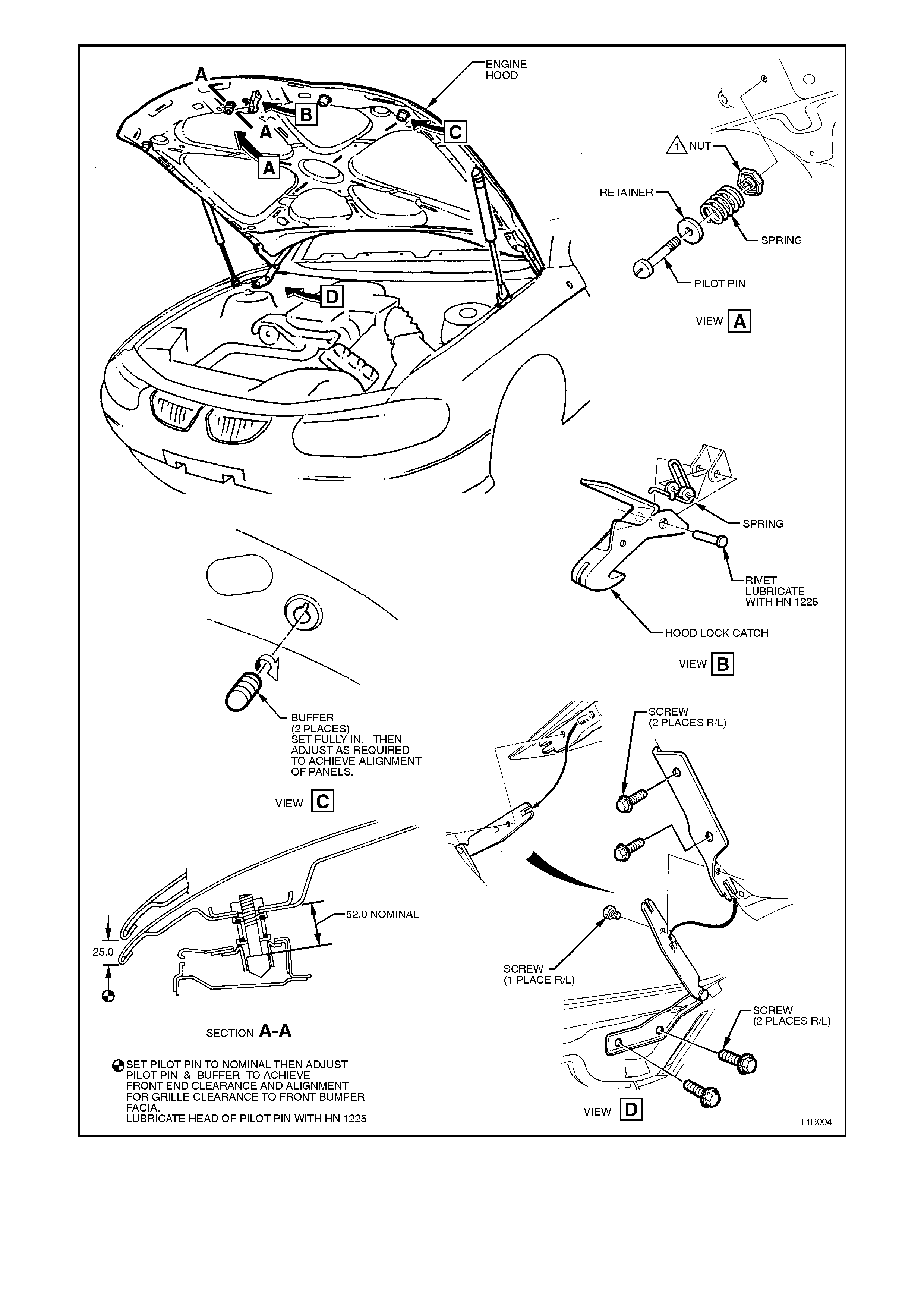
Figure 1B-4

2.4 PILOT PIN, HOOD LOCK
REMOVE
1. Raise the engine hood assembly.
2. Slacken off the hood pilot pin lock nut, then, still retaining the nut, unscrew the pilot pin in an anti-clockwise
direction, refer to Fig. 1B-4.
REINSTALL
Reverse removal operations.

2.5 HOOD LOCK SECONDARY CATCH
REMOVE
1. Raise the engine hood assembly.
2. Remove rivet illustrated in Fig. 1B-4 securing hood lock spring and secondary catch to engine hood assembly
bracket, removing catch and spring.
REINSTALL
Reverse removal operations. Lubricate rivet on reassembly.

2.6 ENGINE HOOD RELEASE CABLE ASSEMBLY
REMOVE
1. Raise the engine hood assembly.
2. Remove radiator front shroud.
3. Depress the hood lock release spring and disengage the nipple at the front end of the release cable from the
release spring, illustrated in Fig. 1B-5.
4. Disengage clip securing cable assembly to front end panel assembly, refer to Fig. 1B-5.
5. From inside the vehicle, slide the cable, bracket and lever assembly illustrated in Fig. 1B-5, from the right hand
shroud panel lower, rearwards; then pull the complete assembly into the vehicle.
REINSTALL
Reverse removal operations.
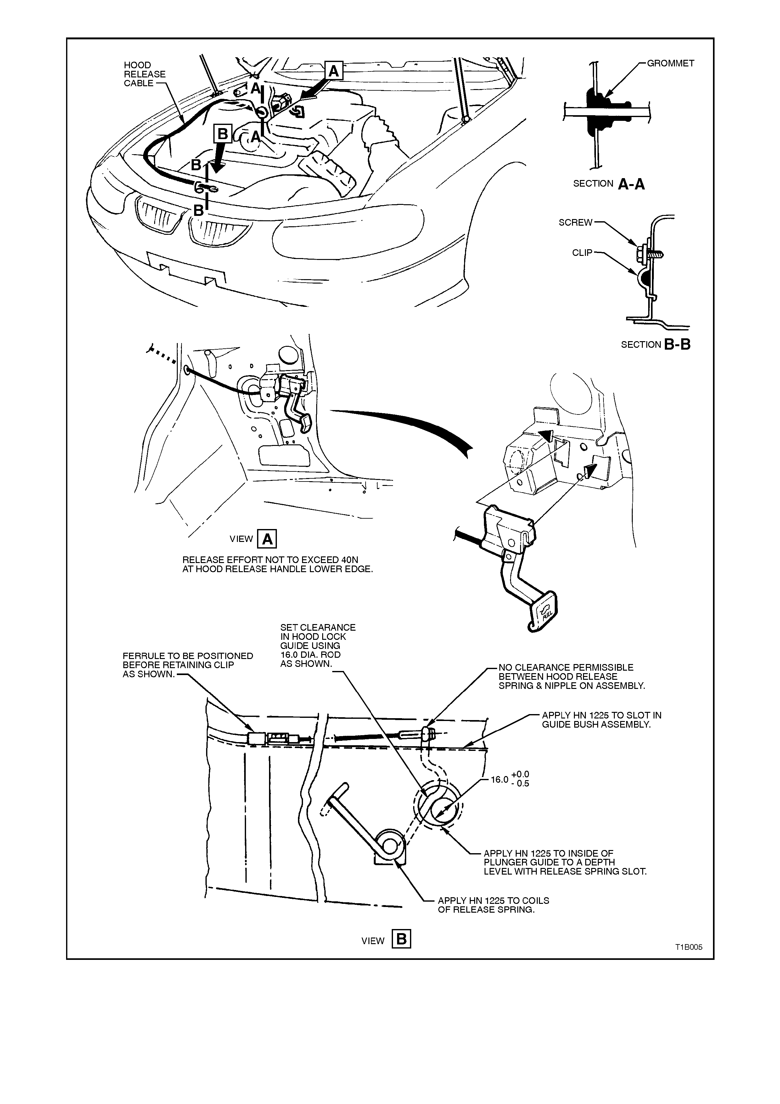
Figure 1B-5

2.7 FUEL FILLER DOOR REMOTE RELEASE ASSEMBLY
REMOVE
1. Remove the right-hand side rocker panel cover, refer to Section 1A1 BODY. Remove the screws attaching
the lever assembly to the rocker panel.
2. Remove the rear seat cushion and back, refer to Section 1A7 SEA TS AND SEAT BELT ASSEMBLIES. On
station wagon models, fold the rear seat back to the horizontal position.
3. Where fitted, remove the carpet from the rear compartment quarter panel. On station wagon models, remove
the quarter window inner trim moulding and rear quarter trim panel, refer to
Section 1A8 HEADLINING AND REAR END TRIM.
4. Remove the nut securing the fuel filler door release mechanism.
5. Release the cable from the mechanism and remove the cable and mechanism.
REINSTALL
Reverse removal operations.

3. TORQUE WRENCH SPECIFI CATIONS
Nm
Front Fender Liner Attaching Screws 1 - 3
Fender Securing Screws 3 - 8
Engine Hood Gas Support Strut Securing Screws 10 - 14
Engine Hood Gas Support Securing Ball Stud 6 - 14
Engine Hood Hinge Supporting Screws 10 - 25
Engine Hood Cable Assembly Clip Securing Screw 1 - 3