
SECTION 2A - AIR CONDITIONING - DESCRIPTION
AND OPERATION
CAUTION:
This vehicle will be equipped with a Supplemental Restraint System (SRS). A SRS
will consist of either seat belt pre-tensioners and a driver’s side air bag, o r seat belt
pre-tensioners and a driver’s and front passenger’s side air bags. Refer to
CAUTIONS, Section 12M, before performing any service operation on or around SRS
components, the steering mechanism or wiring. Failure to follow the CAUTIONS
could result in SRS deployment, resulting in possible personal injury or unnecessary
SRS system repairs.
CAUTION:
This vehicle may be equipped with LPG (Liquefied Petroleum Gas). In the interests of
safety, the LPG fuel system should be isolated by turning 'OFF' the manual service
valve and then draining the LPG serv ice lines, before any service w ork is carried out
on the vehicle. Refer to the LPG leaflet included with the Owner's Handbook for
details or LPG Section 2 for more specific servicing information.
CAUTION:
Whenever any component that forms part of the ABS or ABS/ETC (if fitted), is
disturbed during Service Operations, it is vital that the complete ABS or ABS/ETC
system is checked, using the procedure as detailed in 4 DIAGNOSIS, ABS or
ABS/ETC FUNCTION CHECK, in Section 12L ABS & A BS/ETC.
1. GENERAL DESCRIPTI ON
An integrated air conditioning system is optional on the VT Commodore Executive. This integrated system
combines both the heating and cooling functions in a single unit. The A/C system is switched OFF or ON by the A/C
switch located in the centre dash facia.
The vehicles interior can be heated, cooled or vented (or a combination of these operations) depending on the
position of the two rotary mode switches.
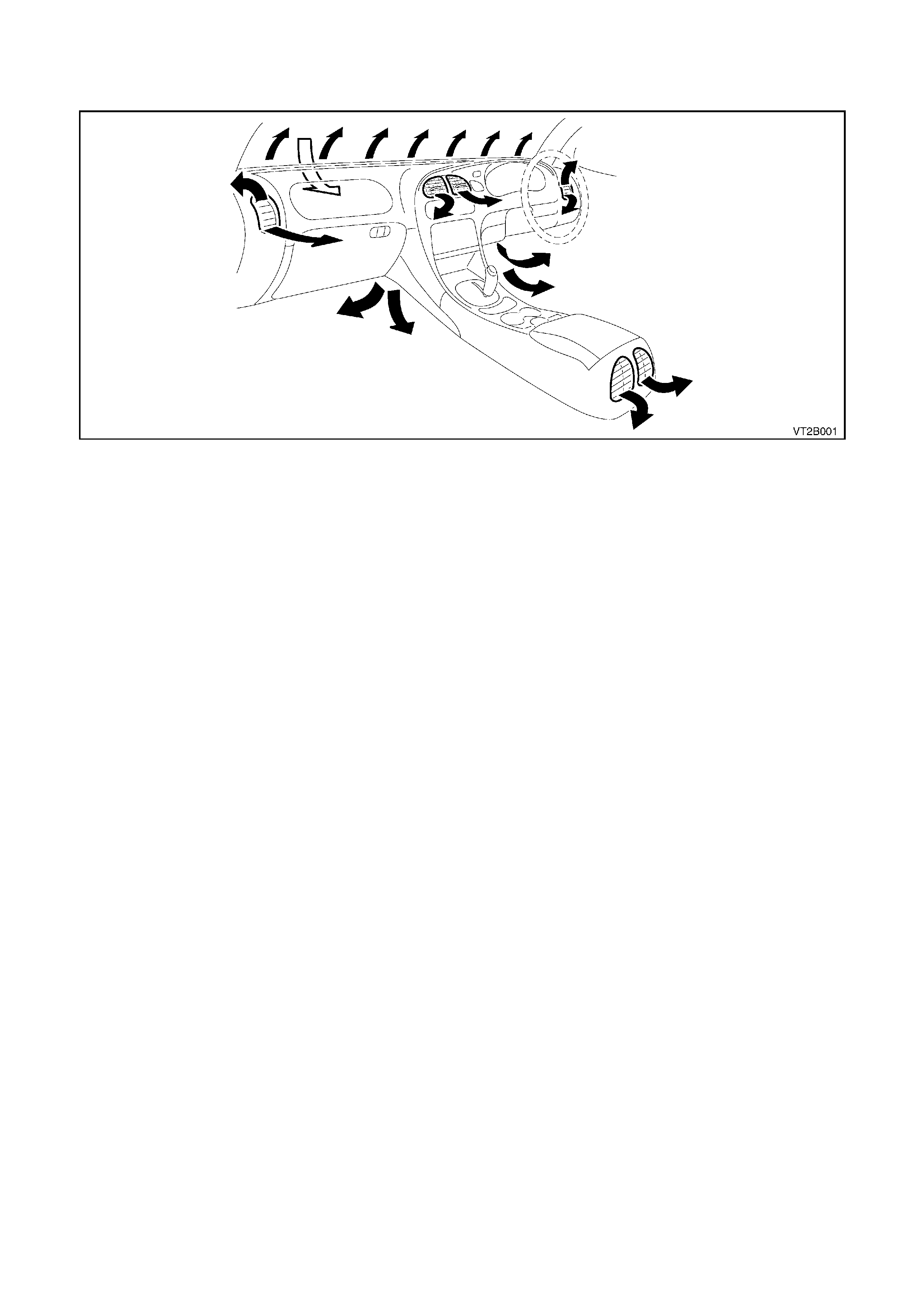
Air enters the heating, ventilation and air conditioning system (HVAC) from under the plenum chamber cover. The
air then passes through the blower motor, evaporator and heater assemblies, to be cooled or heated as required. It
then exits through the centre, side, floor or demist outlets into the vehicle interior. The air outlets are dependant on
the position activated via the mode control.
The centre ventilator outlet can be ‘turned down’ to increase air flow to rear outlets once face comfort is achieved.
A four speed blower fan forces air from the plenum chamber through the evaporator and heater assembly, then out
through the various outlets into the vehicle interior.
NOTE:
The fan switch must be engaged to provide circulation of air over the evaporator coil.
Outside air is used in all mode positions except when recirculate is selected. This mode can be selected via the
mode control switch and is used to close off the vehicle interior from any outside air.
Recirculate mode is normally selected for:-
•Quick cool down of vehicle interior especially after the vehicle has been parked in direct sunlight for a length of
time.
•Improve heat up time as no cooler outside air can flow into the vehicle interior.
•Driving on unsealed roads to prevent dust entering the vehicle interior.
Techline
Techline
Techline
Techline
CAUTION:
DO NOT drive a vehicle for extended periods in the recirculation mode as the lack of fresh air into the
vehicle will cause drowsiness and possibly impair driving performance.
Figure 2A-1
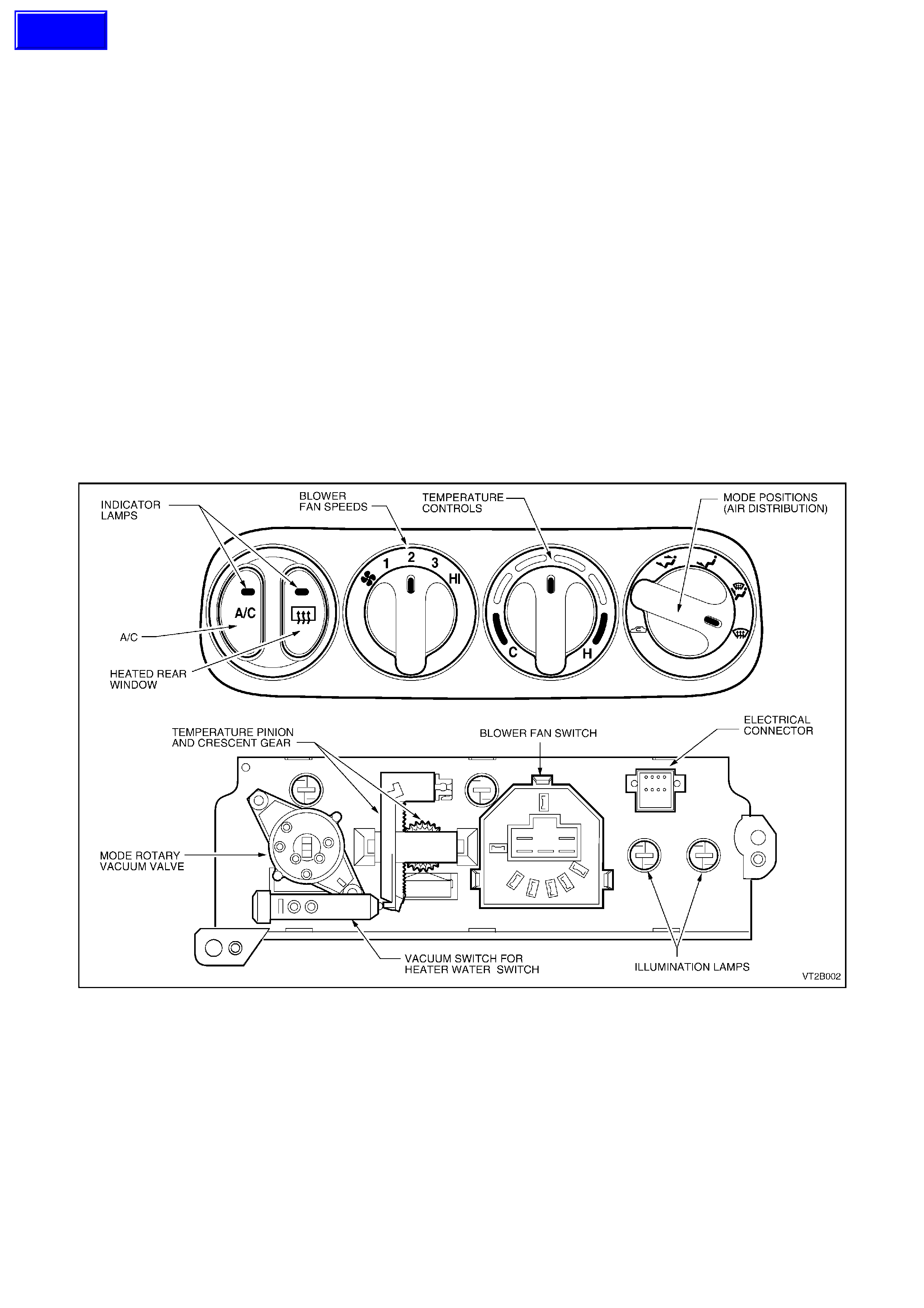
1.1 MANUAL CONTROL
A/C SWITCH
To engage blower fan, push A/C button once: ON - Indicator lamp illuminated, A/C compressor engages.
To disengage blower fan, push A/C button again: OFF - Indicator lamp extinguished, A/C compressor disengages.
HEATED REAR WINDOW SWITCH
To engage rear window demist, push heated rear window button once: ON - Indicator lamp illuminated, heated rear
window ON.
After 15 minutes the heated rear window will automatically turn OFF. To reactivate the heated rear window push
button again. This will activate the heated rear window for a further 15 minutes.
BLOWER FAN SWITCH
Four blower fan speeds are available - a fan speed has to be selected before the A/C can be engaged. The fan
symbol is the blower fan OFF position.
TEMPERATURE CONTROL
C = FULL COLD H = FULL HOT
This control is connected via a rod and levers to the air mix door within the heater A/C case. The air mix door
moves away from or closer to the heater core as required to regulate the amount of radiated heat required to mix
with the intake air or air conditioned air.
The heater water valve is held in the OFF position by a vacuum. Once the first detent is selected from the full cold
position via the temperature control, a vacuum switch located on the rear of the control is activated and the vacuum
line to the heater valve is vented. This allows hot water flow into the heater core.
Figure 2A-2
Techline
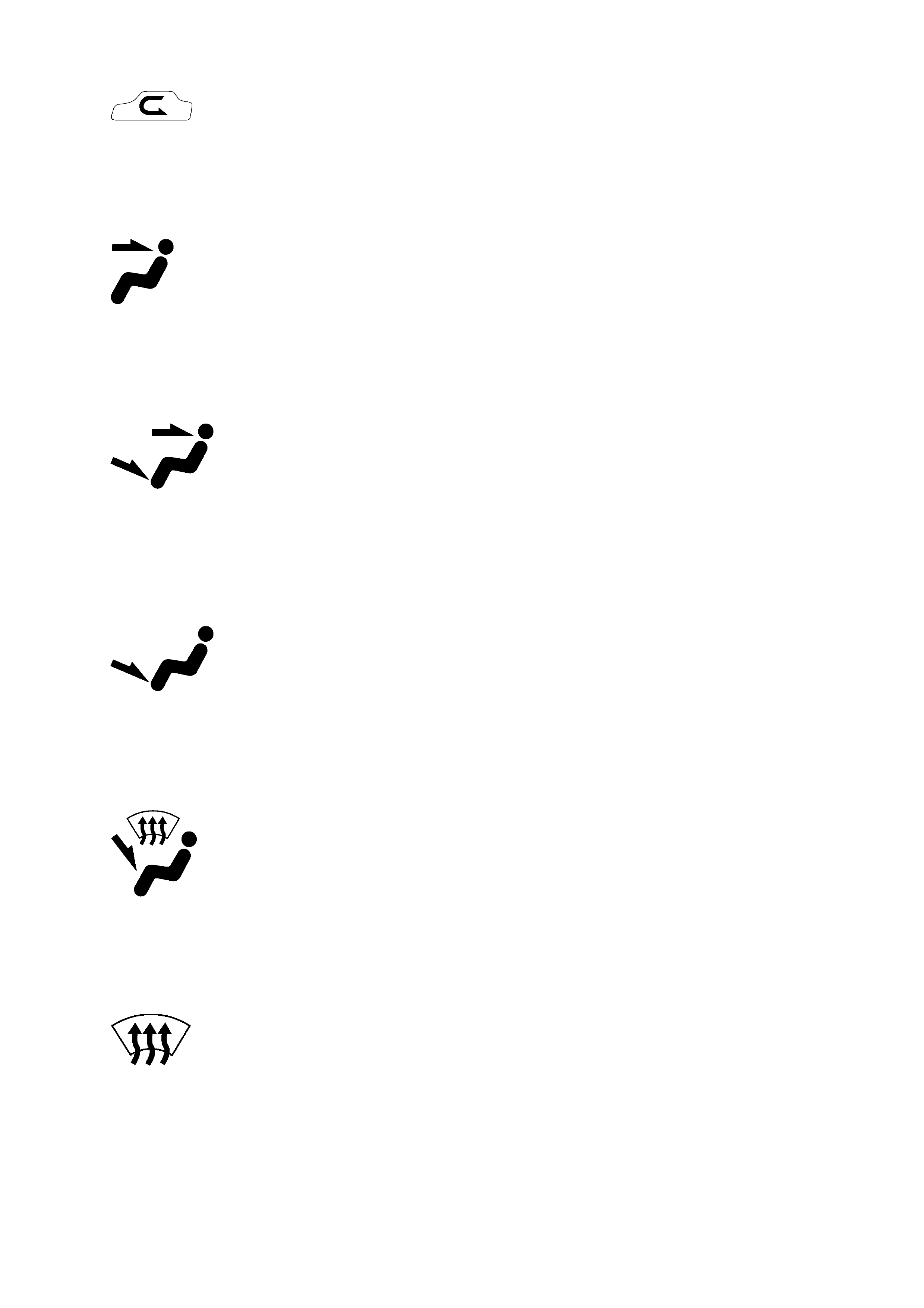
MANUAL MODE CONTROL
100% Recirculated Air:-
No fresh air entry into vehicle, air is directed to the centre, side and rear passenger vents.
Face Mode:-
Air is directed to the centre, side and rear passenger vents.
Bi-Level:-
In this position the air is directed to the floor, centre and side vents. When using bi-level with the temperature
control in the central position, warm air will be directed to the feet and cooled air directed to the face and side vents.
Floor:-
The main air flow is directed to the floor.
Blend:-
Air is directed to the floor as well as to the demist ducts.
Demist:-
Front windscreen and front side windows only. Air is directed to the front windscreen through the demist ducts. It is
recommended that the A/C button and maximum heating be selected as this will aid in accelerated demisting
(dehumidification).
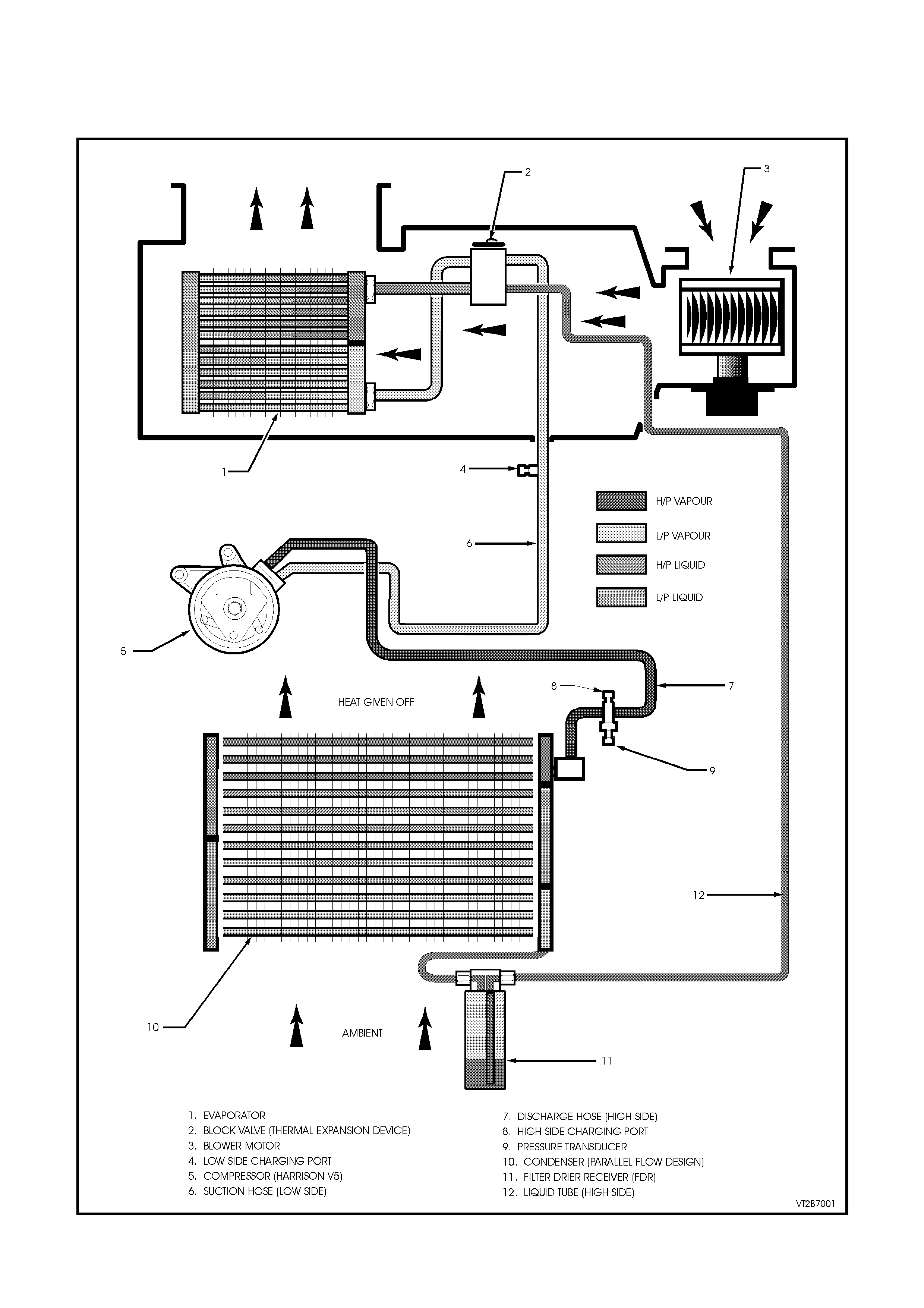
1.2 REFRIGERANT CIRCUIT
The refrigerant circuit illustrated in Fig. 2A-3 incorporates the following major components:
Compressor Thermal Expansion Valve (Block Valve) Evaporator
Condenser Filter Drier Receiver (FDR) Pressure Transducer
Figure 2A-3
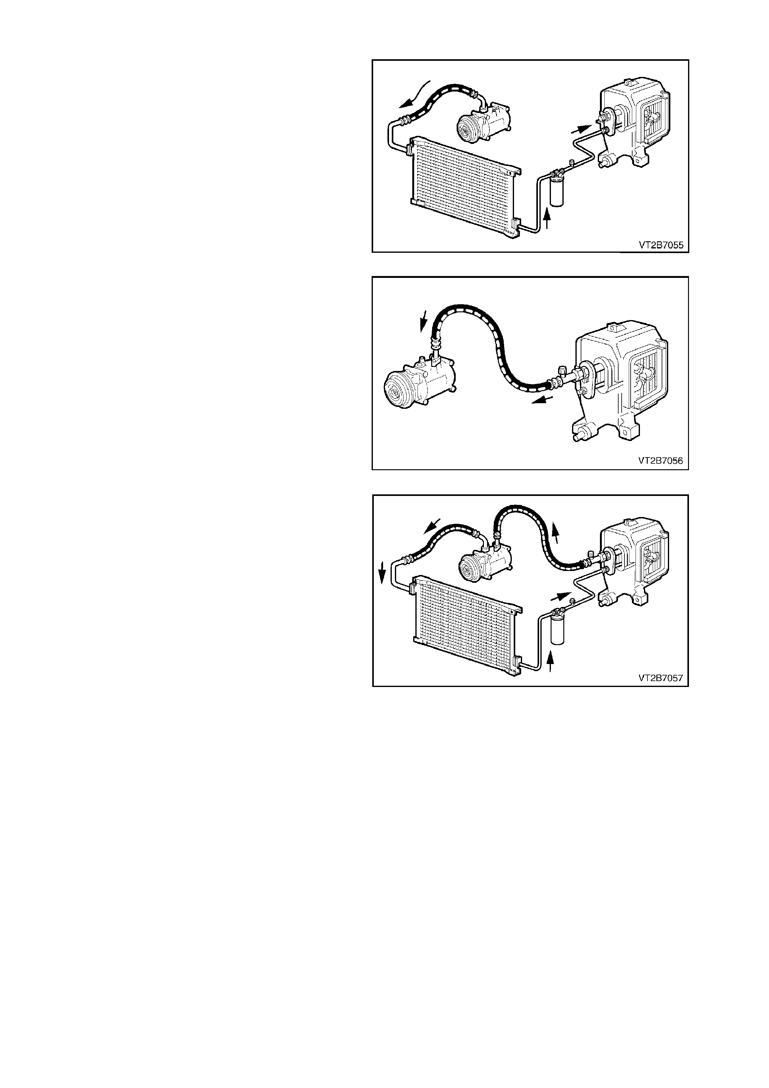
1.3 PRINCIPLES OF AIR CONDITIONING (TXV SYSTEM)
HIGH PRESSURE SIDE
Low pressure R134a vapour entering the
compressor is compressed to become a high
pressure/temperature R134a vapour. This is then
circulated along with lubricating oil to the
condenser. As the high pressure/temperature
vapour travels through the condenser, heat is
released to the cooler ambient air passing over the
condenser tubes condensing the vapour into a
liquid. This high pressure/tem perature liquid travels
through the filter drier into the thermal expansion
valve (TXV) where a small variable orifice provides
a restriction against which the compressor pushes. Figure 2A-4
LOW PRESSURE SIDE
Liquid R134a is pushed into the evaporator and
suction from the compressor pulls the high
pressure/temperature vapour through the small
variable orifice of the thermal expansion valve
(TXV) and into the low pressure side of the A/C
system. T he R134a is now under low pressure and
becomes a low pressure/temperature vapour where
heat from the cabin being blown over the
evaporator coil sur fac e is absor bed into the vapour,
which then flows on to the compressor. The A/C
cycle begins again as the R134a vapour is
compressed and discharged under pressure. Figure 2A-5
HEAT TRANSFER
R134a in the HIGH PRESSURE side is HOT and
the cooler ambient air moving over the condenser
can absorb heat from it.
R134a in the LOW PRESSURE side is COLD and
can absorb large quantities of heat from the air
moving over the evaporator.
Figure 2A-6
SUMMARY
•When the R134a pressure is high, the R134a
temperature is high.
•When the R134a pressure is low, the R134a
temperature is low.
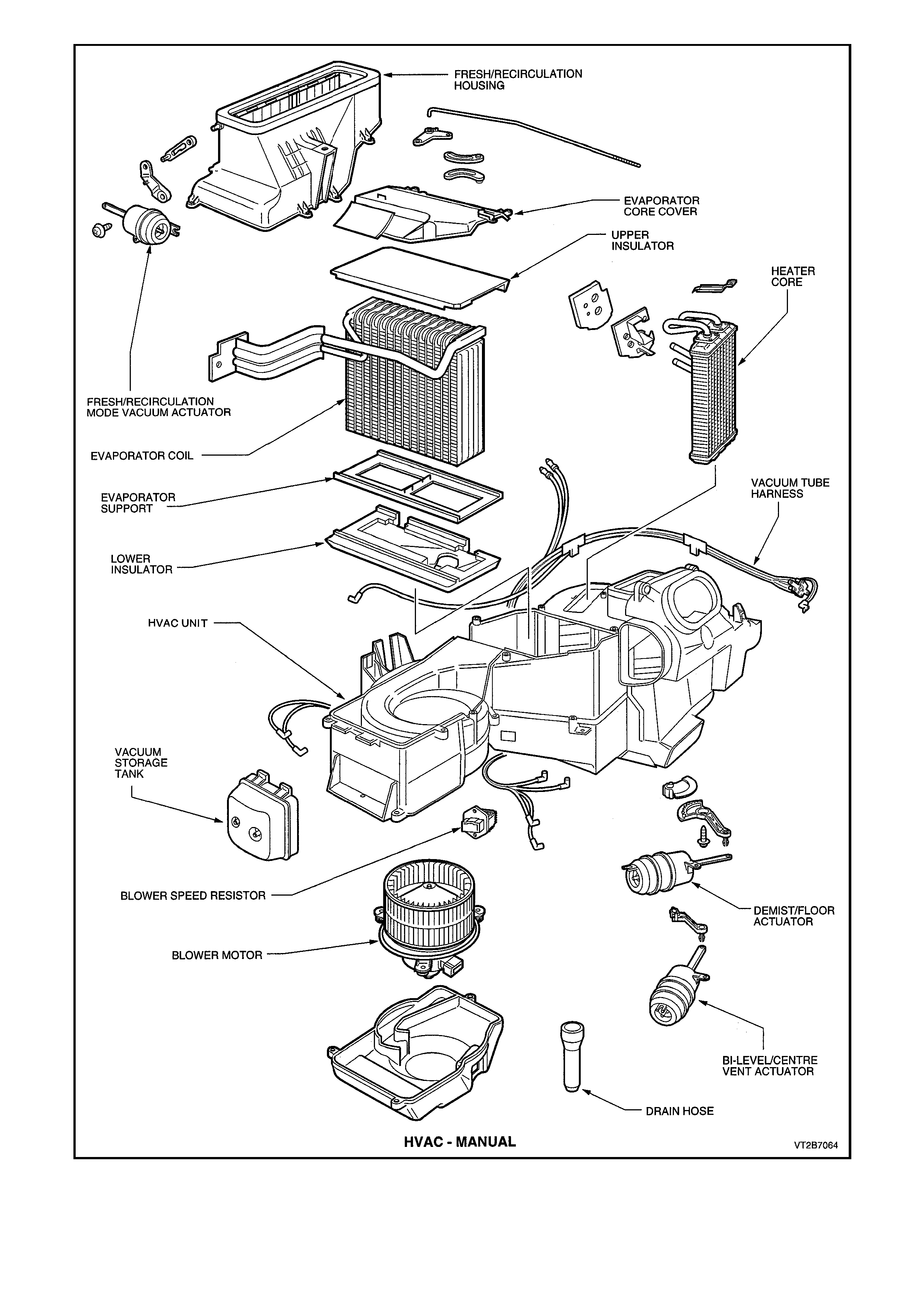
Figure 2A-7
1.4 HEATING, VENTILATION AND AIR CONDITIONING (HVAC) UNIT AIR FLOW MODES
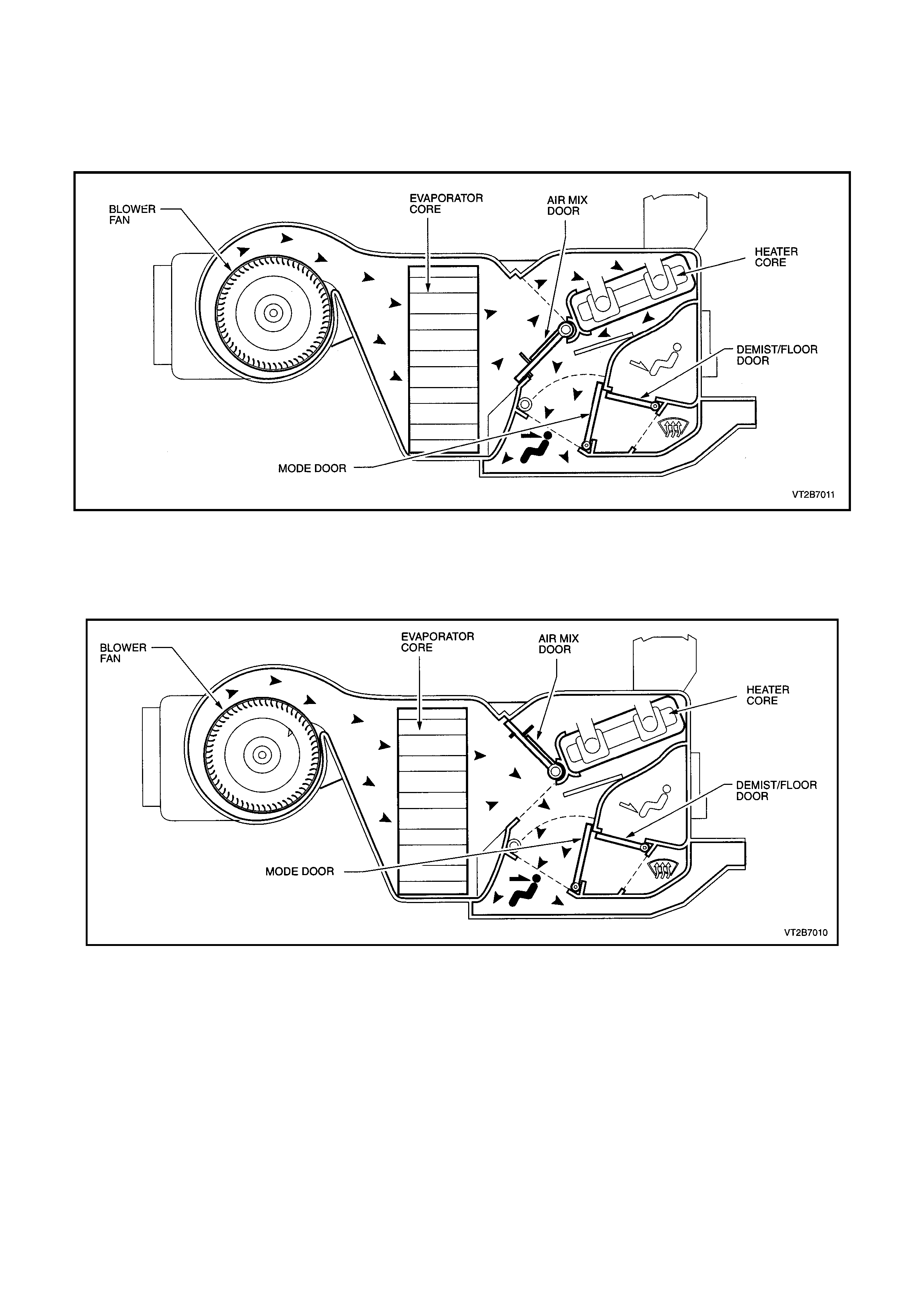
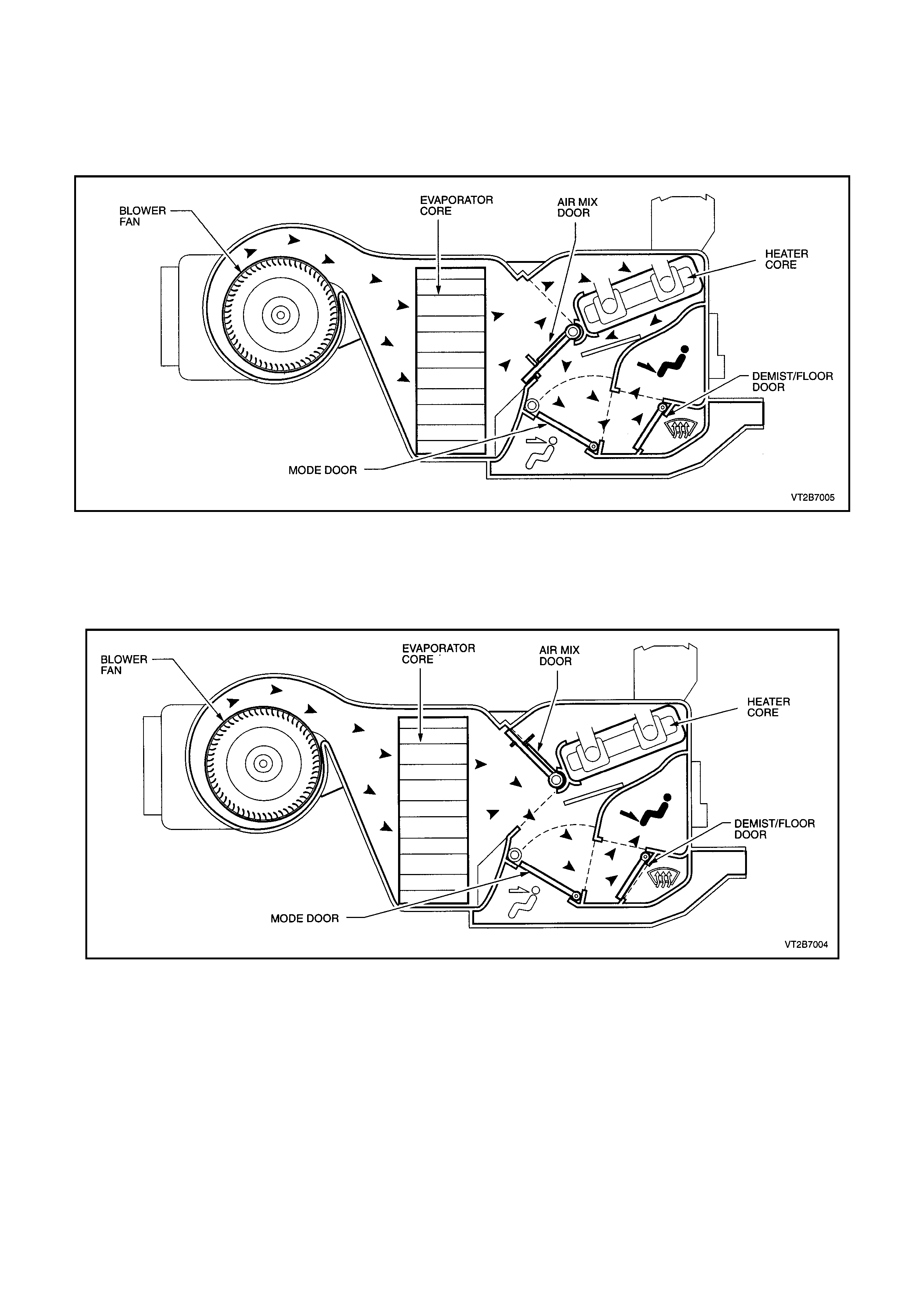
FACE MODE
FULL HEAT
Air is drawn into the HVAC unit by the blow er motor. This air is then forced through the evaporator core fins, through
the hot heater core fins and directed through the open mode door onto the centre and side vents.
Figure 2A-8
FULL COLD
Air is drawn into the HVAC unit by the blower motor, and is then forced through the cold evaporator fins. In full cold
mode the air mix door is fully closed sealing off the passage through the heater core. The cold air travels through
the open mode door and is directed through the centre and side vents.
Figure 2A-9
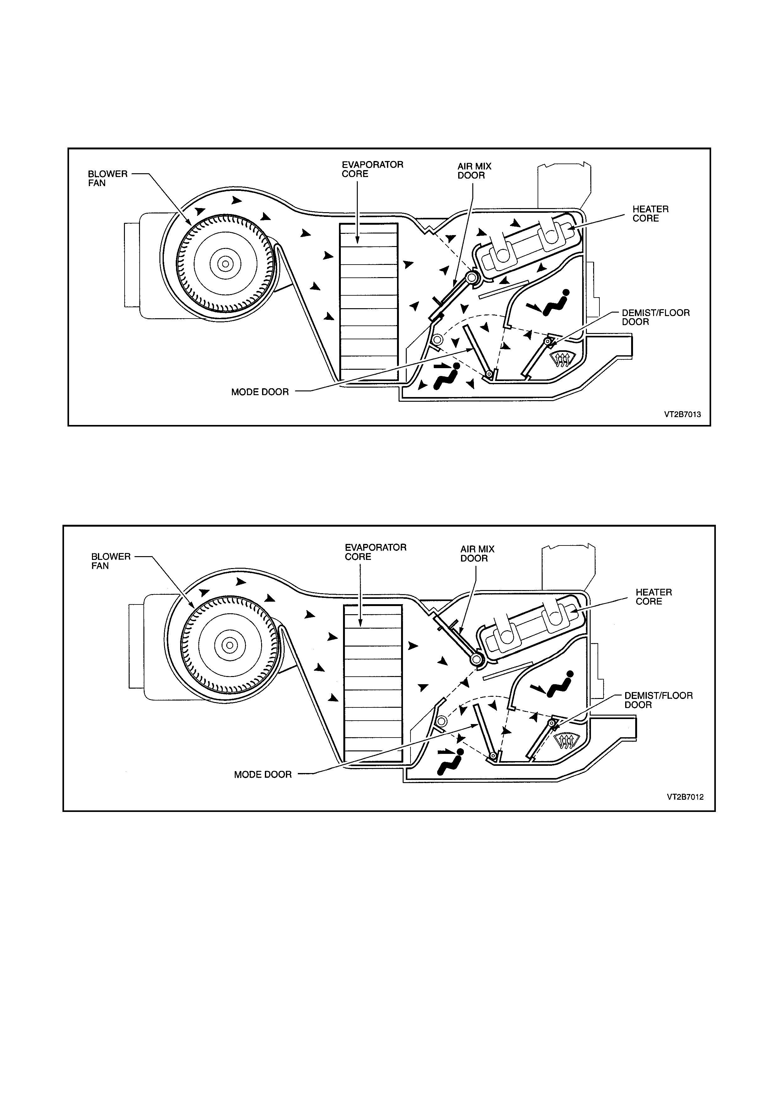
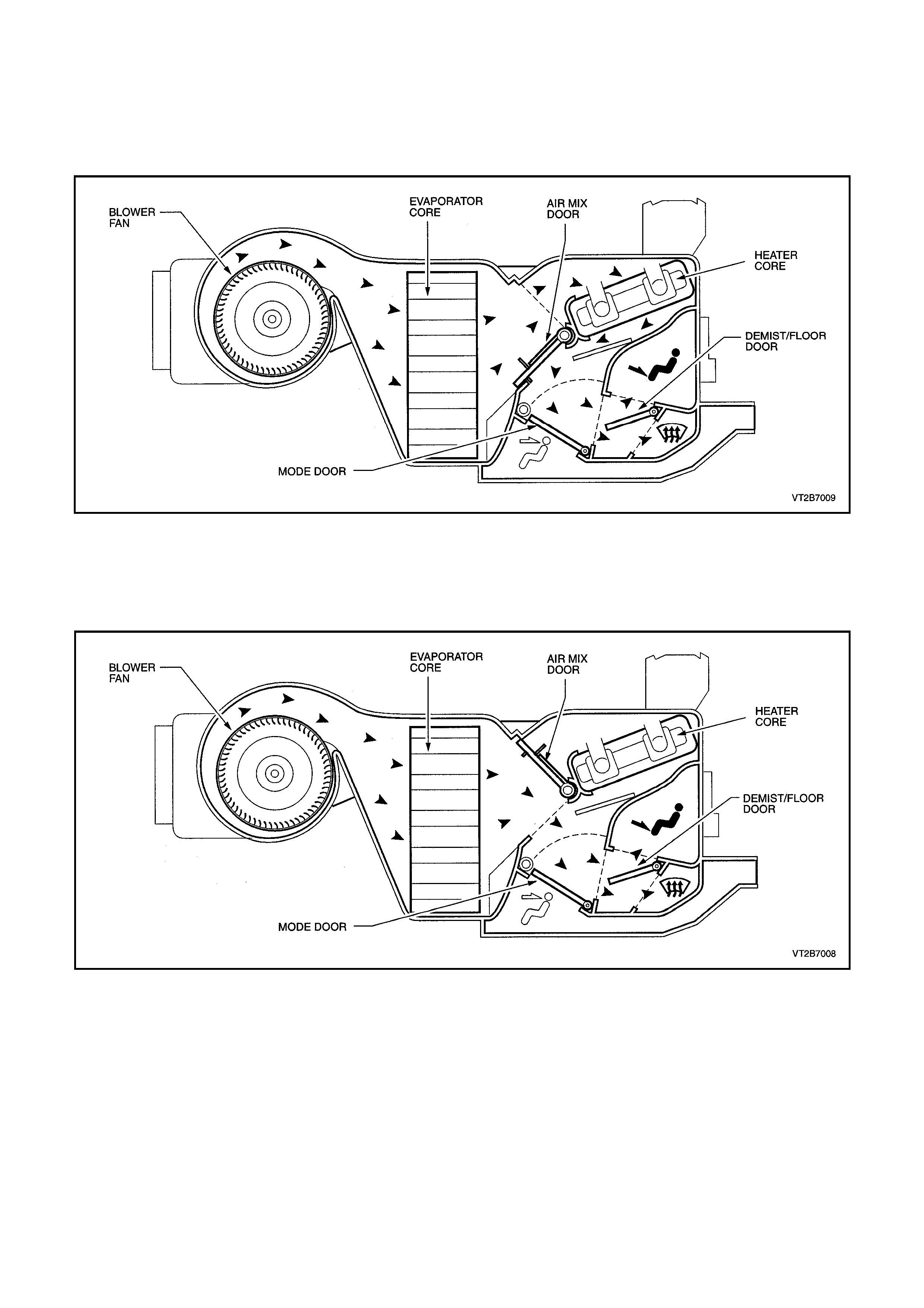
BI-LEVEL MODE
FULL HEAT
Air is drawn into the HVAC unit by the blower motor. This air is then forced through the evaporator fins. In full heat
mode the air mix door is fully open allowing all the air to flow through the hot heater core fins, picking up heat as it
travels. From the heater core the heated air travels around the half opened mode door and is directed to both the
floor ducts, centre and side vents.
Figure 2A-10
FULL COLD
Air is drawn into the HVAC unit by the blow er motor. This air is then forced through the cold evaporator core fins. In
full cold mode the air mix door is fully closed sealing off the passage to the heater core. The cold air then travels
around the half opened mode door and is directed to both the floor ducts, centre and side vents.
Figure 2A-11
FLOOR MODE
FULL HEAT
Air is drawn into the HVAC unit by the blow er motor. This air is then forced through the non evaporator fins. In full
heat mode the air mix door is fully open. This allows all the air to flow through the hot heater core fins, picking up
heat as it travels. From the heater core the heated air travels through the open demist/floor door and is directed to
the floor.
Figure 2A-11
FULL COLD
Air is drawn into the HVAC unit by the blower motor. This air is then forced through the cold evaporator fins. In full
cold mode the air mix door is fully closed sealing off the passage to the heater core. The cold air then travels
through the open demist/floor door and is directed to the floor.
Figure 2A-12
BLEND MODE
FULL HEAT
Air is drawn into the HVAC unit by the blower motor. This air is then forced through the evaporator fins. In full heat
mode the air mix door is fully open. This allows all the air to flow through hot heater core fins, picking up heat as it
travels. From the heater core the heated air travels around the half open demist/floor door and is directed to both
the front windscreen and floor.
Figure 2A-13
FULL COLD
Air is drawn into the HVAC unit by the blow er motor. This air is then forced through the cold evaporator core fins. In
full cold mode the air mix door is fully closed sealing off the passage to the heater core. The cold air then travels
around the half open demist/floor door and is directed to both the front windscreen and floor.
Figure 2A-15
DEMIST MODE
FULL HEAT AND A/C ACTIVATED
Air is drawn into the HVAC unit by the blower motor. This air is then forced through the cold evaporator fins. In full
heat mode the air mix door is fully open. This then allows all cooled air to flow through the hot heater core fins,
picking up heat as it travels. From the heater core the heated air travels around to the demist passage and onto the
front windscreen via the demist vents.
NOTE:
By activating the A/C compressor in this mode dehumidification will take place, de-fogging the front windscreen and
side windows in a shorter duration.
Figure 2A-16
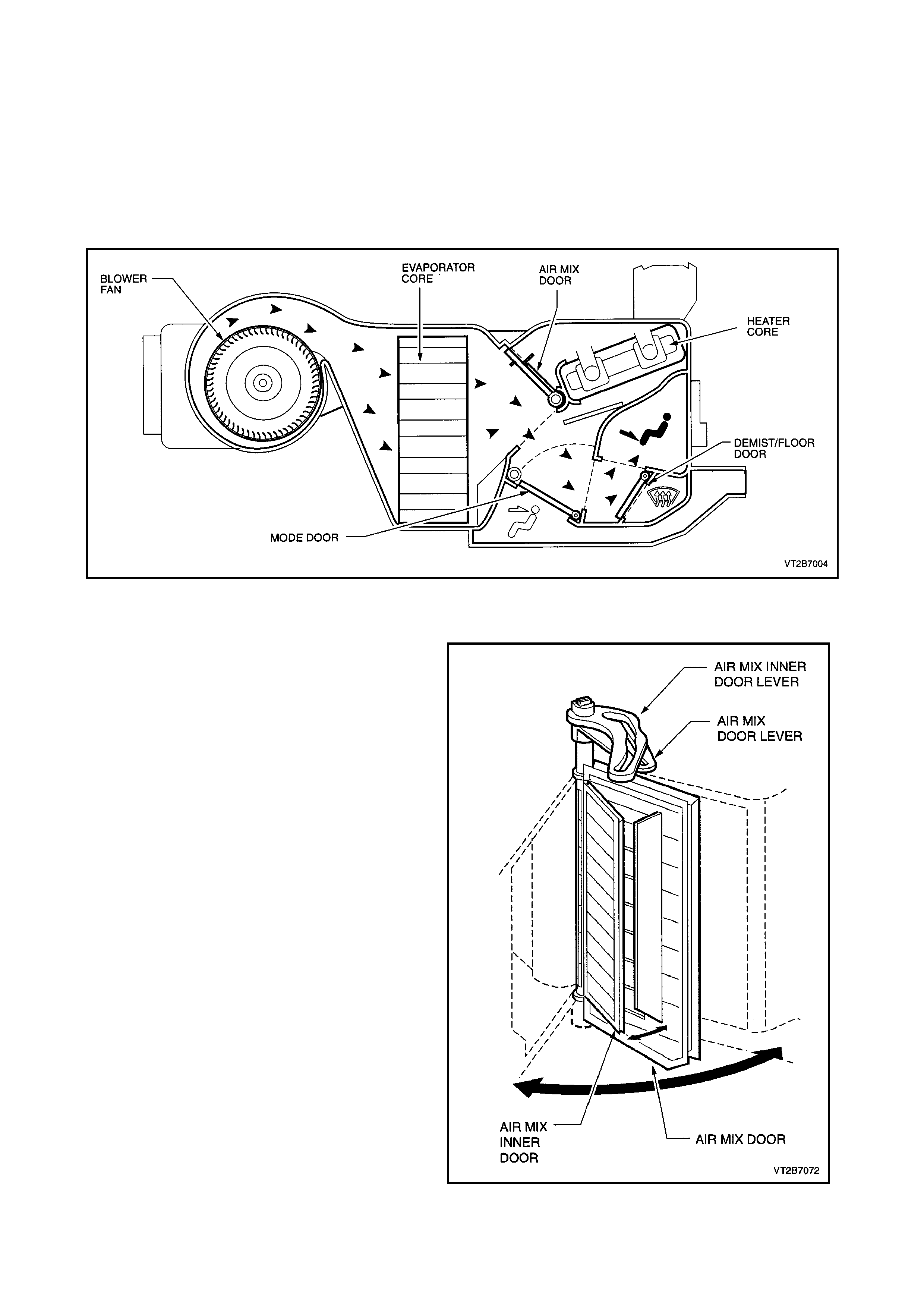
HVAC AIR MIX DOOR
The air mix door incorporates a smaller (inner)
door. This smaller (inner) door is used to
depressurise the HVAC cavity immediately
downstream of the evaporator. When the cavity is
depressurised the door operating loads are
reduced.
In the full hot position both doors are closed. On
selecting a cooler temperature setting the inner
door moves first (to depressurise the cavity) then
the outer door m oves. As the door m oves toward to
full cold position they close together.
The reverse occurs in moving from full cold to full
hot.
Figure 2A-17
1.5 A/C COMPONENTS
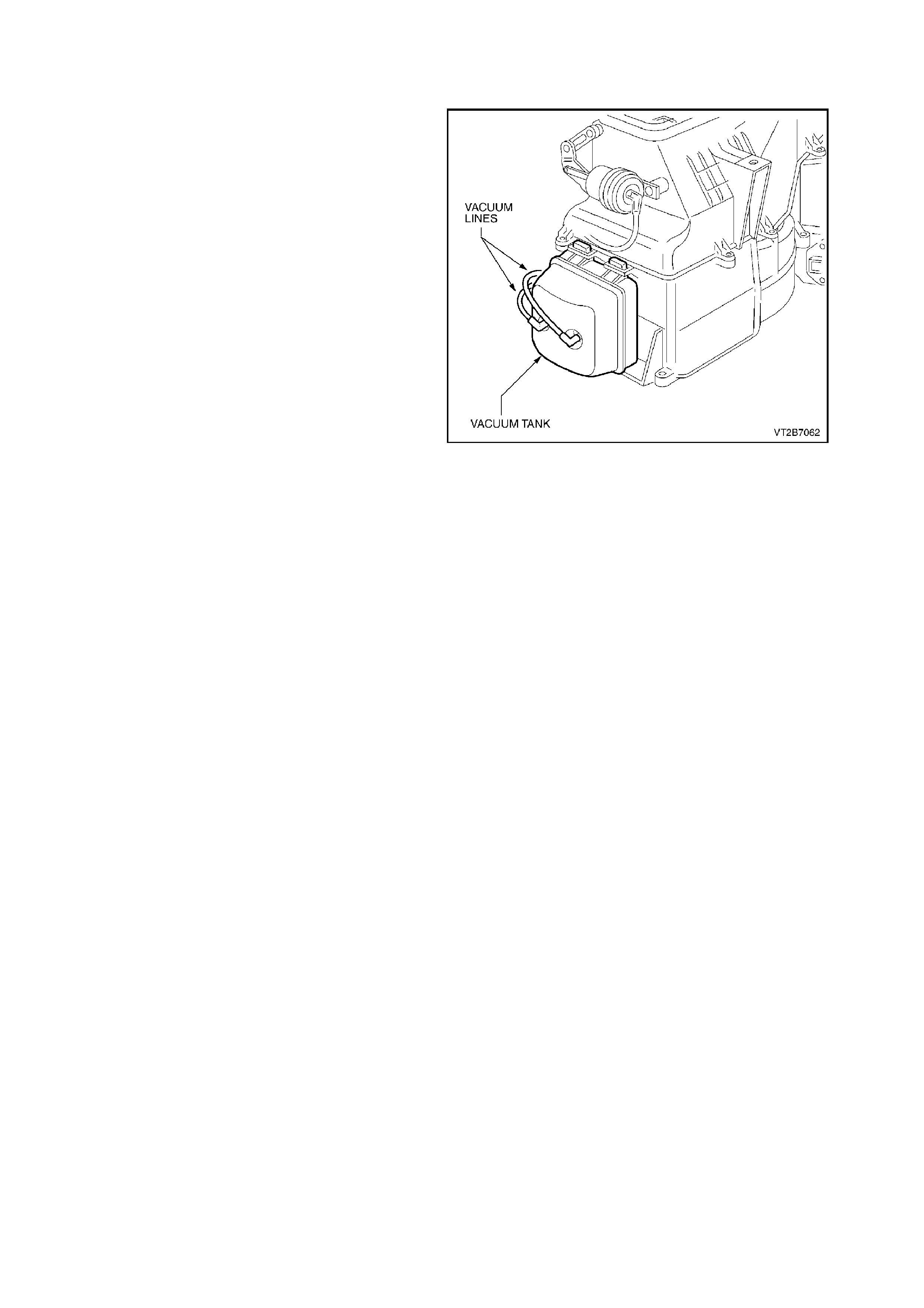
VACUUM TANK
The vacuum tank is located on the left side of the
HVAC unit and is secured with two self tapping
screws.
This tank is used to maintain a vacuum to the
vacuum actuators (which operate the different vent
positions) during driving situations where the
vacuum source is low such as full engine thr ottle. A
one way valve is located in the vacuum source line
from the inlet manifold.
Figure 2A-18
VACUUM CIRCUIT
Vacuum is used to control the ON/OFF functions of the vent modes and the heater tap. This vacuum is provided by
the engine.
The engine vacuum moves from the inlet manifold to a vacuum tank located on the HVAC unit. This vacuum tank is
used to store vacuum in times when engine vacuum is low such as at full engine throttle. A check valve is fitted on
the supply line from the engine inlet manifold.
Through a black plastic vacuum tube, vacuum moves to the mode switch (vent positions). This black plastic tube is
also teed off to the vacuum switch. From the vacuum switch, vacuum moves into a yellow plastic tube and onto the
vacuum operated heater water valve. Vacuum is used to maintain full closure of this valve and no hot water can
flow.
As the mode switch is turned, vacuum is allowed to move through the mode switch and onto the desired vacuum
actuator through different coloured plastic tubing. This vacuum will activate the vacuum actuator rod which then
moves a vent position door.
Figure 2A-19 shows which vacuum actuators are applied with vacuum in a certain mode.
Vacuum is vented from the vacuum actuator/plastic tube once the vacuum mode switch is turned to another
position.
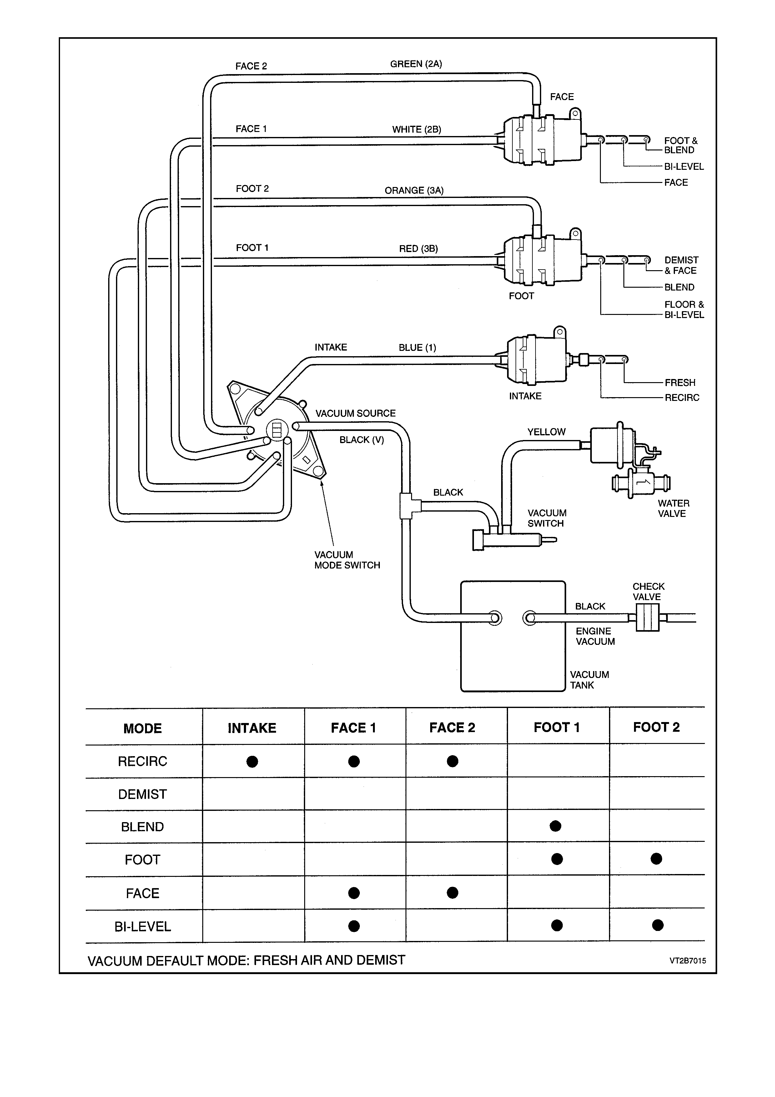
Figure 2A-19
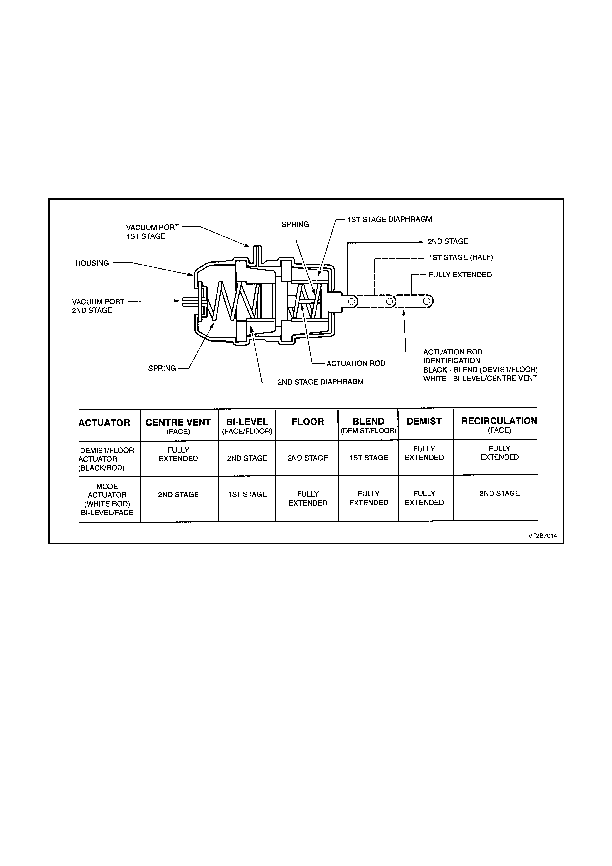
TWO STAGE VACUUM ACTUATOR (DEMIST AND FLOOR MODE)
Operation
The VT HVAC unit now has doors that are required to open half way while another door closes fully. With normal
single stage vacuum actuators this would require a complicated linkage set-up and additional actuators.
To overcome this situation ‘two stage’ actuators are used. Through their design they can move the actuating rod
fully (2nd stage), half way (1st stage) and fully extended (no vacuum). This enables some doors housed within the
HVAC unit to be only half open when a ‘blend’ mode is selected, and other doors to be closed at the same time via
another actuator.
When vacuum is directed to the 1st stage vacuum port only the 1st stage rubber diaphragm is pulled (towards the
rear of the housing), moving the actuator rod only half way. Once the 2nd stage is selected vacuum is also directed
to the 2nd stage vacuum port which pulls on the 2nd stage rubber diaphragm, fully retracting the actuator rod. The
extent of actuator rod travel in either 1st or 2nd stage is governed by compressing two springs on each vacuum
diaphragm. Both these springs are of differing tensions.
Figure 2A-20
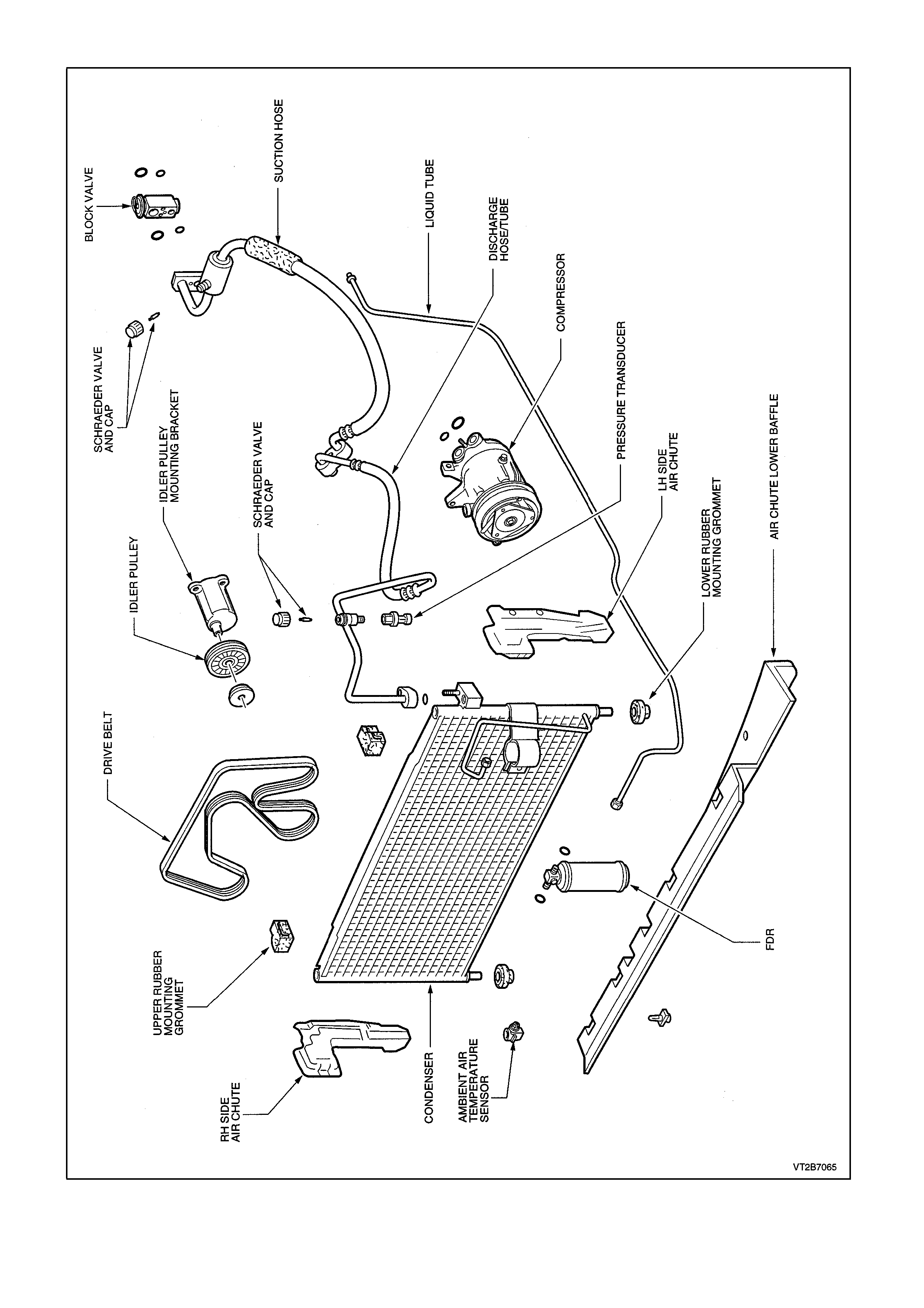
ENGINE BAY COMPONENTS - V6
Figure 2A-21
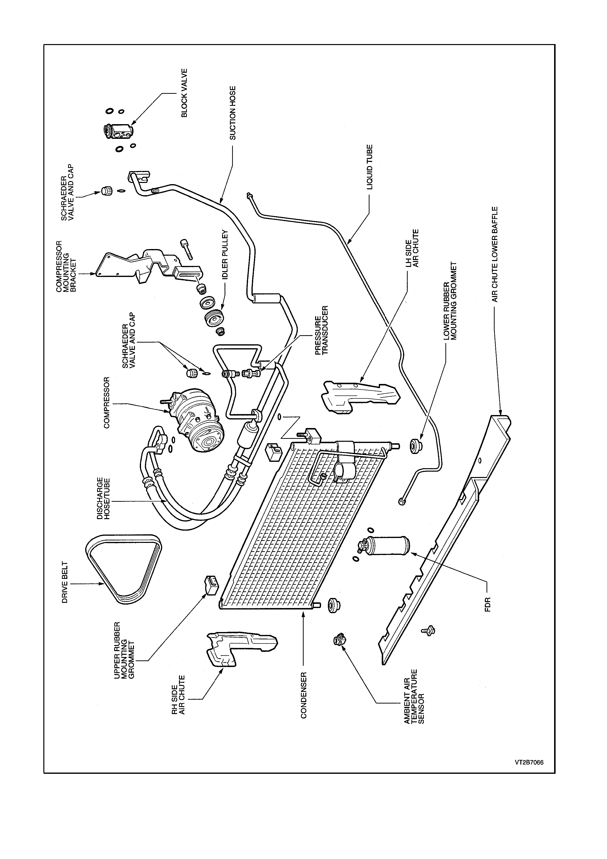
ENGINE BAY COMPONENTS - V8
Figure 2A-22
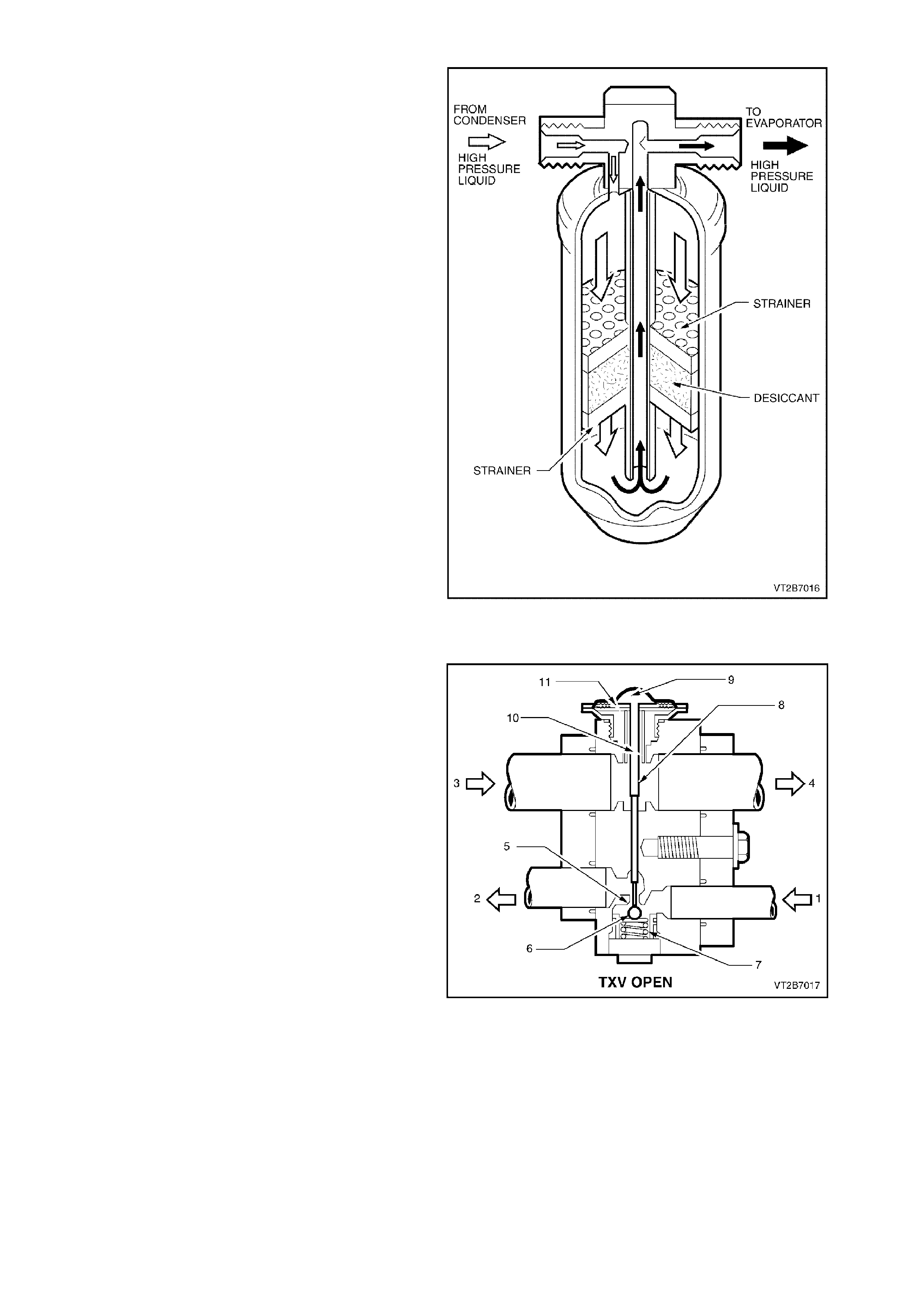
FILTER DRIER RECEIVER
The filter drier acts as a particle filter, refrigerant
storage container and most importantly a moisture
absorber.
Moisture, temperature and R134a causes
hydrofluoric and hydrochloric acid. The silica gel
beads (desiccant) located in the FDR absorb small
quantities of moisture thus preventing acid
establishment.
NOTE:
Ensure the connection indicated with the word ‘IN’
is connected to the condenser outlet.
Figure 2A-23
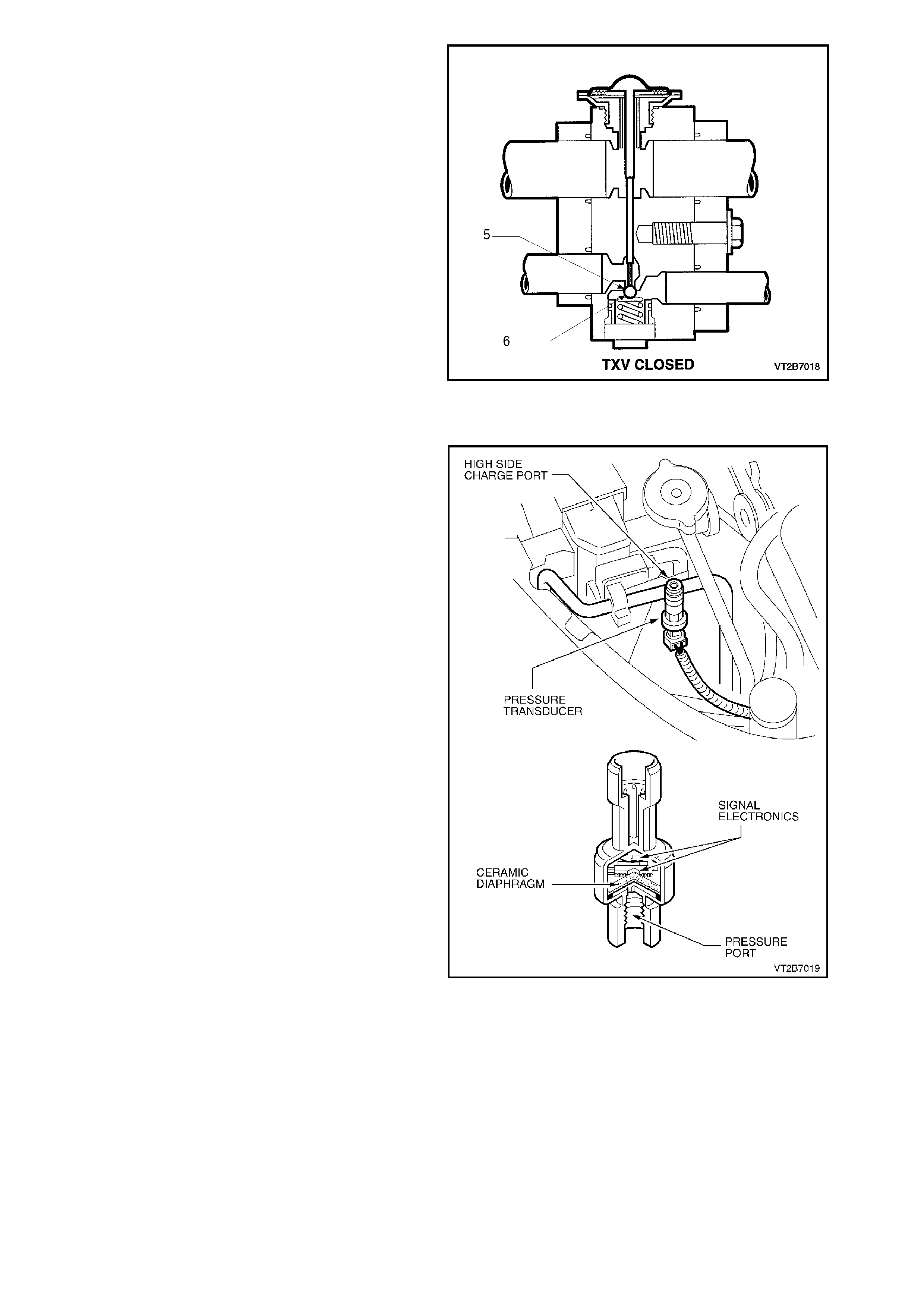
THERMAL EXPANSION VALVE (BLOCK VALVE)
This valve has two refrigerant passages. One is in
the refrigerant line from the condenser to the
evaporator and contains a ball and spring valve.
The other passage is in the refr igerant line fr om the
evaporator to the compressor and contains the
temperature sensing element.
1. From Filter Drier
2. To Evaporator Coil
3. From Evaporator
4. To Compressor
5. Metering Orifice
6. Ball
7. Spring
8. Activating Pin
9. Refrigerant
10. Pressure Compensation Under Diaphragm
11. Metallic Diaphragm
Opening
As the non-cooled refrigerant from the evaporator
coil flows thr ough the block valve outlet (suc tion), it
makes contact with the underside of the thin
metallic diaphragm (11) and reacts on the
refrigerant contained above that diaphragm. This
refrigerant then expands forcing the pin (8)
downwards moving the ball (6) off its seat (5),
compressing the spring (7) and allowing more
refrigerant to enter the evaporator.
Figure 2A-24
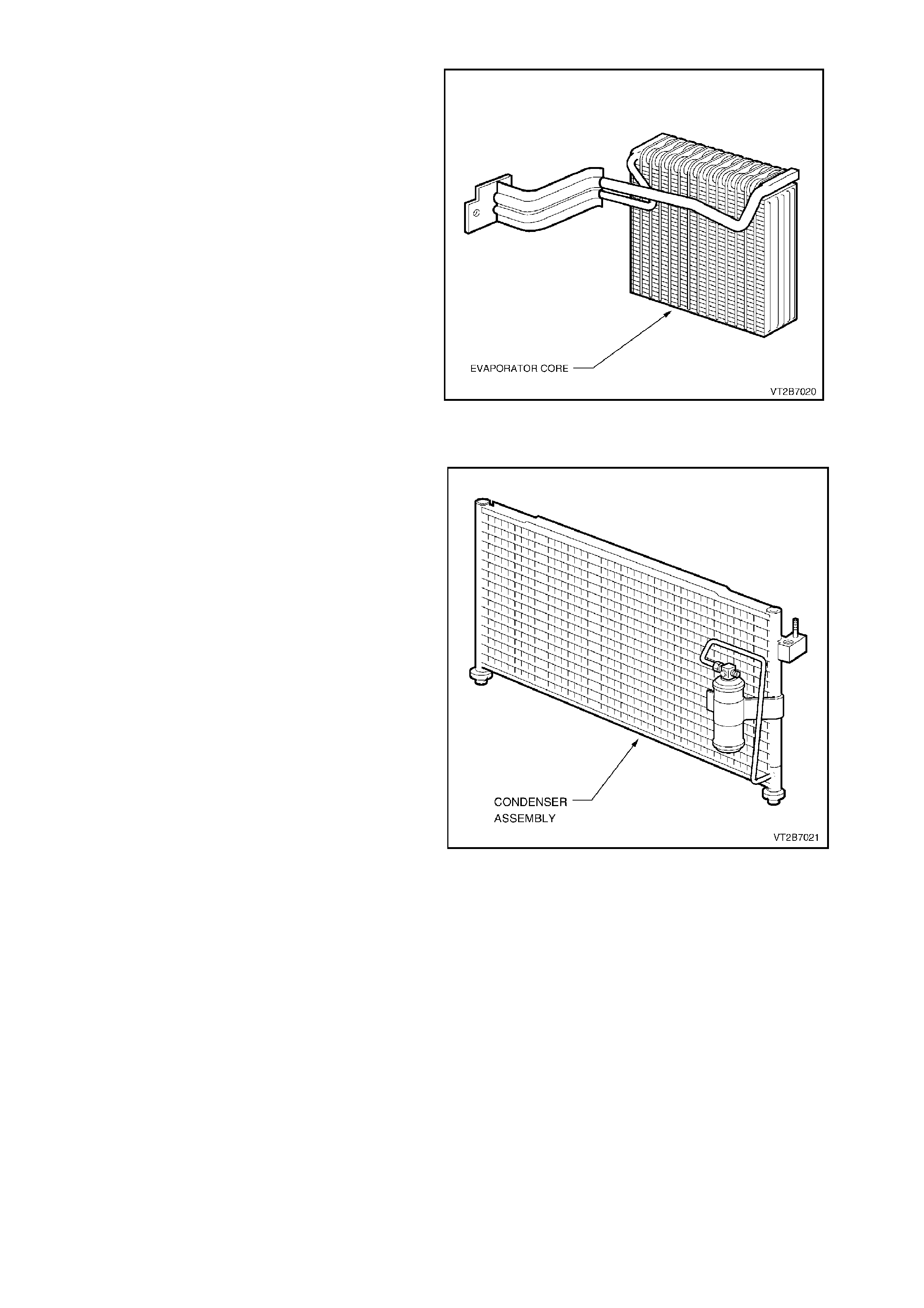
Closing
Similar operation as opening but now the
refrigerant from the evaporator is cold. The
refrigerant contained above the diaphragm now
contracts. The ball (6) moves towards the seat (5)
aided by the compressed spring, reducing
refrigerant flow.
NOTE:
Low pressure liquid R134a travelling through the
evaporator should be completely vaporised by the
time it reaches the block valve outlet side.
Figure 2A-25
PRESSURE TRANSDUCER
The pressure transducer is a sealed gauge
referenc e capac itive pressure sensor with on board
signal conditioning. It provides a 0 to 5 volt output
and requires a 5 volt regulated power supply.
In operation the transducer senses applied
pressure via the deflection of a two piece ceramic
diaphragm with one half being a parallel plate
capacitor. Changes in capacitance influenced by
the refrigerant pressure under the ceramic
diaphragm are converted to an analogue output by
the transducers integral signal electronics.
The pressure transducer’s electronics are on a
flexible circuit board contained in the upper section
of the transducer. They provide linear calibration of
the capacitance signal from the ceramic sensing
diaphragm.
Benefits of using the pressure transducer over a
normal type pressure switch is that the transducer
is constantly monitoring pressures and sending
signals to the powertrain control module (PCM).
The norm al type pressure switch only has an upper
and lower cut out point. The PCM will disengage
the A/C compressor at low or high refrigerant
pressures and electronic diagnostic equipment can
be used to extract system pressure information
making it easier when diagnosing problems.
Low Pressure Cut OFF at 180kPa
ON at 240kPa
High Pressure Cut OFF at 2900kPa
ON at 2400kPa
Coolant Fan High Speed OFF at 1370kPa
ON at 1770kPa
NOTE:
Pressure transducer diagnostics can be found in
Section 6C1 POWERTRAIN MANAGEMENT - V6
ENGINE.
Figure 2A-26
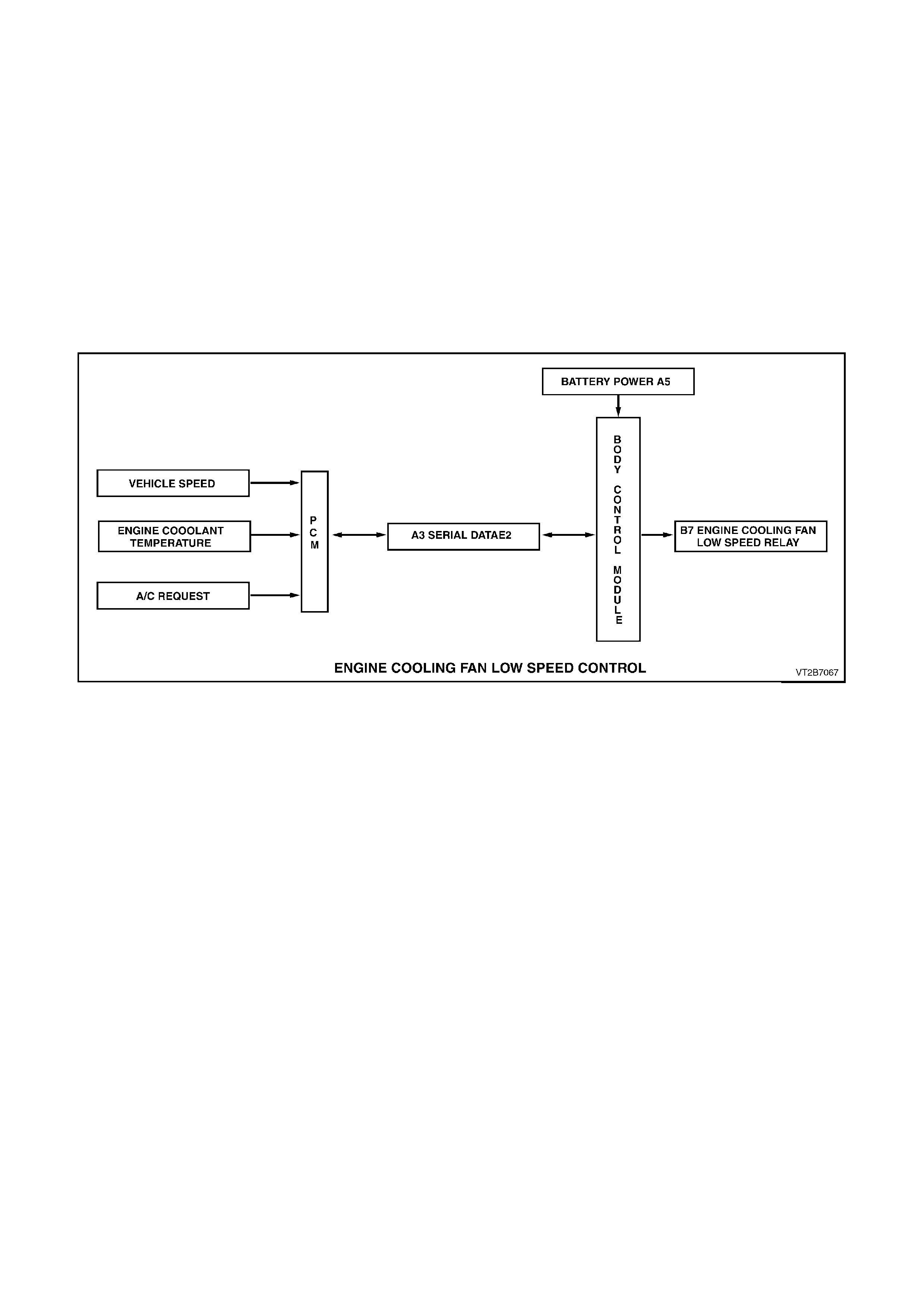
EVAPORATOR
The evaporator is loc ated inside the vehic le hous ed
behind the instrument panel facia in the HVAC unit.
The evaporator core which is aluminium, is the
actual cooling unit of the A/C system. As the low
pressure, low temperature refrigerant enters the
evaporator it begins to boil and evaporate. This
evaporation process absorbs heat from the air
being circulated through the evaporator cor e by the
blower fan.
Due to the evaporator being so cold, condensation
forms on the surface. This condensation is
moisture taken from the air (humidity). Also any
dust particles in the air passing through the
evaporator become lodged in the c ondensate water
droplets, thus filtering the air from contaminants.
Figure 2A-27
CONDENSER
The condenser is mounted forward of the radiator
and is therefore exposed to a flow of ram air from
the movement of the vehicle, and engine cooling
fan.
The purpose of the condenser is the opposite of the
evaporator. The condenser receives high pressure
high temperature refrigerant vapour from the
compressor and as the high pressure high
temperature vapour travels through the condenser
tubes, heat is given off to the cooler ambient air
surrounding the condenser. The vapour then
condenses into a high pressure, high temperature
liquid.
Figure 2A-28

HARRISON V5 COMPRESSOR
The Harrison V5 compressor can match the air conditioning demand under all conditions without cycling. The basic
compressor mechanism is a variable angle wobble-plate with five axially oriented cylinders. The centre of control of
the compressor displacement is a bellows actuated control valve located in the rear head of the compressor which
senses compressor suction pressure. The wobble-plate angle and compressor displacement are controlled by the
compressor crankcase-suction pressure differential.
When the A/C capacity demand is high, the suction pressure will be above the control point. The valve will maintain
a bleed from the compressor crankcase to suction, no crankcase-suction pressure differential and the compressor
will have maximum displacement.
When the A/C capacity demand is lower and the suction pressure reaches the control point, the valve will bleed
discharge gas into the crankcase and close off a passage from the compressor crankcase to the suction plenum.
The pressure differential creates a total force on the pistons resulting in a movement about the wobble-plate pivot
pin that reduces the plate angle.
Figure 2A-29
RADIATOR FAN APPLICATION
The V6 engine has a two-speed electric engine cooling fan assembly that provides the primary means of moving air
through the engine radiator. This fan is placed between the radiator and the engine and has its own shroud. The fan
is used on all vehicles even if not equipped with air conditioning. There is no fan in front of the A/C condenser.
The two-speed electric engine cooling fan is used to cool engine coolant flowing through the radiator, and if fitted,
refrigerant flowing through the A/C condenser. The engine cooling fan motor has four terminals, two negative and
two positive terminals. The two positive terminals are permanently connected to battery voltage. When one of the
negative terminals is earthed, the fan motor will operate at low speed. When both negative terminals are earthed,
the fan will operate at high speed.
The two speed electric fan’s low speed can be enabled when the low speed engine cooling fan micro relay (located
in the engine compartment relay housing, labelled Lo Fan) is energised by the BCM via a request from the
Powertrain Control Module (PCM). The PCM will request low speed fan enable and disable via serial data
communication to the BCM on circuit 1221 (Red/Black wire). After the PCM requests a change in the state of the
low speed relay (i.e. OFF to ON or ON to OFF), the BCM will send a serial data response message back to the
PCM confirming it received the message.
The PCM determines when to enable the low speed fan relay based on inputs from the A/C request signal, Cooling
Temperature Sensor (CIS) and the Vehicle Speed Sensor (VSS).
The low speed cooling fan relay will be turned ON when:
•A/C request indicated (YES) and the vehicle speed is less than 64 km/h or
•Coolant temperature is greater than 104°C or
•An engine coolant temperature sensor failure is detected by the PCM.
•When the ignition switch is turned from ON to OFF and the fan run on bit has been set by the PCM. The PCM
will continue to energise the low speed engine cooling fan micro relay for three minutes.
The PCM will request the BCM to switch off the low speed cooling fan relay when the following conditions have
been met:
•Coolant temperature less than 104°C or
•A/C request not indicated (NO) or
•Coolant temperature less than 99°C or
•A/C request indicated (YES) and the vehicle speed is greater then 64Km/h.
Figure 2A-30
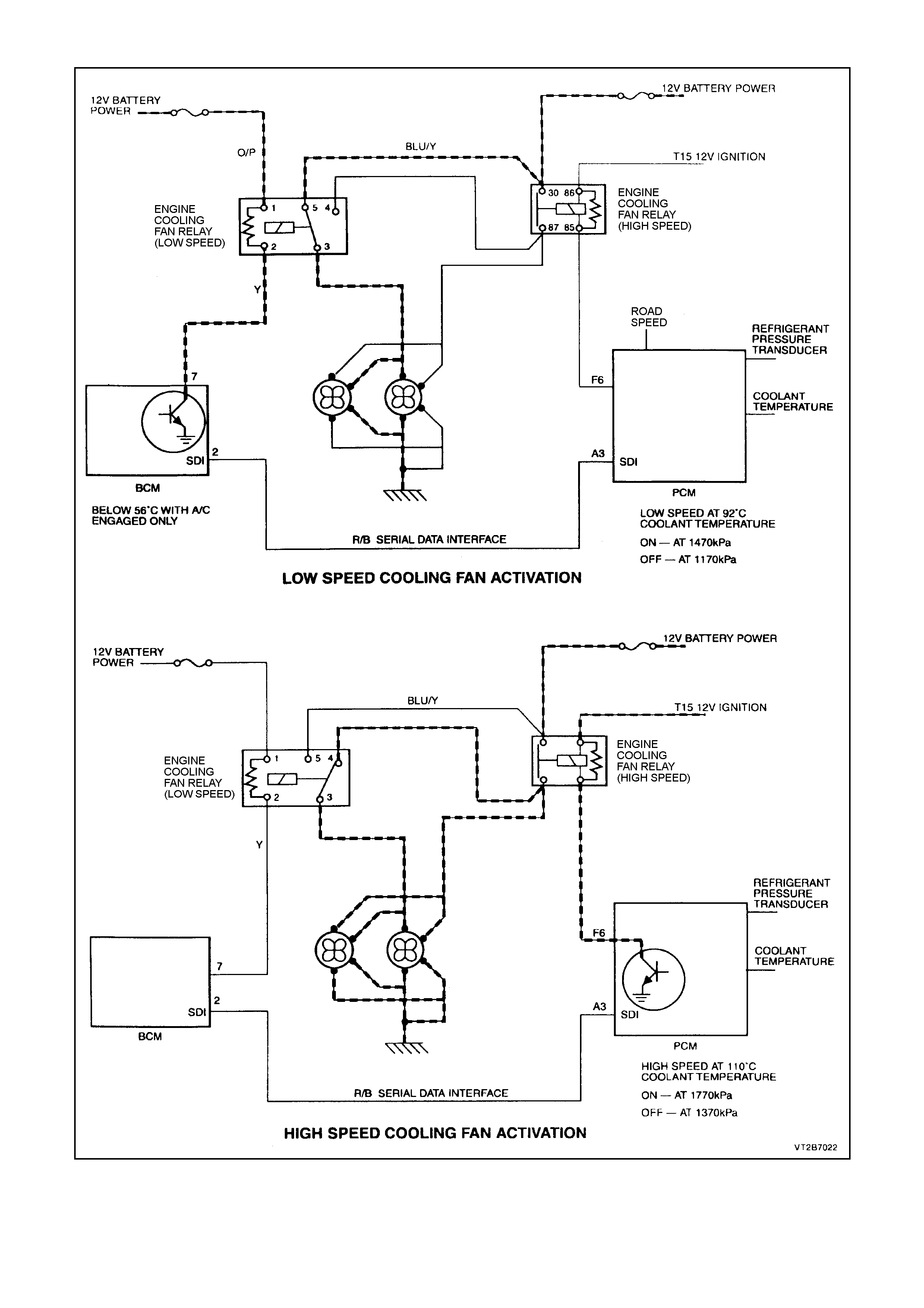
HIGH A ND LOW SPEED COOLING FAN ACTIVATION
Figure 2A-31
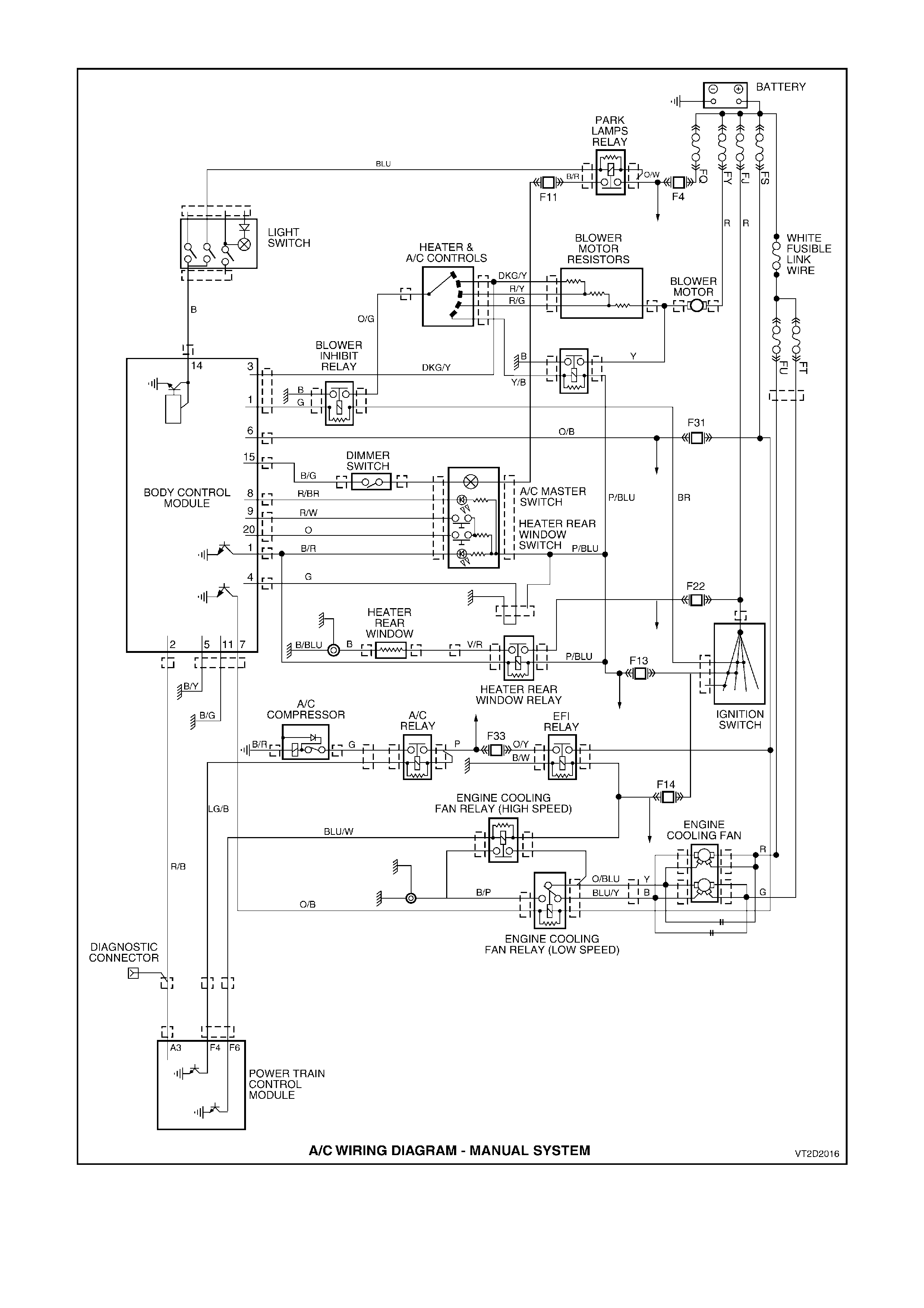
A/C WIRING DIAGRAM - MANUAL SYSTEM
Figure 2A-32