
SECTION 2C - AIR CONDITIONING - SERVICING AND
DIAGNOSIS
CAUTION:
This vehicle will be equipped with a Supplemental Restraint System (SRS). A SRS will
consist of either seat belt pre-tensio ners and a driver’s side air bag , or seat belt pre-
tensioners and a driver’s and front passenger’s side air bags. Refer to CAUTIONS,
Section 12M, before performing any service operation on or around SRS
components, the steering mechanism or wiring. Failure to follow the CAUTIONS
could result in SRS deplo yment, resulting in possible p ersonal injury or unnecessary
SRS system repairs.
CAUTION:
This vehicle may be equipped with LPG (Liquefied Petroleum Gas). In the interests of
safety, the LPG fuel system should be isolated by turning 'OFF' the manual service
valve and then draining the LPG serv ice lines, before any service w ork is carried out
on the vehicle. Refer to the LPG leaflet included with the Owner's Handbook for
details or LPG Section 2 for more specific servicing information.
CAUTION:
Whenever any component that forms part of the ABS or ABS/ETC (if fitted), is
disturbed during Service Operations, it is vital that the complete ABS or ABS/ETC
system is checked, using the procedure as detailed in 4 DIAGNOSIS, ABS or
ABS/ETC FUNCTION CHECK, in Section 12L ABS & ABS/ETC.
1. PRECAUTIONS IN HANDLING REFRIGERANT
In any vocation or trade, there are established procedures and practices which have been developed after many
years of experience. In addition, occupational hazards may be present that require the observation of certain
precautions, or use of special tools and equipment. Observing the procedures, practices and precautions of
servicing refrigeration equipment will greatly reduce the possibility of damage to the customer’s equipment, as well
as virtually eliminating the element of hazard to the serviceman.
Care should be taken when discharging the air conditioning system to ensure the refrigerant is not released to the
atmosphere but captured for recycling. Environment friendly refrigerant R134a is not an ozone depleting substance
but its release would add to the green house warming effect.
Refrigerant R134a is transparent and colourless in both the gaseous and liquid states. At all normal temperatures
and pressures it will be a vapour. The vapour is heavier than air and is non-flammable, non-explosive, non-
poisonous and non-corrosive (except when in contact with moisture).
Techline
Techline
Techline
Techline

The following precautions in handling R134a should be observed at all times:
NOTE:
R134a and R12 are not compatible and must never be mixed.
1. Always use safety glasses and gloves when handling or servicing air conditioning sy stems. If R134a does enter
the eye, freezing of the eye can occur and could result in blindness. The procedure outlined below is suggested
if R134a enters the eyes.
a. Keep calm.
b. Do not rub eyes.
c. Splash large quantities of cool water into the eyes to increase the temperature.
d. Tape a sterile eye patch in place to prevent dirt from entering the eye.
e. Go immediately to a doctor or hospital for professional care.
DO NOT ATTEMPT TO TREAT YOURSELF
2. Always use proper workshop practices. Skylarking is dangerous!
3. Always work in a well ventilated area.
4. Avoid skin contact, as R134a will cause frostbite on contact with bare skin.
5, Do not abuse the refrigerant cylinder, or any other tools you may need to use.
6. Do not weld or steam clean on or near any air conditioning components when pressurised. This may cause a
dangerous pressure build up in the system.
7. Do not discharge refrigerant into an enclosed area.
8. When purging a system, discharge the refrigerant slowly.
9. If it is necessary to transport or carry a cylinder of refrigerant in a car, keep it in a luggage compartment.
10. Refrigerant cylinders should always be protected from the radiant heat of the sun.
11. When filling a refrigerant cylinder, never completely fill it. Always leave space for expansion. If the cylinder was
completely filled and the temperature increased, hydraulic pressure with its tremendous force would result.
REMEMBER:
Prevention is better than cure.
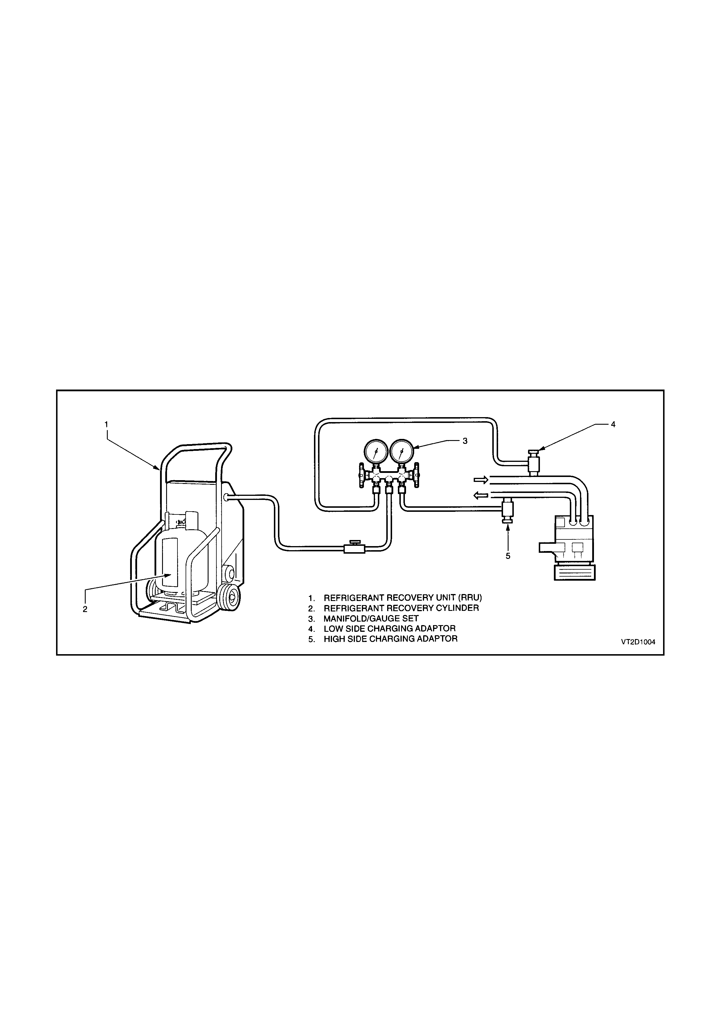
2. DISCHARGING SYSTEM - REFRIGERANT RECOVERY
NOTE:
Care should be taken when discharging the air conditioning system to ensure the refrigerant is not released to the
atmosphere but captured for recycling. R134a is not an ozone depleting substance but its cost and the fact that it
does contribute to the greenhouse effect, make it essential that it is recovered.
Various Refrigerant Recovery Units (RRU) are now available. The following procedure is typical for the use of these
units when recovering refrigerant from a vehicle air conditioning system.
1. Connect the RRU outlet to an R134a recovery cylinder with a refrigerant hose and open the valve on the
cylinder. Ensure that the cylinder has sufficient capacity to hold the refrigerant in the system to be serviced.
This can be confirmed by weighing the cylinder or by referring to the volume gauge if fitted.
2. Connect a gauge manifold set to the car air conditioner. Connect to both the suction and discharge sides of the
system. Connect the centre hose of the gauge set to the inlet of the recovery unit. Connect the RRU to
electrical supply.
3. Open the gauge set and quickly connect stop taps to allow refrigerant to enter the RRU via the centre hose. At
this point, depending on which unit is being used, the RRU will switch on. If the RRU is not the automated type,
switch the unit on.
4. The automatic recovery unit will operate until the air conditioning system has been emptied of refrigerant down
to atmospheric pressure. The cylinder can now be closed.
5. Measure the amount of PAG oil removed from the A/C system. This oil is normally separated from the
incoming refrigerant into the RRU. New clean PAG oil must be added into the system before recharging with
refrigerant.
Figure 2C-1
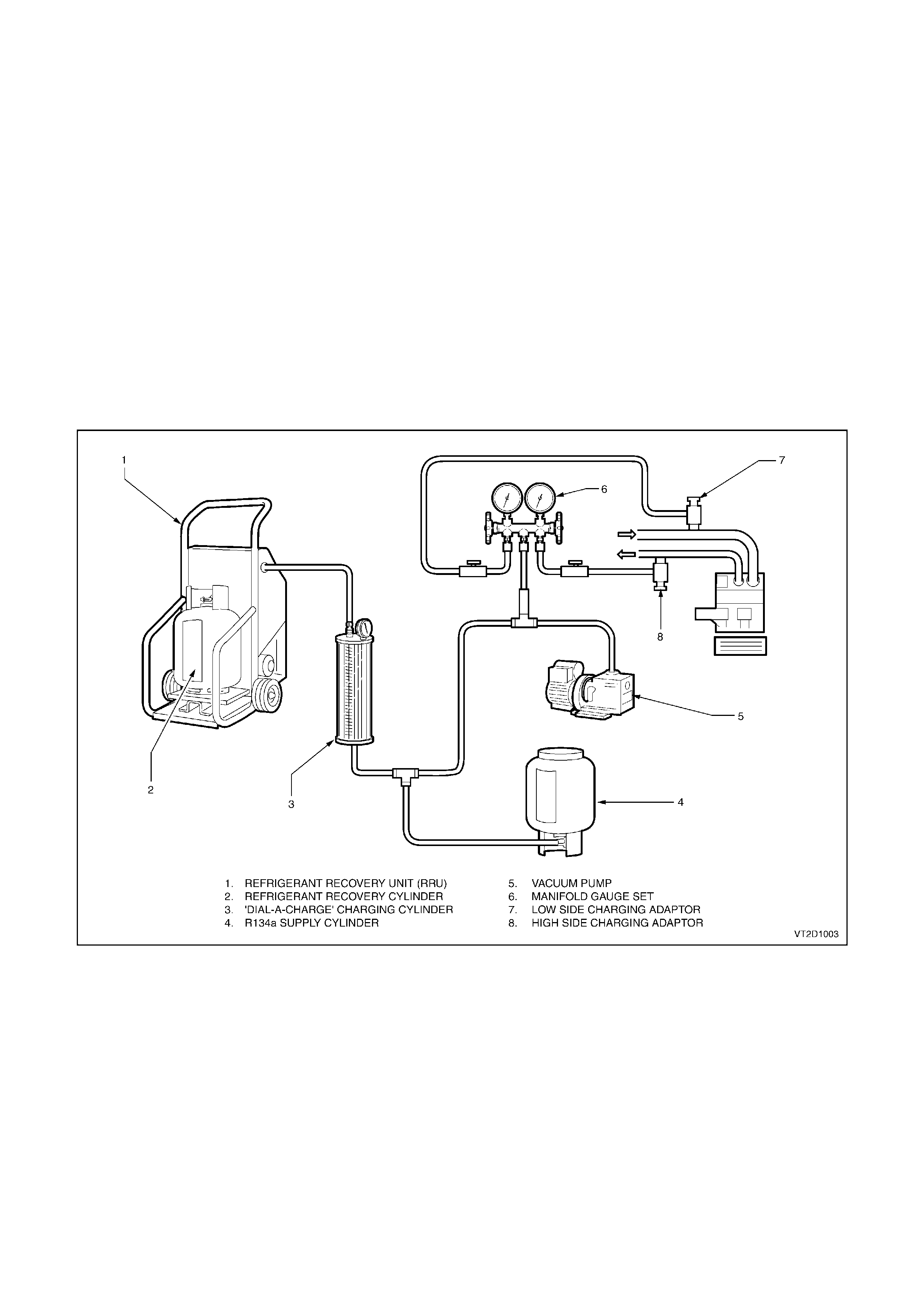
2.1 SYSTEM CHARGING AND EVACUATION
The following equipment is required for system charging and evacuation procedures:-
1. Refrigerant calibration charging cylinder or weighing device.
2. Pressure gauges and hoses.
3. Vacuum pump.
4. Refrigerant Recovery Unit (including compressor and oil collector).
5. Electronic leak detector.
CAUTION:
The wearing of safety goggles and gloves is mandatory during system charging or discharging.
NOTE:
All hoses at point of connection to the system must have isolation valves fitted.
Charging the system includes the following steps:-
1. Filling charging cylinder.
2. Evacuation and leak test.
3. Charging system.
4. Performance test.
Figure 2C-2
FILLING A DIAL-A-CHARGE CYLINDER
1. Open valve on bottom of charging cylinder, allowing refrigerant to enter cylinder from storage cylinder.
2. Bleed cylinder via valve on top (behind pressure gauge) as required to allow refrigerant to enter. This valve
should be connected via a hose to a Refrigerant Recovery Unit (RRU) and recovery cylinder. When refrigerant
reaches the desired level, close valve at bottom of cylinder and be certain that bleed valve is securely closed.

EVACUATION AND LEAK TEST
1. Check that both manifold hand valves of gauge set are closed and turn RRU off.
2. Connect the charging hoses onto the suction (low) and discharge (high) service valves in the system.
NOTE:
DO NOT USE SPANNERS.
3. Connect the centre manifold charging hose to the vacuum pump inlet.
4. Start vacuum pump and slowly open LOW SIDE manifold hand valve. Low side gauge reading should
decrease to 98 - 102 kPa vacuum and high side gauge should read slightly below the zero index of gauge. If
high side gauge reading does not register, check system for blockage or leak.
NOTE:
When high side gauge is slightly below the zero index of gauge, open high side manifold hand valve.
5. After evacuating the system for 15 minutes, to a vacuum of -100 kPa, close both the low and high side hand
valves, then stop the vacuum pump. The system must hold the vacuum of -100kPa for a minimum of
15 minutes. If vacuum is held then the system has no leaks and may continue to be evacuated for a further
15 minutes.
6. Wear safety goggles.
7. Connect the centre charging hose to the charging cylinder hand valve on the bottom of the cylinder. Open the
bottom charging cylinder hand valve. Do not open the low or high side valves on the manifold gauge at this
time.
8. Loosen the centre charging hose nut connected to the centre fitting of the manifold gauge set until a hiss can
be heard. Allow the air to escape for a few seconds, then re-tighten nut.
NOTE:
DO NOT START ENGINE.
9. Partially charge the system with 200g of R134a by slowly opening the high side manifold hand valve; low side
gauge should register a pressure, if not, check for blockage. Close the high side manifold hand valve as soon
as 200g of R134a has entered the system.
10. Check system for leaks with an electronic detector. If a leak is detected, remove refrigerant from system using
the RRU and repair the faulty component or connection. Repeat steps 4 to 10 after repair of leak.
NOTE:
Various types and makes of leak detectors are currently in use. Whichever leak detector is used, it is important to
follow the manufacturer’s instructions in regard to adjustment and setting the instrument prior to conducting the test.
Inspect for leaks by slowly moving the probe of the detector around all hose connections and points of possible
leakage. Refrigerant R134a is heavier than air and will be more apparent at the bottom of a fitting.

CHARGING SYSTEM
After leak check has proven the system to be leak free, charge the proper amount of refrigerant into the system as
follows:-
1 Open the HIGH SIDE manifold hand valve slowly. Fill the system with as much of the specified charge as
possible, then close the high side manifold hand valve.
2. Rotate the compressor by hand for 12 revolutions to ensure no liquid refrigerant is trapped in the suction side
of the compressor. Failure to comply with this step may result in irreversible damage to the compressor.
3. Start the engine and engage compressor clutch and evaporator fan on high speed.
4. Set engine speed to 1500 - 1700 rpm.
5. If the system has been charged with the specified amount (775 - 825g), go to step 7.
6. To complete the charging of the system, slowly open the LOW side manifold hand valve until the specified
amount has been charged into the system.
CAUTION:
Do not allow more than 275 kPa to be registered on the LOW pressure gauge.
7. Perform Cooling System Pressure Test, refer to Section 6B1-1 ENGINE COOLING - V6 or 6B1-2 ENGINE
COOLING - V6 SUPERCHARGED or 6B2 ENGINE COOLING - V8. If unit operates satisfactorily, stop engine,
shut stop valves at hose connections to system and disconnect hoses taking extreme caution, as the discharge
hose can have up to 2070 kPa stored in it. Install service valve caps as required.
WARNING:
NEVER RUN COMPRESSOR WITHOUT REFRIGERANT IN SYSTEM AS COMPRESSOR LUBRICANT RELIES
ON REFRIGERANT FLOW.
No sight glass is fitted to the system due to PAG oil’s foaming properties, which may be confused with a low gas
charge. Topping up the system is not recommended.
Accurate system refrigerant charge may only be determined by charging the correct amount of R134a.
Pressure gauge readings together with face air outlet temperatures are the only method of checking and diagnosing
the system cooling capacity (comparing results with the appropriate graph).
If in doubt as to gas charge, e.g:
Suction pressure low,
Discharge pressure low,
Air outlet temperature (face) above graph range,
Recover refrigerant from the system using R134a specific equipment.
Evacuate system. Charge with 775 - 825g of R134a.
Carry out cooling system pressure test and suction (low side) pressure readings comparisons.

2.2 CHECKING SYSTEM OIL CHARGE
The compressor is charged at the factory with 220ml of Harrison PAG refrigerant oil (Part No. 12345923), which
circulates within the entire A/C system. Only this type of oil which is blue in colour must be used when adding or
changing oil. This oil is not compatible with any other PAG oil.
Although it is not necessary to regularly check the oil level within the system, all the A/C system components will
hold a quantity of the oil circulated. Therefore whenever an A/C system component is replaced, a quantity of new
refrigerant (PAG) oil must be added to the system. Where a major loss of system oil has occurred, due to:
• A broken hose or severed leak,
• Collision damage to refrigerant system components, or
• If excess oil is suspected to be in the system, then
1. Recover refrigerant from the system, then remove the compressor.
2. Carefully drain the refrigerant oil.
3. Flush remaining oil from the rest of the system using R134a refrigerant.
CAUTION:
A refrigerant Recovery Unit (RRU) should be used to flush the system, ensuring that the R134a is not
vented to the atmosphere. The R134a must be reclaimed via the RRU into a separate bottle.
4. Add 220ml of new refrigerant oil to the compressor.
5. Install the compressor, replacing the suction and discharge O - rings. Ensure O - rings are not twisted and that
the seals and O - rings are clean.
6. Evacuate then recharge the system.
PAG OIL PRECAUTIONS:
DO NOT allow PAG oil to contact either bare skin or vehicle paint work. IF CONTACT OCCURS, WASH PAG OIL
OFF IMMEDIATELY.
Techline
Techline

FLUSHING THE A/C SYSTEM FOR CONTAMINATION OR LUBRICATING OIL REMOVAL
Some oil is lost whenever air conditioning system components are replaced.
Where the system has been ruptured, contaminated, or a compressor has to be removed and reinstalled or
replaced, the system should be checked for contamination and, if so, the entire system must be flushed.
Currently the only method recommended when flushing is with refrigerant R134a. Other flushing agents are
currently under investigation.
CAUTION:
A Refrigerant Recovery Unit (RRU) should be used to capture the R134a used for flushing. The R134a must
be reclaimed via the RRU into a separate bottle. Use only a dedicated R134a RRU.
IMPORTANT:
The complete air conditioning system must contain 220ml PAG refrigerant oil.
1. Flush individual components.
2. Self made flushing fittings will be required as A/C system component fittings all differ in size, shape and thread
size.
3. Invert decanting cylinder to use refrigerant in liquid form.
4. Reverse flush components.
5. Do not flush through a compressor otherwise possible internal damage could occur.
6. Recover/recycle flushing refrigerant, the recovery device will remove contaminants through a filtration system.
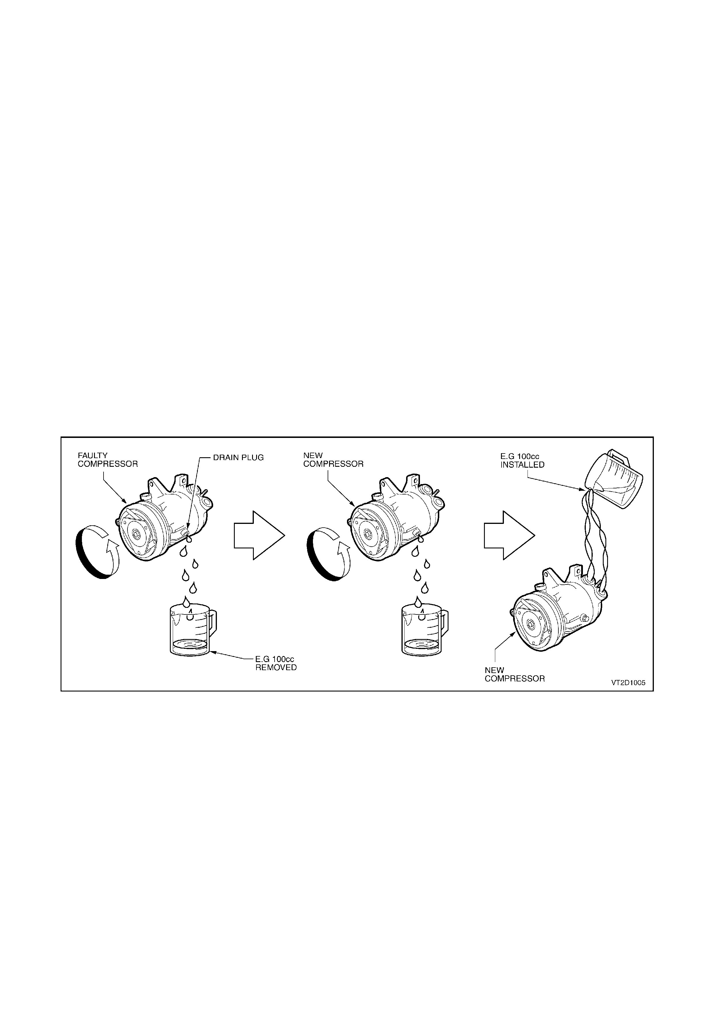
Figure 2C-3
COMPRESSOR
Reinstalling the Original Compressor
1. Drain and measure the refrigerant oil contained in the compressor.
2. Charge oil through the discharge port of the compressor with the same amount of new refrigerant oil.
NOTE:
If the amount of oil in the original compressor was not checked, then approximately 150cm3 of new oil should be
added to the compressor being installed. (This is assuming the compressor being installed has first been drained).
Installing a New Compressor
1. Drain and measure refrigerant oil from the original compressor drain plug.
2. Drain factory installed refrigerant oil from new compressor drain plug (total lubricant quantity 220ml).
3. Measure the same amount of new refrigerant oil that was drained from the original compressor. Install this
amount of oil into the new compressor through the suction/discharge port whilst turning the compressor clutch
pulley front face.
Evaporator or Condenser
Drain as much of the original oil as possible from the evaporator or condenser. Add the same amount of new
refrigerant oil, either to the original or new evaporator or condenser.
If replacing condenser - add approximately 40ml.
If replacing evaporator - add approximately 50ml.
Filter Drier Receiver (FDR)
If replacing the FDR - add approximately 15ml.
The FDR must be replaced whenever the system has been opened to the atmosphere for repair.
Blown or Ruptured Pipe/Hose
When replacement is required add approximately 40ml.
Figure 2C-4

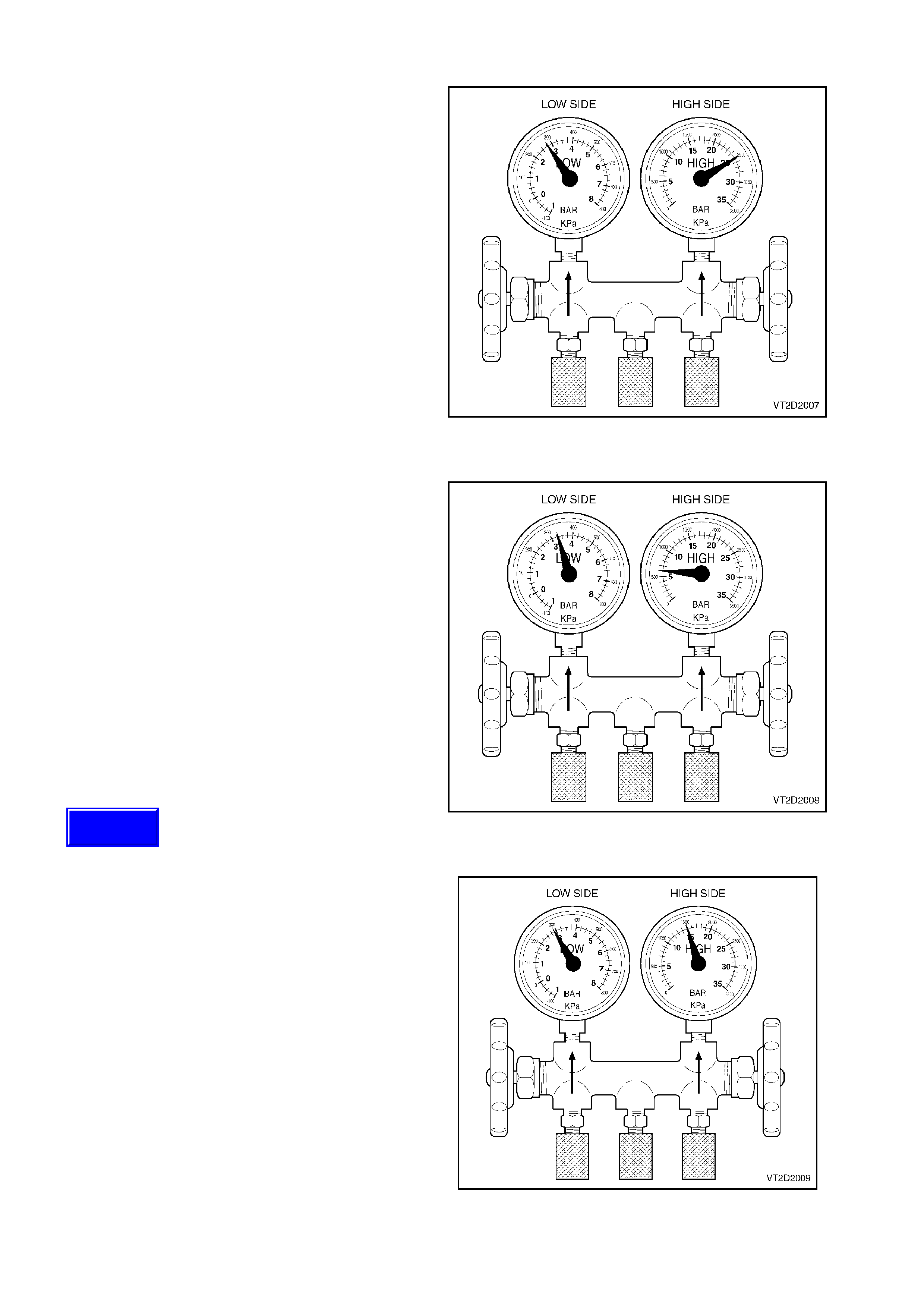
3. DIAGNOSIS
THERMAL EXPANSION VALVE (TXV) REMAINS OPEN
Condition
Low Side Gauge:- High
High Side Gauge:- High
Discharge Air:- Warm
Cause
Thermal expansion valve (TXV) jammed open and
not modulating, causing flooding of evaporator with
refrigerant. This is normally related to incorrect
positioning of temperature sensing bulb or foreign
material and moisture entry causing rust
formations.
Figure 2C
-
5
THERMAL EXPANSION VALVE (TXV) REMAINS CLOSED
Condition
Low Side Gauge:- Low to vacuum
High Side Gauge:- Low
Discharge Air:- Slightly cool.
Expansion Valve:- Sweating or frost build up.
Cause
Thermal expansion valve (TXV) jammed closed.
Insufficient refrigerant flow to suction side of the
compressor. This is normally related to the TXV
sensing bulb malfunction, disconnected from tube,
foreign material in TXV or moisture entry causing
rust formations.
Figure 2C
-
6
Techline
Techline
Techline
Techline

RESTRICTION IN HIGH SIDE OF SYSTEM
Condition
Low Side Gauge:- Low
High Side Gauge:- Low
Discharge Air:- Slightly cool
High Side Tubes:- Cool and showing signs of
sweating or moisture build up at the position after
the point of restriction.
Cause
Foreign material causing blockage between the
compressor outlet and evaporator inlet (high side).
Very little or no refrigerant f low to s uction (low) s ide
of compressor.
Figure 2C-7
EXCESSIVE MOISTURE
Condition
Low Side Gauge:- Normal to vacuum.
High Side Gauge:- Normal.
Discharge Air:- Becomes warmer as the low side
cycles to a vacuum.
Cause
Moisture can f reeze within the expansion valve and
cause blockages through rust formation.
Figure 2C-8
CONDENSER MALFUNCTION OR OVERCHARGE
Condition
Low Side Gauge:- Low to normal.
High Side Gauge:- High.
Discharge Air:- Warm.
High Side Tubes:- Very hot.
Compressor Clutch:- Could continually cycle on the
high pressure switch.
Cause
Refrigerant overcharge.
Engine or condenser fan not operating.
Condenser fins clogged with debris.
No sealing foam between condenser eg. bull bar,
insect screen.
Fan belt slippage.
Radiator overheating.
Figure 2C-9
EXCESSIVE AIR (NON CONDENSABLES)
Condition
Low Side Gauge:- High.
High Side Gauge:- High.
Discharge Air:- Slightly cool.
NOTE:
Low side pressure gauge needle does not f luctuate
when compressor cycles ON and OFF.
Cause
Large amounts of air and moisture in system
caused by insufficient evacuation time or no
evacuation after repairing or servicing the system.
Leaking components within the system allowing
moisture and air to enter.
Figure 2C-10
COMPRESSOR MALFUNCTION
Condition
Low Side Gauge:- High.
High Side Gauge:- Low.
Compressor:- Noisy.
Discharge Air:- Warm.
Discharge Hose:- Cool.
Cause
Compressor faulty, internal failure.
Blockage in suction hose after the low side filling
port.
Figure 2C-11
COMPRESSOR CONTROL VALVE MALFUNCTION
Condition
Low Side Gauge:- Higher or lower than control
point pressure.
High Side Gauge:- Normal.
Discharge Air:- Cool only if above control point.
Evaporator:- Frozen up if too far below control
point.
Cause
Compressor control valve faulty or incorrect valve
rating used. These valves are stam ped with a letter
code on the valve body indicating the pressure
control point for the low side of the system.
Figure 2C-12
Techline

4. HARRISON V5 COMPRESSOR TXV SYSTEM DIAGNOSTICS
DIAGNOSTIC FLOW CHART
This flow chart is the starting point for verifying and diagnosing all air conditioning and HVAC control related
complaints. It represents the correct path to follow from a customer complaint or condition through delivery of the
vehicle back to the customer.
PRELIMINARY CHECKS
This step covers all physical and visual inspections of interior and under-hood components. Many problems can be
detected by a thorough inspection. Failure to perform this step could result in wasted time proceeding further down
the flow chart.
VEHICLE SET UP AND PERFORMANCE TEST
To run the air conditioning performance test, the vehicle must be set up according to the instructions in
6. PERFORMANCE TESTING in this Section. The instructions include manifold gauge set installation and controller
settings. Improper vehicle set up will result in inaccurate pressure and temperature readings.
GENERAL AND SPECIFIC SYSTEM CONDITION CHARTS
These charts were developed in a wind tunnel by producing known system problems and recording pressures at
various ambient temperatures. The tests were then validated using the same vehicle set up in a service
environment. To find your problem, compare the performance test readings to the readings on the charts for your
ambient temperature and humidity. When all pressure and temperature readings fall within the limits of a given
chart, use that chart to repair the vehicle. There is some variance in readings between systems of different vehicles;
however the target areas have been developed to accommodate these changes.
COMPRESSOR CONTROL TEST
This is designed to evaluate the compressors ability to change displacement with varying heat loads.
STEP 1 - PRELIMINARY CHECKS
1. A/C fuse.
2. A/C blower operation.
3. Temperature door. Move temperature door rapidly from cold to hot.
Ensure air mix door fully opens and closes. Adjust rod (manual system) or re-calibrate air mix motor movement
(ECC system).
4. Clutch coil connection.
5. Pressure switch connection.
6. Compressor belt. Replace if damaged or missing.
7. Engine cooling fan operation (at idle, cooling fan must be on at any A/C mode) cooling fan must be operating in
correct direction (drawing ambient air through the condenser toward engine).
8. Condenser - Check for restricted air flow.
9. Dealer technical bulletins for updates on A/C system.
STEP 2 - CHECKING REFRIGERANT CHARGE
This procedure is designed for use with gauges that have been properly calibrated.
Ambient air temperature at least 15°C, and ignition key in the OFF position.
STEP ACTION RESULT YES NO
A. Connect high & low side
pressure gauges.
Read high side pressure.
High
pressure
above
400kPa
Do STEP 3 Go to Step B
B. If high pressure below
400kPa, perform
EVACUATION AND LEAK
TEST.
Leak found Go to Step C Do STEP 3
C. Recover refrigerant and
repair leak.
Evacuate and charge
system.
Do STEP 3

STEP 3 - CHECKING COMPRESSOR CLUTCH ENGA GEMENT
STEP ACTION RESULT YES NO
A. Run engine at idle. Set
A/C controls to: NORMAL
A/C mode, high blower
speed & temperature to
full cold.
Does clutch
engage? Go to Step B Go to Step H
B. Observe for loud knocking
noise coming from
compressor and/or a belt
slippage condition (cycle
compressor on & off to
verify source of noise).
Compressor
noise or belt
slippage
Go to Step C Go to Step D
C. Check for compressor
noise. Longer than
30 seconds Go to Step D Go to Step E
D. Recover refrigerant.
Replace compressor.
Evacuate and charge
system.
Do STEP 4 Go to Step F
E. Possible TXV stuck open.
Do STEP 6 -
DIAGNOSTIC CODE
PROCEDURES, E: TXV
STUCK OPEN.
TXV replaced.
F. Check for noise. Belt slippage Go to Step G
G. Correct condition.
Refer to appropriate
Section.
Do STEP 4
H. Turn OFF the ignition
switch.
Disconnect clutch wires at
compressor.
Connect a jumper lead
from ground to one
compressor clutch
terminal.
Connect a fused jumper
wire from the positive
battery terminal to the
other compressor clutch
terminal.
Does clutch
engage? Go to Step I Go to Step J
I. Repair electrical circuit to
the compressor clutch.
Refer to appropriate
Section for further
diagnostics.
J. Replace clutch coil.
Repeat STEP 3.

STEP 4 - CHECKING SYSTEM PERFORMANCE
This test is designed for typical garage condition: 21°
°°
°C - 37.5°
°°
°C, various humidities and no sun load. Follow the
chart exactly. It is designed to create enough cooling load to cause V5 compressor to operate at full stroke. It is
absolutely essential for accurate results.
Neutralise internal vehicle temperature to workshop ambient conditions. Insert thermometer into centre duct.
STEP ACTION RESULT YES NO
A. Hood up, open doors &
windows.
Temperature control at full
cold, normal A/C mode
high blower speed.
Engine at fast idle
(1500rpm) vehicle interior
temperature at ambient.
Does
engine
cooling
fan run at
highest
speed?
Go to Step B Go to Step C
B. Close doors & windows
set A/C controls to:
normal A/C mode high
blower speed,
temperature control at full
cold run engine at idle for
5 minutes.
Record low & high side
pressure after A/C system
has been run for 5
minutes, also record
centre outlet duct
temperature.
Do STEP 5.
C. Reference engine cooling
fan diagnostics section.
Correct and return to
STEP 4.
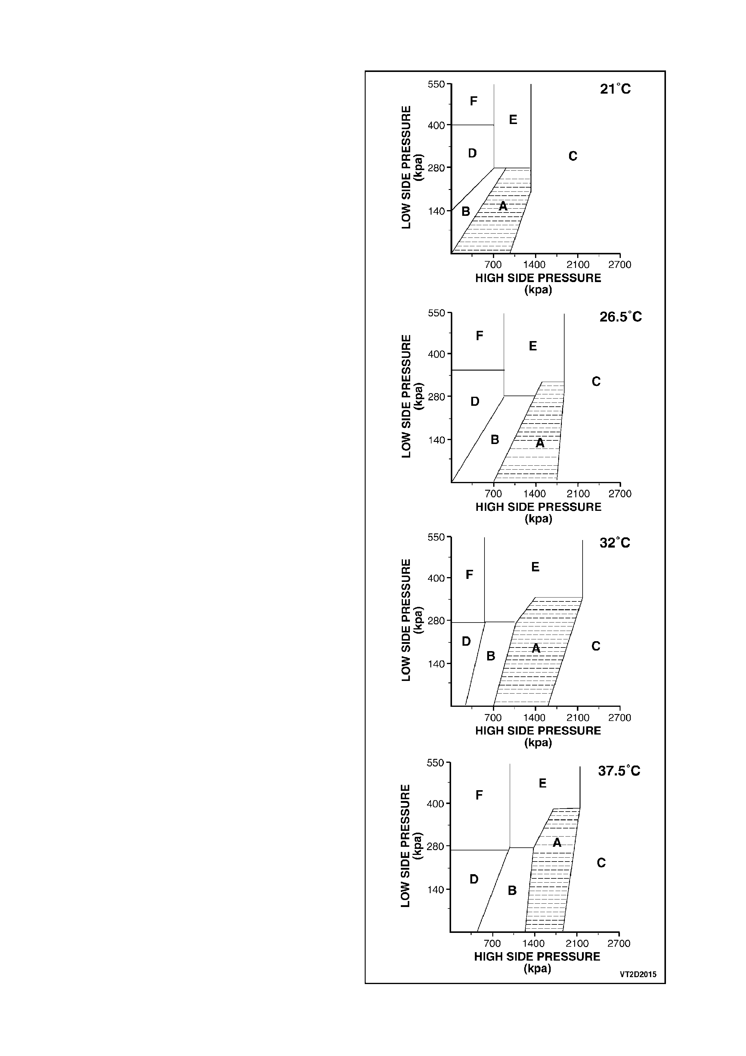
STEP 5 - DIAGNOSTIC CHART
1. Use the chart opposite which corresponds to
the present ambient temperature.
2. Read the high side and low side pressures
and note the letter coded area in which they
intersect.
3. Match the letter code with the corresponding
letter code on the following page and continue
with the diagnostic code procedures.
A = NORMAL SYSTEM
B = LOW REFRIGERANT CHARGE
C = REFRIGERANT OVERCHARGE OR FILTER
DRIER RESTRICTED (GO TO STEP 6)
D = TXV BLOCKED (GO TO STEP 6)
E = TXV STUCK OPEN (GO TO STEP 6)
F = COMPRESSOR NOT PUMPING (GO TO
STEP 6)
Figure 2C-13

STEP 6 - DIAGNOSTIC CODE PROCEDURES
A: Refrigerant overcharge or restricted receiver/drier.
Confirm by touching filter drier inlet/outlet. If there is a temperature and difference between inlet and outlet, replace
filter/drier and return to STEP 4.
Complaint will be poor or intermediate cooling at high ambient temperature (pressure switch shuts system down
because of excessive high side system pressure).
Confirm by touching compressor suction tube - it will be cool and discharge tube will be hot.
B: TXV blocked. Outlet temperature cool to warm.
Confirm by thorough physical inspection of all tubes, hoses and components. In normal operation, the evaporator
inlet temperature is hot. If the inlet pipe is cool, check for high side restriction. If the inlet pipe is room temperature,
confirm TXV is blocked by running engine at 2000 RPM - neither pressure should change by more than 140 kPa. If
TXV is blocked replace.
C: TXV stuck open.
System appears to perform normally, but may go warm temporarily on extended journeys and recorrect itselfafter
vehicle shut down. May also cause compressor ‘slugging’ noise.
Run high blower speed, normal A/C, fast idle for 2 minutes, engine off for 3 minutes. Restart engine with A/C off.
Let engine RPM stabilise. On low blower run A/C and listen for a ‘slugging’ noise (engine hood should be lowered
for this procedure). Replace TXV if stuck open.
D: Compressor not pumping, outlet temperature is ambient.
Confirm by completing STEP 7.
NOTE:
If none of the above conditions can be verified, recover, evacuate and recharge with proper charge and perform
STEP 4 again.
STEP 7 - CHECKING FOR NO STROKE COMPRESSOR
Run engine at 3000 rpm.
Set A/C controls to: high blower speed, temperature to full cold and close vehicle windows & doors. Cycle mode
lever from vent to A/C every 20 seconds for 3 minutes.
STEP ACTION RESULT YES NO
A. Check compressor high
and low side pressure. Within
210 kPa
of each
other
Go to Step B Go to Step D
B. Engine OFF, with
compressor clutch
disengaged,
Check compressor clutch
front plate (not pulley).
Turns
freely by
hand
Go to Step C Go to Step E
C. Replace compressor.
Recover refrigerant.
Evacuate and charge
system.
Go to
Step D
D. Leak test. Leak
found Do STEP 4
E. Perform control valve
diagnosis.
Do STEP 8

STEP 8 - CONTROL VALVE DIAGNOSIS
IMPORTANT:
Follow this test procedure exactly. It is designed to create a low cooling load to cause V5 compressor to operate at
less than full stroke. This is absolutely necessary for accurate results.
STEP ACTION RESULT YES NO
A. Run engine for 5 minutes
at 1500 rpm.
Set A/C controls to:
maximum A/C mode low
blower speed,
temperature to full cold,
close vehicle windows and
doors open hood.
Is low side
pressure
refer to
STEP 5
diagnostic
chart
Do STEP 4 Go to Step B
B. Recover refrigerant.
Replace control valve.
Recover & charge system.
Do leak test.
Leak found Do STEP 4

5. NOISE DIAGNOSIS
Observe for loud knocking noise from compressor and/or a belt slippage condition.
STEP ACTION RESULT YES NO
A. Is there belt slippage
noise? Go to Step B Go to Step E
B. Check for belt damage. Damaged Replace belt Go to Step C
C. Check idler pulleys
individually for bearing
roughness or damage.
Roughness
or damage Replace bearing. Go to Step D
D. Check belt tensioner for
correct operation. Incorrect
operation Repair tensioner
refer to Section
6A1 ENGINE
MECHANICAL-
V6 or
6A2 ENGINE
MECHANICAL-
V8
Go to Step E
E. Possible compressor
noise.
Does noise last longer
than 30 seconds?
Go to Step G Go to Step F
F. Is noise repeatable? Go to Step H It is normal to
observe a liquid
slugging
condition. This
may occur after
extended system
shutdown at
warmer ambient,
followed by an
overnight
ambient drop.
G. Possible low charge or
block valve stuck closed. Valve
closed Go to Step I Go to Step J
H. Possible block valve stuck
open. Valve open Carry out block
valve diagnosis.
Replace if
confirmed to be
fully open.
Go to Step I
I. Check for loose
compressor bolts and/or
A/C plumbing contacting
body work.
Tighten bolts
and/or relocate
plumbing.
Go to Step J
J. Recover refrigerant and
replace compressor,
recharge system.

6. PERFORMANCE TESTING
STEP 1
Park vehicle in a shaded area. Take note of the ambient temperature.
STEP 2
Open both front windows and engine hood.
STEP 3
Connect both high and low pressure service hose coupling valves to the sy stem filling ports.
STEP 4
Open all dash louvres and adjust to the straight ahead position.
STEP 5
Insert thermometer probe approximately 50mm into the centre vent louvre.
NOTE:
If ECC dual zone system, ensure both sides of the centre vent are checked to ensure temperature performance is
correct.
STEP 6
Set controls to:
a. Fresh air position
b. Face vent mode
c. Maximum cooling (ECC system select C maximum cooling)
d. A/C on
e. Highest blower speed
f. Bonnet open
STEP 7
Start engine and bring engine speed to 1700rpm. Allow pressure gauge needles to stabilise.
STEP 8
Take pressure and centre vent temperature readings. Compare these figures taken to the performance charts
(Figures 2C-14 and 2C-15).
NOTE:
Only take pressure and temperature readings when the compressor is engaged.
NOTE:
As you can see from the above typical performance test, the A/C system is put under an increased load, such as
doors and engine hood open and high blower speed. If an A/C system can perform to the manufacturers
specifications under these loads, in normal driving situations with the engine hood down, windows closed and
possibly a lower blow er speed, centre vent temperatures will be lower.
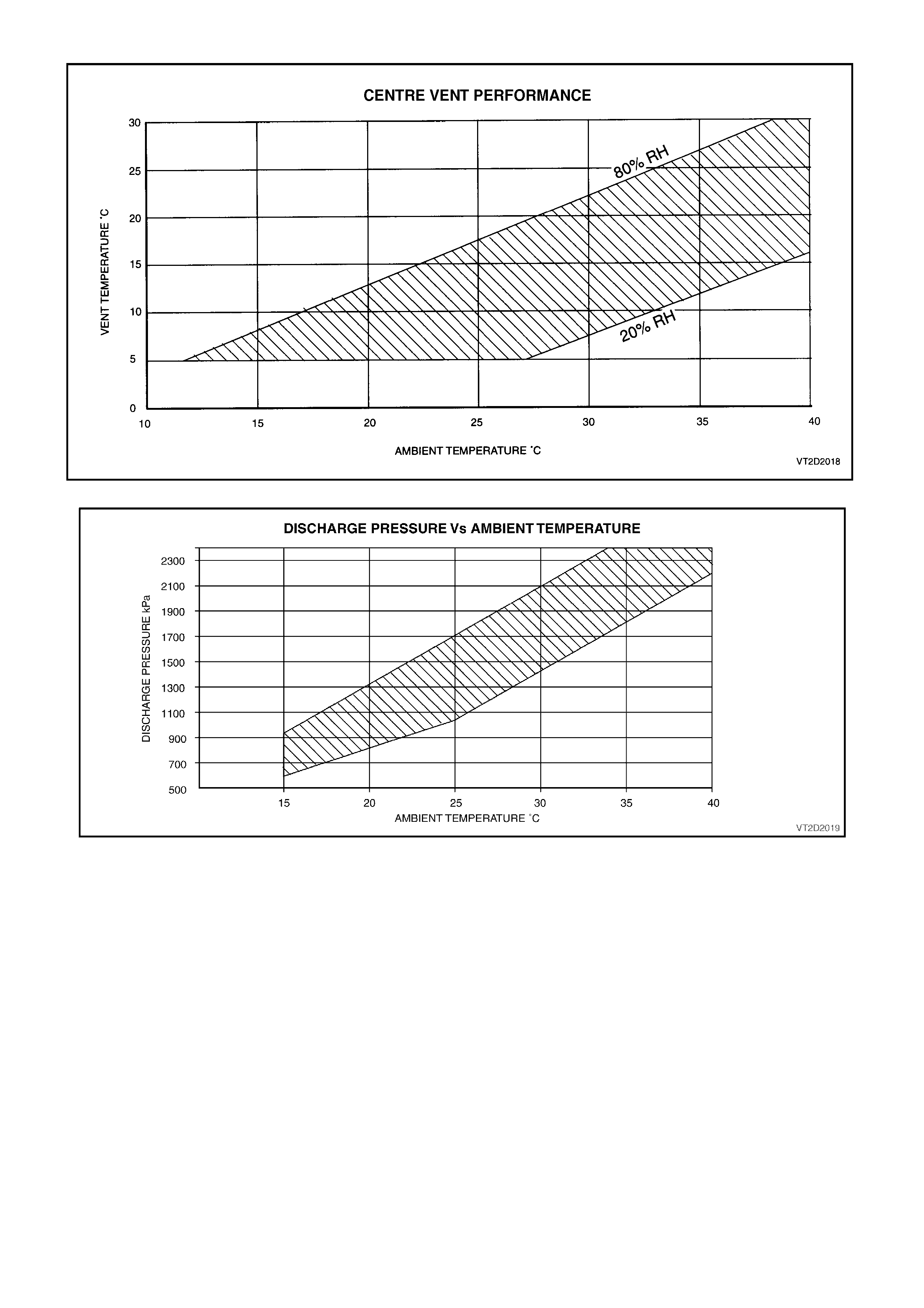
Figure 2C-14
Figure 2C-15