
SECTION 2D - ELECTRONIC CLIMATE CONTROL
(ECC) - DESCRIPTION AND OPERATION
CAUTION:
This vehicle will be equipped with a Supplemental Restraint System (SRS). A SRS will
consist of either seat belt pre-tensio ners and a driver’s side air bag , or seat belt pre-
tensioners and a driver’s and front passenger’s side air bags. Refer to CAUTIONS,
Section 12M, before performing any service operation on or around SRS
components, the steering mechanism or wiring. Failure to follow the CAUTIONS
could result in SRS deplo yment, resulting in possible p ersonal injury or unnecessary
SRS system repairs.
CAUTION:
This vehicle may be equipped with LPG (Liquefied Petroleum Gas). In the interests of
safety, the LPG fuel system should be isolated by turning 'OFF' the manual service
valve and then draining the LPG serv ice lines, before any service w ork is carried out
on the vehicle. Refer to the LPG leaflet included with the Owner's Handbook for
details or LPG Section 2 for more specific servicing information.
1. GENERAL DESCRIPTI ON - ECC
The Electronic Climate Control (ECC) System is available in two forms either in Single Zone or Dual Zone.
The Single Zone is standard on Berlina.
The Dual Zone is standard on Calais.
Techline

1.1 DESCRIPTION AND OPERATION
The ECC Module uses a microprocessor to monitor
inputs, process data and thus control outputs.
The inputs used by the ECC are as follows:
• Serial Data information:
• Sunlight level, Priority Key user & Ignition Off
time from BCM, Engine RPM, coolant
temperature, road speed & AC pressure from
PCM.
•In-car temperature sensor.
•Ambient temperature sensor.
•Evaporator temperature sensor.
•Air mix potentiometer (PBR) (2 for dual zone
systems).
•Ignition Voltage.
•Blower Fan Voltage.
•Customer settings by way of the ECC buttons.
The outputs controlled by the ECC module controls
are as follows:
•Serial Data information:
Sunlight level for Instrument dimming of cruise &
Power indicators, AC request to the PCM.
•Air Distribution Mode (demist, foot, foot & face,
face) by controlling the logic of 4 vacuum
solenoids.
•Vent Air Temperature by controlling the position
of the Air mix door (2 for dual zone systems)
(between approx. 5°C (with AC on) and approx.
70°C (with warm engine).
•Air Inlet Mode (i.e. Fresh or Recirculated) by
controlling a vacuum solenoid.
•Blower fan speed by an analogue signal sent to
the Blower speed controller which amplifies this
signal & thus controls the blower voltage.
•Maximum Blower Relay.
•Rear Window Demist relay.
•ECC display and LEDs to indicate ECC status.
RECOMMENDED SETTINGS
The customer should be encouraged to use the
ECC in full Auto mode (gr een Auto LED ON) and a
set temperature of 23°C.
Changing the set temperature to suit different
conditions could cause the ECC to behave
differently from what the customer expects (eg.
setting to 17°C on a hot day could cause the
customer to complain the blower speed is to high
on hot days). This should be discouraged.

EVAPORATOR TEMPERATURE CONTROL
As the A/C system uses a Harrison V5 variable
stroke compressor, there is NO need for an
evaporator temperature sensor in the manual A/C
system. In the ECC system an evaporator air off
sensor does not exist, but is only used to sense
A/C temper ature for ECC software calculations , not
to cycle the compressor on/off. Anti ice-up is
governed by the evaporator pressure control valve
loca ted w ithin the compressor.
BLOWER FAN CONTROL
There are steples s varying blower fan speeds available in the automatic mode and f ive s peeds in the manual mode.
Manual fifth speed is the same as highest automatic blower fan speed.
When the engine is not running, the actual blower speed will not be higher than appr oxim ately fan speed 3, in order
to improve battery life.
AUTOMATIC MODE
The blower speed will vary according to:
• In-car Temperature
• Ambient Temperature
• Sunload
• Drivers Set Temperature
• Coolant Temperature
• Air Distribution Mode
If the cabin is at the required temperature, the blower will be at a minimum. An increase in sunload in these
conditions would cause the blower to increase.
If heating of the cabin is required (eg. After a cold night), the blower would gradually increase as the coolant
temperature increased to approximately 70°C. Then, as the In-car temperature increased, the blower would
decrease.
If extreme cooling of the cabin were required, the blower would increase to maximum speed (over about 15
seconds). Then, as the In-car temperature decreased, the blower would also decrease.
If cooling of the cabin is required, an increase in sunload will cause the blower speed to increase. If heating up of
the cabin is required, an increase in sunload will normally cause the blower speed to decrease.
If the air distribution mode changes, (eg. From Face to Face/Floor) the fan speed may also change.
In order to maintain a constant air flow, the blower voltage compensated for:
• Road Speed
• Air Inlet mode
• Ignition Voltage

AIR DISTRIBUTION CONTROL
There are 5 distribution modes that can be selected either Automatically or manually. These are:
• Demist
• Foot/Demist
• Foot
• Foot/Face
• Face
AUTOMATIC MODE
The air distribution mode selected will vary according to:
• In-car Temperature
• Ambient Temperature
• Sun load
• Drivers Set Temperature
• Start Up conditions
If the cabin is at the desired temperature, the ECC will select either Foot/Face of Face (depending on if the cabin
needed to be warmed up or cooled down).
If cooling of the cabin were required, Foot mode may be selected for a short time (AC purge), followed by Face
mode.
If heating of the cabin is r equired, dem ist m ode would be selec ted until the coolant is warm enough ( Dem ist Delay),
followed by Foot/Demist. Then, as the In-car temperature increased, the mode should change to Foot/Face.
If heating is requires and the coolant is warm, Foot mode may be selected for a short time (Purge), followed by
Foot/Face mode (or Foot/Demist mode depending on conditions).
AIR INLET CONTROL
When recirculate is selected either Manually or Automatically, the ECC will return the Inlet to Fresh Air mode after
approximately 40 minutes. This is to avoid stuffness in the car. The customer can return to recirculate by pressing
the recirculate button.
AUTOMATIC MODE
The Air Inlet mode selected will vary according to:
• In-car Temperature
• Ambient Temperature
• Sun load
• Drivers Set Temperature
• Start Up conditions
• Evaporator Temperature
• AC Pressure
• Coolant Temperature
If the cabin does not require cooling or AC is Off, Fresh air will be selected.
If extreme cooling of the cabin were required, Fresh maybe selected for a short time (Fresh Delay), then Recirc
mode will be selected until the cabin has cooled down sufficiently. Then, Fresh air mode will be selected.
If the cabin needs cooling down, the air mix is at full cold, the Evaporator temperature is high and the AC pressure
is high, Recirc mode may be selected (ie. heavy traffic on a hot day). Then, as the In-car temperature decreases to
a suitable level, Fresh air mode will be selected.
If the coolant temperature gets very high, Recirc may be selected to increase the cooling capacity of the radiator.

VENT AIR TEMPERATURE CONTROL
The vent temperature will vary between approximately 5°C (with AC on and Air mix door at minimum) and
approximately 70°C (with 90°C coolant and Air mix door at maximum).
MANUAL MODE
If the Set temperature is set to C, the air mix door will be set to minimum.
If the Set temperature is set to H, the air mix door will be set to maximum.
AUTOMATIC MODE
When a Set temperature of between 17°C and 30°C is selected, the Vent Air Temperature will be controlled
automatically.
The Vent Air Temperature will vary according to:
• In-car Temperature
• Ambient Temperature
• Sun load
• Drivers or Passengers Set Temperature
When the cabin is at the desired temperature, the average vent air temperature should be approximately the same
as the set temperature.
If the cabin requires cooling, the ECC will try to control the Vent temperature to less than the Set temperature. The
more cooling required, the lower the vent temperature should be.
If the cabin requires heating, the ECC will try to control the Vent temperature to be more than the Set temperature.
The more cooling required, the higher the vent temperature should be.
Generally, the Automatic blower will be at a fairly low level (less than 50%) before the ECC starts to control the
temperature. (eg. When extreme cooling is required, the blower will start on maximum and the Air mix will start at
minimum. As the cabin cools down the blower will decrease gradually, while the Air mix will stay at minimum, then ,
when the blower is approximately 40%, the air mix door maybe opened to turn the water valve on. Then as the
cabin keeps cooling down, the blower is gradually decreased as the vent temperature is increased).
Increasing the Set temperature will increase the vent temperature (provided air mix is not at maximum).
Decreasing the Set temperature will decrease the vent temperature (provided air mix is not at minimum).
As the In-car temperature increases the vent temperature will decrease.
As the In-car temperature decreases the vent temperature will increase.
As the Sun load increases the vent temperature will decrease.
As the Sun load decreases the vent temperature will increase.
As the Ambient temperature increases the vent temperature will decrease.
As the Ambient temperature decreases the vent temperature will increase.
The ECC controls the Air mix position to achieve the required vent temperature, compensating for:
• Evaporator Temperature
• Coolant Temperature
• Inlet Mode
• Air Distribution Mode
ECC COLD START-UP ROUTINES
There are four cold start-up routines incorporated in the ECC system logic to cater for various conditions on first
starting the vehicle, typically at low ambient temperatures.
Each routine has its own respective set or criteria to satisfy before the routine is executed:
Recirculation delay: Automatically defaults to recirculation mode to prevent cold air from entering the vehicle
interior.
Demist delay: To eliminate cold air at floor during warm-up and prevents drivers breath from fogging front
windscreen.
Purge: Allows coolant to heat-up the heater core and avoid humidity to face/windscreen when the blower fan is
activated.
A/C Purge: To avoid hot air blowing on face when the blower fan is activated.
Fresh delay: Uses cooler outside air to purge hot air from the vehicle.

SENSOR MALFUNCTION INDICATOR
If a sensor open circuits due to an electrical connector disconnection or damaged wiring, an X will appear on the RH
side of the ECC Module LCD display. This X will disappear once the problem has been rectified.
DEFAULT MODE: VACUUM
When a leak is apparent in the vacuum system, the air direction will automatically default to demist and fresh air.
AUTOMATIC OPERATION
In fully automatic mode, the microprocessor uses the sunlight, In-car temperature, ambient temperature, evaporator
temperature & customer set temperature to decide & control the amount of blower voltage, and the air inlet mode.
• The Auto button contains a Green LED.
Auto LED ON: indicates the ECC is in full Auto mode (i.e. all functions are controlled automatically).
• The Auto LED OFF: indicates the ECC is in part Manual mode (i.e. at least one function is not being controlled
automatically).
Any or the Auto functions can be manually overridden by pressing the appropriate button.
NOTE:
If one function has been selected manually, other functions still operate automatically.
The ECC uses the in-car temperature sensor, the ambient temperature sensor, the sun load input from the BCM
and the ‘set’ temperature to determine if the cabin needs to be warmed, cooled or maintained. The following tables
provide examples of what the ECC system will attempt under various conditions:
If the cabin is ‘Just Right’, the ECC will try to maintain the cabin temp in the following situations:
SET
TEMP IN-CAR
TEMP AMBIENT
TEMP SUN LOAD TYPICAL SITUATION
23 25 23 Low Driving for a while on a warm night
23 27 12 Low Driving for a while on a cold night
23 23 23 Medium Driving for a while on a spring afternoon
The ECC will try Cooling Down the cabin in the following situations
SET
TEMP IN-CAR
TEMP AMBIENT
TEMP SUN LOAD TYPICAL SITUATION
23 40 23 Low Dusk, car has been sitting in the sun
23 23 23 High Been driving for a while in early afternoon
sun
23 23 30 Low Been driving for a while on a hot night
23 55 30 High Car has been sitting in sun on a hot
summers day
Extreme cooling is required
17 23 23 Low Driver wants to cool down quickly.
The ECC will try Heating Up the cabin in the following situations
SET
TEMP IN-CAR
TEMP AMBIENT
TEMP SUN LOAD TYPICAL SITUATION
23 15 15 Medium Morning drive after a cool night
23 20 20 Low Early morning drive after a mild night
23 23 10 Low Been driving for a while on a cold night
23 5 5 Low Morning drive after a cold night
Extreme heating is required
30 25 20 Low Driver wants to warm up quickly.
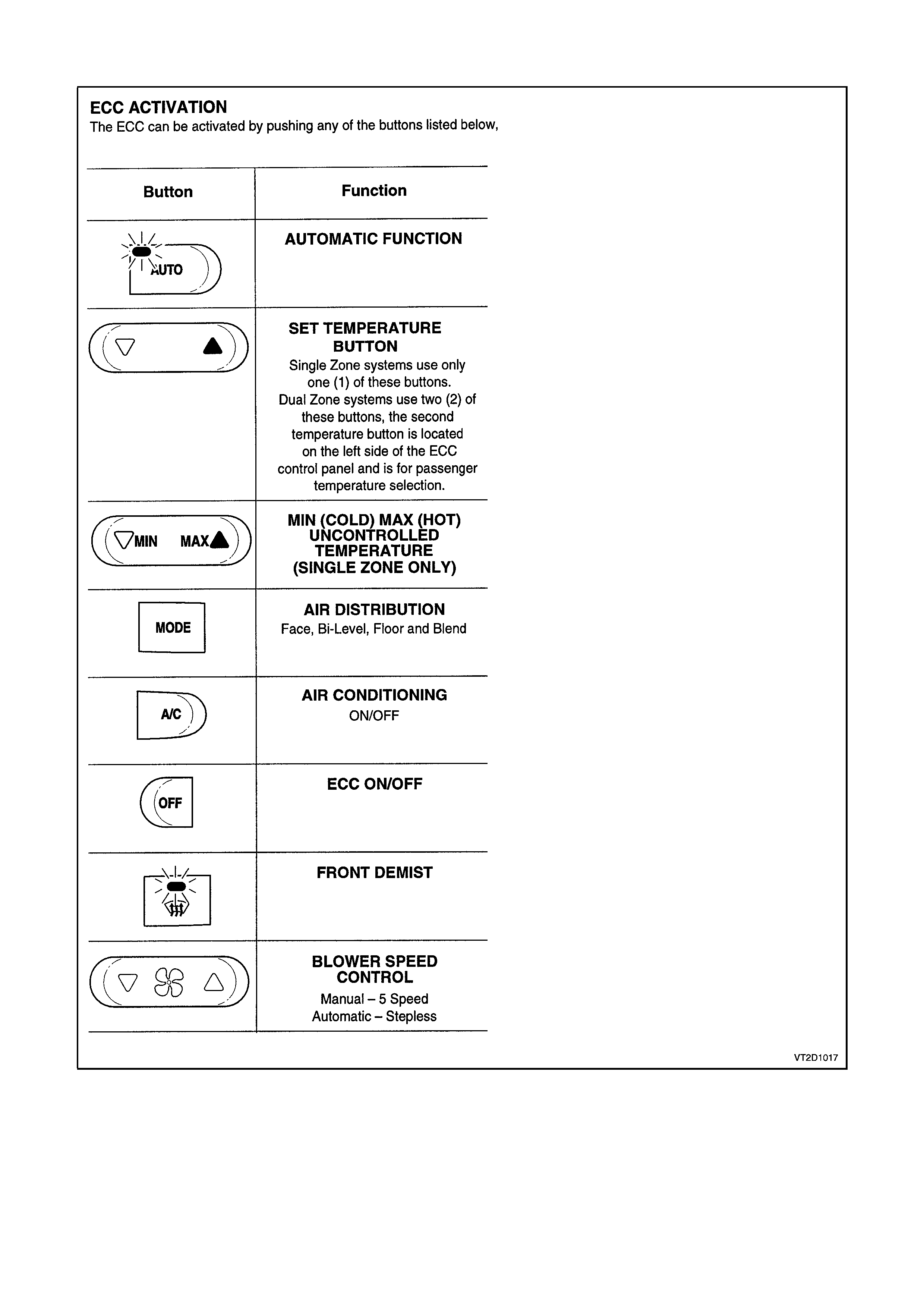
ECC ACTIVATION
Figure 2D-1
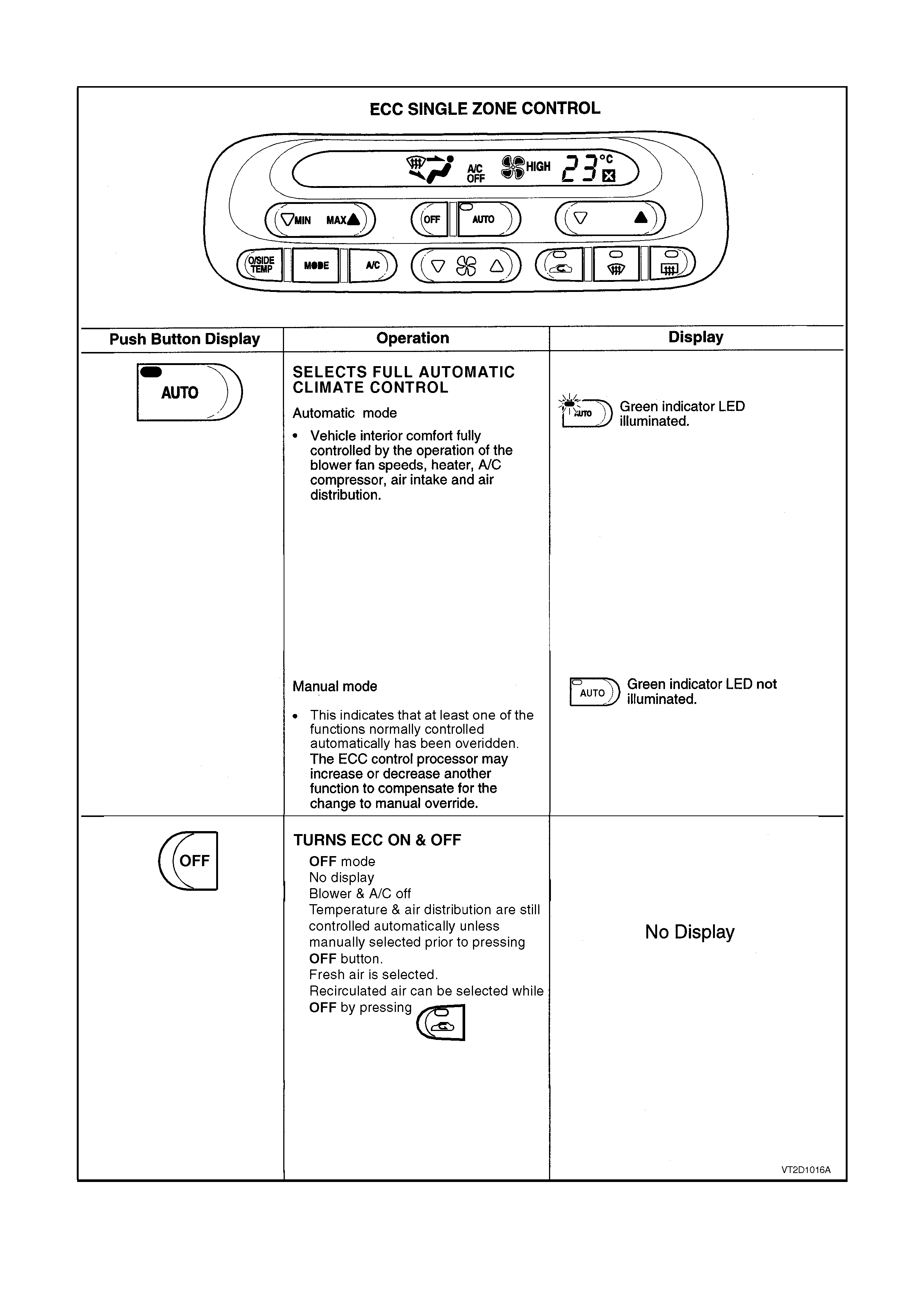
ECC SINGLE ZONE OPERATION
Figure 2D-2
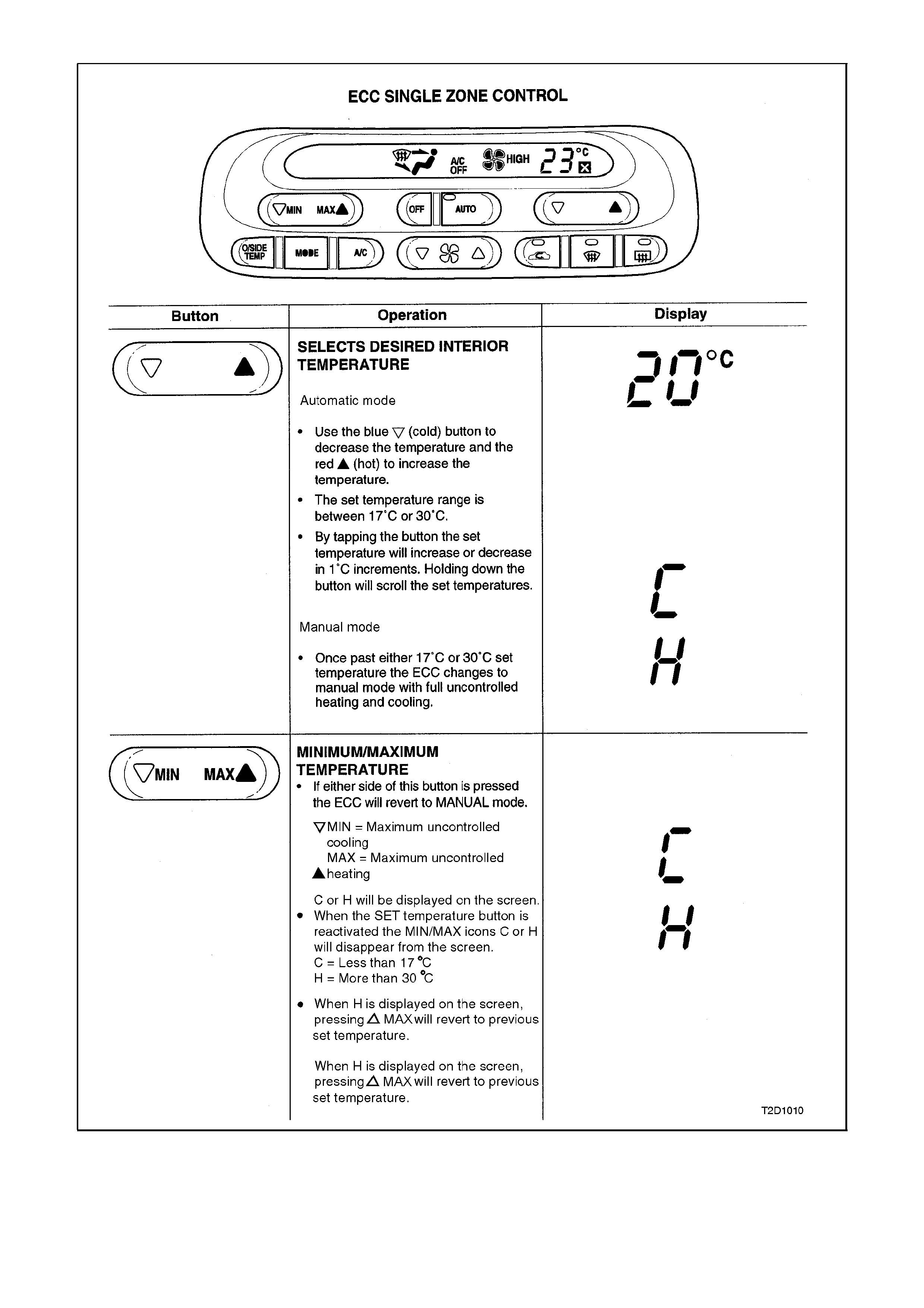
Figure 2D-3
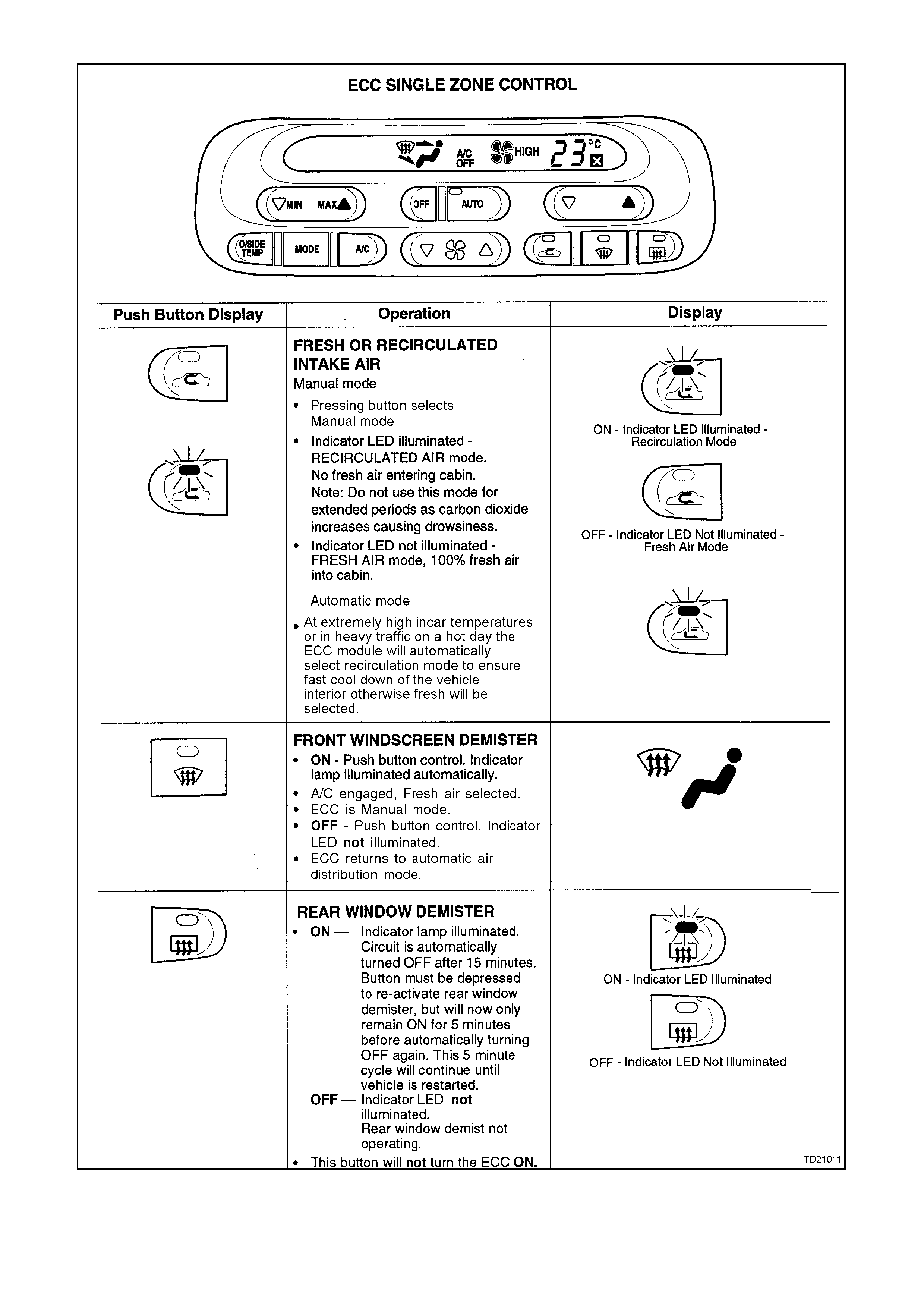
Figure 2D-4
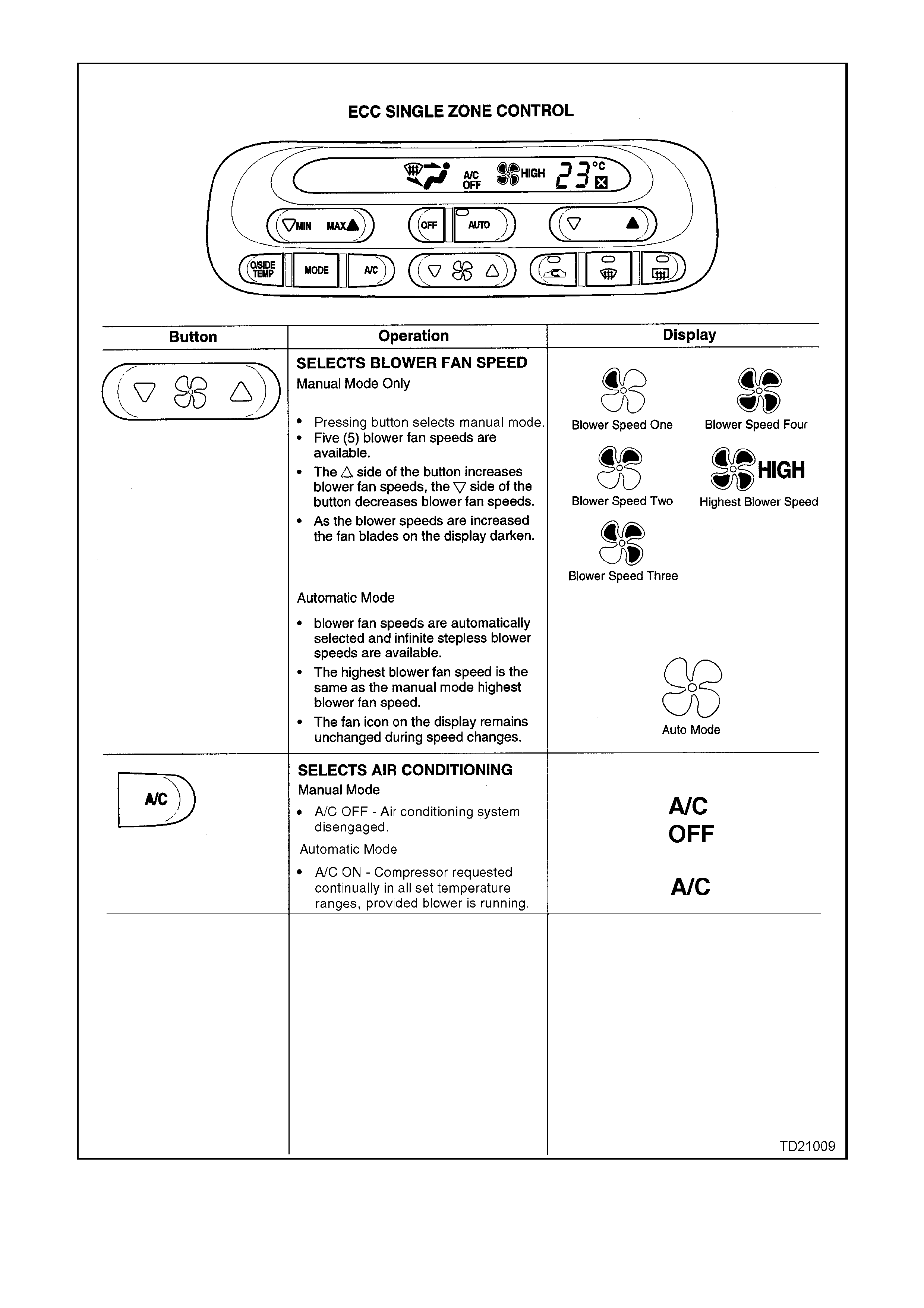
Figure 2D-5
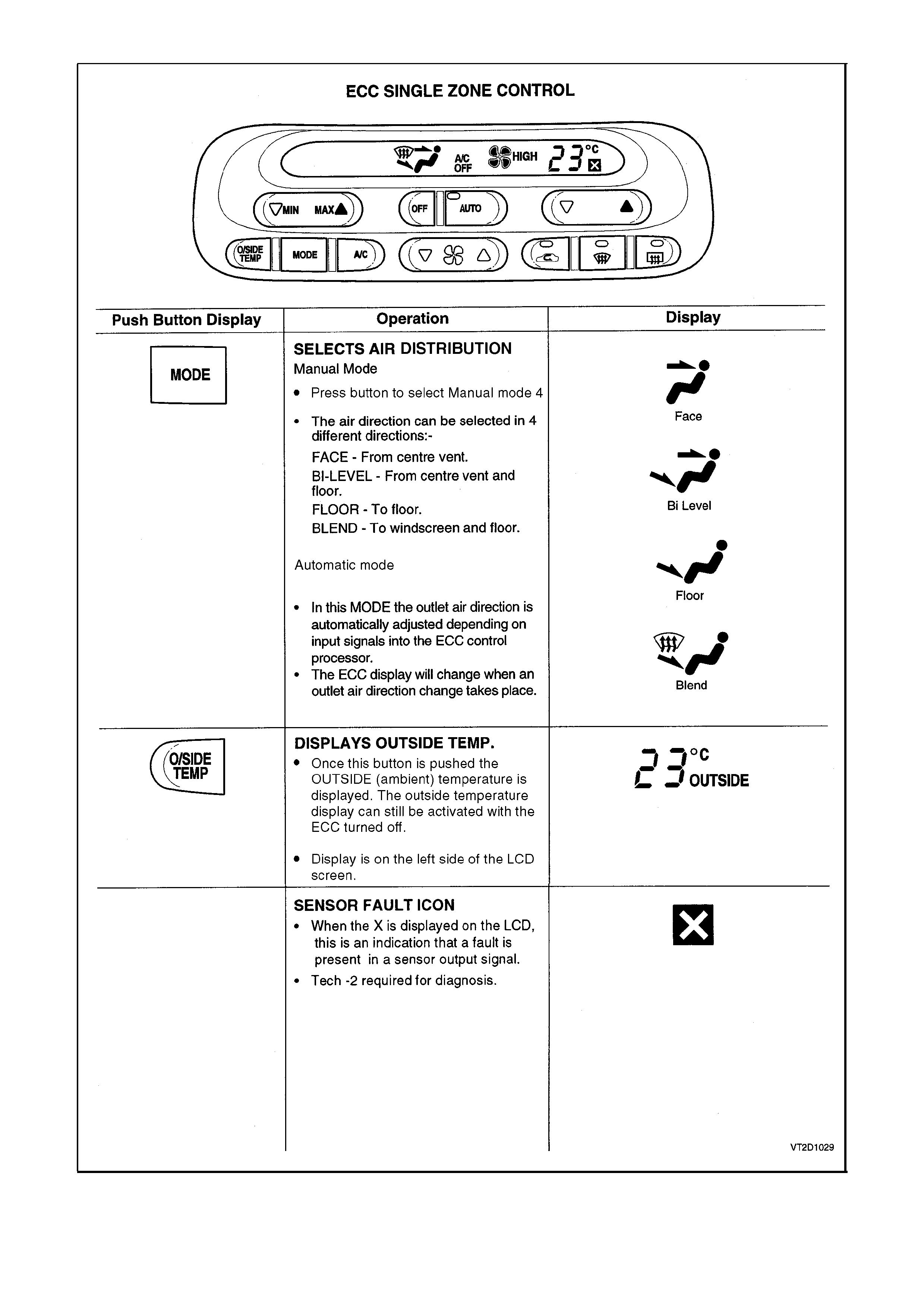
Figure 2D-6

ECC DUAL ZONE OPERATION
General Information
The operation of the Dual Zone ECC system is the same as the Single Zone ECC system noting the following:
Link mode
The link mode refers to the mode when the operation of both the passenger and driver air mix motors are
synchronised.
When the driver ‘set’ temperature is changed, likewise the passenger ‘set’ temperature changes to the same value.
To access the ‘link’ mode press and hold the ‘auto’ button for two seconds.
Unlink mode
This mode is when the passenger sets their desired temperature independent of the driver.
To access the ‘unlink’ mode press the passenger side temperature button.
NOTE:
If the ECC was in link mode this will alter to unlink mode.
Mode control
It is NOT possible for the passenger to alter the mode positions such as Floor, Demist, Centre Vent etc. There is no
individual control. Mode positions will be the same for both passenger and driver.
Fan speed control
As with the mode control it is NOT possible for the passenger to alter the blower fan speeds as an individual
function. Once the blower speeds have been selected, blower speeds for both the passenger and driver will be the
same.
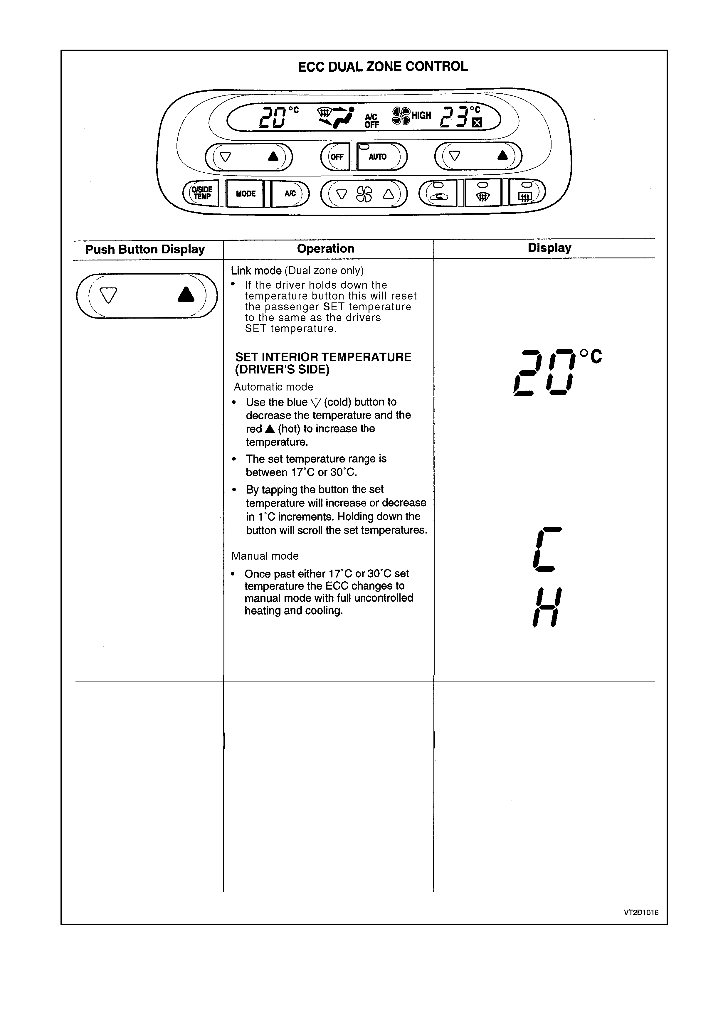
Figure 2D-7
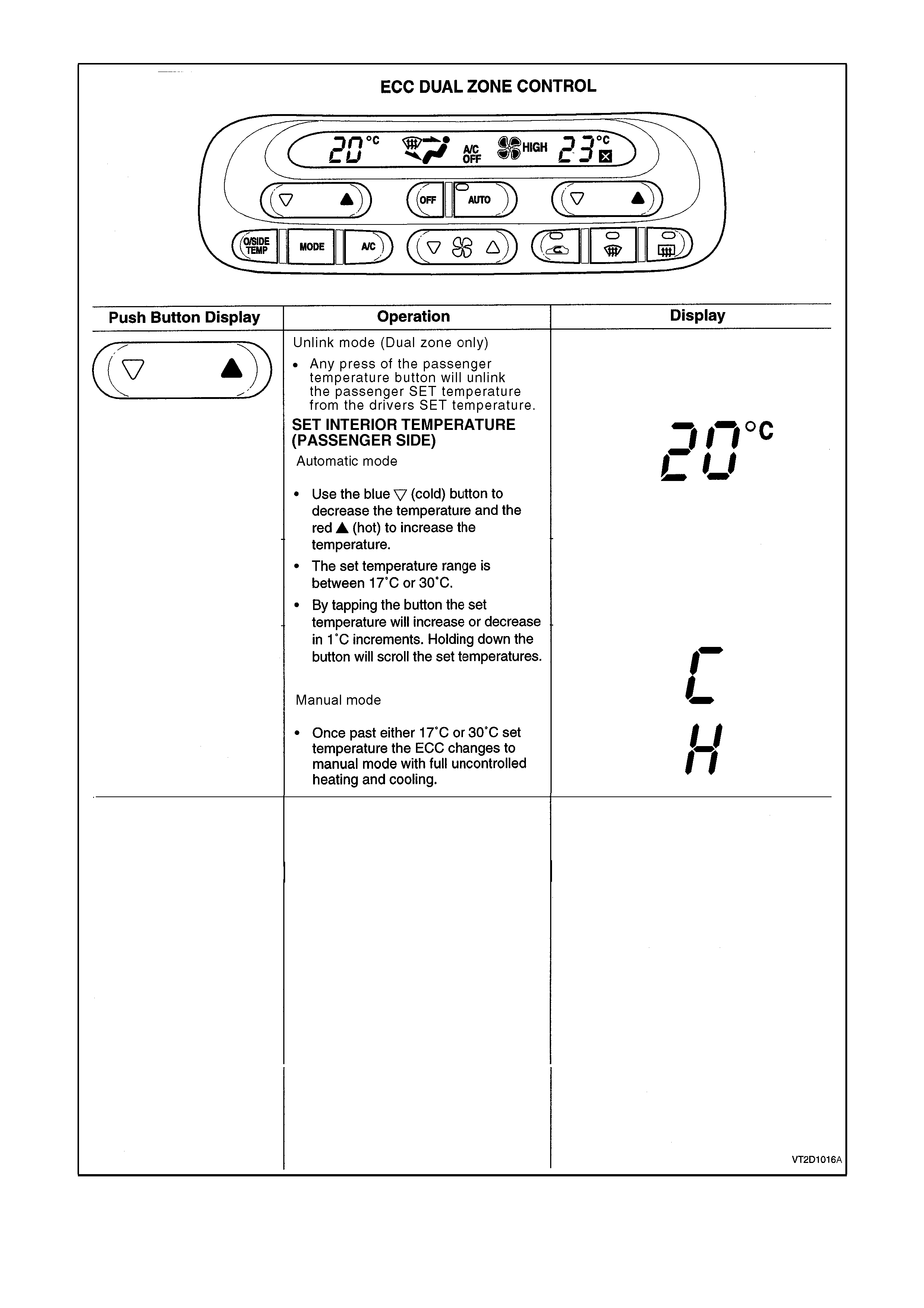
Figure 2D-8
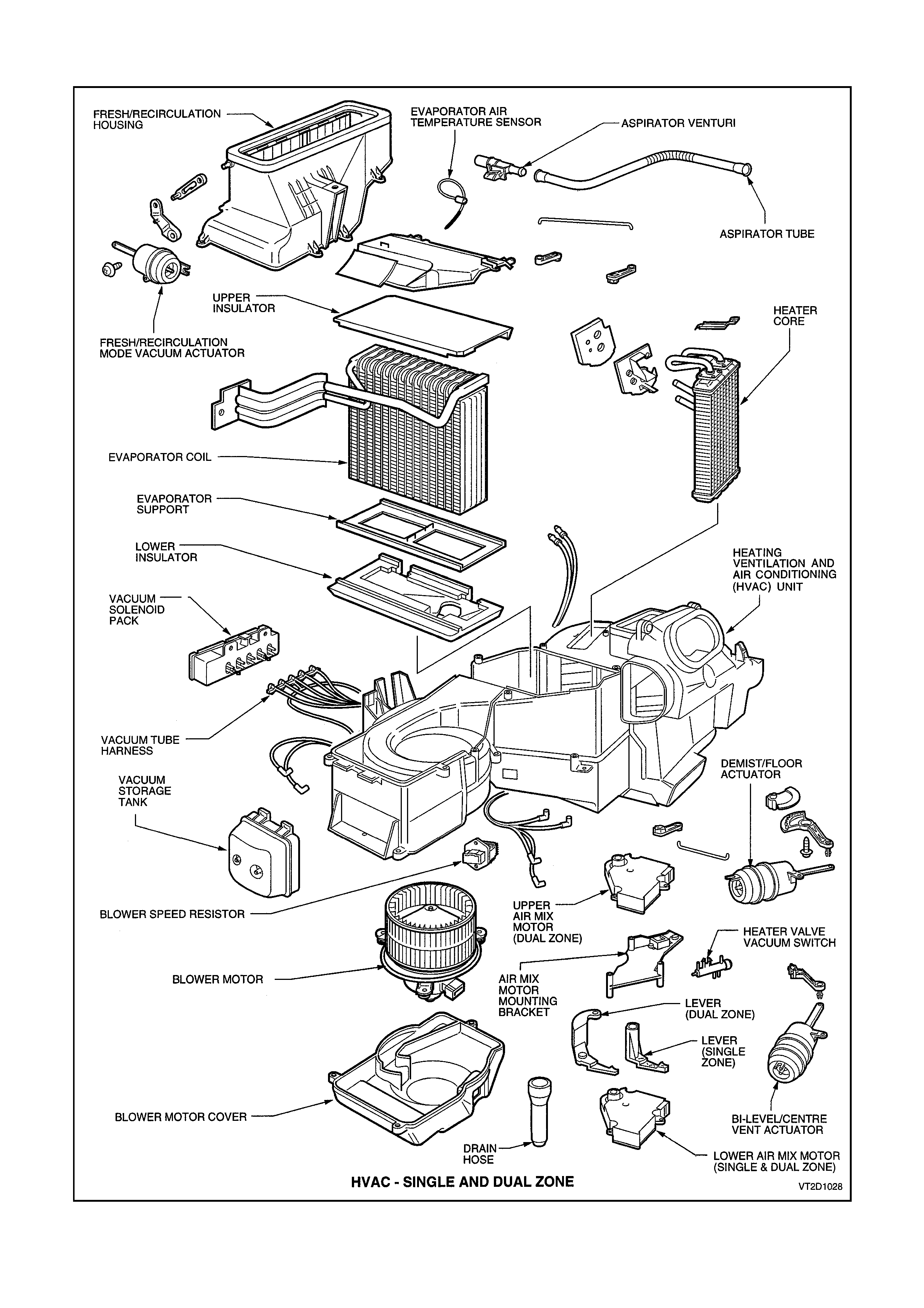
HVAC SYSTEM COMPONENTS
Figure 2D-9
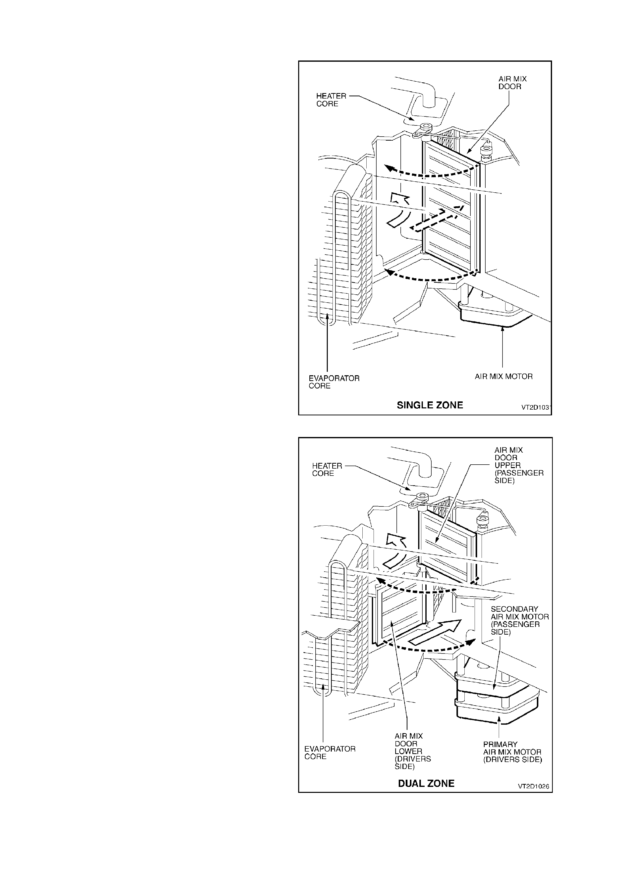
1.2 AIR MIX MOTORS (SINGLE AND DUAL ZONE)
The air mix motor(s), or stepper motor(s) are
located under the HVAC unit. They are used to
operate the air mixing door(s) and are connected
either directly to the air mix door shaft or indirectly
via a rod.
Single Zone (SZ) us es one air mix motor to oper ate
the air mixing door whereas the Dual Zone (DZ)
has two air m ix motors to operate two individual air
mixing doors.
Air mix motor movement is achieved by sending a
12 volt signal between the ECC Module to the air
mix motor. T here is also a 3.5 ± 0.2 volt ‘feedback’
signal from the air mix motor to the ECC Module as
to the location of the air mix door (in relation to air
mix motor drive location).
Figure 2D-10
Figure 2D-11
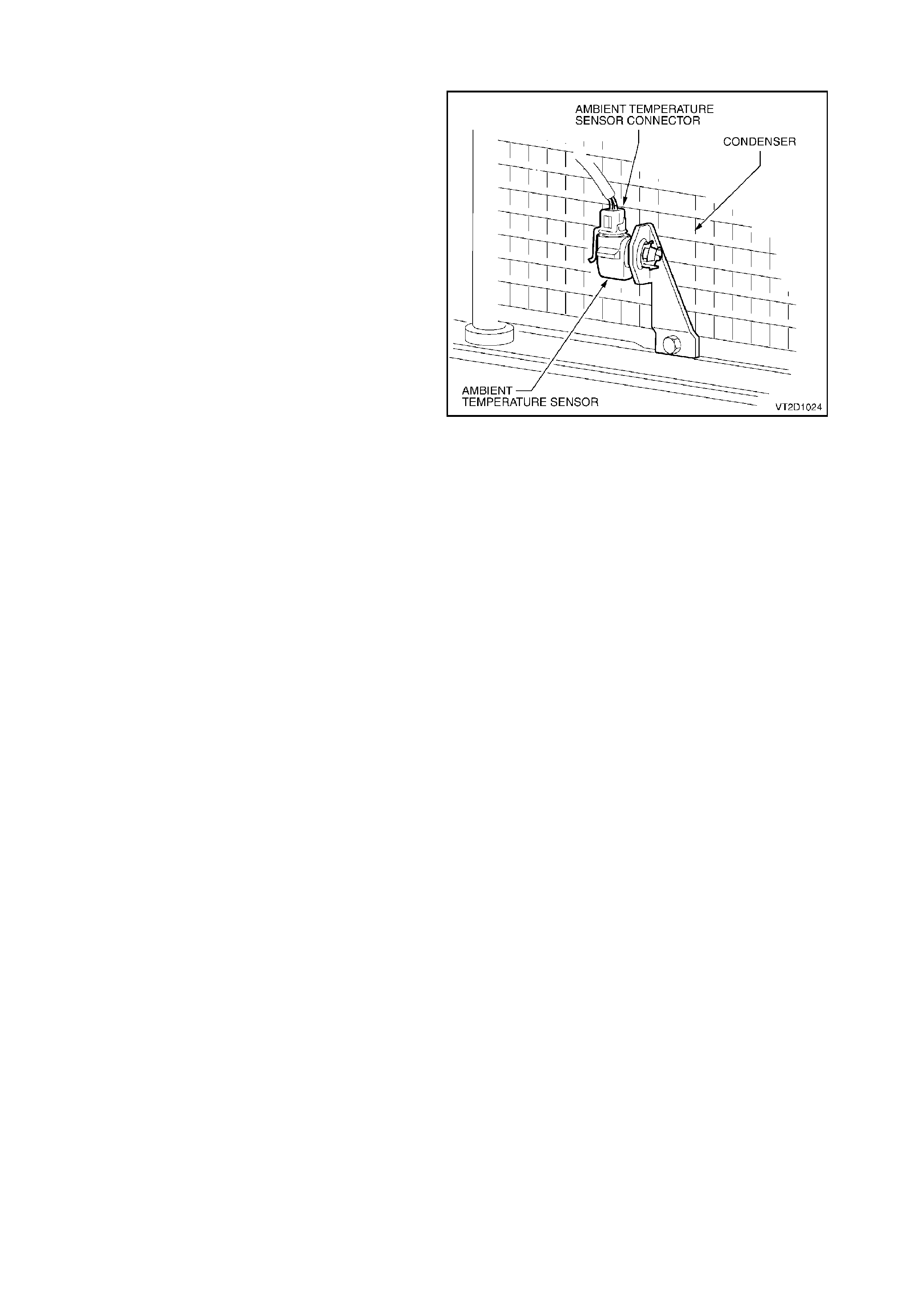
1.3 AMBIENT TEMPERATURE SENSOR
The Am bient T em perature Sensor is loca ted on the
lower driver’s side of the A/C condenser.
It is a thermistor type (NTC) resistor used to
monitor the ambient (outside) temperature. This
sensor is slow reacting due to the dense plastic
housing surrounding it. The ECC takes into account
road speed before updating the temperature
display to avoid false readings in heavy traffic or
extended idle conditions.
Resistance signals are sent directly from the
ambient tem per ature sens or to the ECC Module f or
interpretation.
Figure 2D-12
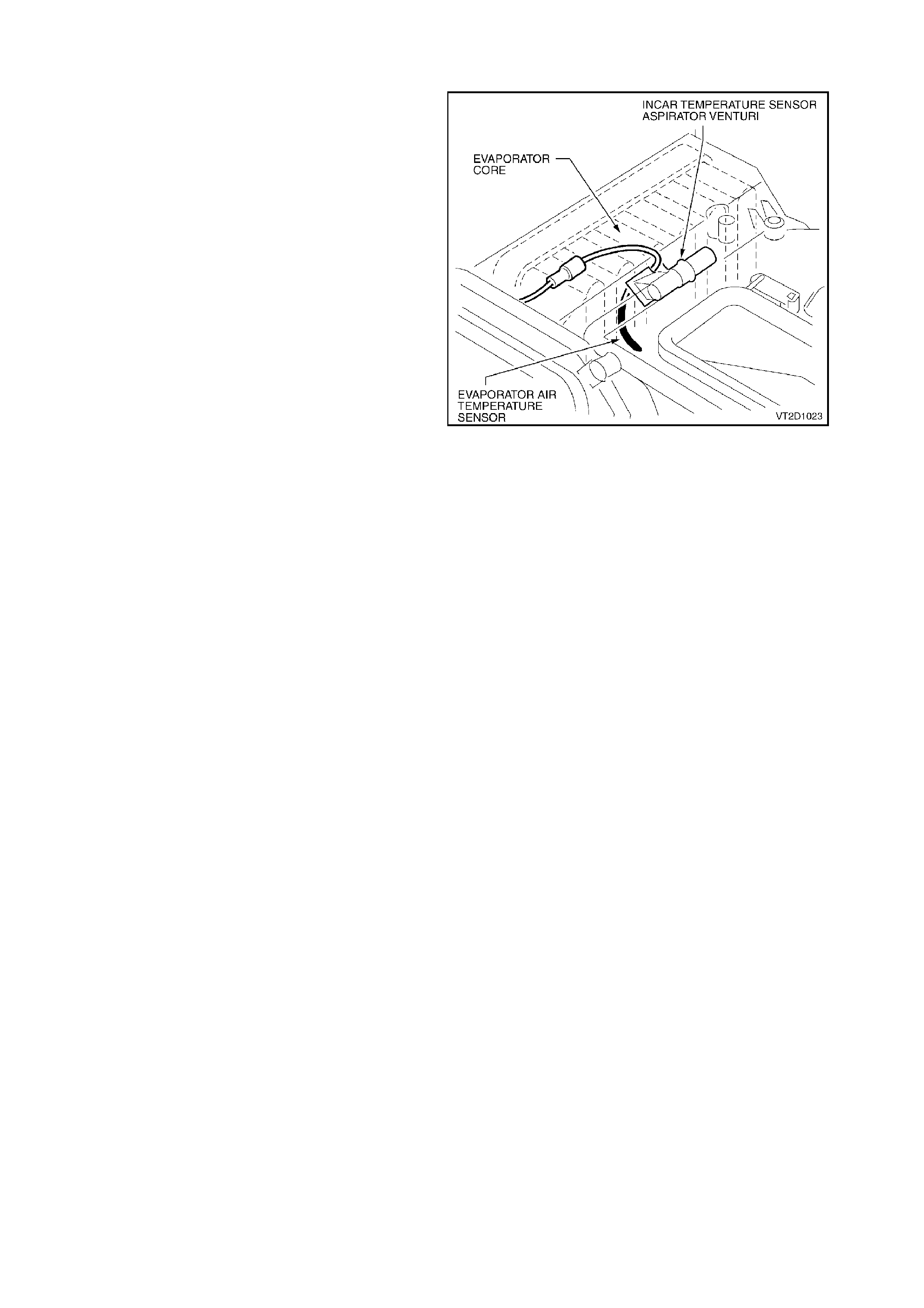
1.4 EVAPORATOR AIR TEMPERATURE SENSOR
The Evaporator Air Temperature Sensor is located
on top of the EBA case near the aspirator venturi.
It is a thermistor type (NTC) resistor used to
monitor the temperature of the air into the HVAC
unit after it has passed through the evaporator coil.
Resistance values are read directly to the ECC
Module for interpretation.
Figure 2D-13
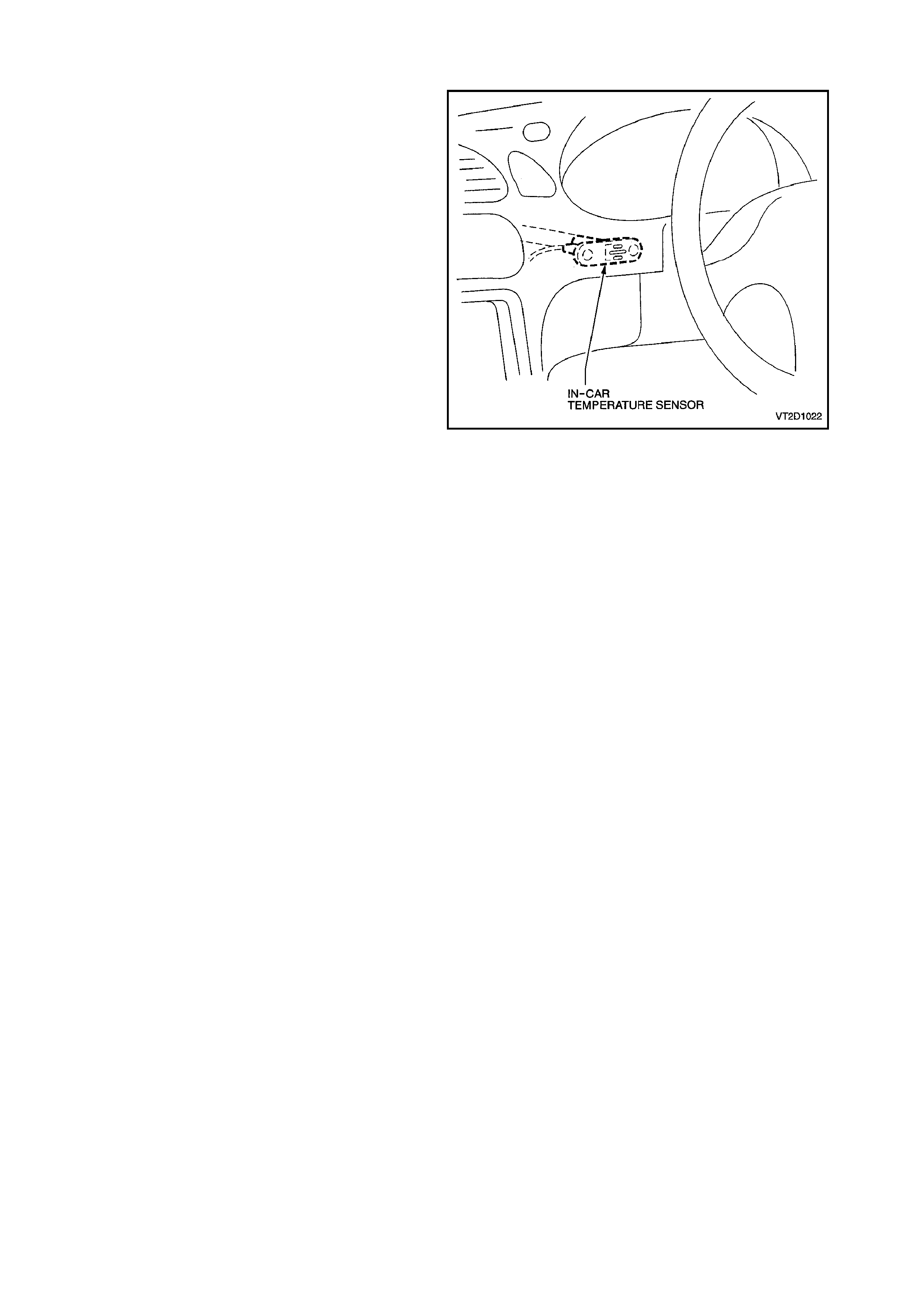
1.5 IN-CAR TEMPERATURE SENSOR
The in-car temperature sensor is located on the
lower driver’s s ide dash panel between the steer ing
wheel and console.
It is also a thermistor type (NTC) resistor used to
monitor the vehicle’s interior temperature.
Resistance signals are read directly by the ECC
Module for interpretation.
It is essential that the aspirator tube (see
1.6 ASPIRATOR TUBE) is connected to give
correct operation.
Figure 2D-14
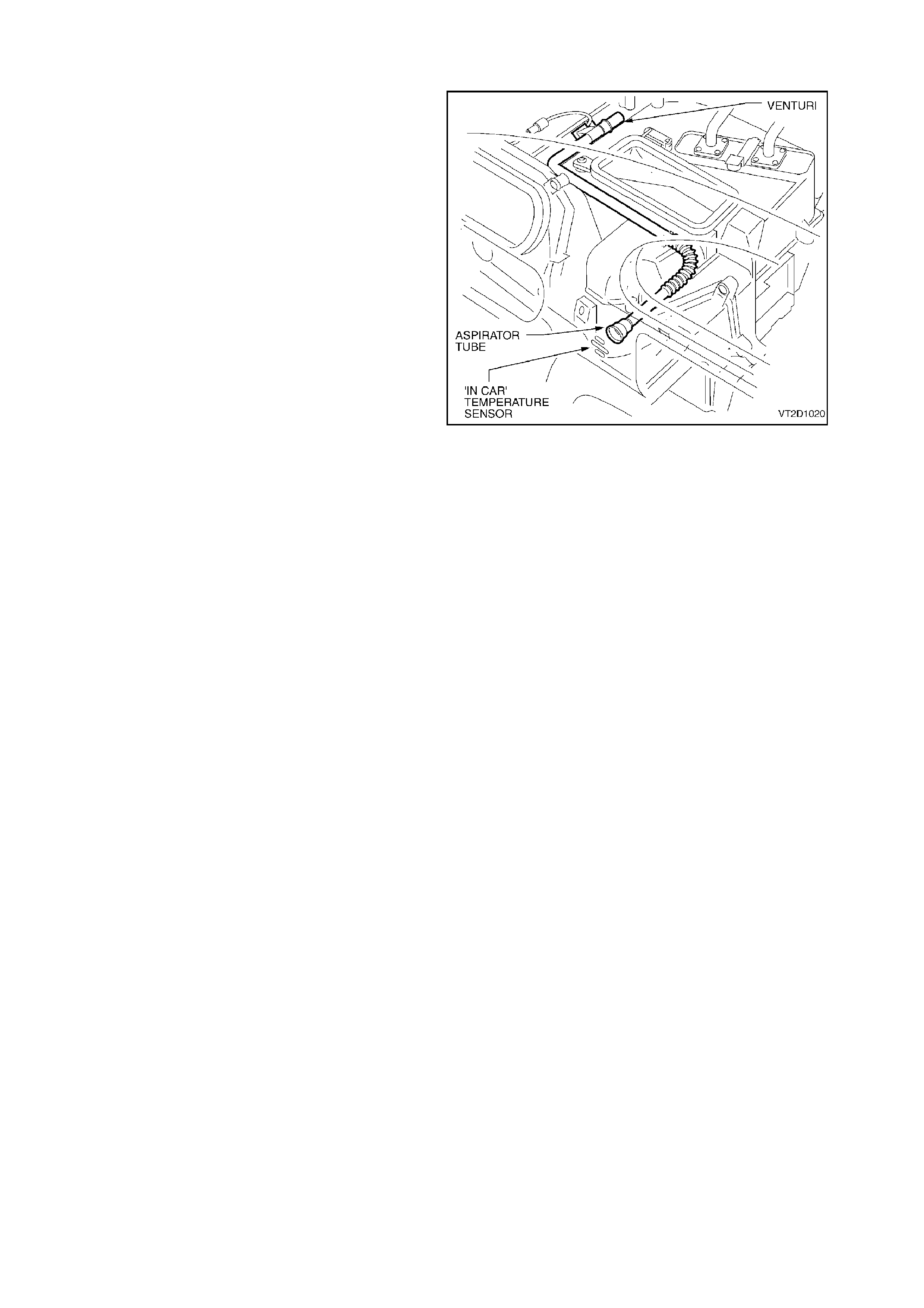
1.6 ASPIRATOR TUBE
Located on the top of the HVAC unit case to the
rear of the in-car temperature s ensor, the Aspirator
Tube is a convoluted plastic tube attached from a
venturi to the rear of the in-car tem perature sensor
housing. Once any fan speed is selected air from
the vehicle interior is sucked to the in-car
temperature sensor via the aspirator tube and
aspirator venturi. This is used to aid the in-car
temperature to react quickly to any changes taking
place within the vehicle interior.
Figure 2D-15
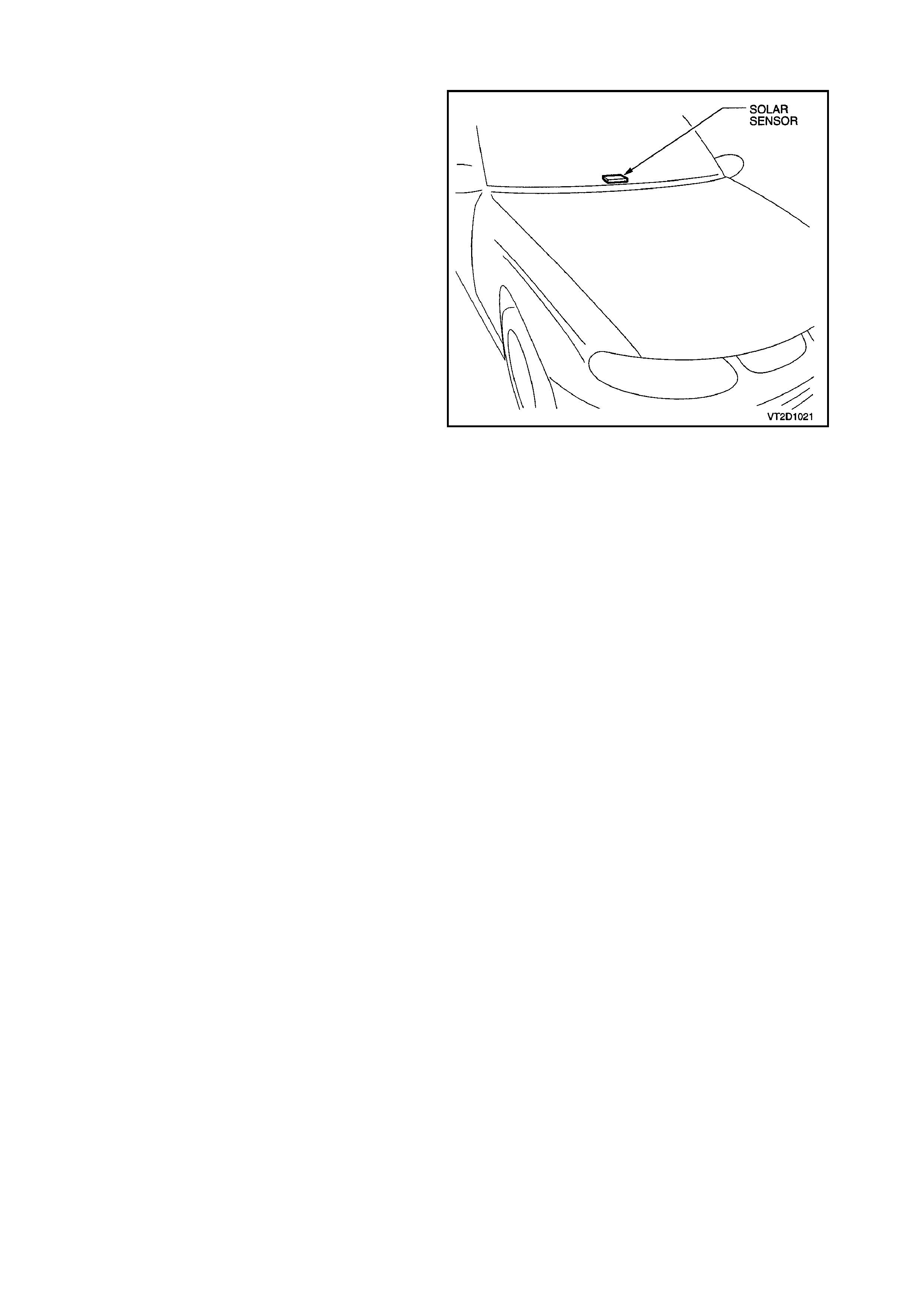
1.7 SOLAR SENSOR
The Solar Sensor (Sun Sensor / Remote Receiver
module) is located in the centre of the Demist panel
and is used to monitor the sun load upon the
vehicle. It is a photochem ical type sensor , m eaning
that a small electrical current will be created
depending on the sun load (str ength) over it. W hen
the sun load is high, a higher blower fan speed and
increased cooling will be selected by the ECC
Module automatically. Likewise, when the sun load
is low, such as going into an underground car park ,
the ECC Module will automatically reduce the fan
speeds and increase heating slightly.
Signals are sent from the solar sensor directly to
the BCM then to the ECC Module via the serial
data.
NOTE:
Solar sensor diagnostics can be found in the BCM
Section.
Figure 2D-16
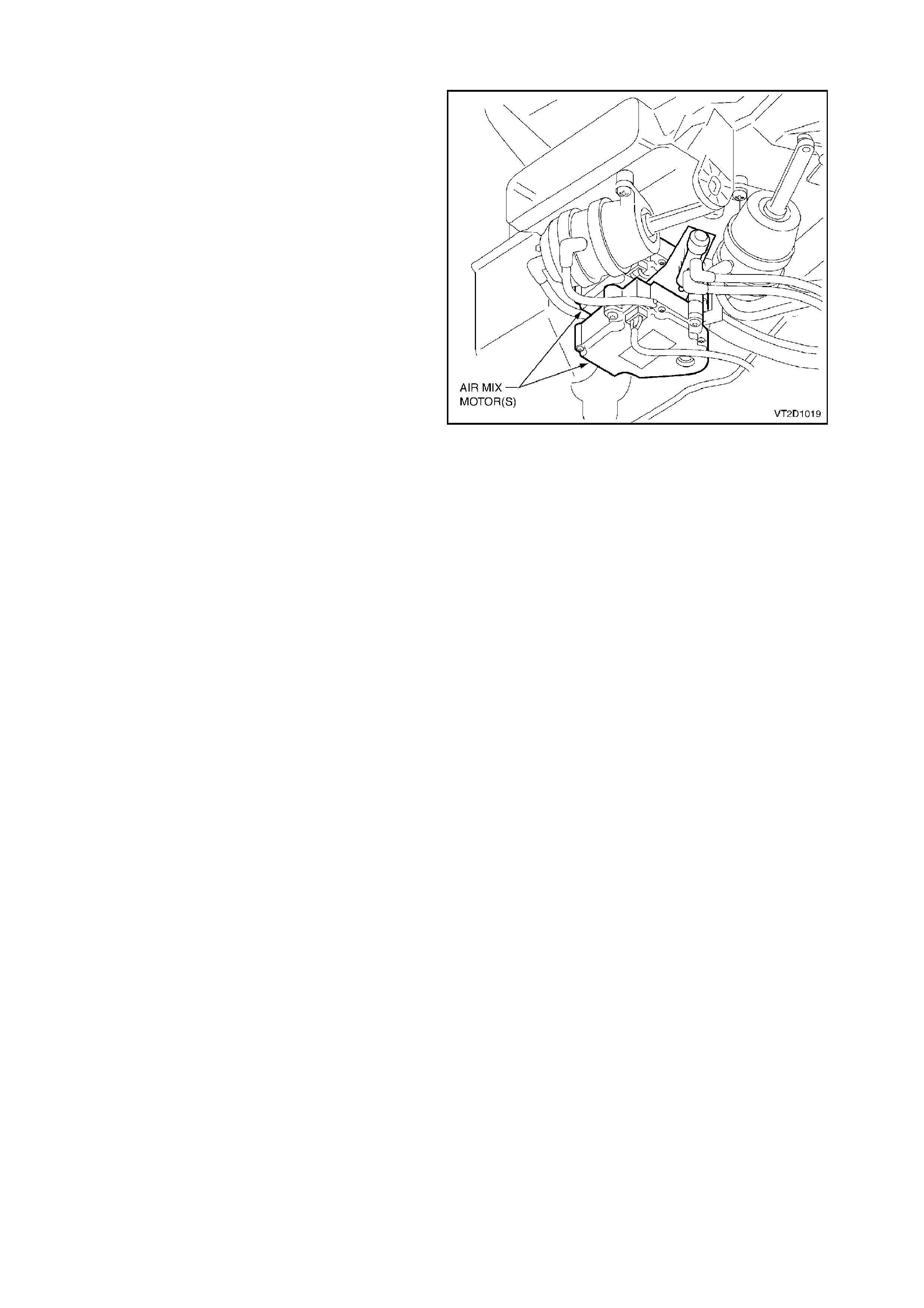
1.8 AIR MIX MOTOR(S)
Located on the underside of the HVAC unit, the Air
Mix Motor is a small electric m otor used to operate
vent position doors. The motor is sent a voltage
signal of 3.5 ±0.2 volts from the ECC Module
causing the motor to turn and open a door. Motor
direction can be changed to close a door by the
ECC reversing the polarity of the voltage signal.
The air mix motor also uses a potentiometer to
send voltage signals to the ECC Module as to the
position of the air mix motor internally.
Figure 2D-17
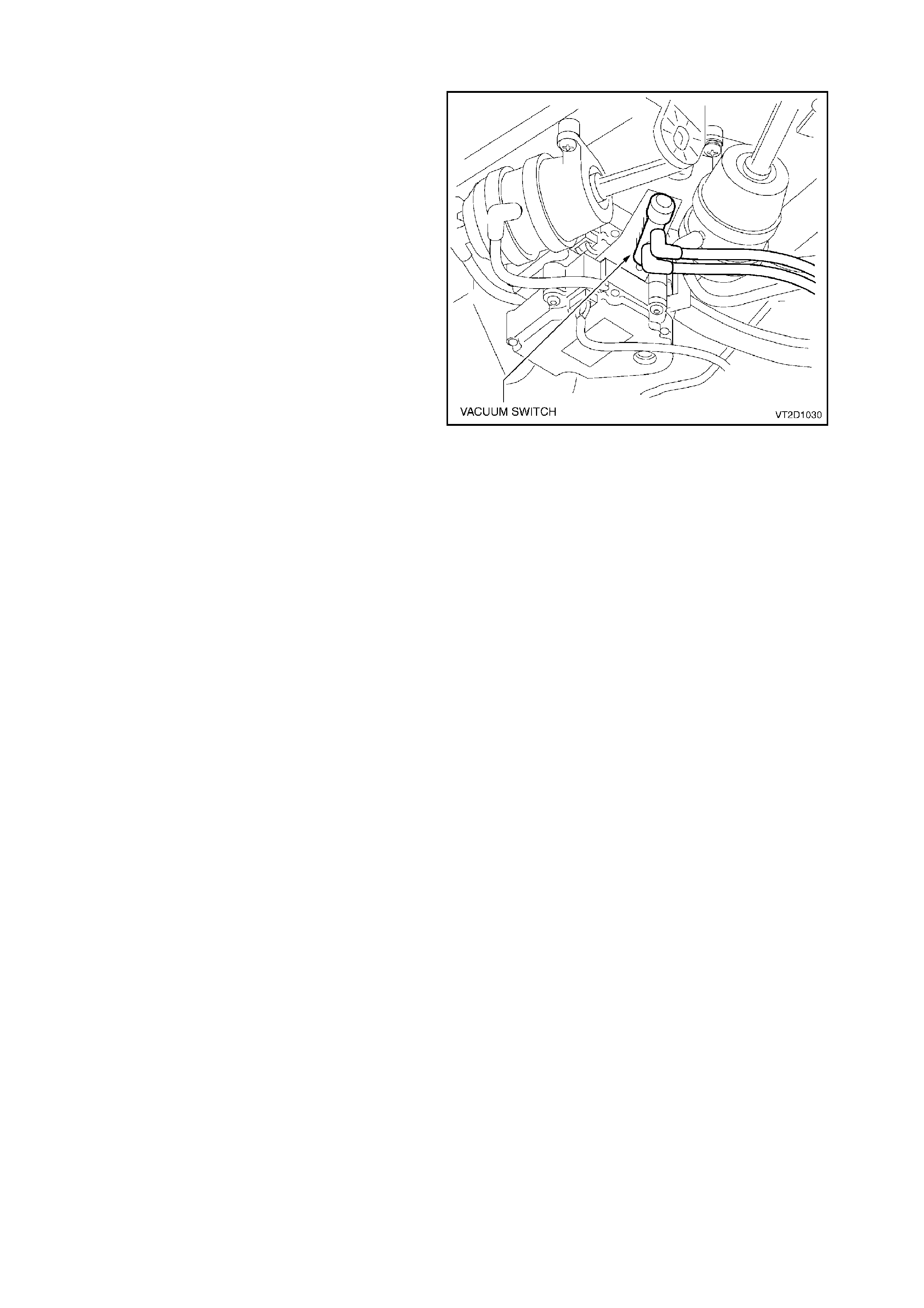
1.9 VACUUM SWITCH
The Vacuum Switch is located on the underside of
the HVAC unit between the vacuum actuators.
The heater water valve is held in the OFF position
by vacuum. A lever attached to the air mix motor
activates a plunger on the vacuum switch. As the
air mix m otor opens the air mix door from full cold,
the vacuum switch plunger is activated and the
vacuum in the heater water valve line is vented
allowing hot water to flow into the heater core.
Figure 2D-18
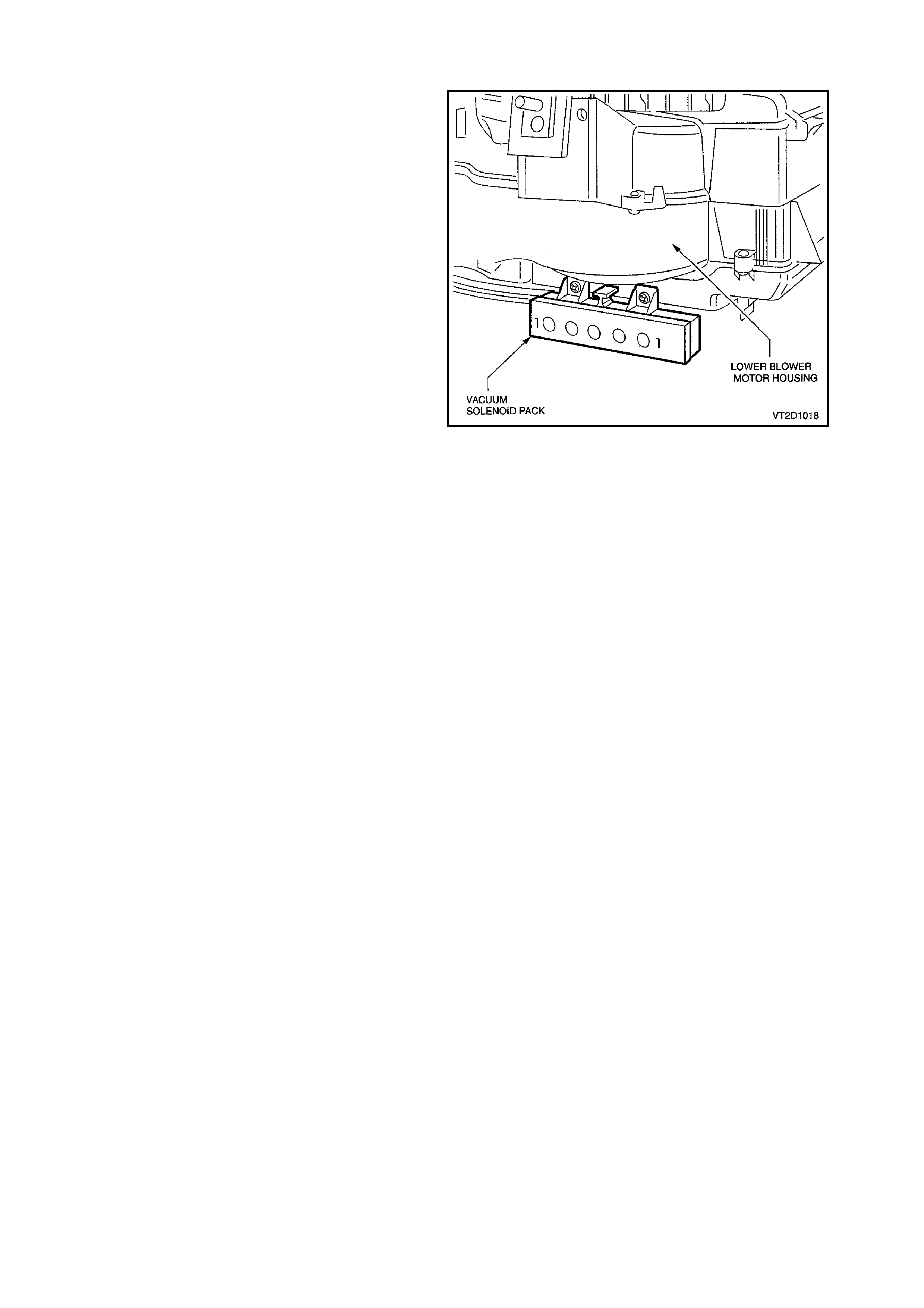
1.10 VACUUM SOLENOID PACK
Located on the lower rear of blower m otor housing,
the Vacuum Solenoid Pack consists of a band of
five electronically activated vacuum solenoids used
to apply or rem ove vacuum to vacuum actuators to
alter air distribution positions.
Power is used to engage these s olenoids and allow
vacuum to flow to an actuator. Removing this
power de-energises the solenoid and allows any
vacuum contained in the actuator and line to vent
through the front section of the solenoid.
VACUUM CIRCUIT
Vacuum is us ed to control the ON /OFF f unctions of
the vent modes and the heater tap. This vacuum is
provided by the engine.
The engine vacuum moves from the inlet manifold
to a vacuum tank located on the HVAC unit. This
vacuum tank is used to store vacuum in times
when engine vacuum is low such as at full engine
throttle. A check valve is fitted on the supply line
from the engine inlet manifold.
Through a black plastic vacuum tube the vacuum
moves to the vacuum solenoid pack. This black
plastic tube is also teed off to the vacuum control
valve. From the contr ol valve, vac uum moves into a
yellow plastic tube and onto the vacuum operated
heater water valve. Vacuum is used to m aintain f ull
closure of this valve and no hot water can flow.
As the ECC mode switch is selected electronic
solenoids are activated in the solenoid pack
causing vacuum to move to the desired vacuum
actuator through different coloured plastic tubing.
This vacuum will activate the vacuum actuator rod
which then moves a vent position door.
Fig. 2D-20 shows which vacuum actuators are
applied with vacuum in a certain mode.
Vacuum is vented f rom the vac uum actuator/plas tic
tube once the vacuum ECC m ode s witch is us ed to
select a different setting.
Figure 2D-19
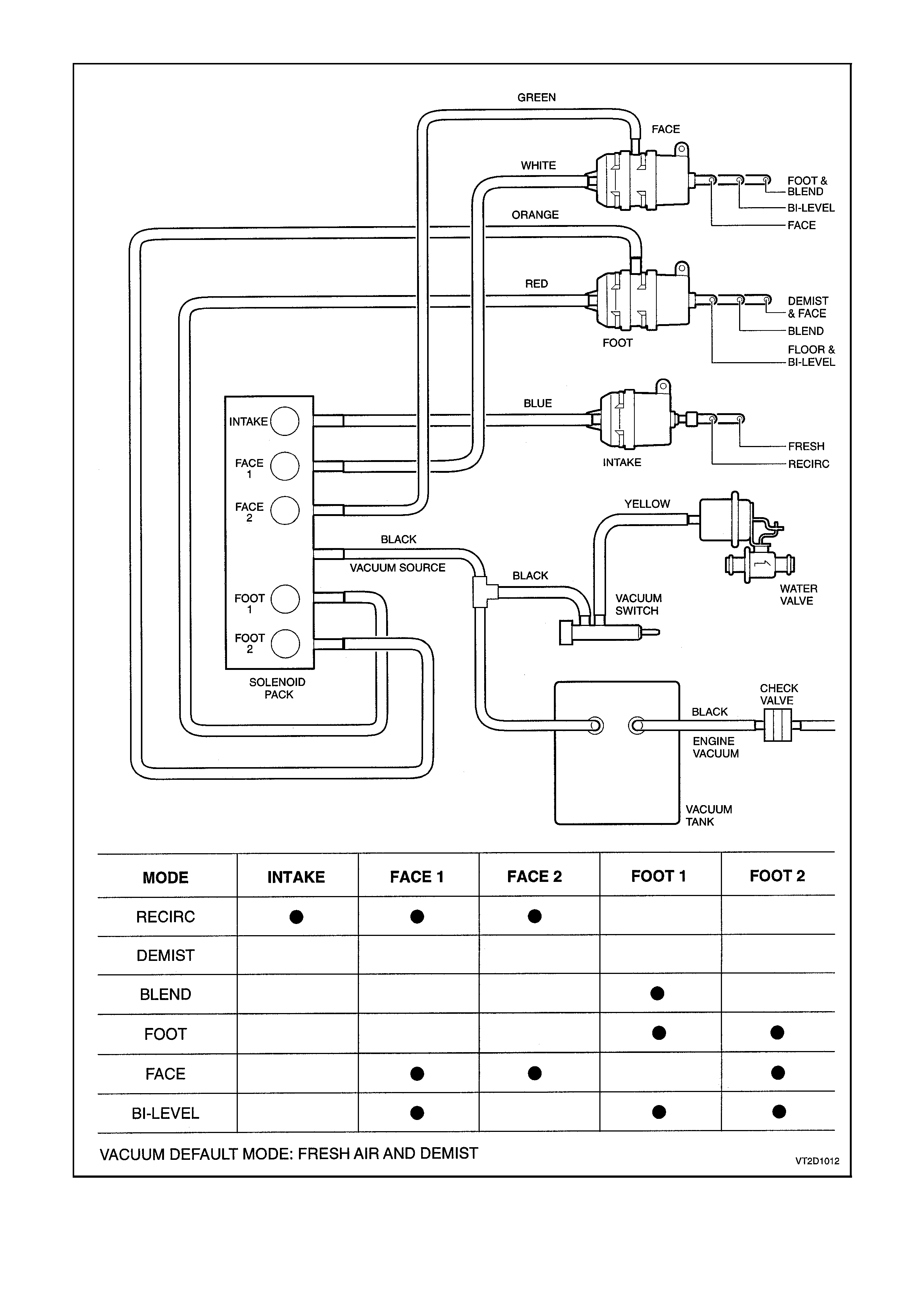
Figure 2D-20
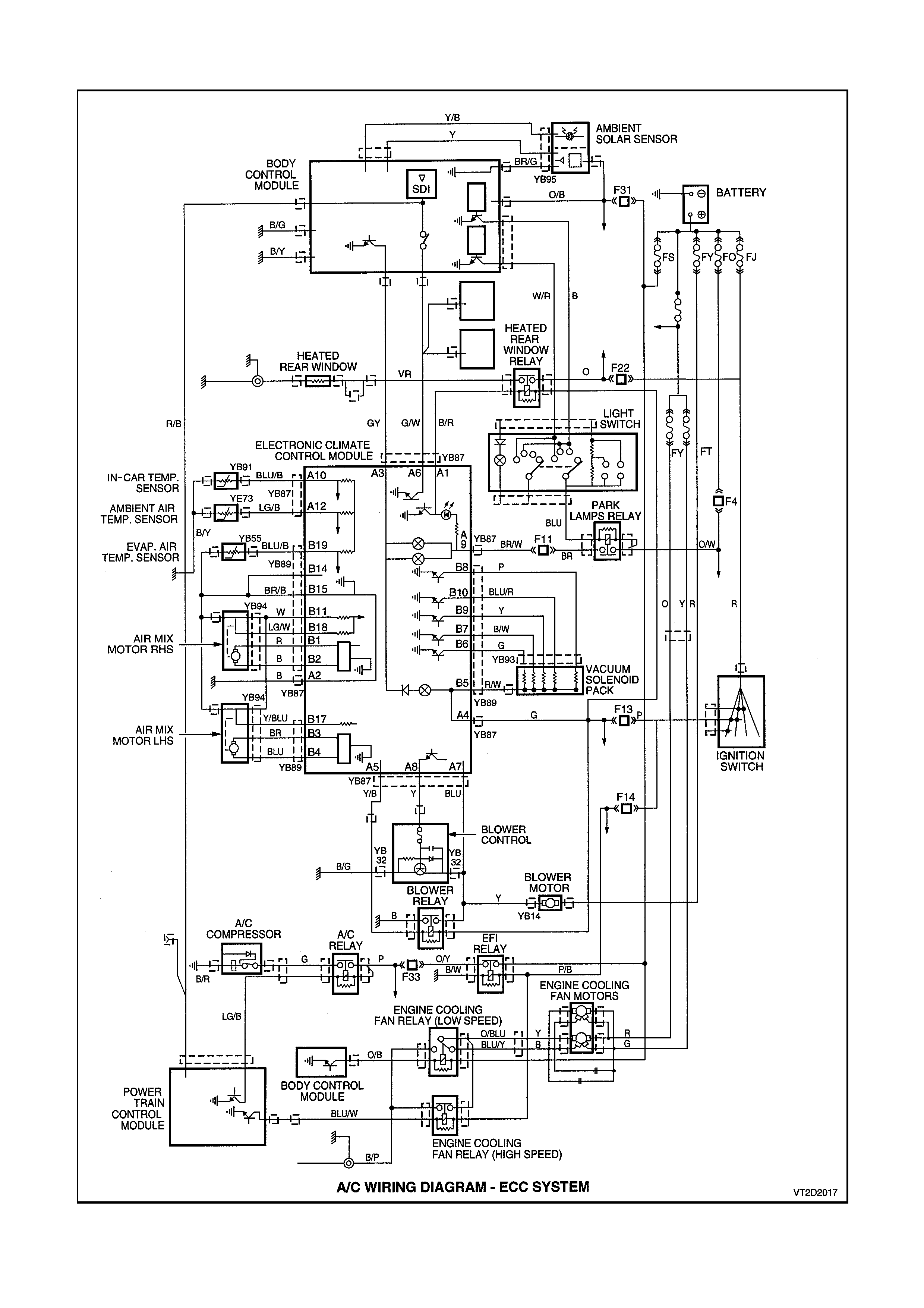
1.11 ECC WIRING DIAGRAM
Figure 2D-21