SECTION 2E - ELECTRONIC CLIMATE CONTROL
- REMOVAL AND INSTALLATION
CAUTION:
This vehicle will be equipped with a Supplemental Restraint System (SRS). A SRS will
consist of either seat belt pre-tensio ners and a driver’s side air bag, o r seat belt pre-
tensioners and a driver’s and front passenger’s side air bags. Refer to CAUTIONS,
Section 12M, before performing any service operation on or around SRS
components, the steering mechanism or wiring. Failure to follow the CAUTIONS
could result in SRS deployment, resu lting in possible perso nal in jury or u nnecessary
SRS system repairs.
CAUTION:
This vehicle may be equipped with LPG (Liquefied Petroleum Gas). In the interests of
safety, the LPG fuel system should be isolated by turning 'OFF' the manual service
valve and then draining the L PG service lines, before any service w ork is carried out
on the vehicle. Refer to the LPG leaflet included with the Owner's Handbook for
details or LPG Section 2 for more specific servicing information.
CAUTION:
Whenever any component that forms part of the ABS or ABS/ETC (if fitted), is
disturbed during Service Operations, it is vital that the complete ABS or ABS/ETC
system is checked, using the procedure as detailed in 4 DIAGNOSIS, ABS or
ABS/ETC FUNCTION CHECK, in Section 12L ABS & ABS/ETC.
1. ELECTRONIC CLI MATE CONTROL
1.1 CONTROL MODULE
REMOVE
1. Detach the instrument facia panel, refer to
Section 2B AIR CONDIT IONING - REMO VAL
AND INSTALLATION.
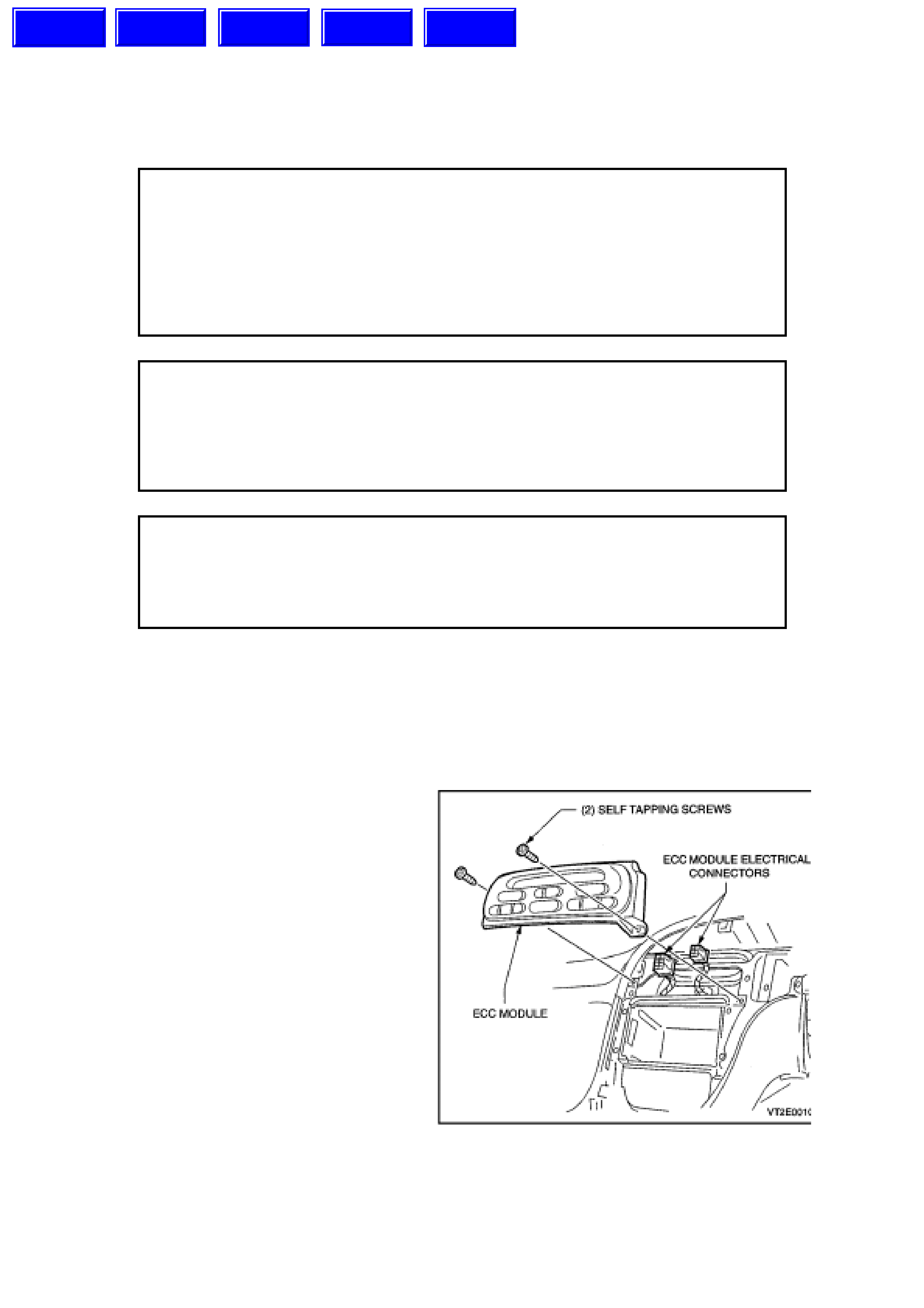
2. Locate and remove the two self tapping
screws used to retain the ECC Module to the
instrument panel carrier.
3. Disconnect the two ECC Module electrical
connectors.
REINSTALL
Installation is the reverse order of removal.
Figure 2E-1
Techline
Techline
Techline
Techline
Techline
1.2 CONTROL ILLUMINATION
REMOVE
1. Remove the ECC Module, refer to
1.1 CONTROL MODULE, Fig. 2E-1 in this
Section.
2. Disconnect the two electrical connectors.
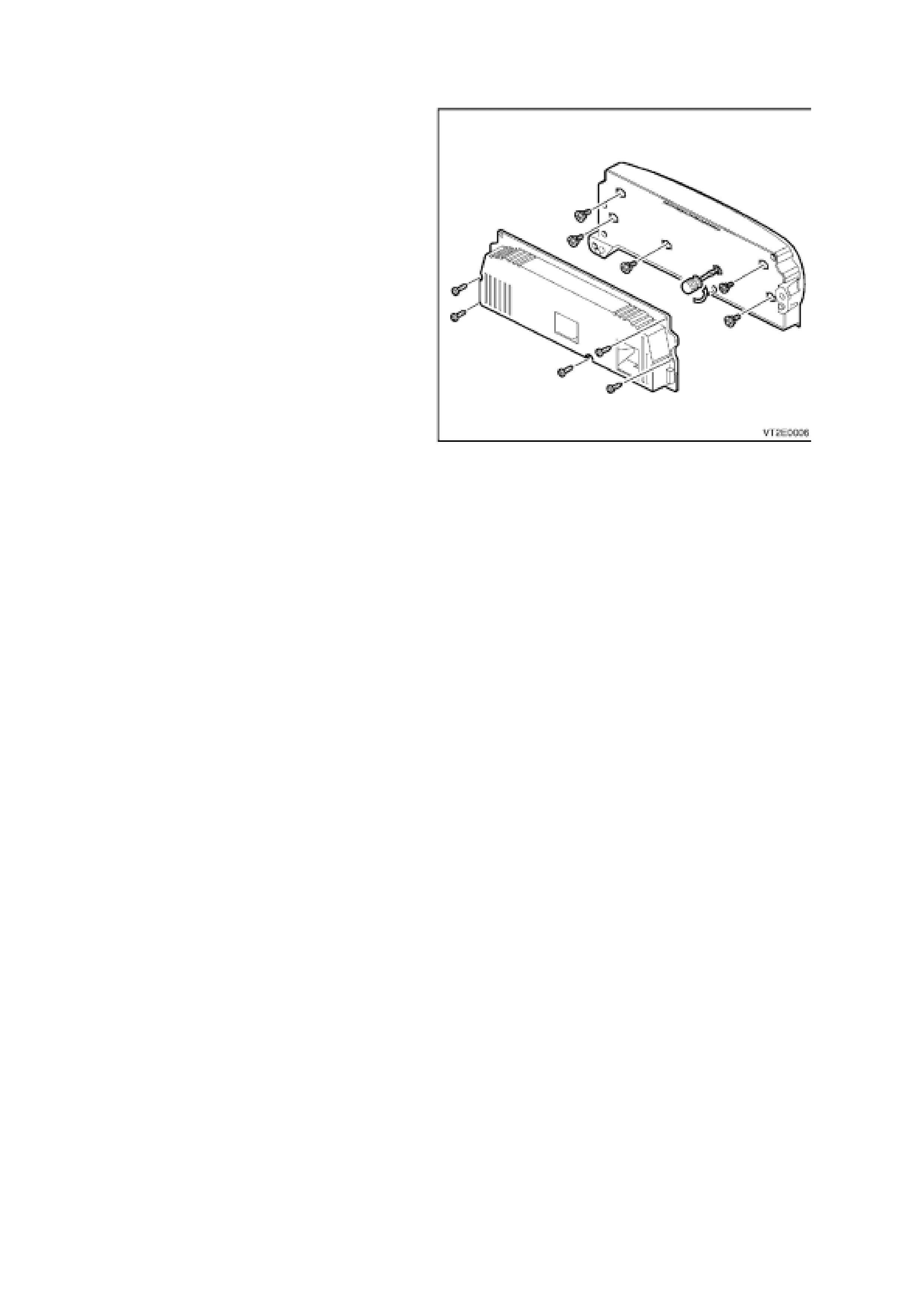
3. Unscrew the five self tapping screws retaining
the rear housing of the ECC Module.
4. Insert a flat blade screwdriver in the plastic
globe holder slot (as shown) then twist anti-
clockwise until the holder stops. Gently ease
globe holder out of the front housing.
REINSTALL
Installation is the reverse order of removal.
Figure 2E-2
2. ECC SENSORS
2.1 SOLAR SENSOR
REMOVE
1. Remove the right and lef t hand s ide instr ument
panel end cap covers, refer to
Section 2B AIR CONDIT IONING - REMO VAL
AND INSTALLATION.
2. Remove the right and left hand dem ist panels,
refer to Section 2B AIR CONDITIONING -
REMOVAL AND INSTALLATION.
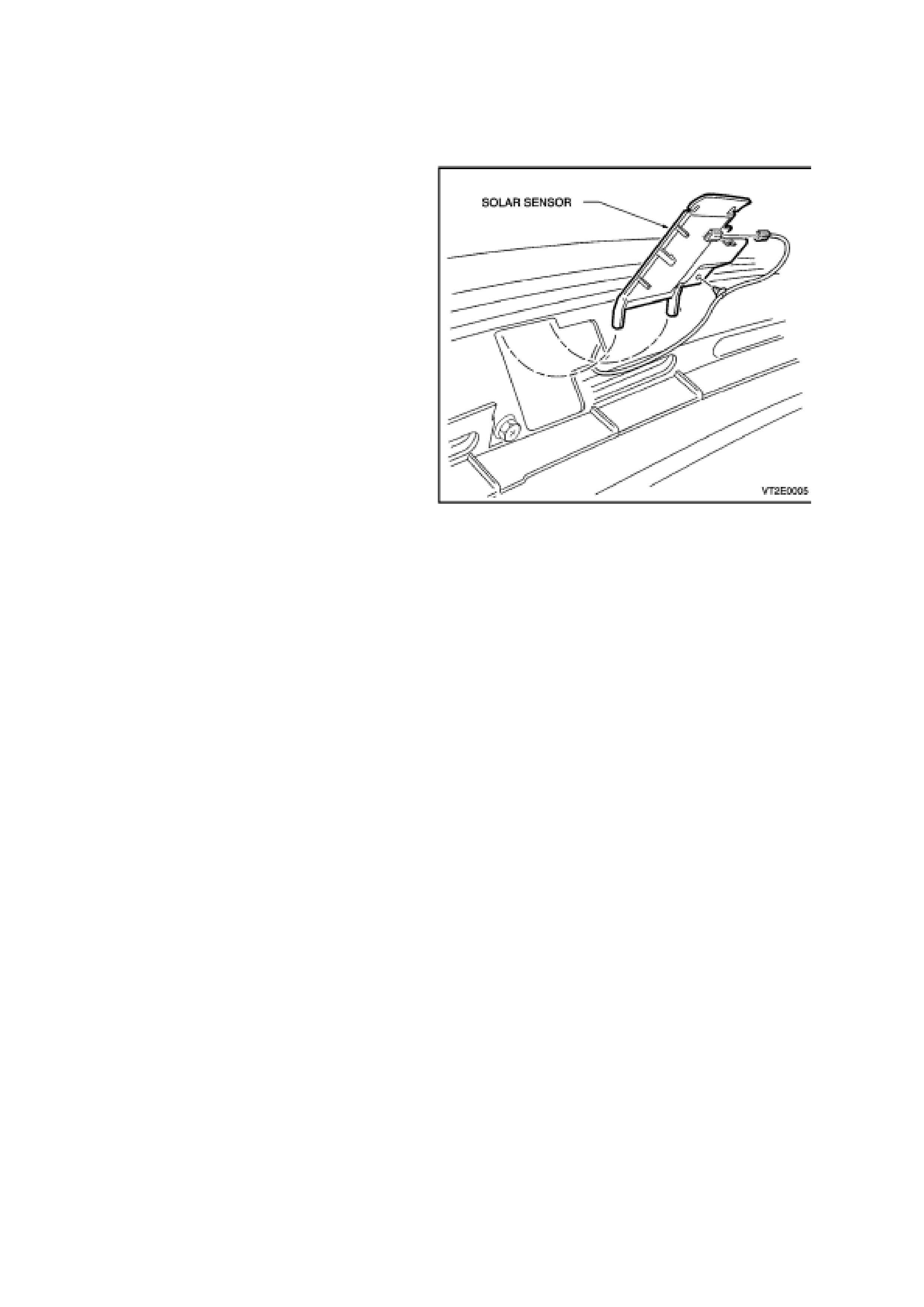
3. 3. Unclip the solar sensor from the dash panel
by lifting from the bottom then pulling
downwards to disengage the locking legs.
Disconnect the electrical connector and unclip
wiring.
REINSTALL
Installation is the reverse order of removal.
NOTE:
Solar sensor diagnostics can be found in
Section 12J-2 HIGH SERIES BCM.Figure 2E-3
2.2 IN-CAR TEMPERATURE SENSOR
REMOVE
1. Remove the transmission console, refer to
Section 1A3 INSTRUMENT PANEL AND
CONSOLE.
2. Remove the radio from the dash, refer to
Section 2B AIR CONDIT IONING - REMO VAL
AND INSTALLATION.
3. Remove the instrum ent panel lower c over r ight
side and the instrument facia assembly, refer
to Section 2B AIR CONDITIONING -
REMOVAL AND INSTALLATION.
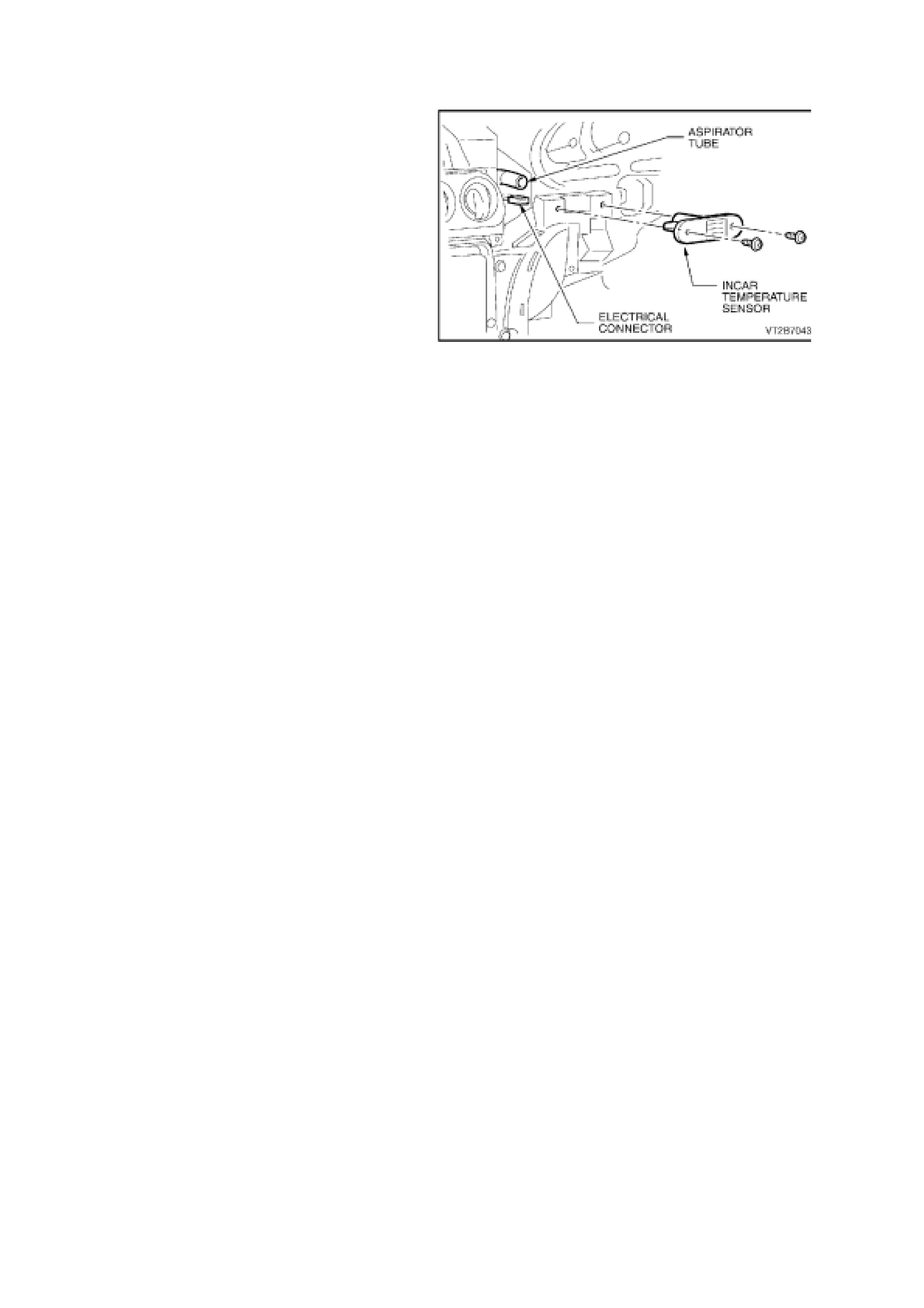
4. Locate the in-car temperature sensor.
Disconnect the electrical connector and
aspirator tube.
5. 5. Detach the in-car temperature sensor two
self tapping screws.
REINSTALL
1. Reassembly takes place in reverse order of
removal.
2. Reset radio security code, refer to the Owner’s
Handbook.
Figure 2E-4
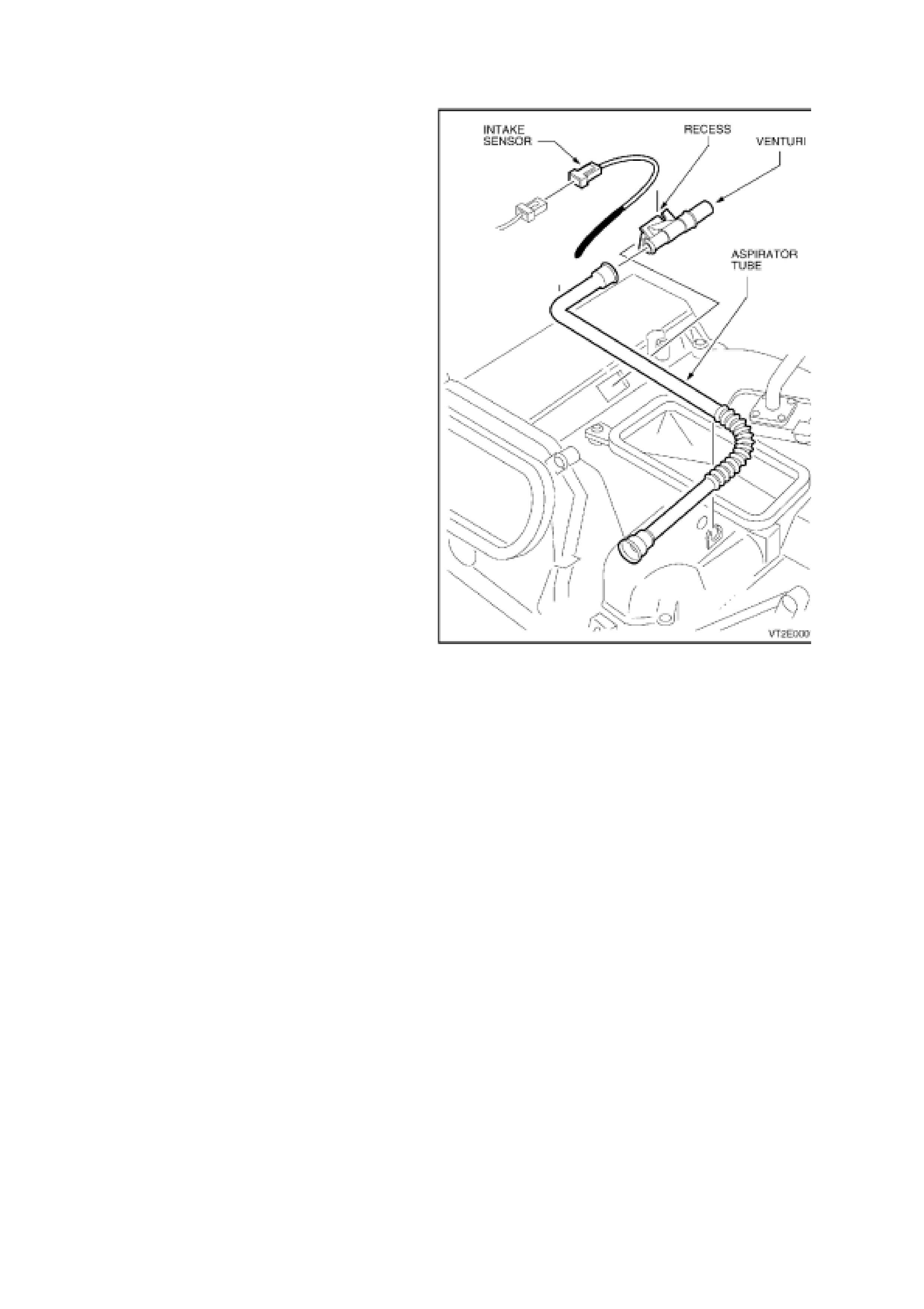
2.3 INTAKE AIR TEMP E RATURE SENSOR AND ASPIRATOR TUBE
REMOVE
1. Remove the instrument facia assembly, refer
to Section 2B AIR CONDITIONING -
REMOVAL AND INSTALLATION.
2. The intak e air temper ature sensor, venturi and
aspirator tube are located on top of the HVAC
unit.
3. Gently unclip the venturi from the evaporator
top cover.
4. Working through venturi opening, use a thin
flat blade screwdriver to gently pry the sensor
wire from the plastic retaining clip.
NOTE:
Avoid damaging the evaporator coil surface when
removing sensor wire.
REINSTALL
1. Installation is the reverse order of removal.
2. When installing the intake air temperature
sensor wire, ensure that the wiring runs in the
recess provided in the venturi housing.
IMPORTANT:
Ensure the evaporator air sensor probe clip is re-
affixed in exactly the same position as when
removed.
Figure 2E-5
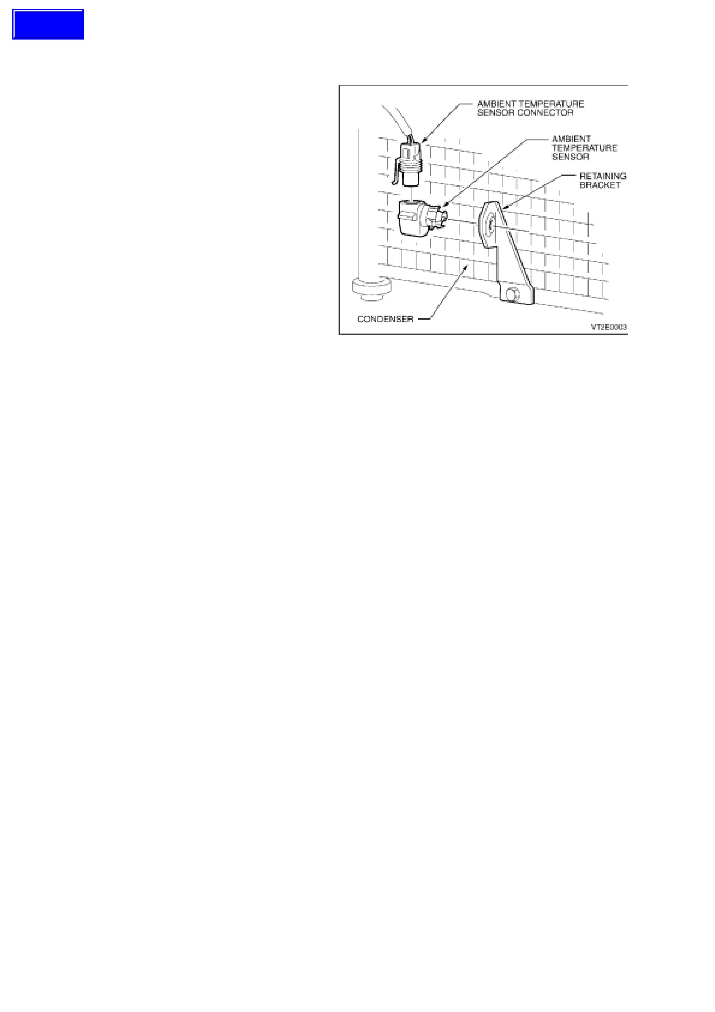
2.4 AMBIENT TEMPERATURE SENSOR
REMOVE
1. Through the front bumper bar opening, detach
the ambient temperature sensor electrical
connector.
2. Using a flat blade screwdriver gently pry the
sensor away from the retaining bracket. The
sensor is clipped into position.
REINSTALL
Installation is the reverse order of removal.
Figure 2E-6
Techline
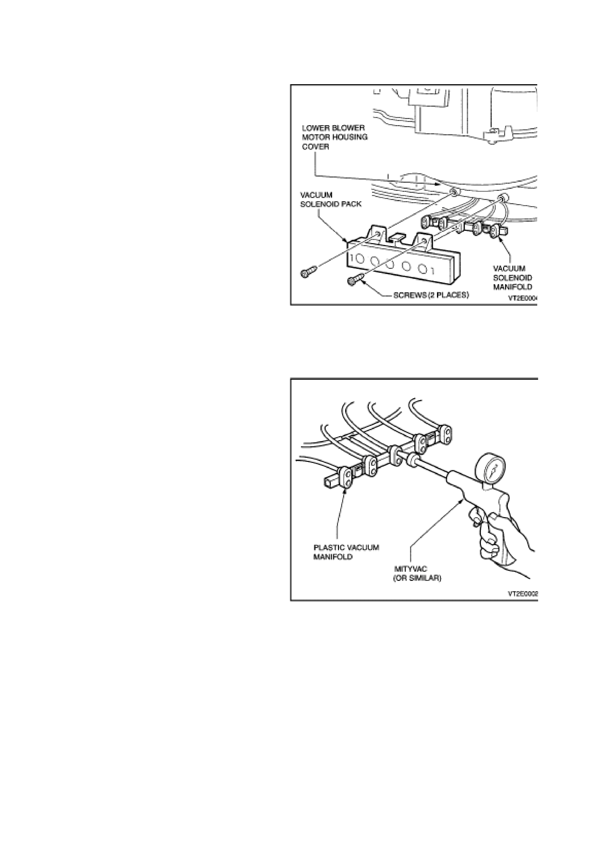
3. VACUUM SOLENOI D PACK
REMOVE
1. Remove the blower motor access cover, refer
to Section 2B AIR CONDITIONING -
REMOVAL AND INSTALLATION.
2. Disconnect the vacuum solenoid pack vacuum
manifold.
3. Remove the two self tapping screws and
detach the vacuum solenoid pack from the
blower motor access cover.
REINSTALL
Installation is the reverse order of removal.
Figure 2E-7
3.1 VACUUM LINE CHECK
REMOVE
1. Unclip the left side footwell upper closing
panel, refer to Section 2B AIR
CONDITIONING - REMOVAL AND
INSTALLATION.
2. Locate the vacuum solenoid pack and
disconnect the plastic vacuum manifold.
3. Using a Mityvac or similar, connect to the
appropriate port of the plastic vacuum manifold
(see table below).
4. Create a vacuum , view Mityvac gauge to see if
the needle rises to positive pressure indicating
a vacuum leak.
5. 5. If a vacuum leak is
indicated it could be either the vacuum tubing
or the vacuum actuator (check to see if the
vacuum tubing is dislodged from the vacuum
actuator). Each of these components will have
to be vacuum leak checked individually.
COLOUR FUNCTION
Green Bi-level
Red Floor
White Centre Vent
Orange Foot / Demist
Blue Recirc / Fresh
Black Vacuum Source
REINSTALL
1. Connect the plastic vacuum manifold to the
vacuum solenoid pack ensuring that the
vacuum tubing is secure.
2. Refit the left side footwell upper closing panel,
refer to Section 2B AIR CONDITIONING -
REMOVAL AND INSTALLATION.
Figure 2E-8
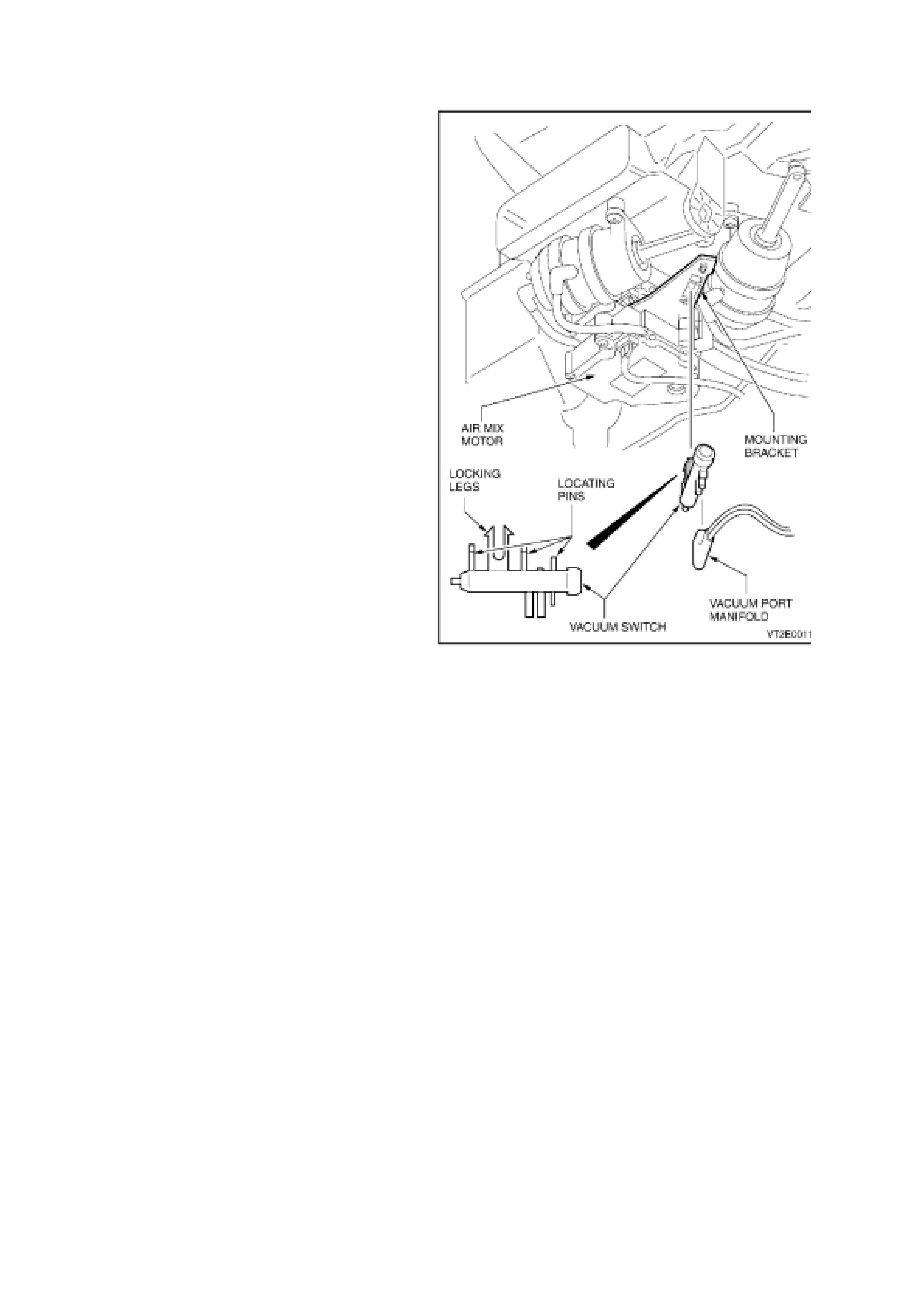
3.2 VACUUM SWITCH FOR HEATER VALVE
REMOVE
1. Remove the right hand side centre facia
extension, refer to Section 2B AIR
CONDITIONING - REMOVAL AND
INSTALLATION.
2. Locate the vacuum switch and remove the
vacuum port manifold.
3. From the upper section of the vacuum valve
brack et push the two lock ing legs together and
remove the vacuum valve.
REINSTALL
1. Firmly insert the vacuum switch into the
mounting bracket ensuring the three locating
pins slide into their positions.
2. Re-connect the vacuum port manifold (one
directional fit).
3. Re-attach right hand side centre facia
extension.
Figure 2E-9
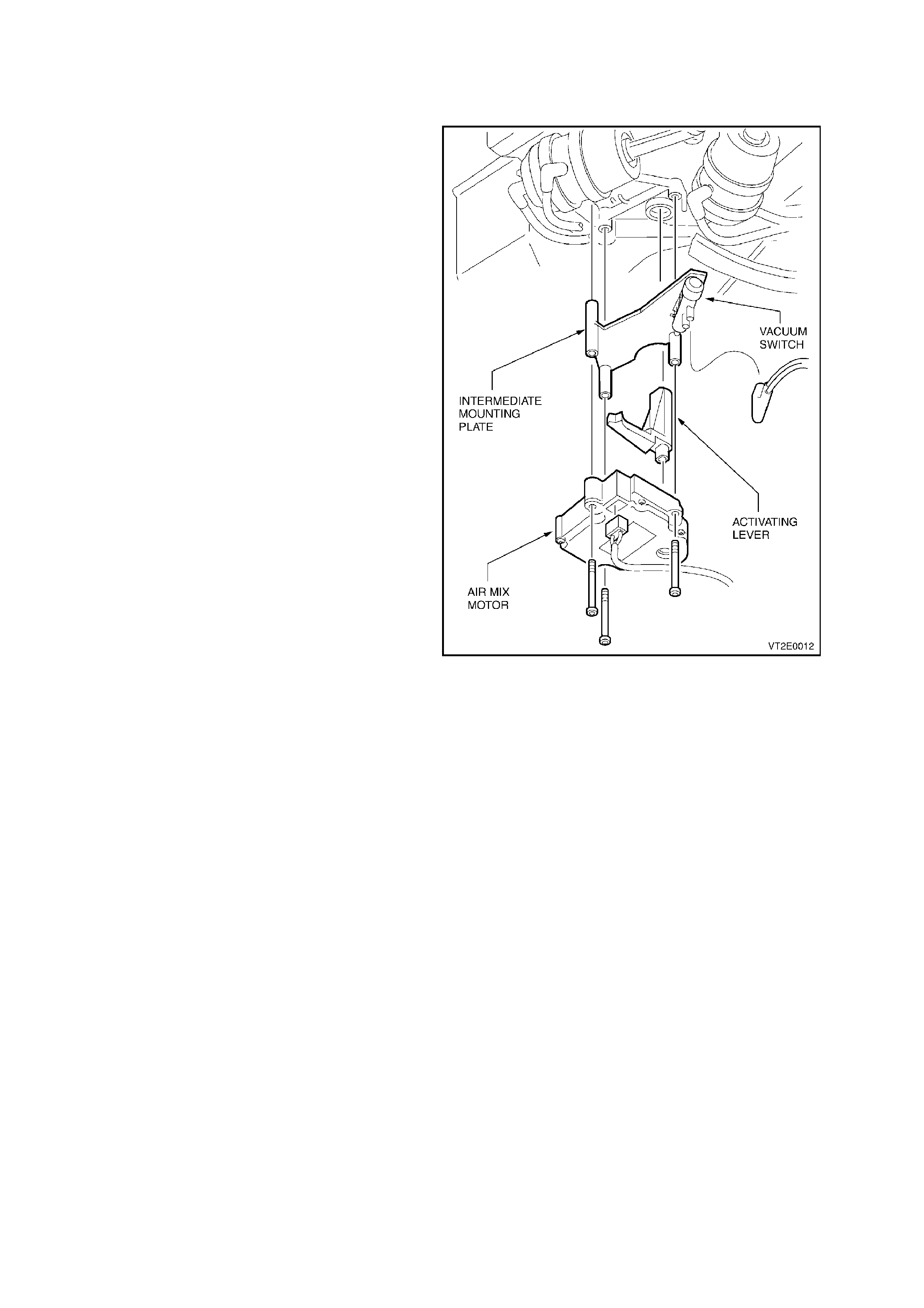
4. AIR MIX MOTOR - SINGLE ZONE
REMOVE
1. Remove the HVAC unit, refer to
Section 2B AIR CONDITIONING - REM OVAL
AND INSTALLATION.
2. From the underside of the HVAC unit, locate
the air mix motors.
3. Disconnect the vacuum manifold from the
vacuum switch and one electrical connector.
4. 4. Unscrew the three self tapping screws
used to retain the air mix motor pack and
remove.
REINSTALL
1. Install the activating lever into the HVAC case
and assemble the intermediate mounting plate,
activating the lever and air mix motor as
shown and secure with the original three self
tapping screws.
2. Re-connect the electrical connection and the
vacuum switch manifold.
3. Refit the HVAC unit.
Figure 2E-10
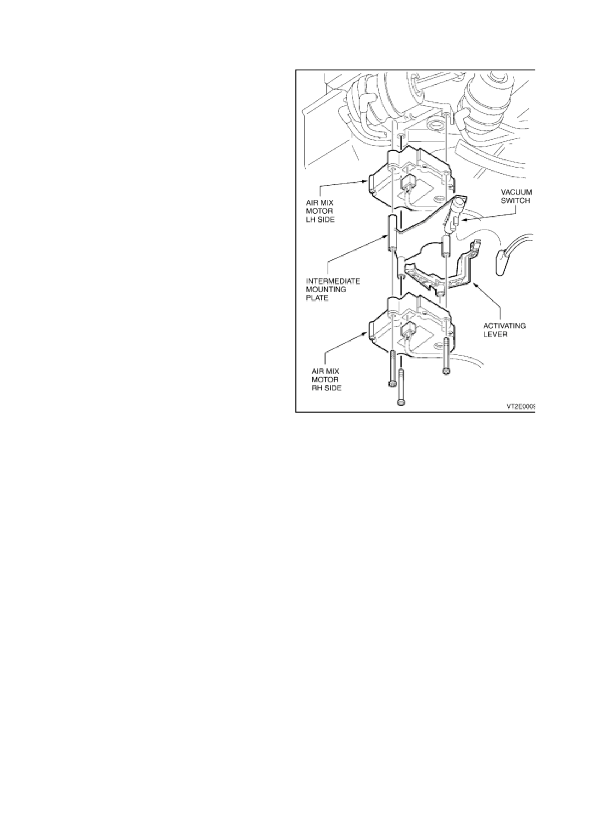
4.1 AIR MIX MOTORS - DUAL ZONE
REMOVE
1. Remove HVAC, refer to Section 2B AIR
CONDITIONING - REMOVAL AND
INSTALLATION.
2. From the under side of the HVAC unit, locate the
air mix motors.
3. Disconnect the vacuum manifold from the
vacuum switch, two electrical c onnections and the
upper mixing door lever.
4. Unscrew the three self tapping screws used to
retain the air mix motor pack and remove.
REINSTALL
1. Align the HVAC shaft end with the upper air mix
motor drive (left hand side) and hold into position.
2. Install the intermediate mounting plate under the
upper air mix motor.
3. Install the lower air mix motor (right hand side)
and secure the air mix motor pack with the
original three self tapping screws.
4. Re-connect the electrical connections, vacuum
switch manifold and upper mixing door lever.
5. Refit the HVAC unit.
Figure 2E-11
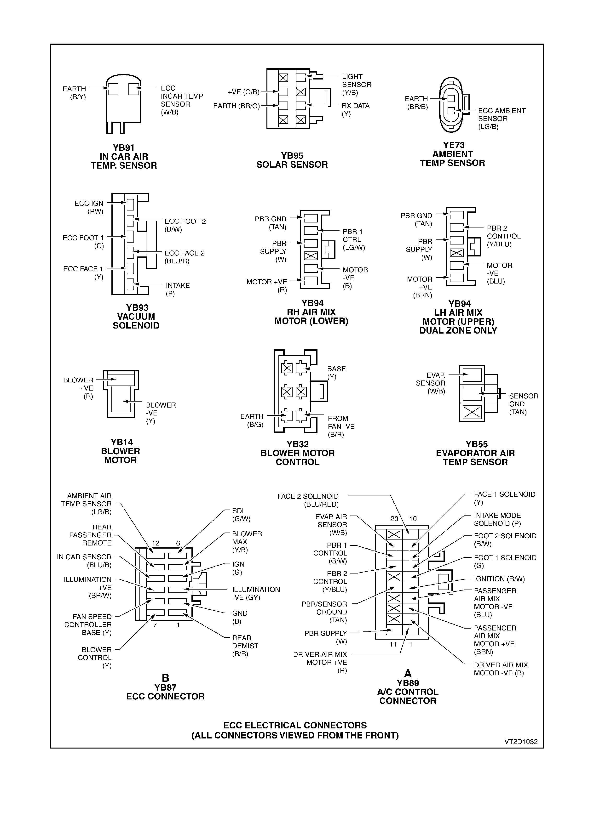
ELECTRICAL CONNECTORS
Figure 2E-12