SECTION 4C - PROPELLER SHAFT AND UNIVERSAL
JOINTS
CAUTION:
This vehicle will be equipped with a Supplemental Restraint System (SRS). An SRS
will consist of either seat belt pre-tensioners and a driver's side air bag, or seat belt
pre-tensioners and a driver's and front passenger's side air bags. Refer to
CAUTIONS, Section 12M, before performing any service operation on or around any
SRS components, the steering mechanism or wiring. Failure to follow the CAUTIONS
could result in SRS deplo yment, resulting in possible p ersonal injury or unnecessary
SRS system repairs.
CAUTION:
This vehicle may be equipped with LPG (Liquefied Petroleum Gas). In the interests of
safety, the LPG fuel system should be isolated by turning ‘OFF’ the manual service
valve and then draining the LPG serv ice lines, before any service w ork is carried out
on the vehicle. Refer to the LPG leaflet included with the Owner's Handbook for
details or LPG Section 2 for more specific servicing information.
CAUTION:
Whenever any component that forms part of the ABS or ABS/ETC (if fitted), is
disturbed during Service Operations, it is vital that the complete ABS or ABS/ETC
system is checked, using the procedure as detailed in 4. DIAGNOSIS, ABS or
ABS/ETC FUNCTION CHECK, in Section 12L ABS & A BS/ETC.
1. GENERAL DESCRIPTI ON
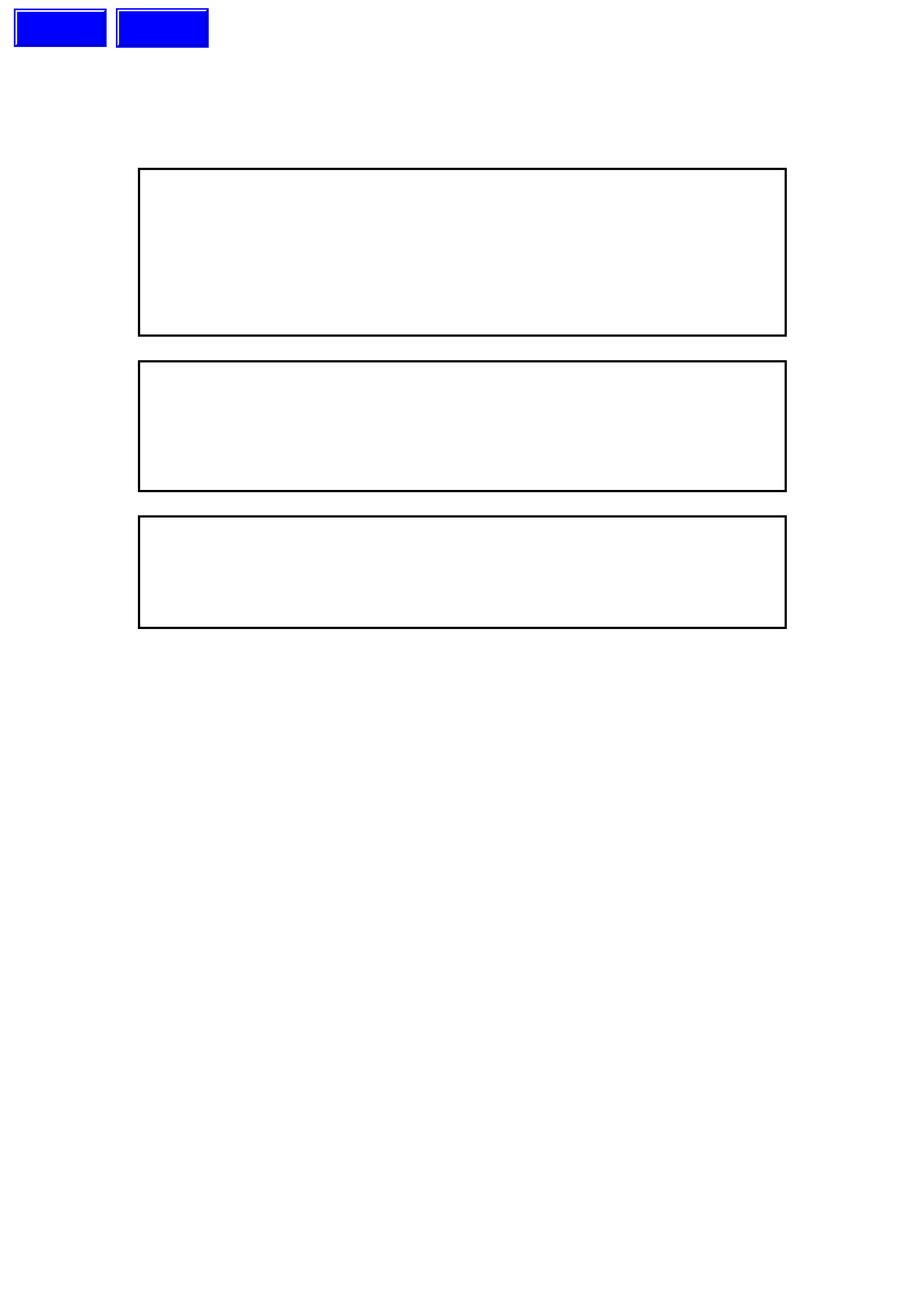
The propeller shaft assembly used on all VT model vehicles is a two piece tubular design, refer to Figure 4C-1.
For all VT models except those fitted with a manual transmission, each end of the propeller shaft, has a needle
bearing universal joint connected to a slip yoke at the transmission end and a flange at the rear axle end.
Drive is transmitted between the two halves of the propeller shaft through a constant velocity joint. A fully sealed ball
bearing, mounted in a reinforced rubber cup, supports the propeller shaft assembly in the centre location. This
centre bearing rubber cup is supported in a cup guide and attached to a carrier, which in turn, is bolted to the
vehicle underbody.
The constant velocity joint has axial movement to allow fore and aft movement of the rear propeller shaft during the
rear suspension movement.
The constant velocity joint, centre bearing, propeller shaft rear universal joint and flange are common for all
applications.
The universal joint/s, constant velocity joint and centre bearing are lubricated for life and do not require any periodic
lubrication.
Those vehicles fitted with the V6 engine and manual transmission have a rubber coupling that bolts directly to the
rear transmission output flange.
When the V8 engine with manual transmission is fitted to a VT model vehicle, an hydraulically dampened rubber
coupling replaces the front, needle roller bearing universal joint. The coupling bolts to a flange on the front propeller
shaft and a flange on the transmission slip joint.
Techline
Techline
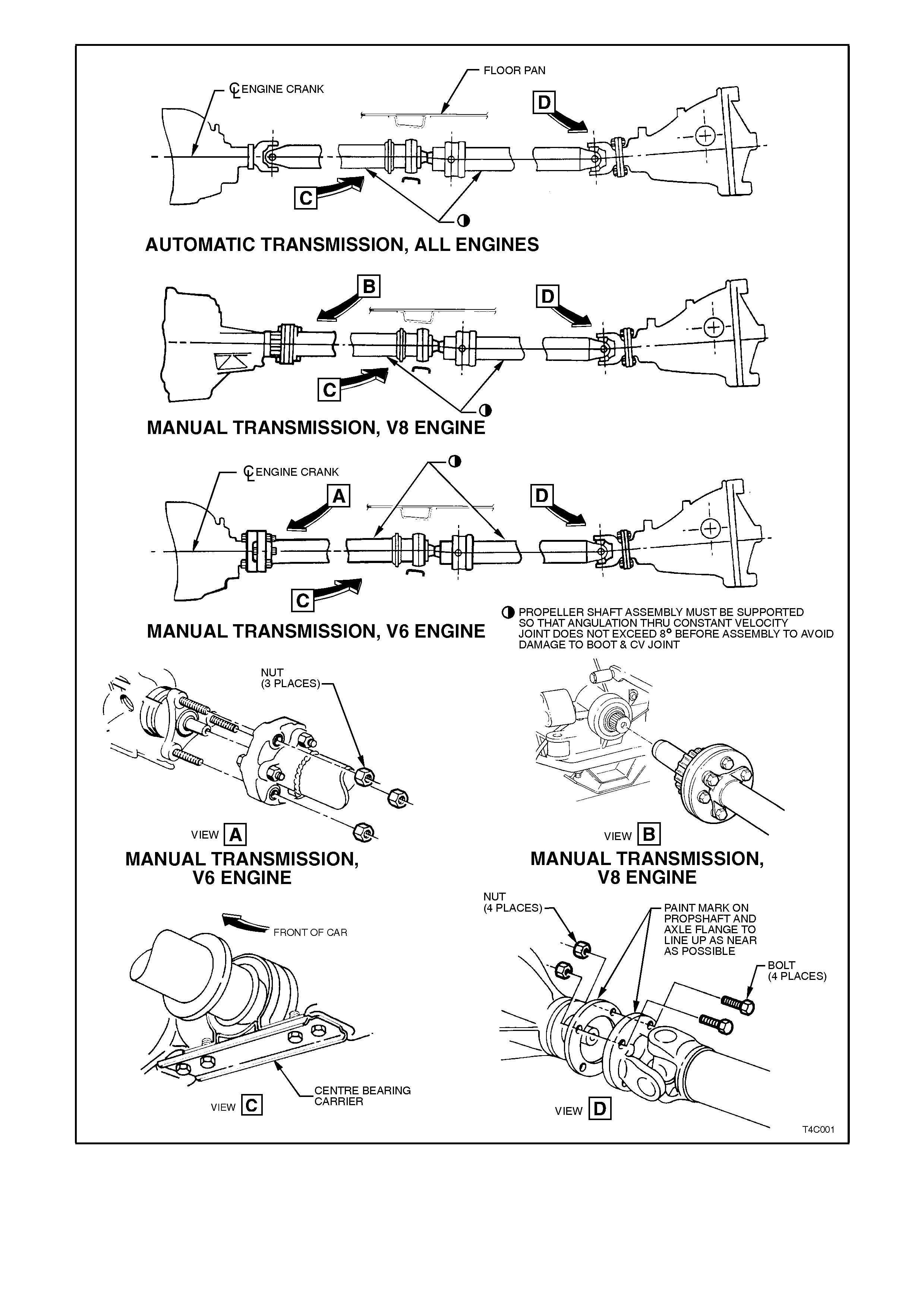
Figure 4C-1
2. SERVICE OPERATIONS
2.1 PROPELLER SHAFT
REMOVE
CAUTION:
Whenever any component that forms part of
the ABS (if fitted) is disturbed during Service
Operations, it is vital that the complete ABS
system be checked, using the procedure as
detailed in DIAGNOSIS, ABS FUNCTION
CHECK, in Section 12L ABS & ABS/ETC.
1. Using a floor jack under the centre of the rear
axle housing, jac k up rear of vehic le and place
safety stands under body rear jacking points.
Refer to Section 0A GENERAL
INFORMATION for location of jacking points.
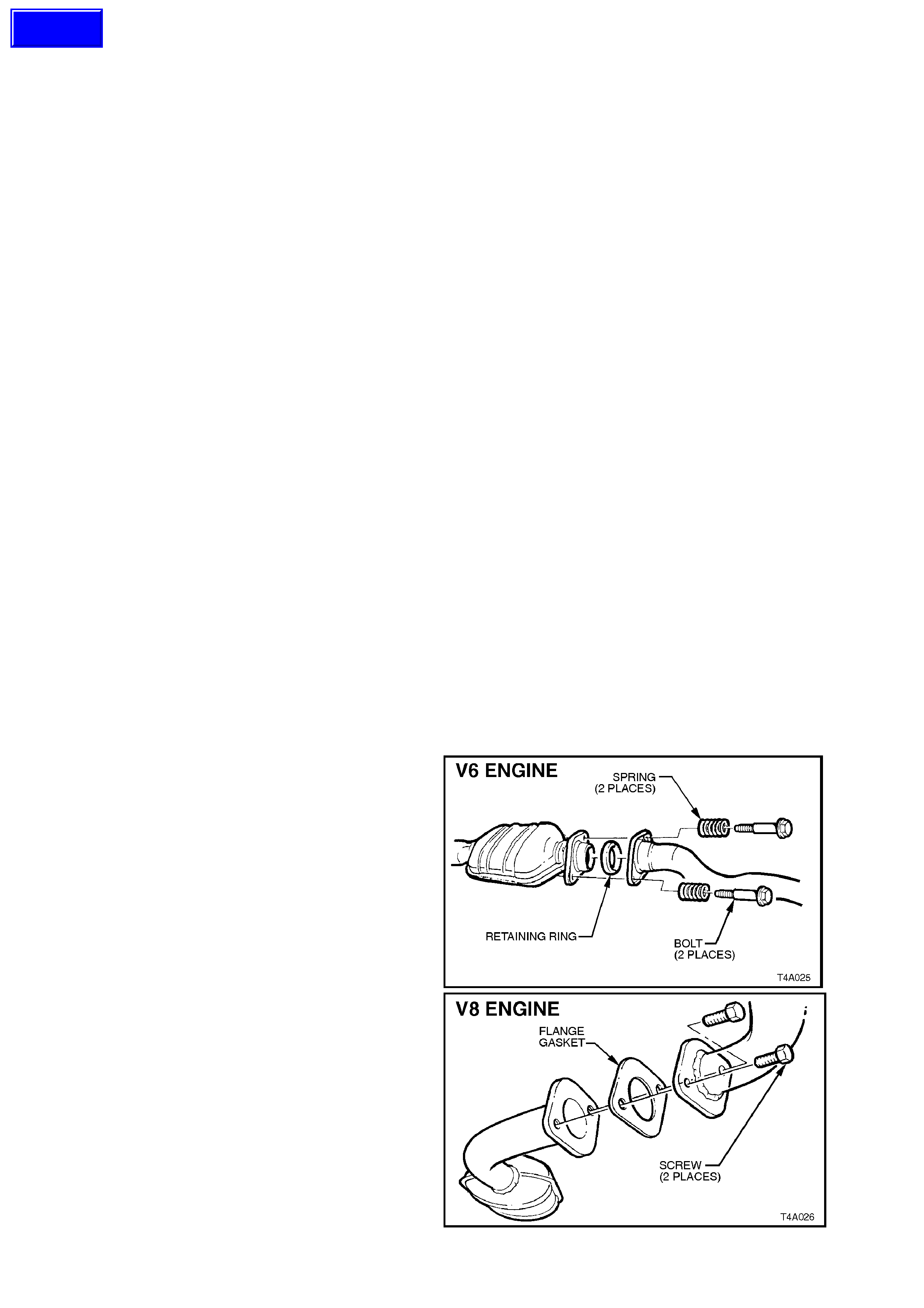
2. Disconnect exhaust system from rear of
catalytic converter (V6 engine) or converters
(V6 Supercharged and V8 engines). Discard
gaskets on the V6 Supercharged and V8
flanges.
NOTE:
Only one flange of the V6 Superc harged/V8 s ystem
is shown.
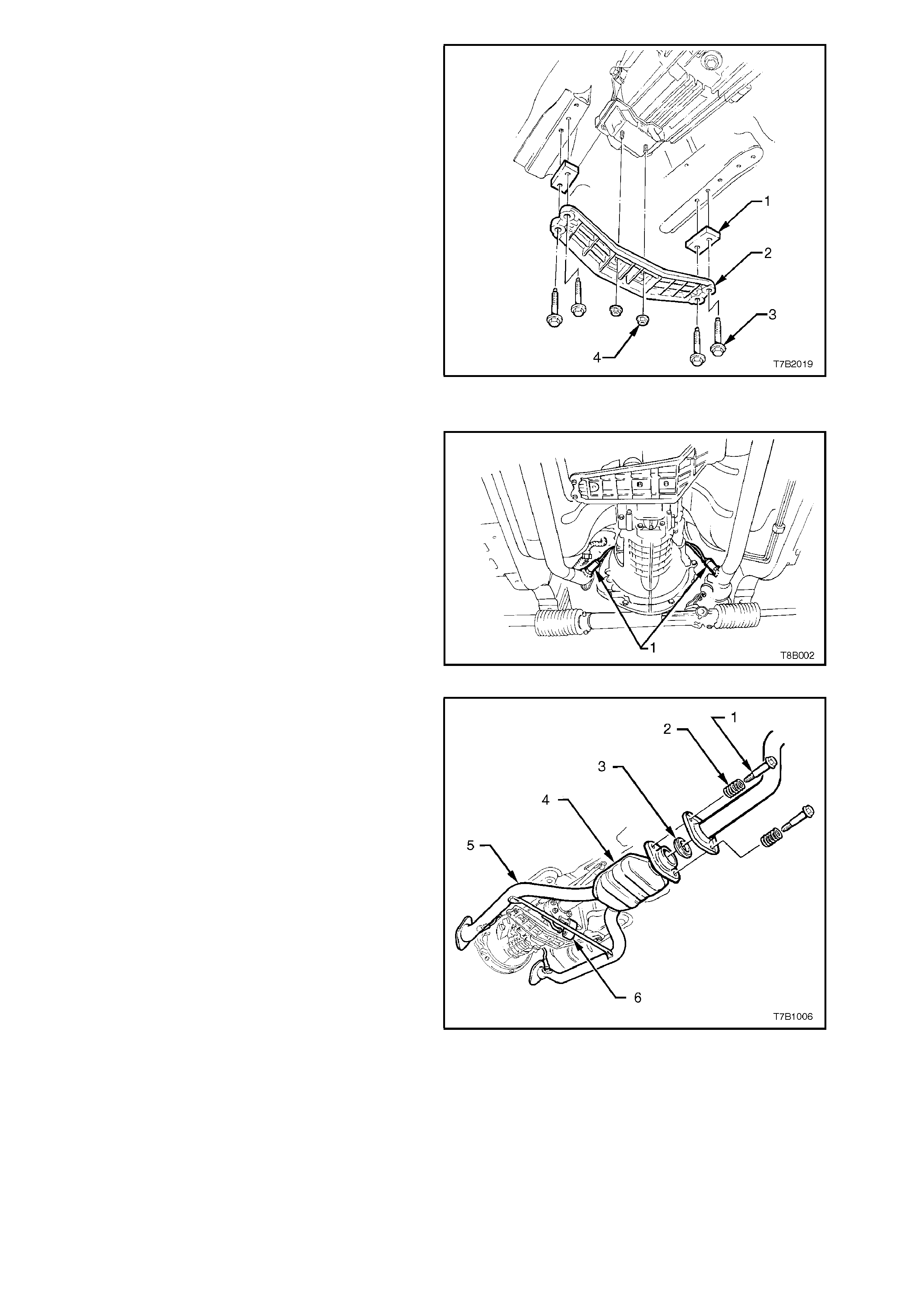
Figure 4C-2
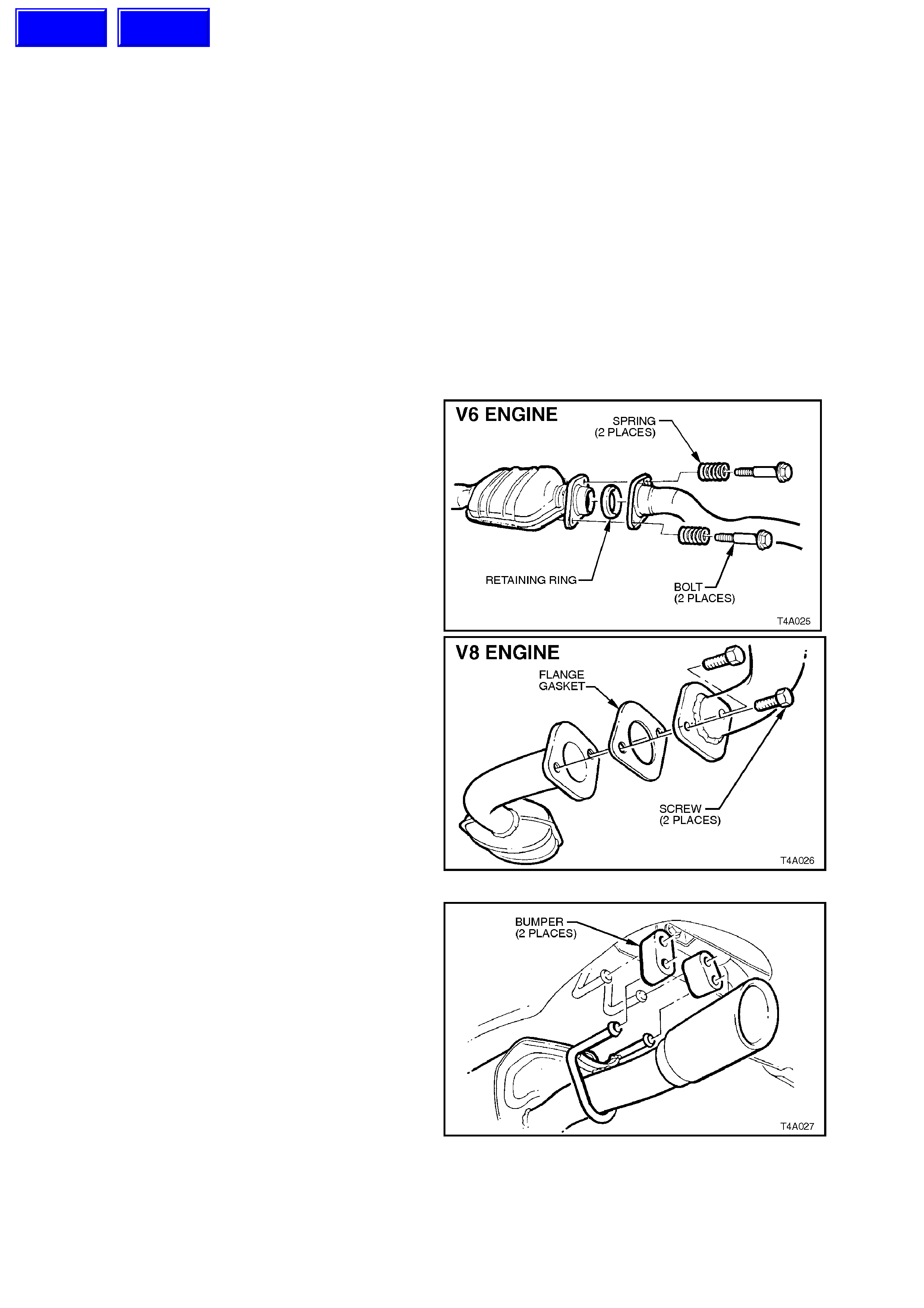
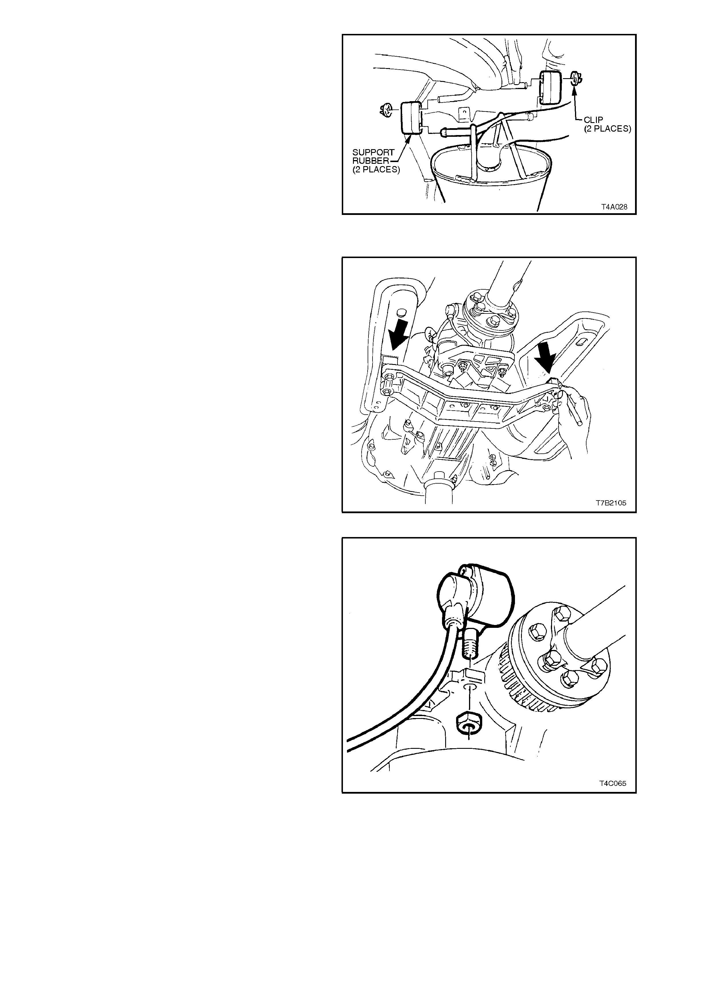
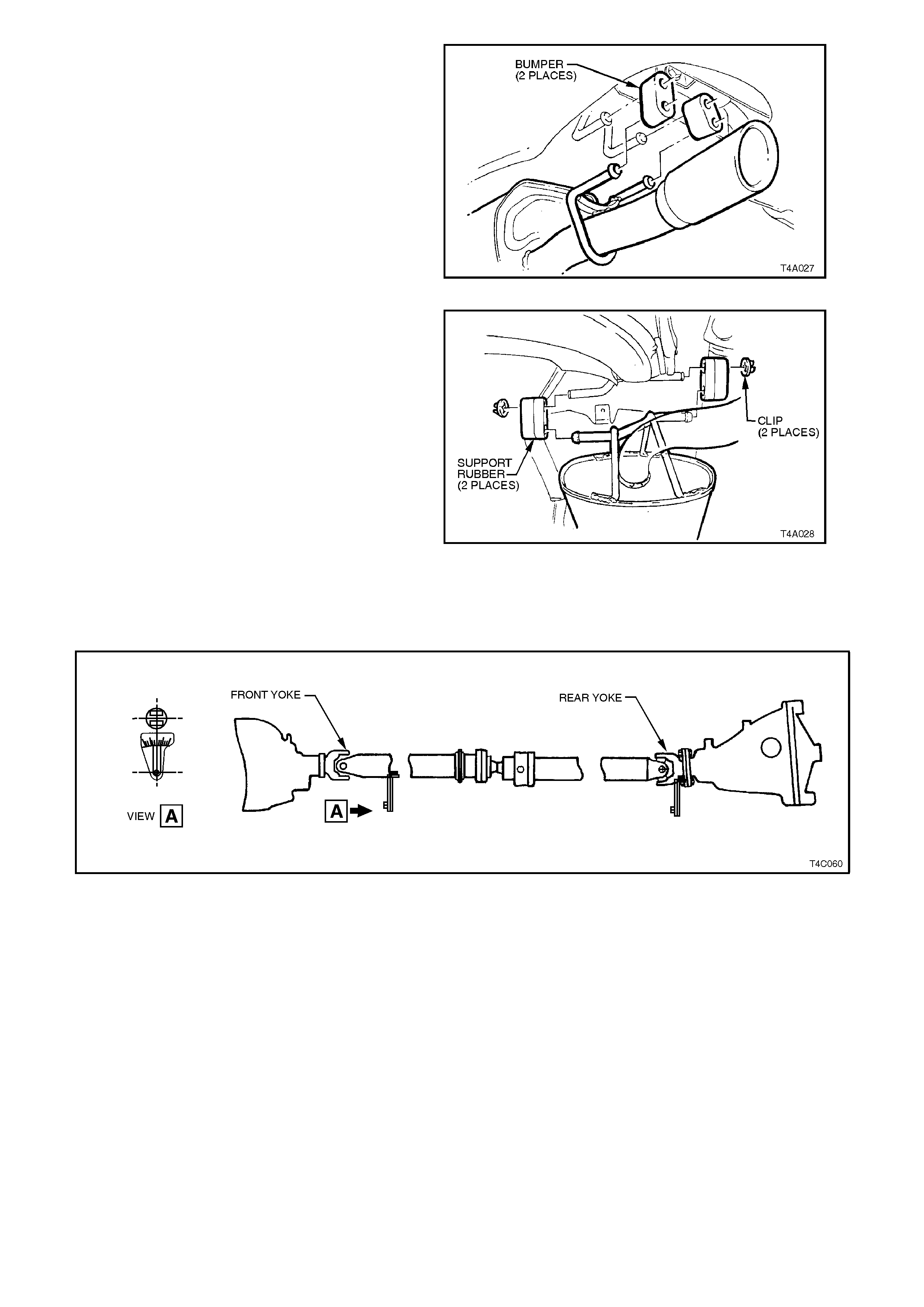
3. Remove the two retainers from the top posts
and discard. Disconnect exhaust system
support rings from rear hanger of the rear
muf fler. Both V6 and V8 arrangem ents are the
same.
Figure 4C-3
Techline
Techline
4. Remove muffler support to rear crossmember
retainers (2 places-V6, 4 places-V6
Supercharged and V8) and discard.
5. Lift up intermediate section of exhaust system
and remove intermediate muffler support
rubbers. Remove intermediate and rear
sections of exhaust system from vehicle.
Figure 4C-4
For VT Models Fitted with V8 Engine and Manual Transmission
6. Support weight of transmission assembly on a
transmission jack.
7. Use a sharp scriber to mark the exact location
of the crossmember to the side frames
(arrows), before loosening any fasteners.
Also scribe around the rear mounting washers,
marking their location on the alloy
crossmember.
IMPORTANT:
These steps are critical to the correct powertrain
alignment on reassembly. If not carried out, then
vehicle vibration and/or handling problems could
result!
Figure 4C-5
8. Remove the nut securing the vehicle speed
sensor pick-up bracket to the rear of the
transmission and secure to one side, using tie
wire.
Figure 4C-6
9. Remove the four crossmember to side frame
bolts (3) and spacers (1). Unless required for
some other purpose, the crossmember (2) to
rear mount nuts (4) do not need to be
disturbed.
10. Lower the transmission to provide clearance
for the propeller shaft to be removed from the
vehicle.
NOTE:
Neither the transmission jack nor propeller shaft
have been shown in the illustration for clarity of the
crossmember orientation.
Figure 4C-7
For VT Models Fitted with V6 Engine and Manual Transmission
NOTE:
To gain access to the front, flexible rubber coupling
bolts and nuts, it is recommended that the twin
exhaust pipe/catalytic converter are removed.
11. Disconnect the wiring harness connectors
from each of the two oxygen sensors (1).
Figure 4C-8
12. Remove the twin exhaust pipe (5) and catalytic
converter assembly (4) and the support rubber
(6) at the rear of the transmission. Carefully
lower and remove the exhaust pipes from the
vehicle, taking care not to damage the exhaust
gas oxygen sensors, in the process.
Figure 4C-9
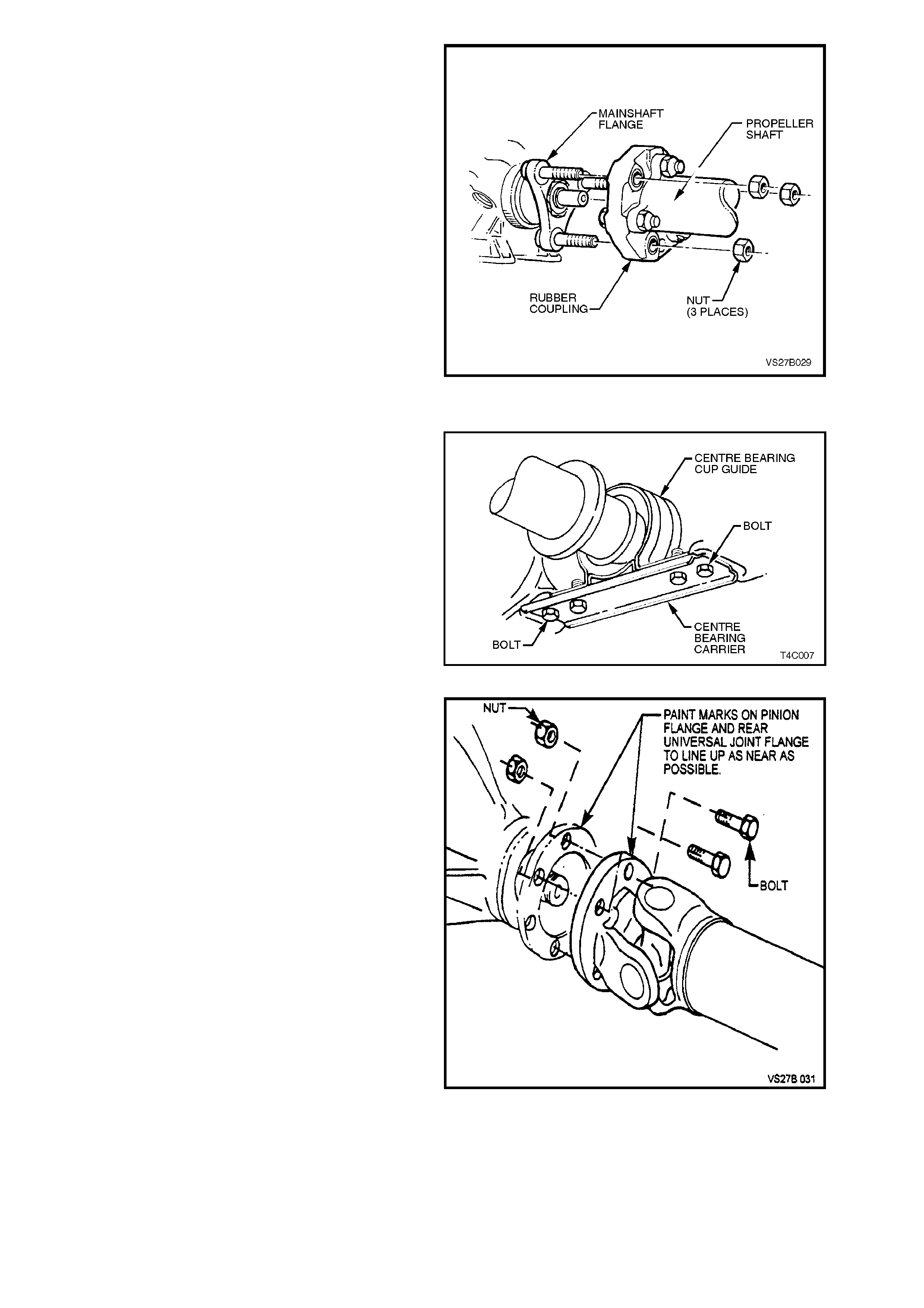
13. Remove propeller shaft flexible rubber
coupling to output flange attaching nuts.
Discard removed nuts.
Figure 4C-10
All VT Models
14. Remove centre bearing carrier to underbody
reinforcement bolts and spacers, if fitted.
NOTE:
For correct reassembly, take particular note of any
spacer arrangement that may be fitted, observing
any side-to-side differences and the orientation of
the offset bracket.
Figure 4C-11
15. Remove bolts and nuts holding propeller shaft
rear universal joint flange to pinion flange.
Disengage rear universal joint flange from
pinion flange.
NOTE:
The two flanges have paint alignment marks that
are assembled as close together as possible. If the
marks are not visible, scribe a line on both flanges
to enable the propeller shaft to be installed in the
original position.
16. Remove propeller shaft by pulling it toward the
rear of vehicle to either disengage the rubber
coupling or the front slip joint yoke from
transmission.
Figure 4C-12

For VT Models with a Sliding Yoke
NOTE 1:
Tak e care to protec t the outer diam eter of the f ront
yoke. Nicks or abrasions will damage the
transm iss ion extension seal during reas sem bly and
result in lubricant leakage past the seal.
NOTE 2:
For VT Models fitted with the V8 engine and
Manual Transmission, take particular care not to
damage any teeth on the vehicle speed sensor
toothed ring, installed onto the sliding yoke. Any
damage to these teeth will cause the sensor to
malfunction.
NOTE 3:
Insert a suitable plug in the end of the trans m ission
rear extension to prevent loss of transmission
lubricant.
REINSTALL
Installation is the reverse of removal procedures
noting the following points:
1. Remove any foreign matter that may have
adhered to the front universal joint yoke and
lubricate with transmission lubricant. Guide
propeller shaft over park brake cable and
insert yoke on to transmission mainshaft.
NOTE:
If the propeller shaft is fitted with a toothed, speed
sensor ring (V8 with Manual Transmission) take
particular care not to damage the teeth, during
installation.
2. Before attaching propeller shaft rear universal
joint flange to pinion flange, align marks on
pinion flange and rear univer s al j oint f lange (or
marks made on removal), refer to
Figure 4C-12.
3. Care must be taken to use only genuine bolts
and nuts. Tighten propeller shaft rear
universal joint flange to pinion flange bolts to
the correct torque specification.
PROPELLER SHAFT REAR
UNIVERSAL JOINT FLANGE 55 - 65
TO PINION FLANGE BOLT Nm
TORQUE SPECIFICATION
4. Clean threads of centre bearing carrier to
underbody reinforcement bolts and underbody
weld nuts with a suitable cleaning solvent.
NOTE:
Replace micro-encapsulated bolts if they have
been rem oved three times . If in doubt, r eplac ement
is recommended. If not replacing the bolts,
apply Loctite 242 or an equivalent thread
sealant to the cleaned threads.
5. Install centre bearing carrier with the correct
orientation (refer to Figure 4C-11).

6. If fitted, ensure that the centre bearing carrier
spacers are in correct position, as noted on
removal (refer to Figure 4C-1) and tighten
centre bearing carrier to underbody
reinforcement bolts to the correct torque
specification.
CENTRE BEARING CARRIER TO
UNDERBODY REINFORCEMENT 20 - 35 Nm
BOLT TORQUE SPECIFICATION
VT Models with V8 Engine and Manual
Transmission
7. With this powertrain combination, when the
propeller shaft is installed into the rear of the
transmission, support the propeller shaft
centre bearing while the transmission is
raised. Loosely install the four rear
crossmember bolts and the centre bearing
bracket retaining bolts, taking note of any
spacers that may be fitted.
8. Align the rear crossmember with the scribed
alignment marks made prior to removal, then
tighten the four bolts to specification.
REAR CROSSMEMBER TO SIDE
FRAME MEMBER BOLT 50 - 65 Nm
TORQUE SPECIFICATION
9. install the vehicle speed s ensor br ack et bolt to
the rear of the transmission and tighten to
specification.
SPEED SENSOR BRACKET 15 - 20
BOLT TORQUE SPECIFICATION Nm
VT Models with V6 Engine and Manual
Transmission
10. Lubricate the transmission output shaft spigot
with molybdenum disulphide grease to Holden
Specification HN1271.
11. Install NEW rubber coupling to transmission
output flange retaining nuts and tighten to the
correct torque specification.
RUBBER COUPLING TO OUTPUT
SHAFT FLANGE RETAINING NUT 74 - 80 Nm
TORQUE SPECIFICATION
12. Replace the exhaust system as follows;
a. W ith V6 engined vehicles, install the twin
exhaust pipes to the manifolds, reconnect
the exhaust gas oxygen sensor wiring
leads and tighten the nuts to the specif ied
torque.
EXHAUST PIPE FLANGE TO
EXHAUST MANIFOLD NUT V6 Engine:
TORQUE SPECIFICATION 18 35 Nm

b. Supercharged and V8 engined vehicles,
ensure the catalytic converter flange is
clean and free from any gasket material.
W ith V6 engined vehicles, check that the
catalytic converter to intermediate
exhaust pipe bolts springs and sealing
ring are all in a serviceable condition.
c. Reinstall exhaust system, using a new
gasket (V6 Supercharged and V8
engined vehicles) at the catalytic
converter and new hanger retainers for
the muff ler support to rear crossmember.
Tighten intermediate exhaust pipe to
converter attaching bolts to the correct
torque specification.
INTERMEDIATE EXHAUST PIPE
TO CATALYTIC CONVERTER All Engines:
BOLT TORQUE SPECIFICATION 40 - 50 Nm
d. Check exhaust clearanc es as detailed in
Section 8B EXHAUST SYSTEM.
All VT Models with a Sliding Yoke
13. If transmission lubricant leaked from the rear
extension when the propeller shaft was
removed, check transmission lubricant level
and top up as necessary. Refer to
Section 0B LUBRICATION AND SERVICE
for lubricant specifications.
2.2 UNIVERSAL JOINTS
REMOVE
NOTE 1:
The following Operation is only suitable for the
replacem ent of a universal j oint, as brinelling of the
needle roller bearings will result from the removal
process.
NOTE 2:
W ith vehicles f itted with the V8 engine and m anual
transmission, the toothed speed sensor ring is
swaged to the front sliding yoke and is not s erviced
as a separate component. For this reason,
particular care must be taken when removing and
handling the propeller shaft to avoid damaging the
teeth.
NOTE 3:
While the majority of illustrations show the front
universal joint, the procedure is the same for both
universal joints.
1. Remove propeller shaft. Refer to
2.1 PROPELLER SHAFT in this Section.
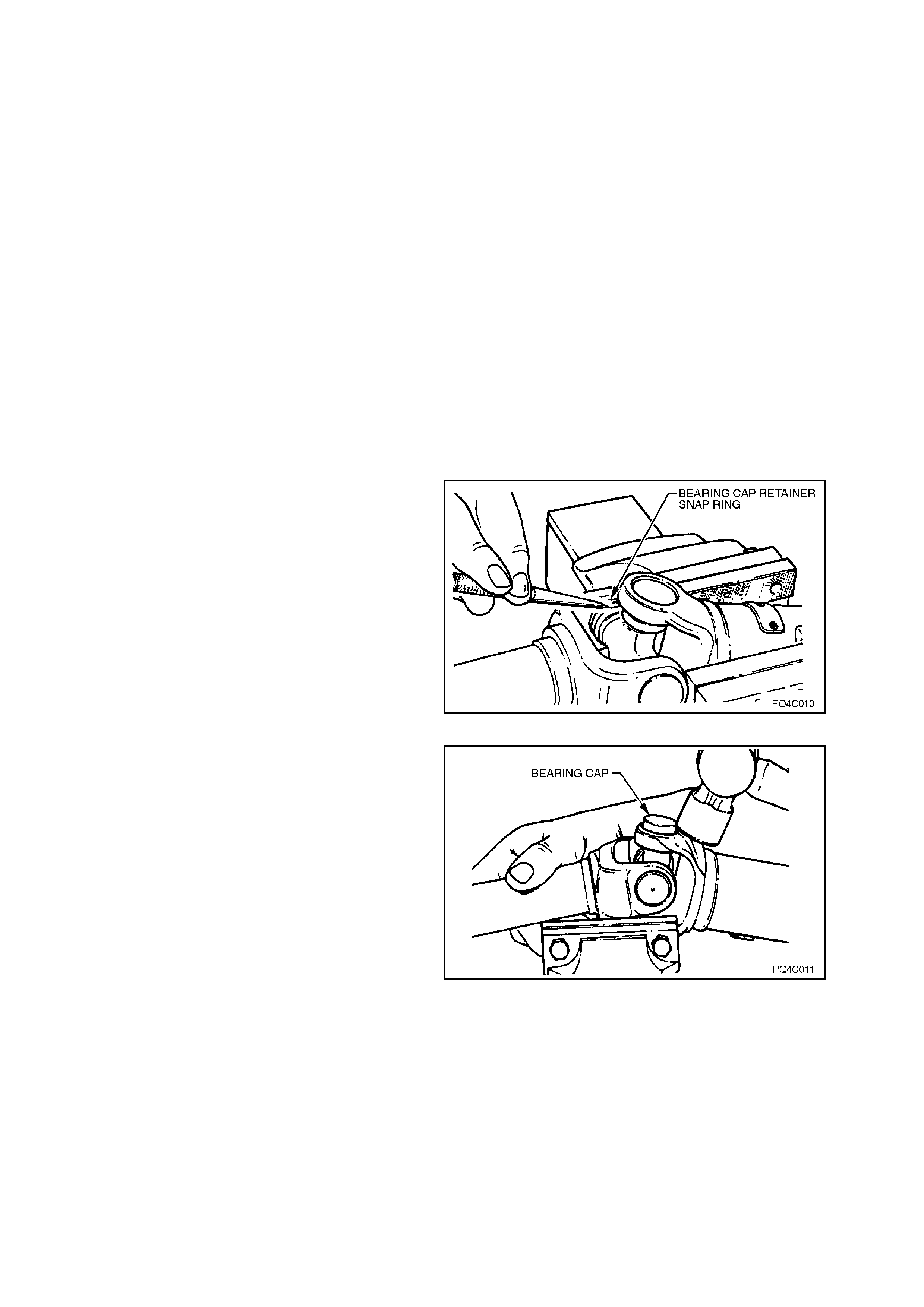
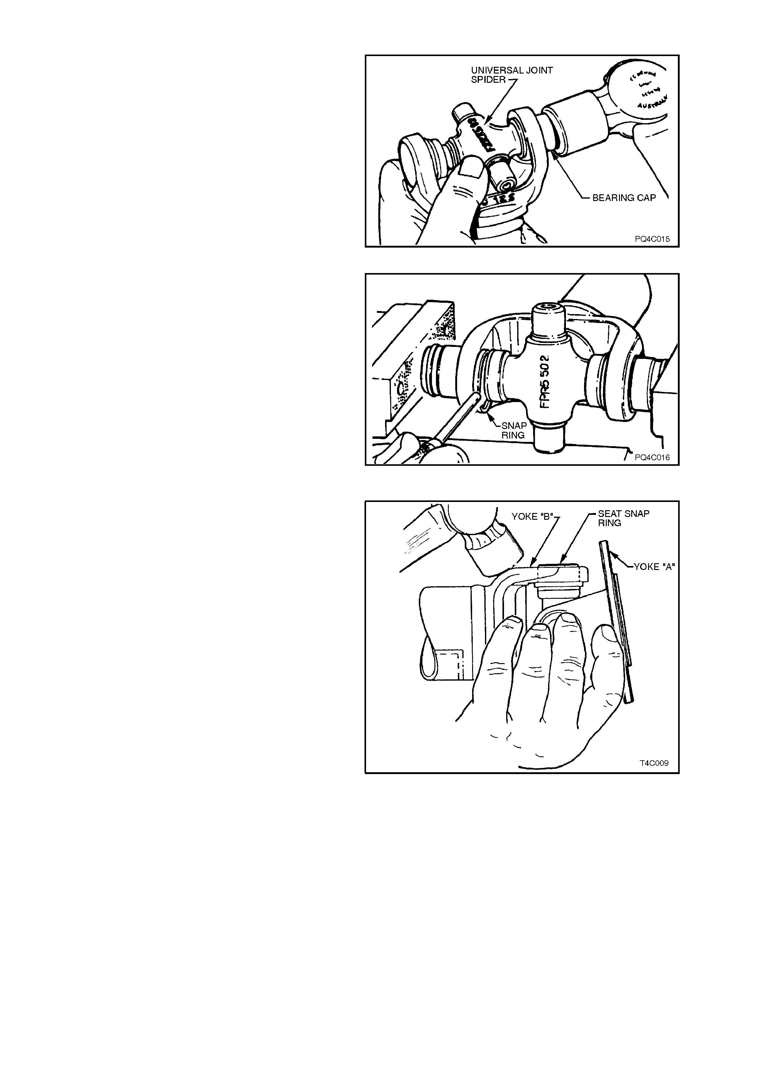
2. Mount propeller shaft in vice equipped with
soft jaws. Remove bearing cap retaining snap
rings from grooves at inner ends of bearing
caps.
Figure 4C-13
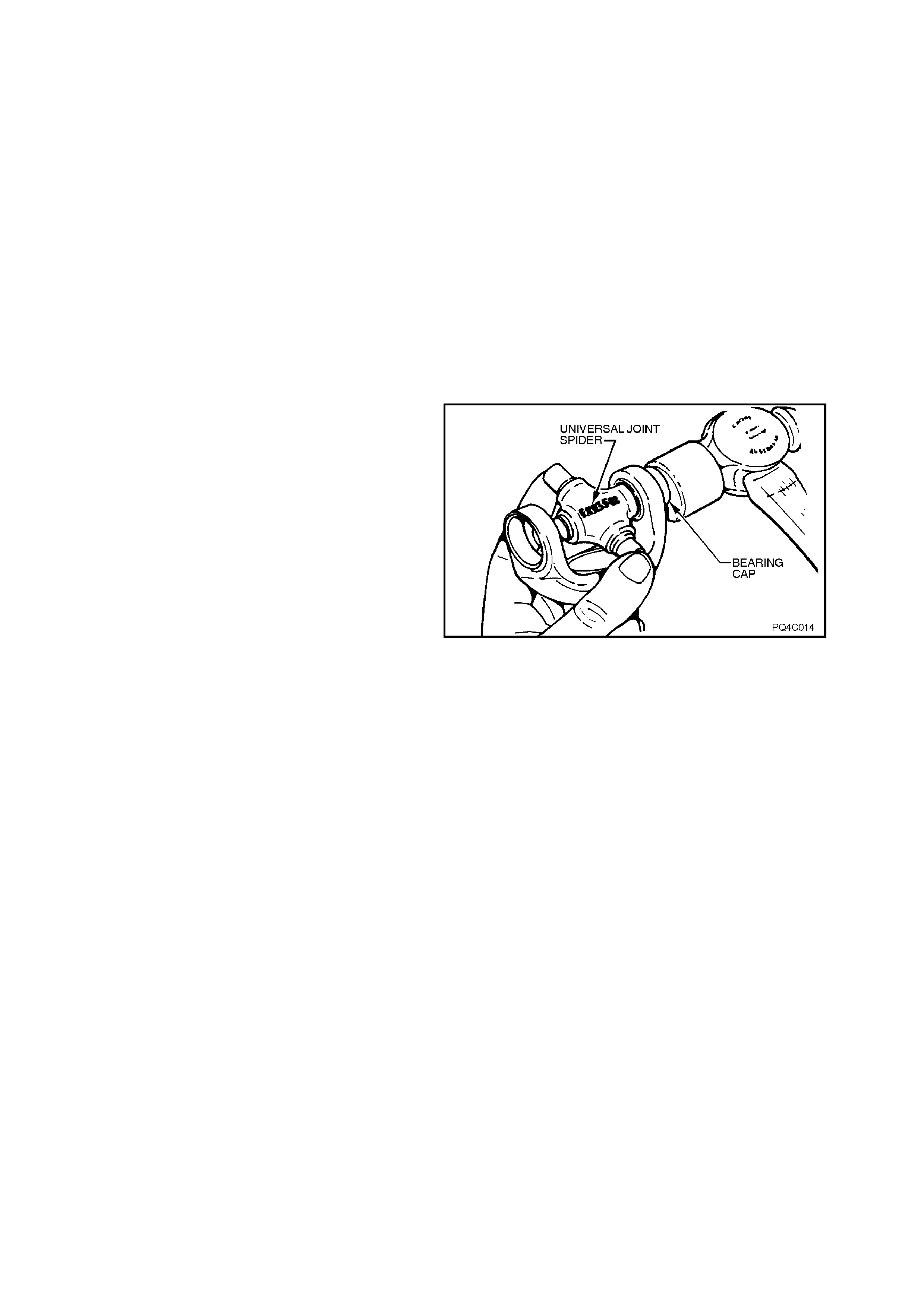
3. Remove bearing caps from ends of the
propeller shaft assembly as follows:
a. Support front universal joint yoke, or rear
universal joint flange ears on open jaws
of a vice.
b. Tap propeller shaft adjacent to bearing
cap with a hamm er so that universal joint
spider forces bearing cap out.
Figure 4C-14
4. Pull dislodged bearing cap from front or rear
universal joint, as shown.
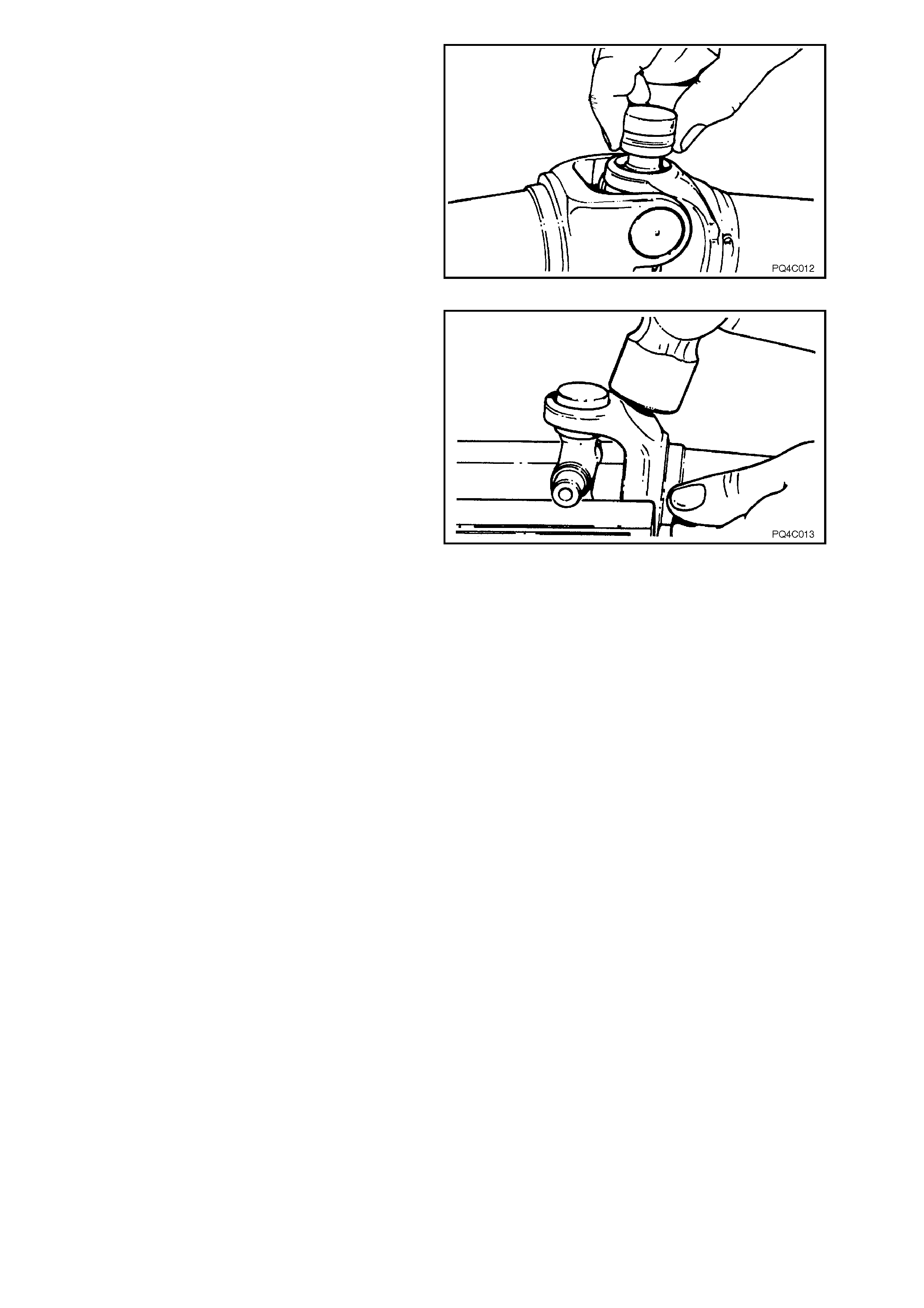
5. Rotate propeller shaft assembly 180° so that
ears on opposite side of yoke, or flange, rest
on the soft jaws in the vice.
6. Remove second bearing cap from propeller
shaft as per steps 3 and 4.
7. Separate yoke or flange from universal joint
spider.
Figure 4C-15
8. Remove bearing caps from yoke or flange by
resting exposed ends of spider on the vice,
and removing bearing caps as previously
described.
9. Remove the spider from the yoke or flange.
10. Thoroughly clean yoke or flange and propeller
shaft universal joint bearing cap bores.
Check bearing cap bores and remove any
burrs.
Figure 4C-16
REINSTALL
Before installing universal joint, note the following:
a. Cleanliness is of prime importance to
ensure maximum universal joint life.
b. Do not allow any needle rollers to
becom e dislodged. Install bearing caps in
the upright position.
c. Universal joint assem blies are prepack ed
with lubricant and do not require any
further lubrication.
d. Take care not to damage bearing cap
seals during installation. Gently ease
bearing caps into their bores during
assembly.
1. Remove bearing caps from spider.
2. Position spider in yoke or flange. Hold spider
to one side in yoke or flange and position a
bearing cap on the end of spider.
3. While holding spider in bearing cap, tap
bearing cap into yoke or flange until bearing
cap snap ring groove is fully visible. Install
snap ring into groove.
Figure 4C-17
4. Turn yoke or flange around and install
opposite bearing cap by positioning spider into
bearing cap to prevent needle rollers from
being dislodged.
Figure 4C-18
5. To fully install second bearing cap, position
yoke or flange in vice with two of the old
universal joint bearing caps, as shown.
Squeeze new bearing caps into position using
the vice jaws.
NOTE:
Ensure that the two old bearing caps are pos itioned
centrally on the new bearing caps, and not up
against the edge of the flange or yoke.
6. Install second snap ring.
7. Install spider and yoke or flange assembly to
propeller shaft.
8. Install remaining bearing caps and snap rings
as previously described. Figure 4C-19
9. While supporting the universal joint in one
hand to minimise any brinelling effect, tap
propeller shaft, yoke and flange ears with a
hammer and ensure that all bearing cap snap
rings are seated correctly in bearing cap
grooves and that universal joints are free to
move in all directions.
Figure 4C-20
10. Reinstall propeller shaft as per
2.1 PROPELLER SHAFT, in this Section.
2.3 FRONT FLEXIBLE JOINT
REPLACE
V8 Engine, Manual Transmission
1. Remove propeller shaft. Refer to
2.1 PROPELLER SHAFT in this Section.
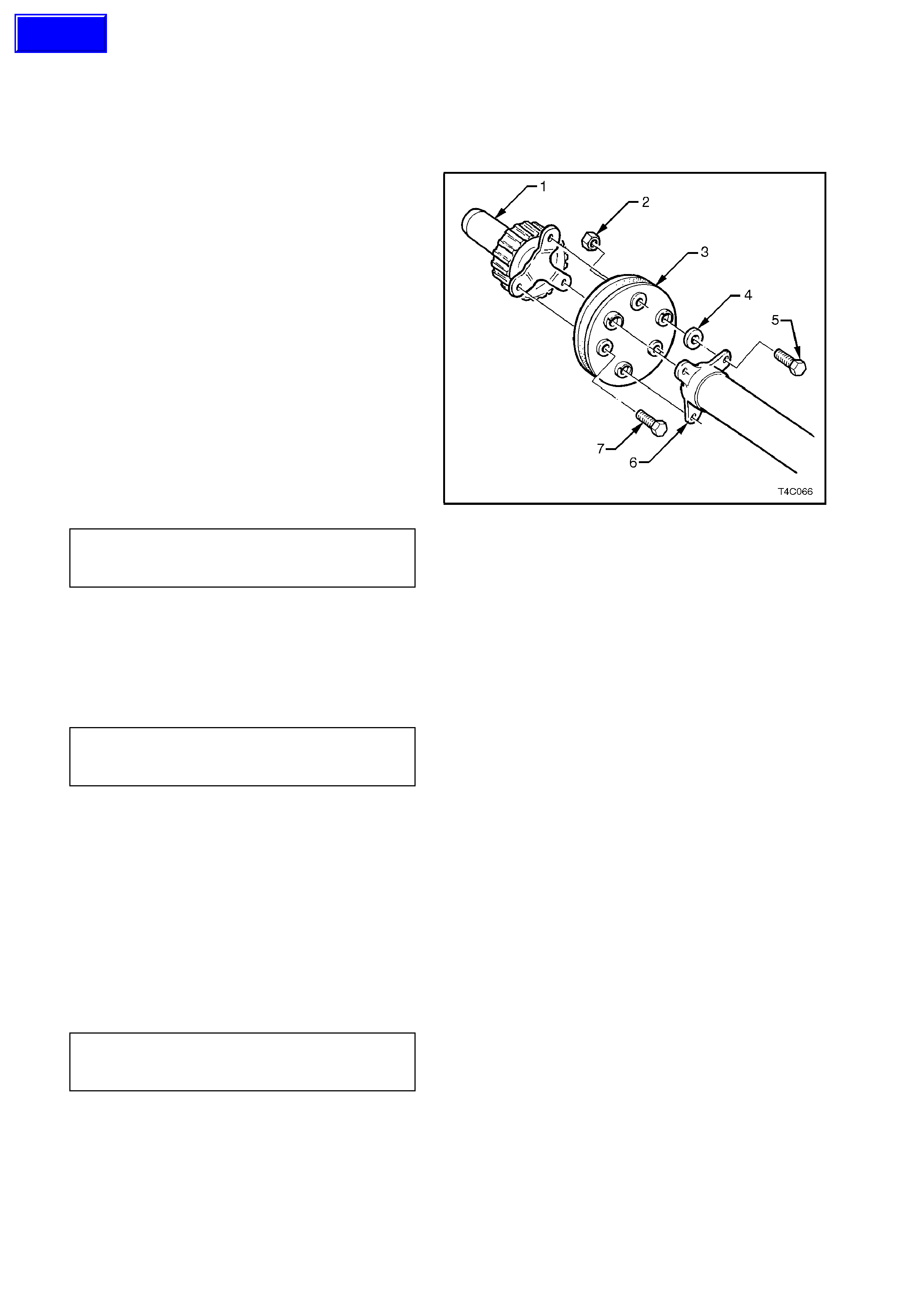
2. Insert a suitable lever between the flexible joint
(3) and the propeller shaft yoke (1) to secure
the assembly.
3. Loosen, then remove the three bolts (7)
holding the flexible joint (3) to the front sliding
yok e (1). Carefully rem ove the yoke and set to
one side to prevent accidental damage to the
toothed speed sensor ring.
4. Using a back-up spanner on the remaining
three bolt heads (5), remove the r etaining nuts
(2) from the front of the flexible joint and
discard them. Remove each bolt, taking note
of the spacer (4) between the front of the
propeller shaft (6) and the flexible joint.
5. Install a replacement flexible joint and fit the
bolts and spacer s to sec ure the propeller shaft
to the joint. Using new nuts (2) , tighten each to
the correct torque specification.
PROPELLER SHAFT TO
FLEXIBLE JOINT NUT 74 - 80 Nm
TORQUE SPECIFICATION
6. Apply thread sealant such as Loctite 242 or
equivalent to the cleaned threads of the
remaining three bolts (7). Install the bolts into
the front sliding yoke (1) and tighten to the
correct torque specification.
FLEXIBLE JOINT BOLT TO FRONT
SLIDING YOKE 74 - 80 Nm
TORQUE SPECIFICATION
Figure 4C-21
V6 Engine, Manual Transmission
1. Insert a suitable lever between the flexible
joint and the propeller s haf t yoke to s ec ure the
assembly.
2. Using a back-up spanner on the three bolt
heads, remove the retaining nuts and discard
them.
3. Install a replacement flexible joint, fit the bolts
and new nuts, tightening each to the correct
torque specification.
PROPELLER SHAFT TO
FLEXIBLE JOINT NUT 74 - 80 Nm
TORQUE SPECIFICATION
Techline
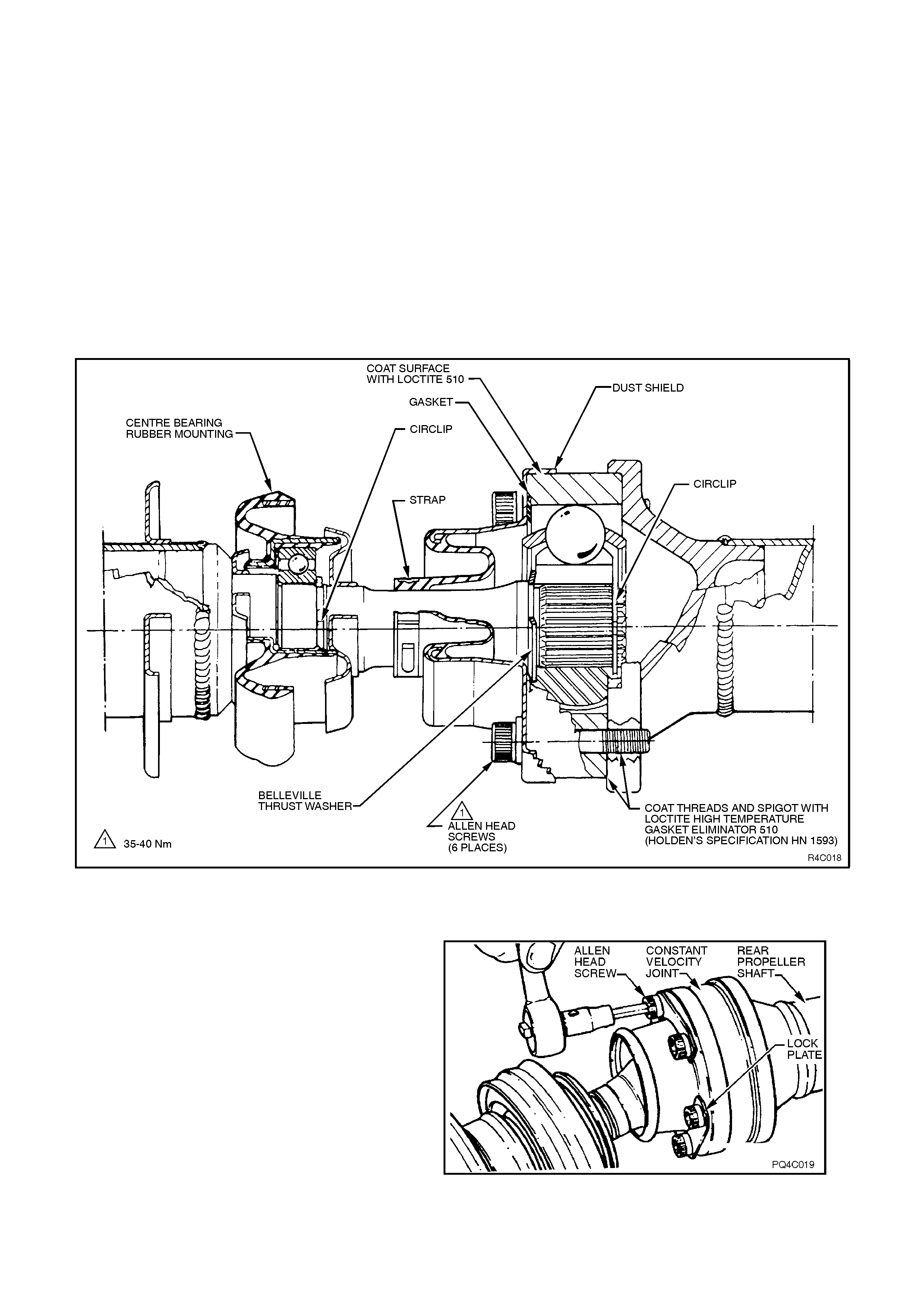
2.4 CONSTANT VELOCITY JOINT
There are two repair kits available from authorised
Holden parts outlets, for constant velocity joint
repairs:
a. A DUST SHIELD KIT, which contains dust
shield, gasket, strap, and tubes of grease
and sealant.
b. A CONSTANT VELOCITY JOINT KIT,
which contains the same items as in the
DUST SHIELD KIT, plus the constant
velocity joint and appropriate retaining
circlips.
REMOVE
Figure 4C-22
1. Remove propeller shaft. Refer to
2.1 PROPELLER SHAFT in this Section.
2. To ensure correct alignment of parts at
reassembly, scribe an aligning mark on
constant velocity joint and two propeller shaft
halves.
3. Remove Allen head screws and lock plates
holding rear propeller shaft half to constant
velocity joint.
Figure 4C-23
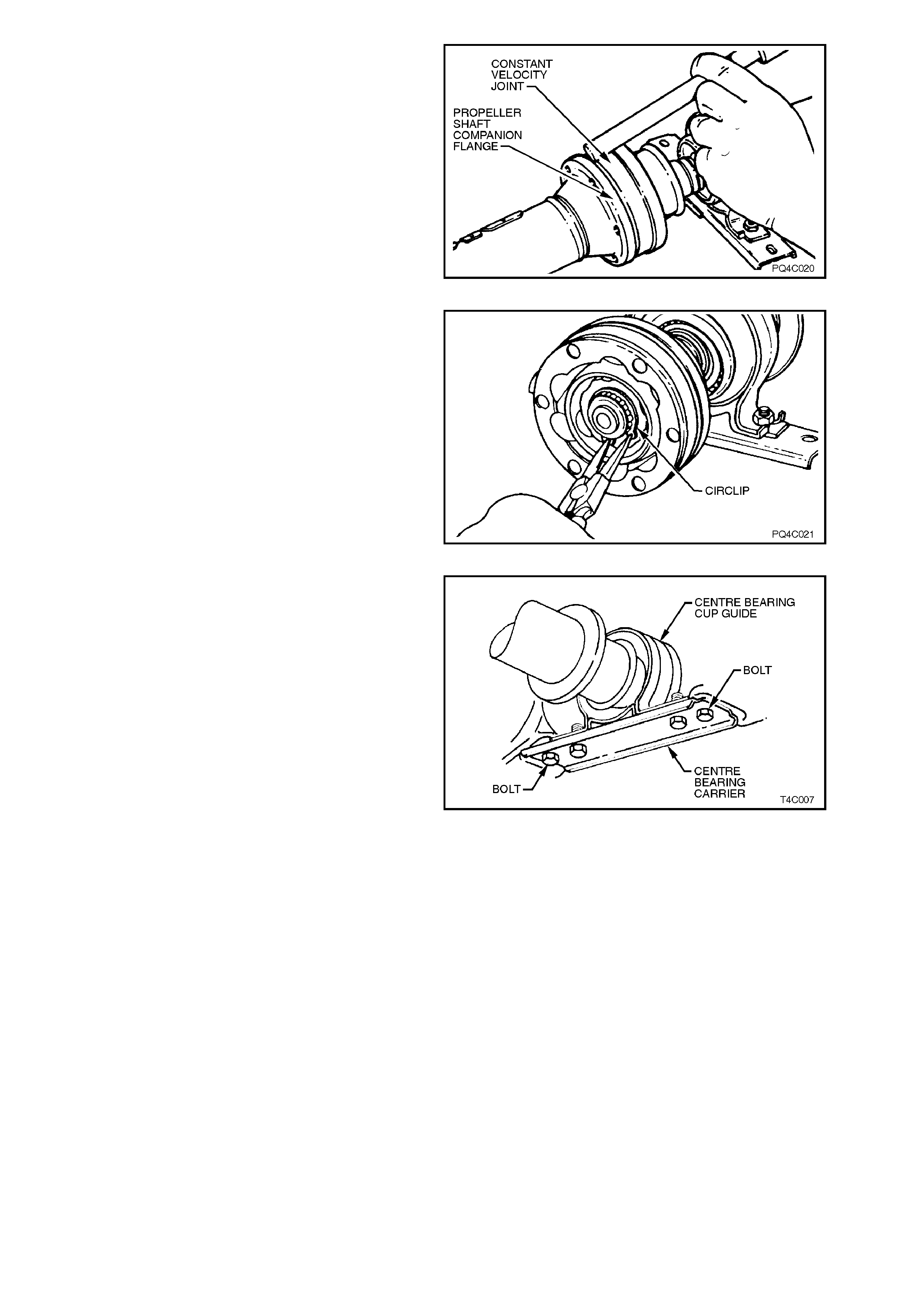
4. Using a hammer and a brass drift, tap
propeller shaft companion flange evenly from
constant velocity joint.
Figure 4C-24
5. Remove constant velocity joint rear retaining
circlip.
Figure 4C-25
6. Remove dust shield strap. Using a hammer
and brass drift, remove dust shield from
constant velocity joint.
7. Remove centre bearing carrier to centre
bearing cup attaching bolts and nuts, remove
carrier.
Figure 4C-26
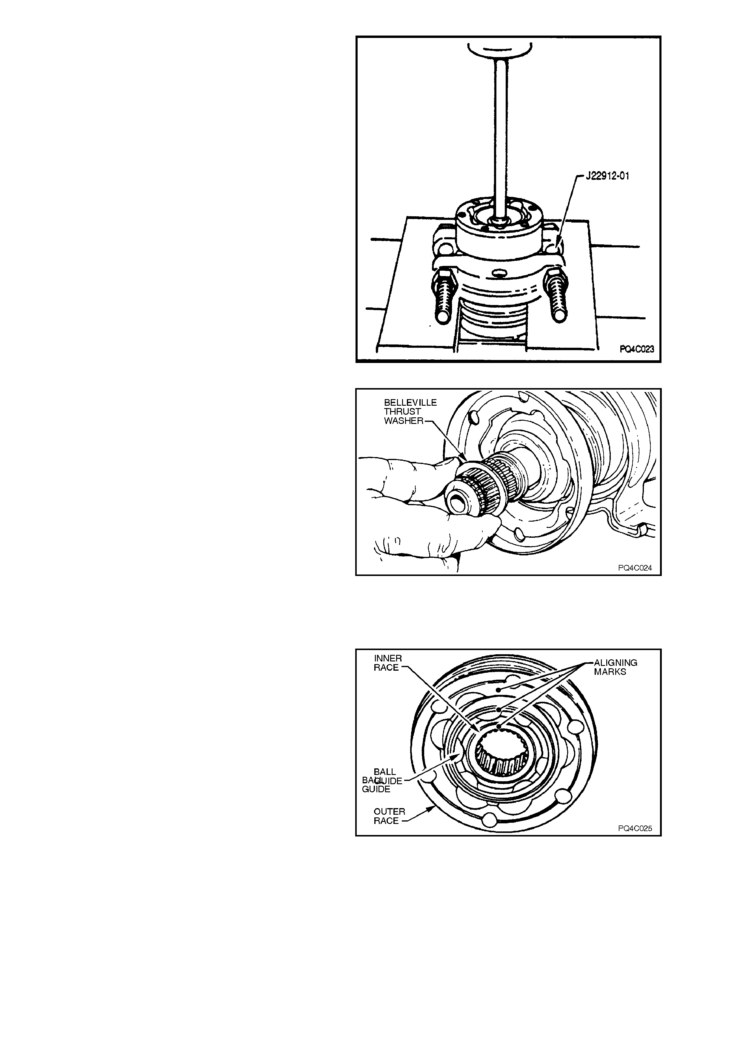
8. Pull back constant velocity joint outer race.
Install suitable press plates, such as J22912-
01 or equivalent, between dust shield and
constant velocity joint, to support inner joint
race. Press shaft from constant velocity joint.
Figure 4C-27
9. Remove thrust washer and dust shield from
propeller shaft.
10. Clean old gask et material f r om dust s hield and
constant velocity joint mating surfaces.
Figure 4C-28
DISASSEMBLE
NOTE:
Comp lete disass embly of the constant velocity joint
is not recom mended. The internal components are
a precision fit and develop their own characteristic
wear patterns. Intermix ing components could result
in looseness, binding and/or subs equent prem atur e
failure of the joint.
If disassembly must be attempted, then it is vital
that the following procedure is carefully followed.
1. Make an aligning mark on inner race, ball
guide and outer race with a daub of paint, as
shown.
NOTE:
The groove in the inner race, the larger chamfer in
the ball guide and the step in the outer rac e ( s tep is
for the dust shield to joint gasket), all face toward
the front of the propeller shaft.
Figure 4C-28
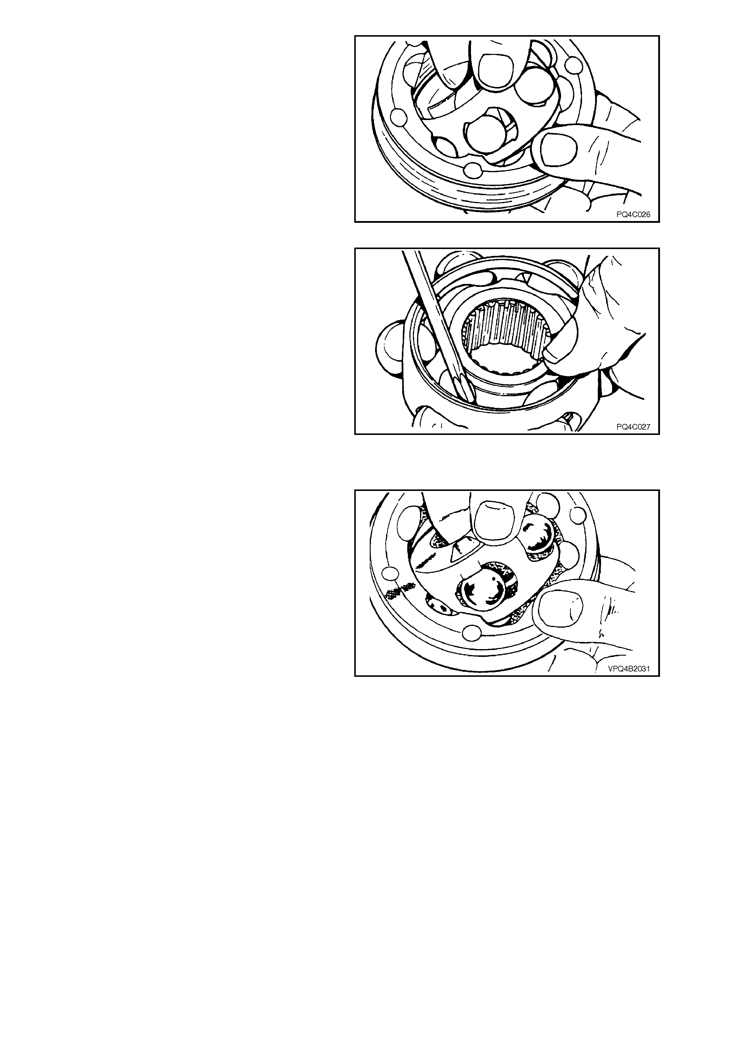
2. Pivot inner race and ball guide at 90° to centre
line of outer race as shown, and lift inner race
and ball guide from outer race.
Figure 4C-29
3. Using a sc rewdriver, lever balls f rom guide, as
shown.
KEEP BALLS IN ORDER FOR RE-ASSEMBLY.
4. Pivot inner race at 90° to centre line of ball
guide and lift inner race from ball guide.
Figure 4C-30
INSPECT
1. Inspect grease in joint, and if obviously
contaminated and/or been subjected to dirt
ingress, the joint has in all likelihood suffered
damage and should be replaced.
If inspec tion reveals that the j oint has not been
contaminated, clean joint by soaking in a
suitable cleaning solvent.
2. Once grease has been removed, inspect
internal components by tilting inner race to one
side to expose each ball.
Replace joint assembly if there is severe
pitting, galling, play between balls and the
cage windows, any cracking or damage to
cage, pitting or galling or chips in raceways. Figure 4C-31
REASSEMBLE
NOTE 1:
During the removal, cleaning, inspection or
replacement of a constant velocity (CV) joint, it is
possible for the joint to become disassembled.
Should an inadvertent disassembly of a constant
velocity joint occur, and notwithstanding the earlier
recommendation, it is possible to reassemble the
CV joint, provided the following procedure is
followed EXACTLY.
NOTE 2:
Under no circumstances may components from
one constant velocity joint be mixed with
components from another CV joint.
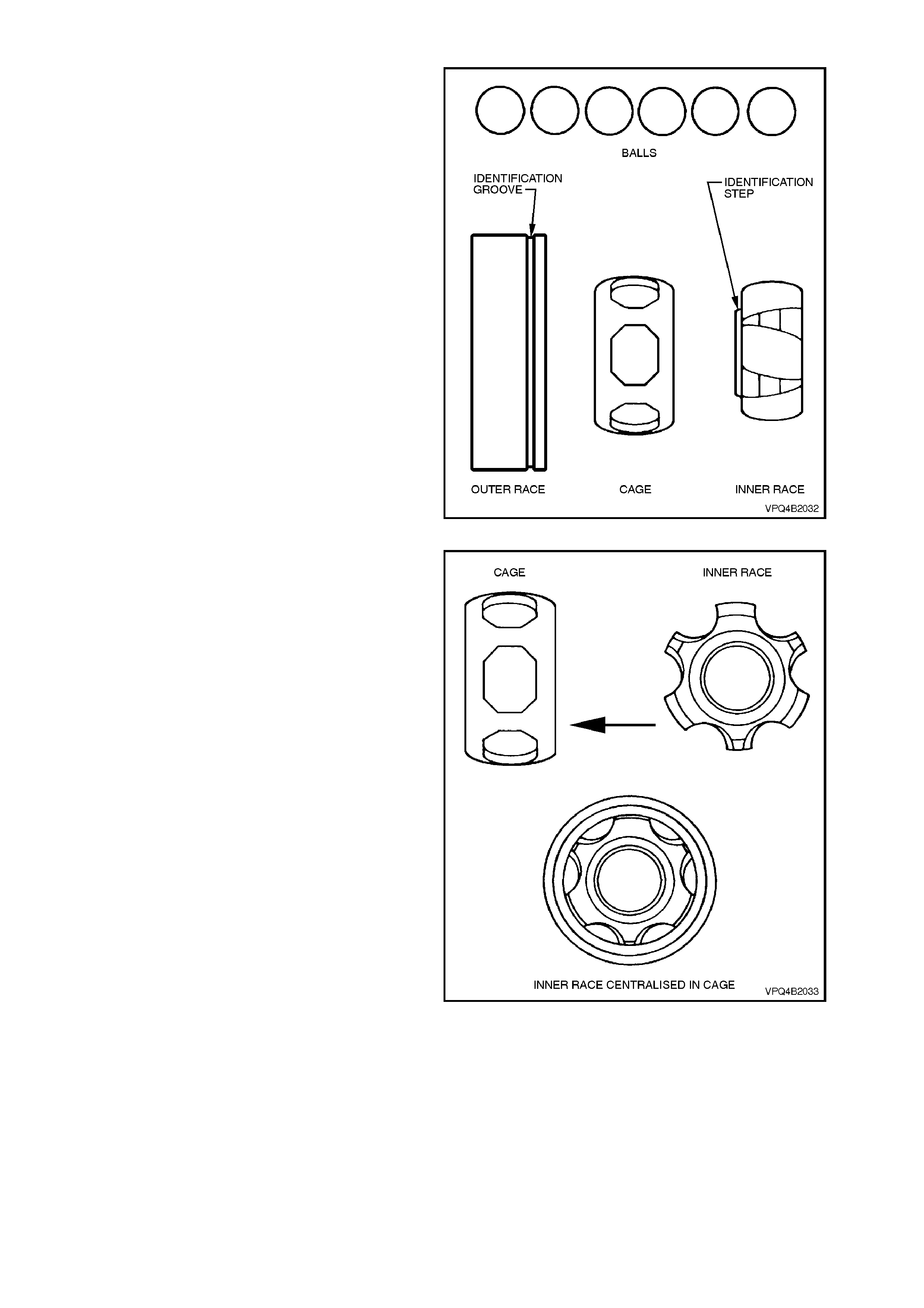
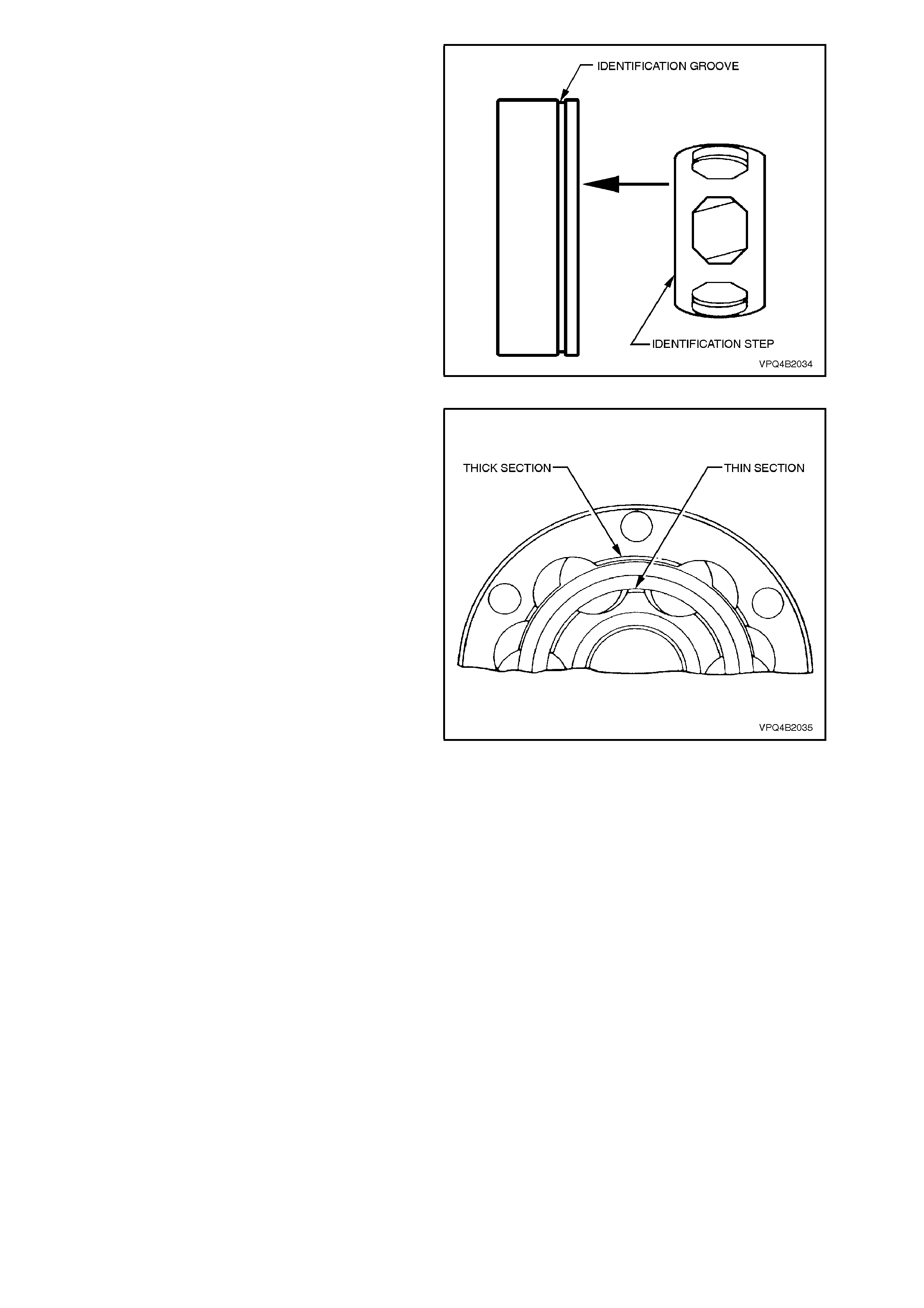
An exploded view of the constant veloc ity joint is as
shown. Note the identification groove on the outer
race and the identification step on the inner race.
Figure 4C-32
1. Place the inner rac e into the cage and position
centrally within the cage.
Figure 4C-33
2. Place the inner race and cage into the outer
race. Make sure that the identification
markings on both the inner and outer races
are on opposite sides of the assembly, as
shown.
Figure 4C-34
3. Align the thick sections on the outer rac e, with
the narrow ones on the inner race.
Figure 4C-35
4. Tilt the cage and inner race as shown, and fit
one ball.
Repeat this process for the remaining five
balls.
Figure 4C-36
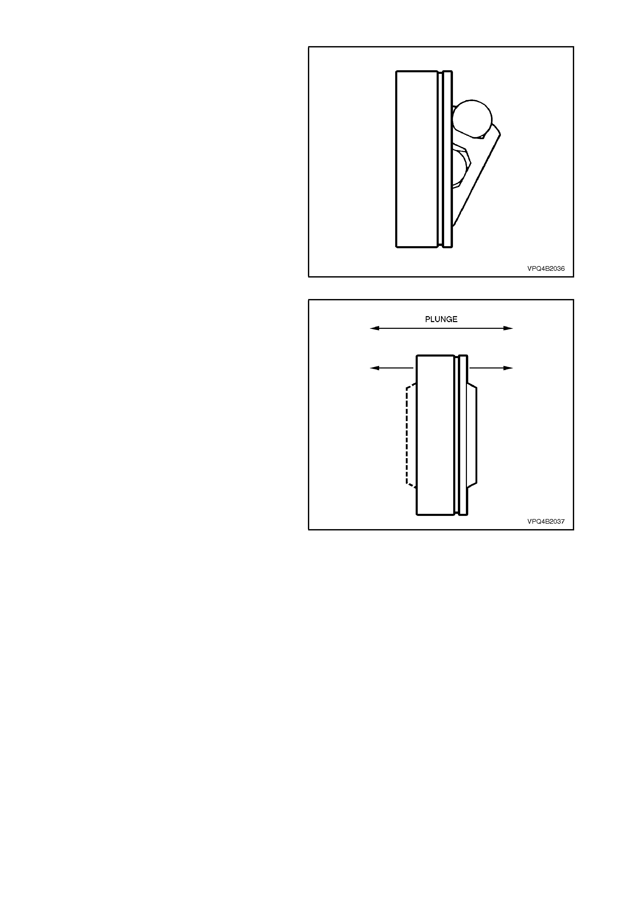
5. When assembly of the CV joint is complete,
check for plunge movement as shown. If NO
plunge movement can be achieved, then
the constant velocity joint has been
INCORRECTLY assembled.
If suc h a s ituation occ urs , the CV j oint must be
disassembled and the assembly process
repeated until such time that the required
plunge movement is achieved.
Figure 4C-37
REINSTALL
Installation is the reverse of removal procedure,
noting the following points:
1. Cleanliness of constant velocity joint and
associated parts is of prime importance to
ensure maximum life of joint assembly.
2. Inspect dust shield to ensure there is no
damage which will allow foreign matter entry.
3. Pack the constant velocity joint with the
lubricant supplied in either of the two available
Repair Kits. Work joint by hand so as to
distribute grease onto all surfaces inside joint.
4. Install new gasket to front of constant velocity
joint.
5. Clean mating surfaces of constant velocity
joint, dust shield and rear propeller shaft
companion flange.
6. Apply a bead of Loc tite 510 High T em peratur e
Gasket Eliminator sealant or equivalent
product (Holden's Specification HN1593) to
dust shield mating surface on the constant
velocity joint, refer to Figure 4C-22 for the
location.
7. Ensure that scribed lines made on removal,
are aligned.
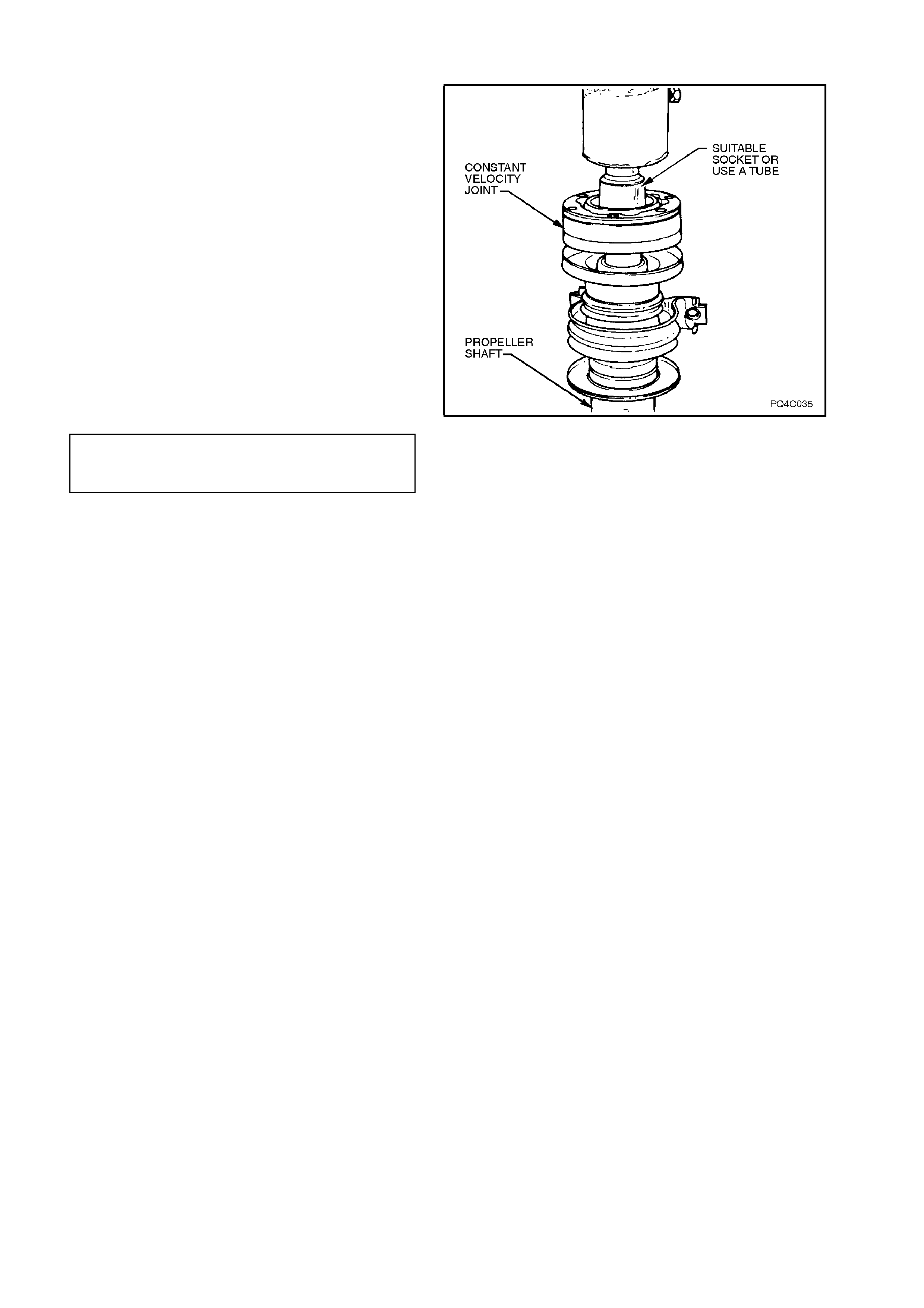
8. Press cons tant velocity joint onto shaf t using a
suitable size socket or tube. Ensure that
socket or tube presses on inner race of joint.
NOTE:
During this pressing operation, ensur e that the ears
of the front propeller shaft (and not the front yoke)
are resting on the press plates.
9. Clean threads in rear propeller shaft
companion flange and six Allen head screws.
10. Coat spigot area of propeller shaft com panion
flange and six Allen head screw threads with
Loctite 510 High Temperature Gasket
Eliminator sealant or equivalent product
(Holden's Specification HN1593), refer to
Figure 4C-22.
11. Tighten six Allen screws to the correct torque
specification.
CONSTANT VELOCITY JOINT TO
REAR PROPELLER SHAFT SCREW 35 - 40 Nm
TORQUE SPECIFICATION
12. Reinstall propeller shaft. Refer to
2.1 PROPELLER SHAFT in this Section.
Figure 4C-38
2.5 CENTRE BEARING ASSEMBLY
NOTE 1:
This bearing cannot be rem oved f rom the propeller
shaft without causing damage to the ball race and
rear dust s linger. New parts must be ins talled when
the propeller shaft is being reassembled.
NOTE 2:
The replacement centre bearing kit contains front
and rear dust slingers, centre bearing and rubber
cup assembly and centre bearing retaining circlip.
REMOVE
1. Remove propeller shaft, refer to
2.1 PROPELLER SHAFT in this Section.
2. Remove constant velocity joint, refer to
2.3 CONSTANT VELOCITY JOINT in this
Section.
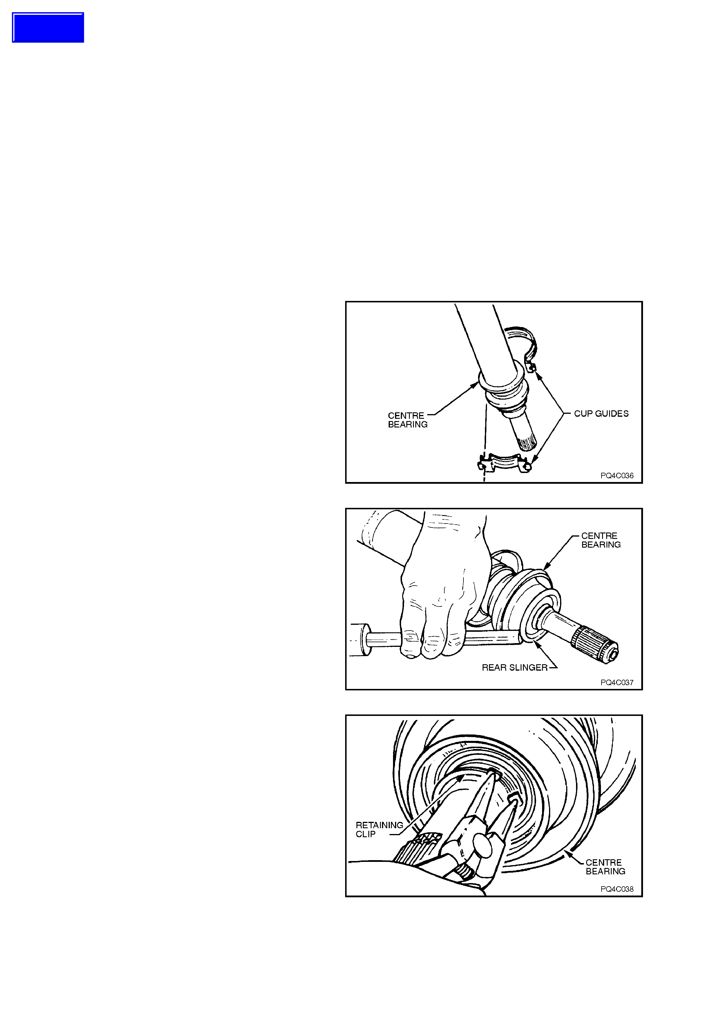
3. Remove the two bolts and nuts securing the
upper and lower cup guides to the centre
bearing carrier, bend back the retaining tabs (if
bent over) and separate cup guide halves from
centre bearing.
NOTE:
For correct reassembly, pay particular attention to
any spacer arrangement that may be fitted, noting
any side-to-side differences.
Figure 4C-39
4. Using a hammer and a suitable punch,
remove centre bearing rear slinger, refer to
Figure 4C-41.
NOTE:
Once removed, the slinger must be discarded and
a new one installed on reassembly.
Figure 4C-40
5. Remove centre bearing retaining circlip.
Figure 4C-41
Techline
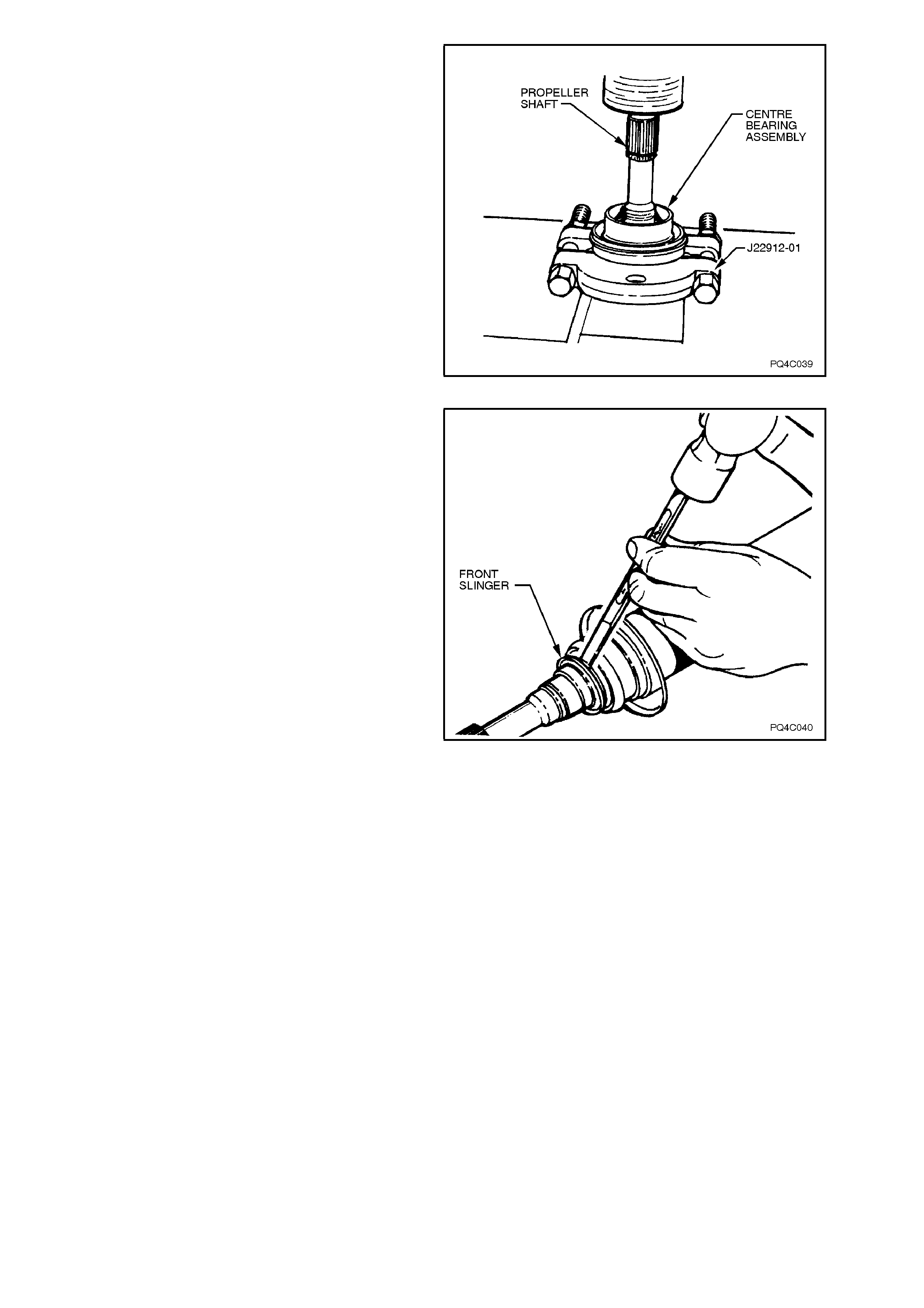
6. Using suitable press plates, such as Tool No.
J22912-01 or equivalent, support centre
bearing and rubber c up m ounting assem bly as
close as possible to propeller shaft, press
propeller shaft from centre bearing.
NOTE:
Take car e not to damage the large diameter s linger
which is fixed to the front propeller shaft tube.
Figure 4C-42
7. Remove centre bearing front slinger using a
hammer and a suitable punch or chisel, take
care not to damage propeller shaft.
NOTE:
The slinger must be discarded once it is removed
and a new one installed on reassembly.
Figure 4C-43
REINSTALL
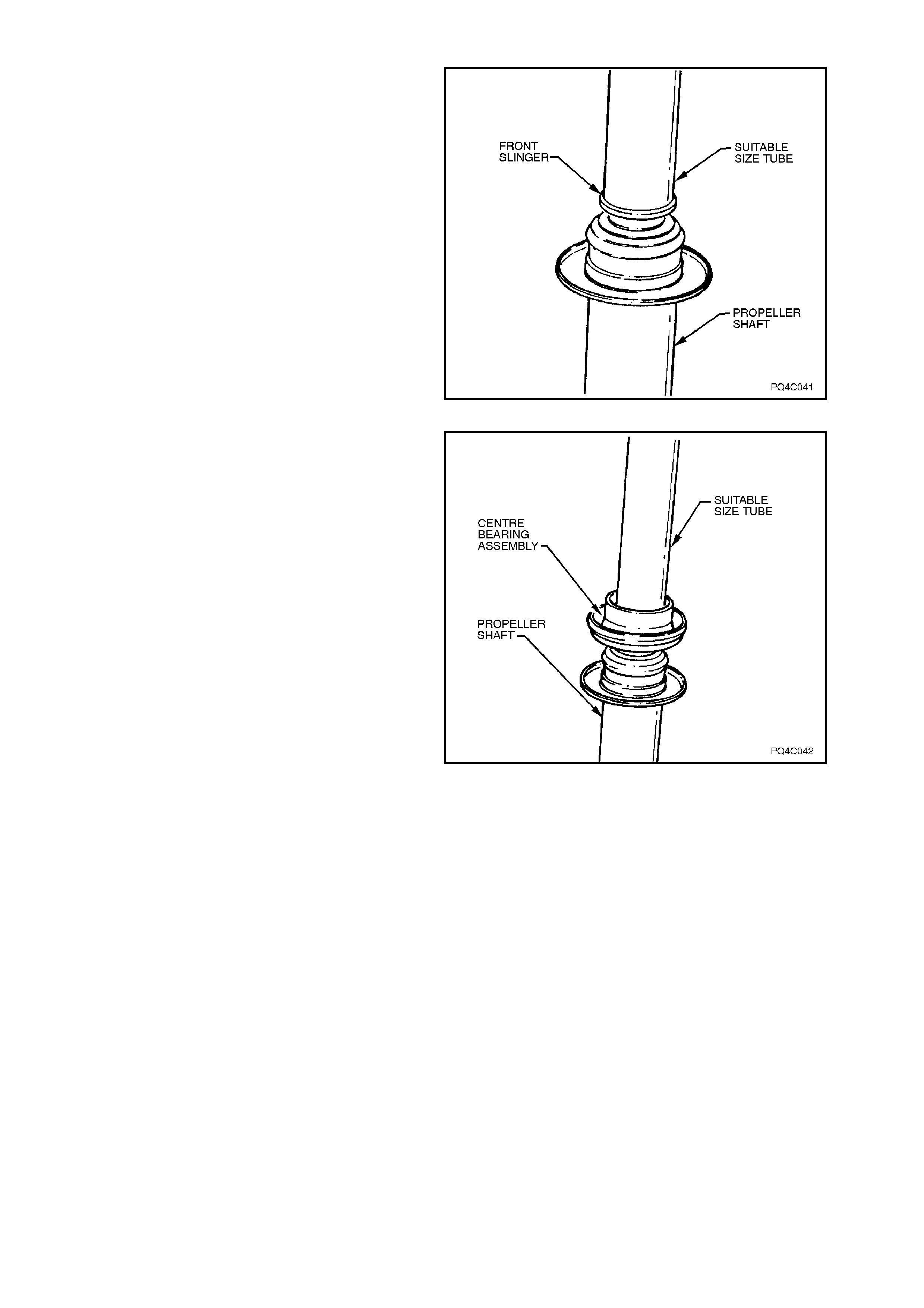
1. Install new front slinger onto front propeller
shaft using a suitable size tube, as shown.
NOTE:
During this operation, ensure that the ears on the
front end of the propeller shaft (and not the front
yoke) are resting on the press plates.
Figure 4C-44
2. Install new centre bearing assembly to
propeller shaft using a suitable size tube.
Figure 4C-45
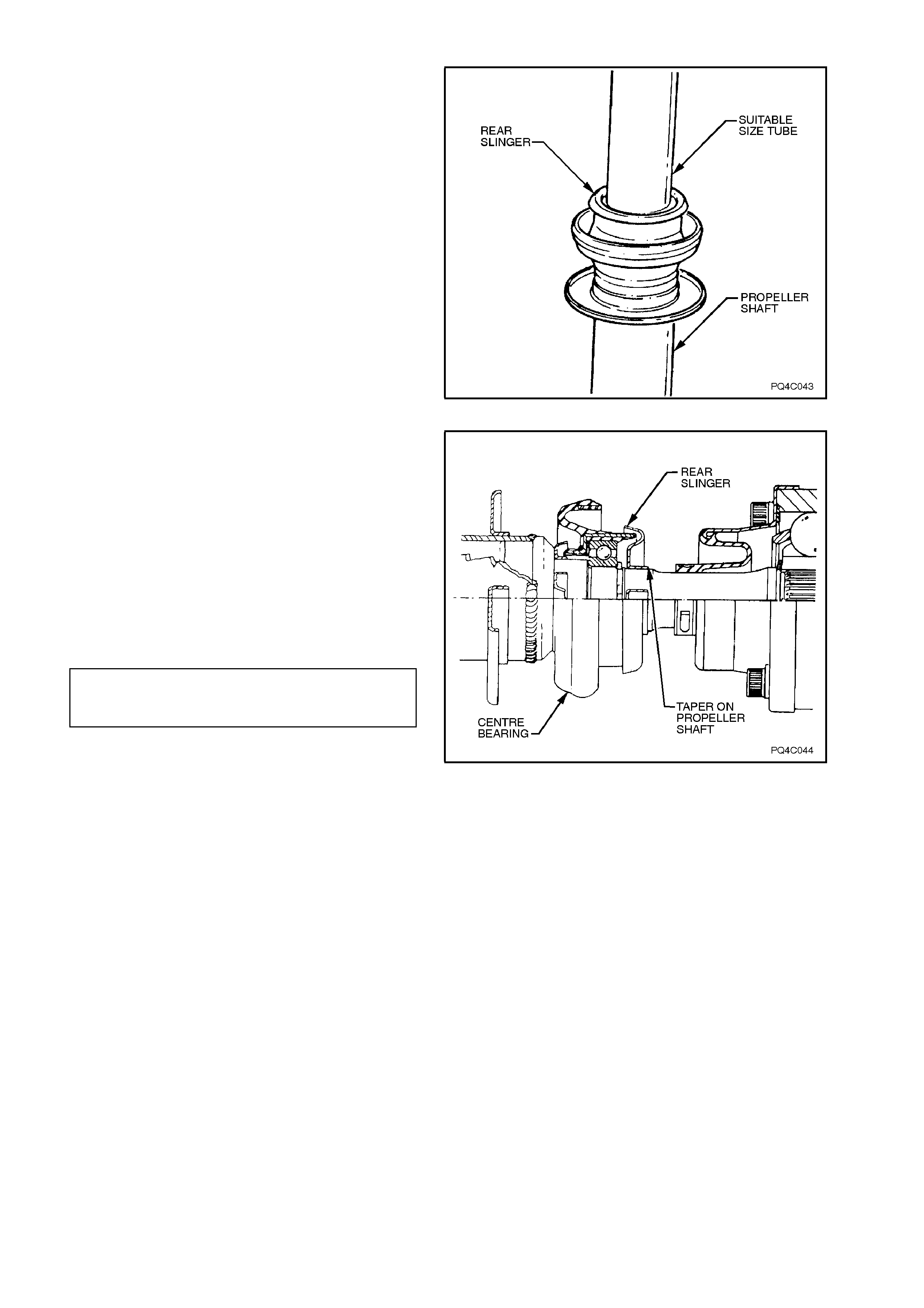
3. Install new rear slinger using a suitable size
tube.
Figure 4C-46
NOTE:
If the rear slinger is installed on too far, the slinger
and centre bearing cup will rub.
The slinger is correctly installed when in the
position as shown.
4. Install bearing upper and lower cup guides to
centre bearing.
5. Install spacer/s, if previously fitted and
retaining bolts and nuts to the centre bearing
carrier and tighten to the correct torque
specification.
CENTRE BEARING CUP GUIDE TO
CARRIER BOLTS AND NUTS 20 - 25 Nm
TORQUE SPECIFICATION
6. Reinstall constant velocity joint. Refer to
2.3 CONSTANT VELOCITY in this Section.
7. Reinstall the propeller shaft. Refer to
2.1 PROPELLER SHAFT in this Section.
8. Check propeller shaft phasing. Refer to
2.6 CHECKING PROPELLER SHAFT
PHASING in this Section.
Figure 4C-47
2.6 CHECKING DRIVELINE ANGLES
MEASURING PROCEDURE
The following procedure is used for investigating
driveline related vibrations in VT Series models
fitted with the 4L60-E automatic transmission,
where incorrect driveline angles are suspected.
NOTE:
This procedur e is not s uitable f or meas uring angles
on drivelines fitted to m anual transmission models,
as there is no needle roller bearing, front universal
joint, from which to take angular readings.
The following checks should be conducted before
carrying out the driveline angles measuring
procedure:
Inspect all universal joints and centre bearing for
wear; i.e. dust seals broken, retaining snap rings
broken or any movement in the universal joints or
centre bearing.
Check engine and transmission mountings and
tightness of all bolts.
Check that the centre bearing spacers (where
fitted) are in plac e and in the c orr ect location. Ref er
to Figure 4C-1 for details.
Check condition of all rear suspension control arm
bushes and tightness of attachments.
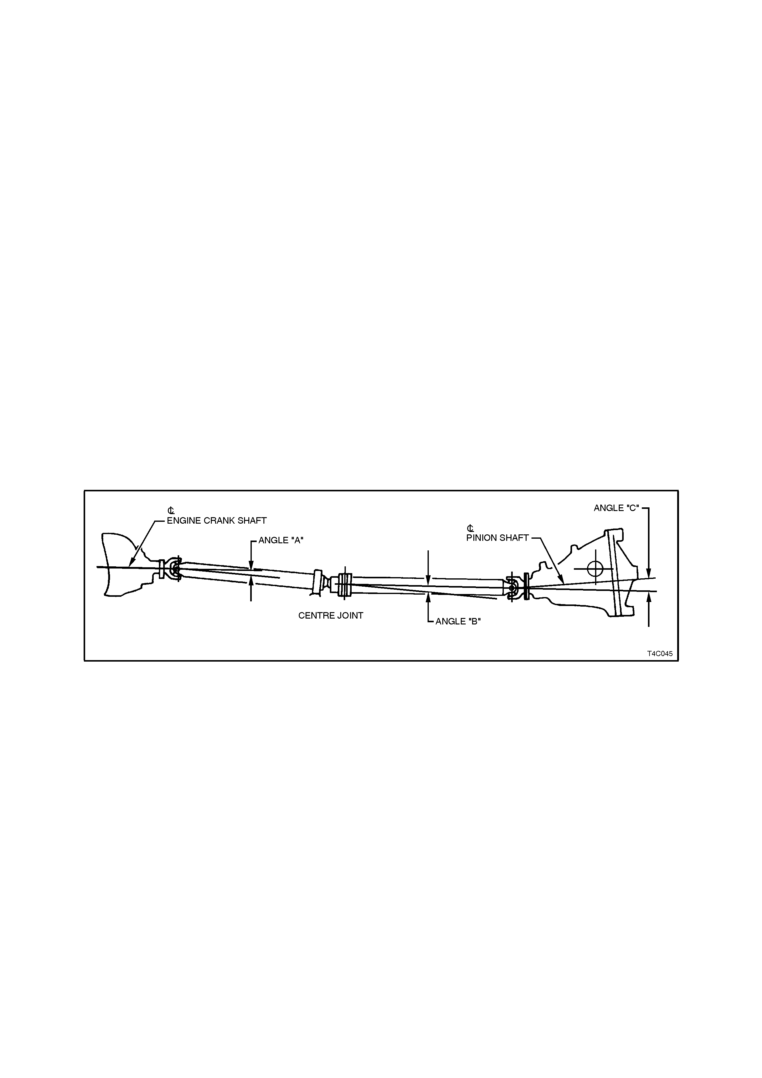
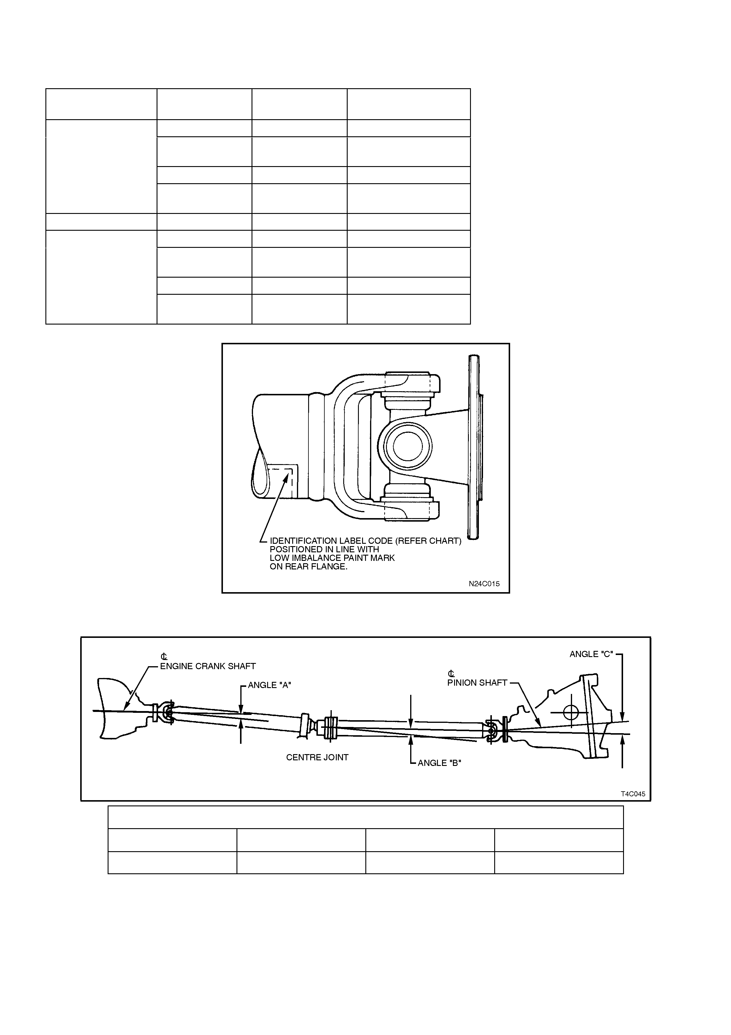
The nex t illustration s hows the driveline angles that
need to be measured.
Figure 4C-48
1. Place vehicle over a pit or on a f our pos t ‘drive
on' hoist. Leave transmission in neutral, park
brake off and chock front wheels.
NOTE:
It is im portant that the vehicle's weight is on all f our
wheels.
2. Ensure vehicle is at kerb weight, i.e. fuel tank
full, without driver, passengers or luggage etc.
3. Bounce rear of vehicle up and down to ensure
suspension has settled.
5. Remove chocks and push vehicle backwards
or forwards until pinion flange rear universal
joint bearing caps are vertical.
Chock wheels to prevent further vehicle
movement. Before carrying out rest of the
measuring procedure, note the following
points;
a. At no stage is the vehic le to be moved by
twisting the propeller shaft.
b. Ensure that all inclinometer readings are
taken from the right hand side of the
vehicle.
c. Mark all universal joint caps that
measurements are taken from so that
later measurements can be taken from
the same caps.
d. Ensure that univers al joint caps ar e clean
and free from paint and dirt.
e. Ensure that the magnet on the
inclinometer sits squarely on the
universal joint caps.
NOTE 1:
For vehicles fitted with the V6 engine, removal of
the engine pipes and catalytic converter will be
required to gain access to the front universal joint.
refer to Section 8B EXHAUST SYSTEM for the
necessary procedure.
NOTE 2:
Ensure that the inclinom eter is positioned and read
at each location with the 30 degrees (or 50 degrees
if inclinom eter is f itted with AU415 scale c onvers ion
kit) end of scale facing toward front of vehicle.
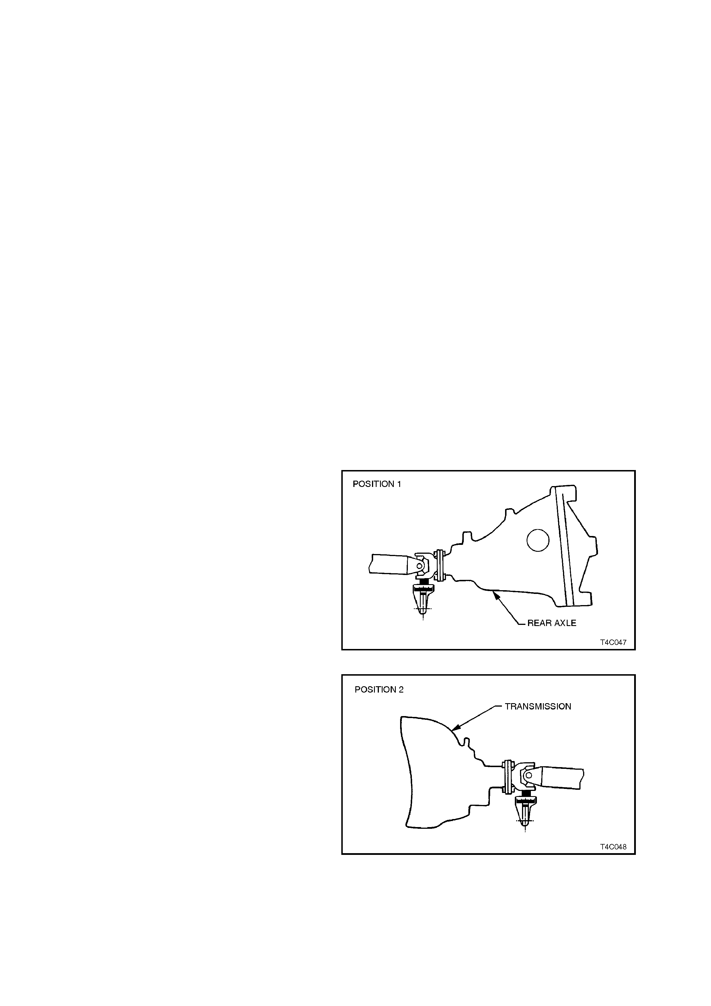
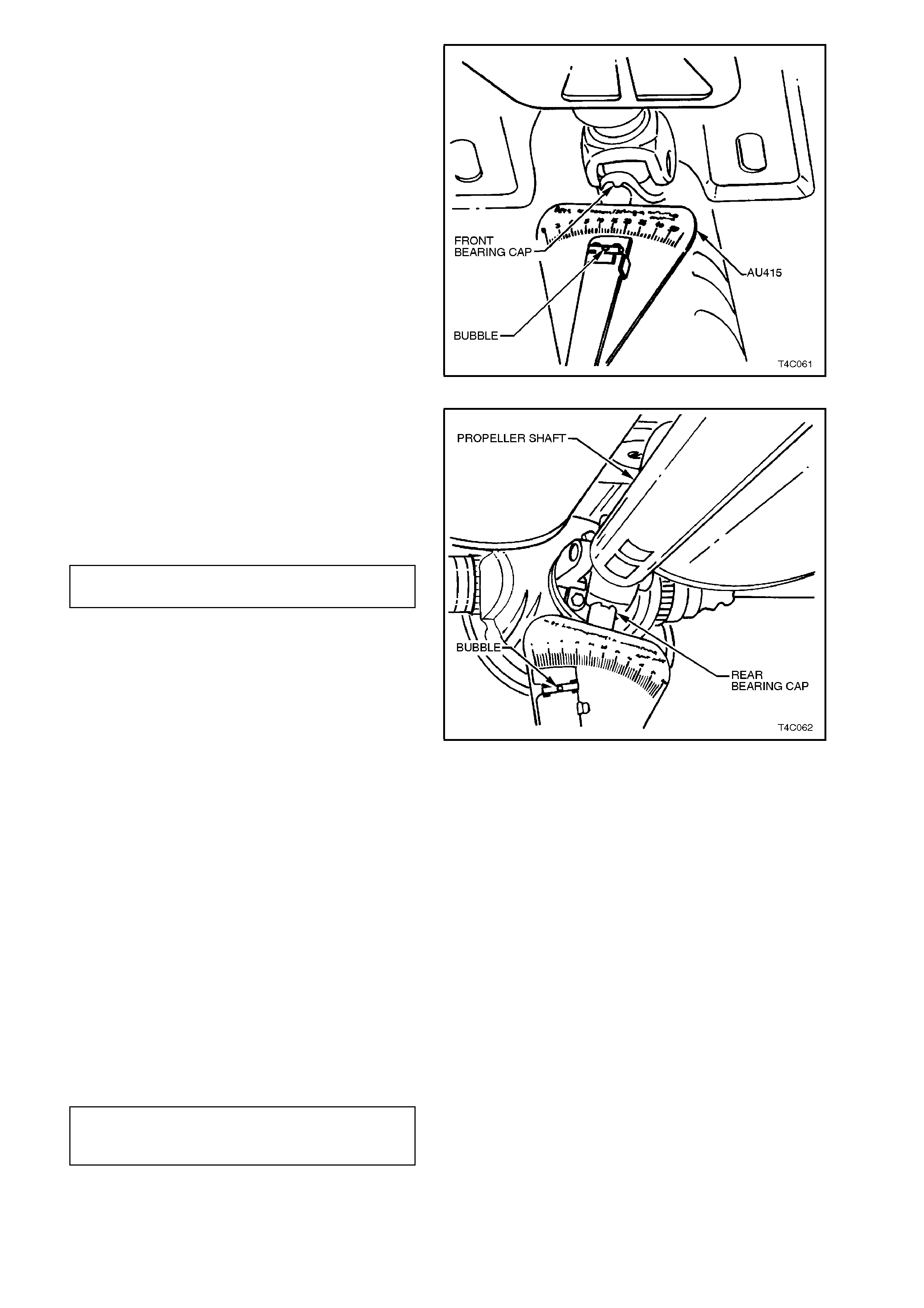
6. Install inclinometer, Tool No. J23498-A on
pinion flange rear universal joint bearing c ap.
Centralise bubble and record reading - this is
POSITION 1.
Figure 4C-49
7. Remove inclinometer, remove chocks and
push vehicle until propeller shaft front
universal joint yoke bearing cap is ver tical. Re-
chock wheels.
8. Install inclinometer on front universal joint
yoke bearing cap. Centralise bubble and
record reading - this is POSITION 2.
Figure 4C-50
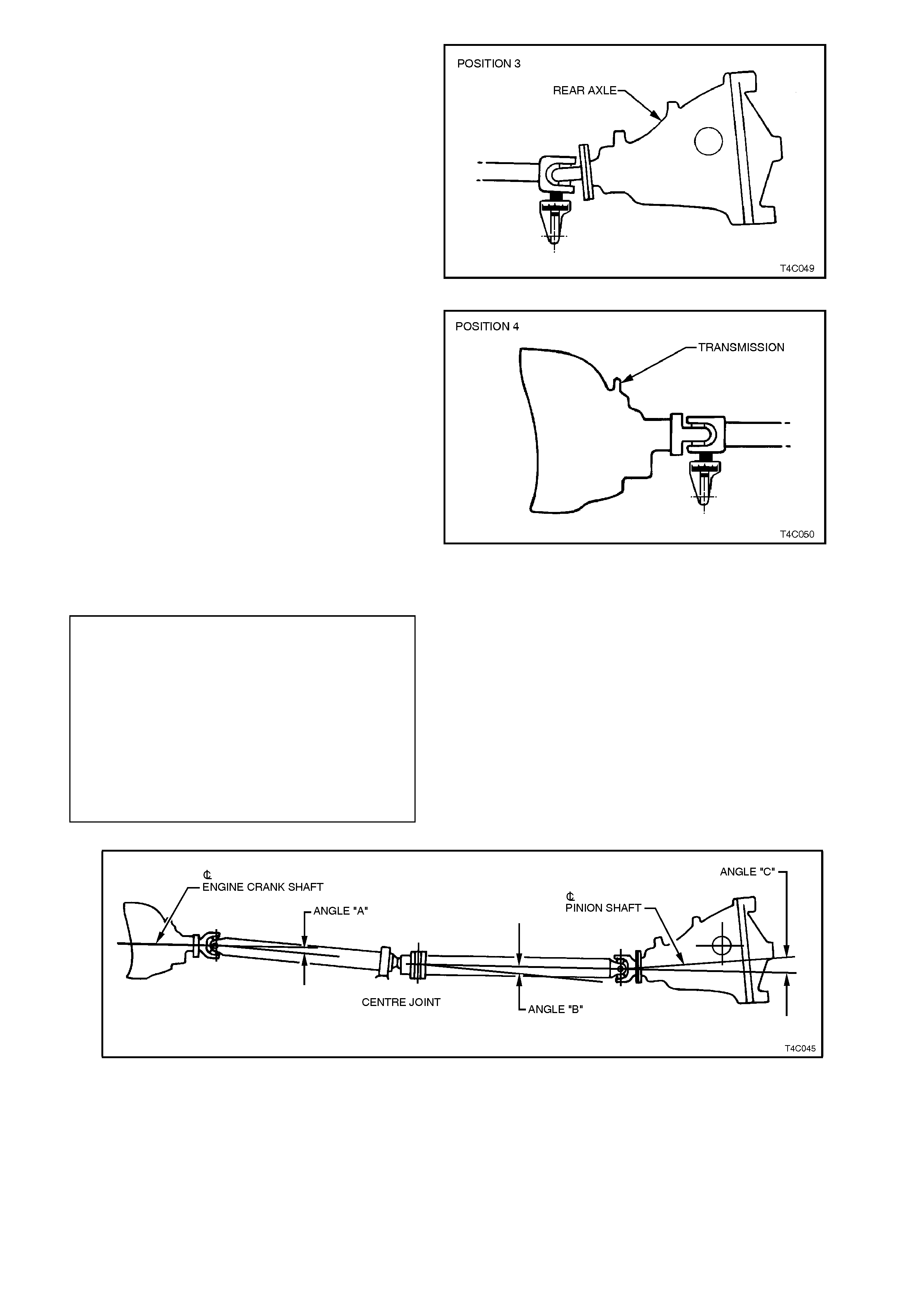
9. Remove inclinometer and chocks and roll
vehicle to rotate propeller shaft until bearing
caps in propeller shaft rear universal joint are
vertical.
10. Chock wheels and place inclinometer on rear
universal joint bearing c ap. Centralise bubble
and record reading - this is POSITION 3.
Figure 4C-51
11. Remove inclinometer, remove chocks and
push vehicle until the propeller shaft front
universal joint bearing caps are vertical. Re-
chock wheels.
12. Install inclinometer on propeller shaft front
universal joint bearing c ap. Centralise bubble
and record reading - this is POSITION 4.
Figure 4C-52
13. To calculate the driveline angles, refer to
Figure 4C-54 and use the following equations;
ANGLE A = POSITION 2 (step 8)
less POSITION 4 (step 12).
ANGLE B = POSITION 4 (step 12)
less POSITION 3 (step 10).
ANGLE C = POSITION 3 (step 10)
less POSITION 1 (step 6).
Refer to 3, SPECIFICATIONS in this Section
for nominal angles A, B and C.
Figure 4C-53
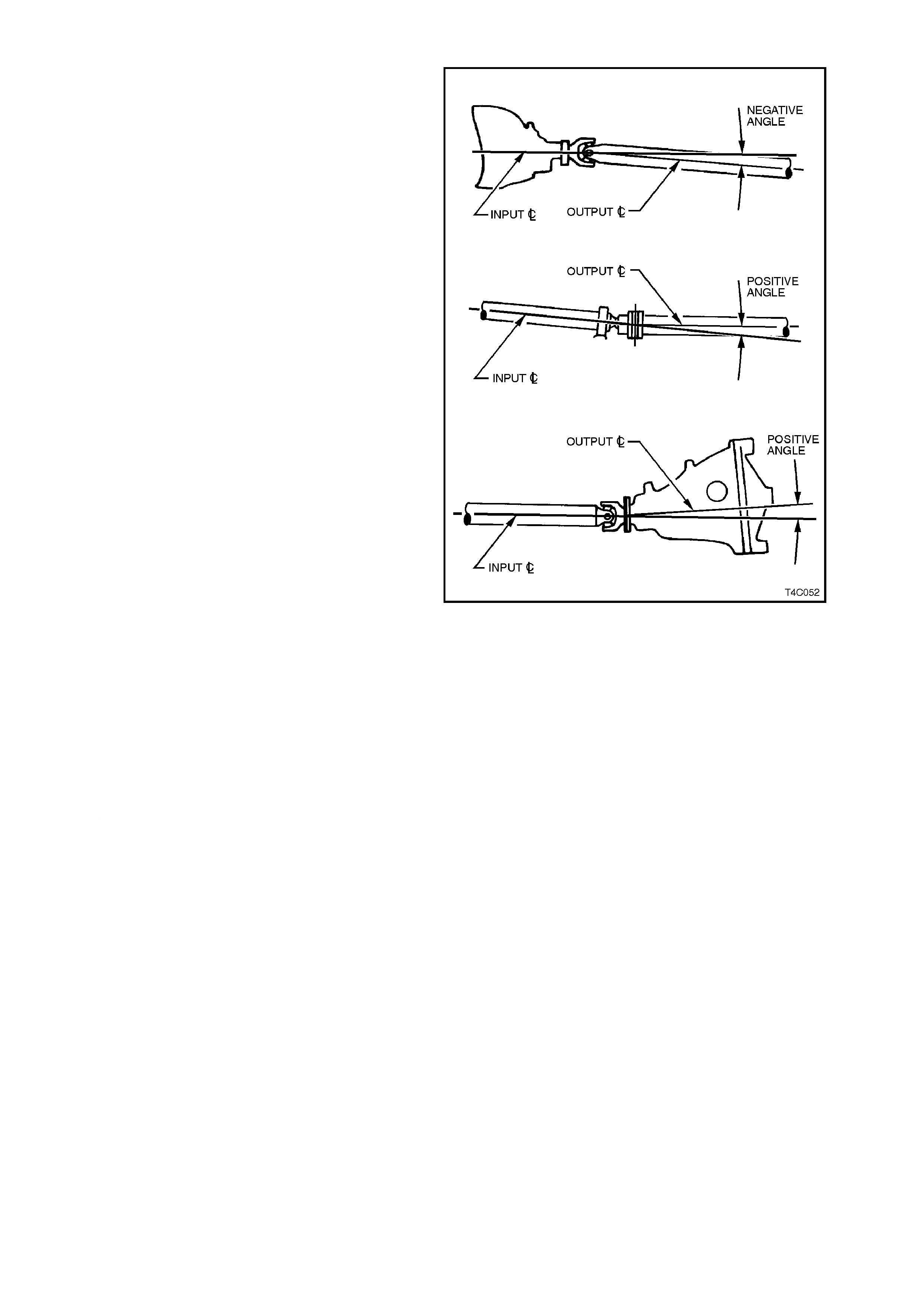
DRIVELINE ANGLE EVALUATION
To determine if a driveline angle is positive or
negative, refer to Figure 4C-55 and the following
explanation.
Determine whether the ‘output’ centreline of the
angle being considered, is either above of below
the ‘input’ centreline.
If the output centreline is above the input, then the
angle is considered positive. Alternatively, if the
output centreline is below the ‘input’ centreline,
then the angle is considered negative.
Examples:
Angle A: If the centreline through the front
propeller shaft is below that of the transmission
output shaft, then the angle will be negative, as
shown.
Angle B: With the centreline through the rear
propeller shaft being above the centreline of the
front propeller shaft, the driveline angle in this
situation will be positive.
Angle C: As the ‘output’ centreline through the f inal
drive pinion in the example shown, is above the
centreline of the rear propeller shaft section, the
angle again, will be positive.
Figure 4C-54
Driveline Angles Within Specification
If all angles are within specification and a vibration
condition exists at 20 - 30 km/h, then it may be
caused by one universal joint axis having a higher
rotational torque than the other. This can only be
evaluated after the propeller shaft has been
removed from the vehicle and each universal joint
rotational 'drag' evaluated.
1. Remove the propeller shaft assembly. Refer to
2.1 PROPELLER SHAFT in this Section.
2. Carefully move each universal joint through
each axis, to assess whether one cross is
more stiff than the other.
Should a higher rotational torque be determined in
one of the universal joints, then the following
procedure is recommended for all of the universal
joint bearing cups:
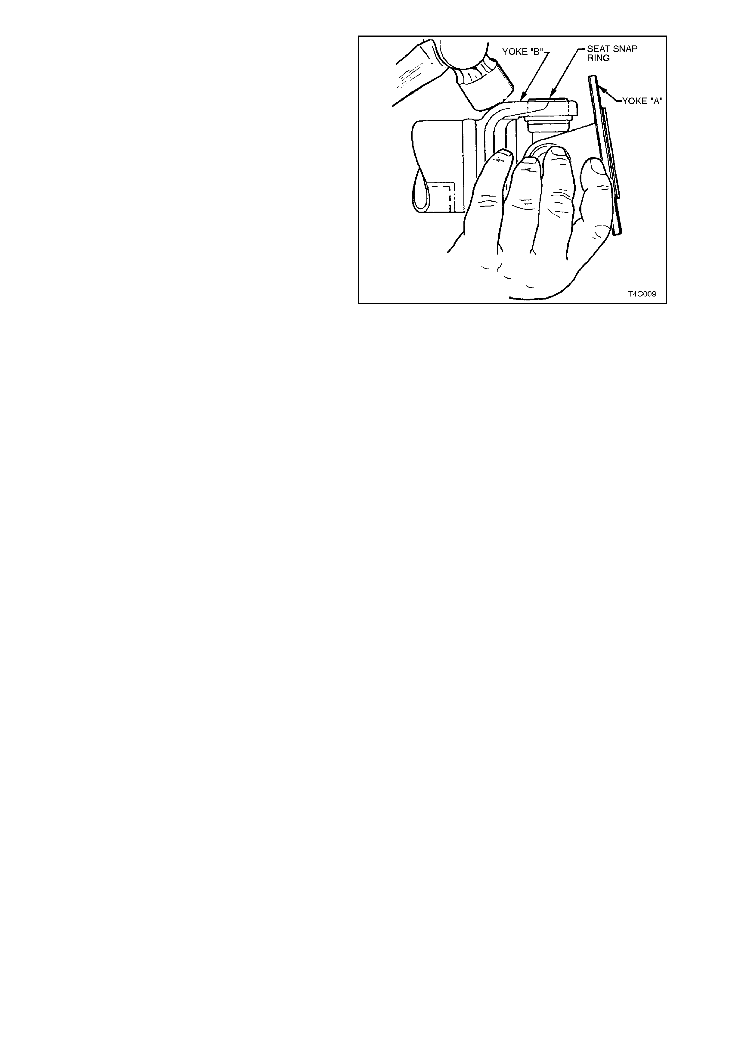
3. Support yoke 'A' in the palm of one hand, to
minimise the possibility of the needle rollers
being brinelled.
NOTE:
Yoke 'A' in the rear universal joint is the pinion
flange com ponent, while in the front universal joint,
yoke 'A' will be the slip joint.
4. Strike the forged part of yoke 'B' with a
hammer, to ensure that the snap ring is fully
seated. Take care not to strike the propeller
shaft tubing or any machined surfaces during
this process. With V8 and manual
transmission, take particular care that the
speed sensor toothed ring is not damaged in
any way during this process.
5. Repeat seating procedure with the opposite
cup.
6. Reverse the position of yokes 'A' and 'B' and
repeat the seating process described in steps
2 and 3.
7. Check that the rotational torque required for
each of the two pivot axes is now similar.
8. Should a check of the other universal joint
indicate that uneven rotation torque is evident,
then the procedure just described should also
be applied to the cups in that universal joint.
Figure 4C-55
9. Reinstall the propeller shaft assembly, as
described in 2.1 PROPELLER SHAFT, then
road test the vehicle to ensure that the
vibration condition has now been corrected.
Driveline Angles Outside Specification
NOTE:
The maximum allowable tolerance from
specification is ± 0.5°.
If driveline angles are not to specification, start by
raising or lowering the c entre bear ing r elative to the
underbody by adding, repositioning or subtracting
spacers between the centre bearing carrier and
underbody or between the centre bearing carrier
and centre bearing.
Raising the centre bearing by 7 mm will increase
Angle "A" (or make more positive) by +0.7°, and
increase Angle "C" (or make more positive) by
+0.6°.
NOTE:
Achievement of correct angle "B" (at constant
velocity joint) is not as critical as Angles "A" and
"C" for minimising noise and vibration.
W hen driveline angles are to specification, rem ove
inclinometer and reinstall the exhaust system.
Refer to Section 8B EXHAUST SYSTEM for
details.

SYMPTOMS AND CAUSES OF DRIVELINE ANGLE RELA TED PROBLEMS
1. Initial Acceleration Shudder - A pronounced shudder that occurs during forward acceleration could be
caused by an excessive angle "A".
2. Acceleration Delayed Shudder - A vehicle m ay accelerate sm oothly from stands till yet begin to shudder f rom
15 - 40 km/h. This condition is usually worse when the vehicle is heavily laden and can be caused by an
insufficient angle "C".
3. Boom or Rumble - Vehicles with an excessive angle "C" m ay suff er fr om cabin boom or rum ble f rom 40 k m /h
on overrun/coast. Condition is usually worse when vehicle has a minimal load in the rear. Acceleration in
reverse with an excessive angle "C" will cause severe driveline vibration.
Techline
2.7 CHECKING PROP E LLER SHAFT PHASING
Before attempting to diagnose propeller shaft
phasing induced vibrations check the following:
1. It is essential that driveline angles are set to
specification, refer to 2.6 CHECKING
DRIVELINE ANGLES in this Section.
2. Check that rear axle pinion flange and
propeller shaft rear universal joint flange
aligning marks are aligned as close as
possible.
3. Check that all propeller shaft assembly
attaching bolts and nuts are tightened to the
correct torque.
4. Road test vehicle and check for the following
symptoms:
a. "RUMBLE" noise and vibration
throughout vehicle speed range, usually
worse during "float" or "overrun"
conditions.
b. At higher speeds, a "BEAT" may develop.
NOTE:
A rumble is a constant sound, e.g. 'the rumble of
distant thunder', whereas a beat is a low frequency
cycling of the rumble noise.
If the vehicle exhibits any of the symptoms noted in
step 4, the next step is to measure the propeller
shaft phas e angle, using the inclinom eter, Tool No.
J23498-A.
NOTE:
As the phase angle specification does not exceed
37 degrees, use of the conversion scale AU415 is
not required for VT Series vehicles.
1. Place vehicle over a pit or on a f our post 'dr ive
on hoist'. Leave transmission in neutral and
park brake off. Vehicle weight must be on all
four wheels.
2. Disconnect exhaust system from rear of
catalytic converter (V6) or converters (V6
Supercharged or V8). Discard gaskets on the
V6 Supercharged/V8 flanges.
NOTE:
Only one flange of the V6 Superc harged/V8 s ystem
is shown.
Figure 4C-56
Techline
4. Remove the two retainers from the top posts
and discard. Disconnect exhaust system
support rings from rear hanger of the rear
muf fler. Both V6 and V8 arrangem ents are the
same.
Figure 4C-57
5. Remove muffler support to rear crossmember
retainers (2 places - V6, 4 places-V6
Supercharged and V8) and discard.
6. Lift up intermediate section of exhaust system
and remove supports from muffler and
crossmember hangers. Then remove
intermediate and rear sections of exhaust
system from beneath vehicle.
Figure 4C-58
7. Push vehicle backwards or forwards until
propeller shaft front universal joint yoke
bearing caps are vertical, refer to Figure 4C-
60.
Figure 4C-59
8. Place inclinometer on propeller shaft front
universal joint bearing cap with scale facing
toward front of vehicle. Chock rear wheels to
prevent vehicle movement.
9. Move inclinometer arm to centralise bubble
and note reading.
Figure 4C-60
10. Remove inclinometer from front universal joint
bearing cap and install onto propeller shaft
rear universal joint bearing cap.
11. Move inclinometer arm to centralise bubble
and note reading.
12. Subtract this reading fr om the reading taken in
step 5 to give propeller shaft phase angle.
PROPELLER SHAFT PHASE
ANGLE SPECIFICATION 0.0 ° ± 7.5 °
NOTE:
A positive phase angle indicates that the rear
universal joint leads the front, whereas a negative
angle is the reverse situation. Refer to
Figure 4C-63 for further information on positive
and negative phase angles.
13. If phase angle is to specification, remove the
inclinometer and install exhaust system as
follows:
a. With V6 Supercharged or V8 engined
vehicles, ensure the catalytic converter
flange is clean and free from any gasket
material. With V6 engined vehicles, check
that the catalytic converter to intermediate
exhaust pipe bolts springs and sealing
ring are all in a serviceable condition.
Figure 4C-61
b. Reinstall exhaust system, using a new
gasket (V6 Supercharged/V8 engined
vehicles) at the catalytic converter and
new hanger retainers for the muffler
support to rear crossmember. Tighten
intermediate exhaust pipe to converter
attaching bolts to the correct torque
specification.
INTERMEDIATE EXHAUST PIPE
TO CATALYTIC CONVERTER All Engines:
BOLT TORQUE SPECIFICATION 40 - 50 Nm
c. Check exhaust clearanc es as detailed in
Section 8B EXHAUST SYSTEM.
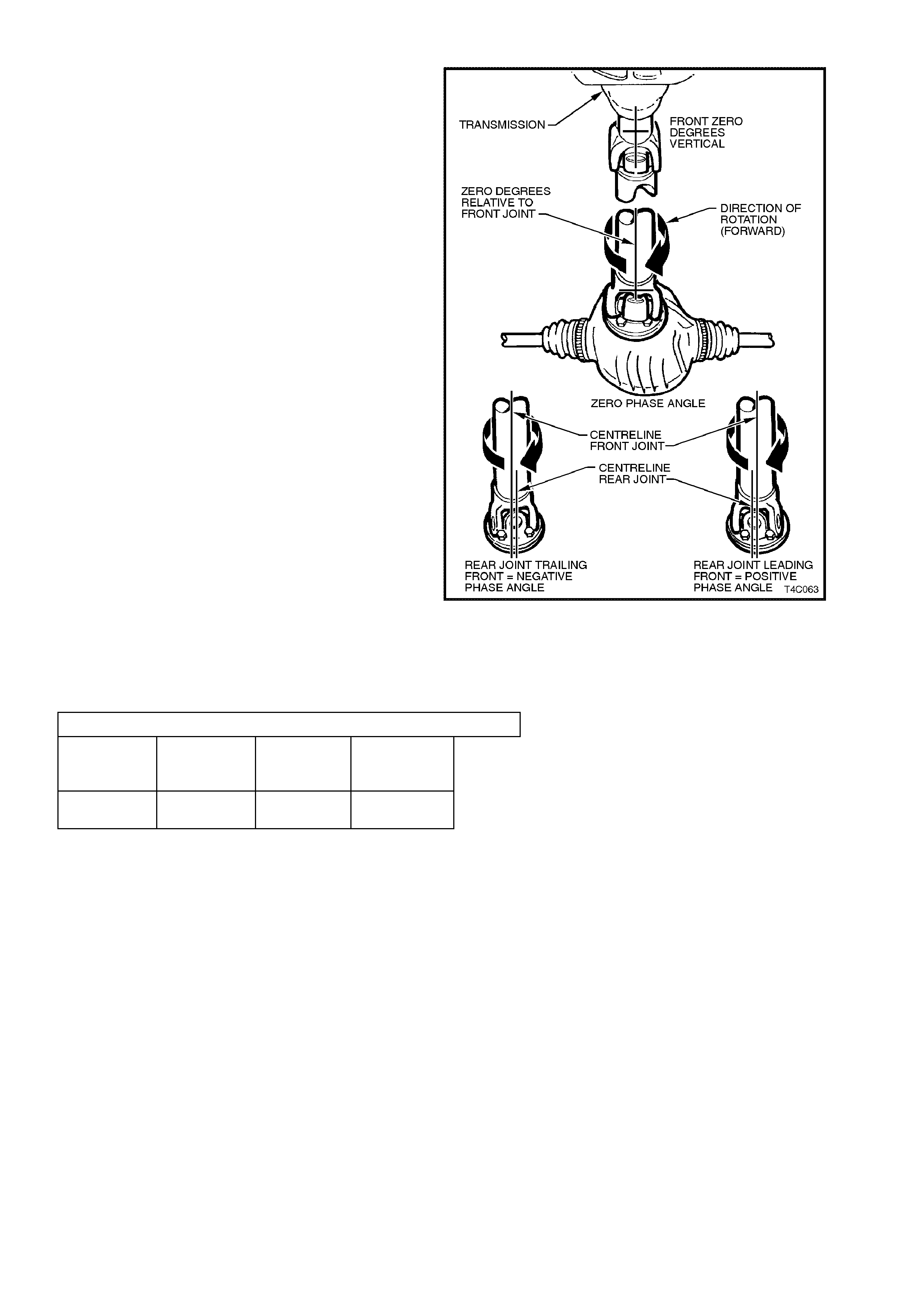
PHASE ANGLE EVALUATION
To determine if a propeller shaft has a negative,
positive zero phase angle, refer to Figure 4C-63
and the following explanation:
Zero phase an gl e: This c ondition applies when the
centreline running through the front universal joint
yoke of the propeller shaft, is in line with the
centreline of the rear propeller shaft yoke.
Positive phase angle: If it is determined that the
rear propeller shaft yoke is leading the front yoke
(when rotating in a forward direction), then this is
referred to as being a positive phase angle.
Negative phase angle: Here, the reverse applies.
Should the rear universal joint ‘trail’ the front, then
the phase angle is negative.
Figure 4C-62
If the propeller shaft phase angle is different than
the specification, refer to the following tables to
determine the appropriate action.
PHASE ANGLE EVALUATION
PHASE
ANGLE
(Degrees)
from
−7.5 to −15
and below
from
−7.5 to +7.5 from
+7.5 to +15
and above
ACTION Re-phase
See next None
(Standard) Re-phase
See next

Re-phasing Propeller Shaft
NOTE:
Once the propeller shaft phase angle has been
corrected, the assembly must be re-balanced.
1. Rem ove constant velocity joint, as detailed in
2.4 CONSTANT VELOCITY JOINT in this
Section.
2. Remove and replace centre bearing
assembly, as detailed in
2.5 CENTRE BEARING in this Section.
3. Reinstall constant velocity joint as detailed in
2.4 CONSTANT VELOCITY JOINT in this
Section.
NOTE:
To correct an excessive phase angle, install the
constant velocity joint around one spline. Which
direction, will be determined by the phase angle
reading.
4. Re-balance propeller shaft.
5. Reinstall propeller shaft. Refer to
2.1 PROPELLER SHAFT in this Section.
3. SPECIFICATIONS
PROPELLER SHAFT IDENTIFICATION
ENGINE TYPE TRANSMISSIO
N TYPE BODY STYLE PROPELLER SHAFT
PRODUCTION I.D.
MANUAL SEDAN JD
V6 STATION
WAGON JF
AUTOMATIC SEDAN JG
STATION
WAGON JH
V6 Supercharged AUTOMATIC SEDAN JG
MANUAL SEDAN MK
V8 STATION
WAGON ML
AUTOMATIC SEDAN JJ
STATION
WAGON JK
Figure 4C-63
DRIVE LINE ANGLES - VEHICLE AT CURB WEIGHT
ALL VT SERIES VEHICLES
Transmission Driveline Angle “A” Driveline Angle “B” Driveline Angle “C”
Automatic + 0.0° ± 0.5° Greater than ± 1.0° 0.0° ± 0.5°
Figure 4C-64

PROPELLER SHAFT:
Phase Angle: Zero ± 7.5°
Balance Specification 10 g cm @ 3,000 r.p.m., on turn over. Low spot
of propeller shaft is marked on the rear universal
joint flange with a daub of paint.
Maximum Rotational Runout 0.25 mm
This can only be measured accurately on a suitable
shaft jig, where the propeller shaft assembly is
correctly supported at the front, centre and rear.
LUBRICANT:
Front and Rear Universal Joints Lithium soap grease to Holden's Specification HN1147
Constant Velocity Joint Molybdenum Disulphide grease to
Holden's Specification HN1583
V6 Manual Transmission Output Shaft Spigot Molybdenum Disulphide grease to
Holden's Specification HN1271
SEALANT:
Loctite 510 High Temperature Gasket
Eliminator
(or equivalent) To meet Holden's Specification HN1593
Loctite 242 Thread Sealant (or equivalent) To meet Holden's Specification HN1256, Class 2, Type 2

4. TORQUE WRENCH SPECIFI CATIONS
Nm
Propeller shaft rear universal joint flange to pinion
flange bolt 55 - 65
Centre bearing carrier to underbody reinforcement bolt 20 - 35
Flexible coupling bolt (All manual transmission) 74 - 80
Engine rear crossmember to side frame bolt (V8 with
manual transmission) 50 - 65
Constant velocity joint to rear propeller shaft screw 35 - 40
Centre bearing cup guide to carrier bolts and nuts 20 - 25
Exhaust pipe to engine manifold (V6 engine) 18 - 35
Exhaust pipe to catalytic converter attaching bolt (All
engines) 40 - 50
Speed sensor bracket bolt to manual transmission (V8
engine) 15 - 20
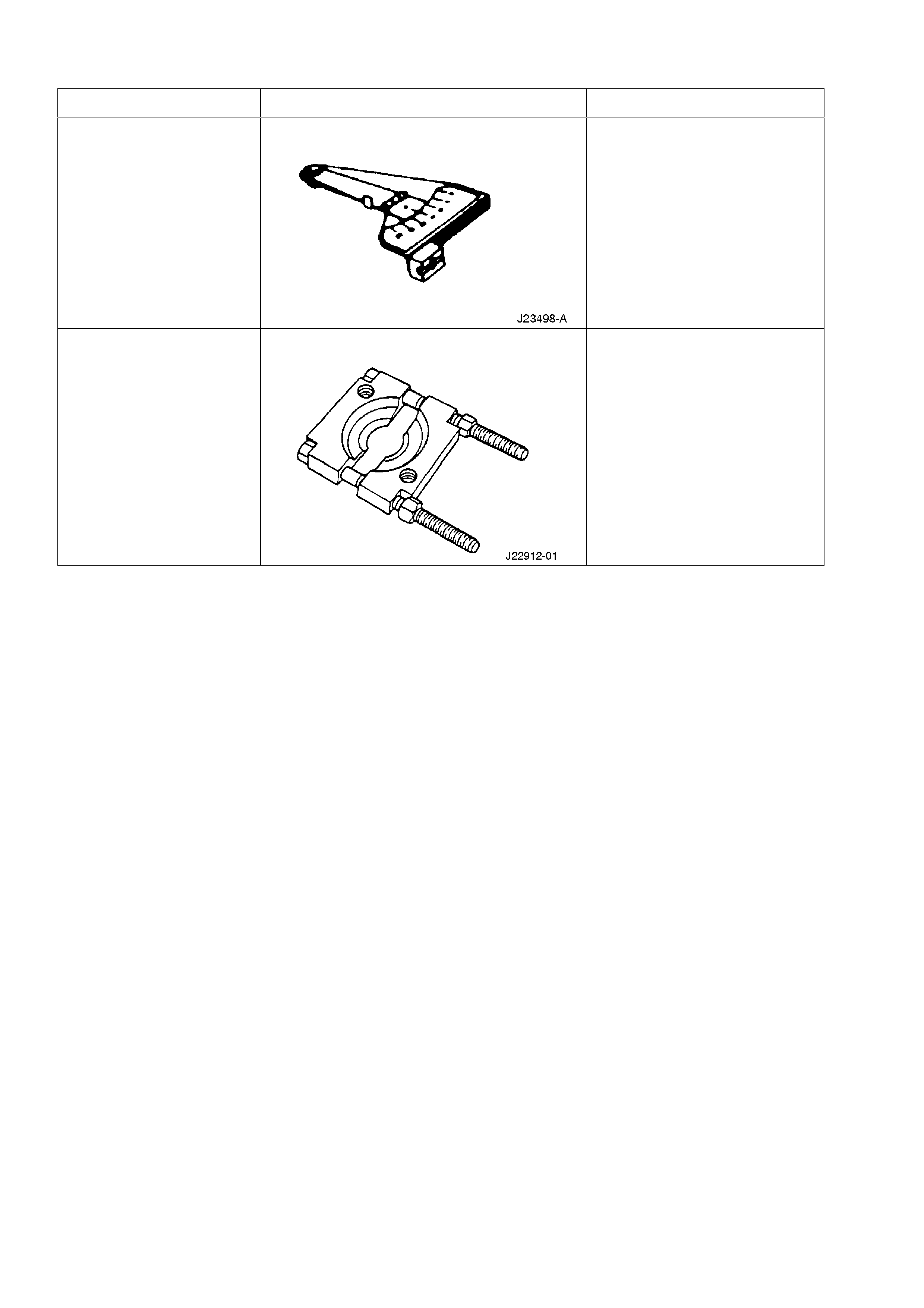
5. SPECIAL TOOLS
TOOL NO. REF IN TEXT TOOL DESCRIPTION COMMENTS
J23498-A INCLINOMETER PREVIOUSLY RELEASED
FOR "V" CAR.
J22912-01 PRESS PLATES PREVIOUSLY RELEASED
FOR TORQUEMASTER AND
FIVE SPEED
TRANSMISSIONS.