
SECTION 5A - STANDARD BRAKES
CAUTION:
This vehicle will be equipped with either a driver's side only or driver's and front
passenger's side AIR BAGS. An AIR BAG is a Supplemental Restraint System (SRS).
Refer to CAUTIONS, Section 12M, before performing any service operation on or
around SRS components, the steering mechanism or wiring. Failure to follow the
CAUTIONS could result in air bag deployment, resulting in possible personal injury
or unnecessary SRS system repairs.
CAUTION:
This vehicle may be equipped with LPG (Liquefied Petroleum Gas). As this fuel is
heavier than air in the vapour form and in the interests of safety, the LPG fuel system
should be isolated by turning 'OFF' the manual service valve and then draining the
LPG service lin es, before any service wo rk is carried out o n the v ehicle. Refer t o the
LPG leaflet included with the Owner's Handbook for details or LPG Section 2 for
more specific servicing information.
CAUTION:
Whenever any component that forms part of the ABS (if fitted), is disturbed during
Service Operations, it is vital that the complete ABS system is checked, using the
procedure as detailed in DIAGNOSIS, ABS FUNCTION CHECK, in Section 12L ABS &
ABS/ASR.
1. GENERAL INFORMATION
1.1 GENERAL DESCRIPTION
Except for those vehicles equipped with ABS as standard equipment, the front and rear disc brakes on VT Series
vehicles, are served by separate brake circuits by means of a tandem master cylinder, working through a vacuum
booster. The dual brake circuit arrangement is designed to provide adequate braking, should a fault occur in either
circuit.
All VT Series vehicles are fitted with a Stepped Tandem, Vacuum Suspended type brake booster and a 25.4 mm
bore master cylinder, regardless of the brake system used. The brake booster can not be serviced and must be
replaced if defective.
All VT models are fitted with ventilated discs at the front and solid discs at the rear. The brake calipers are the
sliding, reaction type, with twin pistons in the front calipers and single in the rear.
The rear brake backing plate assembly is bolted to the trailing arm, as is the disc brake caliper. The machined inner
surface of the disc hub acts as the brake drum.
The single shoe, ‘Banksia’ park brake is a drum type with a manual adjustment incorporated into the design. The
park brake is operated by two separate cables at the rear, connected to an equaliser bracket. Park brake
application force is applied to this equaliser bracket, via a single cable connected to the floor mounted, button
release, park brake lever. Adjustment of the parking brake cables is provided for, by a threaded end on the front,
single cable, at the park brake lever end.
For servicing information on the ABS Braking System, refer to either Section 5B ABS & ABS/ETC, or
Section 12L ABS & ABS/ETC.
Techline
Techline
Techline
Techline
1.2 MASTER CYLINDER
DESCRIPTION
A master cylinder with a 25.4 mm (1”) diameter bore is used on all VT Series vehicles, regardless of the braking
system fitted. The only difference being that the master cylinder used with ABS has a screw in blanking plug
installed into the lower of the two front brake outlets in the master cy linder.
The master cylinder is a tandem, centre valve design, incorporating a fast fill valve that provides a reduced pedal
travel. The master cylinder is mounted to the vacuum brake booster which in turn, is mounted to the engine side of
the dash panel.
MASTER CYLINDER CONSTRUCTION
This tandem master cylinder arrangement provides separate hydraulic circuits for the application of the brakes, in a
front to rear split arrangement.
Both of these circuits are fed by separate fluid feed and compensating ports, through a common fluid reservoir,
sealed by a diaphragm fitted inside the reservoir cover. This diaphragm provides an effective seal against any
atmospheric moisture coming into contact with the hygroscopic brake fluid. This provision maintains the brake
fluid's boiling point, for a maximum period of time.
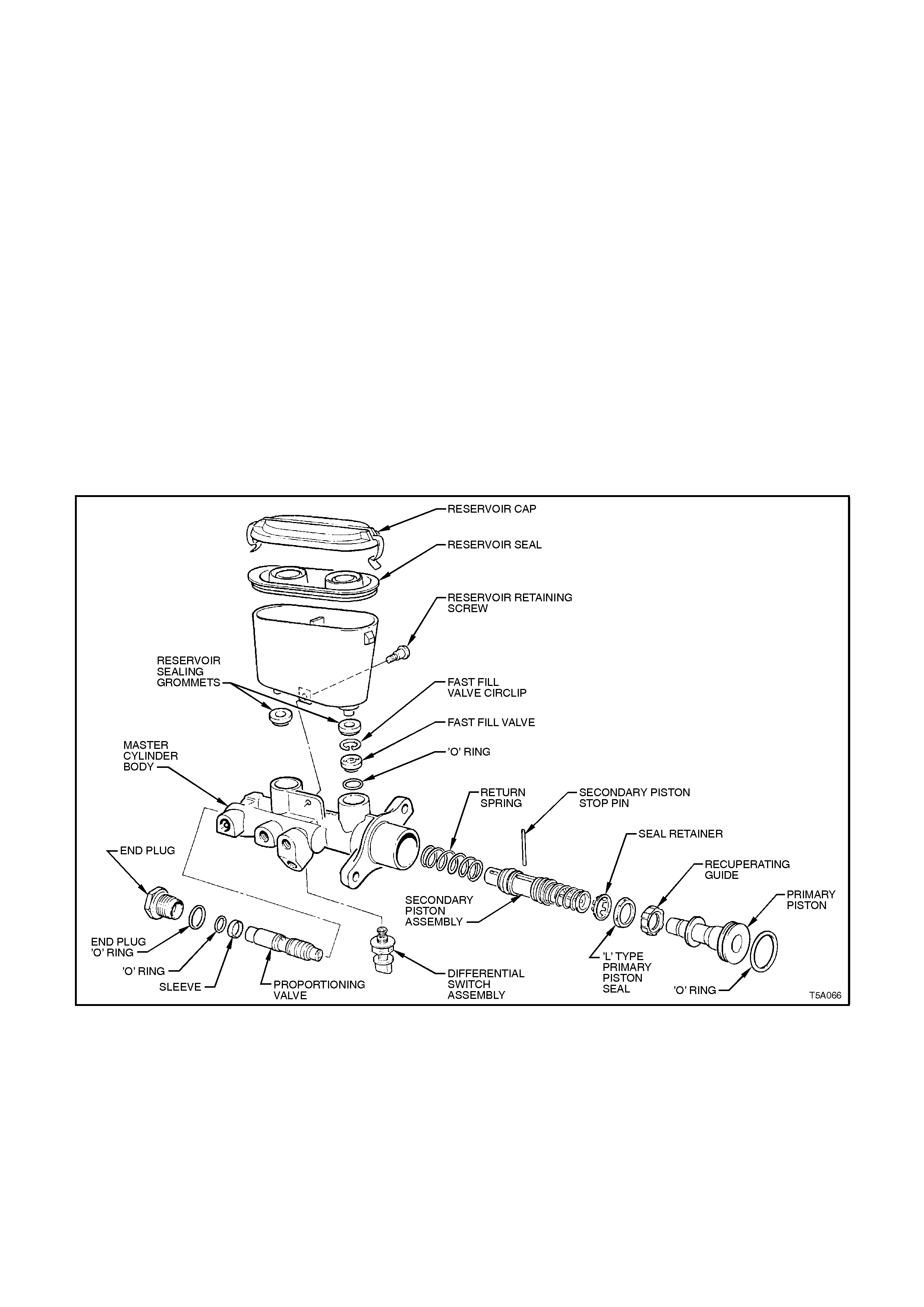
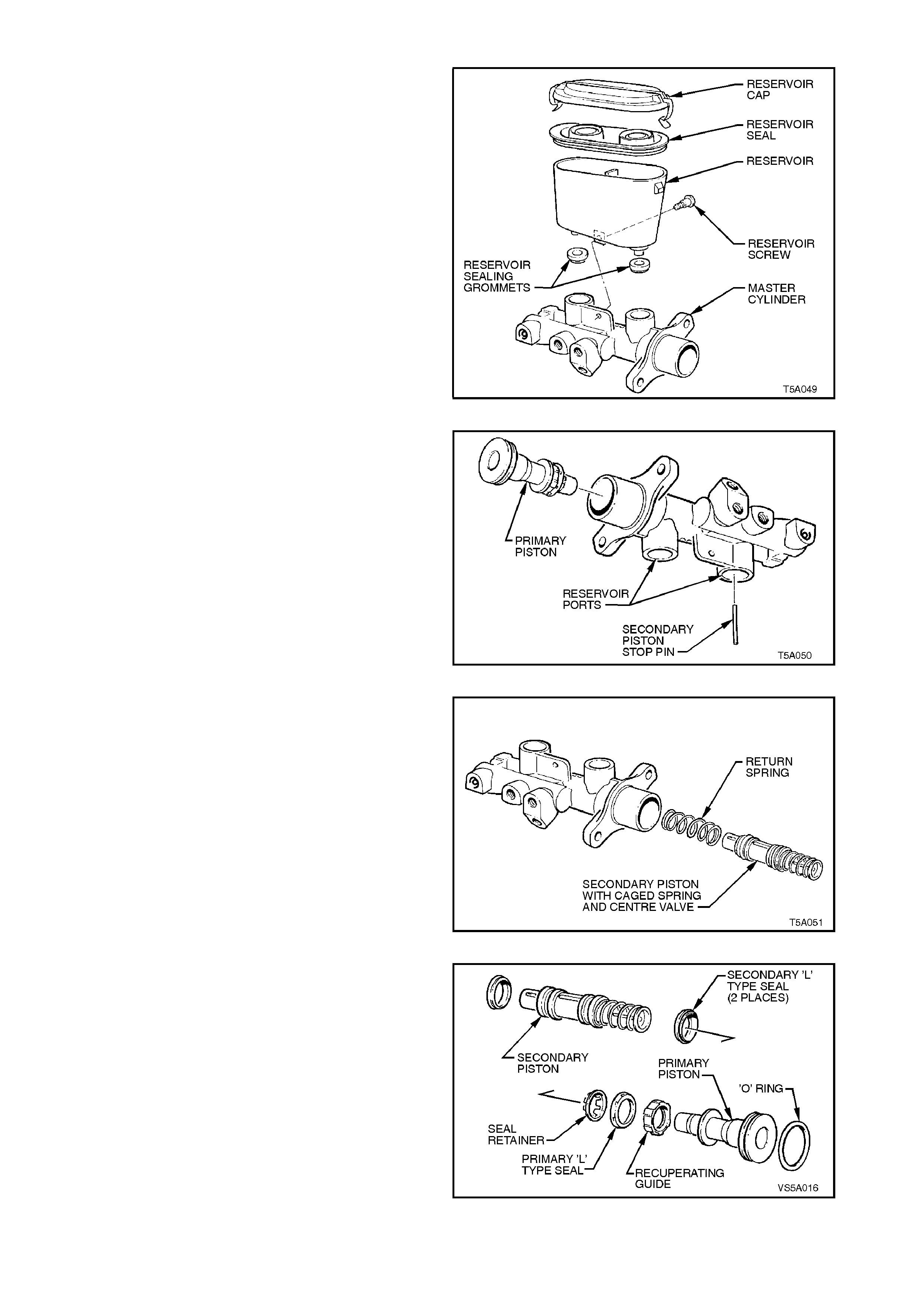
The internal parts of the master cylinder comprise a primary piston with an L type seal and an O-ring seal, a
secondary valve which incorporates a centre valve, a caged spring and two L type seals, a return spring, a
secondary piston stop pin, and a fast fill valve.
In all vehicles, a proportioning valve is located in a parallel bore in the same casting. This valve is used to maintain
the front to rear hydraulic pressure balance and, should one of the two separate systems fail, a separate piston and
differential switch (brake warning lamp switch) are incorporated into the design, so that the vehicle operator can be
warned of a system malfunction.
Figure 5A-1
MASTER CYLINDER OPERATION
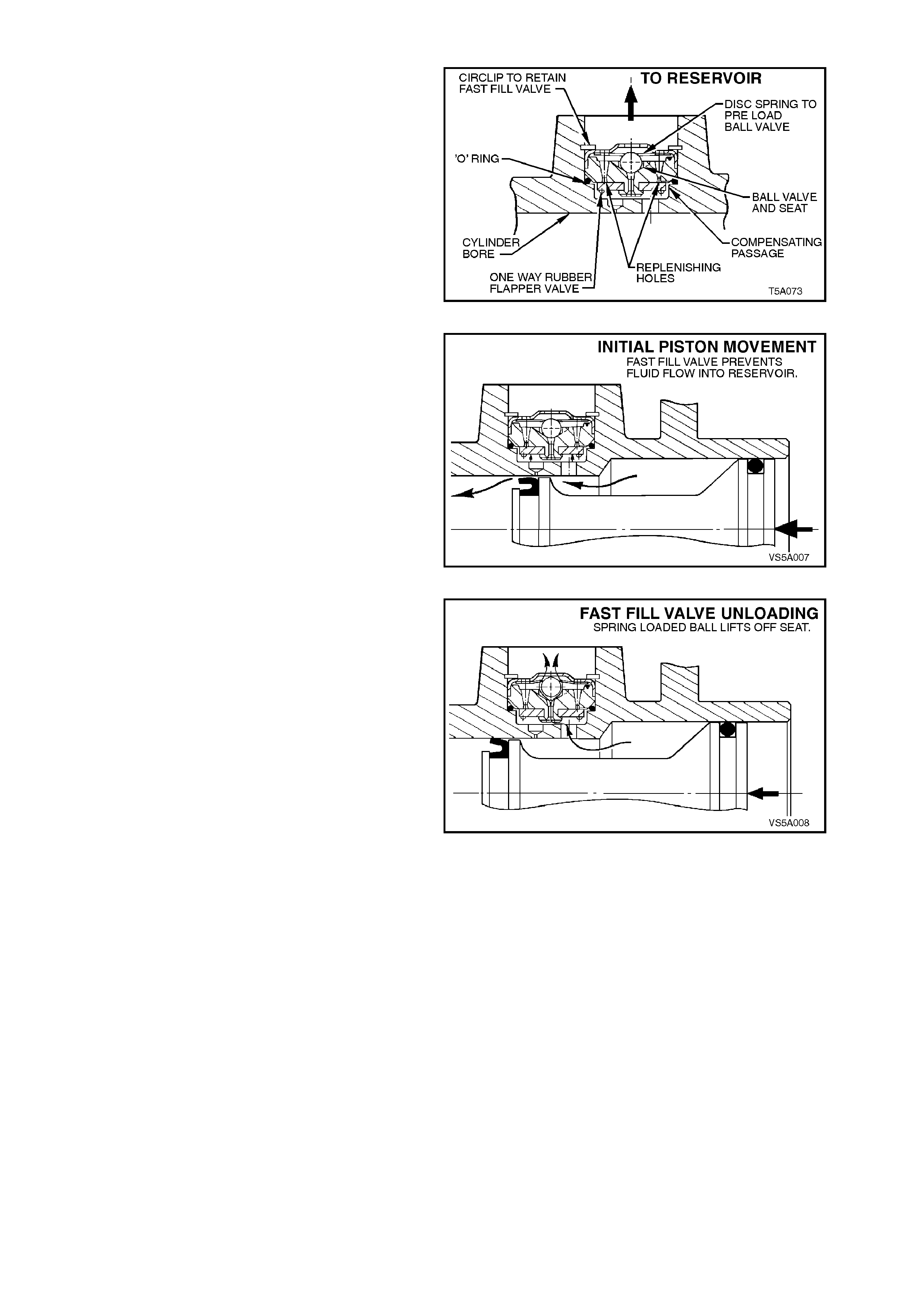
The fast fill (fast pressure build up) valve
incorporated into the master cylinder provides
reduced pedal travel by rapidly overcoming the
large low pressure displacements, such as the
advancement of brake pads against the disc with
minimal primary piston travel.
Figure 5A-2
Initial primary piston movement produces pressure
in the larger bore of the master cylinder which
forces closed the flap on the fast fill valve and
prevents fluid from entering the reservoir port.
This high volume low pressure fluid flows over the
primary piston primary L type seal and into the
smaller bore and out to the brake calipers catering
for most of the low pressure brake system
displacement with minimal primary piston travel.
Figure 5A-3
If further prim ary movem ent increas es the pres sure
in the larger bore, and at a pre-determined
pressure, the ball and seat feature incorporated in
the fast fill valve, unloads, preventing additional
pressure rise and allowing fluid to flow from the
larger bore into the reservoir port.
At this point, the small bore section of the master
cylinder functions as a conventional master
cylinder, producing high operating line pressures,
with minimal primary piston travel.
Figure 5A-4
The combination of hydraulic pressure and the
forc e of the prim ary piston acting on the sec ondary
piston spr ing caus es the secondary piston to move
forward.
This action on the secondary piston moving
forward releases the centre valve pin from contact
with the secondary piston stop pin. With the force
of the centre valve spring, and the release of the
centre valve pin, the rubber centre valve seal is
pushed against the front of the secondary piston
inner bore, ef fec tively blocking off the fluid f rom the
rear brake system compensating port.
At the same time, the primary piston L type seal
passes the front brake system compensating port,
closing it off from the reservoir and thus the high
operating fluid pressure is produced.
The high operating fluid pressure influence is then
registered on the proportioning valve, then to the
front and r ear brake c alipers, where the brak es are
applied.
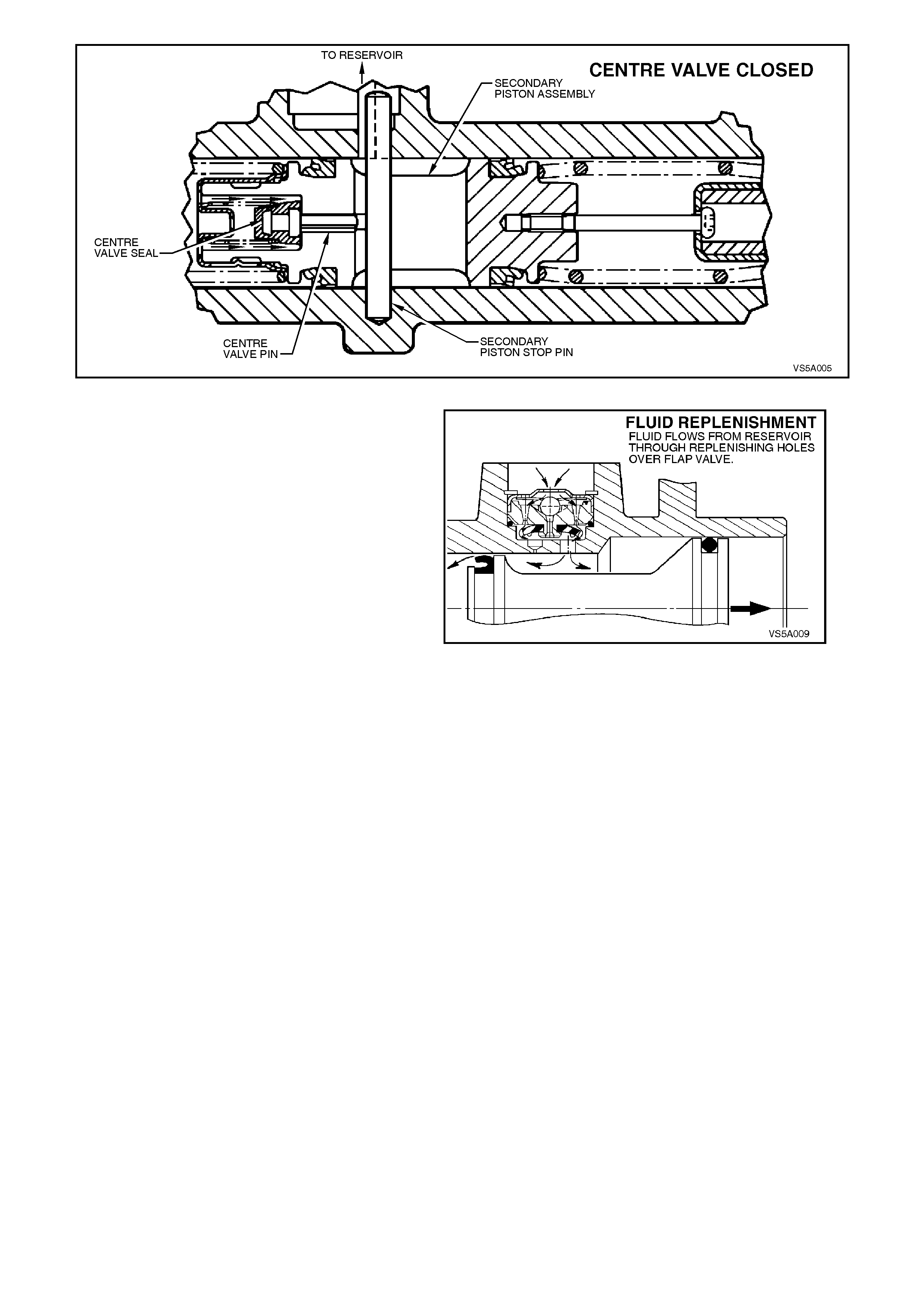
Figure 5A-5
FRONT BRAKE SYSTEM: When the brake pedal
is released and the secondary piston returns, fluid
recuperation will occur from the reservoir through
the replenishing holes in the fast fill valve, over the
rubber flap and into the larger and smaller piston
bores.
When the primary piston has fully returned, the
compensating hole in the master cylinder will be
uncovered, allowing fluid returning from the wheel
cylinders to flow into the reservoir via the fast fill
valve compensating passage, thus relieving all
pressure in the brake system.
Figure 5A-6
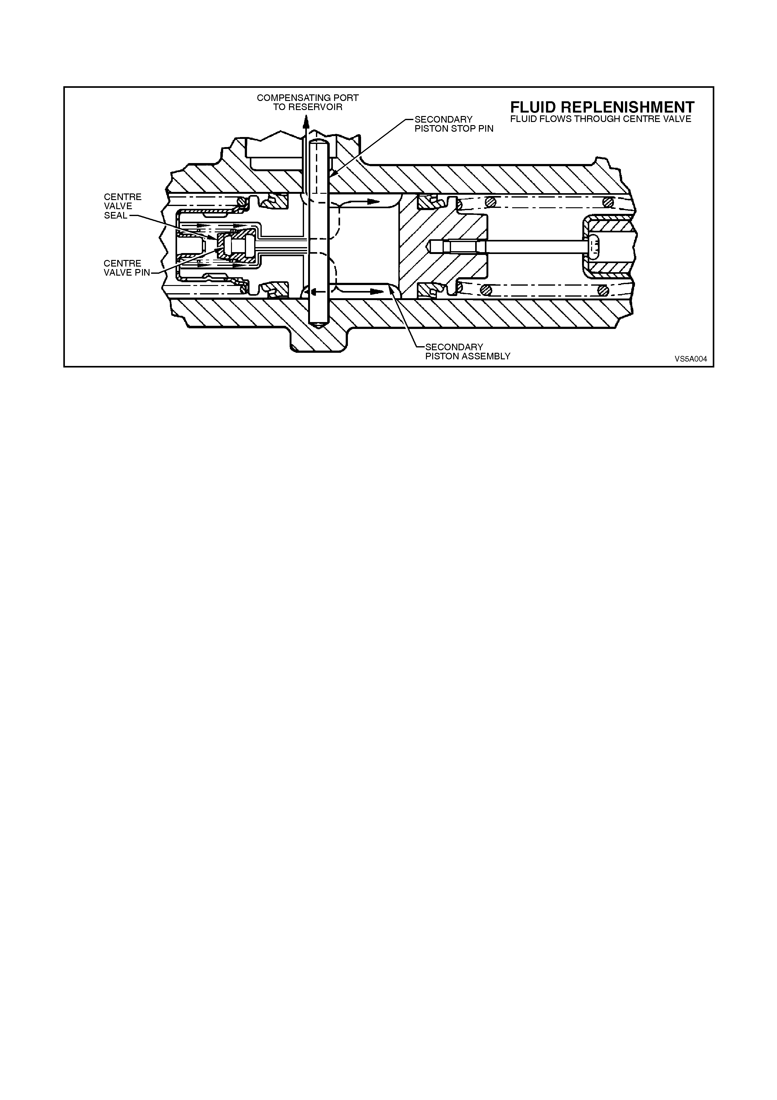
REAR BRAKE SYSTEM: When the brake pedal is released and the secondary piston returns, fluid recuperation will
occur from the reservoir and through the centre valve when the centre valve rubber seal becomes unseated from
the secondary piston bore.
Figure 5A-7
Brake fluid pressure is equal in each system until the proportioning valve reaches its designed ‘crack point'. If the
mas ter cylinder pressure then continues to rise, the propor tioning valve operation changes the front to r ear braking
pressures, to maintain the designed front to rear braking balance.
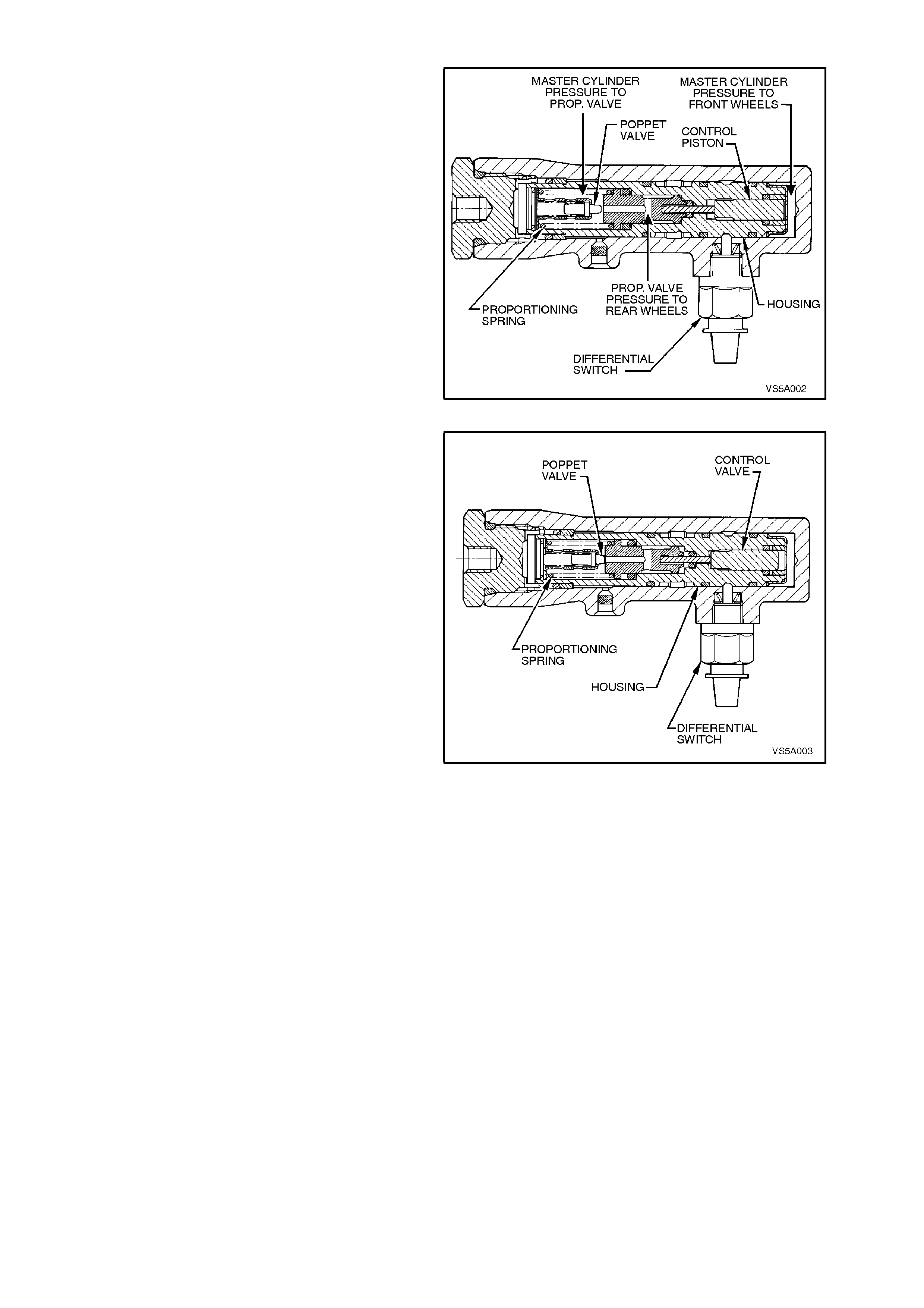
PROPORTIONING VALVE OPERATION
In the relaxed position (see Figure 5A-8), the
proportioning valve piston is held in the valve
housing by the large proportioning spring.
The poppet valve is held against the end of its
retainer by a light return spring and brake fluid is
free to pass from the master cylinder, through the
bore of the proportioning valve piston to the rear
brakes.
Figure 5A-8
W hen master cylinder pressure is increased to the
proportioning valve crack point (see Figure 5A-9),
brake fluid pressur e from the primary section of the
master cylinder acting on the control piston forces
the proportioning valve piston to move to the plug
end, overcom ing the large proportioning s pring and
seals against the poppet valve. This prevents any
further increase in press ure to the rear brakes until
master cylinder pressure is increased.
The proportioning valve piston, once seated, now
has a larger diameter than the control piston. As a
consequence of this differential area, the output to
the rear brakes af ter cr ac k point has been r eac hed,
is less than that applied to the front brakes.
As master cylinder pressure is further increased
above crack point, the piston oscillates against the
poppet valve and proportions the rear brake
pressure to a value lower than the front brakes.
Figure 5A-9
W hen the brake pedal is released (see Figure 5A-
8) and the fluid pressure from the master cylinder
drops, the pressure of the rear brake fluid unseats
the poppet valve, allowing the fluid to return to the
master cylinder. The large proportioning spring
then returns the proportioning valve piston and
control piston to their relaxed positions.
Should a loss of pressure occur in either the front
or rear brake system, when the brake pedal is
applied, the proportioning valve housing will move
within the master cylinder body, closing the switch
contacts on the differential switch and thus
illuminating the brake fail warning light on the
instrument panel.
After repairs have been made, application of a
reasonable force to the brake pedal will
automatically centralise the proportioning valve
housing, opening the differential switch contacts
and turning the brake warning light off.
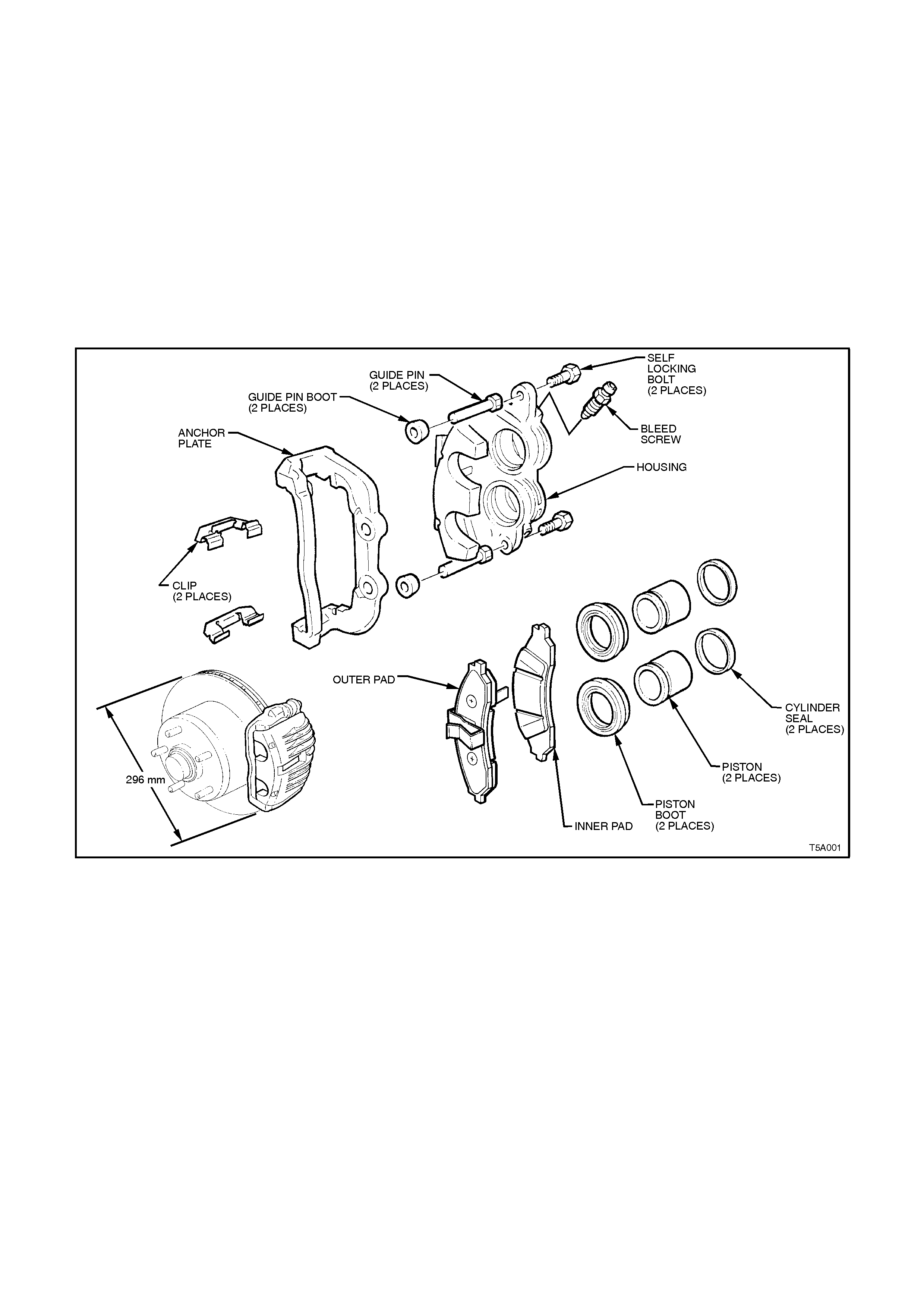
1.3 FRONT AND REAR BRAKES
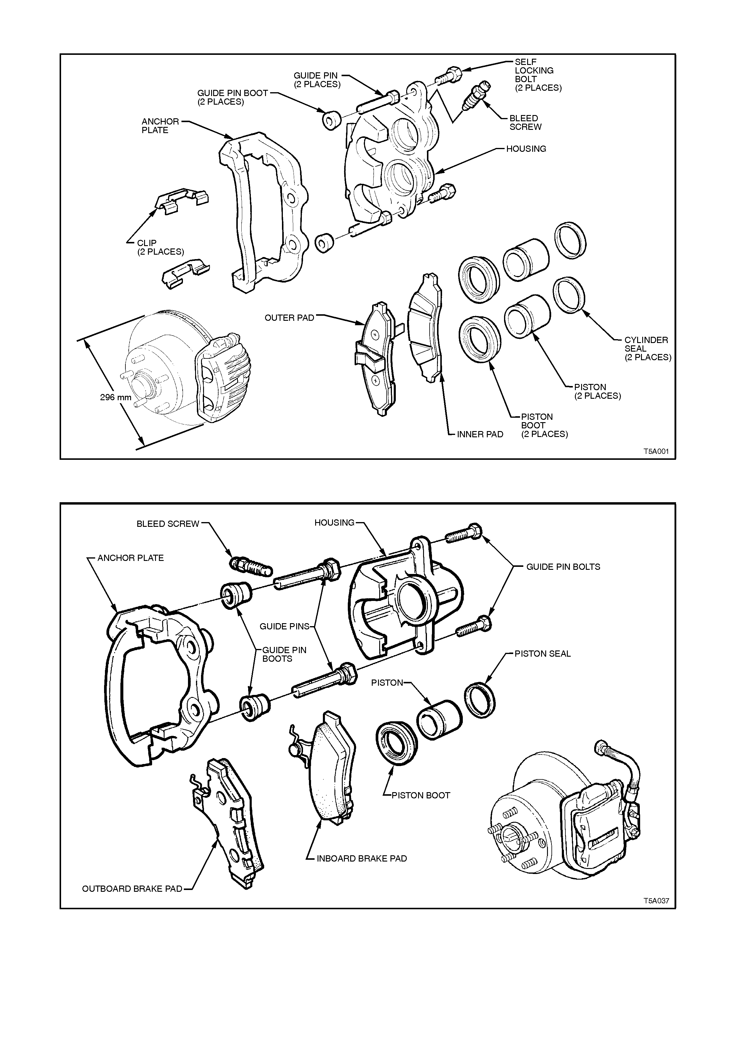
Both front and rear brake assemblies are of a revised design for VT Series vehicles but are common for both the
standard and ABS systems. An exploded view of the new twin piston front caliper are shown in Figure 5A-10.
For the front brakes, the anchor plate is rigidly fixed to the steering knuckle support arm, while the housing slides
within the anchor plate by means of two guide pins bolted to the housing. Rubber boots are fitted to the guide pins
to keep out dirt and foreign matter.
The rear brake caliper anchor plates are bolted to the trailing arm and also have a floating housing, sliding over two
guide pins that are fitted with rubber dust boots.
The housing incorporates either twin (front) or a single hydraulic piston (rear), each with a seal. When hydraulic
pressure is applied, the piston forces the inner pad against the disc and the reaction of the housing pulls the outer
pad against the disc. The forces of the pads on each side of the disc are therefore equal.
When the hydraulic pressure is released, the piston seal/s retracts the piston/s a small amount, allowing the moving
parts to relax sufficiently for the pads to remain in close proximity to the disc without dragging. Adjustment for wear
is automatic.
Refer to 2.5 BRAKE PADS, REPLACE, in this Section, for further information regarding brake pad application.
Figure 5A-10

2. MI NOR SERVICE OPERATIONS
2.1 SERVICE NOTES
IMPORTANT ITEMS:
a. While Holden's wheel brake parts are not asbestos based in their material composition, a danger exists that
non-genuine parts replacement may contain asbestos.
NOT ONLY IS IT IN THE INTERESTS OF PERSONAL SAFETY BUT ALSO THE SAFE AND RELIABLE
OPERATION OF THE BRAKING SYSTEM, THAT ONLY GENUINE PARTS ARE USED FOR
REPLACEMENT PURPOSES.
Even so, when servicing wheel brake parts, do not create dust by grinding or sanding brake linings, by cleaning
wheel brake parts with a dry brush or with compressed air. Breathing in dust that may contain asbestos fibres
can cause serious bodily harm over a protracted period of time.
A water dampened cloth or water based solution should be used to remove any dust on brake parts.
Equipment is commercially available to perform this washing function. These wet methods prevent brake
component fibres from becoming airborne.
b. The polyglycol brake fluid used in VT vehicles is hygroscopic and absorbs moisture from the air through the
brake hoses etc. The boiling resistance of the fluid decreases as the moisture content increases and so the
possibility of a vapour lock under heavy braking conditions increases with the age of the fluid. Therefore, for
maximum brake effectiveness, a two yearly change of brake fluid is mandatory, refer to
2.4 BRAKE FLUID, CHANGE, in this Section.
To prevent the absorption of moisture from the air or other contamination, it is recommended that the brake
fluid be stored in small (500 ml) containers and that any surplus fluid remaining in a container after use be
discarded.
NOTE:
The approved brake fluid (Holden's Specification HN1796) is available in 250 and 500 ml containers. If pressure
bleeding equipment is used, it must be of an approved type with a diaphragm separating the brake fluid from the air.
CAUTION:
Brake fluid is extremely damaging to paint. If fluid should accidentally touch a painted surface, immediately
wash the fluid from the paint and clean the painted surface.
2.2 PARK BRAKE CABLE, ADJUST
1. Raise rear of vehicle and support on jack
stands under each lower control arm, to
maintain the correct suspension attitude.
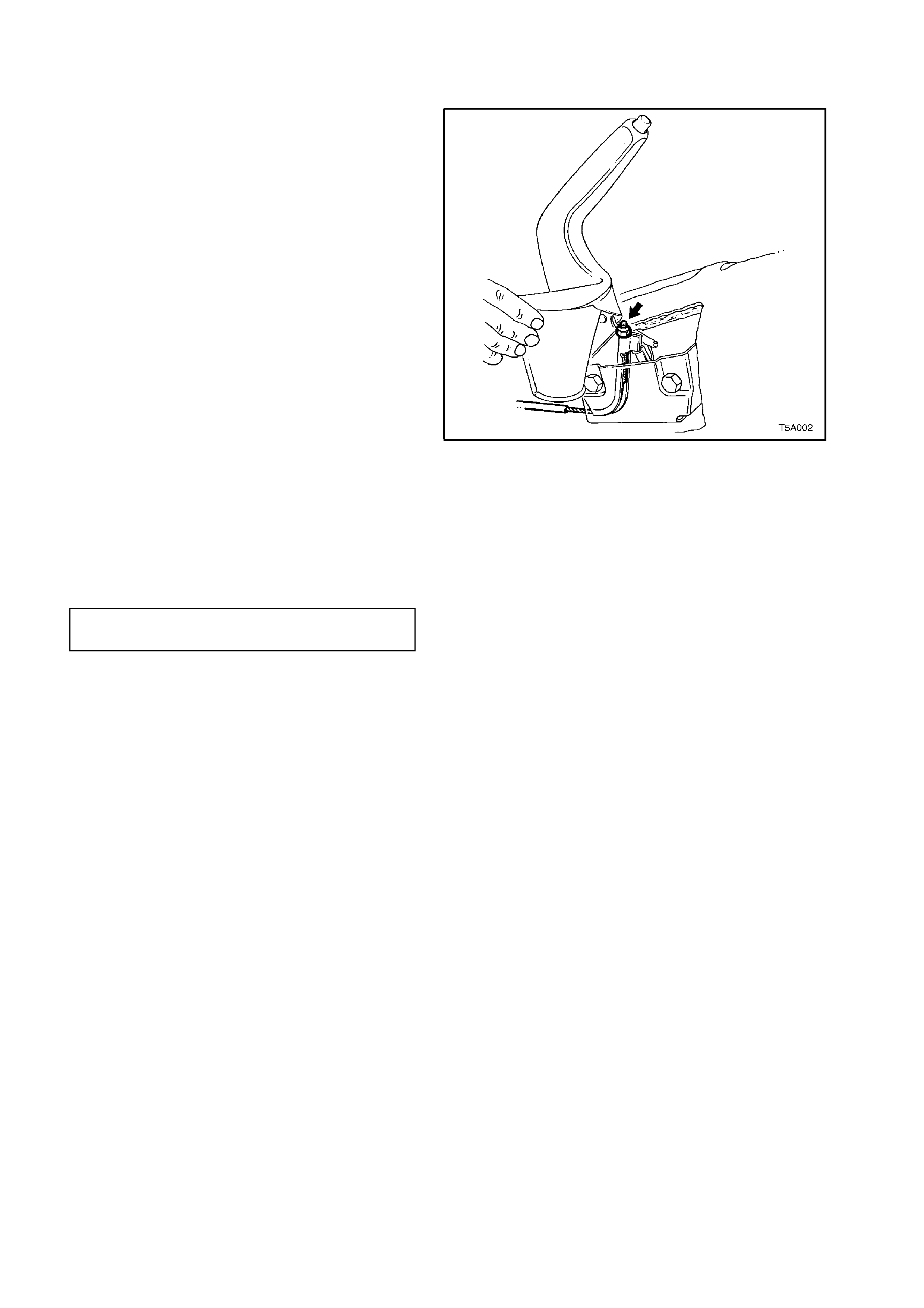
2. Loosen the park brake cable adjustment nut
several turns.
3. Apply the park brake until the lever is
extended 4 - 6 clicks.
4. Using a dial type torque wrench and a deep
socket, tighten the cable adjustment nut
(arrow) until a torque of 2 Nm is applied.
5. Check that this adjustment applies the park
brake shoes to a firm drag torque, by turning
each rear wheel.
NOTE 1:
With a new park brake installation or one that has
the correct park brake shoe adjustm ent, the thread
on the front cable should protrude through the
adjustment nut by 15 - 20 mm.
NOTE 2:
If the park brake cannot be satisfactorily adjusted
by the above method, it will be necessar y to refer to
3.5 PARK BRAKE SHOE, ADJUST in this Section.
Figure 5A-11
2.3 BRAKE SYSTEM BLEED
CAUTION :
Whenever any component that forms part of
the ABS (if fitted) is disturbed during Service
Operations, it is vital that the complete ABS
system be checked, using the procedure as
detailed in DIAGNOSIS, ABS FUNCTION
CHECK, in Section 12L ABS & ABS/ETC.
During overhaul operations, pockets of air may be
trapped in the LHF brake pipe, the front brake
hoses, in the master cylinder and various other
parts of the brake system.
A quick method of locating air pockets is to clamp
the brake hoses near the pipe end. This must be
done using a specially designed clamp that will not
damage the brake hoses. The brake hose clamp,
part number T3, is a suitable clamp obtainable
from PBR - Australia Service Centres.
NOTE:
G-clamps or locking pliers must not be used
under any circumstances.
When approved clamps are used, extreme care
must be taken to ensure they are removed before
the vehicle is driven on the road.
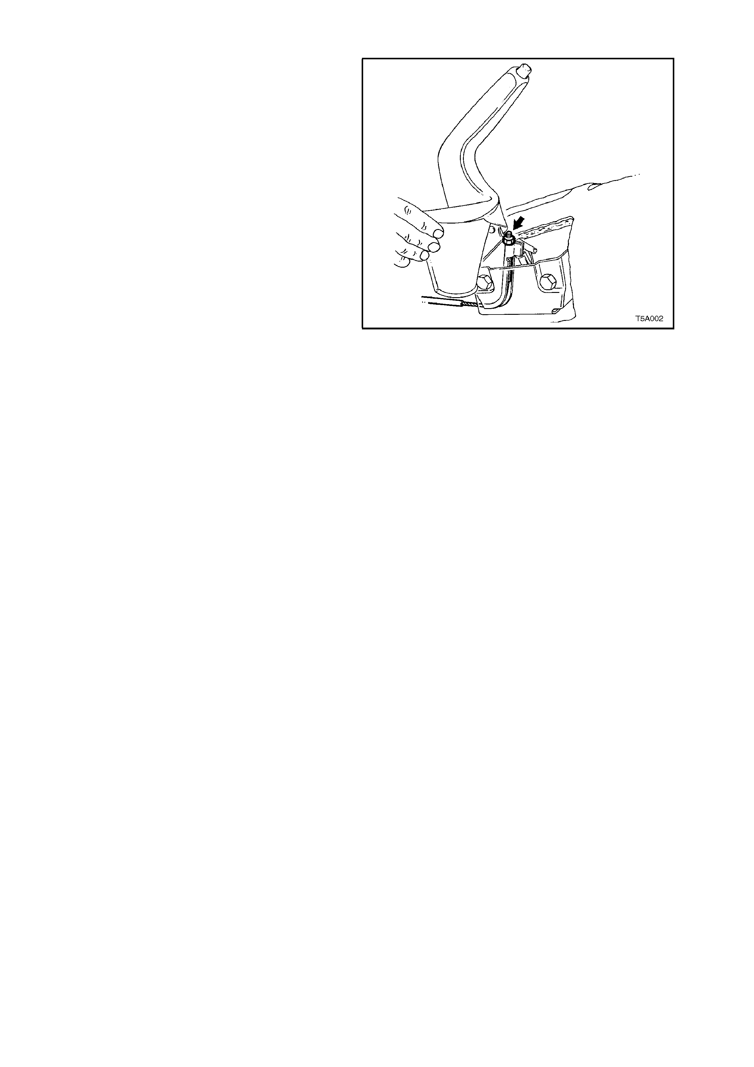
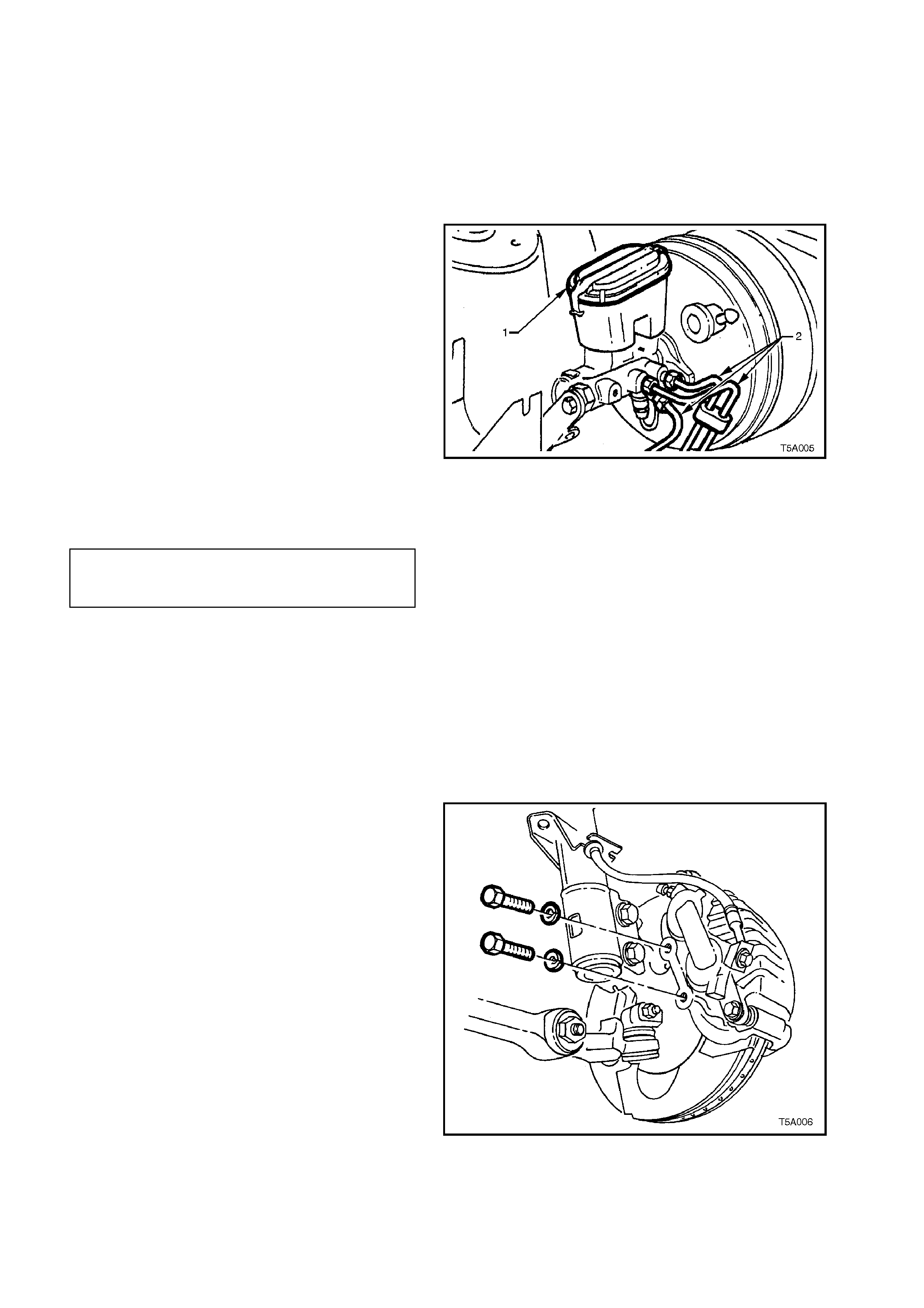
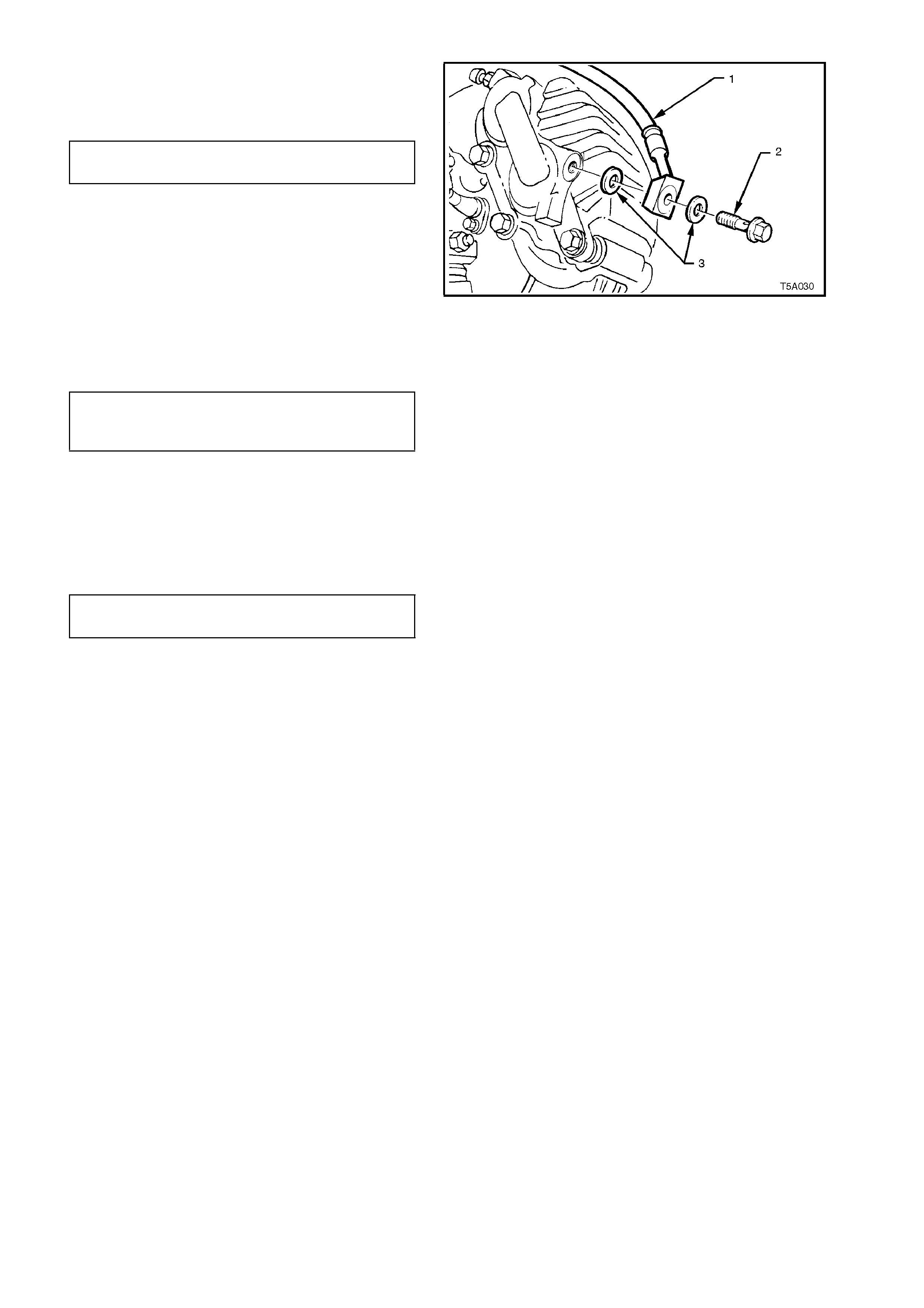
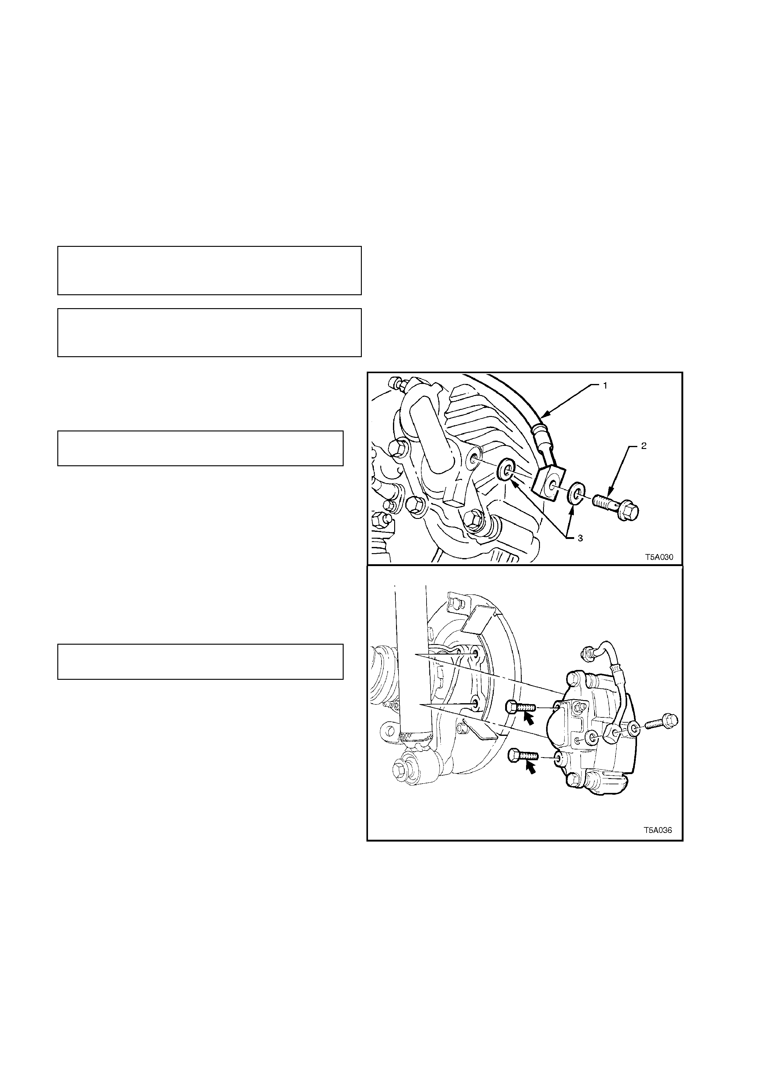
The front chamber of the master cylinder can be
bled by loosening the pipe to the LHF brake at the
master cylinder (2) and allowing brake fluid to drip
from the connection for approximately one minute,
ensuring that spilled fluid drips into a suitable
container. Do not re-use drained fluid and do not
operate the brake pedal or apply pressure to the
master cylinder during this operation.
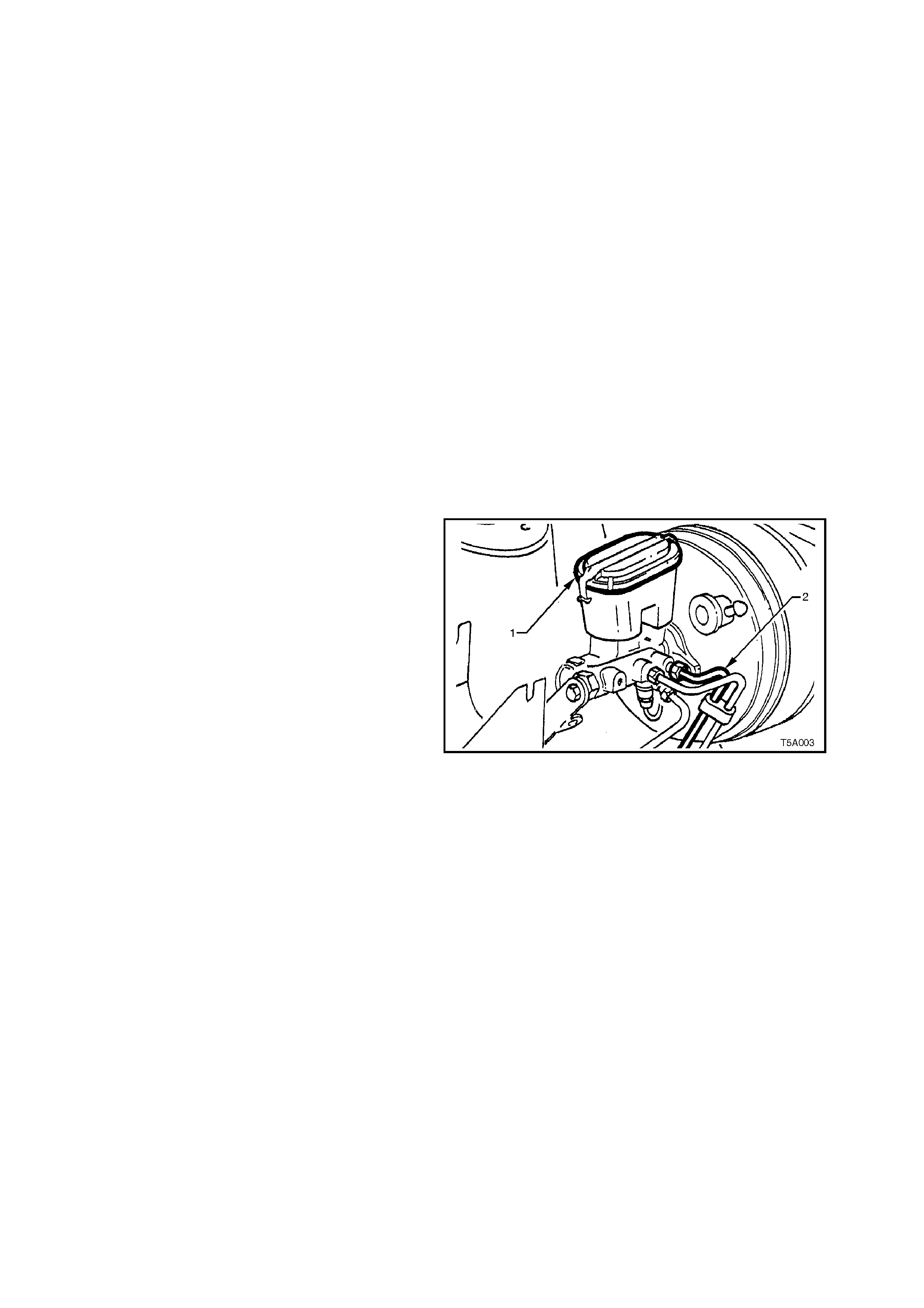
Remove air from other components of the brake
system as follows:
1. Remove master cylinder reservoir cap (1) and
fit pressure bleed cap, part number 4850-150,
obtainable from Brake and Clutch Industries -
Australia Service Centres.
2. Connect cap to pressure bleed pump and
pressurise system to no more than 345 kPa.
Figure 5A-12
3. Open brake bleeder of line to be bled and
pump brake pedal one stroke/second for
approximately 10 strokes, then close bleeder.
During this operation the pressure bleeder to
the mas ter cylinder should not be tur ned off. It
is essential that this volume and rate of flow is
maintained to ensure air trapped in pipes is
carried out of the system with the flow of the
fluid and not allowed to retreat between
strokes of the brake pedal.
Figure 5A-13
2.4 BRAKE FLUID, CHANGE
CAUTION :
Whenever any component that forms part of
the ABS (if fitted) is disturbed during Service
Operations, it is vital that the complete ABS
system be checked, using the procedure as
detailed in DIAGNOSIS, ABS FUNCTION
CHECK, in Section 12L ABS & ABS/ETC.
1. Thoroughly clean master cylinder, especially
around wheel brake line connections.
2. Disconnect wheel brake lines from master
cylinder (2) and remove reservoir cap (1).
3. Allow master cylinder to drain into a container
until empty.
4. Fill master cylinder reservoir with fresh,
specified brake fluid from a sealed 500 ml
container and ensure reservoir is maintained
at least half full for remainder of procedure.
5. Allow fluid to flow from open connection ports
until f luid is free of air . Collect discharged f luid
in suitable container and then discard. Do not
allow fluid to contact paintwork.
Figure 5A-14
6. Reconnect wheel brake lines to master
cylinder and tighten to specified torque.
BRAKE PIPE TO MASTER
CYLINDER FLARE NUT 8 - 11 Nm
TORQUE SPECIFICATION
Drain brake calipers as follows:
7. Raise vehicle and place on safety stands.
Refer to Section 0A GENERAL
INFORMATION for the locations of jacking
and support points.
8. Mark position of wheels relative to hub and
remove wheels.
9. Loosen left hand front caliper bleed screw
(arrow, in Figure 5A-13).
10. Remove front left hand caliper anchor plate
retaining bolts.
NOTE: Dis card the front brak e caliper anchor plate
retaining bolts as they must be replaced on
reassembly.
Figure 5A-15
11. Hold caliper upside down and remove bleed
screw to drain contents of caliper into suitable
receptacle.

12. Hand tighten bleed screw and reinstall caliper
assembly
13. Tighten caliper anchor plate retaining bolts to
specified torque.
FRONT BRAKE
CALIPER ANCHOR 80 – 90 Nm, then
BOLT TORQUE
SPECIFICATION 40° - 50° turn angle
NOTE: Ensure the brake hose plastic sleeve is secured
correctly in suspension strut bracket.
14. Repeat steps 8 to 13 for the remaining caliper
assemblies and tighten the rear brake caliper
anchor plate bolts to the correct torque
specification.
REAR BRAKE CALIPER ANCHOR
BOLT TORQUE SPECIFICATION 70 – 100 Nm
15. Bleed brake system, refer to
2.3 BRAKE SYSTEM BLEED in this section
16. Reinstall road wheel in original position and
lower vehicle.
17. Tighten road wheel nuts to the specified torque
ROAD WHEEL ATTACHING
NUT TORQUE SPECIFICATION 110 – 140 Nm
2.5 BRAKE PADS, REPLACE
CAUTION :
Whenever any component that forms part of
the ABS (if fitted) is disturbed during Service
Operations, it is vital that the complete ABS
system be checked, using the procedure as
detailed in DIAGNOSIS, ABS FUNCTION
CHECK, in Section 12L ABS & ABS/ETC.
This procedure refers to front brake pads. Any
differences relating to rear brake pad replacement
are noted in square brackets.
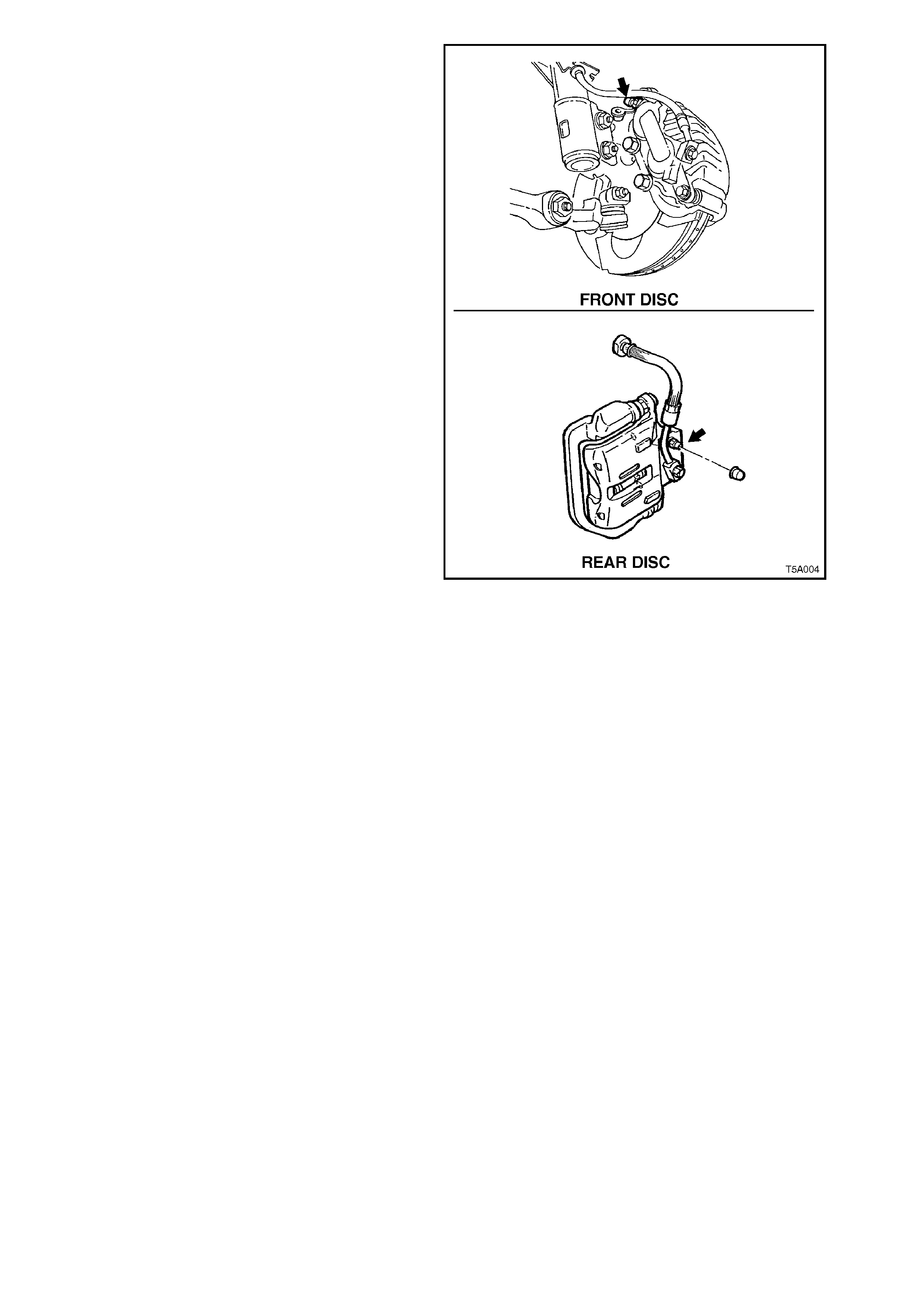
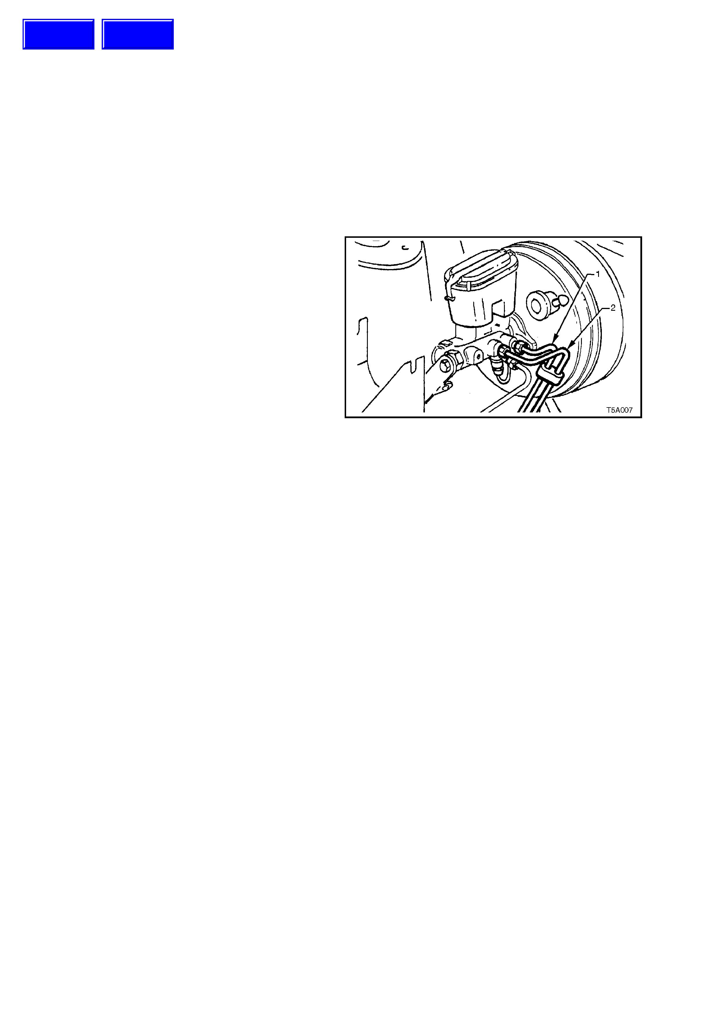
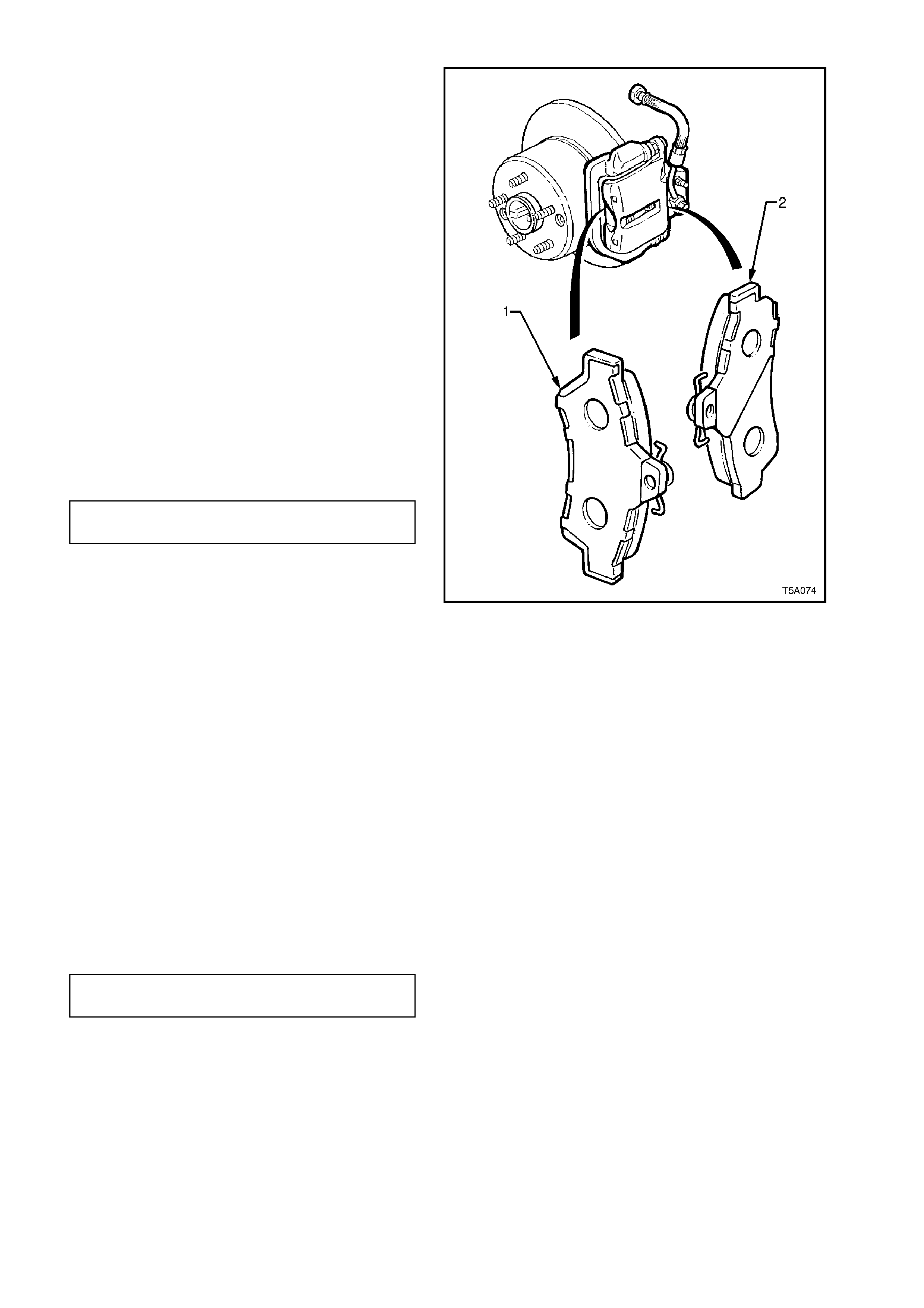
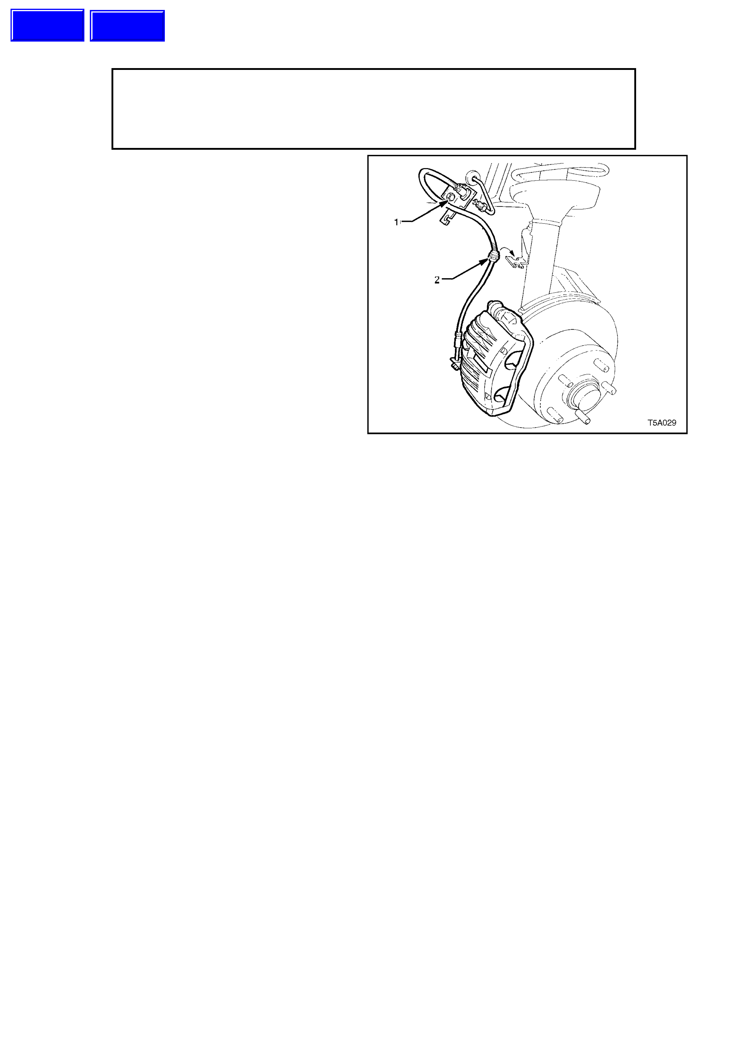
1. Remove master cylinder reservoir c ap. Loos en
front left (1) [or rear (2)] wheel brake line
connection at m aster cylinder, allowing fluid to
bleed into a container until master cylinder
reservoir is approximately
1
/3 full. Re tighten
line connection and install master cylinder cap.
NOTE 1:
Do not completely remove the brake line or empty
the reservoir or it will be necessary to bleed the
system.
NOTE 2:
Discard the f luid removed. DO NOT AT TEMPT TO
RE-USE.
NOTE 3:
Removal of fluid from the reservoir is needed to
stop reservoir overflow when caliper piston is
pushed back in its bore during pad replacement.
NOTE 4:
Brake fluid is extremely damaging to paintwork.
Figure 5A-16
2. Raise front (or rear) of vehicle and place on
safety stands. Refer to
Section 0A GENERAL INFORMATION for
the necessary procedures.
3. Mark relationship of wheel to hub. Remove
front (or rear) wheels.
Techline
Techline
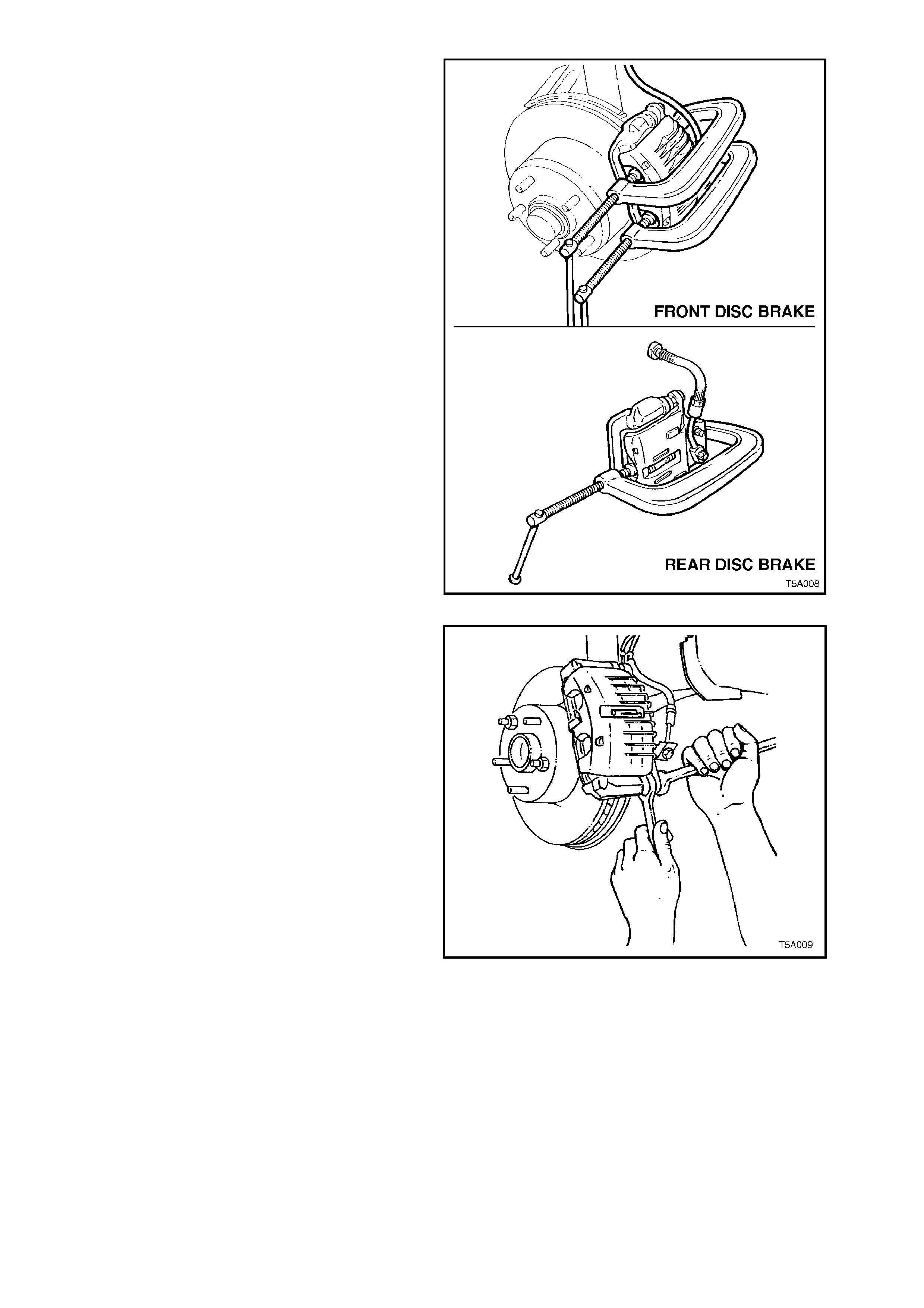
Important: If the vehicle is fitted with ABS, it is
preferred that a brake pad spreading tool is used
for piston return. However, while G-clamp/s can be
used to return pis tons, they MUST be turned slowly
(e.g. 1/4 turn per second, maximum) to avoid
internal ABS modulator damage.
4. Using G-clamps as shown, tighten until the
caliper pistons bottoms in each bore.
NOTE:
Ensure that one end of the G-clamp rests on (or is
adjacent to) the brake hose attaching bolt head,
and the other against the outer pad.
Figure 5A-17
5. Using a suitable size open end spanner to
hold the lower guide pin, remove and discard
the guide pin bolt.
NOTE:
Old bolts must not be re-used as they are vital
safety components which have a micro-
encapsulated adhesive on the bolt thread.
6. Swing caliper assembly up from the anchor
plate and disc and support caliper with a wire
hook.
7. Remove worn pads from anchor plate.
8. Inspect condition of brake disc.
9. Check guide pins for fr ee movem ent in anchor
plate. If there is restriction of movement,
replace guide pins and/or guide pin boots.
Refer to 3.3 BRAKE CALIPER in this Section.
10. Clean any dirt f rom both the piston f ace, which
contacts the inner pad, and the caliper head
area which contacts the outer pad.
11. Install new brake pads as follows:
Figure 5A-18

FRONT BRAKE PAD INSTALLATION
1. Thoroughly clean both piston contact faces, using a
suitable solvent such as Prepsol, if required.
2. Peel the backing paper from the inner pad and
install it to the anchor plate, against the brake disc.
NOTE:
Do not handle the exposed, sticky surface of the pad,
particularly in the piston contact areas.
3. Install the outer pad to the caliper, noting that a leg
of the steel spring should sit on top of the inner
pad.
4. Reinstall the brake caliper housing, ensuring that
the outer spring clip engages with the middle finger
of the caliper housing.
5. Install and tighten a NEW guide pin bolt to the
correct torque specification.
GUIDE PIN BOLT 30 - 34
TORQUE SPECIFICATION Nm
NOTE 1:
Use a suitable open end spanner to prevent the guide
pin from rotating when tightening the guide pin bolt.
NOTE 2:
Do not wedge anything between the guide pin hex and
the caliper as it could cause incorrect alignment of the
pin which would subsequently impair the free sliding of
the caliper relative to the anchor plate.
6. Fill master cylinder to correct level with fresh,
specified brake fluid.
7. Depress and hold the brake pedal down in the
applied position for at least 5 seconds, to ensure
that the inner pads stick to the pistons.
8. Refill master cylinder if necessary.
9. Reinstall wheels, aligning marks made prior to
removal and lower vehicle to the ground.
NOTE: Ensure that brake hose plastic sleeve is secured
in suspension strut bracket.
10. Tighten road wheel attaching nuts to the specified
torque.
ROAD WHEEL ATTACHING 110 - 140
NUT TORQUE SPECIFICATION Nm
Techline
REAR BRAKE PAD INSTALLATION
IMPORTANT:
For noise damping effectiveness, it is critical that
the brake pad and shim assemblies are installed in
the correct locations, as detailed here.
1. The outer pad (1) (which is retained by the
fingers of the brake caliper housing), has a full
shim.
2. The inner pad (2) has an asymmetrical or half
shim, that must be correctly installed to the
caliper. The shim must always be on the upper
half of the pad when installed in the caliper (in-
car position).
NOTE:
The brake pads illustrated would therefore, only be
fitted to the left hand side, rear brake caliper, in the
attitude, as shown.
3. Reinstall caliper housing over brake pads.
Ensure spring clip is located correctly in the
top of the caliper body.
4. Install NEW guide pin bolt. Tighten to specified
torque.
GUIDE PIN BOLT 30 - 34
TORQUE SPECIFICATION Nm
NOTE 1:
Use a suitable open end spanner to prevent the
guide pin from rotating when tightening the guide
pin bolt.
NOTE 2:
Do not wedge anything between the guide pin hex
and the caliper as it could cause incorrect
alignment of the pin which would subsequently
impair the free sliding of the caliper relative to the
anchor plate.
5. Fill master cylinder to correct level with fresh,
specified brake fluid.
6. Depress brake pedal several times to bring
pad assemblies into position against disc.
7. Refill master cylinder if necessary.
8. Reinstall wheels, aligning marks made prior to
removal and lower vehicle to the ground.
9. Tighten road wheel attaching nuts to the
specified torque.
ROAD WHEEL ATTACHING 110 - 140
NUT TORQUE SPECIFICATION Nm
Figure 5A-19

BRAKE PAD BEDDING-IN PROCEDURE
Whenever brake pads are replaced, they should be burnished, by the following bedding-in procedure:
Perform a minimum of 10 moderate (0.3 to 0.4 g deceleration) brake applications from 70 km/h down to 40 km/h
every 500 metres.
NOTE 1:
A ‘panic’ stop would be classified as being a 9 g deceleration braking effort, so a ‘moderate’ deceleration rate of 0.4
g would be one that required approximately half the brake pedal effort needed for a ‘panic’ stop.
NOTE 2:
Do not perform this procedure at less than 500 metre intervals, as the excessive heat build-up, may adversely affect
the frictional characteristics of the new brake pad material.
Techline
2.6 BRAKE PEDAL
CAUTION :
Whenever any component that forms part of the ABS (if fitted) is disturbed during
Service Operations, it is vital that the complete ABS system be checked, using the
procedure as detailed in DIAGNOSIS, ABS FUNCTION CHECK, in Section 12L ABS &
ABS/ETC.
CAUTION:
Disable the SRS (Air Bag). Refer to 'DISABLING THE SRS’, Section 12M, SRS.
REMOVE
1. Remove instrument panel lower right trim
assembly. Refer to
Section 1A3, INSTRUMENT PANEL AND
CONSOLE , for details.
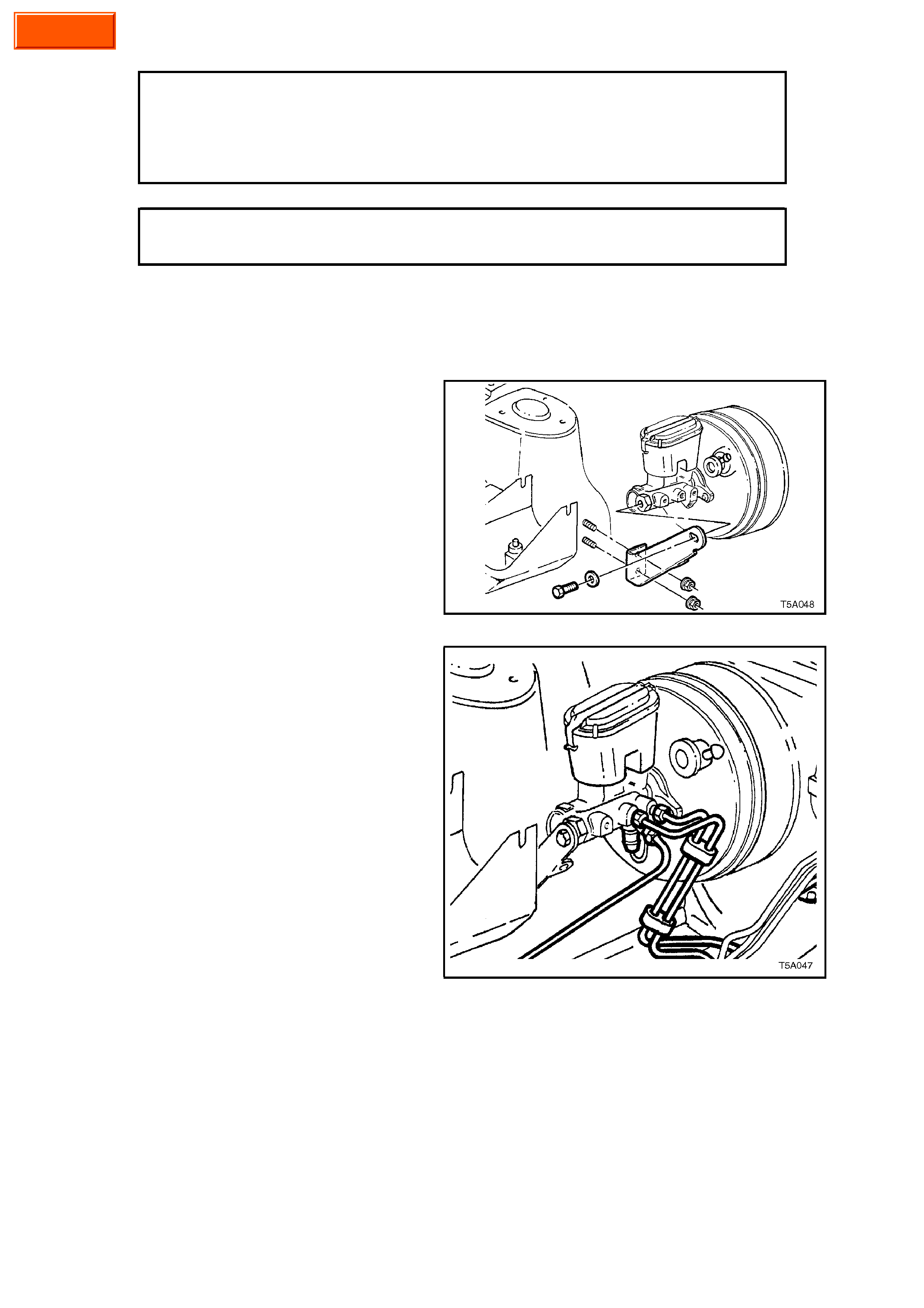
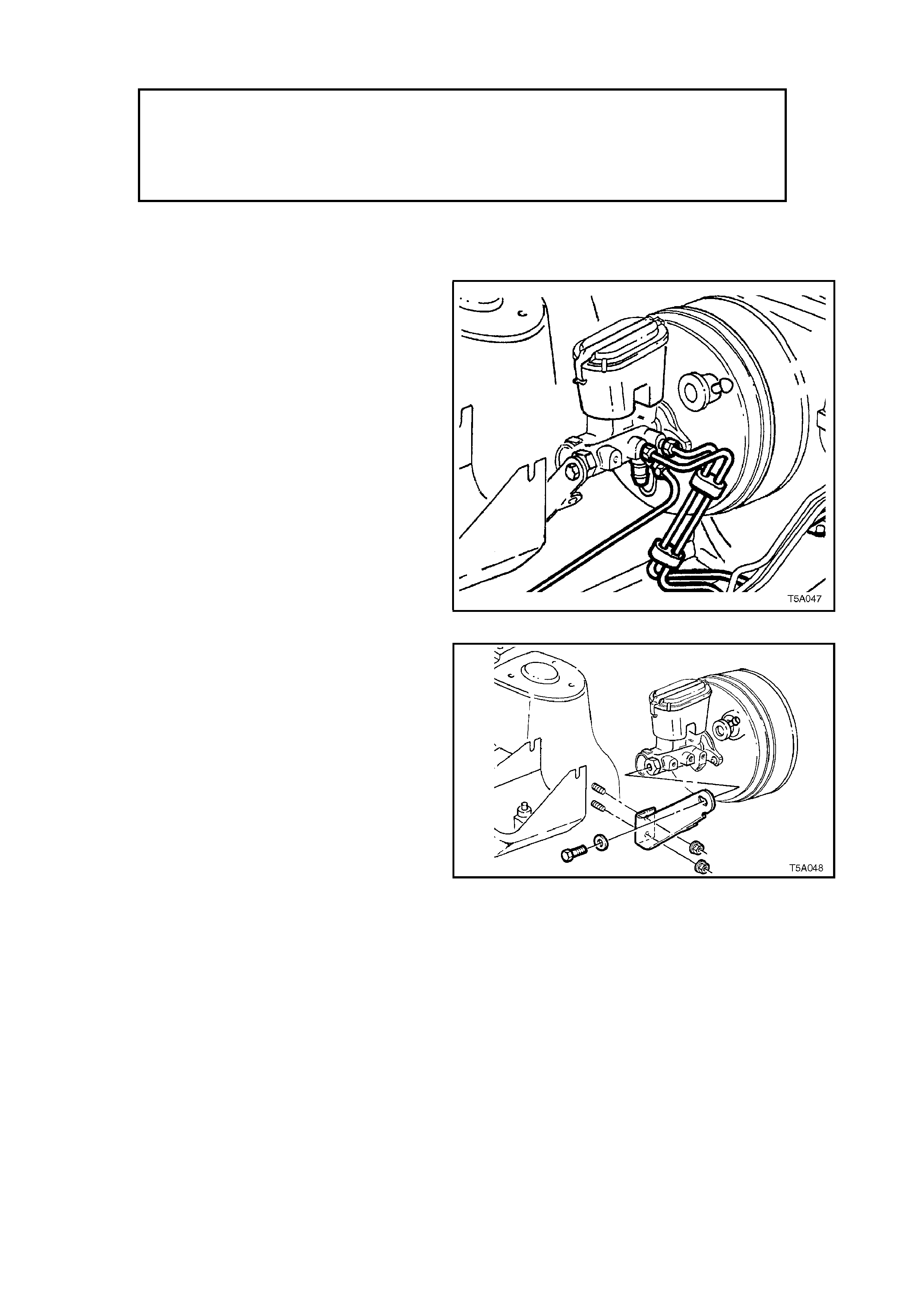
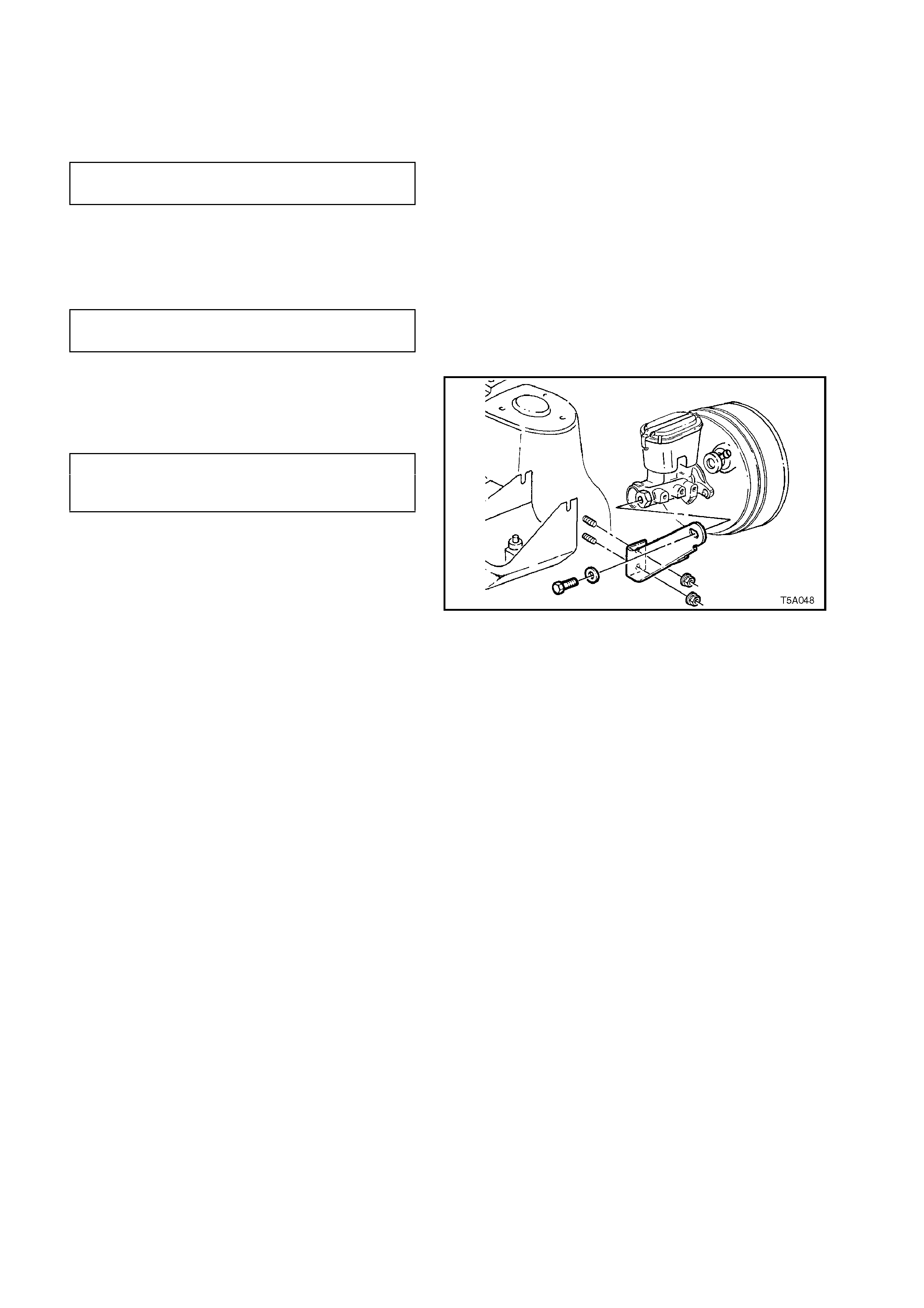
2. Remove master cylinder support bracket from
the front of the master cylinder.
Figure 5A-20
3. Remove br ake pipes f rom the mas ter cylinder.
Plug openings in both the master cylinder and
the pipes, to prevent fluid loss and dirt entry.
Figure 5A-21
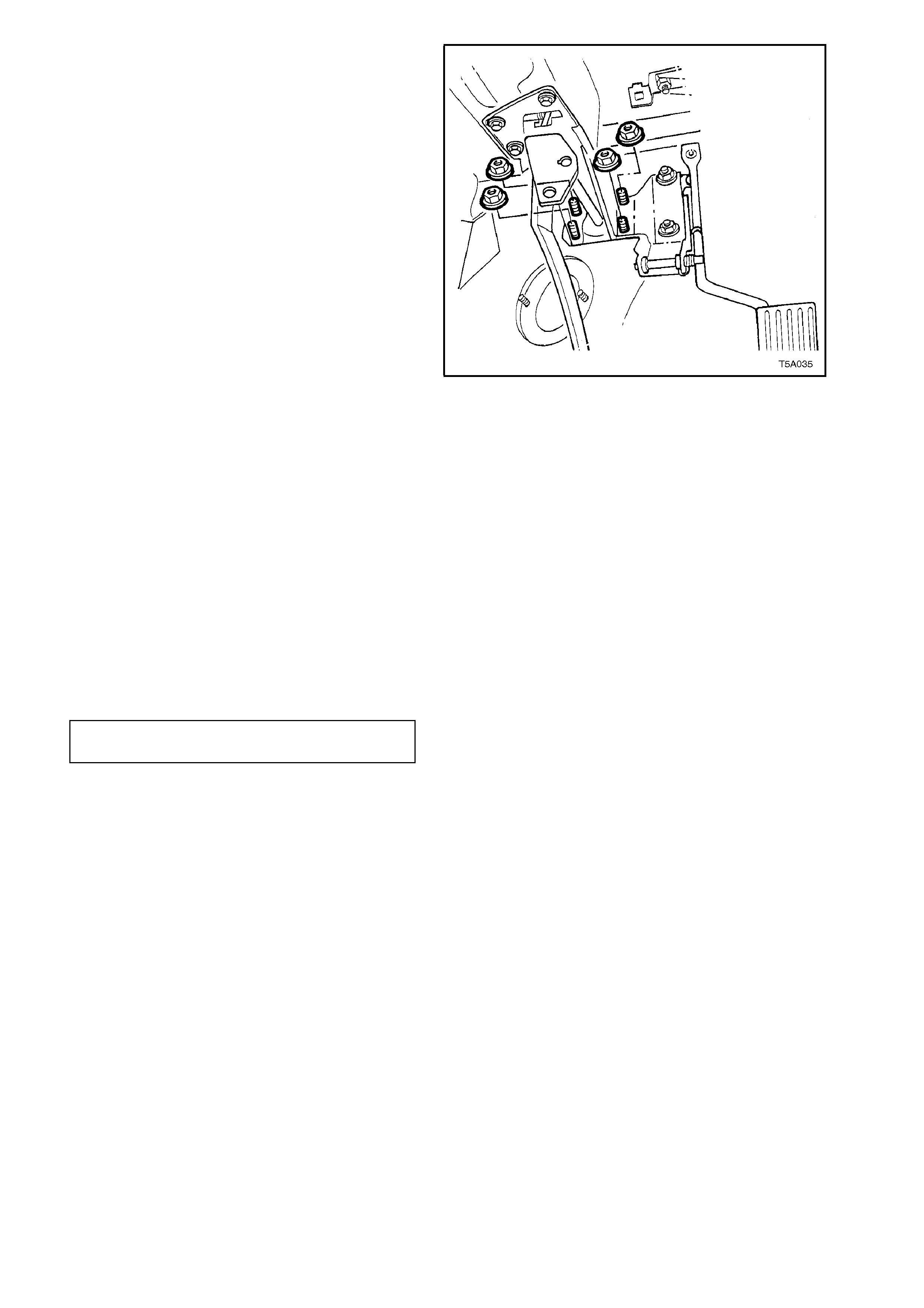
Campaign
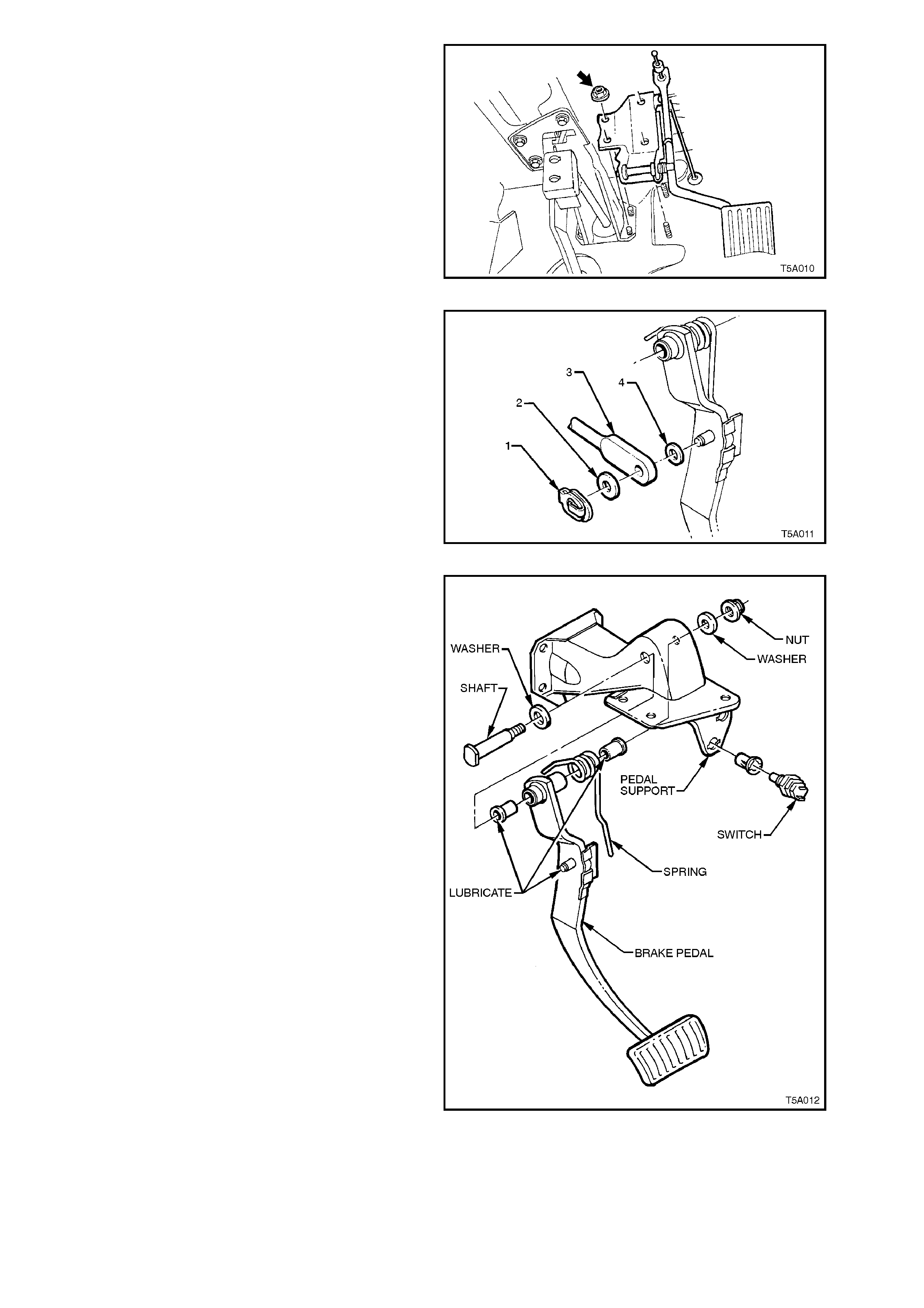
2. Remove nuts (arrow) securing throttle pedal
assembly to dash panel.
3. Remove the remaining two nuts securing the
brake booster to the firewall.
Figure 5A-22
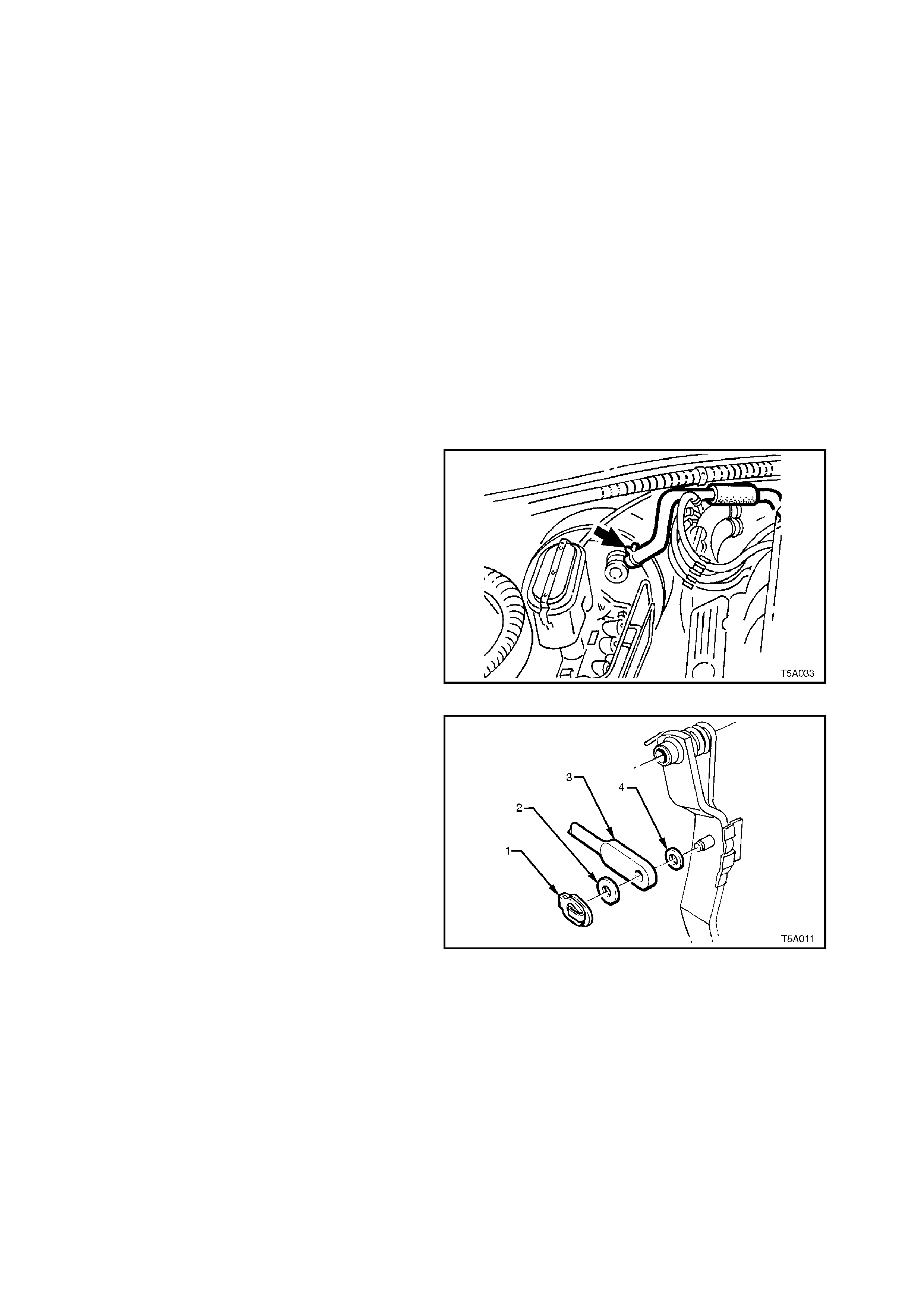
4. Remove push rod retaining clip (1), push rod
(3) and washers (2 and 3) from brake pedal.
5. Remove the three bolts securing the brake
pedal support bracket to the steering column.
6. From the engine compartment, pull the brake
booster forward, allowing the brake pedal and
support to be lowered, rear end first from
under the instrument panel.
Figure 5A-23
7. Remove nut and washer securing pedal shaft
to pedal support.
8. Carefully withdraw shaft from pedal support.
9. Withdraw brake pedal and return spring
assembly.
Figure 5A-24

REINSTALL
1. Lubricate all bearing surfaces with
Molybdenum Disulphide grease (Holden's
Specification HN1271), as indicated in Figure
5A-24.
2. Hold brake pedal and return spring in position
and insert pedal support shaft through pedal
stand.
3. Reinstall shaft retaining washer and nut and
tighten to specified torque.
PEDAL SUPPORT SHAFT NUT 50 - 60
TORQUE SPECIFICATION Nm
4. Reinstall brak e pedal and stand ass embly into
the vehicle and install the three bolts
supporting the pedal stand to the steering
column but do not tighten at this time.
5. Push the brake booster rearward to engage
the four studs with the pedal stand and to
allow the push rod to be installed to the brake
pedal pin.
6. Install the push rod washers and retaining clip
(see Figure 5A-23).
7. Install throttle pedal assembly, install and
tighten all four brake booster nuts to the
specified torque.
BRAKE BOOSTER/THROTTLE
PEDAL BRACKET NUT 20 - 25 Nm
TORQUE SPECIFICATION
8. Tighten the three brake pedal stand bolts to
the specified torque.
BRAKE PEDAL STAND BOLT 20 - 25
TORQUE SPECIFICATION Nm
9. Install the master cylinder support bracket,
tightening the fasteners to the specified
torque.
MASTER CYLINDER BRACKET 15 - 20
NUT TORQUE SPECIFICATION Nm
10. Unplug all hydraulic fitting openings, and
install the brake pipes to the master cylinder,
tightening to the specified torque.
BRAKE PIPE TO MASTER
CYLINDER FLARED NUT 8 - 11 Nm
TORQUE SPECIFICATION
11. Bleed the brake system as detailed in
2.3 BRAKE SYSTEM BLEED, in this Section.
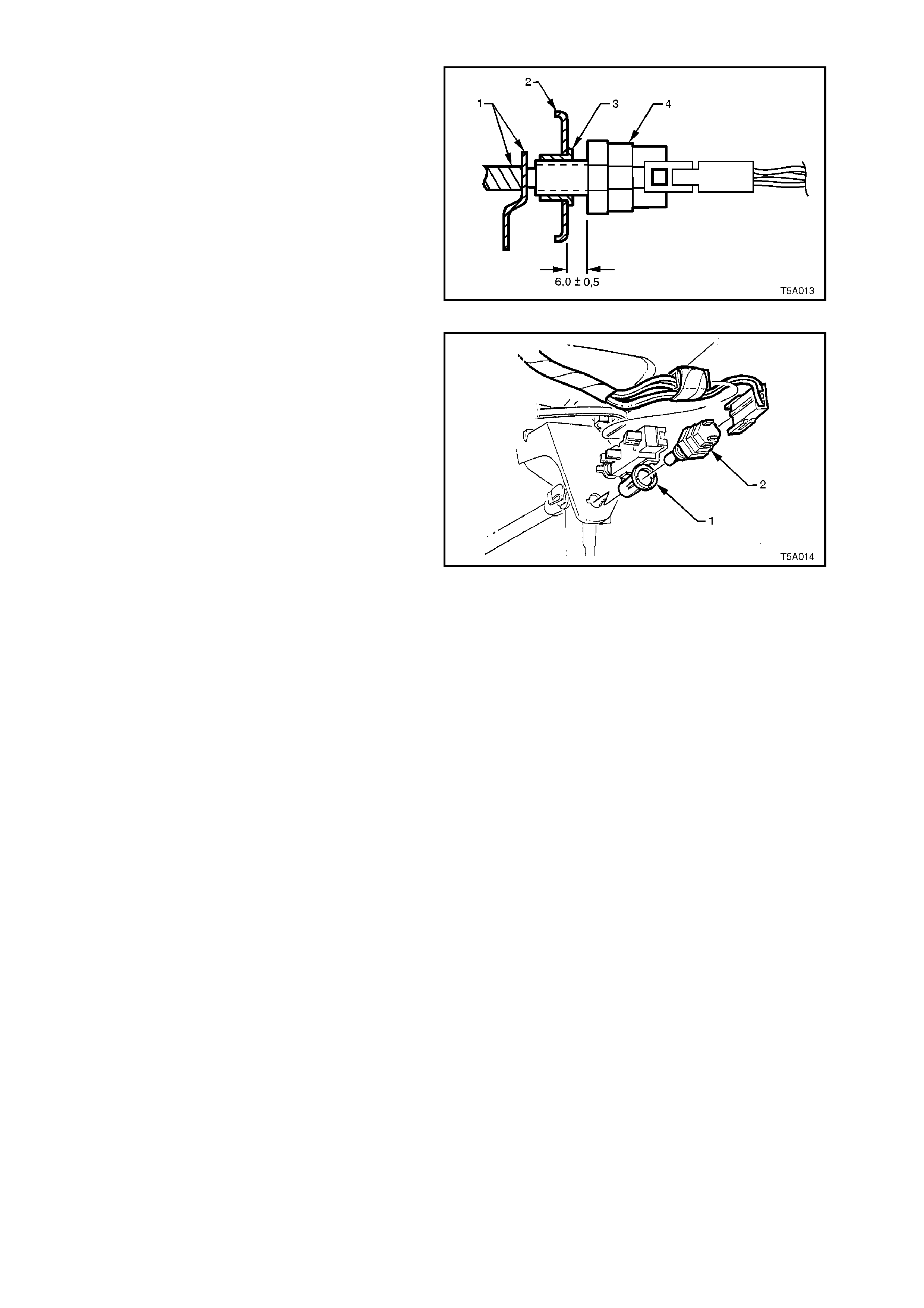
Adjust stop lamp or cruise control switches:
a. Stop Lamp Switch - W ith the pedal held
in the ‘at rest' position, push or pull the
switch (4) through metal clip (3) to
achieve a gap of 6 ± 0.5 mm, as shown,
between brake pedal support (2) and
switch body (4).
Figure 5A-25
b. Cruise Control Switch - Vehicles
equipped with the cruise control feature,
are fitted with two switches. The upper
switch is the cruise control electrical
release switch, while the lower switch (2)
is used to illuminate the stop lamps, and
to provide a signal to the cruise control
module.
With the brake pedal held in the
depressed position, push the switch
forward until the switch body contacts the
tubular clip (1).
Pull the brake pedal fully up against the
brake pedal stop, until audible 'click'
sounds are no longer heard.
Depress the brake pedal again and
repeat the above procedure until the
audible 'click' sounds can no longer be
heard. At this point, the switch will be
correctly adjusted.
8. Reinstall instrument panel lower right trim
assembly.
Figure 5A-26
2.7 PARK BRAKE LEVER
REMOVE
1. Set park brake in the fully released position.
2. Slip the park brake lever boot to one side, then
remove the park brake front cable adjusting
nut (arrow), using a deep socket.
3. Remove driver’s seat. Refer
Section 1A7 SEAT & SEAT BELT
ASSEMBLIES.
4. Lift the carpet from around the park brake
lever, then remove the two mounting bolts.
5. Carefully lift park brake lever assembly,
upwards to free the cable, then disconnect
electrical connector (‘5’ in Figure 5A-28) from
park brake switch.
6. Remove the lever assembly from the vehicle.
Figure 5A-27
REINSTALL
Installation is the reverse of the r emoval proc edure,
except for the following:
1. Tighten park brake lever bolts to specified
torque.
PARK BRAKE LEVER BOLT 35 -65
TORQUE SPECIFICATION Nm
2. Reinstall threaded end of the front park brake
cable, then install the adjusting and lock nut.
Adjust the park brake cable adjustment as
detailed in 2.2 PARK BRAKE CABLE,
ADJUST in this Section.
2.8 FRONT PARK BRAKE CABLE
REMOVE
1. Set park brake in the fully released position.
2. Remove driver’s seat. Refer
Section 1A7 SEAT & SEAT BELT
ASSEMBLIES for the procedure.
3. Remove the park brake lever as detailed in 2.7
PARK BRAKE LEVER, in this Section.
4. Remove the centre console and lift the carpet
to gain access to the two front cable
escutcheon screws (3). Refer to
Section 1A3 INSTRUMENT PANEL AND
CONSOLE, for details. Remove the two
screws.
Figure 5A-28
5. Raise vehicle and place safety stands under
each of the rear trailing arms. Refer to
Section 0A, GENERAL INFORMATION for
the recommended support points for the
vehicle front.
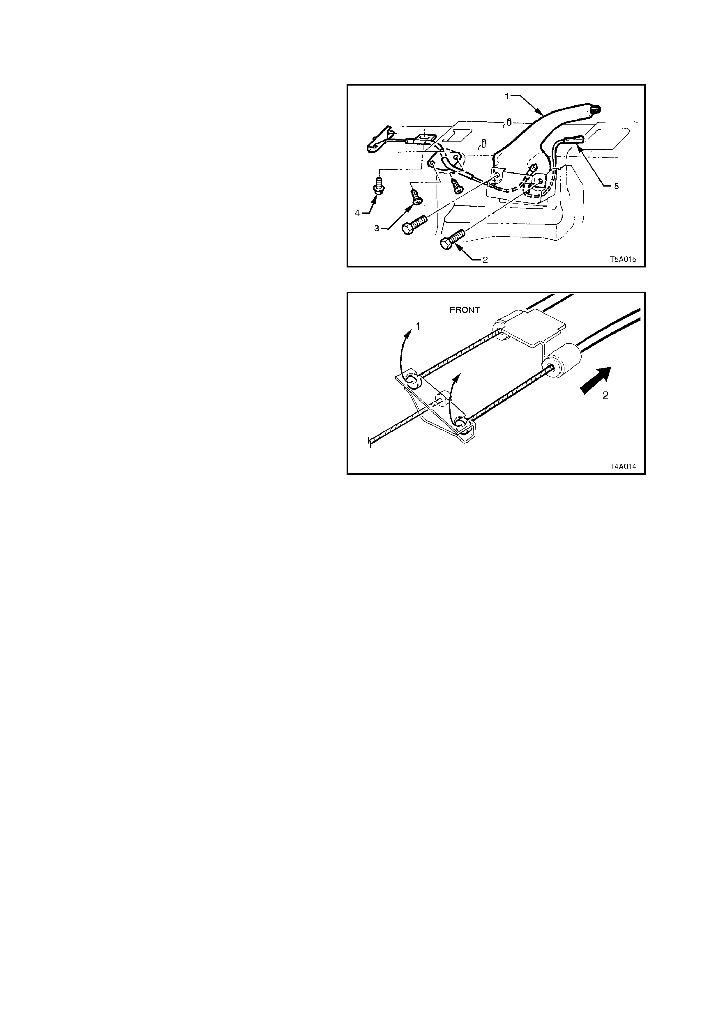
6. Pull each park brake rear cable forward and
up (1) to release it from the equaliser bracket.
Pull to the rear (2) to remove the cable from
the retaining bracket.
7. Remove the front cable outer cable retaining
bracket bolt (‘4’ in Figure 5A-28) from the
vehicle underbody.
NOTE:
Depending on the engine/transm ission fitted to the
vehicle, it may be necessary to first remove the
propeller shaft to enable access to this bolt. Refer
to Section 4C PROPELLER SHAFT AND
UNIVERSAL JOINTS for the procedure.
Figure 5A-29
8. Manoeuvre the front cable assembly and
equaliser bracket, through the aperture in the
floor pan, removing the cable assembly from
inside the vehicle.

REINSTALL
Installation is the reverse to the removal procedure.
1. Manoeuvre the front cable and escutcheon
plate assembly, through the hole in the floor
pan, ensuring that the rubber seal is correctly
positioned. Install the two self tapping screws,
securing the plate to the floor pan.
2. Install the park brak e lever and tighten bolts to
the specified torque.
PARK BRAKE LEVER BOLT 35 -65
TORQUE SPECIFICATION Nm
3. Install the park brake front cable adjusting nut
a few threads to secure the cable.
4. Install the outer front cable retaining bracket
bolt to the vehicle underbody, tightening to the
correct torque specification.
OUTER FRONT CABLE BRACKET 6 - 14
BOLT TORQUE SPECIFICATION Nm
5. As required, install the propeller shaft. Refer to
Section 4C PROPELLER SHAFT AND
UNIVERSAL JOINTS for the procedure and
the specified torque specifications.
6. Reinstall the driver’s seat and centre console.
7. Reinstall the two rear cables to the equaliser
bracket.
8. Adjust the park brake, as detailed in
2.2 PARK BRAKE CABLE, ADJUST in this
Section.
9. Lower the vehicle to the ground.
2.9 REAR PARK BRAKE CABLE/S
REMOVE
1. Release park brake.
2. Using a deep socket, loosen the front cable
adjusting nut (arrow) until the nut is almost
removed.
3. Using a floor jack under centre of differential
carrier, jack up and support rear of vehicle on
safety stands under rear trailing arms.
Figure 5A-30
4. To provide sufficient access, it may be
necessary to remove the propeller shaft from
the vehicle. Refer to
Section 4C PROPELLER SHAFT AND
UNIVERSAL JOINTS for the necessary
procedures.
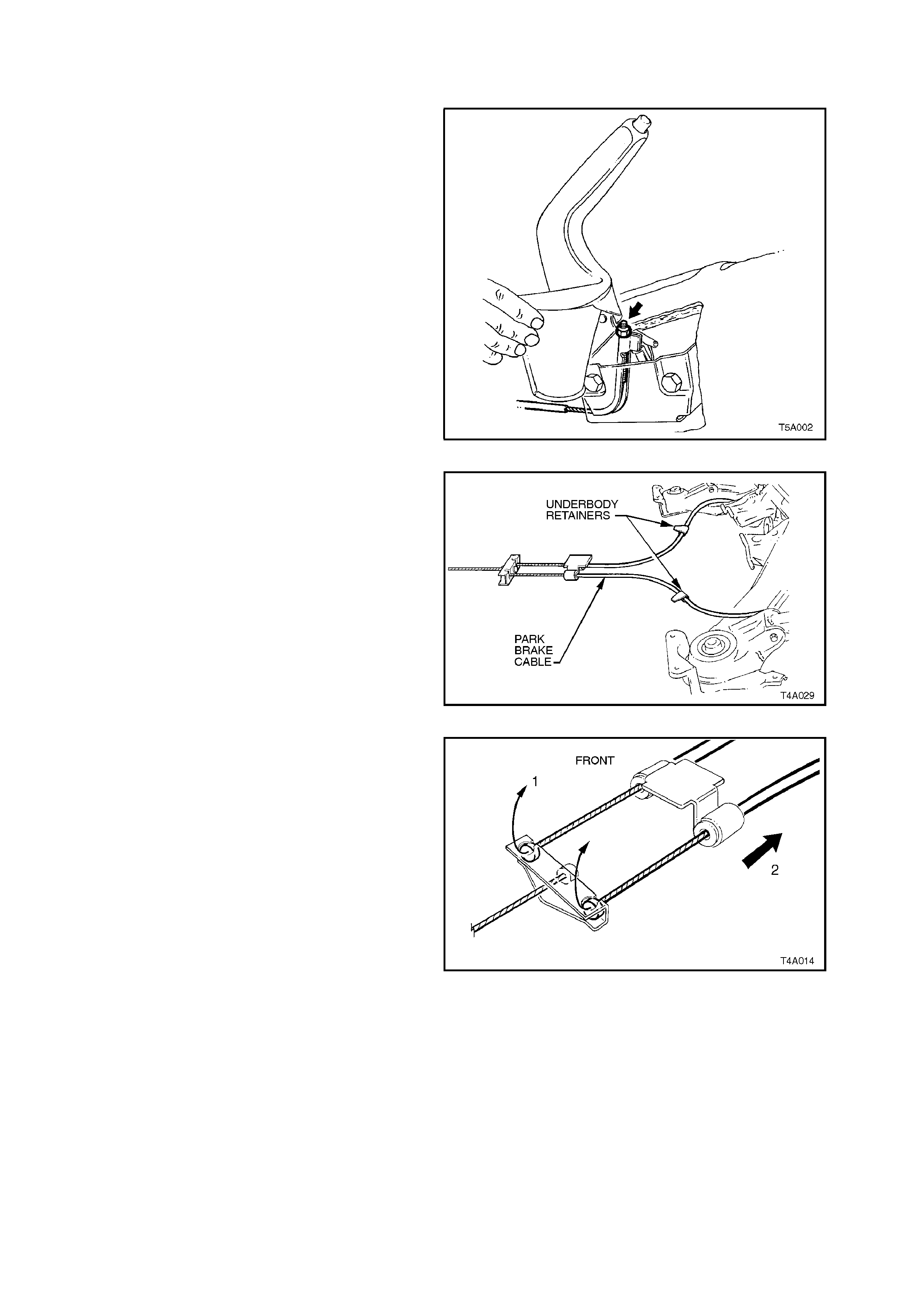
5. Unclip each (or as required) of the cable
grommets from the underbody clip/s, to free
the cable/s.
Figure 5A-31
6. Rem ove the front of the rear cable/s by pulling
the ball nipple forward and up (1), to f ree from
the equaliser bracket.
7. Free the front end of the outer cable from the
underbody bracket by pulling the outer cable
rearward (2).
Figure 5A-32

7. Disconnect the rear clevis from the rear park
brake actuating lever by gripping with pliers
and pivoting the cable rearwards.
8. Pull outer cable forward, out of trailing arm
retainers and remove the cable/s from the
vehicle.
Figure 5A-33
REINSTALL
Installation of the rear park brake cable/s is the
reverse of removal procedure, except for the
following points:
1. Install the cable through the trailing arm
retainer, then fit the cable clevis to the park
brake actuating lever.
2. Wrap rag around the inner cable to protect it
from damage, then use pliers to pull the ball
end on the inner cable forward to engage into
the equaliser bracket.
3. Reinstall the propeller shaft. Ref er to Section
4C PROPELLER SHAFT AND UNIVERSAL
JOINTS for all details.
4. Adjust park brake cable, refer
2.2 PARK BRAKE CABLE, ADJUST, in this
Section.
2.10 FRONT BRAKE HOSE
CAUTION :
Whenever any component that forms part of the ABS (if fitted) is disturbed during
Service Operations, it is vital that the complete ABS system be checked, using the
procedure as detailed in DIAGNOSIS, ABS FUNCTION CHECK, in Section 12L ABS &
ABS/ETC.
REMOVE
1. Raise front of vehicle and place on jack stands.
Refer to Section 0A GENERAL INFORMATION
for the recommended procedure.
2. Mark position of wheel relative to hub and
remove road wheel.
3. Thoroughly clean connections at each end of
brake hose.
4. Disconnect brake pipe from hose and plug pipe.
5. Remove the self-tapping screw (1) securing the
hose bracket to the inner skirt panel.
6. Remove the brake hose from the suspension
strut bracket by turning plastic sleeve on the
hose until the flats on the sleeve align with
brack et opening. Unc lip hose and sleeve ( 2) fr om
bracket.
7. Unbolt and remove brake hose from caliper.
Figure 5A-34
Techline
Techline
REINSTALL
1. Ensure brake hose and caliper mating surfaces are
clean and free from burrs.
2. Reconnect brake hose (1) to caliper and tighten
bolt (2) to specified torque.
BRAKE HOSE TO CALIPER 32 - 37
TORQUE SPECIFICATION Nm
NOTE:
Use NEW copper washers (3).
3. Install the brake hose to the strut bracket by turning
plastic sleeve on the hose until the flats on the
sleeve align with the bracket opening. Clip hose
and sleeve into suspension strut bracket and
secure the sleeve to the bracket by rotating 90º.
4. Reinstall the self tapping screw to retain the hose
bracket to the inner skirt panel.
5. Remove plug from brake pipe and reconnect to
hose. Tighten to specified torque.
BRAKE PIPE TO BRAKE
HOSE FLARED NUT 14 - 17 Nm
TORQUE SPECIFICATION
6. Check that hose is not twisted.
7. Bleed brake/s, see 2.3 BRAKE SYSTEM BLEED,
in this Section.
8. Reinstall road wheel, aligning marks made on
removal and lower vehicle.
Figure 5A-35
9. Tighten road wheel attaching nuts to the specified
torque.
ROAD WHEEL ATTACHING 110 - 140
NUTS TORQUE SPECIFICATION Nm
2.11 REAR CALIPER BRAKE HOSE
CAUTION:
Whenever any component that forms part of the ABS (if fitted) is disturbed during
Service Operations, it is vital that the complete ABS system be checked, using the
procedure as detailed in DIAGNOSIS, ABS FUNCTION CHECK, in Section 12L ABS &
ABS/ETC.
REMOVE
1. Raise rear of vehicle and place on jack stands.
Refer to Section 0A GENERAL
INFORMATION for the procedure.
2. Mark position of wheel relative to hub and
remove road wheel.
3. Thoroughly clean connections at each end of
brake hose.
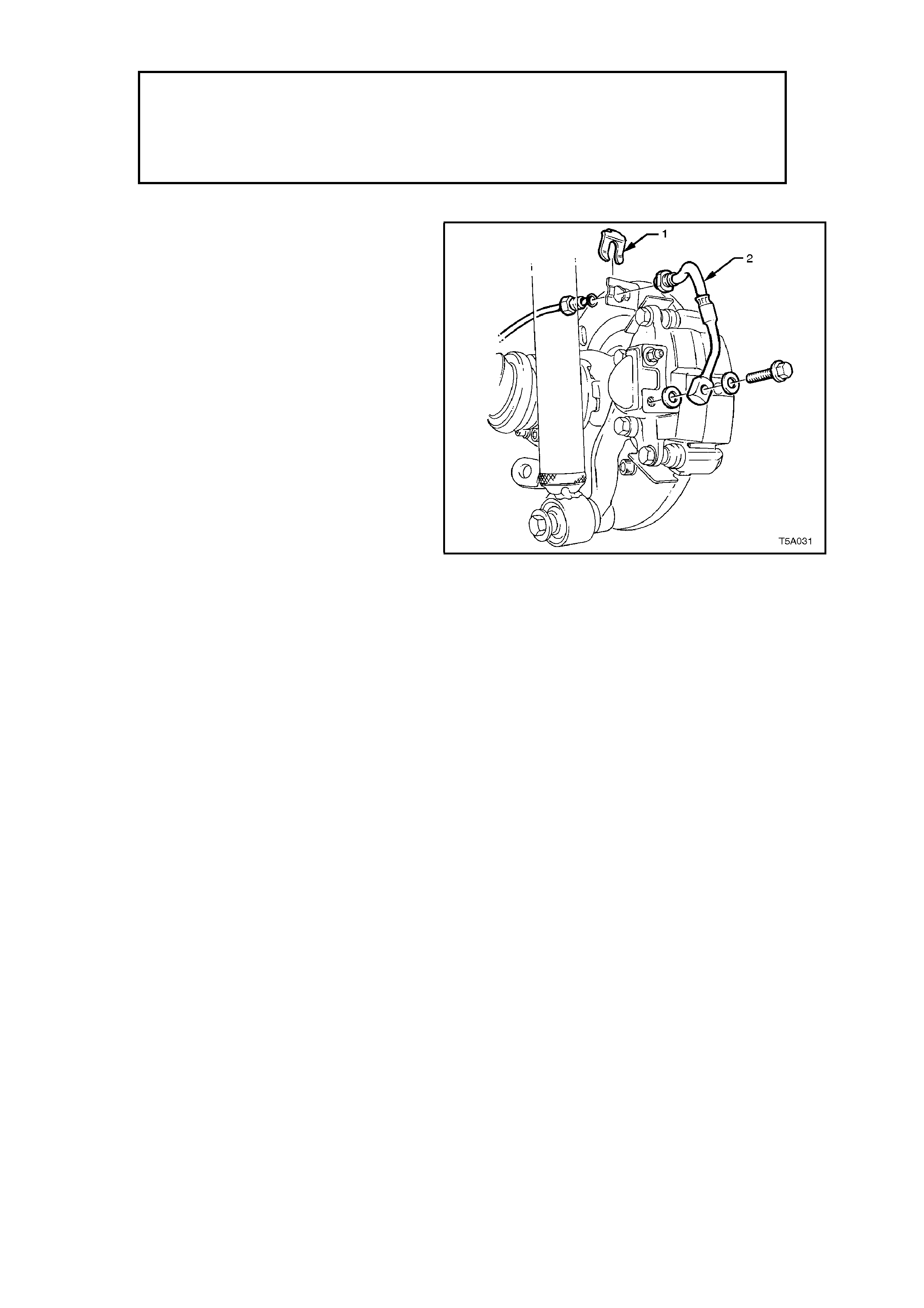
4. While holding the hose (2) with a back-up
spanner, loosen then disconnect brake pipe
from brake hose. Plug the pipe open end.
5. Unclip retainer (1) from hose and withdraw
hose from bracket.
6. Unbolt and remove brake hose from caliper.
Figure 5A-36

REINSTALL
1. Ensure brake hose and caliper mating
surfaces are clean and free of burrs.
2. Reconnect brake hose to caliper and tighten
bolt to specified torque.
BRAKE HOSE TO CALIPER 32 - 37
BOLT TORQUE SPECIFICATION Nm
NOTE:
Use new copper washers and ensure peg on hose
aligns with dimple in caliper.
3. Fit hose correctly into mounting plate bracket
and reinstall retainer. Check that hose is not
twisted.
4. Remove plug from brake pipe and reconnect
to hose. While using a back -up spanner on
the brake hose to prevent twisting, tighten pipe
to specified torque.
BRAKE PIPE TO HOSE FLARED 14 -17
NUT TORQUE SPECIFICATION Nm
5. Bleed brake/s, see 2.3 BRAKE SYSTEM
BLEED, in this Section.
6. Align marks made prior to removal, then
reinstall the road wheel. Lower vehicle.
7. Tighten road wheel attaching nuts to the
specified torque.
ROAD WHEEL ATTACHING 110 - 140
NUT TORQUE SPECIFICATION Nm
2.12 RE AR BRAKE HOSE
CAUTION :
Whenever any component that forms part of the ABS (if fitted) is disturbed during
Service Operations, it is vital that the complete ABS system be checked, using the
procedure as detailed in DIAGNOSIS, ABS FUNCTION CHECK, in Section 12L ABS &
ABS/ETC.
REMOVE
1. Raise rear of vehicle and place on jack
stands. Refer to Section 0A GENERAL
INFORMATION, for details.
2. Thoroughly clean connections at each end of
the rear brake hose to be removed.
Figure 5A-37
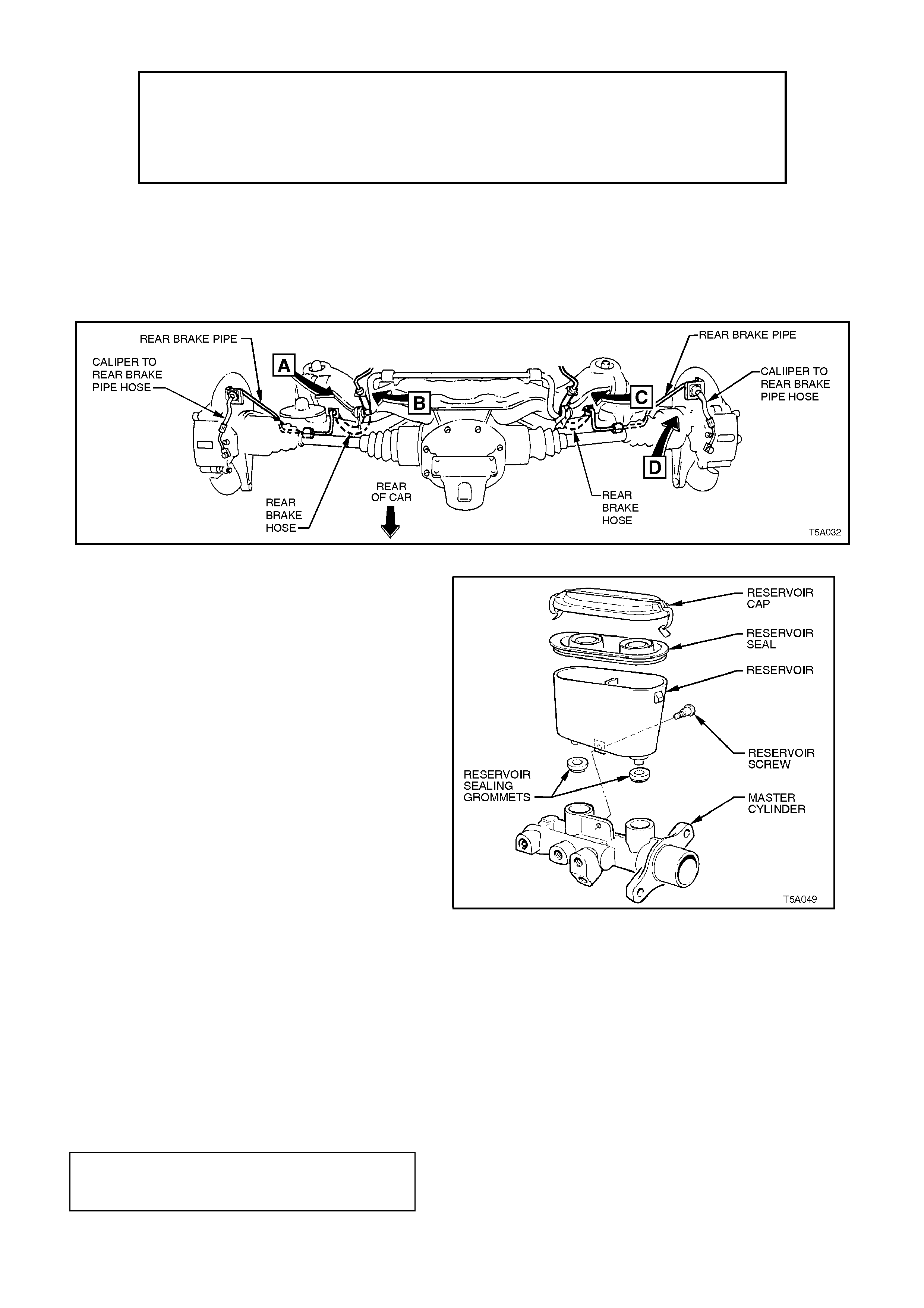
3. Disconnect brake pipe from brake hose at
trailing arm brackets (View [B]). Plug open end
of brake pipe/s to prevent foreign material entry.
4. Disconnect brake hose connection pipe from
brake hose, while holding the hose with a back -
up spanner. For thos e vehicles without ET C, the
RH side brake hose (View [C]), also has a
junction block to provide for a connection from
the master cylinder. Plug all pipe ends to
prevent foreign material entry.
5. Unclip retainers from the end of each hose end
and withdraw hose from brackets.
Figure 7C5-38
REINSTALL
1. Ensure brake hose ends and pipe mating
surfaces are clean and free of burrs.
2. Fit hose into mounting plate brackets and
reinstall retainers. Check that hose is not
twisted.
3. Remove plugs from brake pipes and
reconnect to hose ends. Tighten all pipe nuts
to specified torque.
BRAKE PIPE FLARE NUT
TO BRAKE HOSE TORQUE 14 - 17 Nm
TORQUE SPECIFICATION

3. MAJOR SERVICE OPERATIONS
CAUTION :
Whenever any component that forms part of the ABS (if fitted) is disturbed during
Service Operations, it is vital that the complete ABS system be checked, using the
procedure as detailed in DIAGNOSIS, ABS FUNCTION CHECK, in Section 12L ABS &
ABS/ETC.
3.1 MASTER CYLINDER
REMOVE
1. Remove master cylinder reservoir cap
temporarily and syphon brake fluid from the
reservoir. Reinsta ll reservoir cap.
2. Disconnect electrical connector from brake
warning, differential switch.
3. Disconnect brak e lines f rom m as ter cylinder and
plug both the lines and master cylinder
apertures, to prevent dirt ingress.
Figure 5A-39
4. Remove bracket securing master cylinder to
adjacent spring tower.
5. Remove nuts securing master cylinder to brake
booster and remove master cylinder.
IMPORTANT:
DO NOT disturb brake booster push rod and DO
NOT depress brake pedal with master cylinder
removed or the internal reaction disc in the booster
may become dislodged.
Figure 5A-40
DISASSEMBLE
1. Clean the outside of the master cylinder.
2. Remove reservoir cap and seal. Discard any
fluid left in reservoir
3. Unscrew the reservoir to body retaining screw,
located at the base of the reservoir.
4. Separate the plastic r eservoir, by hand, fr om the
body.
5. Remove the two reservoir sealing grommets
from the body.
Figure 5A-38
6. Invert master cylinder body so that the reservoir
ports face downwards. Depress the primary
piston with a wood dowel or brass rod until the
piston bottoms in the bore of the m ast er cylinder
body. The secondary piston stop pin should
freely fall out.
7. Carefully remove primary piston from the main
bore of the master cylinder.
Figure 5A-42
8. Remove secondary piston and return spring by
lightly tapping the open end of the master
cylinder bore squarely onto a soft piece of wood.
NOTE 1:
The caged spring of the secondary piston has been
set to a predetermined length. Do not attempt to
adjust or remove the caged spring.
NOTE 2:
The centre valve is part of the secondary piston
assembly and is not serviced as a separate part.
Figure 5A-43
9. Remove the seal retainer from the primary
piston by using a small screwdriver to carefully
pry apart the seal retainer legs.
10. Remove the recuperating guide and seal from
the primary piston.
11. Remove all rubber seals from both pistons,
taking EXTREME CARE not to damage the
pistons.
Figure 5A-44
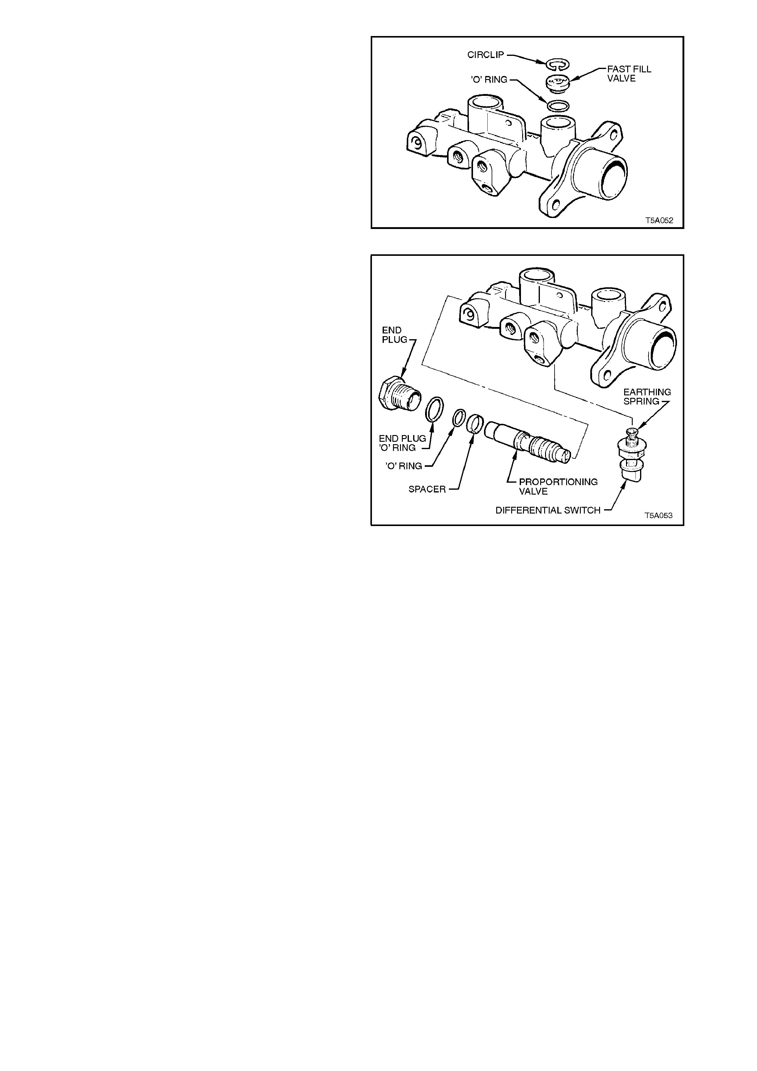
12. Using suitable circlip pliers, remove the circlip
retaining the fast fill valve located in the primary
reservoir port of the master cylinder.
13. Face the master cylinder reservoir ports
downwards to allow the fast fill valve to fall out. If
the valve is stuck, lightly tap the master cylinder
on a piece of wood to assist removal.
14. Remove the valve sealing O-ring from the
bottom of the reservoir port.
Figure 5A-45
15. Unscrew and remove the end plug from the
master cylinder body.
16. Remove the differential switch from the master
cylinder, ensuring that the electrical earthing
spring remains on the switch plunger.
17. Remove the proportioning valve assembly by
lightly tapping the 'end plug' end of the cylinder
bore squarely onto a soft piece of wood to
dislodge the proportioning valve assembly.
IMPORTANT:
Do not damage the proportioning valve assembly by
attempting to pull it out of the bore with pliers.
NOTE:
Do not disassemble the proportioning valve assembly
as this valve is only serviced as a complete
assembly.
Figure 5A-46
CLEAN AND INSPECT
NOTE:
Ensure work area is c lean and f ree of dust or other
contam inants . T hes e c an af f ec t the per f ormanc e of
all the seals in the master cylinder.
1. W ash m aster cylinder body, reservoir and c ap
in clean methylated spirits.
2. Wash all internal parts in brake fluid.
3. Check all recesses, openings and passages
to ensure they are open and free of foreign
matter.
4. Place all parts on a clean surface.
5. Inspect the master cylinder bores for signs of
etching, pitting, scoring or rust. If in poor
condition, replace the master cylinder.
IMPORTANT:
Do not hone the master cylinder bor e.
6. Discard all rubber parts together with the
secondary piston assembly (the secondary
piston assembly incorporates; the secondary
piston, the centre valve and the caged s pring).
Only new parts from the genuine service kit
should be used to reassemble the master
cylinder.
REASSEMBLE
NOTE 1:
Before assembly, lubricate internal parts and
master cylinder bores with clean, recommended
brake fluid from a sealed container.
NOTE 2:
Prior to assembly, ensure that the primary piston,
without seals fitted to it, is free to move the full
piston stroke in the large bore.
Figure 5A-47
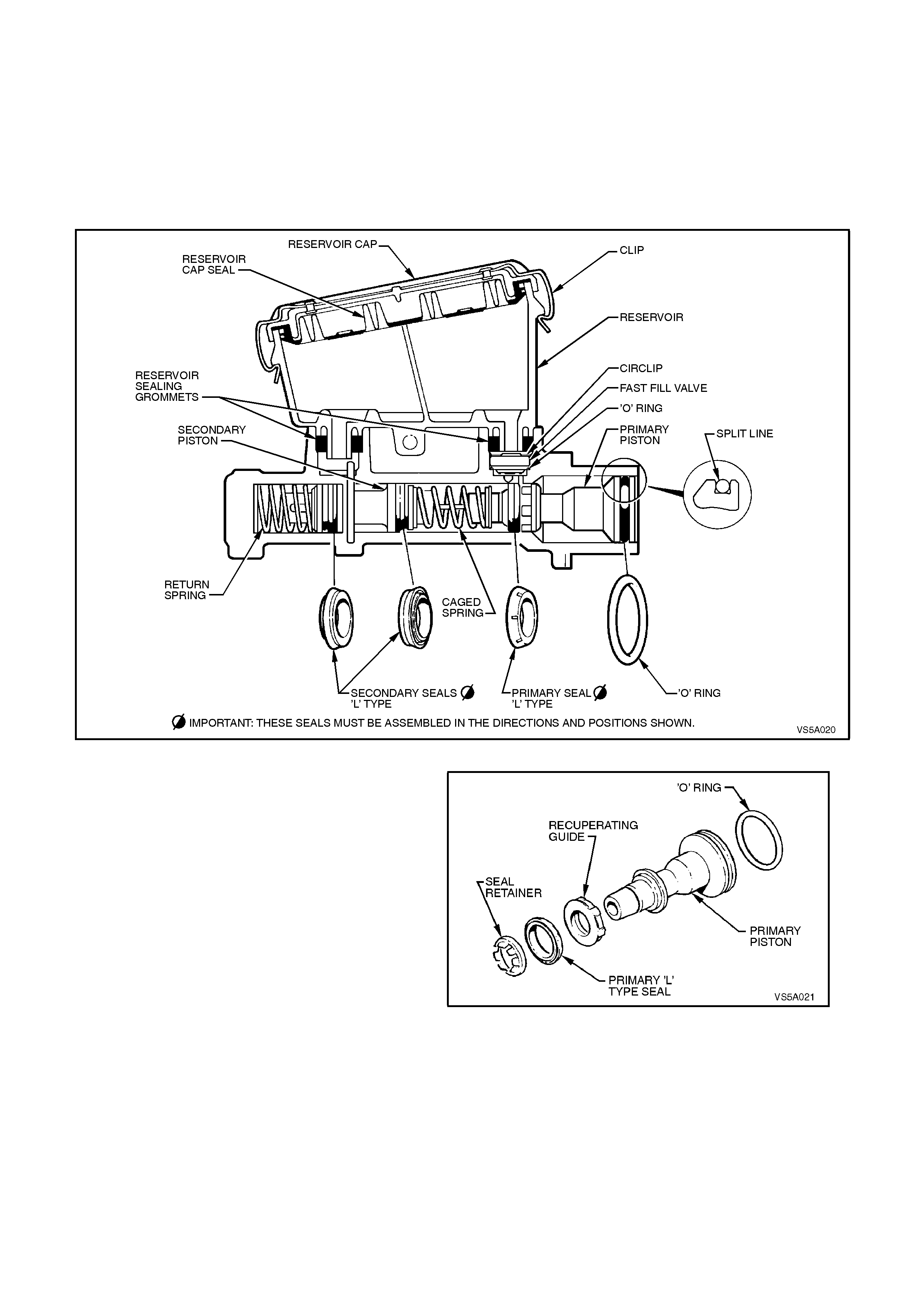
1. Install O-r ing seal into the groove at the end of
the primary piston.
2. Install the recuperating guide followed by the
primary L type seal onto the end of the primary
piston. The sealing face of the L type seal
must face away from the recuperating guide.
NOTE:
The primary L type seal for the primary piston can
be identified by the six shallow grooves around the
seals outer surface.
3. Assemble the seal retainer onto the primary
piston. Using a small screwdriver, clip the
retaining legs of the retainer into the groove on
the primary piston. Care should be taken to
avoid damage to the piston or seal. Figure 5A-48
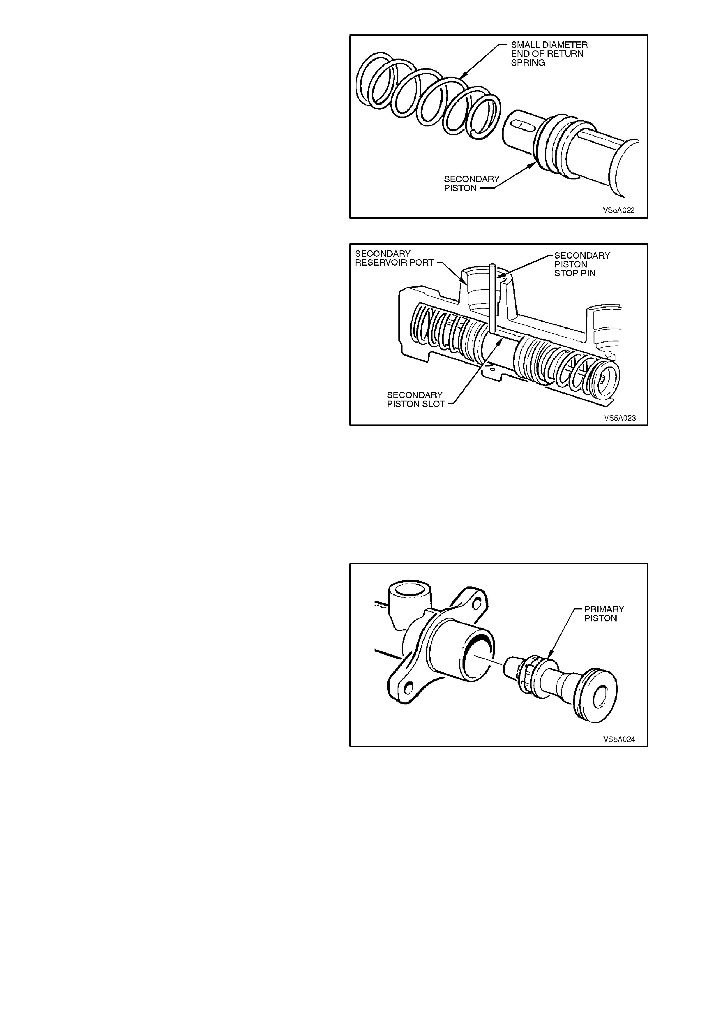
4. Assemble the small end of the return spring
over the end of the secondary piston. This
should be a slight interference fit.
Figure 5A-49
5. Carefully insert the secondary piston, caged
spring end last, through the lar ge bor e and into
the smaller bore of the master cylinder until the
return spring 'bottoms'. Ensure the secondary
spring does not dislodge from the piston
assembly during this operation.
NOTE:
To assemble the secondary piston assembly into
the body, align the slot in the sec ondary piston with
the hole in the reservoir ports. This must be done
so that the secondary piston stop pin can be
inserted into secondary reservoir port in the m aster
cylinder.
Fully stroke the secondary piston using a soft
dowel and while held at the bottom of the bor e,
install the secondary piston stop pin into the
secondary reservoir port. The piston stop pin
should easily fit through the larger hole of the
two holes located in the secondary reservoir
port. The top of the secondary piston stop pin
should not protrude more than 6 mm above
the bottom of the reservoir port.
Figure 5A-50
6. Insert the primary piston into the main bore,
against the secondar y piston and caged s pring
assembly. Carefully push both pistons down
the bore until the primary piston is flush with
the bore opening.
7. Stroke pistons and check that the primary
piston returns to the end of the bore af ter each
stroke. Ensure movement is not sticky.
Figure 5A-51
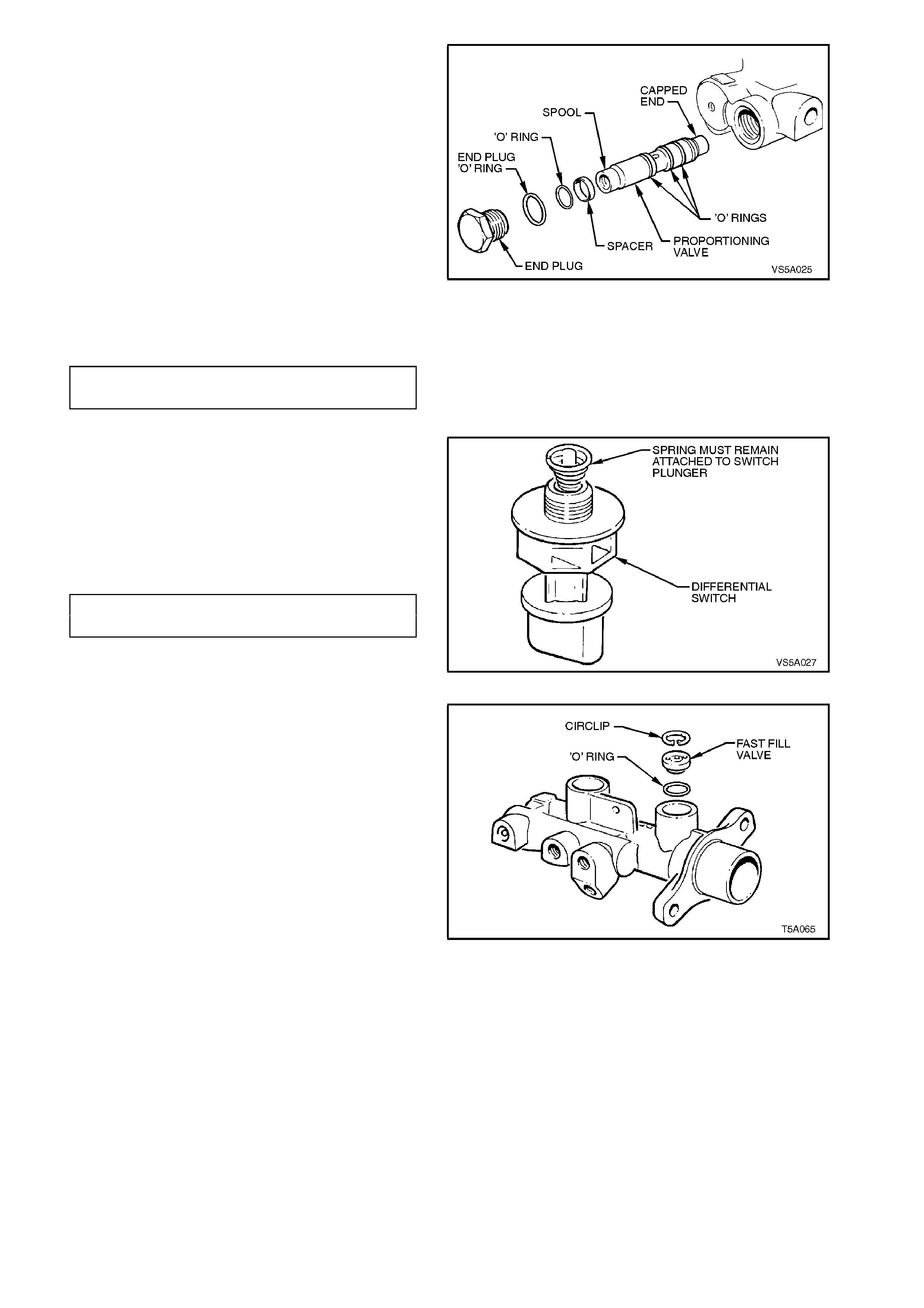
8. Fit new O-rings onto proportioning valve.
9. Ensure spacer and O-ring are fitted over the
proportioning valve spool and that they are
installed the right way (spacer first followed by
the O-ring).
10. Insert proportioning valve into the bore,
capped end first. Extreme care should be
taken when inserting the valve to ensure that
the O-rings are not damaged. If O-rings are
damaged, the master cylinder will not function
correctly and will leak brake fluid. The
proportioning valve assembly must be
bottomed in the bore of the master cylinder.
11. As sem ble a new O-ring onto the end plug, and
screw the end plug into the master cylinder
body.
END PLUG 25 - 30
TORQUE SPECIFICATION Nm
Figure 5A-52
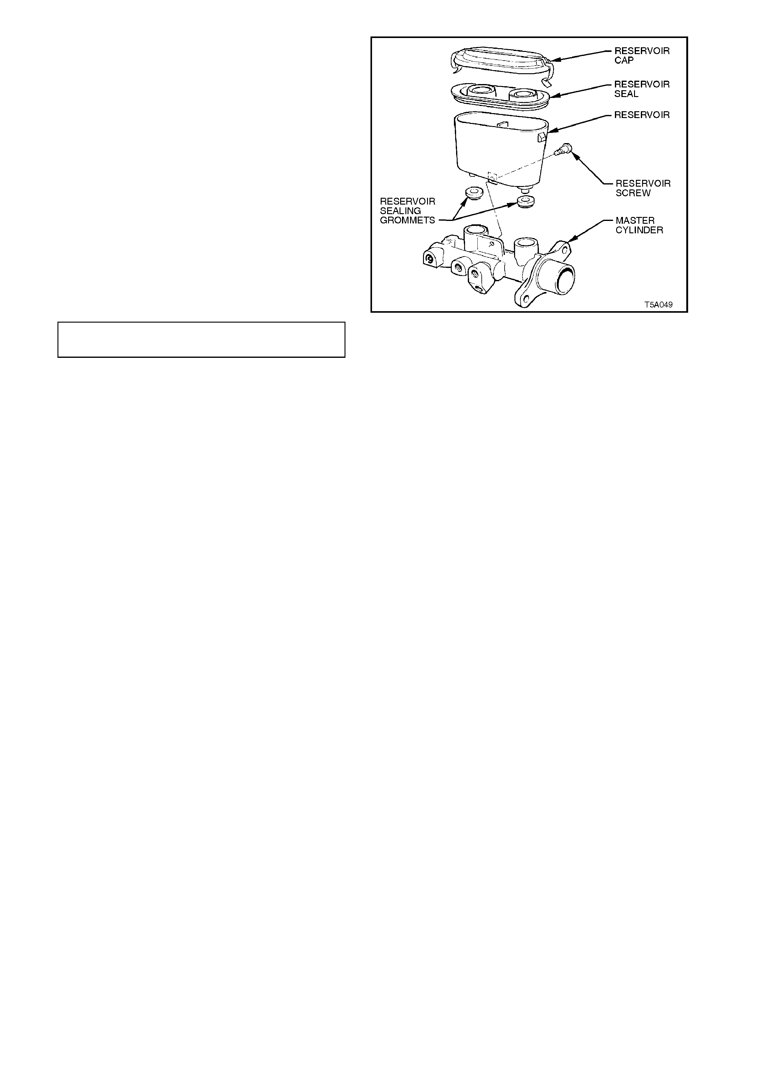
12. Reinstall differential switch and spring. Do not
over tighten.
NOTE:
Ensure the earthing spr ing on the differential s witch
is installed on the plunger as shown. If necessary,
the small end of the spring may need to be closed
down slightly to give the required attachment.
DIFFERENTIAL SWITCH 2
TORQUE SPECIFICATION Nm
Figure 5A-53
13. Carefully install the fast fill valve O-ring in the
bottom shoulder of the primary reservoir port.
14. Fit the fast fill valve into the primary reservoir
port, ensuring the rubber base with six dim ples
is faced downwards. Secure valve with circlip.
Figure 5A-54
15. Lightly smear the bores of the reservoir ports
and sealing grommets with clean brake fluid.
16. Carefully assemble sealing grommets into the
bores of the reservoir ports to locate them
against the shoulder in each bore.
17. Reinstall reservoir by pushing reservoir into the
sealing grommets until the hole for the
retaining screw in the reservoir aligns with the
master cylinder body. Install retaining screw
and tighten to the specified torque. The
retaining screw should just protrude from the
hole in the master cylinder body when
tightened.
NOTE:
Both reservoir and master cylinder holes must be
aligned when installing the res ervoir r etaining scr ew
to avoid cross threading.
RESERVOIR SCREW 4.0 - 5.0
TORQUE SPECIFICATION Nm
18. Fill the master cylinder with fresh,
recommended brake fluid and bleed on the
bench prior to replacing on the vehicle. After
bleeding, block master cylinder outlet ports to
prevent fluid escaping.
19. Assemble new reservoir seal into reservoir
cap. Lubricate inside of the reservoir lips with
clean brake fluid to accept the reservoir cap
seal.
20. Reinstall cap seal and cap.
Figure 5A-55
REINSTALL
1. Reinstall master cylinder assembly on brake
booster taking care not to disturb brake
booster push rod. Tighten master cylinder nuts
to specified torque.
MASTER CYLINDER ATTACHING 15 - 20
NUT TORQUE SPECIFICATION Nm
2. Reinstall bracket securing master cylinder to
adjacent spring tower. Tighten nuts and bolt to
specified torque.
MASTER CYLINDER BRACKET 15 - 20
NUT TORQUE SPECIFICATION Nm
3. Unplug brake lines and master cylinder outlet
ports, reinstall pipes to master cylinder and
tighten to specified torque.
BRAKE PIPE TO MASTER
CYLINDER FLARED NUT 8 - 11 Nm
TORQUE SPECIFICATION
4. Reconnect electrical connector to differential
switch.
5. Bleed brake system, refer to 2.2 PARK
BRAKE CABLE, ADJUST in this Section. Figure 5A-56
3.2 BRAKE BOOSTER
CAUTION :
Whenever any component that forms part of
the ABS (if fitted) is disturbed during Service
Operations, it is vital that the complete ABS
system be checked, using the procedure as
detailed in DIAGNOSIS, ABS FUNCTION
CHECK, in Section 12L ABS & ABS/ETC.
NOTE:
The brake booster is not a serviceable item and if
found to be faulty, must be replaced as a unit.
REMOVE
1. Remove master cylinder, refer to
3.1 MASTER CYLINDER in this Section.
IMPORTANT:
With the master cylinder removed, do not disturb
the brake booster push rod nor depress the brake
pedal, as the reaction disc in the booster may
become dislodged.
2. Remove vacuum hose from brake booster
body. While the V6 engine application is
shown in Figure 5A-57, the V6 supercharged
and V8 attachment methods are similar.
Figure 5A-57
3. Remove instrument panel lower right trim
assembly. Refer to
Section 1A3 INSTRUMENT PANEL AND
CONSOLE, for details.
4. Remove push rod retaining clip (1), push rod
(3) and washers (2 and 4) from brake pedal.
Figure 5A-58
5. Remove brake booster assembly retaining
nuts (4 places) at brake pedal support, from
inside vehicle.
6. Withdraw booster from engine compartment,
turning booster towards engine to clear spring
tower.
Figure 5A-59
REINSTALL
Installation is the reverse of the r emoval proc edure,
except for the following:
1. Lubricate brake pedal and push rod
component bearing surfaces with
Molybdenum Disulphide grease (Holden's
Specification HN1271), refer to
Figure 5A-58.
2. Ensure brak e boos ter hose is routed c orrec tly,
refer Figure 5A-57, for V6 engines.
3. Reinstall master cylinder as detailed in
3.1, MASTER CYLINDER, in this Section.
4. Tighten brake booster retaining nuts to
specified torque.
BRAKE BOOSTER RETAINING 20 - 25
NUT TORQUE SPECIFICATION Nm
3.3 BRAKE CALIPER (FRONT & REAR)
CAUTION :
Whenever any component that forms part of the ABS (if fitted) is disturbed during
Service Operations, it is vital that the complete ABS system be checked, using the
procedure as detailed in DIAGNOSIS, ABS FUNCTION CHECK, in Section 12L ABS &
ABS/ETC.
REMOVE
1
. Raise vehicle and place on jack stands.
2. Mark position of road wheel relative to hub
and remove wheel.
3. Place a drain tray beneath caliper assembly.
4. Loosen and remove brake hose to caliper
attaching bolt. Separate bolt from hose and
discard sealing washers.
5. Remove anchor plate retaining bolts and lift
caliper assembly out over disc.
NOTE: Dis card the front brak e caliper anchor plate
retaining bolts as they must be replaced on
reassembly.
Figure
5A
-
60
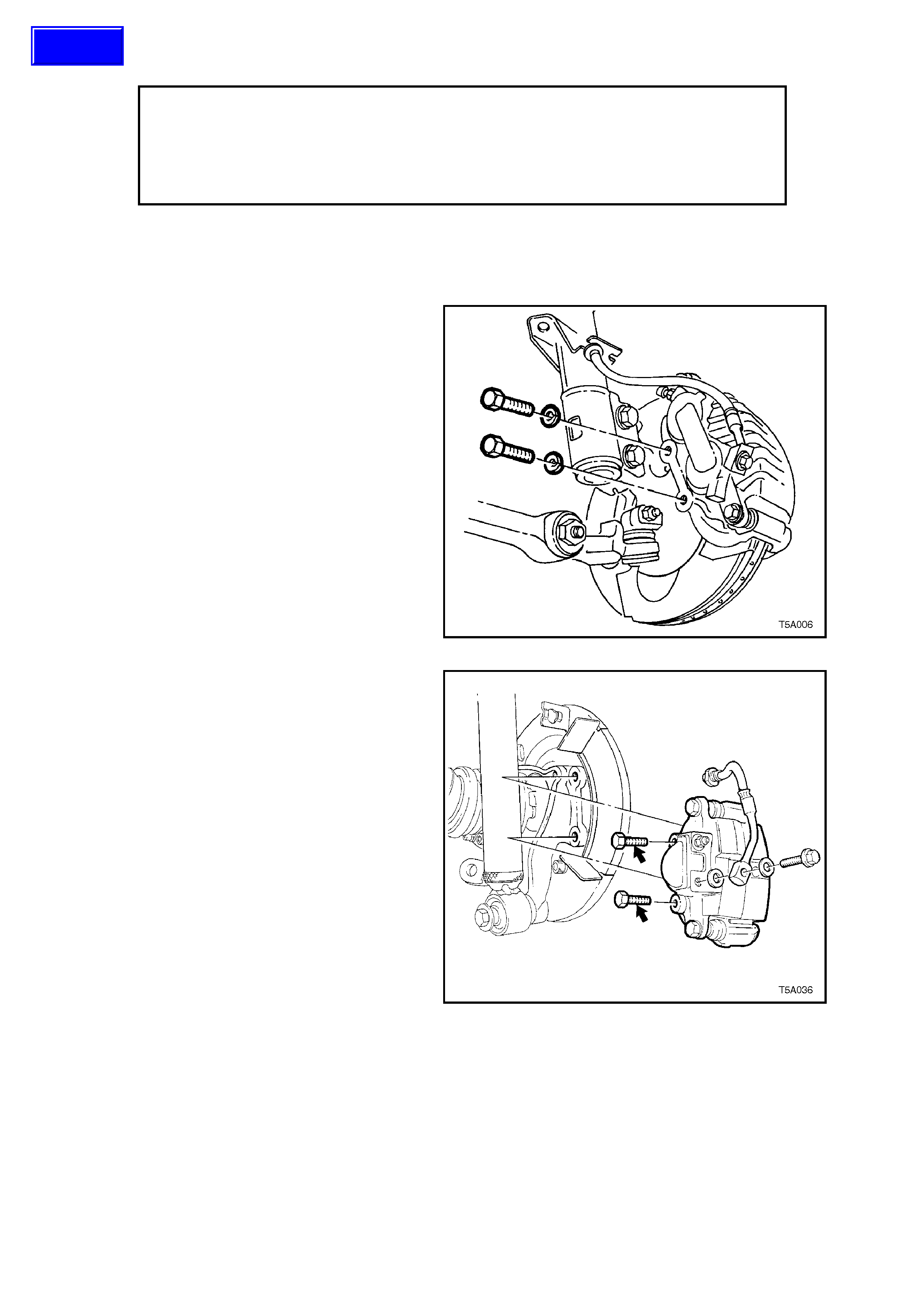
6. The removal procedure for the rear brake
caliper is similar to that for the front.
Figure 5A-61
Techline
DISASSEMBLE
Figure 5A-62
Figure 5A-63

1. Remove guide pin bolts and discard.
2. Separate caliper housing from anchor plate
and remove brake pads.
3. Withdraw guide pins and boots from anchor
plate. Separate boots from pins.
4. Pack a clean piece of cloth between caliper
piston/s and opposite legs on housing and
apply air pressure at brake hose inlet port to
eject a piston.
CAUTION:
Apply light air pressure initially and
progressively increase until the pist on is fo rced
out of the bore. This precaution is advisable to
avoid physical injury, as the piston may
develop considerable force due to the air
pressure.
NOTE:
As only one piston in the front caliper will be
rem oved by this m ethod, r emoval of the s ec ond will
need to be done by us ing internal expanding circlip
pliers, to grasp the inner piston wall. Then, while
twisting the piston, apply a pulling force at the same
time to remove the piston from its bore.
5. Remove rubber boot from bore.
6. Remove seal from bore, taking care not to
damage bore or seal locating groove.
7. Remove bleeder screw.
Figure 5A-64
CLEAN AND INSPECT
1. Clean all metal parts thoroughly with
methylated spirits. Clean rubber parts with
brake fluid only. Use clean, dry compressed
air to dry parts.
2. Examine bore and piston carefully for signs of
damage, abrasion, scuffing or corrosion.
RENEW PISTON IF ANY OF THESE
FACTORS EXIST OR IF THERE IS ANY
DOUBT REGARDING ITS CONDIT ION. If the
bore is unser viceable, a new housing m ust be
fitted.
3. Inspect guide pins f or corrosion. Replace pins
if corroded.
4. Blow through bleed screw port with
compressed air.
REASSEMBLE
1. Lubricate cylinder bore and piston with
specified brake fluid (Holden's Specification
HN1796).
2. Fit new seal into inner groove of bore. Ensure
seal is not twisted and is fully seated in
groove.
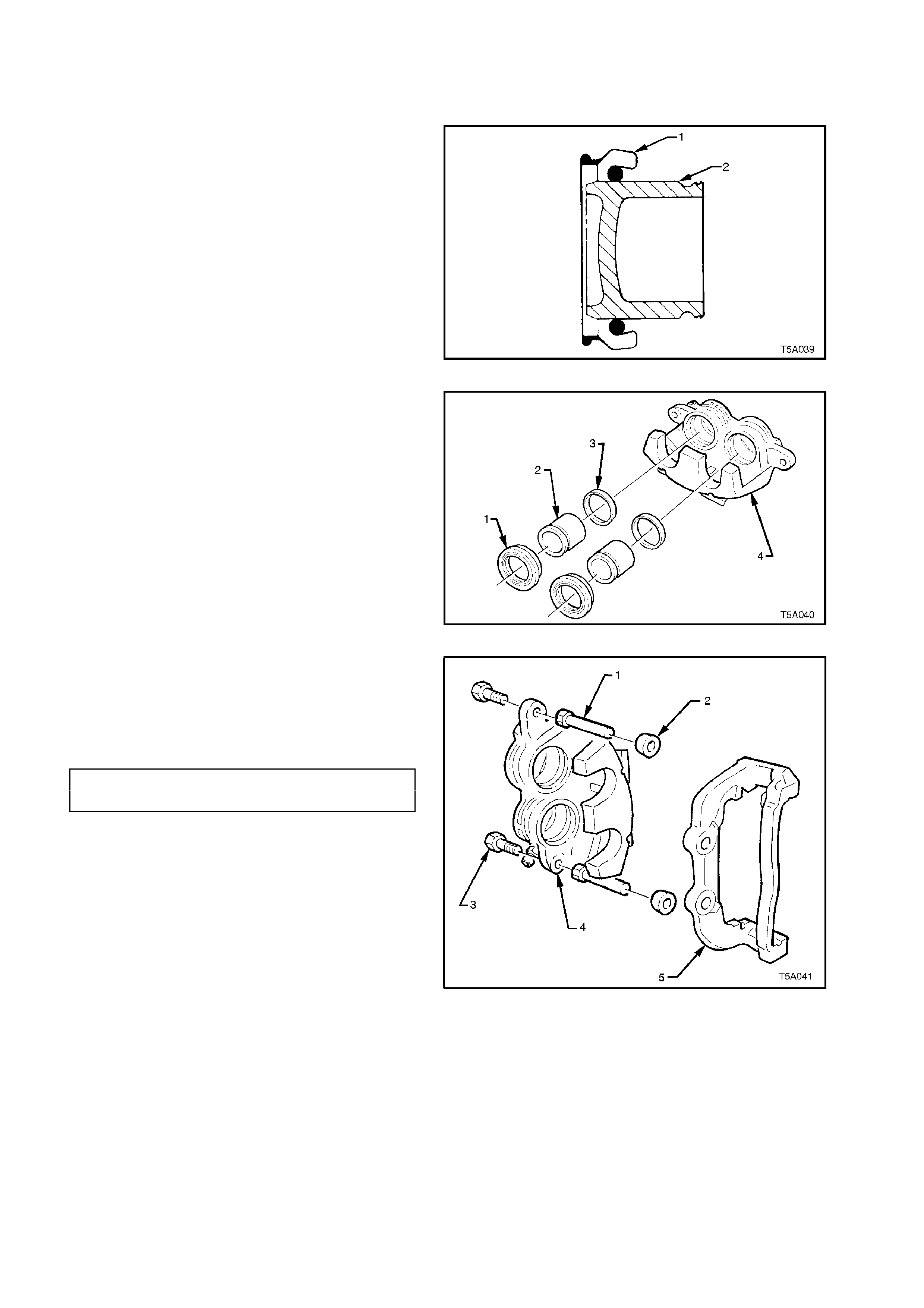
3. Install piston boot (1) over end of piston (2).
Figure 5A-65
4. Position each piston (2) into caliper housing
(4), seating boot (1) into groove in caliper
bore. Ensure boot flange is s quarely and firm ly
seated in groove.
5. Push piston squarely into bore by hand until
fully seated. Ensure piston boot is fully seated
in piston and caliper bore grooves.
6. Lubricate guide pins with silicone type grease
(Dow Corning No. 44, Holden's part number
VS16477).
Figure 5A-66
7. Reinstall guide pins (1) in caliper housing (4)
using NEW caliper housing to guide pin bolts
(3). Use an open end spanner to hold flat
section of guide pin when tightening bolts to
correct torque.
GUIDE PIN BOLT 30 - 34
TORQUE SPECIFICATION Nm
NOTE:
Do not re-use old bolts.
8. Install new guide pin boots (2).
9. Assemble caliper hous ing (4) and anc hor plate
(5) together. Ensure guide pin boots are
correctly located in guide pin and anchor plate
grooves.
10. Reinstall bleed screw.
11. Reinstall brake pads, refer to
2.5 BRAKE PADS, REPLACE in this Section,
for correct installation procedure.
Figure 5A-67
REINSTALL
1. Ensure anchor plate mounting surfaces are
clean.
2. Press inner brake pad by hand to ensure
piston is bottomed in bore.
3. Position caliper assembly over disc, insert
anchor plate retaining bolts. Tighten bolts to
specified torque, refer Figures 5A-60 and
5A-61.
NOTE: New retaining bolts must be used when
reinstalling the front brake caliper anchor plate.
FRONT BRAKE CALIPER 80- 90 Nm, plus
ANCHOR PLATE BOLT 40 - 50
TORQUE SPECIFICATION turn angle
REAR BRAKE CALIPER
ANCHOR PLATE BOLT 70 - 100 Nm
TORQUE SPECIFICATION
4. Reconnect brake hose (1) using NEW, dry,
sealing washers (3). Tighten attaching bolt (2)
to the correct torque specification.
BRAKE HOSE TO CALIPER 32 - 37
BOLT TORQUE SPECIFICATION Nm
5. Bleed brake system, refer to 2.3 BRAKE
SYSTEM, BLEED, in this Section.
6. Depress brake pedal several times to bring
pads into position against disc.
7. Reinstall road wheel(s), aligning marks made
prior to removal, then lower vehicle.
NOTE: Ensure that brake hose plastic sleeve is
secured correctly in suspension strut bracket.
8. Tighten road wheel attaching nuts to the
specified torque.
ROAD WHEEL ATTACHING NUT 100 - 125
TORQUE SPECIFICATION Nm
9. Check level of fluid in master cylinder.
Figure 5A-68
3.4 BRAKE DISC (FRONT AND REAR)
CAUTION :
Whenever any component that forms part of the ABS (if fitted) is disturbed during
Service Operations, it is vital that the complete ABS system be checked, using the
procedure as detailed in DIAGNOSIS, ABS FUNCTION CHECK, in Section 12L ABS &
ABS/ETC.
REMOVE
Remove brake caliper assembly, refer to
3.3 BRAKE CALIPER (FRONT AND REAR), in
this Section.
NOTE:
It is not necessary to disconnect brake hose from
caliper. Support caliper with wire hook to avoid
strain on brake hose.
Front Brake
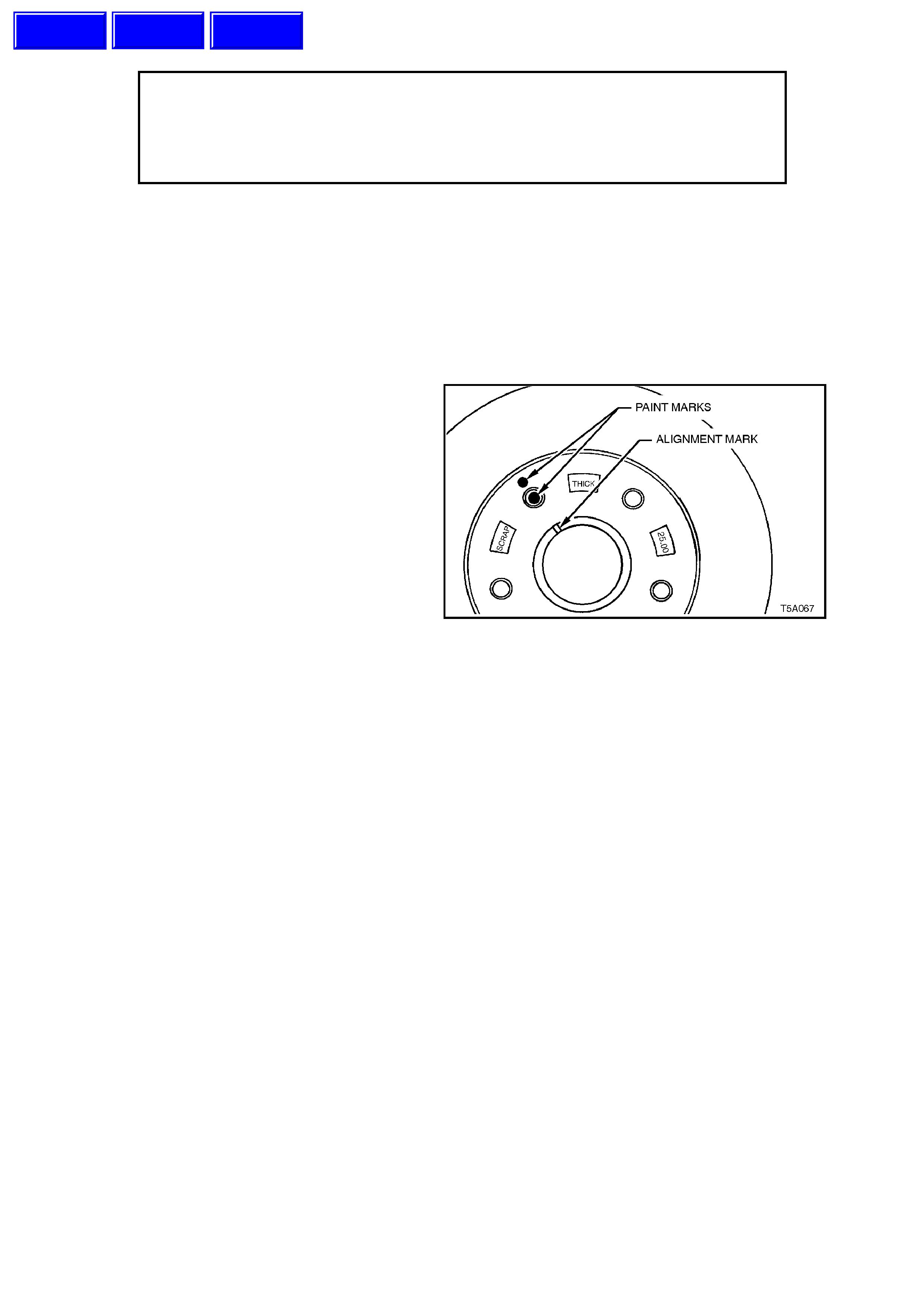
IMPORTANT:
The brake disc to hub relationship is carefully
matched during production, to minimise the effect
of a tolerance stack-up, that could result in disc
runout and subsequent brake shudder.
Therefore, prior to removal of the front disc/s,
check to see whether a paint daub mark is still
visible on the disc hub surface, adjacent to one of
the wheel studs and in alignment with the two
marks on the end of the hub, as shown.
If the paint marks are no longer visible, then
carefully mark the relationship of the disc to the hub
for installation. If this precaution is not taken, then a
disc runout condition could be induced that will
cause brake shudder. Figure 5A-69
If necessary, jar the disc loose by carefully tapping
the disc in the centre between the wheel studs, with
a soft faced hammer, taking care not to damage
the wheel stud threads.
Rear Brake
Ensure park brake is fully released then withdraw
disc f r om wheel studs. As with the fr ont disc , it may
be necessary to jar the disc to loosen, first.
In addition, park brake shoe adjustment may need
to be loosened, to allow the disc to be removed
over the park brake shoes. Refer to Operation
3.5 PARK BRAKE SHOE, ADJUST , in this Section
for details.
Techline
Techline
Techline
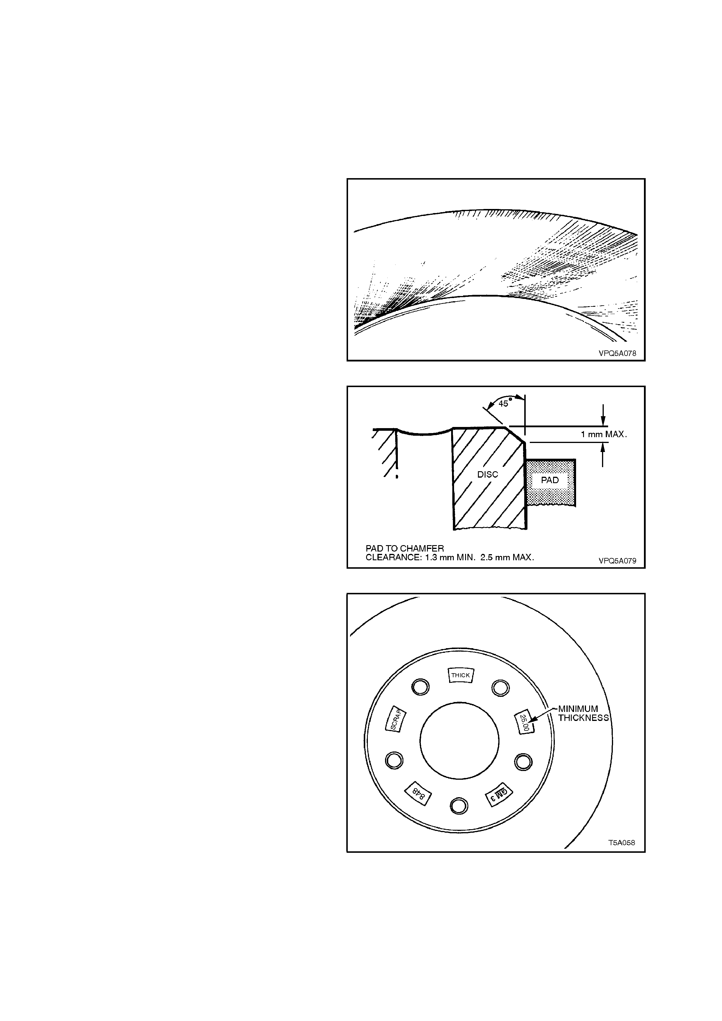
FRONT DISC, INSPECT
If disc surface is rusted or lightly scored, resurf ace
disc. Scores less than 0.4 mm deep will not affect
brake performance.
If scoring is deep or if disc parameters are out of
specification, the disc must be machined.
NOTE 1:
Machine or resurface BOTH sides of disc. Do not
machine or resurface one side only.
NOTE 2:
After machining, disc should be ground to achieve
a non-circumferential finish of 0.4 to 2.0 microns.
Figure 5A-70
NOTE 3:
After machining, the brake disc outer diameter
cham fer m ust be 45° x 1 mm max imum with a pad
to chamfer clearance of 1.3 mm minimum to 2.5
mm maximum. This is to prevent thermal stress
cracking at the top of the disc.
Figure 5A-71
NOTE 4:
Replace disc if specifications cannot be achieved
above the minimum disc thickness.
WARNING:
THE NUMBER CAST INTO THE HUB IS THE
MINIMUM SAFE THICKNESS. AT THIS
THICKNESS THE DISC MUST BE REPLACED
Figure 5A-72
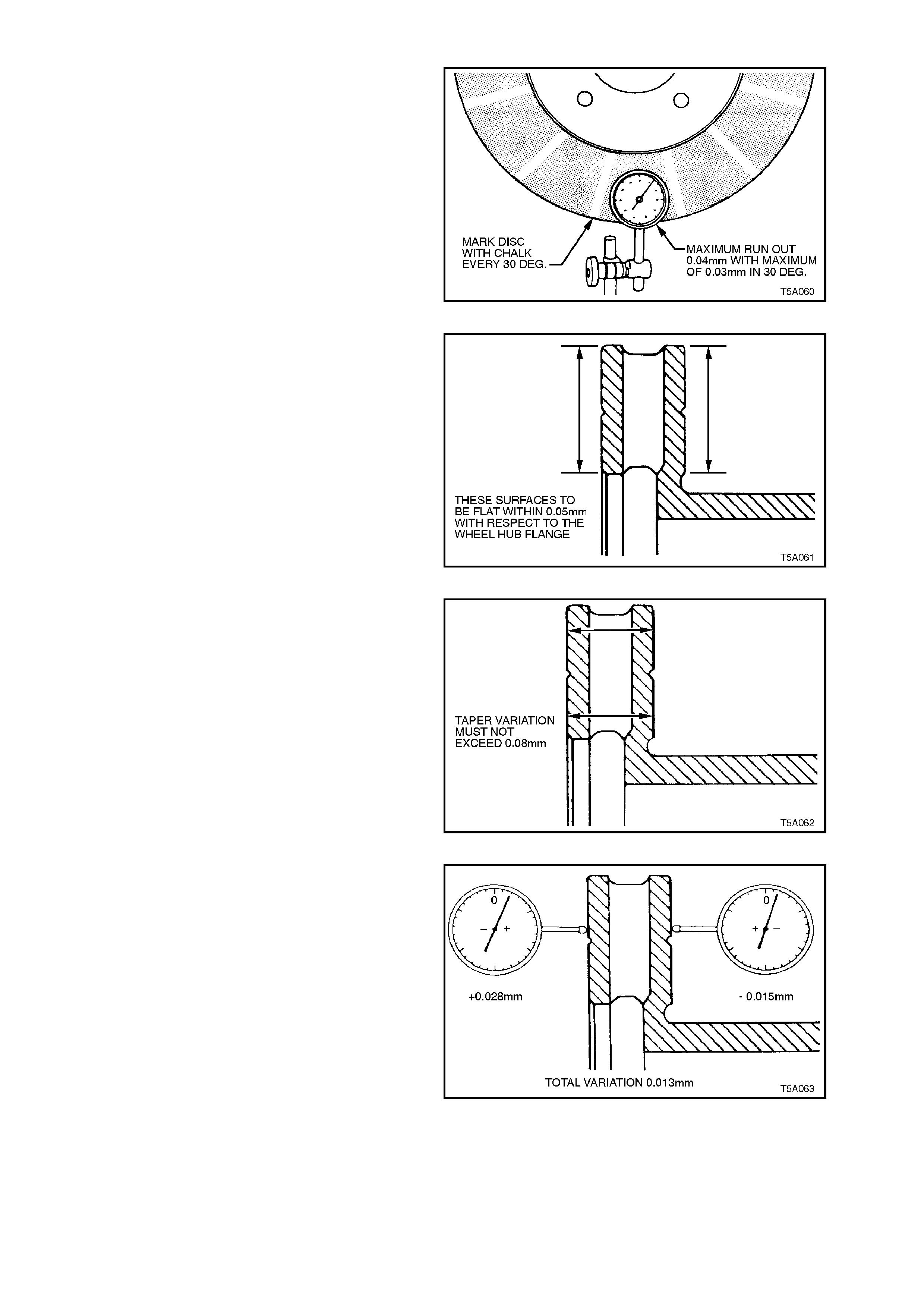
Inspect disc as follows:
1. Check that lateral run-out of each braking
surface does not exceed 0.04 mm Total
Indicated Runout (TIR) and that the rate of
change does not exceed 0.03 mm in 30°.
Figure 5A-73
2. Check that both surfaces are flat within 0.05
mm TIR.
Figure 5A-74
3. Check that disc surfaces are parallel with each
other to within 0.08 mm, when checked
radially.
Figure 5A-75
4. Check that total circumferential thickness
variation, at any radius, does not exceed 0.013
mm in 360° as disc is rotated.
Figure 5A-76
REAR DISC, INSPECT
If disc surface is rusted or lightly scored, resurface
disc. Scores less than 0.4 mm deep will not affect
brake performance.
If scoring is deep or if disc parameters are out of
specification, the disc must be machined.
NOTE 1:
Machine or resurface BOTH sides of disc. Do not
machine or resurface one side only.
NOTE 2:
After machining, disc finish should be 0.6 to 1.25
microns and should not be circumferential i.e. disc
finish s hould be non-direc tional. Park brak e surf ace
finish should be 20 microns.
NOTE 3:
Replace disc if specifications cannot be achieved
above the minimum disc thickness.
WARNING:
THE MINIMUM SAFE THICKNESS IS 13.9 mm.
THE DISC MUST BE REPLACED AT THIS
THICKNESS!
Inspect disc as follows:
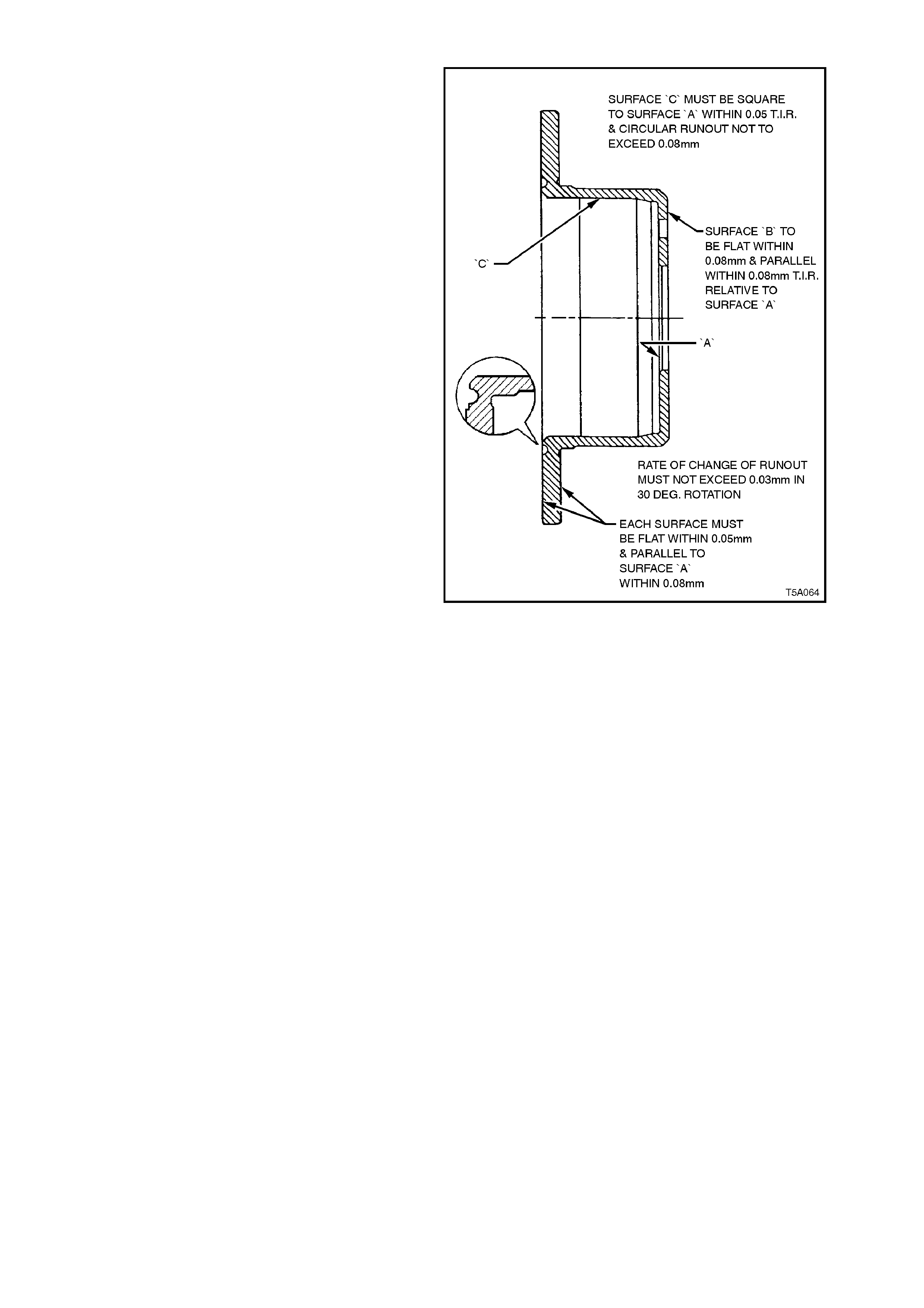
1. Check that surface ‘B' is flat within 0.08 mm
and is parallel with surface ‘A' within 0.08 mm
Total Indicated Runout (TIR).
2. Check that surface ‘C' circular run-out is less
than 0.08 mm and that surface is square to
surface ‘A' within 0.05 mm TIR
3. Check that each disc surf ace is flat within 0.05
mm and is parallel to surface ‘A' within 0.085
mm TIR
4. Check that lateral run-out of each braking
surface is less than 0.05 mm when measured
from surface ‘A' as shown or when bolted to
the axle and that rate of change does not
exceed 0.03 mm in 30°.
5. Check that thickness does not vary by more
than 0.013 mm at any radius when disc is
rotated.
Figure 5A-77

REINSTALL
1. Reinstall disc over wheel studs.
2. Ensure anchor plate mounting surfaces are
clean.
3. Position caliper assembly over disc, insert
anchor plate retaining bolts and washers.
4. Ensure brake hose is not kinked or twisted.
5. Tighten anchor plate bolts to specified torque.
FRONT BRAKE CALIPER 80- 90 Nm, plus
ANCHOR PLATE BOLT 40° - 50°
TORQUE SPECIFICATION turn angle
REAR BRAKE CALIPER
ANCHOR PLATE BOLT 70 - 100 Nm
TORQUE SPECIFICATION
6. Depress brake pedal several times to bring
pads into position against disc.
7. Adjust park brake shoe clearance as detailed
in 3.5 PARK BRAKE SHOE, ADJUST, in this
Section.
8. Reinstall road wheels aligning marks made
prior to removal, then lower vehicle.
9. Tighten road wheel attaching nuts to the
specified torque.
ROAD WHEEL ATTACHING NUT 110 - 140
TORQUE SPECIFICATION Nm
3.5 PARK BRAKE SHOE, ADJUST
CAUTION:
Whenever any component that forms part of
the ABS (if fitted) is disturbed during Service
Operations, it is vital that the complete ABS
system be checked, using the procedure as
detailed in DIAGNOSIS, ABS FUNCTION
CHECK, in Section 12L ABS & ABS/ETC.
1. Using a floor jack under centre of differential
carrier, jack up and support rear of vehicle on
safety stands under rear trailing arms.
2. Remove rear wheel covers (steel wheels) or
centre caps (alloy wheels).
3. Mark relationship of wheels to mounting
flanges.
4. Remove road wheel attaching nuts and
remove wheels.
5. Release park brake and ensure that park
brake actuator arms have fully retracted.
If neces sary, loosen the front park br ake cable
adjustment nut (arrow) with a deep socket, to
ensure slack in the park brake rear cables.
Figure 5A-78
Method 1
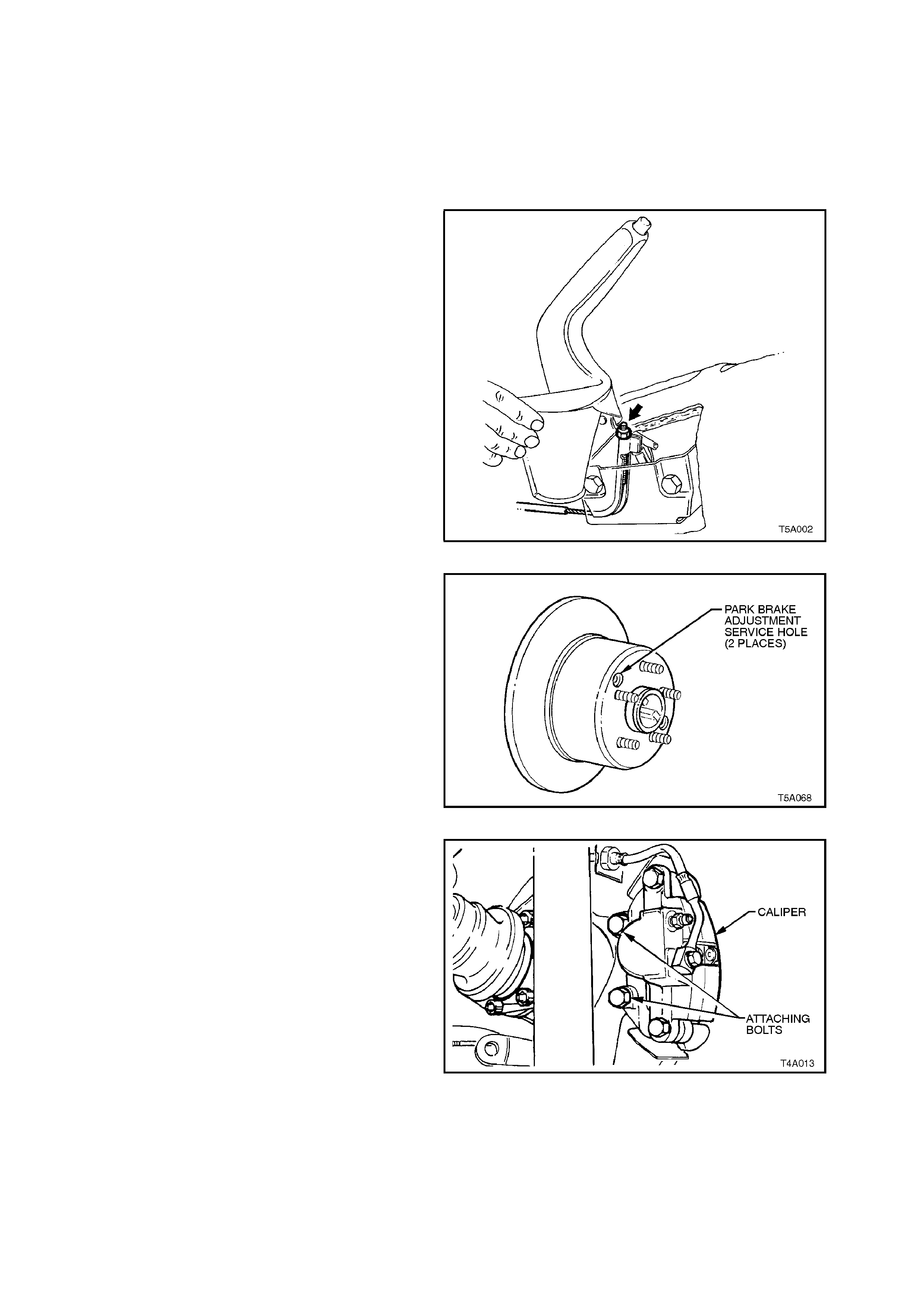
6. Remove the access hole plug. Using a
suitable lever such as a screwdriver, tighten
the park brake shoe screw adjuster, until the
disc is locked. Access to the screw adjuster is
through either one of two holes pr ovided in the
disc.
7. Loosen the adjuster 3 - 5 clicks, then check
that the disc is free and does not drag.
Replace the access hole plug when the
adjustment procedure has been completed.
Figure 5A-79
Method 2
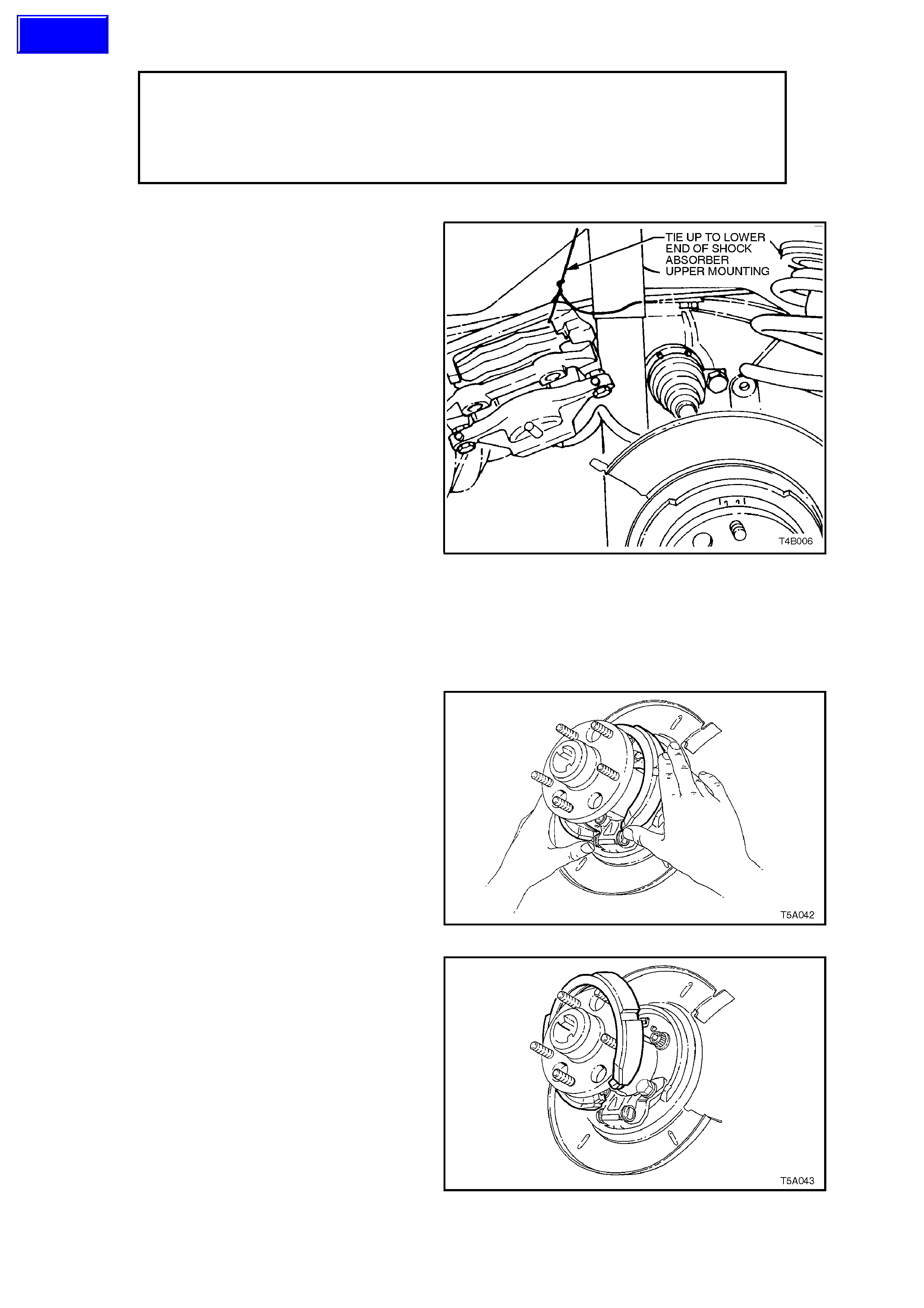
8. Remove rear brake caliper anchor plate to
trailing arm attaching bolts (both sides of
vehicle), then remove calipers from discs.
Using wire, tie up calipers to lower end of
shock absorber upper mountings. DO NOT
ALLOW CALIPERS TO HANG BY BRAKE
HOSES!
Figure 5A-80
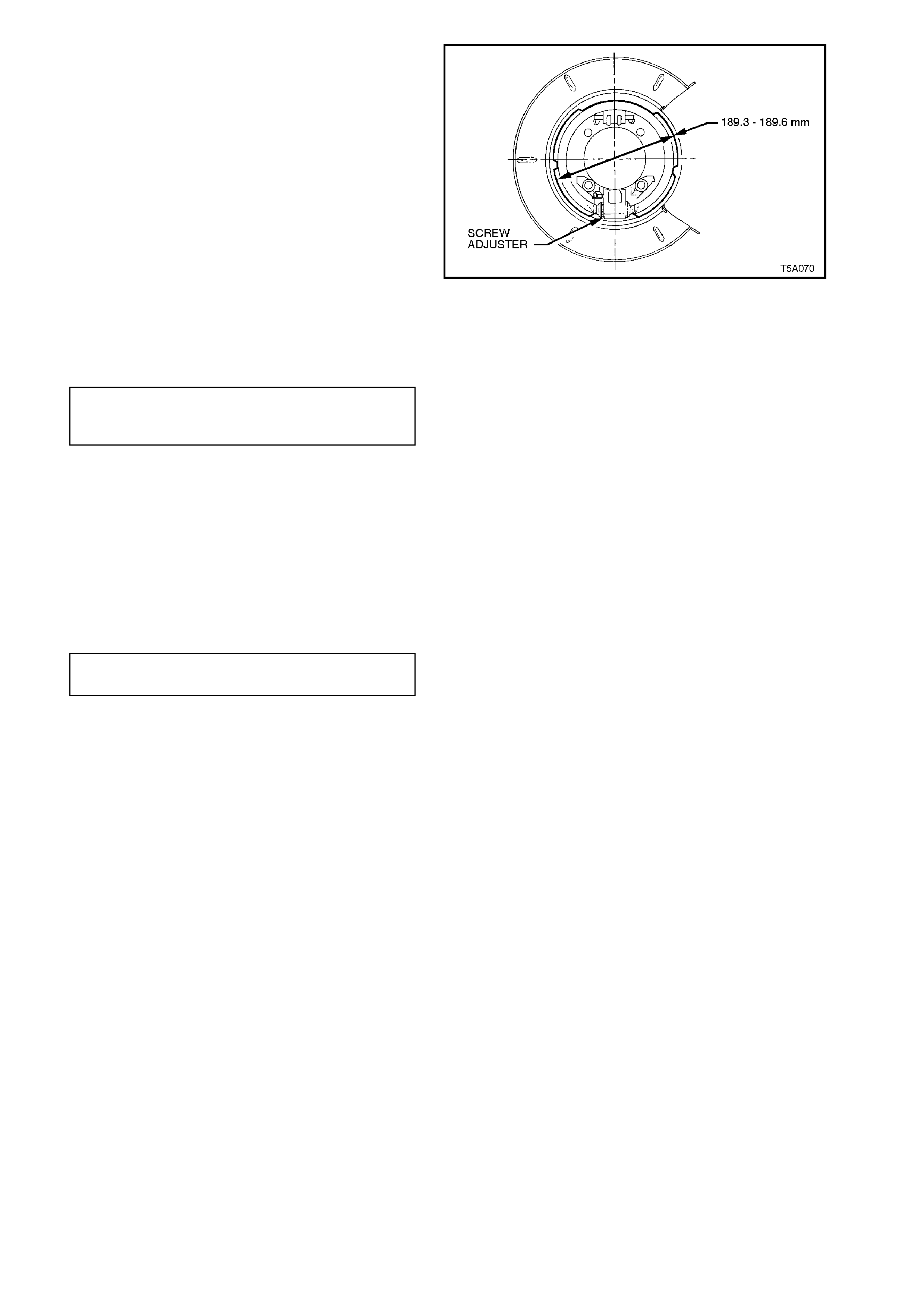
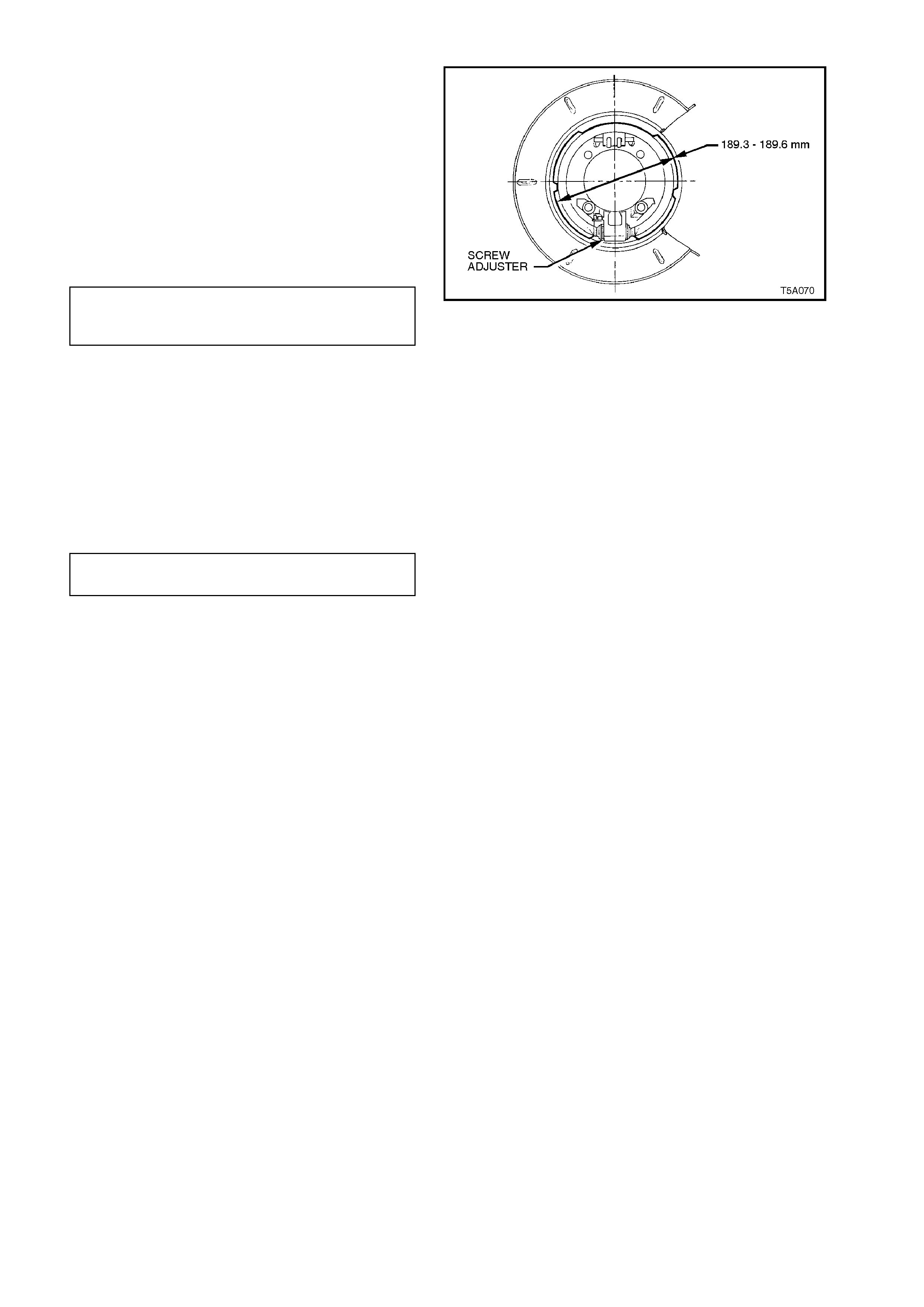
9. Remove disc from rear trunnion, then adjust
each park brake shoe to 189.3 - 189.6 mm
diameter across the linings, using the screw
adjuster provided.
NOTE:
The trunnion has been omitted from the illustration
for clarity.
10. Reinstall rear brake discs and check that they
rotate freely and do not bind.
Figure 5A-81
11. Reinstall brake caliper, install and tighten
caliper anchor plate to trailing arm attaching
bolts, to the correct torque specification.
BRAKE CALIPER ANCHOR PLATE
TO TRAILING ARM ATTACHING 70 - 100 Nm
BOLT TORQUE SPECIFICATION
12. Reinstall rear wheels, aligning marks made
prior to removal, and install attaching nuts.
13. Check park brake cable adjustment, refer to
2.2 PARK BRAKE CABLE, ADJUST, in this
Section.
14. Remove safety stands and lower vehicle.
15. Tighten road wheel attaching nuts to the
correct torque specification.
ROAD WHEEL ATTACHING NUT 110 - 140
TORQUE SPECIFICATION Nm
16. Refit wheel covers/centre caps.
3.6 PARK BRAKE SHOE
CAUTION:
Whenever any component that forms part of the ABS (if fitted) is disturbed during
Service Operations, it is vital that the complete ABS system be checked, using the
procedure as detailed in DIAGNOSIS, ABS FUNCTION CHECK, in Section 12L ABS &
ABS/ETC.
REMOVE
1. Using a floor jack under centre of rear axle,
jack up and support rear of vehicle on jack
stands under rear trailing arms (rear axle
housing).
2. Remove rear wheel covers on steel wheels or
centre caps on alloy wheels.
3. Mark relationship of wheels to mounting
flanges. Remove road wheel attaching nuts
and remove wheels.
4. Release park brake.
5. Remove brake caliper anchor plate to trailing
arm attaching bolts and remove calipers from
disc.
Using wire, tie up calipers to lower end of
shock absorber upper mountings. DO NOT
ALLOW CALIPERS TO HANG BY BRAKE
HOSES.
6. Remove brake discs.
NOTE:
It may be necess ar y to loosen the park br ake shoe
adjustment, to enable disc removal. Use a suitable
size screwdriver, screw in adjuster, using one of
the two access holes in the brake disc (see Figure
5A-79).
Figure 5A-82
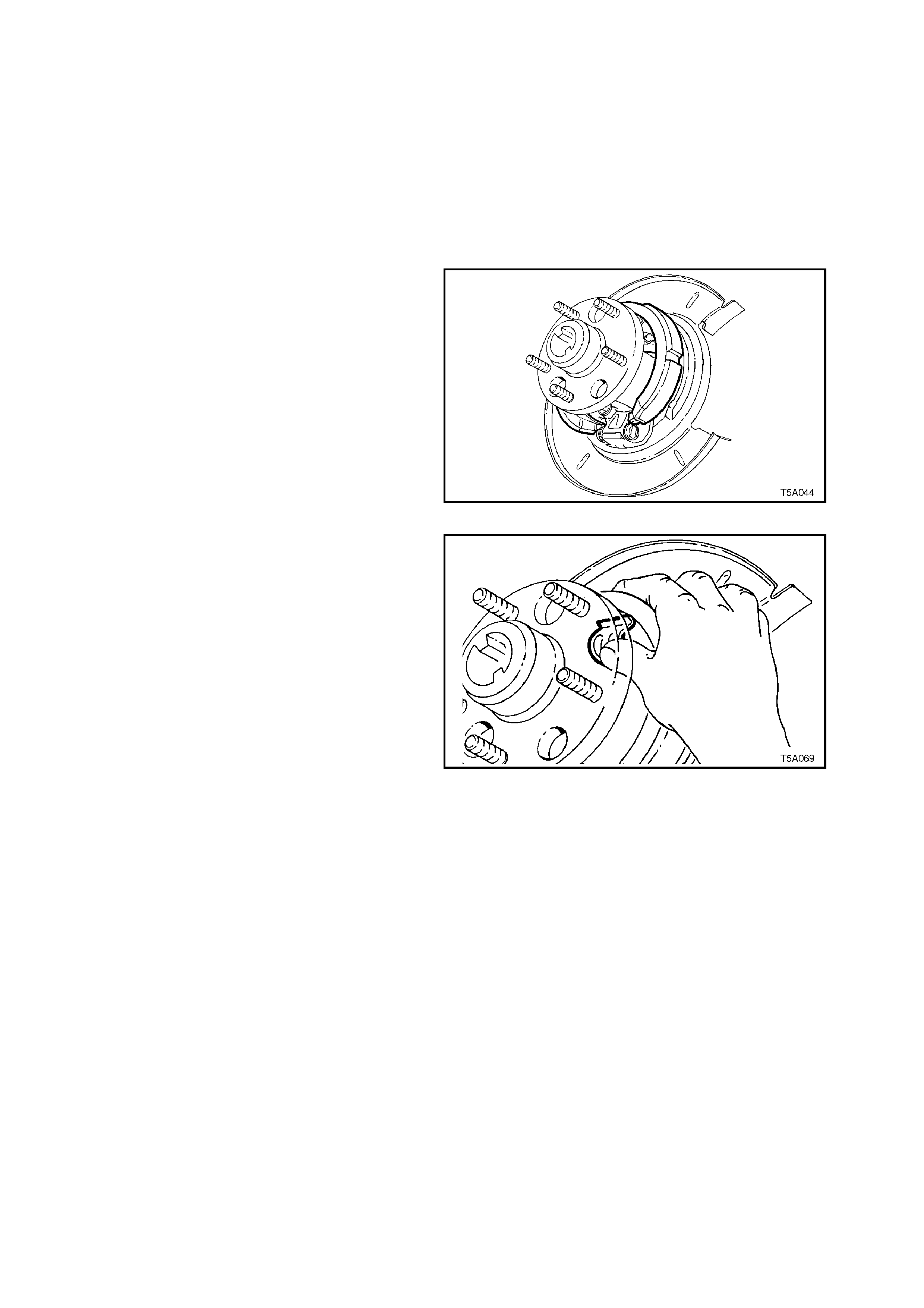
7. Remove park brake shoe by grasping each
end as shown. Push up on one end of the
shoe, dislodging the end from the actuator pin
and the shoe from the retaining clip.
Figure 5A-83
8. Using a screwing motion, rotate the park brake
shoe around the trunnion flange to remove it
from the vehicle.
9. Remove the park brake shoe spring retainer
by prising from the rear disc shield, with a
screwdriver or similar lever.
Figure 5A-84
Techline
10. If required, the actuator screw adjuster and
pins can be removed at this point, but the
body and remaining components are not able
to be removed without first removing the rear
disc shield. For this operation, refer to
3.8 REAR DISC SHIELD, in this Section.
REINSTALL
1. Apply Molybdenum Disulphide grease, to
Holden's Specification HN1587 to the
adjusting screw and pins. Fully wind screw
into sleeve and install into the adjuster body.
2. Install the park brake shoe over the trunnion
flange.
3. With one shoe end loc ated on the adjus ter pin,
roll the shoe to engage the other end onto the
other pin.
Figure 5A-85
4. Install park brak e s hoe retaining spring c lip, by
sliding it into place, ensuring that the spring
clip is c orrec tly located by the tangs in the r ear
brake shield.
Figure 5A-86
5. Adjust each park brake shoe diameter to a
dimension of 189.3 - 189.6 mm, using the
screw adjuster.
NOTE:
The trunnion has been omitted from the illustration
for clarity.
6. Install brake discs and check that no drag is
present.
7. Install caliper anchor plate attaching bolts and
tighten to the correct torque specification.
REAR BRAKE CALIPER ANCHOR
PLATE BOLT 70 - 100 Nm
TORQUE SPECIFICATION Figure 5A-87
8. Adjust park brake cable, refer to
2.2 PARK BRAKE CABLE, ADJUST in this
Section.
9. Install road wheels, aligning marks made prior
to removal, install and tighten attaching nuts.
10. Remove safety stands and lower vehicle.
11. Tighten road wheel attaching nuts to the
correct torque specification.
ROAD WHEEL ATTACHING NUT 110 - 140
TORQUE SPECIFICATION Nm
12. Refit wheel covers/centre caps.
3.7 FRONT DISC BRAKE SHIELD
CAUTION :
Whenever any component that forms part of the ABS (if fitted) is disturbed during Service
Operations, it is vital that the complete ABS system be checked, using the procedure as
detailed in DIAGNOSIS, ABS FUNCTION CHECK, in Section 12L ABS & ABS/ETC.
REMOVE
1. Raise front of vehicle and support on safety
stands under the front crossmember.
2. Remove front wheel cover (steel wheels) or
centre cap (alloy wheels) from side of vehicle
where the shield is to be removed.
3. Mark relationship of wheel to hub/brake disc.
Remove road wheel attaching nuts and
remove wheel.
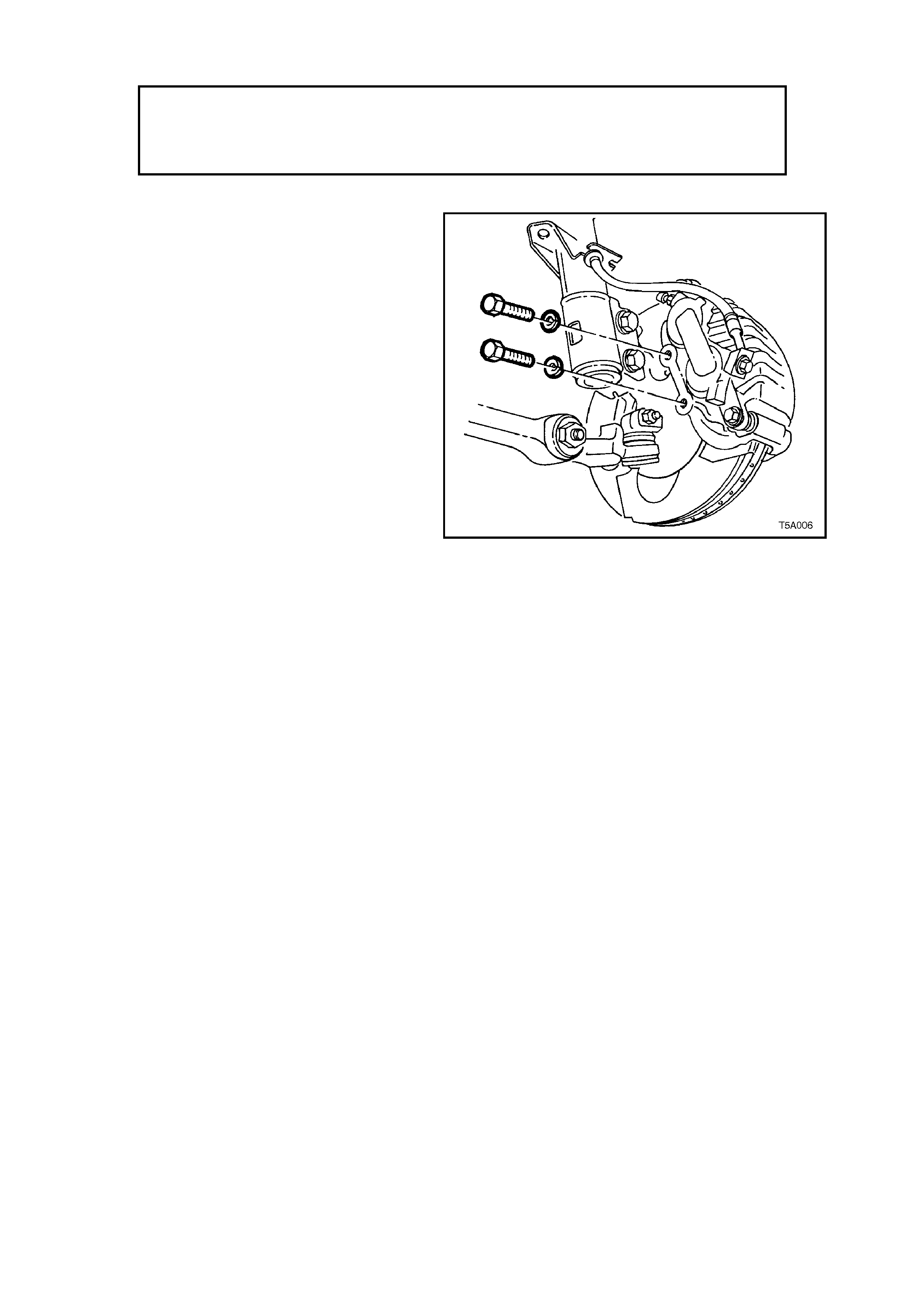
4. Remove front brake caliper anchor plate to
front strut knuckle attaching bolts, remove
caliper from disc.
NOTE: Dis card the front brak e caliper anchor plate
retaining bolts as they must be replaced on
reassembly.
5. Using wire, tie up caliper to lower end of front
suspension coil spring. DO NOT ALLOW
CALIPER TO HANG BY BRAKE HOSE.
Figure 5A-88
6. Remove front brake disc from the wheel
bearing hub.
IMPORTANT:
Marking the relationship of the front brake disc to
the front hub is critical to minimising the possibility
of brake shudder. Refer to 3.4 BRAKE DISC
(FRONT AND REAR) in this Section, for further
information.
NOTE:
For vehicles equipped with ABS, disconnect the
wheel speed sensor connector from the steering
knuckle. To do this, use a 5 mm Allen key (or
socket), remove the set screw and then, holding
the cable retaining bracket, twist and gently pull on
the sens or c onnec tor end. Don't los e the sealing O-
ring.
7. Using a commercially available 10 mm Allen
key socket and a suitable socket bar, loosen
each of the three bolts holding the hub to the
steering knuckle support.
NOTE 1:
For the front lower hub bolt, turn wheel outwards to
provide clearance between the ball joint rivet and
the hub bolt.
NOTE 2:
If the Allen key socket is too long to fit into the front,
upper hub bolt, then the lower strut to steering
knuckle nut will need to be removed and the bolt
withdrawn.
8. To remove hub from knuckle, it may first be
necessary to tap the loosened bolts to break
the seal. DO NOT STRIKE THE HUB.
9. Remove the three bolts and then the hub f rom
steering knuckle.
10. Remove the three rivets securing shield to
knuckle, by drilling the head from each rivet.
Remove the shield from the knuckle support.
11. Carefully drill out the rivet remainder from the
steering knuckle, using a suitable size drill.
Figure 5A-89

REINSTALL
Installation is the r evers e of the rem oval procedur e,
except for the following points:
1. Install the brake shield to the steering knuckle
support, securing with three, common pop
rivets, using a c ommerc ially available pop rivet
gun. Start with the round hole, to ensure that
the clearance to the brake caliper is correct.
2. Before installing the hub, inspect both mating
surf aces to mak e sur e that they are clean and
free from burrs that could prevent correct
alignment of both parts, once installed.
3. Prior to installation, it is also vital that the
sealing O-ring located around the mounting
flange, is checked to ensure its serviceability.
Failing to adequately seal the hub to steering
knuckle interface, will cause water to be drawn
into the cavity in the steering knuckle, during
the normal heating and cooling cycle of
vehicle operation.
Without ABS:
4. Install the hub assembly to the steering
knuckle.
5. Install the three attaching bolts and tighten to
the correct torque specification.
FRONT HUB TO STEERING
KNUCKLE ATTACHING BOLT 120 - 140 Nm
TORQUE SPECIFICATION
NOTE:
The three hub attaching bolts are micro-
encapsulated with thread sealant and are not to be
re-used m ore than thr ee times. If in doubt, the bolts
should be replaced.
With ABS:
6. Carefully align the sensor connection on the
hub, with the hole in the steering knuc kle, then
install the three hub attaching bolts and tighten
to the correct torque specification.
FRONT HUB TO STEERING
KNUCKLE ATTACHING BOLT 120 - 140 Nm
TORQUE SPECIFICATION
7. Fit the wheel speed sensor connector, then
install the cable retaining bracket set screw
and tighten to specification.
SENSOR CABLE RETAINING
SCREW TORQUE 6 - 14 Nm
SPECIFICATION
All Models:
8. Reinstall brake disc and brake caliper,
tightening attaching bolts to specification.
NOTE: New retaining bolts must be used when
reinstalling the front brake caliper anchor plate.
BRAKE CALIPER ANCHOR 80 - 90 Nm,
PLATE RETAINING BOLTS then turn through
TORQUE SPECIFICATION 40 - 50

9. Reinstall road wheel, aligning the marks made
prior to removal and secure with the attaching
nuts.
10. Remove jack stands and lower vehicle.
11. Tighten road wheel attaching nuts to correct
torque specification.
ROAD WHEEL ATTACHING NUT 110 - 140
TORQUE SPECIFICATION Nm
12. Refit wheel cover/centre cap.
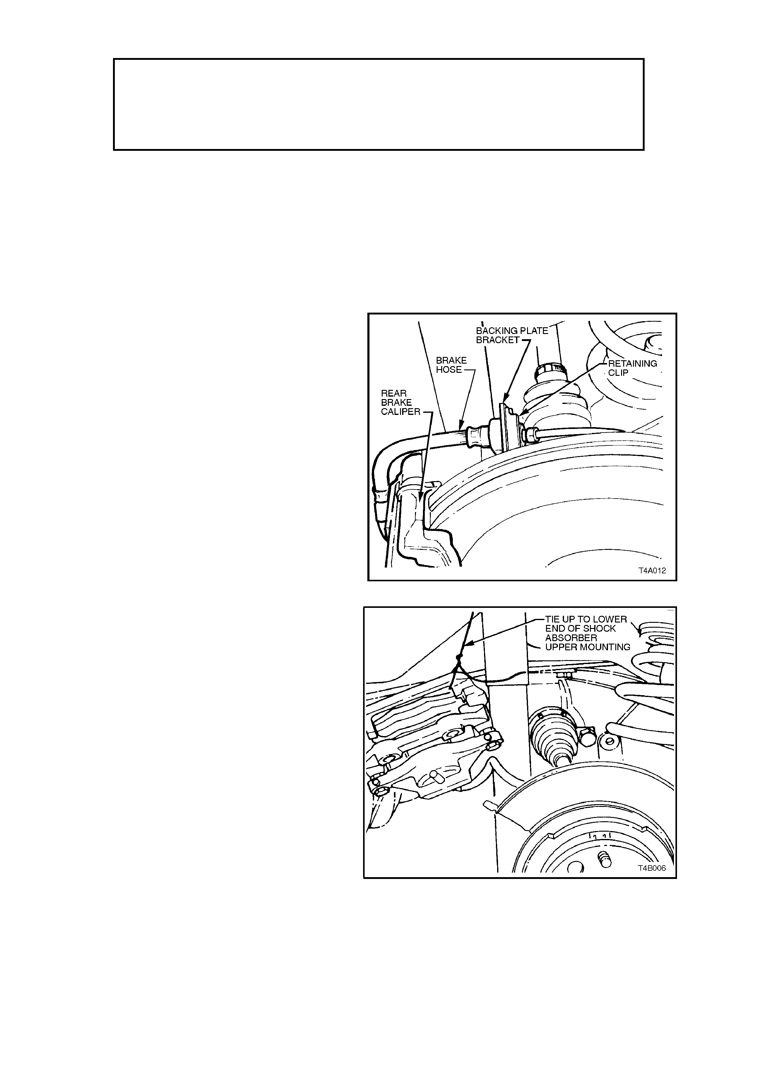
3.8 REAR DISC SHIELD
CAUTION :
Whenever any component that forms part of the ABS (if fitted) is disturbed during
Service Operations, it is vital that the complete ABS system be checked, using the
procedure as detailed in DIAGNOSIS, ABS FUNCTION CHECK, in Section 12L ABS &
ABS/ETC.
REMOVE
1. Using a floor jack under centre of differential
carrier, jack up rear of vehicle then place
safety stands under trailing arms.
2. Remove rear wheel cover (steel wheels) or
centre cap (alloy wheels).
3. Mark relationship of wheel to mounting flange.
4. Remove road wheel attaching nuts and
remove wheel.
5. Release park brake.
6. Thoroughly clean around brake hose to pipe
connection at back ing plate. Disconnect brake
pipe from brake hose at backing plate bracket
and remove brake hose retaining clip.
Figure 5A-90
7. Remove brake caliper anchor plate to trailing
arm attaching bolts and remove caliper from
disc.
Using wire, tie up caliper/s to the lower end of
the shock absorber upper mounting/s. DO
NOT ALLOW THE CALIPER/S TO HANG BY
THE BRAKE HOSE/S.
Remove brake disc.
8. Disconnect the park brake cable from the
actuator arm. See 2.9 REAR PARK BRAKE
CABLES in this Section, for details.
Figure 5A-91
9. Remove trailing arm trunnion flange and
trunnion assembly, refer to
Section 4B, FINAL DRIVE AND DRIVE
SHAFTS for the necessary procedure.
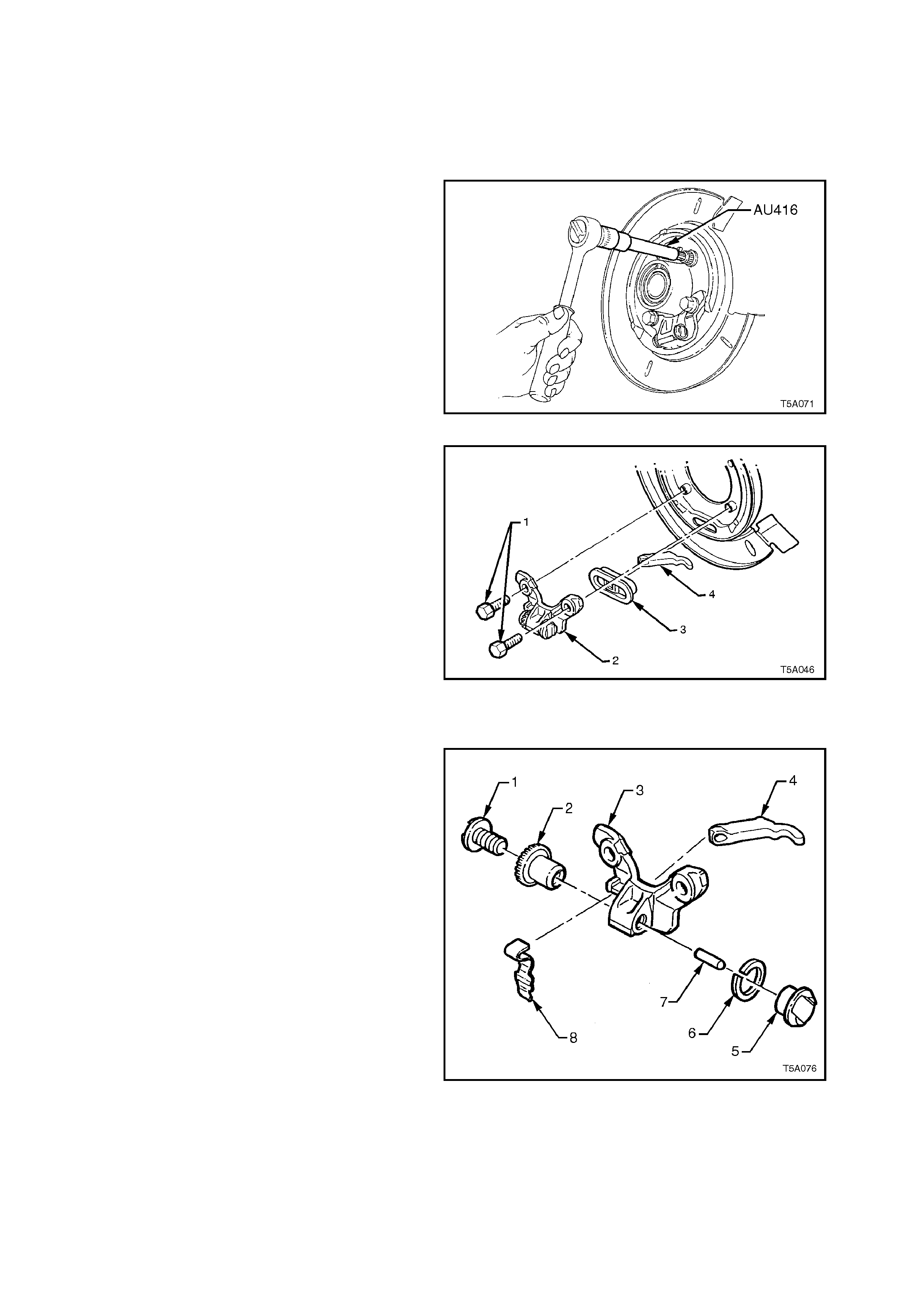
IMPORTANT:
Because the removal procedure of the trunnion
flange will cause the bearing to be brinelled, it
must be replaced on reassembly.
Section 4B, FINAL DRIVE AND DRIVE SHAFTS
also provides the necessary procedure for this
task.
10. Remove park brake shoe assembly. Refer to
3.6 PARK BRAKE SHOE, in this Section.
11. Using Torx bit, Tool No. AU416, remove the
two rear disc shield to upper trailing arm
attaching bolts. Then, using a 15 mm socket,
remove the two lower bolts, that also secure
the park brake actuator assembly.
12. Remove rear disc shield and park brake
actuator assembly from vehicle.
Figure 5A-92
13. In order to disassemble the park brake
actuator assembly (2, 3 and 4) from the rear
disc shield, it will be necessary to carefully
support the disc shield to minimise the
possibility of distortion and press the actuator
assembly from the lower extruded bolt hole
sections of the disc plate.
Figure 5A-93
REINSTALL
Installation of rear disc shield is the reverse to the
removal procedures, except for the following points:
1. As the removed actuator assembly can easily
be disassembled, the view shown, details the
relationships of each, in an exploded view.
2. While supporting the rear disc brake shield,
install the actuator assembly to the extruded
bolt hole sections, after ensuring that the
actuator mechanism is correctly assembled.
Figure 5A-94
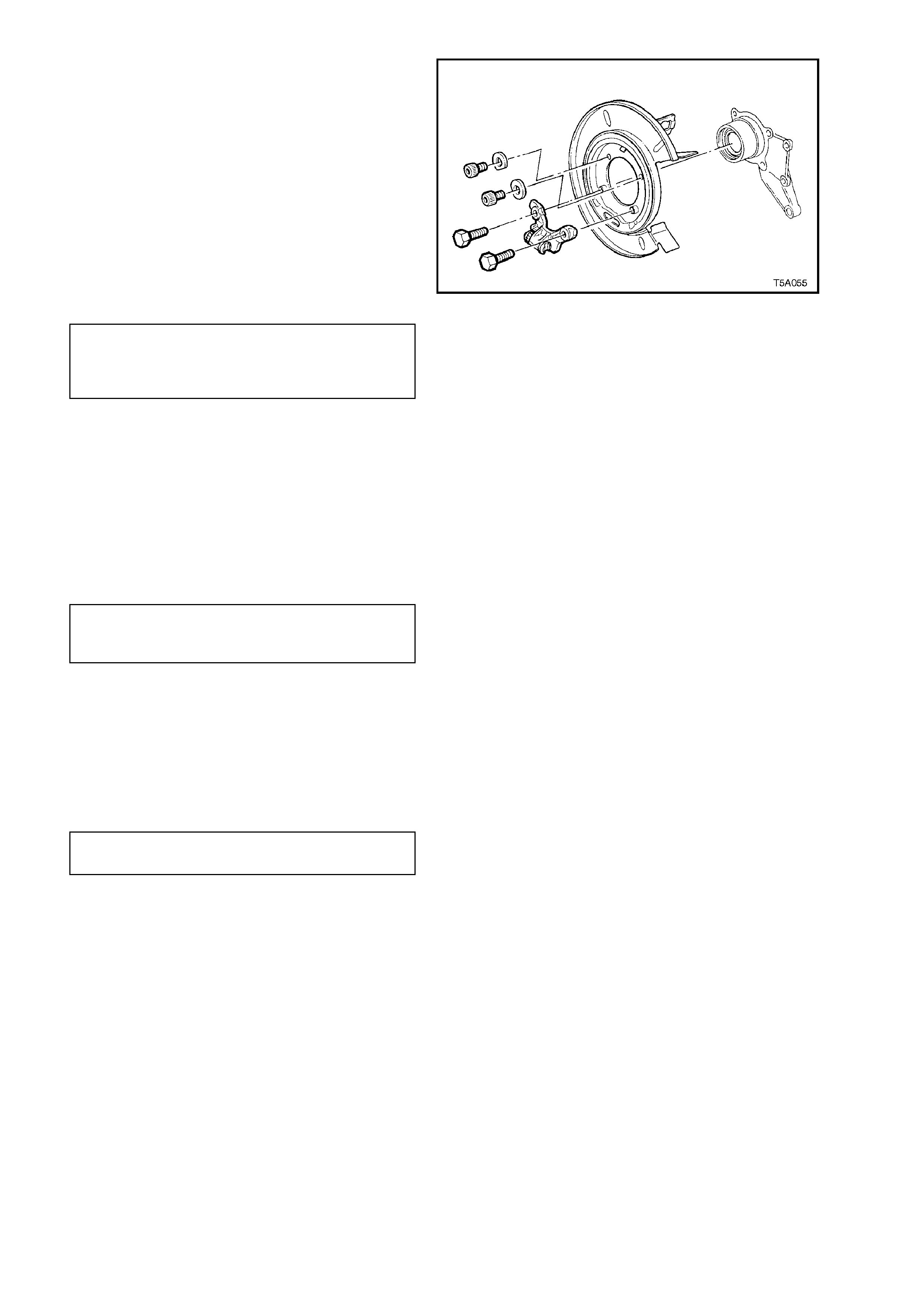
NOTE:
The two shorter, upper bolts have washers that are
to be installed with the cut-out surface facing
around the trailing arm hub outer surface.
3. Install and tighten the four rear disc brake
shield to trailing arm attaching bolts. The two
shorter, Torx bit headed ones to the top and
the two longer hexagon headed to the lower
locations. Tighten all to the specified torque
settings.
NOTE: New, lower, hexagon headed retaining bolts
must be used when reinstalling the rear disc brake
shield to the trailing arm.
REAR DISC BRAKE SHIELD
TO TRAILING ARM Top: 70 - 80 Nm
ATTACHING BOLT Lower: 85 - 90 Nm
TORQUE SPECIFICATION
4. Reinstall the park brake shoe. Refer to
3.6 PARK BRAKE SHOE, in this Section.
5. Reinstall the rear disc and adjust the park
brak e shoe, following the procedure detailed in
3.5 PARK BRAKE SHOE, ADJUST, in this
Section.
Figure 5A-95
6. Install and tighten brake caliper anchor plate
to trailing arm attaching bolts to the correct
torque specification.
BRAKE CALIPER ANCHOR PLATE
TO TRAILING ARM ATTACHING 70 - 100 Nm
BOLT TORQUE SPECIFICATION
7. Install road wheel, aligning marks made prior
to removal and tighten road wheel attaching
nuts
8. Remove jack stands and lower vehicle to the
ground.
9. Tighten road wheel attaching nuts to the
specified torque.
ROAD WHEEL ATTACHING NUT 100 - 125
TORQUE SPECIFICATION Nm
10. Check for brake fluid leaks, repair as
necessary.

4. DIAGNOSIS
X - In d ica te s Ca u s e
X X - Indicates a M ore Possible Cause SYMPTOM
CAUSE
Excessive Brake Pedal Travel
Brake Pedal Travel Gradually Increases
Excessive Brake Pedal Effort
Excessive Braking Action
Brakes Slow to Respond
Brakes Slow to Release
Brakes Drag
Uneven Braking Action (Side to Side)
Uneven Braking Action (Front to Rear)
Scraping Noise from Brakes
Brakes Squeak During Application
Brakes Squeal During a Stop
Brakes Chatter
Brakes Groan at End of Stop
Brake Tell-tale Lamp Glows During a Stop
Leaking Brake Line or C onnection X X X
Leaking Caliper or Piston Line X X X X X
Leaking M aster Cylinder X X X X
Air in Brake System XX X X
C ontam inated o r Im proper Brake Fluid X X X X
Leaking Vacuum S ystem X X X
Restricted Air Passage in Vacuum Booster X XX X
D am aged Vacuum B ooster X X X X XX
Im properly Assembled Vacuum Booster Valving X X X X X X
Wo rn Ou t Dis c P ad s - Re p la c e X X X X X X X X
U neven D isc P ad Wear - Re place or Co rrect X X X X X X X X
C ontam inated D isc P ad - R eplace X X X X X X X X X X
H eat Spotted or S cored B rake Discs X X X X X XX X
O ut-of-P arallel B rake D iscs XX
E xcessive B rake D isc R un-O ut X
B rake A ssem bly A ttachm ents - M issing or Lo ose X X X X X X X X
R estricted B rake Fluid Pa ssage or Sticking C aliper P iston X X X X X X X
Brake Pedal/Linkage Binding or Interference X X X X X
Im properly Adjusted Parking Brake X
Incorrect Front Wheel A lignm en t X X X
In co rre ct T y re P re s s u res X X
Wheel B earing C learance E xcessive X X
Loose Front Suspension and/or Com ponents X X X X X
O ut-of-Balance W heel Assem blies XX
O perator R iding B rake P edal X X X X X X
Techline
Techline
Techline
Techline

5. SPECIFICATIONS
BRAKE FLUID
Type To Holden's Specification HN1796
BRAKE BOOSTER
Make PBR
Type Tandem, Vacuum Suspended
MASTER CYLINDER
Make PBR
Type Tandem
Bore diameter (nominal) 25.4 mm
Crack point 3.1 MPa (stamped on master cy linder
end plug)
FRONT DISC
Type Ventilated
Diameter (nominal) 296 + 0.0 - 0.2 mm
Thickness 28.0 ± 0.15 mm
Lateral Runout (maximum) 0.04 mm Total Indicated Run-out (TIR)
Minimum disc thickness, requiring replacement 25.0 mm
FRONT CALIPER
Make PBR
Type Twin piston, sliding caliper
Bore diameter (nominal) 42.0 mm (each)
Disc pad material Organic, non-asbestos
REAR DISC
Type Solid
Diameter (nominal) 286 + 0.0 - 0.2 mm
Thickness 15.9 mm ± 0.2 mm
Lateral Runout (maximum)
(Rate of change 0.03 mm in 30O rotation max.) 0.05 mm
Minimum disc thickness, requiring replacement 13.9 mm
REAR CALIPER
Make PBR
Type Single piston, sliding caliper
Bore diameter (nominal) 40.5 mm
Disc pad material Organic, non-asbestos
DRUM PARK BRAKE
Make PBR
Type Banksia, single shoe, cable and lever
operated
Drum
Inside Diameter (nominal) 190 mm
Maximum out of square (TIR with disc surface) 0.05 mm
Maximum out of round 0.08 mm
Linings
Type Bonded
Width 25 mm
Thickness 3.5 mm
Techline

6. TORQUE WRENCH SPECIFICATIONS
Nm
Brake pipe to master cylinder flare nut 8 - 11
Front brake caliper anchor bolt 80 - 90 Nm, plus
40° - 50O turn angle
Rear brake caliper anchor plate bolt 70 - 100
Road wheel attaching nut 110 - 140
Brake caliper guide pin bolt 30 - 34
Brake pedal support shaft nut 50 - 60
Throttle pedal support attaching nut 20 - 25
Park brake lever bolt 35 - 65
Outer front park brake cable bracket
retaining bolt 20 - 25
Brake hose to caliper bolt (Front and
Rear) 32 - 37
Brake pipe to brake hose flared nut (All
positions) 14 - 17
Master cylinder end plug 6 - 14
Brake differential warning switch 2.0
Master cylinder reservoir screw 4.0 - 5.0
Master cylinder attaching nut 15 - 20
Master cylinder bracket nut 15 - 20
Brake booster retaining nut 20 - 25
Shock absorber lower mounting nut 105 - 125
Front hub to steering knuckle bolt 120 - 140
Rear disc brake shield to trailing arm. Upper bolt 70 - 80
Lower bolt 85 - 90
ABS sensor lead to steering knuckle
support screw 6 - 14
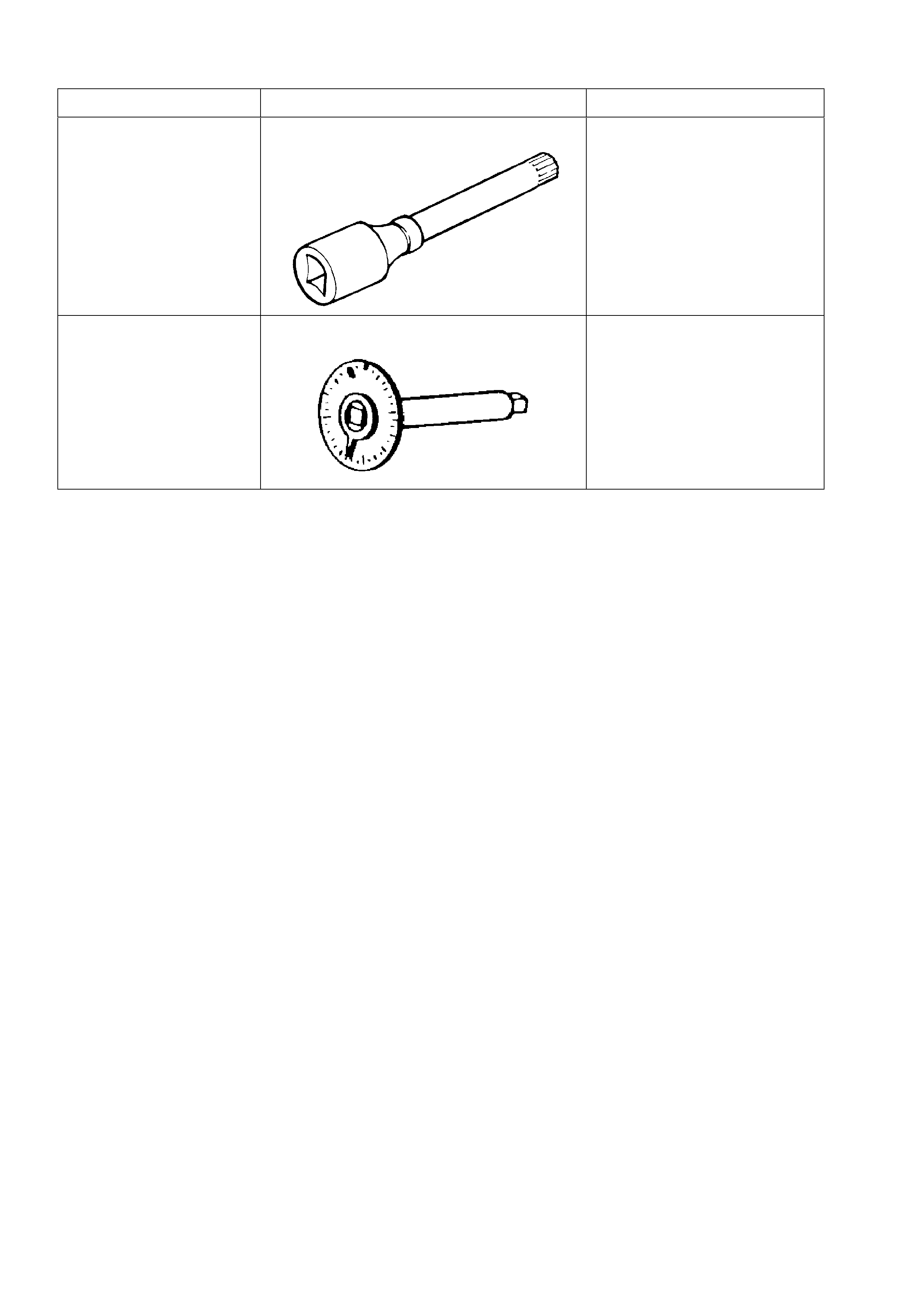
7. SPECIAL TOOLS
TOOL NO. REF IN TEXT TOOL DESCRIPTION COMMENTS
AU416 TORX BIT PREVIOUSLY RELEASED AS
KM322
E7115 ANGLE WRENCH PREVIOUSLY RELEASED
FOR 'J' AND 'V' CARS, AS
TOOL NO. 394.
USED TO TIGHTEN
COMPONENT FASTENERS
WHEN ANGLE TORQUE IS
REQUIRED.