SECTION 6A1-2 - ENGINE MECHANICAL - V6
SUPERCHARGED
CAUTION:
This vehicle will be equipped with a Supplemental Restraint System (SRS). A SRS will
consist of either seat belt pre-tensio ners and a driver’s side air bag, o r seat belt pre-
tensioners and a driver’s and front passenger’s side air bags. Refer to CAUTIONS,
Section 12M, before performing any service operation on or around SRS
components, the steering mechanism or wiring. Failure to follow the CAUTIONS
could result in SRS deployment, resu lting in possible perso nal in jury or u nnecessary
SRS system repairs.
1. GENERAL INFORMATION
A supercharged engine is available as an option on VT Series Models. The supercharged engine gives the benefit
of much improved power and torque at large throttle openings equivalent to having a larger capacity engine. Fuel
economy is better than a larger capacity engine as the supercharger boost is cut at low throttle openings, where the
engine performs similarly to its normally aspirated counterpart. The supercharger does not suffer from the lag that a
turbocharger exhibits, and because of its more friendly operating environment, it is more reliable than a
turbocharger. For supercharger diagnosis, refer to Section 6C1 POWERTRAIN MANAGEMENT - V6 ENGINE.
1.1 GENERAL DESCRIPTION
The supercharger is a positive displacement pump that consists of two counter-rotating rotors in a housing with an
inlet port and outlet port. The rotors are designed with three lobes and a helical twist. An air bypass circuit is built
into the housing.
Rotors in the supercharger are designed to run at a minimal clearance, not in contact with each other or the
housing. The rotors are timed to each other by a pair of precision spur gears which are pressed onto the rotor
shafts. The forward end of the rotors are held in position by deep groove ball bearings. The back end of the rotors
are supported by sealed roller bearings.
The gears and ball bearings are lubricated by a synthetic oil from the oil reservoir in the supercharger and do not
rely on engine oil for lubrication. The cover on the supercharger contains the input shaft which is supported by two
deep groove ball bearings and coupled at one end to the rotor drive gears. A pulley is pressed onto the other end of
the input shaft. The bearings for the input shaft are also lubricated by the synthetic oil.
Engine mechanical service operations for the V6 Supercharged engine carry over in general from those described
for the non-supercharged V6 engine in Section 6A1-1 ENGINE MECHANICAL - V6 ENGINE.
Techline
1.2 SUPERCHARGER ASSEMBLY
The supercharger is designed to pump more air than the naturally aspirated engine would normally use. This air
creates a boost pressure in the intake manifold.
Maximum boost can range from 50 - 75 kPa. Since the supercharger is a positive displacement pump and is directly
driven from the engine accessory drive system, boost pressure is available at all driving conditions. When boost is
not desired, such as during idle and light throttle cruising, the excess air that the supercharger is producing is
recirculated via the bypass passage between the lower intake manifold and the supercharger inlet.
This bypass circuit is regulated by a bypass valve which is similar to a throttle plate. The bypass valve is controlled
by a vacuum actuator which is connected to the vacuum source between the throttle and the supercharger inlet.
Spring force from the actuator holds the valve closed to create boost and vacuum pulls the valve open when the
throttle closes.
The open bypass valve reduces pumping loss thereby increasing fuel efficiency. A PCM controlled solenoid valve is
used to reduce boost in the event of engine overheating as signalled by excessive coolant temperature.
For additional information on supercharger and boost control operation, refer to
Section 6C1 POWERTRAIN MANAGEMENT - V6 ENGINE.
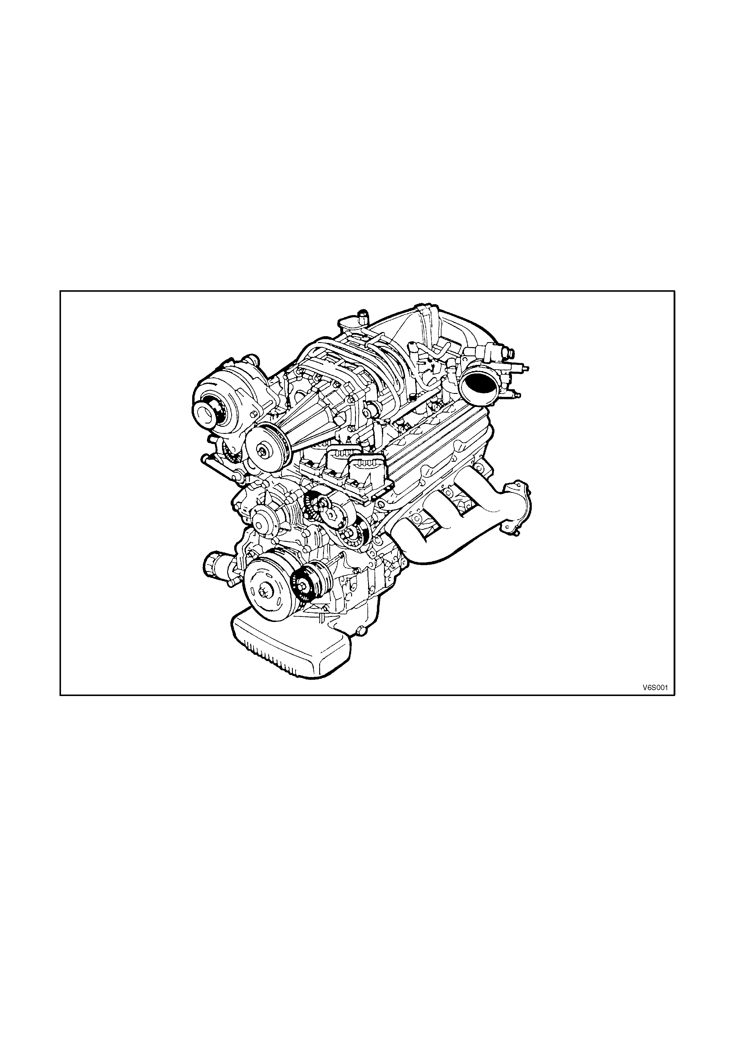
Figure 6A1-2-1
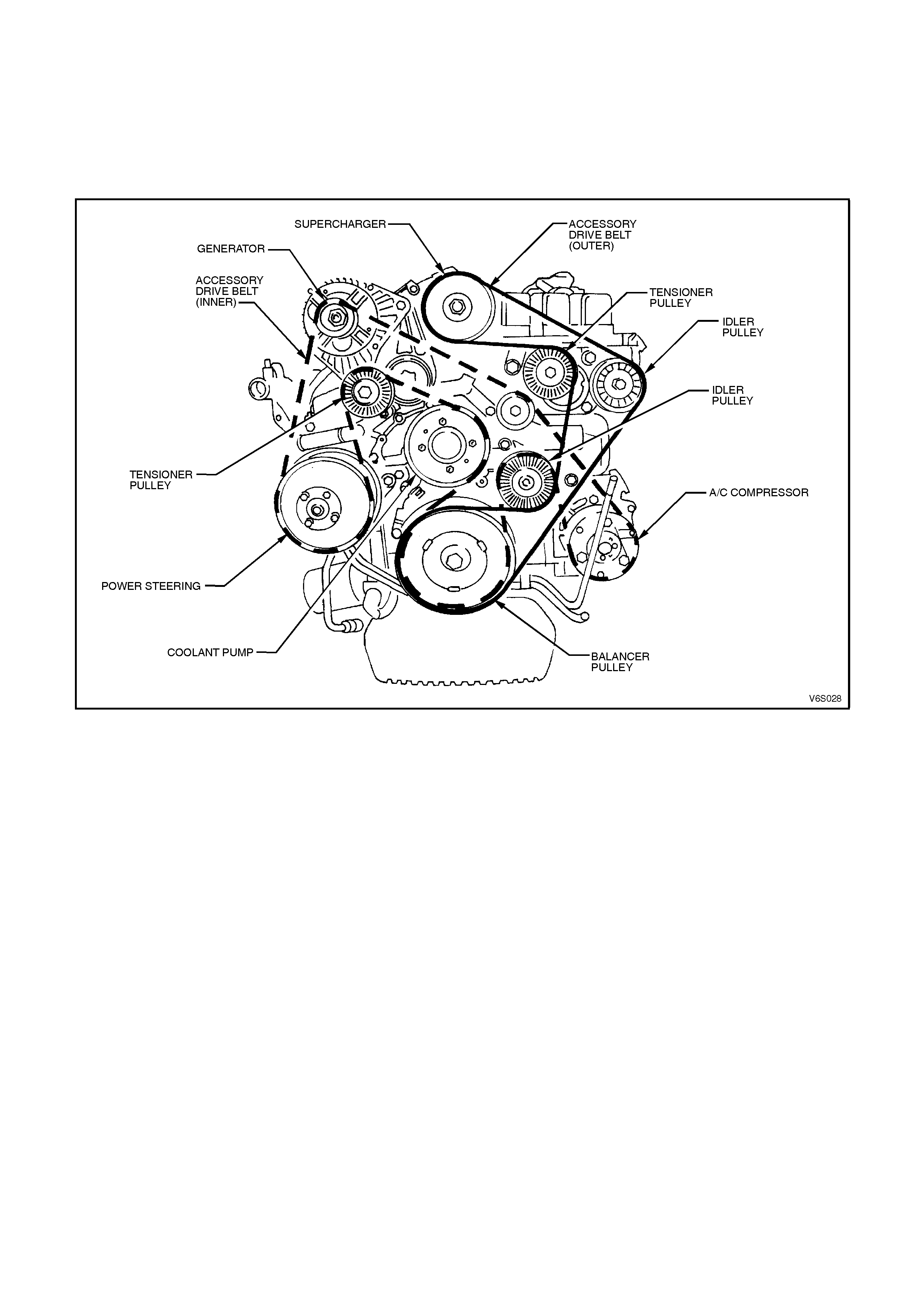
1.3 SUPE RCHARGER DRIVE BELT TENSIONER
The s upercharged engine uses two acces sory dr ive
belts. The inner belt drives the generator, water
pump, air conditioning compressor and power
steering pump. The outer belt drives the
supercharger. All belt driven accessories are rigidly
mounted to the engine. Drive belt tension is
maintained by the spring loaded belt tensioners.
Each belt has its own tensioner.
A belt squeak when the engine is s tarted or s topped
is normal and has no effect on belt durability.
The drive belt tensioner can control belt tension
over a broad range of belt lengths due to stretc hing;
however, there are limits to the tensioners ability to
compensate. Using the tensioner outside of its
operating range can result in poor tension control
and/or damage to the tensioner. T he belt should be
replaced when this condition occurs.
Figure 6A1-2-2
Techline
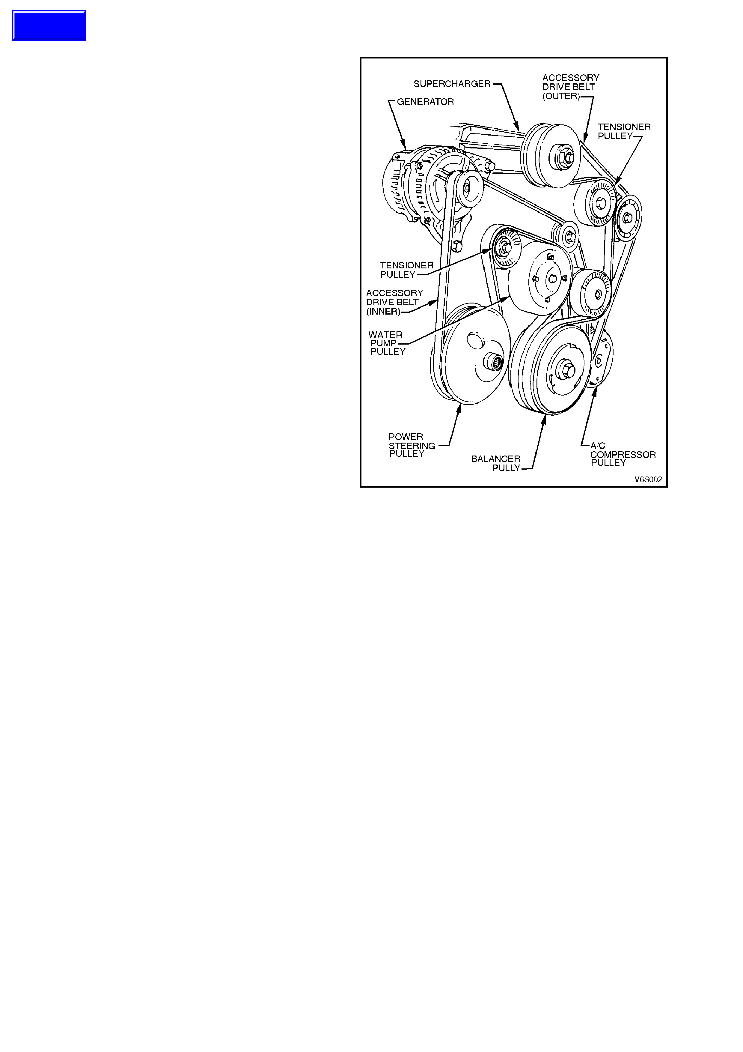
1.4 BALANCE SHAFT
The balance shaft has revised balance
specifications and can be identified by the four
lubrication holes at the rear bushing end of the
shaft.
Figure 6A1-2-3
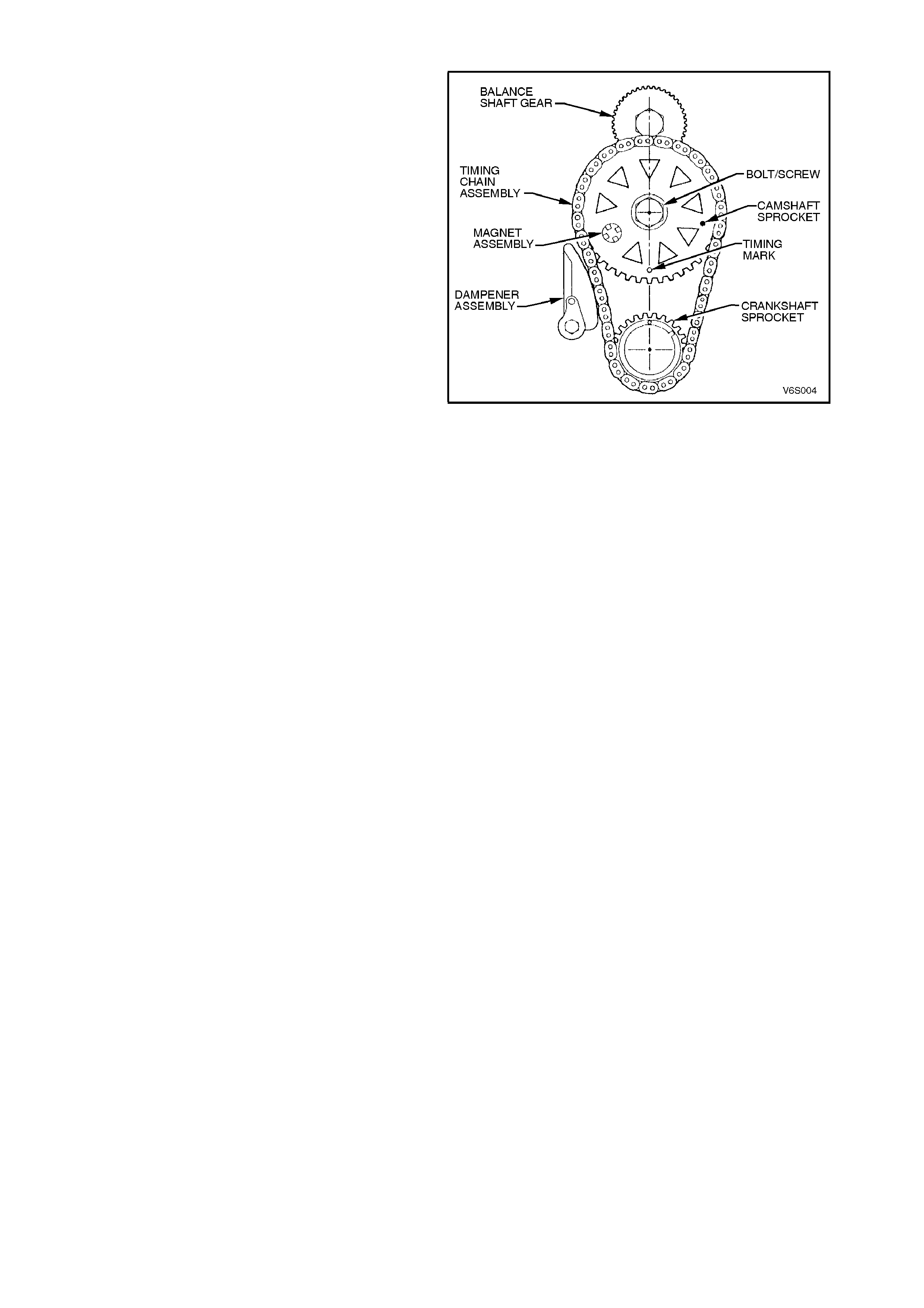
1.5 CAMSHAFT SPROCKET
The c am shaft s prock et f or the super charged engine
can be identified by triangular holes while the
standard sprocket retains round holes.
Figure 6A1-2-4
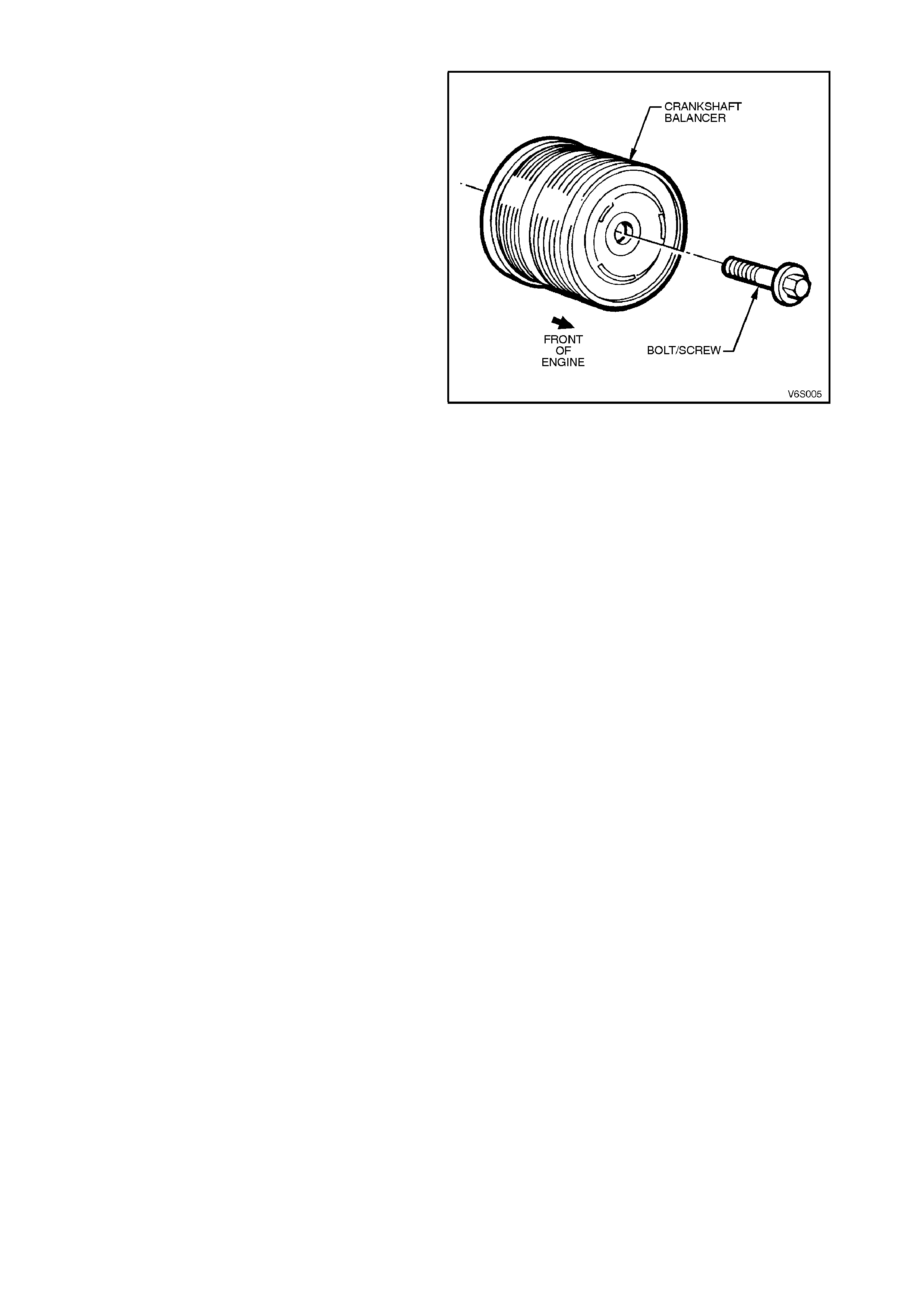
1.6 CRANKSHAFT BALANCER
The crankshaft balancer is a twin track type with
balance compensation specifically for the
supercharged engine.
Figure 6A1-2-5
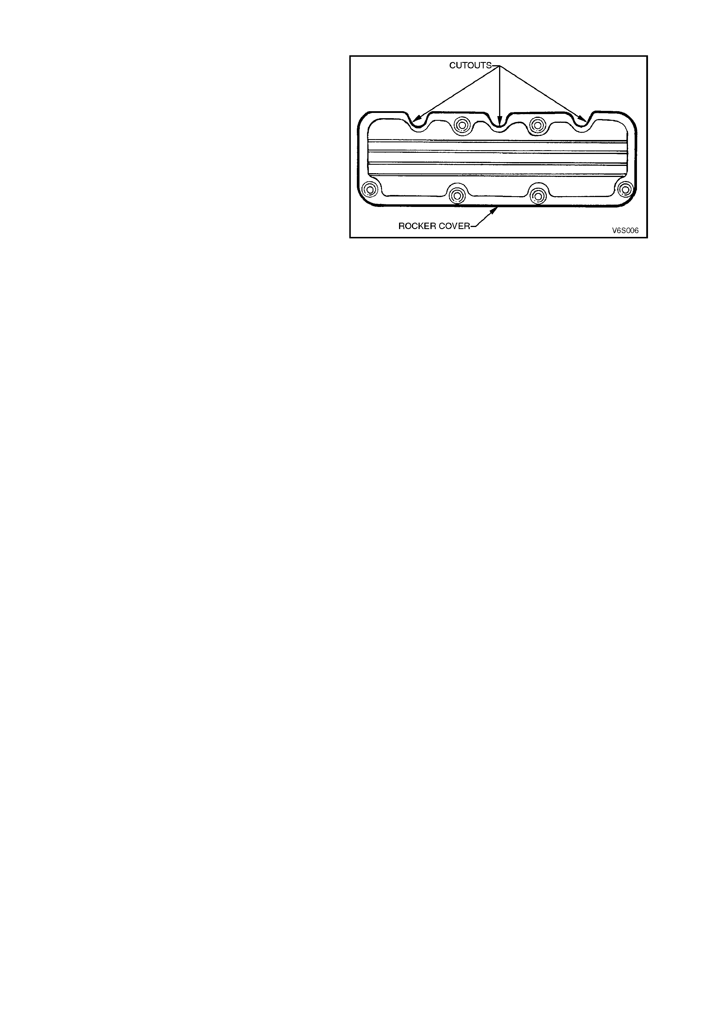
1.7 ROCKER COVERS & GASKETS
Rocker covers and gaskets are modified with cut
outs to suit relocation of the injectors in the cylinder
head inlet ports for the supercharged engine.
Figure 6A1-2-6

1.8 CONNECTING RODS
The connecting rods have larger pin bush internal diameter and the big end/little end centre distance has been
revised.

1.9 PISTONS & PINS
Pistons and pins have been revised with a compression height of 30.6 mm and a larger floating piston pin of 23 mm
nominal diameter.
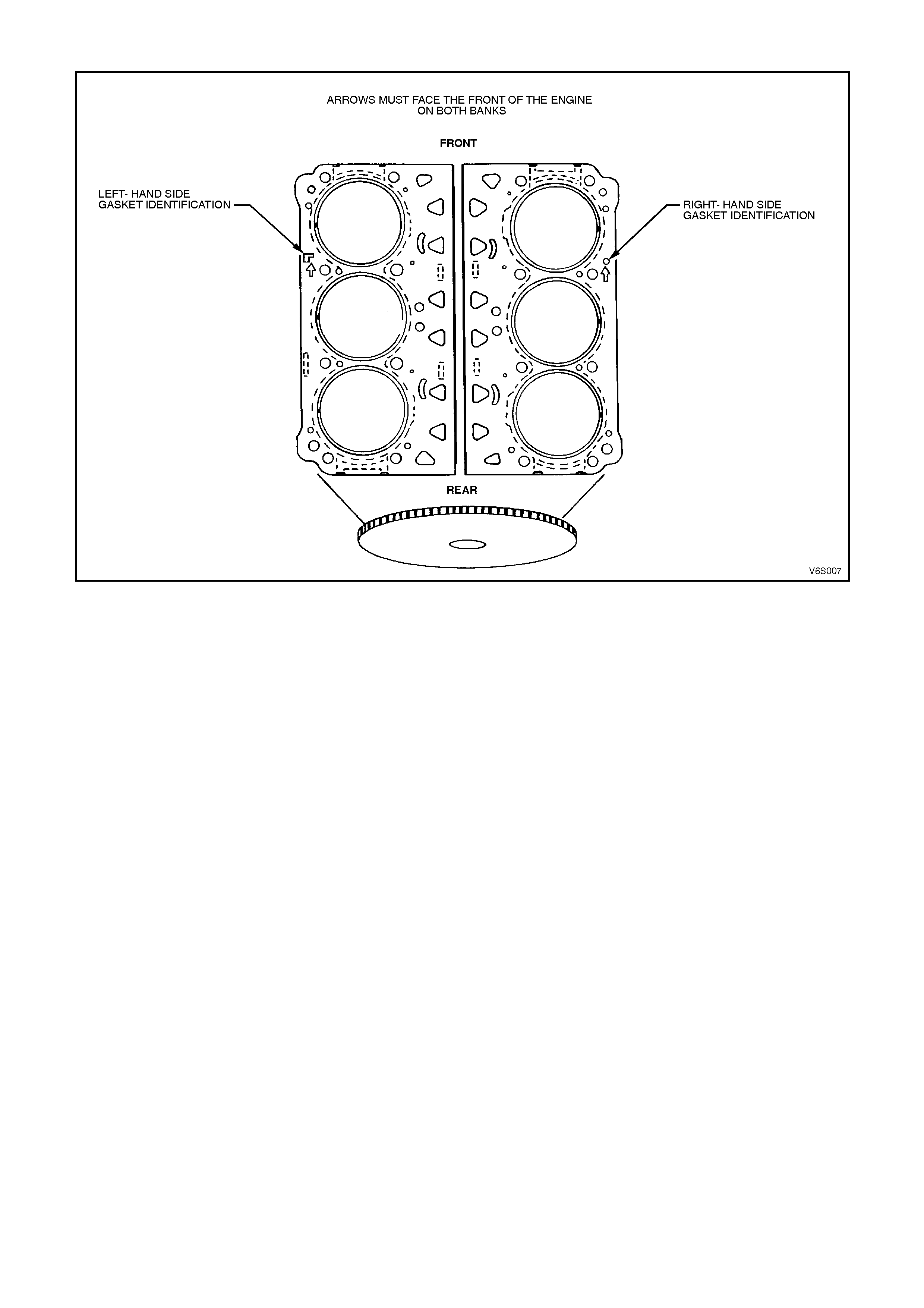
1.10 CYLINDER HEADS & GASKETS
Figure 6A1-2-7
Cylinder heads have been machined for the location of in-head fuel injectors. The cylinder head gaskets feature
revised material and construction and are specific to each bank.
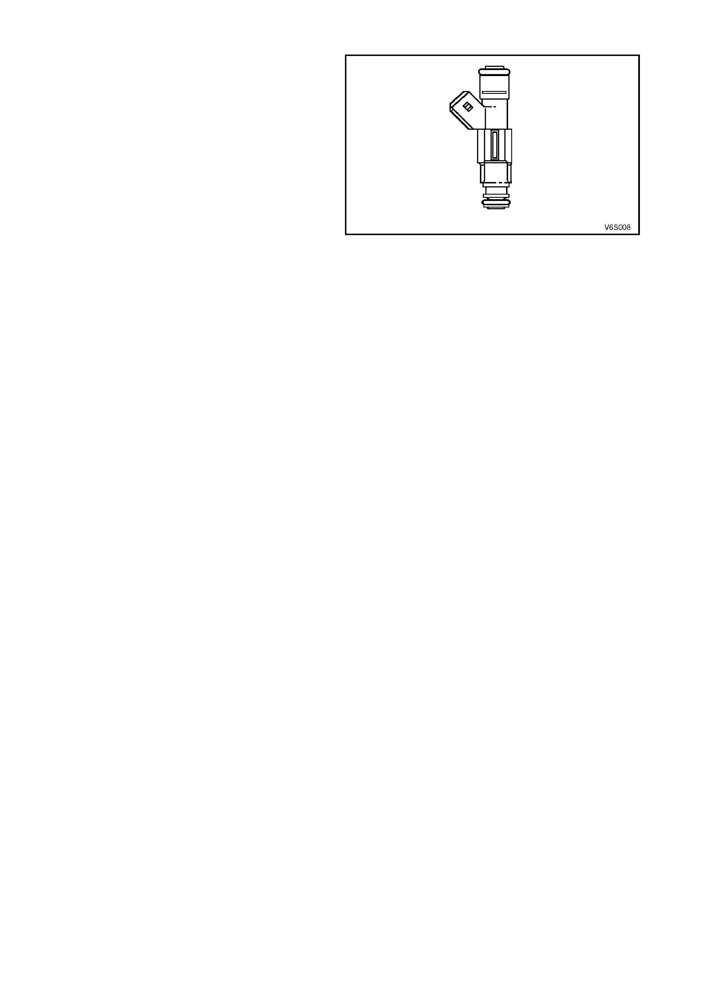
1.11 FUEL INJECTORS
Fuel injectors for VT supercharged engine are
unique to this engine type and are of the high
capacity type.
Figure 6A1-2-8
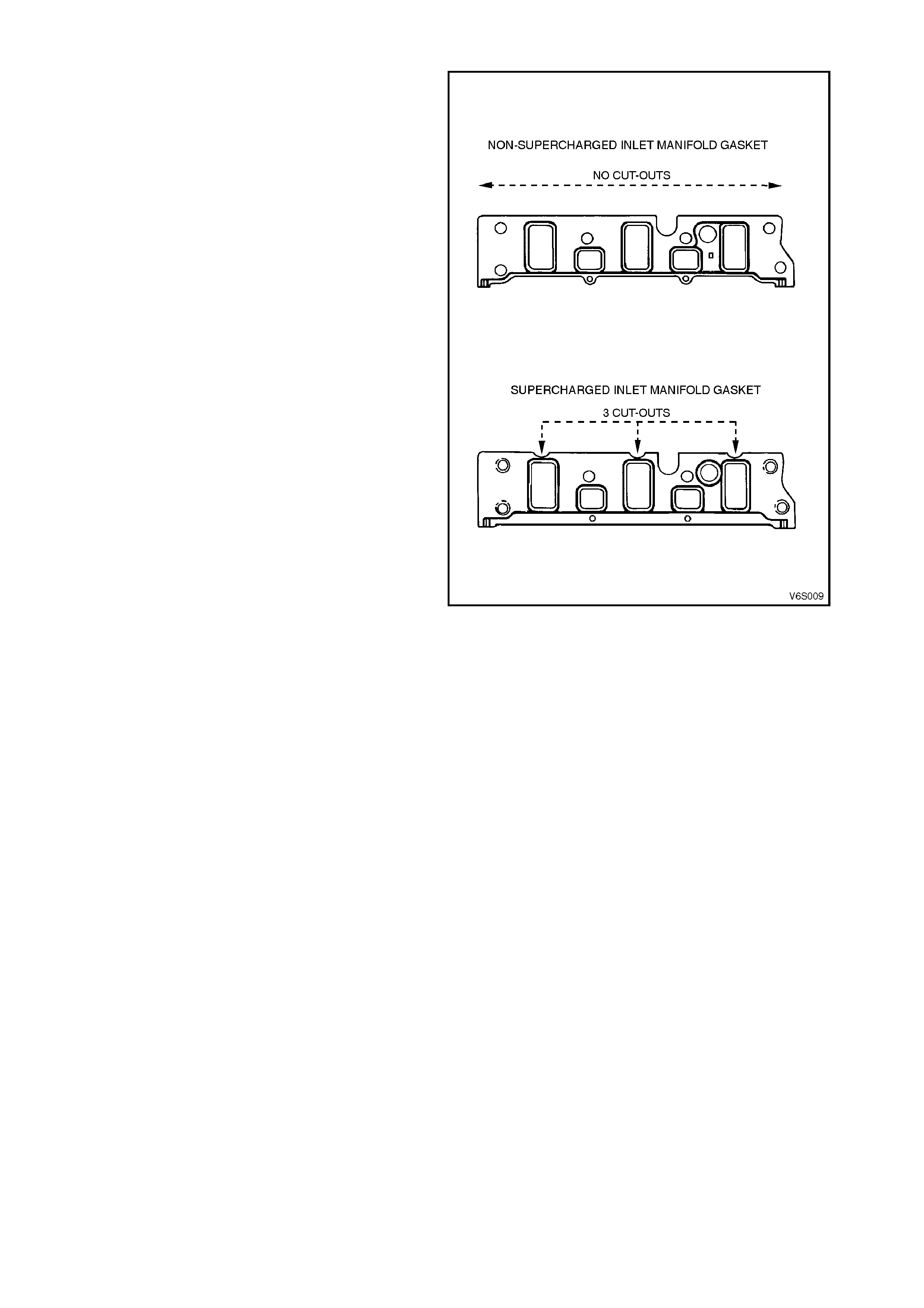
1.12 LOWER INLET MANIFOLD AND GASKETS
The lower inlet manifold is a machined aluminium
casting incorporating the lower section of the inlet
ports, coolant and PCV passages. The top face is
machined flat to accommodate the supercharger
and with the fuel injectors located in the cylinder
heads, cut outs have been incorporated in the
manifold gaskets for the injectors
Figure 6A1-2-9
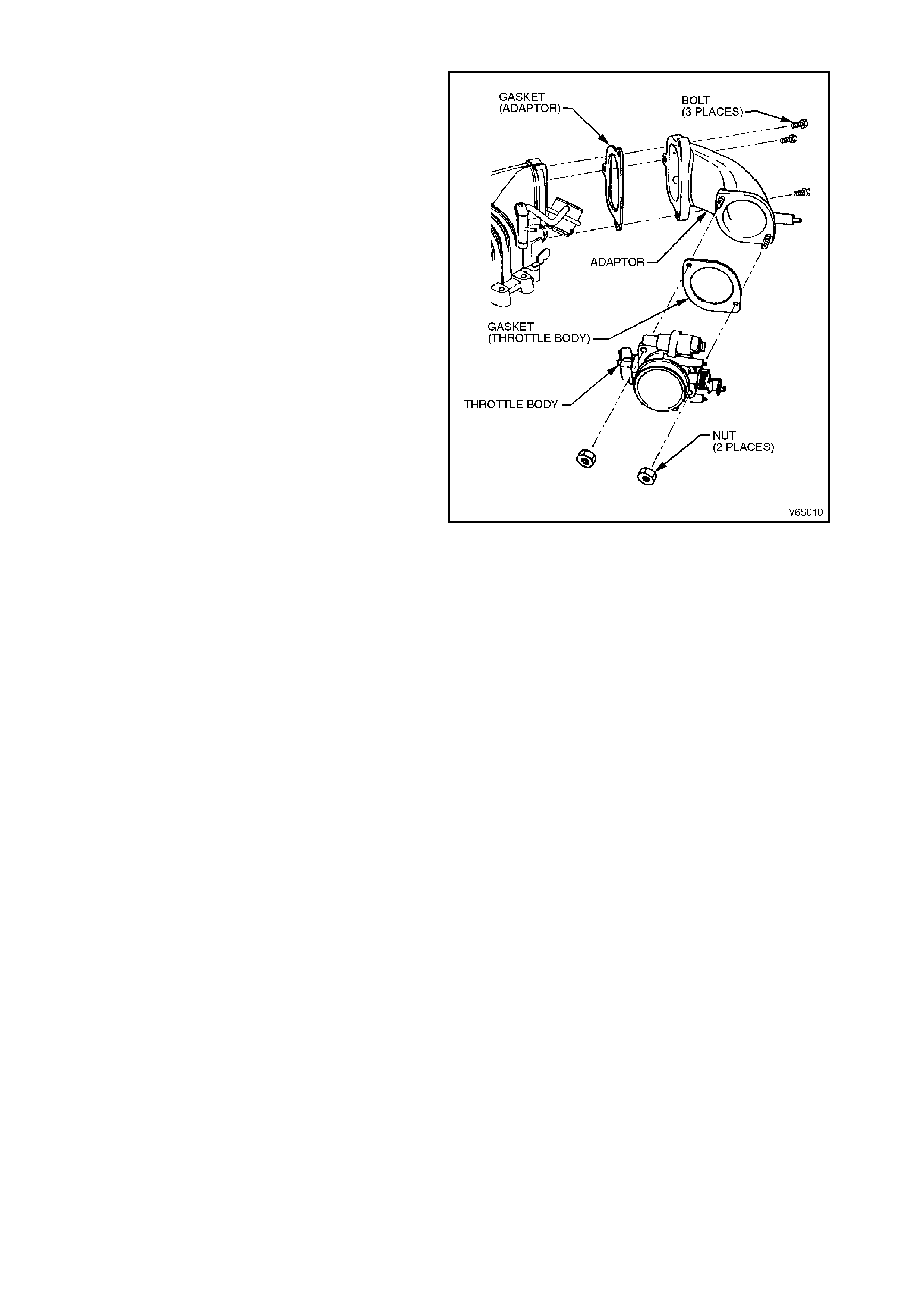
1.13 THROTTLE BODY ADAPTOR
The throttle body adaptor is a machined aluminium
casting which connects the remote throttle body to
the supercharger. The throttle body adaptor
includes brake booster and heater vacuum nipples,
cable bracket and mounting studs to suit the
supercharger inlet.
Figure 6A1-2-10
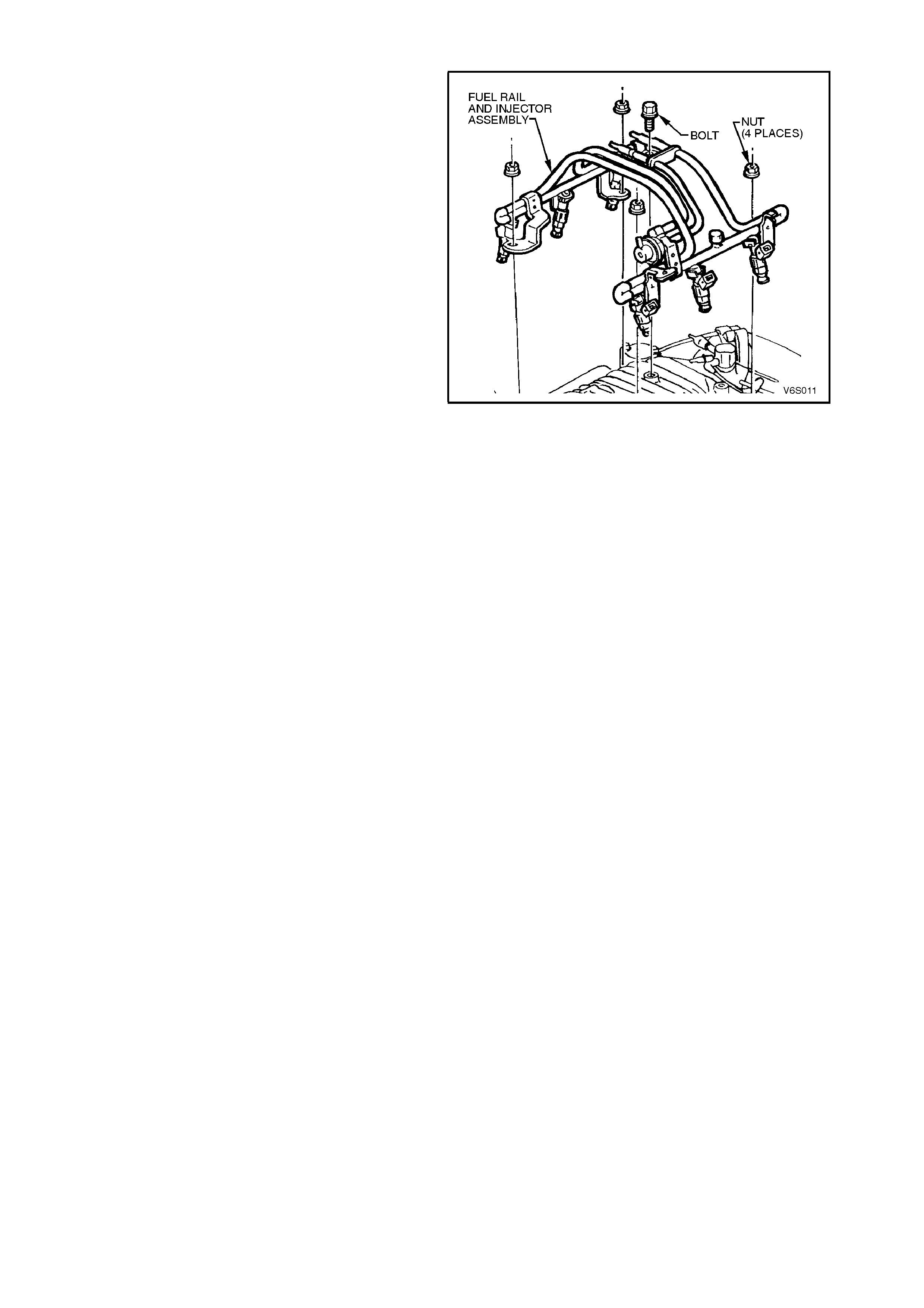
1.14 FUEL RAIL
The fuel rail assembly is a steel tube type and
specific to the supercharged engine. The fuel rail
incorporates the fuel pressure regulator and a
Schraeder valve to enable eas y connection of a f uel
pressure gauge. The fuel pressure regulator is not
serviced separately from the fuel rail.
Figure 6A1-2-11
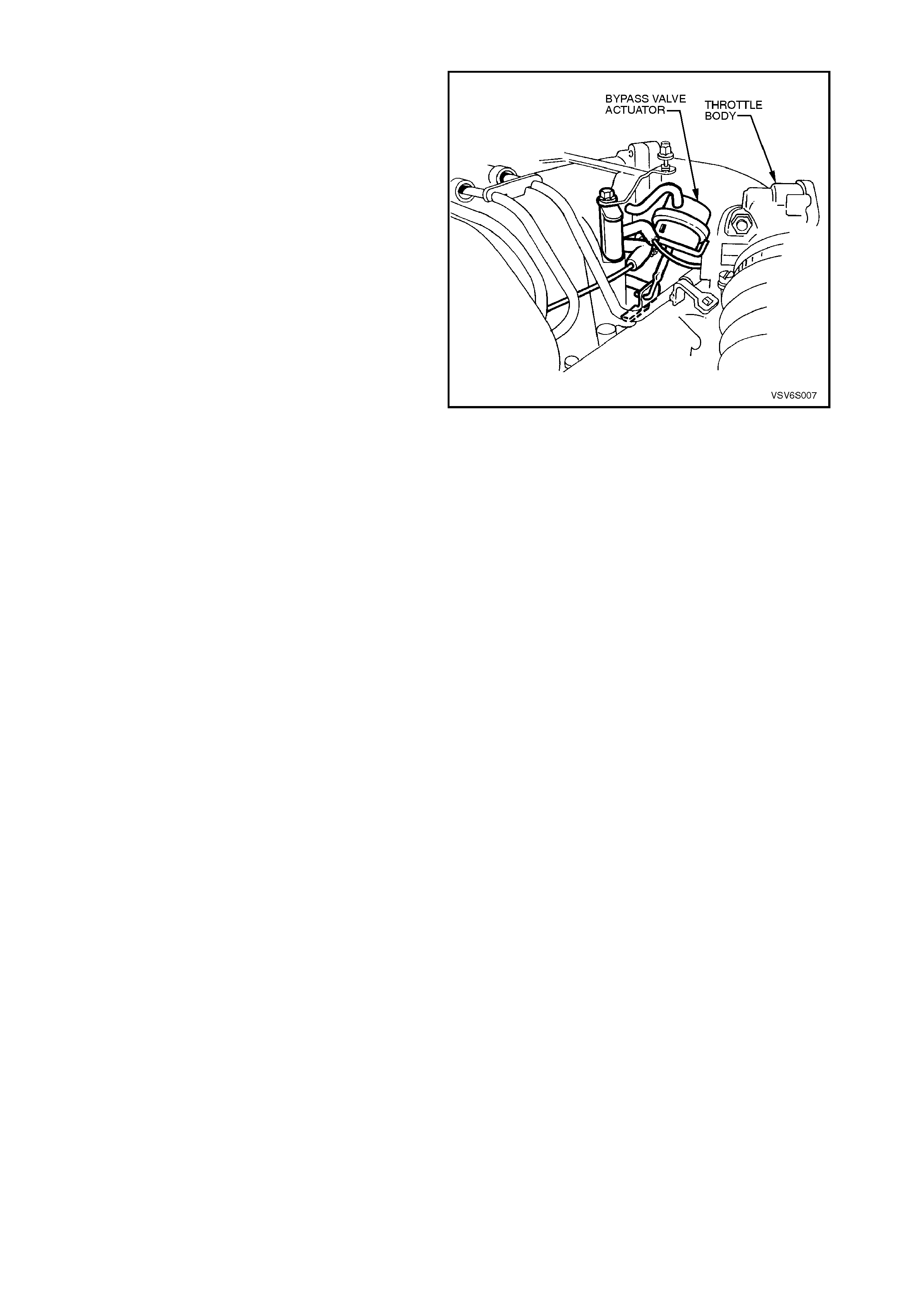
1.15 BYPASS VALVE ACTUATOR
The s upercharger bypass valve actuator operates a
valve which can cut boost at idle or at low throttle
openings by diverting inlet air around the
supercharger.
For additional information on bypass actuator
operation, refer to Section 6C1 POWERTRAIN
MANAGEMENT - V6 ENGINE.
Figure 6A1-2-12
1.16 BOOST CONTROL SO LENOID VALVE
A boost control s olenoid valve, loc ated at the r ear of
the left hand cylinder head is a PCM controlled
engine protection device which reduces boost in the
event of excessive coolant temperature.
Boost pressure is reduced by routing boost air from
the superchar ger outlet via the solenoid to the lower
chamber of the bypass actuator, which then opens
the bypass valve.
NOTE:
Electrical connection must always be maintained to
the boost control solenoid value as no voltage will
trigger boost reduction even under normal coolant
temperature operation.
Figure 6A1-2-13
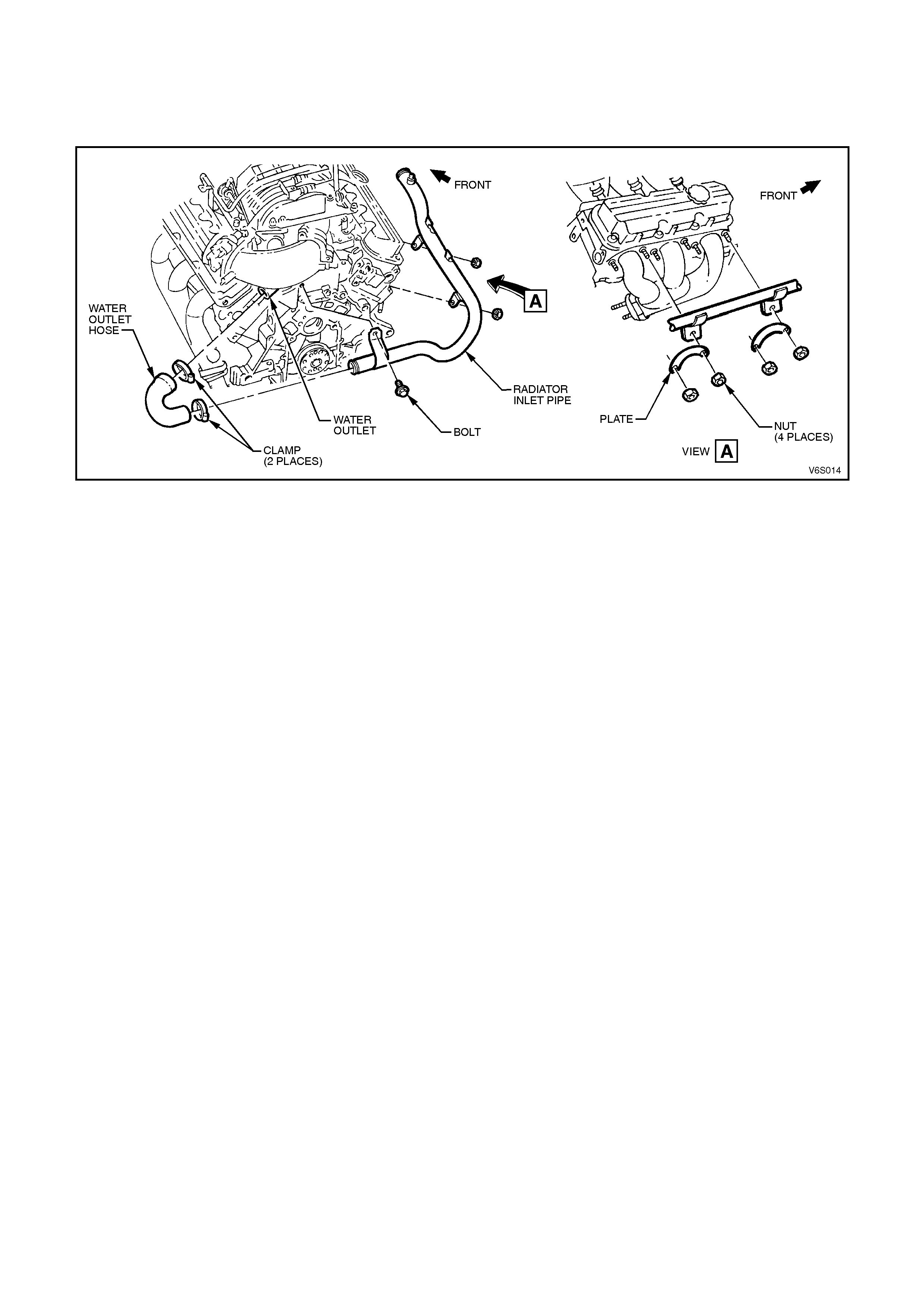
1.17 WATER OUTLET HOSE AND RADIATOR INLET PIPE
The water outlet hose connects the thermostat hosing outlet port to the radiator inlet pipe to convey the engine
coolant from the back of the inlet manifold to the radiator inlet port. The thermostat housing cover is a machined
aluminium casting which includes the cooling system bleeder valve. The thermostat housing is located at the rear of
the inlet manifold.
Figure 6A1-2-14
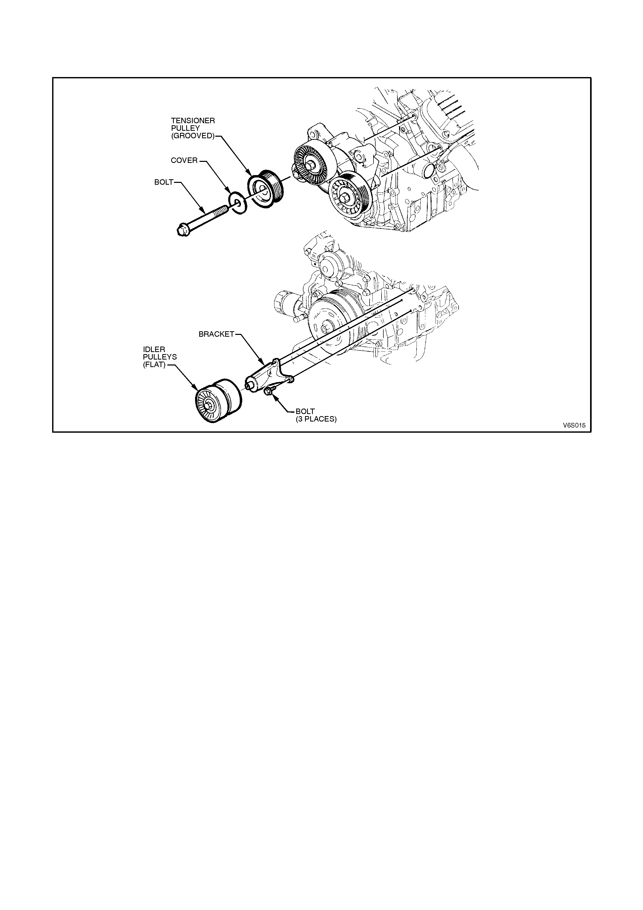
1.18 SUPERCHARGER DRIVE BELT IDLER PULLEY & BELT TE NSIONER
There are two flat idler pulleys for accessory drive and supercharger drive, mounted on aluminium brackets
adjacent to the crankshaft balancer and DIS coil pack.
Figure 6A1-2-15
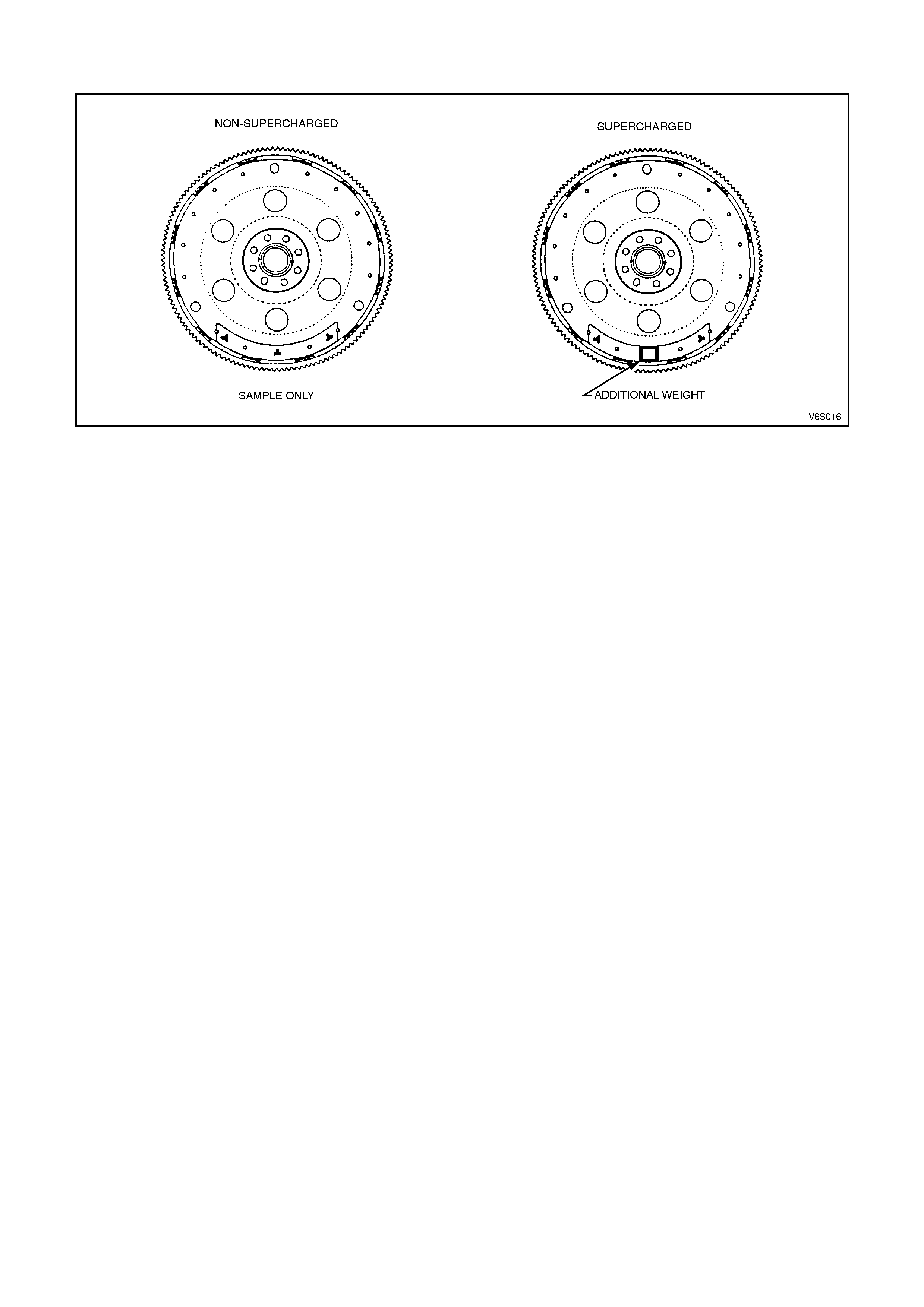
1.19 FLEXPLATE
The flexplate for the supercharged engine has revised balancing.
Figure 6A1-2-16


1.22 DIS COILS & SPARK PLUGS
The coil and module assembly is a Delco-high energy unit with specific bracketing. The spark plugs are a specific
heat range and design for the supercharged engine.
2. SERVICE OPERATIONS
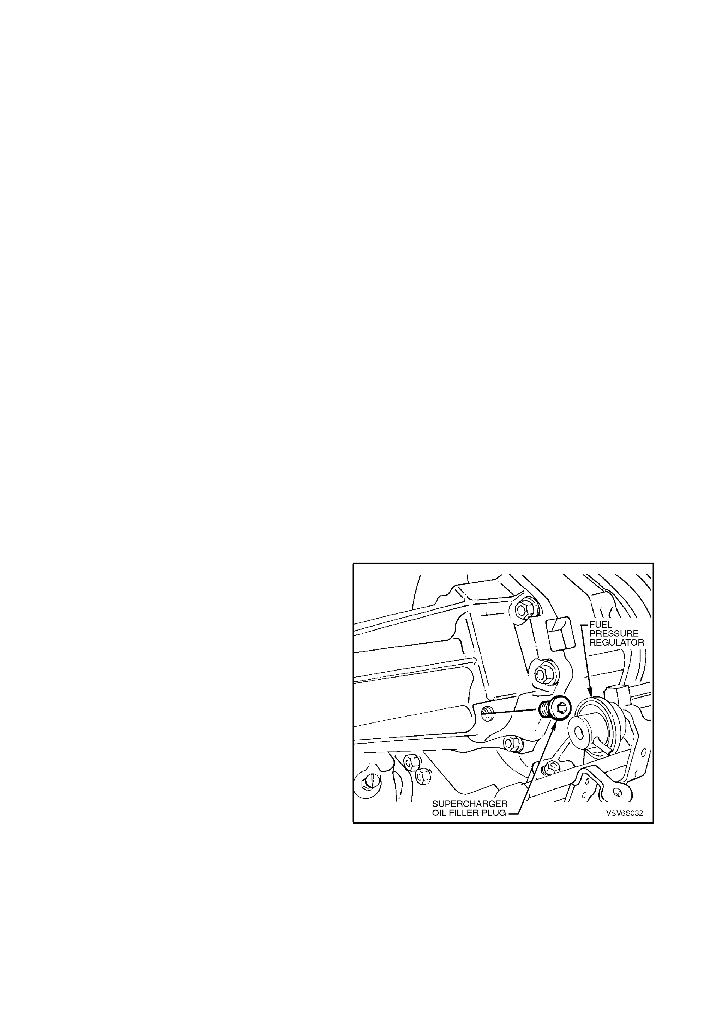
2.1 SUPERCHARGER OIL LEVEL CHECK
NOTE:
A small amount of oil weepage through the front
seal, (behind the pulley) of the supercharger
assembly is normal. T his oil weepage is c aused by
minute traces of oil escaping around the seal. A
build up of airborne dust can adhere to the thin oil
film which causes oil weepage to appear worse
than it really is. The superc harger ass embly should
not be replaced due to weepage. If supercharger
oil is visually dripping or puddling from the
supercharger front seal, the supercharger
assembly will need to be replaced. Refer to
2.2 SUPERCHARGER AND GASKET in this
Section.
CAUTION:
Do not remove the oil plug when engine is
warm. Engine should be cool to the touch.
Approximately 2 -3 hours after running.
Removing oil plug at warm engine
temperatures can cause hot oil to overflow.
This could result in oil loss and possible
personal injury.
Lubricant level is to be checked at the specified
service intervals outlined in the VT Series Owner’s
Handbook.
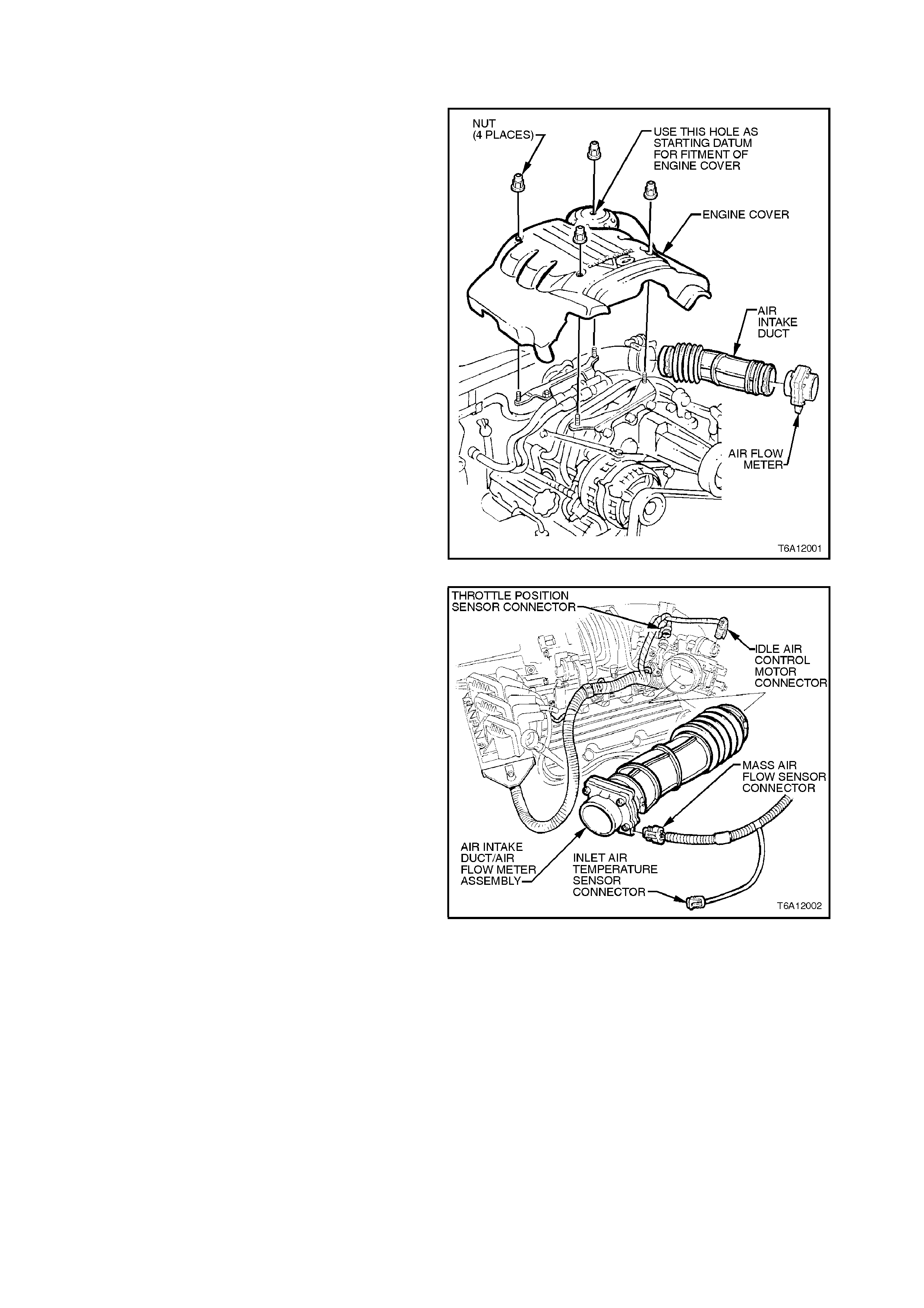
REMOVE
1. Remove the four dome nuts securing the
engine dress cover assembly to the mounting
bracket studs, refer to Fig. 6A1-2-17, lift off
and remove the cover assembly.
NOTE:
To prevent contamination of the supercharger oil,
clean the area around the oil filler plug before
removing.
2. Using a 3/16 inch Allen key socket, remove
supercharger filler plug.
3. Check oil level.
NOTE:
The oil level should be maintained to a level at the
bottom of the threads in the oil filler plug inspection
hole in the supercharger housing.
IMPORTANT:
Do not use petroleum based oil. Use only GM p/no.
12345982 synthetic oil. Use of other oil may cause
supercharger failure.
Figure 6A1-17
REINSTALL
1. Reinstall the oil filler plug, ensuring sealing
cap O - ring is in place on plug.
Tighten plug to the correct torque
specification.
SUPERCHARGER OIL FILLER 10
PLUG TORQUE SPECIFICATION Nm
2. Reinstall engine dress cover to the mounting
brackets, ensuring that stud grommets in the
dress cover remain in place. Tighten securing
dome nuts to the correct torque specification.
ENGINE DRESS COVER
SECURING DOME NUT TO 4.0 - 6.0
MOUNTING BRACKET Nm
TORQUE SPECIFICATION
2.2 SUPE RCHARGER AND GASKET
REMOVE
NOTE:
Servicing of the supercharger unit itself is limited to
replacement only. No attempt should be made to
disassemble the supercharger as parts damage
may result.
1. Disconnect the negative cable from the battery
terminal.
2. Remove the four engine dress cover dome
nuts and remove the cover.
Figure 6A1-2-18
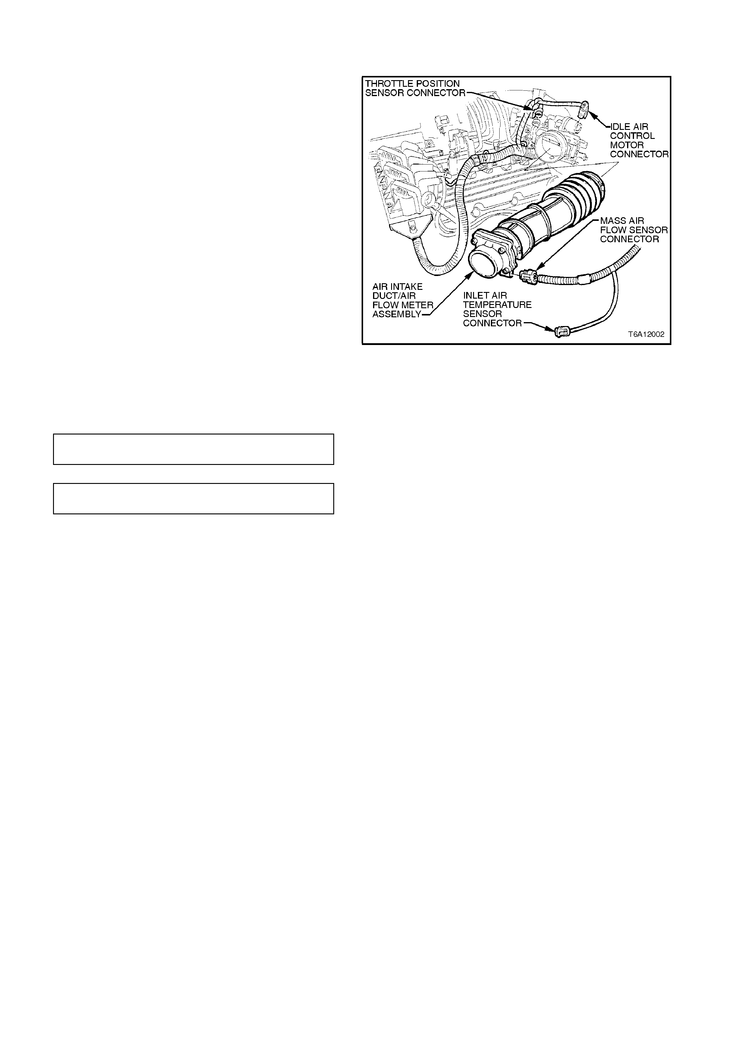
3. Disconnect the electrical connectors from the
IAC, MAF, IAT, TP sensors and place harness
to one side.
4. Remove the c lam ps sec uring air intak e duct/air
flow meter assembly to throttle body and air
filter, removing assembly.
Figure 6A1-19
5. Remove the screws s ecuring rear dress cover
bracket and boost solenoid harness.
6. Disconnect superc harger vacuum connections
from heating/ventilation system, throttle body,
fuel pressure regulator, boost solenoid
harness and engine ventilation hose.
7. Remove bypass solenoid harness, refer to
2.3 BYPASS SOLENOID HARNESS
ASSEMBLY in this Section, and BYPASS
VALVE ACTUATOR in
Section 6C1 POWERTRAIN MANAGEMENT
- V6 ENGINE.
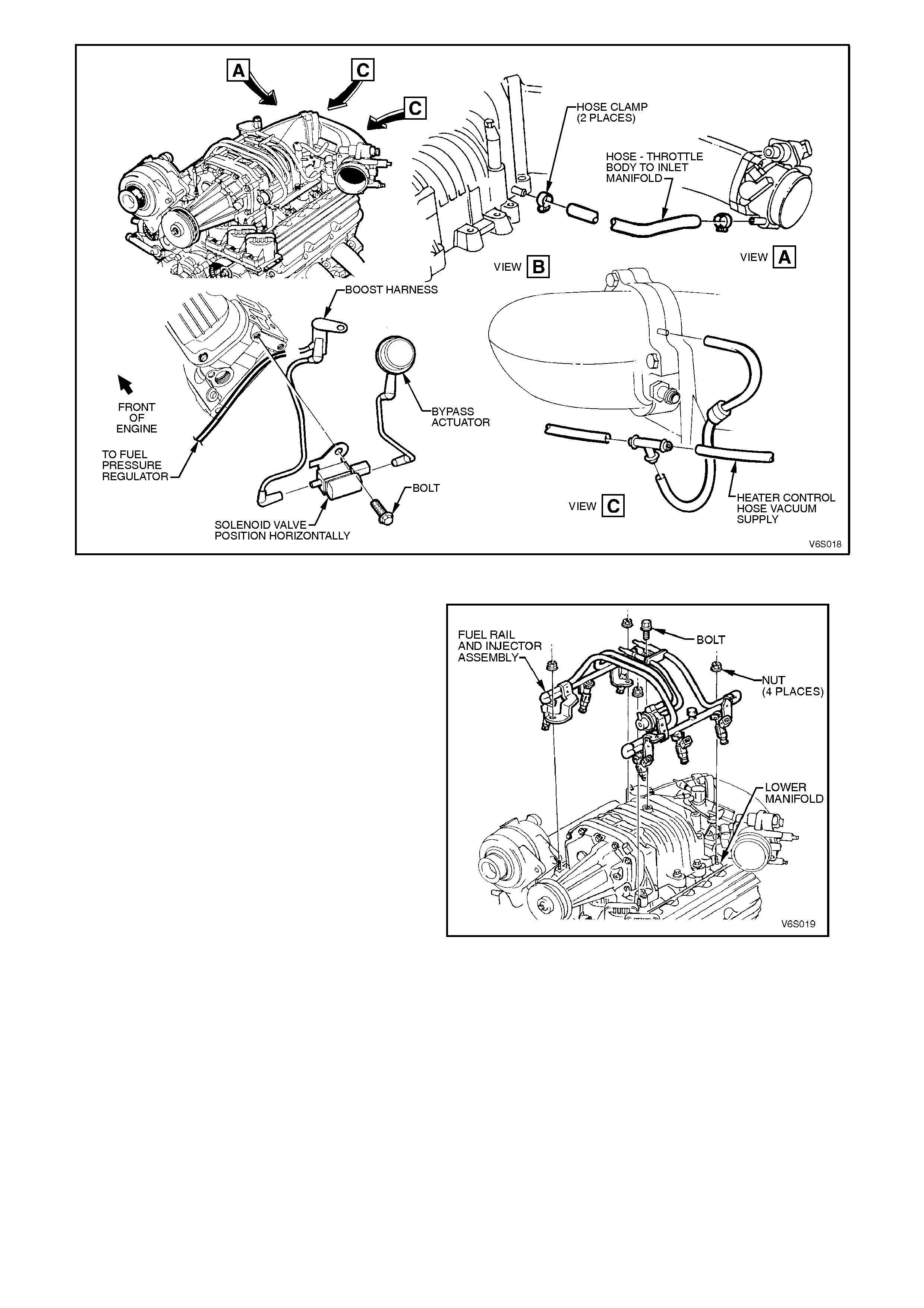
Figure 6A1-2-20
8. Depressurise the fuel rail, refer to
Section 6C1 POWERTRAIN MANAGEMENT
- V6 ENGINE and disconnect the electrical
connectors from injectors.
9. Remove the generator support bracket.
10. Disconnect the fuel lines from the fuel rail
assembly and remove the fuel rail, refer to
Section 6C1 SERVICE OPERATIONS.
Figure 6A1-2-21
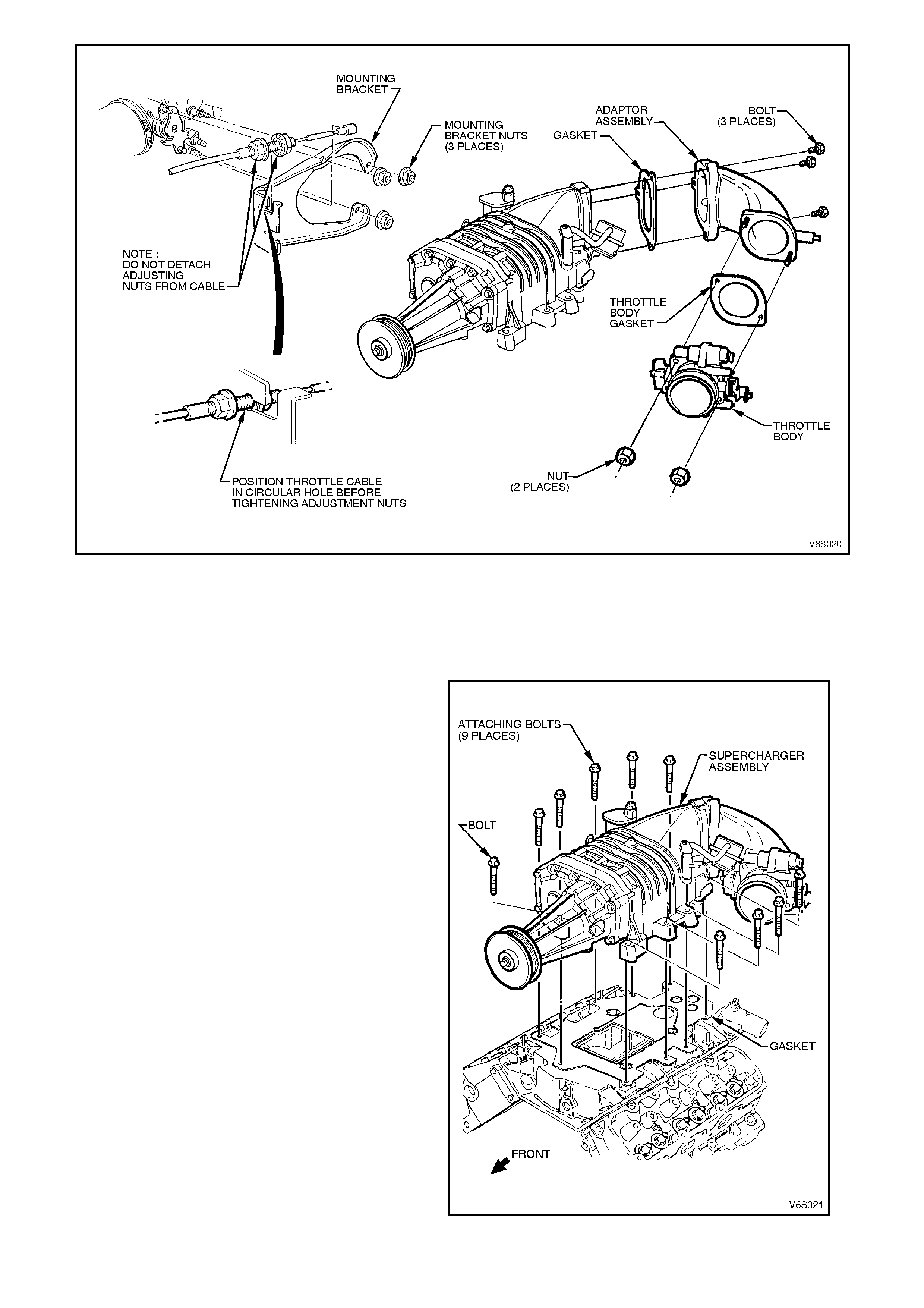
Figure 6A1-2-22
11. Disconnect throttle cable and where fitted
cruise control cable.
12. Remove throttle body from throttle body
adaptor, refer to 2.4 THROTTLE BODY in
this Section.
13. Remove the drive belt from supercharger
pulley, refer to 2.9 SUPERCHARGER DRIVE
BELT in this Section.
14. Remove supercharger to inlet manifold bolts
and remove the supercharger.
CAUTION:
Do not place fingers or foreign objects near
supercharger vanes as personal injury or
damage to supercharger vanes can result.
15. Remove supercharger gasket and O - rings.
Figure 6A1-2-23
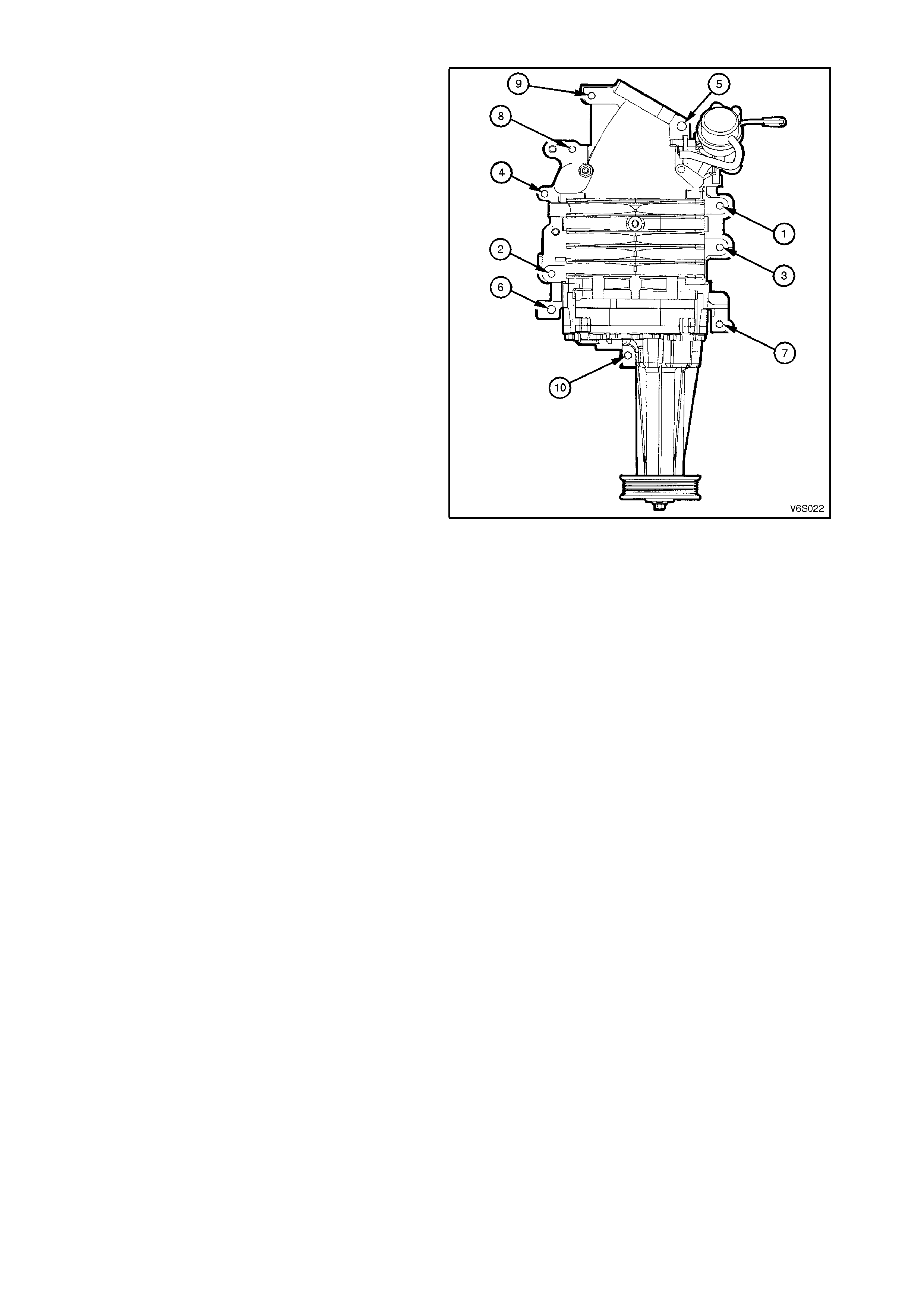
REINSTALL
1. That all mating surfaces are clean.
2. Supercharger to intake manifold gasket and
O - rings are replaced.
3. Torque sequence is maintained.
SUPERCHARGER ATTACHING BOLT
TORQUE SPECIFICATION
FIRST STAGE 14 ± 4.0 Nm
SECOND STAGE 24 ± 3.0 Nm
Figure 6A1-2-24
Installation of the supercharger is the reverse of
removal operations noting the following points:
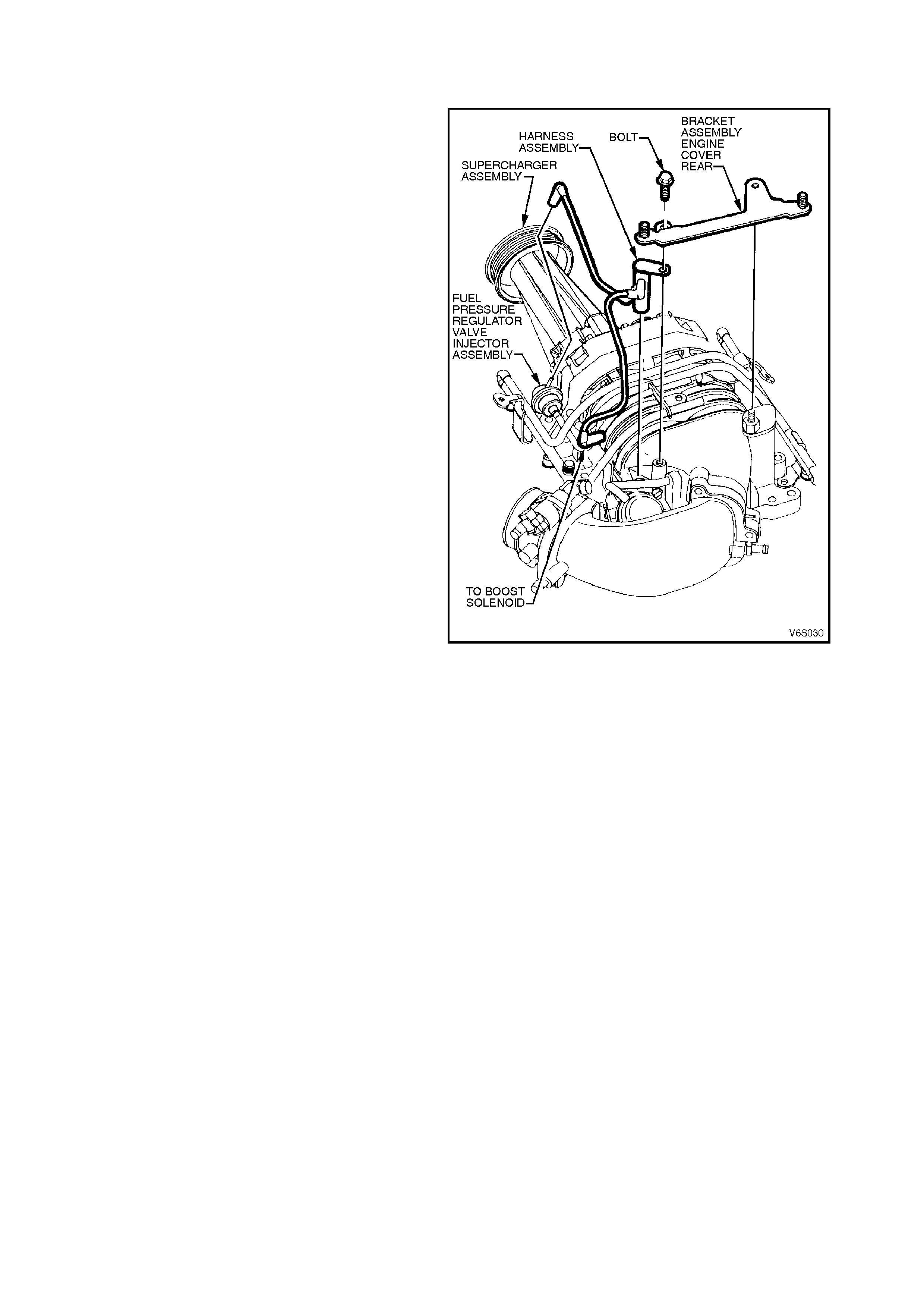
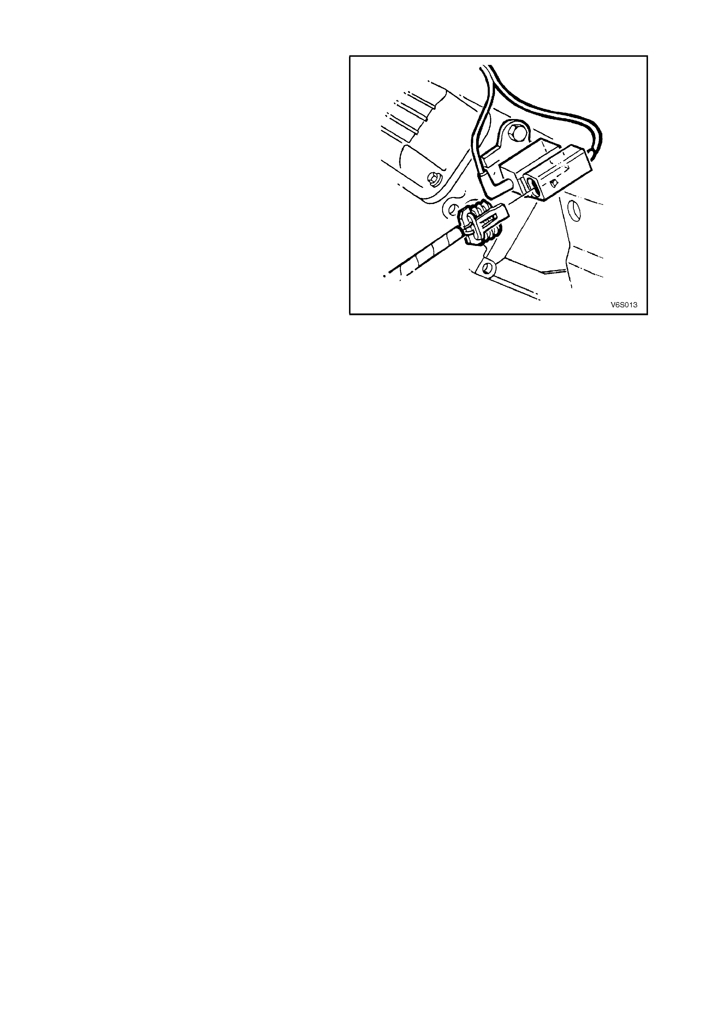
2.3 BYPASS SOLENOID HARNESS ASSEMBLY
REMOVE
1. Disconnect the negative cable from the battery
terminal.
2. Remove the four engine dress cover dome
nuts and remove the cover.
3. Disconnect vacuum connections from fuel
pressure regulator and bypass solenoid.
REINSTALL
Reverse removal operations.
Figure 6A1-2-25
2.4 THROTTLE BODY
REMOVE
1. Disconnect the negative cable from the battery
terminal.
2. Disconnect the electrical connectors from the
IAC, MAF, IAT, TP Sensor and place harness
to one side.
3. Remove the c lam ps sec uring air intak e duc t/air
flow meter assembly to throttle body and air
filter and remove the assembly.
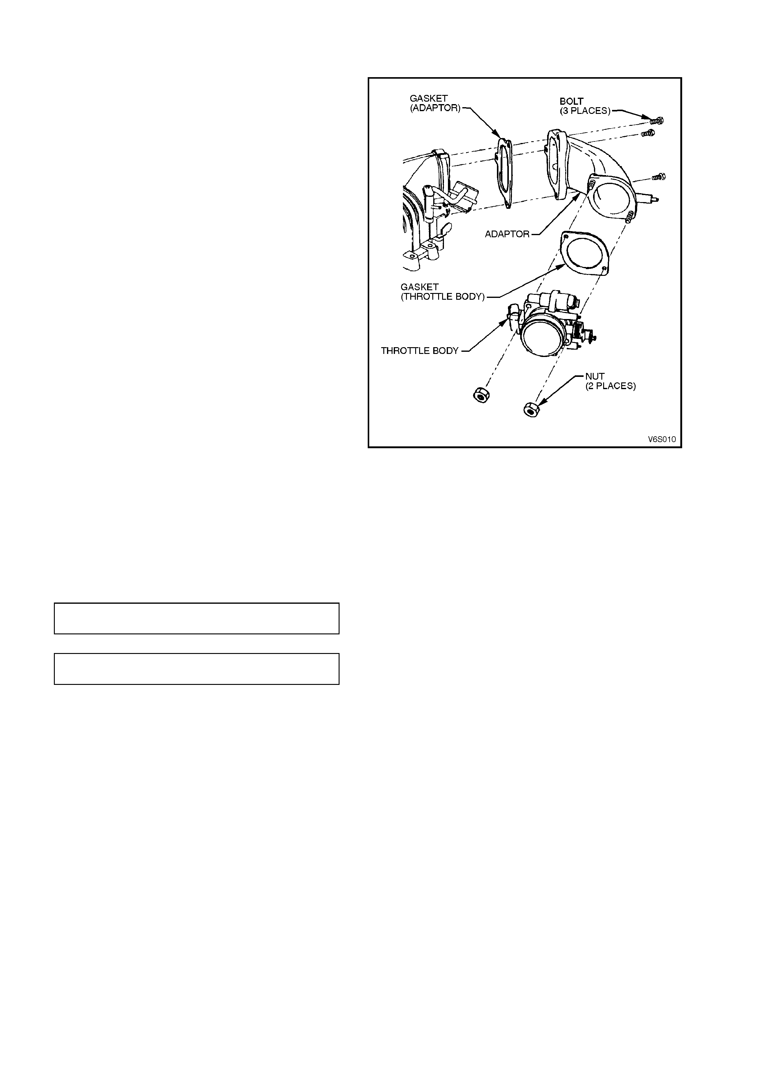
4. Remove the two nuts securing the throttle body
assembly to the throttle body adaptor and
remove the assembly.
Figure 6A1-2-26
REINSTALL
Reverse removal operations.
THROTTLE BODY NUT
TORQUE SPECIFICATION 15 - 20
Nm
ENGINE DRESS COVER NUT
TORQUE SPECIFICATION 4.0 - 6.0
Nm
2.5 THROTTLE BODY ADAPTOR
REMOVE
1. Disconnect the negative cable from the battery
terminal.
2. Remove the four engine dress cover dome
nuts and remove the cover.
3. Remove the Throttle Body, refer to
2.4 THROTTLE BODY in this Section.
4. Remove the bypass solenoid harness and
bypass valve actuator, refer to
2.3 BYPASS SOLENOID HARNESS
ASSEMBLY in this Section.
5. Disconnect the vacuum lines from the throttle
body adaptor.
6. Remove the two bolts and one nut s ec uring the
throttle body adaptor to the supercharger.
Figure 6A1-2-27
REINSTALL
Reverse removal operations, noting the following.
a. Ensure bypass valve actuator preload is
adjusted correctly.
b. Ensure all vacuum lines are connected
correctly.
THROTTLE BODY NUT
TORQUE SPECIFICATION 15 - 20
Nm
ENGINE DRESS COVER NUT
TORQUE SPECIFICATION 4.0 - 6.0
Nm

2.6 ENGINE VENTILATION SYSTEM
The engine ventilation system, utilises engine vacuum to draw blow-by gasses into the combustion chambers where
they are recy cled through the combustion process. The ventilation system should be checked at the specified time
or distance intervals in the VT Series Owner’s Handbook.

2.7 FUNCTIONAL CHECK OF CRANKCASE V E NTILATION VALVE
If an engine is idling rough, check for a clogged crankcase ventilation valve. Replace as required using the following
procedure:
1. Remove crankcase ventilation valve from rear of supercharger, refer to 2.8 CRANKCASE VENTILATION
VALVE in this Section.
2. Shake valve and listen for the rattle of needle inside valve. If valve does not rattle, replace valve.
2.8 CRANKCASE VENTILATION VALVE
REMOVE
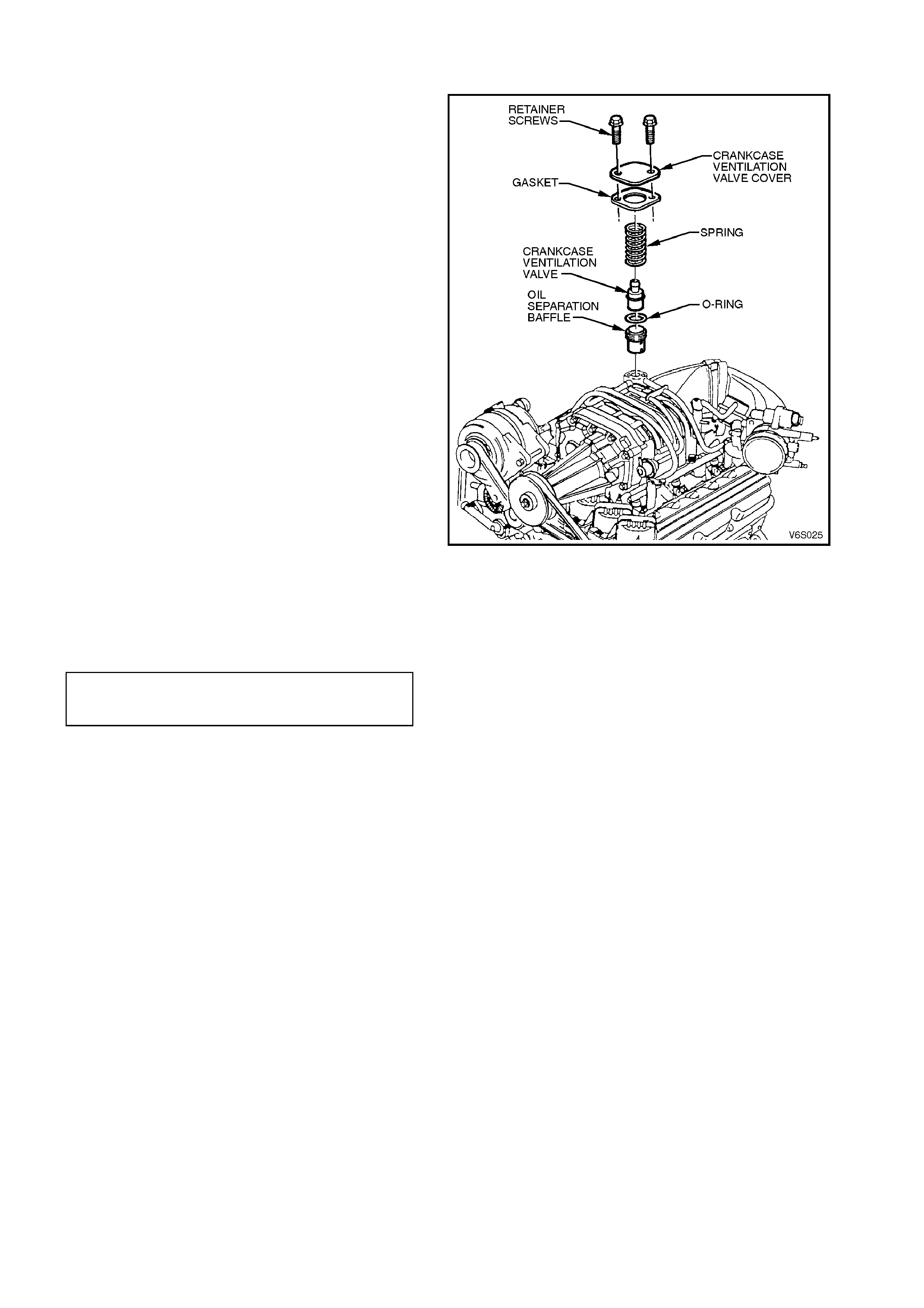
1. Remove the four engine dress cover dome
nuts and remove the cover.
2. Hold down the crankcase ventilation valve
cover and remove the two cover retainer
screws.
3. Remove the crankcase ventilation valve cover,
gasket, crank case ventilation valve, spring and
O - ring.
Figure 6A1-2-28
REINSTALL
Reverse removal operations using new O - rings
and gasket as necessary.
CRANKCASE VENTILATION
VALVE COVER SCREW
TORQUE SPECIFICATION 4.0 - 6.0 Nm
2.9 SUPERCHARGER DRIVE BELT
TENSION CHECK
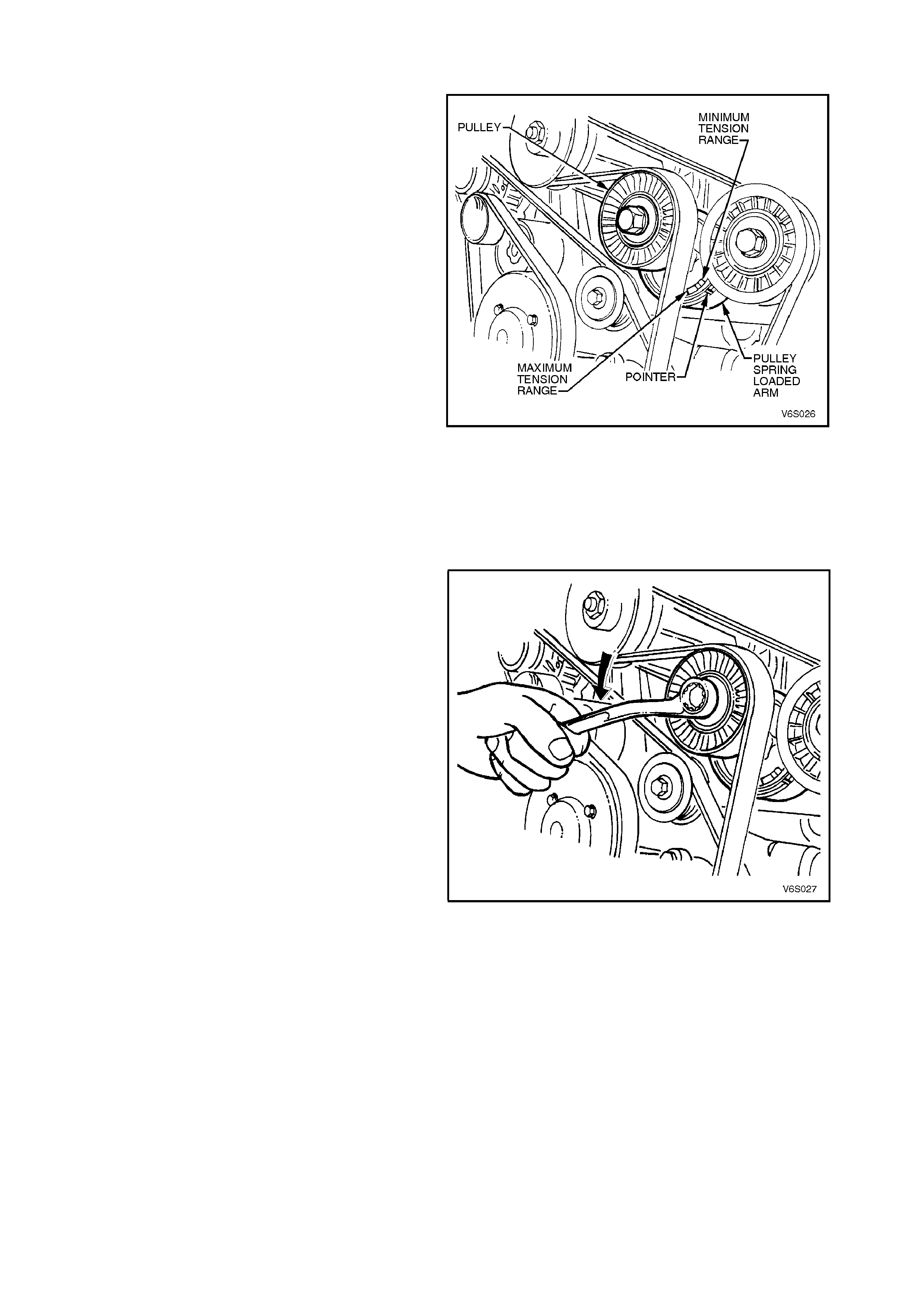
1. Inspect tensioner markings to see if belt is
within operating limits. Replace belt if
excessively worn or outside tensioner’s
operating range.
Refer to Section 6A1-1 ENGINE
MECHANICAL - V6 ENGINE for checking
procedure.
Figure 6A1-2-29
INSPECT
Refer to Section 6A1-1 ENGINE MECHANICAL -
V6 ENGINE.
REMOVE
1. Disconnect the negative cable from the battery
terminal.
2. Remove the four engine dress cover dome
nuts and remove the cover.
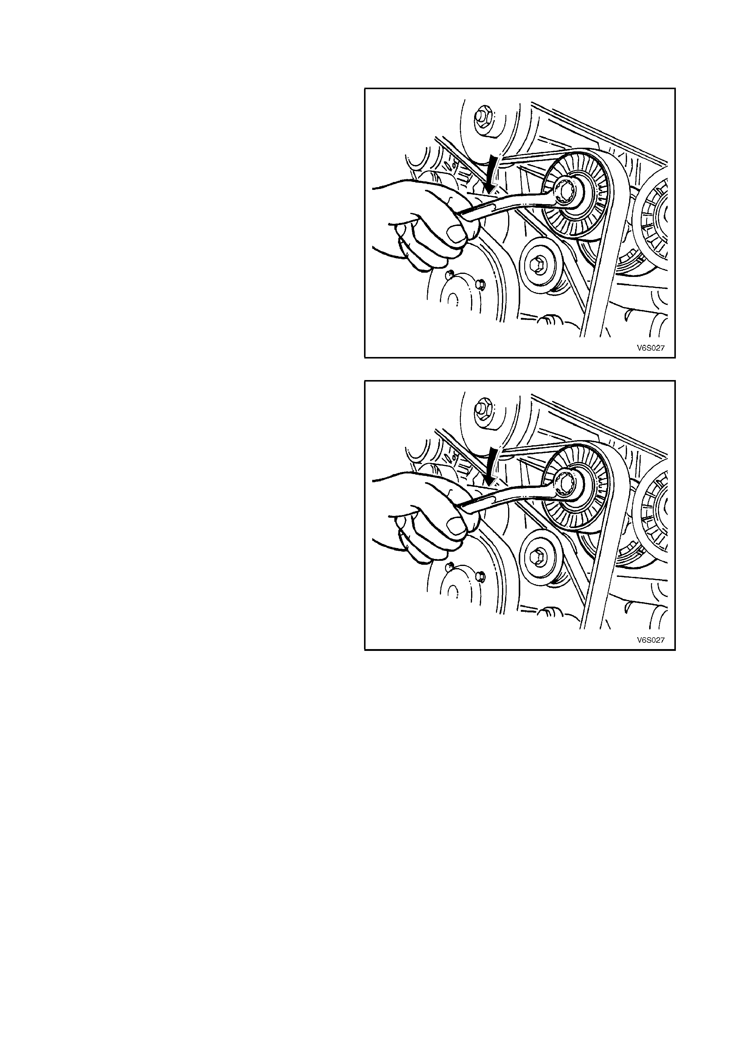
3. Using a 15 mm ring spanner on supercharger
drive belt tensioner pulley pivot bolt, rotate
tensioner pulley assembly anti-clockwise and
remove drive belt from supercharger. Release
tensioner pulley assembly and remove drive
belt from remaining drive pulleys.
Figure 6A1-2-30
REINSTALL
1. Inspect drive belt condition, refer to Section 6A1-1 ENGINE MECHANICAL - V6 ENGINE.
NOTE:
Ensure drive belt ribs are aligned into all pulleys and crankshaft balancer drive belt grooves.
2. Using a 15 mm ring spanner, rotate supercharger drive belt tensioner pulley anti-clockwise and feed drive belt
over supercharger pulley. Return tensioner to its normal position.
3. Reconnect battery negative cable, start engine and check drive belt operation.
Figure 6A1-2-31
2.10 SUPERCHARGER DRIVE BELT TENSIONER ASSEMBLY
REMOVE
1. Disconnect the negative cable from the battery
terminal.
2. Remove the four engine dress cover dome
nuts and remove the cover.
3. Using a 15 mm ring spanner on supercharger
drive belt tensioner pulley pivot bolt, rotate
tensioner pulley assembly anti-clockwise and
remove drive belt from supercharger. Release
tensioner pulley assembly and remove drive
belt from remaining drive pulleys.
Figure 6A1-2-32
4. Using a 15 mm ring spanner on accessory
drive belt tensioner pulley pivot bolt, rotate
tensioner pulley assembly anti-clockwise and
remove drive belt from supercharger drive belt
tensioner idler pulley. Release tensioner pulley
assembly and remove drive belt from
remaining drive pulleys.
Figure 6A1-2-33
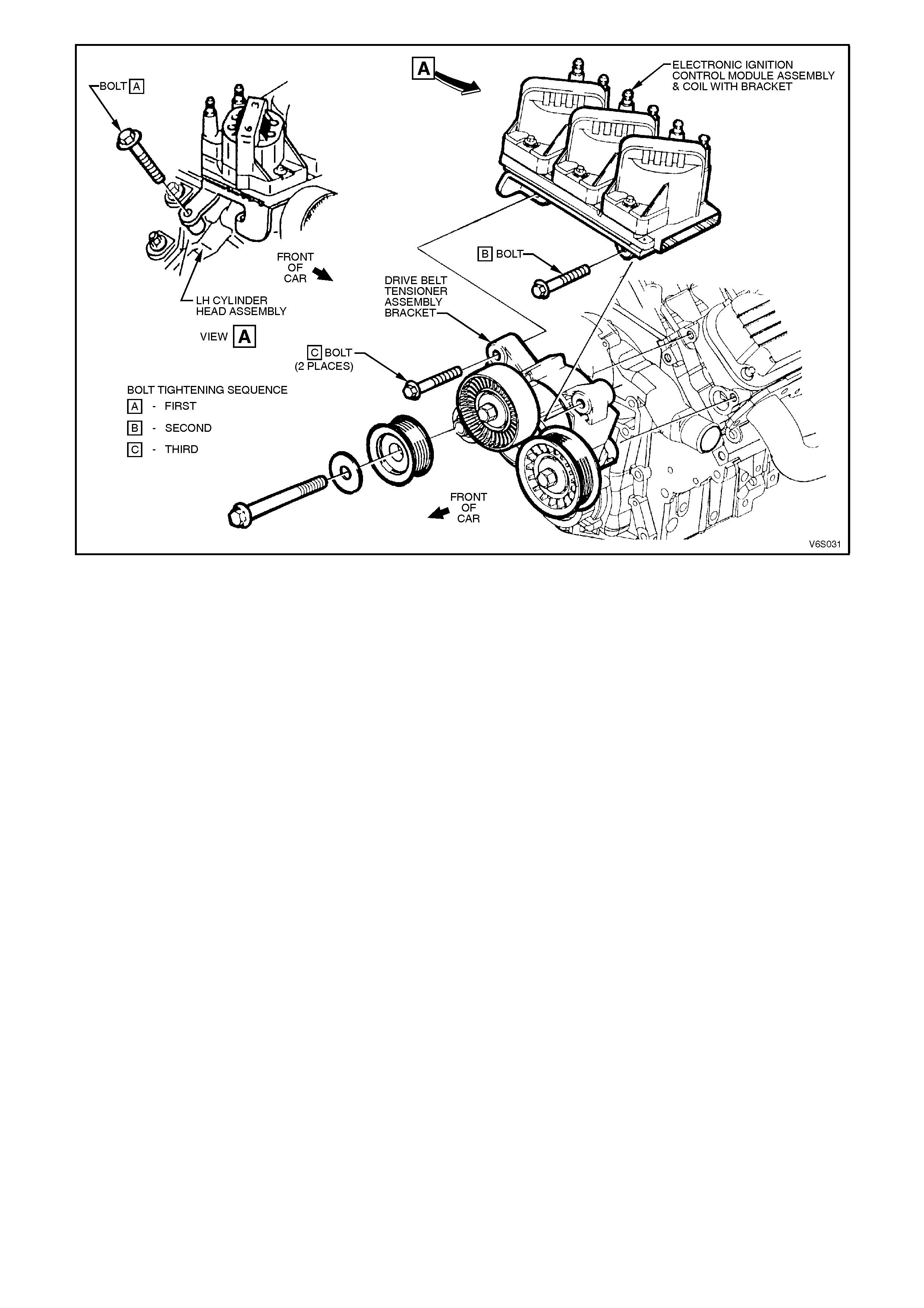
5. Remove the bolts s ecuring the coil pac k to the
drive belt tensioner assembly.
6. Remove the bolts securing the drive belt
tensioner assembly to the cylinder head.

3. SPECIFICATIONS
GENERAL
Engine Type 90 degree V6 supercharged, OHV
Piston Displacement Nom. - cm33791
Compression Ratio 8.5:1
Number of Cylinders 6
Bore x Stroke - mm 96.5 X 86.3
Taxable H.P.RAC OR SAE 34
Power kW DIN @ RPM 171 kw @ 5200
Torque Nm DIN @ RPM 375 Nm @ 3000

4. TORQUE WRENCH SPECIFI CATIONS
Nm
Supercharger drive belt tensioner attaching bolt 40 - 50
Supercharger drive belt tensioner pulley bolt 40 - 50
Supercharger drive belt idler pulley bolt 40 - 60
Supercharger drive belt idler pulley bracket bolt 25 - 35
Supercharger attaching bolts
First stage 14 ± 4.0
Second stage 24 ± 3.0
Supercharger oil filler plug 10
Engine dress cover attaching nut 4.0 - 6.0
Engine dress cover bracket attaching bolt/nut 15 - 20
Coil pack attaching bolts (tighten coil pack in
A,B,C sequence refer to Figure 6A1-2-34)40 - 50
Throttle body adaptor attaching bolts 20 - 28
Throttle body nuts 15 - 20
Crankshaft balancer attaching bolt 270 - 325
Bypass valve actuator attaching bolts 26
Bypass harness attaching bolt 15 - 20
Boost reduction solenoid bolt 30 - 40
Fuel rail attaching bolt 20 - 30
Fuel rail attaching nut 8.0 - 12
Thermostat housing water outlet hose clamp 2.0 - 5.0
Radiator inlet pipe attaching bolt 20 - 27
Bypass actuator solenoid valve attaching bolts 30 - 40
Throttle body to inlet manifold hose clamp 2.0 - 4.0
Throttle cable adjusting nuts 2.0 - 4.0
Crankcase ventilation valve cover retainer
screws 4.0 - 6.0