
SECTION 6C1-2A DIAGNOSTIC CHARTS
CAUTION
This vehicle will be equipped with a Supplemental Restraint System (SRS). A SRS
will consist of either seat belt pre-ten sioners and a driv er’s side air bag, or seat b elt
pre-tensioners and a driver’s and front passenger’s side air bags. Refer to
CAUTIONS, Section 12M, before performing any service operation on or around SRS
components, the steering mechanism or wiring. Failure to follow the CAUTIONS
could result in SRS deployment, resulting in possible personal injury or
unnecessary SRS system repairs.
CAUTION
This vehicle may be equipped with LPG (Liquefied Petroleum Gas). In the interests
of safety, the LPG fuel system should be isolated by turning 'OFF' the manual
service valve and then draining the LPG service lines, before any service work is
carried out on the vehicle. Refer to the LPG leaflet included with the Owner's
Handbook for details or LPG Section 2 for more specific servicing information.
NOTICE
Diagnostic Charts that are labelled Supercharged Engine, apply only to the V6
Supercharged engine application. Charts labelled Non-Supercharged Engine, apply
only to the V6 Non-Supercharge application. If a Chart is not labelled, then this
Chart will apply to both V6 engine applications.
NOTICE
When performing any of these Diagnostic Chart, make certain that the drive w heels
are blocked and the parking brake is firmly set.
SYSTEM COMPONENT LOCATIONS
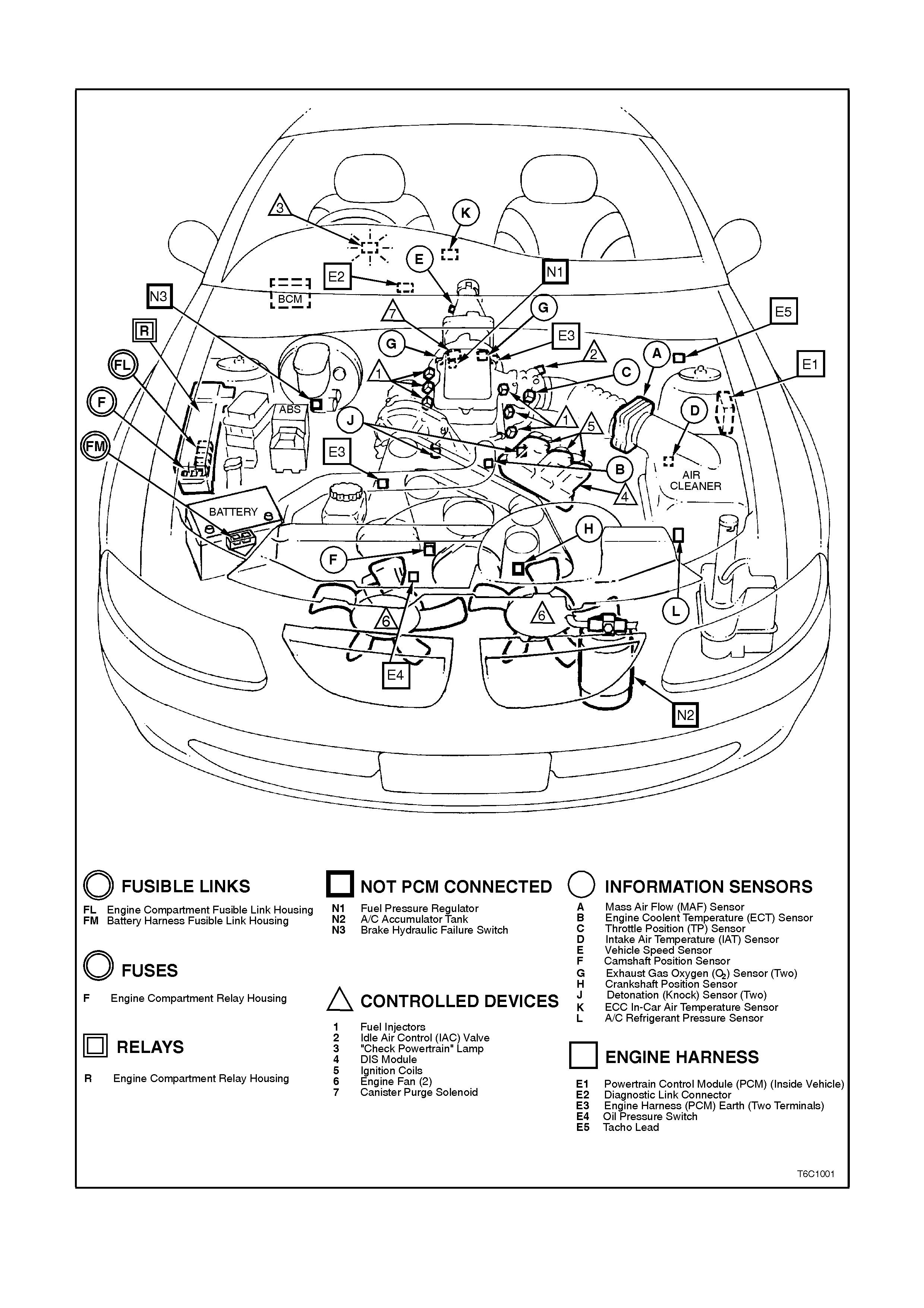
Figure 6C1-2A-1 Engine Compartment Component Locations Non-Supercharged Engine
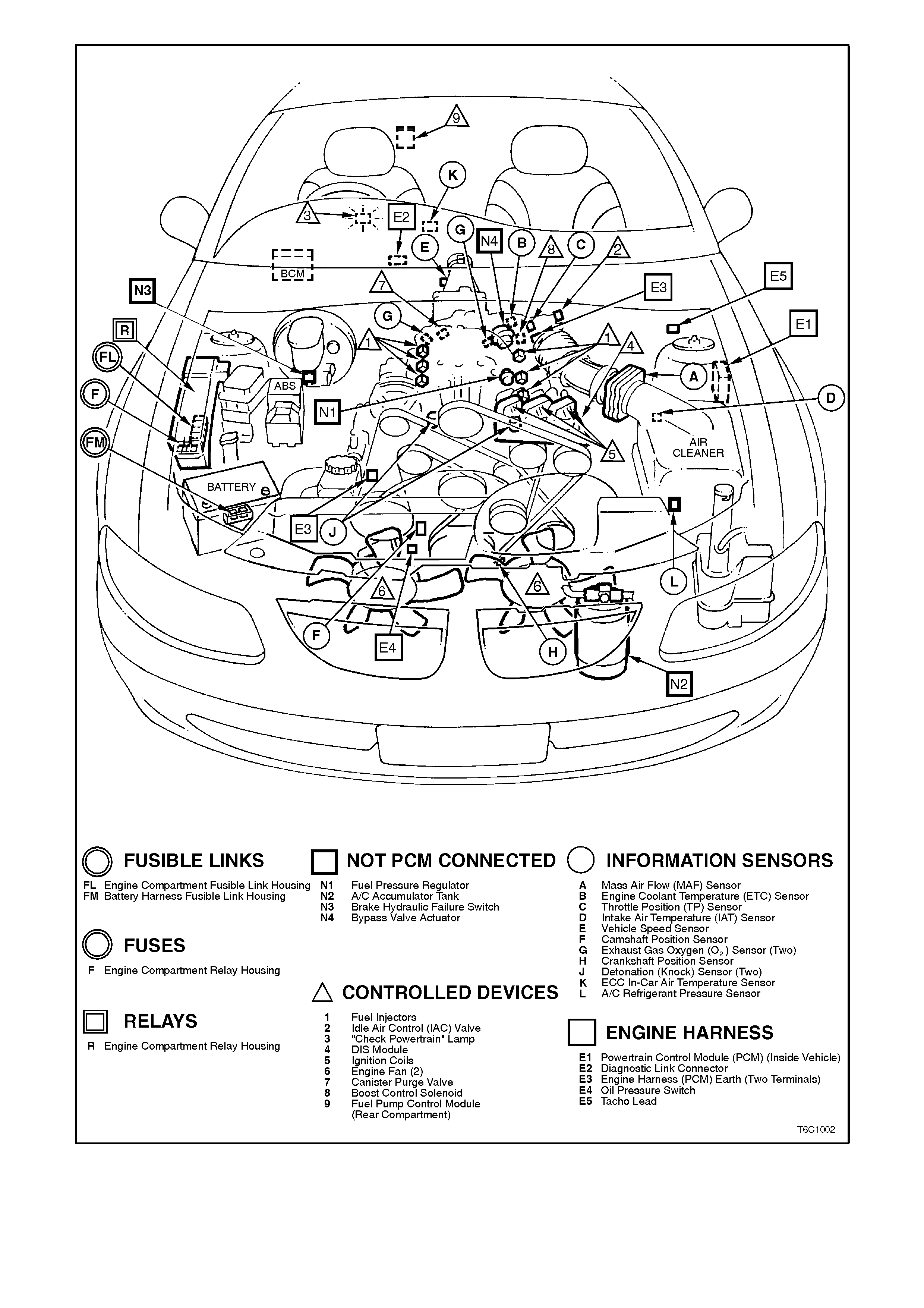
Figure 6C1-2A-2 Engine Compartment Component Locations Supercharged Engine
ENGINE COMPARTMENT RELAY LOCATIONS
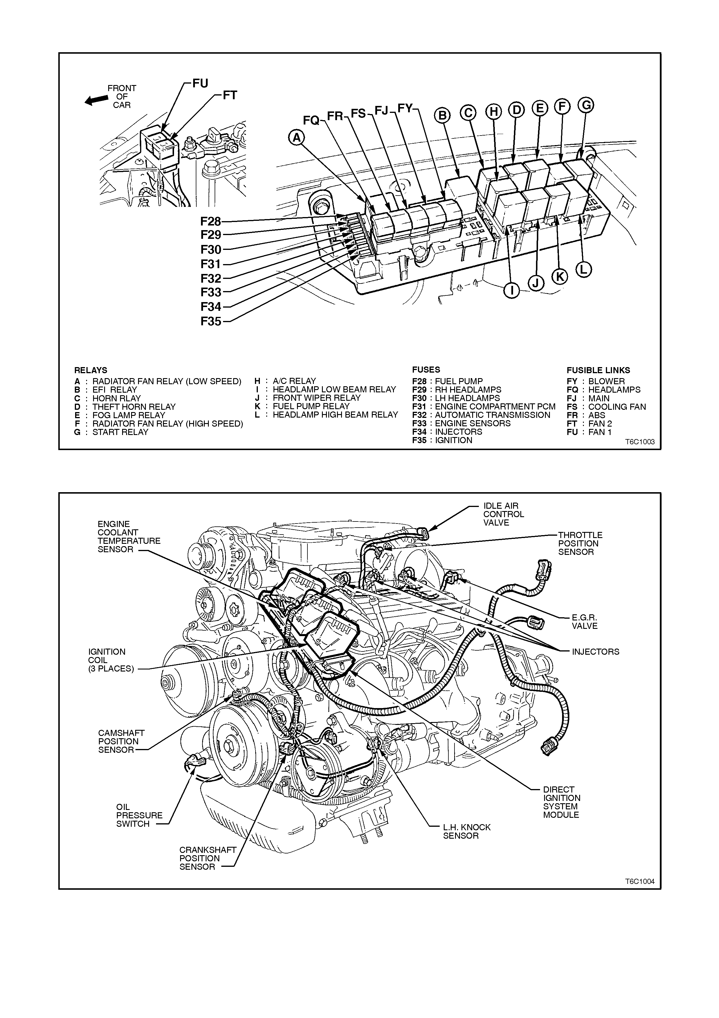
Figure 6C1-2A-3 Engine Compartment Relay Locations
COMPONENT LOCATIONS
Figure 6C1-2A-4 Compartment Locations Non-Supercharged Engine
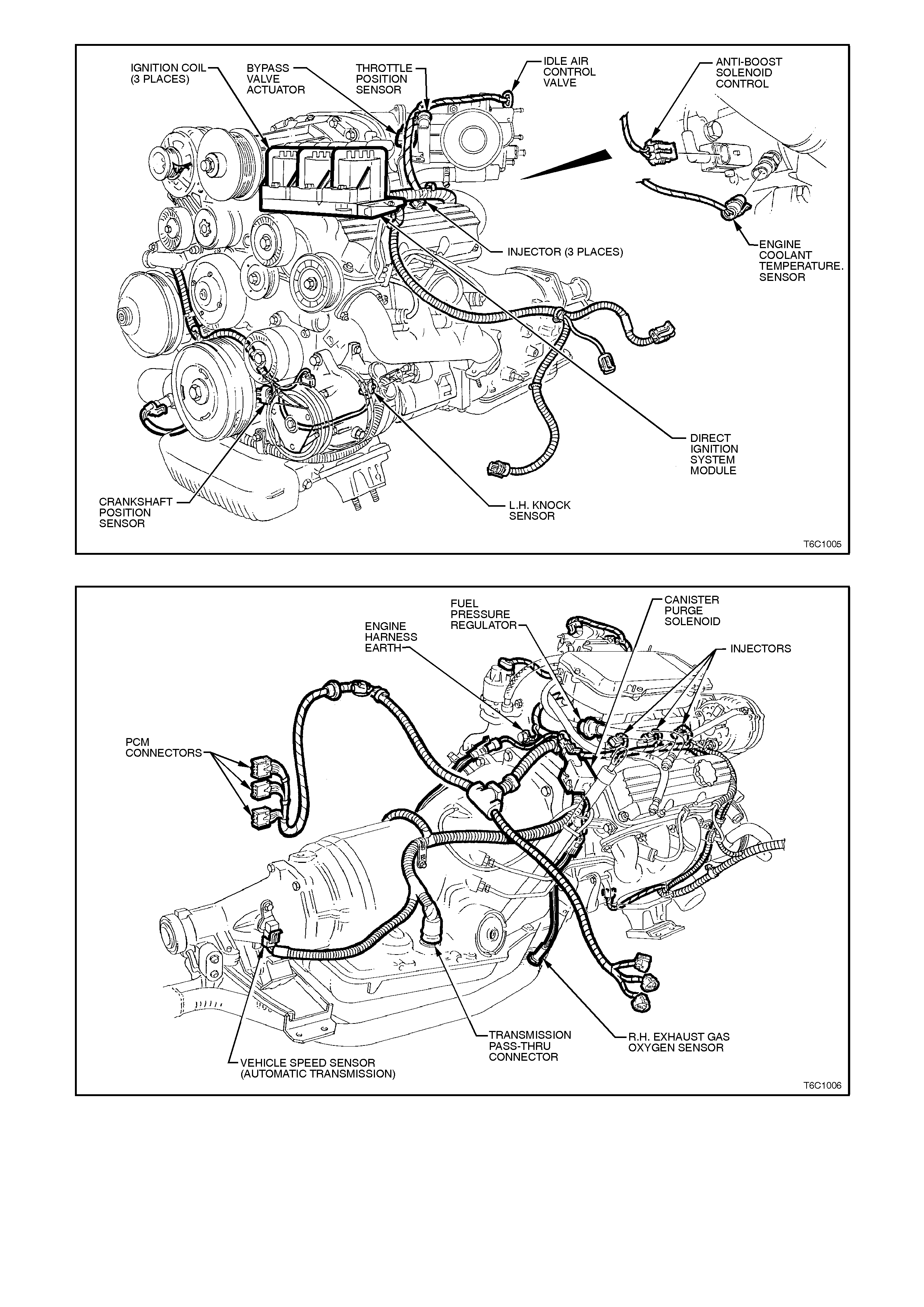
Figure 6C1-2A-5 Compartment Locations Supercharged Engine
Figure 6C1-2A-6 Component Locations Non-Supercharged Engine
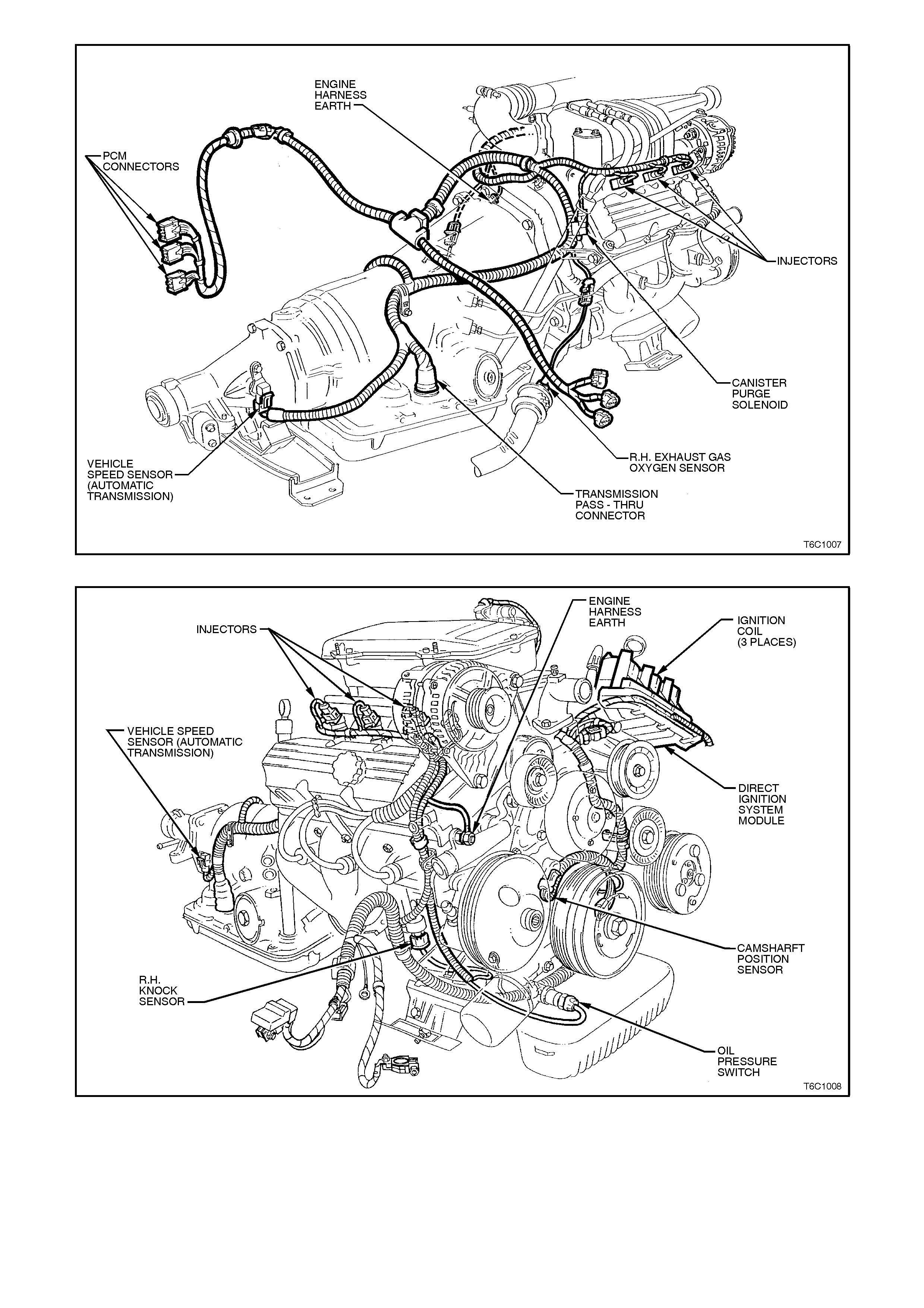
Figure 6C1-2A-7 Compartment Locations Supercharged Engine
Figure 6C1-2A-8 Component Locations Non Supercharged Engine
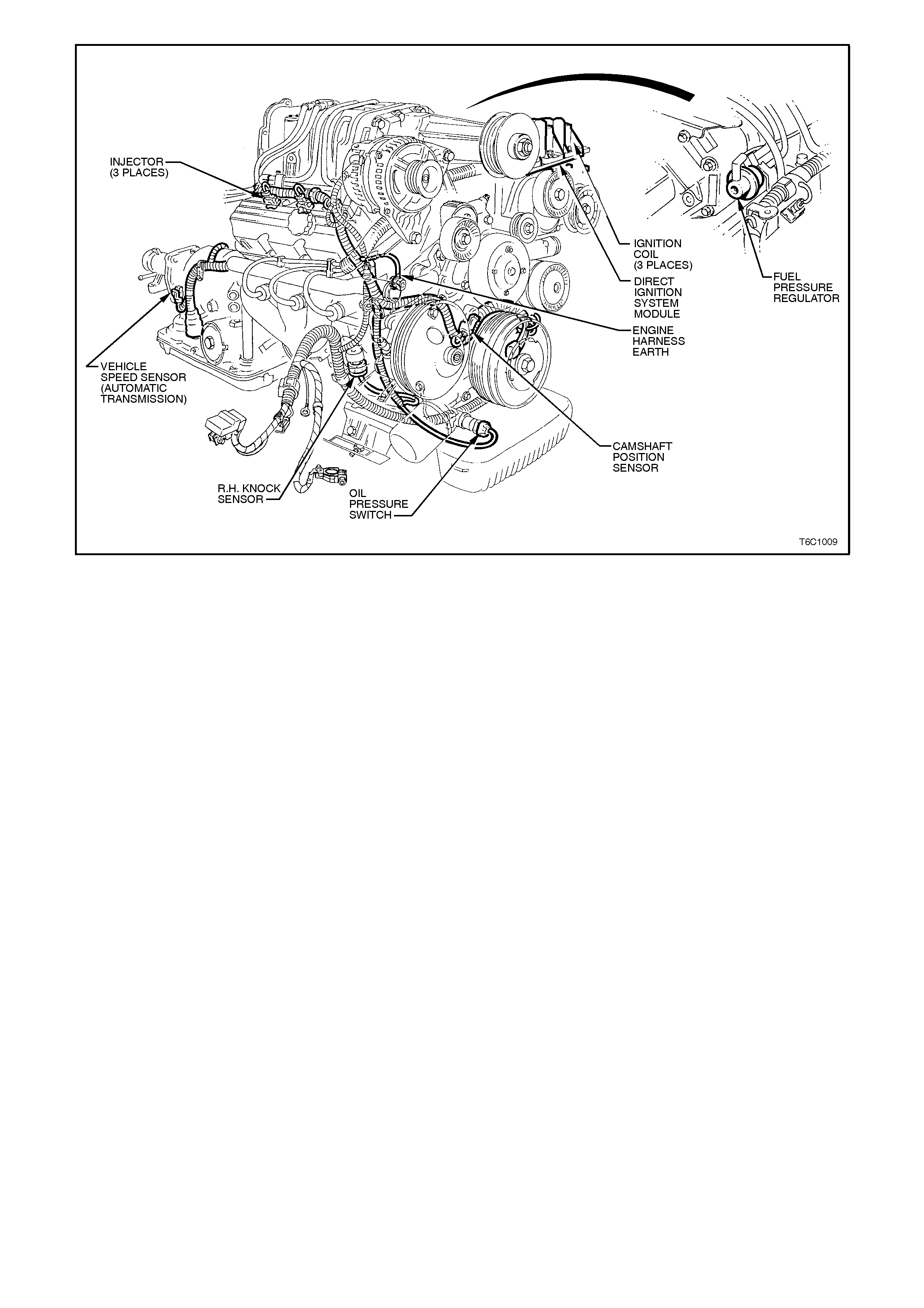
Figure 6C1-2A-9 Powertrain Compartment Locations Supercharged Engine
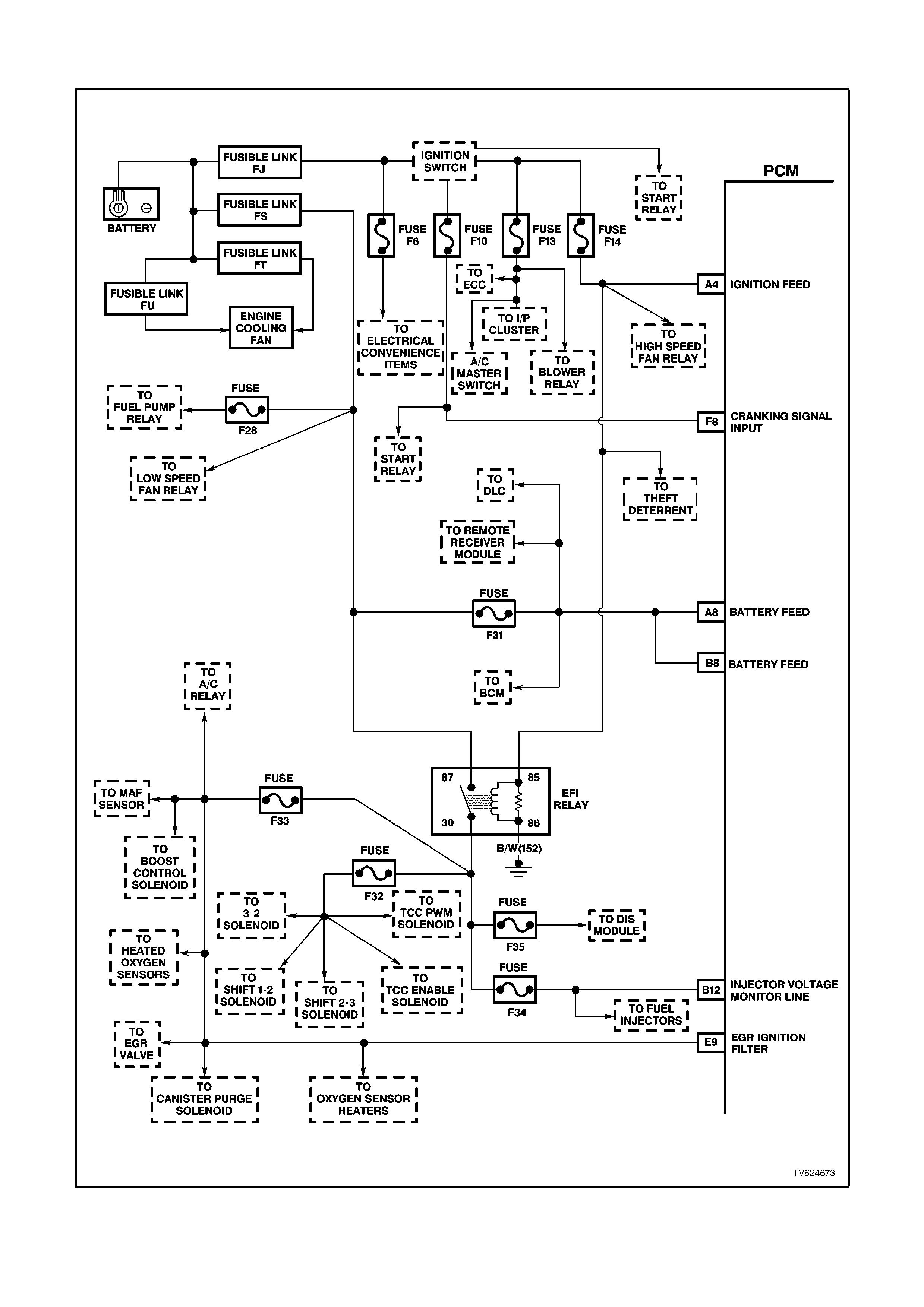
PCM WIRING DI AGRAMS
Figure 6C1-2A-10 V6 PCM Wiring Diagram (1 of 11) Fuse Power Circuits
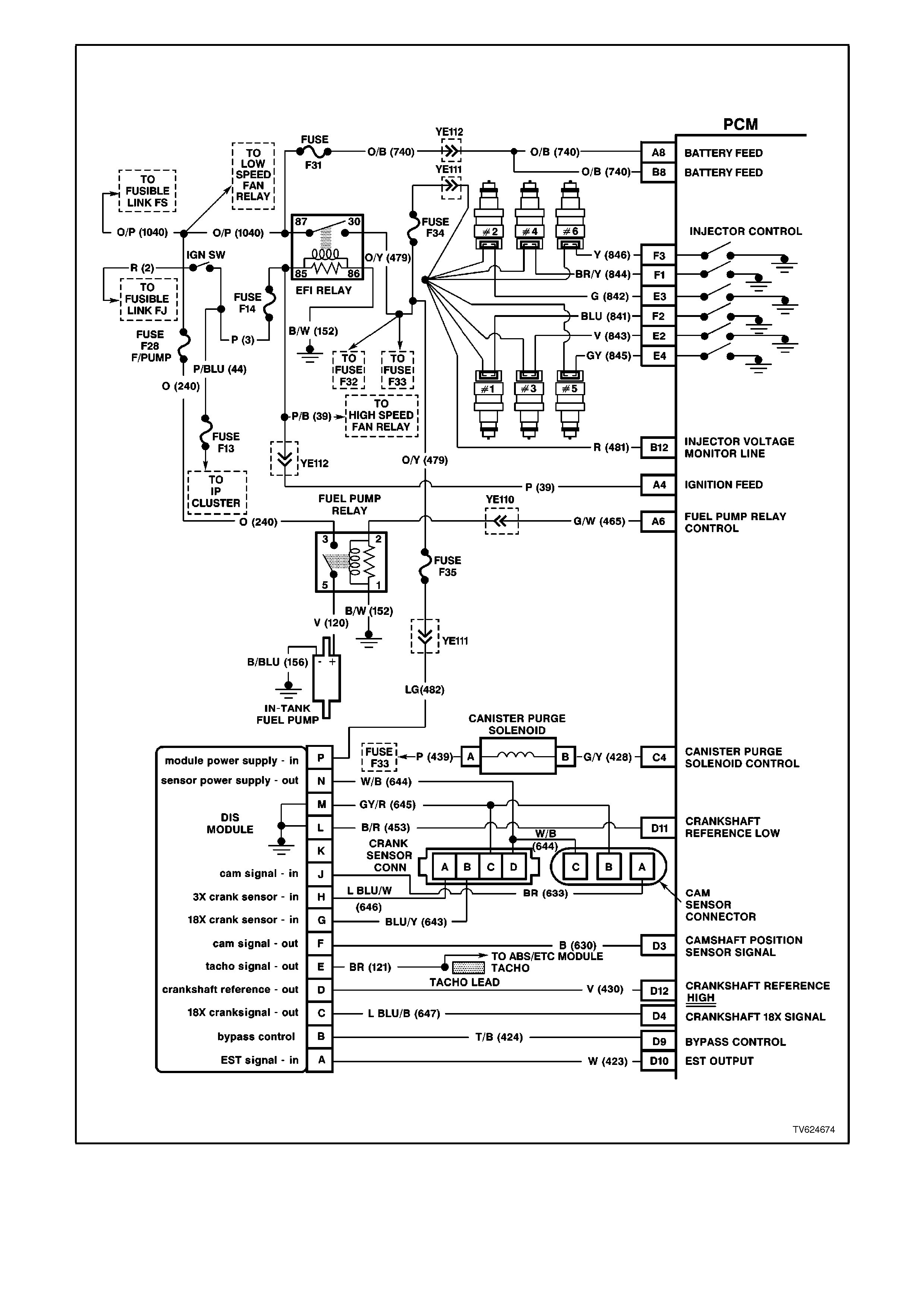
Figure 6C1-2A-11 V6 PCM Wiring Diagram (2 of 11) Non-Supercharged Engine
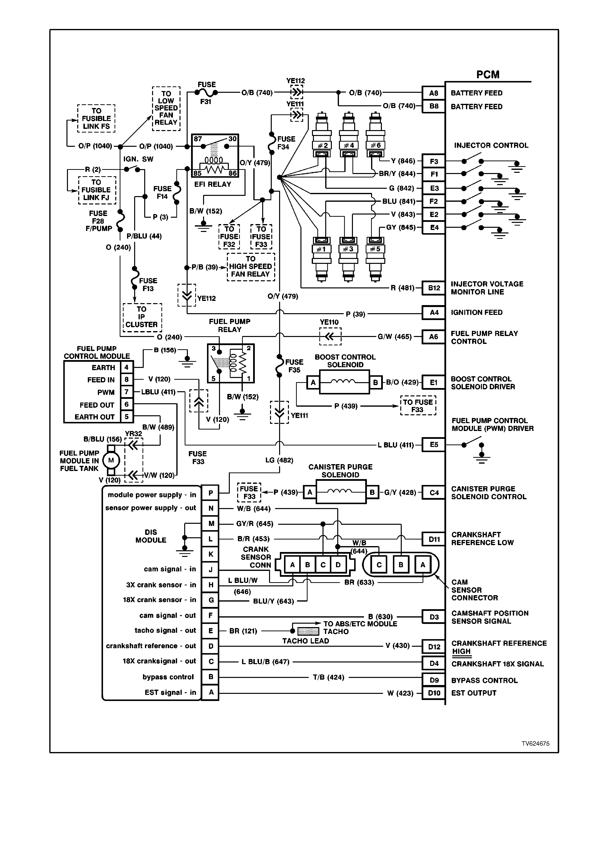
Figure 6C1-2A-12 V6 PCM Wiring Diagram (3 of 11 ) Supercharged Engine
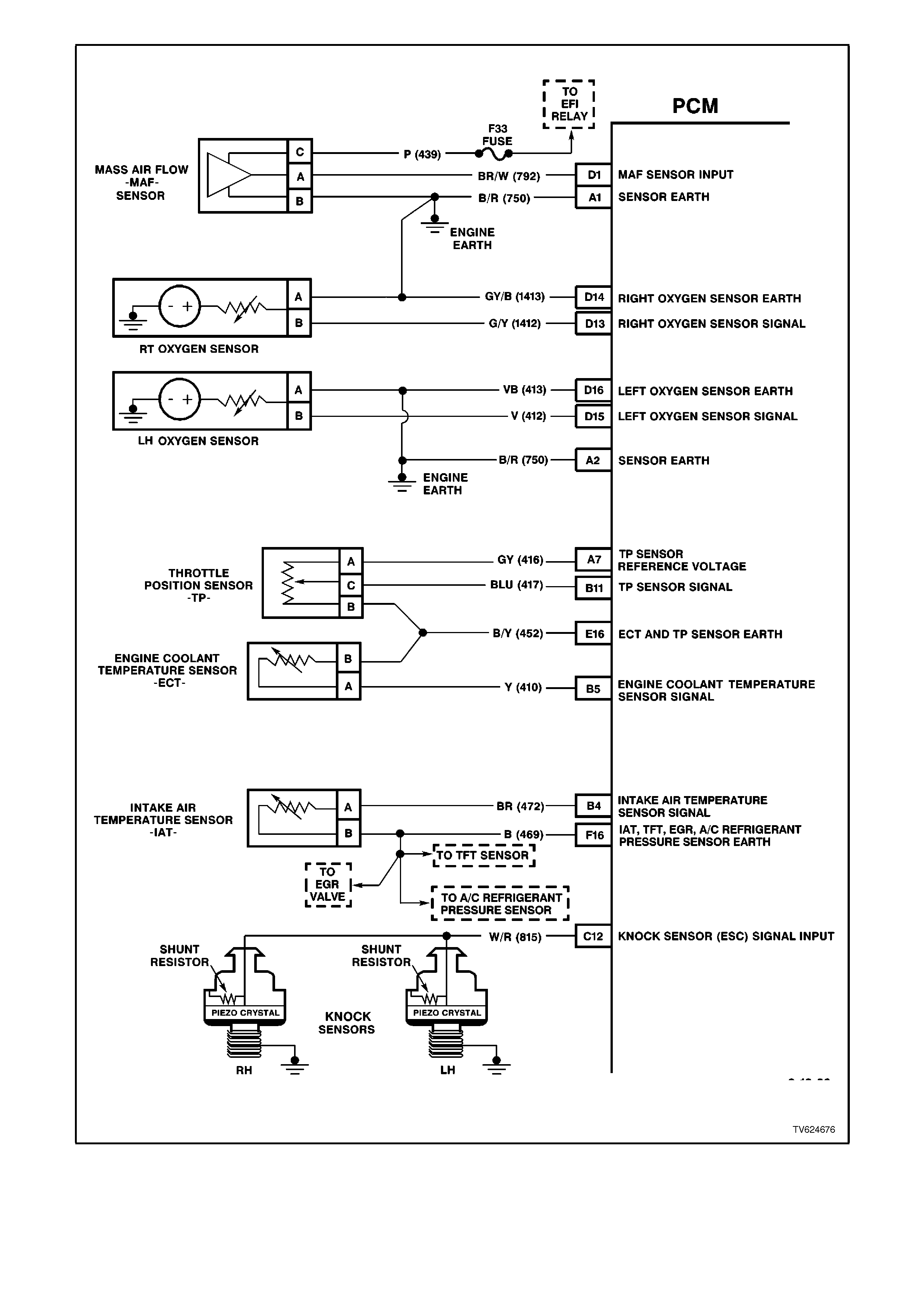
Figure 6C1-2A-13 V6 PCM Wiring Diagram (4 of 11) Non-Supercharged Engine Applications
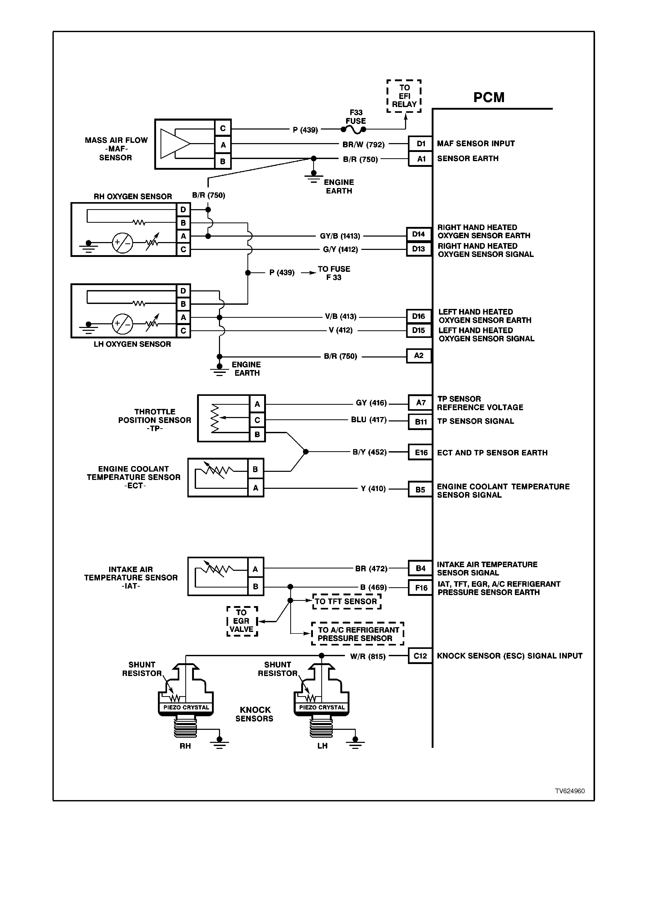
Figure 6C1-2A-13-A V6 PCM Wiring Diagram (5 of 11) Supercharged Engine Applications
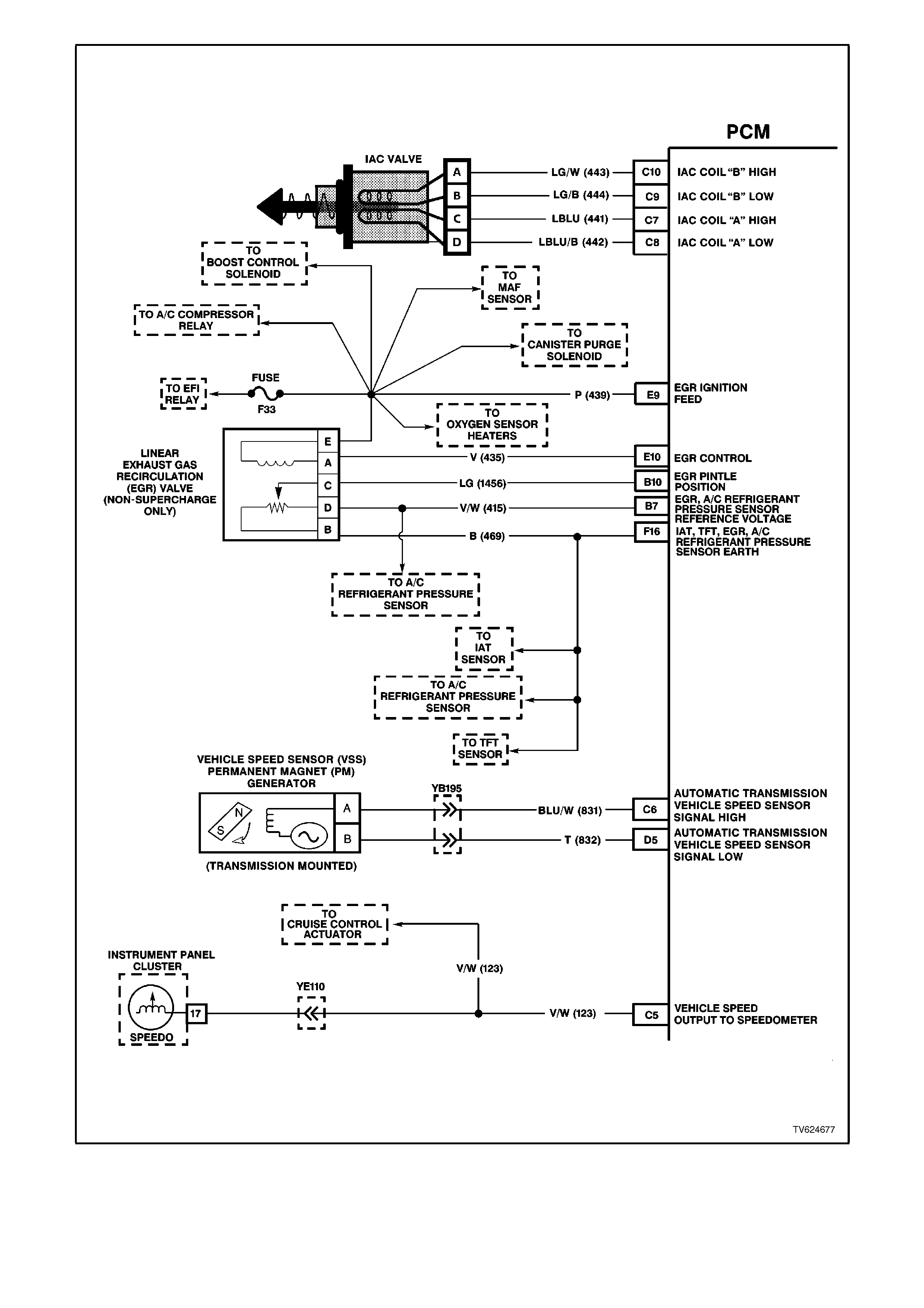
Figure 6C1-2A-14 V6 PCM Wiring Diagram (6 of 11) Both Engine Applications
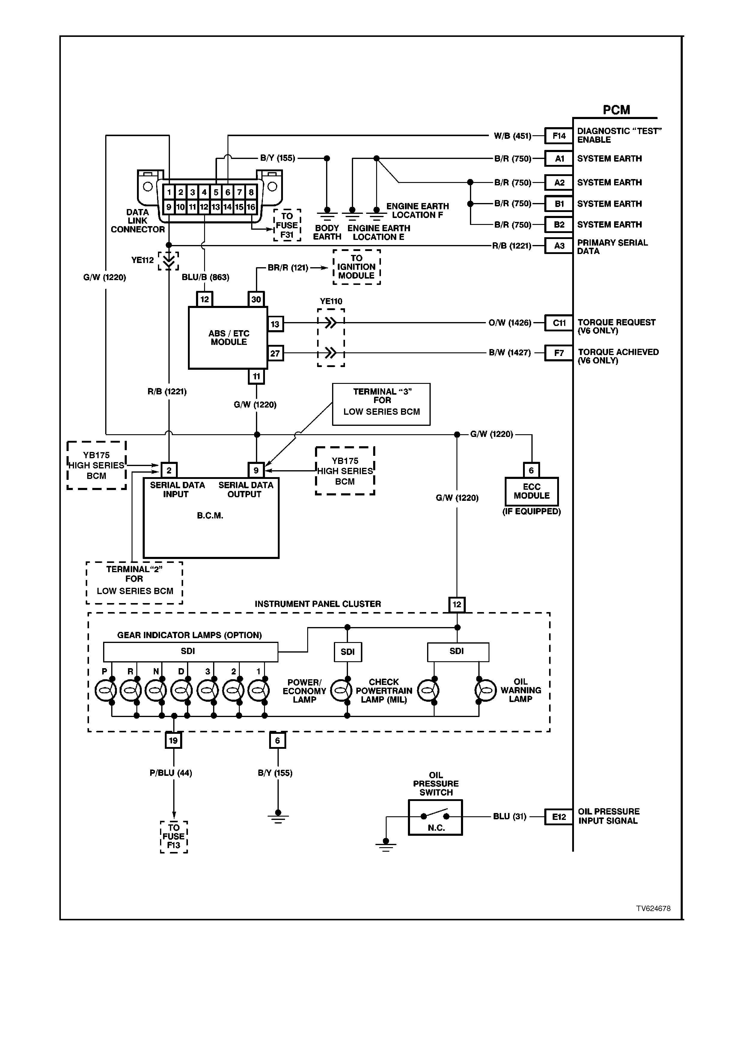
Figure 6C1-2A-15 V6 PCM Wiring Diagram (7 of 11) Both Engine Application
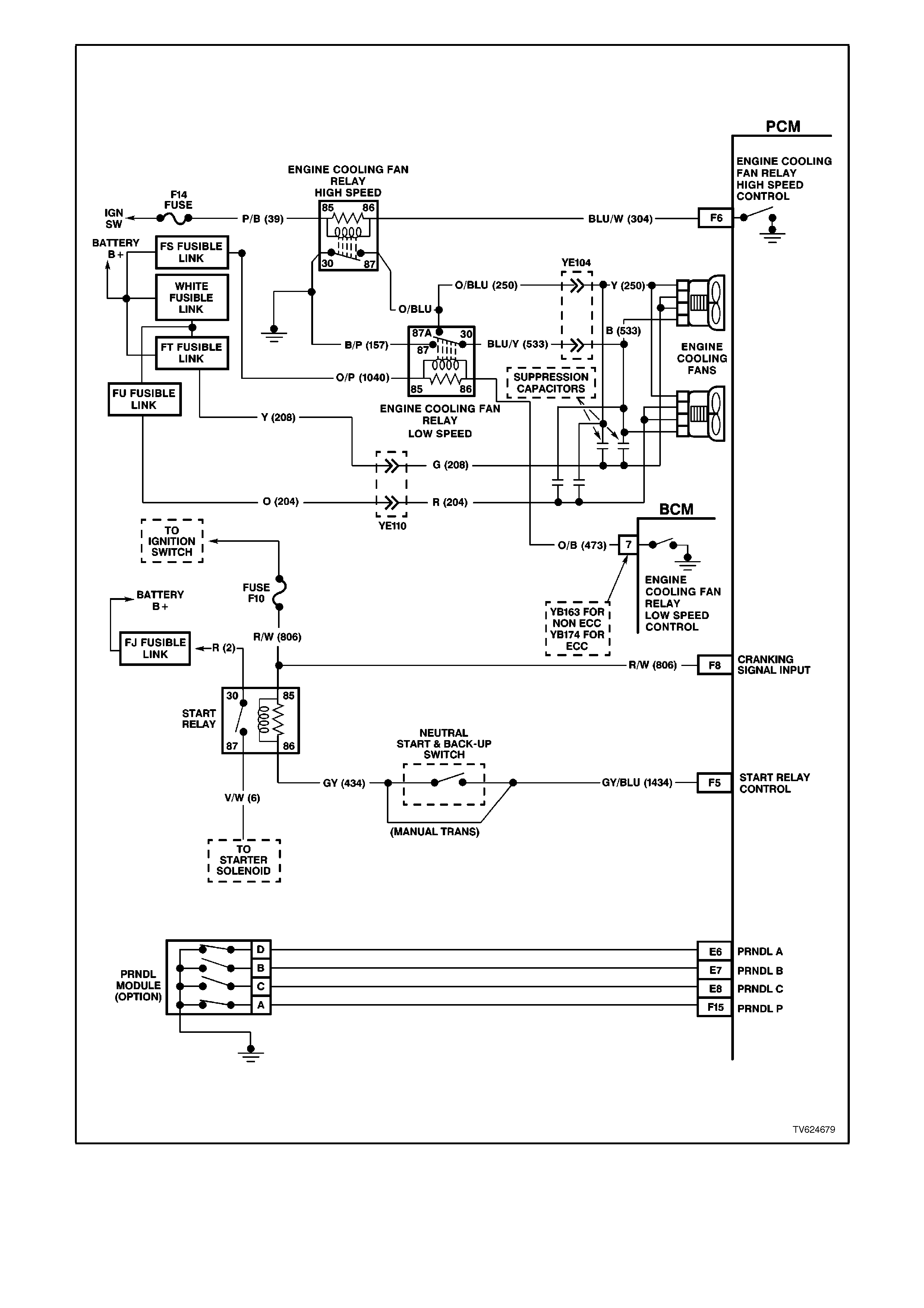
Figure 6C1-2A-16 V6 PCM Wiring Diagram (8 of 11) Both Engine Application
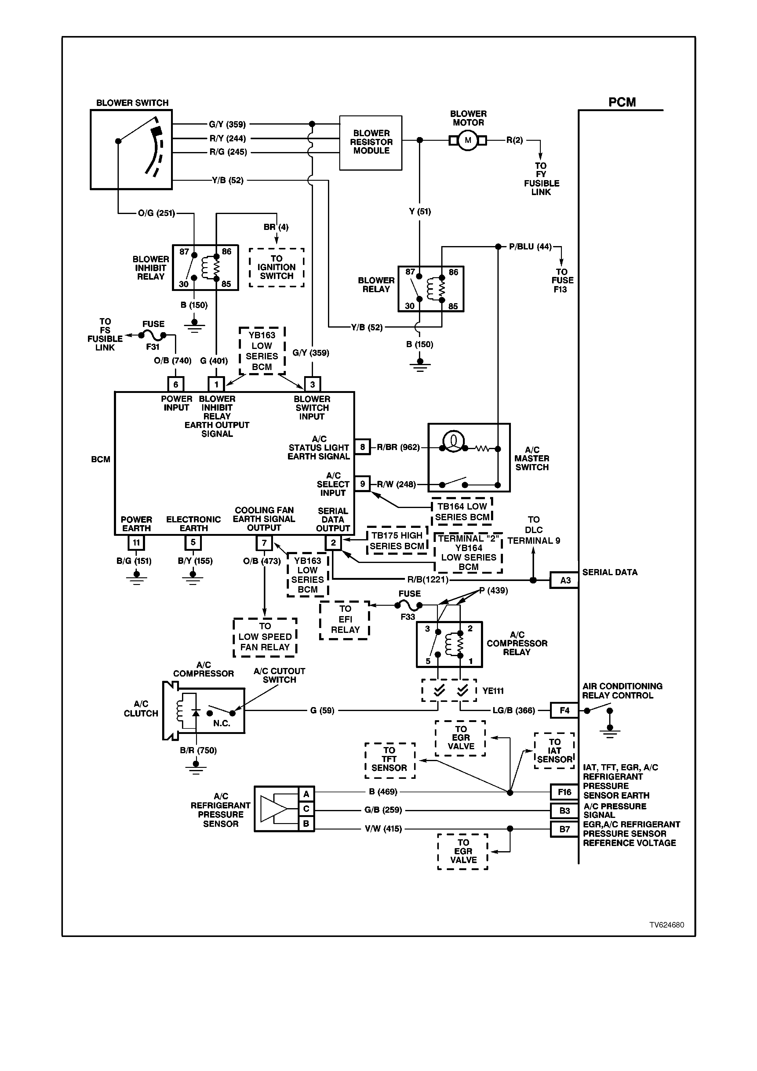
Figure 6C1-2A-17 V6 PCM Wiring Diagram (9 of 11) Both Engine Application
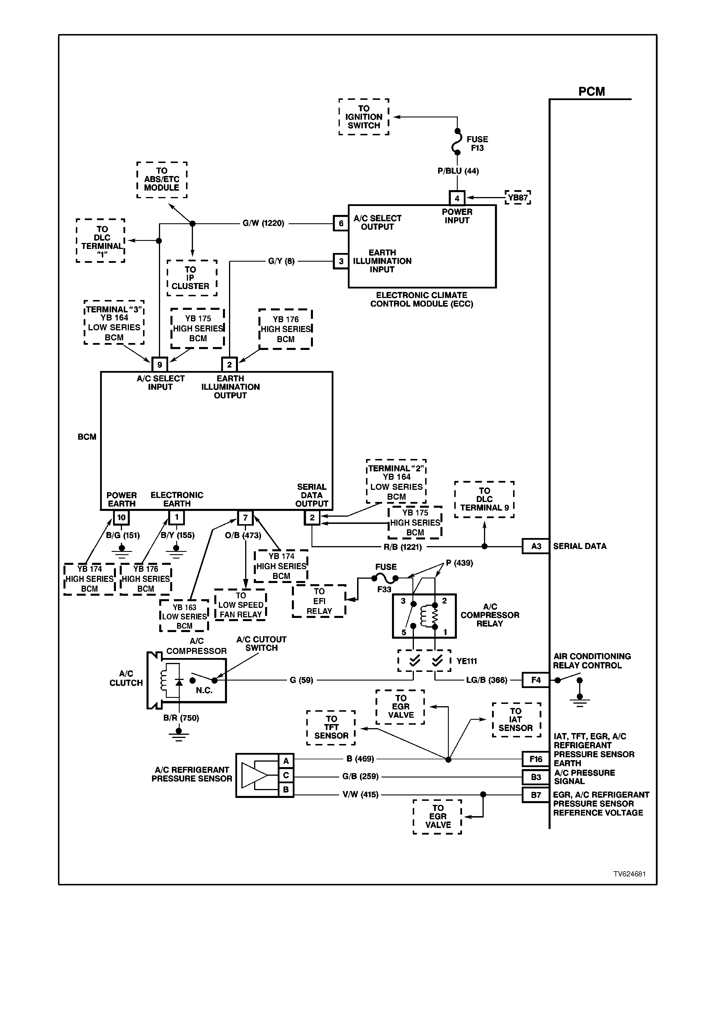
Figure 6C1-2A-18 V6 PCM Wiring Diagram (10 of 11) Both Engine Application
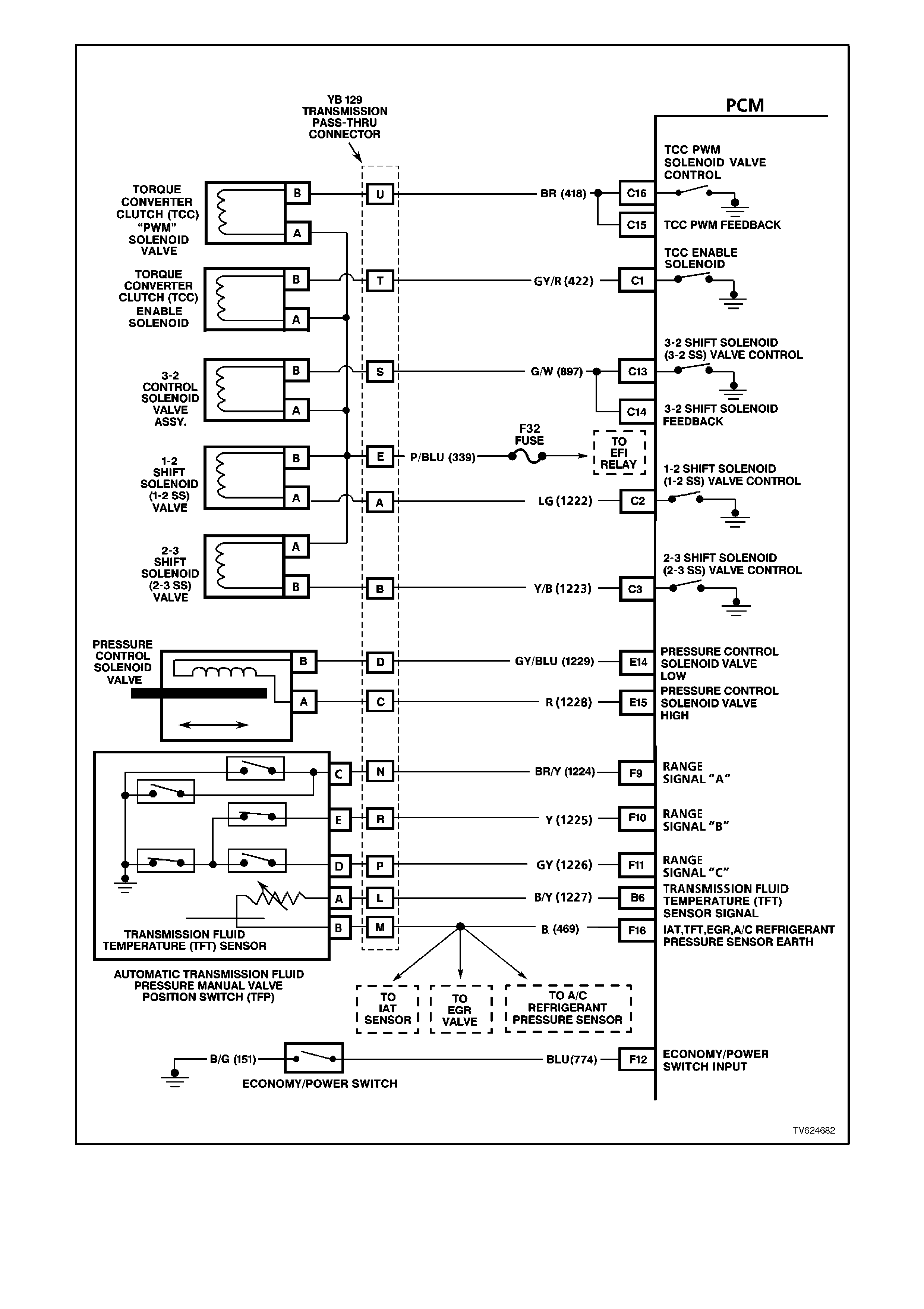
Figure 6C1-2A-19 V6 PCM Wiring Diagram (11 of 11) Both Engine Application
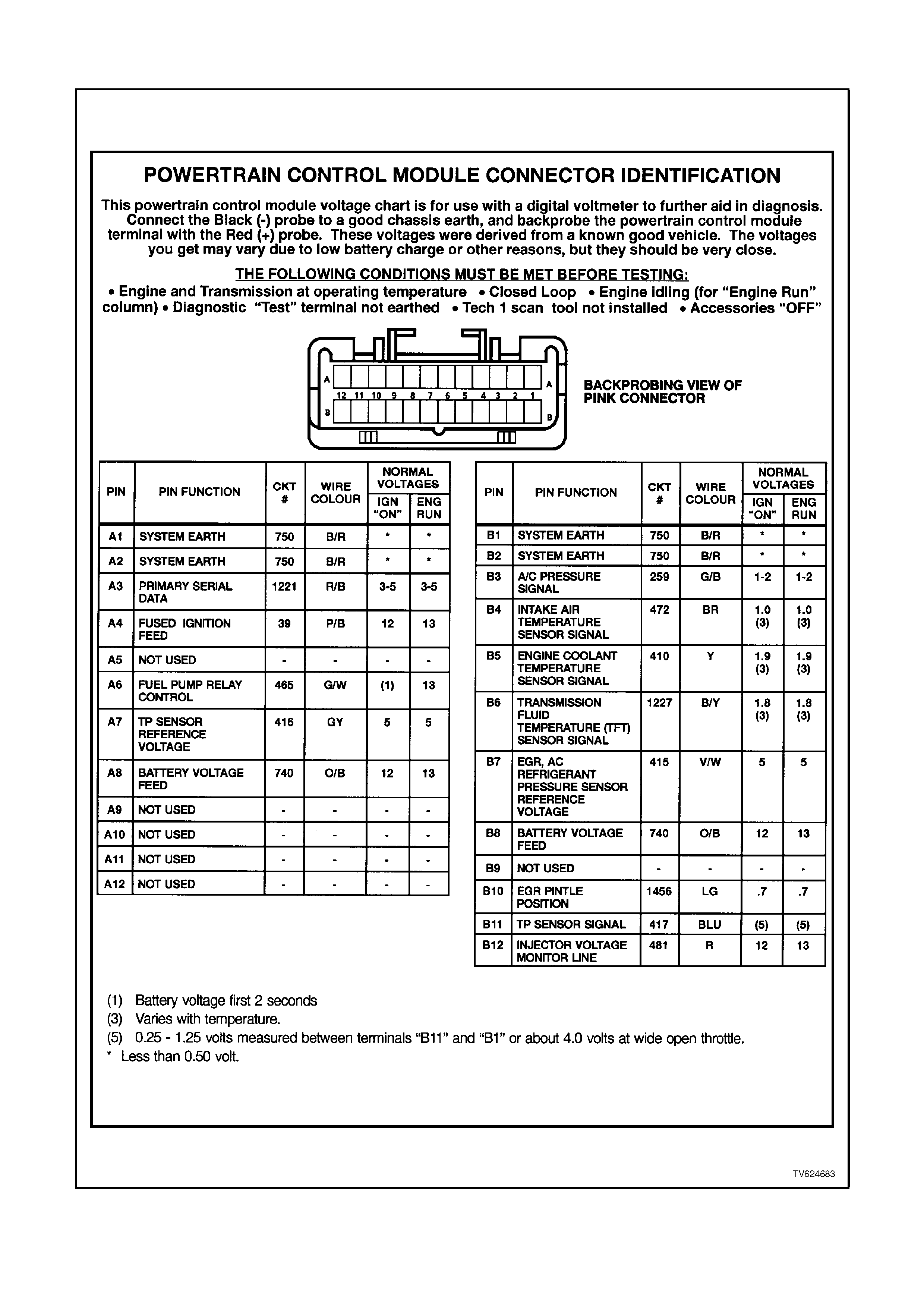
POWERTRAIN CONTROL M O DULE CONNECTOR I DENTIFICATION
Figure 6C1-2A 20 PCM Connector Terminal End View (1 of 3)
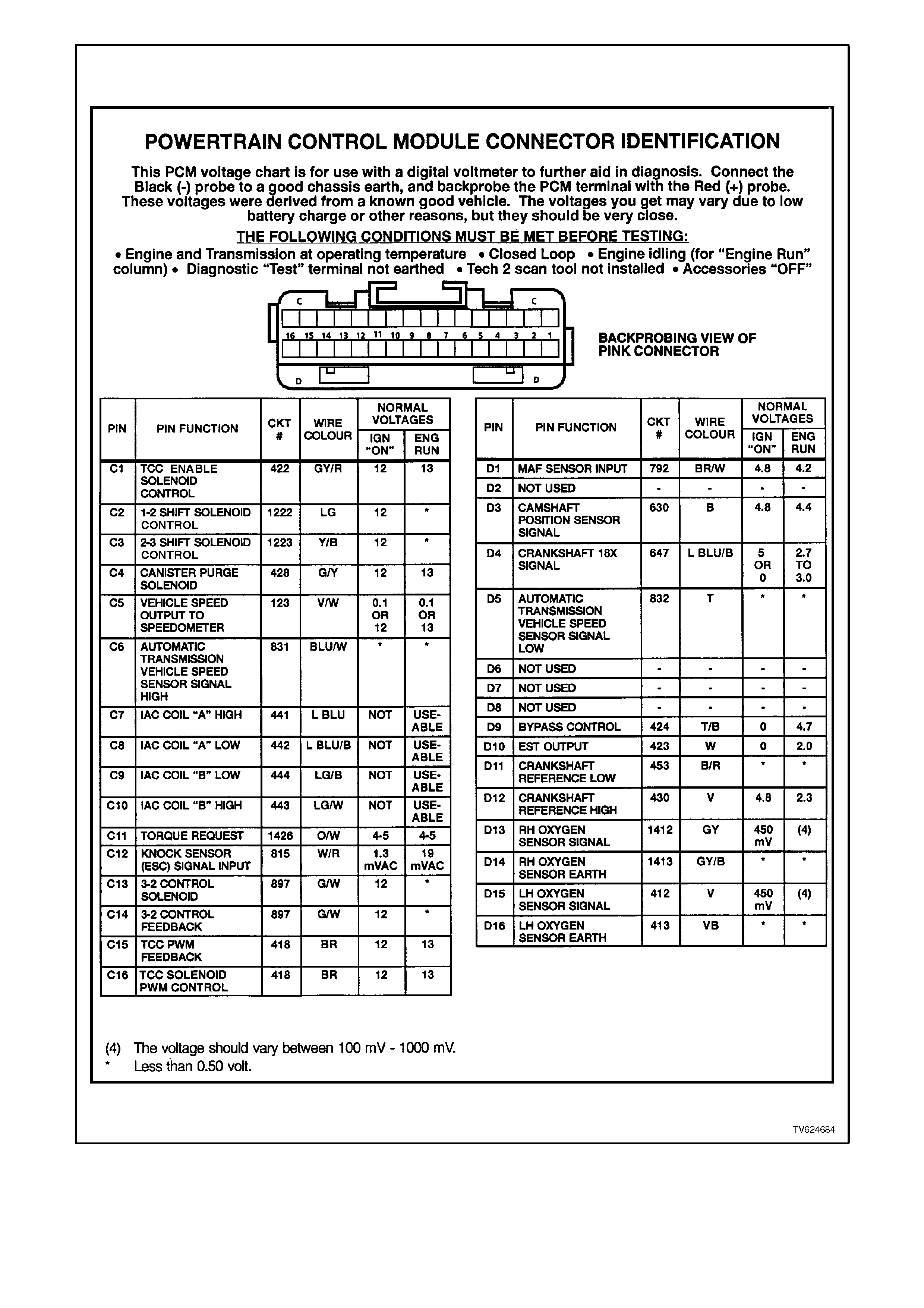
Figure 6C1-2A-21 PCM Connector Terminal End View (2 of 3)
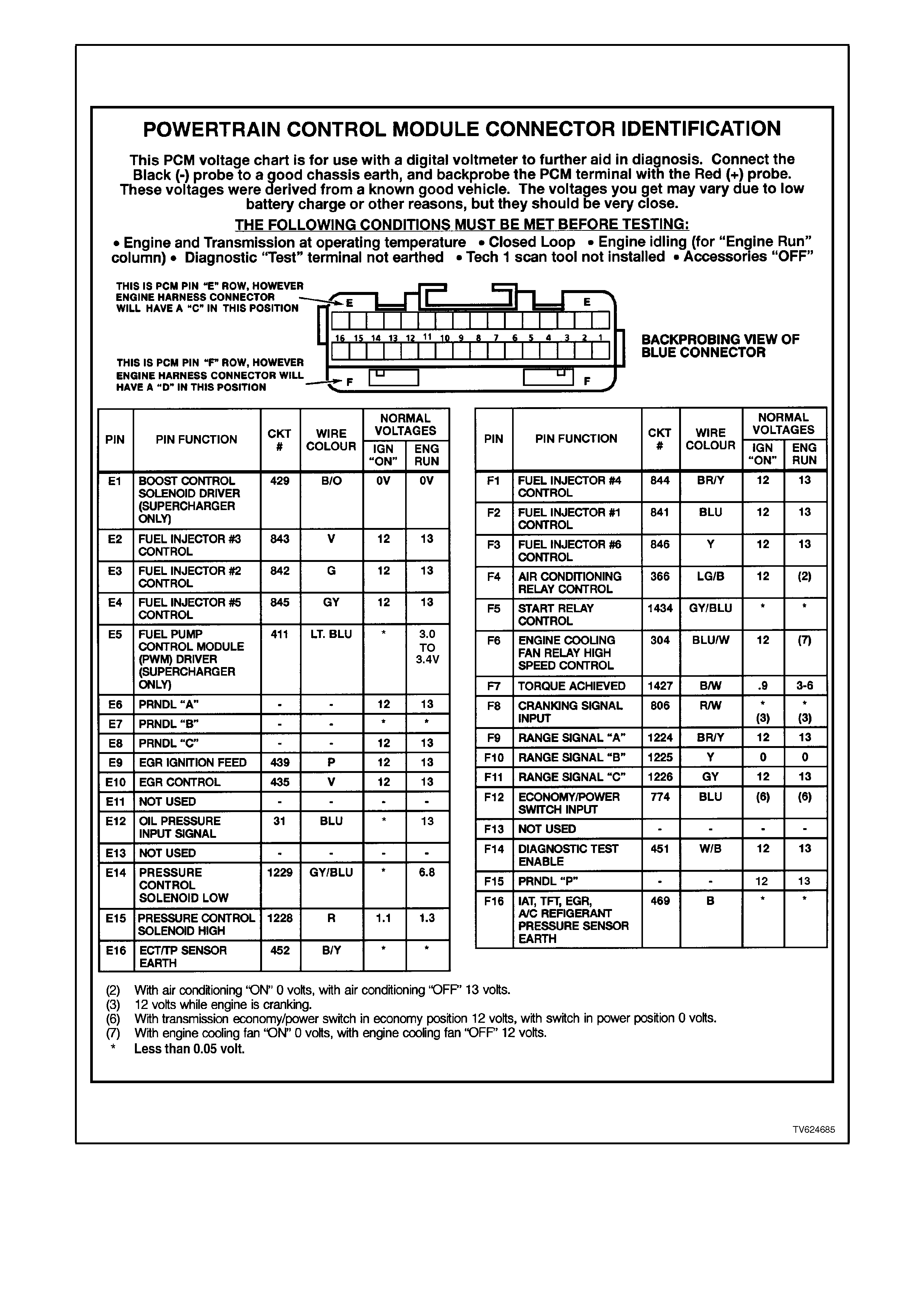
Figure 6C1-2A 22 PCM Connector Terminal End View (3 of 3)

PCM CONNECTOR TERMINAL VOLTAGES WITH EXPLANATIONS
PINS A1 - A12
A1 - SYSTEM EARTH
A2 - SYSTEM EARTH
These terminals should have zero volts. They are connected directly to the engine earth.
A3 - PRIMARY SERIAL DATA
This is a dedicated line for the Tech 2 scan tool communication. The circuit connects the PCM, ABS, and BCM. The
Tech 2 scan tool can "talk" to each of these modules by sending a message to a controller and asking only it to
respond. The communication rate is at 8192 baud. The normal voltage on this circuit is about 5 volts, but when the
Tech 2 scan tool is communicating with a controller, the voltage will vary and if read with a DVM may read about 2.5
volts
A4 - IGNITION SWITCH INPUT SIGNAL
This is the "turn on" signal to the PCM from the ignition switch circuit. It is not the "power supply" to the PCM, it only
tells the PCM that the ignition switch is "ON." The voltage should equal the battery voltage when the key is in either
the `run' or `crank' position.
A5 - NOT USED
A6 - FUEL PUMP (FP) RELAY CONTROL
Turning the ignition "ON" causes the PCM to energise (+12V) the Fuel Pump Relay. If no crankshaft reference input
pulses are received, the PCM turns "OFF" the relay. As soon as the PCM receives crankshaft reference input
pulses, the PCM will turn the Fuel Pump Relay on again.
A7 - THROTTLE POSITION (TP) SENSOR
REFERENCE VOLTAGE
This voltage should always be 5 volts anytime the ignition is "ON." It is a regulated voltage output from the PCM,
and supplies 5 volts to the TP sensor.
A8 - BATTERY VOLTAGE FEED
- HOT AT ALL TIMES -
This supplies the PCM with full-time +12 volts. It stays hot even when the ignition is turned off. It receives its voltage
through the "ENGINE" fuse F25. This PCM terminal could be called the power supply and "MEMORY" terminal.
A9 - NOT USED
A10 - NOT USED
A11 - NOT USED
A12 - NOT USED
PINS B1 - B12
B1 - SYSTEM EARTH
B2 - SYSTEM EARTH
These terminals should have zero volts. They are connected directly to the engine earth.
B3 - A/C REFRIGERANT PRESSURE SENSOR INPUT
SIGNAL
The signal that is sent from the pressure transducer to the PCM indicates to the PCM what the A/C pressure is at.
Depending on the A/C pressure, this signal will indicate to the PCM if A/C pressure is to low or to high.
B4 - INTAKE AIR TEMPERATURE (IAT) INPUT SIGNAL
The PCM sends a 5 volt signal voltage to the IAT sensor, which is a temperature - variable-resistor called a
thermistor. The sensor is also connected to earth, and will alter the signal voltage according to incoming air
temperature. As the air temperature increases, the voltage seen on this terminal decreases. At 0 degrees C, the
voltage will be above 4 volts. At normal operating temperature (10 degrees C to 80 degrees C) the voltage will be
less than 4 volts.
B5 - ENGINE COOLANT TEMPERATURE (ECT)INPUT SIGNAL
The PCM sends a 5 volt signal voltage out to the engine coolant temperature sensor, which is a temperature-
variable-resistor called thermistor. The sensor, being also connected to earth, will alter the voltage according to
engine coolant temperature. As the engine coolant temperature increases, the voltage seen on terminal B5
decreases. At 0 degrees C engine coolant temperature the voltage will be above 4 volts. At normal operating
temperature (85 degrees C to 100 degrees C) the voltage will be less than 2 volts.

B6 - TRANSMISSION FLUID TEMPERATURE (TFT) INPUT SIGNAL
- AUTO TRANS ONLY
The PCM sends a 5 volt signal voltage out to the transmission fluid temperature sensor, which is a temperature-
variable-resistor called thermistor. The sensor, being also connected to earth, will alter the voltage according to
transmission fluid temperature. As the fluid temperature increases, the voltage seen on terminal B6 will decrease.
B7 - EGR/A/C PRESSURE SENSOR REFERENCE VOLTAGE
This voltage should always be 5 volts anytime the ignition is "ON." It is a regulated voltage output from the PCM,
and supplies 5 volts to the A/C Pressure Transducer and EGR valve.
B8 - BATTERY VOLTAGE FEED
- HOT AT ALL TIMES -
This supplies the PCM with full-time +12 volts. It stays hot even when the ignition is turned off. It receives its voltage
through the "ENGINE" fuse F25. This PCM terminal could be called the power supply and "MEMORY" terminal.
B9 - NOT USED
B10 - LINEAR EGR VALVE PINTLE POSITION
This voltage is a indication to the PCM the position of the EGR valve pintle position. A low voltage indicates a fully
extended pintle (closed valve). A voltage near 5 volts indicates a retracted pintle (open valve).
B11 - THROTTLE POSITION (TP) SENSOR
The TP sensor input voltage, which follows actual throttle changes, is variable from 0 to 5 volts. Typically the voltage
is less than 1 volt at idle, and 4 to 5 volts at wide-open throttle.
B12 - INJECTOR CIRCUIT VOLTAGE MONITOR INPUT SIGNAL
The injector voltage monitor line is used so that the PCM will know the exact voltage the fuel injectors are operating
at. This voltage signal is used to modify the fuel injector pulse width calculation.
PINS C1 - C16
C1 - TORQUE CONVERTER CLUTCH ENABLE SOLENOID CONTROL
- AUTO TRANS ONLY
The PCM is used to either open or provide a path to earth for the torque converter solenoid. When the PCM
provides a path to earth, the TCC solenoid is considered ON and voltage should be near 0 volts. The PCM uses
both the TCC enable solenoid and the TCC "PWM" solenoid to control the torque converter clutch. (See TCC PWM
solenoid terminal E1)
C2 - 1 - 2 SHIFT SOLENOID CONTROL
- AUTO TRANS ONLY -
The PCM is used to either open or provide a path to earth for the 1-2 shift solenoid. When the PCM provides a path
to earth, the 1-2 shift solenoid is considered "ON" and the voltage should read 0 volts.
C3 - 2 - 3 SHIFT SOLENOID CONTROL
- AUTO TRANS ONLY
The PCM is used to either open or provide a path to earth for the 2-3 shift solenoid. When the PCM provides a path
to earth, the 2-3 shift solenoid is considered "ON" and the voltage should read 0 volts.
C4 - CANISTER PURGE SOLENOID CONTROL
The PCM operates a normally closed solenoid valve, which controls vacuum to purge the evaporative emissions
storage canister of stored gasoline vapours. The PCM turns "ON" the pulse width modulated control of the purge
solenoid, to control purging of the stored vapours. If the PCM is not energising the purge solenoid, the voltage
measured at this terminal should equal battery voltage. If the PCM is controlling the solenoid, the measured voltage
will be between battery voltage and 0.50 volts.
C5 - VEHICLE SPEED OUTPUT TO SPEEDOMETER
The PCM alternately earths this signal, in pulses, when it receives a vehicle speed signal from the vehicle speed
sensor in the transmission. This pulsing action takes place about 6250 times per kilometer. The speedometer
calculates vehicle speed based on the time between pulses.
C6 - VEHICLE SPEED SENSOR - OUTPUT SHAFT SPEED INPUT SIGNAL HIGH
The transmission has an output shaft speed sensor used by the PCM to calculate vehicle speed, and to help
determine various automatic transmission shifting functions. It is a magnetic inductive sensor that generates an AC
voltage signal sent to the PCM. If measured with the digital AC voltmeter, no voltage will appear until the output
shaft begins turning.
C7 - IDLE AIR CONTROL (IAC )
C8 - IDLE AIR CONTROL (IAC )
C9 - IDLE AIR CONTROL (IAC )

C10 - IDLE AIR CONTROL (IAC)
These terminals connect the Idle Air Control valve, located on the throttle body, to the PCM. It is difficult to predict
what the voltage will be, and the measurement is unusable for any service procedures.
C11 - TRACTION CONTROL (TORQUE REQUESTED)
The ABS/ETC module will send a Nm signal to the PCM when torque reduction is requested from the ABS/ETC
module for traction control. This Nm signal should match closely with Torque Achieved Nm signal, when traction
control is being requested.
C12 - ELECTRONIC SPARK CONTROL (ESC) "KNOCK" INPUT SIGNAL
The Electronic Spark Control "knock" sensor detects when detonation is occurring in the combustion chambers.
When detected, the PCM will reduce the amount of spark advance being delivered on the EST output circuit to the
ignition module.
C13 - 3 - 2 DOWNSHIFT CONTROL SOLENOID
CONTROL
- AUTO TRANS ONLY -
The 3-2 control solenoid is a normally closed, pulse width modulated solenoid used to control the 3-2 downshift. The
PCM operates the 3-2 control solenoid at
a frequency of 50 Hz (cycles per second). The solenoid is constantly fed 12 volts and PCM controls the length of
time the path to earth for the electrical circuit is closed.
C14 - 3 - 2 SHIFT SOLENOID FEEDBACK
- AUTO TRANS ONLY -
The 3-2 Shift solenoid is a normally closed solenoid used to control the 3-2 downshift. The solenoid is constantly fed
12 volts and PCM controls the length of time the path to earth for the electrical circuit is closed. The PCM does this
to provide a smooth 3-2 downshift. If the PCM senses an incorrect voltage on this circuit when controlling the 3-2
downshift solenoid (i.e. - O volts with the solenoid OFF, or 12 volts with the solenoid ON) a DTC code 66 will set.
C15 - TORQUE CONVERTER CLUTCH - PULSE WIDTH MODULATED APPLY SOLENOID FEEDBACK
- AUTO TRANS ONLY -
The PCM uses the pulse width modulated TCC apply solenoid to smoothly engage the torque converter clutch, after
the TCC "ON-OFF" solenoid is energised. By varying the duty cycle pulse width modulation, the PCM can slowly
engage the torque converter clutch, allowing very smooth TCC engagement. If the PCM senses an incorrect voltage
on this circuit when controlling the TCC PWM solenoid (i.e. - O volts with the solenoid OFF, or 12 volts with the
solenoid ON ) a DTC code 83 will set.
C16 - TORQUE CONVERTER CLUTCH - PULSE WIDTH MODULATED APPLY SOLENOID CONTROL
- AUTO TRANS ONLY -
The PCM uses the pulse width modulated TCC apply solenoid to smoothly engage the torque converter clutch, after
the TCC "ON-OFF" solenoid is energised. By varying the duty cycle pulse width modulation, the PCM can slowly
engage the torque converter clutch, allowing very smooth TCC engagement.
PINS D1 - D16
D1 - MASS AIR FLOW (MAF) INPUT SIGNAL
The PCM supplies a 5-volt signal voltage to the mass air flow sensor on this circuit. The mass air flow sensor
pulses the 5-volt signal to earth. These earth pulses occur at a very fast rate - from less than 500 per second (500
Hz) with no airflow through the sensor, to upwards of many thousands of pulses per second at high air flow rates
such as during acceleration. If measured, the voltage seen will be between 0.5 and 4.5 volts, depending on air flow
through the sensor.
D2 - NOT USED
D3 - CAMSHAFT POSITION INPUT SIGNAL
This signal is used by the PCM to "sequence" the energising of the fuel injectors, similar to the firing order of an
engine. This allows the PCM to operate the fuel injectors in a "sequential fuel injection" mode. The camshaft
position sensor is actually wired to the ignition module. The ignition module sends one pulse per every two
crankshaft revolutions to the PCM to determine actual camshaft position, and thus, engine cycle sequence.
D4 - CRANKSHAFT 18X INPUT SIGNAL
The 18X crankshaft reference input signal is used to very accurately control EST spark timing at low engine speeds
- below 1200 RPM. Below 1200 RPM, the PCM monitors the 18X signal to control spark timing. At engine speeds
above 1200 RPM, the PCM uses the 3X crankshaft reference input signal to control spark timing. (See 3X
crankshaft reference terminal D12)

D5 - VEHICLE SPEED SENSOR - OUTPUT SHAFT SPEED INPUT SIGNAL LOW
The transmission has an output shaft speed sensor used by the PCM to calculate vehicle speed, and to help
determine various automatic transmission shifting functions. It is a magnetic inductive sensor that generates an AC
voltage signal sent to the PCM. If measured with the digital AC voltmeter, no voltage will appear until the output
shaft begins turning.
D6 - NOT USED
D7 - NOT USED
D8 - NOT USED
D9 - IGNITION MODULE BYPASS CONTROL
- IGNITION SYSTEM MODE CONTROL -
With ignition "ON" and engine not running this terminal will have very low voltage. As soon as the PCM sees engine
RPM of more than 1600 RPM (Electronic Spark Timing "run" threshold) the PCM turns on 5 volts to the Ignition
Module Bypass Control circuit, causing the ignition module to allow the PCM to operate the ignition system.
D10 - ELECTRONIC SPARK TIMING (EST) OUTPUT
This terminal will have very low voltage with the ignition "ON" but engine not running. With the engine running at
idle, the voltage should be slightly more than 1 volt. As the engine RPM goes up, this voltage will increases.
D11 - CRANKSHAFT REFERENCE INPUT SIGNAL LOW
This terminal should always be zero volts. It is connected through the ignition module to engine earth.
D12 - 3X CRANKSHAFT REFERENCE INPUT SIGNAL HIGH
This terminal could be called the "tach" input. It provides the PCM with RPM and crankshaft position information.
With ignition "ON" but engine not running, the voltage will be either high or low, depending on crankshaft position.
As the crankshaft turns, the voltage will be an average of the two readings. The PCM uses the 3X signal to control
fuel injection, and spark timing with engine speeds above 1200 RPM. (See 18X crankshaft reference terminal D4)
D13 - OXYGEN SENSOR INPUT SIGNAL
- RIGHT BANK -
With ignition "ON" and engine not running, the voltage should be 350 - 450 millivolts (0.350 - 0.450 volts). This is
the PCM-supplied 02 circuit "bias" voltage. With the engine running and after the 02 sensor is hot, the voltage
should be rapidly changing, somewhere between 10 - 1000 millivolts (0.010 - 1.000 volt).
D14 - OXYGEN SENSOR EARTH
- RIGHT BANK -
This terminal should have zero volts. It is connected directly to the engine earth. This terminal earths the PCM
circuitry for the O2 voltage monitor inside the PCM.
D15 - OXYGEN SENSOR INPUT SIGNAL
- LEFT BANK -
With ignition "ON" and engine not running, the voltage should be 350 - 450 millivolts (0.350 - 0.450 volts). This is
the PCM-supplied 02 circuit "bias" voltage. With the engine running and after the 02 sensor is hot, the voltage
should be rapidly changing, somewhere between 10 - 1000 millivolts (0.010 - 1.000 volt).
D16 - OXYGEN SENSOR EARTH
- LEFT BANK -
This terminal should have zero volts. It is connected directly to the engine earth. This terminal earths the PCM
circuitry for the O2 voltage monitor inside the PCM.

PINS E1 - E16
E1 - BOOST CONTROL SOLENOID
The PCM operates a normally closed solenoid valve, which controls vacuum to the By-Pass Valve Actuator. The
PCM turns "ON" the solenoid , to allow vacuum to the By-Pass Valve Actuator, to close the By-Pass valve and allow
full boost. If the PCM is not energising the boost solenoid, the voltage measured at this terminal should equal
battery voltage. If the PCM is controlling the solenoid, the measured voltage will be between battery voltage and
0.50 volts.
E2 - FUEL INJECTOR 3 - CONTROL
E3 - FUEL INJECTOR 2 - CONTROL
E4 - FUEL INJECTOR 5 - CONTROL
The voltage seen at these terminals actually comes through the injectors, which are connected to +12 volts. With
the engine not running, the voltage seen would be battery voltage. With the engine running at idle, the charging
system increases the voltage slightly, so this voltage will increase. With higher engine RPM or more engine load,
the resulting increase in injector pulse frequency or injector pulse width will cause this voltage to appear slightly
less.
E5 - FUEL PUMP CONTROL MODULE
A duty cycle earth signal on this circuit varies depending on engine load. Under normal driving conditions, the duty
cycle earth signal supplied from the PCM to the Fuel Pump Control Module (terminal 7 of the Fuel Pump Control
Module) is at 33% duty cycle. This 33% duty cycle runs the Fuel Pump at a lower fuel flow rate. When the vehicle is
in a heavy engine load condition, the PCM will switch from 33% duty cycle to 100% duty cycle. This will cause the
Fuel Pump to operate at a high fuel flow rate to compensate for the higher engine load condition. This change in
duty cycles does not change the fuel system operating fuel pressure, but changes the fuel flow rate.
E6 - PRNDL A
E7 - PRNDL B
E8 - PRNDL C
These circuits along with PCM circuit F15 indicate to the PCM what transmission gear the driver has selected. The
PCM will then send a command via the serial data line to the instrument panel cluster (smart cluster) to indicate to
the driver what gear has been selected.
E9 - EGR IGNITION
This is a ignition voltage input that runs between the EGR valve and the PCM. The PCM uses this input to
determine actual voltage supplied to the EGR valve.
E10 - EGR CONTROL
The PCM monitors EGR actual position and adjust pintle position accordingly. The PCM uses information from
several sensors to control the pintle position.
E11 - NOT USED
E12 - OIL PRESSURE SWITCH
This is a earth input to the PCM from the Oil Pressure Switch indicating proper oil pressure when the engine is
running. If oil pressure is lost while the engine is running, the oil switch will open its contacts and the earth signal to
the PCM will be removed. When the PCM sees this loss of earth signal, the PCM will command the oil lamp ON.
E13 - NOT USED
E14 - TRANSMISSION PRESSURE CONTROL
SOLENOID (PCS) - LOW
- AUTO TRANS ONLY -
The 4L60-E automatic transmission uses an electrical solenoid to control hydraulic pressure inside the
transmission. This electrical solenoid allows the PCM to control "line pressure", similar to other automatic
transmissions that use a "throttle valve" cable or vacuum modulator. The duty cycle, and amount of current flow to
the PCS, are both controlled by the PCM. By monitoring this line, the PCM can determine if the commanded
amperage has gone to the PCS and returned to the PCM.
E15 - TRANSMISSION FLUID PRESSURE CONTROL
SOLENOID (TFP) - HIGH
- AUTO TRANS ONLY -
The duty cycle, and amount of current flow to the TFP, are controlled by the PCM. This circuit is the B+ supply line
from the PCM to the TFP. The duty cy cle and amperage are controlled by the PCM.
E16 - ENGINE COOLANT TEMPERATURE and THROTTLE POSITION SENSOR EARTH
This terminal should be zero volts. It is connected through the PCM circuitry to engine earth.

PINS F1 - F16
F1 - FUEL INJECTOR 4 - CONTROL
F2 - FUEL INJECTOR 1 - CONTROL
F3 - FUEL INJECTOR 6 - CONTROL
The voltage seen at these terminals actually comes through the injectors, which are connected to +12 volts. With
the engine not running, the voltage seen would be battery voltage. With the engine running at idle, the charging
system increases the voltage slightly, so this voltage will increase. With higher engine RPM or more engine load,
the resulting increase in injector pulse frequency or injector pulse width will cause this voltage to appear slightly
less.
F4 -AIR CONDITIONING RELAY CONTROL
When the A/C is requested, the BCM will communicate to the PCM via the serial data line, requesting A/C. The
PCM supplies the earth path on this terminal to energise the A/C control relay. The voltage will be less than 1 volt
when the PCM energises the relay. When the PCM does energise the A/C control relay, the voltage will be more
than 0.1, but less than 1 volt.
F5 - START RELAY CONTROL
When the PCM receives the proper Theft Deterrent signal, the PCM will supply a earth signal to Start Relay. This
will allow the vehicle to start. If a improper Theft Deterrent signal is sensed by the PCM, then the PCM will not
supply a earth signal to the Start Relay. This will prevent the starter motor from operating.
F6 - ENGINE COOLING FAN - HIGH SPEED RELAY CONTROL
This terminal will have battery voltage until the PCM energises the high speed cooling fan relay by supplying the
earth; then it will be close to zero. The input that causes the PCM to energise the high speed fan relay is the engine
coolant temperature sensor. The PCM will also energise the high speed fan relay in the Diagnostic Mode - i.e.,
ignition "ON," engine stopped, and DLC diagnostic "test" enable terminal earthed. Refer engine fan CHART A-12 in
this Section for further explanation.
(The Body Control Module operates the cooling fan low speed relay)
F7 - TRACTION CONTROL (TORQUE ACHIEVED)
The PCM sends a Nm signal to the ABS/ETC module on the delivered torque circuit informing the ABS/ETC module
of response made to the desired torque Nm signal. This Nm signal should match closely with the Requested Torque
Nm signal. A problem with the delivered torque circuit should cause a ABS/ETC DTC to set, and traction control to
be disabled.
F8 - CRANKING SIGNAL INPUT
This cranking signal circuit provides an input for enabling fuel cutoff during a possible backfire situation. During an
engine start, when the key switch is released from the crank position before the engine is running, the engine may
backfire. The PCM stops all injector pulses when the engine speed is less than 450 RPM, coolant temperature is
greater than -4 degrees C, a cranking signal is not received, but was received within the previous 12.5 milliseconds

F9 - RANGE SIGNAL A INPUT SIGNAL
F10 - RANGE SIGNAL B INPUT SIGNAL
F11 - RANGE SIGNAL C INPUT SIGNAL
- AUTO TRANS ONLY -
Range signal "A", "B" and "C". The PCM sends out a buffered 12 volt signal to the pressure switch assembly,
located in the automatic transmission valve body. The 12 volt signal must pass through either a normally open or
normally closed switch to reach earth. When the switches) are closed, the signal should be near 0 volts. The PCM
monitors the status of these signals to determine which gear servo is actually receiving hydraulic apply pressure.
F12 - NORMAL / ECONOMY INPUT SIGNAL
- AUTO TRANS ONLY -
The PCM sends out a signal voltage of about 12 volts, and monitors the status of this circuit. In the ECONOMY
position the switch is open, the PCM voltage status signal remains high - about 12 volts, and the PCM does not
allow shift point changes. When the transmission switch is pressed to the POWER position the switch is closed and
the PCM voltage status signal is pulled low - about 0 volts. The PCM senses the zero voltage signal, and enables
power mode shifting only if other criteria are met. These criteria include throttle position and engine speed.
F13 - NOT USED
F14 - DIAGNOSTIC TEST ENABLE INPUT SIGNAL
This terminal is connected to the DLC diagnostic test enable terminal. When the diagnostic test terminal is not
earthed, this terminal will have 5 volts on it. When the DLC diagnostic test enable terminal is earthed, the resulting
zero voltage at the PCM will cause it to operate in Diagnostic Mode.
F15 - PRNDL P
This circuit along with PCM circuits E6, E7, E8 indicate to the PCM what transmission gear the driver has selected.
The PCM will then send a command via the serial data line to the instrument panel cluster (smart cluster) to indicate
to the driver what gear has been selected.
F16 - INTAKE AIR TEMPERATURE / TRANSMISSION FLUID TEMPERATURE / EGR VALVE / A /C PRESSURE
SENSOR EARTH CIRCUIT
This terminal should be zero volts. It is connected through the PCM circuitry to engine earth.

TECH 2 SCAN ENGINE DATA
The Tech 2 scan Data listed in the table may be used for comparison
1. After completing the "On-Board Diagnostic System Check"
2. Finding the on-board diagnostics are functioning properly and
3. No diagnostic DTCs are displayed.
A TECH 2 SCAN TOOL THAT DISPLAYS FAULTY DATA SHOULD NOT BE USED, AND THE PROBLEM
SHOULD BE REPORTED TO THE MANUFACTURER. THE USE OF A FAULTY TECH 2 SCAN TOOL CAN
RESULT IN MISDIAGNOSIS AND UNNECESSARY PARTS REPLACEMENT.
Only the parameters listed are used for diagnosis. For more description on the values and use of the Tech 2 scan
tool to diagnosis PCM inputs, refer to the applicable diagnosis chart in this Section. If all values are within the range
illustrated, refer to "Symptoms" Charts in Section 6C1-2B SYMPTOMS .
TEST DESCRIPTION:
Number(s) below refer to number(s) on the Tech 2 scan tool Data Engine Stream.
1. The Tech 2 scan tool "FO: DATA LIST" will display scan position's that will be displayed in order. The Tech 2
can tool will display nine (9) scan position parameters at a time. The "DOWN ARROW" button will scroll down
through all of the scan positions one at a time. After "FUEL" parameter is displayed, pressing the "DOWN
ARROW" button again, will display scan position parameters starting at the top of the list again.
2. "Units Displayed" are the available ways of displaying what each parameter is currently operating in, or a value
that is being sensed or being outputted by the PCM.
3. "Typical Data Value" is separated into two parts. These displayed values are typical of a normally operating
vehicle. The ignition "ON" comparison should be performed first as this may lead to a quick identification of a
failure. The engine running data should be compared to the ignition "ON" data as a diagnostic check to make
sure the component or system is operating properly.
4. Ignition "ON" values are the typical values that should be seen on the Tech 2 scan tool with the ignition "ON,"
and engine stopped. Temperature sensors should be compared to the actual temperatures by letting the
sensor sit overnight and then comparing their values. A difference of 3-5 degrees C from the actual
temperature may indicate a problem with the sensor. Use the diagnostic aids chart for that sensor to compare
the resistance to temperature values.
Some "ON" or "OFF" switches may display an abnormal state. If the chart states this position is abnormal, than
this may be caused by an open or short to earth, depending upon the normal state of the switch. Refer to the
proper Section or more information on diagnosis.
5. "ENGINE RUNNING" typical data values are an average of display values recorded from normally operating
vehicles at normal operating temperature, and are intended to represent what a normally functioning system
would typically display.

TECH 2 SCAN DATA ENGINE STREAM
TYPICAL DATA VALUE !
!!
!
SCAN POSITION "
""
"UNITS
DISPLA YED #
##
#IGNITION "ON" $
$$
$ENGINE RUNNING %
%%
%
ENGINE SPEED RPM 0 RPM ± 100 RPM FROM
DESIRED RPM
(± 50 RPM IN DRIVE)
DESIRED IDLE RPM 0 RPM PCM IDLE COMMAND
(VARIES WITH
TEMPERATURE)
ECT SENSOR
VOLTS VOLTS 1.90 V
(VARIES) 1.96 V
(VARIES)
ENG. COOLANT
TEMP DEGREES C +96 C
(VARIES) +96 C
(VARIES)
IAT VOLTAGE VOLTS 3.82 V
(VARIES) 1.35 V
(VARIES)
IAT DEGREES C +22 C
(VARIES) +77 C
(VARIES)
MAF FREQUENCY Hz 0 Hz 2450 to 2600 Hz
MASS AIR FLOW GRAM /SEC 0 G/S 5 to 9 G/S
MASS AIR FLW/CYL mG/S 0.0 mG/S 140 to 150 mG/S
TPS VOLTAGE VOLTS 0.25V to 1.25V 0.25V to 1.25V
TPS ANGLE 0-100 % 0 % 0 %
RH O2 READY YES / NO NO YES
LH O2 READY YES / NO NO YES
RH O2 SENSOR mV 447 mV 100 - 1000 mV AND
VARYING
LH O2 SENSOR mV 447 mV 100 - 1000 mV AND
VARYING
ST FUEL TRIM R + 100% to -100 % + 0 % + 0 % + 10% to - 10%
ST FUEL TRIM L + 100% to - 100 % + 0 % + 0 % + 10% to - 10%
LT FUEL TRIM R + 100% to - 100 % + 0 % + 0 % + 10% to - 10%
LT FUEL TRIM L + 100% to - 100 % + 0 % + 0 % + 10% to - 10%
LTFT ENABLE YES / NO NO NO
FUELING MODE OPEN / CLOSED
LOOP OPEN LOOP CLOSED LOOP
LTFT CELL CELL # 0 0
RH O2 STATUS RICH / LEAN LEAN LEAN
LH O2 STATUS RICH / LEAN LEAN LEAN
RH O2 CROSS
CNTS COUNTS 0 0
LH O2 CROSS
CNTS COUNTS 0 0
STFT DELTA 0 - 100 % 0 % 0 %
LTFT DELTA 0 - 100 % 0 % 0 %
DECEL FUEL
CUTOFF NO/YES NO NO
INJ. PULSE TIME mS 27.5 mS 3.25 mS
INJECTOR
VOLTAGE VOLTS 11.4 V 14.0 V
AIR / FUEL RATIO % 0.0 : 1 14.7 : 1
PURGE PWM % 0 % 10 %
EGR POS.
COMMANDED %0%0%

TYPICAL DATA VALUE !
!!
!
SCAN POSITION "
""
"UNITS
DISPLA YED #
##
#IGNITION "ON" $
$$
$ENGINE RUNNING %
%%
%
EGR POS.
FEEDBACK. %0%0%
EGR PINTLE
SENSOR VOLTS VOLTS 0.6 VOLT 0.6 VOLT
BATTERY
VOLTAGE VOLTS 11.3 V 14.0 V
REFERENCE
VOLTS VOLTS 4.99 V 4.99 V
CRANK SWITCH ON/OFF OFF OFF
CAM SIGNAL MISSING
/PRESENT MISSING PRESENT
IAC POSITION STEPS 169 STEPS 22 STEPS
LITERS PER HOUR L/HR 00.00 1 - 2 L/Hour
IDLE RPM
VARIANT. RPM 0 RPM 0 RPM
SPARK MODE BYPASS/EST BYPASS EST
SPARK ADVANCE DEGREES BTDC 14 ° BTDC + 14° BTDC
KNOCK SIGNAL KNOCK/NONE NONE NONE
KNOCK RETARD # OF DEGREES 0 ° 0 °
TCC SOLENOID ON / OFF OFF OFF
VEHICLE SPEED KM / H 0 KM/H 0 KM/H
A/C REQUEST ON /OFF OFF OFF
A/C CLUTCH ON /OFF OFF OFF
A/C PRESS. VOLTS VOLTS 1 - 2 V 1 - 2 V
A/C PRESSURE kPa 352 kPa 600 - 700 kPa A/C OFF
800 - 1000 kPa A/C ON
HIGH SPEED FAN ON / OFF OFF OFF
LOW SPEED FAN
REQUEST ON / OFF OFF OFF
THEFT STATUS NO START/START START START
STARTER RELAY OFF/ON ON ON
FUEL PUMP RELAY ON / OFF OFF ON

TYPICAL DATA VALUE !
!!
!
SCAN POSITION "
""
"UNITS
DISPLA YED #
##
#IGNITION "ON" $
$$
$ENGINE RUNNING %
%%
%
SUPERCHARGED
OPTION
(Yes or No
depending on what
engine is selected)
YES/NO YES/NO YES/NO
PWM BOOST
(Only i f
Supercharged
engine is selected)
% 0% 100%
SUPERCHARGER
FUEL PUMP STATE LOW SPEED/
HIGH SPEED HIGH SPEED LOW SPEED
CRANK TIME SEC 0.0 SEC 0.5 SEC
DTC STATUS NO DTC(s)/DTC(s)
SET NO DTC(s) NO DTC(s)
TIME FROM START TIME 0:00:00 VARIES
PROM I.D. FOUR DIGIT
NUMBER
(VARIES WITH
PROM UPDTAES)
8808 8808
CHECK
POWERTRAIN
MALFUNCTION
INDICATOR LAMP
(MIL)
OFF/0N ON OFF
REQUESTED
TORQUE Nm 214Nm 642Nm
(Nm WILL DECREASE
WITH ENGINE LOAD)
ACTUAL TORQUE Nm 0 Nm 35-45 Nm
( Nm WILL CLOSELY
FOLLOW REQUESTED
TORQUE ONCE ENGINE
LOAD IS DETECTED)
LPG SWITCH OFF/ON OFF OFF
LPG FUEL ENABLE NO/YES NO NO
FUEL PETROL / LPG PETROL PETROL

TECH 2 SCAN TOOL ENGINE DATA DESCRIPTIONS
A list of explanations for each data message displayed on the Tech 2 scan tool begins as follows. This information
will assist in tracking down emission or driveability problems, since the displays can be viewed while the vehicle is
being driven. Refer to the "On-Board Diagnostic System Check" for additional informational.
ENGINE SPEED - Range 0-9999 RPM - Engine speed is computed by the PCM from the fuel control reference
input. It should remain close to desired idle under various engine loads with engine idling.
DESIRED IDLE - Range 0-3175 RPM - The idle speed that is commanded by the PCM. The PCM will compensate
for various engine loads to keep the engine at the desired idle speed.
ECT SENSOR VOLTS/ENG COOLANT TEMP - Range -40 degrees to 151 degrees C/ 0 - 5 VOLTS - The Engine
Coolant Temperature (ECT) sensor is mounted in the inlet manifold and sends engine temperature information to
the PCM applies 5 volts to the coolant temperature sensor circuit. The sensor is a thermistor which changes internal
resistance as temperature changes. When the sensor is cold (internal resistance high), the PCM monitors a high
signal voltage which it interprets as a cold engine. As the sensor warms (internal resistance decreases), the voltage
signal will increase, the voltage signal will decrease and the PCM will interpret the lower voltage as a warm engine.
IAT SENSOR VOLTS/IAT - Range -40 degrees to 151 degrees C - The PCM converts the resistance of the intake
air temperature sensor to degrees. Intake Air Temp (IAT) is used by the PCM to adjust fuel delivery and spark
timing according to incoming air density .
MAF SENSOR FREQUENCY - Range 0-10,192 Hz - The signal that is sent from the Mass Air Flow (MAF) sensor
to the PCM is in the form of a frequency output. This frequency output changes as the demand of engine air intake
changes.
MASS AIR FLOW - Range 0-246 Grams/Sec. - The Mass Air Flow (MAF) sensor measures the change in the
intake air flow which results from engine load and speed changes. As intake air flow increases, the air in the inlet
manifold also increases and addition fuel is required.
MASS AIR FLOW/CYL - Range 0-1000 mG/S. - Calculated air flow per each cylinder.
TPS SIGNAL - Range 0 to 5.10 Volts -
Used by the PCM to determine the amount of throttle demanded by the driver. Should read 0.25 - 1.25 volt at idle to
above 4 volts at wide open throttle.
TPS ANGLE - Range 0-100% - Computed by the PCM from TP sensor voltage (Throttle position) should read 0%
at idle, 100% at Wide Open Throttle (WOT).
RH/LH OXYGEN SENSOR READY - Tech 2 Displays "YES" or "NO". Indicates if the 02 sensors have reached
operating temperature.
RH/LH OXYGEN SENSOR - Range 0-1192 - Represents the exhaust sensor output voltage. Should fluctuate
constantly within a range between 100 mV (Lean exhaust) and 1000 mV (Rich exhaust) when operating in "Closed
Loop".
ST FUEL TRIM R/L - Range -100% -0% -+ 100% - Short Term Fuel Trim represents a short-term correction to fuel
delivery by the PCM in response to the amount of time the oxygen sensor voltage spends above or below the 450
mV threshold. If the oxygen sensor voltage has mainly been below 450 mV, indicating a lean air/fuel mixture, STFT
will increase to tell the PCM to reduce fuel delivery to compensate for the indicated rich condition. Under certain
conditions such as extended idle and high ambient temperatures, canister purge may cause STFT to read less than
-10%.
LT FUEL TRIM R/L -100% - 0% - +100% - LTFT is derived by the PCM from the STFT value and is used for long-
term correction of fuel delivery. A value of 0% indicates that fuel delivery requires no compensation to maintain a
14.7:1 air/fuel ratio. A value below 0% means that the fuel system has been rich and fuel delivery is being reduced
(decreased injector pulse width) to maintain a 14.7 to 1 A/F ratio. A value above 0% indicates that a lean condition
exists and the PCM has been compensating by adding fuel (increased injector pulse width). LTFT tends to follow
STFT, a value of less than -10% due to canister purge at idle should not be considered unusual.
LTFT ENABLE - Tech 2 Displays "YES" or "NO". - The Long Term Fuel Trim is enable by the PCM when a long
term fuel correction is required. A YES indicates that the LTFT is enabled, a NO indicates that is not.
FUELING MODE - Tech 2 Displays "OPEN" or "CLOSED" - "Closed Loop" displayed indicates that the PCM is
controlling fuel delivery according to oxygen sensor voltage. In "Open Loop", the PCM ignores the oxygen sensor
voltage and bases the amount of fuel to be delivered on TP Sensor, coolant and IAT sensor inputs only. "Closed
Loop" operation should begin when the 02 sensor becomes active, engine coolant temperature exceeds 50 degrees
C (122 degrees F) for more than 30 seconds and the PCM has seen a RPM of 1200 or greater for 10 seconds. At
extremely high temperature or when towing a trailer, it is possible for the system to remain in "Open Loop" operation
to control catalytic converter temperatures.
LONG TERM FUEL TRIM CELL (LTFT CELL) - Range 0-34 - LTFT cell is dependent upon engine speed and
mass air flow readings and canister purge. A plot of RPM vs MAF is broken into 34 cells. LTFT cell indicates which
cell is currently active.
RH/LH 02 STATUS - Tech 2 Displays "RICH" or "LEAN" - Indicates whether exhaust oxygen sensor voltage is
above (rich) or below (lean) the 450 mV oxygen sensor threshold voltage. Should change constantly indicating that
the PCM is controlling the air/fuel mixture properly.

RH/LH O2 CROSS CNTS - Range 0-255 - The number of times the oxygen sensor voltage crosses over the
rich/lean threshold during a two second interval.
STFT/LTFT DELTA - Range 0-100%. - The difference (Delta) in % of the STFT/LTFT counts from each bank. This
value is used by the PCM to determine bank to bank fuel trim balance.
DECEL FUEL CUTOFF - Tech 2 Displays "YES" or "NO" - Yes displayed indicates that the PCM has detected
conditions appropriate to operate in deceleration fuel mode. The PCM will command deceleration fuel mode when a
sudden decrease in throttle position has been detected while the vehicle is travelling over a certain KM/H. While in
deceleration fuel mode, the PCM will decrease the amount of fuel delivered by entering open loop and decreasing
the injector pulse width.
INJ. PULSE WIDTH TIME - Range 0.0 - 999.9 mS. - The "ON" time of the injector as determined by the PCM.
INJECTOR VOLTAGE - Range 0 - 14.0 Volts. System voltage monitoring
AIR/FUEL RATIO - Range 0.00 : 99.99 - The reading reflects the commanded value. This should be at or near
14.7. A lower number indicates a richer commanded air fuel mixture while a higher number indicates a leaner
mixture.
PURGE PWM - Range 0 - 100% - A proportional signal used to control EVAP Canister Purge function. 0% implies
the valve is commanded fully closed, while 100% implies that the value is fully open.
EGR POSITION COMMANDED - Range 0 - 100% - Represents the EGR pintle position that the PCM is
commanding. Desired EGR position should stay close to EGR Pintle Position.
EGR POSITION FEEDBACK - Range 0% - 100% - Represents the actual position of the EGR pintle in percent. 0%
displayed indicates a fully extended pintle (EGR valve closed).
EGR PINTLE SENSOR - Range 0.0 - 5.0 Volts - Represents the voltage that the PCM uses to determine weather
or not the EGR valve is fully closed (0% pintle position).
BATTERY VOLTAGE - Range 0-25.5 volts - This represents the system voltage measured by the PCM at its
ignition No. 1 feed.
REFERENCE VOLTS - Range 0-5.10 Volts - Indicates the voltage that is supplied to various sensors from the
PCM.
CRANK SWITCH - Tech 2 Displays "ON" or "OFF". - Indicates that the engine is cranking. The signal is used by
the PCM to prevent backfire.
CAM SIGNAL - Range Missing or Present - Signal sent to the PCM by the Cam Sensor. This indicates movement
of the camshaft. This signal is used by the PCM to indicate if the engine is running.
IAC POSITION - Range 0-255 Counts - Displays the commanded position of the idle air control pintle in counts.
The higher the number of counts, the greater the commanded idle speed. Idle air control should respond fairly
quickly to changes in engine load to maintain desired idle RPM.
LITRES Per Hour - Range 0-100 - Indicates fuel consumption per litres per hour.
IDLE RPM VARIANT - Range 0-9999 RPM - Indicates the variation in RPM between sampling's of the engine
speed.
SPARK MODE - Tech 2 displays "BYPASS" or "EST" - Indicates what mode of ignition timing the vehicle is
operating under.
SPARK ADVANCE - Range -90 Degree to +90 Degree - This is a display of the spark advance (EST) calculation
which the PCM is programming into the ignition system. It computes the desired spark advance using data such as
engine temperature, rpm, load, vehicle speed, and operating mode.
KNOCK SIGNAL - Tech 2 Displays "KNOCK" or "NONE" - Indicates whether or not a knock signal is being
detected by the PCM. Should read "NONE" at idle.
KNOCK RETARD - Range 0 Degrees - 90 Degrees - Indicates the amount of spark advance the PCM is removing
from EST in response to the Knock sensor (ESC) signal. Should read 0 degrees at idle.
TCC SOLENOID - Tech 2 Displays "ON" or "OFF". - Indicates if the transmission TCC Solenoid is commanded
the TCC ON or OFF.
VEHICLE SPEED - Range 0-255 km/h - The vehicle speed sensor signal is converted into kph and mph for
display.
A/C REQUEST - Tech 2 Displays "YES" or "NO" - Represents the state of the A/C request serial data input from
the BCM.
A/C CLUTCH - Tech 2 Displays "ON" or "OFF" - Represents the commanded state of the A/C clutch control
relay. Clutch should be engaged when "ON" is displayed.
A/C PRESSURE SENSOR - Tech 2 Displays 0.0 - 5.10 Volts - Represents the A/C refrigerant pressure sensor
signal. The amount of pressure indicates the amount of load that the A/C compressor is placing on the engine.
The PCM uses this information to adjust idle speed and to control the cooling fan.
A/C PRESSURE - Range 0 - 3195 kPa - The kPa displayed indicates that the PCM is monitoring an A/C
Refrigerant Pressure signal voltage which is too high or too low to allow the A/C compressor clutch to engage.
HIGH SPEED FAN - Tech 2 Displays "ON" or "OFF - Indicates if the engine cooling fan high speed relay has
been commanded ON or OFF.

LOW SPEED FAN REQUEST - Tech 2 Displays "ON" or "OFF - Indicates if the engine cooling fan low speed
relay has been commanded ON or OFF.
THEFT STATUS - Tech 2 Displays "NO START" or "START". - Indicates the status of the Theft Deterrent
System.
STARTER RELAY - Tech 2 Displays "OFF" or "ON" - If the scan tool indicates ON, then the vehicle will start. As
long as the Theft Deterrent System is working properly, the scan tool should indicate "ON"
FUEL PUMP RELAY - Tech 2 Displays "ON" or "OFF. - Indicates if the Fuel Pump is ON or OFF.
SUPERCHARGER OPTION - Tech 2 Displays "YES" or "NO" - Under normal driving conditions the scan tool
should indicate NO. When the vehicle is accelerated the scan tool should indicate YES indicating the Supercharger
is being commanded ON.
PWM BOOST- Tech 2 Displays 0% to 100%. Under normal driving conditions, the Tech 2 will display 100% Boost
PWM. When in reverse gear or at a high engine load, the Tech 2 will display 0%.
SUPERCHARGER FUEL PUMP STA TE - Tech 2 Displays "LOW SPEED" or "HIGH SPEED" - Under normal
driving conditions the scan tool should display Low Speed. When the vehicle is accelerated the fuel pump will switch
speeds and the scan tool should display High Speed.
CRANK TIME - Range 0 - 99.9 Seconds. - Indicates the duration of the engine crank time.
DTC STATUS - Tech 2 Displays "NO DTC(s)" or DTC SET – Indicates if a DTC is set. This does not indicate
what DTC is set, just informs that DTC are or are not set.
TIME FROM START - Tech 2 Displays 0:00:00. - Indicates the hours, minutes and seconds the engine has been
running.
PROM I.D. – Tech 2 Displays a four digit number - Indicates the numerical identification of the PROM stored in
the PCM. This PROM number will change with PROM updates.
CHECK POWERTRAIN MALFUNCTION INDICATOR LAMP (MIL) - Tech 2 Displays "OFF" or "ON" - Indicated
if the instrument panel Malfunction Indicator Lamp is "ON", or "OFF".
REQUESTED TORQUE - Tech 2 Displays 0 - 215 Nm of Torque - Indicates what Nm torque signal the ABS/ETC
module is sending to the PCM.
ACTUAL TORQUE - Tech 2 Displays 0 - 215 Nm Of Torque – Indicates the PCM Nm torque response back to
the ABS/ETC module.
LPG SWITCH - Tech 2 Displays "OFF" or "ON" - Indicates which mode the driver has selected, Petrol or LPG
mode.
LPG FUEL ENABLE - Tech 2 Displays "NO" or "YES" – Indicates if the PCM is capable of operating in LPG
mode..
FUEL - Tech 2 Displays Petrol or LPG - Indicates what type of fuelling mode the Vehicle is currently operating
under.

TECH 2 SCAN TRANSM ISSION DATA
The Tech 2 scan Data listed in the table may be used for comparison
1. After completing the "On-Board Diagnostic System Check"
2. Finding the on-board diagnostics are functioning properly and
3. No diagnostic DTCs are displayed.
A TECH 2 SCAN TOOL THAT DISPLAYS FAULTY DATA SHOULD NOT BE USED, AND THE PROBLEM
SHOULD BE REPORTED TO THE MANUFACTURER. THE USE OF A FAULTY TECH 2 SCAN TOOL CAN
RESULT IN MISDIAGNOSIS AND UNNECESSARY PARTS REPLACEMENT.
Only the parameters listed are used for diagnosis. For more description on the values and use of the Tech 2 scan
tool to diagnosis PCM inputs, refer to the applicable diagnosis chart in this Section. If all values are within the range
illustrated, refer to "Symptoms" Charts in Section 6C1-2B SYMPTOMS .
TEST DESCRIPTION:
Number(s) below refer to circled number(s) on the Tech 2 scan tool Transmission Date Stream.
1. The Tech 2 scan tool "FO: DATA LIST" will display scan position's that w ill be displayed in order. The Tech 2
can tool will display nine (9) scan position parameters at a time. The "DOWN ARROW" button will scroll down
through all of the scan positions one at a time. After "CHECK POWERTRAIN MALFUNCTION INDICATOR
LAMP (MIL)" parameter is displayed, pressing the "DOWN ARROW" button again, will display scan position
parameters starting at the top of the list again.
2. "Units Displayed" are the available ways of displaying what each parameter is currently operating in, or a value
that is being sensed or being outputted by the PCM.
3. "Typical Data Value" is separated into two parts. These displayed values are typical of a normally operating
vehicle. The ignition "ON" comparison should be performed first as this may lead to a quick identification of a
failure. The engine running data should be compared to the ignition "ON" data as a diagnostic check to make
sure the component or system is operating properly.
4. Ignition "ON" values are the typical values that should be seen on the Tech 2 scan tool with the ignition "ON,"
and engine stopped. Temperature sensors should be compared to the actual temperatures by letting the
sensor sit overnight and then comparing their values. A difference of 3-5 degrees C from the actual
temperature may indicate a problem with the sensor. Use the diagnostic aids chart for that sensor to compare
the resistance to temperature values.
Some "ON" or "OFF" switches may display an abnormal state. If the chart states this position is abnormal, than
this may be caused by an open or short to earth, depending upon the normal state of the switch. Refer to the
proper Section or more information on diagnosis.
5. "ENGINE RUNNING" typical data values are an average of display values recorded from normally operating
vehicles at normal operating temperature, and are intended to represent what a normally functioning system would
typically display.

TECH 2 SCAN DATA TRANSMISSION STREAM
TYPICAL DATA VALUE !
!!
!
SCAN POSITION
"
""
"
UNITS
DISPLA YED #
##
#
IGNITION
"ON" $
$$
$ENGINE RUNNING %
%%
%
ENGINE SPEED RPM 0 RPM ± 100 RPM FROM
DESIRED RPM
(± 50 RPM IN DRIVE)
VEHICLE SPEED KM/H 0 0
TPS SIGNAL VOLTS 0.25V - 1.25V 0.25V - 1.25V
TPS ANGLE % 0% 0%
ECT SENSOR
VOLTS VOLTS 1.9 V
(VARIES) 1.96 V
(VARIES)
ENG COOLANT
TEMP 0C+96
0C
(VARIES) +960C
(VARIES)
TFT SENSOR
VOLTS VOLTS 2.8 V
(VARIES) 2.8 V
(VARIES)
TFT 0C 94
0C
(VARIES) 940C
(VARIES)
TFP SWITCH A 0V - 12V 12 V 12 V
TFP SWITCH B 0V -12 V 0 V 0 V
TFP SWITCH C 0V - 12V 12 V 12 V
TFP GEAR P/N R,D, 3, 2,1 P/N P/N
PRNDL SWITCH INVALID /
P,R,N,D,3,2,1 INVALID
OR
GEAR
SELECTED
INVALID
OR
GEAR SELECTED
1 - 2 SHIFT
SOLENOID ON/OFF OFF ON
2 - 3 SHIFT
SOLENOID ON/OFF ON ON
1 - 2 SHIFT SOL.
FDBK ON/OFF OFF ON
2 - 3 SHIFT SOL.
FDBK ON/OFF ON OFF
1 - 2 SHIFT TIME SEC 0.00 0.00
2 - 3 SHIFT TIME SEC 0.00 0.00
COMMANDED.
PCS MILLAMPS 0 MA 900 to 1000 MA
ACTUAL PCS MILLAMPS 0 MA 900 to 1000 MA
PCS DUTY CYCLE % 0 % 55 to 65 %
TCC SOLENOID ON/OFF OFF OFF
TCC PWM
SOLENOID %0%0%

TYPICAL DATA VALUE !
!!
!
SCAN POSITION
"
""
"
UNITS
DISPLA YED #
##
#
IGNITION
"ON" $
$$
$ENGINE RUNNING %
%%
%
TRANS SLIP
SPEED RPM 0 +700 to 800 RPM
ECON/POWER
SHIFT SW. *
ECONOMY/POW
ER
* ECONOM Y * ECONOMY
3 - 2 DOWNSHIFT
ENABLE YES/NO NO NO
3 - 2 DOWNSHIFT
SOL. OFF/ON ON ON
LT 1 - 2 SHIFT.
ADAPT kPa 0 kPa 0 kPa
LT 2 - 3 SHIFT.
ADAPT kPa 0 kPa 0 kPa
SHORT TERM
SHIFT ADAPT kPa - 32 kPa - 30 to -40 kPa
ADAPT SHIFT
STATUS DISABLED/ENAB
LED ENABLED ENABLED
SHIFT ADAPT
CELL 000
GEAR RATIO RATIO% 3.06:1 3.06:1
COMMANDED
GEAR 1234 1 GEAR 1 GEAR
BATTERY
VOLTAGE VOLTS 12.6 V 13.5 - 14.5V
TIME FROM
START TIME 0:00:00 VARIES
CHECK
POWERTRAIN
MALFUNCTION
INDICATOR LAMP
(MIL)
OFF/0N ON OFF
* Tech 2 will only display POWER when the gear shift selector is in R, D, 3, 2, or 1 gear position. When in
POWER mode and the gear selector is shifted to PARK or NEUTRAL, the Tech 2 will switch to ECONOMY.

TECH 2 SCAN - TRANSM ISSION DATA DESCRIPTIONS
A list of explanations for each data message displayed on the Tech 2 scan tool begins as follows. This information
will assist in tracking down emission or driveability problems, since the displays can be viewed while the vehicle is
being driven. Refer to the "On-Board Diagnostic System Check" for additional informational.
ENGINE SPEED - Range 0-9999 RPM - Displays the PCM's interpretation of actual engine speed, as received from
the reference input signal. Displays in increments of 1 RPM. Often useful to detect if extra reference pulses are
suspected. A sudden high RPM indication while at a steady throttle would indicate electrical interference in the
reference input signal circuit. This interference is usually caused by PCM wires too close to ignition secondary wires
or an open reference earth circuit.
VEHICLE SPEED - Range 0-255 KM/H - Displays the PCM's interpretation of vehicle speed as received from the
PCM. If this position indicates no vehicle speed (zero), but the speedometer shows otherwise, then a Diagnostic
Trouble Code 24 will eventually set. Also useful for checking speedometer accuracy.
TPS VOLTAGE - Range 0-5.10 VOLTS - This position shows the Throttle Position sensor signal input to the PCM.
Values read will be in voltage and will interpret the throttle opening to the PCM. The voltage should between 0.25 -
1.25 volts with the throttle closed and go up to approximately 4.5 volts at Wide Open Throttle (WOT).
TPS ANGLE - Range 0-100% - This display is the PCM's interpretation of the percentage of throttle opening. TPS
angle should display zero (0%) with the throttle closed and 100% at Wide Open Throttle (WOT).
ECT SENSOR VOLTS/ENG COOLANT TEMP - Range -40 degrees to 151 degrees C/ 0 - 5.10 Volts - The
Engine Coolant Temperature (ECT) sensor is mounted in the inlet manifold and sends engine temperature
information to the PCM applies 5 volts to the coolant temperature sensor circuit. The sensor circuit. The sensor is a
thermistor which changes internal resistance as temperature changes. When the sensor is cold (internal resistance
high), the PCM monitors a high signal voltage which it interprets as a cold engine. As the sensor warms (internal
resistance decreases), the voltage signal will increase, the voltage signal will decrease and the PCM will interpret
the lower voltage as a warm engine.
TFT SENSOR VOLTS/TRANS FLUID TEMP - Range -40 degrees C to 151 degrees C/ 0 - 5.10 VOLTS - This
position will display the PCM's interpretation of temperature in the transmission. The Transmission Fluid
Temperature (TFT) sensor is mounted in the valve body and is wired to the PCM. The PCM monitors the difference
in voltage between two terminals, and the TECH 1 scan tool will display TFT in voltage and a temperature shown in
degrees Celsius. The TFT sensor reading should read close to the air temperature when the transmission is cold,
and increases as the transmission fluid temperature increases. After the engine is started the temperature should
rise steadily to about 82 degrees C- 94 degrees C then stabilise.
TFP SWITCH A/B/C VOLTS - Range 0 Volts or 12 VOLTS - These values represent the three fluid pressure
switch assembly signals. These lines are normally high and are taken low as the fluid pressure switch interprets the
manual valve position. The sequence of these signals is decoded by the PCM to determine the appropriate gear
range. O volts indicates closed, and 12 volts indicates open.
TFP GEAR - Tech 2 Displays P/N-R,D,3,2,1 - This value represents the decoded sequence of the Transmission
Fluid Pressure Manual Valve Position Switch Assembly (TFP). The TFP is used to determine the manual valve
position. The manual valve position is an input to the PCM used to control line pressure, TCC, and shift solenoid
operation.
PRNDL SWITCH - Tech 2 Displays Invalid or P, R, N, D, 3, 2, 1 - This displays if the vehicle is not equipped with
a PRNDL switch ( Invaded), or if equipped, indicates what gear the driver has selected.
1-2 SHIFT SOLENOID, 2-3 SHIFT SOLENOID - The 2 Displays "ON" or "OFF" - This displays the "ON" or "OFF"
state of the two shift solenoids. The shift solenoids are turned "OFF" or "ON" to change gears.
1-2 AND 2-3 SHIFT SOLENOID FEEDBACK - The 2 Displays ON/OFF - The 2 Displays "ON" or "OFF" - These
values represent the true electrical state of the solenoids. The PCM uses this information to set malfunction DTC's.
1-2 SHIFT TIME -Tech 2 Displays Time - This value represents the time taken to shift from first gear to second
gear. This information is only accurate if the shift was adaptable.
2-3 SHIFT TIME - Tech 2 Displays Time - This value represents the time taken to shift from second gear to third
gear. This information is only accurate if the shift was adaptable.
COMMANDED PCS - Tech 2 Range 0 to 1000 Millamps - This value represents the commanded pressure control
solenoid current. The commanded current is determined from the manual valve position, transmission fluid
temperature, transmission output speed, shift solenoid state, TCC, A/C status, engine speed, TCC slip and the
throttle position sensor. The commanded pressure control solenoid current is then used to control the transmission
line pressure.
ACTUAL PCS - Tech 2 Range 0 to 1000 Millamps - This value represents the actual pressure control solenoid
current. This value should always be very similar to the desired pressure control solenoid current. If the actual
deviates from the desired by 0.16 amps, a DTC will set.
PCS DUTY CYCLE - The 2 Range 0 to 100 % - This value represents the pressure control solenoid duty cycle.
This value is determined by the desired pressure control solenoid current.

TCC SOLENOID - The 2 Displays "ON" or "OFF" - The Torque Converter Clutch (TCC) solenoid is an
electronically controlled exhaust valve. When energised (provided an earth) by the PCM, the TCC solenoid stops
converter signal fluid from exhausting. The closing of the solenoid valve causes converter signal fluid pressure to
increase and shift the converter clutch apply valve into the apply position.
This value represents the status of the Torque Converter Clutch (TCC) solenoid. This status is determined by
throttle position, transmission output speed, transmission range, engine coolant temperature, transmission fluid
temperature, and TCC slip.
TCC PWM SOLENOID - Tech 2 Displays 0 to 100 % - A proportional signal used to control TCC function 0%
implies that the TCC solenoid is commanded fully closed, while 100% implies that the TCC solenoid is fully open.
TRANS SLIP SPEED - Tech 2 Displays RPM - This displays the calculated difference between the engine RPM
and the transmission input shaft RPM. This TCC slip RPM should be +/- 30 to the actual engine RPM if TCC is
applied.
ECONO/POWER SHIFT SW - Tech 2 Displays ECONOMY or POWER - This display shows the state of the
Economy/Power switch.
3-2 DOWNSHIFT ENABLE - Tech 2 Displays "YES" or "NO" - This value represents the state of the 3-2
downshift control solenoid. This device regulates the release of the 3-4 clutch and the apply of the 2-4 band. The 3-
2 solenoid is normally "NO", except during a 3-2 downshift when it switches to "YES". The solenoid will be NO in
first gear. The solenoid YES state is determined by throttle position, vehicle speed, and the commanded gear.
3-2 DOWNSHIFT SOL FDBK - Tech 2 Displays "OFF" or "ON" - These values represent the true electrical state
of the solenoid and circuit. The PCM uses this information to set a DTC.
LONG TERM 1 - 2 SHIFT ADAPT -
LONG TERM 2 - 3 SHIFT ADAPT -
SHORT TERM 1 - 2 SHIFT ADAPT
ADAPT SHIFT STATUS - This value indicates if the current shift will update the 1-2 adapt tables which are used to
modify line pressure. The following are used to determine if the shift should be adapted.
Braking pressures (manual gear ranges).
Long shift delay is the time the solenoid changes state until the shift starts.
Long shift time.
Throttle range.
Changes of throttle.
Hot mode
Transmission fluid temperature range.
Manual gear ranges (1, 2).
If shift starts too soon after the solenoid state changes.
Diagnostic failure.
SHIFT ADAPT CELL - This value displays the cell that the PCM is operating in. These are three cells available to
adapt the shift, these cells are: Light throttle, Medium throttle and Full throttle. These three cells are very similar to
LTFT cell used by the engine.
GEAR RATIO - This display represents the gear ratio of the commanded gear. 1st 3.06:1, 2nd 1.63:1, 3rd 1.00:1,
4th 0.69:1, Rev 2.29 :1.
COMMANDED GEAR - Tech 2 Displays 1, 2,, 3, 4 - The gear that the PCM is commanding the transmission to be
in. In Park, the Tech 2 scan tool will display "1", the commanded state of the shift.
BATTERY VOLTAGE - Range 0-25.5 VOLTS - This represents the system voltage measured by the PCM at its
ignition No. 1 feed.
TIME FROM START - Tech 2 Displays 0:00:00 - Indicates the hours, minutes and seconds the engine has been
running.
CHECK POWERTRAIN MALFUNCTION INDICATOR LAMP (MIL) - Tech 2 Displays "OFF" or "ON" - Indicated
if the instrument panel Malfunction Indicator Lamp is "ON", or "OFF".

PCM V6 ENGINE DIAGNOSTIC TROUBLE CODES (DTC)
DTC DESCRIPTION
ILLUMINATE
"CHECK
POWERTRAIN"
LAMP
12 No revolutions per minute signal - normal when
engine is not running No
13 Right Hand (RH) No Oxygen Sensor Signal Yes
14 Engine Coolant Temperature ECT - Signal Voltage
Low Yes
15 Engine Coolant Temperature ECT - Signal Voltage
High Yes
16 Engine Coolant Temperature ECT - Signal Voltage
Unstable No
17 PCM Error - ECT Circuit No
18 EGR Flow Fault (Non-Supercharged Engine Only) No
19 Throttle Position (TP) Sensor Stuck Yes
21 Throttle Position (TP) - Signal Voltage High Yes
22 Throttle Position (TP) - Signal Voltage Low Yes
23 Intake Air Temperature (IAT) - Signal Voltage High No
24 No Vehicle Speed Sensor (VSS) Signal Yes
25 Intake Air Temperature (IAT) - Signal Voltage Low No
26 Intake Air Temperature (IAT) - Signal Voltage
Unstable No
29 EGR Position Fault (Non-Supercharged Engine Only) No
31 Theft Deterrent Signal Missing Yes
32 Mass Air Flow (MAF) - Out Of Range Yes
35 Idle Speed Error No
36 Vacuum Leak No
41 Ignition Electronic Spark Timing (EST) Circuit Fault Yes
42 Bypass Circuit Fault Yes
43 Knock Sensor Circuit Fault No
44 Right Hand (RH) Lean Exhaust Indication Yes
45 Right Hand (RH) Rich Exhaust Indication Yes
46 No Reference Pulses While Cranking Yes

DTC DESCRIPTION
ILLUMINATE
"CHECK
POWERTRAIN"
LAMP
47 18X Reference Signal Missing No
48 Camshaft Position Signal Missing No
49 Cam/Crank Signal Intermittent No
51 PROM Error Yes
54 Sy stem Voltage Unstable Yes
55 PCM - Analog - Digital (A/D) Conversion Error Yes
56 Lean Condition Under Load (Supercharged Engine
Only) Yes
57 Injector Voltage Monitor Fault No
63 Left Hand (LH) No Oxygen Sensor Signal Yes
64 Left Hand (LH) Lean Exhaust Indication Yes
65 Left Hand (LH) Rich Exhaust Indication Yes
76 Short Term Fuel Trim (STFT) Delta High No
78 Long Term Fuel Trim (LTFT) Delta High No
91 QDSM (Quad Driver Module) Circuit Fault No
92 Low Speed Fan No BCM Response No
93 SNEF Circuit Fault No
94 No Vehicle Speed Sensor - Manual Transmission Yes
95 Requested Torque Out Of Range Yes
96 A/C Pressure Sensor Fault No
97 Canister Purge Circuit Fault No

PCM V6 TRANSMISSION DIAGNOSTIC TROUBLE CODES (DTC)
DTC DESCRIPTION
ILLUMINATE
"CHECK
POWERTRAIN"
LAMP
14 Engine Coolant Temperature (ECT) - Signal Voltage
Low Yes
15 Engine Coolant Temperature (ECT) - Signal voltage
High Yes
21 Throttle Position (TP) Signal Voltage High Yes
22 Throttle Position (TP) Signal Voltage Low Yes
24 No Vehicle Speed Sensor (VSS) Signal Yes
28 Transmission Fluid Pressure Manual Valve Position
Switch Assembly Circuit - Malfunction Yes
52 System Voltage Too High - Long Time Yes
53 System Voltage Too High Yes
55 PROM - Analog - Digital (A/D) Conversion Error Yes
58 Transmission Fluid Temperature (TFT) Sensor
Circuit - Low Input No
59 Transmission Fluid Temperature (TFT) Sensor
Circuit - High Input No
66 3-2 Shift Solenoid Circuit - Fault Yes
67 Torque Converter Clutch Enable Solenoid Circuit -
Fault Yes
69 Torque Converter Clutch (TCC) Stuck "ON" No
72 Vehicle Speed Sensor Signal Intermittent No
73 Pressure Control Solenoid (PCS) Current Error No
75 System Voltage Low Yes
79 Transmission Fluid Overtemperature Yes
81 2-3 Shift Solenoid Circuit - Fault Yes
82 1-2 Shift Solenoid Circuit - Fault Yes
83 Torque Converter Clutch Pulse Width Modulation
Solenoid
Circuit - Fault
No
85 Transmission Slipping No
Techline

4L60-E TRANSMISSI ON FLUID CHECKING PROCEDURE
GENERAL INFORMATION
When adding or changing the transmission fluid, use only Dexron III. Refer to the Series Owner's Handbook for the
recommended servicing intervals.
Because this transmission fluid changes colour and smell very easily in its life, these indicators should not
necessarily be relied upon to diagnose either transmission internal condition or fluid deterioration.
The Fluid Checking Procedure shows that a dark brown fluid colour, coupled with a delayed shift pattern, may only
indicate that the fluid requires replacement and alone, is not a definite indication of a potential transmission failure.
NOTE:
Do not overfill the transmission. Overfilling will cause foaming of the fluid, loss of fluid, shift complaints and possible
damage to the transmission.
TRANSMISSION FLUID COLOUR
Transmission fluid colour when new and unused, is red. A red dye is added so that it can be distinguished from
other oils and lubricants. The red dye is not an indicator of fluid quality and is not permanent. As the vehicle is
driven, the transmission fluid will quickly begin to look darker in colour. The colour will then appear light brown. A
DARK brown colour with a distinctively burnt odour MAY indicate fluid deterioration and a need for the fluid to be
changed.
TRANSMISSION FLUID CHECKING PROCEDURE
1. Start the engine and drive vehicle for a maximum of 24 km, or until the transmission normal operating
temperature is reached.
NOTE:
As temperature greatly affects transmission fluid levels, this operation must only be carried out when the
transmission is at normal operating temperature (82 - 94 degrees C). If the vehicle is not at normal operating
temperature, and the proper checking procedures are not followed, the result could be a false reading of the fluid
level on the dipstick.
2. Park vehicle on level earth.
3. Move gear selector to 'PARK' position.
4. Apply park brake.
5. Let engine idle for 3 minutes with accessories turned off.
6. Locate red coloured dipstick in the engine compartment, lift the locking lever, remove the dipstick and check
fluid colour, condition and level.
7. If the fluid level is low, add only enough DEXRONâ III to bring the level into the "HOT" area.
Inaccurate fluid level readings will result if checked immediately after the vehicle has been operated under any or all
of the following conditions:
a. In high ambient temperatures above 32 degrees C.
b. At sustained high speeds.
c. In heavy city traffic during hot weather.
d. Towing
e. In commercial use (eg taxi).
If the vehicle has been operated under these conditions, switch the engine off and allow the vehicle to 'cool' for
approximately thirty minutes. After cool-down period, re-start the vehicle and continue from step 2.

STEP ACTION VALUE YES NO
1. Check the fluid colour.
Is the fluid colour red? Go to Step 2 Go to Step 11
2. Is the fluid level
satisfactory? Go to Step 20 Go to Step 3
3. Check the fluid.
Is the fluid foamy? Go to Step 8 Go to Step 4
4. Check the fluid level. The
proper fluid level should
be In
the middle of the X-hatch.
Is the level high?
Go to Step 9 Go to Step 5
5. Fluid will be low.
Add fluid to the proper
fluid level.
Is the fluid level
satisfactory?
Go to Step 6 Go to Step 1
6. Check for external leaks.
Were any leaks present? Go to Step 7 Go to Step 20
7. Correct the fluid leak
condition.
Is action complete?
Go to Step 20
8. Is the fluid level too high? Go to Step 9 Go to Step 10
9. Remove excess fluid to
adjust to the proper fluid
level.
Is action complete?
Go to Step 20
10. 1. Check for
contaminants in the
fluid.
2. Drain the fluid to
determine the source
of the contamination.
Is action complete?
Go to Step 15
11. Is the fluid colour non-
transparent pink? Go to Step 12 Go to Step 13
12. Replace the cooler.
Is action complete? Go to Step 15
13. The fluid colour should be
light brown. Transmission
fluid may turn dark with
normal use. This does not
always indicate oxidation
or contamination.
Is the fluid colour light
brown?
Go to Step 14 Go to Step 1

STEP ACTION VALUE YES NO
14. Drain the fluid to
determine if the fluid is
contaminated.
A very small amount of
material in the bottom of
the pan is a normal
condition, but large pieces
of metal or other material
in the bottom of the pan
requires a transmission
overhaul.
Was the fluid
contaminated?
Go to Step 15 Go to Step 18
15. Overhaul the
transmission. Refer to
Section 7C5.
Is action complete?
Go to Step 16
16. Flush the cooler.
Is action complete? Go to Step 17
17. Add new fluid.
Is action complete? Go to Step 19
18. Change the fluid and filter.
Is action complete? Go to Step 19
19. Is the fluid level
satisfactory, If not, correct
as necessary.
Is action complete?
Go to Step 20
20. Refer to 4L60-E
Transmission Functional
Test Procedure, in
Section 7C3, Diagnosis.
Is action complete?
Fluid Checking
Procedure
Completed
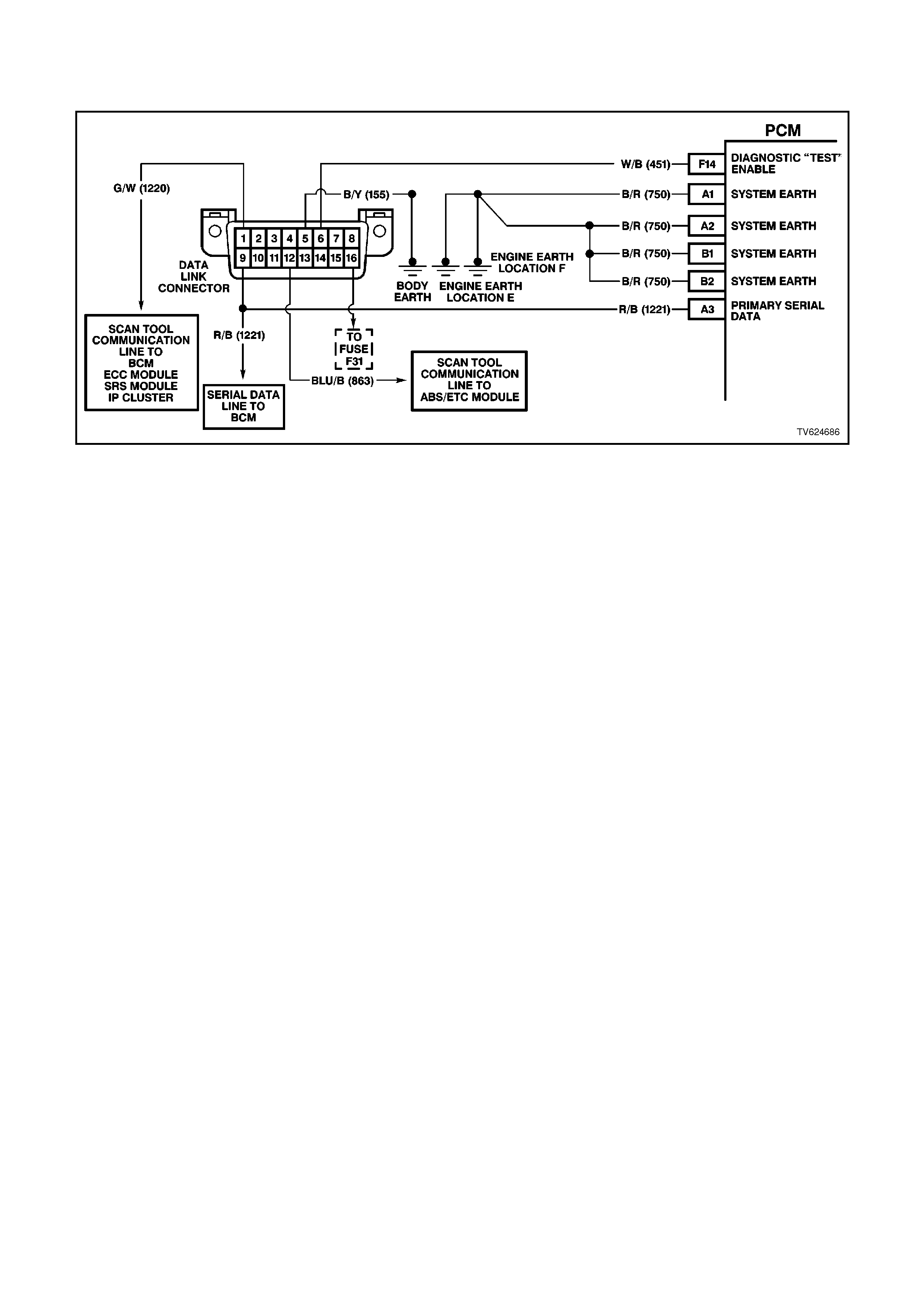
CHART A V6 PCM - ON-BOARD DIAGNOSTIC SYSTEM CHECK
CIRCUIT DESCRIPTION:
The On-Board Diagnostic System Check is an organised approach in identifying a problem created by a powertrain
control system malfunction. It must be the starting point for any driveability complaint diagnosis, because it directs
the service technician to the next logical step in diagnosing the complaint. Understanding the chart and using it
correctly will reduce diagnostic time and prevent the unnecessary replacement of good parts.
TEST DESCRIPTION:
Number(s) below refer to step number(s) on the diagnostic chart.
1. This step is a check for the proper operation of the "Check Powertrain" lamp (MIL). The PCM should provide
serial data communication path for the "Check Powertrain" lamp, this is a bulb check. The "Check Powertrain"
lamp should be "ON." If it can do this, it confirms that the PCM has power, earth and is capable of some
functions.
If the "Check Powertrain" lamp is "OFF," this indicates a problem in the "Check Powertrain" lamp fuse circuits
or the PCM earth circuits or the PCM's serial data communication circuit or a problem with the instrument
cluster. Chart A-1 will check for both ignition feed and constant battery power to the PCM and the PCM earth.
2. This check is done to see if the PCM has the capability of performing internal diagnostics. With the diagnostic
"test" terminal earthed, the "Check Powertrain" lamp, should flash a DTC 12 three times, followed by any
DTC(s) stored in memory. DTC 12 means there is no crankshaft reference signal coming to the PCM, this is
normal because the engine is not running.
3. This check is used to see if the PCM can supply serial data for Tech 2 scan tool use. If a PROM error is
present, the PCM may have been able to flash DTC 12 but not enable serial data.
4. This check is to see there are any Theft Deterrent DTC stored. If Theft Deterrent system is enabled, this may
be the cause of the no crank condition.
5. This test determines if the vehicle is able to crank. If the vehicle will not crank, refer to Chart A-4.0 to diagnosis
starter cranking circuit.
7. This test is used to determine the cause of a "Cranks But Will Not Run," although the PCM is powered up, a
"Cranks But Will Not Run" symptom could exist because of a PCM problem or the vehicle electrical system.
8. Look at all the parameters to determine if one is not in a normal state with just the ignition "ON" and engine
stopped. Look at the ECT value to see if the value is shifted above or below where it should be. If so, refer
"Diagnostic Aid Chart" on DTC 14.
9. Look at all the parameters to determine that all values are within typical ranges for normal operating
temperatures at idle. Keep in mind that a basic engine problem may alter sensor value.
DIAGNOSTIC AIDS:
If the Serial Data circuit is shorted to voltage or earth or open, the vehicle will not crank. Check Serial Data circuit
from PCM to BCM, and from BCM to all other controllers.

STEP ACTION VALUE YES NO
1. 1. Ignition "ON" engine
"STOPPED".
2. Observe the "CHECK
POWERTRAIN"
lamp (MIL).
Is the "CHECK
POWERTRAIN" lamp
(MIL) "ON" steady ?
Go to Step 2 If no, "CHECK
POWERTRAIN"
lamp, Go to Chart
A-1 in this Section
If "CHECK
POWERTRAIN"
lamp is flashing
DTC 12, Go to
Step 10
2. Jumper Data Link
Connector (DLC) terminal
"6" To "5".
Does "CHECK
POWERTRAIN" lamp
flash DTC 12?
Go to Step 3 Go to Chart A-1 in
this Section
3. 1. Disconnect Data Link
Connector jumper.
2. Install scan tool to
Data Link Connector.
Does scan tool display
PCM serial data.?
Go to Step 4 Go to Chart A-2 in
this Section
4. 1. Ignition "ON".
2. Using Tech 2 scan
tool, check for DTC
31.
Is DTC 31 set?
Go to DTC 31
Chart Go to Step 5
5. Does engine crank? Go to Step 6 Go to
Chart A-4.0
6. 1. With Tech 2 scan
tool, display DTC(s).
Are any Diagnostic
Trouble Codes displayed?
NOTE:
Check both Current and
History codes.
Refer To
Applicable DTC
Chart.
Start with lowest
DTC
Go to Step 7
7. Does engine start? Go to Step 8 Go to
Chart A-3.1
for
Non-
Supercharged
Engine
application
or
Chart A-3.1-1
for
Supercharged
Engine
application
in this Section

STEP ACTION VALUE YES NO
8. 1. Ignition "ON", engine
"STOPPED".
2. Compare Tech 2
scan tool data with
typical values shown
on scan data chart.
Are values normal or
within typical ranges?
Go to Step 9 Refer to indicated
"Component(s)-
System" checks in
this Section.
9. 1. Run engine until
normal operating
temperature is
reached.
2. Run engine at 1500
revolutions per
minute for 2 minutes,
then idle engine.
3. Compare Tech 2
scan data with typical
values shown on
"scan data" in this
Section.
Are values normal or
within typical ranges?
Refer to
"Symptom"
Diagnosis Charts"
in Section 6C1-2B
Refer to indicated
"Component(s)-
System "checks
10. Check for earthed
diagnostic "TEST"
terminal circuit.
Was a problem found?
Verify Repair Go to Step 11
11. Replace PCM.
Refer to Section 6C1-3
Service Operations, for
PCM Security Link
procedure.
Is action complete?
Verify Repair
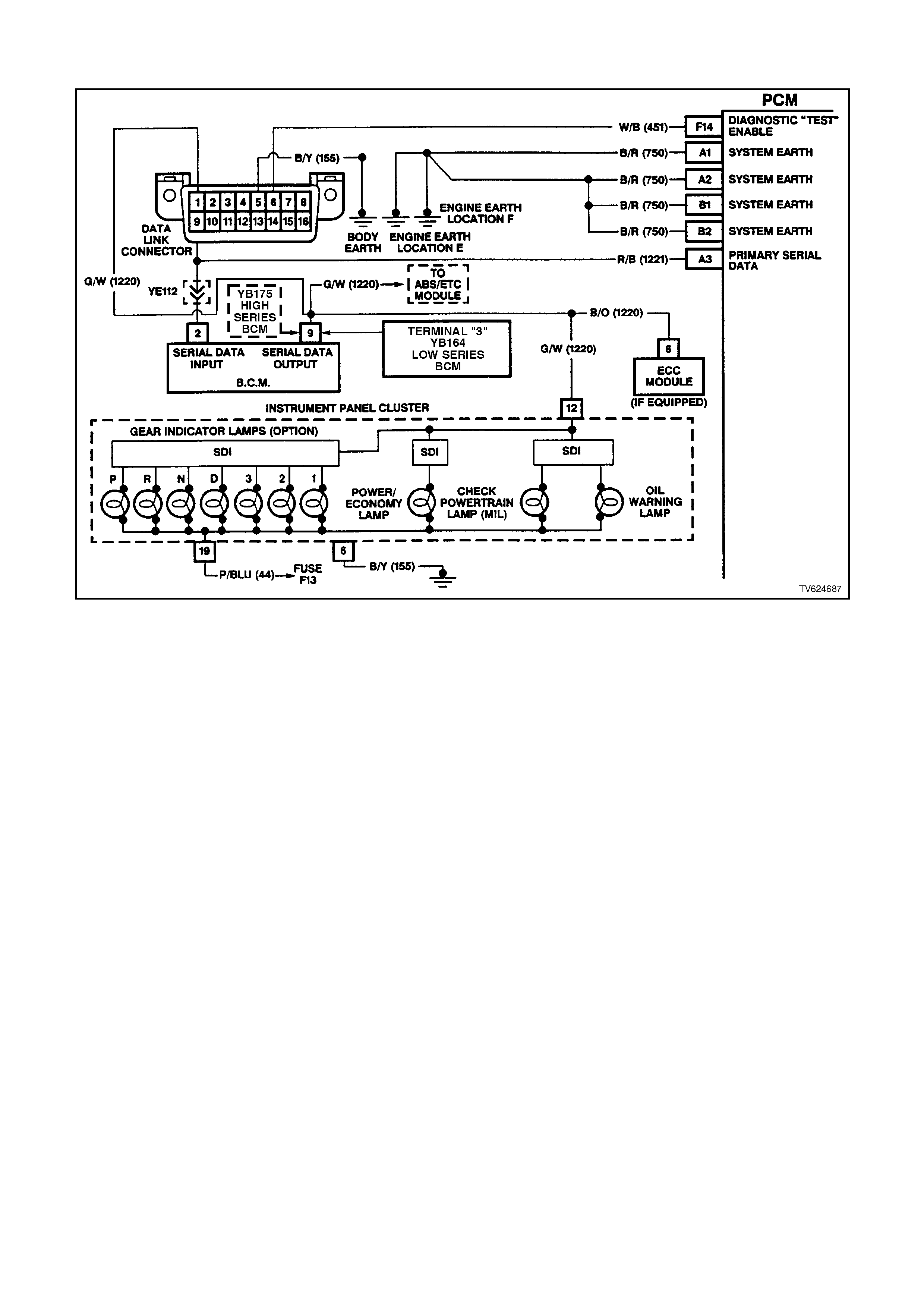
CHART A-1 V6 PCM - NO "CHECK POWERTRAIN" (MIL) LAM P
CIRCUIT DESCRIPTION:
There should always be a steady "Check Powertrain" (MIL) lamp with the ignition "ON" and engine stopped. Battery
voltage is supplied directly to the "Check Powertrain" (MIL) lamp bulb through a fused circuit. The Powertrain
Control Module (PCM) will control the lamp via serial data communication to the Body Control Module (BCM) on the
serial data circuit. When the PCM determines that the "Check Powertrain" lamp should be "ON", the PCM will send
a message on the serial data circuit to the BCM requesting the (MIL) "ON". The BCM will then send a serial data
communication message to the instrument panel (IP) Cluster. The IP Cluster will then determine what message the
BCM is sending, and will then turn "ON" the "Check Powertrain" lamp.
TEST DESCRIPTION:
Number(s) below refer to step number(s) on the diagnostic chart.
2. Fuse F13 supplies power to the instrument panel cluster. If this fuse is blown, the cluster lamps will not light.
5. If the Tech 2 scan tool will not communicate with the vehicle, there may be a problem in the serial data line.
Chart A-2 will check this serial data line.
6. If the Tech 2 scan tool is capable of commanding the MIL "ON" and "OFF", the PCM may be at fault.
7. This step checks for proper serial data voltage to the instrument panel (IP) cluster.

STEP ACTION VALUE YES NO
1. Was the "On-Board
Diagnostic" (OBD) System
Check performed?
Go to Step 2. Go to OBD
System Check in
this Section
2. Check IP cluster fuse
F13.
Is fuse OK?
Go to Step 3 Go to Step 9
3. 1. Ignition "OFF".
2. Disconnect PCM
connectors.
3. Ignition "ON".
4. Probe PCM battery
feed circuits and
ignition feed circuit
with a test light
connected to earth.
Is the test light "ON" for all
circuits?
Go to Step 4 Go to Step 15
4. 1. Ignition "OFF".
2. Disconnect PCM
connectors.
3. Probe PCM earth
circuits with a test
light connected to
B+.
Is the test light "ON" for
both circuits?
Go to Step 5 Go to Step 16
5. 1. Ignition "OFF".
2. Reconnect PCM
connectors.
3. Connect Tech 2 scan
tool to DLC.
4. Ignition "ON", engine
stopped.
Does Tech 2 scan tool
display PCM serial data?
Go to Step 6 Go to Chart A-2
6. With scan tool still
connected to DLC,
command the MIL "ON"
using the scan tool.
Does the MIL turn "ON"
when commanded "ON"
using the scan tool?
Go to Step 14 Go to Step 7
7. 1. Ignition "OFF".
2. Remove IP Cluster
from dash panel.
3. Ignition "ON".
4. Using DVM, probe IP
Cluster connector
terminal 12 with the
DVM connected to
earth.
Does the DVM display a
varying voltage between
the specified value?
3-5 volts Go to Step 8 Go to Step 10

STEP ACTION VALUE YES NO
8. Check for poor connection
between the IP Cluster
and cluster connector.
Was a problem found?
Verify Repair Go to Step 11
9. Repair short to earth in IP
cluster fuse circuit.
Is action complete ?
Verify Repair
10. Repair open in the serial
data circuit from the BCM
to IP Cluster.
Is action complete?
Verify Repair
11. Check "Check Powertrain"
(MIL) bulb for open.
Was a problem found?
Go to Step 12 Go to Step 13
12. Replace "Check
Powertrain " (MIL) bulb.
Is action complete?
Verify Repair
13. Replace IP cluster.
Is action complete? Verify Repair
14. Replace PCM.
Refer to Section 6C1-3
Service Operations, for
PCM Security Link
procedure.
Is action complete?
Verify Repair
15. Check for short to earth,
and repair open in power
circuit that did not light
test light.
Is action complete?
Verify Repair
16. Repair open in earth
circuit that did not light
test light.
Is action complete?
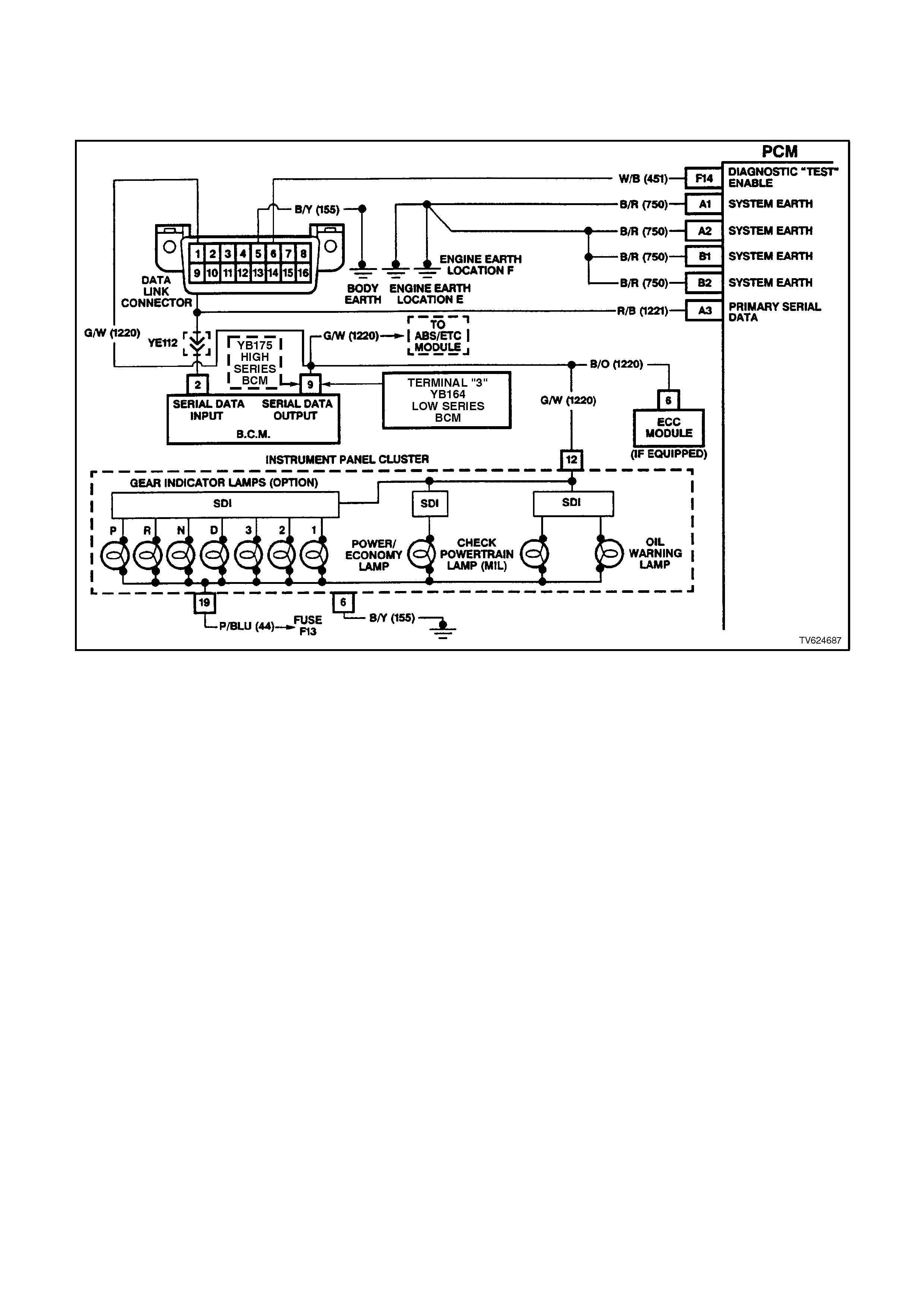
CHART A-2 V6 PCM - NO SERIAL DATA OR WILL NOT FLASH DTC 12,
MALFUNCTION INDICATOR LAMP (MIL)
"CHECK POWERTRAIN" LAMP "ON" STEADY
CIRCUIT DESCRIPTION:
There should always be a steady (MIL) "Check Powertrain" lamp when the ignition is "ON" and engine stopped.
Battery voltage is supplied directly to the (MIL) "Check Powertrain" lamp bulb. The Powertrain Control Module
(PCM) will control the "Check Powertrain" lamp and turn it "ON" via the serial data communication circuit..
With the ignition "ON", engine stopped and diagnostic "test" terminal earthed, the "Check Powertrain" lamp should
flash a DTC 12, followed by any diagnostic trouble code(s) stored in memory.
A steady lamp suggests a fault in the IP cluster.
With the Tech 2 scan tool connected to the DLC and the ignition switch on, the scan tool should display serial data
communication. If the scan tool does not display serial data, the serial data circuit may be open or shorted.
There are several other control modules that are connected to the serial data line (PCM, BCM, ABS/ETC module,
ECC module, SRS module and IP cluster). Any one of these controllers could cause a fault on the serial data line.
This fault could result in the scan tool not being able to display serial data.
TEST DESCRIPTION:
Number(s) below refer to step number(s) on the diagnostic chart.
2. This step checks to see if the PCM will flash DTC 12.
3. This step checks to see if the Tech 2 scan tool will communicate with the PCM.
4. Using a Digital Volt\Ohm meter (DVM), there should be 3 to 5 volts at the DLC terminal 9. If the voltage is
higher or lower, serial communication will be effected. This serial data circuit is also connected to several other
controllers. A problem with any one of these other controllers, may cause serial data communication
malfunction.
13. This step checks to see if the Serial Data circuit is shorted to voltage or earth. Check Serial Data circuit from
PCM, to BCM, and from BCM to all other controllers.
DIAGNOSTIC AIDS:
If there is a fault with the serial data circuit, it could be caused by one or more of the several controllers connected
to this serial data circuit. Isolate the fault by disconnection one at a time each controller until the serial data
communication is restored.

STEP ACTION VALUE YES NO
1. Was the "On-Board
Diagnostic" (OBD) System
Check performed?
Go to Step 2 Go to OBD
System Check in
this Section.
2. 1. Ignition" ON" engine
stopped.
2. Earth diagnostic
"TEST" terminal No.
6.
Does "CHECK
POWERTRAIN" lamp
flash DTC 12?
Go to Step 3 Go to Step 6
3. 1. Connect Tech 2 scan
tool to DLC.
2. Ignition "ON", engine
stopped.
Does Tech 2 scan tool
display PCM serial data?
No trouble found Go to Step 4
4. 1. Ignition "ON" engine
stopped.
2. Using DVM, probe
DLC terminal 9 with
DVM connected to
earth.
Does DVM display voltage
varying between the
specified value?
3-5 volts Go to Step 5 Go to Step 8
5. Check connections
between the DLC and the
PCM. If not
OK repair, if connection
are OK, Replace PCM,
Refer to Section 6C1-3,
Service Operations, for
PCM Security link
procedure.
Is action complete?
Verify Repair
6. 1. Ignition "ON" engine
stopped.
2. Using DVM, probe
DLC terminal 6 with
DVM connected to
earth.
Does DVM display voltage
at specified value?
B+ volts Go to Step 13 Go to Step 12
7. Replace IP cluster.
Is action complete? Verify Repair

STEP ACTION VALUE YES NO
8. Is voltage steady at or
above the specified
value?
5 volts Go to Step 11 Go to Step 9
9. 1. Connect Tech 2 scan
tool to DLC.
2. Ignition "ON", engine
stopped.
Does Tech 2 scan tool
display BCM serial data?
Go to Step 10 Go to Step 13
10. Repair open or short to
earth in the serial data
circuit between the PCM
and the DLC.
Is action complete?
Verify Repair
11. Repair short to voltage on
the serial data circuit.
NOTE:
Insure that none of the
other controllers on the
serial data circuit are
causing this voltage
problem. Unplug each
controller one at a time to
isolate short to voltage.
Is action complete?
Verify Repair
12. Check for an open in the
Diagnostic Test circuit
from the PCM to the DLC.
Was a problem found?
Verify Repair Go to Step 5
13. Check for short to earth or
short to voltage or open in
the serial data line.
Refer to Diagnostic Aids.
Was a problem found?
Verify Repair Go to Step 7
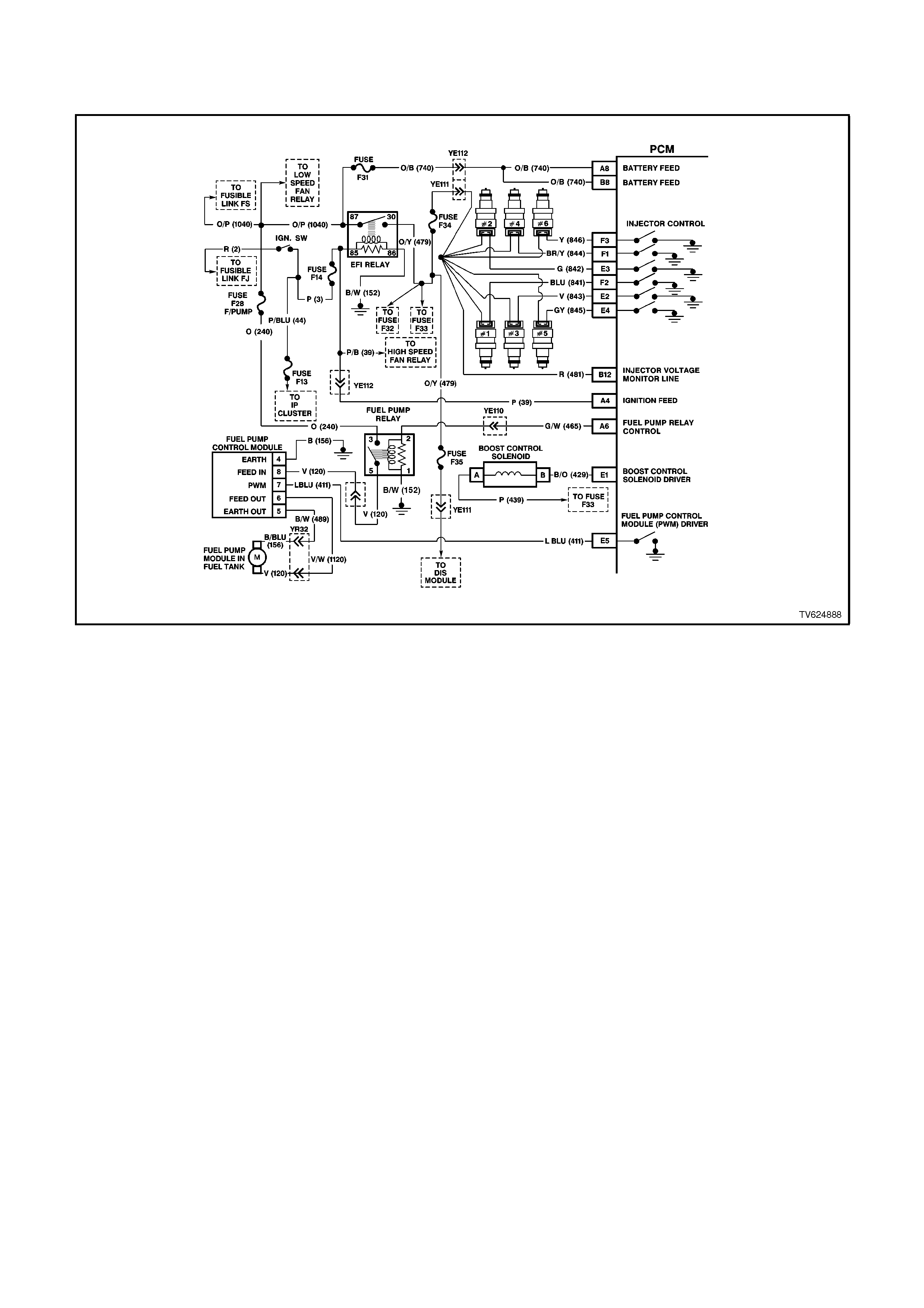
CHART A-3.1 V6 PCM - NON-SUPERCHARGED ENGINE,
ENGINE CRANKS BUT WILL NOT RUN
CIRCUIT DESCRIPTION:
This is the first of several diagnostic charts that must be followed in an orderly , progressive fashion in order to find
the cause of a no-start. These charts assume an adequate supply of good quality fuel is in the fuel tank, that the
cranking motor circuit is in good working order, and that the engine will crank with adequate RPM. These charts
also assume that no Diagnostic Trouble Code (DTC) 31 or 46 is set in the PCM memory, as determined by the On-
Board Diagnostic Circuit Check. The On-Board Diagnostic System Check is always the beginning point for all
diagnostic procedures.
TEST DESCRIPTION:
Number(s) below refer to step number(s) on the diagnostic chart.
1. The PCM must be operable. The On-Board Diagnostic System Check will prove that. There are few chances
that the PCM itself would cause a no-start, but the On-Board Diagnostic System Check will uncover any
problems in the PCM power and earth circuitry.
4. This checks for a short to earth on the injector control circuit. If this were to occur, the engine would be
extremely flooded, since the injectors would be "ON" continuously, and would inject fuel any time there is fuel
pressure.
5. Any time the PCM has been "OFF" for at least 10 seconds, it should energise the Fuel Pump Relay for 2
seconds after the ignition is turned "ON." If the engine is not cranked, the PCM should turn the relay "OFF"
after 2 seconds. Proper operation of the Fuel Pump electrical circuit would be noted here by the test light being
"ON" for 2 seconds after the ignition switch is turned to the "ON" position. After 2 seconds, the test light should
go "OFF."

6. Note that this check is for sufficient voltage at the spark plug wire. If, for some reason, the spark plug
electrodes were wet with fuel (engine flooded), this could cause a no-start. However, a "flooded" engine is a
symptom of some other problem. There is no normal condition that should ever be able to "flood" the engine.
7. This is a quick check of the fuel system. The easiest place to install the pressure gauge is where the fuel pipes
come up into the engine compartment. There are 2 hoses, and the gauge must be connected to the hose or
pipe leading directly to the fuel rail. This connection is on the left (passenger) side of the fuel rail (refer Service
Operation 3.11 FUEL CONTROL SYSTEM; Fuel System Pressure Test). The other hose or pipe leads to the
pressure regulator, and no pressure testing is done there. If the pressure is not as specified, or continues to
drop after the pump stops running, the Fuel System Diagnostic Chart A-4.3 in this Section must be used.
NOTE:
Use ST 125 spark checker or equivalent. An ST 125 requires about 25,000 volts (25 kilovolts, or 25 kV) to "spark".
Do not use a spark plug in open air earthed to the engine as an indication of sufficient "spark". Only a few kilovolts
are required to jump the gap of a spark plug outside of the engine, and that would be an inadequate test of the
ignition coil output ability.

STEP ACTION VALUE YES NO
1. Was the "On-Board
Diagnostic" (OBD) System
Check performed?
Go to Step 2. Go to OBD
System Check in
this Section.
2. Is DTC 31 present ? Go to DTC 31
Chart in this
Section
Go to Step 3
3. Is DTC 46 present ? Go to DTC 46
Chart in this
Section
Go to Step 4
4. 1. Check fuel tank
quantity .
2. Disconnect ALL
injector electrical
connectors.
3. Connect test light
between the
terminals of each
injector harness
connector.
Be very careful to NOT
short across the
terminals, or to engine
earth.
4. Ignition "ON", note
test light.
Is light "OFF"?
Go to Step 5 Go to Step 8
5. 1. Probe Fuel Pump
Relay "5" circuit with
a test light connected
to earth.
2. Ignition "ON".
3. Using TECH 2 scan
tool, Select Fuel
Pump.
4. Activate Fuel Pump.
Is test light "ON"?
Go to Step 6 Go to Chart A-4.1
Non-
Supercharged
Engine
in this Section
6. 1. Ignition "OFF".
2. Remove the spark
plug leads from 2
spark plugs.
3. Connect ST 125
spark checker (refer
note above) to each
individually, and
check for spark while
cranking the engine.
4. Check both wires. A
few sparks and then
nothing is considered
no spark.
Was there spark on both
wires ?
Go to Step 7 Go to Chart A-8 in
this Section

STEP ACTION VALUE YES NO
7. 1. Ignition "OFF".
2. Reconnect both
spark plug leads to
spark plugs.
3. Reconnect all injector
electrical connectors.
4. Remove Fuel Pump
Relay from engine
compartment "FUSE
AND RELAY
CENTRE," and crank
engine for 15
seconds to relieve
any residual fuel
pressure.
5. Ignition "OFF,"
connect Fuel
Pressure Gauge
(Gauge to be
installed in the
pressure line,
between the fuel feed
hose and the fuel
inlet line to the fuel
rail, at left rear of fuel
rail.)
6. Reinstall Fuel Pump
Relay
7. Observe fuel
pressure when
ignition is turned
"ON."
8. Pressure should be
within the value, and
not continue to drop
after pump stops
running.
Is fuel pressure at or
between the value?
270 to
350 kPa Go to Chart A-3.2
in this Section Go to Chart A-4.3
in this Section
8. Repair short to earth on
Injector Circuit.
Was Injector Circuit
shorted to earth ?
Verify Repair Go to Step 9
9. Replace PCM.
Refer to Section 6C1-3
Service Operations, for
PCM Security Link
procedure.
Is action complete?
Verify Repair
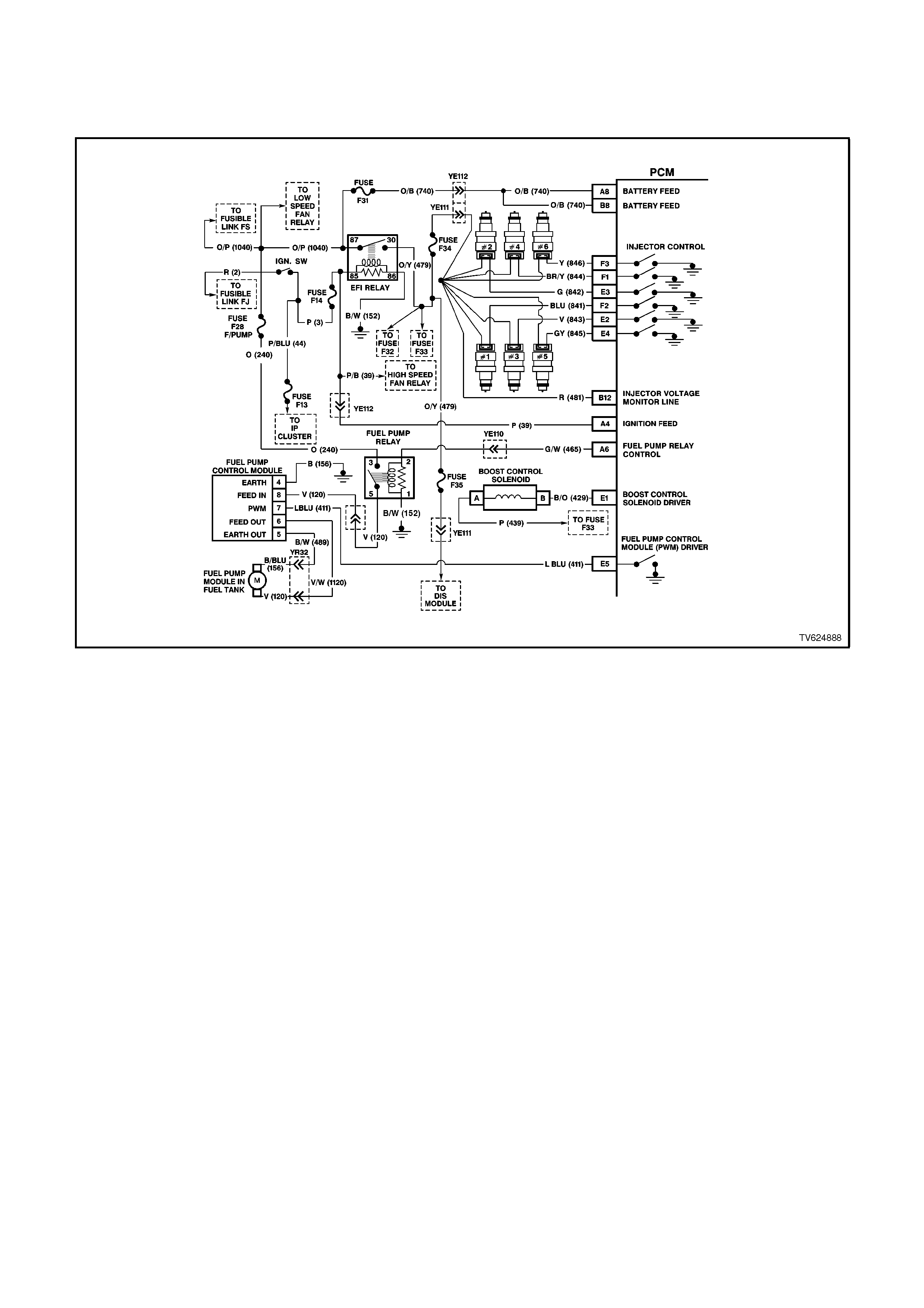
CHART A-3.1-1 V6 PCM - SUPERCHARGED ENGINE, ENGINE CRANKS BUT
WILL NOT RUN
CIRCUIT DESCRIPTION:
This is the first of several diagnostic charts that must be followed in an orderly , progressive fashion in order to find
the cause of a no-start. These charts assume an adequate supply of good quality fuel is in the fuel tank, that the
cranking motor circuit is in good working order, and that the engine will crank with adequate RPM. This
supercharged engine utilises a Fuel Pump Control Module along with the Fuel Pump Relay, for fuel delivery to the
injectors. These charts also assume that no Diagnostic Trouble Code (DTC) 31 or 46 OR is set in the PCM
memory, as determined by the On-Board Diagnostic Circuit Check. The On-Board Diagnostic System Check is
always the beginning point for all diagnostic procedures.
TEST DESCRIPTION:
Number(s) below refer to step number(s) on the diagnostic chart.
1. The PCM must be operable. The On-Board Diagnostic System Check will prove that. There are few chances
that the PCM itself would cause a no-start, but the On-Board Diagnostic System Check will uncover any
problems in the PCM power and earth circuitry.
4. This checks for a short to earth on the injector control circuit. If this were to occur, the engine would be
extremely flooded, since the injectors would be "ON" continuously, and would inject fuel any time there is fuel
pressure.

5. Any time the PCM has been "OFF" for at least 10 seconds, it should energise the Fuel Pump Relay for 2
seconds after the ignition is turned "ON." If the engine is not cranked, the PCM should turn the relay "OFF"
after 2 seconds. Proper operation of the Fuel Pump electrical circuit would be noted here by the test light being
"ON" for 2 seconds after the ignition switch is turned to the "ON" position. After 2 seconds, the test light should
go "OFF."
6. Note that this check is for sufficient voltage at the spark plug wire. If, for some reason, the spark plug
electrodes were wet with fuel (engine flooded), this could cause a no-start. However, a "flooded" engine is a
symptom of some other problem. There is no normal condition that should ever be able to "flood" the engine.
7. This is a quick check of the fuel system. The easiest place to install the pressure gauge is at the schrader
valve fitting (refer Service Operation 3.11 FUEL CONTROL SYSTEM; Fuel System Pressure Test). The other
hose or pipe leads to the pressure regulator, and no pressure testing is done there. If the pressure is not as
specified, or continues to drop after the pump stops running, the Fuel System Diagnostic Chart A-4.3 in this
Section must be used.
NOTE:
Use ST 125 spark checker or equivalent. An ST 125 requires about 25,000 volts (25 kilovolts, or 25 kV) to "spark".
Do not use a spark plug in open air earthed to the engine as an indication of sufficient "spark". Only a few kilovolts
are required to jump the gap of a spark plug outside of the engine, and that would be an inadequate test of the
ignition coil output ability.

STEP ACTION VALUE YES NO
1. Was the "On-Board
Diagnostic" (OBD) System
Check performed?
Go to Step 2. Go to OBD
System Check in
this Section.
2. Is DTC 31 present ? Go to DTC 31
Chart in this
Section
Go to Step 3
3. Is DTC 46 present ? Go to DTC 46
Chart in this
Section
Go to Step 4
4. 1. Check fuel tank
quantity .
2. Disconnect ALL
injector electrical
connectors.
3. Connect test light
between the
terminals of each
injector harness
connector.
Be very careful to NOT
short across the
terminals, or to engine
earth.
4. Ignition "ON", note
test light.
Is light "OFF" ?
Go to Step 5 Go to Step 8
5. 1. Ignition "OFF".
2. Backprobe Fuel
Pump Control
Module "6" circuit
with a test light
connected to earth.
3. Ignition "ON".
4. Using TECH 2 scan
tool, Select Fuel
Pump.
5. Activate Fuel Pump
Is test light "ON"?
Go to Step 6 Go to Chart A-4.1-
1 Supercharged
Engine
in this Section
6. 1. Ignition "OFF".
2. Remove the spark
plug leads from 2
spark plugs.
3. Connect ST 125
spark checker (refer
note above) to each
individually, and
check for spark while
cranking the engine.
4. Check both wires. A
few sparks and then
nothing is considered
no spark.
Was there spark on both
wires ?
Go to Step 7 Go to Chart A-8 in
this Section

STEP ACTION VALUE YES NO
7. 1. Ignition "OFF".
2. Reconnect both
spark plug leads to
spark plugs.
3. Reconnect all injector
electrical connectors.
4. Remove Fuel Pump
Relay from engine
compartment "FUSE
AND RELAY
CENTRE," and crank
engine for 15
seconds to relieve
any residual fuel
pressure.
5. Ignition "OFF,"
connect Fuel
Pressure Gauge
6. Reinstall Fuel Pump
Relay
7. Observe fuel
pressure when
ignition is turned
"ON."
8. Pressure should be
within the value, and
not continue to drop
after pump stops
running.
Is fuel pressure at or
between the value, and
holding steady?
290 to
410 kPa Go to Chart A-3.2
in this Section Go to Chart A-4.3
in this Section
8. Repair short to earth on
Injector Circuit.
Was Injector Circuit
shorted to earth ?
Verify Repair Go to Step 9
9. Replace PCM.
Refer to Section 6C1-3
Service Operations, for
PCM Security Link
procedure.
Is action complete?
Verify Repair
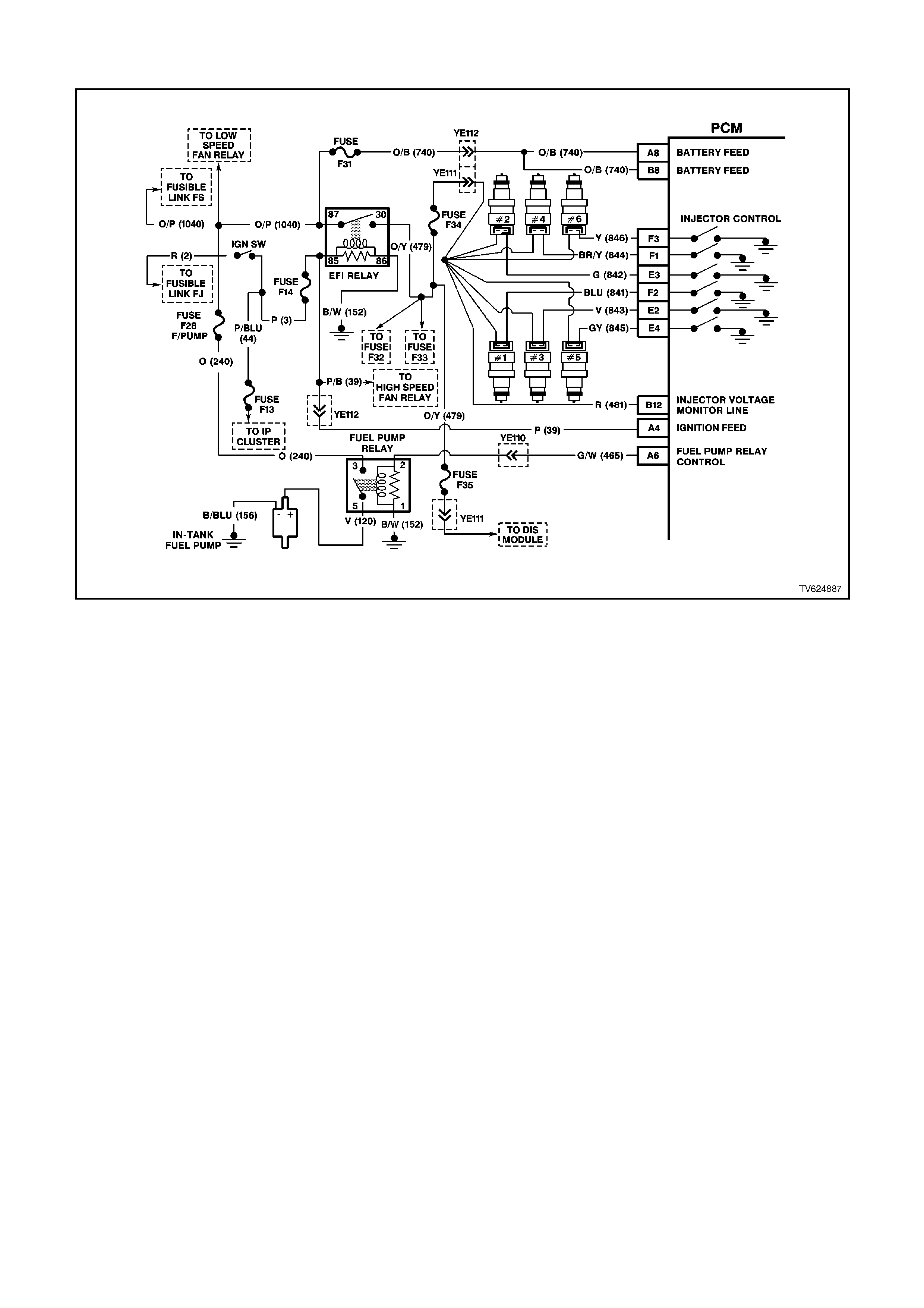
CHART A-3.2 V6 PCM - ENGINE CRANKS BUT WILL NOT RUN
TEST DESCRIPTION:
Number(s) below refer to step number(s) on the diagnostic chart.
6. "STEADY LIGHT" indicates the PCM is continuously supplying the earth path on the injector circuit. It is not
a harness problem at this point; That would have been in Chart A-3.1 for Non-Supercharged engines or Chart A-
3.1-1 for Supercharged engines. This may destroy an injector, as they are designed to be energised in short pulses
and may not withstand 100% "ON" time. If any injector checks less than 11.8 ohms, it could be the cause of the
defective PCM. The PCM can be damaged when it attempts to energise the injector circuit with a very-low-
resistance load. Normal injector resistance is approximately 12.2 ohms at 20 degrees C per individual injector.

STEP ACTION VALUE YES NO
1. Was the "On-Board
Diagnostic" (OBD) System
Check performed?
Go to Step 2. Go to OBD
System Check in
this Section.
2. From either Chart A-3.1
Non-Supercharged
Engine or Chart A-3.1-1
Supercharged Engine
1. Ignition "OFF".
2. With all injectors
disconnected,
connect test light
across both harness
terminals of one
injector connector.
Be very careful to not
short across the
terminals, or to
engine earth.
3. Have a helper crank
the engine while you
closely observe the
test light.
4. Test light should
blink while cranking,
indicating electrical
injector pulses are
present, do this test
for all injectors
Did test light blink while
cranking ?
Go to Step 3 If there was no
blinking light, Go
to Chart 3.3 in this
Section
If the test light
was on steady (no
blinking light) Go
to Step 6
3. 1. Check the remaining
5 injector connectors
for blinking test light,
as described in step
2.
2. Did all the remaining
injector connectors
blink the test light ?
Go to Step 4 Go to Step 5

STEP ACTION VALUE YES NO
4. At this point, the fuel
control system, fuel
delivery system, and
ignition system are OK.
CHECK FOR:
Fouled spark plugs.
Proper MAF sensor
operation. If engine will
start with MAF sensor
electrical connector
disconnected, refer Chart
A-6.1 in this Section.
Proper TP sensor circuit
operation. Use Tech 2
scan tool to monitor TP
sensor signal. If voltage is
over 1.25 volts with
throttle closed, refer Chart
A-6.2 in this Section.
Restricted exhaust
system. Loosen front pipe
from exhaust manifold(s).
If the engine will start,
refer Chart A-13 in this
Section.
Improper engine coolant
temperature (ECT) sensor
resistance. Refer DTC 14
Diagnostic Aids in this
Section to check
resistance of ECT sensor.
Water or foreign material
in fuel, or incorrect fuel.
Spark plug wires crossed.
Camshaft timing chain.
Inadequate engine
compression.
Is action complete?
Verify Repair

STEP ACTION VALUE YES NO
5. Repair open in circuit 481
and injector circuit to
connector that did not
blink the test light.
Is action complete ?
Verify Repair
6. Check for a short to earth
in injector circuit that
caused test light to stay
"ON" steady.
Was a problem found?
Verify Repair Go to Step 7
7. Check resistance across
each injector. Each
injector should be
between the specified
value.
Is each injector at the
value ?
11.8 -
12.8
ohms
Go to step 8 Go to step 9
8. Replace PCM.
Refer to Section 6C1-3
Service Operations, for
PCM Security Link
procedure.
Is action complete?
Verify Repair
9. 1. Replace any injector
that did not measure
within the specified
value.
2. Retest beginning at
Step 2.
Is action complete?
11.8 -
12.8
ohms
Verify Repair
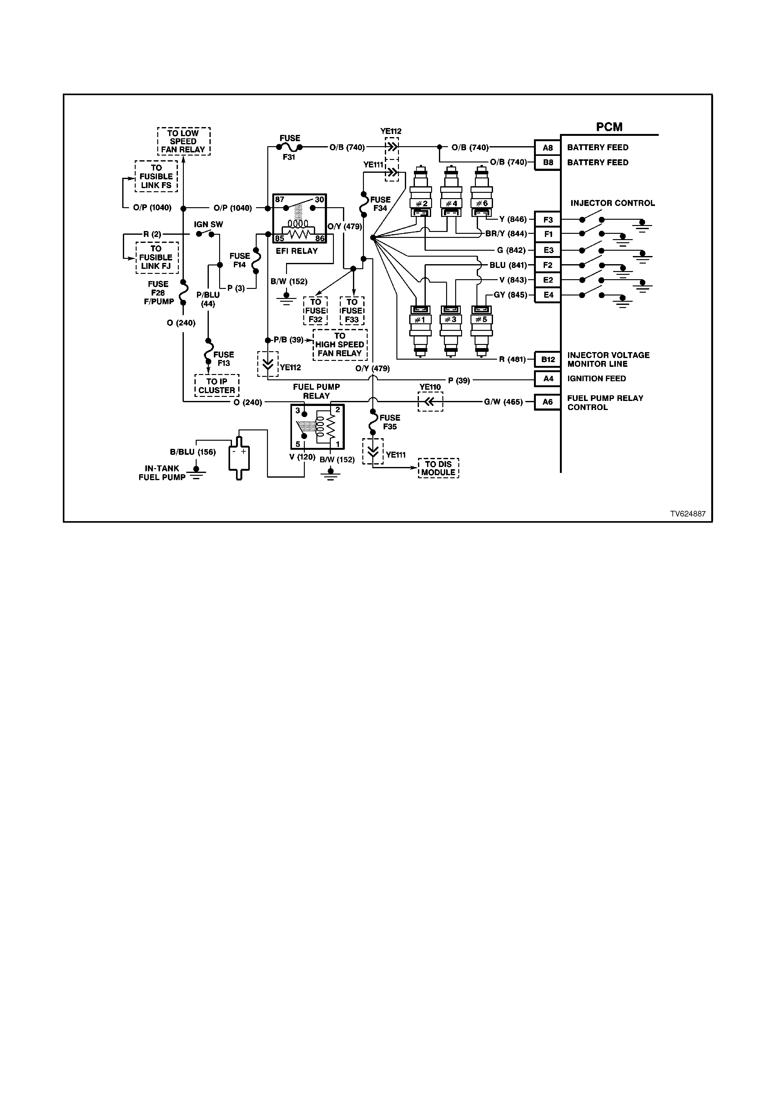
CHART A-3.3 V6 PCM - ENGINE CRANKS BUT WILL NOT RUN
TEST DESCRIPTION:
Number(s) below refer to step number(s) on the diagnostic chart.
2 "NO LIGHT" indicates no PCM control of the injector. Fuse F32 supplies +12 volts to the injectors. Probe both
terminals of one injector connector with a test light to earth. There should be a light on only one terminal,
confirming ignition voltage to one terminal, but not both.
3. The PCM injector control circuit may be open. Reconnect the injectors. Using a test light connected to earth,
check for a light at the PCM connector terminals. A light at this point indicates that injector control circuit is not
"open." The voltage to light that test light comes from circuit 481, through the injector windings, and continues
through the injector control circuit to PCM connector terminals.
7. There is no terminal identification on the relay connector socket, but the relay itself has terminal numbers.
Make certain the correct relay connector socket terminal (NOT the relay) is being probed.

STEP ACTION VALUE YES NO
1. Was the "On-Board
Diagnostic" (OBD) System
Check performed?
Go to Step 2. Go to OBD
System Check in
this Section.
2. 1. Ignition "OFF"
2. Disconnect injector
connectors. From
Chart A-3.2 No Light
3. Ignition "ON," engine
stopped.
4. Probe each terminal
of each injector
harness connector
with a test light to
earth.
Is the test light "ON" at
each terminal?
Go to Step 3 If
the test light was"
ON" at both
terminals, repair
short to voltage
on injector circuit.
----------------------
If
there was no light
"ON", Go to Step
7
3. 1. Ignition "OFF".
2. Reconnect injectors.
3. Ignition "ON".
4. Backprobe PCM
injector control
terminals with a test
light connected to
earth.
Is test light "ON" at each
terminal?
Go to Step 4 Go to Step 12
4. 1. Ignition "ON".
2. With a Tech 2 scan
tool, monitor TP
sensor signal
voltage.
Is voltage less than
value?
1.25
volts Go to Step 5 Go to Chart A-6.2
in this Section
5. Check for faulty
crankshaft reference
signal input to PCM
connector terminal.
Is PCM terminal for circuit
430 (D12) faulty?
Verify Repair Go to Step 6
6. Replace PCM.
Refer to Section 6C1-3
Service Operations, for
PCM Security Link
procedure.
Is action complete?
Verify Repair
7. 1. Ignition "OFF".
2. Disconnect EFI relay.
3. Ignition "ON".
4. Probe EFI relay
harness connector
terminal "30" and
terminal "86" with a
test light connected
to earth.
Is the test light "ON" at
both circuits?
Go to Step 8 Go to Step 13

STEP ACTION VALUE YES NO
8. 1. Ignition "OFF".
2. Disconnect EFI relay.
3. With test light
connected to 12
volts, probe relay
harness terminal
earth circuit of EFI
relay.
Is test light "ON", is it?
Go to Step 9 Go to Step 14
9. Check injector fuse F32
for an open.
Was a problem found?
Go to step 15 Go to Step 10
10. Check for an open in
injector power circuit from
fuse F32 to injector splice.
Was a problem found?
Verify Repair Go to Step 11
11. Replace EFI relay.
Is action complete? Verify Repair
12. Repair open injector
control circuit that did not
light test light.
Is action complete?
Verify Repair
13. Check fuses and repair
circuit that did not turn
"ON" test light.
Is action complete?
Verify Repair
14. Repair earth circuit to EFI
relay.
Is action complete?
Verify Repair
15. Repair short to earth in
fuse circuit.
Replace fuse.
Is action complete?
Verify Repair
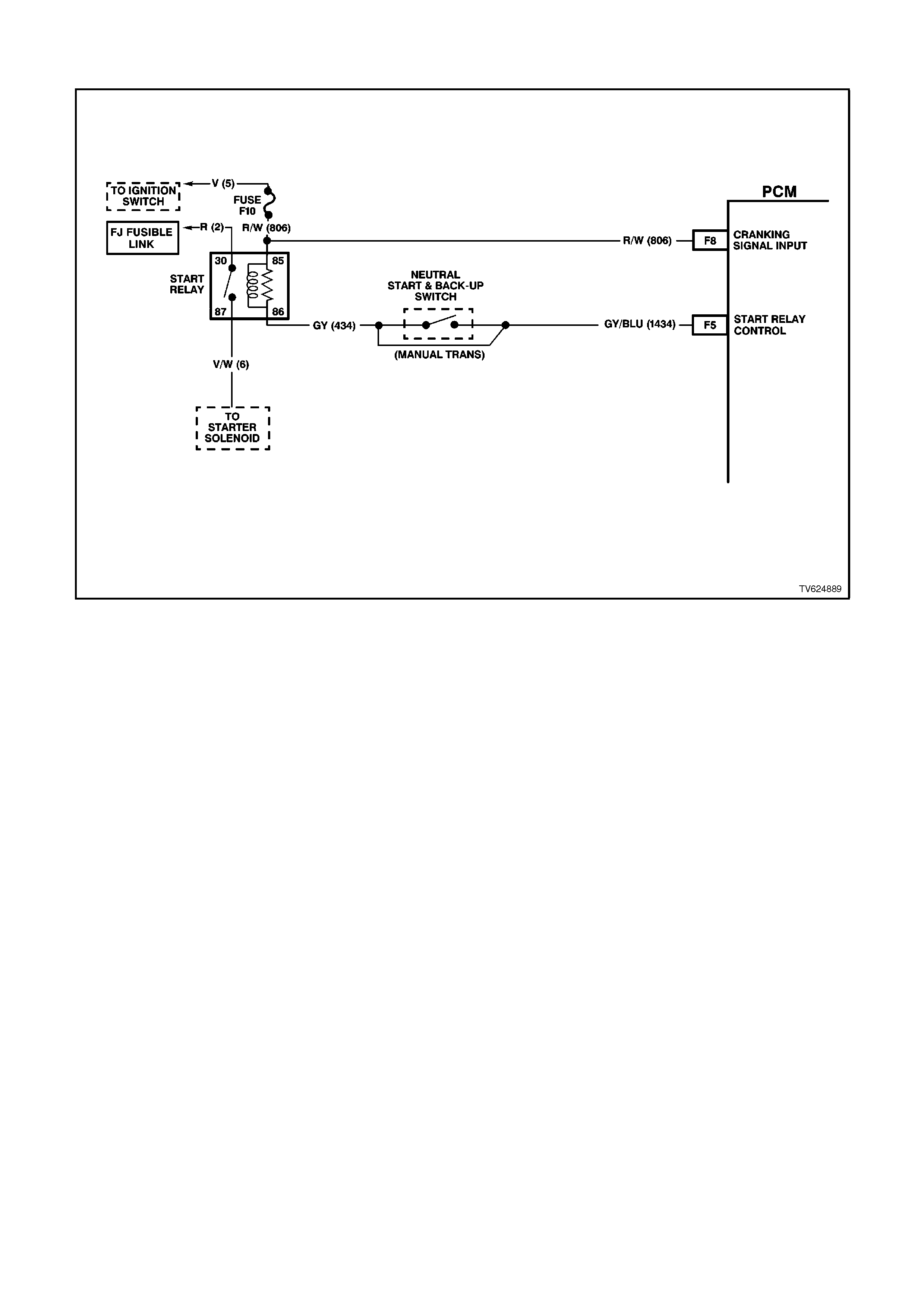
CHART A- 4.0 V6 PCM - STARTER CRANKING CI RCUI T
CIRCUIT DESCRIPTION:
When the ignition is turned to the "ON" position, battery power is supplied from a fusible link to the Start Relay
terminal "30". As the ignition switch is turned to the START position, power is also supplied from the ignition switch
to the PCM Cranking Signal Input terminal, and to the Start Relay terminal "85". The PCM supplies the earth signal
needed to energise the Start Relay and allows power to the starter motor.
When the PCM receives this voltage input at the Cranking Signal Input terminal, the PCM will then look for the
proper Theft Deterrent signal sent from the BCM. If the PCM has determined that the proper Theft Deterrent signal
is present, the PCM will allow the vehicle to crank. If the PCM determines that a improper Theft Deterrent signal
was sent from the BCM, or no Theft Deterrent signal was sent, the PCM will not supply a earth signal from the PCM
terminal to the Start Relay terminal "86". When the Start Relay receives this earth signal from the PCM, the relay will
be energised, allowing the starter motor to operate. This removed earth signal to the Start Relay will cause the
vehicle not to crank.
The cranking signal provides an input for enabling fuel cutoff during a possible backfire situation. During an engine
start, when the ignition switch is released from the crank position before engine is running, the engine may backfire.
The PCM stops all injector pulses when the engine speed is less than 450 RPM, coolant temperature is greater
than -4 degrees C, a cranking signal is not received, but was received within the previous 12.5 milliseconds.
If there is a fault with the PCM Start Relay Control circuit DTC 91 will set.
If there is a problem with the Theft Deterrent signal from the BCM to the PCM, DTC 31 will set.
TEST DESCRIPTION:
Number(s) below refer to step number(s) on the diagnostic chart.
2. This step checks to see if DTC 31 or 91 is set. Either of these DTC could prevent the vehicle from cranking.
This step also verifies that if a PCM was replaced, that the Security Link procedure was performed.
3. This step checks to see if power is being applied to the starter motor. If test light lights, the problem is with the
starter motor.
12. This step checks the adjustment of the Neutral start switch.

STEP ACTION VALUE YES NO
1Was the "On-Board
Diagnostic" (OBD) System
Check performed?
Go to Step 2 Go to OBD
System Check in
this Section
21. Install a Tech 2 scan
tool.
2. Using the scan tool,
check for a DTC 31
or a DTC 91.
Is a DTC 31 or a DTC 91
set?
Go to the
appropriate DTC
chart
Go to Step 3
31. Ignition OFF.
2. Using a test light,
probe the starter
solenoid terminal "S"
with test light
connected to earth.
3. Have a helper turn
the ignition switch to
the START position,
note the test light.
Does the test light
illuminate when the
ignition switch is turned to
the START position?
Refer to Section
6D1-2, Starting
Sy stem - V6
Go to Step 4
4Check fuse F10 for an
open.
Was an open fuse found?
Go to Step 14 Go to Step 5
51. Remove the start
relay.
2. With a test light
connected to earth
probe the start relay
harness terminal 30.
3. Turn the ignition ON.
Does the test light
illuminate?
Go to Step 6 Go to Step 16
61. With the start relay
still removed and the
test light connected
to earth probe the
start relay harness
terminal 85.
2. Turn the ignition to
the start position.
Did the test light
illuminate?
Go to Step 8 Go to Step 15
7Check for an open circuit
between the starter
solenoid and the Start
Relay.
Was a problem found?
Verify Repair Go to Step 9

STEP ACTION VALUE YES NO
81. Ignition OFF.
2. Remove the Start
Relay.
3. Connect a test light
between the relay
harness terminal 85
and terminal 86.
4. Turn the ignition
switch to the START
position.
Does the test light
illuminate when the
ignition switch is turned to
the START position?
Go to Step 7 Go to Step 10
9Replace the Start Relay.
Is the action complete? Verify Repair
10 Is the vehicle equipped
with a manual
transmission?
Go to Step 11 Go to Step 13
11 1. Ignition ON engine
OFF.
2. With a test light
connected to B+,
probe both of the
circuits at the neutral
start switch.
Did the test light illuminate
at both terminals?
Go to Step 17 Go to Step 12
12 Check the adjustment of
the neutral start switch. If
the adjustment is OK,
replace the neutral start
switch.
Is the action complete?
Verify Repair
13 Check for open circuit
from the neutral start
switch to the Start Relay.
Was a problem found?
Verify Repair Go to Step 18
14 Repair the short to earth
in the faulty circuit.
Replace the fusible link or
the fuse as necessary.
Is the action complete?
Verify Repair
15 Repair the open in the
ignition circuit.
Is the action complete?
Verify Repair
16 Check for an open circuit
2 including the fusible link.
Is the action complete?
Verify Repair
17 Repair the open in circuit
434.
Is the action complete?
Verify Repair
18 Replace PCM.
Refer to Section 6C1-3
Service Operations, for
PCM Security Link
procedure.
Is action complete?
Verify Repair
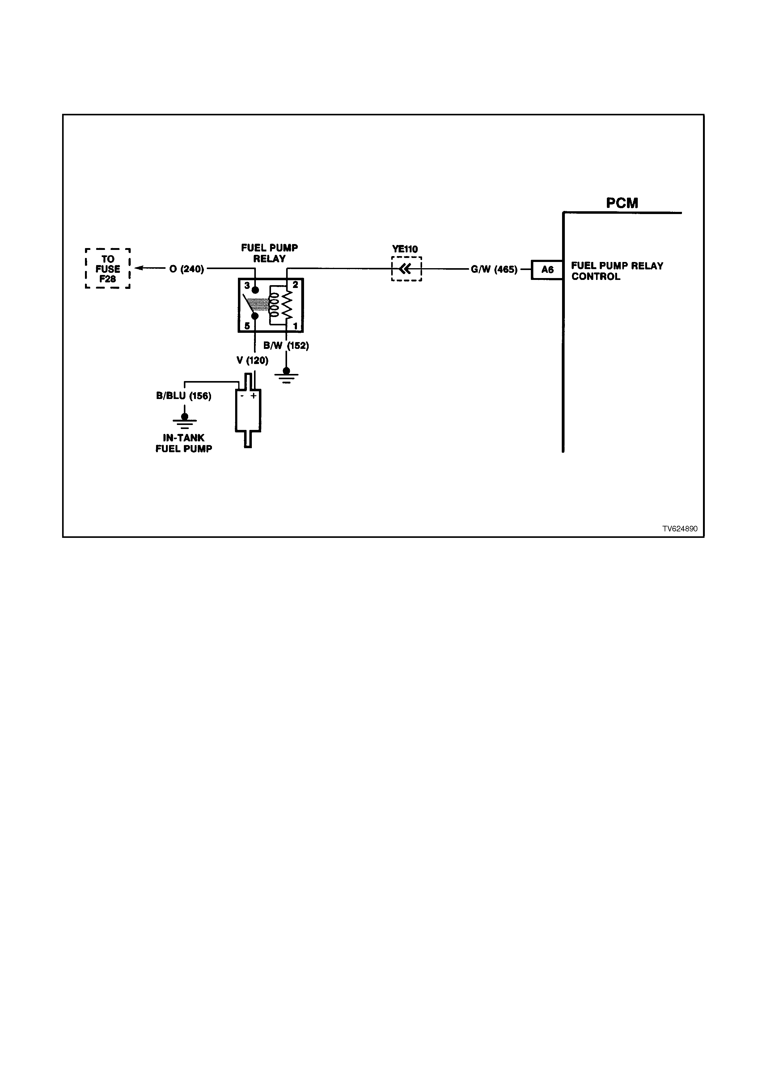
CHART A-4.1 V6 PCM - NON-SUPERCHARGED ENGINE
FUEL PUMP ELECTRI CAL CIRCUIT
CIRCUIT DESCRIPTION:
When the ignition switch is turned "ON," the Power Control Module (PCM) energises its Fuel Pump Relay control
output. It will provide +12 volts to the Fuel Pump Relay, as long as the engine is cranking or running, and the PCM
is receiving crankshaft reference input signal pulses.
If there are no ignition reference pulses (ignition "ON," engine stopped - or - engine stalled), the PCM will shut
"OFF" the Fuel Pump Relay within 2 seconds.
Improper electrical control of the pump will result in one or more of the following symptoms:
Cranks, but won't run.
Hard start.
Cuts out, may feel like ignition problem.
Excessive cranking ti me.
TEST DESCRIPTION:
Number(s) below refer to step number(s) on the diagnostic chart.
3. If the fuse is blown, this test will check for short to earth on Fuel Pump power feed circuit. To prevent mis-
diagnosis, be sure Fuel Pump is disconnected and ignition is "OFF" before performing this test.
4. This checks to see if the cause of the blown fuse is a short to earth in the Fuel Pump Relay power feed circuit..
8. Determines if the PCM and Fuel Pump Relay circuit are operating correctly. The PCM should turn "ON" the
Fuel Pump Relay.
-If test light stays "OFF," go to Chart A-4.2
-If test light stays "ON," disconnect the Fuel Pump Relay. If the test light now stays "ON," repair short to
voltage on Fuel Pump power feed circuit, but if the light goes out, check for short to voltage on Fuel Pump
Relay control circuit. If no voltage on Fuel Pump Relay control circuit, replace relay.
9. This should turn "ON" the Fuel Pump if Fuel Pump power feed circuit. wiring is OK. If the Fuel Pump runs
(Pump Runs? YES), the Fuel Pump electrical circuit is OK. Continue to Chart A-4.3 in this Section to complete
the testing of the fuel delivery system.
14. The fuel pump on the Non-Supercharged Engine application is serviceable separate from the Modular
Sender Assembly. Refer to Section 6C1-3 SERVICE OPERATIONS for replacement procedures.

STEP ACTION VALUE YES NO
1. Was the "On-Board
Diagnostic" (OBD)
System Check
performed?
Go to Step 2. Go to OBD
System Check in
this Section.
2. Check Fuel Pump fuse.
("F/PMP" fuse F28 in
engine compartment fuse
and relay centre)
Is the Fuel Pump fuse
blown ?
Go to step 3 Go to step 8
3. 1. Ignition "OFF".
2. Disconnect Fuel Pump
electrical connector to
pump.
3. Backprobe Fuel Pump
Relay harness
connector for Fuel
Pump power feed circuit
with a test light
connected to + battery
terminal.
Is the test light "ON" ?
Go to Step 15 Go to step 4
4. 1. Ignition "OFF".
2. Reconnect Fuel Pump
electrical connector.
3. Replace Fuel Pump
fuse F28 ("F/PMP").
4. Ignition "ON".
5. Recheck fuse.
Is Fuel Pump fuse OK ?
Problem was
either an
intermittent short
to earth.
Go to step 5
5. Check for short to earth in
Fuel Pump power feed
circuit.
Was a problem found?
Verify Repair Go to step 6
6. Check for shorted to earth
Fuel Pump .
Was Fuel Pump shorted
to earth ?
Verify Repair Go to step 7
7. Replace Fuel Pump
Relay.
Is action complete?
Verify Repair

STEP ACTION VALUE YES NO
8. 1. Ignition "OFF" for 10
seconds:
2. Disconnect Fuel Pump
Relay connector from
relay housing bracket.
3. With Fuel Pump Relay
connected, probe relay
connector terminal "5"
with test light connected
to earth.
4. Using TECH 2 scan
tool, Select FUEL
PUMP .
5. Turn Fuel Pump "ON"
and "OFF"
Is test light "ON" and
"OFF" when Fuel Pump is
"ON" and "OFF" ?
Go to Step 9 If Test
Light stays "OFF",
Go to Chart A-4.2
in this Section
------------------------
If Test Light
stays "ON",
Go to Step 16
9. 1. Ignition "OFF".
2. Disconnect Fuel Pump
Relay.
3. Apply +12 volts to Fuel
Pump Relay terminal
"5".
4. Check that the Fuel
Pump is running, check
by listening for Fuel
Pump operation in fuel
tank.
Is Fuel Pump running ?
Go to Step 10 Go to Step 11
10. 1. Fuel Pump electrical
circuits are OK.
2. Reconnect Fuel Pump
Relay.
To complete testing of the
fuel delivery pressure
system, continue to Chart
A-4.3
Go to Chart
A-4.3 in this
Section
11. Check for faulty
connection at Fuel Pump
and relay.
Is connection faulty?
Verify Repair Go to Step 12
12 Check for open in Fuel
Pump power feed circuit.
Was a problem found?
Verify Repair Go to Step 13
13. Check for open in Fuel
Pump .
Is Fuel Pump open?
Verify Repair Go to Step 14
14. If both circuits check OK,
replace Fuel Pump .
Is action complete?
Verify Repair

STEP ACTION VALUE YES NO
15. Check for and repair short
to earth in Fuel Pump
power feed circuit.
Is repair complete?
Verify Repair
16. 1. Ignition "OFF".
2. Disconnect Fuel Pump
Relay.
Is the test light "OFF"?
Go to Step 17 Go to Step 18
17. Repair short to voltage in
circuit 465.
Is action complete ?
Verify Repair
18. Repair short to voltage in
circuit 120.
Is action complete ?
Verify Repair
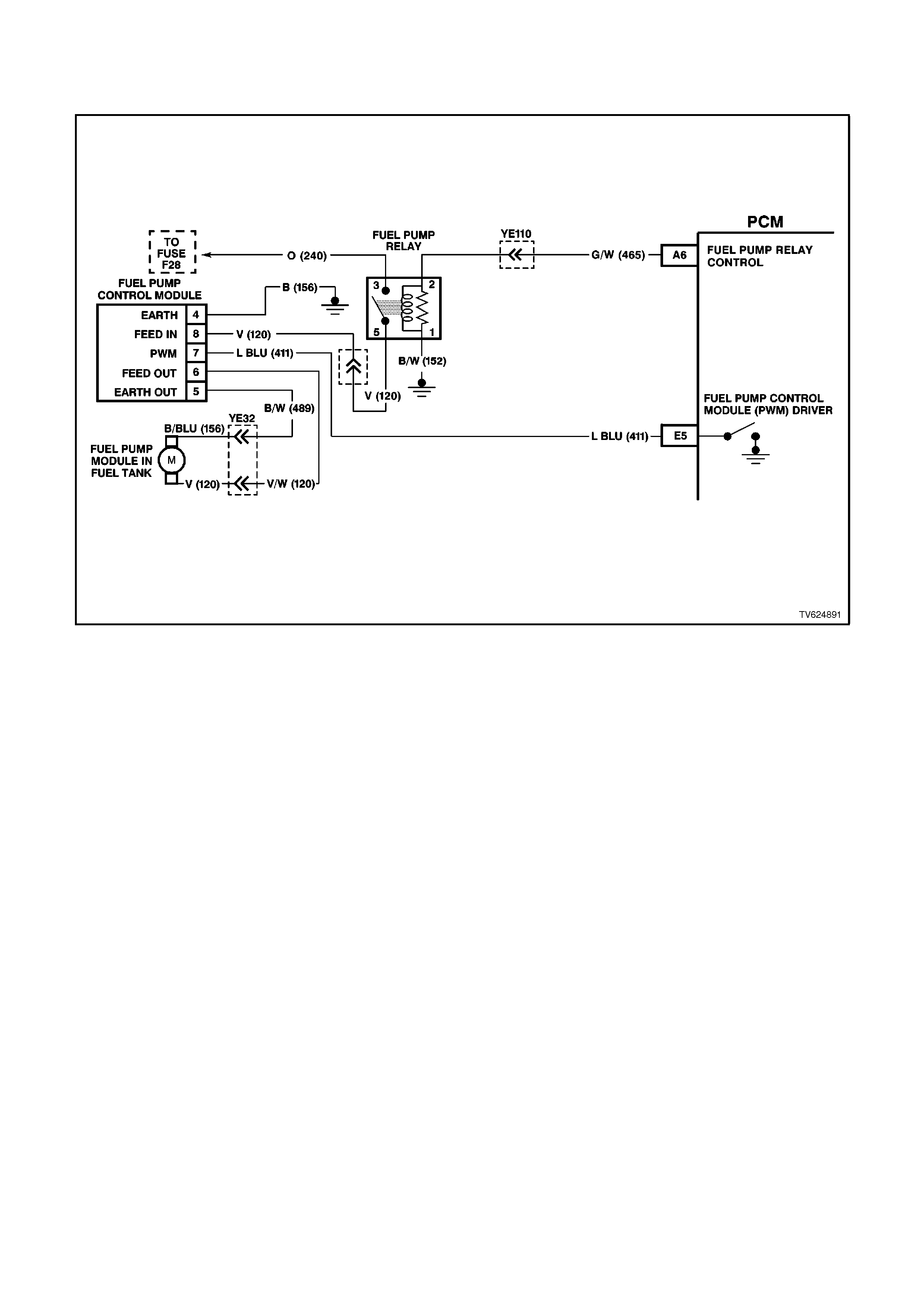
CHART A-4.1-1 V6 PCM - SUPERCHARGED ENGINE
FUEL PUMP ELECTRICAL CIRCUIT
CIRCUIT DESCRIPTION:
When the ignition switch is first turned "ON", the PCM energises the Fuel Pump Relay which applies power to the
Fuel Pump Control Module. The Fuel Pump Relay will remain "ON" as long as the engine is cranking or running and
the PCM is receiving reference pulses. If no reference pulses are present, the PCM de-energises the Fuel Pump
Relay within 2 seconds after the ignition is turned "ON" or the engine is stopped. The Fuel Pump delivers fuel to the
fuel rail injectors, then to the fuel pressure regulator. The pressure regulator control fuel pressure by allowing
excess fuel to be returned to the fuel tank. With the engine stopped, the Fuel Pump can be turned "ON" by using
the Tech 2 scan tool output controls function.
The PCM alters Fuel Pump speed by applying or removing a duty cycle on the Fuel Pump PWM driver circuit 411 to
the Fuel Pump Control Module. Under normal driving conditions, the PCM will apply a 33% PWM earth signal to the
Fuel Pump Control Module circuit 411. This 33% duty cycle will command the Fuel Pump Control Module to run the
fuel pump at a lower speed, (lower fuel volume, low voltage supplied to fuel pump, between 7 to 9 volts.). When
higher fuel volume is required due to increased engine load, the PCM will remove the supplied 33% PWM earth
signal from circuit 411. This will cause the Fuel Pump Control Module to switch internally and allow the Fuel Pump
to run at a higher speed (higher fuel volume, system voltage applied to fuel pump). The PCM also compensates for
low system voltage by commanding the Fuel Pump Control Module to switch to high speed Fuel Pump , when
system voltage is low.
NOTICE:
When performing this diagnostic Chart, make certain that the drive wheels are blocked and the parking
brake is firmly set.
TEST DESCRIPTION:
Number(s) below refer to step number(s) on the diagnostic chart.
3. Checks that fuel pressure is sufficient for the vehicle to start.
4. Ensures that the Fuel Pump PWM driver circuit and the PCM are capable of controlling Fuel Pump speed.
5. Verifies that the Fuel Pump feed and earth circuits are OK between the Fuel Pump Control Module and the
Fuel Pump , and that the Fuel Pump can deliver adequate pressure to the fuel rail.
6. Checks the feed circuit to the Fuel Pump Control Module.
8. Ensures that the Fuel Pump PWM driver circuit is not shorted to earth.
13. Checks the ignition feed circuit to the Fuel Pump Relay contacts.
14. Checks the earth circuit for the Fuel Pump Relay coil.

15. Ensures that the Fuel Pump Relay driver circuit is OK and that the PCM is capable of controlling the Fuel Pump
Relay. Using the Tech 2 scan tool to command the Fuel Pump Relay allows only a 2 second "ON" time.
21. Checks the Fuel Pump Relay driver circuit for a short to earth.
26. If the Fuel Pump is operating but incorrect pressure is noted, the Fuel Pump wiring is OK. Go to Chart A-4.3.
28. Determines weather the problem is being caused by an open in the Fuel Pump feed circuit or the Fuel Pump
earth circuit.
31. Ensures that the Fuel Pump speed control PWM circuit is OK and that the PCM can control the Fuel Pump
speed control PWM driver.
37. The fuel pump on this Supercharged Engine application is serviceable from the Modular Sender Assembly.
Refer to Section 6C1-3 SERVICE OPERATIONS for replacement procedures.

STEP ACTION VALUE YES NO
1. Was the "On-Board
Diagnostic" (OBD) System
Check performed?
Go to Step 2. Go to OBD
System Check in
this Section.
2. Are any DTC’s set? Go to DTC Chart
first Go to step 3
3. 1. Connect Fuel
Pressure Gauge to
fuel pressure tap
fitting.
2. Ignition "ON".
3. Select Fuel Pump
Relay output control
with the Tech 2 scan
tool.
4. Observe the
pressure gauge while
turning the fuel pump
"ON" with the Tech 2.
5. Note fuel pressure on
Fuel Pressure
Gauge.
Is proper fuel pressure
indicated?
290 to
410 kPa Go to Step 4 Go to Step 5
4. 1. Engine idling.
2. Remove vacuum
hose from fuel
pressure regulator,
and plug hose.
3. Observe the Fuel
Pressure Gauge at
idle.
4. Using scan tool,
sele ct Fuel Pump
Speed , and select
High Speed.
Does the fuel pressure
increase slightly from the
idle
Position when the fuel
pump High Speed is
turned "ON"
then turned "OFF"?
No problem found Go to Step 31

STEP ACTION VALUE YES NO
5. 1. Ignition "OFF".
2. Disconnect Fuel
Pump Control
Module.
3. Connect a fused
jumper wire between
Fuel Pump Control
Module harness
connector terminal 6
(Fuel Pump power
feed circuit) and +12.
Volts.
4. Connect a second
jumper between the
Fuel Pump Control
Module harness
connector terminal 5
(Fuel Pump earth
circuit) and chassis
earth.
5. Note the fuel
pressure on the Fuel
Pressure Gauge
Is proper fuel pressure
indicated?
290 to
410
kPa
Go to Step 6 Go to Step 26
6. 1. Ignition "OFF".
2. Disconnect the
jumpers from the
Fuel Pump Control
Module connector.
3. Connect a test light
between the Fuel
Pump Control
Module harness
connector terminal 8
(Fuel Pump Control
Module relay feed
circuit) and earth.
4. Ignition "ON".
5. Using the Tech 2
scan tool output
control functions,
command the Fuel
Pump Relay "ON".
6. Observe the test
light.
Did the test light turn
"ON"?
Go to Step 7 Go to Step 13
7. Probe terminal 4 (Fuel
Pump Control Module
earth circuit) with a test
light to +12 volts.
Is the test light "ON"?
Go to Step 8 Go to Step 25

STEP ACTION VALUE YES NO
8. 1. Ignition "OFF".
2. Disconnect the PCM
connectors.
3. Probe the Fuel Pump
Control Module PWM
driver circuit at the
PCM connector with
a test light connected
to +12 volts.
Is the test light "ON"?
Go to Step 9 Go to Step 10
9. Locate and repair short to
earth in the Fuel Pump
Control Module PWM
driver circuit .
Is action complete?
Go to Step 39
10. 1. Ignition "OFF".
2. Reconnect PCM
connectors.
3. Ignition "ON".
4. Install a
volt/ohmmeter to
measure voltage
between the Fuel
Pump Control
Module connector
terminal 7 (Fuel
Pump Control
Module PWM driver
circuit ) and terminal
4 (earth circuit ).
5. Using the Tech 2
scan tool relay output
test function,
command the Fuel
Pump Relay "ON"
and "OFF".
Does the voltage measure
at or above the specified
value while the Fuel Pump
Relay is commanded
"ON"?
8 volts Go to Step 11 Go to Step 38

STEP ACTION VALUE YES NO
11. 1. Ignition "OFF".
2. Reconnect the Fuel
Pump Control
Module electrical
connector.
3. Ignition "ON".
4. Using a test light,
backprobe between
the Fuel Pump
Control Module
connector terminal 6
(Fuel Pump power
feed circuit ) and
terminal 5 (Fuel
Pump earth circuit ).
5. Using the Tech 2
scan tool relay output
test functions,
command the Fuel
Pump Relay "ON"
and "OFF".
6. Observe the test
light.
Is the test light "ON" while
the Fuel Pump Relay is
commanded "ON"?
Go to Step 12 Go to Step 34
12. 1. Check for a poor
connections at the
Fuel Pump Control
Module.
2. If a problem is found,
replace faulty
terminals as
necessary.
Was a problem found?
Go to Step 39 Refer to
Diagnostic Aids
13. 1. Ignition "OFF".
2. Disconnect the Fuel
Pump Relay.
3. Ignition "ON".
4. Probe the Fuel Pump
Relay fused power
feed circuit with a test
light to earth.
Is the test light "ON"?
Go to Step 14 Go to Step 19
14. Connect test light
between the Fuel Pump
Relay power feed circuit
and the Fuel Pump Relay
earth circuit .
Is the test light "ON"?
Go to Step 15 Go to Step 20

STEP ACTION VALUE YES NO
15. 1. Connect the test light
between the Fuel
Pump Relay control
circuit, and the Fuel
Pump Relay earth
circuit.
2. Using the Tech 2
scan tool output
control function,
command the Fuel
Pump Relay "ON".
Is the test light "ON" when
the Fuel Pump Relay is
commanded "ON"?
Go to Step 16 Go to Step 21
16. 1. Connect a fused
jumper wire between
Fuel Pump Relay
connector power
feed circuit ( terminal
5) and output power
feed circuit ( terminal
3).
2. Probe the Fuel Pump
Control Module Fuel
Pump power feed
circuit at the Fuel
Pump Control
Module harness
connector (terminal
6) with a test light to
earth.
Is the test light "ON"?
Go to Step 17 Go to Step 24
17. 1. Check for a faulty
terminal connection
at the Fuel Pump
Relay.
2. If a problem is found,
repair terminals as
necessary.
Was a problem found?
Go to Step 39 Go to Step 18
18. Replace the Fuel Pump
Relay.
Is action complete?
Go to Step 39
19. Locate and repair open in
Fuel Pump Relay fused
power feed circuit .
Is action complete?
Go to Step 39
20. Locate and repair open in
Fuel Pump Relay earth
circuit.
Is action complete?
Go to Step 39
21. 1. Ignition "OFF".
2. Disconnect the PCM
connectors.
3. Probe the Fuel Pump
Relay control circuit
at the PCM
connector with a test
light to +12 volts.
Is test light "ON"?
Go to Step 22 Go to Step 23

STEP ACTION VALUE YES NO
22. Locate and repair short to
earth in the Fuel Pump
Relay control circuit .
Is action complete?
Go to Step 39
23. 1. Check for the
following conditions:
Fuel Pump Relay control
circuit for an open
between the Fuel Pump
Relay and the PCM.
Fuel Pump Relay control
circuit for a poor terminal
connection at the PCM.
2. If a problem is found,
repair as necessary.
Was a problem found?
Go to Step 39 Go to Step 38
24. Check for a open or poor
connection in the Fuel
Pump Control Module
Fuel Pump power feed
circuit .
Was a problem found?
Go to Step 39 Go to Step 35
25. Locate and repair open in
Fuel Pump Control
Module earth circuit .
Is action complete?
Go to Step 39
26. Remove the fuel tank filler
cap and listen for the Fuel
Pump running.
Is the Fuel Pump running?
Go to
Chart A-4.3 Go to Step 27
27. 1. Using fused jumper
wires, jumper Fuel
Pump control module
terminal 6 circuit to
+12 volts, and jumper
terminal 5 circuit to
earth.
2. Raise the vehicle.
3. Disconnect the Fuel
Pump electrical
connector at fuel
tank.
4. Connect a test light
between the Fuel
Pump electrical
connector power
feed circuit, and fuel
pump earth circuit at
PCM side of
connector.
Is the test light "ON"?
Go to Step 39 Go to Step 28
28. Probe the Fuel Pump
power feed circuit at the
Fuel Pump electrical
connector with a test light
connected to chassis
earth.
Is the test light "ON"?
Go to Step 30 Go to Step 29

STEP ACTION VALUE YES NO
29. Locate and repair open in
the Fuel Pump power feed
circuit .
Is action complete?
Go to Step 39
30. Locate and repair open in
the Fuel Pump earth
circuit .
Is action complete?
Go to Step 39
31. 1. Ignition "OFF"
2. Reconnect fuel
pressure regulator
vacuum hose.
3. Using a test light,
backprobe between
the Fuel Pump
control module
terminal 7 (Fuel
Pump Control
Module PWM circuit )
and terminal 8 (Fuel
Pump Control
Module Fuel Pump
Relay circuit ).
4. Ignition "ON", engine
idling.
5. Observe the test light
while the engine is
idling.
6. Using scan tool,
sele ct Fuel Pump
Speed, and select
High Speed.
Is the test light "ON" when
the engine is idling, and
"OFF" when the fuel pump
High Speed is turned
"ON" ?
Go to Step 32 Go to Step 33

STEP ACTION VALUE YES NO
32. Using a volt/ohmmeter,
backprobe between Fuel
Pump control module
terminal 5 (Fuel Pump
earth circuit) and terminal
6 (Fuel Pump power
supply circuit).
2. Engine idling for
longer than 15
seconds.
3. Observe the voltage
on the volt/ohmmeter
while the engine is
idling.
4. Using scan tool,
sele ct Fuel Pump
Speed, and select
High Speed.
Idle speed voltage is the
first value shown.
Fuel Pump High Speed
voltage is the second
value shown.
Does the voltage measure
near the specified values?
8-9 volts
at idle
+12
volts
Fuel
Pump
High
Speed
Go to Step 36 Go to Step 34
33. 1. Check for the
following conditions:
Fuel Pump PWM driver
circuit for an open or short
to voltage between the
Fuel Pump Control
Module and the PCM.
Fuel Pump PWM driver
circuit for a poor terminal
connection at the PCM.
2. If a problem is found,
repair as necessary.
Was a problem found?
Go to Step 39 Go to Step 38
34. 1. Check terminal
connections at the
Fuel Pump Control
Module.
2. If a problem is found,
repair faulty
terminal(s) as
necessary.
Was a problem found?
Go to Step 39 Go to Step 35
35. Replace the Fuel Pump
Control Module.
Is action complete?
Go to Step 39
36. 1. Check terminal
connections at the
Fuel Pump.
2. If a problem is found,
repair faulty terminal
as necessary
Was a problem found?
Go to Step 39 Go to Step 37
37. Replace the Fuel Pump.
Is action complete? Go to Step 39

STEP ACTION VALUE YES NO
38. Replace PCM.
Refer to Section 6C1-3
Service Operations, for
PCM Security Link
procedure.
Is action complete?
Go to Step 39
39. 1. Ignition "ON", select
Fuel Pump Relay
output control with
the Tech 2 scan tool.
2. Observe the Fuel
Pressure Gauge
while turning the fuel
pump "ON" with the
Tech 2 scan tool.
3. Note the fuel
pressure on the Fuel
Pressure Gauge.
Is proper fuel pressure
indicated?
290 to
410
kPa
Go to Step 40 Go to Step 5
40. 1. Ignition "OFF".
2. Fuel Pressure Gauge
still installed.
3. Remove vacuum
hose from fuel
pressure regulator,
and plug hose.
4. Ignition "ON", engine
idling.
5. Observe the Fuel
Pressure Gauge at
idle.
6. Using scan tool,
sele ct Fuel Pump
Speed , and select
High Speed.
Does the fuel pressure
increase slightly from the
idle
Position when the fuel
pump High Speed is
turned "ON"?
Repair complete.
If a driveability
symptom exist s,
refer to Section
6C1-2B
Symptoms.
Go to Step 31
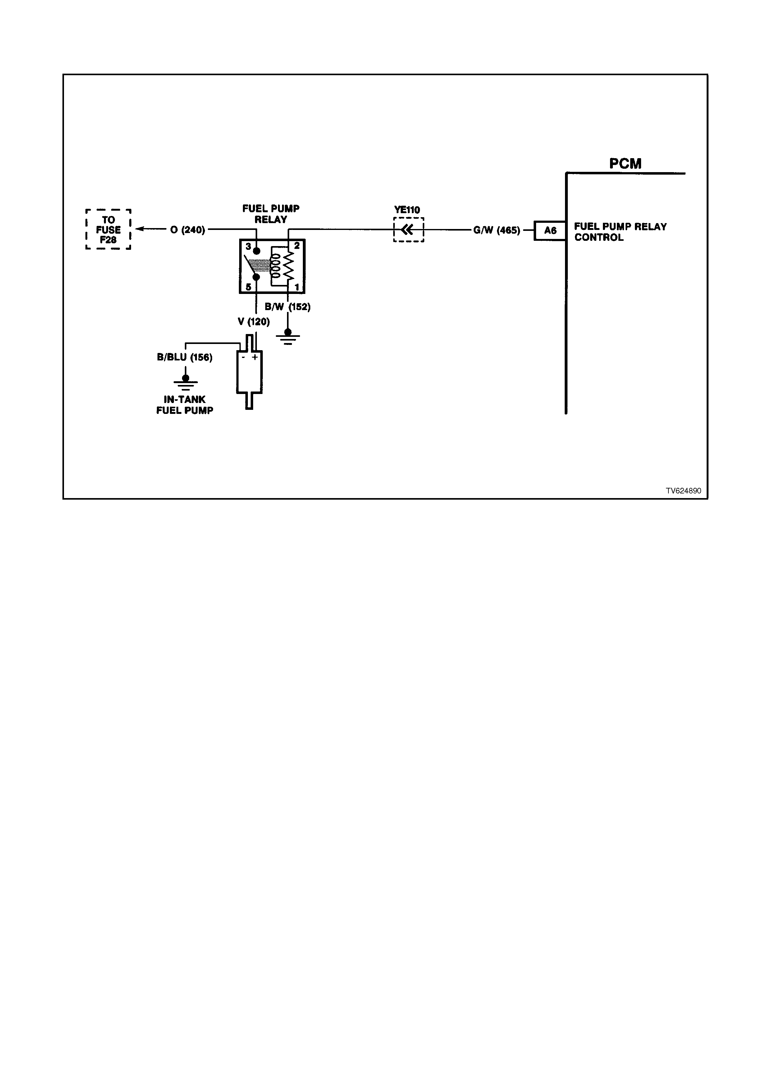
CHART A-4.2 V6 PCM - FUEL PUMP ELECTRI CAL CIRCUIT
CIRCUIT DESCRIPTION:
Relay connector has no terminal identification. See diagram above for terminal identification.
There are 3 basic circuits to any relay. They are:
LOAD - This is the device controlled by the relay. In this case, it is the Fuel Pumps power feed circuit.
LINE - This is the voltage supply that will power the load whenever the relay switch contacts are closed. In this case,
it is the fused power circuit.
CONTROL - This is the circuitry that energises the small electromagnet windings in the relay, which causes the-
switching contacts to change position. In this case, one side of the relay windings is simply earthed. The other
control circuit is the +12 volts supplied by the PCM whenever it wants the relay to be energised.
TEST DESCRIPTION:
Number(s) below refer to step number(s) on the diagnostic chart.
2. This checks the earth circuit) to the relay windings, part of the relay's control circuitry. (CONTROL)
3. This checks Fuel Pump +12 volt power supply circuit to the relay switching contacts. (LINE)
4. This checks for the relay control voltage supplied by the PCM to the relay. (CONTROL) It is the PCM's only
output that switches +12 volts to control a circuit. All other PCM outputs switch the earth circuit.
5. At this point, the 3 other circuits to the relay are OK. This check is to determine if the contacts in the relay will
close, allowing the "line" voltage to pass through the switching contacts to the "load" terminal of the relay, which
goes to the fuel pump motor.
7. If the light stays "OFF," these checks will detect the fault in the Fuel Pump Relay control circuit.

STEP ACTION VALUE YES NO
1. Was the "On-Board
Diagnostic" (OBD) System
Check performed?
Go to Step 2. Go to OBD
System Check in
this Section.
2. Test light stay's "OFF".
1. Ignition "ON", engine
stopped.
2. Disconnect Fuel
Pump Relay
connector from relay
housing bracket.
3. With Fuel Pump
Relay connected,
probe relay
connector earth
circuit with a test light
connected to +12
volts.
Is test light "ON"?
Go to Step 3 Go to step 11
3. Probe relay connector
power feed circuit with
test light connected to
earth.
Is test light "ON" ?
Go to Step 4 Go to step 12
4. 1. Probe relay
connector Fuel Pump
Relay control circuit
with test light to
earth.
2. Using TECH 2 scan
tool, Select FUEL
PUMP.
3. Turn Fuel Pump
"ON" and "OFF".
Is test light "ON" and
"OFF", when Fuel Pump
is turned "ON" and
"OFF"?
Go to Step 5 Go to Step 7
5. 1. Using TECH 2 scan
tool, Select FUEL
PUMP .
2. Turn Fuel Pump
"ON" and "OFF".
3. Probe Fuel Pump
Relay connector Fuel
Pump power feed
circuit with test light
to earth.
Is test light "ON" and
"OFF", when Fuel Pump
is turned "ON" and
"OFF"?
Go to Step 6 Go to Step 8
6. Fuel Pump Relay is
operating correctly.
Repair open in power feed
circuit from Fuel Pump
Relay to Fuel Pump.
Is action complete?
Verify Repair

STEP ACTION VALUE YES NO
7. 1. Ignition "OFF".
2. Disconnect Fuel
Pump Relay and
PCM connectors.
3. Check for open in
Fuel Pump Relay
control circuit.
Was a problem found ?
Verify Repair Go to Step 9
8. 1. Ignition "OFF"
2. Replace Fuel Pump
Relay.
Will engine start ?
Verify Repair Go to OBD
System Check
(Chart A) in this
Section
9. Check for short to earth in
Fuel Pump Relay control
circuit.
Was a problem found ?
Verify Repair. Go to step 10
10. Replace PCM.
Refer to Section 6C1-3
Service Operations, for
PCM Security Link
procedure.
Is action complete?
Verify Repair
11. Repair open in relay earth
circuit .
Is action complete?
Verify Repair
12. Repair open in Fuel Pump
power feed circuit .
Is action complete?
Verify Repair

CHART A-4.3 V6 PCM - FUEL DELIVERY SYSTEM
CIRCUIT DESCRIPTION:
Fuel is drawn from the tank by the electric fuel pump and is fed under pressure through a fuel filter and continues on
into the fuel rail and then is injected into the ports through the fuel injectors.
Fuel pressure in the system is governed by the fuel pressure regulator, in such a manner that a certain pressure
difference between fuel pressure and inlet manifold pressure is maintained. Excess fuel above the regulated
pressure is returned to the fuel tank by the pressure regulator and the fuel return line.
The fuel pump has a check valve to maintain pressure at the fuel rail after the pump stops running. The check valve
plays an important part in the fuel delivery system: to keep the fuel rail "charged" with fuel after the pumps shuts off.
When the engine begins cranking to start, there is no delay before fuel injection begins, and quick starting is
ensured. The check valve is inside the fuel pump, and is not serviceable.
TEST DESCRIPTION:
Number(s) below refer to step number(s) on the diagnostic chart.
2. These are electrical system checks, which must both be OK before any further fuel delivery system checks can
be made. If either do not "pass," refer Chart A-4.1 for Non-Supercharged Engine and Chart A-4.1-1 for
Supercharged Engine, Fuel Pump Electrical Circuit in this Section.
3. This has eleven sequenced segments to follow in order. "1" and "2" is to reduce the residual pressure in the
lines before opening the lines. "6" is to purge any air from the lines after installing the gauge. It also serves to
cool the fuel rail for more accurate pressure testing if the engine is hot. "8" is to allow the PCM to "power
down," so the next time the ignition is turned "ON," the PCM will energise its Fuel Pump Relay control for 2
seconds. "9" and "10" indicate what the pressure should do when the ignition is turned "ON". There are two
things to note:
(A) - pressure reading, and
(B) - that the pressure does not continue to drop after the pump stops running.
4. At this point, the regulated pressure should be within specification, and the pressure does not drop when
the pump stops running. This check is to see if the pressure regulator will modulate the regulated fuel pressure
when the vacuum signal to it changes. During normal engine operation, the regulated pressure can change, based
on inlet manifold pressure. When the manifold pressure is at its lowest (engine idling), fuel pressure will be at its
lowest regulated pressure. When inlet manifold pressure is at its highest (wide open throttle), regulated fuel
pressure will be at its highest regulated pressure.

STEP ACTION VALUE YES NO
1. Was the "On-Board
Diagnostic" (OBD) System
Check performed?
Go to Step 2. Go to OBD
System Check in
this Section.
2. 1. Ignition "ON".
2. Using TECH 2 scan
tool, Select FUEL
PUMP.
3. Turn Fuel Pump "On"
and "OFF".
4. Listen for Fuel Pump
in fuel tank.
Does fuel pump run when
turned "ON" with TECH 2
scan tool?
Go to Step 3 Go to Chart A-4.1
for Non-
Supercharged
Engine application
or Chart A-4.1-1
for Supercharged
Engine application
in this Section
3. 1. Disable output test
for Fuel Pump .
2. Turn ignition "OFF".
3. Remove Fuel Pump
Relay from engine
compartment fuse
and relay centre,
then crank engine for
15 seconds to relieve
any residual fuel
pressure.
4. Connect Fuel
Pressure Gauge,
then reinstall fuel
pump relay .
5. Remove vacuum
hose from fuel
pressure regulator.
6. Ignition "ON",
7. Enable output test
with Tech 2 scan tool
for Fuel Pump and
allow pump to run for
15 seconds. This is
to purge the lines of
any air before
pressure testing.
8. Disable output test
for Fuel Pump .
9. Ignition "OFF" for 10
seconds.
10. Observe fuel
pressure when
ignition is turned
"ON".
11. Pressure should be
within specified value
and not continue to
drop (after a small
amount) after pump
stops running.
Is fuel pressure at or
between the specified
value and holding?
270 to
350 kPa
for Non-
Super-
charged
Engine
290 to
410 kPa
for
Super-
charged
Engine
Go to Step 4 Go to Chart
A-4.4 in this
Section

STEP ACTION VALUE YES NO
4. 1. Ignition "ON".
2. Enable output test
with Tech 2 scan tool
for fuel pump and
note fuel pressure.
3. Connect a hand
vacuum pump to the
fuel pressure
regulator vacuum
fitting, and apply 38
cm Hg of vacuum to
the fuel pressure
regulator.
4. Note fuel pressure
with vacuum applied
to regulator.
When vacuum is applied,
is fuel pressure at least
specified value difference
then when no vacuum
applied?
15 kPa Fuel supply
system OK. Refit
regulator vacuum
hose.
Go to Step 5
5. Replace fuel pressure
regulator.
Is repair complete?
Verify Repair

CHART A-4.4 V6 PCM - FUEL DELIVERY SYSTEM
CIRCUIT DESCRIPTION:
Fuel is drawn from the tank by the electric fuel pump and is fed under pressure through a fuel filter and continues on
into the fuel rail and then is injected into the ports through the fuel injectors.
Fuel pressure in the system is governed by the fuel pressure regulator, in such a manner that a certain pressure
difference between fuel pressure and inlet manifold pressure is maintained. Excess fuel above the regulated
pressure is returned to the fuel tank by the pressure regulator and the fuel return line.
The fuel pump has a check valve to maintain pressure at the fuel rail after the pump stops running. The check valve
plays an important part in the fuel delivery system: to keep the fuel rail "charged" with fuel after the pumps shuts off.
When the engine begins cranking to start, there is no delay before fuel injection begins, and quick starting is
ensured. The check valve is inside the fuel pump, and is not serviceable.
TEST DESCRIPTION:
Number(s) below refer to step number(s) on the diagnostic chart.
2. If the pressure continues to drop after the pump stops running, there is a leak somewhere. Either the Fuel
Pump check valve is leaking fuel back into the tank, the regulator has an internal leak allowing fuel to leak from the
pressure to the return side, or an injector is leaking (dripping).

STEP ACTION VALUE YES NO
1. Was the "On-Board
Diagnostic" (OBD) System
Check performed?
Go to Step 2. Go to OBD
System Check in
this Section.
2. From Chart A-4.3
Fuel pressure not OK.
Does fuel pressure
continue to drop after
pump stops?
Go to Step 3 Go to Step 10
3. 1. Ignition "OFF" for 10
seconds.
2. While you observe the
pressure gauge,
have an assistant
turn the ignition "ON".
3. When the pump stops
running, pinch shut
the rubber section of
the pressure (supply)
hose connection.
Fuel pressure should now
hold, does it?
Go to Step 4 Go to step 7
4. Check for leaks in the
"pressure-side" of the fuel
system.
Were any leaks found ?
Verify Repair Go to step 5
5. Replace fuel pump.
Is action complete? Verify Repair
6. Check For:
Fuel pressure line
restricted between pump
and fuel rail.
Fuel supply line between
tank and pump either
restricted or leaking.
Restricted fuel filter.
Restricted in-tank fuel
strainer.
Defective Fuel Pump .
Was a problem found?
Verify Repair Go to Service
Operation 3.11
FUEL CONTROL
SYSTEM for Fuel
Pump pressure
test procedures

STEP ACTION VALUE YES NO
7. 1. Ignition "OFF" for 10
seconds.
2. Release pinched off
pressure (supply)
hose.
3. While you observe
the pressure gauge,
have an assistant
turn the ignition "ON".
4. When the pump
stops running, pinch
shut the rubber
section of the fuel
return hose.
DO NOT PINCH OFF
THE FUEL RETURN
HOSE AT THE FUEL
PRESSURE
REGULATOR.
Fuel pressure should now
hold, does it?
Go to Step 8 Go to Step 9
8. Replace fuel pressure
regulator.
Is action complete ?
Verify Repair
9. Locate and replace
leaking injectors.
Is action complete ?
Go to Step 11
10. Is there fuel pressure? Go to Step 11 Go to Step 6
11. Is Pressure between
specified values? 270 to
350 kPa
for
Non-
Super-
charged
Engine
290 to
410
kPa
for
Super-
charged
Engine
Fuel Delivery
System OK Go to chart
A-4.5 in this
Section
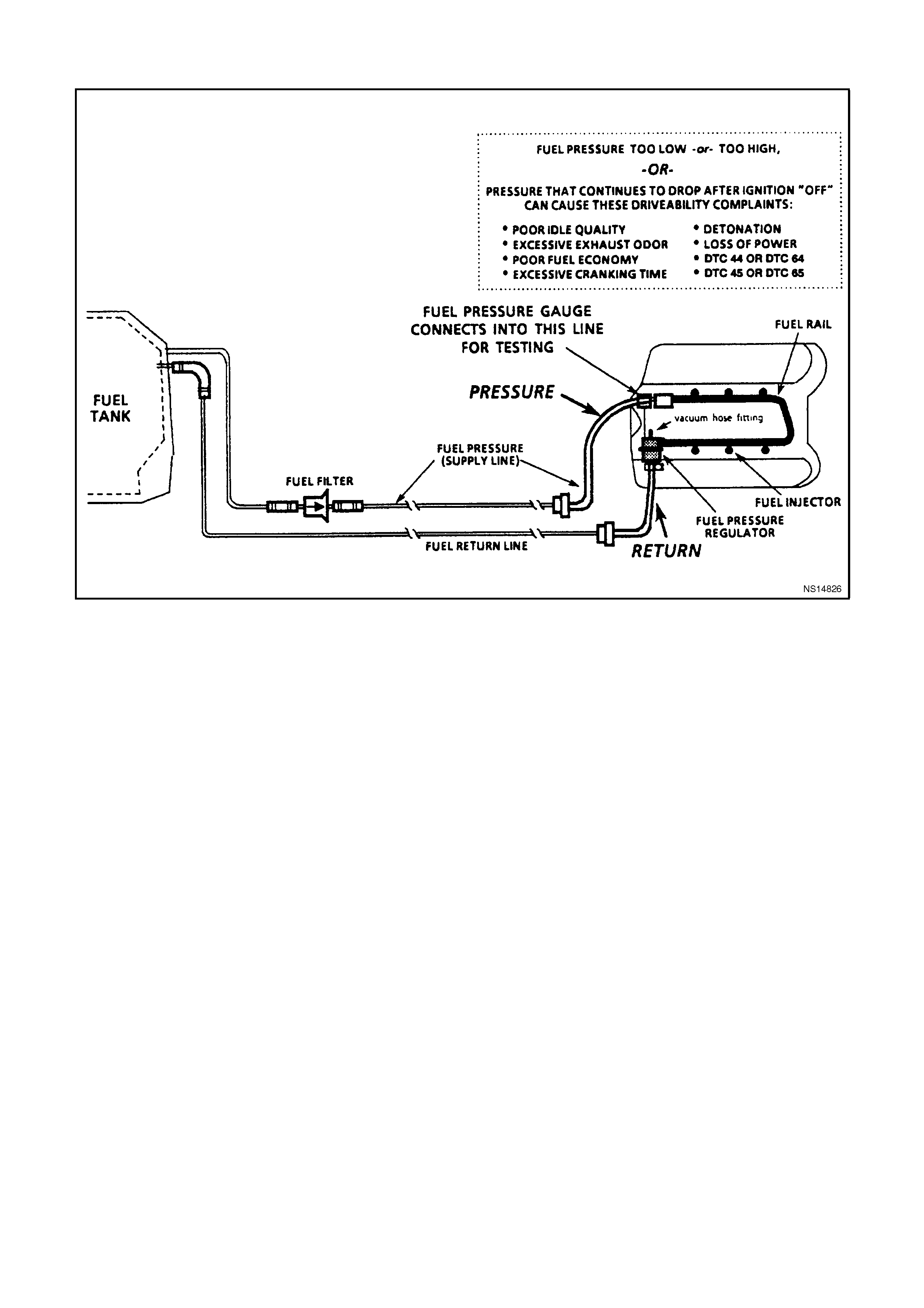
CHART A-4.5 V6 PCM - FUEL DELIVERY SYSTEM
CIRCUIT DESCRIPTION:
Fuel is drawn from the tank by the electric fuel pump and is fed under pressure through a fuel filter and continues on
into the fuel rail and then is injected into the ports through the fuel injectors.
Fuel pressure in the system is governed by the fuel pressure regulator, in such a manner that a certain pressure
difference between fuel pressure and inlet manifold pressure is maintained. Excess fuel above the regulated
pressure is returned to the fuel tank by the pressure regulator and the fuel return line.
The external fuel pump has a check valve to maintain pressure at the fuel rail after the pump stops running. The
check valve plays an important part in the fuel delivery system: to keep the fuel rail "charged" with fuel after the
pumps shuts off. When the engine begins cranking to start, there is no delay before fuel injection begins, and quick
starting is ensured. The check valve is inside the fuel pump , and is not serviceable.
TEST DESCRIPTION:
Number(s) below refer to step number(s) on the diagnostic chart.
3. If any fuel lines, fittings, filter, or components are restricted, correct pressure cannot be attained.
6. When the fuel return hose is pinched shut, there is no pressure regulator control to limit the pressure. The
pressure reading will be whatever the Fuel Pump is capable of producing. This is the same as attaching a
pressure gauge directly to the output of the Fuel Pump . The pressure reading would be a "maximum pressure
- no flow" reading, and should be well over 320 kPa. Do not allow the pressure to exceed 414 kPa.
10. At this point, the pressure checks are OK, but a complete test has not been performed. Return to Chart A-4.3
in this Section to complete the testing.
11. This is to determine if the cause of the high pressure is a restricted fuel return line, or a defective pressure
regulator. If the pressure is normal when the regulator outlet (hose or fuel pipe attached to regulator) is
connected only to an open hose, then the problem is a restricted return line between the regulator and the tank.
12. The fuel pressure regulator on the Non-Supercharged Engine application is serviceable separate from the
fuel rail. The pressure regulator on the Supercharged Engine application is part of the fuel rail, and the complete
fuel rail must be replaced. Refer to Section 6C1-3 SERVICE OPERATIONS for fuel pressure regulator
replacement service procedures.

STEP ACTION VALUE YES NO
1. Was the "On-Board
Diagnostic" (OBD) System
Check performed?
Go to Step 2. Go to OBD
System Check in
this Section.
2. Is fuel pressure less than
values? Go to Step 3 Go to Step 11
3. There is low fuel pressure
1. Make close
inspection of all fuel
lines between fuel
tank and fuel rail for
restrictions. This
includes these lines:
-Tank to filter.
-Filter to fuel rail.
Were any restrictions
found ?
Go to Step 4 Go to Step 5
4. Repair any restrictions,
then recheck pressure.
Is action complete ?
Verify Repair
5. Replace fuel filter, then
recheck fuel pressure.
Is fuel pressure still less
then value ?
Less
then 270
kPa
Non-
Super-
charged
Engine
Less
then 290
kPa
Super-
charged
Engine
Go to Step 6 Go to Step 10
6. 1. Ignition "OFF".
2. Pinch shut the fuel
return hose at the
fuel gauge sender
unit (this fuel return
hose is the lower
hose).
DO NOT PINCH OFF
THE FUEL RETURN
HOSE AT THE FUEL
PRESSURE
REGULATOR.
3. Ignition "ON" 4.
Enable output test
with Tech 2 scan tool
for fuel pump.
Is fuel pressure at or
above the specified
value?
350 kPa
Non-
Super-
charged
Engine
410 kPa
Super-
charged
Engine
Go to Step 7 Go to Step 9

STEP ACTION VALUE YES NO
7. Replace pressure
regulator and recheck
pressure.
Is pressure now between
value ?
270 to
350 kPa
Non-
Super-
charged
Engine
290 to
410
kPa
Super-
charged
Engine
Verify Repair Go to Step 8
8. Replace in-tank fuel
strainer.
Is action complete ?
Verify Repair
9. Pressure less than 320
kPa
Replace fuel pump.
Is action complete ?
Verify Repair
10. Is pressure between
value, and does not
continue
dropping when pump
stops?
270 to
350 kPa
Non-
Super-
charged
Engine
290 to
410
kPa
Super-
charged
Engine
Verify Repair Go to Chart
A-4.1 for Non-
Supercharged
Engine
or
Go to Chart
A- 4.1-1 for
Supercharged
Engine
11. 1. Disconnect fuel
return line flexible
hose from fuel pipe
that leads to the
pressure regulator.
2. Attach a long length
of hose to the fuel
pipe leading to the
pressure regulator.
3. Insert other end of
hose into an
approved fuel
container.
4. Enable output test
with Tech 2 scan tool
for fuel pump.
Is fuel pressure still more
than value ?
350 kPa
Non-
Super-
charged
Engine
410 kPa
Super-
charged
Engine
Go to Step 12 Go to Step 13
12. Replace pressure
regulator
Is action complete ?
Verify Repair
13. Locate and correct
restricted fuel return line
to tank, or blocked return
line screen filter in fuel
tank return connector, or
screen in fuel pressure
regulator.
Is action complete ?
Verify Repair
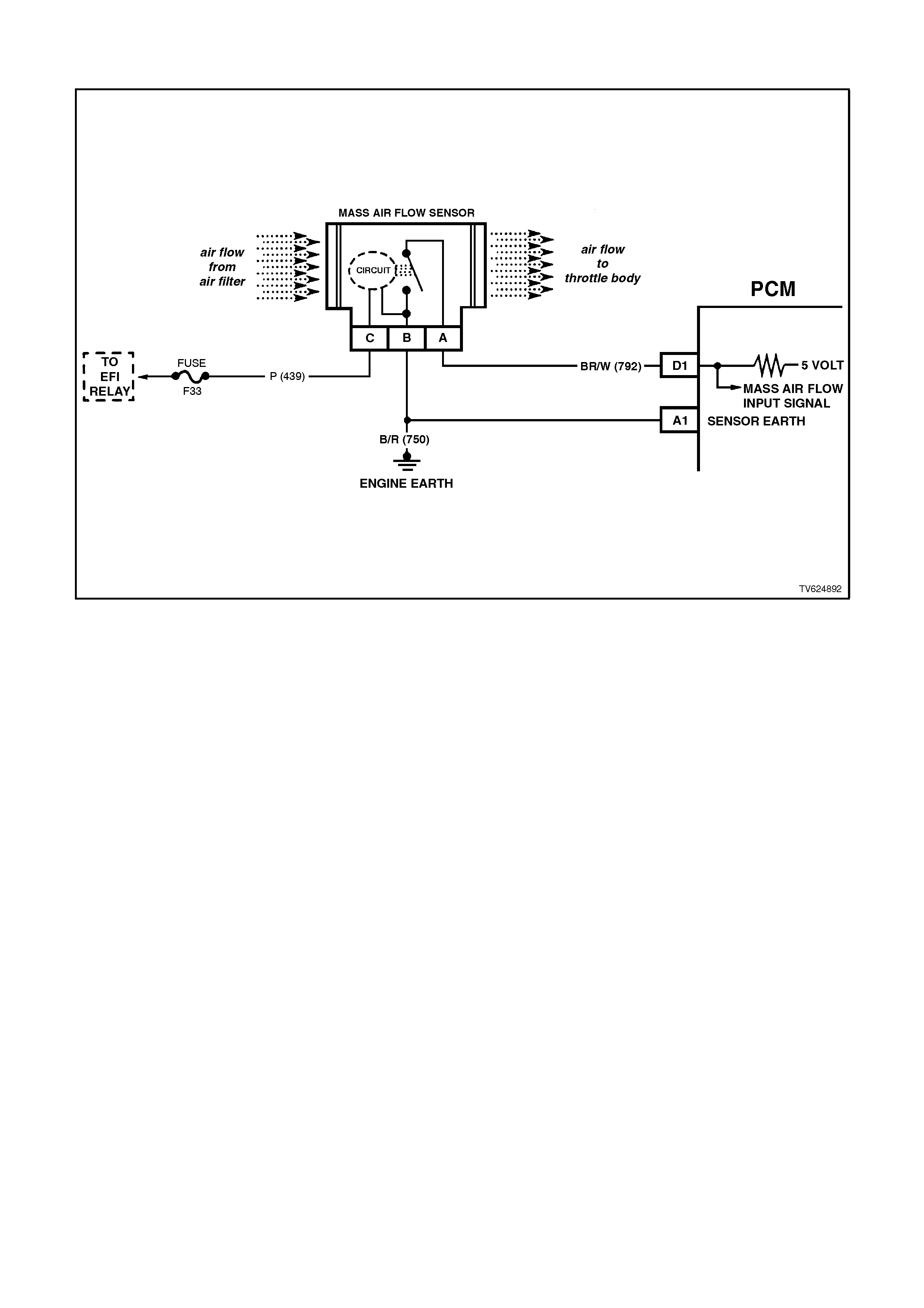
CHART A-6.1 V6 PCM - MAF SENSOR OUTPUT CHECK
CIRCUIT DESCRIPTION:
The signal that is sent from the Mass Air Flow (MAF) sensor is sent in the form of a frequency output. A large
quantity of air passing through the MAF sensor will be indicated as a high frequency output (such as when under
acceleration). A small quantity of air passing through the sensor will be indicated as a low frequency output (such as
when decelerating or at idle). The Tech 2 scan tool displays this information both as air flow in grams per second,
grams per cylinder and frequency. A "normal" reading is approximately 4-9 grams per second at idle and increases
with RPM.
TEST DESCRIPTION:
Number(s) below refer to Step number(s) on the diagnostic chart.
3. This step checks for the proper Mass Air Flow grams per second at idle.
4. This step checks for the proper Mass Air Flow grams per second at 2500 RPM.
5. This step checks the Mass Air Flow sensor for a steady decrease in grams per second as the RPM changes
from 2500 to idle.
DIAGNOSTIC AIDS:
Check air filter for being plugged
Check for air intake ducts for restrictions
Check air intake ducts for leaks after the MAF sensor
Check for partly restricted exhaust system
Check for any other source that would allow air into the engine after the MAF sensor.
This would include:
• inlet manifold gasket
• inlet manifold
• throttle body and or gasket
• PCV system, this includes the oil dipstick for proper seating
•injector o-rings

STEP ACTION VALUE YES NO
1. Was the "On-Board
Diagnostic" (OBD) System
Check performed?
Go to Step 2. Go to OBD
System Check in
this Section.
2. Is DTC 32 present? Go to DTC 32 Go to Step 3
3. 1. Ignition "ON", engine
running at normal
operating temperature.
2. Using Tech 2 scan
tool; select Data List,
then select "Mass Air
Flow G/S".
3. With engine at idle, the
Tech 2 scan tool
should indicate a MAF
sensor reading
between the specified
value.
Is the reading between
the specified value ?
4-9
Grams
Per
Second
(G/S) at
Idle
Go to Step 4 Go to Step 6
4. Increase engine RPM to
2500 and hold steady.
The Tech 2 should now
indicate a MAF sensor
reading at the specified
value.
Is the reading at the
specified value ?
17-20
Grams
Per
Second
(G/S) at
2500
RPM
Go to Step 5 Go to Step 6
5. Release the throttle, and
watch the MAF sensor
readings on the Tech 2.
The Mass Air Flow G/S
should decrease at a
steady rate down to the
reading determined at
idle, did it ?
No trouble found
with Mass Air
Flow sensor
Go to Step 6
6. Check for restrictions in
the Mass Air Flow
induction
system. Also check for air
leaks after the MAF
sensor or a possible
restricted exhaust system.
Refer to Diagnostic Aids
above.
If all checks OK, replace
the Mass Air Flow sensor.
Is action complete ?
Verify Repair

CHART A-6.2 V6 PCM - TP SENSOR OUTPUT CHECK
CIRCUIT DESCRIPTION:
The Throttle Position (TP) sensor is attached to the throttle body, and is internally rotated by the throttle body shaft.
It is a potentiometer with one end connected to 5 volts from the PCM and the other to PCM earth. A third wire is
connected to the PCM, allowing it to measure the variable output voltage from the TP sensor.
As the throttle valve angle is changed (accelerator pedal moved), the TP Sensor output voltage also changes in
proportion. At a closed throttle position, the output voltage is usually below 1.0 volt. As the throttle valve opens, the
output increases so that, at wide-open throttle, the output should be above 4.0 volts. By monitoring the output
voltage from the TP sensor, the PCM can determine fuel needs based on throttle opening (driver demand).
A broken or loose TP Sensor, or one that has an unstable output, can cause intermittent bursts of fuel because the
PCM thinks the throttle is moving. Results could include engine surge or poor idle quality. If the PCM interprets a
high voltage when engine RPM is less than 400, hard starting could be the result (clear-flood mode). A problem in
any of the TP sensor circuits will set either a DTC 21 or DTC 22 after the engine is started. Once a Diagnostic
Trouble Code is set, the PCM will use an artificial default value for TP sensor based on engine RPM to enable the
vehicle to be driven, although performance could be less than normal.
The TP sensor is not adjustable. The PCM uses the reading at idle as "0% throttle," so no adjustment is necessary.
TEST DESCRIPTION:
Number(s) below refer to step number(s) on the diagnostic chart. If a DTC 21 or DTC 22 is present, follow that chart
first,
2. This is a check of the voltage at the idle position. It is usually less than 1.0 volt.
3. The voltage should increase at the same steady rate at which the throttle is opened with the throttle valve.
6. With the throttle valve wide open, the TP sensor output needs to be above 4 volts, allowing the PCM to
interpret a wide open throttle position.
7. If the throttle stop screw has been inadvertently reset, the TP sensor output at idle could be out of allowable
limits.
9. If the closed-throttle voltage is over 2.5 volts, hard starting may be encountered (worse cold) due to "clear-
flood" mode. This mode occurs when engine RPM is less than 400, and TP sensor input indicates the throttle
is more than 80% open. Possible causes: short to voltage on input signal circuit, open earth circuit , or a faulty
sensor.

STEP ACTION VALUE YES NO
1.
Was the "On-Board
Diagnostic" (OBD) System
Check performed?
Go to Step 2. Go to OBD
System Check in
this Section.
2.
1. Ignition "ON", engine
stopped, throttle plate
closed.
2. Tech 2 scan tool set
to TP sensor voltage.
Is voltage on Tech 2 scan
tool within value shown?
0.25 to
1.25
volts
Go to Step 3 Go to Step 4
3.
1. Ignition "ON".
2. With Tech 2 scan
tool still connected,
monitor the voltage
as the throttle is
slowly and steadily
opened to a wide-
open-position.
3. Voltage should
increase at a steady
rate, with no sudden
changes.
Did voltage increase at a
steady rate with throttle
movement ?
Go to Step 6 Go to Step 8
4.
1. Ignition "ON", engine
stopped.
2. Tech 2 'Scan" tool set
to TP sensor voltage.
Is voltage on Tech 2 scan
tool within value shown?
1.26 to
2.5 volts Go to Step 7 Go to Step 5
5.
1. Ignition "ON", engine
stopped.
2. Tech 2 scan tool set to
TP sensor voltage.
Is voltage on Tech 2 scan
tool over value shown?
2.5 volts Go to Step 9 Go to Step 12
6.
1. Ignition "ON".
2. With the Tech 2 scan
tool still connected,
monitor the voltage as
the throttle valve is
opened to the wide
open position.
Have a helper ensure that
the throttle valve is fully
open when accelerator
pedal is fully depressed.
If throttle valve does not
fully open when pedal is
depressed, check for
extra floor mats or carpet
under accelerator pedal.
Then refer to SERVICE
OPERATIONS, 3.11
FUEL CONTROL
SYSTEM - Throttle
Cable - "Adjust".
Is the TPS voltage above
the specified value?
4 volts TP sensor is
working properly
Go to OBD
System Check in
this Section
Go to Step 6

STEP ACTION VALUE YES NO
7. 1. Check throttle stop
screw. refer to
SERVICE
OPERATIONS, 3.11
FUEL CONTROL
SYSTEM - Throttle
Stop Screw - "Reset
Procedure".
Reset only if incorrect.
2. Ignition "ON".
3. Tech 2 scan tool
connected to data link
connector.
4. Recheck TPS voltage.
Is voltage now within the
specified value ?
0.25 to
1.25
volts
Go to Step 6 Go to Step 8
8. Replace TP sensor.
Is action complete ? Verify Repair
9. 1. Ignition "OFF".
2. Disconnect TPS.
3. Connect Tech 2 scan
tool to data link
connector, set to TPS
voltage.
4. Ignition "ON"
Is voltage on Tech 2 scan
tool at or below specified
value?
1.25 volt Go to Step 10 Go to Step 11
10. Check for open in TP
sensor earth circuit..
Was a problem found?
Verify Repair Go to Step 8
11. Repair short to voltage on
TP sensor signal circuit.
Is action complete ?
Verify Repair
12. Repair short to earth on
TP sensor signal circuit.
Is repair complete ?
Verify Repair
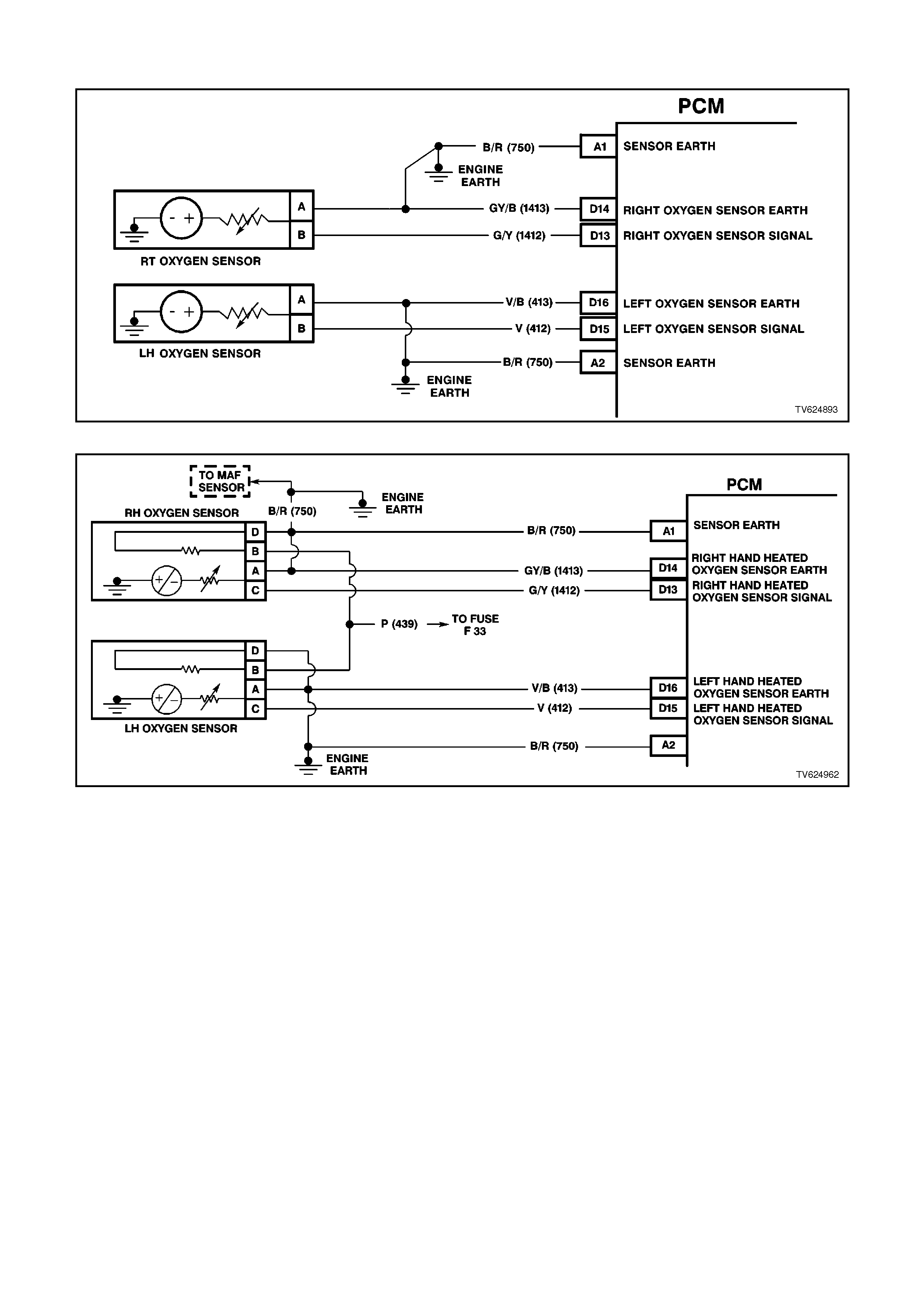
CHART A-6.3 V6 PCM - OXYGEN SENSOR CHECK
NON-SUPERCHARGED ENGINE OXYGEN SENSOR WIRING CIRCUITS
SUPERCHARGED ENGINE OXYGEN SENSOR WIRING CIRCUITS
CIRCUIT DESCRIPTION:
The oxygen sensors are mounted in the exhaust pipes near the cylinders. At operating temperature, the oxygen
sensors are required to respond quickly to changes to oxygen content in the exhaust. If the oxygen sensors become
contaminated or faulty, a sluggish driveability or a complaint of poor idle condition may exist. A proper oxy gen
sensor response should be almost instantaneous to the fuelling mode command.
TEST DESCRIPTION:
Number(s) below refer to step number(s) on the diagnostic chart.
2. Never perform this test on a cold engine. The oxygen sensor must be near normal operating temperature for
this chart to work. It is important to see a low voltage and a high voltage response very quickly because this
means the oxygen sensor is not contaminated or faulty.

STEP ACTION VALUE YES NO
1. Was the "On-Board
Diagnostic" (OBD) System
Check performed?
Go to Step 2. Go to OBD
System Check in
this Section.
2. 1. Ignition "ON", engine
Running.
2. Run engine at 1600 to
1800 RPM for 2
minutes, or until
engine temperature is
above 85 degrees C,
then let engine idle.
3. Using Tech 2 scan
tool, select Misc. Test,
then A/F Ratio, then
display "RH O2 Sensor
and LH O2 Sensor.
4. With engine idling,
Press the Down select
button on Tech 2 scan
tool until 11.7 A/F
Ratio is displayed, at
the same time note the
response of both O2
Sensors.
5. Both O2 Sensors
should display above
specified value.
6. Then press the Up
select button on Tech
2 scan tool until 17.7
A/F Ratio is displayed,
at the same time note
the response of both
O2 Sensors.
7. Both O2 Sensors
should display below
specified value.
Did both O2 Sensors
display above and below
the specified value ?
Above
700 mV
or Below
100 mV
No trouble found Go to Step 3
3. Replace the O2 Sensor
that did not perform as
specified in Step 2.
Is action complete ?
Verify Repair
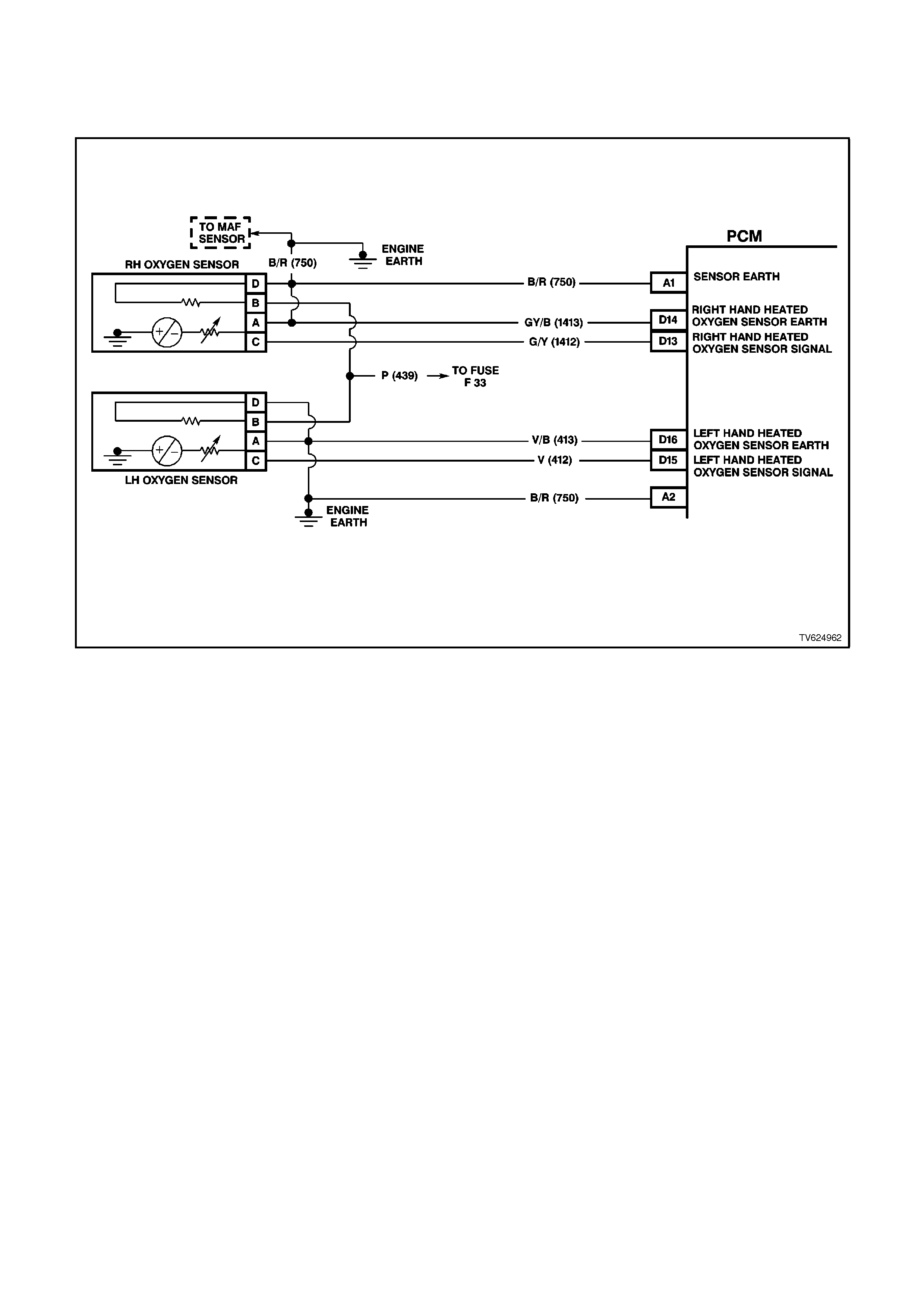
CHART A-6.3A V6 PCM - SUPERCHARGED ENGINE OXYGEN
SENSOR HEATER CHECK
CIRCUIT DESCRIPTION:
On the Supercharged V6 engine, two heated oxygen sensors are used to minimise the amount of time required for
closed loop fuel control operation and to allow accurate exhaust converter operation. The oxygen sensor heater
greatly decreases the amount of time required for the oxygen sensor signal to become active, and the PCM to use
this signal for efficient emissions control.
Because the sensor must be at least 360°C to operate effectively, it is equipped with an internal electric heating
element to quickly heat the sensor after key "ON", or start up. This heating element is powered from the vehicles
electrical system, any time the ignition is "ON".
The heater is used to maintain the oxygen sensor at a sufficiently high temperature. This allows accurate exhaust
oxygen content readings further from the engine, and maintains the sensors temperature at long engine idle
intervals.
TEST DESCRIPTION:
Number(s) below refer to step number(s) on the diagnostic chart.
2. Never perform this test on a cold engine. The oxygen sensor must be near normal operating temperature for
this chart to work. You may not see the voltage at 450 mV when the ignition is cycled "ON", because the Tech
2 scan tool menus take some time, however, it is important to see a low voltage because this means the
oxygen sensor is only monitoring oxygen in the exhaust pipe.

STEP ACTION VALUE YES NO
1. Was the "On-Board
Diagnostic" (OBD) System
Check performed?
Go to Step 2. Go to OBD
System Check.
2. 1. Ignition "ON".
2. Using Tech 2 scan tool
display LH and RH O2
Sensors.
3. Ignition "ON", engine
"OFF".
4. Did LH and RH O2
Sensor voltages drop
to specified value
within 60 seconds?
450 mV
to less
than 100
mV
No problem
found.
Oxygen Sensor
Heater is OK
If both did not
drop to specified
value, go to
Step 8
If only one
dropped to
specified value,
go to Step 3
3. 1. Ignition "OFF".
2. Disconnect the oxygen
sensor harness
connector from the
sensor that did not
drop.
3. Connect test light
between oxygen
sensor connector on
powertrain harness,
circuit 439 and earth,
circuit 750.
4. Ignition "ON".
Is the test light "ON"?
Go to Step 4 Go to Step 7
4. 1. Ignition "OFF".
2. Measure resistance of
oxygen sensor heater
with ohmmeter
between circuits 439
and circuit 750.
Is measured resistance
within the specified value?
3.5 -
13.2
ohms
Go to Step 6 Go to Step 5
5. Replace heated oxygen
sensor.
Is action complete ?
Verify Repair
6. Repair poor connection at
oxygen sensor.
Is action complete ?
Verify Repair
7. 1. Ignition "OFF".
2. Connect test light to
battery positive.
3. Probe oxygen sensor
connector on
powertrain harness
connector, circuit 750.
Is test light "ON" ?
Go to Step 8 Go to Step 9
8. Repair open or short to
earth in circuit 439
between fuse F33 and
oxygen sensor. Replace
fuse if blown.
Is action complete ?
Verify Repair
9. Repair open in circuit 750.
Is action complete? Verify Repair
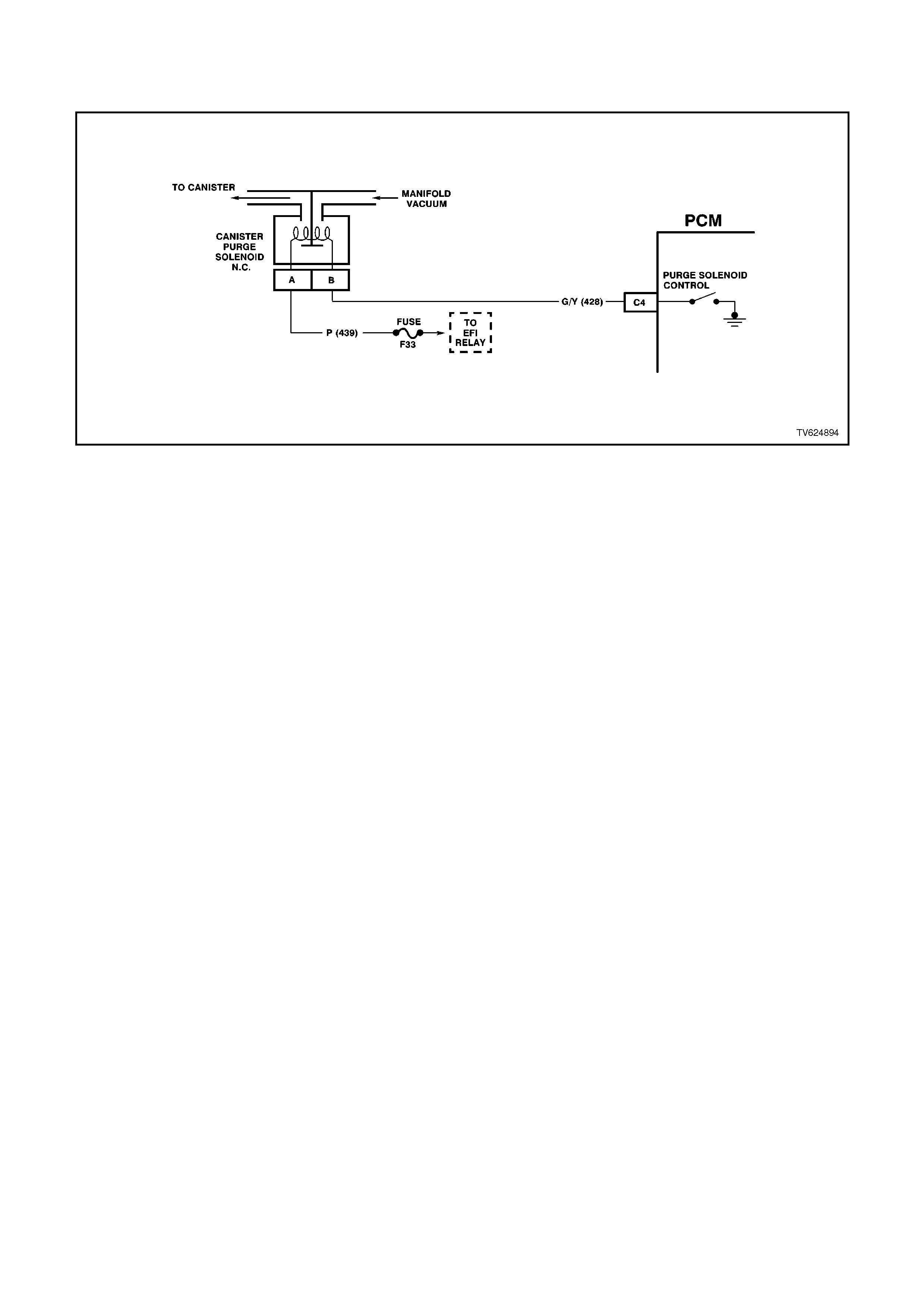
CHART A-6.4 V6 PCM - CANISTER PURGE SOLENOID CHECK
CIRCUIT DESCRIPTION:
The canister purge is controlled by a solenoid that allows manifold vacuum to purge the fuel vapour canister when
energised. The PCM supplies a earth to energise the solenoid (purge "ON").
If the following conditions are met with the engine running, the canister purge solenoid is energised.
• Engine run time after start more than 3 minutes and 15 seconds if coolant is less than 80 degrees C or
• Engine run time after start is more than 15 seconds if coolant is above 80 degrees C.
• Coolant temperature above 60 degrees C
• Engine not in Decel fuel cutoff mode.
• Throttle is less than 92%.
• Engine is in closed loop fuel mode or open loop fuel mode.
TEST DESCRIPTION:
Number(s) below refer to Step number(s) on the diagnostic chart.
2. Checks to see if the solenoid is opened or closed. The solenoid is normally energised in this step, so it should
be open.
3. This checks to see if the Canister Purge Solenoid mechanical function is functioning properly by earthing
Canister Purge Solenoid several times with the Tech 2 scan tool.
4. This checks to see if +B volts is supplied to the Canister Purge Solenoid.
5. This checks to see if the PCM is supplying the earth signal for the Canister Purge Solenoid.
DIAGNOSTIC AIDS:
Normal operation of the Canister Purge Solenoid is described as follows:
With the ignition "ON", engine "OFF", diagnostic "Test" terminal unearthed, the Canister Purge Solenoid will be de-
energised.

STEP ACTION VALUE YES NO
1. Was the "On-Board
Diagnostic" (OBD) System
Check performed?
Go to Step 2. Go to OBD
System Check in
this Section.
2. NOTE:
This chart only covers the
solenoid portion of the
Canister Purge system.
1. Ignition OFF.
2. Disconnect purge
vacuum hose from top
of canister, and place
a vacuum gauge in
hose.
3. Ignition "ON", engine
Running.
4. With Tech 2 scan tool
enable Canister Purge
Solenoid "ON" with Up
and Down buttons on
Tech 2 scan tool.
Does vacuum gauge read
manifold vacuum with
canister purge solenoid
display "ON"?
No trouble found.
Canister Purge
Solenoid is OK.
Go to Step 3
3. 1. Ignition "ON", engine
"OFF".
2. Place index finger on
top of Canister Purge
Solenoid.
3. Enable Canister Purge
Solenoid "ON" and
"OFF" several times
with the Tech 2 scan
tool.
Does the solenoid click
while enabling and
disabling ?
Canister Purge
Solenoid electrical
is OK.
Go to Step 10 for
vacuum check
Go to Step 4
4. 1. Ignition "ON", engine
"OFF".
2. Disconnect Canister
Purge Solenoid
electrical connector.
3. With a test light
connected to earth,
probe Canister Purge
Solenoid electrical
connector power feed
circuit.
Is test light "ON" ?
Go to Step 5 Go to Step 6

STEP ACTION VALUE YES NO
5. 1. Ignition "ON", engine
"OFF".
2. Disconnect Canister
Purge Solenoid
electrical connector.
3. With a test light
connected to +B volts,
probe Canister purge
Solenoid electrical
connector Purge
Solenoid control circuit.
4. With Tech 2" Scan"
tool, enable Canister
Purge Solenoid "ON"
with up and down
buttons on the Tech 2
scan tool.
Is test light "ON" when
Canister Purge Solenoid
is commanded "ON"?
Go to Step 7 Go to Step 8
6. Check for open in power
feed circuit.
Is action complete ?
Verify Repair
7. Replace Canister Purge
Solenoid.
Is action complete ?
Verify Repair
8. Check for open in Purge
Solenoid control circuit
from
PCM to Canister Purge
Solenoid.
Was an open found?
Verify Repair Go to Step 9
9. Check for poor connection
at PCM. If connection is
OK, replace PCM.
Is action complete?
Verify Repair
10. Check manifold vacuum
hose from manifold to
Canister
Purge Solenoid for kinks,
pinched, cracked, or
plugged.
Repair as necessary.
Is action complete?
Verify Repair
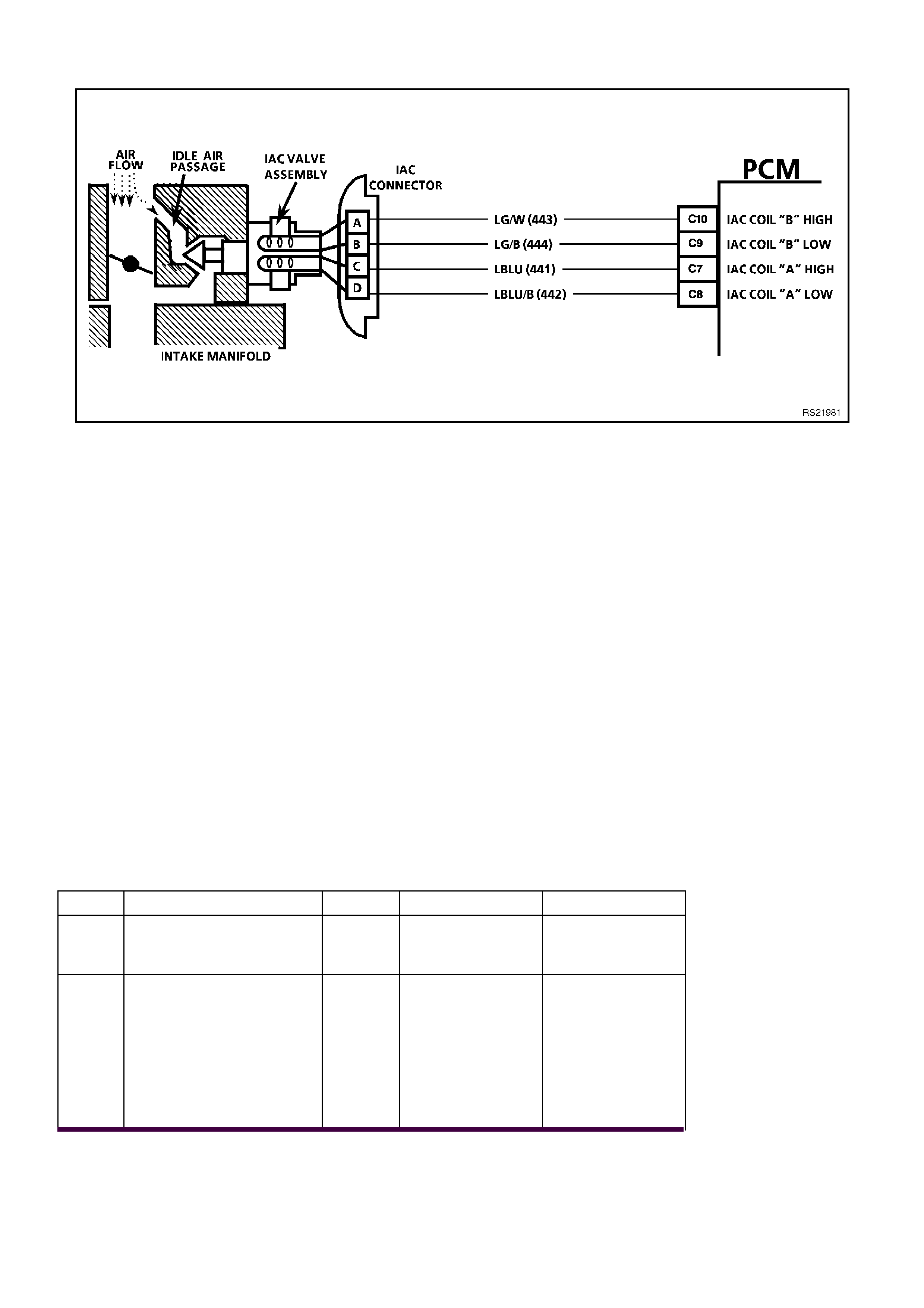
CHART A-7.1 V6 PCM - IDLE AIR CONTROL (IAC) SYSTEM
CIRCUIT DESCRIPTION:
The PCM controls engine idle speed by moving the IAC valve to control closed-throttle air flow around the throttle
plate. It does this by sending voltage pulses (called "counts" or "steps") to the IAC motor windings. The motor shaft
and conical valve move a given distance for each pulse received.
• TO INCREASE IDLE SPEED: The PCM sends enough pulses to retract the IAC valve and allow more air to
bypass the throttle plate through the idle air passage, until idle speed reaches the PCM-desired idle RPM.
• TO DECREASE IDLE SPEED: The PCM sends enough pulses to extend the IAC valve and reduce the airflow
bypassing the throttle plate through the idle air passage, until idle speed reaches the PCM-desired RPM.
The PCM desired idle RPM, and the commanded IAC position, is based on:
• Engine Coolant Temperature
• Actual engine RPM (crankshaft reference input)
• Engine load (A/C request input, engine fan command)
• Battery voltage (voltage at PCM terminal A4)
• Vehicle speed (VSS)
• Throttle position (TP)
TEST DESCRIPTION:
Number(s) below refer to step number(s) on the diagnostic chart.
2. This tests the PCM's ability to control IAC valve.
DIAGNOSTIC AIDS:
Remove IAC and check for frozen or sticking IAC. Check that TP sensor is within acceptable range.
STEP ACTION VALUE YES NO
1. Was the "On-Board
Diagnostic" (OBD) System
Check performed?
Go to Step 2. Go to OBD
System Check in
this Section.
2. 1. Using TECH 2 scan
tool, Select RPM
CONTROL.
2. With the up/down
arrows, v ary RPM from
600 to 1675 RPMs.
Does engine speed rise
and fall?
Go to Step 3 Go to Chart
A-7.2 in this
Section

STEP ACTION VALUE YES NO
3. No trouble found with IAC
system.
CHECK FOR:
• Vacuum leaks
(Causes Fast Idle
Speeds).
• Sticking or binding
throttle shaft, cables,
or linkages.
• Engine Coolant
Temperature sensor
resistance.
• Refer DTC 14 in this
Section.
• TP Sensor Operation.
Refer Chart A-6.2 in
this Section
• Dirty or loose battery
cables or earth straps.
• System earth circuit
terminals at the engine
for being clean and
tight.
• Inspect all accessory
drive pulleys. They
should all spin freely.
• Spark plugs that are
excessively worn, mis-
gapped or cracked.
• For high or low fuel
pressure, or leaking
injectors - refer Cha rt
A-4.3 in this Section
• A/C Clutch Control
circuit failure.
• Refer Chart A 11.1 or
Chart A 11.3 in this
Section.
• Generator Output - if
under 9 volts or over
16 volts, PCM will not
command the IAC to
move.
• Throttle Body - remove
IAC and inspect bore
for foreign material or
evidence of IAC valve
"Dragging" in the bore.
• Throttle Stop Screw,
refer SERVICE
OPERATIONS, 3.11
FUEL CONTROL
SYSTEM - Throttle
Stop Screw - Reset
Procedure.
• Refer To "Rough,
Unstable or Incorrect
Idle" In Section 6C1-
2B SYMPTOMS.
Verify Repair
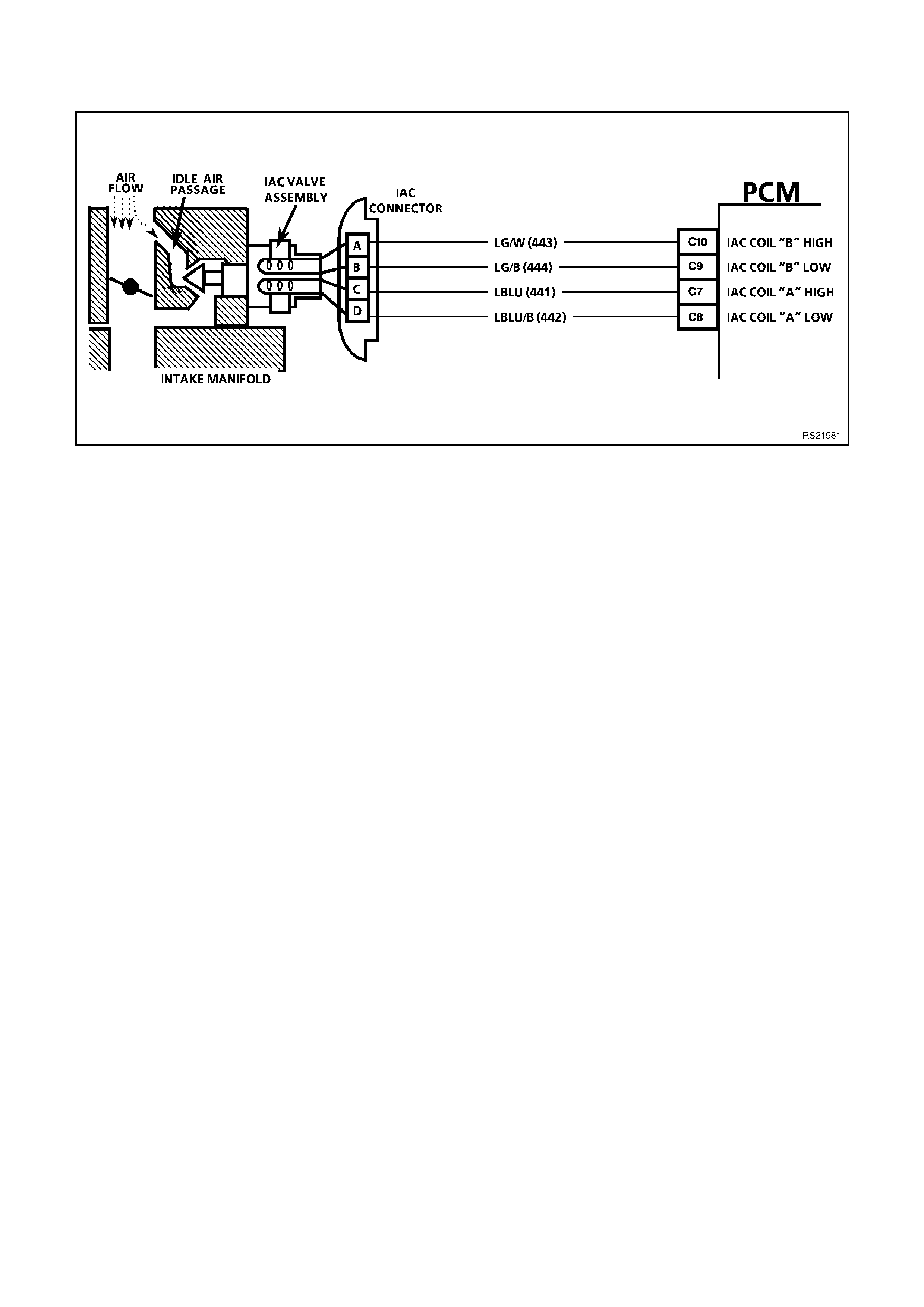
CHART A-7.2 V6 PCM - IDLE AIR CONTROL (IAC) SYSTEM
CIRCUIT DESCRIPTION:
The PCM controls engine idle speed by moving the
IAC valve to control closed-throttle air flow around
the throttle plate. It does this by sending voltage
pulses (called "counts" or "steps") to the IAC motor
windings. The motor s haf t and c onic al valve move a
given distance for each pulse received.
• TO INCREASE IDLE SPEED: The PCM sends
enough pulses to retr act the IAC valve and allow
more air to bypass the throttle plate through the
idle air passage, until idle speed reaches the
PCM - desired idle RPM.
• TO DECREASE IDLE SPEED: The PCM sends
enough pulses to extend the IAC valve and
reduce the air flow bypassing the throttle plate
through the idle air passage, until idle speed
reaches the PCM-desired RPM.
The PCM desired idle RPM, and the commanded
IAC position, is based on:
• Engine Coolant Temperature (ECT)
• Actual engine RPM (crankshaft reference input)
• Engine load (A/C request input, engine fan
command)
• Battery voltage (voltage at PCM terminal A4)
• Vehicle Speed (VSS)
• Throttle Position (TPS)

TEST DESCRIPTION:
Number(s) below refer to step number(s) on the
diagnostic chart.
2. With the ignition "ON," engine stopped, and
Tech 2: IAC reset, the PCM should issue
electrical "extend/retract" pulses to the IAC
valve. With the IAC disconnected, each
connector terminal should have a "pulsing"
voltage, noted by a flashing or flickering test
light. The rate of flashing or flickering is not
important.
8. There are 2 separate windings in the IAC
mo tor. Each winding (A - to - B, and C - to- D)
should have between 40 and 80 ohms
resistance. Also, there should be no continuity
between the two windings.
NOTE:
When performing this test, ensure that a standard
low power test light is used.
Do not use a "High-W attage" test light, as the PCM
could be damaged. A high wattage test light will
either give inaccurate test results, or damage the
PCM, or both.
A low-power test light must be used for any circuit
testing. While a particular brand of test light is not
suggested, a simple test on any test light will ensure
it to be OK for PCM circuit testing. Connect an
accurate ammeter (such as the digital multimeter)
in series with the test light being tested, and power
the test light-am meter c irc uit with the vehicle battery
(See above). If the ammeter indicates less than
3/10 amp current flow (0.3 A or 300 ma), the test
light is OK to use. If more than 0.3A (300 ma), do
not use!

STEP ACTION VALUE YES NO
1. Was the "On-Board
Diagnostic" (OBD) System
Check performed?
Go to Step 2. Go to OBD
System Check in
this Section.
2. • From Chart A-7.1
1. Disconnect IAC valve
electrical connector.
2. Ignition "ON", engine
stopped. Using TECH
2 scan tool, select RE
SET IAC.
3. Probe each IAC
harness connector
terminal for 5 seconds
with test light
connected to earth,
while using Tech 2.
• See note above for
proper test light usage.
Does test light flash at all
terminals while IAC is
being reset ?
Go to Step 3 If No light one or
more terminals,
Go to Step 6
If steady light one
or more terminals,
Go to Step 13
3. Check for faulty IAC
terminals.
Were any faulty terminals
found ?
Go to Step 4 Go to Step 5
4. Repair faulty terminals
Is action complete? Verify Repair
5. Replace IAC valve.
Is action complete ? Verify Repair
6. Check for open or short to
earth in circuit(s) that did
not light the test light.
Were any opens or short's
found ?
Go to Step 7 Go to Step 8
7. Repair any opens or short
found.
Is action complete?
Verify Repair
8. 1. Check resistance
across IAC coils.
2. Check all IAC
terminals opposite
harness connectors
terminals "A" to "B"
and "C" to "D".
Are the IAC coils within
specified value ?
40 to 80
ohms Go to Step 9 Go to Step 5

STEP ACTION VALUE YES NO
9. Check for short between
windings by measuring for
continuity between IAC
terminals "A" to "D".
Ohmmeter should indicate
an open circuit, does it?
Go to Step 10 Go to Step 5
10. Check for faulty PCM
terminals.
Were any faulty terminals
found ?
Go to Step 17 Go to Step 11
11. Check for faulty IAC
terminals.
Were any faulty terminals
found ?
Go to Step 14 Go to Step 12
12. Replace PCM.
Refer to Section 6C1-3
Service Operations, for
PCM Security Link
procedure.
Is action complete?
Verify Repair
13. 1 Ignition "OFF".
2. Disconnect PCM.
3. Ignition "ON".
4. Check for short to
voltage on circuits that
steady light w as "ON".
Was a short to voltage
found ?
Go to Step 15 Go to Step 14
14. Check for faulty IAC
connections.
Were faulty connections
found ?
Go to Step 16 Go to Step 5
15. Repair short to voltage.
Is action complete? Verify Repair
16. Repair faulty IAC
connections.
Is action complete?
Verify Repair
17. Repair faulty PCM
terminals.
Is action complete?
Verify Repair

CHART A-8.1 V6 PCM - DIRECT IGNITION SYSTEM (DIS) CHECK
CIRCUIT DESCRIPTION:
The DIS ignition system uses a waste spark method of spark distribution. In this type of ignition system the ignition
module triggers the correct ignition coil, based on signals from the crankshaft sensor. Each ignition coil provides the
high secondary voltage required to fire two spark plugs at the same time on "companion" cylinders, i.e. cylinders
with pistons at the top of the their stroke (TDC) at the same time. One of these pistons would be at the top of its
compression stroke, the other piston would be at the top of its exhaust stroke.
For additional information about the DIS sy stem, refer to Section 6C1-1 GENERAL DESCRIPTION.
TEST DESCRIPTION:
Number(s) below refer to step number(s) on the diagnostic Chart.
5. Terminal "P" to the DIS module is the +12 volt supply to the DIS system.
7. This procedure will check the crankshaft sensor output, through the harness to the DIS module harness
connector. DIS module harness connector terminals "N" and "P" are jumpered together to provide power to the
sensor Hall circuits. Terminal "M" is earthed to provide an earth path for the Hall circuits. As the crankshaft
balancer interrupter rings are related, the test light should blink "ON" and "OFF" as the blades pass the
crankshaft sensor air gap. The test light should be "ON" when the blade is in the crankshaft sensor air gap,
indicating the Hall circuits are providing the earth path for the test light connected to +12 volts. Terminal "H",
the 3X signal terminals, should blink "ON" and "OFF" three times per crankshaft revolution.
NOTE:
Use ST-125 spark checker or equivalent to check for adequate spark. An ST-125 requires about 25,000 volts (25
kilovolts, or 25 kV) to "Spark". Do not use a spark plug in open air earthed to the engine as an indication of sufficient
"Spark". Only a few kilovolts are required to jump the gap of a spark plug outside of the engine, and that would be
an inadequate test of the ignition system.

STEP ACTION VALUE YES NO
1. Was the "On-Board
Diagnostic" (OBD) System
Check performed?
Go to Step 2. Go to OBD
System Check in
this Section.
2. 1. Remove one spark
plug lead.
2. Connect ST-125 spark
checker (see note
above) to lead and
check for spark while
cranking the engine.
3. Check 3 wires on the
same side of the
engine this way. A few
sparks and then
nothing is considered
No Spark.
Is spark present on all
spark plug leads ?
Go to Step 3 If Spark on only
1 or 2 leads,
Go to Step 4
If No Spark,
Go to Step 5
3. No trouble found with
ignition system.
Is action complete?
Verify Repair
4. Refer to DIS module and
coil checking procedure,
chart A-8.2 Step 5 in this
Section.
Is action complete?
Verify Repair
5. 1. Disconnect 14-pin
connector from DIS
module.
2. Ignition "ON", probe
harness connector
terminal "P" with a test
light connected to
earth.
Is test light "ON" ?
Go to Step 9 Go to Step 6
6. Check ignition module
fuse F23.
Is fuse open?
Go to Step 7 Go to Step 8
7. Repair short to earth in
fuse circuit.
Replace fuse.
Is action complete?
Verify Repair
8. Repair open in power
circuit to DIS ignition
module harness
connector
terminal "P".
Is action complete ?
Verify Repair

STEP ACTION VALUE YES NO
9. 1. Ignition "OFF".
2. Get three paper clips,
and re-form until
straight.
3. Bend one of the
straightened paper
clips into a very narrow
"U", and use it to
jumper DIS module
harness connector
terminals "N" and "P".
4. Insert a straightened
paper clip into terminal
"M".
Connect a jumper lead
from this paper clip to
earth.
• Ensure that the Two
paper clips and/or
jumper leads Do Not
Touch.
5. Insert a straightened
paper clip into harness
connector terminal "H",
and connect a test light
between this terminal
and +12 volts.
6. Ignition "ON".
7. Using a 28 mm socket
and hand tools, slowly
rotate the crankshaft
balancer one
revolution, while
observing the test light.
The test light should go
"ON" and "OFF" as the 3X
interrupter blades pass
through the sensor air
gap, does it ?
Go to Chart 8.2,
Step 8 in this
Section
Go to Step 10
10. Check for good continuity,
and for no Shorts or
Opens on the 4 circuits
between the crank sensor
and DIS module. If all are
OK, replace crank sensor.
Refer DIS SERVICE
OPERATIONS in Section
6C1-3 for proper
procedure.
It must be followed.
Is action complete?
Verify Repair
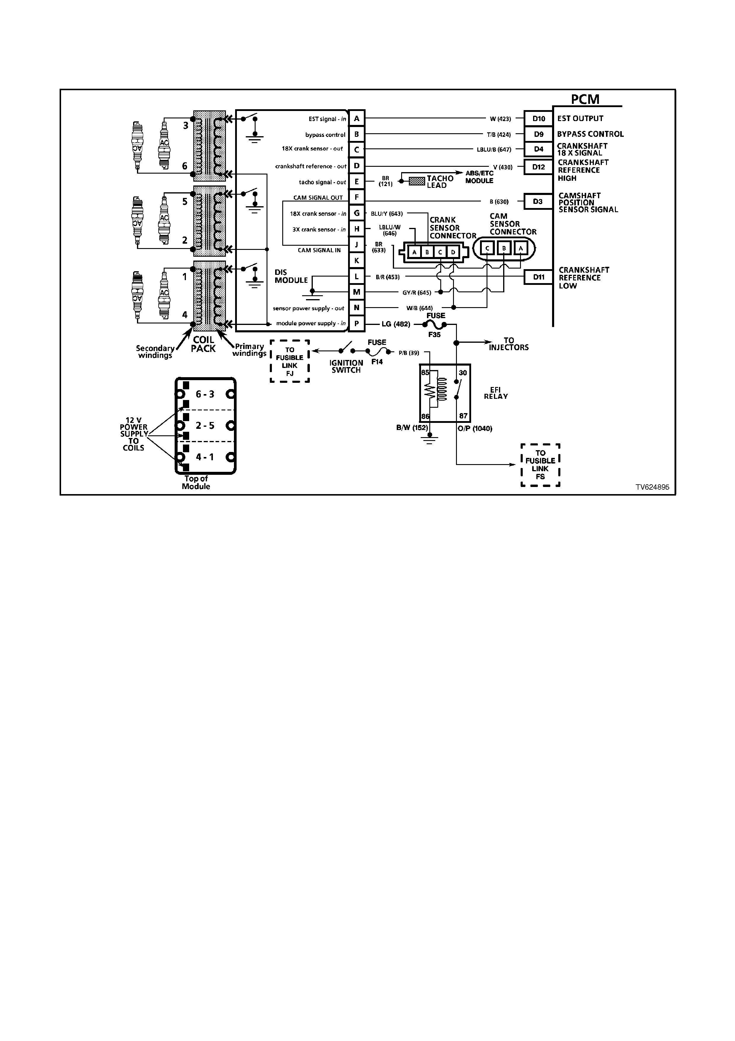
CHART A-8.2 V6 PCM - DIRECT IGNITION SYSTEM (DIS) CHECK
CIRCUIT DESCRIPTION:
The DIS ignition system uses a waste spark method of spark distribution. In this type of ignition system the ignition
module triggers the correct ignition coil, based on signals from the crankshaft sensor. Each ignition coil provides the
high secondary voltage required to fire two spark plugs at the same time on "companion" cylinders, i.e. cylinders
with pistons at the top of the their stroke (TDC) at the same time. One of these pistons would be at the top of its
compression stroke, the other piston would be at the top of its exhaust stroke.
For additional information about the DIS sy stem refer to Section 6C1-1 GENERAL DESCRIPTION .
TEST DESCRIPTION:
Number(s) below refer to Step number(s) on the Diagnostic Chart.
3. Terminal "G", the 18x signal terminal, should blink "ON" and "OFF" eighteen times per crankshaft revolution.
5. This procedure will check the modules ability to control the ignition coil primary system.
7. These checks are for the primary and secondary windings of each of the three ignition coils. The resistance of
each of the six checks (3 primary and 3 secondary windings) must be within the specified ranges.

STEP ACTION VALUE YES NO
1. Was the "On-Board
Diagnostic" (OBD) System
Check performed?
Go to Step 2. Go to OBD
System Check in
this Section.
2. 1. Ignition "OFF".
2. Remove the paper clip
from terminal "H" and
insert it into terminal
"G".
3. Ignition "ON".
Slowly rotate the
crankshaft balancer one
revolution and note test
light. It should go "ON"
and "OFF" as the 18X
interrupter blades pass
through the sensor air
gap, does it?
Go to Step 4 Go to Step 3
3. Check for good continuity,
and for no Shorts or
Opens on the 4 circuits
between the crank sensor
and DIS module. If all are
OK, replace crank sensor.
See DIS SERVICE
OPERATIONS in Section
6C1-3 for proper
procedure. It must be
followed.
Is action complete?
Verify Repair

STEP ACTION VALUE YES NO
4. 1. Remove test light and
all leads from harness
connector terminals.
Reconnect 14-pin
connector to DIS
module. Torque
retaining bolt to
specification value.
2. Disconnect all spark
plug leads from the
DIS coils.
3. Remove 6 screws that
retain the coils to the
module.
4. Remove all three coils.
5. Connect the test light
clip lead to one of the
two coil terminals on
the module.
6. Connect the test light
probe to the other coil
terminal on the
module.
7. While the engine is
cranking, observe test
light. The test light
should blink.
8. This test should be
performed for each
pair of module
terminals that connect
to the three (3) ignition
coils.
Is the test light blinking for
all three coil pairs?
0.6 to
1.2 Nm Go to Step 6 Go to Step 5
5. If no blink, or blinks on
less than all 3 pairs,
replace
DIS module.
Is action complete ?
Verify Repair
6. 1. Ignition "OFF".
2. Using a digital
ohmmeter, check
resistance across the
ignition coil primary
winding (underside)
terminals
3. Correct resistance of
the ignition coils
primary winding must
be within the specified
value.
Are all three coils (6-3, 2-
5, 4-1) within this range?
0.3
ohms to
1.5
ohms
Go to Step 8 Go to Step 7

STEP ACTION VALUE YES NO
7. Replace coil(s) that had
the incorrect ohms
reading.
Is action complete ?
Verify Repair
8. 1. Check resistance
across the ignition coil
secondary tower
terminals. Each tower
is marked.
2. Correct resistance of
the ignition coil
secondary windings
must be within the
specified value.
Are all three coils (6-3, 2-
5, 4-1) within this range ?
5000
(5K
ohms)
to 7000
(7K
ohms)
Go to Step 10 Go to Step 9
9. Replace coil(s) that had
the incorrect ohms
reading.
Is action complete ?
Verify Repair
10. At this point, all DIS
components test indicate
the DIS system should
produce spark. If a No
Spark condition still exists,
very closely check the
metal terminals in the
plastic connectors at the
DIS module and crank
sensor. Also check the
resistance of the spark
plug leads, ensuring that
none are "Open"
Is action complete ?.
Verify Repair
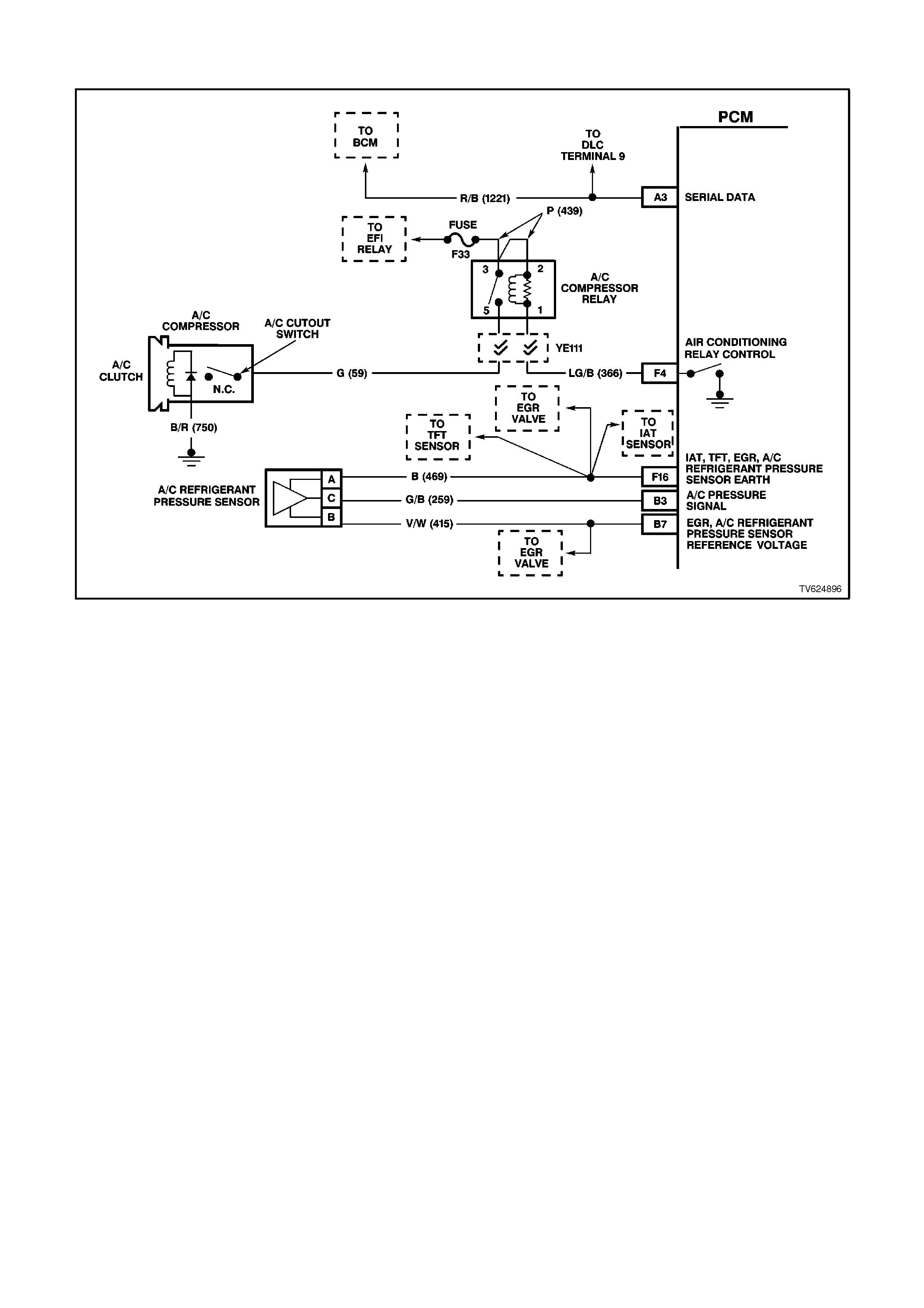
CHART A-11.1 V6 PCM - A/C CLUTCH CONTROL ( NON ECC SYSTEM )
CIRCUIT DESCRIPTION:
With the blower fan switched "ON", and the air conditioning switched "ON," switched ignition voltage is supplied
from fuse F13 through the A/C master switch, and then to the BCM. The BCM will then supply a serial data signal to
the PCM requesting A/C. If the BCM does not receive a earth signal from the blower switch to BCM terminal "3", the
BCM will not supply the serial data request for A/C to the PCM. Once the PCM receives this serial data signal, the
PCM will energise the A/C compressor relay by supplying a earth signal (A/C Relay Control ) from the PCM. The
BCM also supplies a earth signal from BCM terminal "7" to the low speed cooling fan relay.
This serial data signal to the PCM is also used to adjust the idle speed before turning "ON" the A/C compressor
relay. If this signal is not available to the PCM, the A/C compressor will be inoperative.
This system also incorporates a A/C Refrigerant Pressure Transducer. The A/C Refrigerant Pressure Sensor signal
indicates Low / High pressure on the A/C high side refrigerant pressure line to the PCM. The PCM uses this
information to adjust the idle air control valve to compensate for the higher engine loads present with high A/C
refrigerant pressures. A fault in the A/C Refrigerant Pressure Sensor signal will cause DTC 96 to set.
The purpose of this A/C Refrigerant Pressure Sensor is to protect the system from danger because of either
refrigerant pressure too low (which could damage the compressor due to insufficient lubrication), or too high (which
could result in a leak in the sealed refrigerant R134a system).
The PCM will NOT energise the A/C control relay if any of the following conditions are present:
• DTC 91, or 96 is set.
• RPM more than 4,800. If de-energised because of RPM, it can re-energised when RPM falls below 4,000 for at
least 10 seconds.
• Throttle is more than 90% open.
• A/C Refrigerant Pressure Sensor voltage is to Low or to High

TEST DESCRIPTION:
Number(s) below refer to step number(s) on the diagnostic chart.
1. The PCM's diagnostic circuits must be proven before any further testing is performed.
2. The PCM does not normally energise the A/C control relay unless the engine is running.
4. This checks for operation of the condenser fan.
20, 21, 22, 23, 24, 26, 28:
There are no terminal identification on the relay connector (although the relay itself has terminal numbers).
Make certain the correct relay connector terminal (not the relay) is being probed.
39. The most likely cause of an automotive air conditioner not working is a discharged refrigerant R134a system,
due to a refrigerant leak.
CHECK FOR:
If fuse F13 is blown, check for short to earth on all circuit associated with this fuse.
STEP ACTION VALUE YES NO
1. Was the "On-Board
Diagnostic" (OBD) System
Check performed?
Go to Step 2. Go to OBD
System Check in
this Section.
2. 1. Ignition "ON", engine
stopped.
2. Disconnect the A/C
compressor clutch
electrical connector
and reconnect, and
note compressor
clutch.
Did compressor clutch
cycle "OFF" then "ON"
with electrical connector
disconnected and
reconnected?
If A/C clutch
cycled "OFF" then
"ON" or will not
disengage go to
Step 6
Go to Step 3
3. 1. Ignition "ON", engine
idling.
2. Blower Switch turned
"ON".
3. Cycle the A/C switch
"ON" and "OFF",
waiting a few seconds
between positions.
Listen for A/C compressor
clutch. Doe s it cycle "ON"
and "OFF?
Go to Step 4 Go to Step 14
4. 1. Ignition "ON", engine
idling.
2. A/C switch in the "ON"
position.
Does the A/C condenser
fan operate when the A/C
switch is turned "ON" ?
Go to Step 5 Go to Chart
A-12 in this
Section
5. 1. A/C clutch control
circuits OK.
2. If complaint is
insufficient cooling,
review symptoms.
Is action complete ?
Verify Repair

STEP ACTION VALUE YES NO
6. 1. Ignition "OFF".
2. Disconnect A/C
compressor electrical
connector.
3. Observe A/C clutch.
Is A/C clutch staying
engaged to compressor?
Go to Step 7 Go to Step 8
7. Replace A/C compressor
clutch. Refer to
Section 2B for details.
Is action complete?
Verify Repair
8. 1. Ignition "ON", engine
"OFF".
2. Using test light
connected to B+,
backprobe PCM
terminal for A/C Relay
Control.
Does test light illuminate?
Go to Step 9 Go to Step 11
9. Check for a short to earth
in circuit for A/C Relay
Control from the PCM to
A/C Compressor Relay.
Was a problem found?
Verify Repair Go to Step 10
10. Replace PCM.
Refer to Section 6C1-3
Service Operations, for
PCM Security Link
procedure.
Is action complete?
Verify Repair
11. 1. Ignition "ON".
2. Disconnect A/C
compressor electrical
connector.
3. Using test light
connected to earth,
probe A/C compressor
electrical connector
power circuit.
4. With test light "ON",
remove A/C
Compressor Relay and
note test light.
Did test light turn "OFF"?
Go to Step 12 Go to Step 13
12. Replace A/C Compressor
Relay.
Is action complete?
Verify Repair
13. Repair short to voltage on
A/C compressor power
feed circuit from A/C
Compressor Relay to A/C
compressor.
Is action complete?
Verify Repair

STEP ACTION VALUE YES NO
14. 1. Ignition "ON", engine
idling.
2. Install scan tool.
3. Observe A/C
Refrigerant Pressure
Sensor voltage display
on the scan tool.
Is indicated A/C
Refrigerant Pressure
Sensor voltage at or
between the specified
value?
0.35V -
4.2V Go to Step 15 Go to Step 39
15. Check power supply fuse
to A/C master sw itch.
Is fuse open?
Go to Step 16 Go to Step 17
16. Repair short to earth in
fuse circuit, and replace
fuse.
Is action complete?
Verify Repair
17. 1. Ignition "ON", engine
"OFF".
2. Turn A/C Master
Switch to "ON"
position.
3. Using test light
connected to earth,
backprobe BCM
terminal for A/C Select
Input circuit.
Dose test light illuminate?
Go to Step 20 Go to Step 18
18. Check for open or poor
connection in circuit from
A/C Master Switch to
BCM A/C Select Input, or
open in power feed circuit
to A/C Master Switch.
Was a problem found?
Verify Repair Go to Step 19
19. Replace A/C Master
Switch.
Is action complete?
Verify Repair
20. 1. Ignition "ON", engine
idling.
2. Remove Blower Inhibit
Relay from Relay
center, leave harness
connector connected
to relay.
3. Using test light
connected to B+,
backprobe relay
harness connector
terminal 30.
4. Turn A/C Master
Switch to "ON"
position.
Does test light illuminate?
Go to Step 21 Go to Step 26

STEP ACTION VALUE YES NO
21. 1. Ignition "ON", engine
idling.
2. Using test light
connected to B+,
backprobe BCM
terminal for Blower
Switch Input Signal.
3. Turn A/C Master
Switch to "ON"
position.
4. Turn Blower Switch to
"ON" position.
Does test light illuminate?
Go to Step 22 Go to Step 33
22. 1. Ignition "OFF".
2. Remove A/C
Compressor Relay
from Relay center.
3. Ignition "ON", engine
idling.
4. Turn A/C Master
Switch to "ON"
position.
5. Turn Blower Switch to
"ON" position.
6. Using test light
connected to B+,
probe terminal "2" of
A/C Compressor Relay
harness connector.
Does test light illuminate?
Go to Step 23 Go to Step 35
23. 1. Ignition "ON", engine
"OFF".
2. Using test light
connected to earth,
probe A/C Compressor
Relay harness
terminals 1 and 3.
Does test light illuminate
on both circuits?
Go to Step 24 Go to Step 36
24. 1. Ignition "OFF".
2. Reinstall Blower Inhibit
Relay and A/C
Compressor Relay.
3. Disconnect electrical
connector at A/C
compressor.
4. Ignition "ON", engine
idling.
5. Turn A/C Master
Switch to the "ON"
position.
6. Turn Blower Switch to
the "ON" position.
7. Using test light
connected to earth,
probe A/C compressor
harness power feed
circuit from A/C
Compressor Relay to
compressor.
Dose test light illuminate?
Go to Step 25 Go to Step 37

STEP ACTION VALUE YES NO
25. Check A/C compressor
earth circuit for an open, if
open repair. If earth circuit
is OK, Replace A/C
compressor. Refer to
Section 2C.
Is action complete?
Verify Repair
26. 1. Ignition "ON", engine
idling.
2. Using test light
connected to B+,
backprobe Blower
Inhibit Relay terminal
85 for Blower Inhibit
Relay Earth Output
Signal from BCM.
3. Turn A/C master
switch "ON".
Dose test light illuminate?
Go to Step 28 Go to Step 27
27. Check for open in circuit
from BCM to Blower
Inhibit Relay or poor
connection at BCM. If OK,
replace BCM.
Is action complete?
Verify Repair
28. 1. Ignition "ON", engine
"OFF".
2. Disconnect Blower
Inhibit Relay from
harness connector.
3. Using test light
connected to earth,
probe relay harness
terminal 86.
Does test light illuminate?
Go to Step 30 Go to Step 29
29. Repair open in circuit from
Blower Inhibit Relay
terminal 86 to Ignition
Switch.
Is action complete?
Verify Repair
30. 1. Ignition "ON", engine
"OFF".
2. With Blower Inhibit
Relay still
disconnected, probe
relay harness terminal
87 with a test light
connected to B+.
Does test light illuminate?
Go to Step 31 Go to Step 32
31. Replace Blower Inhibit
Relay.
Is action complete?
Verify Repair
32. Repair open in earth
circuit to Blower Inhibit
Relay.
Is action complete?
Verify Repair

STEP ACTION VALUE YES NO
33. Check for open circuit
from Blower Switch to
BCM Blower Switch Input
terminal.
Was a problem found?
Verify Repair Go to Step 34
34. Check for open in circuit
from Blower Inhibit Relay
terminal 30 to Blower
Switch.
Was a problem found?
Verify Repair Go to Step 38
35. Check for open in circuit
from A/C Compressor
Relay to PCM terminal for
A/C Relay Control.
Was a problem found?
Verify Repair Go to Step 10
36. Repair open in circuit that
did not light.
Is action complete?
Verify Repair
37. Check for open in circuit
from A/C Compressor to
A/C Compressor Relay.
Was a problem found?
Verify Repair Go to Step 12
38. Replace Blower Switch.
Is action complete? Verify Repair
39. Check A/C Pressure
Sensor signal circuit for
short to earth.
Was a problem found?
Verify Repair Go to Step 40
40. Check A/C refrigerant (R-
134a) system for being
undercharged, or
overcharged.
Is action complete.
Verify Repair
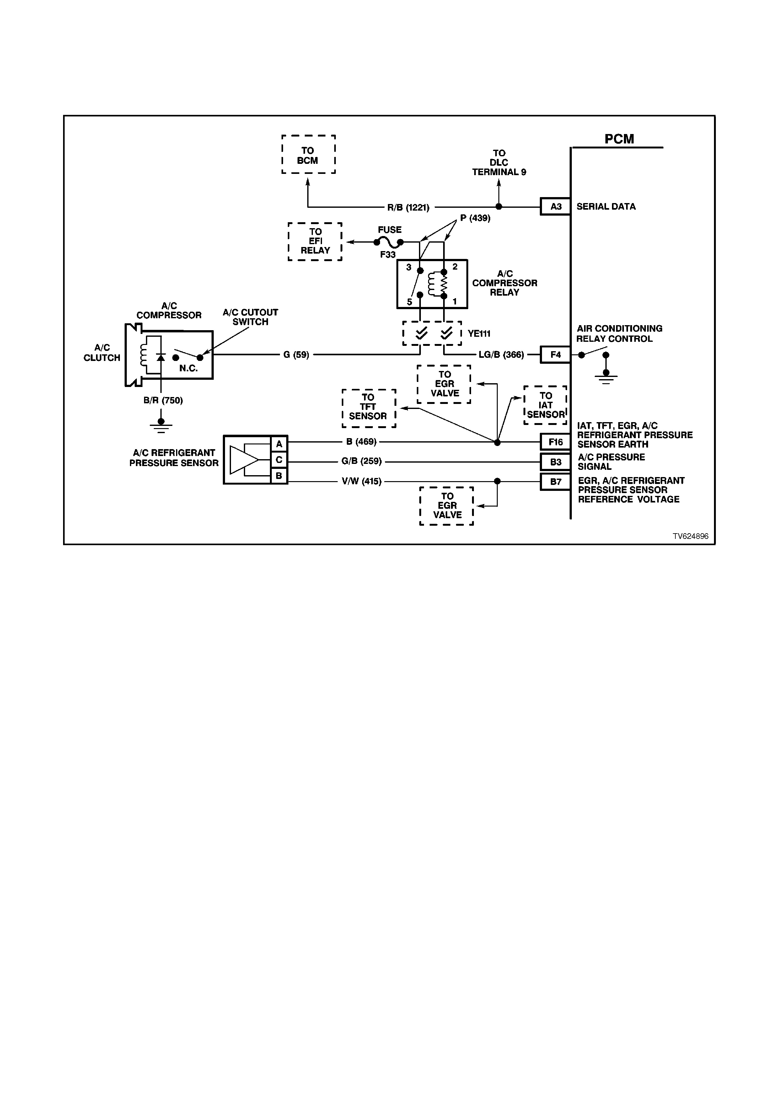
CHART A-11.3 V6 PCM - A/C CLUTCH CONTROL
WITH ELECTRONIC CLI MATE CONTROL (ECC)
CIRCUIT DESCRIPTION:
When the A/C is requested, the Electronic Climate Control Module will supply a signal to the BCM. The BCM will
then send a serial data request to the PCM. When the PCM receives the serial data request on PCM terminal B12,
it indicates that air conditioning has been requested and approximately 1/2 second after the PCM receives this
signal, it will energise the A/C control relay . This serial data signal to the PCM is also used to adjust the idle speed
before turning "ON" the A/C compressor relay. If this signal is not available to the PCM, the A/C compressor will not
operative.
If there is a problem with the PCM A/C Relay Control circuit, QDSM DTC 91 will set.
The BCM also supplies the earth signal from BCM terminal "7" to the low speed cooling fan relay.
This A/C system also incorporates a A/C Refrigerant Pressure Transducer. The A/C Refrigerant Pressure
Transducer signal indicates low and high side refrigerant pressures to the PCM. The PCM uses this information to
adjust the idle air control valve to compensate for the higher engine loads present with high A/C refrigerant
pressures., and not allow A/C operation if pressure is to low A fault in the A/C Refrigerant Pressure Sensor signal
will cause DTC 96 to set.
The PCM will NOT energise the A/C control relay if any of the following conditions are present:
• DTC 91, or 96 is set.
• RPM more than 4,800. If de-energised because of RPM, it can re-energised when RPM falls below 4,000 for at
least 10 seconds.
• Throttle is more than 90% open.
• A/C Refrigerant Pressure Sensor voltage is to Low or to High

TEST DESCRIPTION:
Number(s) below refer to step number(s) on the diagnostic chart.
1. The PCM's diagnostic circuits must be proven before any further testing is performed.
3. The PCM does not normally energise the A/C control relay unless the engine is running.
4. When the Tech 2 scan tool is installed, and the A/C switch is turned "ON", the scan tool should display "A/C
Requested".
6. This checks for operation of the condenser fan.
7. The most likely cause of an automotive air conditioner not cooling properly is a discharged or overcharged
refrigerant R134a system.
18, 19, 20:
There are no terminal identification on the relay connector (although the relay itself has terminal numbers).
Make certain the correct relay connector terminal (not the relay) is being probed.
CHECK FOR:
If fuse F13 is blown, check for short to earth on all circuit associated with this fuse.
STEP ACTION VALUE YES NO
1. Was the "On-Board
Diagnostic" (OBD) System
Check performed?
Go to Step 2 Go to OBD
System Check in
this Section.
2. Check fuse for Electronic
Climate Control module.
Is fuse OK ?
Go to Step 3 Go to Step 16
3. 1. Ignition "ON", engine
stopped.
2. Cycle A/C master
switch "ON" and
"OFF", waiting a few
seconds between
positions.
3. Observe the A/C
compressor clutch.
4. It should not cycle
"ON" and "OFF",
Did the compressor clutch
not cycle "ON" and "OFF"
?
Go to Step 4 If either engages
or will not
disengage Go to
Step 13
4. 1. Ignition "ON".
2. Install Tech 2 scan
tool.
3. Turn A/C switch "On"
Does Tech 2 scan tool
display "A/C Requested" ?
Go to Step 5 Go to Step 8
5. 1. Ignition "ON", engine
idling.
2. Cycle the A/C switch
"ON" and "OFF",
waiting a few seconds
between positions.
3. Listen for A/C
compressor clutch.
Does A/C compressor
clutch cycle "ON" an d
"OFF"?
Go to Step 6 Go to Step 17
6. Ignition "ON", engine
idling.
Does the A/C condenser
fan operate when the A/C
is turned "ON"?
Go to Step 7 Go to Chart
A-12 in this
Section

STEP ACTION VALUE YES NO
7. A/C clutch control circuits
OK. If complaint is
insufficient A/C cooling,
review symptoms.
Is action complete?
Verify Repair
8. Check for poor connection
or an open circuit between
BCM and Electronic
Climate Control Module.
Was a problem found ?
Verify Repair Go to Step 9
9. 1. Ignition "OFF".
2. Disconnect BCM
connectors.
3. Ignition "ON", engine
"OFF".
4. Using DVM connected
to earth, probe BCM
harness connector
terminal for A/C Select
Input from Electronic
Climate Control
module.
5. Turn "ON" A/C switch.
Does DVM indicate
voltage between the
specified value?
2 - 4
volts Go to Step 11 Go to Step 10
10. Check for a open or short
to earth in A/C Select
circuit between BCM and
Electronic Climate Control
module.
Was a problem found?
Verify Repair Go to Step 12
11. Replace BCM.
Is action complete? Verify Repair
12. Check for poor connection
at Electronic Climate
Control module, if
connection OK, replace
faulty Electronic Climate
Control Module.
Is action complete ?
Verify Repair
13. Check for short to earth
from PCM circuit A/C
Relay Control to A/C
Compressor Relay.
Was a problem found?
Verify Repair Go to Step 14
14. Check for short to voltage
on power feed circuit to
A/C compressor.
Was a problem found?
Verify Repair Go to Step 15
15. Replace defective A/C
compressor relay.
NOTE:
If compressor clutch sti ll
will not disengage, replace
A/C compressor clutch.
Refer to Section 2B for
details.
Is action complete ?
Verify Repair

STEP ACTION VALUE YES NO
16. Repair short to earth in
fuse circuit.
Replace fuse.
Is action complete?
Verify Repair
17. 1. Ignition "ON", engine
idling.
2. Install scan tool.
3. Observe A/C
Refrigerant Pressure
Sensor voltage display
on the scan tool.
Is indicated A/C
Refrigerant Pressure
Sensor voltage at or
between the specified
value?
0.35V -
4.2V Go to Step 18 Go to Step 29
18. 1. Ignition "ON", engine
idling.
2. Disconnect A/C
compressor relay.
3. Probe both relay
terminals "3" and "1" of
harness connector,
with a test light
connected to earth.
Is test light "ON" at both
terminals ?
Go to Step 19 Go to Step 25
19. 1. Ignition "ON", engine
idling.
2. Probe A/C compressor
relay connector circuit
for A/C Relay Control
with a test light
connected to B+.
3. Turn A/C switch "ON".
Is test light "ON" when the
A/C switch is "ON" ?
Go to Step 20 Go to Step 23
20. 1. Ignition "ON", engine
idling.
2. Reconnect A/C
compressor relay.
3. Backprobe relay
harness terminal "5"
with a test light
connected to earth.
4. Turn A/C switch "ON".
Is test light "ON" when
A/C switch is turned
"ON"?
Go to Step 21 Go to Step 15

STEP ACTION VALUE YES NO
21. 1. Ignition "OFF".
2. Disconnect A/C
compressor electrical
connector.
3. Ignition "ON", engine
idling.
4. Probe compressor
harness connector
terminal power feed
circuit with a test light
connected to earth.
5. Turn A/C switch "ON".
Is test light "ON" when the
A/C switch is turned
"ON"?
Go to Step 22 Go to Step 28
22. Check for a poor earth
circuit to A/C compressor.
Was a problem found?
Verify Repair Go to Step 27
23. Check for a faulty
connection for A/C
compressor relay.
Was a problem found ?
Verify Repair Go to Step 24
24. Check for a open in the
PCM A/C Relay Control
circuit, from the PCM to
the A/C compressor relay.
Was a problem found ?
Verify Repair Go to Step 26
25. Repair open in circuit that
did not light test light.
Is action complete ?
Verify Repair
26. Replace PCM.
Refer to Section 6C1-3
Service Operations, for
PCM Security Link
procedure.
Is action complete?
Verify Repair
27. Replace A/C compressor.
Is repair complete ? Verify Repair
28. Repair open in circuit 59
to A/C compressor clutch.
Is repair complete ?
Verify Repair
29. Check A/C Pressure
Sensor signal circuit for
short to earth.
Was a problem found?
Verify Repair Go to Step 30
30. Check A/C refrigerant (R-
134a) system for being
undercharged, or
overcharged.
Is action complete.
Verify Repair

CHART A-12.1 V6 PCM - ELECTRI C FAN CONTROL
CIRCUIT DESCRIPTION:
The both V6 engine have two (2) two speed electric radiator fan motors which provides the primary means of
moving air through the engine radiator. The two (2) two speed electric cooling fan's are used to cool engine coolant
flowing through the radiator. It is also used to cool the refrigerant flowing through the A/C condenser.
The engine cooling fan high speed relay is controlled by the PCM. The PCM controls the earth path for the engine
cooling fan high speed relay.
The low speed of the electric fan is controlled by the PCM through special Data Communication to the BCM. The
BCM controls the earth path for the engine cooling fan low speed relay.
Both relays are used to control the earth paths to the electric motor's that drives both five bladed fan's.
ENGINE COOLING FA N LOW SPEED:
The engine cooling fan low speed relay is energised by the BCM. The PCM determines when to enable the engine
cooling fan low speed based on inputs from the A/C request signal, vehicle speed and engine coolant temperature.
The engine cooling low speed fan will be turned "ON" when:
• A/C request indicated (YES) and
• Vehicle speed less than 54 Km/h
- OR -
• Coolant temperature is greater than 104 degrees C and will remain on until coolant temperature goes down
below 99 degrees C
ENGINE COOLING FAN HIGH SPEED:
The engine cooling fan high speed is controlled by the PCM based on input from the Engine Coolant Temperature
Sensor (ECT). The PCM will only turn "ON" the engine cooling fan high speed if the engine cooling low speed fan
has been "ON" for 2 seconds and the following conditions are satisfied.
• There is a BCM message response fault which will cause a DTC 92.
• An engine coolant temperature sensor failure is detected, such as DTC 14,15,16,17, or 91.
• Coolant temperature greater than 109 degrees C.
If the fan low speed was "OFF" when the criteria was met to turn the fan high speed "ON", the fan high speed will
come "ON" 5 seconds after the fan low speed is turned "ON". The engine cooling fan High speed relay can also be
enable by the A/C Refrigerant Pressure Sensor. The A/C Refrigerant Pressure Sensor will provide a signal to the
PCM when A/C pressure becomes to high approximately 1770 kPa.

TEST DESCRIPTION:
Number(s) below refer to step number(s) on the diagnostic chart.
2. This entire diagnostic procedure must begin with a "cold" engine - at ambient air temperature. If the coolant is
hot when diagnosis is performed, replacement of good parts will result. Fan should not be running if engine
coolant temperature is less than 99 degrees C and air conditioning is not "ON".
10. On A/C equipped vehicles, the engine cooling fan High speed relay should energise by the PCM, as soon as
the PCM energises the A/C clutch.
STEP ACTION VALUE YES NO
1. Was the "On-Board
Diagnostic" (OBD) System
Check performed?
Go to Step 2. Go to OBD
System Check
2. 1. Ignition "ON", engine
stopped.
2. Engine coolant
temperature below 99
degrees C.
Are both electric fan
motor's running ?
Go to Step 3 Go to Step 9
3. 1. Ignition "OFF".
2. Remove the Radiator
Fan High Speed Relay.
3. Ignition "ON".
Does both fan's continue
to run ?
Go to Step 4 Go to Step 5
4. 1. Ignition "ON".
2. Remove Radiator Fan
Low Speed Relay from
relay housing.
Does both fan's continue
to run ?
Go to Step 13 Go to Step 16
5. 1. Ignition "ON".
2. Probe Radiator Fan
High Speed Relay
harness connector
circuit 304 with a test
light to +12 volts.
Is the test light "ON"?
Go to Step 6 Go to Step 8
6. 1. Ignition "OFF".
2. Disconnect PCM
connectors.
3. Ignition "ON".
4. Using test light, probe
Radiator Fan High
Speed Relay harness
connector circuit 304
with a test light
connected to +12 volts.
Is the test light "ON" ?
Go to Step 14 Go to Step 7
7. Replace PCM.
Refer to Section 6C1-3
Service Operations, for
PCM Security Link
procedure.
Is action complete?
Verify Repair
8. Replace Radiator Fan
High Speed Relay. Verify Repair

STEP ACTION VALUE YES NO
9. 1. Ignition "ON".
2. Using the scan tool,
Select HIGH FAN relay
control.
3. Turn "ON" "HIGH FAN
" with up/down arrow
keys.
Do both cooling fan's
operate in high fan mode?
Go to Step 20 Go to Chart
A-12.2 in this
Section
10. Is the vehicle equipped
with A/C? Go to Step 11 Go to Step 12
11. 1. Start engine, allow to
idle.
2. Turn A/C "ON".
3. Electric fan's should
run when the A/C
clutch engages.
NOTE:
If A/C clutch will not
engage, refer Chart A-
11.1 or Chart A-11.3 in
this Section .
Do the fan's run when A/C
clutch is engaged?
Go to Step 12 Go to Step 9
12. The electric fan's circuit
are OK. Verify Operation
13. 1. Connect a test light to
+12 volts.
2. Probe circuit's 533 and
250 of Radiator Fan
Low Speed Relay.
Is the test light "ON" ?
Go to Step 15 Go to Step 18
14. Repair short to earth in
circuit 304. Verify Repair
15. Repair short to earth in
circuit 533 and/or circuit
250.
Verify Repair
16. 1. Ignition "ON".
2. Probe Fan Low Speed
Relay harness
connector circuit 473
with a test light
connected to +12 volts.
Is the test light "ON"?
Go to Step 17 Go to Step 21
17. 1. Ignition "OFF".
2. Check for short to
earth on circuit 473.
Was a short to earth
found ?
Verify Repair Go to Step 18

STEP ACTION VALUE YES NO
18. Replace the BCM. Verify Repair
19. 1. Reinstall Radiator Fan
High Speed Relay.
2. Ignition "ON".
3. Using the scan tool,
Select LOW FAN.
4. Turn "ON" "LOW FAN
"with up/down arrow
keys.
Does the radiator fan
motor run?
Go to Step 10 Go to Chart
A-12.3 in this
Section
20. 1. Ignition "ON"
2. Using the scan tool;
Select HIGH FAN relay
control.
3. Turn "ON" "HIGH FAN
"with up/down arrow
keys.
4. While fan is running,
remove Radiator Fan
High Speed Relay.
Did the cooling fan motor
reduce to a lower running
speed ?
Go to Step 19 If radiator fan
motor turned
"OFF",
Go to Chart
A-12.3 in this
Section
21. Check for short to earth in
circuit 250.
Was a problem found?
Verify Repair Go to Step 22
22. Replace Radiator Fan
Low Speed Relay.
Is action complete?
Verify Repair
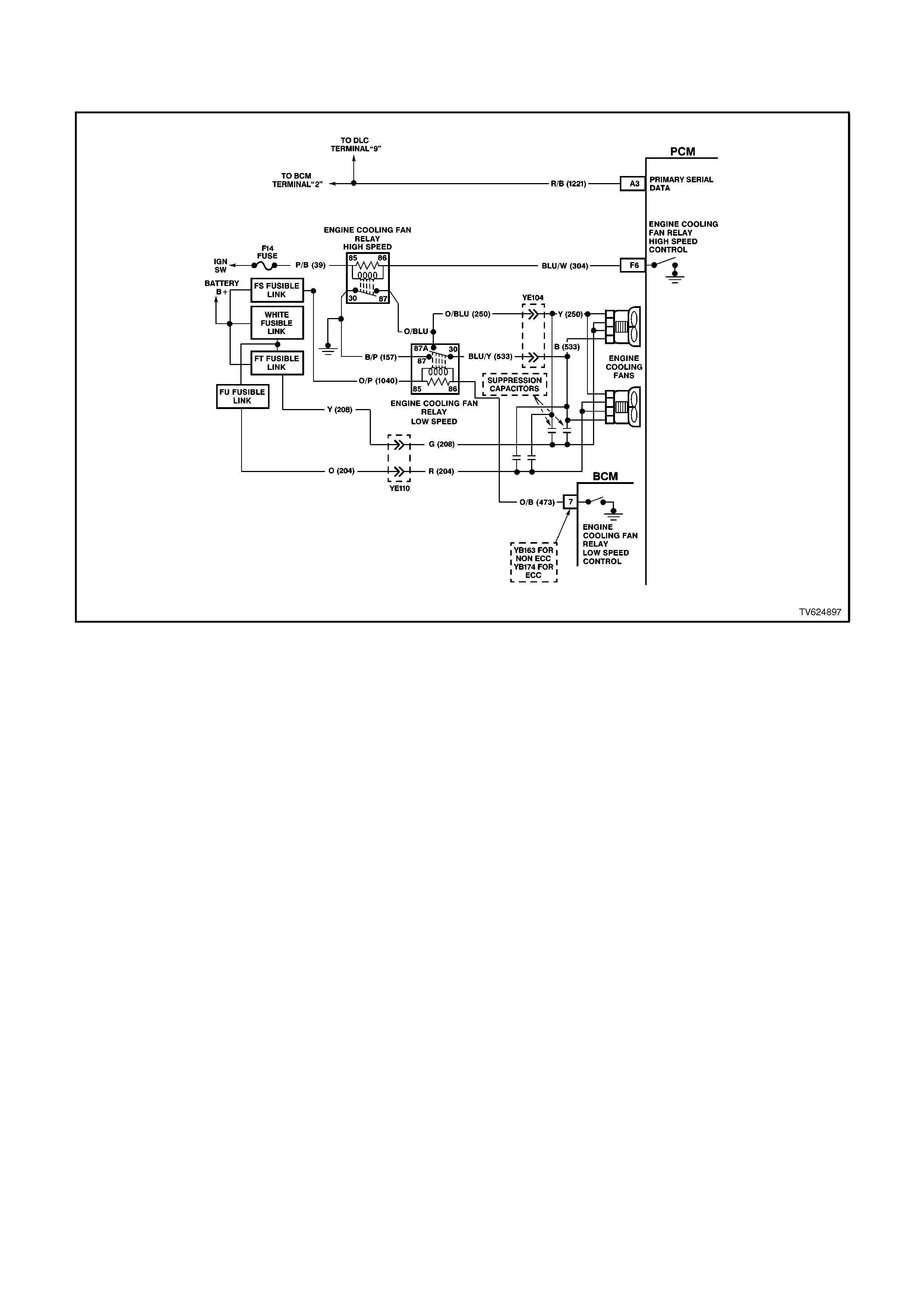
CHART A-12.2 V6 PCM - ELECTRI C FAN CONTROL
CIRCUIT DESCRIPTION:
The both V6 engine have two (2) two speed electric radiator fan motors which provides the primary means of
moving air through the engine radiator. The two (2) two speed electric cooling fan's are used to cool engine coolant
flowing through the radiator. It is also used to cool the refrigerant flowing through the A/C condenser.
The engine cooling fan high speed relay is controlled by the PCM. The PCM controls the earth path for the engine
cooling fan high speed relay.
The low speed of the electric fan is controlled by the PCM through special Data Communication to the BCM. The
BCM controls the earth path for the engine cooling fan low speed relay.
Both relays are used to control the earth paths to the electric motor's that drives both five bladed fan's.
Engine Cooling Fan
Low Speed.
The engine cooling fan low speed relay is energised by the BCM. The PCM determines when to enable the engine
cooling fan low speed based on inputs from the A/C request signal, vehicle speed and engine coolant temperature.
The engine cooling low speed fan will be turned "ON" when:
• A/C request indicated (YES) and
• Vehicle speed less than 54 Km/h
- OR -
• Coolant temperature is greater than 104 degrees C and will remain on until coolant temperature goes down
below 99 degrees C
ENGINE COOLING FAN HIGH SPEED:
The engine cooling fan high speed is controlled by the PCM based on input from the Engine Coolant Temperature
Sensor (ECT). The PCM will only turn "ON" the engine cooling fan high speed if the engine cooling low speed fan
has been "ON" for 2 seconds and the following conditions are satisfied.
• There is a BCM message response fault which will cause a DTC 92.
• An engine coolant temperature sensor failure is detected, such as DTC 14,15,16,17, or 91.
• Coolant temperature greater than 109 C.
If the fan low speed was "OFF" when the criteria was met to turn the fan high speed "ON", the fan high speed will
come "ON" 5 seconds after the fan low speed is turned "ON". The engine cooling fan High speed relay can also be
enable by the A/C Refrigerant Pressure Sensor. The A/C Refrigerant Pressure Sensor will provide a signal to the
PCM when A/C pressure becomes to high approximately 1770 kPa.

TEST DESCRIPTION:
Number(s) below refer to step number(s) on the diagnostic chart.
3. This checks the fused power circuit to the Radiator Fan High Speed Relay.
7. This step checks for proper power supply to both circuits of both fan motors.
STEP ACTION VALUE YES NO
1. Was the "On-Board
Diagnostic" (OBD) System
Check performed?
Go to Step 2. Go to OBD
System Check.
2. From Chart A-12.1
Check fusible links FS,
FT, FU, and White fusible
link for open.
Was a problem found?
Go to Step 8 Go to Step 3
3. 1. Ignition "OFF".
2. Remove Radiator
Fan High Speed
Relay.
3. Ignition "ON"
4. Probe relay socket,
circuit 39 with test
light connected to
earth
Is test light "ON" ?
Go to Step 4 Go to Step 10
4. 1. Ignition "ON".
2. Probe Radiator Fan
High Speed Relay
socket circuit 304
with a test light
connected to +12
volts.
3. Using scan tool,
Select HIGH FAN,
enable fan "ON" with
up/down arrows.
Is test light "ON"?
Go to Step 5 Go to Step 9
5. 1. Ignition "ON".
2. Reinstall Radiator
Fan High Speed
Relay.
3. Back-probe Radiator
Fan High Speed
Relay harness
connector circuit 250
with test light
connected to +12
volts.
4. Using scan tool,
Select HIGH FAN,
enable fan "ON" with
up/down arrow keys.
Is test light "ON"
Go to Step 6 Go to Step 11

STEP ACTION VALUE YES NO
6. 1. Ignition "ON".
2. Disconnect both
electric cooling fan
wiring harness
connector.
3. Probe both fan
harness connector,
circuits 533 and 250
with a test light to
+12 volts.
4. Using scan tool,
Select HIGH FAN,
enable fan "ON" by
pressing up/down
arrow keys.
Is test light "ON" for both
circuits ?
Go to Step 7 Go to Step 13
7. Probe both fan harness
connector power feed
circuits, with a test light
connected to earth.
Is test light "ON" for all
circuits ?
Go to Step 12 Go to Step 15
8. 1. Check for short to
earth that caused
fusible link to blow
2. Check that the
engine cooling fan
motor is not drawing
too much current.
Is action complete ?
Verify Repair
9. 1. Ignition "ON".
2. Using scan tool,
Select HIGH FAN,
enable output by
pressing up/down
arrow keys.
3. Backprobe PCM
terminal "F6" with a
test light connected
to +12 volts.
Is test light "ON"?
Go to Step 14 Go to Step 16
10. Repair open or short to
earth in circuit 39.
Replace fuse if blown.
Verify Repair

STEP ACTION VALUE YES NO
11. With test light connected
to +12 volts, back probe
Radiator Fan High Speed
Relay harness connector
circuit 157.
Does test light illuminate?
Go to Step 17 Go to Step 18
12. Check for poor connection
at both fan motor's. If OK,
replace the electric fan
motor that did not operate.
Verify Repair
13. Check for open in circuits
533 or 250.
Was a problem found?
Verify Repair Go to Step 18
14. Repair open in circuit 304. Verify Repair
15. Repair open circuit in fan
motor power circuit that
did not light test light.
Verify Repair
16. Check for short to voltage
in circuit 304, or faulty
connection at PCM, if OK
replace PCM.
Verify Repair
17. Replace Radiator Fan
High Speed Relay. Verify Repair
18. Check for open in earth
circuit 157.
Was a problem found?
Verify Repair Go to Step 19
19. Replace Radiator Fan
Low Speed Relay. Verify Repair

CHART A-12.3 V6 PCM - ELECTRI C FAN CONTROL
CIRCUIT DESCRIPTION:
The both V6 engine have two (2) two speed electric radiator fan motors which provides the primary means of
moving air through the engine radiator. The two (2) two speed electric cooling fan's are used to cool engine coolant
flowing through the radiator. It is also used to cool the refrigerant flowing through the A/C condenser.
The engine cooling fan high speed relay is controlled by the PCM. The PCM controls the earth path for the engine
cooling fan high speed relay.
The low speed of the electric fan is controlled by the PCM through special Data Communication to the BCM. The
BCM controls the earth path for the engine cooling fan low speed relay.
Both relays are used to control the earth paths to the electric motor's that drives both five bladed fan's.
ENGINE COOLING FA N LOW SPEED:
The engine cooling fan low speed relay is energised by the BCM. The PCM determines when to enable the engine
cooling fan low speed based on inputs from the A/C request signal, vehicle speed and engine coolant temperature.
The engine cooling low speed fan will be turned "ON" when:
• A/C request indicated (YES) and
• Vehicle speed less than 54 Km/h
- OR -
• Coolant temperature is greater than 104 degrees C and will remain on until coolant temperature goes down
below 99 degrees C
ENGINE COOLING FAN HIGH SPEED:
The engine cooling fan high speed is controlled by the PCM based on input from the Engine Coolant Temperature
Sensor (ECT). The PCM will only turn "ON" the engine cooling fan high speed if the engine cooling low speed fan
has been "ON" for 2 seconds and the following conditions are satisfied.
• There is a BCM message response fault which will cause a DTC 92.
• An engine coolant temperature sensor failure is detected, such as DTC 14,15,16,17, or 91.
• Coolant temperature greater than 109 C.
If the fan low speed was "OFF" when the criteria was met to turn the fan high speed "ON", the fan high speed will
come "ON" 5 seconds after the fan low speed is turned "ON". The engine cooling fan High speed relay can also be
enable by the A/C Refrigerant Pressure Sensor. The A/C Refrigerant Pressure Sensor will provide a signal to the
PCM when A/C pressure becomes to high approximately 1770 kPa.

TEST DESCRIPTION:
Number(s) below refer to step number(s) on the diagnostic chart.
3. This checks the FS fusible link power supply to the Radiator Fan Low Speed Relay.
4. This step checks for proper BCM operation for the Radiator Fan Low Speed Relay.
STEP ACTION VALUE YES NO
1. Was the "On-Board
Diagnostic" (OBD) System
Check performed?
Go to Step 2. Go to OBD
System Check.
2. 1. Ignition "OFF".
2. Remove Radiator
Fan Low Speed
Relay.
3. Probe relay socket,
circuit 250 with a test
light connected to
+12 volts.
Is test light "ON" ?
Go to Step 7 Go to Step 3
3. 1. Ignition "OFF".
2. Remove Radiator
Fan Low Speed
Relay
3. Ignition "ON"
4. Probe relay socket,
circuits 1040 with test
light connected to
earth
Is test light "ON" ?
Go to Step 4 Go to Step 9
4. 1. Ignition "ON".
2. Probe Radiator Fan
Low Speed Relay
socket, circuit 473
with a test light
connected to +12
volts.
3. Using scan tool,
Select LOW FAN,
enable fan "ON" with
up/down arrow keys.
Is test light "ON"?
Go to Step 5 Go to Step 8
5. 1. Ignition "ON".
2. Reinstall Radiator
Fan Low Speed
Relay.
3. Back-probe low
speed relay wiring
harness connector,
circuit 533 with test
light connected to
+12 volts.
4. Using scan tool,
Select LOW FAN,
enable fan "ON" with
up/down arrow keys.
Is test light "ON"
Go to Step 10 Go to Step 6

STEP ACTION VALUE YES NO
6. 1. Ignition "OFF".
2. Disconnect both
electric cooling fan
wiring harness
connector.
3. Probe both wiring
harness connector
circuit's 533 with test
light connected to
+12 volts.
4. Using scan tool,
Select LOW FAN,
enable fan "ON" with
up/down arrow keys.
Is test light "ON"
Go to Step 14 Go to Step 12
7. Repair short to earth in
circuit 250.
Is action complete?
Verify Repair
8. 1. Ignition "ON".
2. Using scan tool,
Select LOW FAN,
enable fan "ON".
3. Backprobe BCM
terminal "7" with a
test light connected
to +12 volts.
Is test light "ON"?
Go to Step 13 Go to Step 15
9. Repair open in circuit
which causes test light not
to come "ON".
Is action complete?
Verify Repair
10. Replace Radiator Fan
Low Speed Relay.
Is action complete?
Verify Repair
11. Repair short to earth Verify Repair
12. Repair open in circuits
533 or 250.
Is action complete?
Verify Repair
13. Repair open in circuit 473
between BCM and
Radiator Fan Low Speed
Relay.
Is action complete?
Verify Repair
14. Replace Radiator fan
motor that did not operate.
Is action complete?
Verify Repair
15. Check for faulty
connection at BCM, if OK
replace BCM.
Is action complete?
Verify Repair
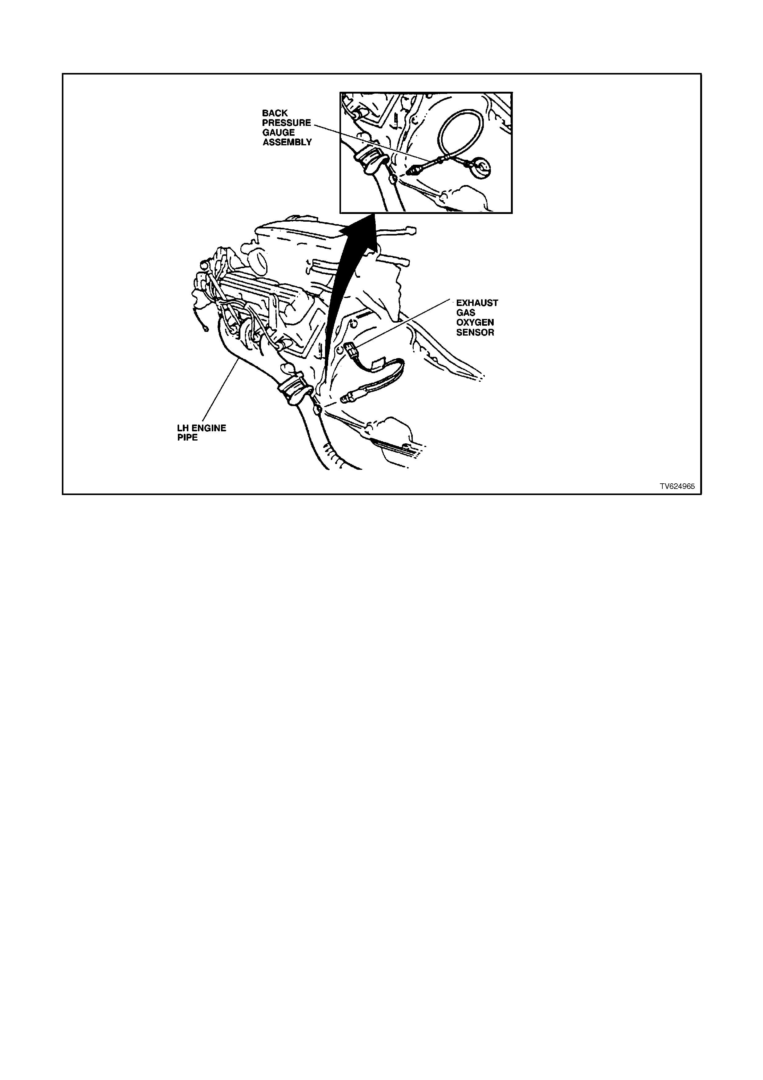
CHART A-13 V6 PCM - RESTRICTED EXHAUST CHECK
There are times when a restricted exhaust can cause a variety of owner complaints. Below is a list of some of these
owner complaints.
• No power, sluggish
• Hesitation on acceleration
• Surges while driving
• Poor fuel economy
• Stalling
• Hard starting
Things that could cause a restricted exhaust:
A. Collapsed exhaust pipe.
B. Muffler. Loose baffles may cause internal restriction
C. Catalytic converter. Things that can cause a catalytic converter to become restricted: (1) The use of LEADED
FUEL (2) A very rich-running engine. This rich-running condition could be caused by fuel pressure too high, or
by a malfunction in the engine control system (3) Engine in a bad state of tune. Worn parts in the ignition
system can cause an engine misfire, which sends unburned fuel into the exhaust system. The catalytic
converter "sees" this unburned fuel as a rich-running condition. (4) Push-starting the engine. This can send a
tremendous amount of unburned fuel into the exhaust system.

STEP ACTION VALUE YES NO
1. Was the "On-Board
Diagnostic" (OBD) System
Check performed?
Go to Step 2. Go to OBD
System Check in
this Section.
2. Carefully remove O2
sensor.
Did O2 sensor remove
from exhaust system ?
Go to Step 3 Go to Step 6
3. 1. Install exhaust back
pressure gauge in
place of removed O2
sensor.
2. Ignition "ON", engine
started.
3. Observe the exhaust
system back
pressure reading on
the gauge.
Is the reading below the
specified value ?
8.6 kPa Go to Step 4 Go to Step 7
4. Accelerate engine to 2000
RPM and observe reading
on gauge.
Is reading on gauge below
the specified value ?
20.7
kPa Go to Step 5 Go to Step 7
5. No problem with exhaust
system.
NOTE:
Make sure to coat threads
of O2 sensor with a
specified anti-seize
compound prior to
installation.
Is action complete ?
Go to OBD
System Check in
this Section

STEP ACTION VALUE YES NO
6. If the O2 sensor will not
remove from the exhaust
system, make sure that
the exhaust system is
above 60 C. Excessive
force may damage
threads.
If the O2 sensor cannot
be removed , the exhaust
pipe and O2 sensor may
need to be replaced.
Was removal of O2
sensor successful ?
Go to Step 3 Verify Repair
7. NOTE:
If there are no obvious
reasons for the excessive
back pressure, a
restricted catalytic
converter should be
suspected and replaced
using current
recommended
procedures. Refer to
Things that could cause
a restricted exhaust: for
possible causes.
NOTE:
Make sure to coat threads
of O2 sensor with a
specified anti-seize
compound prior to
installation.
Is action complete ?
Verify Repair and
Go to OBD
System Check in
this Section
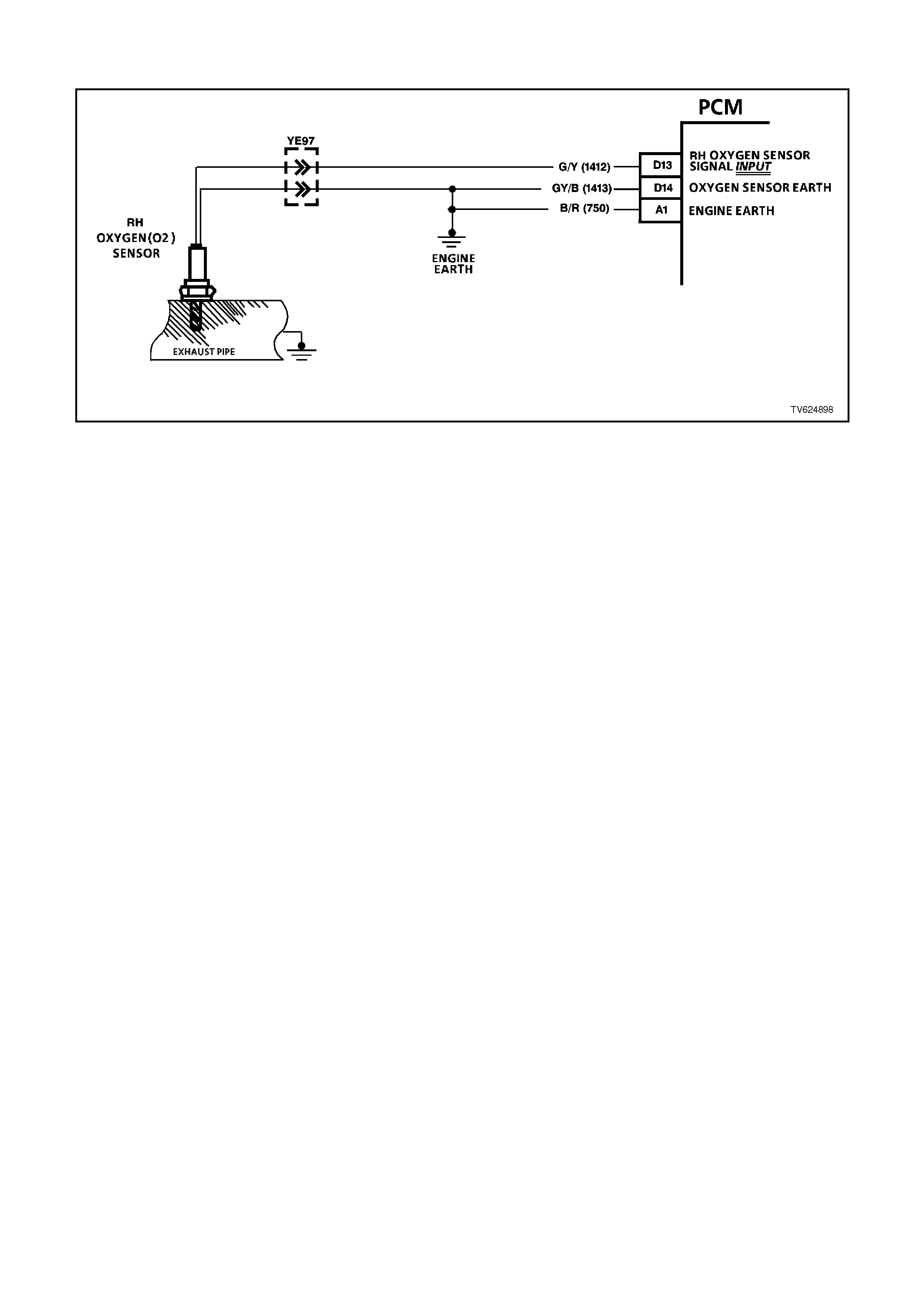
DTC 13 V6 PCM - RI GHT HAND (RH) NO OXYGEN SENSOR SIGNAL
CIRCUIT DESCRIPTION:
The exhaust oxygen sensor is mounted in the exhaust pipe with the sensing portion exposed to exhaust gases.
After the sensor is hot (360 degrees C), it becomes a voltage generator, producing a "changing" voltage. This
voltage ranges from approximately 100 millivolts with a "lean" exhaust, to 900 millivolts with a "rich" exhaust. When
the sensor is cold (below 360 degrees C) it acts like an open circuit and produces almost no voltage. The PCM
supplies a very small "bias" voltage between terminals D13 and D14, normally about 450 millivolts. If measured with
the 10 megaohm digital voltmeter, it may measure as low as 350 millivolts. When the sensor is hot, it's output
overshadows this PCM supplied voltage.
When the fuel system is correctly operating in the closed-loop mode, the sensor output is changing several times
per second, going above and below a mid-point range of 490-500 millivolts at a hot idle. The PCM compares the
voltage between the sensor signal and sensor earth terminals and decides the needed fuel mixture correction. The
PCM also monitors the changing voltage, watching for transitions above and below the mid-point range, to decide
when to operate in the closed-loop mode. An open circuit, defective, or contaminated sensor could cause the
voltage to stay within a 410-477 millivolt band too long, keeping the system in open-loop and setting a DTC 13.
DTC 13 WILL SET IF:
No DTC 19, DTC 21 or DTC 22 is active and all conditions exist for 26 seconds:
• Engine has been running for at least 4 minutes.
• Engine coolant temperature is more than 85 degrees C
• Throttle Position (TP) sensor voltage indicates the throttle is open more than 15% and
• RH O2 sensor voltage stays between 410-477 millivolts.
When DTC 13 is active (MIL) ("Check Powertrain" lamp "ON"), the PCM will operate the fuel system in the open-
loop mode.
TEST DESCRIPTION:
Number(s) below refer to circled number(s) on the diagnostic chart.
2. The Tech 2 scan tool allows you to read the same oxygen sensor voltage the PCM is using for its calculations.
3. This step simulates a lean exhaust indication to the PCM. If the PCM and wiring are OK, the PCM will see the
lean indication and the Tech 2 scan tool should display O2 voltage below 200 mV.
8. In doing this test, use only a high impedance digital volt-ohm meter. This test checks the continuity of circuits
1412 and 750. If circuit 750 is open, the PCM voltage on circuit 1412 will be over 0.6 volts (600 mV).
9. Earth circuit 750 is a separate wire to the PCM from the engine. The PCM uses this circuit to compare it with
the voltage on circuit 1412. It completes the earth path for the PCM's oxygen sensor circuitry, and must be a
complete, clean, and tight connection to the engine.

DIAGNOSTIC AIDS:
Normal Tech 2 scan tool voltage varies between 100 mV to 999 mV while in "Closed Loop". DTC 13 sets if voltage
remains between 410 and 477 millivolts, but the system will go "Open Loop" before the "Check Powertrain" lamp is
turned "ON".
Refer to "Intermittents" in Section 6C1-2B SYMPTOMS . To diagnose the oxygen sensor, refer CHART A-6.3. in
this Section
NOTE:
Oxygen Sensor Contamination - If fuel containing lead or silicone is used, or engine repairs using unapproved RTV
gasket sealer are performed, the sensor may be contaminated. It may send a "False" rich exhaust indication to the
PCM, and the PCM will attempt to drive the fuel system lean to compensate. Poor driveability or a Diagnostic
Trouble Code 13 could result. If this happens, the sensor will need to be replaced, but every attempt to locate the
source of contamination should be pursued.
STEP ACTION VALUE YES NO
1. Was the "On-Board
Diagnostic" (OBD) System
Check performed?
Go to Step 2. Go to OBD
System Check in
this Section.
2. 1. Engine at normal
operating
temperature (above
85 degrees C).
2. Run engine at
approximately 600 to
1800 RPM for two
minutes.
Is Tech 2 scan tool
oxygen sensor voltage
between specified values?
410-477
mV Go to Step 3 If no additional
DTCs were
stored, refer to
"Intermittents" in
Section 6C1-2B
SYMPTOMS.
3. 1. Disconnect O2
Sensor wiring
harness.
2. Jumper harness
circuit (PCM side) to
earth.
With engine running, does
Tech 2 scan tool display
O2 voltage at or below
specified value?
0.2 Volt
(200
mV)
Go to Step 4 Go to Step 6
4. Check for a faulty
connection at the oxygen
sensor.
Was a poor connection
found?
Verify Repair Go to Step 5
5. Replace O2 sensor.
Is action complete? Verify Repair
6. 1. Remove jumper.
2. Ignition "ON," engine
"OFF".
3. Check voltage of
circuit 1412 (PCM
side) at O2 sensor
harness connector
using a DVM.
Is voltage between
specified values?
0.3 - 0.6
Volts
(300-
600 mV)
Go to Step 7 Go to Step 8
7. Replace PCM.
Refer to Section 6C1-3
Service Operations, for
PCM Security Link
procedure.
Is action complete?
Verify Repair

STEP ACTION VALUE YES NO
8. 1. Remove jumper.
2. Ignition "ON," Engine
"OFF".
3. Check voltage of
circuit 1412 (PCM
side) at O2 sensor
harness connector
using a DVM.
Is voltage over specified
value?
0.6 Volts
(600
mV)
Go to Step 9 Go to Step 10
9. Check for an open or
faulty connection in circuit
750.
Was a problem found?
Verify Repair Go to Step 7
10. Check for an open or
faulty connection in circuit
1412.
Was a problem found?
Verify Repair Go to Step 7

DTC 14 V6 PCM - ENGI NE COOLANT TEMPERATURE (ECT)
(SIGNAL VOLTAGE LOW)
CIRCUIT DESCRIPTION:
The Engine Coolant Temperature (ECT) sensor uses a thermistor to control the signal voltage to the PCM. The
PCM applies about 5 volts on circuit 410 to the sensor. When the engine coolant is cold, the sensor (thermistor)
resistance is high, therefore the PCM will see high signal voltage about 4.0 - 4.5 volts.
As the engine coolant warms, the sensor resistance becomes less, and the PCM sees a lower signal voltage. At
normal engine operating temperature (85 degrees C to 95 degrees C), the voltage should measure about 2.2 to 1.8
volts.
A DTC 14 may enable TCC operation when cold.
DTC 14 WILL SET IF:
• Time since engine started is greater than 20 seconds and
• ECT sensor signal voltage is less than 0.3 volts, indicating an engine coolant temperature at or above 140 C for
one second.
When DTC 14 is set, the PCM will default to a 95° C value for engine operation.
TEST DESCRIPTION:
Number(s) below refer to step number(s) on the diagnostic chart.
3. This test will determine if circuit 410 is shorted to earth which will cause the conditions for DTC 14.
4. If checking resistance at the engine coolant temperature sensor is difficult because of sensor location,
disconnect the PCM connectors and check resistance between engine coolant temperature signal and sensor
earth terminals.
DIAGNOSTIC AIDS:
Check harness routing for a potential short to earth in circuit 410.
Check terminals at ECT sensor for a good connector.
The Tech 2 scan tool reads engine coolant temperature in degrees Celsius. After engine is started, the temperature
should rise steadily to about 90 C then stabilise when thermostat opens.
The "Temperature to Resistance Value" scale may be used to test the engine coolant temperature sensor at various
temperature levels to evaluate the possibility of a "shifted" (mis-scaled) sensor. A "shifted" sensor could result in
poor driveability complaints.
When Diagnostic Trouble Code 14 is set, the TCC will be applied with a cold engine and the engine cooling fan will
be turned "ON".
Refer to "Intermittents" in Section 6C1-2B SYMPTOMS .

ECT SENSOR TABLE TEMP. TO RESISTANCE VALUES
(APPROXIMATE)
COHMS
110 134
100 180
90 244
70 474
40 1,483
30 2,268
20 3,555
0 9,517
-10 16,320
-20 28,939
STEP ACTION VALUE YES NO
1. Was the "On-Board
Diagnostic" (OBD) System
Check performed?
Go to Step 2. Go to OBD
System Check in
this Section.
2. Using Tech 2 scan tool,
select "Eng. Coolant
Temp" on the data
display.
Is the "Eng. Coolant
Temp" display value at or
above the specified
value?
140
degrees
C
Go to Step 3 If no additional
DTCs were
stored, refer to
"Intermittents" in
Section 6C1-2B
SYMPTOMS.
3. 1. Ignition "Off".
2. Disconnect engine
coolant temperature
sensor wiring
harness.
3. Ignition "On".
Does Tech 2 scan tool
display "Eng. Coolant
Temp" below specified
value?
-30
degrees
C
Go to Step 4 Go to Step 7
4. Check resistance across
engine coolant
temperature sensor
terminals.
Does DVM ohms reading
match the specified
values for
temperature to sensor
resistance?
See
table
above.
Go to Step 5 Go to Step 8

STEP ACTION VALUE YES NO
5Check for intermittent or
loose terminals in sensor
harness connector, or for
the 2 terminals shorting
together when connected
to the sensor.
Was a faulty connection
found?
Verify Repair Go to Step 6
6Replace PCM.
Refer to Section 6C1-3
Service Operations, for
PCM Security Link
procedure.
Is action complete?
Verify Repair
7Check circuit 410 for short
to earth or to sensor
earth.
Was a short found?
Verify Repair Go to Step 6
8Replace ECT sensor.
Is replacement complete? Verify Repair
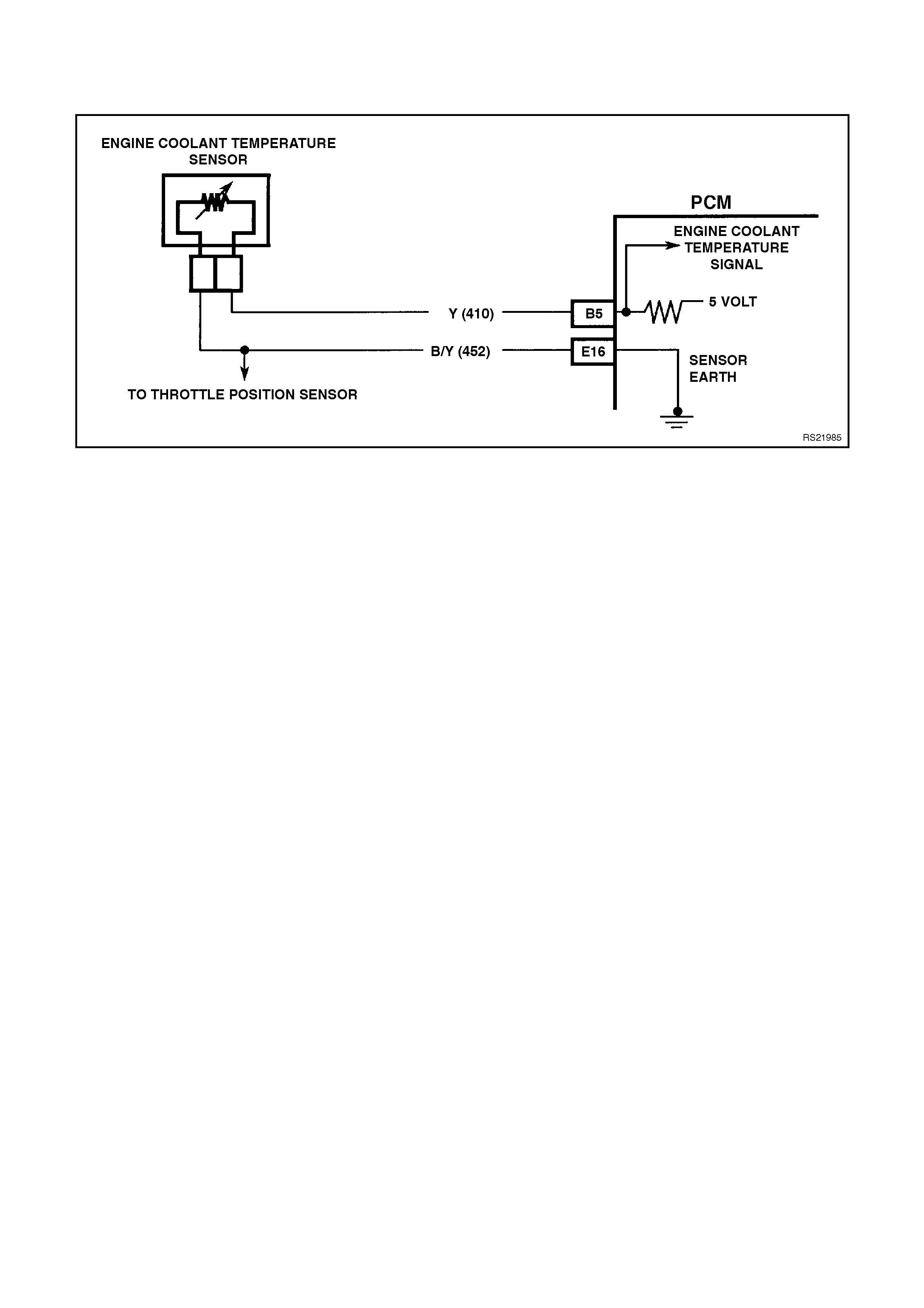
DTC 15 V6 PCM - ENGI NE COOLANT TEMPERATURE (ECT)
(SIGNAL VOLTAGE HIGH)
CIRCUIT DESCRIPTION:
The Engine Coolant Temperature (ECT) sensor uses a thermistor to control the signal voltage to the PCM. The
PCM applies about 5 volts on circuit 410 to the sensor. When the engine coolant is cold, the sensor (thermistor)
resistance is high, therefore the PCM will see high signal voltage, about 4 - 4.5 volts.
As the engine coolant warms, the sensor (thermistor) resistance becomes less, and the PCM sees a lower signal
voltage. At normal engine operating temperature (85 degrees C to 95 degrees C), the voltage will measure about
2.2 to 1.8 volts.
A Diagnostic Trouble Code 14 may enable TCC operation when cold.
DTC 15 WILL SET IF:
• Time since engine started is greater then 10 seconds, and
• ECT input signal voltage is greater than 4.64 volts, indicating an engine coolant temperature at or lower than -30
degrees C for one second.
When DTC 15 is set, the PCM will default to a 95° C value for engine operation.
TEST DESCRIPTION:
Number(s) below refer to step number(s) on the diagnostic chart.
3. This test simulates a Diagnostic Trouble Code 15. If the PCM recognises the low signal voltage, (high
temperature) and the Tech 2 scan tool reads 130 C or above, the PCM and wiring are OK.
4. This test will determine if circuit 410 is open. There should be an open circuit voltage of 5 volts present at
Engine Coolant Temperature (ECT) sensor harness connector if measured with a DVM. By jumpering this 5
volt signal to earth, the PCM should recognise this change.
DIAGNOSTIC AIDS:
A Tech 2 scan tool reads engine coolant temperature in degrees Celsius. After engine is started, the temperature
should rise steadily to about 90 C then stabilise when thermostat opens.
A faulty connection, or an open in circuit 410 or circuit 452 will result in a Diagnostic Trouble Code (DTC) 15.
If DTC 21 is also set, check circuit 452 for faulty wiring or connections. Check terminals at sensor for a good
connection.
The "Temperature to Resistance Value" scale may be used to test the engine coolant temperature sensor at various
temperature levels to evaluate the possibility of a "shifted" (mis-scaled) sensor. A "shifted" sensor could result in
poor driveability complaints.
When the Diagnostic Trouble Code 15 is set, the TCC will be applied with a cold engine and the engine cooling fan
will be forced "ON".
Refer to "Intermittents" in Section 6C1-2B SYMPTOMS .

ECT SENSOR TABLE TEMP. TO RESISTANCE VALUES
(APPROXIMATE)
COHMS
110 134
100 180
90 244
70 474
40 1,483
30 2,268
20 3,555
0 9,517
-10 16,320
-20 28,939
STEP ACTION VALUE YES NO
1. Was the "On-Board
Diagnostic" (OBD) System
Check performed?
Go to Step 2. Go to OBD
System Check in
this Section.
2. 1. Using Tech 2 scan
tool, select "Eng.
Coolant Temp" on
the data display.
Is the "Eng. Coolant
Temp" display value at or
between the specified
value ?
-30 to -
40
degrees
C
Go to Step 3 If no additional
DTCs were
stored, refer to
"Intermittents" in
Section 6C1-2B
SYMPTOMS.
3. 1. Ignition "OFF".
2. Disconnect engine
coolant temperature
sensor powertrain
wiring harness.
3. Jumper harness
terminals together.
4. Ignition "ON".
Does Tech 2 scan tool
display "Eng. Coolant
Temp" at or above
specified value?
130
degrees
C
Go to Step 10 Go to Step 4
4. Jumper circuit 410 to
earth.
Does Tech 2 scan tool
display "Eng. Coolant
Temp" at or above
specified value?
130
degrees
C
Go to Step 5 Go to Step 8
5. Check resistance across
engine coolant
temperature sensor
terminals.
Does DVM reading match
the specified values for
temperatures to sensor
resistance?
See
table
above
Go to Step 6 Go to Step 9

STEP ACTION VALUE YES NO
6. Check for intermittent or
loose terminals in sensor
harness connector.
Terminals may not be
contacting the sensor
when connected.
Was a problem found?
Verify Repair Go to Step 7
7. Replace PCM.
Refer to Section 6C1-3
Service Operations, for
PCM Security Link
procedure.
Is action complete?
Verify Repair
8. Check circuit 410 for open
or faulty connection at
PCM.
Was a problem found?
Verify Repair Go to Step 7
9. Replace ECT sensor.
Is action complete? Verify Repair
10. Check for faulty
connection.
Was a problem found?
Verify Repair Go to Step 9
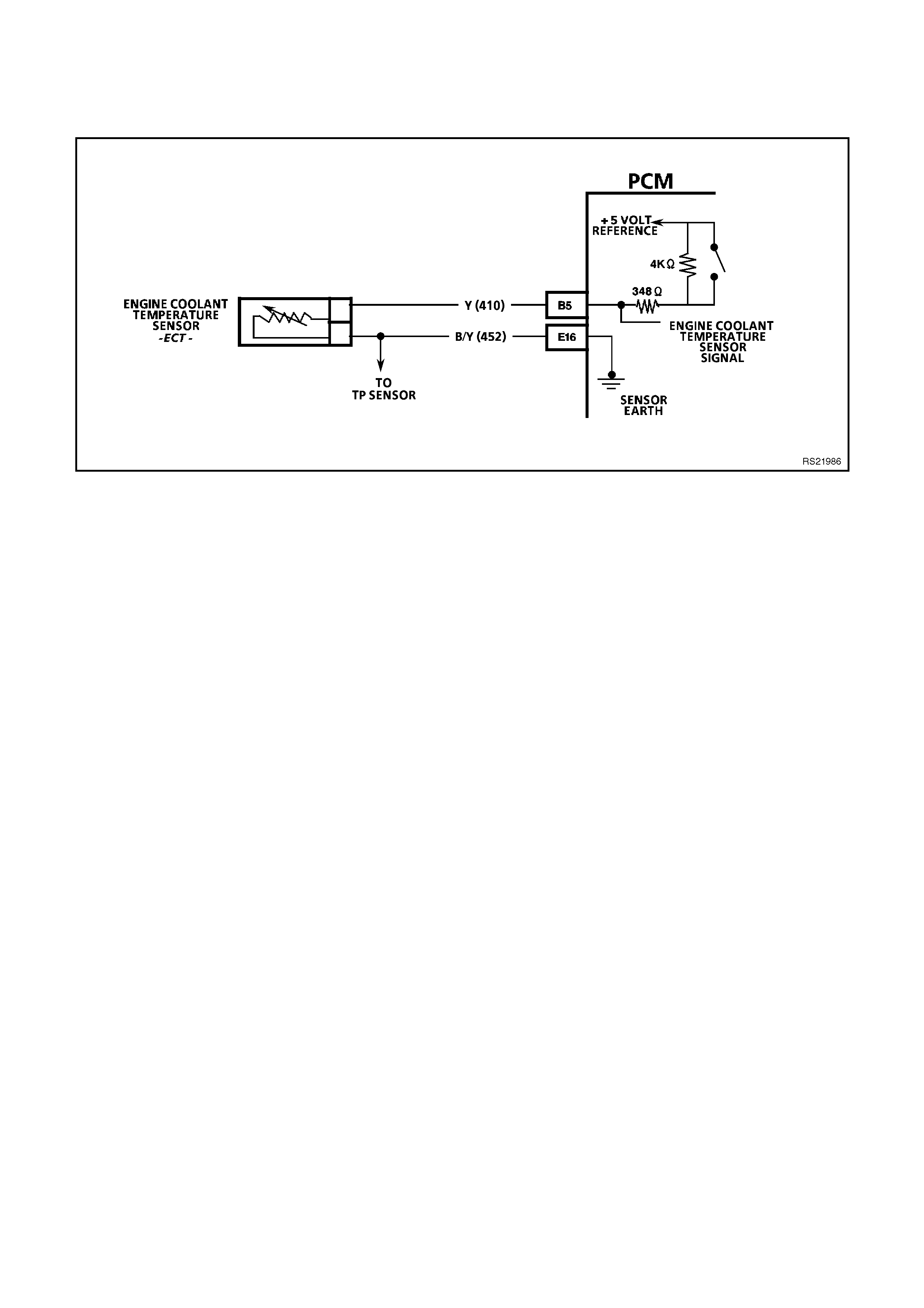
DTC 16 V6 PCM - ENGI NE COOLANT TEMPERATURE (ECT)
(SIGNAL VOLTAGE UNSTABLE)
CIRCUIT DESCRIPTION:
The Engine Coolant Temperature (ECT) sensor is a thermistor located in a coolant passage on the engine. When
engine coolant temperature is cold, the sensor has a high resistance. As temperature increases, the resistance of
the sensor decreases. The PCM provides a five volt signal to the engine coolant sensor, which is also connected to
PCM earth. The PCM reads the voltage drop on the signal line to determine engine coolant temperature.
DTC 16 WILL SET IF:
• DTC 14, 15, or 17 are not set.
• The engine has been operating for more than 11 seconds, and
• ECT reading changes more than 400 mV in 200 milliseconds.
When DTC 16 is set, the PCM will default to a 95° C value for engine operation.
TEST DESCRIPTION:
Numbers below refer to step(s) on the diagnostic chart.
2. This step checks the wiring of the sensor for a intermittent fault.
DIAGNOSTIC AIDS:
When attempting to diagnose an intermittent problem, use the snapshot mode of the Tech 2 scan tool, to review
diagnostic information.
This DTC is more likely to set on a cold engine than on a hot engine because of the pull up resistors in the PCM.
When DTC 16 is set, the PCM will turn "ON" the engine cooling fan.
If DTC 16, 53 and 57 are set, check for short to voltage on "Diagnostic Test" line. circuit 451.

STEP ACTION VALUE YES NO
1. Was the "On-Board
Diagnostic" (OBD) System
Check performed?
Go to Step 2. Go to OBD
System Check in
this Section.
2. 1. Install Tech 2 scan
tool and set up
snapshot mode to
trigger on DTC 16.
2. Watch the Tech 2
scan tool while
wiggling the ECT
sensor connector.
Does the "Eng. Coolant
Temp" reading change
sharply?
Go to Step 8 Go to Step 3
3. Wiggle and tug the ECT
sensor harness.
Does the "Eng. Coolant
Temp" reading change
sharply?
Go to Step 9 Go to Step 4
4. Wiggle and tug the
harness at the PCM.
Does the "Eng. Coolant
Temp" reading change
sharply?
Go to Step 10 Go to Step 5
5. Lightly tap on the PCM.
Does the "Eng. Coolant
Temp" reading change
sharply?
Go to Step 6 DTC 16 is
intermittent. Refer
"Diagnostic Aids".
6. Make sure PCM is
mounted securely to
vehicle.
Was a problem found?
Verify Repair Go to Step 7

STEP ACTION VALUE YES NO
7. Replace PCM.
Refer to section 6c1-3
Service Operations, for
PCM Security Link
procedure.
Is action complete?
Verify Repair
8. 1. Check ECT sensor
connector.
2. Check the tightness
of the female
terminal grip with a
spare male terminal.
3. Inspect connectors
for corrosion. If
connectors are
corroded, try cleaning
with electronic part
cleaner and retest.
4. If these repairs do
not resolve the
problem, replace
terminals.
Are repairs complete?
Verify Repairs
9. 1. Check for an open in
the ECT harness.
2. Check for broken
strands of wire in
ECT sensor harness.
3. Check for cuts or
pinches in ECT
sensor harness.
4. Make repairs as
necessary.
Are repairs complete?
Verify Repairs
10. 1. Check the ECT
sensor connection at
the PCM.
2. Check tightness of
the female terminal
grip with a spare
male terminal.
3. Inspect connectors
for corrosion. If
connectors are
corroded, try cleaning
with electronic parts
cleaner and retest.
4. Remove connector
strain relief and
remove terminal from
connector to check
for broken locking
tang.
Are repairs complete?
Verify Repairs
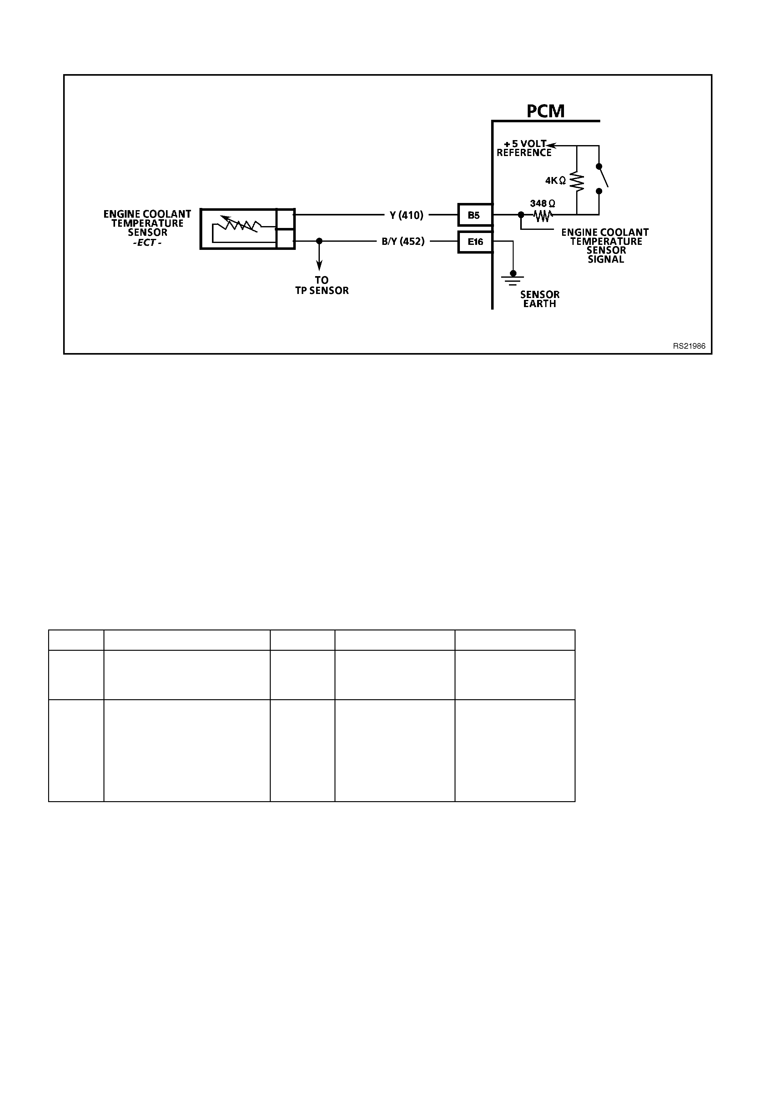
DTC 17 V6 PCM - PCM ERROR - ECT CIRCUIT
CIRCUIT DESCRIPTION:
The PCM uses two different internal pull-up resistors to increase resolution throughout the entire range of engine
operating temperatures. When the engine coolant temperature is less than 50 degrees C, the 4K ohm resistor is
used. When temperature is above 50 degrees C, the PCM switches to the 348 ohm resistor. If the pull-up resistor
does not switch, DTC 17 will set.
DTC 17 WILL SET IF:
• The engine has been operating for more than 10 seconds, and
• The pull-up resistor inside the PCM switches and there is less than a 60 mV change in the engine coolant
temperature signal.
TEST DESCRIPTION:
Number(s) below refer to step(s) on the diagnostic chart.
2. DTC 17 is an internal fault within the PCM. The PCM must be replaced!
DIAGNOSTIC AIDS:
When DTC 17 is set, the PCM will turn "ON" the engine cooling fan.
STEP ACTION VALUE YES NO
1. Was the "On-Board
Diagnostic" (OBD) System
Check performed?
Go to Step 2. Go to OBD
System Check in
this Section.
2. Replace PCM.
Refer to Section 6C1-3
Service Operations, for
PCM Security Link
procedure.
Is action complete?
Verify Repair

DTC 18 V6 PCM - EGR FLOW FAULT (NON SUPERCHARGED ENGINE ONLY)
CIRCUIT DESCRIPTION:
An Exhaust Gas Recirculation (EGR) system is used to lower Oxides of Nitrogen (NOx) emission levels caused by
high combustion temperatures. It accomplishes this by feeding small amounts of exhaust gases back into the
combustion chamber. When the air/fuel mixture is diluted with the exhaust gases, combustion temperatures are
reduced.
The linear EGR valve is designed to accurately supply exhaust gases to the engine without the use of intake
manifold vacuum. The valve controls exhaust flow going into the intake manifold from the exhaust manifold through
an orifice with a PCM controlled pintle. The PCM controls the pintle position using inputs from engine RPM, Engine
Coolant Temperature (ECT), and Mass Air Flow (MAF) sensor. The PCM then commands the EGR valve to operate
when necessary by controlling a earth signal through the PCM. This can be monitored on a scan tool as the EGR
POS COMMANDED. Ignition voltage is supplied to the valve through a fuse.
The PCM monitors the results of its command through a feedback signal. By sending a 5 volt reference and a earth
signal to the EGR valve, a voltage signal representing the EGR valve pintle position is sent to the PCM. This
feedback signal can also be monitored on a scan tool and is the actual position of the EGR pintle. The EGR POS
FEEDBACK should always be near the commanded or EGR POS COMMANDED .
DTC 18 WILL SET IF:
• Engine speed is between 700 and 1100 RPM.
• Engine Coolant Temperature (ECT) is greater than 80°C (176°F).
• Vehicle speed is above 37 KM/H.
• Idle Air Control (IAC) hasn't changed more than 5 counts.
• Throttle Position less than 1%.

TEST DESCRIPTION:
Number(s) below refer to the step number(s) on the Diagnostic chart.
1. The OBD System Check prompts the technician to complete some basic checks and store the freeze frame
and fault records data on the scan tool if applicable. This creates an electronic copy of the data taken when the
fault occurred. The information is then stored on the scan tool for later reference.
2. This step verifies if the exhaust system has been modified.
3. Visually and physically inspect the EGR passages and valve for excessive carbon deposits or damage.
4. This step checks to see if the EGR ports are blocked
5. This step verifies if the fault is present and also verifies if a repair corrected the problem.
DIAGNOSTIC AIDS:
Check for the following conditions:
A poor connection or damaged harness. Inspect the wiring harness for damage. If the harness appears to be OK,
observe the EGR POS FEEDBACK display on the scan tool while moving connectors and wiring harnesses related
to the EGR valve. A change in the display will indicate the location of the fault.
NOTICE:
If the EGR valve shows signs of excessive heat, check the exhaust system for blockage (possibly a plugged
converter).

STEP ACTION VALUE YES NO
1. Was the On-Board
Diagnostic (OBD) System
Check performed?
Go to Step 2 Go to OBD
System Check
2. 1. Inspect the exhaust
system for
modification of
original installed
parts or leaks.
2. If a problem was
found, repair exhaust
system as
necessary.
Was a condition present
that required repair?
Go to Step 5 Go to Step 3
3. 1. Remove the EGR
valve.
2. Visually and
physically inspect the
pintle, valve
passages and the
adaptor for excessive
deposits or any kind
of a restriction.
3. If a problem is found,
clean or replace EGR
system components
as necessary.
Was a condition present
that required repair?
Go to Step 5 Go to Step 4
4. 1. Remove the EGR
from the intake
manifold.
2. Inspect the manifold
EGR ports for a
blockage caused by
excessive deposits
other damage.
3. If a problem is found,
correct the condition
as necessary.
Was a condition present
that required repair?
Go to Step 5 Refer to
Diagnostic Aids
5. 1. Using the scan tool,
clear the DTCs.
2. Start the engine and
allow the engine to
idle until the
specified engine
coolant temperature
is reached.
3. Operate the vehicle
within the conditions
for setting this DTC
as specified in the
supporting text.
Does the scan tool
indicate DTC 18 set?
90°C Go to Step 2 Verify Repair
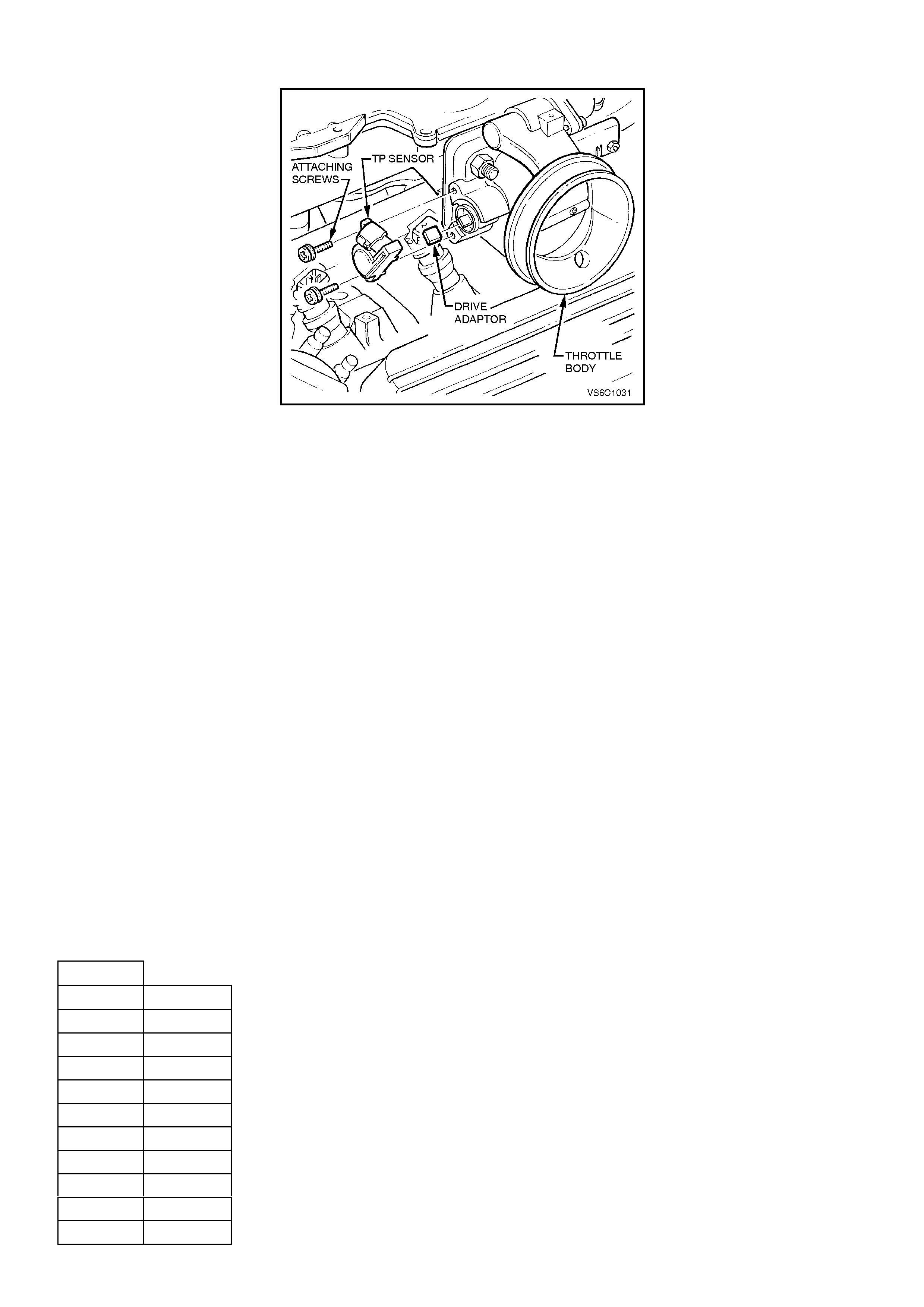
DTC 19 V6 PCM - THROTTLE POSI TION (TP) SENSOR STUCK
CIRCUIT DESCRIPTION:
The Throttle Position (TP) sensor provides a voltage signal that changes relative to the throttle blade angle. Signal
voltage will vary from about 0.25 to 1.25 volts at idle to about 4 volts at Wide Open Throttle (WOT).
The TP sensor signal is one of the most important inputs used by the PCM for transient fuelling and transmission
control and for most of the PCM control outputs.
Diagnostic Trouble Code (DTC) 19 is used to detect a stuck open or TP sensor. DTC 19 detects if the TP sensor
does not return with the throttle blade when decelerating.
DTC 19 WILL SET IF:
• The Throttle Position (TP) sensor percentage of opening angle indicated is greater than the RPM that can be
reached with a Mass Air Flow reading of less than 301 mg/cyl for 20 seconds.
When DTC 19 is set, the PCM will calculate throttle position based off of IACV and MAF for engine and
transmission operation.
DIAGNOSTIC AIDS:
A Tech 2 scan tool reads throttle position in volts. With ignition "ON'' or at idle, TP sensor signal voltage should read
about 0.25 to 1.25 volts with the throttle closed and increase at a steady rate as throttle is moved toward Wide Open
Throttle (WOT).
The Tech 2 scan tool will read throttle angle. 0%=closed throttle; 100%=WOT.
If voltage is steady above DTC 22 voltage criteria and below DTC 21 voltage criteria, check for a short to voltage on
the TP Sensor signal circuit.
Refer to "Intermittents" in Section 6C1-2B SYMPTOMS .
FOR EXAMPLE:
If the TP sensor indicated that the angle of opening is greater than 20% and the engine is operating at 800 RPM or
less, with a MAF sensor reading of 301 mg/cyl or less, then the TP sensor is stuck open.
DTC 19 CRITERIA TABLE MAF LESS THAN 301 MG/CYL.
(APPROXIMATE)
TPS%
V6 RPM
20 800
22 1,200
27 1,600
29 2,000
33 2,400
37 2,800
39 3,200
40 3,600
41 4,000
44 4,400

STEP ACTION VALUE YES NO
1. Was the "On-Board
Diagnostic" (OBD) System
Check performed?
Go to Step 2. Go to OBD
System Check in
this Section.
2. Inspect throttle cable,
linkage, and blade
movement.
Are components binding
or sticking?
Verify Repair Go to Step 3
3Using Tech 2 scan tool to
monitor TP sensor
voltage, inspect TP
sensor for binding or
sticking during its
movement from closed
throttle to wide open
throttle and back to closed
throttle position. Was fault
found?
Go to Step 4 DTC 19
intermittent. If no
additional DTC's
were stored, refer
to Diagnostic Aids
above.
4. Replace binding Throttle
Position (TP) sensor.
Is action complete?
Verify Repair
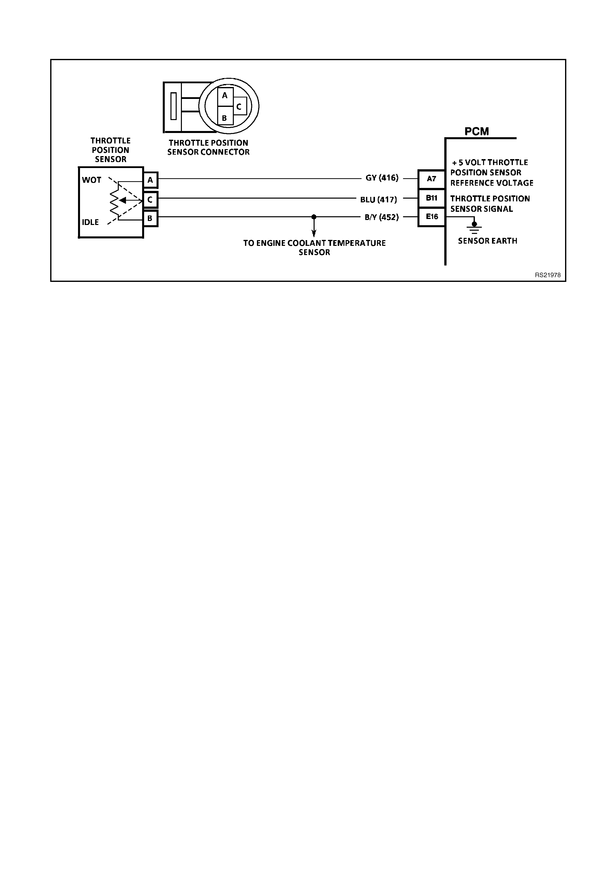
DTC 21 V6 PCM - THROTTLE POSI TION (TP) (SIGNAL VOLTAGE HIGH)
CIRCUIT DESCRIPTION:
The Throttle Position (TP) sensor provides a voltage signal that changes relative to the throttle blade angle. TP
sensor signal voltage will vary from about 0.25 to 1.25 volts at idle to about 4 volts at Wide Open Throttle (WOT).
The TP sensor signal is one of the most important inputs used by the PCM for fuelling and transmission control and
for most of the PCM control outputs.
DTC 21 WILL SET IF:
• TP sensor throttle angle is above 97% (4.9 volts) for 2 seconds.
When DTC 21 is set, the PCM will default to a 35% throttle angle for engine and transmission operation.
TEST DESCRIPTION:
Number(s) below refer to step number(s) on the diagnostic chart.
3. With the TP sensor disconnected, the TP sensor signal voltage should go low if the PCM and wiring are OK.
4. Probing circuit 452 with a test light connected to 12 volts checks the sensor earth circuit. A faulty sensor earth
will cause a DTC 21.
DIAGNOSTIC AIDS:
A Tech 2 scan tool reads throttle position in volts. With ignition "ON'' or at idle, TP sensor signal voltage should read
about 0.25 to 1.25 volts with the throttle closed and increase at a steady rate as throttle is moved toward Wide Open
Throttle (WOT).
The Tech 2 scan tool will read throttle angle. 0%=closed throttle; 100%=WOT. An open in circuit 452 will result in a
DTC 21.
When a DTC 21 is set, the PCM does not receive the proper signal from the TP sensor, but it can still determine the
TP sensor value with a default value based on MAF and engine RPM. If DTC 21 is set, the transmission will have
no TCC.
Refer to "Intermittents" in Section 6C1-2B SYMPTOMS .

STEP ACTION VALUE YES NO
1. Was the "On-Board
Diagnostic" (OBD) System
Check performed?
Go to Step 2. Go to OBD
System Check in
this Section.
2. Throttle closed.
Is Tech 2 scan tool
display "TPS Voltage"
over specified value?
2.5 volts Go to Step 3 If no additional
DTCs were
stored, refer to
"Intermittents" in
Section 6C1-2B
SYMPTOMS.
3. Disconnect TPS wiring
harness.
Does Tech 2 scan tool
display "TPS Voltage"
below specified value?
0.2 volts
(200
mV)
Go to Step 4 Go to Step 7
4. Probe TP sensor earth
circuit with test light
connected to battery
voltage.
Is test light "ON"?
Go to Step 5 Go to Step 8
5. Check for a faulty
connection.
Was faulty connection
found?
Verify Repair Go to Step 6
6. Replace Throttle Position
Sensor (TPS). Verify Repair
7. Is the TP sensor signal
circuit shorted to voltage? Verify Repair Go to Step 9
8. Is the TP sensor earth
circuit open? Verify Repair Go to Step 9
9. Replace PCM.
Refer to section 6C1-3
Service Operations, for
PCM Security Link
procedure.
Is action complete?
Verify Repair

DTC 22 V6 PCM - THROTTLE POSI TION (TP) (SIGNAL VOLTAGE LOW)
CIRCUIT DESCRIPTION:
The Throttle Position (TP) sensor provides a voltage signal that changes relative to the throttle blade. Signal voltage
will vary from about 0.25 to 1.25 volts at idle to about 4 volts at Wide Open Throttle (WOT).
The TP sensor signal is one of the most important inputs used by the PCM for transient fuelling and transmission
control and for most of the PCM control outputs.
DTC 22 WILL SET IF:
• TP sensor throttle angle is less than 2% ( 0.2 volts) for two seconds.
When DTC 21 is set, the PCM will default to a 35% throttle angle for engine and transmission operation.
TEST DESCRIPTION:
Number(s) below refer to step number(s) on the diagnostic chart.
3. This test simulates a Diagnostic Trouble Code 21: (high voltage) If the PCM recognises the high signal voltage
and the Tech 2 scan tool reads over 4 volts or above, the PCM and wiring are OK.
4. This simulates a high signal voltage to check for an open in circuit 417. The Tech 2 scan tool will not read up to
12 volts, but what is important is that the PCM recognises the signal on circuit 417.
DIAGNOSTIC AIDS:
A Tech 2 scan tool reads throttle position in volts. With ignition "ON'' or at idle, TP sensor signal voltage should read
about 0.25 to 1.25 volts with the throttle closed and increase at a steady rate as throttle is moved toward Wide Open
Throttle (WOT).
The Tech 2 scan tool will read throttle angle. 0%=closed throttle; 100%=WOT.
When a DTC 22 is set, the PCM does not receive the proper signal from the TP sensor, but it can still determine the
TP sensor value with a default value based on MAF and engine RPM. If DTC 22 is set, the transmission will have
no TCC.
An open or short to earth in circuit 416 or circuit 417 will result in a DTC 22.
Refer to "Intermittents" in Section 6C1-2B SYMPTOMS .

STEP ACTION VALUE YES NO
1. Was the "On-Board
Diagnostic" (OBD) System
Check performed?
Go to Step 2. Go to OBD
System Check in
this Section.
2. Throttle closed.
Is Tech 2 scan tool
display "TPS Voltage" at
or below specified value?
0.2 Volt
(200
mV)
Go to Step 3 DTC 22 is
intermittent, if no
additional DTCs
were stored, refer
to "Intermittents"
in Section 6C1-2B
SYMPTOMS.
3. 1. Disconnect TPS
wiring harness.
2. Jumper circuits 416
& 417 together.
Does Tech 2 scan tool
display "TPS Voltage"
above specified value?
4.0 Volts
(400
mV)
Go to Step 6 Go to Step 4
4. Probe circuit 417 with test
light connected to 12
volts.
Does Tech 2 scan tool
display "TPS Voltage"
above specified value?
4.0 Volts
(400
mV)
Go to Step 5 Go to Step 7
5. Check for open or short
on circuit 416 or faulty
connection.
Was a short, open or
faulty connection found?
Verify Repair Go to Step 8
6. Replace Throttle Position
(TP) Sensor.
Is action complete?
Verify Repair
7. Check for open or short
on circuit 417 or faulty
connection.
Was a short, open or
faulty connection found?
Verify Repair Go to Step 8
8. Replace PCM.
Refer to Section 6C1-3
Service Operations, for
PCM Security Link
procedure.
Is action complete?
Verify Repair
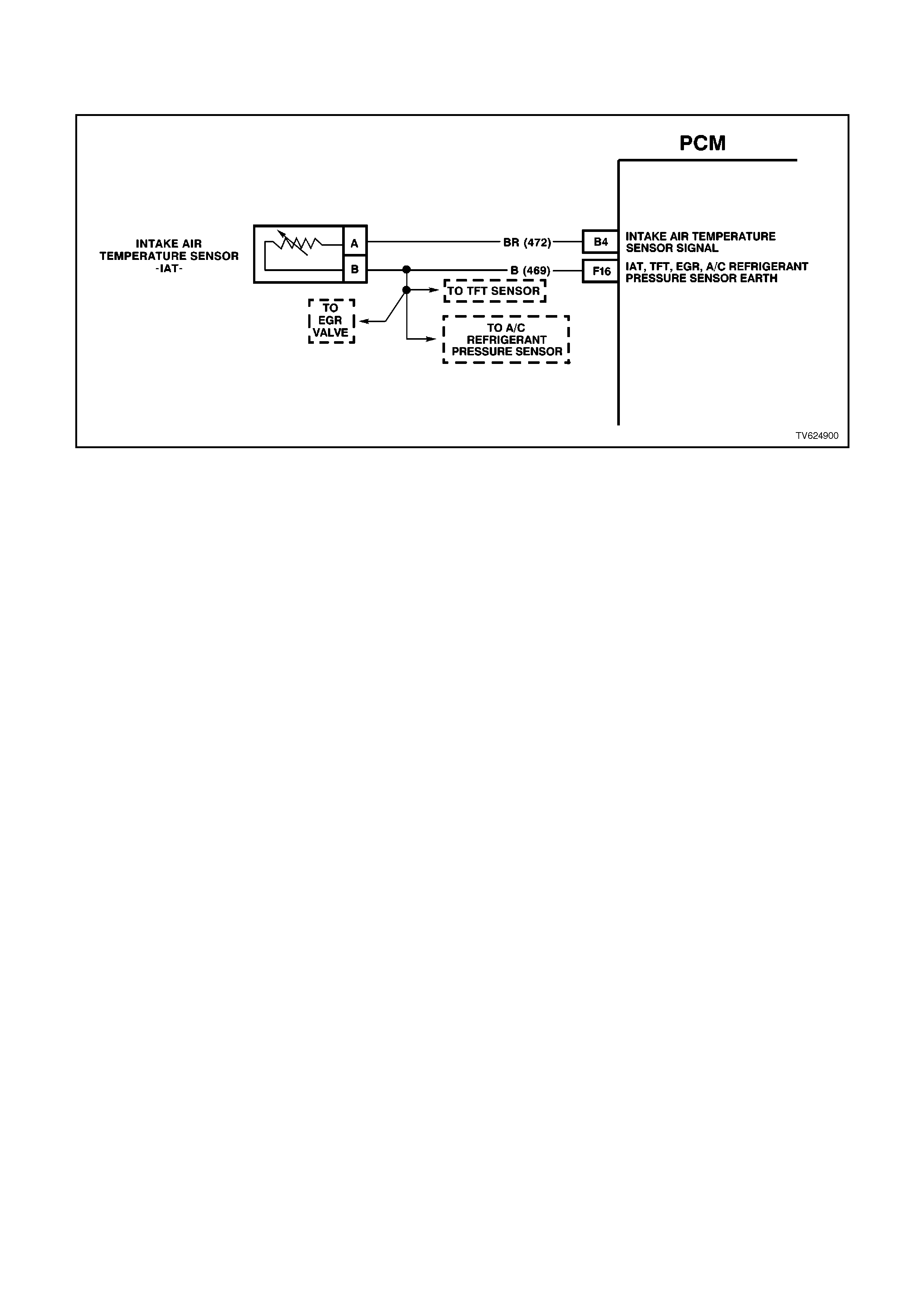
DTC 23 V6 PCM - I NTAKE AIR TEMPERATURE (IAT)
(SIGNAL VOLTAGE HIGH)
CIRCUIT DESCRIPTION:
The Intake Air Temperature (IAT) sensor uses a thermistor to control the signal voltage to the PCM. The PCM
applies a voltage (about 5 volts) on circuit 472 to the sensor. When the intake air is cold, the sensor (thermistor)
resistance is high, therefore, the PCM will sensor a high signal voltage. If the intake air is warm, the sensor
(thermistor) resistance is low, therefore, the PCM will sense a low signal voltage.
DTC 23 WILL SET IF:
• IAT sensor signal voltage is more than 4.9 volts, indicating an intake air temperature below -36°C for one
second.
When DTC 23 is set, the PCM will default to a 25°C IAT for engine operation.
TEST DESCRIPTION:
Number(s) below refer to step number(s) on the diagnostic chart.
3. A Diagnostic Trouble Code 23 will set, due to an open sensor, wire or connection. This test will determine if the
wiring and PCM are OK.
6. This will determine if the IAT sensor signal (circuit 472) or the IAT sensor earth (circuit 469) is open.

IAT SENSOR TABLE RESISTANCE-TEMPERATURE CHARACTERISTICS
Temp
(C) No Load
WTemp
(C) No Load
W
-40 102,129 60 679
-35 73,345 65 566
-30 53,253 70 475
-25 39,066 75 400
-20 28,940 80 338
-15 21,638 85 287
-10 16,321 90 245
-5 12,414 95 210
0 9,517 100 180
5 7,355 105 156
10 5,729 110 135
15 4,497 115 117
20 3,555 120 102
25 2,830 125 89
30 2,268 130 79
35 1,829 135 69
40 1,483 140 61
45 1,210 145 54
50 993 150 48
55 819
DIAGNOSTIC AIDS:
A Tech 2 scan tool indicates the temperature of the air in the intake. When the PCM detects a fault in the IAT
sensor circuit, a default value of 25 degrees C will be used by the PCM.
Carefully check harness and connections for possible open circuit 472 or circuit 469.
An open circuit 469 will set DTC 23 and DTC 59, if the engine has been allowed to sit overnight, then the intake air
temperature and engine coolant temperature values should be within a few degrees of each other. After the engine
is started, the IAT sensor will increase due to engine compartment temperatures.
Refer to "Intermittents" in Section 6C1-2B SYMPTOMS .

STEP ACTION VALUE YES NO
1. Was the "On-Board
Diagnostic" (OBD) System
Check performed?
Go to Step 2. Go to OBD
System Check in
this Section.
2. Does Tech 2 scan tool
display "IAT" at or
between the specified
value?
-30 to -
40
degrees
C
Go to Step 3 DTC 23
intermittent. If no
additional DTCs
were stored, refer
to "Intermittents"
in Section 6C1-2B
SYMPTOMS.
3. 1. Disconnect IAT
sensor wiring
harness.
2. Jumper harness
terminals together.
Does Tech 2 scan tool
display "IAT" at specified
value or higher?
130
degrees
C
Go to Step 4 Go to Step 6
4. Check resistance across
"IAT" sensor terminals.
Is value OK?
See IAT
table
above.
Go to Step 5 Go to Step 12
5. Is there an intermittent or
loose terminal in sensor
harness connector?
Verify Repair Go to Step 11
6. Jumper circuit 472 to
earth.
Does Tech 2 scan tool
display "IAT" at specified
value or higher?
130
degrees
C
Go to Step 7 Go to Step 8
7. Check for an open sensor
earth circuit or faulty
connection.
Was an open or faulty
connection found?
Verify Repair Go to Step 10
8. Check for an open circuit
472 or faulty connection.
Wan an open or faulty
connection found?
Verify Repair Go to Step 10
9. Replace intake air
temperature sensor. Verify Repair
10 Replace PCM.
Refer to Section 6C1-3
Service Operations, for
PCM Security Link
procedure.
Is action complete?
Verify Repair
11. 1. Ignition "OFF"
2. Disconnect PCM
connectors.
3. Remove jumper from
IAT sensor harness.
4. Ignition "ON".
5. Check for short to
voltage in circuit 472.
Was a short to voltage
found?
Verify Repair Go to Step 10
12 Replace IAT sensor.
Is action complete ? Verify Repair
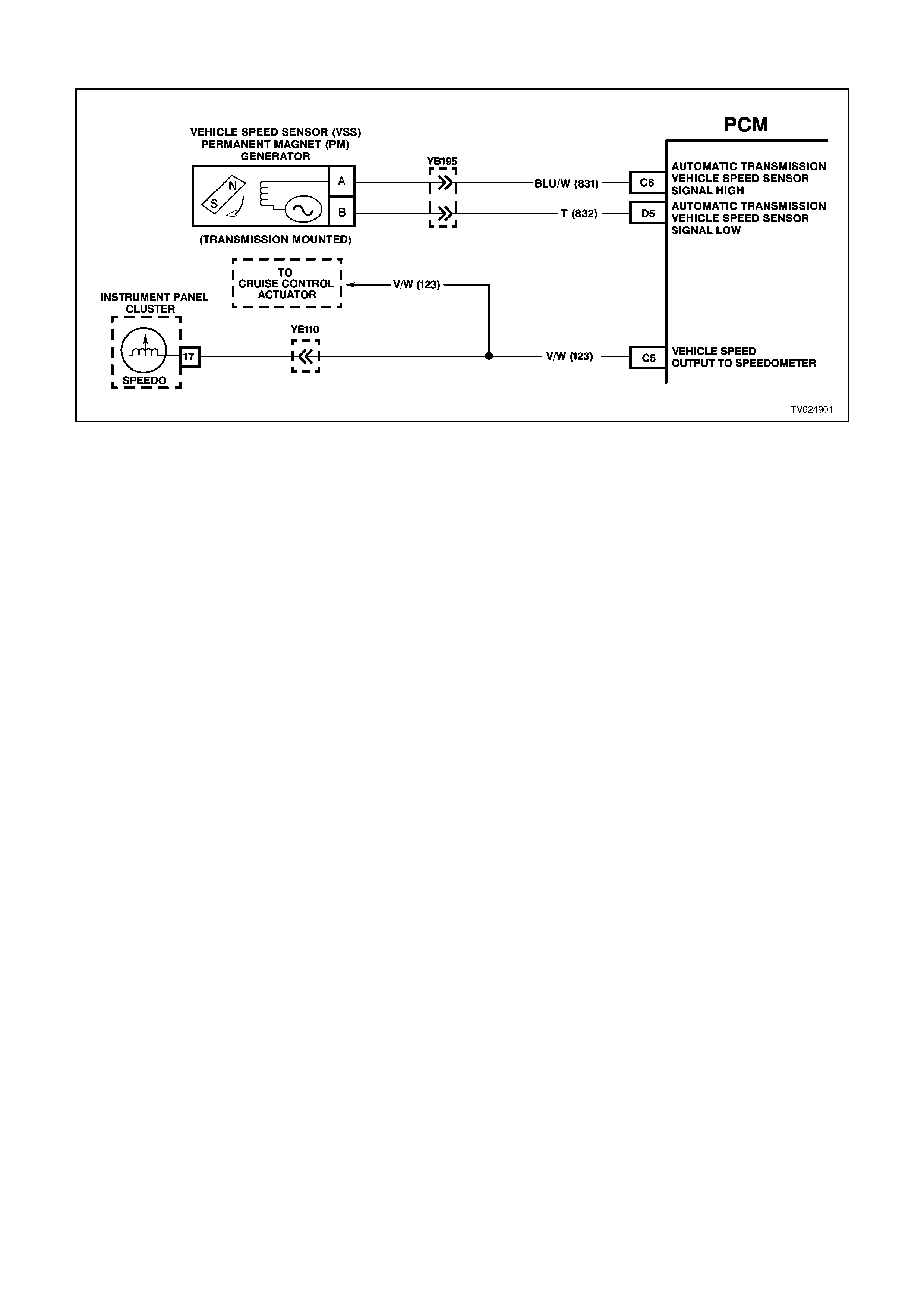
DTC 24 - NO VEHICLE SPEED SENSOR (VSS) SIGNAL
CIRCUIT DESCRIPTION:
The Vehicle Speed Sensor Assembly (VSS Assy.) provides vehicle speed information to the PCM. The VSS Assy.
is a Permanent Magnet (PM) generator. The PM generator produces a pulsing AC voltage. The AC voltage level
and the number of pulses increase with the speed of the vehicle. The PCM then converts the pulsing voltage to
vehicle speed. The PCM uses this information for calculations. A scan tool can display the vehicle speed.
When the PCM detects a low or no vehicle speed, when there is high engine speed in a drive range, then DTC 24
sets.
DTC 24 SETS IF:
• No TPS DTCs 21 or 22.
• No TFP Val. Position Sw. DTC 28.
• The transmission is not in Park or Neutral.
• The TP angle is between 10-99%.
• The engine speed is greater than 3000 RPM.
• The vehicle speed is less than 3 km/h.
• All of the above conditions met for 3 seconds.
DTC 24 Will set if the VSS circuit is open from a standing stop. As the vehicle is accelerated the transmission will
shift from 1st to 2nd gear at approximately 54 km/h. If the VSS signal is not present, DTC 24 will be set.
TEST DESCRIPTION:
The numbers below refer to the step numbers on the diagnostic chart.
3. This step tests the integrity of the VSS Assy.
4. This step tests the VSS Assy. circuit.

DIAGNOSTIC AIDS:
• Inspect the wiring for poor electrical connections at the PCM. Look for the following conditions:
A bent terminal
A backed out terminal
A damaged terminal
Poor terminal tension
A chafed wire
A broken wire inside the insulation
Moisture intrusion
Corrosion
• When diagnosing for an intermittent short or open condition, massage the wiring harness while watching the test
equipment for a change.
• Check circuits 831 and 832 for the proper connections to be sure they are clean and tight and the harness is
routed correctly.
• The scan tool should indicate a vehicle speed whenever the drive wheels are turning greater than 3 km/h.
• The vehicle speed sensor resistance should be between 1470-2140 W at 20°C, and 2270-2820 W at 100° C.
• Refer to "Intermittents" in Section 6C1-2B SYMPTOMS .
When DTC 24 sets, the PCM will command second gear only, commands maximum line pressure, freeze shift
adapts from being updated and inhibit TCC engagement.

STEP ACTION VALUE YES NO
1Was the On-Board
Diagnostic (OBD) System
Check performed?
Go to Step 2 Go to OBD
System Check.
2Install the scan tool.
With the engine OFF, turn
the ignition switch to the
RUN position.
IMPORTANT:
Before clearing the DTCs,
use the scan tool in order
to record the DTC history
for reference. The Clear
Info function will erase the
data.
Record the DTC history.
Clear the DTC.
Raise the drive wheels.
NOTE:
Do not perform this test
without supporting the
rear axle assembly or the
lower control arms on
vehicles with independent
rear suspension so that
the drive shafts are in a
normal horizontal position.
Start the engine.
Place the transmission in
any drive gear.
With the rear wheels
rotating, does the scan
tool Vehicle Speed
increase with the drive
wheel speed?
Go to “Diagnostic
Aids” above Go to Step 3
3Turn the ignition switch to
the OFF position.
Disconnect the VSS
connector from the VSS
assembly.
Using the J 35616
Connector Test Adaptor
Kit, connect the J 39200
DVM to the VSS
terminals.
Select AC volts.
Place the transmission
selector in the neutral
position.
Rotate the drive wheels by
hand, ensuring that the
driveshaft is turning.
With rear wheels rotating,
is the DVM voltage
greater than the specified
value?
0.5 volts
AC Go to Step 4 Go to Step 11

STEP ACTION VALUE YES NO
4Turn the ignition switch to
the OFF position.
Reconnect the VSS
connector to the VSS
Assy.
Disconnect the PCM
connector 1 (Pink-32 pin)
from the PCM.
Connect the DVM test
leads to the connector
terminals D5 (T) and C6
(Blu/W).
Place the transmission
selector in the neutral
position.
Rotate the drive wheels by
hand, ensuring that the
driveshaft is turning.
With rear wheels rotating,
is the DVM voltage
greater than the specified
value?
0.5 volts
AC Go to Step 13 Go to Step 5
5Select W (Ohms), on the
DVM.
Measure the resistance
between the connector
terminals D5 (T) and C6
(Blu/W).
Is the circuit resistance
within the specified
range?
1470-
2820 ohm Go to Step 6 Go to Step 8
6Connect the DVM
between the connector
terminal
C-6 and earth.
Is the circuit resistance
less than the specified
value?
250k ohm Go to Step 7 Go to Diagnostic
Aids
7Check circuit 831 and
circuit 832 for a short
toearth.
Repair the circuit if
necessary.
Was the short to earth
condition found and
corrected?
Go to Step 14 Go to “Diagnostic
Aids” above
8Is the resistance reading
in step 6 greater than the
specified value?
2820 ohm Go to Step 10 Go to Step 9
9Check circuit 831 and
circuit 832 for a shorted
together condition.
Repair the circuit if
necessary.
Was a shorted together
condition found and
corrected ?
Go to Step 14 Go to “Diagnostic
Aids” above

STEP ACTION VALUE YES NO
10 Check circuit 831 and
circuit 832 for an open
condition.
Repair the circuit if
necessary.
Was an open condition
found and corrected ?
Go to Step 14 Go to “Diagnostic
Aids” above
11 Remove the VSS
Assembly.
Inspect the VSS Output
Sensor Rotor for damage
or misalignment.
Did you find a condition?
Refer to Section
7B-1 Manual
Transmission - V6
or Section 7C-4
Automatic
Transmission.
Go to Step 12
12 Replace the VSS Assy.
Refer to Service
Operations.
Is the action complete?
Go to Step 14
13 Replace the PCM. Refer
to Section 6C1-3 Service
Operations, for the
Security Link procedure.
Is the action complete?
Go to Step 14
14 In order to verify your
repair, perform the
following procedure:
Select DTC.
Select Clear Info.
Operate the vehicle
ensuring that the vehicle
speed is greater than 10
km/h and observe the
scan tool Vehicle Speed.
Is the scan tool Vehicle
Speed greater than the
specified value?
10 km/h System OK Begin the
Diagnosis Again
Go to Step 1

DTC 25 V6 PCM - I NTAKE AIR TEMPERATURE (IAT)
(SIGNAL VOLTAGE LOW)
CIRCUIT DESCRIPTION:
The Intake Air Temperature (IAT) sensor uses a thermistor to control the signal voltage to the PCM. The PCM
applies a voltage (about 5 volts) on circuit 472 to the sensor. When manifold intake air is cold (such as when the
engine is first started on a cold day), the sensor (thermistor) resistance is high, therefore, the PCM will sense a high
signal voltage. If the manifold intake air is warm, the sensor (thermistor) resistance is low, therefore, the PCM will
sense a low signal voltage.
DTC 25 WILL SET IF:
• Intake Air Temperature (IAT) signal voltage is less than 0.3 volts, indicating an intake air temperature above 147
degrees C for one second.
When DTC 25 is set, the PCM will default to a 25°C IAT for engine operation.
TEST DESCRIPTION:
Number(s) below refer to step number(s) on the diagnostic chart.

IAT SENSOR TABLE RESISTANCE-TEMPERATURE CHARACTERISTICS
Temp
(C) No Load
WTemp
(C) No Load
W
-40 102,129 60 679
-35 73,345 65 566
-30 53,253 70 475
-25 39,066 75 400
-20 28,940 80 338
-15 21,638 85 287
-10 16,321 90 245
-5 12,414 95 210
0 9,517 100 180
5 7,355 105 156
10 5,729 110 135
15 4,497 115 117
20 3,555 120 102
25 2,830 125 89
30 2,268 130 79
35 1,829 135 69
40 1,483 140 61
45 1,210 145 54
50 993 150 48
55 819
DIAGNOSTIC AIDS:
Intake Air Temperature (IAT) on a Tech 2 scan tool indicates the temperature of the air in the air cleaner. If the
engine has been allowed to sit overnight, the IAT sensor and engine coolant temperature values should be within a
few degrees of each other. After the engine is started, the IAT will increase due to engine compartment
temperatures, however, IAT will rarely exceed 80 degrees C.
When the PCM detects a fault in the IAT circuit, a default value of 25 degrees C will be used.
Check harness routing for possible short to earth in circuit 469.
Refer to "Intermittents" in Section 6C1-2B SYMPTOMS .

STEP ACTION VALUE YES NO
1. Was the "On-Board
Diagnostic" (OBD) System
Check performed?
Go to Step 2. Go to OBD
System Check in
this Section.
2. Does Tech 2 scan tool
display "IAT" equal or
greater than specified
value?
135
degrees
C
Go to Step 3 DTC 25 is
intermittent, if no
additional DTCs
were stored, refer
to "Diagnostic
Aids" above.
3. Disconnect IAT sensor
wiring harness.
Does Tech 2 scan tool
display "IAT" below
specified value?
-30
degrees
C
Go to Step 4 Go to Step 6
4. Measure resistance
across IAT sensor.
Does value correspond to
specified value?
Refer to
IAT
table
above.
Go to Step 5 Go to Step 7
5. Check for intermittent or
loose terminals in harness
connector, or terminals
shorted together.
Was a problem found?
Verify Repair. Go to Step 8
6. Check for a short in circuit
472 to earth or to IAT
sensor earth.
Was a problem found?
Verify Repair. Go to Step 8
7. Replace IAT sensor.
Is action complete? Verify Repair.
8. Replace PCM.
Refer to Section 6C1-3,
for PCM Security Link
procedure.
Is action complete?
Verify Repair.
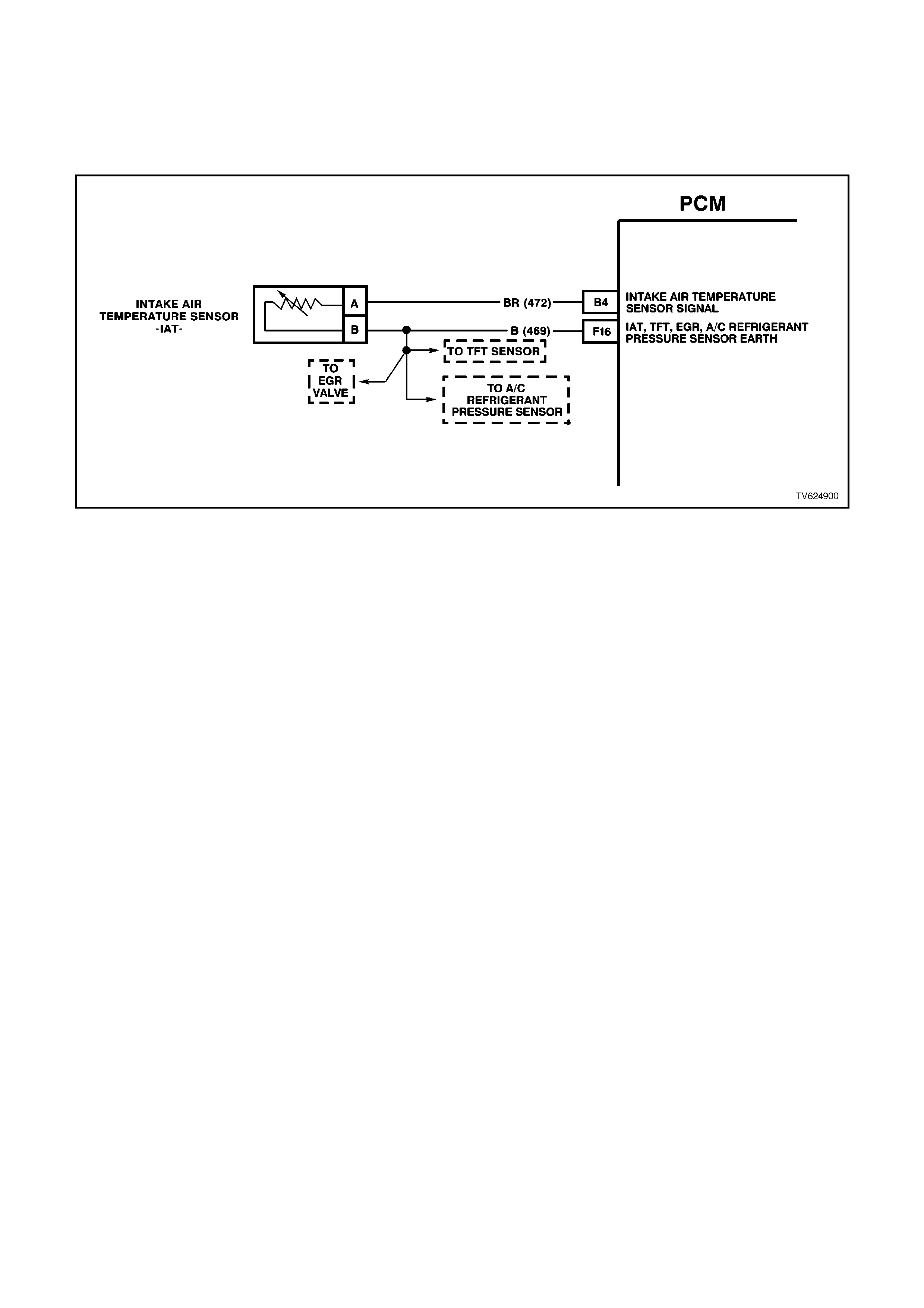
DTC 26 V6 PCM - I NTAKE AIR TEMPERATURE (IAT)
(SIGNAL VOLTAGE UNSTABLE)
CIRCUIT DESCRIPTION:
The Intake Air Temperature (IAT) sensor uses a thermistor to control the signal voltage to the PCM. The PCM
applies a voltage (about 5 volts) on circuit 472 to the sensor. When manifold intake air is cold (such as when the
engine is first started on a cold day), the sensor (thermistor) resistance is high, therefore, the PCM will sense a high
signal voltage. If the manifold intake air is warm, the sensor (thermistor) resistance is low, therefore, the PCM will
sense a low signal voltage.
DTC 26 WILL SET IF:
• The engine has been operating for more than 10 seconds
• IAT sensor reading changes more than 7°C in 100 milliseconds.
When DTC 26 is set, the PCM will default to a 25°C IAT for engine operation.
TEST DESCRIPTION:
Number(s) below refer to step number(s) on the diagnostic chart.

IAT SENSOR TABLE RESISTANCE-TEMPERATURE CHARACTERISTICS
Temp
(C) No Load
WTemp
(C) No Load
W
-40 102,129 60 679
-35 73,345 65 566
-30 53,253 70 475
-25 39,066 75 400
-20 28,940 80 338
-15 21,638 85 287
-10 16,321 90 245
-5 12,414 95 210
0 9,517 100 180
5 7,355 105 156
10 5,729 110 135
15 4,497 115 117
20 3,555 120 102
25 2,830 125 89
30 2,268 130 79
35 1,829 135 69
40 1,483 140 61
45 1,210 145 54
50 993 150 48
55 819
DIAGNOSTIC AIDS:
When attempting to diagnose an intermittent problem, use the snapshot mode of the Tech 2 scan tool to review
diagnostic information.
When the PCM detects a fault in the IAT sensor circuit, a default value of 25 degrees C will be used by the PCM.
STEP ACTION VALUE YES NO
1. Was the "On-Board
Diagnostic" (OBD) System
Check performed?
Go to Step 2. Go to OBD
System Check in
this Section.
2. 1. Install Tech 2 scan tool
and set up snapshot
mode to trigger on
DTC 26.
2. Watch the Tech 2 scan
tool while wiggling the
IAT sensor connector.
Does the "IAT" reading
change sharply?
Go to Step 8 Go to Step 3
3. Wiggle and tug the IAT
sensor harness.
Does the "IAT" reading
change sharply?
Go to Step 9 Go to Step 4
4. Wiggle and tug the
harness at the PCM.
Does the "IAT" reading
change sharply?
Go to Step 10 Go to Step 5
5. Lightly tap on the PCM.
Does the "IAT" reading
change sharply?
Go to Step 6 DTC 26 is
intermittent, refer
to Diagnostic Aids
above.
6. Make sure PCM is
mounted securely to
vehicle.
Was a problem found?
Verify Repair Go to Step 7

STEP ACTION VALUE YES NO
7. Replace PCM.
Refer to Section 6C1-3
Service Operations, for
PCM Security Link
procedure.
Is action complete?
Verify Repair
8. 1. Check IAT sensor
connector.
2. Check the tightness of
the female terminal
grip with a spare male
terminal.
3. Inspect connectors for
corrosion. If
connectors are
corroded, try cleaning
with electronic part
cleaner and retest.
4. If these repairs do not
resolve the problem,
replace terminals.
Is action complete?
Verify Repairs
9. 1. Check for an open in
the IAT harness.
2. Check for broken
strands of wire in IAT
sensor harness.
3. Check for cuts or
pinches in IAT sensor
harness.
4. Make repairs as
necessary.
Is action complete?
Verify Repairs
10. 1. Check the IAT sensor
connection at the
PCM.
2. Check tightness of the
female terminal grip
with a spare male
terminal.
3. Inspect connectors for
corrosion. If
connectors are
corroded, try cleaning
with electronic parts
cleaner and retest.
4. Remove connector
strain relief and
remove terminal from
connector to check for
broken locking tang.
Is action complete?
Verify Repairs
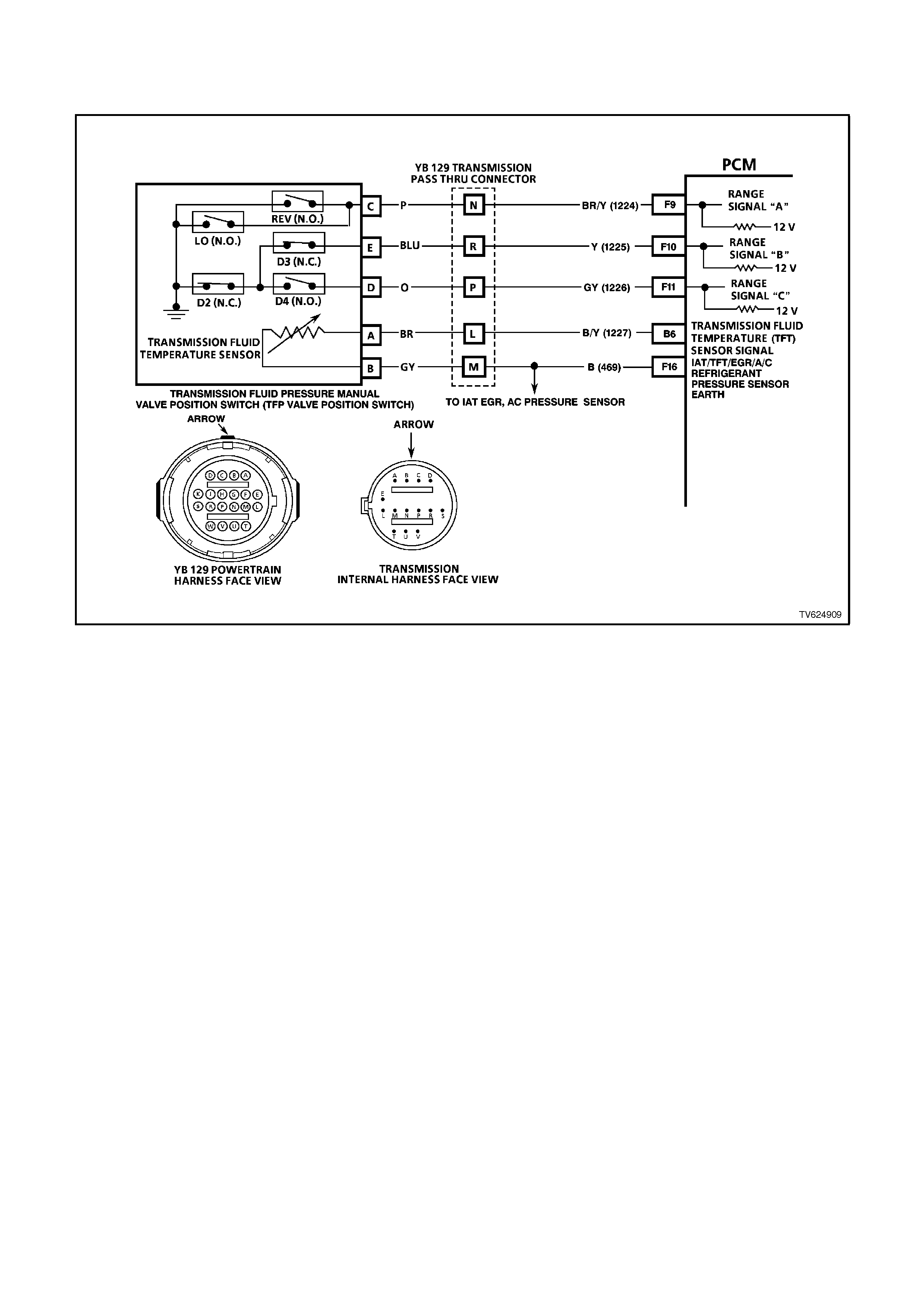
DTC 28 - TRANSMISSION FLUID PRESSURE M ANUAL VALVE POSITION
SWITCH ASSEM BLY CIRCUIT MALFUNCTION
CIRCUIT DESCRIPTION:
The Automatic Transmission Fluid Pressure Manual Valve Position Switch (TFP Val. Position Sw.) consists of five
pressure switches (two normally-closed and three normally-open) and a Transmission Fluid Temperature (TFT)
sensor combined into one unit. The combined unit mounts on the valve body. The PCM supplies the battery voltage
for each range signal. By earthing one or more of the circuits through various combinations of the pressure
switches, the PCM detects which manual valve position you select. The PCM compares the actual voltage
combination of the switches to a TFP Val. Position Sw. combination chart stored in memory. The TFP Val. Position
Sw. cannot distinguish between Park and Neutral because the monitored valve body pressures are identical. With
the engine OFF and the ignition switch in the RUN position, the TFP Val. Position Sw. indicates Park/Neutral.
Disconnecting the transmission pass-through connector removes the earthing potential for the three range signals
to the PCM. In this case, with the engine OFF, and the ignition switch in the RUN position, D2 will be indicated.
When the PCM detects an invalid state of the TFP Val. Position Sw. or the TFP Val. Position Sw. circuit by
deciphering the TFP Val. Position Sw. inputs, then DTC 28 set.
DTC 28 WILL SET IF:
DTC 28 sets when the PCM detects an illegal switch combination for 6 seconds.
TEST DESCRIPTION:
The numbers below refer to the step numbers on the diagnostic chart.
3. This step compares the indicated range signal to the manual valve position that is actually selected.
4. This step tests for correct voltage from the PCM to the transmission pass-through connector terminals.

DIAGNOSTIC AIDS:
• Refer to the TFP Val. Position Sw. Logic Table for the normal range signals and the illegal combinations.
• Inspect the wiring for poor electrical connections at the PCM. Inspect the wiring for poor electrical connections at
the transmission pass-through connector. Look for the following conditions:
A bent terminal
A backed out terminal
A damaged terminal
Poor terminal tension
A chafed wire
A broken wire inside the insulation
Moisture intrusion
• When diagnosing for an intermittent short or open condition, massage the wiring harness while watching the test
equipment for a change.
• Refer to Automatic Transmission Fluid Pressure Manual Valve Position Switch Resistance Check or
Functional Test Procedure for further information.
When DTC 28 is set, the PCM will inhibit TCC engagement, command D2 line pressure, and freeze shift adapts
from being updated.
TFP VALVE POSITION SWITCH LOGIC
Gear
Position Range
Signal
Switch A
Range
Signal
Switch B
Range
Signal
Switch C
POpen 12V Closed 0V Open 12V
RClosed 0V Closed 0V Open 12V
NOpen 12V Closed 0V Open 12V
DOpen 12V Closed 0V Closed 0V
3Open 12V Open 12V Closed 0V
2Open 12V Open 12V Open 12V
1Closed 0V Open 12V Open 12V
Illegal Closed 0V Open 12V Closed 0V
Illegal Closed 0V Closed 0V Closed 0V

STEP ACTION VALUE YES NO
1Was the On-Board
Diagnostic (OBD) System
Check performed?
— Go to Step 2 Go to OBD
System Check
2Perform the following
inspections:
Ensure that the
transmission linkage from
the select lever to the
manual valve is adjusted
properly.
Perform the fluid checking
procedure/inspection.
Did you perform the
inspections?
— Go to Step 3 Perform the
Inspections
31. Install the scan tool.
2. With the engine OFF,
turn the ignition switch
to the RUN position.
IMPORTANT:
Before clearing the DTCs,
use the scan tool in order
to record the DTC history
for reference. The Clear
Info function will erase the
data.
3. Record the DTC
history.
4. While the engine is
idling at normal
operating temperature,
apply the parking
brake.
5. Select each
transmission range: P,
R, N, D4, D3, D2, and
D1.
Does each selected
transmission range match
the scan tool TFP Switch
A/B/C display?
Refer to the TFP Val.
Position Sw. Logic Table.
— Go to “Diagnostic
Aids” above Go to Step 4

STEP ACTION VALUE YES NO
4Turn the ignition OFF.
Disconnect the
transmission pass-
through connector
(additional DTCs may
set).
Install the J 39775 Jumper
Harness on the engine
side of the transmission
pass-through connector.
With the engine OFF, turn
the ignition switch to the
RUN position.
Using the J 39200 DVM
and J 35616 Connector
Test Adaptor Kit, check
for voltage at connector
terminals N, R, and P.
Is B+ displayed on all
three circuits?
— Go to Step 6 Go to Step 5
5Check the circuits that did
not indicate B+ for an
open or a short to earth.
Repair the circuits if
necessary.
Did you find problem?
— Go to Step 13 Go to Step 7
6In order to verify that
circuit 1224, circuit 1225,
and circuit 1226 are not
shorted together, use a
fused jumper to earth, on
each circuit while
monitoring the scan tool
TFP Switch A/B/C display.
When a range signal
circuit is earthed, are any
other range signal circuits
affected?
— Go to Step 8 Go to Step 9
7Replace the PCM.
Refer to Section 6C1-3
Service Operation, for the
Security Link procedure.
Is the action complete?
— Go to Step 13 —
8Repair the affected wiring
as necessary.
Is the action complete?
— Go to Step 13 —

STEP ACTION VALUE YES NO
9Turn the ignition switch to
the OFF position.
Reconnect the pass-
through connector.
Select the PARK position.
Start the engine.
Apply the brakes.
Move the shift sel ector
through all gear ranges,
while observing the A and
C range signals on the
scan tool.
Does either range signal
always indicate 0
volts/ON?
— Go to Step 10 Intermittent
Problem Go to
“Diagnostic Aids”
above
10 Turn the ignition switch to
the OFF position.
Disconnect the
transmission pass-
through connector.
Remove the transmission
pan.
Remove the internal
wiring harness connector
from the TFP Valve
Position Switch.
Check the internal wiring
harness circuits 1224 and
1226 for a short to earth.
Did you find a short to
earth condition on either
circuit?
— Go to Step 12 Go to Step 11
11 Replace the TFP Valve
Position Switch. Refer to
Service Operations,
Section 6C2-3.
Is the action complete?
— Go to Step 13 —
12 Replace the internal A/T
Wiring Harness Assembly
Refer to Service
Operations in
Section 7C-5 - Automatic
Transmission.
Is the replacement
complete?
— Go to Step 13 —

STEP ACTION VALUE YES NO
13 In order to verify your
repair, perform the
following procedure:
Select DTC.
Select Clear Info.
Operate the vehicle under
the following conditions:
With the engine OFF, turn
the ignition switch to the
RUN position for at least 2
seconds.
Start the vehicle and idle
for 5 seconds.
Select each transmission
range: P, R, N, D4, D3,
D2 and D1.
Compare the scan tool
TFP Sw. A/B/C/ display, to
the TFP Valve Position
Sw. Logic Table.
Does each shifter position
range signal match the
scan tool TFP Sw. A/B/C
display?
— System OK Begin the
diagnosis again.
Go to Step 1
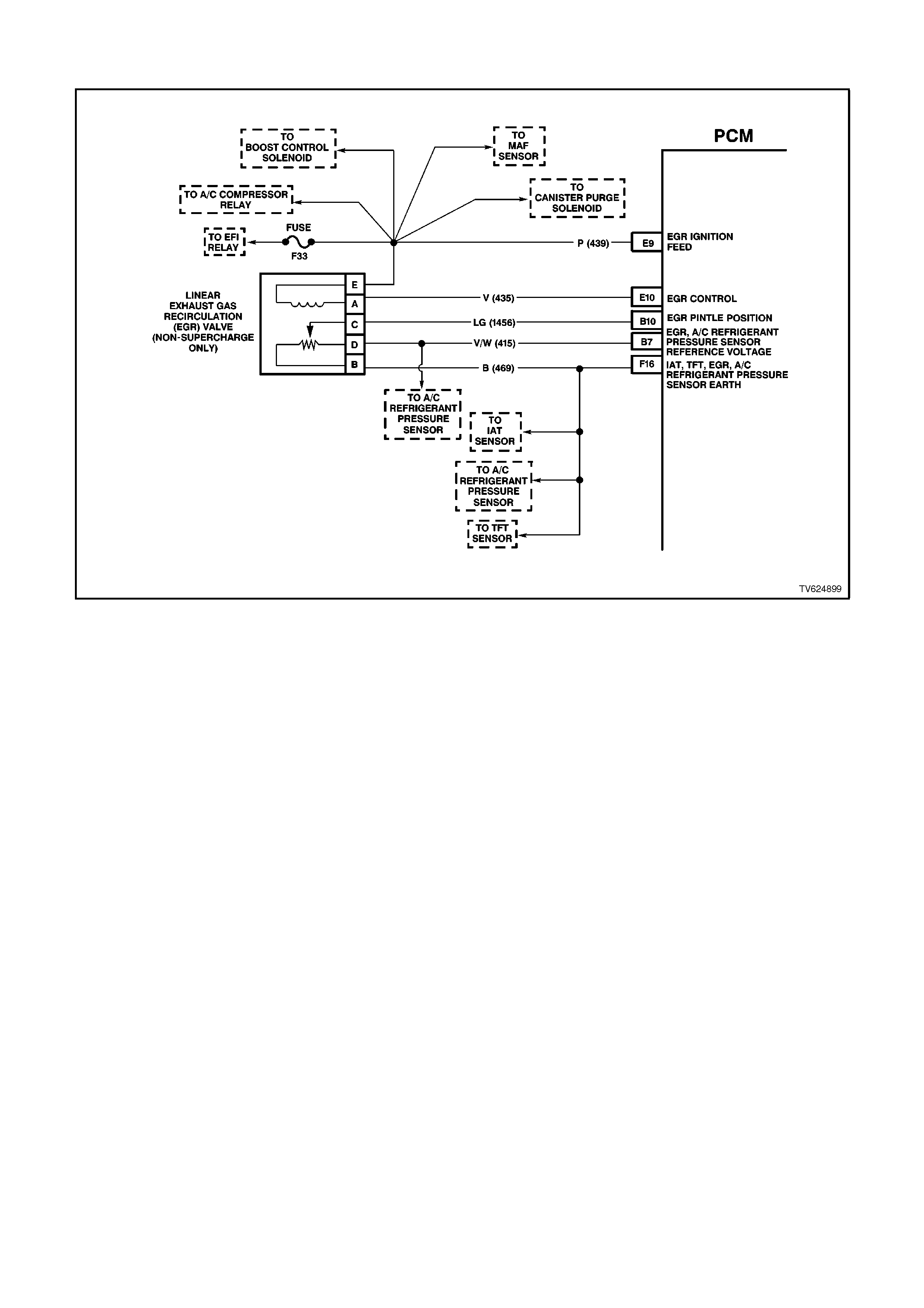
DTC 29 V6 PCM - EGR POSI TION FAULT (NON-SUPERCHARGE ONLY)
CIRCUIT DESCRIPTION:
The PCM monitors the EGR valve pintle position input to ensure that the valve responds properly to commands
from the PCM and to detect a fault if the pintle position sensor and control circuits are open or shorted. If the PCM
detects a pintle position signal voltage outside the normal range of the pintle position sensor, or a signal voltage that
is not within a tolerance considered acceptable for proper EGR system operation, the PCM will set a DTC 29.
DTC 29 WILL SET IF:
• The EGR POS FEEDBACK is less than 0.32 volts for greater than 1 second.
- OR -
• The EGR POS COMMANDED is 10% greater or less than the EGR POS FEEDBACK.
• Any of the above conditions are present for greater than 5 seconds.

TEST DESCRIPTION:
Number(s) below refer to step number(s) on the diagnostic chart.
2. Commanding the EGR valve open determines whether the EGR system can control the EGR valve accurately.
3. When the EGR valve electrical connector is disconnected, the scan tool should display the EGR POS
FEEDBACK as 0%. If it does not, go directly to step 11, as the fault lies either in the EGR signal circuit or the
PCM. If the problem is in the EGR ignition feed circuit, other circuits that share this ignition feed will also
experience a problem unless the circuit is open only on the EGR valve side of the spliced circuit.
4. A test light, when connected to B+, will glow dimly when the EGR valve is commanded to 25%, and brighter as
the EGR valve is commanded to 100%. If the test light flashes, check the sensor earth for an open.
5. If the open condition was due to a blown fuse, locate and repair any shorts that may have caused the fuse to
blow before replacement.
6. If the EGR valve 5 volt reference is shorted to voltage, the DVM will read battery voltage and an additional DTC
will be set and engine performance will be poor. When this circuit is open, an additional DTC may also be set if
the entire circuit is open. Only a DTC 29 set indicates that the circuit is open between the EGR valve electrical
connector and the spliced circuit.
7. The test light will have glowed brightly in step 5 if the EGR control circuit was shorted to earth and the EGR
POS FEEDBACK on the scan tool will display 100%. A test light that did not illuminate, indicates that the circuit
may be open or shorted to voltage.
9. If the 5 volt reference circuit is shorted to earth, an additional DTC will also be set. If no other DTC's are set,
then the fault must be between the EGR valve electrical connector and the 5 volt reference splice to the throttle
position sensor.
10. The EGR POS FEEDBACK should read 0% before jumping the 5 volt reference circuit to the signal circuit. If
any other reading is present, then either the signal circuit or the PCM is at fault.
11. An open or short in the EGR valve sensor earth circuit will also cause an additional DTC to be set. If no other
DTC's are set, and the circuit is found to be open or shorted, the fault is on the EGR valve side of the spliced
circuit.
DIAGNOSTIC AIDS:
Check for the following conditions:
Excessive deposits on the EGR valve pintle or seat. Check for deposits that may interfere with the EGR valve pintle
extending completely or cause the pintle to stick.
Poor connection or damaged harness. Inspect the wiring harness for damage. If the harness appears to be OK,
observe the EGR POS FEEDBACK display on the scan tool while moving connectors and wiring harnesses related
to the EGR valve. A change in the display will indicate the location of the fault.

STEP ACTION VALUE YES NO
1Was the “On-Board
Diagnostic (OBD) System
Check” performed?
Go to Step 2 Go to OBD
System Check
21. Key "ON, engine
"OFF".
2. Install a scan tool.
3. Command the EGR
valve to the specified
values.
Does the EGR POS
COMMANDED follow the
EGR POS FEEDBACK?
25%,
50%,
75%,
100%
Refer to
"Diagnostic Aids" Go to Step 3
31. Key "ON", engine
"OFF".
2. Disconnect the EGR
valve electrical
connector.
3. With a test light
connected to earth,
probe the ignition feed
circuit to the EGR
valve.
Does the test light
illuminate?
Go to Step 4 Go to Step 5
41. Connect the test light
to B+.
2. Probe the EGR control
circuit to the EGR
valve.
3. Command the EGR
valve to the specified
values.
Does the test light glow
dimly and then glow
brighter or flash as the
commanded percentage
is raised?
25%,
50%,
75%,
100%
Go to Step 6 Go to Step 7
5Check for an open in the
EGR valve ignition feed
circuit and repair as
necessary.
Was a repair necessary?
Verify Repair Go to Step 14
6Using a DVM connected
to earth, probe the 5 volt
reference circuit to the
EGR valve.
Does the DVM read the
specified value?
5.0V Go to Step 8 Go to Step 9
7Check for an open or
short in the EGR control
circuit and repair as
necessary.
Was a repair necessary?
Verify Repair Go to Step 14
8Using a DVM connected
to B+, probe the EGR
valve sensor earth circuit.
Does the DVM read the
specified value?
B+ Go to Step 10 Go to Step 11

STEP ACTION VALUE YES NO
9Check for an open or
short in the EGR valve 5
volt reference circuit and
repair as necessary.
Was a repair necessary?
Verify Repair Go to Step 14
10 Jumper the EGR valve 5
volt reference circuit to the
signal circuit.
Does the EGR POS
FEEDBACK display the
specified value?
100% Go to Step 12 Go to Step 13
11 Check for an open in the
EGR valve sensor earth
circuit and repair as
necessary.
Was a repair necessary?
Verify Repair Go to Step 14
12 Replace the EGR valve.
Is the action complete? Verify Repair
13 Check for an open or
short in the EGR valve
signal circuit and repair as
necessary.
Was a repair necessary?
Verify Repair Go to Step 14
14 Replace PCM.
Refer to Section 6C1-3
Service Operations, for
PCM Security Link
procedure.
Is action complete?
Verify Repair
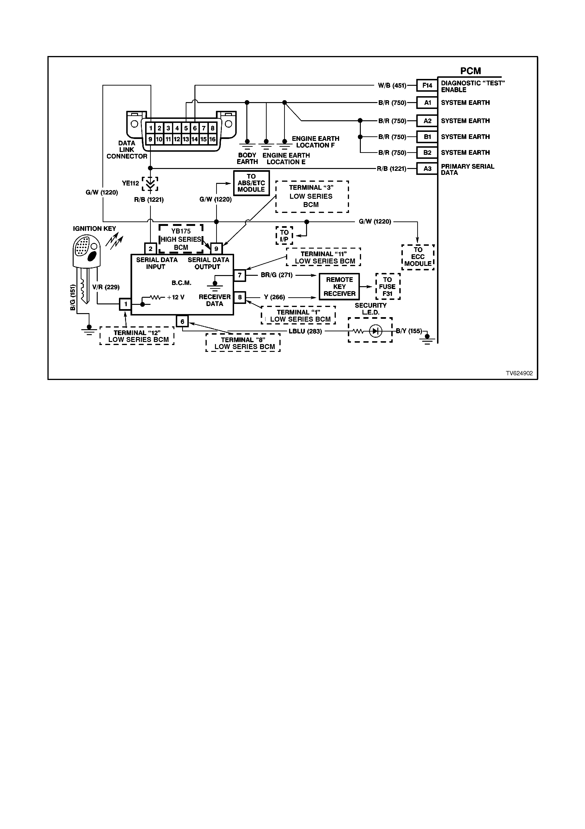
DTC 31 V6 PCM - THEFT DETERRENT SI GNAL MISSING
CIRCUIT DESCRIPTION:
When the ignition is turned "ON", the PCM will send a message on circuit 1221 to the BCM asking for permission to
start. When the BCM receives this message, it instantly sends a message back to the PCM. The message says
that the proper ignition key has been used to turn the ignition and that it is OK for the PCM to enable the fuel
injectors to start the vehicle. If the BCM does not receive communications from the PCM when the ignition is
switched "ON", then the starter motor will be enabled after a one second delay.
DTC 31 WILL SET IF:
• The PCM sends 20 messages to the BCM and does not receive a message back saying it is OK to start.
TEST DESCRIPTION:
Number(s) below refer to step number(s) on the diagnostic chart.
2. If the engine cranks after a one second delay it means the BCM did not see a message from the PCM when
the ignition was turned "ON".
3. An open or short to earth on circuit 1221 will disable any communication of serial data.
DIAGNOSTIC AIDS:
The Tech 2 scan tool has a special test to check this signal. To access this special test, select F3: BCM, then select
F1: THEFT STATUS. The Tech 2 scan tool will either display "OK TO START" or "NO START".
Dirty, Damaged, or Loose Connections or Damaged Harness - Check for any damage to the harness which could
cause an intermittent open or short to earth or backed out terminals at the PCM connectors, broken locks,
improperly formed or damaged terminals.

STEP ACTION VALUE YES NO
1. Was the "On-Board
Diagnostic" (OBD) System
Check performed?
Go to Step 2 Go to OBD
System Check in
this Section.
2. Attempt to start vehicle.
Does engine crank after a
one second delay when
ignition is switched "ON"?
Go to Step 3 DTC 31 is
intermittent, refer
to "Diagnostic
Aids" above.
3. Ignition "ON".
Does voltage between
DLC terminal "9" and
earth equal specified
value?
3 -5
volts Refer to Section
12F "THEFT
DETERRENT" for
further diagnosis.
Go to Step 4
4. Check for poor connection
at PCM terminal and/or
open or shorted circuit
1221.
Was a problem found?
Verify Repair Go to Step 5
5. Replace PCM.
Refer to Section 6C1-3
Service Operations, for
PCM Security Link
procedure.
Is action complete?
Verify Repair
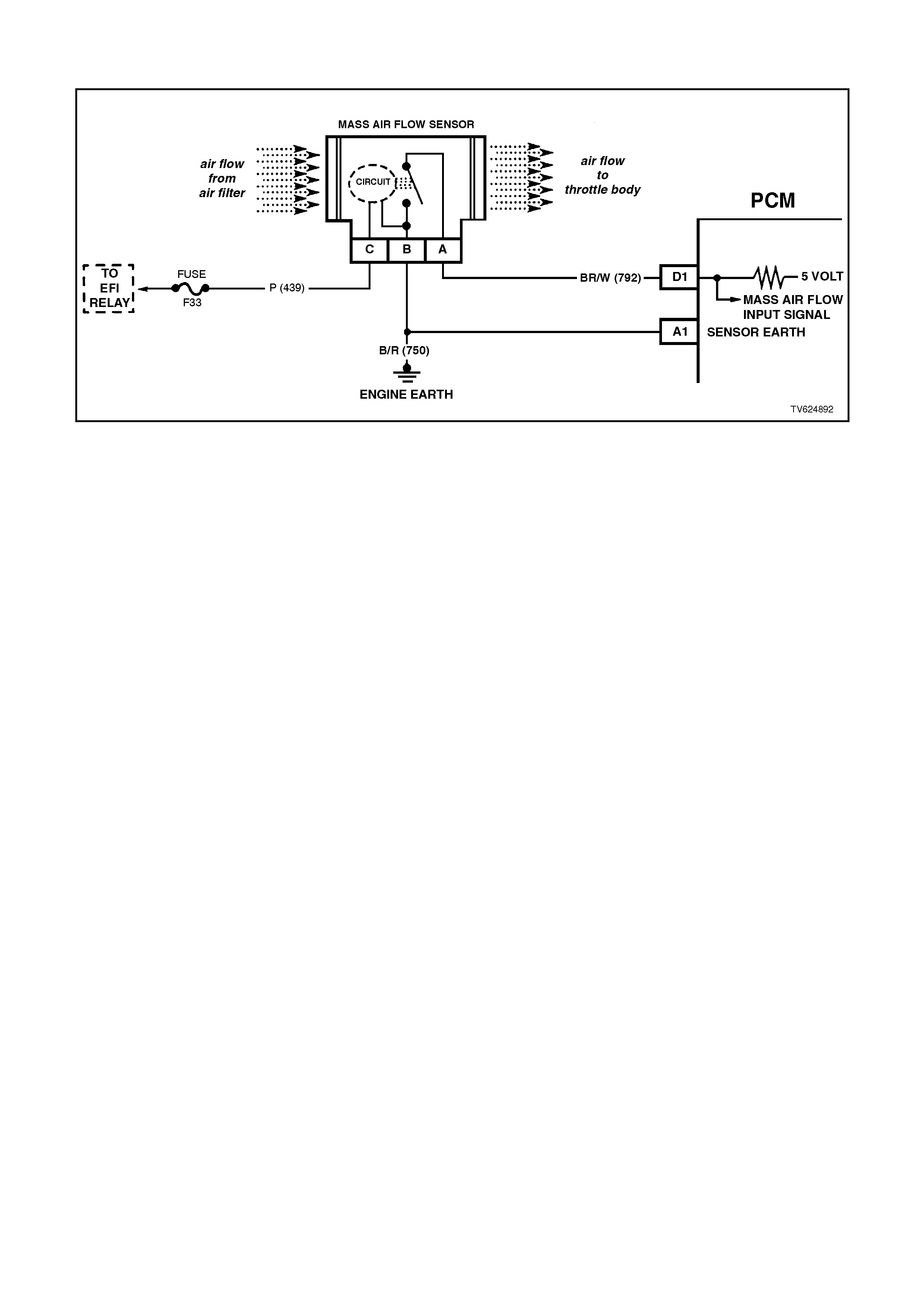
DTC 32 V6 PCM - MASS AIR FLOW (MAF) OUT OF RANGE
CIRCUIT DESCRIPTION:
The Mass Air Flow (MAF) sensor measures the flow of air which passes through it in a given time. The PCM uses
this information to monitor the operating condition of the engine for fuel delivery calculations. A large quantity of air
movement indicates acceleration, while a small quantity indicates deceleration or idle.
The MAF sensor produces a frequency signal which cannot be easily measured.
The MAF sensor can be diagnosed using the procedures on this chart.
With DTC 32 set, the PCM will use a default value for air flow based on throttle position, and engine speed and
some vehicle performance will return. When DTC 32 is set the MIL "Check Powertrain Lamp" will be illuminated.
DTC 32 WILL SET IF:
• Engine running.
• No MAF signal for over two seconds.
TEST DESCRIPTION:
Number(s) below refer to step(s) on the diagnostic chart.
5. Verifies that both ignition feed voltage and a good earth circuit are available.
6. This step checks to see if PCM recognises a problem.
7. A voltage reading at sensor harness connector terminal "A" of less than 4 or over 6 volts indicates a fault in
circuit 792 or poor connection.
DIAGNOSTIC AIDS:
An intermittent may be caused by a poor connection, mis-routed harness, rubbed through wire insulation, or a wire
broken inside the insulation.
Check for:
• Poor Connection at PCM Pin - Inspect harness connectors for backed out terminals, improper mating, broken
locks, improperly formed or damaged terminals, and poor terminal to wire connection.
• Mis-Routed Harness - Inspect MAF sensor harness to ensure that it is not too close to high voltage wires, such
as spark plug leads.
• Damaged Harness - Inspect harness for damage. If harness appears OK, observe Tech 2 scan tool while
moving related connectors and wiring harness. A change in display would indicate the intermittent fault location.
Plugged Air Filter - A wide open throttle acceleration from a stop should cause the MAF reading on the Tech 2 scan
tool to range from about 4-7 g/s at idle to 100 or greater at the time of the 1-2 shift on an automatic transmission. If
not, check for restriction.

STEP ACTION VALUE YES NO
1. Was the "On-Board
Diagnostic" (OBD) System
Check performed?
Go to Step 2. Go to OBD
System Check in
this Section.
2. 1. Ignition "ON".
2. Using Tech 2 scan tool,
select MAF frequency.
Is "MAF frequency"
reading at the specified
value ?
0 Hz Go to Step 4 Go to Step 3
3. Replace MAF sensor.
Is action complete ? Verify Repair
4. 1. Ignition "OFF".
2. Disconnect MAF
sensor.
3. Ignition "ON".
4. Connect a test light to
earth, and probe MAF
sensor harness
connector terminal "C".
Is test light "ON" ?
Go to Step 5 Go to Step 11
5. 1. Ignition "OFF".
2. Disconnect MAF
sensor.
3. Ignition "ON".
4. Measure voltage
between MAF sensor
harness connector
terminals "B" and "C" .
Is voltage greater then
specified value ?
10 volts Go to Step 7 Go to Step 10
6. 1. Ignition "OFF".
2. Reconnect MAF
sensor.
3. Ignition "ON" engine
idling.
Is MAF sensor "MASS
AIR FLOW" reading
between
specified value ?
4 - 9
grams/
sec
DTC 32 is
intermittent. If no
additional DTC's
were stored, refer
to "Diagnostic
Aids" above.
Go to Step 3

STEP ACTION VALUE YES NO
7. 1. Ignition "OFF".
2. Disconnect wiring
harness connector
from MAF sensor.
3. Ignition "ON".
4. Measure voltage at
MAF sensor harness
connector terminal "A"
with a voltmeter to
earth.
Is the measured voltage
between the specified
values ?
4 - 6
volts Go to Step 6 Go to Step 8
8. Is voltage on MAF sensor
harness connector
terminal "A" less than
specified value ?
4 volts Go to Step 9 Go to Step 12
9. Check for an open or
short to earth on circuit
792.
Is a fault found ?
Verify Repair Go to Step 13
10. Repair open in circuit 750.
Is action complete ? Verify Repair
11. Repair open or short to
earth in circuit 339 .
Replace fuse F12 if
blown.
Is action complete ?
Verify Repair
12. Repair short to voltage on
circuit 792.
Is action complete ?
Verify Repair
13. Replace PCM.
Refer to Section 6C1-3
Service Operations, for
PCM Security Link
procedure.
Is action complete?
Verify Repair
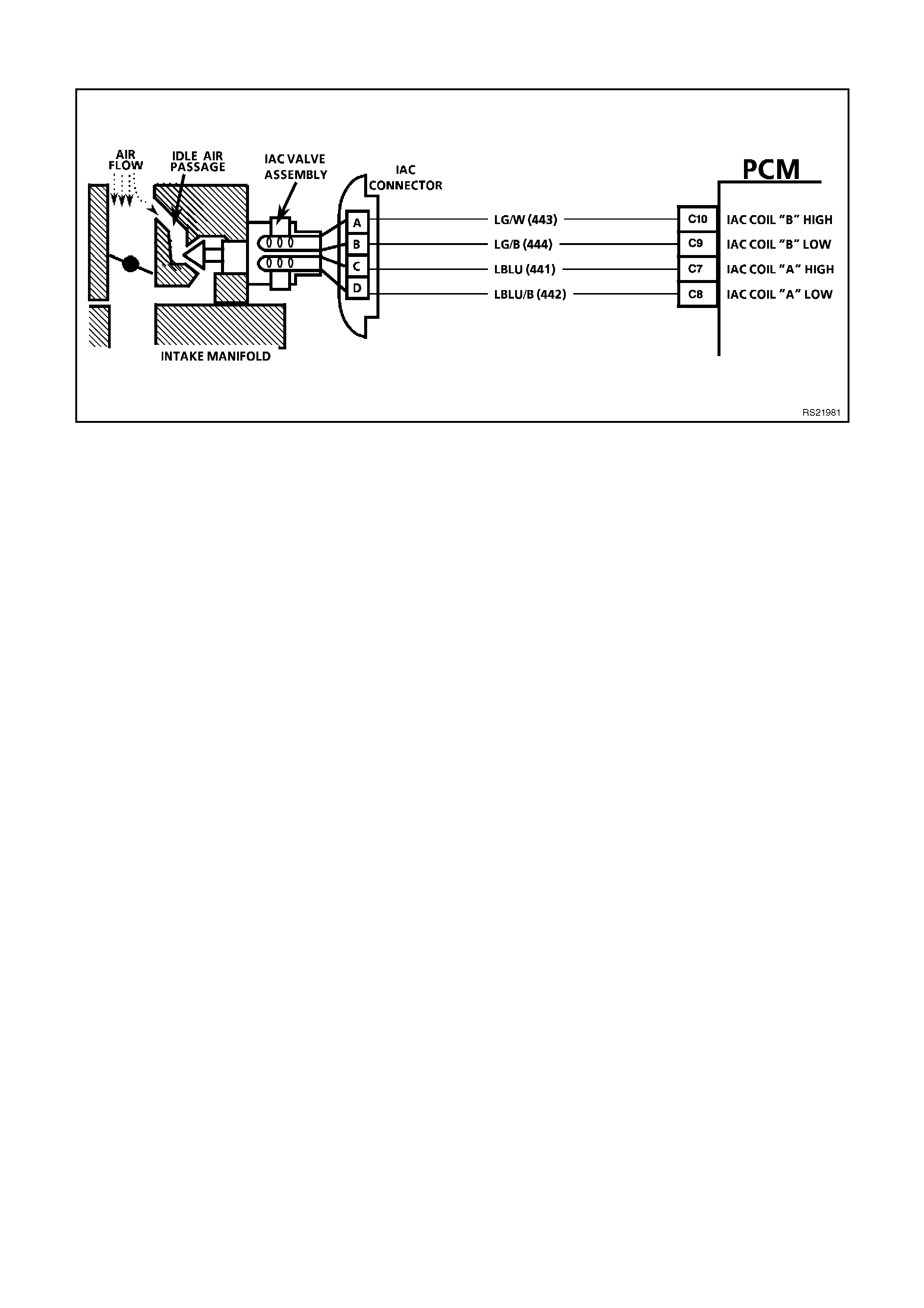
DTC 35 V6 PCM - IDLE SPEED ERROR
CIRCUIT DESCRIPTION:
The IAC valve is a stepper motor. Stepper motors have coils that the PCM turns ON and OFF several times per
second. This allows for an incremental clockwise and counter clockwise rotation of a pintle valve. The pintle valve
has a threaded shaft that either extends or retracts with each pulse of the PCM. The controlled pulses are called
steps or counts. The PCM controls the air entering into the engine at idle through the IAC valve. To increase the
idle speed, the PCM will command the pintle valve away from the throttle body. This allows more air to bypass the
throttle blade and thus increase engine RPM. To decrease the engine RPM at idle, the PCM will command the
pintle valve toward the throttle body seat to restrict air from entering into the engine and thus reduce engine RPM.
DTC 35 WILL SET IF:
• DTC 19, 21, 22, 23, 25, 26, 36, 72, or 94 are not set.
• IAT is at or below 73°C.
• Engine speed is more than 200 RPM lower than Desired idle (negative idle speed error greater than 200 RPM).
• Above conditions for longer than 5 seconds.
TEST DESCRIPTION:
Number(s) below refer to step number(s) on the diagnostic chart.
2. The Tech 2 scan tool RPM control mode is used to extend and retract the IAC valve. The valve should move
smoothly within the specified range. If the idle speed is commanded (IAC extended) too low (below 600 RPM),
the engine may stall. This may be normal and would not indicate a problem. Retracting the IAC beyond its
controlled range (above 1675 RPM) will cause a delay before the RPM's start dropping, this too is normal.
3. This test uses the Tech 2 scan to command the IAC controlled idle speed. The PCM issues commands to
obtain commended idle speed. The test lights each should flash indicated a good circuit as the PCM issues
commands. While the sequence is not important, if either light is OFF or does not flash, check the circuits for
faults, beginning with poor terminal contacts.

DIAGNOSTIC AIDS
A slow, unstable, or fast idle may be caused by a non-IAC system problem that cannot be compensated by the IAC
valve. Out of control range IAC Tech 2 scan tool counts will be above 60 if idle is too low and zero counts if idle is
too high. The following checks should be made to repair a non-IAC system problem:
• Vacuum Leak (High Idle).
If idle is too high, stop the engine. Fully extend (low) IAC with Tech 2 scan tool. Start engine.
If idle speed is above 800 RPM, locate and correct vacuum leak including PCV system. Also, check for binding
of throttle blade or linkage.
• System too lean (High Air/Fuel Ratio).
The idle speed may be too high or too low. Engine speed may be too high or too low. Engine speed may vary
up and down and disconnecting the IAC valve does not help. DTC 44 may be set. Tech 2 scan tool O2 voltage
will be less than 300 mV. Check for low regulated fuel pressure, water in the fuel or a restricted injector.
• System too rich (Low Air/Fuel Ratio).
The idle speed will be too low. Tech 2 scan tool IAC counts will usually be above 80. System is obviously rich
and may exhibit black smoke in exhaust. Tech 2 scan tool O2 voltage will be fixed above 800 mV. Check for
high fuel pressure, leaking or sticking injector. Silicon contaminated O2 sensor Tech 2 scan tool voltage will be
slow to respond.
• Throttle Body.
Remove the IAC valve and inspect bore for foreign material.
• IAC valve Electrical Connections.
The IAC valve connections should be carefully checked for proper contact tension.
• PCV Valve.
An incorrect or faulty PCV valve may result in an incorrect idle speed.
• Refer to "Rough, Unstable, Incorrect Idle or Stalling" in Section 6C2-2B SYMPTOMS.
• If intermittent poor driveability or idle symptoms are resolved by disconnecting the IAC, carefully recheck
connections, valve terminal resistance, or replace IAC.

STEP ACTION VALUE YES NO
1Was the "On-Board
Diagnostic" (OBD) System
Check performed?
Go to Step 2 Go to the OBD
System Check in
this Section
21. Install a Tech 2 scan
tool.
2. Start the engine and
allow the engine to idle
until the specified
temperature is
reached.
3. Transmission in park or
neutral.
4. Set the park brake.
5. Turn the A/C OFF.
6. Using the Tech 2 scan
tool cycle the IAC
valve from 600 RPM to
1675 RPM.
Does the engine speed
change smoothly when
commanded?
80°C Go to Step 3 Go to Step 5
31. Ignition OFF.
2. Disconnect the IAC
valve electrical
connector.
3. Measure the resistance
across the IAC valve
terminals A and B.
4. Measure the resistance
across the IAC valve
terminals C and D.
Are the resistance
readings across terminals
A and B, and terminals C
and D within the specified
values?
40-80
ohms Go to Step 4 Go to Step 13
41. Measure the resistance
across the IAC valve
terminals B and C.
2. Measure the resistance
across the IAC valve
terminals A and D.
Are the resistance
readings across terminals
B and C,
and terminals A and D
within the specified
values?
Infinite IAC valve control
circuits are OK.
Refer to
“Diagnostic Aids”
above.
Go to Step 13
51. Disconnect the IAC
valve electrical
connector
2. Ignition ON engine
OFF.
3. With a test light
connected to earth,.
Probe the IAC valve
electrical connectors.
Does the test light
illuminate on two
terminals?
Go to Step 6 Go to Step 7

STEP ACTION VALUE YES NO
6With a test light
connected to B+, probe
the IAC valve electrical
connector terminals.
Does the test light
illuminate on two
terminals?
Go to Step 8 Go to Step 7
7Check for an open or a
short in the IAC valve HI
and Lo circuits.
Was a problem found?
Go to Step 12 Go to Step 14
81. Start the engine and
allow to idle.
2. With a test light
connected to earth,
probe the IAC valve
electrical terminals?
Does the test light flash
ON and OFF on all the
terminals?
Go to Step 10 Go to Step 9
9Did the test light remain
ON steady for the
terminals that did not
flash?
Go to Step 7 Go to Step 11
10 Check the IAC passages
for a restriction.
Was a fault found?
Go to Step 15 Go to Step 7
11 Check the PCM electrical
connector for proper
tension at the terminals.
Was a problem found?
Go to Step 12 Go to Step 14
12 Repair the circuit or the
connector as necessary.
Is the action complete?
Verify Repair
13 Replace the IAC valve.
Is the action complete? Verify Repair
14 Replace the PCM. Refer
to Section 6C1-3 Service
Operations, for Security
Link procedure
Is the action complete?
Verify Repair
15 Clean the passages as
necessary.
Is the action complete?
Verify Repair

DTC 36 V6 PCM - VACUUM LEAK
CIRCUIT DESCRIPTION:
The PCM controls engine idle speed by adjusting the position of the Idle Air Control (IAC) motor pintle. The IAC is a
bi-directional motor driven by two coils. The PCM sends pulses (steps) to the IAC to extend or retract the IAC pintle
into a passage in the throttle body to decrease or increase air flow. The commanded IAC position (displayed in
counts) can be monitored on the scan tool; a lower number of counts indicates less commanded airflow (pintle
extended). This method allows highly accurate control of idle speed and quick response to changes in engine load.
If the PCM detects a condition where too high of an idle speed is present, the PCM will send 50 counts (steps) to
the IAC motor. If the RPM increases more than 50 RPM it is accepted that the IAC motor is moving and therefore
the fault is a vacuum leak, and DTC 36 will set. If the RPM does not change when the PCM commands the IAC to
respond to a commanded count (steps), the PCM will set a DTC 35.
DTC 36 WILL SET IF:
• Engine is idling.
• Engine coolant temperature is greater than 70°C.
• No vehicle speed is indicated.
• The throttle is closed.
• Engine speed is more than 200 RPM higher than Desired Idle (positive idle speed error greater than 200 RPM).
• Above conditions for longer than 5 seconds.
TEST DESCRIPTION:
Number(s) below refer to step number(s) on the diagnostic chart.
2. The importance of this step cannot be stressed too strongly. It can lead to correcting a problem without further
checks and save valuable time.
4. By restricting vacuum supply hoses, you are isolating which vacuum circuit may have a vacuum leak. When
the leak is stopped, the engine should respond immediately..
DIAGNOSTIC AIDS:
Check the IAC air passage for possible foreign material.
Code 36 may also be set by other system faults. Refer to Section 6C1-2B SYMPTOMS for diagnostic by
symptoms.

STEP ACTION VALUE YES NO
1. Was the "On-Board
Diagnostic" (OBD) System
Check performed?
Go to Step 2 Go to OBD
System Check in
this Section
2. 1. Ignition Off.
2. Perform a
visual/physical check
of all the vacuum
hoses and air duct
between the Mass Air
Flow Sensor and the
throttle body for:
Cracks, Splits, Kinks,
Connections and in
their proper location.
Was a problem found?
Verify Repair Go to Step 3
3. 1. Ignition "ON", engine
running.
2. Listen for a hissing
sound as evidence of a
vacuum leak.
Was a problem found?
Verify Repair Go to Step 4
4. 1. Ignition "ON", engine
running.
2. Using pliers, restrict
each vacuum hose
near the intake
manifold and listen for
the engine RPM to
change when hoses
are restricted.
Did RPM change when
with vacuum hoses
restricted?
Repair vacuum
leak in hose or
vacuum circuit.
Verify Repair
Go to Step 5
5. Inspect suspect areas of
the intake system such
as:
• The intake manifold
gaskets
• PCV system
• Throttle body vacuum
hose connections
• Throttle body gasket
• Supercharger gasket
• Oil dipstick seal and oil
fill cap for sources of
unmetered air.
• IACV O-ring
Was a problem found?
Verify Repair Go to Step 6
6. Clear DTC and drive
vehicle.
Does DTC reset?
Go to Step 7 Repair Complete
7. Replace PCM.
Refer to Section 6C1-3
Service Operations, for
PCM Security Link
procedure.
Is action complete?
Verify Repair
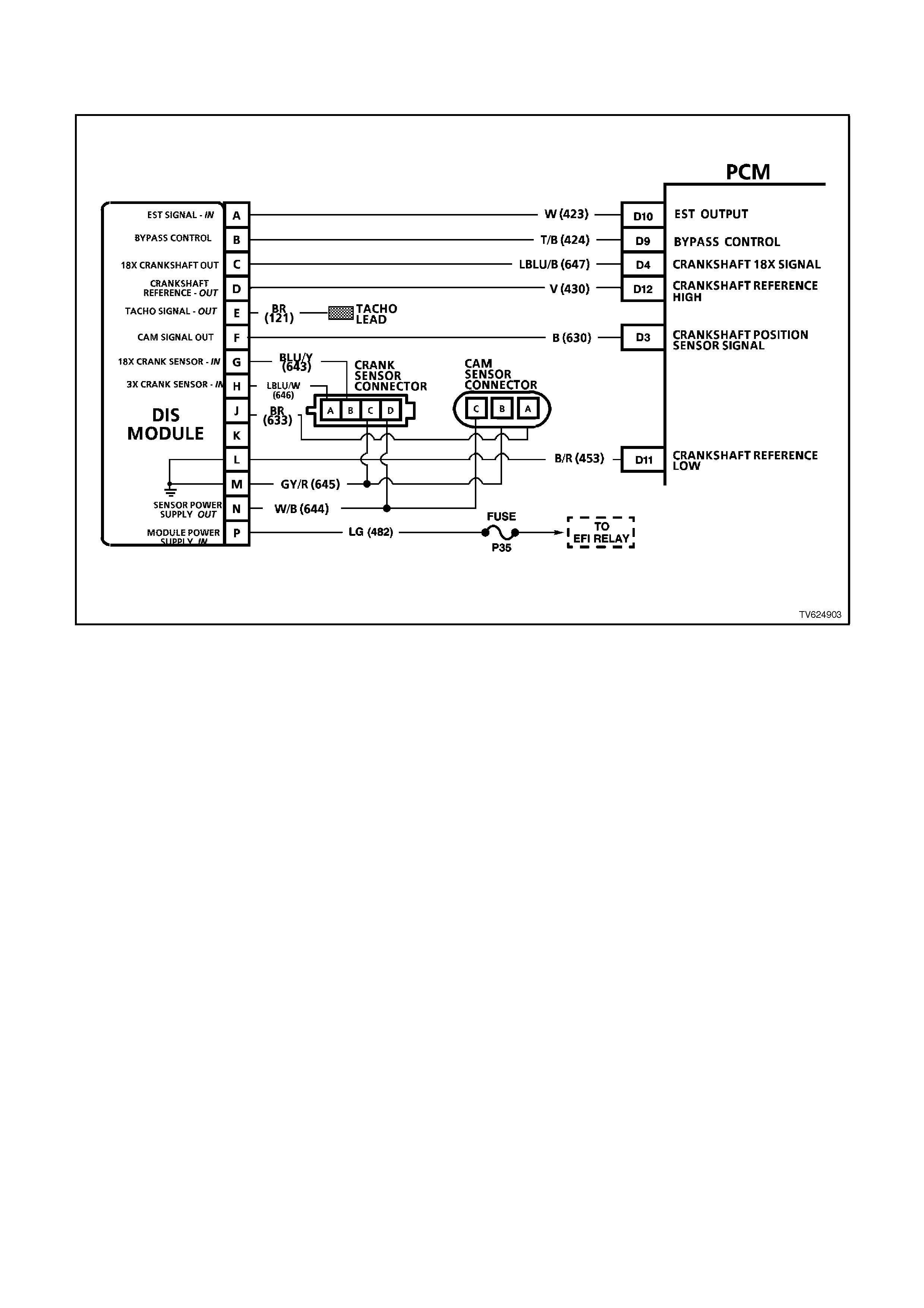
DTC 41 V6 PCM - IGNITION ELECTRONIC SPARK TIMING (EST)
OUTPUT CIRCUIT FAULT
CIRCUIT DESCRIPTION:
There are two modes of ignition system operation: BYPASS mode, and ELECTRONIC SPARK TIMING mode. The
Bypass mode is normally used while starting the engine, while the Electronic Spark Timing mode is used to allow
the PCM to control the ignition system after the engine is running. The PCM controls a "Bypass control circuit", used
to control the ignition module between the two different ignition system modes.
The PCM's Electronic Spark Timing (EST) output circuitry generates EST output pulses anytime crankshaft
reference input pulses are received. The PCM also monitors it's EST output terminal, to monitor if and when EST
pulses are present.
When the ignition system is operating in the Bypass mode (such as when the engine is cranking), the ignition
module earths the EST pulses coming from the PCM. Because the EST pulses should be earthed through the
ignition module during Bypass mode operation., the PCM should not detect EST pulses on it's EST output terminal.
If the EST output circuit wire between the PCM and the ignition module has an "open circuit" fault, then the ignition
module can not earth the PCM's EST output pulses. If the PCM detects two EST pulses during the first 3 crankshaft
reference input pulses, indicating the EST circuit is open, the PCM will set a DTC 41.
DTC 41 can also be set if the Bypass control circuit is shorted to voltage. If this where to happen, the PCM's EST
monitor would not sense the EST signal being earthed in the ignition module while cranking , and DTC 41 would be
set.
DTC 41 WILL SET IF:
• Ignition switch is "ON".
• PCM had detected at least 2 EST output pulses, during the first 3 crankshaft reference signal pulses received
from the ignition module, while cranking to start the engine.

TEST DESCRIPTION:
Number(s) below refer to Step numbers on the Diagnostic Chart.
4. This Step checks to see if circuit 424 is shorted to voltage.
8. This Step checks to see if circuit 423 is open.
DIAGNOSTIC AIDS:
Poor connection at PCM. Inspect harness connectors for backed out terminals, improper mating, broken locks,
improperly formed or damaged terminals, and poor terminal to wire connection.
Damaged Harness. Inspect the wiring harness for damage. If the harness appears to be OK, disconnect the ignition
module, turn the ignition "ON". Connect and observe a voltmeter connected between the Bypass control circuit and
+B, while moving connectors and wiring harness related to the ignition module. A change in voltage will indicate the
location of the fault.

STEP VALUE YES NO
1. Was the "On-Board
Diagnostic" (OBD) System
Check performed?
Go to Step 2 Go to OBD System
Check in this
Section
2. 1. Clear DTC 41.
2. Start engine and run
above 1600 RPM.
3. Observe DTC(s).
Did DTC 41 set?
Go to Step 3 DTC 41 is
intermittent. If no
additional DTC's
were stored, refer
to "Diagnostic Aids"
above.
3. 1. Ignition "OFF".
2. Disconnect ignition
module 14 pin
connector.
3. Probe ignition module
harness connector
terminal "B" with a
voltmeter connected to
earth.
4. Ignition "ON".
Is voltage greater then the
specified value?
0.5 V Go to Step 4 Go to Step 7
4. 1. Ignition "OFF".
2. Disconnect PCM
connectors.
3. Ignition "ON".
Is voltage still present at
ignition module harness
connector terminal "B"?
Go to Step 5 Go to Step 10
5. Repair short to voltage in
Bypass circuit 424.
Is action complete?
Verify Repair
6. Replace ignition module.
Is action complete? Verify Repair

STEP VALUE YES NO
7. 1. Ignition "OFF".
2. Reconnect 14 pin
connector to ignition
module.
3. Backprobe PCM
connector D10 with
voltmeter
connected to earth.
4. Ignition "ON", crank
engine.
Is voltage approximately
at specified value while
cranking or with engine
running?
2 volts Go to Step 8 Go to Step 9
8. Check for faulty
connection, or an open in
the EST circuit 423
between the PCM
terminal D10 and the
ignition module harness
connector terminal "A"
Was a fault found?
Verify Repair Go to Step 6
9. Check PCM for faulty
connection.
Was a faulty connection
found ?
Verify Repair Go to Step 10
10. Replace PCM.
Refer to Section 6C1-3
Service Operations, for
PCM Security Link
procedure.
Is action complete?
Verify Repair

DTC 42 V6 PCM - IGNITION BYPASS CIRCUIT FAULT
CIRCUIT DESCRIPTION:
There are two modes of ignition system operation: BYPASS mode, and ELECTRONIC SPARK TIMING mode. The
Bypass mode is normally used while starting the engine, while the Electronic Spark Timing mode is used to allow
the PCM to control the ignition system after the engine is running. The PCM controls a "Bypass control circuit", used
to control the ignition module between the two different ignition system modes.
The PCM's Electronic Spark Timing (EST) output circuitry generates EST output pulses anytime crankshaft
reference input pulses are received. The PCM also monitors it's EST output terminal, to monitor if and when EST
pulses are present.
When the ignition system is operating in the Bypass mode (such as when the engine is cranking), the ignition
module earths the EST pulses coming from the PCM. Because the EST pulses should be earthed through the
ignition module during Bypass mode operation., the PCM should not detect EST pulses on it's EST output terminal.
When the engine is started, the PCM applies 5 volts to the Bypass control circuit. When received by the ignition
module, this 5 volts control causes the ignition module to release the earth from the EST pulses coming from the
PCM. The ignition module will then use the EST pulses to operate the ignition system. When this occurs, the PCM
will correctly detect EST pulses at it's EST output terminal.
If the Bypass control circuit has as open fault or short to earth, or if the EST circuit has a short to earth or short to
voltage, the PCM cannot control the ignition module to release the EST pulses from being earthed. Because the
PCM also monitors it's EST output terminal for EST pulses, if it detects no EST pulses after it has "turned on" the 5
volts to the Bypass control circuit, and the engine speed goes above 1600 RPM, a DTC 42 will be set.
DTC 42 WILL SET IF:
• Engine speed is greater than 1600 RPM.
• PCM has detected no EST output pulses for 200 milliseconds.

TEST DESCRIPTION:
Number(s) below refer to Step numbers on the Diagnostic chart.
4. This step checks to see if circuit 423 is shorted to voltage.
7. This step checks to see if circuit 423 is shorted to earth.
10. This step checks to see if circuit 424 is shorted to earth.
12. This step checks to see if circuit 424 is open.
13 This step checks to see if the ignition module is capable of switching from Bypass to EST mode.
DIAGNOSTIC AIDS:
• Poor connection at PCM. Inspect harness connectors for backed out terminals, improper mating, broken locks,
improperly formed or damaged terminals, and poor terminal to wire connection.
• Damaged Harness. Inspect the wiring harness for damage. If the harness appears to be OK, disconnect the
ignition module, turn the ignition "ON". Connect and observe a voltmeter connected between the Bypass control
circuit and B+, while moving connectors and wiring harness related to the ignition module. A change in voltage
will indicate the location of the fault.

STEP ACTION VALUE YES NO
1. Was the "On-Board
Diagnostic" (OBD) System
Check performed?
Go to Step 2. Go to OBD
System Check.
2. 1. Clear DTC 42.
2. Start engine, and run
above 1600 RPM.
3. Observe DTC(s).
Did DTC 42 set ?
Go to Step 3 DTC 42 is
intermittent. Refer
to "Diagnostic
Aids" above.
3. 1. Ignition "OFF".
2. Disconnect ignition
module 14 pin
connector.
3. Probe ignition module
harness connector
terminal "A" with a
voltmeter to earth.
4. Ignition "ON".
Is voltage greater then the
specified value?
0.5 V Go to Step 4 Go to Step 6
4. 1. Ignition "OFF".
2. Disconnect PCM
connectors.
3. Ignition "ON".
Is voltage still present at
ignition module harness
connector terminal "A" ?
Go to Step 5 Go to Step 15
5. Repair short to voltage on
circuit 423.
Is action complete ?
Verify Repair
6. 1. Ignition "ON".
2. Probe ignition module
harness connector
circuit 423 with a test
light connected to
battery voltage.
Is test light "ON" ?
Go to Step 7 Go to Step 9
7. 1. Ignition "OFF
2. Disconnect PCM
connectors.
3. Probe ignition module
connector circuit 423
with a test light
connected to battery
voltage.
Is test light "ON" ?
Go to Step 8 Go to Step 14
8. Repair short to earth in
circuit 423.
Is action complete
Verify Repair
9. 1. Ignition "ON".
2. Disconnect ignition
module 14 pin
connector.
3. With test light
connected to battery
voltage, probe ignition
module harness
connector circuit 424.
Is test light "ON" ?
Go to Step 10 Go to Step 12

STEP ACTION VALUE YES NO
10. 1. Ignition "OFF".
2. Disconnect PCM
connectors.
3. Ignition "ON".
4. Disconnect ignition
module 14 pin
connector.
5. With test light
connected to battery
voltage, probe ignition
module harness
connector circuit 424.
Is test light "ON" ?
Go to Step 11 Go to Step 14
11. Repair short to earth on
circuit 424.
Is action complete ?
Verify Repair
12. 1. Ignition "OFF".
2. Disconnect PCM
connectors.
3. Check for faulty
connection or open
circuit 424.
Is fault found ?
Verify Repair Go to Step 13
13. 1. Ignition "OFF".
2. Reconnect ignition
module 14 pin
connector.
3. Disconnect PCM
connectors.
4. Ignition "ON".
5. Probe PCM harness
connector circuit 423
with an ohmmeter
connected to earth.
5. Probe PCM harness
connector circuit 424
with a test light
connected to battery
voltage.
NOTE:
As the test light contacts
circuit 424, does
resistance switch from
under specified value to
over specified value?
300
ohms
to
6000
ohms
Go to Step 14 Go to Step 15
14. Replace PCM.
Refer to Section 6C1-3
Service Operations, for
PCM Security Link
procedure.
Is action complete?
Verify Repair
15. Replace ignition module.
Is action complete ? Verify Repair

DTC 43 V6 PCM - KNOCK SENSOR CIRCUIT FAULT
CIRCUIT DESCRIPTION:
The electronic spark control (ESC) system detects engine detonation. The PCM will retard the Electronic Spark
Tim ing (EST) bas ed on the signal being received from the knoc k sensor . This input allows the EST spar k advance
to be optimised under all conditions. This allows the knock sensor input to reduce to the total advance when
detonation is detected. T otal EST advance can be retarded by as m uch as 12 degrees by the knock sensor input.
This could be described as a “closed-loop” spark advance system.
A loss of this s ignal would c ause the EST advance to r emain at a “no detonation” level. However, if detonation were
occurring, the advance not be retarded, and detonation could become severe enough under heavy engine load
conditions to result in pre-ignition and potential engine damage.
The knock sensor produces a small AC voltage, which goes above and below the DC voltage supplied from the
PCM. The s ensor ’s AC voltage output is dependent upon the level of detonation or k noc k. T he portion of the sensor
reacts like a microphone, producing a small voltage based on vibration.
DTC 43 WILL SET IF:
• One or more of the following DTC’s are not set. DTC 14, 15, 16, 17, 19, 21, 22, or 93.
• The TP sensor angle is greater than or equal to 10%.
• The ECT is greater than 65°C.
• The engine speed is greater than 2500 RPM.
• Engine run time is greater than 10 seconds.
• The PCM does not receive a knock signal.
• The above conditions are present for 3 seconds.
TEST DESCRIPTION:
Number(s) below refer to Step number(s) on the Diagnostic chart.
2. This Step determines if conditions for DTC 43 still exist.
4. If the knock sensor is generating a knock Signal then DTC 43 is intermittent.
5. This Step determines if the knock sensor circuit is shorted to voltage.
6. This Step determines if the knock sensor resistance is between 50,000 ohms and 100,000 ohms.

NOTE:
If the resistanc e is at 50,00 ohm s, this m eans that both knoc k sens or shunt res istors are OK. If the resistanc e is at
100,000 ohms , this means that one of the k nock sens or is open, but the knock sens or s ystem will still work pr operly
with only one knock sensor functioning.
Check each "knock" sensor for an open circuit 815 between splice and sensor. If wiring is OK, replace "knock"
sensor.
7. The signal should be present at the knock sensor terminal during these test conditions.
DIAGNOSTIC AIDS:
If c ircuit 815 is not open or shor ted to earth, the m ost lik ely cause is an open circ uit in the PCM. It is poss ible that a
faulty PCM could be the cause of the DTC 43, and it should be replaced.
Refer to "Intermittents" in Section 6C1-2B SYMPTOMS in this Service Information.
STEP ACTION VALUE YES NO
1. Was the "On-Board
Diagnostic" (OBD) System
Check performed?
Go to Step 2 Go to OBD
System Check in
this Section
2. 1. Install Tech 2 scan
tool.
2. Record then clear
DTC(s).
3. Ignition "ON", engine
idling.
4. Using Tech 2 scan
tool, select "Knock
Signal" and "Knock
Retard".
Is "Knock Retard" above
the specified value?
0° Go to Step 3 Go to Step 4
3. Repair short to voltage on
circuit 815.
Is action complete?
Verify Repair
4. 1. Ignition "ON", engine
Idling.
2. Lightly tap on
alternator bracket with
hammer.
Is Tech 2 scan tool
indicating "Knock Retard"
above the specified
value?
0° DTC 43
is intermittent. If
no additional
DTC's were
stored, refer to
"Diagnostic Aids"
above.
Go to Step 5
5. 1. Ignition "ON", engine
stopped.
2. Backprobe PCM
connector terminal for
circuit 815, with DVM
connected to earth.
3. Set DVM to read DC
voltage.
Is voltage reading on
DVM above the specified
value?
0 volts Go to Step 3 Go to Step 6

STEP ACTION VALUE YES NO
6. 1. Ignition "OFF".
2. Disconnect PCM
connectors.
3. Backprobe PCM
connector terminal for
circuit 815, with DVM
connected to earth.
4. Set DVM to read
resistance.
Is resistance on DVM at
either of the specified
value?
80
K ohms
(80,000
ohms)
Go to Step 7 Go to Step 10
7. 1. Ignition "OFF".
2. Reconnect PCM
connectors.
3. Backprobe PCM
connector terminal for
circuit 815, with DVM
connected to earth.
4. Set DVM to read AC
voltage.
5. Tap on alternator
bracket with hammer.
Is DVM indicating above
specified value?
50 mV
AC Go to Step 8 Go to Step 11
8. Check for poor c onnec tion
at PCM.
Was a poor connection
found?
Verify Repair Go to Step 9
9. Replace PCM.
Refer to Section 6C1-3
Service Operations for
PCM Security Link
procedure.
Is action complete?
Verify Repair
10. Check for open or s hort to
earth in circuit 815.
Was a fault found?
Verify Repair Go to Step 11
11. Replace knock sensor(s)
Is action complete? Verify Repair

DTC 44 V6 PCM - RIGHT HAND (RH) LEAN EXHAUST INDICATION
CIRCUIT DESCRIPTION:
The PCM supplies a voltage of about 450 millivolts between terminal "D14" and "D13". The Oxygen (O2) sensor
varies the voltage within a range of about 1 volt if the exhaust is rich, down through about 100 millivolts, if exhaust is
lean.
The sensor is like an open circuit and produces no voltage when it is below about 360 degrees C. An open sensor
circuit or cold sensor causes "Open Loop" operation.
DTC 44 WILL SET IF:
• No DTC 23, 25, 26, 33, or 34 are set.
• The O2 sensor signal voltage on circuit 1412 remains below 200 millivolts for over 46 seconds.
• The system is in "Closed Loop".
• IAT sensor is below 75 degrees C.

TEST DESCRIPTION:
Number(s) below refer to step(s) on the diagnostic chart.
4. The DTC 44 or lean exhaust is most likely caused by one of the following:
• O2 Sensor Wire - Sensor pigtail may be mispositioned and contacting the exhaust manifold.
• Check for intermittent earth in wire between connector and sensor.
• MAF Sensor - A shifted MAF sensor could cause the fuel system to go lean. Refer to CHART A-6.1 in this
Section.
• Lean Injector(s) - Perform power balance test using the Tech 2 scan tool.
• Fuel Contamination - Water, even in small amounts, near the in-tank Fuel Pump inlet can be delivered to the
injectors. The water causes a lean exhaust and can set a DTC 44 and/or DTC 64.
• Fuel Pressure - System will go lean if pressure is too low. It may be necessary to monitor fuel pressure while
driving the vehicle at various road speeds and/or loads to confirm. Refer to CHART A-4.1 in this Section.
• Exhaust Leaks - If there is an exhaust leak, the engine can cause outside air to be pulled into the exhaust and
past the sensor. Vacuum or crankcase leaks can cause a lean condition.
• If all the above are OK, it is a faulty O2 sensor.
DIAGNOSTIC AIDS:
Using the Tech 2 scan tool, observe the Long Term Fuel Trim values at different RPMs and air flow conditions. The
Tech 2 scan tool also displays the Long Term Fuel Trim cells, so the Long Term Fuel Trim values can be checked
in each of the cells to determine when the DTC 44 or DTC 64 may have been set. If the conditions for DTC 44 or
DTC 64 exists, the Long Term Fuel Trim values will be around +25%.

STEP ACTION VALUE YES NO
1. Was the "On-Board
Diagnostic" (OBD) System
Check performed?
Go to Step 2 Go to OBD System
Check in this
Section
2. 1. Start engine.
2. Run engine until it
reaches normal
operating temperature
(Above 80 degrees C).
3. Continue to run at 1600
to 1800 RPM for two
minutes.
Does Tech 2 scan tool
indicate O2 sensor voltage
fixed below specified
value?
200 mV Go to Step 3 DTC 44 is
intermittent, If no
additional DTCs
were stored, refer
to "Intermittents" in
Section 6C1-2B
SYMPTOMS.
3. Disconnect O2 sensor
connector.
With engine idling, does
Tech 2 scan tool display
O2 sensor voltage between
the specified values?
Between
350 mV
and 550
mV
Go to Step 4 Go to Step 6
4. 1. Refer to step 4 “Test
Description” first.
2. Perform the checks on
the items as noted.
MAF sensor operation
Low fuel pressure
Contaminated fuel exhaust
manifold leaks ahead of O2
sensor
Lean injector (possibly
restricted)
O2 sensor earth circuit
Are all items checked
found to be OK?
Go to Step 5 Verify Repair
5. Replace Oxygen sensor.
Is action complete? Verify repair
6. 1. Ignition "OFF".
2. Disconnect PCM
connectors.
3. With O2 sensor still
disconnected, check O2
signal circuit 1412 for a
short to earth.
Is a short to earth
detected?
Go to Step 7 Go to Step 8
7. Repair circuit 1412.
Is action complete? Verify Repair
8. Replace PCM.
Refer to Section 6C1-3
Service Operations, for
PCM Security Link
procedure.
Is action complete?
Verify Repair
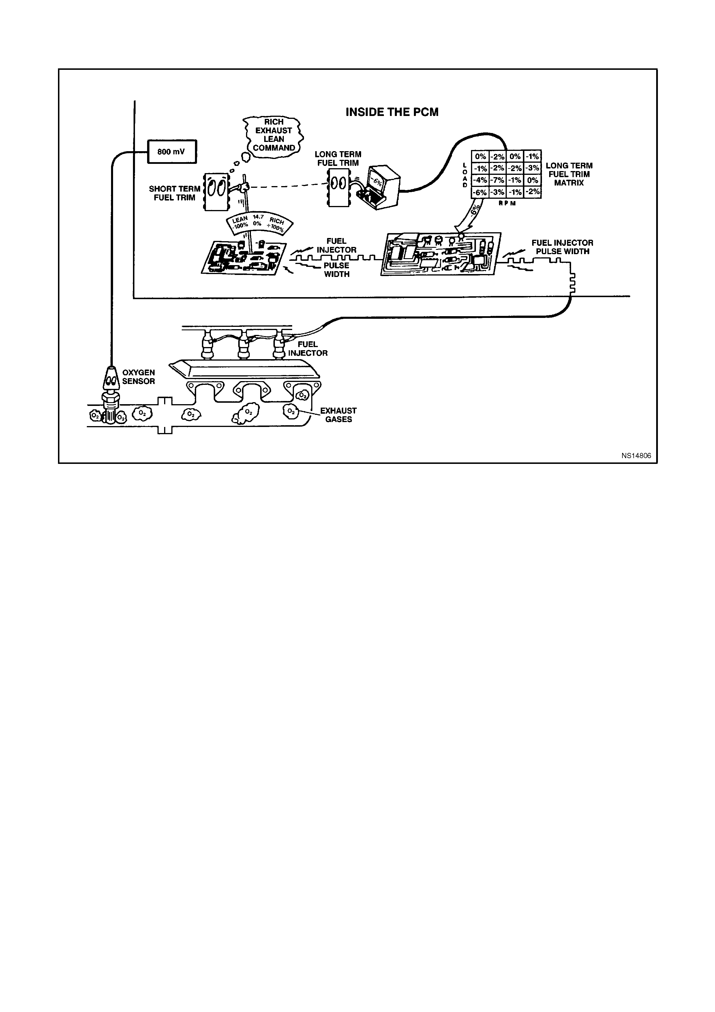
DTC 45 V6 PCM - RIGHT HAND (RH) RICH EXHAUST INDI CATION
CIRCUIT DESCRIPTION:
The PCM supplies a voltage of about 450 millivolts between terminal "D13" and "D14". The Oxygen (O2) sensor
varies the voltage within a range of about 1 volt, if the exhaust is rich and down through about 100 millivolts if
exhaust is lean.
The sensor produces no voltage when it is below about 360 degrees C. An open sensor circuit or cold sensor
causes "Open Loop" operation.
DTC 45 WILL SET IF:
• No DTC 19, 21, or 22 are set.
• The O2 sensor signal voltage on circuit 1412 remains above 780 millivolts for 40 seconds.
• The system is in "Closed Loop".
• Throttle angle is between 9% and 30%.

TEST DESCRIPTION:
Number(s) below refer to Step number(s) on the diagnostic chart.
8. A DTC 45 will most likely NOT be caused by a faulty O2 sensor. DTC 45 indicates a rich exhaust and
diagnosis should begin with the items listed:
• Fuel Pressure. System will be rich, if pressure is too high. The PCM can compensate for some increase.
However, if pressure it gets too high, a DTC 45 and/or DTC 65 may be set. Refer to fuel system diagnosis
CHART A-4.3 in this Section.
• Rich Injector.
• Leaking Injector. Refer to CHART A -4.3 in this Section.
• Check for fuel contaminate oil.
• Short to voltage on circuit 412.
• HEI Shielding. An open earth circuit 453 (ignition system) may result in EMI, or induced electrical "noise" as
reference pulses. The additional pulses result in a higher than actual engine speed signal. The PCM than
delivers too much fuel, causing system to go rich. Engine tachometer will also show higher than actual engine
speed, which can help in diagnosing this problem.
• Canister Purge. Check for fuel saturation. If full of fuel, check canister control and hoses.
• MAF Sensor. A shifted MAF sensor could cause the fuel system to go rich.
• Check for leaking fuel pressure regulator diaphragm by checking vacuum line to regulator for fuel.
• TP Sensor. An intermittent TP sensor output will cause the system to go rich, due to a false indication of the
engine accelerating.
DIAGNOSTIC AIDS:
Using the Tech 2 scan tool, observe the Long Term Fuel Trim values at different RPM and air flow conditions. The
Tech 2 scan tool also displays the Long Term Fuel Trim cells, so the Long Term Fuel Trim values can be checked
in each of the cells to determine when the DTC 45 may have been set. If the conditions for DTC 45 exists, the Long
Term Fuel Trim values will be around - 22%.
NOTE:
Oxygen sensor contamination - If fuel containing lead or silicon is used, or engine repairs using unapproved RTV
gasket sealer are performed, the sensor may be contaminated. It may send a "false" rich exhaust indication to the
PCM, and the PCM will attempt to drive the fuel system lean to compensate. Poor driveability or a DTC 45 could
result. If this happens, the sensor will need to be replaced, but every attempt to locate the source of contamination
should be pursued.

STEP ACTION VALUE YES NO
1. Was the "On-Board
Diagnostic" (OBD) System
Check performed?
Go to Step 2 Go to OBD
System Check
2. 1. Engine at normal
operating temperature
(above 80 degrees C).
2. Run engine at
approximately 1600
RPM to 1800
RPM for two minutes.
Is Tech 2 scan tool
voltage above specified
value?
750 mV Go to Step 3 DTC 45 is
intermittent,
If no additional
DTC(s) were
stored, refer to
"Intermittents" in
Section 6C1-2B
SYMPTOMS.
3. 1. Ignition "OFF".
2. Disconnect O2 sensor
wiring harness.
3. With ohmmeter
connected to earth,
probe circuit 1412 at
O2 sensor wiring
harness connector.
4. Ignition "ON".
Is voltmeter indicating less
then specified value?
350 mV Got to Step 7 Go to Step 4
4. 1. Ignition "OFF".
2. Disconnect PCM
connectors.
3. Probe circuit 1412 at
O2 sensor wiring
harness connector.
5. Ignition "ON".
Is voltmeter indicating
voltage below specified
value ?
350 mV Go to Step 6 Go to Step 5
5. Repair circuit 1412,
shorted to voltage.
Is action complete?
Verify Repair
6. Replace PCM.
Refer to Section 6C1-3
Service Operations, for
PCM Security Link
procedure.
Is action complete?
Verify Repair
7. 1. Disconnect O2 sensor
wiring harness
connector.
2. Jumper harness
connector circuit 1412
to earth.
With engine running, does
Tech 2 scan tool display
O2 voltage below
specified value?
350 mV Go to Step 8 Go to Step 9

STEP ACTION VALUE YES NO
8. See step 8 above to
perform additional checks
for:
High Fuel Pressure
Map Sensor Operation
Leaking Injectors
Ignition Earth Circuit
Canister Purge
Engine Coolant
Temperature Sensor
Circuit
Intake Air Temperature
Sensor Circuit
Throttle Position Sensor
Operation
Do all additional checks
from “Test Description”
step 8 test OK.?
Note: Go to step 8
above Verify Repair
9. 1. Ignition "OFF"
2. Disconnect PCM
connectors.
3. Check O2 sensor earth
circuit 750 for good
continuity between
PCM connector
terminal "D14" and
engine earth.
Is an "OPEN" circuit
indicated?
Verify Repair Go to Step 10
10. Check PCM earth wire
connection at engine.
Must be a clean and tight
connection to the engine.
Is connection good?
Go to Step 6 Verify Repair
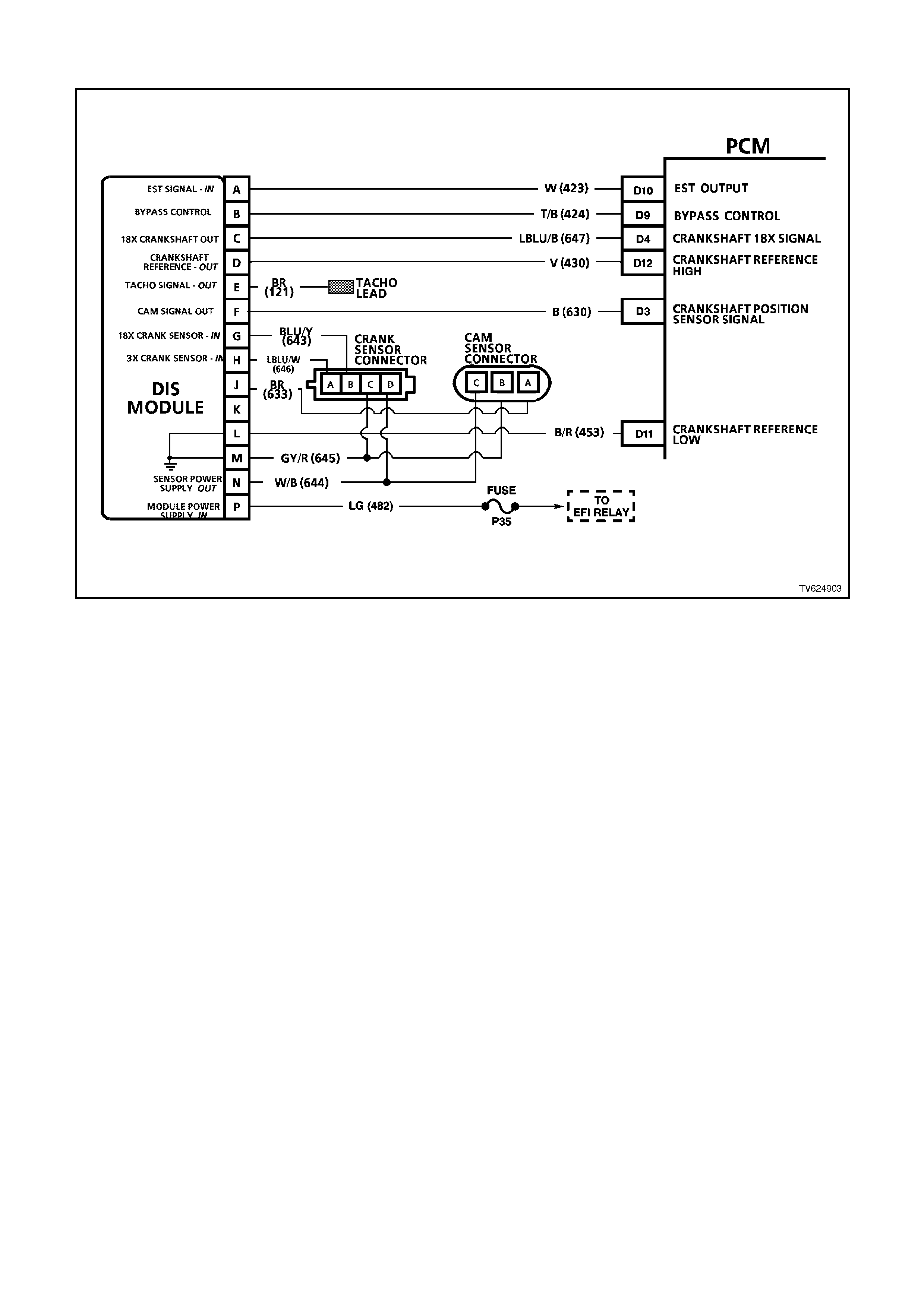
DTC 46 V6 PCM - NO REFERENCE PULSES WHILE CRANKING
CIRCUIT DESCRIPTION:
This DTC is intended to help in diagnosing a no-start condition. Any time the distributor is turning, the ignition
module should generate the crankshaft reference pulses that the PCM should be receiving. Fuel injection pulses
are "timed" from the crankshaft pulses, and without them no injection pulses will occur. The PCM can determine
when these crankshaft pulses should be present, but aren't.
As with any engine while being cranked, there is a small amount of inlet manifold vacuum. Also while cranking, the
battery voltage will be less than 11 volts. If the PCM's MAF sensor input detects manifold vacuum and the ignition
voltage input detects less than 11 volts and there are no distributor reference input pulses, a DTC 46 will set.
NOTE:
It is possible for the ignition system to provide spark, yet there may not be any distributor reference pulses at the
PCM.
DTC 46 WILL SET IF:
• DTC 32 is not set.
• Battery voltage is at or below 11 volts.
• MAF sensor input is above 2048 Hz.
• No DIS reference input pulses at PCM terminal "D12".
• The above conditions exist for more than 2 seconds.

TEST DESCRIPTION:
Number(s) below refer to the step(s) on the diagnostic chart.
2. If engine starts, the problem is not present now. While the PCM monitors 3 inputs to determine DTC 46, only a
lack of distributor reference input signal pulses can set the DTC. If a problem occurred on the MAF or ignition
voltage inputs, other problems would be apparent.
NOTE:
Even one crankshaft reference pulse while cranking will cause DTC 46 to NOT set.
3. Spark on all three wires on the same side of the engine proves the DIS coil pack to be OK. No spark on any
lead means the DIS ignition system is suspect of causing the DTC 46. If the DIS ignition system cannot
generate any spark, it cannot generate the crankshaft reference signal either.
Refer to
CHART A-8.1 in this Section to determine the cause. If there is spark on only 1 or 2 spark plug leads,
the crank sensor is probably OK, but there could be a problem with the coil pack or DIS module. CHART A-8.1
in this Section should determine the problem.
4. The voltage should be either "OFF" (less than 1 volt) or "ON" (more than 3 volts). This is the square-wave,
digital "ON-OFF" distributor reference signal generated by the ignition module. The voltage could be either
reading, depending on where the distributor stopped turning.
5. This is again the distributor reference signal. When the distributor is turning, the signal changes from under 1
volt to over 3 volts, back and forth, eight times per distributor revolution. Since it changes quickly, the voltmeter
can indicate only an average voltage. (expected reading - approximately 2 volts.)
6. A loose connection at PCM terminal "D12" could cause an intermittent voltage measurement to be seen.
NOTE:
Use ST-125 spark checker or equivalent to check for adequate spark. An ST-125 requires about 25,000 volts (25
Kilovolts or 25 kV) to "spark". Do not use a spark plug in open air earthed to the engine as an indication of sufficient
"spark". Only a few kilovolts are required to jump the gap of a spark plug outside of the engine, and that would be
an inadequate test of the ignition system.

STEP ACTION VALUE YES NO
1. Was the "On-Board
Diagnostic" (OBD) System
check performed?
Go to Step 2 Go to OBD
System Check in
this Section
2. Attempt to start engine.
Did engine start and
continue to run?
DTC 46 is
intermittent. If no
additional DTC's
were stored, refer
to "Intermittents"
in Section 6C1-2B
SYMPTOMS.
Go to Step 3
3. 1. Remove the spark plug
leads from two spark
plugs.
2. Connect ST-125 spark
checker (See note
above) to each lead
individually, and check
for spark while
cranking the engine.
Was spark evident on
both leads? (A few
sparks and then nothing is
considered no spark.)
Go to Step 4 Go to Chart A-8.1
in this Section
4. 1. Ignition "OFF" .
2. Disconnect PCM.
3. Backprobe PCM
harness connector
terminal "D12" to earth
with a digital voltmeter
set to read "DC volts".
4. Ignition "ON".
Is the voltage at the
specified value
Approx. Go to Step 5 Go to Step 9
5 volts

STEP ACTION VALUE YES NO
5. 1. Ignition "OFF".
2. Disconnect PCM.
3. Backprobe PCM
harness connector
terminal "D12" to earth
with a digital voltmeter
set to read "DC Volts".
4. Ignition "ON" .
5. While observing digital
voltmeter, crank the
engine.
Is voltage measured
approximately the
specified value?
2 - 3
volts Go to Step 6 Go to Step 8
6. Check PCM terminal
"D12" for a loose
connection.
Was a fault found?
Verify Repair Go to Step 7
7. Replace PCM.
Refer to Section 6C1-3
Service Operations, for
PCM Security Link
procedure.
Is action complete?
Verify Repair
8. Check circuit 430 for a
faulty connection or an
open or short to earth.
Was a fault found?
Verify Repair Go to Step 9
9. Replace Ignition Module
Is action complete? Verify Repair
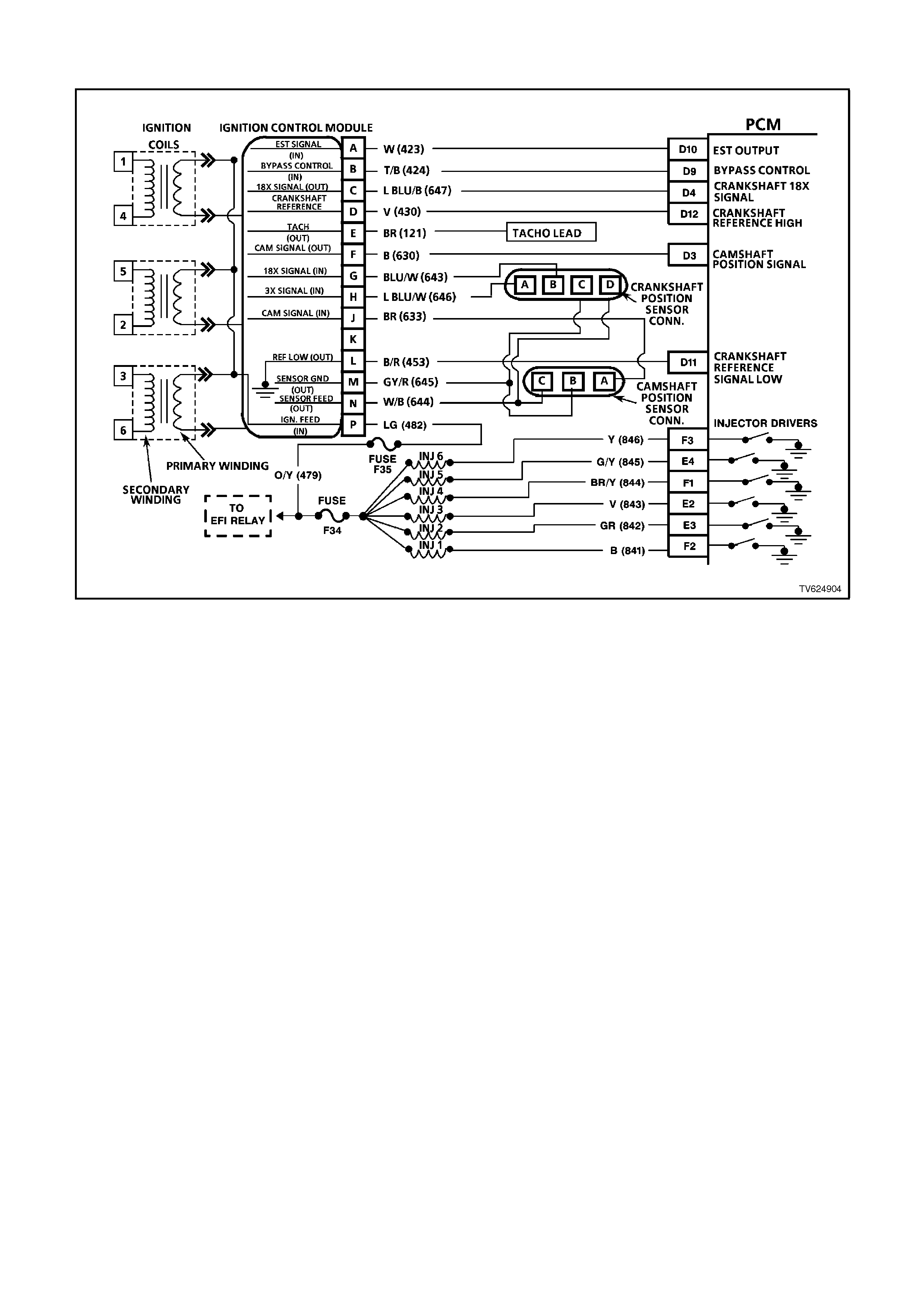
DTC 47 V6 PCM - 18X REFERENCE SI GNAL MISSING
CIRCUIT DESCRIPTION:
The 18X signal (circuit 647) is used by the PCM to improve ignition timing accuracy during crank and at engine
speeds of up to 2000 RPM. The 18X signal circuit allows the use of EST mode below 400 RPM, eliminating the
need to utilise bypass mode during startup, and also allows the PCM to calculate true crankshaft position in 1/6 the
time that use of the crankshaft reference signal would permit.
During normal operation, the PCM uses the 18X signal to control ignition timing until the engine speed exceeds
2000 RPM, at which time the crankshaft reference signal (circuit 430) is used. When conditions for setting DTC 47
exist, the crankshaft reference signal is used by the PCM to control EST. This condition will cause bypass mode to
be used for ignition timing below 400 RPM and EST ignition timing to be degraded below 2000 RPM.
DTC 47 WILL SET IF:
• The engine is running.
• The PCM detects 253 crankshaft reference pulses, and no 18X signal pulses.
• The engine RPM is below 1200.
TEST DESCRIPTION:
Number(s) below refer to step number(s) on the diagnostic chart.
4. If a window on the harmonic balancer is interfering with the 18X Hall-Effect switch, the ignition module will earth
the 18X signal. Starter may have to be bumped several times to obtain a voltage reading.
5. Voltage reading should be lower than that obtained with engine not running, indicating a pulsed reference
signal.
8. Verifies that circuit 647 is not shorted to earth or open in the harness.
DIAGNOSTIC AIDS:
An intermittent may be caused by a poor connection, rubbed through wire insulation, or a wire broken inside the
insulation.
Check for:
• Backed out connector terminals or broken down insulation in circuit 647.
• If connections and harness check OK, try monitoring voltage on circuit 647 with DVM while moving the related
wiring harness and connectors with the engine idling. This may help to isolate the location of the malfunction.

STEP ACTION VALUE YES NO
1. Was the "On-Board
Diagnostic" (OBD) System
Check performed?
Go to Step 2 Go to OBD
System Check in
this Section
2. 1. Ignition "OFF".
2. Install Tech 2 scan tool
and clear DTCs.
3. Ignition "ON".
4. Start engine idle for 1
minute or until
Diagnostic Trouble
Code 47 sets.
Did Diagnostic Trouble
Code 47 set?
Go to Step 3 DTC 47 is
intermittent. If no
additional DTC's
were stored, refer
"Diagnostic Aids"
above.
31 . Backprobe PCM
terminal D4 with a
DVM connected to
earth.
2. Ignition "ON", engine
"OFF", observe voltage
on PCM terminal "D4".
Does voltage measure
specified value?
Approx.
5 volts Go to Step 5 Go to Step 4
4. 1. Bump engine with
starter.
2. Retest voltage at PCM
terminal "D4".
Does voltage measure
specified value?
Approx.
5 volts Go to Step 5 Go to Step 8
5. 1. Start engine, idle 1
minute to stabilise
system.
2. Observe voltage on
PCM terminal "D4".
Does voltage measure
specified value?
Approx.
3 volts Go to Step 7 Go to Step 6

STEP ACTION VALUE YES NO
6. Check for poor ignition
module connections.
Was a fault found?
Verify Repair Go to Step 10
7. Check for poor connection
at PCM "D4".
Was a fault found?
Verify Repair Go to Step 11
8. 1. Ignition "OFF".
2. Disconnect PCM
connectors.
3. Ignition "ON".
4. Measure voltage at
PCM harness
connector terminal
"D4".
Does voltage measure
specified value?
Approx.
5 volts Go to Step 11 Go to Step 9
9. Check circuit 647 open or
shorted to earth.
Was a fault found?
Verify Repair Go to Step 10
10. Replace faulty ignition
control module.
Is action complete?
Verify Repair
11. Replace PCM.
Refer to Section 6C1-3
Service Operations, for
PCM Security Link
procedure.
Is action complete?
Verify Repair

DTC 48 V6 PCM - CAMSHAFT POSITION SIGNAL MISSING
CIRCUIT DESCRIPTION:
During cranking, the ignition module monitors the dual crank sensor 3X signal. The 3X signal is used to determine
the correct cylinder pair to spark first. After the 3X signal has been processed by the ignition module, it sends a
crankshaft reference pulse to the PCM. When the PCM receives this pulse it will command all six injectors to open
for one priming shot of fuel in all cylinders. After the priming, all six of the injectors are left "OFF" until the next
crankshaft reference pulses from the ignition module (two crankshaft revolutions). This allows each cylinder a
chance to use the fuel from the priming shot. During this waiting period, a cam signal will have been received by the
PCM. Now the PCM begins to operate the injectors in sequential fuelling mode by energising each injector based on
true camshaft position. However, if the camshaft position signal is not present at startup, a DTC 48 will set and the
PCM will energise all six injectors at the same time and continue to operate like this until the fault is corrected.
DTC 48 WILL SET IF:
• The engine is running.
• Camshaft position sensor signal is not received by the PCM for at least 5 seconds.
TEST DESCRIPTION:
Number(s) below refer to step number(s) on the diagnostic chart.
3. This step verifies proper operation of circuits 633, 644, and 645.
4. This step verifies the integrity of circuit 630 from ignition module to PCM. If the voltage reading of "D3" drops
slightly from 4.7 volts to approximately 4.1 volts, the camshaft sensor is pulling the signal line low, therefore the
connection to the PCM is not good or the PCM is faulty. If the voltage remains at approximately 4.4 volts and is
steady, continue with diagnosis.
DIAGNOSTIC AIDS
An intermittent may be caused by a poor connection, rubbed through wire insulation, or a wire broken inside the
insulation.
Check for:
• Poor Connection or Damage Harness - Inspect PCM harness connectors for backed out terminal "D3", improper
mating, broken locks, improperly formed or damaged terminal, poor terminal to wire connection and damaged
harness.
• Intermittent Test - If connections and harness check OK, monitor a digital voltmeter connected from PCM
terminal "D3" to earth while moving related connectors and wiring harness. If the failure is induced, the voltage
reading will change. This may help to isolate the location of the malfunction.

STEP ACTION VALUE YES NO
1. Was the "On-Board
Diagnostic" (OBD) System
Check performed?
Go to Step 2. Go to OBD
System Check in
this Section
2. 1. Install Tech 2 scan
tool.
2. Ignition "ON", engine
"OFF".
3. Record, then clear
DTCs.
4. Start engine, idle for 1
minute.
5. Select DATA LIST.
Does Tech 2 scan tool
display "Cam Signal" as
"Missing"?
Go to Step 3 DTC 48 is
intermittent. If no
additional DTCs
were stored, refer
to "Diagnostic
Aids" above.
31. Ignition "OFF".
2. Disconnect camshaft
position sensor
harness connector
from camshaft position
sensor.
3. Ignition "ON", engine
"OFF".
Using DVM, does voltage
between harness
connectors pins "A-B and
"B-C" measure between
specified values?
"A-B"
5-7
volts
"B-C"
8-11
volts
Go to Step 4 Go to Step 11
4. 1. Ignition "OFF".
2. Reconnect camshaft
position sensor
harness to camshaft
position sensor.
3. Install DVM to
backprobe PCM
terminals D3 & A1 to
measure voltage at
PCM terminal D3.
4. Ignition "ON", engine
"OFF".
Is voltage fixed at
specified value?
Approx.
4.7 volts Go to Step 5 Go to Step 10
5. Start engine, idle 1 minute
to stabilise system.
Is voltage reading of "D3"
constantly varying around
a mid-point of specified
value?
Approx.
4.1 volts Go to Step 9 Go to Step 6

STEP ACTION VALUE YES NO
6. 1. Ignition "OFF".
2. Disconnect camshaft
position sensor
harness connector
from camshaft position
sensor.
3. Ignition "ON", engine
"OFF".
4. Touch terminal "A" of
camshaft position
sensor harness
connector with a test
light connected to
earth while observing
voltmeter.
Does voltage reading at
PCM terminal "D3" drop to
specified value?
0 volts Go to Step 7 Go to Step 8
7. CHECK FOR:
Poor connection at
camshaft position sensor
Faulty camshaft position
sensor
Missing camshaft magnet
Is action complete?
Verify Repair
8. Replace faulty ignition
control module.
Is action complete?
Verify Repair
9. Check for poor connection
at PCM terminal D3 or
faulty PCM.
Is action complete?
Verity Repair
10 Bump engine with starter.
Retest voltage at terminal
"D3". Is voltage fixed at
specified value?
Approx.
4.7 volts Go to Step 5 Go to Step 17

STEP ACTION VALUE YES NO
11. Was one voltage reading
low? Go to Step 12 Go to Step 16
12. Was the reading between
harness connector pin
"A-B low?
Go to Step 13 Go to Step 15
13. Check for open or short to
earth in circuit 633
Was a fault found?
Verify Repair Go to Step 14
14. Check for poor ignition
control module
connection.
Was a fault found?
Verify Repair Go to Step 8
15 Repair circuit 644
between splice and
camshaft position sensor
connector.
Is action complete?
Verify Repair
16 Repair circuit 645
between splice and
camshaft position sensor
connector.
Is action complete?
Verify Repair
17 Check circuit 630 for open
or short to earth.
Was a fault found?
Verify Repair Go to Step 18
18 Replace the camshaft
position sensor.
Is action complete?
Verify Repair

DTC 49 V6 PCM - CAM/CRANK SIGNAL INTERMITTENT
CIRCUIT DESCRIPTION:
During cranking, the ignition module monitors the dual crank sensor 3X signal. The 3X signal is used to determine
the correct cylinder pair to spark first. After the 3X signal has been processed by the ignition module, it sends a
crankshaft reference pulse to the PCM. When the PCM receives this pulse it will command all six injectors to open
for one priming shot of fuel in all cylinders. After the priming, the injectors are left "OFF" for the next six crankshaft
reference pulses from the ignition module (two crankshaft revolutions). This allows each cylinder a chance to use
the fuel from the priming shot. During this waiting period, a cam signal will have been received by the PCM. Now the
PCM begins to operate the injectors by energising each injector based on true camshaft position. With the engine
running, the PCM monitors the cam and 18X signal pulses it receives and expects to see 36 18X signal pulses for
each cam pulse.
DTC 49 WILL SET IF:
• Engine is cranking.
• Missing or incorrect number of cam pulses for 15 times.
TEST DESCRIPTION:
Number(s) below refer to step number(s) on the diagnostic chart.
2. Determines if conditions necessary to set DTC 49 exist on this ignition cycle.
3. If 5 volts are not present at PCM harness connector terminal "D3", the cam sensor may be interfacing with the
magnet in the camshaft sprocket. Bumping the starter should correct this condition.
6. If a failure is induced in the 18X signal circuit, the 5 volts on the circuit should change when the faulty wiring or
connection is manipulated.
NOTE:
If DTC 48 is set along with DTC 49, use DTC 48 chart for diagnosis.
DIAGNOSTIC AIDS:
DTC 49 indicates an intermittent fault and may not set immediately or under all conditions. Customer comments of
symptoms experienced may help isolate the cause of the condition. A poor connection or fault in the cam sensor
circuits 630, 633, 644, or 645 or a faulty cam sensor may cause the PCM to re-initialise injector sequence when the
fault occurs, causing a possible stumble or miss. A poor connection or fault in the 18X signal circuit 647, crank
sensor circuits 643, 644, or 645, the 18X portion of the crank sensor or bent or missing vanes on the harmonic
balancer interrupter rings will cause the PCM to stop pulsing the injectors when the fault occurs, causing an
intermittent stumble or stall.

STEP ACTION VALUE YES NO
1. Was the "On-Board
Diagnostic" (OBD) System
Check performed?
Go to Step 2 Go to OBD
System Check in
this Section
2. 1. Install Tech 2 scan
tool.
2. Start and idle engine.
3 Using Tech 2 scan tool,
look at "IGN Cycles" in
DTC history.
Is DTC 49 current?
Go to Step 3 DTC 49 is
intermittent. If no
additional DTC's
were set, refer to
"Diagnostic Aids"
above.
31. Ignition "OFF".
2. Disconnect PCM
connectors.
3. Connect a DVM
between PCM harness
connector terminal
"D3" and earth.
4. Ignition "ON".
Is voltage at "D3' at
specified value?
Approx.
5 volts Go to Step 5 Go to Step 4
4. Bump engine with starter.
Is voltage at "D3" at
specified value?
Approx.
5 volts Go to Step 5 Go to DTC 48 in
this Section
5. Monitor voltage at "D3"
while manipulating
powertrain wiring harness
to PCM connector.
Does voltage remain
steady as wiring is
manipulated?
Go to Step 6 Go to Step 10
6. 1. Connect DVM between
PCM harness
connector terminal
"D4" and earth.
2. Monitor voltage at "D4"
while manipulating
ignition harness,
engine harness, and
dash harness to PCM
connector.
Does voltage remain
steady as wiring is
manipulated?
Go to Step 7 Go to Step 8

STEP ACTION VALUE YES NO
7. Check for:
Poor connections at PCM;
Harmonic balancer
interrupter ring vanes bent
or missing;
Faulty crank sensor
(malfunctioning hot/cold).
Are all above OK?
Refer to
"Diagnostic Aids"
above.
Verify Repair
8. Check for poor connection
at crankshaft position
sensor or ignition control
module.
Was a fault found?
Verify Repair Go to Step 9
9. Repair intermittent
open/short to earth in
circuit 643, 644, 645 or
647.
Is action complete?
Verity Repair
10 Check for poor connection
at camshaft position
sensor or ignition control
module.
Was a fault found?
Verify Repair Go to Step 11
11. Repair intermittent
open/short to earth in
circuit 630, 633, 644 or
645.
Is action complete?
Verify Repair
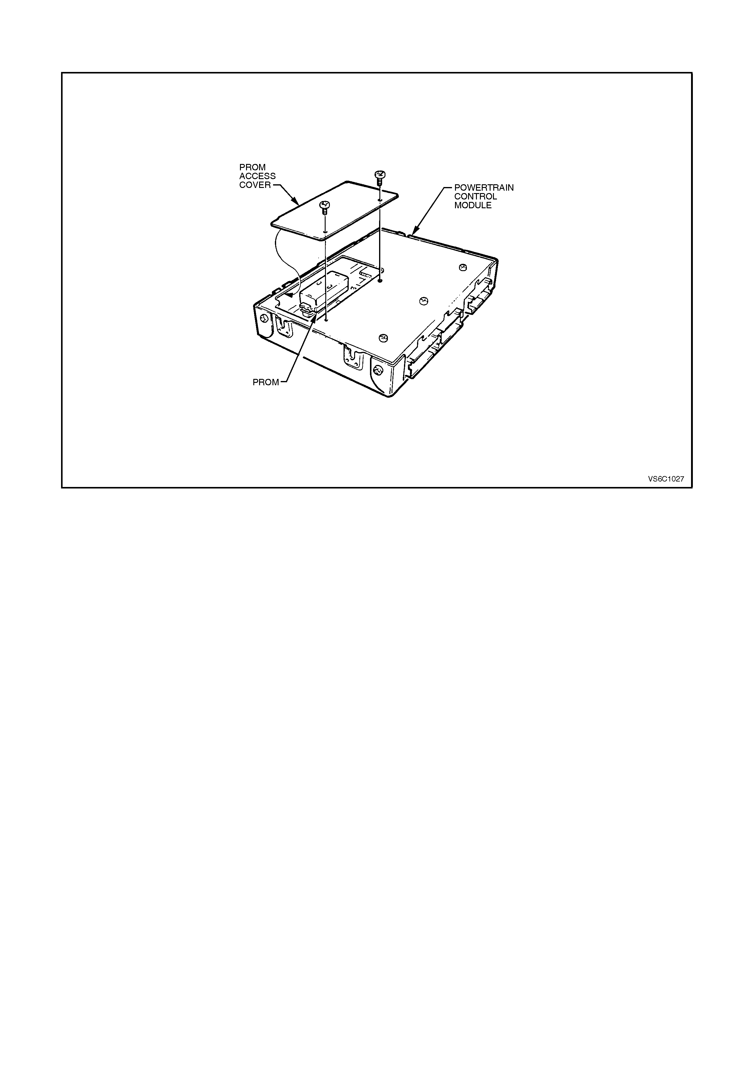
DTC 51 V6 PCM PROM ERROR
Circuit Description
The 18X signal (circuit 647) is used by the PCM to improve ignition timing accuracy during crank and engine speeds
of up to 2000 RPM . The 18X signal allows the use of EST mode below 400 RPM, eliminating the need to utilise
bypass mode during startup, and also allows the PCM calculate true crankshaft position in 1/6 the time that use of
the crankshaft reference signal would permit.
During normal operation, the PCM uses the 18X signal to control ignition timing until the engine speed exceeds
2000 RPM, at which time the crankshaft reference signal (circuit 430) is used. When conditions for setting DTC 47
exist, the crankshaft reference signal is used by the PCM to control EST. This condition will cause bypass mod to
be used for ignition timing below 400 RPM and EST ignition timing to be degraded below 2000 RPM.
DTC 47 ill set if:
• The engine is running.
• The PCM detects 253 crankshaft reference pulses, and no 18X signal pulses.
• The engine RPM is below 1200 RPM.
Test Description:
Number(s) below refer to step number(s) on the diagnostics chart.
4. If a window is on the harmonic balancer is interfering with the 18X Half-Effect switch, the ignition module will
earth the 18X signal. Started may have to be bumped several times to obtain a voltage reading.
5. Voltage reading should be lower than that obtained engine not running, indicating a pulsed reference signal.
8. Verifies that circuit 647 is not shorted to earth or open in the harness.
Diagnostic Aids:
An intermittent may be caused by a poor connection rubbed through wire insulation, or a wire broken inside the
insulation
Check for:
• Backed out connector terminals or broken down insulation in circuit 647
• If connections and harness check OK, try monitoring voltage on circuit 647 with DVM while moving the related
wiring harness and connectors with the engine idling. This may help to isolate the location of the malfunction.

STEP ACTION VALUE YES NO
1. Was the "On-Board
Diagnostic" (OBD) System
Check performed?
Go to Step 2 Go to OBD
System Check in
this Section
2. Check that PROM is fully
inserted into the PCM.
Is PROM fully inserted?
Go to Step 3 Go to Step 5
3. Replace PROM.
Clear DTCs and recheck
for DTC 51.
Does DTC 51 reset?
Go to Step 4 Go to Step 6
4. Replace PCM.
Refer to Section 6C1-3
Service Operations, for
PCM Security Link
procedure.
Is action complete?
Verify Repair
5. Fully insert PROM.
Clear DTCs and recheck
for DTC 51.
Does DTC 51 reset?
Go to Step 3 Go to Step 6
6. Clear DTC’s and confirm
no "Check Powertrain
Lamp".
Is action complete?
Verify Repair

DTC 52 - SYSTEM VOLTAGE TOO HIGH - LONG TIME
CIRCUIT DESCRIPTION:
Circuit 39 is the ignition voltage feed circuit to terminal A4 for the PCM. Circuit 740 is the battery voltage feed circuit
to terminals A8 and B8 for the PCM. When the PCM detects a high voltage for a long time, then DTC 52 sets.
DTC 52 WILL SET IF:
• Engine is running and the PCM terminal "A4" voltage is greater than 16 volts for more than 109 minutes.
During the time fault is present, the pressure control solenoid is turned "OFF", the transmission shifts immediately
to 3rd gear and TCC operation is inhibited. Additional codes may also set.
TEST DESCRIPTION:
The numbers below refer to the step numbers on the diagnostic chart.
4. This step tests the charging system voltage.
5. This step tests PCM battery voltage.

DIAGNOSTIC AIDS:
• Inspect the wiring for poor electrical connections at the PCM. Look for the following conditions:
A bent terminal
A backed out terminal
A damaged terminal
Poor terminal tension
A chafed wire
A broken wire inside the insulation
Moisture intrusion
• When diagnosing for an intermittent short or open condition, massage the wiring harness while watching the test
equipment for a change.
• Charging the battery with a battery charger may set DTCs. Jump starting an engine may set DTCs.
• If DTCs set when you operate an accessory, inspect the applicable wiring for faulty connections. Inspect the
wiring for excessive current draw.
•Inspect the following items for faulty connections:
The starter solenoid
The fusible link
The generator terminals
Battery cables
• Inspect the belts for excessive wear. Inspect the belts for proper tension.
When DTC 52 sets, the PCM turns off all transmission output devices OFF and freezes shift adapts from being
updated.

STEP ACTION VALUE YES NO
1Was the On-Board
Diagnostic (OBD) System
Check performed?
— Go to Step 2 Go to OBD
System Check
21. Install the scan tool.
2. With the engine OFF,
turn the ignition switch
to the RUN position.
IMPORTANT:
Before clearing the DTCs,
use the scan tool in order
to record the DTC history.
The Clear Info function
will erase the data.
3. Record the DTC
history.
4. Using the J 39200
DVM, measure the
battery voltage across
the battery terminals.
Record the
measurement for
future reference.
5. Is the voltage higher
than the specified
value?
10 volts Go to Step 3 Go to Battery
Diagnosis
31. Start the engine.
2. Warm the engine to
the operating
temperature.
Is the generator/check
engine light ON?
85°C Go to Charging
System Diagnosis Go to Step 4
41. Increase the engine
speed to 2000 RPM for
15 seconds.
2. Observe the DVM
battery voltage.
Is the DVM battery voltage
greater than the specified
value?
15 volts Go to Charging
System Diagnosis Go to Step 5

STEP ACTION VALUE YES NO
51. Increase the engine
speed to 2000 RPM.
2. Observe the scan tool
Battery Voltage.
Is the scan tool Battery
Voltage greater than the
specified value?
15.5
volts Go to Step 6 System Checks
OK, Go to
“Diagnostic Aids”
above
6Replace the PCM. Refer
to Section 6C1-3 Service
Operations, for the
Security Link procedure.
Is the action complete?
— Go to Step 7 —
7In order to verify your
repair, perform the
following procedure:
1. Select DTC.
2. Select Clear Info.
3. Operate the vehicle
under the following
conditions:
Start the vehicle.
Warm the engine to
normal operating
temperature.
Is the scan tool Battery
Voltage within the
specified range?
13-15.5
volts System OK Begin the
diagnosis again.
Go to Step 1

DTC 53 V8 PCM - SYSTEM VOLTAGE TOO HIGH
CIRCUIT DESCRIPTION:
Circuit 39 is the ignition voltage feed circuit to terminal A4 for the PCM. Circuit 740 is the battery voltage feed circuit
to terminals A8 and B8 for the PCM. When the PCM detects a high voltage, for a short period of time, then DTC 53
sets.
DTC 53 WILL SET IF:
• Ignition is ON and PCM terminal "A4" voltage is greater than 19.5 volts for greater than 2 seconds.
During the time fault is present, the pressure control solenoid is turned OFF, the transmission shifts immediately to
3rd gear and the TCC operation is inhibited. Additional codes may also set.
TEST DESCRIPTION:
The numbers below refer to the step numbers on the diagnostic chart.
4. This step tests the charging system voltage.
5. This step checks battery voltage of the PCM, using the scan tool.

DIAGNOSTIC AIDS:
• Inspect the wiring for poor electrical connections at the PCM. Look for the following conditions:
A backed out terminal
A bent terminal
A damaged terminal
Poor terminal tension
A chafed wire
A broken wire inside the insulation
Moisture intrusion
Corrosion
• When diagnosing for an intermittent short or open condition, massage the wiring harness while watching the test
equipment for a change.
• Charging the battery with a battery charger may set DTCs. Jump starting an engine may set DTCs.
• If DTCs set when you operate an accessory, inspect the applicable wiring for faulty connections. Inspect the
wiring for excessive current draw.
• Inspect the following items for faulty connections:
The starter solenoid
The fusible link
The generator terminals
Battery cables to earth
• Inspect the belts for excessive wear and proper tension.
When DTC 53 sets, the PCM will turn all transmission output devices are OFF and freeze shift adapts from being
updated.
STEP ACTION VALUE YES NO
1Was the On-Board
Diagnostic (OBD) System
Check performed?
— Go to Step 2 Go to OBD
System Check
21. Install the scan tool.
2. With the engine OFF,
turn the ignition switch
to the RUN position.
IMPORTANT:
Before clearing the DTCs,
use the scan tool in order
to record the DTC history.
The Clear Info function
will erase the data.
3. Record the DTC
history.
4. Using the J 39200
DVM, measure the
battery voltage across
the battery terminals.
Record the
measurement for
future reference.
Is the voltage higher than
the specified value?
10 volts Go to Step 3 Go to Battery
Diagnosis
31. Start the engine.
2. Warm the engine to
the operating
temperature.
Is the generator/check
engine light ON?
85°C Go to Charging
System Diagnosis
in Section 6D1-1
Go to Step 4

STEP ACTION VALUE YES NO
41. Increase the engine
speed to 2000 RPM for
15 seconds.
2. Observe the DVM
battery voltage and
record your reading.
Did the DVM battery
voltage exceed the
specified value?
16.0
volts Go to Charging
System Diagnosis
Section 6D1-1
Go to Step 5
51. Increase the engine
speed to 2000 RPM.
2. Observe the scan tool
Battery Voltage.
Is the scan tool Battery
Voltage within 0.5 volts of
your recorded voltage in
step 4?
— System Checks
OK, Go to
“Diagnostic Aids”
above
Go to Step 6
6Replace the PCM. Refer
to Section 6C1-3 Service
Operations, for the
Security Link procedure.
Is the action complete?
— Go to Step 7 —
7In order to verify your
repair, perform the
following procedure:
1. Select DTC.
2. Select Clear Info.
3. Operate the vehicle
under the following
conditions:
Start the vehicle.
Warm the engine to
normal operating
temperature.
Is the scan tool Battery
Voltage within the
specified range?
13-15.5
volts System OK Begin the
diagnosis again.
Go to Step 1

DTC 54 V6 PCM - SYSTEM VOLTAGE UNSTABLE
CIRCUIT DESCRIPTION:
Diagnostic Trouble Code (DTC) 54 will set when the
ignition is "ON" and PCM terminal "A4" voltage
changed more than 2.5 volts in 100 milliseconds.
DTC 54 WILL SET IF:
• Ignition is "ON".
• System voltage changes more 2.5 volts in 100 milliseconds.
TEST DESCRIPTION:
Number(s) below refer to the step(s) on the diagnostic chart.
2. Diagnostic Trouble Code 54 will set if: The last 25% of the samples for ignition feed voltage changes more
than 2.5 volts in 100 milliseconds.
DIAGNOSTIC AIDS:
When attempting to diagnose an intermittent
problem, use the snapshot mode of the Tech 2 scan
tool, to review diagnostic information.

STEP ACTION VALUE YES NO
1. Was the "On-Board
Diagnostic" (OBD) System
Check performed?
Go to Step 2 Go to OBD
System Check in
this Section
2. 1. Install Tech 2 scan tool
and set up snapshot
mode to trigger on
DTC 54.
2. Ignition "ON".
3. Wiggle the PCM
connector.
Does "System Voltage"
reading change sharply as
connector is wiggled?
Go to Step 7 Go to Step 3
3. Wiggle and tug the
harness at the PCM.
Does "System Voltage"
reading change sharply as
harness is wiggled?
Go to Step 7 Go to Step 4
4. Lightly tap on the PCM.
Does "System Voltage"
reading change sharply as
PCM is tapped?
Go to Step 5 DTC 54 is
intermittent. If no
additional DTC's
were stored, refer
to "Diagnostic
Aids" above.
5. Verify that PCM is
securely mounted to
vehicle
Is PCM securely
mounted?
Go to Step 6 Verify Repair
6. Replace PCM.
Refer to Section 6C1-3
Service Operations, for
PCM Security Link
procedure.
Is action complete?
Verify Repair
7. Check PCM connector for
corrosion.
Is corrosion present?
Go to Step 8 Go to Step 9
8. Clean corroded terminals
with electronic part
cleaner.
Is action complete?
Verify Repair
9. Check tightness of the
female terminal grip with a
spare male terminal.
Are terminals tight?
Go to Step 10 Verify Repair
10. Remove PCM connector
strain relief and remove
terminal from connector to
check for broken or bent
locking tang.
Is locking tang OK?
Find intermittent
open in
powertrain wiring
harness.
Replace terminal
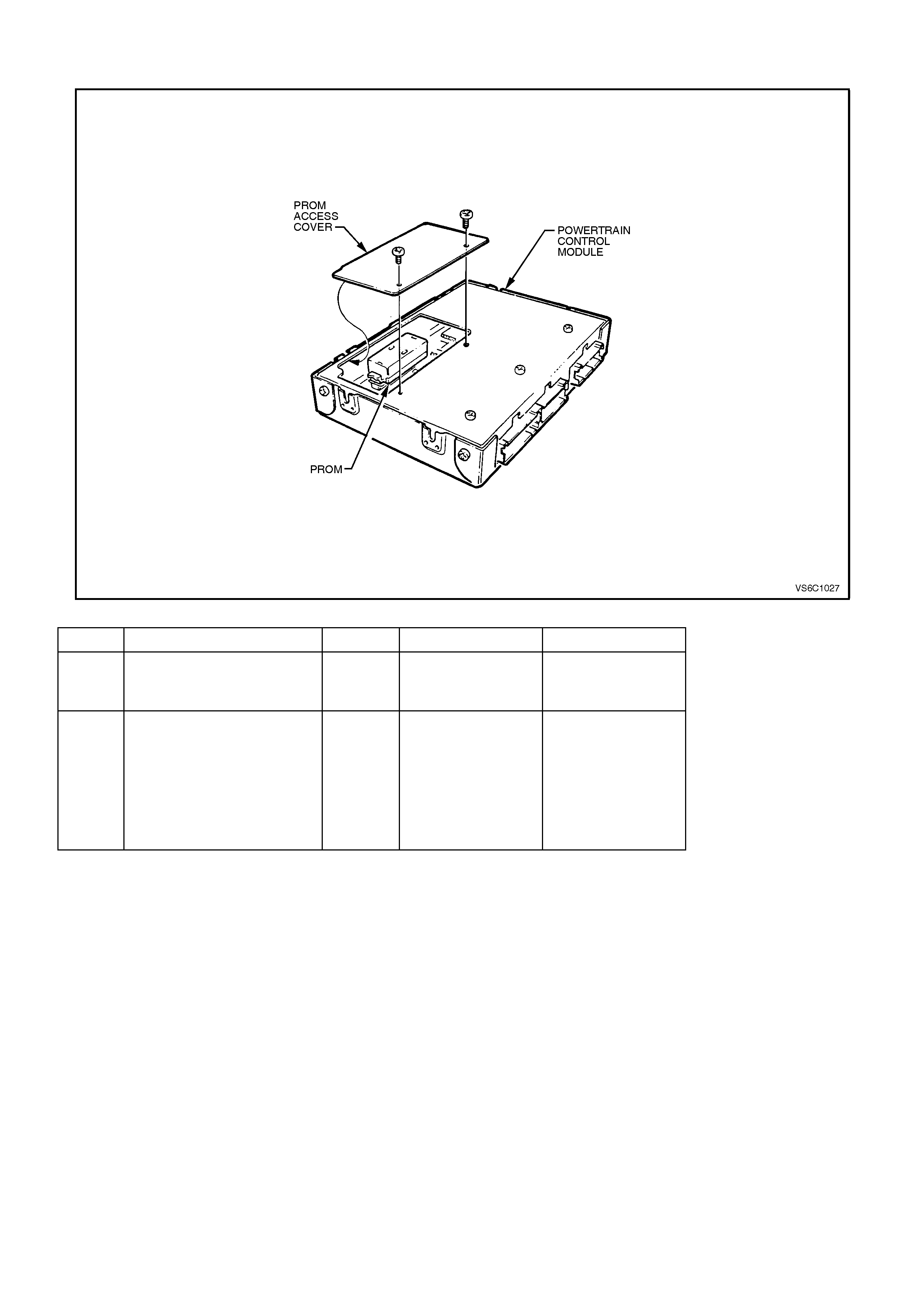
DTC 55 V6 PCM - PCM - ANALOG TO DIGITAL (A/D) CONVERSION ERROR
STEP ACTION VALUE YES NO
1. Was the "On-Board
Diagnostic" (OBD) System
Check performed?
Go to Step 2 Go to OBD
System Check in
this Section
2. Replace Powertrain
Control Module.
Refer to Section 6C1-3
Service Operations, for
PCM Security Link
Procedure.
Is action complete?
Verify repair
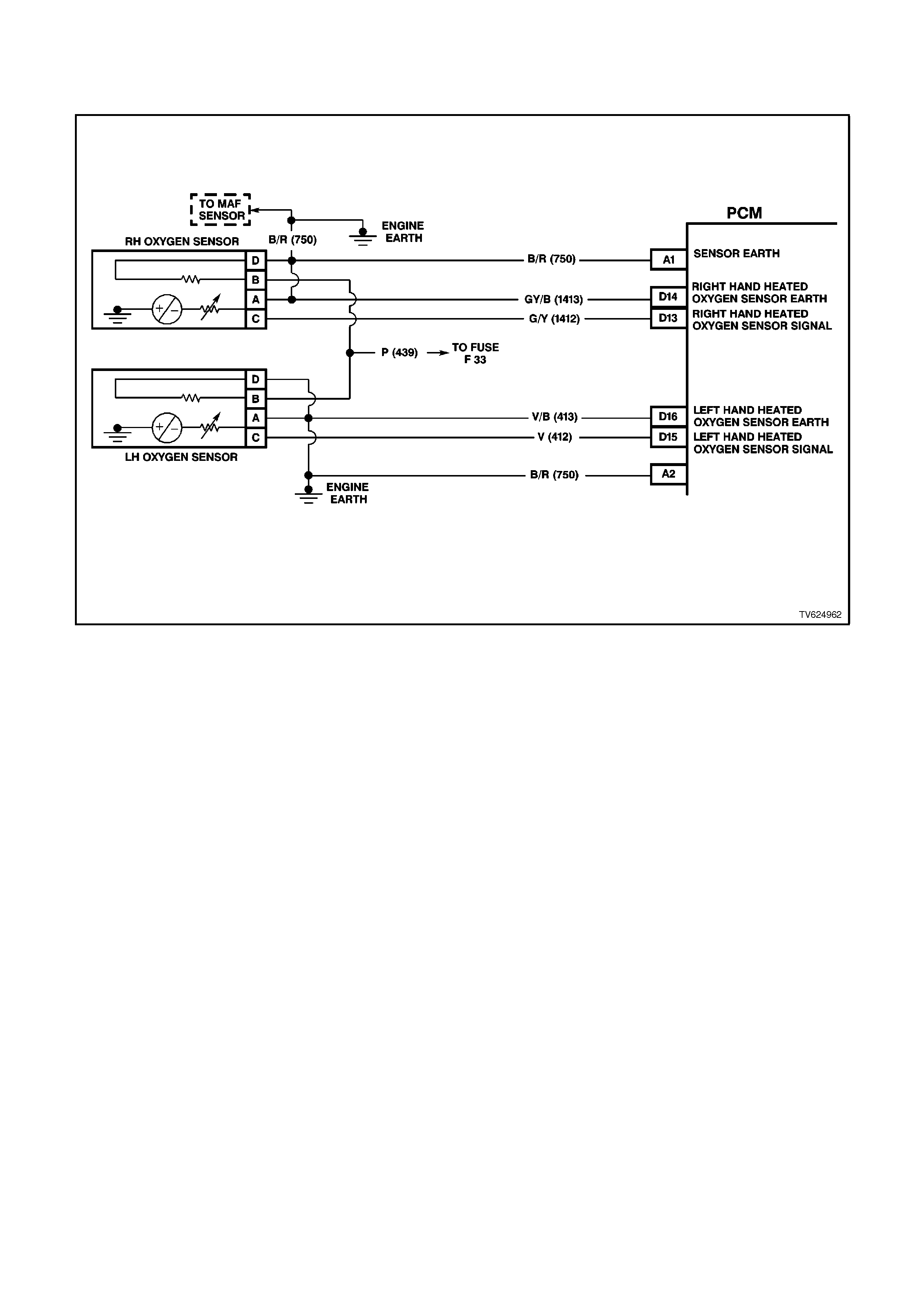
DTC 56 V6 PCM - LEAN CONDITION UNDER LOAD
(SUPERCHARGED ENGINE ONLY)
CIRCUIT DESCRIPTION:
The PCM's internal circuitry can identify if the vehicle's fuel system is capable of supplying adequate amounts of
fuel during heavy acceleration (power enrichment) by monitoring the voltage of the oxygen sensor. When a "power
enrichment" mode of operation is requested during "Closed Loop" (remember the PCM will go "Open Loop" not
make fueling changes based on oxygen sensor signal under heavy acceleration), the PCM will provide more fuel to
the engine. Under these conditions, the PCM should detect a "rich" condition, high oxygen sensor voltage. If this
"rich" exhaust is NOT detected at this time, a DTC 56 will set. A plugged fuel filter or restricted fuel line or a fuel
pump that is not switching to high speed can prevent adequate amounts of fuel from being supplied during the
power enrichment mode but may be fine at idle or light throttle acceleration.
This supercharged engine application has a two speed fuel pump that switches from low speed (low fuel flow) to
high speed (high fuel flow) when heavy boost is required, and will switch back to low speed (low fuel flow) for normal
vehicle driving conditions.
DTC 56 WILL SET IF:
• DTC 13, 44, 45, 63, 64, or 65 are not set.
• The engine has been operating longer than two minutes and the PCM detects low oxygen sensor voltage for
10 seconds during "power enrichment" modes of operation.

TEST DESCRIPTION:
Number(s) below refer to step number(s) on the diagnostic chart.
3. Wrap a shop towel around the fuel pressure connector to absorb any small amount of fuel leakage that may
occur when installing the gauge. Ignition "ON," pump pressure should be 290-410 kPa. This pressure is
controlled by spring pressure within the fuel pressure regular assembly. Pressure below 290 kPa. may cause a
lean condition and may set a DTC 44. It could also cause hard starting cold and poor driveability. Low enough
pressure will cause the engine not to run at all. Restricted flow may allow the engine to run at idle, or low
speeds, but may cause a surge and stall when more fuel is required, as when accelerating or driving at high
speeds. Low fuel pressure under heavy acceleration conditions may set a DTC 56.
5. Restricting the fuel return line allows the fuel pressure to build above regulated pressure. With a Tech 1 scan
tool enable the fuel pump, pressure should rise above 410 kPa as the return line is partially closed.
12. A vehicle driven in extremely hot temperatures and a near empty fuel tank can cause the temperature of the
fuel in the tank to become heated. Couple this with the fact fuel is being sent to an even hotter engine and the
fuel becomes even hotter. Not all fuel sent to the engine is injected and this hot fuel is sent back to the fuel
tank, increasing the temperature of the fuel in the tank even more. If temperature becomes great enough, a
possible vapour leak could exist causing a DTC 56. Check that the engine cooling system and ignition timing
are working properly. Adding fuel to the fuel tank could lower fuel tank temperature.
DIAGNOSTIC AIDS:
A restricted filter can supply adequate amounts of fuel at idle but may not be able to supply enough fuel during
heavy acceleration. A vapour lock condition can cause a DTC 56.
Be certain that the proper fuel pump is installed in the vehicle. If the improper fuel pump is installed, this could
cause DTC 56 to set.
Refer to Chart A-4.1-1 for checking the operation of the two speed fuel pump.

STEP ACTION VALUE YES NO
1. Was the "On-Board
Diagnostic" (OBD) System
Check performed?
Go to Step 2 Go to OBD
System Check in
this Section
2. Is any other DTC set? Go to that DTC
first. Go to Step 3
3. 1. Disconnect Fuel Pump
Relay and crank
engine to relieve fuel
pressure.
2. Install Fuel pressure
gauge.
3. Start and idle engine at
normal operating
temperature.
4. Disconnect vacuum
line going to fuel
pressure regulator.
5. Note fuel pressure with
engine running.
Is fuel pressure within
specified value?
290-410
kPa No trouble found.
If no additional
DTCs were
stored, refer to
"Diagnostic Aids"
above
Go to Step 4
4. Check for restrictions in
the fuel lines or the in-line
fuel filter.
Are restrictions found?
Verify Repair Go to Step 5
5. 1. Ignition "OFF".
2. Ignition "ON".
3. Using a Tech 2 scan
tool, select and enable
the fuel pump.
4. Use a pliers to slowly
close the fuel return
line at the fuel gauge
sender unit while fuel
pump is operating.
Does pressure rise above
value shown?
410 kPa
Do not
exceed
450 kPa
DTC 56 is
intermittent.
Refer to
"Diagnostic Aids"
above.
Go to Step 6

STEP ACTION VALUE YES NO
6. Check for faulty fuel
pump.
Is faulty fuel pump found?
Verify Repair Go to Step 7
7. Verify that fuel pulse
dampener (Pulsator) is
properly connected.
Is the fuel pulse
dampener connected
correctly?
Go to Step 8 Verify Repair
8. Check for restriction in
fuel pump strainer.
Is a restriction found?
Verify Repair Go to Step 9
9. Check that the fuel pump
being used is the correct
part number for the
vehicle.
Is incorrect fuel pump
installed in vehicle?
Go to Step 10 Go to Step 11
10. Install the correct fuel
pump
Is action complete?
Verify Repair
Refer to
"Diagnostic Aids"
above.
11. Check that the fuel sock is
not collapsed.
Is the sock collapsed?
Verify Repair Go to Step 12
12. Check vehicle fuel for
being overheated?
Was a problem found?
Repair
overheating
problem
Go to Step 13
13. Clear DTC and drive
vehicle under the
condition for setting the
DTC above.
Does DTC 56 reset?
Go to Step 2 Repair complete
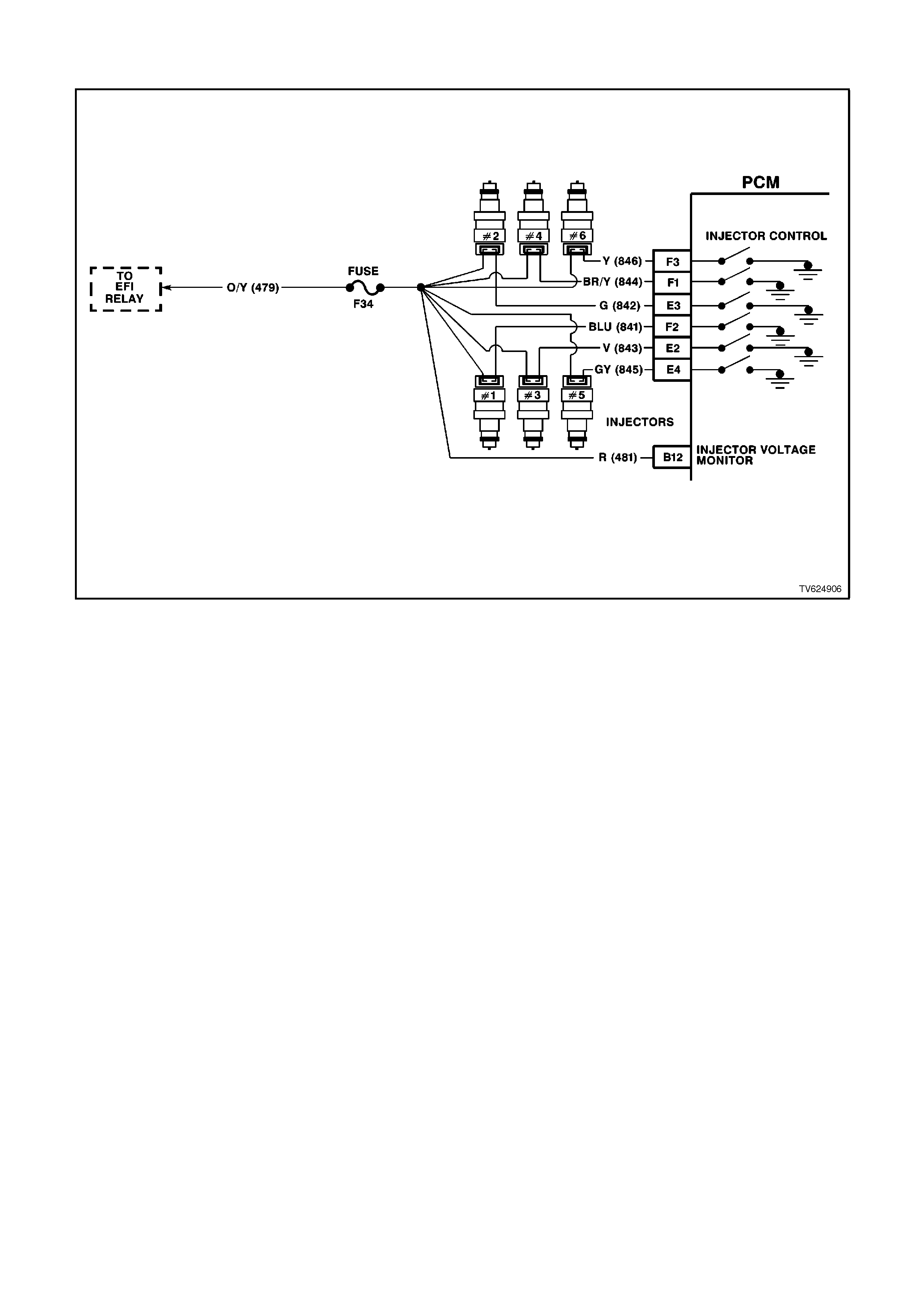
DTC 57 V6 PCM - INJECTOR VOLTAGE MONI TOR FAULT
CIRCUIT DESCRIPTION
The injector voltage monitor line is used so that the PCM will know the exact voltage the fuel injectors are operating
at. This voltage is used to control the pulse width modulation of the fuel injectors. If the injector voltage monitor line
drops more than 2.2 volts for more than 3 seconds, Diagnostic Trouble Code (DTC) 57 will set. This DTC will not
turn "ON" the "Check Powertrain" lamp, but will have a DTC set in the PCM memory that can be read with the Tech
2 scan tool and can be displayed by flashing out codes.
DTC 57 WILL SET IF:
• DTC 54 is not set.
• Injector voltage monitor line voltage is 2.2 volts different than system voltage for 3 seconds.
TEST DESCRIPTION:
Number(s) below refer to the step(s) on the diagnostic chart.
2. The injector voltage monitor line voltage drops more than 2.2 volt in 3 seconds.
DIAGNOSTIC AIDS:
When the injector voltage monitor line voltage drops more than 2.2 volts, the PCM will operate on an incorrect value
for 3 seconds until the DTC 57 is set. After the DTC 57 is set, the PCM will use the battery feed as the voltage value
to control the fuel injectors base pulse width. Check PCM terminal connections for proper mating.
If DTC 16, 53 and 57 are set, check for short to voltage on "Diagnostic Test" line, circuit 451.

STEP ACTION VALUE YES NO
1. Was the "On-Board
Diagnostic" (OBD) System
Check performed?
Go to Step 2. Go to OBD
System Check in
this Section
2. 1. This chart assumes
that no DTC 53 is set
and the battery and
charging systems are
operating properly.
2. Using the Tech 2 scan
tool, display "Injector
Voltage" and "Battery
Voltage".
Are they within the
specified value of each
other?
2.4 volts DTC 57 is
intermittent, if no
additional DTCs
were stored, refer
to "Diagnostic
Aids" above.
Go to Step 3
3. Using DVM, backprobe
PCM terminal "B12" with
red lead and connect
black lead to PCM
terminal "B1".
Is voltage measured
within specified value of
"Battery Voltage" reading
on Tech 2 scan tool?
2.4 volts Go to Step 5 Go to Step 4
4. Repair open in circuit 481
between splice and PCM
terminal "B12".
Is action complete?
Verify Repair
5. Replace PCM.
Refer to Section 6C1-3
Service Operations, for
PCM Security Link
procedure.
Is action complete?
Verify Repair

DTC 58 V8 PCM - TRANSMISSION FLUI D TEMPERATURE (TFT)
SENSOR CIRCUIT - LOW I NPUT
CIRCUIT DESCRIPTION:
The Automatic Transmission Fluid Temperature (TFT) sensor is a thermistor within the Automatic Transmission
Fluid Pressure Manual Valve Position Switch (TFP Val. Position Sw.). The TFT sensor controls the signal voltage to
the PCM. The PCM supplies a 5-volt reference signal to the sensor on circuit 1227. When the transmission fluid is
cold, the sensor resistance will be high. The PCM will then detect a high signal voltage. As the transmission fluid
temperature increases to the normal operating temperature, the sensor resistance becomes less and the voltage
decreases.
When the PCM detects a continuous short to earth in the TFT signal circuit or in the TFT sensor, then a will DTC 58
set.
DTC 58 WILL SET IF:
• The TFT Sensor voltage is less than 0.33 volts for 10 seconds.
TEST DESCRIPTION:
The numbers below refer to the step numbers on the diagnostic chart.
3. This step tests for a short to earth or a skewed sensor.
4. This step creates an open within the transmission in order to test for an internal fault.

DIAGNOSTIC AIDS:
• Inspect the wiring for poor electrical connections at the PCM. Inspect the wiring for poor electrical connections at
the transmission pass-through connector. Look for the following conditions:
A backed out terminal
A damaged terminal
Poor terminal tension
A chafed wire
A broken wire inside the insulation
Corrosion
• When diagnosing for an intermittent short or open condition, massage the wiring harness while watching the test
equipment for a change.
Use the Temperature vs Resistance table when testing the TFT sensor at various temperature levels. Test the TFT
sensor in order to evaluate the possibility of a skewed (mis-scaled) sensor. A skewed sensor can result in
delayed garage shifts or TCC complaints.
• The scan tool can display the transmission fluid temperature in degrees. After the transmission is operating, the
fluid temperature should rise steadily to a normal operating temperature, then stabilise.
TRANSMISSION FLUID TEMPERATURE (TFT) SENSOR TEMPERATURE TO RESISTANCE TABLE
Temperature TFT Resistance Signal
Degrees °C Minimum W Normal W Maximum W Volts
-40 90636 100707 110778 5.0
-30 47416 52684 57952 4.78
-20 25809 28677 31545 4.34
-10 14558 16176 17784 3.89
0 8481 9423 10365 3.45
10 5104 5671 6238 3.01
20 3164 3515 3867 2.56
30 2013 2237 2461 1.8
40 1313 1459 1605 1.1
50 876 973 1070 3.25
60 600 667 734 2.88
70 420 467 514 2.56
80 299 332 365 2.24
90 217 241 265 1.7
100 159 177 195 1.42
110 119 132 145 1.15
120 89.9 99.9 109.9 0.87
130 69.1 76.8 84.5 0.6
140 53.8 59.8 65.8 0.32
150 42.5 47.2 51.9 0
A shunt in the PCM becomes active as the transmission temperature
increases beyond 50 °C. As the temperature decreases, the internal
shunt deactivates at 40 °C.
When DTC 58 sets, the PCM uses a default Transmission Fluid Temperature (TFT) of 135°C and freezes shift
adapts from being updated.

STEP ACTION VALUE YES NO
1Was the On-Board
Diagnostic (OBD) System
Check performed?
— Go to Step 2 Go to OBD System
Check
2Perform the transmission
fluid checking procedure.
Have you performed the
fluid checking procedure?
— Go to Step 3 Go to
Transmission Fluid
Checking
Procedure
31. Install the scan tool.
3. With the engine OFF,
turn the ignition switch
to the RUN position.
IMPORTANT:
Before clearing the DTCs
use the scan tool in order
to record the DTC history.
The Clear Info function will
erase the data.
3. Record the DTC history.
Does the scan tool display
a TFT voltage less than the
specified value?
0.33 volts Go to Step 4 Go to “Diagnostic
Aids” above
41. Turn the ignition OFF.
2. Disconnect the
transmission pass-
through connector.
3. With the engine OFF,
turn the ignition switch
to the RUN position.
Does the scan tool display
a TFT voltage greater than
the specified value?
4.92 volts Go to Step 5 Go to Step 9
51. Install the J 39775
Jumper Harness on the
transmission side of the
pass-through connector.
2. Using the J 39200 DVM
and J 35616 Connector
Test Adaptor Kit,
measure the resistance
between terminal L and
terminal M.
Is the resistance within
specifications?
3088-
3942 ohm
@ 20° C
159-
198 ohm@
100° C
Go to “Diagnostic
Aids” above Go to Step 6
61. Check the internal
Automatic Transmission
Wiring Harness
Assembly for a short to
earth.
2. Replace the harness if
necessary.
Did you find and correct the
problem?
— Go to Step 11 Go to Step 7

STEP ACTION VALUE YES NO
71. Disconnect the internal
Automatic Transmission
Wiring Harness
Assembly at the TFT
sensor.
2. Measure the resistance
of the TFT sensor.
Is the resistance within
specifications?
3088-
3942 ohm
@ 20° C
159-
198 ohm@
100° C
Go to “Diagnostic
Aids” above Go to Step 8
8Replace the TFT Sensor
(this is part of the TFP Val.
Position Sw.). Refer to
Service Operations in
Section 6C1-3.
Is the action complete?
— Go to Step 11 —
91. Check circuit 1227 for a
short to earth.
2. Repair the circuit if
necessary.
Did you find a problem?
— Go to Step 11 Go to Step 10
10 Replace the PCM. Refer to
Section 6C1-3 Service
Operations, for the Security
Link procedure.
Is the action complete?
— Go to Step 11 —
11 In order to verify your
repair, perform the
following procedure:
1. Select DTC.
2. Select Clear Info.
3. With the engine OFF,
turn the ignition switch
to the RUN position.
Does the scan tool indicate
a TFT voltage greater than
the specified value?
0.33 volts System OK Begin the
diagnosis again.
Go to Step 1

DTC 59 V8 PCM - TRANSMISSION FLUI D TEMPERATURE (TFT)
SENSOR CIRCUIT - HI GH INPUT
CIRCUIT DESCRIPTION:
The Automatic Transmission Fluid Temperature (TFT) sensor is a thermistor within the Automatic Transmission
Fluid Pressure Manual Valve Position Switch (TFP Val. Position Sw.). The TFT sensor controls the signal voltage to
the PCM. The PCM supplies a 5-volt reference signal to the sensor on circuit 1227. When the transmission fluid is
cold, the sensor resistance is high. The PCM detects high signal voltage. As the transmission fluid temperature
increases to a normal operating temperature, the sensor resistance becomes less and the voltage decreases.
When the PCM detects a continuous open or short to power in the TFT signal circuit or the TFT sensor, then DTC
59 sets.
DTC 59 WILL SET IF:
• The TFT Sensor voltage is equal to or greater than 4.92 volts for 10 seconds.
TEST DESCRIPTION:
The numbers below refer to the step numbers on the diagnostic chart.
3. This step verifies that a problem exists in the TFT sensor circuit.
4. This step simulates a TFT sensor DTC 58. If the PCM recognises high temperature, the PCM and wiring are
functioning normally.
5. This step tests the TFT sensor and Automatic Transmission Wiring Harness Assembly.

DIAGNOSTIC AIDS:
• Inspect the wiring for poor electrical connections at the PCM. Inspect the wiring for poor electrical connections at
the transmission pass-through connector. Look for the following conditions:
A bent terminal
A backed out terminal
A damaged terminal
Poor terminal tension
A chafed wire
A broken wire inside the insulation
Moisture intrusion
• Corrosion when diagnosing for an intermittent short or open condition, massage the wiring harness while
watching the test equipment for a change.
Use the Temperature vs Resistance table when testing the TFT sensor at various temperature levels. Test the TFT
sensor in order to evaluate the possibility of a skewed (mis-scaled) sensor. A skewed sensor can result in
delayed garage shifts or TCC complaints.
• The scan tool can display the transmission fluid temperature in degrees. After the transmission is operating, the
fluid temperature should rise steadily to a normal operating temperature, then stabilise.
TRANSMISSION FLUID TEMPERATURE (TFT) SENSOR TEMPERATURE TO RESISTANCE TABLE
Temperature TFT Resistance Signal
Degrees °C Minimum W Normal W Maximum W Volts
-40 90636 100707 110778 5.0
-30 47416 52684 57952 4.78
-20 25809 28677 31545 4.34
-10 14558 16176 17784 3.89
0 8481 9423 10365 3.45
10 5104 5671 6238 3.01
20 3164 3515 3867 2.56
30 2013 2237 2461 1.8
40 1313 1459 1605 1.1
50 876 973 1070 3.25
60 600 667 734 2.88
70 420 467 514 2.56
80 299 332 365 2.24
90 217 241 265 1.7
100 159 177 195 1.42
110 119 132 145 1.15
120 89.9 99.9 109.9 0.87
130 69.1 76.8 84.5 0.6
140 53.8 59.8 65.8 0.32
150 42.5 47.2 51.9 0
A shunt in the PCM becomes active as the transmission temperature
increases beyond 50 °C. As the temperature decreases, the internal
shunt deactivates at 40 °C.
When DTC 59 sets, the PCM uses a default Transmission Fluid Temperature (TFT) of 135°C and freezes shift
adapts from being updated.

STEP ACTION VALUE YES NO
1Was the On-Board
Diagnostic (OBD) System
Check performed?
— Go to Step 2 Go to OBD
System Check
2Perform the transmission
fluid checking procedure.
Have you performed the
fluid checking procedure?
— Go to Step 3 Go to
Transmission
Fluid Checking
Procedure
31. Install the scan tool.
2. With the engine OFF,
turn the ignition switch
to the RUN position.
IMPORTANT:
Before clearing the DTCs,
use the scan tool in order
to record the DTC history
for reference. The Clear
Info function will erase the
data.
3. Record the DTC
history.
Does the scan tool display
a TFT Sensor voltage
greater than the specified
value?
4.92
volts Go to Step 4 Go to “Diagnostic
Aids” above
41. Turn the ignition OFF.
2. Disconnect the
transmission pass-
through connector.
3. Install the J 39775
Jumper Harness on
the engine side of the
pass-through
connector.
4. Install a fused jumper
wire from terminal L to
terminal M on the
engine connector.
5. With the engine OFF,
turn the ignition switch
to the RUN position.
Does the TFT Sensor
voltage drop to less than
the specified value?
0.2 volts Go to Step 5 Go to Step 9
51. Turn the ignition OFF.
2. Install the J 39775
Jumper Harness on
the transmission side
of the pass-through
connector.
3. Using the J 39200
DVM and J 35616
Connector Test
Adaptor Kit, measure
the resistance between
terminal L and terminal
M.
Is the resistance within
specification?
3088-
3942 ohm
at 20° C
159-
198 ohm
@
100° C
Go to “Diagnostic
Aids” above Go to Step 6

STEP ACTION VALUE YES NO
61. Check the internal
Automatic
Transmission Wiring
Harness Assembly for
a open condition.
2. Replace the harness if
necessary.
Did you find and correct
the problem?
— Go to Step 12 Go to Step 7
71. Disconnect the internal
Automatic
Transmission Wiring
Harness Assembly at
the TFT sensor.
2. 2. Measure the
resistance of the TFT
sensor.
Is the resistance within
specifications?
3088-
3942 ohm
at 20° C
159-
198 ohm
@
100° C
Go to “Diagnostic
Aids” above Go to Step 8
8Replace the TFT Sensor
(this is part of the TFP
Val. Position Sw.).
Refer to Service
Operations in Section
6C1-3.
Is the replacement
complete?
— Go to Step 12 —
91. Check circuit 1227 for
an open or short to B+.
2. Repair the circuit if
necessary.
Did you find a problem?
— Go to Step 12 Go to Step 10
10 1. Check circuit 469 for
an open.
2. Repair the circuit if
necessary.
Did you find a problem?
— Go to Step 12 Go to Step 11
11 Replace the PCM. Refer
to Section 6C1-3 Service
Operations, for the
Security Link procedure.
Is the action complete?
— Go to Step 12 —
12 In order to verify your
repair, perform the
following procedure:
1. Select DTC.
2. Select Clear Info.
3. With the engine OFF,
turn the ignition switch
to the RUN position.
Does the scan tool
indicate a TFT voltage
less than the specified
value?
4.92
volts System OK Begin the
diagnosis again.
Go to Step 1
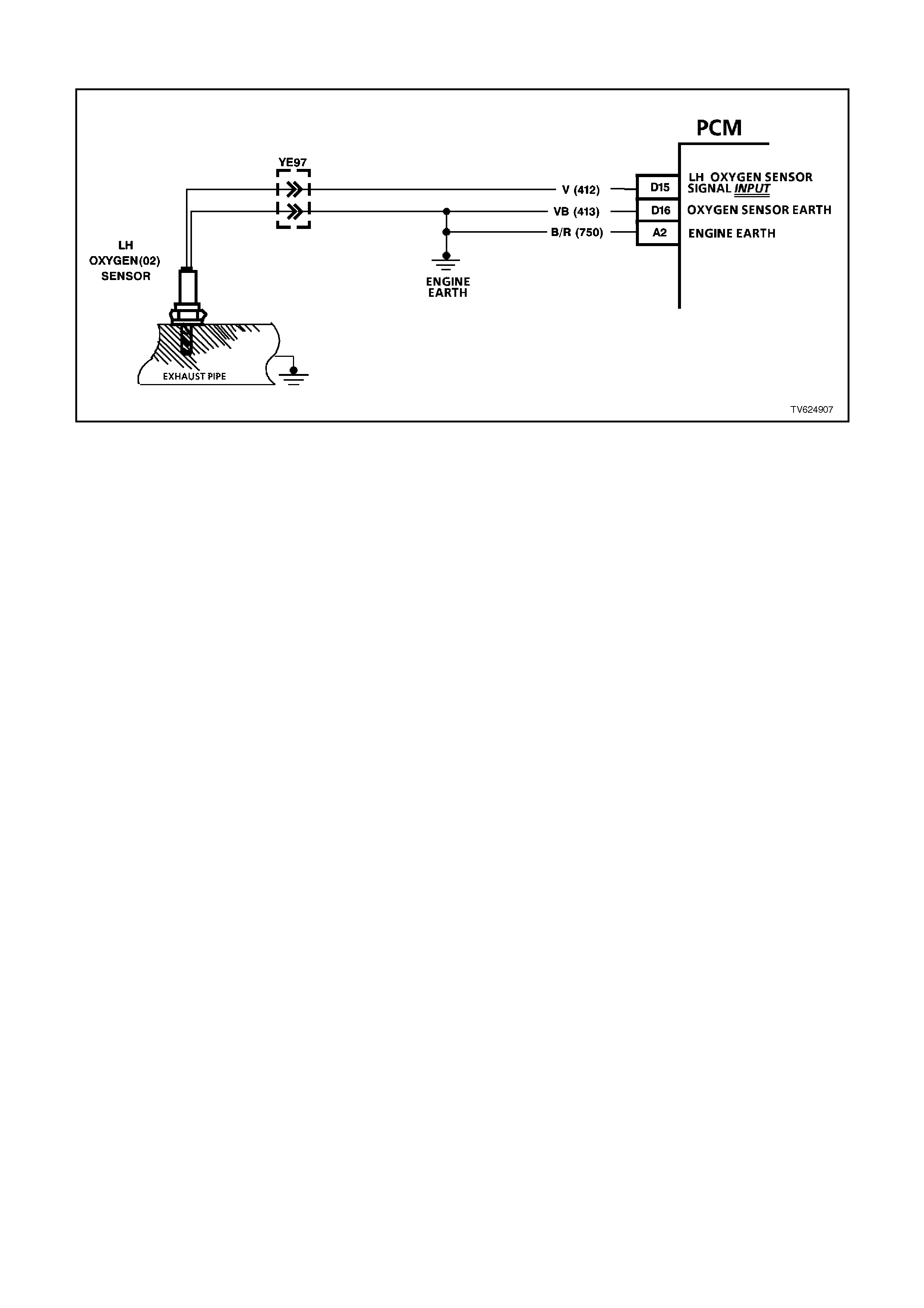
DTC 63 V6 PCM - LEFT HAND (LH) NO OXYGEN SENSOR SIGNAL
CIRCUIT DESCRIPTION:
The exhaust oxygen sensor is mounted in the exhaust pipe with the sensing portion exposed to exhaust gases.
After the sensor is hot (360 degrees C), it becomes a voltage generator, producing a "changing" voltage. This
voltage ranges from approximately 100 millivolts with a "lean" exhaust, to 900 millivolts with a "rich" exhaust. When
the sensor is cold (below 360 degrees C) it acts like an open circuit and produces almost no voltage. The PCM
supplies a very small "bias" voltage between terminals D15 and D16, normally about 450 millivolts. If measured with
the 10 megaohm digital voltmeter, it may measure as low as 350 millivolts. When the sensor is hot, it's output
overshadows this PCM-supplied voltage.
When the fuel system is correctly operating in the closed-loop mode, the sensor output is changing several times
per second, going above and below a mid-point range of 490-500 millivolts, at a hot idle. The PCM compares the
voltage between terminals sensor signal and sensor earth terminals, and decides the needed fuel mixture
correction. The PCM also monitors the changing voltage, watching for transitions above and below the mid-point
range, to decide when to operate in the closed-loop mode. An open circuit, defective, or contaminated sensor could
cause the voltage to stay within a 300-600 millivolt band too long, keeping the system in open-loop and setting a
DTC 63.
When DTC 63 is active ("Check Powertrain" lamp "ON") the PCM will operate the fuel system in the open-loop
mode.
DTC 63 WILL SET IF:
• Engine has been running for at least 4 minutes.
• Engine Coolant Temperature is more than 85°C.
• Throttle Position (TP) sensor voltage indicates the throttle is open more than 15%.
• LH O2 sensor voltage between 410 and 477 millivolts.
TEST DESCRIPTION:
Number(s) below refer to step number(s) on the diagnostic chart.
2. The Tech 2 scan tool allows you to read the same oxygen sensor voltage the PCM is using for its calculations.
3. This step simulates a lean exhaust indication to the PCM. If the PCM and wiring are OK the PCM will see the
lean indication and the Tech 2 scan tool should display O2 voltage below 200 mV.
8. In doing this test use only a high impedance digital volt-ohm meter. The test checks the continuity of circuits
412 and 750. If circuit 750 is open the PCM voltage on circuit 1412 will be over 0.6 volts (600 mV).
9. Earth circuit 750 is a separate wire to the PCM from the engine. The PCM uses this circuit to compare it with
the voltage on circuit 412. It completes the earth path for the PCM's oxygen sensor circuitry, and must be a
complete, clean, and tight connection to the engine.

DIAGNOSTIC AIDS:
Normal Tech 2 scan tool voltage varies between 100 mV to 999 mV while in "Closed Loop." DTC 63 sets if voltage
remains between 410 - 477 millivolts, but the system will go "Open Loop" before the "Check Powertrain " lamp in
turned "ON".
Refer to "Intermittents" in Section 6C1-2B SYMPTOMS .
NOTE:
Oxygen Sensor Contamination - If fuel containing lead or silicone is used, or engine repairs using unapproved RTV
gasket sealer are performed, the sensor may be contaminated. it may send a "false" rich exhaust indication to the
PCM, and the PCM will attempt to drive the fuel system lean to compensate. poor driveability or a Diagnostic
Trouble Code 63 could result. if this happens, the sensor will need to be replaced, but every attempt to locate the
source of contamination should be pursued.
STEP ACTION VALUE YES NO
1. Was the "On-Board
Diagnostic" (OBD) System
Check performed?
Go to Step 2 Go to OBD
System Check in
this Section
2. 1. Engine at normal
operating temperature
(above 85 C).
2. Run engine at
approximately 1600 to
1800 rpm for four
minutes and ten
seconds.
Is Tech 2 scan tool "LH
O2 Sensor" voltage
between specified values?
410-477
mV Go to Step 3 DTC 63 is
intermittent. If no
additional DTCs
were stored, refer
to "Intermittents"
in Section 6C1-2B
SYMPTOMS.
3. 1. Disconnect O2 Sensor
wiring harness.
2. Jumper harness circuit
412 (PCM Side) to
earth.
With engine running, does
Tech 2 scan tool display
"LH O2 Sensor" voltage
below specified voltage?
0.2 volt
(200
mV)
Go to Step 4 Go to Step 6
4. Check for a faulty
connection at the Oxygen
Sensor .
Was a poor connection
found?
Verify Repair Go to Step 5
5. Replace O2 sensor.
Is replacement complete? Verify Repair

STEP ACTION VALUE YES NO
6. 1. Remove jumper.
2. Ignition "ON," engine
"OFF".
3. Check voltage of circuit
412 (PCM Side) at O2
sensor harness
connector using a
DVM.
Is voltage between
specified values?
0.3 - 0.6
volts
(300-
600 mV)
Go to Step 7 Go to Step 8
7. Replace PCM
Is replacement complete? Verify Repair
8. 1. Remove jumper.
2. Ignition "ON," engine
"OFF".
3. Check voltage of circuit
412 (PCM side) at O2
sensor harness
connector using a
DVM.
Is voltage over specified
value?
0.6 volts
(600
mV)
Go to Step 9 Go to Step 11
9. Check for an open or
faulty connection in circuit
750.
Was a fault found?
Verify Repair Go to Step 10
10. Replace PCM.
Refer to Section 6C1-3
Service Operations, for
PCM Security Link
procedure.
Is action complete?
Verify Repair
11. Check for an open or
faulty connection in circuit
412.
Was a fault found?
Verify Repair Go to Step 10

DTC 64 V6 PCM - LEFT HAND (LH) LEAN EXHAUST INDICATION
CIRCUIT DESCRIPTION:
The PCM supplies a voltage of about 450 millivolts between terminals D16 and D15. The Oxygen (O2) sensor
varies the voltage within a range of about 1 volt if the exhaust is rich, down through about 100 millivolts if exhaust is
lean.
The sensor is like an open circuit and produces no voltage when it is below about 315 degrees C. An open sensor
circuit or a cold sensor causes "Open Loop".
DTC 64 WILL SET IF:
• DTC 23, 25, or 26 are not set.
• The O2 sensor signal voltage on circuit 412 remains below 200 millivolts for 46 seconds.
• The system is operating in "Closed Loop".
• IAT sensor is below 75 degrees C.
TEST DESCRIPTION:
Number(s) below refer to step number(s) on the diagnostic chart.
4. DTC 64 or lean exhaust is most likely caused by one of the following:
• O2 sensor wire. Sensor pigtail may be mispositioned and contacting the exhaust manifold.
• Check for intermittent earth in wire between connector and sensor.
• MAF sensor. A shifted MAF sensor could cause the fuel system to go lean, use CHART A-6.1 in this Section to
test for this.
• Lean injector(s). Perform "Power Balance" test using Tech 2 scan tool mode.
• Fuel contamination. Water, even in small amounts, near the in-tank Fuel Pump inlet can be delivered to the
injectors. The water causes a lean exhaust and can set a DTC 44 and/or DTC 64.
• Fuel pressure. System will be lean if pressure is too low. It may be necessary to monitor fuel pressure while
driving the vehicle at various road speeds and/or loads to confirm. Refer to fuel system diagnosis CHART A-4.1
in this Section.
• Exhaust leaks. If there is an exhaust leak, the engine can cause outside air to be pulled into the exhaust and
past the sensor. Vacuum or crankcase leaks can cause a lean condition.
• •If the above are OK, it is a faulty Oxygen Sensor (O2S)
DIAGNOSTIC AIDS:
Using the Tech 2 scan tool, observe the Long Term Fuel Trim values at different rpm and air flow conditions. The
Tech 2 scan tool also displays the Long Term Fuel Trim cells, so the Long Term Fuel Trim values can be checked
in each of the cells to determine when DTC 44 may have been set. The Tech 2 scan tool displays the Long Term
Fuel Trim values will be around +25%.

STEP ACTION VALUE YES NO
1. Was the "On-Board
Diagnostic" (OBD) System
Check performed?
Go to Step 2 Go to OBD System
Check
2. 1. Start Engine.
2. Run engine until it
reaches normal
operating temperature
(Above 80 degrees C).
3. Continue to run at 1600
to 1800 rpm for two
minutes.
Does Tech 2 scan tool
indicate "O2 Sensor
Voltage" fixed below value
shown?
250 mV Go to Step 3 DTC 64 is
intermittent, if no
additional codes
were stored. See
"Intermittents" in
"Symptoms"
section.
3. Disconnect O2 sensor
connector.
With engine idling, does
Tech 2" Scan" tool display
O2 Sensor Voltage"
between the values
shown?
Between
350 mV
and
550 mV
Go to Step 4 Go to Step 6
4. 1. Refer to step 4 above
first.
2. Perform the checks on
the items as noted.
MAF sensor operation
Low fuel pressure
Contaminated fuel
Exhaust manifold leaks
ahead of O2 sensor
O2 sensor reference air
plugged
Lean injector (possible
restricted)
O2 sensor earth circuit
Are all items checked
found to be OK?
Go to Step 5 Verify Repair
5. Replace Oxygen sensor.
Is action complete? Verify Repair
6. 1. Ignition "OFF" .
2. Disconnect PCM
connectors.
3. With O2 sensor still
disconnected, check O2
signal circuit 412 for a
short to earth.
Is a short to earth
detected?
Go to Step 7 Go to Step 8
7. Repair circuit 412.
Is action complete? Verify Repair
8. Replace PCM.
Refer to Section 6C1-3
Service Operations, for
PCM Security Link
procedure.
Is action complete?
Verify Repair

DTC 65 V6 PCM - LEFT HAND (LH) RICH EXHAUST I NDI CATION
CIRCUIT DESCRIPTION:
The PCM supplies a voltage of about 450 millivolts between terminals "D15" and "D15". The Oxygen (O2) sensor
varies the voltage within a range of about 1 volt, if the exhaust is rich, down through about 100 millivolts, if exhaust
is lean.
The sensor produces no voltage when it is below about 360 degrees C. An open sensor circuit or cold sensor
causes "Open Loop" operation.
DTC 65 WILL SET IF:
• Throttle angle is between 9% and 30%.
• The engine fuel control system Is operating in the Closed Loop mode.
• O2 sensor signal voltage between PCM terminal; D13 and D14 has remained above 780 millivolts for more
than 35 seconds.
TEST DESCRIPTION:
Number(s) below refer to step number(s) on the diagnostic chart.
2. The O2 sensor MUST be at operating temperature before checking operation.
3. This step checks for a short to voltage on the O2 signal line.
7. Earthing circuit 412 causes a low O2 signal voltage. If the PCM and wiring are OK, the PCM should recognise
the low voltage and confirm the lean signal.
8. A DTC 65 will most likely NOT be caused by a faulty O2 sensor. DTC 65 indicates a rich exhaust and
diagnosis should begin with the items listed:
• Fuel pressure. System will go rich, if pressure is too high. The PCM can compensate for some increase.
However, if it gets too high, a DTC 45 or DTC 65 may be set. Refer to fuel system diagnosis CHART A-4.3 in
this Section.
• Rich injector.
• Leaking injector. Refer to CHART A-4.3 in this Section.
• Check for fuel contaminated oil.
• Short to voltage on circuit 412.
• HEI shielding. An open earth circuit 453 (ignition system) may result in EMI, or induced electrical "noise." The
PCM looks at this "noise" as reference pulses. The additional pulses result in a higher than actual engine speed
signal. The PCM then delivers too much fuel, causing system to go rich. Engine tachometer will also show higher
than actual engine speed, which can help in diagnosing this problem.
• Canister purge. Check for fuel saturation. If full of fuel, check canister control and hoses.
• MAF sensor. A shifted MAF sensor could cause the fuel system to go rich.
• Check for leaking fuel pressure regulator diaphragm by checking vacuum line to regulator for fuel.
• TP Sensor. An intermittent TP sensor output will cause the system to go rich, due to a false indication of the
engine accelerating.

DIAGNOSTIC AIDS:
Using the Tech 2 scan tool, observe the Long Term Fuel Trim values at different rpm and air flow conditions. The
Tech 2 scan tool also displays the Long Term Fuel Trim cells, so the Long Term Fuel Trim values can be checked
in each of the cells to determine when the DTC 65 may have been set. If the conditions for DTC 65 exists, the Long
Term Fuel Trim values will be around -22%.
NOTE:
Oxygen Sensor Contamination - If fuel containing lead or silicone is used, or engine repairs using unapproved RTV
gasket sealer are performed, the sensor may be contaminated. it may send a "false" rich exhaust indication to the
PCM, and the PCM will attempt to drive the fuel system lean to compensate. Poor driveability or a Diagnostic
Trouble Code 65 could result. if this happens, the sensor will need to be replaced, but every attempt to locate the
source of contamination should be pursued.
STEP ACTION VALUE YES NO
1. Was the "On-Board
Diagnostic" (OBD) System
Check performed?
Go to Step 2 Go to OBD
System Check
2. 1. Engine at normal
operating temperature
(above 80 C).
2. Run engine at
approximately 1600
RPM to 1800 RPM for
two minutes.
Is Tech 2 scan tool
voltage above specified
value?
750 mV Go to Step 3 DTC 65 is
intermittent,
If no additional
DTC(s) were
stored. Refer to
"Intermittents" in
"Symptoms"
section.
3. 1. Ignition "OFF".
2. Disconnect O2 sensor
wiring harness.
3. With ohmmeter
connected to earth,
probe circuit 412 at O2
sensor wiring harness
connector.
4. Ignition "ON".
Is voltmeter indicating less
then specified value?
350 mV Go to Step 7 Go to Step 4
4. 1. Ignition "OFF".
2. Disconnect PCM
connectors.
3. Probe circuit 412 at O2
sensor wiring harness
connector.
5. Ignition "ON".
Is voltmeter indicating
voltage below specified
value?
350 mV Go to Step 6 Go to Step 5
5. Repair circuit 412, shorted
to voltage.
Is action complete?
Verify Repair

STEP ACTION VALUE YES NO
6. Replace PCM.
Refer to Section 6C3
Service Operations, for
PCM Security Link
procedure.
Is action complete?
Verify Repair
7. 1. Disconnect O2 sensor
wiring harness
connector.
2. Jumper harness
connector circuit 412
to earth.
With engine running, does
Tech 2 scan tool
display O2 voltage below
specified value ?
350 mV Go to Step 8 Go to Step 9
8. See “Test Description”
step 8 to perform
additional checks for:
• High Fuel Pressure
• Mass Air Flow Sensor
Operation
• Leaking Injectors
• Ignition Earth Circuit
• Canister Purge
• Engine Coolant
Temperature Sensor
Circuit
• Intake Air Temperature
Sensor Circuit
• Throttle Position
Sensor Operation
Do all checks from step 8
above test OK.?
Go to
“Test Description”
Step 8
Verify Repair
9. 1. Ignition "OFF"
2. Disconnect PCM
connectors.
3. Check O2 sensor earth
circuit 750 for good
continuity between
PCM connector
terminal D15 and
engine earth.
Is an "OPEN" circuit
indicated?
Verify Repair Go to Step 10
10. Check PCM earth wire
connection at engine.
Must be a clean and tight
connection to the engine.
Is connection good ?
Go to Step 6 Verify Repair
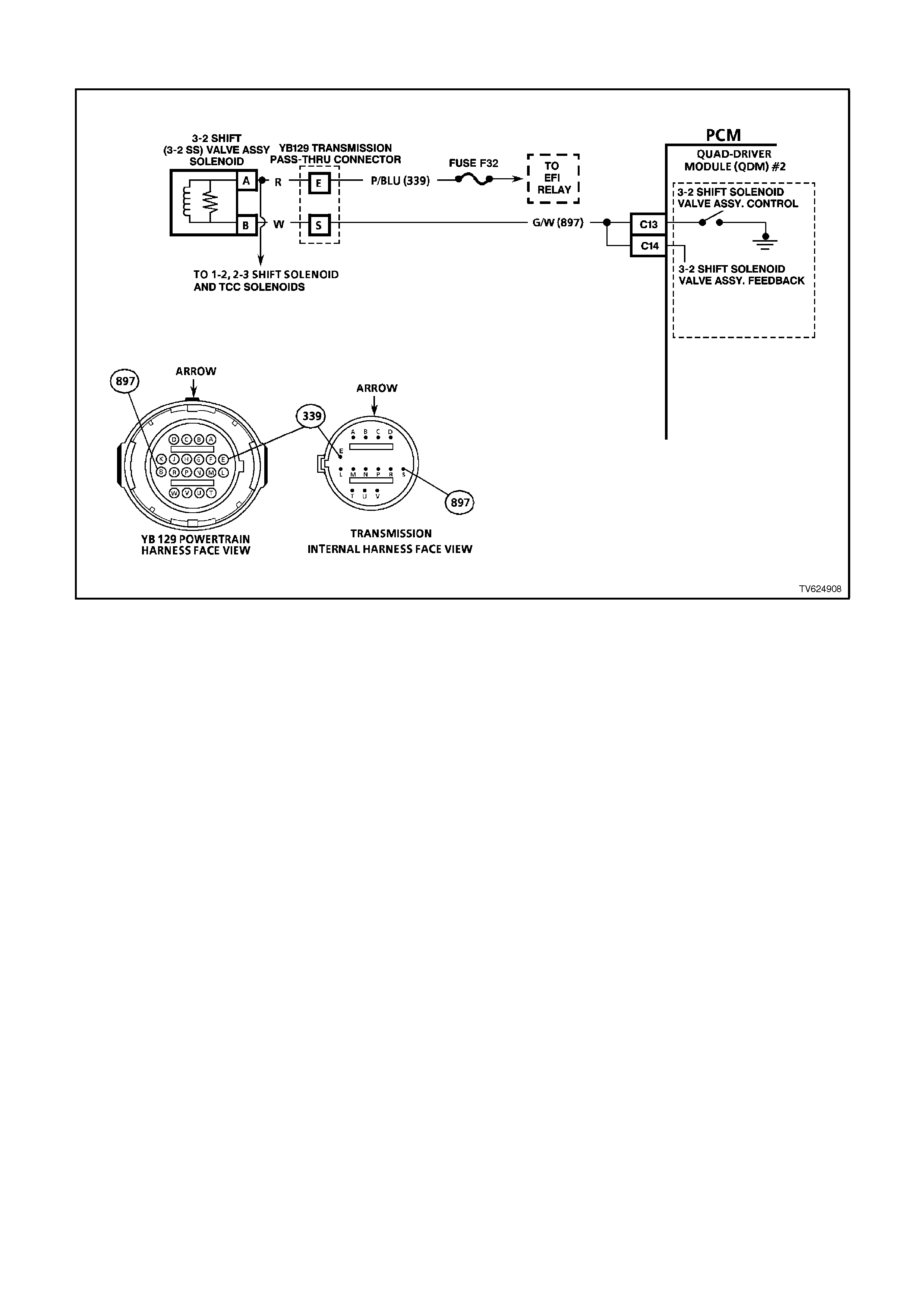
DTC 66 - 3-2 SHIFT SOLENOID CI RCUI T - FAULT
CIRCUIT DESCRIPTION:
The 3-2 Shift Solenoid Valve Assembly (3-2 SS Valve Assembly.) is a normally-closed, 3-port, on/off device that
controls the 3-2 downshift. The solenoid attaches to the control valve body within the transmission. The solenoid
receives ignition voltage through circuit 339. The PCM controls the solenoid by providing an earth path on circuit
687. During a 3-2 downshift, the 2-4 band applies as the 3-4 clutch releases. The PCM varies the timing between
the 3-4 clutch release and the 2-4 band apply depending on the vehicle speed and the throttle position.
When the PCM detects a continuous open or short to earth in the 3-2 SS Valve Assembly circuit or the 3-2 SS
Valve Assembly then DTC 66 sets.
DTC 66 WILL SET IF:
Either of the following fail conditions occurs for 4 seconds:
• The PCM commands the solenoid ON and the voltage remains high (B+).
• The PCM commands the solenoid OFF and the voltage remains low (0 volts).
If the 3-2 control solenoid is OFF, the voltage on the circuit should remain high, if the voltage drops (approximately
to 0 volts) for 4 seconds, then DTC 66 will set. The 3-2 control solenoid feedback line must detect an inappropriate
voltage status on the line for 4 seconds to set DTC 66.

TEST DESCRIPTION:
The numbers below refer to the step numbers on the diagnostic chart.
3. An open fuse indicates a short in circuit 339. A short in any of the five solenoids fed by circuit 339 may cause
an open fuse.
4. This step tests the ability of the PCM to control the solenoid. This step tests for power to the 3-2 SS Valve
Assembly.
9,10. This step tests the resistance of the Automatic Transmission Wiring Harness Assembly and the 3-2 SS
Valve Assembly.
DIAGNOSTIC AIDS:
• Inspect the wiring for poor electrical connections at the PCM. Inspect the wiring for poor electrical connections at
the transmission pass-through connector. Look for the following conditions:
A bent terminal
A backed out terminal
A damaged terminal
Poor terminal tension
A chafed wire
A broken wire inside the insulation
Moisture intrusion
Corrosion
• When diagnosing for an intermittent short or open condition, massage the wiring harness while watching the test
equipment for a change.
When DTC 66 sets, the PCM will command maximum line pressure.

STEP ACTION VALUE YES NO
1Was the On-Board
Diagnostic (OBD) System
Check performed?
— Go to Step 2 Go to OBD
System Check
21. Install the scan tool.
2. With the engine OFF,
turn the ignition switch
to the RUN position.
IMPORTANT:
Before clearing the DTCs,
use the scan tool in order
to record the DTC history
for reference. The Clear
Info function will erase the
data.
3. Record the DTC
history.
4. If DTCs 67, 81, 82, or
83 are also set, inspect
the F32 fuse for an
open.
Is the fuse open?
— Go to Step 3 Go to Step 4
31. Check circuit 339 for a
short to earth.
2. Check each of the five
solenoids for being
internally shorted or
shorted to earth.
3. Check the A/T Wiring
Harness Assembly for
a short to earth on
each of the five
solenoid circuits.
4. Make the repair/
replacement if
necessary.
Did you find and correct a
problem?
— Go to Step 15 Go to “Diagnostic
Aids” above
41. Turn the ignition OFF.
2. Disconnect the
transmission pass-
through connector
(additional DTCs will
be set).
3. Install the J 39775
Jumper Harness on
the engine harness
connector.
4. With the engine OFF,
turn the ignition switch
to the RUN position.
5. Connect a test lamp
from the J 39775
Jumper Harness cavity
E to earth.
Is the test lamp ON?
— Go to Step 6 Go to Step 5
5Repair the open in the
ignition feed circuit 339 to
the transmission pass-
through connector.
Is the action complete?
— Go to Step 15 —

STEP ACTION VALUE YES NO
61. With the ignition switch
in the OFF position,
disconnect the PCM
connector 1.
2. Install a test lamp from
cavity E to cavity S of
the J 39775 Jumper
Harness.
3. With the engine OFF,
turn the ignition switch
to the RUN position.
4. Using a fused jumper
test wire connected to
earth, probe PCM
terminals C13 and
C14.
Is the test lamp ON when
each terminal is
connected to earth, and
then OFF when not
connected to earth?
— Go to Step 7 Go to Step 11
71. Install the J 39775
Jumper Harness on
the transmission pass-
through connector.
2. Using the J 39200
DVM and J 35616
Connector Test
Adaptor Kit, measure
the resistance between
terminal E and terminal
S.
Is the resistance within
the specified range?
20-32 ohm Go to Step 8 Go to Step 9
8Measure the resistance
between terminal S and
earth, and between
terminal E and earth.
Are both measurements
greater than the specified
value?
250K ohm Go to Step 12 Go to Step 10
91. Disconnect the
Automatic
Transmission Wiring
Harness Assembly
from the 3-2 SS Valve
Assembly
2. Measure the
resistance of the 3-2
SS Valve Assembly
Is the resistance within
the specified range?
20-32 ohm Go to Step 13 Go to Step 14

STEP ACTION VALUE YES NO
10 1. Disconnect the
Automatic
Transmission Wiring
Harness Assembly
from the 3-2 SS Valve
Assembly
2. Measure the
resistance from the
components’ terminals
to earth.
Are both measurements
greater than the specified
value?
250K ohm Go to Step 13 Go to Step 14
11 1. Check circuit 897 for
an open.
2. Check circuit 897 for a
short to B+.
3. Check circuit 897 for a
short to earth.
4. Repair the circuit as
necessary.
Did you find and correct
the problem?
— Go to Step 15 Go to “Diagnostic
Aids” above
12 Replace the PCM. Refer
to Section 6C1-3 Service
Operations, for the
Security Link procedure.
Is the action complete?
— Go to Step 15 —
13 Replace the Automatic
Transmission Wiring
Harness Assembly. Refer
to Service Operations.
Is the replacement
complete?
— Go to Step 15 —
14 Replace the 3-2 SS Valve
Assembly Refer to
Service Operations.
Is the replacement
complete?
— Go to Step 15 —
15 In order to verify your
repair, perform the
following procedure:
1. Select DTC.
2. Select Clear info.
3. Drive the vehicle in D3.
Perform several 3-2
downshifts for at least
5 seconds at a time.
Does the 3-2 shift
solenoid change states
during a 3-2 downshift?
— System OK Begin the
diagnosis again.
Go to Step 1
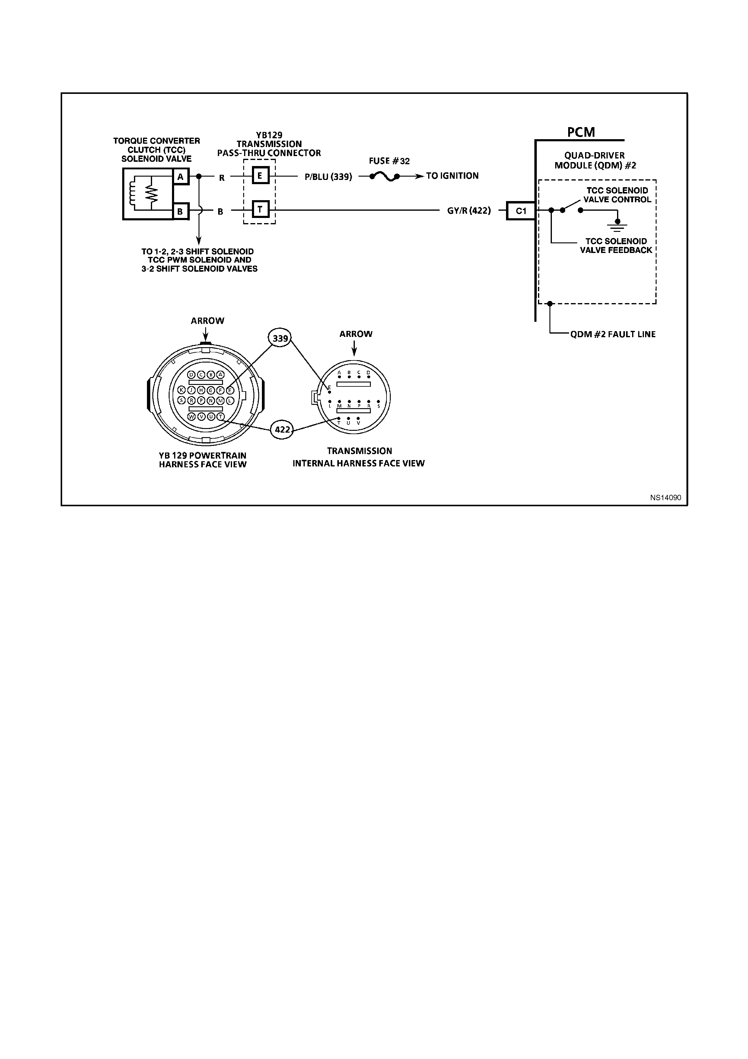
DTC 67 - TORQUE CONVERTER CLUTCH ENABLE
SOLENOID CIRCUI T - ELECTRI CAL
CIRCUIT DESCRIPTION:
The Torque Converter Clutch Solenoid Valve (TCC Solenoid Valve) is an electrical device used with the TCC PWM
Solenoid Valve in order to control the fluid acting on the TCC valve. The TCC valve controls TCC application and
release. The solenoid is a normally-open, ON/OFF device. The TCC Solenoid Valve attaches to the transmission
case assembly extending into the pump cover. The PCM monitors the TP voltage, the vehicle speed and other
inputs in order to determine when to energise the TCC Solenoid Valve. The TCC Solenoid Valve receives ignition
voltage through circuit 339. The PCM controls the solenoid by providing the ground path on circuit 422.
When the PCM detects a continuous open or a short to earth in the TCC Solenoid Valve circuit or in the TCC
Solenoid Valve, then DTC 67 sets.
DTC 67 WILL SET IF:
The system voltage is 10-16 volts.
The above condition is met for 5 seconds and either of the following fail conditions occurs for 4 seconds:
• The PCM commands the solenoid ON and the voltage remains high (B+).
• The PCM commands the solenoid OFF and the voltage remains low (0 volt).
The PCM continually monitors voltage on the TCC circuit connected to the "quad driver" for either low or high
voltage depending on the commanded state of the torque converter clutch. Diagnostic Trouble Code (DTC) 67 will
set if there is a fault detected on the TCC solenoid circuit

TEST DESCRIPTION:
The numbers below refer to the step numbers on the diagnostic chart.
3. An open fuse indicates a short in circuit 339. A short in any of the five solenoids fed by circuit 339 may cause
an open fuse.
4. This step tests for voltage to the solenoid.
6. This step tests the ability of the PCM and wiring to control the earth circuit.
8. This step tests the resistance of the TCC Solenoid Valve and the Automatic Transmission Wiring Harness
Assembly.
DIAGNOSTIC AIDS:
• Inspect the wiring for poor electrical connections at the PCM. Inspect the wiring for poor electrical connections at
the transmission pass-through connector. Look for the following conditions:
A backed out terminal
A damaged terminal
Poor terminal tension
A chafed wire
A broken wire inside the insulation
Corrosion
• When diagnosing for an intermittent short or open condition, massage the wiring harness while watching the test
equipment for a change.
• With the TCC engaged, the TCC slip speed should be -20 to +20 RPM.
• A short to earth in the TCC Solenoid Valve circuit may also set a TCC Stuck On DTC 69.
When DTC 67 sets, the PCM inhibits TCC engagement, inhibits 4th gear if the transmission is in hot mode.

STEP ACTION VALUE YES NO
1Was the On-Board
Diagnostic (OBD) System
Check performed?
— Go to Step 2 Go to OBD
System Check
21. Install the scan tool.
2. With the engine OFF,
turn the ignition switch
to the RUN position.
IMPORTANT:
Before clearing the DTCs,
use the scan tool in order
to record the DTC history
for reference. The Clear
info function will erase the
data.
3. Record the DTC
history.
4. If DTCs 66, 81, 82 or
83 are also set, inspect
the F32 fuse for an
open.
Is the fuse open?
— Go to Step 3 Go to Step 4
31. Check circuit 339 for a
short to earth.
2. Check each of the five
solenoids for being
internally shorted or
shorted to earth.
3. Check the A/T Wiring
Harness Assembly for
a short to earth on
each of the five
solenoid circuits.
4. Make the
repair/replacement if
necessary.
Did you find and correct a
problem?
— Go to Step 12 Go to “Diagnostic
Aids” above
41. Turn the ignition switch
OFF.
2. Disconnect the
transmission pass-
through connector
(additional DTCs may
set).
3. Install the J 39775
Jumper Harness on
the engine harness
connector.
4. With the engine OFF,
turn the ignition switch
to the RUN position.
5. Connect a test tamp
from cavity E of the J
39775 Jumper
Harness to a known
good earth.
Is the test lamp ON?
— Go to Step 6 Go to Step 5

STEP ACTION VALUE YES NO
5Repair the open in the
ignition feed circuit 339 to
the transmission pass-
through connector.
Is the action complete?
— Go to Step 12 —
61. Install the test lamp
from cavities E to T of
the J 39775 Jumper
Harness.
2. Using the device
control function on the
scan tool, command
the TCC Solenoid
Valve ON and OFF
three times.
Does the test lamp turn
ON when the TCC
Solenoid Valve is
commanded ON, and
OFF when commanded
OFF?
— Go to Step 8 Go to Step 7
71. Check circuit 422 for
an open.
2. Check circuit 422 for a
short to B+.
3. Check circuit 422 for a
short to earth.
4. Repair the circuit if
necessary.
Did you find and correct
the problem?
— Go to Step 12 Go to Step 9
81. Install the J 39775
Jumper Harness on
the transmission pass-
through connector.
2. Using the J 39200
DVM and the J 35616
Connector Test
Adaptor Kit, measure
the resistance between
terminals T and E.
Is the resistance within
the specified range?
21-33 ohm Go to Step 10 Go to Step 11
9Replace the PCM.
Refer to Section 6C1-3
Service Operations, for
the Security Link
procedure.
Is the action complete?
— Go to Step 12 —

STEP ACTION VALUE YES NO
10 Measure the resistance
between terminal E and
earth then terminal T and
earth.
Are both readings greater
than the specified value?
250K ohm Go to “Diagnostic
Aids” above Go to Step 11
11 Replace the Automatic
Transmission Wiring
Harness
Assembly (this includes
the TCC Solenoid Valve).
Refer to Service
Operations in
Section 7C-5.
Is the action complete?
— Go to Step 12 —
12 In order to verify your
repair, perform the
following procedure:
1. Select DTC.
2. Select Clear Info.
3. Operate the vehicle
under the following
conditions:
• The PCM commands
the TCC Solenoid
Valve ON, and TCC
Feedback is ON.
• The PCM commands
the TCC Solenoid
Valve OFF, and TCC
Feedback is OFF.
Are both conditions met
for 4 seconds?
— System OK Begin the
diagnosis again.
Go to Step 1
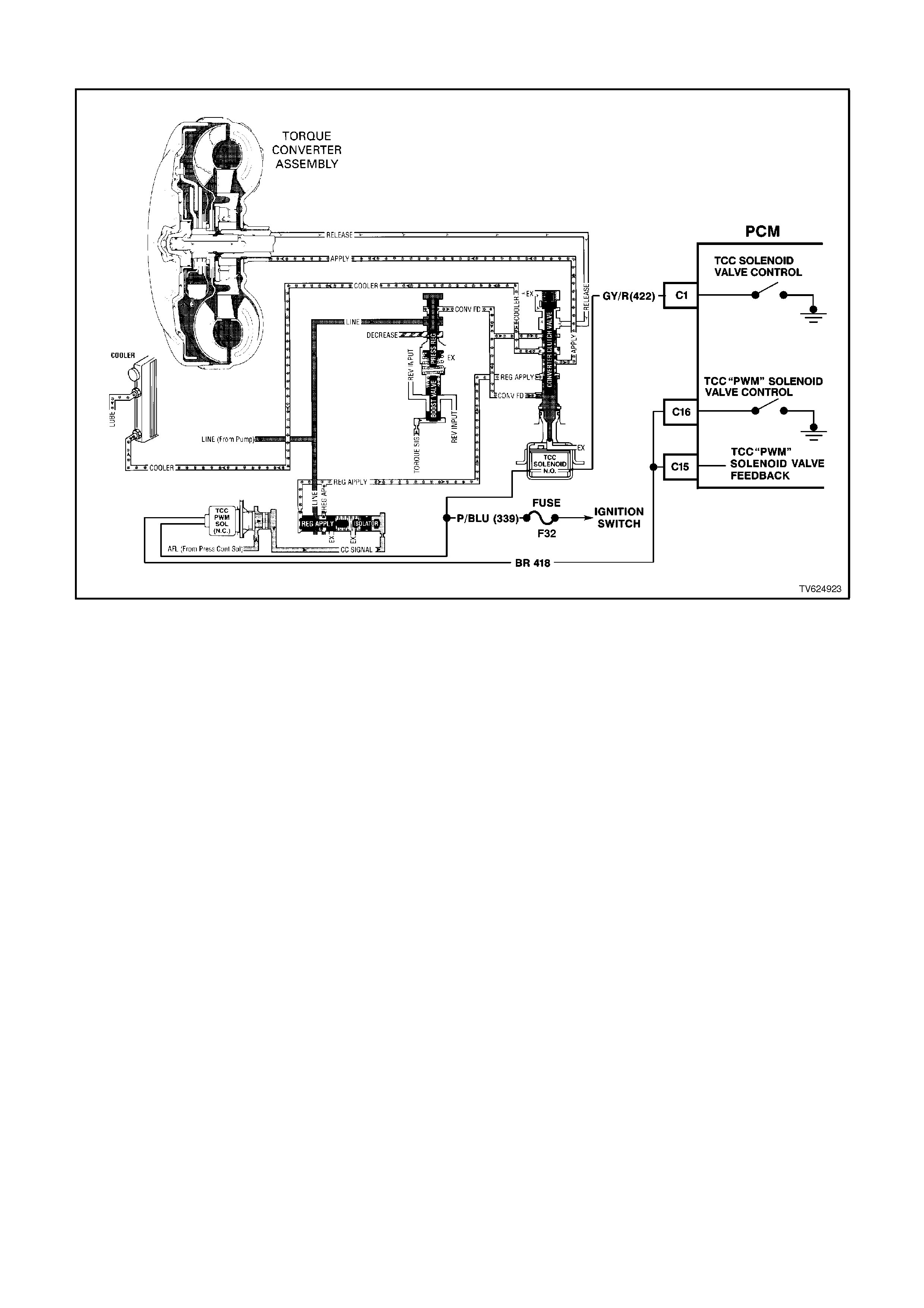
DTC 69 - TORQUE CONVERTER CLUTCH SYSTEM - STUCK ON
CIRCUIT DESCRIPTION:
The PCM energises the Torque Converter Clutch Solenoid Valve (TCC Solenoid Valve) by creating an earth path on
circuit 422. When circuit 422 is earthed (energised) by the PCM, the TCC Solenoid Valve stops converter signal oil
from exhausting. This causes converter signal oil pressure to increase and move the TCC valve. The TCC Solenoid
Valve de-energises when the PCM no longer provides a path to earth. When the TCC Solenoid Valve de-energises,
the valve exhausts fluid and releases the TCC.
When the PCM detects low torque converter slip when the PCM commands the TCC OFF, then DTC 69 sets.
DTC 69 WILL SET IF:
DTC 69 sets if the following conditions occur once per TCC cycle, two consecutive times:
• No TP DTCs 19, 21 or 22.
• No VSS Assembly DTC 24.
• No TFP Valve Position Switch DTC 28.
• No TCC Solenoid Valve DTC 67.
• No TCC PWM Solenoid Valve DTC 83.
• The TP angle is greater than 25%.
• The engine speed is greater than 450 RPM for 8 seconds.
• The commanded gear is not 1st.
• The gear range is D4 or D3.
• The PCM commands the TCC OFF.
• The Trans Slip Speed is -20 to +20 RPM.
• All conditions met for 4 seconds.
Diagnostic Trouble Code 69 is for determining a mechanical fault which will cause the Torque Converter Clutch to
be stuck "ON." An electrical fault in the torque converter clutch solenoid circuit which could cause the torque
converter clutch to be "Stuck ON" is diagnosed in DTC 67.

TEST DESCRIPTION:
The numbers below refer to the step numbers on the diagnostic chart.
3. This step inspects the mechanical state of the TCC. When the PCM commands the TCC Solenoid Valve OFF,
the slip speed should increase to greater than +50 RPM.
DIAGNOSTIC AIDS:
• The TCC fluid will mechanically apply the TCC, possibly causing an engine stall, under the following conditions:
The TCC is mechanically stuck ON
The parking brake is applied
Any gear range is selected
A stuck TP sensor may set DTC 69.
When DTC 69 sets, the PCM freezes shift adapts from being updated.

STEP ACTION VALUE YES NO
1Was the On-Board
Diagnostic (OBD) System
Check performed?
— Go to Step 2 Go to OBD
System Check
21. Install the scan tool.
2. With the engine OFF,
turn the ignition switch
to the RUN position.
Important:
Before clearing the DTCs,
use the scan tool in order
to record the DTC history
for reference. The Clear
Info function will erase the
data.
3. Record the DTC
history.
4. Using the scan tool,
verify the TP Sensor
operation.
Are the TP Sensor values
within the normal range
(shown in the value
column)?
0.6–5.0
volts Go to Step 3 Go to “Diagnostic
Aids” above
3Drive the vehicle in the D4
drive range in fourth gear
under steady acceleration,
with a TP angle greater
than 25%.
While the displayed TCC
Solenoid status is No,
does the scan tool display
a Trans Slip Speed within
the specified range?
-20 to
+20
RPM
Go to Step 4 Go to “Diagnostic
Aids” above

STEP ACTION VALUE YES NO
4The TCC is mechanically
stuck ON. Inspect for the
following conditions:
• A clogged exhaust
orifice in the TCC
Solenoid Valve.
• The converter clutch
apply valve is stuck in
the apply position.
• A misaligned or
damaged valve body
gasket.
• A restricted release
passage.
Did you find and correct a
problem?
¾ Go to Step 5 Go to Symptoms-
No TCC Release
5In order to verify your
repair, perform the
following procedure:
1. Select DTC.
2. Select Clear Info.
3. Operate the vehicle
under the following
conditions:
• Hold the throttle at
25% and accelerate to
55 mph. Ensure that
the Trans Slip Speed
is -50 to +2500 RPM
for 5 seconds, with the
TCC commanded
OFF.
Was the slip speed
greater than 50 RPM in
2nd, 3rd and 4th gears
when the TCC was
commanded OFF?
— System OK Begin the
diagnosis again.
Go to Step 1

DTC 72 V6 PCM - VEHICLE SPEED SIGNAL INTERMITTENT
CIRCUIT DESCRIPTION:
The Vehicle Speed Sensor (VSS) circuit consists of a magnetic induction type sensor and vehicle speed sensor
wiring. Gear teeth pressed on the output shaft of the transmission induce an alternating current in the vehicle speed
sensor. This alternating current is transmitted to the PCM.
DTC 72 WILL SET IF:
• Two successive speed readings have a difference of more than 1000 RPM in any drive range (difference must
be more than 2048 RPM in park or neutral).
This test checks the vehicle speed sensor signal to the PCM.
TEST DESCRIPTION:
Number(s) below refer to step number(s) on the diagnostic chart.
3. This test checks the vehicle speed sensor signal to the powertrain control module.
DIAGNOSTIC AIDS:
DTC 72 is used to detect an intermittent failure. If a hard VSS fault exists, it will set DTC 24.
DTC 72 will set if the vehicle is operating at a road speed and something happens to the VSS signal.
Check all connections for proper retention. When Diagnostic Trouble Code 72 is set, the transmission will have
maximum line pressure and command 3rd gear only. If DTC 72 is set while in 4th gear, the vehicle will stay in 4th
gear. However, as the vehicle is coasting to stop the transmission will downshift normally from 4 to 3. Once the
downshift into 3rd gear has occurred, the vehicle will stay in 3rd gear.
Check that wiring harness for VSS are not routed near high voltage sources such as spark plug cables which could
induce a false signal onto the VSS signal.
DTC 72 could possibly be set by rapidly accelerating the vehicle in a loose material (such as sand or gravel) where
the wheels can be spinning faster than actual vehicle speed then having the spinning wheel rapidly decrease when
it contacts a hard surface. Review DTC history to identify when DTC 72 was set.

STEP ACTION VALUE YES NO
1. Was the "On-Board
Diagnostic" (OBD) System
Check performed?
Go to Step 2 Go to OBD
System Check in
this Section
2. 1. Clear DTC, set Tech 2
scan tool to display
"Vehicle Speed" in the
snapshot mode and
set to trigger on DTC
72.
2. Drive vehicle at
different speeds and
road conditions.
Is DTC 72 set again?
Go to Step 3 DTC 72 Is
intermittent. If no
additional DTC's
were stored, refer
to "Diagnostic
Aids" above.
3. 1. Raise drive wheels.
NOTE:
Do not perform this test
without supporting the
rear axle assembly (five
link suspension) or lower
control arms on vehicles
with independent rear
suspension so that the
drive shafts are in a
normal horizontal position.
on vehicles with IRS,
running the vehicle in gear
with the wheels hanging
down at full travel may
damage the drive shaft.
2. Engine idling in gear.
Does Tech 2 scan tool
display "Vehicle Speed"
above specified value?
0 km/h Go to Step 4 Go to DTC 24 in
this Section
4. Wiggle and tug on
connector at vehicle
speed sensor.
Does Tech 2 scan tool
display "Vehicle Speed"
drop to specified value?
0 km/h Go to step 6 Go to step 5
5. Wiggle and tug on
connectors at Powertrain
Control Module.
Does Tech 2 scan tool
display "Vehicle Speed"
above specified value?
0 km/h Go to step 6 Refer to
"Diagnostic Aids"
above
6. Repair connector
terminals.
Is action complete?
Verify Repair
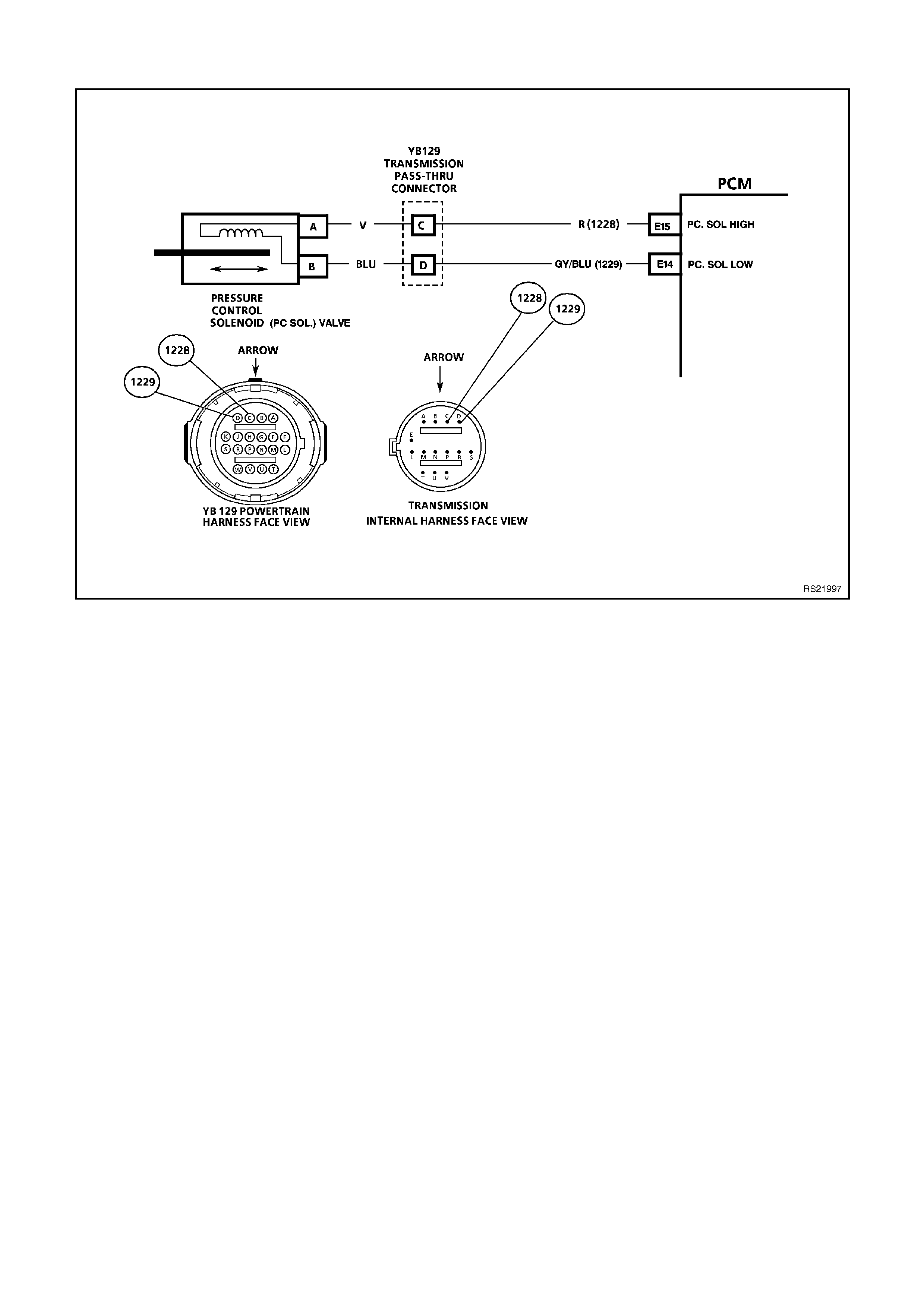
DTC 73 - PRESSURE CONTROL SOLENOID (PCS) CURRENT ERROR
CIRCUIT DESCRIPTION:
The Pressure Control Solenoid Valve (PC Solenoid Valve) is a PCM controlled device which regulates the
transmission line pressure. The PCM compares the TP voltage, the engine speed and other inputs in order to
determine the appropriate line pressure for a given load. The PCM applies a varying amperage to the PC Solenoid
Valve in order to regulate the pressure. The applied amperage can vary from 0.1 to 1.1 amps. The PCM monitors
the amperage.
When the PCM detects a continuous open or short to earth in the PC Solenoid Valve circuit or the PC Solenoid
Valve, then a DTC 73 sets.
DTC 73 WILL SET IF:
• No DTC 75.
• The system voltage is 10-16 volts.
• The engine is running.
• The difference between the PC Solenoid Valve actual return amperage and the desired amperage is 0.16 amp
or greater.
Once a DTC 73 is set, the pressure control solenoid is disabled and full line pressure will be applied until the next
time the ignition key is cycled. If upon restart, the current error does not exist, a DTC 73 will remain stored but the
pressure control solenoid will resume normal function.

TEST DESCRIPTION:
The numbers below refer to the step numbers on the diagnostic chart.
2. This step tests the ability of the PCM to command the PC Solenoid Valve.
3. This step tests the PC Solenoid Valve and Automatic Transmission Wiring Harness Assembly for correct
resistance.
DIAGNOSTIC AIDS:
• Inspect the wiring for poor electrical connections at the PCM. Inspect the wiring for poor electrical connections at
the transmission pass-through connector. Look for the following conditions:
A bent terminal
A backed out terminal
A damaged terminal
Poor terminal tension
A chafed wire
A broken wire inside the insulation
Moisture intrusion
Corrosion
• When diagnosing for an intermittent short or open condition, massage the wiring harness while watching the test
equipment for a change.
When a DTC 73 sets, the PCM will command the PC Solenoid Valve OFF, producing maximum line pressure. The
PCM will also freeze shift adapts from being updated.

STEP ACTION VALUE YES NO
1Was the On-Board
Diagnostic (OBD) System
Check performed?
— Go to Step 2 Go to OBD
System Check
21. Install the scan tool.
2. With the engine OFF,
turn the ignition switch
to the RUN position.
IMPORTANT:
Before clearing the DTCs,
use the scan tool in order
to record the DTC history
for reference. The Clear
Info function will erase the
data.
3. Record the DTC
history.
4. While the engine is
operating, put the
transmission in Park
position.
5. Using the transmission
output control function
on the scan tool, apply
0.1 amp through 1.0
amp while observing
Commanded PCS and
Actual PCS amperage.
Is the Actual PCS
amperage always within
the specified value of the
Commanded PCS
amperage?
0.16
amp Go to
“Diagnostic Aids”
above
Go to Step 3
31. Turn the ignition OFF.
2. Disconnect the
transmission pass-
through connector.
3. Install the J 39775
Jumper Harness on
the transmission side
of the pass-through
connector.
4. Using the J 39200
DVM and J 35616
Connector Test
Adaptor Kit, measure
the resistance between
terminal C and
terminal D.
Is the resistance within
the specified range?
3-7 ohm Go to Step 8 Go to Step 4
4Is the resistance greater
than the specified value? 7 ohm Go to Step 5 Go to Step 6

STEP ACTION VALUE YES NO
51. Check the Automatic
Transmission Wiring
Harness Assembly for
an open.
2. Replace the harness if
necessary. Refer to
Service Operations.
Did you find and correct
the problem?
— Go to Step 15 Go to Step 10
6Is the resistance less than
the specified value? 3 ohm Go to Step 7 —
71. Check the Automatic
Transmission Wiring
Harness Assembly for
a shorted together
condition.
2. Replace the harness if
necessary. Refer to
Service Operations in
Section 7C-5.
Did you find and correct
the problem?
— Go to Step 15 Go to Step 10
8Using the J 39200 DVM
and J 35616 Connector
Test Adaptor Kit, measure
the resistance from
terminal C to the
transmission case .
Is the resistance less than
the specified value?
9 ohm Go to Step 9 Go to Step 11
91. Check the Automatic
Transmission Wiring
Harness Assembly for
a short to earth.
2. Replace the harness if
necessary. Refer to
Service Operations.
Did you find and correct
the problem?
— Go to Step 15 Go to Step 10
10 Replace the PC Solenoid
Valve. Refer to Service
Operations in
Section 6C1-3.
Is the action complete?
— Go to Step 15 —

STEP ACTION VALUE YES NO
11 1. Disconnect the J
39775 Jumper
Harness from the
transmission side of
the pass-through
connector.
2. Reconnect the
transmission pass-
through connector.
3. Disconnect the PCM
connector 3 (BLUE 32
pin).
4. Using the J 39200
DVM and the J 35616
Connector Test
Adaptor Kit, measure
the resistance from
terminal E15 to earth.
Is the resistance greater
than the specified value?
9 ohm Go to Step 12 Go to Step 13
12 1. Check circuit 1228 and
circuit 1229 for an
open.
2. Repair the circuits if
necessary.
Did you find and correct
the problem?
— Go to Step 15 Go to Step 14
13 1. Check circuit 1228 and
circuit 1229 for a short
to earth.
2. Repair the circuits if
necessary.
Did you find and correct
the problem?
— Go to Step 15 _
14 Replace the PCM.
Refer to Section 6C1-3
Service Operations, for
the Security Link
procedure.
Is the action complete?
— Go to Step 15 —
15 In order to verify your
repair, perform the
following procedure:
1. Select DTC.
2. Select Clear info.
3. Operate the vehicle
under the following
conditions:
• The engine is running.
• Observe the Actual
PCS amperage and
the Commanded PCS
amperage.
Is the difference between
the Actual PCS amperage
and the Commanded PCS
amperage less than the
specified value?
0.16
amp System OK Begin the
diagnosis again.
Go to Step 1
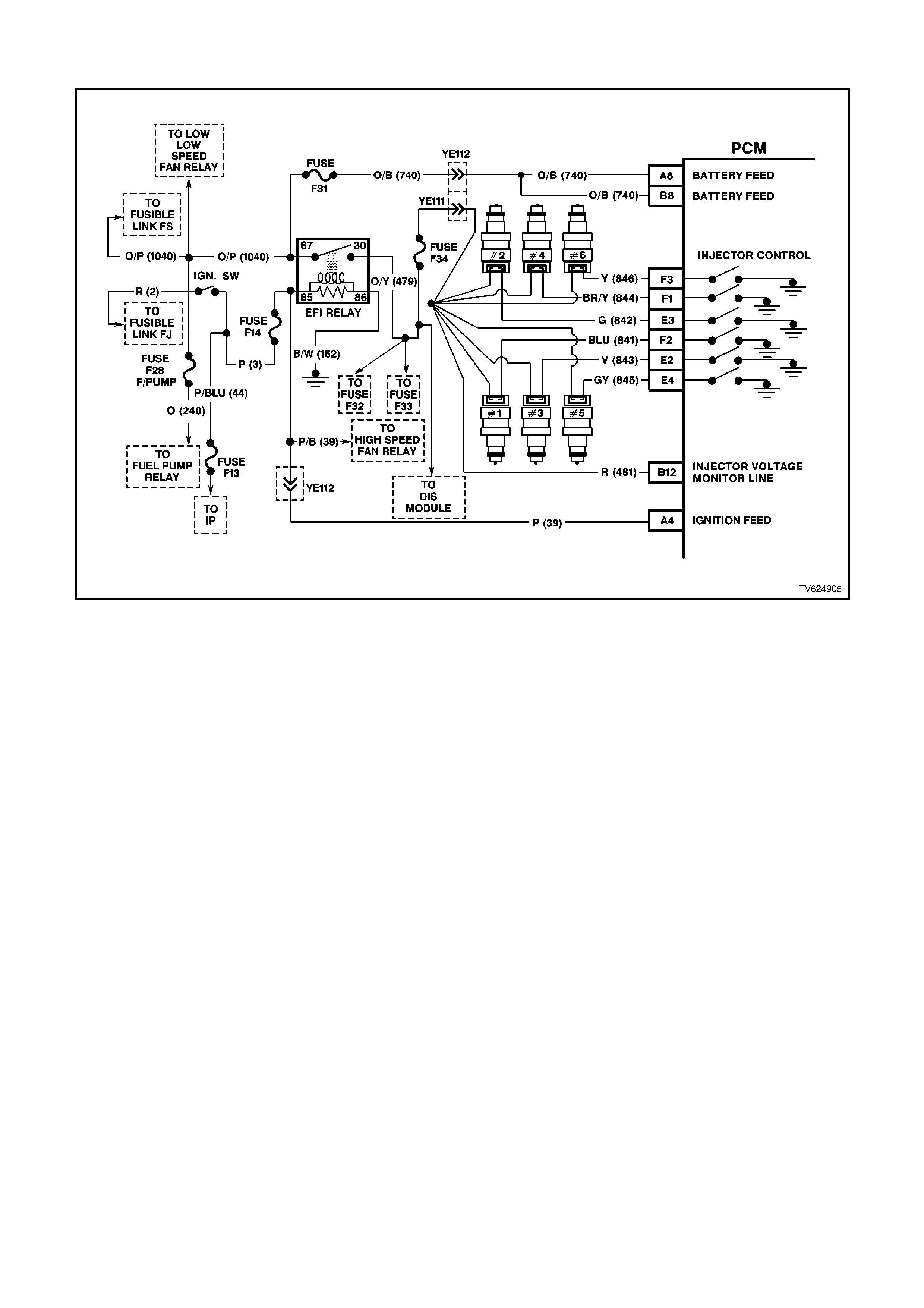
DTC 75 - SYSTEM VOLTAGE LOW
CIRCUIT DESCRIPTION:
Circuit 39 is the ignition voltage feed circuit to terminal A4 for the PCM. Circuit 740 is the battery voltage feed circuit
to terminals A8 and B8 for the PCM. When the PCM detects a low voltage for a short period of time, then DTC 75
sets.
DTC 75 WILL SET IF:
• The system voltage is less than 7.3 volts with the TFT at -40°C.
- OR -
• The system voltage is less than 10 volts with the TFT at 151°C.
One of the above conditions is met for 4 seconds.
Minimum voltage allowed for Diagnostic Trouble Code 75 to set is on a graduated scale and will change with
temperature. Minimum voltage at - 40 degrees C is 7.3 volts, minimum voltage at 151 degrees C is 10.0 volts, 8.6
volts is the minimum voltage at 90 degrees C.
TEST DESCRIPTION:
The numbers below refer to the step numbers on the diagnostic chart.
4. This step tests the charging system voltage.
6. This step tests for proper voltage to the PCM on circuits 39 and 740.

DIAGNOSTIC AIDS:
• Inspect the wiring for poor electrical connections at the PCM. Look for the following conditions:
A bent terminal
A backed out terminal
A damaged terminal
Poor terminal tension
A chafed wire
A broken wire inside the insulation
Moisture intrusion
Corrosion
• When diagnosing for an intermittent short or open condition, massage the wiring harness while watching the test
equipment for a change.
• Charging the battery with a battery charger may set DTCs. Jump starting an engine may set DTCs.
• If DTCs set when you operate an accessory, inspect the applicable wiring for faulty connections. Inspect the
wiring for excessive current draw.
• Inspect the following items for faulty connections:
The starter solenoid
The fusible link
The generator terminals
Battery cables to earth
• Inspect the belts for excessive wear. Inspect the belts for proper tension.
When DTC 75 sets, the PCM will turn off all transmission output devices and freezes shift adapts from being
updated.

STEP ACTION VALUE YES NO
1. Was the On-Board
Diagnostic (OBD) System
Check performed?
— Go to Step 2 Go to OBD
System Check
2. 1. Install the scan tool.
2. With the engine OFF,
turn the ignition switch
to the RUN position.
Important:
Before clearing the DTCs,
use the scan tool in order
to record the DTC history
for reference. The Clear
Info function will erase the
data.
3. Record the DTC
history.
4. Using the J 39200
DVM, measure the
battery voltage across
the battery terminals.
Is the voltage higher than
the specified value?
10 volts Go to Step 3 Go to Battery
Diagnosis,
3. 1. Start the engine.
2. Warm the engine to
normal operating
temperature.
Is the generator/check
engine light ON?
— Go to Charging
System Diagnosis Go to Step 4
4. 1. Turn on the headlights
and the heater blower
motor.
2. Increase the engine
speed to 1500 RPM.
3. Observe the DVM
battery voltage and
record your reading for
reference.
Is the DVM voltage within
the specified range?
13-15
volts Go to Step 5 Go to Charging
System Diagnosis
5. 1. Increase the engine
speed to 1500 RPM.
2. Observe the scan tool
battery voltage.
Is the scan tool Battery
Voltage within the
specified range?
13-15
volts System Checks
OK, Go to
“Diagnostic Aids”
above
Go to Step 6

STEP ACTION VALUE YES NO
6. 1. Turn the ignition switch
to OFF position.
2. Locate terminals A4,
A8 and B8 in the PCM
connector (24 pin).
Do not disconnect the
PCM connector.
3. Connect the DVM
black lead to earth.
4. Start the engine.
5. Run the engine at
1500 RPM with the
headlights and the
blower motor on.
6. Using the J 39200
DVM and J 35616
Connector Test
Adaptor Kit, backprobe
terminals A4, A8 and
B8 to measure the
battery voltage input at
the PCM connector.
Is there a voltage variance
between the voltage
measured at the battery
(taken in Step 4) and at
terminals A4, A8 and B8
that is greater than the
specified value?
0.5 volts Go to Step 7 Go to Step 10
7. Does terminal A4 (circuit
39) have the voltage
variance?
¾ Go to Step 8 Go to Step 9
8. Repair the high resistance
condition in circuit 39.
Is the action complete?
¾ Go to Step 11 ¾
9. Repair the high resistance
condition in circuit 740.
Is the action complete?
— Go to Step 11 —
10. Replace the PCM. Refer
to Section 6C1-3 Service
Operations, for the
Security Link procedure.
Is the action complete?
¾ Go to Step 11 ¾
11. In order to verify your
repair, perform the
following procedure:
1. Select DTC.
2. Select Clear Info.
3. Operate the vehicle
under the following
conditions:
• Start the vehicle.
• Warm the engine to
normal operating
temperature.
Is the scan tool Battery
Voltage within the
specified range?
13-15.5
volts System OK Begin the
diagnosis again.
Go to Step 1
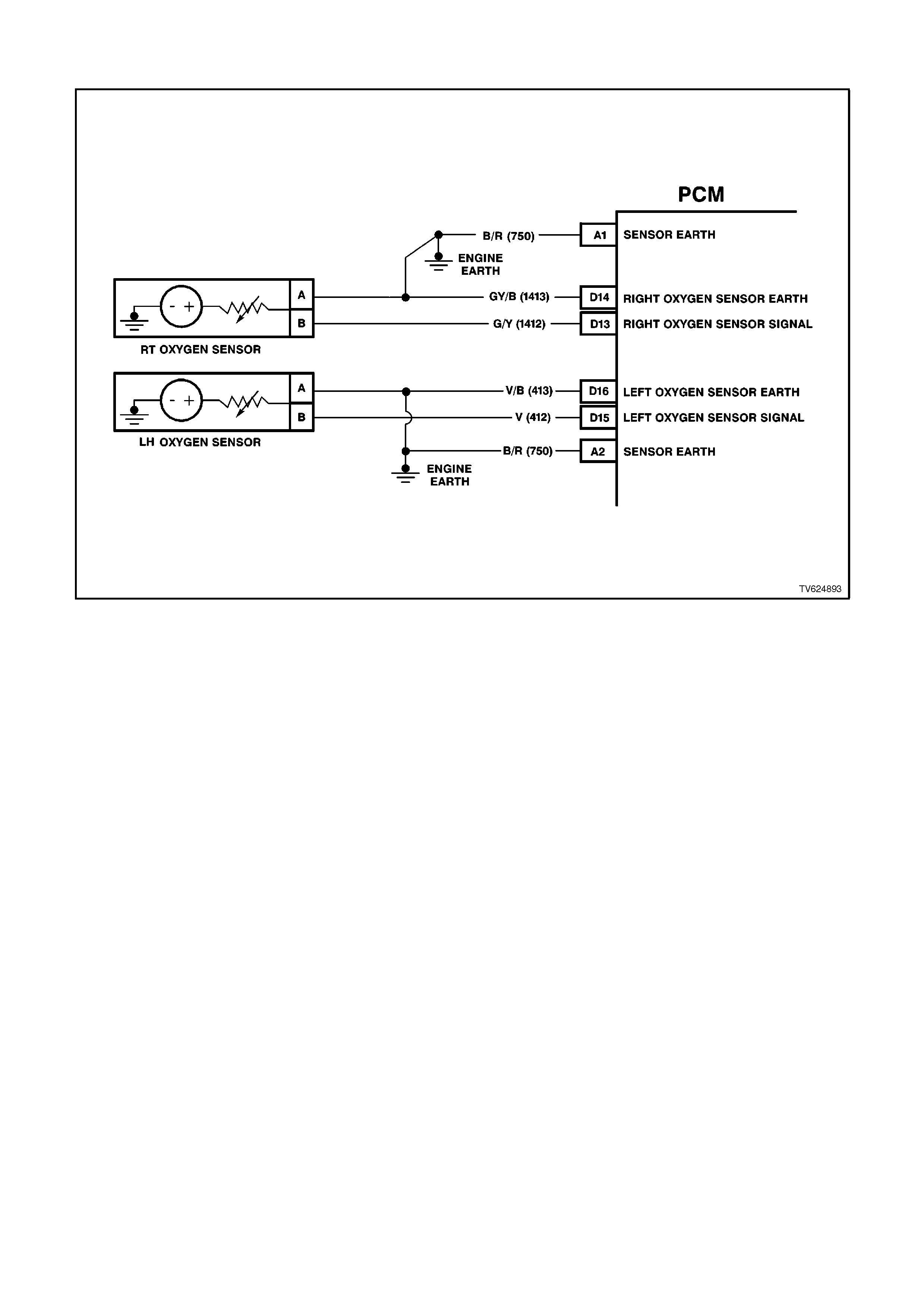
DTC 76 V6 PCM - SHORT TERM FUEL TRIM (STFT) DELTA HIGH
CIRCUIT DESCRIPTION:
The PCM controls left to right cylinder bank fuel delivery separately based on their respective oxygen sensor
signals. If the PCM detects too great a difference between the left to right cylinder bank Short Term (ST) Fuel Trim
values, it will set DTC 76.
DTC 76 will set when the left bank Short Term Fuel Trim value differs from the right bank Short Term Fuel Trim by
more than 63% for 32 seconds while in closed loop.
With a current DTC 76 set, the PCM will not illuminate the MIL (Check Powertrain Lamp). DTC 76 will clear when
the fault no longer exists and the ignition switch is cycled "OFF" and "ON".
DTC 76 WILL SET IF:
• Engine is idling.
• Left to Right Short Term Fuel Trim values differs by more than 63% for 32 seconds.
TEST DESCRIPTION:
Number(s) below refer to step number(s) on the diagnostic table.
2. Check and repair other DTC(s) first
3. Checking for other mechanical problems causing DTC to set.
4. The bank that is the farthest from the neutral value of 0% is the bank which is out of fuel control.
DIAGNOSTIC AIDS:
• Lean or faulty injector(s) on one side of the engine.
• Cracked or fouled spark plug(s).
• Exhaust or inlet manifold leak.
• Make sure oxygen sensor leads are not swapped.

STEP ACTION VALUE YES NO
1. Was the "On-Board
Diagnostic" (OBD) System
Check performed?
Go to Step 2 Go to OBD
System Check in
this Section
2. Are any other PCM
DTC(s) set? Diagnose other
DTC(s) first Go to Step 3
3. Is there a Driveability
complaint associated with
this DTC such as an
Engine Miss, Lack of
Power, or Poor Fuel
Economy?
Go to Step 7 Go to Step 4
4. 1. Start Engine and allow
to warm up (Coolant
Temperature above 85
degrees C).
2. Install Tech 2 scan tool
and note left and right
bank Short Term Fuel
Trim values.
Is the left bank Short
Term Fuel Trim values
further from 0% then the
right bank?
Go to Step 5 Go to Step 6
5. Perform Oxygen Sensor
(O2S) Diagnosis, Chart A-
6.3 in this Section.
Is action complete?
Verify Repair
6. 1. Start Engine and allow
to warm up (Coolant
Temperature above 85
degrees C).
2. Install Tech 2 scan tool
and note left and right
bank Short Term Fuel
Trim values.
Is the right bank Short
Term Fuel Trim values
further from 0% then the
left bank?
Go to Step 5 DTC 76 is
intermittent. Refer
"Diagnostic Aids"
above.
7. Perform the following
tests in the order given
until the problem is
corrected :
• Fuel system check,
(refer Chart A- 4.3 in
this Section).
• Oscilloscope Engine,
note and repair any
Ignition System
problem found.
• Compression test each
cylinder.
Is action complete ?
Verify Repair
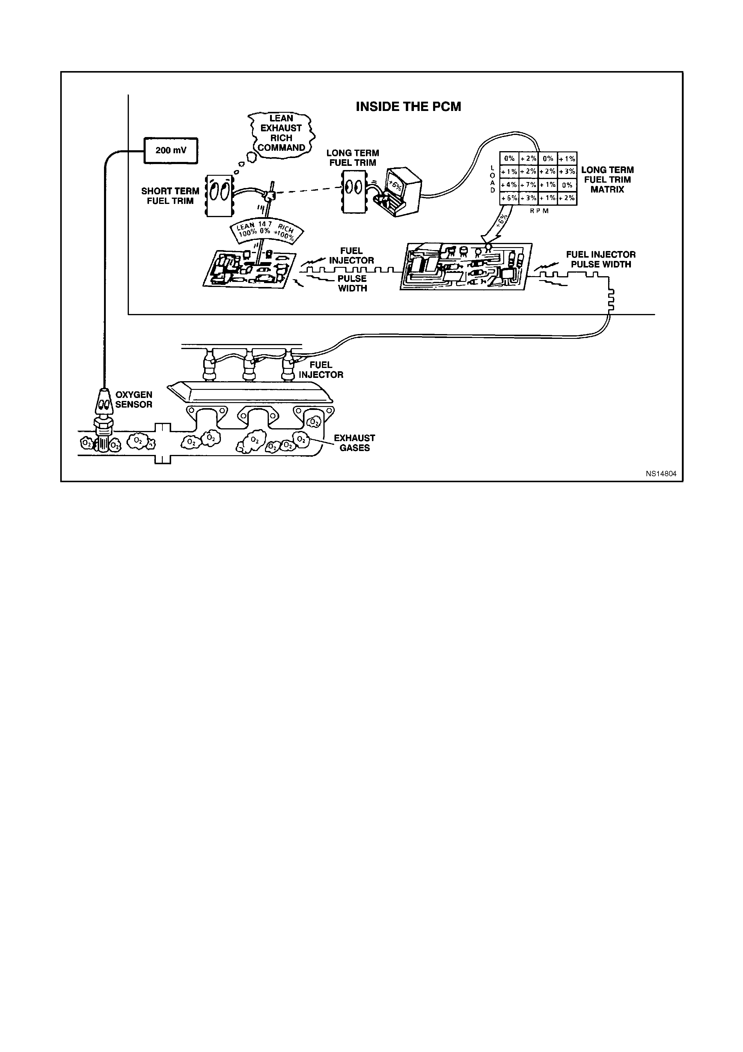
DTC 78 V6 PCM - LONG TERM FUEL TRIM (LTFT) DELTA HIGH
CIRCUIT DESCRIPTION:
The PCM controls left to right cylinder bank fuel delivery separately based on their respective oxygen sensor
signals. If the PCM detects too great a difference between the left to right cylinder bank Long Term Fuel Trim
values, it will set DTC 78.
DTC 78 will set when the left bank Long Term Fuel Trim value differs from the right bank Long Term Fuel Trim by
more than 59% for 32 seconds while in closed loop.
With a current DTC 78 set, the PCM will not illuminate the MIL (Check Powertrain Lamp). DTC 78 will clear when
the fault no longer exists and the ignition switch is cycled "OFF" and "ON".
DTC 78 WILL SET IF:
• Engine is idling.
• Left to Right Short Term Fuel Trim values differs by more than 59% for 32 seconds.
TEST DESCRIPTION:
Number(s) below refer to step number(s) on the diagnostic table.
2. Check and repair other DTC(s) first.
3. Check for other mechanical problems causing DTC to set.
4. The bank that is the farthest from the neutral value of 0% is the bank which is out of fuel control.
DIAGNOSTIC AIDS:
• Lean or faulty injector(s) on one side of the engine.
• Cracked or fouled spark plug(s).
• Exhaust or inlet manifold leak.
• Make sure oxygen sensor leads are not swapped.

STEP ACTION VALUE YES NO
1. Was the "On-Board
Diagnostic" (OBD) System
Check performed?
Go to Step 2 Go to OBD
System Check in
this Section
2. Are any other PCM
DTC(s) set? Diagnose other
DTC(s) first Go to Step 3
3. Is there a Driveability
complaint associated with
this DTC such as an
Engine Miss, Lack of
Power, or Poor Fuel
Economy?
Go to Step 7 Go to Step 4
4. 1. Start Engine and allow
to warm up (Coolant
Temperature above 85
degrees C).
2. Install Tech 2 scan tool
and note left and right
bank Long Term Fuel
Trim values.
Is the left bank Long Term
Fuel Trim values further
from 0% then the right
bank?
Go to Step 5 Go to Step 6
5. Perform Oxygen Sensor
(O2S) Diagnosis, Chart
A-6.3 in this Section.
Is action complete?
Verify Repair
6. 1. Start Engine and allow
to warm up (Coolant
Temperature above 85
degrees C).
2. Install Tech 2 scan tool
and note left and right
bank Long Term Fuel
Trim values.
Is the right bank Long
Term Fuel Trim values
further from 0% then the
left bank?
Go to Step 5 DTC 78 is
intermittent. Refer
"Diagnostic Aids"
above.
7. Perform the following
tests in the order given
until the problem is
corrected :
• Fuel System check,
(refer Chart A-4.3 in
this Section).
• Oscilloscope Engine,
note and repair any
Ignition System
problem found.
• Compression test each
cylinder.
Is action complete?
Verify Repair
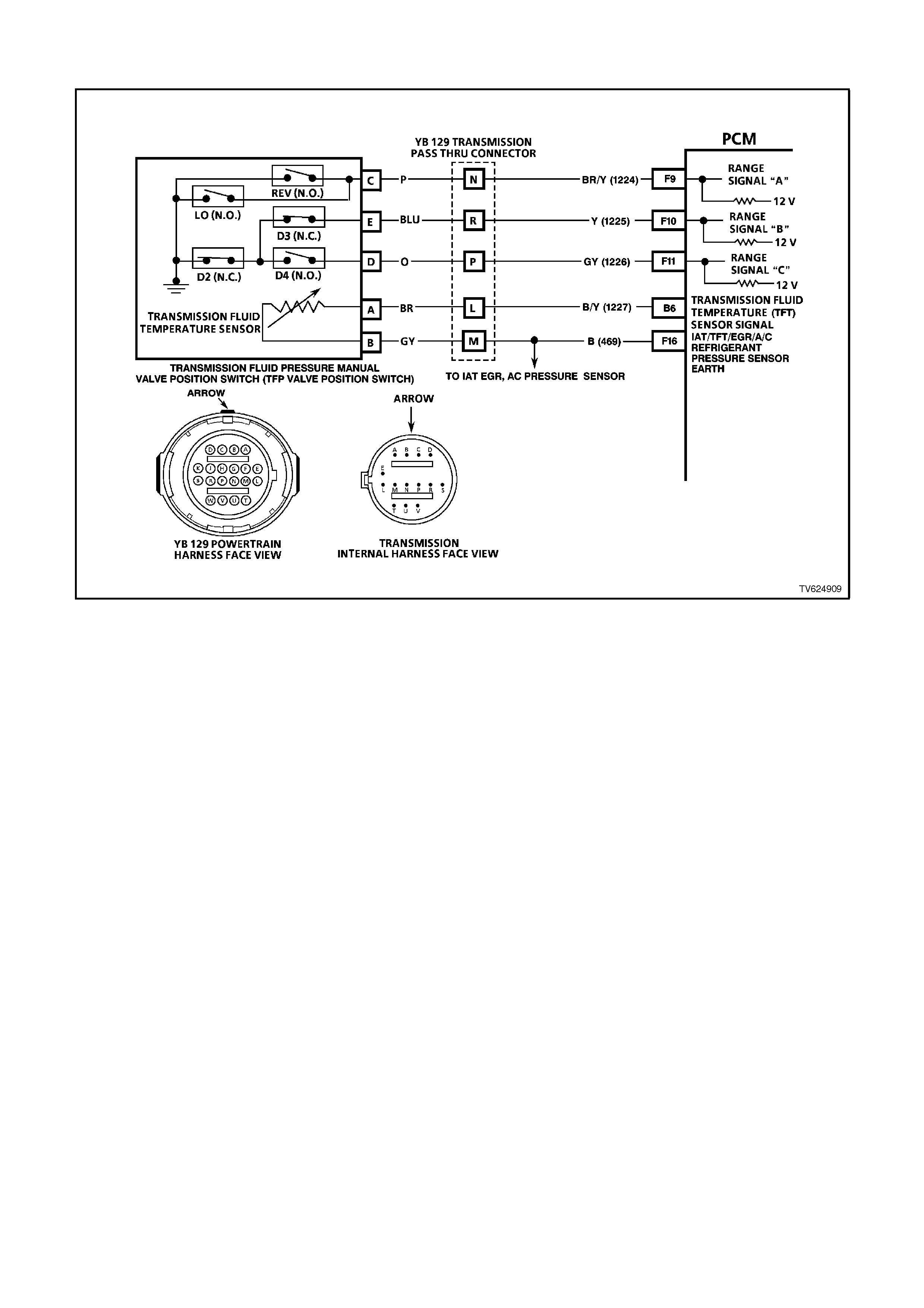
DTC 79 - TRANSMISSION FLUID OVERTEM PERATURE
CIRCUIT DESCRIPTION:
The flow of transmission fluid starts in the bottom of the pan and is drawn through the filter, control valve body
assembly, transmission case and into the oil pump assembly. The oil pump assembly pressurises the fluid and
directs it to the pressure regulator valve where it becomes the main supply of fluid to the various components and
hydraulic circuits in the transmission. Hot fluid exiting the torque converter flows through the converter clutch apply
valve and into the transmission cooler lines to the oil cooler located in the radiator (and auxiliary cooler if equipped).
From the cooler, fluid returns to cool and lubricate the front of the transmission. In forward drive ranges, D4 fluid
from the manual valve is routed through an orifice cup plug in the rear of the transmission case to feed the rear lube
fluid circuit.
When the PCM detects a high transmission fluid temperature (TFT) for a long period of time, then DTC 79 sets.
DTC 79 WILL SET IF:
• No TFT sensor DTC 58.
• The TFT is greater than 146°C. Then the TFT is greater than 137°C for 30 minutes.
As the transmission fluid temperature warms (normal transmission operating temperature 82 degrees C - 94
degrees C), the sensor (thermistor) resistance becomes less and the voltage will measure about 1.5 to 2.0 volts. If
the fluid temperature becomes greater than 146 degrees C and does not drop below 137 degrees C for 30 minutes,
a DTC 79 will set.
When DTC 79 sets the transmission fluid may be severely degraded.

TEST DESCRIPTION:
The numbers below refer to the step numbers on the diagnostic chart.
3. DTC 58 may also set a DTC 79. Go to the DTC 58 table for diagnosis.
4. This step inspects for air restrictions and loss of transmission fluid flow, causing an extremely high TFT.
DIAGNOSTIC AIDS:
• Inspect the cooling system fluid level and condition.
• DTC 79 may set approximately 30 minutes after DTC 58 has set. Follow the diagnostic table for DTC 58 before
proceeding to the diagnostic table for DTC 79. Repairing the condition that set DTC 58 will likely eliminate DTC
79.
• The TFT temperature displayed on the scan tool should rise steadily to a normal operating temperature, then
stabilise.
• Inspect the torque converter stator for a possible problem.
• Ask about the customer's driving habits, trailer towing, etc.
When a DTC 79 sets, the PCM freezes shift adapts from being updated.

STEP ACTION VALUE YES NO
1Was the On-Board
Diagnostic (OBD) System
Check performed?
— Go to Step 2 Go to OBD
System Check
21. Install the scan tool.
2. With the engine OFF,
turn the ignition switch
to the RUN position.
Important:
Before clearing the DTCs,
use the scan tool in order
to record the DTC history
for reference. The Clear
Info function will erase the
data.
3. Record the DTC
history.
4. Perform the
transmission fluid
checking procedure.
Refer to Transmission
Fluid Checking
Procedure.
Was the fluid checking
procedure performed?
— Go to Step 3 Go to
Transmission
Fluid Checking
Procedure
3Is DTC 58 also set? — Go to “Diagnostic
Aids” above Go to Step 4
41. Inspect the cooling
system for the
following conditions:
• Air flow restrictions
• Air flow blockage
• Debris
2. Inspect the
transmission cooling
system for the
following conditions:
• Air flow restrictions
• Air flow blockage
• Debris
• Damaged cooler lines
3. Repair restrictions if
necessary.
Was a problem found?
— Go to Step 7 Go to Step 5

STEP ACTION VALUE YES NO
51. Drive the vehicle in D4
with the TCC
commanded On.
2. Observer the TCC slip
speed on the scan
tool.
Is the TCC slip speed
within the specified value?
-20 to
+20
RPM
Go to Step 6 Refer to Torque
Converter Clutch
Diagnosis
Symptoms
6Perform the Line Pressure
Check Procedure. Refer
to Section 7C-3.
Was a problem found?
— Go to Step 7 Go to “Diagnostic
Aids” above
7In order to verify your
repair, perform the
following procedure:
1. Select DTC.
2. Select Clear Info.
3. Drive the vehicle to
normal operating
engine and
transmission
temperature.
4. Observe the TFT
during the entire drive.
Is the TFT less than the
specified value during the
entire drive?
137°C System OK Begin the
diagnosis again.
Go to Step 1
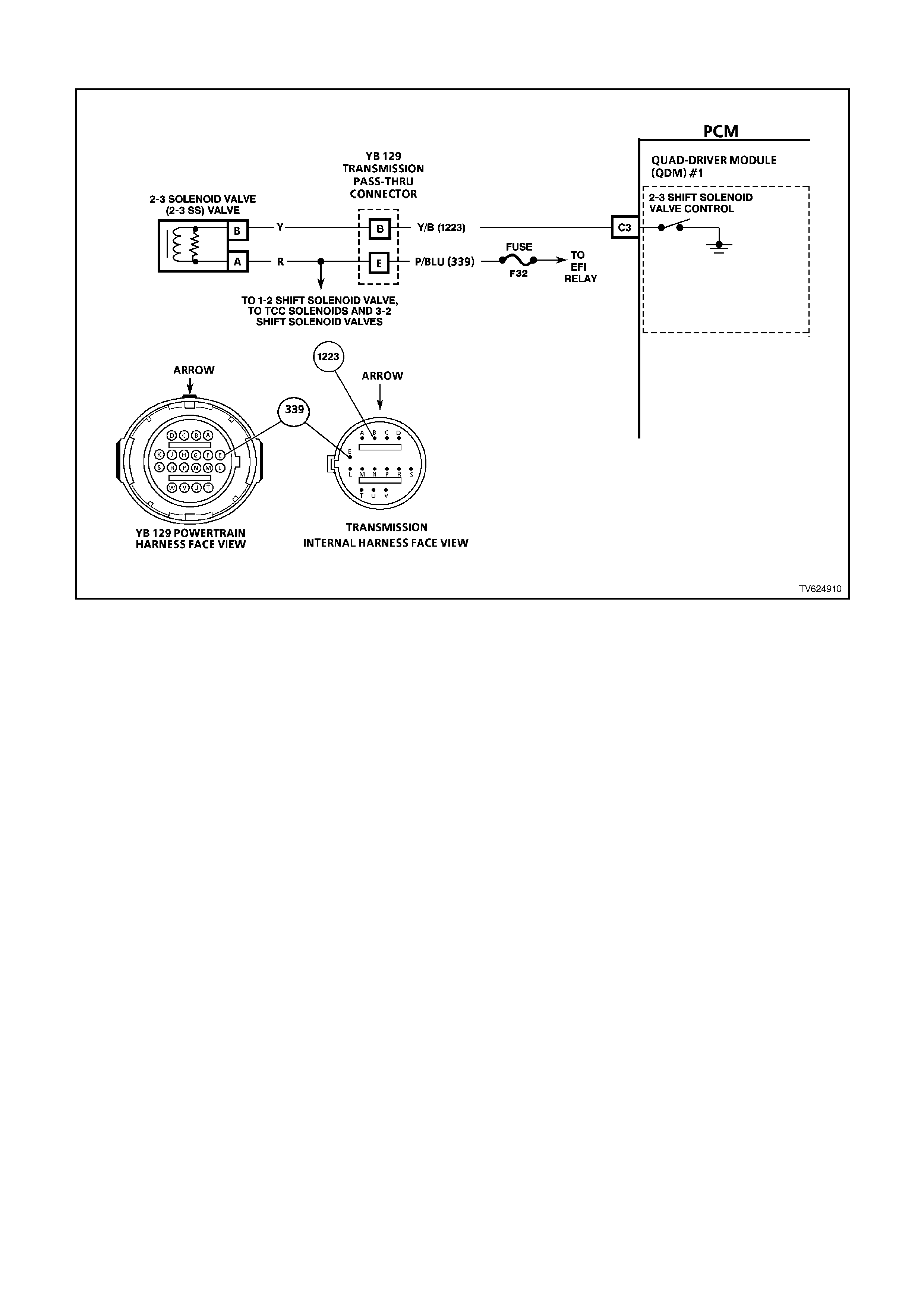
DTC 81 - 2-3 SHIFT SOLENOID CI RCUI T FAULT
CIRCUIT DESCRIPTION:
The 2-3 Shift Solenoid Valve (2-3 SS Valve) controls the fluid flow acting on the 2-3 shift valves. The 2-3 SS Valve
is a normally-open exhaust valve that is used with the 1-2 Shift Solenoid Valve in order to allow four different shifting
combinations. The solenoid attaches to the control valve body within the transmission. The 2-3 SS Valve receives
ignition voltage through circuit 339. The PCM controls the solenoid by providing a path to earth on circuit 1223.
When the PCM detects a continuous open or short to earth in the 2-3 SS Valve circuit or the 2-3 SS Valve, then
DTC 81 sets.
DTC 81 WILL SET IF:
Either of the following fail conditions occurs for 4 seconds.
• The PCM commands the solenoid ON and the voltage remains high (B+).
• The PCM commands the solenoid OFF and the voltage remains low (0 volts).
The PCM continually monitors voltage on each circuit connected to the "quad driver" module looking for
either low or high voltage depending on the commanded state of the devices connected to it.
TEST DESCRIPTION:
The numbers below refer to the step numbers on the diagnostic chart.
3. An open fuse indicates a short circuit or a short to earth on circuit 339. A short in any of the five solenoids fed
by circuit 339 may cause an open fuse.
4. This step tests the function of the 2-3 SS Valve and the Automatic Transmission Wiring Harness Assembly.
5. This step tests for power to the transmission pass-through connector from the ignition through the fuse.
6. This step tests the ability of the PCM and the wiring to control the earth circuit.
13. This step measures the resistance of the Automatic Transmission Wiring Harness Assembly and the 2-3 SS
Valve.

DIAGNOSTIC AIDS:
• Inspect the wiring for poor electrical connections at the PCM. Inspect the wiring for poor electrical connections at
the transmission pass-through connector. Look for the following conditions:
A bent terminal
A backed out terminal
A damaged terminal
Poor terminal tension
A chafed wire
A broken wire inside the insulation
• Moisture intrusion when diagnosing for an intermittent short or open condition, massage the wiring harness while
watching the test equipment for a change.
Refer to the following chart for the correct On and Off states of the shift solenoids.
Gear 1-2 Shift Solenoid 2-3 Shift Solenoid
1ON ON
2OFF ON
3OFF OFF
4ON OFF
When DTC 81 sets, the PCM commands third gear only, maximum line pressure, freezes shift adapts from being
updated and inhibits TCC engagement.

STEP ACTION VALUE YES NO
1Was the On-Board
Diagnostic (OBD) System
Check performed?
— Go to Step 2 Go to OBD
System Check
21. Install the scan tool.
2. With the engine OFF,
turn the ignition switch
to the RUN position.
IMPORTANT:
Before clearing the DTCs,
use the scan tool in order
to record the DTC history
for reference. The Clear
Info function will erase the
data.
3. Record the DTC
history.
4. If DTCs 66, 67, 82, or
83 are also set, inspect
the F32 fuse for an
open.
Is the fuse open?
— Go to Step 3 Go to Step 4
31. Check circuit 339 for a
short to earth.
2. Check each of the five
solenoids for being
internally shorted or
shorted to earth.
3. Check the A/T Wiring
Harness Assembly for
a short to earth on
each of the five
solenoid circuits.
4. Make the
repair/replacement if
necessary.
Did you find and correct a
problem?
— Go to Step 19 Go to “Diagnostic
Aids” above
4Using the device control
function, command the 2-
3 SS Valve ON and OFF
three times while listening
to the bottom of the
transmission pan (a
stethoscope may be
necessary).
Does the solenoid click
when commanded?
— Go to “Diagnostic
Aids” above Go to Step 5

STEP ACTION VALUE YES NO
51. Turn the ignition OFF.
2. Disconnect the
transmission pass-
through connector
(additional DTCs will
set).
3. Install the J 39775
Jumper Harness on
the engine side of the
pass-through
connector.
4. With the engine OFF,
turn the ignition switch
to the RUN position.
5. Connect a test lamp
from J 39775 Jumper
Harness cavity E to
earth.
Is the test light ON?
— Go to Step 6 Go to Step 7
61. Install a test lamp from
cavity E to cavity B of J
39775 Jumper
Harness.
2. Using the device
control function,
command the 2-3 SS
Valve ON and OFF
three times.
Is the test lamp ON when
the 2-3 SS Valve is
commanded ON and OFF
when commanded OFF?
— Go to Step 13 Go to Step 8
7Repair the open in the
ignition feed circuit 339 to
the 2-3 SS Valve.
Is the action complete?
— Go to Step 19 —
8Monitor the test lamp
status.
Was the test lamp OFF at
all times?
— Go to Step 9 Go to Step 10
91. Check circuit 1223 for
an open.
2. Check circuit 1223 for
a short to B+.
3. Repair the circuit if
necessary.
Did you find and correct
the problem?
— Go to Step 19 Go to Step 12
10 Was the test lamp ON at
all times? — Go to Step 11 —
11 1. Check circuit 1223 for
a short to earth.
2. Repair the circuit if
necessary.
Did you find and correct
the problem?
— Go to Step 19 Go to Step 12

STEP ACTION VALUE YES NO
12 Replace the PCM.
Refer to Section 6C1-3
Service Operations, for
the Security Link
procedure.
Is the action complete?
— Go to Step 19 —
13 1. Turn the ignition OFF.
2. Install the J 39775
Jumper Harness on
the transmission pass-
through connector.
3. With J 39200 DVM and
J 35616 Connector
Test Adaptor Kit,
measure the
resistance between
terminals B and E.
Is the resistance within
the specified range?
19-31 ohm Go to Step 15 Go to Step 14
14 1. Disconnect the
Automatic
Transmission Wiring
Harness Assembly
from the 2-3 SS Valve.
2. Measure the
resistance of the 2-3
SS Valve.
Is the resistance within
the specified range?
19-31 ohm Go to Step 17 Go to Step 18
15. Using J 39200 DVM,
measure the resistance
between terminals B and
E and earth.
Are both readings greater
than the specified value?
250 ohm Go to
“Diagnostic Aids”
above
Go to Step 16
16 1. Disconnect the
Automatic
Transmission Wiring
Harness Assembly
from the 2-3 SS Valve.
2. Using J 39200 DVM,
measure the
resistance from the
component's terminals
to earth.
Are both readings greater
than the value shown?
250 ohm Go to Step 17 Go to Step 18
17 Replace the Automatic
Transmission Wiring
Harness Assembly. Refer
to Service Operations in
Section 7C5-5.
Is the action complete?
¾ Go to Step 19 ¾
18 Replace the 2-3 SS Valve.
Refer to Service
Operations in
Section 6C1-3.
Is the action complete?
¾ Go to Step 19 ¾

STEP ACTION VALUE YES NO
19 In order to verify your
repair, perform the
following procedure:
1. Select DTC.
2. Select Clear Info.
3. Operate the vehicle
under the following
conditions while
observing the 2-3 Shift
Solenoid and 2-3 Shift
Solenoid Feedback:
• The PCM commands
the 2-3 SS Valve ON
and the 2-3 Shift
Solenoid Feedback is
ON.
• The PCM commands
the 2-3 SS Valve OFF
and the 2-3 Shift
Solenoid Feedback is
OFF.
Have both conditions
been met for 4 seconds?
¾ System OK Begin the
diagnosis again
Go to Step 1
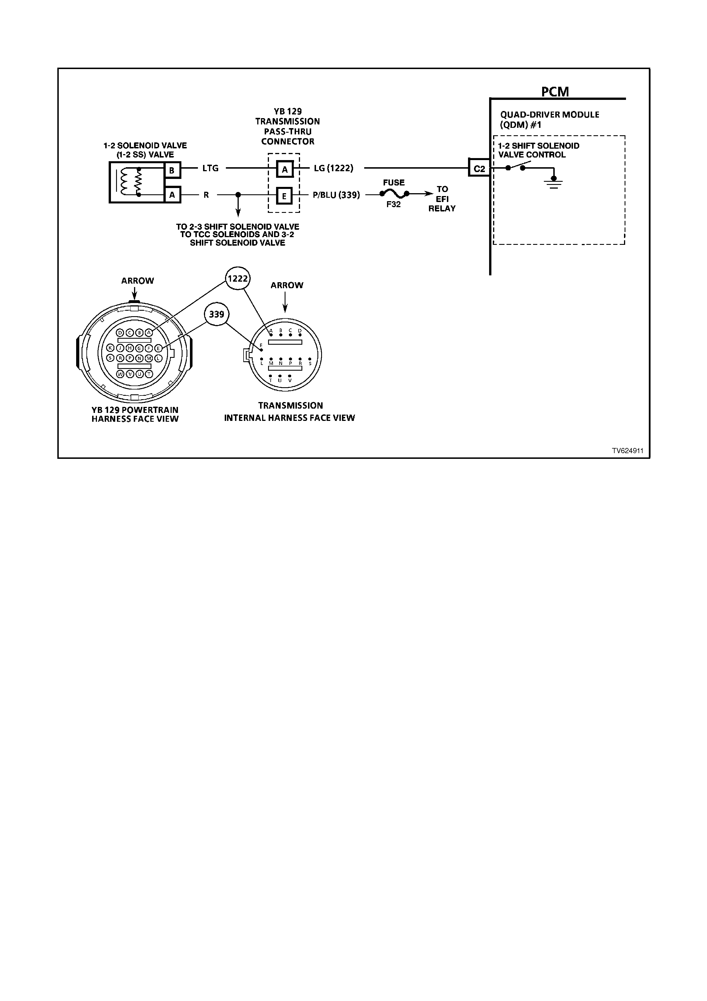
DTC 82 - 1- 2 SHIFT SOLENOID CI RCUI T FAULT
CIRCUIT DESCRIPTION:
The 1-2 Shift Solenoid Valve (1-2 SS Valve) controls the fluid flow acting on the 1-2 and 3-4 shift valves. The 1-2 SS
Valve is a normally-open exhaust valve that is used with the 2-3 Shift Solenoid Valve in order to allow four different
shifting combinations. The solenoid attaches to the control valve body within the transmission. The 1-2 SS Valve
receives voltage through circuit 339. The PCM controls the solenoid by providing the ground path on circuit 1222.
When the PCM detects a continuous open or short to earth in the 1-2 SS Valve circuit or the 1-2 SS Valve, then
DTC 82 sets.
DTC 82 WILL SETS IF:
Either of the following fail conditions occurs for 4 seconds:
• The PCM commands the solenoid ON and the voltage remains high (B+).
• The PCM commands the solenoid OFF and the voltage remains low (0 volts).
The PCM continually monitors voltage on each circuit connected to the "quad driver" module looking for either low
or high voltage depending on the commanded state of the devices connected to it.
TEST DESCRIPTION:
The numbers below refer to the step numbers on the diagnostic chart.
3. An open fuse indicates a short circuit in circuit 339. A short in any of the five solenoids fed by circuit 339 may
cause an open fuse.
4. This tests the function of the 1-2 SS Valve and the Automatic Transmission Wiring Harness Assembly.
5. This step tests for power to the 1-2 SS Valve from the F32 fuse.
6. This step tests the ability of the PCM and the wiring to control the earth circuit.
13. This step measures the resistance of the Automatic Transmission Wiring Harness Assembly and the 1-2 SS
Valve.

DIAGNOSTIC AIDS:
• Inspect the wiring for poor electrical connections at the PCM. Inspect the wiring for poor electrical connections at
the transmission pass-through connector. Look for the following conditions:
A backed out terminal
A damaged terminal
Poor terminal tension
A chafed wire
A broken wire inside the insulation
Moisture intrusion
• When diagnosing for an intermittent short or open condition, massage the wiring harness while watching the test
equipment for a change.
• An open ignition feed circuit can cause multiple DTCs to set.
Refer to the following chart for the correct On and Off states of the shift solenoids.
Gear 1-2 Shift
Solenoid 2-3 Shift
Solenoid
1ON ON
2OFF ON
3OFF OFF
4ON OFF
When DTC 82 sets, the PCM commands maximum line pressure and freezes shifts adapts from being updated.

STEP ACTION VALUE YES NO
1Was the On-Board
Diagnostic (OBD) System
Check performed?
Go to Step 2 Go to OBD
System Check
21. Install the scan tool.
2. With the engine OFF,
turn the ignition switch
to the RUN position.
IMPORTANT:
Before clearing the DTCs,
use the scan tool in order
to record the DTC history
for reference. The Clear
Info function will erase the
data.
3. Record the DTC
history.
4. If DTCs 66, 67, 81, or
83 are also set, inspect
the F32 fuse for an
open.
Is the fuse open?
— Go to Step 3 Go to Step 4
31. Check circuit 339 for a
short to earth.
2. Check each of the five
solenoids for being
internally shorted or
shorted to earth.
3. Check the A/T Wiring
Harness Assembly for
a short to earth on
each of the five
solenoid circuits.
4. Make the
repair/replacement if
necessary.
Did you find and correct a
problem?
— Go to Step 19 Go to “Diagnostic
Aids” above
4Use the scan tool device
control function to
command the 1-2 SS
Valve ON and OFF three
times while listening to the
bottom of the
transmission pan (a
stethoscope may be
necessary).
Does the solenoid click
when commanded?
— Go to “Diagnostic
Aids” above Go to Step 5

STEP ACTION VALUE YES NO
51. Turn the ignition OFF.
2. Disconnect the
transmission pass-
through connector
(additional DTCs will
set).
3. Install the J 39775
Jumper Harness on
the engine harness
connector.
4. With the engine OFF,
turn the ignition switch
to the RUN position.
5. Connect a test lamp
from J 39775 Jumper
Harness cavity E to
earth.
Is the test lamp ON?
— Go to Step 6 Go to Step 7
61. Install a test lamp from
J 39775 Jumper
Harness cavity E to
cavity A.
2. Using the
Transmission Output
Control function on the
scan tool, command
the 1-2 SS Valve ON
and OFF three times.
Is the test lamp ON when
the 1-2 SS Valve is
commanded ON and OFF
when commanded OFF?
— Go to Step 13 Go to Step 8
7Repair the open in the
ignition feed circuit 339 to
the 1-2 SS Valve.
Is the action complete
— Go to Step 19 —
8Monitor the test lamp
status.
Was the test lamp OFF at
all times?
— Go to Step 9 Go to Step 10
9. 1. Check circuit 1222 for
an open.
2. Check circuit 1222 for
a short to B+.
3. Repair the circuit if
necessary.
Did you find and repair the
problem?
— Go to Step 19 Go to Step 12
10 Was the test lamp ON at
all times? — Go to Step 11 —
11 1. Check circuit 1222 for
a short to earth.
2. Repair the circuit if
necessary.
Did you find and correct
the problem?
— Go to Step 19 Go to Step 12

STEP ACTION VALUE YES NO
12 Replace the PCM.
Refer to Section 6C1-3
Service Operations, for
the Security Link
procedure.
Is the action complete?
— Go to Step 19 —
13 1. Turn the ignition OFF.
2. Install the J 39775
Jumper Harness on
the transmission pass-
through connector.
3. With the J 39200 DVM
and J 35616
Connector Test
Adaptor Kit, measure
the resistance between
terminals A and E.
Is the resistance within
the range shown?
19-31 ohm Go to Step 15 Go to Step 14
14 1. Disconnect the internal
Automatic
Transmission Wiring
Harness Assembly
from the 1-2 SS Valve.
2. Measure the
resistance of the 1-2
SS Valve.
Is the resistance within
the range shown?
19-31 ohm Go to Step 17 Go to Step 18
15 Using J 39200 DVM,
measure the resistance
between terminals A and
E and earth.
Are both readings greater
than the specified value?
250K ohm Go to “Diagnostic
Aids” above Go to Step 16
16 1. Disconnect the internal
Automatic
Transmission Wiring
Harness Assembly
from the 1-2 SS Valve.
2. Using the J 39200
DVM, measure the
resistance from the
component's terminals
to earth.
Are both readings greater
than the specified value
250K ohm Go to Step 17 Go to Step 18
17 Replace the internal
Automatic Transmission
Wiring Harness
Assembly. Refer to
Service Operations.
Is the action complete in
Section 7C-5 ?
— Go to Step 19 —
18 Replace the 1-2 SS Valve.
Refer to Service
Operations.
Is the action complete in
Section 6C1-3 ?
— Go to Step 19 —

STEP ACTION VALUE YES NO
19 In order to verify your
repair, perform the
following procedure:
1. Select DTC.
2. Select Clear info.
3. Operate the vehicle
under the following
conditions while
observing the 1-2 shift
solenoid feedback on
the scan tool:
• The PCM commands
the 1-2 SS Valve ON
and the 1-2 shift
solenoid feedback
displays ON.
• The PCM commands
the 1-2 SS Valve OFF
and the 1-2 shift
solenoid feedback
displays OFF
• All conditions are met
for 4 seconds.
Did the scan tool display
ON when the solenoid
was commanded On and
then OFF when
commanded Off?.
— System OK Begin the
diagnosis again.
Go to Step 1
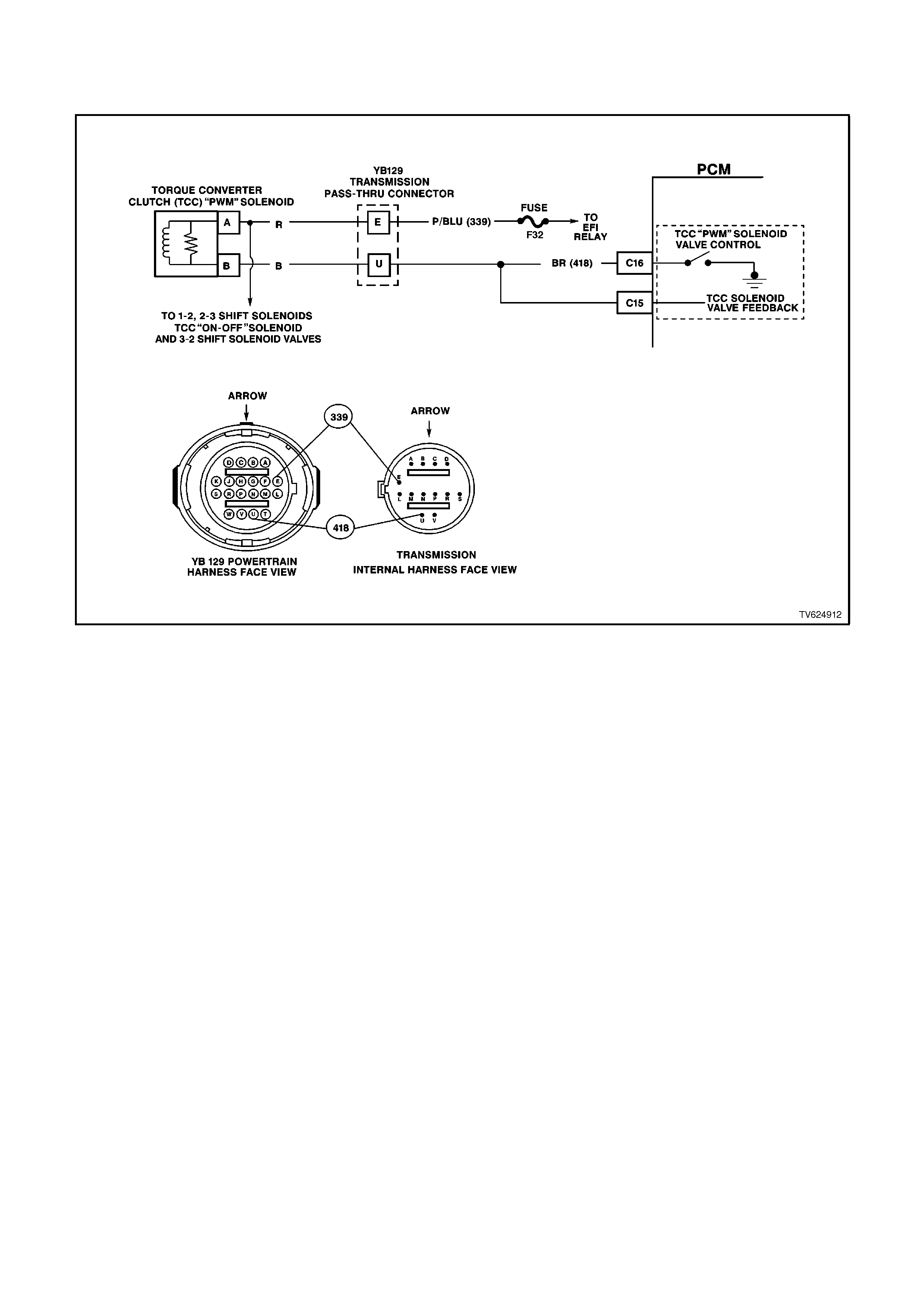
DTC 83 - TORQUE CONVERTER CLUTCH PULSE WIDTH
MO DULATION SOLENOID CIRCUI T FAULT
CIRCUIT DESCRIPTION:
The Torque Converter Clutch Pulse Width Modulation Solenoid Valve (TCC PWM Solenoid Valve) controls the fluid
acting on the converter clutch valve. The converter clutch valve controls the TCC application and release. The
solenoid attaches to the control valve body within the transmission. The solenoid receives ignition voltage through
circuit 339. The PCM controls the solenoid by providing a earth path on circuit 418. Current flows through the
solenoid coil according to the duty cycle (percentage of ON and OFF time). The TCC PWM Solenoid Valve provides
a smooth engagement of the torque converter clutch by operating during a duty cycle percent of ON time.
When the PCM detects a continuous open or short to earth in the TCC PWM Solenoid Valve circuit or the TCC
PWM Solenoid Valve, then DTC 83 sets.
DTC 83 WILL SET IF:
Either of the following fail conditions occurs for 4 seconds:
• The PCM commands the solenoid ON (90%) and the voltage remains high (B+).
• The PCM commands the solenoid OFF (0%) and the voltage remains low (0 volt).
The TCC" PWM" solenoid is used in combination with the TCC Enable solenoid to regulate fluid to the torque
converter, and is attached to the control valve body within the transmission. The use of the Torque Converter Clutch
Pulse Width Modulated, (TCC PWM) solenoid provides the ability of being able to control more precisely, the rate of
Torque Converter Clutch (TCC) apply and release.
TEST DESCRIPTION:
The numbers below refer to the step numbers on the diagnostic chart.
3. An open fuse indicates a short circuit in circuit 339. A short in any of the five solenoids fed by circuit 339 may
cause an open fuse.
4. This step tests for voltage to the solenoid.
6. This step tests the ability of the PCM and wiring to control the earth circuit.
8. This step tests the resistance of the TCC PWM Solenoid Valve and the Automatic Transmission Wiring
Harness Assembly.

DIAGNOSTIC AIDS:
• Inspect the wiring for poor electrical connections at the PCM. Inspect the wiring for poor electrical connections at
the transmission pass-through connector. Look for the following conditions:
A bent terminal
A backed out terminal
A damaged terminal
Poor terminal tension
A chafed wire
A broken wire inside the insulation
Moisture intrusion
• When diagnosing for an intermittent short or open condition, massage the wiring harness while watching the test
equipment for a change.
When DTC 83 Sets, the PCM inhibits TCC engagement and inhibits 4th gear.
STEP ACTION VALUE YES NO
1Was the On-Board
Diagnostic (OBD) System
Check performed?
— Go to Step 2 Go to OBD
System Check
21. Install the scan tool.
2. With the engine OFF,
turn the ignition switch
to the RUN position.
IMPORTANT:
Before clearing the DTCs,
use the scan tool in order
to record the DTC history
for reference. The Clear
Info function will erase the
data.
3. Record the DTC
history.
4. If DTCs 66, 67, 81, or
82 are also set, inspect
the F32 fuse for an
open.
Is the fuse open?
— Go to Step 3 Go to Step 4
31. Check circuit 339 for a
short to earth.
2. Check each of the five
solenoids for being
internally shorted or
shorted to earth.
3. Check the A/T Wiring
Harness Assembly for
a short to earth on
each of the five
solenoid circuits.
4. Make the
repair/replacement if
necessary.
Did you find and correct a
problem?
— Go to Step 15 Go to “Diagnostic
Aids” above.

STEP ACTION VALUE YES NO
41. Turn the ignition OFF.
2. Disconnect the
transmission pass-
through connector
(additional DTCs may
set).
3. Install J 39775 Jumper
Harness on the engine
harness connector.
4. With the engine OFF,
turn the ignition switch
to the RUN position.
5. Connect a lest lamp
from J 39775 Jumper
Harness cavity E to
earth.
Is the test lamp on?
— Go to Step 6 Go to Step 5
5Repair the open in the
ignition feed circuit 339 to
the TCC PWM Solenoid
Valve.
Is the repair complete?
— Go to Step 15 —
61. Install the test lamp
from cavity E to cavity
U of the J 39775
Jumper Harness.
2. Command the TCC
PWM Solenoid Valve
ON and OFF three
times.
Does the test lamp turn
ON when the TCC PWM
Solenoid Valve is
commanded ON, and
OFF when commanded
OFF?
— Go to Step 8 Go to Step 7
71. Check circuit 418 for
an open.
2. Check circuit 418 for a
short to B+.
3. Check circuit 418 for a
short to earth.
4. Repair the circuit if
necessary.
Did you find and correct
the problem?
— Go to Step 15 Go to Step 9
81. Install J 39775 Jumper
Harness on the
transmission pass-
through connector.
2. Using the J 39200
DVM and the J 35616
Connector Test
Adaptor Kit, measure
the resistance between
terminals E and U.
Is the resistance within
the specified range?
10-15 ohm Go to Step 11 Go to Step 10

STEP ACTION VALUE YES NO
9Replace the PCM.
Refer to Section 6C1-3
Service Operations, for
the Security Link
procedure.
Is the action complete?
— Go to Step 15 —
10 1. Disconnect the
Automatic
Transmission Wiring
harness Assembly at
the TCC PWM
Solenoid Valve.
2. Measure the
resistance of the TCC
PWM Solenoid Valve.
Is the resistance within
the specified range?
10-15 ohm Go to Step 13 Go to Step 14
11 Measure the resistance
between terminal E and
earth, and between
terminal U and earth.
Are both readings greater
than the specified value?
250K ohm Go to “Diagnostic
Aids” above Go to Step 12
12 1. Disconnect the
Automatic
Transmission Wiring
Harness Assembly at
the TCC PWM
Solenoid Valve.
2. Measure the
resistance between
each of the component
terminals and a known
good earth.
Are both readings greater
than the specified value?
250K ohm Go to Step 13 Go to Step 14
13 Replace the Automatic
Transmission Wiring
Harness Assembly. Refer
to Service Operations in
Section 7C-5.
Is the action complete?
— Go to Step 15 —
14 Replace the TCC PWM
Solenoid Valve. Refer to
Section 6C1-3 Service
Operations.
Is the action complete?
— Go to Step 15 —

STEP ACTION VALUE YES NO
15 In order to verify your
repair, perform the
following procedure:
1. Select DTC.
2. Select Clear Info.
3. Operate the vehicle
under the following
conditions while
observing the TCC
PWM Solenoid and
TCC Slip Speed:
• The PCM commands
the TCC PWM
Solenoid Valve ON,
and the TCC Slip
Speed is -20 to +20
rpm.
• The PCM commands
the TCC PWM
Solenoid Valve OFF,
and the TCC Slip
Speed is greater than
rpm 50.
Are both of the TCC Slip
conditions met for at least
4 seconds?
— System OK Begin the
diagnosis again
Go to Step 1
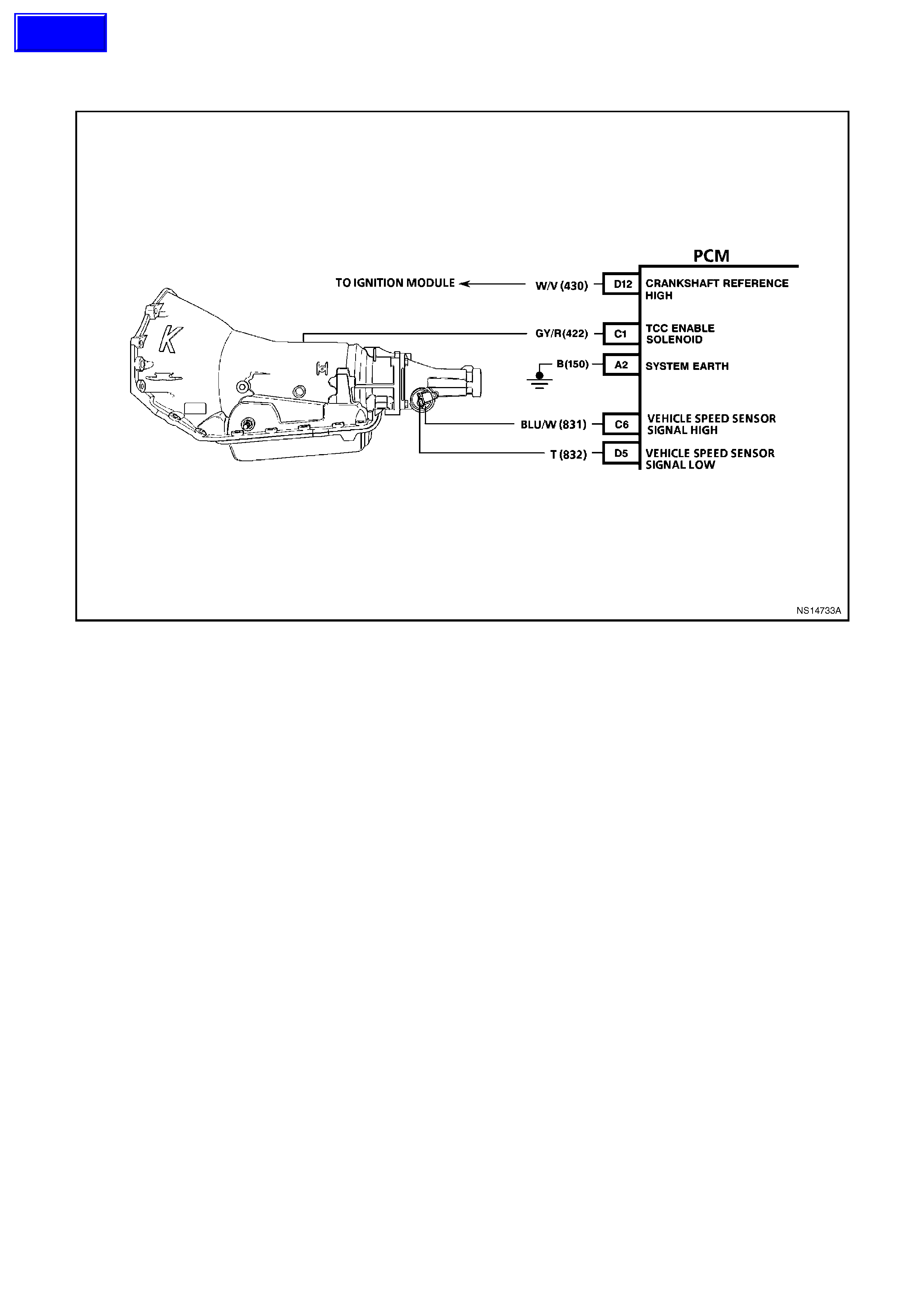
DTC 85 - TRANSMISSION SLIPPING
CIRCUIT DESCRIPTION:
The PCM monitors the difference between the engine speed and the transmission output speed. In D3 drive range
with the TCC engaged, the engine speed should closely match the transmission output speed. In D4 drive range,
with the TCC engaged, the Trans Slip Speed should be -20 to +20 RPM.
When the PCM detects an excessive transmission slip speed when the TCC should be engaged, then DTC 85 will
set.
DTC 85 WILL SET IF:
• No DTC 28.
• Throttle angle is 20-100%.
• TCC is commanded ON.
• The TFT is 60-150°C.
• The engine speed is greater than 450 RPM for 8 seconds.
• The gear range is D3 or D4.
The Trans Slip Speed is greater than 400 RPM for 30 seconds.
TEST DESCRIPTION:
The numbers below refer to the step numbers on the diagnostic chart.
3. This step tests the torque converter for slippage while in a commanded lock-up state.
DIAGNOSTIC AIDS:
• An internal transmission failure could set DTC 85.
When DTC 85 sets, the PCM will inhibit TCC engagement and 4th gear.
Techline

STEP ACTION VALUE YES NO
1Was the On-Board
Diagnostic (OBD) System
Check performed?
— Go to Step 2 Go to OBD
System Check
2Perform the transmission
fluid checking procedure.
Have you performed the
transmission fluid
checking procedure?
— Go to Step 3 Go to
Transmission
Fluid Checking
Procedure
31. Install the scan tool.
2. With the engine OFF,
turn the ignition switch
to the RUN position.
3. Drive the vehicle in 4th
gear with the TCC
engaged.
Is the TCC Slip Speed
between the specified
values for 7 seconds?
300-
1000
RPM
Go to Step 4 Go to “Diagnostic
Aids” above
4Inspect the Torque
Converter Clutch Solenoid
Valve (TCC Solenoid
Valve) for the following
conditions:
• Internal malfunction
(such as sediment or
damage)
• Damaged seals
Inspect the Torque
Converter Clutch Pulse
Width Modulation
Solenoid Valve (TCC
PWM Solenoid Valve) for
the following conditions:
• Internal malfunction
(such as sediment or
damage)
• Damaged seals
Did you find and correct
the problem?
— Go to Step 13 Go to Step 5
5Inspect the 1-2 Shift
Solenoid Valve (1-2 SS
Valve) for the following
conditions:
Internal malfunction (such
as sediment or damage)
Damaged seals
Inspect the 2-3 Shift
Solenoid Valve (2-3 SS
Valve) for the following
conditions:
Internal malfunction (such
as sediment or damage)
Damaged seals
Did you find and correct
the problem?
— Go to Step 13 Go to Step 6

STEP ACTION VALUE YES NO
6Inspect the valve body
assembly for a stuck TCC
signal valve. Refer to Unit
Repair.
Did you find and correct
the problem?
— Go to Step 13 Go to Step 7
7Inspect the torque
converter assembly for
the following conditions:
• Stator roller clutch not
holding
• Internal damage
Did you find and correct
the problem?
— Go to Step 13 Go to Step 8
8Inspect the oil pump
assembly for the following
conditions:
• Stuck converter clutch
valve
• Converter clutch valve
assembled backward
• Mispositioned
converter clutch valve
retaining ring
• Mispositioned pump to
case gasket
• Restricted orifice cup
plugs
• Damaged orifice cup
plugs
• Over-tightened, or
unevenly tightened
pump body to cover
bolts
Did you find and correct
the problem?
— Go to Step 13 Go to Step 9
9Inspect the input housing
and shaft assembly for the
following conditions:
• Cut turbine shaft o-ring
seal
• Damaged turbine shaft
o-ring seal
• Restricted turbine shaft
retainer and ball
assembly
• Damaged turbine shaft
retainer and ball
assembly
Did you find and correct
the problem?
— Go to Step 13 Go to Step 10

STEP ACTION VALUE YES NO
10 Inspect the 2-4 band
assembly for the following
conditions:
• Worn 2-4 band
• Damaged 2-4 band
• Mispositioned 2-4 band
• Misassembled 2-4
band
• The band anchor pin is
not engaged
• Restricted apply
passages in the 2-4
servo assembly
• Blocked apply
passages in the 2-4
servo assembly
• Nicks or burrs on the
servo pin
• Nicks or burrs on the
pin bore in the case
• Damaged fourth servo
piston
• Misassembled fourth
servo piston
• Damaged band apply
pin
• Incorrect band apply
pin
• Damaged servo bore
in the case
• Missing piston seals
• Cut piston seals
• Damaged piston seals
• Porosity in the pistons
• Porosity in the cover
• Porosity in the case
• Damaged piston seal
grooves
• Plugged orifice cup
plug
• Missing orifice cup
plug
Did you find and correct
the problem?
— Go to Step 13 Go to Step 11

STEP ACTION VALUE YES NO
11 Inspect the forward clutch
assembly for the following
conditions:
• Worn clutch plates
• Porosity in the forward
clutch piston
• Damaged forward
clutch piston
• Missing forward clutch
piston inner and outer
seals
• Cut forward clutch
piston inner and outer
seals
• Damaged forward
clutch piston inner and
outer seals
• Missing input housing
to forward clutch
housing o-ring seal
• Cut input housing to
forward clutch housing
o-ring seal
• Damaged input
housing to forward
clutch housing o-ring
seal
• Damaged forward
clutch housing
• Damaged forward
clutch housing retainer
and ball assembly
• Forward clutch
housing retainer and
ball assembly is not
sealing
Did you find and correct
problem?
— Go to Step 13 Go to Step 12

STEP ACTION VALUE YES NO
12 Inspect the 3-4 clutch
assembly for the following
conditions:
• Worn clutch plates
• Porosity in the 3-4
clutch piston
• Damaged 3-4 clutch
piston
• Missing 3-4 clutch
inner and outer seals
• Cut 3-4 clutch inner
and outer seals
• Damaged 3-4 clutch
inner and outer seals
• Damaged 3-4 clutch
sprin g assembly
• Damaged 3-4 clutch
apply ring
• Damaged piston seal
grooves
• Plugged orifice cup
plug
• Missing orifice cup
plug
Did you find and correct
the problem?
— Go to Step 13 Go to “Diagnostic
Aids” above
13 In order to verify your
repair, operate the vehicle
under the following
conditions:
• Drive the vehicle in D4
with the TCC ON and
a throttle position of
16-50%.
Did the vehicle obtain a
Trans Slip Speed of -20 to
+40 RPM?
— System OK Begin the
diagnosis again.
Go to Step 1
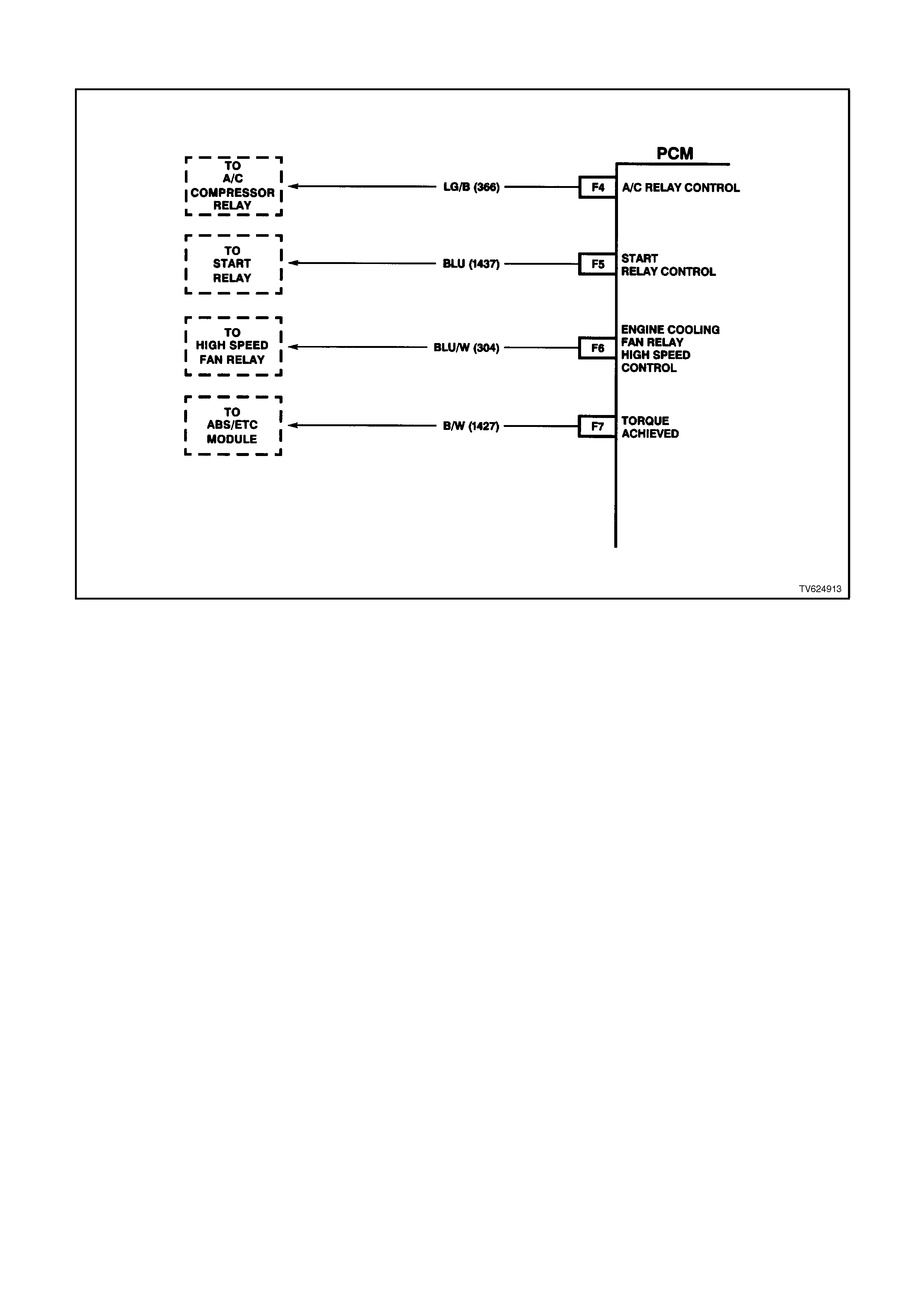
DTC 91 V6 PCM - QDSM (QUAD DRIVER SURFACE MODULE ) CIRCUIT
CIRCUIT DESCRIPTION:
Quad Driver Surface Modules (QDSM) is used by the PCM to turn "on" many of the current-driven devices that are
needed to control various engine functions. A QDSM is capable of controlling up to 4 separate outputs by applying
earth or voltage to the device which the PCM is commanding "ON."
QDSM do not have the capability of diagnosing each output circuit individually. A DTC 91 that is set indicates an
improper voltage level has been detected on one of the QDSM circuits. The QDSM controls the A/C compressor
relay, the Start Relay, High Speed fan relay, and the Torque Achieved circuit to the ABS/ETC module.
When DTC 91 is set, the low speed fan will be turned "ON" and will remain "ON" until DTC 91 has been cleared.
DTC 91 WILL SET IF:
• The ignition has been "ON", and the engine has been running longer than 5 seconds.
• An improper voltage level has been detected on a QDSM circuit.
TEST DESCRIPTION:
Number(s) below refer to step number(s) on the diagnostic chart.
2. This step checks to see if the A/C compressor relay can be controlled using a scan tool. If the scan tool can
control the A/C relay, the A/C circuit is not causing DTC 91 to set.
8. This step checks to see if the Start relay can be controlled using a scan tool. If the scan tool can control the
Start relay, the Start relay circuit is not causing DTC 91 to set.
13. This step checks to see if the High Speed relay can be controlled using a scan tool. If the scan tool can control
the High Speed relay, the High Speed Relay circuit is not causing DTC 91 to set.
DIAGNOSTIC AIDS:
A ABS/ETC DTC may also be set, if the Torque Achieved circuit is causing the fault.
Check the connector harnesses for:
• Dirty, Damaged, or Loose Connections or Damaged Harness - Check for any damage to the harness which
could cause an intermittent open or short to earth or backed out terminals at the PCM and BCM module
connectors, broken locks, improperly formed or damaged terminals.

STEP ACTION VALUE YES NO
1. Was the "On-Board
Diagnostic" (OBD) System
Check performed?
Go to Step 2 Go to OBD
System Check in
this Section
2. 1. Ignition "ON", engine
"OFF".
2. Using scan tool,
command A/C
compressor relay
"ON" and "OFF" while
listening to relay.
Did the A/C compressor
relay click "ON" and
"OFF" when commanded?
Go to Step 8 Go to Step 3
3. 1. Ignition "OFF".
2. Disconnect the PCM
connectors.
3. Ignition "ON".
4. Using DVM, probe
PCM harness
connector terminal
"F4" with negative lead
to earth.
Is the voltage at the
specified value?
B+ Go to Step 4 Go to Step 6
4. Check for poor connection
at PCM harness
connectors.
Was a problem found?
Verify Repair Replace the PCM
and Verify Repair
5. Check for an open or a
short to earth between the
PCM harness connector
terminal "F4", and the A/C
compressor relay terminal
"1".
Was a problem found?
Verify Repair Go to Step 7
6. Replace A/C Compressor
Relay.
Is action complete?
Verify Repair
7. 1. Ignition "ON", engine
"OFF".
2. Using scan tool,
command Start relay
"ON", and "OFF" while
listening to relay.
Did the Start relay click
"ON", and "OFF"?
Go to Step 13 Go to Step 9
8. 1. Ignition "OFF".
2. Disconnect PCM
connectors.
3. Ignition "ON".
4. Using DVM, probe
PCM harness
connector terminal
"F5" with negative lead
to earth.
Is the voltage at the
specified value?
B+ Go to Step 10 Go to Step 11

STEP ACTION VALUE YES NO
9. Check for poor connection
at PCM harness
connectors.
Was a problem found?
Verify Repair Go to Step 5
10. Check for an open or
short to earth between the
PCM harness connector
terminal "F5", and the
Start relay terminal "86".
Was a problem found?
Verify Repair Go to Step 12
11. Replace Start Relay.
Is action complete? Verify Repair
12. 1. Ignition "ON", engine
"OFF".
2. Using scan tool,
command High Speed
fan relay "ON", and
"OFF" while listening to
relay.
Did the High Speed relay
click "ON" and "OFF"
when commanded?
Go to Step 17 Go to Step 14
13. 1. Ignition "OFF".
2. Disconnect PCM
harness connectors.
3. Ignition "ON".
4. Using DVM, probe
PCM harness
connector terminal
"F6", with negative
lead to earth.
Is the voltage at the
specified value?
B+ Go to Step 15 Go to Step 16
14. Check for poor connection
at PCM harness
connectors.
Was a problem found?
Verify Repair Go to Step 5
15. Check for an open or a
short to earth between the
PCM harness connector
terminal "F6", and the
High Speed fan relay
terminal "86".
Was a problem found?
Verify Repair Refer to
Chart A-12.2 for
testing of the High
Speed Fan Relay
16. Check for open or short to
earth in Torque Achieved
circuit between the PCM
and BCM. If OK, check for
poor connection at PCM,
and BCM.
Was a problem found?
Verify Repair Go to Step 5
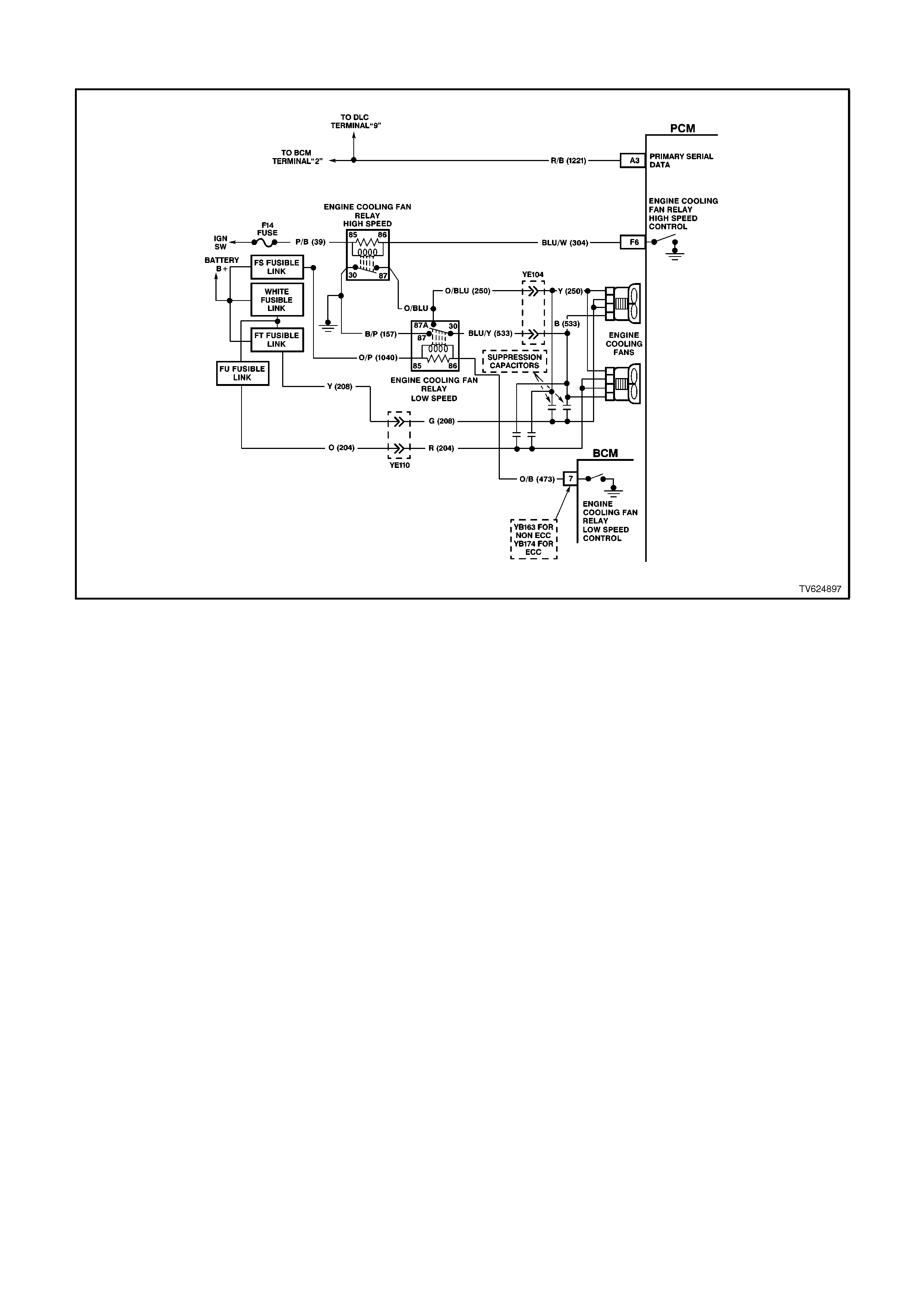
DTC 92 V6 PCM - LOW SPEED FAN - NO BCM RESPONSE
CIRCUIT DESCRIPTION:
The PCM determines operation of the two speed engine cooling fan based on A/C request signal input, engine
coolant temperature and vehicle speed.
The engine cooling fan low speed relay (labelled LO FAN in relay housing) is energised by the BCM. When the
PCM determines that the engine cooling fan low speed relay should be turned "ON", the PCM will send a message
on circuit 1221 to the BCM. This message will ask the BCM to earth circuit 473 and energise the engine cooling fan
low speed relay. After the BCM provides the earth for circuit 473, the BCM will send a message back to the PCM
saying that the earth circuit was commanded.
DTC 92 WILL SET IF:
• Engine is idling.
• PCM supplies a signal to the BCM.
• No response back from BCM to PCM.
TEST DESCRIPTION:
Number(s) below refer to step number(s) on the diagnostic chart.
3. An open or short to earth on circuit 1221 will disable any communication of serial data between the PCM and
BCM.
DIAGNOSTIC AIDS:
• Dirty, Damaged, or Loose Connections or Damaged harness - Check for any damage to the harness which
could cause an intermittent open or short to earth or backed out terminals at the BCM module connectors,
broken locks, improperly formed or damaged terminals.
• The engine will not start if circuit 1221 is open or earthed, therefore if DTC 92 is set and the engine will start,
DTC 92 is intermittent. Review DTC history data to determine when DTC 92 set.

STEP ACTION VALUE YES NO
1. Was the "On-Board
Diagnostic" (OBD) System
Check performed?
Go to Step 2 Go to OBD
System Check in
this Section
2. Is DTC 31 set? Go to DTC 31
Diagnostic Chart
in this Section
Go to Step 3
3. 1. Engine at idle speed.
2. Using Tech 2 scan
tool, select "LOW
FAN"
Does Tech 2 scan tool
"BCM Response" display
change from "FAN OFF"
to "FAN ON" when test is
enabled?
Go to Step 4 Go to
Chart A-12.1 in
this Section
4. Does Tech 2 scan tool
"BCM Response" display
change from "FAN OFF"
to "FAN ON" when test is
enabled?
DTC 92 is
intermittent.
Refer to
"Diagnostic Aids"
above.
Refer
Section 12J-1
LOW SERIES
BCM or
Section 12J-2
HIGH SERIES
BCM for
additional
diagnosis.
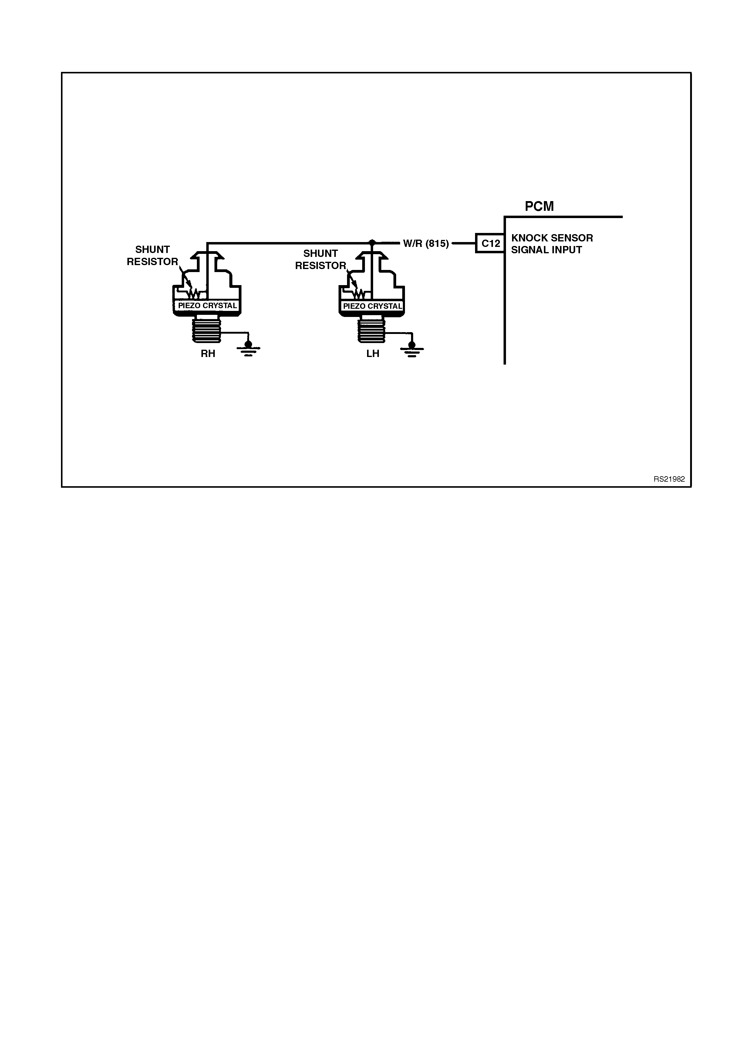
DTC 93 V6 PCM - SNEF CIRCUIT FAULT
CIRCUIT DESCRIPTION:
The Knock sensor is used to detect engine detonation, and the PCM will retard the Electronic Spark Timing (EST)
based on the signal being received The Knock sensor produces an AC signal which varies in signal amplitude and
frequency depending upon the amount of Knock being experienced.
The PCM monitors the output of the SNEF (Signal To Noise Enhancement Filter) circuit. The PCM determines
weather Knock is occurring by comparing the Knock sensor signal level with the voltage level on the SNEF circuit.
The SNEF circuit allows the PCM to reject only false Knock signals by indicating the amount of normal engine
mechanical noise present. Normal engine noise varies depending on engine speed and load. A normal Knock
condition could result in a Knock sensor signal from a few milliseconds to possibly as high as 100 milliseconds in
length.
When the SNEF circuit output is significantly longer than the longest expected "Normal" output it is assumed the
SNEF circuitry has failed and DTC 93 will set.
DTC 93 WILL SET IF:
• Engine has been running longer then 10 seconds
• SNEF circuit indicates Knocking condition for greater than 10 seconds.
TEST DESCRIPTION:
Number(s) below refer to step number(s) on the diagnostic chart.
2. This step checks to see if the Tech 2 scan tool is displaying Knock signal at all times.
3. This step checks to see if a audible Knock is being caused by the engine or transmission.

STEP ACTION VALUE YES NO
1. Was the "On-Board
Diagnostic" (OBD) System
Check performed?
Go to Step 2 Go to OBD
System Check in
this Section
2. 1. Install Tech 2 "Scan "
tool.
2. Ignition "ON", engine
Idling.
3. Using Tech 2 scan
tool, select "Knock
Signal" and "Knock
Retard".
Is "Knock Signal"
indication "Knock"?
Go to Step 3 Go to Step 4
3. With engine running, is a
audible "Knock" condition
heard?
Refer to Engine
Mechanical or
Transmission
Section 5 to repair
audible Knock
Go to Step 4
4. Replace PCM.
Refer to Section 6C1-3
Service Operations, for
PCM Security Link
procedure.
Is action complete?
Verify Repair
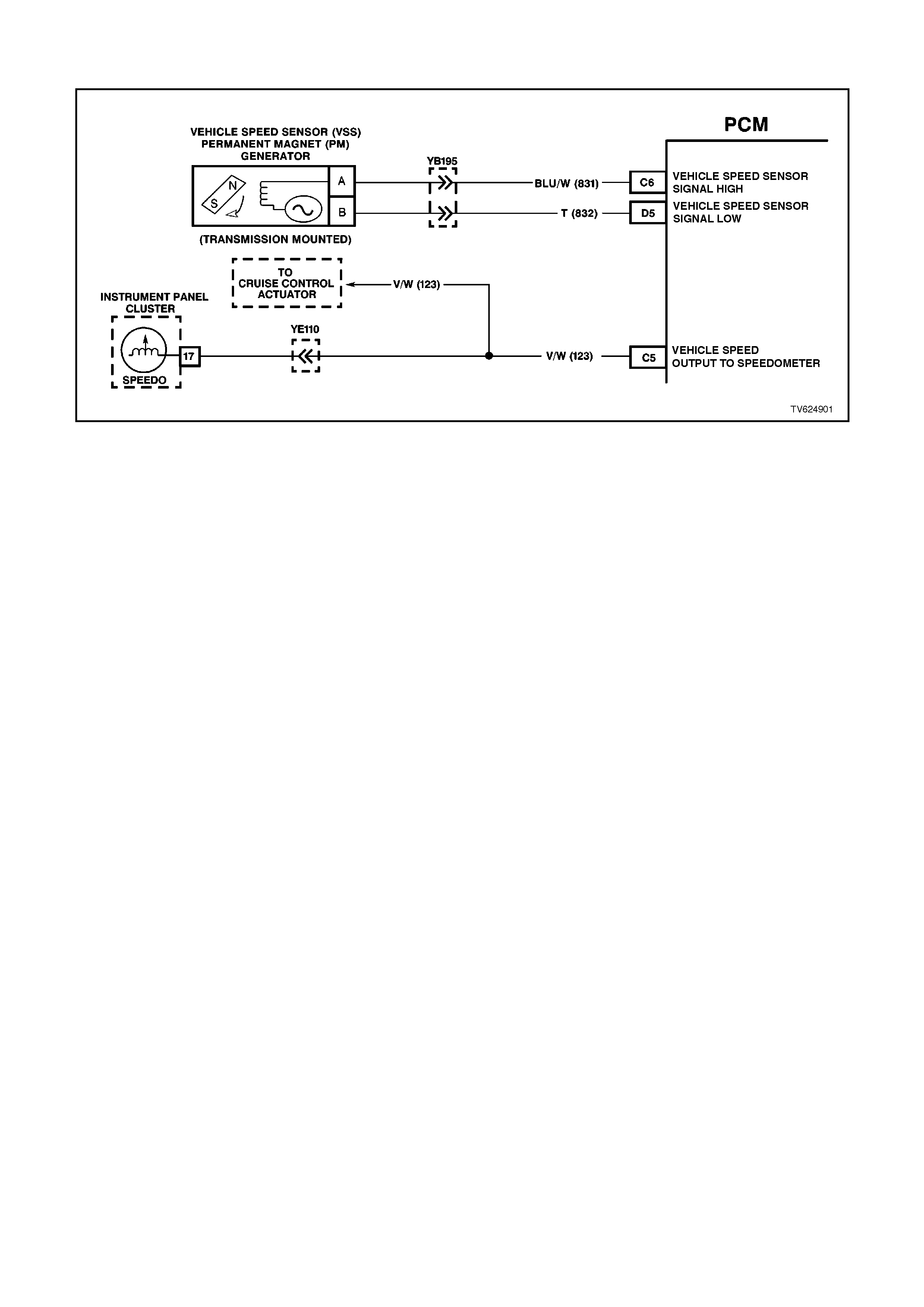
DTC 94 V6 PCM - NO VEHICLE SPEED SIGNAL (M ANUAL TRANSMISSION)
CIRCUIT DESCRIPTION:
The Vehicle Speed Sensor Assembly (VSS Assembly) provides vehicle speed information to the PCM. The VSS
Assembly is a Permanent Magnet (PM) generator. The PM generator produces a pulsing AC voltage. The AC
voltage level and the number of pulses increase with the speed of the vehicle. The PCM then converts the pulsing
voltage to vehicle speed. The PCM uses this information for calculations. A scan tool can display the vehicle speed.
When the PCM detects a low or no vehicle speed, when there is high engine speed and low Throttle Position (TP)
%, then DTC 94 sets.
DTC 94 SETS IF:
• No DTC 19, 21, 22, or 32 is active, and all following conditions are met for at least 4 seconds:
• Circuit 123 voltage is constant - that is, NOT pulsing, and
• Engine RPM between 1400 and 3000 RPM, and
• Throttle is closed < 1% (TP sensor), and
• Engine load very low (MAF sensor) 95 mg/cyl.*
For these conditions to happen during the 4 second period of time, the vehicle must be in-gear, closed-throttle, and
deceleration from road speed must occur.
TEST DESCRIPTION:
The numbers below refer to the step numbers on the diagnostic chart.
3. This step tests the integrity of the VSS Assembly
4. This step tests the VSS Assembly circuit.
DIAGNOSTIC AIDS:
• Inspect the wiring for poor electrical connections at the PCM. Look for the following conditions:
A bent terminal
A backed out terminal
A damaged terminal
Poor terminal tension
A chafed wire
A broken wire inside the insulation
Moisture intrusion
Corrosion
• When diagnosing for an intermittent short or open condition, massage the wiring harness while watching the test
equipment for a change.
• Check circuits 831 and 832 for the proper connections to be sure they are clean and tight and the harness is
routed correctly.
• The scan tool should indicate a vehicle speed whenever the drive wheels are turning greater than 3 km/h.
• The vehicle speed sensor resistance should be between 1470-2140 W at 20°C, and 2270-2820 W at 100° C.
• Refer to "Intermittents" in Section 6C-2B SYMPTOMS .

STEP ACTION VALUE YES NO
1Was the On-Board
Diagnostic (OBD) System
Check performed?
_ Go to Step 2 Go to OBD
System Check.
21. Install the scan tool.
2. With the engine OFF,
turn the ignition switch
to the RUN position.
IMPORTANT:
Before clearing the DTCs,
use the scan tool in order
to record the DTC history
for reference. The Clear
Info function will erase the
data.
3. Record the DTC
history.
4. Clear the DTC.
5. Raise the drive wheels.
NOTE:
Do not perform this test
without supporting the
rear axle assembly or the
lower control arms on
vehicles with independent
rear suspension so that
the drive shafts are in a
normal horizontal position.
6. Start the engine.
7. Place the transmission
in any drive gear.
With the rear wheels
rotating, does the scan
tool Vehicle Speed
increase with the drive
wheel speed?
_Go to
“Diagnostic Aids”
above
Go to Step 3
31. Turn the ignition switch
to the OFF position.
2. Disconnect the VSS
connector from the
VSS assembly.
3. Using the J 35616
Connector Test
Adaptor Kit, connect
the J 39200 DVM to
the VSS terminals.
4. Select AC volts.
5. Place the transmission
in the neutral position.
6. Rotate the drive
wheels by hand,
ensuring that the
driveshaft is turning.
With rear wheels rotating,
is the DVM voltage
greater than the specified
value?
0.5 volts
AC Go to Step 4 Go to Step 11

STEP ACTION VALUE YES NO
41. Turn the ignition switch
to the OFF position.
2. Reconnect the VSS
connector to the VSS
Assembly
3. Disconnect the PCM
connector 1 (Pink-32
pin) from the PCM.
4. Connect the DVM test
leads to the connector
terminals D5 (T) and
C6 (Blu/W).
5. Place the transmission
in the neutral position.
6. Rotate the drive
wheels by hand,
ensuring that the
driveshaft is turning.
With rear wheels rotating,
is the DVM voltage
greater than the specified
value?
0.5 volts
AC Go to Step 13 Go to Step 5
51. Select W (Ohms), on
the DVM.
2. Measure the
resistance between the
connector terminals D5
(T) and C6 (Blu/W).
Is the circuit resistance
within the specified
range?
1470-
2820 ohm Go to Step 6 Go to Step 8
6Connect the DVM
between the connector
terminal C-6 and earth.
Is the circuit resistance
less than the specified
value?
250k ΩGo to Step 7 Go to “Diagnostic
Aids” above
71. Check circuit 831 and
circuit 832 for a short
to earth.
2. Repair the circuit if
necessary.
Was the short to earth
condition found and
corrected?
_ Go to Step 14 Go to “Diagnostic
Aids” above
8Is the resistance reading
in step 6 greater than the
specified value?
2820 ΩGo to Step 10 Go to Step 9
91. Check circuit 831 and
circuit 832 for a
shorted together
condition.
2. Repair the circuit if
necessary.
Was a shorted together
condition found and
corrected ?
_ Go to Step 14 Go to “Diagnostic
Aids” above

STEP ACTION VALUE YES NO
10 1. Check circuit 831 and
circuit 832 for an open
condition.
2. Repair the circuit if
necessary.
Was an open condition
found and corrected ?
_ Go to Step 14 Go to “Diagnostic
Aids” above
11 1. Remove the VSS
Assembly.
2. Inspect the VSS
Output Sensor Rotor
for damage or
misalignment.
Did you find a condition?
_ Refer to
appropriate
Section for repair
information
Go to Step 12
12 Replace the VSS Assy.
Refer to Service
Operations.
Is the action complete?
_ Go to Step 14 _
13 Replace the PCM. Refer
to Section 3 for the
Security Link procedure.
Is the action complete?
_ Go to Step 14 _
14 In order to verify your
repair, perform the
following procedure:
1. Select DTC.
2. Select Clear Info.
3. Operate the vehicle
ensuring that the
vehicle speed is
greater than 3 km/h
and observe the scan
tool Vehicle Speed.
Is the scan tool Vehicle
Speed greater than the
specified value?
10 km/h System OK Begin the
Diagnosis Again
Go to Step 1
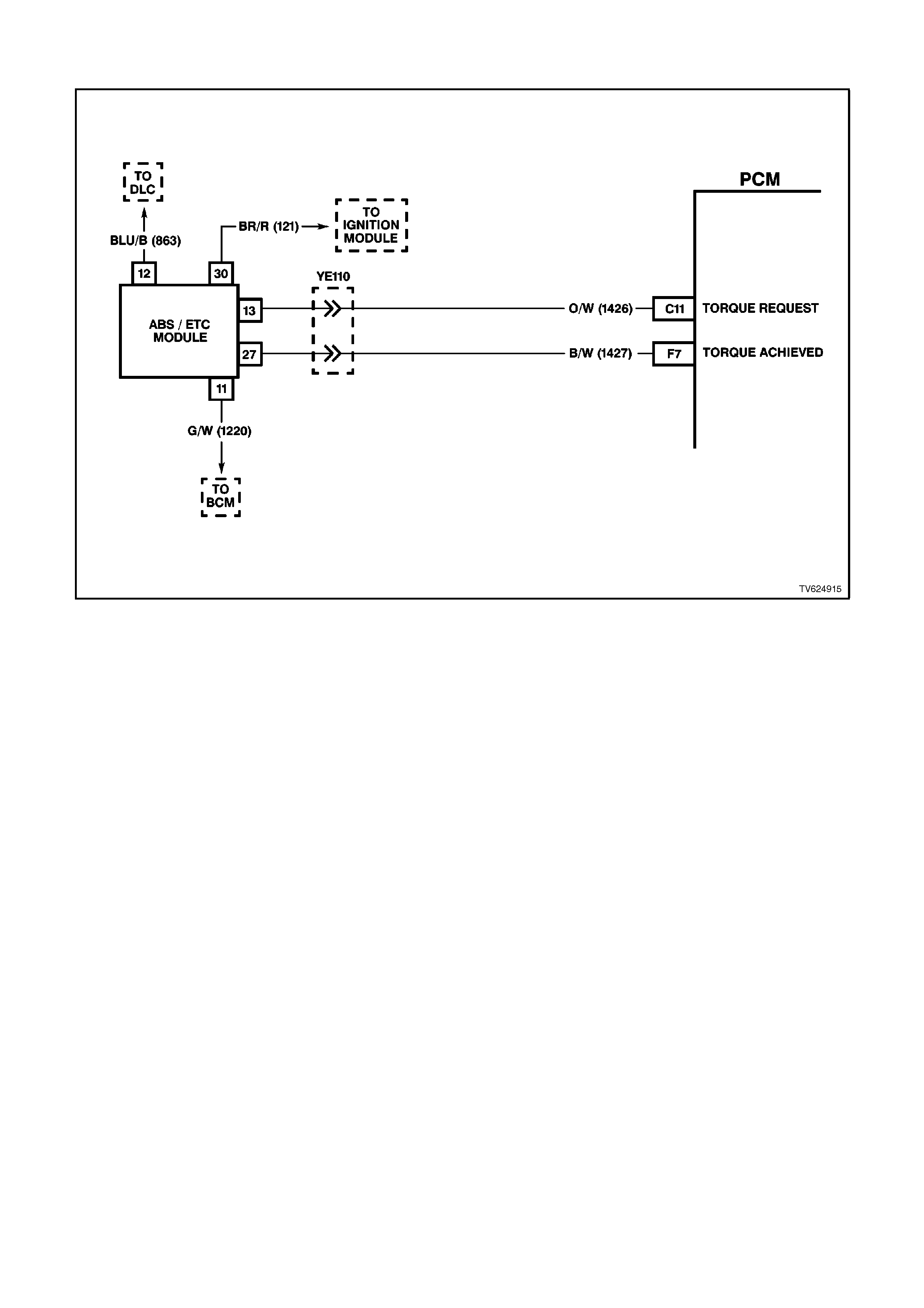
DTC 95 V6 PCM - REQUESTED TORQUE OUT OF RANGE
CIRCUIT DESCRIPTION:
The Anti-Lock Brake System/Electronic Traction Control (ABS/ETC) Module (Traction Control) controls the PWM
signal on the torque request circuit while monitoring the wheel speed sensors to detect slippage. The PCM monitors
the PWM signal and reduces engine torque as needed by retarding ignition timing, decreasing boost duty cycle,
increasing air/fuel ratio, or in severe cases, shutting OFF up to five (5) injectors. The PCM sends a PWM signal to
the ABS/ETC module on the torque achieved circuit informing the ABS/ETC module of response made to the torque
request signal. A problem with the torque Request circuit should cause DTC 95 and a ABS/ETC DTC to set and
traction control to be disabled. Refer to Section 12L ABS & ABS/ETC for information on ABS/ETC operation and
DTC diagnosis.
DTC 95 WILL SET IF:
• Ignition is ON.
• An improper voltage level has been detected on the Torque Requested circuit.
• Above conditions for at least 1 second.
TEST DESCRIPTION:
Number(s) below refer to the step(s) on the diagnostic chart.
2. The PCM supplies 4 to 5 volts on the Torque Request circuit. With the PCM disconnected, there should be no
voltage on the circuit.
6. This step checks to see if the Torque Request circuit is shorted to voltage.
11. This step checks to see if the ABS/ECT system is functioning properly.
DIAGNOSTIC AIDS:
Check for the following conditions:
• Poor connection at PCM. Inspect harness connectors for backed out terminals, improper mating, broken locks,
improper formed or damaged terminals, and poor terminal to wire connection.
• Damaged harness. Inspect the wiring harness for damage. If the harness appears to be OK, disconnect the
PCM, turn the ignition ON and observe a voltmeter connected to the Torque Request circuit at the PCM harness
connector while moving connectors and wiring harnesses related to the ABS/ETC module. If a voltage is
indicated the fault is in the harness.

STEP ACTION VALUE YES NO
1. Was the "On-Board
Diagnostic" (OBD) System
Check performed?
O/C Go to Step 2 Go to OBD
System Check in
this Section
2. 1. Ignition "OFF".
2. Disconnect the PCM
connectors.
3. Ignition "ON".
4. Using volt/ohmmeter,
measure voltage
between the torque
Request circuit at the
PCM harness
connector and earth.
Is voltage at the specified
value?
O/C Go to Step 3 Go to Step 6
3. 1. Ignition "OFF".
2. Reconnect the PCM
connectors.
3. Disconnect the
ABS/ECT connector.
4. Ignition "ON".
5. Using volt/ohmmeter,
measure voltage
between the torque
Request circuit at the
ABS/ECT harness
connector and earth.
Is voltage at the specified
value?
Go to Step 4 Go to Step 8
4. Check for poor connection
at ABS/ECT module.
Was a problem found?
Verify Repair Go to Step 5
5. Replace ABS/ECT
module.
Is action complete?
Verify Repair
6. 1. Ignition "OFF".
2. Disconnect the
ABS/ECT module
connector.
3. Ignition "ON".
4. Using volt/ohmmeter,
measure voltage
between the torque
Request circuit at the
PCM harness
connector and earth.
Is voltage at the specified
value?
O/C Go to Step 5 Go to Step 7
7. Locate and repair short to
voltage in Torque Request
circuit.
Is action complete?

STEP ACTION VALUE YES NO
8. Check for an open or
short to earth in the
Torque Request circuit
between the PCM and the
ABS/ECT module.
Was a problem found?
Verify Repair Go to Step 9
9. Check for poor connection
at PCM harness
connectors.
Was a problem found?
Verify Repair Go to Step 10
10. Replace PCM.
Refer to Section 6C1-3
Service Operations, for
PCM Security Link
procedure.
Is action complete?
Go to Step 12
11. 1. Ignition "OFF".
2. Reconnect the
ABS/ECT connector,
and the PCM
connectors.
3. Raise the rear of the
vehicle, and support
the rear wheel trailing
arms.
4. Backprobe PCM
harness connector for
the Torque Request
circuit with a
volt/ohmmeter
connected to earth.
5. gnition "ON", and the
engine running in park.
Is the voltage near the
specified value?
O/C Go to Step 12 Go to Step 2
12. With the engine still
running in park, and the
volt/ohmmeter still
connected to the Torque
Request circuit, shift the
transmission into D range
and let the rear wheels
turn. Snap the throttle and
note the voltage on the
volt/ohmmeter.
Does the volt/ohmmeter
switch from the First
specified value to the
Second specified value
(and stay at the second
value) when traction
control is activated?
First
4-5 V
Second
1-2 V
ABS/ECT
System is working
properly
Go to Step 2

DTC 96 V6 PCM - A/C PRESSURE SENSOR FAULT
CIRCUIT DESCRIPTION:
The A/C refrigerant pressure sensor responds to changes in the A/C refrigerant high side pressure. This input to the
PCM indicates how much load the A/C compressor is putting on the engine and is one of the factors used by the
PCM to determine the Idle Air Control (IAC) valve position for idle speed. The circuits consist of a 5 volt reference
and a earth circuit, both provided by the PCM, and a signal circuit from the sensor to the PCM. The signal is a
voltage which is proportional to A/C pressure. The sensors operating range is between 0 and 3160 kPa ( 0-468 psi).
At 0 kpa, the signal voltage will be about 0.1 volts, vary ing to about 4.9 volts at 3160 kPa.
DTC 96 WILL SET IF:
• Engine coolant temperature (ECT) is below 120°C.
• Intake Air Temperature (IAT) is below 90°C.
• Engine RPM is at below 2000.
• Engine has been running for less than 10 minutes.
• A/C refrigerant pressure sensor signal voltage is less than 0.2 volt.
- OR -
• A/C refrigerant pressure sensor signal voltage is greater than 4.9 volts.
• Either of the above conditions for longer than 10 seconds.
• When DTC 96 is set, the low speed cooling fan will operate for 5 seconds, then the high speed fan will turn "ON,
and remain "ON" until the fault is removed.

TEST DESCRIPTION:
Number(s) below refer to the step(s) on the diagnostic chart.
3. This step checks to see if the low voltage signal was due to an open in the signal circuit, the 5 volt reference
circuit or if the PCM is faulty .
4. An open in a shared earth circuit can cause other DTC's to be set. If no other DTC's were set, the circuit must
be open between the sensor and the circuit splice.
8. Determines if the low voltage signal was from the sensor or the signal circuit. Jumpering the signal circuit to the
5 volt reference checks the circuits, connections and the PCM.
9. An open in a shared 5 volt reference circuit can cause other DTC's to be set. If no other DTC's were set, the
circuit must have an open between the sensor and the circuits wiring harness splice.
DIAGNOSTIC AIDS:
• DTC 96 will only set wi th a short to voltage or a open circuit. A short to earth will not set the DTC, but the A/C
system will be inoperative.
• DTC 96 sets when the signal voltage falls outside the normal possible range of the sensor. Repair any A/C
pressure problems before using this table.
• Any circuitry, that is suspected as causing the intermittent complaint, should be thoroughly check for backed out
terminals, improper mating, broken locks, improperly formed or damaged terminals, poor terminal to wiring
connections or physical damage to the wiring harness.
STEP ACTION VALUE YES NO
1. Was the "On-Board
Diagnostic" (OBD) System
Check performed?
Go to Step 2 Go to OBD
System Check in
this Section
2. 1. Ignition ON, engine
OFF.
2. Install scan tool, and
display A/C pressure
sensor voltage.
Is the A/C pressure
sensor voltage at or
above the specified
value?
4.0V Go to Step 3 Go to Step 7
3. Disconnect the A/C
pressure sensor electrical
connector.
Does scan tool display
A/C pressure sensor
voltage at or below the
specified value?
0.2 V Go to Step 4 Go to Step 11
4. 1. Ignition "OFF".
2. Using test light
connected to B+,
probe A/C pressure
sensor earth circuit at
harness electrical
connector.
Does test light illuminate?
Go to Step 5 Go to Step 12
5. Check for a poor
connection at A/C
pressure sensor.
Was a problem found?
Verify Repair Go to Step 6
6. Replace A/C pressure
sensor.
Is action complete?
Verify Repair
7. Is the A/C pressure
sensor voltage at or below
the specified value?
0.2 V Go to Step 8 Go to Step 15

STEP ACTION VALUE YES NO
8. 1. Disconnect A/C
pressure sensor
electrical connector.
2. Using fused jumper
wire, jumper the A/C
pressure sensor 5 volt
reference circuit and
signal circuits together
at harness connector.
Does scan tool indicate
A/C pressure sensor
voltage at or above the
specified value?
4.0 V Go to Step 6 Go to Step 9
9. 1. Remove the jumper
wire.
2. Connect a DVM
between the A/C
pressure sensor 5 volt
reference circuit and
earth circuit at the
harness connector.
Does the DVM read at or
between the specified
value?
4.0 -
5.0 V Go to Step 10 Go to Step 13
10. Repair open or short to
earth in A/C pressure
sensor signal circuit.
Is action complete?
Verify Repair
11. Check A/C pressure
sensor signal circuit for
short to voltage.
Was a problem found?
Verify Repair Go to Step 14
12. Repair open in earth
circuit to A/C pressure
sensor.
Is action complete?
Verify Repair
13. Repair open in 5 volt
reference circuit.
Is action complete?
Verify Repair
14. Replace PCM.
Refer to Section 6C1-3
Service Operations, for
PCM Security Link
procedure.
Is action complete?
Verify Repair
15. 1. Using a scan tool,
clear DTC.
2. Start engine and idle at
normal operating
temperature.
3. Operate vehicle A/C
system and note A/C
pressure sensor
voltage on scan tool.
Is voltage displayed at or
between the specified
value?
0.2 -
4.6 V System OK,
refer to
“Diagnostic Aids”
Go to Step 2
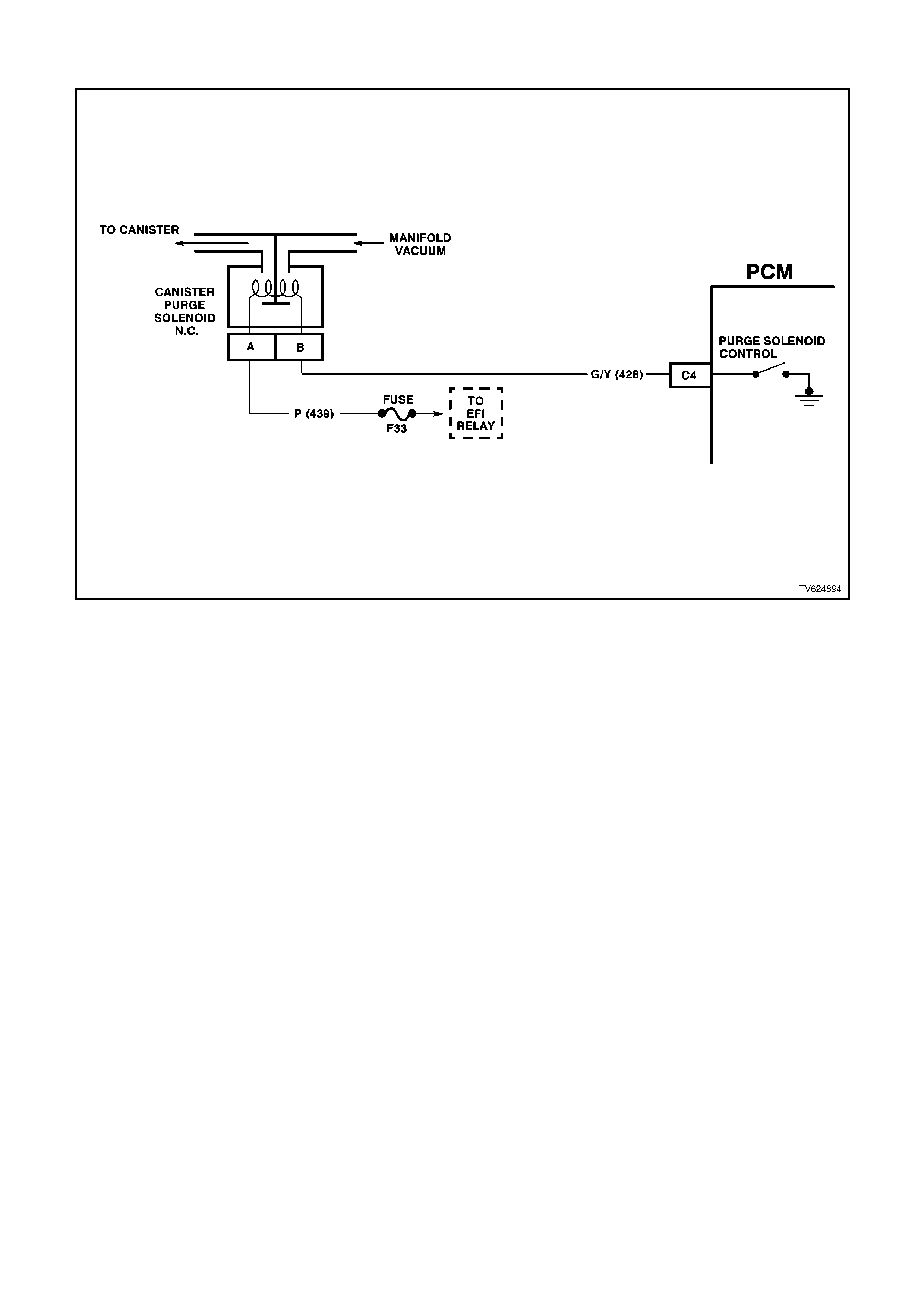
DTC 97 V6 PCM - CANISTER PURGE CIRCUIT FAULT
CIRCUIT DESCRIPTION:
Quad Driver Modules (QDMs) are used by the PCM to turn "ON" many of the current-driven devices that are
needed to control various engine and transmission functions. Each QDM is capable of controlling up to 4 separate
outputs by applying earth to the device which the PCM is commanding "ON".
The Quad Driver Modules (QDMs) used has the capability of diagnosing each output circuit individually. DTC 97 set
indicates an improper voltage level has been detected on the QDM fault line, which controls the Canister Purge
Solenoid.
DTC 97 WILL SET IF:
• Ignition "ON".
• The QDM fault line has detected an improper voltage level on the Canister Purge Solenoid driver
TEST DESCRIPTION:
Number(s) below refer to step number(s) on the diagnostic chart:
2. Normally, ignition feed voltage present on the output driver circuit with the PCM disconnected and the ignition
"ON".
3. Checks for a shorted component or a short to B+ or the Quad driver circuit. Either condition would result in a
measured current of over 1.5 amps. Also checks for a component that is going open while being operated,
resulting in a measured current of 0 amps.
4. Checks for a faulty Canister Purge Solenoid.
DIAGNOSTIC AIDS:
Check for the following conditions:
• Poor connection at PCM. Inspect harness connections for backed out terminals, improper mating , broken locks,
improper formed or damaged terminals, and poor terminal to wire connection.
• Damaged harness. Inspect the wiring harness for damage. If the harness appears to be OK, disconnect the
PCM, turn the ignition "ON" and observe a voltmeter connected to the Canister Purge Solenoid driver circuit at
the PCM harness connector while moving connectors and wiring harness related to the Canister Purge Solenoid.
A change in voltage will indicate the location of the fault.
If DTC 97 cannot be duplicated, the information included in the DTC History can be useful in determining how many
ignition cycles have passed since the DTC was last set.

STEP ACTION VALUE YES NO
1. Was the "On-Board
Diagnostic" (OBD) System
Check performed?
Go to Step 2 Go to OBD System
Check
2. 1. Ignition "OFF".,
disconnect the PCM.
2. Ignition "ON".
3. Using voltmeter,
measure voltage
between the Canister
Purge Solenoid driver
circuit at the PCM
harness connector and
earth.
Is voltage near the
specified value?
B+ Go to Step 3 Go to Step 6
3. 1. Digital volt/ohmmeter
set to 10 amp scale,
install digital volt/
ohmmeter to measure
current between the
Canister Purge Solenoid
driver and earth.
2. Monitor the current
reading on the digital
volt/ohmmeter for at
least 2 minutes.
Does the current reading
remain between the
specified values?
0.1 amp
to
1.5 amps
Go to Step 11 Go to Step 4
4. 1. Disconnect the Canister
Purge Solenoid (leave
the PCM disconnected).
2. Using digital
volt/ohmmeter, measure
voltage between the
Canister Purge Solenoid
driver circuit and earth.
Is voltage at specified
value?
0 volts Go to Step 14 Go to Step 5
5. Locate and repair short to
voltage in the Canister
Purge Solenoid driver
circuit.
Is action complete?
Verify Repair
6. Check the ignition feed
fuse for the Canister Purge
Solenoid.
Is the fuse blown?
Go to Step 7 Go to Step 8
7. 1. Locate and repair short
to earth in ignition feed
circuit for the Canister
Purge Solenoid.
2. Replace fuse.
Is action complete?
Verify Repair

STEP ACTION VALUE YES NO
8. 1. Disconnect the Canister
Purge Solenoid.
2. Ignition "ON".
3. Measure voltage
between the ignition
feed circuit for the
Canister Purge Solenoid
and earth.
Is voltage near the
specified value?
B+ Go to Step 9 Go to Step 13
9. Check the Canister Purge
Solenoid driver circuit for
an open or a short to earth.
Was a problem found?
Verify Repair Go to Step 10
10. Check the Canister Purge
Solenoid driver circuit and
the ignition feed circuit for a
poor connection at the
Canister Purge Solenoid
and the PCM.
Was a problem found?
Verify Repair Replace Canister
Purge Solenoid
and Verify Repair.
11. 1. Ignition "OFF",
reconnect the PCM and
disconnect the Canister
Purge Solenoid.
2. Ignition "ON, connect a
test light between the
Canister Purge Solenoid
driver circuit and the
ignition feed circuit at
the Canister Purge
Solenoid connector.
3. Using the Tech 2 scan
tool, select, PURGE.
4. Cycle the Canister
Purge Solenoid "ON"
and "OFF".
Does the test light flash
"ON" and "OFF"?
Refer to
"Diagnostic Aids"
above.
Go to Step 12
12. Check the Canister Purge
Solenoid driver for a poor
connection at the PCM.
Was a problem found?
Verify Repair Go to Step 15
13. Locate and repair open
ignition feed circuit to the
Canister Purge Solenoid.
Is action complete?
Verify Repair
15. Replace PCM.
Refer to Section 6C1-3
Service Operations, for
PCM Security Link
procedure.
Is action complete?
Verify Repair