
SECTION 6C2-1 GENERAL INFORMATION - V8
ENGINE
CAUTION
This vehicle will be equipped with a Supplemental Restraint System (SRS). A SRS
will consist of either seat belt pre-ten sioners and a driv er’s side air bag, or seat belt
pre-tensioners and a driver’s and front passenger’s side air bags. Refer to
CAUTIONS, Section 12M, before performing any service operation on or around SRS
components, the steering mechanism or wiring. Failure to follow the CAUTIONS
could result in SRS deployment, resulting in possible personal injury or
unnecessary SRS system repairs.
1. GENERAL DESCRIPTI ON
The engine used in this vehicle uses an Powertrain Control Module (PCM) to control exhaust emissions while
maintaining excellent driveability and fuel economy. The PCM maintains a desired air/fuel ratio at precisely 14.7 to
1. To maintain a 14.7 to 1 air fuel ratio the PCM monitors the output signal from the oxygen sensor. The PCM will
either add or subtract fuel pulses based on the oxygen sensor output signal. This method of "feed back" fuel control
is called CLOSED LOOP.
In addition to fuel control, the PCM also controls the following systems:
• The ignition dwell
• The ignition timing
• The idle speed
• The engine electric cooling fan
• The electric fuel pump
• The instrument panel "Check Powertrain" lamp
• The A/C compressor clutch
• The automatic transmission functions
The PCM also interfaces with other vehicle control modules, such as the trip computer, the body control module and
the theft deterrent system. Figure 6C2-1-1 contains a list of the various operating conditions sensed by the PCM on
the left, and the various systems controlled on the right. Details of basic operation, diagnosis, and service are
covered in this CD-ROM.
The PCM has a built-in diagnostic system that identifies operational problems and alerts the driver by illuminating
the "Check Powertrain" lamp on the instrument panel. If the lamp comes "ON" while driving, it does not mean that
the engine should be stopped immediately, but the cause of the lamp coming "ON" should be checked as soon as is
reasonably possible. The PCM has built in backup systems that in all but the most severe faults will allow the
vehicle to operate in a near normal manner until repairs can be made.
Below the instrument panel to the left of the steering column is a Data Link Connector (DLC) which is used by the
assembly plant for a computer "check-out" of the PCM system. The DLC is also used in service to help diagnose
the system. Refer to Section 6C2-2, DIAGNOSIS for further details.
The locations of the main components of the system are shown in Figs. 6C2-1-3 through 6C2-1-6. For the
Transmission Management System Components and their locations, refer to Fig. 6C2-1-43.
Techline
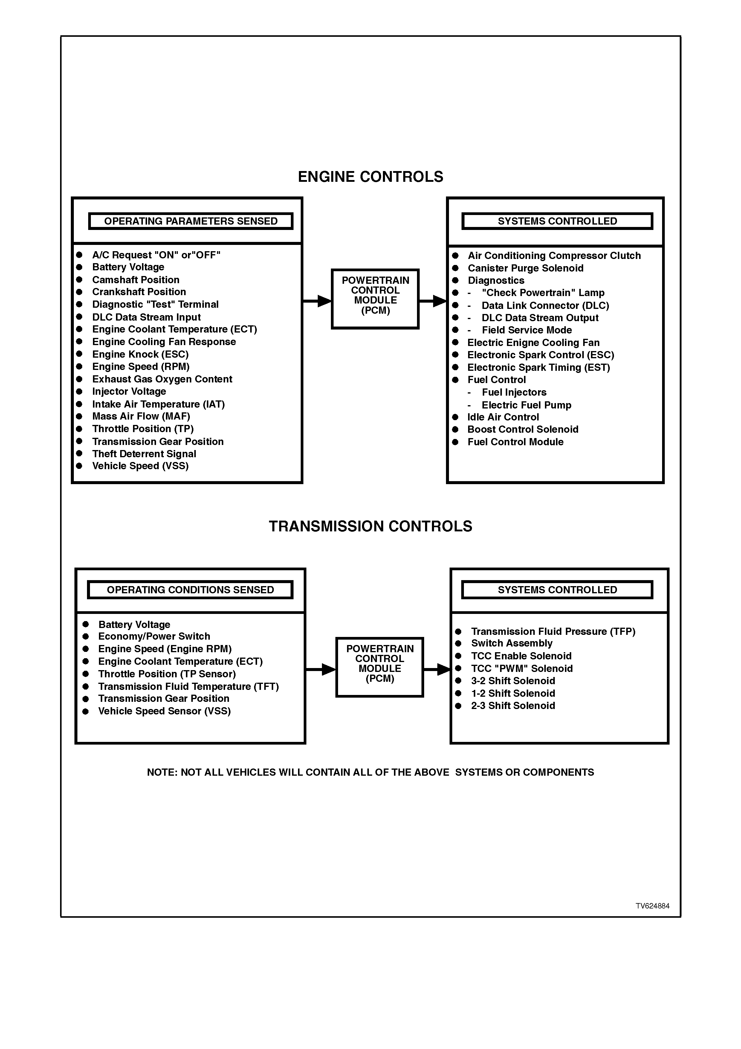
Figure 6C2-1-1 PCM Operating Conditions Sensed and Systems Controlled
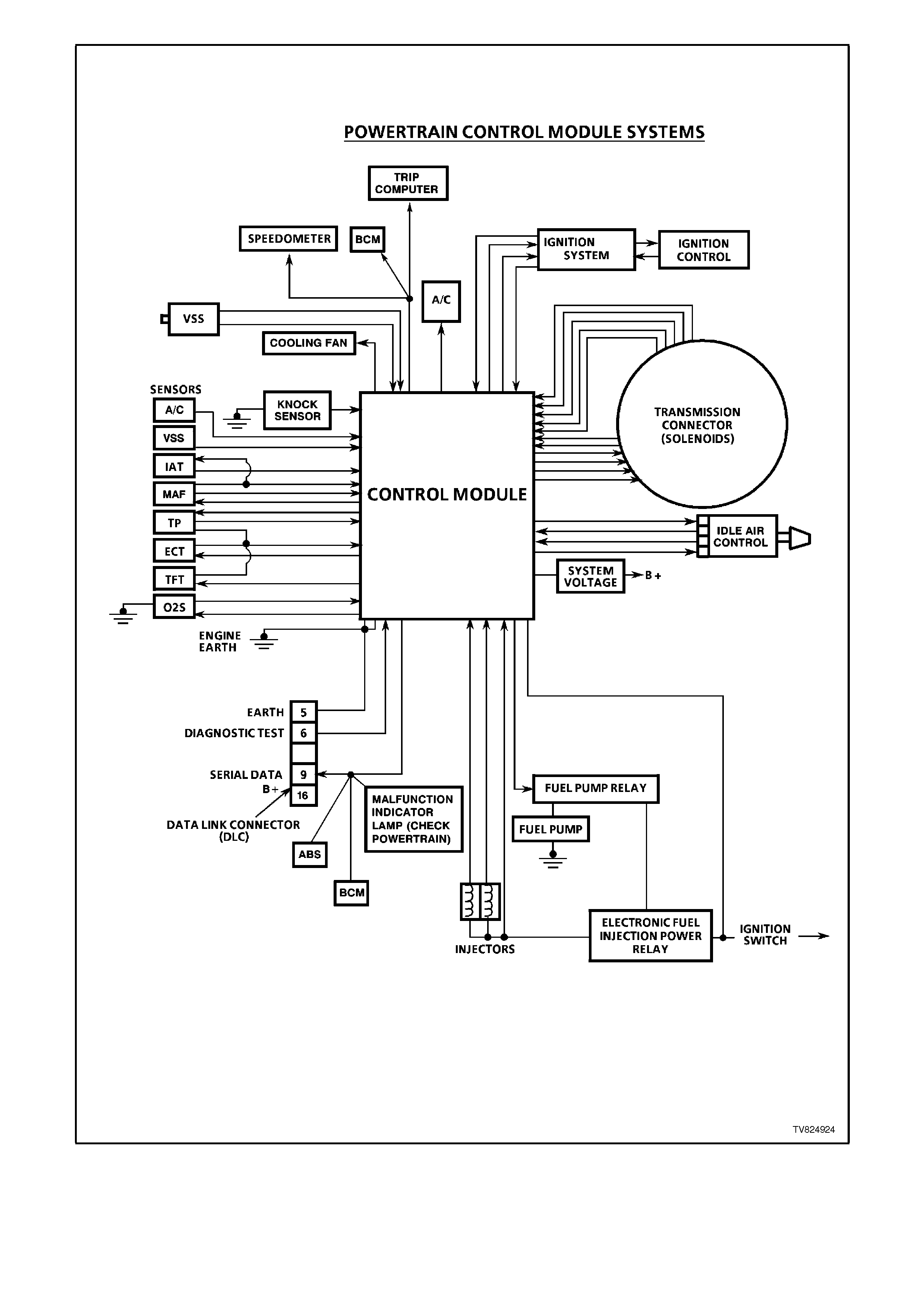
Figure 6C2-1-2 Powertrain Control Module System
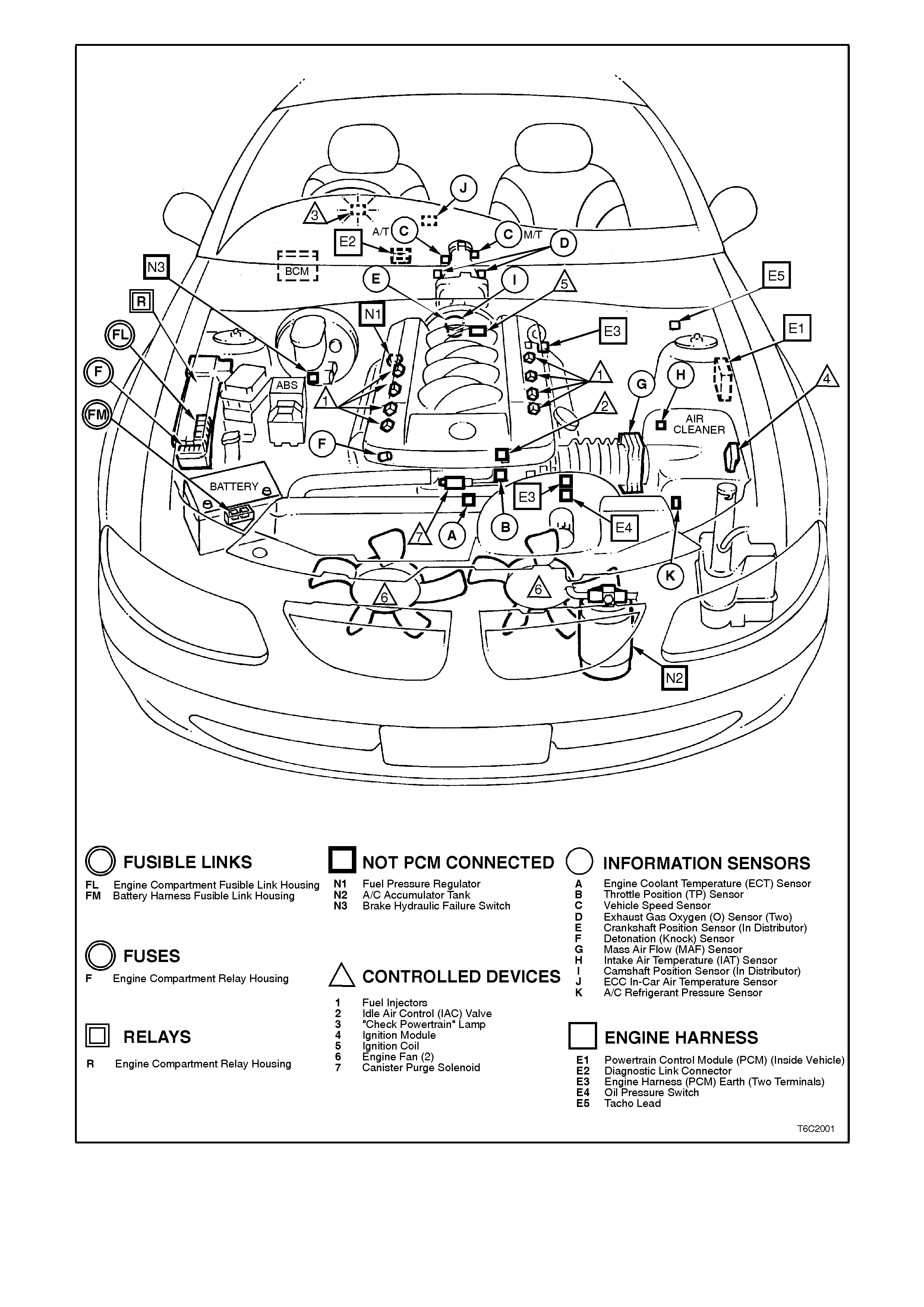
Figure 6C2-1-3 Component Locations 5.0L V-8

Figure 6C2-1-4 V8 Engine View
Figure 6C2-1-5 V8 Engine View
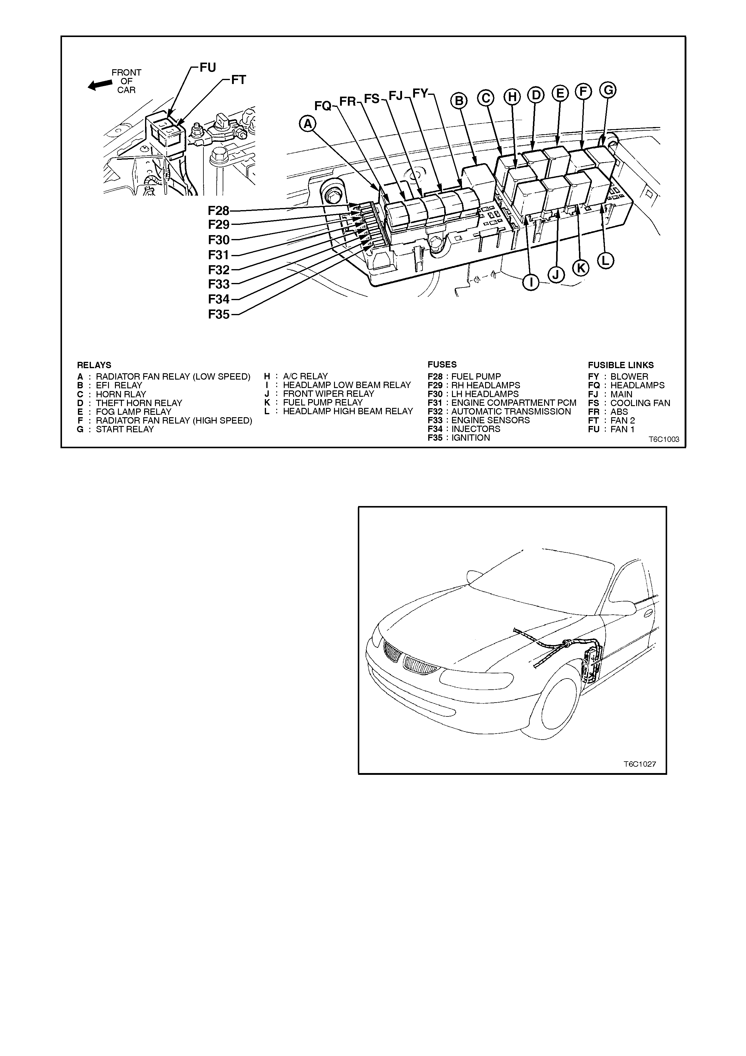
Figure 6C2-1-6 Power Distribution Centre
1.1 POWERTRAIN CONTROL MODULE (PCM)
The Powertrain Control Module (PCM), is the
control centre of the fuel injection system, the
ignition system, and the automatic transmission
management systems. The PCM constantly
monitor s information f rom the var ious sensors, and
controls the systems that affect exhaust emissions
and vehicle performance. The PCM also performs
the diagnostic function of the system. The PCM can
recognise operational problems, alert the driver
through a Malfunction Indicator Lam p (MIL) “Check
Powertrain” lamp and store a diagnostic code(s)
which will identify problem areas to aid the
technician in making repairs. Refer to
Section 6C2-2, DIAGNOSIS for more information
on using the diagnostic functions of the PCM.
The PCM supplies either a buffered 5V or a
buffered 12V to power various sensors and
switches.
The PCM controls the output circuit of the fuel
injectors , the IAC valve, and the various r elays, etc.
The PCM controls the earth circuit through either
transistors or a device called a “quad-driver. The
two exceptions to this are the fuel pump relay
control circuit and if the vehicle has an automatic
transmission, the pressure control solenoid .
On vehicles equipped with an automatic
transmission, the PCM supplies current to the
pressur e control solenoid. T he PCM then m onitors
the amount of current that is returned to the PCM.
Figure 6C2-1-7 PCM Location
PCM SECURITY LINK
Once the PCM and or BCM have been replaced,
the new PCM and or BCM must be security linked
to each other. If this procedure is not performed,
the vehicle will not crank.
There are two different types of procedures that
may be performed to accomplish this task. Refer to
Section 6C2-3 SERVICE OPERATIONS for this
procedure.
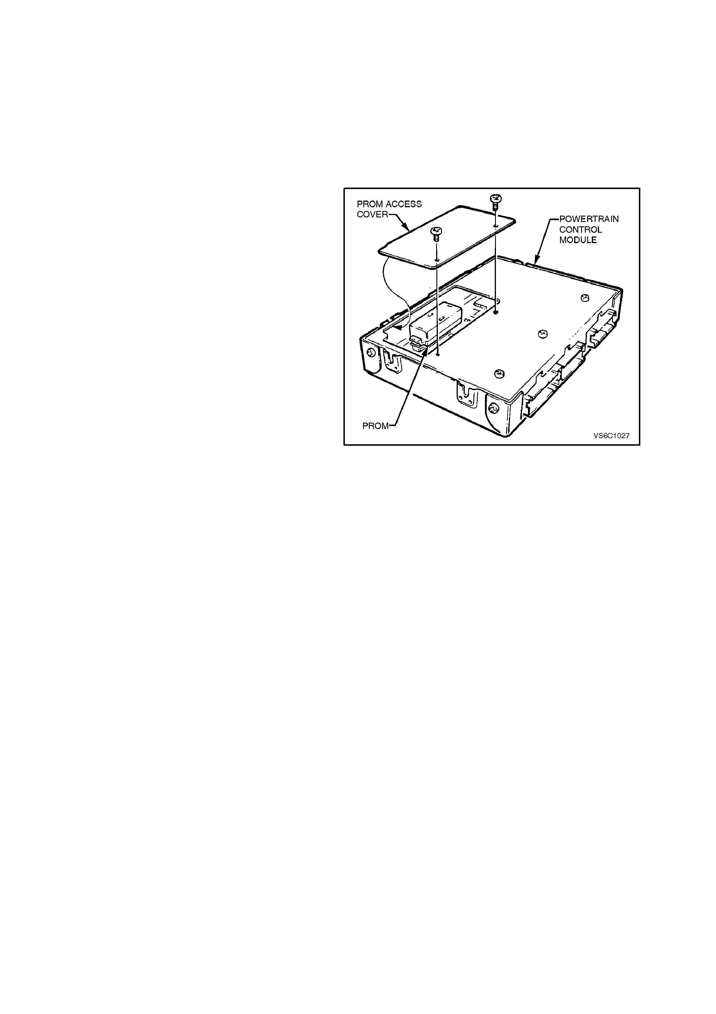
PROM
To allow one series of a PCM to be used for many
different vehicles, a PROM is used. The PROM is
located inside the PCM. The PROM has
information on the vehicle's weight, engine,
transmission, axle ratio and several other factors.
While one PCM part number m ay be used by m any
different vehicles, a PROM is specific. Check the
latest parts catalogue and Service Techline
information for the correct part number when
replacing a PROM. A replacement PCM (called a
controller) is supplied without a PROM. T he PROM
from the old PCM must be carefully removed and
installed in the new PCM. For details, refer
Section 6C2-3, SERVICE OPERATIONS.
Figure 6C2-1-8 PCM PROM Location

PCM MEMORY FUNCTIONS
The following list contain the five types of memory
within the PCM:
ROM
RAM
PROM
EPROM
EEPROM
ROM
Read Only Memory (ROM) is a permanent memory
that is soldered to the circuit boards within the PCM.
The ROM contains the overall control algorithms.
Once the ROM is programmed, the program cannot
be changed. The ROM memory is non volatile, and
does not need power to be retained.
RAM
Random Access Memory (RAM) is the
microprocessor scratch pad. The processor can
write into, or read from this memory as needed. This
memory is volatile and needs a constant supply of
B+ voltage to be retained. If the B+ voltage is lost,
the memory is lost.
PROM
The Programmable Read Only Memory (PROM) is
the portion of the PCM that contains the different
engine and transmission calibration that is specific to
the year, the model and the emissions. The PROM is
a non volatile memory that is read only by the PCM.
The PROM is contained within the Memory
Calibration assembly and is removable from the
PCM. The PROM should be retained with the vehicle
following PCM replacement.
EPROM
Erasable Programmable Read Only Memory
(EPROM) is the portion of the PCM which means
that the program can be erased. This type of
memory is used to store the diagnostic trouble
codes. This memory is erased by disconnecting the
constant battery feed to the PCM, such as
disconnecting the battery.
EEPROM
Electronically Erasable Programmable Read Only
Memory (EEPROM) is the portion of the PCM
memory that the program can only be erased
electronically. This type of memory cannot be erased
by disconnecting the vehicle battery. The only way to
erase this type of memory is by a special electronic
tool. DTC history data is stored in EEPROM and will
be saved even after the B+ supply has been
disconnected. The only way that the DTC history
data can be cleared is with the Tech 2 scan tool.
1.2 ENGINE INFORMATION SENSORS
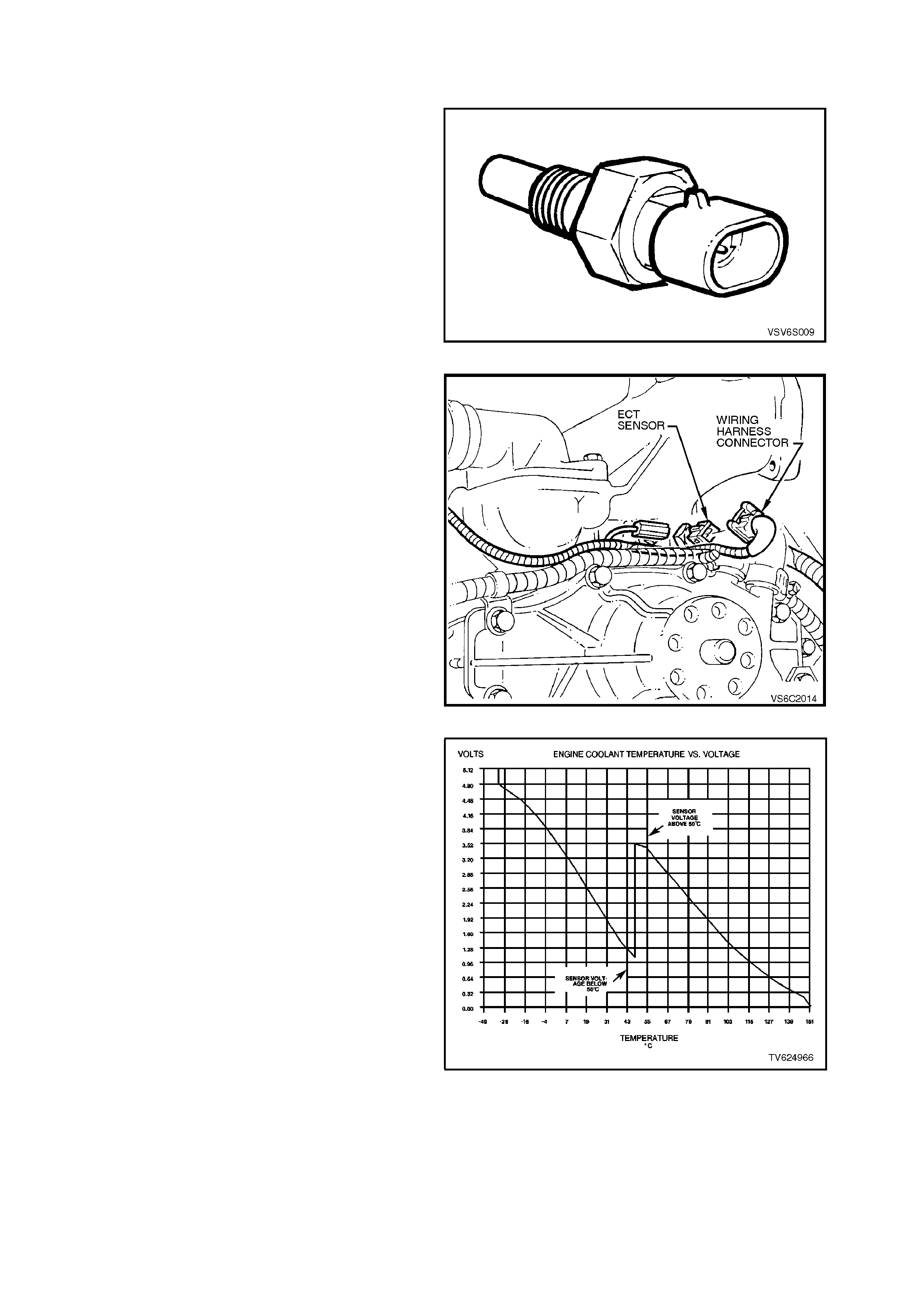
ENGINE COOLANT TEMPERATURE (ECT) SENSOR
The Engine Coolant Temperature (ECT) sensor is
a thermistor (a resistor that changes value based
on temperature) mounted in the engine coolant
stream. A different sensor is used for instrument
panel functions.
A Low coolant engine temperature will produce a
high sensor resistance (28,939 ohms at -20
degrees C). A high engine coolant tem perature will
cause a low sensor resistance (180 ohms at 100
degrees C).
Figure 6C2-1-9 ECT Sensor
The PCM:
• Supplies a 5 volt ref erence voltage and an earth
to the ECT sensor.
• Supplies an earth circuit to the ECT sensor.
• Monitors the circuit voltage.
The circuit voltage will vary depending on the
resistance of the engine coolant temperature
sensor. The circuit voltage will be close to the 5
volts when the sensor is cold, and the resistance
will decrease as the sensor gets warmer. The
engine coolant temperature affects most systems
controlled by the PCM.
Figure 6C2-1-10 ECT Sensor Location
The PCM uses a duel pull-up resistor network to
increase the resolution through the entire range of
the engine coolant tem peratures. When the coolant
temper atur e is less than 51°C, both a 4k ohm and a
348 ohm resistor is used. When the coolant
temperature reaches 51°C, the PCM shorts the 4K
ohm resistor and only the 348K ohm resistor is
used. A fault in one of these two resistors will set
DTC 17.
A fault in the engine coolant temperature sensor
circuit should set either a Diagnostic Trouble Code
(DTC) 14 or DTC 15. An intermittent open or an
intermittent short fault should set a DTC 16.
Figure 6C2-1-11 ECT Temperature vs Voltage
LH AND RH HEATED EXHAUST GAS OXYGEN SENSORS
The heated exhaust gas oxygen sensors are the
key to closed-loop fuel control. The PCM uses
feedback voltage from the oxygen sensors to fine-
tune the fuel injector pulse width. The O2 sensor
voltage is based on the, oxygen content in the
exhaust.
The oxygen sensors that are used are heated.
When the ignition is turned to the ON position, B+
voltage is supplied to the sensor's heating element.
The O 2 sensor will than im mediately begin to warm
up. This reduces the time for the sensor to go into
closed loop.
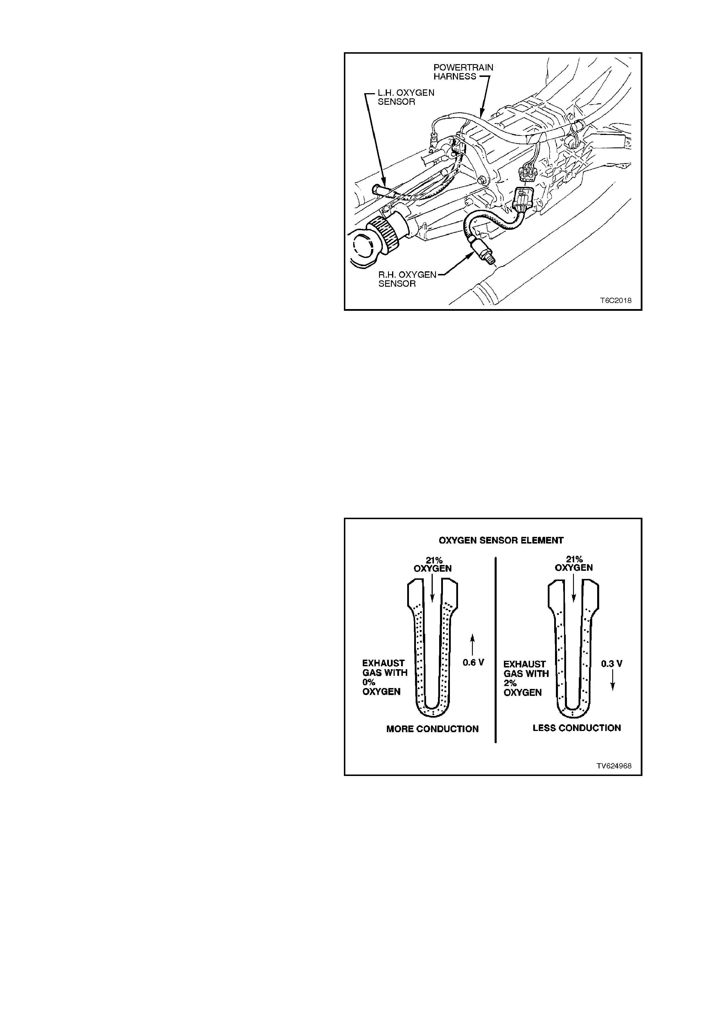
The oxygen sensor contains a zirconia element.
When the zirconia is heated to temperatures
greater than 360 degrees C, the O2 sensor will
produce voltages based on the amount of oxygen
surrounding the tip.
Figure 6C2-1-12 Oxygen Sensor Location
The oxygen sensor is mounted in the exhaust pipe
with the sensing portion exposed to the exhaust
gas stream. When the sensor has reached a
temper ature of greater than 360 degrees C, the O2
sensor acts like a voltage generator. The O2
sensor begins pr oducing a r apidly changing voltage
between 10 and 1000 millivolts. T his voltage output
is dependent upon the oxygen content in the
exhaust gas, as compared to the sensor's
atmospheric oxygen reference cavity. The O2
sensor receives a reference air supply from the air
that passes between the wire strands and the
insulation.
W hen the oxygen sensor is cold, the O2 sensor will
produce either no voltage, or an unusable, slowly
changing voltage. As the oxygen sensor begins
heating, the internal resis tance of the O2 decreas es
and begins producing a rapidly changing voltage.
When the PCM senses the changing voltage, the
PCM knows the oxygen sensor is hot and the
sensor's output is ready to be used for the fine-
tuning the fuel injector pulse width. The PCM
monitors the oxygen sensors cycling band
(approximately 300 - 600 millivolts), to help
calculate when to operate in the closed-loop mode.
When the fuel system is operating in the closed-
loop mode, the oxygen sensor voltage is rapidly
changing several tim es per second. T he O2 sensor
voltage cycles above and below a rich/lean band.
The PCM monitors the changing voltage, and
calculates the needed fuel mixture correction.
A DTC 13 or a DTC 63 can be c aus ed by any of the
following conditions.
• An open oxygen sensor signal circuit.
• An open oxygen sensor earth circuit.
• A defective, contaminated, or cold oxygen
sensor.
Any one of these conditions could cause the
voltage to stay between 410 - 470 millivolt too
long. Keeping the fuel control system in open-loop.
Figure 6C2-13 Oxygen Sensor Zirconia Element

If the PCM monitors a low voltage for too long, a Diagnostic Trouble Code 44 or a DTC 64 will set. If the PCM
monitors a high oxygen sensor circuit voltage for too long, a DTC 45 or a DTC 65 will set. (refer to DTC 44 and
DTC 45).
The oxygen sensor is normally earthed through the oxygen sensor threads. The oxygen sensor is located in the
exhaust pipe. The oxygen sensor earth path may not remain a good earth because of corrosion problems and a
possible poor electrical earth path through the exhaust pipe and the exhaust manifold to the engine earth. The
oxygen sensor has an extra earth circuit to ensure a good earth. A wire is attached to the oxygen sensor housing
and the other end is attached to engine earth. The oxy gen sensor earth from the PCM is also attached to engine
earth, therefore, the earth path is complete between the oxygen sensor and the PCM.
RESPONSE TIME
Not only is it necessary for the oxygen sensor to produce a voltage signal for a rich or a lean exhaust, it is also
important to respond quickly to changes. The PCM monitors the response time. If the oxygen sensor responds
slowly, the customer may complain of poor fuel economy, rough idle or lack of performance. It may also set false
DTCs because the PCM uses oxygen sensor voltages for system checks.
OXYGEN SENSOR CONTAMINANTS
CARBON
Carbon or soot deposits results from an extremely rich air-fuel mixtures. Carbon does not harm an O2 sensor.
Deposits can be burned off in the vehicle by running the engine at least part throttle for two minutes.
SILICA
Certain RTV silicone gasket materials give off vapours that may contaminate the oxygen sensor. The sand like
particles from the RTV silica embed themselves in the oxygen sensor element and plug the surface. This will result
in a lazy oxygen sensor response time. The sensor will also have a whitish appearance.
Silica contamination can also be caused by silicone in the fuel. Careless fuel handling practices with the transport
containers can result in unacceptable concentrations of silicone in the fuel at the fuel pump.
There is also a possibility of silica contamination caused when installing vacuum hoses or fittings. Do not use
silicone sealers on the gaskets or the exhaust joints.
LEAD
Lead glazing of the oxygen sensor can occur when regular, or leaded fuel is burned. Fuel containing large amounts
of methanol will also result in lead contamination.
The methanol dissolves the terne coat of the fuel tank, which introduces lead into the fuel system, and into the
exhaust after combustion. Lead contamination is difficult to detect by visual inspection.
OTHER SUBSTANCES
Oil deposits will ultimately prevent oxygen sensor operation. The O2 sensor will have a dark brown appearance.
Causes of high oil consumption should be checked. The additives in ethylene glycol can also affect the oxygen
sensor performance.
This produces a whitish appearance. If antifreeze enters the exhaust system, you will likely encounter other, more
obvious, symptoms of cooling system trouble.
MULTIPLE FAULTS
If you encounter multiple or repeat oxygen sensor faults on the same vehicle, consider contamination.
Leaded fuel, silica contamination from uncured, low-grade (non approved) RTV sealant, and high oil consumption
are possible.
A problem in the oxygen sensor circuit or fuel system should set one of the following DTC(s)
• DTC 13 or a DTC 63 (open circuit)
• DTC 44 or a DTC 64 (lean indication)
• DTC 45 or a DTC 65 (rich indication)
Refer to applicable diagnostic chart if any of these DTCs are stored in memory.
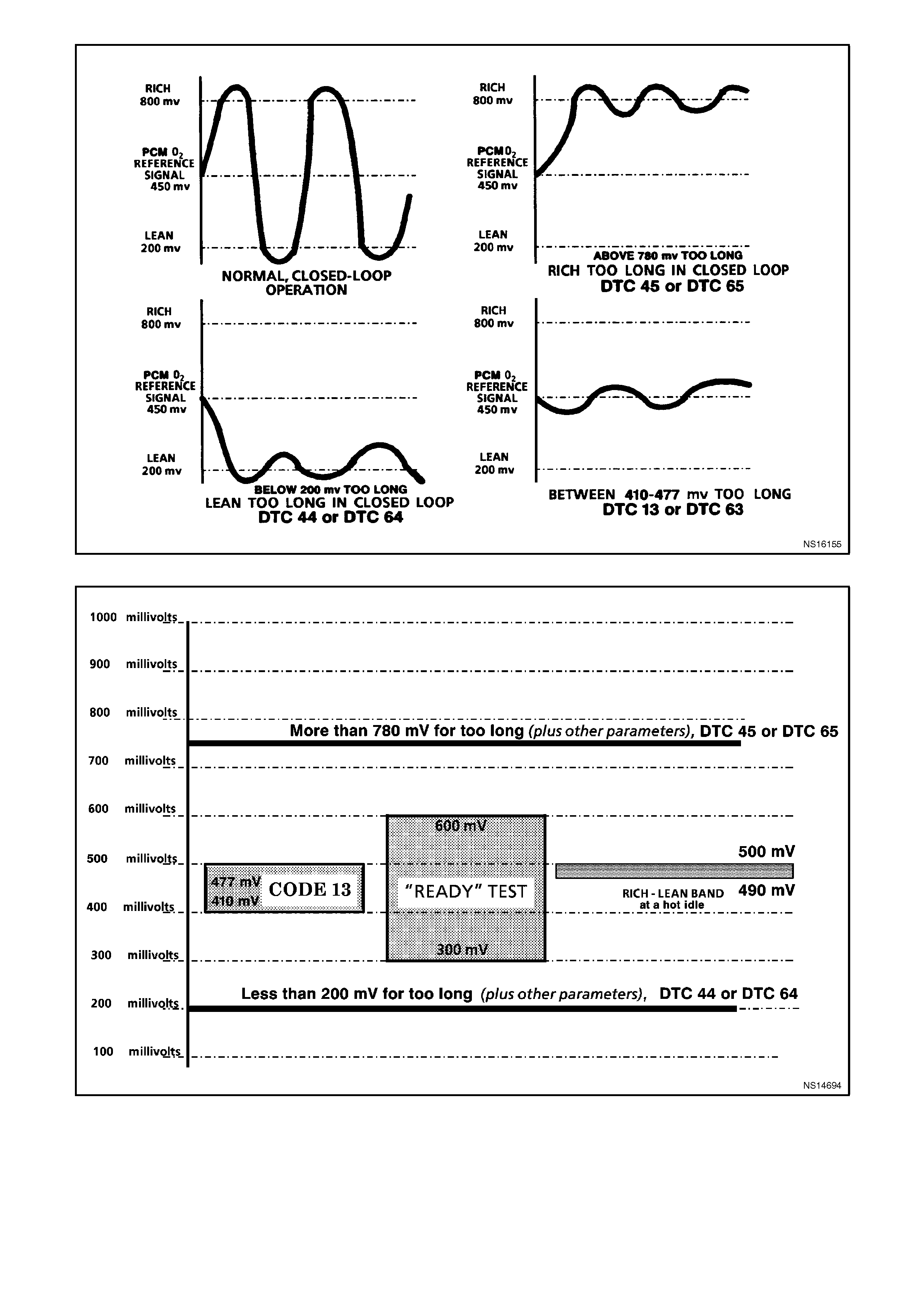
Figure 6C2-1-14 Oxygen Sensor Voltage Curves
Figure 6C2-1-15 Normal Oxygen Sensor Voltages and Abnormal Trends
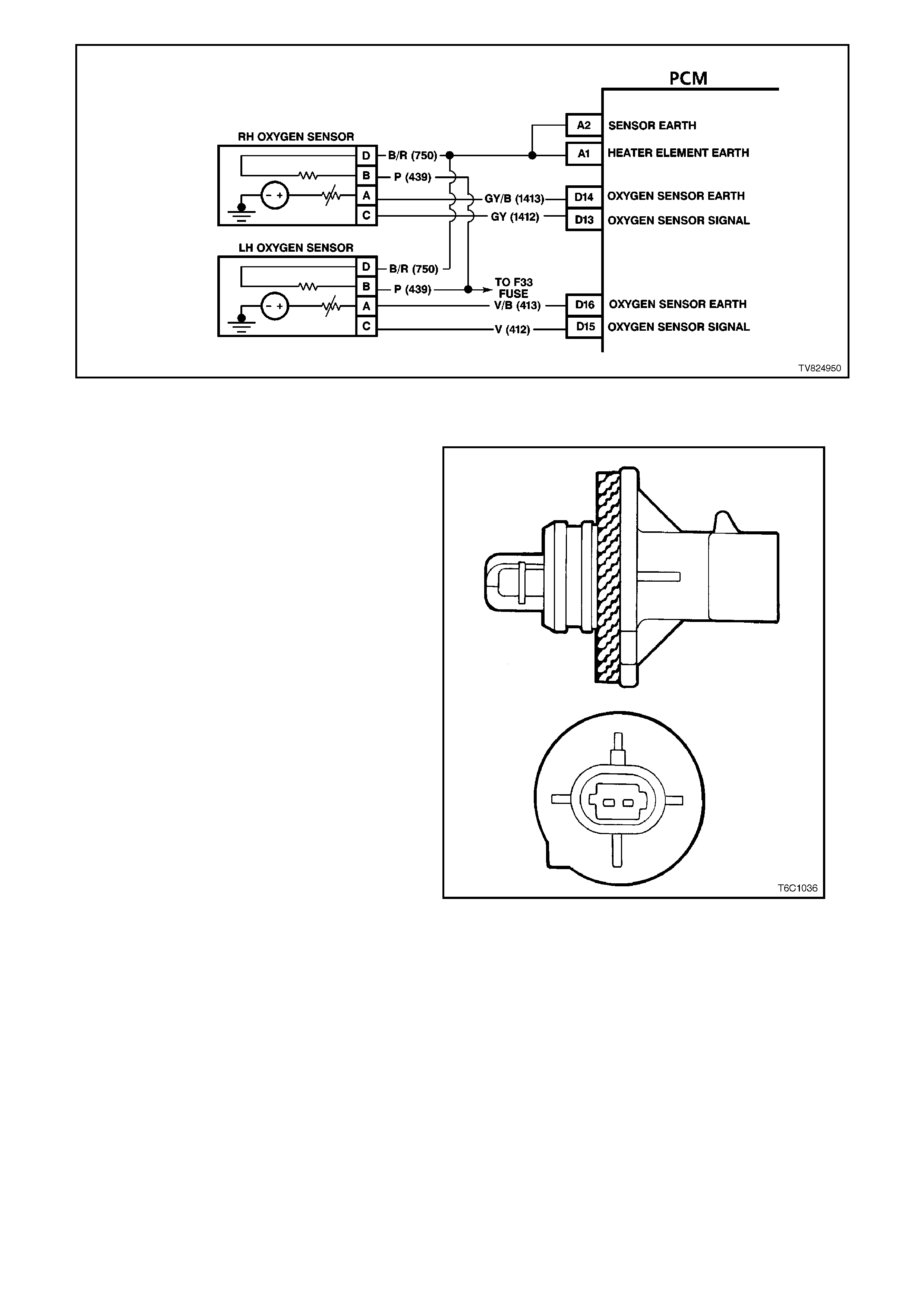
Figure 6C2-1-16 PCM Oxygen Sensor Circuitry
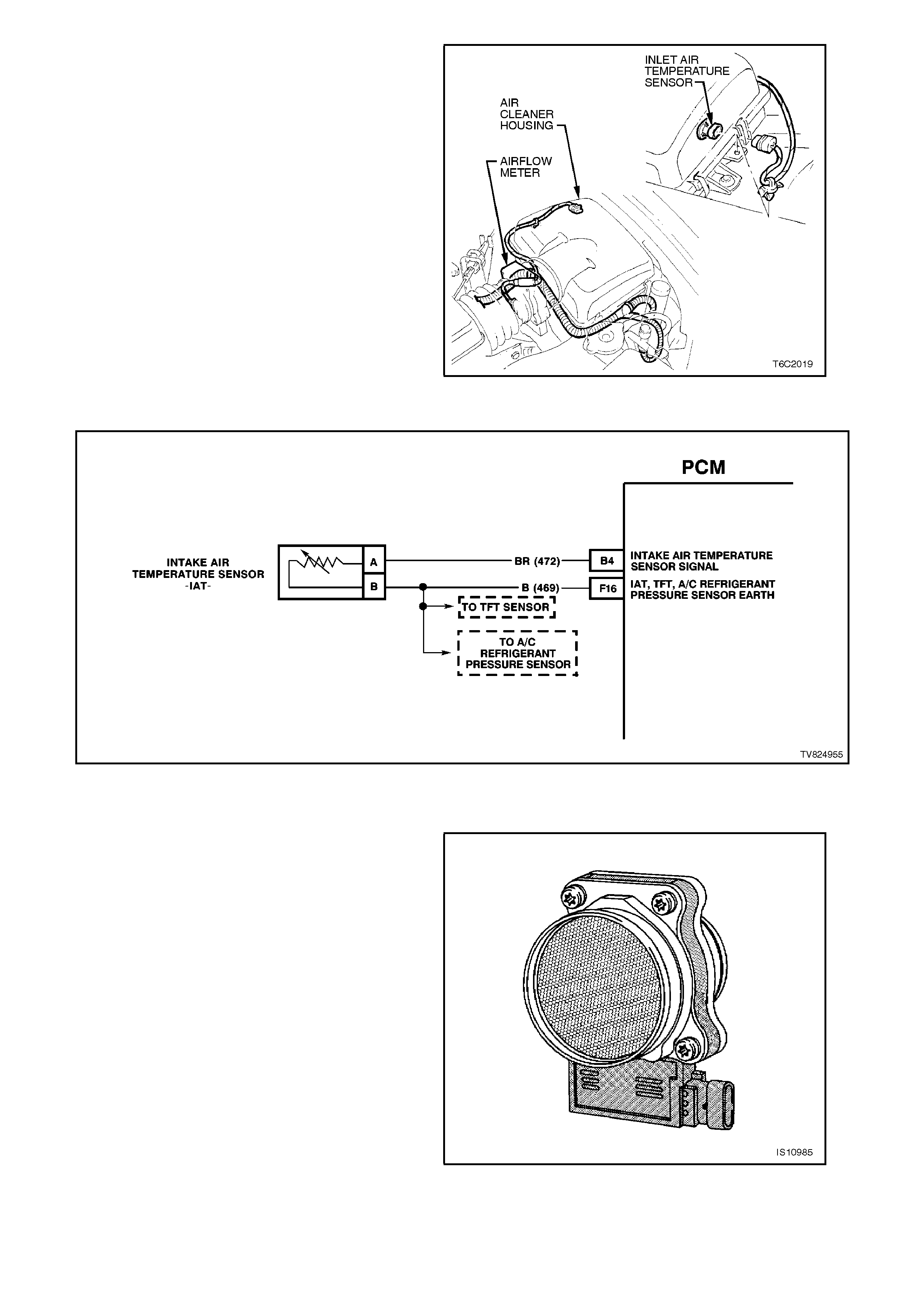
INTAKE AIR TEMPERATURE (IAT) SENSOR
The Intake Air Temperature (IAT) sensor is a
thermistor (a resistor that changes resistance with
changes in temperature). The IAT sensor is
mounted in the air cleaner housing.
The PCM supplies a 5V reference circuit and an
earth circuit to the sensor. A low intake air
temperature will produce a high resistance in the
sensor (100,000 ohms at -40 degrees C), while a
high air intake temperature will produce a low
sensor resistance (70 ohms at 130 degrees C).
Figure 6C2-1-17 IAT Sensor
The circuit voltage will vary depending on the
resistance of the IAT sensor. The voltage will be
close to 5-volts when the sensor is cold, and the
voltage will decrease as the sensor warms.
When the intake air is cold, such as when the
engine is firs t started on a cold day, the IAT s ensor
resistance will be high. Therefore the PCM voltage
signal will be, approximately 4 - 5 volts.
As the incoming air becomes warmer due to the
increasing engine temperature, the IAT sensor
resistance decreases, and the voltage will be
between 1 and 2 volts.
The IAT sensor signal voltage is one of the
param eters used by the PCM in calculating the fuel
injector pulse width.
A fault in the IAT sensor circuit should set either a
Diagnostic Trouble Code (DTC) 23 or a DTC 25.
An interm ittent fault in the IAT sensor cir cuit should
set a DTC 26. Figure 6C2-1-18 IAT Sensor Location
Figure 6C2-1-19 PCM IAT Sensor Circuit
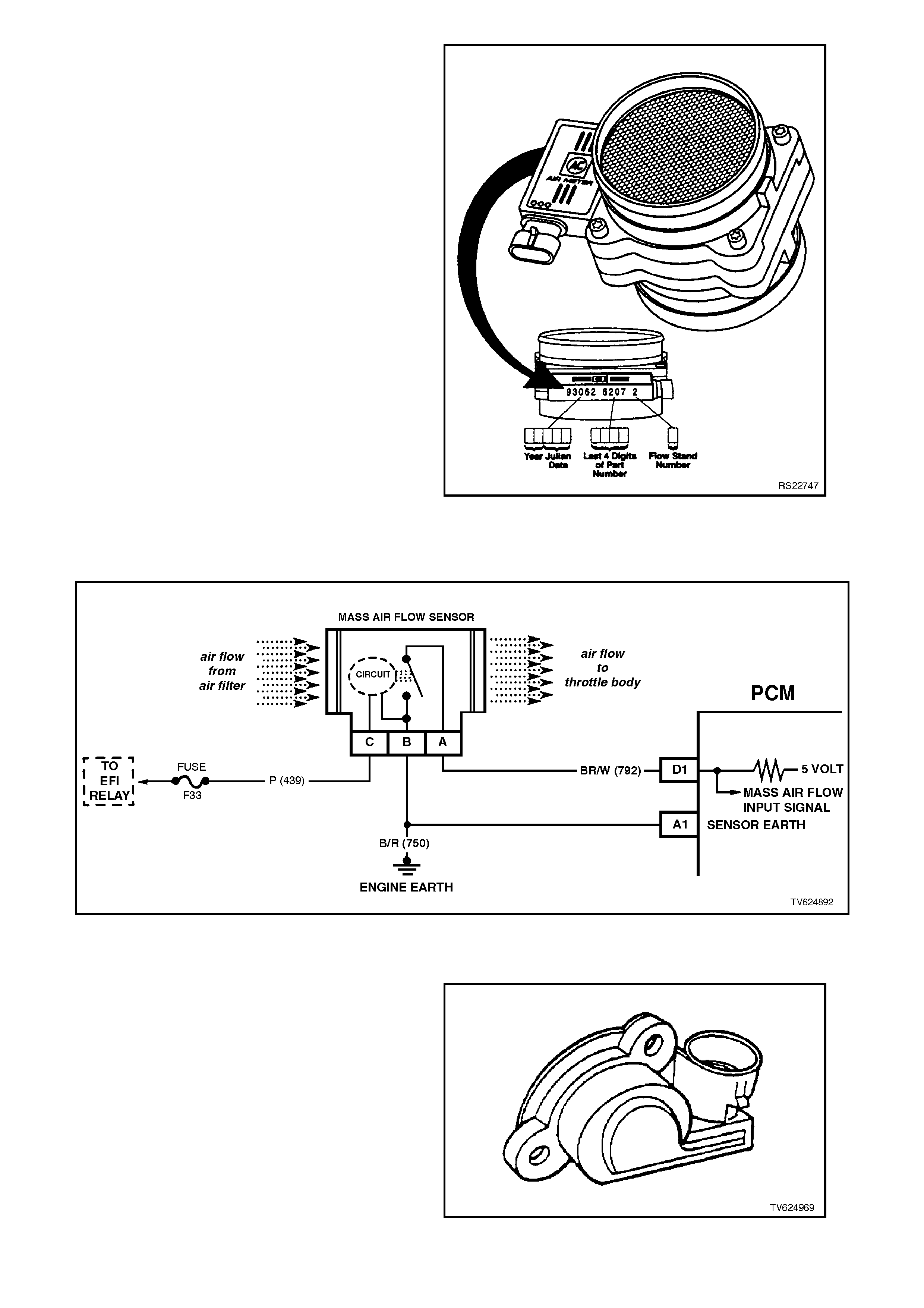
MASS AIR FLOW (MAF) SENSOR
The Mass Air Flow (MAF) sensor used on this
engine utilises a heated elem ent. A heated elem ent
in the MAF sensor is placed in the air flow stream
of the engine intake air system. The heating
element is maintained at a constant temperature
above the ambient air temperature. The amount of
current required to maintain the heated element at
the ambient temperature is a direct function of the
mass flow rate of the air over the heated element.
Figure 6C2-1-20 Mass Air Flow Sensor
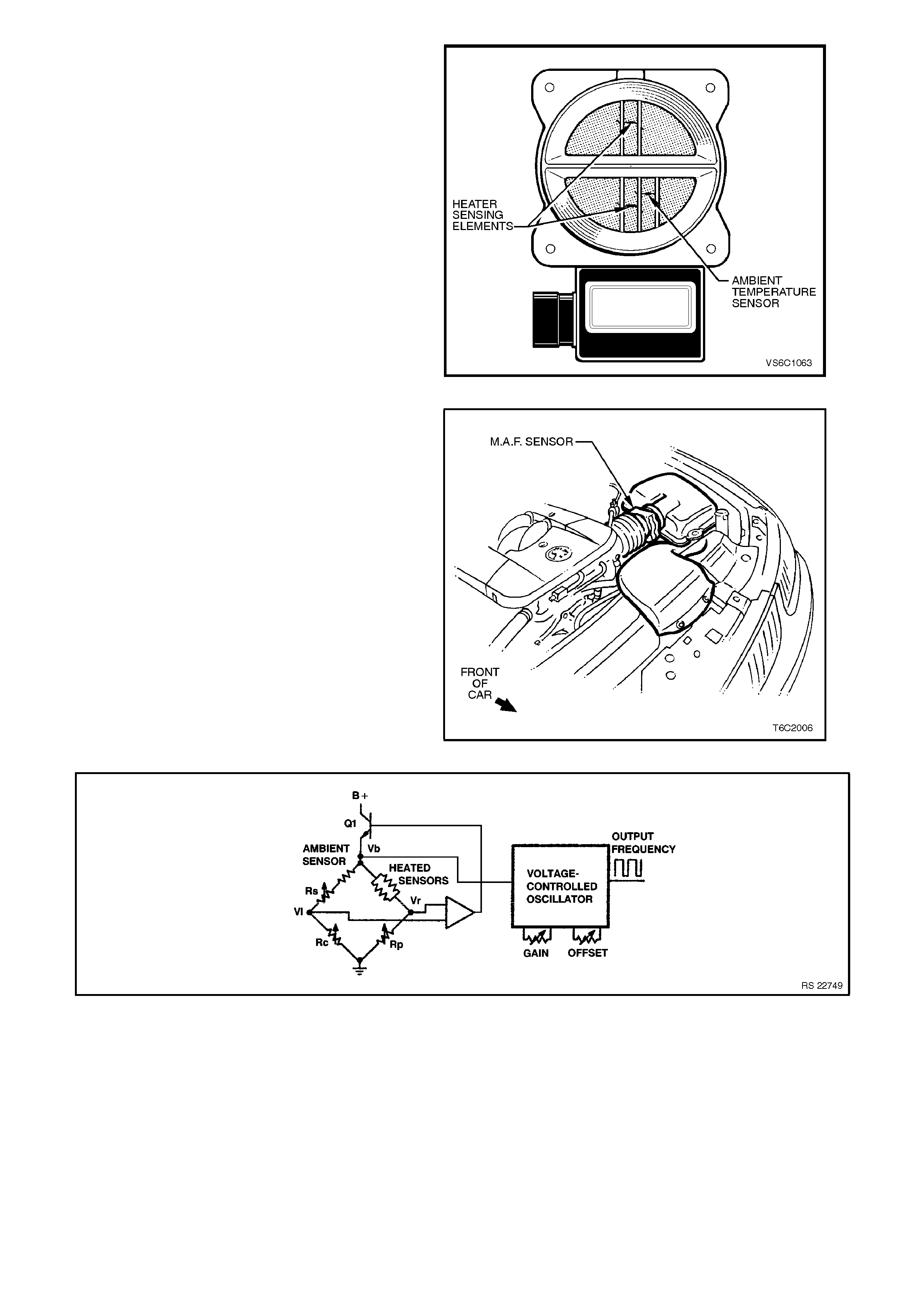
Three sensing elements are used in this system.
One senses the ambient air temper ature. The other
two sensing elements are heat sensing elements.
The ambient air temperature sensor is mounted in
the lower half of the sensor housing.
The two heater sensing elements are heated to a
calculated temperature that is significantly above
the ambient air temperature. The two heater
sensing elements are connected electrically in
parallel and mounted directly in the air flow stream
of the sens or housing. O ne sensor is in the top and
the other sensor is in the bottom of the sensor
housing. This is done so that the air meter is less
sensitive to upstream ducting configurations that
could skew the flow of air through the housing.
Figure 6C2-1-21 Sensing Elements
As the air passes over the heater sensing
elements, the elements begin to cool. By
measuring the amount of voltage required to
maintain the heater sensing elements at the
calculated temperature above ambient, the
incoming air flow rate can be calculated.
After the mass air flow sensor has developed a
signal related to the mass air flow rate, the MAF
sensor then sends the signal to the PCM. In order
to preserve the accuracy of the voltage signal from
the mass air flow sensor, the voltage is converted
to a frequency signal then sent to the PCM.
Figure 6C2-1-22 MAF Sensor Location
Figure 6C2-1-23 MAF Sensor Simplified Schematic
The signal that is sent from the mass air flow
sensor is sent in the form of a frequency output. A
large quantity of air passing through the sensor
(such as when accelerating) will be indicated as a
high frequency output. A small quantity of air
passing through the sensor will be indicated as a
low frequency output (such as when decelerating or
at idle). The scan tool displays the MAF sensor
signal in frequency, and in grams per second and
calculated in mg per cylinder. At idle the readings
should be low and increase with engine RPM.
As the PCM receives the fr equency s ignal from the
mass air flow sensor, the PCM searches the pre-
program med tables of inform ation to determine the
pulse width of the fuel injectors required to match
the mass air flow signal.
If a fault occurs in the mass air flow sensor circuit,
the PCM will store a DTC. The PCM will turn ON
the "Check Powertrain" lam p, indicating a problem.
If this oc c urs , the PC M will calculate a default mas s
air flow signal based on the engine speed and the
throttle position sensor signal.
No field service adjustment is necessary or
possible with this mass air flow sensor.
A fault in the mass air f low s ensor c irc uit s hould set
a DTC 32. T his DTC indicates a fault in the circuit.
Use of the diagnostic chart will lead to either
repairing a wiring problem, replacing the PCM, or
replacing the MAF Sensor.
Figure 6C2-1-24 Mass Air Flow Sensor Identification
Figure 6C2-1-25 MAF Sensor Circuit
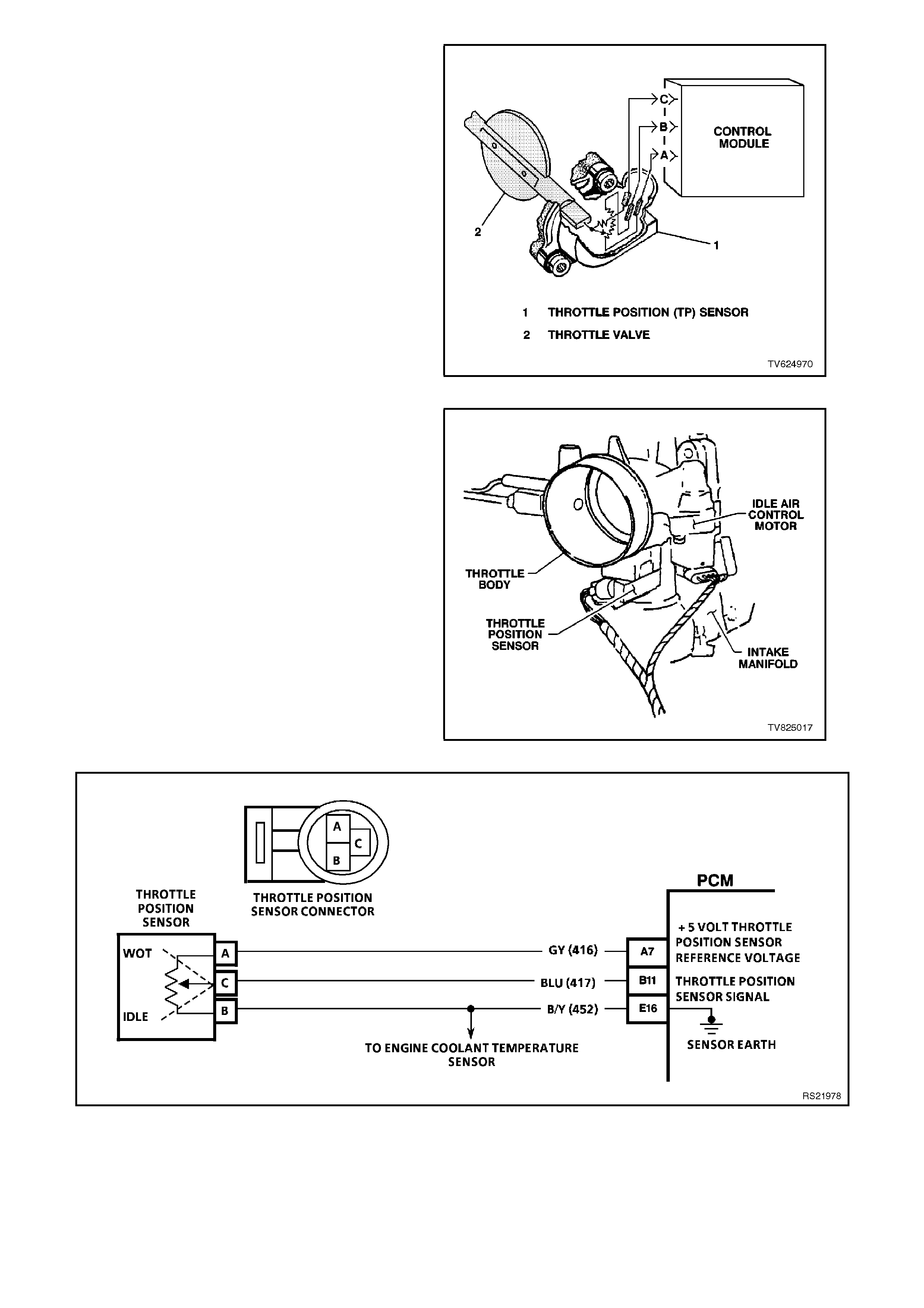
THROTTLE POSITION (TP) SENSOR
The T hr ottle Pos ition (TP) s ens or is mounted to the
throttle shaft on the throttle body. The T P sensor is
a potentiometer. The PCM supplies a 5 volt
referenc e and a earth circuit to the TP sens or. The
signal circuit connects from a sliding contact in the
TP sensor to the PCM. This allows the PCM to
measure the voltage from the TP sensor. As the
throttle is depressed, the output of the TP sensor
changes. At a clos ed throttle position, the output of
the TP sensor is below 1.25V. As the throttle valve
opens, the output increases. At a wide-open
throttle, the TP sensor output voltage should be
greater than 4 volts.
Figure 6C2-1-26 TP Sensor
By monitoring the output voltage from the TP
sensor, the PCM can determine the fuel injector’s
base pulse width.
A broken or loos e T P s ens or c an c ause inter mittent
bursts of fuel from the injectors, and an unstable
idle, because the PCM thinks the throttle is moving.
Figure 6C2-1-27 TP Sensor - Typical
The T P sensor is not adj ustable. There is not a s et
value for the TP sensor voltage at closed throttle.
The actual voltage at closed throttle can vary from
vehicle to vehicle due to tolerances. The PCM has
a special program built in that can adjust for the
tolerance differences in the TP sensor voltage at
idle. The PCM uses the signal at idle for the zero
reading (0% throttle) so no adjustment is
necessary. If the TP sensor voltage were to
change, the TP sensor voltage will still be 0%
because the PCM will learn the new value. The
new value will become the new closed throttle
value. A TP s ensor c irc uit f ault will set either a DTC
21 or a DTC 22.
If the internal spring in the TP sensor fails, the TP
sensor will read high. A stuck high TP sensor
should set a DTC 19.
Figure 6C2-1-28 TP Sensor Location
Figure 6C2-1-29 PCM TP Sensor Circuit
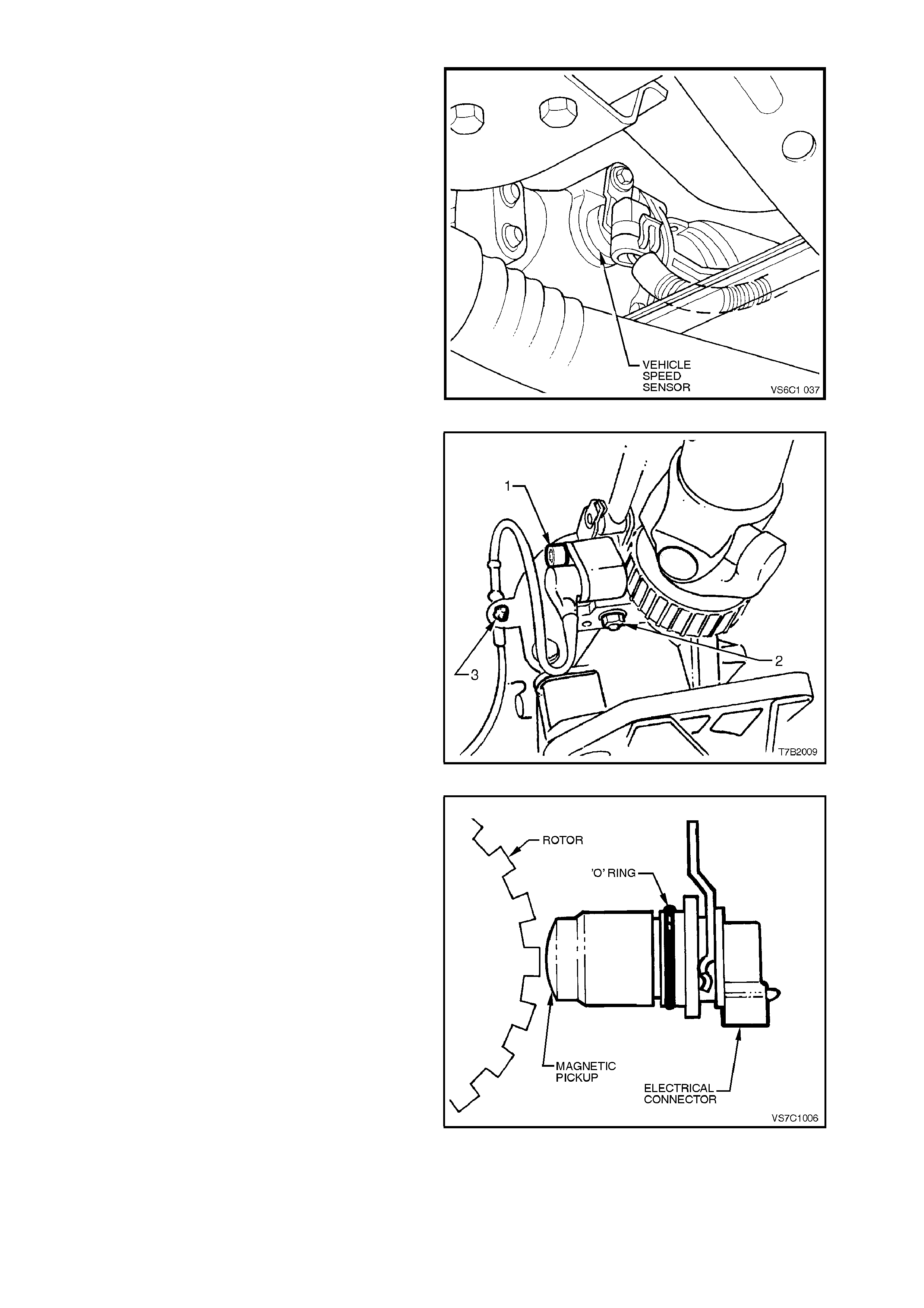
VEHICLE SPEED SENSOR (VSS)
The vehicle speed sensor is located in the
transmission extension housing.
The vehicle speed sensor contains a coil that has
a continuous magnetic field. A voltage signal is
induced in the vehicle speed s ens or by teeth on the
output shaft that rotate past the sensor that break
the magnetic field. Eac h break in the field s ends an
electrical pulse to the PCM. T his voltage output will
vary with speed from a minimum of 0.5 volts AC at
100 RPM to more than 100 volts AC at 8000 RPM
on the vehicle. With the engine at 4000 RPM and in
fourth gear , the voltage will be approximately 10-12
volts AC.
Figure 6C2-1-30 VSS Location - Automatic Transmission
Figure 6C2-1-31 VSS Location - Manual Transmission
The PCM uses the signal from the vehicle speed
sensor to determine the following.
• The vehicle speed.
• The control shift points.
• Calculate transmission slip.
• The engine fuelling modes.
A Diagnostic Trouble Code 24 or DTC 94will set if a
fault exists in the vehicle speed sensor circuit. As
the vehicle is accelerated, the PCM will shift the
transmission into second gear at approximately 50
km/h. If the vehicle speed signal is not present
while in second gear, a DTC 24 will set. The PCM
will substitute a default value for the vehicle speed
if the fault occurred in fourth gear. If the fault
occurr ed in park, neutr al, or first gear , the PCM will
allow 1-2 shifts to occur. If a DTC 24 is set, then
the PCM will default into third gear. If the c onditions
for a DTC no longer exist, then normal operation
will resume after the next ignition cycle. Figure 6C2-1-32 Vehicle Speed Sensor
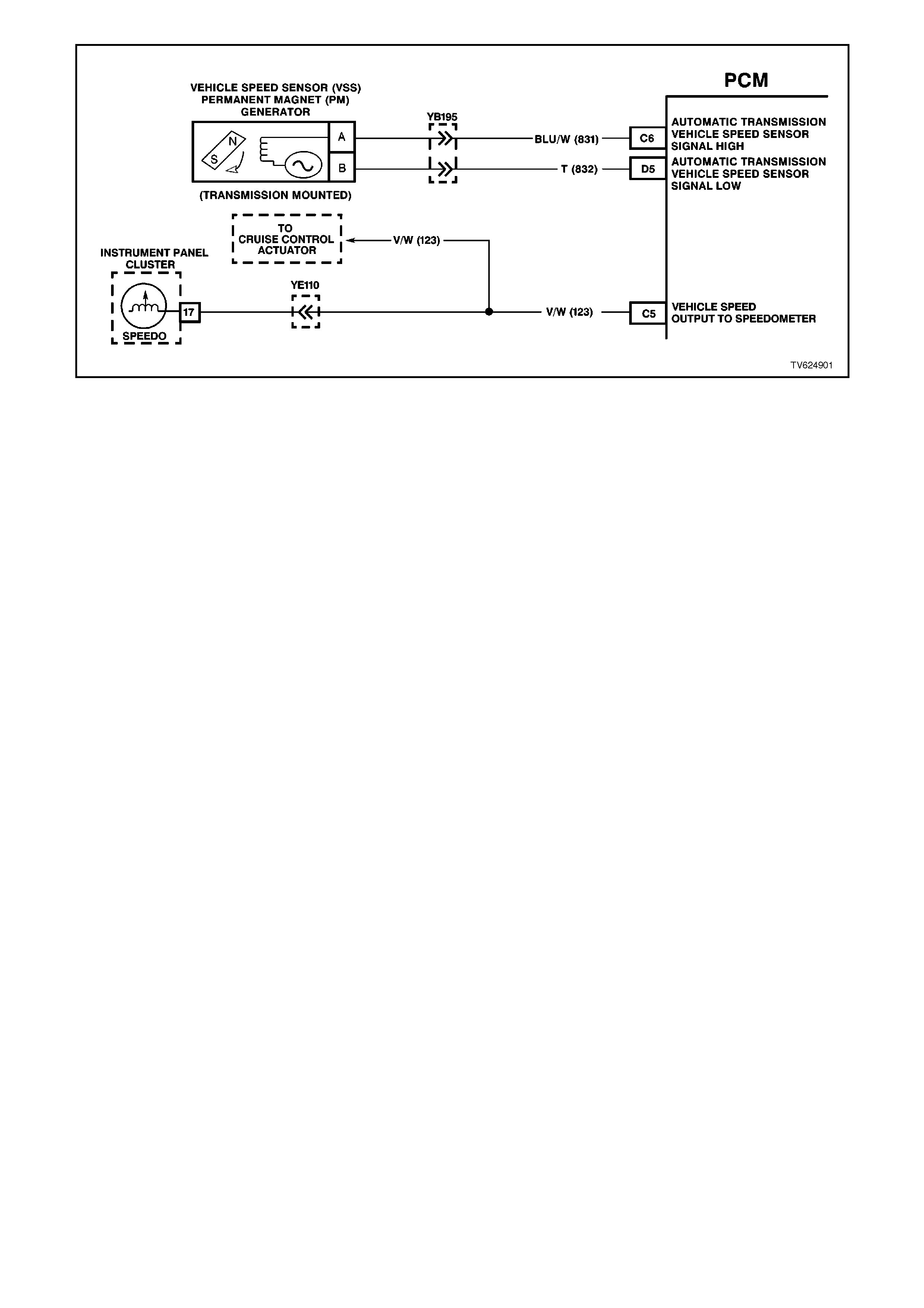
Figure 6C2-1-33 PCM VSS Circuit
A/C REQUEST SIGNAL
When the A/C is requested from the dash master A/C switch, the A/C request signal is sent to the BCM. The BCM
will then send a command via the serial data line to the PCM. The PCM will then supply a earth signal to the A/C
compressor relay, to energise the A/C compressor.
The PCM uses this BCM serial data command to:
• Adjust the Idle Air Control (IAC) position to compensate for the additional load placed on the engine by the air
conditioning compressor, and then
• Energises the A/C compressor relay, to operate the A/C compressor.

Figure 6C2-1-34 PCM A/C Request Signal Circuit Without ECC

Figure 6C2-1-35 PCM A/C Request Signal Circuit With ECC

BATTERY VOLTAGE
The PCM continually monitors the battery voltage. When the battery voltage is low, the ignition system may deliver a
weak spark. Also, the fuel injector mechanical movement takes longer to open. The PCM will compensate for a low
voltage condition by:
• Advancing the ignition timing whenever the battery voltage is less than 12 volts.
• Increasing the engine idle speed whenever the battery voltage is less than 10 volts.
• Increasing the fuel injector pulse width whenever the battery voltage is less than 10 volts.
Diagnostic Trouble Code (DTC) 53 will set when the ignition is ON and the PCM voltage is greater than 19.5 volts
for 2 seconds.
Diagnostic Trouble Code (DTC) 54 will set when the ignition is ON and the PCM voltage changes more than 3 volts
in less than 100 milliseconds.
The minimum voltage for DTC 75 to set is on a graduated scale. The scaling changes with temperature. A DTC 75
will set when the ignition is ON and the B+ voltage is less than the values listed below for about 4 seconds.
• Minimum voltage at -40 degrees C is 7.3 volts.
• Minimum voltage at 90 degrees C is 8.6 volts.
• Minimum voltage at 152 degrees C is 11.4 volts.
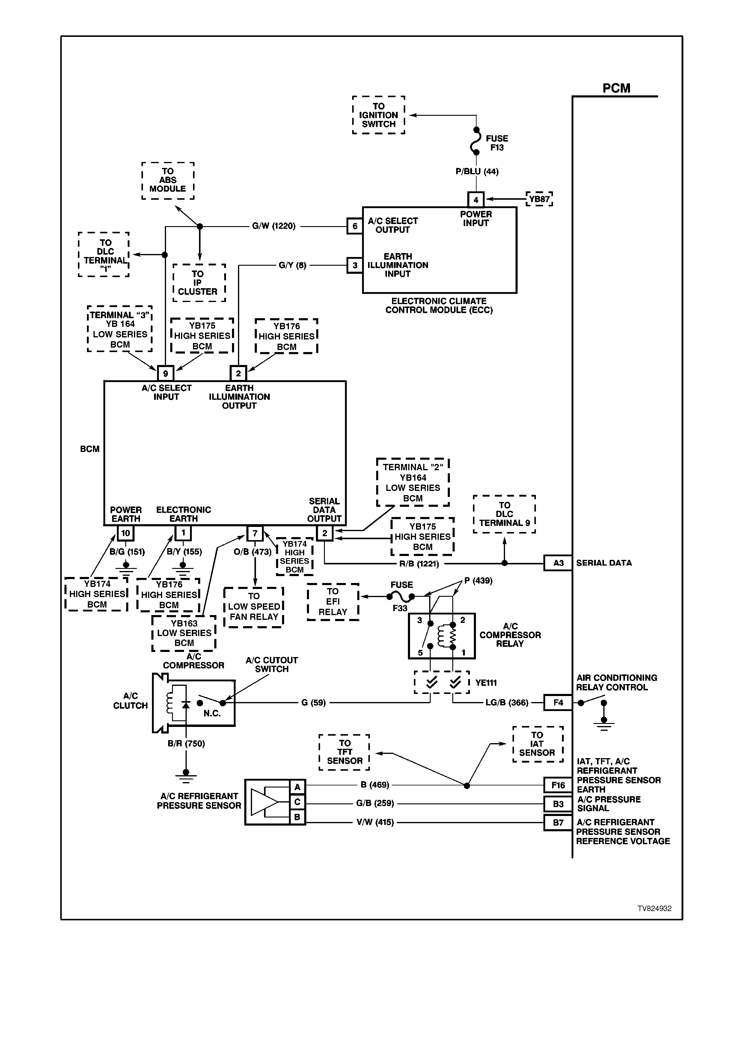
Figure 6C2-1-36 PCM Battery Feed
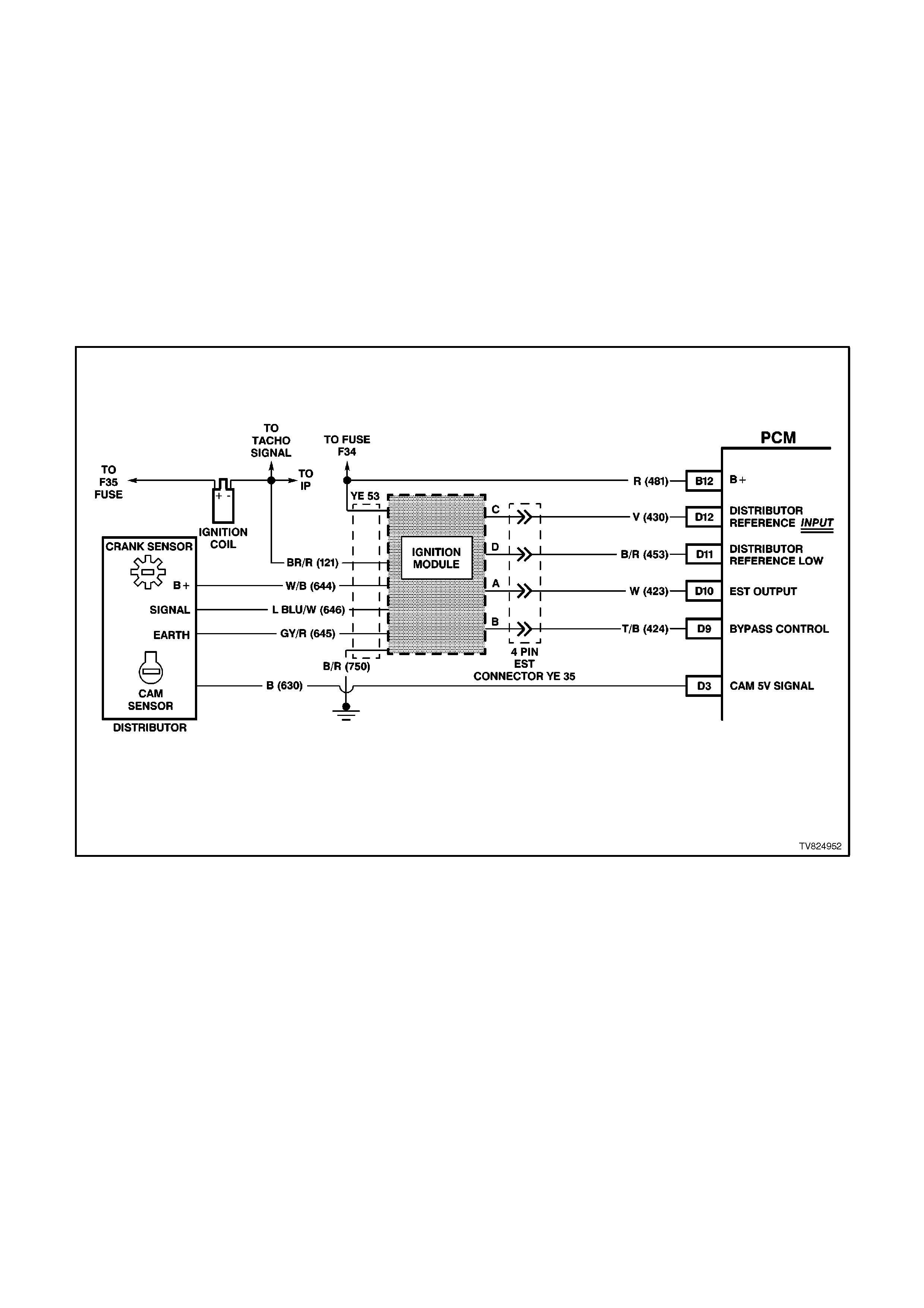
CRANKSHAFT REFERENCE SIGNAL
The crankshaft reference signal is generated within the distributor. The distributor contains a hall-effect crankshaft
sensor. This sensor acts as a reference voltage pulse generator. The crankshaft sensor provides the PCM with the
RPM and crankshaft positioning.
NOTE:
The engine will not run if the control module does not receive a crankshaft reference signal. With no distributor
reference signal the PCM will not command any fuel injector pulses.
The crankshaft reference signal initiates the fuel injector to fire. The PCM uses this signal to determine the engine
RPM. This is one of the signals used to control the following components or systems
• The Fuel Delivery
• The A/C Clutch (ON/OFF)
• The Electronic Spark Timing
• The Idle (IAC)
• The Transmission
Figure 6C2-1-37 PCM Ignition System Circuit
ENGINE COOLI NG FAN SIGNAL
LOW SPEED RESPONSE
The V8 engine has two, two speed electric cooling fans which provides the primary means of moving air through
the engine radiator. These fan are placed between the radiator and the engine and has its own shroud. These fan
are used on all vehicles whether or not it is equipped with air conditioning. There is no fan in front of the A/C
condenser.
The two, two speed electric fan's low speed can only be enabled when the engine cooling fan low speed relay is
energised by the BCM. The PCM will request low speed fan enable and disable via the serial communication to
the BCM. After the PCM requests a change in the engine cooling fan low speed relay , the BCM will send a serial
data response message back to the PCM confirming it received the message. A fault in this response
communication will set a DTC 92.
There are also four (4) suppression capacitors incorporated into the fan motor wiring circuits. These suppression
capacitors help eliminate fan motor noise through the radio speakers. If these capacitors are open, then noise will
be present through the radio speakers. Is shorted to earth, the fan motors could continuously run, or the fuse or
fusible link could fail.
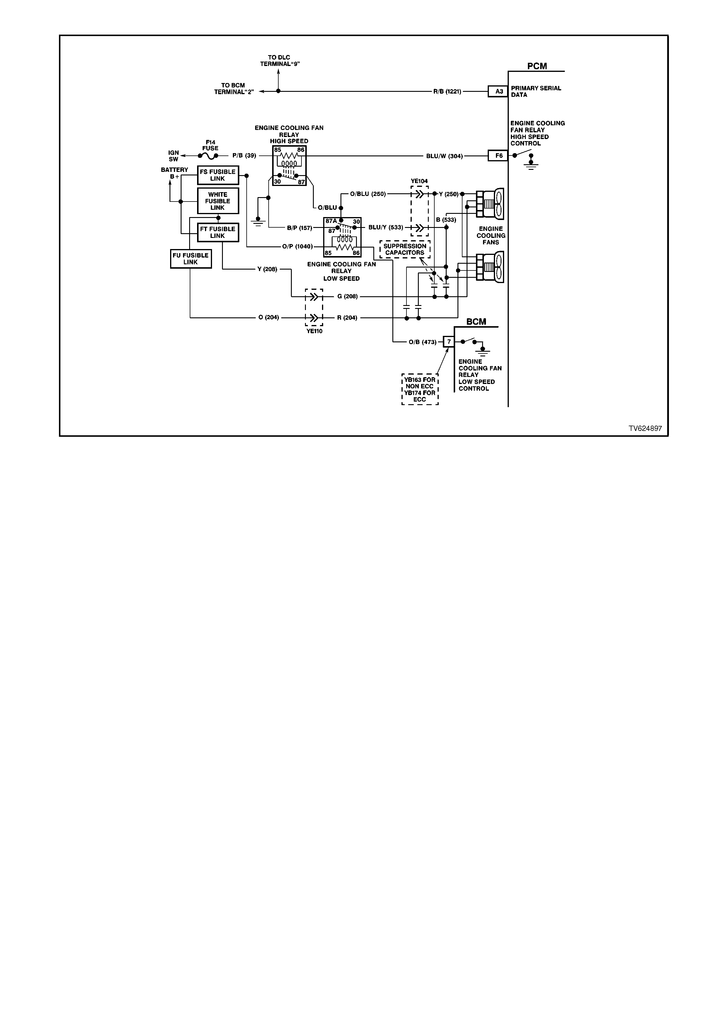
Figure 6C2-1-38 Engine Cooling Fan Signal
ENGINE COOLING FAN HIGH SPEED
The engine cooling fan high speed is controlled by the PCM based on input from the Engine Coolant Temperature
Sensor (ECT). The PCM will only turn "ON" the engine cooling fan high speed if the engine cooling low speed fans
have been "ON" for 2 seconds and the following conditions are satisfied.
• There is a BCM message response fault which will cause a DTC 92.
• An engine coolant temperature sensor failure is detected, such as DTC 14,15,16,17.
• Coolant temperature greater than 109 degrees C.
If the fan low speed was "OFF" when the criteria was met to turn the fan high speed "ON", the fan high speed will
come "ON" 5 seconds after the fan low speed is turned "ON". The high speed engine cooling fan relay can also be
enable by the A/C Refrigerant Pressure Sensor. The A/C Refrigerant Pressure Sensor will enable high speed
cooling fan, if the A/C system pressure becomes to high.
If a fault occurs in the PCM Engine Cooling Fan Relay High Speed Control circuit, a QDSM DTC 91 will set.
There are also four (4) suppression capacitors incorporated into the fan motor wiring circuits. These suppression
capacitors help eliminate fan motor noise through the radio speakers. If these capacitors are open, then noise will
be present through the radio speakers. If shorted to earth, the fan motors could continuously run, or the fuse or
fusible link could fail.
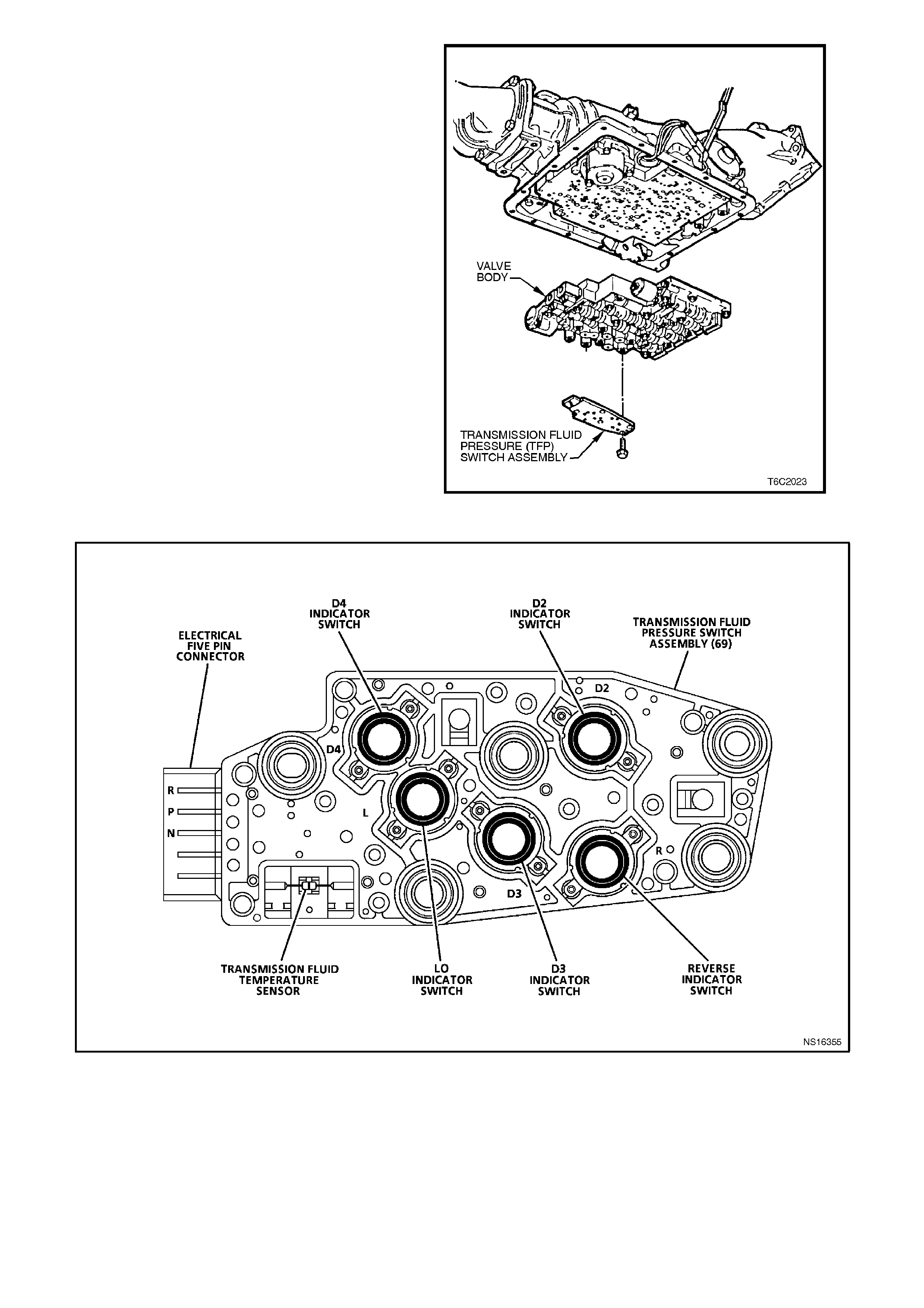
TRANSMISSION FLUID PRESSURE (TFP) SWITCH ASSEMBLY
The Transmission Fluid Pressure (TFP) Switch Assembly is used by the PCM to sense what gear range has been
selected by the vehicle operator. The TFP is located on the transmission valve body and consists of five pressure
switches, 2 normally closed fluid pressure switches and 3 normally open fluid pressure switches combined into one
unit.
The Pressure Switch Assembly is one of the inputs used by the PCM to control Idle Air Control (IAC) and, the
transmission Operation.
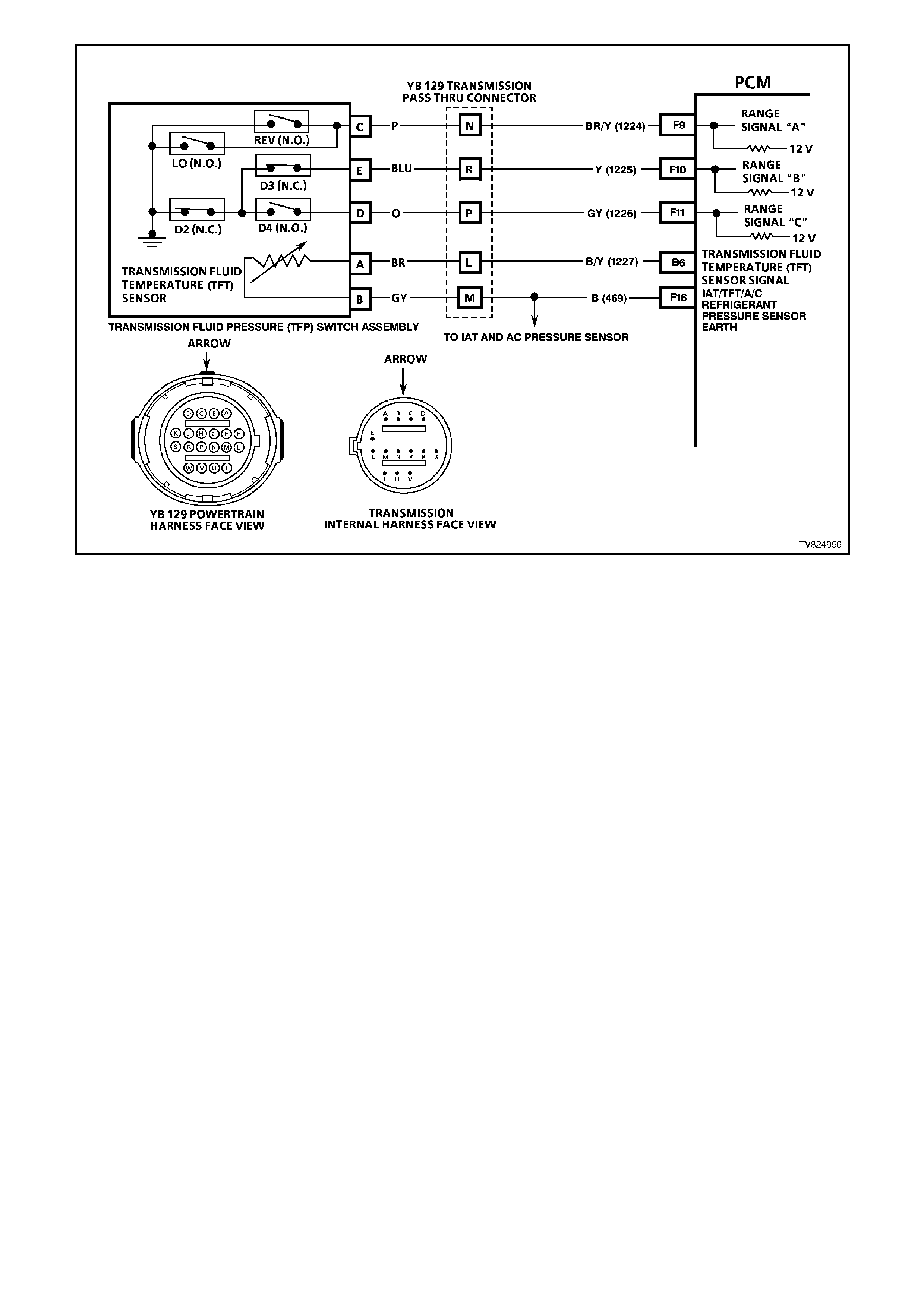
Figure 6C2-1-39 Transmission Fluid Pressure (TFP) Switch Assembly Circuit
THEFT D ETERRENT INPUT SIGNAL
When the ignition switch is turned to the ON position, the BCM polls the PCM and sends an encrypted BCM/key
security code. The security code is received by the BCM, via the remote key reader (slip ring) or via the remote
receiver in the event of no slip ring communication.
The PCM compares the received security code with its stored security code and if matched, the PCM will continue
to enable fuel injector fuelling and engine crank.
The PCM will return a Valid Code message (OK TO START), which tells the BCM to jump from the short loop mode
to the long loop mode.
When the ignition os turned from the OFF position to the ON position, the BCM will communicate with the PCM for
antitheft purposes. If the BCM does not receive a message OK TO START from the PCM within 0.5 second of the
ignition being switched on, the auxiliary bus is isolated via switching within the BCM.
The isolation of the auxiliary data bus during this period eliminates the possibility of a device failure other than the
BCM or PCM causing a problem on the bus and inhibiting antitheft communications.
This period, known as ‘Short Loop Time’, continues until the PCM responds with an acknowledgment or a maximum
period of 5 seconds, after which the BCM will switch to the standard poling sequence.
Following successful antitheft communications, the BCM begins sequential polling of devices on the bus and normal
system operation is established.
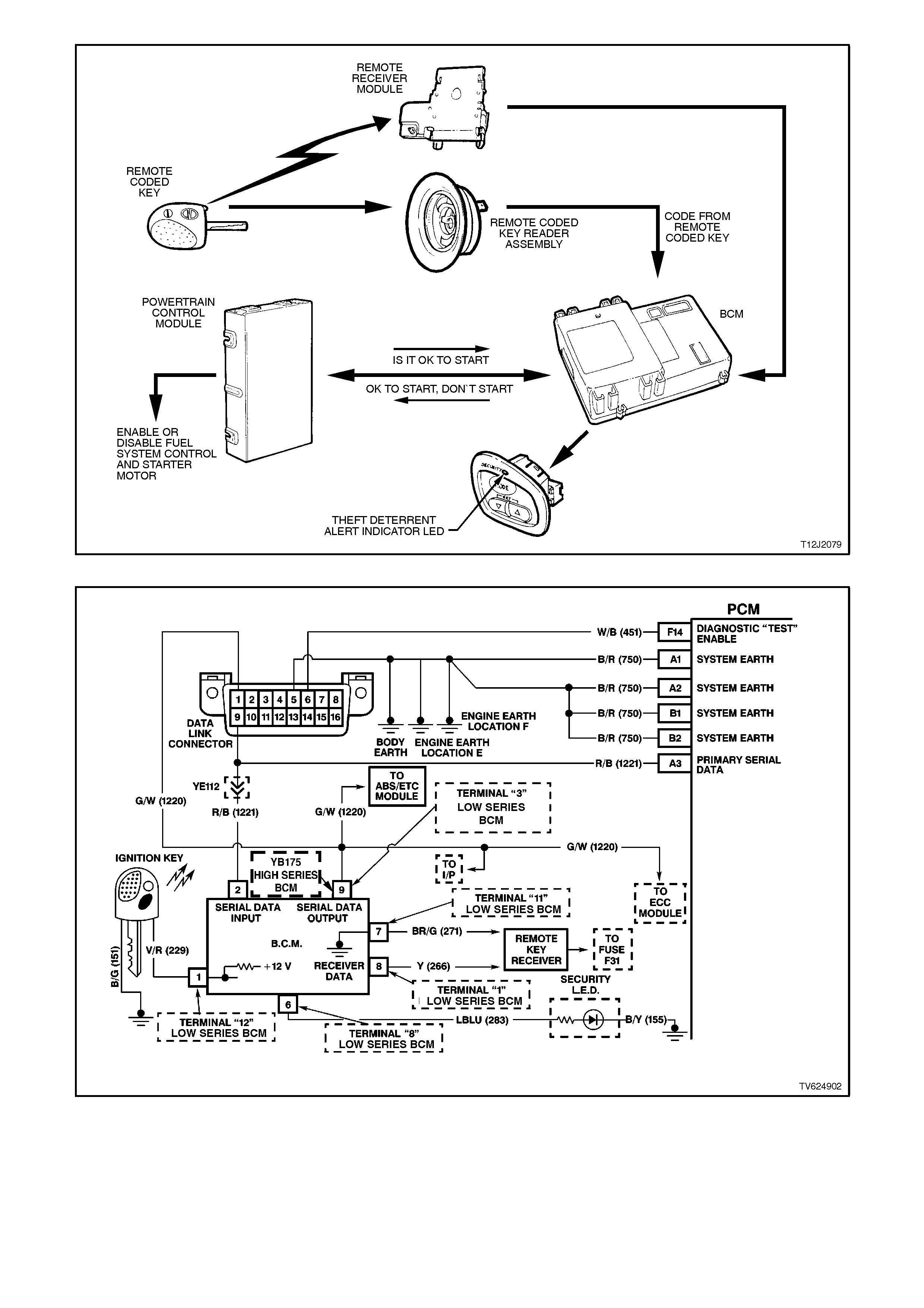
Figure 6C2-1-40 Theft Deterrent System
Figure 6C2-1-41 PCM Theft Deterrent Serial Data Circuit
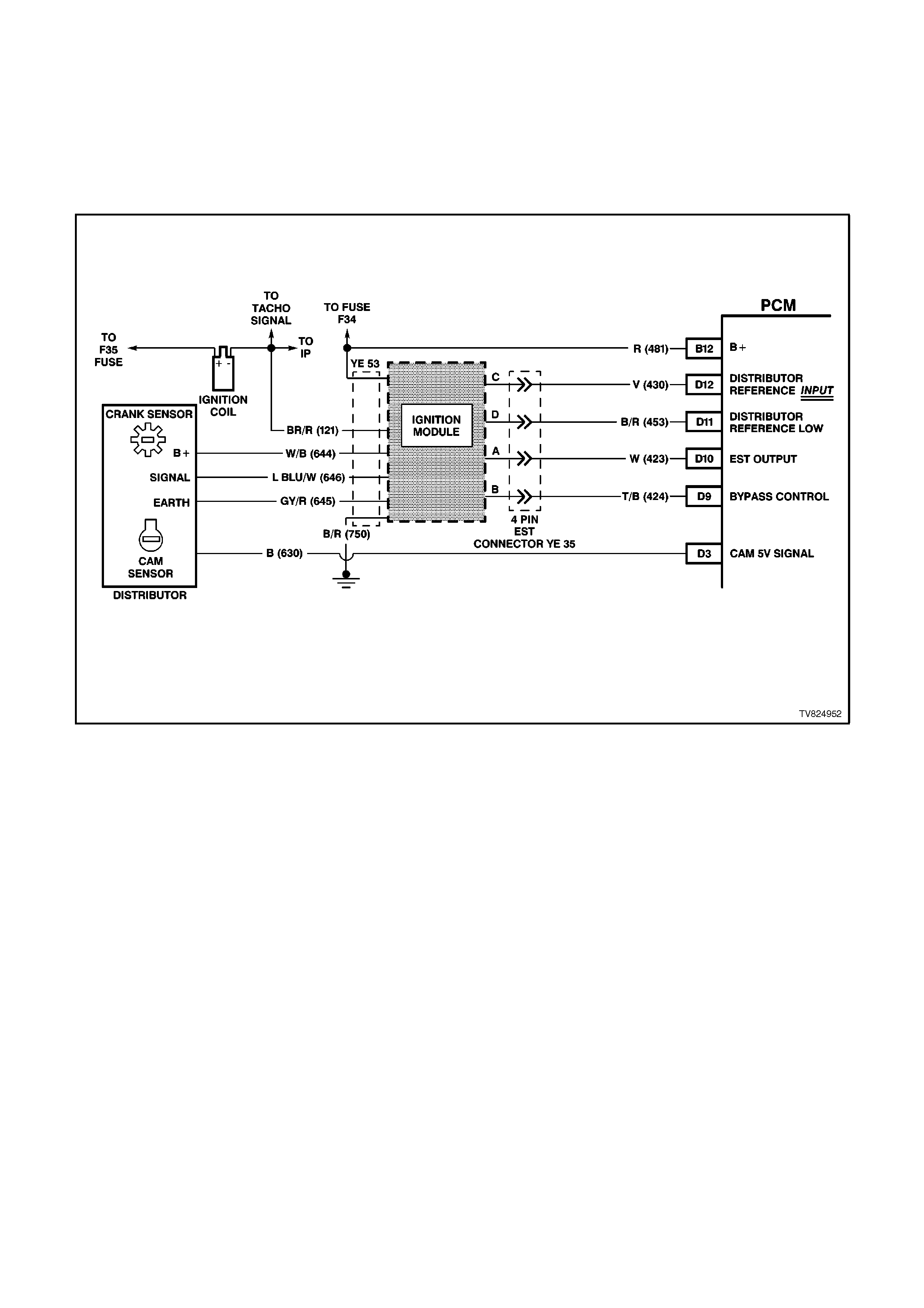
CAMSHAFT POSITION SIGNAL
The camshaft position sensor is located in the distributor directly under the cap. The camshaft position reference
signal is sent directly to the PCM. The PCM then calculates the position of the No. 1 cylinder on its power stroke.
This signal is used by the PCM to calculate sequential fuel injection operation. If the camshaft position signal is lost
while the engine is running, the fuel injection mode will be based on the last fuel injection pulse, and the engine will
continue to run. The engine can be restarted and will run in the synchronous (all eight injectors inject at once) mode
as long as the fault is present. When the camshaft position signal is not being received by the PCM, a DTC 48 will
set. An intermittent camshaft position signal will set a DTC 49. If either of these DTC's are set, the fuel system will
not be in the sequential fuel injection mode.
Figure 6C2-1-42 Camshaft Position Sensor Signal

1.3 TRANSMISSION INPUT INFORMATION SENSORS AND SIGNALS
The control module used with the Sequential Fuel Injection (SFI) engine is called a Powertrain Control Module
(PCM) and controls a number of engine functions such as.
• The fuel control
• The ignition timing
• The transmission functions
The diagnosis of this transmission requires the use of a Tech 2 scan tool.
The transmission control system part of the powertrain control module contains software and hardware. The
software and the hardware monitors a number of the engine and the vehicle functions. Then uses the data to
control the following operations.
• The torque converter clutch engagement.
• The upshift pattern.
• The downshift pattern.
• The line pressure to control shift quality.
INFORMATION SENSORS
The PCM uses the following information sensors and switches to gather data for electronically controlling the
transmission functions.
The Engine Coolant Temperature (ECT) sensor.
The Engine speed.
The Transmission Fluid Pressure Switch
Assembly.
The Throttle Position (TP) Sensor.
The Transmission Fluid Temperature (TFT) sensor.
The Transmission Economy/Power Switch.
The Vehicle Speed Sensor (VSS).
The Mass Air Flow (MAF) Sensor.
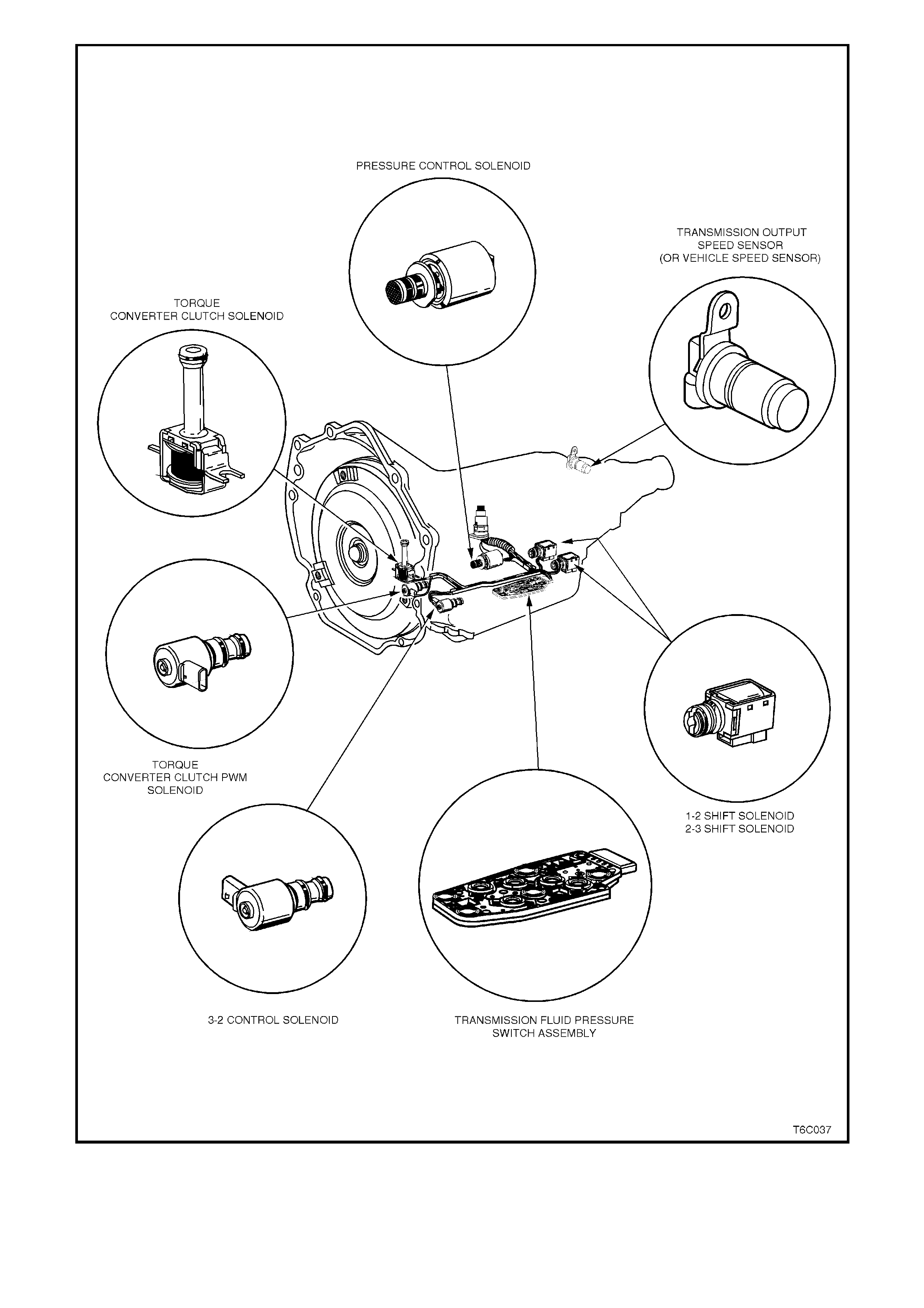
Figure 6C2-1-43 Transmission Electronic Component Location View
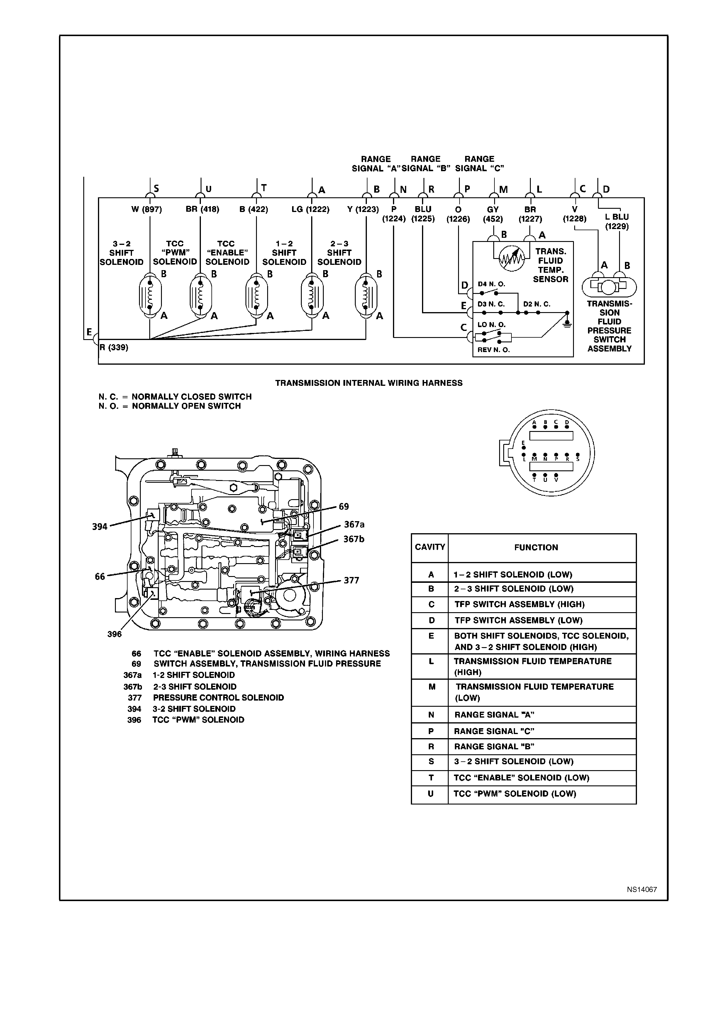
Figure 6C2-1-44 Transmission Wiring
TRANSMISSION FLUID PRESSURE (TFP) SWITCH ASSEMBLY
Figure 6C2-1-45 Transmission Fluid Pressure (TFP) Switch Assembly and Transmission Fluid Temperature Sensor
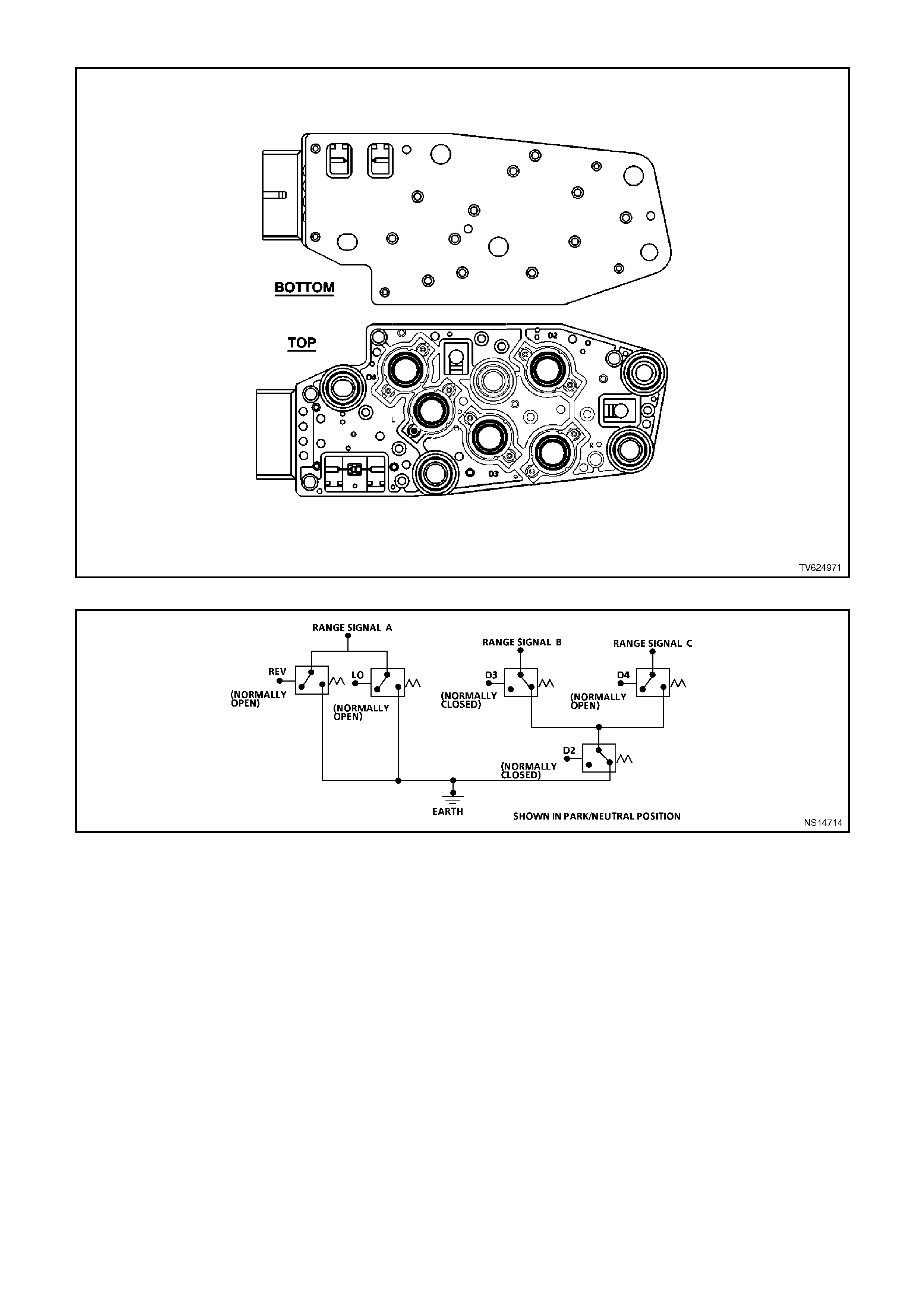
Figure 6C2-1-46 Transmission Fluid Pressure Switch Assembly (TFP) Switches
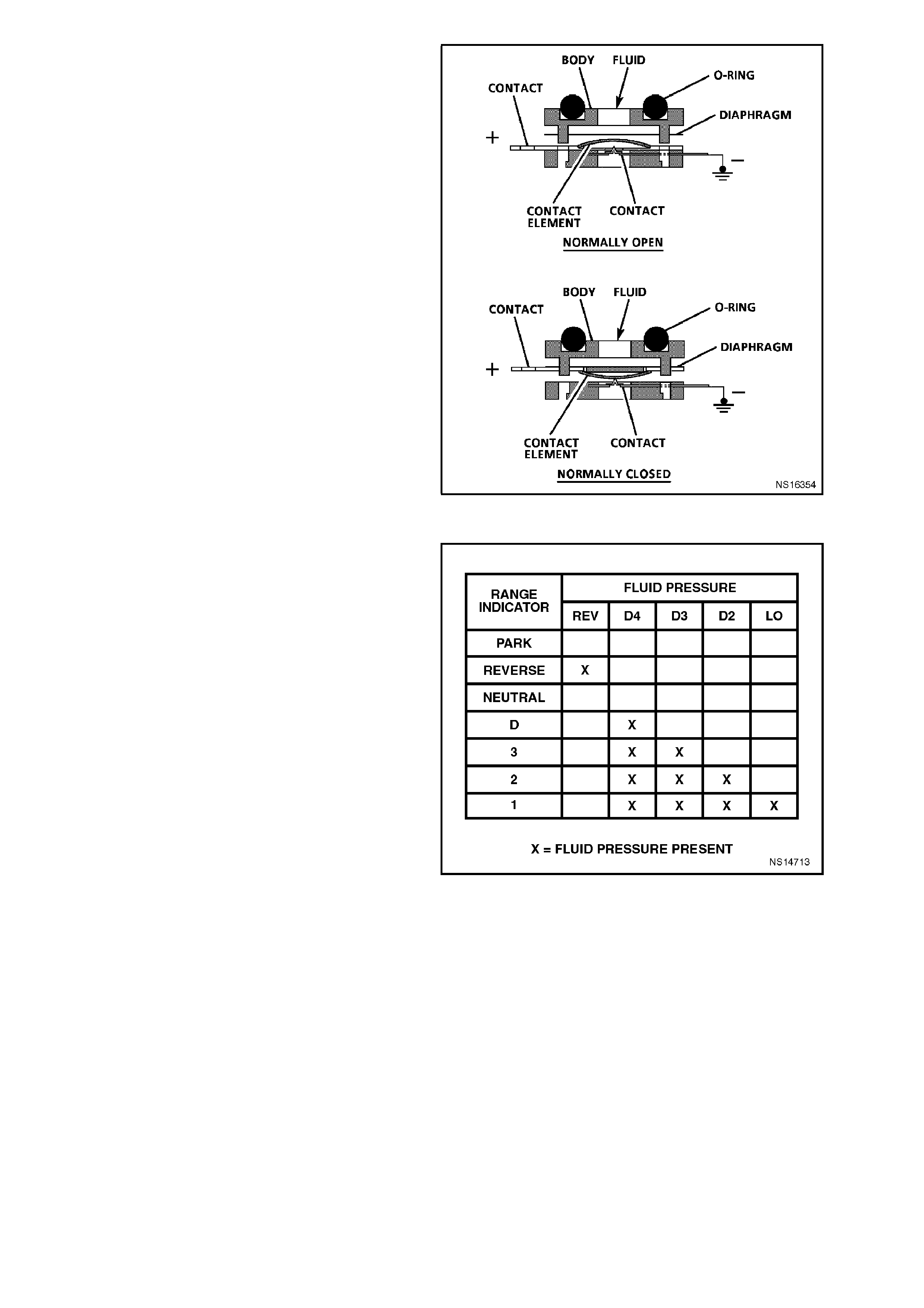
This gear range sensing device is called a
Transmission Fluid Pressure (TFP) switch
assembly. The TFP is used by the PCM to sense
what gear range has been selected by the vehicle
operator. The TFP is located on the valve body.
The TFP consists of five pressure switches. Two
normally closed and three normally open. The
normally open fluid pressure switches are the
"D4", "LO" and "Reverse" fluid pressure switches.
Electrical current is supplied to these switches
when fluid pressure is present. Fluid pressure
moves the diaphragm and contact element until
the contact element touches both the positive
contact and the earth contact. This creates a
closed circuit and allows current to flow from the
positive contact, through the switch to earth. The
normally closed fluid pressure switches are the
"D2" and "D3" fluid pressure switches. They are
norm ally closed and the electrical c urrent is free to
flow from the positive contact to the earth contact
when no fluid pressure is present. The fluid
pressure moves the diaphragm to disable the
positive and earth contacts. This opens the switch
and stops the current from flowing.
Figure 6C2-1-47 Transmission Fluid Pressure (TFP) Switch
Assembly
The PCM supplies the system voltage to the TFP
on three separate lines. An open circuit m easures
12 volts while an earthed circuit measures 0 volts.
The switches are opened and closed by the fluid
pressures. The combination of switches which are
open and closed are used by the PCM to
determ ine actual valve position. The T FP however
cannot distinguish between park and neutral
because the monitored valve body pressures are
identical in both cases.
• L-This switch will have hydraulic pressure
applied to it in m anual 1st gear only and will be
closed.
• R-This switch will have hydraulic pressure
applied to it in reverse only and will be closed.
• D2-This switch will have hydraulic pressure
applied to it in manual 1st and 2nd gear and will
be open.
• D3-This switch will have hydraulic pressure
applied to it in manual 1st, 2nd and 3rd gear
and will be open.
• D4-This switch will have hydraulic pressure
applied to it in all the drive gears except
reverse and will be closed.
Figure 6C2-1-48 Pressure Applied to TFP Switches

Use a high impedance digital volt ohm meter when
measuring the TFP voltages. Measure the TFP
voltage by backprobing the PCM then taking
readings from each terminal to earth. Then
compare these readings to the combination chart.
On the transmission wiring harness, pin N is
"Range Signal A", pin R is "Range Signal B", and
pin P is "Range Signal C". W ith the wiring harness
connected and engine idling, a voltage reading on
these three cir cuits will be B+ whenever the circ uit
is open. The circuits s hould read 0V whenever the
circuit is earthed.
These TFP inputs are used to help control the
following
• The line pressure
• The torque converter clutch apply
• The shift solenoid operation
To monitor the TFP assembly operation, the PCM
compares the actual voltage combination of the
switches to a TFP combination chart stored in
memory. If the PCM detects one of two "illegal"
voltage combinations a Diagnostic Trouble Code
28 will set.
There are two possible combinations of the
switches within the pressure switch assembly that
do not represent an actual gear range. If either of
these combinations are detected by the PCM, a
DTC 28 will set. A DTC 28 will not set if a valid
gear range combination appears at the wrong
time.
Figure 6C2-1-49 Transmission Fluid Pressure Chart
While a DTC 28 is present, the PCM will take the
following actions:
• Assume D4 for shift pattern control.
• Use the D2 pressure table.
• Inhibit the 4th gear operation in hot mode only.
• Inhibit the TCC operation.
• Turn the TCC ON in hot mode.
If the TFP resumes normal functioning, the
transm ission will resum e norm al operation after the
next ignition cycle.
A DTC 28 will not detect an open in either range
signal "B" or range signal "C". An open in either of
these signals will not be an illegal T FP com bination
but a legal TFP c om bination at the wrong tim e. T he
PCM will then receive the wrong information.
There are two faults in the TFP that will cause an
unusual complaint. If the range signal "B" is open
the PCM will interpret this PRNDL select as "2" in
park or neutral with the ignition "ON" or engine
idling. The customer will probably complain that
when "D" range is selected the transmission never
shifts into 4th gear. This is because the PCM only
control shif ts in "D" range, but because of the open
in range signal "B" the PCM interprets "3" and the
transm ission will never shift to f ourth gear because
this "3" input is a normal condition.
The other condition to cause an unusual complaint
is an open in the range signal "C". When the dr iver
selects range "3" the PCM will only interpret this
PRNDL select as "2" and will have 1st and 2nd
gears. If the driver selects "D" the transm ission will
have all gears and TCC but the Tech 2 scan tool
will read P-N all the time. Figure 6C2-1-50 Transmission Fluid Pressure (TFP) Switch
Assembly Location
Figure 6C2-1-51 Transmission Fluid Pressure (TFP) Switch Assembly
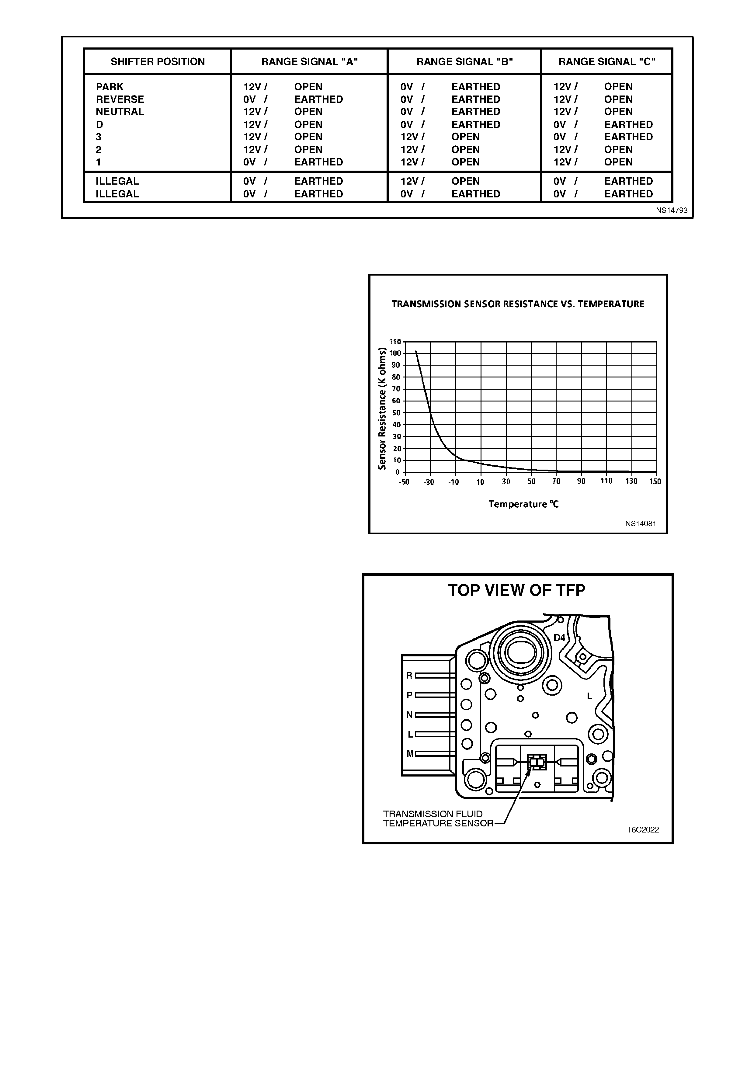
Figure 6C2-1-52 Transmission Fluid Pressure (TFP) Switch Assembly Switch Voltages
TRANSMISSION FLUID TEMPERATURE (TFT) SENSOR
The Transm ission Fluid Temperature (T FT) sensor
is a thermistor (a res istor that changes value based
temperature) that is part of the transmission fluid
Pressure (TFP) Switch Assembly Low transmission
fluid temperature produces high resistance and
high transmission fluid temperature produces low
resistanc e. The PCM supplies a 5 volt s ignal to the
Transmission Fluid Temperature (TFT) sensor
through an internal resistor then measures the
voltage drop in the circuit. The voltage will be high
when the transmission fluid is cold, and low when
the transmission fluid is hot.
Figure 6C2-1-53 TFT Sensor Temperature to Resistance
Relationship
The PCM uses the Transmission Fluid
Temperature (TFT) Sensor to regulate the torque
converter clutch apply, as well as the shift quality.
A Diagnostic Trouble Code (DTC) 58 and DTC 59
indicates a fault in the Transmission Fluid
Temperatur e (T FT) sensor c irc uit. T he Tech 2 s c an
tool will display the transmission fluid temperature
in degrees Celsius. After the vehicle has been
started, the transmission fluid temperature should
rise steadily and then stabilise between 90 and 115
degrees C, depending on load. Both diagnostic
trouble codes will cause the PCM to use a default
value of 130 degrees C. Thus reacting as if the
transmission were hot in either case. When
Diagnostic Trouble Code (DTC) 58 or DTC 59 are
set the torque converter clutch will be enabled in
third and fourth gear and will apply early. Some
driveability symptoms will be noticed especially
when cold.
A DTC 79 will set if the transmission fluid
temperature exceeds 146 degrees C and does not
go lower than 137 degrees C for 30 minutes. The
PCM monitor s the T F T s ens or f or determining DT C
79. An electrical fault in the TFT sensor circuit will
not set a DTC 79. A D TC 79 will only set if the fluid
actually did exceed the temperature or if the TFT
sensor is skewed high or stuck above the
temperature threshold.
Figure 6C2-1-54 Transmission Fluid Temperature Sensor
THROTTLE POSITION (TP) SENSOR
The TP sensor information is used for the engine
functions as well as for the autom atic transm ission
functions
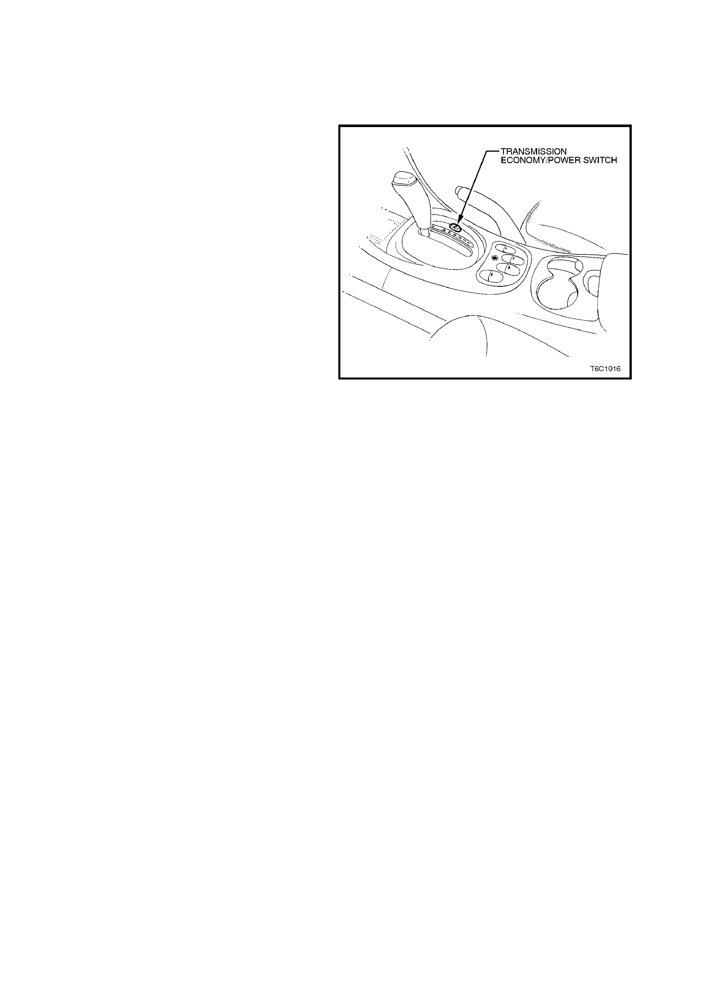
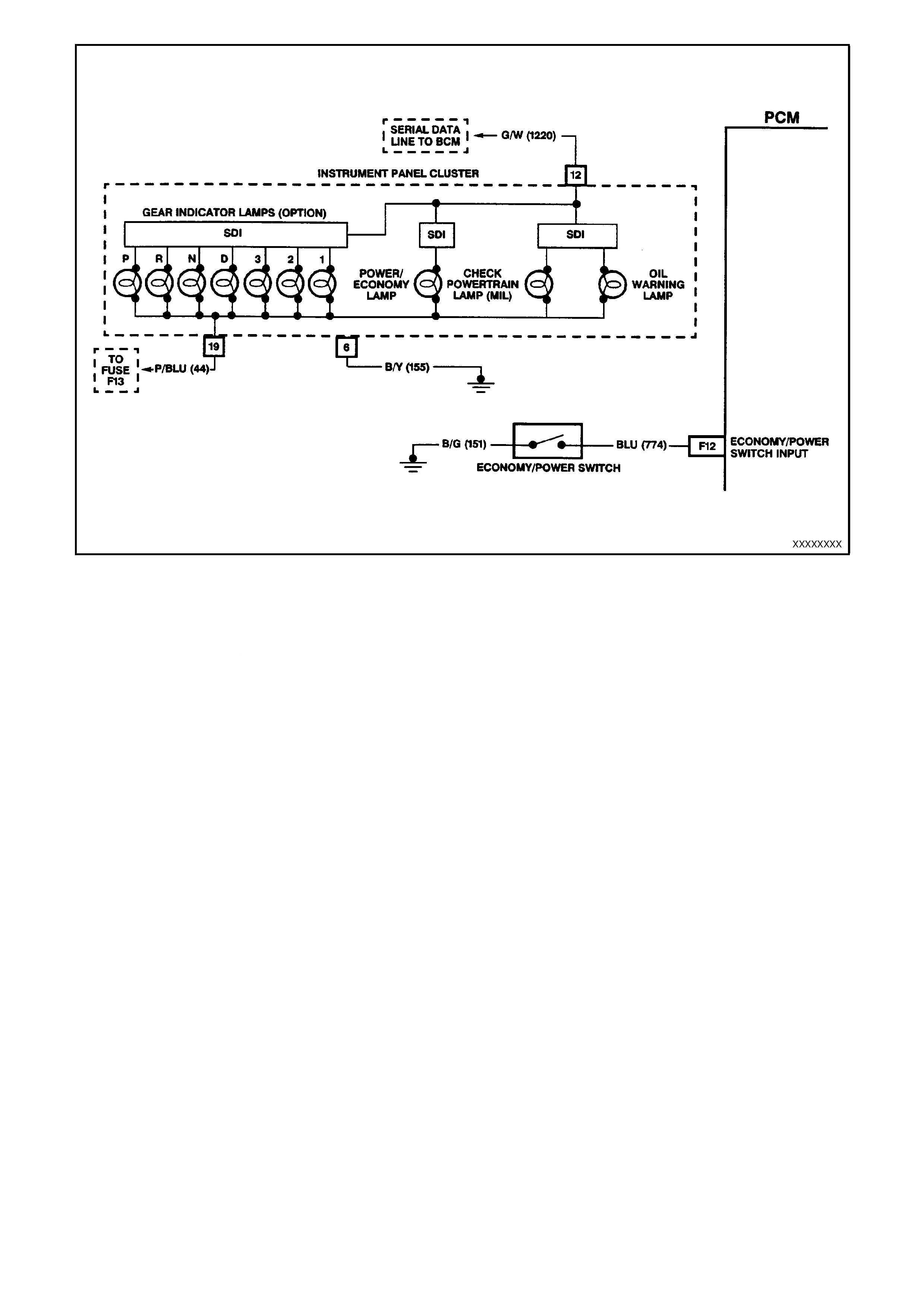
TRANSMISSION ECONOMY/POWER SWITCH
The economy/power switch is used to modify
upshifts and shift times. The driver can select one
of the two transmission modes, "Economy" or
"Power" with a dash or centre console mounted
switch. The out position enables the power mode.
A green indicator lamp is located on the right side
of the instrument panel cluster and displays
"PWR" when illuminated to inform the driver that
the "Power" mode is now enabled.
The PCM sends a voltage signal, about 12 volts,
and monitors the status of this circuit. In the
"Economy" position, the switch is open and the
PCM voltage status signal remains high, about 12
volts. The PCM does not allow shift point changes
in the economy mode. When the transmission
switch is pressed to the Power position the switch
is closed and the PCM voltage status signal is
pulled low, about 0.5 volts. The PCM senses this
voltage drop and enables Power mode (alternate
shift pattern 'tables' to be utilised).
In the "Power" mode, the TCC can be applied in
3rd and 4th gears. When the TCC is applied in 3rd
gear it will stay applied until the normal 4th gear
upshift criteria is met. When the 3-4 upshift
occurs, the TCC will be released momentarily.
Also, in the "Power" mode while in "D" gear select
position, the PCM will delay the 1-2 and 2-3 shift
while under light throttle. The shift patterns will be
the same in the "Economy" and "Power" modes if
the TP sensor is between 80% - 100%. The power
mode should be used when towing as applying the
TCC in 3rd and 4th gear reduces slippage in the
TCC and thus reduces heat build up.
Figure 6C2-1-55 Transmission Economy/Power Switch
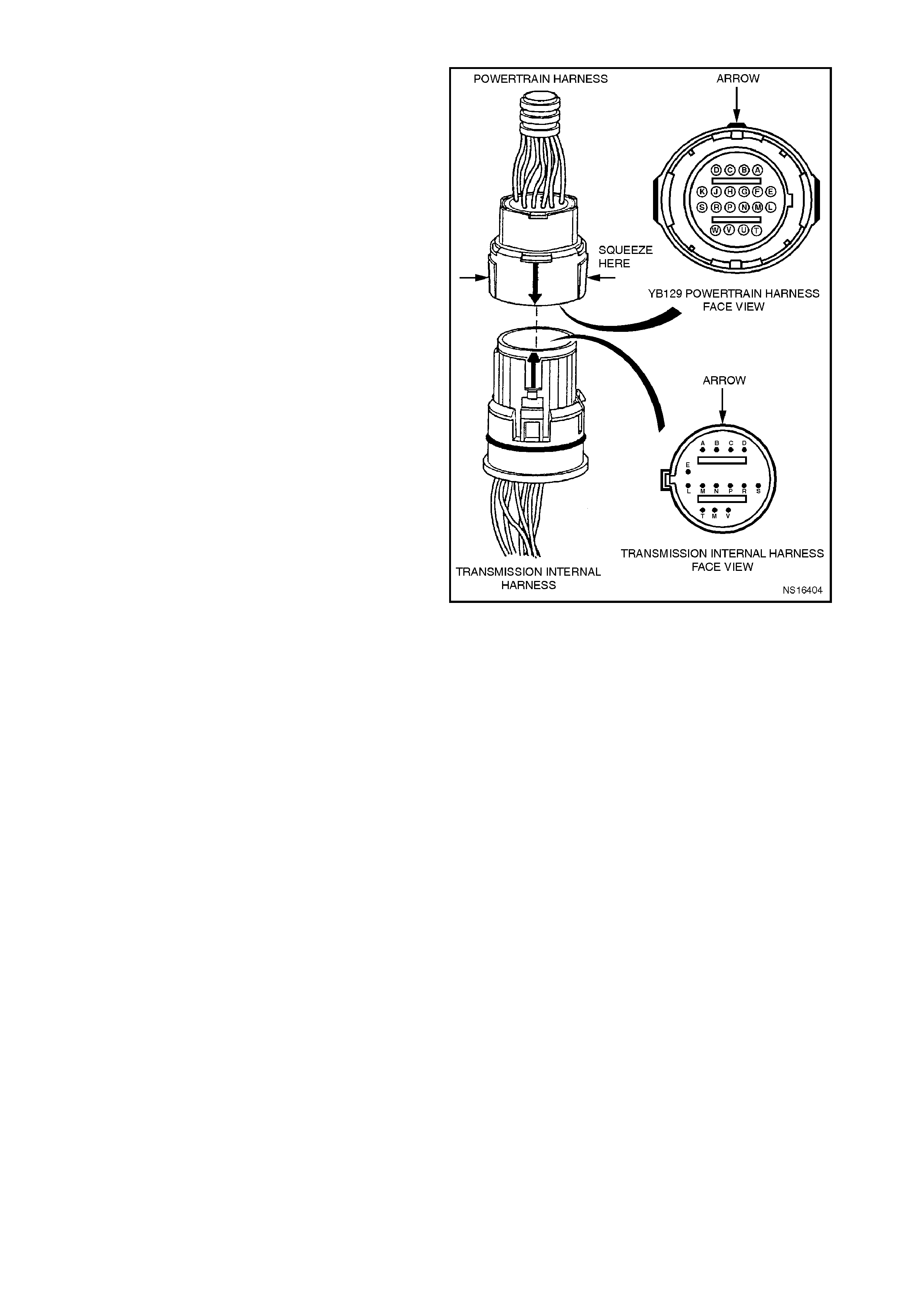
TRANSMISSION PASS-THRU CONNECTOR
The transmission electrical pass-thru connector is a
very important part of the HYDRA-MATIC 4L60-E
operating system.
The wiring harness electric ally c onnects the PCM to
the various sens ors, s olenoids, and relays within the
transmission management system. Many of the
connectors used are environmentally protected. This
is because of the systems low voltages and low
current levels. Anything that interferes with the
electrical connection can cause the transmission to
set diagnostic trouble codes and/or operate
incorrectly.
The following conditions can affect proper electrical
connections.
• Bent pins in the connector from rough handling
during connecting and disconnecting.
• Wires backing away from the pins or coming
uncrimped (in either the transmission or
powertrain wiring harness).
• Dirt contamination entering the connector after
the connector is disconnected.
• Pins in the connector backing out of the
connector or pushed out during connection.
• Excessive transmission fluid leaking into the
connector, wicking up into the powertrain wiring
harness and degrading the wire insulation.
• Water/moisture intrusion in the connector.
• Low pin tension from excessive connecting and
disconnecting of the wiring harness.
• Pin corrosion from contamination.
The presence of transmission fluid in the
transm iss ion connector is not harm ful. T he f luid only
affects the vehicle harness wiring insulation if the
fluid wicks up.
Points to remember when working with the
transmission electrical connector.
• To remove the connector, squeeze the two tabs
towards each other and pull straight up.
• Limit the twisting or the wiggling of the connec tor
during removal.
• Do not pry the connector with a screwdriver or
any other tool.
• To install the connector, first orient the pins by
lining up the arrows on each half of the
connector. Pus h the connector straight down into
the transmission without twisting or angling the
mating parts.
• The connector should click into place with a
positive feel and/or noise.
• Whenever the transmission pass-thru connector
is disconnected from the transmission, and the
ignition is switched is ON or the engine is started,
numerous DTC's will set.
Figure 6C2-1-57 YB 129 Powertrain Harness Connector
1.4 TRANSMISSION OUTP UTS CONTROLLED BY THE PCM
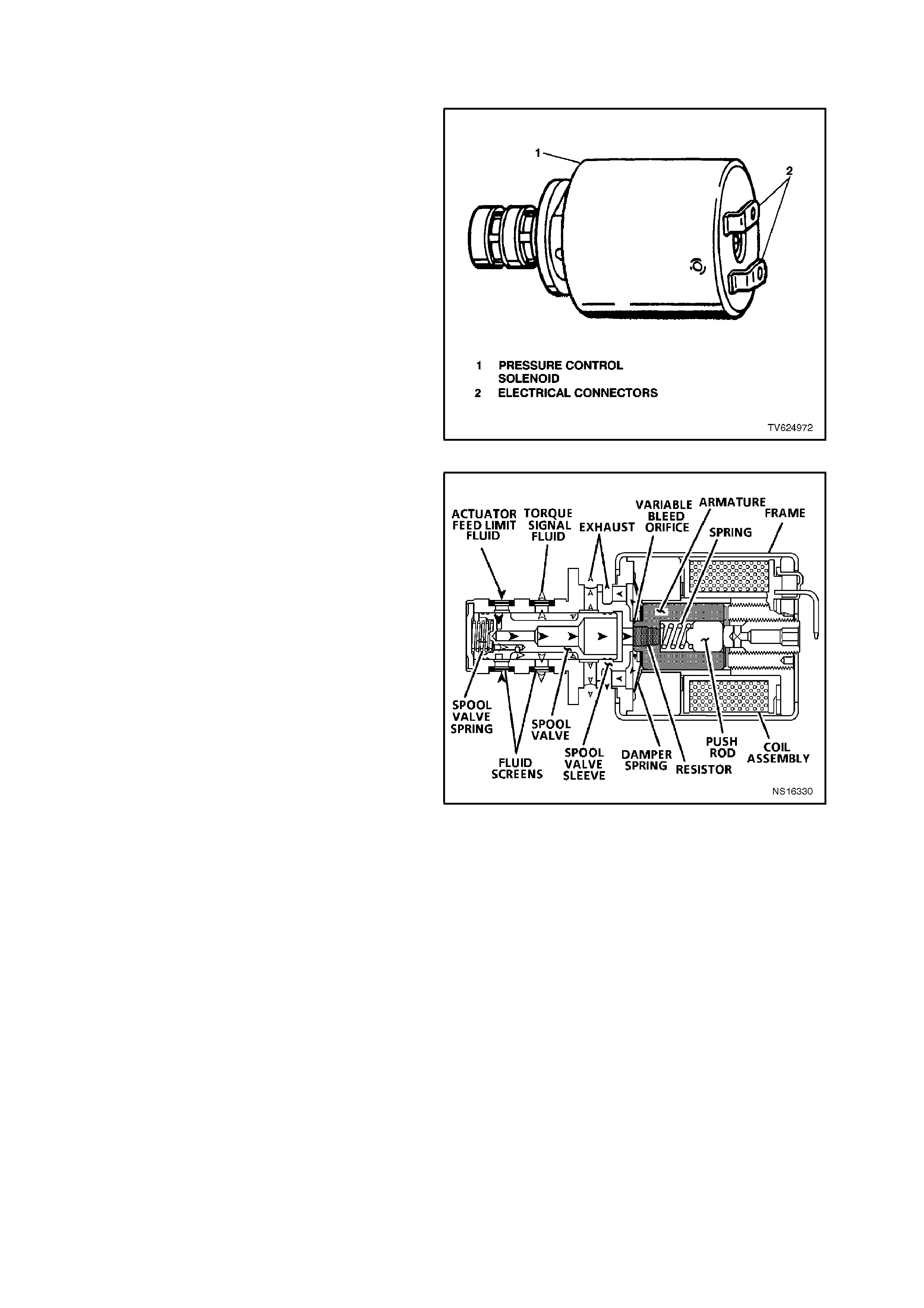
PRESSURE CONTROL SOLENOID
The transm ission Pressure Control Solenoid (PCS)
is an electronic pressure regulator that controls
pressure based on current flow through its coil
winding. The magnetic field produced by the coil
moves the solenoid's internal valve which varies
the pressure to the pressure regulator valve.
Figure 6C2-1-58 Pressure Control Solenoid
The pressure control solenoid takes the place of
the throttle valve used on past model 4L60
transmissions. The PCM varies the line pressure
based on engine load. Engine load is calculated
from various inputs, including the TP sensor and
the MAF sensor. The transmission’s line pressure
is regulated by the PCM. The PCM controls the
amperage applied to the pressure control solenoid
between 0 amps (high line pressure) to 1.1 amps
(low line pressure). This changes the duty cycle of
the pressure control solenoid, which ranges
between 0% to 100%.
Diagnostic T rouble Code 73 will set when the PCM
detects a difference of 0.16 amp or more between
the amperage commanded and actual amperage.
When a DTC 73 is set, the pressure control
solenoid will be commanded OFF creating
maximum line pressure. Whenever the conditions
for setting the DTC no longer exist the PCM will
then resume the normal operation of the pressure
control solenoid. Figure 6C2-1-59 Pressure Control Solenoid Cutawa y View
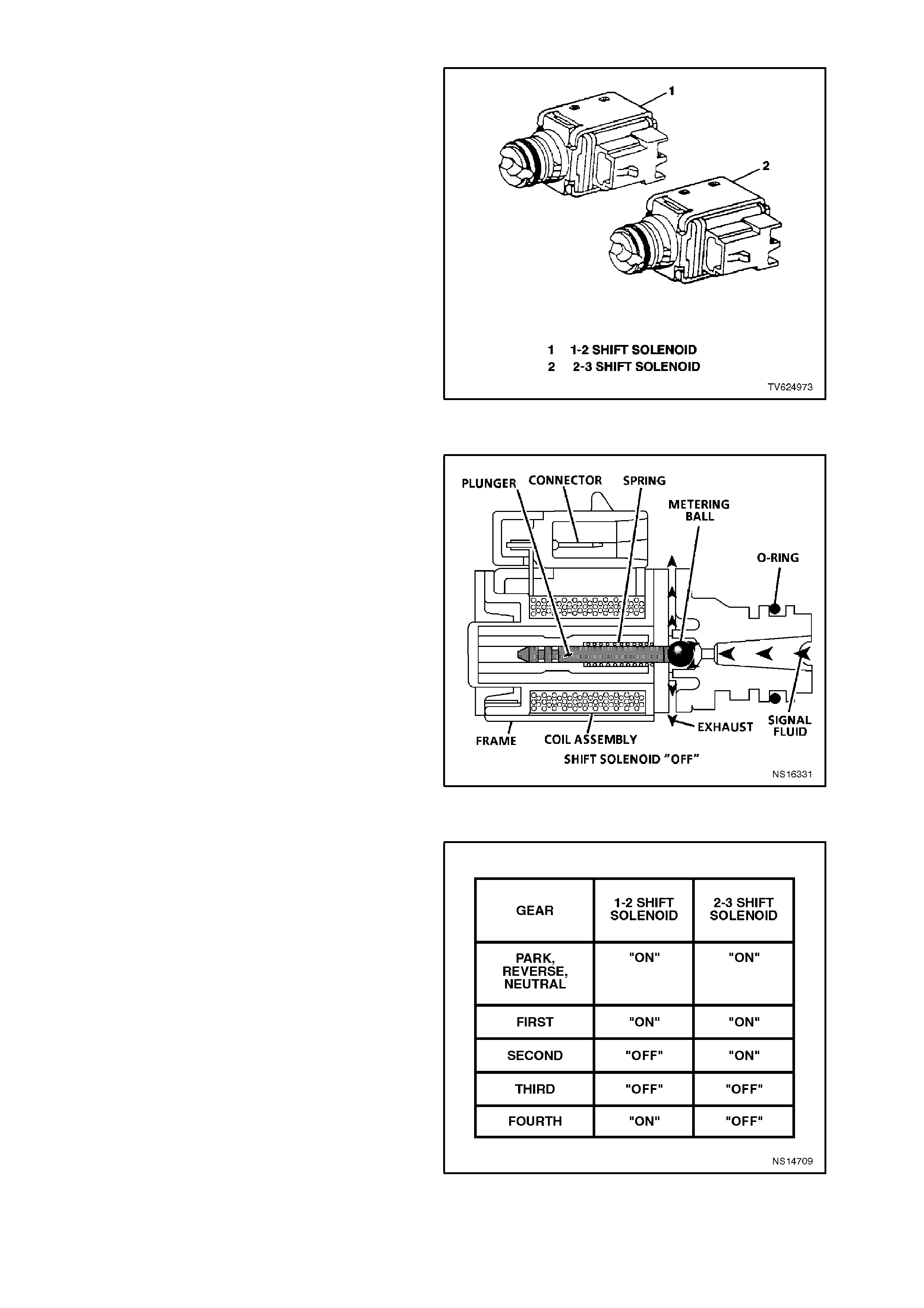
SHIFT SOLENOIDS
The 1-2 s hif t s olenoid and the 2- 3 s hif t s olenoid are
identical solenoids in operation that control the
movement of the 1-2 and 2-3 shift valves (the 3-4
shift valve is not directly controlled by a shift
solenoid). The solenoids are normally open valves
that work in four combinations to shift the
transmission into different gears. The PCM
controlled sh ift solenoids elim inate the need for the
Throttle Valve and the governor pressures to
control shift the valve operation.
IMPORTANT:
The PCM does not have total contr ol of shifting the
transmission. The manual valve can hydraulically
override the shift solenoids. Only in "D" are the
PCM and shift solenoids totally determining what
gear the transm ission is in. In the m anual positions
"3", "2", and "1", the transmission manual valve
position will change fluid direc tion in the valve body.
The transmission will shift hydraulically. The PCM
will have limited control and will respond to the
hydraulic changes to the manual valve. The PCM
will change the shift solenoids when the pressure
switch assembly switches change position and
throttle position and vehicle speeds fall into the
correct ranges for PCM control. In other words the
PCM "catches up" to what happened hydraulically.
The Tech 2 scan tool will only display the
commanded state of the shift solenoids not the
actual gear the transmission is in.
Figure 6C2-1-60 Shift Solenoids
Figure 6C2-1-61 Shift Solenoid Valve Cutaway View
Figure 6C2-1-62 Solenoid Status
1-2 SHIFT SOLENOID
The 1-2 s hift solenoid is attac hed to the valve body
and is a normally open valve. The PCM enables the
solenoid by earthing it through an internal quad
driver. The 1-2 shift solenoid is ON in 1st and 4th
gear, and OFF in 2nd and 3rd gears.
When ON, the shift solenoid redirects the fluid to
act on the shift valves.
There is one diagnostic trouble code associated
with the 1-2 shift solenoid, Diagnos tic T r ouble Code
82 1-2 shift solenoid circuit fault. The PCM
continually monitors the 1- 2 shif t s olenoid cir cuit f or
expected voltage (O FF high ON low). If the voltage
reading is not what is expected on the circuit, a
DTC 82 will set. While Diagnos tic Trouble Code 82
is set, the line pr essure will be high and the vehicle
will have 2nd or 3rd gear only. Whenever the
conditions for setting a DTC 82 no longer exist the
PCM will then resume normal operation of the 1-2
shift solenoid .
2-3 SHIFT SOLENOID
The 2-3 shift s olenoid is attached to the valve body
and is a normally open valve. The PCM enables the
solenoid by earthing it through an internal quad
driver. The 2-3 shift solenoid is ON in 1st and 2nd
gear and OFF in 3rd and 4th gear. When ON, the
shift solenoid redirects the fluid to act on the shift
valves.
There is one Diagnostic Trouble Code (DTC)
associated with the 2-3 shift solenoid DTC 81. T he
PCM continually monitors the 2-3 shift solenoid
circuit for expected voltage (OFF high ON low). If
the voltage reading is not what is expected,
Diagnostic T rouble Code 81 will set. W hile DTC 81
is set, the TCC operation will be inhibited, the line
pressure will be set to high and the transmission
will have 2nd or 3rd gear only. Whenever the
conditions for setting the DTC no longer exist the
PCM will then resume normal operation of the 2-3
Shift Solenoid on the next ignition cycle.
3-2 SHIFT SOLENOID
The 3-2 shift solenoid is a pulse width modulated
(PWM) solenoid used to im prove the 3-2 downshif t.
The 3-2 shift solenoid uses pulse width modulation
to control pressure so that the release of the 3-4
clutch and the apply of the 2-4 band are smooth.
The duty cycle is normally about 0% in first gear
and about 90% in all other drive gears, except
during a 3-2 downshift when the duty cycle drops.
The duty cycle is determined by the following
inputs.
• The throttle position
• The vehicle speed
• The commanded gear
Figure 6C2-1-63 3-2 Shift Solenoid

There is one Diagnostic Trouble Code (DTC)
associated with the 3-2 shift solenoid, DTC 66. A
DTC 66 will set when the PCM detects either A
high voltage when the 3-2 shift solenoid is
commanded high duty cycle or if low voltage exists
on the feedback line when the solenoid is
commanded low duty cycle. While the 3-2 shift
solenoid DT C 66 is s et, the s olenoid will be at a low
duty cycle, creating a soft shift into 3rd gear. The
vehicle will only have 3rd gear unless second gear
is manually selected. The torque converter clutch
will be ON in third gear only and the line pressure
will be high. Whenever the conditions for setting the
DTC no longer exist, the PCM will then resume
normal operation of the 3-2 shift solenoid on the
next ignition cycle.
Figure 6C2-1-64 3-2 Shift Solenoid Valve Cutaway View
TORQUE CONVERTER CLUTCH (TCC) SOLENOID VALVES
This transmission uses two Torque Converter
Clutch (TCC) solenoids. The torque converter
clutch solenoids are used to control torque
converter clutch apply and release. The TCC
enable solenoid has priority in applying and
releasing the torque converter clutch.
The Torque Converter Clutch (TCC) enable
solenoid is commanded either ON or OFF by the
PCM. When earthed (energised ON), by the PCM,
the TCC enable solenoid stops the converter feed
from exhausting. This causes the converter feed
pressur e to increase and shif t the TCC valve to the
apply position. This pressure allows the TCC to
couple the transmission with the engine for a near
100% engagement.
Figure 6C2-1-65 Torque Converter Clutch (TCC) Enable
Solenoid
There are two Diagnostic Trouble Codes (DTC)
associated with the TCC enable solenoid. The first
diagnostic trouble c ode is DTC 67, the T CC enable
Solenoid Circuit Fault. DTC 67 is designed to
detect a fault in the TCC electrical circuit. While a
DTC 67 is set the PCM will inhibit 4th gear if the
transmission is in the hot mode, and no TCC
operation.
The second diagnostic trouble code associated
with the TCC enable solenoid is DTC 69, TCC
Stuck ON. Diagnostic T rouble Code 69 is des igned
to detect a TCC that does not disengage. It does
this by monitoring engine RPM when the TCC
enable solenoid is commanded ON. If the engine
speed does not increase when the TCC enable
solenoid is disengaged, a DTC 69 will set. W hile a
DTC 69 is set the TCC will be ON in all gears or
second, third and fourth gears depending upon the
fault, and the transmission will have an early shift
pattern. Whenever the conditions for setting the
DTC no longer exis t, the PCM will then resum e the
normal operation of the TCC, on the next ignition
cycle.
Figure 6C2-1-66 TCC Solenoid Cutaway View
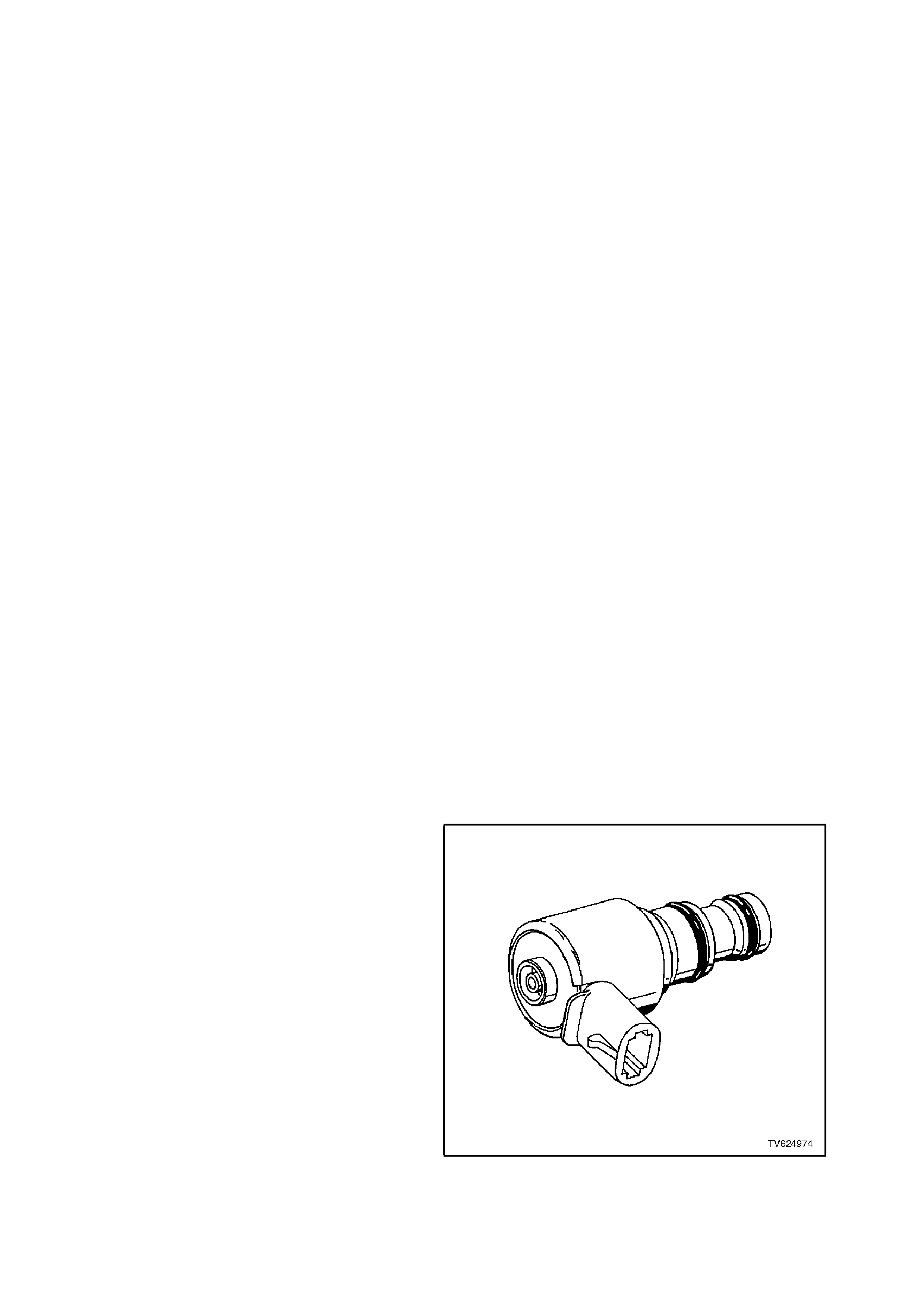
The Torque Converter Clutch "PWM" Solenoid is
used to control the fluid acting on the converter
clutch valve. This controls the TCC apply and the
release. This solenoid is attached to the control
valve body assembly within the transmission. The
TCC "PWM" Solenoid does not have total control
over the TCC engagement. The TCC PWM
Solenoid is used as a supplement to the TCC
enable Solenoid. The TCC "PWM" Solenoid is used
to provide smooth engagement of the torque
converter clutch by operating on a negative duty
cycle percent of ON time. This means that the
earth (negative or low) side of the solenoid circ uit is
controlled by the PCM.
Figure 6C2-1-67 Torque Converter Clutch (TCC) "PWM"
Solenoid
The TCC "PWM" solenoid is constantly fed B+ to
the high side. The PCM controls the length of time
the electrical c ircuit path to earth is closed (i.e. duty
cycle).
When the PCM closes the solenoid earth circuit,
current flows through the TCC "PWM" solenoid,
and the earth circuit is at a low voltage state (0
volts and solenoid energised).
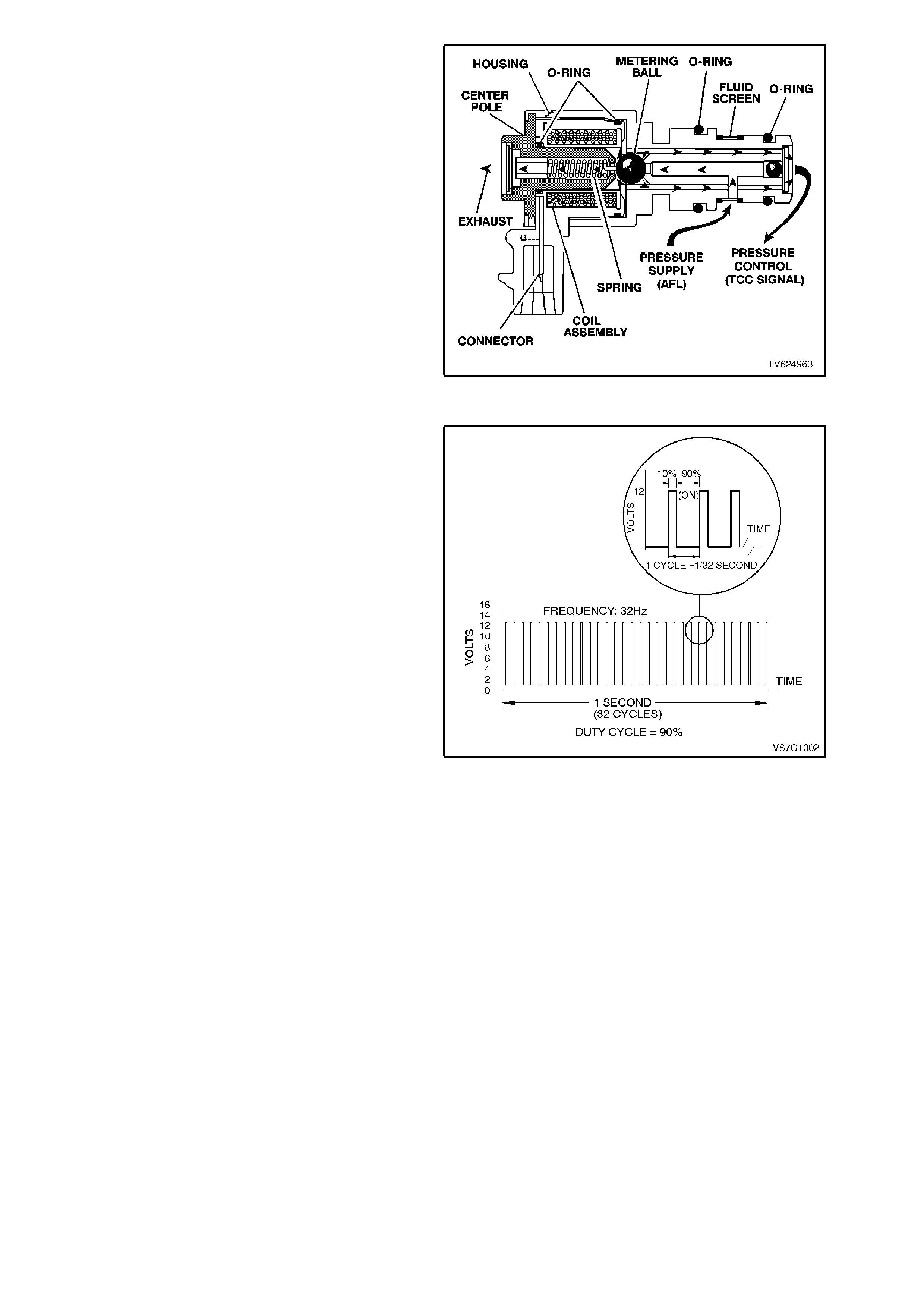
Fig. 6C2-1-69 illustrates an example of the TCC
"PWM" solenoid operating with a 90% negative
duty cycle at a constant operating frequency of 32
Hz (cycles per second). The frequency means that
the solenoid is puls ed (energised) with current fr om
the PCM 32 times per second. The 90% negative
duty cycle means that during each of these 32
cycles the solenoid is energis ed (ON) and 0 volts is
measured on the low (negative) side of the circuit,
90 % of the time.
Figure 6C2-1-68 Torque Converter Clutch (TCC) "PWM"
Solenoid Cutaway View
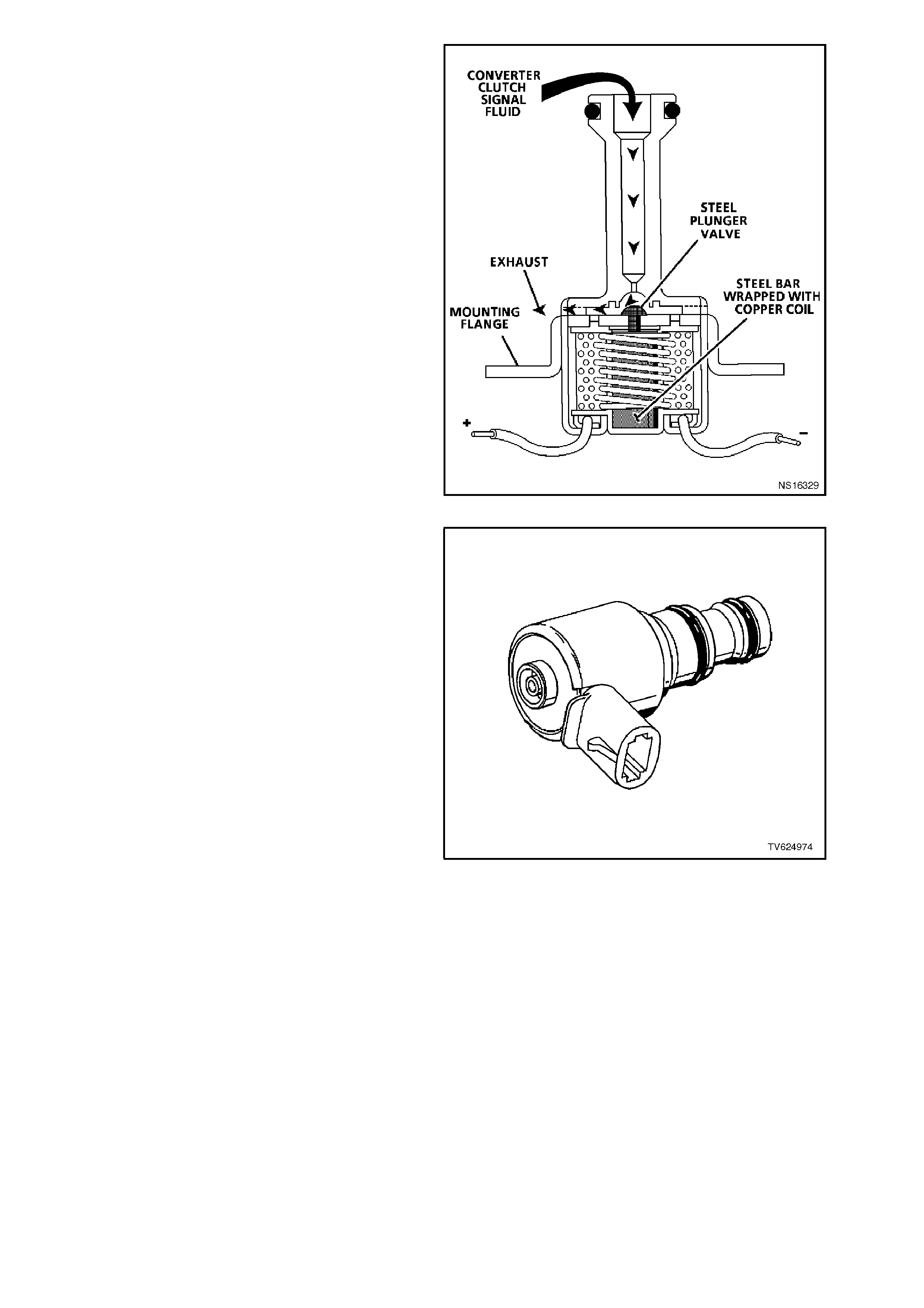
At speeds below approximately 13 km/h, the
negative duty cycle will be 0%. This means that no
current will flow to the TCC "PW M" s olenoid, W hen
in this condition, the spring force will move the
plunger (refer Fig. 6C2-1-66), seating the metering
ball and blocking the filtered Actuator Feed Limit
(AFL) fluid from entering the Torque Converter
Clutch Signal (TCC SIGNAL) circuit. This action
opens the Torque Converter Clutch Signal fluid
circuit to exhaust through the solenoid.
Above the speed of approximately 13 km/h, the
TCC "PWM" solenoid will be operating at about a
90% duty cycle. T his action will cause the m etering
ball to close off the path to exhaust, most of the
time and allow fluid to flow past the metering ball
and into the TCC SIGNAL circuit, in readiness for
the apply of the torque converter clutch.
W hen the PCM signals the TCC to apply, the TCC
"PWM" solenoid operates with a variable, negative
duty cycle, ranging from 90% to 0%, with an
operating fr equency of 32 Hz. Th is allows the PCM
to control the current flow through the solenoid coil
according to the duty cycle that it sets . This has the
effect of creating a variable magnetic field, that
magnetises the solenoid core, attracting the
metering ball to seat against spring force. A high
percentage duty cycle keeps the metering ball
seated more, thereby creating higher TCC signal
fluid pressures.
Figure 6C2-1-69 Torque Converter Clutch (TCC) "PWM"
Solenoid Duty Cycle
TCC "PWM" SOLENOID OPERATION
W hen the vehic le road speed r ises above about 13
km/h, the PCM commands the TCC "PWM"
solenoid duty cycle to change from 0% to 90%, in
readiness for an apply of the torque converter.
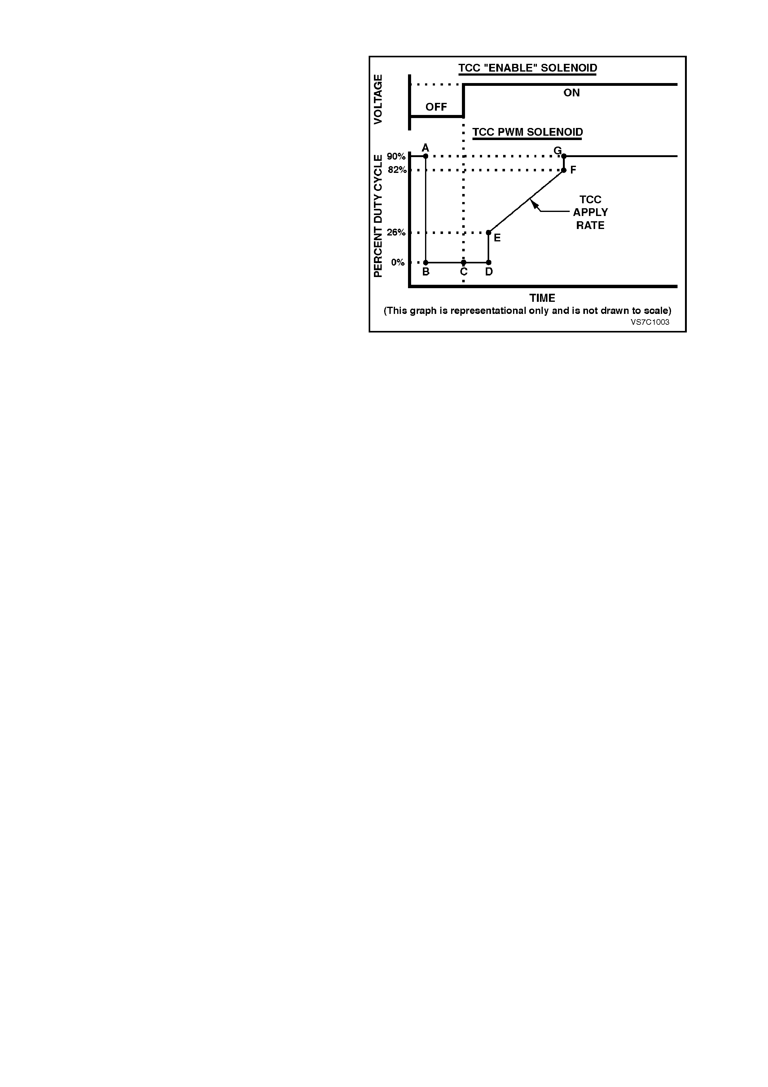
To apply the torque converter clutch, the process
the PCM adopts, is as follows;
-The duty cycle is dropped to 0% (point "B")
and a measurable amount of time is allowed
for the T CC enable solenoid to turn "ON". This
is shown as the time between points "B" and
"C" in Fig. 6C2-1-67. Note that, at point "B",
the TCC enable solenoid is activated.
-The tim e from point "C" to "D" is used to allow
converter ( CONV FD) fluid to build in pressure
and move the Converter Clutch Valve into the
apply position.
-At this point, with the TCC enable solenoid
applied, the PCM increases the duty cycle to
about 26% (point "E"). From this point, the
duty cycle is 'ram ped' to around the 82% point
("E" to "F"). T he rate at which the duty cyc le is
increased over this period of time, determ ines
how quickly the value of the regulated apply
fluid increases and therefore, how quickly the
torque converter clutch is applied. This rate of
change also affects the converter clutch apply
'feel'.
-As soon as the duty cycle reaches 82%, it is
then immediately increased to the maximum of
90%, to achieve full apply pressure in the
regulated apply fluid circuit (point "G").
NOTE:
That the duty cycle and apply pressure will
continually vary, depending on vehicle specif ication
and operating conditions.
The two TCC solenoids work together so that the
TCC apply or release rate can be calibrated for a
variety of conditions.
If a fault is detected by the PCM, in the TCC
"PWM" solenoid electr ical cir cuit, a DT C 83 will set.
W hen a DTC 83 is set, the PCM will inhibit the 4th
gear operation and the TCC operation.
Figure 6C2-1-70 Torque Converter Clutch Solenoid
Operation

1.5 FUEL CONTROL SYSTEM
PURPOSE
The purpose of closed loop fuel control is to control the tailpipe emissions. The tailpipe emissions consist of
hydrocarbons (HC), Carbon Monoxide (CO), and Oxides of Nitrogen (NOx).
The closed loop system regulates the exhaust emissions by controlling the air/fuel ratio at an optimum level during
various driving conditions. The most efficient air/fuel ratio to minimise exhaust emissions is 14.7 to 1. This allows
the three-way catalytic converter to operate at a maximum conversion efficiency. Due to the constant monitoring of
the exhaust gases by the oxygen sensor, and the adjusting of the fuel injector pulse width by the PCM, the fuel
injection system is called a "closed-loop" fuel control system.
FUNCTION
The fuel supply system delivers the fuel at a regulated pressure to the fuel rail. The fuel injectors, act as fuel flow
control valves. The fuel injectors spray atomised fuel into the inlet ports whenever they are "pulsed" by the PCM. All
VT vehicles are equipped with the sequential port fuel injection system.
The PCM controls the amount of fuel being injected into the engine by controlling the time the fuel injectors are
opened. This length-of-time is called a pulse width. To increase the amount of fuel being injected, the pulse width is
lengthened, and vice versa. The pulse width is calibratable and varies between 0 - 11 milliseconds with the engine
running at idle. The injection pulses normally occur once every crankshaft revolution.
MASS AIR FLOW SYSTEM
The Mass Air Flow sensor measures the intake air that enters the engine.
Advantages of Mass Air Flow.
• Will compensate for variations in base engine components. (Camshaft, valves, compression ratio)
• Compensates for engine aging.
• No air measurement lag time.
• Excellent idle stability.
Two specific data sensors provide the PCM with the basic information for the fuel management portion of operation.
That is, two specific signals; crankshaft reference signal from the ignition system, and the Mass Air Flow (MAF)
sensor signal. Both of these signals to the PCM establish the engine speed and amount of air entering into the
engine. Due to the additional temperature compensation sensor in the MAF sensor, this system does not require a
manifold absolute pressure sensor.
The engine RPM signal comes from the ignition module to the PCM on the crankshaft reference signal. The PCM
uses RPM information to calculate the fuel injector pulse width and the spark timing for a given operating RPM
band.
The amount of air entering into the engine is sent as a signal from the mass air flow sensor to the PCM.
When the engine is started, the PCM will immediately look at the Engine Coolant Temperature sensor to determine
how much fuel is required to start the engine. The PCM constantly monitors the MAF sensor values to determine
both the spark advance and the engine fuelling requirements. The Mass Air Flow sensor measures the amount of
air that enters into the engine. The PCM then calculates how much fuel that must be injected to maintain an air/fuel
ratio of 14.7 to 1. An engine started in cold weather will require more fuel and more spark advance than an engine
started hot.
The mass air flow sensor used on this engine utilises a heated element. Three sensing elements are used in this
system.
As the incoming air passes over the heated elements they begin to cool. By measuring the amount of voltage
required to maintain the heated elements at a temperature above ambient temperature the mass air flow rate can
be calculated.
As the PCM receives the frequency signal from the mass air flow sensor, the PCM searches for programmed tables
to determine the pulse width of the fuel injectors required to match the mass air flow signals.
The signal that is sent from the mass air flow sensor is sent in the form of a frequency output. A large quantity of air
passing through the sensor (such as when accelerating) will be indicated as a high frequency. A small quantity of air
passing through the sensor will be indicated as a low frequency (such as deceleration or at idle). The Tech 2 "scan"
tool displays the MAF sensor information in frequency, grams per second. A "normal" reading is approximately 6 -
10 grams per second at idle and increases the engine RPM.

MODES OF OPERATION
The PCM monitors the voltage signals from several of the sensors to determine how much fuel to deliver to the
engine. Also, when to operate in the open-loop or closed-loop mode. The fuel is controlled in one of several
possible modes. All the modes are controlled by the PCM, and are described in the following paragraphs.
STARTING MODE
When the ignition is turned ON, the PCM will energise the fuel pump relay. Then the fuel pump relay will energise
the fuel pump. The fuel pump then pressurise the fuel rail. The PCM then checks the engine coolant temperature
sensor to determine the injector pulse width for starting the engine.
When the cranking begins, the PCM will operate in the Starting Mode until the engine speed is greater than 400
RPM -or- the "Clear Flood" mode is enabled. The pulse width during the Starting Mode is between 4 and 26
milliseconds, depending on the engine coolant temperature.
CLEAR FLOOD MODE
If the engine floods, it can be started by depressing the accelerator pedal to the floor while cranking the engine. The
PCM then pulses the fuel injectors with only a 4 millisecond pulse width. This should clear a flooded engine. The
PCM holds this pulse width as long as the throttle position sensor indicates the throttle is nearly wide open, and
RPM is below 400.
If the throttle is held wide-open, while attempting to start a non-flooded engine, the engine may not start. A 4
millisecond pulse width may not be enough fuel to start a non-flooded engine, especially if the engine is cold.
NORMAL OPEN LOOP MODE
After the engine is running (RPM more than 400), the PCM will operate the fuel control system in the Open Loop
mode. In open loop, the PCM ignores the signal from the Oxygen Sensor (O2S), and calculates the air/fuel ratio
injector pulse width based on inputs from the crankshaft reference signal (RPM input) and these four sensors.
• The MAF sensor
• The IAT sensor
• The ECT sensor
• The TP sensor
The system will stay in the Open Loop mode until all the Closed Loop mode criteria have been met.
In open loop, the calculated pulse width may give an air/fuel ratio other than 14.7 to 1. An example of this would be
when the engine is cold, because a richer mixture is needed to ensure good driveability.
The normal open loop mode is not active when adverse or abnormal vehicle operating conditions are occurring
adverse conditions include engine overheating due to high vehicle speed or high ambient temperature.
RUN CLOSED LOOP MODE
In the Closed Loop mode, the PCM initially calculates the fuel injector pulse width with the same sensors it uses in
open loop. The difference is that in closed loop, the PCM uses the Oxygen Sensor signal to modify and precisely
tune the fuel. in order to precisely maintain the 14.7 to 1 air/fuel ratio. This allows the catalytic converter to operate
at it's maximum conversion efficiency.
IDLE MODE
The Idle Mode allows a slightly richer mixture at idle for better idle quality. The Idle Mode air/fuel ratio is about 14
to 1. This is an open loop mode, meaning the O2 sensor signal is ignored.
The Idle Mode is in when the throttle is closed, and the vehicle speed is less than 5 km/h.
In the case where the vehicle comes to a stop while operating in the Closed Loop mode, the Idle Mode will be
delayed for about 20-30 seconds. During this time, the PCM will "learn" a fuel correction factor for a 14.7 to 1 air/fuel
ratio before switching to the Idle Mode.
ACCELERATION MODE
The PCM looks at rapid changes in throttle position (TP sensor) to increase engine power, and provides extra fuel
by increasing the injector pulse width. If the increased fuel requirements are great enough, the PCM may add extra
fuel injection pulses between the injector pulses that normally occur once per crankshaft revolution.
DECELERATION MODE
When deceleration occurs, the fuel remaining in the intake manifold can cause excessive emissions and possibly
backfiring. The PCM monitors the changes in throttle position, and air flow, then reduces the amount of fuel being
delivered by decreasing the pulse width.

DECEL FUEL CUTOFF MODE
Decel fuel cutoff disables the fuel delivery during a deceleration to reduce the emissions and to improve the fuel
economy.
When deceleration from road speed occurs, the PCM can cut off the fuel pulses completely for short periods. The
decel fuel cutoff mode occurs when all of the following conditions are met:
• The Coolant temperature is above 63 degrees C.
• The Engine RPM has dropped more than 200 RPM.
• The Vehicle speed is greater than 42 km/h.
• The Throttle Position Sensor angle is less than 2%.
When the decel fuel cutoff is in effect, any one of these can cause the injection pulses to restart.
• The Engine speed has not dropped more than 200 RPM.
• The Vehicle speed is less than 42 km/h.
• The Throttle Position Sensor is greater than 2%.
BATTERY VOLTAGE CORRECTION MODE
At low battery voltages, the ignition system may deliver a weak spark. Also, the fuel injector will take longer to open.
The PCM will compensate by:
• Increasing the spark advance whenever the system voltage is less than 12 volts.
• Increasing the idle RPM whenever the system voltage is less than 10 volts.
• Increasing injector pulse width whenever the system voltage is less than 10 volts.
FUEL CUTOFF MODE
Fuel is cutoff by the PCM whenever the ignition is turned OFF. This prevents dieseling. Also, the fuel pulses are not
delivered if the PCM doesn’t receive any distributor reference pulses from the ignition module.
The Fuel Cutoff Mode is also enabled at
• High engine RPM, as an over speed protection for the engine. When cutoff is in effect due to high RPM, injection
pulses will resume after engine RPM drops slightly.
• High vehicle speed.- When the vehicle speed exceeds a calibratable value (about 220 km/h) the fuel base pulse
width is set to zero. Normal fuel operation will return when the vehicle speed falls below a calibratable value
(about 210 km/h).
SEQUENTIAL FUEL INJECTION MODE
When the engine is cranked, all eight injectors will be energised simultaneously. After the engine has been started
and a good camshaft signal has been processed, the PCM will energise each individual injector in the normal firing
order. This mode of operation helps to stabilise idle, reduce emissions and reduce fluctuations in fuel pressure
ADAPTIVE LEARNING
Adaptive learning is the ability of the on-board computer to determine and remember its most recent operating
experience. The PCM uses this remembered information to "learn from experience" and to make adjustments with
respect to what it learnt. If the engine were to develop a restricted fuel filter, the PCM will change the fuel injector
pulse width richer to compensate for this condition and will remember to keep this fuel injector pulse in memory until
the restriction is corrected. After the restriction has been fixed, the PCM will eventually go back to the original pre-
programmed fuel injector pulse.
Adaptive learning is an on-going process that continues throughout the life of the engine. A new engine with good
compression will have good vacuum. As the engine wears and compression decreases, a slight decrease in engine
vacuum will be noticed, which translates into a slightly lower MAF grams per second at idle, which will decrease
injector pulse width to compensate for this condition.

SHORT TERM FUEL TRIM
Short Term Fuel Trim (STFT) represents short term corrections to the fuel injector pulse width calculations, based
on the oxygen sensor input signal to the PCM.
When the engine is started cold, in "Open Loop," the PCM will control the fuel injection pulse width based upon
various sensor inputs such as RPM, ECT, MAF and TP sensor until the oxygen sensors become hot enough
(approximately 315 degrees C) to operate properly. During this "Open Loop" period, both Short Term Fuel Trim
(STFT) and Long Term Fuel Trim (LTFT) are disabled and will read 0% on a Tech 2 scan tool.
When the oxygen sensor has come up to its normal operating temperature (approximately 600 degrees C or
above), it will produce a varying voltage to the PCM and provide a good indication of what has happened in the
combustion chambers.
At this time the PCM will switch from "Open Loop" to "Closed Loop" and the STFT will start to constantly monitor the
oxygen sensor signal, so that the PCM can modify fuel injector pulse width wi th greater accuracy than in "Open
Loop".
STFT monitors the oxygen sensor signal so that it can adjust the fuel injector pulse width to maintain an air/fuel ratio
of 14.7 to 1 for maximum catalytic converter efficiency. An STFT value of 0% is equivalent to an air/fuel ratio of 14.7
to 1 and an average oxygen sensor signal voltage of 450 mV.
The normal position for Short Term Fuel Trim is 0%, any change from this value indicates the Short Term Fuel Trim
is changing the fuel injector pulse width. The amount of pulse width change depends upon how far the STFT value
is from 0%. If the STFT value is above 0%, the fuel injector pulse width is being increased, thus adding more fuel. If
the STFT value is below 0%, the fuel injector pulse width is being decreased, thus removing fuel. The normal
operating range of STFT is considered to be between -22% and +25% ; any value out of this range is usually
caused by a malfunction.
If an engine has a restricted fuel filter, the low fuel pressure will result in less fuel being injected and allows more air
into the air charge than is needed to ignite the amount of fuel the fuel injector has injected, therefore, a lean air/fuel
ratio exists in the combustion chamber. After combustion has taken place, the exhaust gases still contain more
oxygen content than normal and the oxygen sensor reads this as low voltage, say 200 mV. The STFT detects that
the oxygen sensor signal is low and will increase the value to richen up the air/fuel mixture. On a Tech 2 scan tool it
will display STFT as a value above 0%. This STFT change will increase the injector pulse width allowing the fuel
injectors to stay open longer and inject more fuel.
If the additional fuel was injected and the oxygen sensor signal voltage is still low, the STFT will continue to increase
its value until the oxygen sensor signal voltage goes above 450 mV. If the STFT continues to detect a low oxygen
sensor signal voltage it will continue to try and compensate for the lean exhaust condition until it runs out of its
authority in the particular Long Term Fuel Trim (LTFT) cell it's operating in. At this point, the PCM will reset STFT to
0% and go through this procedure again until it can control the system.
If after a specified amount of resets have been tried and failed, the PCM knows that it cannot control for the failure
and the STFT will remain at its maximum value.
STFT values are based on the oxygen sensor signal voltage reading, therefore, STFT is used by the PCM to make
quick changes to the fuel injector pulse width over a short period of time.
LONG TERM FUEL TRIM
Long Term Fuel Trim is used to adjust for engine to engine variation and to adjust for engine aging. LTFT is a
portion of the PCM memory used to adjust fuel delivery across all operating conditions of the engine. The PCM
monitors the STFT and will adjust the long term trend of the fuel injector pulse width if the STFT has been at a value
for a certain period of time. LTFT is used to change the long term fuel injector pulse width and is only operational
when the fuel control system is in "Closed Loop." A normal LTFT value is 0% and should follow the STFT value.
If an engine has a restricted fuel filter, the low fuel pressure will result in less fuel being injected and will cause the
STFT value to go higher than 0%, say 2%. If this STFT value change does not compensate for the restricted fuel
filter, the PCM will continue to increase the STFT value. The STFT may climb as high as its maximum calibrated
value if there is a severe restriction. The PCM will continue to monitor STFT as it climbs, but it will not make any
changes to the fuel injector pulse width for a specific period of time. After a specific period of time has elapsed and
the STFT value has remained above say +8%, the LTFT will move up to say 4% and wait again to detect if the
STFT has dropped back down to 0%. If not, the STFT will gradually move toward its maximum calibrated value limit
until it gains control of the fuel injection sy stem. If STFT and LTFT are both set at their maximum value limit, the
fuel control system is "out of the limits of control" and will set either a Diagnostic Trouble Code (DTC) 44, or DTC 64
(lean exhaust) or DTC 45, or DTC 65 (rich exhaust) and go into "open loop" operation. Under the conditions of
power enrichment, (Wide Open Throttle, WOT), the PCM sets the STFT to 0% and freezes it there until power
enrichment is no longer in effect. This is done so that LTFT will not try to correct for the commanded richness of
power enrichment.
The PCM will keep the latest LTFT values stored in its LTFT memory cells. MAF sensor readings and engine RPM
are used by the LTFT to determine what cell to read. LTFT values are stored in the PCM's long term memory, for
use each time the engine's RPM and load matches one of the LTFT cells. All LTFT values are reset to 0% when the
PCM's "long term memory power supply" is disconnected, as when diagnostic trouble codes are cleared. The Tech
2 "scan" tool also has the ability to reset LTFT to 0% with a special command.
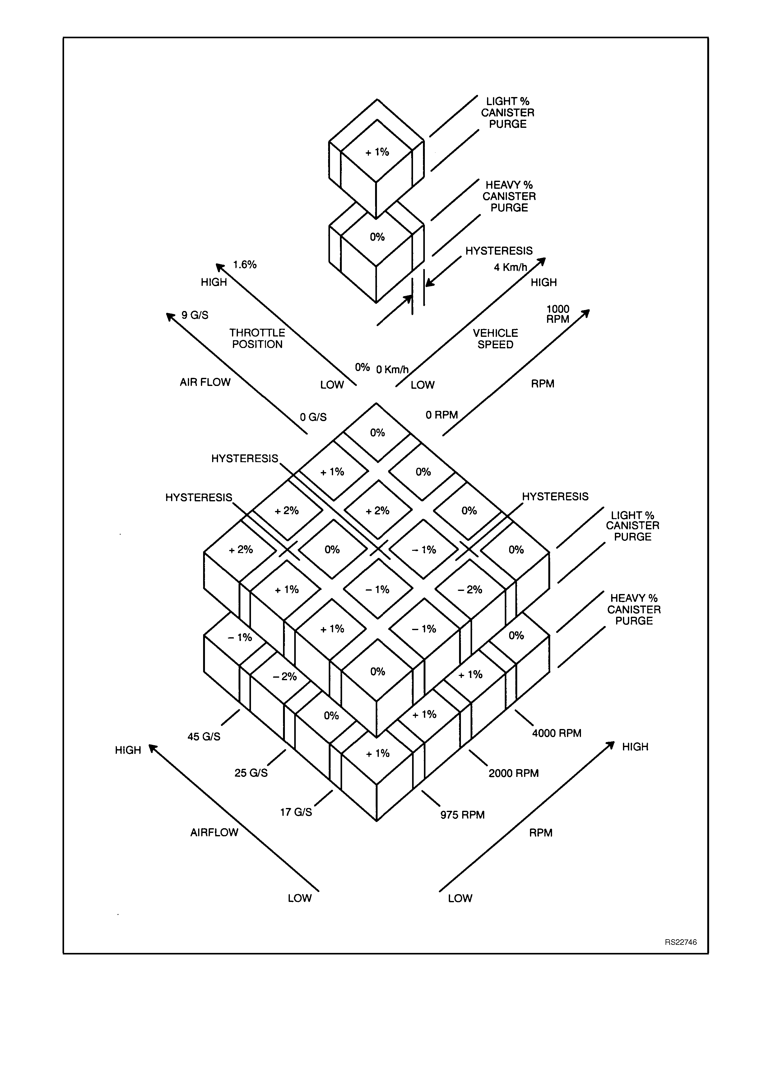
Figure 6C2-1-71 Long Term Fuel Trim Values

LONG TERM FUEL TRIM CELL
The Long Term Fuel Trim function of the PCM is divided up into cells. These cells are arranged by the Mass Air
Flow and the Engine Speed. Each cell corresponds to a region on a MAF vs RPM table. Each region is calibrated to
a LTFT value of 0%. A value of 0% in a given block indicates no fuel adjustment is needed for that engine condition.
A higher number, say + 4%, indicates that the PCM has detected a lean exhaust, and is adding fuel to compensate.
Conversely, a lower number, say -6%, indicates that the PCM has detected a rich exhaust, and is subtracting fuel to
compensate.
As the vehicle is accelerated or decelerated the engine's LTFT calibration will change cells. As the LTFT changes
cells so does the STFT. The STFT will only make short term corrections in whatever the LTFT cell the engine is
operating in. When the engine is idling, the engine can be in one of two cells. On a vehicle with an automatic
transmission, depending upon canister purge, the engine will idle in cell 0 or 17. When the engine is running at idle
and the canister purge is ON, the LTFT would be in cell number 0 on an automatic transmission equipped vehicle.
Cells 16 and 33 are used for idle on vehicles with manual transmission.
Whatever the cell the engine is operating in, the PCM will read that cell's particular LTFT value and electronically
adjust the fuel injector base pulse width to compensate for a rich or lean condition. If an engine has a restricted fuel
filter and the customer has driven the vehicle like this for quite some time, the STFT value would be high, and the
PCM would be compensating for this condition by adding more fuel. Because the STFT value is above 0%, the
LTFT will also be greater than 0% in most of the cells to compensate for the lean exhaust. If you suspect a
driveability problem associated with an over rich or an over lean condition, then use the STFT value to detect what
the fuel control system is doing at the time. Use the LTFT to identify what the system has "learned" over a period of
time to compensate for the condition.
Use the LTFT cells to determine if the fuel control system is commanding rich or lean throughout the operating
range. If it is only rich or lean at idle or part throttle, look for components that would cause problems in these areas.
All LTFT cell values are reset to 0% when the long term memory power to the PCM is disconnected, such as when
clearing DTC's.
The Tech 2 scan tool has the ability to reset all the LTFT cells to 0% with a special command.
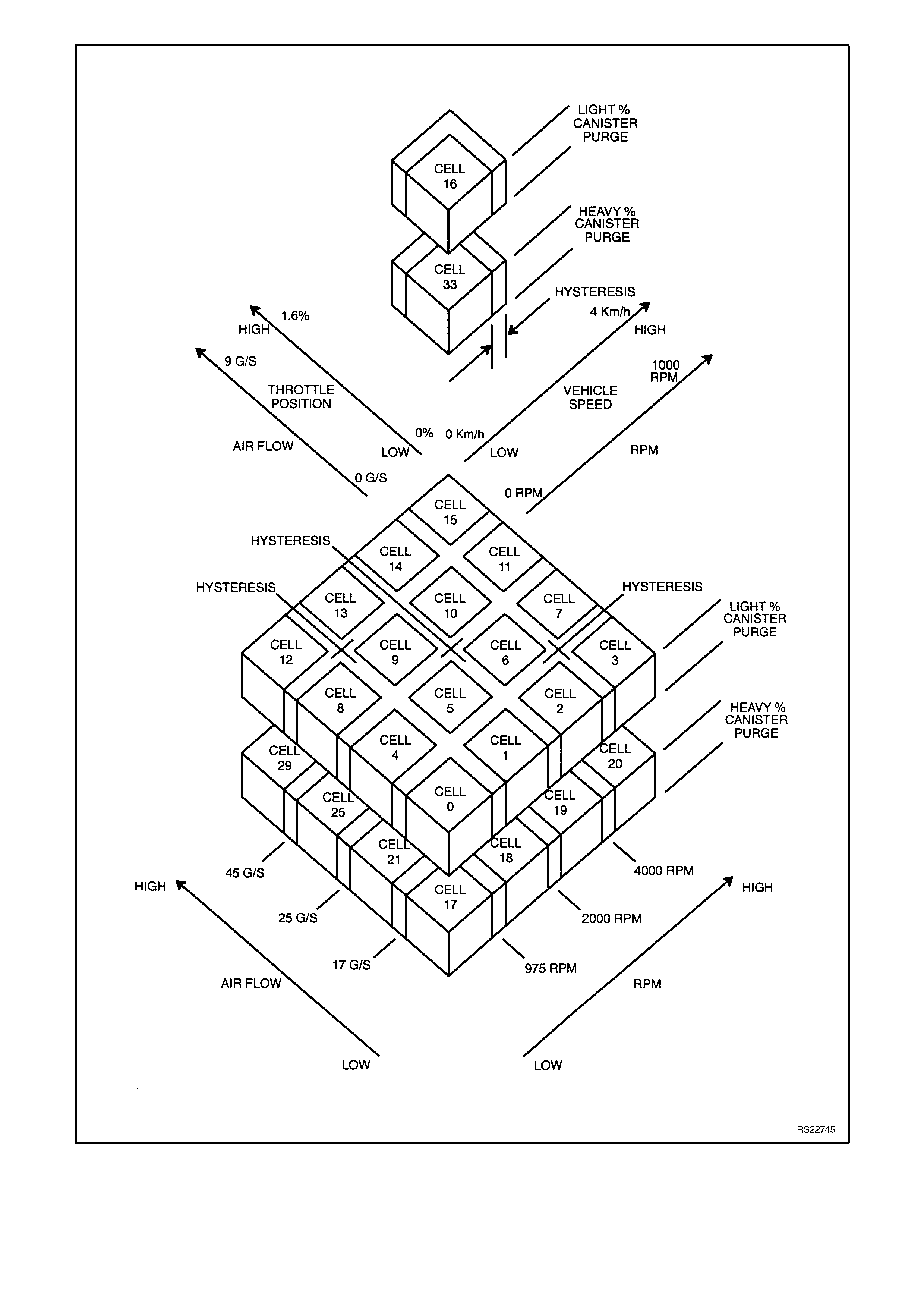
Figure 6C2-1-72 Long Term Fuel Trim Cell Matrix
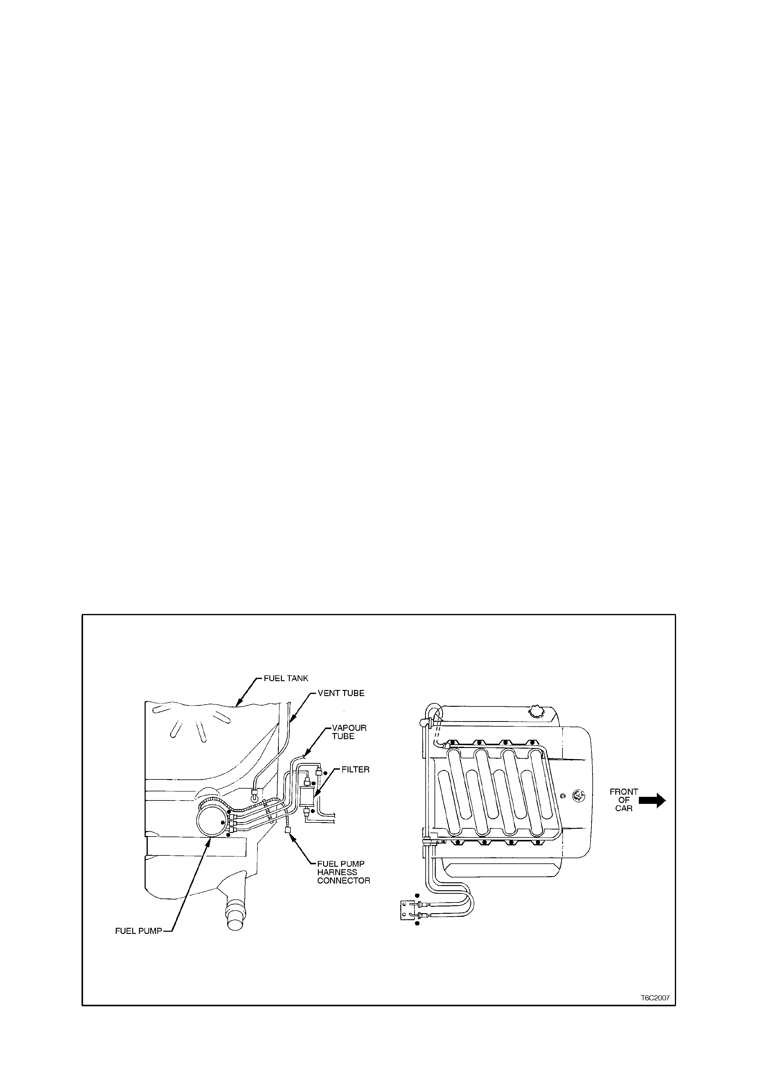
FUEL SYSTEM OPERATION
The fuel control system starts with the fuel in the fuel tank. A single in-tank high pressure fuel pump is used. From
the high pressure pump, fuel flows through the fuel pressure supply line to a fuel filter, then onto the engine fuel rail.
The high pressure in-tank single pump is capable of providing fuel pressure greater than 575 kPa. A fuel pressure
regulator mounts between the fuel rail and the return fuel line. This keeps fuel available to the injectors at a
regulated pressure between 270 and 350 kPa.
The regulated pressure will vary, depending on the intake manifold pressure. The pressure regulator senses the
manifold pressure through a small hose connected to the throttle body housing. When the throttle body housing
pressure is low (closed-throttle), the regulated pressure is also low. When the throttle is wide open, the intake
manifold pressure and the fuel pressure are high.
Fuel in excess of the fuel injector is returned to the fuel tank by the separate return line connected to the outlet of
the pressure regulator.
The fuel injectors are located in each runner of the intake manifold. The fuel injectors are controlled by the PCM.
They deliver fuel in one of several modes, as described previously.
The fuel pump is normally energised by the PCM via the fuel pump relay.
SYSTEM COMPONENTS
The Fuel Control System is made up of the following
components.
• PCM
• Fuel pressure supply line
• Fuel pump relay
• Fuel rail
• Fuel strainer
• Fuel Injectors
• Fuel pump
• Fuel pressure regulator
•Fuel filter
• Swirl pot
• Fuel pressure regulator
• Fuel filter
• Fuel return line
• Swirl pot
Figure 6C2-1-73 Fuel Delivery System
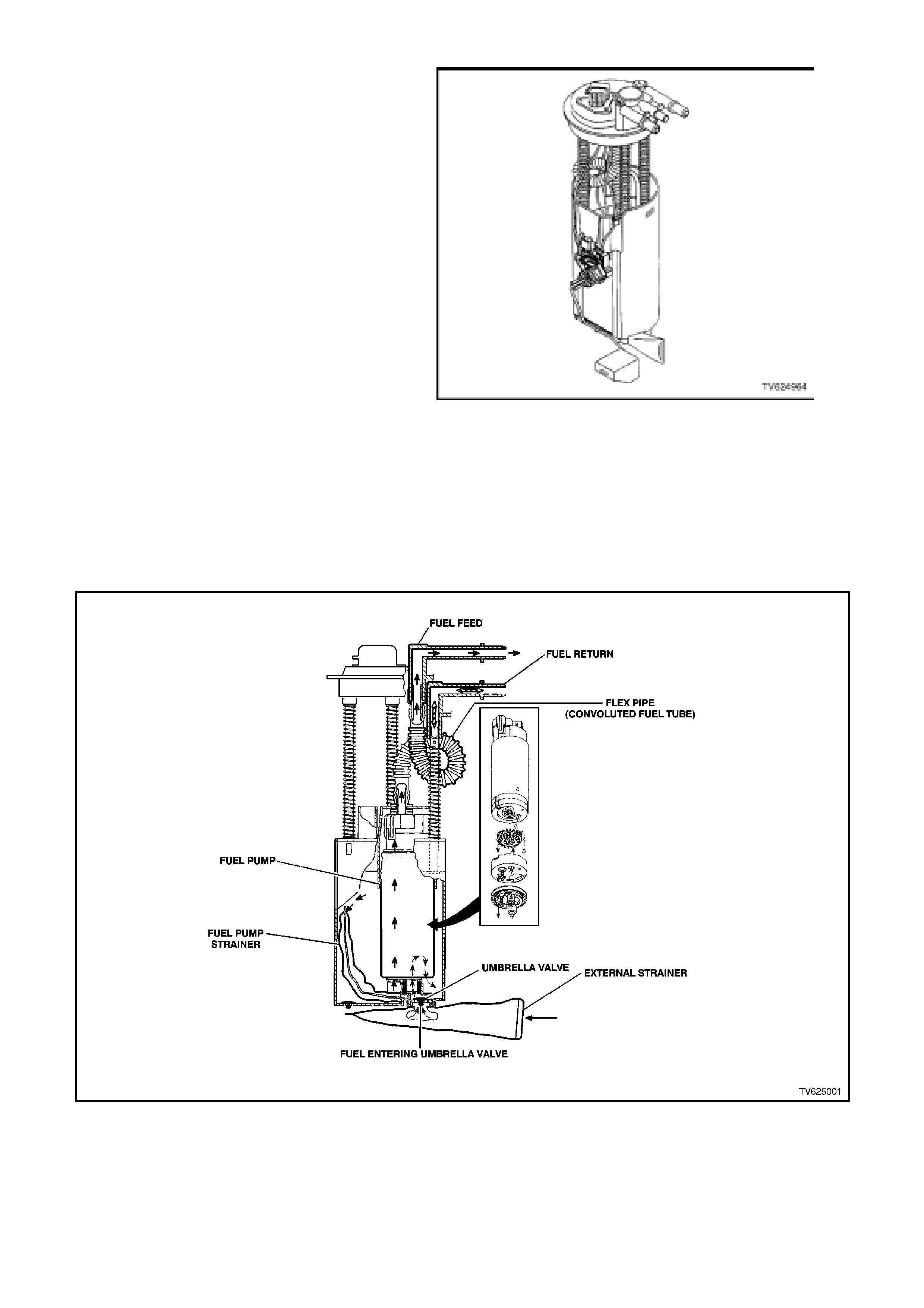
MODULAR FUEL SENDER ASSEMBLY
The modular fuel sender assembly is attached to
the top of the f uel tank , and ex tends f r om the top of
the fuel tank to the bottom.
The modular fuel sender assembly consists of the
following major components:
• A Fuel Sender Cover
• Fuel Pipes (above cover)
• A Fuel Pump
• A Fuel Pump Strainer
• A Fuel Pump Reservoir
• A Fuel Sender Strainer
• A Ceramic Fuel Level Sensor Assembly
The fuel level sender assembly consists of the
following:
• A Float
• A Wire Float Arm
• A Rheostat
The fuel level is sensed by the position of the float
and float arm, position changes, the amount of
current passing through the rheostat varies, thus
changing the fuel gauge reading on the instrument
panel.
The V8 application uses a GEN III TURBINE fuel
pump, and can be serviced separately from the
sender unit assembly.
Figure 6C2-1-74 Modular Sender Assembly
Figure 6C2-1-75 Fuel Pump/Sender Assembly
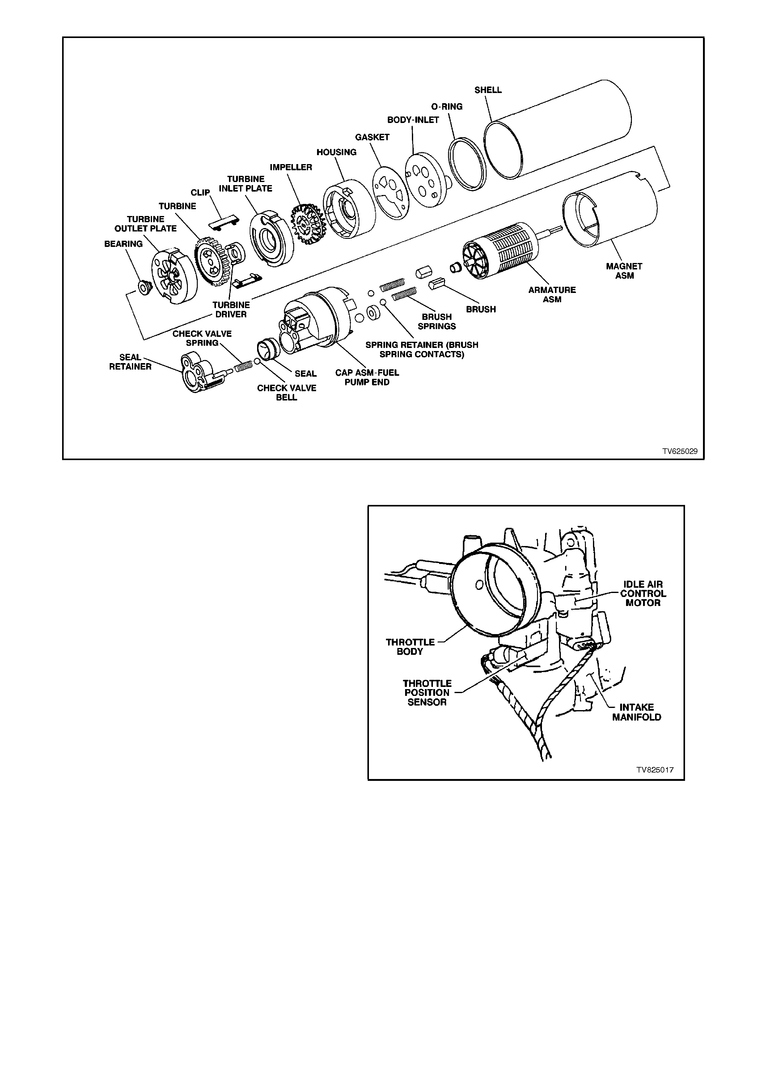
Figure 6C2-1-76 Fuel Pump
THROTTLE BODY UNIT
The throttle body unit is single casting assembly.
The throttle body has two electrical components
connected to it. The two components are
• T he Idle Air Control (IAC) valve to contr ol the air
flow bypassing the throttle blade. This "bypass"
airflow provides the air requirements for the
engine when the throttle is closed. More
"bypass" air gives the engine the ability of a
higher idle speed. A lower flow rate of this
"bypass" air gives lower idle speeds.
• The Throttle Position (TP) Sensor , which gives
the PCM information about throttle positioning,
and if the throttle is m oving (opening or c losing).
The PCM can also determine how quickly the
throttle is opening or closing with this signal.
The throttle body contains 2 small vacuum
ports. These ports provide vacuum signals to
the evaporative emission's canister. In a V8
engine there are also 2 larger ports that are
provided for the crankcase ventilation system. Figure 6C2-1-77 Throttle Body
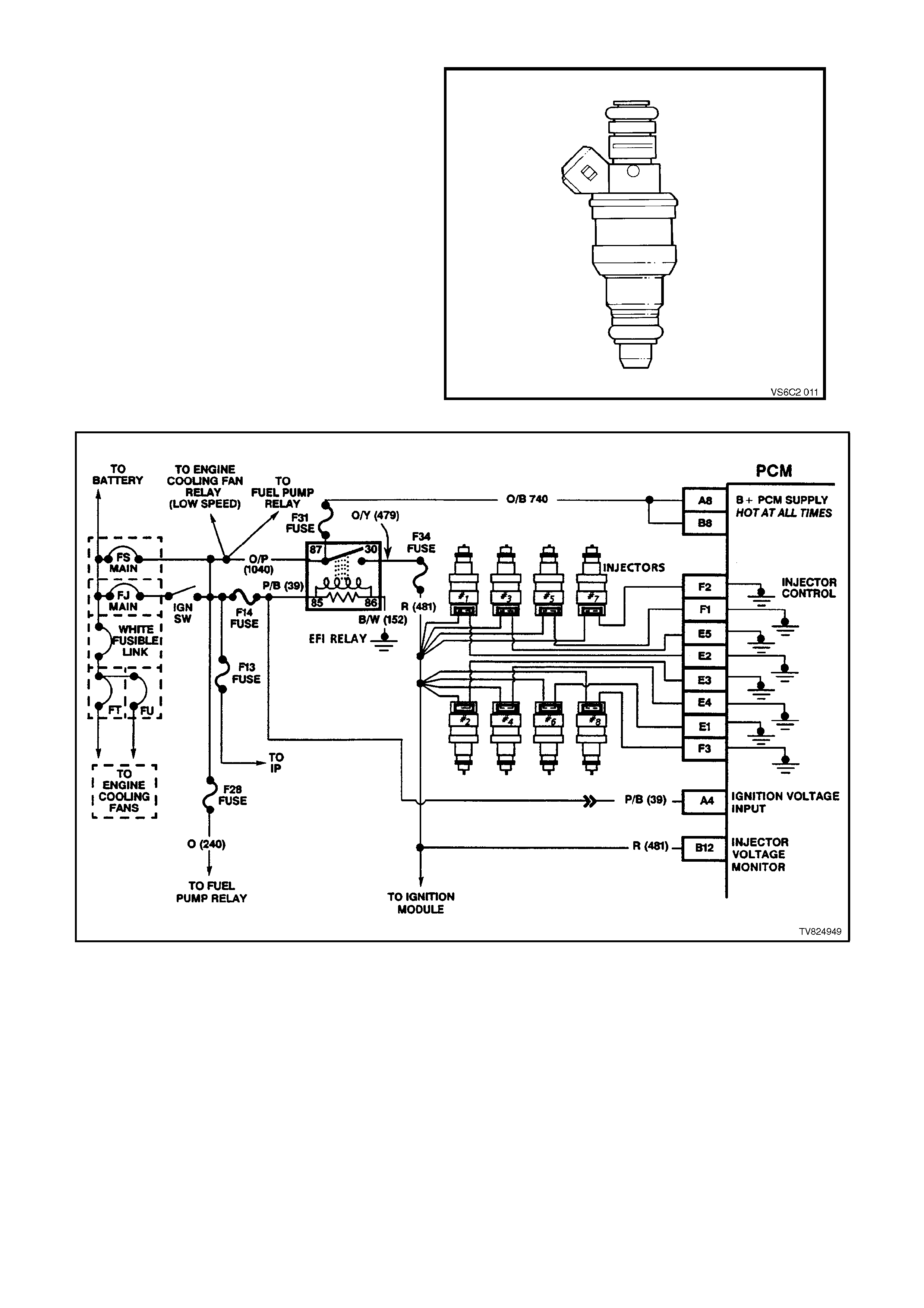
FUEL INJECTORS
The fuel injectors are electrically-operated fuel
control valves. The injectors are supplied B+ from
the ignition switch through the EFI relay. The fuel
injectors are controlled by the PCM which provides
the earth circuit. The PCM energises the injectors
to open. The injectors are never fully energised
"ON," as that would flood the engine with too much
fuel. The PCM supplies the earth circuit in short
pulses. The longer the duration of the pulse width
the more fuel that is injected into the engine. Inside,
the injectors have a coil that becomes an
electromagnet when energised. The resistance of
these windings is im portant for the PCM to operate
correctly.
A fuel injector which does not operate will cause a
misfire condition. An injector which is stuck partly
open could cause dieseling because fuel would be
delivered to the engine after the ignition key is
turned OFF. Figure 6C2-1-78 Fuel Injector
Figure 6C2-1-79 Fuel Injector Circuit
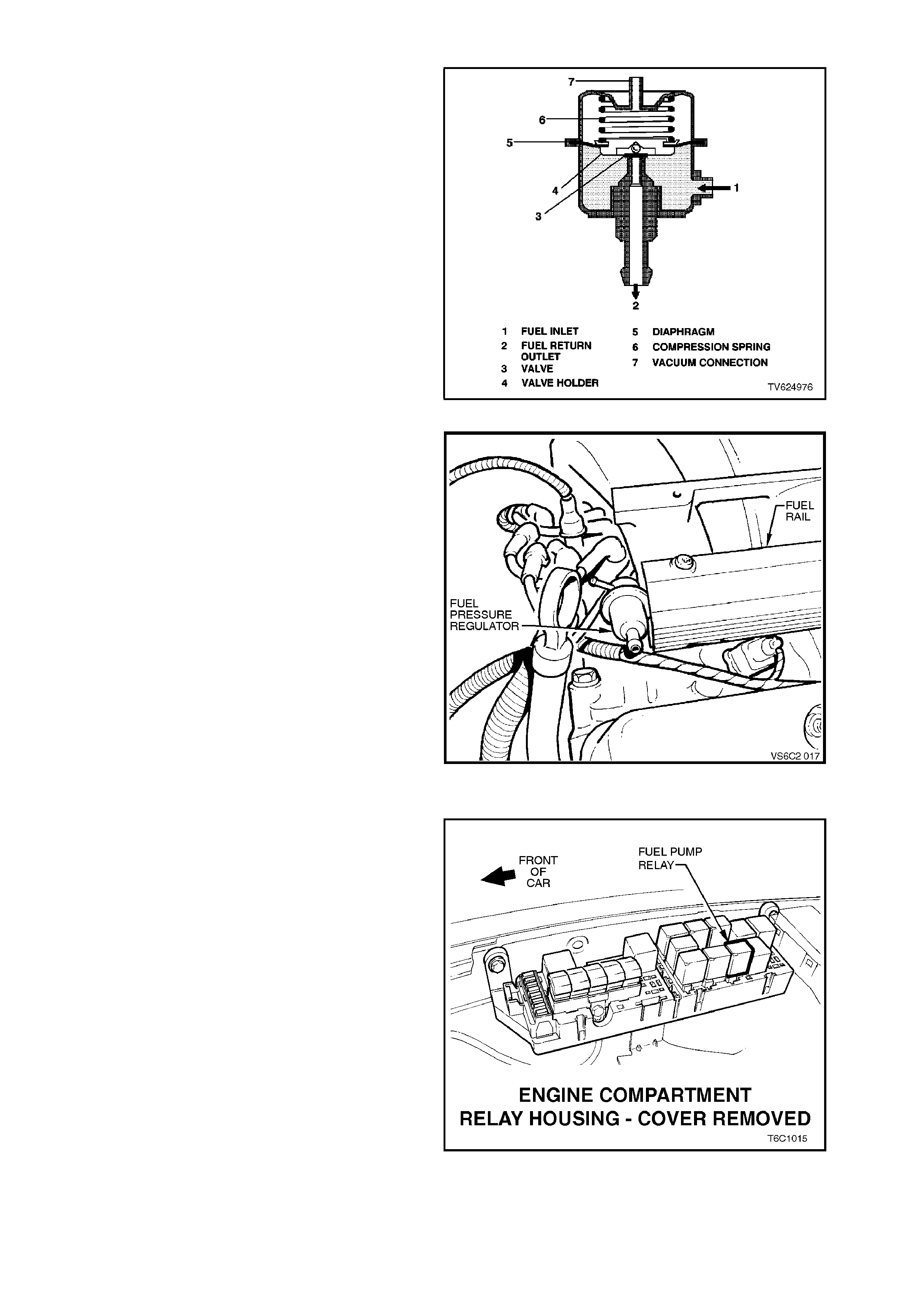
FUEL PRESSURE REGULATOR
The fuel pressure regulator is a diaphragm-
operated relief valve with fuel pump pressure on
one side, and intake manifold pressure (engine
vacuum) combined with mechanical spring
pressure on the other side. The function of the
regulator is to m aintain a regulated pressure at the
injector s at all tim es, by c ontrolling the flow into the
return line.
Figure 6C2-1-80 Typical Fuel Pressure Regulator
Figure 6C2-1-81 Fuel Pressure Regulator Location
FUEL PUMP ELECTRICA L CIRCUITS
When the ignition switch is turned to ON after
having been "OFF" for at least 10 seconds, the
PCM will immediately energise the fuel pump relay
to operate the fuel pump. This builds up the fuel
pressur e quickly. If the engine is not crank ed within
two seconds, the PCM will shut the fuel pum p relay
"OFF" and wait until the engine is c ranked. As s oon
as the engine begins cranking, the PCM will sense
the engine turning from the crankshaft reference
input, and turn the relay "ON" again to run the fuel
pump.
The fuel pump relay is located in the engine
compartment relay housing.
Figure 6C2-1-82 Fuel Pump Relay Location
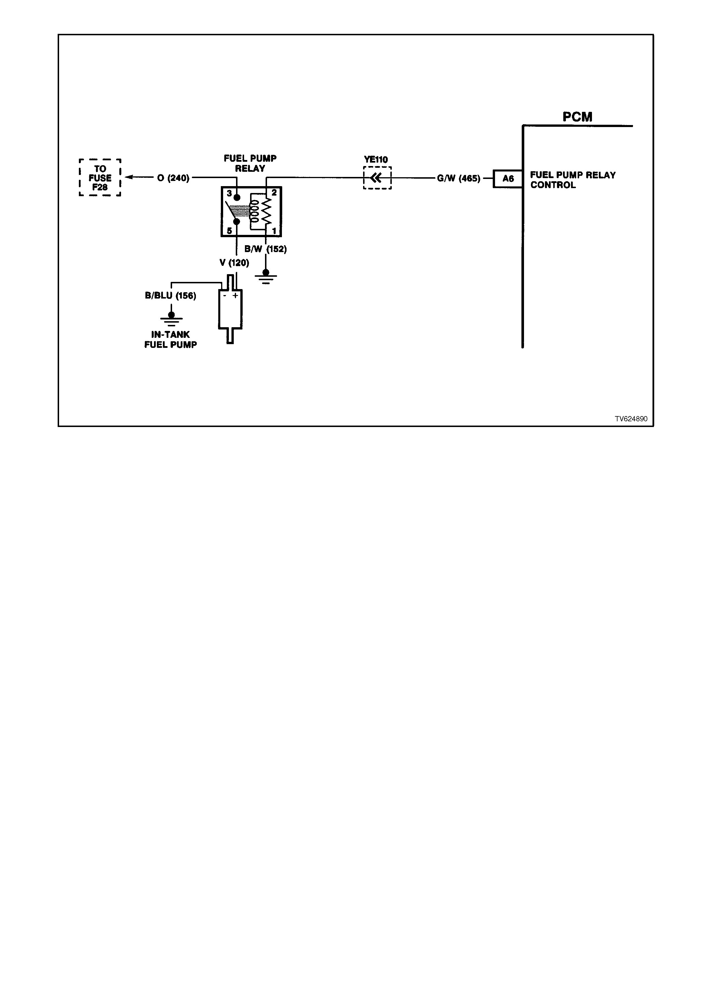
Figure 6C2-1-83 Fuel Pump Electrical Circuits
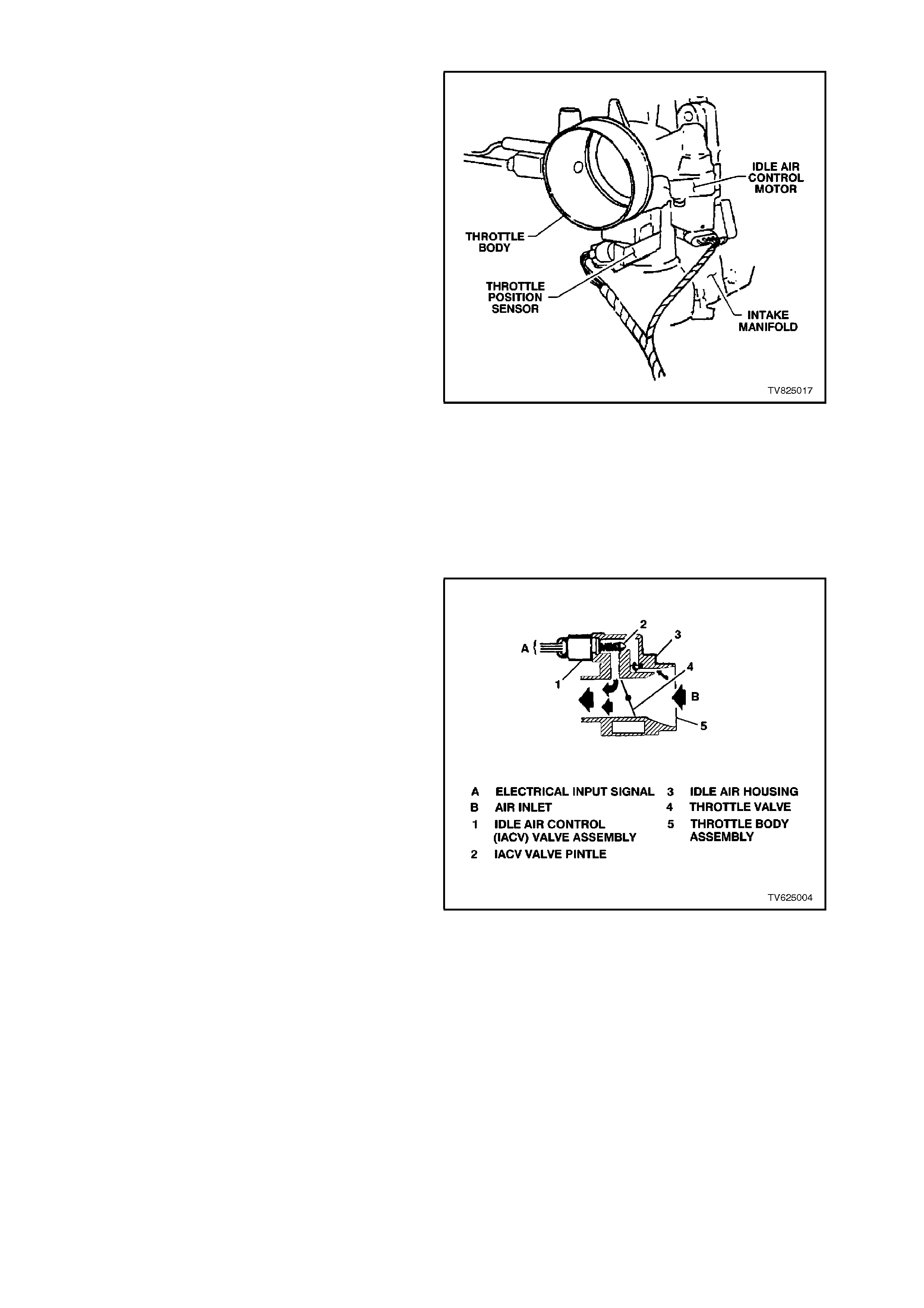
1.6 IDLE AIR CONTROL (IAC) VALVE
The Idle Air Control (IAC) valve, contr ols the engine
idle speed. This prevents the engine from stalling
due to the changes in the engine load at idle.
The IAC valve, mounted on the throttle body,
controls the incoming air around the throttle valve
at idle. By extending the pintle (to decrease air
flow) or retr acting the pintle (to increase air flow), a
controlled amount of air can move around the
throttle valve. If the engine RPMs are too low, m ore
air is allowed to bypass around the throttle valve.
This will increase the engine speed at idle. If the
engine speed is too high, less air is bypassed
around the throttle valve. T his will dec r eas e engine
speed at idle.
The IAC valve moves in small steps from 0
(extended pintle, bypass air passage fully shut) to
196 (retracted pintle, maximum bypass airflow) as
commanded by the PCM.
At idle, the desired position of the IAC valve is
calculated by the PCM based on the following
conditions.
• The engine coolant temperature sensor
• The engine speed
• The engine load
• The battery voltage
Figure 6C2-1-84 IAC Valve Location
If the IAC valve loses voltage with the engine
running, the PCM can lose track of the actual
position of the IAC. If this happens, the PCM will
reset the IAC valve. W hen the PCM r esets the IAC
valve, the actual reset procedure occurs when the
engine speed goes above 2000 RPM after the
ignition has been "OFF" for at least 10 seconds.
The reset procedure is as follows.
The PCM commands the IAC valve to close the idle
air passageway in the throttle body. The PCM does
this by commanding "extend" pulses to move the
IAC pintle fully shut in the bore. Then, the PCM
resets the IAC valve to 0 when at a fully shut
position. Next, the PCM issues retract steps to
properly position the pintle.
Figure 6C2-1-85 IAC Valve
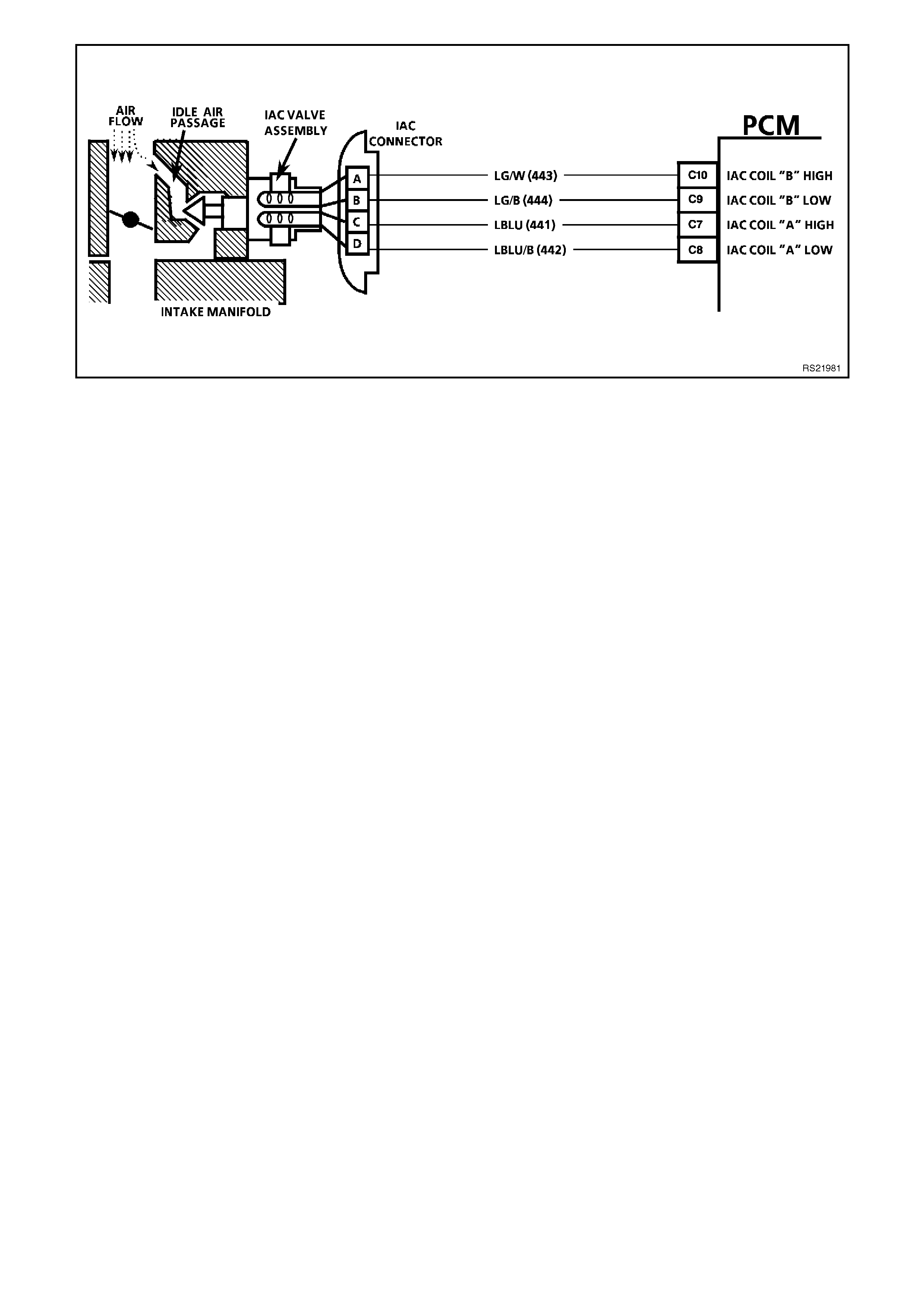
Figure 6C2-1-86 PCM IAC Valve Circuit
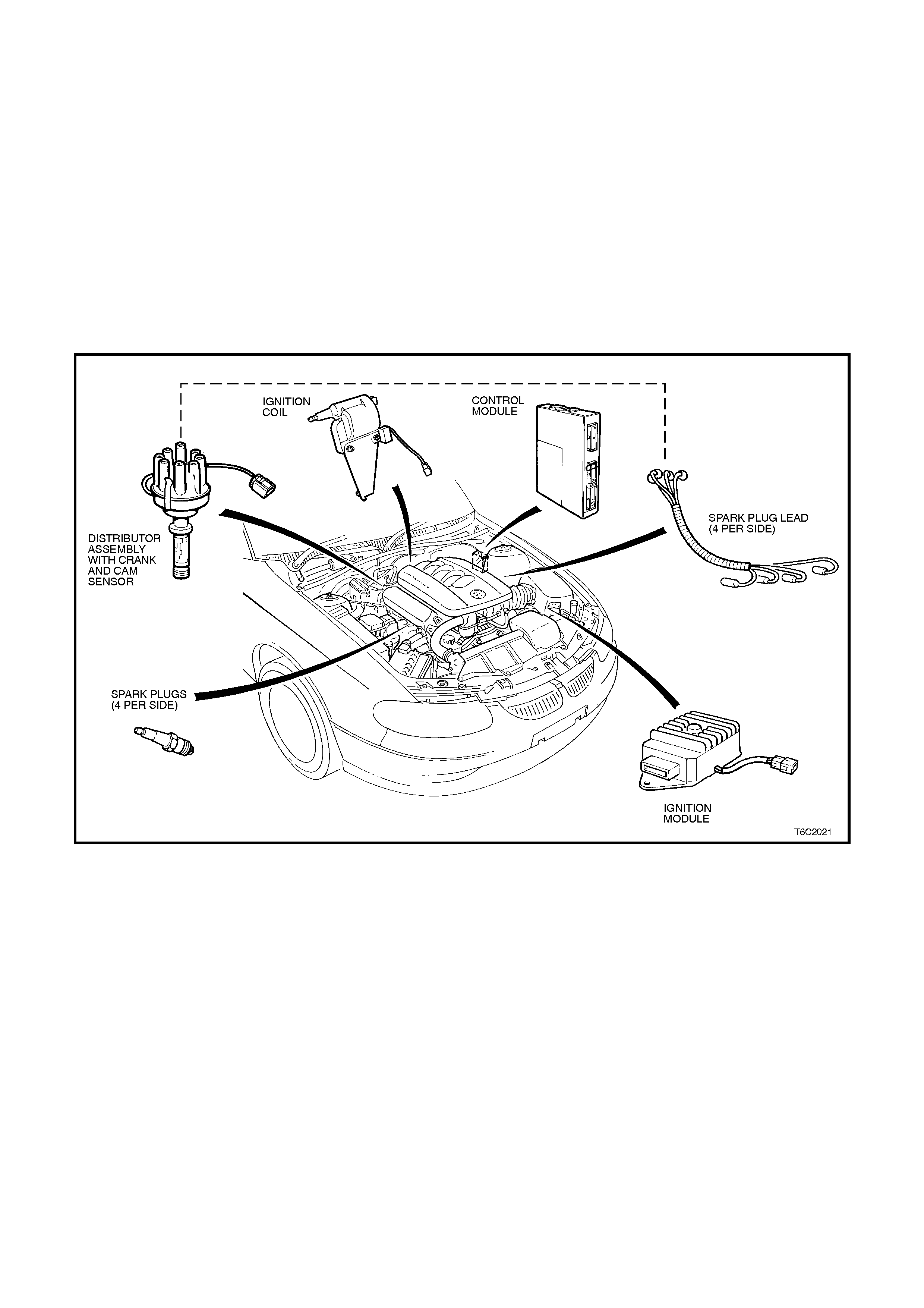
1.7 IGNITION SYSTEM
PURPOSE
The ignition system controls the fuel combustion by providing a spark to ignite the air/fuel mixture in the cy linder at
the correct time. This provides good engine performance, fuel economy, and control exhaust emissions. The PCM
controls the spark advance and the ignition dwell when the ignition system is operating in the EST mode.
The main components that make up the ignition system for the V8 SFI engine are:
• The Distributor Assembly
• The Ignition Coil
• The Ignition Module
• The PCM
• The Spark Plugs
• The Spark Plug Wires
• The Cam sensor
Figure 6C2-1-87 V8 Ignition System
DISTRIBUTOR
The distributor performs the normal distributor function of directing secondary ignition voltage from the ignition coil
to the correct cylinder by means of a rotor, distributor cap, and spark plug leads. There are no advance
mechanisms in the distributor.
IGNITION COIL
The Ignition coil's purpose is to transform the battery voltage which is low voltage high amperage to high voltage
low amperage. This high voltage output allows the spark to jump the gap of the spark plug. The ignition coil is
specifically designed for the PCM and ignition system and must not be replaced with any other type of ignition coil.
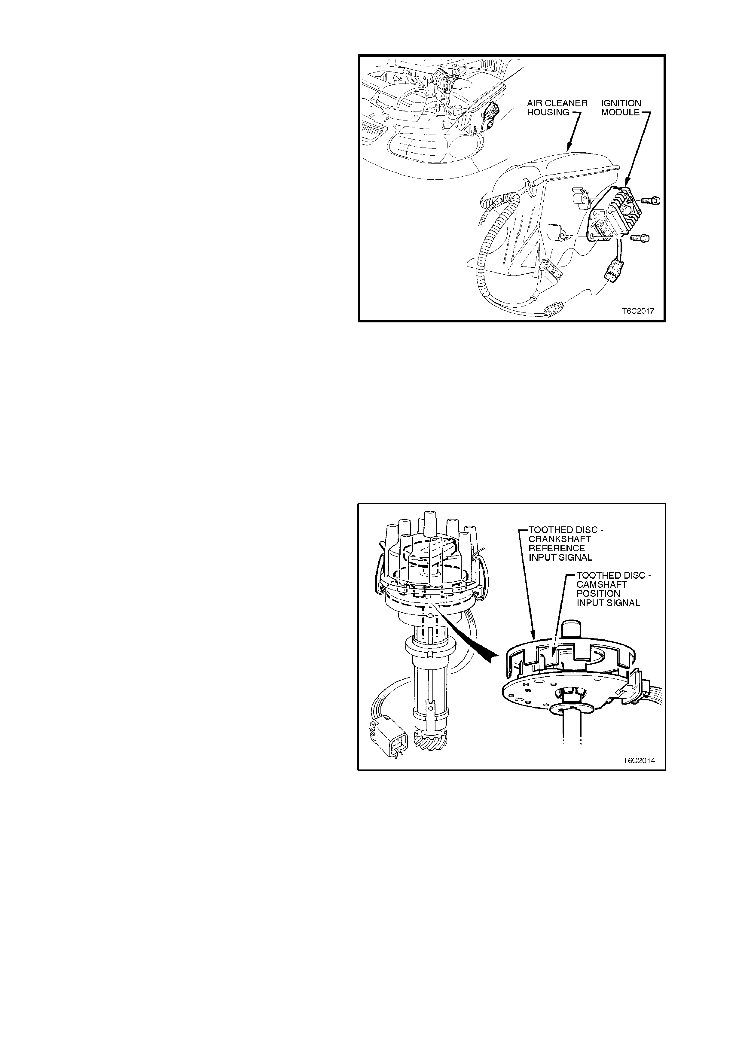
IGNITION MODULE
The ignition module, mounted separately in the
engine compartment, provides an interface
amongs t the Hall switch in the dist ributor, the PCM,
and the ignition coil. T he ignition m odule proc ess es
the Hall switch reference pulses, then sends the
signal to the PCM as a "crankshaft reference input
signal." The PCM calculates the needed spark
advance and dwell time, and sends EST output
pulses back to the ignition module. The module
triggers the ignition coil based on these EST pulses
sent from the PCM.
If the PCM detects a problem in the EST circuit or
cannot control the ignition system, the module is
capable of operating the ignition system, with a
fixed 10 degrees BTDC spark advance.
Figure 6C2-1-88 Ignition Module Location
PCM
When the ignition system is operating in the EST
mode, the PCM controls the spark timing and
dwell. The PCM, via the bypass control circuit,
commands the ignition module which of the two
modes to operate in; either the "EST m ode", or the
"bypass mode". If the module does not receive a
command from the bypass control circuit, the
ignition system will remain in the "bypass mode."
CRANKSHAFT POSITION SENSOR
The crankshaft sensor, is mounted underneath the
distributor cap.
The crankshaft sensor is a Hall-effect switch. A Hall
switch reacts like a solid-state switch, earthing a
low-current signal voltage when a magnetic field is
present. When the magnetic field is shielded from
the switch by a piece of steel placed in the air gap
between the magnet and the switch, the signal
voltage is not earthed. If the piece of steel is
repeatedly moved in and out of the air gap, the
signal voltage will appear to go "ON-OFF-ON-OFF-
ON-OFF". This ON-OFF signal occurs 4 times per
crankshaft revolution and is referred to as a 4X
reference signal. This ON-OFF signal is similar to
the signal that a set of breaker points would
generate. As a distributor shaft is turned the points
would open and close.
The c rankshaf t position sens or is used by the PCM
to determine engine speed and crankshaft
positioning. Figure 6C2-1-89 Crankshaft and Camshaft Location

1.8 ELECTRONIC SPARK TIMING (EST)
The V8 Ignition System uses the same four ignition module -to- PCM circuits as do all other Delco engine
management systems. They are as follows.
• The Crankshaft Reference PCM Input
• The Crankshaft Reference Earth
• The Bypass Control Mode
• The EST Output Mode
The Electronic Spark Timing is the PCM's method of controlling spark advance and ignitions dwell, when the ignition
system is operating in the EST mode.
There are two modes of ignition system operation:
• Bypass mode
• EST mode
In the bypass mode, the ignition system operates` independently of the PCM, with the bypass mode spark advance
always at 10 degrees BTDC. The bypass mode is in affect when cranking the engine. The PCM has no control of
the ignition system when in this mode.
After the engine starts (RPM greater then 450 RPM, the PCM will command the ignition system to go into the EST
mode. The ignition spark advance will remain in the EST mode until one of the following conditions occurs.
• The ignition key is turned OFF.
• The engine quits running.
• An EST fault is detected.
If an EST fault is detected while the engine is running, the ignition system will switch back to the bypass mode. The
engine may quit running, but will restart and stay in the bypass mode.
In the EST mode, the ignition spark timing and ignition dwell time is fully controlled by the PCM. The EST spark
advance and the ignition dwell is calculated by the PCM using the following inputs.
• Engine speed Crankshaft reference
• Crankshaft position Crankshaft reference
• Engine load MAF
• Engine coolant ECT temperature
• Throttle position TP sensor
• Park/Neutral TFP
• Detonation Knock sensor
• Vehicle speed VSS
• Diagnostic request DLC diagnostic "test" input terminal
• PCM supply voltage
The following describes the four PCM-to-ignition module circuits.
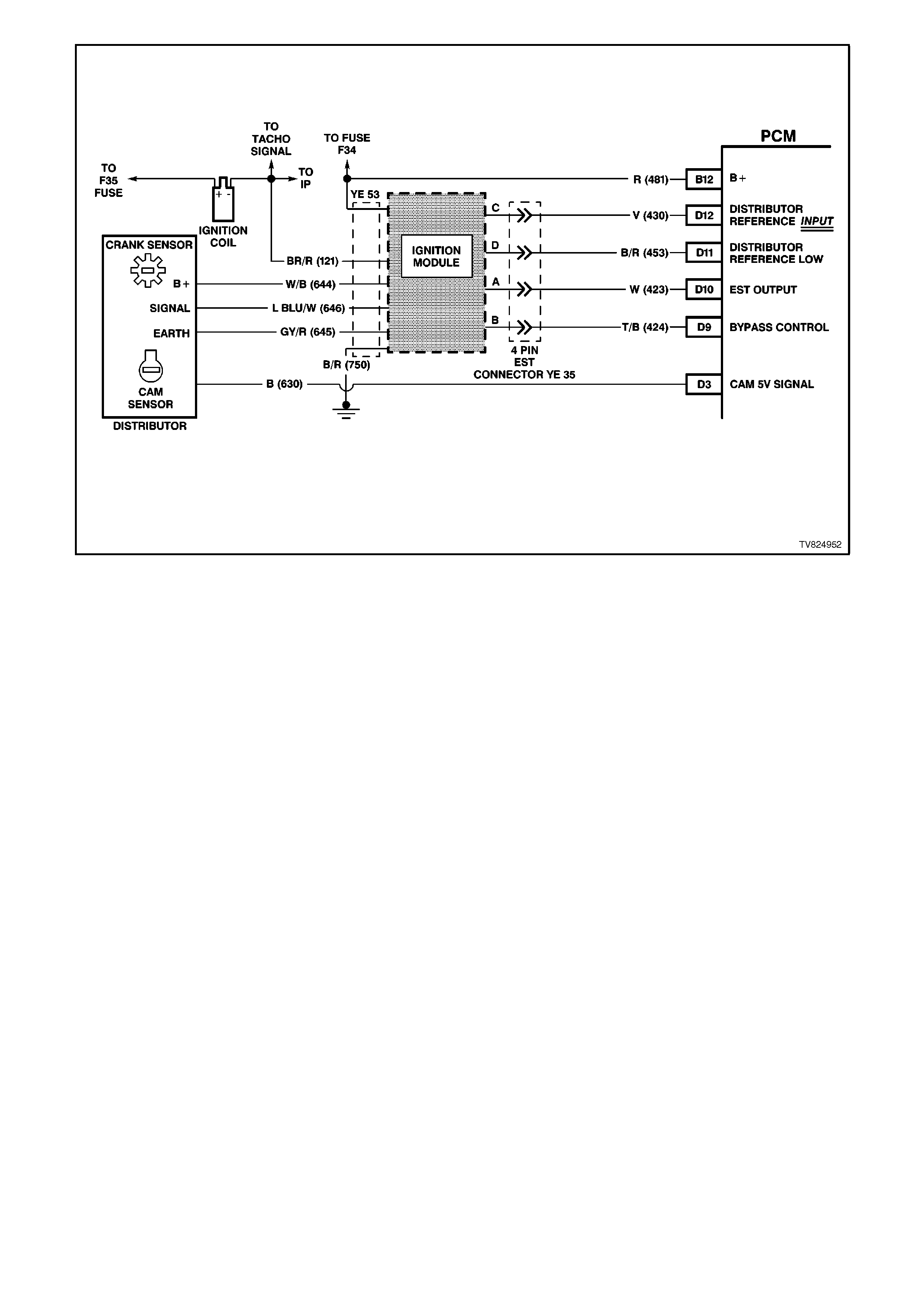
Figure 6C2-1-90 Ignition System with EST Circuits Show n
CRANKSHAFT REFERENCE PCM INPUT
From the ignition module, the PCM uses this signal to calculate the engine RPM and the crankshaft position. The
PCM compares pulses on this circuit to any pulses that are on the earth circuit. The PCM also uses the pulses on
this circuit to initiate injector pulses. If the PCM doesn’t receive any pulses on this circuit, no fuel injection pulses will
occur, the engine will not run, and a DTC 46 will set when attempting to start the engine.
CRANKSHAFT REFERENCE EARTH
This is an earth circuit for the digital RPM counter inside the PCM. The wire is connected to engine earth through
the ignition module. Although this circuit is electrically connected to the PCM, it is not connected to earth at or
through the PCM. If the circuit is open, or earthed at the PCM, it may cause poor engine performance and possibly
a "Check Powertrain" lamp with no DTC set.
BYPASS CONTROL
The PCM either allows the ignition module to keep the spark advance at the "bypass mode" 10 degrees BTDC, or
the PCM signals the ignition module that the PCM is going to control the spark advance (EST mode). The ignition
module switches between the modes by the level of voltage that the PCM sends to the ignition module on the
bypass control circuit. The PCM provides 5 volts to the ignition module if the PCM is going to control spark timing
(EST mode). If the PCM does not turn supply the 5 volts, or if the ignition module doesn't receive it, then the module
will keep control of spark timing (bypass mode). An open or short to the voltage bypass control circuit will set a DTC
42. While a DTC 42 is set the ignition system will stay in the "bypass mode." If the bypass control circuit becomes
earthed during the EST mode and engine speed is greater than 1600 RPM, the engine may stall, but will restart. A
DTC 42 will set, and the ignition system will operate in the bypass mode.
EST OUTPUT
In the EST mode the PCM sends timing pulses to the ignition module. These pulses are the ignition timing pulses
used by the ignition module to energise the ignition coil. If the EST output circuit is open or shorted to voltage when
the engine is started, a DTC 41 will set and the ignition system will stay in the bypass mode. If the EST Output
circuit becomes earthed during the EST mode above an engine speed of 1600 RPM, the engine may stall, but will
restart. A DTC 42 will set, and the ignition system will operate in the bypass mode.
RESULTS OF INCORRECT OPERATION
An open or an earth in the EST or bypass circuit will set a DTC 41 or a DTC 42. If a fault occurs in the EST output
circuit when the engine is running, the engine may stumble or stall but will restart and run in the bypass mode. A
fault in either circuit will force the ignition system to operate on bypass mode timing (10 degrees BTDC), which will
result in reduced performance and fuel economy.
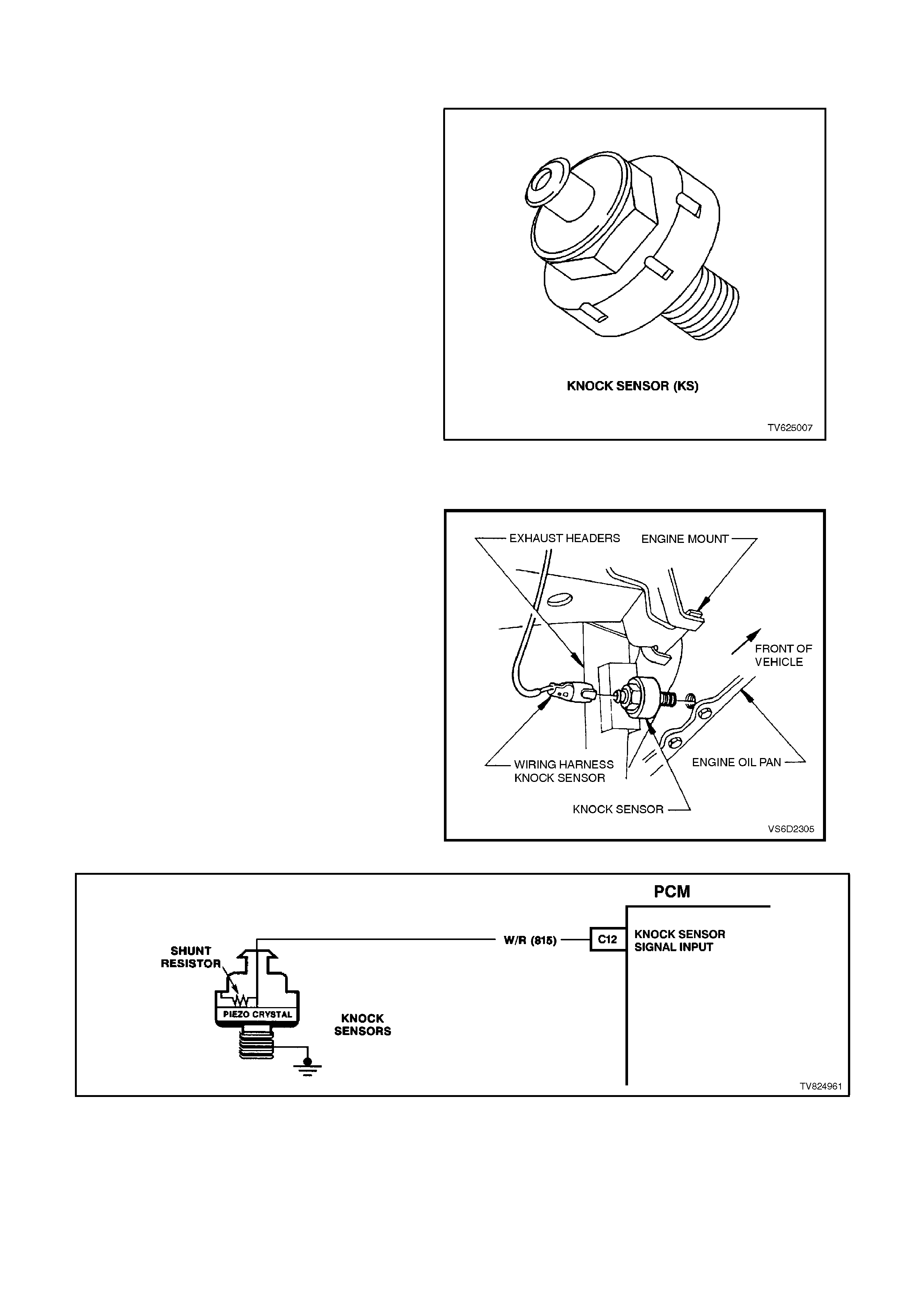
1.9 KNOCK SENSOR (KS) SYSTEM
PURPOSE
Varying octane levels in today's petrol may cause
detonation in some engines. Detonation is caused
by an uncontrolled pressure in the combustion
cham ber . This uncontrolled pr es sur e c ould produc e
a flam e f r ont oppos ite that of the normal flam e f r ont
produced by the spark plug.
The "rattling" sound normally associated with
detonation is the result of two or more opposing
pressures (flame fronts) colliding within the
combustion chamber. Though "light" detonation is
sometimes considered normal, "heavy" detonation
could result in engine damage. Light detonation
occurs when the point of maximum pressure has
been exceeded.
To control spark knock, a Knock Sensor (KS)
System is used. This system is designed to retard
the spark timing up to 12 degrees. This allows the
engine to use maxim um spark advance to im prove
the driveability and the fuel economy. Figure 6C2-1-91 Knock Sensor
OPERATION
The Knock Sensor (KS) system has two major
components:
• The KS Module (part of PROM)
• The Knock Sensor
The knock sensor detects abnormal mechanical
vibration (spark knocking) in the engine. There are
several calibrations of knock sensors because
each engine produces a different frequency of
mechanical noise. The knock sensor is specifically
chosen f or this engine to best detect engine knock .
This engine has one knock sensor. The knock
sensor is mounted on the engine block near the
cylinders to better detect engine detonation.
Figure 6C2-1-92 Knock Sensor Location
Figure 6C2-1-93 PCM Knock Sensor Wiring

A knock sensor is used to detect engine
detonation. The PCM will retard the Electronic
Spark Timing (EST) based upon the signals being
received.
The PCM supplies a 5 volt signal to the knock
sensor. The shunt resistor inside the knock sensor
keeps the voltage at approxim ately 2.5 volts. Under
a no knock condition, the circuit should be about
2.5 volts. The knock sensor produces an AC
voltage that rides on top of the 2.5 volts DC voltage
and increases in amplitude and in signal frequency
with the severity of the k noc k . This signal voltage is
used as an input to the PCM. This AC signal
voltage to the PCM is proces sed by a Signal Noise
Enhancement Filter (SNEF) module. The SNEF
module is used to determine if the AC signal
coming in is noise or detonation. This SNEF
module is part of the PROM and cannot be
replaced. The PCM then adjusts the ignition timing
to reduce the spar k advance. How m uch the tim ing
is retarded is bas ed upon the amount of time knock
that is detected and is limited to a maximum value
of 12 degrees. After the detonation stops, the
tim ing will gradually return to it's calibr ated value of
spark advance. The Knock Sensor s ys tem will only
retard timing after the following conditions are met:
• The engine run time is greater than 5 seconds.
• The engine speed is greater than 1000 RPM.
• The engine coolant temperature is greater than
44°C.
Figure 6C2-1-94 Knock Sensor Sectioned View
The Tech 2 Scan tool has two data display
parameters to check for diagnosing the knock
sensor circuit. The "KNOCK SIGNAL" is used to
monitor the input signal from the knock sensor.
This will display "YES" when knock is being
detected. "KNOCK RETARD" is the indication of
how much the PCM is retarding the spark advance.
A DTC 43 is designed to diagnose the knock
sensor and the wiring. A DTC 43 will diagnose an
open or a short in the wiring circuit. When a DTC
43 is set, the PCM will retard the total spark
advance by 6 degrees.
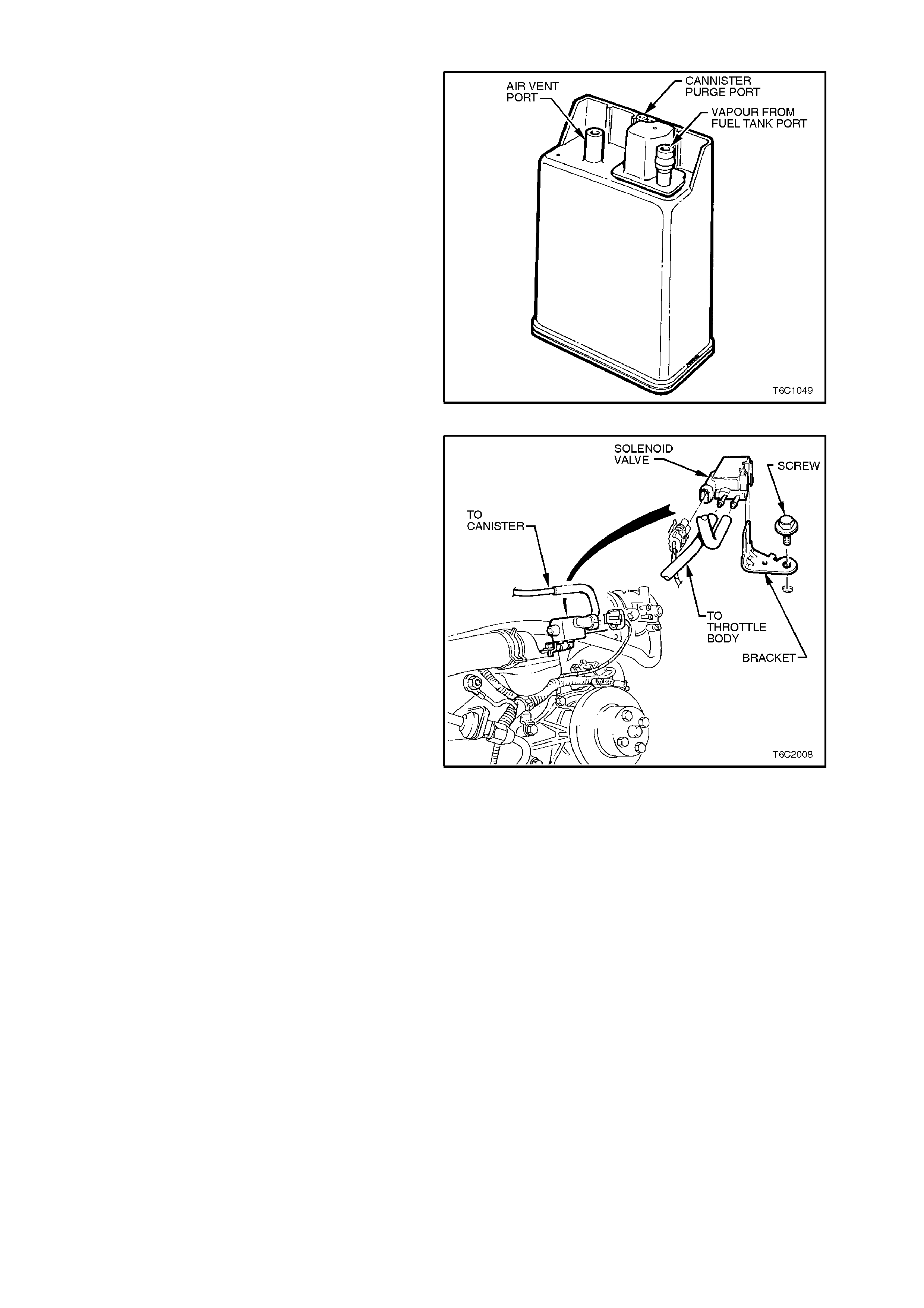
1.10 EVAPORATIVE EMISSION CONTROL
The Evaporative Emission Control System (EECS)
used on this vehicle is the charcoal canister
storage m ethod. This method transfers f uel vapour
from the fuel tank to an activated car bon (charcoal)
storage device (canister) located under the rear of
the vehicle, to hold the vapours when the vehicle is
not operating. W hen the engine is running, the fuel
vapour is purged from the carbon element by intake
air flow and consumed in the normal combustion
process.
Figure 6C2-1-95 Fuel Vapour Canister
This system has a remote mounted canister purge
control solenoid. The PCM operates this solenoid
to control vacuum to the canister. Under cold
engine conditions, the solenoid is turned "OFF" by
the PCM, which blocks vacuum to the canister to
prevent purge.
The PCM turns ON the solenoid valve and allows
purge when the following conditions have been
met.
• The engine coolant temperature is less than 80
degrees C, 3 minutes and 10 seconds after
engine start.
• The engine coolant temperature is greater than
80 C, 15 seconds after engine start.
• The engine coolant temperature is above 60
degrees C.
• The engine is not in Decel Fuel Cutoff Mode.
• The throttle opening is less than 92%.
• The engine is in Closed Loop Fuel Mode or
Open Loop Fuel Mode.
The canister cannot be repaired, and is serviced
only as an assembly. Periodically check the
canister at the time or distance intervals specified
in the Owner's Handbook.
Figure 6C2-1-96 Canister Purge Solenoid Location

Figure 6C2-1-97 Canister Purge Solenoid Circuit
The fuel vapour canister is mounted in a bracket
under the body, near the fuel filter.
Figure 6C2-1-98 Canister Location
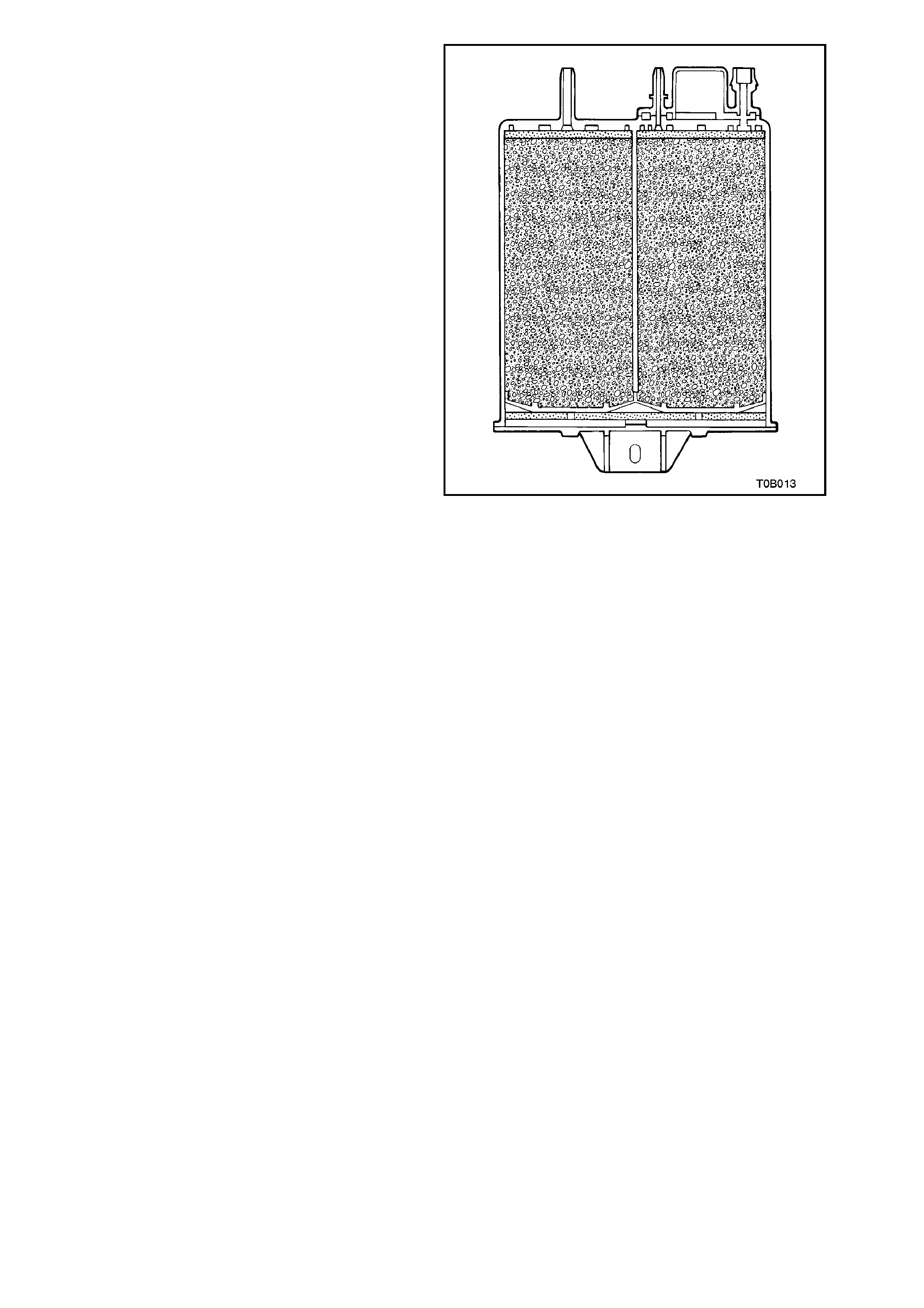
The c anister is a three port des ign. The f uel vapour
is absorbed by the charcoal within the canister.
When the engine is running at idle speed and
above idle, air is drawn into the canister through the
atmospheric port at the top of the canister
assembly. The air mixes with the fuel vapour and
the mix tur e is dr awn into the intak e manif old via the
canister purge line. The Uppermost port on the
canister is controlled by the PCM controlled
canister purge solenoid. The canister purge
solenoid controls the manifold vacuum signal from
the throttle body. The port below the canister purge
port is the vapour inlet from the fuel tank. The
single off centre port is open to the atmosphere.
Figure 6C2-1-99 Sectioned View of Canister
RESULTS OF INCORRECT OPERATION
• Poor idle, stalling and poor driveability can be
caused by one of the following conditions.
-An inoperative canister purge solenoid.
-A damaged canister.
-Hoses split, cracked and/or not connected
to the proper tubes.
• An evidence of fuel loss or fuel vapour odour
can be caused by one of the following
conditions.
-A Liquid fuel leaking from fuel lines.
-A Cracked or damaged canister.
-is connected, misrouted, kinked,
deteriorated or damaged vapour hoses, or
control hoses.
If the solenoid is s tuc k open, or the c ontrol c irc uit is
shorted to earth the c anis ter will purge to the intake
manifold all the time. This can allow extra fuel at
idle or during warm-up, which can cause rough or
unstable idle or a rich fuel operation.
If the canister purge solenoid is always closed, the
canister can become overloaded, with f uel res ulting
in fuel odour.
A fault in the canister purge s olenoid or circuit m ay
result in DTC 97.
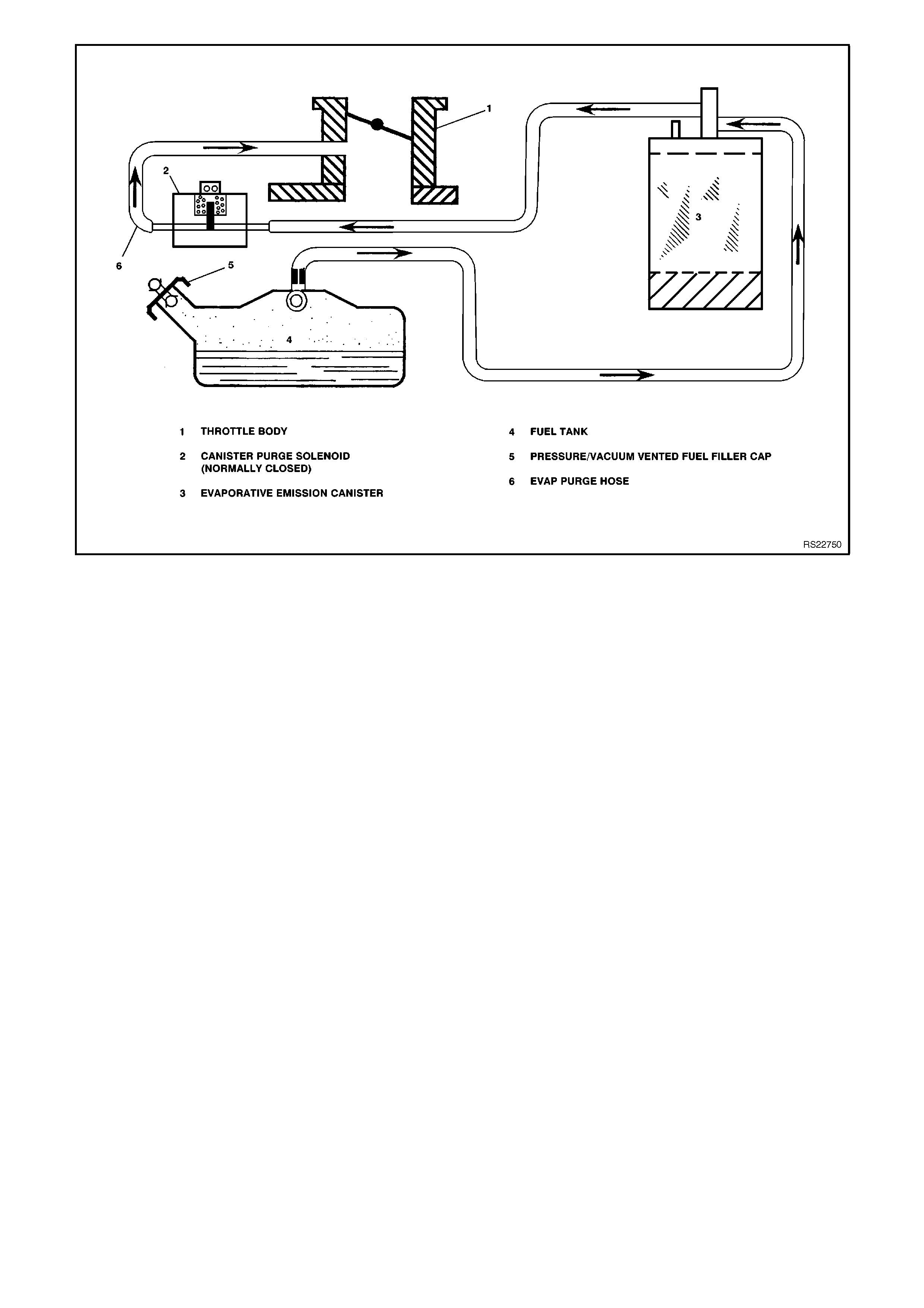
Figure 6C2-1-100 EVAP System Typical

1.11 ELECTRIC COOLING FAN
Figure 6C2-1-101 Cooling Fan Circuit
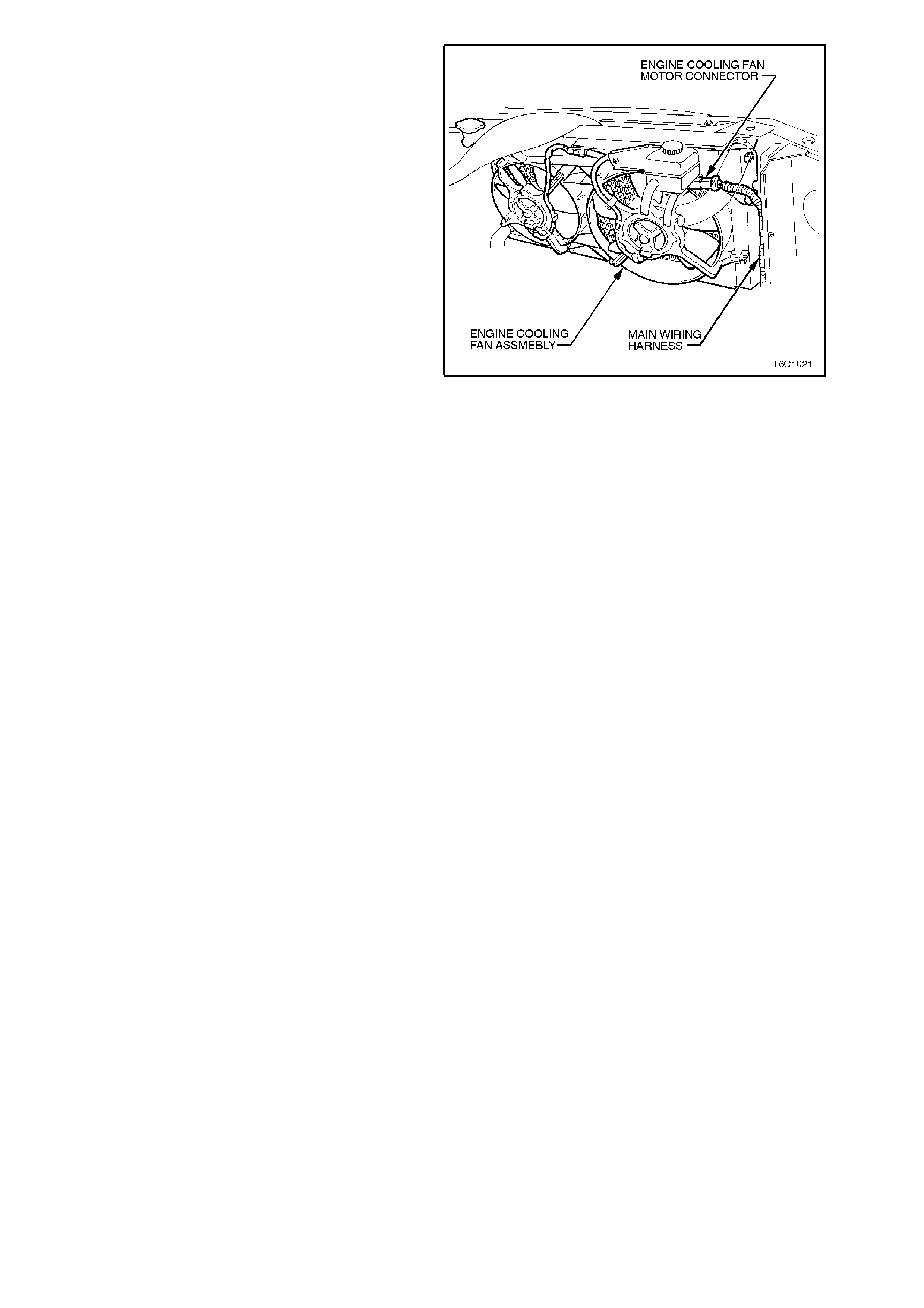
The V8 engine has two, two speed electric engine
cooling fan assembly that provides the primary
means of moving air through the engine radiator.
The two, two speed electric cooling f an are us ed to
cool engine coolant flowing through the radiator.
The two, two speed electric cooling fans are also
used to cool the ref rigerant f lowing through the A/C
condenser (if fitted). Each engine cooling fan m otor
has four terminals, two negative and two positive
terminals. The two negative terminals are the relay
controlled circuits for the fan operation. The two
positive terminals are the direct power feed from a
fusible link to the fan motors. When an earth signal
is applied to one of the negative term inals, the fan
motor will operate at low speed. When a earth
signal is applied to both negative terminals, both
fan will operate at high speed.
The engine cooling fan high speed relay is
controlled by the PCM. The PCM controls the earth
path for the engine cooling fan high speed relay.
The low speed of the electric fan is controlled by
the PCM through a special Data Com munic ation to
the BCM. The BCM controls the earth path for the
engine cooling fan low speed relay. The engine
cooling fan high speed relay and the engine
cooling fan low speed r elay are used to c ontrol the
earth signal to the electr ic m otor that drives the five
bladed fan.
The PCM determines operation of the two, two
speed engine cooling fan based on A/C request,
engine coolant temperature, A/C Refrigerant
Pressure Sensor, and vehicle speed signal inputs.
There are four (4) suppression capacitors
incorporated into the fan motor wiring circuits.
These suppression capacitors help eliminate fan
motor noise through the radio speakers. If these
capacitors are open, then noise will be present
through the radio speak ers. If shorted to earth, the
fan motors could continuously run, or the fuse or
fusible link could fail.
Figure 6C2-1-102 Engine Cooling Fan Assembly
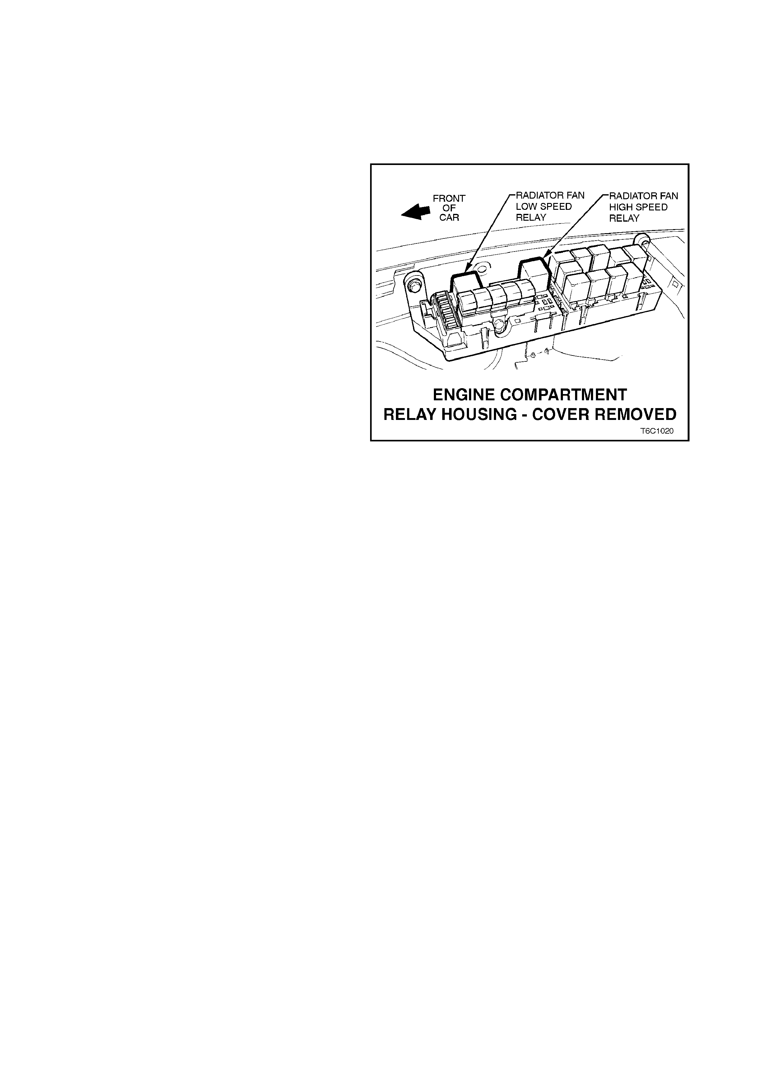
ENGINE COOLING FAN LOW SPEED
The engine cooling fan low speed relay is
energised by the BCM. The PCM determ ines when
to enable the low speed fan based on inputs from
the BCM serial data, Engine Coolant Temperature
(ECT) sensor and the Vehicle Speed Sensor
(VSS). The cooling fan low speed relay will be
turned "ON'' when:
• The A/C request indicated (YES) and either
the vehicle speed is less than 30 km/h.
- OR -
• A/C pressure is greater than 1500 kPa
- OR -
• The coolant temperature is greater than 95
degrees C.
If the coolant temperature is greater than 117
degrees C when the ignition is switched off, the
relay is energised for up to approximately 4
minutes.
If an engine coolant temperature sensor fault is
detected, such as DTC 14, 15, 16 or 17.
The cooling fan low speed relay will be turned
"OFF'' when any of the following conditions have
been met :
• The A/C request is not indicated (NO)
• The A/C request is indicated (YES) and the
vehicle speed is greater than 50 km/h and A/C
pressure is less than 1170 kPa.
Figure 6C2-1-103 Cooling Fan Relay Locations
ENGINE COOLING FAN HIGH SPEED
The engine cooling fan high speed relay is
controlled by the PCM based on input from the
Engine Coolant Temperature (ECT) sensor. The
PCM will only turn "ON'' the engine cooling fan high
speed relay fan if the engine cooling fan low s peed
relay has been "ON" for 2 seconds and the
following conditions are satisfied.
• There is a BCM message response fault which
will cause a DTC 92
• An engine coolant temperature sensor fault is
detected such as DTC 14,15,16,17.
• Coolant temperature greater than
104 degrees C.
The engine cooling fan high speed relay can also
be enabled by the A/C Refrigerant Pressure
Sensor. When the A/C Refrigerant Pressure
Sensor determines the A/C system pressure is to
high, greater than 2600 kPa, and this will instruct
the PCM to enable the high speed fan.
If the low speed fan was "OFF" when the criteria
was met to turn the high speed fan "ON", the high
speed fan will come "ON" 5 seconds after the low
speed fan is turned "ON". " If both the engine
cooling fan relays are "ON", the PCM will turn
"OFF" the high speed relay when:
The engine coolant temperature is less than 99
degrees C.
• A/C request not indicated (NO)
• A/C request indicated (YES) and A/C pressure
is less than 2300 kPa.
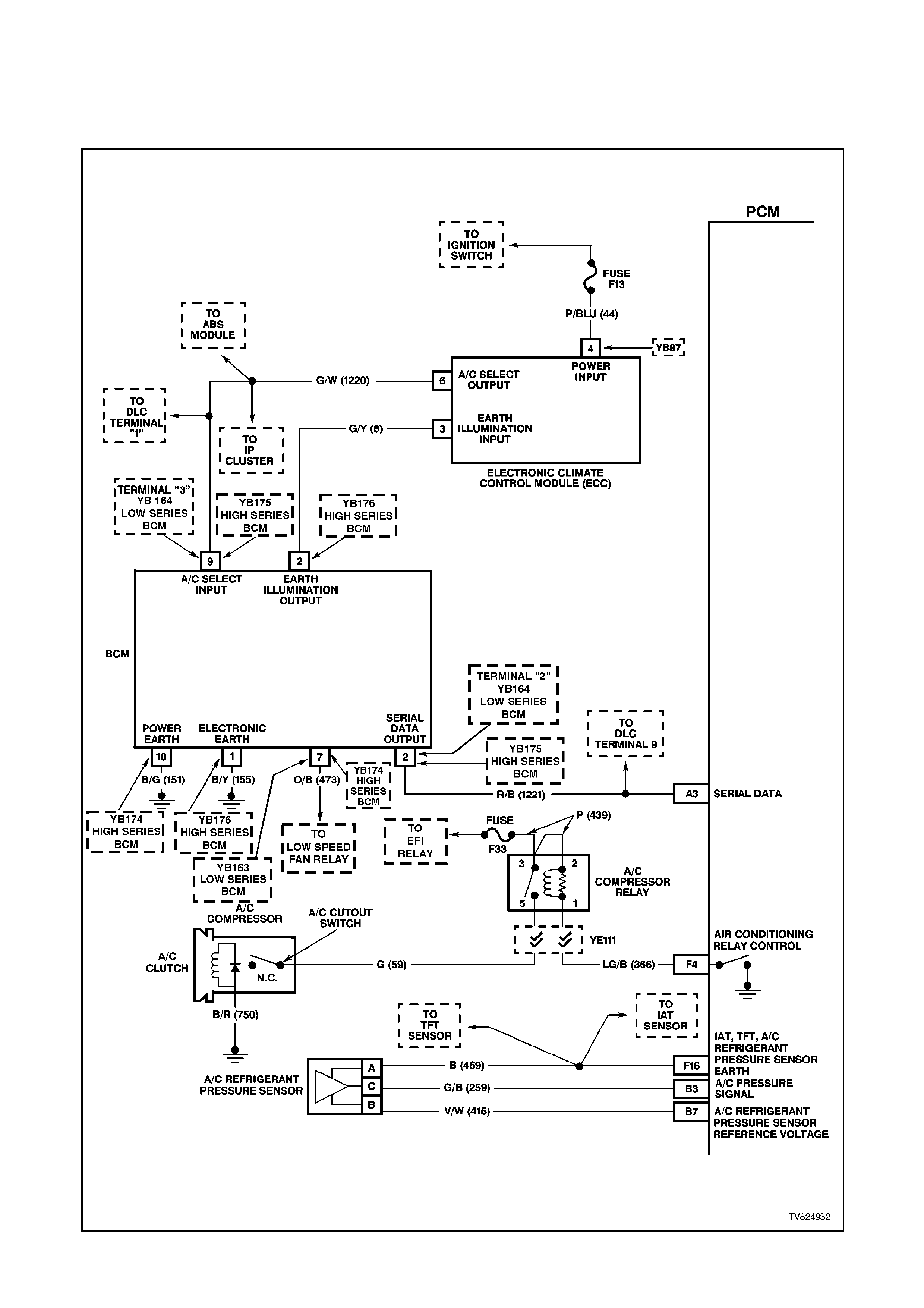
1.12 A/C CLUTCH CONTROL
This vehicle uses one of two types of A/C clutch controls. Either a standard A/C type or an Electronic Climate
Control (ECC) module type.
A/C CLUTCH CONTROL WITH ELECTRIC CLIMATE CONTROL
Figure 6C2-1-104 A/C Clutch Control With ECC
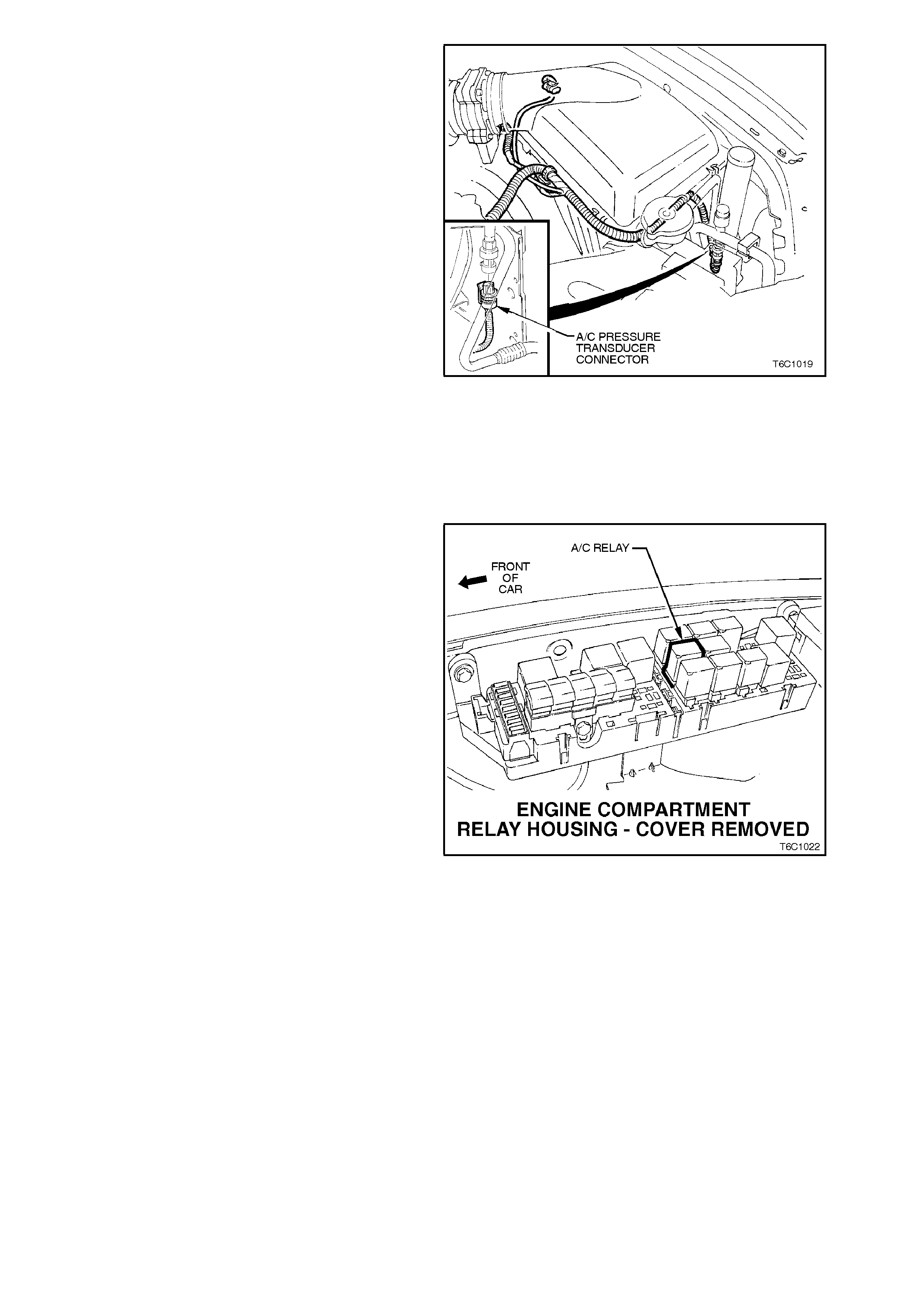
With the ECC system, when the A/C is requested,
the Electronic Climate Control Module will supply a
signal to the BCM. The BCM will then send a serial
data request to the PCM. W hen the PCM receives
the serial data request on PCM terminal B12, the
PCM will indicate that air conditioning has been
requested. Approximately 1/2 second after the
PCM receives this s ignal, the PCM will energise the
A/C control relay. This serial data signal to the PCM
is also used to adjust the idle speed before turning
"ON" the A/C compressor relay. If this signal is not
available to the PCM, the A/C compressor will be
inoperative.
If there is a problem with the PCM A/C Relay
Control circuit, QDSM DTC 91 will set.
The BCM also supplies the earth signal from BCM
terminal "7" to the low speed cooling fan relay.
This A/C system also incorporates a A/C
Refrigerant Pressure Sensor. The A/C Refrigerant
Pressure Sensor signal indicates high side
refrigerant pressure to the PCM. The PCM uses
this infor mation to adj ust the idle air c ontrol valve to
compensate for the higher engine loads present
with high A/C refrigerant pressures. A fault in the
A/C Refrigerant Pressure Sensor signal will cause
DTC 96 to set.
Figure 6C2-1-105 A/C Refrigerant Pressure Sensor
Location
The PCM will NOT energise the A/C control
relay if any of the following conditions are
present.
• The engine speed is gr eater than 5,800 RPM. If
disabled because of RPM, the A/C can be
enabled when the RPM falls below 5,400 RPM.
• The throttle is greater than 99%. When dis abled
during wide-open throttle, the A/C will enable
when the throttle is less than 93%.
On vehicles equipped with non-ECC systems the
power flow is diff erent. W ith the blower fan and the
air conditioning switched "ON," switched ignition
voltage is supplied from fuse F13 through the A/C
master switch, and then to the BCM. The BCM will
then supply a serial data signal to the PCM
requesting A/C. If the BCM does not receive a
earth signal from the blower switch to BCM terminal
"3", the BCM will not supply the serial data request
for A/C. Once the PCM receives this serial data
signal, the PCM will energise the A/C compressor
relay. The BCM also supplies the earth signal from
BCM terminal "7" to the low speed cooling fan
relay.
This serial data signal to the PCM is also used to
adjust the idle speed before turning "ON" the A/C
compressor relay. If this signal is not available to
the PCM, the A/C compressor will be inoperative.
This system, lik e the ECC system als o inco rpor ates
a A/C Refrigerant Pressure Sensor. The A/C
Refrigerant Pressure Sensor signal indicates high
side refrigerant pressure to the PCM. The PCM
uses this information to adjust the idle air control
valve to compensate for the higher engine loads
with high A/C refrigerant pressures. A fault in the
A/C Refrigerant Pressure Sensor signal will cause
a DTC 96 to set.
Figure 6C2-1-106 A/C Relay Location

A/C CLUTCH CONTROL WITH NON ECC AIR CONDITIONING
With the blower fan ON, and the air conditioning ON, the switched ignition voltage is supplied from fuse F13
through the A/C master switch, and then to the BCM. The BCM will then supply a serial data signal to the PCM
requesting A/C. If the BCM does not receive a earth signal from the blower switch to BCM terminal "3", the BCM will
not supply the serial data request for the A/C. Once the PCM receives the serial data signal, the PCM will energise
the A/C compressor relay by supplying a earth signal (A/C Relay Control ). The BCM also supplies a earth signal
from BCM terminal "7" to the low speed cooling fan relay.
This serial data signal to the PCM is also used to adjust the idle speed before turning ON the A/C compressor relay.
If this signal is not available to the PCM, the A/C compressor will be inoperative.
This system also incorporates an A/C Pressure Transducer. The A/C Pressure Transducer signal indicates low side
and high side refrigerant pressure to the PCM. The PCM uses this information to adjust the idle air control valve to
compensate for the higher engine loads present with high A/C refrigerant pressures.
The purpose of the A/C Pressure Transducer is to protect the system from damage due to either the refrigerant
pressure being too low (which could damage the compressor due to insufficient lubrication), or too high (which
could result in a leak in the sealed refrigerant R134a system).
The PCM will NOT energise the A/C control relay if any of the following conditions are present:
• The engine speed is greater than 4,800 RPM. If de-energised because of RPM, it can re-energised when the
speed falls below 4,000 RPM for at least 10 seconds.
• The Throttle Position sensor is greater than 90% open.
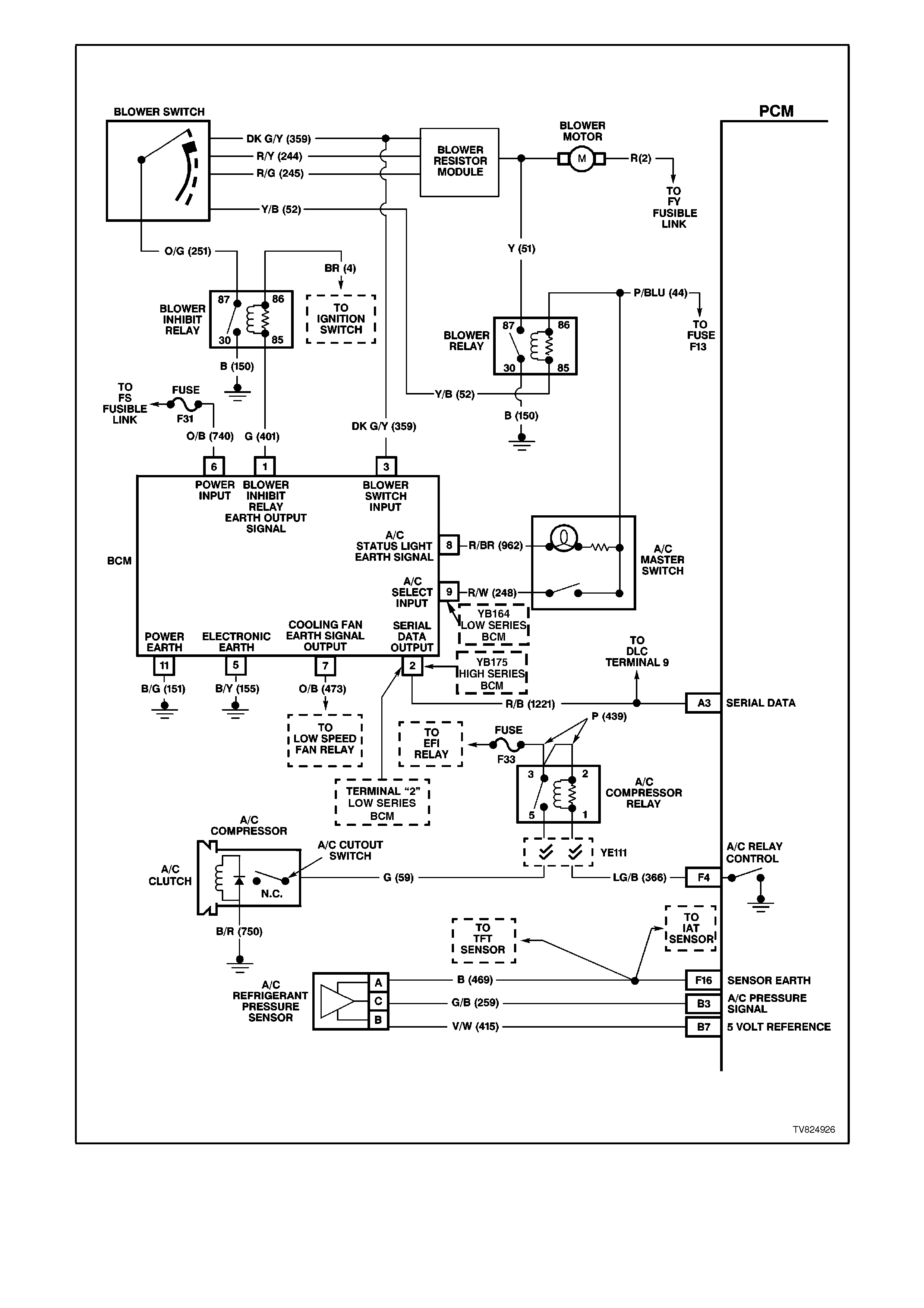
Figure 6C2-1-107 PCM A/C Clutch Control Without ECC

1.13 ABBREVIATIONS AND GLOSSARY OF TERMS
Abbreviations used are listed below in alphabetical order with an explanation of the abbreviation.
AC - ALTERNATING CURRENT - A current whose polarity is constantly changing between positive and negative.
A/C - AIR CONDITIONING
A/F - AIR/FUEL (A/F RATIO)
ANALOG SIGNAL - An electrical signal that varies in voltage within a given parameter.
BAROMETRIC PRESSURE - Atmospheric pressure. May be called BARO, or barometric absolute pressure.
BATTERY - Stores chemical energy and converts the chemical energy into electrical energy. This provides DC
current for the vehicles electrical systems.
CAT. CONV - CATALYTIC CONVERTER - A muffler-shaped device fitted in the exhaust system, between the
engine and the muffler. The purpose of the catalytic converter is to chemically convert engine producing gases into
environmentally safe gases. HC, CO, and NOx emitted by the engine, are converted to water vapour, carbon
dioxide, and nitrogen.
"CHECK POWERTRAIN" LAMP - A Warning indicator located on the instrument panel, and controlled by the PCM.
The lamp is illuminated by the PCM when it detects a fault in the engine management system, or when the ignition
is "ON" with the engine not running (bulb check).
CKT - CIRCUIT
CLOSED LOOP - A fuel control mode of operation that uses the signal from the exhaust oxygen sensor, in order to
control the air/fuel ratio precisely at a 14.7 to 1 ratio. This allows maximum efficiency of the catalytic converter.
CO - CARBON MONOXIDE - One of the pollutants found in the engine exhaust.
DIAGNOSTIC TROUBLE CODE - The PCM can detect faults in the engine management system. If a fault occurs,
the PCM may turn on the "Check Powertrain" lamp and a two digit code number will set. A diagnostic trouble code
can be read from the PCM through the "Check Powertrain" lamp or with the Tech 2 scan tool. This DTC will indicate
the area of the fault.
DIAGNOSTIC "TEST" ENABLE TERMINAL - A terminal in the Data Link Connector(DLC) that is earthed to get a
Diagnostic Trouble Code.
DIGITAL SIGNAL - An electrical signal that is either ON or OFF.
DLC - DATA LINK CONNECTOR - Used at the assembly plant to evaluate the engine management system. For
service: to flash the "Check Powertrain" lamp, use of Tech 2 scan tool, & making other system checks.
DLC DATA STREAM - An output from the PCM, initiated by the Tech 2 scan tool. This output is a digital signal,
used by assembly plant test equipment and the Tech 2 scan tool. This signal is transmitted from the PCM to the
Data Link Connector(DLC).
DRIVER - An electronic device, usually a power transistor, that operates like an electrical switch turning a circuit
“ON” and “OFF”.
DUTY CYCLE - The time, in percentage, that a circuit is "ON" versus "OFF" .
DVM (10 Meg.) - DIGITAL VOLTMETER - A multipurpose meter that has capability of measuring Voltage, Amps,
and Resistance.
FIELD SERVICE MODE - A PCM mode of operation that is used during service. It is operational when the engine is
running and the DLC diagnostic "test" enable terminal is earthed.
ENGINE COOLANT TEMPERATURE (ECT) SENSOR - A sensor that senses the engine coolant temperature and
sends that information to the powertrain control module.

EECS - EVAPORATIVE EMISSIONS CONTROL SYSTEM - Used to prevent petrol vapours from the fuel tank from
entering into the atmosphere. The vapours are stored in a canister, located in the engine compartment. The
canister contains an activated charcoal element. The petrol vapours are purged from the canister into the manifold
to be burned in the engine.
EMI OR ELECTRICAL NOISE - An unwanted signal interfering with another needed signal. Common examples are
an electric razor's effect on a television, or AM radio reception while driving under high voltage power lines.
EPROM - ERASABLE PROGRAMMABLE READ ONLY MEMORY - Type of read only memory (ROM) that can be
erased with ultraviolet light and reprogrammed.
ESD - ELECTROSTATIC DISCHARGE - The discharge of static electricity, which has built up on an insulated
material.
EEPROM - ELECTRICALLY ERASABLE PROGRAMMABLE READ ONLY MEMORY - Ty pe of read only memory
(ROM) that can be electrically programmed, erased and reprogrammed.
FIELD SERVICE MODE - A PCM mode of operation that is used during service. The field service mode is
operational when the engine is running and the DLC diagnostic "test" enable terminal is earthed.
FUSE - A thin metal strip which melts through when excessive current flows through it, creating an open circuit.
Protecting a circuit from damage.
HC - HYDROCARBONS (HC) - Any unburned fuel leaving the engine from incomplete combustion.
IAC VALVE- IDLE AIR CONTROL VALVE - Installed on the throttle body unit and controlled by the PCM to regulate
idle air flow, and thus idle RPM.
IAT SENSOR- INTAKE AIR TEMPERATURE SENSOR - A sensor that senses intake manifold incoming air
temperature, and sends the information to the PCM.
IDEAL MIXTURE - The air/fuel ratio which provides the best performance, while maintaining maximum conversion
of exhaust emissions, typically 14.7 to 1 on petrol engines.
IGN - IGNITION
INPUTS - Information from sensors (MAF, TPS, etc) and switches (A/C request, etc.) used by the PCM to
determine how to control its outputs.
INTERMITTENT - An electrical signal that occurs now and then; not continuously. In electrical circuits, refers to
occasional open, short, or earth in a circuit.
IPC - INSTRUMENT PANEL CLUSTER
LOW - A voltage less than a specific threshold. Operates the same as an earth and may, or may not, be connected
to chassis earth.
MAF - MASS AIR FLOW SENSOR - A device that monitors the amount of air flow coming in the engine intake. The
MAF sensor sends a signal to the PCM.
N.C. - NORMALLY CLOSED - Switch contacts that are closed, when they are in the normal operating position.
N.O. - NORMALLY OPEN - Switch contacts that are normally open when in the normal operating position.
NOx - NITROGEN OXIDE - One of the pollutants found in gasoline engine exhaust. The are formed from normal
combustion and increase in severity with combustion temperatures.
OXYGEN SENSOR - The exhaust gas oxygen sensor is located in the exhaust manifold. The O2 sensor measures
the oxygen in the exhaust manifold after the combustion process. The O2 sensor produces a small electrical signal
based on the amount of oxygen in the exhaust gas.
OPEN LOOP - The PCM control of the fuel control system without the use of the oxygen sensor information.
OUTPUT - Functions, typically include solenoids and relays, that are controlled by the PCM.
PCM - POWERTRAIN CONTROL MODULE. A metal cased box containing electronic circuitry w hich electrically
monitors and controls the transmission system and emission systems on the engine management system. It also
turns "ON" the "Check Powertrain" lamp when a malfunction occurs in the system.
PCV - POSITIVE CRANKCASE VENTILATION - Method of reburning crankcase fumes, rather than passing them
directly into the atmosphere.
PROM - PROGRAMMABLE READ ONLY MEMORY - An electronic term used to describe the engine calibration
unit. A plug-in memory unit that instructs the PCM how to operate for a particular vehicle.
PULSE WIDTH MODULATED (PWM) - A digital signal turned "ON" and "OFF'" for a percentage of available on-
plus-off cycle time such as, 30% "on" and 70% "off" would be called a 30% "ON" PWM signal.

QUAD DRIVER - A transistor in the PCM, capable of operating four separate outputs. Outputs can be either "ON-
OFF" or pulse width modulated.
RAM - RANDOM ACCESS MEMORY - Is the microprocessors "scratch pad". The processor can write into, or read
from this memory as needed. This memory is volatile and needs a constant supply of voltage to be retained. If the
voltage is lost or removed, this memory is lost.
SERIAL DATA - Serial date is a series of rapidly changing voltage signals pulsed from high to low voltage. These
voltage signals are typically 5 volts (high) and 0 volts (low) and are transmitted through a wire often referred to as
the serial data line.
SFI - SEQUENTIAL FUEL INJECTION - Method of injecting fuel into the engine. Places a fuel injector at each inlet
port of a cylinder head, directly in front of the intake valve, mounted in the intake manifold.
SOLENOID - An electromagnetic coil which creates a magnetic field when current flows through it and causes a
plunger or ball to move.
SWITCH - Opens and closes circuits, thereby controlling current flow.
TCC - TORQUE CONVERTER CLUTCH - A PCM controlled solenoid in an automatic transmission which positively
couples the transmission input shaft to the engine.
TECH 2 SCAN TOOL - A hand-held diagnostic tool, containing a microprocessor that reads the PCM's DLC data
stream. A display panel displays the PCM's input signals and output commands.
TP SENSOR - THROTTLE POSITION - A sensor that sends a signal to the PCM. The PCM can determine from
this signal the current throttle position, and the rate of throttle opening / closing.
VACUUM, MANIFOLD - A vacuum source from below the throttle plate.
VACUUM, PORTED - Vacuum source from a small "port" in the throttle body. With the throttle closed, there is no
vacuum, because the port is on the air cleaner side of the throttle blade, and is exposed to engine vacuum only after
the throttle is open.
VSS - VEHICLE SPEED SENSOR- A permanent magnet type sensor which produces an AC voltage which is sent
to the PCM to determine vehicle speed.
UART - UNIVERSAL ASYNCHRONOUS RECEIVE AND TRANSMIT - A method of communicating between
electronic devices.
WOT - WIDE OPEN THROTTLE - A throttle position opening greater than 80%.