SECTION 6D1-2 STARTING SYSTEM - V6 ENGINE
CAUTION:
This vehicle will be equipped with a Supplemental Restraint System (SRS). A SRS will
consist of either seat belt pre-tensio ners and a driver’s side air bag , or seat belt pre-
tensioners and a driver’s and front passenger’s side air bags. Refer to CAUTIONS,
Section 12M, before performing any service operation on or around SRS
components, the steering mechanism or wiring. Failure to follow the CAUTIONS
could result in SRS deplo yment, resulting in possible p ersonal injury or unnecessary
SRS system repairs.
CAUTION:
This vehicle may be equipped with LPG (Liquefied Petroleum Gas). As this fuel in the
gaseous form is heavier than air, and in the interests of safety, the LPG fuel system
should be isolated by turning 'OFF' the manual service valve and then draining the
LPG service lin es, before any service wo rk is carried out on the vehicle. Refer to the
LPG leaflet included with the Owner's Handbook for details or LPG Section 2 for
more specific servicing information.
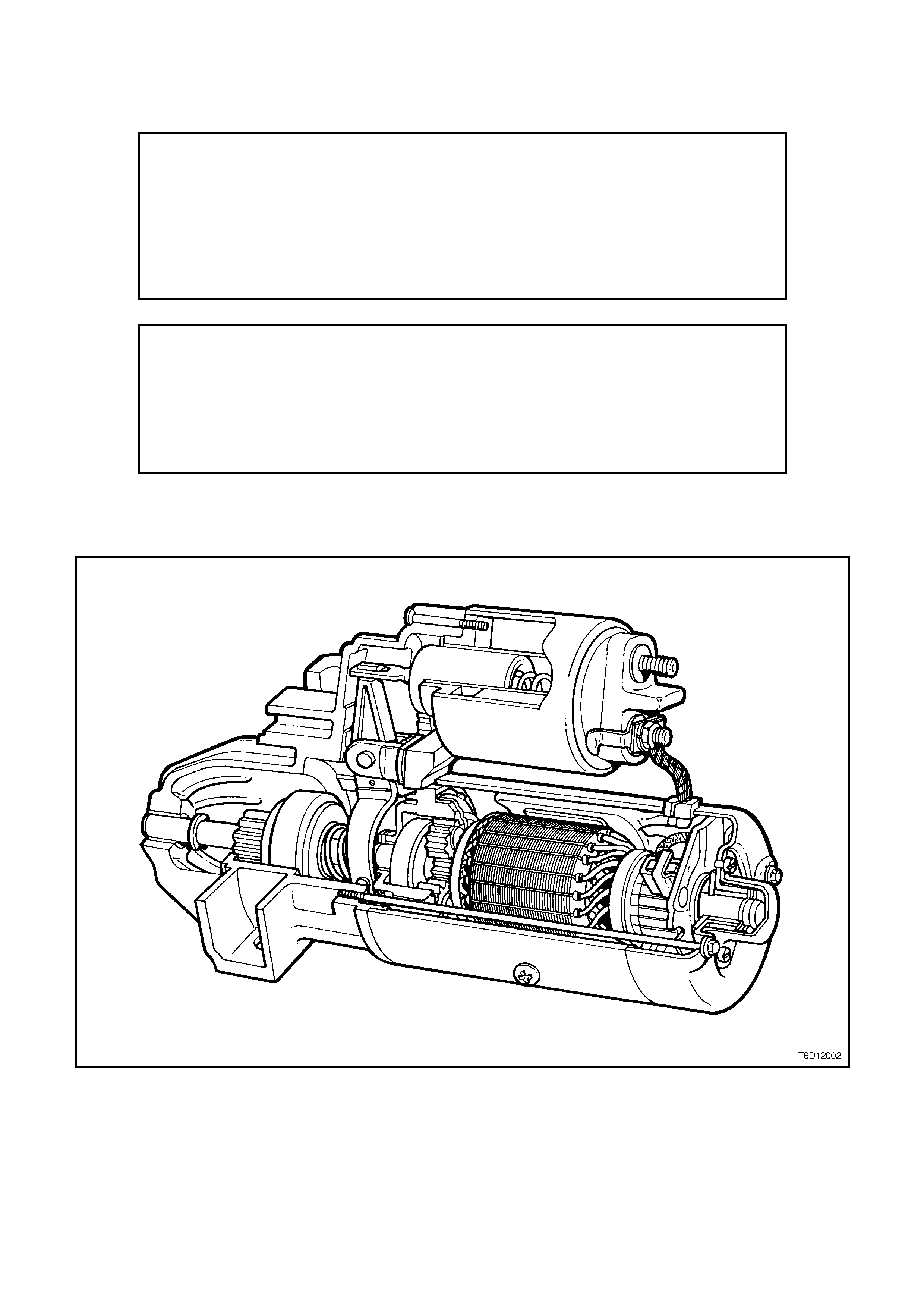
1. GENERAL INFORMATION
Figure 6D1-2-1
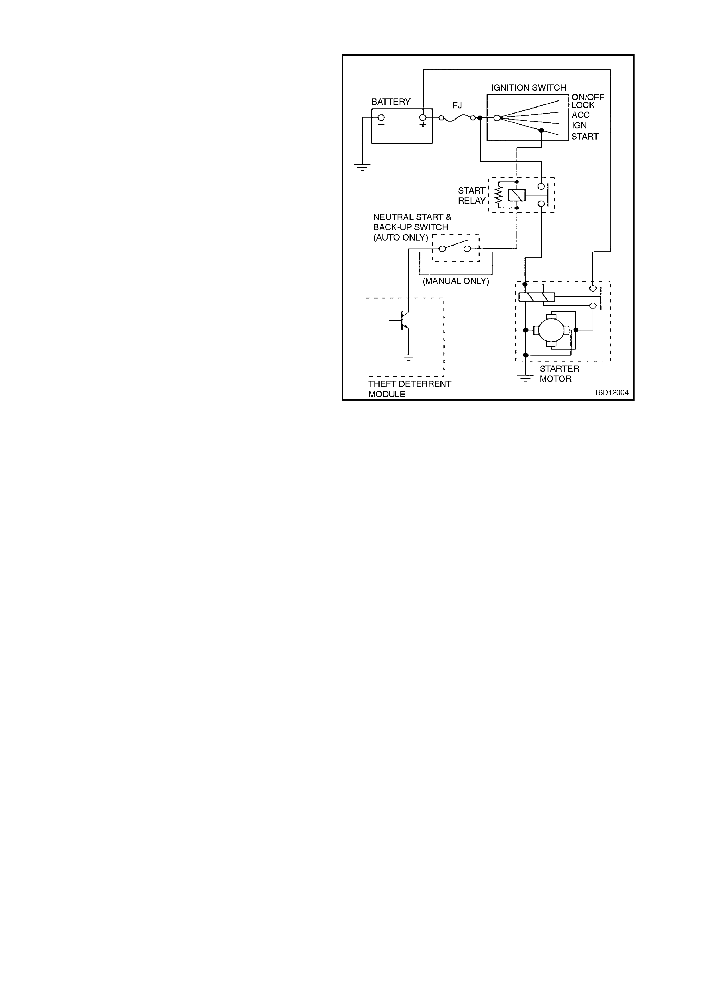
1.1 GENERAL DESCRIPTION
The starting system comprises the battery, starter
motor, ignition switch, neutral/back-up switch
(vehicles with automatic transmission), theft
deterrent engine crank inhibitor (function of theft
deterrent system) and related electrical wiring.
The starter motor is a series parallel wound, four
pole, four brush type with a planetary drive train.
The arm ature shaft is supported at each end by oil
absorbent sintered metal bushes pressed into the
commutator end cover and the inside of the
planetary drive shaft.
The planetary drive train consists of an internal
toothed ring gear (made from a high-grade
polyamide compound with mineral additives) and
keyed to the drive end housing, three gear wheels
which rotate on needle bearings and attached to
the planetary drive shaft. The gear wheels mesh
with gear teeth on the front end of the armature
shaft. The planetary drive shaft is supported at
each end by oil absorbent sintered metal bushes
pressed into the drive end housing and the inside of
the internal toothed gear. The arm ature rotates the
drive assembly at a reduced speed of
approximately 3.36:1.
These bearings require lubrication only at time of
overhaul.
The four brushes are supported by the brush holder
which is retained to the commutator end cover by
screws. Two brushes are grounded to the field coil
housing, and two are insulated from the housing
and connected to the field coils. The field coils are
held in place by the pole shoes which are attached
to the field coil housing by large diameter screws.
The field coils are connected to an insulated
terminal on the field coil housing through which
current is supplied to the starter motor from the
solenoid switch.
On the drive end housing, a plastic fork with plastic
bearing block is used to engage the drive as sem bly
with the flexplate/ring gear.
The drive assembly transmits cranking torque to
the flexplate/ring gear. To prevent the armature
from being driven at excessive speed by the
engine, an internal clutch allows the drive assem bly
pinion gear to rotate freely in relation to the
planetary shaft and armature when the engine
begins to operate.
Figure 6D1-2-2
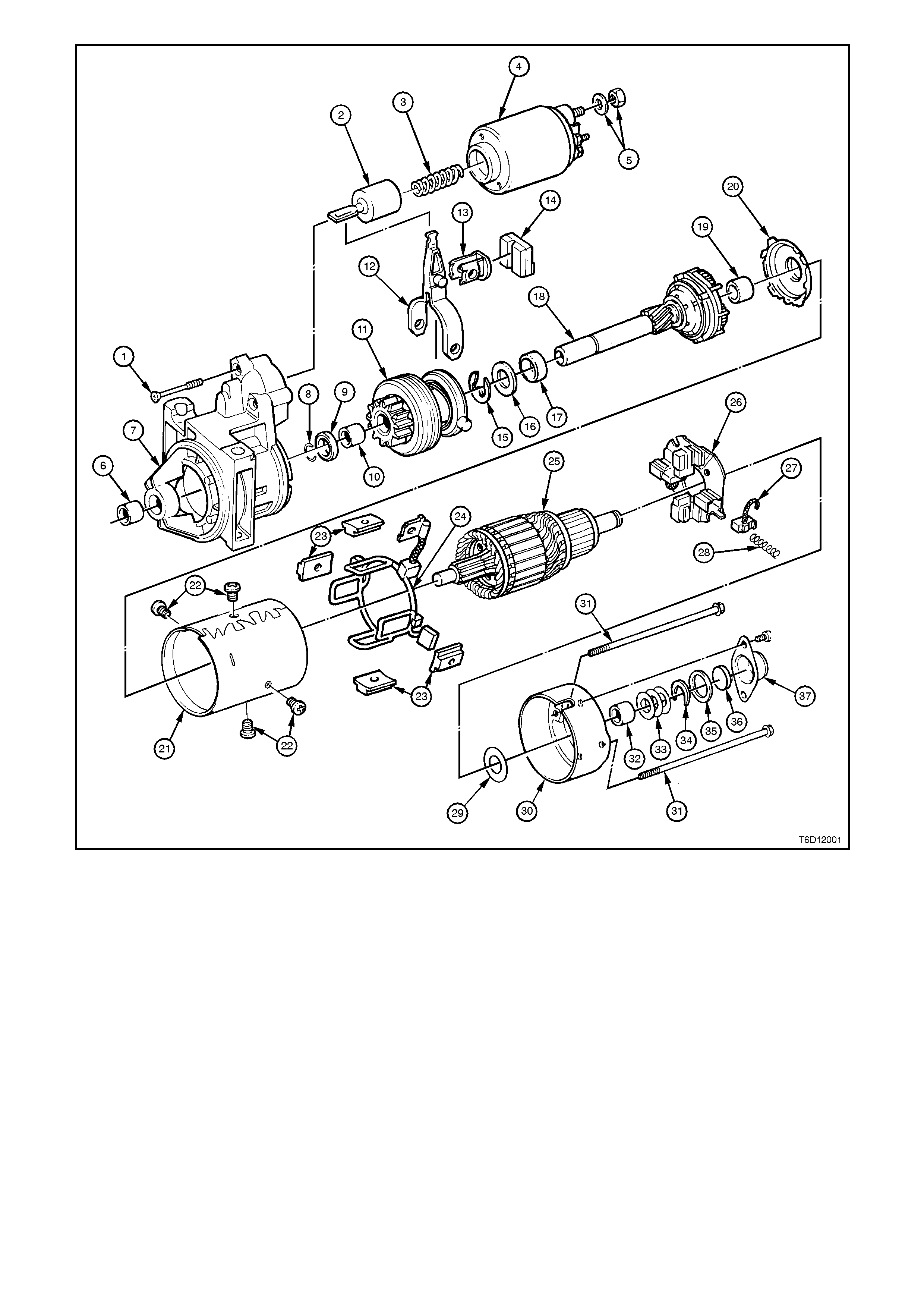
Figure 6D1-2-3
1 Solenoid switch to drive end 12 Drive lever bearing 24 Brush holder spring
housing mounting screws 13 Sealing rubber 25 Thrust washer
2 Plunger 14 Planetary drive shaft 26 Commutator end cover
3 Return spring 15 Commutator front cover bush 27 Through bolt (standard)
4 Solenoid switch 16 Cover plate 28 Commutator end cover bush
5 ‘M’ terminal nut and washer 17 Field coil housing 29 Adjustment washers
6 Drive end housing bush 18 Field coil pole side screws 30 Horse shoe clip
7 Drive end housing 19 Pole shoe 31 Dust cover seal
8 Stud ring 20 Field coil and positive brushes 32 Felt pad
9 Stop ring retainer 21 Armature 33 Dust cover
10 Drive assembly 22 Brush holder & negative
brushes
11 Fork lever 23 Brush

2. SERVICE OPERATIONS
2.1 PERFORMANCE TESTING
The following tests involve the starter motor being
removed from the vehicle, refer to 2.2 STARTER
MOTOR - REMOVE in this Section.
SOLENOID SWITCH TESTS
Pull-In Test
1. Remove nut and washer from solenoid switch
short threaded ter m inal ('M' term inal) . Rem ove
field coil braided cable and terminal from
threaded terminal.
2. Using suitable test leads and 12 volt battery,
connect as shown in Figure 6D1-2-4. Check
that drive assembly moves outward.
If drive assembly does not move, replace
solenoid switch as described in this Section.
Figure 6D1-2-4
Hold-In Test
1. With battery connections to starter motor and
solenoid switch as shown for Pull-In Test,
disconnect negative lead from solenoid switch
short threaded terminal ('M' terminal).
2. Check that drive assembly remains outward.
If drive assembly returns inward, replace
solenoid switch as described in this Section.
Figure 6D1-2-5
Drive Assembly Return
1. With battery and connections to starter motor
and solenoid switch as at end of Hold-In Test,
disconnect negative lead from drive end
housing.
2. Check that drive assembly returns inward.
If drive assembly does not return, replace
solenoid switch as described in this Section.
Figure 6D1-2-6
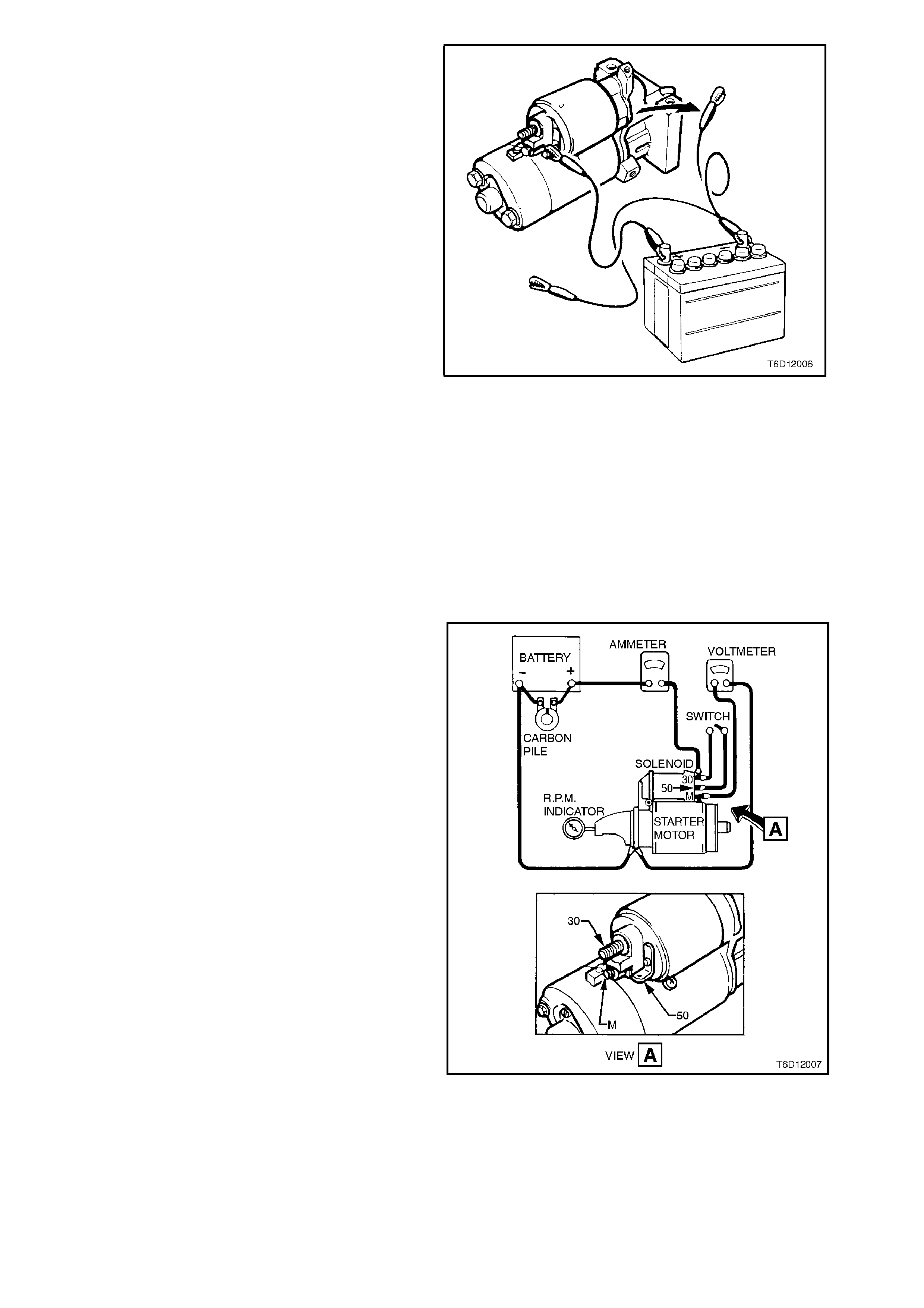
NO LOAD TEST
The drive assembly pinion should be checked for
freedom of operation by turning it on the planetary
drive shaft. The planetary drive and armature
should be check ed f or f reedom of r otation by prying
the drive assem bly pinion with a screwdriver. If the
planetary drive and armature do not rotate freely,
the starter motor should be disassembled
immediately. However, if the planetary drive and
armature do rotate freely, the starter motor should
be given a NO LOAD test before disassembly.
Clamp starter motor securely to a test bench and
make connections as shown. Close the switch and
compare the rpm, current and voltage readings with
the following specifications.
STARTER MOTOR SPEED
(ARMATURE RPM) 5300 RPM
STARTER MOTOR CURRENT 125 AMPS
TERMINAL VOLTAGE 11.5 VOLTS
If the NO LOAD test indicates that the starter
motor is defective, refer to 3. DIAGNOSIS in this
Section for probable cause of starter motor fault.
Figure 6D1-2-7
2.2 STARTER MOTOR
REMOVE
1. Disconnect battery earth lead.
2. Jack up front of vehicle and support on safety
stands. For location of jacking locations, refer
to Section OA GENERAL INFORMATION.
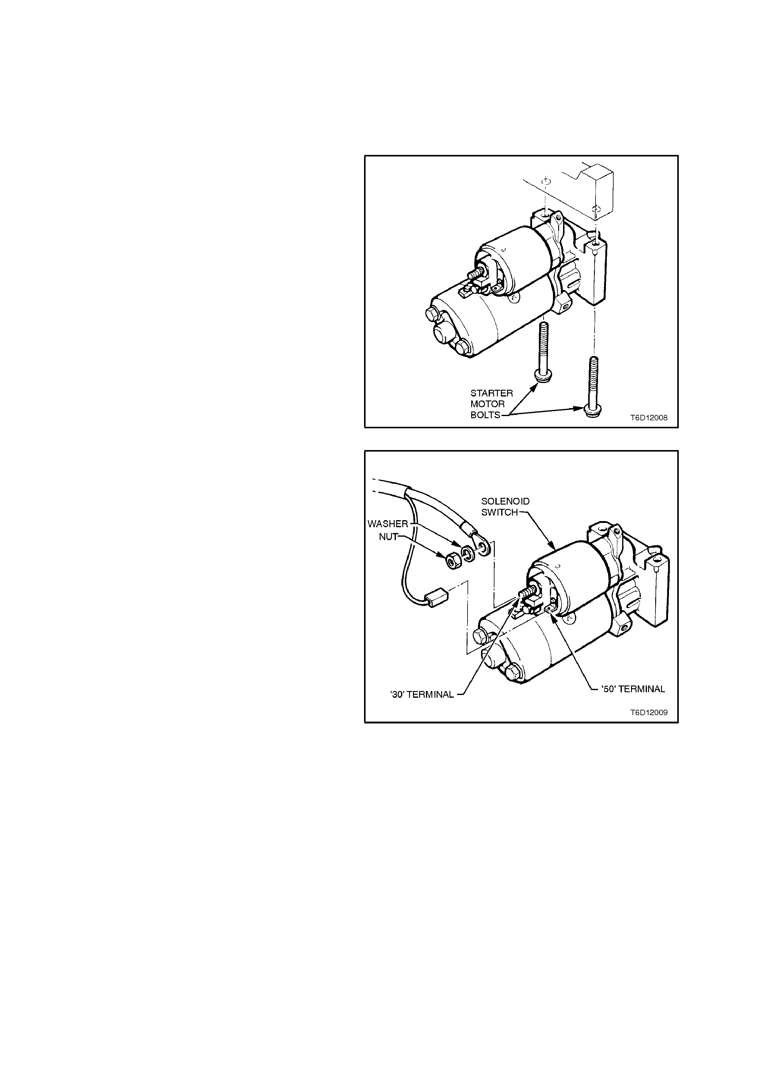
3. Remove starter motor to cylinder block
mounting bolts.
Lower starter motor and out as far as poss ible
so as to gain access to wiring harness
connections at starter motor solenoid switch.
Figure 6D1-2-8
4. Pull wiring harness connector from solenoid
switch '50' terminal.
5. Remove nut, washer and battery lead from
solenoid switch '30' (B+) terminal.
Figure 6D1-2-9
6. Withdraw starter motor.
Figure 6D1-2-10
REINSTALL
Installation of the starter motor is the reverse of
removal procedures, noting the following points:
1. Ensure that all fasteners are tightened to the
correct torque specification.
STARTER MOTOR TO CYLINDER
BLOCK MOUNTING BOLT TORQUE
SPECIFICATION 40 - 60 Nm
STARTER MOTOR '30' (B+)
TERMINAL NUT
TORQUE SPECIFICATION 9.8 - 11.3
. Nm
2. Check starter motor operation.
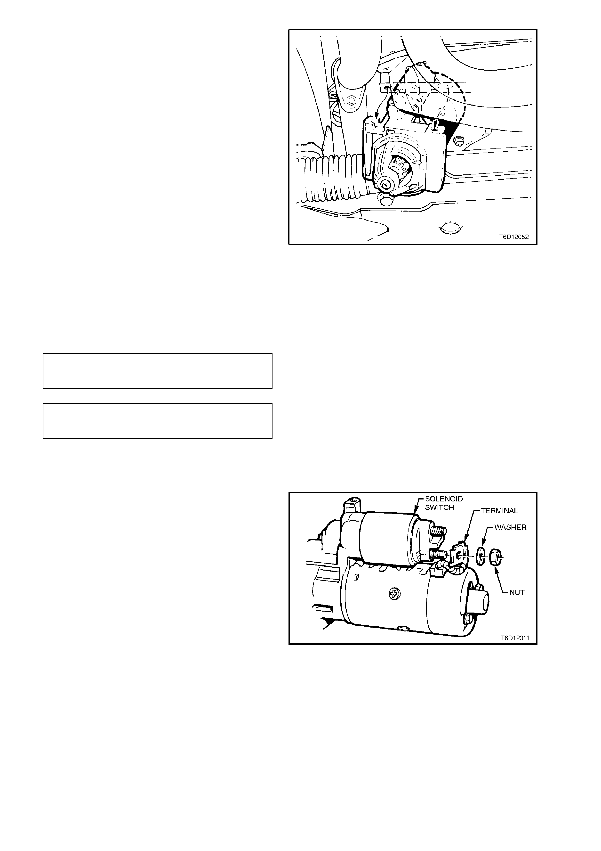
DISASSEMBLE
1. Remove nut and washer from solenoid switch
short threaded ter m inal ('M' term inal) . Rem ove
field coil braided cable and terminal from
threaded terminal.
Figure 6D1-2-11
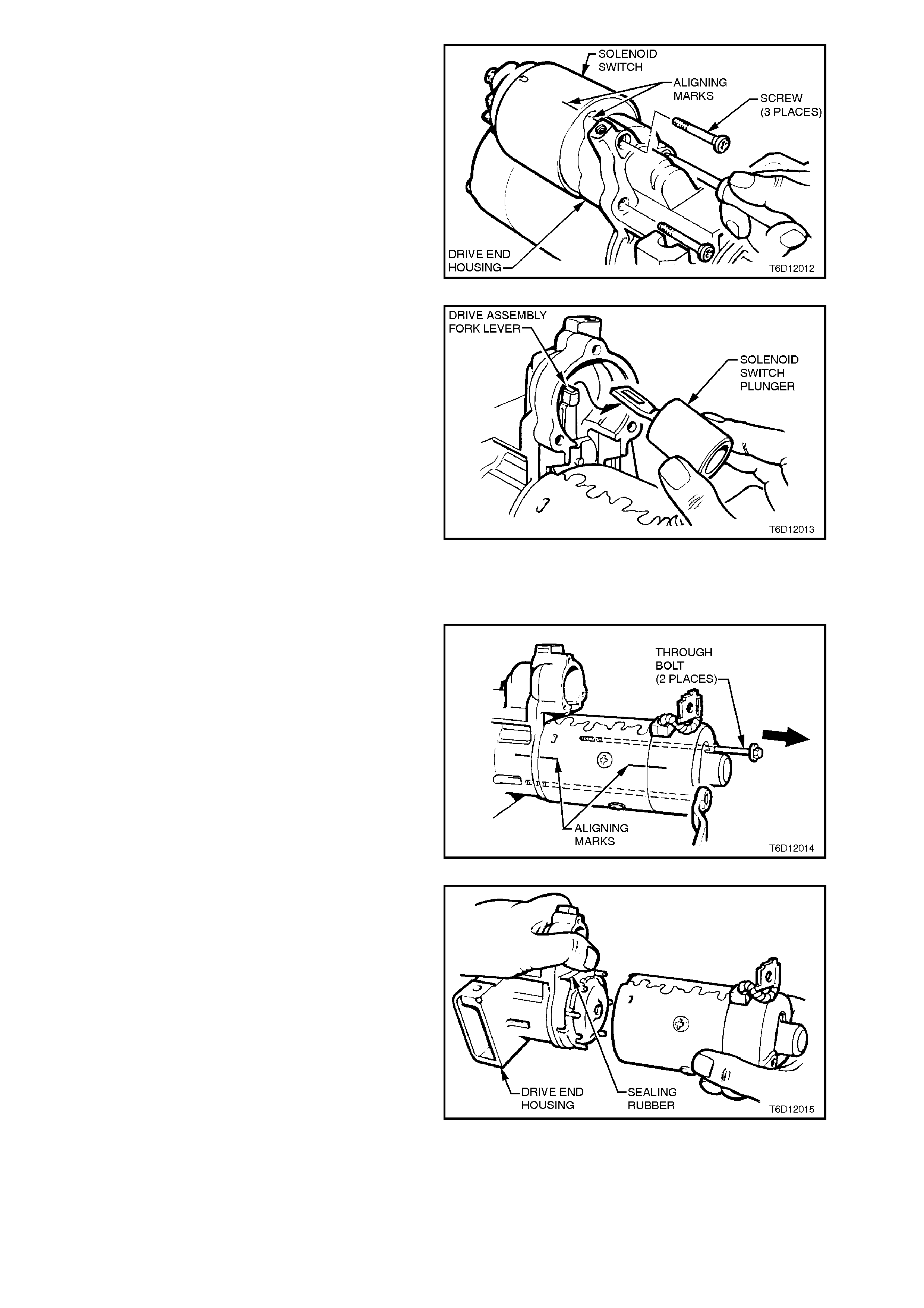
2. Scribe an aligning mark on drive end housing
and solenoid switch housing as an aid for
reassembly.
Remove the thr ee solenoid switch to drive end
housing mounting screws.
NOTE:
It may be necessar y to loosen the m ounting s crews
using an im pact driver. Ens ure to only lightly tap on
the impact driver so as not to damage the drive end
housing.
Figure 6D1-2-12
3. Pull solenoid switch from drive end housing,
taking care not to lose the plunger return
spring. (Plunger will slide out from solenoid
switch and remain attached to drive assembly
fork lever).
4. Remove solenoid switch plunger by lifting up
and then unhooking front from drive assembly
fork lever.
Figure 6D1-2-13
5. Scribe an aligning mar k on drive end housing,
field coil housing and commutator end cover
as an aid for reassembly.
6. Loosen and remove the two through bolts
securing the commutator end cover and field
coil housing to the drive end housing.
Figure 6D1-2-14
7. Keeping the sealing rubber seated in the drive
end housing, remove the commutator end
cover, field coil housing and armature an
assembly from the drive end housing.
Figure 6D1-2-15
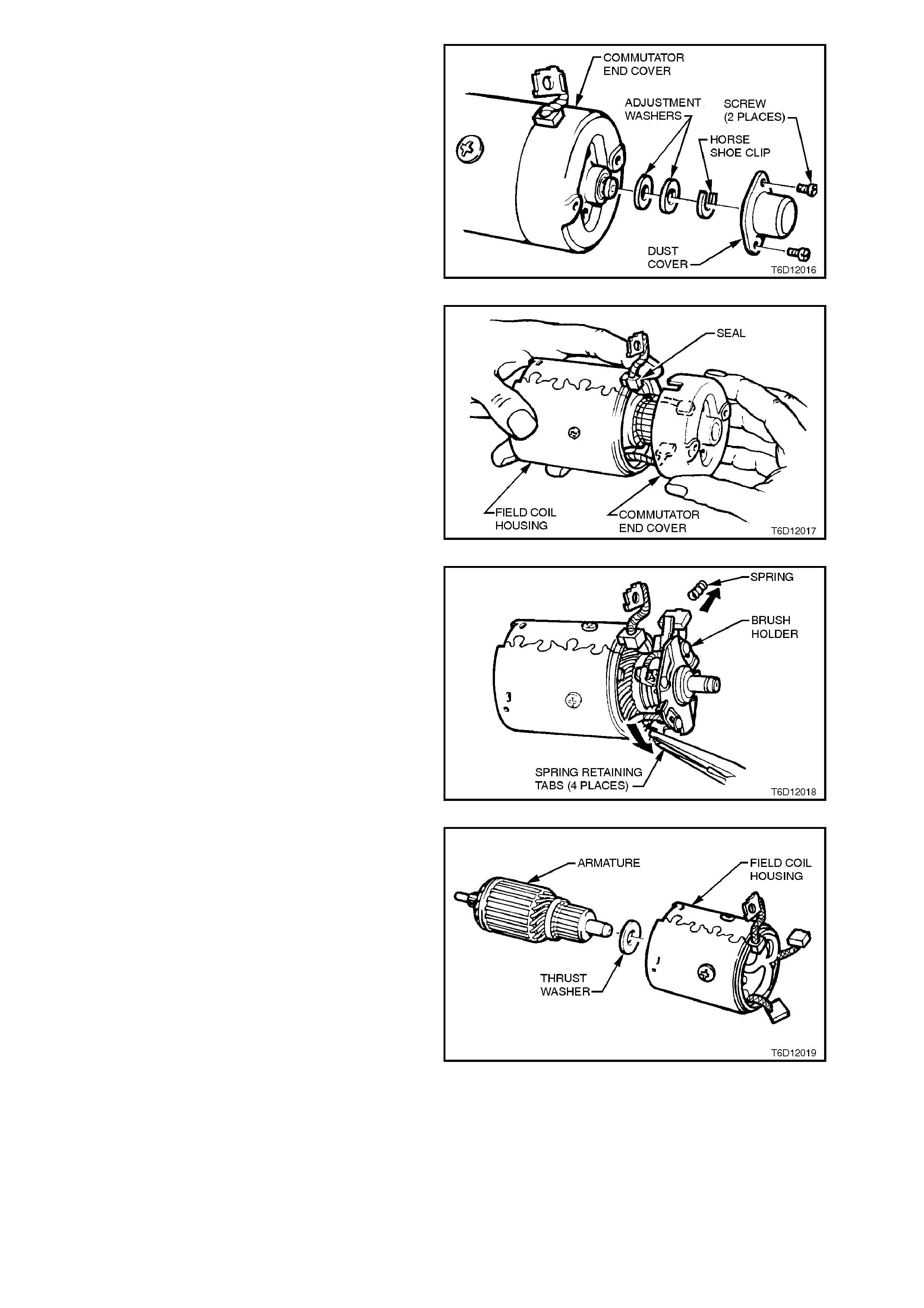
8. Remove the scr ews secur ing the dust cover to
the commutator end cover and brush holder.
Remove horse shoe clip and adjustment
washer/s from commutator end of armature.
Figure 6D1-2-16
9. While holding field coil braided cable seal to
the field coil housing, pull commutator end
cover from field coil housing.
Figure 6D1-2-17
10. Carefully bend back all the brus h holder spr ing
retaining tags, remove all springs and the
positive brushes. Remove the brush holder
from the armature's commutator.
Figure 6D1-2-18
11. Remove the armature from the field coil
housing. Rem ove the armature to com mutator
end cover thrust washer. (The washer may
either be on the end of the armature or
attached to the inside of the commutator end
cover).
Figure 6D1-2-19
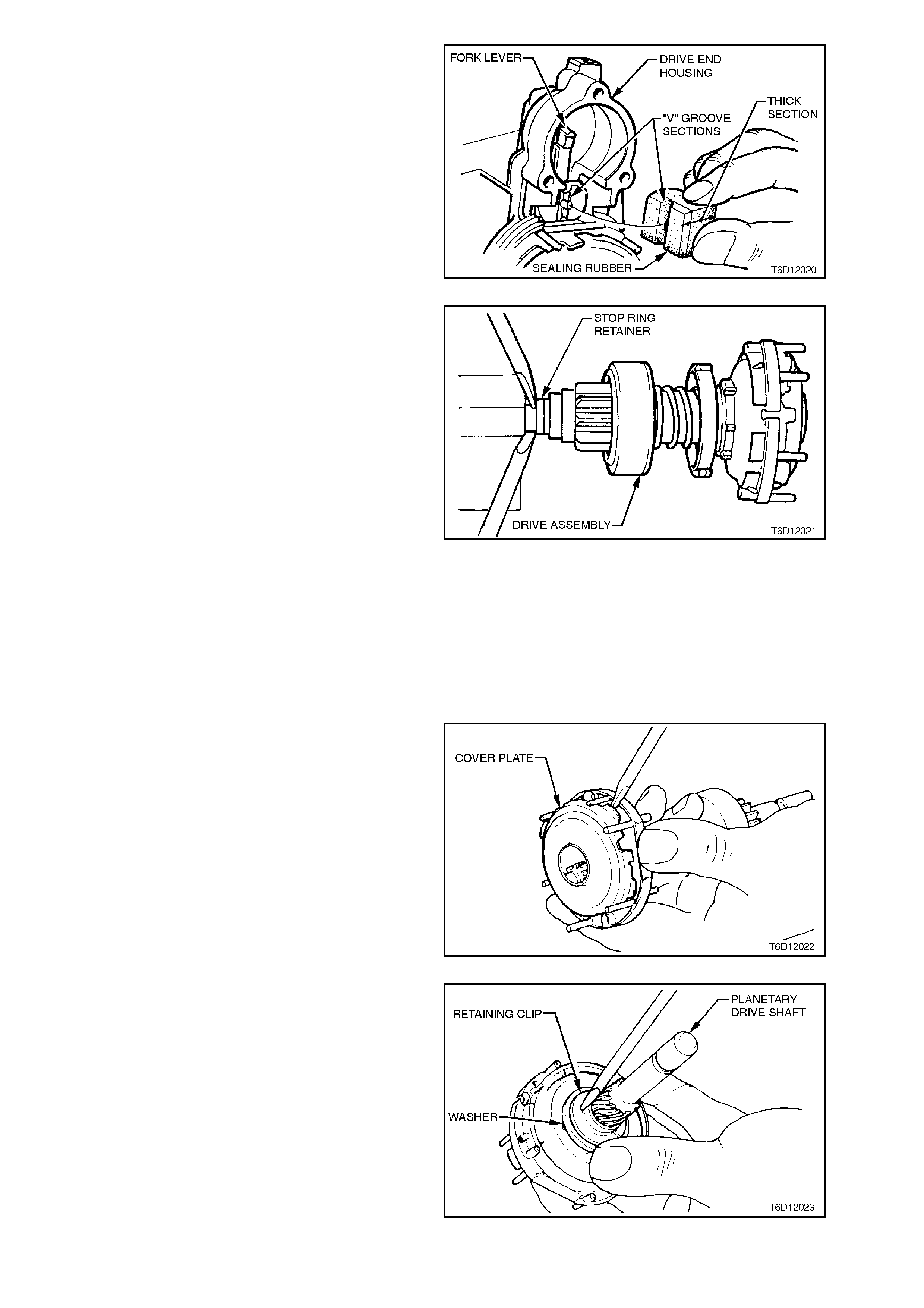
12. Remove the sealing rubber from drive end
housing, noting how it is installed.
13. Remove the drive assembly with fork lever and
planetary drive assembly from the drive end
housing.
14. Remove fork lever from drive assembly by
spreading fork lever arms and disengaging
from drive assembly pivots.
Figure 6D1-2-20
15. Clamp the end of the planetary drive shaf t in a
vice fitted with soft jaws. Prise the stop ring
retainer towards the drive assembly using two
screwdrivers pivoting on vice jaws and levering
against stop ring retainer.
As an alternative, use Bosch Tool Nos. KDAL
5047 and KDAL 5028.
16. Remove planetary drive shaft and drive
assembly from the vice.
17. Using a pair of circlip pliers, expand the stop
ring and slide it from the planetary drive shaft,
taking care not to scratch or damage the
planetary drive shaft.
18. Before attempting to remove the drive
assembly, remove any burrs on the planetary
drive shaft, particularly in the area of the stop
ring groove using a fine file. This step is
necessary so as to prevent damaging the drive
assembly to planetary drive shaft bushing
when removing the drive assembly.
Slide the stop ring retainer and drive assem bly
from the planetary drive shaft.
Figure 6D1-2-21
19. Prise the cover plate from the ring gear.
Figure 6D1-2-22
20. Remove planetary drive shaft to ring gear
retaining clip and washer.
Figure 6D1-2-23
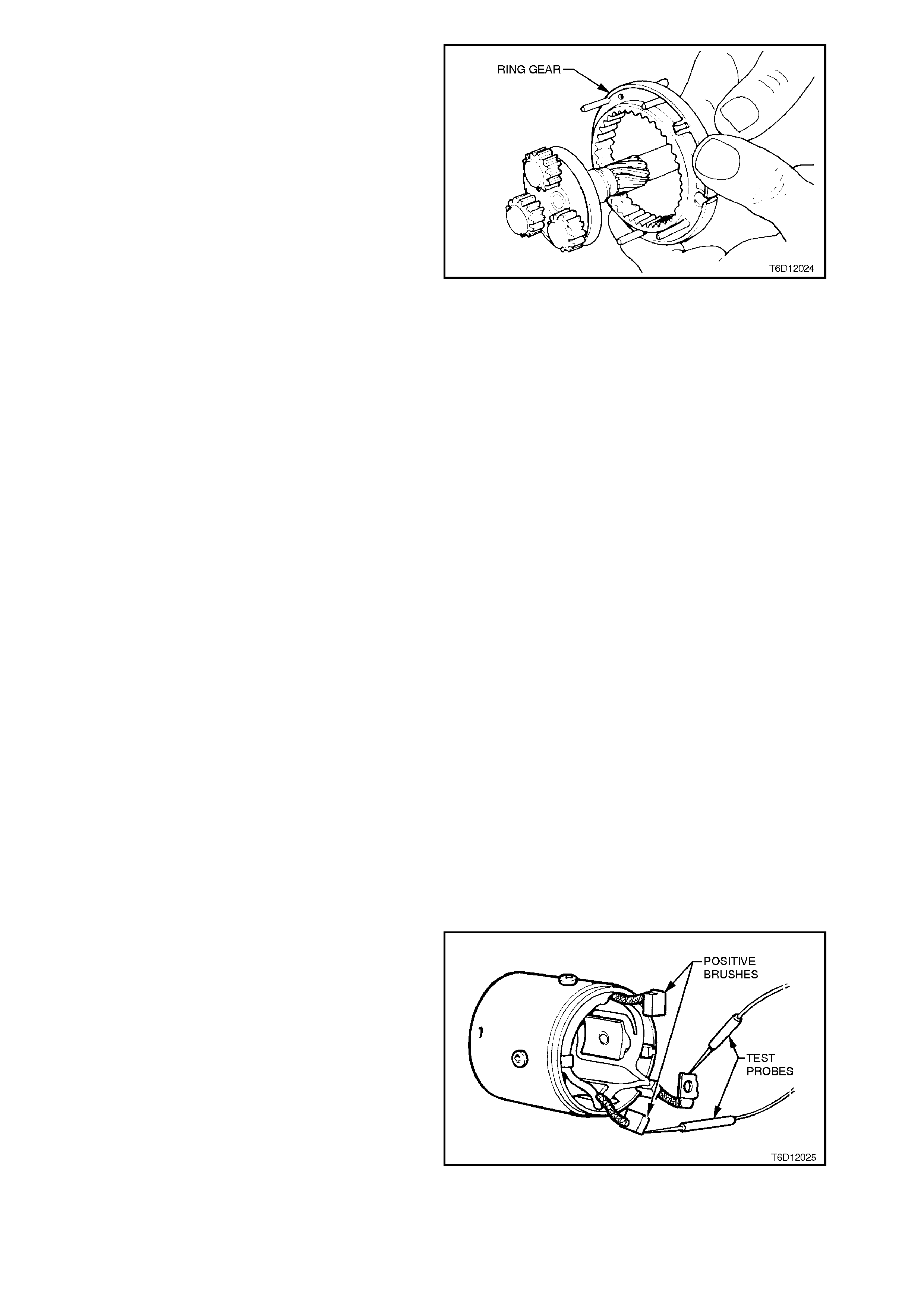
21. Push planetary drive shaft from ring gear and
separate components.
Figure 6D1-2-24
CLEANING AND INSPECTION
With the starter motor completely disass embled, all
components should be cleaned and thoroughly
inspected.
W ash all c omponents exc luding the armature, field
coils, brushes, solenoid switch and drive assembly
in a suitable cleaning agent. Clean these
com ponents with clean shop rags and com pressed
air.
CAUTION:
Do not clean armature or field coils with
cleaning solvent as damage to the insulation
could occur.
Washing the drive assembly in solvent will
wash out all the lubricant, causing the drive
assembly to slip.
WARNING:
CLEAN ALL PARTS OTHER THAN THOSE
PREVIOUSLY NOMINATED USING A NON
VOLATILE OR LOW INFLAMM ABLE AGENTS IN
A WELL VENTILATED AREA. IT IS IMPORTANT
THAT ALL PARTS ARE THOROUGHLY DRIED
BEFORE ASSEMBLY, TAKING CARE NOT TO
BREATH IN ANY VAPOURS. OBSERVE THE
SAFETY REGULATIONS AND PRECAUTIONS
ISSUED BY THE MANUFACTURER OF THE
CLEANING AGENT IN USE.
COMPONENT CHECKING
FIELD COILS
1. Connect a 12 volt powered DC test lamp
between field coil braided c able term inal and a
positive brush. If the field coil circuit is
serviceable, the lam p will illum inate to indicate
continuity.
Repeat the procedure on the other positive
brush.
Figure 6D1-2-25
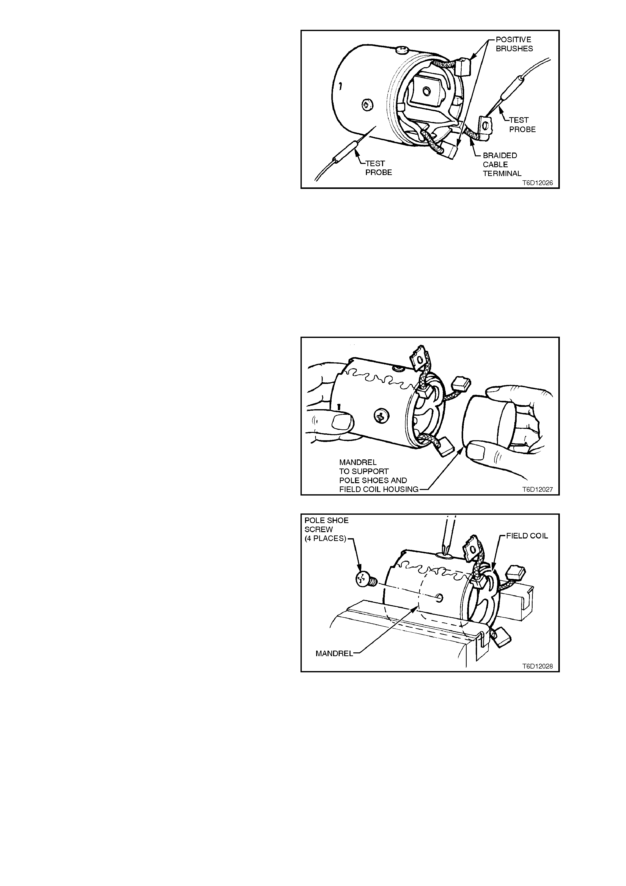
2. Ensure brushes are not touching the field coil
housing. T est the f ield coils f or shor t circ uits to
earth using an insulation tester with a
minimum AC voltage of 40 volts.
NOTE:
An ohmmeter cannot be used to check the field
coils for shor t circuits to ear th as the output voltage
from the ohmmeter does not place sufficient
'stress' on the field coils to give an accurate test
result.
Figure 6D1-2-26
3. Visually inspect field coil windings for signs of
insulation breakdown and/or burns
(overheating). If this condition is present, the
field coil must be replaced as follows:
NOTE:
This starter motor uses an interlocking joint in the
field coil hous ing, therefor e care mus t be ex ercis ed
whenever clamping the field coil housing in a vice.
Ensure the vice is fitted with soft jaws and do not
over tighten as it will distort the housing.
It is recommended that a mandrel having a
diameter of 52.8 + 0.2 - 0.1 mm x 30 mm long be
inserted inside the field coil housing, between the
field coil pole shoes. This step is necessary so as
to support the field coil housing in the vice whilst
the field coil pole shoe screws are removed.
a. Place mandrel inside field coil housing
and clamp the housing in a vice with soft
jaws.
Figure 6D1-2-27
b. Using a Posidriv No. 3 bit, loosen and
remove the four field coil pole shoe
screws.
Figure 6D1-2-28
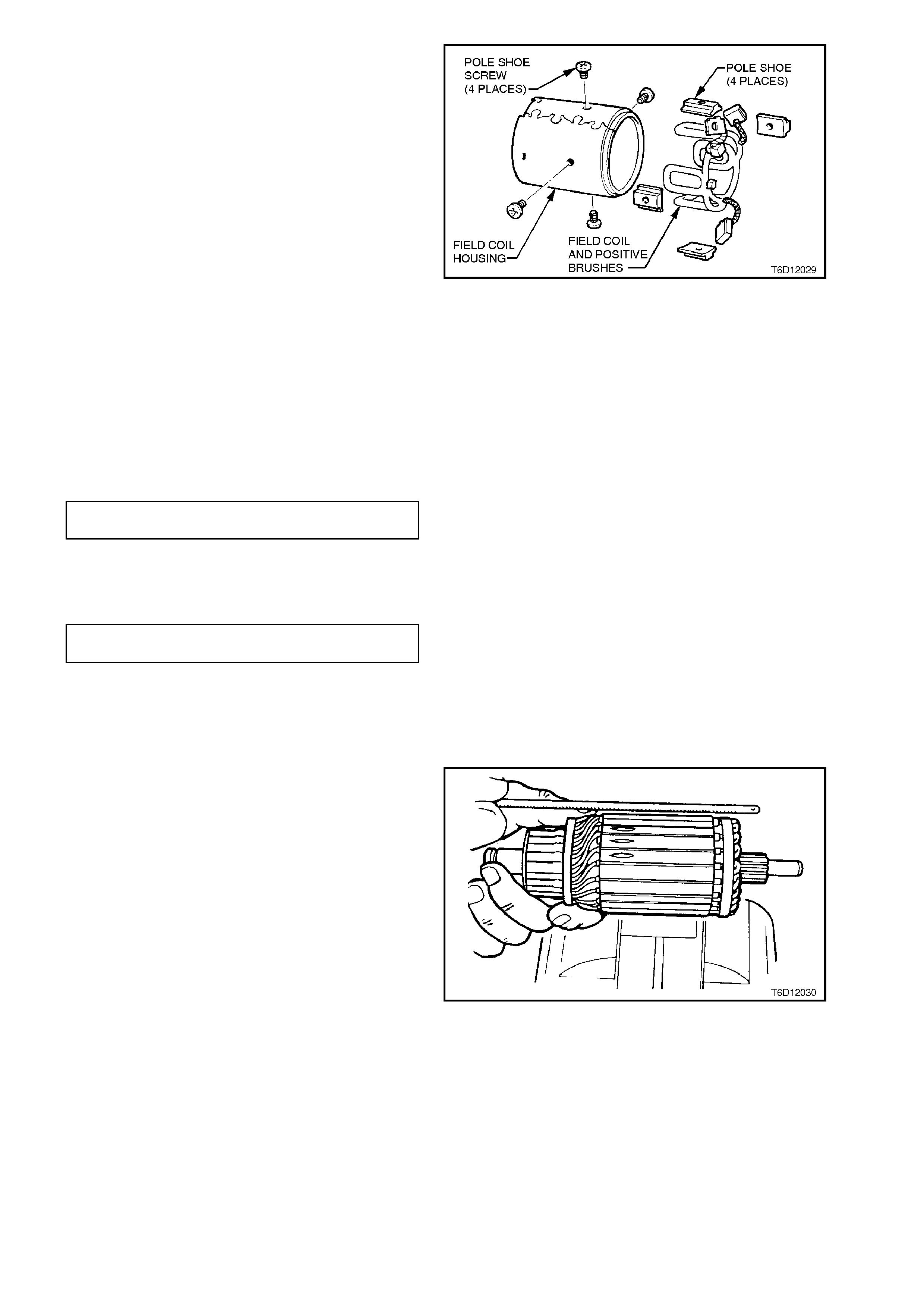
c. Remove field coil housing from vice and
pull the field coil out from the brush end of
the housing complete with mandrel and
pole shoes. Separate mandrel, field coils
and pole shoes.
Figure 6D1-2-29
d. Insert the pole shoes into the new field
coil and place inside the field coil
housing. Install the pole shoe screw and
leave finger tight.
e. Insert mandrel inside field coil housing to
support pole shoes and clamp in vice with
soft jaws.
f. Tighten field coil pole shoe screws to the
correct torque specification.
FIELD COIL POLE SHOE SCREW
TORQUE SPECIFICATION 25
. Nm
g. Recheck field coils using insulation
tester.
FIELD COIL RESISTANCE 1 Megohm
or greater
ARMATURE INSULATION TEST
Check armature insulation resistance to earth
using a 'meggar' or similar tester. A reading of 1
Megohm or greater should be expected.
ARMATURE SHORT CIRCUIT TEST
Test armature for short circuits on a growler.
1. Place the armatur e on a gr owler and switch on
growler. Hold a hacksaw blade approximately
6 mm above armature core and rotate
armature.
2. If the hacksaw blade vibrates, undercut
between the commutator segments (to a depth
of approximately 0.8 mm) using a suitable
small file, then re-check armature.
3. If hacksaw blade still vibrates, the armature is
short circuited and must be replaced.
Figure 6D1-2-30
ARMATURE CONTINUITY TEST
An open circuit in the armature winding may
sometimes be detected by examining the
commutator for evidence of burnt or darkened
segments. A burnt or darkened commutator
segm ent is c aused by an arc for med every time the
segment connected to the open circuit winding
passes under the brush.
If a segment has been burnt or is darkened,
replace armature.
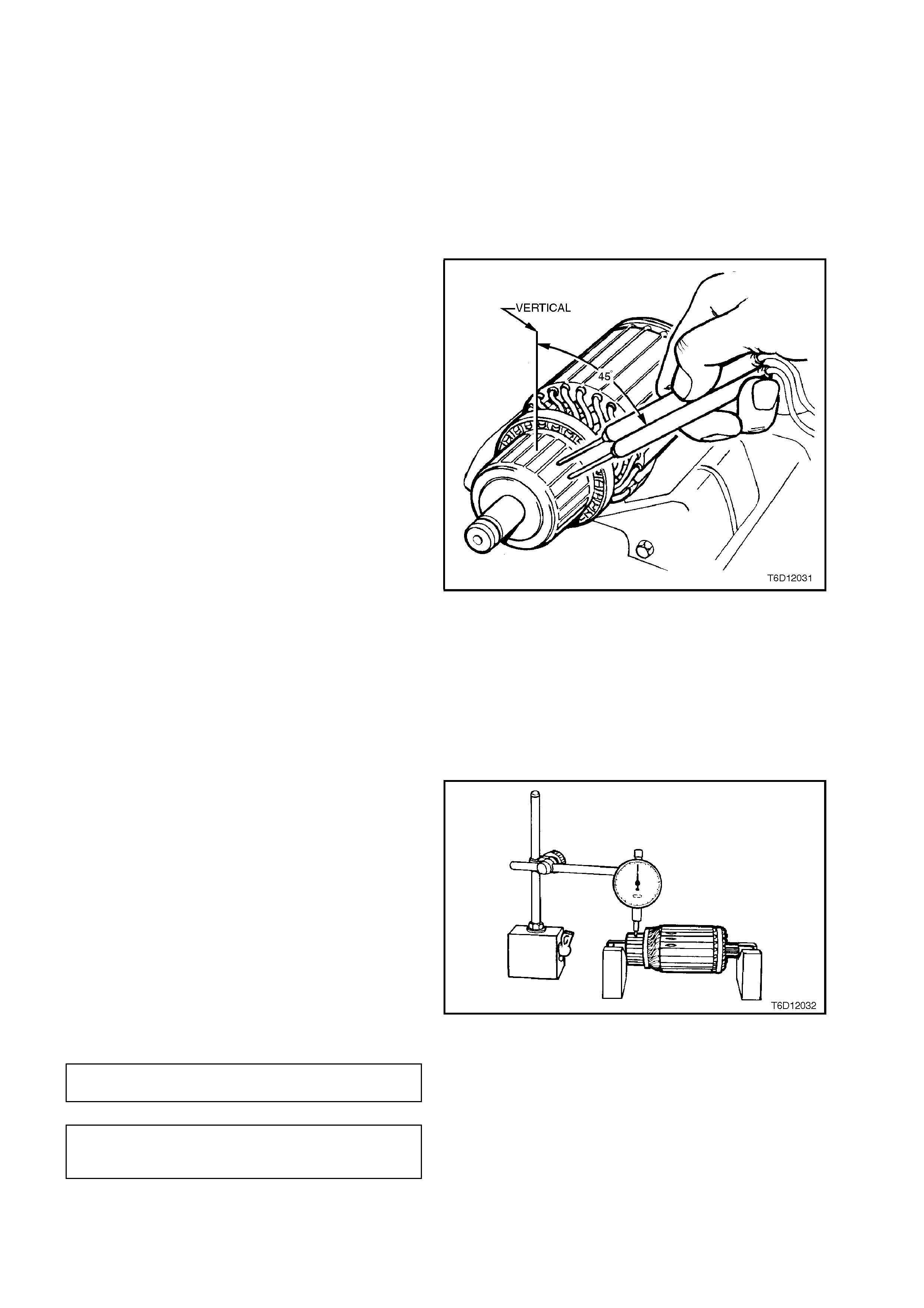
Test the armature for continuity on a growler.
1. Place the armatur e on a gr owler and switch on
growler.
2. Using a voltmeter, measure the voltage
induced in the armature windings by touching
probes onto two adjacent commutator
segments.
NOTE:
To obtain maximum voltage reading, choose two
segments which are approximately 45 degrees
from the top of the commutator.
3. Rotate the armature in the growler so that the
next two commutator segments are in the
same position as the previous two segments
in step 2. Measure voltage across adjacent
commutator segments.
4. Repeat step 3 until voltage reading across all
adjacent sets of commutator segments has
been measured.
The voltage reading ac ross eac h adjacent pair
of commutator segm ents should be the same,
provided each adjacent set of segments are
positioned in the growler in the same location.
If a voltage reading across any adjacent set of
segments differs from the remainder, the
armature winding has an open circuit, and the
armature must be replaced.
Figure 6D1-2-31
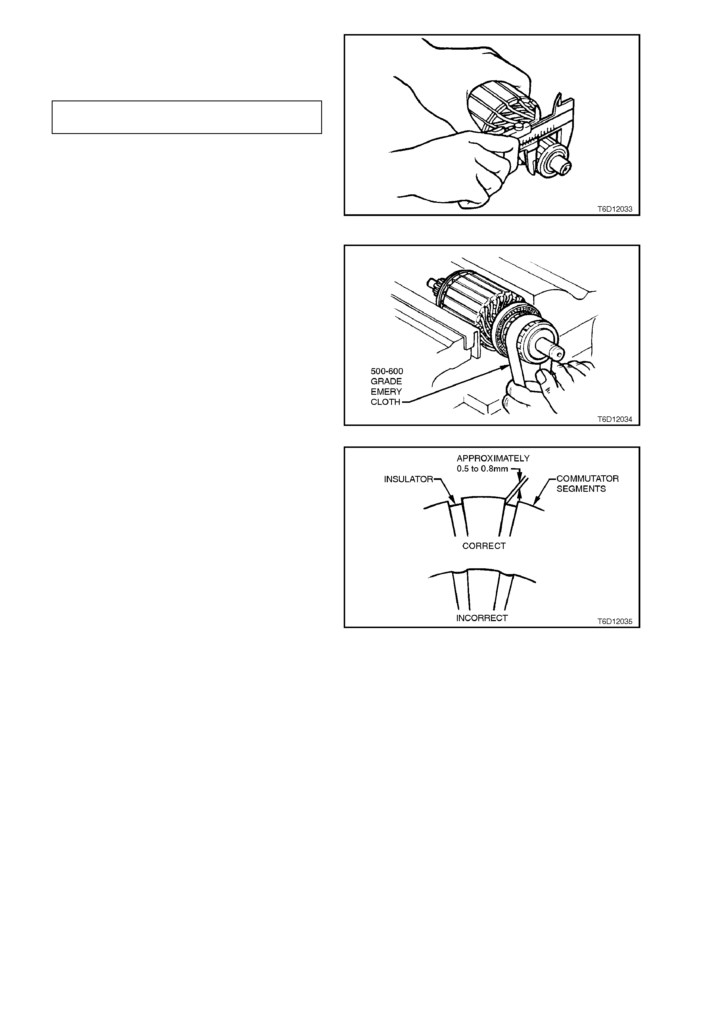
COMMUTATOR SURFACE
Check commutator and armature laminations for
out-of-round.
If the armature is otherwise satisfactory but
commutator is worn, burnt, out-of round, or has
high insulation between the segments, the
commutator should be machined.
If the out-of-round check on the armature
laminations is greater than the specified value,
replace the armature.
Figure 6D1-2-32
COMMUT ATOR MAXIMUM
PERMISSIBLE OUT-OF-ROUND 0.1
mm
MAXIMUM PERMISSIBLE OUT-OF-
ROUND OF ARMATURE
LAMINATIONS 0.5 mm
NOTE:
Replace the armature if the commutator diameter is
below the dimension given in the following chart.
COMMUT ATOR MINIMUM 31.2
DIAMETER mm
When machining the armature, it must not be held
by the laminations. The armature must be held at
the drive end and supported at the c ommutator end
bearing surface.
It is recommended that the commutator be turned
in two stages, that is pre-turning and finish turning. Figure 6D1-2-33
Finish cut the armature using a fine tool. The cut
should be no more than 0.03 mm. After turning,
polish surface if necessary using 500-600 grade
emery cloth and then brush out the commutator
segment slots using a stiff brush.
Check the diam eter of the com mutator. If less than
the specified value, replace the armature.
Figure 6D1-2-34
Check depth of insulating mica from commutator
surface. If depth is less than 0.2 mm, undercut
using a file to a depth of 0.5 to 0.8 mm.
CAUTION:
It is important to use dust extraction when
undercutting commutators.
After under cutting, car efully clean all dirt and debr is
from commutator segment slots and lightly polish
commutator with fine emery cloth to remove any
burrs left by the undercutting operation. Clean
commutator and armature thoroughly using
compressed air.
Figure 6D1-2-35
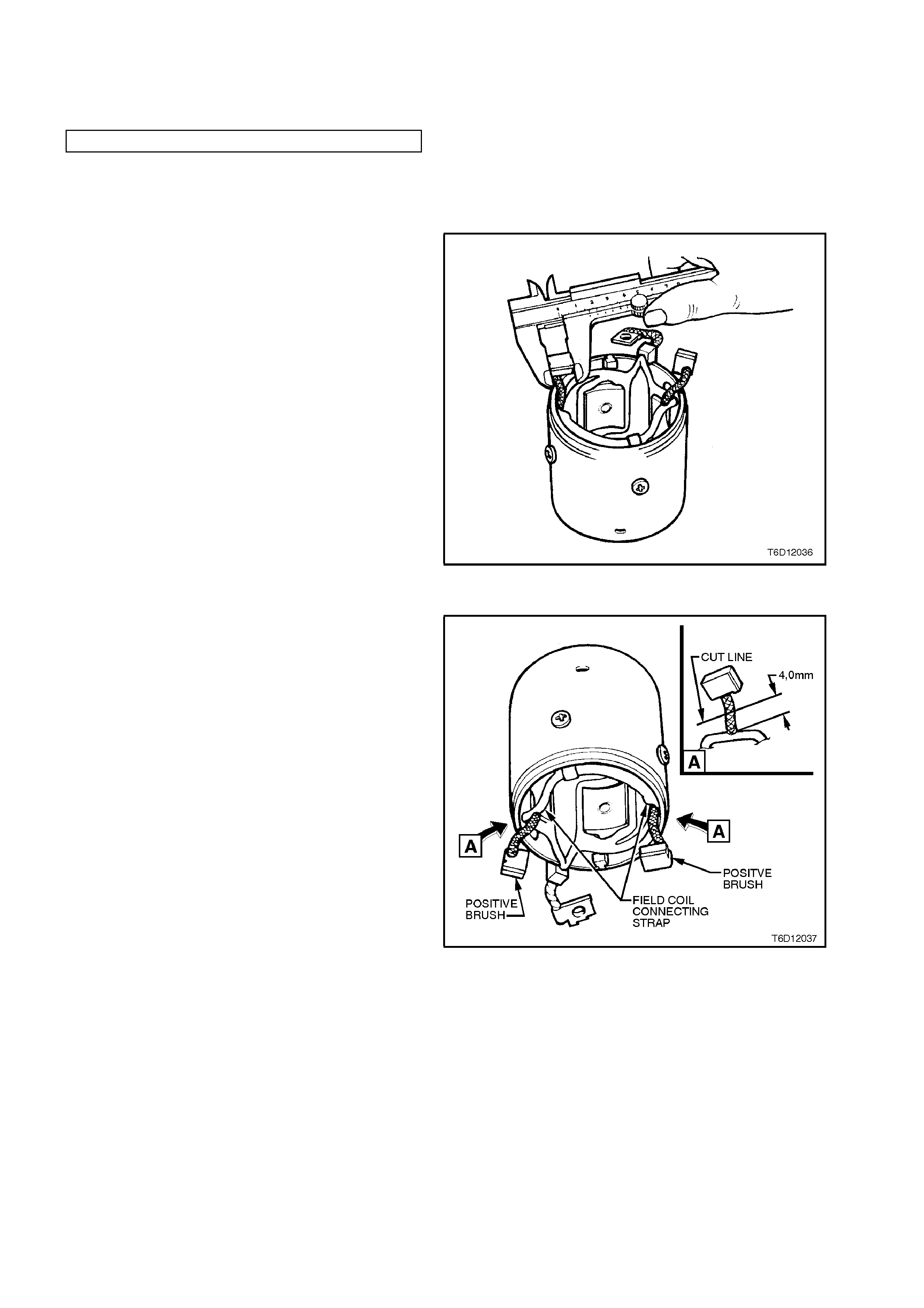
BRUSHES
Check brush holder springs for breakage and
corrosion, replace as necessary.
MINIMUM BRUSH LENGTH 7 mm
Ensure that brushes slide sm oothly in their holders,
brush connec tions are good and brushes are clean
and not chipped.
Check brush length. If any brush is below
specification, replace the complete brush set and
machine commutator if necessary.
If necessary, replace brushes as follows:
Figure 6D1-2-36
POSITIVE BRUSHES
1. Cut the brush lead approximately 4 mm up
from the f ield c oil connec ting s tr ap and disc ar d
brush.
2. Clean the remains of brush lead on field coil
connecting strap and 'tin' the lead with 60/40
resin cored solder.
3. Hold the new brush lead in position on the pre-
tinned cut-off lead using a pair of pointed nose
pliers. Solder new brush lead to cut-off lead.
NOTE:
When soldering the new brush lead into place,
ensure that the solder does not run up the lead by
capillary action. Should this happen, it will make the
lead too inflexible and not allow correct brush
movement and/or cause fouling during reassembly.
Figure 6D1-2-37
NEGATIVE BRUSHES
1. Before removing the old brushes, special
attention must be paid to the direction of the
brushes in the way they are soldered to the
plate.
2. Cut old brush lead off at lowest point of the
flexible braded section.
3. Clean remaining brush lead on brush holder.
'Tin' rem aining br us h lead on brus h holder with
60/40 resin cored solder.
Figure 6D1-2-38
3. Hold the new brush lead in position on the pre-
tinned cut-off lead using a pair of pointed nose
pliers, noting brush lead direction as per step
1. Solder new brush lead to cut-off lead.
NOTE:
When soldering the new brush lead into place,
ensure that the solder does not run up the lead by
capillary action. Should this happen, it will make the
lead too inflexible and not allow correct brush
movement and/or cause fouling during reassembly.
Figure 6D1-2-39
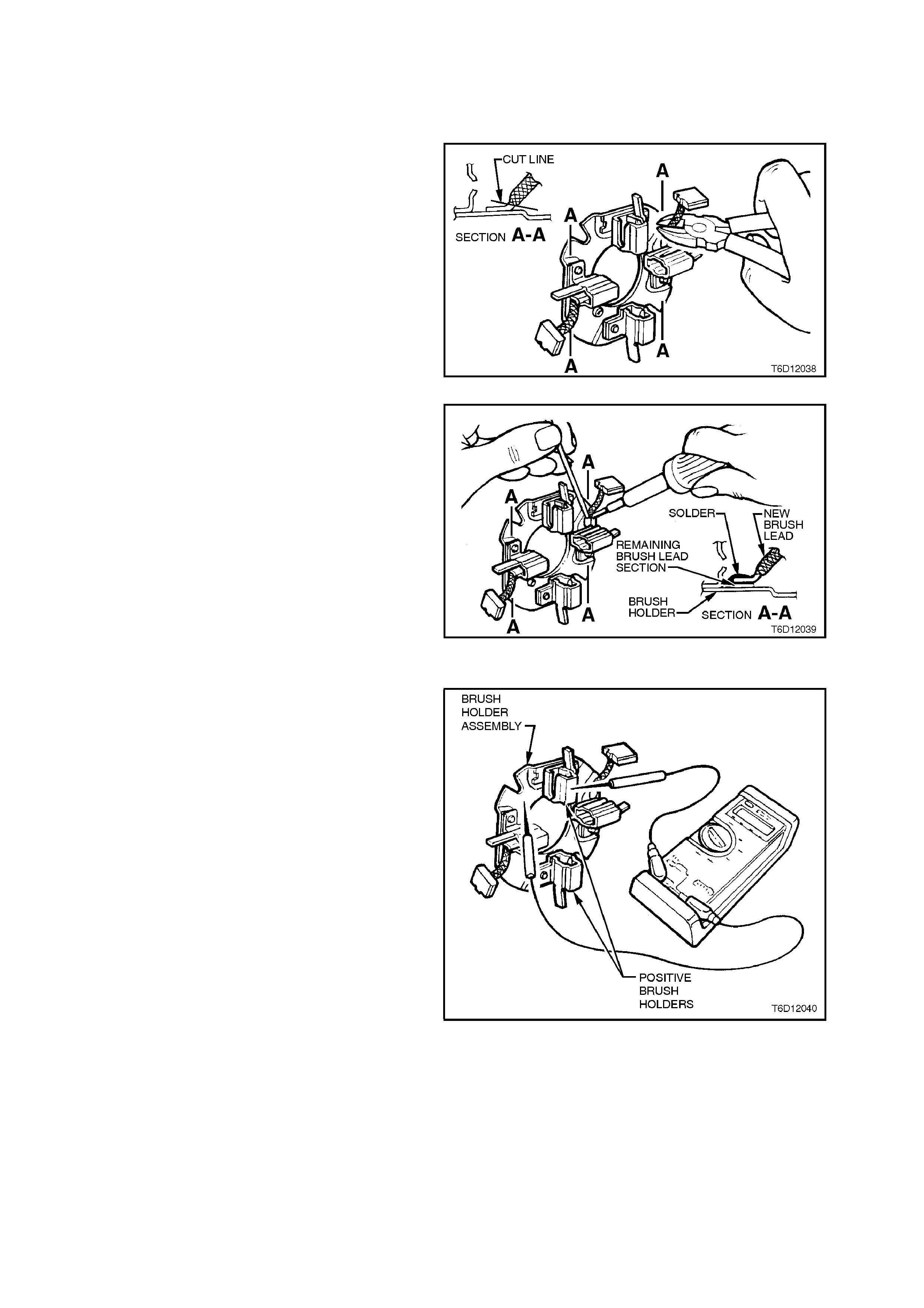
BRUSH HOLDER ASSEMBLY
Using an ohmmeter, check insulation between the
positive brush holders and the brush holder
assembly base. If continuity exists, replace holder
assembly.
Figure 6D1-2-40
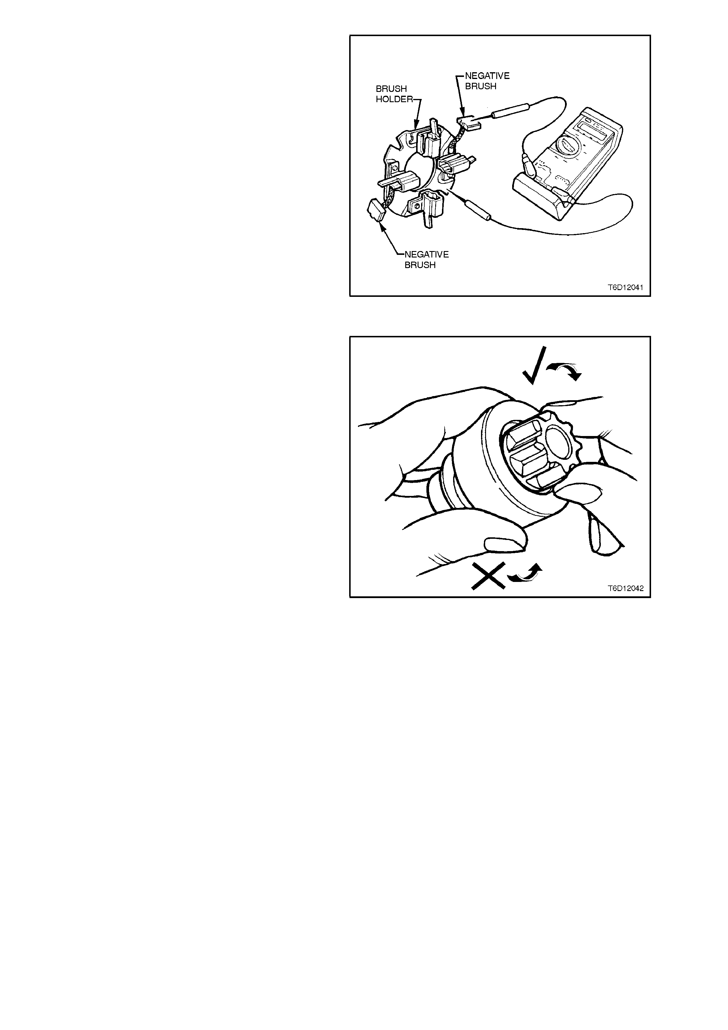
Check continuity between negative brushes and
holder assembly base. If continuity does not exist,
replace the brush holder.
Check condition of the brush holder spring retaining
tags. If any tags are weak, broken or there is any
sign of fatigue from being bent back, replace the
brush holder assembly.
Figure 6D1-2-41
DRIVE ASSEMBLY CHECK
Inspect drive assembly pinion gear for burrs and
worn or chipped teeth.
Check the operation of the pinion. The pinion gear
should rotate free and smooth in relation to the
drive assembly pinion housing when turned in a
clockwise direction, but will not rotate when turned
in a counter-clockwise direction.
Replace the drive assembly if out of specification,
or if pinion gear is damaged or broken, inspect
flexplate/ring gear teeth and replace as necessary,
refer to Section 6A1-1 ENGINE MECHANICAL -
V6 ENGINE.
Examine the pinion internal bush for wear or
scoring, if in any doubt, replace the drive assembly.
Inspect fork lever contact surfaces and pivots.
Replace fork lever if worn.
Figure 6D1-2-42
BUSHES
Check the fit of the armature shaft in the
commutator end cover and the front end of the
planetary drive shaft in the drive end housing.
If bushes are exc essively worn, the starter motor is
likely to operate inefficiently and/or the armature
may foul on the field coils.
To remove the bushes, support the commutator
end cover or drive end housing (as appropriate),
and carefully tap bush out using a suitable sized
mandrel.
NOTE:
If new bushes are to be installed, they must be
soaked in clean engine oil overnight. If time does
not perm it over night s oaking, oil can be forc ed into
the bush by placing a thumb over end of the bush
and filling the bush cavity with oil.
Using the other thumb over the opposite end of the
bush, press bush firmly compressing the oil
between thumbs until the oil is visible on the outer
surfaces of the bearing.
To install new bushes, press or tap into position
with a suitable shouldered mandrel.
Do not ream bushes after they have been installed
as the self-lubricating qualities of the bush will be
diminished.
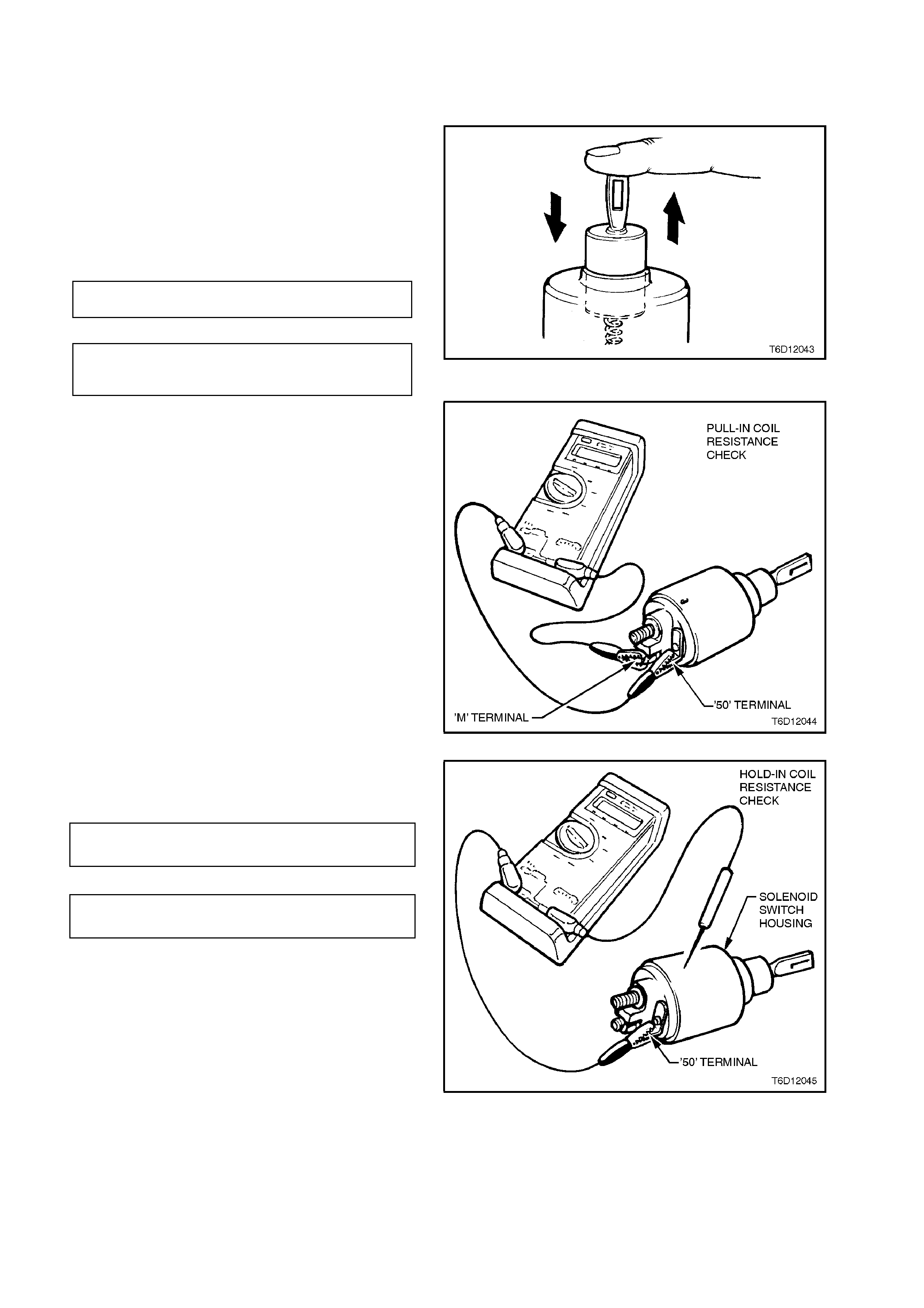
SOLENOID SWITCH TESTING
Inspect the solenoid switch for any external
damage.
Install return spring and plunger to solenoid switch.
Depress plunger and release it. T he plunger s hould
return quickly to its original position. If the plunger
sticks in the switch bore, replace solenoid switch
assembly.
PULL-IN WINDING TERMINALS 50
RESISTANCE AND M
HOLD-IN WINDING TERMINAL 50 AND
RESISTANCE SOLENOID SWITCH
HOUSING Figure 6D1-2-43
Check the solenoid switch windings dc resistances
using an ohmmeter acr os s the ter minals nominated
in the following chart.
Figure 6D1-2-44
Replace solenoid switch if resistance readings are
not to specification
PULL-IN WINDING 0.248 - 0.281 Ohms
RESISTANCE @ 20° C
HOLD-IN WINDING 1.16 - 1.30 Ohms
RESISTANCE @ 20° C
Figure 6D1-2-45
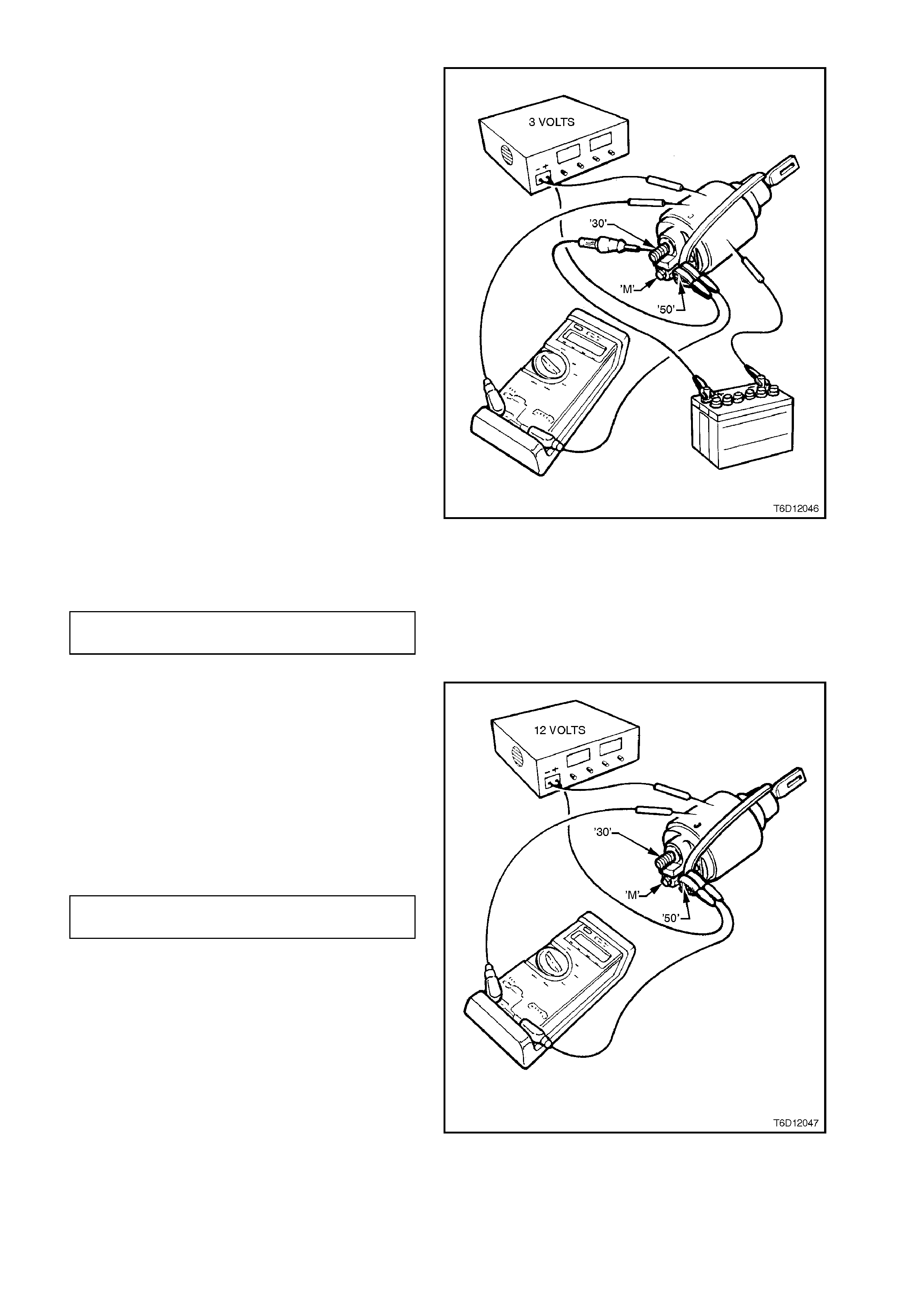
TESTING 'PULL-IN' AND 'HOLD-IN' VOLTAGES
During the following solenoid switch 'pull-in' and
'hold-in' checks, the solenoid switch must be held
vertically, i.e. with the plunger uppermost. It is
recommended that a rubber band be fitted around
the plunger and solenoid switch housing to prevent
the plunger from flinging out during testing.
Using a power supply capable of supplying 30
amps, set the voltage to 3.0 volts. A battery and a
variable resistor may also be used.
Connect the solenoid to the power supply as shown
in Fig. 6D1-2-46.
Connect a 12 volt test lamp between solenoid
switch terminal '30' and +12 volt supply. Also,
connect a voltmeter between solenoid switch
terminal 50 and earth.
Fully press in solenoid plunger until test lamp
illuminates. Allow the plunger to spring out by
approximately 8 - 10 mm and hold in this position.
NOTE:
The test duration for the following 'pull-in' voltage
check should be no more than two seconds.
Slowly increase the voltage on terminal '50' until the
plunger pulls in, noting the voltmeter r eading. At the
same time, the test lamp must be fully illuminated
(check of solenoid switch main contact continuity)
Voltage reading should be as specified in the
following chart.
PULL-IN VOLTAGE TEST 3.0 - 6.5
SPECIFICATION VOLTS
Figure 6D1-2-46
Set the power supply to 12 volts and connect the
positive lead to solenoid switch terminal '50'.
Connect the negative lead to the solenoid switch
housing. Press the plunger in f ully. It should r em ain
held in by the solenoid's hold-in winding.
Decrease the voltage until the winding will no
longer hold the plunger, noting the voltmeter
reading.
Voltage reading should be as specified in the
following chart.
HOLD-IN VOLTAGE TEST 0.2 - 2.0
SPECIFICATION VOLTS
Press the plunger until the solenoid switch contac ts
close (indicated by test lamp illuminating).
It should be possible to depress the plunger into the
solenoid switch housing a further 1 mm or more. If
less than 1 mm is achieved, the solenoid switch
must be replaced.
Figure 6D1-2-47
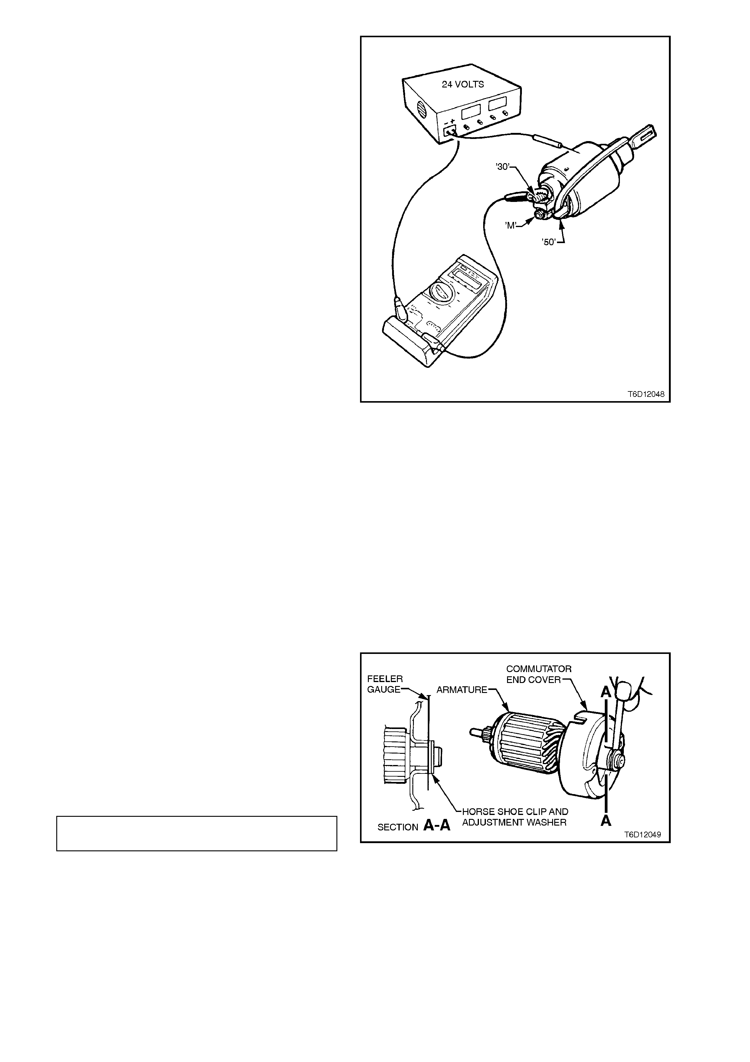
A 24 volt supply is required for this test.
Attach positive supply lead to solenoid switch
terminal '30' (main battery supply input) and
negative lead to solenoid switch housing.
Press the plunger in fully and then release. The
plunger should return to its rest position by the
action of the return spring. If it does not, the
windings have interwinding short circuits.
W hen the solenoid s witch is connected in this way,
the windings are differentially compounded, that is
their fields are in opposition to each other.
At end of solenoid switch testing, remove rubber
band retaining the plunger and return spring in the
solenoid switch housing.
Figure 6D1-2-48
REASSEMBLE
Reassembly of the starter motor is the reverse of
the disassembly procedure, noting the following
points:
1. Lubricate drive end housing, commutator end
cover and drive assembly to planetary drive
bushes with clean engine oil.
2. Lightly coat helix on armature shaft, helix
inside drive assembly, inside of ring gear and
armature to commutator end cover thrust and
adjustment washers with Molybdenum
Disulphide grease (Holden Specification HN
1271 or equivalent). Pack som e grease inside
of commutator end cover dust cover.
3. Check armature end play by installing
armature to commutator end cover thrust
washer, assembling armature to commutator
end cover. Install adjustment washer and
horse shoe c lip. Us ing f eeler gauges , meas ure
clearance between adjustment washer and
commutator end cover. If necessary, adjust
armature end float to specification using
adjustm ent washers between com mutator end
cover and horse shoe clip.
ARMATURE END PLAY 0.05 - 0.3
SPECIFICATION mm
W hen end f loat is corr ect, rem ove c omm utator end
cover from armature.
Figure 6D1-2-49

4. To install the stop ring retainer over the stop
ring, clamp the fr ont end of the planetary drive
shaft in a vice fitted with soft jaws. Slide the
stop ring retainer up to the s top r ing and fit two
open end spanners in between the stop ring
retainer and the drive assembly gear.
Using a pin punch and ham mer, lightly tap the
stop ring into the planetary drive shaft groove.
Then push down on the two spanners to force
the stop ring retainer over the stop ring.
Figure 6D1-2-50
5. Slide drive assembly up and down planetary
drive shaft ensuring that it moves freely.
Check drive assembly clutch action.
6. Expand fork lever arms and position over drive
assembly pivots.
7. Install planetary drive shaft into the opening of
the drive end housing, aligning the flat on the
ring gear outer sur face toward the opening f or
the solenoid switch. Slide the assembly into
position allowing the fork lever pivot to enter
the drive end housing.
Install the sealing rubber behind the pivot,
aligning the 'V' groove with the mating raised
groove on the pivot and thick section toward
the drive end housing solenoid switch
opening.
8. Assemble armature into the field coil housing
with commutator exposed at rear of housing.
Install brush holder over commutator, aligning
the positive brush holders with the brush lead
connections on the field coils.
Position all brushes into their respective
holders, ensuring that the brush leads locate
into the slots on the side of eac h holder. Ins tall
brush springs and carefully bend over the
brush holder spring retaining tags.
9. Ensure that armature to commutator end
cover thrust washer is installed on armature.
Assem ble comm utator end cover, aligning the
field coil braided cable grommet with the
cutout in the commutator end cover.
Install correct adjustment washers and horse
shoe clip.
Assemble dust cover onto commutator end
cover and align screw holes in dust cover with
commutator end cover and brush holder.
Install dust cover securing screws and tighten
to the correct torque specification.
DUST COVER SECURING SCREW
TORQUE SPECIFICATION 1.4 - 2.0
Nm
10. Assemble the field coil housing to the drive
end housing, aligning the cutout in the field
coil housing with the sealing rubber in the
drive end housing. Carefully fit the armature
into the planetary drive. It may be necessary to
rotate the pinion gear slightly to enable the
armature gear to engage the planetary gears
(do not force entry).

11. Install through bolts and tighten to the correct
torque specification.
THROUGH BOLT
TORQUE SPECIFICATION 7.5
Nm
12. Lightly coat solenoid switch plunger with
Molybdenum Disulphide grease (Holden
Specification HN 1271 or equivalent).
NOTE:
Do not under any circumstances allow grease on
the rear face of the plunger. If too much grease is
applied, it may enter the contact chamber of the
solenoid switch and cause contact problems.
13. Assemble return spring and plunger to
solenoid switch.
Pull pinion gear forward and assemble
solenoid switch assembly to drive end
housing, ensuring that plunger hooks over
drive assembly fork lever.
Ensure that solenoid switch housing is
correctly aligned with drive end housing, that is
with terminal 30 facing away from field coil
housing. Install and tighten solenoid switch to
drive end housing mounting screws to the
correct torque specification.
SOLENDOID SWITCH TO DRIVE END
HOUSING MOUNTING SCREW
TORQUE SPECIFICATION 5.5 Nm
14. Install field coil braided cable and terminal
over solenoid switch lower threaded terminal.
Install washer and nut to threaded terminal
and tighten to the correct torque specification.
THREADED TERMINAL NUT
TORQUE SPECIFICATION 9
Nm
15. With the starter motor reassembled, a NO
LOAD test should be conducted, refer to
2.1 PERFORMANCE TESTING in this
Section.
Failure of the starter motor to perform
according to the NO LOAD specification may
be due to tight or dirty brushes or high
resistance connections. Rectify any faults
found.

3. DIAGNOSIS
Many starting problems can be categorised within the following classifications:
1. The starter motor will not crank the engine.
2. The engine will crank at normal speed, but will not start.
3. The starter cranks the engine very slowly.
If the engine is cranked over by the starter motor at the normal speed, but will not start, the problem is in the
ignition system, fuel system or engine, rather than a fault in the starting system.
Before removing the starter motor, when investigating a starting problem, follow the procedures outlined in the
accompanying diagnostic charts.
SYMPTOM PROBABLE FAULT
A. Speed, torque and current low. A. High resistance in motor. Check field to
terminal connection, condition of
brushes and their connections and
check for dirty brushes or burnt
commutator.
B. Speed and torque low, current high. B. Tight or worn bearings, bent armature
shaft, insufficient end play, armature
fouling pole shoe, short-circuited
armature, earthed armature or field coil.
C. Speed and current high, torque low. C. Short circuited windings in field coil.
D. Armature does not rotate. No current. D. Open circuited armature, field coils or
solenoid. If commutator is badly burned,
there may be poor contact between
brushes and commutator, owing to
excessively worn or sticking brushes.
E. Armature does not rotate. High current. E. Earthed field winding or short-circuited
solenoid switch. Armature physically
prevented from rotating.
F. Excessive brush movement causing arcing
at commutator. F. Low brush spring tension, worn or out-
of-round commutator, 'thrown' or high
segment on commutator, or insulation
protruding between segments.
G. Excessive arcing at commutator. G. Defective armature windings, sticking
brushes or dirty commutator.
H. Armature rotates but pinion does not mesh
with ring gear. H. Pinion bearing fouled, burred, damaged
flexplate/ring gear or broken pinion
teeth.
VT series Commodores are fitted with a timed security override. Turn ignition switch to the ‘ON’ position and
security override will occur in two hours. (Theft alert indicator LED stops)
If engine now cranks then fault is in the theft deterrent system. Refer to Section 12F THEFT DETERRENT
SYSTEM.
If engine still does not crank then continue with this diagnostic procedure.

NO CRANKING, NO SOUND FROM SOLENOID:
STEP ACTION RESULT YES NO
1. • Turn Headlamps and
Dome l amps On, Turn
Ignition to Start
Position.
Lamps
Dim Go to Step 2 Go to Step 3
2. • Check battery
• Charge battery
• Check generator
• Check cranking
voltage at battery posts
• Check current draw
Is 9.6
volts
present
Go to Step 7 Test battery.
If OK repair
Starter
3. • Turn on radio Operate
OK Go to Step 4 Go to Step 6
4. • Check voltage at
Solenoid Switch
terminal ‘50’.
Is 7.0
volts
present
Repair Starter Go to Step 5
5. • With Key in Start
Position, Check at
Ignition terminal ‘50’.
Is 7.0
volts
present
Repair wiring
Ignition Switch
Starter Motor
Replace Ignition
Switch
6. • Check engine main
wiring harness fusible
link and ignition
connections
7. • Check voltage from
engine block to Neg.
post. Key in start
position. (Pos. lead on
block)
Is 0.5
volts or
more
present
Clean and tighten
negative cable
conn. And/or
replace cable
Go to Step 8
8. • Check cranking
voltage at starter “B”
terminal
Is 9.0
volts
present
Check fuse and
engine to M.W.H.
connectors
Clean and tighten
positive cable
conn. And/or
replace cable

SLOW CRANKING, SOLENOID CLICKS OR CHATTERS:
Check : Battery state of charge. Refer to Section 12A BATTERY A ND CABLES.
Visual condition of battery cables and connections.
If battery needs charging, carry out generator and battery drain check, charge battery and recheck cranking. If
trouble has not been found proceed.
Remove engine fuse link from engine compartment fuse housing. This prevents fuel injection and ignition during
engine cranking. Make all voltmeter readings with ignition key in start position.
STEP ACTION RESULT YES NO
1. • Measure cranking
voltage at battery
terminal posts
Is 9.6
volts or
more
present
Go to Step 2 Go to Step 3
2. • Measure voltage from
battery negative
terminal to engine
block. (positive lead on
block)
Is 0.5
volts or
more
present
Repair negative
cable and
connections
Go to Step 4
3. • Charge and load test
battery Is battery
OK Repair Starter Replace battery
4. • Measure voltage at
solenoid switch ‘30’
(B+) terminal, clean
and tighten
connections at starter
Is 9.0
volts or
more
present.
Repair starter Go to Step 5
5. • Clean and tighten
positive cable
connections.
• If OK replace cable
This procedure is designed for use on engines and batteries at room temperature or normal operating
temperatures. It also assumes there are no engine defects which could cause cranking problems. To use it under
other conditions might result in misdiagnosis.

4. SPECIFICATIONS
Type Bosch DV. Four pole, four brush
with planetary drive train
Rotation (drive end view) Clockwise
Number of pinion teeth 9
No load test:
Maximum current 125 amps at 11.5 Volts
rpm 5300
Lock test:
Maximum current (including solenoid) 740 amps
Volts 4 volts
Torque 20 Nm
Solenoid Test Solenoid detached from
starter motor:
Pull in voltage 7.8 volts @ 20°C
Hold-in winding resistance 1.16 - 1.3 Ohms @ 20°C
Pull-in winding resistance 0.248 - 0.281 Ohms @ 20°C
Armature end play 0.05 - 0.30 mm
Armature laminations permissible out-of-round 0.5 mm
Commutator:
Maximum permissible out-of-round 0.1 mm
Diameter - New 32.3 mm
Minimum diameter 31.2 mm
Depth of undercut 0.8 mm
Brushes:
Minimum length 7 mm
Field coil winding resistance 1 Megohm or greater

5. TORQUE WRENCH SPECIFI CATIONS
Nm
Through bolts 7.5
Pole screws 25
Solenoid attaching bolts 5.5
'30' terminal nut 9.8 - 11.3
'50' terminal nut 9.0
'Dust cover securing screws 1.4 - 2.0
Starter motor to cylinder block
mounting bolts 40 - 60