SECTION 6E1 EMISSION CONTROL - V6 ENGINE
CAUTION:
This vehicle will be equipped with a Supplemental Restraint System (SRS). A SRS will
consist of either seat belt pre-tensioners and a driver's side air bag, or seat belt pre-
tensioners and a driver's and front passenger's side air bags. Refer to CAUTIONS,
Section 12M, before performing any service operation on, or around any SRS
components, the steering mechanism or wiring. Failure to follow the CAUTIONS
could result in SRS deplo yment, resulting in possible p ersonal injury or unnecessary
SRS system repairs.
CAUTION:
This vehicle may be equipped with LPG (Liquefied Petroleum Gas). In the interests of
safety, the LPG fuel system should be isolated by turning 'OFF' the manual service
valve and then draining the LPG serv ice lines, before any service w ork is carried out
on the vehicle. Refer to the LPG leaflet included with the Owner's Handbook for
details or LPG Section 2 for more specific servicing information.
1. GENERAL INFORMATION
VT Series Models fitted with V6 engines are designed to comply with the requirements of Australian Design Rule,
ADR 37. In order to meet the low exhaust emission levels specified in ADR 37, these vehicles operate on unleaded
petrol and are fitted with a catalytic converter in the exhaust system. These vehicles also feature electronically
controlled fuel injection and direct ignition system.
In addition, these vehicles are fitted with the following emission control systems:
V6 NON SUPERCHARGED V6 SUPERCHARGED
ENGINE VENTILATION ENGINE VENTILATION
EVAPORATIVE EMISSION CONTROL EVAPORATIVE EMISSION CONTROL
THREE WAY CATALYTIC CONVERTER THREE WAY CATALYTIC CONVERTER
EXHAUST GAS RECIRCULATION

1.1 VEHICLE EMISSION CONTROL INFORMATION LABEL
The Vehicle Emission Control Information Label, is
located in the engine compartment as shown in
Figure 6E1-1. The label contains important engine
tune conditions to achieve the correct emission
levels, and should be ref err ed to bef ore making any
adjustments. Refer to Figure 6E1-2 for the V6
engine or 6E1-3 for the V6 supercharged engine.
Figure 6E1-1
Figure 6E1-2
Figure 6E1-3

1.2 EMISSIONS MANAGEMENT
All aspects of engine air/fuel ratio and spark timing are controlled by the Powertrain Control Module (PCM). The
mixture control is a closed loop system which incorporates dual oxygen sensors in the exhaust system engine pipe.
The Engine Ventilation system is not controlled by the PCM. How ever the Evaporative Emission Control system is
now controlled by the PCM through a canister purge solenoid valve. The PCM and its associated systems are
described in Section 6C1 POWERTRAIN MANAGEMENT - V6 ENGINE.
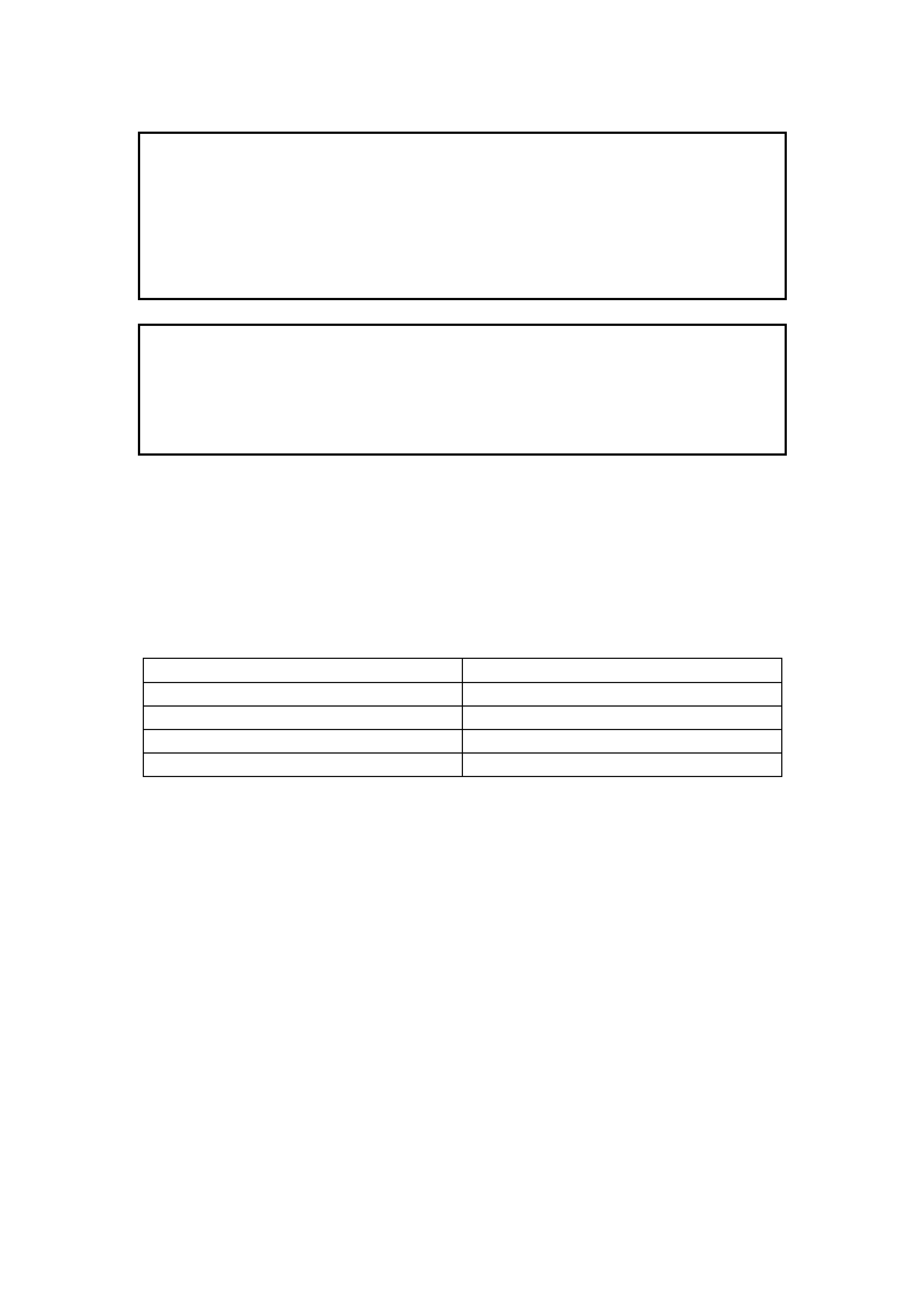
1.3 ENGINE VENTILATION
The engine ventilation system uses a Positive
Crank case Ventilation (PCV) valve whic h is located
in the inlet manifold.
During normal driving conditions, crankcase
vapours are drawn into the inlet manifold via a PCV
valve.
Vapours are then delivered through the plenum
chamber of the inlet manifold into the combustion
chamber, to be burnt with the air/fuel mixture.
Figure 6E1-4
Figure 6E1-5

Fresh air is, in turn, drawn into the cr ankcase via a
breather hose (3) which is connected between the
throttle body (1) and a port on the inlet manifold (2).
Figure 6E1-6
The PCV valve meters the mixture of fresh air and
crankcase vapours into the induction system at a
rate dependant upon manifold vacuum.
To m aintain idle quality, the PCV valve re stricts the
flow when inlet manifold vacuum is high. If
abnormal manifold conditions arise, the system is
designed to allow excessive amounts of crankcase
vapours to flow back through the breather hose (1),
into the throttle body to be consumed by normal
combustion.
Figure 6E1-7
The engine ventilation system must be checked at
the time or distance intervals specified in the VT
Series Owner's Handbook.
The PCV valve is a non-s erviceable item and m ust
be replaced if defective.
1.4 EVAPORATIVE EMISSION CONTROL
The Evaporative Emission Control System (EECS)
captures fuel vapours, which would normally
escape from the fuel tank and enables them to be
consumed in the combustion process. The EECS
used on VT Series Models is the charcoal canister
storage m ethod. This method transfers fuel vapour
from the fuel tank to an activated car bon (charcoal)
storage canister to hold vapours when the vehicle
is not operating. When the engine is running, the
fuel vapour is purged from the carbon element by
intake air flow and consumed in the normal
combustion process. The fuel tank cap is not
vented to atmosphere, but is fitted with a valve to
allow both pressure and vacuum relief. The
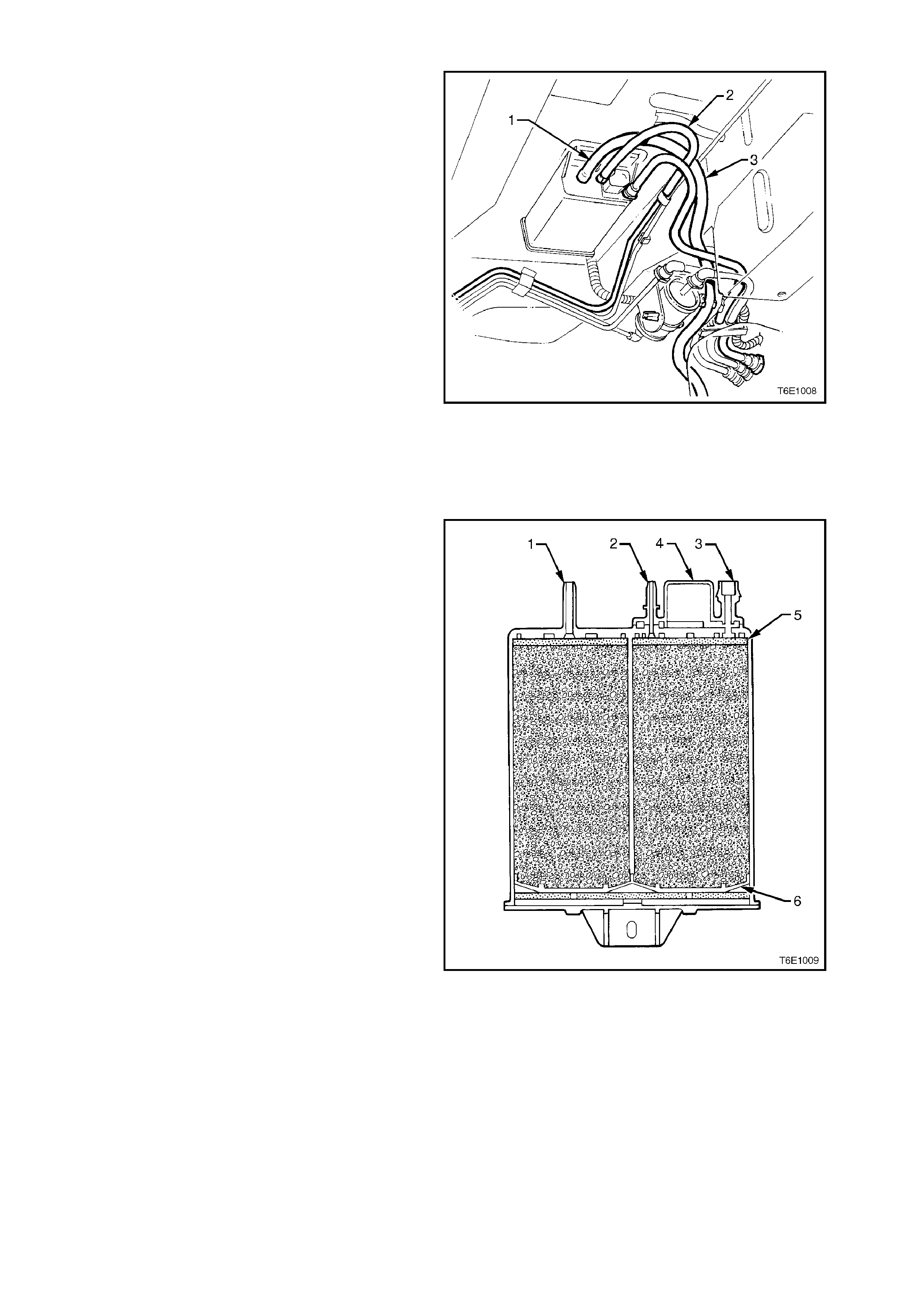
canister is a three port design:
1. Atmospheric port (fresh air inlet)
2. Purge Port
3. Vapour inlet port
The fuel vapour is absorbed by the charcoal in the
canister. When the engine is running, air is drawn
into the canister through the atmospheric port at
the top of the canis ter ass embly. The air mixes with
the vapour and the m ixture is drawn into the intake
manifold via the canister purge line.
Figure 6E1-8
The purge port (3) on the c anister is controlled by a
PCM activated purge solenoid valve. The solenoid
valve controls the manifold vac uum s ignal from the
throttle body. The vapour inlet port (1) allows fuel
vapour to enter the canis ter from the f uel tank . T he
atmospheric port (1) allows fresh air to be drawn
into the canister.
This system has a remote mounted canister purge
control solenoid valve. The PCM operates this
solenoid valve to control vacuum to the canister.
Under cold engine conditions, the solenoid valve is
turned OFF by the PCM, which blocks vacuum to
the canister and prevents purge.
The PCM turns ON the solenoid valve and allows
purge:
• When the engine coolant temperature is less
than 20° C, 3 minutes and 10 seconds after
engine start.
• W hen the engine c oolant temper ature is greater
than 80° C, 5 seconds after engine start.
• Engine is not in Dec el Fuel Cutof f Mode and the
throttle opening is less than 92%.
• Engine is in Closed Loop Fuel Mode.
The canister cannot be repaired, and is serviced
only as an assembly. Periodically check the
canister at the time or distance intervals specified
in the VT Series Owner's Handbook.
1. Atmospheric Port
2. Vapour Inlet Port
3. Purge Port
4. Liquid Trap
5. Volume Compensator and Filter
6. Diffuser
Figure 6E1-9
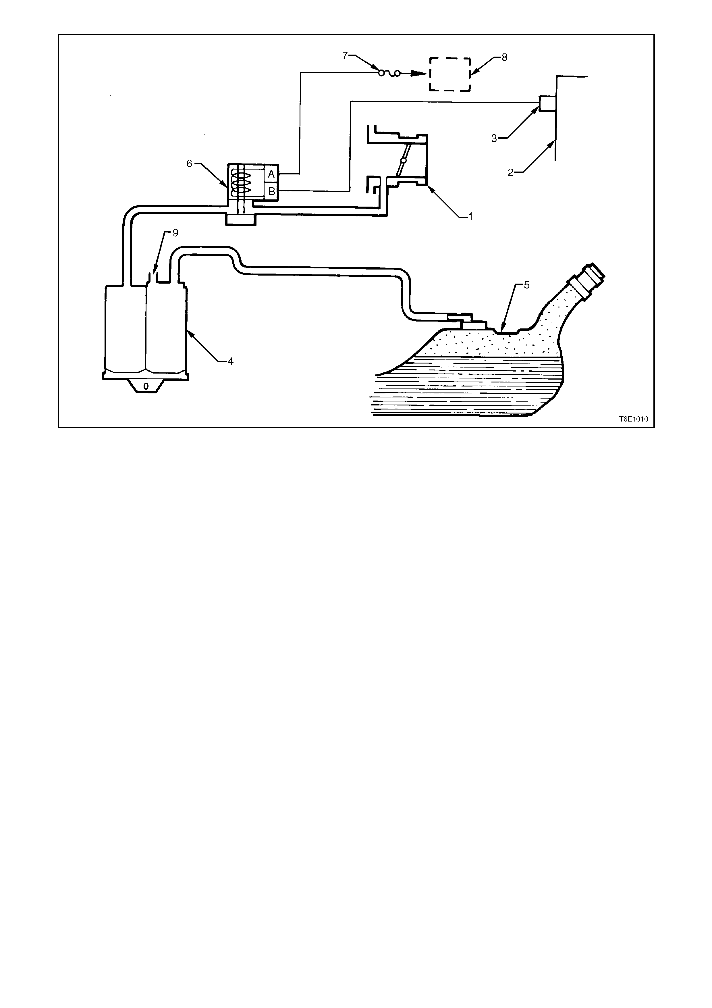
Figure 6E1-10
1. Throttle Body 4. Carbon Canister 7. Fuse F33
2. PCM 5. Fuel Tank 8. EFI Relay
3. PCM Terminal C4 6. Purge Solenoid Valve 9. Atmospheric Port
1.5 EXHAUST GAS RECIRCULATION
PRINCIPLES OF OPERATION
The Non Superc harged V6 engine is equipped with
an Exhaust Gas Recirculation (EGR) system. The
EGR system is used to lower Oxides of Nitrogen
(NOx) emission levels, caused by high com bustion
temperature.
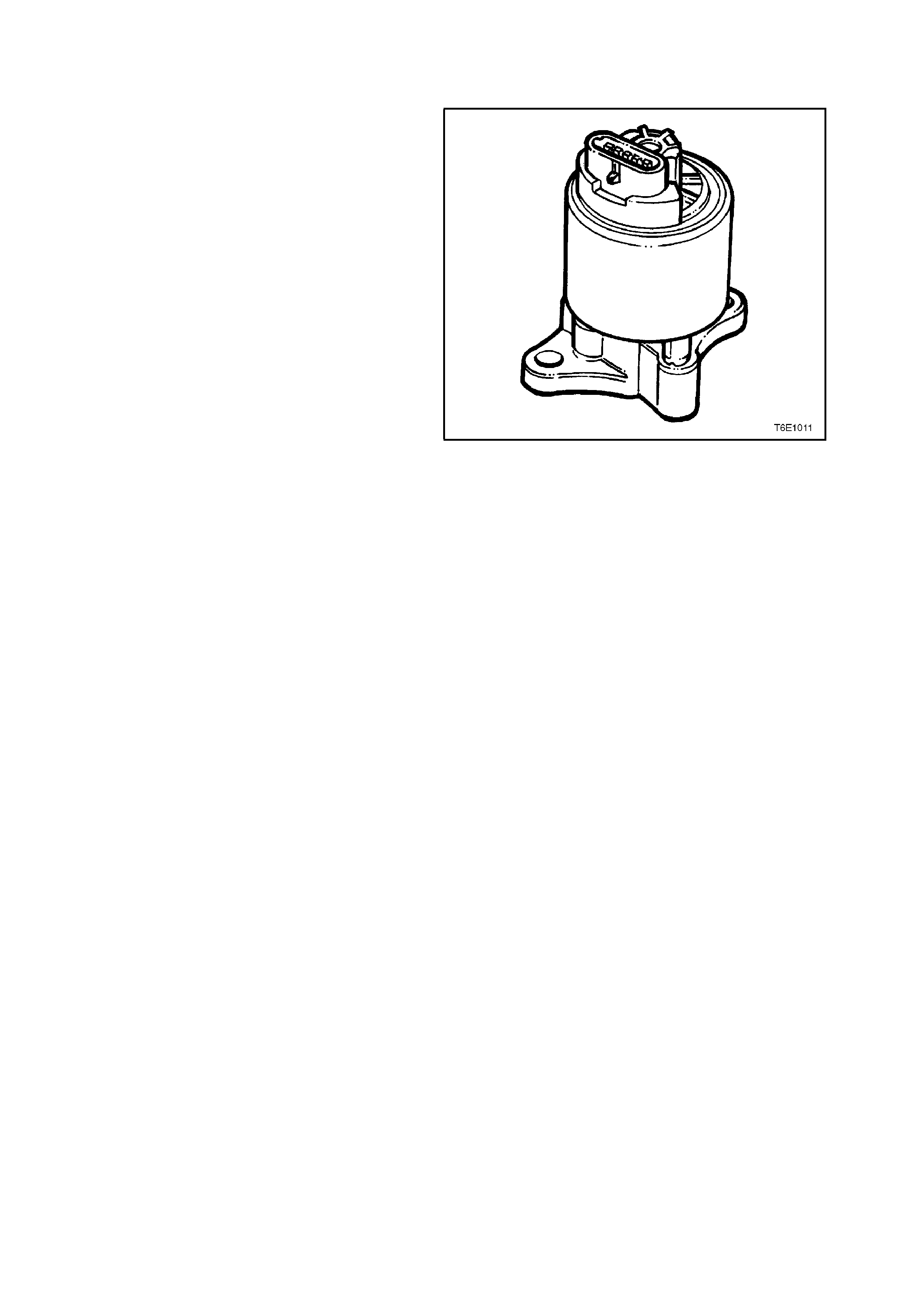
A linear EGR valve feeds small amounts of exhaust
gas back into the c ombus tion chamber . T his dilutes
the air/fuel mixture and combustion temperatures
are reduced.
The linear EGR valve is designed to accurately
supply exhaust gas to the engine independent of
the intake manif old vac uum. T he valve c ontr ols gas
flow from the exhaust to the intake manifold
through an orifice with a PCM controlled pintle.
During operation, the PCM controls pintle position
by monitoring the pintle position feedback signal.
The linear EGR valve is us ually activated under the
following conditions:
• Warm engine operation.
• Above idle speed.
The PCM monitors actual EGR position and adjusts
the pintle accordingly. The PCM uses information
from the following sensors to control pintle position:
• Engine Coolant Temperature (ECT) sensor.
• Throttle Position (TP) sensor.
• Mass Air Flow (MAF) sensor.
• Engine RPM
Figure 6E1-11
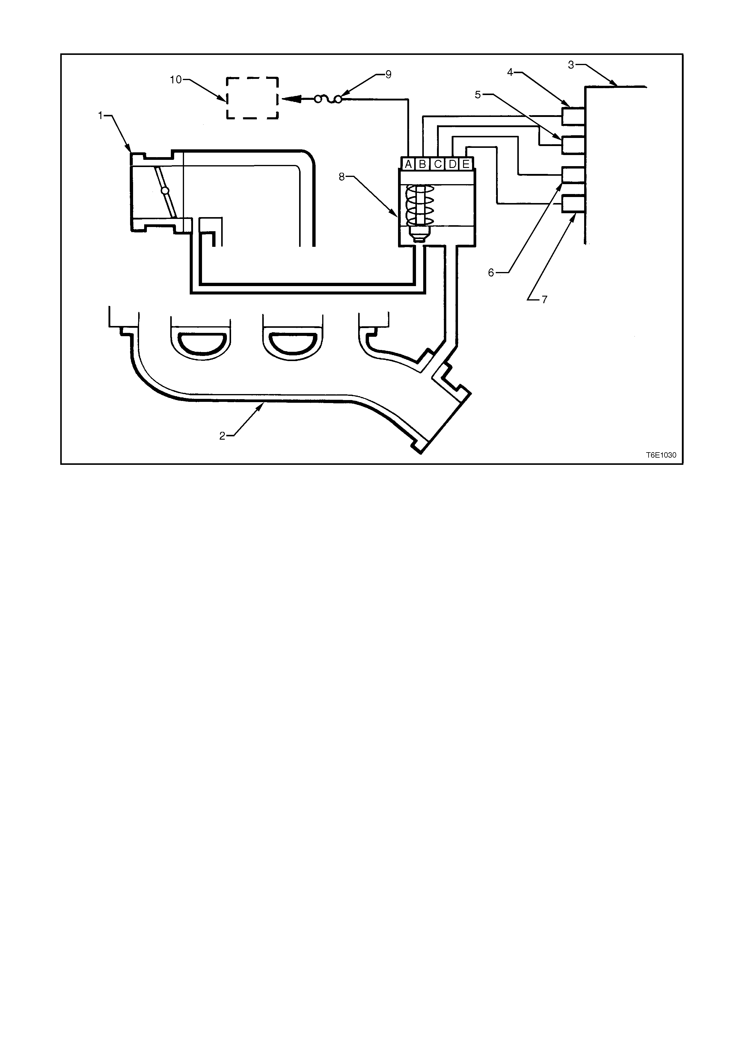
Figure 6E1-12
1. Throttle Body 5. PCM Terminal B10 9. Fuse F33
2. Exhaust manifold 6. PCM Terminal B7 10. EFI Relay
3. PCM 7. PCM Terminal F16
4. PCM Terminal E10 8. Linear EGR Valve
1.6 THREE-WAY CATALYTIC CONVERTER
PRINCIPLES OF OPERATION
Catalyst is the term used to describe substances which accelerate chemical reactions without themselves changing.
In the field of motor vehicle technology, the catalyst has the task of lowering the levels of pollutants, carbon
monoxide (CO), hydrocarbons (HC) and oxides of nitrogen (NOX), in the exhaust gases by converting them into
harmless naturally occurring gases.
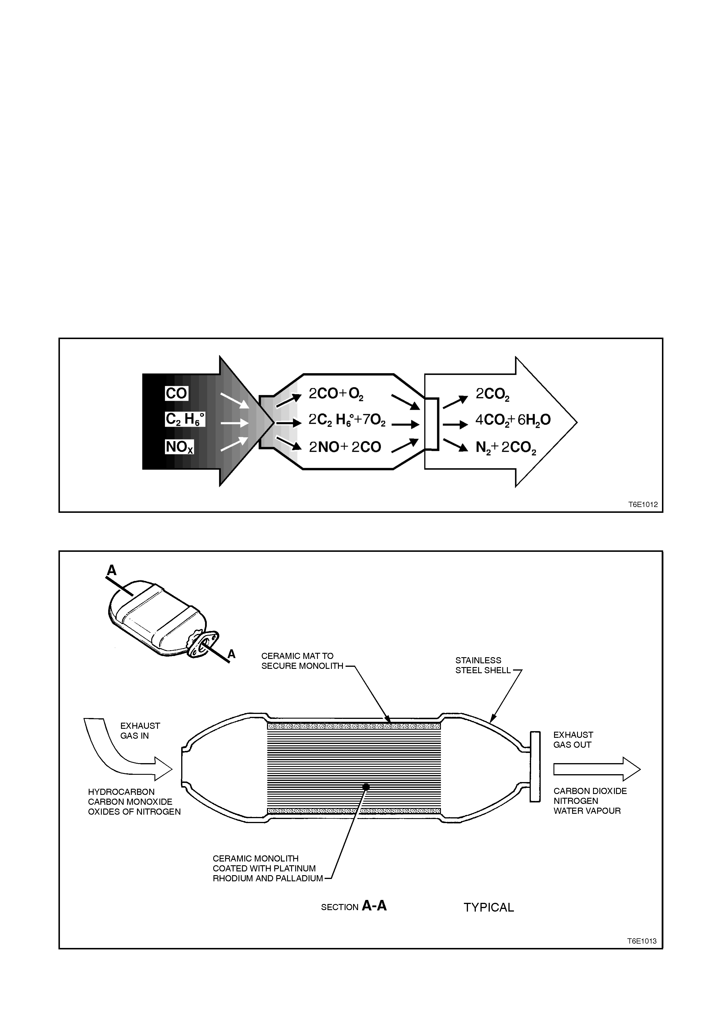
CO and HC are converted by oxidation with the oxygen (O2) contained in the exhaust gases into non-poisonous
carbon dioxide (CO2) and water vapour (H2O). To eliminate the oxides of nitrogen (NOX), the harmful carbon
monoxide which binds the oxygen in the exhaust gases is used as a reducing agent. The products of this reaction
are carbon dioxide (CO2) and nitrogen (N2). Together with oxygen, these two gases are components of the air that
we breathe.
The catalytic converter consists of a stainless steel housing enclosing a ceramic monolith. The monolith is an
extruded core of cordierite, a specially developed high temperature ceramic with approximately 160 cells/sq. cm. in
cross section. This gives the monolith a very large surface area for its mass. Distributed over the monolith surface is
a catalyst consisting of a combination of the precious metals, Platinum, Palladium and Rhodium.
Engine exhaust gases flow over the monolith and reactions with the catalysts occur. The converter is called a three-
way type because it simultaneously converts three components of exhaust gas (CO, HC and NOX) to harmless
natural gases.
Figure 6E1-13
Figure 6E1-14
The catalytic converter can only reduce exhaust
emissions if:-
a. The engine is designed for use with a
catalytic converter and unleaded petrol,
since lead contaminates the catalytic
coating and prevents it from functioning.
b. It is integrated in the exhaust system in
such a way that the exhaust emission
conversion occurs in the most effective
temperature range - in the vicinity of 600
degrees Celsius.
c. The catalysts function effectively within
certain air/fuel ratios only, consequently
the air/fuel ratio supplied to the engine
must be controlled within strict limits for
proper emission conversion and long
converter life. This control is offered by
operating under a closed loop mixture
control system , with dual oxygen sensor s.
For details of the oxygen sensors, ref er to
Section 6C1 POWERTRAIN
MANAGEMENT - V6 ENGINE.
The catalytic converter can be damaged, or
rendered ineffective, if operated outside the limits
of the closed loop mixture control system, or if the
engine burns excessive amounts of oil or if the
exhaust temperature at the converter is too high
(above 850 degrees Celsius).
Figure 6E1-15

SERVICE NOTES
1. Never operate the vehicle with leaded petrol as the lead will contaminate the ceramic monolith.
2. Never drop the catalytic converter, as it will damage the ceramic monolith.
3. Do not allow water, oil or fuel to enter the converter as the ceramic monolith will be contaminated.
4. Do not use any engine additive that is not recommended by Holden. Many additives contain phosphorous,
which will contaminate the ceramic monolith.
5. In order to prevent the catalytic converter from overheating, the following sequence must be followed when
carrying out a cylinder balance test.
a. Maximum time each cylinder may be switched off is 8 seconds.
b. Pause for at least 8 seconds between each switch off.
c. If repeating a cylinder balance test, allow engine to idle for a least 60 seconds before retesting.
6. The vehicle must not be started by pushing or towing, as unburned fuel could reach the catalytic converter and
destroy the ceramic monolith. Always use jumper leads to start vehicle which has a flat or defective battery.
7. When carrying out a compression test, remove the ENGINE fuse, F25, from the engine compartment relay
housing, refer to Section 6A1 ENGINE MECHANICAL - V6 ENGINE. This prevents fuel injection and ignition
during engine cranking.
8. Do not drive vehicle for long periods with engine misfiring or with spark plug leads disconnected, as the
catalytic converter will overheat.
9. Do not coast downhill with engine misfiring or with spark plug leads disconnected.
10. Never re-use catalytic converter flange gaskets.
11. If the catalytic converter housing must be welded, use MIG or TIG with stainless steel wire. Do not use
oxy/acetylene welding, as damage to the monolith may result.
12. The catalytic converter is integrated with the exhaust system. For removal and installation instructions, refer to
Section 8B EXHAUST SYSTEM.
2. SERVICE OPERATIONS
2.1 POS I TIVE CRANKCASE VENTILATION VALVE
REPLACEMENT AND FUNCTIONAL CHECK V6 NON-SUPERCHARGED ENGINE
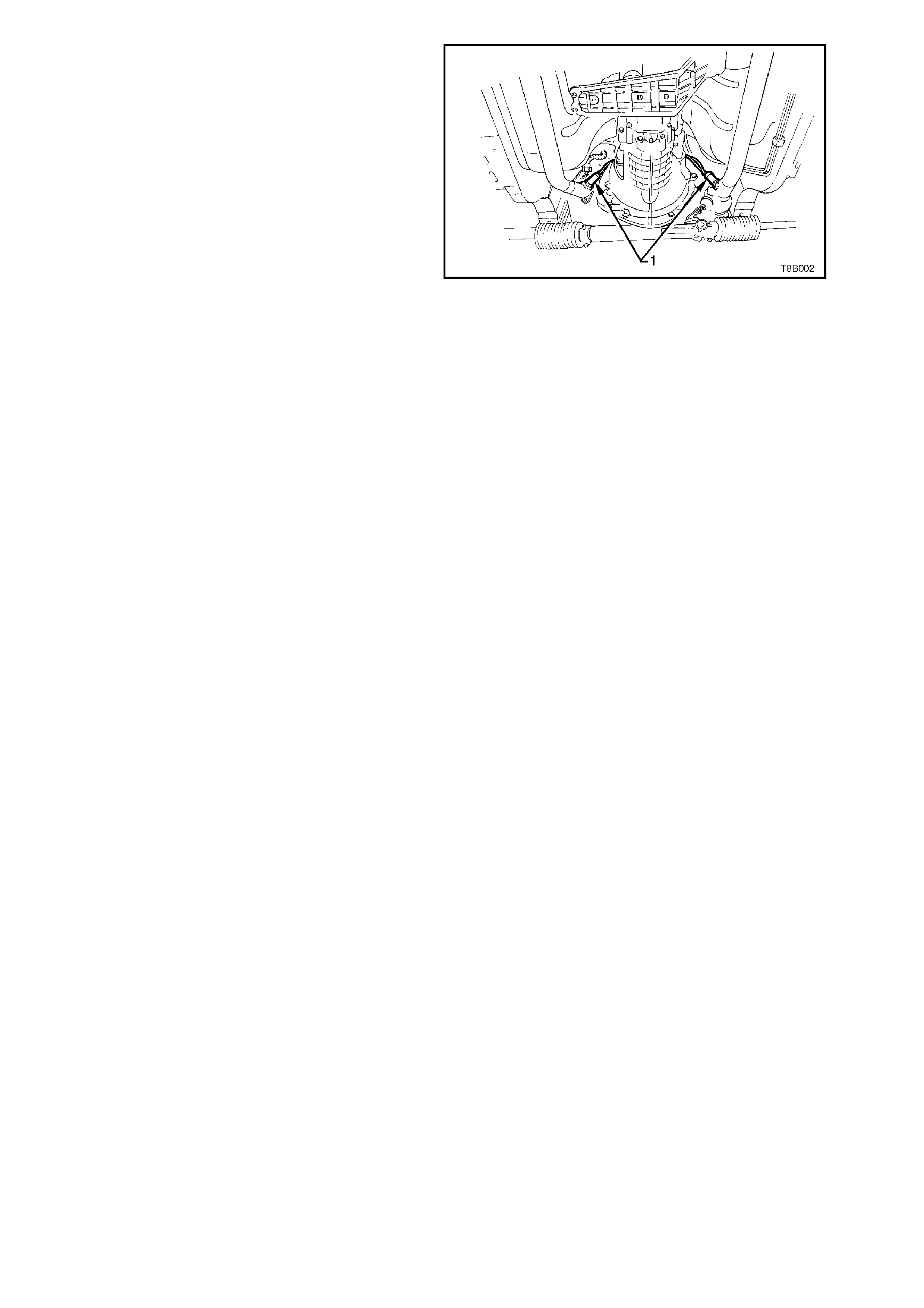
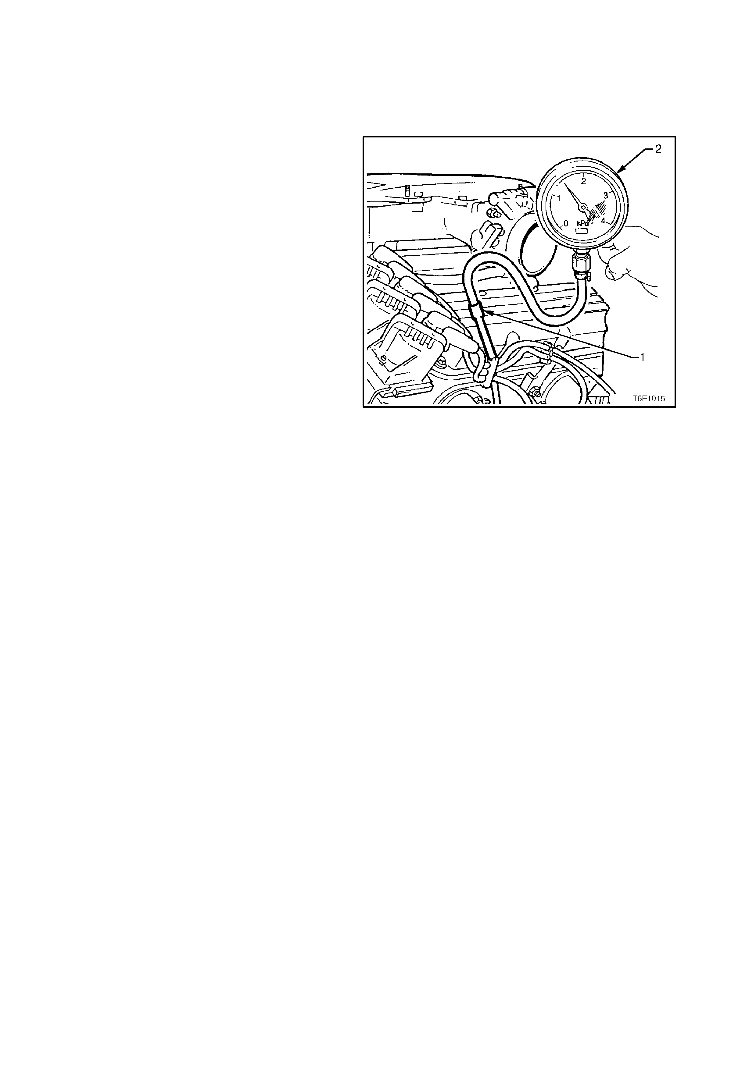
Remove engine oil dipstick. Connect a
commercially available vacuum gauge (2) with a
scale of approximately 0 to -4 kPa (vacuum gauge
must be able to read less than -1 kPa) to the
engine oil dipstick tube (1), ensuring a tight seal.
Allow engine to idle and read vacuum gauge. If a
vacuum is present, approximately -0.2 to -1.00 kPa,
the PCV valve and PCV system are functioning
correctly.
If no vacuum or a possible positive pressure is
registered, this can indicate several abnormalities;
• The engine may not be sealed and/or is dr awing
outside air. Check engine crankcase, i.e. valve
cover, oil pan gasket etc. for leaks.
• The engine may be badly worn causing
excessive engine blow-by.
• The PCV valve may be blocked and requires
further investigation using the following
procedure.
1. Remove PCV valve from inlet manifold, refer
2.9 LOWER INLET MANIFOLD, in Section
6A1 ENGINE MECHANICAL - V6 ENGINE.
2. Shake PCV valve and lis ten for rattle of check
valve inside valve housing. If valve does not
rattle, discard and install new PCV valve and
O ring.
3. Install PCV valve with O ring, refer 2.9
LOWER INLET MANIFOLD, in Section 6A1
ENGINE MECHANICAL - V6 ENGINE.
NOTE:
It is possible (and normal) to have a positive
pressure reading at the engine oil dipstick tube
while the vehicle is under driving conditions at wide
open throttle.
CAUTION:
Do not clam p the hos e f rom the PCV valve outlet at
the intake manifold to the throttle body when the
engine is running as this can cause dam age to the
engine.
Figure 6E1-16
REPLACEMENT AND FUNCTIONAL CHECK V6 SUPERCHARGED ENGINE
If an engine is idling rough, check for a clogged
crankcase ventilation valve using the following
procedure:
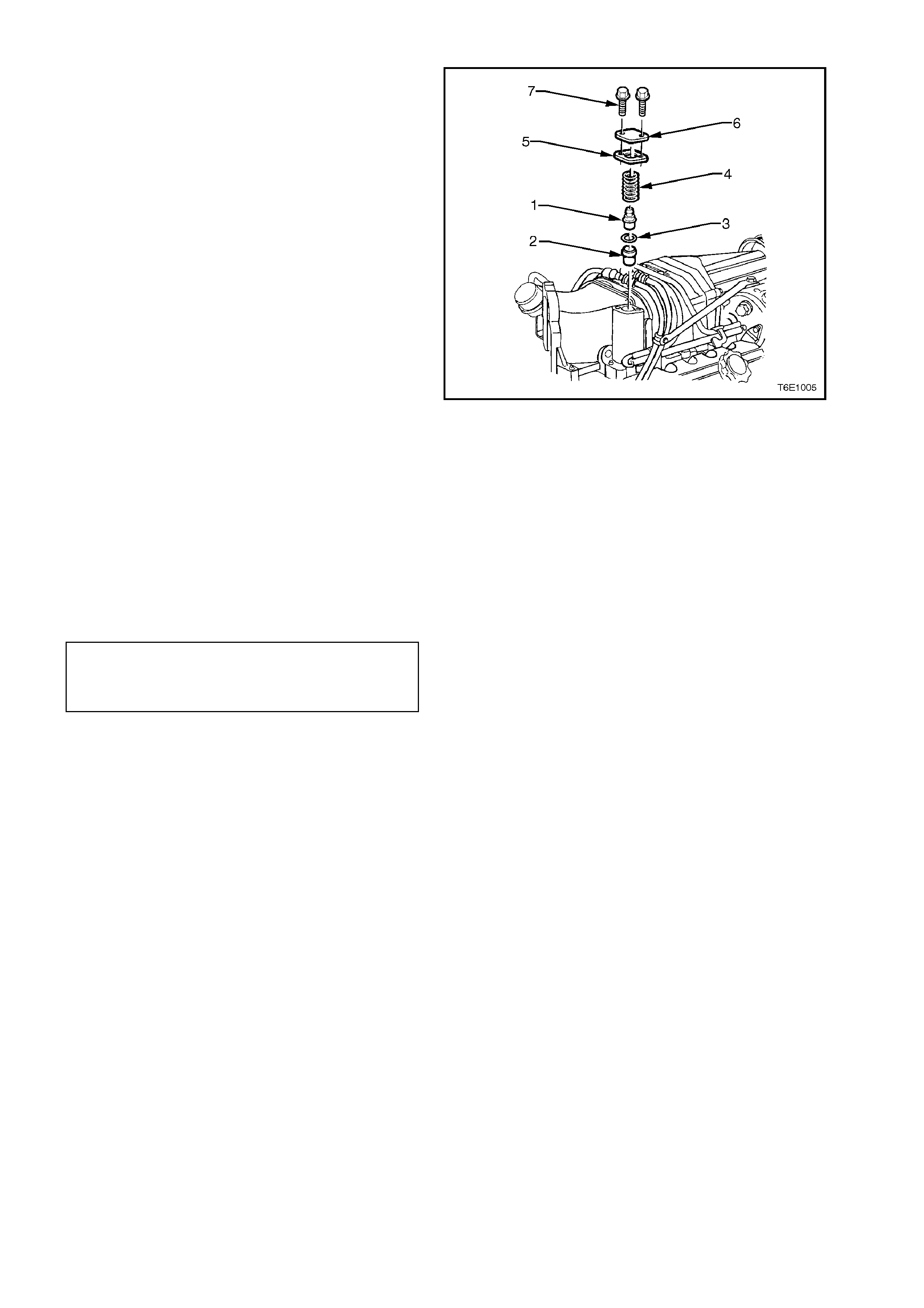
REMOVE
1. Remove the four engine dress cover dome
nuts and remove cover.
2. To overcome spring force, hold down the
positive crankcase ventilation valve cover and
remove the two cover retainer screws.
3. Remove the positive crankcase ventilation
valve cover, gasket, positive crankcase
ventilation valve, spring and O-ring.
4. Shake valve and listen for the rattle of needle
inside valve. If valve does not rattle, replace
valve.
Figure 6E1-17
REINSTALL
Installation of the positive crankcase ventilation
valve is the reverse of the removal procedure,
noting the following:
1. Reinstall positive crankcase ventilation valve
using new O-rings and gasket as necessary.
2. Tighten positive crankcase ventilation valve
cover retaining screws to the correct torque
specification.
POSITIVE CRANKCASE
VENTILATION VALVE COVER
RETAINING SCREW
TORQUE SPECIFICATION
4 - 6
Nm
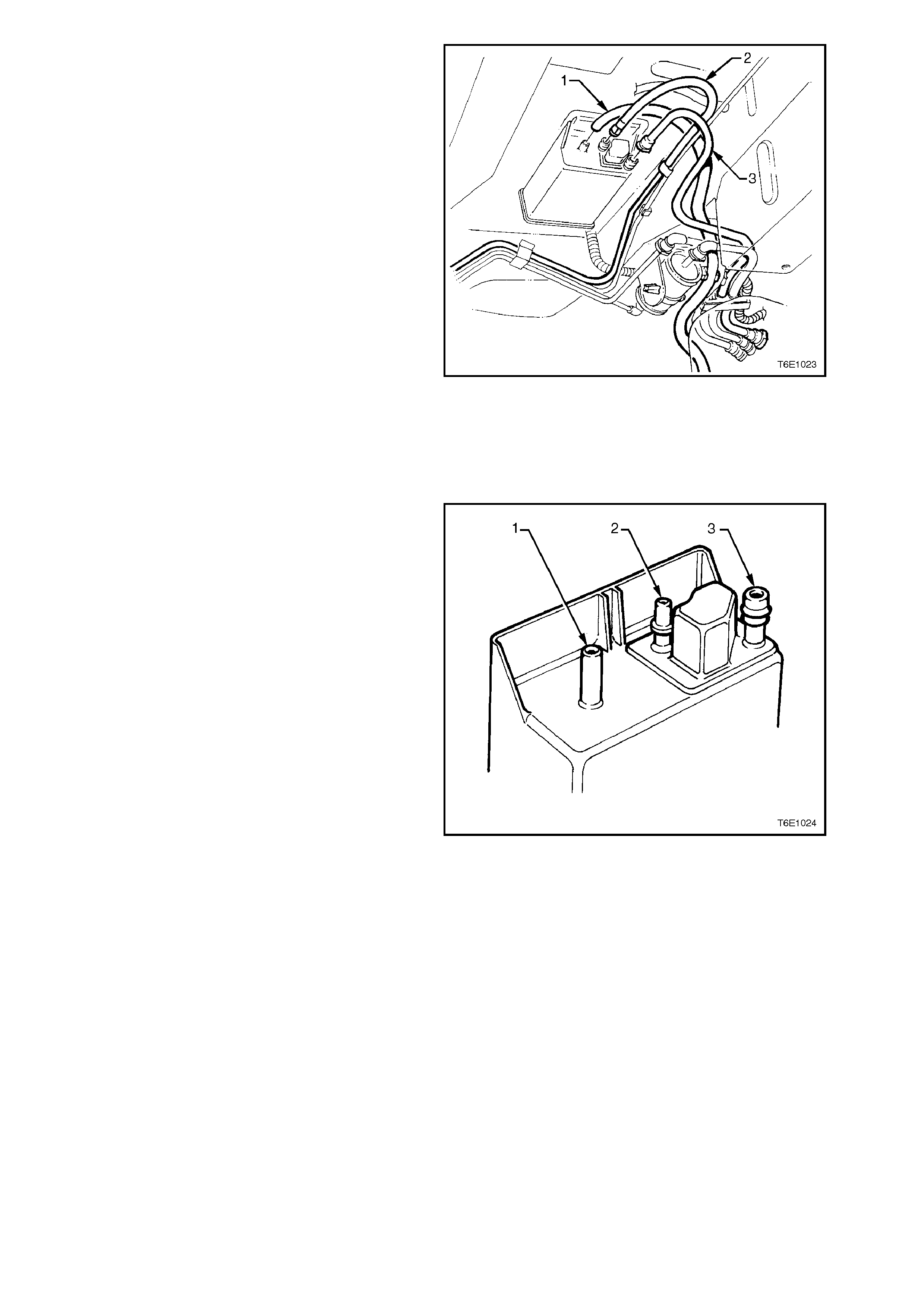
2.2 EVAPORATIVE EMISSION CONTROL CANISTER
REMOVE
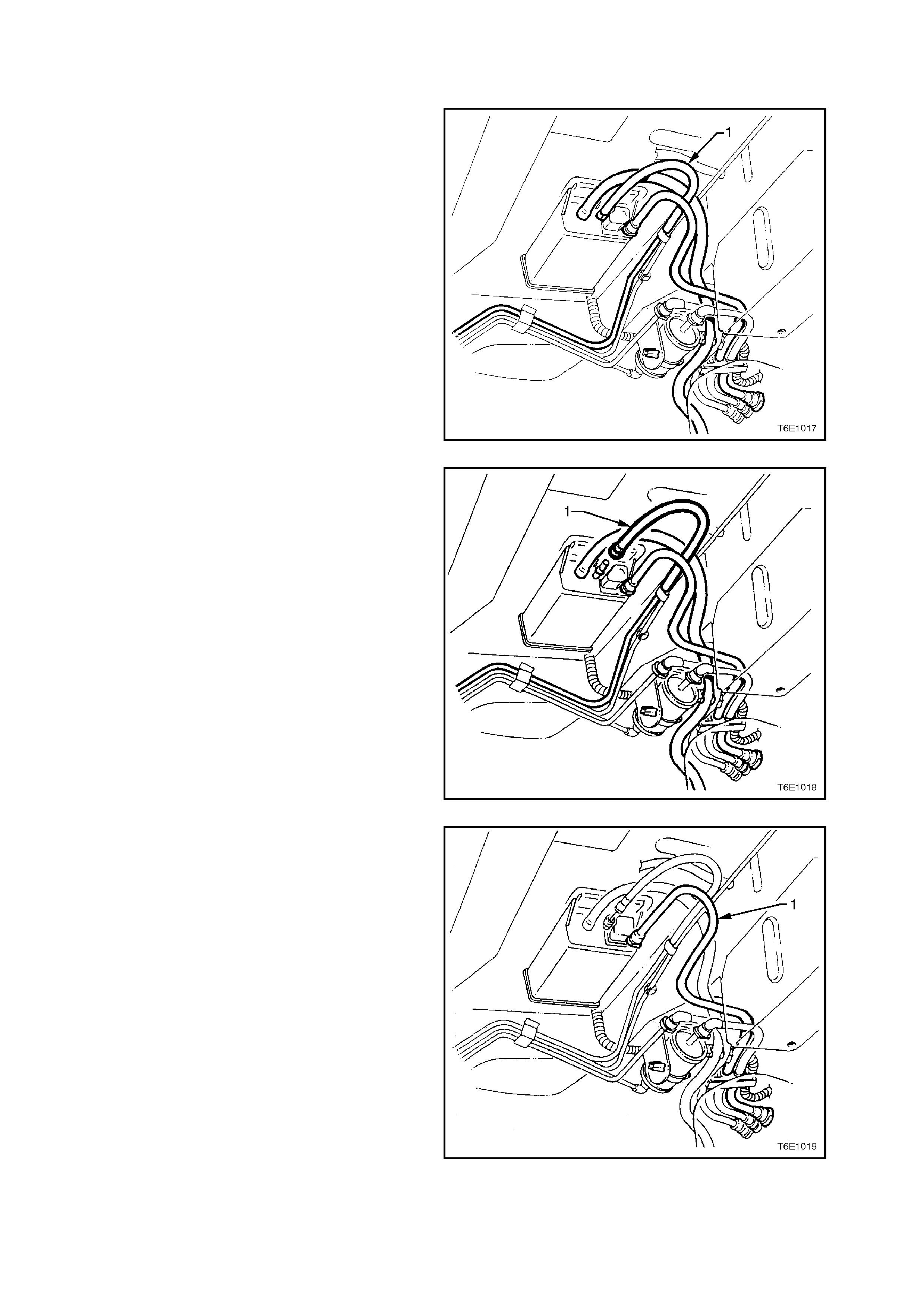
1. Disconnect fuel vapour inlet line (1) by using
the following procedure:
a. Grasp both sides of the quick-connect
fitting. Twist the connector 1/4 turn in
each direction in order to loosen any dirt
within the quick-connect fitting.
CAUTION:
Wear safety glasses when using compressed
air. b. Using compressed air, blow any dirt out
of the quick connect fitting.
Figure 6E1-18
c. Grasp the quick-connect fitting and push
toward the canister
d. Squeeze the quick-connect fitting to
release the retaining tabs, then pull back
on the connector to remove the vapour
fuel line (1) from the canister.
Figure 6E1-19
2. Disconnect f uel vapour purge line (1) by using
the following procedure:
a. Grasp both sides of the quick-connect
fitting. Twist the connector 1/4 turn in each
direction in order to loosen any dirt within
the quick-connect fitting.
CAUTION:
Wear safety glasses when using compressed
air. b. Using compressed air, blow any dirt out of
the quick connect fitting.
Figure 6E1-20
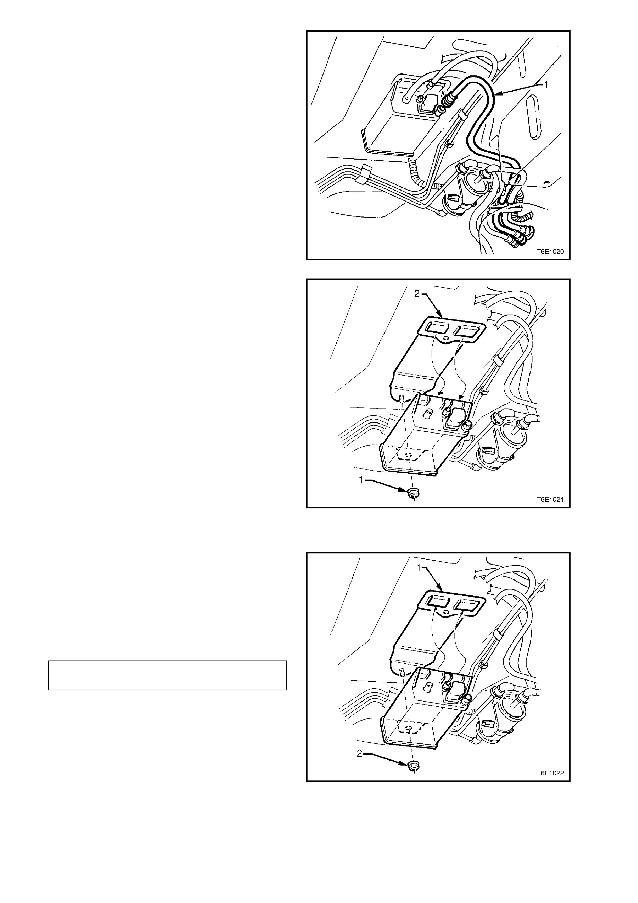
c. Grasp the quick-connect fitting and push
toward the canister
d. Squeeze the quick-connect fitting to
release the retaining tabs, then pull back
on the connector to remove the vapour
purge line from the canister.
3. Remove atmospheric vent line from
atmospheric port.
Figure 6E1-21
4. Loosen and remove canister retaining nut (1).
5. Remove canister from retaining stud, then
slide canister out of retainer (2).
Figure 6E1-22
REINSTALL
1. Reinstall canister into canister mounting
bracket (1) and over retaining stud.
2. Reinstall canister retaining nut (2) and hand
tighten.
3. Push canister toward centre of vehicle and
tighten canister retaining nut to the correct
torque.
CANISTER RETAINING NUT 2.0 - 5.0
TORQUE SPECIFICATION Nm
Figure 6E1-23
4. Reinstall atmospheric port hose (1).
5. Align fuel vapour purge line quick connector
(2) with fuel vapour purge line port then push
connector firmly onto port.
6. Align fuel vapour inlet line quick connector (3)
with fuel vapour inlet line port then push
connector firmly onto port.
7. Once installed, pull on each quick connect in
order to make sure the connections are secure
and locked in position.
Figure 6E1-24
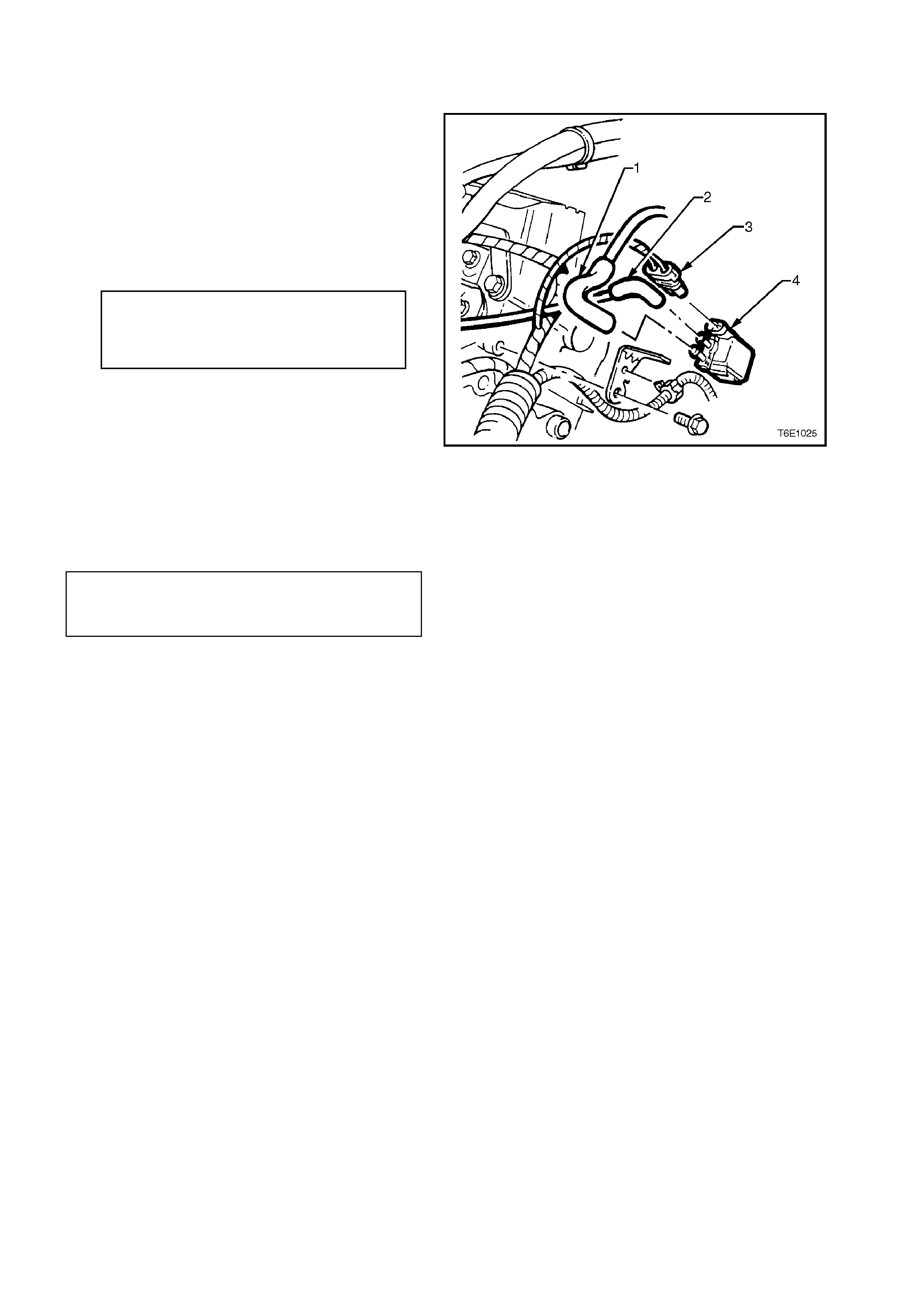
SERVICE CHECKS
1. Remove canister as previously described.
2. Shake canister. There should be no audible
sound of carbon movement.
3. Using low pressure compressed air (20-35
kPa), blow into the vapour inlet port (2) . Check
that air flows freely from the atmospheric port
(1).
Block the atmospheric port (1) and air should flow
from the purge line port (3).
4. If air flow through the purge line port (3) is
poor, clean the atmospheric filter by blocking
off the vapour inlet port (2) and blowing
compressed air at approximately 300 kPa
through purge line port (3). Recheck air flow
through filter as in Step 3. If air flow through
atmospheric port (1) is still poor, replace
canister.
5. Block the atmospheric port (1) and the purge
line port (3). Apply low pressure compressed
air (20-35 kPa) to the vapour inlet port (2). If
any air leak s f r om canis ter , i.e. around por ts or
seams, canister must be replaced. Figure 6E1-25
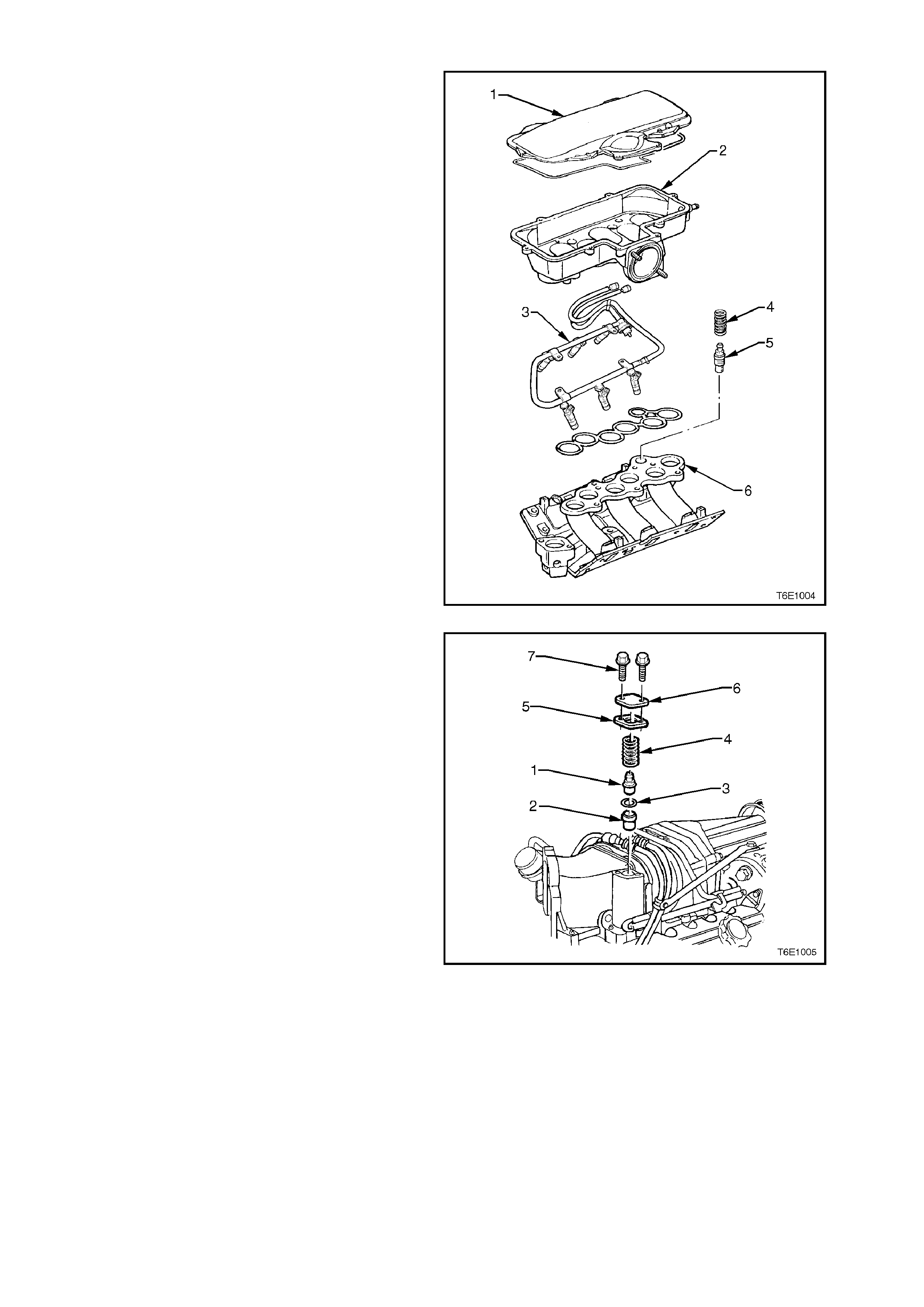
2.3 CANISTER PURGE SOLENOID VALVE
REMOVE
1. Disconnect battery earth lead.
2. Mark hoses on canister purge solenoid valve
(top and bottom), and pull hoses from valve.
3. Pull up on solenoid wiring harness connector
retaining tab and pull connector from solenoid
valve.
4. Remove bolt from solenoid bracket. This bolt
attaches to the rear of the right hand cylinder
head, remove solenoid.
1. Vacuum Hose to Carbon Canister.
2. Vacuum Hose from Throttle Body.
3. Canister Purge Solenoid Connector YE99.
4. Canister Purge Solenoid.
Figure 6E1-26
REINSTALL
1. Reinstall canister purge solenoid valve to rear
of cylinder head and install bracket bolt.
Tighten bolt to the correct torque specification.
CANISTER PURGE SOLENOID
VALVE BRACKET TO
CYLINDER HEAD BOLT
TORQUE SPECIFICATION
15 - 20
Nm
2. Reconnect vacuum hoses and wiring harness
connector to canister purge solenoid valve,
ensuring connections are correct.
NOTE:
Apply Loctite 4210 Adhesive to both ends of the
Solenoid to Throttle Body vacuum hose prior to
assembly.
3. Reconnect battery earth.
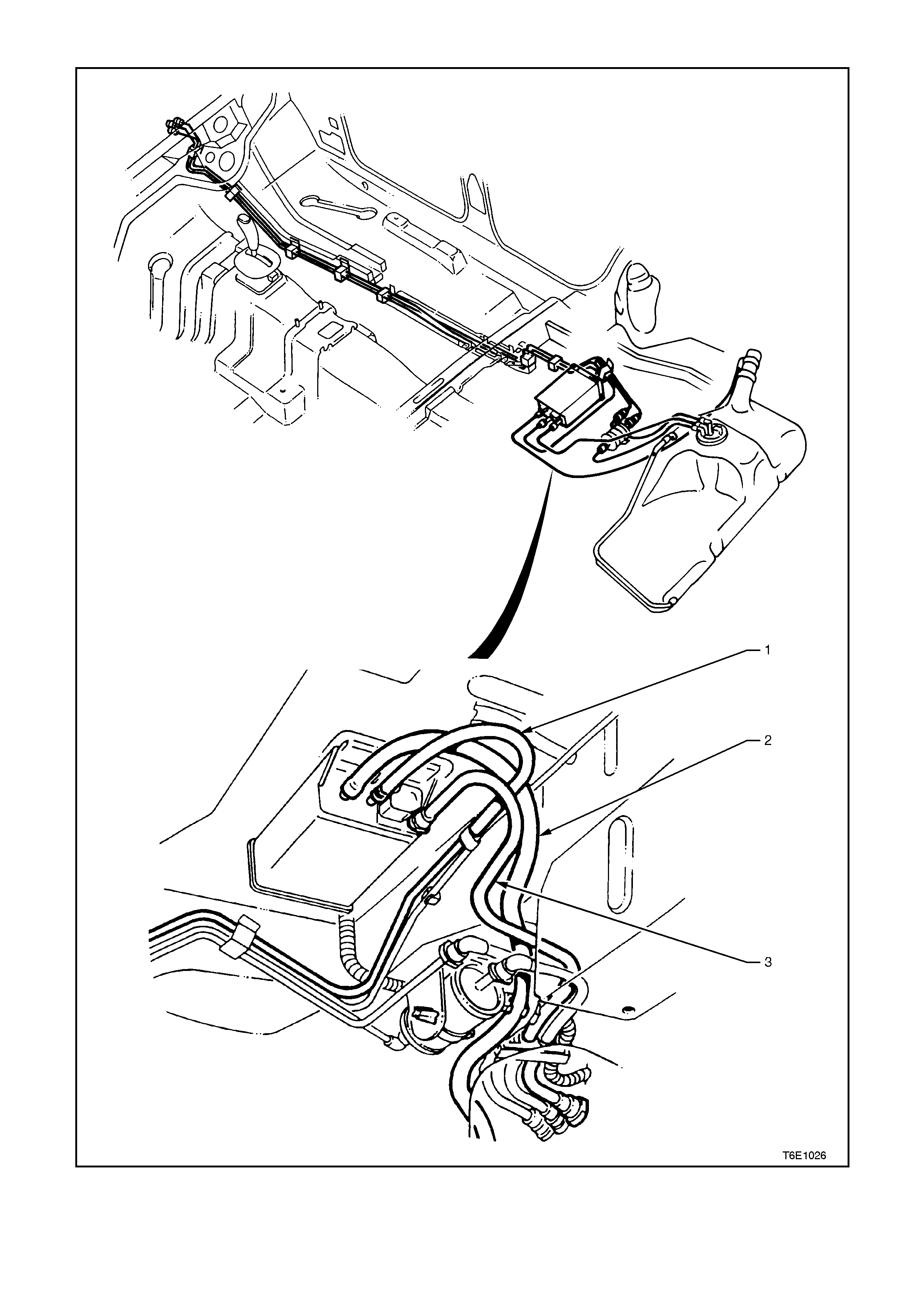
VACUUM HOSE LAYOUT DIAGRAMS
Figure 6E1-27
1. Fuel Vapour inlet line 2. Fuel Vapour Purge Line 3. Atmospheric Vent Line
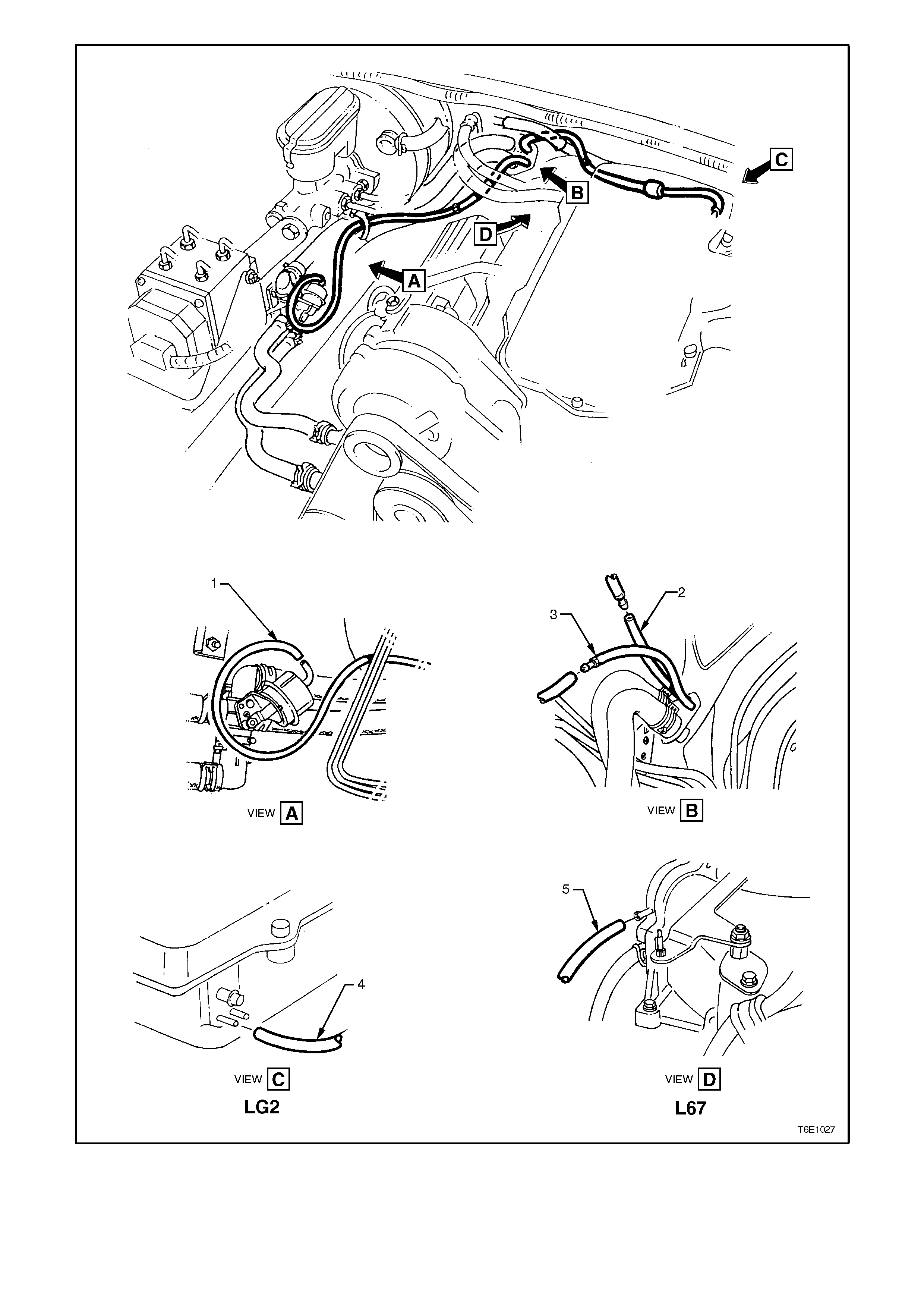
Figure 6E1-28
1. Vacuum Line
from A/C 2. Vacuum Supply
Line to A/C 3. Vacuum Line to
Water Valve 4. Vacuum Supply
Line to A/C
(LG2)
5. Vacuum Supply
Line to A/C (L67)
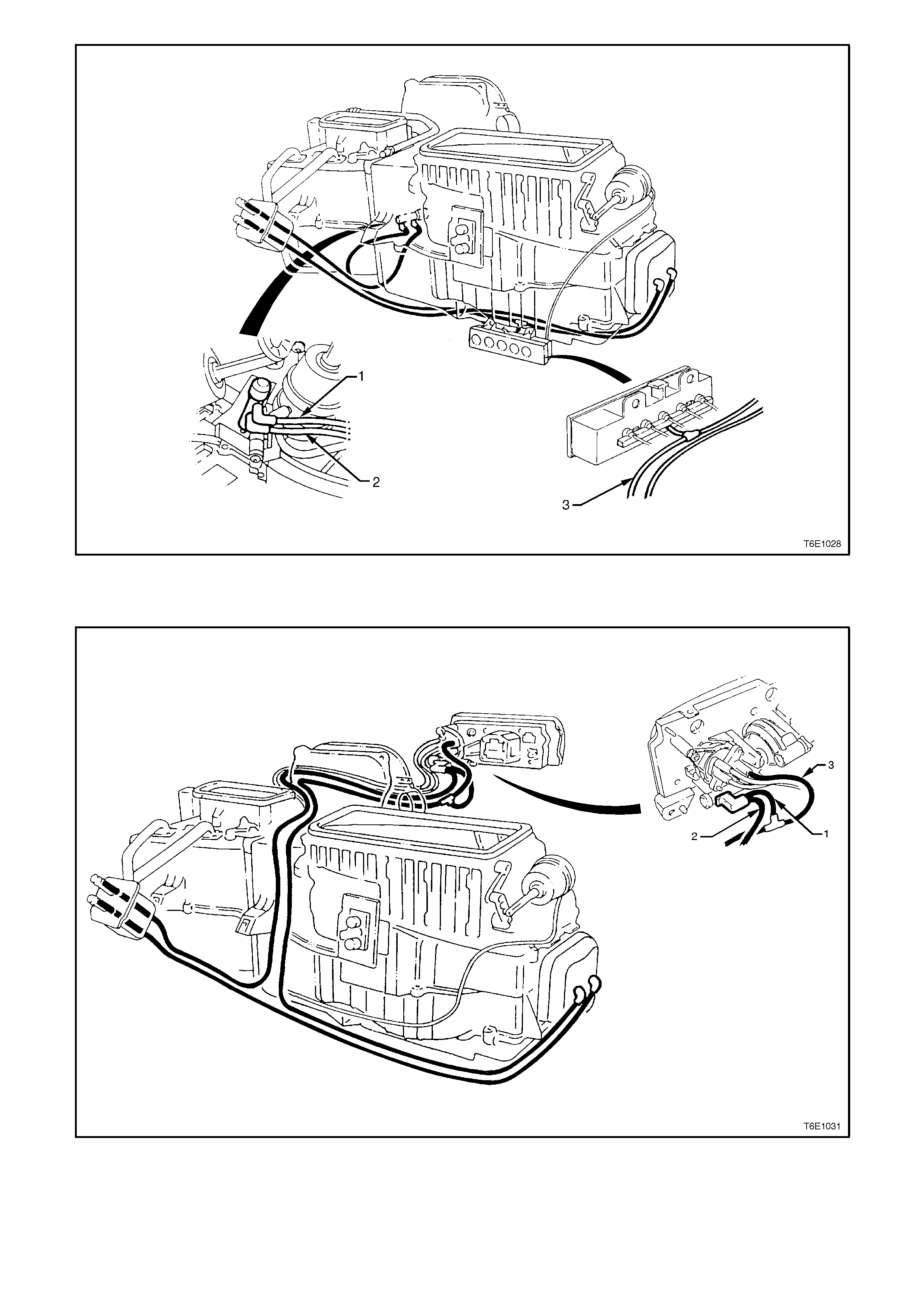
Figure 6E1-29
1. Vacuum Control Switch Supply 2. Vacuum Line to Water Valve 3. Vacuum Supply
Figure 6E1-30
1. Vacuum Control Switch Supply 2. Vacuum Line to Water Valve 3. Vacuum Supply
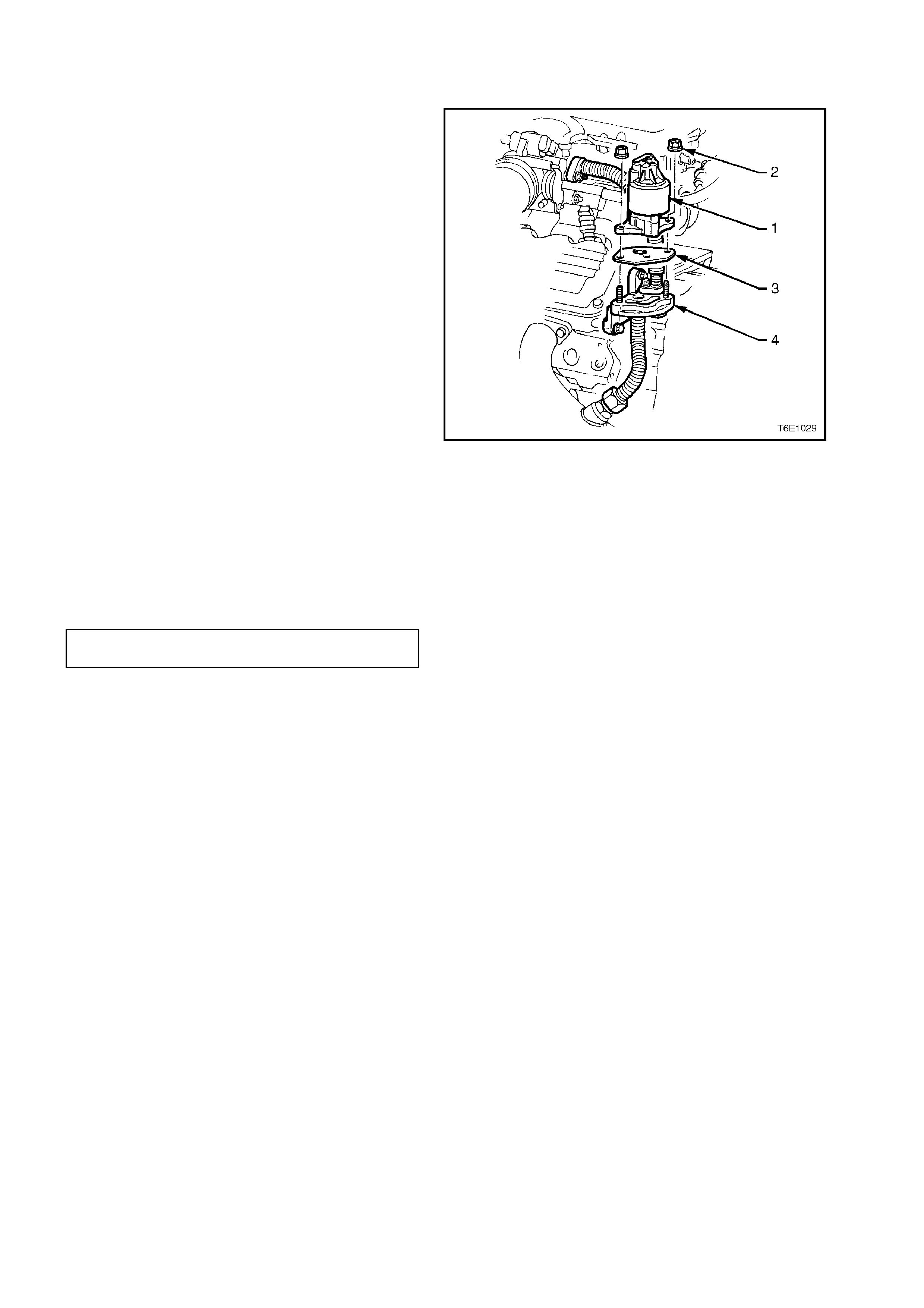
2.4 LINEAR EGR VALVE
REMOVE
1. Disconnect battery earth lead.
2. Remove engine dress cover.
3. Disconnect EGR valve electrical connector.
4. Remove EGR valve retaining nuts (2).
5. Remove EGR valve (1) and gasket (3) from
EGR adaptor assembly (4).
Figure 6E1-31
REINSTALL
1. Install a new EGR adaptor to EGR valve
gasket.
2. Reinstall EGR valve and retaining nuts.
3. Tighten EGR valve retaining nuts to the
correct torque.
EGR VALVE RETAINING NUTS
TORQUE SPECIFICATION 20 - 27
Nm
4. Reinstall engine dress cover.

3. DIAGNOSIS
POSITIVE CRANKCASE VENTILATION
CONDITION PROBABLE CAUSE CORRECTIVE ACTION
Rough, slow idle or stalling PCV valve blocked.
Blocked or damaged
ventilation hose.
Clean valve or replace.
Clean or replace hose.
Rough, fast idle or stalling PCV valve stuck in
intermediate position.
PCV valve leaking.
Clean valve or replace.
Check valve O ring, replace
if necessary.
Check valve installation.
Excessive sludging or
diluting of oil Engine is not being vented. Check for clogged PCV
valve circuit and clogged
ventilation circuit.

EVAPORATIVE EMISSION CONTROL
CONDITION PROBABLE CAUSE CORRECTIVE ACTION
Loss of fuel from filler cap Unsatisfactory sealing
between cap
and filler neck.
Malfunction of filler cap relief
valve.
Replace filler cap.
Replace filler neck if
damaged.
Replace filler cap.
Loss of fuel from fuel lines Loose line connection.
Faulty or leaking vapour
separator.
Secure connection.
Replace.
Loss of fuel from canister Fuel tank overfilled.
When the fuel warms up
during parking or warm
weather operation, excess
fuel is discharged into the
canister, flooding it.
Kinked hoses at filler neck
and vapour separator
reservoir.
Blocked, damaged or
disconnected purge valve at
canister.
Avoid overfilling of tank.
Clean hose. Replace
damaged hose. Install
correctly.
Replace canister
Collapsed fuel tank or
pressure in tank Faulty fuel filler cap
(in high temperature
operating conditions some
pressure may normally be
encountered in the fuel
tank).
Kinked hoses at filler neck
and vapour separator
reservoir.
Blocked or kinked vent line
Defective canister (usually
internal blocked).
Purge solenoid valve is
closed causing canister to
become overloaded.
Replace filler cap.
Clean line. Replace
damaged line
Replace canister.
Refer to 6C1
POWERTRAIN
MANAGEMENT - V6
ENGINE.
Rough idle Improperly routed or
disconnected purge line.
Purge solenoid valve is open
or not receiving power.
Install purge line.
Refer to 6C1
POWERTRAIN
MANAGEMENT - V6
ENGINE.
For diagnosis of faults pertaining to vehicle performance, refer to Section 6C1 POWERTRAIN MANAGEMENT -
V6 ENGINE.
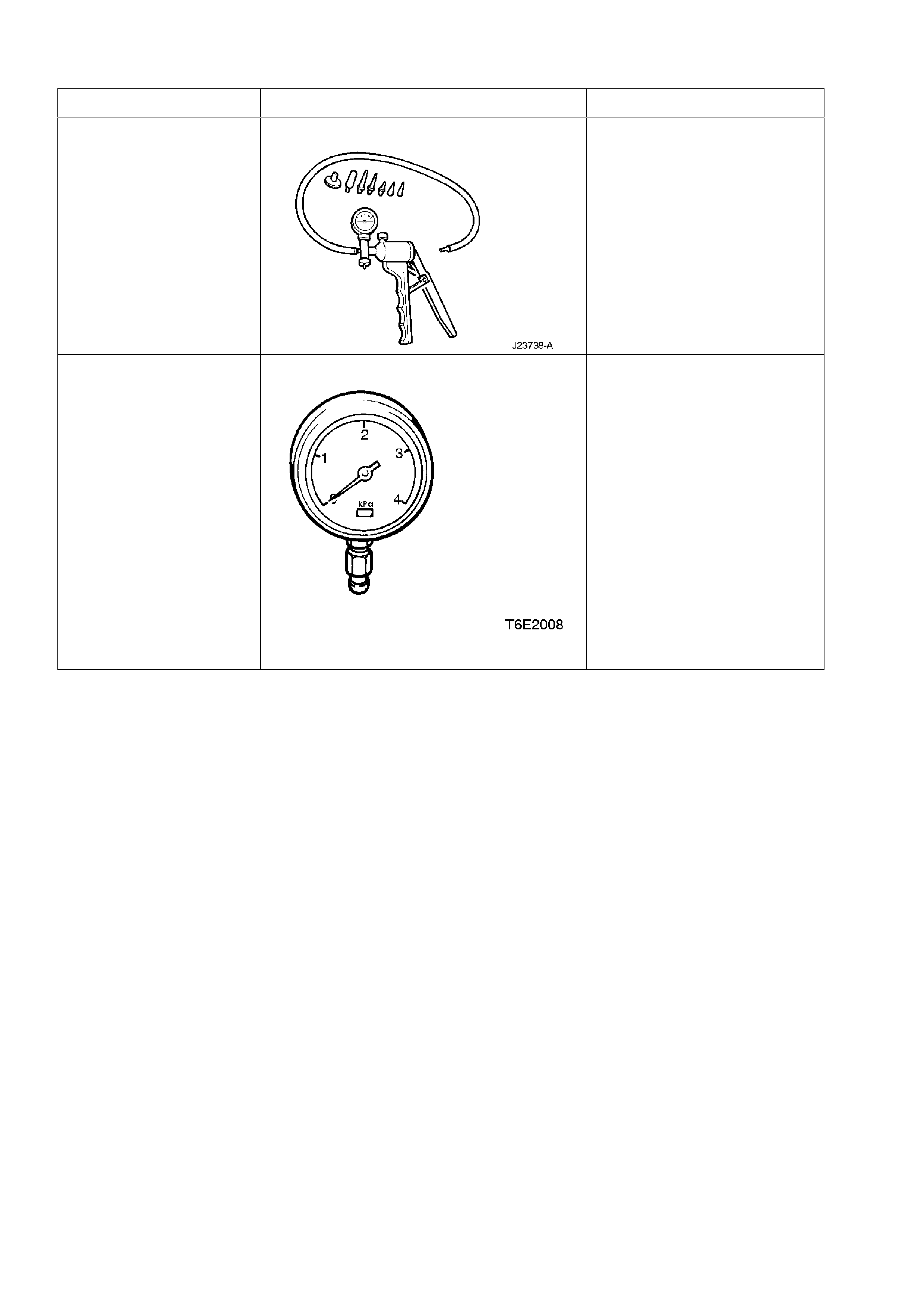
4. SPECIAL TOOLS
TOOL NO. REF IN TEXT TOOL DESCRIPTION COMMENTS
J23738 - A HAND VACUUM PUMP PREVIOUSLY RELEASED
FOR 'V' AND 'J' CARS.
N/A VACUUM GAUGE VACUUM GAUGE WITH
SCALE OF
0 TO -4 KPA
COMMERCIALLY AVAILABLE
SUCH AS "H 68930 30" FROM
:
EXTECH EQUIPMENT
3 WOODBINE COURT
WANTIRNA SOUTH
VICTORIA 3152
PHONE : 03 887 0055
OR
008 338132