SECTION 6F1 ENGINE TUNE - V6 ENGINE
CAUTION:
This vehicle will be equipped with a Supplemental Restraint System (SRS). A SRS will
consist of either seat belt pre-tensioners and a driver's side air bag, or seat belt pre-
tensioners and a driver's and front passenger's side air bags. Refer to CAUTIONS,
Section 12M, before performing any service operation on, or around any SRS
components, the steering mechanism or wiring. Failure to follow the CAUTIONS
could result in SRS deployment, resu lting in possible perso nal in jury or u nnecessary
SRS system repairs.
CAUTION:
This vehicle may be equipped with LPG (Liquefied Petroleum Gas). In the interests of
safety, the LPG fuel system should be isolated by turning 'OFF' the manual service
valve and then draining the L PG service lines, before any service w ork is carried out
on the vehicle. Refer to the LPG leaflet included with the Owner's Handbook for
details or LPG Section 2 for more specific servicing information.
1. GENERAL INFORMATION
Engine tuning, although simplified by electronically
controlled air/fuel mixture and ignition timing, is of
great importance due to the susceptibility of the
catalytic converter to damage caused by rich
air/fuel mixture. The air/fuel ratio is controlled to
near optimum condition by the Powertrain Control
Module (PCM) refer to
Section 6C1 POWERTRAIN MANAGEMENT - V6
ENGINE. A rich mixture can be induced by cross-
firing spark plug leads, mis-firing spark plugs or a
damaged exhaust gas oxygen sensor.
The PCM will set a Diagnostic Trouble Code and
the Check Engine Light will be illuminated, in the
event of the mixture continuing to operate outside
the specified lim its. Prolonged operation with a rich
mixture may damage the catalytic converter, refer
to Section 6E1 EMISSION CONTROL.
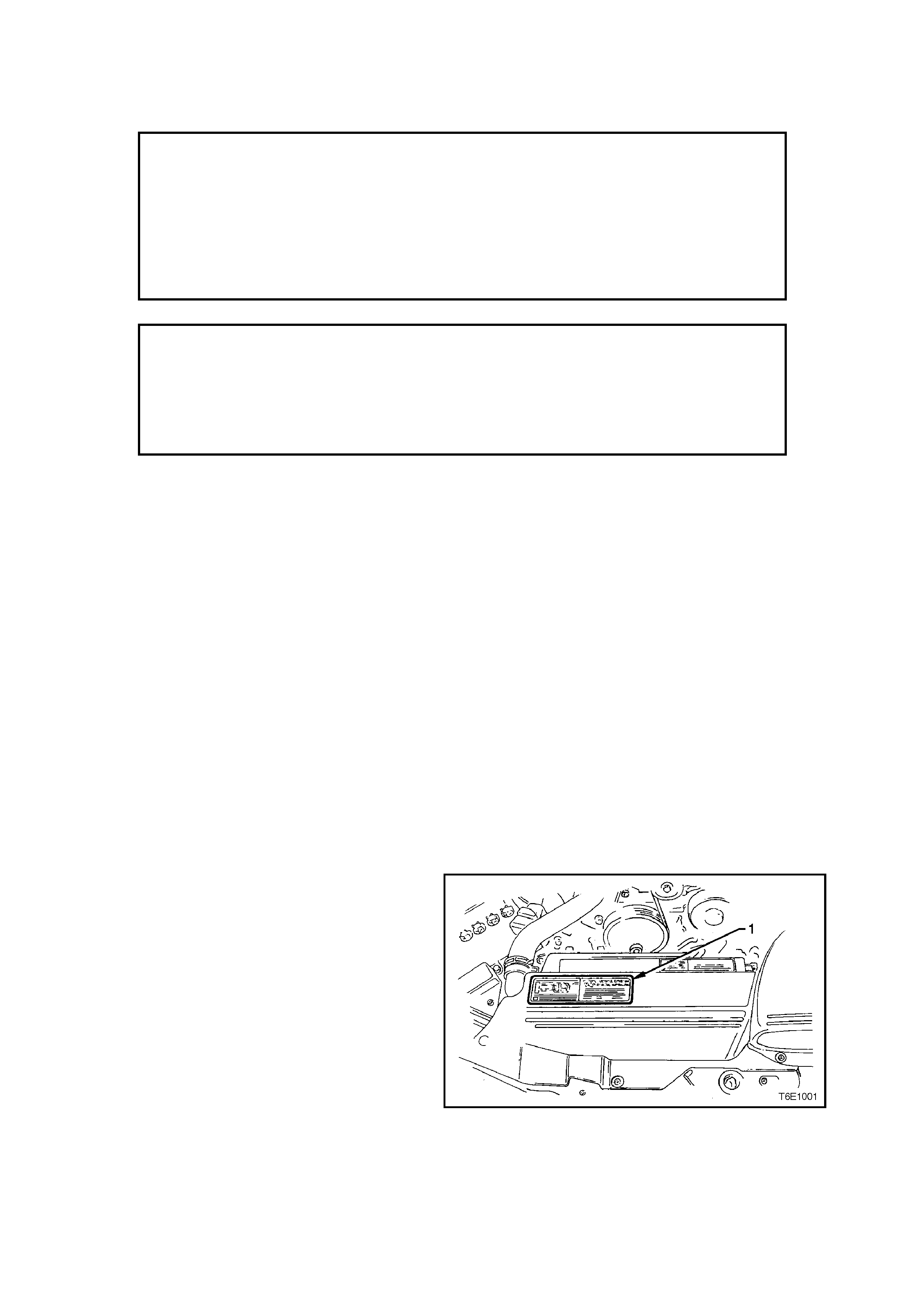
Engine tune specifications necessary to achieve
the correct emission levels are located on the
Vehicle Emission Control Information Label,
located in the engine compartment, refer figure
6F1-1. The label should be referred to before
making any adjustments.
To maintain the performance and emission control
levels specified for the vehicle, it is necessary for
regular maintenance to be performed in
accordance with the schedule set out in the VT
Series Owner's Handbook.
Figure 6F1-1
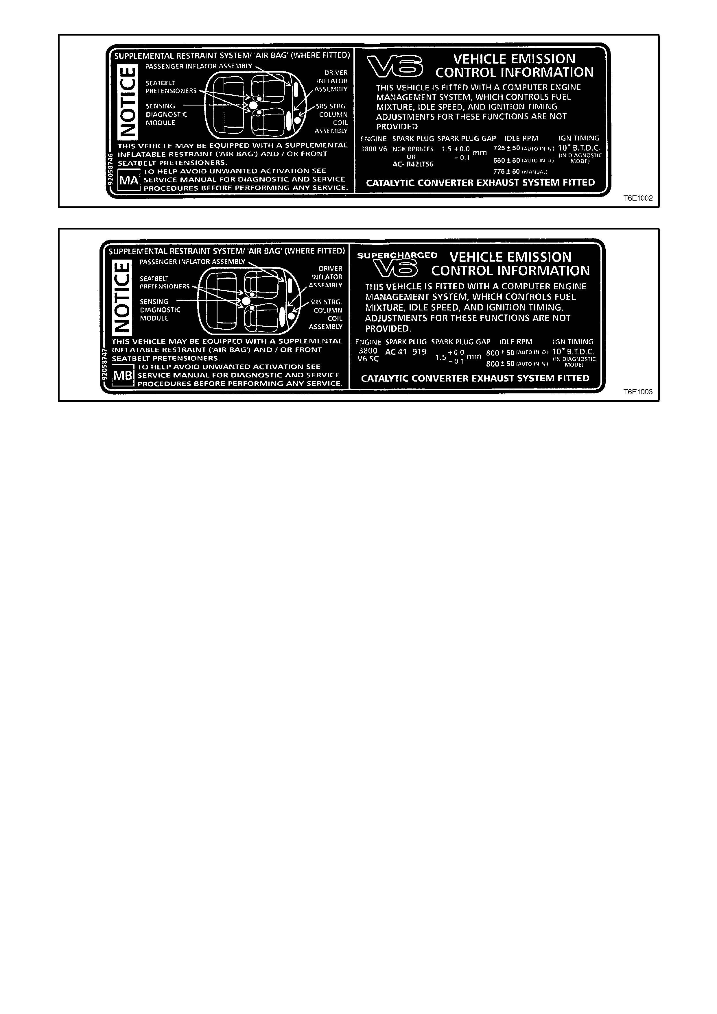
Figure 6E1-2
Figure 6E1-3
The following engine tune recommendations chart sets out the items recommended for attention during an engine
tune and cross reference is provided to the appropriate source of information in the Service Manual.
There is no provision for ignition timing, idle speed and idle mixture adjustments on VT Series Models with a V6
engine, (refer to Section 6C1 POWERTRAIN MANAGEMENT - V6 ENGINE).
The Engine Tune Data Chart provides condensed engine tuning data.
NOTE:
The use of unleaded petrol results in black tail pipe deposits rather than the familiar grey colour. Therefore, the
black colour does not indicate a poor state of engine tune.
2. ENGINE TUNE RECOMMENDATIONS
ENGINE TUNE RECOM MENDATIONS VT SERVICE MANUAL REFERENCE
SECTION
Engine compression Test Section 6A1, ENGINE MECHANICAL.
Also refer to 3.1 TUNING SERVICE
NOTES in this section.
Engine drive belt Check Section 6A1, ENGINE MECHANICAL.
Cooling system Check for leaks Section 6B1, ENGINE COOLING.
Valve lash adjustment Non-adjustable
hydraulic lifters
Idle speed Non-adjustable
Idle mixture Non-adjustable
Air cleaner Check or replace, test
for leaks Section 6C1, POWE RTRAIN
MANAGEMENT - V6 ENGINE.
Fuel filter Check and replace Section 6C1, POWERTRAIN
MANAGEMENT - V6 ENGINE.
Spark plugs Clean, adjust or replace Section 6D1-3, IGNITION SYSTEM.
Spark plug leads Test for continuity Section 6D1-3, IGNITION SYSTEM.
Ignition timing Non-adjustable
Exhaust system Check for excessive
back pressure, general
condition and oxygen
sensor operation
Section 8B1, EXHAUST SYSTEM and
Section 6C1, POWERTRAIN
MANAGEMENT - V6 ENGINE.
Engine ventilation Check Section 6E1, EMISSION CONTROL.
Evaporative emission
control Check lines, hoses and
canister Section 6E1, EMISSION CONTROL.
Battery and cables Check Section 12A, BATTERY AND CABLES.

3. ENGINE TUNI NG DATA
ENGINE TYPE TRANSMISSION IDLE SPEED
ENGINE
WARM (rpm)
IGNITION
TIMING SPARK PLUGS
3.8 LITRE
P.F.I. V6 MANUAL
AUTOMATIC
TRANSMISSION
775 ± 50
725 ± 50
(IN NEUTRAL)
650 ± 50
(IN DRIVE)
10 DEGREES
B.T.D.C. IN
DIAGNOSTIC
MODE
TYPE
BPR6EFS
OR
AC-R42LTS6
GAP (mm)
1.5 + 0.0
– 0.1
3.8 LITRE
P.F.I. V6
SUPERCHARGED
AUTOMATIC
TRANSMISSION 800 ± 50
(IN NEUTRAL)
800 ± 50
(IN DRIVE)
10 DEGREES
B.T.D.C. IN
DIAGNOSTIC
MODE
TYPE
AC41-919 GAP (mm)
1.5 + 0.0
– 0.1
NOTE: Idle speed is controlled by the PCM and varies wi th: - Battery voltage
- Engine temperature
- Air conditioning request
3.1 TUNING SERVICE NOTE S
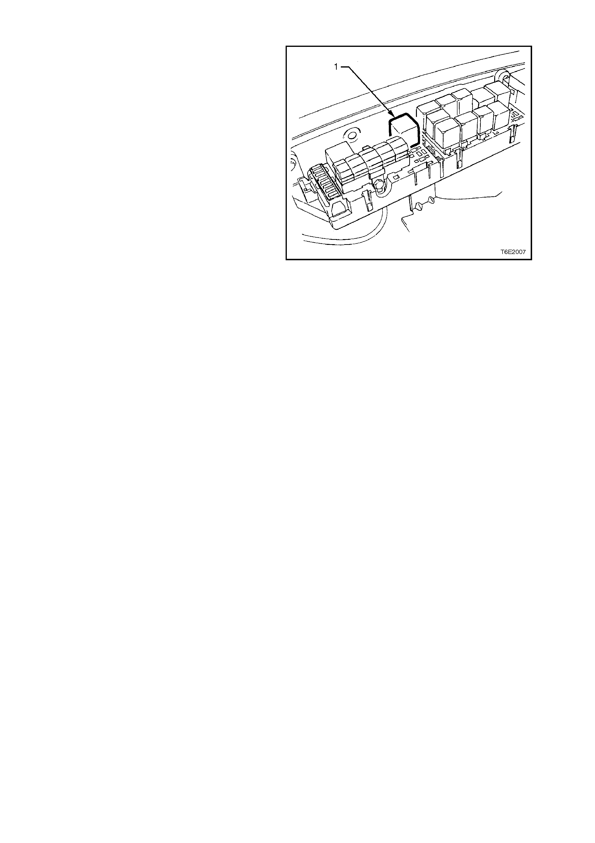
CAUTION:
To prevent both fuel being injected into the
cylinders and ignition during cranking, remove
the EFI relay (1) when performing a
compression test. This will avoid damaging the
catalytic converter with unburned fuel.
For compression testing procedure and
specifications, refer to Section 6A1 ENGINE
MECHANICAL.
1. DO NOT operate the engine with any spark
plugs or spark plug leads disconnected as:
a. Damage to the Ignition System or PCM
may result.
b. The resultant rich mixture could damage
the catalytic converter.
2. Make all engine checks with engine coolant
and oil at normal operating temperatures,
preferably achieved by driving.
3. Ensure that the air conditioner (where fitted) is
switched OFF.
4. Verify that check powertrain light is OFF with
the engine running.
Figure 6F1-4
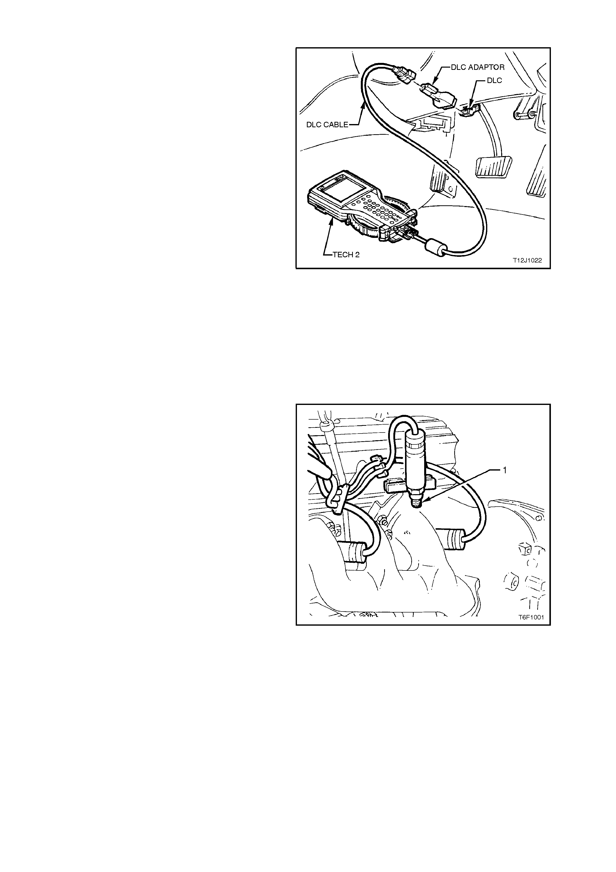
3.2 CYLINDE R BALANCE CHE CK
1. Connect Tech 2 to the Data Link Connector
(refer to Section 0C TECH 2, 1.2
Connections)
2. Select VT Commodore, Engine, Functional
Tests, Power Balance.
3. Perform Power Balance as directed by
TECH 2.
NOTE 1:
RPM readings displayed on tech 2 should be within
50 RPM for all cylinders.
NOTE 2:
Any cylinder that does not cause a drop in engine
idle speed is mis-firing.
Figure 6F1-5
Once the suspect cylinder has been isolated, the
cause of the problem will still need to be
determined. Reasons include fuel, spark or engine
mechanical problems.
The following are a few quick checks to help isolate
the cause of the engine misfire. For additional
diagnostic information refer to Section 6C1
POWERTRAIN MANAGEMENT - V6 ENGINE.
IGNITION
1. Rem ove spark plug lead from plug and engine
harness connector from injector of mis-firing
cylinder.
2. Install Test Plug, Tool No. 7230 (1) and
connect to a good engine earth point.
Failure to properly earth the Test Plug 7230
can result in damage to ignition system
components due to excessive secondary
voltages required to fire the 7230.
NOTE 1:
Avoid placing the Test Plug 7230 near sensors,
modules or other electronic equipm ent that may be
affected by electromagnetic interference.
NOTE 2:
Disconnect plug end of s park plug wire and engine
wiring harness from injector for com panion cylinder
and jumper spark plug wire directly to engine earth.
3. Start and run engine. If tester shows good
spark, check for faulty spark plug.
If weak or no spark, check lead for short to
earth, open or very high resistance.
NOTE:
If any lead is open circuited, recheck coil
secondary resistance, it may have been
damaged by high voltage produced by open
circuit.
Figure 6F1-6
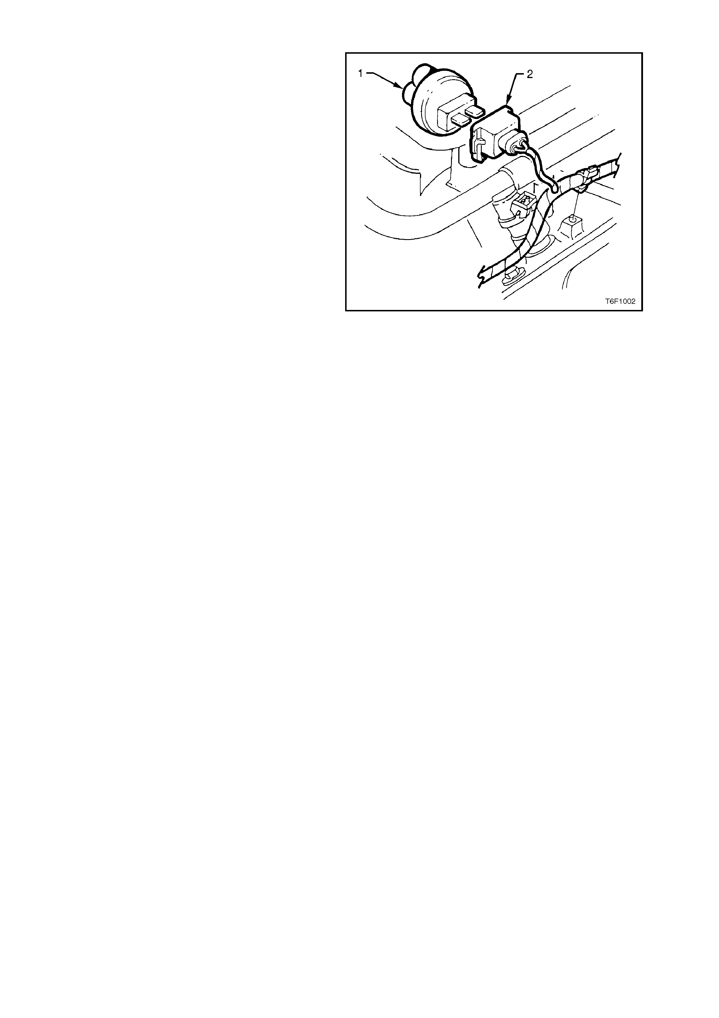
FUEL
1. Disconnect engine harness connector from
injector of cylinder that is mis-firing.
Install injector node light tester (1), Tool No.
BT-8329 into connector (2) and start engine.
2. Check tester for light flashing.
a. No or erratic light flashing, check engine
harness between connector and PCM.
b. Regular flashes, check for blocked or
faulty injector (refer to Section 6C1
POWERTRAIN MANAGEMENT - V6
ENGINE).
Figure 6F1-7
MECHANICAL
Perform compression test as outlined in
Section 6A1 ENGINE MECHANICAL.
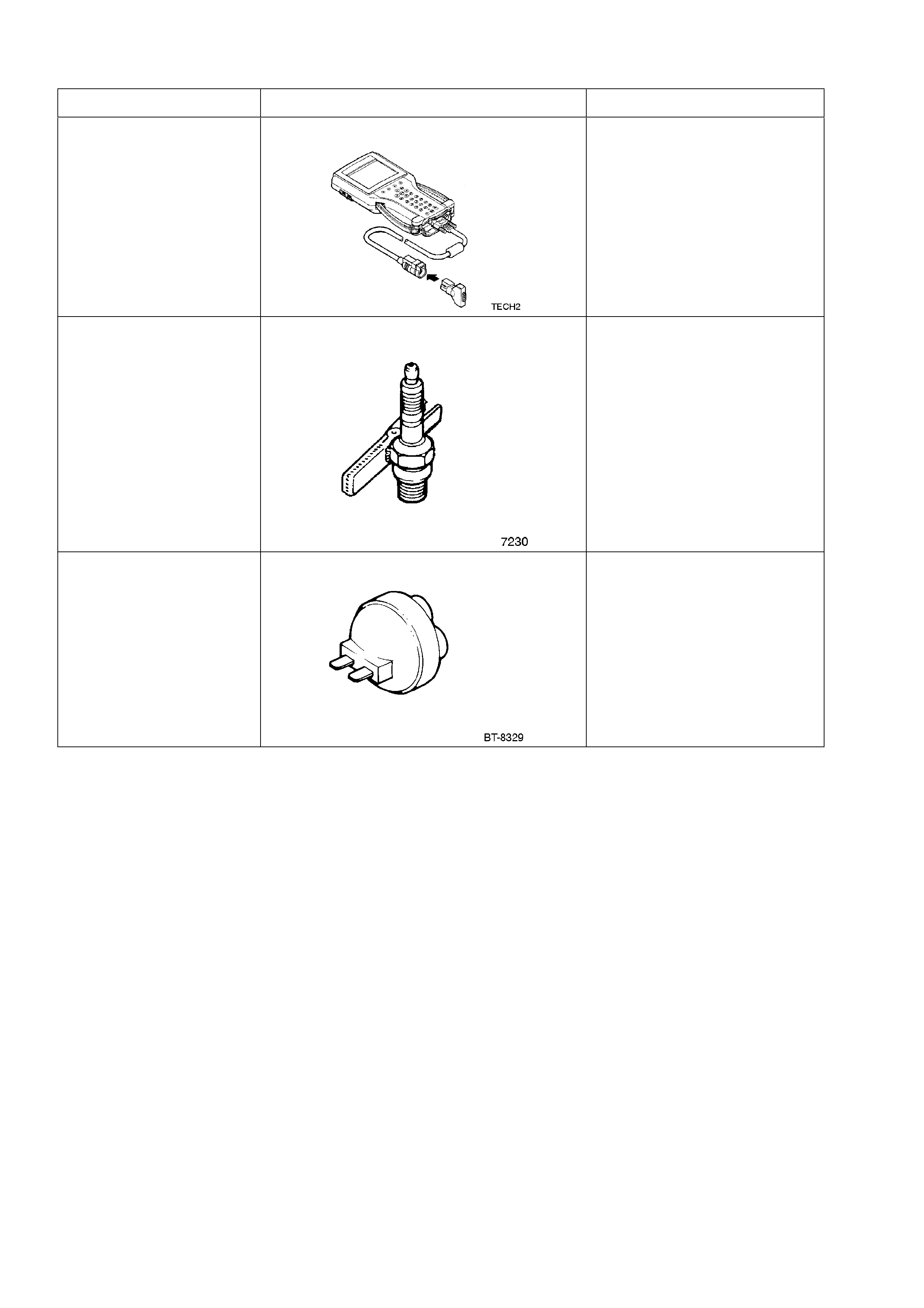
4. SPECIAL TOOLS
TOOL NO. REF IN TEXT TOOL DESCRIPTION COMMENTS
TECH 2 TECH 2 DIAGNOSTIC TOOL PREVIOUSLY RELEASED
FOR ‘T’ AND 'J' CARS.
7230 TEST PLUG PREVIOUSLY RELEASED
FOR 'V' AND 'J' CARS.
BT-8329 INJECTOR NODE LIGHT TESTER PREVIOUSLY RELEASED
FOR 'V' AND 'J' CARS.