
SECTION 7A - CLUTCH
CAUTION:
This vehicle will be equipped with a Supplemental Restraint System (SRS). An SRS
will consist of either seat belt pre-tensioners and a driver's side air bag, or seat belt
pre-tensioners and a driver's and front passenger's side air bags. Refer to
CAUTIONS, Section 12M, before performing any service operation on or around any
SRS components, the steering mechanism or wiring. Failure to follow the CAUTIONS
could result in SRS deplo yment, resulting in possible p ersonal injury or unnecessary
SRS system repairs.
CAUTION:
This vehicle may be equipped with LPG (Liquefied Petroleum Gas. In the interests of
safety, the LPG fuel system should be isolated by turning ‘OFF’ the manual service
valve and then draining the LPG serv ice lines, before any service w ork is carried out
on the vehicle. Refer to the LPG leaflet included with the Owner's Handbook for
details or LPG Section 2 for more specific servicing information.
CAUTION:
Whenever any component that forms part of the ABS or ABS/ETC (if fitted), is
disturbed during Service Operations, it is vital that the complete ABS or ABS/ETC
system is checked, using the procedure as detailed in 4. DIAGNOSIS, ABS or
ABS/ETC FUNCTION CHECK, in Section 12L ABS & A BS/ETC.
1. GENERAL INFORMATION
For use with the Type 260 (V6 engine) manual transmission, an hydraulically controlled, diaphragm spring clutch
pressure plate and dual mass engine flywheel are used. From the start of production of VT Series vehicles, this
clutch and manual transmission are fitted as standard equipment on V6 powered, Executive models and optional on
Berlina.
When the Type 290 manual transmission is fitted to the optional V8 engine, the clutch control is also hydraulic,
working a conventional diaphragm spring clutch pressure plate and a solid engine fly wheel.
Techline
Techline
2. GENERAL DESCRIPTI ON
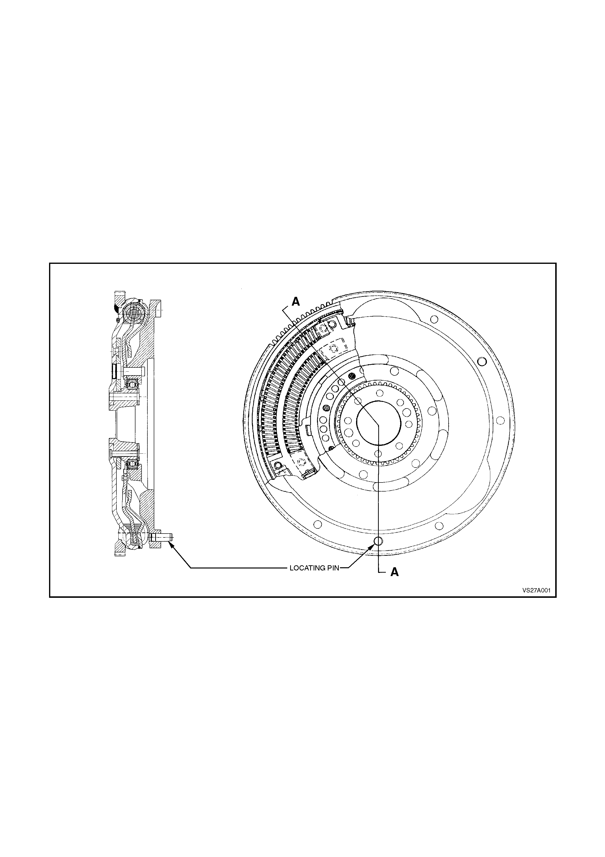
2.1 DUAL MASS FLYWHEEL
V6 ENGINE
Most engine vibrations caused by the igniting fuel air mixture are absorbed by the engine flywheel and clutch
assembly. However, vibrations that are not absorbed, can travel via the transmission bearings, as far as the
propeller shaft and the vehicle body. Using a dual mass flywheel makes it possible for even these secondary
vibrations to be absorbed at that point.
The fly wheel is divided into two parts that are joined radially by springs. The first half is bolted directly to the engine
crankshaft. A torsion damper consisting of springs and dampening friction systems forms the intermediary
components, while the clutch is bolted to the second half of the fly wheel. The single, dry clutch driven plate is no
longer fitted with torque reaction springs.
The effectiveness of the dual mass flywheel is due to the division of the moments of inertia. The moment of inertia
of the flywheel half on the engine side is reduced and correspondingly increased on the transmission side flywheel
half.
As a result of this sy stem, critical vibrations are only discernible at engine speeds below idle speed. This prevents
body noises and allows smooth gear changing, especially at low temperatures.
Figure 7A-1
SERVICE IMPLICATIONS
Re-surfacing of the clutch driven plate surface, is not possible for the following reasons:
1. As both flywheel masses are able to move independently to each other, it is not possible to effectively clamp
the assembly without the possibility of misalignment.
2. A special balancing procedure is followed at manufacture that involves rotating the flywheel to 6,000 rpm for a
minimum amount of time prior to undertaking balancing at normal speeds.
Because the ring gear is welded to the crankshaft side of the flywheel, ring gear replacement is not possible, as re-
welding could cause distortion and possible burning of the grease used to lubricate the springs.
V8 ENGINE
A conventional, solid flywheel is used for V8 powered applications.
2.2 CLUTCH CONTROL
Hydraulic actuation for the clutch has been adopted
for a number of beneficial reasons;
Noise reduction.
Automatic adjustment.
Constant pedal position.
Constant efficiency factor.
Constant pedal path.
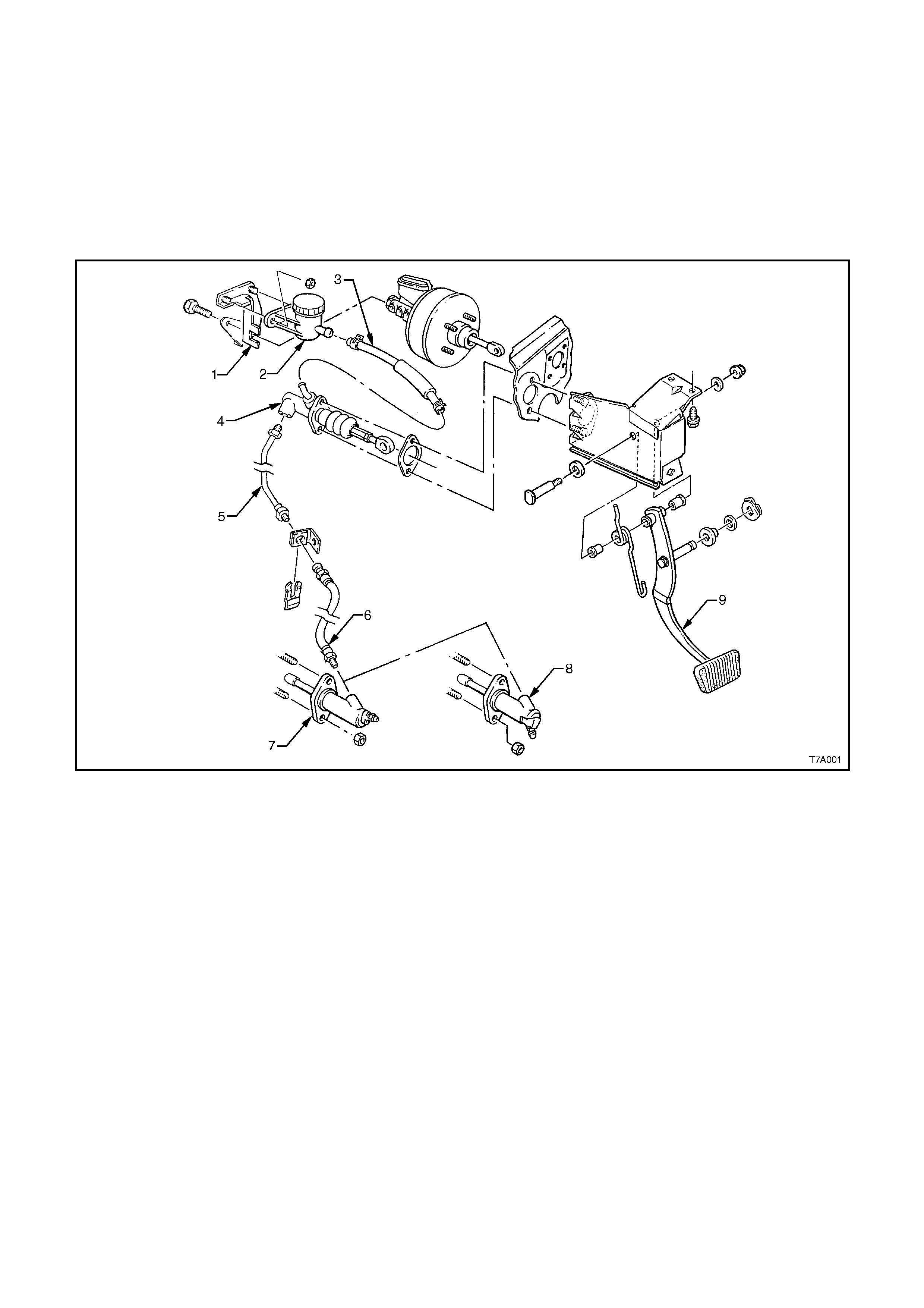
ARRANGEMENT
1. Bracket - Clutch Fluid Reservoir
2. Reservoir - Clutch Fluid
3. Hose - Reservoir to Master Cylinder
4. Master Cylinder
5. Pipe - Master Cylinder to Actuating Cylinder
6. Hose - Pipe to Actuating Cylinder
7. Actuating Cylinder - V8 Engine
8. Actuating Cylinder - V6 Engine
9. Pedal - Clutch
Figure 7A-2 Clutch Control Layout
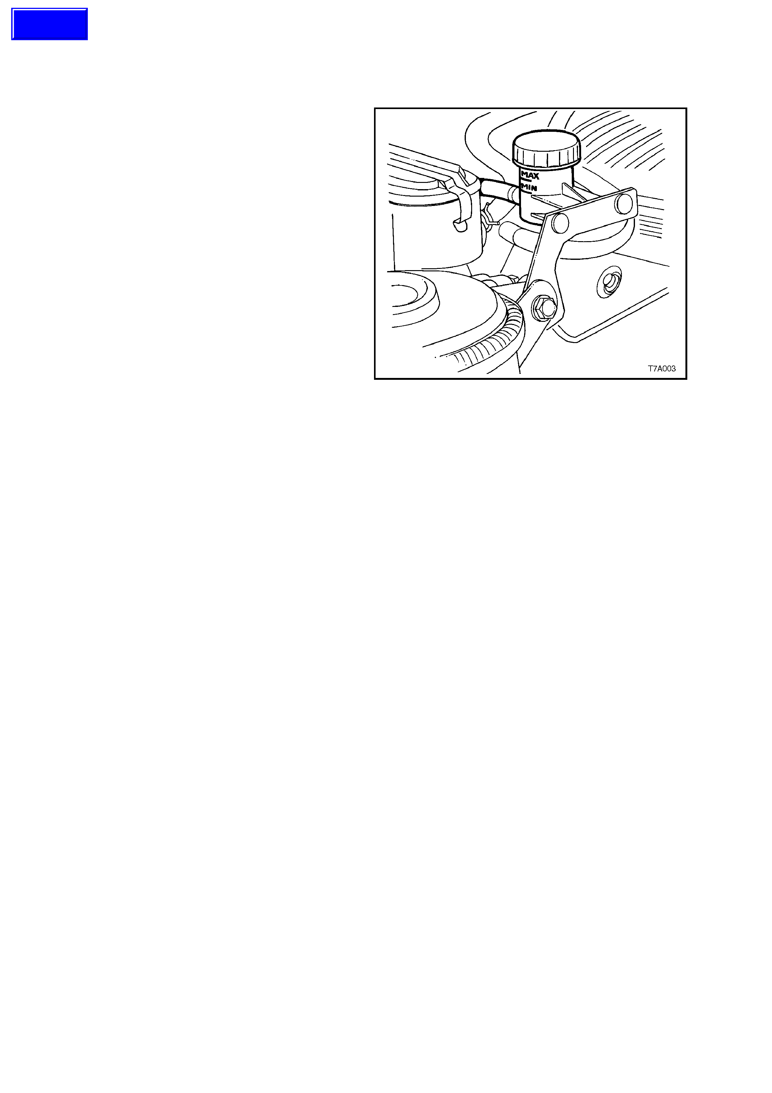
Brake fluid is fed to the clutch master cylinder from a remote reservoir mounted to a bracket, bolted to the end of
the brake master cylinder. A flexible line connects the two components.
The master cylinder is attached to the firewall in the engine compartment.
The clutch pedal is mounted in the clutch/brake pedal support bracket, bolted to the dash panel.
The clutch master cylinder piston is connected to the clutch pedal by an adjustable push rod, that is bushed and
retained by a spring clip.
No clutch adjustments are required. Although the clutch master cylinder push rod does feature an adjustment, it is
only for production purposes and is not to be tampered with, in service.
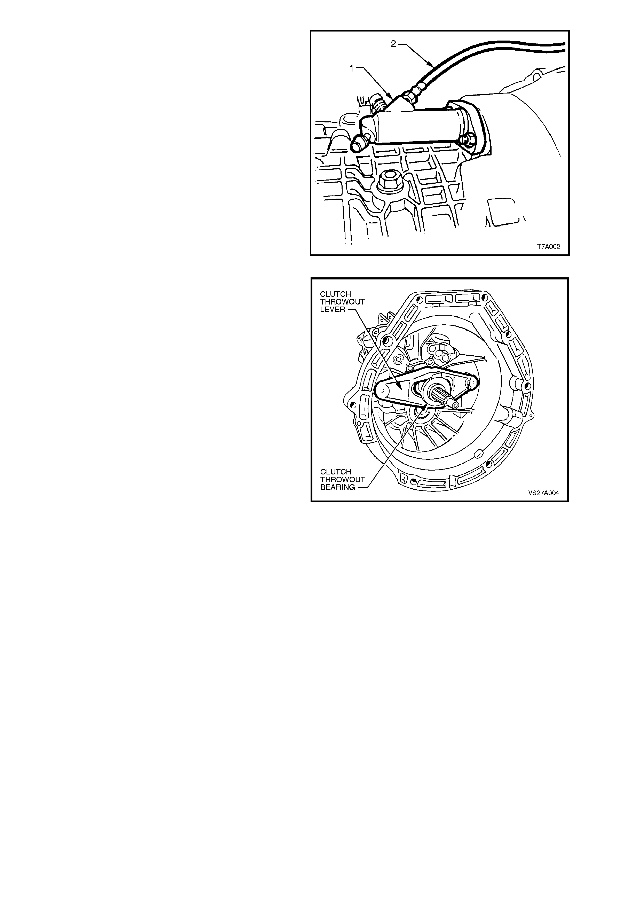
Stroking of the clutch throwout bearing is achieved
by using an hydraulic clutch actuating cylinder (1)
mounted on the r ight hand side of the transm ission
clutch housing.
Hydraulic connection to the master cylinder is by a
flexible hose (2) and steel piping.
The actuating cylinder is fitted with a bleed valve to
assist in removal of air from the hydraulic system.
NOTE:
Apart from the slight change to the actuating
cylinder design used for the V8 application, the
operation is the same as this V6 engined
description.
Figure 7A-3
The c lutch throwout bearing is a sealed-for-life, ball
race type, that is in constant contact with the clutch
pressure plate diaphragm spring.
The throwout bearing is actuated by a pressed
steel clutch throwout lever, that is retained by a
spring clip and pivots at one end, while the stroking
of the clutc h actuating c ylinder piston and pus h rod,
moves it at the other.
NOTE:
While the V6 transmission and clutch release
mechanism is shown, the V8 arrangement is the
same.
Figure 7A-4
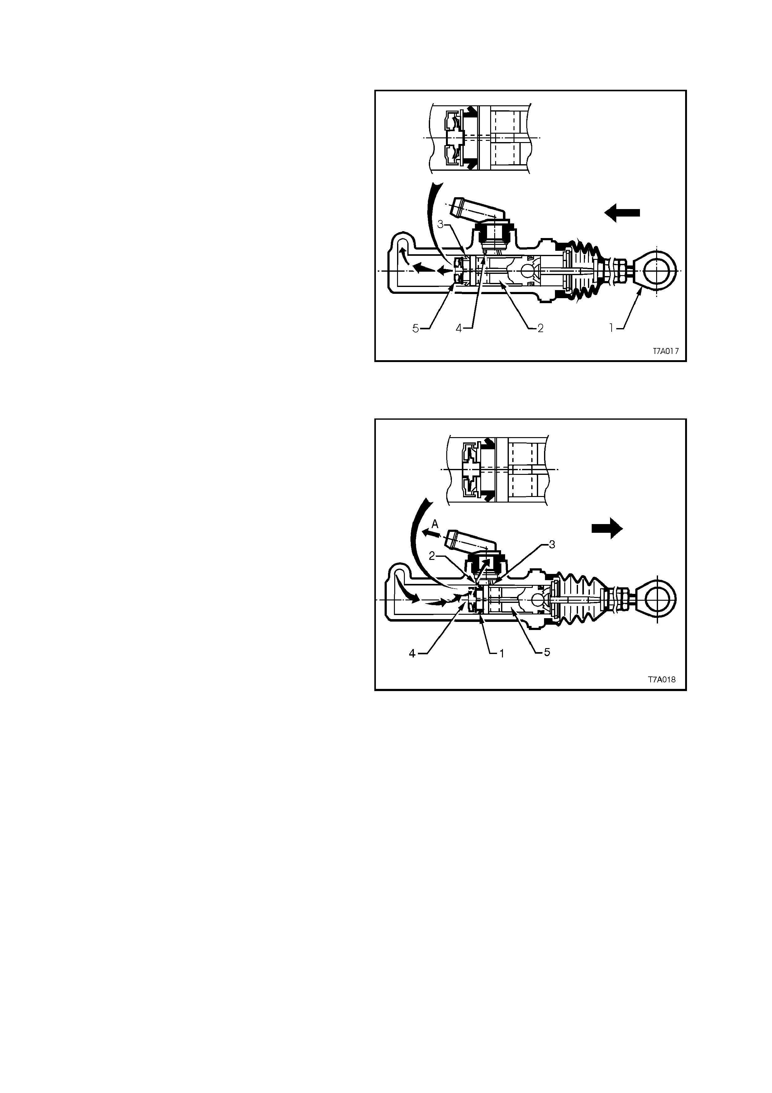
2.3 CLUTCH MASTER CYLINDER/ ACTUATING CYLINDER OPERATION
CLUTCH RELEASED
As the clutch pedal is depressed, force is
transm itted via the clutch pedal push r od (1), to the
clutch master cylinder piston (2), moving it down
the cylinder bore. When the piston starts to move,
the primary seal (3) covers the compensating port
(4) and the res ultant build-up in pr essure, seats the
relief valve (5) in the end of the piston.
As hydraulic pressure develops, the fluid is
displaced and moves the piston in the clutch
actuating cylinder against the return spring and
clutch pressure plate diaphragm spring forces, to
stroke the actuating cylinder push rod. In turn, this
action moves the clutch throwout lever and bearing,
releasing the clutch pressure plate.
Figure 7A-5
CLUTCH APPLIED
As the depressed clutch pedal is raised, the clutch
pressure plate diaphragm spring force moves the
fluid back through hydraulic system, to the master
cylinder. As the clutch pedal is lifted to the point
where the pedal is fully released, the master
cylinder, primary piston seal (1) uncovers the
compensating port (2). Once this occurs, excess,
pressurised fluid (arrows) returns to the fluid
reservoir, via ‘A’.
If the clutch pedal is released very quickly, the
combined forces of the clutch pressure plate
diaphragm spring, the return s pring in the actuating
cylinder and the clutch pedal return spring, return
both the pistons quicker than the fluid can return to
the reservoir through the relatively small
compensating port (2).
This cr eates a partial vac uum c ondition that c auses
atmospheric pressure acting on the reservoir fluid,
to force fluid through the recuperating port (3),
unseating the relief valve (4) in the end of the
master cylinder piston equalising fluid pressure.
Should any excess fluid build up in front of the
master cylinder piston (5), it can then return to the
reservoir via the compensating port (2).
Figure 7A-6
3.2 CLUTCH HYDRAULIC SYSTEM, BLEED
The clutch hydraulic system must be bled
whenever the hydraulic line has been
disconnected, or when a leak has allowed air to
enter the system. Air trapped in the system can
prevent full disengagement of the clutch.
During bleeding operations, the master cylinder
reservoir must be kept at least half full with
hydraulic brake fluid.
1. Carefully clean any dirt from around the
reservoir cap.
2. Remove the filler cap and top up reservoir as
required, with heavy duty hydraulic brake fluid
to Holden’s Specification HN 1796.
3. Slip the end of a bleeder hose (1) over the
bleeder screw (2) on the clutch actuating
cylinder (4) and insert the other end into a
clean glass container such as a jar, that has
been partially filled with new brake fluid. (V6
version is shown - the V8 arrangem ent is very
similar). Ensure that the end of the hose
always remains submerged in the brake fluid
during bleeding operations.
4. Loosen the bleeder screw ½ to ¾ turn.
5. Fully depress the clutch pedal by hand, then
allow it to return slowly. Continue this slow
pumping motion, forcing fluid and air through
the hydraulic system until all bubbles cease to
appear at the end of the bleeder hose.
6. While depressing the pedal, tighten the
bleeder screw, then remove the bleeder hose
from the actuating cylinder bleeder screw.
7. Once all bleeding operations have been
completed, ensure that the fluid level in the
reservoir is correct.
Figure 7A-8
3.3 CLUTCH MASTER CYLINDER
REMOVE
CAUTION:
Disable the SRS (Air Bag). Refer to Section 12M
DISABLING THE SRS.
1. Disconnect the battery earth cable.
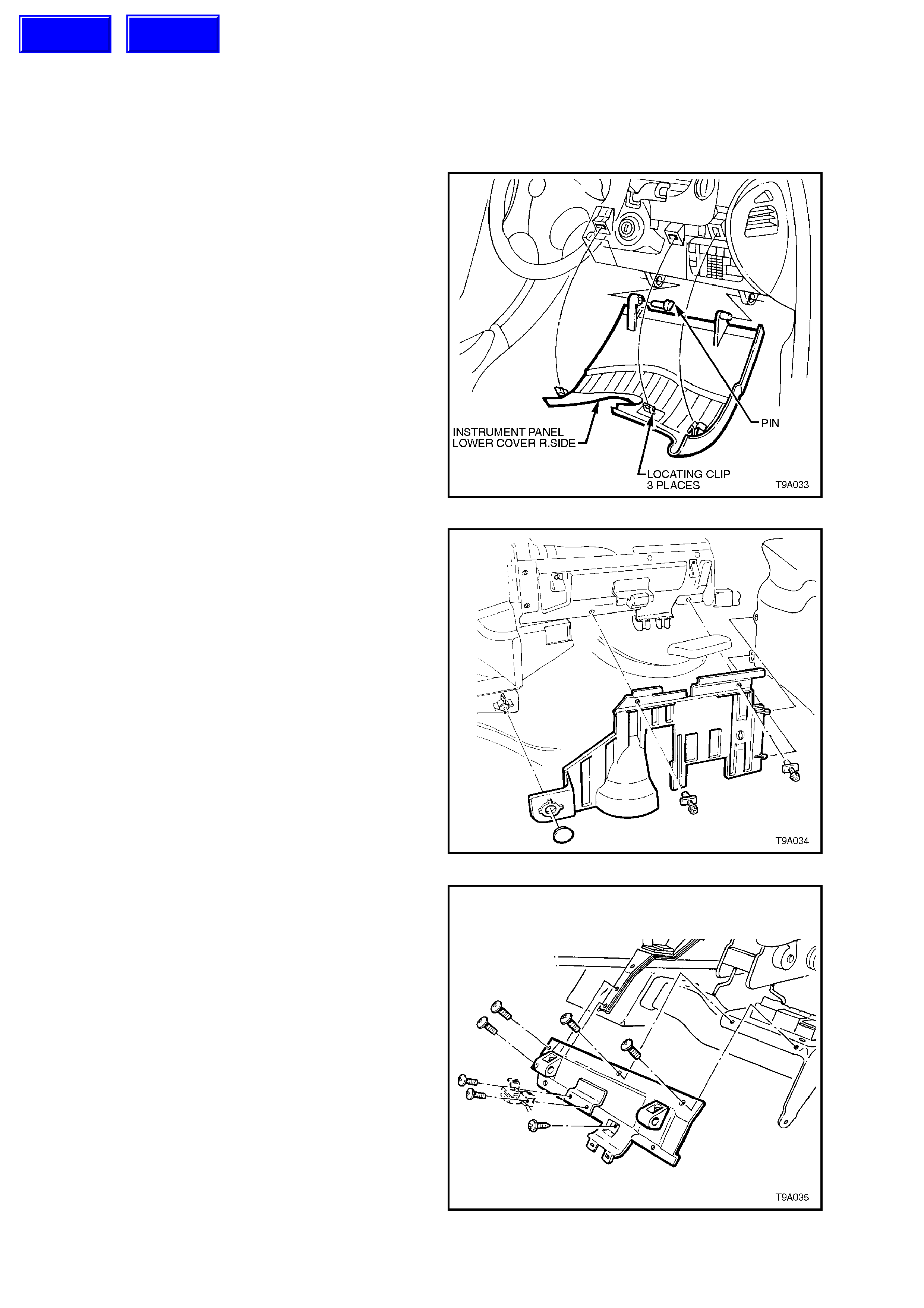
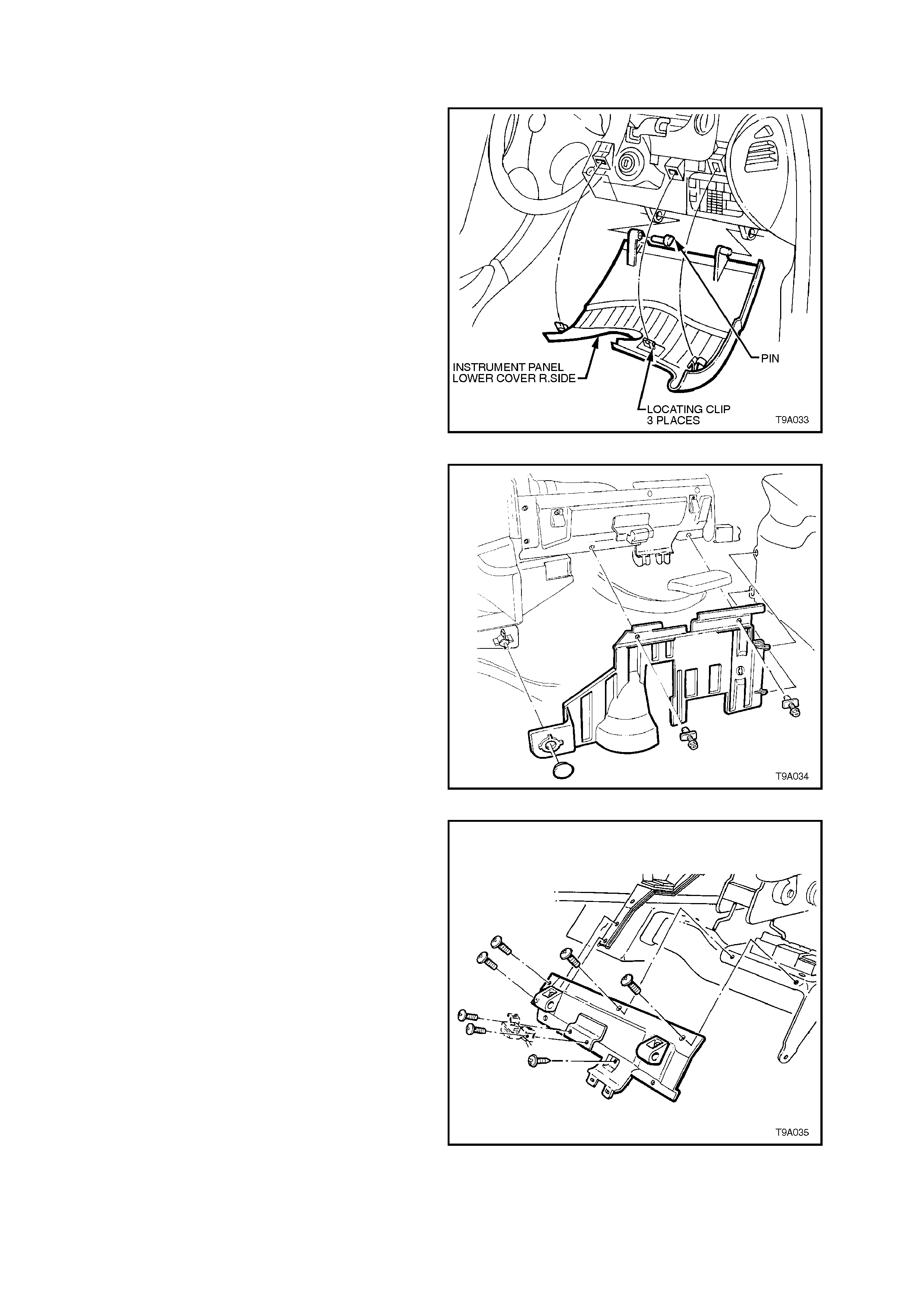
2. From inside the passenger compartment,
rem ove the lower inst rument panel, r ight hand
cover assembly, as follows;
Grasp the top edge of the c oveer on each s ide
of the steering column with the finger tips and
pull outwards, to free the retaining lugs from
the clips.
Prise out the left hand hinge pin with a
screwdriver or similar tool.
Tilt the panel down on the left hand side and
disengage the right hand side hinge pin.
Figure 7A-9
3. Remove the instrument panel lower trim by
removing the two fasteners and retainer.
Lower the panel sufficiently to gain access to
the footwell illum ination lam p holder, then twist
the lamp holder to remove from the trim.
Figure 7A-10
4. Remove screws attaching the fuse and Body
Control Module (BCM) panel to the dash
panel. Leaving the Data Link Connec tor (DLC)
attached to the panel, swing the panel to one
side and secure with tie wire or similar.
Figure 7A-11
Techline
Techline
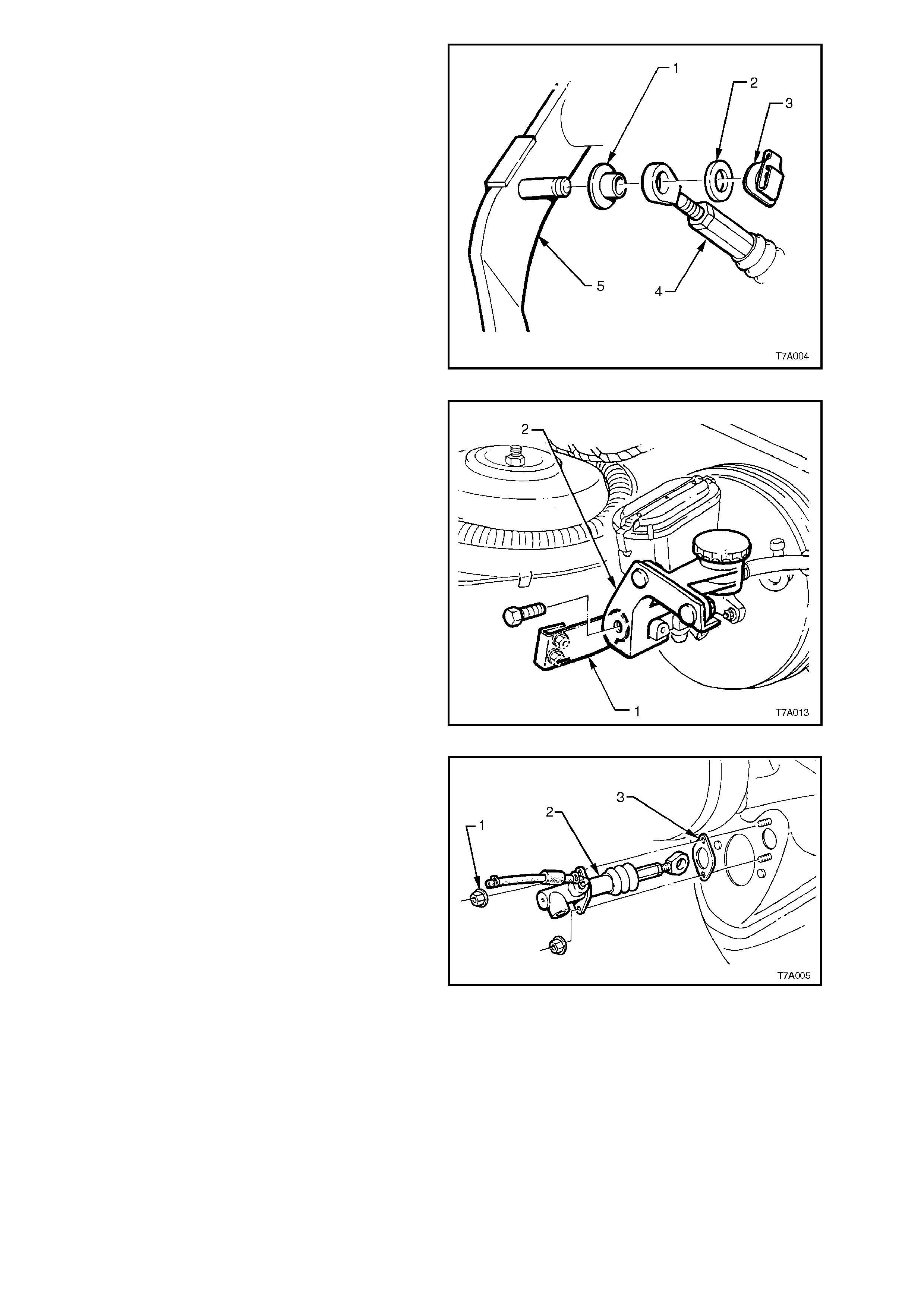
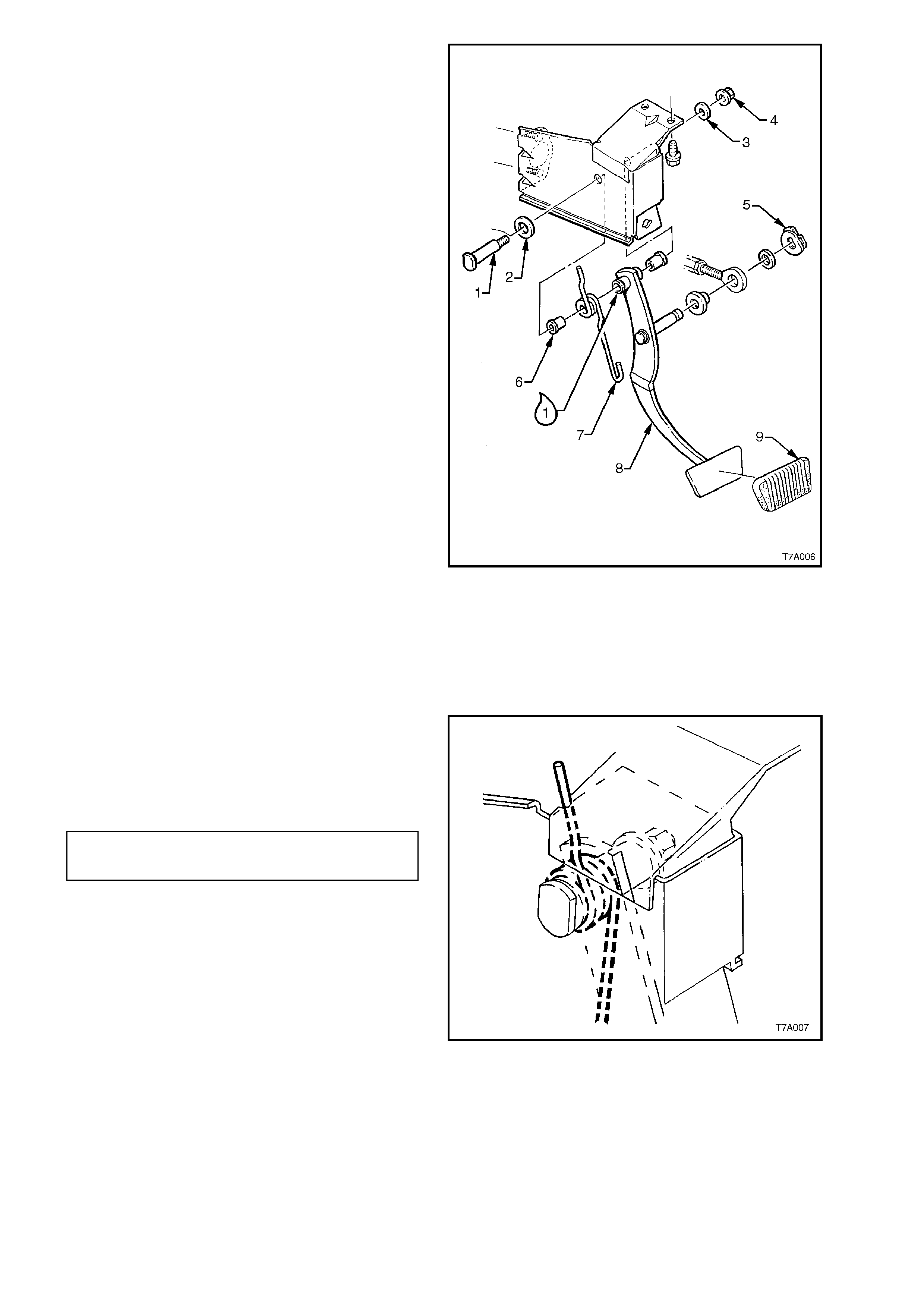
5. Disconnect the clutch master cylinder push
rod by removing the spring clip (3) and metal
washer (2) from pin on the clutch pedal (5).
Disconnect the master cylinder push rod (4)
from the inner bush (1).
Figure 7A-12
6. Remove the clutch master cylinder fluid
reservoir and bracket (2) as an assembly by
removing the bolt from the end of the brake
master cylinder end brace (1). Support the
clutch reservoir to prevent fluid spillage.
Figure 7B2-13
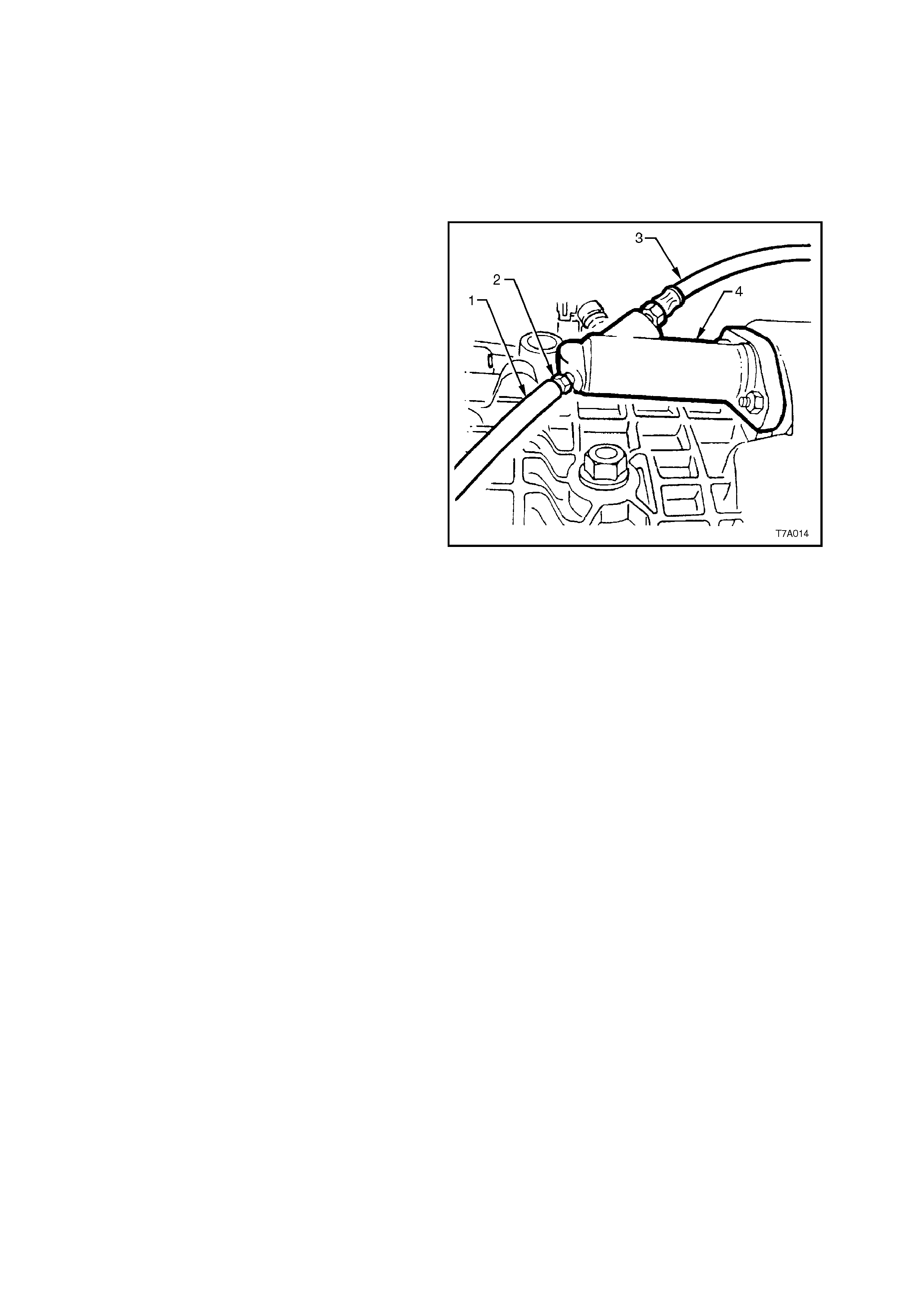
6. Remove the hydraulic steel pipe (not shown)
from the c lutch m aster cylinder, then plug both
the open pipe end and the master cylinder
opening to prevent dirt entry and fluid loss.
7. Remove the two clutch master cylinder
retaining nuts (1) from the engine bay side of
the cockpit module and remove the master
cylinder (2) and reservoir assembly from the
vehicle. Also remove the gasket (3).
Figure 7A-14
DISASSEMBLE
1. Drain the brake fluid from the reservoir into a
suitable container. Discard the collected fluid.
2. Disconnect the flexible hose from the master
cylinder and set to one side, with the reservoir.
3. Remove the boot from the cylinder groove and
pull back over the eyelet shaped end of the
push rod.
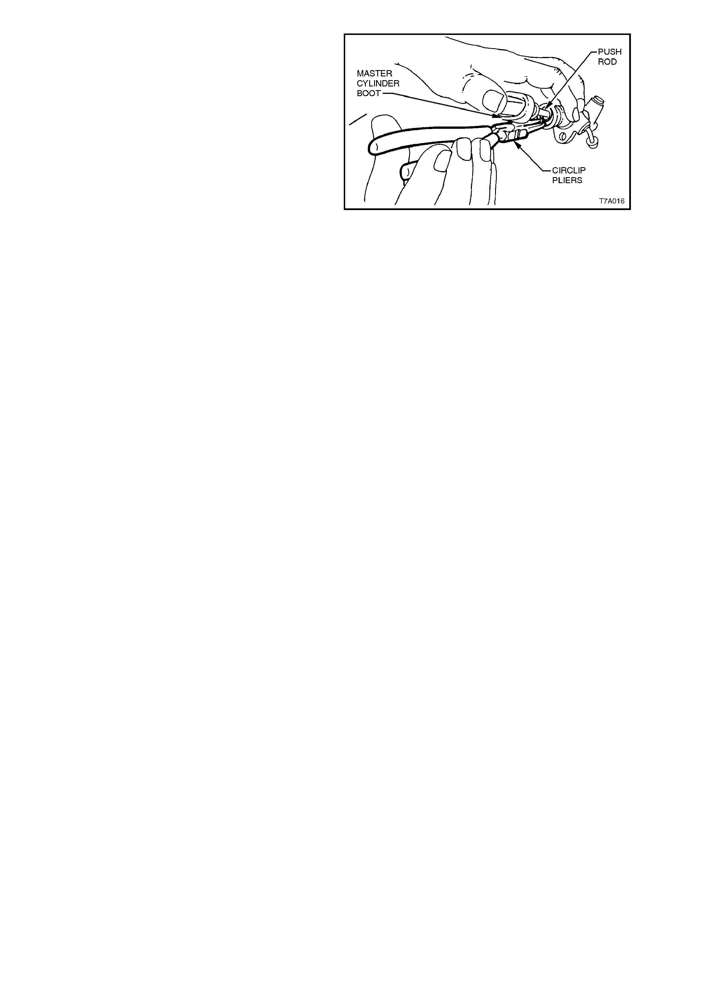
4. Using the master cylinder push rod, depress
the master cylinder piston sufficient to relieve
pressure on the circlip. Then, using suitable
circlip pliers, remove the circlip from the
master cylinder body.
5. As the push rod is secured to the piston,
gently pulling on the push rod will remove the
piston assembly and retaining washer from the
master cylinder bore.
6. As the repair kit supplies all of the removed
components as a complete assembly, no
further dismantling is required.
IMPORTANT:
While the push rod appears to be adjustable, the
push rod length is set by the manufacturer and is
not to be disturbed!
Figure 7A-15
CLEAN AND INSPECT
IMPORTANT: Do not wash hands in petrol or oil
before cleaning or handling master cylinder parts;
always use a soap and water based hand cleaning
product.
Hands m ust be clean bef ore hydraulic c omponents
are handled and washed, as the slightest trace of
mineral based grease or oil in the cylinder or on
components, can cause excessive swelling and/or
destroy rubber based parts.
1. Wash all parts in clean alcohol or methylated
spirits and blow dry with compressed air.
2. Inspect the master cylinder bore for scores,
deep scratches or corrosion. If considered to
be unserviceable, the complete master
cylinder assembly must be replaced.
NOTE:
The master cylinder bore must not be honed.
3. Carefully inspect the piston to ensure that it is
free from burrs and/or sharp edges, which
may cause damage to the master cylinder
wall.
4. Check that the breather c ap ventilation system
on the reservoir is intact and functional.
5. Replace all internal components supplied in
the clutch master cylinder overhaul kit.
REASSEMBLE
1. Dip piston seals and the piston in clean brak e
fluid to Holden’s Specification HN 1796.
2. After lubricating the master cylinder bore with
clean brake fluid to Holden’s Specification HN
1796, install piston, push rod and boot
assembly into the cylinder.
NOTE:
Ensure that neither of the piston seals get caught
or damaged during the installation process.
3. Install the washer (3) and retaining circlip (4).
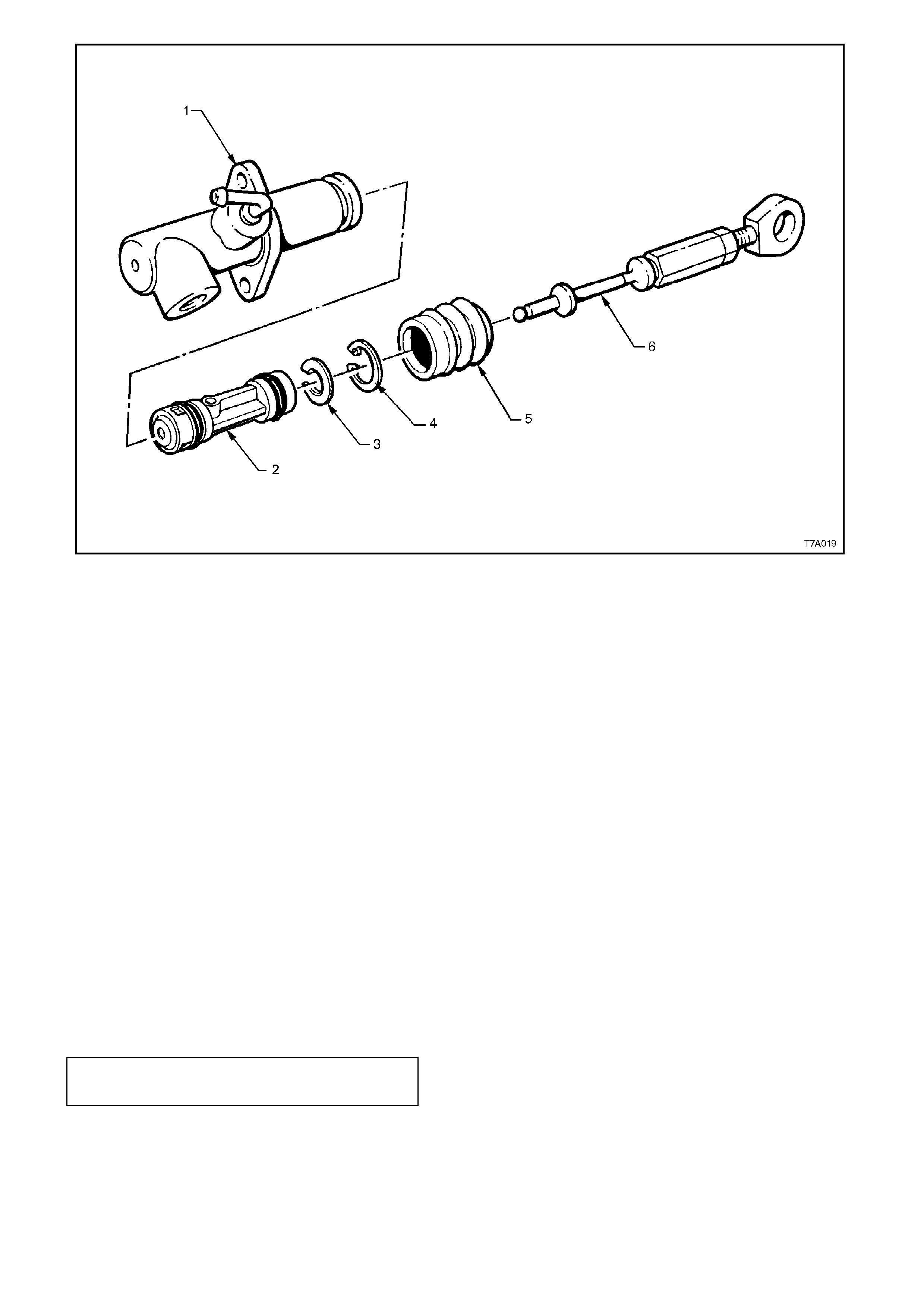
1. Cylinder - Clutch Master
2. Spring - Return
3. Retainer
4. Seal - Primary
5. Washer
6. Piston
7. Seal - Secondary
8. Washer - Retaining
9. Circlip
10. Boot
11. Rod Assembly - Push
Figure 7A-16 - Clutch Master Cylinder
4. Install the flange of the boot (5) over the end
of the master cylinder bore (1), ensuring that
the boot fits completely into the groove
provided.
5. Install master cylinder reservoir hose to the
mas ter cylinder fitting, ensuring that the clam p
is securely tightened.
6. Plug the master cylinder outlet fitting to
prevent the entry of foreign matter into the
cylinder, during installation operations.
REINSTALL
Installation is the reverse of removal operations
except for the following points:
1. Install master cylinder over studs, fit retaining
nuts and washers and tighten to the correct
torque specification.
CLUTCH MASTER CYLINDER NUT 20 - 30
TORQUE SPECIFICATION Nm

2. Install and tighten hydraulic pipe flare nut to
master cylinder to the correct torque
specification.
HYDRAULIC PIPE FLARE NUT
TO CLUTCH MASTER CYLINDER 8 - 11 Nm
TORQUE SPECIFICATION
3. Bleed the clutch hydraulic system, as detailed
in 3.2 CLUTCH HYDRAULIC SYSTEM,
BLEED, in this Section.
4. Following bleeding operations, check that the
hydraulic fluid level is correct, as detailed in
3.1 FLUID LEVEL CHECK, in this Section.
5. Check clutch operation.
IMPORTANT:
Enable the SRS (Air Bag). Refer to Sectio n 12M
ENABLING THE SRS.
3.4 CLUTCH ACTUATING CYLINDER
REMOVE
1. Raise the vehicle and place on safety stands.
Refer to Section 0B GENERAL
INFORMATION for location of jacking points.
NOTE:
The text and illustrations for this Operation can
refer to either the V6 or V8 clutch system, as the
procedure for both, is identical.
2. Place a suitable, clean container under the
clutch actuating cylinder, then disconnect the
hydraulic pipe from the hydraulic hose, at the
bracket attached to the vehicle sub-frame.
Plug the end of the pipe to block the flow of
brak e fluid from the c lutch mas ter cylinder and
reservoir.
Also plug the hose opening to prevent the
entry of foreign matter during removal
operations.
3. Remove the hose retaining clip with
combination pliers and remove the hose from
the bracket.
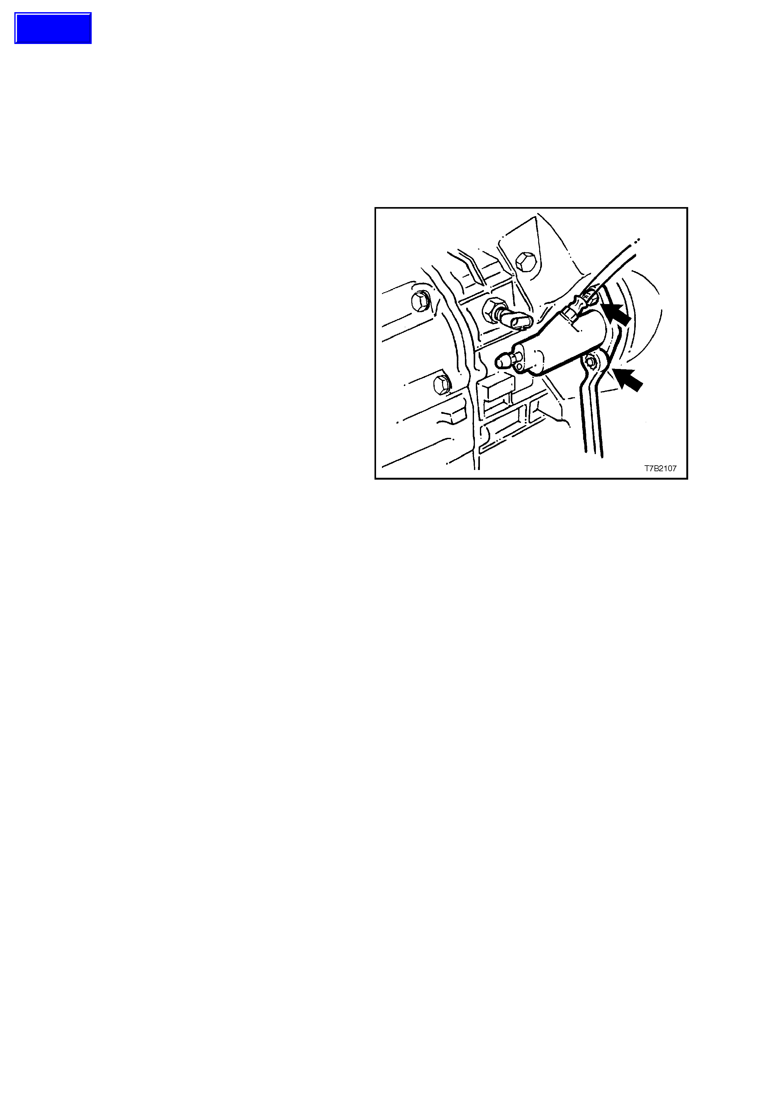
4. Remove the two clutch actuating cylinder
mounting nuts (arrows), then remove cylinder
from the vehicle.
NOTE:
As spring force from the actuating cylinder piston
positioning spring, will push the cylinder out from
the transmission housing, hold the cylinder in,
against this force while removing the mounting
nuts.
Figure 7A-17 - V8 Application
DISASSEMBLE
1. While holding the piston inwards against
spring for ce, prise the retainer from the end of
the actuating cylinder.
2. Release the holding force and remove the
retainer, boot and push rod assembly, piston
and seal, and the spring from the cylinder. It
may be necessary to tap the open end of the
cylinder against a block of wood to dislodge
the piston assembly and spring.
3. Remove the bleeder screw from the cylinder.
4. Prise the seal from the piston and discard.
CLEAN AND INSPECT
IMPORTANT:
Do not wash hands in petrol or oil before cleaning
or handling actuating cylinder parts; always use a
soap and water based hand cleaning product.
Hands m ust be clean bef ore hydraulic com ponents
are handled and washed, as the slightest trace of
mineral based grease or oil in the cylinder or on
components, can cause excessive swelling and/or
destroy rubber based parts.
1. Wash all parts in clean alcohol or methylated
spirits and blow dry with compressed air.
2. Inspect the actuating cylinder bore for scores,
deep scratches or corrosion. If considered to
be unserviceable, the complete cylinder
assembly must be replaced.
Techline
NOTE:
The actuating cylinder bore must not be honed.
3. Carefully inspect the piston to ensure that it is
free from burrs and/or sharp edges, which
may cause damage to the cylinder wall.
4. Check that the bleeder screw thread is
undamaged and that the drilled passage is
clear of debris.
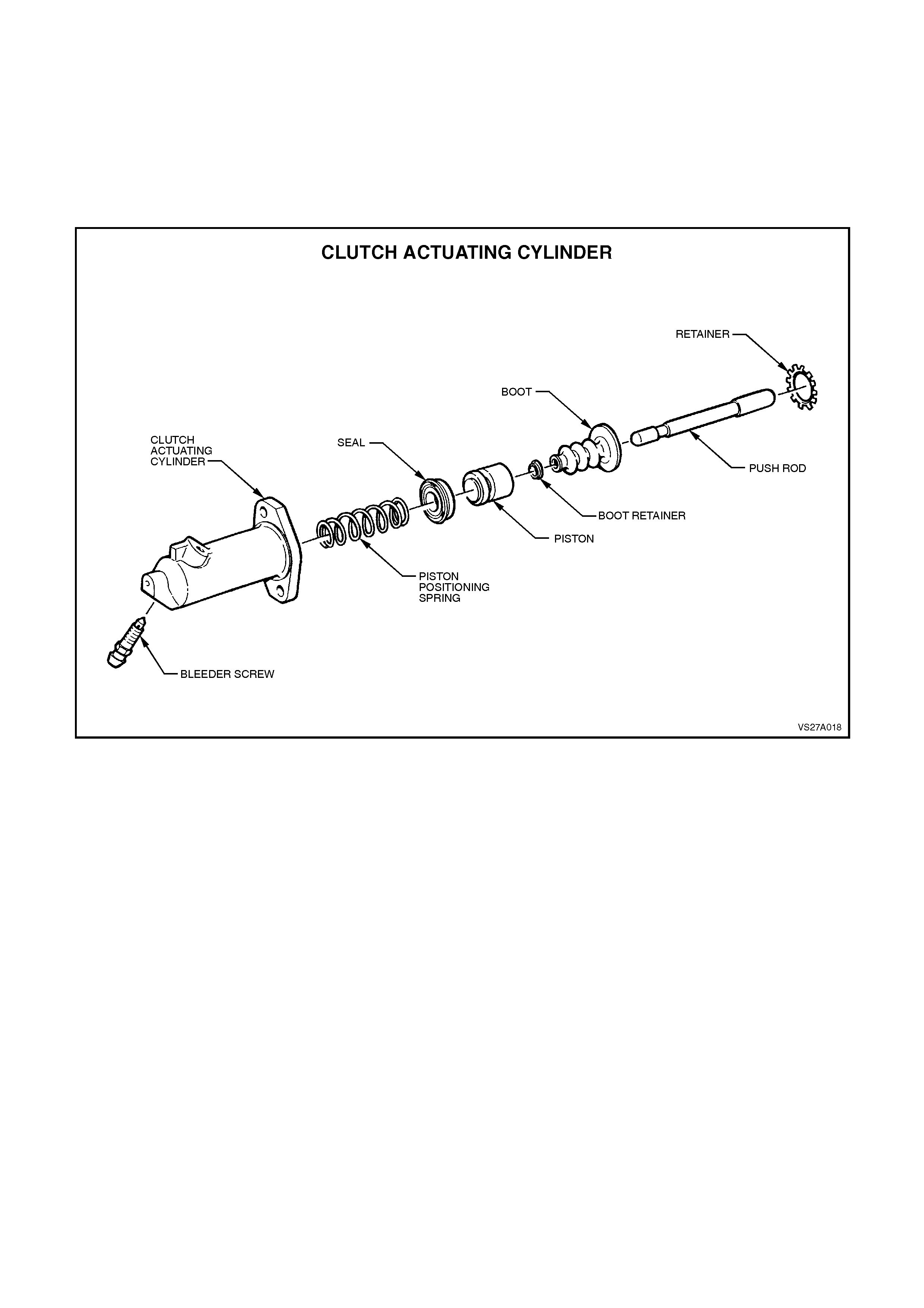
5. Replace all rubber seals and the dust boot.
Figure 7A-18 - Clutch Actuating Cylinder - V6 Engine
REASSEMBLE
1. Dip piston seal and the piston in clean brake
fluid to Holden’s Specification HN 1796, then
install seal over piston land, with the lip facing
away from the push rod end.
2. After lubricating the actuating cylinder bore
with clean brake f luid to Holden’s Spec if ic ation
HN 1796, install the spring and piston
assembly into the cylinder.
3. Install the push rod, boot and retaining
washer, into the cylinder.
4. Using a suitable sleeve such as a deep
socket, install a new retainer into the end of
the cylinder.
5. Install the bleeder screw and tighten finger
tight only, at this time.
6. Plug the actuating cylinder outlet fitting to
prevent the entry of foreign matter into the
cylinder, during installation operations.
REINSTALL
Installation is the reverse of removal operations
except for the following points:

1. Install hydraulic hose to clutch actuating
cylinder and tighten to the correct torque
specification.
HYDRAULIC HOSE TO CLUTCH
ACTUATING CYLINDER 10 - 12 Nm
TORQUE SPECIFICATION
2. Install actuating cylinder over the housing
studs and fit retaining nuts and washers.
NOTE:
During installation, ensure that the actuating
cylinder push rod is correctly located in the clutch
lever. If installed out of position, the push rod and
piston will be pumped out of the cylinder during
bleeding operations, damaging the piston seal.
3. Tighten fasteners to the correct torque
specification.
CLUTCH ACTUATING CYLINDER 20 - 25
NUT TORQUE SPECIFICATION Nm
4. Install and tighten hydraulic pipe flare nut to
actuating cylinder to the correct torque
specification.
HYDRAULIC PIPE FLARE NUT TO
FLEXIBLE HOSE 12 - 14 Nm
TORQUE SPECIFICATION
5. Bleed the clutch hydraulic system, as detailed
in 3.2 CLUTCH HYDRAULIC SYSTEM,
BLEED, in this Section.
6. Following bleeding operations, check that the
hydraulic fluid level is correct, as detailed in
3.1 FLUID LEVEL CHECK, in this Section.
7. Lower vehicle and road test vehicle, to check
clutch operation.
3.5 CLUTCH P EDAL
REMOVE
CAUTION:
Disable the SRS (Air Bag). Refer to Section
12M DISABLING THE SRS.
1. Disconnect the battery earth cable.
2. From inside the passenger compartment,
remove the lower the instrument panel, right
hand cover assembly, as follows;
Grasp the top edge of the cover on each side
of the steering column with the finger tips and
pull outwards, to free the retaining lugs from
the clips.
Prise out the left hand hinge pin with a
screwdriver or similar tool.
Tilt the panel down on the left hand side and
disengage the right hand side hinge pin.
Figure 7A-19
3. Remove the instrument panel lower trim by
removing the two fasteners and retainer.
Lower the panel sufficient to gain access to
the footwell illum ination lam p holder, then twist
the lamp holder to remove from the trim.
Figure 7A-20
4. Remove screws attaching the fuse and Body
Control Module (BCM) panel to the dash
panel. Leaving the Data Link Connec tor (DLC)
attached to the panel, swing the panel to one
side and secure with tie wire or similar.
Figure 7A-21
6. Remove the clutch master cylinder push rod
retaining clip (5) and washer from the clutch
pedal pin.
7. Release the end of return spring (7) from
clutch pedal (8) end.
8. Remove clutch pedal pivot retaining nut (4),
washer (3) and pivot bolt (1) and washer (2).
9. Remove the clutch pedal (8) assembly and
spring (7) from the support bracket.
10. Remove return spring (7) and the two bushes
(6) from pedal (8).
Figure 7A-22
REINSTALL
1. Install two pedal bushes into pedal pivot bore.
2. Lubricate bearing surfaces as indicated in
Figure 7A-22 with Molybdenum Disulphide
grease (Holden's Specification HN 1271).
3. Assemble clutch pedal return spring to clutch
pedal, then install pedal to clutch/brake pedal
support.
4. Install clutch pedal pivot bolt (1) and washers
(2 and 3). Install and tighten nut (4) to the
correct torque specification.
CLUTCH PEDAL PIVOT BOLT 12 - 16
TORQUE SPECIFICATION Nm
5. When the return spring is ins talled to the pedal
pin, the upper end will be positioned as shown.
5. Install clutch master cylinder push rod to the
pedal pin, ensuring that the ‘eye’ indexes over
the stepped bush. Install the outer washer and
secure with the clip.
6. Reinstall all removed instrument panel
components in the reverse to removal
operations.
7. Road test vehicle to check clutch operation. Figure 7A-23
IMPORTANT:
Enable the SRS (Air Bag). Refer to Section
12M ENABLING THE SRS.
3.6 CLUTCH DRIVEN P LATE, PRESSURE PLATE AND/OR THROWOUT BE ARING
REMOVE
CAUTION:
Disable the SRS (Air Bag). Refer to Section
12M DISABLING THE SRS.
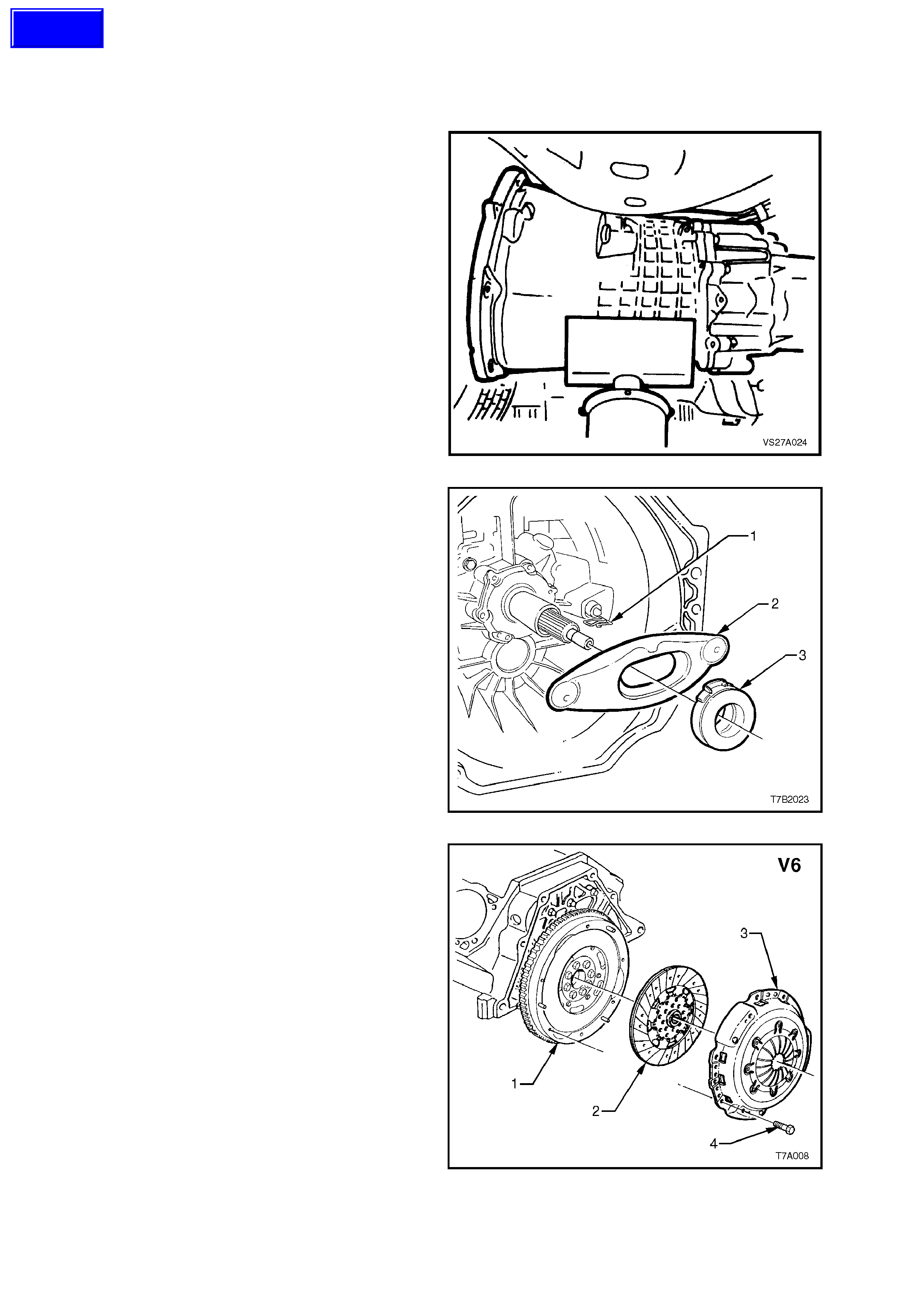
1. Remove transmission assembly. Refer to
7B1 MANUAL TRANSMISSION - V6 ENG INE
or
7B2 MANUAL TRANSMISSION - V8 ENGINE
Figure 7A-24
2. Release the clutch throwout lever (2) from the
retaining wire clip (1), then remove the lever
and bearing assembly (3) from the
transmission housing.
Figure 7A-25
3. Mark the relationship of the clutch pressure
plate to the flywheel, to maintain the correct
balance condition on reassembly.
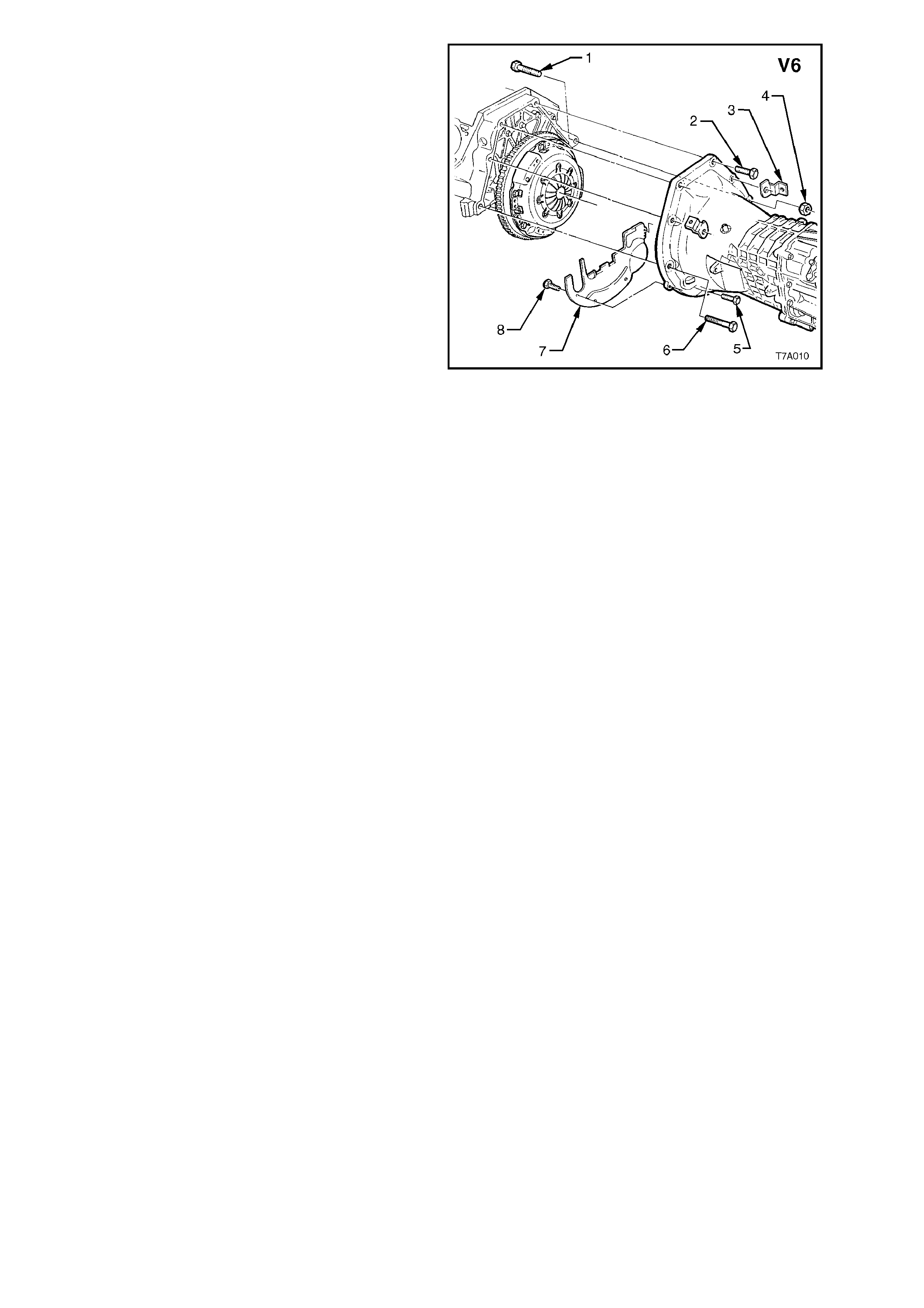
4. Initially loosen all press ure plate re taining bolts
(4), working from opposite sides, to avoid
distortion of the cover (3).
5. Continue loosening bolts from opposite sides,
until all are rem oved, then lift the c lutch driven
plate (2) and pressure plate (3) assemblies
from the flywheel (1).
Figure 7A-26
Techline

INSPECT
1. W ipe press ure plate and flywheel surfac es clean using a sof t cloth dampened with a suitable cleaning s olvent
(do not use petroleum based products).
NOTE 1:
Do not wash the pressure plate assembly - blow dust out with compressed air after fitting a suitable protective
breathing filter.
NOTE 2:
Do not soak the throw out bearing in cleaning solvent as this will destroy the bearing lubricant.
2. Inspect maindrive gear shaft spigot bush for wear. If necessary, replace the bush as outlined in this Section.
NOTE:
Do not remove the bush unless inspection reveals that it is unserviceable.
3. Inspect clutch lever pivot socket and stud for wear. Replace as required. Check lever retaining spring for
damage or distortion. Spring tension should be sufficient to hold lever in position on the stud. Check clutch
lever for cracks or wear.
4. Check throwout bearing for roughness of operation or signs of wear. Replace if necessary.
Examine bearing hub bore for burrs. Any burrs should be removed. If burrs are found, inspect transmission
maindr ive gear bearing r etainer f or s c oring. If s c oring is s light, remove us ing f ine emery cloth. Replace r etainer
if scoring is excessive, refer Section 7B1 MANUAL TRANSMISSION - V6 ENGINE or
7B2 MANUAL TRANSMISSION - V8 ENGINE .
5. Inspect flywheel and clutch pressure plate friction surfaces for burn marks scoring or roughness. Slight
roughness may be smoothed with fine emery cloth.
Scoring of flywheel or pressure plate surfaces will necessitate replacement of damaged component/s.
6. Inspect clutch driven plate for lining wear or other damage.
Examine clutch driven plate linings for oil or fluid contamination.
NOTE:
If oil or fluid is found on the clutch linings, locate and correct the cause of the leak before proceeding with the clutch
repairs.
7. If installing the clutch driven plate, check clutch hub for a free sliding fit on maindrive gear clutch shaft splines.
REINSTALL
1. Lubricate crankshaft spigot bush with a small amount of SAE 90 Gear Oil.
2. Assemble clutch driven plate, together with cover and pressure plate assembly and insert a suitable clutch
centring tool into spigot bearing, through driven plate.
IMPORTANT:
The V6 clutch driven plate is installed with the offset end of the splined hub facing forward. The word “Getriebeseite”
(Gearbox Side) is also stamped on the inner surface on the short hub side. However, the V8 clutch driven plate is
installed with the offset end of the splined hub facing rearwards towards the gearbox. This clutch driven plate has
“Engine Side” stamped on the appropriate side of the plate.
3. Line up marks on pressure plate cover and flywheel, made during disassembly, and install pressure plate over
the locating dowel pins. Loosely install pressure plate to flyw heel bolts.
FOR V6 ENGINED APPLICATIONS:
4. Install the bracket of Tool AKM-632-A, to the
top two gearbox mounting holes, using two of
the gearbox bolts, each with a nut and a flat
washer.
NOTE:
The thread for the nut is 12 mm x 1.75 pitch.
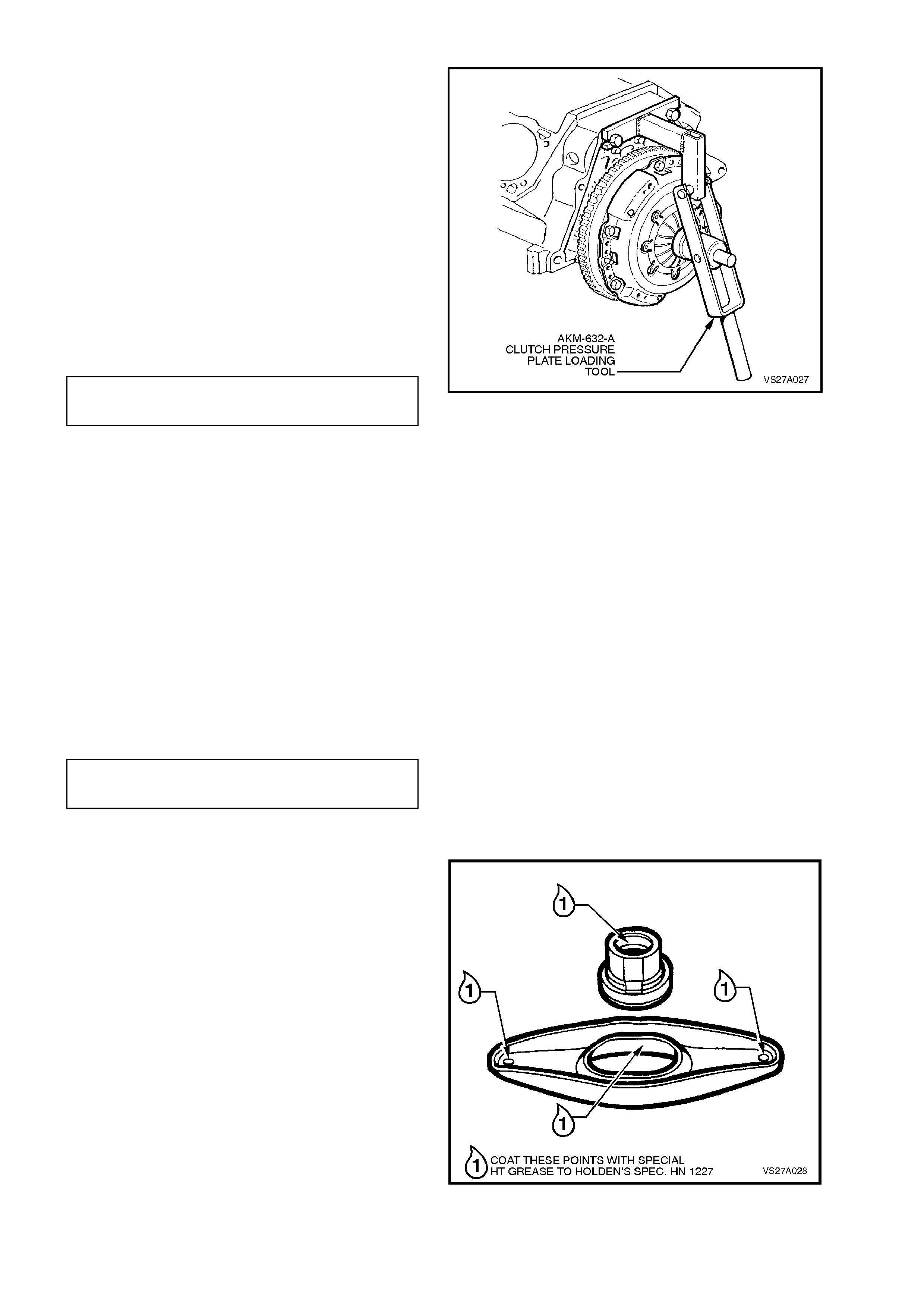
5. Hook the arm of Tool AKM-632-A under the
lugs of the bracket as shown, and apply force
to the arm, depressing the pressure plate by
18 mm, fully releasing the clamping force on
the driven plate.
6. W ith the pr essure plate loaded in this m anner,
tighten the pressure plate bolts to the correct
torque specification, working from opposite
sides.
CLUTCH PRESSURE PLATE BOLT 28 - 35
(V6 ) TORQUE SPECIFICATION Nm
IMPORTANT:
It is critical that the loading tool is used to depress
the pressure plate diaphragm spring, while the
bolts are tightened. If not used, then the pressure
plate cover will be distorted, resulting in an uneven
force being applied to the driven plate and the bolt
torque figures will also be inadequate.
7. Release the force on the lever of Tool AKM-
632-A, when all bolts have been tightened to
the correct specification. Remove Tool
AKM632-A and the bracket.
FOR V8 ENGINED APPLICATIONS:
8. W orking from opposite sides gradually tighten
the pressure plate cover bolts, until the c orrect
torque specification is attained.
CLUTCH PRESSURE PLATE BOLT 41 - 47
(V8) TORQUE SPECIFICATION Nm
ALL APPLICATIONS:
Figure 7A-27
9. Remove the clutch plate centring tool.
10. Lubricate the clutch throwout lever at each of
the points indicated, using special HT Grease
to Holden’s Specification HN 1227.
Use the same lubricant and apply it to the
groove on the inner surface of the throwout
bearing sleeve as shown.
DO NOT OVER-LUBRICATE!
11. Assemble the clutch throwout bearing to the
sleeve, then install the lever and bear ing to the
throwout bearing guide in the transmission.
Secure the pivot end of the lever with the wire
clip and push the actuating cylinder end
inwards, to secure the position of the bearing
to the lever.
Figure 7A-28
12. Reinstall the transm ission assem bly. Refer to
Section 7B1 MANUAL TRANSMISSION, V6
ENGINE or
Section 7B2 MANUAL TRANSMISSION, V8
ENGINE.
NOTE:
When installing the transmission, do not allow it to
‘hang’ on the maindrive gear splines, as the clutch
driven plate will be damaged.
13. Start engine, and check for exhaust leaks
before road testing the vehicle for satisfactory
clutch operation.
IMPORTANT:
Enable the SRS (Air Bag). Refer to Sect ion 12M
ENABLING THE SRS.
Figure 7A-29
3.7 DUAL MASS FLYWHEEL (V6 ENGINED APPLICATIONS ONLY)
CAUTION:
Disable the SRS (Air Bag). Refer to Section
12M DISABLING THE SRS.
NOTE:
Normally this operation would be included with
engine mechanical items (V6 Engine, 6A1) but, as
this component forms an integral part of the clutch
assembly and the driveline, it has also been
included in this Section.
REMOVE
1. Disconnect battery earth lead.
2. Remove manual transmission and the clutch
assembly, refer to 3.6 CLUTCH DRIVEN
PLATE, PRESSURE PLATE AND/OR
THROWOUT BEARING in this Section and
7B, MANUAL TRANSMISSION - V6 ENGINE.
3. Remove the starter motor. Refer
6D1-2 STARTING SYSTEM - V6 ENGINE.
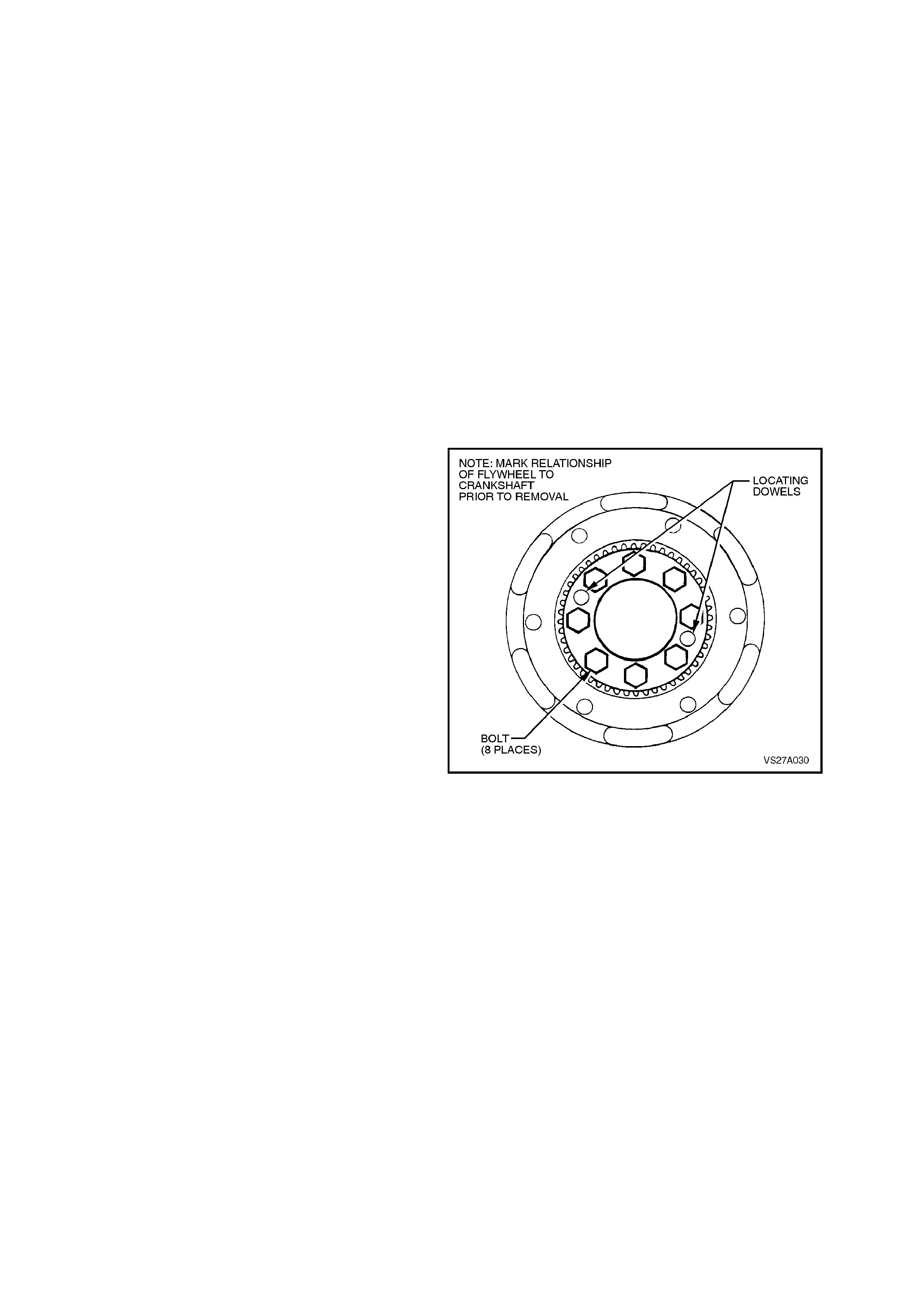
4. To maintain balance conditions, mark the
relative position of the flywheel to the engine
crankshaft.
5. Using a screwdriver or suitable holding tool,
lock the flywheel from turning, while loosening
the eight fastening bolts, working gradually
from opposite sides. Remove flywheel from
the engine crankshaft.
NOTE:
Discard all flywheel attaching bolts once removed,
as new bolts must be used on reassembly.
Figure 7A-30
INSPECT
1. Inspect f lywheel ring gear for crac k s and badly
worn or damaged teeth.
NOTE 1:
If any condition renders the ring gear
unserviceable, the complete dual mass flywheel
MUST be replaced.
NOTE 2:
If ring gear tooth damage is found, the starter
motor pinion gear teeth must also be checked for
damage.
2. Inspect the clutc h driven plate face of the dual
mass flywheel for scoring or excessive heat
damage. W hile som e evidence of heat cracks
can be ignored, should the surface be
considered unserviceable, then the flywheel
MUST be replaced as an assembly .
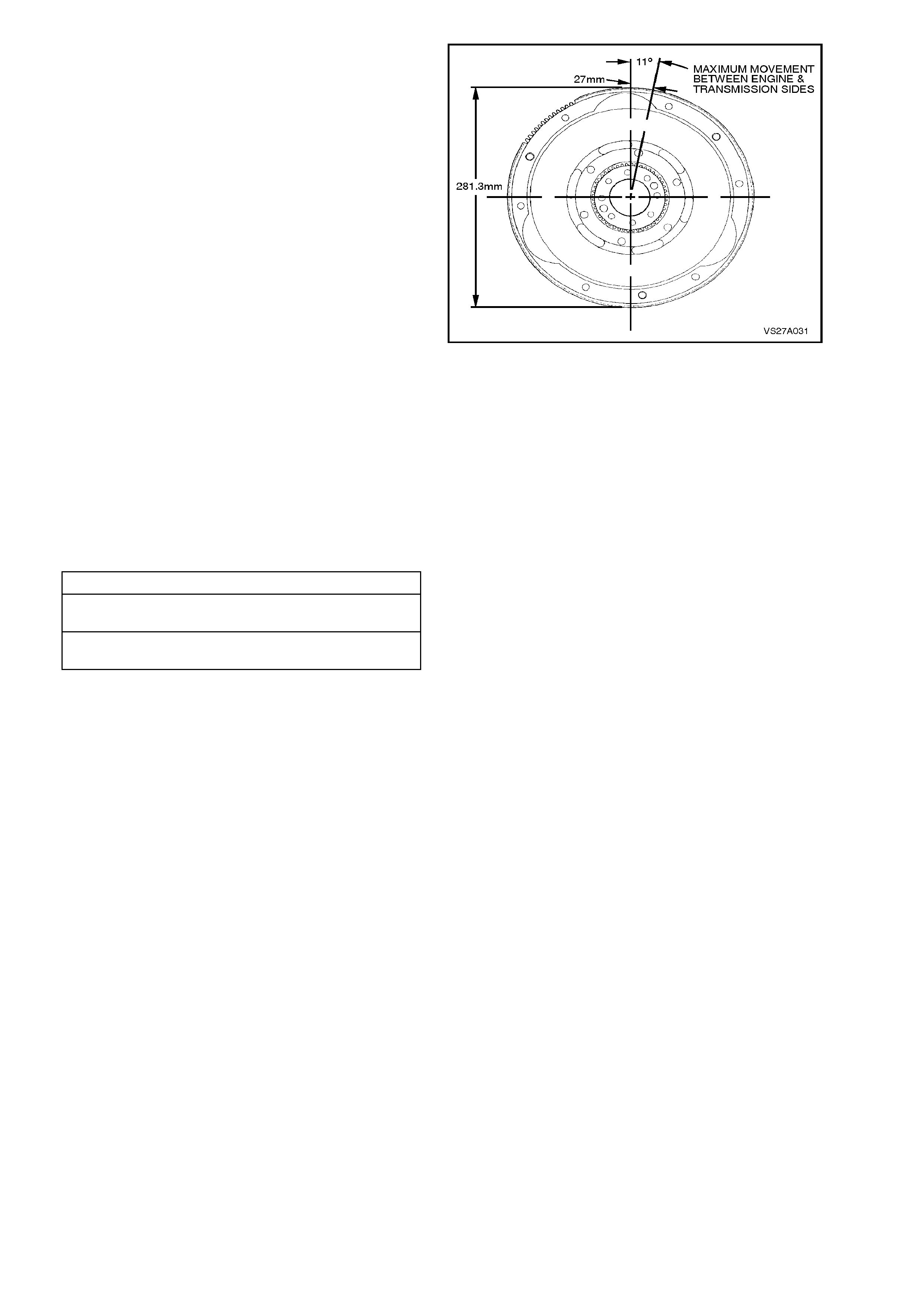
3. Check the rotational free play between the
engine and transmission sides of the dual
mass flywheel. Should the amount of travel
exceed specification, then the flywheel
assembly MUST be replaced as an assembly.
Figure 7A-31
REINSTALL
Installation is the reverse of removal operations
except for the following items.
1. Install flywheel to the engine crankshaft,
aligning with the marks made before removal.
2. Install new bolts and tighten in the
recommended sequence, working from
opposite sides.
FLYWHEEL BOLT TIGHTENING SEQUENCE
STEP 1 TORQUE ALL BOLTS TO
18 - 22 Nm
STEP 2 TIGHTEN ALL BOLTS A FURTHER
80° - 90° TURN ANGLE
3. Reinstall clutch assembly and manual
transmission, refer to 3.6 CLUTCH DRIVEN
PLATE, PRESSURE PLATE AND/OR
THROWOUT BEARING in this Section and
7B, MANUAL TRANSMISSION - V6 ENGINE.
4. Reconnect battery earth lead.
5. Check starter motor operation and road test
vehicle to check transmission and clutch
operation.
IMPORTANT:
Enable the SRS (Air Bag). Refer to Sectio n 12M
ENABLING THE SRS.
3.8 CRANKSHAFT SPIGOT BUSH
REPLACE
CAUTION:
Disable the SRS (Air Bag). Refer to Section
12M DISABLING THE SRS.
1. Disconnect battery earth lead.
2. Remove manual transmission and the clutch
assembly, refer to 3.6 CLUTCH DRIVEN
PLATE, PRESSURE PLATE AND/OR
THROWOUT BEARING in this Section and
7B, MANUAL TRANSMISSION - V6 ENGINE.
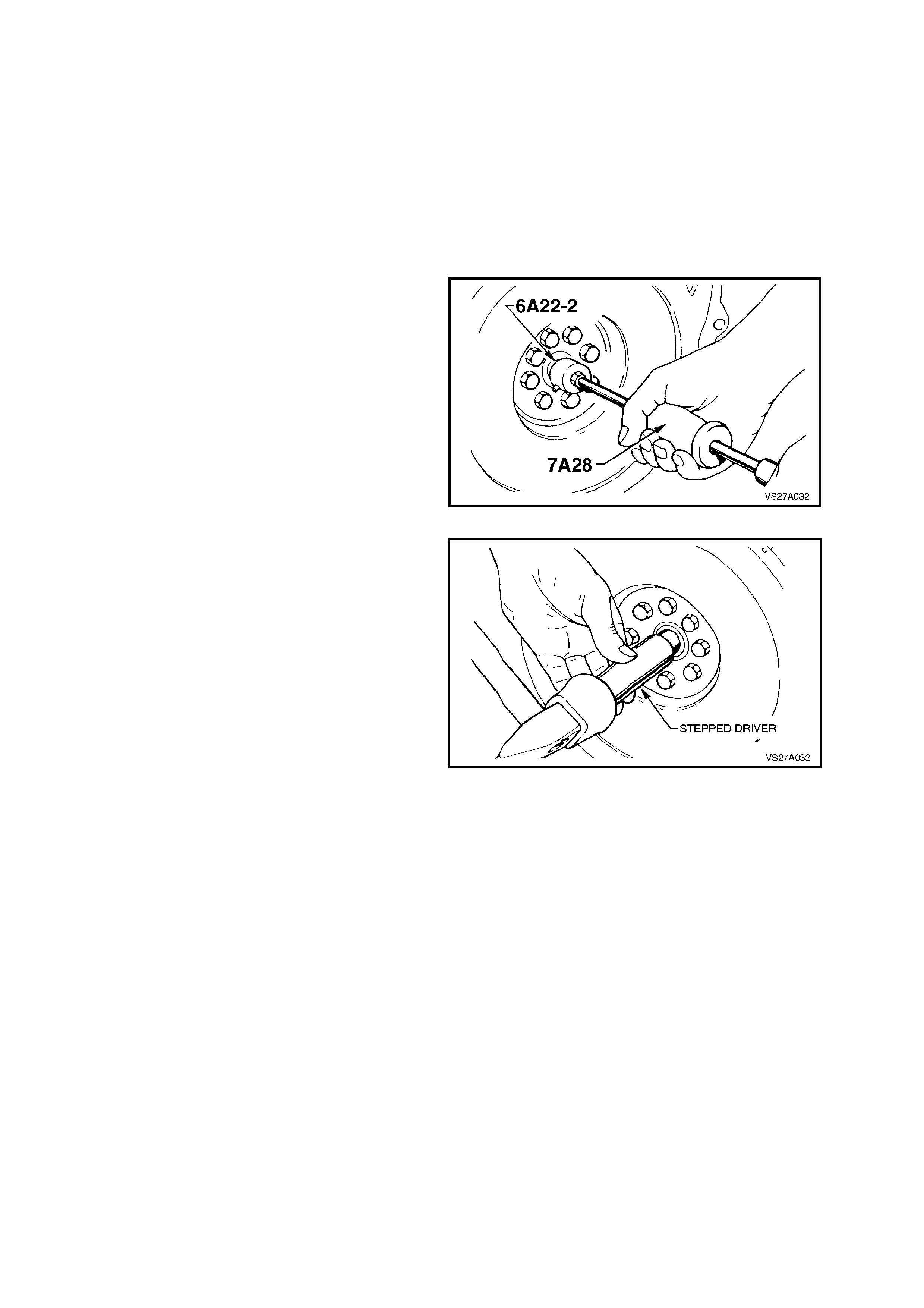
3. Remove bush, using Tool No. 6A22-2, in
conjunction with slide hammer 7A28.
Figure 7A-32
4. To install a new bush, use a stepped driver.
Place a new bush over the smaller diameter of
the fabricated tool, with the radius in the bore
of the bearing agains t the shoulder of the tool.
Drive the bearing into the crankshaft until the
bearing shoulder contacts the crankshaft boss.
Figure 7A-33
5. Lubricate the bearing with a small amount of
SAE 90 gear oil.
6. Reinstall clutch assembly and manual
transmission, refer to 3.6 CLUTCH DRIVEN
PLATE, PRESSURE PLATE AND/OR
THROWOUT BEARING in this Section and
7B, MANUAL TRANSMISSION - V6 ENGINE.
7. Reconnect battery earth lead.
8. Check starter motor operation and road test
vehicle to check transmission and clutch
operation.
IMPORTANT:
Enable the SRS (Air Bag). Refer to Sectio n 12M
ENABLING THE SRS.

4. DIAGNOSIS
CONDITION PROBABLE CAUSE CORRECTIVE ACTION
SLlPPING Worn or oil-soaked lining.
Driven plate sticking on main
drive gear splines.
Weak or broken diaphragm
spring
Master or actuating cylinder
defective
Replace driven plate, correct
oil leak.
Clean splines and apply
special HT Grease, to
Holden’s Specification HN
1227.
Replace pressure plate and
diaphragm assembly. Refer
Operation 3.6 Clutch Driven
Plate, Pressure Plate and/or
Throwout Bearing, in this
Section.
Overhaul defective cylinder as
outlined under 3.3 Master
Cylinder or 3.4 Clutch
Actuating Cylinder, in this
Section.
DRAG OR FAILURE TO
RELEASE Air trapped in hydraulic
system.
Leak In hydraulic system.
Clutch master or actuating
cylinder defective.
Cracked or oil-soaked linings.
Excessive driven plate run-out
or distorted.
Driven plate sticking on
splines.
Main drive gear spigot partially
seized in crankshaft spigot
bush.
Bleed system as outlined
under 3.2 Clutch Hydraulic
System Bleed, in this Section.
Correct leak and bleed
hydraulic system.
Overhaul defective cylinder as
outlined under 3.3 Master
Cylinder or 3.4 Clutch
Actuating Cylinder, in this
Section.
Replace driven plate. Refer
Operation 3.6 Clutch Driven
Plate, Pressure Plate and/or
Throwout Bearing, in this
Section.
Replace driven plate. Refer
Operation 3.6 Clutch Driven
Plate, Pressure Plate and/or
Throwout Bearing, in this
Section.
Clean and free splines and
apply special HT Grease, to
Holden’s Specification HN
1227.
Remove clutch, Iubricate or
replace bush. Refer Operation
3.8 Crankshaft Spigot Bush, in
this Section.

CONDITION PROBABLE CAUSE CORRECTIVE ACTION
GRAB OR CHATTER Oil on linings.
Worn main drive gear splines.
Rough, or grooved, flywheel or
pressure plate.
Loose engine mountings.
Loose or worn universal joints
or loose rear universal joint
flange.
Defective clutch driven plate.
Defective dual mass flywheel.
Replace driven plate, correct
oil leak.
Replace main drive gear.
Replace flywheel or replace
both flywheel and pressure
plate.
Tighten or replace mountings.
Tighten or replace universal
joint/s and/or flange.
Replace clutch driven plate.
Refer 3.6 Clutch Driven Plate,
Pressure Plate and/or
Throwout Bearing, in this
Section
Replace dual mass flywheel.
Refer 3.7 Dual Mass Flywheel,
in this Section
HARD OR STIFF CLUTCH
ACTlON Clutch pedal bush seized or
tight on pedal shaft.
Blockage in fluid hydraulic
pipe.
Replace bushes as detailed in
3.5 Clutch Pedal in this
Section.
Clean lines and bleed
hydraulic system. Refer 3.2
Clutch Hydraulic System Bleed
in this Section.
CLUTCH ENGAGEMENT
TOO SLOW Blockage in fluid hydraulic
pipe.
Clutch master or actuating
cylinder defective.
Incorrect brake fluid used.
Clean lines and bleed
hydraulic system. Refer 3.2
Clutch Hydraulic System Bleed
in this Section.
Overhaul defective cylinder as
outlined under 3.3 Master
Cylinder or 3.4 Clutch
Actuating Cylinder, in this
Section.
Flush and bleed hydraulic
system. Refer 3.2 Clutch
Hydraulic System Bleed in this
Section.

5. SPECIFICATIONS
MASTER CYLINDER: V6 Engine V8 Engine
Type Compensating port.
Bore Size 19.05 mm
Nominal Stroke 30 mm
CLUTCH ACTUATING CYLINDER
Type Flange mounted with side port delivery and end bleed.
Bore Size 22.2 mm 20.6 mm
Available Stroke 25.6 mm 28.8 mm
BRAKE FLUID:
Type To Holden’s Specification HN 1796.
CLUTCH DRIVEN PLATE:
Type Single plate dry disc.
Disc Facing:
Outside Diameter 240 ± 1.0 mm 266 ± 1.0 mm
Inside Diameter 155 ± 1.5 mm 172 ± 1.0 mm
Thickness of disc assembly
with 7,000 N load applied 8.4 ± 0.2 mm 8.23
CLUTCH PRESSURE PLATE:
Type Recessed, with a pressed steel cover plate and a
Belleville diaphragm spring.
CLUTCH THROWOUT
BEARING:
Type Ball race.
Lubrication Sealed with grease for life.
DUAL MASS FLYWHEEL
(V6 EN GINE ONLY):
Type Spring dampened internally; the transmission side
being recessed to accommodate the clutch assembly.
Rotational free play maximum,
including length tolerances and
heat setting losses:
Degrees 11°
Distance 27 mm at the outside diameter (281.3 mm) of the
secondary side of the flywheel assembly.
Serviceability None. Starter motor ring gear is not replaceable and
machining of the clutch facing surface is not permitted.

6. TORQUE WRENCH SPECIFI CATIONS
Nm
Clutch actuating cylinder mounting nut 20 - 25
Clutch flexible hose to clutch actuating cylinder 10 - 12
Clutch master cylinder nut to engine firewall 20 - 30
Clutch pedal pivot bolt 12 - 16
Clutch pressure plate cover to flywheel V6 Engine 28 - 35
V8 Engine 41 - 47
Fly wheel to crankshaft mounting bolts V6 Engine Step 1 18 - 22
Step 2 Turn a further
80 - 90°
V8 Engine 81 - 88
Hydraulic Pipe Flare Nut to Master Cylinder or
Flexible Hose 8 - 11
Lower flywheel cover attaching screw 5 - 10
Starter motor retaining bolt V6 Engine 36 - 50
V8 Engine 24 - 32
Transmission to engine bolt V6 Engine
(and
Beaming
brace bolt)
50 - 85
V8 Engine 30 - 45
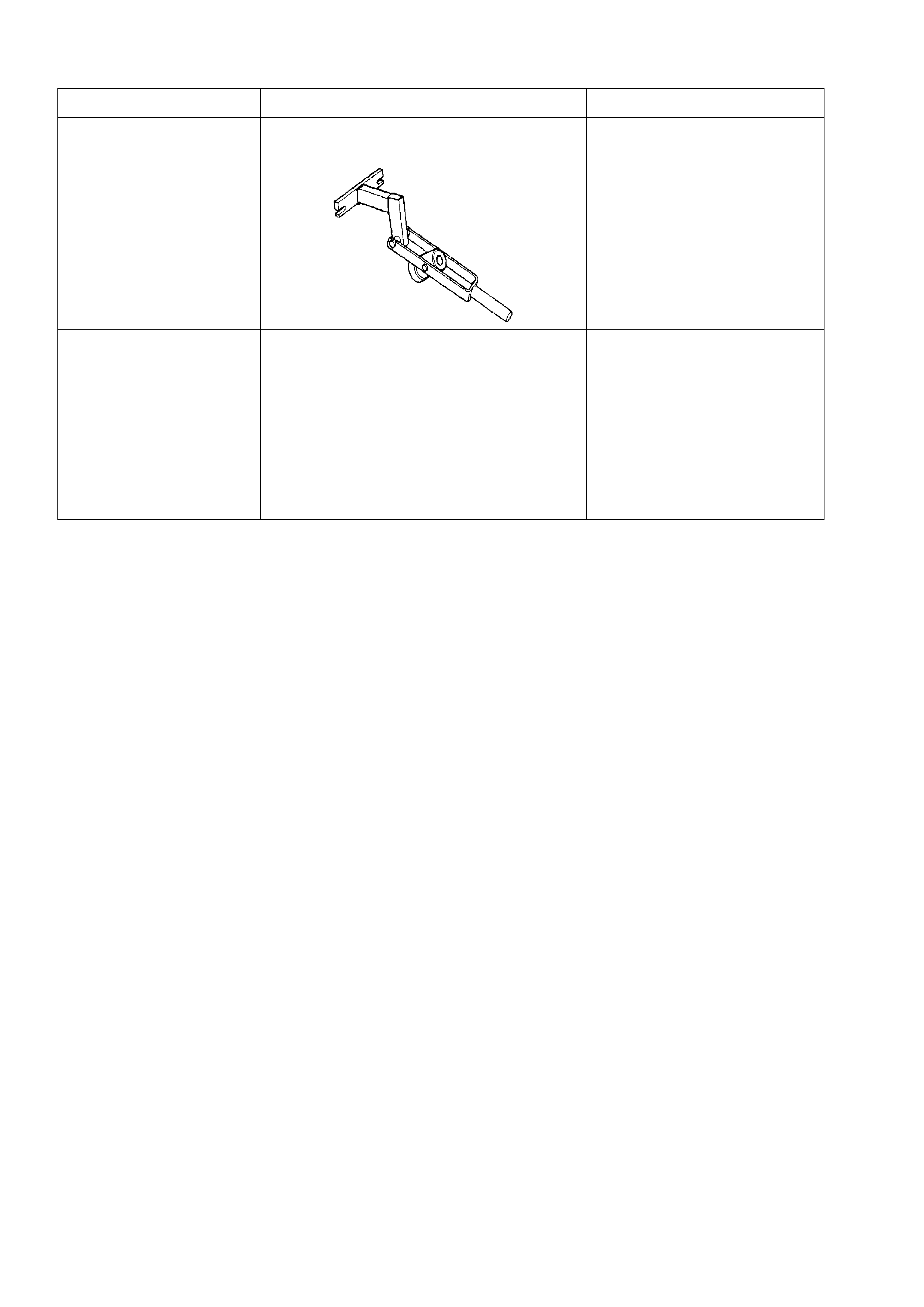
7. SPECIAL TOOLS
TOOL NO. REF IN TEXT TOOL DESCRIPTION COMMENTS
AKM-632-A CLUTCH PRESSURE PLATE LOADING
TOOL USED TO ‘LOAD’ THE
PRESSURE PLATE ON V6
ENGINED VEHICLES, WHILE
TIGHTE NING THE RETAINING
BOLTS.
PREVIOUSLY RELEASED
FOR VS SERIES II.
N/A CLUTCH CENTRING TOOL COMMERCIALLY AVAILABLE.