
SECTION 7C1 - HYDRA-MATIC 4L60-E AUTOMATIC
TRANSMISSION: GENERAL INFORMATION
CAUTION:
This vehicle will be equipped with a Supplemental Restraint System (SRS). An SRS
will consist of either seat belt pre-tensioners and a driver's side air bag, or seat belt
pre-tensioners and a driver's and front passenger's side air bags. Refer to
CAUTIONS, Section 12M, before performing any service operation on or around any
SRS components, the steering mechanism or wiring. Failure to follow the CAUTIONS
could result in SRS deployment, resu lting in possible perso nal in jury or u nnecessary
SRS system repairs.
CAUTION:
This vehicle may be equipped with LPG (Liquefied Petroleum Gas). In the interests of
safety, the LPG fuel system should be isolated by turning ‘OFF’ the manual service
valve and then draining the L PG service lines, before any service w ork is carried out
on the vehicle. Refer to the LPG leaflet included with the Owner's Handbook for
details or LPG Section 2 for more specific servicing information.
1. SECTION DESCRIPTIONS
A multi-section approach to the Hydra-matic 4L60-E Automatic Transmission has been adopted for VT Series
vehicles.
SECTION 7C1: HYDRA-MATIC AUTOMATIC TRANSMISSION: GENERAL INFORMATION
The purpose of this section is to provide an overview of this automatic transmission, by briefly describing what
each of the various sub-sections contains.
In addition, an overview of the transmission features is provided, that includes;
A general description of the transmission, its operation and control, as well as transmission identification
information.
A brief description of some salient systems such as torque converter clutch and 3-2 downshift controls.
A glossary of generic terms that are used
Some notes that address safe workshop practices
Service notes relating to fasteners and consumable items used at various stages throughout this section.
SECTION 7C2 HYDRA-MATIC AUTOMATIC TRANSMISSION:- ELECTRICAL DIAGNOSIS
As the electrical systems and diagnosis for this transmission are controlled by the Powertrain Control Module
(PCM), this material has now been included in the appropriate sections relating to the PCM; namely
Section 6C1 POWERTRAIN - V6 ENGINE or Section 6C2 POWERTRAIN - V8 ENGINE.
SECTION 7C3 HYDRA-MATIC AU TOMATIC TRANSMISSION:- GENERAL DIA GNOSIS
As distinct from the previous section, 7C3 contains inform ation that will assist in the diagnosis of the m echanical
and hydraulic components in the 4L60-E automatic transmission, with the unit installed in the vehicle.
Exam ples of the type of diagnostic inf orm ation contained within this s ection are; transm ission f unctional tes t, fluid
checking procedure, shift speed and line pressure information. Other material contained in this section refers to
some fluid flow and circuit descriptions, plus fluid passage identification diagrams relating to this transmission.
SECTION 7C4 HYDRA-MATIC AU TOMATIC TRANSMISSION:- ON-VEHICLE SERVICING
Inform ation in this section covers transmission fluid level checking and diagnosis, as well as specific information
for servicing some components while the transmission remains installed in the vehicle.
This section also contains the necessary procedures for the removal and installation of the transmission.
SECTION 7C5 HYDRA-MATIC AU TOMATIC TRANSMISSION:- UNIT REPAIR
This section contains the procedures necessary for the disassembly, inspection, overhaul and assembly
operations of the mechanical components, once the transmission is removed from the vehicle. Also included is
information relating to the measurement of certain clearances, the correct use of special tools and torque
specifications required for assembly.
Techline
Techline

2. TRANSMISSION OPERATION - OVERVIEW
2.1 GENERAL DESCRIPTION
The Hydra-matic 4L60-E is a fully automatic, four speed, rear wheel drive transmission. It consists primarily of a
four element torque converter, two planetary gear sets , various clutches, an oil pump and a control valve body.
The four element torque converter contains a pump, a turbine, a pressure plate splined to the turbine and a stator
assembly. The torque converter acts as a fluid coupling to transmit power smoothly from the engine to the
transmission. It also hydraulically provides additional torque multiplication when required. The pressure plate,
when applied, provides a mechanical 'direct drive' coupling of the engine to the transmission.
The two planetary gear sets provide the four forward gear ratios and reverse. Changing of the gear ratios is fully
automatic and is accomplished through the use of various electronic sensors that provide input signals to the
Powertrain Control Module (PCM). The PCM interprets these signals to send current to the various solenoids
inside the transmission.
By using electronics, the PCM controls shift points, shift feel and torque converter clutch apply and release, to
provide proper gear ranges for maximum fuel economy and vehicle performance.
Five multiple-disc clutches, one roller clutch, a sprag clutch and a brake band provide the friction elements
required to obtain the various ratios with the planetary gear sets.
An hydraulic system (the control valve body), pressurised by a vane type pump, provides the working pressure
needed to operate the friction elements and automatic controls.
The general arrangement of both the majority of mechanical and hydraulic components is as shown next.
With traditional, hydraulically controlled transmissions, the gear shifts are controlled by the opposing pressures of
hydraulic fluid in a complex system of spring-loaded valves. In this electronically controlled Hydra-matic 4L60-E
transmission, gear shift points and shift feel are determined by electrical signals sent from the Powertrain Control
Module (PCM).
The PCM processes data every 25 milliseconds from various sensors, such as throttle position, vehicle speed,
gear range, temperature, engine load and other inputs. Using this data, a signal is transmitted to the valve body
shift solenoids, which activate the shift valves for precise shift control. Shift points are therefore precisely
controlled and are identical from vehicle to vehicle.
Shift feel is also electronically controlled by the PCM, by signals sent to the Variable Force Solenoid, which
controls fluid line pressure and it is this pressure that precisely determines how the shifts will feel. In this way, the
Powertrain Control Module (PCM) electronically synchronises the engine and transmission into a single, integrated
powertrain system, for optimum performance, shift timing, fuel efficiency and emission control.
TRANSMISSION COMPONENT SUMMARY
Mechanical/Hydraulic Electrical
Torque Converter with Converter Clutch Two Shift Solenoids
13 Vane, Variable Displacement Oil Pump. Effectively, an ON/OFF, 3-2 Downshift Solenoid
Five Multiple Disc Clutch Packs A Transmission Pressure Control Solenoid (Force Motor)
A 2-4 Band Assembly An ON/OFF, Torque Converter Clutch (TCC) Solenoid
Two Planetary Gear Sets One Pulse Width Modulated (PWM) TCC Solenoid
One Sprag Clutch Transmission Fluid Temperature Sensor
One Roller Clutch Fluid Pressure Switch Assembly
A Control Valve Body Assembly Vehicle Speed Sensor
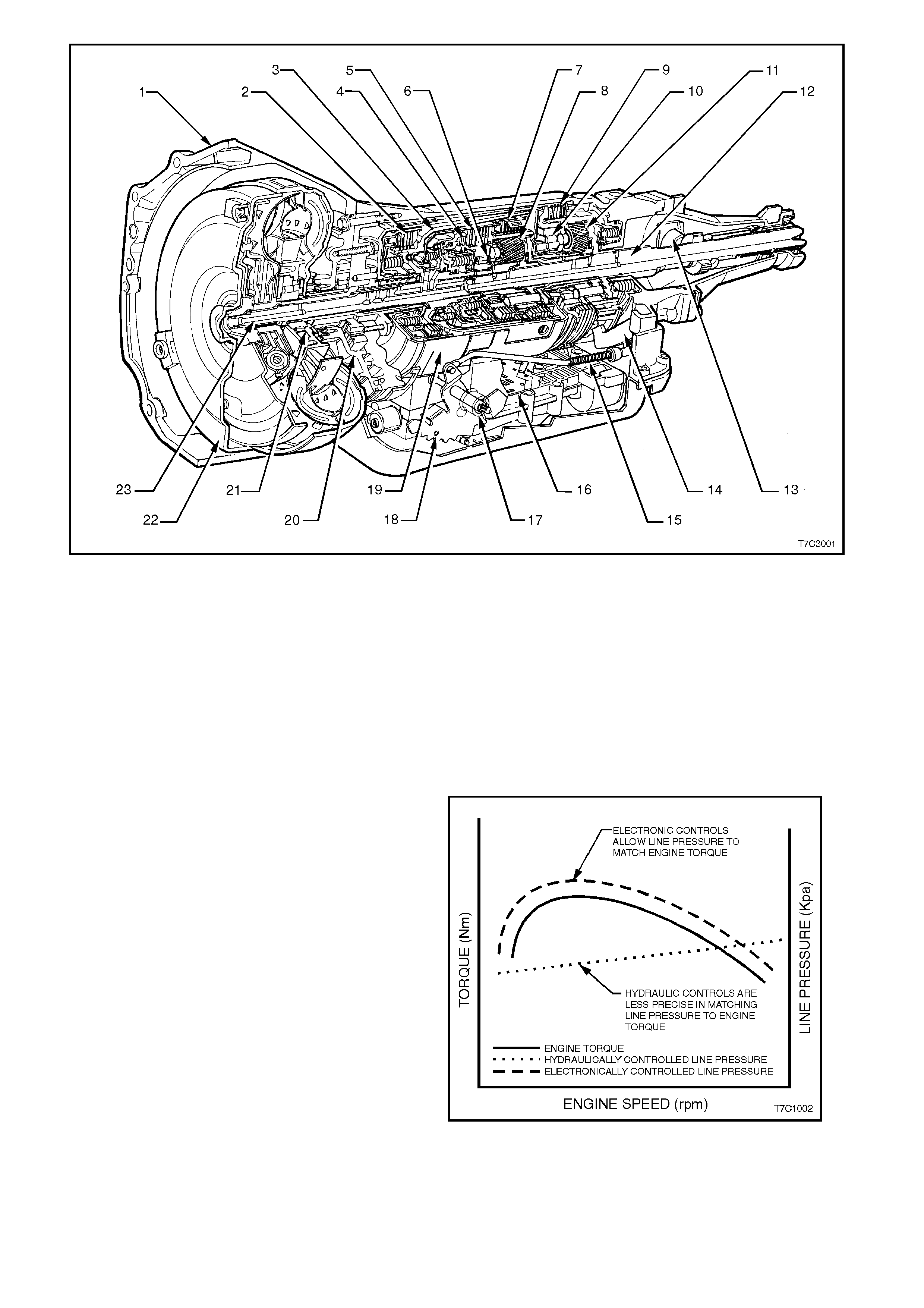
Figure 7C1-1
1. Case Assembly 9. Low and Reverse Clutch 17. Manual Shaft
2. Reverse Input Clutch 10. Low Roller Clutch Assembly 18. Inside Detent Lever
3. Input Clutch Housing 11. Reaction Planetary Gear Set 19. 2 - 4 Band Assembly
4. Overrun Clutch 12. Output Shaft 20. Pump Assembly
5. Forward Clutch 13. Speed Sensor 21. Stator Roller Clutch
6. Forward Clutch Sprag Assembly 14. Parking Pawl 22. Torque Converter Assembly
7. 3 - 4 Clutch 15. Parking Lock Actuator Assembly 23. Turbine Shaft
8. Input Planetary Gear Set 16. Control Valve Assembly
MATCHING ENGINE TORQUE AND LINE PRESSURE
The torque output from an engine varies in relation
to engine speed, in an inconsistent manner that
results in the typical curve, as shown. By using
springs and hydraulic pressure to control fluid line
pressure in an automatic transmission, control is
purely linear (indicated by the dotted line) and this
does not provide an ideal match to engine output.
With the Hydra-matic 4L60-E automatic
transm ission, the use of electronic control over line
pressure means that a much more precise match
with engine performance is possible and the ‘shift
feel' more closely approximates engine output.
Figure 7C1-2
ECONOMY AND POWER AND CRUISE MODE
The programming in the Powertrain Control Module (PWM) provides for these three different shift patterns which
are driver controllable, through the use of the Economy/Power button, located in the centre console.
Economy Mode
The calibration for this mode is for maximum comfort, with minimal intrusion of engine noise and smooth shifts
under all driving conditions. W hen additional power is required f or acceleration, full throttle upshifts are sim ilar to
those calibrated for the Power Mode.
Power Mode
When activated, the PCM modifies the transmission calibration in the following ways:
1. When the throttle is less than 80% open, later upshift points are provided.
2. Shift time is reduced.
The Torque Converter Clutch (TCC) will be applied in both third and fourth speed ranges.
Cruise Mode
When the cruise control (if fitted) is engaged, the PCM modifies the transmission calibration so that earlier
downshifts and later upshift points are provided.
SHIFT PATTERN MODIFICATION
Through the electronic programming of the logic processes contained in the Powertrain Control Module, the
frequency of gear shifting and torque converter clutch application and release is minimised. The end result of
these logic processes , is that trans miss ion 'busyness' (a quic k ser ies of ups hif ts and downshif ts ; e.g. a '4-3- 4' s hif t
pattern) is minimised.
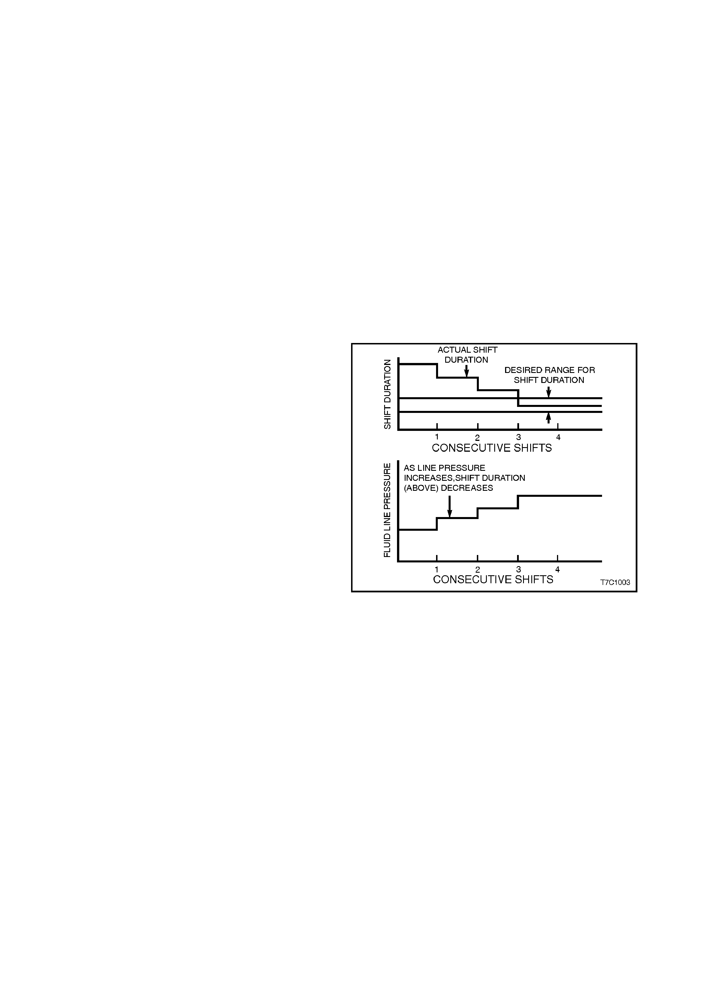
ADAPTIVE CONTROLS
As a normal part of its operation, the PCM
continually monitors the transmission's shift time
(duration) for the 1-2 upshift and compares this with
it's pre-programmed information. As normal
transmission wear occurs, such as with friction
material and spring tensions, the time that is taken
for this shift to occur, will change.
When the PCM finds that the time is outside it's
programmed limits, the transmission fluid line
pressure is modified via the pressure control
solenoid and this 'adapts' the change time to
maintain the correc t shift f eel. Line press ure c an be
adapted to values ranging from 35 kPa below, to 70
kPa above normal line pressure. This 'learning'
feature is similar to what is used for fuel control.
Figure 7C1-3
SYSTEM PROTECTIVE DEVICES
a. Should 1st gear be selected and left in that range, the PCM will protect the engine from an over-speeding
condition by upshifting to 2nd speed at a pre-determined point. Similarly, the PCM provides high speed,
downshift protection by preventing a manual shift into 1st gear above pre-determined engine speeds.
b. Under severe operating conditions such as towing in high ambient temperatures, fluid temperatures rise to
the point where lubrication break down can occur. W ith the VR range of vehicles, in addition to having an oil
cooler f itted, the 4L60-E trans miss ion is als o f itted with a transmiss ion f luid temperature s ens or loc ated in the
Transmission Range (TR) Pressure Switch Assembly (PSA).
When fluid temperatures in excess of 135° C are sensed, the Torque Converter Clutch is applied as
programmed, in 3rd or 4th gear.
This action reduces further fluid temperatures that could arise in normal operation of the torque converter.
While these high fluid temperatures are sensed, Torque Converter Clutch apply is not available however,
when the throttle opening is above 50%.
Similarly, when the fluid temperature is below 29° C, the PCM prevents Torque Converter Clutch apply.
c. Should a condition occur that prevents electronic control of the transmission's functions, a "Fail Safe" m ode
will default the transm is sion to 3rd gear (when either Drive ' D' or '3' is selec ted) and also apply max im um line
pressure. W hile in this m ode, the vehicle operator can still m anually select '2', '1', Reverse, Park or Neutral,
should the need arise.
SELF DIAGNOSIS
Should any transm ission operation controlled by the PCM begin to operate outside pre-set parameters, the PCM
has the ability to store a range of diagnostic codes that can be accessed by the servicing Technician, thereby
localising the problem circuit.
PCM SENSORS AND ACTUATORS
As indicated earlier, there are a number of sensors and switches that provide input information for the PCM
programming that will allow the PCM to make decisions about such things as; shift pattern, shift feel and torque
converter clutch operation.
The PCM does this by comparing this input information with its ‘Look up' tables on Shift Pattern, Fluid Pressure
maps, Shift Duration parameters, Extreme Heat Protection programming and Adaptive Controls.
In addition, each input signal and output actuator operation is als o m onitored and, if outside pre-s et param eters, a
diagnostic code is logged for future reference by the servicing Technician.
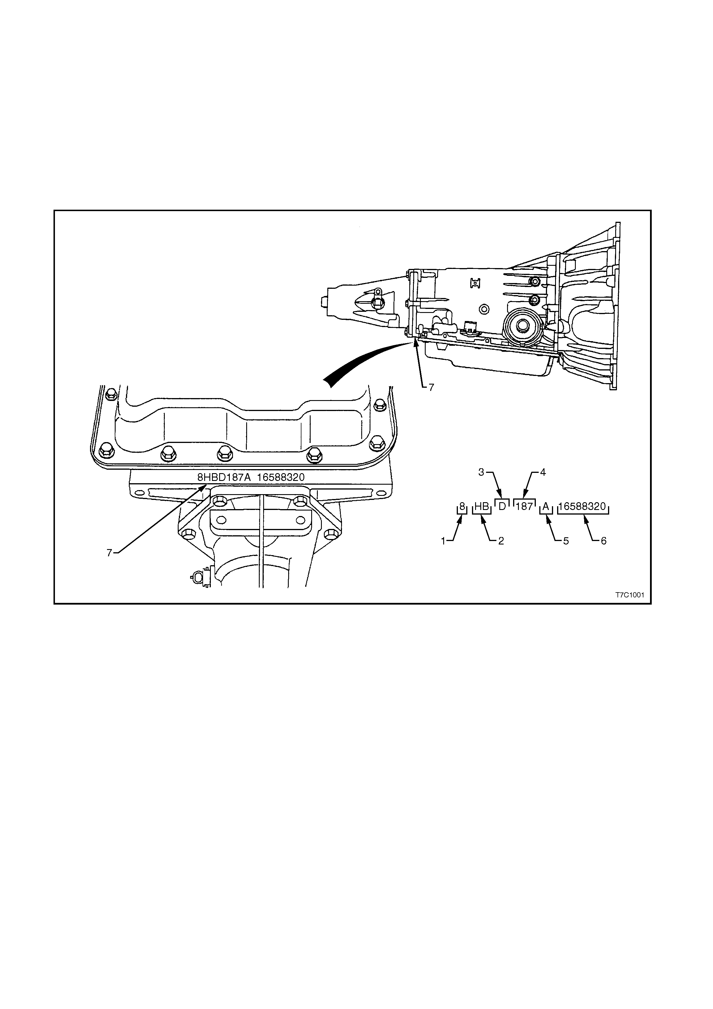
TRANSMISSION IDENTIFICATION
An Adhesive label is attached to the upper surface of the central case section of all 1998 Model Year
transmissions and also stamped into a machined surface at the rear, underside of the transmission centre case as
shown next.
Figure 7C1-4
1. Model Year (‘8’ = 1998) 4. Julian Date (or Day of the Year)
2. Model: 5. Shift Built (A, B, J = First Shift;
C, H, W = Second Shift
V8 - 5.0 litre 8HBD
V6 - 3.8 litre 8HFD
V6 Supercharged -
3.8 litre 8HND
6. Individual Transmission Serial
Number
3. Transmission Model
Identifier (D = 4L60-E) 7. Transmission Identification
Number Location

TRANSMISSION SPEED RANGES
The Hydra-matic 4L60-E transmission can be operated in any one of the following seven modes:
PPark position enables the engine to be started while preventing the vehicle from rolling either forward or
backward. For safety reasons, the parking brake should be used in addition to the park position. Since the
output shaft is mechanically locked to the case through the parking pawl and reaction internal gear, 'Park'
position should not be selected until the vehicle has come to a complete stop.
RReverse allows the vehicle to be operated in a rearward direction.
NNeutral allows the engine to be started and operated without driving the vehicle. If necessary, this position
should be selected to re-start the engine while the vehicle is moving.
DDrive range should be used for all normal driving conditions for maximum efficiency and fuel economy. This
range provides four gear ratios plus converter clutch operation. Downshifts are available for safe passing by
depressing the accelerator or by manually selecting a lower gear with the shift selector.
NOTE:
When towing, if 4 - 3 - 4 shifts occur, then it is recommended that the ‘3 Drive’ mode of operation be selected.
3Drive position is used for city traffic and hilly terrain. It provides three gear ranges. Again, downshifts are
available for safe passing by depressing the accelerator.
2Manual second is used to provide acceleration, engine braking, or greater traction from a stopped situation.
When manual second is selected, the vehicle will start off and remain in second gear. This range maybe
selected at any vehicle speed.
1Manual first is used to provide maximum engine braking. This range may also be selected at any speed,
however the transmission will not shift into first gear until the vehicle speed is below approximately 48 to 56
km/h. Above this speed the transmission will remain in second gear. Manual first is particularly useful for
maintaining maximum engine braking while descending steep grades.
Reference to Figure 7C1-5, shows the application of the various components that are applied in each of the
available modes.
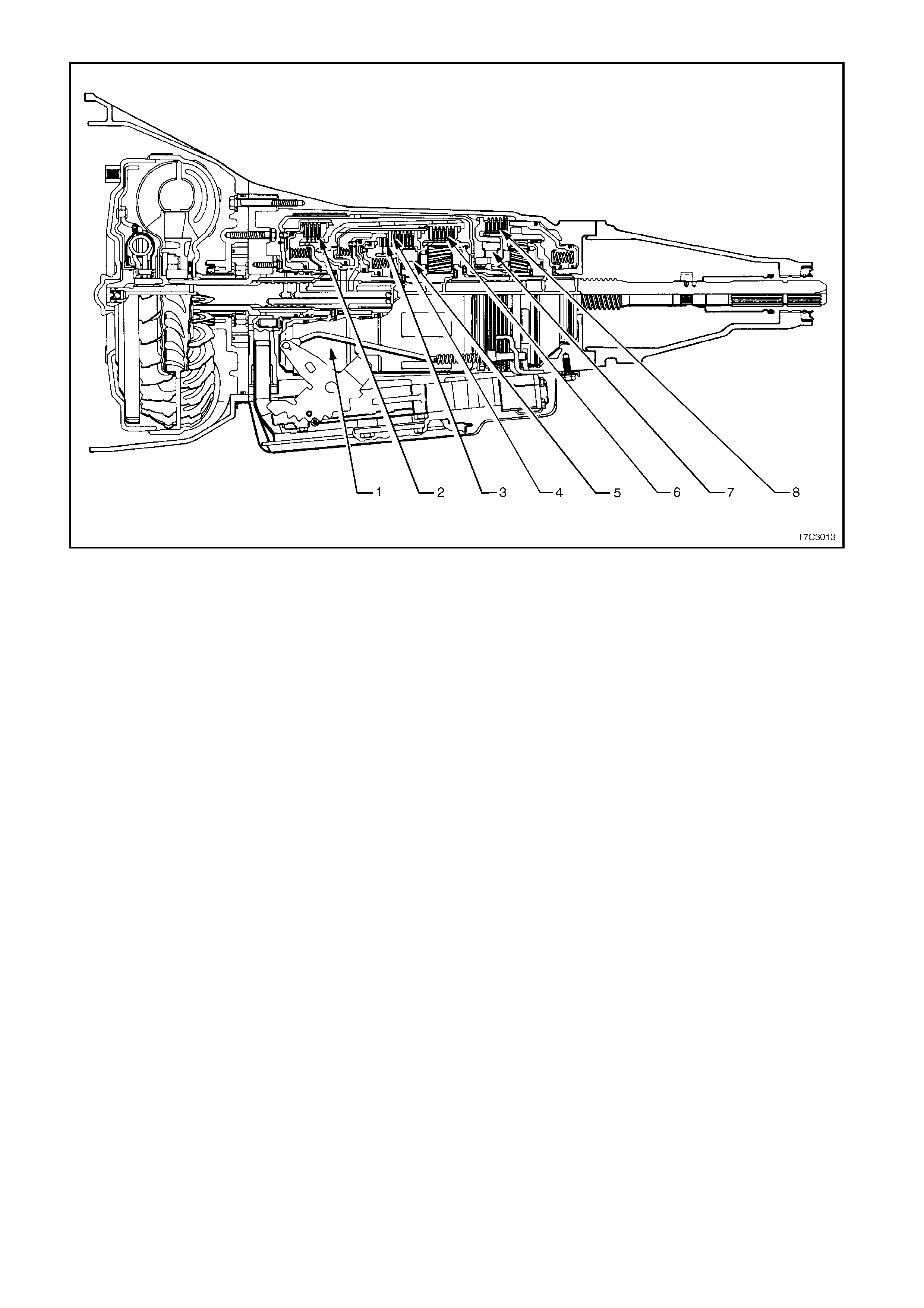
TRANSMISSION RANGE REFERENCE CHART
Figure 7C1-5
RANGE GEAR SHIFT
SOLENOID 2-4
BAND REVERSE
INPUT OVERRUN
CLUTCH FORWARD
CLUTCH FORWARD
SPRAG CL. 3-4
CLUTCH LOW/
ROLLER LOW/
REVERSE
1 - 22 - 3 (#1) CLUTCH
(#2) (#3) (#4) ASSEMBLY
(#5) (#6) CLUTCH
(#7) CLUTCH
(#8)
PARK On * On * APPLIED
REVERSE On * On * APPLIED APPLIED
NEUTRAL On * On *
D1ST On On APPLIED HOLDING HOLDING
2ND OFF On APPLIED APPLIED HOLDING
3RD OFF OFF APPLIED HOLDING APPLIED
4TH On OFF APPLIED APPLIED APPLIED
31ST On On APPLIED HOLDING HOLDING
2ND OFF On APPLIED APPLIED HOLDING
3RD OFF OFF APPLIED APPLIED HOLDING APPLIED
21ST On On APPLIED APPLIED HOLDING HOLDING
2ND OFF On APPLIED APPLIED APPLIED HOLDING
11ST On On APPLIED APPLIED HOLDING HOLDING APPLIED
2ND ** OFF On APPLIED APPLIED APPLIED HOLDING
•
••
• SHIFT SOLENOID STATE IS A FUNCTION OF VEHICLE SPEED AND MAY CHANGE IF A VEHICLE SPEED INCREASES
SUFFICIENTLY IN PARK, REVERSE OR NEUTRAL.. HOWEVER, tHIS DOES NOT AFFECT TRANSMISSION OPERATION.
** IN MANUAL FIRST, SECOND GEAR IS ONLY AVAILABLE ABOVE APPROXIMATELY 70 KM/H TO PREVENT ENGINE
OVERSPEEDING.
2.2 PULSE WIDTH MODULATED TCC SOLENOID
A Torque Conver ter Clutch Pulse W idth Modulated
(TCC PWM) solenoid is used in conjunction with
the Torque Converter Clutch (TCC) solenoid to
control torque converter clutch apply and release.
Introduced in the 1995/1996 Model Year 4L60-E
Hydra-Matic automatic transmissions, this method
of control continues with 1998 Model Year
transmission.
This control is accomplished by the Powertrain
Control Module (PCM) varying the solenoid's duty
cycle percent time energised, according to various
PCM input signals. This f eature is in addition to the
ON/OFF control of the TCC solenoid.
DUTY CYCLE
The TCC PWM solenoid operates on a negative
duty cycle, which m eans that the earth (negative or
low) side of the solenoid circuit is controlled by the
PCM.
Therefore, the TCC PWM solenoid is constantly fed
approximately 12 volts to the high (positive) side
and the PCM controls the length of time the
electrical circuit path to earth is closed (i.e. duty
cycle).
When the PCM closes the solenoid earth circuit,
current flows through the TCC PW M solenoid, and
the earth circuit (or negative side) is at a low
voltage state (0 volts and solenoid energised).
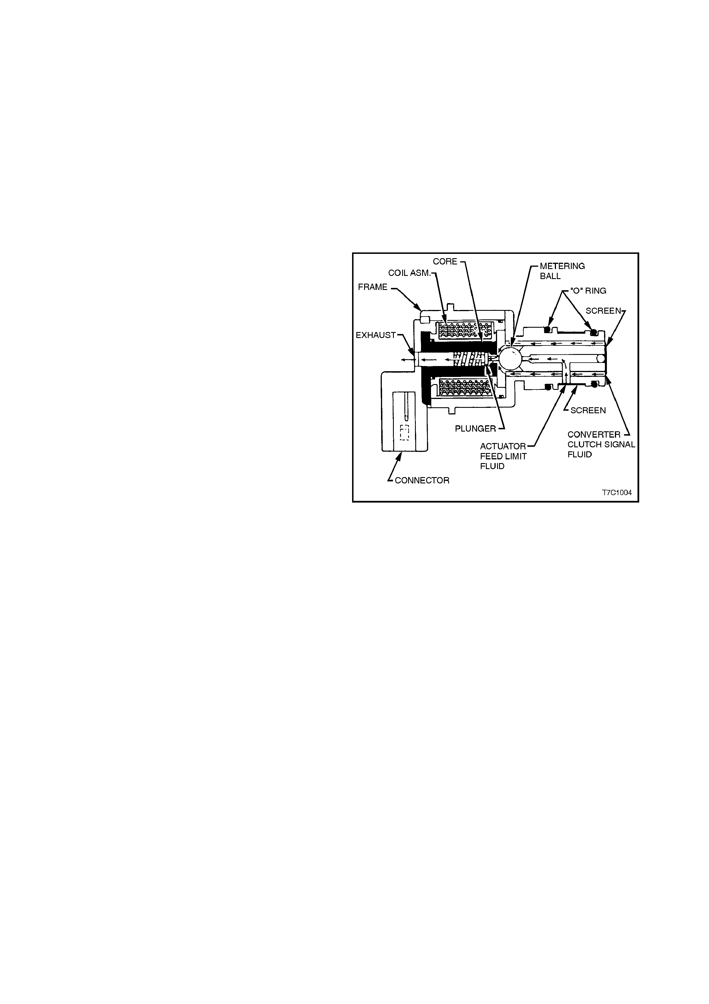
Figure 7C1-6
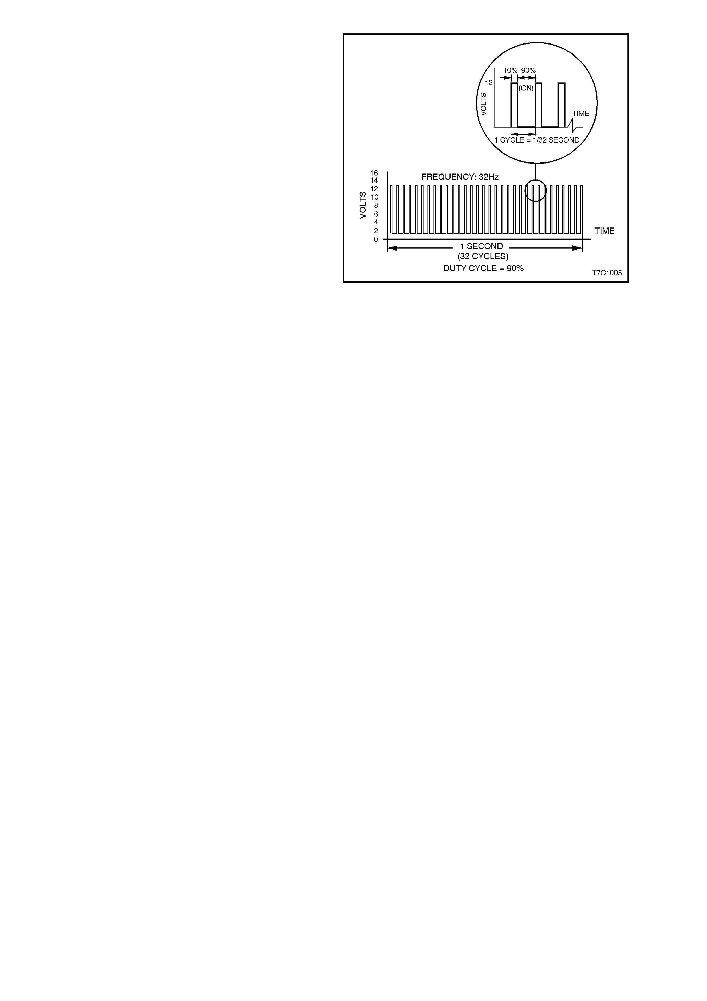
Figure 7C1-7 shows an example of the TCC PW M
solenoid operating with a 90% negative duty cycle
at a constant operating frequency of 32 Hz (cycles
per second). The frequency means that the
solenoid is puls ed (energised) with current f rom the
PCM 32 times per second. The 90% negative duty
cycle means that during each of these 32 cycles
the solenoid is energised (ON) and 0 volts is
measured on the low (negative) side of the circuit,
90% of the time.
At road speeds below approximately 13 km/h, the
negative duty cycle will be 0%, which means that
no current will flow through the TCC PWM
solenoid, deactivating it. When in this condition,
spring force will move the plunger (refer Figure
7C1-6), seating the metering ball and blocking the
filtered Actuator Feed Limit (AFL) fluid from
entering the Converter Clutch Signal (CC SIGNAL)
circuit. This action opens the Converter Clutch
Signal fluid circuit to exhaust through the solenoid.
Above road speeds of approximately 13 km/h, the
TCC PWM solenoid will be operating at about a
90% duty cycle. T his action will cause the m etering
ball to close off the path to exhaust, most of the
time and allow AFL fluid to flow past the metering
ball and into the CC SIGNAL circuit, in readiness
for the apply of the torque converter clutch.
W hen the PCM signals TCC apply, the TCC PW M
solenoid operates with a variable, negative duty
cycle, ranging from 90% to 0%, with an operating
frequenc y of 32 Hz. This allows the PCM to control
the current flow through the s olenoid coil according
to the duty cycle it sets. This has the effect of
creating a variable magnetic field, that magnetises
the solenoid core, attracting the metering ball to
seat against spring force. A high percentage duty
cycle keeps the metering ball will be seated more
often, thereby creating higher TCC signal fluid
pressures.
Figure 7C1-7
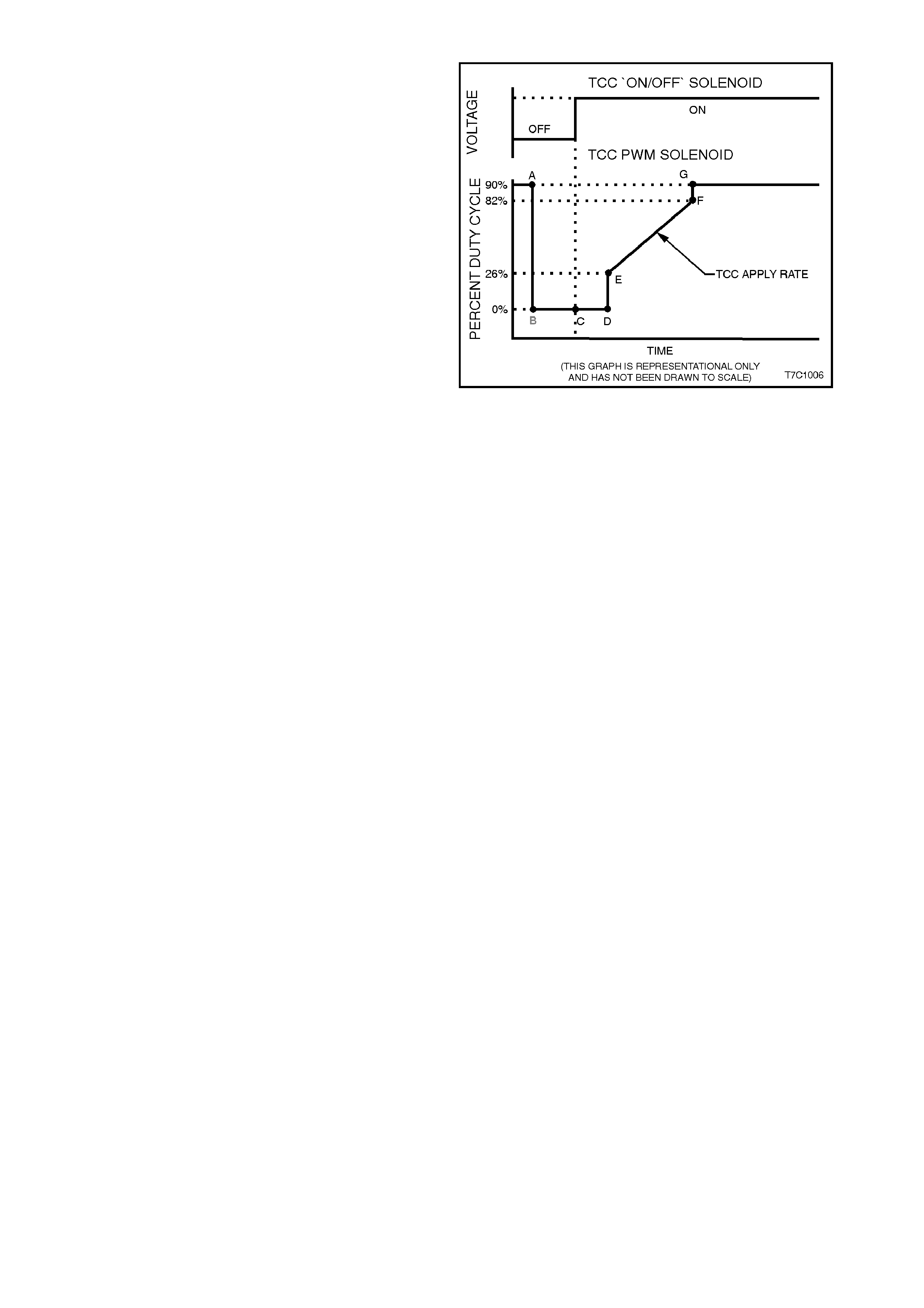
TCC PWM SOLENOID OPERATION
When vehicle road speed rises above about 13
km/h, the PCM causes the TCC PWM solenoid
duty cycle to change from 0% to 90% (point 'A'), in
readiness for an apply of the torque converter
clutch.
To apply the torque converter clutch, the process
the PCM adopts, is as follows;
•The duty cycle is dropped to 0% (point 'B')
and a measurable am ount of time is allowed
for the 'ON/OFF' TCC solenoid to turn on.
This is shown as the time between points 'B'
and 'C', in Figure 7C1-8. Note that, at point
'C', the TCC 'ON/OFF' solenoid is activated.
•The tim e from point 'C' to 'D' is us ed to allow
converter feed (CONV FD) fluid to build in
pressure and move the Converter Clutch
Valve into the apply position.
•At this point, with the TCC 'ON/OFF' solenoid
applied, the PCM then increases the duty
cycle to about 26% (point 'E'). From this
point, the duty cycle is 'ramped' to around the
82% point ('E' to 'F'). The rate at which the
duty cycle is increased over this period of
time, deter mines how quickly the value of the
regulated apply fluid incr eas es and ther ef or e,
how quickly the torque converter clutch is
applied. This rate of change also affects the
converter clutch apply 'feel'.
•As soon as the duty cycle reaches the 82%
value, it is then immediately increased to the
maximum of 90%, to achieve full apply
pressure in the regulated apply fluid circuit
(point 'G').
NOTE:
Both the duty cycle and apply pressure will
continually vary, depending on vehicle specif ication
and operating conditions.
Figure 7C1-8

2.3 TORQUE CONVERTER CLUTCH
GENERAL DESCRIPTION
While the Powertrain Control Module (PCM) continues to control the apply/release of the Torque Converter Clutch,
via the use of the Torque Converter Clutch solenoid (as it does in earlier transmissions), the use of the Pulse
Width Modulated Torque Converter Clutch, (TCC PWM) solenoid, provides the ability of being able to control
more precisely, the rate of Torque Converter Clutch (TCC) apply and release.
Essentially the TCC PWM solenoid changes ac tuator feed lim it ( AFL) f luid to c onverter c lutch s ignal (CC SIG NAL)
fluid, that is directed to the base of the Isolator Valve. Depending on the PCM controlled duty cycle, the TCC PWM
solenoid determines the value of the CC SIGNAL fluid pressure.
By having an electronically controllable, variable fluid pressure acting on the end of the Isolator Valve, the force
controlling the position of the Regulated Apply (REG APPLY) Valve is also variable.
This means that the Regulated Apply Valve can now vary the regulated apply (REG AP) fluid pressure that is
directed to the Converter Clutch Valve.
TORQUE CONVERTER CLUTCH - RELEASED
W ith the TCC 'O N/OFF' solenoid de-activated (as determ ined by the PCM), the spring force acting on the end of
the Converter Clutch Valve positions the valve so that the torque converter hydraulic circuits function as follows:
•Regulated apply (REG AP) fluid rests at the Converter Clutch Valve.
•Converter feed (CONV FD) fluid from the Pressure Regulator Valve, (converted from LINE fluid) both
passes through an or ifice at the base of the Converter Clutch Valve, to ex haust at the Norm ally Open (NO )
TCC 'ON/OFF' solenoid and is directed through the Converter Clutch Valve to become RELEASE fluid.
•This circuit feeds RELEASE fluid to the front of the torque converter, past the torque converter pressure
plate, circulating through the torque converter to exit as APPLY fluid.
After passing through the Converter Clutch Valve, APPLY fluid becomes COOLER fluid. Then, after it flows
through the cooler, it is used in the transmission LUBE circuits.
TORQUE CONVERTER CLUTCH - APPLIED
When the PCM determines that the torque converter clutch should be applied, the TCC 'ON/OFF' solenoid is
activated, closing off the exhaust port at the base of the Converter Clutch Valve. As previously explained, during
this period the TCC PWM solenoid duty cycle is dropped to zero.
This action causes the following hydraulic/electronic circuit changes to take place:
•Converter feed (CONV FD) f luid pres s ur e rapidly builds at the base of the Conver ter Clutch Valve, moving it
upwards against spring force.
•Depending upon the duty cycle selected by the PCM, the rate of torque converter clutch apply, is directly
controlled by the TCC PWM solenoid. As previously stated, this occurs because the CC SIGNAL fluid acting
on the end of the Isolator Valve, changes the value of the spring force, that dictates the position of the
Regulator Apply Valve.
•Through this electronic control then, variable regulator apply (REG AP) fluid now becomes converter
APPLY fluid, after it passes through the Converter Clutch Valve. Therefore, the rate of apply, is directly
related to the value of this fluid pressure.
•Converter RELEASE f luid passes through to exhaust at the s pring end of the Converter Clutch Valve. T his
action allows the torque converter press ure plate to be forc ed against the f ront fac e of the tor que converter ,
creating a frictional grip between the Impeller and the Turbine, effectively locking the assembly.
•Converter feed (CONV FD) fluid now flows through the Conver ter Clutch Valve to provide f luid flow through
the cooler and supply LUBE fluid for various transmission components.
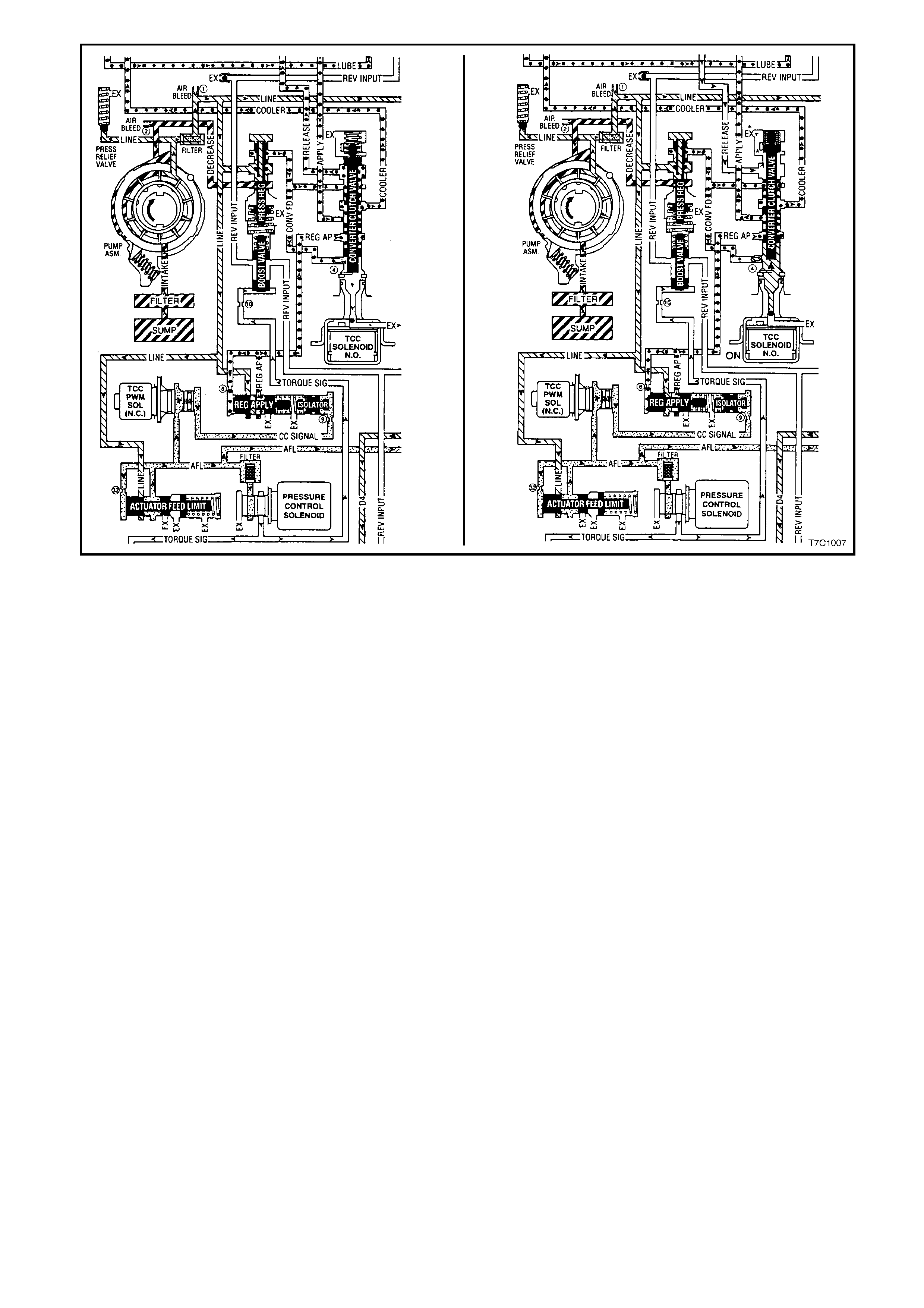
Figure 7C1-9
2.4 3-2 DOWNS HIFT CONTROL SO LE NOID
GENERAL DESCRIPTION
The 3-2 downshift control solenoid is a normally closed solenoid and is used to control the 3-2 downshift.
During a 3-2 downshift, the 2-4 band is applied, as the 3-4 clutch releases. The timing between the 3-4 clutch
release and the 2-4 band apply not only m us t be timed but it also mus t be varied, depending on vehic le speed and
throttle.
The PCM will turn the 3-2 control solenoid either on of off to control 3rd ac cumulator (3RD ACC) press ure so that
the release of the 3-4 clutch and the apply of the 2-4 band is such that a bind-up or flair does not occur.
The normally closed 3-2 control solenoid is ON in all drive gears, except during a 3-2 downshift, when the solenoid
is turned OFF. The amount of time the solenoid is ON, is determined by throttle position, vehicle speed and the
commanded gear.
3-2 CONTROL SOLENOID OPERATION
Solenoid ON
W hen the solenoid is activated by the PCM, curr ent flows through the solenoid coil, c reating a magnetic f ield that
magnetis es the solenoid core. T his attracts the m etering ball, m oving the ball and plunger agains t spring f orce to
block the internal exhaust port, opening the valve and allowing actuator feed lim it (AFL) fluid to act on the end of
the 3-2 control valve. When the fluid pressure increases enough, the valve will move away from the solenoid
against spring force, closing the 3-2 control valve.
Figure 7C1-10 3-2 Downshift Control Solenoid ON
Solenoid OFF
W hen the solenoid is OFF, no cur rent flows to the solenoid c oil. A spring inside the solenoid, holds a plunger and
ball against the fluid inlet port that blocks actuator feed limit (AFL) fluid from acting on the large end of the 3-2
control valve. This allows the 3-2 control valve spring force to push the valve to the solenoid, holding the 3-2
control valve open, exhausting any residual fluid through the solenoid.
Figure 7C1-11 3-2 Downshift Control Solenoid OFF

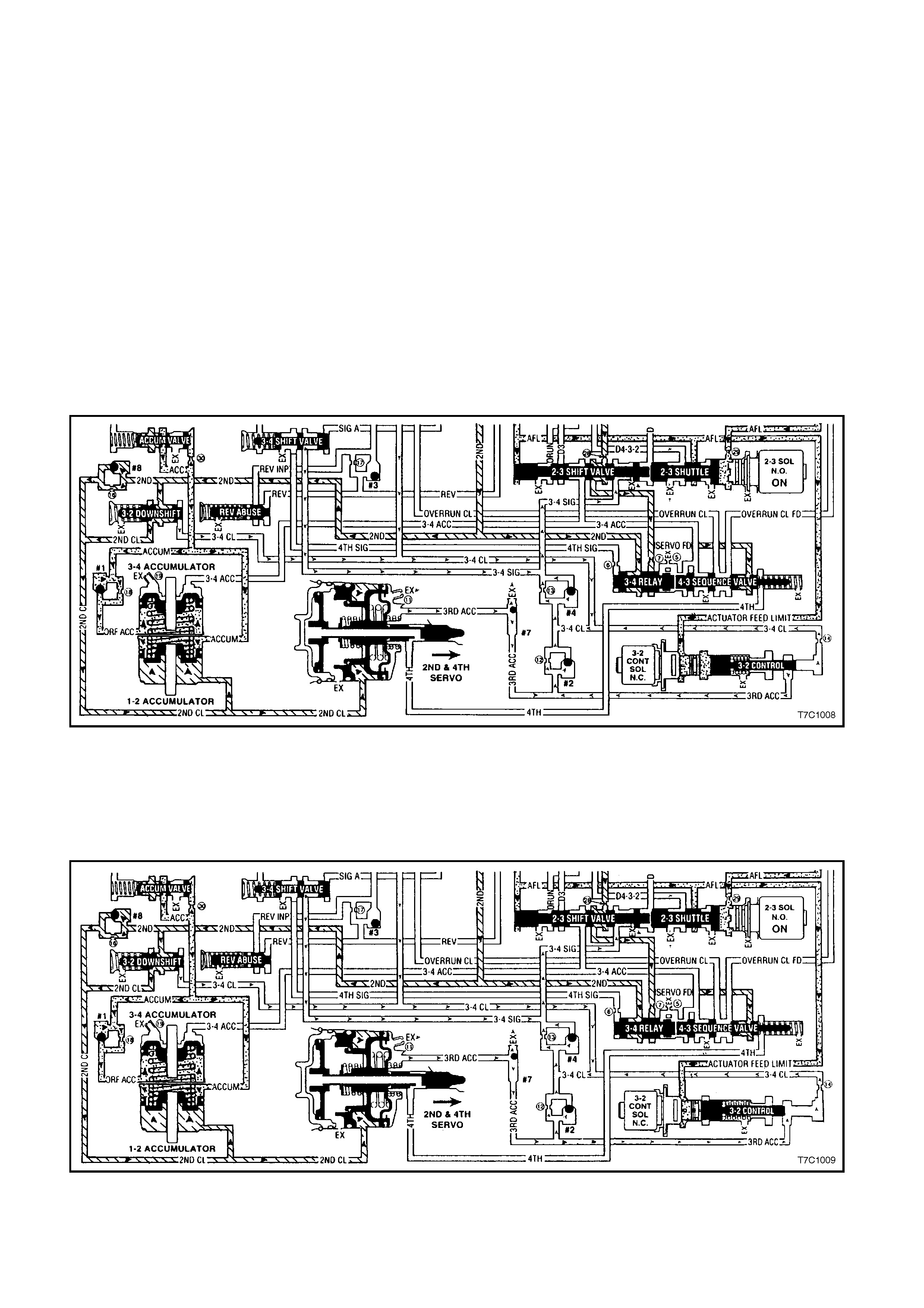
3-2 Downshift Timing
At higher vehicle speeds , the apply of the 2-4 band mus t be delayed to allow engine speed to inc rease suf ficiently
for a sm ooth transfer of engine load to the 2-4 band. T his is achieved by delaying the exhaust of 3rd accum ulator
(3RD ACC) fluid. Under these conditions (see Figure 7C1-10), the 3-2 control solenoid is commanded ON, moving
the 3-2 control valve away from the solenoid (closing the 3-2 control valve) during the shift. This causes the
exhausting 3-4 clutch fluid (3-4 CL) to seat check ball #4 and flow through orifice #13 to exhaust at the 2-3 shift
valve, via the 3-4 signal (3-4 SIG) circuit.
While this 3-4 clutch exhaust is in process, the apply rate of the 2-4 band is governed by the exhausting 3rd
accum ulator (3RD ACC) fluid. The initial fluid flow seats check ball #7 and, with the 3-2 control valve closed, 3rd
accum ulator (3RD ACC) fluid also seats check ball #2. Fluid then must pass through both orif ice #12 and #13 to
exhaust through the 3- 4 signal (3-4 SIG ) pass age. This action delays the apply of the 2-4 band to ef fec t a sm ooth
downshift.
At lower vehicle speeds (s ee Figure 7C1-11), when the band mus t be applied more quickly, the PCM com mands
the 3-2 control solenoid OFF, allowing spring f orce to move the control valve to the solenoid (opening the valve).
This now opens another circuit, allowing 3rd accumulator (3RD ACC) fluid to flow through both orifice #12 and #14
to exhaust with the 3-4 clutch fluid. T his allows the 2-4 band to be applied m ore quick ly for the correct shift tim ing
under these operating conditions.

3. TRANSM ISSION DEFINITIONS AND ABBREVIATIONS
The following definitions and abbreviations are provided to establish a common language and assist the user in
describing transmission related conditions. The use of these terms and/or conditions can be found in the various
parts of the automatic transmission section, but more particularly, in 7C3 HYDRAULIC/MECHANICAL
DIAGNOSIS.
3.1 DEFINITIONS
The following definitions have been arranged in alphabetical order and are intended to assist the user with an
explanation of their meaning, in order to gain the maximum benefit from those Sections that deal with the
Hydra-matic 4L60-E, automatic transmission. There are additional, unique definitions in
Section 7C3 HYDRAULIC/M ECHANICAL DIAGNOSIS that should also be r eferred to when using that particular
information.
Accumulator - A component of the transmission that absorbs hydraulic pressure during the apply of a clutch or
band. Accumulators are designed to control the quality of a shift from one gear range to anther. within
Adaptive Learning - Programming within the PCM that automatically adjusts hydraulic pressures in order to
compensate for changes in the transmission (i.e. component wear).
Applied - An 'Apply Component' that is holding another component to which it is splined or assembled to. Also
referred to as "engaged".
Apply Components - Hydraulically operated clutches, servo’s, bands and mechanical one-way roller or sprag
clutches that drive or hold members of a planetary gear set.
Apply Plate - A steel clutch plate in a clutch pack, located next to the (apply) piston.
Backing Plate - A steel plate in a clutch pack that is usually the last plate in that clutch assembly (furthest from
the clutch piston).
Band - An apply component that consists of a flexible strip of steel and friction material that wraps around a drum.
When applied, it tightens around the drum and prevents the drum from rotating.
Brake Switch - An electrical device that provides signals to the Powertrain Control Module (PCM), based on the
position of the brake pedal. The PCM uses this information to apply or release the torque converter clutch (TCC).
Centrifugal Force - A force that is imparted on an object (due to rotation) that increases as that object moves
further away from a centre-point of rotation.
Checkball - A spherical, hydraulically controlled component (usually of steel) that either seals or opens fluid
circuits. It is also referred to as a check valve.
Clutch Pack - An assembly of components generally consisting of clutch plates, an apply plate and a backing
plate.
Clutch Plate - An hydraulically activated component that has two basic designs: (1) all steel, or (2) a steel core
with friction material bonded to one or two sides of the plate.
Control Valve Body - A machined metal casting that contains valve trains and other hydraulically controlled
components that shift the transmission.
Coupling Speed - The speed at which a vehicle is travelling and no longer requires torque multiplication through
the torque converter. At this point, the stator 'free wheels' to allow fluid leaving the turbine to flow directly to the
pump. (Also see Torque Converter).
De-energise(d) - To interrupt the electrical current that flows to an electronically controlled device, making it
electrically inoperable.
Direct Drive - A condition in a gears set where the input speed and input torque equals the output speed and
output torque. The gear ratio through the gear set is 1:1.
Downshift - A change in a gear ratio where both input speed and torque increases.
Duty Cycle - In reference to an electronically controlled solenoid, it is the amount of time (expressed as a
percentage) that current flows through the solenoid coil.
Energise(d) - To supply a current to an electronically controlled device, enabling it to perform its designed
function.
Engine Compression Braking - A condition where compression from the engine is used with the transmission to
decrease vehicle speed.
Exhaust - The release of fluid pressure from a hydraulic circuit. (The words 'exhausts' and 'exhausting' are also
used and have the same intended meaning.)
Fail-Safe Mode - A condition whereby a component (i.e. engine or transmission) will partially function even if its
electrical circuit is disabled.
Fluid - In this Section, 'fluid' refers primarily to Automatic Transmission Fluid (or ATF) and, for the Hydra-matic
4L60-E transmission, the only recommended fluid is Dexron III®.
Fluid Pressure - A pressure that is consistent throughout a given fluid circuit.
Force - A measurable effort that is exerted on an object (component).
Freewheeling - A condition where power is lost through a driving or holding device (i.e. roller or sprag clutches).
Friction Material - A heat and wear resistant fibrous material, bonded to clutch plates and bands.
Gear - A round, toothed device that is used for transmitting torque through other components.

Gear Range - A specific speed to torque ratio at which the transmission is operating (i.e. 1st gear, 2nd gear etc.).
Gear Ratio - Revolutions of an input gear as compared to the revolutions of an output gear. It can also be
expressed as the number of teeth on a gear as compared to the number of teeth on a gear that it is in mesh with.
Hydraulic Circuit - A fluid passage which often includes the mechanical components in that circuit designed to
perform a specific function.
Input - A starting point for torque, revolutions or energy into another component of the transmission.
Internal Gear - The outermost member of a gear set that has gear teeth in constant mesh with the planetary
pinion gears of the gear set.
Land (Valve Land) - The larger diameters of a spool valve that contact the valve bore or bushing.
Line Pressure - The main fluid pressure in a hydraulic system created by the pump and pressure regulator valve.
Manual Valve - A spool valve that distributes fluid to various hydraulic circuits and is mechanically linked to the
gear selector lever.
Orifice - A restricting device (usually a hole in the spacer plate) for controlling pressure build up into another
circuit.
Overdrive - An operating condition in the gear set allowing output speed to be higher than input speed and output
torque to be lower than input torque.
Overrunning - The function of a one-way mechanical clutch that allows the clutch to freewheel during certain
operating conditions of the transmission.
Pinion Gears - Pinion gears (housed in a carrier) that are in constant mesh with a circumferential internal gear
and centralised sun gear.
Planetary Gear Set - An assembly of gears that consists of an internal gear, planet pinion gears with a carrier,
and a sun gear.
Powertrain Control Module (PCM) - An electronic device that manages the vehicle's engine and automatic
transmission functions.
Pressure - A measurable force that is exerted on an area and expressed as kilopascals (kPa).
Pulse Width Modulated (PWM) - An electronic signal that continuously cycles the ON and OFF time of a device
(such as a solenoid) while varying the amount of ON time.
Race (Inner or Outer) - A highly polished steel surface that contacts bearings or sprag or roller elements.
Reduction (Gear Reduction) - An operating condition in the gear set allowing output speed to be lower than input
speed and output torque to be higher than input torque.
Residual Fluid Pressure - Excess pressure contained within an area after the supply pressure has been
terminated.
Roller Clutch - A mechanical clutch (holding device) consisting of roller bearings assembled between inner and
outer races.
Servo - A spring loaded device consisting of a piston in a bore that is operated (stroked) by hydraulic pressure to
apply or release a band.
Spool Valve - A round hydraulic control valve often containing a variety of land and valley diameters.
Sprag Clutch - A mechanical clutch (holding device consisting of "figure eight" like elements assembled between
inner and outer races.
Throttle Position - The travel of the throttle plate that is expressed in percentages and measured by the Throttle
Position Sensor (TP Sensor).
Torque - A measurable twisting force expressed in terms of Newton metres (Nm).
Torque Converter - A component of an automatic transmission, (attached to the engine flexplate) that transfers
torque from the engine to the transmission through a fluid coupling.
Variable Capacity Pump - The device that provides fluid for operating the hydraulic circuits in the transmission.
The amount of fluid supplied varies depending on vehicle operating conditions.

3.2 ABBREVIATIONS
PCM - Powertrain Control Module.
TCC - Torque Converter Clutch.
TP Sensor - Throttle Position Sensor.
ECT Sensor - Engine Coolant Temperature Sensor.
VS Sensor - Vehicle Speed Sensor.
TFP VAL. POSITION SW. - Transmission Fluid Pressure Manual Valve Position Switch
RWD - Rear Wheel Drive.
2WD - Two Wheel Drive.
PSA - Transmission Fluid Pressure Switch Assembly.
TTS - Transmission Temperature Sensor.

4. SERVICE NOTES
In the interests of safety to personnel, equipment and to the vehicle and its components, the following notes
should be read and adhered to whenever servicing operations are to be carried out on the Hydra-matic 4L60-E
automatic transmission. In addition, some of this information also refers to the adherence to sound workshop
practices and, to achieve the design life of affected components, it is also recommended that these points are
taken into account.
4.1 FASTENERS
Always reinstall fasteners at the same locations as they were removed.
If a fastener requires replacement, always use a part of the correct part number or of equal size and strength or
stronger.
Tighten fasteners to correct torque value when required. Torque values are specified for dry, unlubricated fastener
threads.

4.2 GENERAL WORKSHOP PRACTICE
Keep work area and tools clean.
To avoid unnecessary contamination, always clean the exterior of the transmission before removing any parts.
Do not use wiping cloths or rags because of the risk of lint being trapped in the transmission.
Do not use solvents on:
•neoprene seals.
•composition faced clutch plates.
•thrust washers.
Always use protective eye wear when using compressed air on components.
Blow out all passages with compressed air. Only probe small passages with soft, thin wire.
Handle parts with care to avoid nicks and scratches.
Do not remove Teflon oil seal rings unless damaged or performing a complete overhaul.
Expand internal snap rings and compress external snap rings to maximise retention and security.
Lubricate all internal parts with transmission fluid (Only use Dexron® III), as they are being installed.
When installing cap screws into aluminium castings:
•always use a torque wrench.
• always dip screw threads in transmission fluid (Only use Dexron® III).
Stripped or dam aged threads in alum inium cast ings may be reconditioned by using c omm ercially available thread
inserts.
Once removed, replace all gaskets, seals and O-rings with new parts and:
•always use seal protectors where indicated and do not use gasket cement or sealant on any joined face
unless specified to do so.
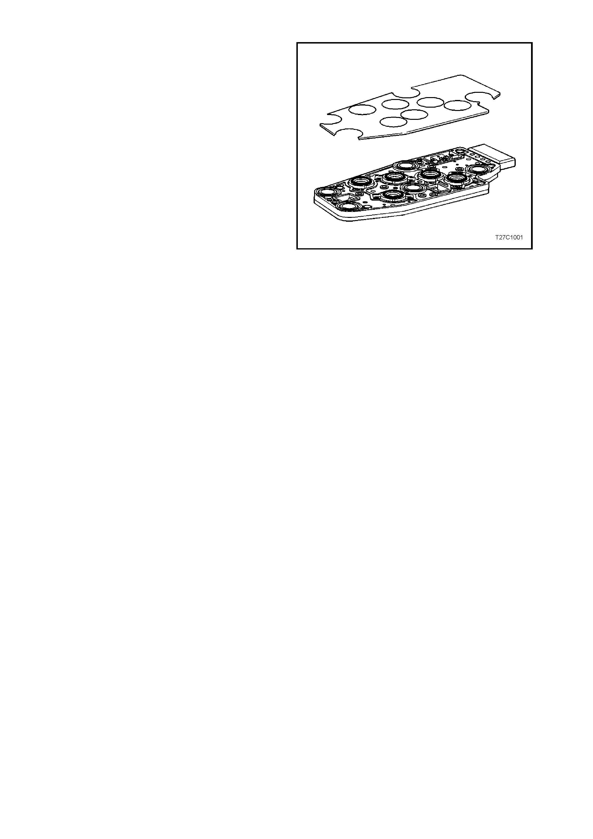
4.3 1999 MY TRANSMISSION REVISION
A plastic shield was fitted over the Transmission
Fluid Pressure (TFP) Switch Assembly from a
production date of April 8, 1999 and a Julian date of
098.
The reason for fitting the shield is to prevent debris
such as aluminium shavings, bronze material and
certain clutch material from causing the pressure
switches in the TFP switch to either stick or
electrically short out.
Should any of these conditions occur, a Diagnostic
Trouble Code (DTC) 28 (V6/V6 Supercharged
engines) or P1810 (GEN III V8 engine) will set and
the Check Powertrain Lamp, in the instrument
panel will be illuminated.
As the shield is not sold separately, a new part
number has been generated and the new part will
service all 1998/1999 Model Year 4L60-E
automatic transmissions. Figure 7C1-12