
SECTION 7C4 - HYDRA-MATIC 4L60-E AUTOMATIC
TRANSMISSION: ON-VEHICLE SERVICING
CAUTION:
This vehicle will be equipped with a Supplemental Restraint System (SRS). An SRS
will consist of either seat belt pre-tensioners and a driver's side air bag, or seat belt
pre-tensioners and a driver's and front passenger's side air bags. Refer to
CAUTIONS, Section 12M, before performing any service operation on or around any
SRS components, the steering mechanism or wiring. Failure to follow the CAUTIONS
could result in SRS deplo yment, resulting in possible p ersonal injury or unnecessary
SRS system repairs.
CAUTION:
This vehicle may be equipped with LPG (Liquefied Petroleum Gas. In the interests of
safety, the LPG fuel system should be isolated by turning ‘OFF’ the manual service
valve and then draining the LPG serv ice lines, before any service w ork is carried out
on the vehicle. Refer to the LPG leaflet included with the Owner's Handbook for
details or LPG Section 2 for more specific servicing information.
CAUTION:
Whenever any component that forms part of the ABS or ABS/ETC (if fitted), is
disturbed during Service Operations, it is vital that the complete ABS or ABS/ETC
system is checked, using the procedure as detailed in 4. DIAGNOSIS, ABS or
ABS/ETC FUNCTION CHECK, in Section 12L ABS & A BS/ETC.
1. GENERAL INFORMATION
As detailed in 7C1, material contained within this Section, details service operations that can be carried out on a
transmission while it is still installed in the vehicle, as well as the procedures required to remove and reinstall the
transmission assembly from/to the vehicle.
General servicing information is also included in this Section and it is recommended that this material be read and
followed, whenever servicing operations are to be carried out, on this transmission.
1.1 GENERAL SERVICE PRECAUTIONS
RECOMMENDATIONS
When servicing the transmission, all parts should be cleaned and inspected as outlined under 'Clean and Inspect',
in these recommendations. Individual units should be reassembled before disassembly of other units to avoid
confusion and interchanging of parts.
1. Thoroughly clean the transmission exterior before removal of any component.
2. Disassembly and reassembly must be made on a clean work bench. Cleanliness is of the utmost importance.
The bench tools, and parts must be kept clean at all times.
3. Before installing screws and other fasteners into aluminium parts, DIP SCREWS INTO TRANSMISSION
FLUID (Only use DexronÒ III) to prevent galling aluminium threads and to prevent screws from seizing.
4. To prevent thread stripping, always use a torque wrench when installing screws.
5. If threads in aluminium parts are stripped or damaged, the part can be made serviceable by the use of
commercially available, thread inserts.
6. Protective tools must be used when assembling seals to prevent damage. The slightest flaw in the sealing
surface of the seal can cause an oil leak.
7. Aluminium castings and valve parts are very susceptible to nicks, burrs, etc., and should be handled with care.
8. Internal snap rings should be expanded and external snap rings compressed if they are to be re-used. This will
ensure proper seating when reinstalled.
9. O-rings, gaskets and oil seals that are removed should not be re-used.
10. Teflon oil seal rings should not be removed unless damaged.
11. During assembly of each unit, all internal moving parts must be lubricated with transmission fluid.
Techline
Techline
Techline

OIL COOLER PIPES
If replacement of transmission steel tubing cooler pipes is required, use only double wrapped and brazed steel
tubing meeting Holden Specification 123M or equivalent. Under no circumstances is copper or aluminium tubing to
be used to replace steel tubing. These materials do not have satisfactory fatigue durability to withstand normal car
vibrations.
Steel tubing should be flared using the double flare method.
CLEAN AND INSPECT
After complete disassembly of a component, wash all metal parts in a clean solvent and dry with compressed air.
Blow oil passages out and check to make sure they are not obstructed. Small passages should be checked with tag
wire. All parts should be inspected to determine which parts are to be replaced.
Pay particular attention to the following:
1. Inspect linkage and pivot points for excessive wear.
2. Bearing and thrust surfaces of all parts should be checked for excessive wear and scoring.
3. Check for broken seal rings, damaged ring lands and damaged threads.
4. Inspect seal and O-rings.
5. Mating surfaces of castings should be checked for burrs. Irregularities may be removed by lapping the surface
with emery paper. The emery paper is laid on a flat surface, such as a piece of plate glass.
6. Castings should be checked for cracks and porosity.
NOTE:
Do not use solvents on neoprene seals, composition faced clutch plates or thrust washers as damage to parts may
occur.

2. MAINTENANCE AND GENERAL INFORMATION
2.1 FLUID LEVEL CHECK
GENERAL INFORMATION
When adding or changing the transmission fluid, use only Dexron® III (to Holden’s Specification HN2126). Refer to
the VT Series Owner's Handbook for servicing intervals.
Because this transmission fluid changes colour and smell very early in its life, these indicators should not
necessarily be relied upon to diagnose either transmission internal condition nor fluid deterioration.
Reference to the Fluid Checking Procedure shows that a dark brown fluid colour, coupled with a delayed shift
pattern, may only indicate that the fluid requires replacement and alone, is not a definite indication of a potential
transmission failure.
NOTE:
Do not overfill the transmission. Overfilling will cause foaming of the fluid, loss of fluid, shift complaints and possible
damage to the transmission.
TRANSMISSION FLUID COLOUR
Transmission fluid colour when new and unused, is red. A red dye is added so that it can be distinguished from
other oils and lubricants. The red dye is not an indicator of fluid quality and is not permanent. As the vehicle is
driven, the transmission fluid will quickly begin to look darker in colour. The colour will then appear light brown. A
DARK brown colour with a distinctively burnt odour MAY indicate fluid deterioration and a need for the fluid to be
changed.
TRANSMISSION FLUID CHECKING PROCEDURE
1. Start engine and drive vehicle for a distance of 24 km, or until transmission normal operating temperature is
reached.
NOTE:
As temperature greatly affects transmission fluid levels, this operation must only be carried out with the
transmission at normal operating temperature (82 - 94° C). If the vehicle is not at normal operating temperature,
and the proper checking procedures are not followed, the result could be a false reading of the fluid level on the
dipstick.
2. Park vehicle on level ground.
3. Move gear selector to 'PARK' position.
4. Apply park brake.
5. Let engine idle for 3 minutes with accessories turned off.
6. Lift the locking lever on the red coloured dipstick, remove dipstick and check fluid colour, condition and level.
7. If the fluid level is low, add only enough Dexron® III to bring the level into the “HOT” area.
*Inaccurate fluid level readings will result if checked immediately after the vehicle has been operated under any
or all of the following conditions:
a. In high ambient temperatures above 32° C.
b. At sustained high speeds.
c. In heavy city traffic during hot weather.
d. Towing.
e. In commercial use (e.g. taxi).
*If the vehicle has been operated under these conditions, switch the engine off and allow the vehicle to 'cool' for
approximately thirty minutes. After the cool-down period, re-start the vehicle and continue from step 2, above.

4L60-E TRANSMISSION FLUID CHECKING PROCEDURE
STEP ACTION YES NO
1. Check the fluid colour.
Is the fluid colour red?
Go to Step 2 Go to Step 11
2. Is the fluid level satisfactory? Go to Step 20 Go to Step 3
3. Check the fluid.
Is the fluid foamy?
Go to Step 8 Go to Step 4
4. Check the fluid level. The correct fluid level should
be in the middle of the cross-hatch.
Is the level high?
Go to Step 9 Go to Step 5
5. Fluid will be low.
Add fluid to the correct fluid level.
Is the fluid level satisfactory?
Go to Step 6 Go to Step 1
6. Check for external leaks.
Were any leaks present?
Go to Step 7 Go to Step 20
7. Correct the fluid leak condition.
Is action complete?
Go to Step 20
8. Is the fluid level too high? Go to Step 9 Go to Step 10
9. Remove excess fluid to adjust to the correct fluid
level.
Is action complete?
Go to Step 20
10. 1. 1. Check for contaminants in the fluid.
2. Drain the fluid to determine the source of
contamination.
Is action complete?
Go to Step 15
11. Is the fluid colour a non-transparent pink? Go to Step 12 Go to Step 13
12. Replace the leaking cooler.
Is the action complete?
Go to Step 15
13. The fluid colour should be light brown.
Transmission fluid may turn dark with normal use.
This does not always indicate oxidation or
contamination.
Is the fluid colour light brown?
Go to Step 14 Go to Step 1
14. Drain the fluid to determine if the fluid is
contaminated. A very small amount of material in
the bottom of the oil pan is a normal condition, but
larger pieces of metal or other material in the
bottom of the oil pan are not and the transmission
requires an overhaul.
Was the fluid contaminated?
Go to Step 15 Go to Step 18
15. Overhaul the transmission or fit a SRTA unit. Refer
to Section 7C5 Unit Repair.
Is action complete?
Go to Step 16

STEP ACTION YES NO
16. Flush the coolers.
Is action complete?
Go to Step 17
17. Add new fluid.
Is action complete?
Go to Step 19
18. Change the fluid and filter.
Is action complete?
Go to Step 19
19. Is the fluid level satisfactory? If not, correct as
necessary.
Is action complete?
Go to Step 20
20. Refer to Functional Test Procedure, in Section 7C3,
DIAGNOSIS.
Is action complete?
Fluid Checking
Procedure
Completed

2.2 FLUID LEAK DIAGNOSIS AND REPAIR
The cause of most external leaks can usually be located and repaired with the transmission installed in the vehicle.
METHODS FOR LOCATING LEAKS
General Method
1. Verify that the leak is in fact, transmission fluid.
2. Thoroughly clean the suspected leak area.
3. Operate the vehicle for about 24 km or until normal operating temperatures are reached.
4. Park the vehicle over clean paper or cardboard.
5. Switch the engine off and look for fluid spots on the paper.
6. Make necessary repairs.
Powder Method
1. Thoroughly clean the suspected leak area with a suitable cleaning agent.
2. Apply an aerosol type powder (eg foot powder) to the suspected leak area.
3. Operate the vehicle for about 24 km or until normal operating temperatures are reached.
4. Switch the engine off.
5. Inspect the suspected leak area and trace the leak path through the powder to find the source.
6. Make necessary repairs.
Dye and Black Light Method
While the following can be used as a guide, always follow the manufacturer’s recommendations for use of this
equipment.
1. Pour the manufacturer's recommended amount of dye (such as J28431-B) into the transmission.
2. Road test the vehicle under normal operating conditions.
3. Direct the black light (Tool No. J42220) to the suspect area. Any fluid leak will appear as a brightly coloured
path, leading to the source.
NOTE:
The colour of the dyed fluid can be checked on the transmission dipstick.
4. Make the necessary repairs, then re-check that the leak has been rectified.
REPAIRING THE LEA K
NOTE 1:
Once the leak has been located and traced back to its source, the CAUSE of the leak must be determined, for the
repair to be satisfactory.
NOTE 2:
If a gasket is replaced, but the sealing flange is distorted or bent (eg oil pan flange), the new gasket will not stop the
leak. Obvious damage such as this must be rectified before fitting new gaskets, if a satisfactory repair is to be
expected.
NOTE 3:
Before attempting to repair a leaking seal and/or gasket, check to make sure that the following conditions do not
apply:
Gaskets:
Fluid level or pressure is too high.
Blocked or partially blocked vent or drain back holes.
Incorrectly torqued fasteners or dirty/damaged threads.
Warped/bent flanges or sealing surface.
Scratches, burrs or other damage to the sealing surface.
Damaged or worn gasket.
Cracking or porosity of the component or adjacent part.
Improper sealant used (where applicable).

Seals:
Fluid level or pressure is too high.
Blocked or partially blocked vent or drain back holes.
Damaged seal bore (Scratched burred or nicked).
Damaged or worn seal.
Incorrect previous installation.
Cracks in the component.
Manual or output shaft is scratched, nicked or worn.
Loose or worn bearing, causing excess seal wear.
POSSIBLE POINTS OF FLUID LEAKS
1. Transmission and Oil Pan:
Attaching bolts not torqued correctly.
Improperly installed or damaged gasket.
2. Case Leak:
Filler tube multi-lip seal damaged or missing.
Filler tube bracket misaligned.
Speed sensor seal damaged.
Manual shaft seal worn or damaged.
Oil cooler connector fittings loose or damaged.
Propeller shaft oil seal worn or damaged.
Line pressure plug loose or thread damage has occurred.
Porous casting.
3. Leak at End of Converter:
Converter seal damaged.
•Seal lip cut (Check converter hub for damage).
•Bushing has moved forward and/or is damaged.
•Garter spring is missing from seal.
Converter leak in the weld area.
Porous casting (case or pump).
4. Fluid Comes from Vent or Fill Tube:
Overfilled.
Water or coolant in fluid (milky/pink fluid colour).
Case porous.
Incorrect fluid level indicator.
Blocked or partially blocked vent.
Drain back holes blocked.
The alignment of the oil pump to case gasket is incorrect.
CASE POROSITY REPAIR
1. Clean the area with epoxy manufacturer's recommended solvent and air dry.
CAUTION:
Epoxy adhesives may cause skin irritations and eye damage. Read and follow all information on the
product label, as provided by the manufacturer.
2. Mix sufficient amount of epoxy adhesive ('Araldite' or an equivalent product), following the manufacturer's
recommendations.
3. While the transmission case is hot, apply epoxy adhesive with a clean, dry stiff brush.
4. Allow the adhesive to dry for the recommended time before starting the engine and checking the results of the
repair.
5. Repeat the fluid leak diagnosis procedure previously detailed.
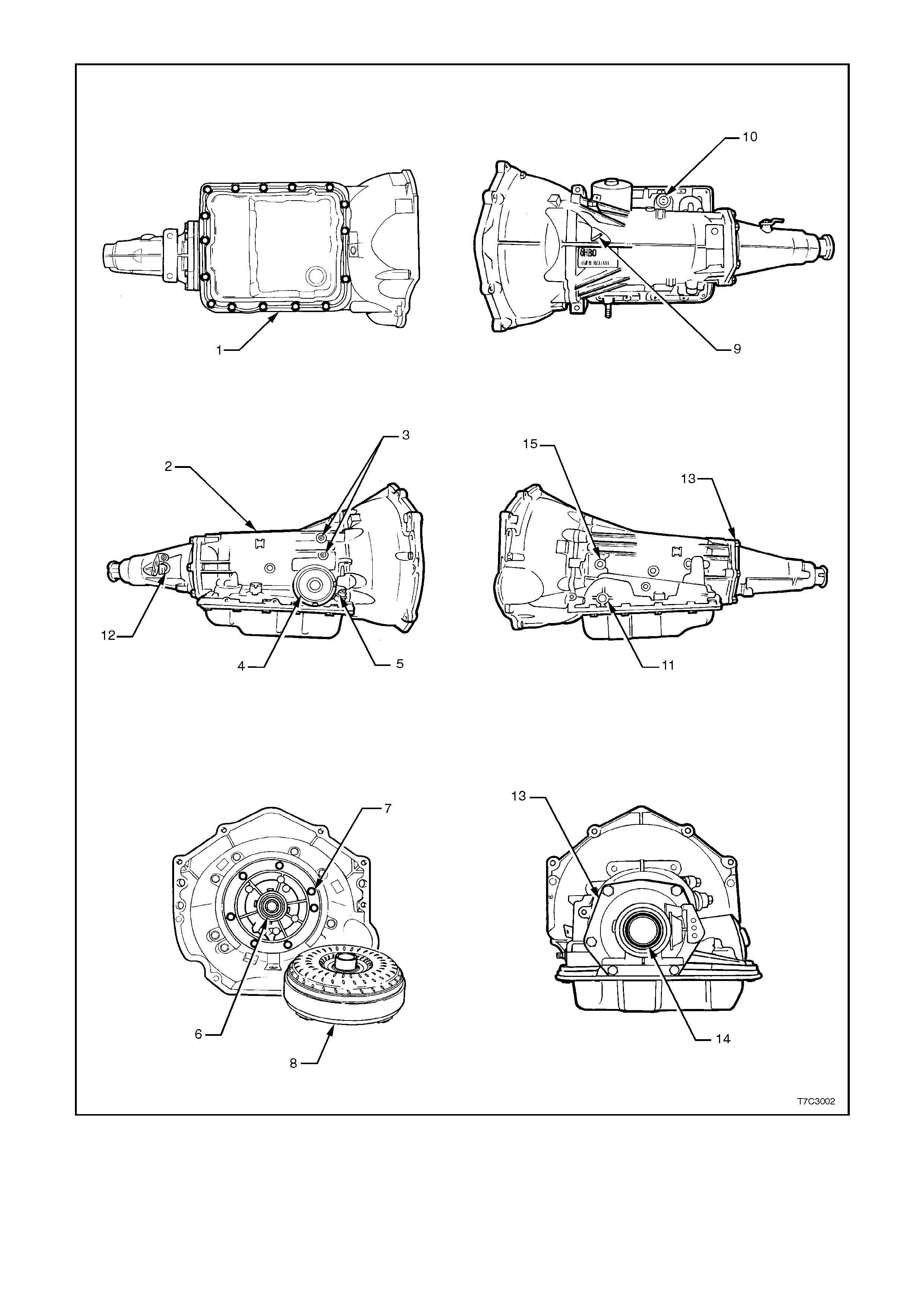
1. Oil Pan Gasket
2. Transmission Main Case
3. Cooler Connections
4. 2-4 Servo Cover Seal
5. Oil Filler Tube Seal
6. Oil Pump Seal Assembly
7. Oil Pump to Case Seal
8. Torque Converter
9. Transmission Vent
10. Pass-through Connector O-ring
11. Manual Shaft Oil Seal
12. Vehicle Speed Sensor O-ring
13. Extension Housing to Case
Seal
14. Extension Housing Oil Seal
Assembly
15. Line Pressure Plug
Figure 7C4-1
2.3 FLEXPLATE AND/OR TORQUE CONVERTER VIBRATION TEST
Should an imbalance condition with either of these
two components be suspected, then the following
procedures should be followed.
EVALUATION
1. Start the engine and run until normal oper ating
temperature is reached.
2. With the engine at idle speed and the
transmission in "PARK" or "NEUTRAL",
observe the vibration condition.
2. Stop the engine.
RECTIFICATION
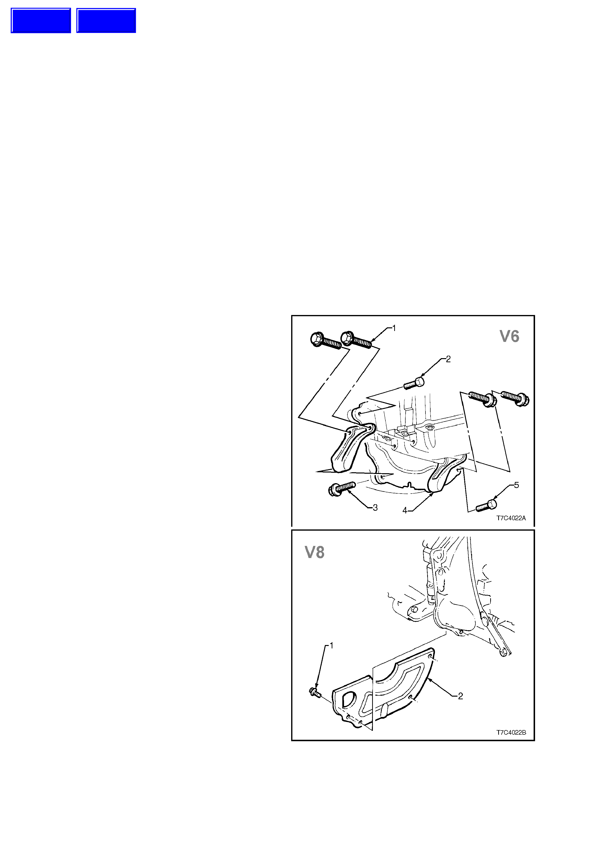
1. Remove the converter cover as follows:
a. Remove the starter motor. Refer to
Section 6D1-2 STARTING SYSTEM V6
ENGINE or to Section 6D2- 2 STARTING
SYSTEM V8 ENGINE, for the necessary
procedure.
b. W hen a V6 engine is fitted to the vehicle,
the beaming braces (4) will need to be
removed, to allow cover removal.
Remove the lower retaining bolts (3),
before the brace to oil pan bolts (1).
Finally remove the two cover retaining
screws (2), and remove the cover from
the front of the transmission.
2. Remove the thr ee torque c onver ter to f lex plate
attaching bolts.
3. Rotate the torque converter through 1/3 turn and
install the attaching bolts, after having cleaned
the threads an applying a thread sealant such
as Loctite 242 or equivalent to Holden’s
Specification HN1256, Class 2, Type 2. Tighten
bolts to the correct torque specification.
TORQUE CONVERTER TO
FLEX PLATE BOLT 60 - 70 Nm
TORQUE SPECIFICATION
Figure 7C4-2
4. Reinstall the torque converter housing cover
and beaming braces (V6 engine), tightening
bolts to the correct torque specification.
NOTE:
When installing the beaming braces (V6 engine),
first tighten the brace to oil pan bolts ( 1) f inger tight,
to ensure correct alignment, torque the
transmission to brace bolts (3), then the oil pan
bolts.
LOWER COVER ATTACHING All Engi nes:
SCREW TORQUE SPECIFICATION 3 - 5 Nm
BEAMING BRACE TO OIL PAN V6 Engine:
BOLT TORQUE SPECIFICATION 20 - 35 Nm
BEAMING BRACE TO TORQUE
CONVERTER HOUSING BOLT V6 Engine:
TORQUE SPECIFICATION 50 - 85 Nm
5. Install the starter motor, by following the
procedure detailed in Section 6D1-2
STARTING SYSTEM - V6 ENGINE or
Section 6D2-2 STARTING SYSTEM - V8
ENGINE.
STARTER MOTOR ATTACHING All Engines :
TORQUE SPECIFICATION 40 - 60 Nm
STARTER MOTOR BRACE BOLT 12 - 16
(V8) TORQUE SPECIFICATION Nm
6. Start the engine and check for vibration.
Repeat the above procedure until the best
possible balance is obtained.
Figure 7C4-2

2.4 TRANSMISSION COOLER REVERSE FLUSH AND FLOW RATE CHECK
IMPORTANT:
It is essential that a reverse flush and oil cooler
flow rate check is performed, after ANY of the
following situations:
•Transmission replacement.
•If fluid contamination is suspected.
•Whenever the oil pump and/or torque
converter is replaced.
NOTE:
The reverse flush must be completed prior to
conducting a flow rate check.
REVERSE FLUSH
The recommended procedure for reverse flushing
the transmission cooler and lines, particularly after
an overhauled or replaced transmission has been
installed into the vehicle, is as follows:
1. Disconnect both cooler lines at the
transm ission and at the radiator cooler. Use a
back-up spanner to hold unions, to prevent
damage to the lines.
2. Carefully check the cooler inlet fitting (lower
right hand side) to see whether any material is
evident at this point. If so, dislodge and
remove with a suitable tool and/or
compressed air blown in the reverse direction
through the cooler.
3. Using a com mer c ially available pressure s pr ay
gun and clean solvent, such as white spirit:
a. Back flush through both cooler lines.
b. Back flush through the coolers, including
the external cooler (if fitted).
c. Blow compressed air through return and
inlet pipes to remove solvent.
d. Flush pipes with transmission fluid.
4. Reconnect cooler lines to the transmission
and cooler but leave the cooler return line to
transmission connection open.
5. Conduct a flow rate test as described below,
to ensure that any restriction has been
cleared.
6. If f low rate is satisf actory, reconnect the return
line to the transmission, tightening all fittings
to the specified torque.
OIL COOLER LINES
AND FITTINGS 15 - 18 Nm
TORQUE SPECIFICATION
7. Lower vehicle and check f luid level as detailed
in 2.1 FLUID LEVEL CHECK, in this Section.

FLOW RATE CHECK
CAUTION:
Do not run engine any longer than absolutely
necessary, as too low a fluid level can cause
aeration and foaming.
1. When installing the transmission assembly,
leave the cooler return line disconnected from
the transmission (lower fitting).
2. Ensure that the fluid level is to the
recommended level, as detailed in
2.1 FLUID LEVEL CHECK, in this Section.
3. Place a container underneath the
disconnected cooler line.
4. W ith the selector lever in the Neutral position,
start the engine and observe the f luid flow into
the container, after all air bubbles have
ceased and a steady flow is evident. Measure
the flow rate.
RESULT:
The fluid flow rate should be approxim ately 1.2 litre
in a 20 second period.
If the flow rate is less than this specification, the
source of the restriction must be located and
rectif ied. Poss ibilities are either r adiator tank cooler
and/or external cooler (if fitted).
5. Reinstall the cooler return line and tighten all
fittings to the specified torque.
OIL COOLER LINES AND FITTINGS 15 - 18
TORQUE SPECIFICATION Nm
3. ON-VEHICLE SERVICE OPERATIONS
3.1 FLUID CHANGE AND FILTER REPLACEMENT
NOTE:
To avoid personal injury from accidental hot oil
spillage, perform fluid change only when
transmission fluid is cold.
1. Raise vehicle and support on safety stands.
Refer to Section 0A, GENERAL
INFORMATION for location of the
recommended jacking points.
2. Clean all dirt from around oil pan and
transmission case.
3. Place drain tray under transmission.
4. Hold oil pan in place and, remove the oil pan
bolts from the front and both sides.
5. Loosen the rear oil pan bolts by about 4 turns
each and, while still supporting the oil pan,
lightly tap the sides with a rubber hammer to
break the gasket seal.
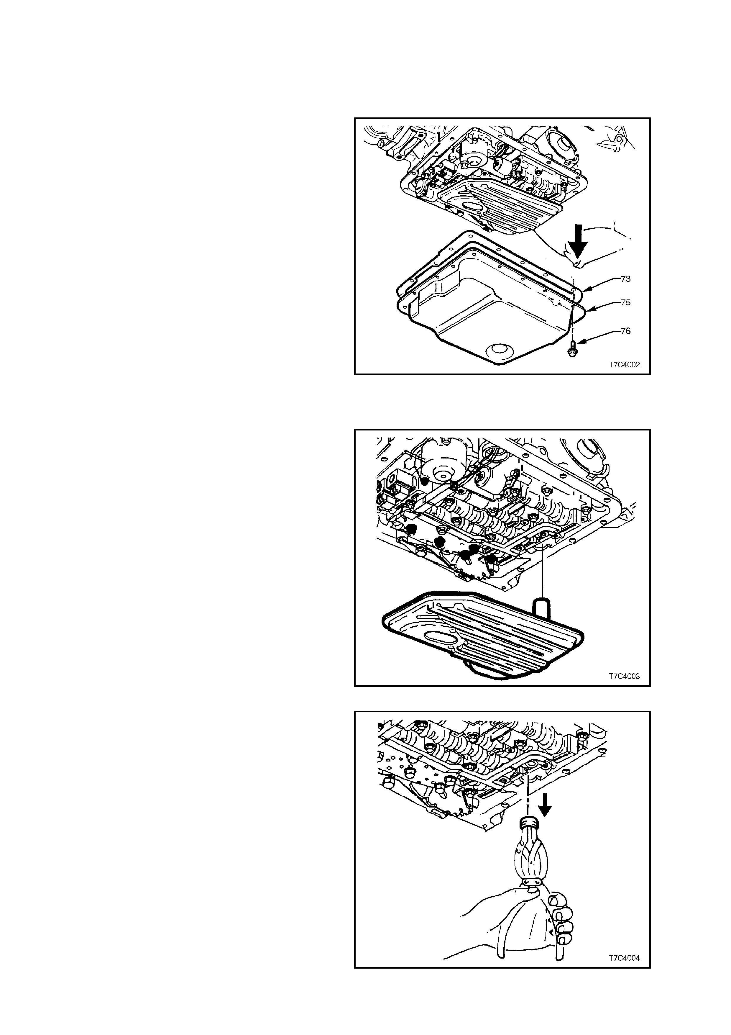
6. Lower the front of the oil pan and drain the
fluid into a suitable c ontainer, then r emove the
oil pan from the transmission.
Figure 7C4-3
7. Pull down and twist the filter to rem ove it from
the transmission case.
8. Open the filter by prying the metal crimping
away from the top of the filter and pull apart.
Inspect the f ilter mater ial for particles that may
indicate evidence of a potential transmission
problem. Examples of the type of material to
look for, are;
- Clutch friction material.
- Bronze slivers, indicating bush wear.
- Steel particles.
Figure 7C4-4
9. Using suitable circlip pliers or a two legged
puller ane slide hammer, such as Litchfield
E6668 or other commercial equivalent,
rem ove the f ilter seal. Tak e c ar e not to sc r atch
the oil pump bore during the process.
NOTE:
If scratched, fluid leakage could occur from this
point, once the vehicle has been put back into
service.
Figure 7C4-5
10. Remove old oil pan gasket and discard.
11. Clean the transmission case, oil pan and oil
pan gasket surface, drying with compressed
air. Ensure that all tr aces of the old gask et are
removed.
12. Lubricate a new filter seal with petroleum jelly
(Vaseline or equivalent) and install into the oil
pump bore, using a suitable sized socket or
piece of tubing.
13. Install a new filter into the transmission case.
14. Check that magnet is functional and located in
the designated position in the oil pan. Install
new gasket and reinstall oil pan. Tighten bolts
to specified torque.
OIL PAN BOLT 9.5 - 13.8
TORQUE SPECIFICATION Nm
15. Lower vehicle and add approxim ately 4.8 litres
(V6 engine) or 5.0 litres (V8 engine) of
DexronÒ III automatic transmission fluid.
16. Operate the vehicle for about 24 km or until
normal operating temperatures are reached.
Check that there are no fluid leaks from the oil
pan area.
17. Check transmission fluid level, refer
2.1 FLUID LEVEL CHECK in this Section.
Figure 7C4-6
3.2 SELECTOR LINKAGE
REMOVE
1. Set transmission selector lever to 'PARK'
position.
2. Raise front of vehicle and place on safety
stands Refer to Section 0A GENERAL
INFORMATION for location of the
recommended jacking points.
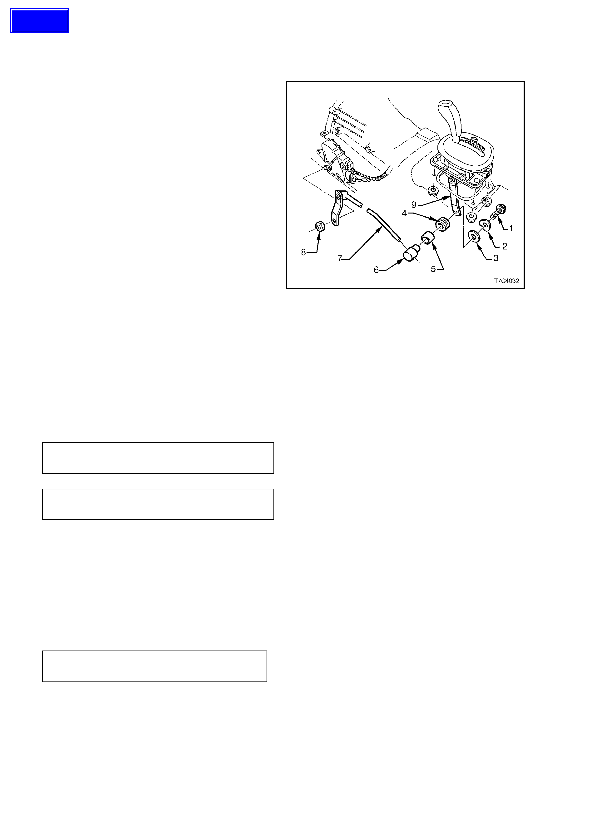
3. Remove locking bolt (1), dished washer (2),
flat washer (3), insulator (4) and sleeve (5)
from lower end of selector lever (9).
4. Slide trunnion (6) from selector rod (7).
5. While holding the transmission selector lever
with an adjustable wrench, remove retaining
nut (8), rod and lever assembly (7) from
transmission manual shaft.
Figure 7C4-7
INSPECT
Check all items for wear and/or damage, replace
all worn or damaged items.
REINSTALL
Installation is the reverse of the r emoval proc edur e.
Tighten the selector lever retaining nut to the
specified torque. Adjust linkage as described
below.
MANUAL SHAFT LEVER NUT 15 - 35
TORQUE SPECIFICATION Nm
SELECTOR LEVER LOCKING 15 - 35
BOLT TORQUE SPECIFICATION Nm
ADJUST
Refer to Figure 7C4-7.
1. Loosen locking bolt at selector lever.
2. Position transmission selector lever in the
'PARK' position.
3. Position gearshift lever in the 'PARK' position,
then tighten the locking bolt at the selector
lever, to the specified torque.
SELECTOR LEVER LOCKING 15 - 35
BOLT TORQUE SPECIFICATION Nm
4. Lower vehicle and test that the vehicle
operates correctly.
5. Ensure that engine can be started only in
'PARK' and 'NEUTRAL'. If required, adjust
the Neutral Start and Back-up Lamp switch
as detailed in 3.4 NEUTRAL START AND
BACK-UP LAMP SWITCH, in this Section.
Techline
3.3 SELECTOR CONTROL LEVER ASSEMBLY
REMOVE
1. Raise vehicle and place on safety stands.
Refer to Section 0A GENERAL
INFORMATION for the location of
recommended jacking points.
2. Remove centre console insert (refer Section
1A3 INSTRUMENT PANEL AND CONSOLE).
3. Disconnect the wiring harness connector (1)
from the control lever assembly patch
harness.
4. From beneath vehicle, disconnect rod from
selector lever by removing bolt securing
trunnion to lever (refer to 3.2 SELECTOR
LINKAGE in this Section).
5. Remove the four nuts securing the control
lever assembly to the floor pan.
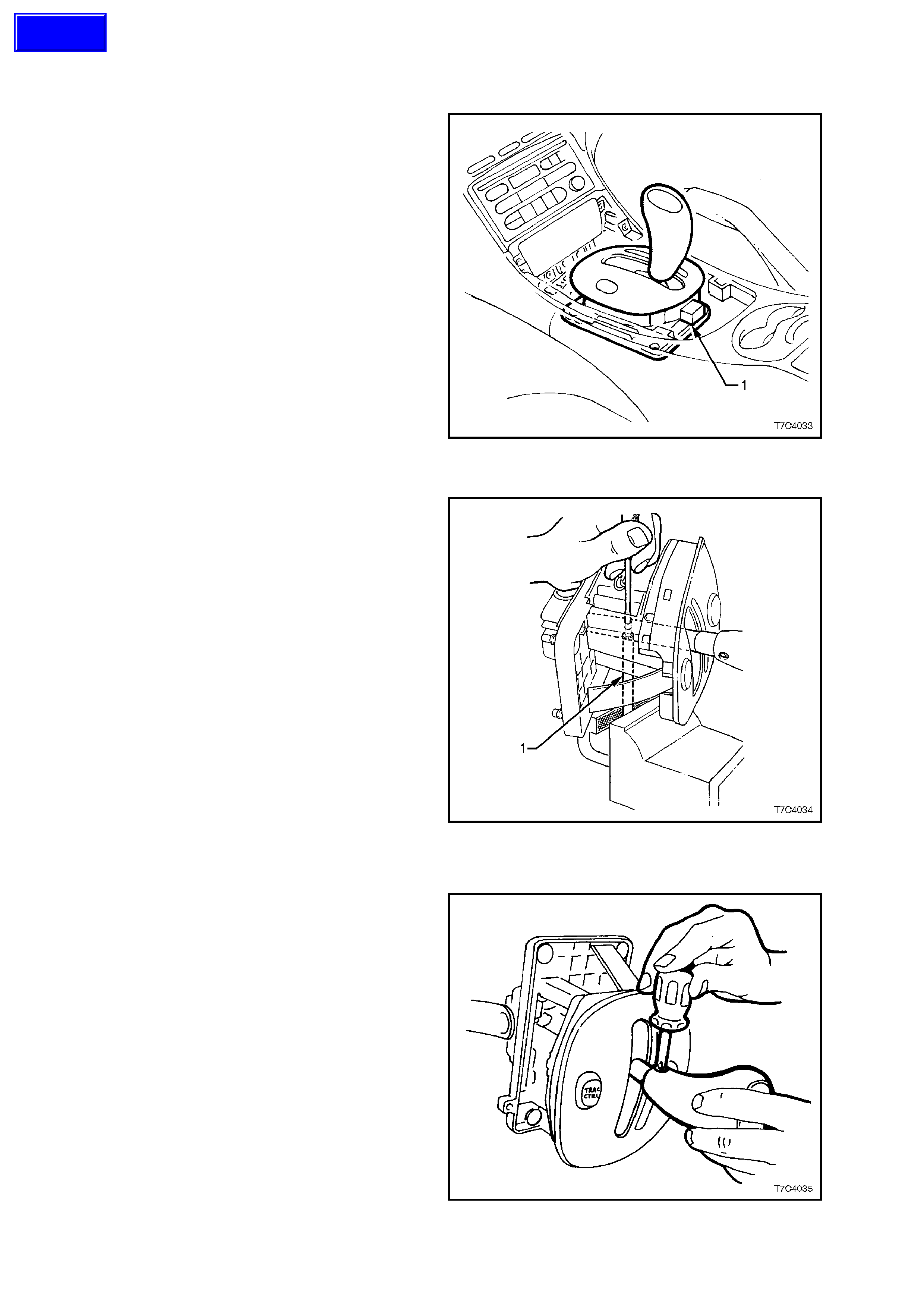
6. From inside the vehicle, lift the control lever
assembly from the floor pan. Figure 7C4-8
DISASSEMBLE
NOTE: During manufacture, the lower housing is
attached to the base with a solvent adhesive, as an
aid to production installation. For service
replacement, while the lower housing is only
serviced as a complete assembly, the upper
housing is available separately. On installation, the
four retaining clips on a replacem ent upper housing
provide sufficient retention, without the need for
solvent to be used.
If required, the upper components and switches
can be serviced without needing to separate the
two fused components.
1. Clamp a 100 mm length of suitable diameter
tubing (1), vertically in a bench vice, as shown.
2. Locate the protruding end of the selector lever
roll pin, over the tubing, then remove the pin,
using a suitable sized pin punch and hammer.
3. Remove the button slider and spring from the
selector handle. Take care not to lose the
lower slider guide and spring from the shift
lever.
Figure 7C4-9
4. Remove the selector handle securing screw.
Figure 7C4-10
Techline
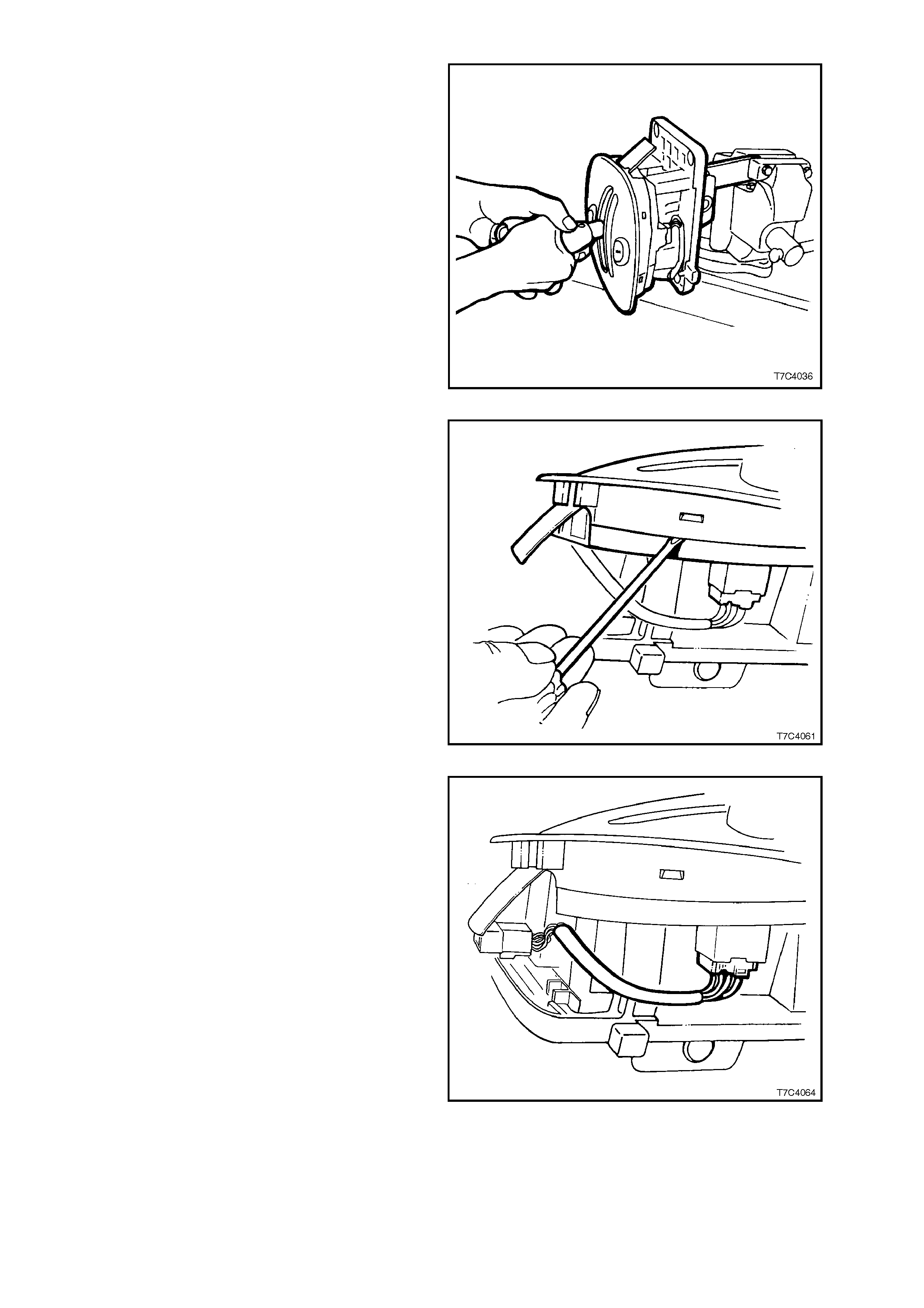
5. With the lower selector lever clamped in a
vice, hold the selector knob as shown and
remove by rocking back and forth while firmly
pulling on the handle.
Figure 7C4-11
6. Carefully prise the upper housing from the
lower, freeing the four locating tangs.
NOTE:
The selector lever and base cannot be further
dismantled, without breaking the base and/or base
side plate. These parts are only serviced as a sub-
assembly.
Figure 7C4-12
7. Remove the selector indicator globe and
holder from the lower housing and the patch
harness connector/s from the switch/es.
Release the harness connector f rom the lower
housing and remove the patch harness from
the selector lever mechanism.
Figure 7C4-13
8. Remove the selector slide indicator (3) and
globe diffuser (4) from the lower housing (5).
Figure 7C4-14
9. If required, the selector indicator lens can be
removed from the upper housing by pressing
from the outside, inwards.
Figure 7C5-15
11. To remove the ‘POWER’ switch or
‘TRACTION’ switch (if fitted), use a small
bladed screwdriver and lever one of the
locating tangs under the lower housing to free
the switch. Remove from above, as shown.
Figure 7C4-16
REASSEMBLE
Reassembly is the opposite of the disassembly
process, noting the following points:
1. Testing of either switch can be undertaken by
reference to Section 12L, ABS & ABS/ETC,
as both switches are the same.
2. When installing the r oll pin to the button s lider,
it will be helpful to use a guide pin to assist
with hole alignment.
IMPORTANT:
Careful alignment of the selector handle and the
button slider is required, if irrepairable damage to
the button slider is to be avoided.
3. Install the pin sufficient to engage each of the
moulded selector detents in the base (arrow).
Figure 7C4-17
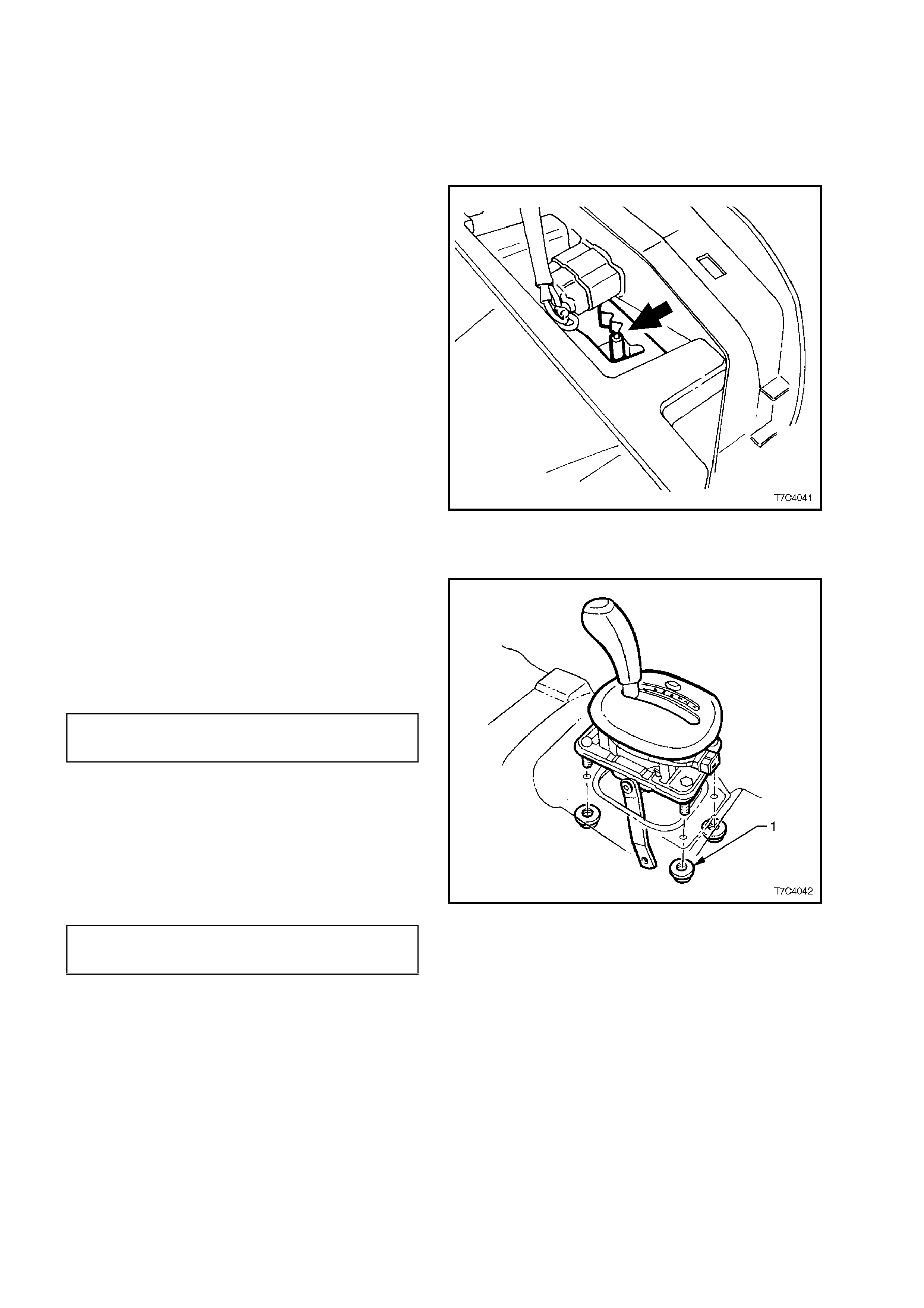
REINSTALL
1. Clean mating surf aces of f loor pan and inspec t
the base seal for damage, replacing if
necessary.
2. Reinstall selector lever assembly to the floor
pan, install the four retaining nuts (1) and
tighten to the correct torque specification.
SELECTOR BASE RETAINING 12 - 18
NUT TORQUE SPECIFICATION Nm
3. The rem ainder of the installation is the r everse
of the removal procedure.
4. Adjust shift linkage as detailed in
3.2 SELECTOR LINKAGE in this Section,
tightening the selector rod locking bolt to the
correct torque specification.
SELECTOR LEVER LOCKING 15 - 35
BOLT TORQUE SPECIFICATION Nm
Figure 7C4-18
3.4 NEUTRAL START AND BACK-UP LAMP SWITCH
REMOVE
1. Raise the front of the vehicle and place on
safety stands. Refer to Section 0A,
GENERAL INFORMATION for the location of
recommended jacking points.
2. W hile holding the lower selector lever (3) with
an adjustable wrench, remove the retaining
nut (2).
3. Carefully remove the lever from the
transmission manual shaft.
4. Prise the wiring harness connector CPA
(Connector Position Assurance) securing pin
(6) from the neutral start and back-up lamp
switch (4), taking care not to break the pin.
Disconnect the wiring harness connector (5)
from the switch assembly (4).
5. Remove the two switch retaining screws (1),
then slide the switch assembly (4) over the
manual shaft and remove from the vehicle. Figure 7C4-19
REINSTALL
Installation of the neutral start and back-up lamp
switch is the reverse of the removal procedure
except for the following:
1. When installing the two switch securing
screws, leave them finger tight, until the
adjustment process has been completed.
2. After installing the selector lever and retaining
nut, hold the lever with an adjustable wrench
and tighten the nut to the correct torque
specification.
SELECTOR LEVER RETAINING 15 - 35
NUT TORQUE SPECIFICATION Nm
3. Following the neutral start and back-up lamp
switch adjustment procedure, check that the
engine can only be started when the gearshift
lever is either in the ‘P’ (Park) or ‘N’ (Neutral)
positions.
ADJUST
1. Select Reverse range, using the gear selector
control lever.
2. With the vehicle raised and the ignition
switched to the ON position, rotate the neutral
start and back-up lamp switch back and forth
until the best ‘neutral’ position is attained,
where the vehicle’s back-up lamps are
illuminated.
3. Tighten the switch retaining bolts but not fully
at this stage.
4. Select P (Park ), R (Rever se) then N (Neutral),
checking that the back-up lamps are only
illuminated when R (Reverse) is selected.
Techline

5. Tighten the two switch assembly securing
screws to the correct torque specification.
NEUTRAL START & BACK-UP
LAMP SWITCH RETAINING 15 - 35 Nm
TORQUE SPECIFICATION
6. Lower the vehicle to the ground and check the
operation of the neutral start and back-up
lamp switch. The vehicle should only start in
either ‘P’ (Park) or ‘N’ (Neutral) ranges and the
reverse lam ps s hould only illum inate when the
‘R’ (Reverse) range is selected.
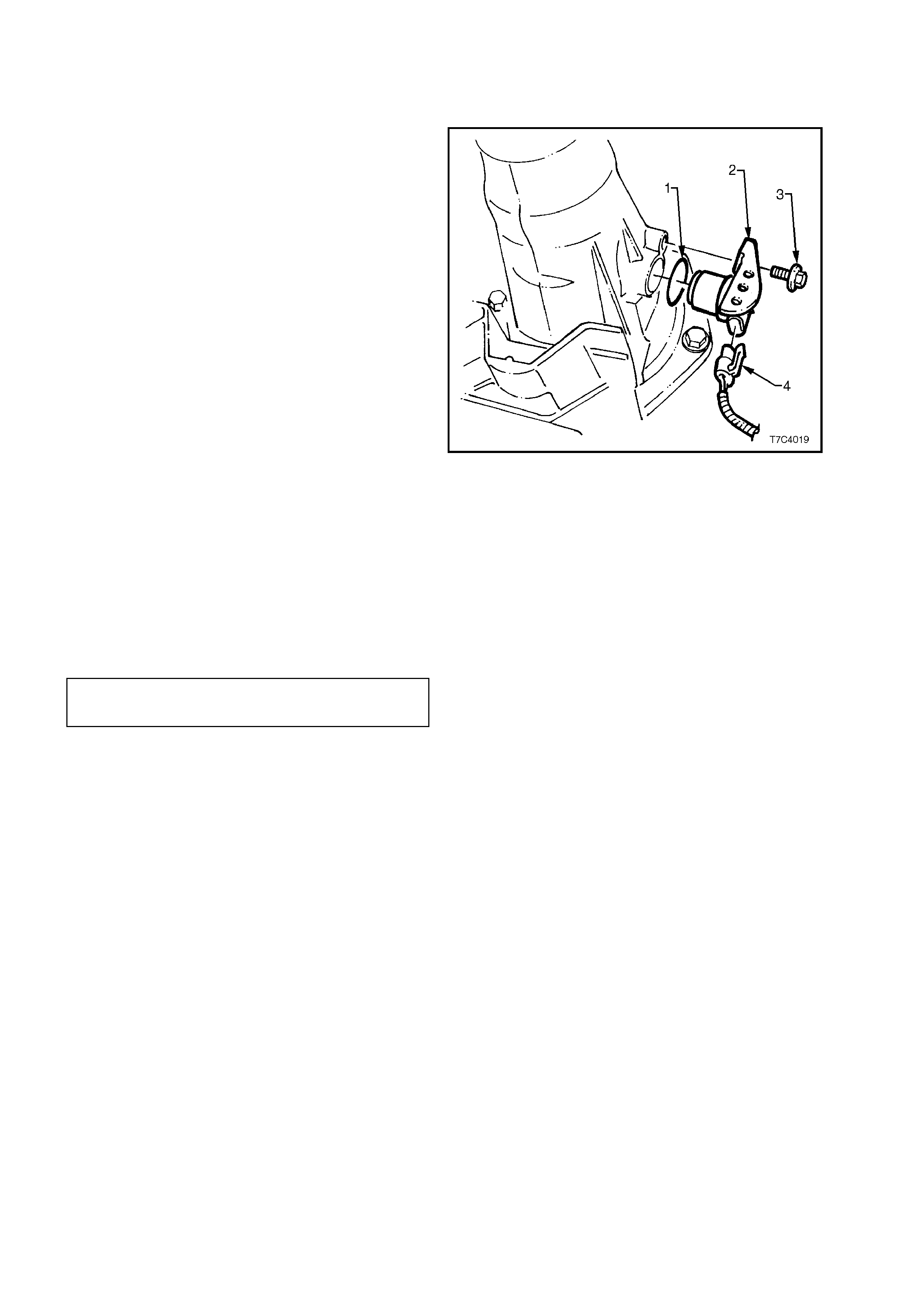
3.5 VEHICLE SPEED SENSOR
REMOVE
1. Raise rear of vehicle and place on safety
stands. Refer Section 0A GENERAL
INFORMATION for location of the
recommended jacking points.
2. Place drip tray beneath speed sensor.
3. Disconnect electrical connector (4) from the
vehicle speed sensor (2).
4. Unscrew vehicle speed sens or retaining scr ew
(3).
5. With a pulling/turning motion, remove vehicle
speed sensor as sembly (2) and O-r ing seal ( 1)
from the transmission extension housing.
Figure 7C4-20
REINSTALL
1. Lubricate a new O -ring s eal (1) with petroleum
jelly (Vaseline or equivalent) and install on the
vehicle speed sensor (2).
2. Install the speed sensor (2) into the
transmission extension housing.
3. Reinstall retaining s crew (3) and tighten to the
specified torque.
SPEED SENSOR RETAINING 10.5 - 13.5
SCREW TORQUE SPECIFICATION Nm
4. Reinstall the wiring harness connector (4) to
the speed sensor (2).
5. Lower vehicle and check fluid level. Refer
2.1 FLUID LEVEL CHECK in this Section.
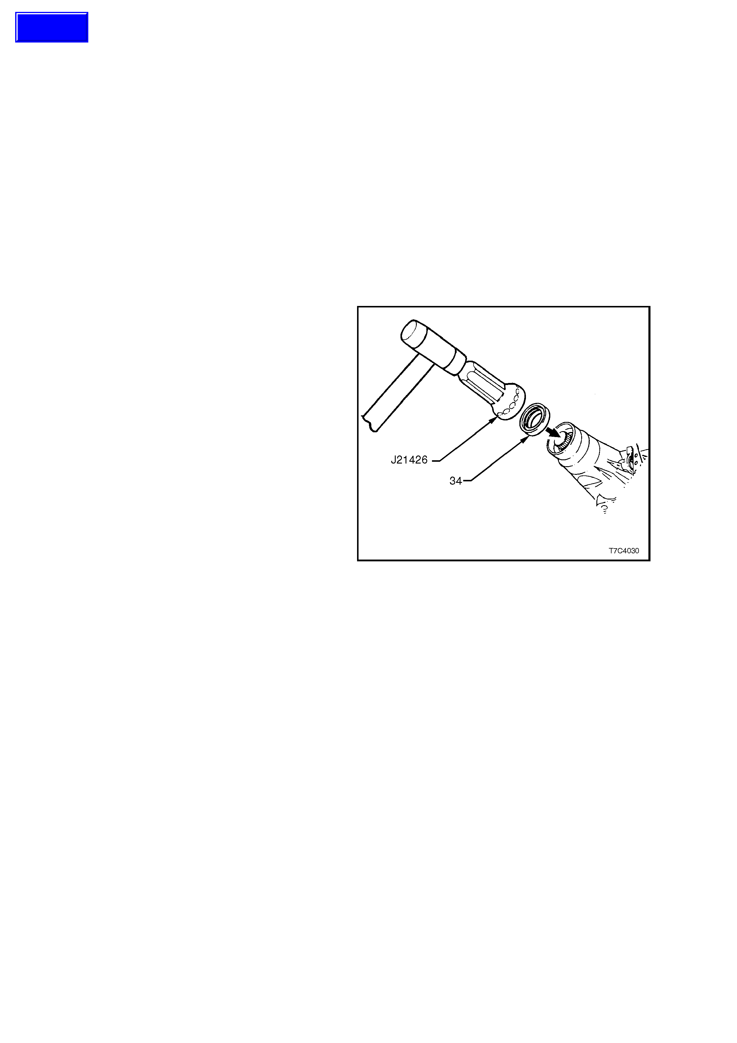
3.6 CASE EXTENSION OIL SEAL
REPLACE
1. Raise rear of vehicle and place on safety
stands. Refer to Section 0A GENERAL
INFORMATION for location of the
recommended jacking points.
2. Place a drip tray beneath rear of transmission.
3. Remove propeller shaft assembly, refer to
Section 4C PROPELLER SHAFT AND
UNIVERSAL JOINTS.
4. Using a suitable tool such as E308 or
equivalent, remove the oil seal from rear of
case extension.
5. Thoroughly clean around seal bore in case
and ensure there are no burrs.
6. Tap new seal (34) into place with Tool No.
J21426.
7. Reinstall propeller shaft.
8. Check fluid level, refer to 2.1 FLUID LEVEL
CHECK in this Section.
Figure 7C4-21
Techline
3.7 EXTENSION HOUSING AND/OR BUSH
REPLACE
1. Raise vehicle and place on safety stands.
Refer to Section 0A GENERAL
INFORMATION for location of the
recommended jacking points.
2. With vehic les fitted with the naturally aspirated
V6 engine, remove the twin exhaust pipe and
catalytic converter assembly. For those
vehicles f itted with either the V6 s upercharged
or V8 engines, remove the exhaust system
from the rear of both catalytic converters
rearwards. Refer to Section 8B EXHAUST
SYSTEM.
3. Place drip tray beneath case extension.
4. Remove propeller shaft, refer to Section 4C
PROPELLER SHAFT AND UNIVERSAL
JOINTS.
5. Use a sharp s criber to m ark the ex act location
of the crossmember (2) to the side frame,
before loosening any of the four c rossm ember
to side frame attaching bolts (3).
IMPORTANT:
This step is critical to the correct powertrain
alignment on reassembly. If not carried out, then
vehicle vibration and/or handling problems could
result!
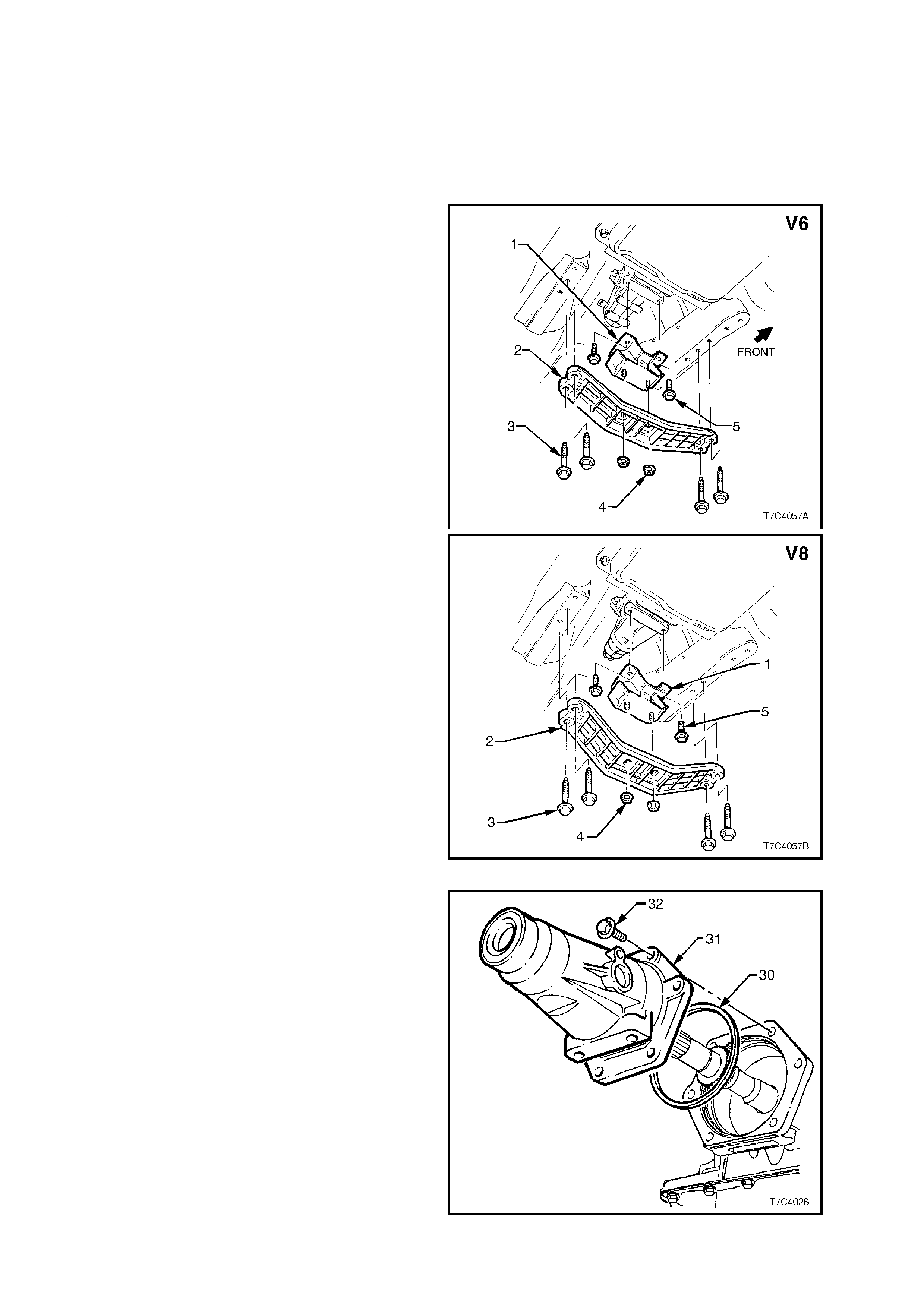
6. Remove two bolts (5) securing rear engine
mount to transmission.
7. Support transm iss ion with a jack . Do not place
the support beneath case extension or oil pan.
8. Remove the four crossmember to side frame
bolts (3) and remove crossmember (2) and
rear engine mount (1) from the vehicle.
Figure 7C4-22
9. Remove vehicle speed sensor assembly
wiring harness connector, then remove the
sensor from the extension housing. Refer to
3.5 VEHICLE SPEED SENSOR in this Sect ion
for details.
10. Remove six bolts securing case extension to
transmission case.
11. Remove case extension and seal assembly
from the rear of the transmission case.
Figure 7C4-23
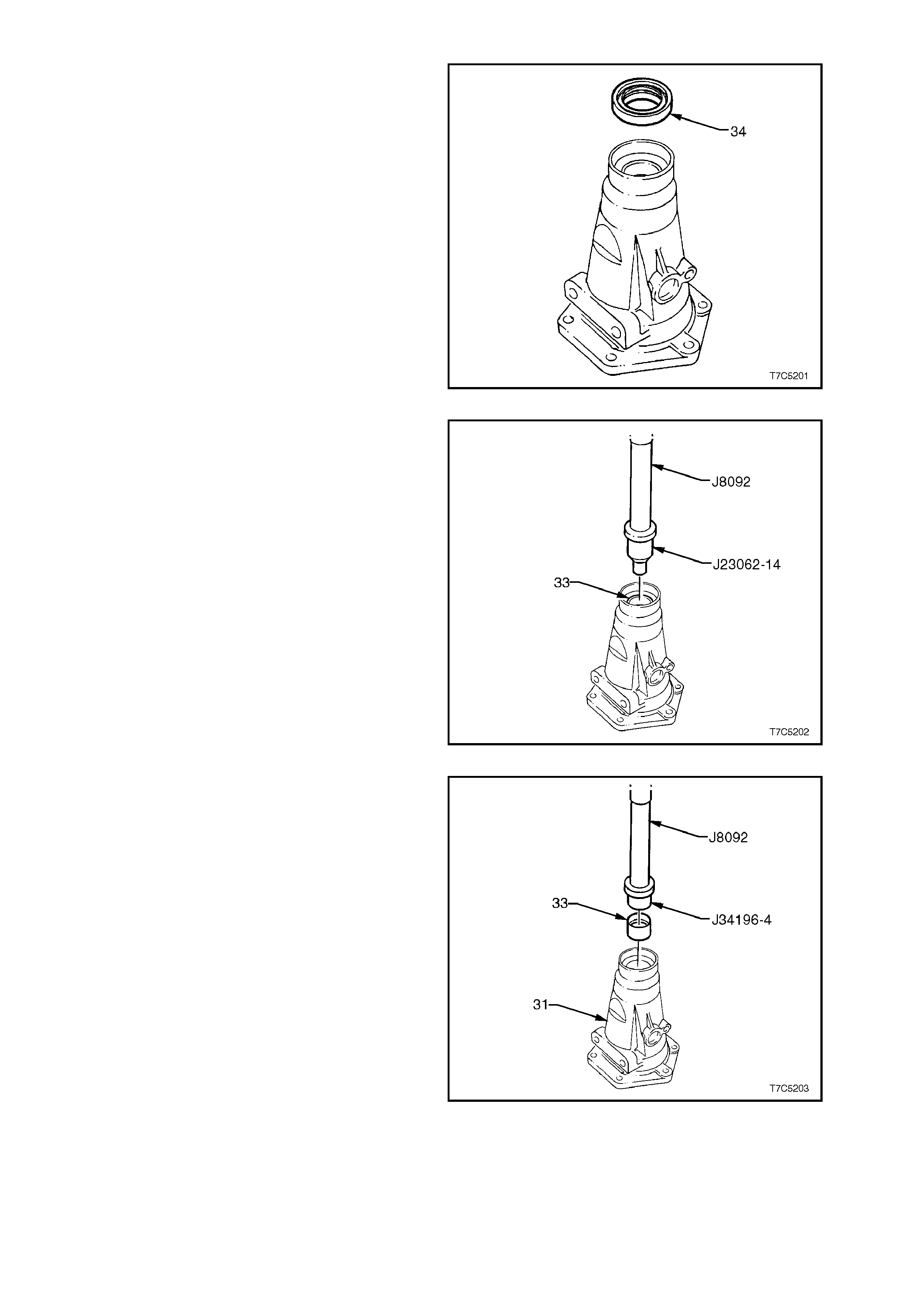
12. If bush is to be replaced, remove the case
extension oil seal, using a removing tool such
as Tool E308 or commercial equivalent.
Figure 7C4-24
13. Using bush remover, Tool J23062-14 and
driver handle J8092, press the bush (33) f rom
the extension housing.
NOTE:
Take note of the orientation of the split in the bush
for installation purposes.
Figure 7C4-25
14. Lubricate the outside of a new bush with
automatic transmission fluid to reduce the
chance of material pick-up.
15. Install a new bush (33) into the extension
housing (31), using installer J34196-4 and
driver handle J8092, ensuring that the split in
the bush is in the same orientation as the
original.
Figure 7C4-26
Installation of c omponents is in the rever se or der to
removal (Steps 1 to 10 above), taking note of the
following points.
16. Lubricate the seal lips of a new case
extension oil seal and install, using Tool No.
J21426.
17. Lubricate a new extension housing to case
seal ring with automatic transmission fluid,
then install to the extension housing. Reinstall
the housing to the transmission case and
tighten the six bolts to the correct torque
specification.
EXTENSION HOUSING TO CASE 42 - 48
BOLT TORQUE SPECIFICATION Nm
18. Lubricate a new vehicle speed sensor O-ring
with automatic transmission fluid, then install
to the sensor. Reinstall the sensor to the
extension housing and tighten the retaining
screw to the correct torque specification.
SPEED SENSOR RETAINING 10.5 - 13.5
SCREW TORQUE SPECIFICATION Nm
19. If removed, reinstall the rear engine mounting
to the crossmember, after noting the
orientation of the rear cross mem ber relative to
the installed engine.
20. Tighten the engine mounting nuts to the
correct torque specification.
REAR ENGINE MOUNTING TO
CROSSMEMBER NUT 20 - 30 Nm
TORQUE SPECIFICATION
21. Reinstall the rear crossmember, ensuring that
it is aligned with the scribe lines m ade prior to
removal, before tightening the attaching bolts
to the correct torque specification.
REAR ENGINE MOUNTING TO
EXTENSION HOUSING BOLT 50 - 65 Nm
TORQUE SPECIFICATION
REAR CROSSMEMBER TO SIDE
RAIL ATTACHING BOLT 50 - 65 Nm
TORQUE SPECIFICATION
Figure 7C4-27
22. For installation of the exhaust pipes and
catalytic converter on naturally aspirated V6
powered vehicles, refer to Section 8B
EXHAUST SYSTEM.
23. Refer to Section 4C PROPELLER SHAFT
AND UNIVERSAL JOINTS for installation of
the propeller shaft.
24. Lower vehicle and check transmission fluid
level (Refer to 2.1 FLUID LEVEL CHECK, in
this Section).
3.8 1-2 ACCUMULATOR ASSEMBLY
REMOVE
1. Remove oil pan and filter, refer
3.1 FLUID LEVEL CHANGE AND FILTER
REPLACEMENT in this Section.
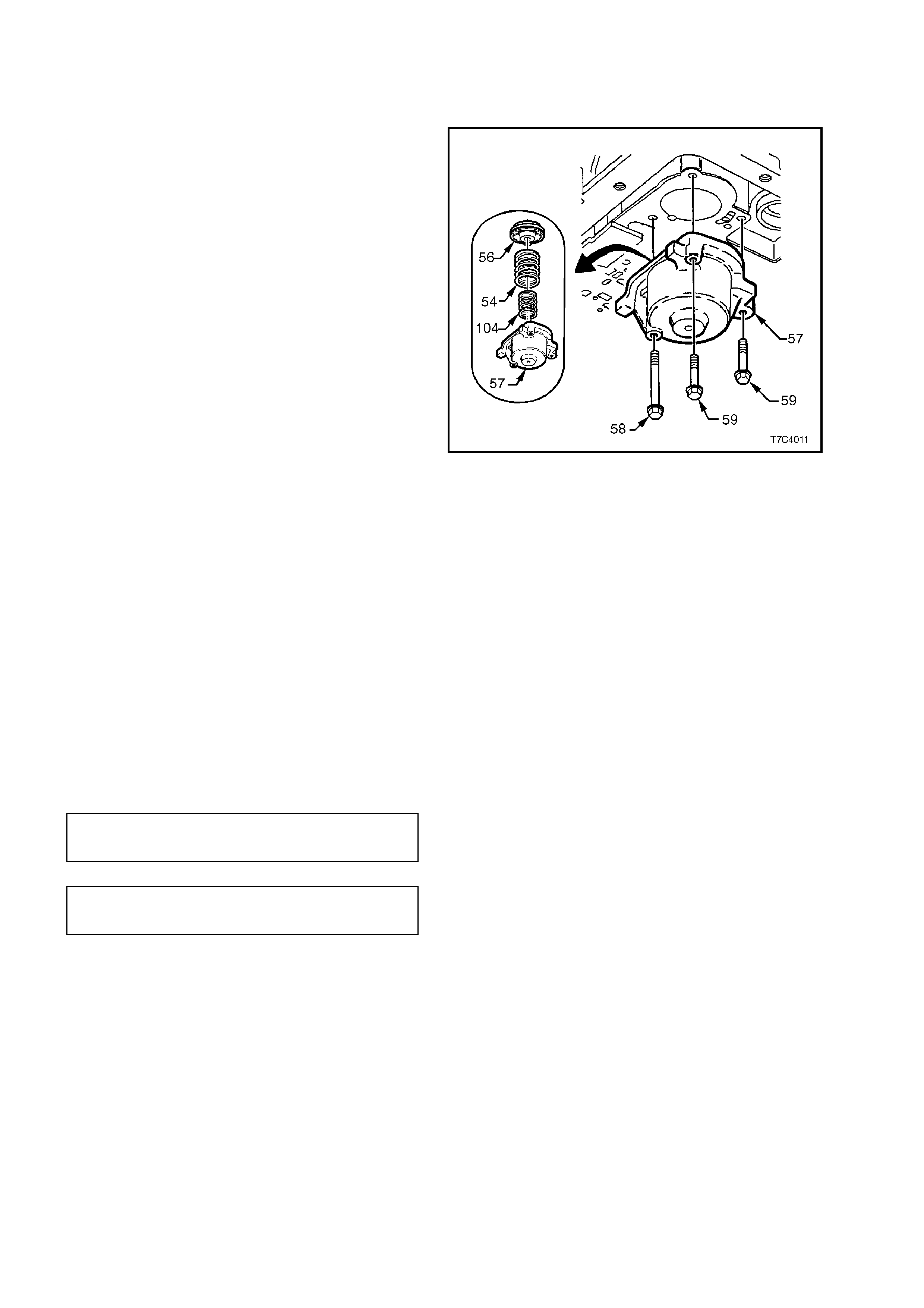
2. Progressively loosen, then remove the three
accumulator c over bolts ( 58 and 59), the c over
(57) and pin assembly, piston and seal
assembly (56) and the two springs (54 and
104), from the control valve body spacer plate.
3. Using LOW pres s ur e air, apply to the drilling in
the cover to remove the 1-2 accumulator
piston (56). Remove and discard the piston
seal.
4. Remove the two 1-2 accumulator springs (54
and 104).
Figure 7C4-28
CLEAN AND INSPECT
1. Clean com ponents with a suitable solvent and
air dry.
2. Check that springs are not distorted, or
broken.
3. Lubricate new seal with petroleum jelly and
install on piston. Check that piston seal does
not bind in the piston groove.
4. Check all machined surfaces for damage or
wear.
REINSTALL
Installation is the reverse of the r emoval proc edur e.
Use a new oil pan gasket and tighten all fasteners
to specified torque settings.
1 - 2 ACCUMULATOR COVER 8 - 14
BOLTS TORQUE SPECIFICATION Nm
OIL PAN BOLT 9.5 - 13.8
TORQUE SPECIFICATION Nm

3.9 CONTROL VALVE BODY AND W I RING HARNESS
REMOVE
1. Remove oil pan and filter, refer
3.1 FLUID LEVEL CHANGE AND FILTER
REPLACEMENT in this Section.
2. Disconnect wiring harness connectors from all
electrical components, except the Torque
Converter Clutch (TCC) Solenoid.
3. Remove two bolts ( 68) securing T CC solenoid
assembly.
4. Withdraw TCC solenoid assembly from pump.
5. Swing the wiring harness and TCC s olenoid to
one side and tie up with a piece of tie wire to a
suitable place on the underneath of the
vehicle.
Figure 7C4-29
6. Remove the Transmission Pressure Switch
Assembly retaining bolts, then remove the
Pressure Sw itch Assembly.
Figure 7C4-30
7. Remove the bolt (64) securing the manual
detent spring (63).
Figure 7C4-31
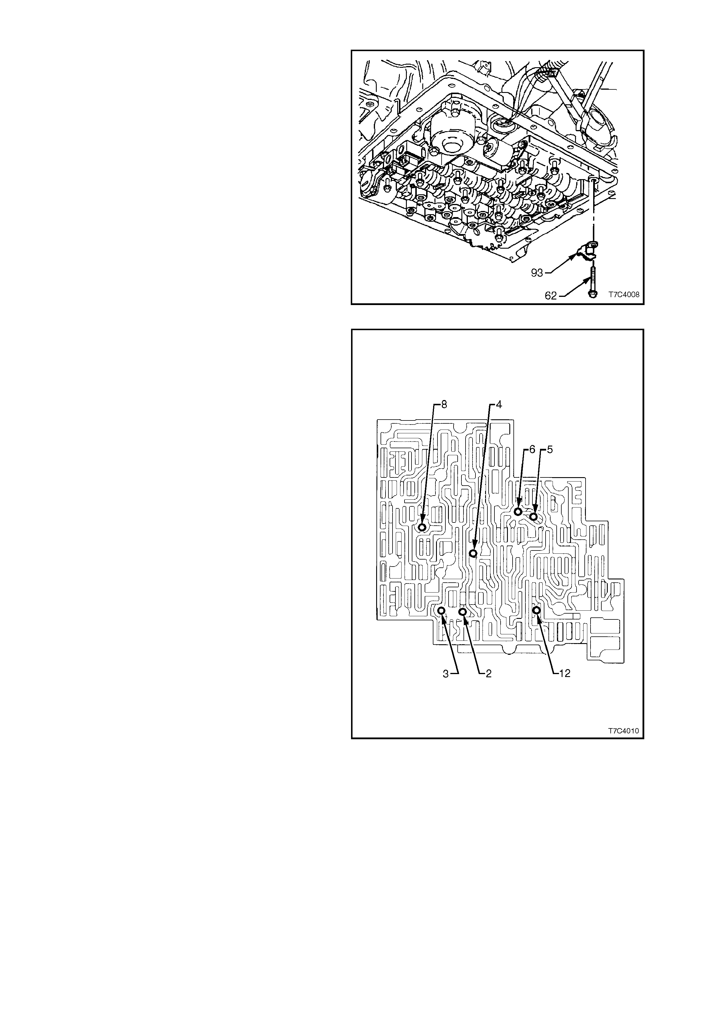
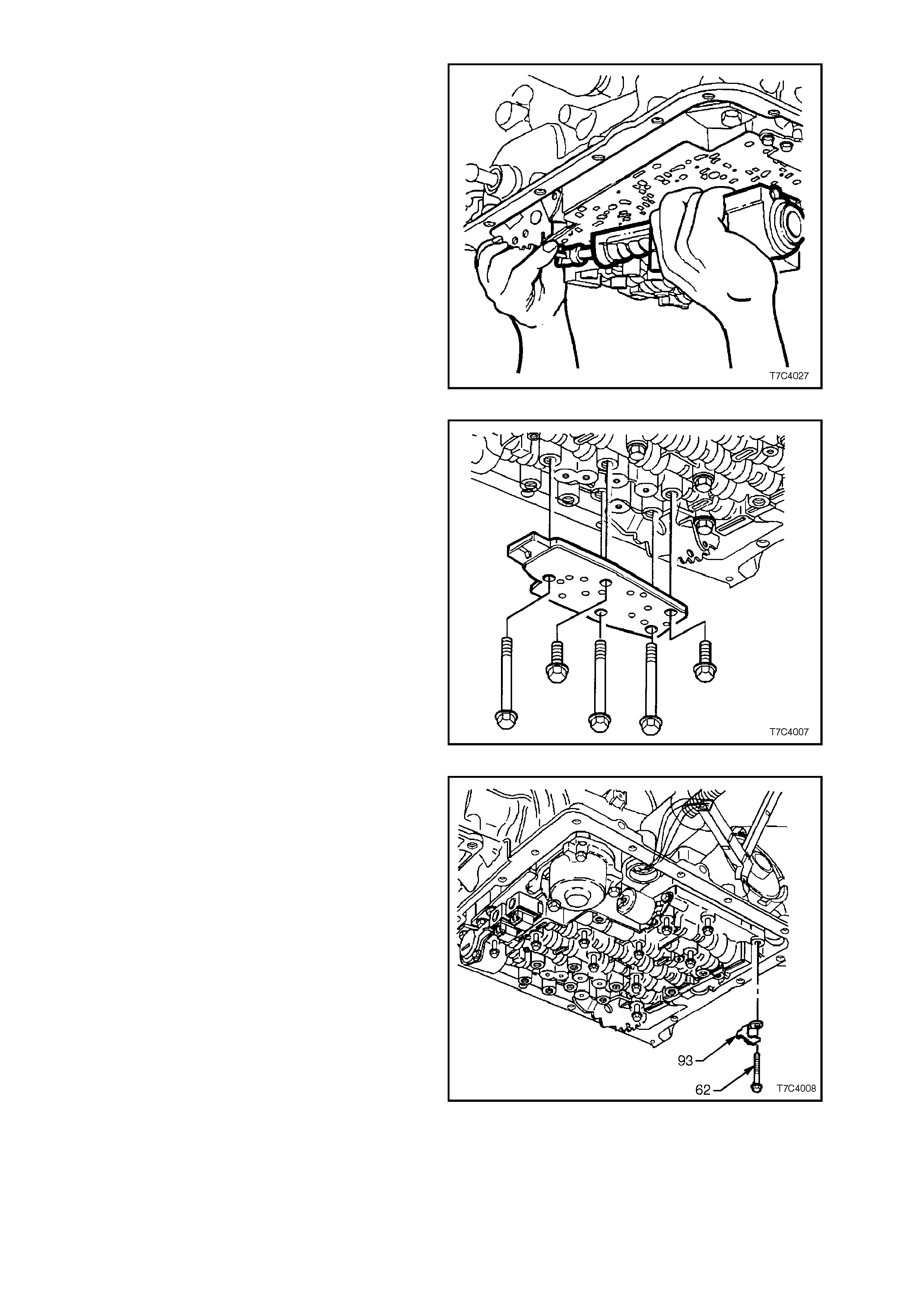
8. Remove the control valve body retaining bolt
(62) securing the dipstick stop bracket (93).
9. Remove remaining control valve body bolts.
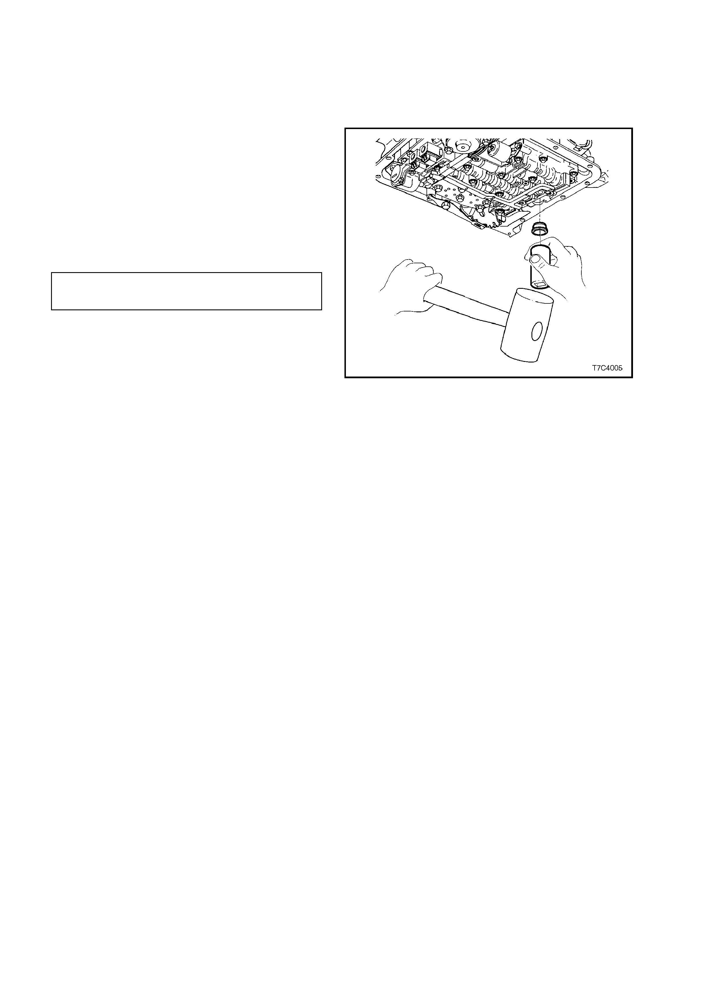
9. Remove control valve body assembly by
supporting at the rear with one hand, while
holding the manual valve with the other. As the
valve body is being lowered, rotate it slightly to
release the m anual valve link fr om the m anual
valve.
10. Remove manual valve link from inner detent
lever.
Figure 7C4-32
NOTE:
Take care not to lose the seven check balls that
are located under the control valve body. Locations
for the seven check balls are as shown.
Figure 7C4-33
DISASSEMBLE, CLEAN, INSPECT AND REASSEMBLE
For these Operations, refer to 2.16 CONTROL
VALVE BODY in 7C5, AUTOMATIC
TRANSMISSION - UNIT REPAIR.
REINSTALL
1. Ensure spacer plate gasket is in satisfactory
condition. If gasket needs to be r eplaced, r ef er
to 3.10 SPACER PLATE, CHECK BALLS,
FILTER SCREENS AND 3-4
ACCUMULATOR in this Section.
2. Reinstall check balls in control valve body as
shown in Figure 7C4-34 and secure with
petroleum jelly.
3. Install the manual valve link into the inner
detent lever.
4. While supporting the manual valve link in one
hand and the valve body in the other, rotate
the valve body slightly and connect the link
with the manual valve. Move the m anual valve
forward to retain the link connection and
carefully offer the valve body up, into position.
NOTE:
Be careful not to damage the two filter screens
attached to the spacer plate, during this operation.
Figure 7C4-34
5. Reinstall bolts to the transmission range
pressure switch assembly (PSA), but do not
tighten.
Figure 7C4-35
6. Install the dipstick stop bracket (93) and
retaining bolt (62). Do not tighten at this time.
7. Loosely install the remainder of the control
valve body bolts.
Figure 7C4-36
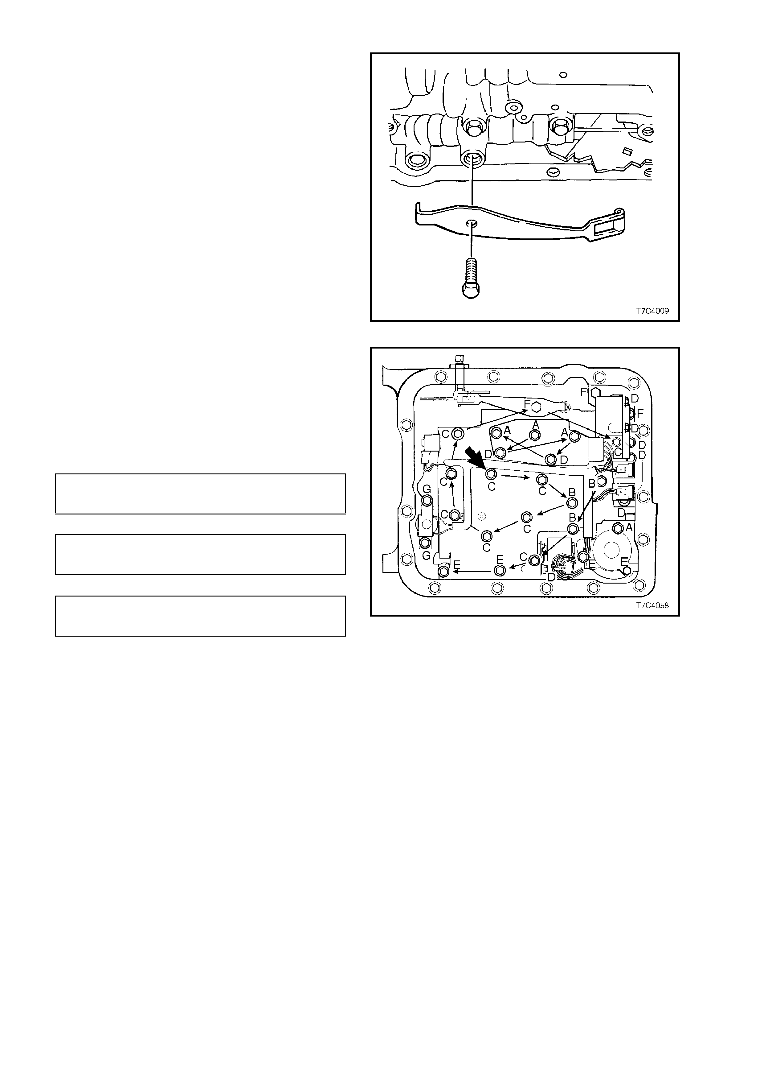
8. Reinstall the manual detent spring assembly
retaining bolt.
Figure 7C4-37
9. Coat a new TCC solenoid O-ring with
petroleum jelly and install on solenoid, then
reinstall TCC solenoid assembly into the oil
pump body.
10. Tighten all bolts to the specified torque
specification, starting from the center (bold
arrow), in the order shown.
CONTROL VALVE BODY and PSA 8 - 14
TORQUE SPECIFICATION Nm
MANUAL DETENT SPRING 20 - 27
BOLT TORQUE SPECIFICATION Nm
TCC SOLENOID BOLT 8 - 14
TORQUE SPECIFICATION Nm
IMPORTANT:
The control valve body bolts must be tightened in
an outward spiral from the centre (bold arrow), as
shown. Failure to f ollow this pattern m ay dis tort the
valve body, causing valves to jam in their bores.
NOTE:
There are 7 different bolt sizes used. The letters
shown, relate to the following bolt sizes.
Control Valve Body Fastener Specifications
A-M6 x 1.00 x 65.0
B-M6 x 1.00 x 54.4
C-M6 x 1.00 x 47.5
D M6 x 1.00 x 18.0
E-M6 x 1.00 x 35.0
F-M8 x 1.25 x 20.0
G-M6 x 1.00 x 12.0
Figure 7C4-38
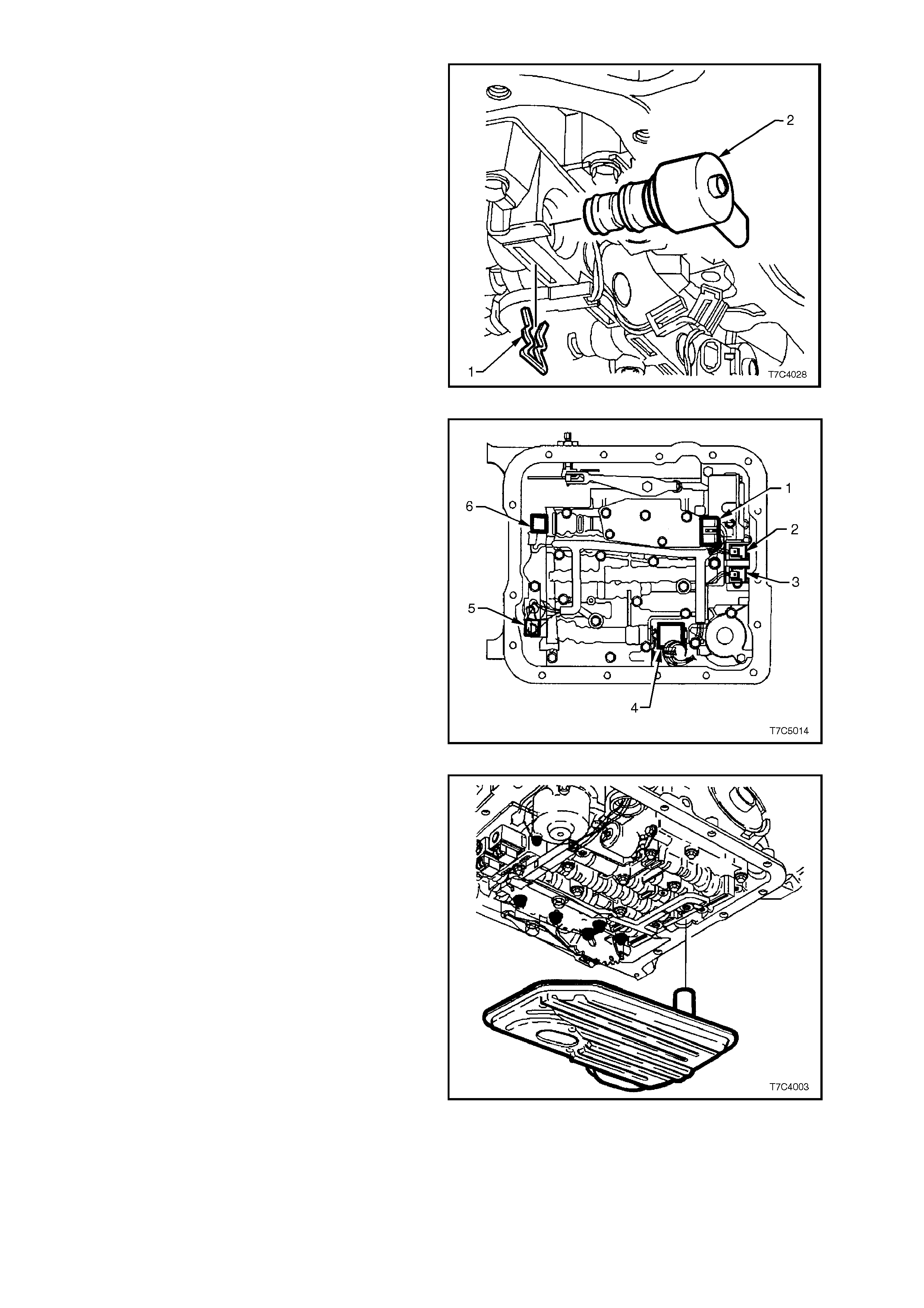
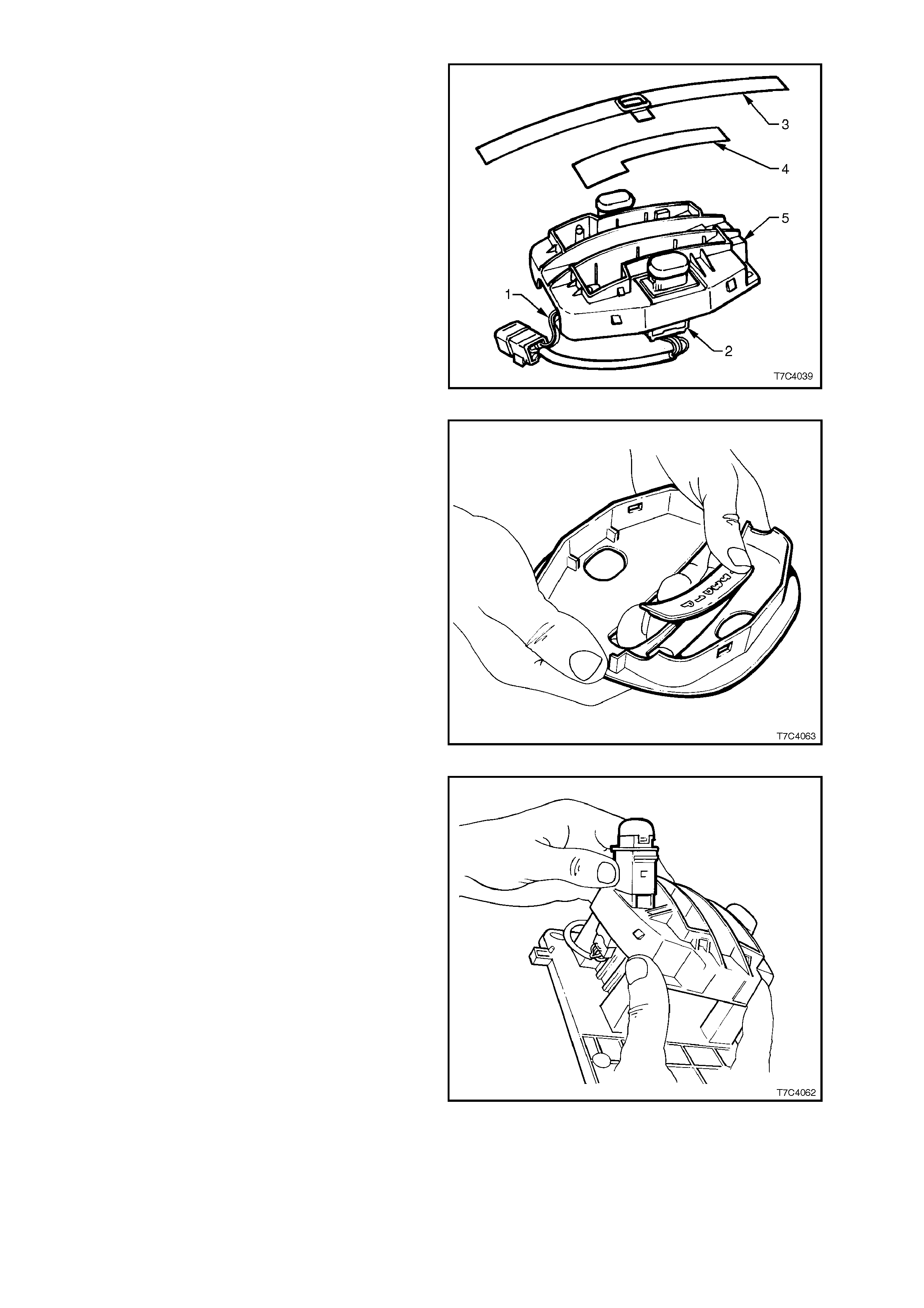
11. Coat a new TCC PWM solenoid O-ring with
petroleum jelly, install on the solenoid (2).
Then reinstall the solenoid into the control
valve body, securing with retaining clip (1).
Figure 7C4-39
12. Reinstall electrical wiring harness clips to
secure the harness to the control valve body
and install the wiring harness connectors as
shown, and identified below.
Electrical Connector Identification
1. Pressure Switch Assembly (PSA).
2. 1-2 Shift Valve Solenoid
3. 2-3 Shift Valve Solenoid
4. Pressure Control Solenoid (PCS)
5. TCC Pulse Width Modulated (T CC PWM)
Solenoid
6. 3-2 Control Solenoid
Figure 7C4-40
13. Reinstall oil filter into the oil filter seal.
Figure 7C4-41
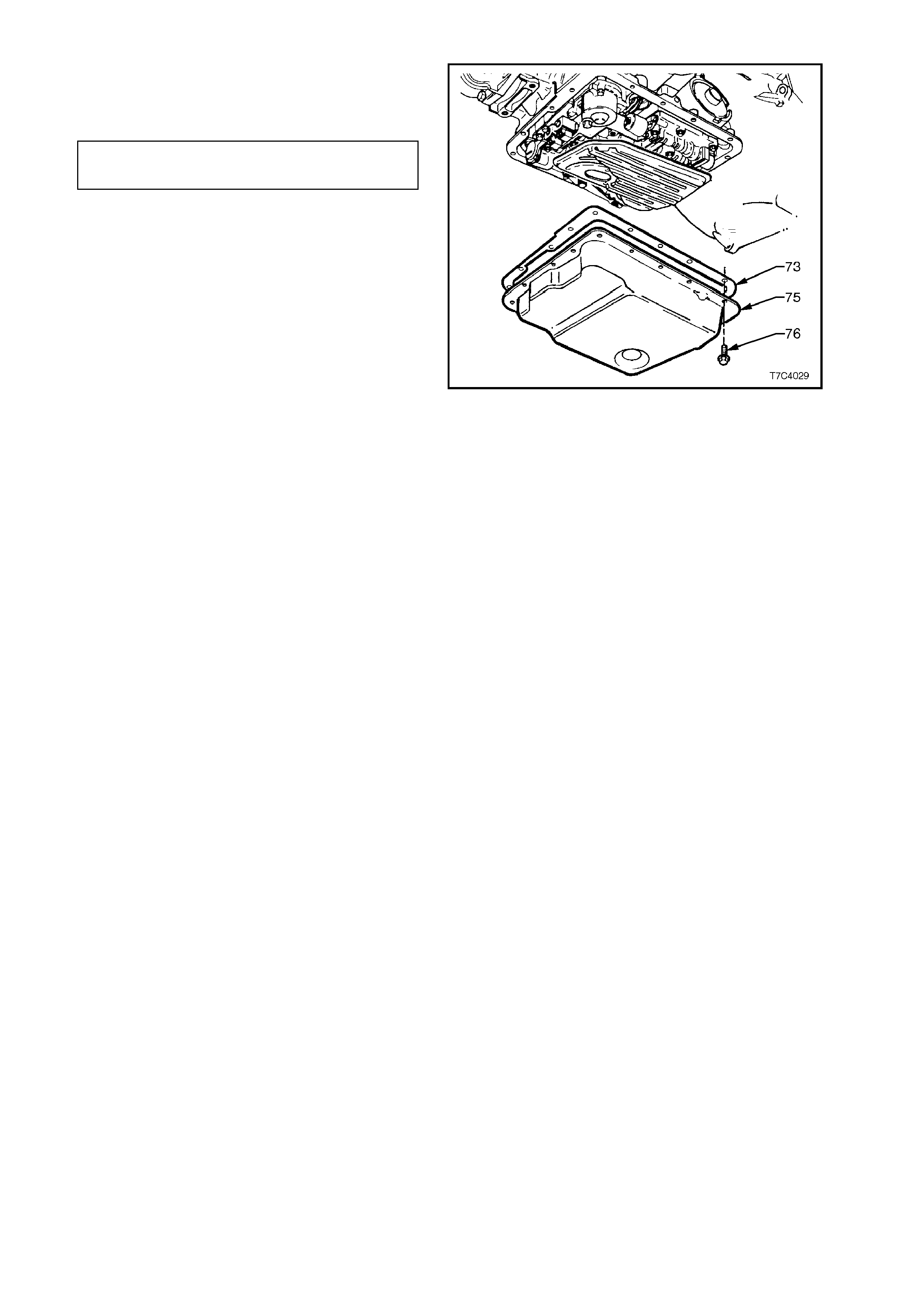
14. Install a new oil pan gasket (73), then reinstall
the oil pan (75), tightening the bolts (76) to the
correct torque specification.
OIL PAN BOLT 9.5 - 13.8
TORQUE SPECIFICATION Nm
15. Fill transmission with DexronÒ III automatic
transmission fluid, as detailed in
Operation 3.1, in this Section.
16. Lower vehicle and road test until the
transmission has reached operating
temperature.
17. Re-check fluid level (see Operation 2.1, in
this Section) and c heck f or f luid leaks fr om the
oil pan area.
Figure 7C4-42
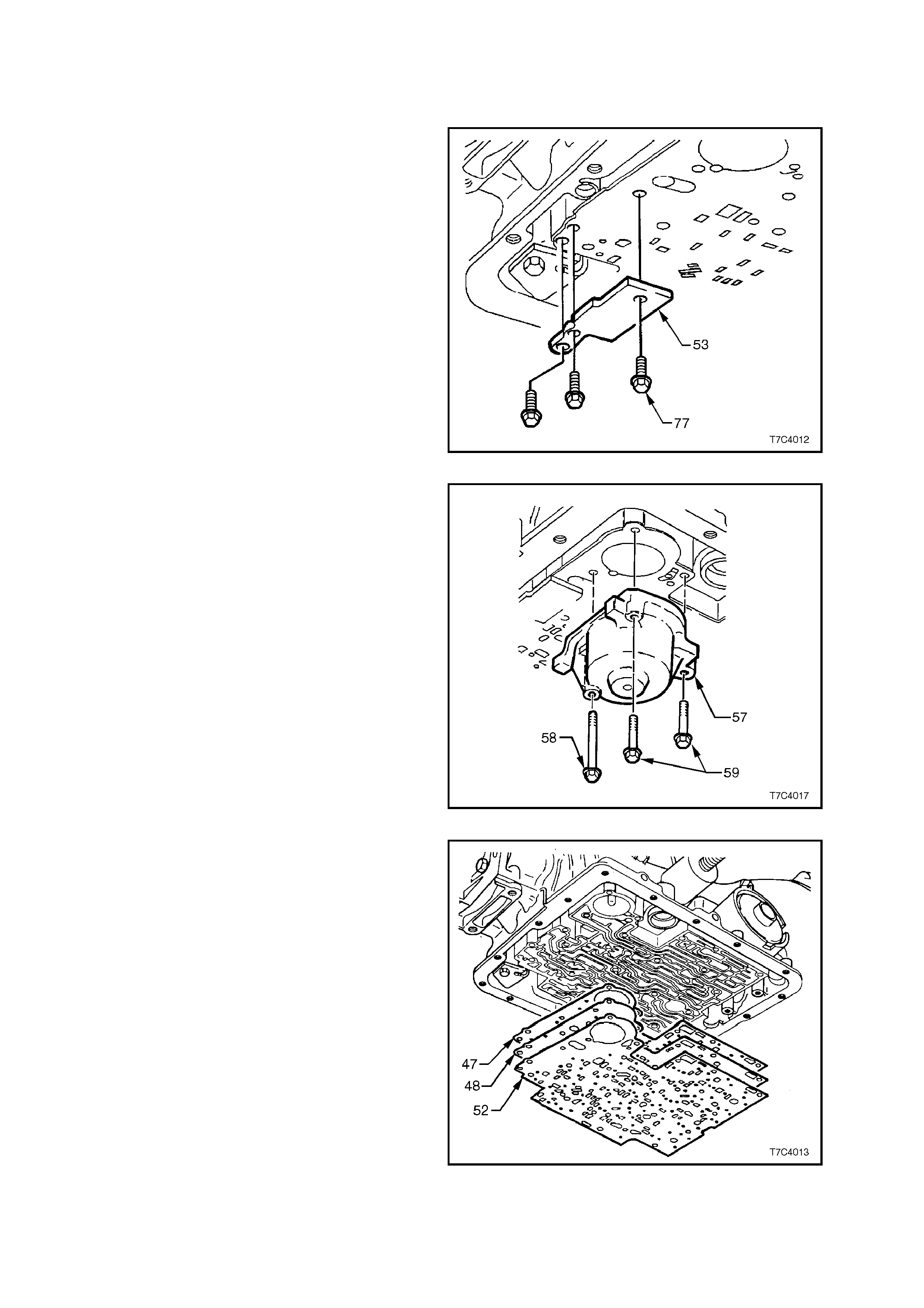
3.10 S PACER PLATE, CHECK BALLS, FILTER SCREENS AND 3-4 ACCUMULATOR
REMOVE
1. Remove control valve body as described in
3.9 CONTROL VALVE BODY AND WIRING
HARNESS in this Section.
2. Remove the three spacer plate retaining plate
bolts (77) and plate (53).
Figure 7C4-43
3. W hile s upporting the spacer plate, remove 1- 2
accumulator assembly retaining bolts (58 and
59), then carefully lower the accumulator
assem bly from the spacer plate and set to one
side, assuming that removal of the piston and
springs is not required.
NOTE:
The 3-4 accumulator spring may push the spacer
plate away from transmission case when the
accumulator cover is removed.
Figure 7C4-44
4. Remove the spacer plate (48) and two spacer
plate gaskets (47 and 52) from the
transmission case.
IMPORTANT:
As the spacer plate and gaskets are lowered from
the transmission, a check ball and the 3-4
accumulator spring will also come away. Do not
lose the check ball.
Figure 7C4-45
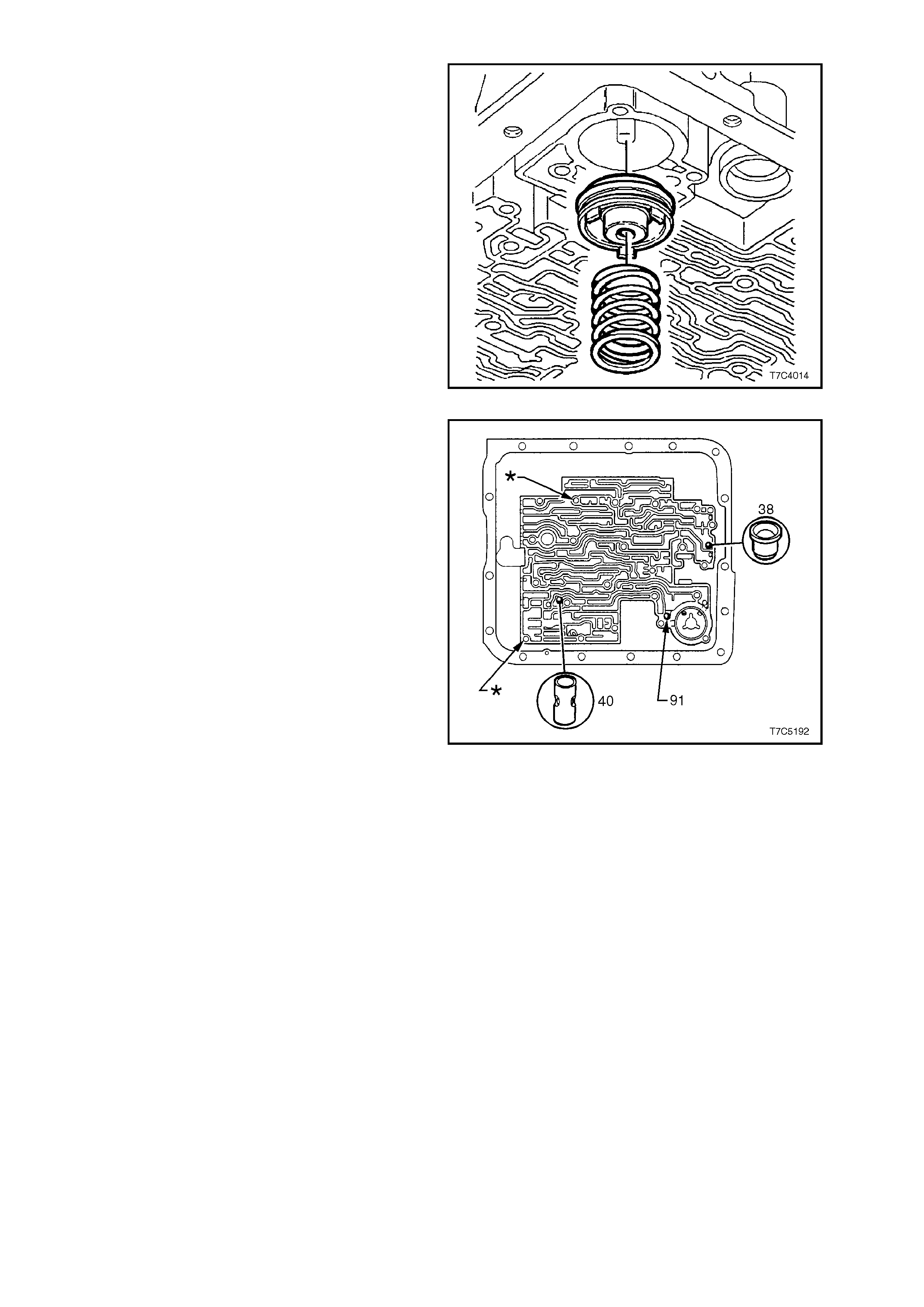
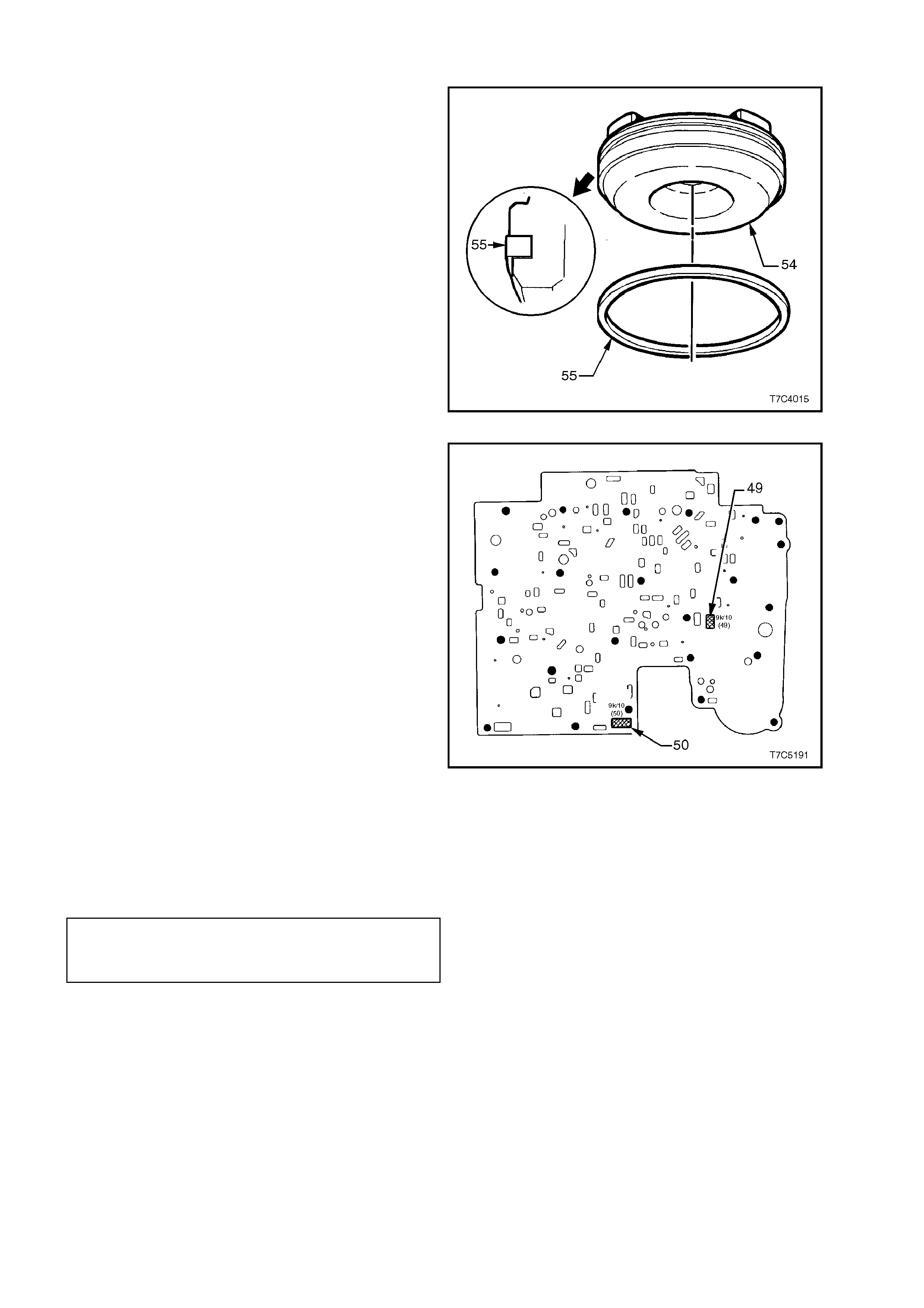
5. If removal of the 3-4 accumulator piston is
required, use snap ring pliers and rotate the
piston while pulling it from the case. Remove
and discard the piston seal.
Figure 7C4-46
6. The location of the checkball (91), 3rd
accumulator check ball assembly (40) and
orifice cup plug (38) in the transmission case,
are as shown.
NOTE:
The locations marked as (Q) are for two guide
studs to be inserted for reassembly.
Figure 7C4-47
CLEAN AND INSPECT
1. Wash components in clean solvent.
2. Dry with compressed air.
3. Inspect piston for porosity, ring groove
damage or pin hole damage.
4. Check spring for distortion or damage.
5. Inspect accumulator bore for wear or damage.
6. Check spacer plate, filter screens and check
balls for damage.
REINSTALL
1. Lubricate new seal (55) with petroleum jelly
and install on 3-4 accumulator piston (54).
2. Reinstall pin in case.
3. Reinstall piston onto pin s o that the pis ton s ide
with three lugs, faces out of bore (Refer to
Figure 7C4-48).
4. Install guide pins (J25025-1) into transmission
case in the locations shown in Figure 7C4-47.
NOTE:
Ensure that the guide pins are f ully installed s o that
no thread is visible. Otherwise the spacer plate
gasket could become caught in a thread during
installation, resulting in incorrect alignment.
5. Reinstall the check ball in the transmission
case as shown (Figure 7C4-47) and use
petroleum jelly to hold the ball in place.
6. Reinstall 3-4 accumulator spring. Figure 7C4-48
7. If a new spacer plate is to be installed, it will be
necessary to fit two filter screens (49 and 50)
to the spacer plate bef or e f itment. Locations of
these screens are as shown.
8. Reinstall spacer plate with new gaskets that
have been smeared with petroleum jelly and
hold in place until accumulator is reinstalled.
NOTE:
Gasket marked 'C' is fitted between spacer plate
and transmission case and gasket marked 'V' is
located between spacer plate and control valve
body.
Figure 7C4-49
9. Reinstall accumulator. Refer to 3.8 1-2
ACCUMULATOR in this Section.
10. Install spacer plate support plate (53) and
retaining bolt (77), tightening to the correct
torque specification.
SPACER PLATE SUPPORT
PLATE RETAINING BOLT 8 - 14 Nm
TORQUE SPECIFICATION
10. Remove guide pins (J25025-1) from the
transmission case.
11. Reinstall control valve body. Refer to
3.9 CONTROL VALVE BODY AND WIRING
HARNESS in this Section.
12. Reinstall filter and oil pan. Refer to 3.1 FLUID
CHANGE AND FILTER REPLACEMENT in this
Section.
3.11 MANUAL SHAFT SEAL
REPLACE
1. Disconnect selector linkage from
transmission. Refer to 3.2 SELECTOR
LINKAGE in this Section.
2. Remove oil pan and filter, refer to
3.1 FLUID CHANGE AND FILTER
REPLACEMENT in this Section.
3. Remove bolt s ecuring manual detent spring to
control valve body and remove spring
assembly.
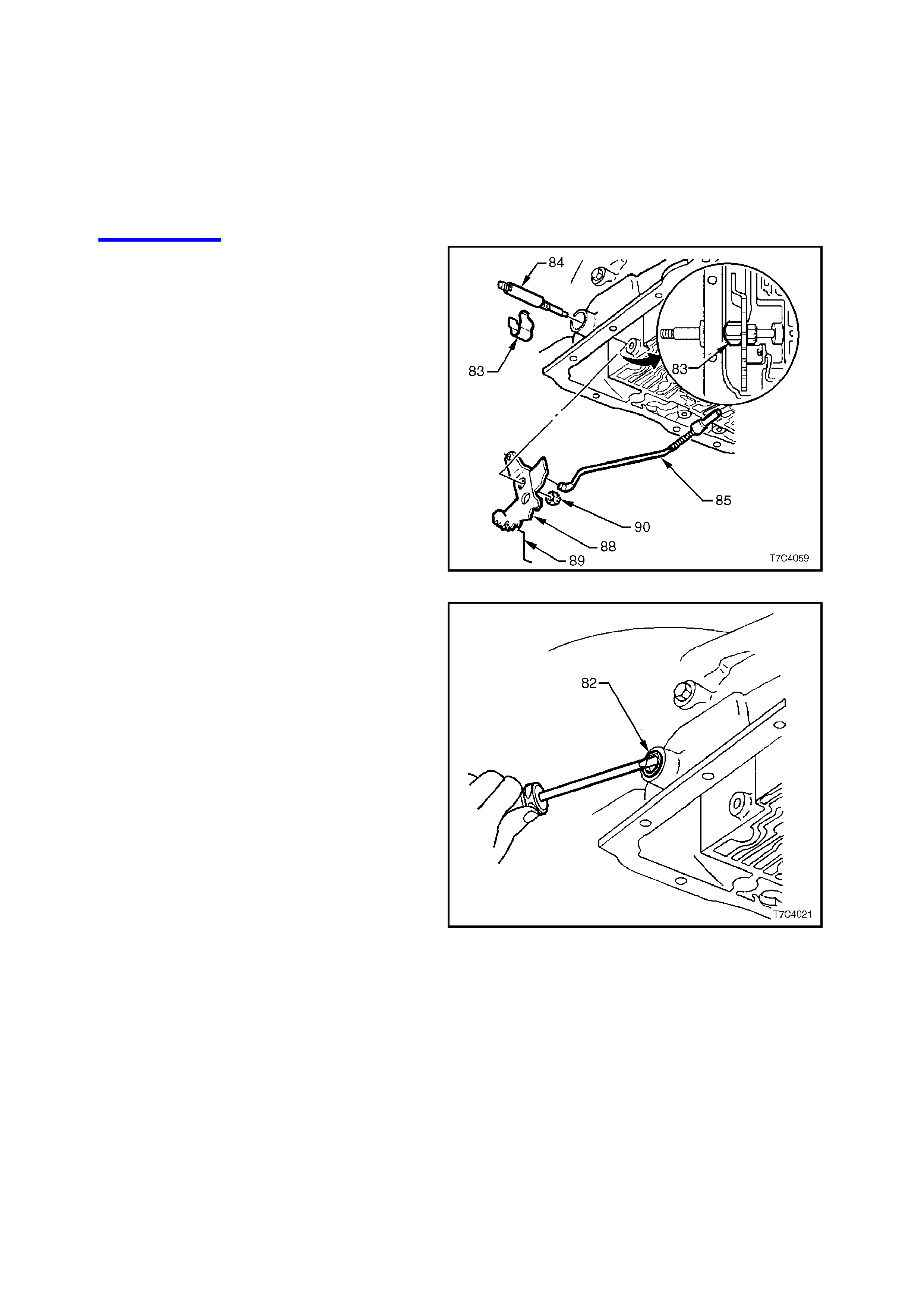
4. Remove nut (90) securing inner detent lever
(88) to manual shaft (84).
5. Remove retaining clip (83) from manual shaft
(84).
6. Withdraw manual shaft from transmission
case.
NOTE:
It may be necessary to first remove burrs from the
shaft, caused by the inner detent lever.
Figure 7C4-50
7. Prise manual shaft seal (82) from transmission
case with suitable tool such as a screwdriver.
Figure 7C4-51
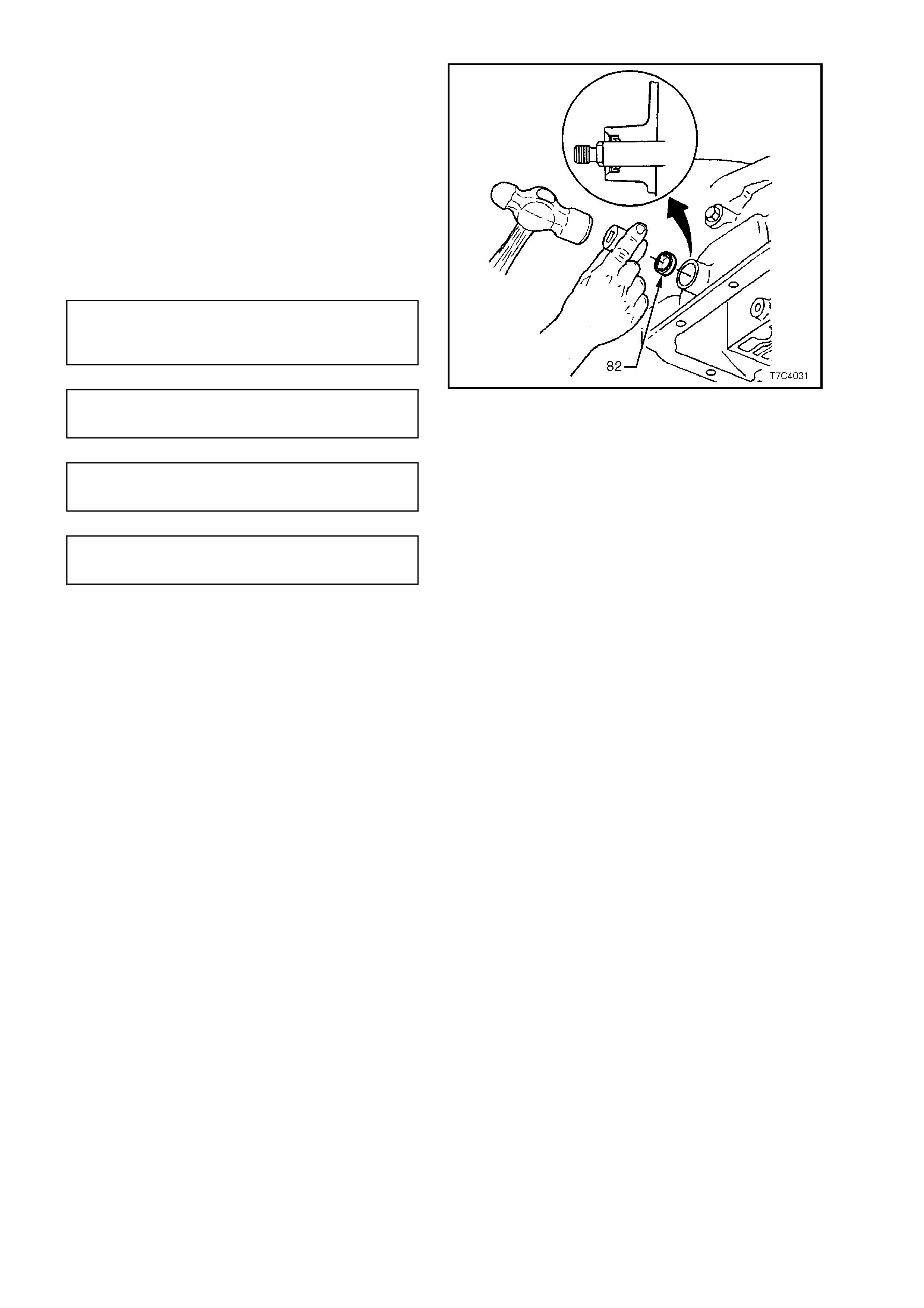
8. Tap new seal into place with a 14 mm socket.
Seal lip faces inwards.
9. Reinstall components in reverse order of
removal (steps 1 to 6 above). Tighten nuts and
bolts to specified torques.
NOTE:
If the selector lever was removed from the manual
shaft in the disassembly process (not a necessary
step), then the lever must be held with an
adjustable wrench when tightening the retaining nut
to the specified torque.
MANUAL SHAFT TO INNER
DETENT LEVER NUT 27 - 34 Nm
TORQUE SPECIFICATION
MANUAL DETENT SPRING BOLT 20 - 27
TORQUE SPECIFICATION Nm
MANUAL SHAFT LEVER NUT 15 - 35
TORQUE SPECIFICATION Nm
SELECTOR LEVER LOCKING 15 - 35
BOLT TORQUE SPECIFICATION Nm
Figure 7C4-52
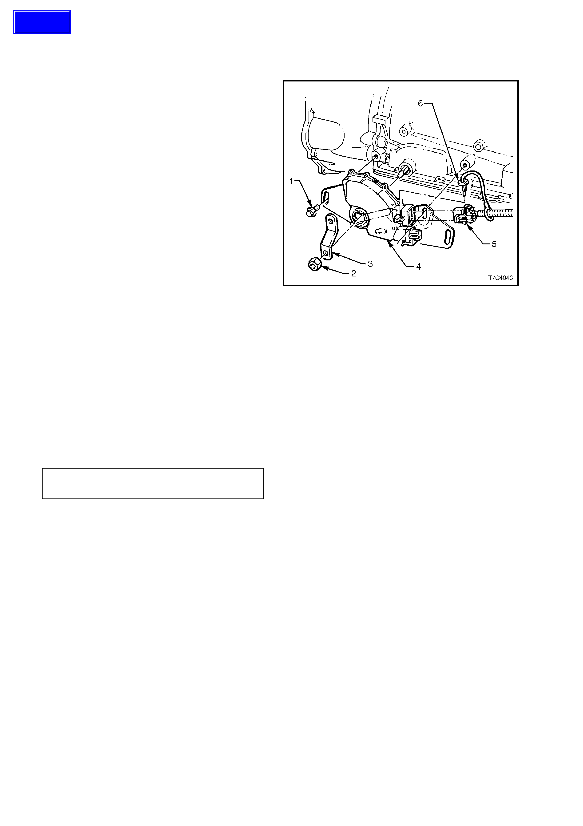
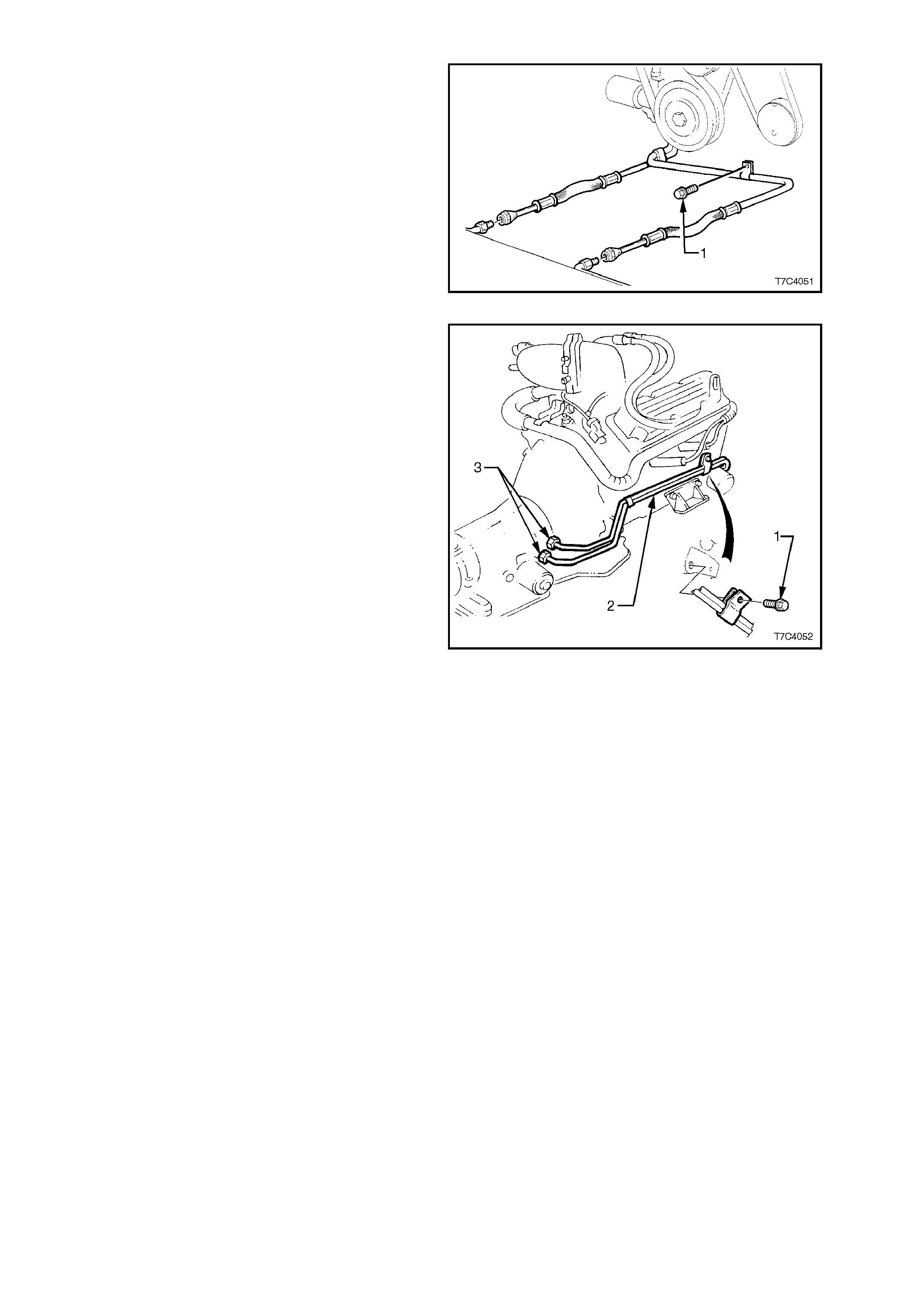
3.12 FILLER TUBE
REPLACE
1. Disconnect the battery earth lead.
2. Remove the transmission dipstick (1 or 5).
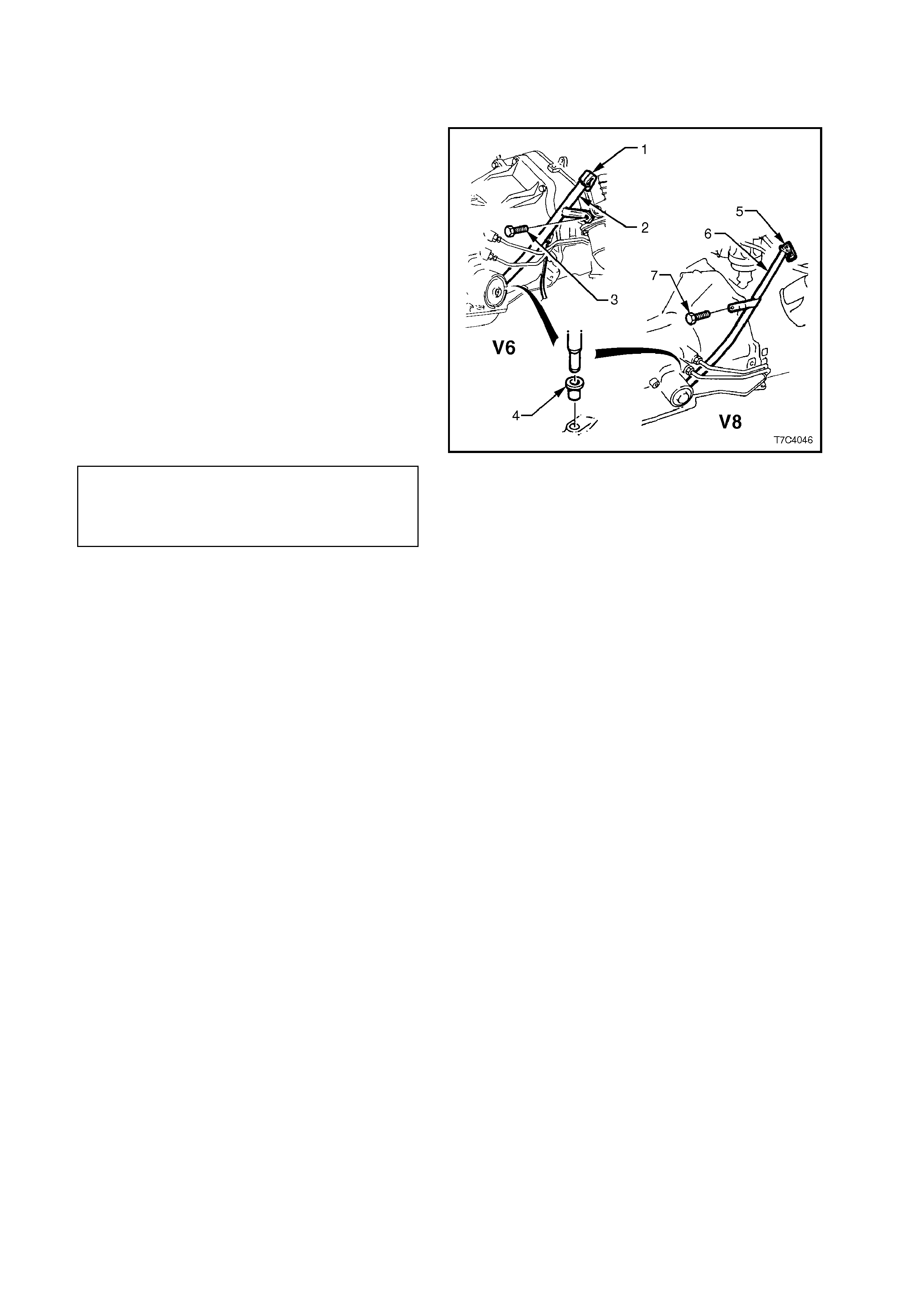
3. Remove the bolt securing transmission filler
tube to converter housing (V8 engine) (7) or
right hand cylinder head (V6 engine) (3).
4. Using a twisting/pulling motion, remove filler
tube (2 or 6) from transmission case seal (4)
and withdraw from engine compartment.
5. Replace the filler tube seal (4), lubricate with
transmission fluid and install into transmission
case.
6. Reinstall the filler tube (2 or 6) in the reverse
order to removal, routing the transmission
breather hose into the correct position.
7. Tighten the filler tube bracket retaining bolt (3
or 7) to the correct torque specification.
FILLER TUBE V6 Engine:
RETAINING 20 - 35 Nm
BRACKET BOLT V8 Engine:
TORQUE SPECIFICATION 30 - 45 Nm
Figure 7C4-53
3.13 TRANSMISSION ASSEMBLY
REMOVE
1. Disconnect the battery earth lead.
2. Raise vehicle and place on safety stands.
Place drip tray beneath transmission.
3. Remove filler tube as detailed above.
4. Plug filler tube hole to prevent dirt entry.
5. Remove propeller shaft assembly: Refer to
Section 4C PROPELLER SHAFT AND
UNIVERSAL JOINTS.
6. Disconnect electrical connectors from vehicle
speed sensor and oxygen sensors.
7. If not already removed in Step 5, remove
exhaust pipes from the exhaust manifolds to
the rear of the catalytic converter (only
required for the naturally aspirated V6 engine).
8. Hold the transmission selector lever with an
adjustable wrench while loosening the
retaining nut. Remove the selector lever from
the manual shaft.
9. Remove converter housing lower cover, as
follows;
a. Remove the starter motor. Refer to
Section 6D1-2, STARTING SYSTEM -
V6 ENGINE or to Section 6D2-2,
STARTING SYSTEM - V8 ENGINE, for
the necessary procedure.
b. W hen a V6 engine is fitted to the vehicle,
the beaming braces (4) will need to be
removed, to allow the transmission lower
cover to be removed. Remove the lower
retaining bolts (3), then the four bolts (1)
securing the br aces to the oil pan. F inally,
remove the two cover retaining screws (2)
and remove the lower transmission cover
from the front of the torque converter
housing.
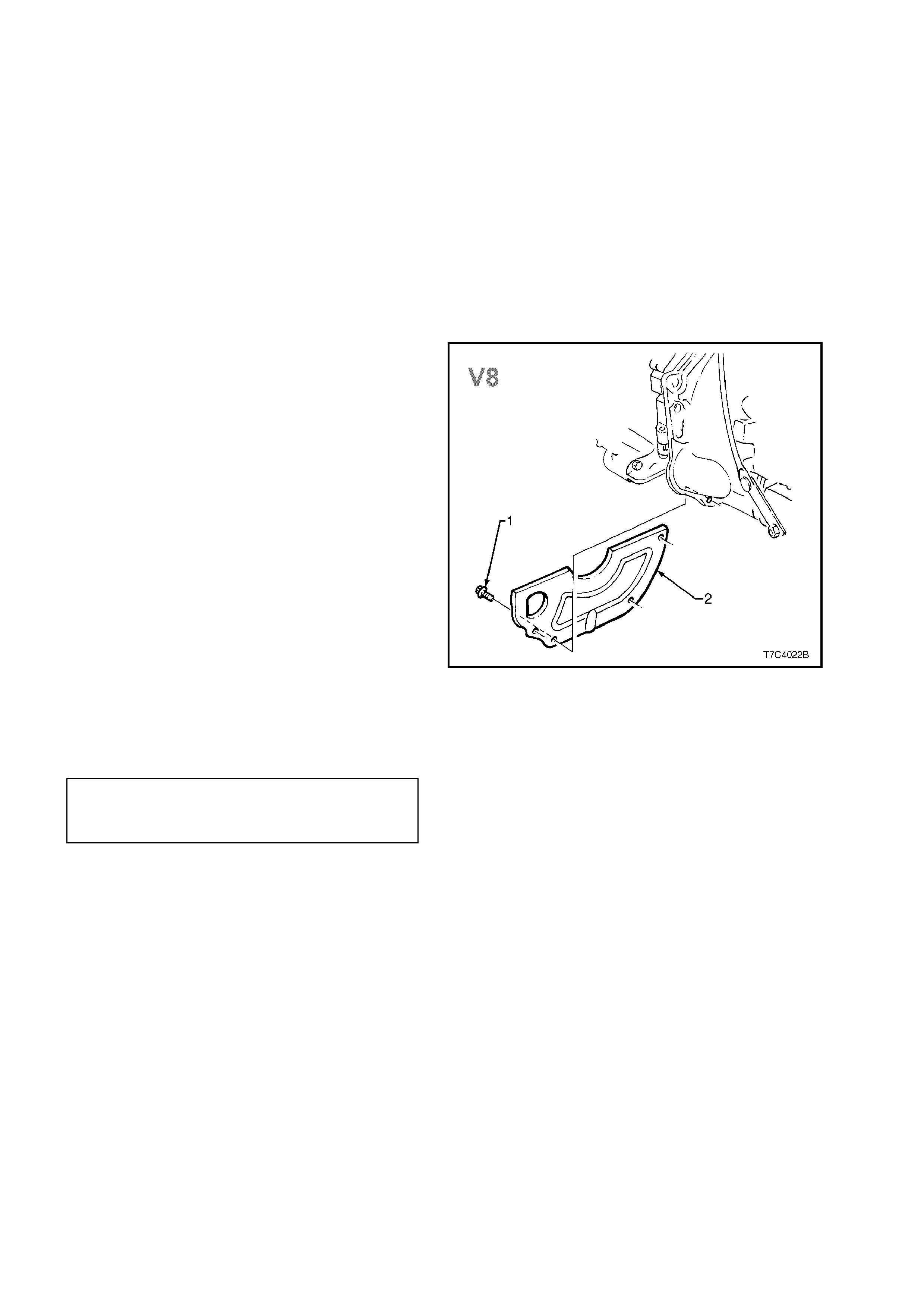
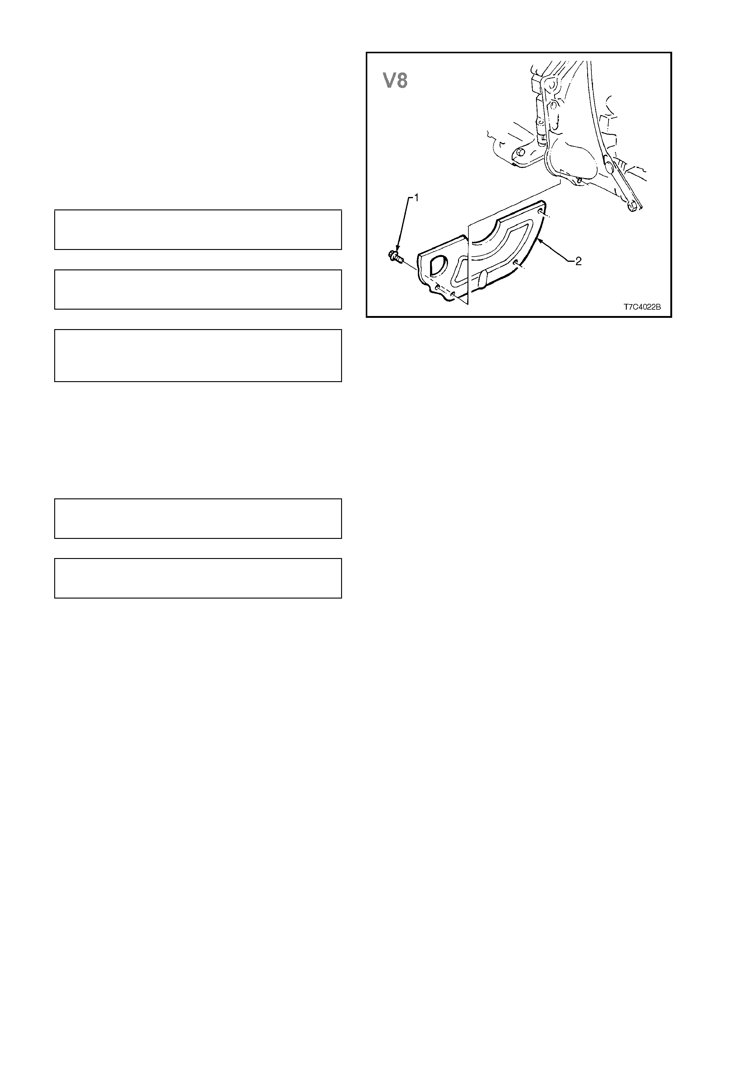
c. With V8 engine, remove the four lower
cover retaining screws (1), then remove
the lower cover (2) from the front of the
torque converter housing.
10. Mark relative position of torque converter and
flexplate, then remove three torque converter
to flexplate attaching bolts. Discard the
removed bolts.
Figure 7C4-54
Techline
Techline
11. Use a sharp s criber to m ark the ex act location
of the crossmember (2) to the side frame,
before loosening any of the four c rossm ember
to side frame attaching bolts (3).
IMPORTANT:
This step is critical to the correct powertrain
alignment on reassembly. If not carried out, then
vehicle vibration and/or handling problems could
result.
12. Remove two bolts (5) securing rear engine
mount to transmission.
13. Support transm iss ion with a jack . Do not place
the support beneath case extension or oil pan.
14. Remove the bolts securing crossmember to
underbody and remove cros s member f r om the
vehicle.
NOTE:
W hile the V6 rear engine mounting arrangement is
shown, the V8 arrangement is similar. Figure 7C4-55
15. Lower rear of transmission to provide sufficient
clearance, without placing any strain on any
electrical wiring and remove electrical
connector from the transmission as follows:
NOTE:
Take care when lowering rear of transmission that
the inlet manifold does not hit the firewall.
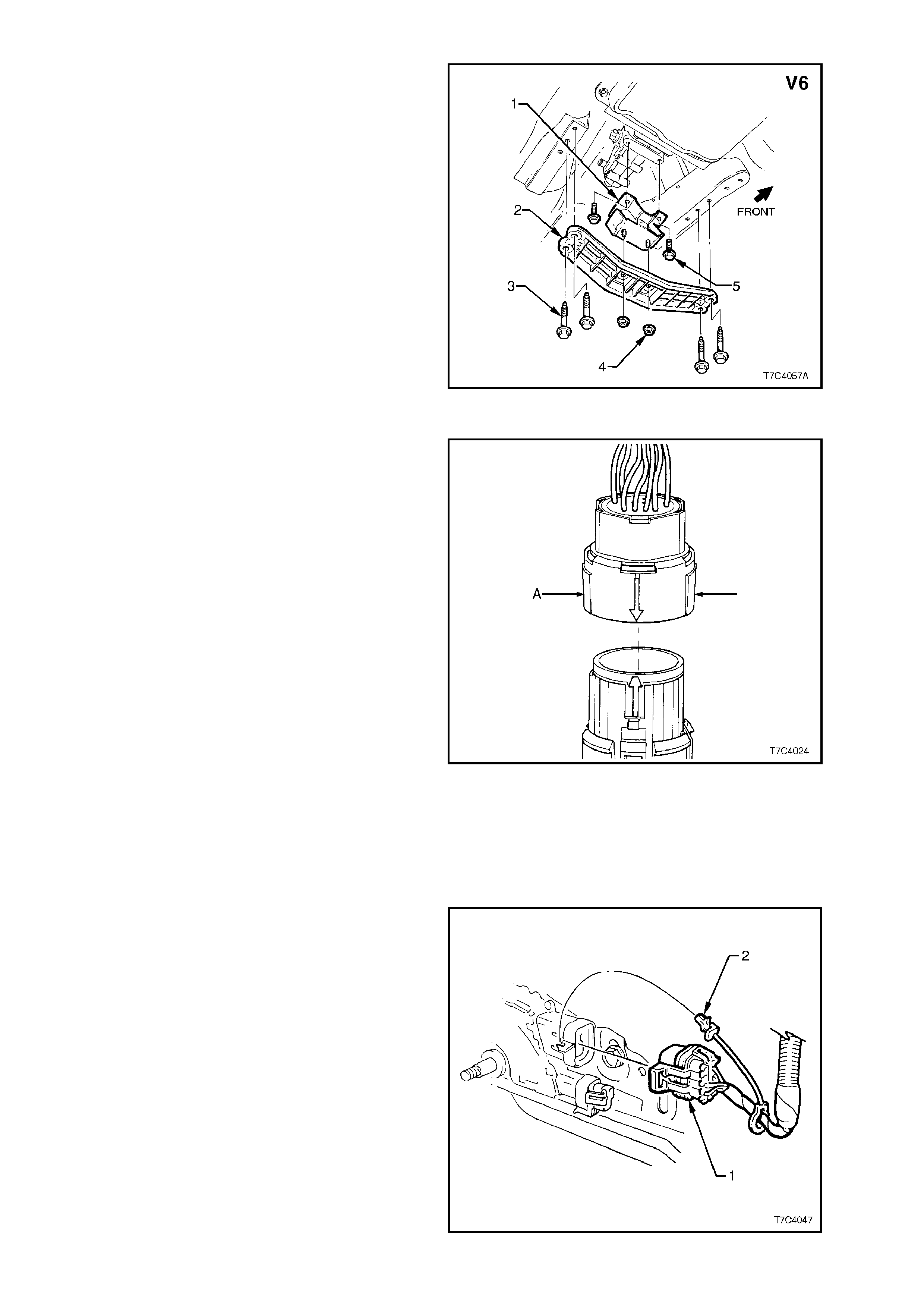
· Roll back the dust boot from the connector, to
gain access to the connector.
· Squeeze the widest side of the connector
inwards (A) and PULL DIRECTLY UPWARD.
IMPORTANT:
Do not wriggle the connector from side to side
while removing it! If this situation occurs, there is a
very real possibility of the connector pins being
permanently damaged.
16. Remove the wiring harness clip retaining
screws f rom both the right and lef t sides of the
transmission case .
17. While the rear of the transmission is lowered,
disconnect cooler pipes from tr ansm iss ion and
plug connections, both in the tr ansm iss ion and
the pipe ends themselves, to prevent dirt
entry.
Figure 7C4-56
18. Remove the wiring harness CPA (Connector
Position Assurance) security pin (2) from the
neutral start and back-up lamp switch, then
remove the connector (1) from the switch.
Figure 7C4-57

19. Lower rear of transmission further if
necessary, to gain access to the converter
housing bolts. Then, using a long socket
extension, a univers al joint and a suitable size
socket, remove the remaining converter
housing bolts (and nut, for V6 engine).
20. Support transmission assembly on a suitable
cradle and secure. Also place a suitable
support under engine oil pan rail to support
engine after transmission has been removed.
22. Remove transmission assembly from the
vehicle.
23. Install suitable converter holding tool to
prevent converter becoming dislodged.
REINSTALL
If transmission fluid is contaminated with grit or
foreign material, reverse flush coolers and
connecting pipes as detailed in
2.4 TRANSMISSION COOLER REVERSE FLUSH
AND FLOW RATE CHECK in this Section.
Reinstallation is the reverse of the removal
procedure, noting the following points:
1. Ensure transmission and engine mating
surfaces are clean and free of burrs.
2. Lubricate the torque converter spigot with
wheel bearing grease to Holden’s
Specification HN1227, prior to installation.
3. Ensure locating dowels completely enter
converter housing holes.
4. Prior to reins talling NEW conver ter to f lexplate
bolts, ensure locating marks on converter and
flexplate are aligned.
5. Remove the access hole cover plate in the
lower surface of the torque converter housing
and lever the torque converter forward, prior to
installing and tightening the torque converter
to flexplate attaching bolts. Reinstall the
access hole cover plate.
6. Apply thread sealant such as Loctitie 242 or
equivalent to Holden’s Specification HN1256,
Class 2, Type 2 to the cleaned bolt threads.
Tighten bolts to the correct torque
specification.
TORQUE CONVERTER TO
FLEX PLATE BOLT 60 - 70 Nm
TORQUE SPECIFICATION
7. Oil filler tube seal must be installed into
transmission before installing filler tube to
avoid damage to the seal.
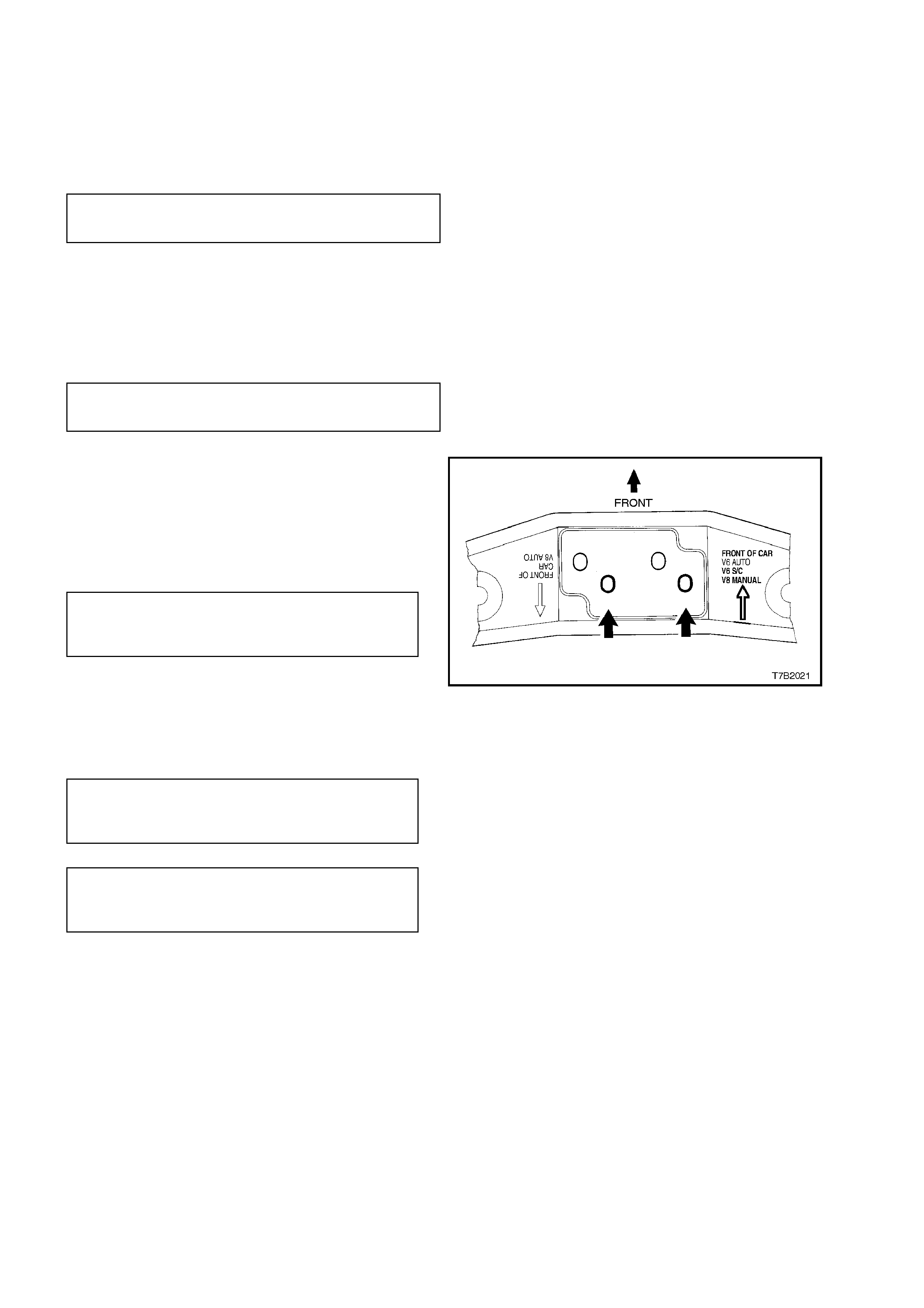
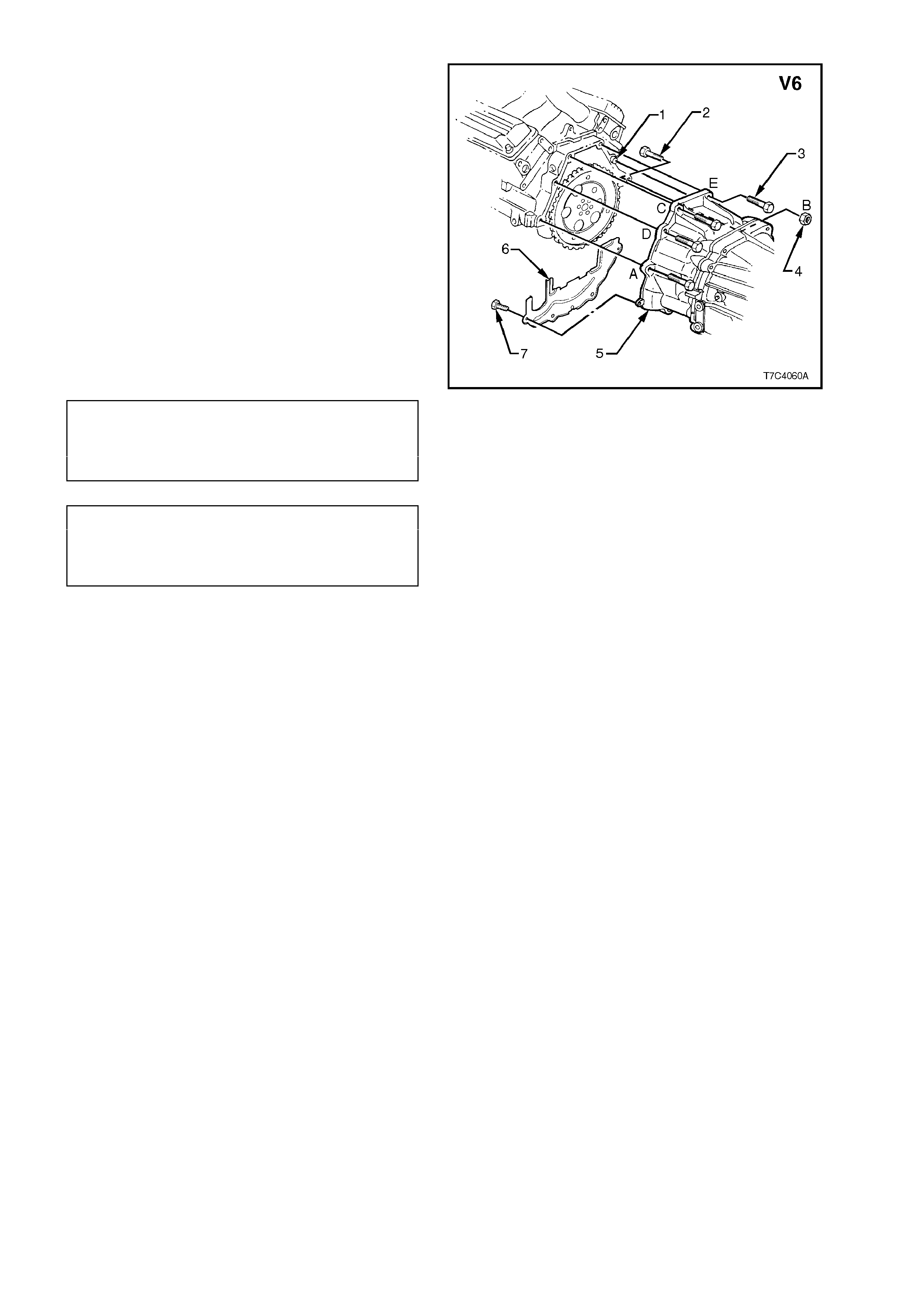
8. The tightening sequence for the transmission
to engine block bolts (and nut (4) f or V6) is as
shown. To avoid confusion the order
suggested, runs from ‘A’ to ‘E’ for V6
applications and f rom ‘A’ to ‘F’ f or V8 powered
vehicles.
NOTE 1:
The bolt (2) and nut (4) loc ation is as shown f or the
V6 transmission.
NOTE 2:
With the V8 transmission, the bolt (4) also holds
the dipstick tube bracket.
Tighten bolts to the correct torque specification.
TORQUE CONVERTER V6 Engine:
HOUSING TO 50 - 60 Nm
ENGINE BOLT V8 Engine:
TORQUE SPECIFICATION 30 - 45 Nm
LOWER TRANSMISSION V6 Engine:
COVER BOLT 30 - 45 Nm
TORQUE SPECIFICATION V8 Engine:
5 - 10 Nm
Figure 7C4-58
9. Prior to installing the wiring harnes s connector
to the transmission, check that all connector
pins and seals are in sound condition. Push
down on the connector body until a 'click' is
heard.
10. Installation of the beaming brace on vehicles
fitted with the V6 engine, is specific and the
procedure detailed in Section 6A1, 2.24
BEAMING BRACE, MUST be followed.
11. Tighten all bolts and nuts to the torque
settings, as specified in
5. TORQUE SPECIFICATIONS, in this
Section.
12. Lower vehicle and check fluid level, refer to
2.1 FLUID LEVEL CHECK, in this Section.
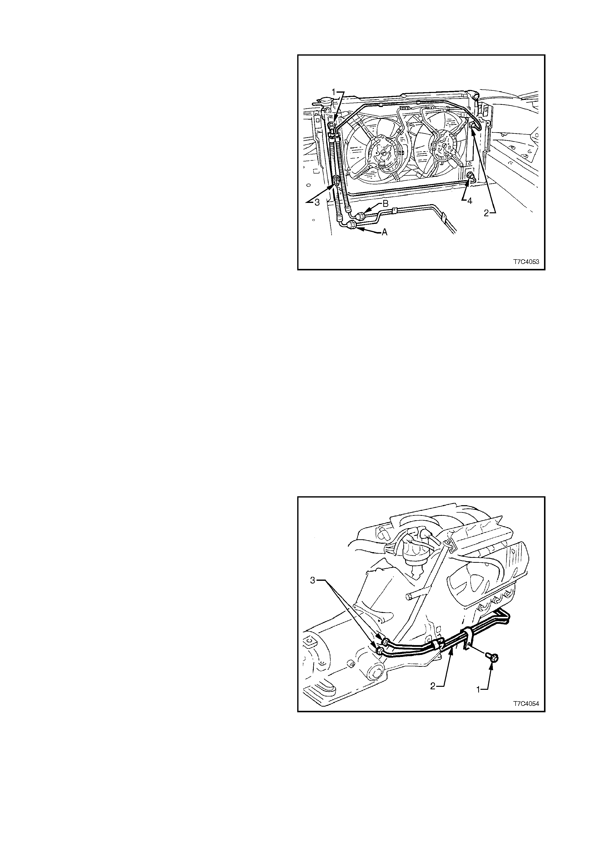
3.14 TRANSMISSION COOLER PIPES
REMOVE
FOR V6 POWERED VEHICLES
Auxiliary Oil Cooler Hoses
1. Place a drain tray beneath the front of the
vehicle.
2. With the engine hood raised, hold the unions
on the auxiliary oil cooler with a back-up
spanner and disconnect the two transmission
oil cooler hoses (2 and 3), at the auxiliary oil
cooler (1). To prevent foreign matter entry,
plug all open cooler connection points.
NOTE:
Removal of the upper right grille vent will make
access to the fittings, easier. Figure 7C4-59
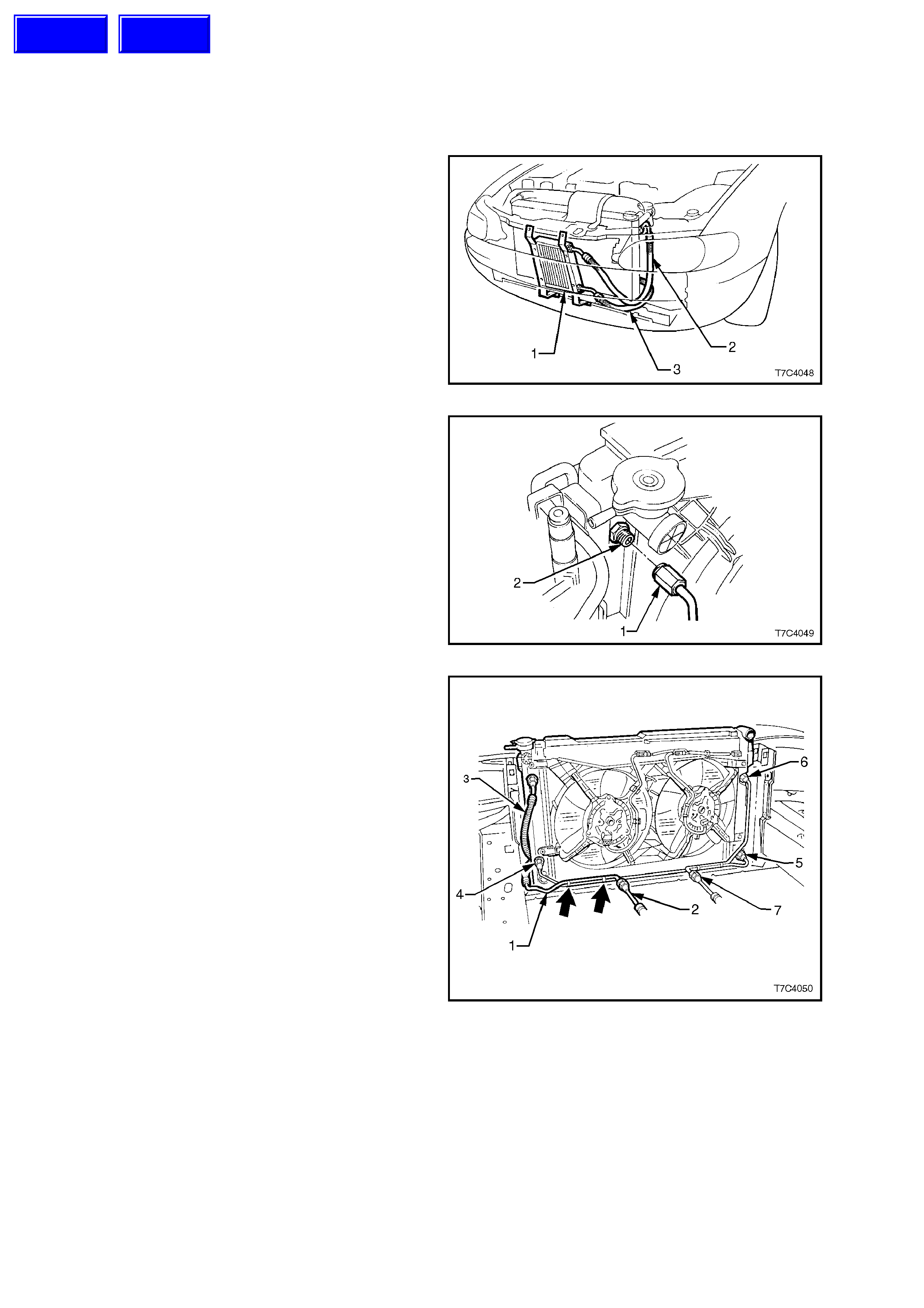
3. Hold the union (2) at the top lef t of the radiator
tank with a back-up spanner and disconnect
the oil cooler hose (1) from that location.
Figure 7C4-60
4. Remove the clips securing the oil cooler pipes
to each other (arrows).
5. While using a back-up spanner on the
auxiliary oil cooler pipe, disconnect the
transmission return line pipe (2).
6. Remove both auxiliary oil cooler hose
assemblies from the vehicle.
Radiator Cooler P ipes
1. Hold the union at the lower left of the radiator
tank (4) with a back-up spanner and
disconnect the oil cooler pipe from that
location.
2. Repeat this removal operation for the two
pipes on the radiator right hand tank (5 and 6).
3. While using a back-up spanner on the oil
cooler pipe to transmission feed cooler hose
connection (7), disconnect the transmission
feed line hose.
4. Remove the radiator cooler pipes from the
vehicle, separating as required by removing
the pipe clips (arrows).
Figure 7C4-61
Techline
Techline
Transmission Oil Cooler Pipes
1. Remove the clamp bolt (1) securing the
transm ission return line pipe to the front of the
engine.
Figure 7C4-62
2. Remove the clamp bolt (1) securing the
transm ission cooler pipes (2) to the right hand
side of the engine, as shown.
3. Using a pipe spanner, loos en then rem ove the
transmission cooler pipes from the
transmission fittings (3).
NOTE 1:
Use a back-up spanner on the transmission fittings.
NOTE 2:
Applying heat to the pipe spanner and bending it
slightly to modify it, will assist in the loosening
process.
4. Remove the cooler pipes (2) from the vehicle
and separate if required, by rem oving the pipe
clip.
Figure 7C4-63
FOR V8 POWERED VEHICLES:
NOTE:
As an auxiliary oil cooler is not used with the
standard V8 engine, the oil cooler pipe removal
procedures described here, will only reflect this
transmission cooler arrangement.
Oil Cooler Hoses:
1. Hold the union at the top left of the radiator
tank (1) with a back-up spanner and
disconnect the oil cooler hose from that
location.
2. While using a back-up spanner on the
transmission cooler pipe (A), disconnect the oil
cooler hose and remove from the vehicle.
3. Hold the union at the top right of the radiator
tank (2) with a back-up spanner and
disconnect the oil cooler hose pipe from that
location. Remove the cooler pipe clips at the
top of the radiator shroud.
4. While using a back-up spanner on the
transmission cooler pipe (B), disconnect the oil
cooler hose and remove from the vehicle.
NOTE:
To prevent foreign matter entry, plug open
connection points at the radiator and transmission
oil cooler pipe.
Radiator Crossover Cooler Pipe
1. Hold the union at the lower left of the radiator
tank (3) with a back-up spanner and
disconnect the oil cooler pipe from that
location.
2. Repeat this removal operation for the lower
fitting on the radiator right hand tank (4).
3. Remove the radiator cross-over pipe from the
vehicle.
Figure 7C4-64
Transmission Oil Cooler Pipes
1. Remove the clamp bolt securing the
transmission cooler pipes to the front of the
engine (not shown).
2. Remove the clamp bolt (1) securing the
transm ission cooler pipes (2) to the right hand
side of the engine, as shown.
3. Using a pipe spanner, loosen, then remove the
transmission cooler pipes from the
transmission fittings (3).
NOTE 1:
Use a back-up spanner on the transmission fittings.
NOTE 2:
Applying heat to the pipe spanner and bending it
slightly to modify it, will assist in the loosening
process.
4. Remove the cooler pipes (2) from the vehicle
and separate if required, by rem oving the pipe
clip. Figure 7C4-65

REINSTALL
The installation process of the oil cooler
pipes/hoses, is the r everse to rem oval, except
for the following:
1. Ensure that all pipe clamps are fitted correctly
and that pipe/hose routings are as shown in
the removal illustrations.
2. Ensure that all fasteners and fittings are
tightened to the correct torque specifications.
TRANSMISSION OIL COOLER
PIPE BRACKET V6 Engine:
BOLT - V6 ENGINE 20 - 35 Nm
TORQUE SPECIFICATION
TRANSMISSION OIL
COOLER PIPE V6 Engine:
BRACKET SCREW 2.0 - 5.0 Nm
TORQUE SPECIFICATION
TRANSMISSION OIL
COOLER PIPE V8 Engine:
BRACKET SCREWS 5.0 - 8.0 Nm
TORQUE SPECIFICATION
OIL COOLER HOSE
FITTINGS TO V6 Engine:
AUXILIARY COOLER 25 - 30 Nm
TORQUE SPECIFICATION
OIL COOLER
HOSE FITTINGS All Engines:
TO RADIATOR 25 - 30 Nm
TORQUE SPECIFICATION
TRANSMISSION OIL COOLER
PIPE FITTINGS TO All Engines:
RADIATOR PIPES 20 - 23 Nm
TORQUE SPECIFICATION
3. Check for leaks and top up transmission fluid
level as required. Ref er to 2.1 FLUID LEVEL
CHECK in this Section.
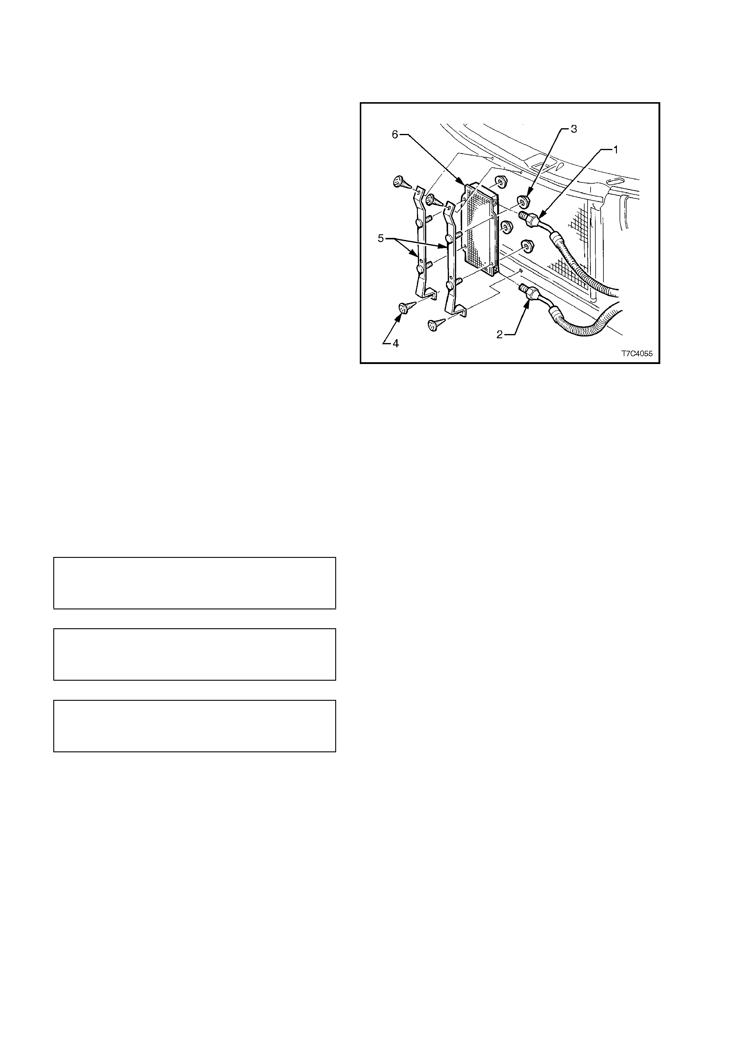
3.15 AUXILIARY OIL COOLER
REMOVE
1. Place a drip tray beneath the auxiliary oil
cooler assembly.
2. With the engine hood raised, hold the unions
on the auxiliary oil cooler (6) with a back-up
spanner and disconnect the two transmission
oil cooler hoses (1 and 2) at the auxiliary oil
cooler (6). To prevent foreign matter entry,
plug all open connections.
NOTE:
Removal of the upper right grille vent will make
access to the fittings, easier.
3. Remove the four auxiliary cooler mounting
bracket retaining nuts (3), then remove the
cooler (6) from the vehicle.
4. If required, remove the four screws (4)
securing the auxiliary cooler mounting
brackets (5), then remove them from the
vehicle.
NOTE:
In order to gain access to the bracket screws, it
will be necessary to remove the front bumper bar.
Refer to Section 1D BUMPER BARS.
Figure 7C4-66
REINSTALL
The installation process of the auxiliary oil cooler, is
the reverse to removal, except for the following:
1. Ensure that all fasteners and fittings are
tightened to the correct torque specifications.
OIL COOLER HOSE FITTINGS TO
AUXILIARY COOLER 25 - 30 Nm
TORQUE SPECIFICATION
AUXILIARY COOLER TO
MOUNTING BRACKET NUTS 5.0 - 12 Nm
TORQUE SPECIFICATION
AUXILIARY COOLER MOUNTING
BRACKET SCREWS 1.5 - 2.5 Nm
TORQUE SPECIFICATION
2. Check for leaks and top up transmission fluid
level as required. Ref er to 2.1 FLUID LEVEL
CHECK in this Section.

4. SPECIFICATIONS
NOTE:
For a complete listing of specifications as they apply to internal components not discussed in this Section, refer to
Section 7C5 HYDRA-MATIC 4L60-E AUTOMATIC TRANSMISSION: UNIT REPAIR.
GENERAL:
Type Hydra-matic 4L60-E
Transmission Code V6 Engine - 8HFD
V6 Supercharged Engine - 8HND
V8 Engine - 8HBD
Special Features Electronically controlled shift pattern, feel and torque
converter clutch operation
Selector Location Floor mounted console
GEAR RATIOS:
Park (P) —
Reverse (R) 2.294:1
Neutral (N) —
Drive (D) 0.696:1
Third (3) 1.000:1
Second (2) 1.625:1
First (1) 3.059:1
SHIFT SPEEDS: Refer to Section 7C3 DIAGNOSIS
OIL PRESSURE: Refer to Section 7C3 DIAGNOSIS
TORQUE CONVERTER:
Number of Elements 3 plus torque converter clutch
Maximum Torque Ratio at Stall V6 Engine - 1.63:1 (k=122)
V6 Supercharged Engine - 1.63:1 (k=133)
V8 Engine - 2.15:1 (k=115)
Nominal Diameter V6 Engine - 245 mm
V6 Supercharged Engine - 258 mm
V8 Engine - 298 mm
LUBRICANT:
Type Recommended DexronÒ III (To Holden's Specification HN2126)
Capacity Nominal Only. Check when transmission
is at operating temperature.
Refill V6 Engine - 4.8 litres
V8 Engine - 5.0 litres
Total (Dry) V6 Engine - 7.9 litres
V8 Engine - 10.6 litres
Fluid Cooling Engine coolant to fluid in both radiator tanks and
externally, air to fluid cooler (where fitted)
2 - 4 SERVO:
Selective Pin Length
1 Groove 65.82 - 66.12 mm
2 Grooves 67.23 - 67.53 mm
No Groove 68.64 - 68.94 mm

5. TORQUE WRENCH SPECIFI CATIONS
NOTE:
For a complete listing of torque wrench specifications as they apply to internal components not discussed in this
Section, refer to Section 7C5 HYDRA-MATIC 4L60-E A UTOMATIC TRANSMISSION: UNIT REPAIR.
Nm
Oil Pan Bolt 9.5 - 13.8
Manual Shaft Lever Nut 15 - 35
Manual Shaft to Inner Detent Lever Nut 27 - 34
Manual Detent Spring Retaining Nut 20 - 27
Selector Lever Locking Bolt 15 - 35
Selector Lever Base Nut 12 - 18
Neutral Start and Back-up Lamp Switch
Bolt 15 - 35
Speed Sensor Retaining Screw 10.5 - 13.5
1 - 2 Accumulator Cover Bolt 8 - 14
Control Valve Body Bolt 8 - 14
Torque Converter Clutch Solenoid Bolt 8 - 14
Spacer Plate Support Plate Bolt 8 - 14
Extension Housing to Case Bolt 42 - 48
Oil Cooler Pipe to Transmission Fitting 15 - 18
Rear Engine Mounting to Transmission
Extension Bolt 50 - 65
Rear Engine Mounting to Crossmember
Nut 20 - 30
Crossmember to Side Rail Attaching Bolt 50 - 65
Starter Motor Attaching Bolt - All Engines 40 - 60
Starter Motor Brace Bolt - V8 Engine 12 - 16
Torque Converter Housing to Engine
Block Bolt - V6 Engine 50 - 60
- V8 Engine 30 -45
Transmission Filler Tube Bracket
Retaining Bolt - V6 Engine 20 - 35
- V8 Engine 30 -45
Torque Converter to Engine Flexplate
Attaching Bolt 60 - 70
Torque Converter Lower Cover Attaching
Screw - All Engines 3.0 - 5.0
Beaming Brace to Engine Oil Pan Bolt - V6 Engine 20 - 35
Beaming Brace to Torque Converter
Housing Bolt - V6 Engine 50 - 85
Transmission Oil Cooler Pipe Bracket Bolt - V6 Engine 20 - 35
Transmission Oil Cooler Pipe Bracket
Screw - V6 Engine 2.0 - 5.0
- V8 Engine 5.0 - 8.0
Transmission Oil Cooler Pipe Fittings to
Oil Cooler Pipes - All 20 - 23
Oil Cooler Hose Fittings to Auxiliary Oil
Cooler - V6 Engine 25 - 30
Oil Cooler Hose Fittings to Radiator - All Engines 25 - 30
Auxiliary Oil Cooler to Mounting Bracket
Nut - V6 Engine 5.0 - 12
Auxiliary Oil Cooler Mounting Bracket
Screws - V6 Engine 1.5 - 2.5
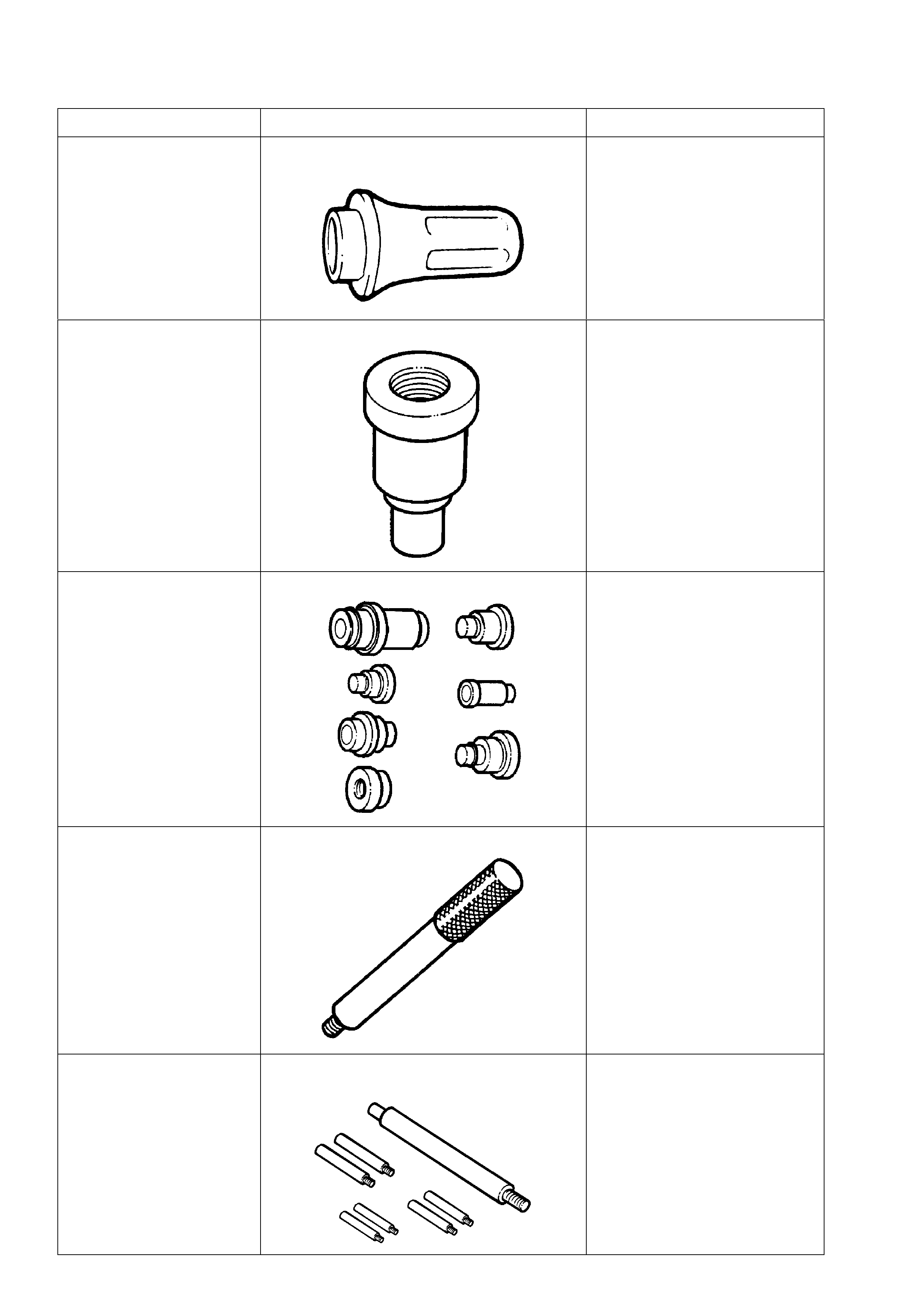
6. SPECIAL TOOLS
TOOL NO. REF IN TEXT TOOL DESCRIPTION COMMENTS
J21426 REAR EXTENSION HOUSING SEAL
INSTALLER PREVIOUSLY RELEASED
FOR TRIMATIC, AS 7AT-6.
J23062-14 BUSH REMOVER NEW RELEASE. USED IN
CONJUNCTION WITH DRIVER
HANDLE J8092.
J34196-B BUSH REMOVER/INSTALLER SET NEW RELEASE. INSTALLER
J34196-4 IS USED TO
INSTALL THE EXTENSION
HOUSING BUSH.
J8092 DRIVER HANDLE PREVIOUSLY RELEASED.
J25025-1 DIAL INDICATOR STAND AND GUIDE PIN
SET PREVIOUSLY RELEASED.
USED HERE FOR THE GUIDE
PINS FOR ALIGNING THE
CONTROL VALVE BODY
SPACER PLATE
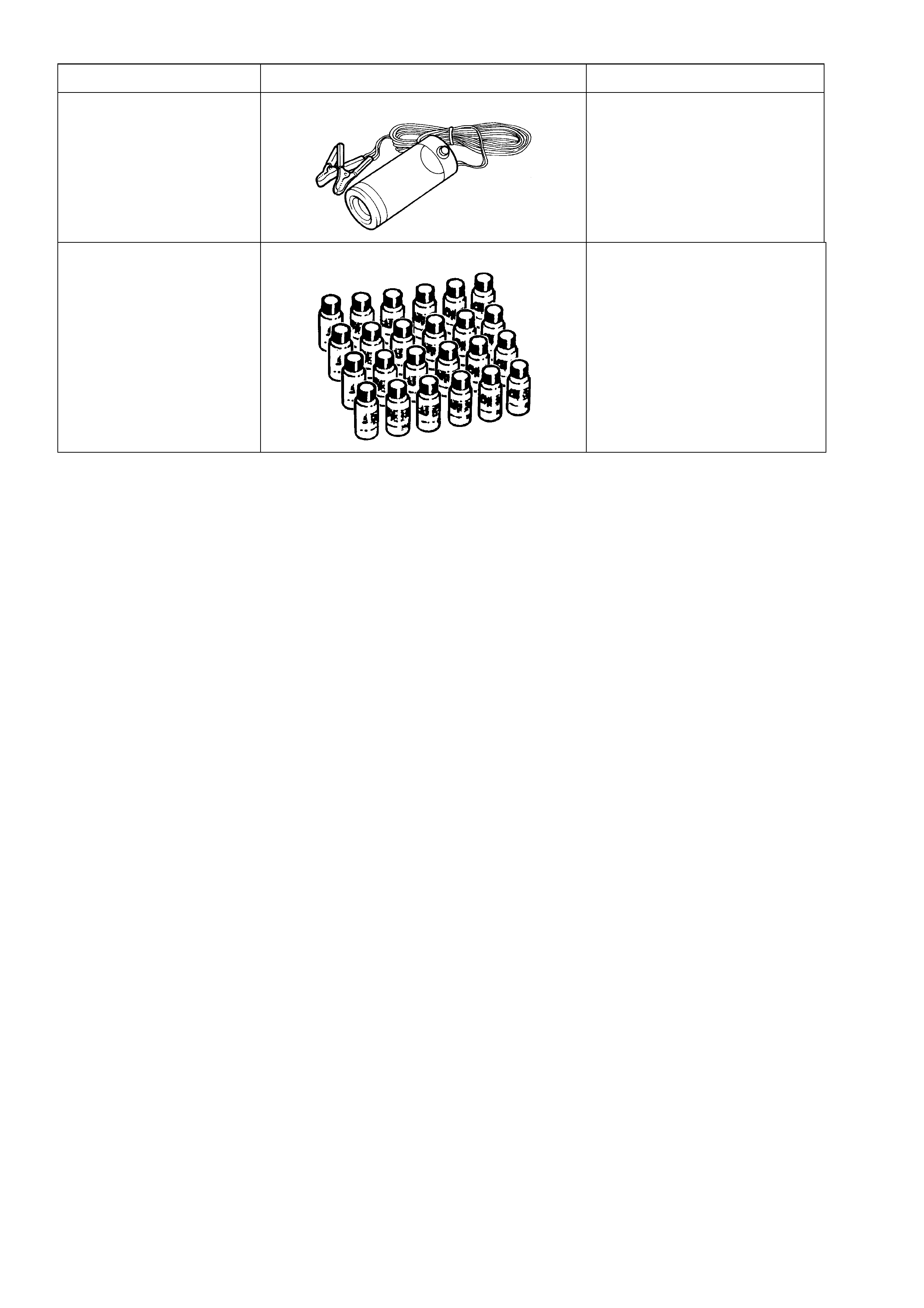
TOOL NO. REF IN TEXT TOOL DESCRIPTION COMMENTS
J42220 12 VOLT BLACK LIGHT PREVIOUSLY AVAILABLE
J28431-B
(24 X 1 FLUID OUNCE
BOTTLES)
FLUORESCENT OIL DYE PREVIOUSLY AVAILABLE.
USED IN CONJUNCTION
WITH 12V BLACK LIGHT.
SUITABLE FOR LOCATING
ENGINE TRANSMISSION AND
POWER STEERING FLUID
LEAKS