SECTION 8A - FUEL TANK
CAUTION:
This vehicle will be equipped with a Supplemental Restraint System (SRS). An SRS
will consist of either seat belt pre-tensioners and a driver's side air bag, or seat belt
pre-tensioners and a driver's and front passenger's side air bags. Refer to
CAUTIONS, Section 12M, before performing any service operation on or around any
SRS components, the steering mechanism or wiring. Failure to follow the CAUTIONS
could result in SRS deplo yment, resulting in possible p ersonal injury or unnecessary
SRS system repairs.
CAUTION:
This vehicle may be equipped with LPG (Liquefied Petroleum Gas. In the interests of
safety, the LPG fuel system should be isolated by turning ‘OFF’ the manual service
valve and then draining the LPG serv ice lines, before any service w ork is carried out
on the vehicle. Refer to the LPG leaflet included with the Owner's Handbook for
details or LPG Section 2 for more specific servicing information.
CAUTION:
Whenever any component that forms part of the ABS or ABS/ETC (if fitted), is
disturbed during Service Operations, it is vital that the complete ABS or ABS/ETC
system is checked, using the procedure as detailed in 4. DIAGNOSIS, ABS or
ABS/ETC FUNCTION CHECK, in Section 12L ABS & A BS/ETC.
1. GENERAL INFORMATION
The 75 litre fuel tank fitted to all VT Series models is a multi-layer polycarbonate construction with an integral fuel
filler neck. The fuel tank is not serviceable and if damaged, must be replaced as an assembly.
The fuel tank is supported by three mounting straps and a seal is fitted around the fuel filler neck where it protrudes
through the vehicle body.
An in-tank, modular fuel sender assembly is used, that incorporates a fuel reservoir, the fuel sender unit and the
fuel pump in the one unit.
Apart from the complete assembly, serviced components for the modular fuel sender, are the fuel pump, pick-up
strainer and fuel sender assembly.
Servicing details for these and other fuel tank/line related items are covered in this Section.
Quick-connect fuel line fittings are used for all fuel line connections, including, the modular fuel sender assembly,
fuel vapour canister, fuel filter, fuel feed and return lines, both at the fuel tank and engine ends.
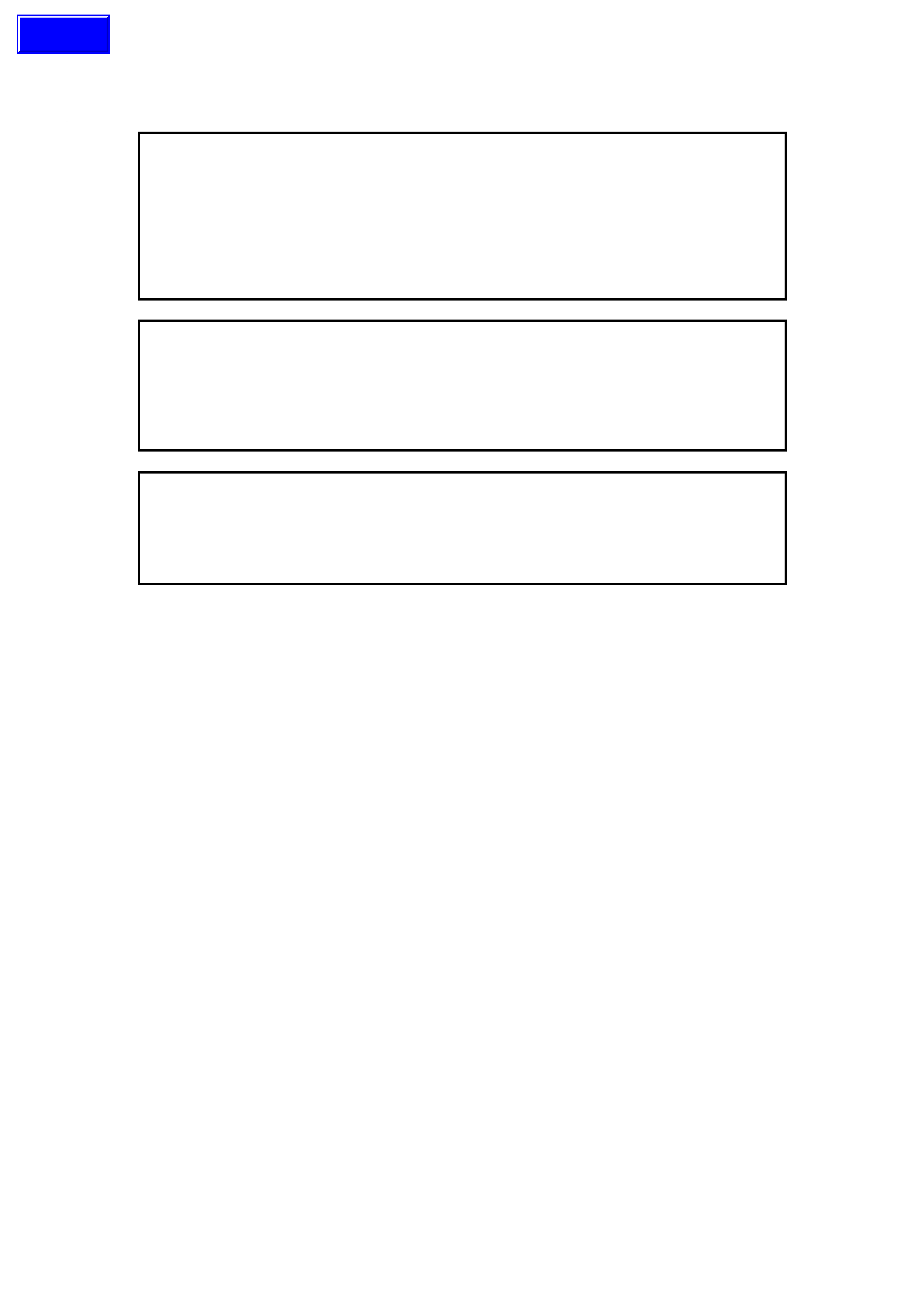
1.1 MODULAR FUEL SENDER ASSEMBLY
The modular fuel sender assembly is designed to maintain an optimum fuel level in the reservoir. This ensures a
continuous fuel flow under all fuel level conditions and vehicle attitudes. As there are two different construction fuel
pumps used, two fuel flow descriptions are required.
The first details fuel flow through the turbine fuel pump that is used with both the V6 and V8 engines.
Turbine Fuel Pump (View A, in Figure 8A-1)
Fuel is drawn into the reservoir from the fuel tank, through the external strainer (3) and into the fuel pump’s first
stage impeller, via the primary fuel pump inlet. First stage fuel is then directed to the reservoir, filling the reservoir
bucket..
Fuel levels in the reservoir are also maintained by return engine fuel, via the return line. Reservoir fuel flow
proceeds through the fuel pump strainer, bypassing the first stage impeller. Fuel proceeds to the second impeller
and the high pressure third stage of the impeller pump.
High pressure fuel then flows through the end cap, the lower connector and the fuel pump flex pipe. From the flex
pipe, fuel then exits the modular fuel sender assembly through the fuel feed fitting and flows on to the externally
mounted fuel filter.
Techline
Roller Vane Fuel Pump, (View B, in Figure 8A-1)
This pump design is used with the V6 Supercharged engine and in a similar manner to the first, fuel enters the roller
vane pump via the two strainers (3 and 5). The initial function of the pump is to separate vapour from the fuel and
this is done in the first stage. This vapour separation maximises hot fuel handling and allows the vapour to return to
the tank at a lower pressure and temperature.
The pump then discharges the liquid fuel into the roller vane section of the pump. Attached to the pump outlet is a
diverter that allows the primary fuel volume to flow into the flex pipe and also deliver a portion of the flow to the jet
pump.
Action of this diverted fuel from the outlet of the fuel pump, passing through the jet pump filter (6) and creates a low
pressure area at its base, causing the umbrella valve (2) to unseat, drawing cooler fuel into the reservoir area.
Figure 8A-1
With either pump, when power is switched off, the
reservoir remains full of fuel, because of the action
of the primary (2) and secondary (4) umbrella
valves. During refuelling operations, the secondary
umbrella valve (4) unseats, allowing fuel to enter
the reservoir up to the fuel tank f uel level. Fuel tank
overflow fuel enters the reservoir over the top of the
assembly.
Should the external strainer (3) becom e blocked or
restrict fuel entry, then the secondary umbrella
valve (4) will unseat, allowing fuel to enter the
reservoir area.
Electrical power to the f uel pum p enters the unit via
a connector that is secured to the cover. An internal
harness assem bly com pletes the connection to the
pump (not shown).
Also incorporated into the cover design, is a ‘roll
over’ valve that lim its vapour venting to the canister
through the use of a sized orifice. In the event that
the vehicle rolls over , the vent line to the canist er is
safely shut off by the roll-over valve.
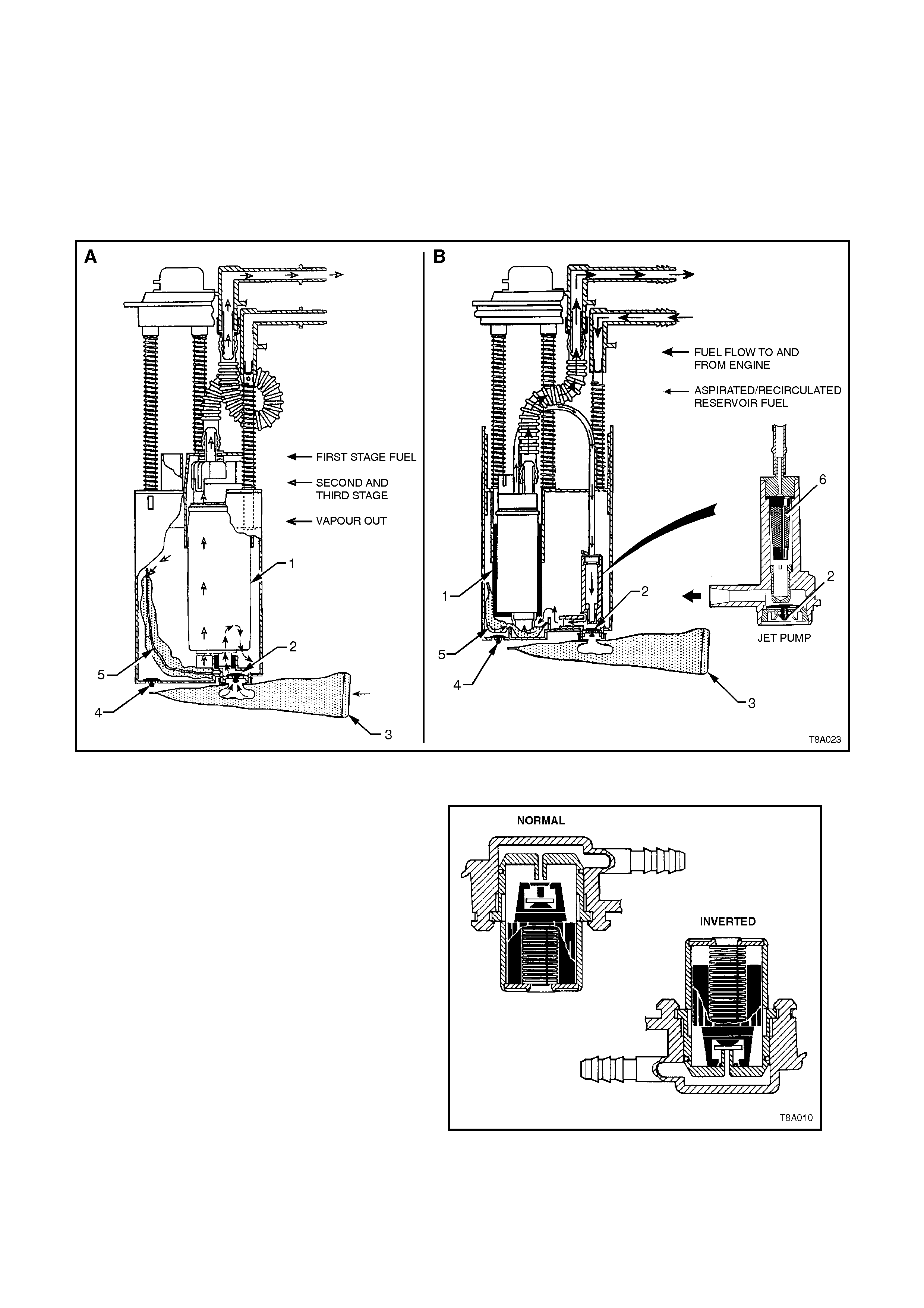
Figure 8A-2
1. Inlet Body 2. Inlet Housing 3. Inlet Plate
A 1st Stage Impeller B 2nd Stage Impeller C To the 3rd Stage Impeller
Figure 8A-3 Turbine Fuel Pump
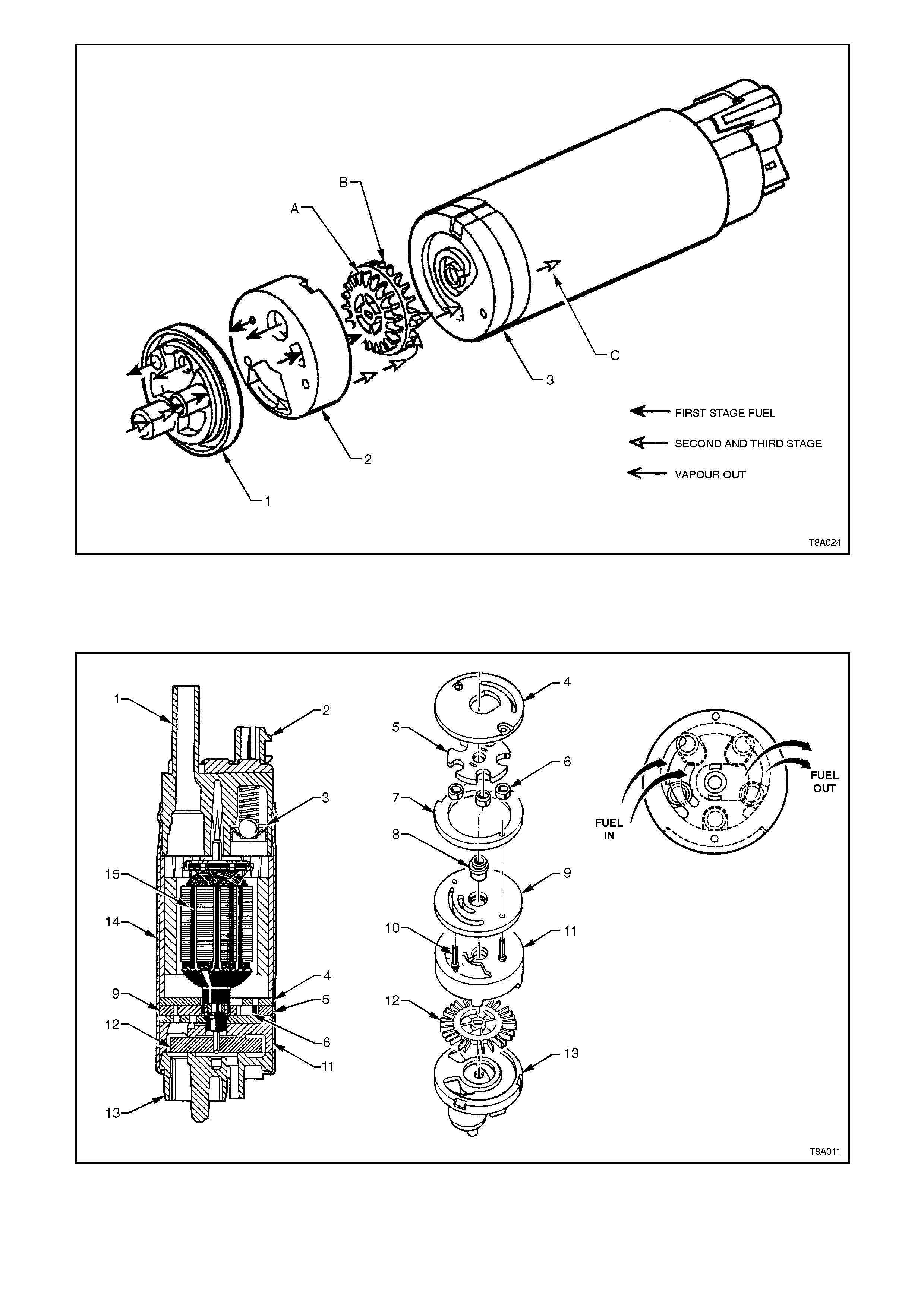
1. End Cap 4. Outlet Plate 7. Eccentric Ring 10. Rivets 13. Inlet Body
2. RFI Module 5. Rotor 8. Bearing 11. Housing 14. Shell
3. Relief Valve 6. Rollers 9. Face Plate 12. Impeller 15. Electric Motor
Figure 8A-4 Roller Vane Fuel Pump Assembly
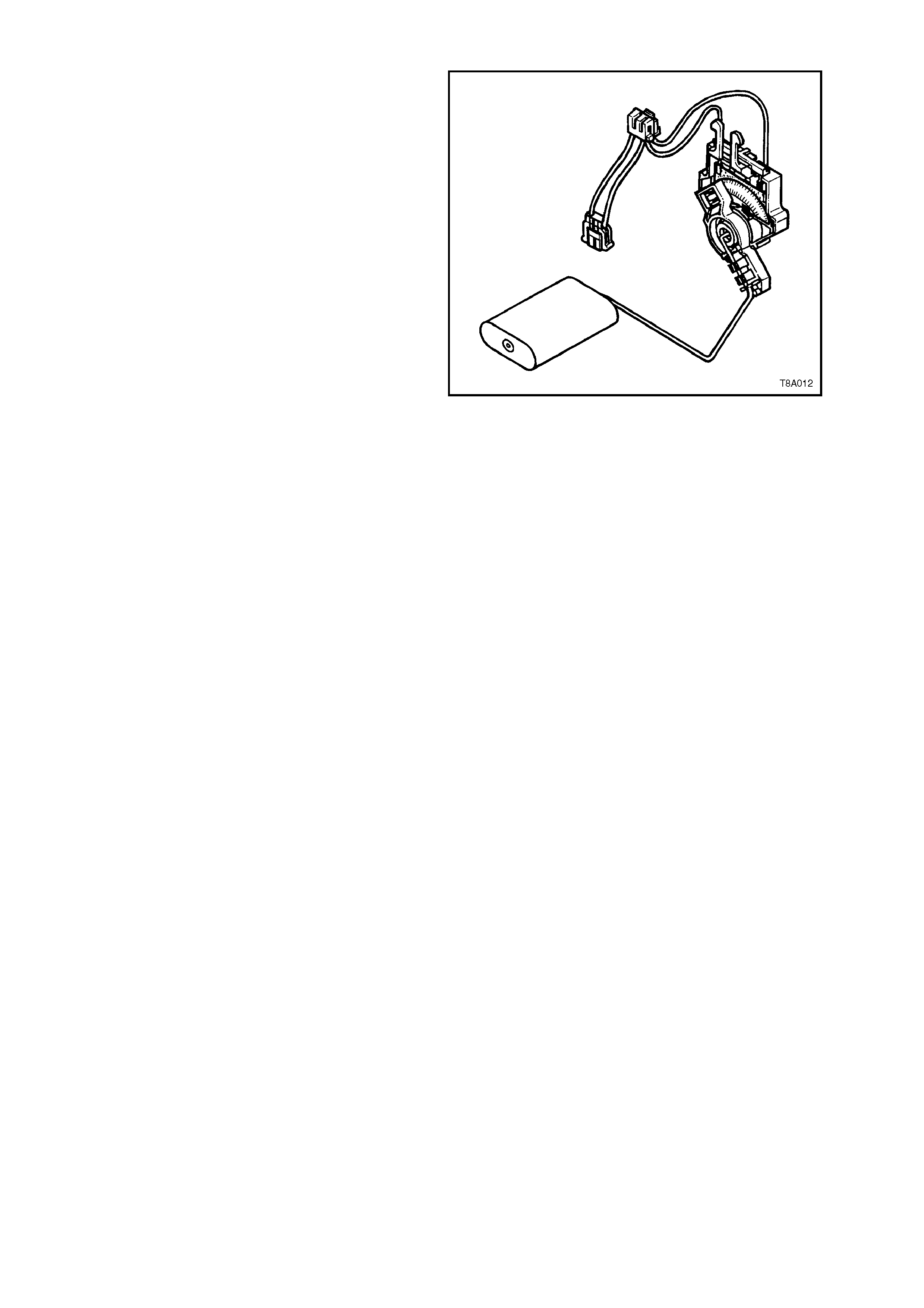
1.2 FUEL GAUGE TANK SENDER UNIT
The ceramic resistor card fuel level sensor
assembly, consists of a ceramic resistor card (1),
wiper arm (2), float arm assembly (3) and a below
cover, wiring harness (4). Action of these
components converts the fuel level in the fuel tank
into a variable electrical signal used to drive the fuel
gauge in the instrument panel.
The assem bly is attached to the outside surface of
the modular fuel sender assembly and secured with
a retainer. The electrical harness (4) attached to
the fuel sender cover c onnects the ceram ic res istor
card to the vehicle wiring harness.
The function of the ceramic resistor card is to vary
the resistance, dependent upon the float position
and to send that signal to the Body Control Module
(BCM). This resistance signal changes, relative to
the wiper contact position on the c onductive bars of
the ceramic resistor card.
New electronics in the BCM average out any slosh
variation, which means that fuel tank baffling is not
as critical to maintaining accurate gauge readings.
Figure 8A-5
1.3 FUEL FILLER CAP
The fuel filler cap is the 'SCREW ON' type with a
ratcheting feature to tighten. When installing the
cap, tighten it until a ratcheting (clicking) sound is
heard, indicating the cap is properly tightened.
IMPORTANT:
Should a replacem ent cap be required, us e only an
all black fuel cap that is specified for VT Series
Models. Use of an incorrect cap will cause
malfunction of the emission control system.
The warning 'UNLEADED FUEL ONLY' is
embossed on the cap.
Figure 8A-6
Techline
Techline
2. SERVICE OPERATIONS
2.1 FUEL TANK
REMOVE
1. Depressurise the fuel system. Refer to
Section 6C1-3 (V6 engine) or Section 6C2-3
(V8 engine).
CAUTION:
Even though the fuel system may have been
de-pressurised, the fuel filter and lines will
contain fuel that will be spilled during service
operations. Therefore, ensure that no naked
flames or other ignition sources are in the
immediate area.
2. Syphon fuel from tank, using commercially
available equipment.
CAUTION:
Never drain or store fuel into an open
container, due to the possibility of fire or
explosion.
3. Raise vehicle, preferably on a hoist.
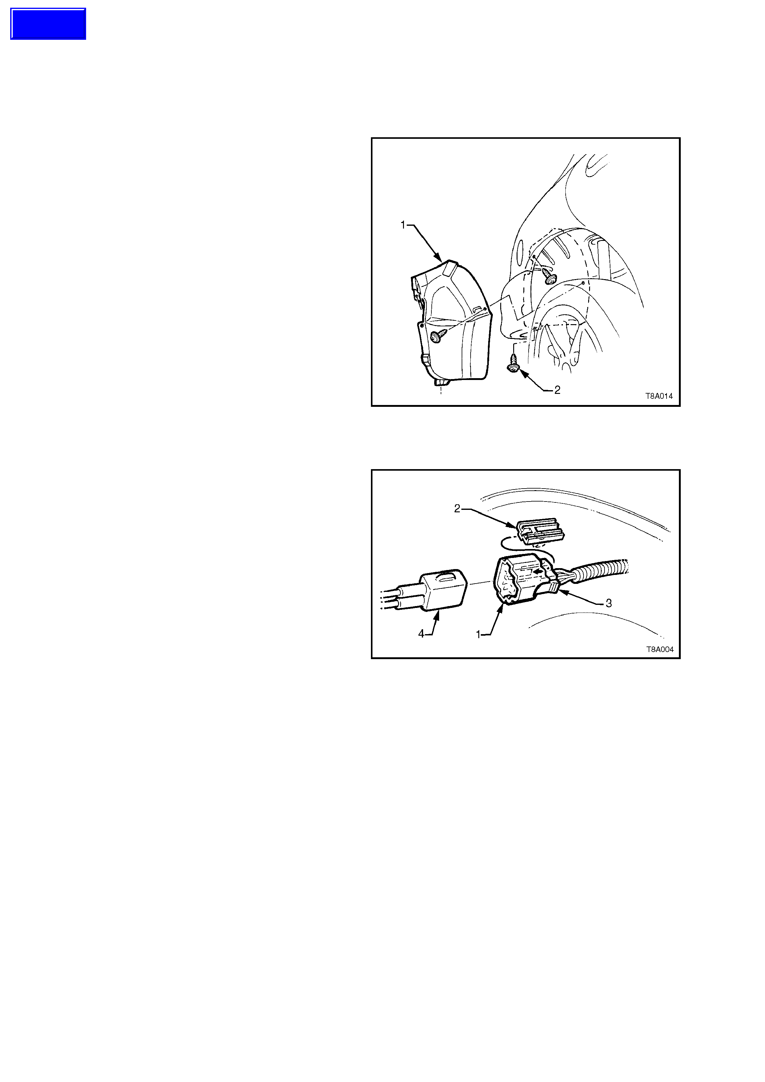
4. Remove three stone guard retaining screws
(2), then remove the stone guard (1), from
under the right hand rear guard.
Figure 8A-7
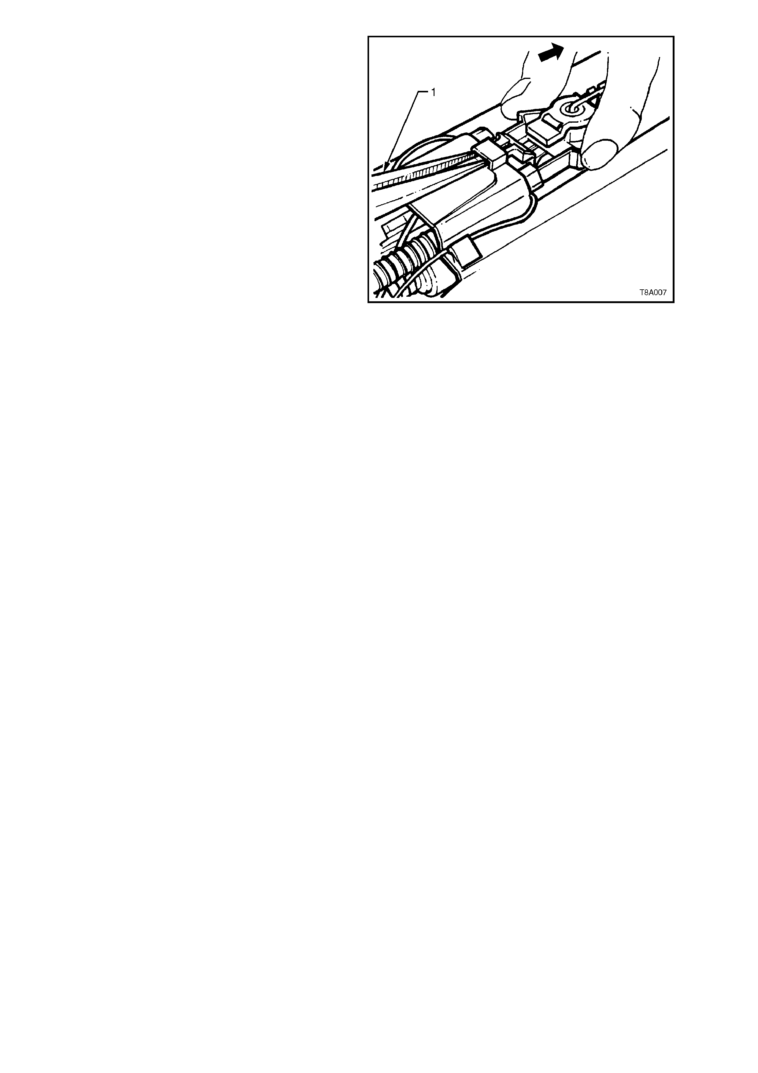
5. Remove the fuel sender electrical connector
(1) from its mounting foot (2) by pulling
forward to dislodge the assembled connector
forward. Once released, depress the locking
tab (3) and separate the connector halves (1
and 4).
6. Place a drain tray under the fuel filter area.
Figure 8A-8
7. Remove the quick connect fittings to the
vapour canister (1), return line (3) and fuel
filter (4), using the following method:
Push inwards to release the seal pressure,
depress the side tangs of the connector, then
pull to disconnect.
8. Disconnect the vapour canister breather hose
at the canister (2).
NOTE:
Ensure that all dirt and foreign material is rem oved
from any fuel connection, prior to removal.
9. If required, remove the fuel filter (5) by
removing the fuel feed line quick connector
(6), then depressing the two barbs on the
mounting strap nipple (7).
CAUTION:
Fuel will spill from the disconnected filter.
Techline
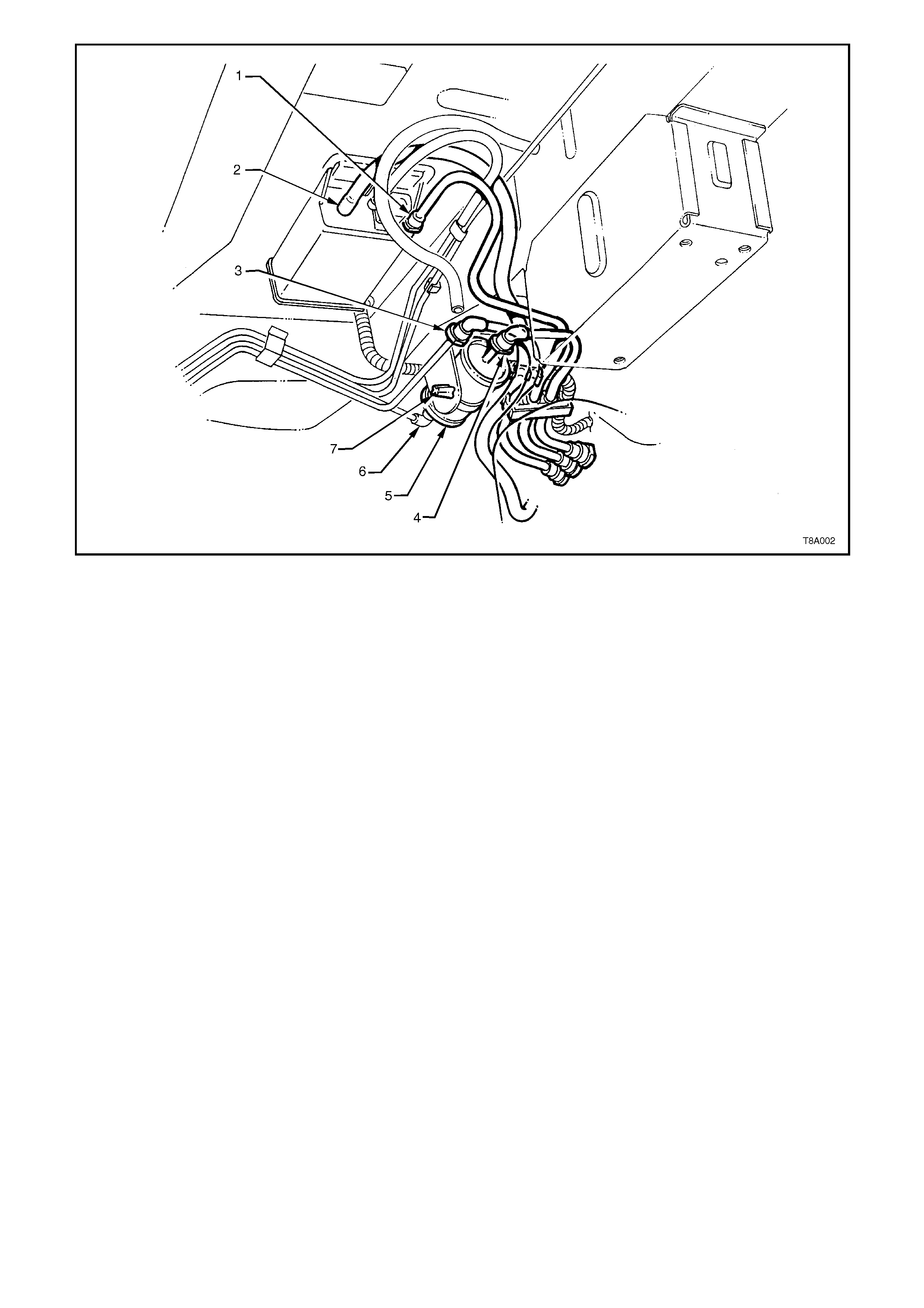
Figure 8A-9
9. Disconnect the earth strap from the spade
connector (A, in view E) under the front right
hand strap mounting bolt (4) of the right hand
tank support strap (3). See Figure 8A-10.
10. Remove the fuel tank support straps as
follows;
Remove the centre strap (2) by removing the
rear retaining nut (5) and washer, then unhook
the strap from the front support (view C).
While supporting the fuel tank in the centre,
remove strap (3) (closest to the filler neck),
after removing the bolt at the front and
unhooking the strap from the rear support
(views A and B).
Finally remove strap (1) after removing the
nuts and washers from each end of the strap
(views C and D).
11. Lower the fuel tank from the vehicle, left side
first, to release the fuel filler neck from the
body opening.
REINSTALL
Is the opposite to removal except for the following;
1. Check that the insulation has not become
dislodged from the top of the tank (Refer Figure
8A-10).
2. Offer up the fuel neck with the insulator installed,
to the body opening, then raise the up, tank into
place.
3. Fit the support straps in the following
suggested order:
Loosely install straps 1 and 3.
Check that the filler neck seal is correctly
located in the body opening. While pushing
the fuel tank firmly to the right-hand side,
tighten the strap (1) bolt (4 in view E) and nut.
Tighten the f ront bolt (4 in view A) of str ap (3) .
Ensure that the earth s trap s pade c onnec tor is
also fitted.
Hook strap (2) into the front retainer and install
the retaining nut.
FUEL TANK MOUNTING STRAP
BOLTS AND NUTS 15 - 25 Nm
TORQUE SPECIFICATION
5. Connect the electrical connector, ensuring that
both locking tabs are in place. Then, engage
the assembled connector with its mounting
foot and push rearwards to engage the locking
tab.
6. Install the disconnected fittings to the fuel
filter, c anis ter and r etur n line, r outing cor r ect ly,
as shown in Figure 8A-9, using the following
assembly sequence:
a. Canister vent hose to canister (2).
b. Fuel vapour return line to canister (1).
c. Fuel tank vent line to canister (1).
d. Fuel return line to brake and fuel pipe
harness assembly (3).
e. Fuel lines (4) and (6) to the fuel filter (5).
f. Fuel filter (5) and strap assembly (7) to
the filter mounting bracket (if removed).
7. Reinstall the stone guard to the right-hand
wheel opening, tightening the mounting
screws to secure.
8. Before starting the vehicle, carry out a fuel
system leak test, as detailed in Section 6C1
POWERTRAIN MANAGEMENT-V6 ENGINE
or Section 6C2 POWERTRAIN
MANAGEMENT-V8 ENGINE.
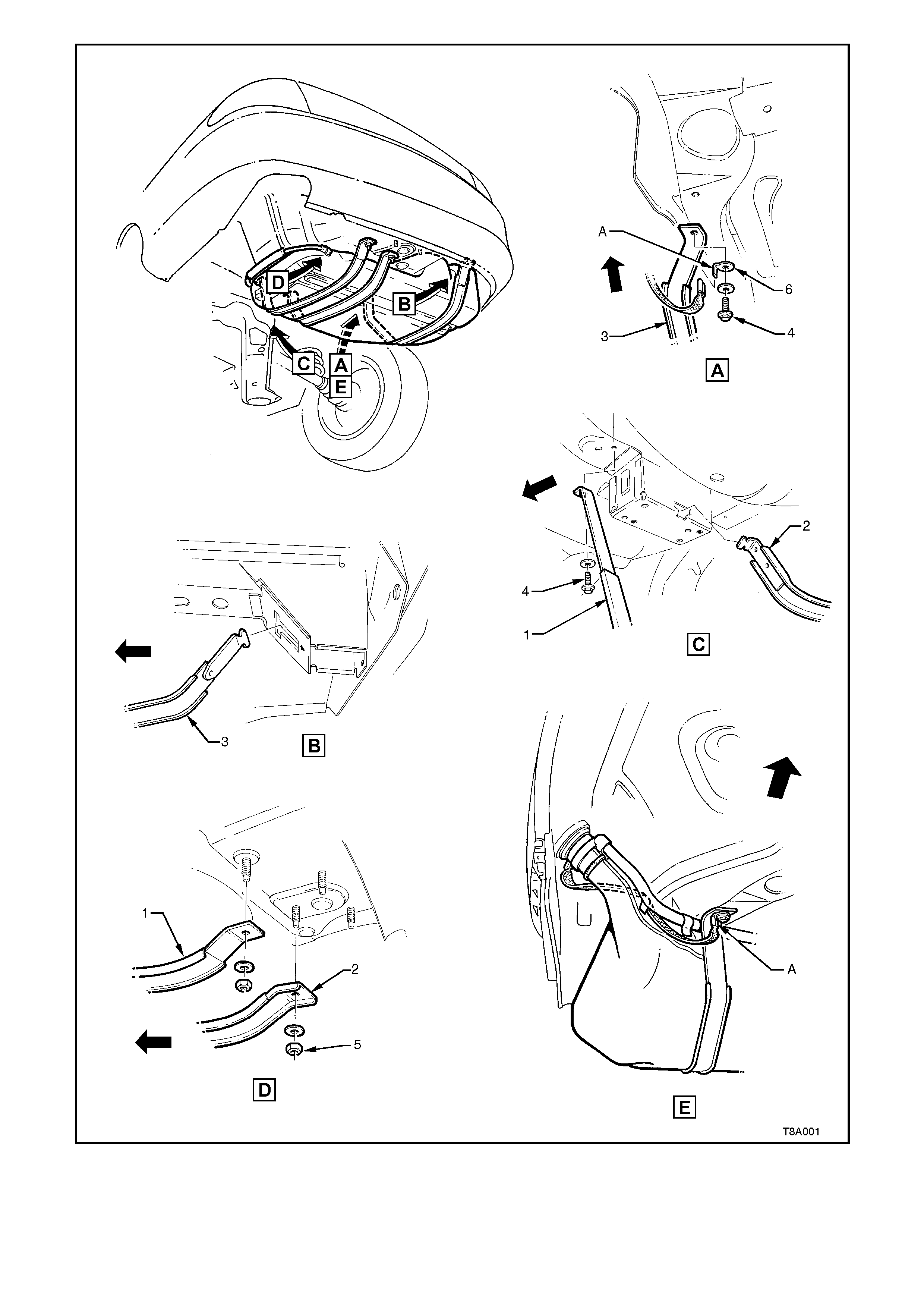
Figure 8A-10
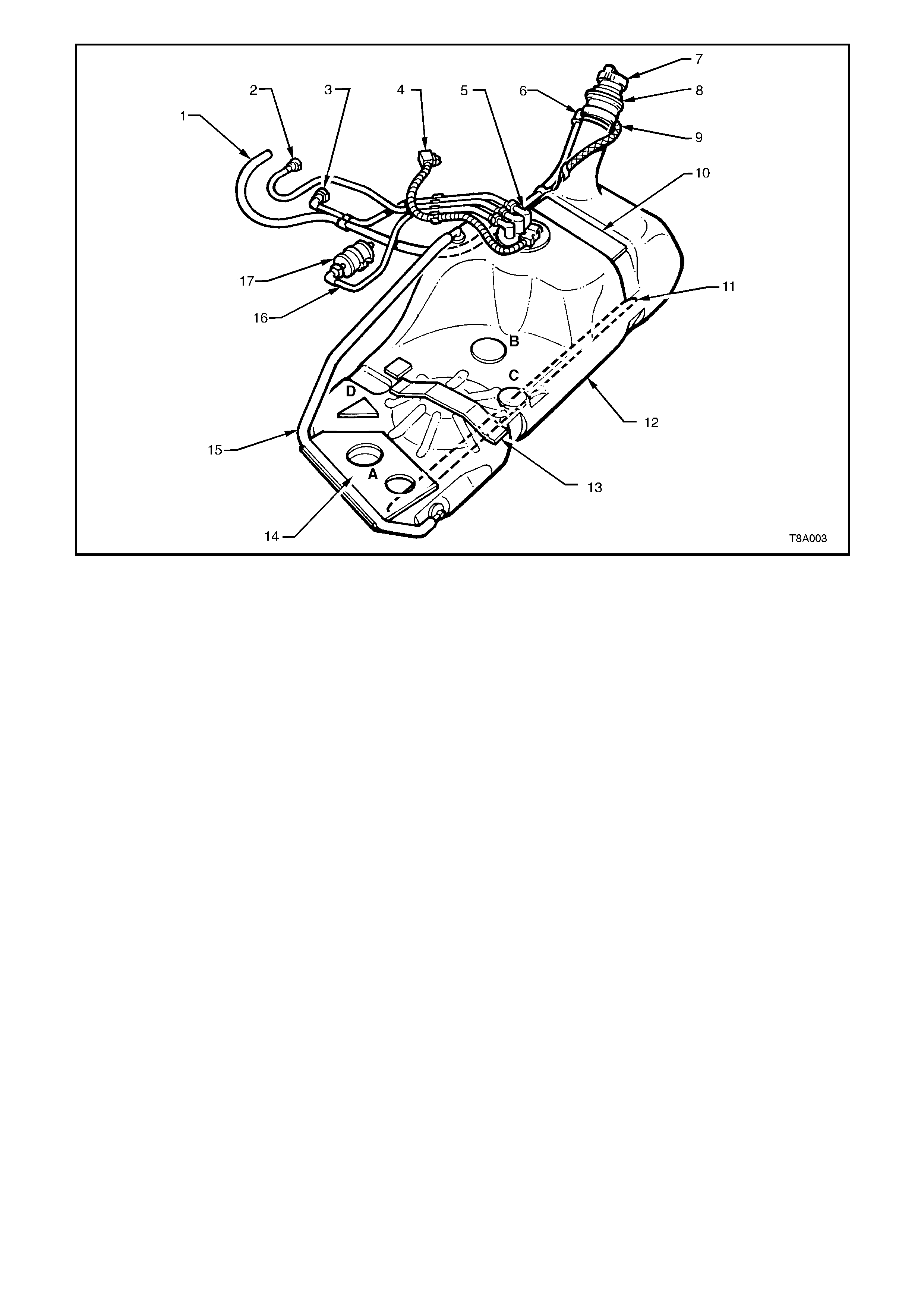
1. Hose, Filler Neck Breather 7. Cap, Fuel Filler 13. Insulator
2. Hose Fuel Tank Vent 8. Insulator, Fuel Filler Neck 14. Insulator Kit - A, B, C, D.
3. Hose Fuel Return 9. Strap, Fuel Filler Earth 15. Line, Fuel Tank Vent
4. Connector Electrical Harness 10. Insulator - Top R.H. Side 16. Hose, Fuel Feed
5. Sender Assembly, Modular Fuel 11. Reinforcement, Fuel Tank 17. Filter Fuel
6. Fitting, Canister Vent Hose 12. Tank, Fuel
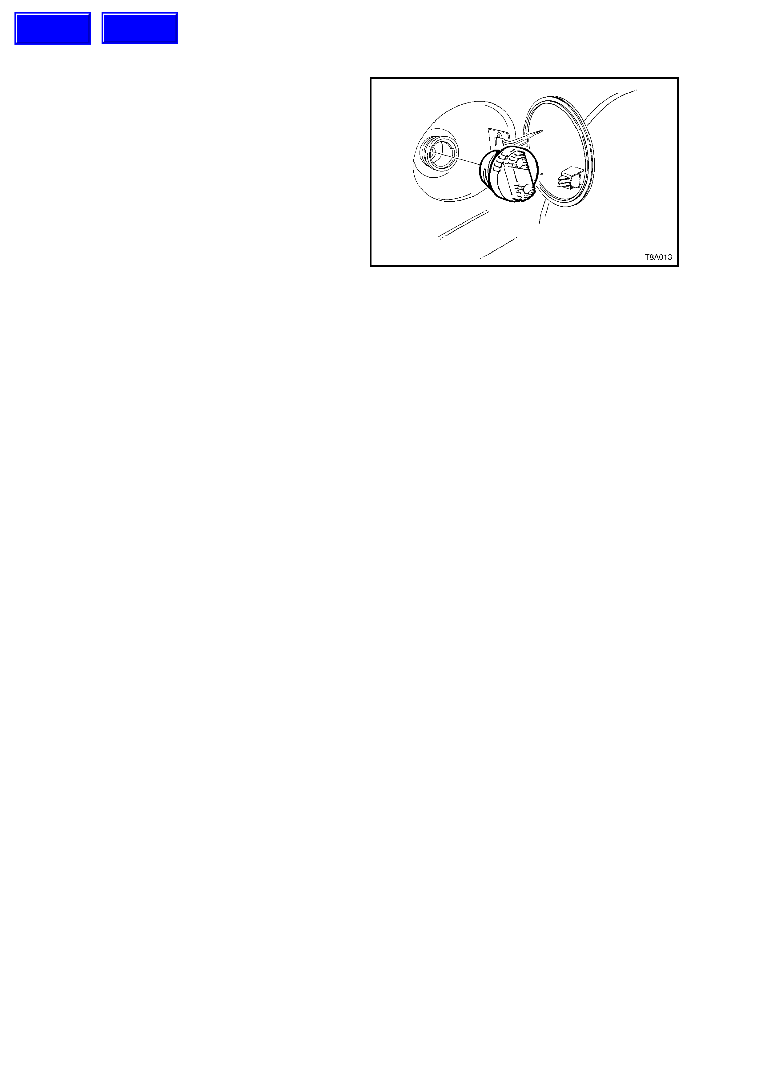
Figure 8A-11
2.2 MODULAR FUEL SENDER ASSEMBLY
REMOVE
1. Remove the fuel tank. See Operation 2.1 in
this Section for the procedure.
IMPORTANT:
Clean all traces of dirt and other foreign material
from the top of the fuel tank, in the vicinity of the
modular fuel sender assembly, before proceeding.
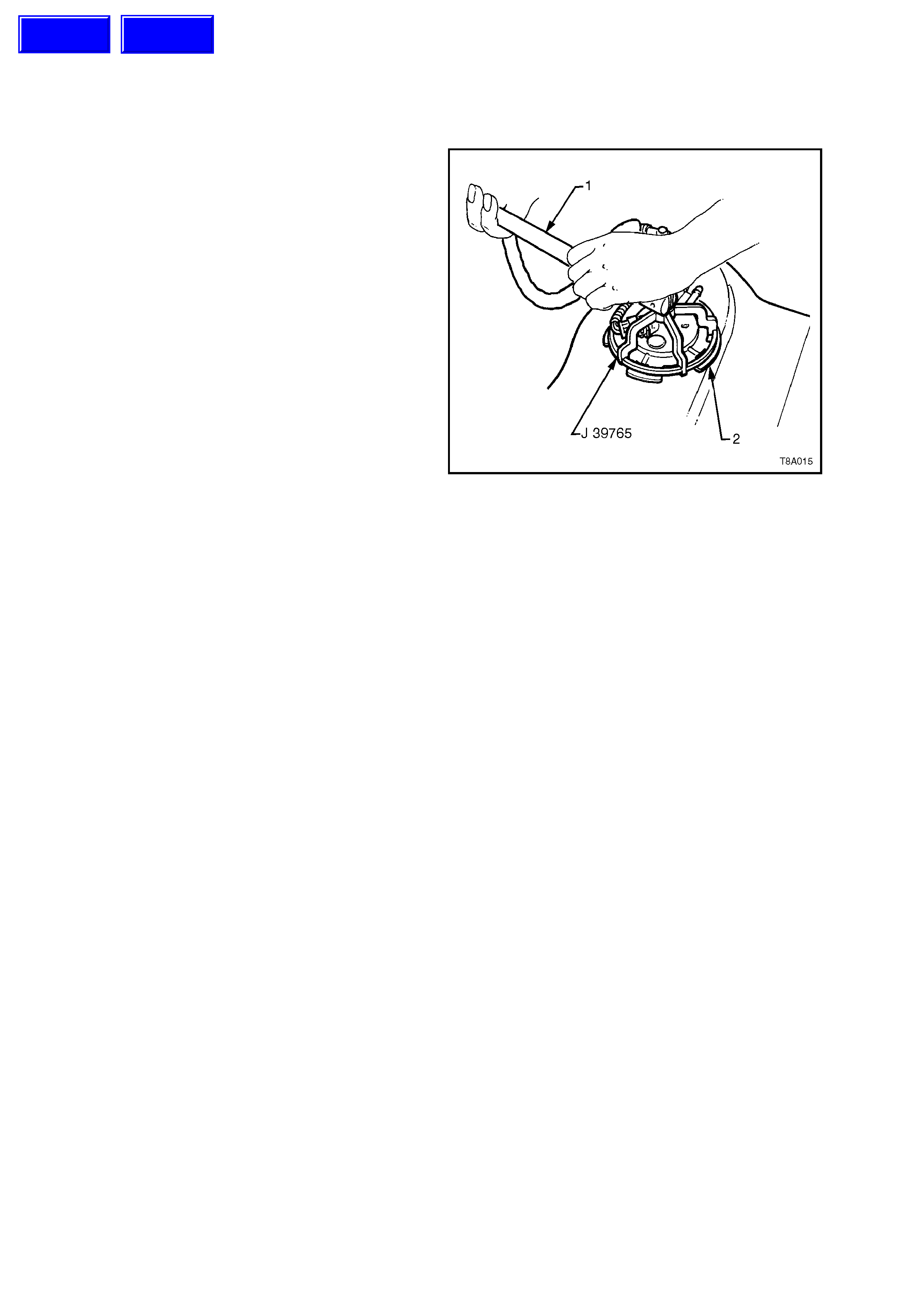
2. Using Tool No. J39765 and a ½” socket bar
(1), remove the module assembly retaining
ring (2) by turning in an anti-clockwise
direction.
NOTE:
The Modular fuel sender unit will spring up when
the locking ring is removed.
3. Carefully lift the module assembly from the
fuel tank, taking care not to damage the fuel
sender float and arm.
IMPORTANT:
The reservoir will be full of fuel. Because the
modular unit needs to be tipped to one side to free
the float arm on the fuel sender, be careful of fuel
spillage. When the modular fuel sender assembly
is removed from the fuel tank, pour any remaining
fuel in the reservoir into a suitable container.
4. Discard the sealing O-ring.
CAUTION:
An empty fuel tank contains a potentially
explosive mixture of fuel vapour and air. Do not
permit naked flames or sparks in the vicinity.
Figure 8A-12
REINSTALL
1. Locate a new O-ring seal in the fuel tank
recess.
2. Reinstall the module assembly to the fuel
tank, taking care not to damage the fuel
sender float or arm in the process.
NOTE:
Care should be taken not to fold or twist the fuel
pick-up strainer during module installation. Also
assure that the f uel pum p pick -up s trainer does not
interfere with the full travel of the float arm.
3. Install the retaining ring over the module
assembly and use a ½” socket bar and Tool
No. J39765, to rotate the retainer in a
clockwise direction until the tangs are
engaged.
4. Reinstall the fuel tank as described in
Operation 2.1, in this Section.
Techline
Techline
2.3 FUEL SENDER ASSEMBLY
REPLACE
1. Remove the modular f uel sender assembly as
described in Operation 8A-2 in this Section.
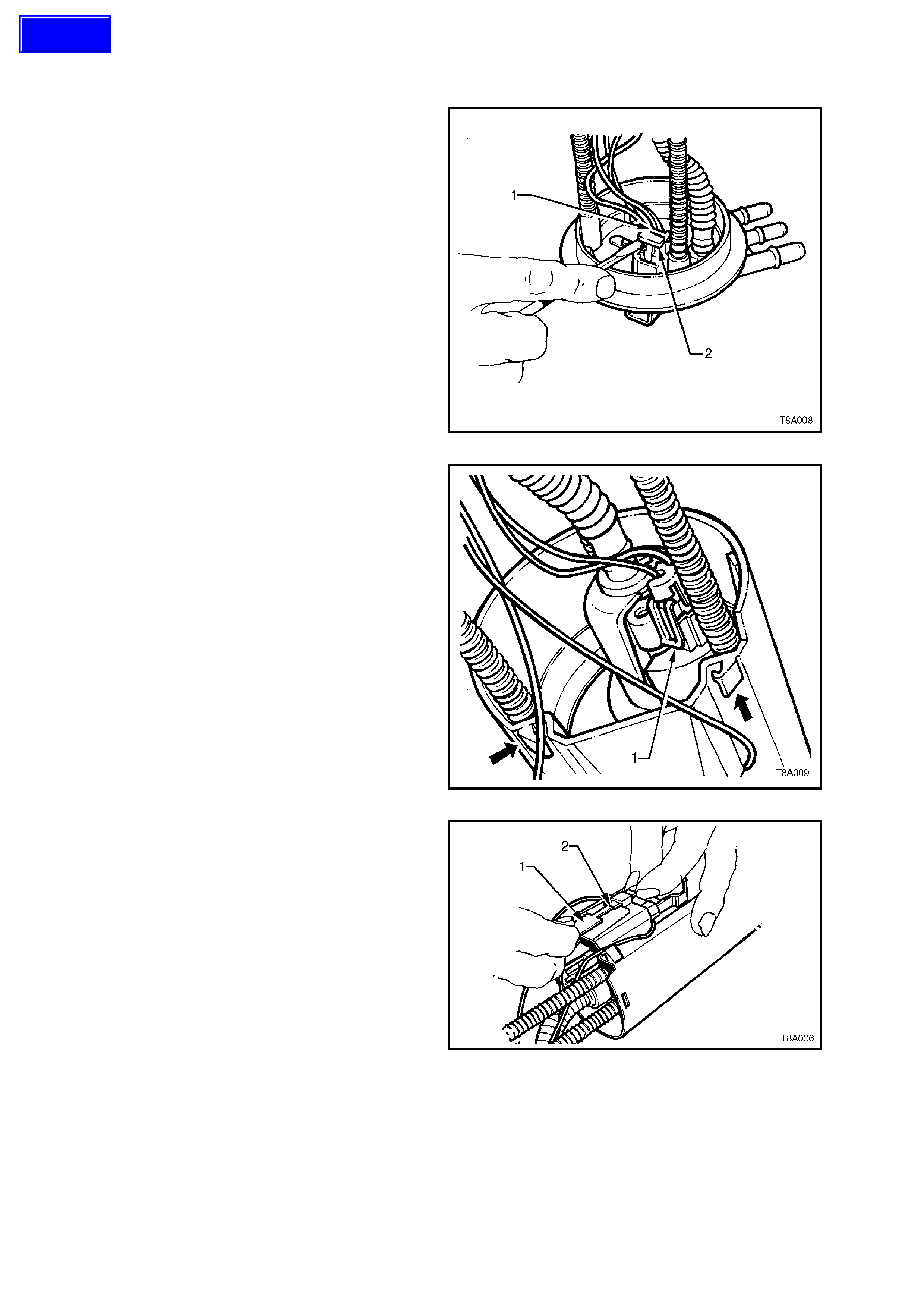
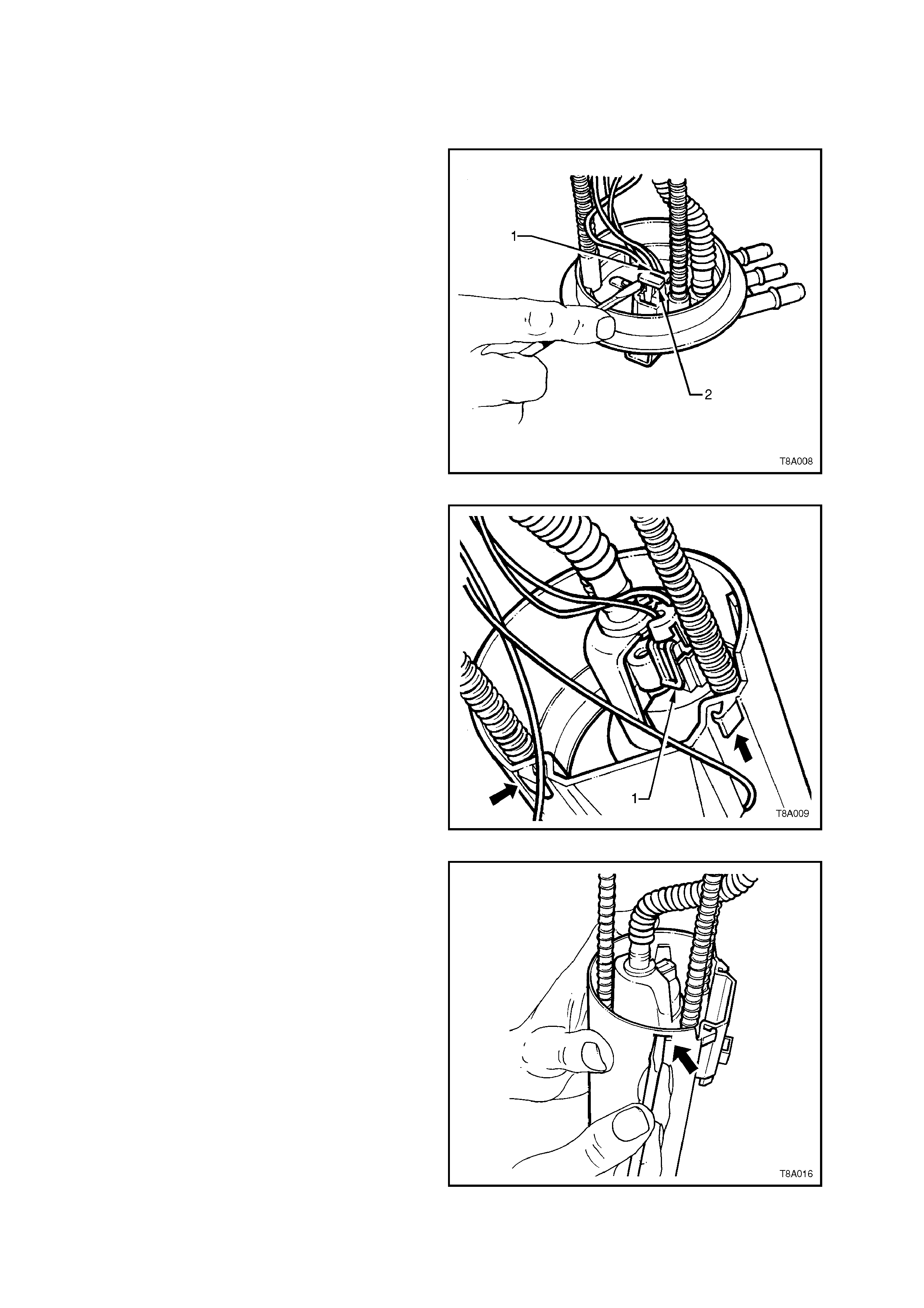
2. Remove the fuel pump/sender patch harness
connector as follows;
a. Using a small screwdriver, first remove
the red Connector Position Assurance
(CPA) locking tab (2), then the grey one
(1). Depress the connector lock and
remove from the top cover.
Figure 8A-13
b. Release the locking tabs on the fuel
pump harness connector (1) and remove
the connector from the fuel pump.
c. Release each of the two fuel sender wires
from the retainers (arrows) on the side of
the module body.
Figure 8A-14
3. Remove the fuel sender Connector Position
Assurance (CPA) locking tab (2), using a
piece of broken hacksaw blade (1), ground to
a width of 1.5 mm and push the tab down, as
shown.
NOTE:
Because of the fragile nature of this CPA, it is
recom mended that a replac ement tab be used af er
installation of the fuel sender assembly.
Figure 8A-15
Techline
4. Use long nosed pliers (1) to press the sender
locking tabs and push down to remove, as
shown.
5. Before installation into the fuel tank , check the
fuel sender float position, as follows:
a. Stand the assembly upright on a flat
surface.
b. Measure the distance between the base
of the fuel sender float and the flat
surface.
c. If required, the float position should be
adjusted to achieve a nominal
measurement of 10 mm.
6. Installation is the reverse of the removal
process.
Figure 8A-16
2.4 FUEL PUMP
REPLACE
1. Remove fuel gauge tank unit as outlined in
Operation 2.1 in this Section.
2. Remove Modular Fuel Sender assembly as
outlined in Operation 2.2, in this Section.
3. Remove the fuel pump/sender patch harness
connector as follows;
a. Using a small screwdriver, first remove
the red Connector Position Assurance
(CPA) locking tab (2), then the grey one
(1). Depress the connector lock and
remove from the top cover.
Figure 8A-17
b. Release the locking tabs (1) on the fuel
pump harness connector and rem ove the
connector from the fuel pump.
Figure 8A-18
3. Separate the inner member from the outer
reservoir, by releasing the two tangs (arrow)
with a small screwdriver, as shown.
Figure 8A-19
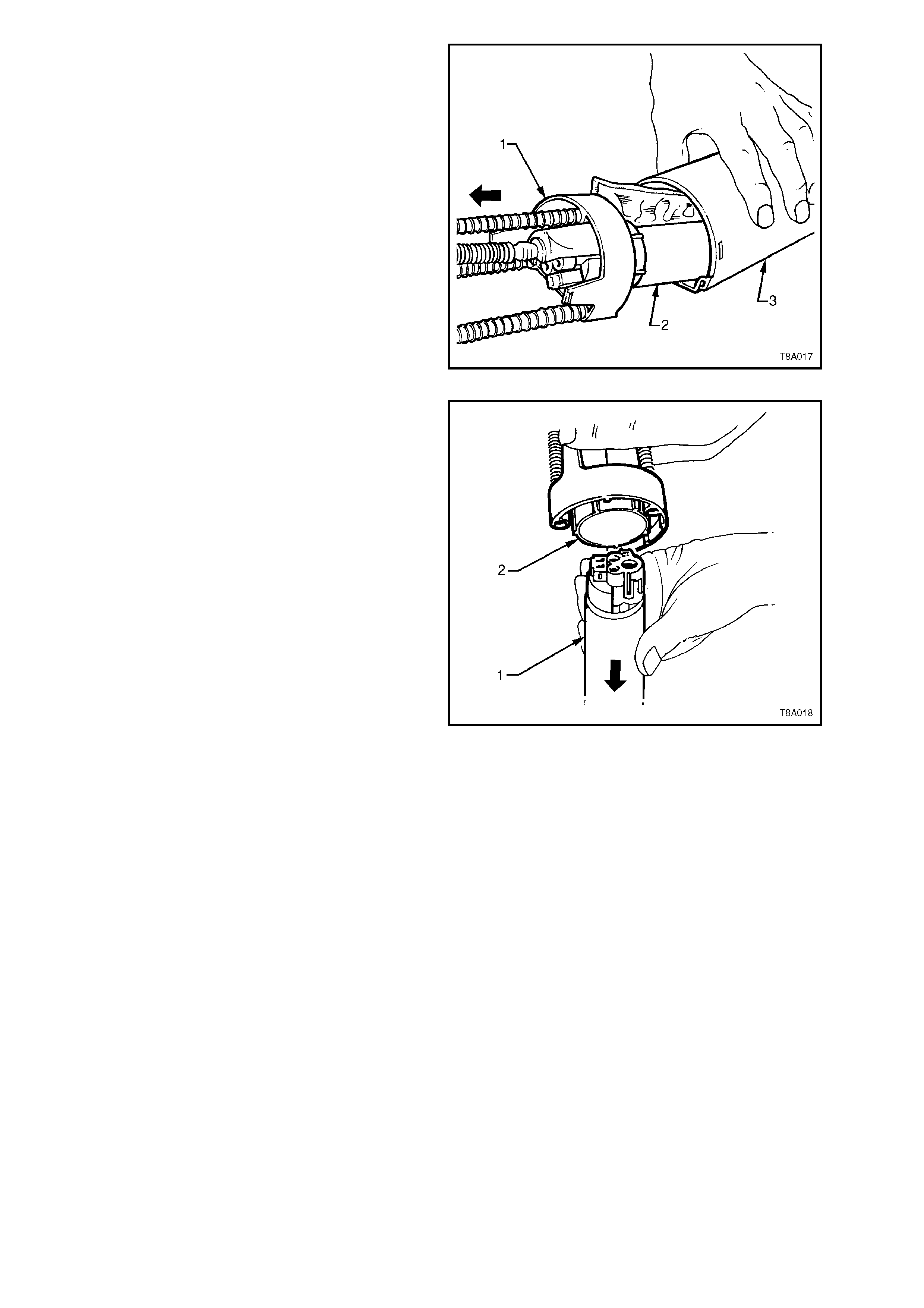
4. Slide the inner member (1), cover assembly
and fuel pump (2) from the outer reservoir
shell (3).
Figure 8A-20
5. Using a twisting/pulling motion, remove the
fuel pump (1) and integral strainer from the
inner member assembly.
6. Installation is the reverse of the removal
process , noting that the f uel pump inlet s ealing
grommet is to be installed in the base of the
outer shell, before the pump is installed.
Figure 8A-21

2.5 FUEL PUMP PICK-UP STRAINER
REPLACE
1. Remove the modular f uel s ender as s embly, as
described in Operation 2.2 in this Section.
2. Using a screwdriver (2), prise the pick-up
strainer (1) from the base of the reservoir,
noting the strainer position for installation.
Discard the strainer and O-ring (3).
Figure 8A-22
3. With a new O-ring (2) installed on a
replacement strainer (1), firmly press into
place on the reservoir in the same position
noted on removal.
4. Reinstall the modular fuel sender assembly,
as described in Operation 2.2 in this Section.
Figure 8A-23
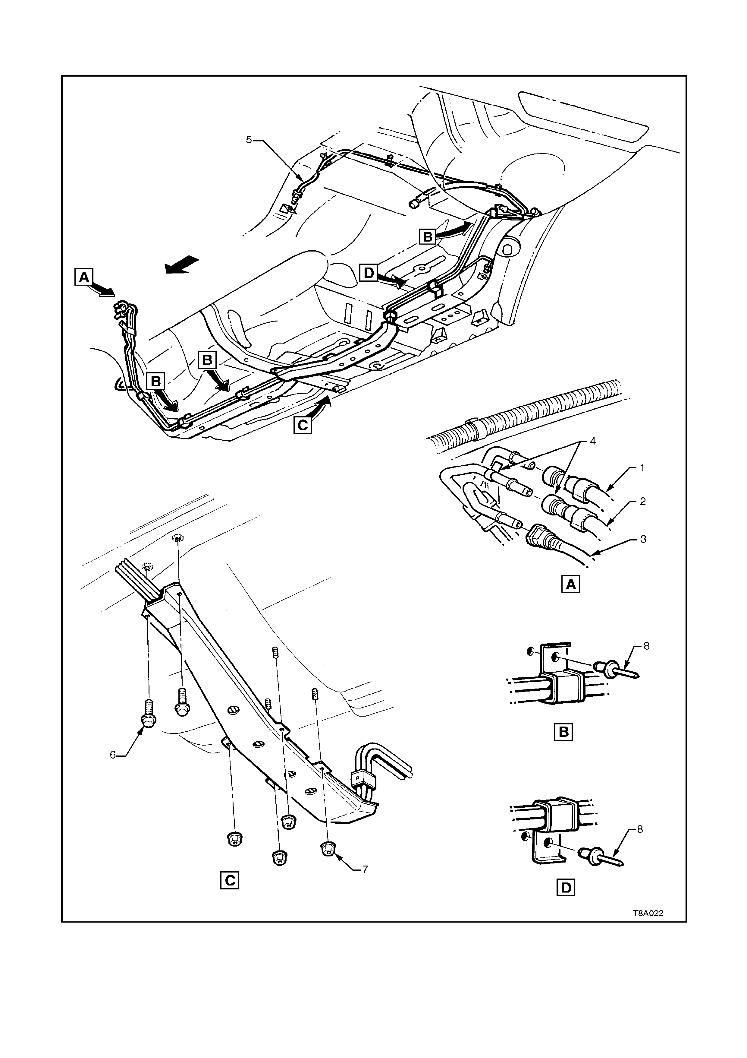
2.6 FUEL PIPE ARRANGEMENT
Figures 8A-24 and 8A-25 illustrate the fuel pipe layout and location of other fuel tank related items.
1. Hose, Fuel Return from Engine 4. Tab, White Identifying 7. Nut, Stone Guard Securing
2. Hose, Fuel Feed to Engine 5. Pipe, Brake Fluid 8. Rivet, Fuel Line Bracket Pop
3. Hose, Fuel Vapour 6. Bolt, Stone Guard Securing
Figure 8A-24
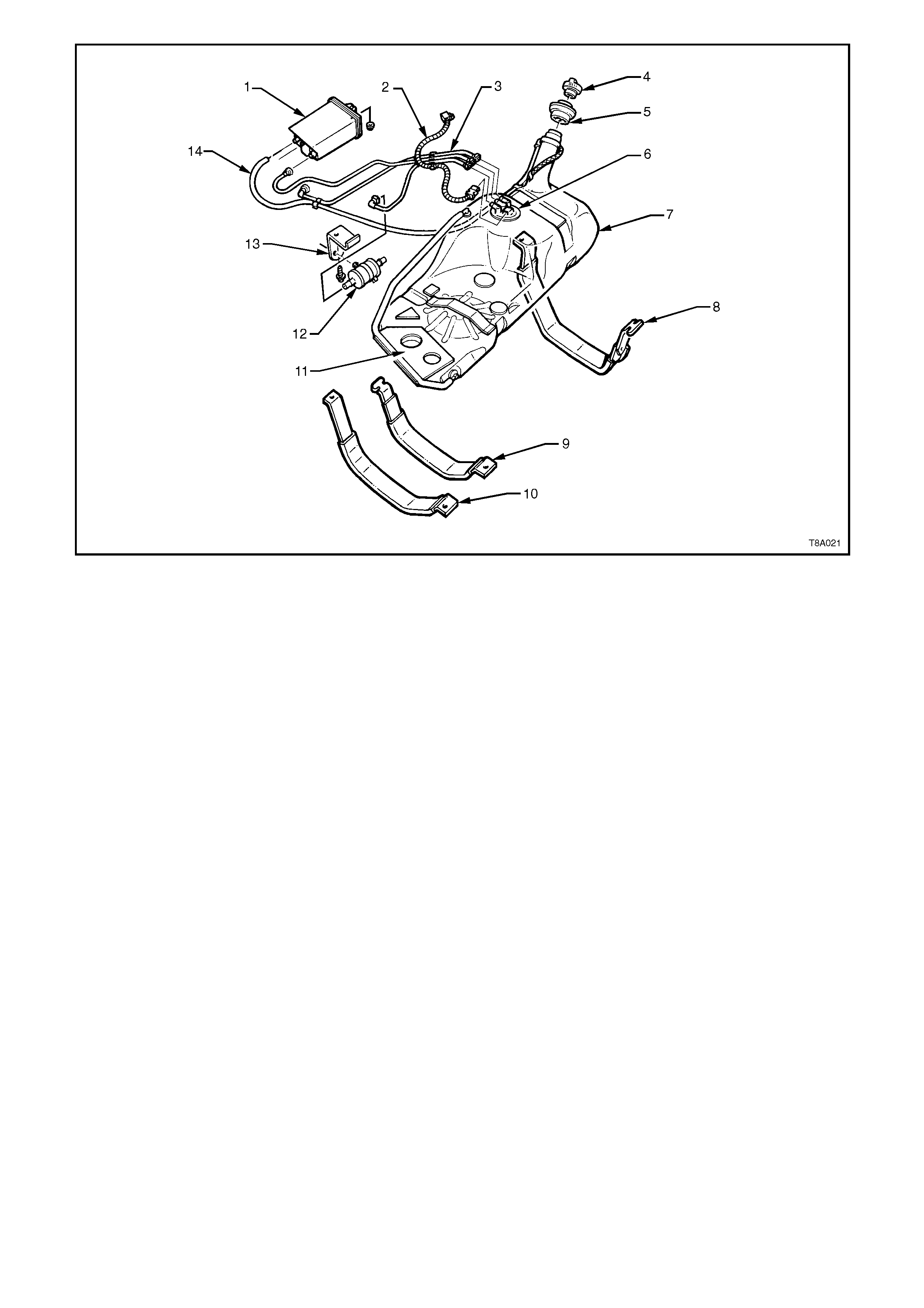
1. Canister, Fuel Vapour 6. Sender Assembly, Modular Fuel 11. Insulator, Fuel Tank to Underbody
2. Harness, Electrical Patch 7. Tank, Fuel 12. Filter Fuel
3. Hoses, Fuel and Vapour 8. Strap, Fuel Tank Mounting, RHS 13. Bracket, Fuel Filter Mounting
4. Cap, Fuel Filler 9. Strap, Fuel Tank Mounting, Centre 14. Hose Fuel Tank Vent
5. Insulator, Fuel Filler Neck 10.Strap, Fuel Tank Mounting, LHS
Figure 8A-25


4. TORQUE WRENCH SPECIFI CATIONS
Nm
Fuel Tank Strap Nuts/Bolts 15 - 25
Fuel Filter Bracket Screw 5.0 - 8.0
Canister mounting Nut 2.0 - 5.0
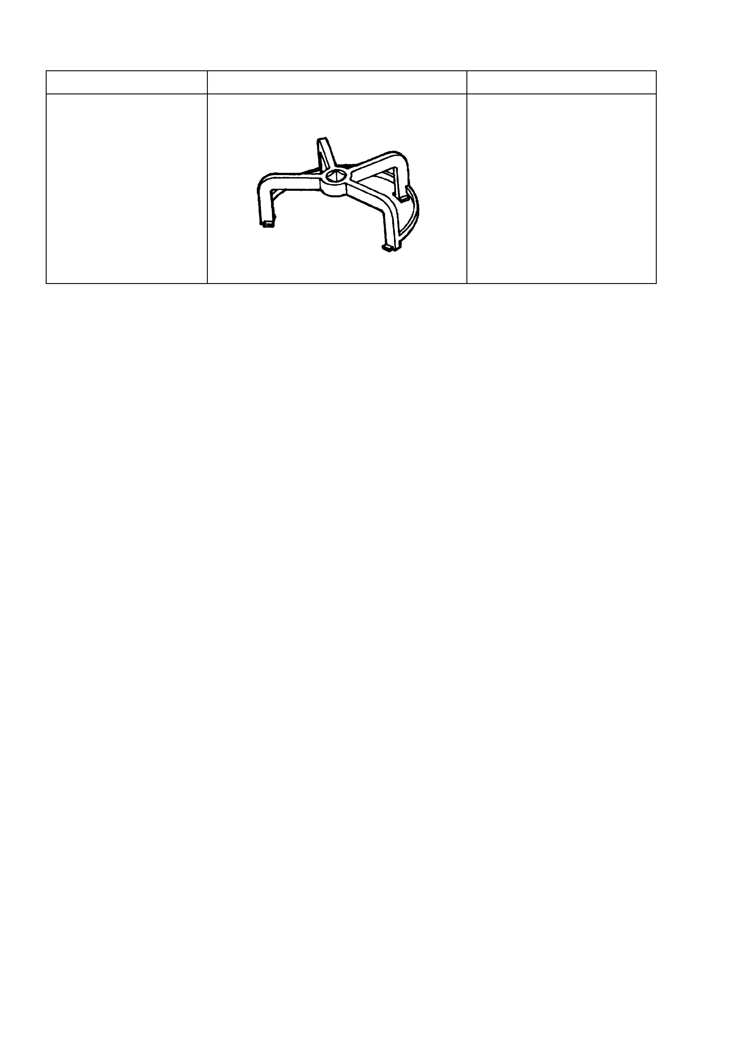
5. SPECIAL TOOLS
TOOL NO. REF IN TEXT TOOL DESCRIPTION COMMENTS
J39765 MODULAR FUEL SENDER ASSEMBLY
REMOVER/INSTALLER NEW RELEASE