SECTION 8B - EXHAUST SYSTEM
CAUTION:
This vehicle will be equipped with either a driver's side only or driver's and front
passenger's side AIR BAGS. An AIR BAG is a Supplemental Restraint System (SRS).
Refer to CAUTIONS, Section 12M, before performing any service operation on or
around SRS components, the steering mechanism or wiring. Failure to follow the
CAUTIONS could result in air bag deployment, resulting in possible personal injury
or unnecessary SRS system repairs.
CAUTION:
This vehicle may be equipped with LPG (Liquefied Petroleum Gas). As this fuel is
heavier than air in the vapour form and in the interests of safety, the LPG fuel system
should be isolated by turning 'OFF' the manual service valve and then draining the
LPG service lin es, before any service wo rk is carried out on the vehicle. Refer to the
LPG leaflet included with the Owner's Handbook for details or LPG Section 2 for
more specific servicing information.
CAUTION:
Whenever any component that forms part of the ABS (if fitted), is disturbed during
Service Operations, it is vital that the complete ABS system is checked, using the
procedure as detailed in DIAGNOSIS, ABS FUNCTION CHECK, in Section 12L ABS &
ABS/ETC.
1. GENERAL DESCRIPTI ON
The engine exhaust manifolds for all engines connect to two equal length, symmetrical stainless steel front pipes.
With V8 engines, the front exhaust pipes are of a dual wall air gap construction.
As introduced with V6 engined, VS Series II Statesman and Caprice vehicles, all VT models with the V6 engine
continue with a single intermediate muffler and a single exhaust outlet.
V8 engined VT models also feature the low back pressure exhaust system introduced with VS Series II Statesman
and Caprice models and retain a dual exhaust system back to the rear of the twin intermediate mufflers. At this
point, the exhaust converges into a single pipe and rear muffler/tailpipe arrangement. The exhaust outlet for V6
supercharged and V8 engines can be identified by the large, chrome, oval fitting.
On V6 engined models, a single, three way catalytic converter forms a welded junction point for each of the engine
pipes. A brace is welded to both engine pipes and a flanged joint and sealing ring is used at the rear of the catalytic
converter, secured to the intermediate exhaust pipe by two spring loaded bolts. The intermediate tail pipe has a U-
bolt clamped, slip joint, located behind the rear axle and before the rear muffler.
The system layout for the V6 supercharged and V8 engines is similar, in that a catalytic converter is welded to each
engine pipe, with a flanged, gasketed joint connecting each converter to the twin, intermediate exhaust pipes.
The two intermediate exhaust pipes are stiffened by a welded bridging piece and balance pipe, at points before the
twin intermediate mufflers.
The V6 engine exhaust system is supported by a rubber bumper to the rear of the transmission and two rubber
bumper supports attached to the rear suspension crossmember, supporting the rear of the intermediate muffler.
Additional support is provided by two rubber bumper supports attached to brackets welded to the vehicle
underbody, and brackets attached to the rear tail pipe, rear of the rear muffler.
The support system for the V8 and V6 supercharged engines is similar to the V6 engine, except that two rubber
bumpers are used to support each of the twin intermediate mufflers and no support is used at the rear of the
transmission.
The rubber bumpers are a common part for all locations and are secured by:
a. Clips at the intermediate muffler brackets, welded to the rear suspension crossmember and clips at the rear
body hanger bracket.
b. Flanged pegs at all other locations.
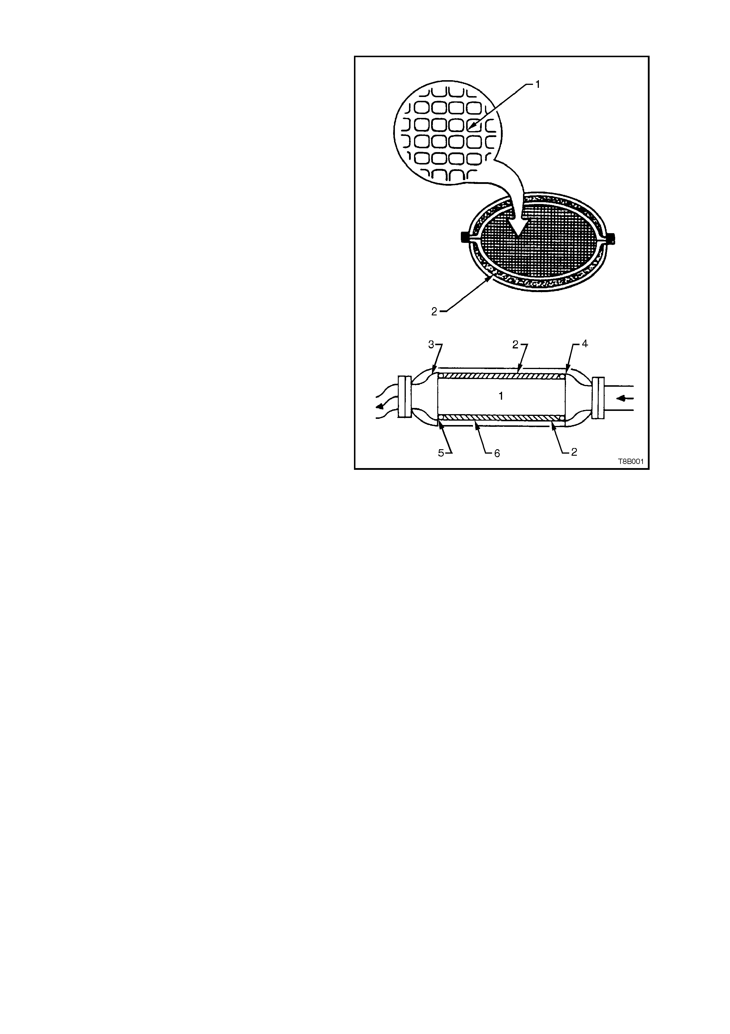
1.1 CATALYTIC CONVERTER
The catalytic converter is similar to a muffler in
appearance. Inside the outer steel shell (6), the
converter comprises a ceramic monolith (1) which
is honeycom bed in the direction of ex haust flow, as
shown. The ceramic monolith (1) is surrounded by
a ma t (2) which has the prim ary func tion of holding
it firmly within the case while preventing the
monolith from contacting the inner shell (3). A
mes h seal (4 and 5) at each end, is used to prevent
direct exhaust gases from eroding the mat (2).
The surf ac es of the ceramic monolith ( 1), which ar e
exposed to exhaust gases, are coated with the
catalytic material. The material contains Rhodium,
Palladium and Platinum which facilitate the
chemical reactions necessary to oxidise carbon
monoxide and hydrocarbons to harmless carbon
dioxide.
The catalytic converter normally operates at
approxim ately 600° C. The catalytic mater ial is very
sensitive to the effects of a rich or lean fuel m ixtur e
which causes the temperature of the converter to
rise rapidly.
CAUTION:
Excessively rich or lean fuel mixture can cause
sudden failure of the catalytic converter.
The catalytic converter is also sensitive to the use
of leaded petrol. This causes deposits to form in
the converter which restrict the exhaust flow and
prevent the catalyst from work ing. T his als o causes
an increase in exhaust back pressure and the
temperature of the converter assembly to rise.
Note that the use of unleaded petrol results in black
tailpipe deposits rather than the grey colour that
some people may normally associate with an
acceptable c ombustion condition. T his black colour
resulting from the use of unleaded fuel does not
necessarily indicate a state of poor engine tune.
Figure 8B-1
2. SERVICE OPERATIONS
2.1 SERVICE NOTES
When installing any exhaust system component, care must be taken to install each component in the correct
relationship to one another.
Incorrect assembly of exhaust system components can frequently be the cause of rattles and ‘booms' due to
incorrect alignment or clearance from body or suspension parts.
When installing the exhaust system, ensure that the correct assembly, installation, tightening sequence and
clearance for the system involved are observed.
When exhaust system service work is required, refer to the various illustrations and instructions provided in this
Section, for the necessary information for the correct arrangement, alignment and clearances for each of the three
engines available in the VT Series range of vehicles.
Step by step procedures for the replacement of individual exhaust system components are not included as special
instructions are not required; only normal workshop practices are necessary. Both clearances and torque
specifications for fasteners are detailed in the illustrations included in this Section.
The catalytic converter is serviced as a complete unit only. If removing or replacing the converter, always ensure
that new sealing rings/gaskets are installed on reassembly.
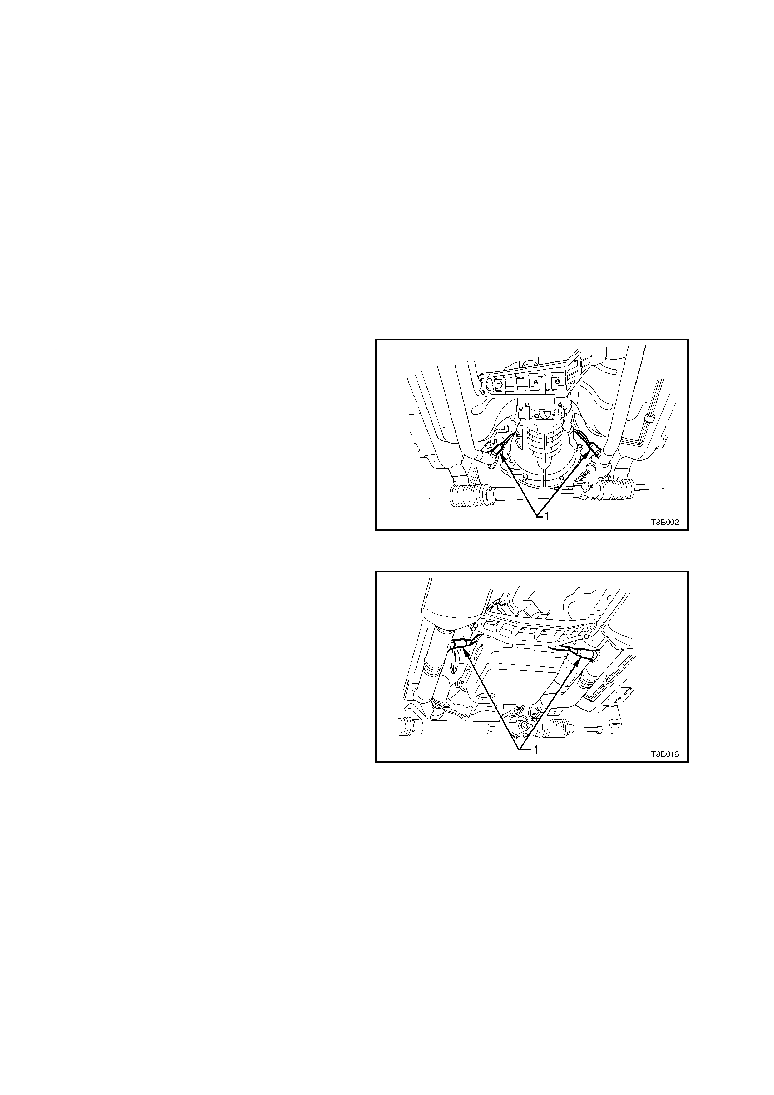
For Oxygen Sensor (1) replacement, refer to
Section 6C1 POWERTRAIN MANAGEMENT - V6
ENGINE or Section 6C2 POWERTRAIN
MANAGEMENT - V8 ENGINE.
Figure 8B-2 Oxygen Sensor Location, V6 & V6
Supercharged Engine
Figure 8B-3 Oxygen Sensor Location, V8 Engine
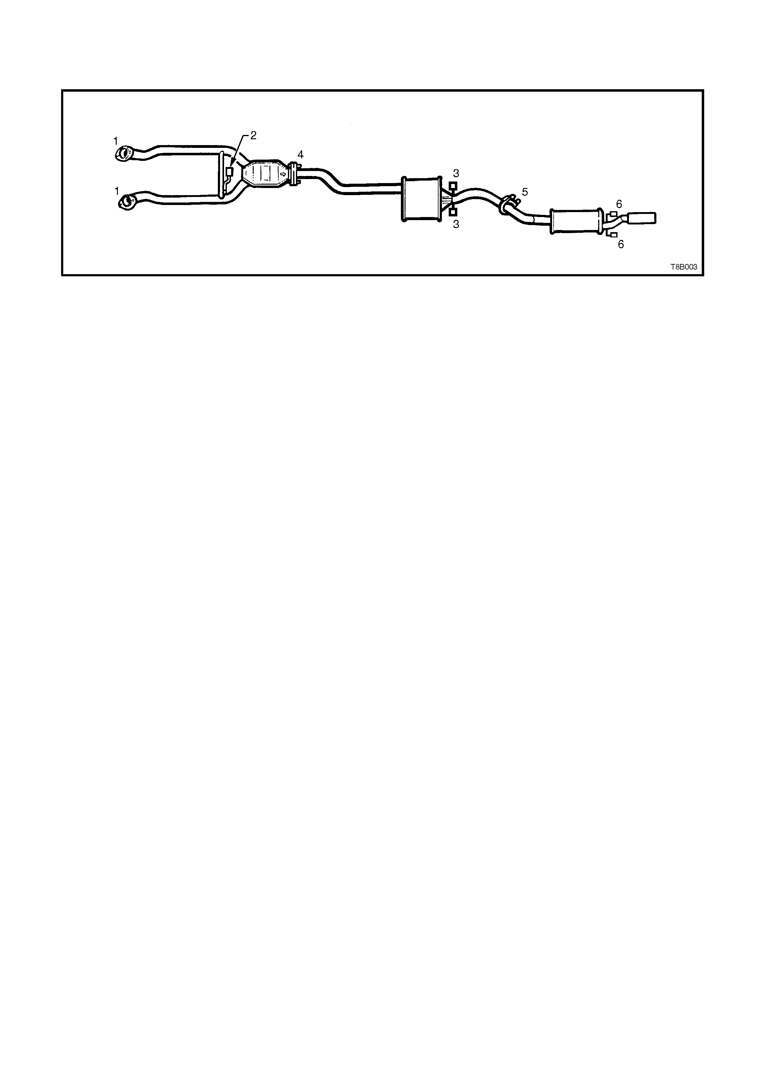
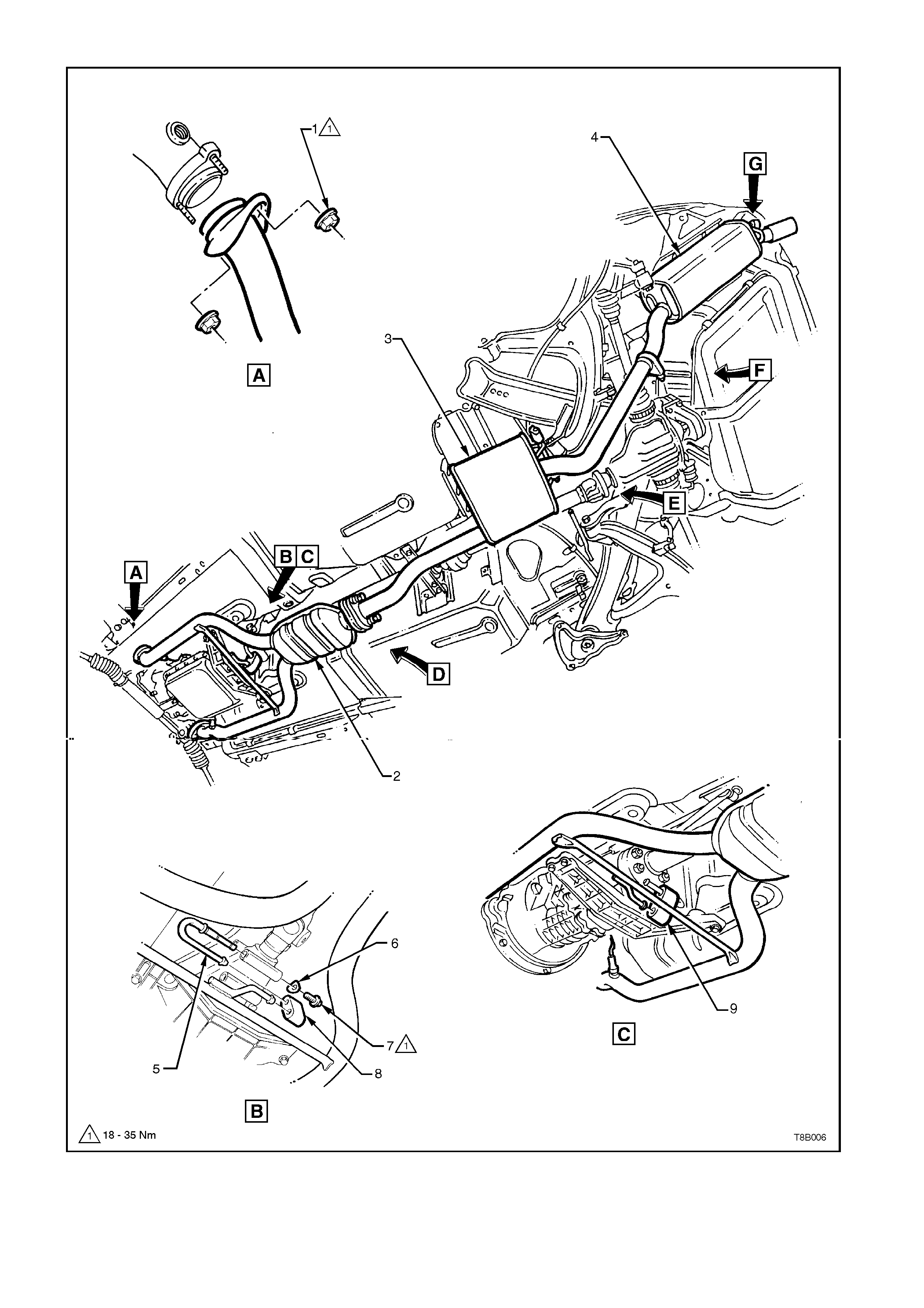
2.2 EXHAUST FITMENT AND TIGHTENING SEQUENCE
V6 ENGINE
Figure 8B-4 V6 Engine Exhaust
Installation
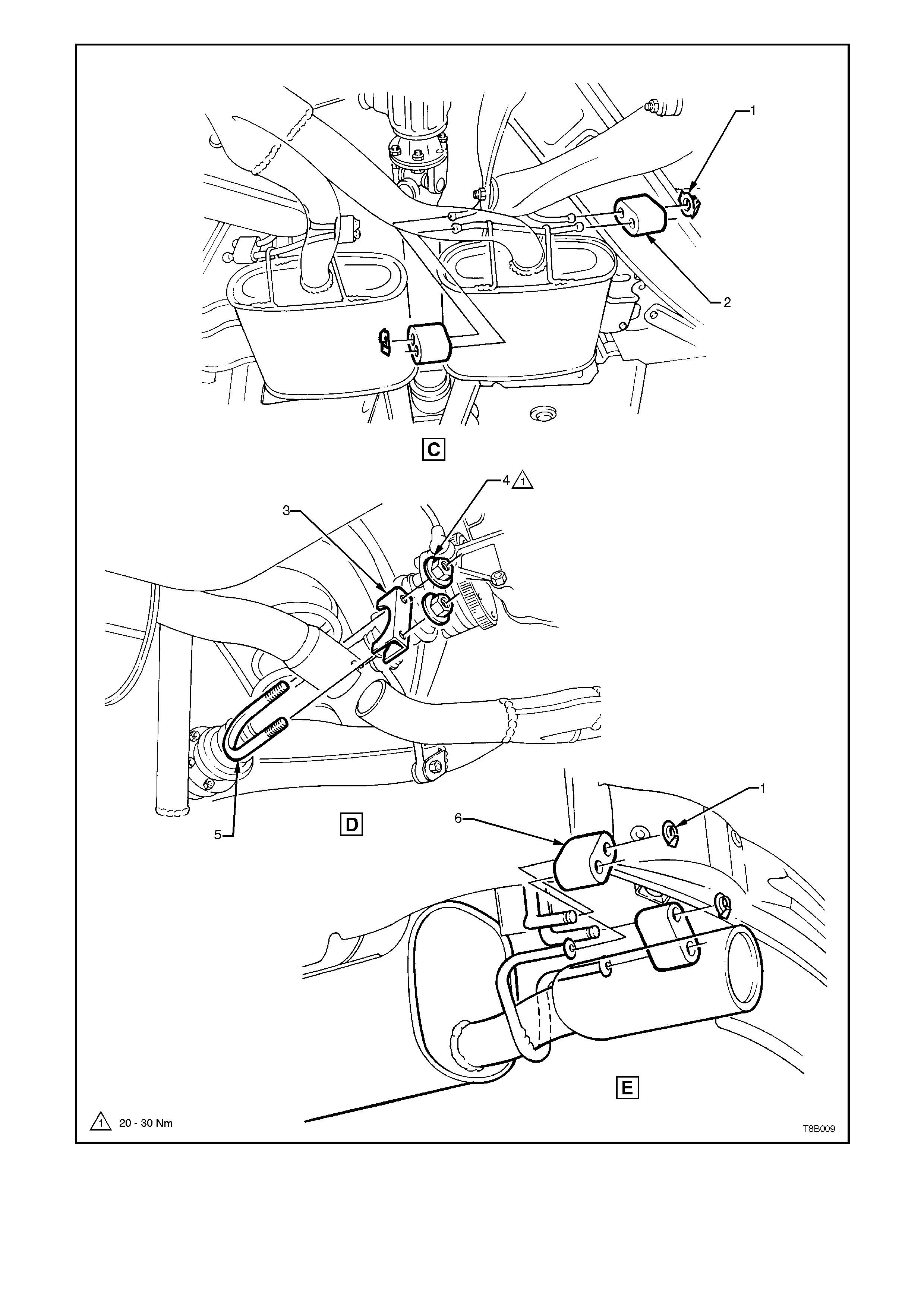
Loosely install exhaust system as follows;
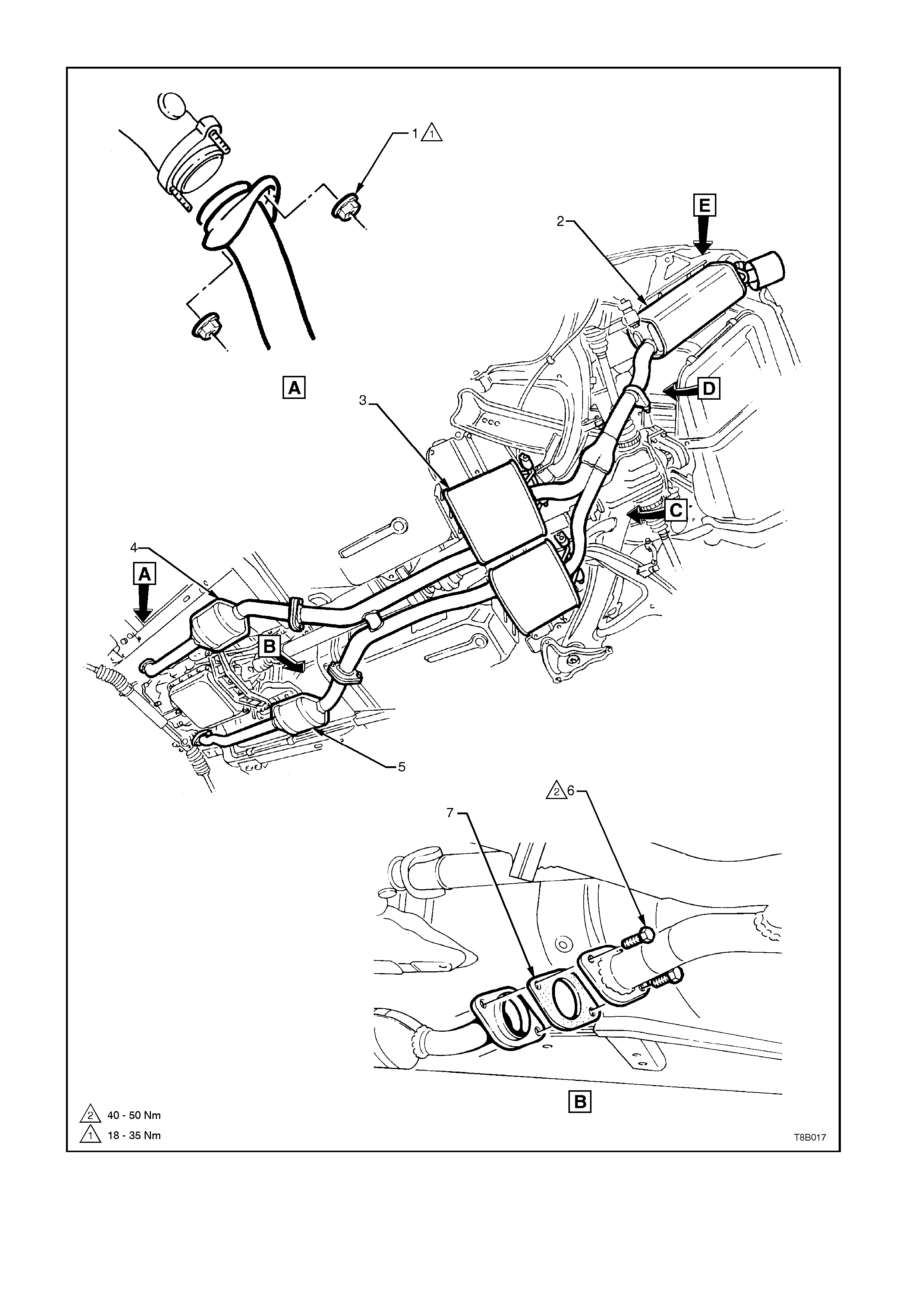
1. Attach front pipe and catalytic converter assembly, loosely to the exhaust manifolds (1).
2. Fit bumper rubber to the front pipes and the transmission extension housing hanger (2).
3. Hook intermediate assembly to suspension with two bumper rubbers. Fit two retaining clips to the suspension
bracket ends (3).
4. Fit sealing ring to the rear of the catalytic converter (4).
5. Attach the intermediate exhaust pipe to the catalytic converter using the two stepped bolts and conical springs
(4).
6. Install the intermediate muffler assembly to the rear muffler assembly and loosely install U-bolt clamp (5).
7. Attach the rear muffler assembly to the body mount hangers with two bumper rubbers (6) and retaining clips.
Tightening Sequence
1. Tighten the two stepped bolts at the rear of the catalytic converter, checking that the sealing ring is installed
(4).
2. Evenly tighten the U-bolt clamp nuts at the intermediate to rear muffler slip joint (5).
3. Tighten each flange nut evenly, so that a similar amount of thread is showing on each (1).
4. Ensure that all bumper rubbers are under load (2, 3 and 6). If this is not achieved, loosen exhaust joints in the
reverse order to the above. Load the hangers and re-tighten in the sequence described, from steps 1 to 3.
NOTE:
The exhaust system should be self-aligning and not require further adjustment, provided step 4 is achieved.
V6 SUPERCHARGED AND V8 ENGINES
Figure 8B-5 V6 Supercharged and V8 Engine Exhaust
Installation
Loosely install exhaust system as follows;
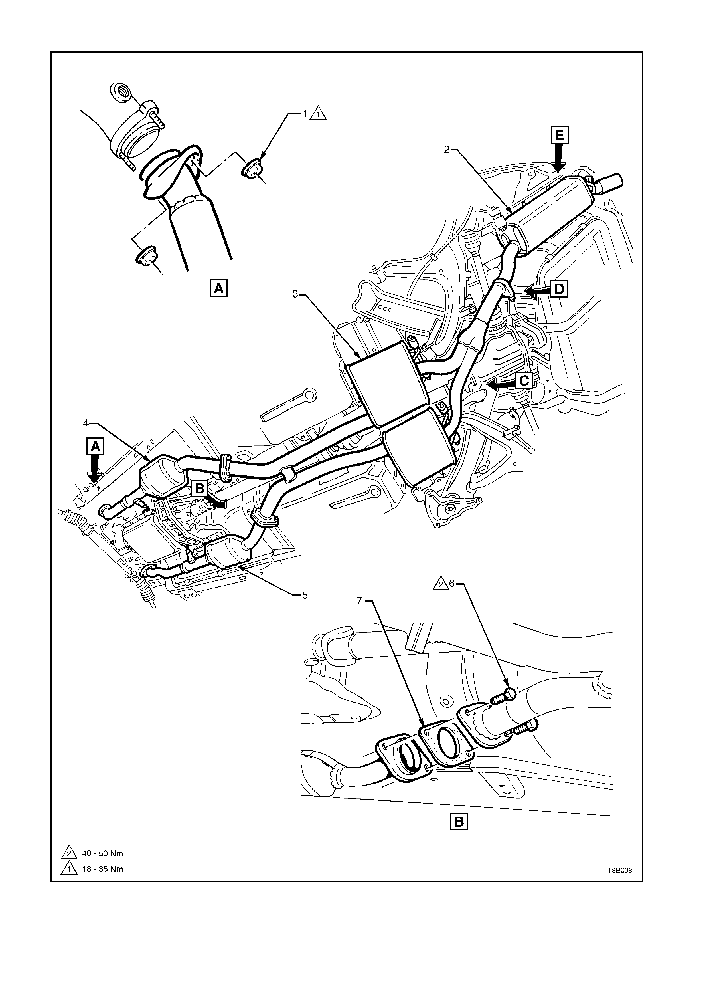
1. Attach front pipe and catalytic converter assembles, loosely to the exhaust manifolds (1).
2. Hook intermediate assembly to suspension brackets with four bumper rubbers (two per intermediate muffler).
Fit four retaining clips to the suspension bracket ends (2).
3. Install bolts to the intermediate muffler assembly to catalytic converter flanges, after installing a new gasket to
each flange (3).
4. Install the intermediate muffler assembly to the rear muffler assembly and loosely install U-bolt clamp (4).
5. Attach the rear muffler assembly to the body mount hangers with two bumper rubbers (5) and retaining clips.
Tightening Sequence
1. Tighten the flange bolts at the rear of the catalytic converter (3).
2. Evenly tighten the U-bolt clamp nuts at the intermediate to rear muffler slip joint (4).
3. Tighten each of the flange nuts evenly, so that a similar amount of thread is showing on each (1).
4. Ensure that all bumper rubbers are under load (2 and 5. If this is not achieved, loosen exhaust joints in the
reverse order to the above. Load the hangers and re-tighten in the sequence described, from steps 1 to 3.
NOTE:
The exhaust system should be self-aligning and not require further adjustment, provided step 4 is achieved.
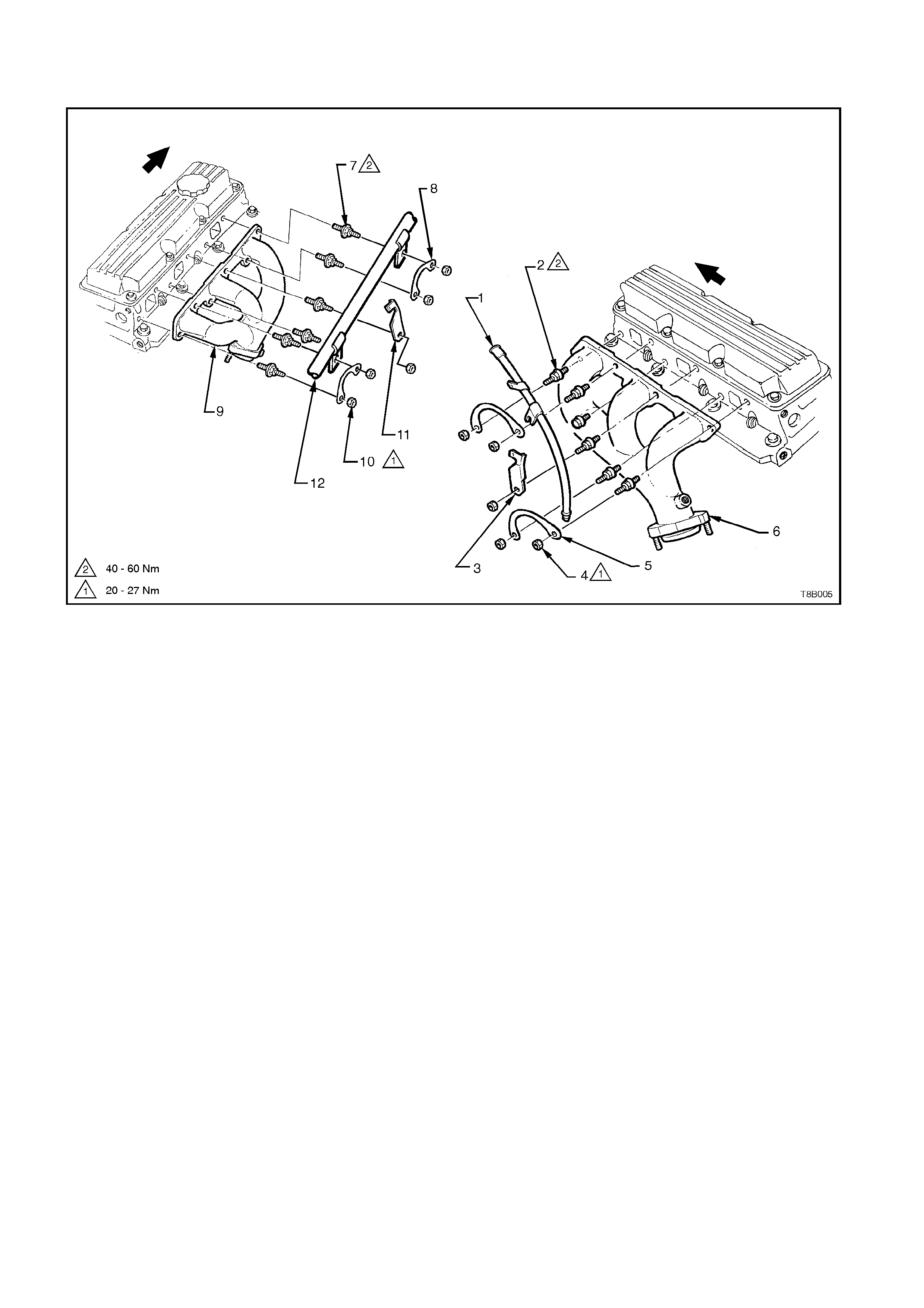
2.3 EXHAUST MANIFOLD INSTALLATIONS
V6 AND V6 SUPERCHARGED ENGINES
1. Dipstick Tube 5. Bolt Lock Plate - 2 places. 9. Exhaust Manifold - RH side
2. Stud - 5 places 6. Exhaust Manifold, LH side 10. Nut - 5 places
3. Nut - 4 places 7. Stud, 6 places 11. Spark Plug Lead Support
4. Bolt - 2 places 8. Bolt Lock Plate - 2 places 12. Radiator Inlet Pipe - V6 Supercharged
Figure 8B-6 V6 and V6 Supercharged Engines
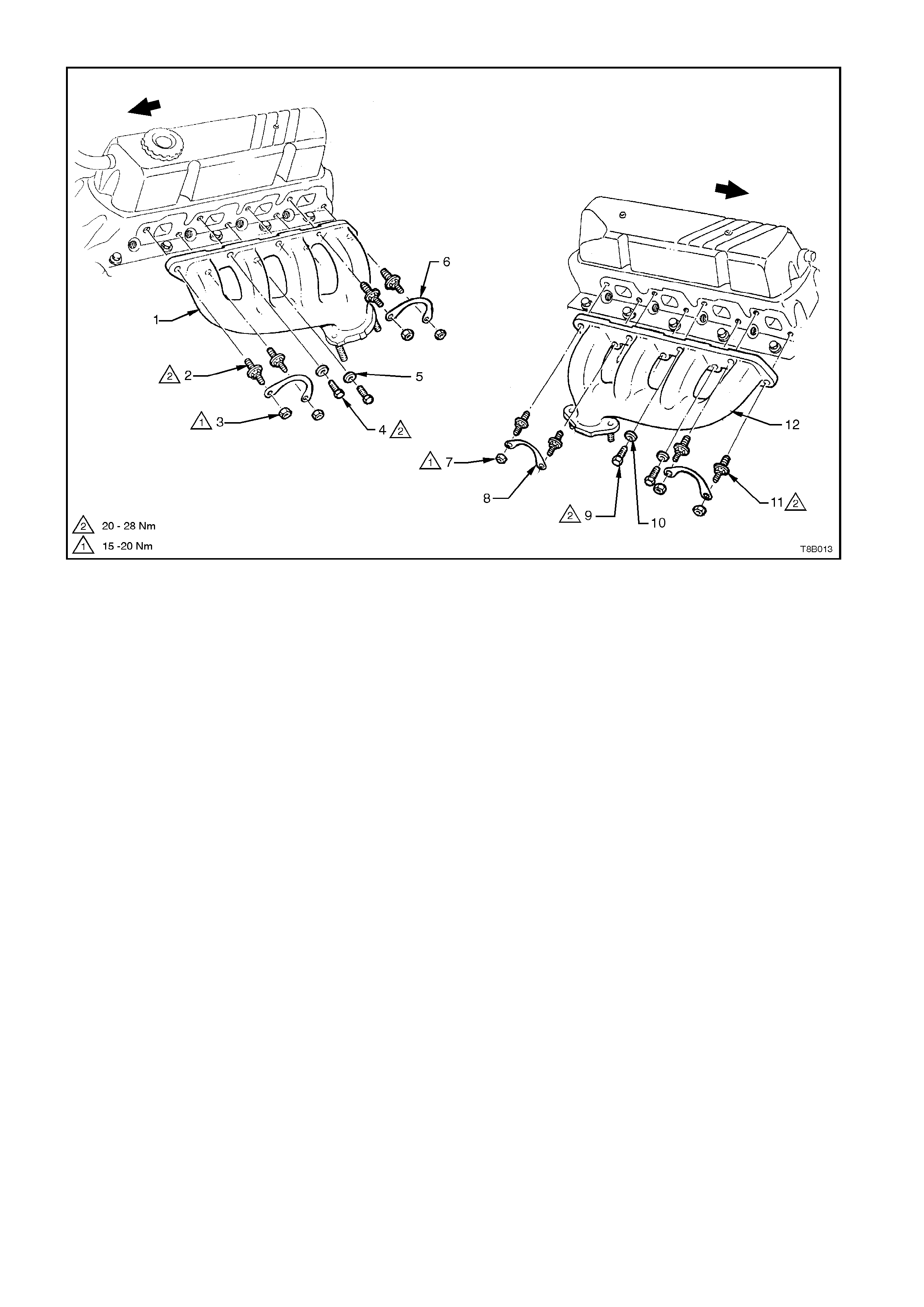
V8 ENGINE
1. Exhaust Manifold, LH side. 5. Washer - 2 places. 9. Bolt - 2 places.
2. Stud - 4 places. 6. Bolt Lock Plate - 2 places. 10. Washer - 2 places
3. Nut - 4 places. 7. Nut - 4 places. 11. Stud - 4 places.
4. Bolt - 2 places. 8. Bolt Lock Plate - 2 places 12. Exhaust Manifold - RH side
Figure 8B-7 V8 Engine

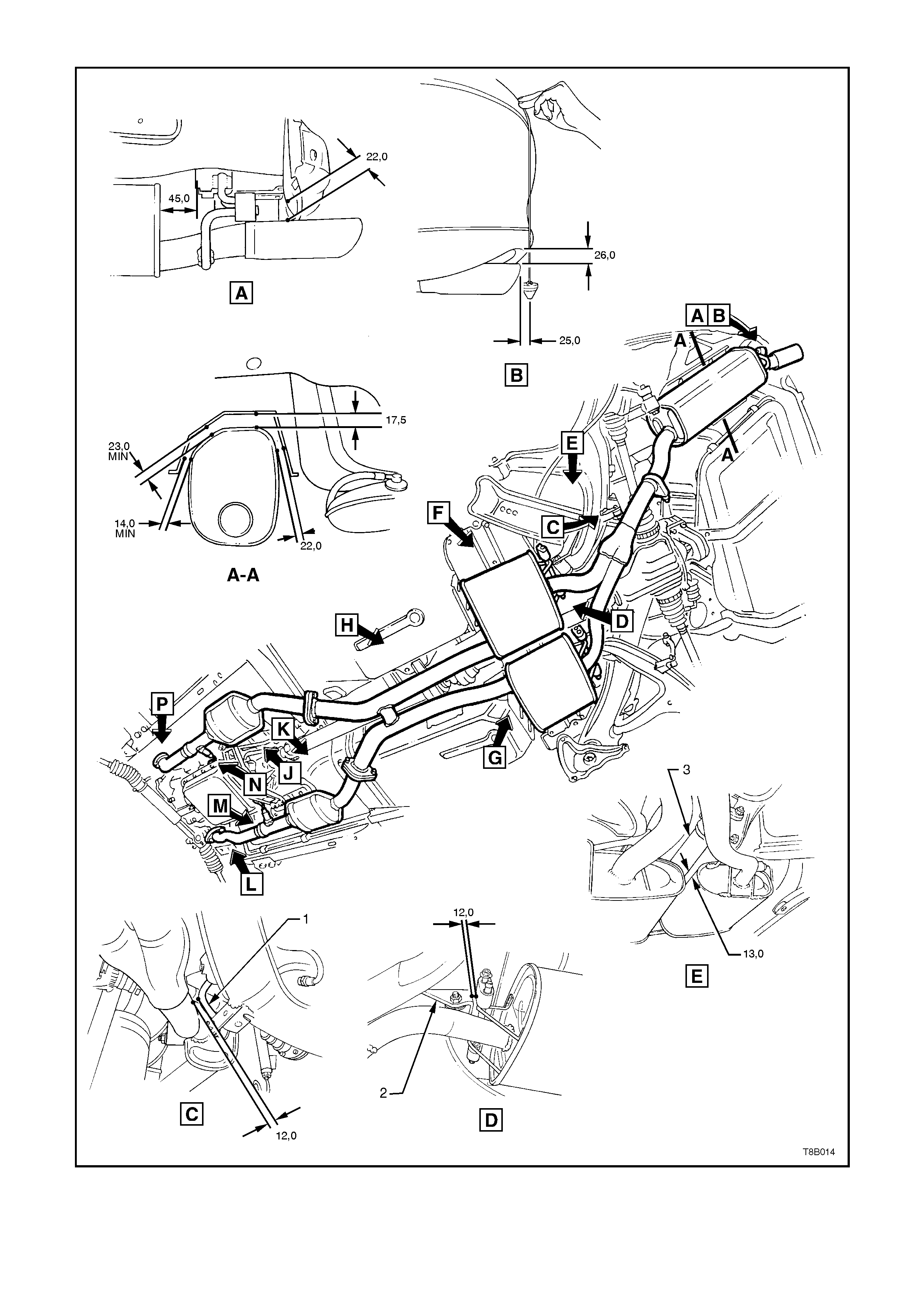
2.4 EXHAUST SYSTEM LAYOUTS
The layout diagrams on the following pages relate to the exhaust systems used for the V6, V6 Supercharged and
V8 engines.
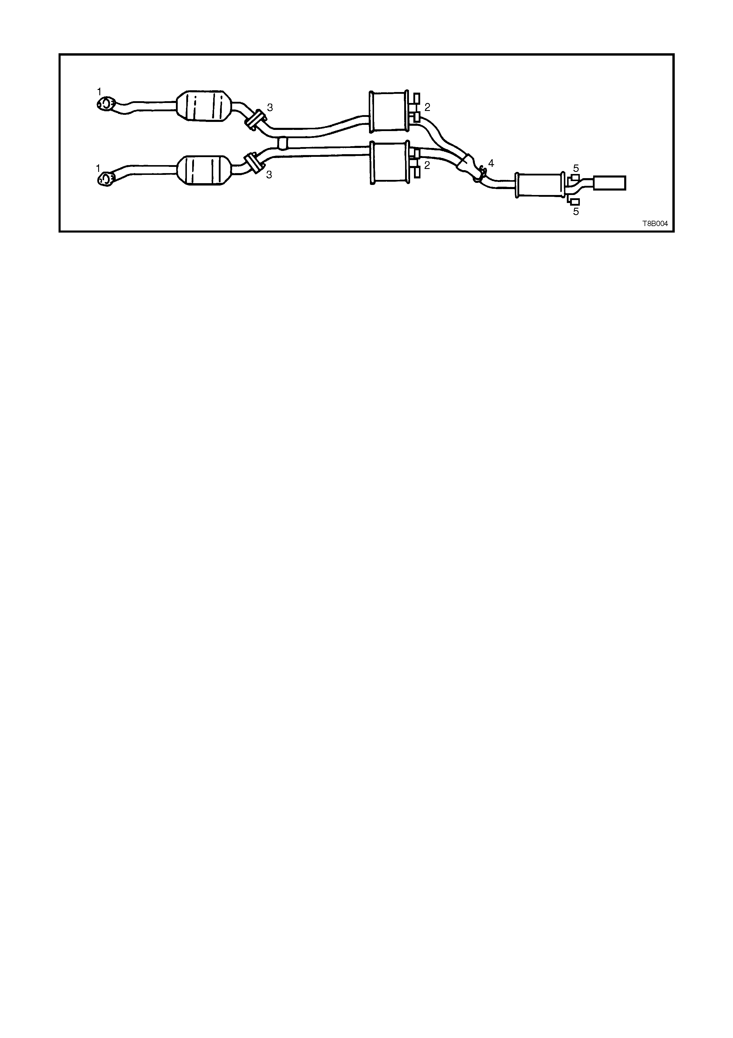
V6 ENGINE
1. Nut - 2 places 4. Muffler 7. Bolt - Auto. Trans.
2. Catalytic Converter 5. Support, Exhaust Pipes 8. Bumper Rubber - Auto. Trans.
3. Intermediate Muffler 6. Wave Washer - Auto. Trans. 9. Bumper Rubber - Man. Trans.
Figure 8B-8 - Exhaust System Layout, V6 Engine (Sheet 1 of 2)
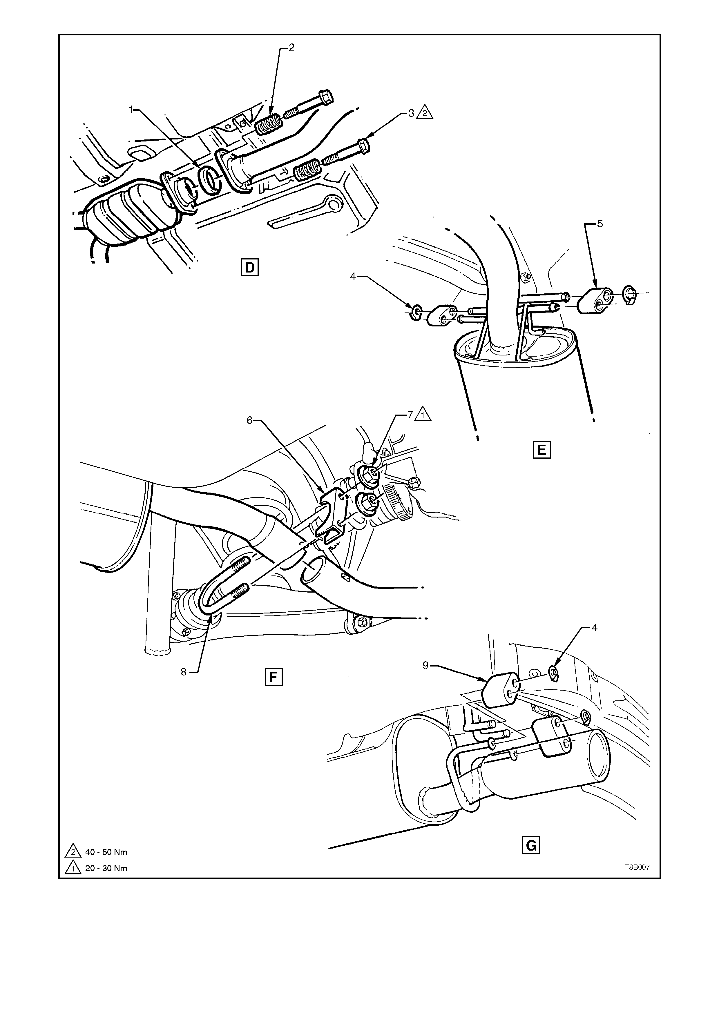
1. Sealing Ring 4. Retainer - 4 places 7. Nut - 2 places
2. Spring - 2 places 5. Bumper Rubber - 2 places 8. U-bolt
3. Stepped Bolt - 2 places 6. Clamp 9. Bumper Rubber - 2 places
Figure 8B-8A - Exhaust System Layout, V6 Engine (Sheet 2 of 2)
V6 SUPERCHARGED ENGINE
1. Nut - 2 places. 4. Catalytic Converter L/Hand. 6. Bolt - 4 places.
2. Muffler. 5. Catalytic Converter R/Hand. 7. Gasket - 2 places.
3. Intermediate Muffler - Right and Left.
Figure 8B-9 Exhaust System Layout, V6 Supercharged Engine (Sheet 1 of 2)
1. Retainer - 6 places. 3. Clamp - U-bolt. 5. U-bolt.
2. Bumper Rubber - 4 places. 4. Nut - 2 places. 6. Bumper Rubber - 2 places.
Figure 8B-9A Exhaust System Layout, V6 Supercharged Engine (Sheet 2 of 2)
V8 ENGINE
1. Nut - 2 places 4. Catalytic Converter L/Hand 6. Bolt - 4 places.
2. Muffler 5. Catalytic Converter R/Hand 7. Gasket - 2 places
3. Intermediate Mufflers - Right and Left
Figure 8B-10 Exhaust System Layout, V8 Engine (Sheet 1 of 2)
1. Retainer - 6 places 3. Clamp - U-bolt 5. U-bolt
2. Bumper Rubber - 4 places 4. Nut - 2 places 6. Bumper Rubber - 2 places
Figure 8B-10A Exhaust System Layout, V8 Engine (Sheet 2 of 2)
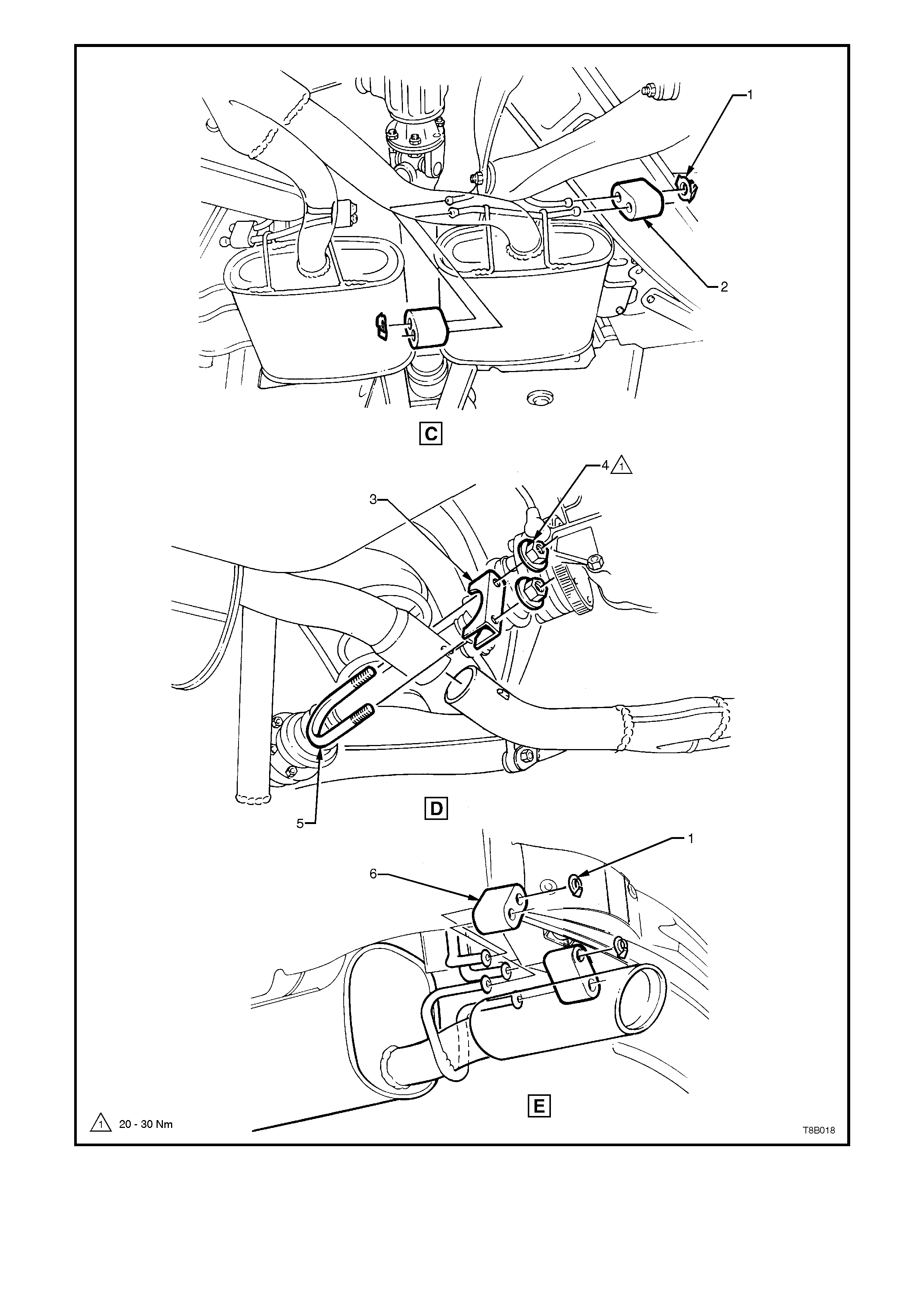
2.5 EXHAUST SYSTEM CLEARANCES
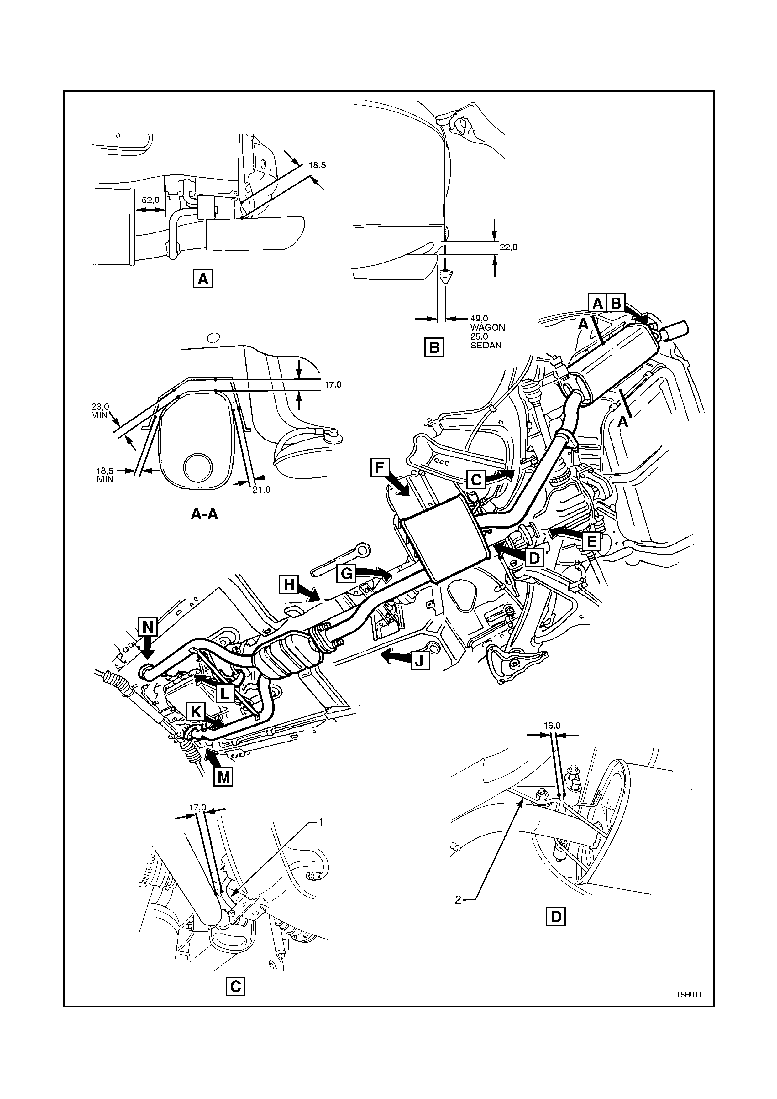
V6 ENGINE
1. Stabiliser Bar Link 2. Rear Suspension Control Arm Mount
Figure 8B-11 Exhaust System Clearances, V6 Engine (Sheet 1 of 2)
1. Rear Footwell 2. Intermediate Heat Shield
3. RH Sub Frame 4. Engine Block
Figure - 8B-11A Exhaust System Clearances, V6 Engine (Sheet 2 of 2)
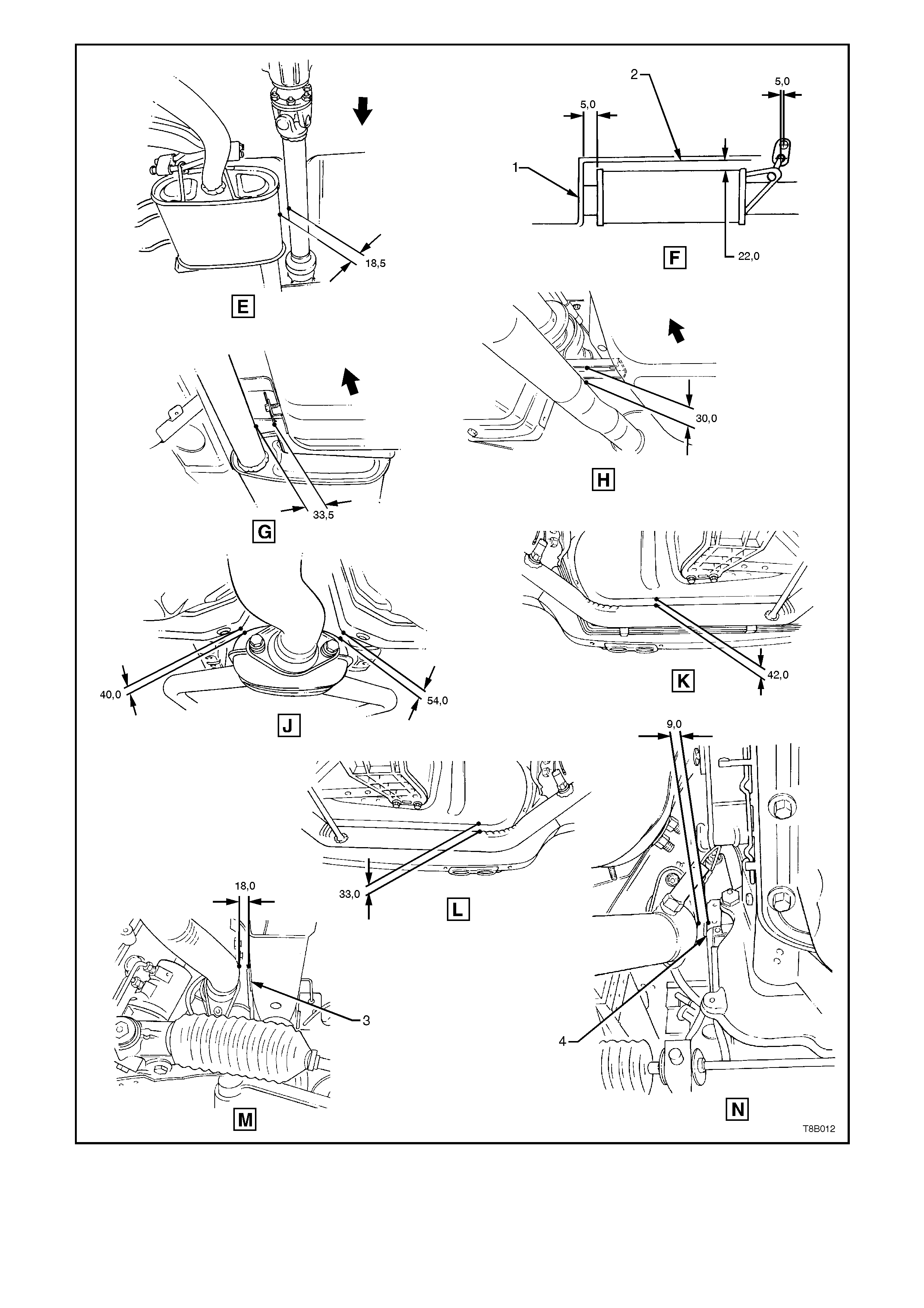
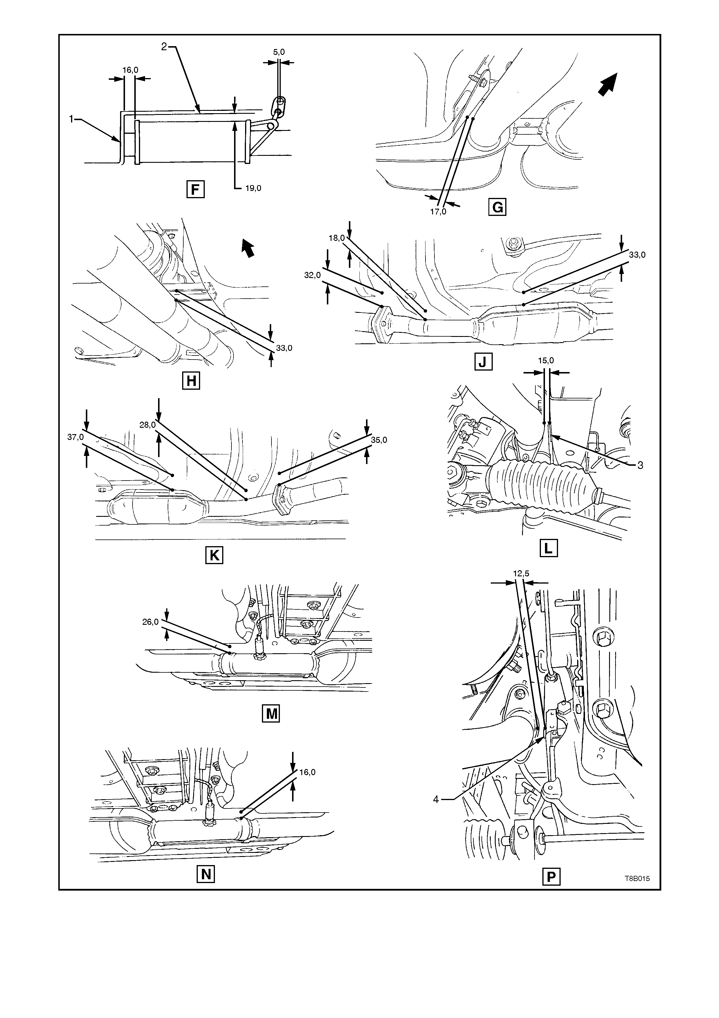
V6 SUPERCHARGED ENGINE
1. Stabiliser Bar Link 2. Rear Suspension Control Arm Mount
3. Propeller Shaft
Figure - 8B-12 Exhaust System Clearances, V6 Supercharged Engine (Sheet 1 of 2)
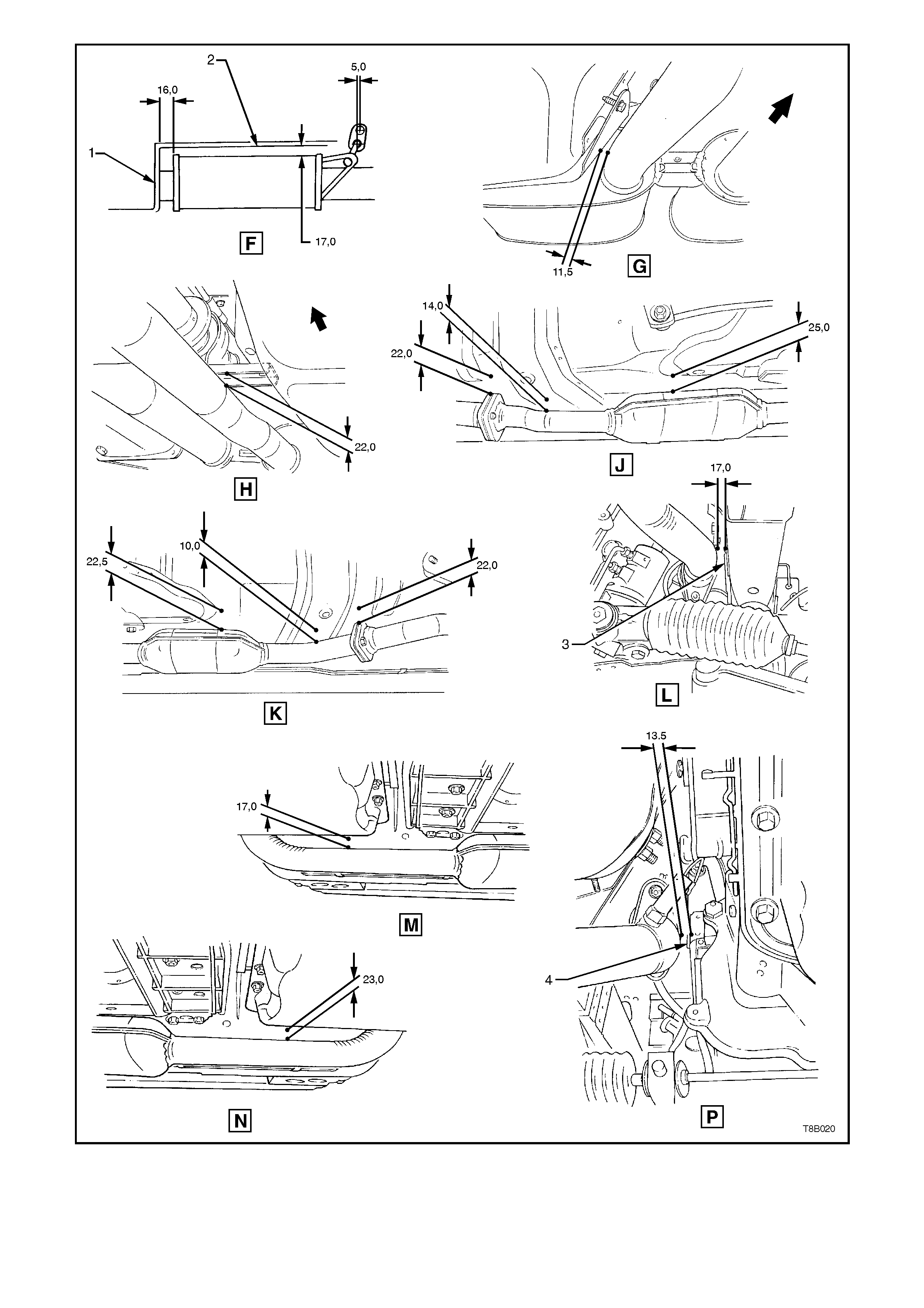
1. Rear Footwell 2. Intermediate Heat Shield
3. RH Sub Frame 4. Engine Block
Figure 8B-12A Exhaust System Clearances, V6 Supercharged Engine (Sheet 2 of 2)
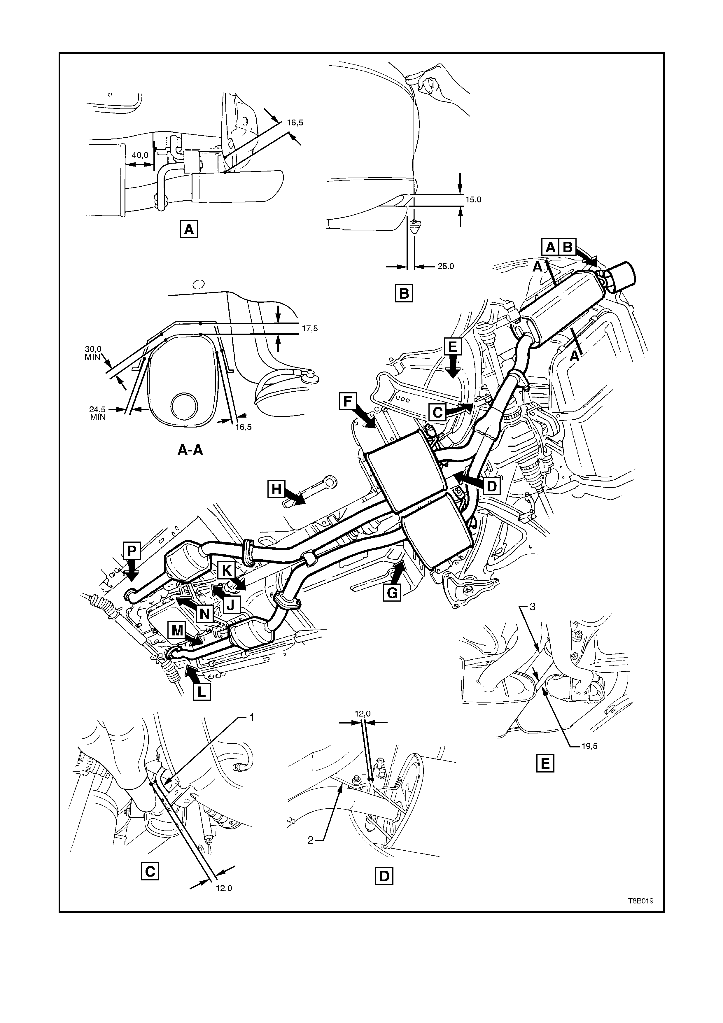
V8 ENGINE
1. Stabiliser Bar Link 2. Rear Suspension Control Arm Mount
3. Propeller Shaft
Figure 8B-13 Exhaust System Clearances, V8 Engine (Sheet 1 of 2)
1. Rear Footwell 2. Intermediate Heat Shield
3. RH Sub Frame 4. Engine Block
Figure 8B-13A Exhaust System Clearances, V8 Engine (Sheet 2 of 2)
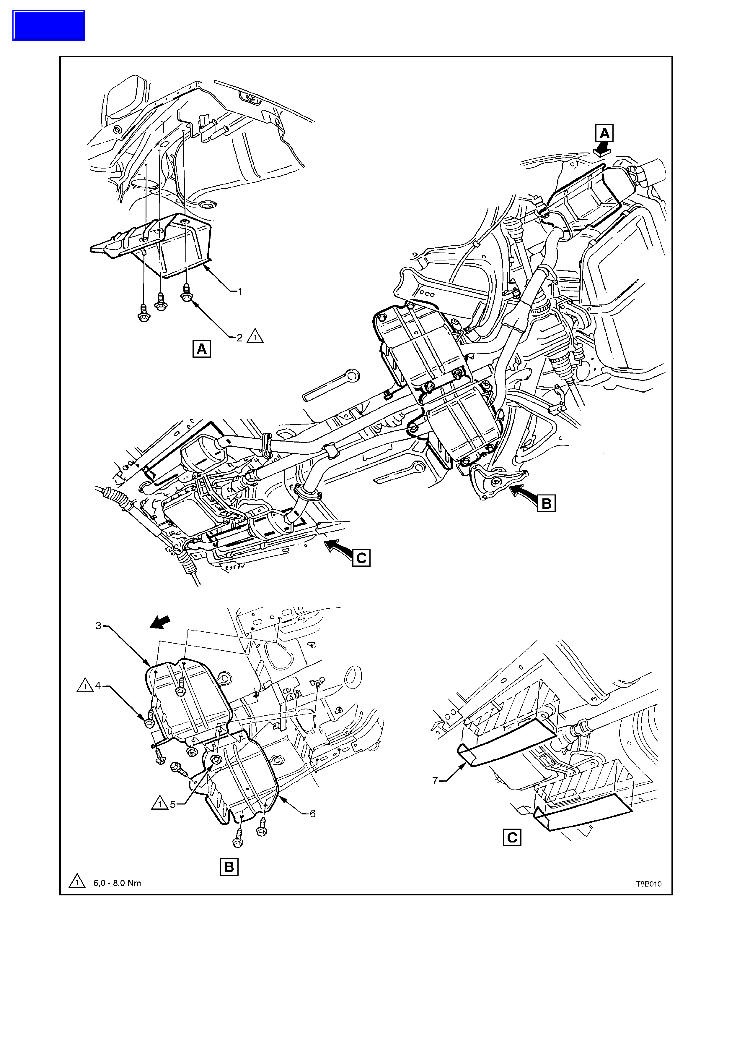
2.6 EXHAUST SYSTEM HEAT SHIELDS
1. Heat Shield - Rear Muffler 5. Nut - 2 places
2. Screw - 3 places 6. Heat Shield - RH Intermediate Muffler (all except V6)
3. Heat Shield - LH Intermediate Muffler 7. Self-adhesive Insulators (all except V6)
4. Screw - 6 places
Figure 8B-14 - Heat Shields, All Engines
Techline

3. EXHAUST SYSTEM DIAGNOSIS
CONDITION PROBABLE CAUSE CORRECTION
Leaking exhaust gases Leaks at pipe joints. Tighten U-bolt nuts and joint bolts
to the specified torques.
Damaged or improperly
installed converter sealing
ring/gaskets.
Replace gasket as necessary.
Burned or rusted out exhaust
pipe or muffler/s. Replace component as
necessary.
Exhaust noises Leaks at manifold or pipe
connections. Tighten clamps at leaking
connections to specified torques.
Replace gasket as required.
Burned or blown out pipe or
muffler/s. Replace pipe/muffler assembly as
necessary.
Exhaust manifold/s cracked or
broken. Replace manifold.
Leak between manifold/s and
cylinder head/s. Tighten manifold to cylinder head
studs to specified torque.
Loss of engine power,
hesitation, surging, poor
fuel economy, stalling or
Clogged catalytic converter
(may result from serious engine
malfunction).
Replace catalytic converter.
hard starting Crushed pipework. Replace pipework.
Internal rattling in muffler Dislodged tubes and/or baffles
in muffle r. Replace muffler.
Catalytic converter monolith
has crumbled and pieces blown
into muffler.
Replace catalytic converter
assembly and affected muffler.

4. SPECIFICATIONS
TYPE: Single system
MATERIAL:
Engine Pipes 409 stainless steel
Intermediate Muffler Aluminium coated, seam welded, mild steel tube
Rear Muffler 409 stainless steel
CATALYTIC CONVERTER:
Make AC Australia
Type Three way monolith
Outer Steel Shell
Material Stainless
Inlet Diameter 57 mm
Outlet Diameter 57 mm
Monolith
Material Extruded Cordierite
Volume 1.7 litres
Cells/in2400

5. TORQUE WRENCH SPECIFI CATIONS
V6 V6 Supercharged V8
(Nm) (Nm) (Nm)
Engine front pipe flange to exhaust
manifold flange attaching nuts 18 - 35 18 - 35 18 - 35
Extension housing to exhaust pipe
support bracket attaching bolt (A/T only) 18 - 35 --
Front exhaust pipe and intermediate
flanges to catalytic converter assembly 40 - 50 40 - 50 40 - 50
Exhaust U-bolt clamp nuts 20 - 30 20 - 30 20 - 30
Exhaust manifold to cylinder head studs 40 - 60 40 - 60 20 - 28
Exhaust manifold lock plate and support
nuts 20 - 27 20 - 27 15 - 20
Heat shield screws/nuts to underbody -
All engines 5 - 8