SECTION 9B - SPEED SENSITIVE POWER STEERING
CAUTION:
This vehicle will be equipped with a Supplemental Restraint System (SRS). An SRS
will consist of either seat belt pre-tensioners and a driver's side air bag, or seat belt
pre-tensioners and a driver's and front passenger's side air bags. Refer to
CAUTIONS, Section 12M, before performing any service operation on or around any
SRS components, the steering mechanism or wiring. Failure to follow the CAUTIONS
could result in SRS deployment, resu lting in possible perso nal in jury or u nnecessary
SRS system repairs.
CAUTION:
This vehicle may be equipped with LPG (Liquefied Petroleum Gas). In the interests of
safety, the LPG fuel system should be isolated by turning ‘OFF’ the manual service
valve and then draining the L PG service lines, before any service w ork is carried out
on the vehicle. Refer to the LPG leaflet included with the Owner's Handbook for
details or LPG Section 2 for more specific servicing information.
CAUTION:
Whenever any component that forms part of the ABS or ABS/ETC (if fitted), is
disturbed during Service Operations, it is vital that the complete ABS or ABS/ETC
system is checked, using the procedure as detailed in 4. DIAGNOSIS, ABS or
ABS/ETC FUNCTION CHECK, in Section 12L ABS & ABS/ETC.
1. GENERAL INFORMATION
Fitted to VT Calais as standard equipment, this power steering design provides variable assistance, depending on
vehicle speed. During low speed and/or parking manoeuvres, maximum assistance is provided, while minimal boost
with maximum feel is retained for high speed driving and cornering.
To achieve this variable assistance from a mechanical viewpoint, when compared to the power steering fitted to
other VT models, some minor changes to the power steering pumps and the steering rack assemblies are required.
1.1 GENERAL DESCRIPTION - RACK AND PINION ASSEMBLY
Apart from a design change to the upper end of the pinion assembly, the components in this steering system are
similar to the unit fitted to the remainder of the VT range of vehicles, with the standard power steering system.
With the exception of the servicing operations contained in this Section, all other servicing procedures for the
steering rack and associated components are the same as detailed in Section 9A STEERING.
Because the operation of the steering rack itself is as described in Section 9A STEERING, the following
description of the Speed Sensitive Rack and Pinion Assembly operation is restricted to the rotary valve only.
Techline
Techline
1.2 SPEED SENSITIVE ROTARY VALVE
GENERAL DESCRIPTION
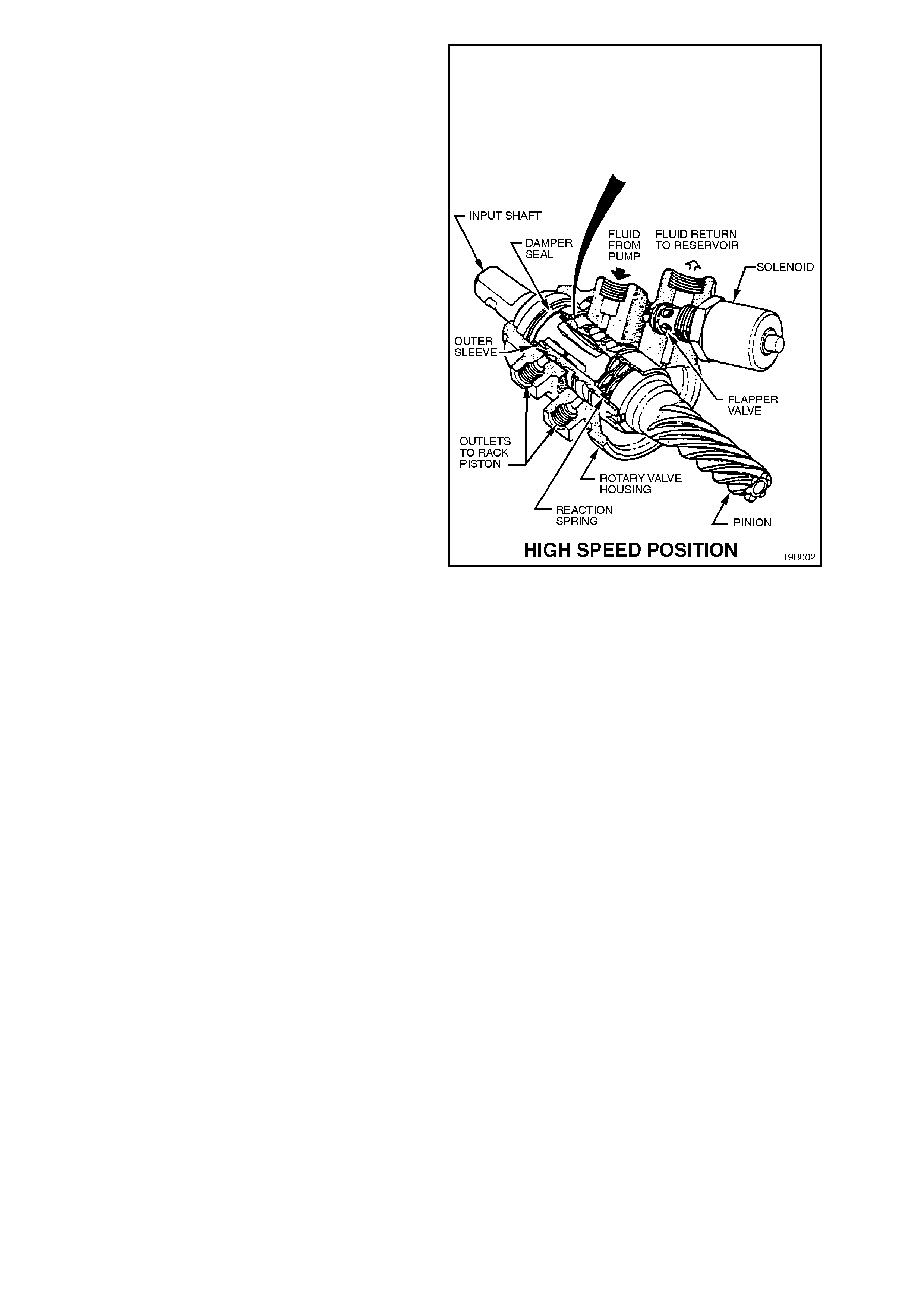
Sectioned views of the rotary control valve and
pinion assem bly are illustrated in F igures 9B-1, 9B-
2 and 9B-3, and it can be seen that the as s embly is
a modular design which provides some
interchangeability between the two different power
steering systems.
The vehicle speed related boost characteristic, is
caused by the outer sleeve member moving along
the inner input shaft member by approximately 4
mm. This outer sleeve movement alters the
quantity of fluid that is diverted to the rack piston,
varying the power assistance required. The outer
sleeve movement is controlled by a solenoid
operated 'flapper' valve, located in the fluid return
side of the valve. The solenoid operation is
controlled by the Body Control Module which
supplies a variable, pulse width, pulsed signal,
providing a variable pulse width (or "ON" time),
which is inversely proportional to road speed.
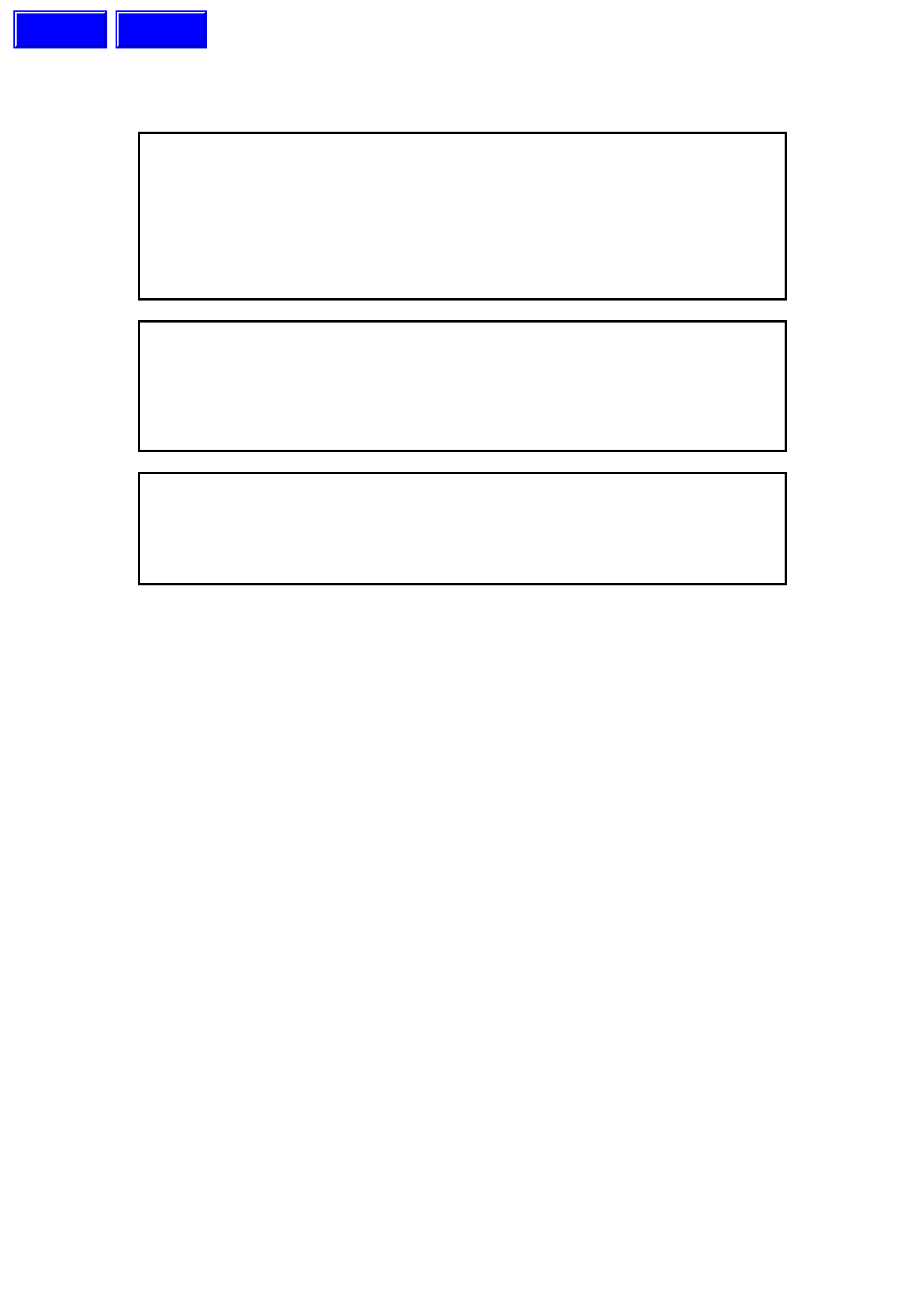
The outer sleeve's 'back and forth' movement
causes the slots in the internal bor e of the sleeve to
mask off pocketed regions machined in the inner
valve member of the input shaft, indicated in
Figures 9B-1 and 9B-2 as the 'High Speed Edge'.
The relative position of the inner valve and outer
sleeve has the effect of changing the fluid flow
characteristic and system pressure, inversely with
vehicle speed.
At low vehicle speeds, so lenoid valve activity raises
hydraulic pressure on the return side of the valve,
moving the sleeve against a reaction force provided
by a 'balancing' or reaction spring. Having raised
the system pres sure, the volum e of f luid diverted to
the steering rack will now be dependent upon the
twisting of the inner valve member, relative to the
outer sleeve.
Figure 9B-1
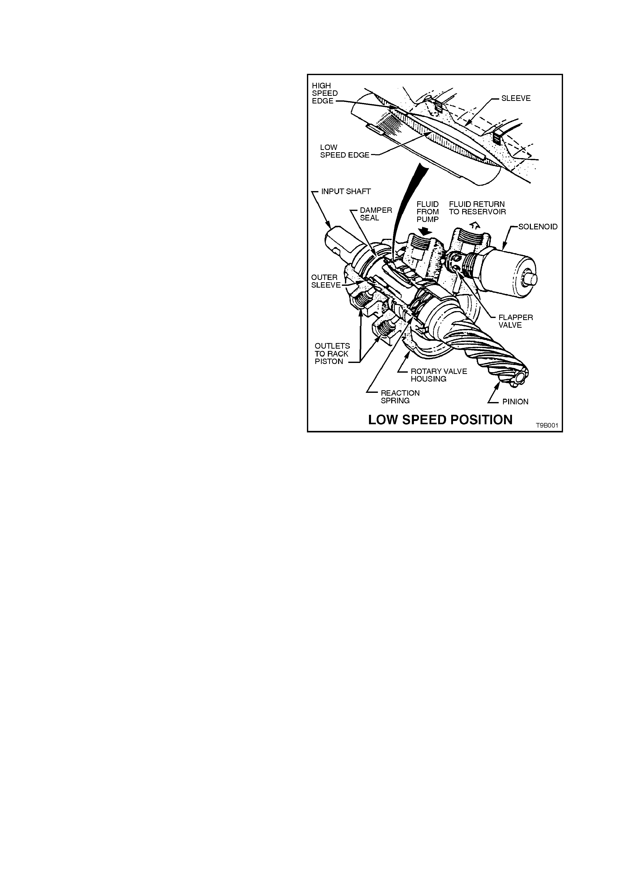
During high speed driving, when minimum boost is
required, the solenoid is not activated (above
approximately 80 km/h) and the reaction spring
moves the sleeve to its maximum point of travel.
This action effectively reduces the hydraulic
assistanc e provided to the steering rack . As vehic le
speed reduces, the solenoid is progressively
activated by the Body Control Module (BCM) and
the sleeve position is determined by the relative
balance between the return fluid pressure and the
reaction spring.
During slow speed parking manoeuvres, the
solenoid is fully activated, allowing the increased
return f luid pres sur e to move the s leeve agains t the
reaction spr ing, providing m axim um boos t pres sure
to the steering rack assembly, thereby requiring
minimum driver steering effort to turn the steering
wheel.
In the unlikely event of an electronic/electrical
failure, the control spring will move the sleeve to
the 'high speed' (or high effort) mode.
When the engine is stopped, the outer sleeve
member is pushed to the high speed (minimum
boost) position by the reaction spring. If this
situation continues f or a lengthy period of tim e (e.g.
overnight), cold, viscous fluid will have collected
behind the sleeve, at the reaction spring end. To
avoid a time delay on start up for the sleeve to be
positioned into the maximum boost position, an
orifice or bleed hole (refer to Figure 9B-3) is
provided, that allows the collected fluid to by-pass
the solenoid flapper valve and be exhausted to the
fluid reservoir.
A damper seal located at the fluid end of the
sleeve, is used to reduce sleeve oscillation that
could occur under some engine and vehicle
operating conditions. With these changing fluid
pressure levels, fluid is able to force past the seal
lip and, with a controlled leakage factor
incorporated into the seal design, effective damping
of the sleeve is achieved.
Figure 9B-2
Figure 9B-3 - Speed Sensitive Rotary Valve - Sectioned View
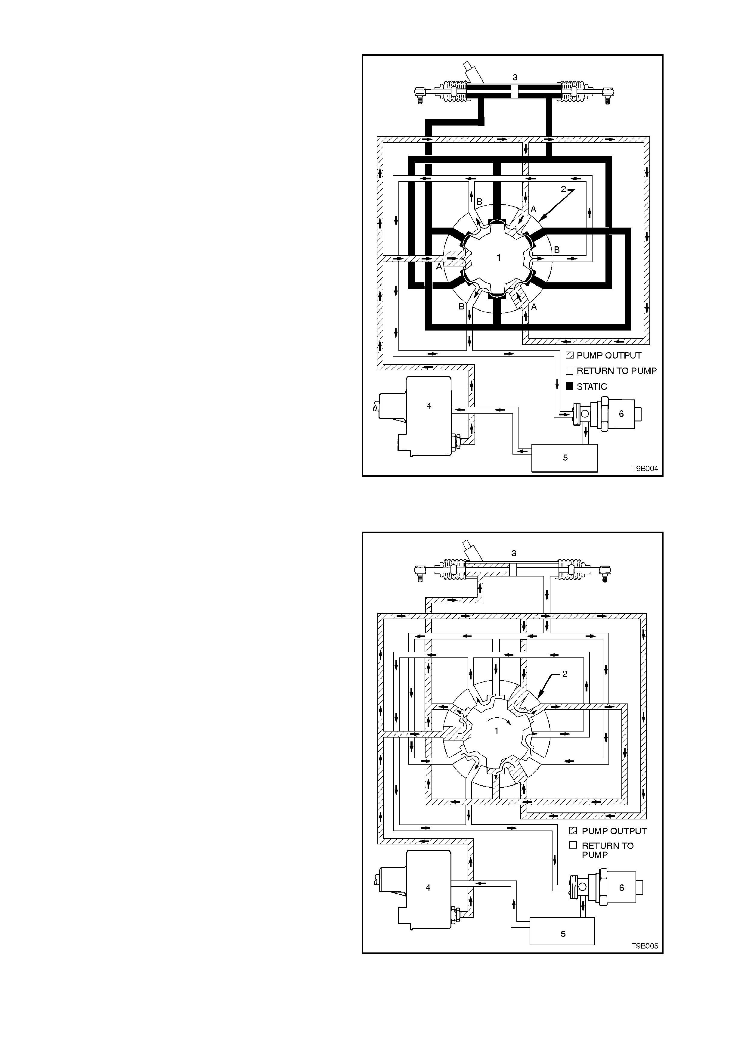
NEUTRAL POSITION (STRAIGHT AHEAD) - LOW SPEED METERING EDGE EXPOSED
With vehicle speeds less than approximately 18
km/h, the solenoid is fully activated, causing the
increased return fluid pressure to move the sleeve
against the reaction s pring, expos ing the low speed
metering edge. In the straight ahead position, the
fluid flow is directed into the inner valve assembly
through a number of drilled holes in the outer
sleeve. In this steering position, the inner valve
allows fluid to pass equally to both sides of the rac k
piston and also to return to the fluid reservoir,
through holes drilled in the longitudinal grooves of
the inner valve. With equal pressure applied to both
sides of the rack piston, no power assistance is
available.
Figure 9B-4
TURNING RIGHT - LOW SPEED METERING EDGE EXPOSED
When turning right with the low speed metering
edge exposed, as soon as slight relative rotation
between the input shaft (inner rotating valve) and
outer sleeve occurs, fluid is restricted in its free
return to the pump and is directed to the driver's
side of the piston. At the same time, fluid on the
other side of the piston is directed to the return
circuit, leading to the reservoir and pump. This
action is slight at first so that only a small amount of
assistance is provided, but becomes progressively
greater as the torsion bar flexes and the driver
requires more assistance.
Figure 9B-5
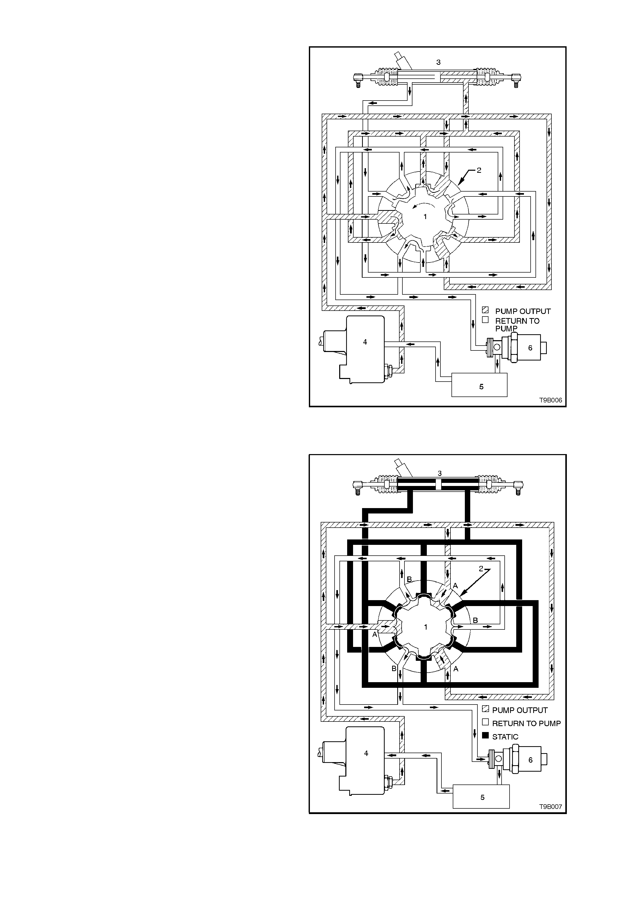
TURNING LEFT - LOW SPEED METERING EDGE EXPOSED
When turning left with the low speed metering edge
exposed, as soon as slight relative rotation
between the input shaft (inner rotating valve) and
outer sleeve occurs, fluid is restricted in its free
return to the pump and is directed to the
passenger's side of the piston. At the same time,
fluid on the other side of the piston is directed to
the return circuit, leading to the reservoir and
pump. This action is slight at first so that only a
small amount of assistance is provided, but
becomes progressively greater as the torsion bar
flexes and the driver requires more assistance.
Figure 9B-6
NEUTRAL POSITION (STRAIGHT AHEAD) - HIGH SPEED METERING EDGE EXPOSED
With vehicle speed above approximately 80 km/h,
the solenoid is not ac tivated at all, and the reac tion
spring moves the outer sleeve to it's maximum
point of travel, exposing the high speed metering
edge. In the straight ahead position, the f luid f low is
directed into the inner valve assembly through a
number of drilled holes in the outer sleeve. In this
steering position, the inner valve allows fluid to
pass equally to both sides of the rack piston and
also to return to the fluid reservoir, through holes
drilled in the longitudinal grooves of the inner valve.
With equal pressure applied to both sides of the
rack piston, no power assistance is available.
Figure 9B-7
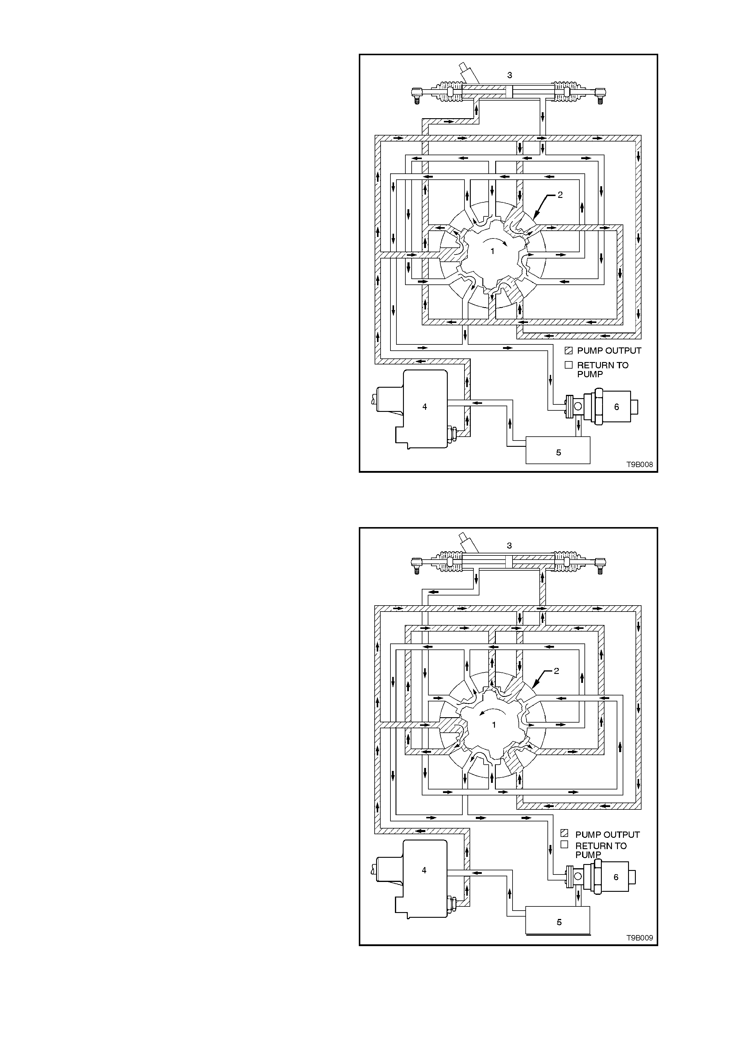
TURNING RIGHT - HIGH SPEED METERING EDGE EXPOSED
When turning right with the high speed metering
edge exposed, increased relative rotation is
required between the input shaft (inner rotating
valve) and outer sleeve, before the fluid is
restricted in its free return to the pump and is
directed to the driver's side of the piston. This
means that little or no assistance is provided with
norm al steering m anoeuvres at these road s peeds.
At the sam e time, f luid on the left s ide of the piston
is directed to the return circuit, leading to the
reservoir and pump.
Figure 9B-8
TURNING LEFT - HIGH SPEED METERING EDGE EXPOSED
When turning left with the high speed metering
edge exposed, increased relative rotation is
required between the input shaft (inner rotating
valve) and outer sleeve, before the fluid is
restricted in its free return to the pump and is
directed to the passenger's side of the piston. This
means that little or no assistance is provided with
norm al steering m anoeuvres at these road s peeds.
At the same time, fluid on the right side of the
piston is directed to the return circuit, leading to the
reservoir and pump.
Figure 9B-9
1.3 POWER STEERING PUMPS
GENERAL DESCRIPTION
The power steering pumps fitted to vehicles with
speed sensitive power steering are of the constant
flow type. However, servicing procedures are
essentially the same as those for the droop flow
design, fully detailed in Section 9A STEERING.
The only exception is the outlet fitting, which does
not feature a m etering needle valve as in the dr oop
flow design.
If a power steering pump r equires r eplacement, it is
essential that the correct type is selected. Refer to
the following table and the diagram shown, for
identification details of the available power steering
pumps for the complete range of VT Series
vehicles, regardless whether the system is the
standard or speed sensitive design.
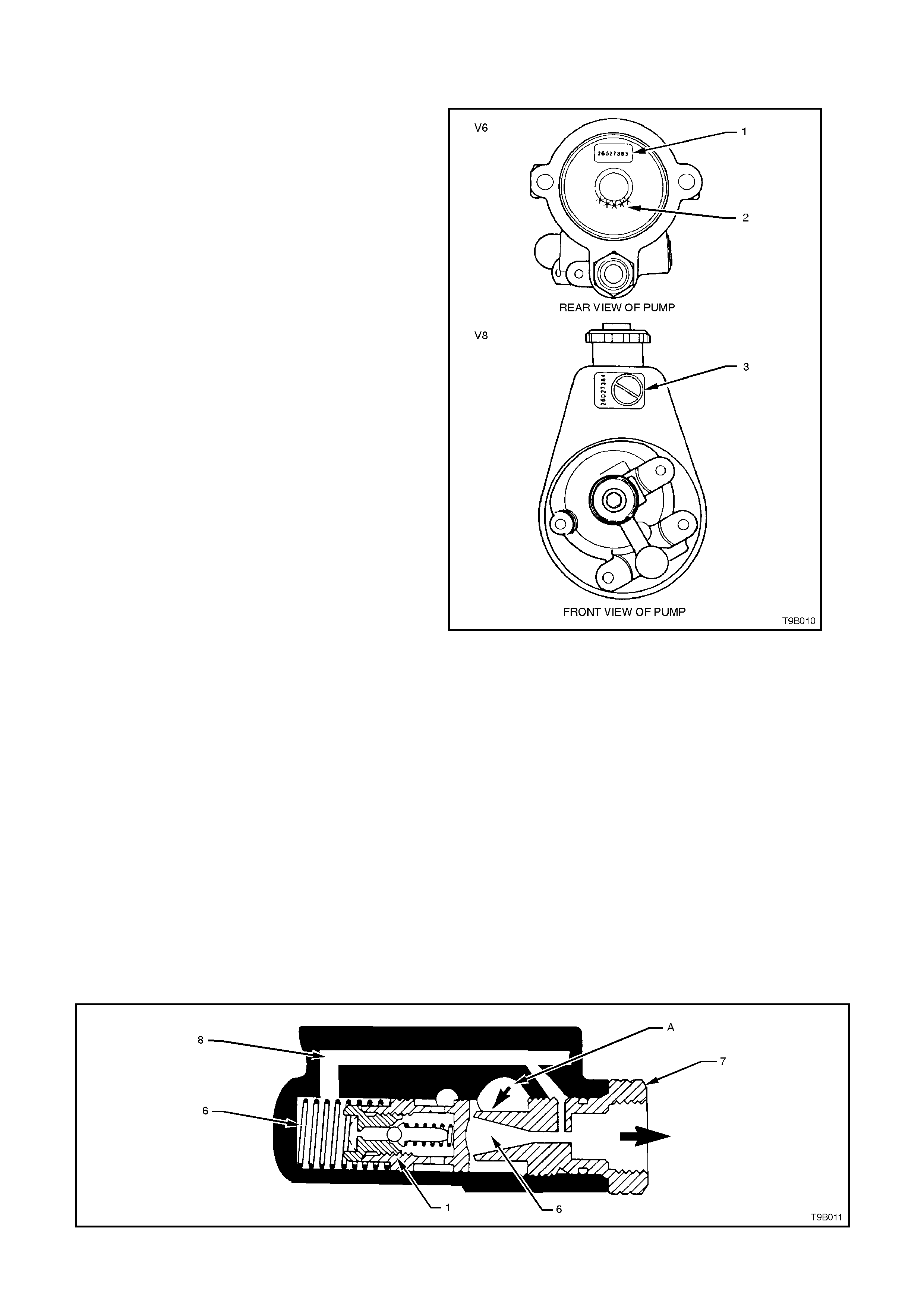
The location of the part number (1 or 3) is as
shown, while the last 5 digits (2) of the V6 pump is
also provided.
PUMP APPLICATION PART NUMBER
V6 ENGINE:
STANDARD 26056053
SPEED SENSITIVE 26056054
V8 ENGINE
STANDARD 26056055
SPEED SENSITIVE 26056056
Because the pumps used for the speed sensitive
power steering, have a constant flow outlet fitting,
the operation is slightly different to the droop flow
design. Figure 9B-10
CONSTANT FLOW CONTROL VALVE OPERATION
Slow Cornering
Pump speeds during slow cornering or parking are normally low, as are demands for fluid flow volume, due to
slower steering manoeuvres.
With reasonably high relative movem ent of the inner valve and outer sleeve in the s teering rac k control valve at this
time, the fluid is pressurised to approximately 3,400 kPa to 4,800 kPa and directed to the high pressure cavity
behind the pressure plate. Discharge ports direct this fluid to the outlet fitting (7) and then on to the steering gear.
The discharge fluid pressure from the outlet fitting, is slightly lower in pressure than the internal high pressure (A),
coming from the pump ring.
This drop in pressure, due to venturi action, occurs as the fluid flows through the orifice (6) in the outlet fitting (7).
This lower pres sur e is trans mitted to the spr ing (6) end of the c ontr ol valve (1) by a fluid pas s age (8) c onnec ting the
control valve (1) to the outlet fitting (7).
This results in a pressure unbalance at each end of the control valve (1), causing it to move away from the outlet
fitting (7). Owing to the force of the control valve spring (6), the valve (1) remains closed to the fluid by-pass hole.
Because suf ficient fluid is allowed to circulate through the system, fluid pressure does not build up high enough to
cause the pressure relief ball check in the valve (1).
Figure 9B-11
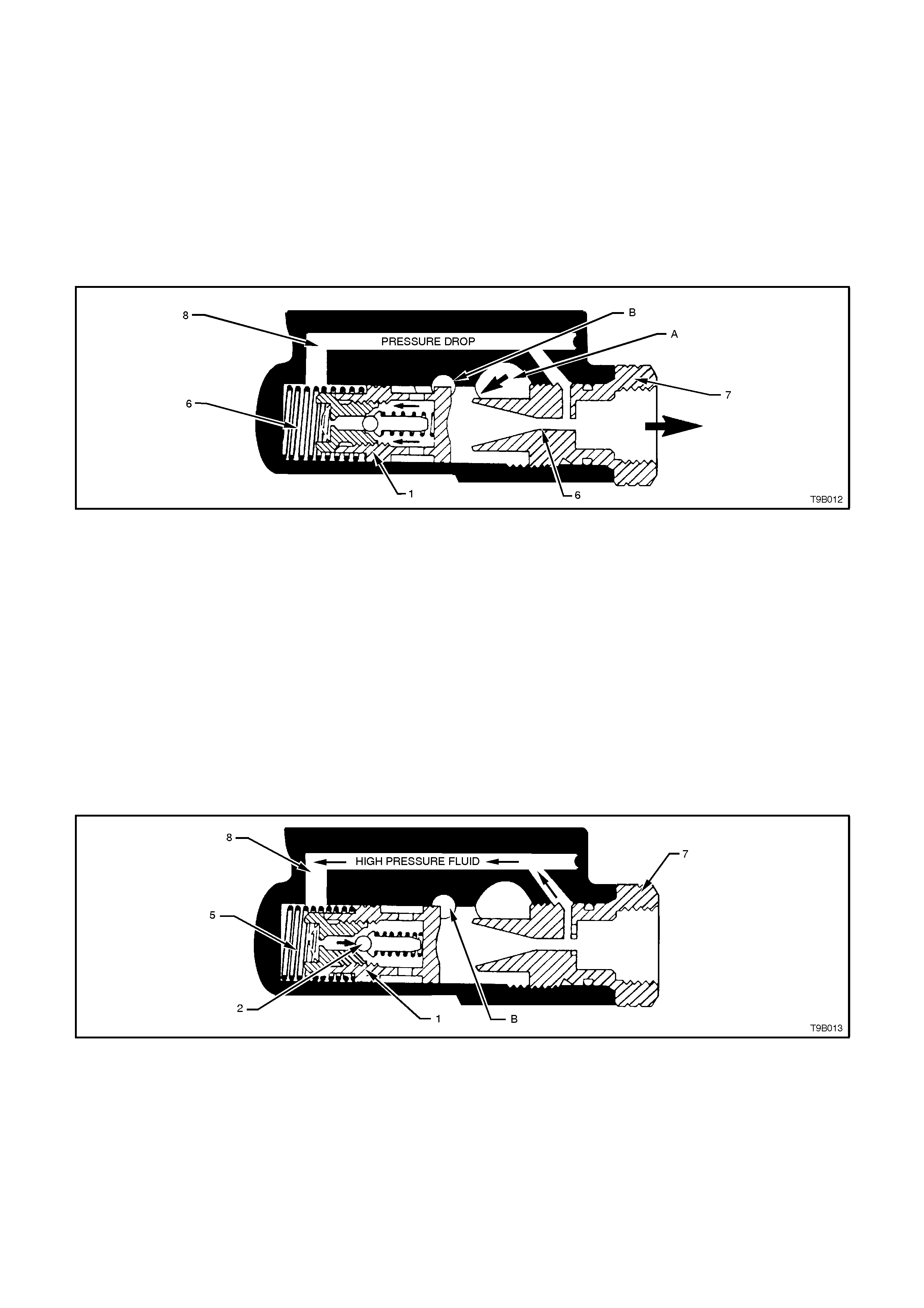
MODERATE TO HIGH SPEED OPERATION
System press ure in this m ode is norm ally low (approx imately 260 kPa) due to the lac k of steering manoeuvr es and
high fluid flow rates. W hen the steering is in the straight ahead position, fluid is discharged f rom the high pressure
cavity (A), through the outlet fitting (7) to the steering gear and back to the pump reservoir.
When this flow exceeds a preset level, fluid is by-passed within the pump, as follows:
Fluid passing through the outlet fitting (7), causes a pressure reduction to occur in the orifice (6) by venturi action.
This reduced press ure is trans mitted to the spr ing (6) end of the c ontrol valve (1), via the f luid by-pass pass age (8)
connecting the control valve (1) and the outlet fitting (7), as shown.
This pressure difference on each side of the control valve, causes the valve to move against spring (6) force,
opening the fluid by-pass passage (B) to the pump inlet. Depending on vehicle road speed, pump speed and the
steering requirements needed by the driver, this valve (1) will modulate, controlling the fluid flow rate through the
steering system.
Figure 9B-12
CORNERING AGAINST WHEEL STOPS
When the steering wheel is turned to full lock and held in that position, the steering rack power piston chamber
becomes fully pressurised and fluid flow stops.
NOTE:
This full lock condition should not be maintained for long periods of time (in excess of five minutes) due to
excessive fluid temperature rise.
The resulting high pressur e is then transm itted to the spring (5) end of the control valve (1) through the connec ting
fluid passage (8) from the outlet fitting (1).
When the pressure builds up high enough, the relief ball check (2) within the control valve (1) opens, allowing a
small amount of fluid to pass through the pressure relief orifice, causing a pressure drop that results in a lower
pressur e acting on the spring (5) end of the contro l valve (1). The c ontrol valve then m oves against spr ing (5) forc e
and opens up the fluid by-pass passage (B) so that fluid is returned to the pump inlet. Pre-determined relief
pressure is thus maintained while the steering gear is turned and held on full lock.
Figure 9B-13
1.4 SOLENOID VALVE
GENERAL DESCRIPTION
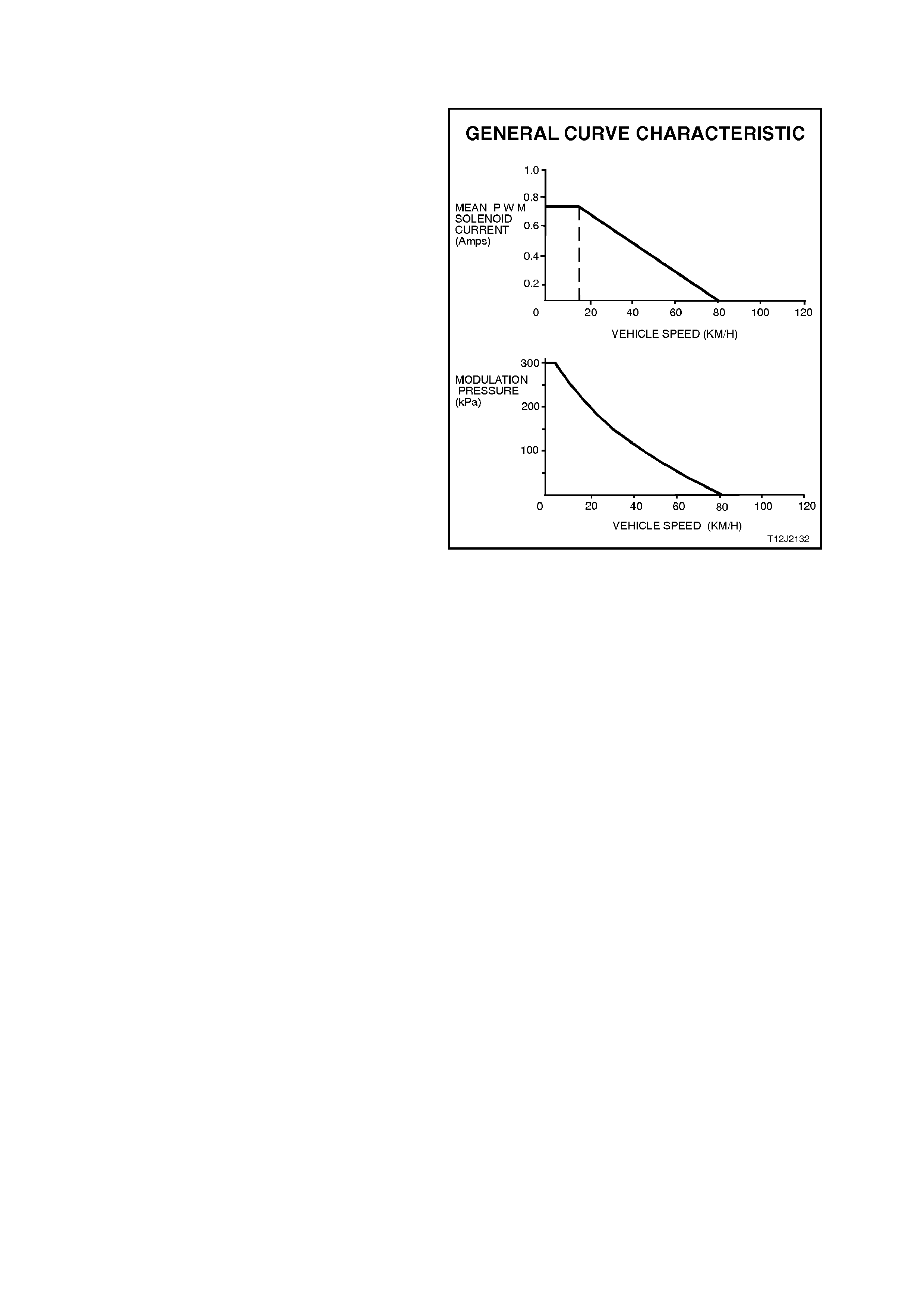
When activated, the solenoid receives a Pulse
Width Modulated (PWM) current flow from the
Body Control Module (BCM), that varies inversely
with vehicle road speed. By changing the pulse
width of the BCM current flow (i.e. the "ON" time),
pressure control within the power steering system
is maintained. As illustrated by the 'typical'
diagrams shown, the average PWM solenoid
current is controlled by the BCM's programming to
provide the m odulated pressures shown. Max imum
modulation pressure is only applied during parking
and up to a low speed of a few km/h.
From this speed, the modulated pressure falls as
road speed increases until, at approximately 80
km/h, the solenoid receives no further current
pulses fr om the BCM and modulation pres sure f alls
to 0 kPa.
Reference to the following table and the graphs, the
PWM current flow relative to road speed and
modulation pressure, is shown.
CURRENT (Amp.) ROAD SPEED (km/h)
0.75 0 - 12
0.45 40
0.0 80+
NOTE:
Do not disassemble the solenoid or attempt to
adjust it. If a problem with this component is
suspected, the whole solenoid assembly must be
replaced.
Figure 9B-14
2. SPEED SENSITIVE POWER STEERING SERVICE OPERATIONS
With the exception of operations detailed in this
Section, speed s ensitive power steering operations
are the same as for standard power steering, as
detailed in Section 9A STEERING.
2.1 POWER STEERING GEAR
Important:
NOTE 1:
Remove the ignition key from the ignition lock and
ensure that the steering column is locked. If this
operation is not carried out and the steering wheel
is spun while the steer ing gear is r emoved f r om the
vehicle, the clock spr ing coil in the upper end of the
steering column will be destroyed!
NOTE 2:
If the ignition switch is not in the "OFF" position
when this procedure is c arr ied out, the BCM will log
a fault situation and a total BCM reset will have to
be carried out. Refer to Section '12J-2 HIGH
SERIES BCM' for the necessary procedure.
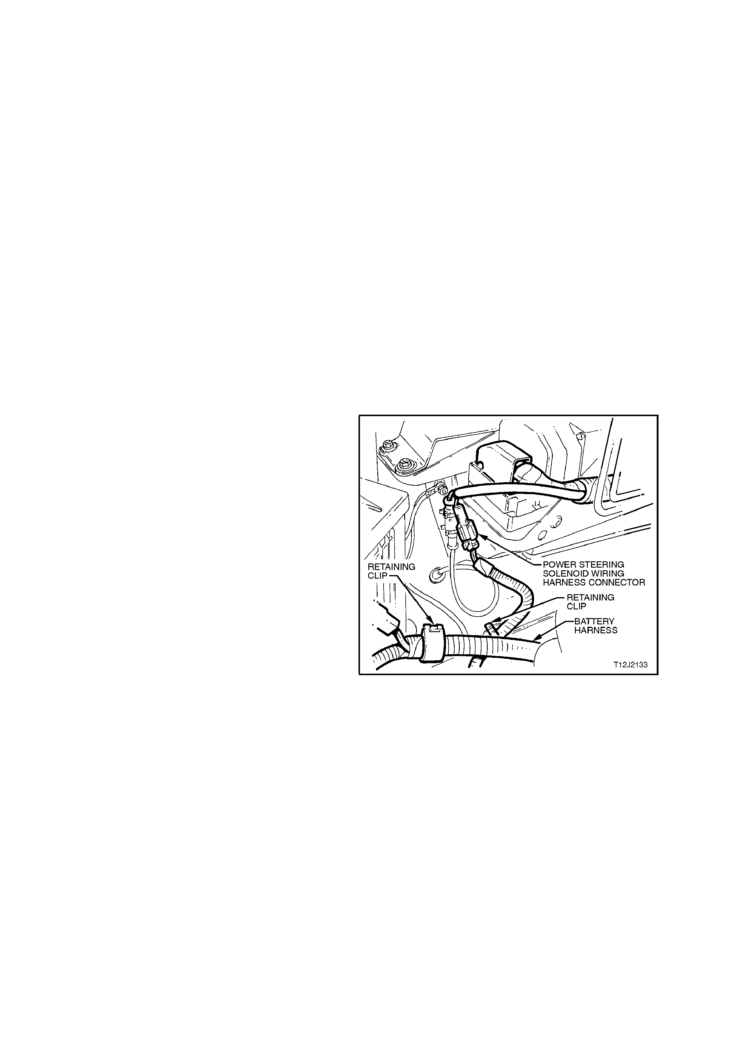
REMOVE
1. Disconnect power steering solenoid wiring
harness connector by lifting the locking tab
and pulling on the connector halves.
Do not pull on the wiring.
2. Disconnect the retaining clips securing the
solenoid wiring, in two places.
For all other removal operations, refer to the
procedure outlined in 3.6 POWER STEERING
GEAR in Section 9A STEERING.
Figure 9B-15
REINSTALL
With the exception of the following operations,
reinstall the power steering, as detailed in
Steering 9A STEERING.
1. Reconnect the power steering solenoid wiring
harness connector, ensuring that the two
connector halves lock together.
2. Reconnect the retaining clip to secure the
solenoid wiring harness.
2.2 SOLENOID ASSEMBLY
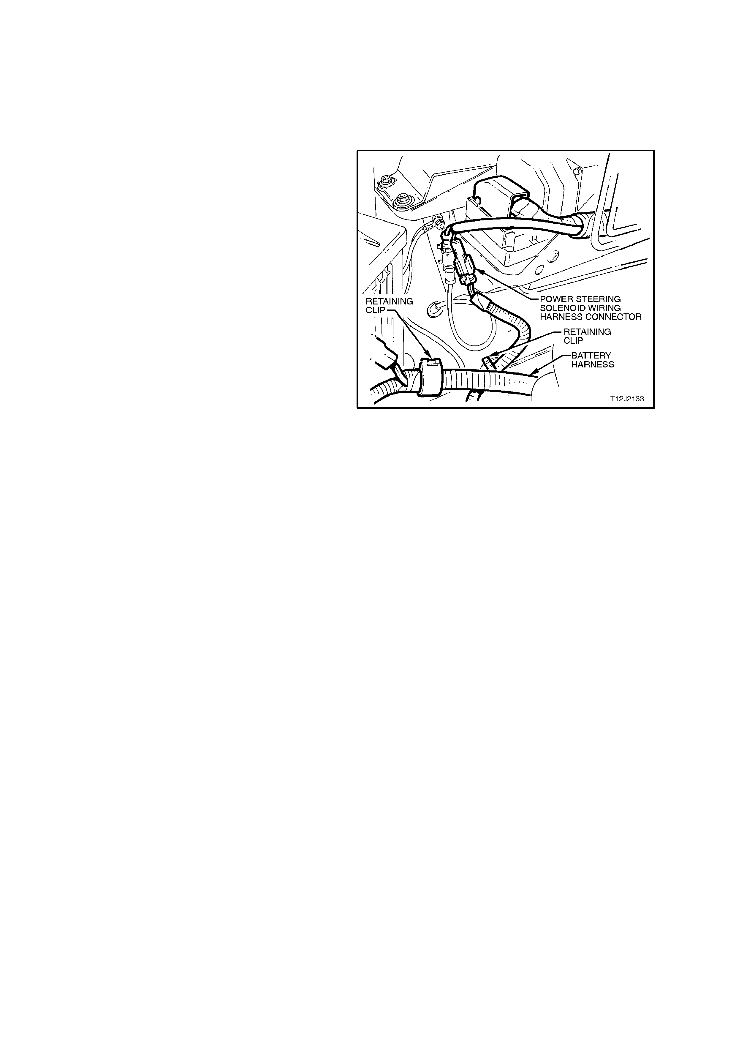
REMOVE
1. Disconnect wiring harness connector by lifting
the locking tab and pulling on the connector
halves.
DO NOT pull on the wiring.
NOTE:
The ignition switch MUST be turned 'OFF'.
2. Remove the retaining clips securing the
solenoid wiring, in two places.
Figure 9B-16
3. Using a 1 1/8" set spanner, loosen, then
remove the solenoid from the rotary valve
body.
IMPORTANT:
Do not disassemble the solenoid or attempt to
adjust the flapper valve seat. It is pre-set during
manufacture and is not to be tampered with. If a
problem with the solenoid is suspected, the
complete solenoid assembly must be replaced.
TEST
Because the temperature of the solenoid has a
marked effect on its resistance, the temperature
must be taken into account when checking the
following resistance readings.
1. Using a digital Ohmmeter, check the
resistance between each of the two solenoid
wires and the body of the solenoid.
Each reading should be infinity (Open Circuit).
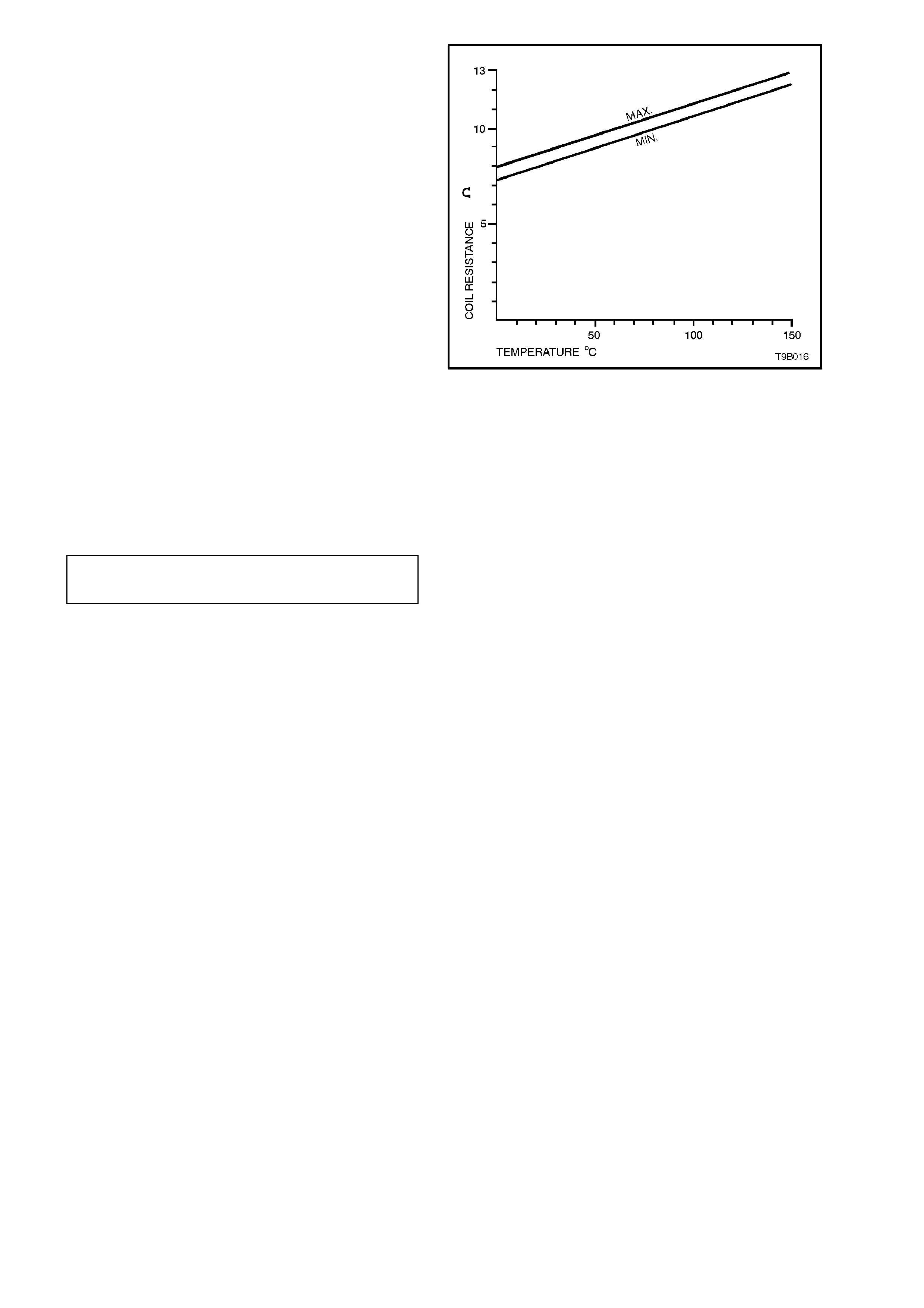
2. The resistance between the two wires at the
harness connector will change with solenoid
temperature. The resistance reading therefore,
should be within the ranges detailed in the
following table or as indicated in the graph.
RESISTANCE (W) TEMPERATURE (° C)
7.6 0
9.2 50
10.9 100
12.3 150
Figure 9B-17
REINSTALL
1. Replace both the O-ring on the solenoid stem
and the sealing ring around the threaded
section.
2. Apply petroleum jelly to the O-ring, install the
solenoid and tighten to the specified torque.
SOLENOID ASSEMBLY 35 - 40
TORQUE SPECIFICATION Nm
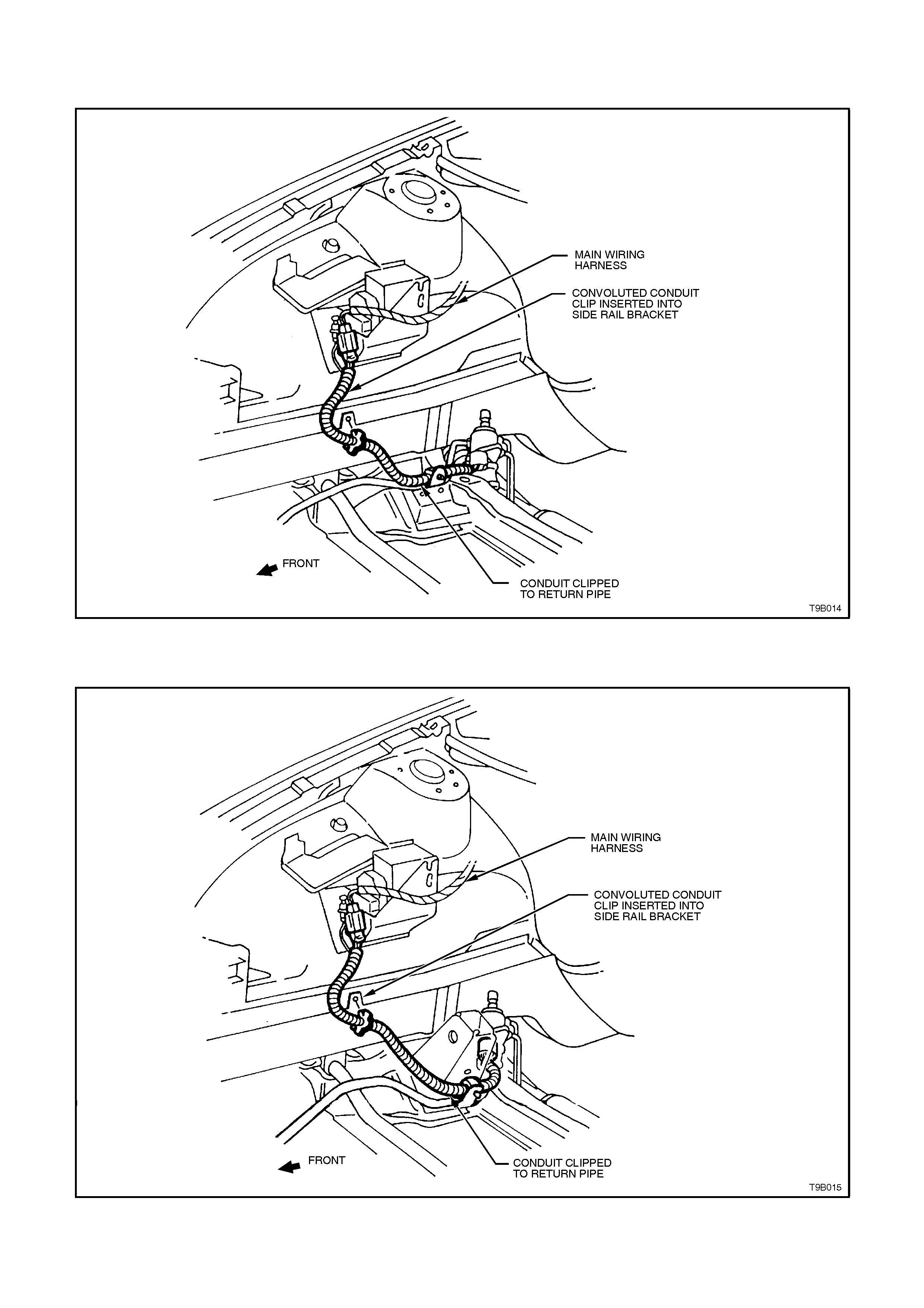
2.3 SOLENOID WIRING ROUTING
V6 ENGINE
Figure 9B-18 - V6 Engine
V8 ENGINE
Figure 9B-19 - V8 Engine

3. DIAGNOSIS
Diagnosis of the Speed Sensitive Power Steering System relies on a series of different tests to determine the
component/s causing the problem.
For example, pressure testing is required to isolate power steering pump from steering rack malfunctions, while
electrical testing of the solenoid and its circuit is needed to establish correct functioning of this component.
3.1 GENERAL DIAGNOSTIC INFORMATION
Faulty steering can be caused by problems in areas other than the pump or steering gear. Areas of the steering
system which can be easily checked and quickly corrected without disassembly and overhaul of any major
components should be attempted first.
Problem s such as hard or loose steering, road shoc k or vibrations ar e not always due to the steer ing gear or pum p,
but are often related to such factors as low tyre pressure or front end alignment. These items should be checked
and corrected before any adjustment or disassembly of the steering gear or pump is attempted.
Other factors which may affect correct operation of the steering system, are:
1. Loose component mountings.
2. Drive belt tension.
3. Fluid level and condition.
These factors must be checked and corrected before making any further diagnosis of the steering system.
After the source of the problem has been located, the cause of the problem can be diagnosed and corrected.
For exam ple, if the fluid level in the reservoir is found to be low, refill and c heck the entire hydraulic s ystem for fluid
leaks. Refilling the reservoir will not necessarily correct the problem.
Techline
Techline
3.2 SPEED SENSITIVE POWER STEERING DIAGNOSIS
For power steering pump noise and/or leaks, refer
to 4. DIAGNOSIS, in Section 9A STEERING.
STAGE 1. PRESSURE CHECKS
1. Check high pressure s ide of hydraulic s ystem ,
as detailed in 3.4 HYDRAULIC SYSTEM -
CHECK in Section 9A STEERING.
NOTE:
Constant Flow pump pressure specifications are
the same as Droop Flow pumps. Therefore, refer
to Section 9A STEERING for these details.
Results:
This pressure test is designed to assist in the
diagnosis of a pressure related hydraulic problem,
either in the power steering pump or steering rack
assembly. It will not assist in the diagnosis of
vehicle speed related problems within the steering
system.
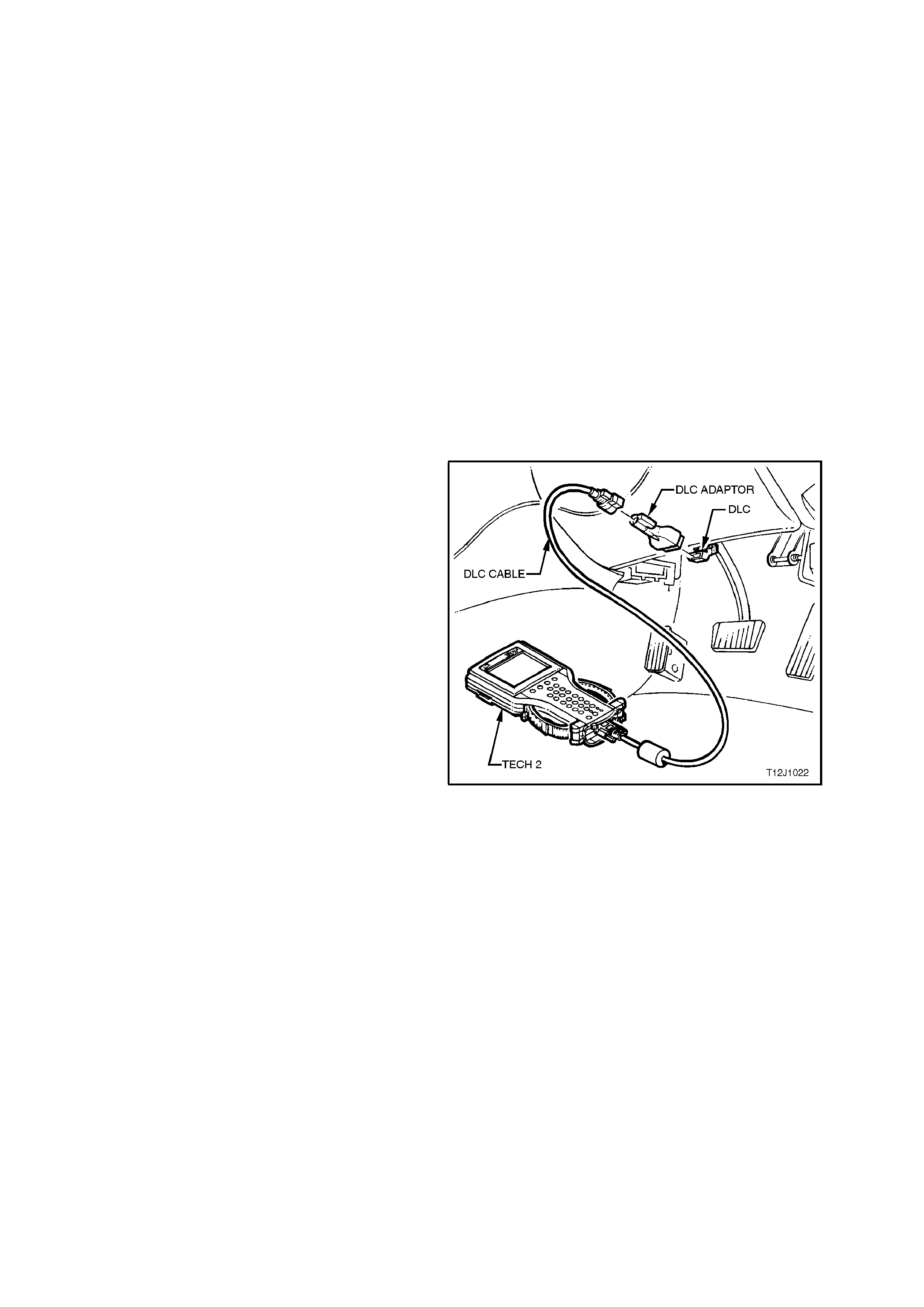
STAGE 2. ELECTRICAL CHECKS
Because of the risk of damage to electronic
components and the possibility that a BCM reset
condition may occur, the method recommended to
check the electrical components of the speed
sensitive power steering system is to use the TECH
2 Diagnostic Tool.
When connected to the Data Link Connector (DLC)
with the appropriate software, c ables and adaptors,
TECH 2, is capable of reading serial data relative to
the speed sensitive power steering solenoid.
The DLC is connected to the instrument panel
lower right hand trim, to the right of the steering
column.
For additional general information on connecting
and operating TECH 2, refer to
Section 0C, TECH 2.
Figure 9B-20

4. SPECIFICATIONS
STEERING GEAR
Steering Gear Type
Speed Sensitive Power Steering Rack and Pinion with integral power
cylinder and rotary control valve
mechanism - variable ratio with variable assist.
Steering Gear Ratio
On-Centre 17.2:1
Toward Lock 11.8:1
No. of Steering Wheel Turns Lock to Lock 3.0
Nominal Rack Travel Total 164 mm
POWER STEERING PUMP
Make Saginaw
Type V6 'N' Series: Constant Flow Type
V8 'P' Series: Constant Flow Type
Pressure Relief (at engine idle speed)
V6 7,580 - 8,270 kPa
V8 8,270 - 8,960 kPa
Drive Pulley
Lubrication (Power Steering) DEXRONÒ III Automatic Transmission Fluid.
Fluid Capacity Approximately 650 ml
Note: Use fluid level indicator as a final check
to ensure correct refill quantity.
Drive Belt Tension
V6 Belt Self Adjusting
V8 -New Belt 57 kg
Used Belt 34 kg (A belt is considered "used" after
10 minutes of operation).
GENERAL SPECIFICATIONS
Front Toe Specification (All VT Models)
Toe-in Total 0° 10' ± 0° 10'
Toe-in (per Wheel) 0° 5' ± 0° 5'
Specified Grease EP Semi Fluid Lithium Base O-Grease
Specified Thread Locking Compound Loctite 242 or equivalent to Holden
Specification HN 1256 Class 2, Type 2

5. TORQUE WRENCH SPECIFI CATIONS
NOTE:
Only those torque wrench specifications relating to service operations described in this Section, are included here.
For the remainder of torque specifications applicable to power steering components, refer to
6. TORQUE WRENCH SPECIFICATIONS, in Section 9A, STEERING.
POWER STEERING GEAR Nm
Solenoid 35 - 40
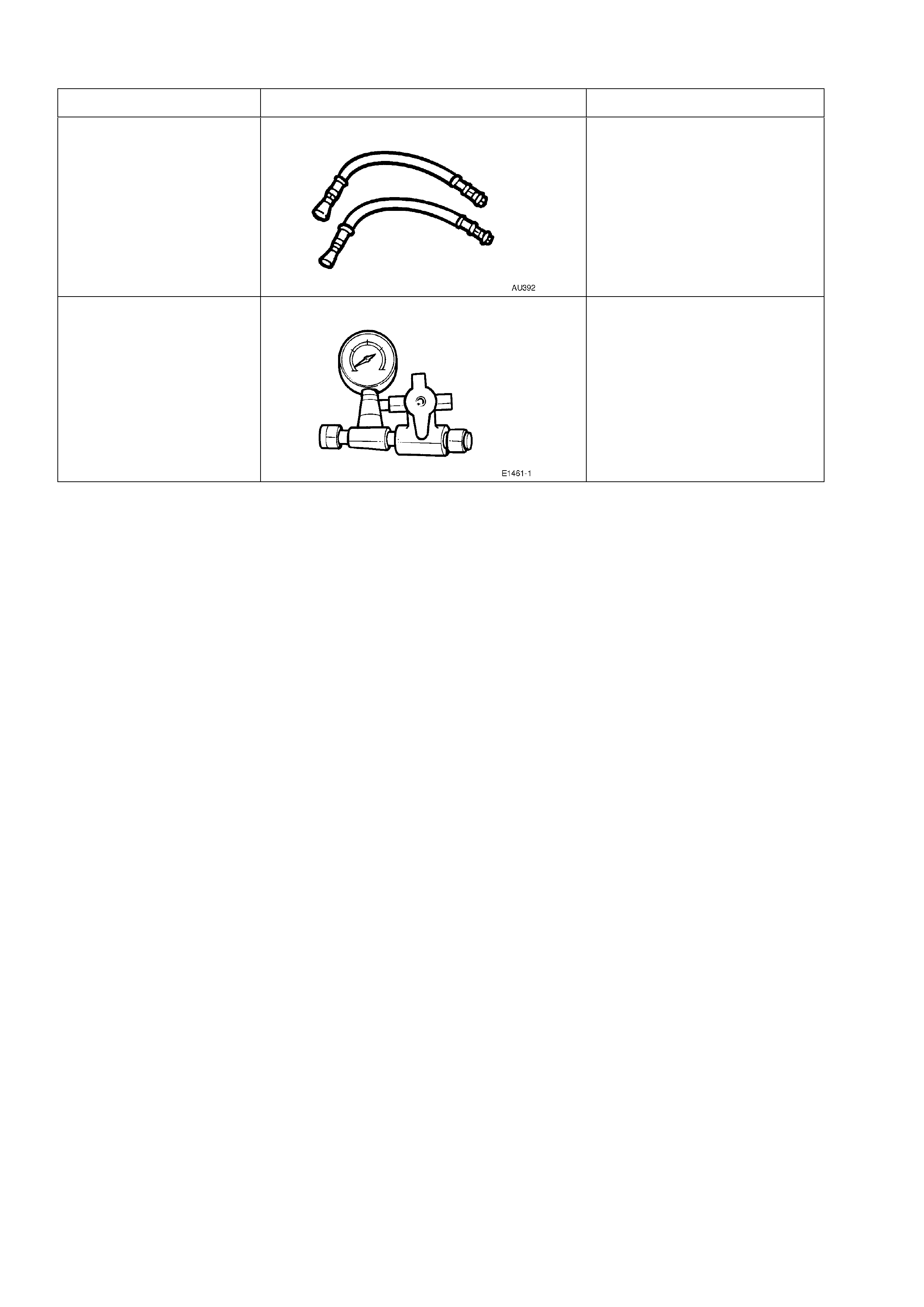
6. SPECIAL TOOLS
TOOL NO. REF IN TEXT TOOL DESCRIPTION COMMENTS
AU392 PRESSURE HOSE SET PREVIOUSLY RELEASED.
COMPRISES:
AU392-1, HOSE WITH MALE
END FITTING.
AU392-2, HOSE WITH
FEMALE END FITTING.
E1461-1 PRESSURE GAUGE ASSEMBLY PREVIOUSLY RELEASED AS
J22912-01