
SECTION 2C - AIR CONDITIONING -
SERVICING AND DIAGNOSIS
CAUTION:
This vehicle will be equipped with a Supplemental Restraint System (SRS). A SRS will consist of either
seat belt pre-tensioners and a driver's air bag, seat belt pre-tensioners and a driver's and front
passenger's air bag s or seat belt pre- tensio ners, d riv er’s and fron t p asseng er’s air bag and lef t and rig ht
hand side air bags. Refer to SAFETY PRECAUTIONS, Section 12M Supplemental Restraint System of
this Service Information CD before performing any service operation on, or around any SRS
components, the steering mechanism or wiring. Failure to follow the SAFETY PRECAUTIONS could
result in SRS deployment, resulting in possible personal injury or unnecessary SRS system repairs.
CAUTION:
This vehicle may be equipped with LPG (Liquefied Petroleum Gas). In the interests of safety, the LPG
fuel system should be isolated by turning 'OFF' the manual service valve and then draining the LPG
service lines, before any service work is carried out on the vehicle. Refer to the LPG leaflet included with
the Owner's Handbook for details or the appropriate Sections of this Service Information CD for more
specific servicing information.
1. GENERAL INFORMATION
With the introduction of the GEN III V8 engine, and in particular the acc ompanying Harrison V7 Com pres s or, c omes
some minor changes to how the air conditioning system should be diagnosed.
For this reason, the diagnosis procedures of the previously published Section 2C AIR CONDTIONING –
SERVICING AND DIAGNOSIS for VT Series I has been updated and republished in full in this Section. As such,
these diagnosis procedures supersede those previously published, and can be used on all VT Series Models.
For all Servicing procedures, including; safety precautions, discharging, evacuation and charging the air
conditioning system, refer to Section 2C AIR CONDITIONING - SERVICING AND DIAGNOSIS of this Service
Information CD.
Techline
Techline
Techline
Techline
Techline
Techline

2. DIAGNOSIS
2.1 PREREQUISITES AND PRELIMINARY CHECKS FOR DIAGNOSIS AND
TROUBLESHOOTING
The following list are the prerequisites and prelim inar y checks that s hould be perf orm ed bef ore proc eeding with any
system diagnosis.
1. Perform a visual inspection of all interior and under-hood components. Many problems can be detected by a
thorough inspection of system components without having to perform any system diagnosis. Repair system as
necessary.
2. If the vehicle is equipped with ECC, ensure this system is functioning correctly, refer to Section 2D AIR
CONDITIONING - ECC - DESCRIPTION AND OPERATION of this Service Information CD.
3. Ensure air conditioning fuses are okay.
4. Ensure the blower fan is operating correctly.
5. Ensure the temperature controls / door is moving freely from hot to cold.
6. Ensure the condenser air flow is not restricted by foreign matter.
7. Ensure the clutch coil and pressure switch connections are okay.
8. Engine cooling fans are operating correctly. (At idle, the cooling fans must be on at any A/C mode and cooling
fans must be operating in the correct direction; drawing ambient air through the condenser toward engine).
9. If the air conditioning system is noisy, particularly from or around the compressor, check for (and repair as
necessary):
• Damaged or slipping compressor drive belt.
• Idler pulleys for bearing roughness or damage.
• Drive belt tensioner.
• Loose compressor mounting bolts.
• Ensure air conditioning pipes do not contact the vehicle body work.
Techline
Techline
Techline

2.2 GENERAL AND SPECIFIC SYSTEM CONDITION CHARTS
The charts and graphs in this Section were developed in a climatic controllable wind tunnel by producing known
system problems and recording pressures at various am bient temperatures. Results were then validated using the
same vehicle set up in a service environment.
The air conditioning diagnosis chart is the starting point for verifying and diagnosing all air conditioning and HVAC
control related complaints. The chart represents the correct path to follow from a customer complaint or condition
through delivery of the vehicle back to the customer.
In general, there are some variances in the readings between systems of different vehicles; however the target
areas have been developed to accommodate these changes.
2.3 AIR CONDITIONING DIAGNOSIS CHART
STEP ACTION VALUE YES NO
1. • Ensure all the preliminary checks been performed
as per 2.1 PREREQUISITES AND PRELIMINARY
CHECKS FOR DIAGNOSIS AND
TROUBLESHOOTING in this Secti on.
• Have all the checks and prerequisites been
preformed and met?
Go to Step 2 Perform checks
and ensure
prerequisites are
met as per 2.1
prerequisites and
preliminary checks
for diagnosis and
troubleshooting in
this Section.
2. • Check performance of the air conditioning system
as per 2.4 PERFORMANCE TEST in this Section.
• Is the air conditioning system operating as
specified in this test ?
System OK Go to Step 3.
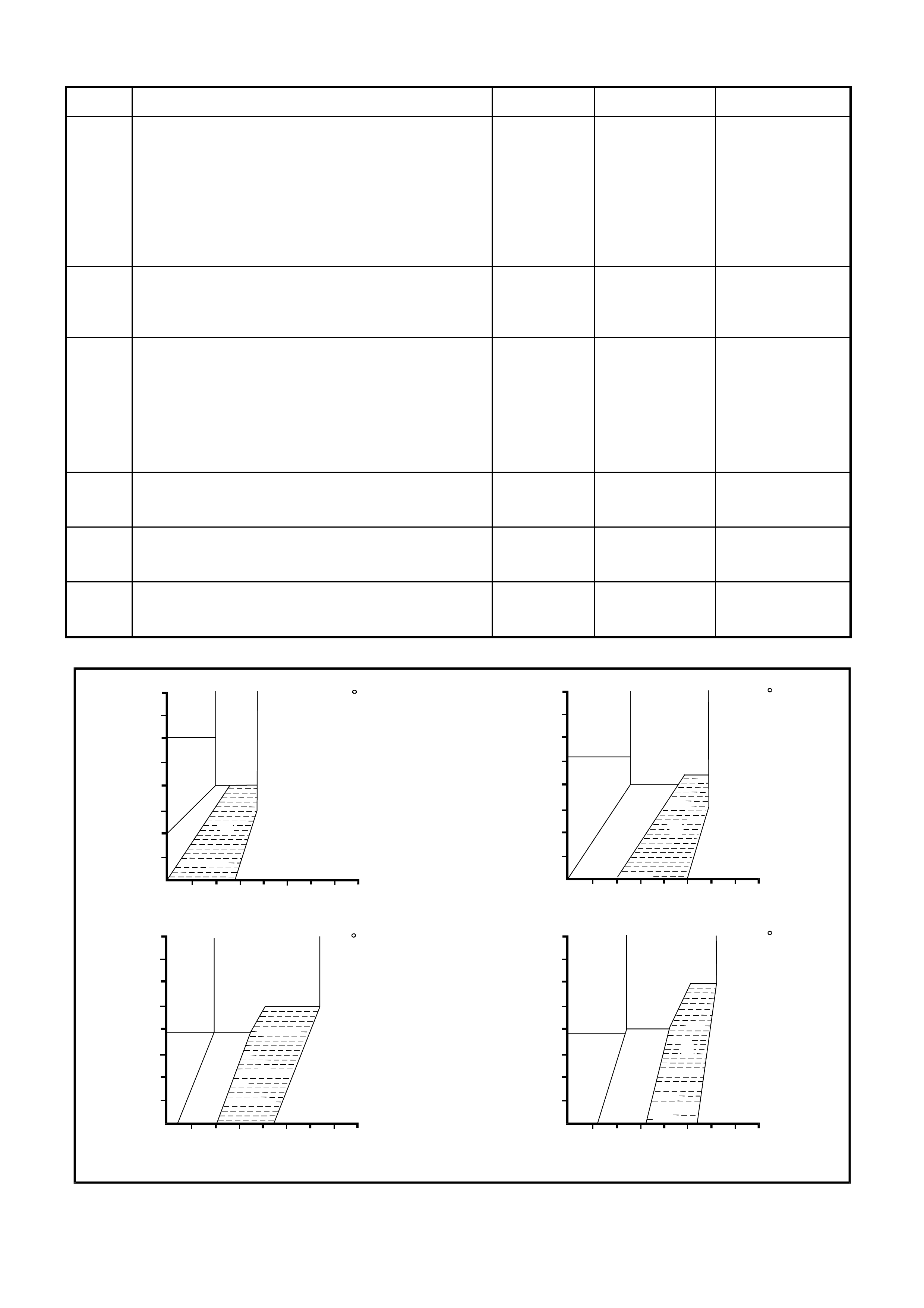
3. • Compare the gauge readings and ambient
temperature recorded in the performance test with
the following diagnostic chart graphs, refer Fig. 2C-
1. Read the high and low pressures and note
where they intersect in the graph.
• Do pressure readings intersect within area A of the
diagnostic chart graph (refer Fig. 2C-1) for the
relevant ambient temperature?
System OK Go to Step 4.
4. • Do pressure readings intersect areas B or D of the
diagnostic chart graph (refer Fig. 2C-1) for the
relevant ambient temperature?
Refer to Repair
Procedure 1 in
this Section
Go to Step 5.
5. • Do pressure readings intersect area C of the
diagnostic chart graph (refer Fig. 2C-1) for the
relevant ambient temperature?
Refer to Repair
Procedure 2 in
this Section
Go to Step 6.
6. • Do pressure readings intersect area E of the
diagnostic chart graph (refer Fig. 2C-1) for the
relevant ambient temperature?
Refer to Repair
Procedure 3 in
this Section
Refer to Repair
Procedure 4 in this
Section
D
F
B
E
C
A
21 C
560
490
420
350
280
210
140
1400 2100 2800
700
70
HI GH SIDE P RESSURE
LOW SIDE PRESSURE
(kpa)
(kpa)
D
F
B
E
C
A
26.5 C
560
490
420
350
280
210
140
1400 2100 2800700
70
HI GH SIDE PRESSURE
LOW SIDE PRESSURE
(kpa)
(kpa)
D
F
B
E
C
A
32 C
560
490
420
350
280
210
140
1400 2100 2800
700
70
HI GH SIDE P RESSURE
LOW SIDE PRESSURE
(kpa)
(kpa)
D
F
B
E
C
A
37.5 C
560
490
420
350
280
210
140
1400 2100 2800700
70
HI GH SIDE PRESSURE
LOW SIDE PRESSURE
(kpa)
(kpa)
T22C001
Figure 2C-1 Diagnostic Chart Graphs

REPAIR PROCEDURE 1 (Areas B and D pressure reading in Fig.2C-1)
CONDITION / COMPLAINT POSSIBLE CAUSE ACTION
Discharge Air:- Slightly cool to
warm.
Thermal expansion valve
sweating or has a frost build up
on it.
Low Side Gauge Reading:- Low
(or vacuum)
High Side Gauge Reading :-
Low
Thermal expansion valve remains closed
or blocked.
Thermal expansion valve jammed closed
causing insufficient refrigerant flow to the
suction side of the compressor. This is
normally related to the thermal expansion
valve sensing bulb malfunction or from
being disconnected from the tube, foreign
material in thermal expansion valve or
moisture entry causing rust formations.
Confirm by thorough physical inspection of
all tubes, hoses and components. In
normal operation, the evaporator inlet
temperature is hot. If the inlet pipe is cool,
check for high side restriction. If the inlet
pipe is room temperature, confirm thermal
expansion valve is blocked by running
engine at 2000 RPM - neither high or low
pressure should change by more than 140
kPa.
If the thermal expansion valve proves to be
blocked, replace thermal expansion valve.
Verify repair by repeating the performance
test as detailed in 2.4 AIR CONDITIONING
PERFORMANCE TEST in this Section.
Discharge Air:- Slightly cool to
warm.
High pressure side tubes are
cool and showing signs of
sweating or moisture build up at
a point after a restriction
Low Side Gauge Reading:- Low
High Side Gauge Reading :-
Low
Restriction in high side of system or faulty
compressor control valve.
Foreign material causing blockage
between the compressor outlet and
evaporator inlet (high side).
Very little or no refrigerant flow to suction
(low) side of compressor.
Test compressor control valve by running
engine at 1500 rpm for 10 minutes with air
conditioning controls set to; maximum/full
cold with lowest blower fan speed. Close
doors and windows, open engine hood.
If the low side gauge reads less than
200kPa, replace the compressor control
valve.
If the compressor control valve is okay,
check system for blockages and repair as
necessary.
Verify repair by repeating the performance
test as detailed in 2.4 AIR CONDITIONING
PERFORMANCE TEST in this Section.
Discharge Air:- Slightly cool to
warm.
Low Side Gauge Reading:- Low
High Side Gauge Reading :-
Low
Refrigerant undercharged.
Refrigerant leak from system. Evacuate and leak test the air conditioning
system, refer 2.1 SYSTEM CHARGING
AND EVACUATION in Section 2C AIR
CONDITIONING - SERVICING AND
DIAGNOSIS of this Service Information
CD.
Verify repair by repeating the performance
test as detailed in 2.4 AIR CONDITIONING
PERFORMANCE TEST in this Section.

REPAIR PROCEDURE 2 (Area C pressure reading in Fig.2C-1)
CONDITION / COMPLAINT POSSIBLE CAUSE ACTION
Discharge Air:- Slightly cool to
warm.
Compressor clutch may
continually cycle on the high
pressure switch. Compressor
may also be noisy when
operating.
Low Side Gauge Reading:- Low
to normal
High Side Gauge Reading :-
high to very high
Refrigerant overcharged, restricted filter
drier receiver, blocked or obstructed
condenser fins (air flow), cooling system
overheating, faulty cooling fan operation,
or drive belt slippage.
Referring to the appropriate Sections of
this Service Information CD, check, and
repair as necessary, the following:
• Ensure cooling fans are operating
correctly.
• Check cooling system operation.
• Physically check for blocked or
restricted condenser fins, clean or
remove obstruction.
• Check compressor drive belt for
damage, slippage or incorrect
operation.
• Touch the filter drier receiver inlet and
outlet pipes; if there is a temperature
difference between these two pipes,
replace the filter drier receiver.
If all the above are okay, recharge the air
conditioning system with refrigerant, refer
to 2.1 SYSTEM CHARGING AND
EVACUATION in Section 2C AIR
CONDITIONING - SERVICING AND
DIAGNOSIS of this Service Information
CD.
Verify repair by repeating the performance
test as detailed in 2.4 AIR CONDITIONING
PERFORMANCE TEST in this Section.
REPAIR PROCEDURE 3 (Area E pressure reading in Fig.2C-1)
CONDITION / COMPLAINT POSSIBLE CAUSE ACTION
Discharge Air:- May perform
normally, but on an extended
journey the air temperature may
go warm temporarily and then
correct itself after vehicle shut
down.
Compressor may produce a
‘slugging’ noise.
Low Side Gauge Reading:-
High.
High Side Gauge Reading :-
normal to high.
Thermal expansion valve stuck open To check the thermal expansion valve;
• Run blower fan on high.
• Air conditioning on.
• Fast idle engine for 2 minutes, then
turn engine off for 3 minutes.
• Restart engine and turn air conditioner
off and let RPM stabilise.
• Turn blower fan to low speed, turn air
conditioner on.
• With engine hood closed, listen for a
‘slugging’ sound.
If a ‘slugging’ noise can be heard, replace
thermal expansion valve.
If thermal expansion valve is okay, check
for a faulty compressor control valve, refer
Repair Procedure 1 in this Section.
Verify repair by repeating the performance
test as detailed in 2.4 AIR CONDITIONING
PERFORMANCE TEST in this Section.

REPAIR PROCEDURE 4 (Area F pressure reading in Fig.2C-1)
CONDITION / COMPLAINT POSSIBLE CAUSE ACTION
Discharge Air:- warm; outlet
temperature will be the same
as ambient air temperature.
Low Side Gauge Reading:-
High.
High Side Gauge Reading :-
Low.
Compressor faulty or possible
blockage in the suction. Test compressor as per the following
compressor diagnostic chart.
Verify repair by repeating the
performance test as detailed in 2.4 AIR
CONDITIONING PERFORMANCE
TEST in this Section.
Compressor Diagnostic Chart
STEP ACTION VALUE YES NO
1. • With refrigerant recovery unit manifold pressure
gauges connected to the high and low service
valves, start the engine and run engine at 3000 rpm.
• Set the air conditioner controls to; blower speed
high, temperature setting on maximum cold and
fresh (outside) air mode.
• Close the vehicles windows and doors.
• Run vehicle under these conditions for 5 minutes.
• Are the high and low pressure gauge readings
within 210kPa of each other.
Go to Step 2. Go to Step 5.
2• Turn engine off.
• With compressor disengaged, turn the compressor
clutch front plate (not the drive belt pulley) by hand.
• Does the compressor clutch front plate turn freely?
Go to Step 5. Go to Step 3.
3• Replace compressor and recharge air conditioning
system.
• Repeat performance test as detailed in this Section
to verify repair.
• Has fault been rectified ?
System OK. Go to Step 4.
4• Leak test air conditioning system, refer 2.1 SYSTEM
CHARGING AND EVACUATION in Section 2C AIR
CONDITIONING - SERVICING AND DIAGNOSIS, in
VT Series I Service Information.
• Was a leak found?
Repair leak as
necessary. Verify
repair by
repeating the
performance test
as detailed in this
Section.
Go to Step 5.
5• With refrigerant recovery unit manifold pressure
gauges connected to the high and low service
valves, start the engine and run engine at 1500 rpm.
• Set the air conditioner controls to; blower speed low,
temperature setting on maximum cold and
recirculated air mode.
• Close the vehicles windows and doors.
• Run vehicle under these conditions for 5 minutes.
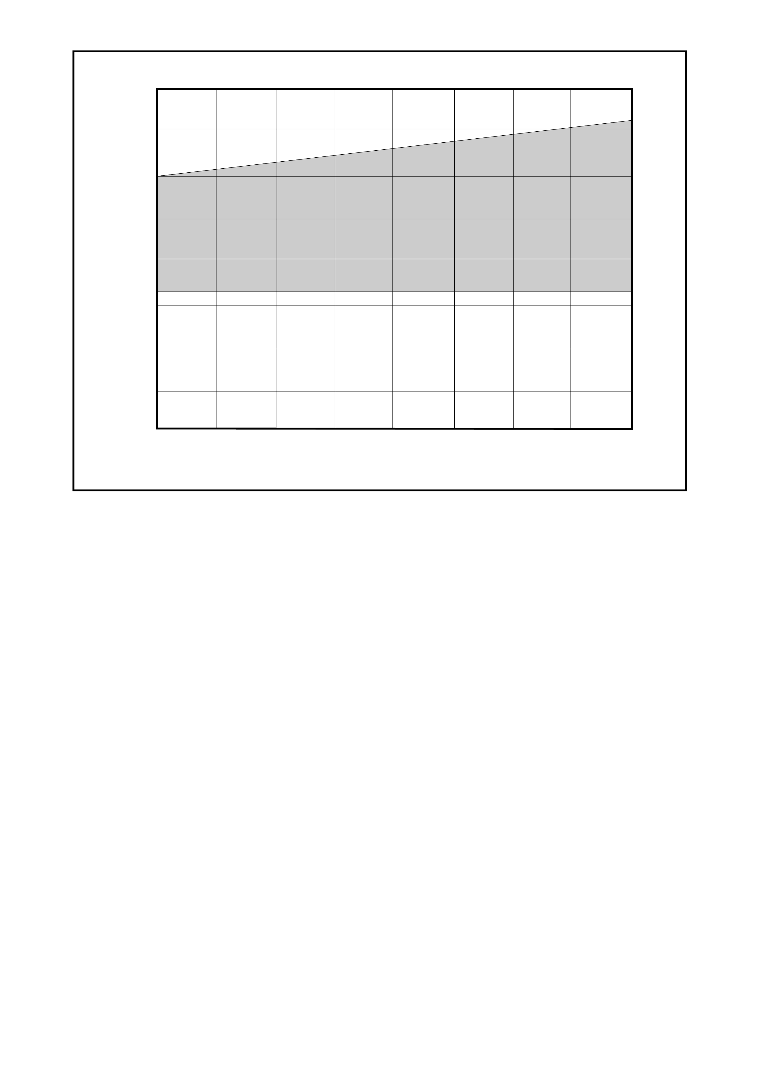
• Do the high and low pressure gauge readings
intersect within the shaded area of the following
compressor control valve test specification graph,
refer Fig. 2C-2 ?
System OK. Replace
compressor
control valve.
Verify repair by
repeating the
performance test
as detailed in
2.4 AIR
CONDITIONING
PERFORMANCE
TEST in this
Section.
500 1000 1500 2000 2500
0
50
100
150
200
250
300
350
400
HIGH PRESSURE SIDE (kPa)
LO W PR ESSURE SIDE (kPa)
T22C002
Figure 2C-2 Harrison V5 and V7 compressor control valve test specification
2.4 AIR CONDITIONING PERFORMANCE TEST
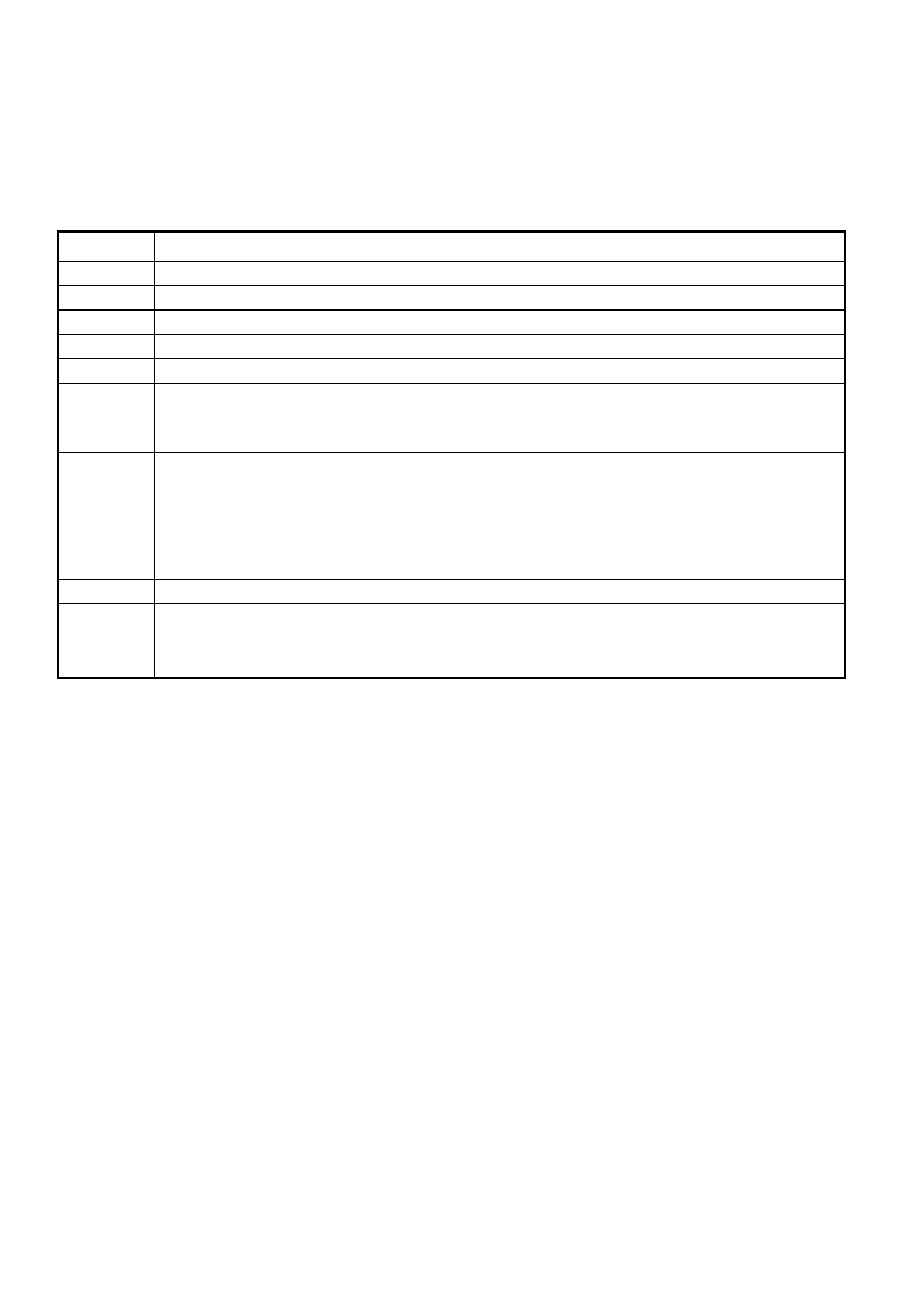
NOTE: The f ollowing perfor m ance test is designed to put the air c onditioning system under an increased load. If an
air conditioning system can perform to the manufacturers specifications under these loads, in normal driving
situations, engine hood down, windows clos ed and possibly a lower blower speed, the centre vent tem peratures will
be lower.
If the air conditioning system performs outside the specified range, as detailed in Fig. 2C-3 and 2C-4, refer to 2.3
AIR CONDITIONING DIAGNOSIS CHART in this Section.
STEP No. ACTION
1Park vehicle in a shaded area.
2Measure and record the ambient temperature.
3Open both front windows and engine hood.
4Connect both high and low pressure service hose coupling valves to the system filling ports.
5Open all dash louvres and adjust to the straight ahead position.
6Insert thermometer probe approximately 50mm into the centre vent louvre.
NOTE: If the vehicle has an ECC dual zone system, ensure both sides of the centre vent are
checked to ensure temperature performance is correct.
7Set air conditioning controls to:
a. Fresh air position
b. Face vent mode
c. Maximum cooling (ECC system select C maximum cooling)
d. A/C on
e. Highest blower speed
8Start engine and bring engine speed to 1700rpm. Allow pressure gauge needles to stabilise.
9Tak e pressur e and centre vent tem per ature readings. Com par e the recor ded values of the vehicle
against the performance charts in Figures 2C-3 and 2C-4.
NOTE: Only take pressure and temperature readings when the compressor is engaged.
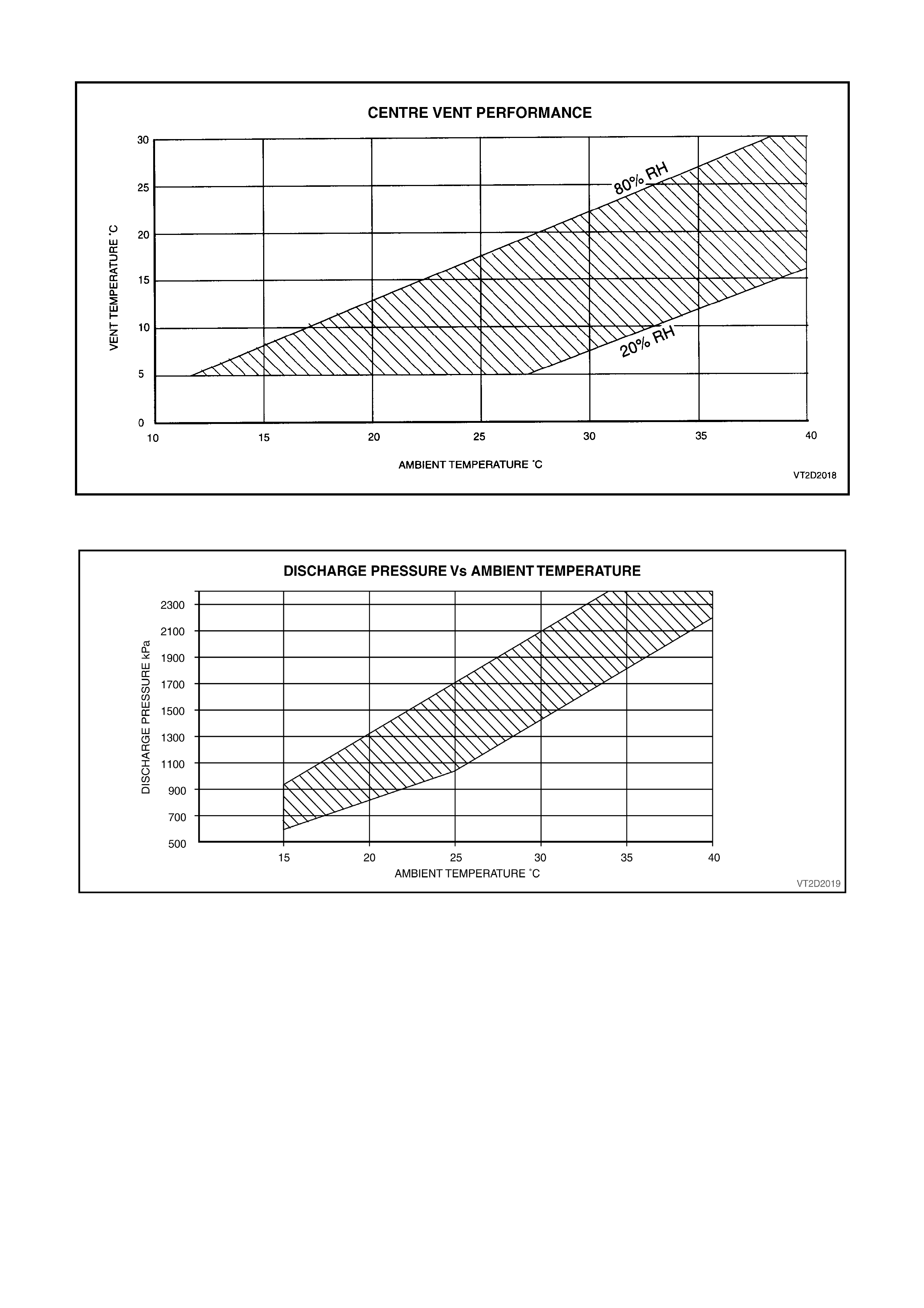
Figure 2C-3 Performance Chart A
Figure 2C-4 Performance Chart B