
SECTION 2D - ELECTRONIC CLIMATE CONTROL
(ECC) – DESCRIPTION AND OPERATION
CAUTION:
This vehicle will be equipped with a Supplemental Restraint System (SRS). A SRS will consist of either
seat belt pre-tensioners and a driver’s side air bag, or seat belt pre-tensioners and a driver’s and front
passenger’s side air bags. Refer to CAUTIONS, Section 12M, of this Service Information before
performing any service operation on or around SRS components, the steering mechanism or wiring.
Failure to follow the CAUTIONS could result in SRS deployment, resulting in possible personal injury or
unnecessary SRS system repairs.
CAUTION:
This vehicle may be equipped with LPG (Liquefied Petroleum Gas). In the interests of safety, the LPG fuel
system should be isolated by turning 'OFF' the manual service valve and then draining the LPG service
lines, before any service work is carried out on the vehicle. Refer to the LPG leaflet included with the
Owner's Handbook for details or the appropriate Section of this Service Information for more specific
servicing information.
1. GENERAL DESCRIPTI ON – ECC
A running change was m ade to the ECC system during VT Series II Model production. The vacuum solenoid pack
fitted to the HVAC unit was changed from a five solenoid pack to a six solenoid pack. The additional solenoid is
used to activate the heater water valve. Prior to this change, a plunger and vacuum switch assembly (1.9 Vacuum
Switch in Section 2D of the VT Series I Service Information), located on the air mix motor mounting plate, was used
to activate the water valve. The vacuum switch assembly was deleted as part of this modification.
Modifications have also been made to the vacuum harness and wiring harness to accommodate the additional
vacuum solenoid. These components are not interchangeable with those of the previous design. The ECC control
module remains unaltered and is therefore interchangeable with earlier type control modules.
ECC system modif ications ar e detailed in this Sec tion. They are applicable to models built f r om early October 1999,
Vehicle Identification Number L514226 – Single Zone and L513521 – Dual Zone.
For information regarding the description and operation of the heating and air conditioning system that is not
included in this Section, refer to Section 2A AIR CONDITIONING – DESCRIPTION AND OPERATION of the VT
Series I Service Information.
For inf orm ation regarding the des cription and oper ation of the ECC s ystem that is not inc luded in this Section, r efer
to Section 2D AIR CONDITIONING – ECC – DESCRIPTION AND OPERATION of the VT Series I Service
Information.
Techline
Techline
Techline
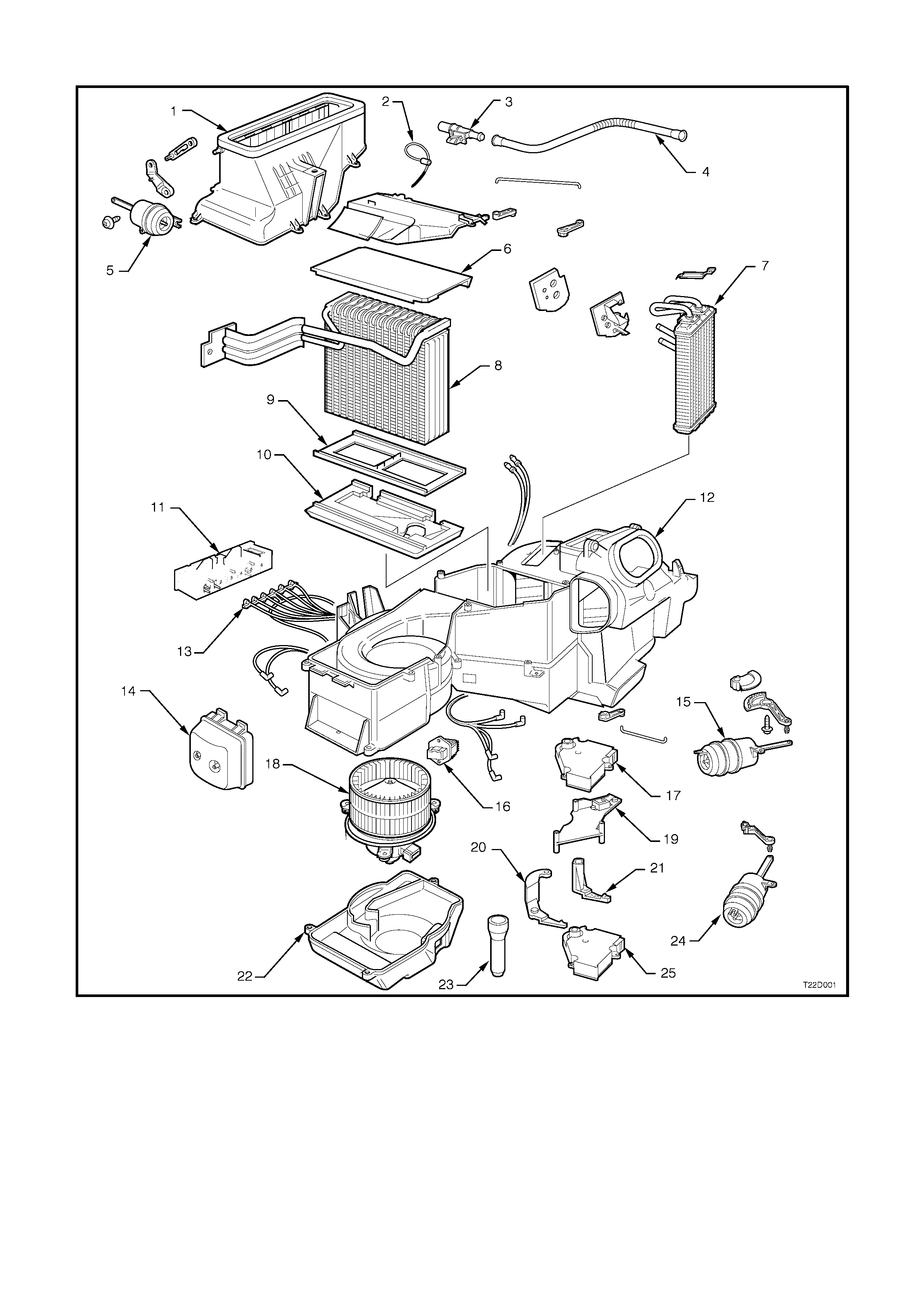
1.1 HVAC SYSTEM COMPONENTS
Figure 2D-1 HVAC components – single zone and dual zone
1. Fresh/recirculation housing 10. Lower insulator 19. Air mix motor mounting bracket
2. Evaporator air temperature sensor 11. Vacuum solenoid pack 20. Lever (dual zone)
3. Aspirator venturi 12. HVAC unit 21. Lever (single zone)
4. Aspirator tube 13. Vacuum tube harness 22. Blower motor cover
5. Fresh/recirculation mode vacuum actuator 14. Vacuum storage tank 23. Drain hose
6. Upper insulator 15. Demist/floor actuator 24. Bi-level/centre vent actuator
7. Heater core 16. Blower speed resistor
8. Evaporator coil 17. Upper air mix motor (dual zone) 25. Lower air mix motor (single and
dual zone)
9. Evaporator support 18. Blower motor
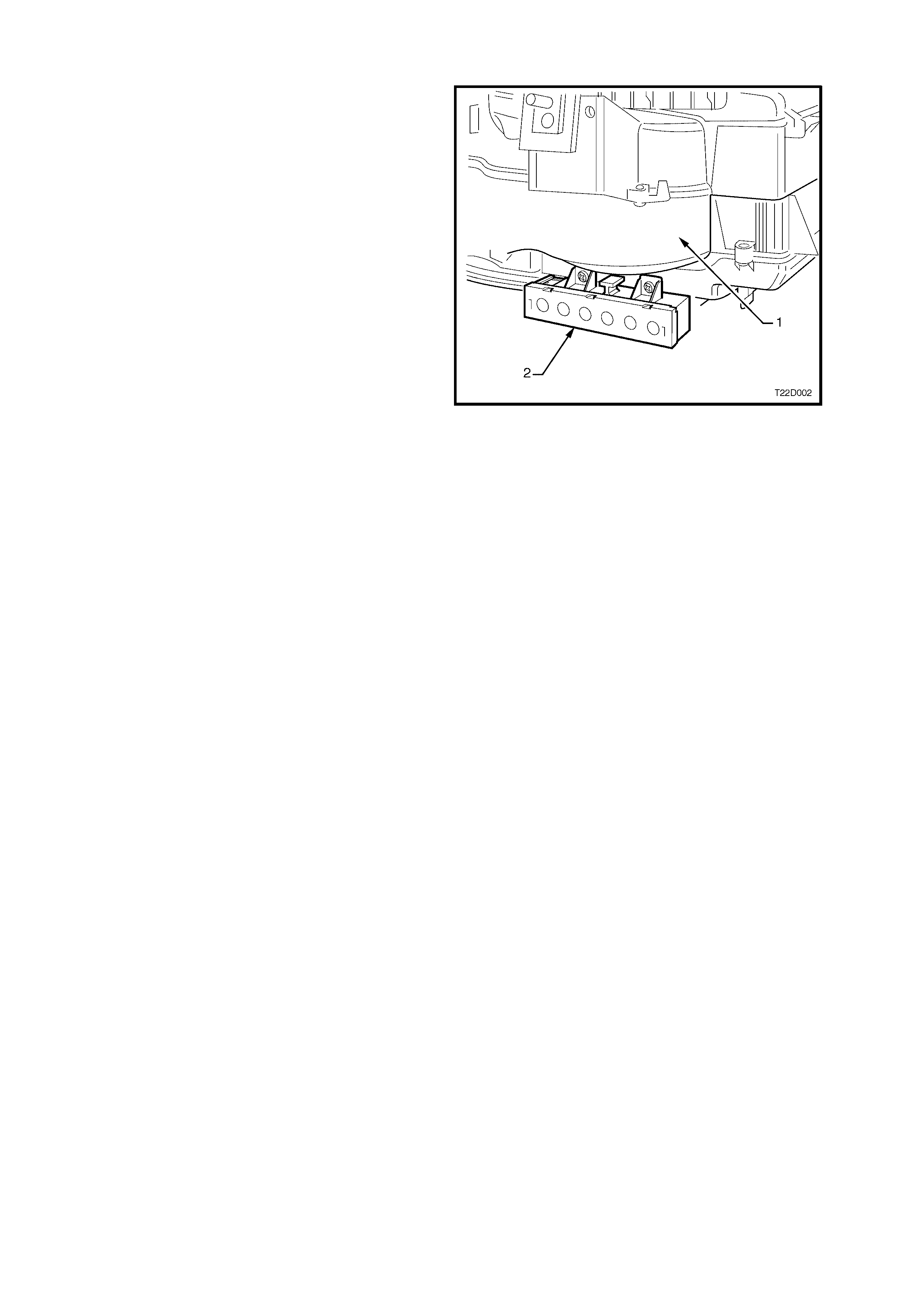
1.2 VACUUM SOLENOID PACK
Located on the lower rear of blower motor housing
(1), the vacuum solenoid pack (2) now consists of a
band of six electronically activated vacuum
solenoids. Five are used to apply or remove
vacuum to vacuum actuators to alter the air
distribution positions. The remaining solenoid is
used to actuate the water valve.
Power is supplied to these solenoids through the
ECC control module. When a mode switch is
selected on the ECC control module, current flows
through appropriate solenoids and allows vacuum
to flow to the actuators. Rem oving this current flow
de-energises the solenoids and allows any vacuum
contained in the actuator and line to vent through
the front section of the solenoid.
NOTE: The six solenoid pack and five solenoid
pack are not interchangeable.
VACUUM CIRCUIT
Vacuum provided by the engine is used to control
the ON/OFF functions of the vent modes and the
water valve.
The engine vacuum moves from the inlet manifold
to a vacuum tank located on the HVAC unit. This
vacuum tank is used to store vacuum when engine
vacuum is low such as at full engine throttle. A
check valve is fitted on the supply line from the
engine inlet manifold.
Vacuum generated within the inlet manifold is
applied to the vacuum solenoid pack through a
black plas tic vac uum tube. T he yellow vacuum tube
servicing the heater water valve actuator,
previously connected to the vacuum switch (deleted
component), is now connected directly to the
vacuum solenoid pack.
The operation of the water valve remains the sam e.
When vacuum is applied to the water valve
actuator, full closure occurs and no hot water can
flow through the heater core.
As the various ECC mode switches are selected,
the electronic solenoids are activated in the
solenoid pack causing vacuum to move to the
desired vacuum actuator through colour keyed
plastic tubing. Vacuum will activate the vacuum
actuator rod, which then moves a vent position door
or the water valve.
Fig. 2D-3 shows which vacuum actuators are
applied by vacuum in a certain mode.
Vacuum is vented f rom the vac uum actuator/plas tic
tube once the vacuum ECC m ode s witch is used to
select a different setting.
Figure 2D-2
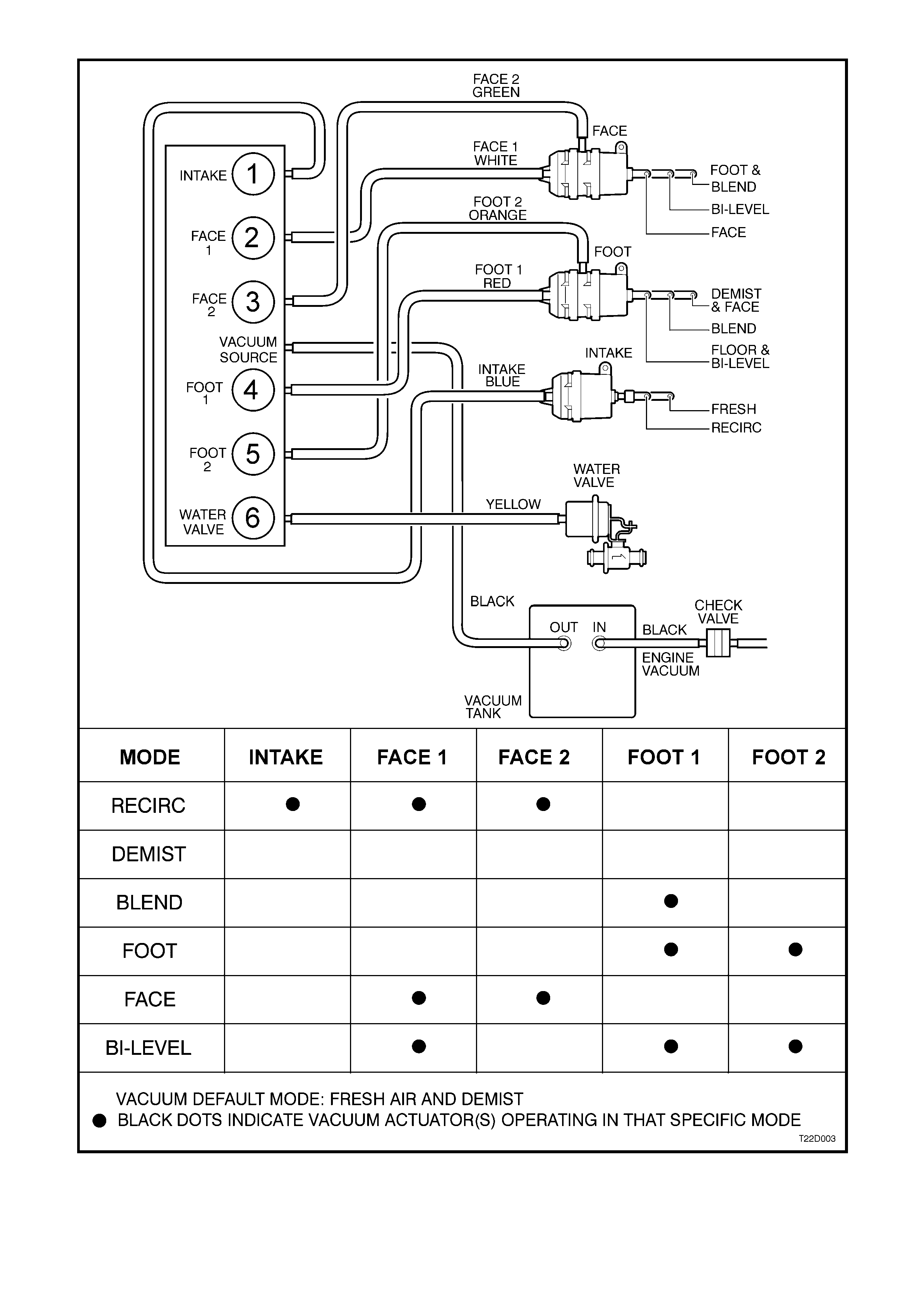
Figure 2D-3
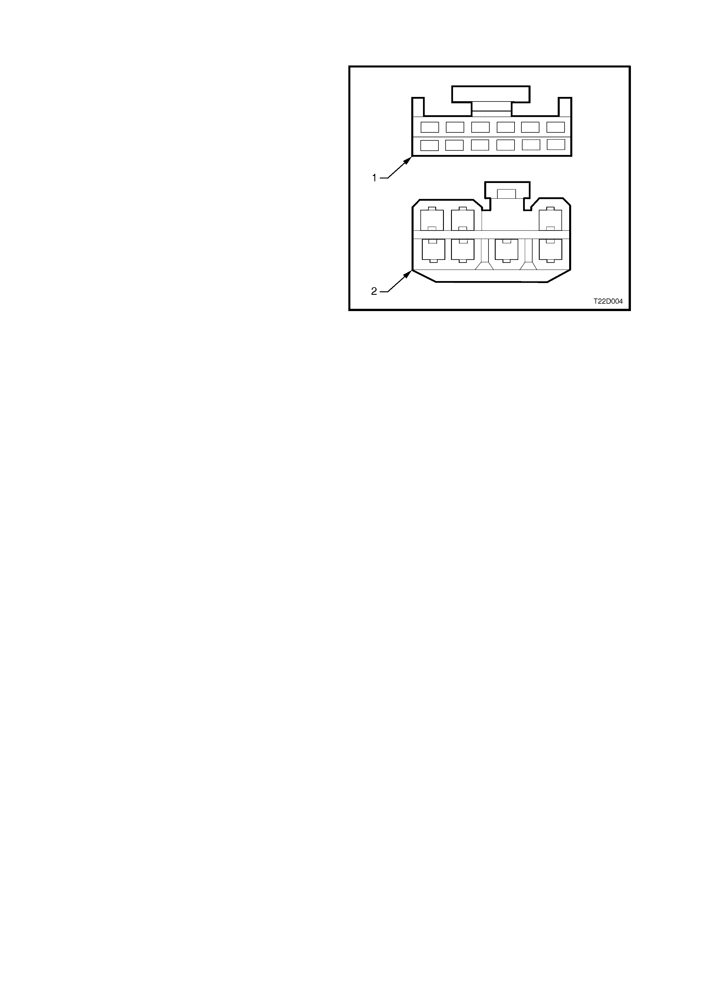
1.3 HVAC CONNECTOR AND HARNESS
A modified harness and connector is fitted to the
six solenoid type HVAC system.
Early models are fitted with a five solenoid type
solenoid pack (pre Vehicle Identification Number
L514226 – Single Zone and L513521 – Dual Zone)
and utilise a 6 pin, 12 cavity connector (1).
Models af ter the above break points are f itted with a
six solenoid type solenoid pack and utilise a 7 pin,
7 cavity connector (2). The additional violet
coloured wire connects the ECC control module
(YB89, Terminal 20) to the solenoid pack (YB93)
and is for water valve solenoid activation.
The connector designation for both early and late
type solenoid pack connectors is YB93.
For further information relating to ECC wiring refer
to Section 12P WIRING DIAGRAMS.
Figure 2D-4
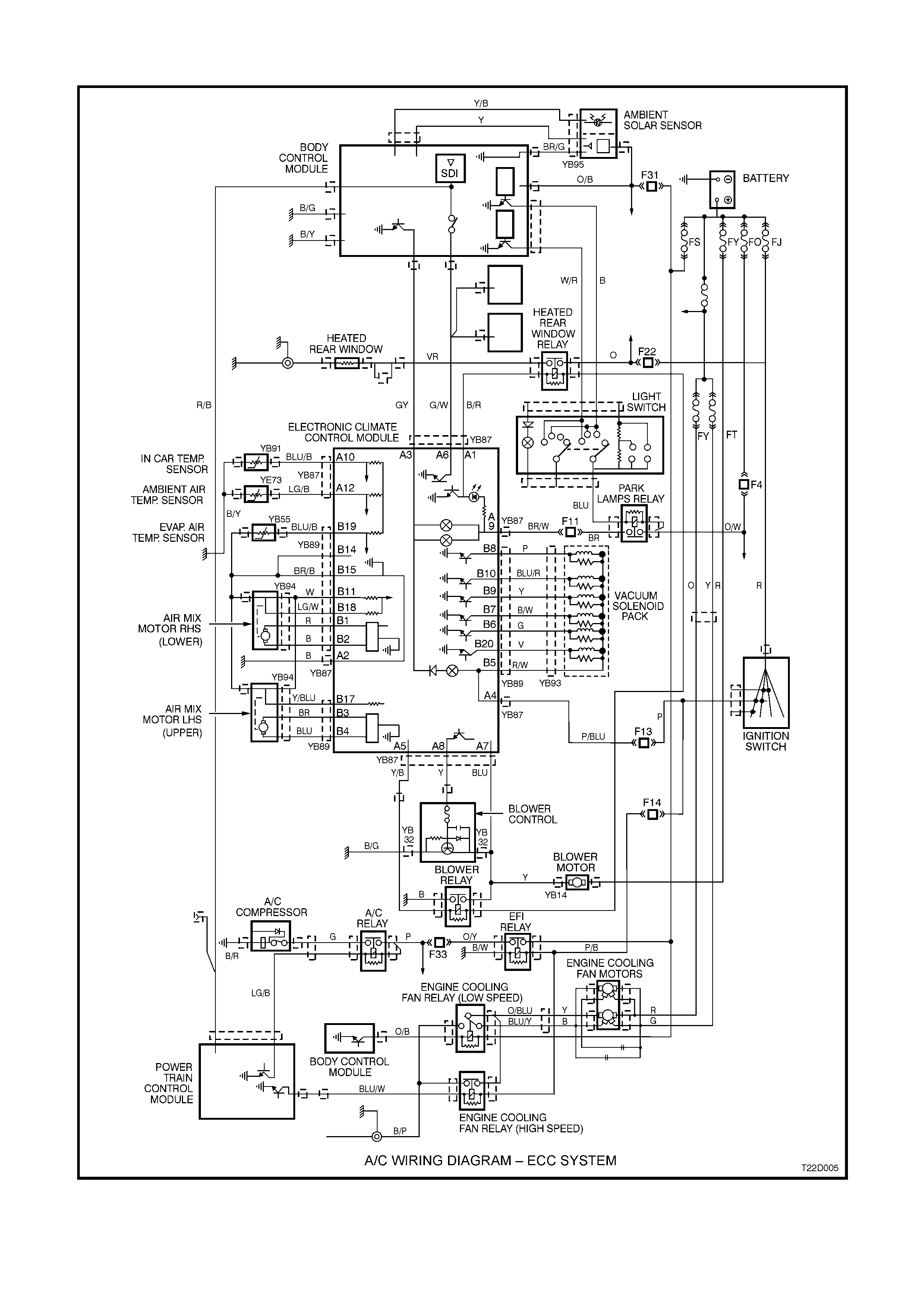
1.4 ECC WIRING DIAGRAM
Figure 2D-5