
SECTION 2E - ELECTRONIC CLIMATE CONTROL –
REMOVAL AND INSTALLATION
CAUTION:
This vehicle will be equipped with a Supplemental Restraint System (SRS). A SRS will consist of either
seat belt pre-tensioners and a driver's air bag, seat belt pre-tensioners and a driver's and front
passenger's air b ags o r seat b elt p re-t ension ers, driv er’s an d f ron t p asseng er’s air bag and left and righ t
hand side air bags. Refer to SAFETY PRECAUTIONS, Section 12M Supplemental Restraint System in this
Service Information before performing any service operation on, or around any SRS components, the
steering mechanism or wiring. Failure to follow the SAFETY PRECAUTIONS could result in SRS
deployment, resulting in possible personal injury or unnecessary SRS system repairs.
CAUTION:
This vehicle may be equipped with LPG (Liquefied Petroleum Gas). In the interests of safety, the LPG
fuel system should be isolated by turning 'OFF' the manual service valve and then draining the LPG
service lines, before any service work is carried out on the vehicle. Refer to the LPG leaflet included with
the Owner's Handbook for details or the appropriate Section of this Service Information for more
specific servicing information.
1. GENERAL INFORMATION
The removal and installation procedures for the Electronic Climate Control (ECC) for early VT Series II Models
remain unchanged from the information published in the VT Series I Service Information.
For VT Series II Models built from early October 1999, Vehicle Identification Number L514226 – Single Zone and
L513521 – Dual Zone, the following modifications are applicable:
• The vacuum solenoid pack fitted to the HVAC unit was changed from a five solenoid pack to a six solenoid pack.
The additional solenoid is used to activate the heater water valve.
• Modifications have been made to the vacuum harness and wiring harness to accommodate the additional
vacuum solenoid.
• The vacuum switch assembly has been deleted as part of this modification.
Due to a number of discrepancies shown in the ECC electrical connector terminal assignment chart in Volume 1,
this chart has been corr ected and republis hed in this Sec tion. This republished c hart super sedes the ECC electrical
connector c hart detailed in Section 2E ELECTRONIC CLIM ATE CONT ROL – REMOVAL AND INST ALLATION of
the VT Series I Service Information.
It should be noted that this char t is only intended as a guide for removal and ins tallation procedur es. Whenever any
diagnosis or repairs to the electrical connectors and wiring is required, reference to the ECC wiring diagrams,
connecter term inal assignm ents or diagnosis procedur es should be made. Ref er to the appropriate Sec tions in this
Service Information.
Techline
Techline
Techline
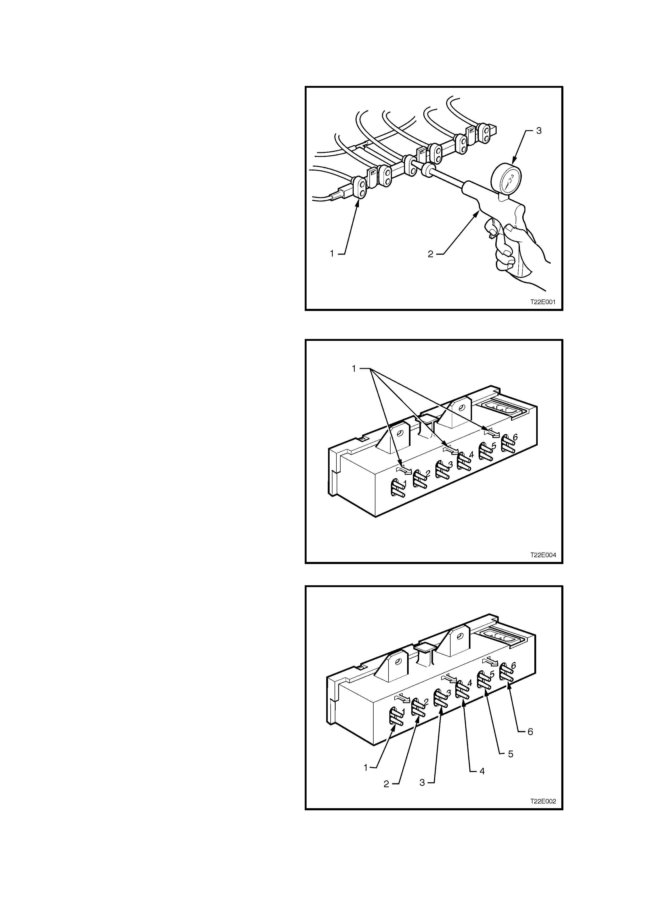
2 VACUUM LINE CHECK
REMOVE
1. Locate the vacuum solenoid pack (in the upper
left-hand side footwell) and disconnect the
plastic vacuum manifold (1).
2. Connect a Mityvac (2) or similar tool to the
appropriate port of the plastic vacuum
manifold.
3. Using the Mityvac, apply a vacuum to the
manidold port. Observe the Mityvac gauge (3)
to see if the needle rises to positive pressure
indicating a vacuum leak.
4. If a vacuum leak is indicated it could be either
the vacuum tubing or the vacuum actuator
(ensure that the vac uum tubing is not dislodged
from the vacuum actuator). Each of these
components will have to be vacuum leak
checked individually.
Figure 2E-1
REINSTALL
1. Install the plastic vacuum manifold to the
vacuum solenoid pack ensuring that the
manifold is fitted securely to the manifold
retaining tangs (1) and that the vacuum tubing
is not kinked.
Figure 2E-2
2. Ensure that the vacuum tubing is connected to
the correct ports of the solenoid pack. Figure
2E-3 shows the solenoid outlets from the
vacuum solenoid pack.
(1) Fresh/recirculation (Blue)
(2) Face 1 (White)
(3) Face 2 (Green)
(4) Foot 1 (Red)
(5) Foot 2 (Orange)
(6) Water valve (Yellow)
The black tubing is connected to the vacuum
tank.
3. Turn the EEC system on and check for correct
operation
Figure 2E-3
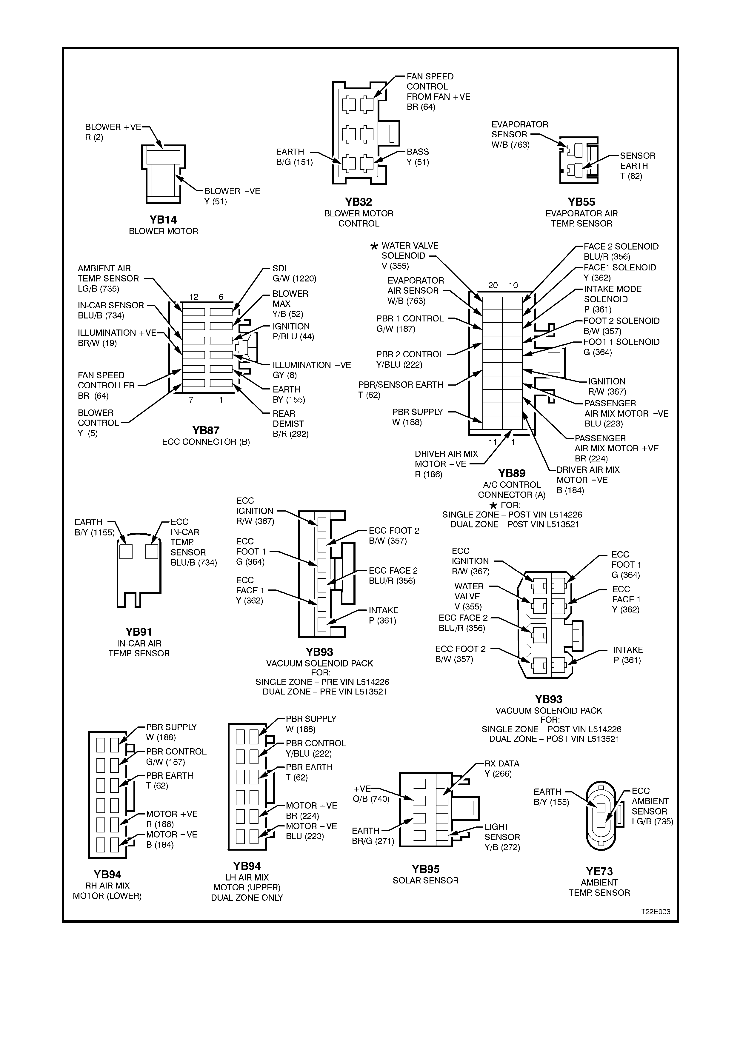
Figure 2E-4 ECC ELECTRICAL CONNECTORS