SECTION 2F - ELECTRONIC CLIMATE
CONTROL – DIAGNOSTICS
CAUTION:
This vehicle will be equipped with a Supplemental Restraint System (SRS). A SRS will consist of either
seat belt pre-tensioners and a driver's air bag, seat belt pre-tensioners and a driver's and front
passenger's air b ags o r seat b elt p re-t ension ers, driv er’s an d f ron t p asseng er’s air bag and left and righ t
hand side air bags. Refer to SAFETY PRECAUTIONS, Section 12M Supplemental Restraint System in this
Service Information before performing any service operation on, or around any SRS components, the
steering mechanism or wiring. Failure to follow the SAFETY PRECAUTIONS could result in SRS
deployment, resulting in possible personal injury or unnecessary SRS system repairs.
CAUTION:
This vehicle may be equipped with LPG (Liquefied Petroleum Gas). In the interests of safety, the LPG
fuel system should be isolated by turning 'OFF' the manual service valve and then draining the LPG
service lines, before any service work is carried out on the vehicle. Refer to the LPG leaflet included with
the Owner's Handbook for details or the appropriate Section of this Service Information for more
specific servicing information.
1. GENERAL INFORMATION
VT Series II Models built from early October 1999, Vehicle Identification Number L514226 – Single Zone and
L513521 – Dual Zone, were subject to the following running changes:
• The vacuum solenoid pack fitted to the HVAC unit was changed from a five solenoid pack to a six solenoid pack.
The additional solenoid is used to activate the heater water valve.
• Modifications were made to the vacuum harness and wiring harness to accommodate the additional vacuum
solenoid.
• The water valve vacuum switch assembly was deleted.
Additional diagnostic information is applicable to vehicles affected by these changes and is detailed in this Section.
For vehicles built prior to Vehicle Identification Number L514226 – Single Zone and L513521 – Dual Zone,
diagnostic information remains unchanged. For diagnostic information applicable to these vehicles, refer to
Section 2F AIR CONDITIONING – ECC – DIAGNOSTICS in the VT I Series Service Information.
Techline
Techline
Techline
Techline
2 TECH 2 TES T MODES AND DISPLAYS FOR ECC DIAGNOSIS
A prerequisite to this diagnostic section is for the user
to be familiar with the proper use of TECH 2. If
additional information is required on the operation of
TECH 2, reference should be made to either
Section 0C T ECH 2 of this Ser vice Inf orm ation, or the
TECH 2 OPERATOR’S MANUAL.
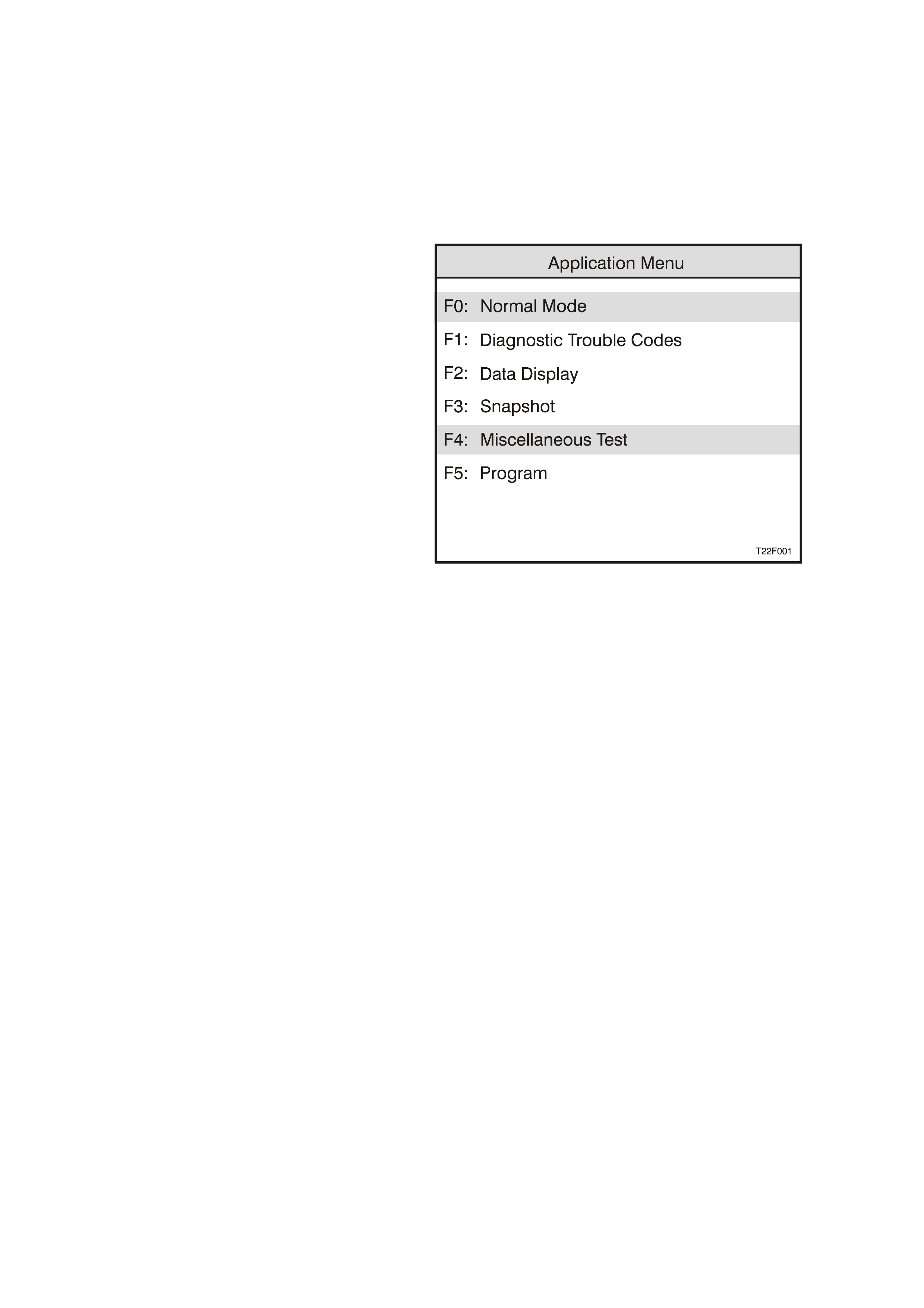
F4: MISCELLANEOUS TESTS
In the Miscellaneous Tests mode, functional tests
are available on the ECC systems that will help
identify proper operation. In this mode, error
conditions can be further identified by testing and
observing the results.
In the Miscellaneous Tests mode, the following
tests can be performed:
Driver’s Side Air Mix Door
Blower Speed
LCD Display Test
Outlet Mode
Maximum Fan Relay
Rear Demist Relay
Solenoids:
Solenoid 1 Face Level 1
Solenoid 2 Face Level 2
Solenoid 1 Foot Level 1
Solenoid 2 Foot Level 2
Fresh/Recirc
Water Valve
Refer to Section 2F AIR CONDITIONING – ECC –
DIAGNOSTICS in the VT I Series Service
Information for all the above Miscellaneous Test
Modes excluding Solenoids/Water Valve
WATER VALVE SOLENOID
Purpose of test: To ensure the ECC Module
electrical circuit is OK.
Procedure: The test procedure for the water valve
solenoid is the s ame as that f or the other solenoids
fitted to the solenoid pack. Remove the left side
footwell upper closing panel, locate the vacuum
solenoid pack (rear of blower housing). W ith TECH
2 connected to the DLC, select Body / Electronic
Climate Control / Miscellaneous Tests / Solenoids.
Conduct Solenoids test by using the On soft key,
activating one solenoid at a time.
Listen or feel for the solenoids activating (clicking).
Use the Off soft key to deactivate solenoids and
likewise listen or feel for solenoids activating
(clicking).
Figure 2F-1
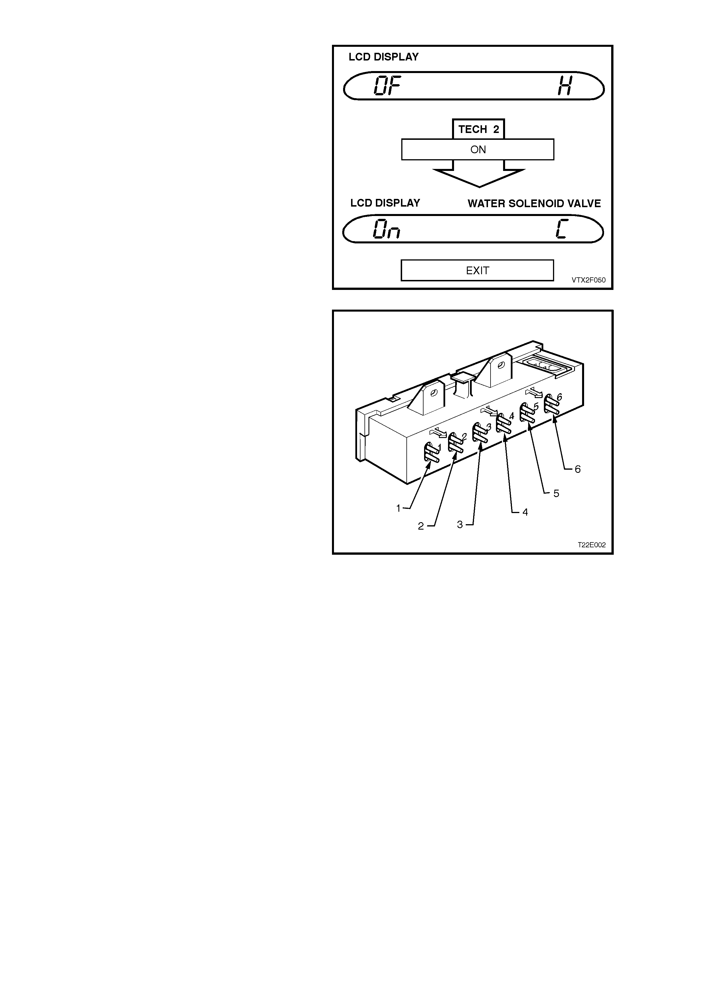
Figure 2F-2 shows the screen display for the water
valve solenoid.
Figure 2F-2
Figure 2F-3 shows the solenoid outlets from the
vacuum solenoid pack.
(1) Fresh/recirculation (Blue)
(2) Face 1 (White)
(3) Face 2 (Green)
(4) Foot 1 (Red)
(5) Foot 2 (Orange)
(6) Water valve (Yellow)
NOTE: T he water valve solenoid (6) is f itted only to
vehicles built from early October 1999, Vehicle
Identification Number L514226 – Single Zone and
L513521 – Dual Zone.
Figure 2F-3
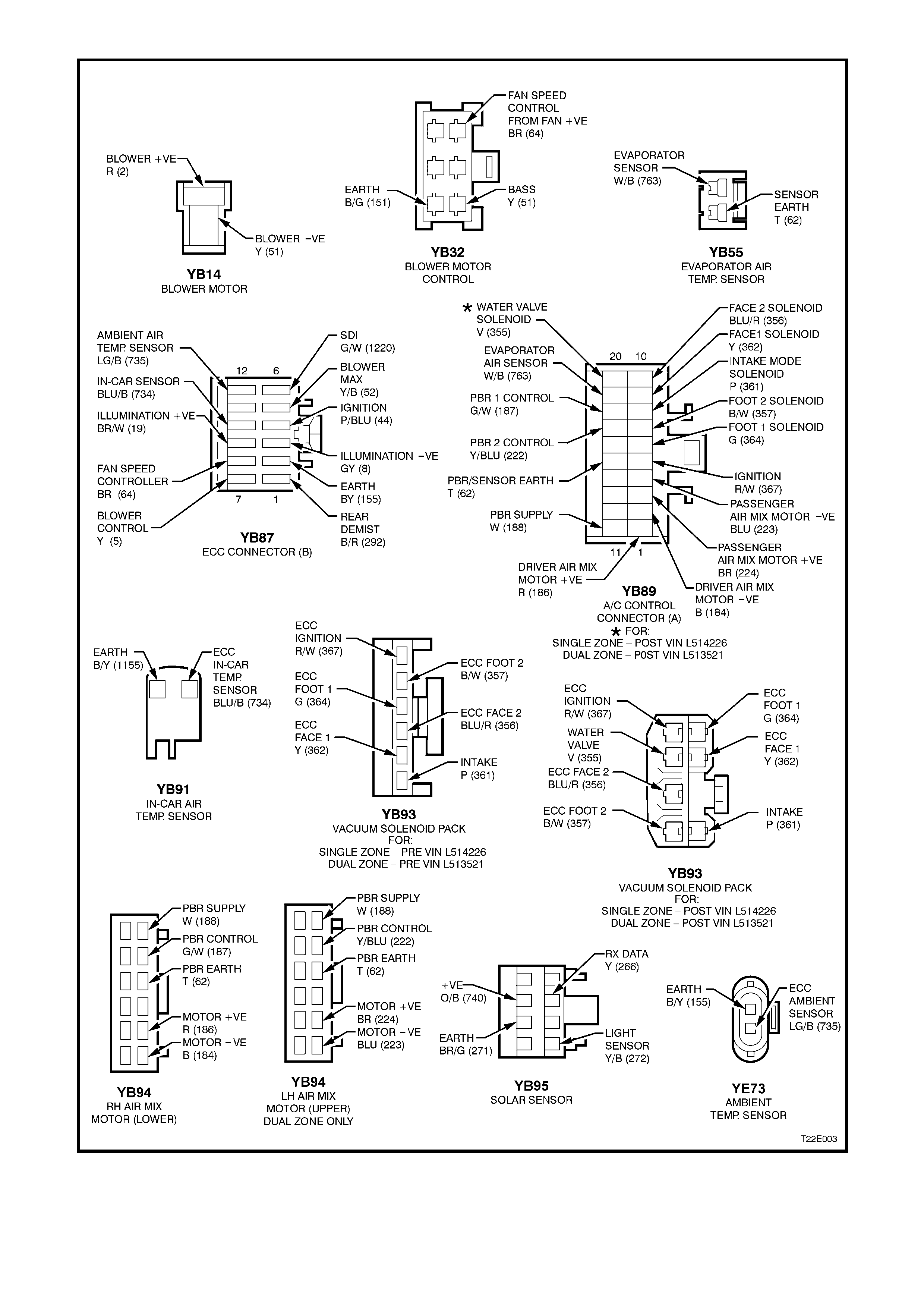
Figure 2F-4 ECC ELECTRICAL CONNECTORS