
SECTION 1A1 - BODY
CAUTION:
This vehicle will be equipped with a Supplemental Restraint System (SRS). A SRS will consist of either
seat belt pre-tensioners and a driver's air bag, seat belt pre-tensioners and a driver's and front
passenger's air bag s or seat belt pre- tensio ners, d riv er’s and fron t p asseng er’s air bag and lef t and rig ht
hand side air bags. Refer to SAFETY PRECAUTIONS, Section 12M Supplemental Restraint System of
this Service Information CD before performing any service operation on, or around any SRS
components, the steering mechanism or wiring. Failure to follow the SAFETY PRECAUTIONS could
result in SRS deployment, resulting in possible personal injury or unnecessary SRS system repairs.
CAUTION:
This vehicle may be equipped with LPG (Liquefied Petroleum Gas). In the interests of safety, the LPG
fuel system should be isolated by turning 'OFF' the manual service valve and then draining the LPG
service lines, before any service work is carried out on the vehicle. Refer to the LPG leaflet included with
the Owner's Handbook for details or the appropriate Section of this Service Information for more
specific servicing information.
1. GENERAL INFORMATION
The information covering the VT Series body in Section 1A1 BODY of the VT Series I Service Information remains
unchanged for VT Series II Models, however, there is one Service Operation that is misleading; rocker panel cover
removal and reinstallation.
As a result of this misleading information, this Service Operation has been revised and published in this Section.
For all other body Service Operations, refer to Section 1A 1 BODY of the VT Series I Service Information.
Techline
2. SERVICE OPERATIONS
2.1 ROCKER P ANEL COVER
REMOVE
1. Disable the SRS, refer to Section 12M
SUPPLEMENTAL RESTRAINT SYSTEM of
the VT Series I Service Information.
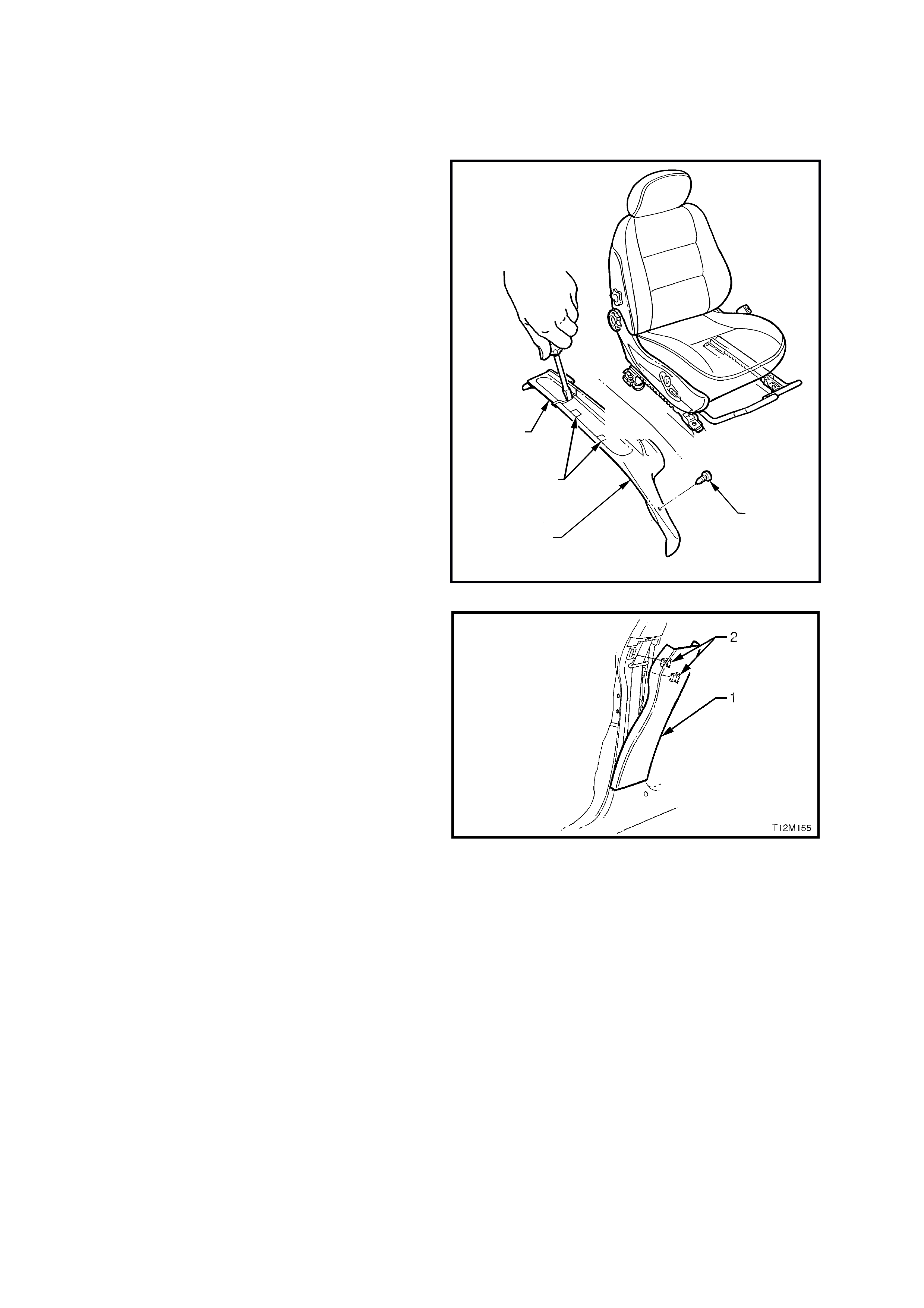
2. If removing the dr iver’s s ide roc ker panel c over ,
rem ove the retaining s crew (1) from the dr iver’s
side outer front guide rail cover.
3. Using a small sc rewdriver , pus h in the centr e of
the front (3) and rear (2) outer seat guide rail
covers where the two parts meet.
4. Remove the front outer guide rail cover by
lifting the outer edge of the front cover up and
pulling it forward. Lift driver’s outer front seat
guide rail cover over fuel filler door release
lever.
2
1
T12M111
3
4
Figure 1A1-1
5. From the top of the lower B pillar trim (1), gently
lever trim out away from B pillar to release the
two retaining clips (2).
6. Lift lower B pillar trim up to disengage it from
the rocker panel trim, and remove the lower B
pillar trim.
Figure 1A1-2
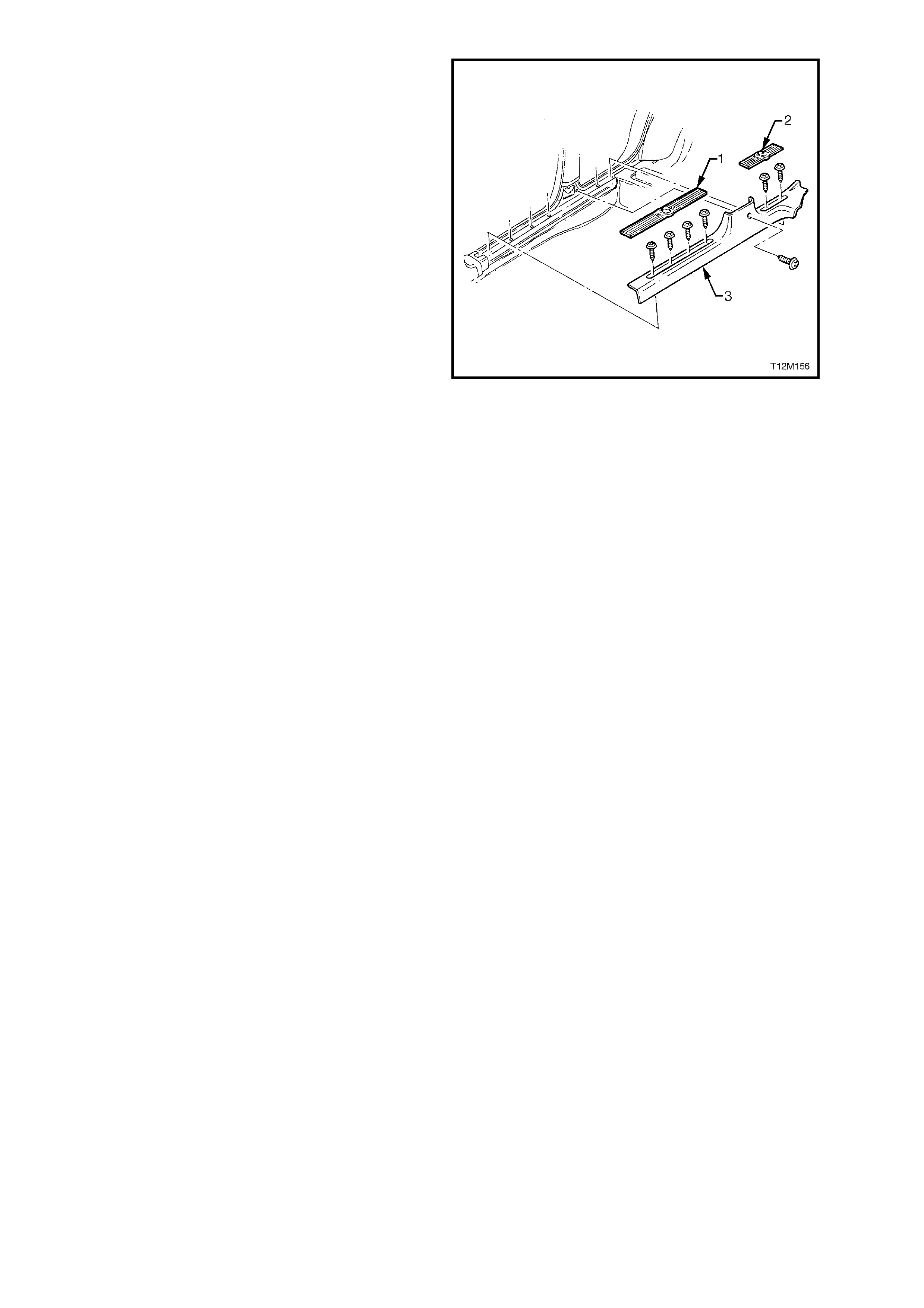
7. Gently pry the front (1) and rear (2) rocker
panel cover inse rts fr om the ro cker panel cover
(3).
8. Loosen and remove the rocker panel cover
retaining screw (seven places), and remove
rocker panel cover.
REINSTALL
Reinstallation of the rocker panel cover is the
reverse of the removal procedure, noting the
following.
Before tightening the rocker panel cover retaining
screws, ens ur e the lip on the door s eal s its over the
rocker panel cover.
Figure 1A1-3