
SECTION 1A5 - FRONT & REAR
DOOR ASSEMBLIES
CAUTION:
This vehicle will be equipped with a Supplemental Restraint System (SRS). A SRS will consist of either
seat belt pre-tensioners and a driver's air bag, seat belt pre-tensioners and a driver's and front
passenger's air bag s or seat belt pre- tensio ners, d riv er’s and fron t p asseng er’s air bag and lef t and rig ht
hand side air bags. Refer to SAFETY PRECAUTIONS, Section 12M Supplemental Restraint System of
this Service Information CD before performing any service operation on, or around any SRS
components, the steering mechanism or wiring. Failure to follow the SAFETY PRECAUTIONS could
result in SRS deployment, resulting in possible personal injury or unnecessary SRS system repairs.
CAUTION:
This vehicle may be equipped with LPG (Liquefied Petroleum Gas). In the interests of safety, the LPG
fuel system should be isolated by turning 'OFF' the manual service valve and then draining the LPG
service lines, before any service work is carried out on the vehicle. Refer to the LPG leaflet included with
the Owner's Handbook for details or the appropriate Section of this Service Information for more
specific servicing information.
1. GENERAL INFORMATION
Since the VT Series Service Information CD was
first published, there have been revisions made to
the following components / procedures for front
and rear door assemblies:
The removal of the exterior rear view mirror
assembly has been revised.
Service replacem ent com ponents for the f ront door
lock exterior handle and lock cylinder assem bly are
supplied as single components (in lieu of an
assembly). To complement this change, a
procedure has been developed to assemble and
disassemble the assembly.
The left and right hand rear door wiring harness
connectors have been changed to a new type of
connector. With the introduction of this new
connector, it is unnecessary to have to use Tool
No. AU455 to remove the connector from the B
pillar. Once the grommet on the B pillar has been
removed, the wiring harness and connector can
simply be extracted for access or disconnection.
The front door check link mounting was revised;
the hinge at the A pillar is now attac hed by to bolts
and the check link as s embly is attached to the door
by two nuts.
Whenever reinstalling a door check link, ensure the
attaching bolts and nuts are tightened to the correct
torque specification.
DOOR CHECK LINK ATTACHING
BOLT AND NUT 10 - 12 Nm
TORQUE SPECIFICATION
The Service Operations for revisions 1 and 2 are
detailed in this Section. All other front and rear door
assembly Service Operations for VT Series and VT
Series II Models carry over from those detailed in
Section 1A5 FRONT & REAR DOOR
ASSEMBLIES of this Service Information CD.
Techline
Techline
Techline
2. SERVICE OPERATIONS
2.1 EXTERIOR REAR VISION MIRROR
REMOVE
1. Disconnect battery earth lead.
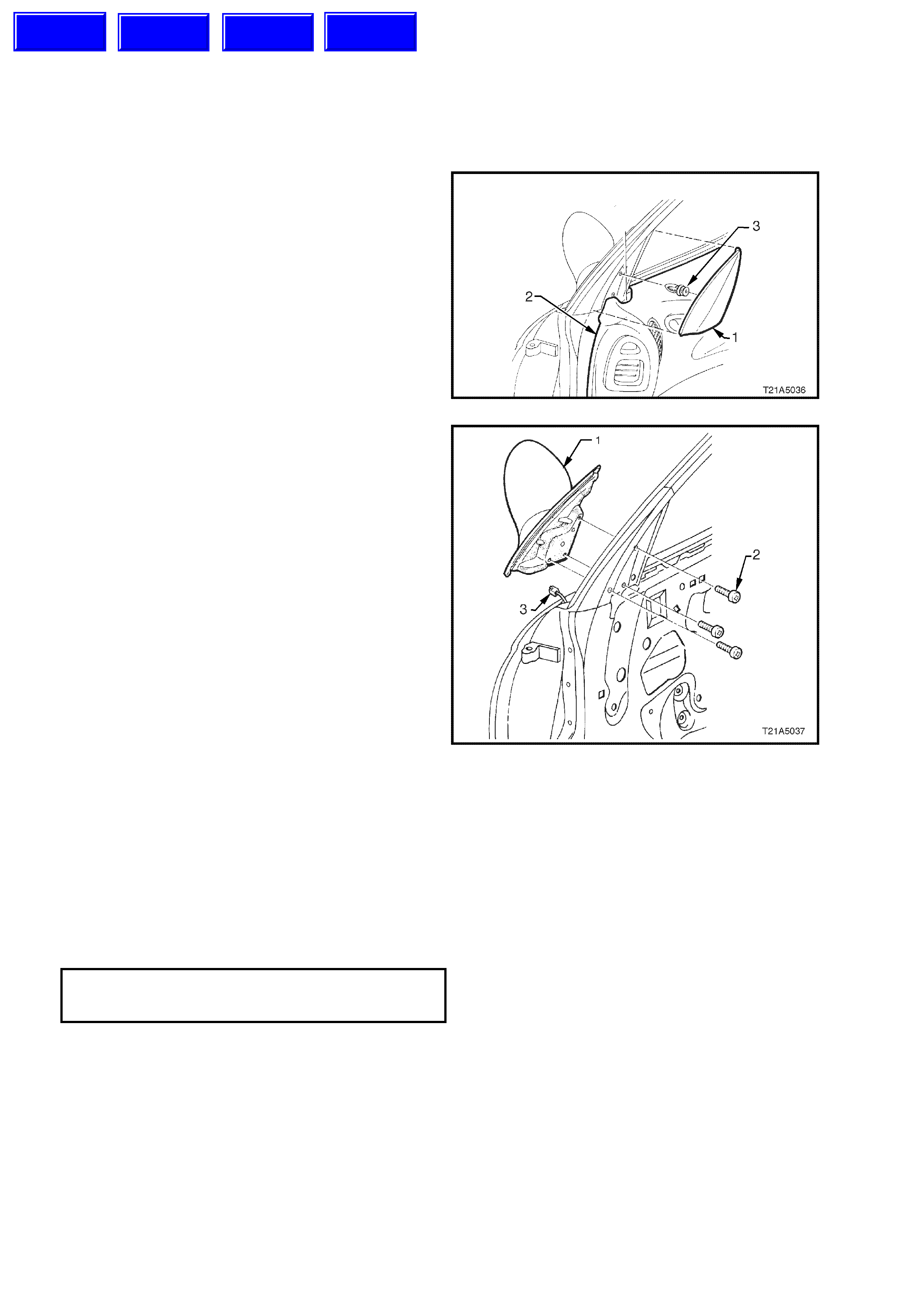
2. Remove the mirror inner cover cap (1) by
gently prying the cap away from the door.
NOTE: The inner cover cap retaining clip (3) can
only be used once.
3. Remove door inner trim panel (2), refer to
Section 1A5 FRONT & REAR DOOR
ASSEMBLIES of this Service Information CD.
Figure 1A5-1
4. Remove the three screws (2) securing the
exterior rear view mirror (1) to the door and,
while supporting the mirror, disconnect the
mirror wiring harness connector (3).
.
Figure 1A5-2
REINSTALL
Reinstallation of the ex ter ior r ear view mirror as s embly
is the reverse of the removal procedure, noting the
following:
1. Ensure the wiring harness connector for the
exterior rear view mirror is routed correctly.
2. Ensure the exterior rear view mirror to door
securing screws are tightened to the correct
torque specification.
EXTERIOR REAR VIEW MIRROR
TO DOOR SECURING SCREW 2.5 - 3.0 Nm
TORQUE SPECIFICATION
3. Install mir ro r inner c over c ap us ing a new retaining
clip.
NOTE: If the mirror inner cover cap is removed, its
retaining clip will have a reduced tension, therefore,
offering insufficient retention if it is reused.
Techline
Techline
Techline
Techline
2.2FRONT DOOR EXTERIOR HANDLE AND LOCK CYLINDER ASSEMBLY
DISASSEMBLY
1. Remove the f ront door exterior handle and lock
assembly, refer 1A5 FRONT AND REAR
DOOR ASSEMBLIES of this Service
Information CD.
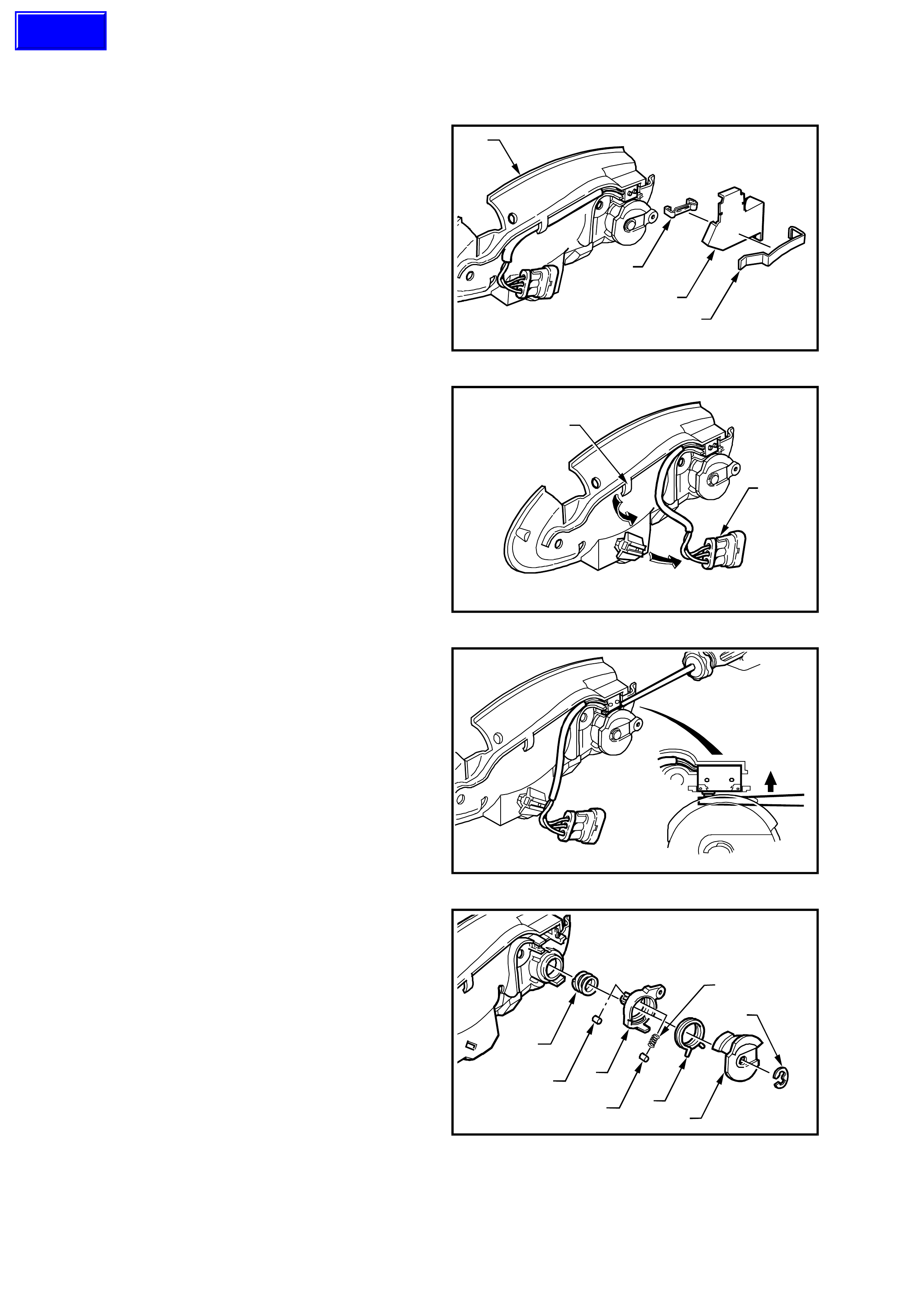
2. Using a small screwdriver, gently prise the
retaining clip (20) away from the door handle
bracket assembly (1) and remove the security
shield (19).
3. Using a small screwdriver, gently prise the
microswitch retaining clip (18) away from the
door handle bracket assembly (1).
T21A5001
1
19 20
18
Figure 1A5-3
4. Slide the microswitch wiring harness connector
(22) off the connector retaining bracket and
feed the wiring harness out from under the
bracket assembly retainer (23) .
T21A5002
23
22
Figure 1A5-4
5. Using a small flat bladed screwdriver, push the
two microswitch contacts in and remove the
microswitch assembly.
T21A5003
Figure 1A5-5
6. Remove the circlip (2) and slide the cam
control, clips and springs (3, 4, 5, 6, 7 & 8)
away from lock assembly.
T21A5004
6
8
83
2
7
5
4
Figure 1A5-6
Techline
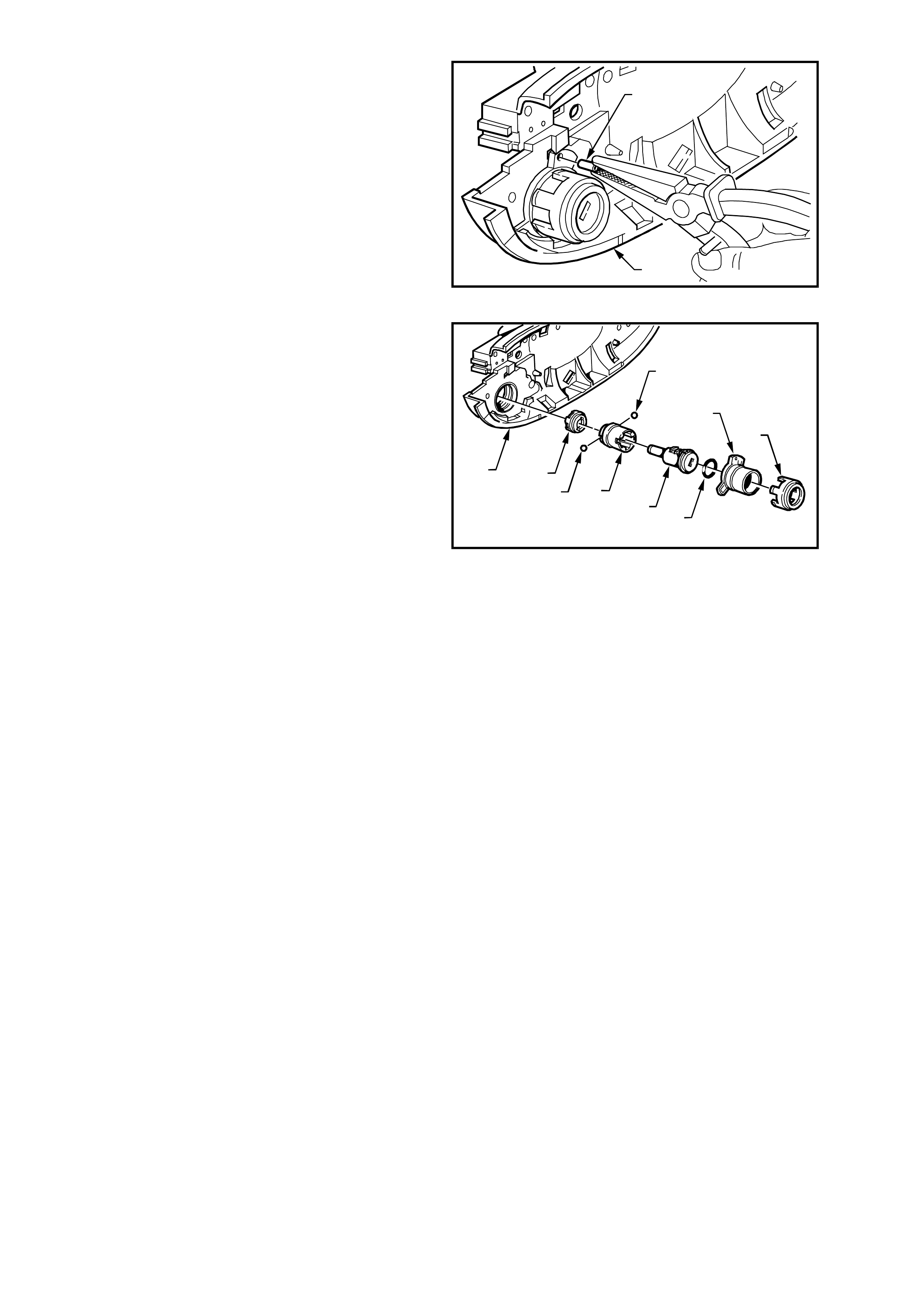
7. Using a suitable pier of pliers, pull the roll pin
(9) out of the door handle bracket assembly.
T21A5005
9
1
Figure 1A5-7
8. Rotate lock housing anti-clock wise and rem ove
decorative housing, lock housing, O-ring, lock
assem bly, lock assem b ly sleeve, retaining balls
(two places) and coupling (10, 11, 12, 13, 14,
15 & 16) from the door handle bracket
assembly (1).
T21A5006
16
16 14
1
13 12
11
10
15
Figure 1A5-8
REASSEMBLY
Reassembly of the front door exterior handle and
lock assembly is the reverse of the removal
procedure, noting the following:
1. The Holden Service Parts Operations
departm ent supplies service k its with un-coded
lock cylinders to facilitate re-coding of the lock
cylinder to match the original key.
Holden Ltd. recommends lock cylinder
overhaul and re-coding be performed by a
qualified locksmith, and should be sublet.
2. To assist assembly of the front door exterior
handle and lock assembly, the following figure
shows an exploded view of the assembly.
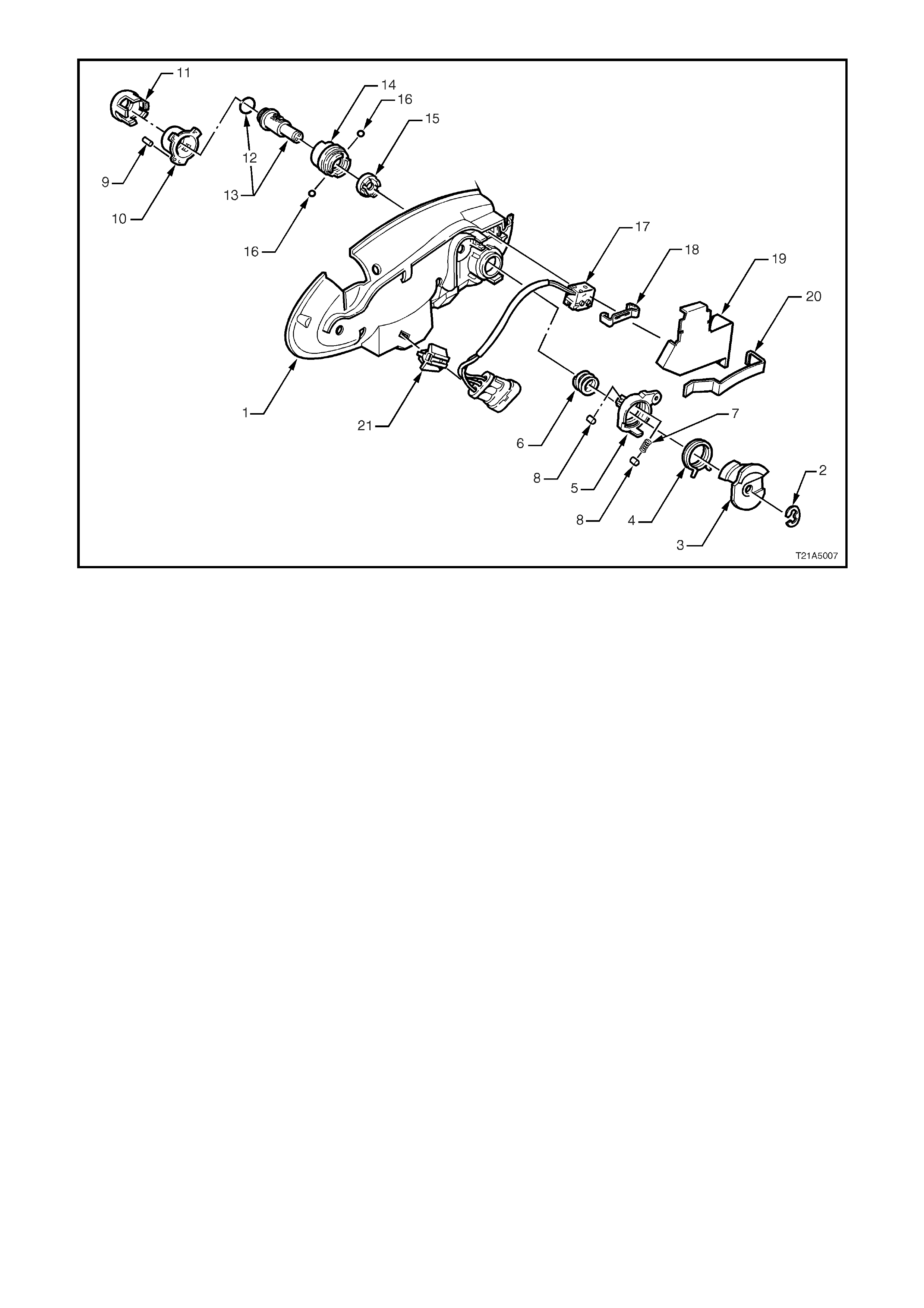
Figure 1A5-9
1. Exterior Door Handle Bracket 8. Roller 15. Coupling
2. Circlip 9. Roll Pin 16. Retaining Balls
3. Cam Control 10. Lock Housing 17. Microswitch Assembly
4. Spring 11. Decorative Housing 18. Retaining Clip
5. Clip 12. O-Ring 19. Security Shield
6. Push Spring 13. Cylinder Lock Assembly 20. Retaining Clip
7. Push Spring 14. Cylinder Lock Sleeve 21. Connector Retaining Bracket