
SECTION 1A6 - STATIONARY GLASS
CAUTION:
This vehicle will be equipped with a Supplemental Restraint System (SRS). A SRS will consist of either
seat belt pre-tensioners and a driver's air bag, seat belt pre-tensioners and a driver's and front
passenger's air bags or seat belt pre-tensioners, driver’s and front passenger’s air bag and left and
right-hand side air bags. Refer to SAFETY PRECAUTIONS, Section 12M Supplemental Restraint System
of this Service Information CD before performing any service operation on, or around any SRS
components, the steering mechanism or wiring. Failure to follow the SAFETY PRECAUTIONS could
result in SRS deployment, resulting in possible personal injury or unnecessary SRS system repairs.
CAUTION:
This vehicle may be equipped with LPG (Liquefied Petroleum Gas). In the interests of safety, the LPG
fuel system should be isolated by turning 'OFF' the manual service valve and then draining the LPG
service lines, before any service work is carried out on the vehicle. Refer to the LPG leaflet included with
the Owner's Handbook for details or the appropriate Section of this Service Information for more
specific servicing information.
1. GENERAL DESCRIPTI ON
The windshield, which is laminated and features a tinted upper band, is bonded in the body opening w ith urethane.
The rear window on sedans and the tailgate glass on station wagons, both of which have a elec trically heated demist
facility, are also bonded in the body openings with urethane.
The rear quarter windows on s tation wagons utilise a s elf adhesive foam weatherstrip to seal the glass to the body
and are secured to the body opening by plastic screw on nuts.
Toughened safety glass is used for all the windows except the windshield.
For replacement of urethane bonded glasses, urethane service kits have been developed and must be used to
ma intain original installation requirem ents. Glass installed with urethane requires either par tial or com plete removal
of the urethane when replacing the glass.
Two diff erent installation methods are used when replacing the windshield, rear window and tailgate window to VT
Series II models, a ‘short method’ and a ‘long method’.
Partial rem oval of the urethane is r eferred to as the ‘s hort method’. Com plete removal of the urethane is known as
the ‘long method’.
The short m ethod is used where original urethane lef t on body opening pinch weld flanges af ter glass r emoval, c an
serve as a base for the new glass. This method would be used in cases of replacem ent of crack ed windshields or
removal of glass that is intact. The amount of urethane left in the glass opening can be controlled during glass
removal, leaving the maximum amount of original urethane intact on the body opening flange.
The long method is to be used when the original urethane left in the window opening, after glass removal, cannot
serve as a base for replacement glass. This method would be used in cases needing metal work or where paint
refinishing is required in the body opening; or in cases where the glass has been previously replaced, using the
short m ethod. In such instances, the build up of urethane could position the glass too high in the body opening. In
these cases, the original urethane is completely removed and replaced with new urethane during glass installation.
A one piece windshield moulding is now used in place of the two piece mould fitted to previous VT Series models.
For service procedures related to the rear door fixed window, refer to Section 1A5 FRONT & REAR DOOR
ASSEMBLIES of the VT Series I Service Information.
Techline
Techline
Techline

2. SERVICE NOTES
CAUTION: Safety glasses and work gloves must be worn at all times when operating with glass.
Skinning (partial curing) of the urethane commences after exposure to the atmosphere. At 23 degrees
Celsius and 50 percent relative humidity, skinning commences after 30 minutes. Complete curing of the
urethane at this temperature and humidity takes 72 hours.
Urethane service kits are available from most windshield agents. Manufacturer’s instructions should always
be followed.
Window glass should be installed in the window opening within 5 minutes of the application of urethane.
3. SERVICE OPERATIONS
3.1 WI NDSHIELD GLASS — ALL MODELS
REMOVE
The windshield glass removal procedure is the
same for both the short and long installation
methods with one exception.
If the short method installation is to be used, more
care m ust be taken during glass r emoval to ensure
that an even surface of the original remaining
urethane exists in the body opening to serve as a
base for the new urethane bead and the
replacement glass.
The windshield moulding is installed over the edge
of the windshield glass and can be removed by
pulling the moulding from the windshield opening
starting at the windshield lower corner, after
removal of the components as detailed below.
Mouldings are available for service replacement.
Refer to the VT Series parts information for details.
CAUTION: Care must be taken during any
operation involving windshield removal or
installation not to exert any load on the
windshield glass. Failure to observe this may
result in damage to the glass.
1. To prevent damage to paint f inis h and trim, and
to minimise clean up, mask-up and place
protective covers over parts adjacent to the
windshield.
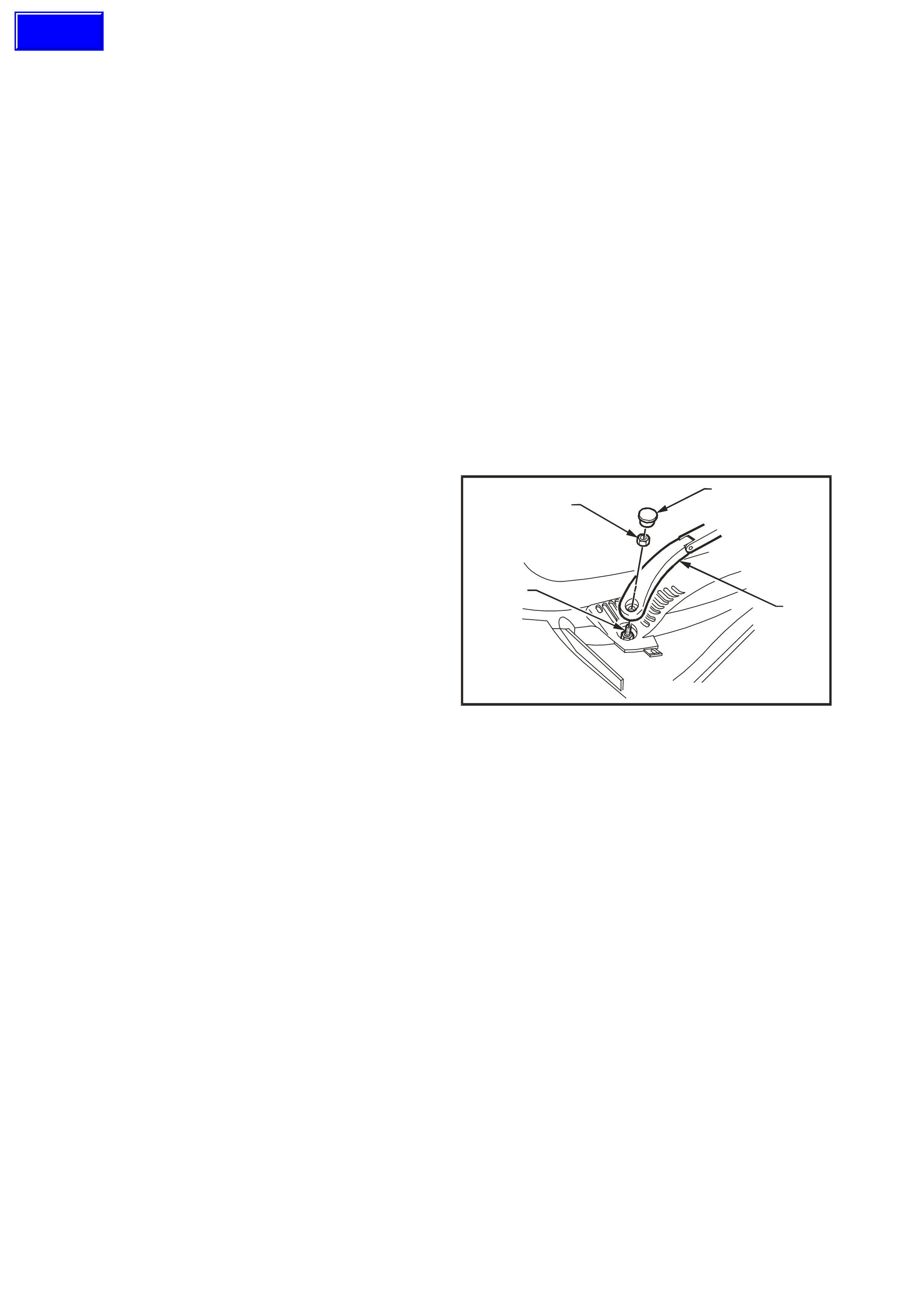
2. Prise cap (1) from wiper arm (2) and remove
wiper arm retaining nut (3) from drive spindle
(4).
31
2
T21A6001
4
Figure 1A6-1
Techline
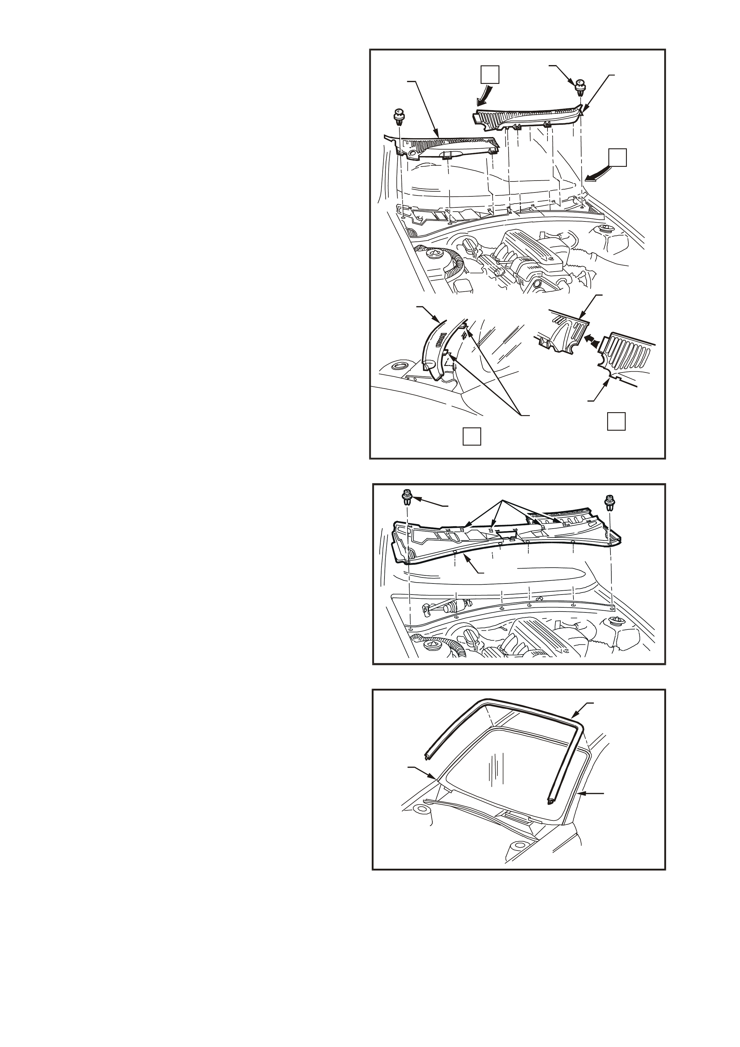
3. Remove six scrivets (1) retaining both left
plenum cover (2) and right plenum cover (3).
Remove the plenum covers, taking care not to
break the retaining lugs (4).
A
B
T21A6002
B
A
3
3
2
2
2
1
4
Figure 1A6-2
4. Remo ve six scr ivets (1) retaining plenum water
deflector (2), pull deflector towards front of
vehicle, disengaging the four retaining tabs (3)
and remove from the vehicle.
13
2
T21A6003
Figure 1A6-3
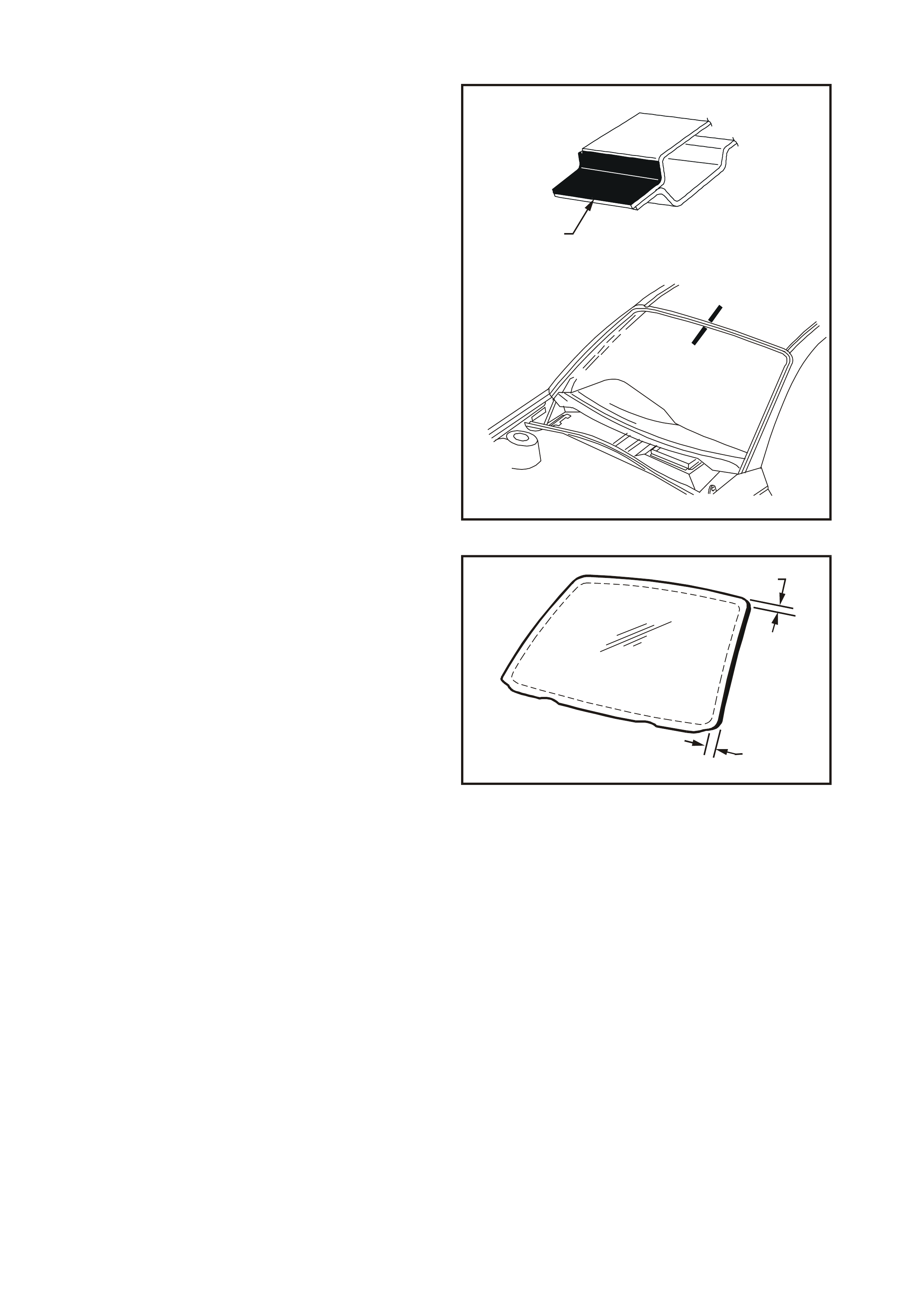
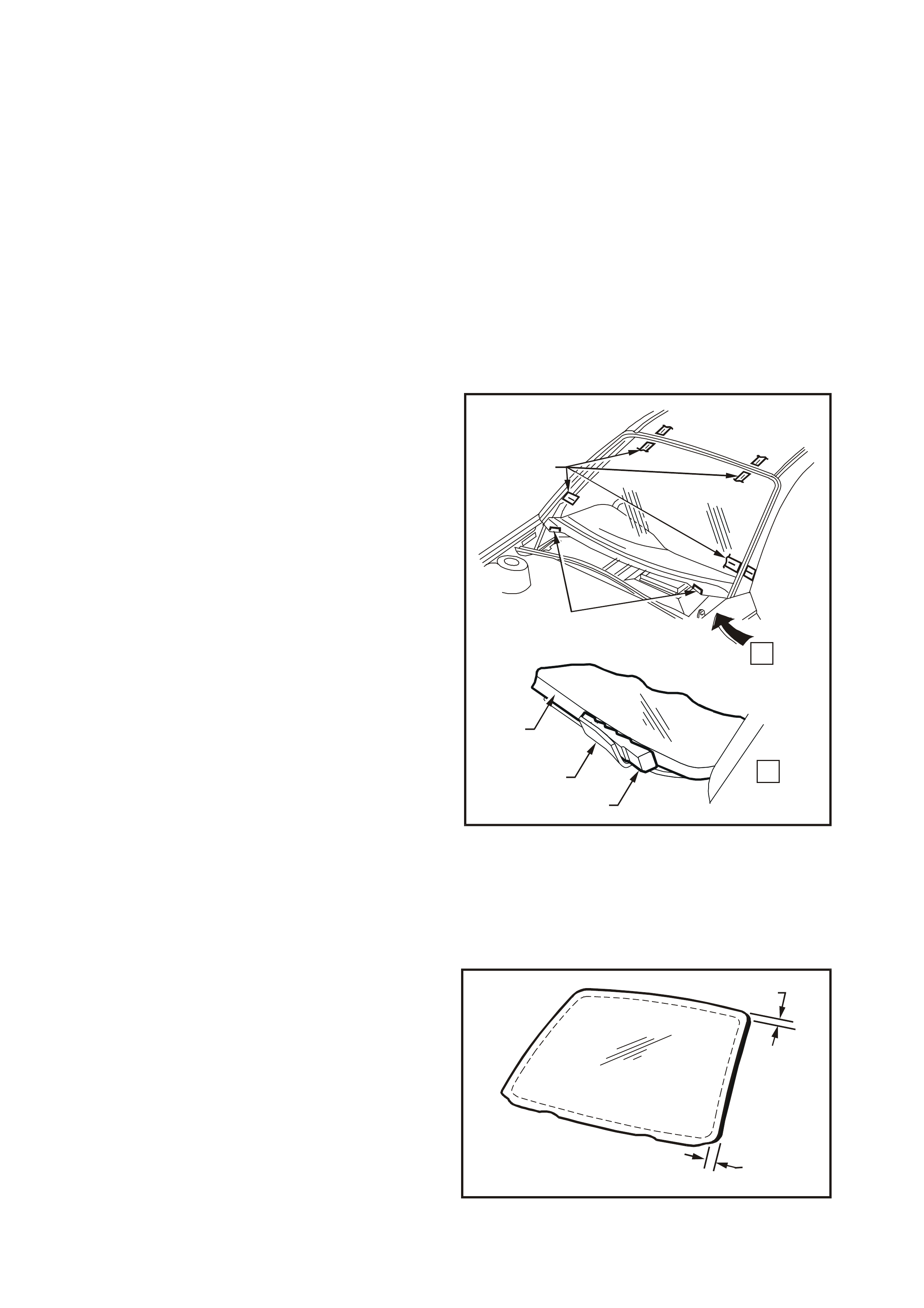
5. Remove windshield moulding (1) by pulling the
moulding from the windshield to body join (2),
starting at the windshield lower corner (3) and
working around the windshield.
1
2
3
T21A6004
Figure 1A6-4
6. From inside vehicle, remove instrument panel
end cap cover right side and left side. Refer to
Section 1A3 INSTRUMENT PANEL AND
CONSOLE of this Service Information CD.
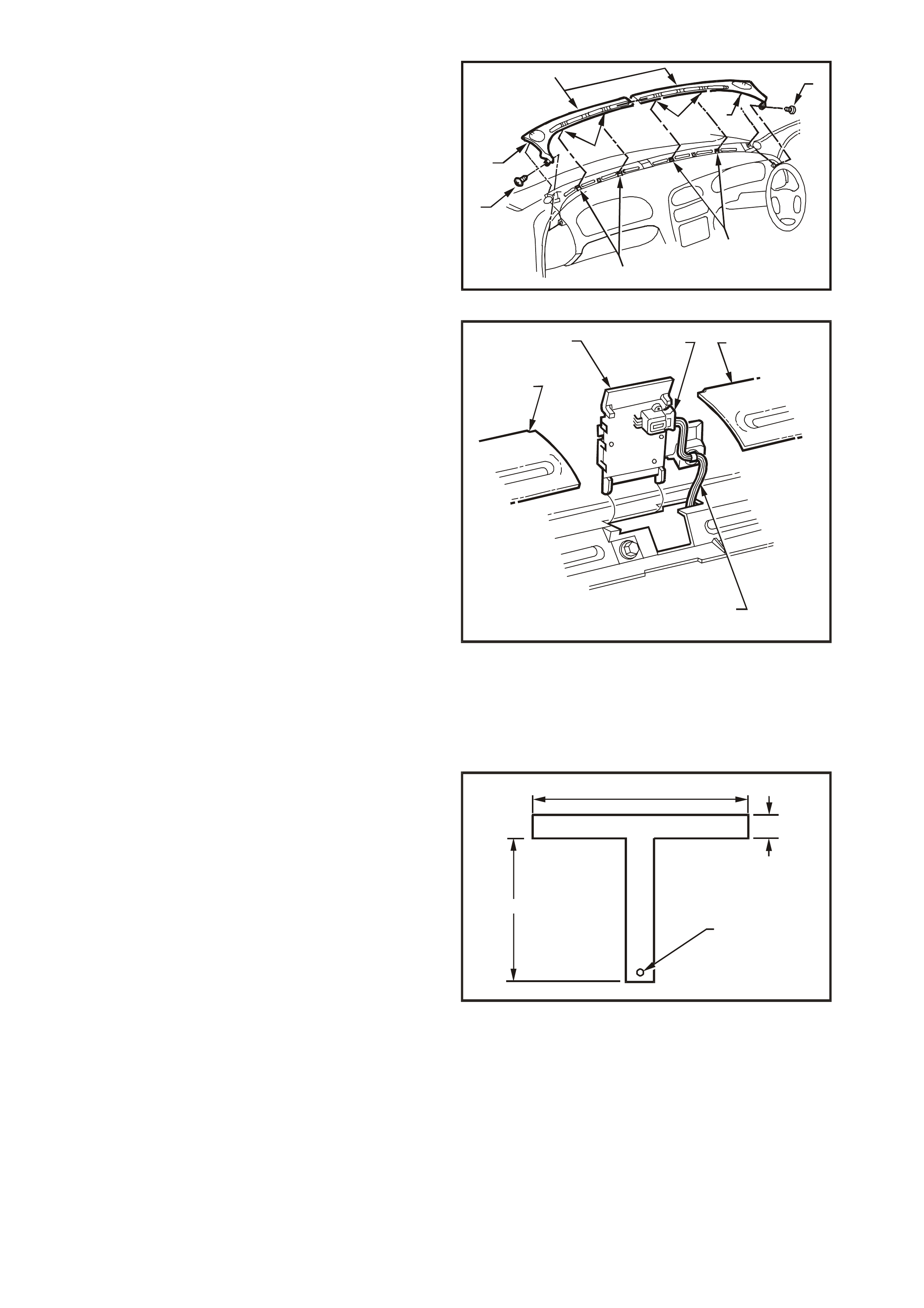
7. Remove retaining screws (1) from the outer
ends of the demist nozzles (2).
8. Carefully disengage the horizontal retaining
lugs (3) of both demist nozzles, from the top of
the instrument panel (4) with minimum upward
movement of the demist nozzles. This is to
ensure that minimal leverage is placed on the
outer vertical retaining lugs (5).
9. Disengage the vertical retaining lugs on the end
of the demist nozzles by pulling backward and
upward, until the demist nozzles are
disengaged from the instrument panel.
T21A6005
2
3
4
4
3
5
5
1
1
Figure 1A6-5
IMPORTANT: Note that on all vehicles a remote
receiver module, and on some models a solar
sensor, is installed between the left-hand and right-
hand demist nozzles on the instrum ent panel. Care
must be taken to avoid damage to the remote
receiver module (and solar sensor where fitted)
during windscreen removal procedure. It is not
necessary to remove the remote receiver module
(or solar sensor). Figure 1A6-6 illustrates:
1. Remote receiver module / solar sensor.
2. Wiring harness connector.
3. Right-hand demist nozzle.
4. Left-hand demist nozzle.
5. Wiring harness.
T21A6006
5
13
4
2
Figure 1A6-6
10. Remove interior mirror assembly by sliding
mirror base upwards.
11. Remove A-pillar trim assembly, refer to
Section 1A8 HEADLINING AND REAR END
TRIM of this Service Information CD.
12. Using piano wire and T-handles AU 390 or
equivalent (refer to Fig. 1A6-7 for dimensions),
thread one end of the piano wire through the
urethane, starting at the windshield upper
corner, pulling the end of the wire through with
pliers.
NOTE 1: Use at least 700 mm of wire between the
T-handles.
NOTE 2: Ensure that the headlining and other trim
items are not damaged.
T21A6007
100mm
10mm
100mm 2m m
Figure 1A6-7
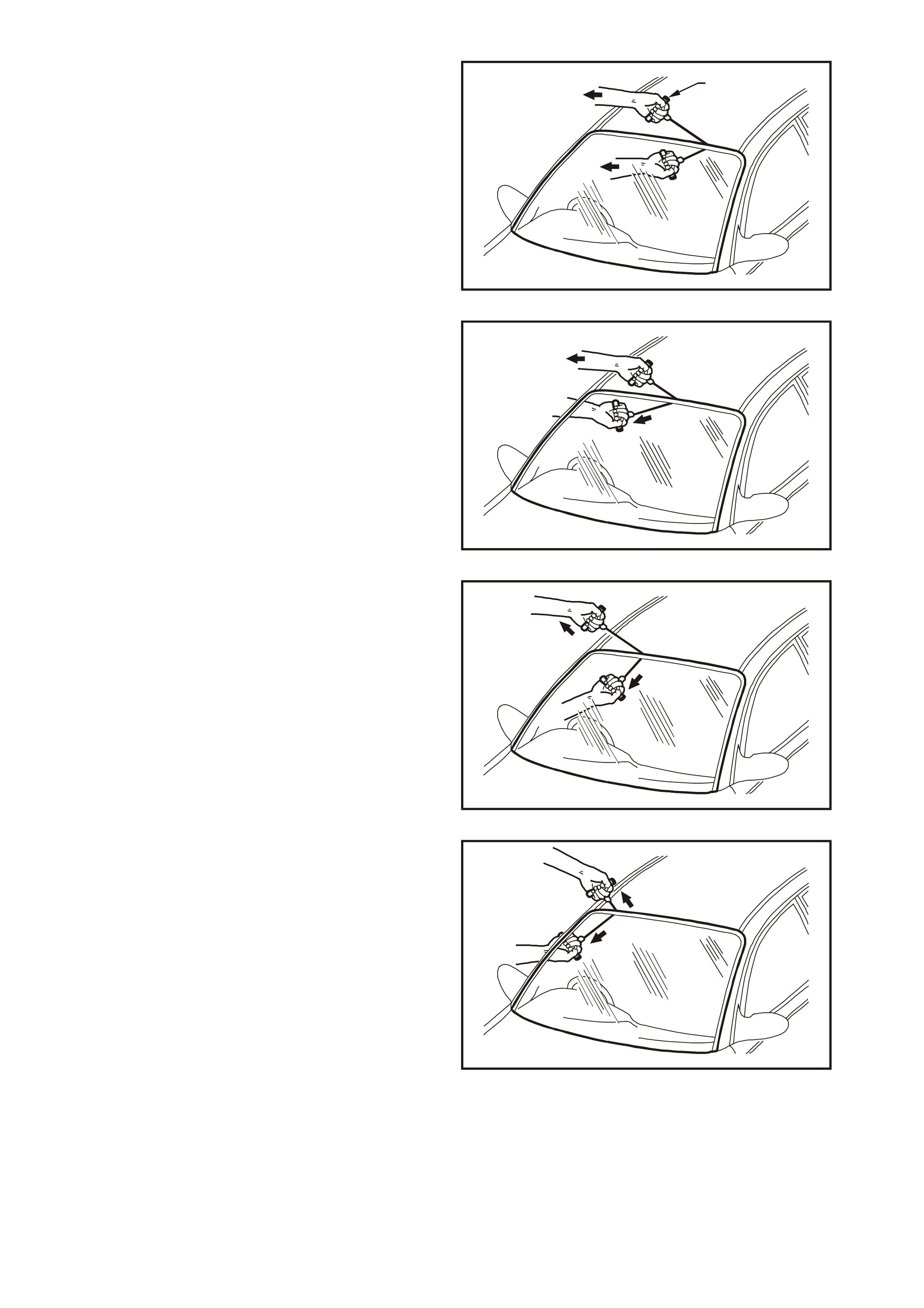
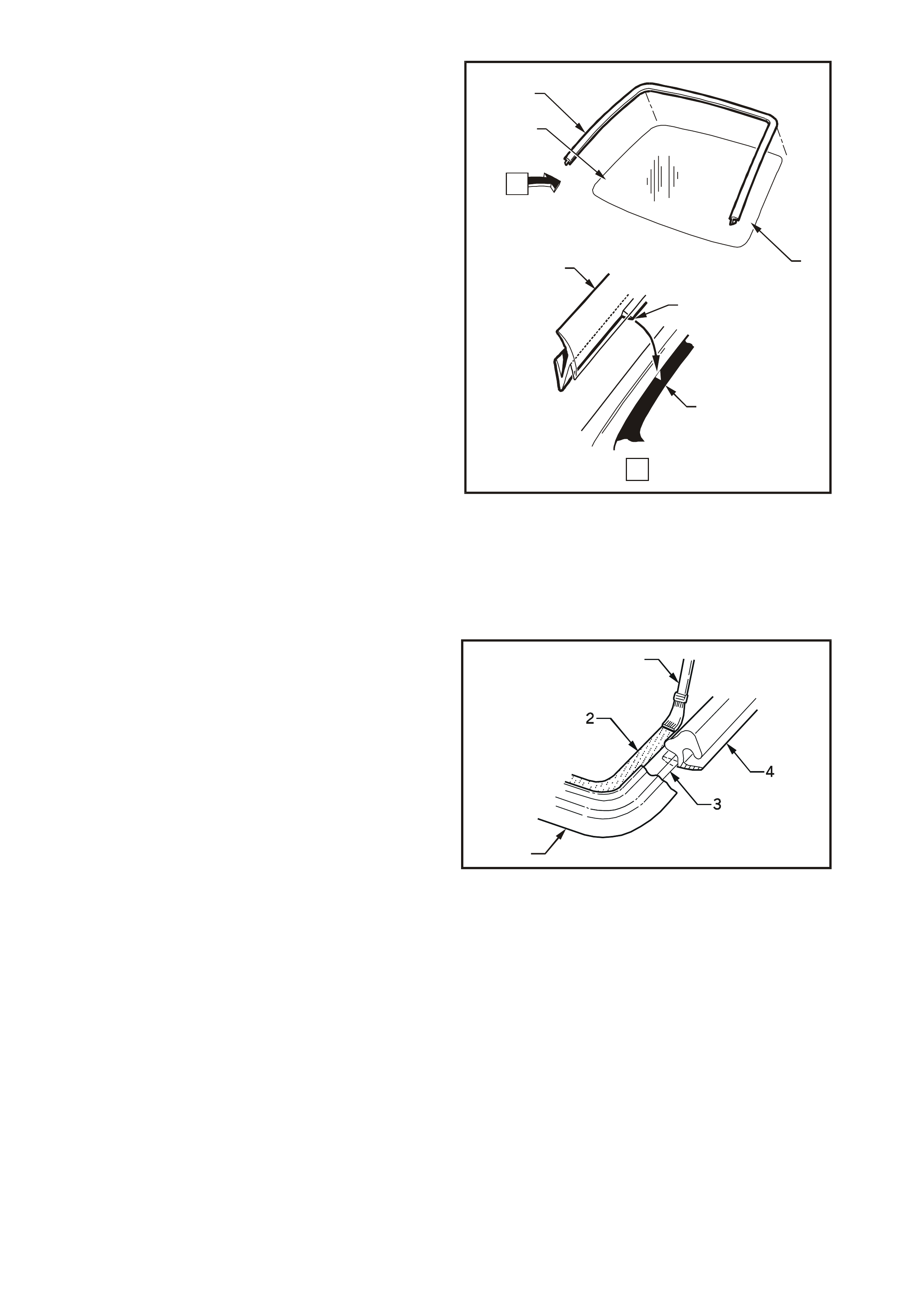
13. Connect the wire to the remaining T-handle
and with the aid of an assistant, commence
cutting the urethane bead, keeping the outside
T-handle (1) parallel to the edge of the glass
using the full length of the wire to prevent heat
build up in the wire.
NOTE: To minimise damage to the interior of the
vehicle, the operator inside the vehicle should act
as an anchor point, holding the T-handle as close
as possible to the glass at all times, especially
along the lower edge of the windshield, while the
outside operator pulls the wire up to the interior T-
handle in a ‘walking’ motion refer to Figs. 1A6-8,
1A6-9, 1A6-10, and 1A6-11.
T21A6008
1
Figure 1A6-8
T21A6009
Figure 1A6-9
T21A6010
Figure 1A6-10
T21A6011
Figure 1A6-11

14. Carefully lift the windshield out of the body
opening. If there is evidence of glass adhering
to the urethane, cut the area again with the
piano wire.
15. If the original windshield is to be installed
again, place the windshield on a clean
protected surface, holding fixture etc.
NOTE: The use of suction cups will greatly assist
any handling of the windshield.
LONG METHOD INSTALLATION
DESCRIPTION
The long method windshield replacement is used
when original urethane adhesive material cannot
serve as a base for the replacement windshield.
This method should be used on vehicles requiring
metal or paint repair to the windshield opening
when original adhesive is completely removed and
replaced with new urethane for windshield
installation.
This method is also used when the windshield has
been previously replaced, using the short method.
In such instances, the build-up of urethane could
position the windshield too high in the opening.
REPARATION
IMPORTANT: Note that on all vehicles a remote
receiver module, and on some models a solar
sensor, is installed between the lef t-hand and right-
hand demis t nozzles on the ins trum ent panel. T ake
particular care during the urethane removal
procedure to avoid damage to the remote receiver
module (and solar sensor where fitted).
CAUTION: Do not use petroleum based
solvents to clean the windshield or body
opening flange as the presence of oil will
prevent adhesion of the new urethane/silicon.
1. Using a sharp scraper, carefully remove any
original urethane from around the windshield.
Clean the windshield to be installed with a
suitable oil free cleaning agent.
2. Using a knife or sharp scraper, remove the
original urethane from around the entire
perimeter of the windshield opening flange.
Avoid the removal of paint when removing
urethane from opening flange.
Body Opening Check
1. Thoroughly check the windshield body opening
flange fo r any ir regularities before installing the
windshield.
2. Remove the A-pillar trims. Refer to Section
1A8 HEADLINING AND REAR END TRIM of
this Service Information CD.

CAUTION: Care should be taken to ensure that
glass does not strike the windshield opening.
Chipped edges can lead to subsequent
breakage of glass.
3. Place the windshield in the body opening
temporarily to check for correct alignment
between the windshield and body opening. If
necessary, reform the body opening flange to
produce a uniform flange to windshield contour.
4. Using a wedge (1) placed between the lower
edge of the windshield (2) and the reinforcing
flanges (3), correctly locate the windshield in
the body opening.
5. Tape mark the outer top and side of the
windshield, pillar and roof with masking tape
(4). This procedure will assist in the alignment
of the windshield in the correct horizontal and
vertical plane during final windshield
installation.
6. Remove and place the windshield face down
on a clean protected surface or fixture.
T21A6012
4
3
1
3
2
.
.
.
..
.
.
..
..
.
.
...
...
.
.
..
.
.
.
...
.
..
..
.
.
...
...
.
.
..
.
.
.
.
..
.
..
...
...
..
..
.
..
..
.
.....
.
........
.
.
.
..
.....
.....
.
....
.
.
....
.
..
.
...
..
.
.
.
..
.
...
...
.
.
.
..
..
.
...
.
..
.
A
A
Figure 1A6-12
REINSTALL
1. Using one of the applicators in the service kit,
apply flange primer (1) to any section of the
windshield opening flange that has been
cleaned back to bare metal or to be painted.
Allow this primer to dry for 15 minutes.
IMPORTANT: Do not touch primed surfaces.
2. Thoroughly clean the inner surface and edges
of the windshield to which the urethane is to be
applied, using clean lint-free cloths and a
suitable oil free cleaning solvent.
T21A6013
1
A
-A
A
A
Figure 1A6-13
3. Apply clear glass primer to inner surface of
glass around the perimeter of the windshield
over the width of the solid black ceramic
pattern (or a width of 50 mm) and immediately
wipe off with a lint-free cloth.
4. Check the condition of the windshield
moulding. Discard and replace with new
moulding if damaged.
50mm
50mm
T21A6014
Figure 1A6-14
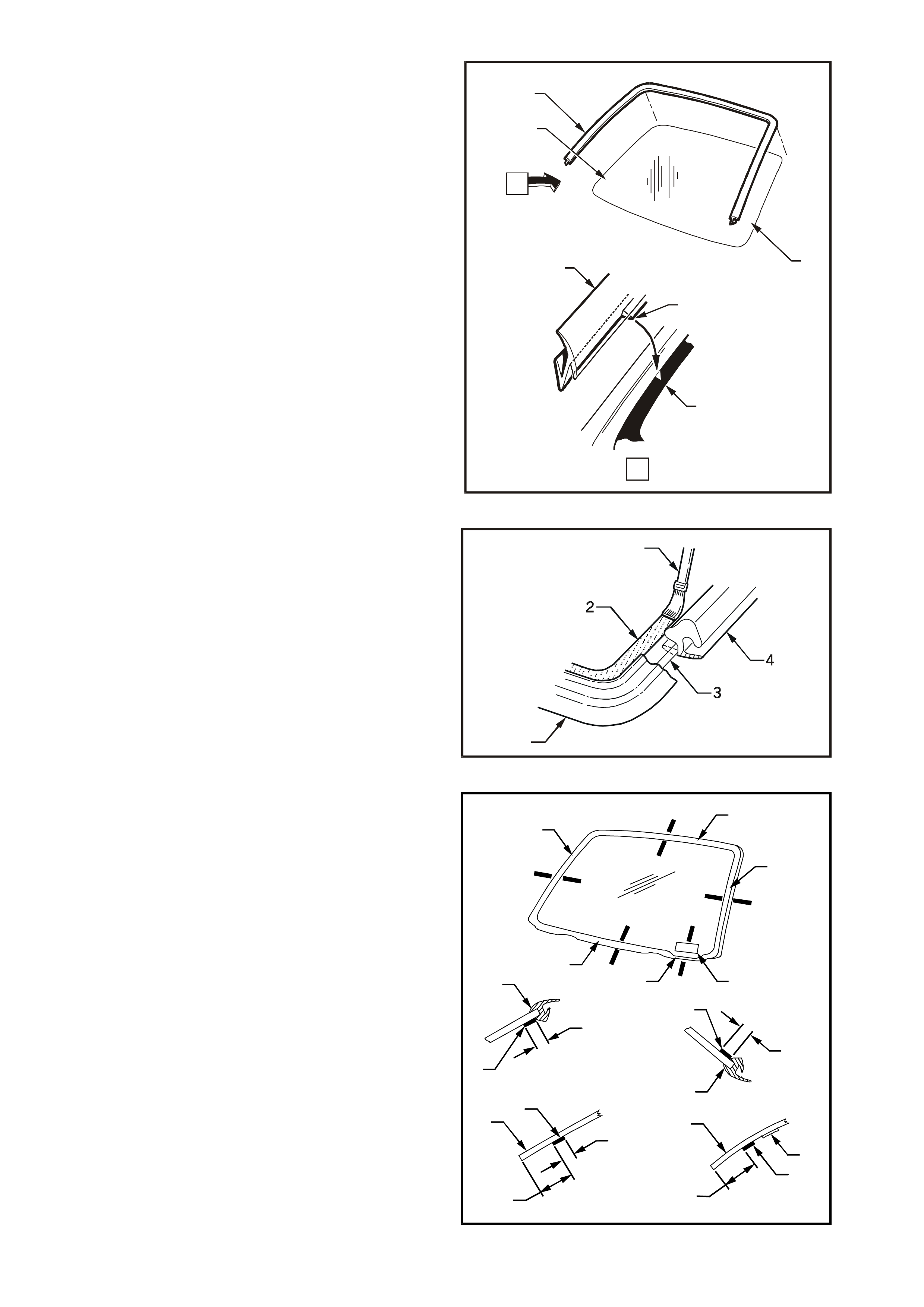
5. Fit windshield moulding (1) to sides and upper
section of windshield. Ensure that notch of
moulding (2) is aligned with ‘V’ locating mark
(3) on lower portion of right-hand and left-hand
side of windshield.
T21A6015
A
A
1
1
2
3
3
3
Figure 1A6-15
6. Using the applicator (1) included in the service
kit, apply black glass primer (2) to the
windshield (3) alongside the moulding (4).
T21A6016
4
1
Figure 1A6-16
7. Apply black glass primer (1) to the inner
surface of the upper section (2) and sides (3) of
the windshield over a width of 20 mm inboard
from the moulding (4). Repeat this process
35 mm from the lower edge (5) of the
windshield. Ensure that a suitably reduced
application of primer black glass primer (6) is
applied 15 mm from the lower edge of the
windshield (7) adjacent to the VIN plate (8).
T21A6017
A-A
1
20mm
4
A
BBB
B
C
C
D
D
A
2
3
3
87
5
B-B
1
4
20mm
C-C
20mm
1
5
35mm
D-D
8
6
7
15mm
Figure 1A6-17
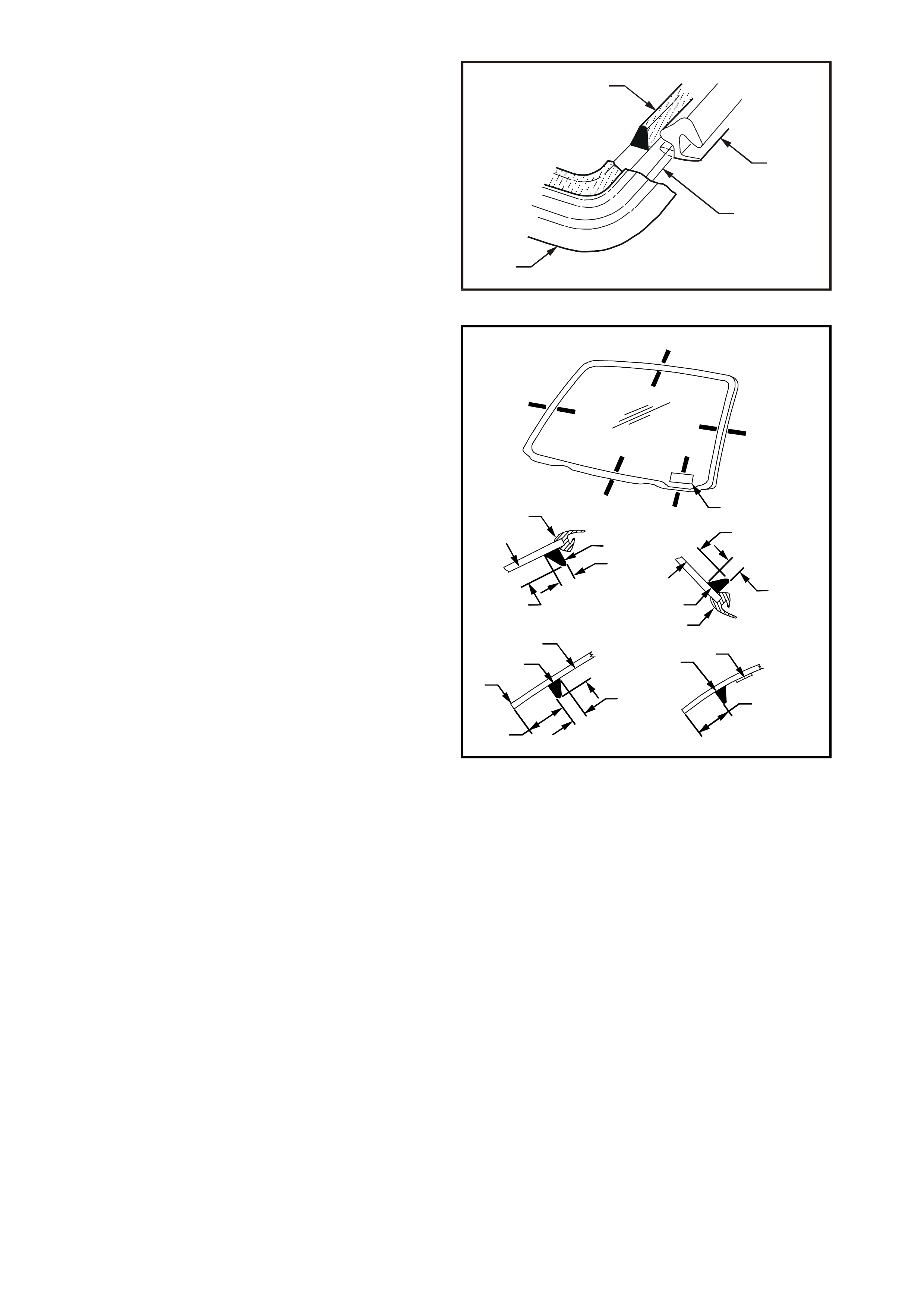
8. Using a hand or automatic applicator, apply a
smooth continuous bead of urethane (1), such
as Betaseal 587.02 or equivalent, to the
windshield (2) alongside the moulding (3).
T21A6018
2
1
3
3
Figure 1A6-18
IMPORTANT: On the lower left-hand side of the
body opening, care must be taken to ensure the
urethane bead diameter is such that when
compressed by the windshield installation, the
vehicle identification number is not obscured.
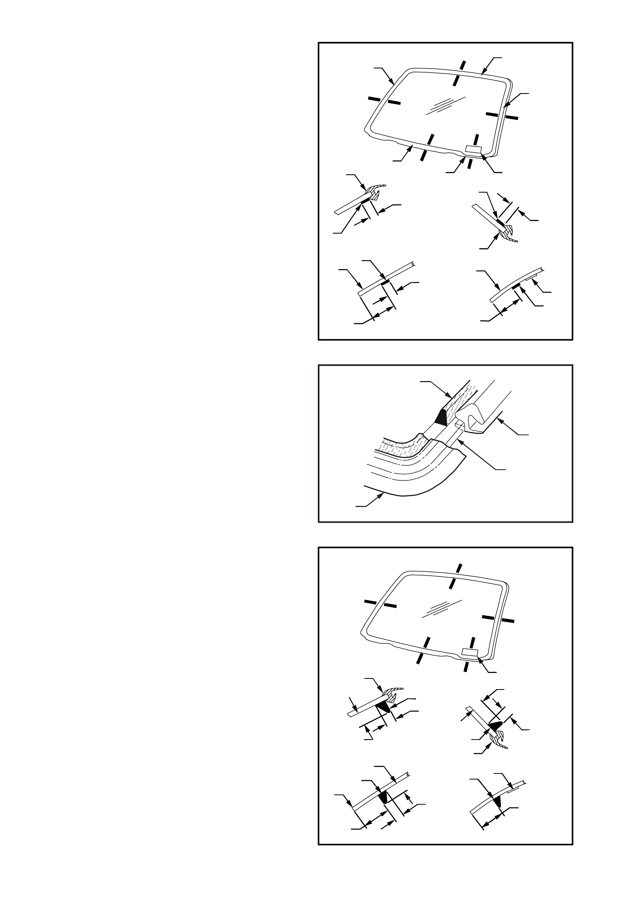
9. Apply urethane (1) adjacent to the m oulding (2)
and 35 mm inboard (3) from the lower edge of
the windshield (4). A suitably reduced amount
of urethane (5) should be applied adjacent to
the VIN plate (6) to ensure that the VIN is not
obscured when the windshield is installed. All
other bead dimensions are shown in Fig. 1A6-
19.
T21A6019
A
BBB
B
C
C
D
D
A
6
D-D
6
5
15mm
B-B
1
2
14 mm
+3
–0
7 mm
+3
–0
C-C
35mm
14 mm
+3
–0
7 mm
+3
–0
3
4
A-A
1
2
14 mm
+3
–0
7 mm
+3
–0
Figure 1A6-19
NOTE: In cold weather, the placement of car tr idges
adjacent to a source of warmth will assist the flow
of urethane when using a hand applicator.
10. Install the interior mirror assembly.
IMPORTANT: For ease of installation and to avoid
unnecessary stress on related components, it is
recommended that the interior mirror assembly be
fitted to the windshield prior to installation of the
windshield to the vehicle.
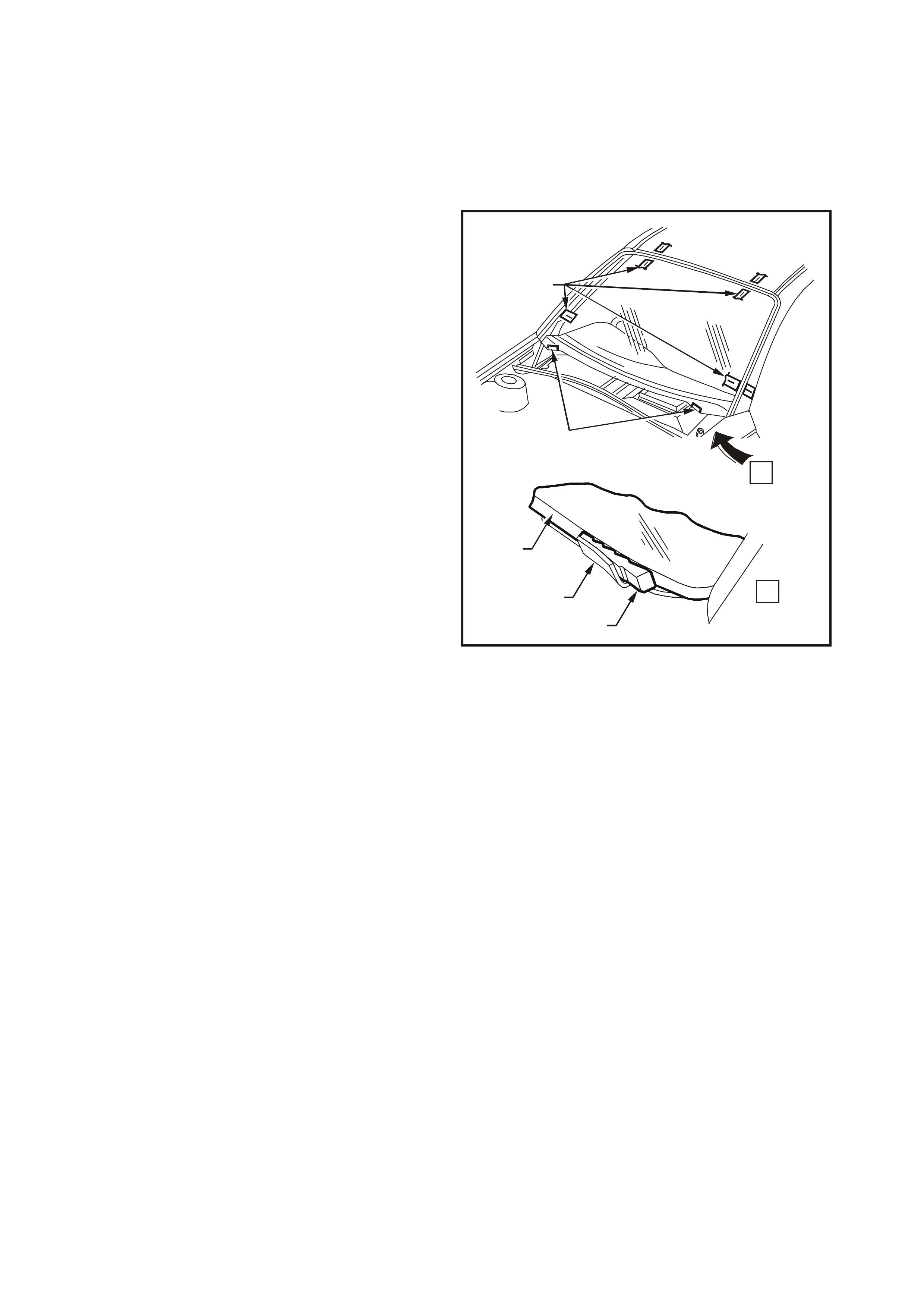
11. With the aid of an assistant, install the
windshield, using the previously attached
masking tape (1) on the roof and windshield to
ensure accurate installation. Use a wedge (2)
placed between the lower windshield edge (3)
and the reinforcing flanges (4) to locate glass
vertically in the 1windshield opening. Press
windshield firmly into position.
12. Check effectiveness of sealing from inside of
the vehicle. Should any gaps in the sealing
exist, apply additional urethane on the outside
to fill these gaps. Using a spatula, smooth the
surf ace of the urethane around the edge on the
outside of the windshield to ensure effective
sealing.
13. Water test the windshield, using a moderate
spray of water.
T21A6020
1
4
2
4
3
.
.
.
..
.
.
..
..
.
.
...
...
.
.
..
.
.
.
...
.
..
..
.
.
...
...
.
.
..
.
.
.
.
..
.
..
...
...
..
..
.
..
..
.
.....
.
........
.
.
.
..
.....
.....
.
....
.
.
....
.
..
.
...
..
.
.
.
..
.
...
...
.
.
.
..
..
.
...
.
..
.
A
A
Figure 1A6-20
NOTE: Do not direct a heavy stream of water onto
freshly applied urethane. If a water leak is evident,
apply additional urethane to the leak area, using a
spatula to work urethane into source of leak.
IMPORTANT: If silicon is used for spot sealing,
allow a minimum of 1 hour to permit the silicon to
skin and adhere to the original urethane prior to
water testing the repair.
14. Clean off any excess urethane/silicon using
Prepsol or white spirit. Clean the windshield,
then remove the masking tape previously
installed.
15. Install the A-pillar trims. Refer to Section 1A8
HEADLINING AND REAR END TRIM of this
Service Information CD.
16. Install the demis t nozzles and retaining sc rews.
Install the instrument panel end cap covers.
Refer to Section 1A3 INSTRUMENT PANEL
AND CONSOLE of this Service Information
CD.
17. Install the plenum chamber water deflector,
right-hand and left-hand side plenum covers
and wiper arm assemblies.

CAUTION: Ensure that door windows are
partially lowered to eliminate pressure build up
which can be caused by slamming doors. A
curing time of 24 hours is recommended,
although the vehicle may be driven after
5 hours, providing it is driven only on a smooth
road at speeds not exceeding 80 km/h with the
door windows partially lowered.
SHORT METHOD INSTALLATION
DESCRIPTION
Short method installation involves the maximum
amount of the original urethane being left intact on
the body opening to form a sound base for the
replacement urethane and windshield.
This method is recommended when replacing a
cracked or broken windshield, or a leak condition
that cannot be overcom e by using minor water leak
repair procedures.
If material other than urethane has been used for
previous servicing of the windshield, the long
method installation procedure (complete removal of
adhesive) is mandatory to achieve an effective
glass to metal bond.
PREPARATION
CAUTION: Care should be taken to ensure that
glass does not strike the windshield opening.
Chipped edges can lead to subsequent
breakage of glass.
1. Using a wedge (1) placed between the lower
edge of the windshield (2) and the reinforcing
flanges (3), correctly locate the windshield in
the body opening.
2. Tape mark the outer top and side of the
windshield, pillar and roof with masking tape
(4). This procedure will assist in the alignment
of the windshield in the correct horizontal and
vertical plane during final windshield
installation.
3. Remove and place the windshield face down
on a clean protected surface or fixture.
T21A6012
4
3
1
3
2
.
.
.
..
.
.
..
..
.
.
...
...
.
.
..
.
.
.
...
.
..
..
.
.
...
...
.
.
..
.
.
.
.
..
.
..
...
...
..
..
.
..
..
.
.....
.
........
.
.
.
..
.....
.....
.
....
.
.
....
.
..
.
...
..
.
.
.
..
.
...
...
.
.
.
..
..
.
...
.
..
.
A
A
Figure 1A6-21
REINSTALL
1. Thoroughly clean the inner surface and edges
of the windshield to which the urethane is to be
applied, using clean lint-free cloths and a
suitable oil free cleaning solvent.
2. Apply clear glass primer to inner surface of
glass around the perimeter of the windshield
over the width of the solid black ceramic
pattern (or a width of 50 mm) and immediately
wipe off with a lint-free cloth.
3. Check the condition of the windshield
moulding. Discard and replace with new
moulding if damaged.
50mm
50mm
T21A6014
Figure 1A6-22
4. Fit windshield moulding (1) to sides and upper
section of windshield. Ensure that notch of
moulding (2) is aligned with ‘V’ locating mark
(3) on lower portion of right-hand and left-hand
side of windshield.
T21A6015
A
A
1
1
2
3
3
3
Figure 1A6-23
5. Check the original urethane around the
windshield opening flange for voids or
looseness. Cut away any loose pieces of
urethane and, using a suitable spatula, paddle
fresh urethane or silicon smoothly into any
voids or uneven sections.
6. Using the applicator (1) included in the service
kit, apply black glass primer (2) to the
windshield (3) alongside the moulding (4).
T21A6016
4
1
Figure 1A6-24
7. Apply black glass primer (1) to the inner
surface of the upper section (2) and sides (3) of
the windshield over a width of 20 mm inboard
from the moulding (4). Repeat this process
35 mm from the lower edge (5) of the
windshield. Ensure that a suitably reduced
application of primer black glass (6) is applied
15 mm from the lower edge of the windshield
(7) adjacent to the VIN plate (8).
T21A6017
A-A
1
20mm
4
A
BBB
B
C
C
D
D
A
2
3
3
87
5
B-B
1
4
20mm
C-C
20mm
1
5
35mm
D-D
8
6
7
15mm
Figure 1A6-25
8. Using a hand or automatic applicator, apply a
smooth continuous bead of urethane (1), such
as Betaseal 587.02, 15.685 (High Viscosity) or
equivalent (to Holden Specific ation HN2293), to
the windshield (2) alongside the moulding (3).
T21A6018
2
1
3
3
Figure 1A6-26
IMPORTANT: On the lower section of the body
opening, care must be taken to ensure the
urethane bead diameter is such that when
compressed by the windshield installation, the
vehicle identification number is not obscured.
9. Apply urethane (1) adjacent to the m oulding (2)
and 35 mm inboard (3) from the lower edge of
the windshield (4). A suitably reduced amount
of urethane (5) should be applied adjacent to
the VIN plate (6) to ensure that the VIN is not
obscured when the windshield is installed. All
other bead dimensions are shown in Fig. 1A6-
27.
T21A6019
A
BBB
B
C
C
D
D
A
6
D-D
6
5
15mm
B-B
1
2
14 mm
+3
–0
7 mm
+3
–0
C-C
35mm
14 mm
+3
–0
7 mm
+3
–0
3
4
A-A
1
2
14 mm
+3
–0
7 mm
+3
–0
Figure 1A6-27

NOTE: In cold weather, the placement of car tr idges
adjacent to a source of warmth will assist the flow
of urethane when using a hand applicator.
10. Install the interior mirror assembly.
IMPORTANT: For ease of installation and to avoid
unnecessary stress on related components, it is
recommended that the interior mirror assembly be
fitted to the windshield prior to installation of the
windshield to the vehicle.
11. With the aid of an assistant, install the
windshield, using the previously attached
masking tape (1) on the roof and windshield to
ensure accurate installation. Use a wedge (2)
placed between the lower windshield edge (3)
and the reinforcing flange (4) to locate glass
vertically in the windshield opening. Press
windshield firmly into position.
12. Check effectiveness of sealing from inside of
the vehicle. Should any gaps in the sealing
exist, apply additional urethane on the outside to
fill these gaps. Using a spatula, smooth the
surface of the urethane around the edge on the
outside of the windshield to ensure effective
sealing.
13. Water test the windshield, using a moderate
spray of water.
NOTE: Do not direct a heavy stream of water onto
freshly applied urethane. If a water leak is evident,
apply additional urethane to the leak area, using a
spatula to work urethane into source of leak.
T21A6020
1
4
2
4
3
.
.
.
..
.
.
..
..
.
.
...
...
.
.
..
.
.
.
...
.
..
..
.
.
...
...
.
.
..
.
.
.
.
..
.
..
...
...
..
..
.
..
..
.
.....
.
........
.
.
.
..
.....
.....
.
....
.
.
....
.
..
.
...
..
.
.
.
..
.
...
...
.
.
.
..
..
.
...
.
..
.
A
A
Figure 1A6-28
IMPORTANT: If silicon is used for spot sealing,
allow a minimum of 1 hour to permit the silicon to
skin and adhere to the original urethane prior to
water testing the repair.
14. Clean off any excess urethane/silicon using
Prepsol or white spirit. Clean the windshield,
then remove the masking tape previously
installed.
15. Install the A-pillar trims. Refer to Section 1A8
HEADLINING AND REAR END TRIM of this
Service Information CD.
16. Install the demis t nozzles and retaining sc rews.
Install the instrument panel end cap covers.
Refer to Section 1A3 INSTRUMENT PANEL
of this Service Information CD.
17. Install the plenum chamber water deflector,
right-hand and left-hand side plenum covers
and wiper arm assemblies.
CAUTION: Ensure that door windows are
partially lowered to eliminate pressure build up
which can be caused by slamming doors. A
curing time of 24 hours is recommended,
although the vehicle may be driven after
5 hours, providing it is driven only on a smooth
road at speeds not exceeding 80 km/h with the
door windows partially lowered.
3.2 REAR QUARTER WINDOW ASSEMBLY — STATION WAGONS
REMOVE
CAUTION: Safety glasses and work gloves
must be worn at all times when operating with
glass.
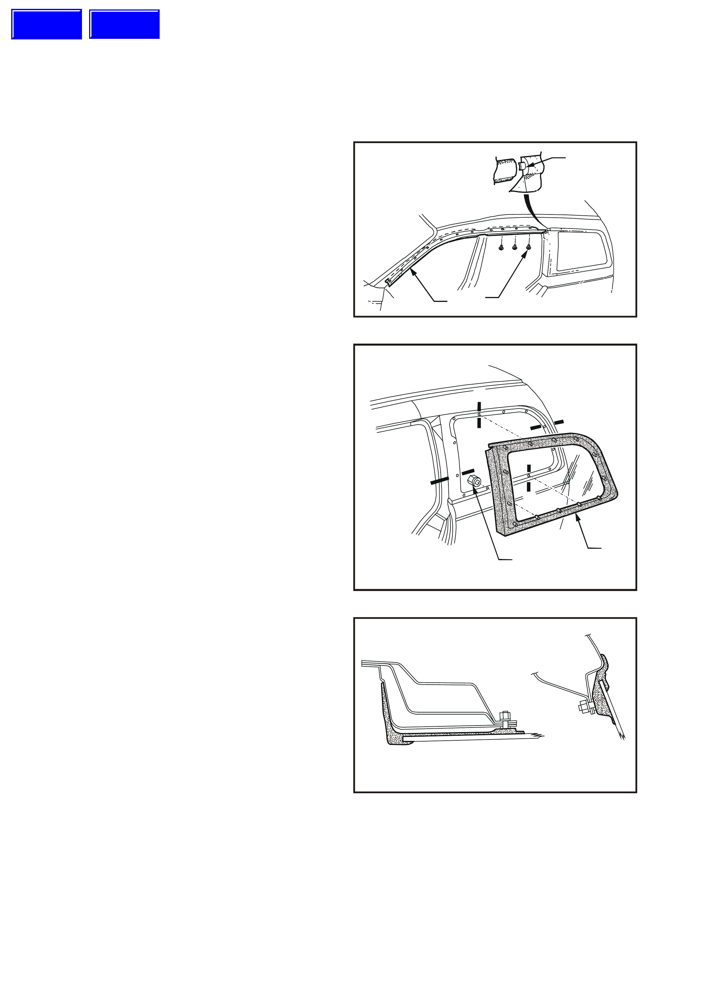
1. Partially remove the door frame opening
moulding (1) where it joins the quarter window
glass frame tab (3) by removing the moulding
screws (2) on the upper section of the
moulding, and release quarter window glass
frame tab (3). Refer to Section 1A9
EXTERIOR ORNAMENTATION of this Service
Information CD,
2. Remove the quarter window inner trim
moulding assembly, refer to Section 1A8
HEADLINING AND REAR END TRIM of this
Service Information CD.
T21A6021
1
3
2
Figure 1A6-29
3. Remove the 13 plastic nuts (1) securing the
quarter window (2) to the body opening and
carefully lift the window from the vehicle.
For sections A-A, and B-B refer to Fig. 1A6-31.
For sections C-C, and D-D refer to Fig. 1A6-32.
T21A6022
12
A
B
A
CC
D
D
B
Figure 1A6-30
T21A6023
B-B
A-A
Figure 1A6-31
Techline
Techline

T21A6024
C-C D-D
Figure 1A6-32
REINSTALL
Reverse removal operations with the following
additional procedure.
Leave the quarter window plastic nuts loose until
door frame opening moulding is fastened in
position. Position quarter window and tighten the
quarter window plastic nuts to the correct torque
specification.
QUARTER WINDOW
PLASTIC NUTS
TORQUE SPECIFICATION 1 – 3 Nm
NOTE: Should the foam weatherstrip which seals
the window to the body opening require
replacement, sections are available. Refer to the
VT Series parts information for details.
3.3 TAILGATE WINDOW — STATION WAGONS
REMOVE
CAUTION: Safety glasses and work gloves
must be worn at all times when operating with
glass.
1. Disconnect battery ground cable.
2. Place protective covering around tailgate
opening.
3. Remove rear wiper blade and arm assembly,
refer to Section 12C INSTRUMENTS,
WIPERS, WASHERS & HORN of this Service
Information CD.
4. Remove rear window washer nozzle, refer to
Section 1A4 REAR COMPARTMENT LID
AND TAILGATE of this Service Information
CD.
5. Remove the tailgate panel upper and lower
trim, refer to Section 1A4 REAR
COMPARTMENT LID AND TAILGATE of this
Service Information CD.
6. Carefully disconnect the tailgate electrical
demister connectors.
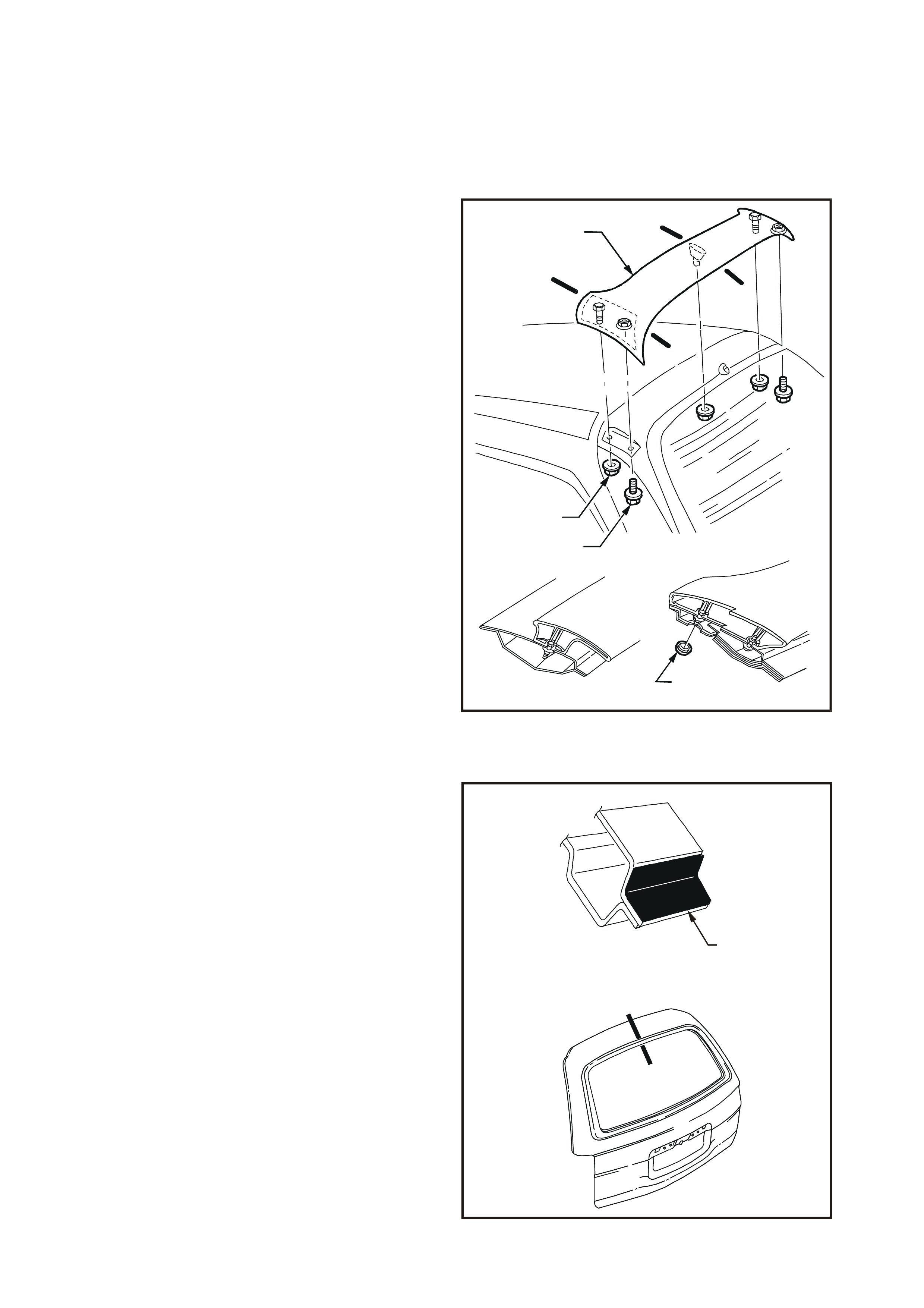
7. Remove the two cover plugs (1), three nuts (2)
and two screws (3) securing the tailgate air
deflector and remove the assembly.
8. Should the glass be broken, carefully remove
all fragments of glass from the tailgate window
opening. Otherwise, carefully cut out the tail
gate window by following the procedure set out
in Steps 12 to 15 of 3.1 WINDSHIELD GLASS
in this Section.
NOTE: It is not necessary to remove all traces of
the original urethane. However, any original
urethane remaining must be smooth and firm.
T21A6025
1
2
4
3
A
A
-A B-B
B
B
A
Figure 1A6-33
LONG METHOD INSTALLATION
1. Using one of the applicators in the service kit,
apply flange primer (1) to any section of the
tailgate opening flange that has been cleaned
back to bare metal or to be painted. Allow this
primer to dry for 15 minutes.
IMPORTANT: Do not touch primed surfaces.
2. Thoroughly clean the inner surface and edges
of the tailgate glass to which the urethane is to
be applied, using clean lint-free cloths and a
suitable oil free cleaning solvent.
T21A6035
A
A
1
A-A
Figure 1A6-34
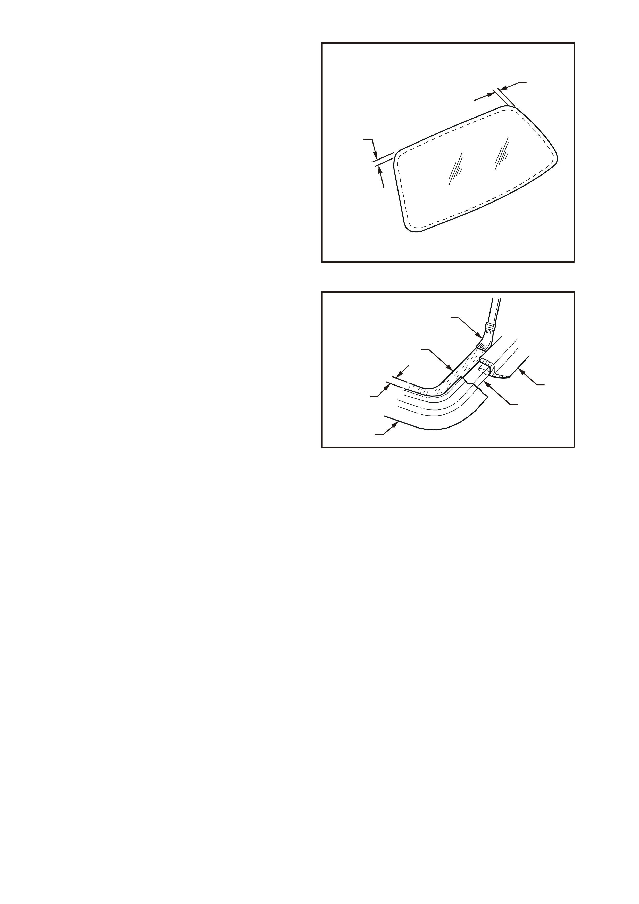
3. Apply clear glass primer to inner surface of
glass around the perimeter of the tailgate over
the width of the solid black ceramic pattern (or
a width of 50 mm) and immediately wipe off
with a lint-free cloth.
4. Check the condition of the tailgate moulding
and replace if damaged. Fit the tailgate
moulding over the edge of the glass, with
moulding joint at centre line upper side of
glass, ensure moulding is fitted correctly to
glass.
T21A6026
50mm
50mm
Figure 1A6-35
5. Using the applicator (1) included in the service
kit, apply black glass primer (2) to the tailgate
glass (3) alongside the moulding (4). Primer
application should be to a width of 20 mm
around the entire perimeter and over the
Holden logo.
T21A6027
4
3
1
2
4
20mm
Figure 1A6-36
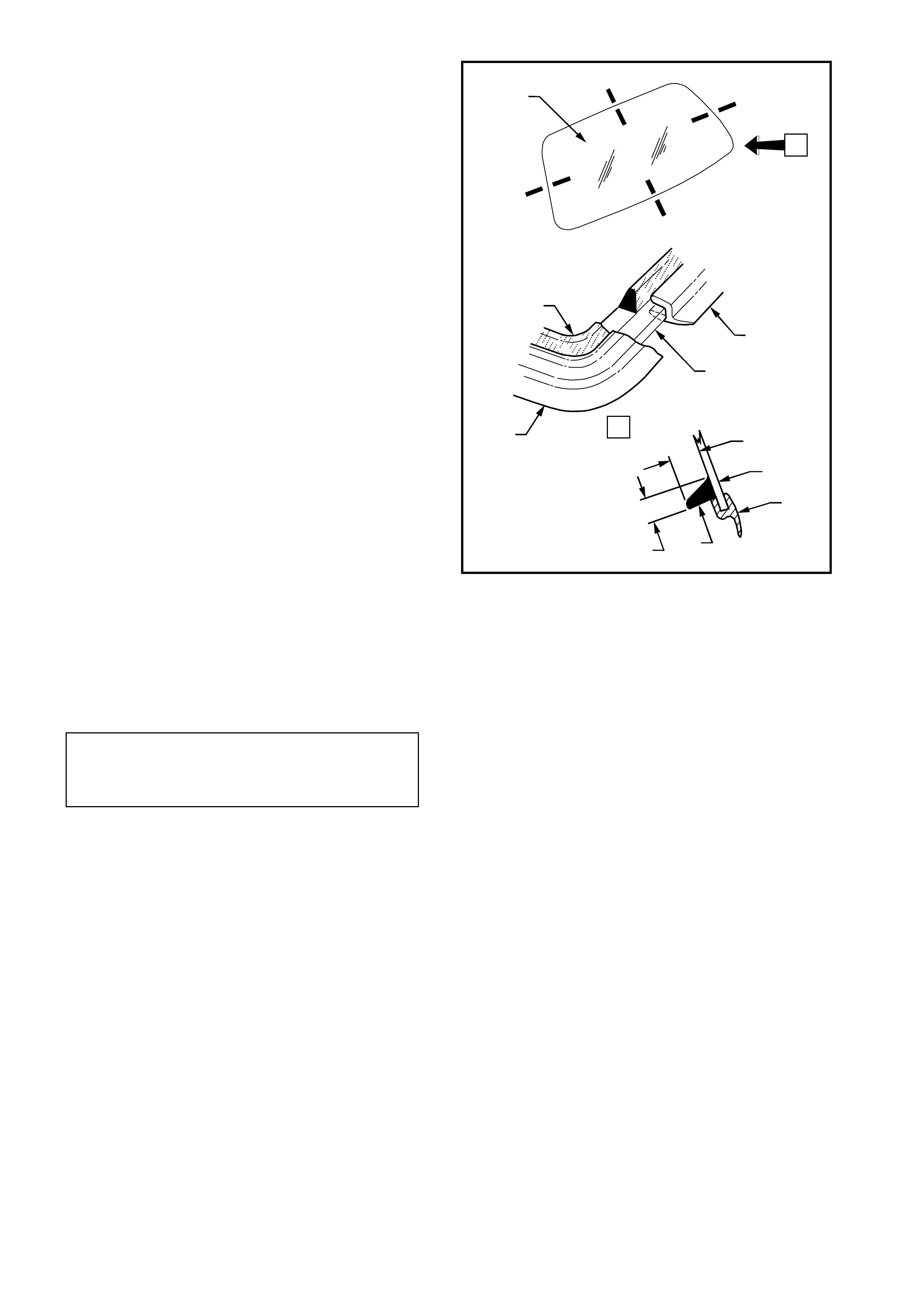
6. Using a hand or automatic applicator, apply a
smooth continuous bead of urethane (1), such
as Betaseal 587.02 or equivalent, to the tailgate
glass (2) alongside the m oulding (3). T he bead
dimensions are shown in Fig. 1A6-37.
NOTE: In cold weather, the placement of c artr idges
adjacent to a source of warmth will assist the flow
of urethane when using a hand applicator.
7. With the aid of an assistant, install the tailgate
glass and press the glass firmly into position.
8. Check effectiveness of sealing from inside of
the vehicle. Should any gaps in the sealing
exist, apply additional urethane on the outside
to fill these gaps. Using a spatula, smooth the
surf ace of the urethane around the edge on the
outside of the tailgate to ensure effective
sealing.
9. W ater test the tailgate, using a m oderate spray
of water.
NOTE: Do not direct a heavy stream of water onto
freshly applied urethane. If a leak is evident, apply
additional urethane to the leak area, using a
spatula to work urethane into source of leak.
IMPORTANT: If silicon is used for spot sealing,
allow a minimum of 1 hour to permit the silicon to
skin and adhere to the original urethane prior to
water testing the repair.
10. Clean off any excess urethane/silicon using
Prepsol or white spirit.
T21A6028
14 mm
+3
–0
2
3
1
7 mm
+3
–0
A-A
1
3
2
3
A
2
A
A
A
A
AA
A
A
A
Figure 1A6-37
11. Install the tailgate air deflector and secure with
three nuts and two screws. Tighten the nuts
and screws to the correct torque specification.
TAILGATE AIR DEFLECTOR
RETAINING NUTS
AND SCREWS
TORQUE SPECIFICATION
2 – 5 Nm
12. Connect the tailgate electrical demister
connectors, then clean the tailgate and
surrounding area.
CAUTION: Ensure that door windows are
partially lowered to eliminate pressure build up
which can be caused by slamming doors. A
curing time of 24 hours is recommended,
although the vehicle may be driven after 5
hours, providing it is driven only on a smooth
road at speeds not exceeding 80 km/h.
SHORT METHOD INSTALLATION
The short method of installation for the tailgate is
the same as that detailed in 3.1 WINDSHIELD
GLASS in this Section. Note that the clear and
black primers must follow the entire perimeter of
the tailgate glass.

3.4 BACK WINDOW — SEDANS
REMOVE
CAUTION: Safety glasses and work gloves
must be worn at all times when operating with
glass.
1. Disconnect battery ground cable.
2. Place protective covering adjacent to back
window to protect trim and paint finish.
3. Remove the right-hand and left-hand side roof
finisher mouldings, refer to Section 1A9
EXTERIOR ORNAMENTATION of this Service
Information CD.
4. Remove the rear window inner trim moulding
assembly, refer to Section 1A8 HEADLINING
AND REAR END TRIM of this Service
Information CD.
5. Carefully disconnect the back window electrical
demister connectors.
6. Should the glass be broken, carefully remove
all fragments of glass from the back window
opening. Otherwise, carefully cut out the back
window glass by following the procedure set
out in Steps 12 to 15 of 3.1 WINDSHIELD
GLASS in this Section.
NOTE: It is not necessary to remove all traces of
the original urethane. However, any original
urethane remaining must be smooth and firm.
Body Opening Check
1. Thoroughly check the back window opening
flange fo r any irregularities before inst allation of
replacement window.
CAUTION: Care should be taken to ensure that
glass does not strike the back window opening.
Chipped edges can lead to subsequent
breakage of glass.
2. Check and if necessary, re-form the body
flange to produce a uniform flange to glass
contour.
3. Correctly locate the glass in the body opening,
then tape mark the outer top of glass and roof
on the right-hand and left-hand sides. This
procedure will assist the alignm ent of the glass
in the correct horizontal plane during final
installation.
Techline
LONG METHOD INSTALLATION
1. Using one of the applicators in the service kit,
apply flange primer (1) to any section of the
back window opening flange that has been
cleaned back to bare metal or to be painted.
Allow this primer to dry for 15 minutes.
IMPORTANT: Do not touch primed surfaces.
2. Thoroughly clean the inner surface and edges
of the back window glass to which the ur ethane
is to be applied, using clean lint- free cloths and
a suitable oil free cleaning solvent.
T21A6036
1
A
A
A-A
Figure 1A6-38
3. Apply clear glass primer to the inner surface of
glass around the perimeter of the back window
edge over a width of 50 mm and immediately
wipe off with a lint-free cloth.
T21A6029
50mm
50mm
Figure 1A6-39

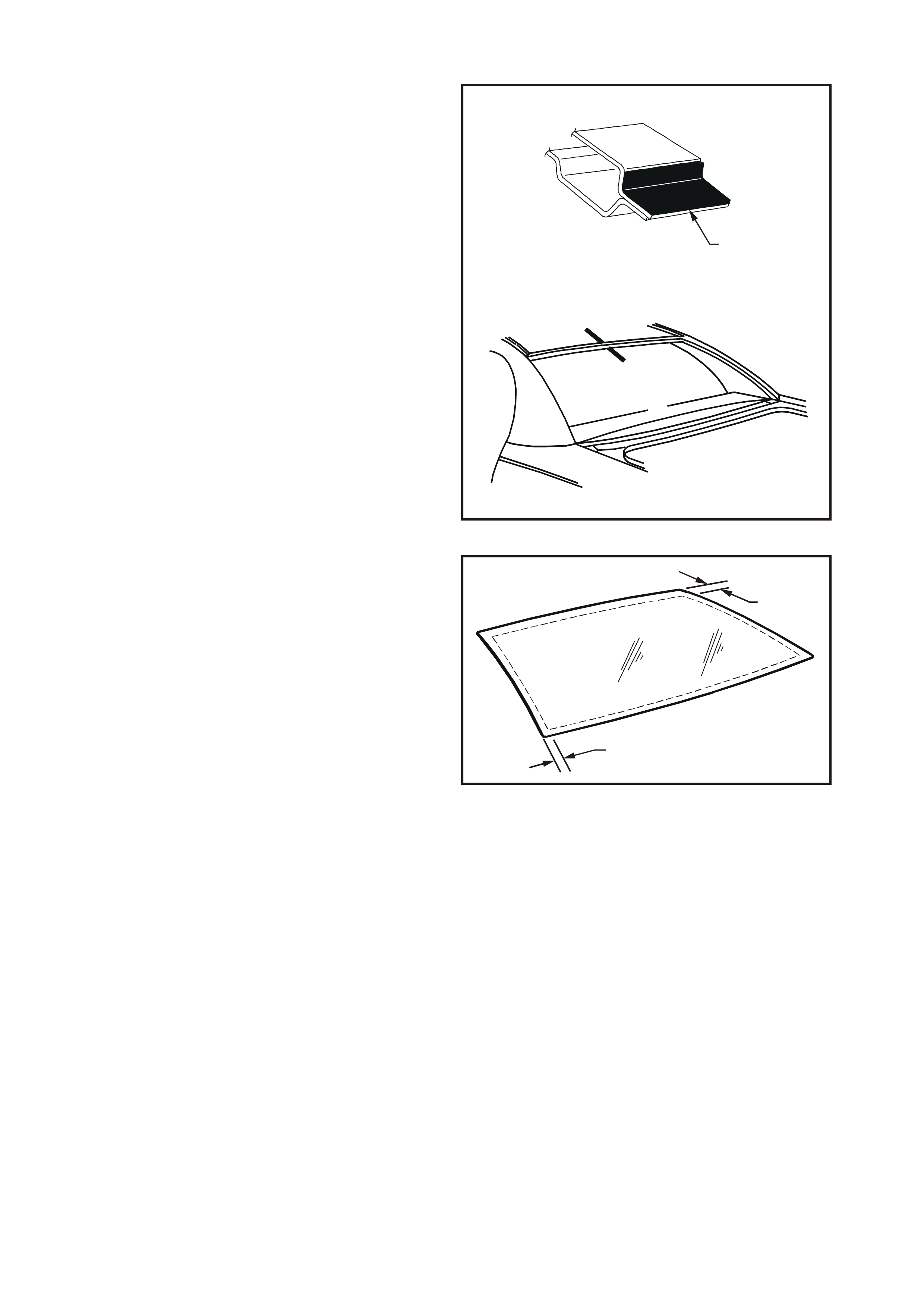
4. Check the condition of the back window
mouldings and replace if damaged. Install the
back window upper moulding (1) and lower
moulding (2) over the edge of the glass,
ensuring that each moulding is fitted correctly
to the glass. Refer to Fig. 1A6-40.
5. Install two roof to glass retaining m ouldings (3)
to left-hand and right-hand sides of glass.
Ensure that mouldings are positioned to
alignment marks (4), and are fitted correctly to
edge of glass.
6. Using the applicator (5) included in the service
kit, apply black glass primer (6) around the
perimeter of the back window glass bonding
surf ace over a width of 20 m m along the inside
edge of back window mouldings.
7. Using a hand or automatic applicator, apply a
smooth continuous bead of urethane (7), such
as Betaseal 587.02, 15.685 (High Viscosity) or
equivalent (to Holden Specification HN2293),
inboard of the mouldings around the entire
perimeter of the body opening. The urethane
bead should be as specified in Fig. 1A6-40.
NOTE: In cold weather, the placement of c artr idges
adjacent to a source of warmth will assist the flow
of urethane when using a hand applicator.
8. With the aid of an assistant, install the back
window glass and press the glass firmly into
position.
NOTE 1: Ensure glass is centralised in body
opening left to right by checking that the gaps
between the glass moulding and C-pillar are even
on both sides of the vehicle.
NOTE 2: Ensure windscreen glass moulding is
under-f lush with roof opening to pr event wind noise
occuring.

Figure 1A6-40
1. Upper moulding 3. Roof-to-glass
retaining moulding 5. Applicator 7. Urethane
2. Lower moulding 4. Alignment marks 6. Black glass primer
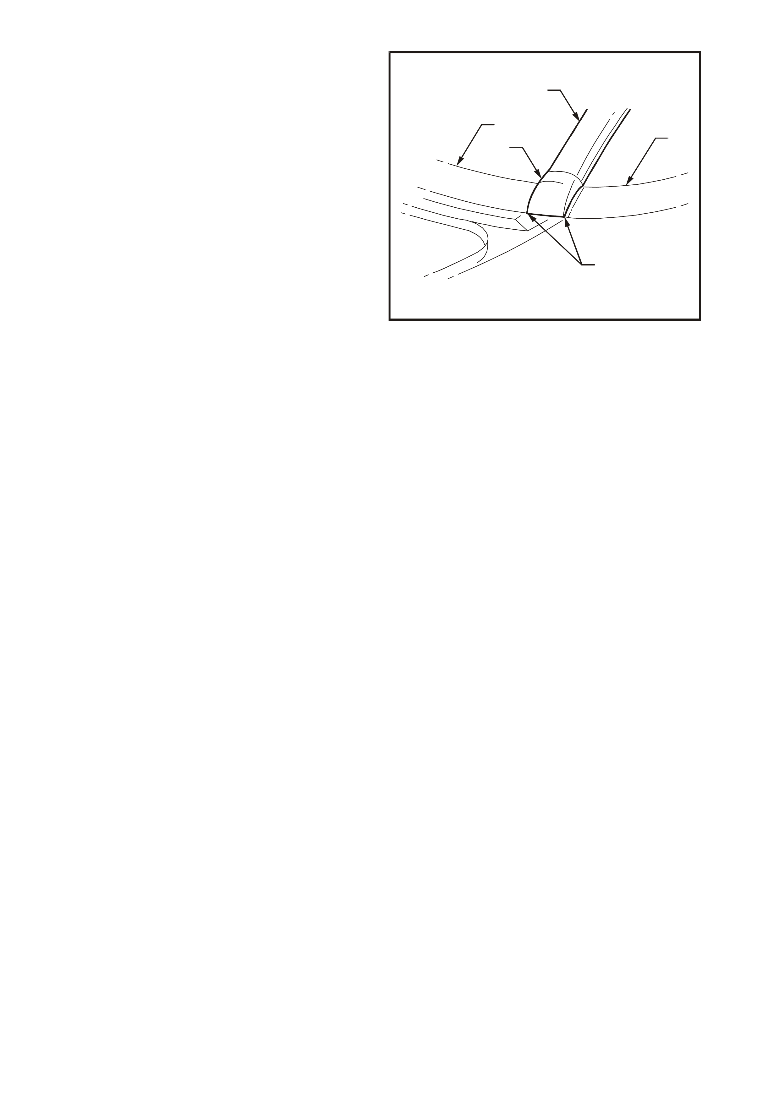
9. Engage the roof finisher moulding assembly
over side moulding as shown in Fig. 1A6-41
and slide along until roof finis her m oulding is in
position (refer to Fig. 1A6-42).
10. Engage roof finisher moulding assembly clips
along roof until r oof f inisher m oulding as sem bly
sits flush against roof, refer to Section 1A9
EXTERIOR ORNAMENTATION of this Service
Information CD. The following items are
illustrated in Fig. 1A6-41:
1. Roof finisher moulding.
2. Notch (locate over window moulding).
3. C-pillar.
4. Back window glass.
5. Back window side moulding.
6. Urethane bead.
7. Roof panel.
8. Roof finisher moulding locating clips
(seven places, ensure lead clip is installed
under roof panel flange).
NOTE: Front of roof finisher moulding must be
installed under windshield moulding cover.
IMPORTANT: Roof finisher mouldings must be
fitted within 10 minutes of installing glass.
T21A6031
21
8
5
8
3
1
1
6
7
4
3
B
B-B
A-A
B
A
A
Figure 1A6-41
NOTE: Ensure that the end cap of the roof finisher
moulding is aligned with quarter panel to roof
moulding. The following items are illustrated in
Fig. 1A6-42:
1. Roof finisher moulding.
2. C-pillar.
3. Roof finisher moulding end cap.
4. Back window lower moulding.
5. End cap of roof finisher moulding to be in
line with items 2 and 4.
11. Check effectiveness of sealing from inside of
the vehicle. Should any gaps in the sealing
exist, apply additional urethane on the outside
to fill these gaps. Using a spatula, smooth the
surf ace of the urethane around the edge on the
outside of the back window to ensure effective
sealing.
12. Water test using a moderate spray of water.
NOTE: Do not direct a heavy stream of water onto
freshly applied urethane. If a leak is evident, apply
additional urethane to the leak area, using a
spatula to work urethane into source of leak.
IMPORTANT: If silicon is used for spot sealing,
allow a minimum of 1 hour to permit the silicon to
skin and adhere to the original urethane prior to
water testing the repair.
13. Clean off any excess urethane/silicon using
Prepsol or white spirit, then remove the
masking tape previously installed.
14. Connect the electrical demist connectors, then
clean the rear window and surrounding area.
CAUTION: Ensure that door windows are
partially lowered to eliminate pressure build up
which can be caused by slamming doors. A
curing time 24 hours is recommended,
although the vehicle may be driven after 5
hours, provided it is driven only on a smooth
road at speeds not exceeding 80 km/h.
T21A6032
4
1
3
5
2
Figure 1A6-42

3.5 MINOR WATER LEAK CORRECTION
1. Secure protective covering with masking tape
adjacent to the leak suspect area.
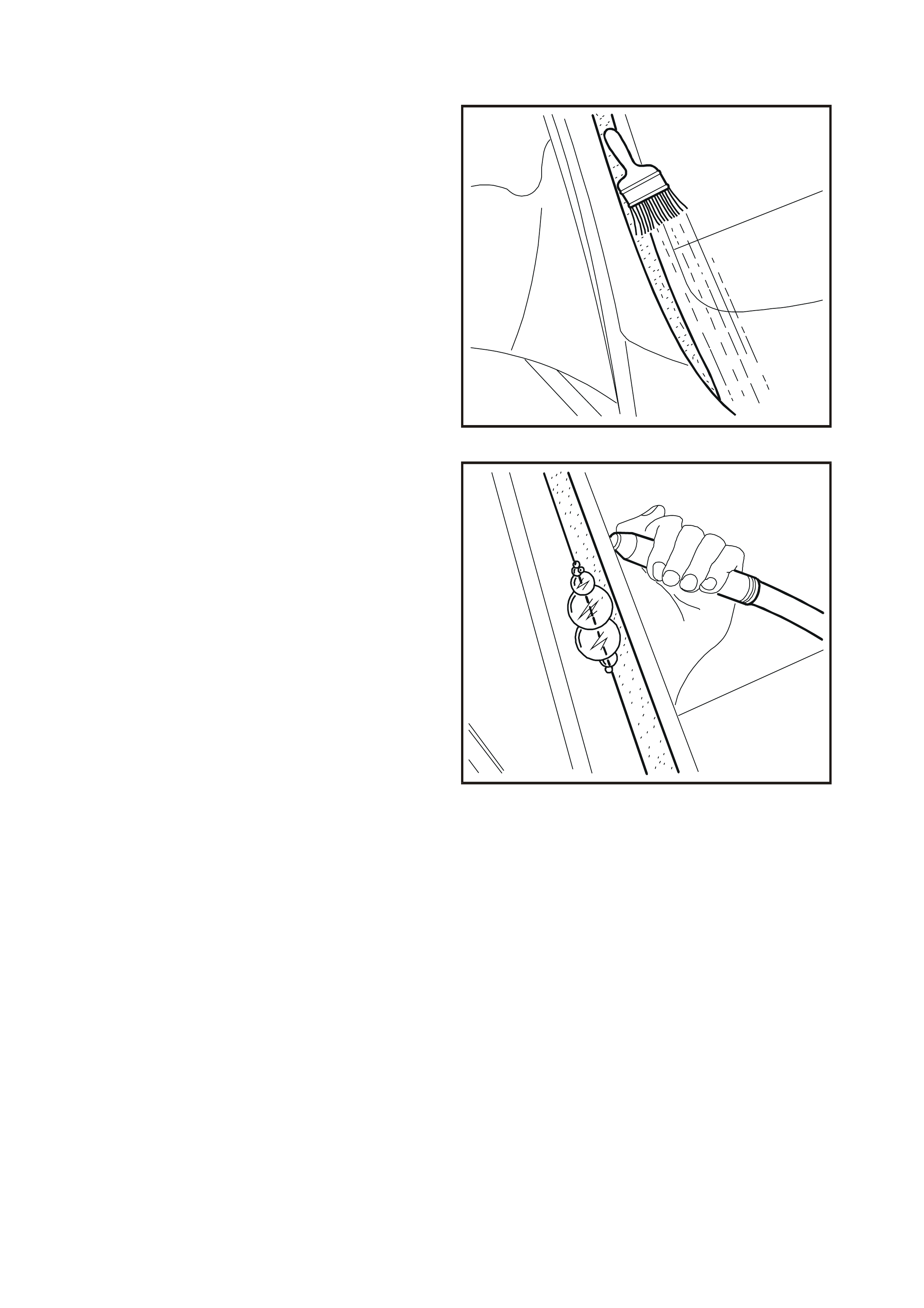
NOTE: To determine the precise location of the
water leak, use the air/soap bubble leak test. The
soap/water solution can be applied with either a
spray applicator or brush as illustrated in Fig. 1A6-
43.
2. Locate an air hose nozzle on the inside of the
windshield as illustrated in Fig. 1A6-44. Have
an assistant outside the vehicle apply a soapy
water solution opposite the air s ource. As a low
air pressure (60 kPa) is applied, soap bubbles
will form on the outside of the windshield,
indicating the location of the leak.
3. If the suspect leak area is not obvious,
com mence the tes ting ac ros s the top and down
the sides until the leak location has been
determined.
T21A6033
Figure 1A6-43
4. It may be necessary to lift or remove moulding
covering the leak location.
NOTE 1: If silicon is to be used, thoroughly dry out
the repair area with compressed air.
NOTE 2: If urethane is to be used, it is only
necessary to remove dust, foreign matter, etc.
Water activates the curing process of urethane.
5. Using a spatula, work fresh urethane or silicon
in and around the leak area.
6. If urethane has been used, leak test the repair ,
using the air/soap bubble leak test or a non-
pressurised water leak test.
IMPORTANT: If silicon is used for spot sealing,
allow a minimum of 1 hour to permit the silicon to
skin and adhere to the original urethane prior to
testing the repair. Should the leak persist, apply
additional urethane/silicon until the leak has been
corrected.
7. Secure the section of moulding lifted or
removed to carry out the leak correction.
8. Remove the masking tape and protective
covers, then clean the glass and adjacent paint
and trim surfaces.
T21A6034
Figure 1A6-44

4. TORQUE WRENCH SPECIFI CATIONS
Nm
Instrument Panel and Cap Cover Attachment Screws ......... 1 – 3
Demist Nozzle Securing Screws........................................... 1 – 3
Quarter Window Plastic Securing Nuts................................. 1 – 3
Tailgate Air Deflector Securing Nuts and Screws................. 2 – 5

5. SPECIAL TOOLS
TOOL NO. REF IN TEXT TOOL DESCRIPTION COMMENTS
AU390 FABRICATED T HANDLE WINDSCREEN
REMOVAL TOOL AND PIANO WIRE
AU390-1 PIANO WIRE
J39032 STATIONARY GLASS REMOVAL TOOL