
SECTION 1A7 - SEAT & SEAT BELT ASSEMBLIES
CAUTION:
This vehicle will be equipped with a Supplemental Restraint System (SRS). A SRS will consist of either
seat belt pre-tensioners and a driver's air bag, seat belt pre-tensioners and a driver's and front
passenger's air bag s or seat belt pre- tensio ners, d riv er’s and fron t p asseng er’s air bag and lef t and rig ht
hand side air bags. Refer to SAFETY PRECAUTIONS, Section 12M Supplemental Restraint System of
this Service Information CD before performing any service operation on, or around any SRS
components, the steering mechanism or wiring. Failure to follow the SAFETY PRECAUTIONS could
result in SRS deployment, resulting in possible personal injury or unnecessary SRS system repairs.
CAUTION:
This vehicle may be equipped with LPG (Liquefied Petroleum Gas). In the interests of safety, the LPG
fuel system should be isolated by turning 'OFF' the manual service valve and then draining the LPG
service lines, before any service work is carried out on the vehicle. Refer to the LPG leaflet included with
the Owner's Handbook for details or the appropriate Section of this Service Information CD for more
specific servicing information.
1. GENERAL DESCRIPTI ON
Since the VT Series Service Information CD was first published, there have been several changes to the seats. The
information contained in this Section provides a summary of these changes, together with any relevant Service
Operations, Diagnostic Procedures and Specifications.
Noting the following Cautions, information, including General Description, Service Operations, Diagnosis,
Specifications and Special Tools, that is not covered in this Section, refer to Section 1A7 SEAT & SEAT BELT
ASSEMBLIES of the VT Series I Service Information.
Thes e following Cautions apply to Service Operations detailed in both this Sec tion and thos e pr eviously published in
Section 1A7 SEAT A ND SEAT BELT ASSEMBLIES of the VT Series I Service Information.
CAUTION: Before performing any Service Operation on a front seat assembly, ensure the SRS is disabled.
Refer to Section 12M SUPPLEMENTAL RESTRAINT SYSTEM of the VT Series I Service Information.
CAUTION: Accessory and after market seat covers MUST NOT be fitted to a vehicle with side impact air
bags unless approved by Holden Ltd. Seat covers that are not approved by Holden Ltd. could greatly inhibit
the performance of the side impact air bag and occupants safety in the event of side impact air bag
deployment.
SUMMARY OF CHANGES
In August 1998, side impact air bags became available as an option to VT Series Models. With the availability of this
option, a revised procedure for disassembling and reassembling the front seat has been developed.
For additional information, including the removal and reinstallation of a side impact air bag module assembly,
refer to Section 12M SUPPLEMENTAL RESTRAINT SYSTEM of the VT Series I Service Information.
New lumbar support knob for vehicles with side impact air bags.
NOTE: If a lumbar support knob requires replacement, and the vehicle is equipped with side impact air bags,
only install this new type lumbar support knob which has been modified to suit side impact air bag applications.
New seat fabrics / colours for VT Series II Models.
Since the start of VT Ser ies vehicle production, var ious fas tener types and tor que wrench s pecifications have been
revised. Therefore, 4. TORQUE WRENCH SPECIFICATIONS in this Section has been revised to reflect these
changes and re-published in full. Whenever tightening a seat or seat belt fast ener on a VT Series Model, referenc e
to this Section should be made.
From vehicle Tag Number L423680 there was a revision to the wiring on the four way seat electric motors.
Previously, the electric seat motors were constantly supplied with power and connected to earth to activate. With
this wiring revision, the seat m otors ar e constantly earthed and connected to battery voltage to activate. As a result
of this change, there have been some revisions to the diagnostic procedures, refer to 3. DIAGNOSTICS in this
Section.
NOTE: The wiring of the eight way electric seat remains unchanged. Eight way electric seat m otors are constantly
earthed and connected to battery voltage to activate.
Techline
Techline
Techline
Techline
2. SERVICE OPERATIONS
2.1 FRONT BUCKET SEAT ASSEMBLY
REMOVE
1. Position the relevant front seat to obtain the
easiest access to the seats four retaining bolts
and, if possible, the seat should be fully raised
and the seat back tilted forward.
2. Disable the SRS, refer to Section 12M
SUPPLEMENTAL RESTRAINT SYSTEM of
the VT Series I Service Information.
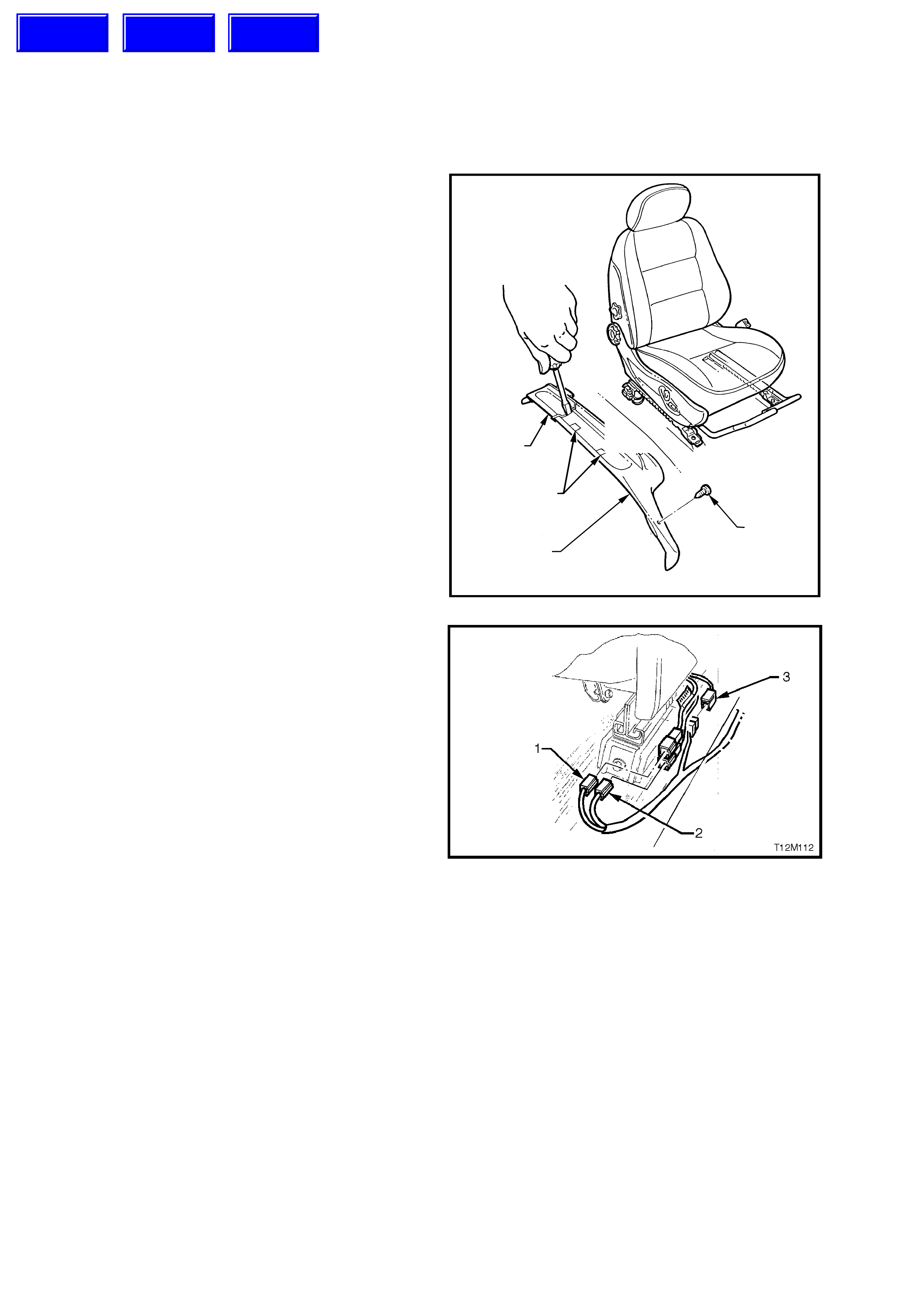
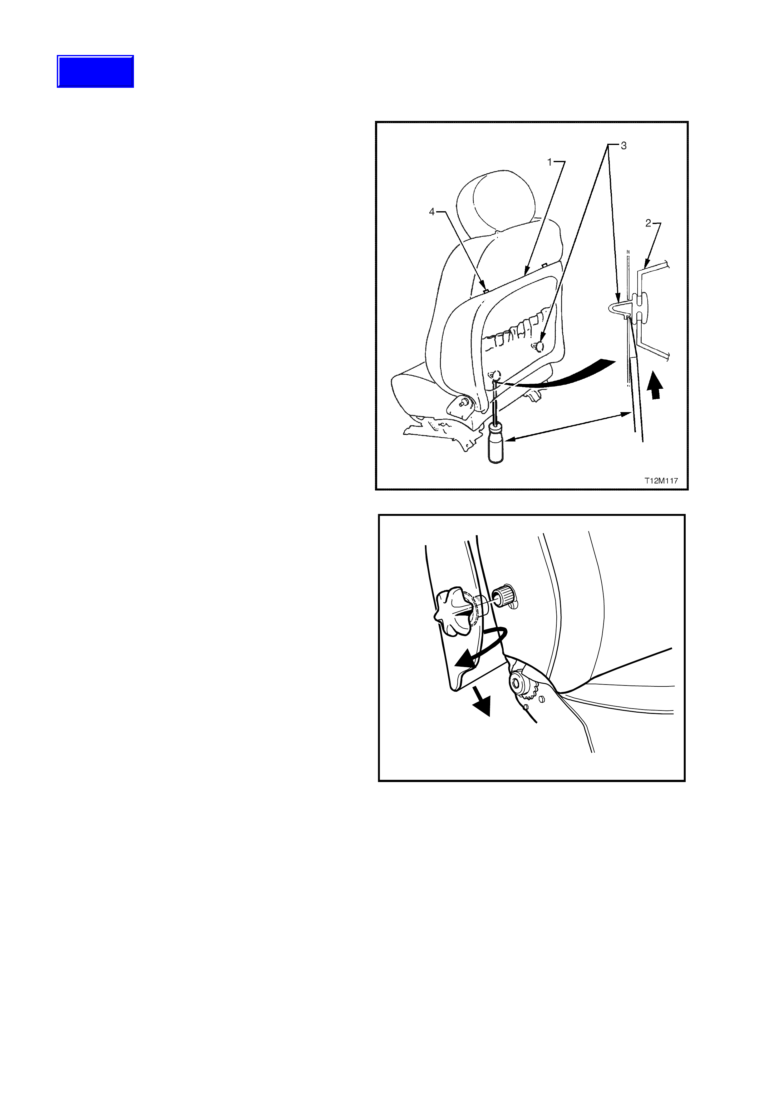
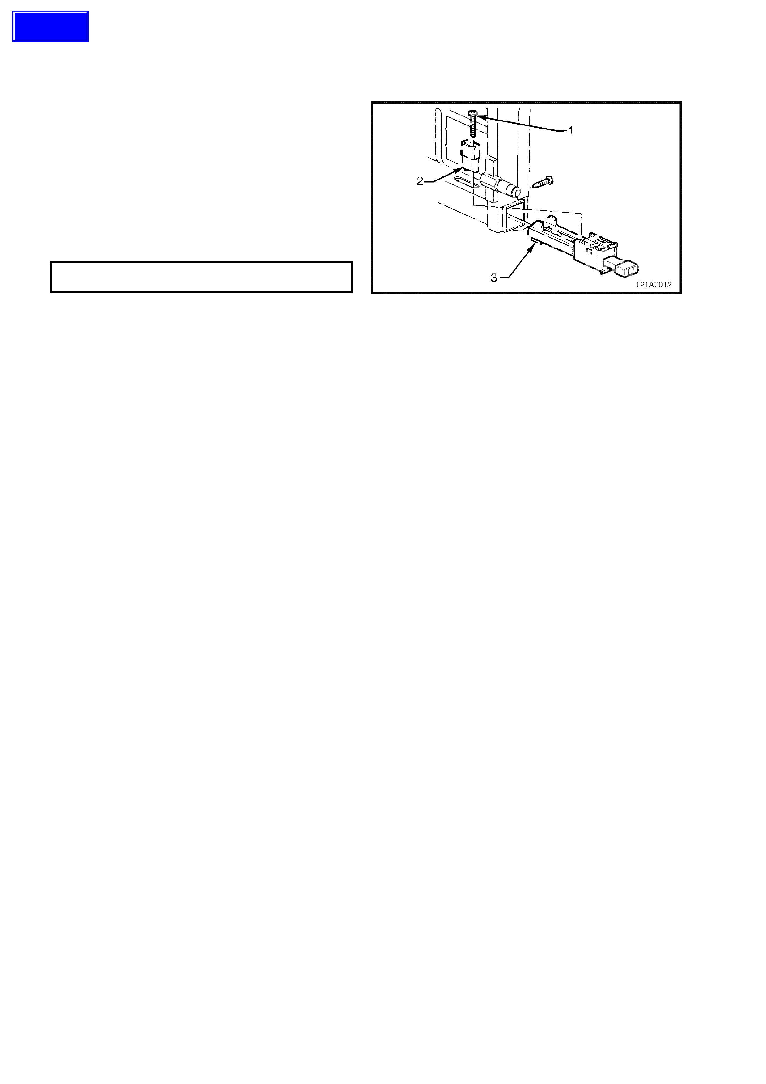
3. If removing the driver’s seat, remove the
retaining screw (1) from the driver’s side outer
front guide rail cover.
4. Using a small screwdriver, push in the centre of
the front (3) and rear (2) outer seat guide rail
covers where the two parts meet.
5. Remove the front outer guide rail covers by
lifting the outer edge of the front cover up and
pulling it forward. Lift driver’s outer front seat
guide rail cover over fuel filler door release
lever.
6. Lift the two rear guide r ail covers up and off the
guide rails.
2
1
T12M111
3
4
Figure 1A7-1
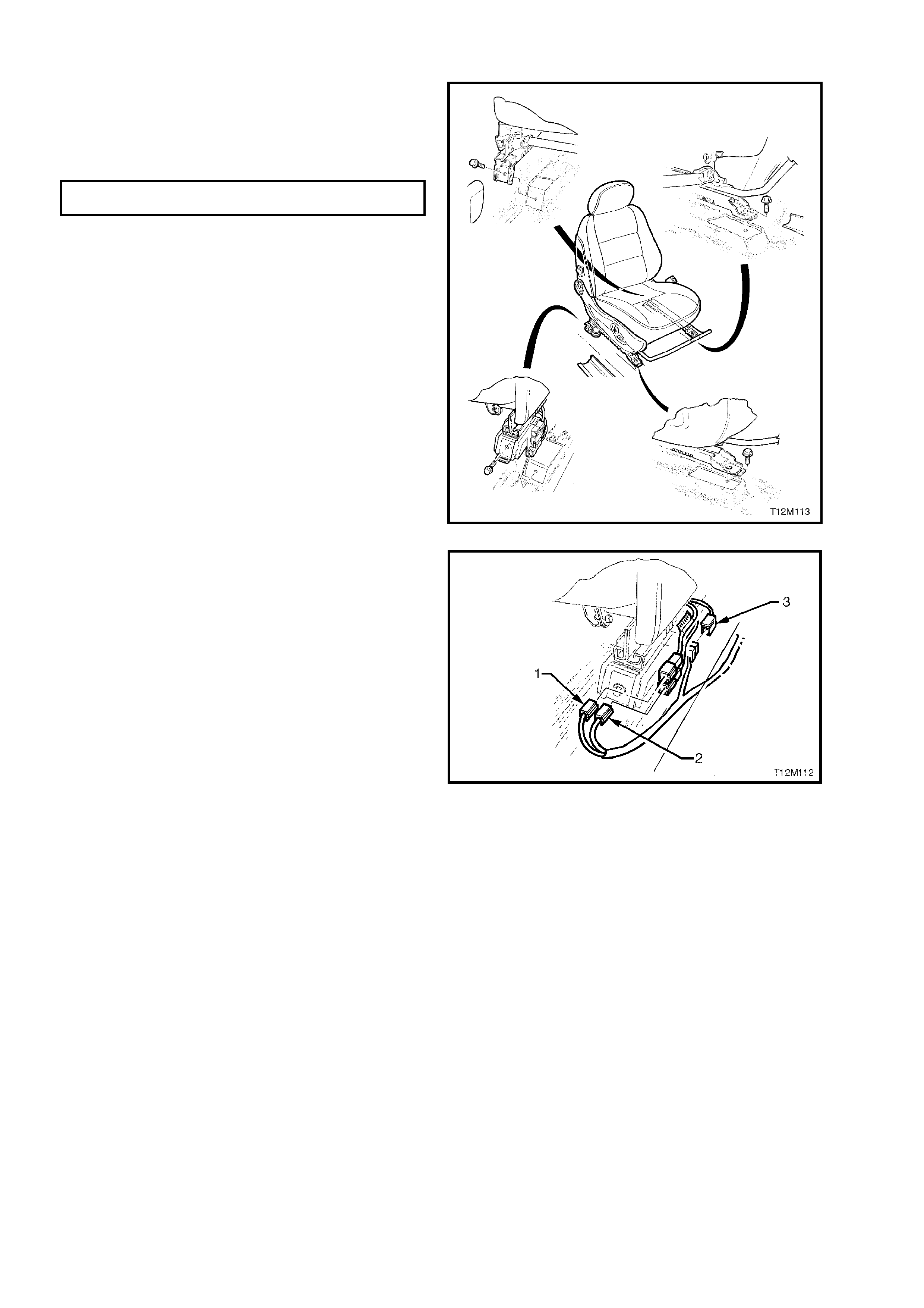
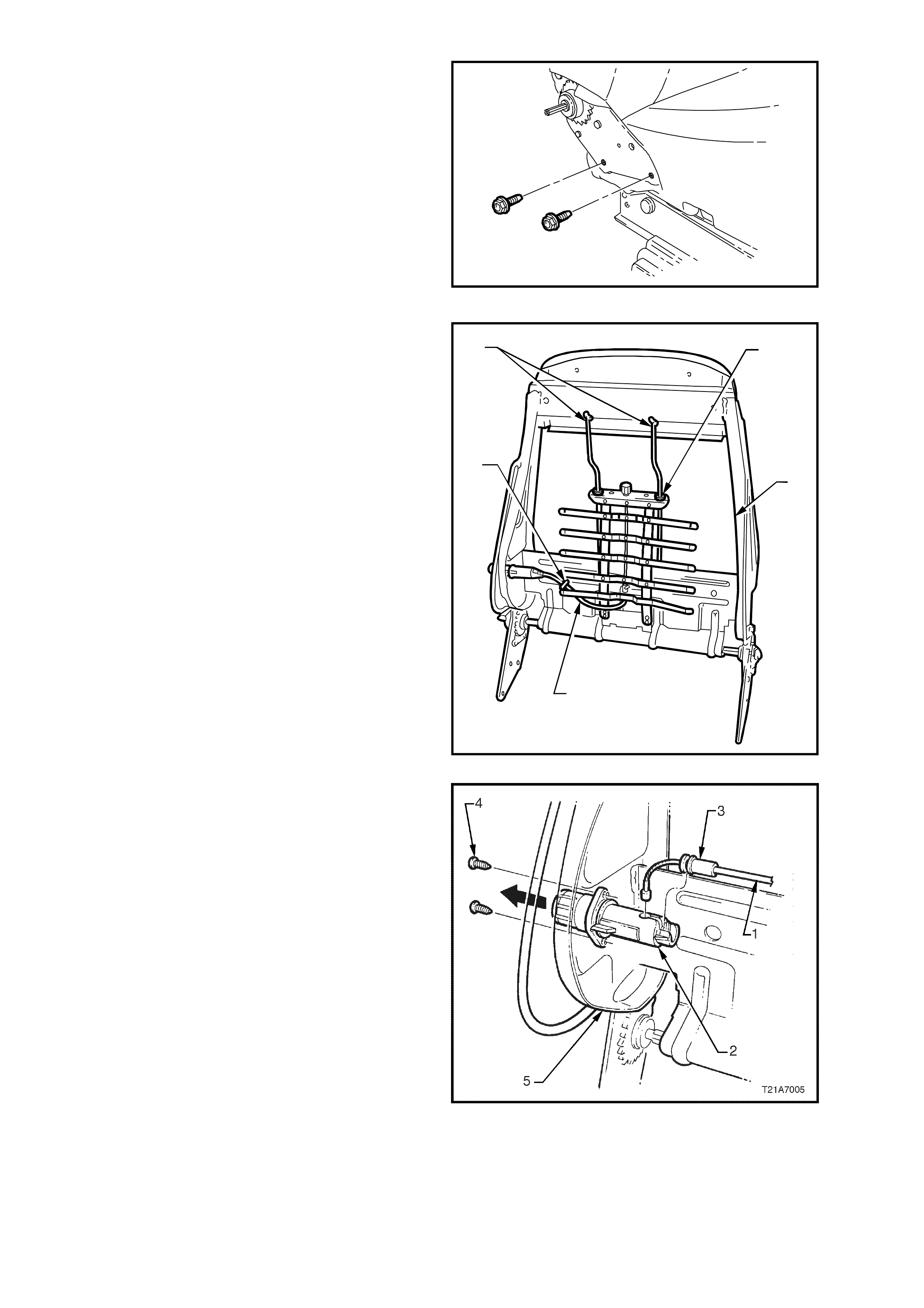
7. Disconnect seat (3), seat belt pre-tensioner (2)
and, if fitted, the side air bag m odule (1) wiring
harness connectors from outer side of the
relevant seat.
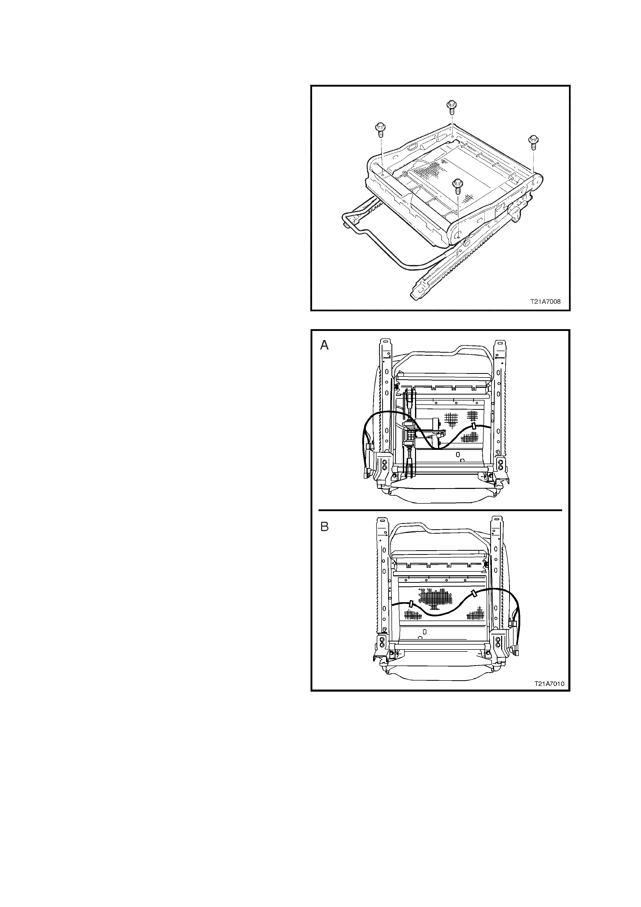
8. Remove the four bolts securing the front seat
to the floor and remove seat.
Figure 1A7-2
Techline
Techline
Techline
REINSTALL
1. Position the front seat assembly into the
vehicle.
2. Install the four bolts securing the front seat to
the floor and tighten to the correct torque
specification.
FRONT SEAT TO FLOOR SECURING 35 - 50
BOLT TORQUE SPECIFICATION Nm
Figure 1A7-3
3. Connect seat (3), pre-tensioner (2) and, if
fitted, side air bag module (1) wiring harness
connectors.
4. Align the front outer seat guide rail cover’s two
retaining clips and push firmly to engage.
NOTE: The two retaining clips can be aligned by
using the alignment marks on the upper side
of the cover, refer to Fig. 1A7-1, (4) in this
Section.
5. Push the front of the outer seat guide rail
cover down to engage cover with front of seat
rail.
6. If installing the driver’s side outer seat guide
rail cover, install the screw at the front of the
front outer seat guide rail cover.
7. Install the rear outer seat guide rail cover
lower rear retainer over the seat guide r ail and
push rear outer seat guide rail cover forward to
engage with front outer seat guide rail cover.
8. Enable the SRS, refer to Section 12M
SUPPLEMENTAL RESTRAINT SYSTEM of
this Service Information CD.
Figure 1A7-4

9. If the vehicle is equipped with side impact air
bags, switch ignition on, and observe the SRS
warning lamp in the instrument cluster. The
warning lamp should be illuminated for
approxim ately five seconds. During this period
the SDM performs a wiring and system self
check.
If no system faults are detected, the SRS
warning lamp will be switched off. If the
warning lamp remains illuminated and an
audible alarm chimes, or the warning lamp
illuminates two seconds after it was originally
switched off, an SRS fault is present. Refer to
Section 12M SUPPLEMENTAL RESTRAINT
SYSTEM of this Service Information CD.
10. Check operation of front seat mechanical and
electrical adjustments / operation. While
check ing the seat adjustm ent / operation, also
check to ensure that the seat wiring harnesses
do not foul with any of the seats moveable
components (ie. seat motor drive shafts, etc.).
2.2 LUMBAR SUPPORT ADJUSTER KNOB - VEHICLES WITHOUT
SIDE IMPACT AIR BAGS
REMOVE
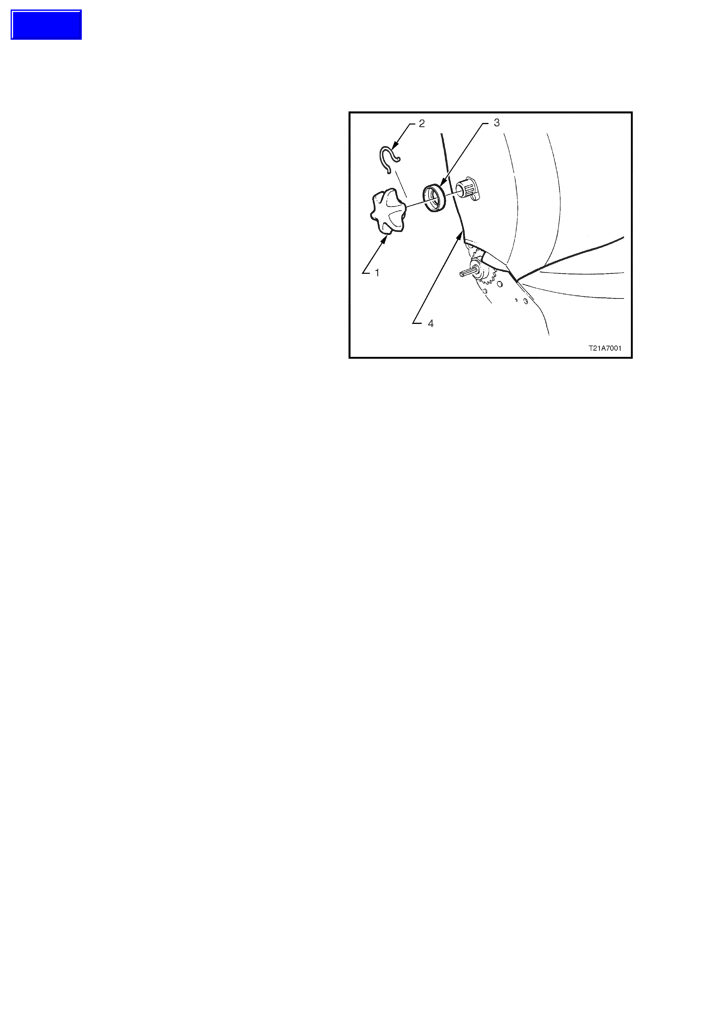
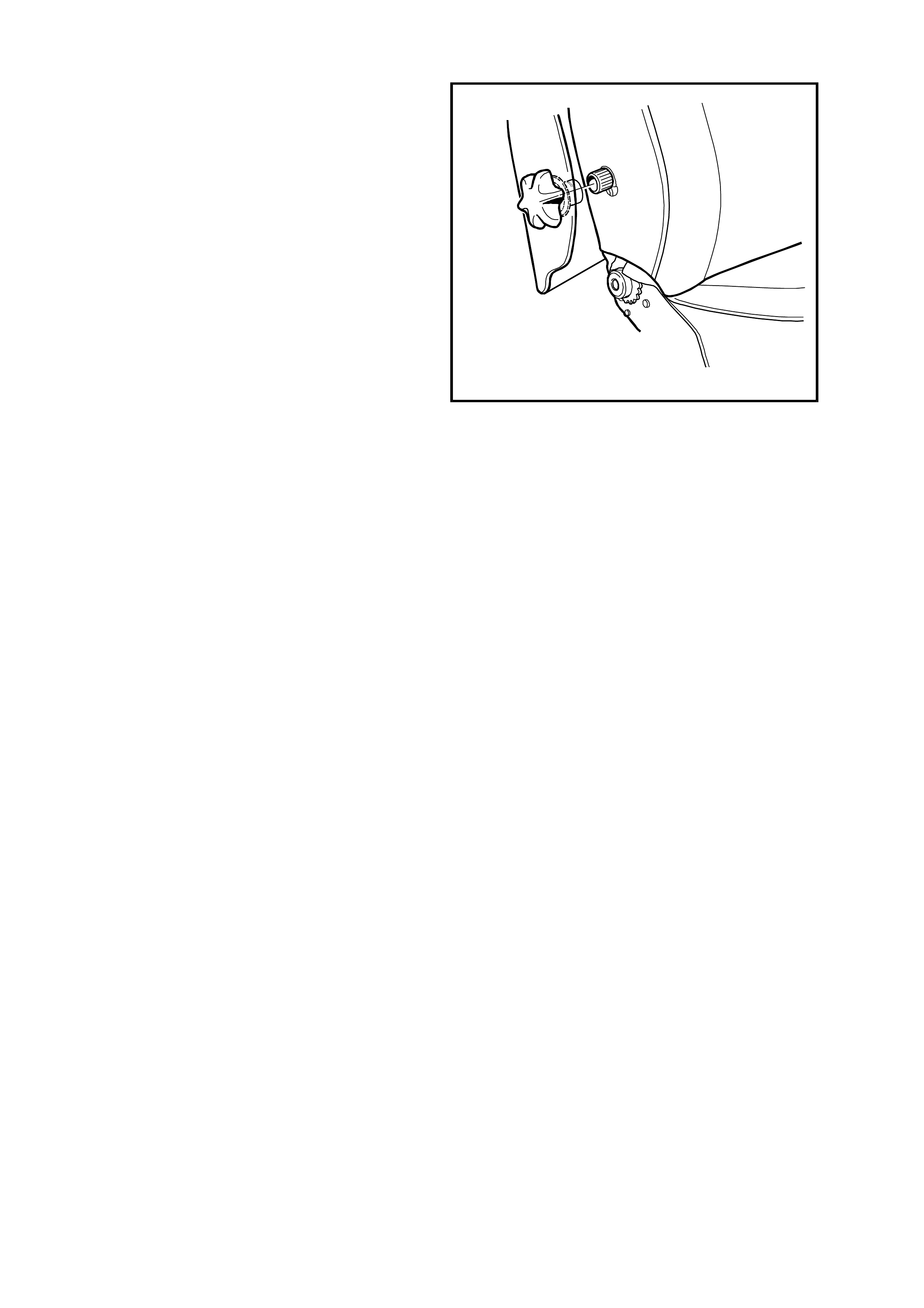
Remove lumbar support knob (1) by pushing seat
back cover (4) in far enough to expose circlip (2),
using a suitable pair of pliers or a small screw
driver, remove circlip and remove lumbar support
adjusting knob and spacer (3), refer Fig. to 1A7-5.
REINSTALL
1. Install circlip onto lumbar support adjusting
knob.
2. Ensure splines of lumbar support are correctly
aligned and push adjusting knob onto lumbar
adjuster shaft until circlip locks adjusting knob
into place.
Figure 1A7-5
Techline
2.3 FRONT SEAT BACK COVER- VEHICLES WITHOUT SIDE IMPACT AIR BAGS
REMOVE
1. Remove lumbar support adjusting knob, refer
to 2.2 LUMBAR SUPPORT ADJUSTER
KNOB in this Section.
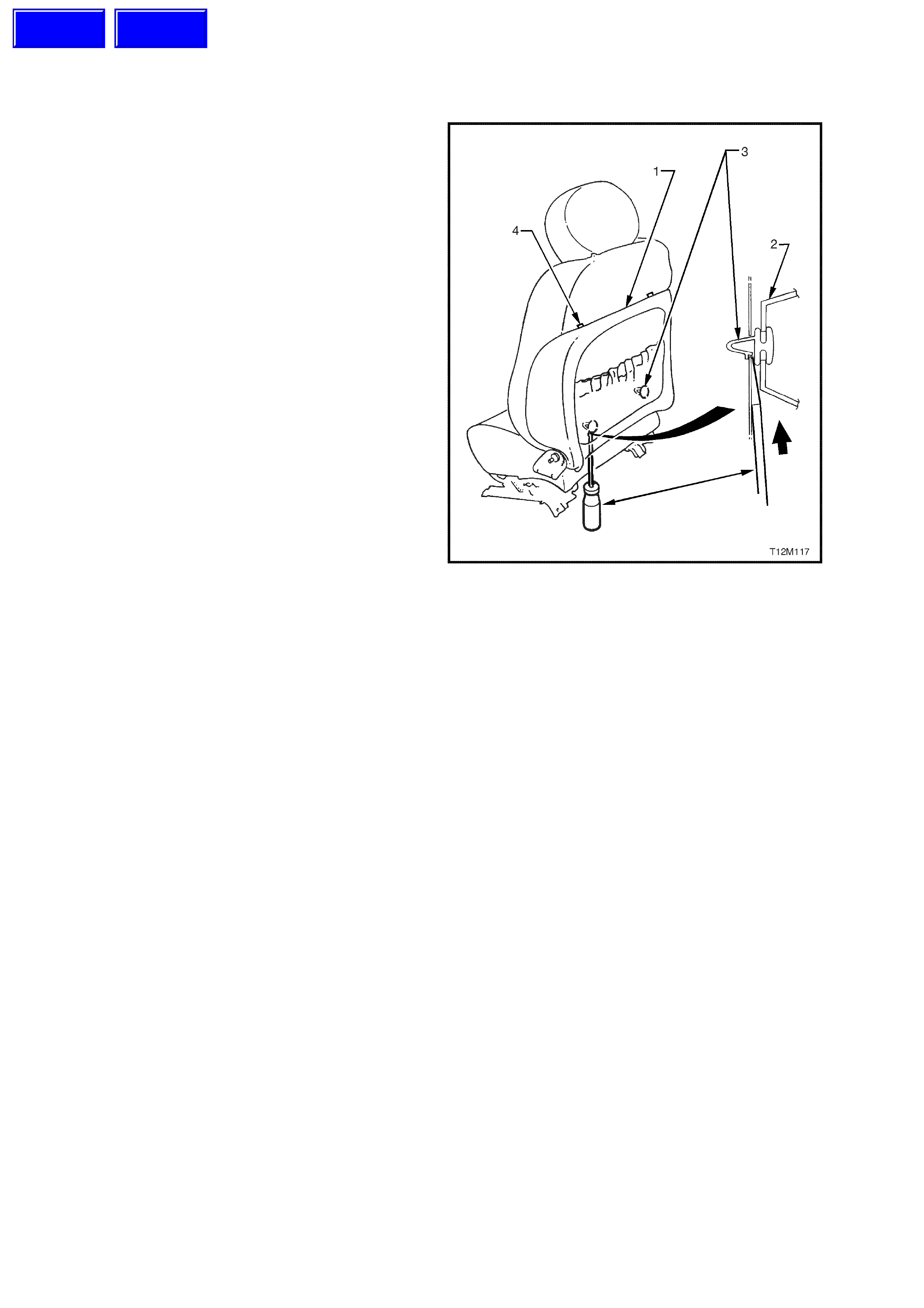
2. Insert a screwdriver between the seat back
cover (1) and seat back (2) and push up on the
retaining clip (3) (2 places) while pulling the
bottom of the back cover out, away from seat,
to release lower retaining clips, and then pull
back cover down to release top retainers (4).
Remove seat back cover.
REINSTALL
Reinstallation of the front seat back cover is the
reverse of the removal operation.
Figure 1A7-6
Techline
Techline
2.4 LUMBAR SUPPORT ADJUSTER KNOB & FRONT SEAT BACK
COVER ASSEMBLY - VEHICLES WITH SIDE IMPACT AIR BAGS
REMOVE
1. Insert a screwdriver between the seat back
cover (1) and seat back (2) and push up on
the lower retaining clip (3) (2 places) while
pulling the bottom of the back cover out, away
from seat, to release lower retaining clips.
Figure 1A7-7
2. From the front side of the seat back cover, in
front of the lumbar support knob, pull the seat
back cover outwards from the seat assembly
to disengage the lumbar support knob.
While holding the side of the seat back cover
out, pull the seat back cover down to release
the top seat back cover retainers, refer (4) in
Fig. 1A7-7. Remove seat back cover and
lumber support knob assembly.
NOTE: It is recommended not to remove the
lumbar support knob from the seat back cover
unless either the knob or the seat back cover is to
be replaced.
3. Remove the lumbar suppor t knob fr om the s eat
back cover by, shining a light between the
lumbar knob and the boss to locate two
retaining tangs.
4. Insert a flat blade screwdriver between the
lumbar knob and boss and disengage the two
tangs. Separate the lumbar knob and boss.
T12M137
Figure 1A7-8
Techline
REINSTALL
NOTE: If a lumbar support knob requires
replacem ent on a vehicle with side im pact air bags,
do not fit a non side impact air bag lumber
support knob (circlip type). Always refer to the
latest VT Series spare parts information for the
correct part number.
1. If removed, install lumbar knob and boss onto
seat back cover and push the lumbar knob
onto the boss until the two retaining tangs
engage.
2. locate the two upper retaining clips (4) on the
seat back cover (1) with the seat back (refer
Fig. 1A7-7 in this Section).
3. Pull the side of the seat back cover out, align
the splines on the lumbar support knob and
adaptor with the splines on the lum bar s upport
shaft. Push lumbar support knob and adaptor
onto lumbar support shaft.
4. Push the seat back cover into the seat back,
to engage the two lower retaining clips (refer
Fig. 1A7-7 in this Section).
T12M136
Figure 1A7-9
2.5 FRONT SEAT BACK PAD AND COVER ASSEMBLY
REMOVE
1. Disconnect the battery earth and positive
leads.
NOTE: If the vehicle is equipped with side impact
air bags, wait at least 10 seconds before
performing any work on the vehicle.
2. Remove front seat assembly, refer to 2.1
FRONT BUCKET SEAT ASSEMBLY in this
Section.
3. Remove inner and outer side cover
assemblies, refer to Section 1A7 SEAT &
SEAT BELT ASSEMBLIES of this Service
Information CD.
4. Remove lumbar support knob and seat back
cover, refer 2.4 LUMBAR SUPPORT
REMOVE and 2.5 SEAT BACK COVER (with
or without side impact air bags) in this Section.
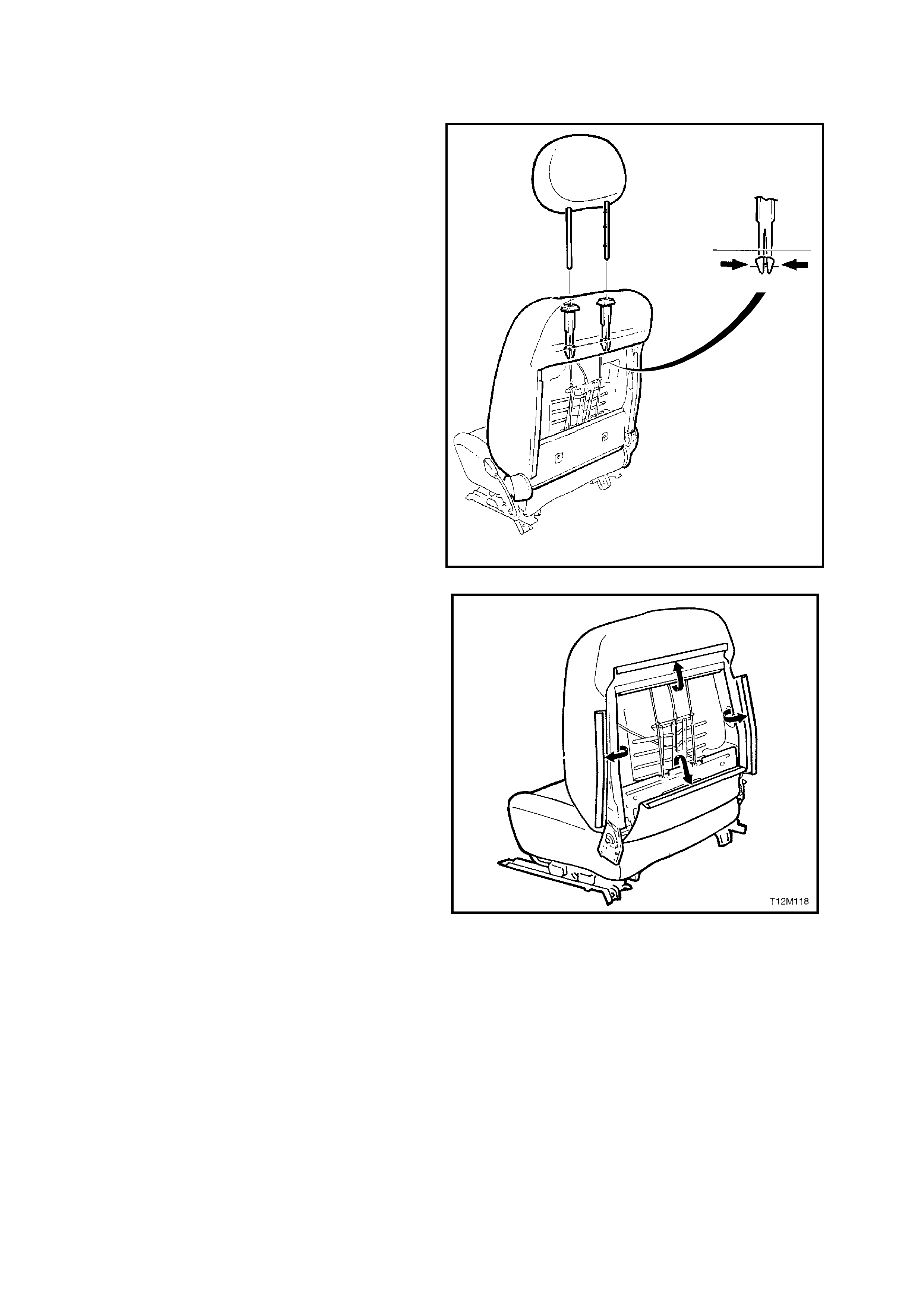
5. While holding head restraint height adjuster
lock in, pull head restraint completely out of
guide.
6. From the back of front seat, squeeze the
lock ing prongs of head r estr aint guide together
while pulling top of guide out of seat back
assembly, refer to Fig 1A7-10
T12M110
Figure 1A7-10
7. Pull the four ‘J’ strips away from the seat
frame.
8. Lift cover and pad assembly away from seat
back frame.
REINSTALL
Reinstallation is the reverse of the removal
operation, noting the following:
1. Ensure the head restraint guide with adjusting
lock is installed on the correct side, ie. side
with notches on the head restraint.
2. Ensure all fasteners are tightened to the
correct torque specification.
Figure 1A7-11
2.6 FRONT SEAT BACK FRAME, LUMBAR SUPPORT AND ADJUSTER ASSEMBLY
REMOVE
NOTE: The lumbar support is part of the seat back
frame and can only be replaced as an assembly.
1. Disconnect the battery earth and positive
leads.
2. Remove front seat back cover and pad
assembly, refer to 2.5 FRONT SEAT BACK
PAD AND COVER ASSEMBLY in this
Section.
3. On seats with side impact air bags c ut the wire
ties (five places) securing the side air bag
module ‘pigtail’ wiring harnes s to the f ront seat
assembly, taking care not to damage the
wiring harness.
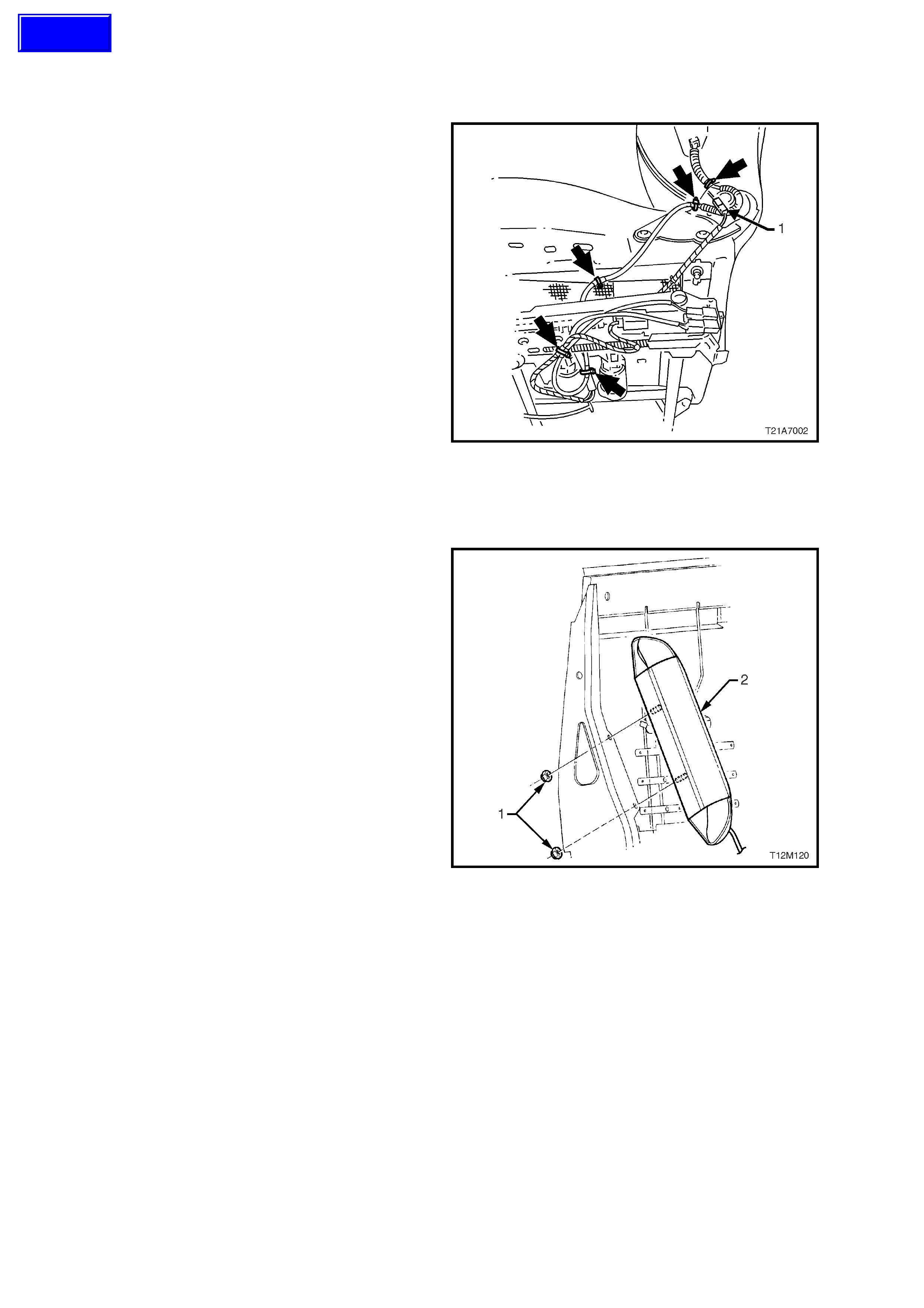
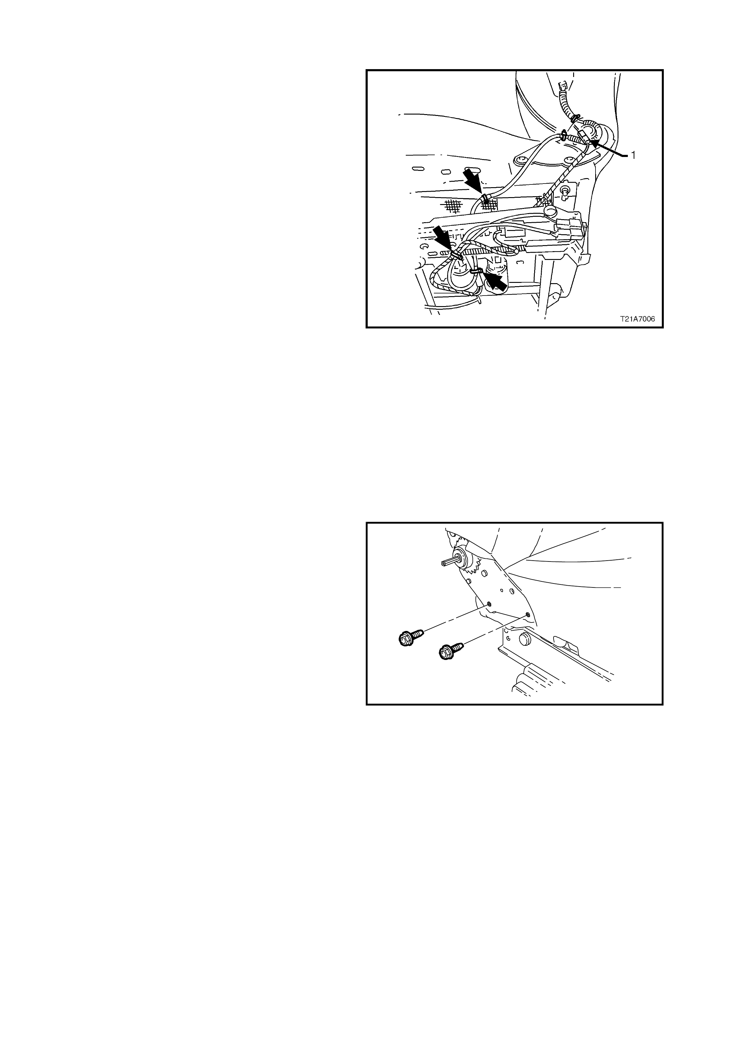
4. On seats with electric seat recliner
assemblies, disconnect the wiring harness
connector for the recliner motor (1).
NOTE: Fig 1A7-12 shows a seat with an electric
seat recliner assembly and side impact air bags.
On seats with out an electric seat recliner
assembly, the conduit around the recliner (as
shown) is not fitted.
Figure 1A7-12
5. Loosen and remove the two nuts securing the
side air bag assembly to the front seat back
frame.
Remove side air bag module and ‘pigtail’
wiring harness assembly from front seat back
frame.
CAUTION: When carrying a live (undeployed)
side air bag inflator module assembly, make
sure the bag opening is pointed away from you.
Never carry the side air bag inflator module
assembly by the wiring harness or connectors.
In case of an accidental deployment, the bag
will then deploy with minimal chance of injury.
When placing a live side air bag inflator module
assembly on a bench or other surface, always
face the air bag opening up, away from the
surface. Never rest the air bag inflator module
assembly with the opening face down. This is
necessary so that a free space is provided to
allow t he air b ag t o exp and in t he u nlikely ev ent
of accidental deployment. Otherwise, personal
injury may result.
6. If necessary, remove the two nuts retaining the
front seat foam block insert to the seat frame
and remove foam block insert.
Figure 1A7-13
Techline
7. Remove the four bolts (two on each side)
securing the seat back assembly to the seat
height adjuster and cushion frame assembly,
remove the seat back frame assembly.
T21A7003
Figure 1A7-14
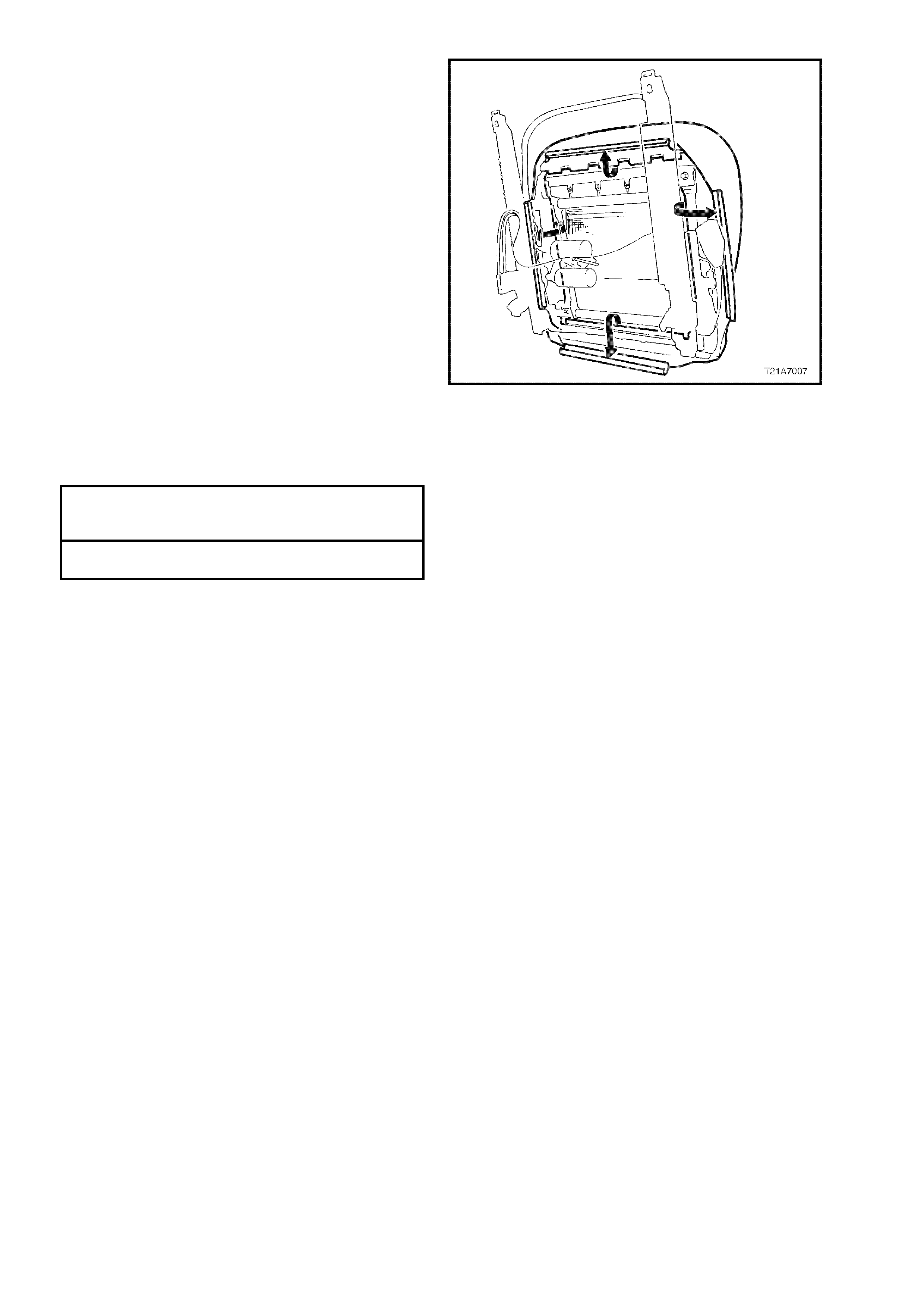
8. From the rear of the front seat back frame,
disengage the lumbar support adjuster cable
wire tie clip (3) by squeezing the tangs on the
wire tie retaining clip together and pushing
wire tie retaining clip through seat back frame
(1).
9. Push down the top of the lumbar support to
disengage the two retainers ( 2) from the guide
rails (4) on the seat back, allowing lumbar
support to swing freely.
10. While slightly compressing lumbar support
assembly by hand to release cable ( 5) tens ion,
disengage cable from the top of the lumbar
support.
11. Unclip lower cable retainer from lower lumbar
bracket.
T21A7004
42
31
5
Figure 1A7-15
12. Remove adjusting cable (1) from adjuster (2)
by unclipping outer casing (3) of cable from
adjuster and removing cable assembly.
Remove the two screws (4) securing the
lumbar support adjuster to the seat back
frame (5) and remove adjuster.
Figure 1A7-16

REINSTALL
Reinstallation of the front seat back frame, lumbar
support and adjus ter ass embly is the reverse of the
removal operation, noting the following:
1. Align hole in adjuster for adjusting cable ball
by turning the adjuster until access hole lines
up, insert cable into adjuster and push outer
casing of cable into locking seat of adjuster
until it clicks.
2. Ensure all fasteners are tightened to the
correct torque specification.
SEAT BACK TO SEAT ADJUSTER AND
GUIDE RAIL ASSEMBLY SECURING 30 - 45 Nm
BOLT TORQUE SPECIFICATION
FRONT SEAT FOAM BLOCK INSERT
TO FRONT SEAT BACK RETAINING 5.0 - 6.0 Nm
NUT TORQUE SPECIFICATION
SIDE IMPACT AIR BAG ASSEMBLY TO
FRONT SEAT BACK RETAINING 5.0 - 6.0 Nm
NUT TORQUE SPECIFICATION
FRONT SEAT TO FLOOR SECURING
BOLT TORQUE SPECIFICATION 35 - 50 Nm
3. Route the side impact air bag wiring harness
through to the side of the seat rail assembly
and secure with new wire ties as per Fig. 1A7-
17.
NOTE 1: On seats without an electric seat recliner
assembly, the conduit around the recliner (as
shown in Fig. 1A7-17) is not fitted.
NOTE 2: If the side impact air bag modules
wiring harness is not routed correctly, damage
to the harness may occur, resulting in the side
impact air bag becoming inoperative and
setting a Diagnostic Trouble Code (DTC) (SRS
warning lamp on).
NOTE 3: The wiring harness that connects to the
side impact air bag module, and runs through the
front seat down to the seat rail, is not serviced
separately from the side air bag inflator module due
to the design of the anti-back-out connector on the
module assembly.
If this wiring harness, as with any other SRS
‘pigtail’ type wiring harness becomes damaged no
wire, connector or terminal repairs are to be
attempted. REPLACE THE SIDE AIR BAG
MODULE AND PIGTAIL WIRING HARNESS
ASSEMBLY.
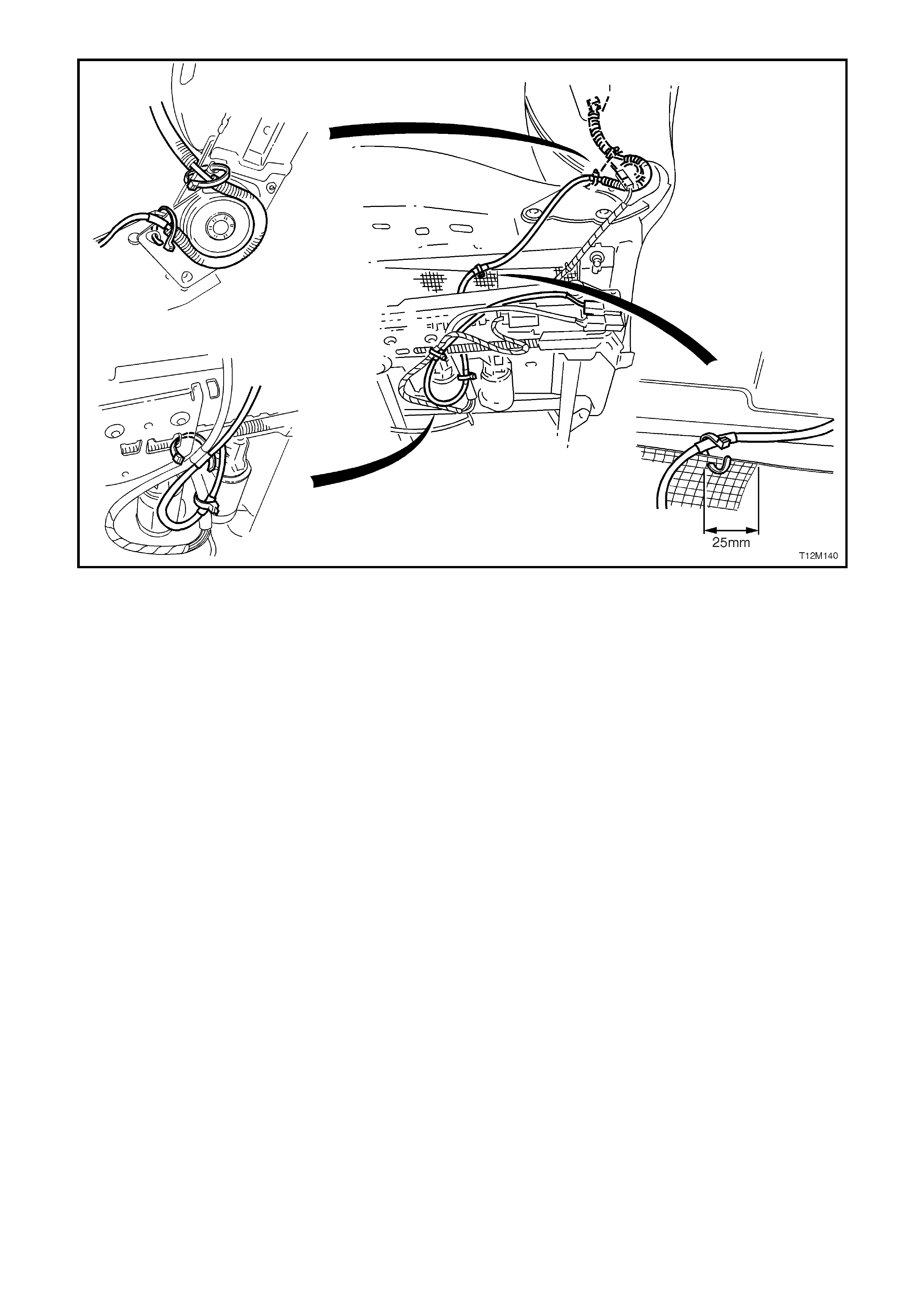
Figure 1A7-17
4. Reconnect batter earth and positive leads,
switch ignition on, and observe the SRS
warning lamp in the instrument cluster. The
warning lamp should be illuminated for
approximately five seconds. During this period
the SDM performs a wiring and system self
check.
If no system faults are detected, the SRS
warning lamp will be switched off. If the
warning lamp remains illuminated and an
audible alarm chimes, or the warning lamp
illuminates two seconds after it was originally
switched off, an SRS fault is present. Refer to
3 DIAGNOSTICS in Section 12M
SUPPLEMENTAL RESTRAINT SYSTEM of
this Service Information CD to rectify fault.
5. Check operation of front seat mechanical and
electrical adjustments / operation. While
checking the seat adjustment / operation, also
check to ensure that the side air bag harness
does not foul with any of the seats moveable
components (ie. seat motor drive shafts, etc.).
2.7 FRONT SEAT CUSHION PAD AND COVER ASSEMBLY
REMOVE
1. Disconnect the battery earth and positive
leads.
NOTE: If the vehicle is equipped with side impact
air bags, wait at least 10 seconds before
performing any work on the vehicle.
2. Remove front seat assembly, refer to 2.1
FRONT BUCKET SEAT ASSEMBLY in this
Section.
3. Remove inner and outer side cover
assemblies, refer to Section 1A7 SEAT &
SEAT BELT ASSEMBLIES of this Service
Information CD.
4. On seats with side impact air bags, taking care
not to damage the wiring harness, c ut three of
the five wire ties (m arked with an arrow in Fig.
1A7-18) securing the side air bag module
‘pigtail’ wiring harness to the front seat
assembly.
5. On seats with electric seat recliner
assemblies, disconnect the wiring harness
connector for the recliner motor (1 ).
NOTE: Fig. 1A7-18 shows a seat with an electric
seat recliner assembly and side impact air bags.
On seats without an electr ic s eat r ec liner as s embly,
the conduit around the recliner (as shown) is not
fitted.
Figure 1A7-18
6. Remove the four bolts (two on each side)
securing the seat back assembly to the seat
height adjuster and cushion frame assembly,
remove the seat back frame assembly.
T21A7003
Figure 1A7-19
7. From under seat cushion, pull the front and
side ‘J’ strips away from the seat frame.
8. Lift cover and pad assembly away from seat
frame and then release the rear ‘J’ strip.
REINSTALL
Installation of the f ront seat cushion pad and cover
assembly is the reverse of the removal operation,
noting the following:
1. W hen installing the seat back assembly to the
seat adjuster and guide rail assembly, ensure
there is a metal to metal contact of parts (no
trim material caught between).
2. Ensure all fasteners are tightened to the
correct torque specification.
Figure 1A7-20
SEAT BACK TO SEAT ADJUSTER AND
GUIDE RAIL ASSEMBLY SECURING 30 - 45 Nm
BOLT TORQUE SPECIFICATION
FRONT SEAT TO FLOOR SECURING
BOLT TORQUE SPECIFICATION 35 - 50 Nm
3. Route the side impact air bag wiring harness
through to the side of the seat rail assembly
and secure with new wire ties as per Fig. 1A7-
17 in this Section.
NOTE 1: If the side impact air bag module
wiring harness is not routed correctly, damage
to the harness may occur, resulting in the side
impact air bag becoming inoperative and
setting a Diagnostic Trouble Code (DTC) (SRS
warning lamp on).
NOTE 2: The wiring harness that connects to the
side impact air bag module, and runs through the
front seat down to the seat rail, is not serviced
separately from the side air bag inflator module due
to the design of the anti-back-out connector on the
module assembly.
If this wiring harness, as with any other SRS
‘pigtail’ type wiring harness, becomes damaged no
wire, connector or terminal repairs are to be
attempted. REPLACE THE SIDE AIR BAG
MODULE AND PIGTAIL WIRING HARNESS
ASSEMBLY.

4. Reconnect battery earth and positive leads,
switch ignition on, and observe the SRS
warning lamp in the instrument cluster. The
warning lamp should be illuminated for
approxim ately five seconds. During this period
the SDM performs a wiring and system self
check.
If no system faults are detected, the SRS
warning lamp will be switched off. If the
warning lamp remains illuminated and an
audible alarm chimes, or the warning lamp
illuminates two seconds after it was originally
switched off, an SRS fault is present. Refer to
3. DIAGNOSTICS in Section 12M
SUPPLEMENTAL RESTRAINT SYSTEMS of
this Service Information CD to rectify fault.
5. Check operation of front seat mechanical and
electrical adjustments / operation. While
check ing the seat adjustm ent / operation, also
check to ensure that the side air bag harness
does not foul with any of the seats moveable
components (ie. seat motor drive shafts, etc.).
2.8 FRONT SEAT CUSHION FRAME ASSEMBLY
REMOVE
1. Remove front seat cushion cover and pad
assembly, refer to 2.7 FRONT SEAT
CUSHION PAD AND COVER ASSEMBLY in
this Section.
2. Remove the four bolts securing the front seat
cushion frame to adjuster and guide rail
assembly.
Figure 1A7-21
NOTE: Before disconnecting pre-tensioner wiring
harness connector, take note of wiring harness
routing.
3. Tak ing care not to damage the wiring harness,
cut the wire ties (two on non electric seats;
View B, and one on 4 and 8 way electric seats;
View A) securing the seat belt pre-tensioner
wiring harness to the front seat suspension
mat.
4. By squeezing the retaining tangs on the seat
belt pre-tensioner wiring harness connector
retaining clip at the outer s ide of the front s eat
adjuster and guide rail assembly, disconnect
the connector from the pre-tensioner
assembly.
Figure 1A7-22
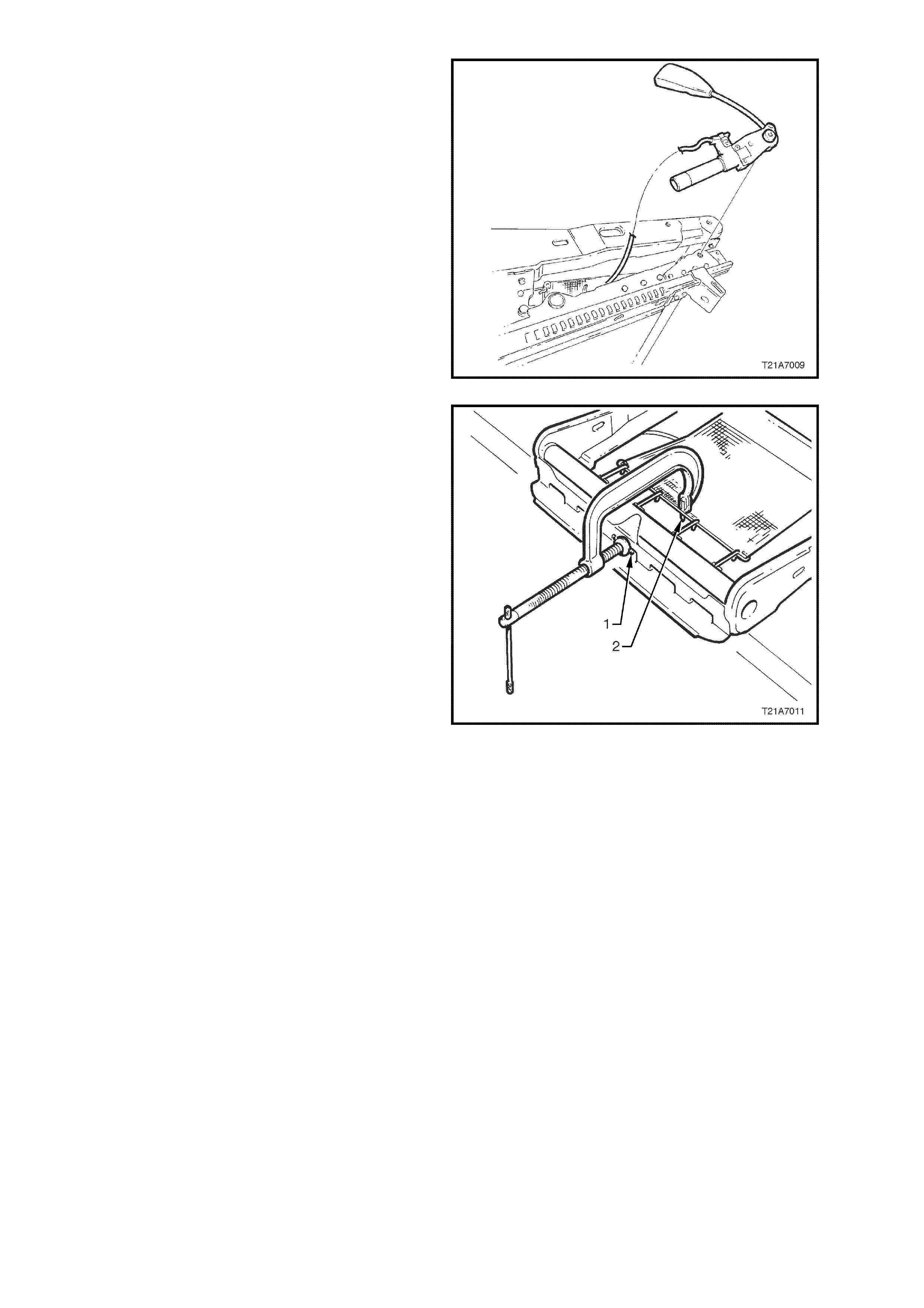
5. Remove bolt securing seat belt buckle and
pre-tensioner assembly to frame and remove
seat belt buckle and pre-tensioner assembly.
Figure 1A7-23
6. Using a pre-fabricated tool:
‘G’ clamp with a 5mm diameter metal dowel
(1) welded to one end, approximately 40mm
long and with a 2mm diameter pin (2)
approximately 20mm long welded to the other
end.
Using the pre-fabricated tool, stretch the
suspension mat far enough to allow for
webbing clamps to be removed from seat
frame. Back ‘G’ clamp load off and remove
suspension mat.
NOTE: When using pre-fabricated tool, use
existing holes in s us pens ion mat to ensur e that mat
deformation does not occur.
Figure 1A7-24

REINSTALL
Reinstallation of the front seat cushion frame
assembly is the reverse of the removal operation,
noting the following:
1. Ensure all fasteners are tightened to the
correct torque specification.
SEAT BACK TO SEAT ADJUSTER AND
GUIDE RAIL ASSEMBLY SECURING 30 - 45 Nm
BOLT TORQUE SPECIFICATION
FRONT SEAT TO FLOOR SECURING
BOLT TORQUE SPECIFICATION 35 - 50 Nm
SEAT BELT BUCKLE AND PRE-
TENSIONER ASSEMBLY BOLT 45 - 50Nm
TORQUE SPECIFICATION
FRONT SEAT CUSHION FRAME TO
SEAT GUIDE RAIL AND ADJUSTER 24 - 32 Nm
BOLT TORQUE SPECIFICATION
2. Ensure the pre-tens ioner, seat adj uster m otor,
and (if fitted) side impact air bag wiring
harnesses are routed correctly and retained by
wiring ties at each red spot tape loc ation, ref er
Figs. 1A7-17 & 1A7-22 in this Section.
3. When installing seat belt buckle and pre-
tensioner assembly ensure that the front
locating pin on the pre-tensioner assembly
aligns with seat frame.
NOTE 1: If the side impact air bag module or
seat belt pre-tensioner wiring harnesses are
not routed correctly, damage to the harness
may occur, resulting in the side impact air bag
or seat belt pre-tensioner becoming inoperative
and setting a Diagnostic Trouble Code (DTC)
(SRS warning lamp on).
NOTE 2: The wiring harness that connects to the
side impact air bag module, and runs through the
front seat down to the seat rail, is not serviced
separately from the side air bag inflator module due
to the design of the anti-back-out connector on the
module assembly.
If this wiring harness, as with any other SRS
‘pigtail’ type wiring harness, becomes damaged no
wire, connector or terminal repairs are to be
attempted. REPLACE THE SIDE AIR BAG
MODULE AND PIGTAIL WIRING HARNESS
ASSEMBLY.

4. Reconnect battery earth and positive leads,
switch ignition on, and observe the SRS
warning lamp in the instrument cluster. The
warning lamp should be illuminated for
approxim ately five seconds. During this period
the SDM performs a wiring and system self
check.
If no system faults are detected, the SRS
warning lamp will be switched off. If the
warning lamp remains illuminated and an
audible alarm chimes, or the warning lamp
illuminates two seconds after it was originally
switched off, an SRS fault is present. Refer to
3. DIAGNOSTICS in Section 12M
SUPPLEMENTAL RESTRAINT SYSTEM of
this Service Information CD to rectify fault.
5. Check operation of front seat mechanical and
electrical adjustments / operation. While
check ing the seat adjustm ent / operation, also
check to ensure that the side air bag harness
does not foul with any of the seats moveable
components (ie. seat motor drive shafts, etc.).

2.9 FRONT SEAT RECLINING MOTOR AND GEARBOX ASSEMBLY
REMOVE & REINSTALL
The removal and installation procedure f or the f ront s eat r ec lining motor and gearbox as s embly remains unc hanged
from that detailed in Section 1A7 SEATS AND SEAT BELT ASSEMBLIES of this Service Information CD, noting
the following:
To remove and reinstall the front seat back pad and cover assembly, reference to 2.5 FRONT SEAT BACK PAD
AND COVER ASSEMBLY in this Section should be made.
Techline
2.10 RE AR SEAT BACK LOCK, ACTUATOR, CABLE AND RELEASE BUTTON - WAGON
REMOVE & REINSTALL
The rem oval and installation procedure for the rear
seat back lock, actuator, cable and release button
remains unchanged from that detailed in Section
1A7 SEATS AND SEAT BELT ASSEMBLIES of
this Service Information CD, noting the following:
W hen reinstalling the seat back release handle (2)
to lock assembly (3), apply Loctite 262 or
equivalent, to Holden Specific ation HN 1256, to the
threads of the retaining s c rew ( 1) and tighten s c rew
to the correct torque specification.
SEAT BACK LOCK HANDLE RETAINING 3.0
SCREW TORQUE SPECIFICATION Nm
Figure 1A7-25
Techline

3. DIAGNOSTICS
NOTE: The following diagnsotic procedures only relate to vehicles built after Tag Number L423680 fitted with the
four way electric seat.
3.1. PREREQUISITES TO DIAGNOSIS AND TROUBLE SHOOTING
PRELIMINARY SYSTEM REQUIREMENTS
The prerequisites before proceeding with system checks are:
• Fusible link FJ and circuit breaker F2 must be checked before any electrical diagnostic checks are performed.
• Ensure no moisture is present in the main wiring harness to body wiring harness or seat harness connections.
• Ensure that sound earth connections are available for all functioning components.
• Ensure the battery is in good condition and adequately charged (above 11.5 Volts) before carrying out any
electrical checks.
SAFETY REQUIREMENTS
Disconnect the battery when carrying out work which involves the risk of an electrical short circuit.
Do not touch mechanical components during function checks, to avoid the risk of a hand being caught in the
mechanism.
If the vehicle is equipped with side im pact air bags, bef ore removing any components on or around the front seats ,
disable the SRS, refer to Section 12M SUPPLEMENTAL RESTRAINT SYSTEM of this Service Information CD.
CHECKING EQUIPMENT
An unpowered testlamp with a current draw of less than three Amps.
A digital multimeter, with a minimum 10 Megohm impedance MUST be used when undertaking any electrical
checks on these systems.
Exercise care when taking readings from wiring harness connectors. It is preferred that the back probing method
with individual connectors is employed wherever possible, to avoid terminal damage and subsequent connection
failure.
When carrying out wiring chec k s as directed to by the diagnostic c harts , r ather than pr obe terminals and c onnec tors
with incorrect sized m ultimeter connec tions, use the adaptors contained in c onnector test adaptor kit KM-609. This
will prevent any possibility of spreading or damaging wiring harness terminals.
IMPORTANT:
• When checking, the exact order of the test steps should be observed.
• If the required nominal value is not achieved in any stage, then the problem must be rectified before proceeding
further.
• Unless the multimeter being used has an auto ranging function, check that the correct range, as specified, is
selected before the test is carried out.
3.2 VISUAL INSPECTION
When investigating any complaint of an elec tr ic s eat pr oblem or malf unc tion, s tart diagnos is with a vis ual inspec tion
of the system.
The visual inspection procedure may quickly identify the cause and illuminate the need for additional diagnosis, in
particular if the problem is a mechanical fault.
If the complaint condition can not be resolved by the visual inspection, proceed to the appropriate diagnostic chart in
this Section.
NOTE: Diagnostic Chart 3.3, Diagostic Chart 3.4 and Diagnostic Chart 3.5 in this Section relate to electrical
faults only and assume there are no mechanical faults.
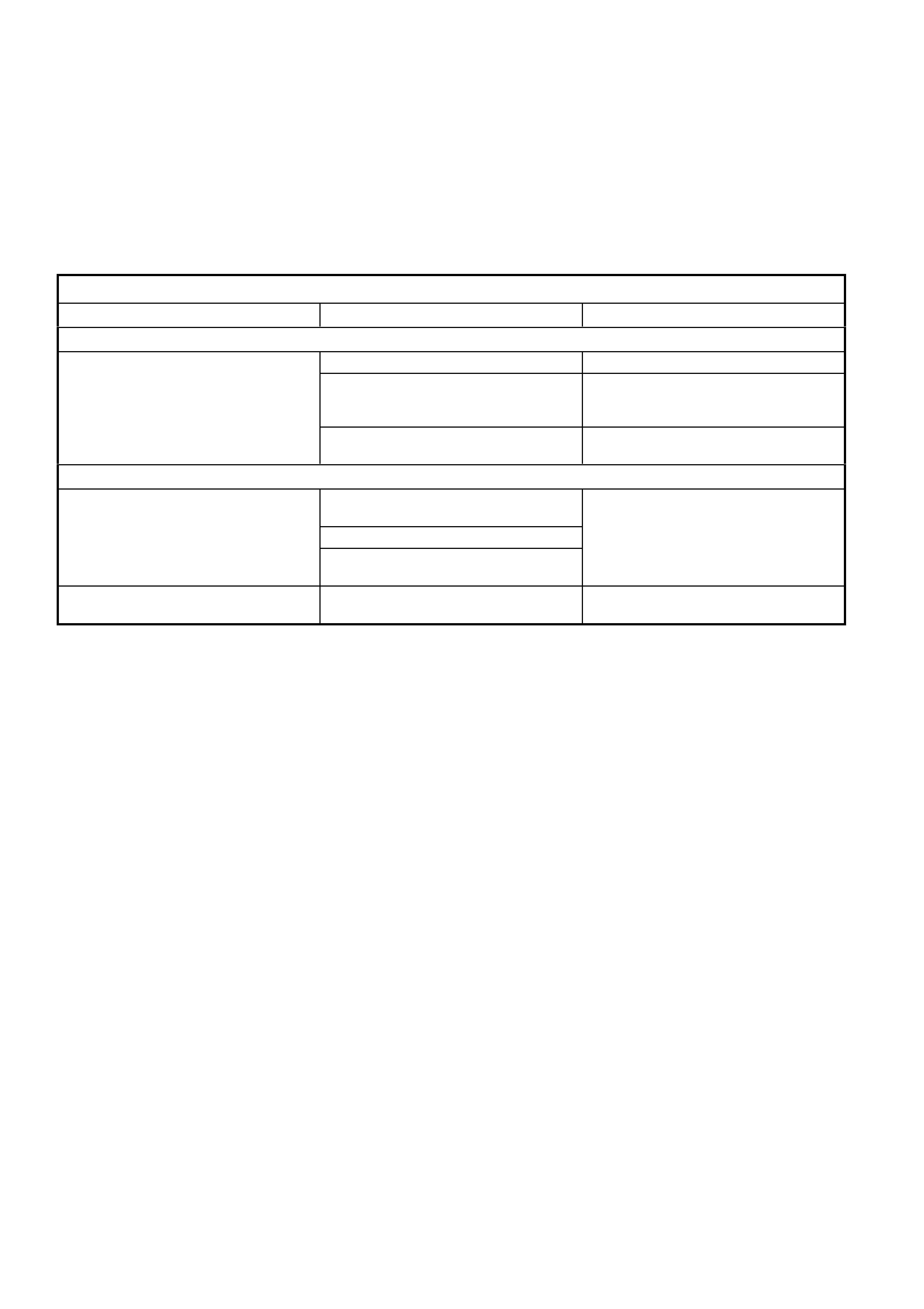
ELECTRIC SEAT VISUAL INSPECTION
ITEM INSPECT FOR CORRECTIVE ACTION
GENERAL
Operation of seat (noisy, slow or no Foreign material causing seat to bind. Remove foreign material.
operation at all). Dry components, build up of dirt on
moving components. Clean and apply Lithium based grease
(to Holden specification HN 2073) to
noisy component.
Bent, loose or physically damaged
components. Repair or replace faulty components.
WIRING CONNECTIONS & CIRCUIT BREAKER
Seat and switch wiring harness
connectors. Loose connections at individual
motors. Ensure secure connections.
Loose connections at control switch.
Loose connection at power supply
connector at side of seat assembly.
Circuit breaker F2. Loose connection or not fitted. Ensure secure connection or supply
new circuit breaker.

3.3 ELECTRIC SEAT DOES NOT MOVE IN ANY DIRECTION
STEP ACTION VALUE YES NO
1. • At the side of the front seat assembly, back probe
power seat connector YB116, circuits 540 and 156
with a test lamp.
• Does the test lamp illuminate ?
Go to Step 4. Go to Step 2.
2. • Disconnect body harness from connector YB116.
• Using a voltmeter, measure voltage at Orange/Black
wire connection and a sound earth connection.
• Is voltage as specified ?
Battery + Go to Step 3. Check and repair
open or short in
circuit 540
(including fusible
link FJ and circuit
breaker F2),
recheck and
verify repair.
3. • With body harness connector YB116 disconnected,
check for continuity between Black/Blue wire
connection and earth location E6.
• Does continuity exist ?
Circuit OK. Check and repair
earth circuit 156,
recheck and
verify repair.
4. • Back probe seat switch connector YB211, Red and
Black wire connections with a test lamp.
• Does the test lamp illuminate ?
Go to Step 5. Check and repair
open in either
Red or Black
wire circuits
between seat
switch connector
and body
harness
connector YB116
5. • From under front seat assembly, back probe any one
of the seat adjusting motors wiring harness
connectors (YB212) with a test lamp connected to
both sides of the connector.
• Operate the selected seat adjusting motor.
• Does the test lamp illuminate ?
Replace seat
adjusting motors,
refer to the
appropriate
Service
Operation in 2.
SERVICE
OPERATIONS in
Section 1A7
SEAT & SEAT
BELT
ASSEMBLIES of
this Service
Information CD.
Replace seat
adjusting switch
assembly, refer
to 2. SERVICE
OPERATIONS in
Section 1A7
SEAT & SEAT
BELT
ASSEMBLIES of
this Service
Information CD.
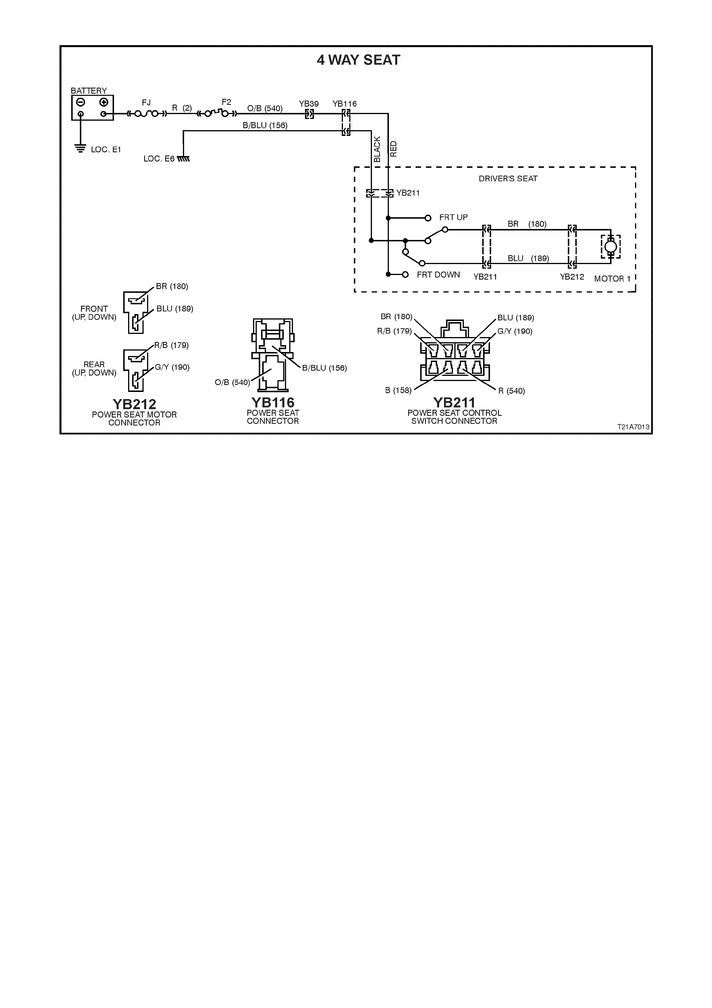
Figure 1A7-26
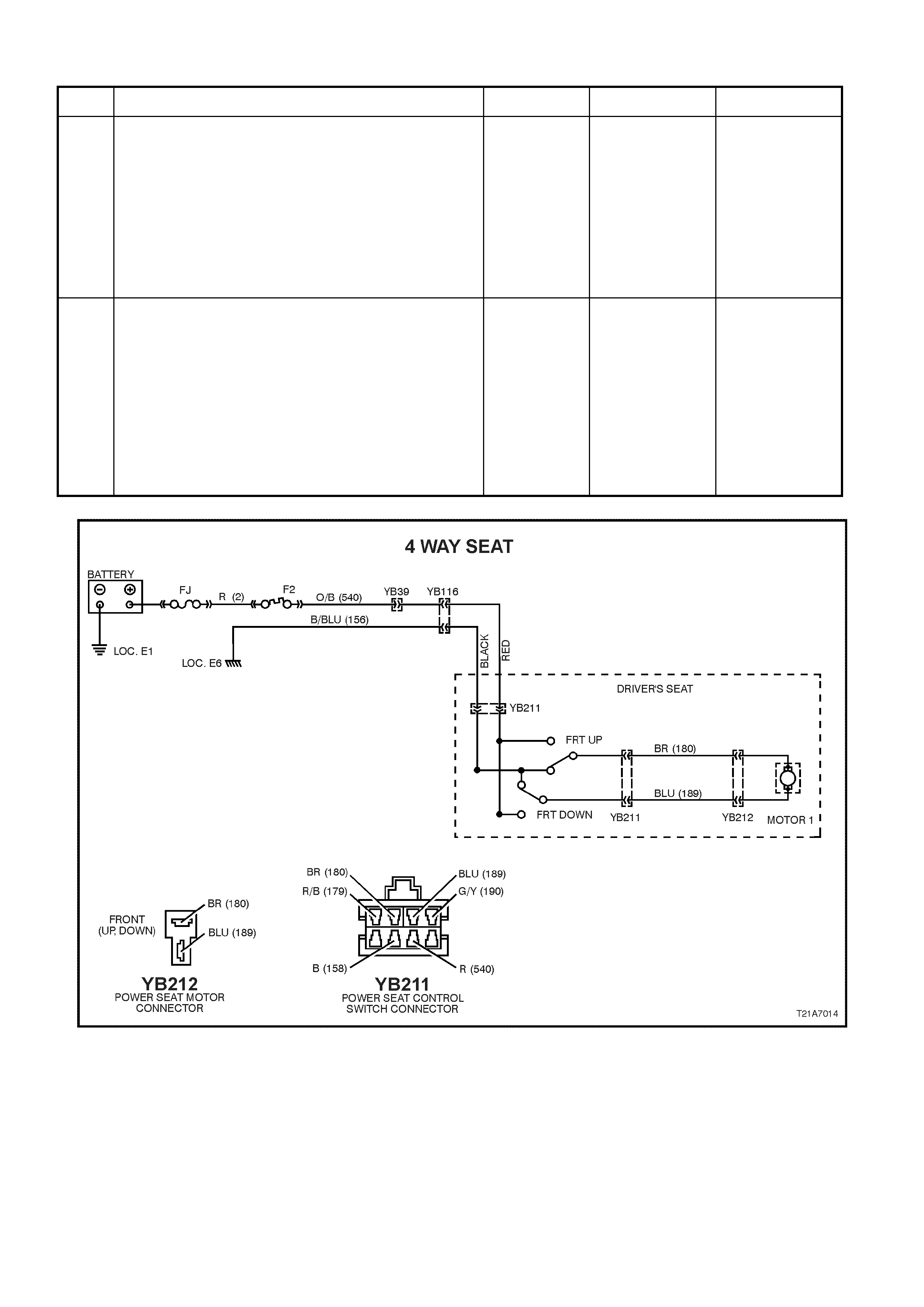
3.4 ELECTRIC SEAT FRONT UP AND DOWN OPERATION INOPERATIVE
STEP ACTION VALUE YES NO
1. • From under front seat assembly, back probe the seat
front lift motor wiring harness connector YB212,
between circuit 180 (Brown wire) and circuit 189
(Blue wire) connections with a test lamp.
• Operate the seat front lift motor.
• Does the test lamp illuminate ?
Replace the seat
front lift motor
assembly, refer
2. SERVICE
OPERATIONS in
Section 1A7
SEAT & SEAT
BELT
ASSEMBLIES of
this Service
Information CD.
Go to Step 2.
2. • Back probe seat switch connector YB211, between
circuit 180 (Brown wire) and circuit 189 (Blue wire)
connections with a test lamp.
• Operate the seat front lift motor.
• Does the test lamp illuminate ?
Check and repair
open in circuits
180 (Brown wire)
or circuit 189
(Blue wire)
between seat
adjusting switch
connector and
seat front lift
motor connector.
Recheck and
verify repair.
Replace seat
adjusting switch,
refer to
2. SERVICE
OPERATIONS in
Section 1A7
SEAT & SEAT
BELT
ASSEMBLIES of
this Service
Information CD.
Figure 1A7-27
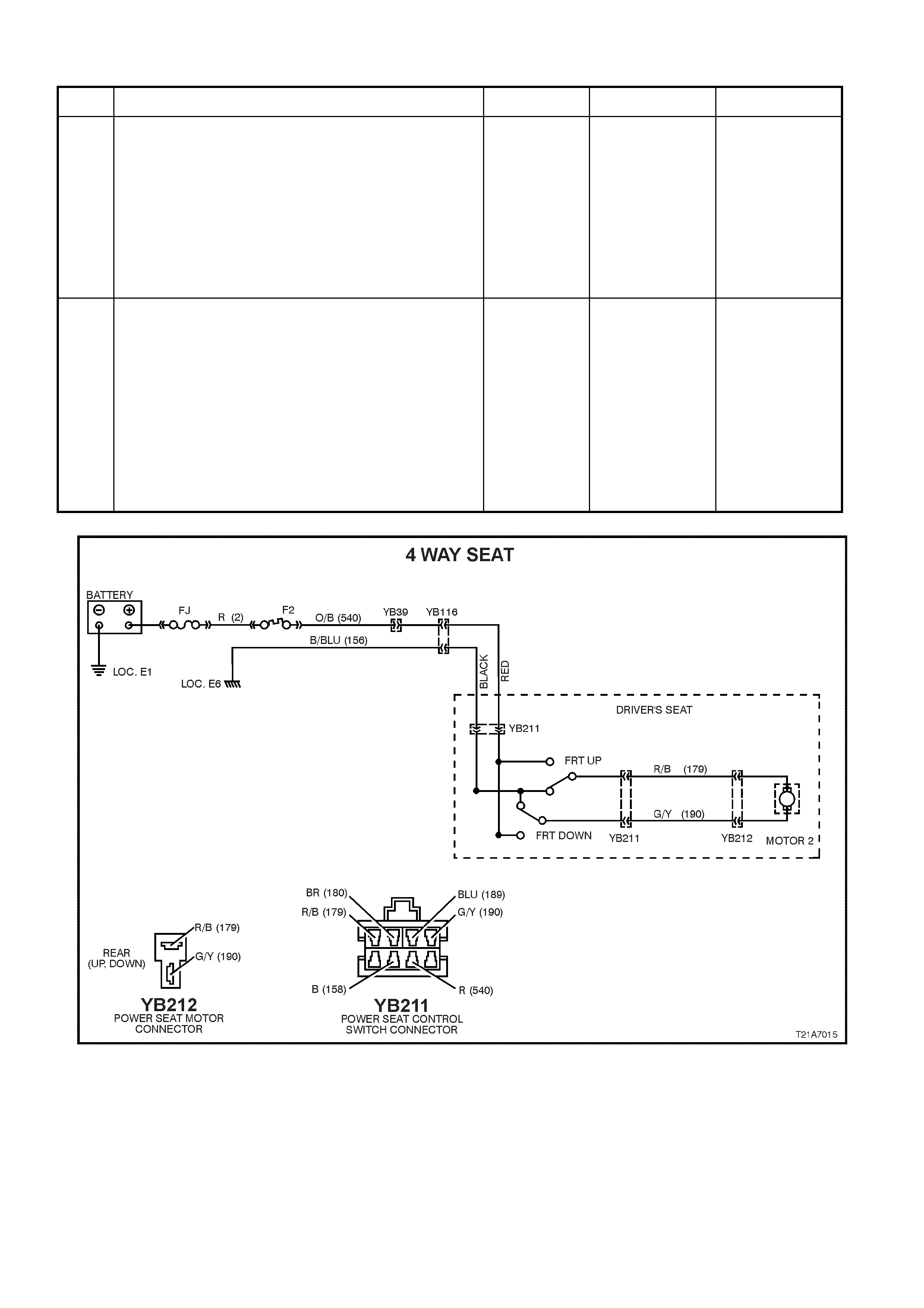
3.5 ELECTRIC SEAT REAR UP AND DOWN OPERATION INOPERATIVE
STEP ACTION VALUE YES NO
1. • From under front seat assembly, back probe the seat
rear lift motor wiring harness connector YB212,
between circuits 179 (Red/Black wi re) and circuit 190
(Green/Yellow wire) connections with a test lamp.
• Operate the seat rear lift motor.
• Does the test lamp illuminate ?
Replace the seat
rear lift motor
assembly, refer
to 2. SERVICE
OPERATIONS in
Section 1A7
SEAT & SEAT
BELT
ASSEMBLIES of
this Service
Information CD.
Go to Step 2.
2. • Back probe seat adjusting switch connector, YB211
circuits 179 (Red/Black wire) and circuit 190
(Green/Yellow wire) connections with a test lamp.
• Operate the seat rear lift motor.
• Does the test lamp illuminate ?
Check and repair
open in circuits
179 (Red/Black
wire) or circuit
190 (Green/
Yellow wire)
between seat
adjusting switch
connector and
seat rear lift
motor connector.
Recheck and
verify repair.
Replace seat
adjusting switch,
refer to 2.
SERVICE
OPERATIONS in
Section 1A7
SEAT & SEAT
BELT
ASSEMBLIES of
this Service
Information CD.
Figure 1A7-28

4. TORQUE WRENCH SPECIFI CATIONS
Nm
Armrest Bracket to Frame Retaining Screw ......................... 4.0
Armrest to Bracket Retaining Screw..................................... 4.0
Armrest to Bracket Securing Bolt - Sedan............................ 7 - 10
B pillar Upper Trim Retaining Screw..................................... 1.0 - 3.0
Bracket to Seat Back Retaining Bolt..................................... 15 - 25
Centre Cover to Frame Retaining Screw.............................. 2.5
Centre Hinge Lower Securing Bolt........................................ 35 - 50
Centre Hinge Upper Securing Bolt........................................ 25 - 35
Child Seat Anchor Bolt.......................................................... 14 - 21
Front Seat Belt Guide Retaining Screw ................................ 2.4 - 3.4
Front Seat Cushion Frame to Seat Guide Rail
and Adjuster Assembly Bolt.................................................. 24 - 32
Front Seat to Floor Securing Bolt.......................................... 35 - 50
Garnish Retaining Screw ...................................................... 2.0
LHR Seat Back Lock Retaining Screw.................................. 3.0
Outer Front Seat Guide Rail Cover....................................... 1.0 - 3.0
Rear Seat Back to Floor Retaining Bolt................................ 25 - 30
Rear Seat Back Lock Handle Retaining Screw..................... 3.0
Seat Back to Height Adjuster Assembly Securing Bolt......... 30 - 45
Seat Back to Seat Adjuster & Guide Rail Assembly
Securing Bolt......................................................................... 30 - 45
Seat Belt Buckle and Pre-tensioner Asm Bolt....................... 45 - 50
Seat Belt Buckle Anchor Securing Bolt................................. 35 - 50
Seat Belt guIde Bracket Securing Bolt.................................. 20 - 22
Seat Belt Retractor Retaining Nut......................................... 35 - 50
Seat Belt Securing Bolt......................................................... 40 - 54
Side Inner Cover Retaining Screw........................................ 1.0 - 3.0
Striker Retaining Bolt - Wagon Seat Back............................ 25 - 35
Striker Retaining Screw - Sedan Seat Back Lock................. 25 - 35
Side Impact Air Bag Assembly to Front Seat Back
Frame Retaining Nut............................................................. 5.0 - 6.0
Front Seat Foam Block Insert Retaining Nut........................ 5.0 - 6.0